Classic 93380 - Elliptical bike Life Gear - Free user manual and instructions
Find the device manual for free Classic 93380 Life Gear in PDF.


User questions about Classic 93380 Life Gear
0 question about this device. Answer the ones you know or ask your own.
Ask a new question about this device
Download the instructions for your Elliptical bike in PDF format for free! Find your manual Classic 93380 - Life Gear and take your electronic device back in hand. On this page are published all the documents necessary for the use of your device. Classic 93380 by Life Gear.
USER MANUAL Classic 93380 Life Gear
natural_image
Line drawing of an outdoor fitness equipment with levers and arms (no text or symbols)
OWNER'S MANUAL
IMPORTANT: Read all instructions carefully before using this product. Retain this owner's manual for future reference.
The specifications of this product may vary from this photo, subject to change without notice.
TABLE OF CONTENTS
WARRANTY 1
SAFETY INSTRUCTIONS 2
PARTS LIST 3
HARDWARE PACKING LIST 5
TOOLS 6
OVERVIEW DRAWING 7
ASSEMBLY INSTRUCTIONS 8
LifeGear Inc. warrants to the original purchaser that this product is free from defects in material and workmanship when used for the purpose intended, under the conditions that it has been installed and operated in accordance with LifeGear's Owner's Manual. LifeGear's obligation under this warranty is limited to replacing or repairing, free of charge, any parts which may prove to be defective under normal home use. This warranty does not include any damage caused by improper operation, misuse or commercial application.
From the date of purchase, the frame is warranted to be free from defects for 1 (one) year.
This warranty is extended only to the original owner and is not transferable.
When ordering replacement parts please have the following information ready:
- Owner's Manual
- Model Number
- Description of Parts
- Part Number
- Date of Purchase
SAFETY INSTRUCTIONS
Basic precautions should always be followed, including the following safety instructions when using this equipment: Read all instructions before using this equipment.
- Read all the instructions in this manual and do warm up exercises before using this equipment.
- Before exercise, in order to avoid injuring the muscle, warm-up exercise of every position of the body is necessary. Refer to Warm Up and Cool Down Routine page. After exercise, relaxation of the body is suggested for cool-down.
- Please make sure all parts are not damaged and fixed well before use. This equipment should be placed on a flat surface when using. Using a mat or other covering material on the ground is recommended.
- Please wear proper clothes and shoes when using this equipment; do not wear clothes that might catch any part of the equipment.
- Do not attempt any maintenance or adjustments other than those described in this manual. Should any problems arise, discontinue use and consult an Authorized Service Representative.
- Be careful when step on or leave the pedal always hold the handlebars first. Make the pedal at your side at the lowest position, step on the pedal, and stride over the main frame then step on the other pedal. When using, please hold the handlebar by hands, make the pedals running smoothly by push or pull handlebars, then run the equipment regularly by cooperation of hands and feet. After exercise, please also make one pedal at the lowest position and leave your foot on the higher pedal first and then another.
- Do not use the equipment outdoors.
- This equipment is for household use only.
- Only one person should be on the equipment while in use.
- Keep children and pets away from the equipment while in use. This machine is designed for adults only. The minimum free space required for safe operation is not less than two meters.
- If you feel any chest pains, nausea, dizziness, or short of breath, you should stop exercising immediately and consult your physician before continuing.
- The maximum weight capacity for this product is 110kgs.
WARNING: Before beginning any exercise program consult your physician.
This is especially important for the persons who are over 35 years old or who have pre-existing health problems. Read all instructions before using any fitness equipment.
CAUTION: Read all instructions carefully before operating this product.
Retain this Owner's Manual for future reference.
PARTS LIST
| No. | Description | Qty | No. | Description | ||
| 001 | Main Frame 1 027 Nylon Nut M6 8 | |||||
| 002L | Left Foot Bar 1 028 Washer ∅6x∅12x1 7 | |||||
| 002R | Right Foot Bar 1 029 Bolt M6x40 6 | |||||
| 003L | Left Handrail Arm | 1 | 030 | Tension Cable L=1600 | 1 | |
| 003R | Right Handrail Arm | 1 | 031 | Cap S13 | 2 | |
| 004L | Left Handrail ∅32x1.5x633 | 1 | 032 Screw ST4.2x25 | 10 | ||
| 004R | Right Handrail ∅32x1.5x633 | 1 | 033L | Left Handrail Arm Cover-B | 1 | |
| 005 | Front Post | 1 | 033R Right Handrail Arm Cover-B | 1 | ||
| 006 | Handlebar | 1 | 034 | Big Washer ∅20∅8x1.5 | 2 | |
| 007 | Bolt M6x10 | 1 | 035 | Bolt ∅15.8x62.5 | 2 | |
| 008 | Screw ST2.9x10 | 2 | 036 Left Foot Pedal 395x153x70 | 1 | ||
| 009 | Washer ∅102x∅14x1 | 2 | 037 | Right Foot Pedal 395x153x70 | 1 | |
| 010 | Front Stabilizer | 1 | 038 | Front Stabilizer End Cap ∅50 | 2 | |
| 011 | Rear Stabilizer ∅50x1.5x480 | 1 | 039 | Bolt M6x48 | 2 | |
| 012 | Bolt M10x57 | 4 | 040 | Transport Wheel ∅23x∅6x32 | 2 | |
| 013 | Rear Stabilizer End Cap ∅50x1.5 | 2 | 041 | Bolt M8x16 | 8 | |
| 014 | Big Curve Washer ∅10x∅25x2 | 4 | 042 | Big Curve Washer ∅20x∅8x1.5 | 6 | |
| 015 | Cap Nut M10 | 4 | 043 Bolt M10x18 | 2 | ||
| 016L | Bolt for left U Shape Bracket 1/2" | 1 | 044 | Spring Washer ∅18x∅10.5x3 | 2 | |
| 016R | Bolt for right U Shape Bracket 1/2" | 1 | 045 | Bolt M6x35 | 4 | |
| 017L | Left Nylon Nut 1/2" | 1 | 046 Washer ∅28x5 | 2 | ||
| 017R | Right Nylon Nut 1/2" | 1 | 047 Powder Metal Bushing ∅33x∅29x∅16x14x3 | 4 | ||
| 018 | Wave Washer ∅28x∅17x0.3 | 2 | 048 | Curve Washer ∅6x∅12x1 | 4 | |
| 019 | Powder Metal Bushing ∅29x∅16x14 | 8 | 049 | Cap S16 | 2 | |
| 020 | Spring Washer ∅13x∅20x2 | 2 | 050 | Cap Nut M6 | 4 | |
| 021 | Bearing 6000 ZZ 2 051 Plastic Bushing ∅32x∅16x5x∅50 2 | |||||
| 022 | Bolt M8x20 | 2 | 052 Big Washer ∅10x∅20x1.5 | 2 | ||
| 023 | U Shape Bracket | 2 | 053 Curve Washer ∅8x∅16x1.5 | 2 | ||
| 024 | Nylon Nut M8 | 2 | 054 Tension Control Knob | 1 | ||
| 025 | Washer ∅16x∅8x1.5 | 2 | 055 | Spring Washer ∅8 | 6 | |
| 026 | Bolt M8x50 | 2 | 056 | Computer RD-93232 | 1 |
PARTS LIST
| No. | Description | Qty | No. | Description | ||
| 057 | Bolt M5x12 4 078 Crank Nut 7/8" | 1 | ||||
| 058 | Hand Pulse Sensor with Wire L=750 | 2 | 079 | Crank with Belt Pulley | 1 | |
| 059 | Handrail Foam Grip ∅31x∅37x480 | 2 | 080 | Nut M10x1 | 2 | |
| 060 | Handlebar Foam Grip ∅21x∅27x360 | 2 | 081 | Flywheel ∅230 | 1 | |
| 061 | Handrail End Cap ∅32x1.5 | 2 | 082 | Belt PJ330 J6 | 1 | |
| 062 | Handlebar End Cap ∅28.6x1.5 | 2 | 083 | Idle Wheel Bracket | 1 | |
| 063 | Screw ST4.2x20 | 2 | 084 | Bolt M8x30 | 1 | |
| 064 | Curve Washer for Tension Control Knob ∅20x∅5.2 | 1 | 085 | Eyebolt M6x36 | 2 | |
| 065 | Bolt for Tension Control Knob M5x45 | 1 | 086 | U Bracket | 2 | |
| 066 | Phillips Self Tapping Screw ST4.2x25 | 6 | 087 | Spring Washer ∅6x∅11.2x2 | 2 | |
| 067 | Sensor Wire I L=1100 | 1 | 088 | Nut M6 | 2 | |
| 068 | Sensor Wire II L=1600 | 1 | 089 | Bolt M8x10 | 1 | |
| 069 | Cover Cap ∅40x∅25x10 | 2 | 090 | Right Decorative Cover ∅50 | 1 | |
| 070 | Left Cover 538x374x79 | 1 | 091 | Left Decorative Cover ∅50 | 1 | |
| 071 | Right Cover 538x374x81 | 1 | 092 | Powder Metal Bushing ∅18x∅8.5 | 4 | |
| 072 | Bearing Cup | 2 | 093L | Foot Bar Cover-A | 2 | |
| 073 | Bearing | 2 | 093R | Foot Bar Cover-B | 2 | |
| 074 | Notched Bearing Nut 15/16" | 1 | 094L | Left Handrail Arm Cover-A | 1 | |
| 075 | Slotted Bearing Nut 7/8" | 1 | 094R | Right Handrail Arm Cover-A | 1 | |
| 076 | Washer ∅34.5x∅23x2.5 | 1 | 095 | Phillips Self Tapping Screw ST4.2x25 | 4 | |
| 077 | Washer ∅40x∅24x2.5 | 1 | 096 | Screw ST2.9x12 | 8 |
HARDWARE PACKING LIST
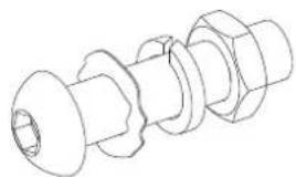
natural_image
Technical line drawing of a mechanical bolt assembly (no text or symbols)(16R) Bolt for right U Shape Bracket 1/2"
(17R) Right Nylon Nut 1/2" 1 PC
(18) Wave Washer
∅28x∅17x0.3 1 PC
(20) Spring Washer
∅13x∅20x2 1 PC
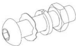
natural_image
Technical line drawing of a mechanical component with threaded shaft and flanges (no text or symbols)(16L) Bolt for left U Shape Bracket 1/2"
(17L) Left Nylon Nut 1/2" 1 PC
(18) Wave Washer
∅28x∅17x0.3 1 PC
(20) Spring Washer
∅13x∅20x2 1 PC
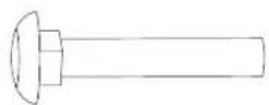
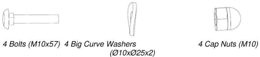
(12) Bolt M10x57 4 PCS
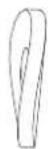
(14) Big Curve Washer ∅10x∅25x2 4 PCS
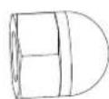
(15) Cap Nut M10 4 PCS

(27) Nylon Nut M6 6 PCS
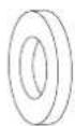
(28) Washer ∅6x∅12x1 6 PCS
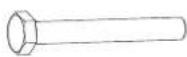
(29) Bolt M6x40 6 PCS

(31) Cap S13 2 PCS
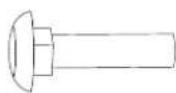
(45) Bolt M6x35 4 PCS
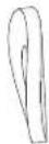
(48) Curve Washer ∅6x∅12x1 4 PCS
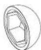
(49) Cap S16 2 PCS
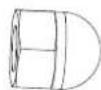
(50) Cap Nut M6 4 PCS
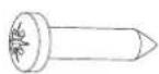
(95) Phillips Self Tapping Screw ST4.2x25 4 PCS
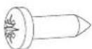
(96) Screw ST2.9x12 8 PCS
TOOLS
natural_image
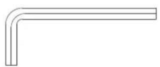
Simple L-shaped metal angle bracket diagram (no text or symbols)Allen Wrench S6 1 PC
natural_image
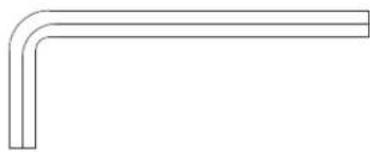
Simple line drawing of a bent pipe or angle bracket (no text or symbols)Allen Wrench S8 1 PC
natural_image
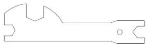
Pure technical line drawing of a mechanical wrench (no text or symbols)Multi Hex Tool 1 PC
natural_image
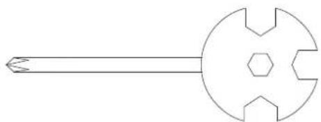
Simple line drawing of a mechanical tool with a circular head and hexagonal base (no text or symbols)Multi Hex Tool with Phillips Screwdriver S10, S13, S14, S15 1 PC
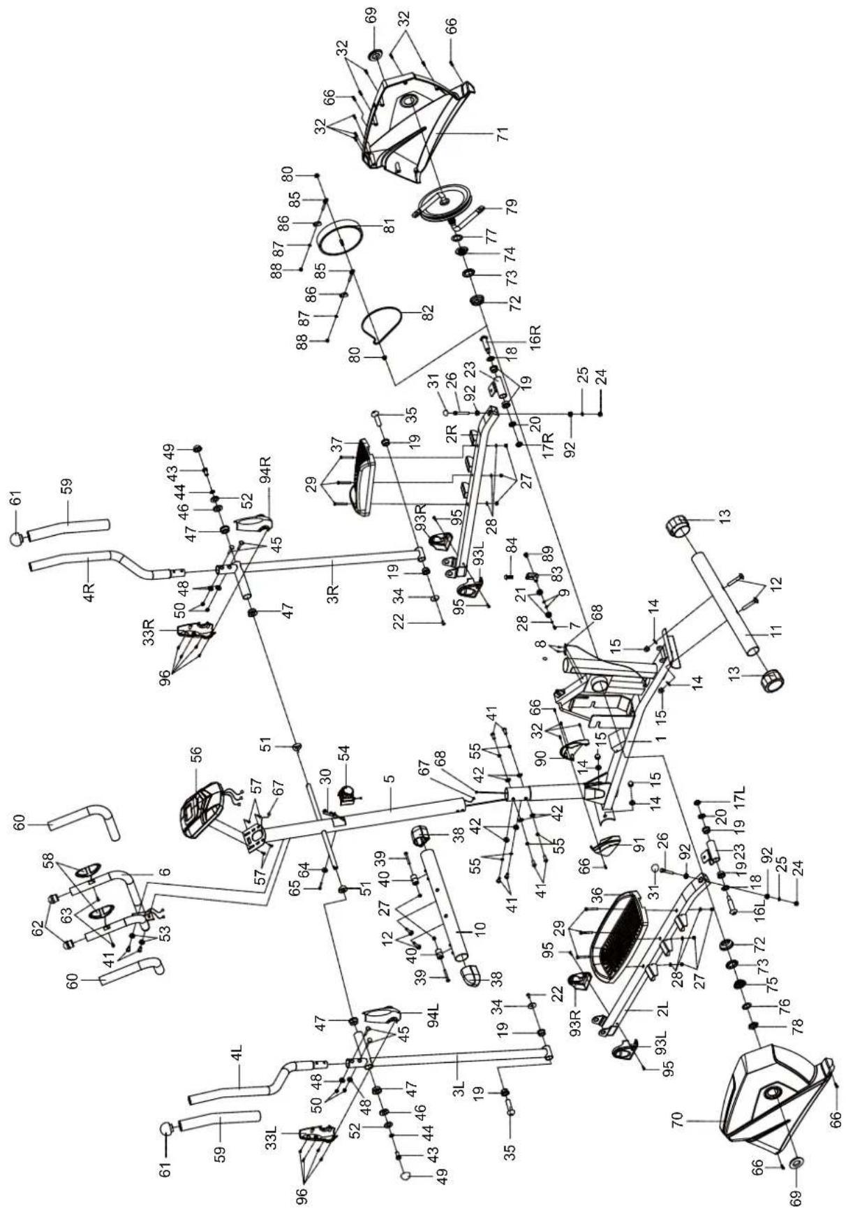
OVERVIEW DRAWING
text_image
Technical diagram of a mechanical assembly with numbered components and dimension annotationsASSEMBLY INSTRUCTIONS
text_image
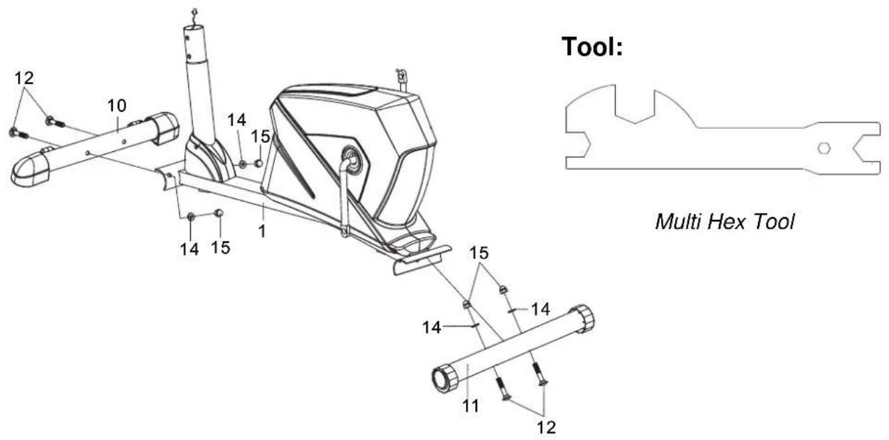
Tool: Multi Hex Tool1. Front and Rear Stabilizers Installation
Position the Front Stabilizer (10) in front of Main Frame (1) and align bolt holes.
Attach the Front Stabilizer (10) onto the front curve of the Main Frame (1) with two M10x57 Bolts (12), two ∅10x∅25x2 Big Curve Washers (14), and two M10 Cap Nuts (15). Tighten cap nuts with the Multi Hex Tool provided.
Position the Rear Stabilizer (11) behind the Main Frame (1) and align bolt holes.
Attach the Rear Stabilizer (11) onto the rear curve of the Main Frame (1) with two M10x57 Bolts (12), two ∅10x∅25x2 Big Curve Washers (14), and two M10 Cap Nuts (15). Tighten cap nuts with the Multi Hex Tool provided.
Hardware:
text_image
65 64 30 54 5 41 55 42 42 41 55 67 30 68 1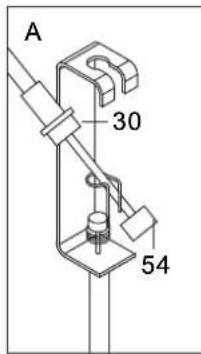
text_image
A 30 54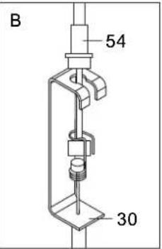
text_image
B 54 30Tool:
natural_image
Simple L-shaped metal angle bracket diagram (no text or symbols)Allen Wrench S6
natural_image
Simple line drawing of a mechanical tool with a central circular component and six symmetrical protrusions (no text or symbols)Multi Hex Tool with Phillips Screwdriver S10, S13, S14, S15
2. Front Post and Tension Control Knob Installation
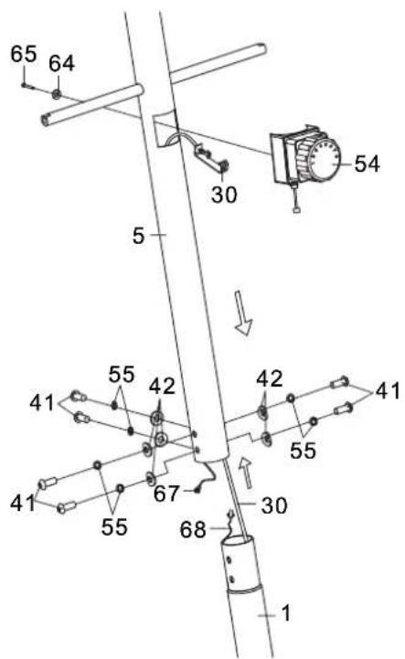
Remove six M8x16 Bolts (41), six ∅20x∅8x1.5 Big Curve Washers (42), and six ∅8 Spring Washers (55) from the Main Frame (1). Remove bolts and washers with the S6 Allen Wrench provided.
Insert the Tension Cable (30) through into the bottom hole of Front Post (5) and pull it out from the square hole of Front Post (5).
Connect the Sensor Wire II (68) from the Main Frame (1) to the Sensor Wire I (67) from the Front Post (5).
Insert the Front Post (5) onto the tube of the Main Frame (1) and secure with six M8x16 Bolts (41), six ∅20x∅8x1.5 Big Curve Washers (42), and six ∅8 Spring Washers (55) that were removed. Tighten bolts and washers with the S6 Allen Wrench provided.
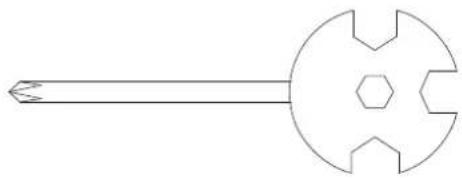
Remove the ∅20x∅5.2 Curve Washer for Tension Control Knob (64) and M5x45 Bolt for Tension Control Knob (65) from the Tension Control Knob (54). Remove bolt and curve washer with the Multi Hex Tool with Phillips Screwdriver provided.
Put the cable end of resistance cable of Tension Control Knob (54) into the spring hook of Tension Cable (30) as shown in drawing A of figure 2. Pull the resistance cable of Tension Control Knob (54) up and force it into the gap of metal bracket of Tension Cable (30) as shown in drawing B of figure 2. Attach the Tension Control Knob (54) onto the Front Post (5) with the ∅20x∅5.2 Curve Washer for Tension Control Knob (64) and M5x45 Bolt for Tension Control Knob (65) that were removed. Tighten bolt curve washer with the Multi Hex Tool with Phillips Screwdriver provided.
text_image
Allen Wrench S8Tool:
natural_image
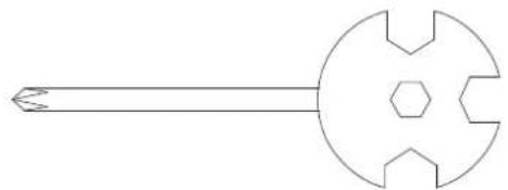
Line drawing of a mechanical wrench (no text or symbols)Multi Hex Tool
natural_image
Pure technical line drawing of a mechanical tool or component without any text, numbers, or symbolsMulti Hex Tool with Phillips Screwdriver S10, S13, S14, S15
3. Left/Right Handrail Arms, Left/Right Foot Bars, Left/Right Foot Pedals, and Foot Bar Covers-A/B Installation
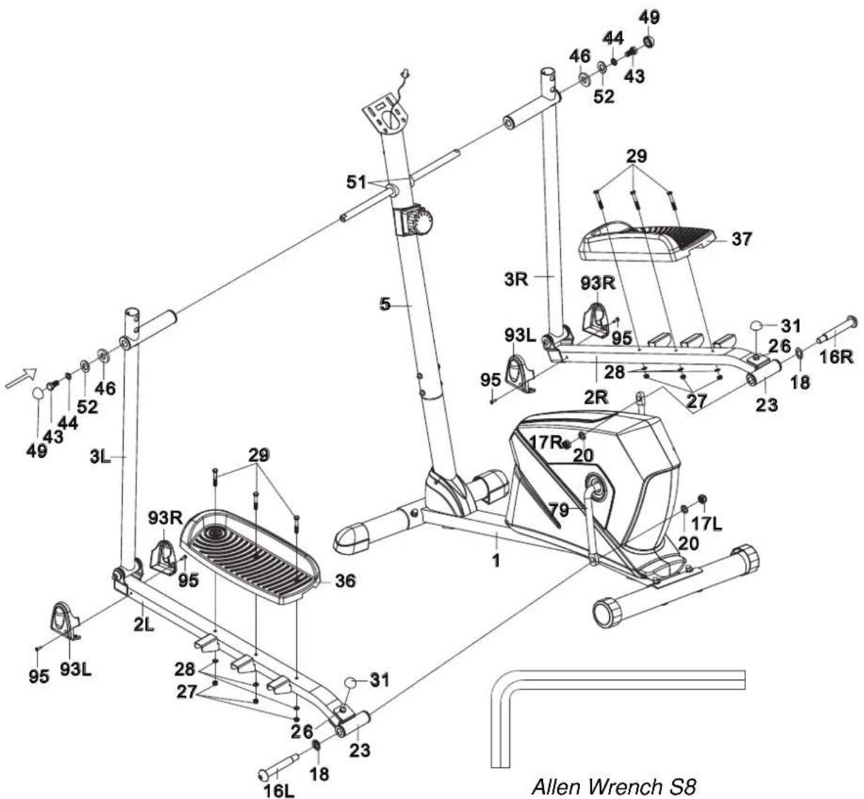
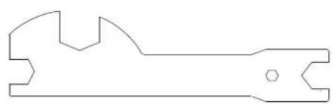
Remove two M8x18 Bolts (43), two ∅18x∅10.5x3 Spring Washers (44), two ∅10x∅20x1.5 Big Washers (52), and two ∅28x5 Washers (46) from the left and right horizontal axes of the Front Post (5). Remove bolts and washers with the Multi Hex Tool provided.
Attach the Left Handrail Arm (3L) onto the left horizontal axis of the Front Post (5) with one M8x18 Bolt (43), one ∅18x∅10.5x3 Spring Washer (44), one ∅10x∅20x1.5 Big Washer (52), and one ∅28x5 Washer (46) that were removed. Tighten bolts and washers with the Multi Hex Tool provided. Install a S16 Cap (49) onto the M8x18 Bolt (43).
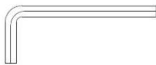
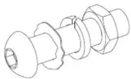
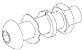
Attach the left U Shape Bracket (23) to the left Crank (79) with one 1/2" Bolt for left U Shape Bracket (16L), ∅28x∅17x0.3 Wave Washer (18), ∅13x∅20x2 Spring Washer (20), and 1/2" Left Nylon Nut (17L). Tighten bolt and washers with the S8 Allen Wrench provided. Install a S13 Cap (31) onto the M8x50 Bolt (26).
NOTE: 1/2” Bolt for left U Shape Bracket (16L) and 1/2” Bolt for right U Shape Bracket (16R) are marked “R” for Right and “L” for Left.
Attach the Left Foot Pedal (36) onto the Left Foot Bar (2L) with three M6 Nylon Nuts (27), three ∅6x∅12x1 Washers (28), and three M6x40 Bolts (29). Tighten nylon nuts with the Multi Hex Tool with Phillips Screwdriver provided.
Attach the Foot Bar Covers-A/B (93L, 93R) onto the Left Foot Bar (2L) with one ST4.2x25 Phillips Self Tapping Screws (95). Tighten screws with the Multi Hex Tool with Phillips Screwdriver provided.
Repeat above step to attach the Right Handrail Arm (3R) onto the right horizontal axis of the Front Post (5) and right U Shape Bracket (23) to the right Crank (79).
Hardware:
natural_image
Technical line drawing of a mechanical bolt assembly (no text or symbols)(16R) Bolt for right U Shape Bracket 1/2" 1
(17R) Right Nylon Nut 1/2" 1 PC
(18) Wave Washer ∅28x∅17x0.3 1 PC
(20) Spring Washer ∅13x∅20x2 1 PC
natural_image
Technical line drawing of a mechanical bolt assembly (no text or symbols)(16L) Bolt for left U Shape PC Bracket 1/2" 1 PC
(17L) Left Nylon Nut 1/2" 1 PC
(18) Wave Washer ∅28x∅17x0.3 1 PC
(20) Spring Washer ∅13x∅20x2 1 PC

6 Nylon Nuts (M6)
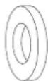
6 Washers (∅6x∅12x1) 6 Bolts (M6x40)
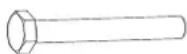

2 Caps (S13) 2 Caps (S16) 4 Phillips Self Tapping Screws (ST4.2x25)
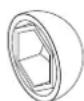
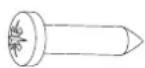
text_image
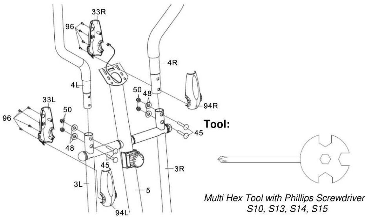
33R 96 4L 50 48 4R 94R Tool: 33L 50 48 45 3R Multi Hex Tool with Phillips Screwdriver S10, S13, S14, S15 96 33L 48 45 3L 5 94L4. Left/Right Handrails and Left/Right Handrail Arm Covers-A/B Installation
Attach the Left/Right Handrails (4L, 4R) onto the Left/Right Handrail Arms (3L, 3R) with four M6x35 Bolts (45), four ∅6x∅12x1 Curve Washers (48), and four M6 Cap Nuts (50). Tighten cap nuts with the Multi Hex Tool with Phillips Screwdriver provided.
Attach the Left Handrail Arm Cover-A (94L) and Left Handrail Arm Cover-B (33L) onto the Left Handrail Arm (3L) with four ST2.9x12 Screws (96). Tighten screws with the Multi Hex Tool with Phillips Screwdriver provided.
Attach the Right Handrail Arm Cover-A (94R) and Right Handrail Arm Cover-B (33R) onto The Right Handrail Arm (3R) with four ST2.9x12 Screws (96). Tighten screws with the Multi Hex Tool with Phillips Screwdriver provided.
Hardware:
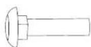
4 Bolts (M6x35)
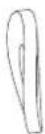
4 Curve Washers
(∅6x∅12x1)
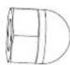
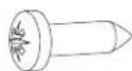
4 Cap Nuts (M6) 8 Screws (ST2.9x12)
text_image
Technical diagram of a mechanical or electrical device with numbered components and labeled partsTool:
natural_image
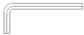
Simple L-shaped metal angle bracket diagram (no text or symbols)Allen Wrench S6
natural_image
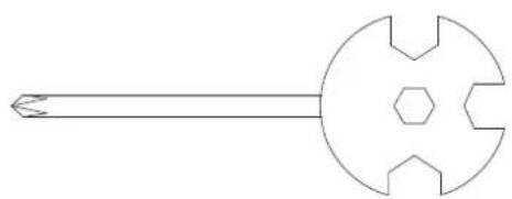
Simple line drawing of a mechanical tool or knob with a central circular head and six symmetrical cutouts (no text or symbols)Multi Hex Tool with Phillips Screwdriver S10, S13, S14, S15
5. Handlebar and Computer Installation
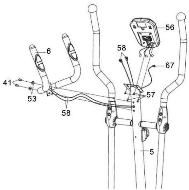
Remove four M5x12 Bolts (57) from the back of the Computer (56). Remove bolts with the Multi Hex Tool with Phillips Screwdriver provided.
Remove two M8x16 Bolts (41) and two ∅8x∅16x1.5 Curve Washers (53) from the Front Post (5). Remove bolts and curve washers with the S6 Allen Wrench provided.
Insert the Hand Pulse Sensor Wires (58) from the Handlebar (6) into the hole on the Front Post (5) and then pull them out from the top end of the Front Post (5).
Attach the Handlebar (6) onto the Front Post (5) with two M8x16 Bolts (41) and two ∅8x∅16x1.5 Curve Washers (53) that were removed. Tighten bolts and curve washers with the S6 Allen Wrench provided.
Connect the Sensor Wire I (67) and Hand Pulse Sensor Wires (58) to the wires that come from the Computer (56) and then attach the Computer (56) onto the top end of the Front Post (5) with four M5x12 Bolts (57) that were removed. Tighten bolts with the Multi Hex Tool with Phillips Screwdriver provided.
MODE: Press the MODE button to select each function of computer.
Press and hold the MODE button for 3 seconds, all data values will clear to zero except the ODO (ODOMETER) data values.
SET: Press the SET button to set data values of TIME, DISTANCE, CALORIES, or Pulse for target pre-setting.
RESET: Press the RESET button to clear data values of TIME, DISTANCE, or CALORIES to zero.
Press the RESET button to clear data values of TIME, DISTANCE, CALORIES, or Pulse to zero for target pre-setting.
Press and hold the RESET button for 3 seconds, all data values will clear to zero except the ODO (ODOMETER) data values.
COMPUTER FUNTIONS:
AUTO ON/OFF: When you start to exercise or press any key on the computer, the computer will turn on. If you leave the equipment for 256 seconds, the power will turn off automatically.
SCAN: Press the MODE button until the screen displays SCAN; the computer will automatically scan the function of TIME, SPEED, DIST (DISTANCE), CAL (CALORIES), ODO (ODOMETER), and ♥ (PULSE) every 6 seconds.
TIME: Displays your elapsed workout time in minutes and seconds. When you start to exercise, time starts counting up from 0:00 to 99:59 minutes per 1 second increment. You may also pre-set target time in STOP mode before training. To set TIME press the MODE button until you see the TIME begin blinking. Press the SET button to change the time, each time you press the SET button TIME should change by 1 minute. Press the RESET button to clear the target time to zero. The pre-set target time range is from 00:00 to 99:00 minutes. Once you pre-set target time and then start to exercise, time starts counting down from pre-set target time to 0:00 per 1 second backward. When the pre-set target time counts down to 0:00, time will start to count up immediately and the computer will begin
beeping to remind you.
SPEED: Display the current training speed.
DIST (DISTANCE): Displays the accumulative distance traveled during workout. When you start to exercise, distance starts counting up from 0.0 to 999.9 km per 0.1km increment. You may also pre-set target distance in STOP mode before training. To set DISTANCE press the MODE button until you see the DIST begin blinking. Press the SET button to change the distance, each time you press the SET button DISTANCE should change by 1.0 km. Press the RESET button to clear the target distance to zero. The pre-set target distance range is from 0.0 to 999.0 km. Once you pre-set target distance and then start to exercise, distance starts counting down from pre-set target distance to 0.0. When the pre-set target distance counts down to 0.0, distance will start to count up immediately and the computer will begin beeping to remind you.
CAL (CALORIES): Displays the total accumulated calories burned during workout. When you start to exercise, calories start counting up from 0.0 to 999.9 calories. You may also pre-set target calories in STOP mode before training. To set CALORIES press the MODE button until you see the CAL begin blinking. Press the SET button to change the calories, each time you press the SET button CALORIES change by 1.0 calorie. Press the RESET button to clear the target calories to zero. The pre-set target calories range is from 0.0 to 999.0 calories. Once you pre-set target calories and then start to exercise, calories start counting down from pre-set target calories to 0.0. When the pre-set target calories count down to 0.0, calories will start to count up immediately and the computer will begin beeping to remind you. (This data is a rough guide for comparison of different exercise sessions and should not be used in medical treatment).
ODO (ODOMETER): Displays the total accumulative distance traveled. The data values of ODO can not be clear to zero by pressing and holding the MODE or RESET button for 3 seconds. If you take out the batteries from the computer, the ODO data values will clear to zero.
(PULSE): Displays your current heart rate figures after you grip the handlebar sensors with both your hands during exercise. To ensure the pulse readout is more precise, please always hold on to the handlebar grip sensors with two hands instead of just with one hand only when you try to test your heart rate figures. You may also pre-set target heart rate in STOP mode before training. To set PULSE press the MODE button until you see the PULSE begin blinking. Press the SET button to pre-set target heart rate. Press the RESET button to clear the target heart rate to zero. The pre-set heart rate range is from 40 to 240 beats per minute. Once you pre-set target heart rate and then start to exercise, please grip the handlebar sensors with both your hands during exercise. If the heart rate detected greater than the target heart rate, the computer will begin beeping to remind you.
HOW TO INSTALL THE BATTERIES:
- Remove the battery cover at the rear of computer.
- Place two "SIZE-AA" batteries into the battery housing.
- Insure batteries are correctly positioned and battery springs are proper contact with batteries.
- Re-install the battery cover.
- If the display is illegible or only partial segment appear, remove batteries and wait 15 seconds before reinstalling.
ADJUSTMENTS
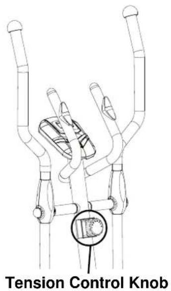
Adjusting the Tension Control Knob
To increase the load, turn the tension control knob in a clockwise direction.
To decrease the load, turn the tension control knob in a counterclockwise direction.
text_image
Tension Control KnobAdjusting the Rear Stabilizer End Cap
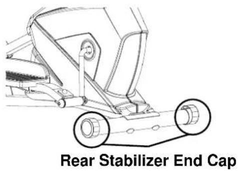
Turn the rear stabilizer end cap on the rear stabilizer as needed to level the elliptical trainer.
text_image
Rear Stabilizer End CapMAINTENANCE
Cleaning
The elliptical trainer can be cleaned with a soft cloth and mild detergent. Do not use abrasives or solvents on plastic parts. Please wipe your perspiration off the elliptical trainer after each use. Be careful not get excessive moisture on the computer display panel as this might cause an electrical hazard or electronics to fail.
Please keep the elliptical trainer, specially, the computer console, out of direct sunlight to prevent screen damage.
Please inspect all assembly bolts and pedals on the machine for proper tightness every week.
Storage
Store the elliptical trainer in a clean and dry environment away from children.
TROUBLESHOOTING
| PROBLEM | SOLUTION |
| The elliptical trainer wobbles when in use. | Turn the rear stabilizer end cap on the rear stabilizer as needed to level the elliptical trainer. |
| There is no display on the computer console. | 1. Remove the computer console and verify the wires that come from the computer console are properly connected to the wires that come from the front post.2. Check if the batteries are correctly positioned and battery springs are in proper contact with batteries.3. The batteries in the computer console may be dead. Change to new batteries. |
| There is no heart rate reading or heart rate reading or is erratic / inconsistent. | 1. Make sure that the wire connections for the hand pulse sensors are secure.2. To ensure the pulse readout is more precise, please always hold on to the handlebar grip sensors with two hands instead of just with one hand only when you try to test your heart rate figures.3. Gripping the hand pulse sensors too tight. Try to maintain moderate pressure while holding onto the hand pulse sensors. |
| The elliptical trainer makes a squeaking noise when in use. | The bolts may be loose on the elliptical trainer, please inspect the bolts and tighten the loose bolts. |
WARM UP AND COOL DOWN ROUTINE
A good exercise program consists of a warm-up, aerobic exercise, and a cool down. Do the entire program at least two to three times a week, resting for a day between workouts. After several months you can increase your workouts to four or five times per week.
AEROBIC EXERCISE is any sustained activity that sends oxygen to your muscles via your heart and lungs. Aerobic exercise improves the fitness of your lungs and heart. Aerobic fitness is promoted by any activity that uses your large muscles eg: legs, arms and buttocks. Your heart beats quickly and you breathe deeply. An aerobic exercise should be part of your entire exercise routine.
The WARM-UP is an important part of any workout. It should begin every session to prepare your body for more strenuous exercise by heating up and stretching your muscles, increasing your circulation and pulse rate, and delivering more oxygen to your muscles.
COOL DOWN at the end of your workout, repeat these exercises to reduce soreness in tired muscles.
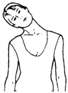
HEAD ROLLS
Rotate your head to the right for one count, feeling the stretch up the left side of your neck, then rotate your head back for one count, stretching your chin to the ceiling and letting your mouth open. Rotate your head to the left for one count, then drop your head to your chest for one count.
natural_image
Line drawing of a person's neck and shoulder (no text or symbols)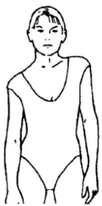
natural_image
Line drawing of a person wearing a swimsuit (no text or symbols)SHOULDER LIFTS
Lift your right shoulder toward your ear for one count. Then lift your left shoulder up for one count as you lower your right shoulder.
SIDE STRETCHES
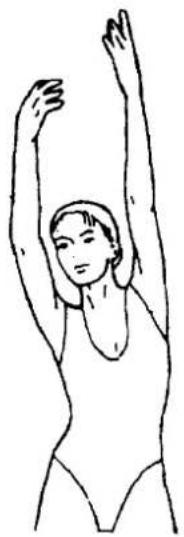
Open your arms to the side and lift them until they are over your head. Reach your right arm as far toward the ceiling as you can for one count. Repeat this action with your left arm.
natural_image
Line drawing of a person performing a stretching exercise with arms raised (no text or symbols)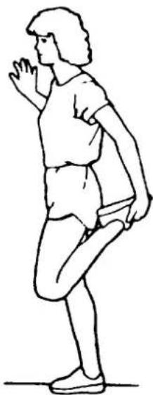
natural_image
Line drawing of a person in athletic attire performing a stretching or kneeling pose (no text or symbols)QUADRICEPS STRETCH
With one hand against a wall for balance, reach behind you and pull your right foot up. Bring your heel as close to your buttocks as possible. Hold for 15 counts and repeat with left foot.
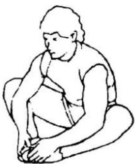
INNER THIGH STRETCH
Sit with the soles of your feet together and your knees pointing outward. Pull your feet as close to your groin as possible. Gently push your knees toward the floor. Hold for 15 counts.
natural_image
Line drawing of a seated person with hand on chin, no text or symbols present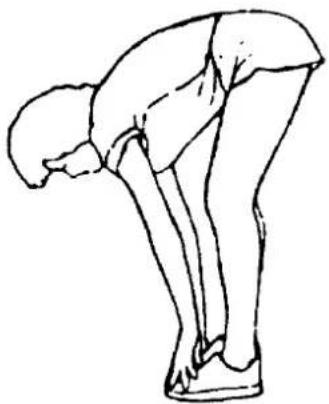
natural_image
Line drawing of a person bending forward with hands on hips (no text or symbols)TOE TOUCHES
Slowly bend forward from your waist, letting your back and shoulders relax as you stretch toward your toes. Reach as far as you can and hold for 15 counts.
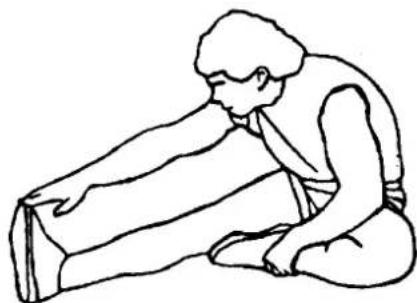
HAMSTRING STRETCHES
Extend your right leg. Rest the sole of your left foot against your right inner thigh. Stretch toward your toe as far as possible. Hold for 15 counts. Relax and then repeat with left leg.
natural_image
Line drawing of a person kneeling and stretching their back (no text or symbols)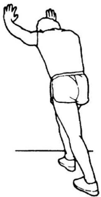
natural_image
Line drawing of a person in motion, possibly dancing or gesturing, with no text or symbols present.CALF/ACHILLES STRETCH
Lean against a wall with your left leg in front of the right and your arms forward. Keep your right leg straight and the left foot on the floor; then bend the left leg and lean forward by moving your hips toward the wall. Hold, then repeat on the other side for 15 counts.