
L1510P - Screen LG - Free user manual and instructions
Find the device manual for free L1510P LG in PDF.


User questions about L1510P LG
0 question about this device. Answer the ones you know or ask your own.
Ask a new question about this device
Download the instructions for your Screen in PDF format for free! Find your manual L1510P - LG and take your electronic device back in hand. On this page are published all the documents necessary for the use of your device. L1510P by LG.
USER MANUAL L1510P LG
Make sure to read the Important Precautions before using the product. Keep the User's Guide(CD) in an accessible place for furture reference.
See the label attached on the back cover and quote this information to your dealer when you require service.
This unit has been engineered and manufactured to ensure your personal safety, however improper use may result in potential electrical shock or fire hazards. In order to allow the proper operation of all safeguards incorporated in this display, observe the following basic rules for its installation, use, and servicing.
On Safety
Use only the power cord supplied with the unit. In case you use another power cord, make sure that it is certified by the applicable national standards if not being provided by the supplier. If the power cable is faulty in any way, please contact the manufacturer or the nearest authorized repair service provider for a replacement.
The power supply cord is used as the main disconnection device. Ensure that the socket-outlet is easily accessible after installation.
Operate the display only from a power source indicated in the specifications of this manual or listed on the display. If you are not sure what type of power supply you have in your home, consult with your dealer.
Overloaded AC outlets and extension cords are dangerous. So are frayed power cords and broken plugs. They may result in a shock or fire hazard. Call your service technician for replacement.
Do not Open the Display.
■ There are no user serviceable components inside.
■ There are Dangerous High Voltages inside, even when the power is OFF.
■ Contact your dealer if the display is not operating properly.
To Avoid Personal Injury :
■ Do not place the display on a sloping shelf unless properly secured.
■ Use only a stand recommended by the manufacturer.
To Prevent Fire or Hazards:
■ Always turn the display OFF if you leave the room for more than a short period of time. Never leave the display ON when leaving the house.
- Keep children from dropping or pushing objects into the display's cabinet openings. Some internal parts carry hazardous voltages.
■ Do not add accessories that have not been designed for this display.
■ During a lightning storm or when the display is to be left unattended for an extended period of time, unplug it from the wall outlet.
On Installation
Do not allow anything to rest upon or roll over the power cord, and do not place the display where the power cord is subject to damage.
Do not use this display near water such as near a bathtub, washbowl, kitchen sink, laundry tub, in a wet basement, or near a swimming pool.
Displays are provided with ventilation openings in the cabinet to allow the release of heat generated during operation. If these openings are blocked, built-up heat can cause failures which may result in a fire hazard. Therefore, NEVER:
■ Block the bottom ventilation slots by placing the display on a bed, sofa, rug, etc.
- Place the display in a built-in enclosure unless proper ventilation is provided.
■ Cover the openings with cloth or other material.
- Place the display near or over a radiator or heat source.
Do not rub or strike the Active Matrix LCD with anything hard as this may scratch, mar, or damage the Active Matrix LCD permanently.
Do not press the LCD screen with your finger for a long time as this may cause some afterimages.
Some dot defects may appear as Red, Green or Blue spots on the screen. However, this will have no impact or effect on the display performance.
If possible, use the recommended resolution to obtain the best image quality for your LCD display. If used under any mode except the recommended resolution, some scaled or processed images may appear on the screen. However, this is characteristic of the fixed-resolution LCD panel.
On Cleaning
■ Unplug the display before cleaning the face of the display screen.
- Use a slightly damp (not wet) cloth. Do not use an aerosol directly on the display screen because over-spraying may cause electrical shock.
On Repacking
- Do not throw away the carton and packing materials. They make an ideal container in which to transport the unit. When shipping the unit to another location, repack it in its original material.
On Disposal
■ The fluorescent lamp used in this product contains a small amount of mercury.
■ Do not dispose of this product with general household waste.
Disposal of this product must be carried out in accordance to the regulations of your local authority.
■ Before setting up the monitor, ensure that the power to the monitor, the computer system, and other attached devices is turned off.
Positioning your display
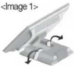
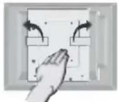
- Remove the tape.
natural_image
3D diagram of a computer monitor with an open lid and base, showing rotation arrows (no text or symbols)Put the set as the picture below
natural_image
Hand pressing down on a wall-mounted electrical outlet with directional arrows indicating flow (no text or symbols)Do not remove the tape with the set up side down as the
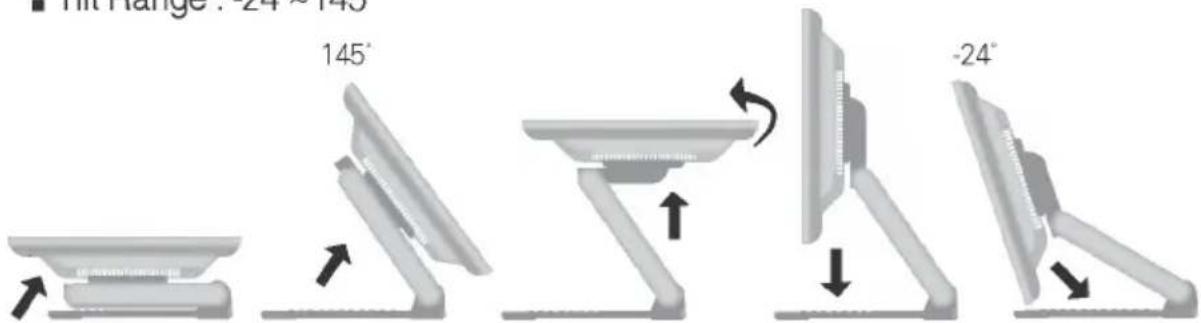
- Adjust the position of the panel in various ways for maximum comfort.
■ Tilt Range : -24°\~145°
text_image
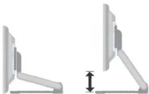
■ Hit Range: 24-145° 145° -24°■ Height Range : maximum 3.39inch (86.1mm)
natural_image
Two identical views of a computer monitor with adjustable arm and base, showing no text or symbols.■ Landscape & Portrait : You can rotate the panel 90° clockwise. (* For detailed information, please refer to the Pivot Software CD provided.)
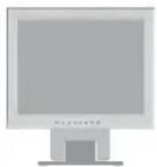
natural_image
Computer monitor with blank screen and stand (no visible text or symbols)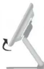
natural_image
Side view of a desktop computer stand with a curved arrow indicating rotation (no text or symbols)* Make sure not to touch the floor when the head rotates to use the Pivot function.
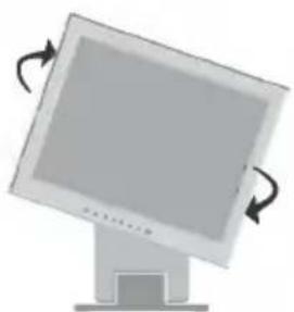
natural_image
Illustration of a computer monitor with curved arrows indicating rotation (no text or symbols)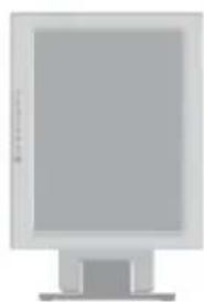
natural_image
Computer monitor with blank screen and stand (no visible text or symbols)Ergonomic
It is recommended that in order to maintain an ergonomic and comfortable viewing position, the forward tilt angle of the monitor should not exceed 5 degrees.
Using the Computer
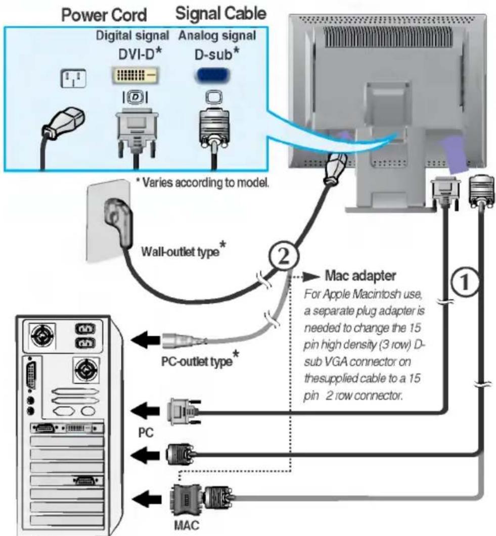
- Connect the signal cable. When attached, tighten the thumbscrews to secure the connection.
- Connect the power cord into a proper power outlet that is easily accessible and close to the display.
NOTE
■ This is a simplified representation of the rear view.
■ This rear view represents a general model; your display may differ from the view as shown.
flowchart
graph TD
    A["Power Cord"] --> B["Signal Cable"]
    B --> C["Mac adapter"]
    C --> D["PC outlet type*"]
    C --> E["PC"]
    C --> F["MAC"]
    D --> G["Wall-outlet type*"]
    E --> G
    F --> G
    G --> H["Computer"]
    style A fill:#f9f,stroke:#333
    style B fill:#ccf,stroke:#333
    style C fill:#cfc,stroke:#333
    style D fill:#fcc,stroke:#333
    style E fill:#cff,stroke:#333
    style F fill:#ffc,stroke:#333
    style G fill:#fcf,stroke:#333
- Press ⏻ button on the front switch panel to turn the power on. When monitor power is turned on, the 'Self Image Setting Function' is executed automatically.
NOTE
'Self Image Setting Function'? This function provides the user with optimal display settings. When the user connects the monitor for the first time, this function automatically adjusts the display to optimal settings for individual input signals. If you want to adjust the monitor while in use, or wish to manually run this function once again, push the 'AUTO' button on the front panel of the monitor. Otherwise, you may execute the 'Factory reset' option on the OSD adjustment menu. However, be aware that this option initializes all the menu items except 'Language'.
Front Panel Controls
text_image
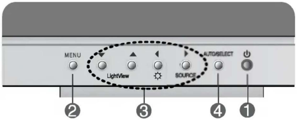
MENU LightView SOURCE AUTO/SELECT ② ③ ④ ①| Control | Function | |
| 1 | Power Button | Use this button to turn the display on or off. |
| Power (DPMS) Indicator | This Indicator lights up green when the display operates normally. If the display is in DPM (Energy Saving) mode, this indicator color changes to amber. | |
| 2 | MENU Button | Use this button to enter or exit the On Screen Display. |
| 3 | ▼▲◀▶ Buttons | Use these buttons to choose or adjust items in the On Screen Display. |
| 4 | AUTO/SELECT Button | Use this button to enter a selection in the On Screen Display. |
| Control | Direct Access Function |
  | 3 LIGHTVIEWDAY NIGHT This feature lets you easily select the best desired image condition optimized to the environment (ambient illumination, image types etc).DAY : Bright ambient illuminationNIGHT : Dark ambient illuminationTEXT : For text images (Word processing etc.)MOVIE : For animation images in videos or moviesPHOTO : For pictures or drawingsNORMAL : This is under normal operating conditionsLIGHTVIEW → LIGHTVIEW → MENU |
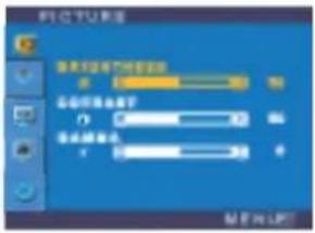 | Bring up Contrast and Brightness adjustment. |
 | 4 AUTO IMAGE ADJUSTMENTWhen adjusting your display settings, always press the AUTO/SELECT button before entering the On Screen Display(OSD). This will automatically adjust your display image to the ideal settings for the current screen resolution size (display mode).The best display mode is 1024x768. |
  | OSD LOCKED/UNLOCKED: MENUThis function allows you to secure the current control settings, so that they cannot be inadvertently changed. Press and hold the MENU button for 5 seconds: the message“OSD LOCKED” appears.You can unlock the OSD controls at any time by pushing the MENU button for 5 seconds:the message “OSD UNLOCKED” will appear. |
Screen Adjustment
Making adjustments to the image size, position and operating parameters of the display is quick and easy with the On Screen Display Control system. A short example is given below to familiarize you with the use of the controls. The following section is an outline of the available adjustments and selections you can make using the OSD.
NOTE
- Allow the display to stabilize for at least 30 minutes before making image adjustments.
To make adjustments in the On Screen Display, follow these steps:

flowchart
graph LR
    A["MENU"] --> B["▼▲"]
    B --> C["AUTO/SELECT"]
    C --> D["▼▲ ◀▶"]
    D --> E["MENU ← MENU ↓"]
1 Press the MENU Button, then the main menu of the OSD appears.
2 To access a control, use the ▼ or ▲ Buttons. When the icon you want becomes highlighted, press the AUTO/ SELECT Button.
③ Use the ▼▲◀▶ Buttons to adjust the item to the desired level.
4 Accept the changes by pressing the MENU Button.
5 Exit the OSD by pressing the MENU Button.
On Screen Display(OSD) Selection and Adjustment
The following table indicates all the On Screen Display control, adjustment, and setting menus.
| Main menu | Sub menu | A | D | Reference | |
| PICTURE | BRIGHTNESS | ● | ● | To adjust the brightness,contrast and gamma of the screen | |
| CONTRAST | ● | ● | |||
| GAMMA | ● | ● | |||
| COLOR | PRESET | 6500K | ● | ● | To customize the color of the screen |
| 9300K | ● | ● | |||
| RED | ● | ● | |||
| GREEN | ● | ● | |||
| BLUE | ● | ● | |||
| POSITION | HORIZONTAL | ● | To adjust the position of the screen | ||
| VERTICAL | ● | ||||
| TRACKING | CLOCK | ● | To improve the clarity and stability of the screen | ||
| PHASE | ● | ||||
| SETUP | LANGUAGE | ● | ● | To customize the screen status for a user's operating environment | |
| OSD POSITION | HORIZONTAL | ● | ● | ||
| VERTICAL | ● | ● | |||
| WHITE BALANCE | ● | ||||
| POWER INDICATOR | ● | ● | |||
| FACTORY RESET | ● | ● | |||
| ●:AdjustableA:Analog InputD:Digital Input | |||||
NOTE
■ The order of icons may differ depending on the model (A8\~A10).
You were introduced to the procedure of selecting and adjusting an item using the OSD system. Listed below are the icons, icon names, and icon descriptions of the all items shown on the Menu.
NOTE
■ OSD (On Screen Display) menu languages on the monitor may differ from the manual.
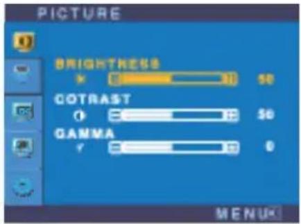
To adjust the brightness and contrast of the screen
OSD Adjust
text_image
PICTURE BRIGHTNESS × 0 10 50 COTRAST ○ 0 10 50 GAMMA Y 0 10 0 M E N U KDescription

BRIGHTNESS
To adjust the brightness of the screen.

CONTRAST
To adjust the contrast of the screen.

GAMMA
Set your own gamma value. (-50\~50) On the monitor, high gamma values display whitish images and low gamma values display high contrast images.
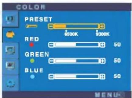
To customize the color of the screen
OSD Adjust
text_image
COLOR PRESET 6500K 9300K RED 50 GREEN 50 BLUE 50 MENUDescription
PRESET 6500K/9300K
Select the screen color.
• 6500K: Slightly reddish white.
• 9300K: Slightly bluish white.
RED
GREEN Set your own color levels.
BLUE
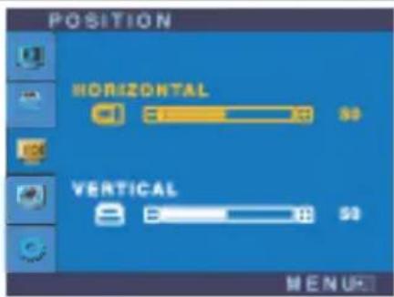
To adjust the position of the screen
OSD Adjust
text_image
POSITION HORIZONTAL VERTICAL M E N UDescription

Horizontal Position
To move image left and right.

Vertical Position
To move image up and down.
To improve the clarity and stability of the screen
| OSD Adjust | Description | |
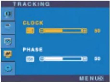 | CLOCK | To minimize any vertical bars or stripes visible on the screen background. The horizontal screen size will also change. |
| PHASE | To adjust the focus of the display. This item allows you to remove any horizontal noise and clear or sharpen the image of characters. | |
To customize the screen status for a user's operating environment
| OSD Adjust | Description | |
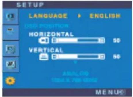 | LANGUAGE | To choose the language in which the control names are displayed. |
| OSD POSITION | To adjust position of the OSD window on the screen. | |
| WHITE BALANCE | If the output of the video card is different the required specifications, the color level may deteriorate due to video signal distortion. Using this function, the signal level is adjusted to fit into the standard output level of the video card in order to provide the optimal image. Activate this function when white and black colors are present in the screen. | |
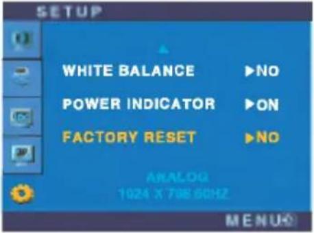 | POWER INDICATOR | Use this function to set the power indicator on the front side of the monitor to ON or OFF.If you set OFF, it will go off after 15 seconds. If you set ON at any time, the power indicator will automatically be turned on. |
| FACTORY RESET | Restore all factory default settings except "LANGUAGE."Press the ► button to reset immediately. | |
If this does not improve the screen image, restore the factory default settings. If necessary, perform the white balance function again. This function will be enabled only when the input signal is an analog signal.
Check the following before calling for service.
| No image appears | |
| ● Is the power cord of the display connected? | · Check and see if the power cord is connected properly to the power outlet. |
| ● Is the power indicator light on? | · Press the Power button. |
| ● Is the power on and the power indicator green? | · Adjust the brightness and the contrast. |
| ● Is the power indicator amber? | · If the display is in power saving mode, try moving the mouse or pressing any key on the keyboard to bring up the screen.· Make sure if the power is on.· Try to turn on the PC. |
| ● Do you see an "OUT OF RANGE" message on the screen? | · This message appears when the signal from the PC (video card) is out of horizontal or vertical frequency range of the display. See the 'Specifications' section of this manual and configure your display again. |
| ● Do you see a "CHECK SIGNAL CABLE" message on the screen? | · This message appears when the signal cable between your PC and your display is not connected. Check the signal cable and try again. |
| Do you see a “OSD LOCKED” message on the screen? | |
| ● Do you see “OSD LOCKED” when you push MENU button? | · You can secure the current control settings, so that they cannot be inadvertently changed. You can unlock the OSD controls at any time by pushing theMENUbutton for 5 seconds: the message“OSD UNLOCKED” will appear. |
| Display image is incorrect | |
| ● Display Position is incorrect. | Press the AUTO/SELECT button to automatically adjust your display image to the ideal setting.If the results are unsatisfactory, adjust the image position using the H position and V position icon in the on screen display.Check Control Panel --> Display --> Settings and see if the frequency or the resolution were changed. If yes, readjust the video card to the recommend resolution. |
| ● On the screen background, vertical bars or stripes are visible. | Press the AUTO/SELECT button to automatically adjust your display image to the ideal setting.If the results are unsatisfactory, decrease the vertical bars or stripes using the CLOCK icon in the on screen display. |
| ● Any horizontal noise appearing in any image or characters are not clearly portrayed. | Press the AUTO/SELECT button to automatically adjust your display image to the ideal setting.If the results are unsatisfactory, decrease the horizontal bars using the PHASE icon in the on screen display.Check Control Panel --> Display --> Settings and adjust the display to the recommended resolution or adjust the display image to the ideal setting. Set the color setting higher than 24 bits (true color). |
| ● The screen color is mono or abnormal. | Check if the signal cable is properly connected and use a screwdriver to fasten if necessary.Make sure the video card is properly inserted in the slot.Set the color setting higher than 24 bits (true color) at Control Panel - Settings. |
| ● The screen blinks. | Check if the screen is set to interlace mode and if yes, change it to the recommend resolution.Make sure the power voltage is high enough, It has to be higher than AC100-240V 50/60Hz. |
| Have you installed the display driver? | |
| ● Have you installed the display driver? | · Be sure to install the display driver from the display driver CD (or diskette) that comes with your display. Or, you can also download the driver from our web site: http://www.lge.com. |
| ● Do you see an "Unrecognized monitor, Plug&Play (VESA DDC) monitor found" message? | · Make sure to check if the video card supports Plug&Play function. |
| USB function | ||
| USB function cannot be setup. | Check if the USB cable is correctly connected.Check if the PC and OS are USB compliant.For verification of USB support, consult the manufacturer of each system. | |
| Display | 15 inches (38.1cm) Flat Panel Active matrix-TFT LCD | |
| Anti-Glare coating | ||
| 15 inches viewable | ||
| 0.297mm pixel pitch | ||
| Sync Input | Horizontal Freq. | 30 - 63kHz (Automatic) |
| Vertical Freq. | 56 - 75Hz (Automatic) | |
| Input Form | Separate TTL, Positive/Negative SOG (Sync On Green) Digital | |
| Video Input | Signal Input | 15 pin D-Sub connector DVI - D connector (Digital) |
| Input Form | RGB Analog (0.7Vp-p/75ohm), Digital | |
| Resolution | Max | Digital : VESA 1024 x 768@75Hz Analog : VESA 1024 x 768@75Hz |
| Recommend | VESA 1024 x 768@60Hz | |
| Plug&Play | DDC 2B | |
| Power Consumption | Normal : 25W Stand-by/Suspend ≤ 2W DPMS Off ≤ 2W | |
| Dimensions &Weight (with tilt stand) | Full Up Position  | |
| Width 35.60 cm / 14.02 inches Height 38.00 cm / 14.96 inches Depth 22.90 cm / 9.02 inches | ||
| Net 5.1 kg (11.24 lbs) | ||
| Tilt Range | Tilt Range -24°~145° (Head) Height Range 3.89inch (86.1mm) Rotate 90° clockwise (Landscape->Portrait) | |
| Power Input | AC 100-240V~50/60Hz 0.6A | |
| Environmental Conditions | Operating Conditions Temperature 10°C to 35 °CHumidity 10 % to 80 % non-Condensing | |
| Storage Conditions Temperature -20°C to 60 °CHumidity 5 % to 95 % non-Condensing | ||
| Tilt Stand | Attached( O ), Detached ( ) | |
| Signal cable | Attached( ), Detached ( O ) | |
| Power cord | Wall-outlet type or PC-outlet type | |
NOTE
■ Information in this document is subject to change without notice.
Preset Modes (Resolution)
| Display Modes (Resolution) | Horizontal Freq. (kHz) | Vertical Freq. (Hz) | ||
| 1 | VGA | 640 x 350 | 31.468 | 70 |
| 2 | VGA | 720 x 400 | 31.468 | 70 |
| 3 | VGA | 640 x 480 | 31.469 | 60 |
| 4 | VESA | 640 x 480 | 35.000 | 66.67 |
| 5 | VESA | 640 x 480 | 37.861 | 72.8 |
| 6 | VESA | 640 x 480 | 37.500 | 75 |
| 7 | VESA | 800 x 600 | 35.156 | 56.25 |
| 8 | VESA | 800 x 600 | 37.879 | 60 |
| 9 | VESA | 800 x 600 | 48.077 | 72 |
| 10 | VESA | 800 x 600 | 46.875 | 75 |
| 11 | MAC | 832 x 624 | 49.725 | 75 |
| 12 | VESA | 1024 x 768 | 48.363 | 60 |
| 13 | VESA | 1024 x 768 | 56.476 | 70 |
| 14 | VESA | 1024 x 768 | 60.023 | 75 |
Indicator
| MODE | LED Color |
| Normal | green |
| Stand-by/Suspend | amber |
| DPMS Off | amber |
natural_image
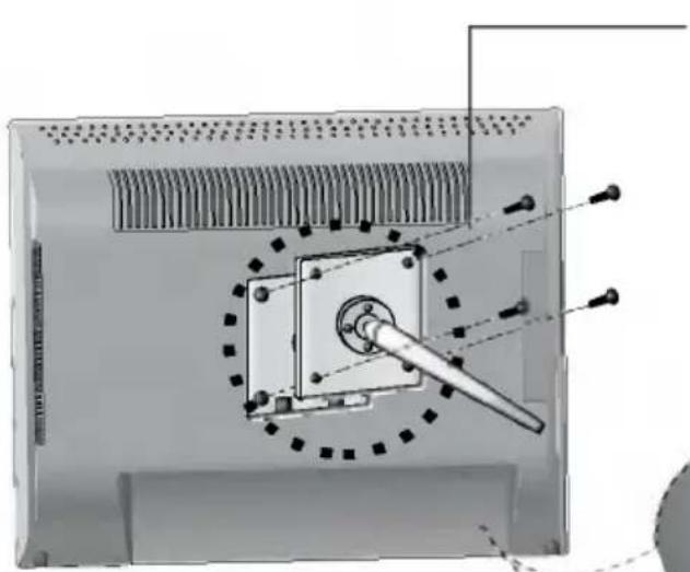
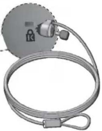
Technical diagram of a mechanical assembly with a central shaft and mounting bracket, showing alignment lines (no text or symbols)Kensington Security Slot- optional
Connected to a locking cable that can be purchased separately at most computer stores
VESA wall mounting
Connected to another object (stand type and wall-mounted type. This monitor accepts a VESA-compliant mounting interface pad.- optional) For further information, refer to the VESA Wall Mounting Instruction Guide.
natural_image
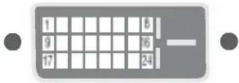
3D illustration of a handheld device with a circular head and coiled cable, no text or symbols visibleSignal Connector Pin Assignment
text_image
1 8 9 16 17 24■ DVI-D Connector
| Pin | Signal(DVI-D) | Pin | Signal(DVI-D) |
| 1 | T. M. D. S. Data2- | 16 | Hot Plug Detect |
| 2 | T. M. D. S. Data2+ | 17 | T. M. D. S. Data0- |
| 3 | T. M. D. S. Data2/4 Shield | 18 | T. M. D. S. Data0+ |
| 4 | T. M. D. S. Data4- | 19 | T. M. D. S. Data0/5 Shield |
| 5 | T. M. D. S. Data4+ | 20 | T. M. D. S. Data5- |
| 6 | DDC Clock | 21 | T. M. D. S. Data5+ |
| 7 | DDC Data | 22 | T. M. D. S. Clock Shield |
| 8 | Analog Vertical Sync. | 23 | T. M. D. S. Clock+ |
| 9 | T. M. D. S. Data1- | 24 | T. M. D. S. Clock- |
| 10 | T. M. D. S. Data1+ | ||
| 11 | T. M. D. S. Data1/3 Shield | ||
| 12 | T. M. D. S. Data3- | ||
| 13 | T. M. D. S. Data3+ | ||
| 14 | +5V Power | ||
| 15 | Ground (return for +5V, H. Sync. and V. Sync.) |
T. M. D. S. (Transition Minimized Differential Signaling)
USB (Universal Serial Bus) is an innovation in connecting your different desktop peripherals conveniently to your computer. By using the USB, you will be able to connect your mouse, keyboard, and other peripherals to your display instead of having to connect them to your computer. This will give you greater flexibility in setting up your system. USB allows you to connect a chain of up to 120 devices on a single USB port; and you can “hot” plug (attach them while the computer is running) or unplug them while maintaining the Plug and the Plug auto detection and configuration. This display has an integrated BUS-powered USB hub, allowing up to 2 other USB devices to be attached it.
USB connection
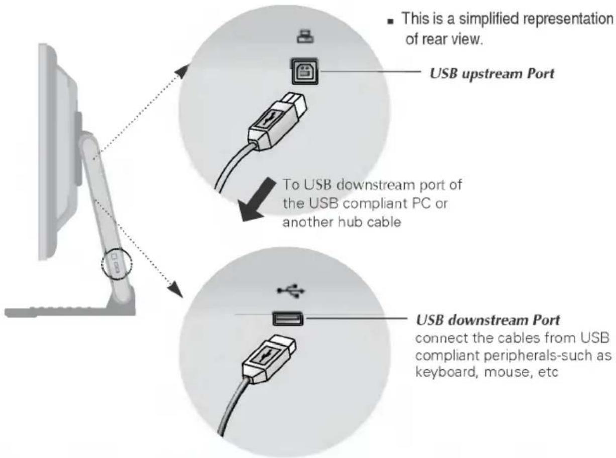
- Connect the upstream port of the display to the downstream port of the USB compliant PC or another hub using the USB cable. (Computer must have a USB port)
- Connect the USB compliant peripherals to the downstream ports of the display.
text_image
This is a simplified representation of rear view. USB upstream Port To USB downstream port of the USB compliant PC or another hub cable USB downstream Port connect the cables from USB compliant peripherals-such as keyboard, mouse, etcNOTE
■ To activate the USB hub function, the display must be connected to a USB compliant PC(OS) or another hub with the USB cable(enclosed).
■ When connecting the USB cable, check that the shape of the connector at the cable side matches the shape at the connecting side.
■ Even if the display is in a power saving mode, USB compliant devices will function when they are connected the USB ports(both the upstream and downstream) of the display.
USB Specifications
| USB standard | Rev. 1.1 complied BUS-powered hub |
| Downstream power supply | 100mA for each (MAX) |
| Communication speed | 12 Mbps (full), 1.5 Mbps (low) |
| USB port | 1 Upstream port2 Downstream ports |
IMPORTANT: These USB connectors are not designed for use with high-power USB devices such as a video camera, scanner, etc. LGE recommends connecting high-power USB devices directly to the computer
Digitally yours


LG