
L1780QP - Monitor LG - Free user manual and instructions
Find the device manual for free L1780QP LG in PDF.


User questions about L1780QP LG
0 question about this device. Answer the ones you know or ask your own.
Ask a new question about this device
Download the instructions for your Monitor in PDF format for free! Find your manual L1780QP - LG and take your electronic device back in hand. On this page are published all the documents necessary for the use of your device. L1780QP by LG.
USER MANUAL L1780QP LG
Make sure to read the Important Precautions before using the product. Keep the User's Guide(CD) in an accessible place for furture reference.
See the label attached on the product and quote this information to your dealer when you require service.
This unit has been engineered and manufactured to ensure your personal safety, however improper use may result in potential electrical shock or fire hazards. In order to allow the proper operation of all safeguards incorporated in this display, observe the following basic rules for its installation, use, and servicing.
On Safety
Use only the power cord supplied with the unit. In case you use another power cord, make sure that it is certified by the applicable national standards if not being provided by the supplier. If the power cable is faulty in any way, please contact the manufacturer or the nearest authorized repair service provider for a replacement.
The power supply cord is used as the main disconnection device. Ensure that the socket-outlet is easily accessible after installation.
Operate the display only from a power source indicated in the specifications of this manual or listed on the display. If you are not sure what type of power supply you have in your home, consult with your dealer.
Overloaded AC outlets and extension cords are dangerous. So are frayed power cords and broken plugs. They may result in a shock or fire hazard. Call your service technician for replacement.
Do not Open the Display.
■ There are no user serviceable components inside.
■ There are Dangerous High Voltages inside, even when the power is OFF.
■ Contact your dealer if the display is not operating properly.
To Avoid Personal Injury :
■ Do not place the display on a sloping shelf unless properly secured.
■ Use only a stand recommended by the manufacturer.
To Prevent Fire or Hazards:
■ Always turn the display OFF if you leave the room for more than a short period of time. Never leave the display ON when leaving the house.
- Keep children from dropping or pushing objects into the display's cabinet openings. Some internal parts carry hazardous voltages.
■ Do not add accessories that have not been designed for this display.
■ During a lightning storm or when the display is to be left unattended for an extended period of time, unplug it from the wall outlet.
On Installation
Do not allow anything to rest upon or roll over the power cord, and do not place the display where the power cord is subject to damage.
Do not use this display near water such as near a bathtub, washbowl, kitchen sink, laundry tub, in a wet basement, or near a swimming pool.
Displays are provided with ventilation openings in the cabinet to allow the release of heat generated during operation. If these openings are blocked, built-up heat can cause failures which may result in a fire hazard. Therefore, NEVER:
■ Block the bottom ventilation slots by placing the display on a bed, sofa, rug, etc.
■ Place the display in a built-in enclosure unless proper ventilation is provided.
■ Cover the openings with cloth or other material.
■ Place the display near or over a radiator or heat source.
Do not rub or strike the Active Matrix LCD with anything hard as this may scratch, mar, or damage the Active Matrix LCD permanently.
Do not press the LCD screen with your finger for a long time as this may cause some afterimages.
Some dot defects may appear as Red, Green or Blue spots on the screen. However, this will have no impact or effect on the display performance.
If possible, use the recommended resolution to obtain the best image quality for your LCD display. If used under any mode except the recommended resolution, some scaled or processed images may appear on the screen. However, this is characteristic of the fixed-resolution LCD panel.
On Cleaning
■ Unplug the display before cleaning the face of the display screen.
■ Use a slightly damp (not wet) cloth. Do not use an aerosol directly on the display screen because over-spraying may cause electrical shock.
On Repacking
- Do not throw away the carton and packing materials. They make an ideal container in which to transport the unit. When shipping the unit to another location, repack it in its original material.
On Disposal
■ The fluorescent lamp used in this product contains a small amount of mercury.
■ Do not dispose of this product with general household waste.
Disposal of this product must be carried out in accordance to the regulations of your local authority.
■ Before setting up the monitor, ensure that the power to the monitor, the computer system, and other attached devices is turned off.
- For the desktop monitor, install the computer with the stand unfolded, for the rack wall mounting, install the computer with the stand folded.
Unfolding the stand base
- Place the monitor with its front facing downward on a cushion or soft cloth.
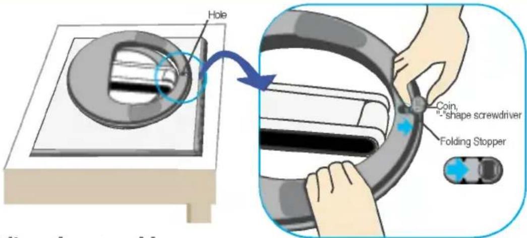
- Remove the tape of stand base's hole, pull it towards the front side (in the direction of the arrow) from the stand base using a coin or " shape screwdriver.
* Caution : To avoid any minor injury, be sure to pull the folding stopper with the stand base pressed by one hand, as shown below.
Make sure to pull up the folding stopper while pressing down the stand base with one hand as shown in the below figure. Otherwise, you can be injured by the projected stand base.
text_image
Hole Coin, "shape screwdriver" Folding StopperFolding the stand base
- To fix a stand, push the folding stopper inwards until you hear the "click" sound using a coin of "- shape screw driver, while pressing down the stand base to the monitor.
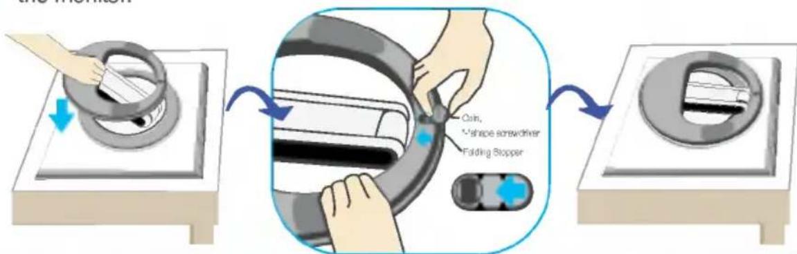
text_image
Cash, +shape screwdriver Folding StopperImportant
- This illustration depicts the general model of connection. Your monitor may differ from the items shown in the picture.
Using the Computer
- Connect the signal cable. When attached, tighten the thumbscrews to secure the connection. ①
- Connect the power cable with the AC adapter (AC power supply) ②, and then plug the cable in the outlet. ③ (Voltage will be automatically controlled.)
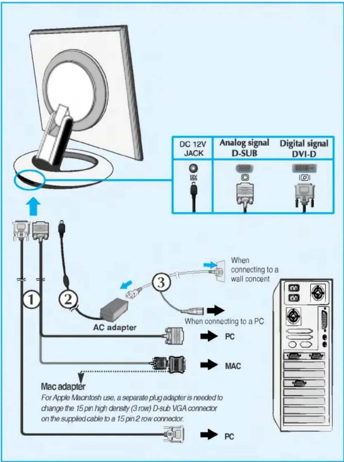
flowchart
graph TD
    A["DC 12V JACK"] --> B["AC adapter"]
    B --> C["Mac adapter"]
    C --> D["PC"]
    E["Analog signal D-SUB"] --> F["Digital signal DVI-D"]
    G["When connecting to a wall concert"] --> H["When connecting to a PC"]
    I["For Apple Macintosh use, a separate plug adapter is needed to change the 15 pin high density (3 row) D-sub VGA connector on the supplied cable to a 15 pin 2 row connector."]
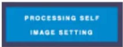
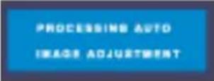
- Touch ⏻ button on the front switch panel to turn the power on. When monitor power is turned on, the 'Self Image Setting Function' is executed automatically.(Only Analog Mode)
text_image
PROCESSING SELF IMAGE SETTINGNOTE
'Self Image Setting Function'? This function provides the user with optimal display settings. When the user connects the monitor for the first time, this function automatically adjusts the display to optimal settings for individual input signals. If you want to adjust the monitor while in use, or wish to manually run this function once again, touch the 'AUTO/SET' button on the front panel of the monitor. Otherwise, you may execute the 'FACTORY RESET' option on the OSD adjustment menu. However, be aware that this option initializes all the menu items except 'LANGUAGE'.
This model supports Auto Pivot (automatic rotation) and Auto Mirror (automatic up/down reversal) functions.
To use this function, install the provided Forte Manager software first and then, perform Automatic setting.(Manual is the default setting when you purchase the product.)
- Refer to the installation guide included in the CD for more details on the installation method.
- For the automatic setting, select Forte Manager -> Option -> Pivot -> Enable AutoPivot.
Notice
■ Forte Manager software requires Microsoft Explorer 6.0 or later.
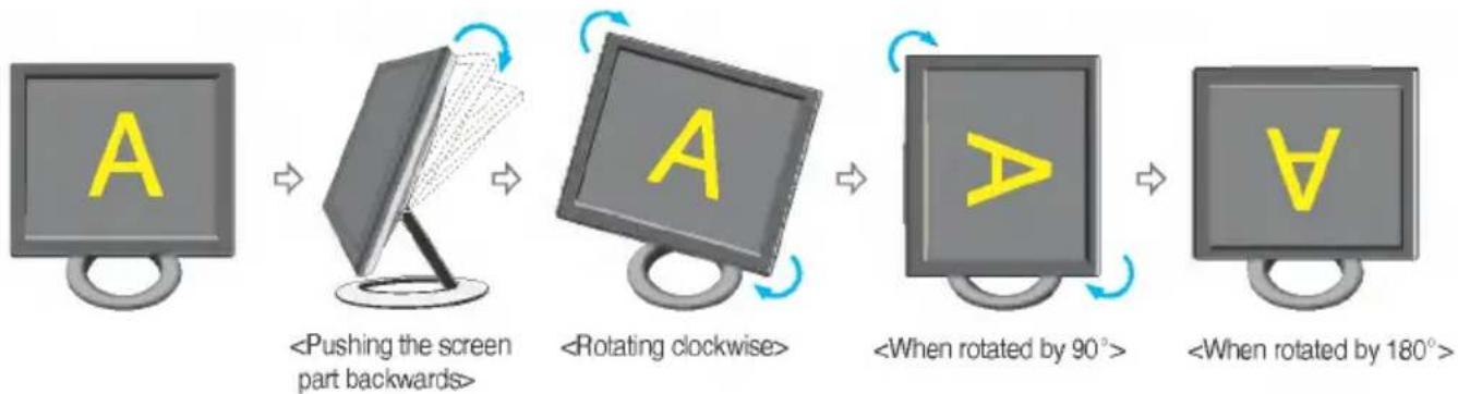
■ When the Auto Pivot or Auto Mirror function is engaged, the direction of the OSD (On Screen Display) menu will not be changed if rotated by 180°. (See the below figure.)
■ The response time (speed) for the Auto Pivot and Auto Mirror function can vary depending on the video card and the PC performance, and these functions are not supported in the DOS mode.
Auto Pivot
■ Screen rotation: You can rotate the monitor screen part clockwise by 180°.
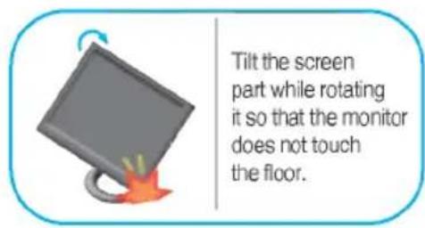
※ Caution : Be careful not to touch the ⏻ button section when rotating the screen.
Be careful that your hands are not pressed down when rotating the screen.
This rear view represents a general model, your display may differ from the view as shown.
flowchart
graph LR
    A["Computer monitor with letter 'A'"] --> B["Pushing the screen part backwards"]
    B --> C["Rotating clockwise with letter 'A'"]
    C --> D["When rotated by 90°, rotation arrow"]
    D --> E["When rotated by 180°, rotation arrow"]
text_image
Tilt the screen part while rotating it so that the monitor does not touch the floor.
Refer to the next page about Auto Mirror function.
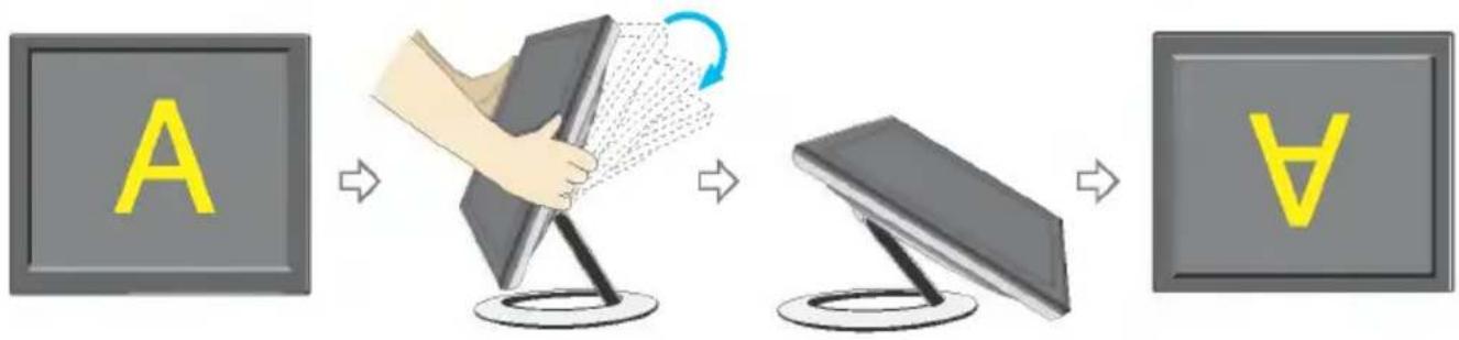
Auto Mirror
■ Screen switch: The monitor screen part is automatically mirrored when you switch it forward/backward as shown in the figure.
※ Caution : Be careful not to touch the ⏻ button section when rotating the screen.
Be careful that your hands are not pressed down when rotating the screen.
→ This rear view represents a general model, your display may differ from the view as shown.
flowchart
graph LR
    A["A"] --> B["Hand holding a tablet with fan"]
    B --> C["Screen icon: Screen icon with letter 'A'"]
    C --> D["Arrow to screen icon"]
Tip
■ If you activate the Auto Pivot or Auto Mirror function while the screen is almost on a level, the screen display may not work properly.
In this case, set the screen up straight and adjust to the proper angle.
- It is recommended that in order to maintain an ergonomic and comfortable viewing position, the forward tilt angle of the monitor should not exceed 5 degrees.
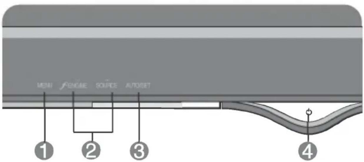
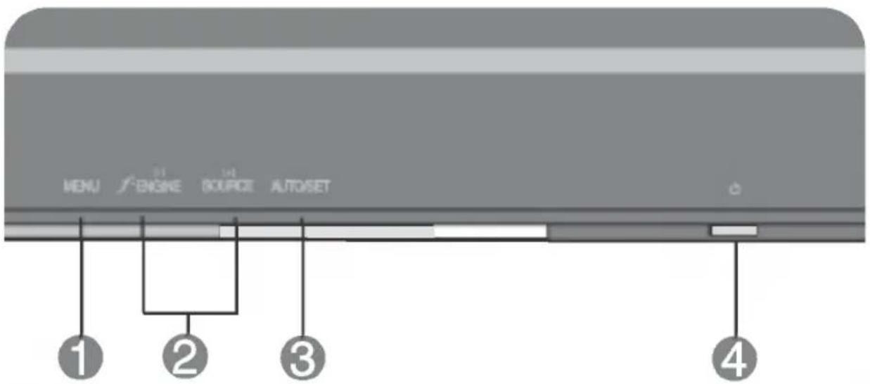
Front Panel Controls
text_image
MENU FNGAME SOURCE AUTOSET ① ② ③ ④
text_image
MENU /F-ENGINE SOURCE AUTOSET ① ② ③ ④| Control | Function |
| 1 MENU Button | Use this button to enter or exit the On Screen Display. |
| OSD LOCKED/UNLOCKEDThis function allows you to lock the current control settings, so that they cannot be inadvertently changed.Touch and hold theMENU buttonfor 5 seconds. The message "OSD LOCKED" should appear.You can unlock the OSD controls at any time by touching theMENU buttonfor 5 seconds. The message "OSD UNLOCKED" should appear. | |
| 2 - + Buttons | Use these buttons to select or adjust functions in the On Screen Display. |
| - Button | f·ENGINE hot key |
 | For more information, refer to page A15 |
| + Button | SOURCE hot keyUse this button to make Dsub or DVI connector active.This feature is used when two computers are connected to the display. The default setting is Dsub. |
 | Use this button to enter a selection in the On Screen Display. |
| AUTO IMAGE ADJUSTMENTWhen adjusting your display settings, always touch the AUTO/SET button before entering the On Screen Display(OSD). This will automatically adjust your display image to the ideal settings for the current screen resolution size (display mode). | |
 | The best display mode is17 inch monitor : 1280x102419 inch monitor : 1280x1024 |
 | Use this button to turn the display on or off. |
| Power Indicator | This Indicator lights up blue when the display operates normally(On Mode). If the display is in Sleep Mode (Energy Saving), this indicator color changes to amber. |
Screen Adjustment
Making adjustments to the image size, position and operating parameters of the display is quick and easy with the On Screen Display Control system. A short example is given below to familiarize you with the use of the controls. The following section is an outline of the available adjustments and selections you can make using the OSD.
NOTE
- Allow the display to stabilize for at least 30 minutes before making image adjustments.
To make adjustments in the On Screen Display, follow these steps:
MENU → - + → AUTO/SET → - + → MENU
1 Touch the MENU Button, then the main menu of the OSD appears.
2 To access a control, use the - or + Buttons. When the icon you want becomes highlighted, touch the AUTO/SET Button.
③ Use the - /+ Buttons to adjust the image to the desired level. Use the AUTO/SET Button to select other sub-menu items.
4 Touch the MENU Button once to return to the main menu to select another function. Touch the MENU Button twice to exit from the OSD.
Automatic save
With the OSD open, once you have made an adjustment the monitor automatically save any adjustments you have made, even if you exit the menu or open another menu. If you make an adjustment and then wait for the OSD to disappear, the adjustment will also been saved.
The following table indicates all the On Screen Display control, adjustment, and setting menus.
| Main menu | Sub-menu | A | D | Reference | |
| PICTURE | BRIGHTNESS | ● | ● | To adjust the brightness,contrast and gamma of the screen | |
| CONTRAST | ● | ● | |||
| GAMMA | ● | ● | |||
| COLOR | PRESET | 6500K | ● | ● | To customize the color ofthe screen |
| 9300K | ● | ● | |||
| RED | ● | ● | |||
| GREEN | ● | ● | |||
| BLUE | ● | ● | |||
| POSITION | HORIZONTAL | ● | To adjust the position of the screen | ||
| VERTICAL | ● | ||||
| TRACKING | CLOCK | ● | To improve the clarity andstability of the screen | ||
| PHASE | ● | ||||
| SETUP | LANGUAGE | ● | ● | To customize the screenstatus for a user's operatingenvironment | |
| OSD | HORIZONTAL | ● | ● | ||
| POSITION | VERTICAL | ● | ● | ||
| WHITE BALANCE | ● | ||||
| POWER INDICATOR | ● | ● | |||
| FACTORY RESET | ● | ● | |||
| FLATRONF-ENGINE(-) | MOVIE/TEXT | ● | ● | To select or customizedesired image settings | |
| USER | ● | ● | |||
| NORMAL | ● | ● | |||
| ●:AdjustableA:Analog InputD:Digital Input | |||||
NOTE
■ The order of icons may differ depending on the model [A11\~A15].
On Screen Display(OSD) Selection and Adjustment
You were introduced to the procedure of selecting and adjusting an item using the OSD system. Listed below are the icons, icon names, and icon descriptions of the all items shown on the Menu.
Touch the MENU Button, then the main menu of the OSD appears.
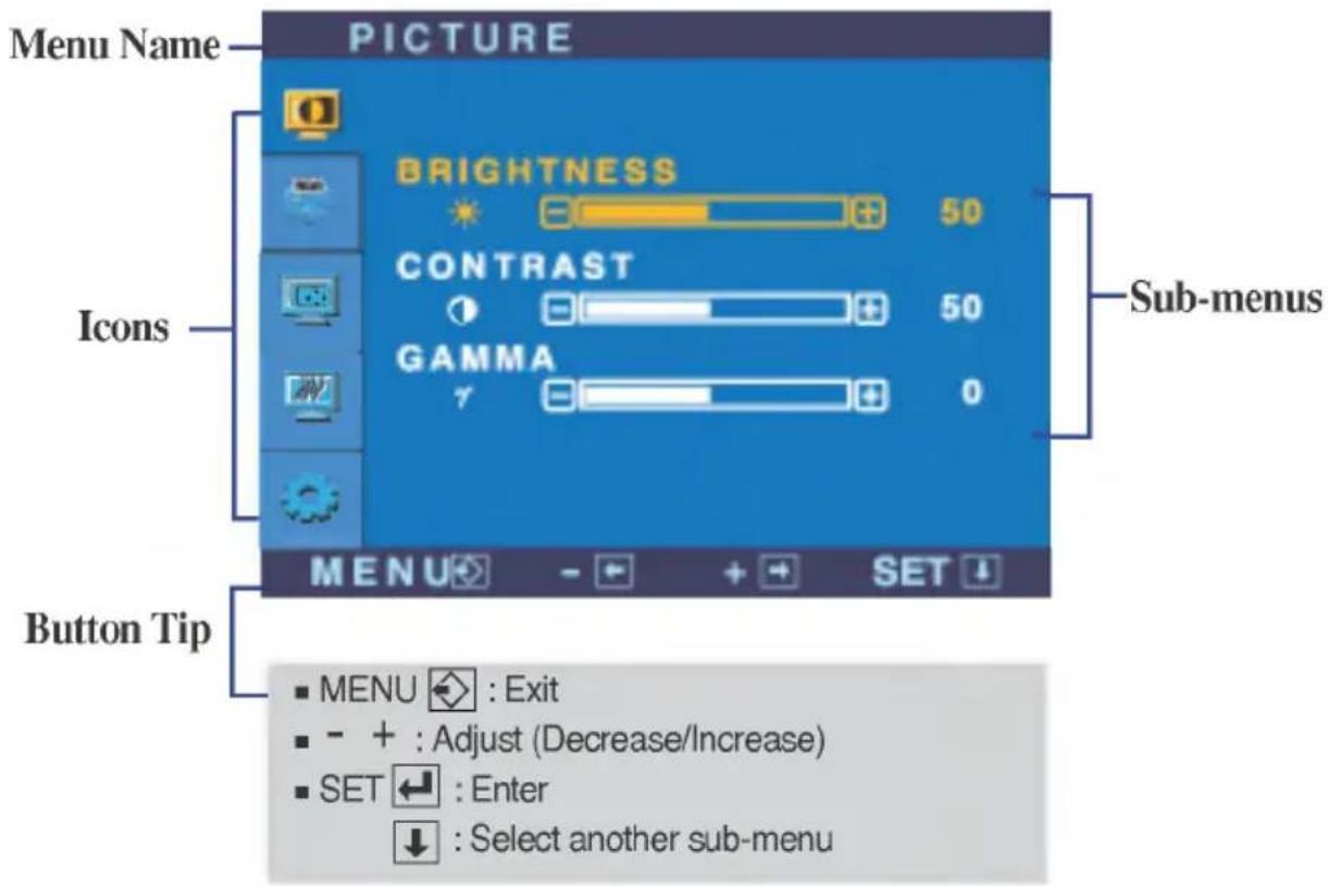
text_image
Menu Name PICTURE BRIGHTNESS 50 CONTRAST 50 GAMMA 7 Sub-menus Icons MENU → - → + → SET ↓ Button Tip ■ MENU ← : Exit ■ - + : Adjust (Decrease/Increase) ■ SET ← : Enter ↓ : Select another sub-menu* You can use the Forte Manager program when configuring or controlling the screen display. For more details, refer to the manual included in the Forte Manager Software CD.
NOTE
■ OSD (On Screen Display) menu languages on the monitor may differ from the manual.
On Screen Display(OSD) Selection and Adjustment
| Main menu | Sub menu | Description |
| PICTURE | ||
| BRIGHTNESS | To adjust the brightness of the screen. | |
| CONTRAST | To adjust the contrast of the screen. | |
| GAMMA | Set your own gamma value. : -50/0/50On the monitor, high gamma values display whitish images and low gamma values display high contrast images. | |
| ■ MENU : Exit■ - : Decrease■ + : Increase■ SET : Select another sub-menu | ||
COLOR
| PRESET | Select the screen color. | |
| 6500K: Slightly reddish white. | ||
| 9300K: Slightly bluish white. | ||
| RED | 50 | Set your own red color levels. |
| GREEN | 50 | Set your own green color levels. |
| BLUE | 50 | Set your own blue color levels. |
POSITION
| POSITION | HORIZONTAL | To move image left and right. |
| VERTICAL | To move image up and down. | |
| ■ MENU : Exit■ - : Decrease■ + : Increase■ SET : Select another sub-menu | ||
| Main menu | Sub menu | Description |
TRACKING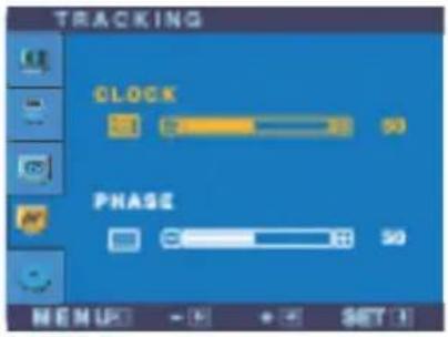 | CLOCK | To minimize any vertical bars or stripes visible on the screen background. The horizontal screen size will also change. |
| PHASE | To adjust the focus of the display. This item allows you to remove any horizontal noise and clear or sharpen the image of characters. | |
| ■ MENU : Exit■ - : Decrease■ + : Increase■ SET : Select another sub-menu | ||
SETUP 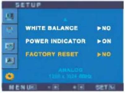 | LANGUAGE | To choose the language in which the control names are displayed. |
| OSD POSITION | To adjust position of the OSD window on the screen. | |
| WHITE BALANCE | If the output of the video card is different the required specifications, the color level may deteriorate due to video signal distortion. Using this function, the signal level is adjusted to fit into the standard output level of the video card in order to provide the optimal image. Activate this function when white and black colors are present in the screen. | |
| POWER INDICATOR | Use this function to set the power indicator on the front side of the monitor to ON or OFF. If you set OFF, it will go off. If you set ON at any time, the power indicator will automatically be turned on. | |
| FACTORY RESET | Restore all factory default settings except "LANGUAGE." Press the ▶ button to reset immediately. | |
■ MENU : Exit
- :Adjust
■ + :Adjust
■ SET : Select another sub-menu
| LANGUAGE | To choose the language in which the control names are displayed. |
| OSD POSITION | To adjust position of the OSD window on the screen. |
| WHITE BALANCE | If the output of the video card is different the required specifications, the color level may deteriorate due to video signal distortion. Using this function, the signal level is adjusted to fit into the standard output level of the video card in order to provide the optimal image. Activate this function when white and black colors are present in the screen. |
| POWER INDICATOR | Use this function to set the power indicator on the front side of the monitor to ON or OFF.If you set OFF, it will go off.If you set ON at any time, the power indicator will automatically be turned on. |
| FACTORY RESET | Restore all factory default settings except "LANGUAGE."Press the ▶ button to reset immediately. |
If this does not improve the screen image, restore the factory default settings. If necessary, perform the white balance function again. This function will be enabled only when the input signal is an analog signal.
On Screen Display(OSD) Selection and Adjustment
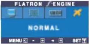
The OSD screen will appear when you touch the f·ENGINE (-) button at the front side of the monitor.
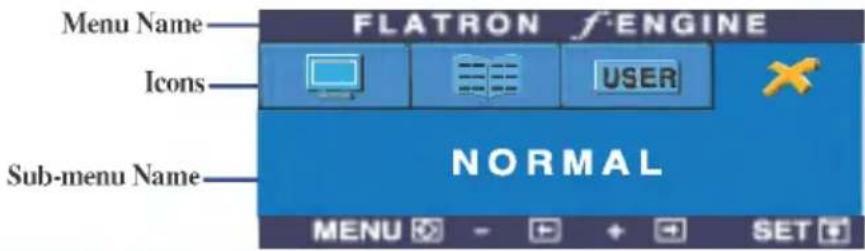
text_image
Menu Name FLATRON ENGINE Icons USER Sub-menu Name NORMAL MENU - + + SETFLATRON F-ENGINE
When you execute F-ENGINE, two tones will appear on the screen as shown. The applied screen will appear on the left side, whereas the non-applied screen will appear on the right side. Touch the SETbutton to use the adjusted screen.
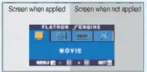
text_image
Screen when applied Screen when not applied FLATRON /ENGINE MOVIEMain menu
Sub menu
Description
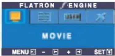
text_image
FLATRON / ENGINE MOVIE MENU - + + SETMOVIE TEXT
This feature lets you easily select the best desired image condition optimized to the environment (ambient illumination, image types etc).
MOVIE: For animation images in videos or movies
TEXT: For text images (Word processing etc.)
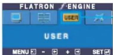
text_image
FLATRON / ENGINE USER MENU - + + SETTo adjust the USER sub-menu function, Press the SET Button
USER
User
You can manually adjust brightness, ACE or RCM. You can save or restore the adjusted value even when using a different environment setting.
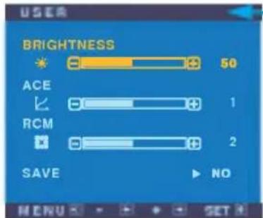
text_image
BRIGHTNESS 50 ACE 1 RCM 2 SAVE NO MENU SET(Brightness): Adjusts screen brightness.
ACE(Adaptive Clarity Enhancer): Selects the clarity mode.
RCM(Real Color Management): Selects the color mode.
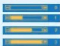
Not applied Green enhance Flesh tone Color Enhance
Select the SAVE sub-menu using the SET button and save the YES value using the -buttons.
text_image
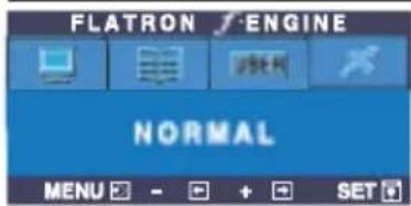
FLATRON ENGINE NORMAL MENU - + SETNORMAL This is under normal operating conditions.
Check the following before calling for service.
| No image appears | |
| ●Is the power cord of the display connected? | ·Check and see if the power cord is connected properly to the power outlet. |
| ●Is the power indicator light on? | ·Touch the Power button. |
| ●Is the power on and the power indicator blue or green? | ·Adjust the brightness and the contrast. |
| ●Is the power indicator amber? | ·If the display is in power saving mode, try moving the mouse or pressing any key on the keyboard to bring up the screen.·Try to turn on the PC. |
| ●Do you see an "OUT OF RANGE" message on the screen? | ·This message appears when the signal from the PC (video card) is out of horizontal or vertical frequency range of the display. See the 'Specifications' section of this manual and configure your display again. |
| ●Do you see a "CHECK SIGNAL CABLE "message on the screen? | ·This message appears when the signal cable between your PC and your display is not connected. Check the signal cable and try again. |
| Do you see a "OSD LOCKED" message on the screen? | |
| ● Do you see "OSD LOCKED" when you touch MENU button? | · You can secure the current control settings, so that they cannot be inadvertently changed. You can unlock the OSD controls at any time by touching the MENU button for 5 seconds. The message "OSD UNLOCKED" should appear. |
| Display image is incorrect | |
| ● Display Position is incorrect. | · Touch the AUTO/SET button to automatically adjust your display image to the ideal setting. If the results are unsatisfactory, adjust the image position using the H position and V position icon in the on screen display. · Check Control Panel --> Display --> Settings and see if the frequency or the resolution were changed. If yes, readjust the video card to the recommend resolution. |
| ● On the screen background, vertical bars or stripes are visible. | · Touch the AUTO/SET button to automatically adjust your display image to the ideal setting. If the results are unsatisfactory, decrease the vertical bars or stripes using the CLOCK icon in the on screen display. |
| ● Any horizontal noise appearing in any image or characters are not clearly portrayed. | · Touch the AUTO/SET button to automatically adjust your display image to the ideal setting. If the results are unsatisfactory, decrease the horizontal bars using the PHASE icon in the on screen display. · Check Control Panel --> Display --> Settings and adjust the display to the recommended resolution or adjust the display image to the ideal setting. Set the color setting higher than 24 bits (true color). |
| ● The screen color is mono or abnormal. | · Check if the signal cable is properly connected and use a screwdriver to fasten if necessary. · Make sure the video card is properly inserted in the slot. · Set the color setting higher than 24 bits (true color) at Control Panel - Settings. |
| ● The screen blinks. | · Check if the screen is set to interlace mode and if yes, change it to the recommend resolution. · Make sure the power voltage is high enough, It has to be higher than AC100-240V 50/60Hz. |
| Have you installed the display driver? | ||
| ● Have you installed the display driver? | · Be sure to install the display driver from the display driver CD (or diskette) that comes with your display. Or, you can also download the driver from our web site: http://www.lge.com. | |
| ● Do you see an "Unrecognized monitor, Plug&Play (VESA DDC) monitor found" message? | · Make sure to check if the video card supports Plug&Play function. | |
| Display | 17 inches (43.2cm) Flat Panel Active matrix-TFT LCD | |
| Anti-Glare coating | ||
| 17 inches viewable | ||
| 0.264mm pixel pitch | ||
| Sync Input | Horizontal Freq. | 30 - 83kHz (Analog) |
| 30 - 71kHz (Digital) | ||
| Vertical Freq. | 56 - 75Hz (Automatic) | |
| Input Form | Separate TTL, Positive/Negative SOG (Sync On Green) Digital | |
| Video Input | Signal Input | 15 pin D-Sub Connector DVI - D connector |
| Input Form | RGB Analog (0.7Vp-p/75ohm), Digital | |
| Resolution | Max | DVI Digital: VESA 1280 x 1024@60Hz D-sub Analog: VESA 1280 x 1024@75Hz |
| Recommend | VESA 1280 x 1024@60Hz | |
| Plug&Play | DDC 2B | |
| Power Consumption | On Mode | 35W |
| Sleep Mode | ≤ 1W | |
| Off Mode | ≤ 1W | |
| Dimensions &Weight (with tilt stand) | Width | 37.37 cm / 14.71 inches |
| Height | 37.76 cm / 14.86 inches | |
| Depth | 24.00 cm / 9.44 inches | |
| Net | 4.3 kg (9.47 lbs) | |
| Tilt/Height Range | Tilt | 0°~157° |
| Folding Height | 6.42 cm (2.52 inches) | |
| Rotate | 180° clockwise (Landscape -> Portrait) | |
| Power Input | 12V = 3A | |
| AQDC Adapter | LG. AD-4212L | DVE. DSA-0421S-12 1 |
| Environmental Conditions | Operating Conditions | |
| Temperature | 10°C to 35 °C | |
| Humidity | 10 % to 80 % non-Condensing | |
| Storage Conditions | ||
| Temperature | -20°C to 60 °C | |
| Humidity | 5 % to 95 % non-Condensing | |
| Tilt Stand | Attached( O ), Detachable ( ) | |
| Signal cable | Attached( ), Detachable ( O ) | |
| Power cord | Wall-outlet type or PC-outlet type | |
NOTE
■ Information in this document is subject to change without notice.
| Display | 19 inches (48.18cm) Flat Panel Active matrix-TFT LCD | |
| Anti-Glare coating | ||
| 19 inches viewable | ||
| 0.294 mm pixel pitch | ||
| Sync Input | Horizontal Freq. | 30 - 83kHz (Analog) |
| 30 - 71kHz (Digital) | ||
| Vertical Freq. | 56 - 75Hz (Automatic) | |
| Input Form | Separate TTL, Positive/Negative SOG (Sync On Green) Digital | |
| Video Input | Signal Input | 15 pin D-Sub Connector DVI - D connector |
| Resolution | Input Form | RGB Analog (0.7Vp-p/75ohm), Digital |
| Max | DVI Digital: VESA 1280 x 1024@60Hz D-sub Analog: VESA 1280 x 1024@75Hz | |
| Recommend | VESA 1280 x 1024@60Hz | |
| Plug&Play | DDC 2B | |
| Power Consumption | On Mode | : 39W |
| Sleep Mode | ≤ 1W | |
| Off Mode | ≤ 1W | |
| Dimensions &Weight (with tilt stand) | Width | 42.23 cm / 16.63 inches |
| Height | 41.01 cm / 16.15 inches | |
| Depth | 26.10 cm / 10.28inches | |
| Net | 5.66 kg (12.48 lbs) | |
| Tilt/Height Range | Tilt | 0°~157° |
| Folding Height | 70.20 cm (2.83 inches) | |
| Rotate | 180° clockwise (Landscape -> Portrait) | |
| Power Input | 12V = 3A | |
| AC/DC Adapter | LG. AD-4212L DVE. DSA-0421S-12 1 | |
| Environmental Conditions | Operating Conditions | |
| Temperature | 10°C to 35 °C | |
| Humidity | 10 % to 80 % non-Condensing | |
| Storage Conditions | ||
| Temperature | -20°C to 60 °C | |
| Humidity | 5 % to 95 % non-Condensing | |
| Tilt Stand | Attached( O ), Detachable ( ) | |
| Signal cable | Attached( ), Detachable ( O ) | |
| Power cord | Wall-outlet type or PC-outlet type | |
NOTE
■ Information in this document is subject to change without notice.
Preset Modes (Resolution)
● 17 inch monitor
| Display Modes (Resolution) | Horizontal Freq. (kHz) | Vertical Freq. (Hz) | ||
| 1 | VGA | 640 x 350 | 31.469 | 70 |
| 2 | VGA | 720 x 400 | 31.468 | 70 |
| 3 | VGA | 640 x 480 | 31.469 | 60 |
| 4 | VESA | 640 x 480 | 37.500 | 75 |
| 5 | VESA | 800 x 600 | 37.879 | 60 |
| 6 | VESA | 800 x 600 | 46.875 | 75 |
| 7 | MAC | 832 x 624 | 49.725 | 75 |
| 8 | VESA | 1024 x 768 | 48.363 | 60 |
| 9 | VESA | 1024 x 768 | 60.023 | 75 |
| 10 | MAC | 1152 x 870 | 68.681 | 75 |
| 11 | VESA | 1152 x 900 | 61.805 | 65 |
| *12 | VESA | 1280 x 1024 | 63.981 | 60 |
| 13 | VESA | 1280 x 1024 | 79.976 | 75 |
*Recommend Mode
● 19 inch monitor
| Display Modes (Resolution) | Horizontal Freq. (kHz) | Vertical Freq. (Hz) | ||
| 1 | VGA | 640 x 350 | 31.469 | 70 |
| 2 | VGA | 720 x 400 | 31.468 | 70 |
| 3 | VGA | 640 x 480 | 31.469 | 60 |
| 4 | VESA | 640 x 480 | 37.500 | 75 |
| 5 | VESA | 800 x 600 | 37.879 | 60 |
| 6 | VESA | 800 x 600 | 46.875 | 75 |
| 7 | MAC | 832 x 624 | 49.725 | 75 |
| 8 | VESA | 1024 x 768 | 48.363 | 60 |
| 9 | VESA | 1024 x 768 | 60.023 | 75 |
| 10 | MAC | 1152 x 870 | 68.681 | 75 |
| 11 | VESA | 1152 x 900 | 61.805 | 65 |
| *12 | VESA | 1280 x 1024 | 63.981 | 60 |
| 13 | VESA | 1280 x 1024 | 79.976 | 75 |
*Recommend Mode
Indicator
| MODE | LED Color |
| On Mode | blue |
| Sleep Mode | amber |
| Off Mode | 0ff |
This monitor meets VESA-compliant mounting interface pad specifications.


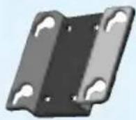
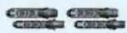
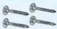
□ Screws for wall mount rack - 4EA
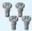
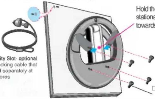
□ Screws for monitor stationary rack-4EA
This rear view represents a general model; your display may differ from the view as shown.
1
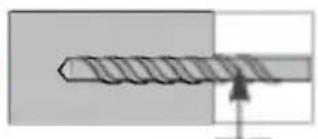
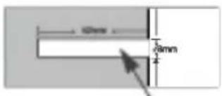
■ Mark the locations of the □ racks that are to be mounted on the wall, and drill fourholes 40 mm or deeper in the wall.
■ Set the location of the rack 0^ 10^ lower than the eye level of the user.
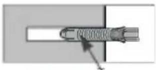
■ Clean the holes before inserting three □ anchors at the same depth.
①
natural_image
Diagram of a screw with a directional arrow indicating force or movement (no text or symbols)Drill
②
text_image
10mm 28mmHole
③
natural_image
Pure diagram of a mechanical component with no text or symbols, showing a cross-section view without any readable labels or symbols.□ Anchor
2
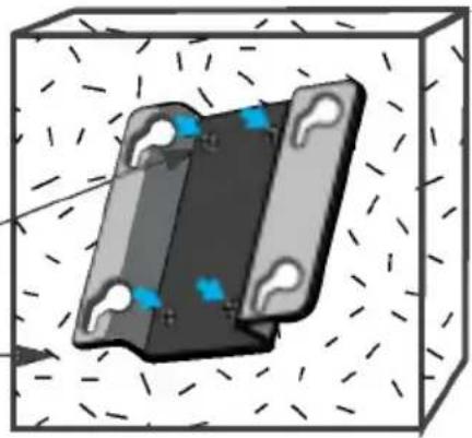
■ Contact □ racks closely on the wall where the anchors are inserted, and fasten the □ screws for wall mount rack, as shown.
Wall
natural_image
3D diagram of a mechanical component inside a cube with directional arrows indicating movement (no text or symbols)□ Screws for wall mount rac
3
■ Put the monitor on a soft cloth or cushion with its front facing downward.
To fix a stand, push the folding stopper inwards until you hear the "click" sound using a coin of "shape screw driver, while pressing down the stand base to the monitor.

text_image
Coils A package screwdriver Folding Stopper4
■ Tighten the four □ screws about half into the slots in the base part, hold the two screws at the bottom to pull them inward, and then tighten the screws all the way.
text_image
City Slot- optional locking cable that d separately at lores Hold the stationa towardsHold the □ Screws for monitor stationary rack and pull them towards the arrow direction.
□ Screws for monitor stationary rack
5
■ Make the screws in the stand base to fit into the □ Rack grooves. Then, fix it firmly by sliding it to the end of the groove.
■ Rotate the monitor screen by 180 degrees and make the cable connection part to face downward.
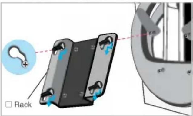
text_image
Rack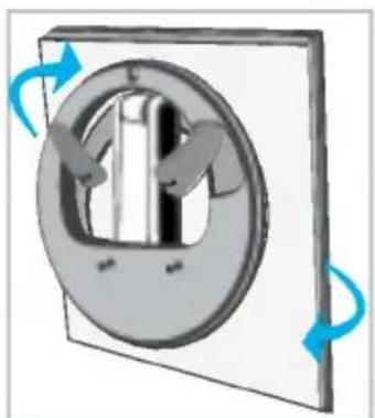
natural_image
Diagram of a mechanical switch or dial with rotating arrows indicating rotation (no text or symbols)Digitally yours


LG