
Pro PR675AWD - Lawn mower POULAN - Free user manual and instructions
Find the device manual for free Pro PR675AWD POULAN in PDF.


| Product Type | Self-Propelled Rotary Lawn Mower |
| Brand | Poulan |
| Model | Pro PR675AWD |
| Cutting Width | 22 in. (56 cm) |
| Engine | Briggs & Stratton 190cc (or equivalent) |
| Drive System | Self-propelled, front wheel drive with variable speed (Autowalk) |
| Cutting Height Adjustment | Single lever, 7 positions (1–3.5 in.) |
| Deck Material | Steel |
| Grass Catcher | Rear bag, fabric, 2.5 bushel capacity |
| Mulching Capability | Yes (with mulcher plug) |
| Starting System | Recoil start (optional electric start) |
| Handle Type | Adjustable, folding for storage |
| Wheel Size (Front/Rear) | 8 in. / 10 in. |
| Weight | Approximately 85 lbs (38.5 kg) |
| Fuel Tank Capacity | 1.5 quarts (1.4 L) |
| Oil Capacity | 20 oz (0.6 L) |
| Sound Level | 96 dB(A) (typical) |
| Safety Features | Operator presence control, discharge deflector, rear deflector |
| Maintenance | Blade sharpening/replacement, oil change, air filter cleaning |
| Warranty | 2 years limited |
| Additional Features | Water washout port for easy cleaning, folding handle |
Frequently Asked Questions - Pro PR675AWD POULAN
User questions about Pro PR675AWD POULAN
0 question about this device. Answer the ones you know or ask your own.
Ask a new question about this device
Download the instructions for your Lawn mower in PDF format for free! Find your manual Pro PR675AWD - POULAN and take your electronic device back in hand. On this page are published all the documents necessary for the use of your device. Pro PR675AWD by POULAN.
USER MANUAL Pro PR675AWD POULAN
SELF-PROPELLED ROTARY LAWN MOWER
TABLE OF CONTENTS
Safety Rules ......2-4
Assembly 5-9
Operation 10-21
Maintenance .....22-26
Service and
Adjustments .....27-33
Storage 33-35
Troubleshooting .....35-36
SAFETY RULES
IMPORTANT: This cutting machine is capable of amputating hands and feet and throwing objects. Failure to observe the following safety instructions could result in serious injury or death.
⚠ Look for this symbol to point out im portant safety precautions. It means CAU TION!!! BECOME ALERT!!! YOUR SAFE TY IS INVOLVED.
WARNING: In order to prevent ac ci-den tal starting when setting up, trans port-ing, ad just ing or making repairs, always dis con nect spark plug wire and place wire where it can not come in contact with plug.
CAUTION: Muffler and other engine
parts become extremely hot during operation and remain hot after engine has stopped. To avoid severe burns on contact, stay away from these areas.

natural_image
Silhouette of a hand reaching toward grass with a crossed-out hand symbol nearby (no text or symbols present)⚠ WARNING: Engine exhaust, some of its constituents, and certain vehicle components contain or emit chem i cals known to the State of Cal i for nia to cause can cer and birth defects or oth er re pro duc tive harm.
WARNING: Battery posts, terminals and related accessories contain lead and lead compounds, chemicals known to the State of Cal i for nia to cause can cer and birth defects or oth er re pro duc tive harm. Wash hands after handling.
WARNING: This lawn mower is equipped with an internal com bus tion engine and should not be used on or near any un im proved forest-covered, brush-covered or grass-cov ered land unless the engine's exhaust system is equipped with a spark arrester meeting applicable local or state laws (if any). If a spark arrester is used, it should be maintained in effective working order by the operator.
In the state of California the above is required by law (Section 4442 of the California Public Resources Code). Other states may have similar laws. Federal laws apply on federal lands. A spark arrester for the muffler is available through your nearest Sears Parts & Repair Center (See the REPAIR PARTS section of this manual).
I. CHILDREN

WARNING: CHILDREN CAN BE SERIOUSLY INJURED OR KILLED BY THIS EQUIPMENT. Carefully read and follow all of the safety instructions below.
The American Academy of Pediatrics recommends that children be a minimum of 12 year of age before operating a pedestrian controlled lawn mower and a minimum of 16 years of age before operating a riding lawn mower.
Tragic accidents can occur if the oper a tor is not alert to the presence of children. Children are often attracted to the machine and the mowing activity. Never assume that children will remain where you last saw them.
- Keep children out of the mowing area and under the watchful care of a re-spon si ble adult other than the operator.
- Be alert and turn machine off if chil dren enter the area.
- Before and while walking back wards, look behind and down for small chil dren.
- Never allow children to operate the machine.
II. GENERAL OPERATION
- Read, understand, and follow all in struc tions on the machine and in the manual(s) before starting. Be thor ough ly familiar with the controls and the proper use of the machine before starting.
- Do not put hands or feet near or under rotating parts. Keep clear of the discharge opening at all times.
- Only allow responsible individuals, who are familiar with the in struc tions, to operate the machine.
- Clear the area of objects such as rocks, toys, wire, bones, sticks, etc., which could be picked up and thrown by blade. Stay behind the handle when the engine (motor) is running.
- Be sure the area is clear of other people before mowing. Stop ma chine if anyone enters the area.
- Do not operate machine bare footed or while wearing sandals. AI ways wear substantial footwear with good ankle support while mowing.
SAFETY RULES
- Do not pull mower backwards unless absolutely nec es sary. Always look down and behind before and while moving backwards.
- Never direct discharged material toward anyone. Avoid discharging material against a wall or obstruction. Material may richochet back toward the operator. Stop blade when crossing gravel surfaces.
- Do not operate the mower without proper guards, plates, grass catcher or other safety protective devices in place.
- See manufacturer's instructions for proper operation and installation of accessories. Only use accessories approved by the manufacturer.
- Stop the blade(s) when crossing gravel drives, walks, or roads.
- Never leave a running machine unattended.
- Stop the engine (motor) and wait until the blade comes to a complete stop before cleaning the machine, removing the grass catcher, or unclogging the discharge chute.
- Mow only in daylight or good artificial light.
- Do not operate the machine while under the influence of alcohol or drugs.
- Never operate machine in wet grass. Always be sure of your footing: keep a firm hold on the handle; walk, never run.
- Disengage the drive system, if so equipped, before starting the engine (motor).
- If the equipment should start to vi brate abnormally, stop the engine (motor) and check immediately for the cause. Vibration is generally a warning of trouble.
- Always wear eye protection when op erat ing machine.
- Use extra care when approaching blind corners, shrubs, trees, or other objects that may obscure vision.
- When loading or unloading this machine, do not exceed the maximum recommended operation angle of 15irc .
- Wear proper Personal Protective Equipment (PPE) while operating this machine, including (at a minimum) sturdy footwear, eye protection, and hearing protection. Do not mow in shorts or open toed footwear.
Always let someone know you are outside mowing.
Slopes are a major factor related to slip & fall accidents, which can result in severe injury. All slopes require extra caution. If you feel uneasy on a slope, do not mow it.
DO:
- Mow across the face of slopes: never up and down. Exercise extreme caution when changing direction on slopes.
- Remove obstacles such as rocks, tree limbs, etc.
- Watch for holes, ruts, bumps or hidden objects. Uneven terrain could cause a slip and fall accident. Tall grass can hide obstacles.
DO NOT:
- Do not mow near drop-offs, ditches or embankments. You could lose your footing or balance.
- Do not mow on wet grass or excessively steep slopes. Poor footing could cause a slip and fall accident.
IV. SAFE HANDLING OF GASOLINE
To avoid personal injury or property damage, use extreme care in handling gasoline. Gasoline is extremely flammable and the vapors are explosive.
- Extinguish all cigarettes, cigars, pipes and other sources of ignition.
- Use only an approved container.
- Never remove gas cap or add fuel with the engine running.
- Allow engine to cool before refueling.
- Never refuel the machine indoors.
- Never store the machine or fuel container where there is an open flame, spark or pilot light such as a water heater or on other appliances.
- Never fill containers inside a vehicle, on a truck or trailer bed with a plastic liner. Always place containers on the ground away from your vehicle before filling.
- Remove gas-powered equipment from the truck or trailer and refuel it on the ground. If this is not possible, then refuel such equipment with a portable container, rather than from a gasoline dispenser nozzle.
- Keep the nozzle in contact with the rim of the fuel tank or container opening at all times until fueling is complete. Do not use a nozzle lock-open device.
- If fuel is spilled on clothing, change clothing immediately.
- Never overfill fuel tank. Replace gas cap and tighten securely.
SAFETY RULES
V. GENERAL SERVICE
- Never run a machine inside a closed area.
- Never make adjustments or repairs with the engine (motor) running. Dis con nect the spark plug wire, and keep the wire away from the plug to prevent ac ci den-tal starting.
- Keep all nuts and bolts tight to be sure the equipment is in safe working condition.
- Never tamper with safety devices. Check their proper operation reg u lar ly. Never do anything to interfere with the intended function of a safety device or reduce the protection provided by a safety device.
-
Keep machine free of grass, leaves, or other debris build-up. Clean oil or fuel spillage. Allow machine to cool before storing.
-
Stop and inspect the equipment if you strike an object. Repair, if nec es sary, before restarting.
- Never attempt to make wheel height adjustments while the engine is running.
- Grass catcher components are subject to wear, dam age, and de te ri or a tion, which could expose moving parts or allow objects to be thrown. Frequently check com po nents and replace with man u fac tur er's recommended parts, when necessary.
- Mower blades are sharp and can cut. Wrap the blade(s) or wear gloves, and use extra caution when ser vic ing them.
- Do not change the engine governor setting or overspeed the engine.
- Maintain or replace safety and instruction labels, as necessary.
CONGRATULATIONS on your purchase of a new Lawn Mower. It has been designed, en gi neered and manu fac tured to give you the best pos sible de penda bil ity and per for- m ance.
Should you experience any prob lems you can not easily remedy, please contact your nearest authorized service center. They have com pe tent, well trained tech ni cians and the proper tools to service or repair this unit.
- Read the SAFETY RULES and this Operator's Manual in its entirety before you attempt to assemble or operate your new lawn mower to insure proper operation and to prevent injury to yourself and others. Save this manual for future reference.
- Your new lawn mower has been assembled at the factory with the exception of those parts left unassembled for shipping purposes. To ensure safe and proper operation of your lawn mower, all parts and hardware you assemble must be tightened securely. Use the correct tools as necessary to ensure proper tightness.
- All parts such as nuts, washers, bolts, etc., necessary to complete the assembly have been placed in the parts bag.
TO REMOVE LAWN MOWER FROM CARTON
- Remove all loose parts from carton.
- Remove lawn mower hous ing with care. Avoid touch ing blade under hous ing. Always wear gloves or other protection when working under or lifting mower.
THINGS TO KNOW BE FORE YOU ASSEMBLE OR OPERATE YOUR LAWN MOW ER
Do I have a side or rear discharge lawn mower?
Look for the grass discharge opening on your mower. If the opening is on the right side of the mower housing, it is a side discharge mower. If the opening is at the back of the mower housing, it is a rear discharge mower. Only rear discharge lawn mowers have a grass catcher in clud ed with the mower. Approved grass catchers for side discharge mow ers may be purchased from your nearest au tho rized dealer.
Do I have a mulching lawn mower?
Look for the grass discharge opening on your mower. Raise the discharge deflector (rear door on rear discharge mowers). If the opening is closed off by a plate, then your lawn mower is mulcher ready. To convert to a discharging mower, see the Operation section of this manual.
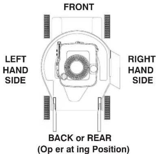
What is the right and left side of the lawn mower?
When right hand (RH) or left hand (LH) is mentioned in this manual, it means when you are in the operating position (standing be hind the handle).
What kind of engine is on my lawn mower?
When learning how to operate your new lawn mower, you will need to know what kind of engine powers the mower. A decal on the engine will indicate the man u fac tur-er and type or brand name of the engine.
BRIGGS & STRATTON ENGINES

OTHER ENGINES
HONDA
KOHLER
RATO™
ASSEMBLY
⚠️CAUTION: Do not operate this lawn mower without the discharge deflector or an entire approved grass catcher in place. These guards are for your protection and are required by the American National Standards Institute and Consumer Products Safety Com mis sion.
⚠️CAUTION: Disconnect spark plug wire from spark plug and place wire where it cannot come in contact with plug.
HOW TO SET UP YOUR MOW ER UNFOLD HANDLE
IMPORTANT: Unfold handle carefully so as not to pinch or damage con trol cables.
"QUICK RELEASE" HANDLES (ON 18" HI-VAC MODELS ONLY)
- Move height adjustment lever forward to raise mower to highest position.
- Tighten handle bolts (on both sides).

LEVER FORWARD TO RAISE MOWER
ASSEMBLY
"QUICK RELEASE" HANDLES (ALL OTHER MODELS)
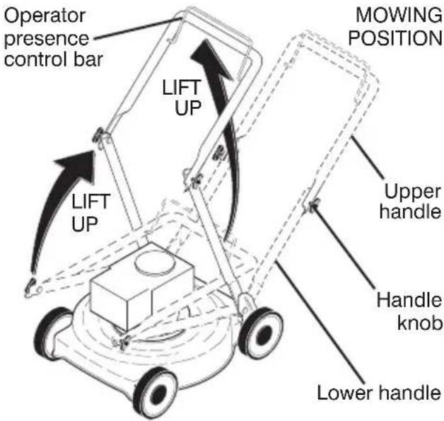
- Raise lower handle section to mowing position and align holes in lower handle with holes in handle brackets.
- Insert handle bolts through lower handles and handle brackets; secure with lower ("standard") knobs.
- Remove protective padding, raise upper handle section into place on lower handle and tighten both upper ("quick-adjust") knobs.

2 POSITION / "ADJUSTABLE" HANDLES
- Raise handles until lower handle section locks into place in mowing position.
3 POSITION "EZ" HANDLES
- Raise lower handle section to operating position and align hole in handle with one of three height positioning holes.
- Insert handle bolt through handle and bracket and secure with knob.
- Repeat for opposite side of handle.

3 POSITION "QUICK" HANDLES
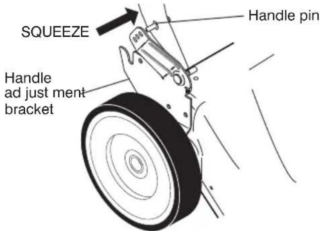
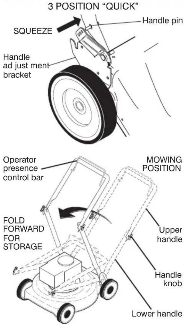
- Raise lower handle section to operating position and squeeze the bottom ends of lower handle towards each other until the pin in handle can be inserted into one of the three height adjustment holes.
ALL HANDLES
- Raise upper handle section into place on lower hand dle, remove protective padding and tighten both handle knobs.
- Remove handle padding holding operator presence control bar to upper handle.
- Your lawn mower handle can be adjusted for your mowing comfort. Refer to "ADJUST HANDLE" in the Service and Adjustments section of this manual.
NOTE: For shipping purposes, the rear wheels on your lawn mower may not be adjusted to the same position as the front wheels. Before operating mower adjust all wheels to the same cutting height.
ASSEMBLY
INSTALL STARTER ROPE (MODELS EQUIPPED WITH T-KNOB)
- Loosen T-knob.
- Hold control bar against upper handle.
- Slowly pull engine starter rope out until rope will slip into loop of rope guide.
- Tighten T-knob.


INSTALL REAR WHEELS ("HIGH WHEEL" MOWERS ONLY)
Some high wheel models require washers which will be provided in a parts bag. If provided, install washers on the axle first as shown.
• Install one (1) rear wheel on the axle of rear wheel adjuster.
• Install 3/8-16 locknut and tighten securely.
- Repeat procedure for other rear wheel.

AS SEM BLE GRASS CATCHER (REAR DISCHARGE MOWERS ONLY)
IMPORTANT: If your model lawn mower is mulcher ready, the mulcher plate or plug must be removed before using mower as a bagger. To convert mower to bagging or discharging, see the Operation section in this manual.
Look at the different grass catcher illustrations that follow. Determine which type of grass catcher you have and follow the appropriate instructions.

ASSEMBLY
"FABRIC TOP" GRASS CATCHERS
ASSEMBLE/ATTACH GRASS CATCH ER
- Put grass catcher frame into grass bag with rigid part of bag on the bottom.
- Slip vinyl bindings over frame.
NOTE: If vinyl bindings are too stiff, hold them in warm water for a few minutes. If bag gets wet, let it dry before using.
- Lift the rear door on the mower housing.
- For HINGE BRACKET mounted catcher, place the grass catch er frame onto the formed tabs on the rear door hinge bracket.

- For HANDLE BRACKET mounted catcher, place frame side hooks into slots in handle brackets.

- For DOOR PIVOT PIN mounted catcher, place the grass catcher frame hooks onto the door pivot pins.

- For DOOR SLOT mounted catcher, place the grass catcher frame hooks into the slots of the rear door.
NOTE: The grass catcher is secured to the lawn mower housing when the rear door is lowered onto the grass catcher frame.

ALL GRASS CATCHERS
CAUTION: Under normal usage, the catcher material is subject to de te ri o ration and wear and should, therefore, be checked frequently for replacement. Any replacement catcher should be checked to ensure compliance with original man u-fac tur er's spec i fi ca tions.
⚠️ CAUTION: Do not run lawn mower with out the discharge deflector (rear door), approved grass catcher, clipping de flec tor or mulcher plate in place. Never attempt to operate mower with the discharge deflector (rear door) removed or propped open.
SPARK PLUG BOOT
On some models a spark plug boot is packed loose in the parts bag. If your model has the boot, install on spark plug wire and reconnect spark plug wire to spark plug.

ASSEMBLY
TO PRE PARE BATTERY (ELECTRIC START MODELS ONLY)
NOTE: Your battery must be charged before you can start your lawn mower.
- Open battery box (if equipped).
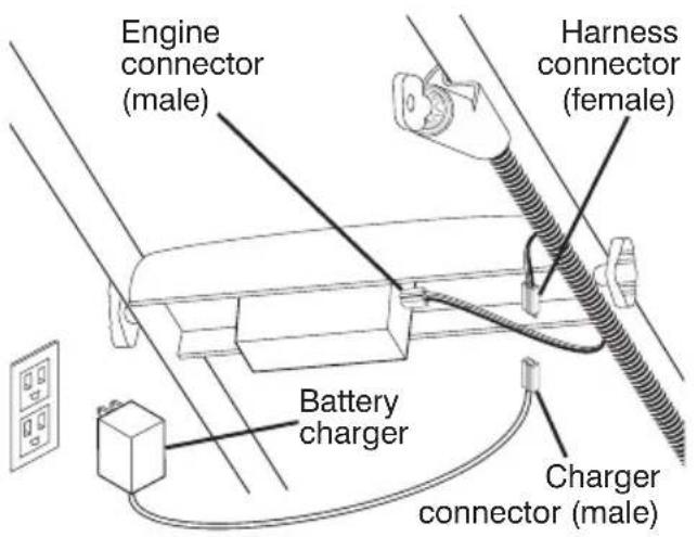
- Disconnect engine connector (male) (if equipped) from battery con nec tor (female).
- Con nect battery charger con nec tor (male) to harness con nec tor (fe male).
- Plug battery charger into 110 volt A.C. outlet.
- Leave battery charger connected for 24 hours before starting your engine for the first time.
- Reconnect engine connector (male) (if equipped) to battery con nec tor (female).
- After charging, connect engine con nec tor (male) (if equipped) to bat tery connector (female).
Connect your battery charger to charge battery after each use.
IMPORTANT: The engine will not recharge your battery.
At the end of the mowing season the battery should be charged for 48 hours to protect the battery during winter storage.
⚠️CAUTION: Always dis con nect the en gine connector from the battery con- nector to prevent ac ci den tal start ing when trans port ing or stor ing your lawn mower after the season.
HANDLE-MOUNTED KEY SWITCH
22PLUS FRONT WHEEL DRIVE

DECK-MOUNTED BATTERY

22PLUS REAR WHEEL DRIVE

OPERATION

The operation of any lawn mower can result in foreign objects thrown into the eyes, which can result in severe eye damage. Always wear safety glasses or eye shields while operating you lawn mower or performing any adjustments or repairs. We re

Use ear pro tec- tors to a v o i d
mend standard safety glasses or a wide vision safety mask over spectacled damage to hearing.
HOW TO USE YOUR LAWN MOWER ENGINE SPEED CONTROL
MODELS WITH REMOTE THROTTLE
Engine speed is con trolled by the throttle control located on the upper handle.
- Move lever forward to FAST engine speed for starting and better bagging.
- Move lever backward for SLOW engine speed.
- Some models have engines equipped with a choke feature. Move the lever all the way forward to the CHOKE position when starting a cold engine.
NOTE: Be sure engine START/STOP switch (if equipped) is in the ON po si tion.

MODELS WITH FIXED SPEED ENGINES Engine speed was set at the factory for optimum per form ance. Engine speed is not adjustable.
Adjust cutting height to suit your requirements. Me di um position is best for most lawns. Raise wheels for low cut and lower wheels for high cut.
NOTE: For shipping purposes, the rear wheels on your lawn mower may not be adjusted to the same position as the front wheels. Before operating mower adjust all wheels to the same cutting height.
"MANUAL" ADJUSTMENT
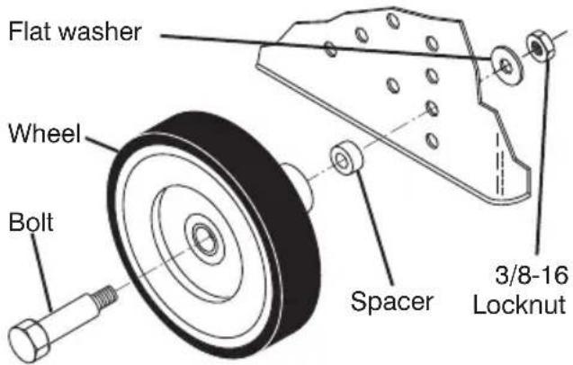
- Remove wheel, bolt, and hardware and reassemble in desired adjustment hole.
- Reinstall wheel components in the same order as they were before removal. Tighten securely.
• Make sure all wheels are at same height.
"QUICK" ADJUSTMENT
- To change cutting height, squeeze adjuster lever to ward wheel. Move wheel up or down to suit your require ments. Be sure all wheels are in the same setting.
NOTE: Adjuster is properly positioned when plate tab inserts into hole in lever. Also, 9-position adjusters (if so equipped) allow lever to be positioned between the plate tabs.
natural_image
Illustration of a hand holding a tire, with a dashed line indicating a measurement or assembly step (no text or symbols present)
LEVER FORWARD TO RAISE MOWER
Lever
OPERATION
"QUICK-PIN" ADJUSTMENT
- To change cutting height, pull up on adjuster lever, move wheel up or down to suit your require ments and release adjuster lever. Be sure all wheels are in the same setting.
NOTE: Adjuster is properly positioned when lever inserts into hole in plate.
"DUAL POINT" ADJUSTMENT
Both front wheels are adjusted by a single lever on the left front wheel. Likewise, both rear wheels are adjusted by a single lever on the left rear wheel.
- Pull adjuster lever toward wheel. To raise mower, move lever forward to desired position. To lower mower, move the lever toward the rear.
Be sure to adjust both front and rear wheels to the same height.
"SINGLE POINT" ADJUSTMENT
- Pull adjuster lever toward wheel. To raise mower, move lever forward to desired position. To lower mower, move the lever toward the rear.
Height adjuster lever

"THREE POINT" ADJUSTMENT (18" (45cm) HI-VAC MODELS ONLY)
Both rear wheels are adjusted by a single lever on the left rear wheel.
- Pull adjuster lever toward wheel. To raise mower, move lever forward to desired position. To lower mower, move the lever toward the rear.
NOTE: There are seven (7) height adjustment positions for the rear wheels.
Both front wheels are adjusted as follows:
- Remove wheel, bolt, and hardware and reassemble in desired ad just ment hole.
- Reinstall wheel components in the same order as they were before removal. Tighten securely.
NOTE: There are seven (7) height adjustment holes for the front wheels. Be sure both front wheels are in the same hole.
IMPORTANT: Be sure to adjust both front and rear wheels to the same height.

The front wheels can be “locked” into position or set to “freewheel” for better maneuverability. Placing the lockbars in the outer holes of the adjustment brackets “locks” the front wheels. Likewise, placing the lockbars in the inner holes of the adjustment brackets allows the front wheels to spin freely (“freewheel”).
- Lift lockbar until the frontmost end clears the adjustment bracket, then pivot lockbar to desired position.
IMPORTANT: Front wheels must be "locked" into position when operating on a slope. Mow across the face of slopes: never up and down.
TO CONVERT MOWER:
Most mowers are shipped ready to be used as a mulcher.
"REAR DISCHARGE ONLY" MOWERS
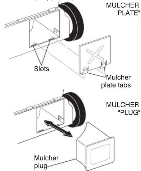
Some models have a separate mulcher plug, other models have the mulcher plug built into the rear door. To convert to bagging or discharging, the plate or plug (if so equipped) must be removed from the discharge opening of the lawn mower.
- Open rear door and remove mulcher plate or plug (if so equipped). Store mulcher plate or plug in a safe place.
- You can now install grass catcher or optional clipping deflector accessory.
- To return to mulching operation, install mulcher plate or plug into discharge opening of mower.
⚠️ CAUTION: Do not run your lawn mower without mulcher plate/plug in place or ap proved clipping deflector or grass catch er in place. Never attempt to op er ate the lawn mower with the rear door removed or propped open.
MULCHER PLUG BUILT INTO REAR DOOR

natural_image
Line drawing of a mechanical device with wheels and a handle, no text or symbols presentOPERATION
"SIDE DISCHARGE ONLY" MOWERS MULCHER PLATE
To convert to bagging or discharging, mulcher plate must be removed from underside of lawn mower.
- Remove the four (4) screws and lock nuts securing the mulcher plate to the mower.
- Store mulcher plate and hardware in a safe place.
- Mower can now be used for side discharging or option al grass catcher accessory can be attached.
- To return to mulching operation, simply reinstall mulcher plate and tighten hardware securely.

MULCHER PLUG TYPE "A"
To convert to mulching operation, mulcher plug must be installed into discharge opening of mower.
- Open discharge deflector.
- Insert tab of mulch plug into housing opening.
- Align hooks of mulch plug over hinge rod of discharge deflector. Push mulch plug down until mulch plug is seat ed in housing opening.
⚠️CAUTION: Do not run your lawn mower without discharge deflector, ap proved grass catcher or mulcher plug in place.

MULCHER PLUG TYPE "B"
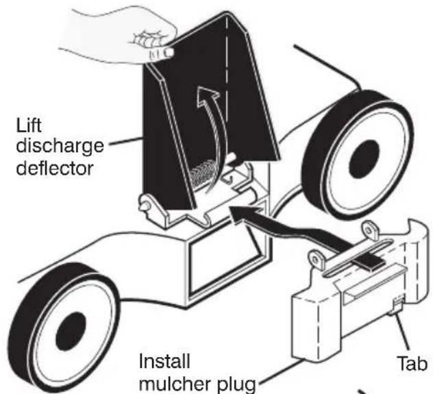
To convert to bagging or dis charging:
- Lift discharge deflector and remove mulcher plug.
- Mower can now be used for side dis-charging or option al grass catcher can be attached.
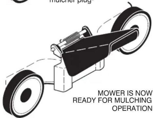
- To return to mulching operation, simply reinstall mulcher plug as shown, making sure tab is seated properly.
CAUTION: Do not run your lawn mower without discharge deflector, approved grass catch er or mulcher plug in place.
OPERATION
"MULTI-CUT" MOWERS
Your lawn mower was shipped ready to be used as a mulcher. To convert to bagging or discharging:
REAR BAGGING
- Open rear door and remove mulcher plate or plug (if equipped). Store mulcher plate or plug in a safe place.
- You can now install grass catcher.
- To convert to mulching or discharging operation, install mulcher plate or plug (if equipped) into rear discharge opening of mower, making sure all tabs are seated properly. Close rear door.

"REAR DOOR PROP" (IF EQUIPPED) (22PLUS MODELS ONLY)
NOTE: Rear door will remain open until operator presence control bar is held down to the handle.
⚠️ CAUTION: Do NOT force rear door to close. Serious damage to your mower could result.

SIDE DISCHARGING
- Mulcher plate or plug (if equipped) must be installed into rear discharge opening of mower. Rear door must be closed.
- Open mulcher door and install discharge deflector under door as shown.
- Mower is now ready for discharging operation.
- To convert to mulching or bagging operation, dis charge deflector must be removed and mulcher door must be closed and locked.

OPERATION
SIMPLE STEPS TO REMEMBER WHEN CONVERTING YOUR "MULTI-CUT" LAWN MOWER:
FOR MULCHING -
- Rear mulcher plate or plug (if equipped) installed and rear door closed.
- Mulcher door closed.
FOR REAR BAGGING -
- Rear mulcher plate or plug (if equipped) removed.
- Grass catcher installed.
- Mulcher door closed.
- Rear mulcher plate or plug (if equipped) installed and rear door closed.
• Discharge deflector installed.
⚠️CAUTION: Do not run your lawn mower without rear mulcher plate or plug in place or approved grass catcher in place. Never at tempt to operate the lawn mower with the rear door re moved or propped open.
TO EMPTY GRASS CATCHER (REAR DISCHARGE AND MULTI-CUT MODELS)
- Simply open rear door and lift grass catcher up and away from mower.
NOTE: Do not drag the bag when emptying. It will cause unnecessary wear.
CAUTION: Under nor mal usage, the catch er material is subject to de te ri or a tion and wear and should, therefore, be checked frequently for replacement. Any replacement catcher should be checked to ensure compliance with original man u fac tur er's spec i fi ca tions.
⚠️CAUTION: Do not run lawn mower with out the rear door, ap proved grass catcher or clip ping de flec tor in place. Never at tempt to op er ate mower with the rear door removed or propped open.
18" (45cm) HI-VAC MODELS:
Your lawn mower was shipped ready to be used as a mulcher. To convert to rear bagging or side discharging:
REAR BAGGING
- Remove knob securing mulcher door to lawn mower housing.
- Open mulcher door and position discharge chute over both threaded studs.
- Secure discharge chute to lawn mower housing with both knobs.
- Place the grass catcher on the rear door as shown.
NOTE: Be sure the grass catcher is securely locked in place.
- Mower is now ready for rear bagging operation.

SIDE DISCHARGING
- Discharge chute must be removed.
- Open mulcher door and install side discharge deflector beneath it as shown.

OPERATION
- Secure rear of side discharge deflector to lawn mower housing with knob.
- Mower is now ready for side discharging operation.
SIMPLE STEPS TO REMEMBER WHEN CONVERTING YOUR 18" HI-VAC:
FOR MULCHING -
- Grass catcher, discharge chute and side discharge deflector removed.
- Mulcher door secured to mower housing with knob.
FOR REAR BAGGING -
- Side discharge deflector removed.
- Grass catcher and discharge chute installed with discharge chute secured to lawn mower housing with knob.
- Grass catcher and discharge chute removed.
- Side discharge deflector installed and secured to mower housing with knob.
⚠️ CAUTION: Do not run your lawn mower with out mulcher door closed; side discharge deflector installed, or discharge chute and ap proved grass catcher in place. Never at tempt to op er ate the lawn mower with mulcher door re moved or propped open.
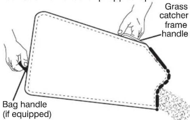
TO EMPTY GRASS CATCHER
- Remove grass catcher with clippings from lawn mower using both front and center of handle as shown.
- Empty clippings from grass catcher.
- Reinstall grass catcher on rear door.
NOTE: Do not drag the bag when emptying; it will cause unnecessary wear.
21" (53cm) HI-VAC MODELS:
Your lawn mower was shipped ready to be used as a mulcher. To convert to rear bagging or side discharging:
REAR BAGGING
- Remove knob securing mulcher door to lawn mower housing.
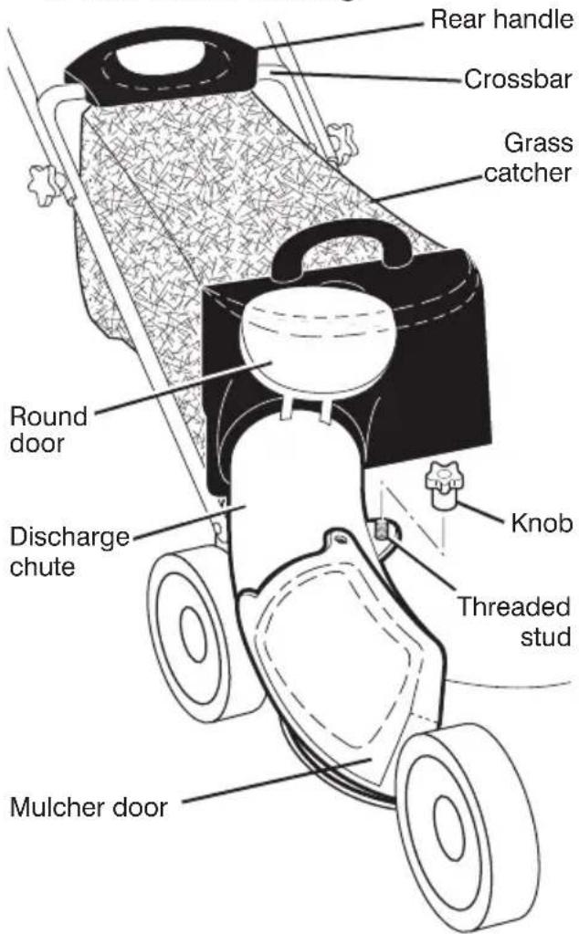
- Open mulcher door and insert tabs of discharge chute into hinge bracket opening and position rear of chute over threaded stud.

OPERATION
- Secure rear of discharge chute to lawn mower housing with knob.
- Place rear handle of grass catcher on the crossbar of the lawn mower's lower handle as shown.
- Lift the round door of the discharge chute and place the grass catcher into place on the discharge chute.
NOTE: Be sure the grass catcher is securely locked in place and the round door of the discharge chute rests on the grass catcher as shown.
- Mower is now ready for rear bagging operation.
- To convert to mulching operation, remove grass catch er and discharge chute. Secure mulcher door to mower housing with knob.
- To convert to side dis charging operation, remove grass catch er and discharge chute. Install side discharge deflector and secure it to lawn mower housing with knob.
SIDE DISCHARGING
- Grass catcher and discharge chute must be removed.
- Open mulcher door and install front of side dis charge deflector beneath it as shown.
-
Secure rear of side discharge deflector to lawn mower housing with knob.
-
Mower is now ready for side discharging operation.
- To convert to mulching operation, side dis charge deflector must be removed and mulcher door secured to mower housing with knob.
- To convert to rear bagging operation, side discharge deflector must be removed; discharge chute and grass catcher installed and discharge chute secured to mower housing with knob.

SIMPLE STEPS TO REMEMBER WHEN CONVERTING YOUR 21" HI-VAC:
FOR MULCHING -
- Grass catcher, discharge chute and side discharge deflector removed.
- Mulcher door secured to mower housing with knob.
FOR REAR BAGGING -
- Side discharge deflector removed.
- Grass catcher and discharge chute installed with discharge chute secured to lawn mower housing with knob.
- Round door of discharge chute resting on top of grass catcher.
- Grass catcher and discharge chute removed.
- Side discharge deflector installed and secured to mower housing with knob.
CAUTION: Do not run your lawn mower with out mulcher door closed; side discharge deflector installed, or discharge chute and ap proved grass catcher in place. Never at tempt to op er ate the lawn mower with mulcher door or round door re moved or propped open.
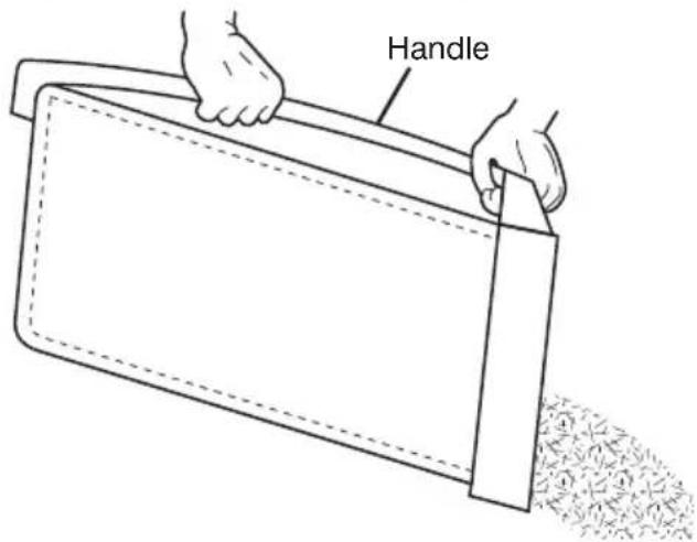
TO EMPTY GRASS CATCHER
- Open round door of discharge chute to move starter rope out and away from grass catcher.
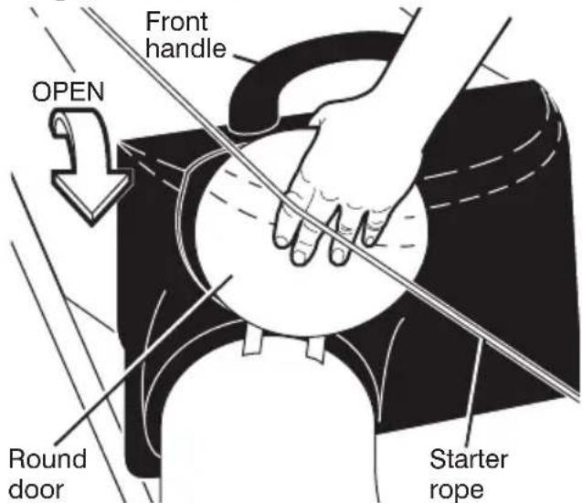
- Remove grass catcher with clippings from lawn mower using both front and rear handles.
- Empty clippings from grass catcher using rear handle. The weight of the grass will open the door.
- Snap door shut over frame before installing grass catcher on mower.
NOTE: Do not drag the bag when emptying; it will cause unnecessary wear.
OPERATION
OPERATOR PRESENCE CONTROL BAR (ALL MODELS)
Your lawn mower is equipped with an oper a tor presence control bar which requires the operator to be po si tioned behind the lawn mower handle in order to start and operate the lawn mower.
CAUTION: Federal reg u la tions require an en gine control to be in stalled on this lawn mower in order to min i mize the risk of blade contact injury. Do not un der any cir cum stanc es attempt to de feat the func tion of the operator con trol. The blade turns when the engine is running.
DRIVE CONTROL
"STANDARD" DRIVE CONTROL
- Self-propelling is controlled by holding the operator presence control bar down to the handle and pushing the drive control lever forward until it clicks; then releasing the lever.
- Forward motion will stop when the operator presence control bar is released. To stop forward motion without stopping engine, release the operator presence control bar slightly until the drive control disengages. Hold operator presence control bar down against handle to continue mowing without self-propelling.
- To keep drive control engaged when turning corners, push down on handle and lift front wheels off ground while turning lawn mower.
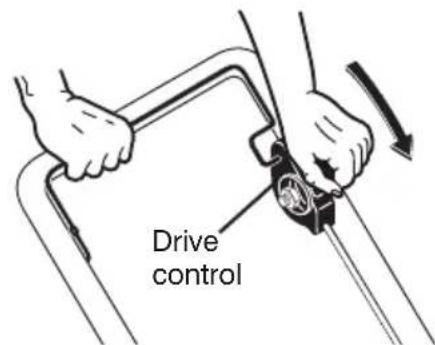
TO ENGAGE DRIVE CONTROL

DRIVE CONTROL DISENGAGED
"DUAL BAIL" DRIVE CONTROL
- To start forward motion, lift drive control bar up to handle.
- To stop forward motion, release drive control bar.

DRIVE CONTROL ENGAGED

natural_image
Illustration of hands using a tool to lift a curved metal object (no text or symbols)DRIVE CONTROL DIS EN GAGED
"AUTOWALK" DRIVE CONTROL
- Self-propelling is controlled by holding the operator presence control bar down to the handle and pulling the drive control lever(s) rearward to the handle. The farther toward the handle the lever(s) are pulled, the faster the unit will travel.
- Forward motion will stop when either the operator presence control bar or a drive control lever are released. To stop forward motion without stop ping engine, re lease the drive control lever(s) only. Hold op er a tor presence control bar down against handle to con tin ue mowing without self-propelling.
NOTE: If after releasing the drive control the mower will not roll backwards, push the mower forward slightly to disengage drive wheels.
OPERATION
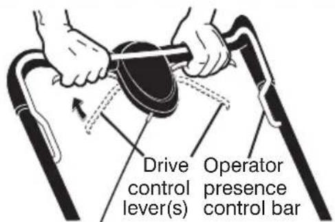
TO ENGAGE DRIVE CONTROL
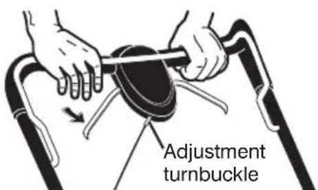
DRIVE CONTROL DISENGAGED
FRONT WHEEL DRIVE MODELS ONLY:
- To keep drive control engaged when turning corners, push down on the handle to lift the front wheels off the ground while turning lawn mower. Over time, the drive control system may become “loose”, resulting in decreased speed. There is a turnbuckle on the un der side of the drive control housing to increase tension on the drive cable. Proceed as follows:
- Turn unit off and disconnect spark plug wire from spark plug.
- Turn nut on underside of drive control to increase drive speed.
- Operate mower to test drive speed. Readjust as required.
- If condition fails to improve after the above steps (forward speed remains the same), your drive belt is worn and should be replaced.

"VARI-SPEED" DRIVE CONTROL
- Self-propelling is controlled by holding the operator presence control bar down to the handle and pulling the drive control bar up to the handle. The closer to the handle the bar is pulled, the faster the unit will travel.
- Forward motion will stop when either the operator presence control bar or drive control bar are released. To stop forward motion without stop ping engine, re lease the drive control bar only. Hold op er a tor presence control bar down against handle to con tin ue mowing without self-propelling.
NOTE: If after releasing the drive control the mower will not roll backwards, push the mower forward slightly to disengage drive wheels.
FRONT WHEEL DRIVE MODELS ONLY:
- To keep drive control engaged when turning corners, push down on the handle to lift the front wheels off the ground while turning lawn mower.

Over time, the drive control system may become "loose", resulting in decreased speed. There are holes in the drive control housing to increase tension on the drive cable. Pro ceed as follows:
- Turn unit off and disconnect spark plug wire from spark plug.
- Loosen nut, move drive control housing down handle to the next hole and retighten nut.
- Operate mower to test drive speed.
- If condition fails to improve after the above steps (forward speed remains the same), your drive belt is worn and should be replaced.
OPERATION
BEFORE STARTING EN GINE
Read the engine manual packed with your mower.
FILL ENGINE WITH OIL
Your lawn mower is shipped without oil in the engine.
- Be sure mower is level and area around oil fill is clean.
- Remove engine oil filler plug (oil fill cap/dipstick on models so equipped).
- Slowly add oil. For type and grade of oil to use, see “ENGINE” in the Maintenance section of this manual.
- Fill to the top of slot in filler hole (to "FULL" line on dipstick on models so equipped). Do not overfill.
- Replace plug (oil fill cap/dipstick on models so equipped) and tighten.
- Check oil level before each use. Add oil as needed.
- To change oil, see Maintenance section of this manual.
FILL GASOLINE TANK
- Fill gasoline tank with fresh, clean, unleaded gaso line. DO NOT USE PREMIUM GASOLINE. BE CARE FUL NOT TO OVERFILL TANK.
WARNING: Al co hol blended fuels (called gaso hol or using ethanol or metha nol) can at tract moisture which leads to separation and formation of acids during storage. Acidic gas can damage the fuel system of an engine while in storage. To avoid engine problems, the fuel system should be emptied before storage of 30 days or longer. Drain the fuel tank, start the engine and let it run until fuel lines and car before are empty Use fresh fuel next season. See Stor age In struc tions for ad di tion al in for ma tion. Ne use en gine or car bu re tor clean er prod ucts fuel tank or per ma nent dam age may occur.
TO STOP ENGINE
- To stop engine, release operator presence control bar and/or place engine START/STOP switch (if equipped) in the OFF po si tion.
NOTE: For engines with a primer, it may be nec es sary to repeat priming steps in cooler weather. In warmer weath er, overpriming may cause flood ing and en gine will not start. If you do flood engine, wait a few minutes before attempting to start and DO NOT repeat priming steps.
TO START ENGINE
⚠️ CAUTION: The mow er blade rotates whenever the engine is running.
NOTE: Due to protective coatings on the engine, a small amount of smoke may be present during the initial use of the product and should be considered normal.
- Place engine START/STOP switch (if equipped) in the ON po si tion.
- Move engine speed control to FAST position (or to CHOKE/START position on models equipped with choke feature).
- If your mower has a primer, to start a cold engine, push primer as many times as in structured in the engine manual packed with your mower. Use a firm push. This step is not usually necessary when starting an engine which has already run for a few minutes.
- Hold operator presence control bar down against handle.

MODELS WITH RECOIL START ER • Pull starter handle quickly. Do not allow ever s in starter rope to snap back.
MODELS WITH ELECTRIC START ER
- Push the engine start button (or turn the key on models so equipped).
IMPORTANT: Do not crank engine more than five continuous seconds each time you try to start. Wait 5 to 10 seconds between each attempt.
ALL MODELS
- For engines equipped with choke, slowly move engine speed control lever to FAST after engine starts.
OPERATION
MOWING TIPS
CAUTION: Do not use de-thatcher blade attachments on your mower. Such attachments are hazardous, will damage your mower and could void your warranty.
- For most cutting conditions and better bagging per form ance, the engine speed should be set in the FAST po si tion.
- Under certain conditions, such as when mowing very tall grass, raise the mower height on the first cut to reduce pushing effort, to avoid over heating the engine, and to avoid leaving clumps of grass clippings. Make the second cut to the desired height.
- For extremely heavy cutting, reduce the width of cut.
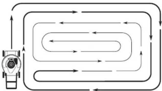
- For side discharge lawn mowers, cut in a coun ter clock wise di rec tion, starting at the outside of the area to be cut, in order to spread grass clip pings more evenly and to put less load on the engine. To keep clip pings off of walkways, flower beds, etc., make the first cuts in a clock wise direction.
- When using a rear discharge lawn mower in moist, heavy grass, clumps of cut grass may not enter the grass catcher. Reduce ground speed (pushing speed) and/or run the lawn mower over the area a second time.
- If a trail of grass clipping is left on the right side of a rear discharge lawn mower, mow in a clockwise direction with a small overlap to collect the clippings on the next pass.
flowchart
graph TD
    A["Device"] --> B{Loop Back}
    B -->|Yes| C["Return Path"]
    B -->|No| D["Loop Back"]
    C --> E["Return Path"]
    D --> F["Return Path"]
    E --> G["Output"]
    F --> G
    G --> H["Feedback Loop"]
    H --> I["Return Path"]
    I --> J["Output"]
- Pores in cloth grass catchers can become filled with dirt and dust with use and the catcher will collect less grass. To prevent this, regularly hose catcher off with water and let dry before use.
FOR MULCHING MOWERS ONLY - MULCHING MOWING TIPS
IMPORTANT: For best performance, keep mower housing free of built-up grass and trash. See "CLEANING" in the Maintenance section of this manual.
- The special mulching blade will recut the grass clip pings many times and reduce them in size so that as they fall onto the lawn they will disperse into the grass and not be noticed. Also, the mulched grass will bio de grade quickly to provide nu tri ents for the lawn. Always mulch with your highest engine (blade) speed as this will provide the best recutting action of the blades.
- Avoid cutting your lawn when it is wet. Wet grass tends to form clumps and in ter feres with the mulching action. The best time to mow your lawn is the early afternoon. At this time the grass has dried, yet the newly cut area will not be exposed to direct sunlight.
- For best results, adjust the lawn mower cutting height so that the lawn mower cuts off only the top one-third of the grass blades. If the lawn is overgrown it will be necessary to raise the height of cut to reduce pushing effort and to keep from over loading the engine and leaving clumps of mulched grass. For ex tremely heavy grass, reduce your width of cut by overlapping previously cut path and mow slowly.

- Certain types of grass and grass con di tions may re quire that an area be mulched a second time to com pletely hide the clip pings. When doing a sec-ond cut, mow across (per pen dic u lar) to the first cut path.
- Change your cutting pattern from week to week. Mow north to south one week then change to east to west the next week. This will help prevent matting and graining of the lawn.
MAINTENANCE
| MAINTENANCE SCHEDULE | BEFORE EACH USE | AFTER EACH USE | EVERY 10 HOURS | EVERY 25 HOURS OR SEASON | EVERY 100 HOURS | BEFORE STORAGE | |
| LAWN MOWER | Check for Loose Fasteners | √ | √ | ||||
| Clean / Inspect Grass Catcher * | √ | √ | √ | ||||
| Check Tires | √ | ||||||
| Check Drive Wheels *** | √ | ||||||
| Clean Lawn Mower **** | √ | √ | |||||
| Clean under Drive Cover *** | √ | ||||||
| Check Drive Belt / Pulleys *** | √ | ||||||
| Check / Sharpen / Replace Blade | √3 | ||||||
| Lubrication | √ | ||||||
| Clean and Recharge Battery ** | √ | √4 | |||||
| ENGINE | Check Engine Oil level | √5 | |||||
| Change Engine Oil | √1,2,6 | ||||||
| Clean Air Filter | √2 | ||||||
| Inspect Muffler | √ | ||||||
| Replace Spark Plug | √ | ||||||
| Replace Air Filter Paper Cartridge | √2 | ||||||
| Empty fuel system or add Stabilizer | √ | ||||||
* (if so equipped)
** Electric-Start mowers
*** Power-Propelled mowers
**** Use a scraper to clean under deck
1 - Change more often if operating under a heavy load or in high outdoor temperatures.
2 - Service more often if operating in dirty or dusty conditions.
3 - Replace blades more often when mowing in sandy soil.
4 - Charge 48 hours at end of season.
5 - And after each 5 hours of use.
6 - See "LUBRICATION" in the Maintenance section of this manual.
GENERAL RECOMMENDATIONS
The warranty on this lawn mower does not cover items that have been subjected to operator abuse or negligence. To receive full value from the war ranty, operator must maintain mower as instructed in this manual. Some adjustments will need to be made periodically to properly maintain your unit. All adjustments in the Service and Adjustments section of this manual should be checked at least once each season.
- Once a year, replace the spark plug, clean or replace air filter element, and check blade for wear. A new spark plug and clean/new air filter element assures proper air-fuel mixture and helps your en gine run better and last longer.
- Follow the Maintenance Sched ule in this manual.
BEFORE EACH USE
- Check engine oil level.
- Check for loose fasteners.
LUBRICATION
Keep unit well lubricated (See "LUBRICATION CHART").
IMPORTANT: Do not oil or grease plastic wheel bearings. Viscous lu bri cants wil
LUBRICATION CHART

① Handle bracket mounting pins
① Spray lubricant
② See "ENGINE" in Maintenance section.
attract dust and dirt that will short en the life of the self-lu bri cat ing bearings. If you feel they must be lu bri cated, use only a dry, pow dered graphite type lubricant sparingly.
MAINTENANCE
LAWN MOWER
Always observe safety rules when performing any main te nance.
TIRES
- Keep tires free of gasoline, oil, or insect control chemi cals which can harm rubber.
- Avoid stumps, stones, deep ruts, sharp objects and other hazards that may cause tire damage.
BLADE CARE
For best results, blade must be kept sharp. Re place a bent or dam aged blade.
CAUTION: Use only a replacement blade approved by the manufacturer of your mower. Using a blade not approved by the manufacturer of your mower is hazardous, could damage your mower and void your warranty.
TO REMOVE BLADE
- Disconnect spark plug wire from spark plug and place wire where it cannot come in contact with plug.
- Turn lawn mower on its side. Make sure air filter and carburetor are up.
- Use a wood block between blade and mower hous ing to prevent blade from turning when re moving blade bolt.
NOTE: Protect your hands with gloves and/or wrap blade with heavy cloth.
-
Remove blade bolt by turning counterclockwise.
-
Remove blade and attaching hard-ware (bolt, lock wash er and hardened wash er).
-
Remove debris shield (if equipped).
NOTE: Remove the blade adapter and check the key inside hub of blade adapter. The key must be in good condition to work properly. Replace adapter if damaged.

TO REPLACE BLADE
- Position the blade adapter on the engine crank shaft. Be sure key in adapter and crankshaft keyway are aligned; and that the drive belt is inside the tabs of the belt retainer (if equipped).
- Position blade on the blade adapter aligning the two (2) holes in the blade with the raised lugs on the adapter.
- Be sure the trailing edge of blade (opposite sharp edge) is up toward the engine.
- Install the blade bolt with the lock washer and hardened washer into blade adapter and crankshaft.
- Use block of wood between blade and lawn mower housing and tighten the blade bolt, turning clockwise.
- The recommended tightening torque is 35-40 ft. lbs.
IMPORTANT: Blade bolt is heat treated. If bolt needs replacing, replace only with approved bolt.
TO SHARPEN BLADE
NOTE: We do not recommend sharp en- ing blade - but if you do, be sure the blade is balanced. An un balanced blade will cause eventual damage to lawn mower or engine.
- The blade can be sharp ened with a file or on a grinding wheel. Do not attempt to sharpen while on the mower.
MAINTENANCE
BLADES WITH ROUND HOLE:
- To check blade balance, drive a nail into a beam or wall. Leave about one inch of the straight nail ex posed. Place center hole of blade over the head of the nail. If blade is balanced, it should remain in a horizontal position. If either end of the blade moves downward, sharpen the heavy end until the blade is balanced.
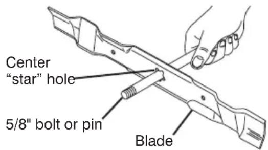
BLADE'S WITH "STAR" HOLE:
- To check blade balance, you will need a 5/8" diameter steel bolt, pin, or a cone balancer. (When using a cone bal anc er, follow the in struc tions supplied with bal anc er.)
NOTE: Do not use a nail for balancing blade. The lobes of the center hole may appear to be centered, but are not.
- Slide blade on to an unthreaded portion of the steel bolt or pin and hold the bolt or pin parallel with the ground. If blade is balanced, it should remain in a horizontal position. If either end of the blade moves downward, sharpen the heavy end until the blade is balanced.
DRIVE WHEELS
Check drive wheels each time before you mow to be sure they move freely.
The wheels not turning freely means trash, grass cuttings, etc. are in the drive wheel area and must be cleaned to free drive wheels.
If necessary to clean the drive wheels, check both drive wheels.
- If after cleaning, the drive wheels do not turn freely, contact your nearest authorized service center.
18" (45cm) HI-VAC MODELS ONLY:
-
Remove hubcaps (if equipped) and locknuts.
-
Remove wheels from wheel ad just er axles.
-
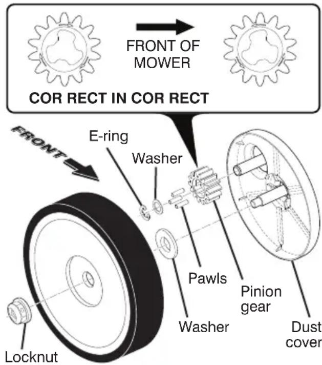
Remove any trash or grass cuttings from inside the dust cover, pinion gear and drive wheel gear teeth.
-
If you remove the pinion gears, wipe clean with dry cloth. Re as sem ble dry. Do not lubricate. Do not use oil or grease.
IMPORTANT: The pinion gears (on both sides of the mower) are the same, however, they must be installed cor rect ly. If in stalled in cor rect ly, the drive system will not work.
-
There are arrows embossed on both sides of the pinion gear. With the arrow at the top of the pinion, the arrow must point towards the front of the mower. If the arrow points to the rear of the mower, turn the pinion around, then assemble it to the mower.
-
Place wheels back on adjuster ax les.
- Replace locknuts and hubcaps.
- If after cleaning, the drive wheels do not turn freely, contact your nearest authorized service center.
GEAR CASE
- To keep your drive system working properly, the gear case and area around the drive should be kept clean and free of trash build-up. Clean under the drive cover twice a season.
- The gear case is filled with lubricant to the proper level at the factory. The only time the lubricant needs attention is if service has been performed on the gear case.
MAINTENANCE
ENGINE
Read the maintenance section of your engine manual.
LUBRICATION
Change the oil after the first two hours of operation and every 25 hours there after or at least once a year if the lawn mower is not used for 25 hours in one year. Refer to engine manual.
NOTE (B&S W26 engines with Synthetic oil ONLY): An oil change is not required but if you desire to change the oil follow the procedure below.
TO CHANGE ENGINE OIL (SEE ENGINE MANUAL)
- Be sure lawn mower is on level surface.
- Oil will drain more freely when warm.
- Catch oil in a suitable container.
- For engines without dipstick, re move bottom oil drain plug.
- For engines with oil fill cap/dipstick, remove bottom drain plug or remove engine oil cap and turn lawn mower on its side.
NOTE: Before tipping lawn mower to drain oil, empty fuel tank by running engine until fuel tank is empty.
• After oil has drained completely, re place oil drain plug and tighten se cure ly.
- Refill engine with oil. Pour slowly. Do not overfill.
- Fill to top of slot inside of filler hole or to "FULL" line on dipstick on models so equipped. Keep oil at proper level.
AIR FILTER
Your engine will not run properly and may be damaged by using a dirty air filter. Clean the element after every 25 hours of operation or every season. Replace the air filter every 100 hours of operation or every season, whichever occurs first. Service air cleaner more often under dusty conditions. See the maintenance section of your engine manual.
IN-LINE FUEL FILTER (KOHLER or B&S PRO / ENDURANCE ENGINES ONLY)
The fuel filter should be replaced once each season. If fuel filter becomes clogged, ob struct ing fuel flow to car bu re-tor, re place ment is re quired.
- With engine cool, remove filter and plug fuel line sections.
- Place new fuel filter in position in fuel line with arrow pointing towards carburetor.
- Be sure there are no fuel line leaks and clamps are properly positioned.
- Immediately wipe up any spilled gaso- line.

MUFFLER
Inspect and replace corroded muffler as it could create a fire hazard and/or damage.
SPARK PLUG
Replace spark plug at the beginning of each mowing season or after every 100 hours of operation, whichever occurs first. Set spark plug gap according to engine manual specifications.
CLEANING
IMPORTANT: For best performance, keep mower housing free of grass build-up and trash. Clean the underside of your mower after each use.
- Clean the underside of your lawn mower by scraping to remove buildup of grass and trash.
- Clean engine often to keep trash from accumulating. A clogged engine runs hotter and shortens engine life.
- Keep finished surfaces and wheels free of all gasoline, oil, etc.
- With the exception of the water washout port (if equipped), we do not recommend using a garden hose to clean the outside of your lawn mower unless the elec tri cal system, muffler, air filter and carburetor are covered to keep water out. Water in engine can result in shortened engine life.
MAINTENANCE
CLEAN UNDER DRIVE COVER
Clean under the drive cover at least twice a season. Scrape underside of cover with a putty knife or similar tool to remove any buildup of trash or grass.
WATER WASHOUT FEATURE (IF EQUIPPED)
Your lawn mower may be equipped with a fitting that allows quick and easy cleaning of the underside of the housing. To use this feature, proceed as follows:
- Move lawn mower to an area of cut grass or another hard surface.
NOTE: Water, grass and other debris will drain from beneath the mower housing during the washout process.
- Remove grass catcher and discharge chute assembly from lawn mower.
- Close mulcher door (if equipped).
- Connect a garden hose to the fitting where shown.
IMPORTANT: Be sure the garden hose is not routed under the lawn mower housing or entangled in the wheels.
- Turn on water supply and check for leaks at the fitting.
If no leaks are present, start engine (as described in the Operation section of this manual) and let engine run until the underside of the lawn mower is clean.
WARNING: Do not engage the drive system during the washout process.
- Shut off the engine.
- Shut off water supply and remove hose from fitting.
CAUTION: Do not remove hose from fitting while engine is running. Water in engine can result in shortened engine life.
- Start engine (as described in the Operation section of this manual) and let engine run for a full minute to remove excess water from mower.

GRASS CATCHER (IF EQUIPPED)
Grass catcher may be hosed with water but must be dry when used.
CAUTION: Under nor mal usage, the catch er material is subject to de te ri o ra tion and wear and should therefore be checked to ensure compliance with origi nal manufacturer specifications.
SERVICE AND ADJUSTMENTS
⚠️CAUTION: Before performing any service or adjustments:
- Release operator presence control bar.
• Make sure the blade and all moving parts have com plete ly stopped. - Disconnect spark plug wire from spark plug and place wire where it can not come in contact with plug.
LAWN MOWER
See "TO ADJUST CUTTING HEIGHT" in the Operation section of this manual.
REAR DEFLECTOR
The rear deflector, attached between the rear wheels of your mower, is provided to min i mize the possibility that objects will be thrown out of the rear of the mower into the operator's mowing position. Replace the deflector if it becomes dam aged.
DISCHARGE DEFLECTOR (IF EQUIPPED)
The discharge deflector, attached to the dis charge opening of your lawn mower, is provided to prevent the possibility of injury re sult ing from objects being thrown out of the dis charge opening into the operator mowing position. Replace the dis charge deflector if it becomes dam aged.
TO ADJUST HANDLE
3 POSITION "EZ" HANDLES
The handle on your lawn mower has three (3) height positions - adjust to height that suits you.
- Remove knob and carriage bolt on one side of the lower handle.
- While holding handle assembly, remove knob and car riage bolt from opposite side, align hole in handle with desired hole in handle bracket and reassemble bolt and knob and tighten securely.
- Align opposite side of handle with same positioning hole and secure with bolt and knob.

3 POSITION "QUICK" HANDLES
The handle on your lawn mower has three (3) height positions - adjust to height that suits you.
- Squeeze the bottom ends of lower handle towards each other until the pin in handle can be inserted into one of the three height adjustment holes.

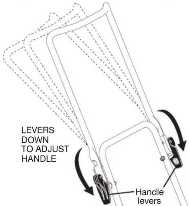
"QUICK RELEASE" HANDLES
The upper handle may be adjusted to three (3) different height positions.
- Loosen both handle levers enough to allow the upper handle to pivot to the desired adjustment position.
- Tighten both handle levers securely.
SERVICE AND ADJUSTMENTS
TO REMOVE / REPLACE DRIVE BELT
FRONT WHEEL DRIVE MODELS:
"STANDARD" OR "DUAL BAIL" MODELS:
- Remove drive cover. Remove belt from gearcase pulley by pushing down on pulley and rolling belt off it.
- Turn lawn mower on its side. See engine manual for proper direction of turning over the engine.
NOTE: Before tipping lawn mower to remove drive belt, empty fuel tank by running engine until fuel tank is empty.
- Remove blade.
- Remove belt from engine pulley on crankshaft.
• Install new belt by reversing above steps.
NOTE: Always use factory approved belt to assure fit and long life.
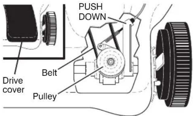
"AUTO WALK" or "VARI-SPEED" MODELS:
- Remove drive cover and belt keeper.
- Remove belt from gearcase pulley by pushing down on pulley and rolling belt off it.
- Turn lawn mower on its side. See engine manual for proper direction of turning over the engine.
NOTE: Before tipping lawn mower to remove drive belt, empty fuel tank by running engine until fuel tank is empty.
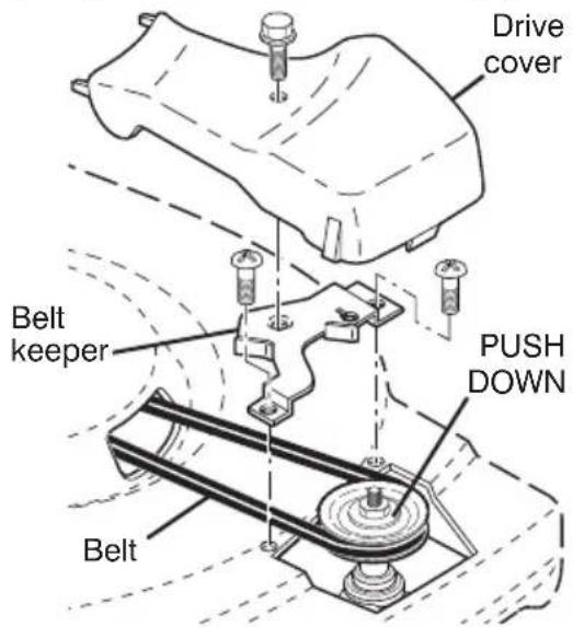
- Remove blade and debris shield.
- Remove belt from engine pulley on crankshaft.
• Install new belt by reversing above steps.
NOTE: Always use factory approved belt to assure fit and long life.
MODELS WITH GEARCASE-MOUNTED BELT KEEPER:
- Remove drive cover and belt keeper.
- Remove belt from gearcase pulley.
- Turn lawn mower on its side. See engine manual for proper direction of turning over the engine.
NOTE: Before tipping lawn mower to remove drive belt, empty fuel tank by running engine until fuel tank is empty.
- Remove blade and blade adapter.
- Remove belt from pulley of blade adapter.
• Install new belt by reversing above steps.
NOTE: Always use factory approved belt to assure fit and long life.


SERVICE AND ADJUSTMENTS
REAR WHEEL DRIVE MODELS:
MODELS WITH IDLER ASSEMBLY:
- Disconnect spark plug wire from spark plug and place wire where it cannot come in contact with plug.
- Remove screws retaining drive cover (not shown); and remove drive cover from lawn mower housing.
- Remove drive cable from anchor, then detach it and return spring (if equipped) from idler arm assembly.
- Remove idler arm assembly from housing by removing hex nut; then remove drive belt from drive pulley, belt keepers and idler arm assembly.

- Turn lawn mower on its side. See engine manual for proper direction of turning over the engine.
NOTE: Before tipping lawn mower to remove drive belt, empty fuel tank by running engine until fuel tank is empty.
- Use a wood block between blade and mower hous ing to prevent blade from turning when re moving blade bolt.
NOTE: Protect your hands with gloves and/or wrap blade with heavy cloth.
- Remove blade bolt.
- Remove blade, attaching hardware (bolt, lock wash er, hardened wash er) and blade adapter.
- Remove drive belt from engine pulley; discard old belt.
• Install new belt by reversing above steps.
NOTE: Always use factory approved belt to assure fit and long life.
- The recommended tightening torque is 35–40 ft. lbs.
IMPORTANT: Blade bolt is grade 8 heat treated.

MODELS WITH GEARCASE-MOUNTED BELT KEEPER:
• Remove drive cover.
- Remove spring and belt keeper.
- Remove belt from gearcase pulley.
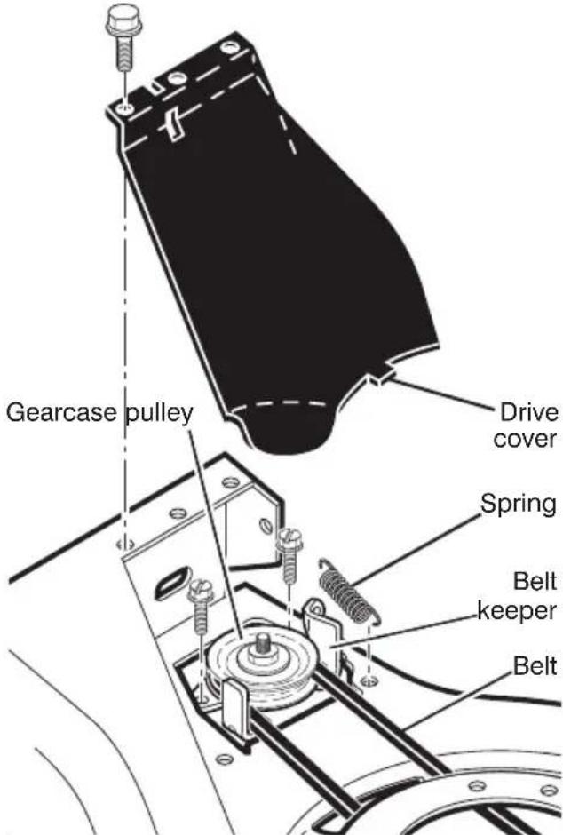
- Turn lawn mower on its side. See engine manual for proper direction of turning over the engine.
NOTE: Before tipping lawn mower to remove drive belt, empty fuel tank by running engine until fuel tank is empty.
- Remove blade and blade adapter.
- Remove belt from blade adapter.
SERVICE AND ADJUSTMENTS
- Position the blade adapter on the engine crank shaft. Be sure key in adapter and crankshaft keyway are aligned; and that the drive belt is inside the tabs of the belt retainer.

- Route the other end of the new drive belt through hole in housing.
- Return mower to upright po si tion.
• Install new belt on gearcase pulley. - Reinstall belt keeper and spring.
- Reinstall drive cover.
NOTE: Always use factory approved belt to assure proper fit and long life.
- Turn lawn mower on its side with air filter and car bu re tor down.
- Reinstall blade and blade adapter.
HI-VAC MODELS:
- Disconnect spark plug wire from spark plug and place wire where it cannot come in contact with plug.
- Remove screws retaining drive cover and remove drive cover from lawn mower housing.
- Remove drive cable from anchor, then detach it and return spring from idler arm assembly.
18" (45cm) HI-VAC MODELS:
Drive cable anchor Return spring
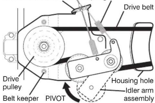
21" (53cm) HI-VAC MODELS:
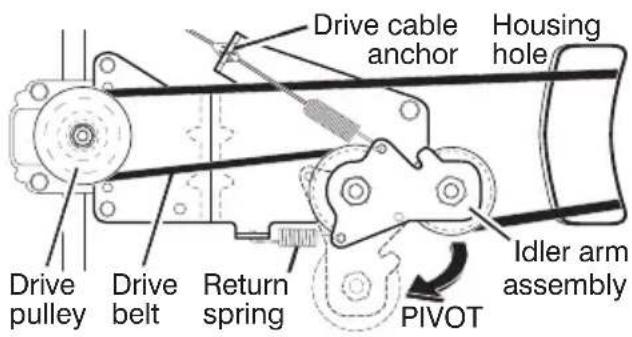
- Pivot idler arm assembly to slacken drive belt, then remove drive belt from drive pulley, belt keepers and idler arm.
- Turn lawn mower on its side. Make sure air filter and carburetor are up.
NOTE: Before tipping lawn mower to remove drive belt, empty fuel tank by running engine until fuel tank is empty.
- Remove screw securing debris shield. Note that the debris shield has a tab which fits into a gap in the housing.

- Use a wood block between blade and mower hous ing to prevent blade from turning when re moving blade bolt.
NOTE: Protect your hands with gloves and/or wrap blade with heavy cloth.
- Remove blade bolt.
- Remove blade, attaching hardware (bolt, lock wash er, hardened wash er), blade adapter and debris shield as one assembly.
- Remove drive belt from blade adapter and debris shield; discard old belt.
SERVICE AND ADJUSTMENTS
TO REPLACE DRIVE BELT
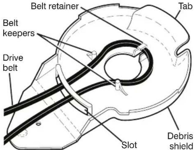
- Place new drive belt in the belt retainer of the debris shield. Be sure to route belt between belt keepers and through slot as shown.
18" (45cm) HI-VAC MODELS:

21" (53cm) HI-VAC MODELS:
-
Route the other end of the new drive belt through hole in housing.
-
Reattach debris shield to housing with screw previously removed. Be sure tab of debris shield is in gap of housing.
-
Position blade on the blade adapter aligning the two (2) holes in the blade with the raised lugs on the adapter.
-
Be sure the trailing edge of blade (opposite sharp edge) is up toward the engine as shown.
-
Install the blade bolt with the lock washer and hardened washer into blade adapter and crankshaft.
-
Use block of wood between blade and lawn mower housing and tighten the blade bolt, turning clockwise.
- The recommended tightening torque is 35–40 ft. lbs.
IMPORTANT: Blade bolt is grade 8 heat treated.
-
Return mower to upright position.
-
Install new drive belt into idler arm assembly, then around the drive pulley. Be sure belt is inside of belt keepers.
NOTE: Pulling on the drive belt (to install it on the drive pulley) will cause the other end of the belt to free itself from the debris shield retainer and come into contact with the pulley end of the blade adapter.
-
Reattach drive cable and return spring to the idler arm assembly, then reattach drive cable to anchor.
-
Reattach drive cover with screws previously removed.
-
Connect spark plug wire to spark plug.
22PLUS REAR WHEEL DRIVE MODELS:
-
Remove screws securing rear baffle.
-
Turn lawn mower on its side with air filter and car bu re tor down.
NOTE: Before tipping lawn mower to remove drive belt, empty fuel tank by running engine until fuel tank is empty.
- Remove rear baffle from mower.

SERVICE AND ADJUSTMENTS
- Remove blade bolt, lockwasher, hardened washer and blade.
- Remove debris shield.
- Remove gearcase belt keeper.
- Remove drive belt.
TO REPLACE DRIVE BELT
- Place new drive belt on gearcase pulley.
NOTE: Always use factory approved belt to assure proper fit and long life.
- Reinstall gearcase belt keeper. Be sure the new drive belt is inside the tabs of the gearcase belt keeper.
- Position the blade adapter on the engine crank shaft. Be sure key in adapter and crankshaft keyway are aligned; and that the drive belt is inside the tabs of the belt retainer.
- Place rear baffle in mower housing.
- Reinstall debris shield.
- Reinstall blade.
- Return mower to upright po si tion.
- Reinstall rear baffle screws.
ENGINE
CARBURETOR
The carburetor has been preset at the factory.
- The air filter must be assembled to the car bu re tor when running engine. See the ADJUSTMENT section of your engine manual for further instructions.
ENGINE SPEED
The engine speed has been factory set.
THROTTLE CONTROL
If it becomes necessary to adjust or replace the throttle control, see the ADJUSTMENT section of your engine manual.
STORAGE
Immediately prepare your lawn mower for storage at the end of the season or if the unit will not be used for 30 days or more.
CAUTION: Never store the lawn mower with gaso line in the tank inside a building where fumes may reach an open flame or spark. Allow the engine to cool before storing in any enclosure.
LAWN MOWER
When lawn mower is to be stored for a period of time, clean it thor oughly, remove all dirt, grease, leaves, etc. Store in a clean, dry area.
- Clean entire lawn mower (See “CLEANING” in the Maintenance section of this manual).
- Lubricate as shown in the Main tenance section of this manual.
- Be sure that all nuts, bolts, screws, and pins are securely fastened. Inspect moving parts for damage, breakage and wear. Replace if necessary.
- Touch up all rusted or chipped paint surfaces; sand lightly before painting.
HANDLE
Your handle may be folded for storage as shown.
- Squeeze the bottom ends of lower handle towards each other until handle clears the handle brackets and swing handles forward over mower. - Loosen upper handle mounting hardware enough to allow upper handle to be folded back.
IMPORTANT: When folding handles for storage or transportation, be sure to fold handles as shown or you may damage the control cables.
3 POSITION HANDLES
When setting up your handle from the storage position, the lower hand dle will require manually locking into the mowing position.
3 POSITION "EZ"

STORAGE
"QUICK-RELEASE" HANDLES
You can fold your lawn mower handle for storage.
ON 18" HI-VAC MODELS ONLY:
- Loosen the two (2) handle levers on sides of the upper handle and allow handle to fold down to the rear.
- Move height adjustment lever forward to raise mower to highest position.
- Loosen handle bolts (on both sides), then pivot entire handle as sem bly forward and allow it to rest on mower.

ON ALL OTHER MODELS:
- Loosen the two "quick-adjust" handle knobs on sides of the upper handle and allow handle to fold down to the rear.
- Loosen the two "standard" handle knobs on sides of the lower handle and pivot entire handle as sem bly forward and allow it to rest on mower.
- Reinstall "standard" knobs and carriage bolts to lower handle or handle brackets for safe keeping.
- When setting up your handle from the storage position, the lower handle will automatically lock into the mowing position.
IMPORTANT: When folding the handle for storage or transportation, be sure to fold the handle as shown or you may damage the control cables.
STORAGE

ENGINE
FUEL SYS TEM
IMPORTANT: It is important to prevent gum deposits from forming in essential fuel system parts such as carburetor, fuel filter, fuel hose, or tank during storage. Alcohol blended fuels (called gasohol or using ethanol or methanol) can attract moisture which leads to separation and formation of acids during storage. Acidic gas can damage the fuel system of an engine while in storage.
- Drain the fuel tank.
- Start the engine and let it run until the fuel lines and car bu re tor are empty.
- Never use engine or carburetor cleaner products in the fuel tank or permanent damage may occur.
- Use fresh fuel next season.
NOTE: Fuel stabilizer is an acceptable alternative in min i mizing the formation of fuel gum deposits during stor age. Add stabilizer to gasoline in fuel tank or storage container. Always follow the mix ratio found on stabilizer container. Run engine at least 10 min utes after adding stabilizer to allow the stabilizer to reach the car bu re tor. Do not drain the gas tank and car bu re tor if using fuel stabilizer.
ENGINE OIL
Drain oil (with engine warm) and replace with clean oil. (See "ENGINE" in the Maintenance section of this manual).
CYLINDER
- Remove spark plug.
- Pour one ounce (29 ml) of oil through spark plug hole into cylinder.
- Pull starter handle slowly to dis trib ute oil.
- Replace with new spark plug.
BATTERY (IF EQUIPPED)
Disconnect the battery from the engine connector and charge battery 48 hours.
OTHER
- Do not store gasoline from one sea son to another.
- Replace your gasoline can if your can starts to rust. Rust and/or dirt in your gasoline will cause problems.
- If possible, store your unit indoors and cover it to protect it from dust and dirt.
- Cover your unit with a suitable protective cover that does not retain moisture. Do not use plastic. Plastic cannot breathe, which allows con den sa tion to form and will cause your unit to rust.
IMPORTANT: Never cover mower while engine and exhaust areas are still warm.
CAUTION: Never store the lawn mower with gaso line in the tank in side a building where fumes may reach an open flame or spark. Allow the engine to cool before storing in any en clo sure.
TROUBLESHOOTING
See appropriate section in manual unless directed to an authorized Service Center.
| PROBLEM | CAUSE | CORRECTION |
| Does not start 1.2. Out of fuel. 2.3. Stale fuel. 3.4. Water in fuel. 4.5. Spark plug wire is 5.6. Bad spark plug. 6.7. Loose blade or blade adapter.8. Control bar in position.9. Control bar defective.10. Fuel valve lever (if so equipped) in OFF position.11. Weak battery (if equipped).12. Disconnected connector (if equipped).13. Blown fuse (if equipped). | Dirty air filter. 1. Clean/replace air filter.Fill fuel tank.Drain fuel tank and refill tank with fresh, clean gasoline.Drain fuel tank and refill tank with fresh, clean gasoline.5. Connect wire to plug. disconnected.6. Replace spark plug.7. Tighten blade bolt or blade adapter.8. Control bar in position.9. Control bar defective.10. Fuel valve lever (if so equipped) in OFF position.11. Weak battery (if equipped).12. Disconnected battery connector (if equipped).13. Replace fuse. | air filter. |
| Loss of power dragging in heavy grass.2. Cutting too much grass.3. Dirty air filter.4. Buildup of grass, leaves, and trash under mower.5. Too much oil in engine.6. Walking speed too fast. | 1. Rear of lawn mower housing or cutting blade handling.2. Raise cutting height.3. Clean/replace air filter.4. Clean underside of mower housing.5. Check oil level.6. Cut at slower walking speed. | 1. Raise cutting height. |
| Poor cut – uneven2. Wheel heights height.and trash under | 1. Worn, bent or loose blade. blade bolt.uneven.2. Set all wheels at same3. Buildup of grass, leaves mower. | 1. Replace blade. Tighten at same3. Clean underside of |
| Excessive vibration2. Bent engine center. | 1. Worn, bent or loose blade. blade bolt.2. Contact a qualified service | 1. Replace blade. Tighten at same |
| Starter rope hard to pull pulling starter rope.2. Bent engine center.3. Blade adapter 4. Blade dragging grass or to hard surface. | 1. Engine flywheel brake is on when control bar is released.2. Contact a qualified servicebroken.3. Replace blade adapter.4. Move lawn mower to cut | 1. Depress control bar to upper handle before |
TROUBLESHOOTING (continued)
See appropriate section in manual unless directed to an authorized Service Center.
| PROBLEM | CAUSE | CORRECTION |
| Grass catcher 1. not filling 2. Lift on blade worn off. 2. Replace blade.(If so equipped) 3. Catcher not venting air. 3. Clean grass catcher. | Cutting height too low. 1. Raise cutting height. | cutting height. |
| Hard to push 1. Grass is too high or wheel 1. Raise cutting height.height is too low.2. Rear of lawn mower 2. Raise rear of lawn mowerhousing or cutting blade housing one (1) settingdragging in grass. higher.3. Grass catcher too full. 3. Empty grass catcher.4. Handle height position not 4. Adjust handle height to suit.right for you. | ||
| Loss of driveor slowing ofdrive speed4. “Loose” drive | 1. Belt wear.2. Belt off of pulley.3. Drive cable worn or broken.control system. 4. Adjust drive control. | Check/replace drive belt.Check/reinstall drive belt.Replace drive cable. |
natural_image
Top-down schematic of a mechanical component with four wheels and central hub (no text or symbols)


- SELF-PROPELLED ROTARY LAWN MOWER
- TABLE OF CONTENTS
- SAFETY RULES
- CHILDREN
- GENERAL OPERATION
- DO:
- DO NOT:
- SAFE HANDLING OF GASOLINE
- GENERAL SERVICE
- TO REMOVE LAWN MOWER FROM CARTON
- THINGS TO KNOW BE FORE YOU ASSEMBLE OR OPERATE YOUR LAWN MOW ER
- Do I have a side or rear discharge lawn mower?
- Do I have a mulching lawn mower?
- What is the right and left side of the lawn mower?
- What kind of engine is on my lawn mower?
- ASSEMBLY
- HOW TO SET UP YOUR MOW ER UNFOLD HANDLE
- "QUICK RELEASE" HANDLES (ON 18" HI-VAC MODELS ONLY)
- "QUICK RELEASE" HANDLES (ALL OTHER MODELS)
- POSITION / "ADJUSTABLE" HANDLES
- POSITION "EZ" HANDLES
- POSITION "QUICK" HANDLES
- ALL HANDLES
- INSTALL STARTER ROPE (MODELS EQUIPPED WITH T-KNOB)
- INSTALL REAR WHEELS ("HIGH WHEEL" MOWERS ONLY)
- AS SEM BLE GRASS CATCHER (REAR DISCHARGE MOWERS ONLY)
- "FABRIC TOP" GRASS CATCHERS
- ALL GRASS CATCHERS
- SPARK PLUG BOOT
- TO PRE PARE BATTERY (ELECTRIC START MODELS ONLY)
- OPERATION
- HOW TO USE YOUR LAWN MOWER ENGINE SPEED CONTROL
- MODELS WITH REMOTE THROTTLE
- "MANUAL" ADJUSTMENT
- "QUICK" ADJUSTMENT
- "QUICK-PIN" ADJUSTMENT
- "DUAL POINT" ADJUSTMENT
- "SINGLE POINT" ADJUSTMENT
- TO CONVERT MOWER:
- "REAR DISCHARGE ONLY" MOWERS
- "SIDE DISCHARGE ONLY" MOWERS MULCHER PLATE
- MULCHER PLUG TYPE "A"
- MULCHER PLUG TYPE "B"
- "MULTI-CUT" MOWERS
- REAR BAGGING
- "REAR DOOR PROP" (IF EQUIPPED) (22PLUS MODELS ONLY)
- SIDE DISCHARGING
- SIMPLE STEPS TO REMEMBER WHEN CONVERTING YOUR "MULTI-CUT" LAWN MOWER:
- FOR MULCHING -
- FOR REAR BAGGING -
- TO EMPTY GRASS CATCHER (REAR DISCHARGE AND MULTI-CUT MODELS)
- 18" (45cm) HI-VAC MODELS:
- TO EMPTY GRASS CATCHER
- 21" (53cm) HI-VAC MODELS:
- SIMPLE STEPS TO REMEMBER WHEN CONVERTING YOUR 21" HI-VAC:
- OPERATOR PRESENCE CONTROL BAR (ALL MODELS)
- DRIVE CONTROL
- "STANDARD" DRIVE CONTROL
- "DUAL BAIL" DRIVE CONTROL
- "AUTOWALK" DRIVE CONTROL
- FRONT WHEEL DRIVE MODELS ONLY:
- "VARI-SPEED" DRIVE CONTROL
- BEFORE STARTING EN GINE
- FILL ENGINE WITH OIL
- FILL GASOLINE TANK
- TO STOP ENGINE
- TO START ENGINE
- MOWING TIPS
- FOR MULCHING MOWERS ONLY - MULCHING MOWING TIPS
- GENERAL RECOMMENDATIONS
- BEFORE EACH USE
- LUBRICATION
- MAINTENANCE
- LAWN MOWER
- TIRES
- BLADE CARE
- TO REMOVE BLADE
- TO REPLACE BLADE
- TO SHARPEN BLADE
- BLADES WITH ROUND HOLE:
- DRIVE WHEELS
- GEAR CASE
- ENGINE
- TO CHANGE ENGINE OIL (SEE ENGINE MANUAL)
- AIR FILTER
- IN-LINE FUEL FILTER (KOHLER or B&S PRO / ENDURANCE ENGINES ONLY)
- MUFFLER
- SPARK PLUG
- CLEANING
- CLEAN UNDER DRIVE COVER
- WATER WASHOUT FEATURE (IF EQUIPPED)
- GRASS CATCHER (IF EQUIPPED)
- SERVICE AND ADJUSTMENTS
- ⚠️CAUTION: Before performing any service or adjustments:
- REAR DEFLECTOR
- DISCHARGE DEFLECTOR (IF EQUIPPED)
- TO ADJUST HANDLE
- "QUICK RELEASE" HANDLES
- TO REMOVE / REPLACE DRIVE BELT
- FRONT WHEEL DRIVE MODELS:
- MODELS WITH GEARCASE-MOUNTED BELT KEEPER:
- REAR WHEEL DRIVE MODELS:
- HI-VAC MODELS:
- TO REPLACE DRIVE BELT
- 22PLUS REAR WHEEL DRIVE MODELS:
- CARBURETOR
- ENGINE SPEED
- THROTTLE CONTROL
- STORAGE
- HANDLE
- POSITION HANDLES
- "QUICK-RELEASE" HANDLES
- ON 18" HI-VAC MODELS ONLY:
- ON ALL OTHER MODELS:
- FUEL SYS TEM
- ENGINE OIL
- CYLINDER
- BATTERY (IF EQUIPPED)
- OTHER
- TROUBLESHOOTING
- TROUBLESHOOTING (continued)
Brand : POULAN
Model : Pro PR675AWD
Category : Lawn mower