Ernie - Uncategorized Habitat - Free user manual and instructions
Find the device manual for free Ernie Habitat in PDF.


User questions about Ernie Habitat
0 question about this device. Answer the ones you know or ask your own.
Ask a new question about this device
Download the instructions for your Uncategorized in PDF format for free! Find your manual Ernie - Habitat and take your electronic device back in hand. On this page are published all the documents necessary for the use of your device. Ernie by Habitat.
USER MANUAL Ernie Habitat
Assembly Instructions - Please keep for future reference
ERNI-BC-AW16-A
Dimensions
Width - 70cm
Depth - 33cm
Height - 200cm

natural_image
Isometric line drawing of a multi-level shelving unit with no text or symbolsTools required

Important – Please read these instructions before assembly
If you need help or have damaged or missing parts, email:
customerservices@habitat.co.uk or call: 0344 499 4686
habitat


Safety and Care Advice
Important – Please read these instructions fully before starting assembly
Check you have all the components and tools listed on the front cover and pages 2 - 3.
Remove all fittings from the plastic bags and separate them into their groups.
Keep children and animals away from the work area, small parts could choke if swallowed.
Make sure you have enough space to layout the parts before starting.
Do not stand or put weight on the product, this could cause damage.
Assemble the item as close to its final position (in the same room) as possible.
Do not place furniture directly in front of radiators, fi res or any other source of heat.
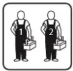
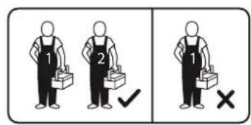
Parts of the assembl y will be easier with 2 people.
Assemble on a soft level surface to avoid damaging the unit or your floor.
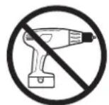
We do not recommend the use of power drill/ drivers for inserting screws, as this could
damage the unit. Only use hand screwdrivers.
Dispose of all packaging carefully and responsibly.
General care and maintenance
Only clean using a damp cloth and mild detergent, do no use bleach or abrasive cleaners.
From time to time check that there are no loose screws on this unit.
This product should not be discarded with household waste. Take to your local authority waste disposal centre.
Cleaning and care of high gloss surfaces
Regular dusting with a dry cloth will keep your units clean.
Clean marks with a damp cloth.
Do not allow spillages to stay on the surface for long.
To remove stubborn stains, wipe over with a damp cloth and washing up liquid.
Do not use abrasive cleaners.
Do not clean with products containing the following: Acetone,
(e.g nail varnish remover). Ammonia (e.g.bleach). or Sodium hydroxide (e.g. Caustic soda, drain and oven cleaners).
In the event of accidental contact with aggressive cleaners, rinse thoroughly with water.
Use place mats to protect the surface from moisture and heat.
Maximum weight limit
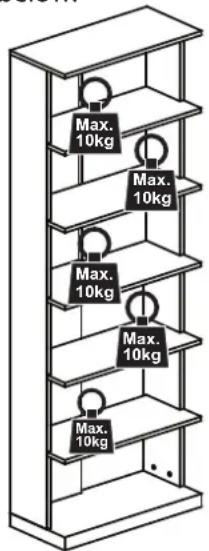
Important: Rec omended maximum load for each shelf is shown below.
text_image
Max. 10kg Max. 10kg Max. 10kg Max. 10kg Max. 10kgGeneral information
If for any reason you should have problems with your Habitat product, please contact the store from which you purchased it.
Please retain your receipt as proof of purchase.
If you have any comments or suggestions regarding this product, assembly instructions or service
received, please contact the store or Habitat Head Office via its web site: www.habitat.co.uk
or write directly to: Habitat Retail Ltd. 489-499 Avebury Boulevard, Milton Keynes MK9 2NW
Please check you have all the panels listed below

Note: There are 'Batch Code' lables where shown on the indicated items, these should be retained.
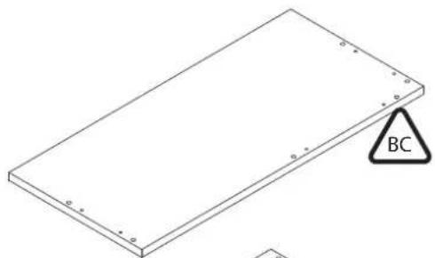
natural_image
Isometric view of a rectangular plate with a warning sign labeled 'BC' (no text or symbols on the plate itself)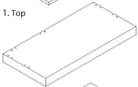
natural_image
Isometric line drawing of a rectangular block with labeled points (no text or symbols beyond label)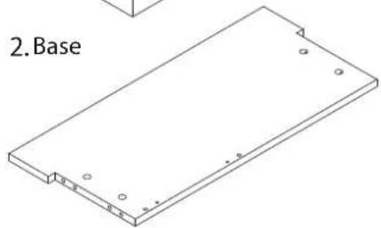
natural_image
Isometric line drawing of a rectangular plate with mounting holes and a labeled '2. Base' (no other text or symbols)- Middle shelf
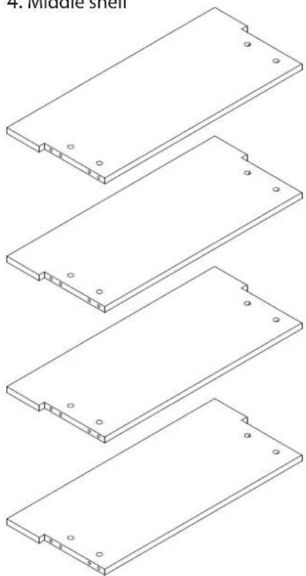
natural_image
Isometric line drawing of four rectangular metal plates with mounting holes and mounting holes (no text or symbols)5.Shelf
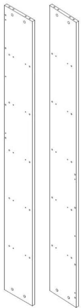
natural_image
Two identical 3D panel structures with mounting holes and scattered circular features, no text or symbols present.- Side
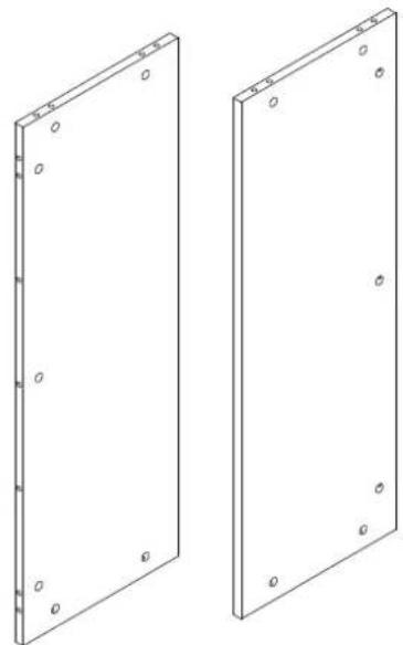
natural_image
Two identical isometric views of a rectangular panel with mounting holes and mounting holes (no text or symbols)- Back
text_image
1 of 1Components - Fittings
If you need help or have damaged or missing parts, email: customerservices@habitat.c o.uk or call: 0344 499 4686
Please check you have all the fi xings listed below
text_image
1 of 1Note: The quantities bebw are the correct amount to complete the assembly. In some cases more fittings may be supplied than are required.

text_image
0 5 10 15 20 25 30 35 40 45 50 55 60 65 70 75 80 85 90 95 100 105 11 0 115 120A 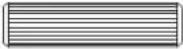 | B  | C  |
| Wooden dowels x44 | Locking cams x42 | Covercap oak/walnut x42 |
D  | E 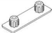 | F 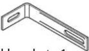 |
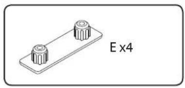
| Metal dowels x42 | Feet x4 | Wall bracket x1 |
G  | ||
| 15mm Screw x1 |
Assembly Instructions
Step 1
natural_image
Technical line drawing of a mechanical component with two cylindrical features on a base plate (no text or symbols)- Base
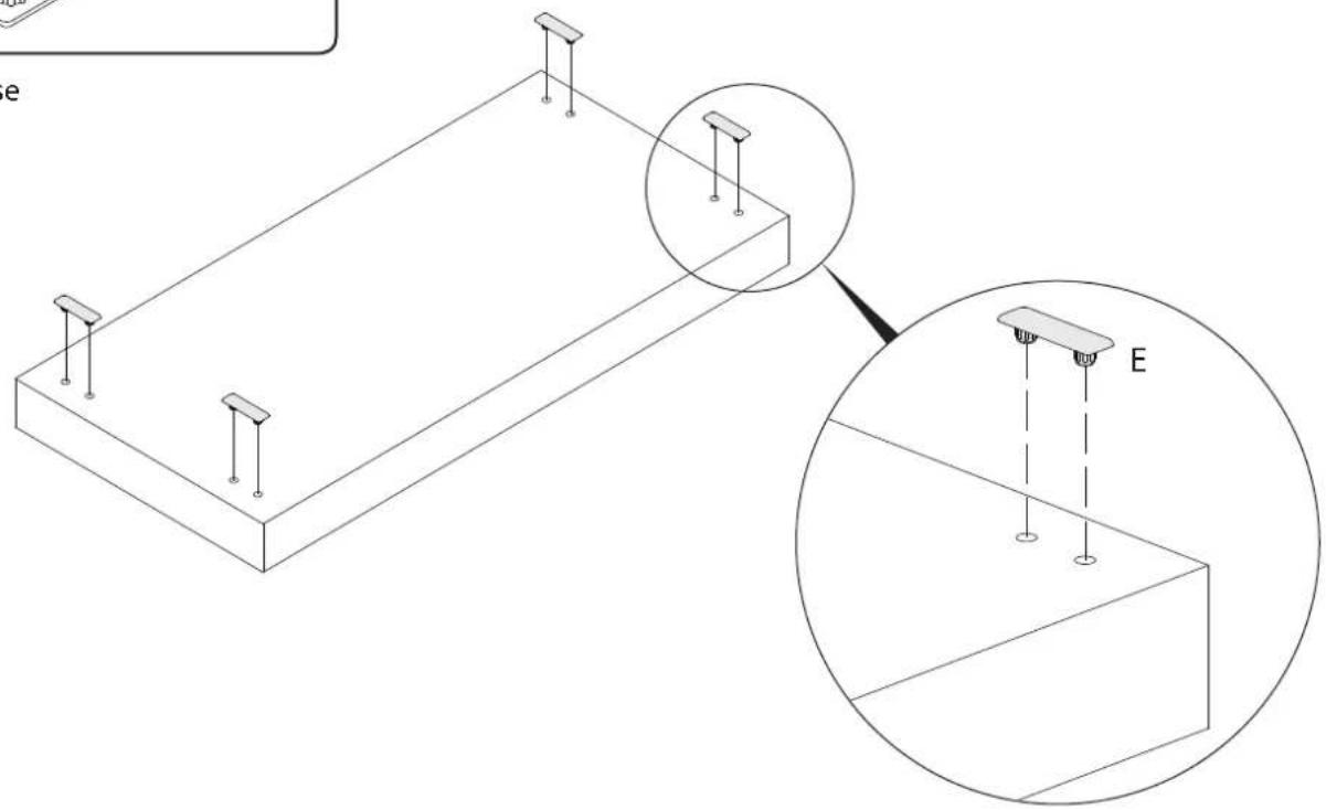
natural_image
Isometric technical diagram of a rectangular structure with supports and a magnified inset showing a labeled component 'E' (no text or symbols present)Step 2
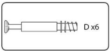
text_image
D x6- Base
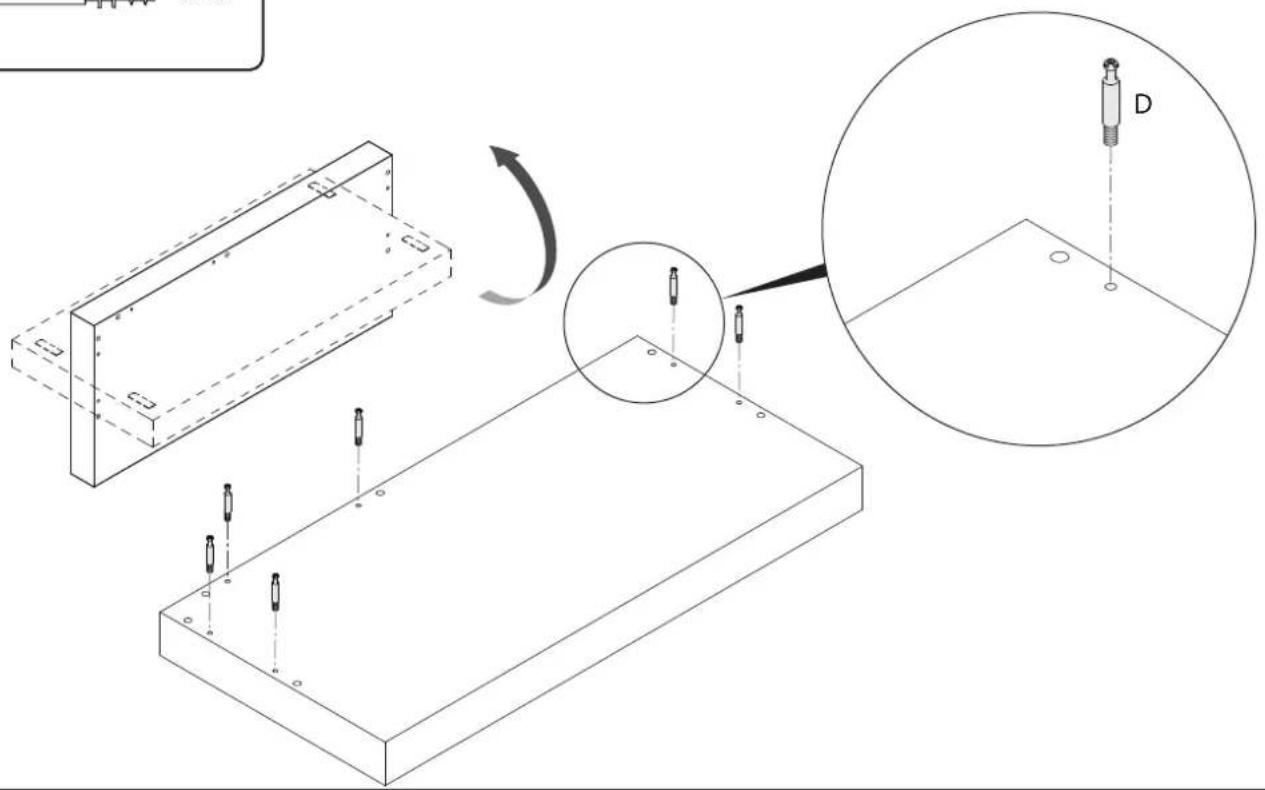
text_image
Technical diagram showing assembly of a rectangular component with a magnified inset highlighting a D-shaped component.Assembly Instructions
Step 3
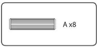
text_image
A x8- Side
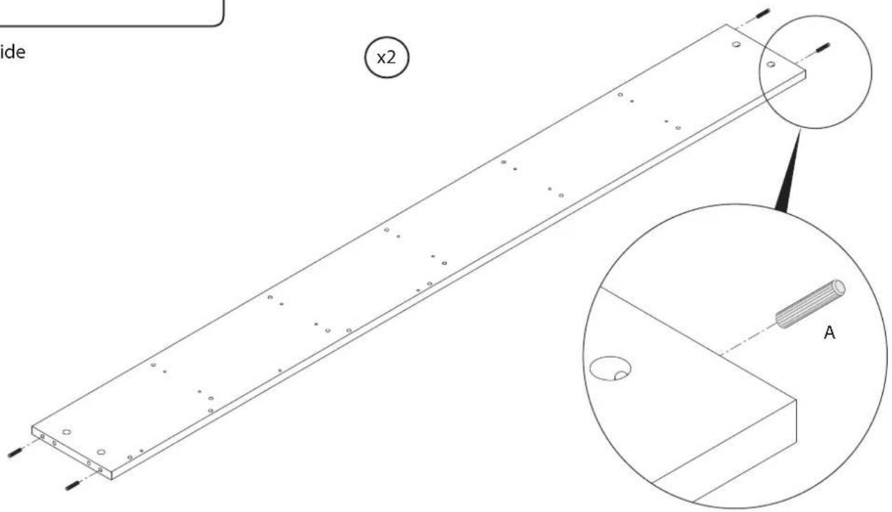
text_image
x2 AStep 4
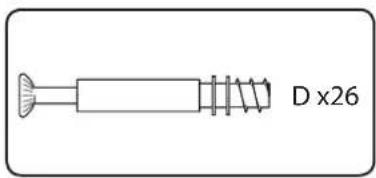
text_image
D x26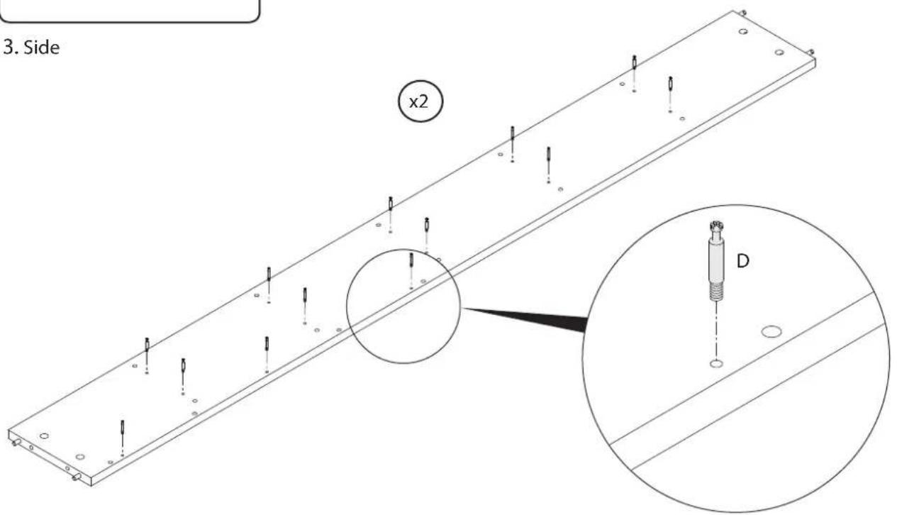
text_image
3. Side x2 DAssembly Instructions
Step 5
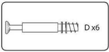
text_image
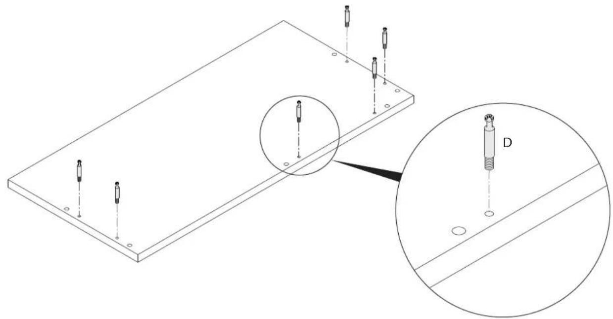
D x6- Top
natural_image
Technical line drawing of a mechanical assembly with two views (diameter and height) showing internal components, no text or symbols present.Step 6
text_image
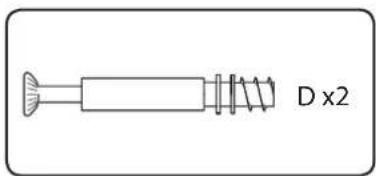
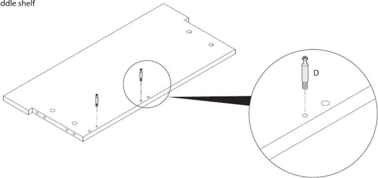
D x2- Middle shelf
text_image
ddle shelf DAssembly Instructions
Step 7
text_image
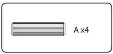
A x4- Middle shelf
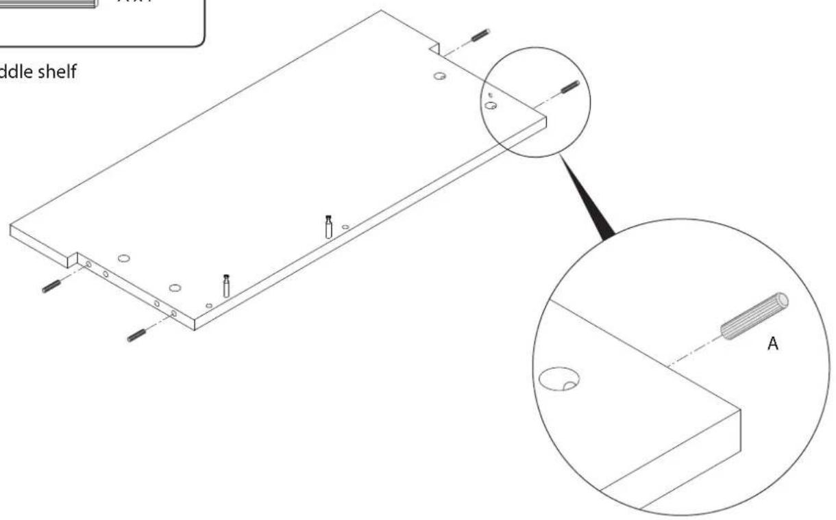
text_image
Middle shelf AStep 8
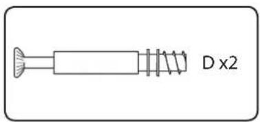
natural_image
Simple line drawing of a screw with threaded shaft and threaded end (no text or symbols)- Middle shelf
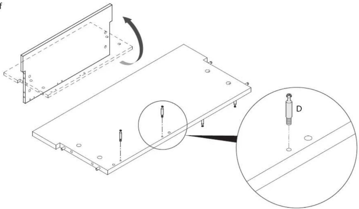
natural_image
Technical diagram showing a mechanical assembly with a component being inserted, including a magnified inset of a screw and a labeled component 'D' (no text or symbols present)Assembly Instructions
Step 9
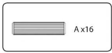
text_image
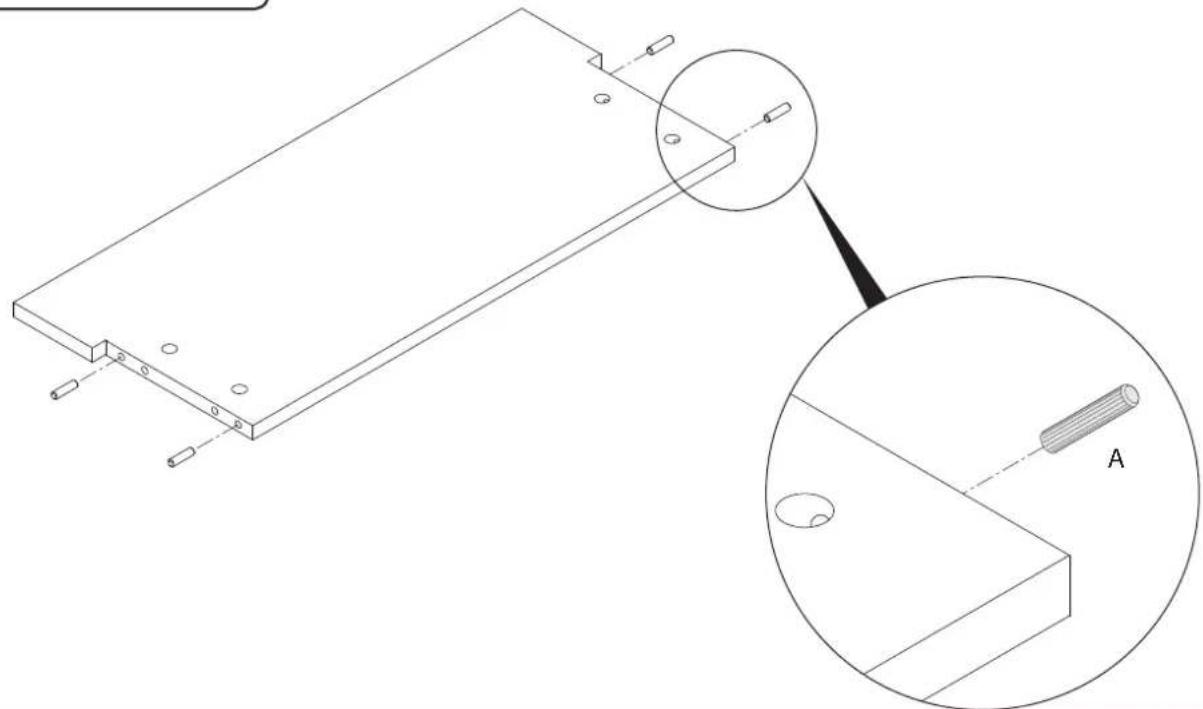
A x16
- Shelf
natural_image
Technical line drawing of a mechanical assembly with an inset showing a component labeled 'A' (no text or symbols present)Step 10
text_image
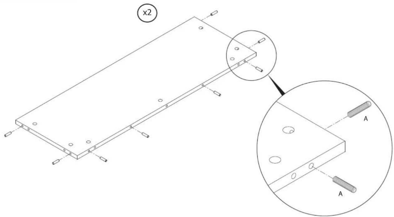
A x16- Back
text_image
x2 A AAssembly Instructions
Step 11
text_image
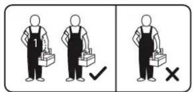
Diagram showing two scenarios of a person holding boxes, one marked with a checkmark and the other with an 'X' symbol.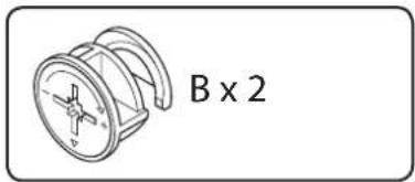
text_image
B x 2
text_image
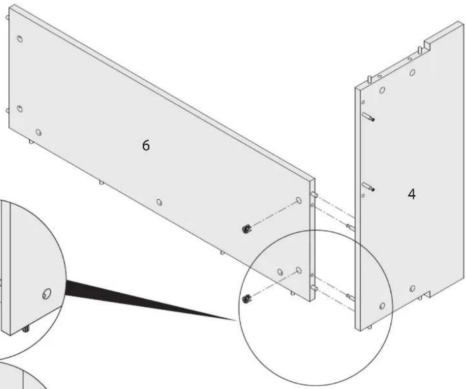
6 4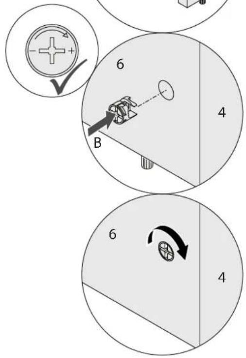
text_image
6 B 4 6 4Assembly Instructions
Step 12
text_image
Diagram showing two groups of workers with different positions and checkmark indicators, likely illustrating a task or process.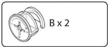
text_image
B x 2
text_image
Technical diagram illustrating a mechanical assembly with numbered components and tool application stepsAssembly Instructions
Step 13
text_image
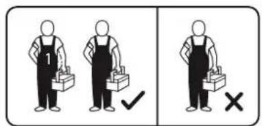
Diagram showing two groups of workers with checkmarks and a cross symbol indicating incorrect or incorrect conditions.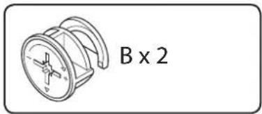
natural_image
Simple line drawing of a mechanical device with no text or symbols
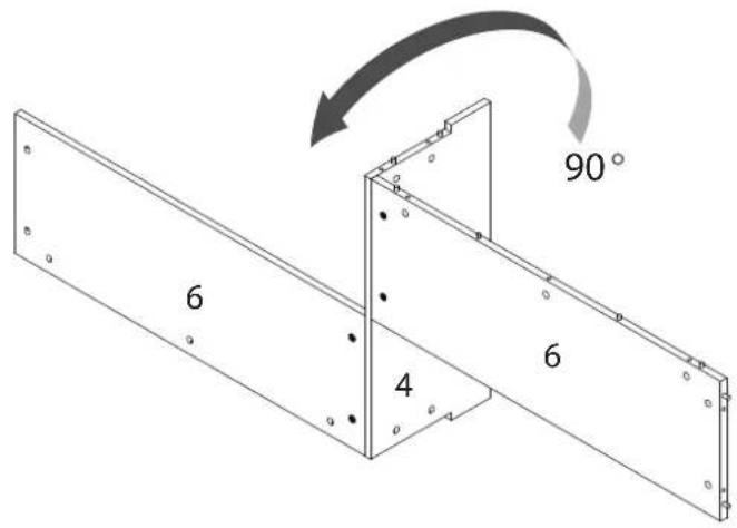
text_image
6 4 6 90°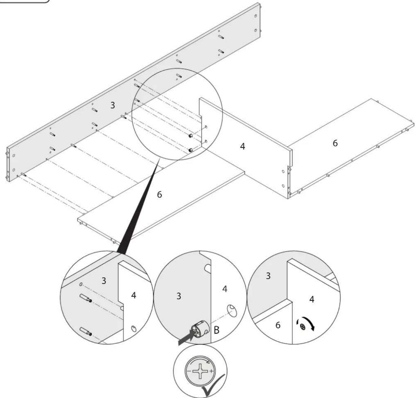
text_image
Technical diagram showing assembly steps of a metal frame with numbered components and directional arrows indicating motion or movement.Assembly Instructions
Step 14
text_image
Diagram showing two scenarios of a person holding boxes, one marked with a checkmark and the other with an 'X' symbol.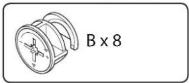
text_image
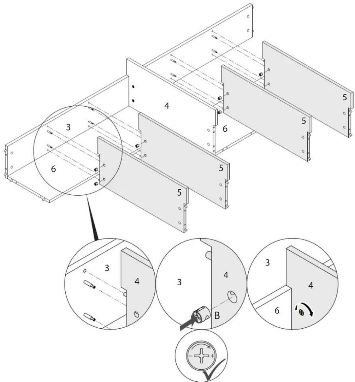
B x 8
text_image
Technical diagram showing assembly of a metal frame with numbered components and mechanical parts, including close-ups and directional arrows.Assembly Instructions
Step 15
text_image
Diagram showing three scenarios of a person holding boxes, with checkmark and cross symbols indicating correct and incorrect actions.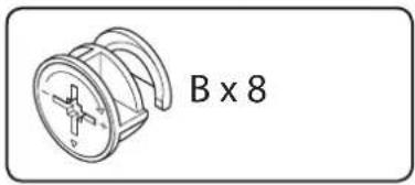
natural_image
Technical line drawing of a mechanical component with no visible text or symbols
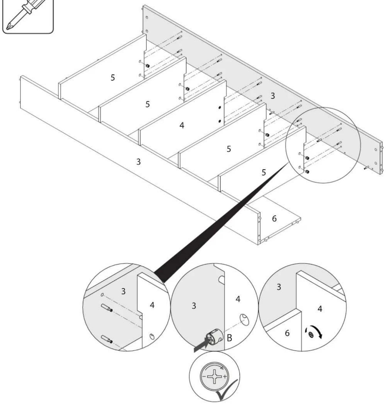
text_image
Technical diagram of a mechanical assembly with numbered components and directional arrows indicating motion or movement.Assembly Instructions
Step 16
text_image
Diagram showing three scenarios of a person holding boxes, with checkmark and cross symbols indicating correct and incorrect actions.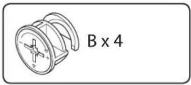
natural_image
Technical line drawing of a mechanical component with no visible text or symbols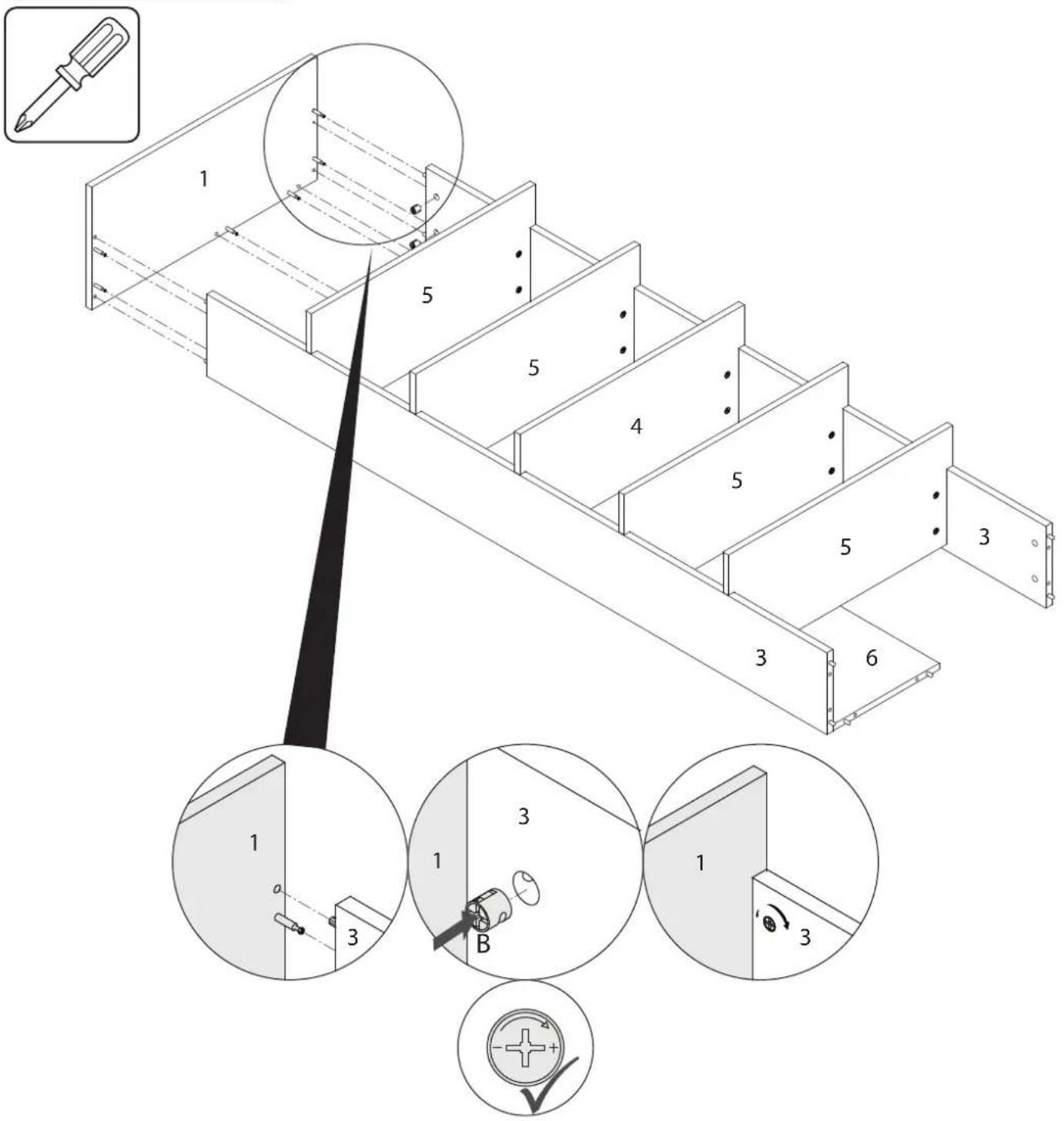
text_image
Technical diagram illustrating a staircase structure with numbered components and mechanical assembly steps, including tool insertion and component identification.Assembly Instructions
Step 17
text_image
Diagram showing two groups of workers with checkmarks and a cross symbol indicating incorrect or incorrect conditions.
natural_image
Technical line drawing of a mechanical component with no visible text or symbols
text_image
1 5 5 4 5 3 5 3 2 6 3 2 3 B 6 3 2Assembly Instructions
Step 18
text_image
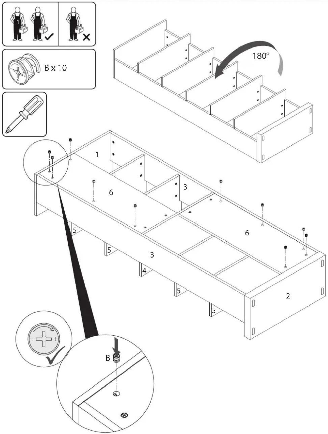
B x 10 180° 1 6 3 6 5 3 4 5 2 5 BAssembly Instructions
Step 19
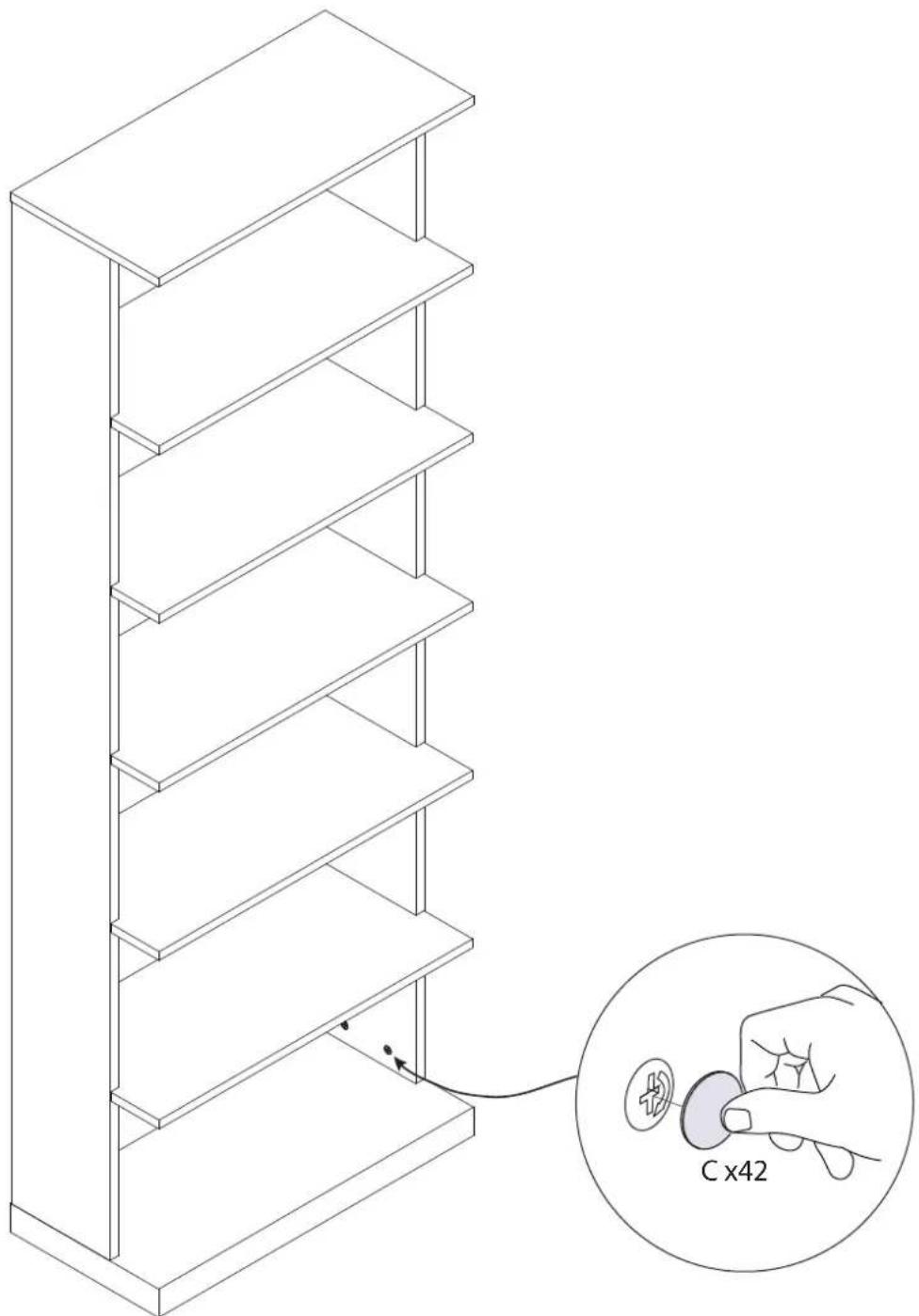
natural_image
Isometric line drawing of a multi-level shelving unit with a close-up inset showing a hand inserting a coin to a component labeled 'C x42' (no text or symbols on the main structure)Assembly Instructions
Step 20
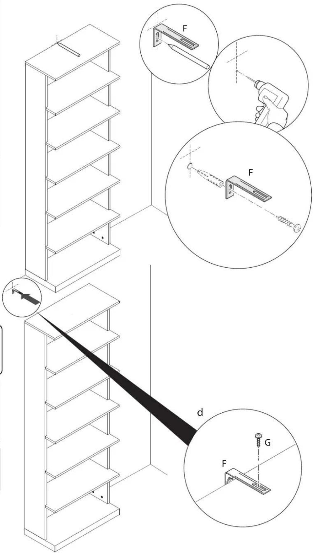
WARNING! This product must be secured to an adjacent wall with the anti-topple wall bracket kit provided.
Due to the variety of different wall types, Habitat cannot provide you with the exact fittings you will need to fix this product to your wall. You must first identify the type of wall you intend to fix the product onto and then contact your local hardware store to get the appropriate fittings.
Before drilling into walls always check to ensure that there are no hidden pipes or cables.
Please refer to the Wall Mountings & Fixings Guide at the end of this assembly/care instruction.
text_image
Diagram showing three groups of workers with different symbols: one with a checkmark and another with a cross, likely indicating correct or incorrect conditions.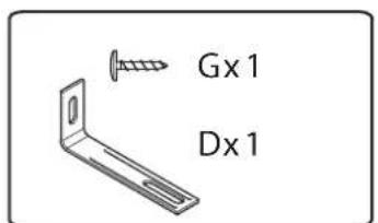
text_image
Gx1 Dx1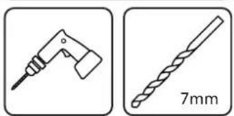
natural_image
Two technical illustrations: a hand tool and a drill bit, both with a 7mm scale indicator (no text or symbols on the devices themselves)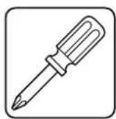
text_image
Technical diagram illustrating a staircase with force application and mechanical assembly, labeled with components F, G, and d.A Guide to - Wall Mounting & Fixings
Important note:
Wall Fixings:
- because of the variety of different wall types, Habitat cannot provide you with the exact fixings you will need to fix this product to the wall.
You must first identify the type of wall you intend to fix product onto and then contact your local hardware store to get the appropriate fixings.

Important: When drilling into walls always check that there are no hidden wires or pipes etc.
Make sure that the screws and wall plugs being used are suitable for supporting your unit. Consult a qualified tradesperson if you are unsure.
Hints:
1: General rule: ⚠️ Always use a larger screw and wall plug if you are not sure.
2: Ensure you use the recommended drill bit to match the wall plug and hole size.
3: Ensure you drill the hole horizontally, do not force the drill or enlarge the hole.
4: Take extra care when drilling high walls, ceilings and ceramic tiles. Ensure wall plugs are inserted beyond the thickness of the ceramic tiles to avoid the tiles splitting or cracking.
5: Ensure wall plugs are well fitted and are a tight fit in the drilled hole.
Types of walls
You can use one of the following types of wall plug if your walls are made of brick, breeze block, concrete, stone or wood.
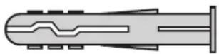
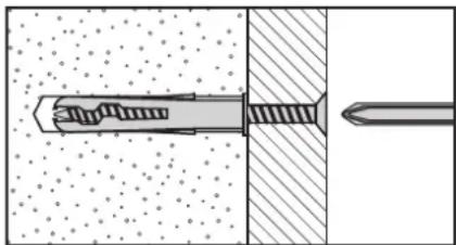
No.1 "General Purpose" wall plug
natural_image
Cross-sectional diagram of a mechanical component with internal threading and fastener, showing no text or symbolsGenerally aerated blocks should not be used to support heavy loads, use a specialist fitting in this case. For light loads, general purpose wall plugs can be used.
No.3 "Cavity Fixing" wall plug
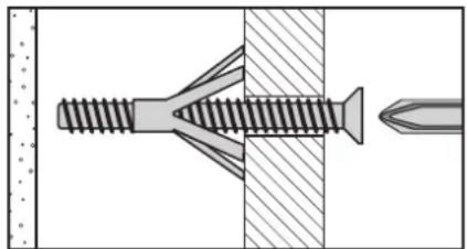
natural_image
Technical diagram of a screw fastener assembly with a pin inserted, showing internal threading and fastener connection (no text or labels)For use with plasterboard partitions or hollow wooden doors.
No.5 "Hammer Fixing" wall plug
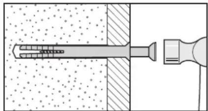
natural_image
Diagram showing a tool interacting with a cylindrical component, with no visible text or symbols.For use with walls stuck with plasterboard. The hammer fixing allows it to be fixed to the wall rather than the plasterboard. Always check the fixing is secure to the retaining wall.
No.2 "Plasterboard" wall plug
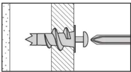
natural_image
Diagram of a screw fastener and nail being inserted into a wall, showing internal components (no text or labels)For use when attaching light loads on to plasterboard partitions.
No.4 "Cavity Fixing-Heavy Duty" wall plug
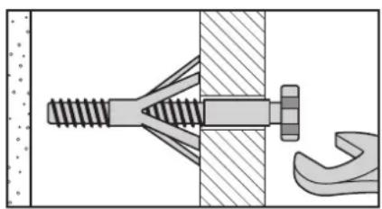
natural_image
Technical diagram showing a bolted joint inserted into a wall, with a separate clamp bracket (no text or symbols present)For use when fitting or supporting heavy loads such as shelving, wall cabinets and coat racks.
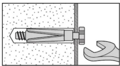
No.6 "Shield Anchor" wall plug Heavy loads
natural_image
Diagram of a mechanical assembly with a wrench and threaded component inserted into a wall, no text or symbols present.For use with heavier loads such as TV & HiFi speakers and satellite dishes etc.

Care & Maintenance
Safety: Always check the fitting and location to ensure your safety in and around the home.
Fitting: From time to time check the fitting to ensure the wall plugs or screws do not become loose.