
PPU-700II - Label printer CITIZEN - Free user manual and instructions
Find the device manual for free PPU-700II CITIZEN in PDF.


| Product Type | Thermal Label Printer |
| Model | PPU-700II |
| Brand | Citizen |
| Print Method | Line thermal dot print |
| Print Width | 80 mm (640 dots) |
| Dot Density | 8 × 8 dots/mm (203 dpi) |
| Print Speed | 150 mm/sec max. (1200 dot lines/sec) |
| Paper Width | 58, 67, 80, or 82.5 mm |
| Paper Thickness | 0.065 to 0.150 mm |
| Roll Diameter (max) | 203 mm (with optional PHU) |
| Barcode Types | UPC-A/E, JAN, CODE39, CODE128, QR Code, PDF417 (PPU-700II only) |
| Interface | USB 2.0 (standard), serial RS-232C, parallel IEEE1284 (option) |
| Input Buffer | 4K bytes / 72 bytes |
| Supply Voltage | DC 24V ±7% |
| Power Consumption | 100 W |
| AC Adapter (specified) | 36AD2 series, input AC 100-240V, output DC 24V 2A |
| Dimensions (W × D × H) | 163.2 × 176 × 144 mm |
| Weight | 2.1 kg |
| Operating Temperature | -10 to 50°C (PPU-700II) |
| Operating Humidity | 35 to 85% RH (no condensation) |
| Print Head Life | 150 km or 100 million pulses |
| Auto Cutter Life | 1 million cuts (0.065 mm paper) |
| Safety Compliance | UL, C-UL, TUV, GS, VCCI Class A, FCC Class A, CE |
| Optional Accessories | PHU-3*** Paper Feed Unit, 36AD2 AC Adapter |
| Maintenance | Clean thermal head with alcohol; clean presenter roller; avoid solvents |
Frequently Asked Questions - PPU-700II CITIZEN
User questions about PPU-700II CITIZEN
0 question about this device. Answer the ones you know or ask your own.
Ask a new question about this device
Download the instructions for your Label printer in PDF format for free! Find your manual PPU-700II - CITIZEN and take your electronic device back in hand. On this page are published all the documents necessary for the use of your device. PPU-700II by CITIZEN.
USER MANUAL PPU-700II CITIZEN
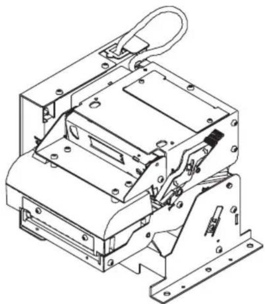
PRINTER PRESENTER UNIT
MODEL PPU-700/700II
User's Manual
natural_image
Technical line drawing of a mechanical assembly with mounting brackets and mounting holes (no text or symbols)If you want to dispose this product, do not mix with general household waste. There is a separate collection systems for used electronics products in accordance with legislation under the WEEE Directive (Directive 2002/96/EC) and is effective only within European Union.
Ge
Declaration of Conformity
This printer conforms to the following Standards:
The Low Voltage Directive 2006/95/EC, the EMC Directive 2004/108/EC, the RoHS Directive 2002/95/EC, and the WEEE Directive 2002/96/EC.
LVD : EN60950-1
EMC : EN55022 Class A
EN61000-3-2
EN61000-3-3
EN55024
This declaration applies only to the 230-V model.
IMPORTANT: This equipment generates, uses, and can radiate radio frequency energy and if not installed and used in accordance with the instruction manual, may cause interference to radio communications. It has been tested and found to comply with the limits for a Class A computing device pursuant to Subpart J of Part 15 of FCC Rules, which are designed to provide reasonable protection against such interference when operated in a commercial environment. Operation of this equipment in a residential area is likely to cause interference, in which case the user at his own expense will be required to take whatever measures may be necessary to correct the interference.
CAUTION: Use shielded cable for this equipment.
Sicherheitshinweis
This digital apparatus does not exceed the class A limits for radio noise emissions from digital apparatus, as set out in the radio interference regulations of the Canadian department of communications.
- The information contained in this manual is subject to change without prior notice.
- Reproduction or transfer of part or all of this manual in any means is prohibited without permission from CITIZEN SYSTEMS.
- Except explained elsewhere in this manual, do not attempt to service, disassemble, or repair this product.
- Note that CITIZEN SYSTEMS is not responsible for any damage attributable to incorrect operation/handling or improper operating environments that are not specified in this manual.
- Operate this printer only as described in this manual. Failure to do so may cause accidents or other problems.
- Data are basically for temporary use and not for storage for a long period or permanently. Please note that CITIZEN SYSTEMS is not responsible for damage or lost profit resulting from the loss of data caused by accidents, repairs, tests or other occurrence.
- If you find loss of information, error, or uncertain matter, please contact your CITIZEN SYSTEMS dealer.
- Please note CITIZEN SYSTEMS is not responsible for anything that may occur from operating this printer regardless of what is stated in "7" above.

CAUTION
This is a Class A information technology equipment based on the standard of the Voluntary Control Council for Interference by Information Technology Equipment (VCCI). If this equipment is used in a domestic environment, radio disturbance may arise. When such trouble occurs, the user may be required to take corrective actions.
SAFETY PRECAUTIONS ... WHICH SHOULD BE STRICTLY OBSERVED
Before using this product for the first time, carefully read these SAFETY PRECAUTIONS. Incorrect operation may result in unexpected accidents (fire, electric shock, or injury).
●After having read this manual, keep it in a safe, readily accessible place for future reference.
●Some of the descriptions contained in this manual may not be relevant to some printer models.
In order to prevent injury hazard to operators, third parties or damage to property, special warning symbols are used in this user's manual to indicate important items to be strictly observed.
The following describes the degree of hazard and damage that could occur if the printer is improperly operated by ignoring the instructions indicated by the warning symbols.

WARNING
Neglecting the precautions indicated by this symbol may result in fatal or serious injury.

CAUTION
Neglecting the precautions indicated by this symbol may result in injury or damage to properties.

This symbol is used to alert your attention to important items.

This symbol is used to alert you to the danger of electric shock or electrostatic damage.

This symbol denotes a request to unplug the printer from the wall outlet.

This symbol is used to indicate the "information" on the use, or the like.

This symbol is used to indicate prohibited actions.
 WARNING WARNING | |
| Do not use or store this product in a place where it will be exposed to:●Flames or moist air●Direct sunlight●Hot airflow or radiation from a heating device●Salty air or corrosive gases●Ill-ventilated atmosphere●Chemical reactions in a laboratory●Airborne oil, steel particles, or dust●Static electricity or strong magnetic field•Neglecting these warnings may result in printer failure, overheating, emission of smoke, fire, or electric shock. |   |
| Do not drop any foreign object nor spill liquid into the printer. Do not place any object on the printer either.●Do not drop any metallic object such as paper clip, pin or screw into the printer.●Do not place a flower vase, pot or cup containing water on the printer.●Do not spill coffee, soft drinks or any other liquid into the printer.●Do not spray insecticide or any other chemical liquid over the printer.●Never use organic cleaning solvent such as alcohol, paint thinner, trichloroethylene, benzene, or ketone.•A metallic foreign object, if accidentally dropped into the printer, may cause printer failure, fire, or electric shock. Should it occur, immediately turn the printer off, unplug it from the supply outlet, and call your local CITIZEN SYSTEMS dealer. |    |
| Do not handle the printer in the following ways:●Do not allow the printer to sustain strong impacts or hard jolts (e.g., trampling, dropping, striking with a hard edge).●Never attempt to disassemble or modify the printer.•Neglecting to handle properly may result in printer failure, overheating, emission of smoke, fire, or electric shock. |   |
| Install, use, or store the printer out of the reach of children.•Electric appliances could cause an unexpected injury or accident if they are handled or used improperly.•Keep the power cord and signal cables out of the reach of children. Also children should not be allowed to gain access to any internal part of the printer.•The plastic bag the printer came in must be disposed of properly or kept away from children. Wearing it over the head may lead to suffocation. |  |

WARNING
Please observe the following precautions for power source and power cord:
●Do not plug or unplug the power cord with a wet hand.
●Use the printer only at the specified supply voltage and frequency.
●Use only the specified AC adapter with the printer.
- Check to make sure that the supply outlet from which the printer is powered has a sufficient capacity.
- Do not supply the printer from a power strip or current tap shared with other appliances.
- Do not plug the power cord into a supply outlet with dust or debris left on its plug.
●Do not use a deformed or damaged power cord.
- Neglecting to handle properly may result in printer failure, emission of smoke, fire, or electric shock.
- An overload may cause the power cord to overheat or fire or the circuit breaker to trip.
- Do not use the printer while the power cord is loaded with anything or it is trampled on.
- Do not use or carry the printer with its power cord bent, twisted, or pulled.
●Do not attempt to modify the power cord unnecessarily.
●Do not lay the power cord in the neighbor of a heating device.
- Neglecting these cautions may cause wires or insulation to break, which could result in leakage, electric shock, or printer failure. If a power cord sustains damage contact your CITIZEN SYSTEMS dealer.
- Do not leave things around the supply outlet. - Supply power to the printer form a convenient wall outlet, readily accessible in an emergency.
• The printer may not be immediately shut down in an emergency.
●Insert the power plug fully into the supply outlet.
- If the printer is likely to be out of use for a long time, leave it disconnected from its supply outlet.





CAUTION
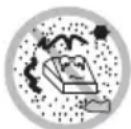
Do not use or store this product in a place where it will be exposed to:
●Flames or moist air
- Direct sunlight
●Hot airflow or radiation from a heating device
●Salty air or corrosive gases
●III-ventilated atmosphere
●Chemical reactions in a laboratory
●Airborne oil, steel particles, or dust
●Static electricity or strong magnetic field
- Otherwise failure, smoke, ignition, fire, or electric shock may occur.
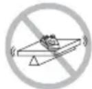
●Place the printer on a flat, stable surface without vibration.
• O therwise dropping may cause injury.
Do not use the printer under the following conditions.
●A state where the printer ventilation holes are blocked by a nearby wall or something
●A state where any object is placed on the printer
●A state where the printer is covered or wrapped by a cloth or bed clothing
- Be careful about internal heat buildup, which could cause fire and deform the case.
- Avoid using the printer near a radio or TV set or from supplying it from the same outlet as these appliances.
- Avoid using the printer interconnected with a cable or cord that has no protection against noise. (For interconnections, use shielded or a twisted pair of cables and ferrite cores, or other anti-noise devices.)
● Avoid using the printer with a device that is a strong source of noise. - The printer may have an adverse effect on nearby radio or TV transmissions. There may also be cases when nearby electrical appliances adversely influence the printer, causing data errors or malfunction.
Use the printer with its grounding post connected to a convenient grounding facility.
• I f leakage occurs electric shock may result.
Do not connect the printer's grounding post onto any of the following facilities.
●Utility gas piping
A gas explosion could result
●Telephone line ground
●Lightning rod
If lightning strikes a large surge of current may cause fire or shock.
●Utility water pipes
Plastic water pipes should not be used for grounding. (Those approved by a Waterworks Department may be used.)
Before connecting or disconnecting the grounding lead to or from the printer, always unplug it from supply outlet.





CAUTION
Please observe the following precautions for power source and power cord:
●Use the printer only at the specified supply voltage and frequency.
●Use only the specified AC adapter with the printer.
- Check to make sure that the supply outlet from which the printer is powered has a sufficient capacity.
- Do not supply the printer from a power strip or current tap shared with other appliances.
- Do not plug the power cord into a supply outlet with dust or debris left on its plug.
- Neglecting to handle properly may result in printer failure, emission of smoke, fire, or electric shock.
- An overload may cause the power cord to overheat or fire or the circuit breaker to trip.
●Do not leave things around the supply outlet.
●Use the printer near a convenient wall outlet, readily accessible in an emergency.
- Otherwise the printer may not be immediately shut down in an emergency.
●Insert the power plug fully into the supply outlet.
- If the printer is likely to be out of use for a long time, leave it disconnected from its supply outlet.
Plug or unplug the power cord or other cables with the power off and by holding the plug or connector.
Do not use the power cord or other signal cables under the following conditions.
●A state where the power cord or cable is loaded by something or trampled on.
●A state where the printer is used or carried with its power cord bent, twisted, or pulled
- Do not lay the power cord in the neighbor of a heating device.
- Do not attempt to modify the power cord unnecessarily.
- Neglecting these cautions may cause wires or insulation to break, which could result in leakage, electric shock, or printer failure. If a power cord sustains damage contact your CITIZEN SYSTEMS dealer.
Be sure to firmly insert the cable plug into its mating socket.
- A cross connection may damage the printer's internal electronics or the host system's hardware.







CAUTION
To prevent possible malfunction or failure observe the following.
●Avoid operating the printer without paper properly loaded.
●Avoid the use of paper not complying with specifications.
- Otherwise thermal print head may be damaged and may result in poor print quality.
- Do not drop any metallic object such as paper clip, pin or screw into the printer.
●Do not spill coffee or any other liquid into the printer.
●Do not spray insecticide or any other chemical liquid over the printer.
- A metallic foreign object, if accidentally dropped into the printer, may cause printer failure, fire, or electric shock. Should it occur, immediately turn the printer off, unplug it from the supply outlet, and call your local CITIZEN SYSTEMS dealer.
- Avoid using torn pieces of paper or spliced with plastic adhesive tapes.
●Avoid forcibly pulling already loaded paper by hand.
- Otherwise paper jam may occur. If paper jam occurs, remove it correctly by referring to "Removing Jammed Paper" in this manual.
- Do not allow the printer to sustain strong impacts or hard jolts (e.g., trampling, dropping, striking with a hard edge).

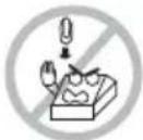

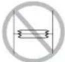
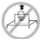
To prevent injury and printer failures from worsening, observe the following:
●Do not touch the printing surface of the thermal head.
- Do not touch any of the moving parts (e.g., paper cutter, gears, active electrical parts) while the printer is working.
●In case of trouble do not attempt to repair the printer. Ask CITIZEN SYSTEMS service for repair.
●Be careful that the paper cover does not entrap your hands or fingers.
- Be careful with sharp edges on the printer. Don't allow them to injure you or damage property.
• M ay result in electric shock, burn, or injury.
- If the printer emits smoke, an odd smell, or unusual noise while printing, immediately abort the current print session and unplug the printer from the supply outlet.



DAILY MAINTENANCE
Observe the following precautions for daily maintenance.
- When cleaning the printer, always turn it off and unplug it from the supply outlet.
●Use a soft, dry cloth for cleaning the surface of the printer case.
●For severe stains, use a soft cloth slightly dampened with water.
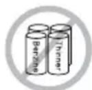
●Never use organic cleaning solvent such as alcohol, paint thinner, trichloroethylene, benzene, or ketone. Never use a chemically processed cleaning cloth.
●To remove paper chips, use a soft brush. - When transporting the printer, remove the paper roll from its paper holder.


CAUTION
- The thermal head is at a dangerously high temperature immediately after printing. Allow it to cool off before launching maintenance work.
●Clean the thermal head by wiping the dust off the surface of the heating element on the print head with gauze slightly moistened by alcohol.

CAUTION
- Do not touch the heating element of the print head by bare hand or via metal strip.
- The thermal head is at a dangerously high temperature immediately after printing. Allow it to cool off before launching maintenance work.
●Clean the presenter by wiping the dust off the surface of the rubber roller with gauze slightly moistened by alcohol.
THE TABLE OF CONTENTS
1. GENERAL OUTLINE ...... 12
1.1 Features .... 12
1.2 Unpacking 12
2. BASIC SPECIFICATIONS ...... 13
2.1 Model Classification ..... 13
2.1.1 PPU-700/PPU-700II Series 13
2.1.2 Option 14
2.2 Basic Specifications 15
2.3 Print Paper Specifications .....17
2.3.1 Specified Paper 17
2.3.2 Print Position 18
2.3.3 Print Head and Paper Cut Position 19
2.3.4 Black Mark Layout and Operating Condition 20
3. APPEARANCE AND COMPONENTS PARTS ...... 21
3.1 PPU-700/PPU-700II Printer 21
3.2 Detector Position 23
3.3 PHU-3***(Paper Feed Unit) (Option) 24
4. OPERATION 25
4.1 Connecting AC Adapter and AC Cable 25
4.2 Connecting Interface Cables 26
4.3 Interface Board Change 27
4.4 Connecting PHU (Paper Feed Unit) 27
4.5 Connector for Operation Panel (CN500) 28
4.6 Setting/Replacing Paper Roll 29
4.6.1 Paper Setting from Paper Side-in 29
4.6.2 Paper Setting by Auto-loading 30
4.6.3 When Using PHU-3 *** (Paper Feed Unit) 31
4.7 Removing the Remaining Paper Roll 32
4.8 Removing Jammed Paper 32
4.9 Removing Cutter Lock 33
4.10 Changing Paper Width 34
4.11 FEED Switch 35
4.12 Paper End 35
4.13 Paper Near-End Sensor (When PHU-3*** is used) ......36
4.14 Paper Retraction 37
4.15 Self-printing 37
4.16 Hexadecimal Dump Feature 37
4.17 Operation Panel and Error Indication 38
5. NOTES ON EXTERIOR DESIGN 40
5.1 Notes on Paper Exit ....40
5.2 Notes on Paper Collection Hole and Collection Path .....42
5.3 Notes on Paper Insertion Path 43
5.4 PHU-3*** (Paper Feed Unit) Installation 43
5.5 Layout Examples of Control Box 44
6. DIP SWITCHES 45
6.1 Setting DIP Switches 45
6.2 DIP Switch Functions ....46
7. MEMORY SWITCHES 47
7.1 Setting Memory Switches 47
7.2 Memory Switch Functions ....49
APPENDIX-1. PPU-700 EXTERNAL VIEW 52
APPENDIX-2. PPU-700II EXTERNAL VIEW ....53
APPENDIX-3. PPU-700 PHU-3\*\*\* (PAPER FEED UNIT) INSTALLATION....54
APPENDIX-4. BLOCK DIAGRAM 55
1. GENERAL OUTLINE
The PPU-700/PPU-700II are a printer designed for use with a broad array of terminal equipment including data, measuring instruments, outdoor information, or as a presenter for issuing various kinds of tickets and coupon tickets.
With extensive features, it can be used in a wide range of applications.
To obtain the best results from the PPU-700/PPU-700II printers, please read the instructions in this manual thoroughly.
1.1 Features
(1) Paper side-insert mechanism facilitating paper insertion and maintenance.
(2) Paper width can be chosen among 58, 67, 80, and 82.5 mm.
(3) Line thermal printing allows high-speed, low-noise printing.
(4) Allows collection of paper not received. (Paper collection mechanism)
(5) Small size and light weight requiring minimum installation space.
(6) Long-life head and high reliability with simple mechanism.
(7) Built-in input buffer.
(8) Barcode printing is available with special command.
(9) Page mode allows free layout of printing.
(10) User-defined characters and logos can be registered in the flash memory.
(11) User-designed characters can be registered.
(94 Kanji characters, 95 ANK characters)
(12) Detection of black mark is available. (Option)
(13) Free layout of each unit.
(14) Large-sized roll paper can be used. (Option)
(15) Built-in buzzer
(16) Various kinds of customization are available.
(17) 2-color printing
(18) Equipped with USB interface as standard. (PPU-700II)
(19) Barcode & 2D Barcode printing is supported. (PPU-700II)
1.2 Unpacking
After unpacking the printer, confirm that the following are provided.
●Printer: 1
●User's Manual: 1

CAUTION!
●Place the printer on the equipment positioned horizontally and stably.
●Avoid installation near heater or in direct sunlight.
●Avoid use in the environment with high temperature, high humidity, and very dirty.
● Avoid dew condensation. In the case of dew condensation, keep power off till dew condensation is cleared.
2. BASIC SPECIFICATIONS
2.1 Model Classification
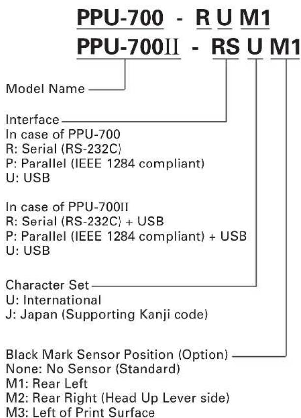
The printer models are classified by the following designation method:
2.1.1 PPU-700/PPU-700II Series
flowchart
graph TD
    A["PPU-700 - R U M1\nPPU-700II - RS U M1"] --> B["Model Name"]
    A --> C["Interface"]
    C --> D["In case of PPU-700\nR: Serial (RS-232C)\nP: Parallel (IEEE 1284 compliant)\nU: USB"]
    A --> E["Character Set"]
    E --> F["U: International\nJ: Japan (Supporting Kanji code)"]
    A --> G["Black Mark Sensor Position (Option)"]
    G --> H["None: No Sensor (Standard)\nM1: Rear Left\nM2: Rear Right (Head Up Lever side)\nM3: Left of Print Surface"]
natural_image
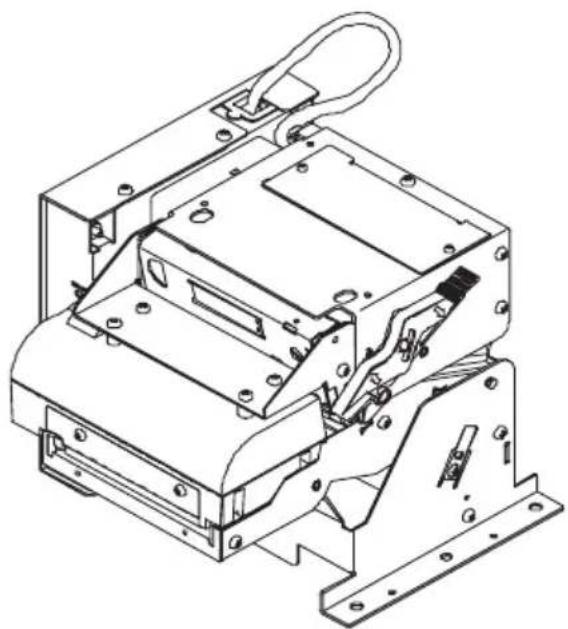
Technical line drawing of an electronic device housing with mounting brackets and internal components (no text or symbols)2.1.2 Option
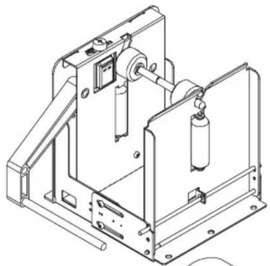
(1) PHU Series (Paper Feed Unit)
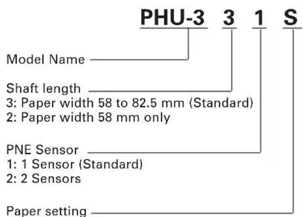
S: Side (Standard)
T: Top
natural_image
Technical line drawing of a mechanical device with no visible text or symbols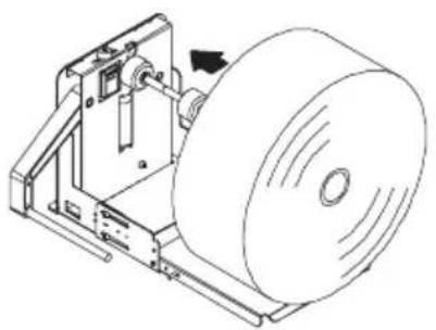
natural_image
Technical line drawing of a mechanical device with a circular component and directional arrow (no text or symbols)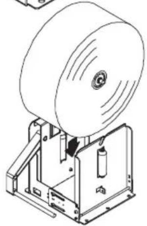
natural_image
Technical line drawing of a mechanical device with a large cylindrical component and internal components (no text or symbols)PHU-3**S PHU-3**T
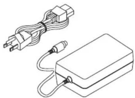
(2) 36AD2 Series (AC Adapter)
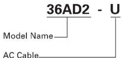
U: USA (120V 3-core cord)
E: Europe (230V Class I Cord)
J: Japan (100V 3-core cord)
natural_image
Line drawing of a power plug connected to a rectangular electronic device with cables (no text or symbols)2.2 Basic Specifications
| Model Item PPU-700-PU/PPU | PPU-700-RU/PPU-700II-RSU PPU-700-RK/PPU-700II-RSK-700II-PAU PPU-700-PK/PPU-700II-PAKPPU-700-UU/PPU-700II-UBU PPU-700-UK/PPU-700II-UBK | ||
| Print method Line thermal dot print method | |||
| Print width 80 mm/640 dots | |||
| Dot density 8 × 8 dots/mm (203 dpi) | |||
| Print speed 150 mm/sec (max., Print density level 2), (1200 dot lines/sec) | |||
| Number of print Font A: 48 columns, 12 × 24 dotscolumns Font B: 64 columns, 9 × 17 dotsFont C: 72 columns, 8 × 16 dots | |||
| Kanji Font A: 24 columns, 24 × 24 dotsKanji Font B: 36 columns, 16 × 16 dots | |||
| Character size Font A: 1.50 × 3.00 mmFont B: 1.13 × 2.13 mmFont C: 1.00 × 2.00 mm | |||
| Kanji Font A: 3.00 × 3.00 mmKanji Font C: 2.00 × 2.00 mm | |||
| Character type Alphanumeric characters, International characters, PC850, 852, 857, 858,860, 863, 865, 866, WPC1252, Katakana | |||
| Kanji (JIS Level 1, Level 2) | |||
| User memory | 256 KB (Capable of registering user-defined characters and logos) | ||
| Barcode type | UPC-A/E, JAN (EAN) 13 columnns/8 columns, ITF, CODE 39, CODE 128,CODABAR, CODE 93, QR Code (PPU-700II Only), PDF417 (PPU-700II Only) | ||
| Line spacing | 4.23 mm (1/6 in.), selectable by use of command | ||
| Paper(See paper spec.) | Thermal paper rollWidth: 58 to 82.5 mmExternal diameter: φ203 mm max. (when using PHU)Core: Internal diameter: φ25.4 mm, Outer diameter: φ30 mm or morePaper thickness: 65 to 150 μm | ||
| Presenter | Standard length: 90 mm | ||
| Interface *1 | Serial (RS-232C compliant), Parallel (IEEE1284 compliant), USB Interface | ||
| Input buffer | 4K bytes/72 bytes | ||
| Supply voltage | DC 24V ±7% | ||
| Power consumption 100 W | |||
| AC adapter specificationType | Rated input: AC 100V to 240V, 50/60 Hz, 150 VARated output: DC 24V, 2A | ||
| 36AD2-U | 36AD2-E | 36AD2-J | |
| Weight | 2.1 kg | ||
| Outside dimensions | 163.2 (W) × 176 (D) × 144 (H) mm (See external view) | ||
| Operating temperature and humidity | 5 to 40°C (PPU-700), -10 to 50°C (PPU-700II),35 to 85% RH (No dew condensation) | ||
| Storage temperature and humidity | -20 to 60°C, 10 to 90% RH (No dew condensation) | ||
| ModelItem PPU-700-PU/PPU | PPU-700-RU/PPU-700II-RSU PPU-700-RK/PPU-700II-RSK700II-PAU PPU-700-PK/PPU-700II-PAKPPU-700-UU/PPU-700II-UBU PPU-700-UK/PPU-700II-UBK | ||
| Reliability Print head life: 150 Km, 100 million pulses (At normal temperature, humidity with recommended paper used)Auto cutter life: 1 million cuts (At normal temperature, humidity, with paper thickness of 0.065 mm) | |||
| Safety Standard *2 UL, C-UL, TUV, GS, VCCI Class AFCC Class A CE marking | |||
Note:
*1: PPU-700 and PPU-700II are not compatible in interface.
*2: Represents the safety standards acquired when CITIZEN SYSTEMS-made AC adapter (36AD2 series) is used.
2.3 Print Paper Specifications
2.3.1 Specified Paper
Thermal Paper Roll
●Type: Heat-sensitive paper
●Paper width: 58 mm, 67 mm, 80 mm, 82.5 mm
●Paper thickness: 0.065 to 0.150 mm
●Roll diameter: φ203 max.
●Print surface: Outer side of the roll (surface)
●Core: φ25.4 (inner diameter),
30 mm or more (outer diameter)
●Recommended paper: Nippon Paper Industries TF50KS-E, EC
Mitsubishi Paper Mills F230AA
Or other equivalent paper

CAUTION!
● Paper not complying with the specifications may cause some departure in print tone.
- Adjust the print tone with the DIP switch. (See "7.2 Memory Switch Functions".)
- Do not paste paper end to the core.
- If printed documents are exposed to a particular chemical or oil afterwards, coloration or faint letters may result.
● Rubbing the document surface with your nail or metallic device may cause coloration.
- Coloration occurs at a temperature of around 70^ or above. Keep documents away from heat, moisture, or light.
2.3.2 Print Position
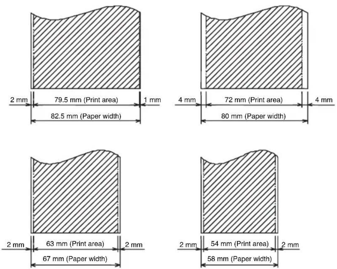
* Hatched portion: Printable area
2.3.3 Print Head and Paper Cut Position
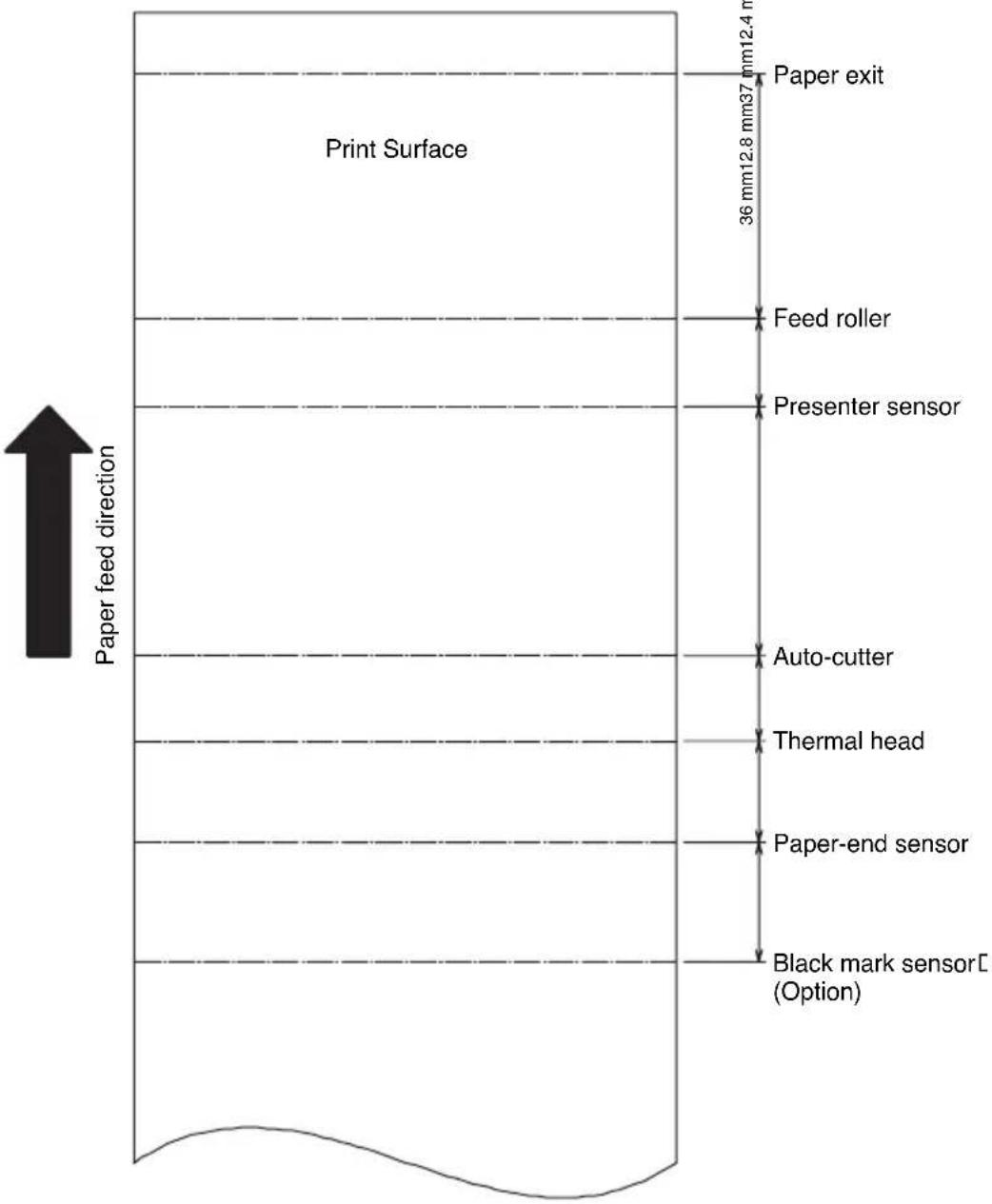
other
| Component | Depth (mm) | | --------------------- | ---------- | | Paper feed direction | 36 | | Paper exit | 12.4 | | Feed roller | 37 | | Presenter sensor | 38 | | Auto-cutter | 39 | | Thermal head | 40 | | Paper-end sensor | 41 | | Black mark sensorC (Option) | 42 |2.3.4 Black Mark Layout and Operating Condition
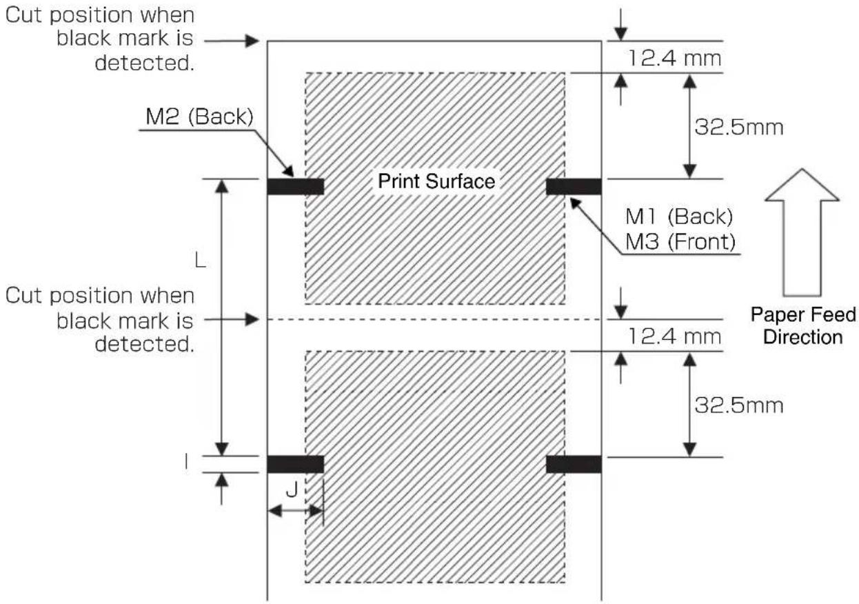
| Symbol Item BM Paper | ||
| I Black | mark length 5 to 10 mm | |
| J Black | mark width 10 mm min. | |
| L Black | mark pitch 100 mm ~ 3000 mm | |
- Black marks are selected at two places on the back and one place on the front (PCS value is 0.9 or more).
* BM position is an option of factory shipment.
- Though printing is available on the printing side having a black mark on the back, print density may become thin depending on the type of paper; therefore, user's notice such as printing on the place without black mark is necessary.
- Distance between black mark and black mark sensor is approx. 32.5 mm. If black mark is detected within this distance, next black mark is detected.
- Cut position when black mark is detected by the GS+S command (black mark detection command) is about 45 mm with the top of black mark used as a reference.
- Amount of automatic paper feed at the detection of black mark can be set by the ESC Y n1 n2 command.
- Basically cut command can be executed in any condition. If minimum distance for issuing a ticket (80 mm) is not satisfied, paper feed as much as the shorted amount is added by the printer.
* The user is requested to prepare the printing layout in consideration of the above regulations.
3. APPEARANCE AND COMPONENTS PARTS
3.1 PPU-700/PPU-700II Printer
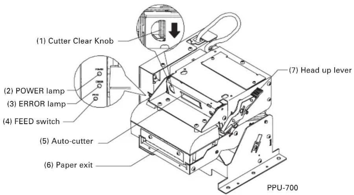
(1) Cutter Clear Knob
Operated at the occurrence of cutter error.
(2) POWER lamp
Lights when the printer is powered on.
(3) ERROR lamp
Lights or blinks at the occurrence of error.
(4) FEED switch
This switch, when pressed, feeds and cuts paper and ejects the paper from the presenter.
(5) Auto-cutter
Cuts the printed paper.
(6) Paper exit
(7) Head up lever
Used when setting paper or for maintenance.
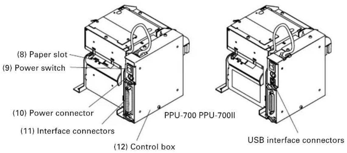
(8) Paper slot
(9) Power switch
Switch to turn ON/OFF presenter power.
(10) Power connector
Connector for power supply from outside.
(11) Interface connectors
Connects the interface cable for communication. Serial, parallel, and USB connectors are provided.
(PPU-700)
One of these interfaces is installed depending on the model category.
(PPU-700II)
Though USB is supplied as standard with every printer; however, installation of serial or parallel interface is subject to the model category.
(12) Control box
Control board is contained.
(13) Buzzer
Located on the control board and sounds at the occurrence of error, etc.
3.2 Detector Position
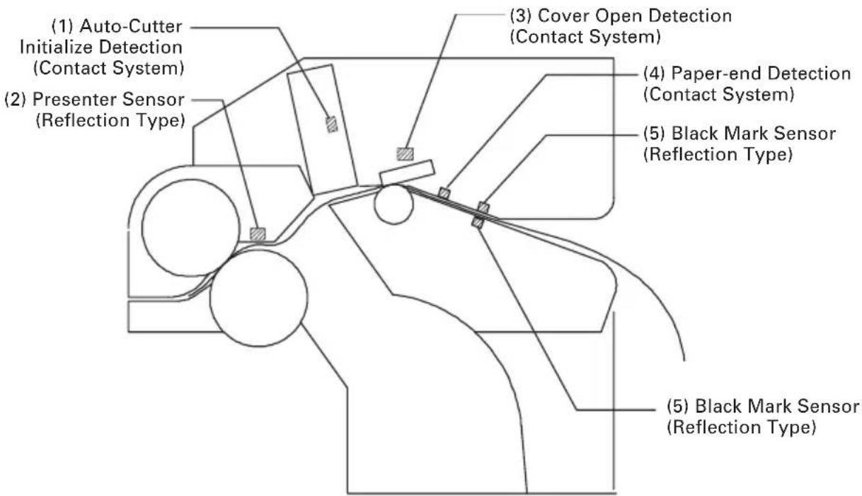
(1) Auto-Cutter Initialize Detection (Contact System) Detects the position of cutter blade.
(2) Presenter Sensor (Reflection Type)
Detects the presence or absence of paper and paper jam.
(3) Cover Open Detection (Contact System) Detects open and close of paper guide.
(4) Paper-end Detection (Contact System)
Detects presence and absence of paper supplied
(5) Black Mark Sensor (Reflection Type): Option Detects Black Mark.
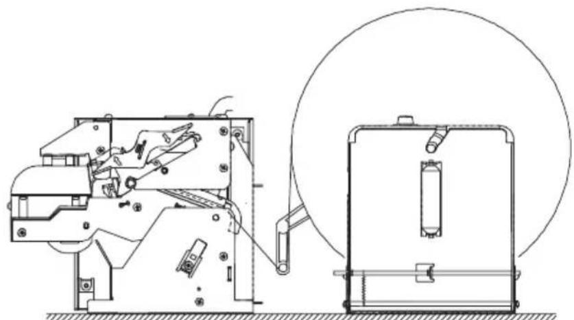
3.3 PHU-3\*\*\*(Paper Feed Unit) (Option)
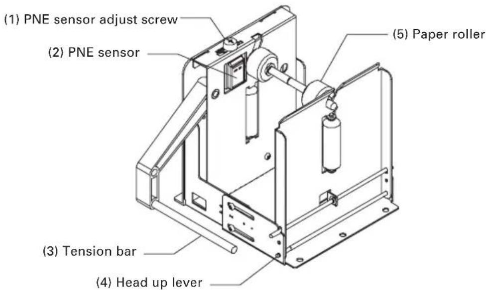
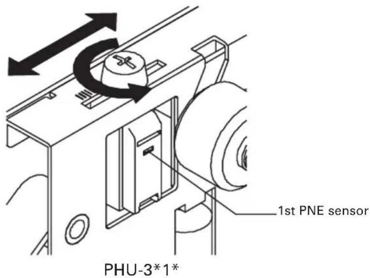
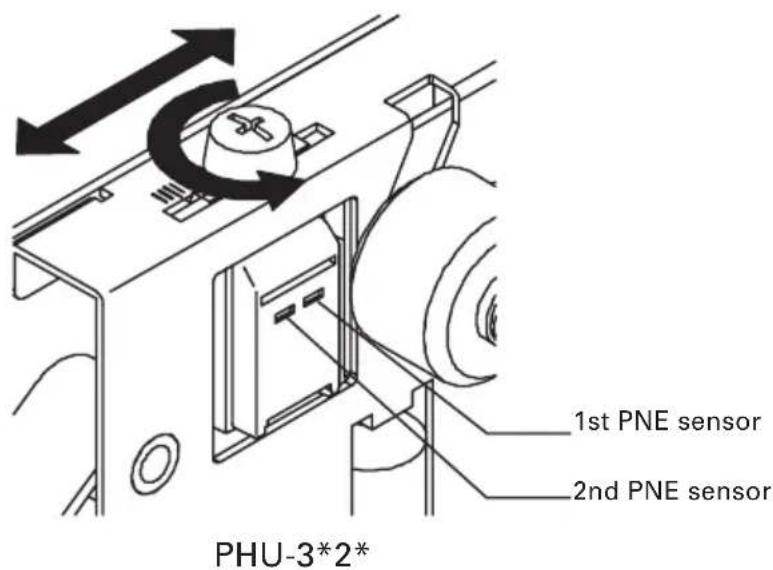
(1) PNE sensor adjust screw
Screw to adjust the amount of paper by moving the sensor position.
(2) PNE sensor
Sensor to detect that paper is low.
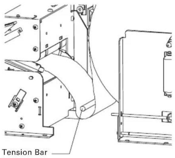
(3) Tension bar
Absorbs the shock at the rotation of paper roll.
(4) Head up lever (PHU-3**T: Not provided for paper top set type)
Used for opening the side door for paper setting.
(5) Paper roller
Used for supporting paper roll.
natural_image
Technical line drawing of a mechanical device with internal components and a circular component (no text or symbols)Paper Feed Unit Installation
For detailed dimensions, refer to "Appendix-3 PPU-700 PUU-3*** (Paper Feed Unit) Installation".
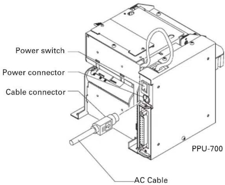
4.1 Connecting AC Adapter and AC Cable
- Turn the printer power off.
- Confirm the direction of the cable connector of the AC adapter and insert it into the power connector until it is locked.

CAUTION!
●Keep DC 24 V ±7% for supply voltage.
●AC power supply must be separated from the equipment that may cause noise.
- When lightning is coming, unplug the AC cable from the wall outlet and do not use the printer. Lightning strike may cause a fire or electric shock.
●Always hold the connector portion when attaching or removing the cable connector of the AC adapter.
●Do not pull the AC cable. Otherwise, the cord may be damaged resulting in a fire, electric shock, or disconnection.
- Keep the AC cable off any heating instrument. The cover of the cable may be melt resulting in a fire or electric shock.
- If you leave the printer unused for a long period, keep the AC cable unplugged from the wall outlet for safety purpose.
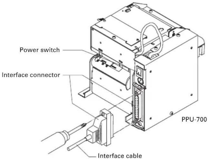
4.2 Connecting Interface Cables
- Turn the printer power off.
- Connect the interface connector in the correct direction.
- Fix the interface connector using a screwdriver.
- Connect the other end of the interface cable to the host.

CAUTION!
- Confirm the pin arrangement for the interface connector and cable. Wrong wiring may result in fault, malfunction, or the like of the computer as well as the printer.
●Always hold the connector when connecting or disconnecting the interface cable. Holding the cable may cause disconnection of the cable core. - Confirm that the interface cable is connected securely. Poor contact may result in a failure in communication.
For serial interface cable, use the one with the following connection.
25-pin - 25-pin cable
PC
Printer
| Signal Pin | |
| FG | 1 |
| TXD 2 | |
| RXD 3 | |
| CTS 5 | |
| DSR 6 | |
| SG | 7 |
| DTR 20 | |
9-pin - 25-pin cable
PC
Printer
| Signal Pin | |
| RXD 2 | |
| TXD 3 | |
| DTR 4 | |
| SG 5 | |
| DSR 6 | |
| CTS 8 | |
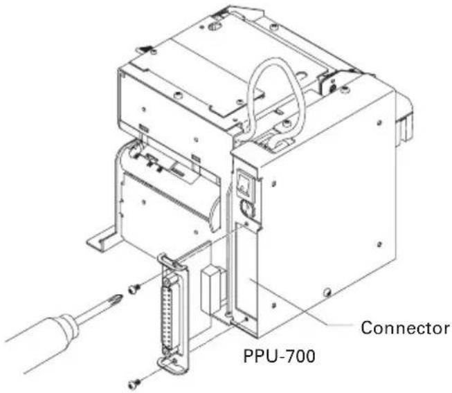
4.3 Interface Board Change
- Turn the printer power off.
- Remove two screws from the places shown in the figure below and detach the interface board.
- Firmly connect the connector of the interface board to be changed.
- Fix with screws.

CAUTION!
●PPU-700 and PPU-700II are not compatible in interface.
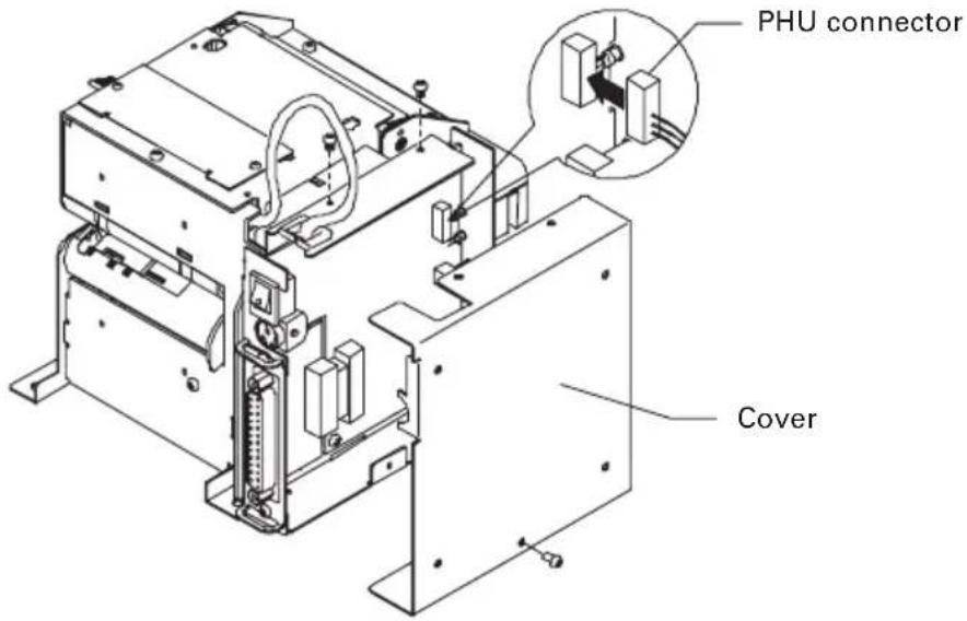
4.4 Connecting PHU (Paper Feed Unit)
- Turn the printer power off.
- Remove the three screws on the control box and open the cover.
- Connect the PHU connector to the connector on the printed board in the control box shown in the following figure.
4.5 Connector for Operation Panel (CN500)
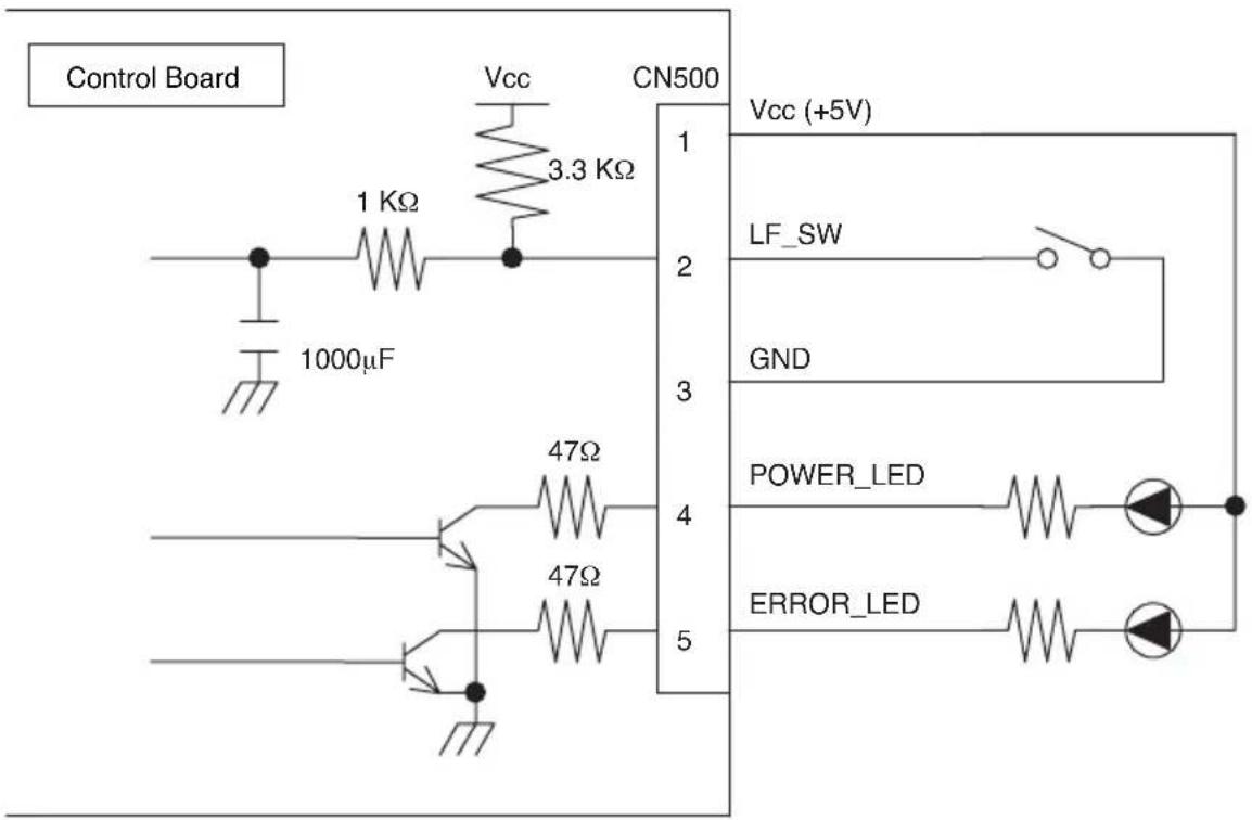
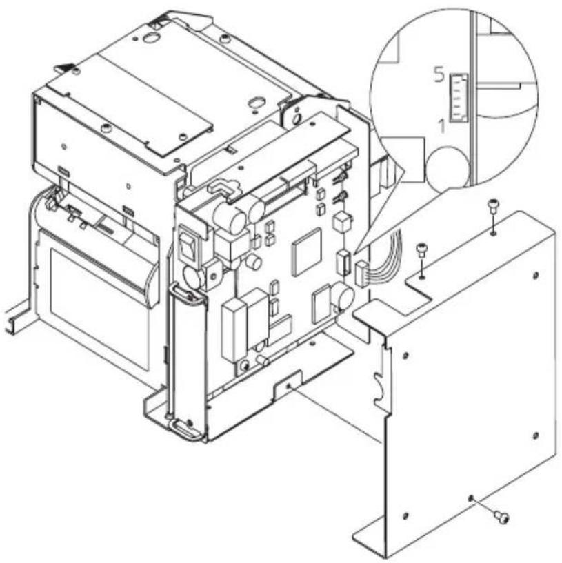
Pin Assignment
| Pin No. Signal Name Input/Output Function | ||
| 1 Vcc — Power supply for circuit (+5V) | ||
| 2 LF_SW Input LF switch input (paper feeding) | ||
| 3 GND — GND for circuit | ||
| 4 POWER_LED Output POWER_LED output | ||
| 5 ERROR_LED Output ERROR_LED output |
Connector used: 53014-0510 (Molex)
Connection Example

CAUTION!
● POWER LED and ERROR LED are provided with a resistor of 47 at the circuit side. When using LED, connect the resistor to conform to the rating of the LED. (Saturation voltage across collector and emitter of transistor V_CE(sat) = 0.25V (max.) )
- LF_SW input terminal has the above circuit configuration. A ceramic capacitor is provided at the circuit side to prevent chattering. Note that chattering may be large depending on the switch.
natural_image
Technical line drawing of an electronic device with internal components and a magnified inset showing measurement scale (no text or symbols)4.6 Setting/Replacing Paper Roll
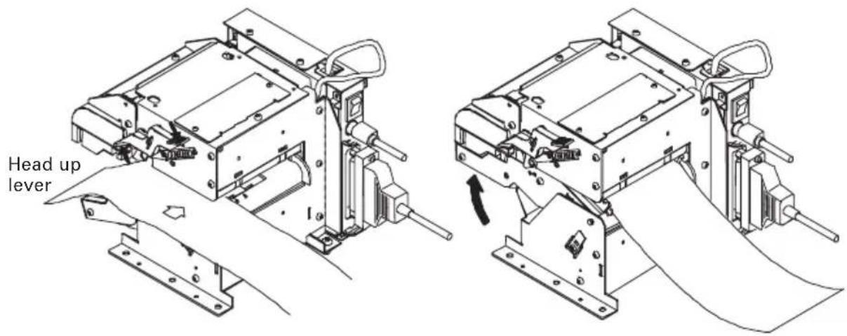
4.6.1 Paper Setting from Paper Side-in
- Open the paper guide with the head up lever.
- Cut the top end of the paper roll at about right angle to the roll direction. (Fig. 4-1)
- Insert a paper roll.
- Confirm that the roll paper end is rest in the guide. Close the paper guide.
- Roll paper is automatically loaded and paper initializing operation starts.
- When paper initialize operation is finished, the printer is ready for printing.
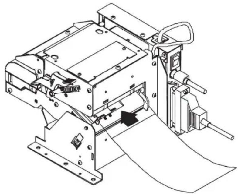
4.6.2 Paper Setting by Auto-loading
- Keep the paper guide closed.
- Cut the end of the roll paper almost at right angle. (Fig. 4-1)
- Insert the roll paper from the paper slot till it gets a drag.
- Paper is detected and automatically fed for a certain time and then paper initialize operation starts.
- When paper initialize operation is finished, the printer is ready for operation.
- When paper feeding fails, extract the paper once and repeat the procedure from step 3.
natural_image
Technical line drawing of an industrial machine with visible components and a paper sheet (no text or symbols)4.6.3 When Using PHU-3 \*\*\* (Paper Feed Unit)
When using the PHU-3*** (Paper Feed Unit), always pass the paper over the tension bar.
This feature serves as a shock absorber against the shock during rotation of paper roll thereby preventing deformed character, meandering paper feed, breakage of paper feed mechanism.

CAUTION!
●Always use the specified paper roll.
- Use of paper other than specified may result in disclaimer of warranties for print quality, head life, presenter feature, etc.
- Do not set the roll paper with fuzzy or bent edge. Otherwise, paper jam or wrong paper insertion may occur.
- If roll paper is slackened, rewind the roll to remove the slack.
- If roll paper is set with a slant, open the guide using the head up lever and correct the roll position or remove the roll paper and retry setting the paper again.
●During auto-loading, do not touch the roll paper. Otherwise, wrong paper feed or paper skew may occur.
● During printing, do not hold or touch the roll paper. Otherwise, paper jam may occur.
● After paper setting, the printer enters the print ready state. Note that if data remains in the buffer, printing starts after paper setting is completed.

natural_image
Pure geometric line drawings with circles and crosses, no text or symbols presentFig. 4-1
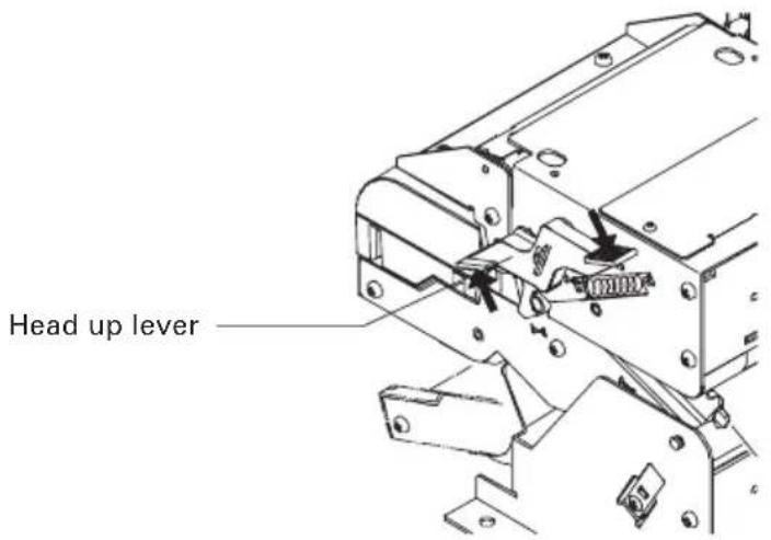
4.7 Removing the Remaining Paper Roll
- Operate the head up lever.
- The guide opens. Remove the roll paper.

CAUTION!
The thermal head is at a high temperature immediately after printing. Sufficient care must be taken in the work just after printing.
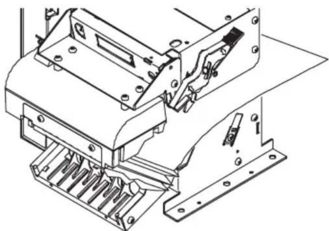
4.8 Removing Jammed Paper
- Turn the printer power off.
- Cut the roll paper at the point near the paper slot.
- Operate the head up lever to open the guide.
natural_image
Technical line drawing of a mechanical assembly with no visible text or symbols
CAUTION!
●Do not access the printer head just after printing operation because the print head remains hot.
●Do not touch the surface of the heated portion of the head with a bare hand or with a metal tool.
4.9 Removing Cutter Lock
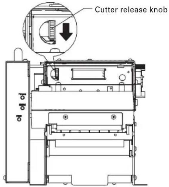
When cutter lock is used, opening the guide with the head up lever may fail. Forced opening may cause a break. Remove cutter lock in the following procedure.
- Press the FEED switch or turn the printer power off and then on. The autocutter starts initialize operation to restore the cutter.
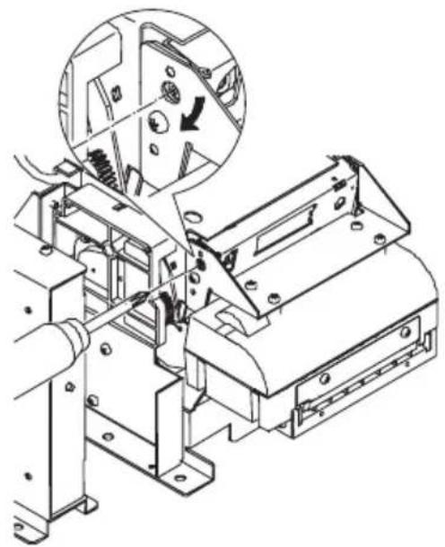
- If the above operation is not successful for restoring the cutter, turn off the printer and turn the cutter release knob of the auto-cutter in the arrow direction using a pointed tool (such as pincette or ball-point pen). The blade of the auto-cutter will be restored.
- Remove the paper remainder on the blade of the cutter by using tweezers or the like.
- When the control box is set apart from the printer, turn the cross hole shown in the figure in the arrow direction to restore the blade.
natural_image
Technical line drawing of a mechanical assembly with a magnified inset showing internal components (no text or symbols)4.10 Changing Paper Width
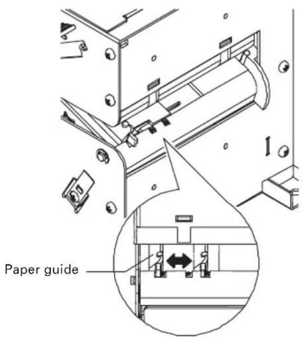
The printer can accept four kinds of paper widths: 82.5 mm, 80 mm, 67 mm, and 58 mm.
Use the following procedure to set the paper width.
- Move the paper guide of the paper slot at the back of the printer to meet the paper width.
(Changing print width is available with a command. For details, refer to Command Reference.)
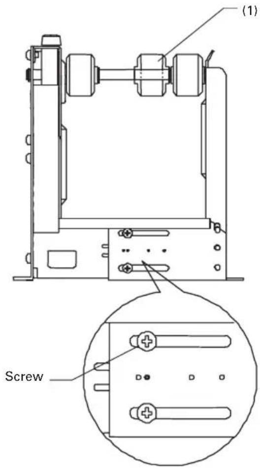
- When using the paper holder (PHU-3***), loosen the screws (4 places including other side) shown in the figure, adjust the holder to the specified width, and then tighten the screws.
When the paper width is 58 mm or 67 mm, remove the E ring and move the paper roller located at position (1) in the figure.
4.11 FEED Switch
- The FEED switch, when pressed, feeds paper, cuts the paper, and then ejects the paper.
4.12 Paper End
- If no print paper is present in the printer, Busy, Fault, and PError alarms are sent to the computer through the parallel interface or DTR output is sent to the printer through the serial interface.
- If data remains in the buffer, printing occurs after supplying paper.
- Set a new paper roll in accordance with "4.5 Setting/Replacing Paper Roll".
- After paper setting, Busy (DTR), Fault, and PError outputs are cleared.
4.13 Paper Near-End Sensor (When PHU-3\*\*\* is used)
- When the print paper remainder becomes low, the Paper Near-End (PNE) sensor sends a signal to the computer telling the paper is low and stops printing. This function is enabled or disabled by the memory switch. For memory switch setting, refer to "7.2 Memory Switch Functions (MSW2-8)".
- The PNE sensor can be adjusted in the following range by loosening the top screw.
- Set a new paper roll in accordance with "4.5 Setting/Replacing Paper Roll".
| Type | Number of PNE Sensors | Adjustable Range (Outer Diameter of Rolled Paper) | |
| 1st PNE Sensor 2nd PNE Sensor | |||
| PHU-3*1* | 1 | 23.6 to 50 | — |
| PHU-3*2* | 2 | 23.6 to 40 | 33.6 to 50 |
Note: For PHU-3*2*, the space between the 1st PNE sensor and the 2nd PNE sensor shall be fixed at 5 mm.
4.14 Paper Retraction
- This printer has a function of automatically collecting the ejected paper. This function is enabled or disabled by the memory switch. For memory switch setting, refer to "7.2 Memory Switch Functions".
- After print paper is cut, paper is collected after a certain period of time has passed with the presenter loaded with paper.
- The time can be adjusted by a command.
- Before collecting the ejected paper, allow a space for paper path at the mounting area and at the bottom of the printer and prepare a collection box. For details, refer to "5.2 Notes on Paper Collection Hole and Collection Path".
4.15 Self-printing
- This printer has a function of printing a set of predetermined characters. Turn on the printer while pressing the FEED switch. Hold the FEED switch pressed for about 1 second and then release the FEED switch. Then the printer starts self-printing. Model name, ROM version, DIP switch status, memory switch status, and built-in characters are printed.
- After self-printing is completed, the printer performs initialize operation and is ready for printing.

CAUTION!
Do not print with low paper supply.
4.16 Hexadecimal Dump Feature
- This printer has the function to print data sent from the host in hexadecimal numbers and the corresponding characters. With the printer cover open and pressing and holding the FEED switch, turn the printer power on and then close the cover. The printer starts initialization and prints "HEX DUMP PRINT MODE" followed by printing of data received thereafter in hexadecimal numbers and characters.
- After the printer stops printing, turn the printer power off or press the FEED switch three times or apply a reset signal from the interface, then the printer executes initialization and enters the standby state.

CAUTION!
●Do not print in paper low condition.
- If there is no character corresponding to data, the printer prints “.”
●During hexadecimal dump printing, commands other than DLE EOT, DLE ENQ, and DLE DC4 provide no function.
- If the print data is less than a line, printing is caused by the occurrence of a certain offline factor (pressing the FEED switch or the like).
4.17 Operation Panel and Error Indication
(1) POWER LED (Green)
ON: Lights while power is supplied.
OFF: Goes off while power is not supplied.
Blinking: Blinks while some operation is in process.
(2) ERROR LED (Red)
The ON/Blink status indicates the status of the error. Blinking also occurs while the printer is waiting for macro execution. (For details, refer to Command Details and Macro execution command.)
| ERROR POWER LED ERROR LED BUZZER | |||
| Paper end Lights Lights |  | ||
| Paper near-end Lights | Lights — | ||
| Cover open Lights Lights |  | ||
| Cutter motor lock Lights | 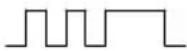 | 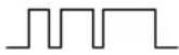 | |
| Head overheat Lights — |  | ||
| Memory check error Lights | |||
| Low voltage error Lights — | 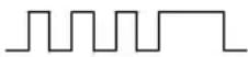 | ||
| High voltage error Lights — |  | ||
| Sum check error |  | — | |
| Presenter error | Lights |  | |
| Black marked paper detection error | Lights |  | |
| Macro execution wait | Lights — | 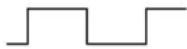 | |
Description of Errors
●Paper end
When the paper roll has run out, the Paper end sensor located in the paper path near the print head detects the end of the paper roll, causing the PE to be output and the printing to stop.
●Paper near-end
When the paper roll diameter is reduced to the lower limit, the Paper near-end sensor is activated and causes the PE to be output, indicating that the paper supply has become low.
●Cover open
When the cover is open, the cover open sensor reacts to stop the printing operation.
●Head overheat
To protect the print head from overheating, the head temperature sensor is activated if the head temperature rises over approx. 65^ C, causing ERROR to be output and the printing to stop. Printing resumes automatically when the head temperature lowers below 60^ C.
●Cutter motor lock
While the cutter motor is running, if the cutter position sensor inside the cutter unit keeps ON or OFF for approx. 1 second or more, the printer judges that the motor has locked, causing the cutter operation and printing operation to stop. (See "4.8 Removing Cutter Lock".)
●Low voltage error
This error occurs when the voltage supplied to the printer is too low. If this error occurs, turn the printer power off immediately.
●High voltage error
This error occurs when the voltage supplied to the printer is too high. If this error occurs, turn the printer power off immediately.
●Presenter error
This error occurs when the presenter cannot eject paper or it cannot collect the ejected paper. To clear this error, remove the jammed paper or press the FEED switch.
●Black mark detection error
This error occurs when the printer cannot detect the black mark. If this error occurs, turn the printer power off and confirm the paper and memory switch setting.
5. NOTES ON EXTERIOR DESIGN
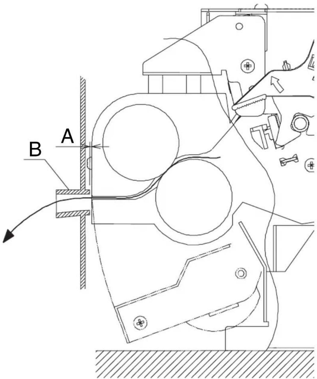
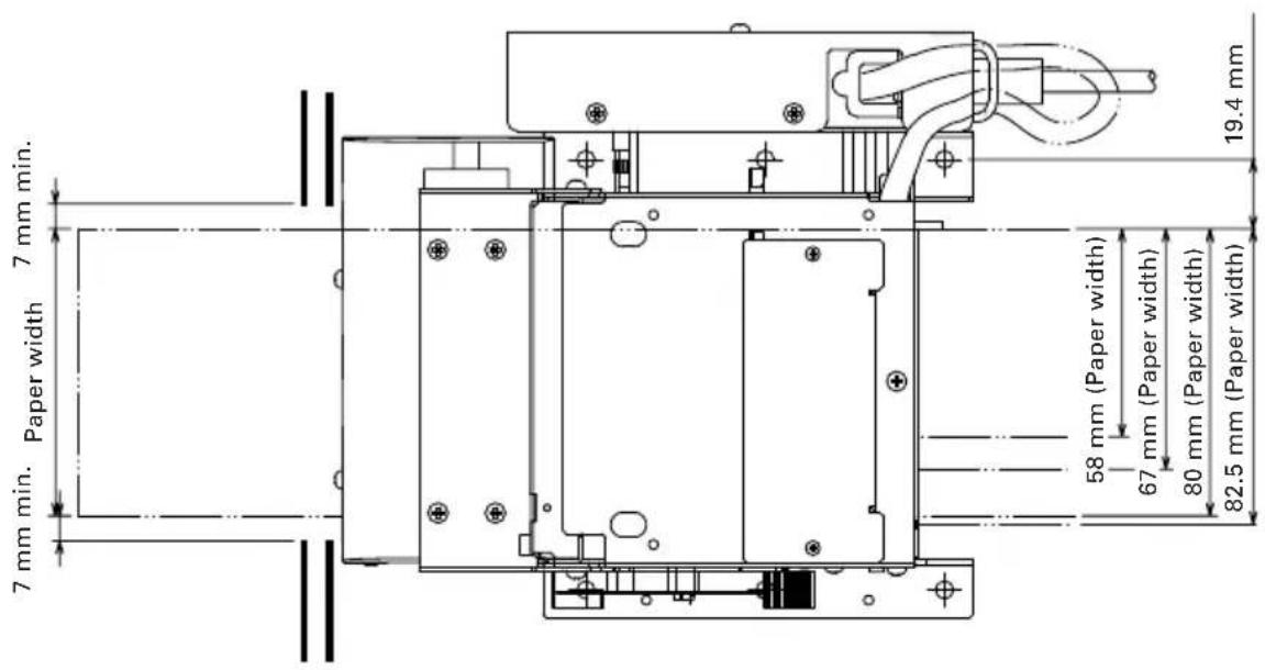
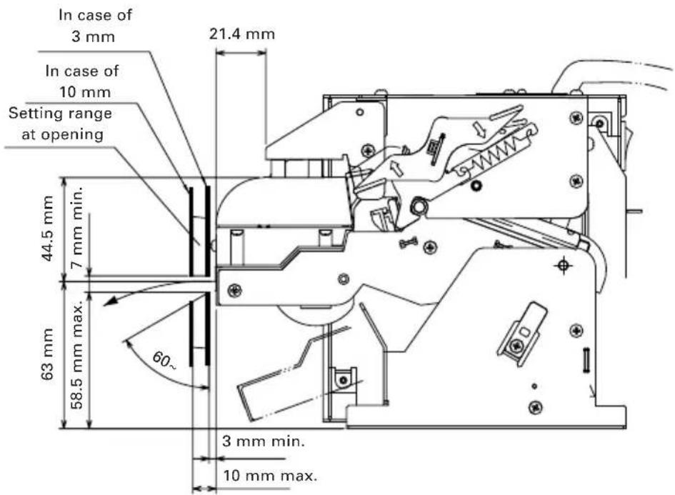
5.1 Notes on Paper Exit
- Use consideration to prevent the ejected paper from entering the gap of the exterior case. (Dimension A must be minimum.)
- Avoid the shape that may obstruct the paper ejected from the presenter unit.
- Use consideration to design the shape that may prevent entry of dust, drops of water from the outside. (Portion B)
- Keep a space enough to open the paper guide for maintenance purpose.
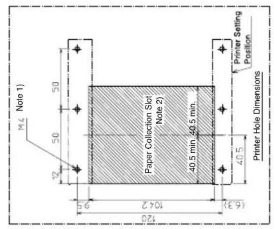
5.2 Notes on Paper Collection Hole and Collection Path
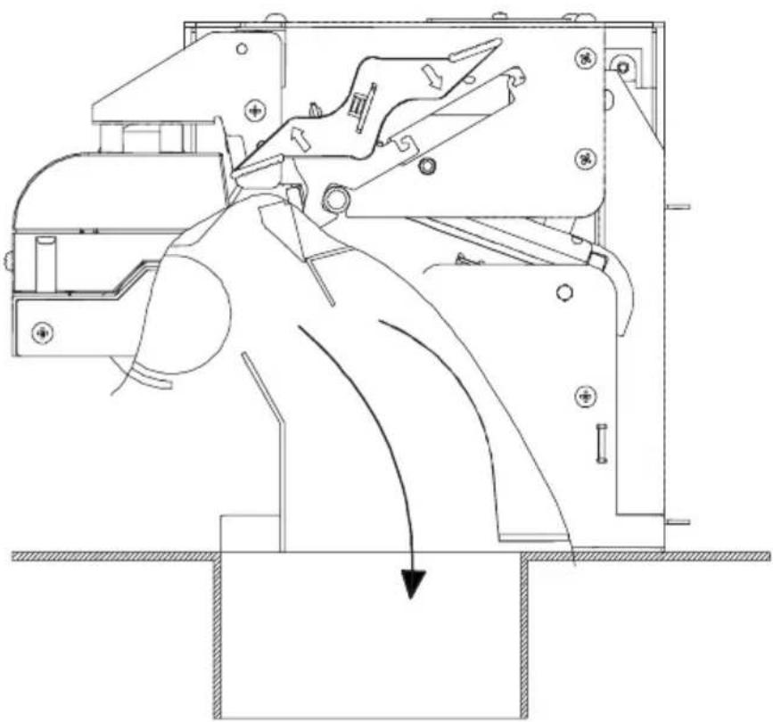
When implementing paper collection, be sure to prepare the paper collection hole as shown below.
Be careful to prevent irregularity, burr, etc. along the collecting path. Otherwise paper jam may occur.
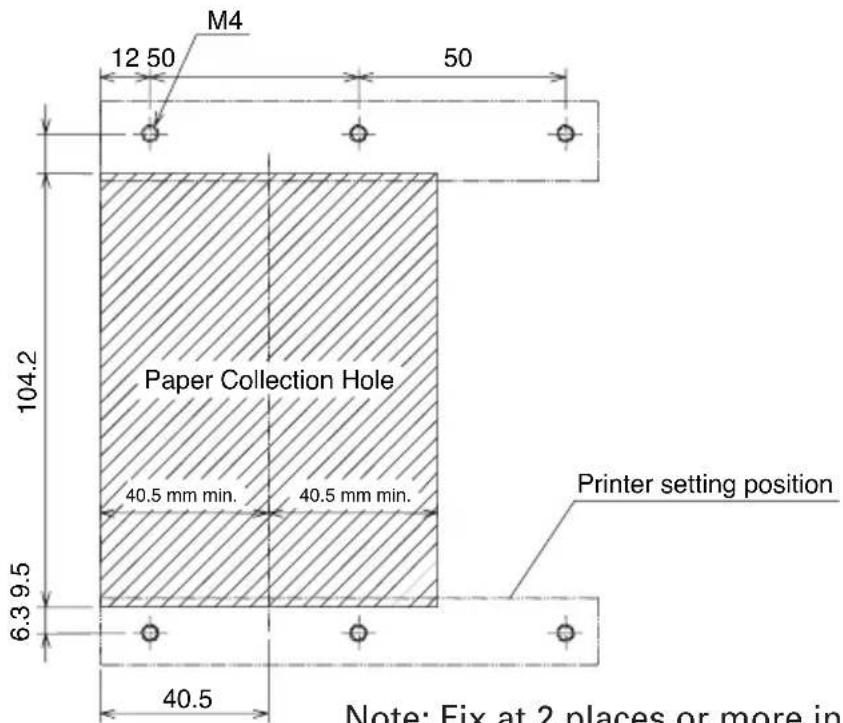
Note: Fix at 2 places or more in one side totaling 4 places or more.
natural_image
Technical line drawing of a mechanical device with internal components and directional arrows (no text or symbols)5.3 Notes on Paper Insertion Path
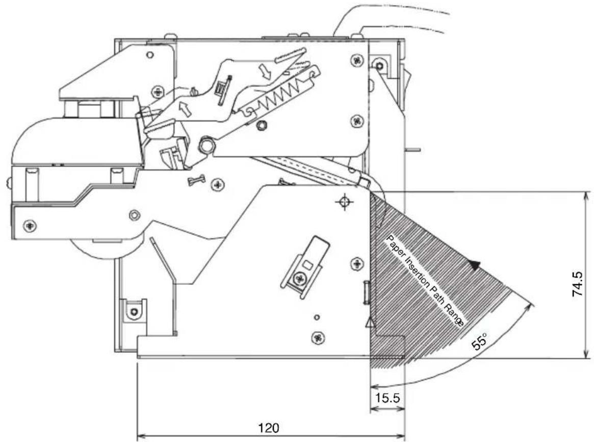
When feeding paper without using optional PHU-3***, set the paper path in the following range. When using a large-diameter paper roll, be sure to provide a shock absorber to prevent shock during rotation of paper roll.
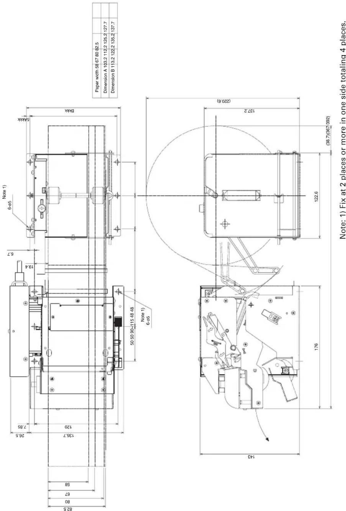
5.4 PHU-3\*\*\* (Paper Feed Unit) Installation
Refer to "Appendix-3. PPU-700 PUU-3*** (Paper Feed Unit) Installation".
5.5 Layout Examples of Control Box
Separation of Control Box from Printer allows you to enjoy free layout.
| Layout Example (1/3) | |
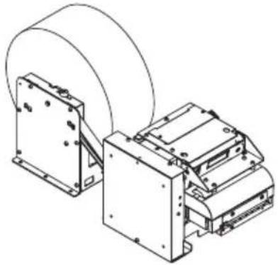 | 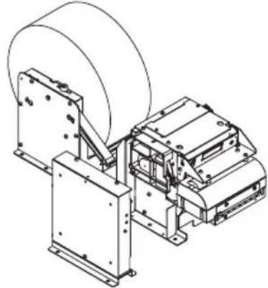 |
| Basic Type Example 1) With board installed separately. | |
| Layout Example (2/3) | |
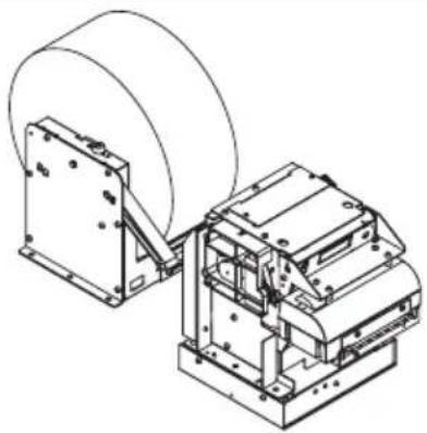 | 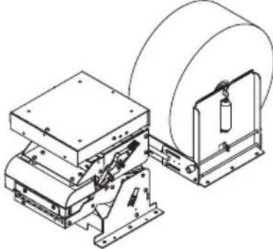 |
| Example 2) With board installed below the printer. | Example 3) With board installed above the printer. |
| Layout Example (3/3) | |
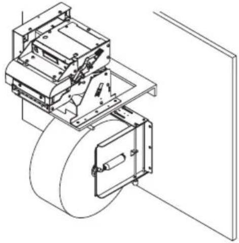 | 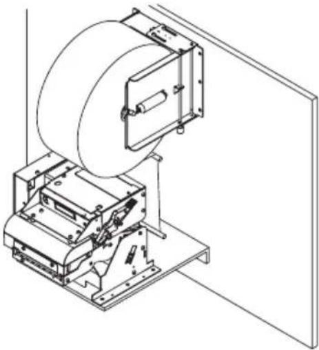 |
| Example 4) With paper holder installed under the printer. | Example 5) With paper holder installed above the printer. |
6. DIP SWITCHES
6.1 Setting DIP Switches
The DIP switch is located on the serial interface board of the printer.
DIP switch setting with the printer power on is not valid. After setting, turn the printer power on.
- Turn the printer power off.
- Remove the screw from the board. (Be sure not to have the screw be lost.)
- Slide the interface board to remove it.
- Set the DIP switch.
- After setting, remount the interface board and screw it.

CAUTION!
●Pay attention to the edge of the interface board.
- The screw used is M2 × 3 mm. Do not use screws of other size. (If the screw is lost, use the screw of the same size. Do not use longer size.)
● Turn the printer power off before setting DIP switches. Otherwise, a failure may occur.
●Do not use keen edged tool when setting the DIP switch.
●Do not use the printer with the interface board removed.
6.2 DIP Switch Functions
DIP Switches
| Switch No. | Function ON OFF | Factory Setting | ||
| 1 | Setting and selecting condition for communication | DIP switch setting is DIP enabled. disabled. | switch setting is ON | |
| 2 | Communication mode Xon/Xoff DTR/DSR OFF | |||
| 3 | Bit length 7-bit 8-bit OFF | |||
| 4 | Parity check With parity No parity OFF | |||
| 5 | Selecting parity | Even parity | Odd parity | OFF |
| 6 | Selecting baud rate | (See Table 1) | ON | |
| 7 | ON | |||
| 8 | INIT | Reset | Disabled | OFF |
Table 1 Selecting baud rate
| Baud Rate (bps) | Switch No. | |
| 6 | 7 | |
| 2,400 OFF | OFF | |
| 4,800 | ON | OFF |
| 9,600 OFF | ON | |
| 19,200 | ON | ON |
7.1 Setting Memory Switches
Memory switch is a generic name for the following.
(1) Memory switches MSW1, MSW2, MSW3, MSW4
(2) Customize value
(3) Condition for communication through serial interface
The memory switch can be selected, changed, or written by the combination of three actions: pressing the FEED switch, pressing and holding the FEED switch, and opening or closing the paper cover.
- Entering memory switch setting mode
Set paper to the printer and keep the printer cover open. With the FEED switch pressed and held, turn the printer power on, and then press the FEED switch twice. Close the cover. If the current settings of the memory switch, etc. are printed, the printer is now in the memory switch setting mode.
- Selecting memory switch
When the FEED switch is pressed short (within 2 seconds), printing occurs in the order of "MSW1" → "MSW2" → "MSW3" → "MSW4" → "Write/Factory Setting" → "MSW1" → ..... repeatedly. When the memory switch you want to change is reached, press and hold the FEED switch (for more than 2 seconds).
- Selecting each switch item
There are eight setting items for each switch. Press and hold the FEED switch for long (within 2 seconds), the printer goes to the next item and prints the current setting of the item. Repeat pressing and holding till the item you want to change setting is reached.
- Changing the setting
When the item you want to change is reached, press the FEED switch short. The changed set value is printed. To return to the previous setting press the FEED switch short. When you press the FEED switch long, the set value is accepted and then the printer goes to the next setting item.
- Returning to the memory switch select mode
When the setting of the desired content is completed, open the paper cover and then close the paper cover. This allows the printer to print the setting of the changed memory switch.
- Saving the setting and exiting the memory switch setting mode
Press the FEED switch short to move to "Write/Factory Setting". Then press and hold the FEED switch. The printer prints the content of new setting and exits the memory switch setting mode to return to the normal standby state.
* Unless saving the setting is executed, the changed setting cannot be enabled.
- Initializing the memory switch
When you want to return the memory switch setting to the initial state, go to "Write/Factory Setting" in the above procedure. Here, open the paper cover and press and hold the FEED switch. This allows the printer to return to the initial state.
* All the memory switch settings are returned to the factory set values.
7.2 Memory Switch Functions
Model PPU-700
| No. Function OFF ON | |||
| MSW1-1 Power ON Info ● Valid Not send | |||
| MSW1-2 Buffer Size ● 4K bytes 45 bytes | |||
| MSW1-3 Busy Condition ● Full/Err Full | |||
| MSW1-4 Receive Error ● Print ? Invalid | |||
| MSW1-5 CR Mode ● Ignored LF | |||
| MSW1-6 Reserved ● Fixed | — | ||
| MSW1-7 | DSR Signal | ● Invalid | Valid |
| MSW1-8 | INIT Signal | ● Invalid | Valid |
| MSW2-1 | Reserved | — | ● Fixed |
| MSW2-2 | Reserved | — | ● Fixed |
| MSW2-3 | Spool print | Invalid | ● Valid |
| MSW2-4 | Full col print | CBM1000 | ● EPSON |
| MSW2-5 | Resume aft PE | ● Print next line | Print top |
| MSW2-6 Reserved ● Fixed | — | ||
| MSW2-7 Reserved ● Fixed | — | ||
| MSW2-8 | PNE sensor | ● Valid | Invalid |
| MSW3-1 | Resum Ctrr Err | ● Valid | Invalid |
| MSW3-2 | Resum Open Err | ● Close | Command |
| MSW3-3 | Parallel 31 Pin | ● Valid | Invalid |
| MSW3-4 | Paper Select | ● Thermal | Black MK |
| MSW3-5 Reserved ● Fixed | — | ||
| MSW3-6 Reserved ● Fixed | — | ||
| MSW3-7 | Emulation | ● PPU-231 | TM-L90 |
| MSW3-8 | Open w/Printing | ● Auto | Possible |
| MSW4-1 Reserved ● Fixed | — | ||
| MSW4-2 Reserved ● Fixed | — | ||
| MSW4-3 | Pape Top Feed | ● Valid | Invalid |
| MSW4-4 | Collect mode | ● Invalid | Valid |
| MSW4-5 | Collecti Direction | ● Rear | Front |
| MSW4-6 | Collect Method | ● General | Direct |
| MSW4-7 | Print Continue | ● Invalid | Valid |
| MSW4-8 Reserved ● Fixed | — | ||
● Default (Factory shipment)
Model PPU-700II
| No. Function OFF ON | |||
| MSW1-1 Power ON Info ● Valid Not send | |||
| MSW1-2 Buffer Size ● 4K bytes 45 bytes | |||
| MSW1-3 Busy Condition ● Full/Err Full | |||
| MSW1-4 Receive Error ● Print ? Invalid | |||
| MSW1-5 CR Mode ● Ignored LF | |||
| MSW1-6 Reserved ● Fixed | — | ||
| MSW1-7 | DSR Signal | ● Invalid | Valid |
| MSW1-8 | INIT Signal | ● Invalid | Valid |
| MSW2-1 | Reserved | — | ● Fixed |
| MSW2-2 | Reserved | — | ● Fixed |
| MSW2-3 | Spool print | Invalid | ● Valid |
| MSW2-4 | Full col print | CBM1000 | ● EPSON |
| MSW2-5 | Resume aft PE | ● Print next line | Print top |
| MSW2-6 Reserved ● Fixed | — | ||
| MSW2-7 Reserved ● Fixed | — | ||
| MSW2-8 | PNE sensor | ● Valid | Invalid |
| MSW3-1 | Resum Ctrr Err | ● Valid | Invalid |
| MSW3-2 | Resum Open Err | ● Close | Command |
| MSW3-3 | Parallel 31 Pin | ● Valid | Invalid |
| MSW3-4 | Paper Select | ● Thermal | Black MK |
| MSW3-5 Reserved ● Fixed | — | ||
| MSW3-6 Reserved ● Fixed | — | ||
| MSW3-7 | Emulation | ● PPU-231 | TM-L90 |
| MSW3-8 | Open w/Printing | ● Auto | Possible |
| MSW4-1 Reserved ● Fixed | — | ||
| MSW4-2 Reserved ● Fixed | — | ||
| MSW4-3 | Pape Top Feed | ● Valid | Invalid |
| MSW4-4 | Collect mode | ● Invalid | Valid |
| MSW4-5 | Collecti Direction | ● Rear | Front |
| MSW4-6 | Collect Method | ● General | Direct |
| MSW4-7 | Print Continue | ● Invalid | Valid |
| MSW4-8 Reserved ● Fixed | — | ||
● Default (Factory shipment)
| Switch No. | Setting | 0 (OFF) | 1 (ON) |
| Memory SW5-1 | Buzzer | Valid | Invalid |
| SW5-2 | Reserved | Fixed | - |
| SW5-3 | USB Mode | Virtual COM | Printer Class |
| SW5-4 | Reserved | Fixed | - |
| SW5-5 | Reserved | Fixed | - |
| SW5-6 | Reserved | Fixed | - |
| SW5-7 | Clear PNE LED | Auto | Set Paper |
| SW5-8 | Reserved | Fixed | - |
| Switch No. Setting Default Set Values | |||
| Memory SW7-1 Baud Rate 9600 | bps 1200 bps, 2400 bps, 4800 bps, 9600 bps, 19200 bps, 38400 bps | ||
| SW7-2 Data Length 8bits | 7bits, 8bits | ||
| SW7-3 Stop Bit 1bit 1bit, 2bits | |||
| SW7-4 Parity NONE | NONE, EVEN, ODD | ||
| SW7-5 Flow Control | DTR/DSR | DTR/DSR, XON/XOFF | |
| SW7-6 Reserved | - | ||
| SW7-7 VCom Protocol | PC Setting | PC Setting, DTR/DSR, XON/XOFF | |
| Memory SW8-1 | Print Width | 576 dots | |
| SW8-2 Paper Color | 1 Color Normal | 1 Color Normal, Color Normal | |
APPENDIX-1. PPU-700 EXTERNAL VIEW
Unit: mm
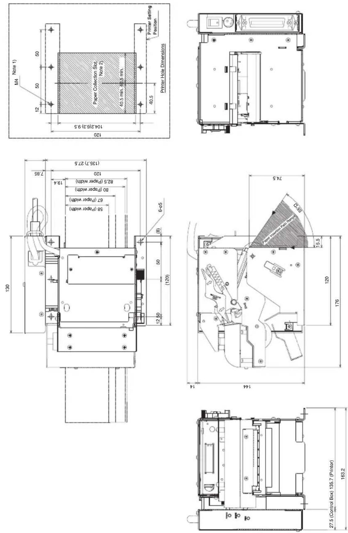
Notes: 1) Fix at 2 places or more in one side totaling 4 places or more.
2) When collecting paper, be sure to prepare a paper collection hole.
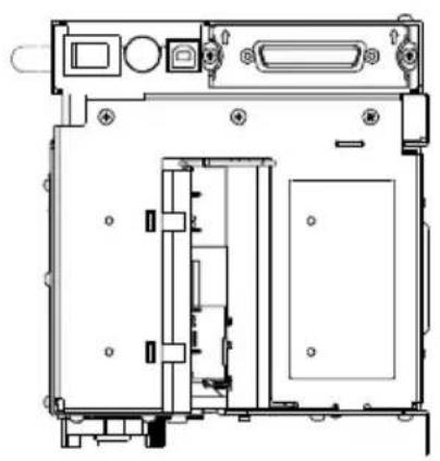
APPENDIX-2. PPU-700II EXTERNAL VIEW
Unit: mm
natural_image
Technical line drawing of a mechanical assembly with no visible text or symbols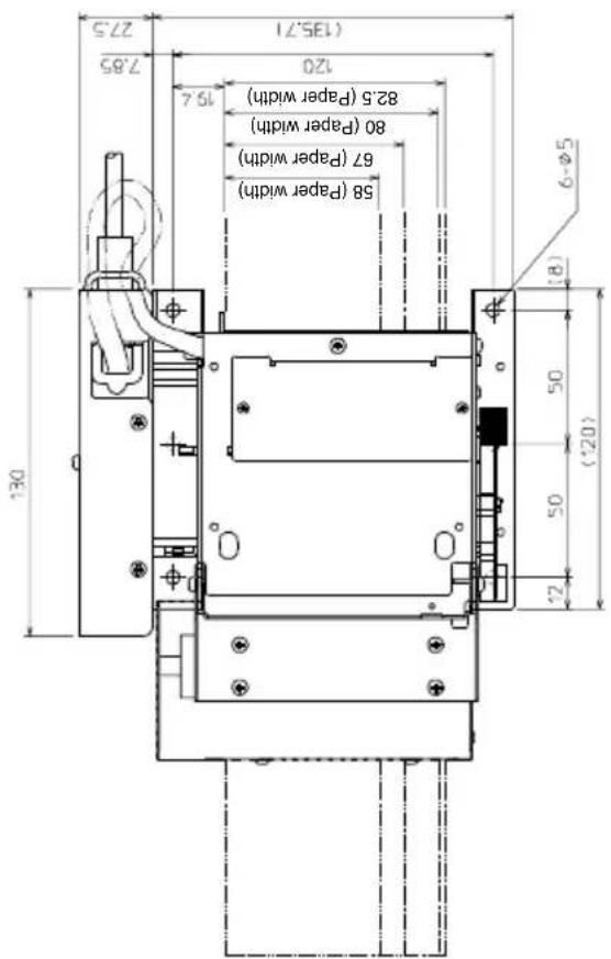
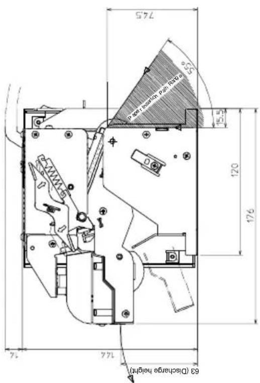
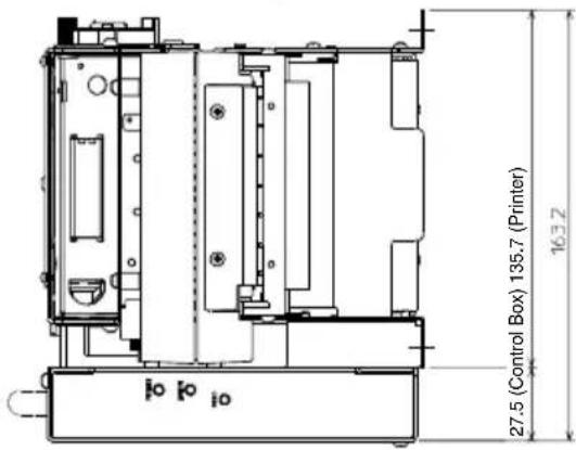
Notes: 1) Fix at 2 places or more in one side totaling 4 places or more. 2) When collecting paper, be sure to prepare a paper collection hole.
APPENDIX-3. PPU-700 PHU-3\*\*\* (PAPER FEED UNIT) INSTALLATION
APPENDIX-4. BLOCK DIAGRAM
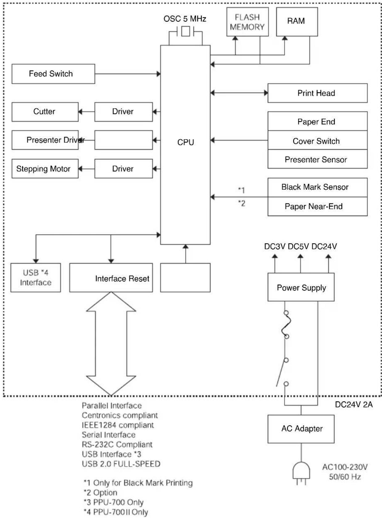
flowchart
graph TD
    A["CPU"] --> B["Feed Switch"]
    A --> C["Cutter"]
    A --> D["Presenter Driver"]
    A --> E["Stepping Motor"]
    A --> F["Driver"]
    A --> G["Flash Memory"]
    A --> H["RAM"]
    A --> I["Print Head"]
    A --> J["Paper End"]
    A --> K["Cover Switch"]
    A --> L["Presenter Sensor"]
    A --> M["Black Mark Sensor"]
    A --> N["Paper Near-End"]
    A --> O["Interface Reset"]
    O --> P["USB *4 Interface"]
    O --> Q["Parallel Interface Centronics compliant IEEE1284 compliant Serial Interface RS-232C Compliant USB Interface *3 USB 2.0 FULL-SPEED"]
    Q --> R["*1 Only for Black Mark Printing"]
    Q --> S["*2 Option"]
    Q --> T["*3 PPU-700 Only"]
    Q --> U["*4 PPU-700II Only"]
    A --> V["Power Supply"]
    V --> W["AC Adapter"]
    W --> X["DC24V 2A"]
    W --> Y["DC3V DC5V DC24V"]
    W --> Z["AC100-230V 50/60 Hz"]

- PRINTER PRESENTER UNIT
- MODEL PPU-700/700II
- User's Manual
- Ge
- Declaration of Conformity
- Sicherheitshinweis
- CAUTION
- SAFETY PRECAUTIONS ... WHICH SHOULD BE STRICTLY OBSERVED
- WARNING
- DAILY MAINTENANCE
- THE TABLE OF CONTENTS
- GENERAL OUTLINE ...... 12
- BASIC SPECIFICATIONS ...... 13
- APPEARANCE AND COMPONENTS PARTS ...... 21
- OPERATION 25
- NOTES ON EXTERIOR DESIGN 40
- DIP SWITCHES 45
- MEMORY SWITCHES 47
- APPENDIX-1. PPU-700 EXTERNAL VIEW 52
- APPENDIX-2. PPU-700II EXTERNAL VIEW ....53
- APPENDIX-3. PPU-700 PHU-3\*\*\* (PAPER FEED UNIT) INSTALLATION....54
- APPENDIX-4. BLOCK DIAGRAM 55
- GENERAL OUTLINE
- Features
- Unpacking
- CAUTION!
- BASIC SPECIFICATIONS
- Model Classification
- PPU-700/PPU-700II Series
- Option
- Basic Specifications
- Print Paper Specifications
- Specified Paper
- Thermal Paper Roll
- Or other equivalent paper
- Print Position
- Black Mark Layout and Operating Condition
- APPEARANCE AND COMPONENTS PARTS
- PPU-700/PPU-700II Printer
- Detector Position
- PHU-3\*\*\*(Paper Feed Unit) (Option)
- Connecting AC Adapter and AC Cable
- Connecting Interface Cables
- Interface Board Change
- Connecting PHU (Paper Feed Unit)
- Connector for Operation Panel (CN500)
- Pin Assignment
- Connection Example
- Setting/Replacing Paper Roll
- Paper Setting from Paper Side-in
- Paper Setting by Auto-loading
- When Using PHU-3 \*\*\* (Paper Feed Unit)
- Removing the Remaining Paper Roll
- Removing Jammed Paper
- Removing Cutter Lock
- Changing Paper Width
- FEED Switch
- Paper End
- Paper Near-End Sensor (When PHU-3\*\*\* is used)
- Paper Retraction
- Self-printing
- Hexadecimal Dump Feature
- Operation Panel and Error Indication
- POWER LED (Green)
- ERROR LED (Red)
- Description of Errors
- ●Paper end
- ●Paper near-end
- ●Cover open
- ●Head overheat
- ●Cutter motor lock
- ●Low voltage error
- ●High voltage error
- ●Presenter error
- ●Black mark detection error
- NOTES ON EXTERIOR DESIGN
- Notes on Paper Exit
- Notes on Paper Collection Hole and Collection Path
- Notes on Paper Insertion Path
- PHU-3\*\*\* (Paper Feed Unit) Installation
- Layout Examples of Control Box
- DIP SWITCHES
- Setting DIP Switches
- DIP Switch Functions
- Setting Memory Switches
- Memory Switch Functions
- APPENDIX-1. PPU-700 EXTERNAL VIEW
- APPENDIX-2. PPU-700II EXTERNAL VIEW
- APPENDIX-3. PPU-700 PHU-3\*\*\* (PAPER FEED UNIT) INSTALLATION
- APPENDIX-4. BLOCK DIAGRAM
Brand : CITIZEN
Model : PPU-700II
Category : Label printer