GW3300 - Router Virtual Access - Free user manual and instructions
Find the device manual for free GW3300 Virtual Access in PDF.


User questions about GW3300 Virtual Access
0 question about this device. Answer the ones you know or ask your own.
Ask a new question about this device
Download the instructions for your Router in PDF format for free! Find your manual GW3300 - Virtual Access and take your electronic device back in hand. On this page are published all the documents necessary for the use of your device. GW3300 by Virtual Access.
USER MANUAL GW3300 Virtual Access
GW3300 Series User Manual
Issue: 1.8
Date: 02 February 2018
1 Introduction....10
1.1 Document scope 10
1.2 Using this documentation.... 10
2 GW3300 Series router hardware 13
2.1 Hardware specification.... 13
2.2 Hardware features 13
2.3 RS232 mode pin-out on the GW3300.... 14
2.4 RS485 mode pin-out on the GW3300.... 14
2.5 Mobile technology 14
2.6 WiFi technology 14
2.7 Power supply.... 15
2.8 Dimensions.... 15
2.9 Operating temperature range 15
2.10 Antenna.... 16
2.11 Getting started 16
2.12 Inserting the SIM cards 16
2.13 Connecting cables.... 16
2.14 Connecting the antenna.... 16
2.15 Powering up 17
2.16 Reset button 17
3 GW3300 Series LED behaviour....18
3.1 Configuration LED 18
3.2 SIM LED 18
3.3 Signal strength LEDs 18
3.4 Ethernet port LED behaviour 19
4 Installing a router into a vehicle....20
4.1 Installing a router into a vehicle using a non-fused power cable....20
4.2 Installing a router into a vehicle using a fused power cable 21
5 Factory configuration extraction from SIM card 22
6 Accessing the router....23
6.1 Configuration packages used 23
6.2 Accessing the router over Ethernet using the web interface 23
6.3 Accessing the router over Ethernet using an SSH client 24
6.4 Accessing the router over Ethernet using a Telnet client 25
6.5 Configuring the password.... 25
6.6 Configuring the password using the web interface.... 25
6.7 Configuring the password using UCI 26
6.8 Configuring the password using package options.... 26
6.9 Accessing the device using RADIUS authentication 27
6.10 Accessing the device using TACACS+ authentication 28
6.11 SSH 31
6.12 Package dropbear using UCI 33
6.13 Certs and private keys.... 34
6.14 Configuring a router's web server 35
6.15 Basic authentication (httpd conf) 40
6.16 Securing uhttpd 41
6.17 Displaying custom information via login screen 41
7 Router file structure 43
7.1 System information....43
7.2 Identify your software version 44
7.3 Image files....45
7.4 Directory locations for UCI configuration files 45
7.5 Viewing and changing current configuration 45
7.6 Configuration file syntax 46
7.7 Managing configurations 46
7.8 Exporting a configuration file 47
7.9 Importing a configuration file 48
8 Using the Command Line Interface....52
8.1 Overview of some common commands 52
8.2 Using Unified Configuration Interface (UCI) 55
8.3 Configuration files....60
8.4 Configuration file syntax 60
9 Upgrading router firmware....62
9.1 Software versions 62
9.2 Upgrading firmware using CLI 68
10 System settings....71
10.1 Configuration package used 71
10.2 Configuring system properties 71
10.3 System settings using UCI 75
10.4 System diagnostics 76
11 Configuring an Ethernet interface....78
11.1 Configuration packages used 78
11.2 Configuring an Ethernet interface using the web interface 78
11.3 Interface configuration using UCI 90
11.4 Configuring port maps....93
11.5 Port map packages....93
11.6 Interface diagnostics....95
12 Configuring VLAN 97
12.1 Maximum number of VLANs supported 97
12.2 Configuration package used 97
12.3 Configuring VLAN using the web interface 97
12.4 Viewing VLAN interface settings.... 100
12.5 Configuring VLAN using the UCI interface.... 101
13 Configuring ignition sense 102
13.1 Configuration packages used 102
13.2 Configuring vapowermond using the web interface.... 102
13.3 Configuring vapowermond using the command line 104
13.4 Ignition sense diagnostics 105
14 Configuring a WiFi connection .... 106
14.1 Configuration packages used 106
14.2 Configuring a WiFi interface using the web interface.... 106
14.3 Configuring WiFi in AP mode.... 112
14.4 Configuring WiFi using UCI 114
14.5 Creating a WiFi in Client mode using the web interface 117
14.6 Configuring WiFi in Client mode using command line 118
15 Configuring a mobile connection 120
15.1 Configuration package used 120
15.2 Configuring a mobile connection using the web interface.... 120
15.3 Configuring a mobile connection using CLI 126
15.4 Diagnositcs 127
16 Configuring mobile manager....131
16.1 Configuration package used 131
16.2 Configuring mobile manager using the web interface.... 131
16.3 Configuring mobile manager using command line.... 136
16.4 Monitoring SMS 137
16.5 Sending SMS from the router 138
16.6 Sending SMS to the router 138
17 Configuring a GRE interface....139
17.1 Configuration packages used.... 139
17.2 Creating a GRE connection using the web interface 139
17.3 GRE configuration using command line 144
17.4 GRE configuration using UCI 144
17.5 GRE configuration using package options.... 144
17.6 GRE diagnostics.... 145
18 Configuring static routes ...... 147
18.1 Configuration package used 147
18.2 Configuring static routes using the web interface 147
18.3 Configuring IPv6 routes using the web interface 148
18.4 Configuring routes using command line 148
18.5 IPv4 routes using UCI.... 149
18.6 IPv4 routes using package options.... 150
18.7 IPv6 routes using UCI.... 150
18.8 IPv6 routes using packages options.... 150
18.9 Static routes diagnostics.... 151
19 Configuring BGP (Border Gateway Protocol) 152
19.1 Configuration package used 152
19.2 Configuring BGP using the web interface.... 152
19.3 Configuring BGP using UCI 155
19.4 Configuring BGP using packages options.... 156
19.5 View routes statistics.... 157
20 Configuring OSPF (Open Shortest Path First) 158
20.1 Introduction 158
20.2 Configuration package used 163
20.3 Configuring OSPF using the web interface 164
20.4 Configuring OSPF using the command line 167
20.5 OSPF using UCI 168
20.6 OSPF using package options.... 169
20.7 OSPF diagnostics 170
20.8 Quagga/Zebra console.... 171
21 Configuring VRRP 177
21.1 Overview 177
21.2 Configuration package used 177
21.3 Configuring VRRP using the web interface 177
21.4 Configuring VRRP using command line.... 181
22 Configuring Routing Information Protocol (RIP) 184
22.1 Introduction 184
22.2 Configuration package used 185
22.3 Configuring RIP using the web interface.... 186
22.4 Configuring RIP using command line 190
22.5 RIP diagnostics.... 194
23 Configuring Multi-WAN 198
23.1 Configuration package used 198
23.2 Configuring Multi-WAN using the web interface.... 198
23.3 Configuring Multi-WAN using UCI 202
23.4 Multi-WAN diagnostics.... 204
24 Automatic operator selection....206
24.1 Configuration package used 206
24.2 Configuring automatic operator selection via the web interface 206
24.3 Configuring via UCI 230
24.4 Configuring no PMP + roaming using UCI 234
24.5 Automatic operator selection diagnostics via the web interface 236
24.6 Automatic operator selection diagnostics via UCI 238
25 Configuring Connection Watch (cwatch) 241
25.1 Configuration package used 241
25.2 Configuring Connection Watch using the web interface 241
25.3 Configuring cwatch using command line 243
25.4 cwatch diagnostics 244
26 Configuring DHCP server and DNS (Dnsmasq) 245
26.1 Configuration package used 245
26.2 Configuring DHCP and DNS using the web interface 245
26.3 Configuring DHCP and DNS using UCI 253
26.4 Configuring DHCP pools using UCI 255
26.5 Configuring static leases using UCI 256
27 Configuring DHCP client....257
27.1 Configuration packages used 257
27.2 Configuring DHCP client using the web interface 257
27.3 Configuring DHCP client using command line 263
27.4 DHCP client diagnostics 264
28 Configuring DHCP forwarding 267
28.1 Configuration packages used 267
28.2 Configuring DHCP forwarding using the web interface 267
28.3 Configuring DHCP forwarding using command line 268
28.4 DHCP forwarding over IPSec.... 269
28.5 DHCP forwarding diagnostics 272
29 Configuring Dynamic DNS....274
29.1 Overview 274
29.2 Configuration packages used 274
29.3 Configuring Dynamic DNS using the web interface 274
29.4 Dynamic DNS using UCI 276
30 Configuring hostnames....278
30.1 Overview 278
30.2 Local host file records.... 278
30.3 PTR records.... 280
30.4 Static leases.... 282
31 Configuring firewall....285
31.1 Configuration package used 285
31.2 Configuring firewall using the web interface 285
31.3 Configuring firewall using UCI 297
31.4 IPv6 notes 300
31.5 Implications of DROP vs. REJECT 300
31.6 Connection tracking 301
31.7 Firewall examples 301
32 Configuring IPSec....309
32.1 Configuration package used 309
32.2 Configuring IPSec using the web interface 309
32.3 Configuring IPSec using UCI 318
32.4 Configuring an IPSec template for DMVPN via the web interface 322
32.5 Configuring an IPSec template to use with DMVPN 329
32.6 IPSec diagnostics using the web interface 331
32.7 IPSec diagnostics using UCI 331
33 Dynamic Multipoint Virtual Private Network (DMVPN) 332
33.1 Prerequisites for configuring DMVPN 332
33.2 Advantages of using DMVPN 332
33.3 DMVPN scenarios 333
33.4 Configuration packages used 335
33.5 Configuring DMVPN using the web interface 335
33.6 DMVPN diagnostics.... 337
34 Configuring multicasting using PIM and IGMP interfaces 340
34.1 Overview 340
34.2 Configuration package used 340
34.3 Configuring PIM and IGMP using the web interface 340
34.4 Configuring PIM and IGMP using UCI 342
35 QoS: VLAN 802.1Q PCP tagging .... 344
35.1 Configuring VLAN PCP tagging 344
36 QoS: type of service....347
36.1 QoS configuration overview 347
36.2 Configuration packages used 347
36.3 Configuring QoS using the web interface.... 347
36.4 Configuring QoS using UCI 349
36.5 Example QoS configurations 352
37 Management configuration settings 353
37.1 Activator 353
37.2 Monitor 353
37.3 Configuration packages used 353
37.4 Autoload: boot up activation.... 354
37.5 Autoload packages 354
37.6 Autoload using UCI 357
37.7 HTTP Client: configuring activation using the web interface 358
37.8 Httpclient: Activator configuration using UCI 361
37.9 Httpclient: Activator configuration using package options.... 361
37.10 User management using UCI 362
37.11 Configuring the management user password using UCI 363
37.12 Configuring management user password using package options.... 364
37.13 User management using UCI 364
37.14 User management using package options 364
37.15 Configuring user access to specific web pages 365
38 Configuring Monitor 366
38.1 Introduction 366
38.2 Reporting device status to Monitor 366
38.3 Reporting GPS location to Monitor 372
38.4 Reporting syslog to Monitor 373
38.5 Configuring ISAD 375
39 Configuring SNMP 378
39.1 Configuration package used 378
39.2 Configuring SMNP using the web interface.... 378
39.3 Configuring SNMP using command line 384
39.4 Configuring SNMP interface alias with static SNMP index 390
39.5 SNMP diagnostics.... 392
40 Event system 394
40.1 Configuration package used 394
40.2 Event system overview 394
40.3 Configuring the event system using the web interface 395
40.4 Configuring the event system using command line 406
40.5 Event system diagnostics.... 414
41 Configuring data usage monitor 418
41.1 Introduction 418
41.2 Configuration package used 418
41.3 Configuring data usage using the web interface 418
41.4 Data usage status.... 421
41.5 Data usage diagnostics.... 421
42 Configuring Terminal Server 423
42.1 Overview 423
42.2 Configuration packages used 423
42.3 Configuring Terminal Server using the web interface 423
42.4 Terminal Server using UCI 434
42.5 Terminal Server using package options.... 434
42.6 Terminal server DSR signal management based on network configuration.... 434
42.7 Terminal Server diagnostics 436
43 Configuring terminal package....439
43.1 Configuration packages used 439
43.2 Configuring terminal package using the web interface 439
43.3 Configuring terminal package using UCI 439
43.4 Configuring terminal using package options.... 440
43.5 Terminal diagnostics.... 440
44.1 What are SAToP and CESoPSN? 441
44.2 Clocking.... 441
44.3 Virtual Access proprietary SAToP/CESoPSN protocol extension.... 442
44.4 Configuration package used 442
44.5 Configuring SAToP/CESoPSN 443
44.6 Configuring main settings using UCI 444
44.7 Configuring port settings using the web interface 445
44.8 Configuring port settings using UCI 451
44.9 CESoPSN diagnostics.... 452
45.1 Overview 462
45.2 Monitoring serial interfaces using the web interface 462
45.3 Monitoring serial interfaces using command line 463
44 Configuring SAToP and CESoPSN 441
45 Serial interface 462
1 Introduction
This user manual describes the features and how to configure Virtual Access GW3300 Series routers.
Designed for managed network providers, GW3300 Series routers provide secure WAN connectivity for internet and private networking environments over 3G or 4G broadband paths and incorporate optional 802.11n WiFi connectivity.
1.1 Document scope
This document covers the following models in the GW3300 Series.
GW3330 Four Ethernet, 3G/4G/LTE, Dual SIM, WiFi, Serial
1.2 Using this documentation
You can configure your router using either the router's web interface or via the command line using UCI commands. Each chapter explains first the web interface settings, followed by how to configure the router using UCI. The web interface screens are shown along with a path to the screen for example, 'In the top menu, select Service -> SNMP.' followed by a screen grab.
After the screen grab there is an information table that describes each of the screen's fields.
1.2.1 Information tables
We use information tables to show the different ways to configure the router using the router's web and command line. The left-hand column shows three options:
- Web: refers the command on the router's web page,
• UCI : shows the specific UCI command, and - Opt: shows the package option.
The right-hand column shows a description field that describes the feature's field or command and shows any options for that feature.
Some features have a drop-down menu and the options are described in a table within the description column. The default value is shown in a grey cell.
Values for enabling and disabling a feature are varied throughout the web interface, for example, 1/0; Yes/No; True/False; check/uncheck a radio button. In the table descriptions, we use 0 to denote Disable and 1 to denote Enable.
Some configuration sections can be defined more than once. An example of this is the routing table where multiple routes can exist and all are named 'route'. For these sections, the UCI command will have a code value [0] or [x] (where x is the section number) to identify the section.
| Web Field/ UCI / Package Option | Description |
| Web: MetricUCI: network.@route[0].metricOpt: metric | Specifies the route metric to use. |
Note: these sections can be given a label for identification when using UCI or package options.
network.@route[0]=route
network.@route[0].metric=0
can be written as:
network routename=route
network.routename.metric=0
However the documentation usually assumes that a section label is not configured.
The table below shows fields from a variety of chapters to illustrate the explanations above.
| Web Field/ UCI / Package Option | Description | |
| Web: EnableUCI: cesop.main.enableOpt: enable | Enables CESoPSN services. | |
| 0 | Disabled. | |
| 1 | Enabled. | |
| Web: Syslog SeverityUCI: cesop.main.severityOpt: log_severity | Selects the severity used for logging events CESoPSN in syslog.The following levels are available. | |
| 0 | Emergency | |
| 1 | Alert | |
| 2 | Critical | |
| 3 | Error | |
| 4 | Warning | |
| 5 | Notice | |
| 6 | Informational | |
| 7 | Debug | |
| Web: Agent AddressUCI: snmpd.agent[0].agentaddressOpt: agentaddress | Specifies the address(es) and port(s) on which the agent should listen.[(udp|tcp):]port[@address][,...] | |
Table 1: Example of an information table
1.2.2 Definitions
Throughout the document, we use the host name 'VA_router' to cover all router models.
UCI commands and package option examples are shown in the following format:
root@VA_router:~# vacmd show current config
1.2.3 Diagnostics
Diagnostics are explained at the end of each feature's chapter.
1.2.4 UCI commands
For detailed information on using UCI commands, read chapters 'Router File Structure' and 'Using Command Line Interface'.
2 GW3300 Series router hardware
2.1 Hardware specification
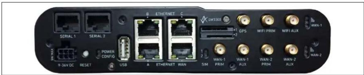
text_image
B ETERNET C GW3300 +1 GPS +2 WIFI PRIM WIFI AUX +1 +2 SN MAX 9-36V DC RESET POWER CONFIG USB A ETERNET WAN SIM WAN-1 WAN-1 WAN-2 WAN-2 PRIM AUX PRIM AUX WAN-1 WAN-2 WAN-2Figure 1: GW3300 router front interface
2.2 Hardware features
- Dual SIM sockets
- Seven SMA connectors: 2 for WiFi, 2 for each radio module, and 1 for GPS
• Four 1Gbps Ethernet ports - Two serial ports
- WiFi
- USB*
• Power ignition sense - Last GASP
- Optional SIM protection cover
* Note: USB not currently supported.
The asynchronous serial ports are named '/dev/ttyUSB0' and '/dev/ttyUSB1'
Each serial port has a number of configurable settings, such as baud rate, word size, parity, flow control mode, and so on.
Each serial port is configurable to operate in either RS232 or RS485 mode. The default mode is RS232 for the first port and RS485 for the second port.
For more information on using the port in RS485 mode, read the Terminal Server section of this manual.
2.3 RS232 mode pin-out on the GW3300
| RJ45 Pin | Name Direction | |
| 1 RTS Out | ||
| 2 DTR Out | ||
| 3 | TX Data | Out |
| 4 | GND | - |
| 5 GND | - | |
| 6 | RX Data | In |
| 7 | DSR | In |
| 8 CTS In | ||
Table 2: RS232 mode pin-out on the GW3300
2.4 RS485 mode pin-out on the GW3300
| RJ45 Pin | 4-wire mode | 2-wire mode | ||
| Signal | Direction | Signal | Direction | |
| 1 | ||||
| 2 | RXD+ | Input to the GW3300 | ||
| 3 | RXD- | Input to the GW3300 | ||
| 4 | ||||
| 5 | ||||
| 6 | TXD- | Output from GW3300 | D- | In/Out |
| 7 | TXD+ | Output from GW3300 | D+ | In/Out |
| 8 | ||||
Table 3: RS485 mode pin-out on the GW3300
2.5 Mobile technology
• LTE (FDD) B1/B2/B3/B5/B7/B8/B20
• 450LTE/LTE/FDD on 450 band 31
• Quad-band DC-HSPA+/HSPA+/HSPA/UMTS 850/900/1900/2100 MHz
• Quad-band EDGE/ GPRS/GSM 850/900/1800/1900 MHz
2.6 WiFi technology
• 802.11 a/b/g/n
• Dual band 2.4GHz and 5GHz
• 802.11ndata rate to 300Mbps
• At least 20dBm output power
2.7 Power supply
- DC input 9-36V
• Active power conditioning accommodating voltage dips - Ignition sense
2.8 Dimensions
Unit size: H45 x W180 x D153 (mm)
Unit weight: 940g
Vehicle mount kit √
DIN rail option √
2.9 Operating temperature range
The operating temperature range depends on the router's type of module.
| RF Band | Region | 2G Bands | 3G Bands | LTE Bands | Operating Temp | Order Code |
| A Europe China | 850/900/1800/1900 | 900/2100 | - | -40°C to 70°C | -RFA | |
| B Europe Asia | 850/900/1800/1900 | 850/900/1900/2100 | - | -40°C to 70°C | -RFB | |
| C Europe Asia | 850/900/1800/1900 | 850/900/1900/2100 | B1/B2/B3/B5/B7/B8/B20 | -30°C to 70°C | -RFC | |
| D | Worldwide | - | - | B3/B7/B20/B31 | -20°C to 60°C | -RFD |
| E | Europe | 900/1800 | 900/2100 | B1/B3/B7/B8/B20/B38/B40 | -30°C to 70°C | -RFE |
| F | Worldwide | - | CDMA TX 452.500 ~ 457.475 RX 462.000 ~ 467.475 | - -20°C to 60°C -RFF | ||
| G | Worldwide | 850/900/1800/1900 | 850/900/2100 | B1/B3/B5/B7/B20 | -400°C to 70°C | -RFG |
| H | North America | - | 850/1900 | B2/B4/B5/B17 | -30°C to 70°C | -RFH |
| J | Worldwide | 450 | - | -40°C to 70°C | -RFJ | |
| K EMEA APAC | 850/900/1800/1900 | 850/900/1800/1900 | B1/B2/B3/B7/B8/B20/B5/B28 | -20°C to 70°C | -RFK | |
| L Europe APAC | 900/1800 | 900/2100 | - | -40°C to 70°C | -RFL | |
| M | North America | - | 850/1900 | B2/B4/B5/B17 | -30°C to 70°C | -RFM |
| N | Worldwide | - | 850/900/1700/1800/1900/2100 | B1/B2/B3/B4/B5/B7/B12/B13/B20/B25/B26/B29/B30/B41 | -40°C to 70°C | -RFN |
| P | Australia New Zealand Latin America Taiwan | 850/900/1800/1900 | 850/900/1900/2100 | B1/B2/B3/B4/B5/B7/B8/B28/B40 | -40°C to 70°C | -RFP |
| Q | Mexico USA Canada | - | 850/1900 | B1/B2/B4/B5/B12/B13 | -40°C to 70°C | -RFQ |
| R | EMEAKoreaThailandIndonesia | 900/1800 | 850/900/2100 | B1/B2/B3/B5/B7B8/B20/B38/B40B41 | -40°C to 70°C | -RFR |
| S | Europe | 900/1800 | 850/900/2100 | B1/B3/B5/B7/B8B20/B38/B40/B41 | -40°C to 70°C | -RFS |
| X | Australia | 900/1800 | 850/900/2100 | B1/B3/B5/B7/B28 | -40°C to 70°C | -RFX |
Table 4: RF bands with operating temperatures
2.10 Antenna
Up to 7 SMA female connectors:
- 2 x WiFi
- 2 x WAN-1
- 2 x WAN-2
- 1 xGPS, 5V power
2.11 Getting started
To enable and configure connections on your router, it must be correctly installed.
The GW3300 Series router contains an internal web server that you use for configurations. Before you can access the internal web server and start the configuration, ensure the components are correctly connected and that your PC has the correct networking setup.
2.12 Inserting the SIM cards
- Ensure the unit is powered off.
- Hold the SIM 1 card with the chip side facing down and the cut corner front left.
- Gently push the SIM card into SIM slot 1 until it clicks in.
- If using SIM 2 then hold the SIM with the cut corner front right
- Gently push the SIM card into SIM slot 2 until it clicks in.
2.13 Connecting cables
Connect one end of the Ethernet cable into port A and the other end to your PC or switch.
2.14 Connecting the antenna
If only connecting one antenna, screw the antenna into the MAIN SMA connector. If using multiple antennas, screw the antennas into the relevant SMA connectors.
Virtual Access supplies a wide range of antennas. Please visit our website: www.virtualaccess.com or contact Virtual Access for more information.
2.15 Powering up
During boot time, the power LED flashes.
Other LEDs display different diagnostic patterns during boot up.
Booting is complete when the power LED stops flashing and stays on steady.
2.16 Reset button
The reset button is used to request a system reset.
When you press the reset button all LEDs turn on simultaneously. The length of time you hold the reset button will determine its behaviour.
| Press Duration PWR/ CONFIG LED | behaviour | Router Behaviour on depress |
| 0-3 seconds | On | Normal reset to running config. No special LED activity. |
| Between 3 and 15 seconds | Flashing slowly | Releasing between 3-15 seconds switches the router back to factory configuration. |
| Between 15 and 20 seconds | On | Releasing between 15-20 seconds performs a normal reset to running config. |
| Between 20 seconds and 30 seconds | Flashing faster | Releasing between 20-30 seconds reboots the router in recovery mode. |
| Over 30 seconds | On | Releasing after 30 seconds performs a normal reset. |
Table 5: GW3300 Series router reset behaviour
2.16.1 Recovery mode
Recovery mode is a fail-safe mode where the router can load a default configuration from the routers firmware. If your router goes into recovery mode, all config files are kept intact. After the next reboot, the router will revert to the previous config file.
You can use recovery mode to manipulate the config files, but should only be used if all other configs files are corrupt. If your router has entered recovery mode, contact your local reseller for access information.
3 GW3300 Series LED behaviour
3.1 Configuration LED
The configuration LED is either flashing or solid depending on the router's status.
The GW3300 Series takes approximately 1 minute to boot up. During this time, the configuration LED flashes.
Other LEDs display different diagnostic patterns during boot up.
Booting is complete when the configuration LED stops flashing and stays on steady.
| LED | Colour | Status |
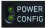 | Green flashing quickly Unit | is booting from power on. |
| Green flashing slowly | Unit is in recovery mode. | |
| Green flashing quickly Unit | is in factory config. | |
| Green on | Unit has completed booting up process and is in either config 1 or config2 |
Table 6: Config LED colours and status descriptions
3.2 SIM LED
The SIM LED is either flashing or solid depending on which SIM is in use and its status.
| LED | Colour | Status |
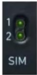 | Green on Using SIM connected to network. | |
| Green flashing Using SIM attempting to connect to network. | ||
Table 7: SIM LED colours and status descriptions
3.3 Signal strength LEDs
There are three signal strength LEDs. They are all green.
| LEDs | Colour | Status |
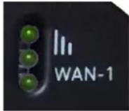 | Green Off/off No signal detected. | |
| Green flashing Off/on | Low signal strength. | |
| Green flashing On/off | Medium signal strength. | |
| Green On/on | Good signal strength. |
Table 8: Signal strength LED status descriptions
3.4 Ethernet port LED behaviour
The Ethernet ports have two LEDs: a LINK LED (green) and an ACT LED (amber). When looking at the ports, the LED on the left hand side is the LINK LED, and the ACT LED is on the right hand side.
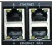
Figure 2: Ethernet LEDs on the GW3300 router
| Link LED (green) | Off | No physical Ethernet link detected. |
| On Physical Ethernet link detected. | ||
| ACT LED (amber) | Off | No data is being transmitted/received over the link. |
| Flashing | Data is being transmitted/ received over the link. | |
4 Installing a router into a vehicle
The type of cable you need depends on your application and vehicle. You will have received either a fused or non-fused power cable for the installation.
4.1 Installing a router into a vehicle using a non-fused power cable
Install the router using the vehicle installation power cable 840-00076 provided.
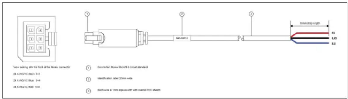
text_image
View looking into the front of the Molex connector 24 A WGHC Black 1+2 24 A WGHC Blue 3+4 24 A WGHC Red 5+6 ① Connector: Molex Microfit 6-circuit standard ② Identification label: 20mm wide ③ Each wire is 1mm square with overall PVC sheath 840-00074 50mm strip length BD BAX BLBFigure 3: 840-00076 3 core power cable
| (1) | Connector: Molex Microfit 6circuit standard |
| (2) | Label 20mm wide |
| (3) | Each wire is 1.0mm square, with overall PVC sheath |
| Note: | Requires 5 amp fuse in series with red and blue wires |
Table 9: Power cable descriptions
- Connect the BLACK wire to a ground wire.
- Connect the BLUE wire to a 12V switched vehicle ignition wire.
- Connect the RED wire to a 12V permanent wire.
Plug the 6 pin connector into the router.
4.2 Installing a router into a vehicle using a fused power cable
Install the router using the vehicle installation power cable 840-00105 provided.

text_image
View locking into the front of the Motex connector 24.A.WG/1C Black 1+2 24.A.WG/1C Blue 2=4 24.A.WG/1C Red 5=6 ① Connector: Motex Microfit 6-circuit standard ② Identification later 20mm wide ③ Each wire is 1mm square with overcast PVC sheath ④ Fuse: 2A.32VDC ATOFU/SES, 46Pa PVC 846-03105 50mm strip lengthFigure 4: 840-00105 3 core power cable
| (1) | Connector: Molex Microfit 6circuit standard |
| (2) | Label 20mm wide |
| (3) | Each wire is 1.0mm square, with overall PVC sheath |
| (4) | Fuse |
| Note: | Requires 5 amp fuse in series with red and blue wires |
Table 10: Power cable descriptions
- Connect the BLACK wire to a ground wire.
- Connect the BLUE wire to a 12V switched vehicle ignition wire.
- Connect the RED wire to a 12V permanent wire.
Plug the 6 pin connector into the router.
5 Factory configuration extraction from SI M card
Virtual Access routers have a feature to update the factory configuration from a SIM card. This allows you to change the factory configuration of a router when installing the SIM.
- Make sure the SIM card you are inserting has the required configuration written on it.
- Ensure the router is powered off.
- Hold the SIM 1 card with the chip side facing down and the cut corner front left.
- Gently push the SIM card into SIM slot 1 until it clicks in.
- Power up the router.
Depending on the model, the power LED and/or the configuration LED flash as usual.
The SIM LED starts flashing. This indicates the application responsible for 3G and configuration extraction management is running. It also means the update of the configuration is happening.
When the update is finished, depending on the model, the power LED and/or the configuration LED blink alternatively and very fast for 20 seconds.
Note: factory configuration extraction is only supported on mobile modules that support phone book operations.
6 Accessing the router
Access the router through the web interface or by using SSH. By default, Telnet is disabled.
6.1 Configuration packages used
| Package | Sections |
| dropbear dropbear | |
| system | main |
| uhttpd main | cert |
6.2 Accessing the router over Ethernet using the web interface
DHCP is disabled by default, so if you do not receive an IP address via DHCP, assign a static IP to the PC that will be connected to the router.
| PC IP address | 192.168.100.100 |
| Network mask 255.2 | 55.255.0 |
| Default gateway 192.168.100.1 | |
Assuming that the PC is connected to Port A on the router, in your internet browser, type in the default local IP address 192.168.100.1, and press Enter. The Authorization page appears.

text_image
Authorization Required Please enter your username and password. Username root Password ....| Login ResetFigure 5: The login page
The password may vary depending on the factory configuration the router has been shipped with. The default settings are shown below. The username and password are case sensitive.
In the username field, type root.
In the Password field, type admin.
Click Login. The Status page appears.
6.3 Accessing the router over Ethernet using an SSH client
You can also access the router over Ethernet, using Secure Shell (SSH) and optionally over Telnet.
To access CLI over Ethernet start an SSH client and connect to the router's management IP address, on port 22:192.168.100.1/24.
On the first connection, you may be asked to confirm that you trust the host.

text_image
PuTTY Security Alert The server's host key is not cached in the registry. You have no guarantee that the server is the computer you think it is. The server's rsa2 key fingerprint is: sch-rsa 1040 e5ee:21 f1:067480a8e66c:d04b33:2dfte:51 If you trust this host, hit Yes to add the key to PuTTY's cache and carry on connecting. If you wont to carry on connecting just once, without adding the key to the cache, hit No. If you do not trust this host, hit Cancel to abandon the connection.Figure 6: Confirming trust of the routers public key over SSH
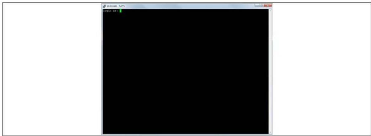
text_image
LOGIS: ms: Logic ms:Figure 7: SSH CLI logon screen
In the SSH CLI logon screen, enter the default username and password.
Username: root
Password: admin
6.3.1 SCP (Secure Copy Protocol)
As part of accessing the router over SSH, you can also use SCP protocol. Use the same user authentication credentials as for SSH access. You can use SCP protocol to securely, manually transfer files from and to the router's SCP server.
No dedicated SPC client is supported; select the SCP client software of your own choice.
6.4 Accessing the router over Ethernet using a Telnet client
Telnet is disabled by default, when you enable Telnet, SSH is disabled.
To enable Telnet, enter:
root@VA_router: ~# /etc/init.d/dropbear disable
root@VA_router: ~# reboot -f
To re-enable SSH, enter:
root@VA_router: ~# /etc/init.d/dropbear enable
root@VA_router: ~# reboot -f
Note: As SSH is enabled by default, initial connection to the router to enable Telnet must be established over SSH.
6.5 Configuring the password
6.5.1 Configuration packages used
| Package | Sections |
| system main |
6.6 Configuring the password using the web interface
To change your password, in the top menu click System -> Administration. The Administration page appears.

text_image
Status → System → Services → Network → Logout Router Password Changes the administrator password for accessing the device Password R2 Confirmation R2Figure 8: The router password section
In the Router Password section, type your new password in the password field and then retype the password in the confirmation field.
Scroll down the page and click Save & Apply.
Note: the username 'root' cannot be changed.
| Web Field/ UCI / Package Option | Description |
| Web: PasswordUCI: system.main.passwordOpt: password | Defines the root password. The password is displayed encrypted via the CLI using the ‘hashpassword’ option.UCI: system.main.hashpasswordOpt: hashpassword |
6.7 Configuring the password using UCI
The root password is displayed encrypted via the CLI using the hashpassword option.
root@VA_router:~# uci show system
system.main=system
system.main.hostname=VA_router
system.main.hashpassword=1jRX/x8A/$U5kLCMpi9dcahRhOl7eZV1
If you are changing the password using UCI, enter the new password in plain text using the password option.
root@VA_router:~# uci system.main.password=newpassword
root@VA_router:~# uci commit
The new password will take effect after reboot and will now be displayed in encrypted format via the hashpassword option.
6.8 Configuring the password using package options
The root password is displayed encrypted via the CLI using the hashpassword option.
root@VA_router:~# uci export system
package system

config system 'main'
option hostname 'VA_router'
option hashpassword '1wRYYiJOz$EeHN.GQcxXhRgNPVbqxVw
If you are changing the password using UCI, enter the new password in plain text using the password option.
package system
config system 'main'
option hostname 'VA_router'
option hashpassword '1wRYYiJOz$EeHN.GQcxXhRgNPVbqxVw'
option password 'newpassword'
The new password will take effect after reboot and will now be displayed in encrypted format via the hashpassword option.
6.9 Accessing the device using RADIUS authentication
You can configure RADIUS authentication to access the router over SSH, web or local console interface.
package system

config system 'main'
    option hostname 'VirtualAccess'
    option timezone 'UTC'

config pam_auth
    option enabled 'yes'
    option pamservice 'login'
    option pammodule 'auth'
    option pamcontrol 'sufficient'
    option type 'radius'
    option servers '192.168.0.1:3333|test|20 192.168.2.5|secret|10'

config pam_auth
    option enabled 'yes'
    option pamservice 'sshd'
    option pammodule 'auth'
    option pamcontrol 'sufficient' it checks package management_users
    option type 'radius'
    option servers '192.168.0.1:3333|test|20 192.168.2.5|secret|10'

config 'pam_auth'
    option enabled 'yes'
    option pamservice 'luci'
    option pammodule 'auth'
    option pamcontrol 'sufficient'
    option type 'radius'
    servers '192.168.0.1:3333|test|20 192.168.2.5|secret|10'
| UCI/Package Option | Description | |
| UCI: system.@pam_auth[0].enabled=yesOpt: enabled | Enables and disables RADIUS configuration sections. | |
| yes | Enables following RADIUS configuration section. | |
| no Disables following RADIUS configuration section. | ||
| UCI: system.@pam_auth[0].pamserviceOpt: pamservice | Selects the method which users should be authenticated by. | |
| login | User connecting over console cable. | |
| sshd | User connecting over SSH. | |
| luci | User connecting over web. | |
| UCI: system.@pam_auth[0].pamcontrolOpt: pamcontrol | Specifies authentication behaviour after authentication fails or connection to RADIUS server is broken. | |
| Sufficient | First authenticates against remote RADIUS if password authentication fails then it tries local database (user defined in package management_users) | |
| Required | If either authentication fails or RADIUS server is not reachable then user is not allowed to access the router. | |
| [success= done new_authtok_reqd= done authinfo_unavail= ignore default= die] | Local database is only checked if RADIUS server is not reachable. | |
| UCI: system.@pam_auth[0].pammodule.authOpt: pammodule | Enables user authentication. | |
| UCI: system.@pam_auth[0].type.radiusOpt: type | Specifies the authentication method. | |
| UCI: system.@pam_auth[0].serversOpt: servers | Specifies the RADIUS server or multiple servers along with port number and password. The example below explains the syntax. 192.168.0.1:3333|test|20 192.168.2.5|secret|10 | |
Table 11: Information table for RADIUS authentication
6.10 Accessing the device using TACACS+ authentication
TACACS+ authentication can be configured for accessing the router over SSH, web or local console interface.
package system
config system 'main'
    option hostname 'VirtualAccess'
    option timezone 'UTC'

config pam_auth
    option enabled 'yes'
    option pamservice 'sshd'
option pammodule 'auth'
option pamcontrol 'sufficient'
option type 'tacplus'
option servers '192.168.0.1:49|secret'

config pam_auth
option enabled 'yes'
option pamservice 'sshd'
option pammodule 'account'
option pamcontrol 'sufficient'
option type 'tacplus'
option servers '192.168.0.1:49|secret'
option args 'service=ppp'

config pam_auth
option enabled 'yes'
option pamservice 'sshd'
option pammodule 'session'
option pamcontrol 'sufficient'
option type 'tacplus'
option servers '192.168.0.1:49|secret'
option args 'service=ppp'

config pam_auth
option enabled 'yes'
option pamservice 'luci'
option pammodule 'auth'
option pamcontrol 'sufficient'
option type 'tacplus'
option servers '192.168.0.1:49|secret'

config pam_auth
option enabled 'yes'
option pamservice 'luci'
option pammodule 'account'
option pamcontrol 'sufficient'
option type 'tacplus'
option servers '192.168.0.1:49|secret'
option args 'service=ppp'

config pam_auth
option enabled 'yes'
option pamservice 'luci'
option pammodule 'session'
option pamcontrol 'sufficient'
option type 'tacplus'
option servers '192.168.0.1:49|secret'
option args 'service=ppp'

config pam_auth
option enabled 'yes'
option pamservice 'login'
option pammodule 'auth'
option pamcontrol 'sufficient'
option type 'tacplus'
option servers '192.168.0.1:49|secret'

config pam_auth
option enabled 'yes'
option pamservice 'login'
option pammodule 'account'
option pamcontrol 'sufficient'
option type 'tacplus'
option servers '192.168.0.1:49|secret'
option args 'service=ppp'

config pam_auth
option enabled 'yes'
option pamservice 'login'
option pammodule 'session'
option pamcontrol 'sufficient'
option type 'tacplus'
option servers '192.168.0.1:49|secret'
option args 'service=ppp'
| UCI / Package Option | Description | |
| UCI: system.@pam_auth[0].enabled=yesOpt: enabled | Enables and disables TACACS configuration sections. | |
| yes | Enables following TACACS configuration section. | |
| no Disables following TACACS configuration section. | ||
| UCI: system.@pam_auth[0].pamserviceOpt: pamservice | Selects the method which users should be authenticated by. | |
| login | User connecting over console cable. | |
| sshd | User connecting over SSH. | |
| luci | User connecting over web. | |
| UCI: system.@pam_auth[0].pamcontrolOpt: pamcontrol | Specifies authentication behaviour after authentication fails or connection to TACACS server is broken. | |
| Sufficient | First authenticates against remote TACACS if password authentication fails then it tries local database (user defined in package management_users) | |
| Required | If either authentication fails or TACACS server is not reachable then user is not allowed to access the router. | |
| [success= done new_authtok_reqd= done authinfo_unavail= ignore default= die] | Local database is only checked if TACACS server is not reachable. | |
| UCI:system.@pam_auth[0].pammodule.authOpt: pammodule | Selects which TACACS module this part of configuration relates to. | |
| auth auth module | provides the actual authentication and sets credentials | |
| account | account module checks to make sure that access is allowed for the user | |
| session | session module performs additional tasks which are needed to allow access | |
| system.@pam_auth[0].type=tacplusOpt: type | Specifies the authentication method. | |
| UCI: system.@pam_auth[0].serversOpt: servers | Specifies the TACACS servers along with port number and password. The example below explains the syntax.192.168.0.1:49|secret' | |
| UCI:system.@pam_auth[1].args= service= pppOpt: args | Additional arguments to pass to TACACS serer. | |
Table7: Information table for TACACS authentication
6.11 SSH
SSH allows you to access remote machines over text-based shell sessions. SSH uses public key cryptography to create a secure connection. These connections allow you to issue commands remotely via a command line.
The router uses a package called Dropbear to configure the SSH server on the box. You can configure Dropbear via the web interface or through an SSH connection by editing the file stored on: /etc/config_name/dropbear.
6.11.1 Configuration packages used
| Package | Sections |
| dropbear dropbear |
6.11.2 SSH access using the web interface
In the top menu, click System -> Administration. The Administration page appears. Scroll down to the SSH Access section.
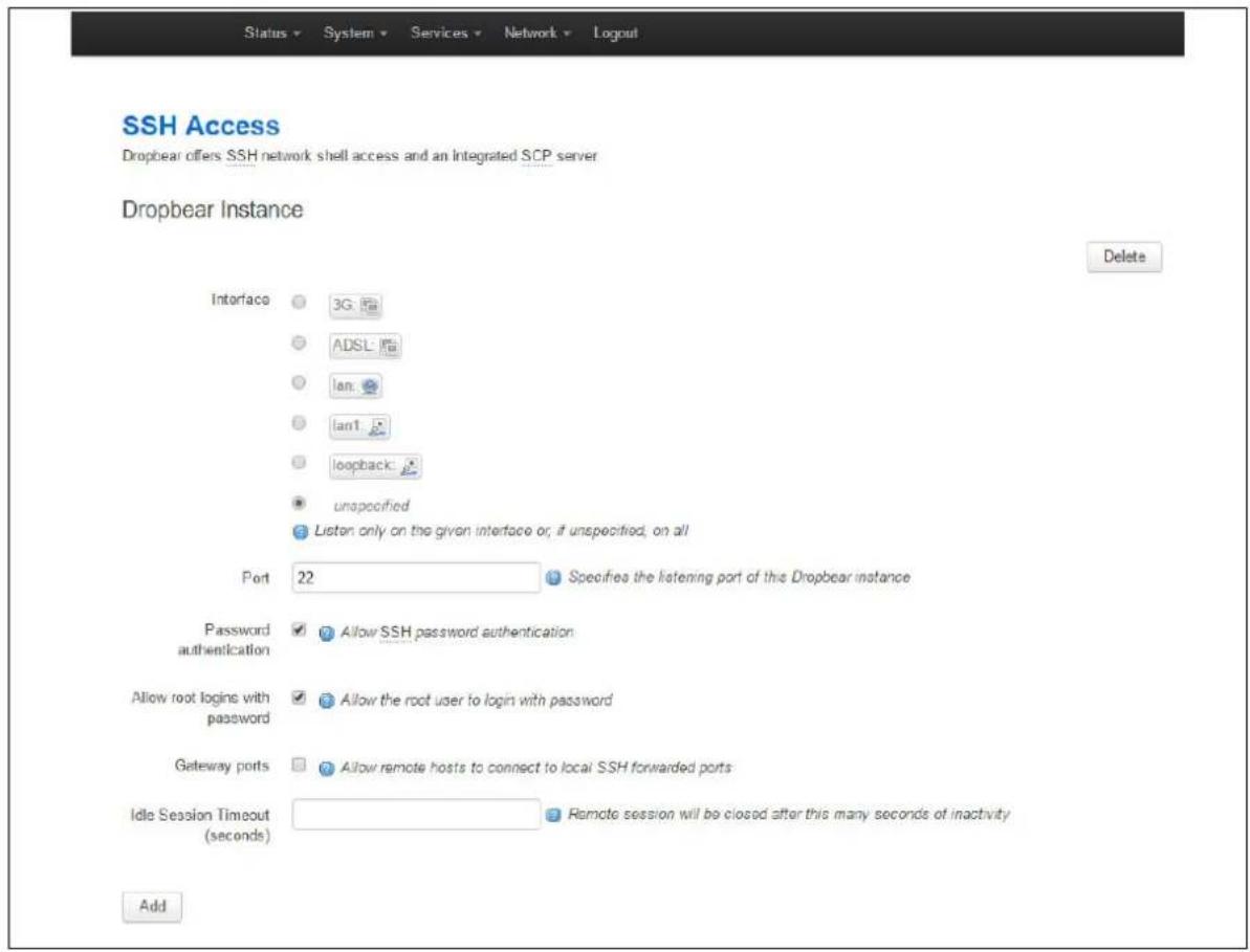
text_image
Status ▼ System ▼ Services ▼ Network ▼ Logout SSH Access Dropbear offers SSH network shell access and an Integrated SCP server Dropbear Instance Delete Interface ● 3G ● ADSL ● lan ● lan1 ● loopback ● unspecified ● Listen only on the given interface or, if unspecified, on all Port 22 Specifies the listening port of this Dropbear instance Password authentication ✓ Allow SSH password authentication Allow root logins with password ✓ Allow the root user to login with password Gateway ports ✓ Allow remote hosts to connect to local SSH forwarded ports Idle Session Timeout (seconds) Remote session will be closed after this many seconds of inactivity AddFigure 9: The SSH access section
| Web Field/ UCI / Package Option | Description | |
| Basic settings | ||
| Web: InterfaceUCI: dropbear.@dropbear[0].InterfaceOpt: interface | Listens only on the selected interface. If unspecified is checked, listens on all interfaces. All configured interfaces will be displayed via the web GUI. | |
| (unspecified) | listens on all interfaces. | |
| Range Configured interface names. | ||
| Web: PortUCI: dropbear.@dropbear[0].PortOpt: port | Specifies the listening port of the Dropbear instance. | |
| 22 | ||
| Range | 0-65535 | |
| Web: Password authenticationUCI: dropbear.@dropbear[0].PasswordAuthOpt: PasswordAuth | If enabled, allows SSH password authentication. | |
| 0 | Disabled. | |
| 1 Enabled. | ||
| Web: Allow root logins with passwordUCI: dropbear.@dropbear[0].RootPasswordAuthOpt: RootPasswordAuth | Allows the root user to login with password. | |
| 0 Disabled. | ||
| 1 | Enabled. | |
| Web: Gateway portsUCI: dropbear.@dropbear[0].GatewayPortsOpt: GatewayPorts | Allows remote hosts to connect to local SSH forwarded ports. | |
| 0 Disabled. | ||
| 1 | Enabled. | |
| Web: Idle Session TimeoutUCI: dropbear.@dropbear[0].IdleTimeoutOpt: IdleTimeout | Defines the idle period where remote session will be closed after the allocated number of seconds of inactivity. | |
| 30 | 30 seconds. | |
| Range | ||
| Web: n/aUCI: dropbear.@dropbear[0]. BannerFileOpt: BannerFile | Defines a banner file to be displayed during login. | |
| /etc/banner | ||
| Range | ||
| Web: n/aUCI: dropbear.@dropbear[0].MaxLoginAttemptsOpt: MaxLoginAttempts | Specifies maximum login failures before session terminates. | |
| 10 | ||
| 0-infinite | ||
Table 12: Information table for SSH access settings
6.12 Package dropbear using UCI
root@VA_router:~# uci show dropbear
dropbear.@dropbear[0]=dropbear
dropbear.@dropbear[0].PasswordAuth=on
dropbear.@dropbear[0].RootPasswordAuth=on
dropbear.@dropbear[0].GatewayPorts=0
dropbear.@dropbear[0].IdleTimeout=30
dropbear.@dropbear[0].Port=22
dropbear.@dropbear[0].MaxLoginAttempts=3
Package dropbear using package options
root@VA_router:~# uci export dropbear
package dropbear
config dropbear'
option PasswordAuth 'on'
option RootPasswordAuth 'on'
option Port '22'
option GatewayPorts '0'
option IdleTimeout '30'
option MaxLoginAttempts '3'
6.13 Certs and private keys
Certificates are used to prove ownership of a public key. They contain information about the key, its owner's ID, and the digital signature of an individual that has verified the content of the certificate.
In asymmetric cryptography, public keys are announced to the public, and a different private key is kept by the receiver. The public key is used to encrypt the message, and the private key is used to decrypt it.
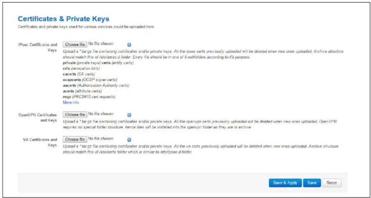
To access certs and private keys, in the top menu, click System -> Administration. The Administration page appears. Scroll down to the Certs & Private Keys section.
text_image
Certificates & Private Keys Certificates and private keys used for various services could be uploaded here IPsec Certificates and Keys Choose file | No file chosen Upload a *tar.gz file containing certificates and/or private keys. All the ipsec certs previously uploaded will be deleted when new ones uploaded. Archive structure should match this of /etc/pcsec.d folder. Every file should be in one of 8 subfolders according to it's purpose. private (private keys) certs (entity certs) crls (revocation lists) cacerts (CA certs) ocspcerts (OCSP signer certs) aacerts (Authorization Authority certs) acerts (attribute certs) reqs (PKCS#10 cert requests) More info OpenVPN Certificates and Keys Choose file | No file chosen Uploaded a *tar.gz file containing certificates and/or private keys. All the openvpn certs previously uploaded will be deleted when new ones uploaded. OpenVPN requires no special folder structure, hence files will be installed into the openvpn folder as they are in archive. VA Certificates and Keys Choose file | No file chosen Uploaded a *tar.gz file containing certificates and/or private keys. All the va certs previously uploaded will be deleted when new ones uploaded. Archive structure should match this of /etc/pcert s folder which is similar to /etc/pcsec.d folder. Save & Apply Save ResetFigure 10: The certificates & private keys section
This section allows you to upload any certificates and keys that you may have stored. There is support for IPSec, OpenVPN and VA certificates and keys.
If you have generated your own SSH public keys, you can input them in the SSH Keys section, for SSH public key authentication.

text_image
SSH-Keys Here you can paste public SSH-Keys (one por line) for SSH public-key authentication.Figure 11: The SSH-keys box
6.14 Configuring a router's web server
The router's web server is configured in package uhttpd. This file defines the behaviour of the server and default values for certificates generated for SSL operation. uhttpd supports multiple instances, that is, multiple listen ports, each with its own document root and other features, as well as cgi and lua. There are two sections defined:
Main: this uHTTPd section contains general server settings.
Cert: this section defines the default values for SSL certificates.
6.14.1 Configuration packages used
| Package | Sections |
| uhttpd | main |
| cert |
To configure the router's HTTP server parameters, in the top menu, select Services -> HTTP Server. The HTTP Server page has two sections.
| Main Settings Server configurations | |
| Certificate Settings | SSL certificates. |
6.14.2 Main settings
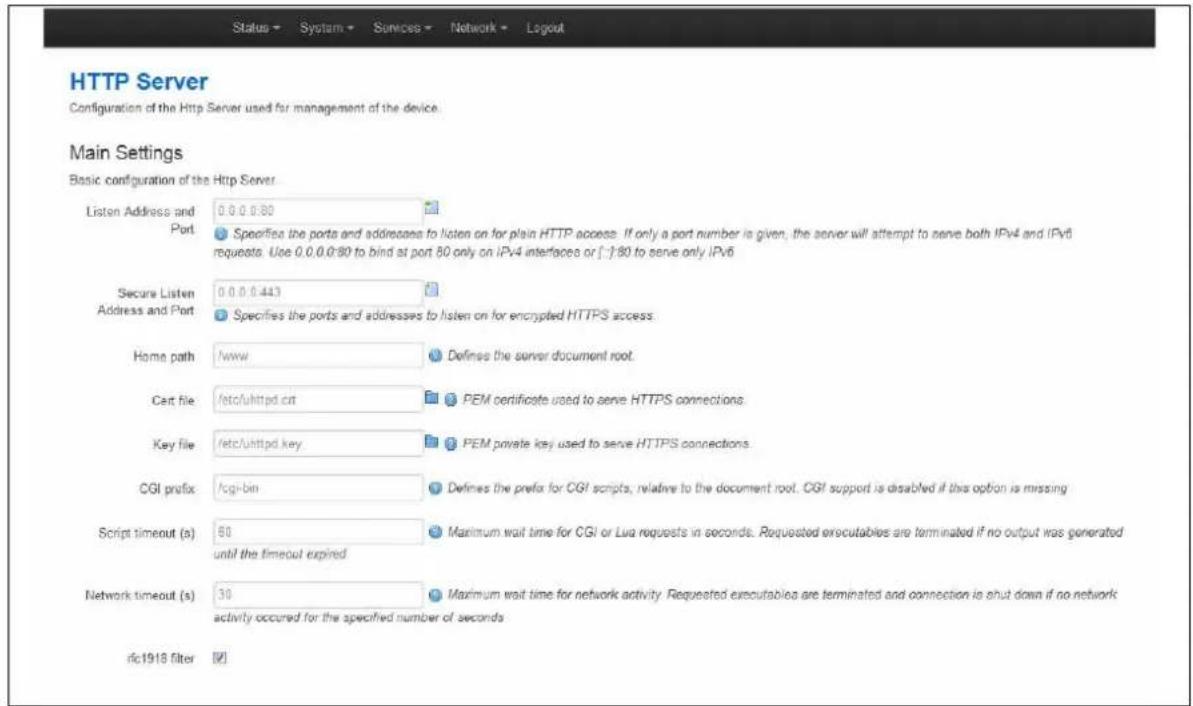
text_image
HTTP Server Configuration of the Http Server used for management of the device. Main Settings Basic configuration of the Http Server Listen Address and Port 0.0.0.0.80 Specifies the ports and addresses to listen on for plain HTTP access. If only a port number is given, the server will attempt to serve both IPv4 and IPv6 requests. Use 0.0.0.0.90 to bind at port 80 only on IPv4 interfaces or [-]:80 to serve only IPv6 Secure Listen 0.0.0.0.443 Specifies the ports and addresses to listen on for encrypted HTTPS access. Home path /www Defines the server document root. Cerit file /etc/uhtpd.crt PEM certificate used to serve HTTPS connections. Key file /etc/uhtpd.key PEM private key used to serve HTTPS connections. CGI prefix /cgi-bin Defines the prefix for CGI scripts, relative to the document root. CGI support is disabled if this option is missing Script timeout (s) 60 Maximum wait time for CGI or Lua requests in seconds. Requested executables are terminated if no output was generated until the timeout expired Network timeout (s) 30 Maximum wait time for network activity. Requested executables are terminated and connection is shut down if no network activity occurred for the specified number of seconds. rfc1918 filter [√]Figure 12: HTTP server settings
| Web Field/ UCI / Package Option | Description | |
| Web: Listen Address and PortUCI: uhttpd.main.listen_httpOpt: list listen_http | Specifies the ports and addresses to listen on for plain HTTP access. If only a port number is given, the server will attempt to serve both IPv4 and IPv6 requests. | |
| 0.0.0.0:80 Bind at port 80 only on IPv4 interfaces. | ||
| [::]:80 Bind at port 80 only on IPv6 interfaces | ||
| Range IP address and/or port | ||
| Web: Secure Listen Address and PortUCI: uhttpd.main.listen_httpsOpt: list listen_https | Specifies the ports and address to listen on for encrypted HTTPS access. The format is the same as listen_http. | |
| 0.0.0.0:443 Bind at port 443 only | ||
| [::]:443 | ||
| Range | IP address and/or port | |
| Web: Home pathUCI: uhttpd.main.homeOpt: home | Defines the server document root. | |
| /www | ||
| Range | ||
| Web: Cert fileUCI: uhttpd.main.certOpt: cert | ASN.1/DER certificate used to serve HTTPS connections. If no listen_https options are given the key options are ignored. | |
| /etc/uhttpd.crt | ||
| Range | ||
| Web: Key fileUCI: uhttpd.main.keyOpt: key | ASN.1/DER private key used to serve HTTPS connections. If no listen_https options are given the key options are ignored. | |
| /etc/uhttpd.key | ||
| Range | ||
| Web: CGI profileUCI: uhttpd.main.cgi_prefixOpt: cgi_prefix | Defines the prefix for CGI scripts, relative to the document root. CGI support is disabled if this option is missing. | |
| /cgi-bin | ||
| Range | ||
| Web: N/AUCI: uhttpd.main.lua_prefixOpt: lua_prefix | Defines the prefix for dispatching requests to the embedded lua interpreter, relative to the document root. Lua support is disabled if this option is missing. | |
| /luci | ||
| Range | ||
| Web: N/AUCI: uhttpd.main.lua_handlerOpt: lua_handler | Specifies the lua handler script used to initialise the lua runtime on server start. | |
| /usr/lib/lua/luci/sgi/uhttpd.lua | ||
| Range | ||
| Web: Script timeoutUCI: uhttpd.main.script_timeoutOpt: script_timeout | Sets the maximum wait time for CGI or lua requests in seconds. Requested executables are terminated if no output was generated. | |
| 60 | ||
| Range | ||
| Web: Network timeoutUCI: uhttpd.main.network_timeoutOpt: network_timeout | Maximum wait time for network activity. Requested executables are terminated and connection is shut down if no network activity occurred for the specified number of seconds. | |
| 30 | ||
| Range | ||
| Web: N/AUCI: uhttpd.main.realmOpt: realm | Defines basic authentication realm when prompting the client for credentials (HTTP 400). | |
| OpenWrt | ||
| Range | ||
| Web: N/AUCI: uhttpd.main.configOpt: config | Config file in Busybox httpd format for additional settings. Currently only used to specify basic auth areas. | |
| /etc/http.conf | ||
| Range | ||
| Web: N/AUCI: uhttpd.main.index_pageOpt: index_page | Index file to use for directories, for example, add index.php when using php. | |
| Range | ||
| Web: N/AUCI: httpd.main.error_pageOpt: error_page | Virtual URL of file of CGI script to handle 404 requests. Must begin with '/' (forward slash). | |
| Range | ||
| Web: N/AUCI: uhttpd.main.no_symlinksOpt: no_symlinks | Does not follow symbolic links if enabled. | |
| 0 Disabled. | ||
| 1 Enabled. | ||
| Web: N/AUCI: uhttpd.main.no_dirlistsOpt: no_symlinks | Does not generate directory listings if enabled. | |
| 0 | Disabled. | |
| 1 Enabled. | ||
| Web:rfc 1918 filterUCI: uhttpd.main.rfc1918_filter=1Opt:rfc1918_filter | Enables option to reject requests from RFC1918 IPs to public server IPs (DNS rebinding counter measure). | |
| 0 | Disabled. | |
| 1 Enabled. | ||
Table 13: Information table for http server basic settings
6.14.3 HTTP server using UCI
Multiple sections of the type uhttpd may exist. The init script will launch one webserver instance per section.
A standard uhttpd configuration is shown below.
root@VA_router:~# uci show uhttpd
uhttpd.main=uhttpd
uhttpd.main.listen_http=0.0.0.0:80
uhttpd.main.listen_https=0.0.0.0:443
uhttpd.main.home=/www
uhttpd.main.rfc1918_filter=1
uhttpd.main.cert=/etc/uhttpd.crt
uhttpd.main.key=/etc/uhttpd.key
uhttpd.main.cgi_prefix=/cgi-bin
uhttpd.main.script_timeout=60
uhttpd.main.network_timeout=30
uhttpd.main.config=/etc/http.conf
HTTP server using package options
root@VA_router:~# uci export dropbear
config uhttpd 'main'
list listen_http '0.0.0.0:80'
list listen_https '0.0.0.0:443'
option home '/www'
option rfc1918_filter '1'
option cert '/etc/uhttpd.crt'
option key '/etc/uhttpd.key'
option cgi_prefix '/cgi-bin'
option script_timeout '60'
option network_timeout '30'
option config '/etc/http.conf'
6.14.4 HTTPS server certificate settings
To configure HTTPS server certificate settings, in the top menu, select Services -> HTTP Server. Scroll down to the Certificate Settings section.
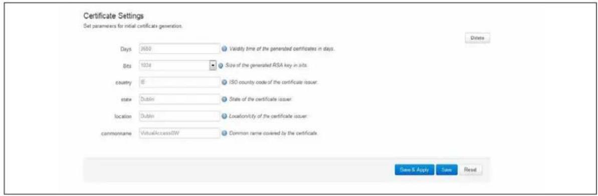
text_image
Certificate Settings Set parameters for initial certificate generation. Delete Days 3600 Validity time of the generated certificates in days. Bits 100s Size of the generated RSA key in bits. country E ISO county code of the certificate issuer. state Dublin State of the certificate issuer location Dublin Locationicity of the certificate issuer commonname VirtualAccessOW Common name covered by the certificate. Save & Apply Save ReadFigure 13: HTTP server certificate settings
| Web Field/ UCI / Package Option | Description | |
| Web: Days | Validity time of the generated certificates in days. | |
| UCI: uhttpd px5g.days | 730 | |
| Opt: days | Range | |
| Web: Bits | Size of the generated RSA key in bits. | |
| UCI: uhttpd px5g.bits | 1024 | |
| Opt: bits | Range | |
| Web: Country | ISO code of the certificate issuer. | |
| UCI: uhttpd px5g.country | ||
| Opt: country | ||
| Web: State | State of the certificate issuer. | |
| UCI: uhttpd px5g.state | ||
| Opt: state | ||
| Web: Location | Location or city of the certificate user. | |
| UCI: uhttpd px5g.location | ||
| Opt: location | ||
| Web: Commonname | Common name covered by the certificate. For the purposes of secure Activation, this must be set to the serial number (Eth0 MAC address) of the device. | |
| UCI: uhttpd.commonname | ||
| Opt: commonname | ||
Table 14: Information table for HTTP server certificate settings
6.14.5 HTTPS server using UCI
root@VA_router:~# uci show uhttpdpx5g
uhttpdpx5g=cert
uhttpdpx5g.days=3650
uhttpdpx5g.bits=1024
uhttpdpx5g.country=IE
uhttpdpx5g.state=Dublin
uhttpdpx5g.location=Dublin
uhttpdpx5g.commonname=00E0C8000000
HTTPS server using package options
root@VA_router:~# uci export uhttpd
package uhttpdconfig 'cert' 'px5g'
option 'days' '3650'
option 'bits' '1024'
option 'state' 'Dublin'
option 'location' 'Dublin'
option 'commonname' '00E0C8000000'
6.15 Basic authentication (httpd conf)
For backward compatibility reasons, uhttpd uses the file /etc/httpd.conf to define authentication areas and the associated usernames and passwords. This configuration file is not in UCI format.
Authentication realms are defined in the format prefix:username:password with one entry and a line break.
Prefix is the URL part covered by the realm, for example, cgi-bin to request basic auth for any CGI program.
Username specifies the username a client has to login with.
Password defines the secret password required to authenticate.
The password can be either in plain text format, MD5 encoded or in the form \p\user where the user refers to an account in /etc/shadow or /etc/passwd.
If you use \p\... format, uhttpd will compare the client provided password against the one stored in the shadow or passwd database.
6.16 Securing uhttpd
By default, uhttpd binds to 0.0.0.0 which also includes the WAN port of your router. To bind uhttpd to the LAN port only you have to change the listen_http and listen_https options to your LAN IP address.
To get your current LAN IP address, enter:
uci get network.lan.ipaddr
Then modify the configuration appropriately:
uci set uhttpd.main.listen_http='192.168.1.1:80'
uci set uhttpd.main.listen_https='192.168.1.1:443'
config 'uhttpd' 'main'
list listen_http 192.168.1.1:80
list listen_https 192.168.1.1:443
6.17 Displaying custom information via login screen
The login screen, by default, shows the hostname of the router in addition to the username and password prompt. However, the router can be configured to show some other basic information if required using a UDS script.
Note: this can only be configured via the command line.
6.17.1 Configuration packages used
| Package Sections | |
| luci | main |
| uds script |
6.17.2 Configuring login screen custom information
The luci package option login_page_info_template is configured with the path to a UDS script that would render the required information on the right side of the login page.
The following example shows how to display serial number and mobile signal strength.
Note: this can only be configured via the command line.
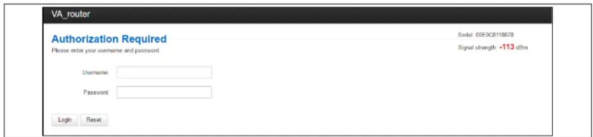
text_image
VA_router Authorization Required Please enter your username and password. Username Password Login Reset Serial: 00E0C8118878 Signal strength: -113 dBmFigure 14: Example login screen displaying serial and signal strength
6.17.2.1 Login screen custom information using UCI
root@VA_router:~# uci show luci
luci.main=core
luci.main.login_page_info_template=/tmp/uds/sysauth_template

root@VA_router:~# uci show uds
uds.sysauth_template=script
uds.sysauth_template.enabled=1
uds.sysauth_template.exec_type=none
uds.sysauth_template.fname=sysauth_template.htm
uds.sysauth_template.type=none
uds.sysauth_template.text=Serial: <%=pcdata(luci.version.serial)%><br/><%
local sig = luci.dispatcher.uci.cursor_state():get("mobile", "3g_1_1",
"sig_dbm") or -113 sig = tonumber(sig) local hue = (sig + 113) * 2 local
hue = math.min(math.max(hue, 0), 120) %> Signal strength: <h3
style="color:hsl(<%=hue%), 90%, 50%); display:inline;"><%=sig%></h3> dBm
6.17.2.2 Login screen custom information using package options
root@VA_router:~# uci export luci
package luci
config core 'main'
    option login_page_info_template '/tmp/uds/sysauth_template'
root@VA_router:~# uci export uds
package uds
config script 'sysauth_template'
    option enabled '1'
    option exec_type 'none'
    option fname 'sysauth_template.htm'
    option type 'none'
    list text 'Serial: <%=pcdata(luci.version.serial) %><br/>
    list text '<% local sig = luci.dispatcher.uci.cursor_state():get("mobile", "3g_1_1", "sig_dbm") or -113'

list text 'sig = tonumber(sig)'
list text 'local hue = (sig + 113) * 2'
list text 'local hue = math.min(math.max(hue, 0), 120) %>'
list text 'Signal strength: <h3 style="color:hsl(<%=hue%), 90%, 50%); display:inline;"><%=sig%></h3> dBm
7 Router file structure
This section describes the file structure and location of essential directories and files on Virtual Access routers.
Throughout this document, we use information tables to show the different ways to configure the router using the router's web interface and command line interface (CLI).
When showing examples of the command line interface we use the host name 'VA_router' to indicate the system prompt. For example, the table below displays what the user should see when entering the command to show the current configuration in use on the router:
root@VA_router:~# va_config.sh
7.1 System information
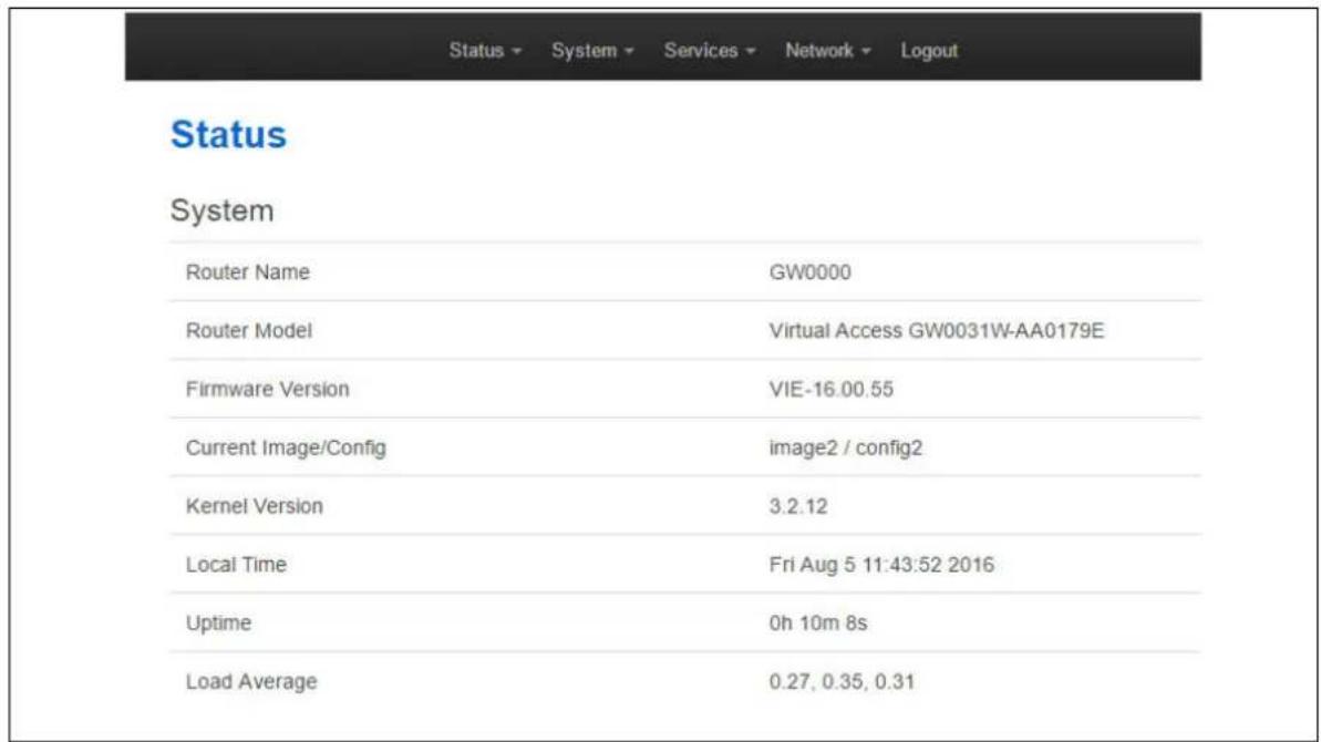
General information about software and configuration used by the router is displayed on the Status page. To view the running configuration file status on the web interface, in the top menu, select Status -> Overview. This page also appears immediately after you have logged in.
text_image
Status System Router Name GW0000 Router Model Virtual Access GW0031W-AA0179E Firmware Version VIE-16.00.55 Current Image/Config image2 / config2 Kernel Version 3.2.12 Local Time Fri Aug 5 11:43:52 2016 Uptime 0h 10m 8s Load Average 0.27, 0.35, 0.31Figure 15: Example of the status page
System information is also available from the CLI if you enter the following command:
The example below shows the output from the above command.
VA_SERIAL: 00E0C8121215
VA_MODEL: GW0000
VA_ACTIVEIMAGE: image2
VA_ACTIVECONFIG: config1
VA_IMAGE1VER: VIE-16.00.44
VA_IMAGE2VER: VIE-16.00.44
7.2 Identify your software version
To check which software version your router is running, in the top menu, browse to Status -> Overview.
Status
| System | |
| Router Name | GW0000 |
| Router Model | Virtual Access GW0031W-AA0179E |
| Firmware Version | VIE-16.00.55 |
| Current Image/Config | image2 / config2 |
| Kernel Version | 3.2.12 |
| Local Time | Fri Aug 5 11:43:52 2016 |
| Uptime | 0h 10m 8s |
| Load Average | 0.27, 0.35, 0.31 |
Figure 16: The status page showing a software version prior to 72.002
| Status | |
| System | |
| Router Name | dmvpn |
| Router Model | GW2028 |
| Firmware Version | LIS-15.00.72.002rc4 |
| Current Image/Config | image1 / config1 |
| Kernel Version | 3:2.12 |
| Local Time | Thu Jan 26 14:46.03 2017 |
| Uptime | 0h 39m 37s |
| Load Average | 1.02, 0.53, 0.48 |
Figure 17: The status page showing software version 72.002
In the Firmware Version row, the first two digits of the firmware version identify the hardware platform, for example LIS-15; while the remaining digits: .00.72.002, show the software version.
7.3 Image files
The system allows for two firmware image files:
- image1, and
- image2
Two firmware images are supported to enable the system to rollback to a previous firmware version if the upgrade of one image fails.
The image names (image1, image2) themselves are symbols that point to different partitions in the overall file system. A special image name “altimage” exists which always points to the image that is not running.
The firmware upgrade system always downloads firmware to "altimage".
7.4 Directory locations for UCI configuration files
Router configurations files are stored in folders on:
• /etc/factconf,
• /etc/config1, and
• /etc/config2
Multiple configuration files exist in each folder. Each configuration file contains configuration parameters for different areas of functionality in the system.
A symbolic link exists at /etc/config, which always points to one of factconf, config1 or config2 is the active configuration file.
Files that appear to be in /etc/config are actually in /etc/factconf|config1|config2 depending on which configuration is active.
If /etc/config is missing on start-up, for example on first boot, the links and directories are created with configuration files copied from /rom/etc/config/.
At any given time, only one of the configurations is the active configuration. The UCI system tool (Unified Configuration Interface) only acts upon the currently active configuration.
7.5 Viewing and changing current configuration
To show the configuration currently running, enter:
root@VA_router:~# va_config.sh
To show the configuration to run after the next reboot, enter:
root@VA_router:~# va_config.sh next
To set the configuration to run after the next reboot, enter:
root@VA_router:~# va_config.sh -s [factconf|config1|config2|altconfig]
7.6 Configuration file syntax
The configuration files consist of sections – or packages - that contain one or more config statements. These optional statements define actual values.
Below is an example of a simple configuration file.
package 'example'
config 'example' 'test'
option 'string' 'some value'
option 'boolean' '1'
list 'collection' 'first item'
list 'collection' 'second item'
The config 'example' 'test' statement defines the start of a section with the type example and the name test.
| Command | Target | Description |
| export | [] | Exports the configuration in a machine readable format. It is used internally to evaluate configuration files as shell scripts. |
| import | [] | Imports configuration files in UCI syntax. |
| add | Adds an anonymous section of type-section type to the given configuration. | |
| add_list | Adds the given string to an existing list option. | |
| show | [.[.<option>]=] | Shows the given option, section or configuration in compressed notation. |
| get | Gets the value of the given option or the type of the given section. | |
| Set | Sets the value of the given option, or adds a new section with the type set to the given value. | |
| delete | Deletes the given section or option. |
Table 1: Common commands, target and their descriptions
7.7 Managing configurations
7.7.1 Managing sets of configuration files using directory manipulation
Configurations can also be managed using directory manipulation.
To remove the contents of the current folder, enter:
root@VA_router:/etc/config1# rm -f *
Warning: the above command makes irreversible changes.
To remove the contents of a specific folder regardless of the current folder (config2), enter:
root@VA_router:/ # rm -f /etc/config1/*
Warning: the above command makes irreversible changes.
To copy the contents of one folder into another (config2 into config1), enter:
root@VA_router:/etc/config1# cp /etc/config2/* /etc/config1
7.8 Exporting a configuration file
If you have software versions prior to 72.002, to export a configuration file using the web interface, go to section 7.8.1.
If you have software version 72.002 or above, export a configuration file using the web interface go to section 7.8.2.
To export a configuration file using CLI, for any software version, go to section 7.8.3.
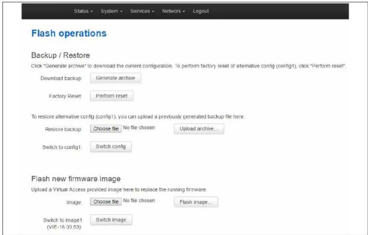
7.8.1 Exporting a configuration file using the web interface for software versions pre- 72.002
The current running configuration file may be exported using the web interface.
In the top menu, select System > Backup/ Flash Firmware. The Flash operations page appears.
text_image
Status ▼ System ▼ Services ▼ Network ▼ Logout Flash operations Backup / Restore Click "Generate archive" to download the current configuration. To perform factory reset of alternative config (config1), click "Perform reset". Download backup: Generate archive Factory Reset: Perform reset To restore alternative config (config1), you can upload a previously generated backup file here. Restore backup: Choose file No file chosen Upload archive... Switch to config1: Switch config Flash new firmware image Upload a Virtual Access provided image here to replace the running firmware. Image: Choose file No file chosen Flash image... Switch to image1 Switch image (VIE-16.00.53)Figure 18: The flash operations page
In the Backup/Restore section, select Generate Archive.
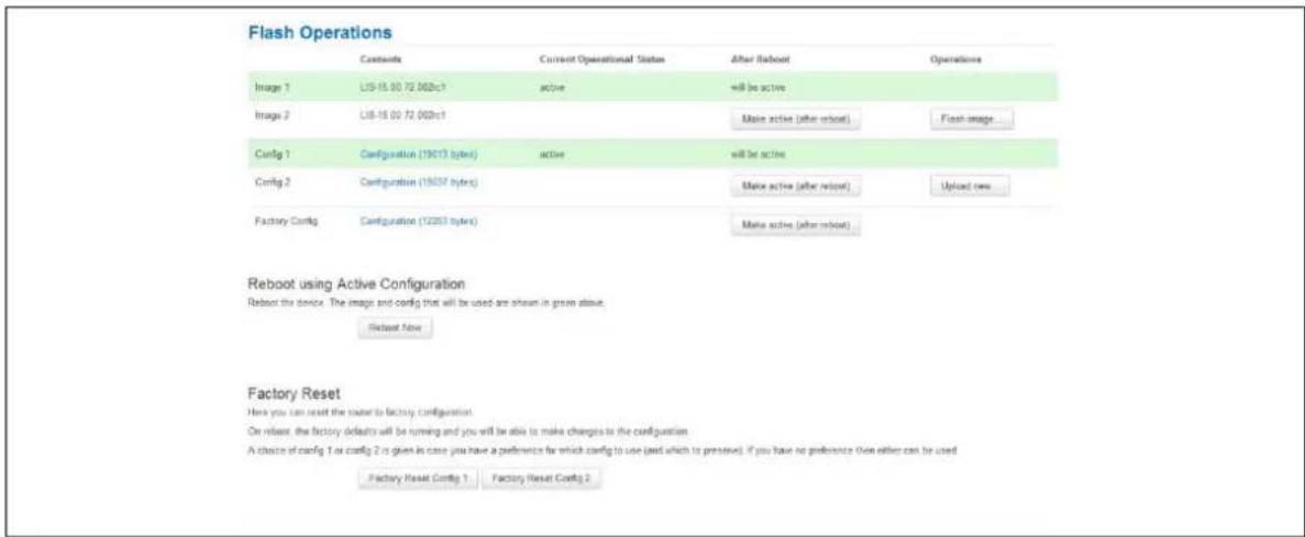
7.8.2 Exporting a configuration file using the web interface for software version 72.002 and above
The current running configuration file may be exported using the web interface.
In the top menu, select System > Flash Operations. The Flash operations page appears.
text_image
Flash Operations Contents Current Operational Status After Reboot Operations Image 1 LIS-15.00 72 002c1 active +will be active Image 2 LIS-15.00 72 003c1 Maine active (after reboot) Fast image... Config 1 Configuration (19C13 hertz) active +will be active Config 2 Configuration (19C5F hertz) Maine active (after reboot) Upload new... Factory Config Configuration (12263 hertz) Maine active (after reboot) Reboot using Active Configuration Reboot the device. The image and config that will be used are shown in green above. Restart Now Factory Reset Here you can reset the server to factory configuration. On reboot, the factory defaults will be running and you will be able to make changes to the configuration. A choice of config 1 or config 2 is given in case you have a preference for which config to use (and which to preserve). If you have no preference then either can be used. Factory Reset Config 1 Factory Reset Config 2Figure 19: The flash operations page
In the Flash Operation section, click the configuration file in the Contents column to download it.
7.8.3 Exporting a configuration file using UCI
You can view any configuration file segment using UCI.
To export the running configuration file, enter:
root@VA_router:~# uci export
To export the factory configuration file, enter:
root@VA_router:~# uci -c /etc/factconf/ export
To export config1 or config2 configuration file, enter:
root@VA_router:~# uci -c /etc/config1/ export
root@VA_router:~# uci -c /etc/config2/ export
7.9 Importing a configuration file
If you have software versions prior to 72.002, to export a configuration file using the web interface, go to section 7.9.1.
If you have software version 72.002 or above, export a configuration file using the web interface go to section 7.9.2.
To export a configuration file using CLI, for any software version, go to section 7.9.3.
7.9.1 Importing a configuration file using the web interface for software versions pre- 72.002
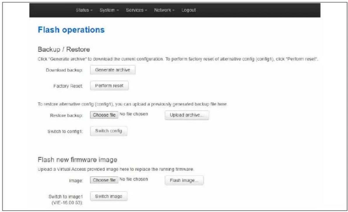
You can import a configuration file to the alternate configuration segment using the web interface. This will automatically reboot the router into this configuration file.
In the top menu, select System > Backup/ Flash Firmware. The Flash operations page appears.
text_image
Status - System - Services - Network - Logout Flash operations Backup / Restore Click "Generate archive" to download the current configuration. To perform factory reset of alternative config (config1), click "Perform reset". Download backup: Generate archive Factory Reset: Perform reset To restore alternative config (config1), you can upload a previously generated backup file here. Restore backup: Choose file No file chosen Upload archive... Switch to config1: Switch config Flash new firmware image Upload a Virtual Access provided image here to replace the running firmware. Image: Choose file No file chosen Flash Image... Switch to image1 (VIE-16.00 53): Switch imageFigure 20: The flash operations page
Under Backup/Restore, choose Restore Backup: Choose file. Select the appropriate file and then click Upload archive.

text_image
System - Restoring... The system restoring alternative config from the backup Waiting for router...Figure 21: The system – restoring...page
When the 'waiting for router' icon disappears, the upgrade is complete, and the login homepage appears.
7.9.2 Importing a configuration file using the web interface for software version 72.002 and above
You can import a configuration file to the alternate configuration segment using the web interface.
In the top menu, select System > Flash Operations. The Flash operations page appears.
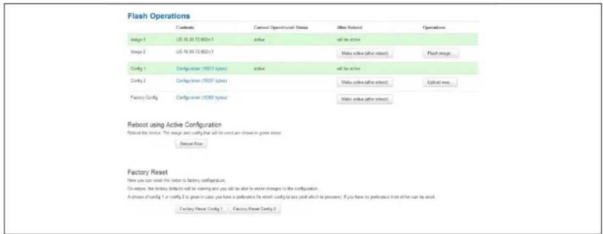
text_image
Flash Operations Contents Current Operational States After Reboot Operations Image 1 US-15.00/72.602c:1 active will be active Image 2 US-15.00/72.602c:1 Make active (after reboot) Flash image Config 1 Configuration (19317 bytes) active will be active Config 2 Configuration (19337 bytes) Make active (after reboot) Upload new... Factory Config Configuration (10283 bytes) Make active (after reboot) Reboot using Active Configuration Reboot the device, The image and config that will be used are shown in green space. Reload Now Factory Reset Here you can reset the router to factory configuration. On reboot, the factory defaults will be running and you will be able to make changes to the configuration. A choice of config 1 or config 2 is given in cases you have a preference for which config to use (and which to preserve). If you have no preference than either can be used. Factory Reset Config 1 Factory Reset Config 2Figure 22: The flash operations page
In the Operations column, click Upload new. Select the appropriate file.
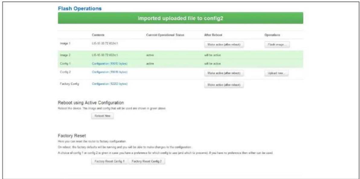
text_image
Flash Operations Imported uploaded file to config2 Contents Current Operational Status After Reboot Operations Image 1 LIS-15 00.72 600rc1 Make active (after reboot) Flash image... Image 2 LIS-15 00.72 600rc1 (active Wil be active Config 1 Configuration (19013 bytes) (active Wil be active Config 2 Configuration (19618 bytes) Make active (after reboot) Upload new... Factory Config Configuration (12203 bytes) Make active (after reboot) Reboot using Active Configuration Robot this device: The image and config that will be used are shown in green above Roboot Now Factory Reset Here you can reset the router to factory configuration. On reboot, the factory defaults will be running and you will be able to make changes in the configuration. A choice of config 1 or config 2 is given in case you have a preference for which config to use (and which to present). If you have no preference then either can be used. Factory Reset Config 1 Factory Reset Config 2Figure 23: The flash operations succeed upload configuration page
If you select 'Flash image and do not reboot', the router will only run this configuration if you click OK to return to the Flash Operations page. There you can manually select Made Active (after reboot). Then click Reboot Now in the 'Reboot using Active Configuration' section.
7.9.3 Importing a configuration file using UCI
You can import a configuration file to any file segment using UCI.
To import to config1, enter:
root@VA_router:~# uci -c /etc/config1/ import
<paste in config file>
<CTRL-D>
Note: it is very important that the config file is in the correct format otherwise it will not import correctly.
8 Using the Command Line Interface
This chapter explains how to view Virtual Access routers' log files and edit configuration files using a Command Line Interface (CLI) and the Unified Configuration Interface (UCI) system. Some commands may vary between router models.
8.1 Overview of some common commands
Virtual Access routers' system has an SSH server typically running on port 22.
The factconf default password for the root user is admin.
To change the factconf default password, enter:
root@VA_router:/# uci set system.main.password="*******"
root@VA_router:/# uci commit system
To reboot the system, enter:
The system provides a Unix-like command line. Common Unix commands are available such as ls, cd, cat, top, grep, tail, head, more and less.
Typical pipe and redirect operators are also available, such as: >, >>, <, |
The system log can be viewed using any of the following commands:
root@VA_router:/# logread
root@VA_router:/# logread | tail
root@VA_router:/# logread -f
These commands will show the full log, end of the log (tail) and continuously (-f). Enter Ctrl-C to stop the continuous output from logread -f.
To view and edit configuration files, the system uses the Unified Configuration Interface (UCI) which is described further on in this chapter. This is the preferred method of editing configuration files. However, you can also view and edit these files using some of the standard Unix tools.
For example, to view a text or configuration file in the system, enter:
root@VA_router:/# cat /etc/passwd
The command output information shows the following, or similar output.
root:x:0:0:root:/root:/bin/ash
daemon:*:1:1:daemon:/var:/bin/false
ftp:*:55:55:ftp:/home/ftp:/bin/false
sftp:*:56:56:sftp:/var:/usr/lib/sftp-server
network:*:101:101:network:/var:/bin/false
nobody:*:65534:65534:nobody:/var:/bin/false
To view files in the current folder, enter:
root@VA_router:/# ls
bin etc lib opt sbin usr
bkrepos home linuxrc proc sys var
dev init mnt root tmp www
For more details add the -l argument:
root@VA_router:/# ls -l
drwxrwxr-x 2 root root 642 Jul 16 2012 bin
drwxr-xr-x 5 root root 1020 Jul 4 01:27 dev
drwxrwxr-x 1 root root 0 Jul 3 18:41 etc
drwxr-xr-x 1 root root 0 Jul 9 2012 lib
drwxr-xr-x 2 root root 3 Jul 16 2012 mnt
drwxr-xr-x 7 root root 0 Jan 1 1970 overlay
dr-xr-xr-x 58 root root 0 Jan 1 1970 proc
drwxr-xr-x 16 root root 223 Jul 16 2012 rom
drwxr-xr-x 1 root root 0 Jul 3 22:53 root
drwxrwxr-x 2 root root 612 Jul 16 2012 sbin
drwxr-xr-x 11 root root 0 Jan 1 1970 sys
drwxrwxrwt 10 root root 300 Jul 4 01:27 tmp
drwxr-xr-x 1 root root 0 Jul 3 11:37 usr
lrwxrwxrwx 1 root root 4 Jul 16 2012 var -> /tmp
drwxr-xr-x 4 root root 67 Jul 16 2012 www
To change the current folder, enter cd followed by the desired path:
root@VA_router:/# cd /etc/config1
root@VA_router:/etc/config1#
Note: if the specified directory is actually a link to a directory, the real directory will be shown in the prompt.
To view scheduled jobs, enter:
root@VA_router:/# crontab -l
0 * * * * slaupload 00FF5FF92752 TFTP 1 172.16.250.100 69
To view currently running processes, enter:
root@VA_router:/# ps
PID Uid VmSize Stat Command
1 root 356 S init
2 root DW [keventd]
3 root RWN [ksoftirqd_CPU0]
4 root SW [kswapd]
5 root SW [bdflush]
6 root SW [kupdated]
8 root SW [mtdblockd]
89 root 344 S logger -s -p 6 -t
92 root 356 S init
93 root 348 S syslogd -C 16
94 root 300 S klogd
424 root 320 S wifi up
549 root 364 S httpd -p 80 -h /www -r VA_router
563 root 336 S crond -c /etc/crontabs
6712 root 392 S /usr/sbin/dropbear
6824 root 588 S /usr/sbin/dropbear
7296 root 444 S -ash
374 root 344 R ps ax
375 root 400 S /bin/sh /sbin/hotplug button
384 root 396 R /bin/sh /sbin/hotplug button
385 root RW [keventd]
To search for a process, enter: pgrep -fl '
root@VA_router:/# pgrep -fl 'wifi'
424 root 320 S wifi up
To kill a process, enter the PID:
8.2 Using Unified Configuration Interface (UCI)
The system uses Unified Configuration Interface (UCI) for central configuration management. Most common and useful configuration settings can be accessed and configured using the UCI system.
UCI consists of a Command Line Utility (CLI), the files containing the actual configuration data, and scripts that take the configuration data and apply it to the proper parts of the system, such as the networking interfaces. Entering the command 'uci' on its own will display the list of valid arguments for the command and their format.
root@VA_router:/lib/config# uci
Usage: uci [
Commands:
export    [<config>]
import    [<config>]
changes    [<config>]
commit    [<config>]
add    <config> <section-type>
add_list    <config>.<section>.<option>=<string>
show    [<config>[.<section>[.<option>]]]
get    <config>.<section>[.<option>]
set    <config>.<section>[.<option>]=<value>
delete    <config>[.<section[.<option>]]
rename    <config>.<section>[.<option>]=<name>
revert    <config>[.<section>[<option>]]
Options:
-c <path> set the search path for config files (default: /etc/config)
-d <str> set the delimiter for list values in uci show
-f <file> use <file> as input instead of stdin
-m when importing, merge data into an existing package
-n name unnamed sections on export (default)
-N don't name unnamed sections
-p <path> add a search path for config change files
-P <path> add a search path for config change files and use as default
-q quiet mode (don't print error messages)
-s force strict mode (stop on parser errors, default)
-S disable strict mode
-X do not use extended syntax on 'show'
The table below describes commands for the UCI command line and some further examples of how to use this utility.
| Command | Target | Description |
| commit [] | Writes changes of the given configuration file, or if none is given, all configuration files, to the filesystem. All "uci set", "uci add", "uci rename" and "uci delete" commands are staged into a temporary location and written to flash at once with "uci commit". This is not needed after editing configuration files with a text editor, but for scripts, GUIs and other programs working directly with UCI files. | |
| export [] | Exports the configuration in a UCI syntax and does validation. | |
| import [] | Imports configuration files in UCI syntax. | |
| changes [] | Lists staged changes to the given configuration file or if none given, all configuration files. | |
| add | Adds an anonymous section of type section-type to the given configuration. | |
| add_list | Adds the given string to an existing list option. | |
| show [.<config>].[<section>[.<option>]]] | Shows the given option, section or configuration in compressed notation. | |
| get <config>.<section>[.<option>] | Gets the value of the given option or the type of the given section. | |
| set | Sets the value of the given option, or add a new section with the type set to the given value. | |
| delete | Deletes the given section or option. | |
| rename | Renames the given option or section to the given name. | |
| revert | Deletes staged changes to the given option, section or configuration file. | |
Table 15: Common commands, target and their descriptions
Note: all operations do not act directly on the configuration files. A commit command is required after you have finished your configuration.
root@VA_router:~# uci commit
8.2.1 Using uci commit to avoid router reboot
After changing the port, uhttpd listens on from 80 to 8080 in the file /etc/config/uhttpd; save it, then enter:
root@VA_router:~# uci commit uhttpd
Then enter:
root@VA_router:~# /etc/init.d/uhttpd restart
For this example, the router does not need to reboot as the changes take effect when the specified process is restarted.
8.2.2 Export a configuration
Using the uci export command it is possible to view the entire configuration of the router or a specific package. Using this method to view configurations does not show comments that are present in the configuration file:
root@VA_router:~# uci export httpd
package 'httpd'
config 'httpd'
option 'port' '80'
option 'home' '/www'
8.2.3 Show a configuration tree
The configuration tree format displays the full path to each option. This path can then be used to edit a specific option using the uci set command.
To show the configuration 'tree' for a given config, enter:
root@VA_router:/# uci show network
network.loopback=interface
network.loopback.ifname=lo
network.loopback.proto=static
network.loopback.ipaddr=127.0.0.1
network.loopback.netmask=255.0.0.0
network.lan=interface
network.lan.ifname=eth0
network.lan.proto=dhcp
network.wan=interface
network.wan.username=foo
network.wan.password=bar
network.wan.proto=3g
network.wan.device=/dev/ttyACM0
network.wan.service=umts
network.wan.auto=0
network.wan.apn=arkessa.com
network.@va_switch[0]=va_switch
network.@va_switch[0].eth0=A B C
network.@va_switch[0].eth1=D
It is also possible to display a limited subset of a configuration:
root@VA_router:/# uci show network.wan
network.wan=interface
network.wan.username=foo
network.wan.password=bar
network.wan.proto=3g
network.wan.device=/dev/ttyACM0
network.wan.service=umts
network.wan.auto=0
network.wan.apn=hs.vodafone.ie
8.2.4 Display just the value of an option
To display a specific value of an individual option within a package, enter:
root@VA_router:~# uci get httpd.@httpd[0].port
80
root@VA_router:~#
8.2.5 High level image commands
To show the image running currently, enter:
root@VA_router:~# vacmd show current image
To set the image to run on next reboot, enter:
root@VA_router:~# vacmd set next image [image1|image2|altimage]
root@VA_router:~# reboot
8.2.6 Format of multiple rules
When there are multiple rules next to each other, UCI uses array-like references for them. For example, if there are 8 NTP servers, UCI will let you reference their sections as timeserver.@timeserver[0] for the first section; or timeserver.@timeserver[7] for the last section.
You can also use negative indexes, such as timeserver.@timeserver[-1] '-1' means the last one, and '-2' means the second-to-last one. This is useful when appending new rules to the end of a list.
root@VA_router:/# uci show va_eventd
va_eventd.main=va_eventd
va_eventd.main.enabled=yes
va_eventd.main.event_queue_file=/tmp/event_buffer
va_eventd.main.event_queue_size=128K
va_eventd.@conn_tester[0]=conn_tester
va_eventd.@conn_tester[0].name=Pinger
va_eventd.@conn_tester[0].enabled=yes
va_eventd.@conn_tester[0].type=ping
va_eventd.@conn_tester[0].ping_dest_addr=192.168.250.100
va_eventd.@conn_tester[0].ping_success_duration_sec=5
va_eventd.@target[0]=target
va_eventd.@target[0].name=MonitorSyslog
va_eventd.@target[0].enabled=yes
va_eventd.@target[0].type=syslog
va_eventd.@target[0].target_addr=192.168.250.100
va_eventd.@target[0].conn_tester=Pinger
va_eventd.@target[0].suppress_duplicate_forwardings=no
va_eventd.@forwarding[0]=forwarding
va_eventd.@forwarding[0].enabled=yes
va_eventd.@forwarding[0].className=ethernet
va_eventd.@forwarding[0].target=MonitorSyslog
va_eventd.@forwarding[1]=forwarding
va_eventd.@forwarding[1].enabled=yes
va_eventd.@forwarding[1].className=auth
va_eventd.@forwarding[1].target=MonitorSyslog
va_eventd.@forwarding[2]=forwarding
va_eventd.@forwarding[2].enabled=yes
va_eventd.@forwarding[2].className=ads1
va_eventd.@forwarding[2].target=MonitorSyslog
va_eventd.@forwarding[3]=forwarding
va_eventd.@forwarding[3].enabled=yes
va_eventd.@forwarding[3].className=ppp
va_eventd.@forwarding[3].target=MonitorSyslog
8.3 Configuration files
The table below lists common package configuration files that can be edited using uci commands. Other configuration files may also be present depending on the specific options available on the Virtual Access router.
| File | Description |
| Management | |
| /etc/config/autoload | Boot up Activation behaviour (typically used in factconf) |
| /etc/config/httpclient | Activator addresses and urls |
| /etc/config/monitor | Monitor details |
| Basic | |
| /etc/config/dropbear | SSH server options |
| /etc/config/dhcp | Dnsmasq configuration and DHCP settings |
| /etc/config/firewall | NAT, packet filter, port forwarding, etc. |
| /etc/config/network | Switch, interface, L2TP and route configuration |
| /etc/config/system | Misc. system settings including syslog |
| Other | |
| /etc/config/snmpd SNMPd settings | |
| /etc/config/uhttpd | Web server options (uHTTPd) |
| /etc/config/strongswan | IPSec settings |
8.4 Configuration file syntax
The configuration files usually consist of one or more config statements, so-called sections with one or more option statements defining the actual values.
Below is an example of a simple configuration file.
package 'example'
config 'example' 'test'
option 'string' 'some value'
option 'boolean' '1'
list 'collection' 'first item'
list 'collection' 'second item'
The config 'example' 'test' statement defines the start of a section with the type example and the name test. There can also be so-called anonymous sections with only a type, but no name identifier. The type is important for the processing programs to decide how to treat the enclosed options.
The option 'string' 'some value' and option 'boolean' '1' lines define simple values within the section.
Note: there are no syntactical differences between text and boolean options. Per convention, boolean options may have one of the values '0', 'no', 'off' or 'false' to specify a false value or '1', 'yes', 'on' or 'true' to specify a true value.
In the lines starting with a list keyword, an option with multiple values is defined. All list statements that share the same name collection in our example will be combined into a single list of values with the same order as in the configuration file.
The indentation of the option and list statements is a convention to improve the readability of the configuration file but it is not syntactically required.
Usually you do not need to enclose identifiers or values in quotes. Quotes are only required if the enclosed value contains spaces or tabs. Also it is legal to use double-quotes instead of single-quotes when typing configuration options.
All of the examples below are valid syntax.
option example value
option 'example' value
option example "value"
option "example" 'value'
option 'example' "value"
In contrast, the following examples are not valid syntax.
option 'example" "value'
Quotes are unbalanced.
option example some value with space
Missing quotes around the value.
It is important to note that identifiers and config file names may only contain the characters a-z, A-Z, 0-9 and _. However, option values may contain any character, as long they are properly quoted.
9 Upgrading router firmware
This chapter describes how to upgrade router firmware. The upgrade process is as follows:
- Firmware is transferred to the device.
- Firmware is checked to ensure there are no corruptions.
- Firmware is saved to persistent storage.
• Data in persistent storage is validated.
To avoid any unrecoverable errors during the process, you must follow several safety steps described in this chapter.
On successful completion of the process, you can restart the device running the new firmware.
9.1 Software versions
If you have software versions prior to 72.002, to upgrade firmware using the web interface, go to section 9.1.2.
If you have software version 72.002 or above, to upgrade firmware using the web interface go to section 9.1.3.
To upgrade firmware using CLI, for any software version, go to section 9.1.4.
9.1.1 Identify your software version
To check which software version your router is running, in the top menu, browse to Status -> Overview.
| Status | |
| System | |
| Router Name | GW0000 |
| Router Model | Virtual Access GW0031W-AA0179E |
| Firmware Version | VIE-16.00.55 |
| Current Image/Config | Image2 / config2 |
| Kernel Version | 3.2.12 |
| Local Time | Fri Aug 5 11:43:52 2016 |
| Uptime | Oh 10m 8s |
| Load Average | 0.27, 0.35, 0.31 |
| Router Name | dmvpn |
| Router Model | GW2028 |
| Firmware Version | LIS-15.00.72.002rc4 |
| Current Image/Config | image1 / config1 |
| Kernel Version | 3.2.12 |
| Local Time | Thu Jan 26 14:46:03 2017 |
| Uptime | 0h 39m 37s |
| Load Average | 1.02, 0.53, 0.48 |
Figure 24: The status page showing a software version prior to 72.002
Figure 25: The status page showing software version 72.002
In the Firmware Version row, the first two digits of the firmware version identify the hardware platform, for example LIS-15; while the remaining digits: .00.72.002, show the software version.
9.1.2 Upgrading router firmware for software versions pre-72.002
Copy the new firmware issued by Virtual Access to a PC connected to the router.
In the top menu, select System tab -> Backup/ Flash Firmware. The Flash operations page appears.
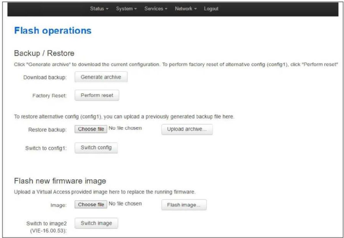
text_image
Status ▼ System ▼ Services ▼ Network ▼ Logout Flash operations Backup / Restore Click "Generate archive" to download the current configuration. To perform factory reset of alternative config (config1), click "Perform reset" Download backup: Generate archive Factory Reset: Perform reset To restore alternative config (config1), you can upload a previously generated backup file here. Restore backup: Choose file No file chosen Upload archive... Switch to config1: Switch config Flash new firmware image Upload a Virtual Access provided image here to replace the running firmware. Image: Choose file No file chosen Flash image... Switch to image2 Switch image (VIE-16.00.53):Figure 26: The flash operations page
Under Flash new firmware image, click Choose File or Browse.
Note: the button will vary depending on the browser you are using.
Select the appropriate image and then click Flash Image. The Flash Firmware – Verify page appears.
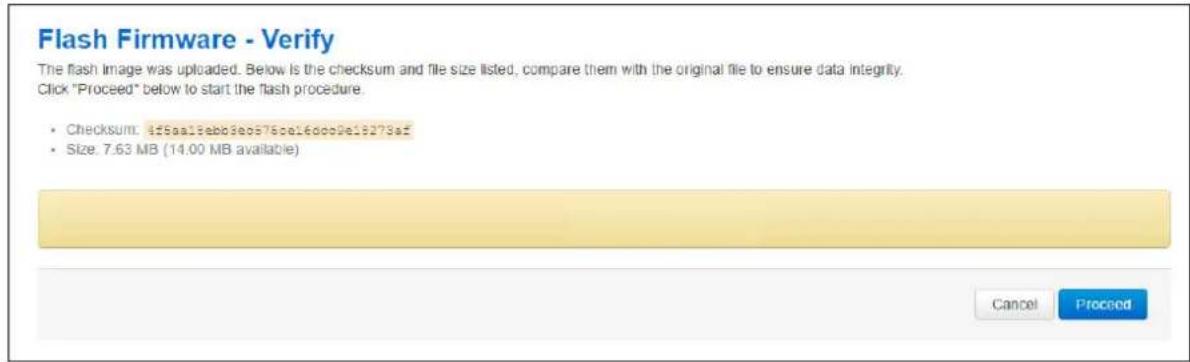
text_image
Flash Firmware - Verify The flash image was uploaded. Below is the checksum and file size listed, compare them with the original file to ensure data integrity. Click "Proceed" below to start the flash procedure. • Checksum: 455aa13ebb3e0576e16d002e18273af • Size: 7.63 MB (14.00 MB available) Cancel ProceedFigure 27: The flash firmware - verify page
Click Proceed. The System – Flashing... page appears.

text_image
System - Flashing... The system is flashing now. DO NOT POWER OFF THE DEVICE! Wait a few minutes until you try to reconnect. It might be necessary to renew the address of your computer to reach the device again, depending on your settings. Waiting for router...Figure 28: The system – flashing...page
When the 'waiting for router' icon disappears, the upgrade is complete, and the login homepage appears.
To verify that the router has been upgraded successfully, click Status in the top menu. The Firmware Version shows in the system list.
| Status System | |
| Router Name | GW0000 |
| Router Model | Virtual Access GW0031W-AA0179E |
| Firmware Version | VIE-16.00.55 |
| Current Image/Config | Image2 / config2 |
| Kernel Version | 3.2.12 |
| Local Time | Fri Aug 5 11:43:52 2016 |
| Uptime | Oh 10m: 8s |
| Load Average | 0.27, 0.35, 0.31 |
Figure 29: The system status list
9.1.3 Upgrading router firmware for software version 72.002 and above
Copy the new firmware issued by Virtual Access to a PC connected to the router.
In the top menu, select System tab > Flash operations. The Flash operations page appears.
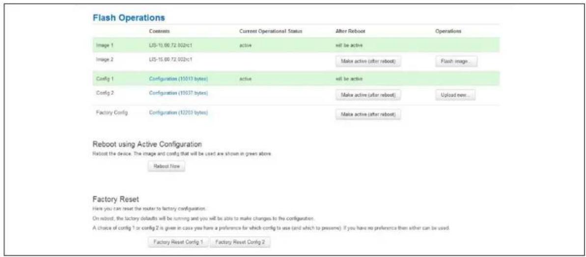
text_image
Flash Operations Contents Current Operational Status After Reboot Operations Image 1 LIS-10.00.72.002c1 active will be active Image 2 LIS-15.00.72.002c1 Make active (after reboot) Flash image... Config 1 Configuration (10013 bytes) active will be active Config 2 Configuration (10037 bytes) Make active (after reboot) Upload new... Factory Config Configuration (12/203 bytes) Make active (after reboot) Reboot using Active Configuration Reboot the device. The image and config that will be used are shown in green above Reboot Flow Factory Reset Here you can reset the router to factory configuration. On reboot, the factory defaults will be running and you will be able to make changes to the configuration. A choice of config 1 or config 2 is given in case you have a preference for which config to use (and which to preserve). If you have no preference then either can be used. Factory Reset Config 1 Factory Reset Config 2Figure 30: The flash operations page
Under Flash Operations, click Flash Image. Only the inactive image is available to flash. Select the appropriate image and then wait until image has loaded.
Note: this process may take a while depending on the available connection speed. When the image has loaded, the Update Firmware page appears.
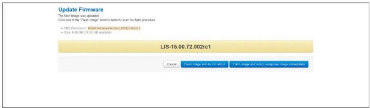
text_image
Update Firmware The flash image was uploaded Click one of the "Flash Image" buttons below to start the flash procedure • MDS Checkouts: i:fb022412e2e28403d12f932fcrb6011 • Size: 6.66 MB (14.00 MB available) LIS-15.00.72.002rc1 Cancel Flash image and do not reboot Flash image and reboot using new image immediatelyFigure 31: The flash firmware - verify page
Click either: Flash image and do not reboot, or Flash image and reboot using new image immediately. The 'Firmware update is being applied' message appears.
When the firmware update is complete, the Update Firmware page appears. There are various messages, depending on which option you selected, or if any corruptions have occurred.
9.1.4 Flash image and do not reboot option

text_image
Update Firmware The flash image was uploaded. Click one of the "Flash Image" buttons below to start the flash procedure. • MOS Checkups: 07fd28412e26d3d17f0026fb0011 • Size: 8.6F MB (14.00 MB available) LIS-15.00.72.002rc1 Firmware update is being applied. Do not power cycle the device or leave this page. Progress can be monitored below. Verify file integrity Verified Write file to flash 100% Verify flash integrity Verified Firmware update is complete The uploaded firmware has been applied to image2. The router will only run this firmware if is manually "Made Active" on the flash operations page. Click OK to return to the flash operations page. OKFigure 32: The firmware update page after '...do not reboot' option selected
If you select 'Flash image and do not reboot', the router will only run the firmware if you click OK to return to the Flash Operations page. There you can manually select Made Active (after reboot). Then click Reboot Now in the 'Reboot using Active Configuration' section.
9.1.5 Update flash image and reboot using new image immediately option
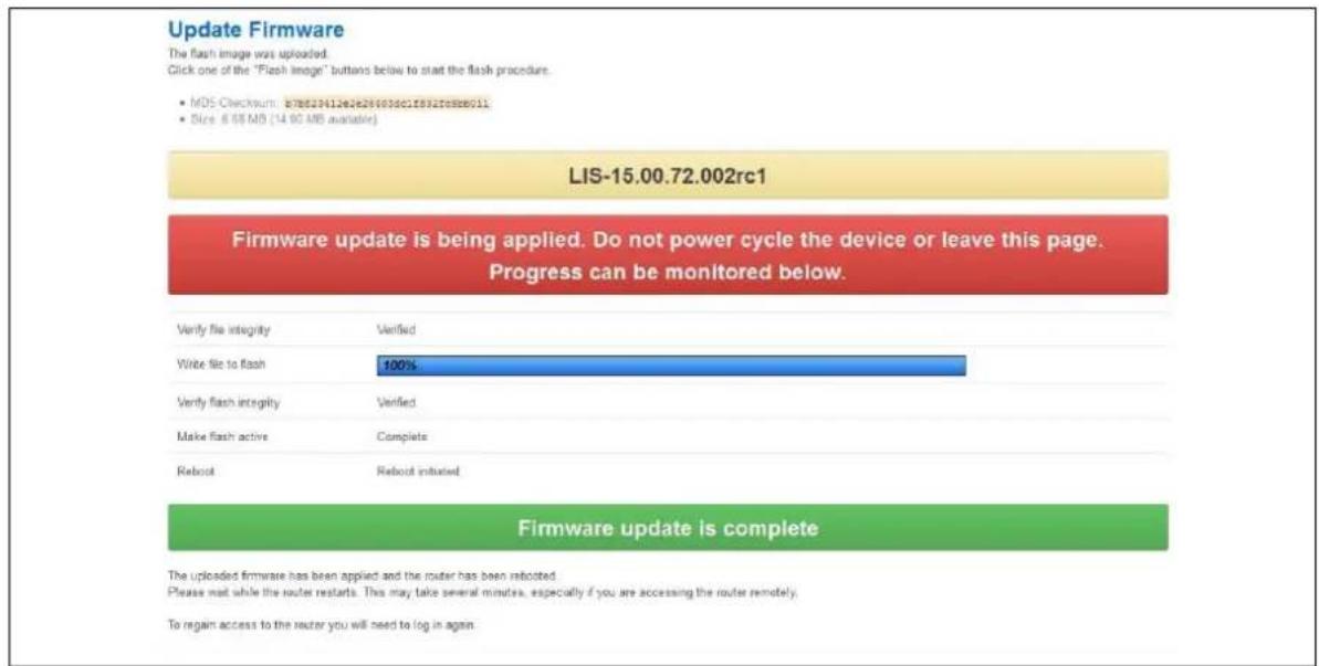
text_image
Update Firmware The flash image was uploaded. Click one of the "Flash image" buttons below to start the flash procedure. • MDS Checksum: 876339112e288003dc1f832fe888011 • Size: 6.6% MB (14.00 MB available) LIS-15.00.72.002rc1 Firmware update is being applied. Do not power cycle the device or leave this page. Progress can be monitored below. Verify file integrity Verified Write file to flash 100% Verify flash integrity Verified Make flash active Complete Reboot Rebout initiated Firmware update is complete The uploaded firmware has been applied and the router has been relocated. Please wait while the router restarts. This may take several minutes, especially if you are accessing the router remotely. To regain access to the router you will need to log in againFigure 33: The firmware update page after 'update flash image and reboot...' option selected
If you select 'Update flash image and reboot using new image immediately' and the overall validation and flashing process has succeeded, the router will reboot immediately. To regain access to the router you must login again. If any part of the processes encounters an error the reboot does not occur and a report is given.
9.1.6 Possible file corruption
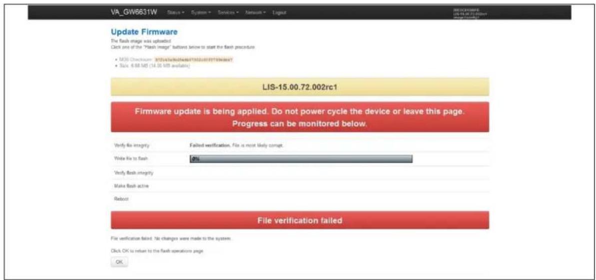
text_image
VA_GW6631W Status System Services Network Layout DISCONTENTS LIS FLA 4.0.002 Image monitor Update Firmware The flash image was uploaded Click one of the "Flash image" buttons below to start the flash procedure • MOS Checkups: 32/04/2019/07/2019/07/2019/07/2019/07/2019/07/2019/07/2019/07/2019/07/2019/07/2019/07/2019/07/2019/07/2019/07/20 • Size: 6.88 MB (14.00 MB available) LIS-15.00.72.002rc1 Firmware update is being applied. Do not power cycle the device or leave this page. Progress can be monitored below. Verify file integrity Failed verification. File is most likely compt. Write file to flash OK Verify flash integrity Make flash active Reboot File verification failed File verification failed. No changes were made to the system. Click OK is return to the flash operations page OKFigure 34: The firmware update failure page
In the unfortunate event that the firmware upgrade fails, the 'Failed verification File is most likely corrupt' or similar message will appear in the Verify file integrity row. No changes will be made to the system and the general message File verification failed appears.
9.1.7 Verify the firmware has been upgraded successfully
To check the firmware version, in the top menu, browse to System -> Flash Operations, or after router reboots, in the top menu, click Status. The Firmware Version shows in the system list and also in the right top corner of the menu bar.
| Status | |
| System | |
| Router Name | GW0000 |
| Router Model | Virtual Access GW0031W-AA0179E |
| Firmware Version | VIE-16.00.55 |
| Current Image/Config | Image2 / config2 |
| Kernel Version | 3.2.12 |
| Local Time | Fri Aug 5 11:43:52 2016 |
| Uptime | 0h 10m 8s |
| Load Average | 0.27, 0.35, 0.31 |
Figure 35: The system status list showing current firmware version
9.2 Upgrading firmware using CLI
9.2.1 Transfer file to router
To upgrade firmware using CLI, you will need a TFTP server on a connected PC or SCP available.
Open up an SSH or Telnet session to the router.
Enter in the relevant username and password.
To access the temp folder, enter cd / tmp
Depending on the router's software version the following TFTP clients are available:
- atftp
- curl
To determine which is available on your router, enter:
which curl || which atftp
The output shows the available application:
/usr/bin/curl
ATFTP
Inline command usage:
atftp -g -r LIS-15.00.72.002.image -l /tmp/LIS-15.00.72.002.image x.x.x.x
where x.x.x.x is the IP address of your PC, -g is get operation and -l / -r are local and remote file name to store.
CURL
Inline command usage:
curl tftp://x.x.x.x/LIS-15.00.72.002.image -o /tmp/LIS-15.00.72.002.image
where x.x.x.x is the IP of your PC, -o is local file name to store.
SCP
Secure Copy (SCP) is a part of Secure Shell (SSH) and enables file transfers to the router using authentication and encryption. It is different to TFTP, which uses UDP, while SCP uses a TCP connection. On Unix machines, SCP is a standard part of the system; on Windows it requires an additional application.
The usage example below is for a Unix machine and therefore assumes the image file is in the current folder.
scp LIS-15.00.72.002.image root@x.x.x.x:/tmp/LIS-15.00.72.002.image
Where the first argument 'LIS-15.00.72.002.image' in SCP is the source and the second argument 'tmp/LIS-15.00.72.002.image' is the destination path, enter root as the username to connect to x.x.x.x IP address.
After you execute the above command you will be asked to provide a root password.
At this stage the output shows the process of copying the software file into destination directory.
root@192.168.100.1's password:
LIS-15.00.72.000.image 100% 6812KB 2.2MB/s 00:03
9.2.1.1 Image verification before flashing
To verify the integrity of the image, firmware version xx.yy.72.002 and later uses an image-check application.
Note: it is the user's responsibility to verify the image before starting to write the image to flash process.
To use the image-check on downloaded image, enter:
image-check /tmp/LIS-15.00.72.002.image
In the case of any image corruption, an appropriate error message appears:
Error: no SquashFS filesystem after CRC'd section - data length 3
Error: read failed, expected at least 3 more bytes
or similar.
Note: the image is valid only if no error message appears. This process is done automatically during Web UI firmware update.
Flashing
When downloaded firmware verification succeeds, the new image can be written to flash.
To write the image into the alternative image, enter:
mtd write LIS-15.00.72.002.image altimage
Note: this is an example, substitute the correct file name.
9.2.1.2 Flash verification after flashing
After the write process has finished, you must complete a post verification of the firmware.
To verify the checksum of downloaded firmware, enter:
va_image_csum.sh /tmp/LIS-15.00.72.002.image
The checksum of the downloaded binary is shown:
08761cd03e33c569873bcc24cf2b7389 7006920 LIS-15.00.72.002 This MD5
To verify the checksum of written firmware, enter:
va_image_csum.sh alt
After a while the checksum will be calculated:
Calculating checksum......
08761cd03e33c569873bcc24cf2b7389 7006920 LIS-15.00.72.002 This MD5
Verify and compare the checksum with the MD5 sum of the downloaded image.
If the checksum of the written firmware in altimage matches the one from the downloaded image in /tmp, the new firmware has been programmed successfully.
9.2.1.3 Setup an alternative image
Provided the programming has succeeded, you can set it as the next image to use after reboot; enter:
vacmd set next image altimage
To reboot using the new firmware, enter:
reboot
10 System settings
The system section contains settings that apply to the most basic operation of the system, such as the host name, time zone, logging details, NTP server, language and style.
The host name appears in the top left hand corner of the interface menu. It also appears when you open a Telnet or SSH session.
Note: this document shows no host name in screen grabs. Throughout the document we use the host name 'VA_router'.
The system configuration contains a logging section for the configuration of a Syslog client.
10.1 Configuration package used
| Package | Sections |
| system | main |
| timeserver |
10.2 Configuring system properties
To set your system properties, in the top menu, click System. There are four sections in the System page.
| Section | Description |
| General settings | Configure host name, local time and time zone. |
| Logging | Configure a router to log to a server. You can configure a Syslog client in this section. |
| Language and Style | Configure the router's web language and style. |
| Time synchronization | Configure the NTP server in this section. |
10.2.1 General settings
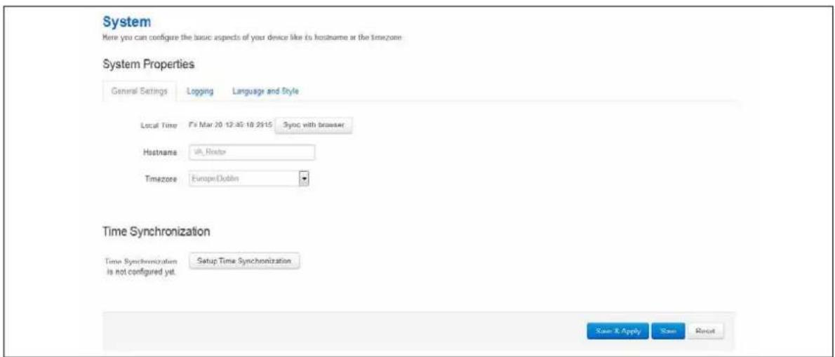
text_image
System Here you can configure the issue aspects of your device like its hostname at the timezom System Properties General Settings Logging Language and Style Local Time F's Mar 20 12:45 18 29:15 Sync with browser Hostname UK Hostor Timezone Europe Dublin Time Synchronization Time Synchronization Setup Time Synchronization Is not configured yet. Save & Apply Save RestFigure 36: General settings in system properties
| Web Field/ UCI / Package Option | Description | |
| Web: Local Time | Sets the local time and syncs with browser. You can manually configure on CLI, using:date -s YYYY.MM.DD-hh:mm:ss | |
| Web: hostnameUCI: system.main.hostnameOpt: hostname | Specifies the hostname for this system. | |
| Web: TimezoneUCI: system.main.timezoneOpt: timezone | Specifies the time zone that the date and time should be rendered in by default. | |
| Web: n/aUCI: system.main.timezoneOpt: time_save_interval_min | Defines the interval in minutes to store the local time for use on next reboot.10m | |
Table 16: Information table for general settings section
10.2.2 Logging
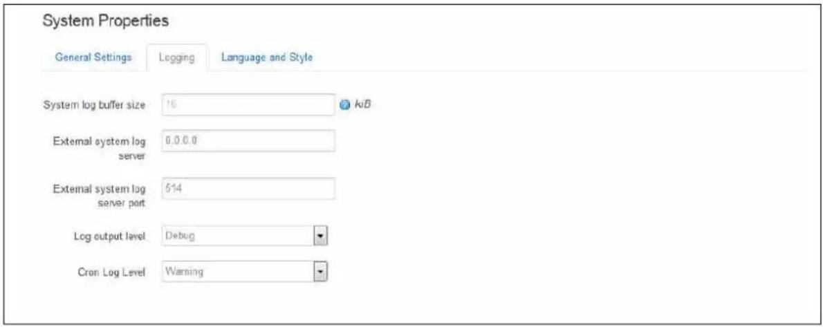
text_image
System Properties General Settings Logging Language and Style System log buffer size 10 kB External system log server 0.0.0.0 External system log server port 514 Log output level Debug Cron Log Level WarningFigure 37: The logging section in system properties
| Web Field/ UCI / Package Option | Description | |
| Web: System log buffer sizeUCI: system.main.log_sizeOpt: log_size | Log buffer size in KB. | |
| Range | ||
| 16 | 16 KB | |
| Web: External system log serverUCI: system.main.log_ipOpt: log_ip | External syslog server IP address. | |
| Range | ||
| 0.0.0.0 | ||
| Web: External system log server portUCI: system.main.log_portOpt: log_port | External syslog server port number. | |
| Range | ||
| 514 | ||
| Web: Log output levelUCI: system.main.conloglevelOpt: conloglevel | Sets the maximum log output level severity for system events.System events are written to the system log. Messages with a lower level or level equal to the configured level are displayed in the console using the logread command, or alternatively written to flash, if configured to do so. | ||
| Web value | Description | UCI | |
| Debug Information useful to developers for debugging the application. | 8 | ||
| Info Normal operational messages that require no action. | 7 | ||
| Notice Events that are unusual, but not error conditions. | 6 | ||
| Warning May indicate that an error will occur if action is not taken. | 5 | ||
| Error | Error conditions | 4 | |
| Critical | Critical conditions | 3 | |
| Alert | Should be addressed immediately | 2 | |
| Emergency | System is unusable | 1 | |
| Web: Cron Log LevelUCI: system.main.cronloglevelOpt: cronloglevel | Sets the maximum log level for kernel messages to be logged to the console. Only messages with a level lower, or level equal to the configured level will be printed to the console. | ||
| Web value | Description | UCI | |
| Normal | Normal operation messages | 8 | |
| Warning | Error messages | 9 | |
| Debug | Debug messages | 5 | |
| Web: n/aUCI: system.main.log_fileOpt: log_file | Since logread is only small in size it can be beneficial to write system events to flash. This option defines the file path to write the events. Set to 'root/syslog.messages' | ||
| Web: n/aUCI: system.main.log_typeOpt: log_type | Defines whether to write the system events to a file rather than logread. Set to 'file' to write to the file configured under log_file option. | ||
| Web: n/aUCI: system.main.log_file_countOpt: log_file_count | Defines the number of archive syslog files to store in flash. When configured above to write to /root.syslog.messages files will be stored at /root/syslog.messages,x (where x starts at 0). | ||
| Range | |||
| 1 | Stores 1 archive log file in flash | ||
Table 17: Information table for the logging section
10.2.3 Language and style
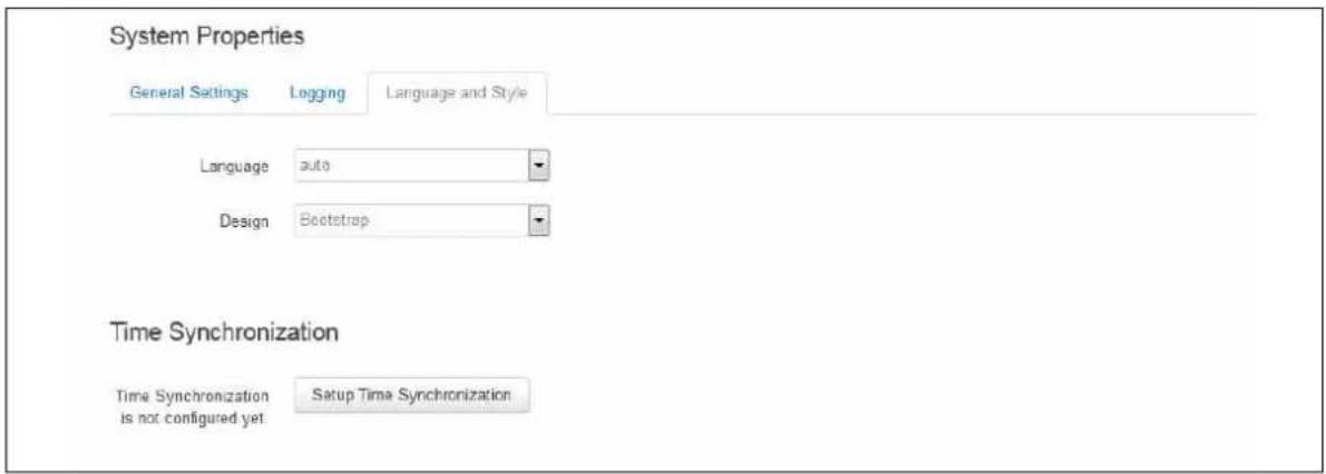
text_image
System Properties General Settings Logging Language and Style Language auto Design Bootstrap Time Synchronization Time Synchronization is not configured yet Setup Time SynchronizationFigure 38: The language and style section in system properties
| Web Field/ UCI / Package Option | Description | |
| Language Sets the language to 'auto' or 'English'. | ||
| Design | Sets the router's style. | |
Table 18: Information table for the language and style page
10.2.4 Time synchronization
The router time must be synchronised using NTP. The router can act as both an NTP client and an NTP server. It is enabled as an NTP client by default and individual interfaces can be configured to respond to NTP requests.
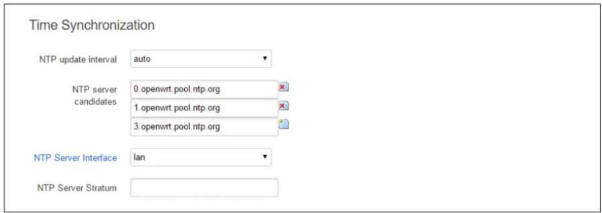
text_image
Time Synchronization NTP update interval auto NTP server candidates 0.openwrt.pool.ntp.org 1.openwrt.pool.ntp.org 3.openwrt.pool.ntp.org NTP Server Interface lan NTP Server StratumFigure 39: The time synchronization section in system properties
| Web Field/ UCI / Package Option | Description | |
| Web: NTP update intervalUCI: system.ntp.interval_hoursOpt: interval_hours | Specifies interval of NTP requests in hours. Default value set to auto. | |
| Auto | ||
| Range | auto; 1-23 | |
| Web: NTP server candidatesUCI: system.ntp.serverOpt: list server | Defines the list of NTP servers to poll the time from. If the list is empty, the built in NTP daemon is not started. Multiple servers can be configured and are separated by a space if using UCI.By default all fields are set to 0.0.0.0. | |
| Web: NTP Server InterfaceUCI: system.ntp.listenOpt: listen | Defines a list of interfaces that respond to NTP requests.Interfaces should be delimited using space. Example:option listen 'LAN1 LAN2' | |
| Blank | Do not respond to NTP requests. | |
| Range | ||
| Web: NTP Server StratumUCI: system.ntp.stratumOpt: stratum | Defines how far this NTP Server is from the reference clock. For example, an NTP server getting time directly from the reference clock will have a stratum of 1. In general, this should be left blank, which means that the router NTP Server will derive the stratum from the NTP dialogue. | |
| Blank | NTP server will derive stratum | |
| Range | ||
Table 19: Information table for time synchronization section
10.2.5 System reboot
The router can be configured to reboot immediately, or scheduled to reboot a configured time in the future.
In the top menu, select System -> Reboot. The System page appears.
Ensure you have saved all your configuration changes before you reboot.
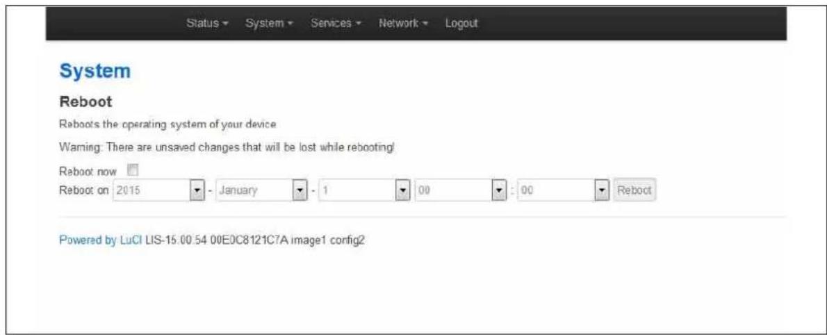
text_image
Status ▼ System ▼ Services ▼ Network ▼ Logout System Reboot Reboot's the operating system of your device Warning: There are unsaved changes that will be lost while rebooting! Reboot now Reboot on 2015 - January - 1 00 : 00 Reboot Powered by LuCI LIS-15.00.54 00E0C8121C7A image1 config2Figure 40: The reboot page
Check the Reboot now check box and then click Reboot.
10.3 System settings using UCI
root@VA_router:~# uci show system
system.main=system
system.main.hostname=VA_router
system.main.timezone=UTC
system.main.log_ip=1.1.1.1
system.main.log_port=514
system.main.conloglevel=8
system.main.cronloglevel=8
system.ntp.interval_hours=auto
system.ntp.server=0.VA_router.pool.ntp.org 10.10.10.10
System settings using package options
root@VA_router:~# uci export system
package 'system'

config 'system' 'main'
option 'hostname' "VA_router"
option 'timezone' "UTC"
option 'log_ip' "1.1.1.1"
option 'log_port' "514"
option time_save_interval_min "10"
option conloglevel '8'
option cronloglevel '8'

config 'timeserver' 'ntp'
option interval_hours 'auto'
list server "0.VA_router.pool.ntp.org"
list server '10.10.10.10'
option listen 'LAN1 LAN2'
10.4 System diagnostics
10.4.1 System events
Events in the system have a class, sub class and severity. All events are written to the system log.
10.4.1.1 Logread
To view the system log, enter:
root@VA_router:~# logread
Shows the log.
root@VA_router:~# logread | tail
Shows end of the log.
root@VA_router:~# logread | more
Shows the log page by page.
root@VA_router:~# logread -f
Shows the log on an ongoing basis. To stop this option, press ctrl-c.
root@VA_router:~# logread -f &
Shows the log on an ongoing basis while in the background. This allows you to run other commands while still tracing the event logs. To stop this option, type fg to view the current jobs, then press ctrl-c to kill those jobs.
10.4.2 System events in flash
Since logread is only small in size it can be beneficial to write system events to flash. To do this you need to modify the system config under the system package. Set the options 'log_file', 'log_size' and 'log_type' as below:
root@VA_router:~# uci export system
package system
config system 'main'
option hostname 'VA_router'
option zonename 'UTC'
option timezone 'GMT0'
option conloglevel '8'
option cronloglevel '8'
option time_save_interval_hour '10'
option log_hostname '%serial'
option log_ip '1.1.1.1'
option log_port '514'
option log_file '/root/syslog.messages'
option log_size '400'
option log_type 'file'
The above commands will take effect after a reboot.
root@VA_router:~# cat /root/syslog.messages
Shows all the system events stored in flash.
root@VA_router:~# tail /root/syslog.messages
Shows end of the events stored flash.
root@VA_router:~# tail -f /root/syslog.messages &
Shows the log on an ongoing basis. To stop this option, press ctrl-c.
11 Configuring an Ethernet interface
This section describes how to configure an Ethernet interface including configuring the interface as a DHCP server, adding the interface to a firewall zone, mapping the physical switch ports and defining loopback interface.
11.1 Configuration packages used
| Package | Sections |
| network | interface |
| route | |
| va_switch | |
| alias | |
| firewall | zone |
| dhcp | dhcp |
11.2 Configuring an Ethernet interface using the web interface
To create and edit interfaces via the web interface, in the top menu, click Network -> Interfaces. The Interfaces overview page appears.
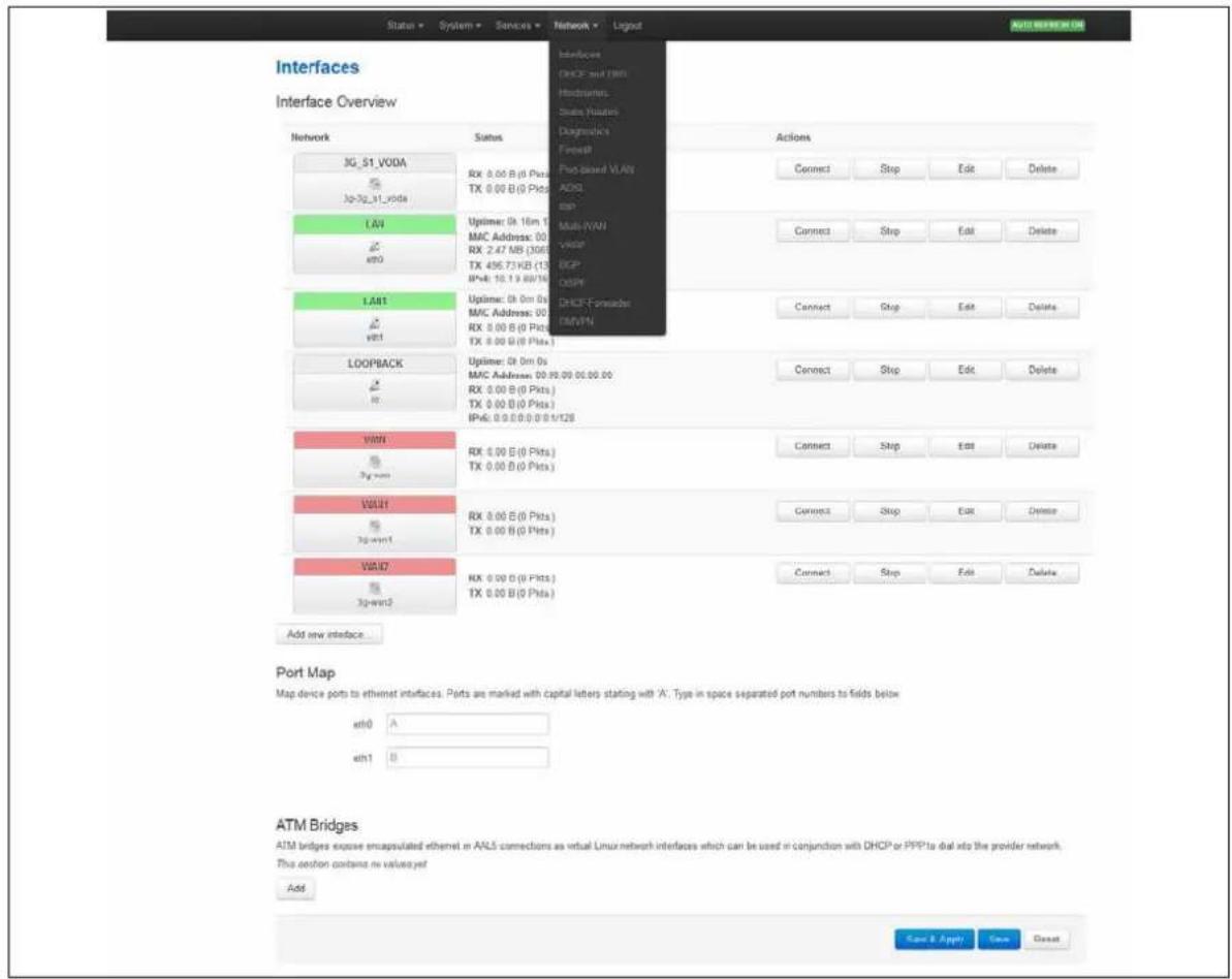
text_image
Interface Interface Overview Network Status Actions JG_51_VODA RX 0.00 B (0 Pkt) TX 0.00 B (0 Pkt) Rx 0.00 B (0 Pkt) Upltime: 0h 16m 1 MMC Address: 00 RX 2.47 MB (306) TX 496.73 KB (13) IP+6: 10.19 BB/16 Upltime: 0h 0m 0s MMC Address: 00 RX 8.00 B (0 Pkt) TX 8.00 B (0 Pkt) LoopBACK Upltime: 0h 0m 0s MMC Address: 00.98.09.00.00.00 RX 8.00 B (0 Pkt) TX 8.00 B (0 Pkt) IP+6: 0.0.0.0.0.0.1/128 VWTH RX 8.00 B (0 Pkt) TX 8.00 B (0 Pkt) VWHT RX 8.00 B (0 Pkt) TX 8.00 B (0 Pkt) VWID RX 8.00 B (0 Pkt) TX 8.00 B (0 Pkt) Add new interface... Port Map Map device ports to ethimet interfaces. Ports are marked with capital letters starting with 'A'. Type in space separated port numbers to fields below. eth0 A eth1 B ATM Bridges ATM bridges expose encapsulated ethemet in AALS connections as virtual Linux network interfaces which can be used in conjunction with DHCP or PPPTa dial into the provider network. This option contains no values yet Add Save & Apply Save CancelFigure 41: The interfaces overview page
There are three sections in the Interfaces page.
| Section | Description |
| Interface Overview | Shows existing interfaces and their status. You can create new, and edit existing interfaces here. |
| Port Map | In this section you can map device ports to Ethernet interfaces. Ports are marked with capital letters starting with 'A'. Type in space-separated port character in the port map fields. |
| ATM Bridges | ATM bridges expose encapsulated Ethernet in AAL5 connections as virtual Linux network interfaces, which can be used in conjunction with DHCP or PPP to dial into the provider network. |
11.2.1 Interface overview: editing an existing interface
To edit an existing interface, from the interface tabs at the top of the page, select the interface you wish to configure. Alternatively, click Edit in the interface's row.
11.2.2 Interface overview: creating a new interface
To create a new interface, in the Interface Overview section, click Add new interface. The Create Interface page appears.
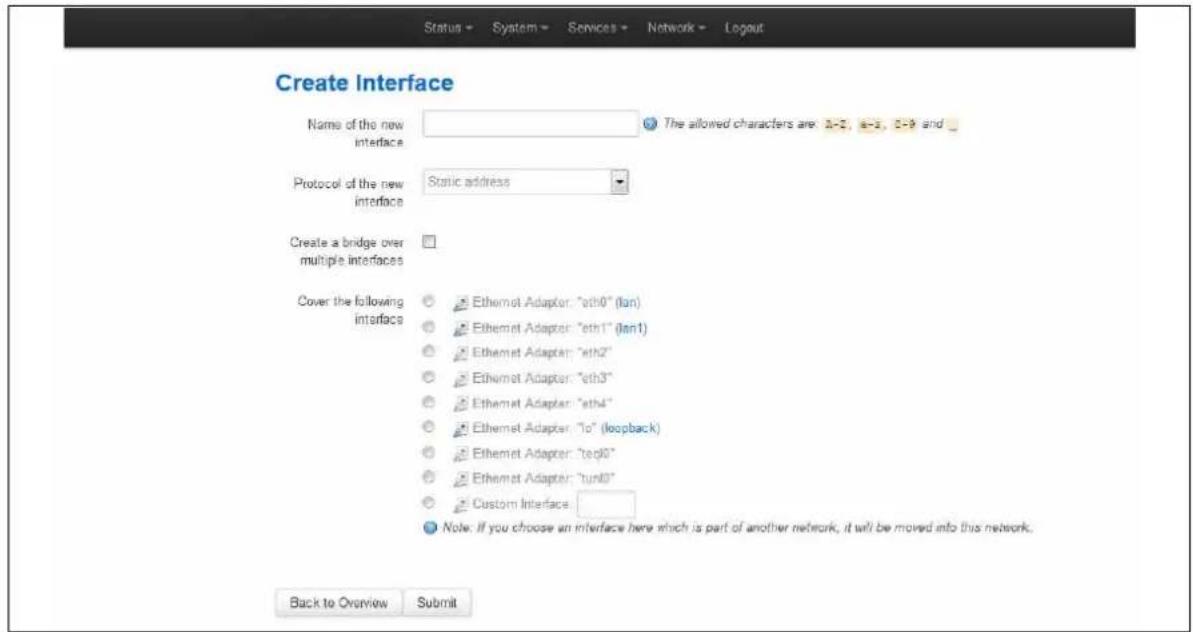
text_image
Create Interface Name of the new interface The allowed characters are 0-2, 6-3, 0-9 and _ Protocol of the new interface Static address Create a bridge over multiple interfaces Cover the following interface Ethernet Adapter: "eth0" (lan) Ethernet Adapter: "eth1" (lan1) Ethernet Adapter: "eth2" Ethernet Adapter: "eth3" Ethernet Adapter: "eth4" Ethernet Adapter: "to" (loopback) Ethernet Adapter: "teq0" Ethernet Adapter: "tun0" Custom Interface Note. If you choose an interface here which is part of another network, it will be moved into this network. Back to Overview SubmitFigure 42: The create interface page
| Web Field/ UCI / Package Option | Description | |
| Web: Name of the new interfaceUCI: network.<if name>.opt: config interface | Assigns a logical name to the interface. The network interface section will assign this name ( ).Type the name of the new interface.Allowed characters are A-Z, a-z, 0-9 and _ | |
| Web: Protocol of the new interfaceUCI: network.<if name>.protoOpt: proto | Specifies what protocol the interface will operate on. Select Static. | |
| Option | Description | |
| Static Static configuration with fixed address and netmask. | ||
| DHCP Client | Address and netmask are assigned by DHCP. | |
| Unmanaged | Unspecified | |
| IPv6-in-IPv4 (RFC4213) | Used with tunnel brokers. | |
| IPv6-over-IPv4 | Stateless IPv6 over IPv4 transport. | |
| GRE | Generic Routing Encapsulation protocol | |
| IOT | ||
| L2TP | Layer 2 Tunnelling Protocol | |
| PPP | Point to Point Protocol | |
| PPPoE | PPP over Ethernet | |
| PPPoATM | PPP over ATM | |
| LTE/UMTS/GPRS/EV-DO | CDMA, UMTS or GPRS connection using an AT-style 3G modem. | |
| Web: Create a bridge over multiple interfacesUCI: network.<if name>.typeOpt: type | If you select this option, then the new logical interface created will act as a bridging interface between the chosen existing physical interfaces. | |
| Empty | ||
| Bridge Configures a bridge over multiple interfaces. | ||
| Web: Cover the following interfaceUCI: network.<if name>.ifnameOpt: ifname | Physical interface name to assign to this logical interface. If creating a bridge over multiple interfaces select two interfaces to bridge. When using uci the interface names should be separated by a space e.g. option ifname 'eth2 eth3' | |
Table 20: Information table for the create new interface page
Click Submit. The Interface configuration page appears. There are three sections:
| Section | Description |
| Common Configuration | Configure the interface settings such as protocol, IP address, gateway, netmask, custom DNS servers, MTU and firewall configuration. |
| IP-Aliases | Assigning multiple IP addresses to the interface |
| DHCP Server | Configuring DHCP server settings for this interface |
11.2.3 Interface overview: common configuration
The common configuration section has four sub sections:
| Section | Description |
| General Setup | Configure the basic interface settings such as protocol, IP address, gateway, netmask, custom DNS servers. |
| Advanced Settings | 'Bring up on boot', 'Monitor interface state', Override MAC address, Override MTU and 'Use gateway metric' |
| Physical Settings | Bridge interfaces, VLAN PCP to SKB priority mapping, |
| Firewall settings | Assign a firewall zone to the interface |
11.2.3.1 Common configuration – general setup
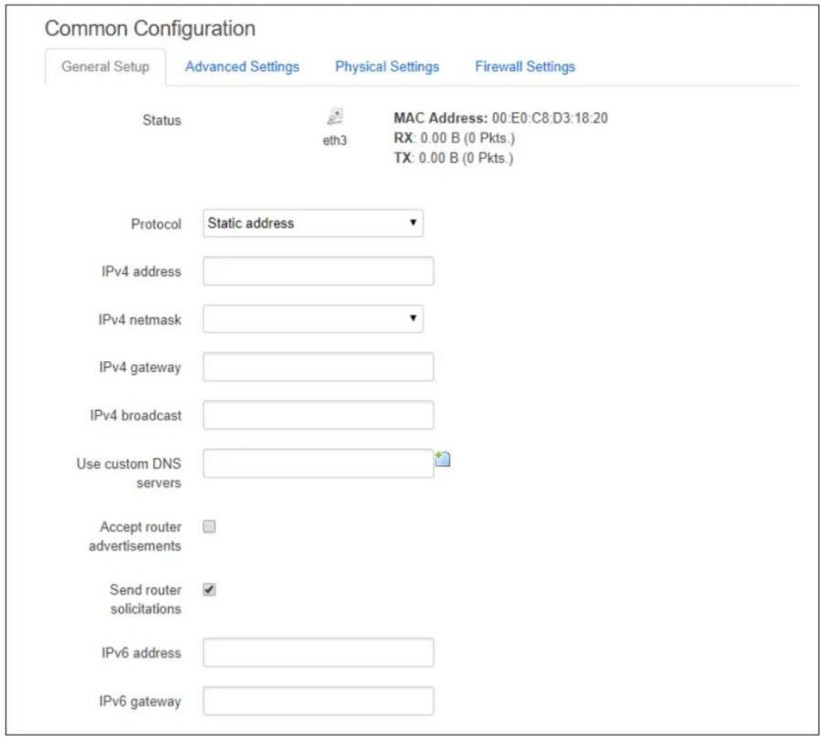
text_image
Common Configuration General Setup Advanced Settings Physical Settings Firewall Settings Status MAC Address: 00:E0:C8:D3:18:20 eth3 RX: 0.00 B (0 Pkts.) TX: 0.00 B (0 Pkts.) Protocol Static address ▼ IPv4 address IPv4 netmask ▼ IPv4 gateway IPv4 broadcast Use custom DNS servers Accept router advertisements Send router solicitations IPv6 address IPv6 gatewayFigure 43: The Ethernet connection common configuration settings page
| Web Field/ UCI / Package Option | Description | |
| General Setup | ||
| Web: Status | Shows the current status of the interface. | |
| Web: ProtocolUCI: network..protoOpt: proto | Protocol type. The interface protocol may be one of the options shown below. The protocol selected in the previous step will be displayed as default but can be changed if required. | |
| Option | Description | |
| Static | Static configuration with fixed address and netmask. | |
| DHCP Client Address and netmask are assigned by DHCP. | ||
| Unmanaged | Unspecified | |
| IPv6-in-IPv4 (RFC4213) | Used with tunnel brokers. | |
| IPv6-over-IPv4 | Stateless IPv6 over IPv4 transport. | |
| GRE | Generic Routing Encapsulation protocol | |
| IOT | ||
| L2TP | Layer 2 Tunnelling Protocol. | |
| PPP | Point-to-Point protocol | |
| PPPoE | PPP over Ethernet | |
| PPPoATM | PPP over ATM | |
| LTE/UMTS/GPRS/EV-DO | CDMA, UMTS or GPRS connection using an AT-style 3G modem. | |
| Web: IPv4 addressUCI: network..ipaddrOpt: ipaddr | The IPv4 address of the interface. This is optional if an IPv6 address is provided. | |
| Web: IPv4 netmaskUCI: network..netmaskOpt: netmask | Subnet mask to be applied to the IP address of this interface. | |
| Web: IPv4 gatewayUCI: network..gatewayOpt: gateway | IPv4 default gateway to assign to this interface (optional). | |
| Web: IPv4 broadcastUCI: network..broadcastOpt: broadcast | Broadcast address. This is automatically generated if no broadcast address is specified. | |
| Web: Use custom DNS serversUCI: network..dnsOpt: list dns | List of DNS server IP addresses (optional). Multiple DNS Servers are separated by a space if using UCI. | |
| Web: Accept router advertisementsUCI: network..accept_raOpt: accept_ra | Specifies whether to accept IPv6 Router Advertisements on this interface (optional).Note: default is 1 if protocol is set to DHCP, otherwise defaults to 0. | |
| Web: Send router solicitationsUCI: network..send_rsOpt: send_rs | Specifies whether to send Router Solicitations on this interface (optional).Note: defaults to 1 for Static protocol, otherwise defaults to 0. | |
| Web: IPv6 addressUCI: network..ip6addrOpt: ip6addr | The IPv6 IP address of the interface. Optional if an IPv4 address is provided.CIDR notation for the IPv6 address is required. | |
| Web: IPv6 gatewayUCI: network..ip6gwOpt: ip6gw | Assign given IPv6 default gateway to this interface (optional). | |
Table 21: Information table for LAN interface common configuration settings
11.2.3.2 Common configuration: advanced settings
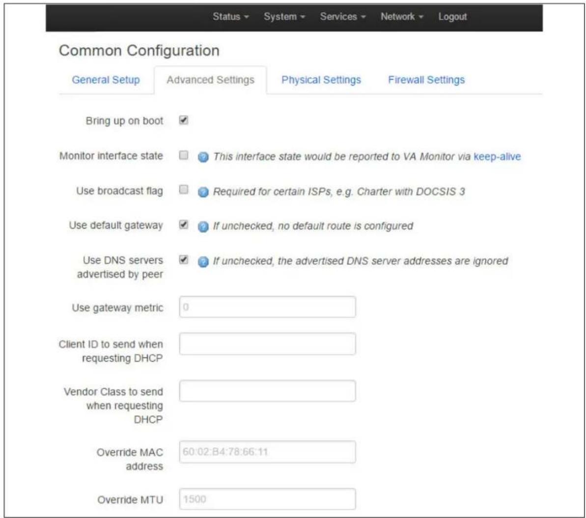
text_image
Status ▼ System ▼ Services ▼ Network ▼ Logout Common Configuration General Setup Advanced Settings Physical Settings Firewall Settings Bring up on boot ✓ Monitor interface state ☐ This interface state would be reported to VA Monitor via keep-alive Use broadcast flag ☐ Required for certain ISPs, e.g. Charter with DOCSIS 3 Use default gateway ✓ If unchecked, no default route is configured Use DNS servers advertised by peer ✓ If unchecked, the advertised DNS server addresses are ignored Use gateway metric 0 Client ID to send when requesting DHCP Vendor Class to send when requesting DHCP Override MAC address 60:02:B4:78:66:11 Override MTU 1500Figure 44: The Ethernet connection advanced settings page
| Web Field/ UCI / Package Option | Description | |
| Web: Bring up on bootUCI: network.<if name>.autoOpt: auto | Enables the interface to connect automatically on boot up. | |
| 0 | Disabled. | |
| 1 | Enabled. | |
| Web: Monitor interface stateUCI: network.<if name>.monitoredOpt: monitored | Enabled if status of interface is presented on Monitoring platform. | |
| 0 | Disabled. | |
| 1 | Enabled. | |
| Web: Override MAC addressUCI: network.<if name>.macaddrOpt: macaddr | Override the MAC address assigned to this interface. Must be in the form: hh:hh:hh:hh:hh:hh, where h is a hexadecimal number. | |
| Web: Override MTUUCI: network.<if name>.mtuOpt: mtu | Defines the value to override the default MTU on this interface. | |
| 1500 | 1500 bytes | |
| Web: Use gateway metricUCI: network.<if name>.metricOpt: metric | Specifies the default route metric to use for this interface (optional). | |
| 0 | ||
| Range | ||
| Web: Dependant InterfacesUCI: network[..x..].dependantsOpt: dependants | Lists interfaces that are dependent on this parent interface.Dependant interfaces will go down when parent interface is down and will start or restart when parent interface starts.Separate multiple interfaces by a space when using UCI.Example: option dependants 'PPPADSL MOBILE'This replaces the following previous options in child interfaces. | |
| gre | option local_interface | |
| lt2p | option src_ipaddr | |
| iot | option wan1 wan2 | |
| 6in4 | option ipaddr | |
| 6to4 | option ipaddr | |
| Web: SNMP Alias ifindexUCI: network[..x..].snmp_alias_ifindexOpt: snmp_alias_ifindex | Defines a static SNMP interface alias index for this interface, that can be polled via the SNMP interface index(snmp_alias_ifindex+ 1000). See Configuring SNMP section for more information | |
| Blank | No SNMP interface alias index | |
| Range | 0 - 4294966295 | |
Table 22: Information table for common configuration advanced settings
11.2.3.3 Common configuration: physical settings

text_image
Common Configuration General Setup Advanced Settings Physical Settings Firewall Settings Bridge interfaces creates a bridge over specified interface(s) VLAN PCP to skb- >priority mapping Space separated list ofFigure 45: The common configuration physical settings page
| Web Field/ UCI / Package Option | Description | |
| Web: Bridge interfacesUCI: network..typeOpt: type | Sets the interface to bridge over a specified interface(s). The physical interfaces can be selected from the list and are defined in network..ifname. | |
| Empty | ||
| Bridge | Configures a bridge over multiple interfaces. | |
| Web: Enable STPUCI: network..stpOpt: stp | Enable Spanning Tree Protocol. This option is only available when the Bridge Interfaces option is selected. | |
| 0 | Disabled. | |
| 1 | Enabled. | |
| Web: VLAN PCP to skb>priority mappingUCI: network..vlan_qos_map_ingressOpt: list vlan_qos_map_ingress | VLAN priority code point to socket buffer mapping. Multiple priority mappings are entered with a space between them when using UCI.Example: network..vlan_qos_map_ingress = 1:2 2:1 | |
| Web: skb priority to >VLAN PCP mappingUCI: network..vlan_qos_map_egressOpt: list vlan_qos_map_egress | Socket buffer to VLAN priority code point mapping. Multiple priority mappings are entered with a space between them when using UCI.Example: network..vlan_qos_map_egress = 1:2 2:1 | |
| Web: InterfaceUCI: network..ifnameOpt: ifname | Physical interface to assign the logical interface to. If mapping multiple interfaces for bridging the interface names are separated by a space when using UCI and package options.Example: option ifname ‘eth2 eth3’ or network..ifname=eth2 eth 3 | |
Table 23: Information table for physical settings page
11.2.3.4 Loopback interfaces
Loopback interfaces are defined in exactly the same way as Ethernet interfaces. Please see section above.
Note: There is no software limitation as to how many loopback interfaces can exist on the router.
11.2.3.5 Common configuration: firewall settings
Use this section to select the firewall zone you want to assign to this interface.
Select unspecified to remove the interface from the associated zone or fill out the create field to define a new zone and attach the interface to it.
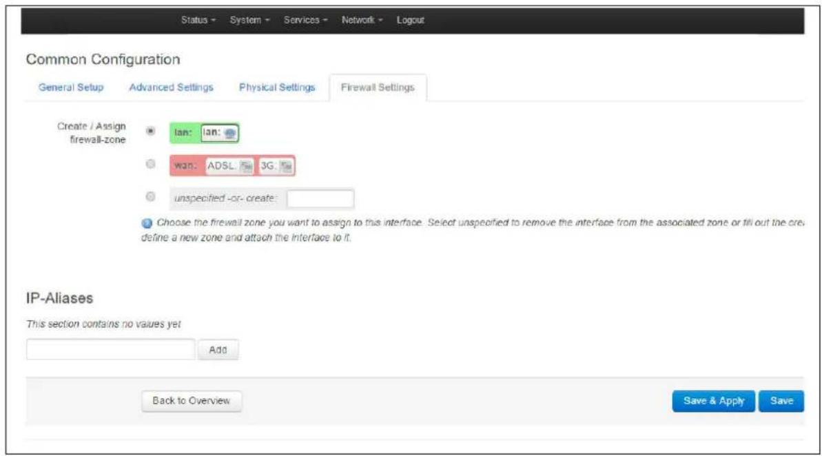
text_image
Status - System - Services - Network - Logout Common Configuration General Setup Advanced Settings Physical Settings Firewall Settings Create / Assign firewall-zone Ian: Ian: wan: ADSL 3G: unspecified -or- create: Choose the firewall zone you want to assign to this interface. Select unspecified to remove the interface from the associated zone or fill out the cre. define a new zone and attach the interface to it. IP-Aliases This section contains no values yet Add Back to Overview Save & Apply SaveFigure 46: GRE firewall settings
11.2.4 Interface overview: IP-aliases
IP aliasing means associating more than one IP address to a network interface. You can assign multiple aliases.
11.2.4.1 IP-alias packages
| Package | Sections |
| Network | alias |
11.2.4.2 IP-alias using the web
To use IP-aliases, enter a name for the alias and click Add. This name will be assigned to the alias section for this IP-alias. In this example, we use the name 'ethalias1'.
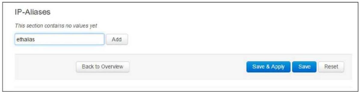
text_image
IP-Aliases This section contains no values yet ethalias Add Back to Overview Save & Apply Save ResetFigure 47: The IP-Aliases section
| Web Field/ UCI / Package Option | Description |
| UCI: network.=ifnameOpt: config interface ‘aliasname’ | Assigns the alias name. |
| UCI: network..interfaceOpt: interface | This maps the IP-Alias to the interface. |
| UCI: network..protoOpt: proto | This maps the interface protocol to the alias. |
Table 24: Information table for IP-Aliases name assignment
The IP Aliases configuration options page appears. The IP-Alias is divided into two sub sections: general setup and advanced.
11.2.4.3 IP-aliases: general setup
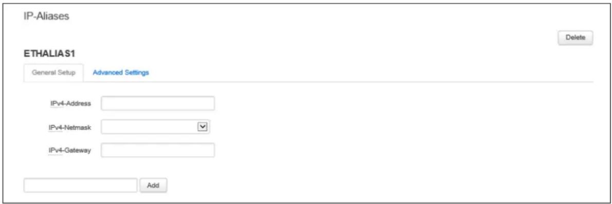
text_image
IP-Aliases ETHALIA S1 General Setup Advanced Settings IPv4-Address IPv4-Netmask IPv4-Gateway Add DeleteFigure 48: The IP-Aliases general setup section
| Web Field/ UCI / Package Option | Description |
| Web: IPv4-AddressUCI: network.<alias name>.ipaddrOpt: ipaddr | Defines the IP address for the IP alias. |
| Web: IPv4-NetmaskUCI: network.<alias name>.netmaskOpt: netmask | Defines the netmask for the IP alias. |
| Web: IPv4-GatewayUCI: network.<alias name>.gatewayOpt: gateway | Defines the gateway for the IP alias. |
Table 25: Information table for IP-Alias general setup page
11.2.4.4 IP-aliases: advanced settings
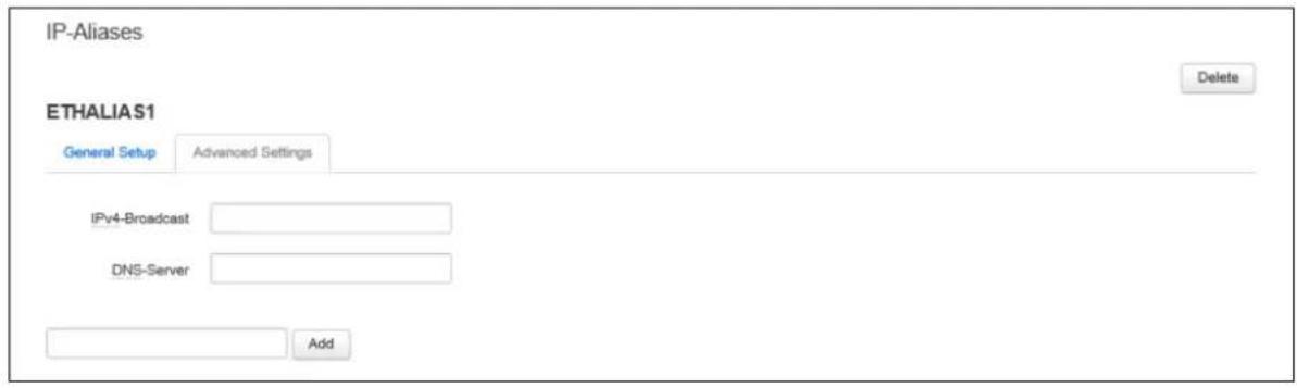
text_image
IP-Aliases ETHALIA S1 General Setup Advanced Settings IPy4-Broadcast DNS-Server Add DeleteFigure 49: The IP-Aliases advanced settings section
| Web Field/ UCI / Package Option | Description |
| Web: IPv4-BroadcastUCI: network.<alias name>.bcastOpt: bcast | Defines the IP broadcast address for the IP alias. |
| Web: DNS-ServerUCI: network.<alias name>.dnsOpt: dns | Defines the DNS server for the IP alias. |
Table 26: Information table for IP-Alias advanced settings page
11.2.5 Interface overview: DHCP server
Note: this option is only available for interfaces with a static IP address.
11.2.5.1 DHCP server: packages
| Package | Sections |
| dhcp | dhcp |
To assign a DHCP Server to the interface, click Setup DHCP Server.
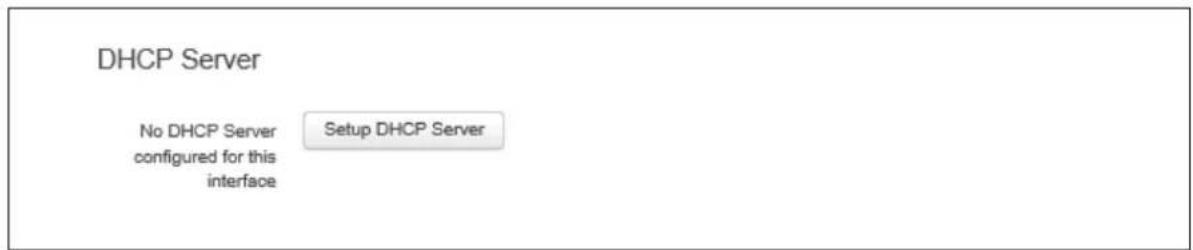
text_image
DHCP Server No DHCP Server configured for this interface Setup DHCP ServerFigure 50: The DHCP Server settings section
The DHCP Server configuration options will appear. The DHCP Server is divided into two sub sections – general setup and advanced.
11.2.5.2 DHCP server: general setup
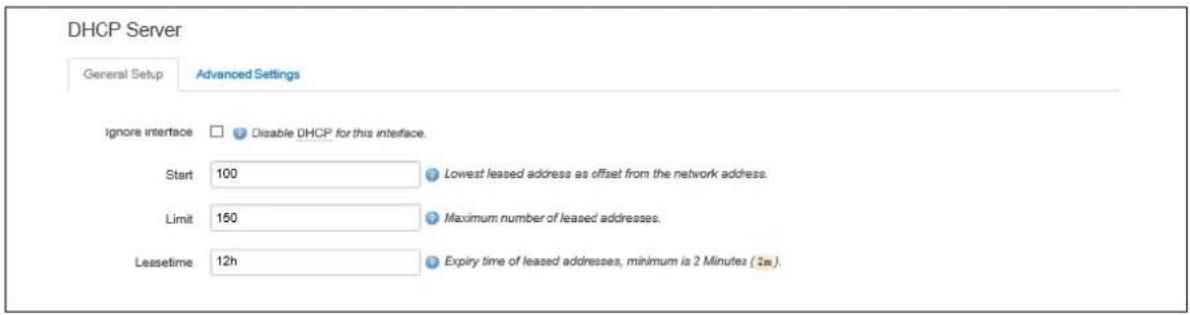
text_image
DHCP Server General Setup Advanced Settings Ignore interface ☐ Disable DHCP for this interface. Start 100 Lowest leased address as offset from the network address. Limit 150 Maximum number of leased addresses. Lease time 12h Expiry time of leased addresses, minimum is 2 Minutes (2m).Figure 51: The DHCP server general setup section
| Web Field/ UCI / Package Option | Description | |
| Web: Ignore interfaceUCI: dhcp.@dhcp[x].ignoreOpt: ignore | Defines whether the DHCP pool should be enabled for this interface. If not specified for the DHCP pool then default is disabled i.e. dhcp pool enabled. | |
| 0 | Disabled. | |
| 1 | Enabled. | |
| Web: n/aUCI: dhcp.@dhcp[x].startOpt: start | Defines the offset from the network address for the start of the DHCP pool. It may be greater than 255 to span subnets. | |
| 100 | ||
| Range | ||
| Web: n/aUCI: dhcp.@dhcp[x].limitOpt: limit | Defines the offset from the network address for the end of the DHCP pool. | |
| 150 | ||
| Range | 0 – 255 | |
| Web: n/aUCI: dhcp.@dhcp[x].leasetimeOpt: leasetime | Defines the lease time of addresses handed out to clients, for example 12h or 30m. | |
| 12h | 12 hours | |
| Range | ||
Table 27: Information table for DHCP server general setup page
11.2.5.3 DHCP server: advanced settings
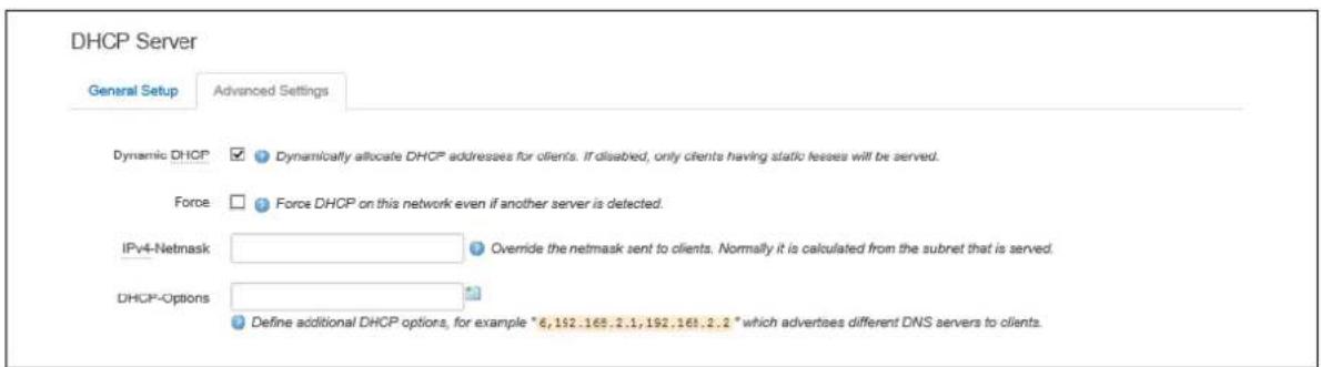
text_image
DHCP Server General Setup Advanced Settings Dynamic DHCP ✓ Dynamically allocate DHCP addresses for clients. If disabled, only clients having static fees will be served. Force □ Force DHCP on this network even if another server is detected. IPv4-Netmask ○ Override the netmask sent to clients. Normally it is calculated from the subnet that is served. DHCP-Options Define additional DHCP options, for example * 6,192.165.2.1,192.165.2.2 * which advertises different DNS servers to clients.Figure 52: The DHCP server advanced settings section
| Web Field/ UCI / Package Option | Description | |
| Web: Dynamic DHCPUCI: dhcp.@dhcp[x].dynamicdhcpOpt: dynamicdhcp | Defines whether to allocate DHCP leases. | |
| 1 | Dynamically allocate leases. | |
| 0 Use /etc/ethers | s file for serving DHCP leases. | |
| Web: ForceUCI: dhcp.@dhcp[x].forceOpt: force | Forces DHCP serving on the specified interface even if another DHCP server is detected on the same network segment. | |
| 0 | Disabled. | |
| 1 | Enabled. | |
| Web: DHCP-OptionsUCI: dhcp.@dhcp[x].dhcp_optionOpt: list dhcp_option | Defines additional options to be added for this dhcp pool. For example with 'list dhcp_option 26,1470' or 'list dhcp_option mtu, 1470' you can assign a specific MTU per DHCP pool. Your client must accept the MTU option for this to work. Options that contain multiple vales should be separated by a space.Example: list dhcp option 6,192.168.2.1 192.168.2.2 | |
| No options defined. | ||
| Syntax | Option_number, option_value | |
| Web: n/aUCI: dhcp.@dhcp[x].networkidOpt: networked | Assigns a network-id to all clients that obtain an IP address from this pool. | |
Table 28: Information table for DHCP advanced settings page
For more advanced configuration on the DHCP server, read 'DHCP server and DNS configuration section.
11.3 Interface configuration using UCI
The configuration files are stored on /etc/config/network, /etc/config/firewall and /etc/config/dhcp
root@VA_router:~# uci show network
.....
network.newinterface=interface
network.newinterface.proto=static
network.newinterface.ifname=eth0
network.newinterface.montored=0
network.newinterface.ipaddr=2.2.2.2
network.newinterface.netmask=255.255.255.0
network.newinterface.gateway=2.2.2.10
network.newinterface.broadcast=2.2.2.255
network.newinterface.vlan_qos_map_ingress=1:2 2:1
network.ethalias1=alias
network.ethalias1.proto=static
network.ethalias1.interface=newinterface
network.ethalias1.ipaddr=10.10.10.1
network.ethalias1.netmask=255.255.255.0
network.ethalias1.gateway=10.10.10.10
network.ethalias1.bcast=10.10.10.255
network.ethalias1.dns=8.8.8.8

root@VA_router:~# uci show firewall
....firewall.@zone[0]=zone
firewall.@zone[0].name=lan
firewall.@zone[0].input=ACCEPT
firewall.@zone[0].output=ACCEPT
firewall.@zone[0].forward=ACCEPT
firewall.@zone[0].network=lan newinterface

root@VA_router:~# uci show dhcp
...
dhcp.@dhcp[0]=dhcp
dhcp.@dhcp[0].start=100
root@VA_router:~# uci show firewall
dhcp.@dhcp[0].leasetime=12h
dhcp.@dhcp[0].limit=150
dhcp.@dhcp[0].interface=newinterface
To change any of the above values use uci set command.
11.3.1 Interface common configuration using package options
The configuration files are stored on /etc/config/network, /etc/config/firewall and /etc/config/dhcp
root@VA_router:~# uci export network
package network
......
config interface 'newinterface'
option proto 'static'
option ifname 'eth0'
option monitored '0'
option ipaddr '2.2.2.2'
option netmask '255.255.255.0'
option gateway '2.2.2.10'
option broadcast '2.2.2.255'
list vlan_qos_map_ingress '1:2'
list vlan_qos_map_ingress '2:1'
config alias 'ethalias1'
option proto 'static'
option interface 'newinterface'
option ipaddr '10.10.10.1'
option netmask '255.255.255.0'
option gateway '10.10.10.10'
option bcast '10.10.10.255'
option dns '8.8.8.8'

root@VA_router:~# uci export firewall
package firewall

config zone
option name 'lan'
option input 'ACCEPT'
option output 'ACCEPT'
option forward 'ACCEPT'
option network 'lan newinterface'

root@VA_router:~# uci export dhcp
package dhcp

......

config dhcp
option start '100'
option leasetime '12h'
option limit '150'
option interface 'newinterface'
To change any of the above values use uci set command.
11.3.2 Loopback interfaces
Loopback interfaces are defined in exactly the same way as Ethernet interfaces. Read the section above.
Note: There is no software limitation as to how many loopback interfaces can exist on the router.
An example showing a partial uci export of a loopback interface configuration is shown below.
root@VA_router:~# uci export network
...
config interface 'loopback'
option proto 'static'
option ifname 'lo'
option ipaddr '127.0.0.1'
option netmask '255.0.0.0'
11.4 Configuring port maps
11.5 Port map packages
| Package | Sections |
| Network | va_switch |
11.5.1 Configuring port map using the web interface
The new logical Ethernet interface needs to be mapped to a physical switch port. To configure the Ethernet switch physical port to logical interface mappings, go to the Port Map section at Network->Interfaces.
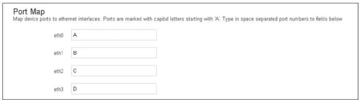
text_image
Port Map Map device ports to ethernet interfaces. Ports are marked with capital letters starting with 'A'. Type in space separated port numbers to fields below eth0 A eth1 B eth2 C eth3 DFigure 53: The Interface port map section
| Web Field/ UCI / Package Option | Description | |
| Web: eth0UCI: network.@va_switch[0].eth0Opt: eth0 | Defines eth0 physical switch port mapping. Must be entered in upper case. | |
| A | Eth0 assigned to switch port A | |
| B | Eth0 assigned to switch port B | |
| C | Eth0 assigned to switch port C | |
| D | Eth0 assigned to switch port C | |
| Web: eth1UCI: network.@va_switch[0].eth1Opt: eth1 | Defines eth1 physical switch port mapping. Must be entered in upper case. | |
| A | Eth1 assigned to switch port A | |
| B | Eth1 assigned to switch port B | |
| C | Eth1 assigned to switch port C | |
| D | Eth1 assigned to switch port C | |
| Web: eth2UCI: network.@va_switch[0].eth2Opt: eth2 | Defines eth0 physical switch port mapping. Must be entered in upper case. | |
| A | Eth2 assigned to switch port A | |
| B | Eth2 assigned to switch port B | |
| C | Eth2 assigned to switch port C | |
| D | Eth2 assigned to switch port C | |
| Web: eth3UCI: network.@va_switch[0].eth3Opt: eth3 | Defines eth0 physical switch port mapping. Must be entered in upper case. | |
| A | Eth3 assigned to switch port A | |
| B | Eth3 assigned to switch port B | |
| C | Eth3 assigned to switch port C | |
| D | Eth3 assigned to switch port C | |
Table 29: Information table for interface port map page
11.5.2 Configuring port maps using UCI
The configuration files are stored on /etc/config/network
root@VA_router:~# uci show network
......
network.@va_switch[0]=va_switch
network.@va_switch[0].eth0=A
network.@va_switch[0].eth1=B
network.@va_switch[0].eth2=C
network.@va_switch[0].eth3=D
To change any of the above values use uci set command.
11.5.3 Configuring port map using package options
The configuration files are stored on /etc/config/network
root@VA_router:~# uci export network
...
config va_switch
option eth0 'A'
option eth1 'B'
option eth2 'C'
option eth3 'D'
To change any of the above values use uci set command.
11.5.4 ATM bridges
The ATM bridges section is not used when configuring an Ethernet interface.
11.6 Interface diagnostics
11.6.1 Interfaces status
To show the current running interfaces, enter:
root@VA_router:~# ifconfig
3g-CDMA Link encap:Point-to-Point Protocol
inet addr:10.33.152.100 P-t-P:178.72.0.237 Mask:255.255.255.255
UP POINTOPOINT RUNNING NOARP MULTICAST MTU:1400 Metric:1
RX packets:6 errors:0 dropped:0 overruns:0 frame:0
TX packets:23 errors:0 dropped:0 overruns:0 carrier:0
collisions:0 txqueuelen:3
RX bytes:428 (428.0 B) TX bytes:2986 (2.9 KiB)
eth0 Link encap:Ethernet HWaddr 00:E0:C8:12:12:15
inet addr:192.168.100.1 Bcast:192.168.100.255
Mask:255.255.255.0
inet6 addr: fe80::2e0:c8ff:fe12:1215/64 Scope:Link
UP BROADCAST RUNNING MULTICAST MTU:1500 Metric:1
RX packets:6645 errors:0 dropped:0 overruns:0 frame:0
TX packets:523 errors:0 dropped:0 overruns:0 carrier:0
collisions:0 txqueuelen:1000
RX bytes:569453 (556.1 KiB) TX bytes:77306 (75.4 KiB)
lo Link encap:Local Loopback
inet addr:127.0.0.1 Mask:255.0.0.0
inet6 addr: ::1/128 Scope:Host
UP LOOPBACK RUNNING MTU:16436 Metric:1
RX packets:385585 errors:0 dropped:0 overruns:0 frame:0
TX packets:385585 errors:0 dropped:0 overruns:0 carrier:0
collisions:0 txqueuelen:0
RX bytes:43205140 (41.2 MiB) TX bytes:43205140 (41.2 MiB)
To display a specific interface, enter:
root@VA_router:~# ifconfig eth0
eth0 Link encap:Ethernet HWaddr 00:E0:C8:12:12:15
inet addr:192.168.100.1 Bcast:192.168.100.255
Mask:255.255.255.0
inet6 addr: fe80::2e0:c8ff:fe12:1215/64 Scope:Link
UP BROADCAST RUNNING MULTICAST MTU:1500 Metric:1
RX packets:7710 errors:0 dropped:0 overruns:0 frame:0
TX packets:535 errors:0 dropped:0 overruns:0 carrier:0
collisions:0 txqueuelen:1000
RX bytes:647933 (632.7 KiB) TX bytes:80978 (79.0 KiB)
11.6.2 ARP table status
To show the current ARP table of the router, enter:
root@GW7314:~# arp
? (10.67.253.141) at 30:30:41:30:43:36 [ether] on eth8
? (10.47.48.1) at 0a:44:b2:06 [ether] on gre-grel
11.6.3 Route status
To show the current routing status, enter:
root@VA_router:~# route -n
Kernel IP routing table
Destination Gateway Genmask Flags Metric Ref Use Iface
192.168.100.0 * 255.255.255.0 U 0 0 0 eth0
Note: a route will only be displayed in the routing table when the interface is up.
12 Configuring VLAN
12.1 Maximum number of VLANs supported
Virtual Access' routers support up to 4095 VLANs.
12.2 Configuration package used
| Package | Sections |
| Network |
12.3 Configuring VLAN using the web interface
12.3.1 Create a VLAN interface
To configure VLAN using the web interface, in the top menu, select Network - > Interfaces.
Click Add new interface. The Create Interface page appears.
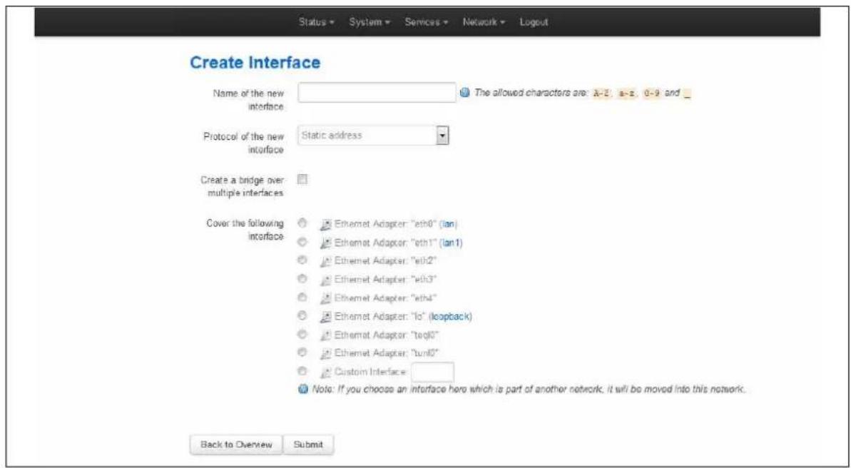
text_image
Create Interface Name of the new interface: The allowed characters are: A-2, a-3, 0-9 and _ Protocol of the new interface: Static address Create a bridge over multiple interfaces Cover the following interface: Ethernet Adapter: "eth0" (lan) Ethernet Adapter: "eth1" (lan1) Ethernet Adapter: "eth2" Ethernet Adapter: "eth3" Ethernet Adapter: "eth4" Ethernet Adapter: "lo" (loopback) Ethernet Adapter: "teqlo" Ethernet Adapter: "tunlo" Custom Interface: Note: If you choose an interface here which is part of another network, it will be moved into this network. Back to Overview SubmitFigure 54: The create interface page
| Web Field/ UCI / Package Option | Description | |
| Web: Name of the new interfaceUCI: network.vlan1=interfaceOpt: interface | Type the name of the new interface. For example, VLAN1. | |
| Web: Protocol of the new interfaceUCI: network.vlan_test.proto: proto | Protocol type. Select Static. | |
| Option | Description | |
| Static Static configuration with fixed address and netmask. | ||
| DHCP Client Address and netmask are assigned by DHCP. | ||
| Unmanaged | Unspecified | |
| IPv6-in-IPv4 (RFC4213) | Used with tunnel brokers. | |
| IPv6-over-IPv4 | Stateless IPv6 over IPv4 transport. | |
| GRE | Generic Routing Encapsulation protocol | |
| IOT | ||
| L2TP | Layer 2 Tunnelling Protocol | |
| PPP | Point to Point Protocol | |
| PPPoE | PPP over Ethernet | |
| PPPoATM | PPP over ATM | |
| LTE/UMTS/GPRS/EV-DO | CDMA, UMTS or GPRS connection using an AT-style 3G modem. | |
| Web: Create a bridge over multiple interfacesUCI: network.vlan1.typeOpt: type | Create a bridge over multiple interfaces. | |
| Web: Cover the following interfaceUCI: network.vlan1.ifnameOpt: ifname | Check the Custom Interface radio button.Enter a name, for example eth0.100. This will assign VLAN 100 to the eth0 interface. | |
Table 30: Information table for the create interface page
Click Submit. The Interfaces page for VLAN1 appears.
12.3.2 General setup: VLAN
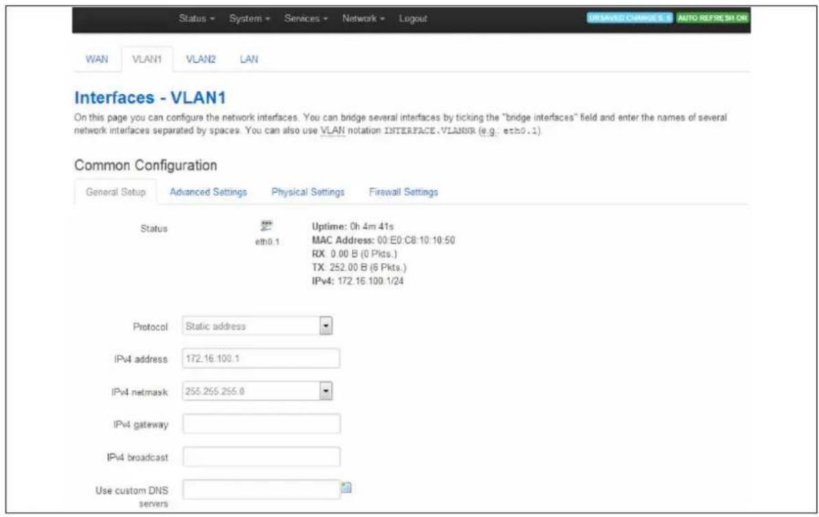
text_image
Status - System + Services - Network - Logout WAN VLAN1 VLAN2 LAN Interfaces - VLAN1 On this page you can configure the network interfaces. You can bridge several interfaces by ticking the "bridge interfaces" field and enter the names of several network interfaces separated by spaces. You can also use VLAN notation INTERFACE.VLANNR (e.g.: eth0.1) Common Configuration General Setup Advanced Settings Physical Settings Firewall Settings Status Uptime: 0h 4m 41s eth0.1 MAC Address: 00:E0:C8:10:10:50 RX: 0.00 B (0 Pkts.) TX: 252.00 B (6 Pkts.) IPv4: 172.16 100.1/24 Protocol Static address IPv4 address 172.16.100.1 IPv4 netmask 255.255.255.0 IPv4 gateway IPv4 broadcast Use custom DNS serversFigure 55: The VLAN 1 interface page
| Web Field/ UCI / Package Option | Description | |
| Web: ProtocolUCI: network.VLAN1.protoOpt: proto | Protocol type. | |
| Option | Description | |
| Static Static configuration with fixed address and netmask. | ||
| DHCP Client | Address and netmask are assigned by DHCP. | |
| Unmanaged | Unspecified | |
| IPv6-in-IPv4 (RFC4213) | Used with tunnel brokers. | |
| IPv6-over-IPv4 | Stateless IPv6 over IPv4 transport. | |
| GRE | Generic Routing Encapsulation protocol | |
| IOT | ||
| L2TP | Layer 2 Tunnelling Protocol | |
| PPP | Point to Point Protocol | |
| PPPoE | PPP over Ethernet | |
| PPPoATM | PPP over ATM | |
| LTE/UMTS/GPRS/EV-DO | CDMA, UMTS or GPRS connection using an AT-style 3G modem. | |
| Web: IPv4 addressUCI: network.VLAN1.ipaddrOpt: ipaddr | The IPv4 address of the interface. This is optional if an IPv6 address is provided. | |
| Web: IPv4 netmaskUCI: network.VLAN1.netmaskOpt: netmask | Subnet mask to be applied to the IP address of this interface. | |
| Web: IPv4 gatewayUCI: network.VLAN1.gatewayOpt: gateway | IPv4 default gateway to assign to this interface (optional). | |
| Web: Use custom DNS serversUCI: network.VLAN1.dnsOpt: dns | List of DNS server IP addresses (optional). | |
Table 31: Information table for VLAN general settings
12.3.3 Firewall settings: VLAN
Use this section to select the firewall zone you want to assign to the VLAN interface.
Select unspecified to remove the interface from the associated zone or fill out the create field to define a new zone and attach the interface to it.
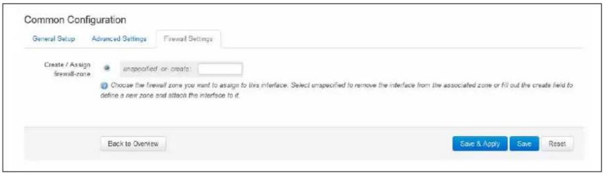
text_image
Common Configuration General Setup Advanced Settings Firewall Settings Create / Assign firewall-zone unspecified -or -create: Choose the firewall zone you want to assign to this interface. Select unspecified to remove the interface from the associated zone or fill out the create field to define a new zone and attach the interface to it. Back to Overview Save & Apply Save ResetFigure 56: Firewall settings page
When you have added all the VLAN interfaces you require, click Save & Apply.
12.4 Viewing VLAN interface settings
To view the new VLAN interface settings, in the top menu, select Network -> Interfaces. The Interfaces Overview page appears.
The example below shows two VLAN interfaces configured.
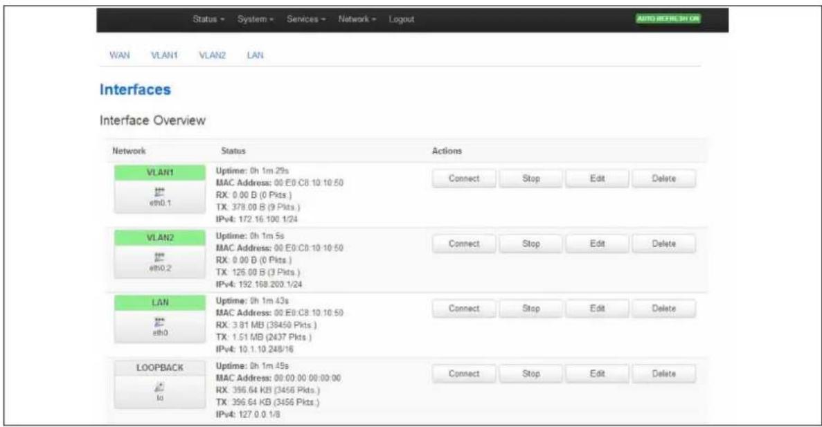
text_image
Status - System - Services - Network - Logout AUTO REFERENCE ON WAN VLAN1 VLAN2 LAN Interfaces Interface Overview Network Status Actions VLAN1 Uptime: 0h 1m 29s MAC Address: 00 E0:C8:10:10:50 RX: 0.00 B (0 Pkts.) TX: 378.00 B (9 Pkts.) IPv4: 172.16.100.1/24 Connect Stop Edit Delete VLAN2 Uptime: 0h 1m 5s MAC Address: 00 E0:C8:10:10:50 RX: 0.00 B (0 Pkts.) TX: 126.00 B (3 Pkts.) IPv4: 192.168.200.1/24 Connect Stop Edit Delete LAN Uptime: 0h 1m 43s MAC Address: 00 E0:C8:10:10:50 RX: 3.81 MB (38450 Pkts.) TX: 1.51 MB (2437 Pkts ) IPv4: 10.1.10.248/16 Connect Stop Edit Delete LOOPBACK Uptime: 0h 1m 45s MAC Address: 00:00:00 00:00:00 RX: 396.64 KB (3456 Pkts.) TX: 396.64 KB (3456 Pkts.) IPv4: 127.0.0.1/8 Connect Stop Edit DeleteFigure 57: The interface overview page showing two VLAN interfaces
12.5 Configuring VLAN using the UCI interface
You can configure VLANs through CLI. The VLAN configuration file is stored on: /etc/config/network
<h1 id="uci-export-network">uci export network</h1>
package network
config interface 'vlan100'
option proto 'static'
option ifname 'eth0.100'
option monitored '0'
option ipaddr '192.168.100.1'
option netmask '255.255.255.0'
option gateway '192.168.100.10'
option broadcast '192.168.100.255'
option dns '8.8.8.8'
Modify these settings by running uci set
When specifying the ifname ensure that it is written in dotted mode, that is, eth1.100 where eth1 is the physical interface assigned to VLAN tag 100.
Note: VLAN1 is, by default the native VLAN and will not be tagged.
13 Configuring ignition sense
In automotive applications, the ignition sense input can detect when the vehicle's ignition has been enabled. This allows the router to remain powered on after the vehicle has stopped. The time delay between ignition off and power down is configurable.
Routers for ignition sense applications are supplied with a power lead with 3 connectors for 12V permanent, 12V switched (ignition sense) and ground.
13.1 Configuration packages used
| Package | Sections |
| vapowermond main |
13.2 Configuring vapowermond using the web interface
You can configure the Vapowermond package using the web interface. In the top menu, click Services -> Power Monitor. The basic settings page appears.
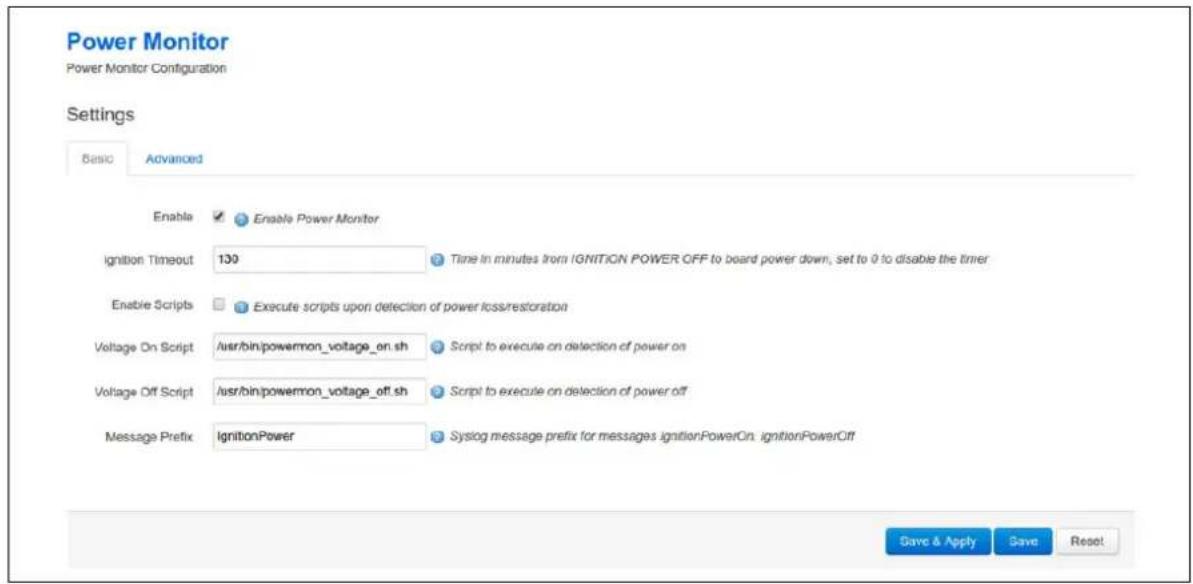
text_image
Power Monitor Power Monitor Configuration Settings Basic Advanced Enable Enable Power Monitor Ignition Timeout 130 Time in minutes from IGNITION POWER OFF to board power down, set to 0 to disable the timer Enable Scripts Execute scripts upon detection of power loss/restoration Voltage On Script /usr/bin/powermon_voltage_on.sh Script to execute on detection of power on Voltage Off Script /usr/bin/powermon_voltage_off.sh Script to execute on detection of power off Message Prefix IgnitionPower Syslog message prefix for messages ignitionPowerOn. ignitionPowerOff Save & Apply Save ResetFigure 58: Power monitor basic settings page
13.2.1 Power monitor basic settings
| Web field/ UCI / Package Option | Description | |
| Web field: EnableUCI: vapowermond.main.enabledOpt: enabled | Enables vapowermond package on a router. | |
| 0 | ||
| Range | 0-1 | |
| Web field: Ignition TimeoutUCI: vapowermond.main.timeoutOpt: timeout | Time in minutes from ignition power off to router power down. Set to 0 to disable the timer. | |
| 30 | ||
| Range 0-infinite | ||
| Web field: Enable ScriptsUCI:vapowermond.main.voltage_sense_scripts_enableOpt:voltage_sense_scripts_enable | Execute scripts upon detection of power loss/restoration. | |
| 0 Disabled | ||
| Range 0-1 | ||
| Web field: Voltage On ScriptUCI: vapowermond.main.voltage_on_scriptOpt: voltage_on_script | Script to execute on detection of power on./usr/bin/powermon_voltage_on.sh | |
| Web field: Voltage Off ScriptUCI: vapowermond.main.voltage_off_scriptOpt: voltage_off_script | Script to execute on detection of power off./usr/bin/powermon_voltage_off.sh | |
| Web field: Message PrefixUCI: vapowermond.main.voltage_msgOpt: voltage_msg | Syslog message prefix for messages IgnitionPowerOn,IgnitionPowerOff. | |
Table 32: Information table for power monitor basic settings
13.2.2 Power monitor advanced settings
Click the Advance tab to access advanced settings.
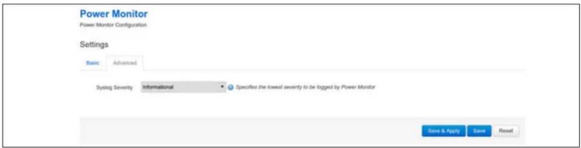
text_image
Power Monitor Power Monitor Configuration Settings Basic Advanced Syslog Severity Informational Specifies the lowest severity to be logged by Power Monitor Save & Apply Save ResetFigure 59: Power monitor advanced settings page
| Web field/ UCI / Package Option | Description | |
| Web field: Syslog SeverityUCI: vapowermond.main.log_severityOpt: log_severity | Specifies the lowest severity to be logged by Power Monitor. | |
| 0 | Emergency | |
| 1 Alert | ||
| 2 Critical | ||
| 3 | Error | |
| 4 Warning | ||
| 5 Notice | ||
| 6 | Informational | |
| 7 Debug | ||
Table 33: Information table for power monitor advanced settings
13.3 Configuring vapowermond using the command line
13.3.1 UCI
root@VA_router:~# uci show vapowermond
vapowermond.main=vapowermond
vapowermond.main.enabled=1
vapowermond.main.timeout=30
vapowermond.main.voltage_sense_scripts_enable=0
vapowermond.main.voltage_on_script=/usr/bin/powermon_voltage_on.sh
vapowermond.main.voltage_off_script=/usr/bin/powermon_voltage_off.sh
vapowermond.main.voltage_msg=powermon
vapowermond.main.log_severity=5
13.3.2 Package options
root@VA_router:~# uci export vapowermond
package vapowermond

config vapowermond 'main'
    option enabled '1'
    option timeout '30'
    option voltage_sense_scripts_enable '0'
    option voltage_on_script '/usr/bin/powermon_voltage_on.sh'
    option voltage_off_script '/usr/bin/powermon_voltage_off.sh'
    option voltage_msg 'powermon'
    option log_severity '5'
13.4 Ignition sense diagnostics
13.4.1 Monitoring Vapowermond status using the command line interface
To view status information about the current ignition sense state enter:
root@VA_router:~# cat /sys/class/gpio/gpio29/value 1
1 for ignition on; 0 for ignition off
14 Configuring a WiFi connection
This section explains how to configure WiFi on a Virtual Access router using the web interface or via UCI.
WiFi can act as an Access Point (AP) to another device in the network or it can act as a client to an existing AP.
You can configure WiFi in two different ways:
• on a new interface, or
• on an existing interface
14.1 Configuration packages used
| Package | Sections |
| network wlan_ap | wlan_client |
| wireless wifi-device | wifi-iface |
14.2 Configuring a WiFi interface using the web interface
To create a new WiFi interface via the web interface, in the top menu, click Network -> Wifi. The Wireless overview page appears.
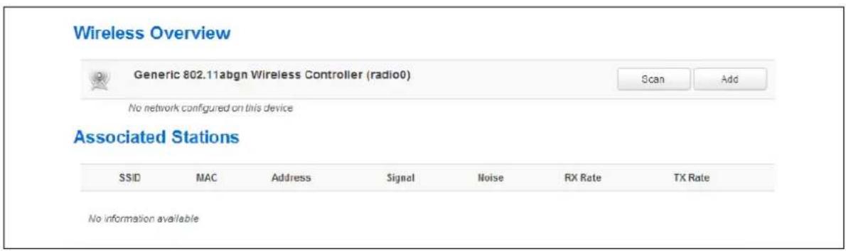
text_image
Wireless Overview Generic 802.11abgn Wireless Controller (radio0) Scan Add No network configured on this device Associated Stations SSID MAC Address Signal Noise RX Rate TX Rate No information availableFigure 60: The wireless overview page
Click Add to create a new WiFi interface. The Wireless Network configuration page appears. The Wireless Network configuration page consists of two sections:
| Section | Description |
| Device Configuration | Configuration of physical wireless radio settings such as channel and transmit power settings, HT mode, country code, distance optimization, fragmentation threshold and RTS/CTS threshold. The settings are shared among all defined wireless networks. |
| Interface Configuration | Configuration of the network interface - interface name, mode, network settings, security and filtering |
14.2.1 Wireless network: device configuration
The Device Configuration section covers physical settings of the radio hardware such as channel, transmit power or antenna selection, which is shared among all defined wireless
networks (if the radio hardware is multi-SSID capable). There are two sections within the Device Configuration section.
| Section | Description |
| General Setup | Channel and transmit power settings. |
| Advanced Settings | HT mode, country code, distance optimization, fragmentation threshold and RTS/CTS threshold. |
14.2.1.1 Device configuration: general setup
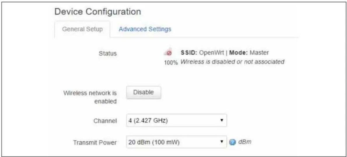
text_image
Device Configuration General Setup Advanced Settings Status SSID: OpenWrt | Mode: Master 100% Wireless is disabled or not associated Wireless network is enabled Disable Channel 4 (2.427 GHz) Transmit Power 20 dBm (100 mW) dBmFigure 61: The device configuration general setup section
| Web Field/ UCI / Package Option | Description | |
| Web: Wireless network | Enable or disables a wireless | |
| UCI: wireless.radio0.disabled | 1 | Disables Wifi interface. |
| Opt: disanabled | 0 | Enables Wifi interface. |
| Web: Channel | Select the channel you require. | |
| UCI: wireless.radio0.channel | Range | 1-11 |
| Opt: channel | 11 (2.462GHz) | |
| Web: Transmit power | Select the transmit power range range you require. | |
| UCI: wireless.radio0.txpower | Range | 0dBm(1mW)-17dBm(50mW) |
| Opt: txpower | 17dBM(50mW) | |
Table 34: Information table for the device configuration section
14.2.1.2 Device configuration: advanced settings
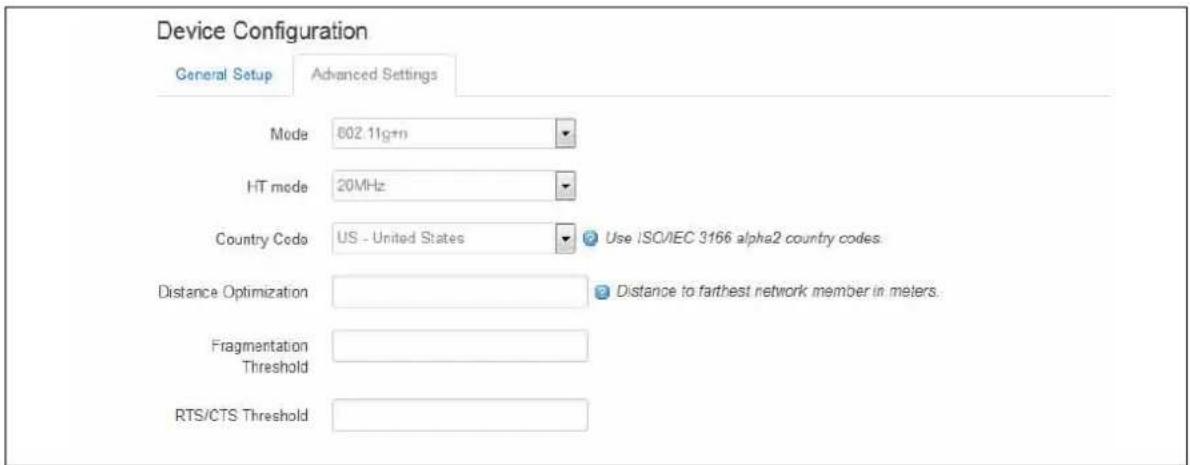
text_image
Device Configuration General Setup Advanced Settings Mode 802.11g+n HT mode 20MHz Country Code US - United States Use ISC/IEC 3166 alpha2 country codes. Distance Optimization Distance to farthest network member in meters. Fragmentation Threshold RTS/CTS Threshold General Setup Advanced SettingsFigure 62: The device configuration advanced settings section
| Web Field/ UCI / Package Option | Description | |
| Web: ModeUCI: wireless. radio0.hwmodeOpt: hwmode | Mode options. | |
| Option | Description | |
| Auto Wireless pro | protocol negotiate with supplicat device. | |
| 802.11b | Select the wireless protocol to use | |
| 802.11g | Select the wireless protocol to use | |
| 802.11a | Select the wireless protocol to use | |
| 802.11g+n | Select the wireless protocol to use | |
| 802.11a+n | Select the wireless protocol to use | |
| Web: HT modeUCI: wireless.radio0.htmodeOpt: country | HT mode options. | |
| 20MHz | specifies the channel width in 802.11 | |
| 40MHz 2nd channel below | specifies the channel width in 802.11 | |
| 40MHz 2nd channel above | specifies the channel width in 802.11 | |
| Web: Country CodeUCI: wireless.radio0.countryOpt: country | Sets the country code. Use ISO/1EC 3166 alpha2 country codes. | |
| Web: Distance OptimizationUCI: wireless.radio0.distanceOpt: distance | Defines the distance between the AP and the furthest client in meters | |
| 15 | 15 meters | |
| Range | ||
| Web: Fragmentation ThresholdUCI: wireless.radio0.fragOpt: frag | Defines the fragmentation threshold | |
| None | Routers defaults applied | |
| Range | ||
| Web: RTS/CTS ThresholdUCI: wireless.radio0.rtsOpt: rts | Defines the RTS/CTS threshold | |
| None | Router defaults applied | |
| Range | ||
Table 35: Information table for device configuration advanced settings
14.2.2 Wireless network: interface configuration
The interface configuration section is used to configure the network and security settings. It has three sub sections.
| Section | Description |
| General Setup | Identification, network and mode settings. |
| Wireless Security | Encryption, cipher and key security settings |
| MAC Filter | MAC address filter settings. |
14.2.2.1 Interface configuration: general setup
Use this section to configure the interface name, mode and network settings. Differing web options may be presented depending on the Mode selected.
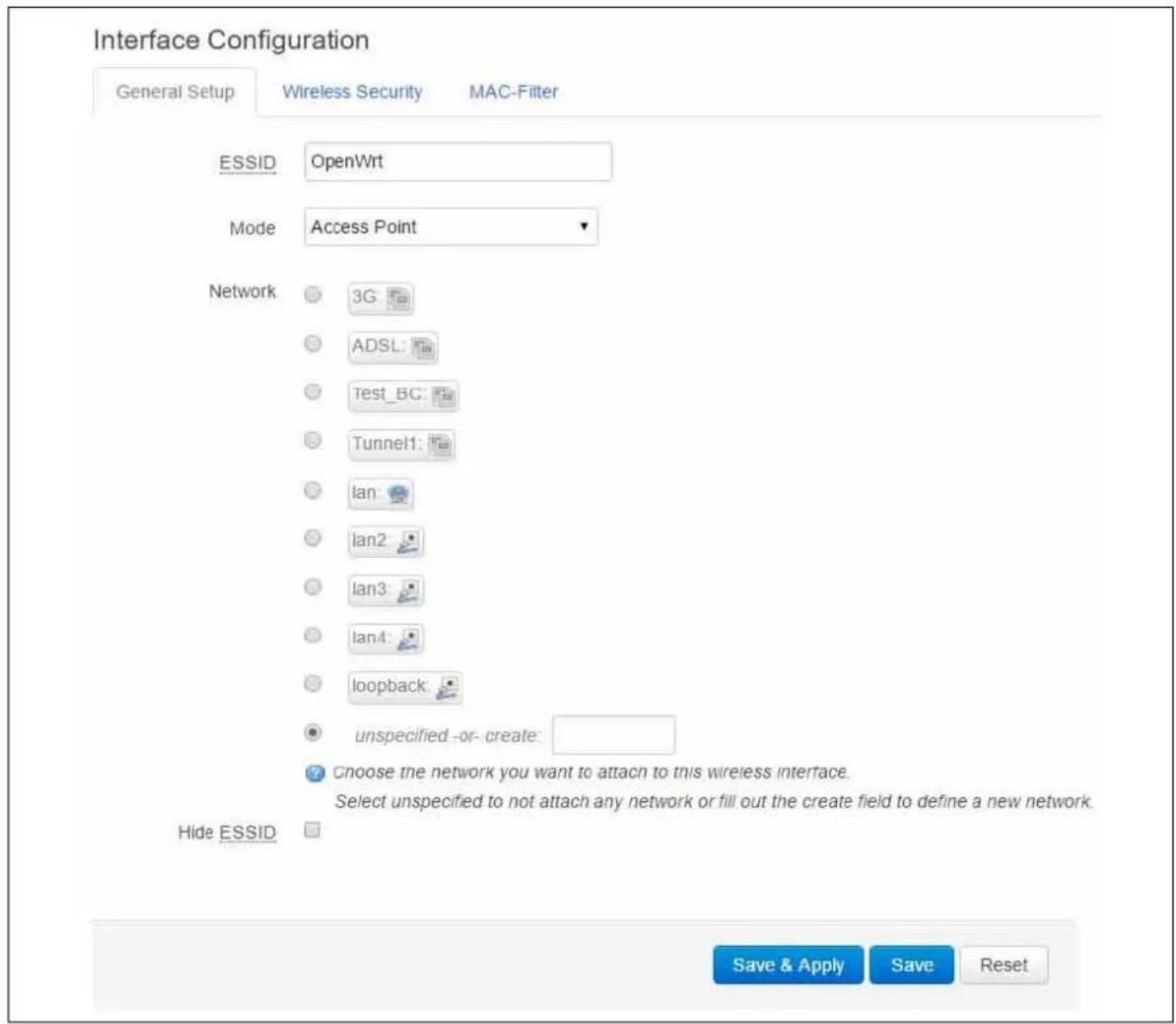
text_image
Interface Configuration General Setup Wireless Security MAC-Filter ESSID OpenWrt Mode Access Point Network 3G ADSL Test_BC Tunnel1 lan lan2 lan3 lan4 loopback unspecified -or- create: Choose the network you want to attach to this wireless interface. Select unspecified to not attach any network or fill out the create field to define a new network. Hide ESSID Save & Apply Save ResetFigure 63: The interface configuration general setup section
| Web Field/ UCI / Package Option | Description | |
| Web: ESSIDUCI: wireless. @wifi-iface[0].ssidOpt: ssid | Extended Service Set Identification. Type the name of the wireless local area network. | |
| Web: ModeUCI: wireless.@wifi-iface[0].modeOpt: mode | Mode type. For AP mode, select Access Point. | |
| Web value | UCI | |
| Access Point | ap | |
| Client | sta | |
| Ad-Hoc | adhoc | |
| 802.11s | mesh | |
| Pseudo Ad-Hoc (ah demo) | ahdemo | |
| Monitor | monitor | |
| Access Point (WDS) | ap-wds | |
| Client (WDS) | sta-wds | |
| Web: ModeUCI: wireless.@wifi-iface[0].bssidOpt: bssid | Defines the BSSID value. Only displayed if using client, ad-hoc or client (wds) modes. | |
| Web: NetworkUCI: wireless.@wifi-iface[0].networkOpt: network | The network the wireless interface is attached to. If using an existing interface select the appropriate network. Select unspecified to not attach to any network or fill out the create field to define a new network. | |
| Web: Hide ESSIDUCI: wireless.@wifi-iface[0].hiddenOpt: hidden | Hides the SSID when enabled. Only displayed if using access point or access point (wds) modes | |
| 1 | Enabled. | |
| 0 | Disabled. | |
Table 36: Information table for the interface configuration general setup section
14.2.2.2 Interface configuration: wireless security
Use this section to configure encryption, ciper and create a security key. Differing options will be defined depending on the encryption selected.
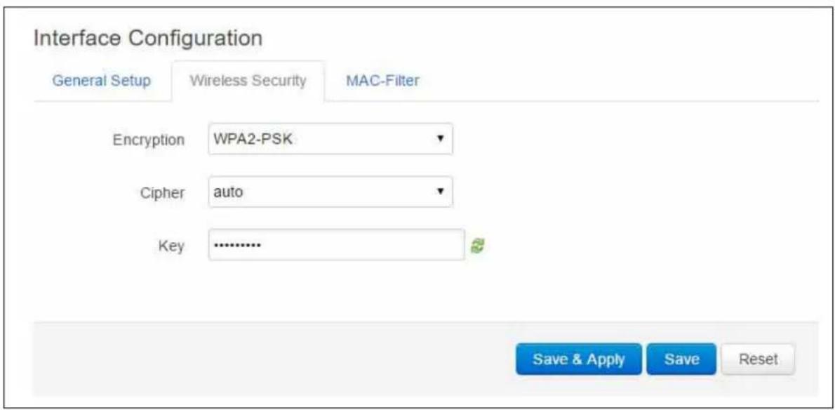
text_image
Interface Configuration General Setup Wireless Security MAC-Filter Encryption WPA2-PSK Cipher auto Key ............. Save & Apply Save ResetFigure 64: The wireless security section
| Web Field/ UCI/ Package Option | Description | |
| Web: EncryptionUCI: wireless.@wifi-iface[0].encryptionOpt: encryption | Method of encryption. | |
| Web value | UCI value | |
| No encryption | none | |
| WEP Open System | wep-open | |
| WEP Shared Key | wep-shared | |
| WPA-PSK | psk | |
| WPA2-PSK | psk2 | |
| WPA-PSK/WPA2-PSK Mixed Mode | psk-mixed | |
| WPA-EAP | wpa | |
| WPA2-WAP | wpa2 | |
| Web: CipherUCI: wireless.@wifi-iface[0].cipher=Opt: cipher | Cipher type. Only displayed if WPA encryption modes are selected. | |
| Web value | UCI | |
| Auto | auto | |
| Force CCMP (AES) | ccmp | |
| Force TKIP | tkip | |
| Force TKIP and CCMP | tkip+ccmp | |
| Web: KeyUCI: wireless.@wifi-iface[0].keyOpt: key | Specifies the wireless key authentication phrase. | |
| Web: Key #1UCI: wireless.@wifi-iface[0].key1Opt: key1 | Specifies the first wireless key authentication phrase. | |
| Web: Key #2UCI: wireless.@wifi-iface[0].key2Opt: key2 | Specifies the second wireless key authentication phrase. | |
| Web: Key #3UCI: wireless.@wifi-iface[0].key3Opt: key3 | Specifies the third wireless key authentication phrase. | |
| Web: Key #4UCI: wireless.@wifi-iface[0].key4Opt: key4 | Specifies the fourth wireless key authentication phrase. | |
| Web: Radius Authentication-ServerUCI: wireless.@wifi-iface[0].auth_serverOpt: auth server | Defines the Radius server for EAP authentication. | |
| Web: Radius Authentication-PortUCI: wireless.@wifi-iface[0].auth_portOpt: auth_port | Defines the Radius server port for EAP authentication. | |
| Web: Radius Authentication-SecretUCI: wireless.@wifi-iface[0].auth_secretOpt: auth_secret | Defines the Radius server secret for EAP authentication. | |
| Web: Radius Accounting-ServerUCI: wireless.@wifi-iface[0].acct_serverOpt: acct_server | Defines the Radius server for EAP accounting. | |
| Web: Radius Accounting -PortUCI: wireless.@wifi-iface[0].acct_portOpt: acc_port | Defines the Radius port for EAP accounting. | |
| Web: Radius Accounting -SecretUCI: wireless.@wifi-iface[0].acct_secretOpt: acct_secret | Defines the Radius secret for EAP accounting. | |
| Web: NAS IDUCI: wireless.@wifi-iface[0].nasidOpt: nasid | Defines the nas ID for the wireless interface. | |
Table 37: Information table for the interface configuration wireless security section
14.2.2.3 Interface configuration: MAC filter
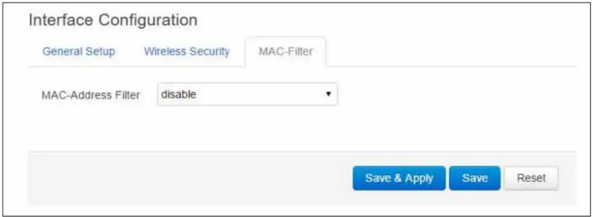
text_image
Interface Configuration General Setup Wireless Security MAC-Filter MAC-Address Filter disable Save & Apply Save ResetFigure 65: The MAC filter section
| Web Field/ UCI / Package Option | Description | ||
| Web: MAC-Address FilterUCI: wireless.@wifi-iface[0].macfilterOpt: macfilter | MAC address filtering process. | ||
| Option | Description | UCI | |
| Disable | Disables MAC Address filter. | disable | |
| Allow listed only | Allows only the MAC address listed in the text field. | allow | |
| Allow all except listed | Allows everything but the MAC address listed in the text field. | deny | |
| Web: MAC -ListUCI: wireless.@wifi-iface[0].maclistOpt: list maclist | Defines the MAC addresses to use. Multiple MAC address should be separated by a space if using UCI. MAC must be in the format hh:hh:hh:hh:hh:hh | ||
Table 38: Information table for interface configuration MAC filter section
14.3 Configuring WiFi in AP mode
AP mode is when the routers WiFi is used as an access point to one of the routers other interfaces. For example, if a router is connected to the internet via 3G, the WiFi on the router can be used as an access point for other devices to connect to the router and use its 3G internet connection.
14.3.1 AP mode on a new interface
Configure the WiFi network in AP mode as described in the above section 'Configuring a WiFi interface', selecting a new interface for the Wireless Network in the Interface Configuration section.
Next, in the top menu, select Network -> Interfaces. The Interface Overview page appears.
In the Interface Overview page, click Edit on the newly created WiFi interface. Then configure the interface by following instructions in the chapter 'Configuring an Ethernet interface'. When you have completed those steps, continue with the section below.
14.3.2 AP mode on an existing Ethernet interface
Configure the WiFi network in AP mode as described in the above section 'Configuring a WiFi interface'.
Next, in the top menu, select Network -> Interfaces. The Interface Overview page appears.
In the Interface Overview page, click Edit on the Ethernet interface that will be bridged into the router's WiFi AP. The Common Configuration page appears. It has four sections.
This configuration only uses the Physical Settings section.
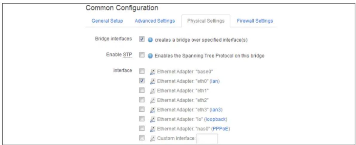
text_image
Common Configuration General Setup Advanced Settings Physical Settings Firewall Settings Bridge interfaces ✓ creates a bridge over specified interface(s) Enable STP ✓ Enables the Spanning Tree Protocol on this bridge Interface ✓ Ethernet Adapter: "base0" ✓ Ethernet Adapter: "eth0" (lan) ✓ Ethernet Adapter: "eth1" ✓ Ethernet Adapter: "eth2" ✓ Ethernet Adapter: "eth3" (lan3) ✓ Ethernet Adapter: "lo" (loopback) ✓ Ethernet Adapter: "nas0" (PPPoE) ✓ Custom Interface:Figure 66: The physical settings section in the common configuration page
| Web Field/ UCI / Package Option | Description | |
| Web: Bridge InterfacesUCI: network.lan.typeOpt: Type | Creates a bridge over the specified interface. | |
| Empty | ||
| Bridge Configures a bridge over multiple interfaces. | ||
| Web: Enable STPUCI: network.lan.stpOpt: stp | Enables the Spanning Tree Protocol on this bridge. | |
| 0 | Disabled. | |
| 1 | Enabled. | |
| Web: InterfaceUCI: network.lan.ifnameOpt:ifname | Select the physical interfaces to bridge. If mapping multiple interfaces for bridging the interface names are separated by a space when using UCI and package options.Example: option ifname ‘eth2 eth3’ or network.<ifname>.ifname=eth2 eth 3 | |
Table 39: Information table for the physical section on the common configuration page
14.4 Configuring WiFi using UCI
The configuration files are stored on:
• Network file /etc/config/network
• Wireless file /etc/config/wireless
14.4.1 AP modem on a new Ethernet interface using package options
root@VA_router:~# uci export network
package network

config interface 'newwifilan'
    option proto 'static'
    option ipaddr '192.168.111.1'
    option netmask '255.255.255.0'
root@VA_router:~# uci export wireless
package wireless

config wifi-device 'radio0'
    option type 'mac80211'
    option channel '11'
    option phy 'phy0'
    option hwmode '11ng'
    option htmode 'HT20'

list ht_capab 'SHORT-GI-40'
    list ht_capab 'TX-STBC'
    list ht_capab 'RX-STBC1'
    list ht_capab 'DSSS_CCK-40'
    option txpower '17'
    option country 'US'

config wifi-iface
    option device 'radio0'
    option mode 'ap'
    option disabled '1'
    option ssid 'Test_AP'
    option network 'newwifilan'
    option encryption 'psk'
    option key 'secretkey'
14.4.2 AP modem on a new Ethernet interface using UCI
root@VA_router:~# uci show network
network.newlan=interface
network.newlan.proto=static
network.newlan.ipaddr=192.168.111.1
network.newlan.netmask=255.255.255.0
root@VA_router:~# uci show wireless
wireless.radio0=wifi-device
wireless.radio0.type=mac80211
wireless.radio0.channel=11
wireless.radio0.phy=phy0
wireless.radio0.hwmode=11ng
wireless.radio0.htmode=HT20
wireless.radio0.ht_capab=SHORT-GI-40 TX-STBC RX-STBC1 DSSS_CCK-40
wireless.radio0.txpower=17
wireless.radio0.country=US
wireless.@wifi-iface[0]=wifi-iface
wireless.@wifi-iface[0].device=radio0
wireless.@wifi-iface[0].mode=ap
wireless.@wifi-iface[0].disabled=1
wireless.@wifi-iface[0].ssid=Test_AP
wireless.@wifi-iface[0].network=newlan
wireless.@wifi-iface[0].encryption=psk
wireless.@wifi-iface[0].key=secretkey
14.4.3 AP mode on an existing Ethernet interface using packages options
root@VA_router:~# uci export network
package network
config interface 'lan'
    option ifname 'eth0'
    option proto 'static'
    option ipaddr '192.168.100.1'
    option netmask '255.255.255.0'
    option type 'bridge'
root@VA_router:~# uci export wireless
package wireless
config wifi-device 'radio0'
option type 'mac80211'
option channel '11'
option phy 'phy0'
option hwmode '11ng'
option htmode 'HT20'
list ht_capab 'SHORT-GI-40'
list ht_capab 'TX-STBC'
list ht_capab 'RX-STBC1'
list ht_capab 'DSSS_CCK-40'
option txpower '17'
option country 'US'

config wifi-iface
option device 'radio0'
option mode 'ap'
option disabled '1'
option ssid 'Test_AP'
option network 'lan'
option encryption 'psk'
option key 'secretkey'
14.4.4 AP mode on an existing Ethernet interface using UCI
root@VA_router:~# uci show network
network.lan=interface
network.lan.ifname=eth0
network.lan.proto=static
network.lan.ipaddr=192.168.6.1
network.lan.netmask=255.255.255.0
network.lan.type=bridge
root@VA_router:~# uci show wireless
wireless.radio0=wifi-device
wireless.radio0.type=mac80211
wireless.radio0.channel=11
wireless.radio0.phy=phy0
wireless.radio0.hwmode=11ng
wireless.radio0.htmode=HT20
wireless.radio0.ht_capab=SHORT-GI-40 TX-STBC RX-STBC1 DSSS_CCK-40
wireless.radio0.txpower=17
wireless.radio0.country=US
wireless.@wifi-iface[0]=wifi-iface
wireless.@wifi-iface[0].device=radio0
wireless.@wifi-iface[0].mode=ap
wireless.@wifi-iface[0].disabled=1
wireless.@wifi-iface[0].ssid=Test_AP
wireless.@wifi-iface[0].network=lan
wireless.@wifi-iface[0].encryption=psk
wireless.@wifi-iface[0].key=secretkey
14.5 Creating a WiFi in Client mode using the web interface
A WiFi network in Client mode receives a wireless network from another WiFi AP.
Configure the Wifi network in Client mode as described in the above section 'Configuring a WiFi interface', selecting a new interface for the Wireless Network in the Interface Configuration section. For the examples below the new WiFi interface will be called 'newwifiClient'
Example:
wireless.@wifi-iface[0].network=newwifiClient
wireless.@wifi-iface[0].mode=sta
In the top menu, select Network -> Interfaces. The Interfaces Overview page appears. Click Edit in the newly created WiFi Client interface. The Common Configuration page appears.
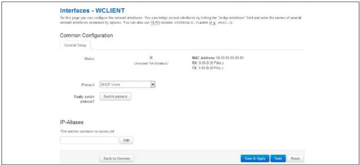
text_image
Interfaces - WCLIENT On this page you can configure the network interfaces. You can bridge several interfaces by ticking the "bridge interfaces" field and enter the names of several network interfaces separated by spaces. You can also use VLAN notation INTERFACE.VLAMNR (e.g. echo.1) Common Configuration General Setup Status MAC Address: 00.00.00.00.00.00 Unknown "VA-Wireless" RX: 0.00 B (0 Pkts.) TX: 0.00 B (0 Pkts ) Protocol DHCP client Really switch protocol? Switch protocol IP-Aliases This section contains no value yet Add Back to Overview Save & Apply Save ResetFigure 67: The client interface page
| Web Field/ UCI/ Package Option | Description | |
| Web: ProtocolUCI: network. newwifiClient.proto: proto | Specifies what protocol the interface will operate on. Select DHCP Client. | |
| Option | Description | |
| Static Static configuration with fixed address and netmask. | ||
| DHCP Client | Address and netmask are assigned by DHCP. | |
| Unmanaged | Unspecified | |
| IPv6-in-IPv4 (RFC4213) | Used with tunnel brokers. | |
| IPv6-over-IPv4 | Stateless IPv6 over IPv4 transport. | |
| GRE | Generic Routing Encapsulation protocol | |
| IOT | ||
| L2TP | Layer 2 Tunnelling Protocol | |
| PPP | Point to Point Protocol | |
| PPPoE | PPP over Ethernet | |
| PPPoATM | PPP over ATM | |
| LTE/UMTS/GPRS/EV-DO | CDMA, UMTS or GPRS connection using an AT-style 3G modem. | |
Table 40: Information table for interfaces WClient page
When you have clicked Save and Apply, the router will restart the network package. It may take up to one minute for connectivity to the router to be restored.
14.6 Configuring WiFi in Client mode using command line
The configuration files are stored on:
• Network file /etc/config/network
- Wireless file /etc/config/wireless
14.6.1 Client modem using package options
root@VA_router:~# uci export network
package network
config interface 'newwifiClient'
option proto 'dhcp'
root@VA_router:~# uci export wireless
package wireless
config wifi-device 'radio0'
option type 'mac80211'
option channel '11'
option phy 'phy0'
option hwmode '11ng'
option htmode 'HT20'
list ht_capab 'SHORT-GI-40'
list ht_capab 'TX-STBC'
list ht_capab 'RX-STBC1'
list ht_capab 'DSSS_CCK-40'
option txpower '17'
option country 'US'

config wifi-iface
option device 'radio0'
option ssid 'Remote-AP'
option mode 'sta'
option network 'newwifiClient'
option encryption 'psk2'
option key 'testtest'
14.6.2 Client modem using UCI
root@VA_router:~# uci show network
network.new=interface
network.WCLIENT.proto=dhcp
14.6.2.1 uci show wireless
root@VA_router:~# uci show wireless
wireless.radio0=wifi-device
wireless.radio0.type=mac80211
wireless.radio0.channel=11
wireless.radio0.phy=phy0
wireless.radio0.hwmode=11ng
wireless.radio0.htmode=HT20
wireless.radio0.ht_capab=SHORT-GI-40 TX-STBC RX-STBC1 DSSS_CCK-40
wireless.radio0.txpower=17
wireless.radio0.country=US
wireless.@wifi-iface[0]=wifi-iface
wireless.@wifi-iface[0].device=radio0
wireless.@wifi-iface[0].ssid=Remote-AP
wireless.@wifi-iface[0].mode=sta
wireless.@wifi-iface[0].network=newwifiClient
wireless.@wifi-iface[0].encryption=psk2
wireless.@wifi-iface[0].key=testtest
15 Configuring a mobile connection
15.1 Configuration package used
| Package | Sections |
| network | interface |
15.2 Configuring a mobile connection using the web interface
Note: if you are creating multiple mobile interfaces, simply repeat the steps in this chapter for each interface. Multiple interfaces are required for dual SIM or multiple radio module scenarios. Configuring static routes and/or Multi-WAN can be used to manage these interfaces.
In the top menu, select Network -> Interfaces. The Interfaces Overview page appears.
15.2.1 Create a new mobile interface
To create a new mobile interface, in the Interface Overview section, click Add new interface. The Create Interface page appears. In the examples below, 3G has been used for the interface name.
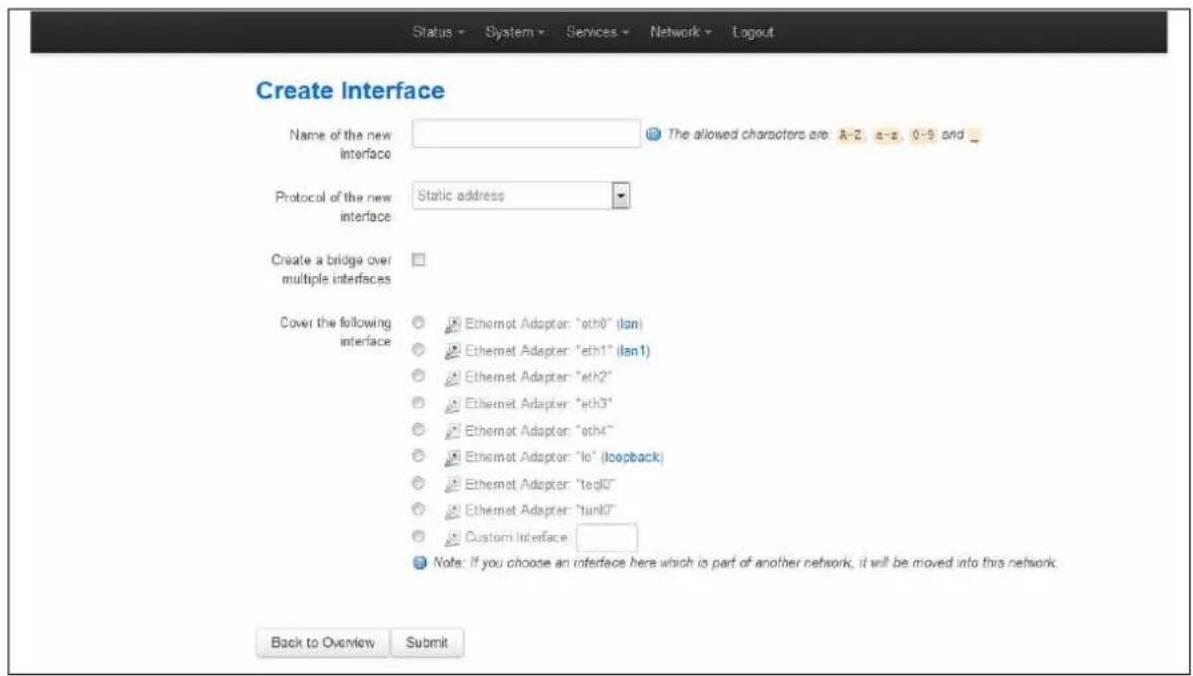
text_image
Create Interface Name of the new interface The allowed characters are: A-2, a-3, 0-9 and _ Protocol of the new interface Static address Create a bridge over multiple interfaces Cover the following interface Ethernet Adaptor: "oth0" (lan) Ethernet Adapter: "eth1" (lan1) Ethernet Adapter: "eth2" Ethernet Adapter: "eth3" Ethernet Adaptor: "oth4" Ethernet Adaptor: "lo" (loopback) Ethernet Adapter: "teg0" Ethernet Adapter: "tun0" Custom Interface Note: If you choose an interface here which is part of another network, it will be moved into this network. Back to Overview SubmitFigure 68: The create interface page
| Web Field/ UCI / Package Option | Description | |
| Web: Name of the new interfaceUCI: network.3G=interfaceOpt: interface | Allowed characters are A-Z, a-z, 0-9 and _ | |
| Web: Protocol of the new interfaceUCI: network.3G.proto: proto | Protocol type. Select LTE/ UMTS/ GPRS/ EV-DO. | |
| Option | Description | |
| Static Static configuration with fixed address and netmask. | ||
| DHCP Client | Address and netmask are assigned by DHCP. | |
| Unmanaged | Unspecified | |
| IPv6-in-IPv4 | ||
| IPv6-over-IPv4 | ||
| GRE | ||
| IOT | ||
| L2TP | Layer 2 Tunnelling Protocol. | |
| PPP | ||
| PPPoE | ||
| PPPoATM | ||
| LTE/UMTS/GPRS/EV-DO | CDMA, UMTS or GPRS connection using an AT-style 3G modem. | |
| Web: Create a bridge over multiple interfacesUCI: network.3G.typeOpt: type | Enables bridge between two interfaces.Not relevant when configuring a mobile interface. | |
| 0 | Disabled. | |
| 1 | Enabled. | |
| Web: Cover the following interfaceUCI: network.3G.ifnameOpt: ifname | Select interfaces for bridge connection.Not relevant when configuring a mobile interface. | |
Table 41: Information table for the create interface page
Click Submit. The Common Configuration page appears. There are three sections in the mobile interface common configurations:
| Section | Description |
| General Setup | Configure the basic interface settings such as protocol, service type, APN information, user name and password. |
| Advanced Settings | Set up more in-depth features such as initialisation timeout, LCP echo failure thresholds and inactivity timeouts. |
| Firewall settings | Assign a firewall zone to the connection. |
15.2.1.1 Mobile interface: general setup
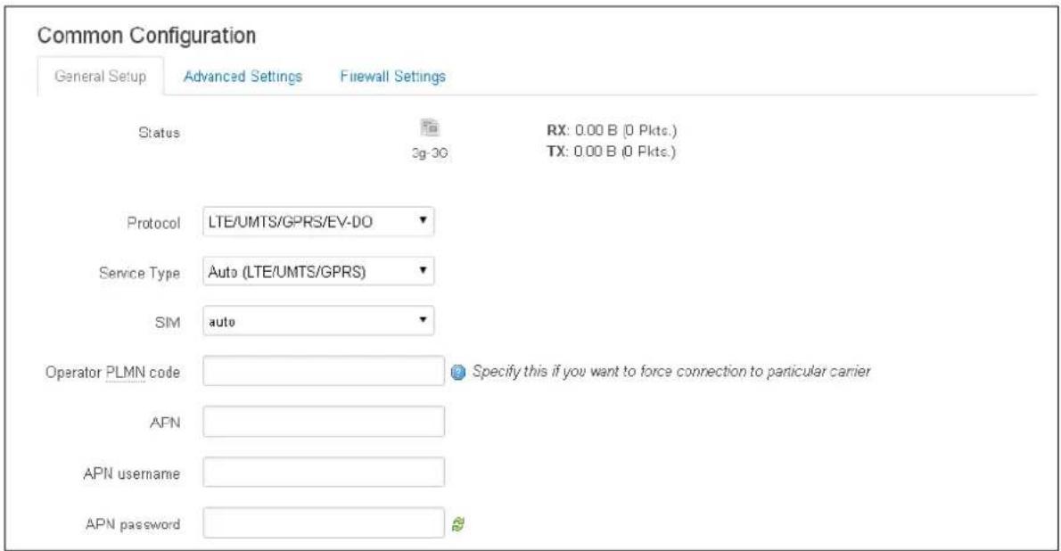
text_image
Common Configuration General Setup Advanced Settings Firewall Settings Status 3g-3G RX: 0.00 B (0 Pkts.) TX: 0.00 B (0 Pkts.) Protocol LTE/UMTS/GPRS/EV-DO Service Type Auto (LTE/UMTS/GPRS) SIM auto Operator PLMN code Specify this if you want to force connection to particular carrier APN APN username APN passwordFigure 69: The common configuration page
| Web Field/ UCI / Package Option | Description | |
| Web: StatusUCI: n/aOpt: n/a | Shows the current status of the interface. | |
| Web: ProtocolUCI: network.3G.protoOpt: proto | Protocol type. Select LTE/ UMTS/ GPRS/ EV-DO. | |
| Option | Description | |
| Static Static configuration with fixed address and netmask. | ||
| DHCP Client | Address and netmask are assigned by DHCP. | |
| Unmanaged | Unspecified | |
| GRE | ||
| IOT | ||
| L2TP | Layer 2 Tunnelling Protocol. | |
| PPP | ||
| PPPoE | ||
| PPPoATM | ||
| LTE/UMTS/GPRS/EV-DO | CDMA, UMTS or GPRS connection using an AT-style 3G modem. | |
| Web: Service TypeUCI: network.3G.serviceOpt: service | Service type that will be used to connect to the network. | |
| gprs_only | Allows GSM module to only connect to GPRS network. | |
| Ite_only | Allows GSM module to only connect to LTE network. | |
| cdma | Allows GSM module to only connect to CDMA network. | |
| auto GSM module will automatically detect the best available technology code. | ||
| Web: n/aUCI: network.3G.service_orderOpt: service_order | Defines a space separated list of services, in preferred order. Valid options are gprs, umts, lte, auto.If no valid_service order is defined, then the configured Service Type is used. Example:network.3G.service_order="gprs umts lte auto" | |
| Blank | Use configured service type. | |
| Range | gprs umts lte auto | |
| Web: Operator PLMN codeUCI: network.3G.operatorOpt: operator | Specifies an operator PLMN code to force the connection to a particular carrier. The PLMN code is identified as a combination of the MCC and the MNC.Note: the operator option is used in conjunction with the operator format option option opformat which is used to define how the operator string is parsed. If configuring via the web GUI the op format is automatically set to '2' to indicate it is a PLMN code.See below for alternative options for the operator format option. | |
| Web: n/aUCI: network.3G.opformatOpt: opformat | Defines the operator format. We recommended you use PLMN code.The operator is case sensitive so if using long or short character format it must match the operator exactly.To see the current operator using SSH enter the command:cat /var/ state/ mobile or using the web mobile stats page at Status -> Mobile Stats. | |
| 0 | Long character format | |
| 1 | Short character format | |
| 2 | PLMN code | |
| Web: SIMUCI: network.3G.simOpt: sim | Defines which SIM is used on this interface. | |
| 1 | SIM 1 | |
| 2 | SIM 2 | |
| any | Automatically detect | |
| Web: APNUCI: network.3G.apnOpt: apn | APN name of Mobile Network Operator. | |
| Web: APN usernameUCI: network.3G.usernameOpt: username | Username used to connect to APN. | |
| Web: APN passwordUCI: network.3G.passwordOpt: password | Password used to connect to APN. | |
| Web: n/aUCI: network.3G.retry_interval_secOpt: retry_interval_sec | Allows you to specify exact integer or range that will be used to calculate random number to delay PPP connection. | |
| 0 PPP will connect immediately, without any delay. | ||
| 1-infinite PPP will attempt to connect again after specified interval. | ||
| Range PPP will attempt to connect within specified range. The exact interval is calculated randomly from specified range.retry_interval_sec 60 180 | ||
Table 42: Information table for common configuration settings
The Modem Configuration link at the bottom of the page is used for SIM pin code and SMS configuration. For more information, read the chapter 'Configuring mobile manager'.
15.2.1.2 Mobile interface: advanced settings
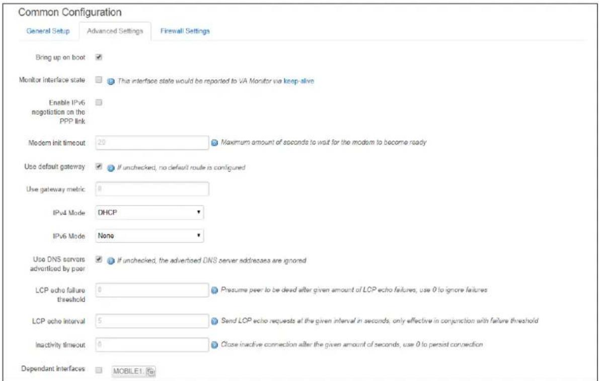
text_image
Common Configuration General Setup Advanced Settings Firewall Settings Bring up on boot Monitor Interface state This interface state would be reported to VA Monitor via keep-alive Enable IPv6 negotiation on the PPP link Modern init timeout 20 Maximum amount of seconds to wait for the modem to become ready Use default gateway If unchecked, no default route is configured Use gateway metric 0 IPv4 Mode DHCP IPv6 Mode None Use DNS servors advertised by peer If unchecked, the advertised DNS server addresses are ignored LCP echo failure threshold 0 Presume peer to be dead after given amount of LCP echo failures, use 0 to ignore failures LCP echo interval 5 Send LCP echo requests at the given interval in seconds, only effective in conjunction with failure threshold Inactivity timeout 0 Close inactive connection after the given amount of seconds, use 0 to persist connection Dependant Interfaces MOBILE1Figure 70: The advanced settings tab
| Web Field/ UCI / Package Option | Description | |
| Web: Bring up on bootUCI: network.3G.autoOpt: auto | Enables the interface to connect automatically on boot up or reconnect automatically when disconnected. | |
| Web: Monitor interface stateUCI: network.3G.m monitoredOpt: monitored | Enabled if status of interface is presented on Monitoring platform. | |
| 0 | Do not monitor interface. | |
| 1 | Monitor interface. | |
| Web: Enable IPv6 negotiation on the PPP linkUCI: network.3G.ipv6Opt: ipv6 | Enables IPv6 routing on the interface. | |
| 0 | Do not enable IPv6. | |
| 1 | Enable IPv6. | |
| Web: Modem int timeoutUCI: network.3G.maxwaitOpt: maxwait | Maximum amount of seconds to wait for the modem to become ready. | |
| 20 | Seconds | |
| Range | ||
| Web: Use default gatewayUCI: network.3G.defaultrouteOpt: defaultroute | Enables this interface as a default route | |
| 0 | Do not use as a default route. | |
| 1 | Use as a default route. | |
| Web: Use gateway metricUCI: network.3G.metricOpt: metric | Defines the metric for the default route. Lower number metrics are used first when route is up. | |
| 0 | ||
| Range | ||
| Web: IPv4 ModeUCI: network.3G.ipv4modeOpt: ipv4mode | Defines the IPv4 address assignment approach for mobile interfaces in Ethernet Mode. Note: by default, mobile interfaces are in Ethernet mode. | ||
| Option | Description | UCI | |
| None | No dynamic assignment | none | |
| DHCP | DHCP address assignment | dhcp | |
| Web: IPv6 ModeUCI: network.3G.ipv6modeOpt: ipv6mode | Defines the IPv6 address assignment approach for mobile interfaces in Ethernet Mode.Note: by default, mobile interfaces are in Ethernet mode. | ||
| Option | Description | UCI | |
| None | No dynamic assignment | none | |
| DHCPv6 | DHCP address assignment | dhcp | |
| RA Router Advertisement (RA)assignment | ha | ra | |
| DHCPv6 after RA | Wait for RA, then start DHCP | ra_then_dhcp | |
| Web: Use DNS servers advertised by peerUCI: network.3G.peerdnsOpt: peerdns | If unchecked, the advertised DNS server addresses are ignored. | ||
| 0 | Use static DNS | ||
| 1 | Use advertised DNS | ||
| Web: Use custom DNS serversUCI: network.3G.dnsOpt: dns | Specifies DNS server. Only available if Use DNS servers advertised by peer is unselected. When multiple DNS servers are required separate using space for UCI or option value.Example:uci set network.3G.dns='1.1.1.1 2.2.2.2' | ||
| Web: LCP echo failure thresholdUCI: network.3G.keepaliveOpt: keepalive | Presumes peer to be dead after a given amount of LCP echo failures, use 0 to ignore failures.This command is used in conjunction with the LCP echo interval. The syntax is as follows: uci network.3G.keepalive=<echo failure threshold><echo interval>Example:uci set network.3G.keepalive=15 10 | ||
| Web: LCP echo internalUCI: network.3G.keepaliveOpt: keepalive | Send LCP echo requests at the given interval in seconds, only effective in conjunction with failureThis command is used in conjunction with the LCP echo failure threshold. The syntax is as follows: uci network.3G.keepalive=<echo failure threshold><echo interval>Example:uci set network.3G.keepalive=15 10 | ||
| Web: Inactivity timeoutUCI: network.3G.demandOpt: demand | Closes an inactive connection after the given amount of seconds. Use 0 to persist connection. | ||
| 0 | Do not disconnect on inactivity | ||
| Range | |||
| Web: Dependant InterfacesUCI: network.3G.dependantsOpt: dependants | Lists interfaces that are dependent on this parent interface.Dependant interfaces will go down when the parent interface is down and will start or restart when the parent interface starts.Separate multiple interfaces by a space when using UCI.Example: option dependants 'PPPADSL MOBILE'This replaces the following previous options in child interfaces. | ||
| gre | option local interface | ||
| It2p | option src_ipaddr | ||
| iot | option wan1 wan2 | ||
| 6in4 | option ipaddr | ||
| 6to4 | option ipaddr | ||
| Web: SNMP Alias ifindexUCI: network.[..x..].snmp_alias_ifindexOpt: snmp_alias_ifindex | Defines a static SNMP interface alias index for this interface that can be polled via the SNMP interface index.(snmp_alias_ifindex+1000). See Configuring SNMP section for more information. | ||
| Blank | No SNMP interface alias index | ||
| Range | 0 - 4294966295 | ||
Table 43: Information table for general set up page
15.2.1.3 Mobile interface: firewall settings
Use this section to select the firewall zone you want to assign to the interface.
Select unspecified to remove the interface from the associated zone or fill out the create field to define a new zone and attach the interface to it.
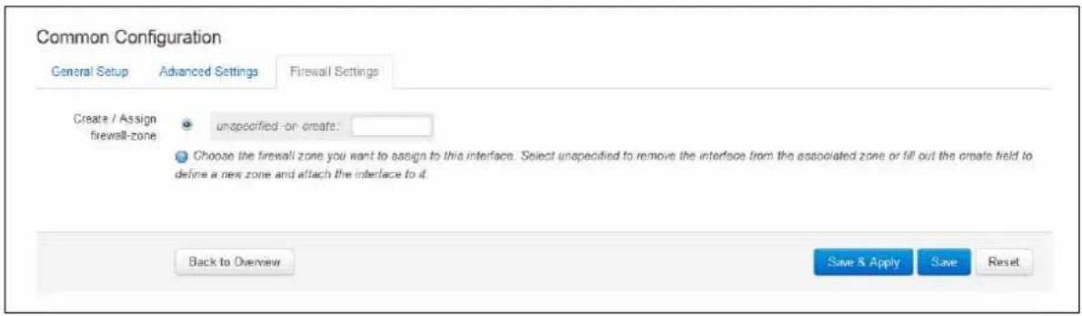
text_image
Common Configuration General Setup Advanced Settings Firewall Settings Create / Assign firewall-zone unspecified-or-create: Choose the firewall zone you want to assign to this interface. Select unspecified to remove the interface from the associated zone or fill out the ordate field to define a new zone and attach the interface to d. Back to Overview Save & Apply Save ResetFigure 71: Firewall settings page
15.3 Configuring a mobile connection using CLI
15.3.1 UCI
To establish a basic mobile connection, enter:
root@VA_router:~# uci show network
network.3G=interface
network.3G.proto=3g
network.3G.montored=0
network.3G.sim=any
network.3G.auto=1
network.3G.defaultroute=1
network.3G.metric=1
network.3G.service=autonetwork.3G.apn=test.apn
network.3G.username=username
network.3G.password=password
network.3G.ipv4mode=dhcp
network.3G.ipv6mode=none
15.3.2 Package options
root@VA_router:~#
package network

config interface '3G'
    option proto '3g'
    option monitored '0'
    option auto '1'
    option sim 'any'
    option defaultroute '1'
    option metric '1' option service 'auto'
    option apn 'test.apn'
    option username 'username'
    option password 'password'
    option ipv4mode 'dhcp'
    option ipv6mode 'none'
15.4 Diagnositcs
Note: the information presented on screen and data output using UCI depends on the actual mobile hardware being used. Therefore, the interfaces or output you see may differ from the samples shown here.
15.4.1 Mobile status via the web
To view mobile connectivity information, in the top menu, select Status -> Mobile Information. The Mobile Information page appears. The information presented depends on the actual mobile hardware used; it might therefore differ from the samples shown here.
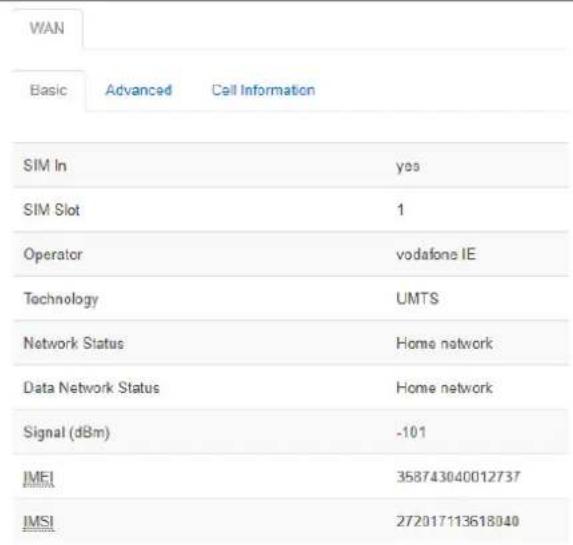
text_image
WAN Basic Advanced Call Information SIM In yes SIM Slot 1 Operator vodafone IE Technology UMTS Network Status Home network Data Network Status Home network Signal (dBm) -101 IMEI 358743040012737 IMSI 272017113618040Figure 72: The mobile information page
| WAN | ||
| Basic | Advanced | Cell Information |
| Network Status | Home network | |
| Data Network Status | Home network | |
| IMEI IMSI EQUITY | 358743040012737 | |
| Operator | vodafone IE | |
| Phone Number | +353874512040 | |
| SIM In | yes | |
| SIM Slot | 1 | |
| SIM1 ICCID SOMATOIS | 8935301140701270414 | |
| Signal (dBm) | -101 | |
| Technology | UMTS | |
| Temperature (C) | 28 | |
| Hardware Revision | R1C08 | |
Figure 73: The advanced information page
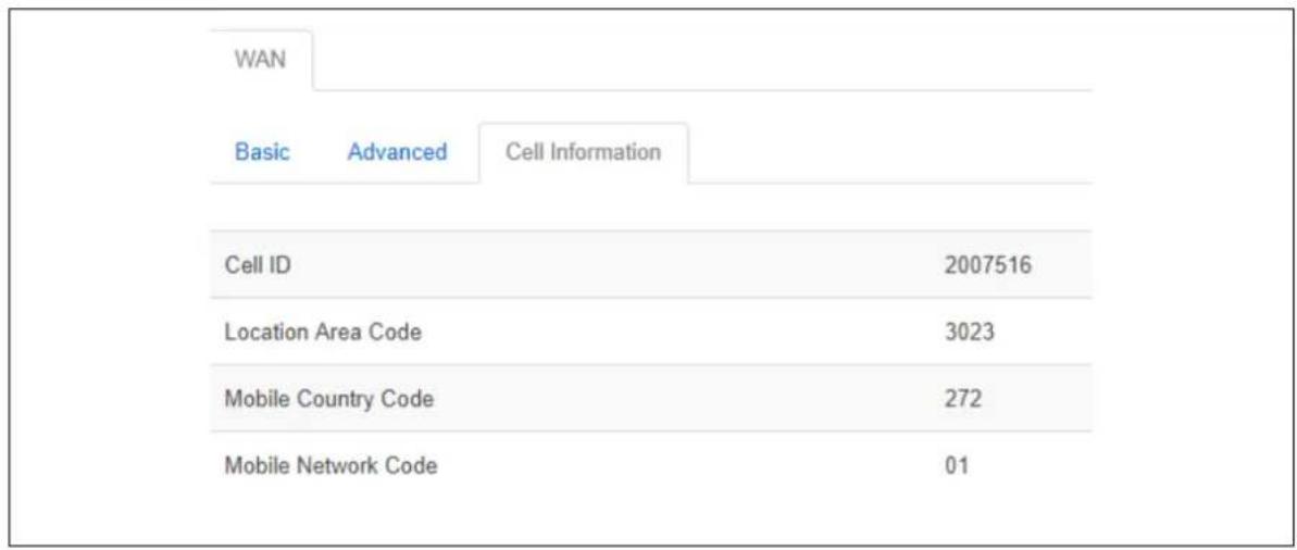
text_image
WAN Basic Advanced Cell Information Cell ID 2007516 Location Area Code 3023 Mobile Country Code 272 Mobile Network Code 01Figure 74: The cell information page
15.4.2 Mobile status using UCI
To display information and status of mobile interfaces such as 3G, 4G or CDMA, enter mobile_status:
root@VA_router:~# mobile_status
Mobile Interface : WAN
Status : idle
SIM In : yes
SIM Slot : 1
Operator : vodafone IE
Technology : UMTS
CS Network Status : Home network
PS Network Status : Home network
Signal (dBm) : -107
IMEI : 358743040012737
IMSI : 272017113618040
For more advanced information, enter mobile_status -a:
root@ VA_router:~# mobile_status -a
Mobile Interface : WAN
Status : idle
CS Network Status : Home network
PS Network Status : Home network
IMEI : 358743040012737
IMSI : 272017113618040
Operator : vodafone IE
Phone Number : +353874512040
SIM In : yes
SIM Slot : 1
SIM1 ICCID : 8935301140701270414
Signal (dBm) : -107
Technology : UMTS
Temperature (C) : 28
Hardware Revision : R1C08
16 Configuring mobile manager
The Mobile Manager feature allows you to configure SIM settings.
16.1 Configuration package used
| Package | Sections |
| mobile | Main |
| Callers | |
| Roaming template |
16.2 Configuring mobile manager using the web interface
Select Services -> Mobile Manager. The Mobile Manager page appears.
There are four sections in the mobile manager page:
| Section | Description |
| Basic settings | Enable SMS, configure SIM pin code, select roaming SIM, collect ICCCIDs and set IMSI. |
| CDMA* | CDMA configuration. |
| Callers | Configure callers that can use SMS. |
| Roaming Interface Template | Configure Preferred Roaming List options. |
| * Option available only for Telit CE910-SL module. | |
16.2.1 Mobile manager: basic settings
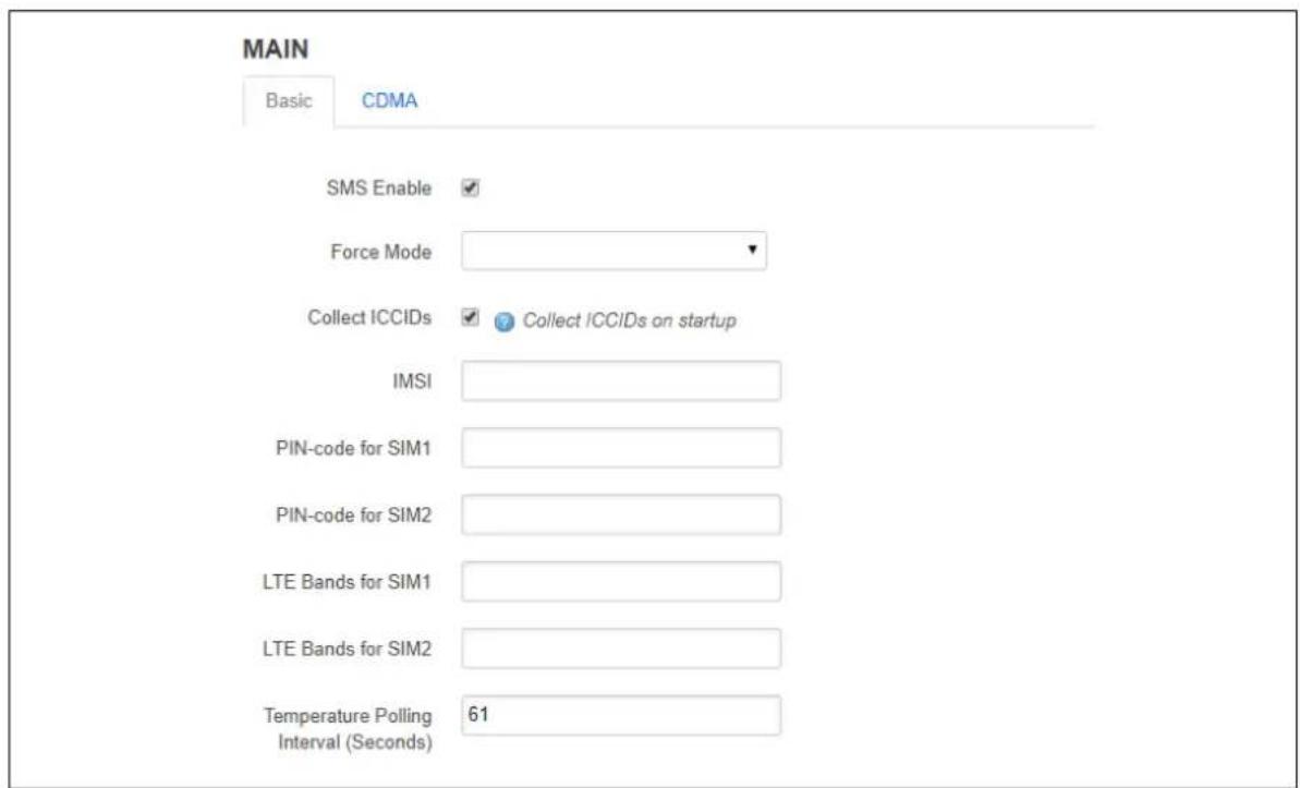
text_image
MAIN Basic CDMA SMS Enable ✓ Force Mode ✓ Collect ICCIDs ✓ Collect ICCIDs on startup IMSI PIN-code for SIM1 PIN-code for SIM2 LTE Bands for SIM1 LTE Bands for SIM2 Temperature Polling Interval (Seconds) 61Figure 75: The mobile manager basic page
| Web Field/ UCI / Package Option | Description | |
| Web: SMS EnableUCI: mobile.main.smsOpt: sms | Enables or disables SMS functionality. | |
| 0 | Disabled. | |
| 1 | Enabled. | |
| Web: Force ModeUCI: mobile.main.force_modeOpt: force_mode | Defines whether to operate mobile modem in TTY or Ethernet mode. The mode will be dependent on the service provided by the mobile provider. In general, this is Ethernet mode (default). | |
| Blank | Ethernet mode (option not present). | |
| tty | Enable TTY mode. | |
| Web: Collect ICCIDsUCI: mobile.main.init_get_iccidsOpt: init_get_iccids | Enables or disables integrated circuit card identifier ICCID's collection functionality. If enabled then both SIM 1 and SIM 2 ICCIDs will be collected otherwise it will default to SIM 1. This will be displayed under mobile stats. | |
| 0 | Disabled. | |
| 1 | Enabled. | |
| Web: IMSIUCI: mobile.main.imsiOpt: imsi | Allows the IMSI (International Mobile Subscriber Identity) to be changed. | |
| Default | Programmed in module. | |
| Digits | Up to 15 digits. | |
| Web: PIN code for SIM1UCI: mobile.main.sim1pinOpt: sim1pin | Depending on the SIM card specify the pin code for SIM 1. | |
| Blank | ||
| Range | Depends on the SIM provider. | |
| Web: PIN code for SIM2UCI: mobile.main.sim2pinOpt: sim2pin | Depending on the SIM card specify the pin code for SIM 2. | |
| Blank | ||
| Range | Depends on the SIM provider. | |
| Web: LTE bands for SIM1UCI: mobile.main.sim1_lte_bandsOpt: sim1_lte_bands | Depending on the SIM card specify the LTE bands for SIM 1. Comma delimiter. Example: option sim1_lte_bands '3,20' Limits LTE bands to 3 and 20. Note: currently only supported by Hucom/Wetelcom, SIMCom7100, Cellient MPL200 and Asiatel. | |
| Blank | ||
| Range | LTE bands range from 1 to 70. | |
| Web: LTE bands for SIM2UCI: mobile.main.sim2_lte_bandsOpt: sim2_lte_bands | Depending on the SIM card specify the LTE bands for SIM 2. Comma delimiter. Example: option sim1_lte_bands '3,20' Limits LTE bands to 3 and 20. Note: currently only supported by Hucom/Wetelcom, SIMCom7100, Cellient MPL200 and Asiatel. | |
| Blank | ||
| Range | LTE bands range from 1 to 70. | |
| Web: Temperature Polling IntervalUCI: mobile.main.temp_poll_interval_secOpt: temp_poll_interval_sec | Defines the time in seconds to poll the mobile module for temperature. Set to 0 to disable. | |
| 61 | 61 seconds. | |
| Range | ||
| Web: n/aUCI: mobile.main.disable_timeOpt: disable_time | Defines whether to use time obtained from the mobile carrier to update the system clock when NTP is enabled. | |
| 0 | Disabled. | |
| 1 | Enabled. | |
| Web: n/aUCI: mobile.main.service_orderOpt: service_order | Defines a space separated list of services, in preferred order. Valid options are gprs, umts, lte, auto.If no valid_service order is defined, then the configured Service Type is used. Example:mobile.main.service_order="gprs umts lte auto" | |
| Blank | Use configured service type. | |
| Range | gprs umts lte auto. | |
Table 44: Information table for mobile manager basic settings
16.2.2 Mobile manager: CDMA settings
This configuration page is only supported for the Telit CE910-SL CDMA module.
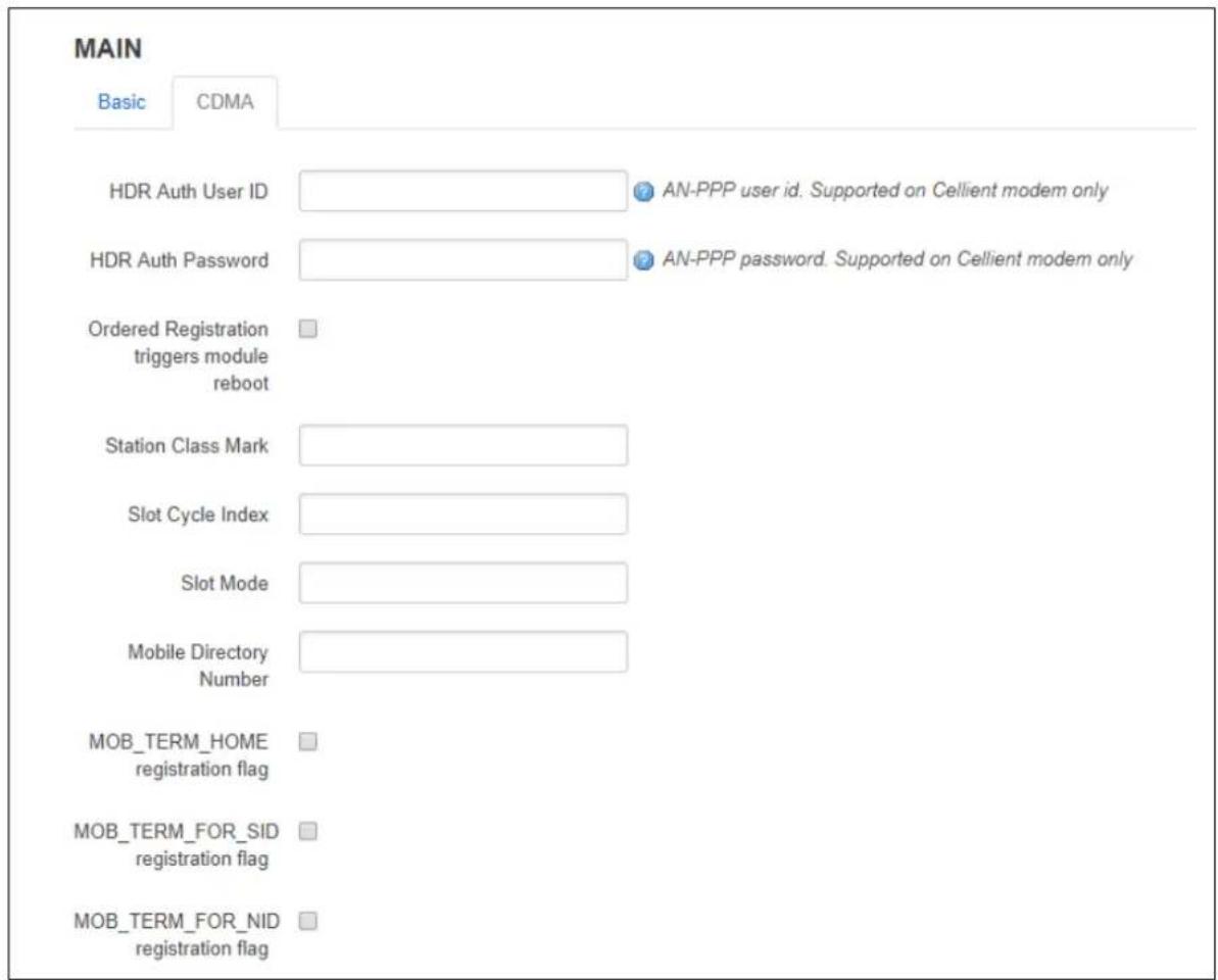
text_image
MAIN Basic CDMA HDR Auth User ID ● AN-PPP user id. Supported on Cellient modem only HDR Auth Password ● AN-PPP password. Supported on Cellient modem only Ordered Registration triggers module reboot Station Class Mark Slot Cycle Index Slot Mode Mobile Directory Number MOB_TERM_HOME registration flag MOB_TERM_FOR_SID registration flag MOB_TERM_FOR_NID registration flagFigure 76: The mobile manager CDMA page
| Web Field/ UCI / Package Option | Description | |
| Web: HDR Auth User IDUCI: mobile.main.hdr_useridOpt: hdr_userid | AN-PPP user ID. Supported on Cellient (CDMA) modem only. | |
| Blank | ||
| Range | Depends on the CDMA provider. | |
| Web: HDR Auth User PasswordUCI: mobile.main.hdr_passwordOpt: hdr_password | AN-PPP password. Supported on Cellient (CDMA) modem only. | |
| Blank | ||
| Range | Depends on the CDMA provider. | |
| Web: Ordered Registration triggers module rebootUCI: mobile.main.mobile.main.cdma_ordered_registration_reboot_enabledOpt:cdma Fijieds registration reboot enabled | Enables or disables rebooting the module after Order Registration command is received from a network. | |
| 0 | Disabled. | |
| 1 | Enabled. | |
| Web: Station Class MarkUCI: mobile.main.cdma station class markOpt: cdma station class mark | Allows the station class mark for the MS to be changed. | |
| 58 | ||
| 0-255 | ||
| Web: Slot Cycle IndexUCI: mobile.main.cdma slot cycle indexOpt: cdma slot cycle index | The desired slot cycle index if different from the default. | |
| 2 | ||
| 0-7 | ||
| Web: Slot ModeUCI: mobile.main.cdma slot modeOpt: cdma slot mode | Specifies the slot mode. | |
| 0 | ||
| Web: Mobile Directory NumberUCI:mobile.main.cdma mobile directory numberOpt: cdma mobile directory number | Allows the mobile directory number (MDN) to be changed | |
| Default | Programmed in module. | |
| Digits | Up to 15 digits. | |
| Web: MOB TERM HOME registration flagUCI: mobile.main.cdma mob term home registration flagOpt:cdma mob term home registration flag | The MOB TERM HOME registration flag | |
| 0 | Disabled. | |
| 1 | Enabled. | |
| Web: MOB TERM FOR SID registration flagUCI: mobile.main.cdma mob term for sid registration flagOpt:cdma mob term for sid registration flag | The MOB TERM FOR SID registration flag | |
| 0 | Disabled. | |
| 1 | Enabled. | |
| Web: MOB TERM FOR NID registration flagUCI: mobile.main.cdma mob term for nid registration flagOpt:cdma mob term for nid registration flag | The MOB TERM FOR NID registration flag | |
| 0 | Disabled. | |
| 1 | Enabled. | |
| Web: Access Overload ControlUCI:mobile.main.cdma access overload controlOpt: cdma access overload control | Allows the access overload class to be changed | |
| Default | Programmed into module as part of IMSI | |
| Range | 0-7 | |
| Web: Preferred Serving SystemUCI:mobile.main.cdma preferred serving systemOpt: cdma preferred serving system | The CDMA Preferred Serving System(A/B) | |
| 5 | ||
| Web: Digital Analog Mode PreferenceUCI: cdma digital analog mode preferenceOpt: cdma digital analog mode preference | Digital/Analog Mode Preference. | |
| 4 | ||
| Web: Primary Channel AUCI: mobile.main.cdma_primary_channel_aOpt: cdma_primary_channel_a. | Allows the primary channel (A) to be changed. | |
| 283 | ||
| 1-2016 | Any band class 5 channel number. | |
| Web: Primary Channel BUCI: mobile.main.cdma_primary_channel_bOpt: cdma_primary_channel_b | Allows the primary channel (B) to be changed. | |
| 384 | ||
| 1-2016 | Any band class 5 channel number | |
| Web: Secondary Channel AUCI:mobile.main.cdma_secondary_channel_aOpt: cdma_secondary_channel_a | Allows the secondary channel (A) to be changed. | |
| 691 | ||
| 1-2016 | Any band class 5 channel number. | |
| Web: Secondary Channel BUCI:mobile.main.cdma_secondary_channel_bOpt: cdma_secondary_channel_b | Allows the secondary channel (B) to be changed. | |
| 777 | ||
| 1-2016 | Any band class 5 channel number. | |
| Web: Preferred Forward & Reverse RCUCI:mobile.main.cdma_preferred_forward_and_reverse_rcOpt:cdma_preferred_forward_and_reverse_rc | The Preferred Forward & Reverse RC value, this takes the form "forward_rc,reverse_rc"Format: forward radio channel, reverse radio channelDefault: 0,0 | |
| Web: SID-NID pairsUCI: mobile.main.cdma_sid_nid_pairsOpt:cdma_sid_nid_pairs | Allows specification of SID:NID pairs, this takes the form "SID1,NID1,SID2,NID2,...Format: SID1 (0-65535),NID (0-65535)Default: 0,65535 | |
Table 45: Information table for mobile manager CDMA settings
16.2.3 Mobile manager: callers
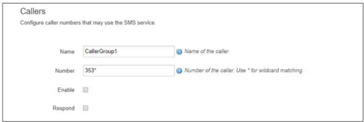
text_image
Callers Configure caller numbers that may use the SMS service. Name CallerGroup1 Name of the caller. Number 353* Number of the caller. Use * for wildcard matching. Enable RespondFigure 77: The mobile manager CDMA page
| Web Field/ UCI / Package Option | Description | |
| Web: Name | Name assigned to the caller. | |
| UCI: mobile.@caller[0].name | Blank | |
| Opt:name | Range | No limit |
| Web: Number | Number of the caller allowed to SMS the router. Add in specific caller numbers, or use the * wildcard symbol. | |
| UCI: mobile.@caller[0].number | ||
| Opt:number | Blank | |
| Range | No limit | |
| Characters | Global value (*) is acceptedInternational value (+) is accepted | |
| Web: Enable | Enables or disables incoming caller ID. | |
| UCI: mobile.@caller[0].enabled | 0 | Disabled. |
| Opt:enabled | 1 | Enabled. |
| Web: Respond | If checked, the router will return an SMS. Select Respond if you want the router to reply. | |
| UCI: mobile.@caller[0].respond | 0 | Disabled. |
| Opt: respond | 1 | Enabled. |
Table 46: Information table for mobile manager callers settings
16.2.4 Mobile manager: roaming interface template
For more information on Roaming Interface Template configuration, read the chapter, 'Automatic Operator Selection'.
16.3 Configuring mobile manager using command line
16.3.1 Mobile manager using UCI
The configuration files for mobile manager are stored on /etc/config/mobile
The following example shows how to enable the SMS functionality to receive and respond from certain caller ID numbers.
root@VA_router:~# uci show mobile
uci set mobile.main=mobile
uci set mobile.main.sim1pin=0000
uci set mobile.main.sim2pin=0000
uci set mobile.main.roaming_sim=none
uci set mobile.main.sms=1
uci set mobile.main.hdr_password=5678
uci set mobile.main.hdr_userid=1234
uci set mobile.main.init_get_iccids=1
uci set mobile.@caller[0]=caller
uci set mobile.@caller[0].name=user1
uci set mobile.@caller[0].number=3538712345678
uci set mobile.@caller[0].enabled=1
uci set mobile.@caller[0].respond=1
uci set mobile.@caller[1]=caller
uci set mobile.@caller[1].name=user2
uci set mobile.@caller[1].number=3538723456789
uci set mobile.@caller[1].enabled=1
uci set mobile.@caller[1].respond=1
16.3.2 Mobile manager using package options
root@VA_router:~# uci export mobile
package mobile
config mobile 'main'
    option sim1pin '0000'
    option sim2pin '0000'
    option roaming_sim 'none'
    option sms '1'
    option hdr_password '5678'
    option hdr_userid '1234'
    option init_get_iccids '1'
config caller
    option name 'vasupport'
    option number '353871234567'
    option enabled '1'
    option respond '1'
config caller
    option name 'vasupport1'
    option number '353872345678'
    option enabled '1'
    option respond '1'
16.4 Monitoring SMS
You can monitor inbound SMS messages using the router's web browser or via an SSH session.
To monitor SMS using the web browser, login and select Status > system log.
Scroll to the bottom of the log to view the SMS message.
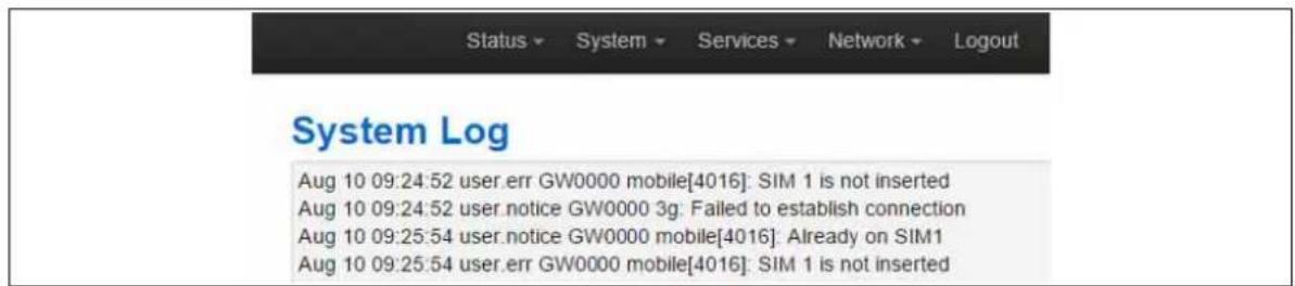
text_image
Status ▼ System ▼ Services ▼ Network ▼ Logout System Log Aug 10 09:24:52 user.err GW0000 mobile[4016]: SIM 1 is not inserted Aug 10 09:24:52 user.notice GW0000 3g: Failed to establish connection Aug 10 09:25:54 user.notice GW0000 mobile[4016]: Already on SIM1 Aug 10 09:25:54 user.err GW0000 mobile[4016]: SIM 1 is not insertedFigure 78: Example of output from system log
To monitor using SSH, login and enter:
logread -f &
An outgoing SMS message appears.
sendsms 353879876543 'hello'
root@VirtualAccess:~# Aug 10 16:29:11 user.notice VirtualAccess mobile[1737]: Queue sms to 353879876543 "hello"
16.5 Sending SMS from the router
You can send an outgoing message via the command line using the following syntax:
sendsms 353879876543 'hello'
root@VirtualAccess:~# Aug 10 16:29:1 user.notice VirtualAccess mobile[1737]: Queue sms to 353879876543 "hello"
16.6 Sending SMS to the router
The router can accept UCI show and set commands via SMS if the caller is enabled.
Note: commands are case sensitive.
An example would be to SMS the SIM card number by typing the following command on the phone and checking the SMS received from the router.
uci show mobile.@caller[0].number
17 Configuring a GRE interface
General Routing Encapsulation (GRE) is a tunnelling protocol used for encapsulation of other communication protocols inside point to point links over IP.
17.1 Configuration packages used
| Package | Sections |
| network | interface |
17.2 Creating a GRE connection using the web interface
To create GRE interfaces through the web interface, in the top menu, select Network - > Interfaces.
There are three sections in the Interfaces page.
| Section | Description |
| Interface Overview | Shows existing interfaces and their status. You can create new, and edit existing interfaces here. |
| Port Map | In this section you can map device ports to Ethernet interfaces. Ports are marked with capital letters starting with 'A'. Type in space separated port numbers in the port map fields. |
| ATM Bridges | ATM bridges expose encapsulated Ethernet in AAL5 connections as virtual Linux network interfaces, which can be used in conjunction with DHCP or PPP to dial into the provider network. |
In the Interface Overview section, click Add new interface. The Create Interface page appears.
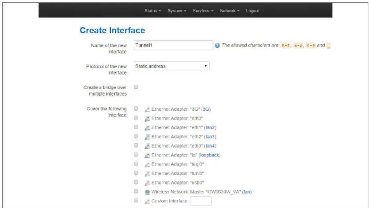
text_image
Create Interface Name of the new interface Tunnel1 The allowed characters are: A-2, A-3, 0-5 and _ Protocol of the new interface Static address Create a bridge over multiple interfaces Cover the following interface Ethernet Adapter: "3G" (3G) Ethernet Adapter: "eth0" Ethernet Adapter: "eth1" (lan2) Ethernet Adapter: "eth2" (lan3) Ethernet Adapter: "eth3" (lan4) Ethernet Adapter: "lo" (loopback) Ethernet Adapter: "leql0" Ethernet Adapter: "tuni0" Ethernet Adapter: "usb0" Wireless Network Master: "GW6630W_VA" (lan) Custom Interface:Figure 79: The create interface page
| Web Field/ UCI / Package Option | Description | |
| Web: Name of the new interfaceUCI: network.<if name>.Opt: config interface | Assigns a logical name to the GRE tunnel, The network interface section will be assigned this name<if name>.Type the name of the new interface.Allowed characters are A-Z, a-z, 0-9 and _.Must be less than 11 characters. | |
| Web: Protocol of the new interfaceUCI: network.<if name>.protoOpt: proto | Specifies what protocol the interface will operate on. Select GRE. | |
| Option | Description | |
| Static Static configuration with fixed address and netmask. | ||
| DHCP Client Address and netmask are assigned by DHCP. | ||
| Unmanaged | Unspecified | |
| IPv6-in-IPv4 (RFC4213) | Used with tunnel brokers. | |
| IPv6-over-IPv4 | Stateless IPv6 over IPv4 transport. | |
| GRE | Generic Routing Encapsulation protocol | |
| IOT | ||
| L2TP | Layer 2 Tunnelling Protocol | |
| PPP | Point-to-Point protocol | |
| PPPoE | PPP over Ethernet | |
| PPPoATM | PPP over ATM | |
| LTE/UMTS/GPRS/EV-DO | CDMA, UMTS or GPRS connection using an AT-style 3G modem. | |
| Web: Create a bridge over multiple interfacesUCI: network.<if name>.Opt: n/a | Not applicable for GRE. | |
| Web: Cover the following interfaceUCI: network.<if name>.Opt: n/a | Not applicable for GRE. | |
Table 47: Information table for the create new interface page
Click Submit. The Common Configuration page appears. There are three sections in the Common Configurations page.
| Section | Description |
| General Setup | Configure the basic interface settings such as protocol, IP address, mask length, local interface, remote IP address, TTL, tunnel key and MTU. |
| Advanced Settings | 'Bring up on boot' and 'monitor interface state' settings. |
| Firewall settings | Assign a firewall zone to the connection. |
17.2.1 GRE connection: common configuration - general setup
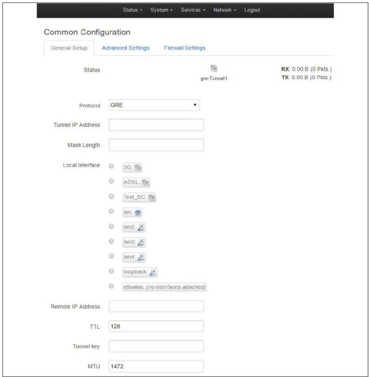
text_image
Status System Services Network Logout Common Configuration General Setup Advanced Settings Firewall Settings Status gre-Tunnel1 RX: 0.00 B (0 Pkts.) TX: 0.00 B (0 Pkts.) Protocol GRE Tunnel IP Address Mask Length Local Interface JG: ADSL: Test_BC: lan: lan2: lan3: lan4: loopback: ethallas: (no interfaces attached) Remote IP Address TTL 128 Tunnel key MTU 1472Figure 80: The GRE common configuration page
| Web Field/ UCI / Package Option | Description | |
| Web: Protocol of the new interfaceUCI: network.<if name>.protoOpt: proto | Shows the protocol the interface will operate on. GRE should be currently selected. | |
| Web: Tunnel IP AddressUCI: network.<if name>.ipaddrOpt: ipaddr | Configures local IP address of the GRE interface. | |
| Web: Mask LengthUCI: network<if name>.mask_lengthOpt: mask_length | Subnet mask, in CIDR notation, to be applied to the tunnel.Typically '30' for point-to-point tunnels. | |
| 24 | ||
| Range | 0 - 30 | |
| Web: Local InterfaceUCI: network.<if name>.local_interfaceOpt: local interface | Specifies which interface is going to be linked with the GRE tunnel interface (optional). | |
| Web: Remote IP addressUCI: network.<if name>.remote_ipOpt: remote_ip | For point to point tunnels specifies Remote IP address. | |
| Web: TTLUCI: network.<if name>.ttlOpt: ttl | Sets Time-To-Live value on the interface. | |
| 128 | ||
| Range | ||
| Web: Tunnel keyUCI: network.<if name>.keyOpt: key | Sets GRE tunnel ID key (optional).Usually an integer. | |
| Web: MTUUCI: network.<if name>.mtuOpt: mtu | Configures MTU (maximum transmission unit) size of PDUs using this interface. | |
| 1472 | ||
| Range | ||
Table 48: Information table for GRE
17.2.2 GRE connection: common configuration-advanced settings
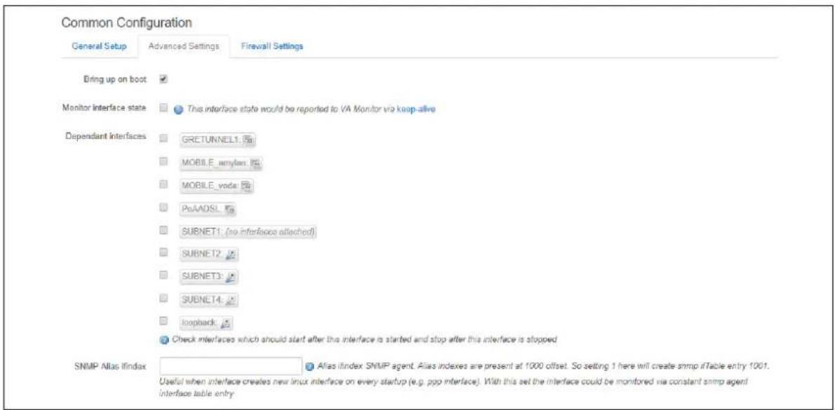
text_image
Common Configuration General Setup Advanced Settings Firewall Settings Bring up on boot Monitor interface state This interface state would be reported to VA Monitor via keep-alive Dependant Interfaces GRETUNNEL1.5a MOBILE_amylan.fla MOBILE_voda.fla PuAOSL.fla SUBNET1: (no interface attached) SUBNET2 SUBNET3 SUBNET4 _loopback .Check interfaces which should start after this interface is started and stop after this interface is stopped SNMP Alias ifindex Alias ifindex SNMP agent. Alias indexes are present at 1000 offset. So setting 1 here will create snmp ifTable entry 1001. Useful when interface creates new linux interface on every startup (e.g. ppp interface). With this set the interface could be monitored via constant snmp agent interface table entryFigure 81: GRE advanced settings page
| Web Field/ UCI / Package Option | Description | |
| Web: Bring up on bootUCI: network.<if name>.autoOpt: auto | Enables the interface to connect automatically on boot up. | |
| 0 | Disabled. | |
| 1 | Enabled. | |
| Web: Monitor interface stateUCI: network.<if name>.monitoredOpt: monitored | Enabled if status of interface is presented on Monitoring platform. | |
| 0 | Disabled. | |
| 1 | Enabled. | |
| Web: Dependant InterfacesUCI: network[..x..].dependantsOpt: dependants | Lists interfaces that are dependent on this parent interface.Dependant interfaces will go down when parent interface is down and will start or restart when parent interface starts.Separate multiple interfaces by a space when using UCI.Example: option dependants 'PPPADSL MOBILE'This replaces the following previous options in child interfaces. | |
| gre | option local_interface | |
| It2p | option src_ipaddr | |
| iot | option wan1 wan2 | |
| 6in4 | option ipaddr | |
| 6to4 | option ipaddr | |
| Web: SNMP Alias ifindexUCI: network[..x..].snmp_alias_ifindexOpt: snmp_alias_ifindex | Defines a static SNMP interface alias index for this interface, that can be polled via the SNMP interface index(snmp_alias_ifindex+ 1000). See Configuring SNMP section for more information | |
| Blank | No SNMP interface alias index | |
| Range | 0 - 4294966295 | |
Table 49: Information table for GRE advanced settings
17.2.3 GRE connection: firewall settings
Use this section to select the firewall zone you want to assign to this interface.
Select unspecified to remove the interface from the associated zone or fill out the create field to define a new zone and attach the interface to it.
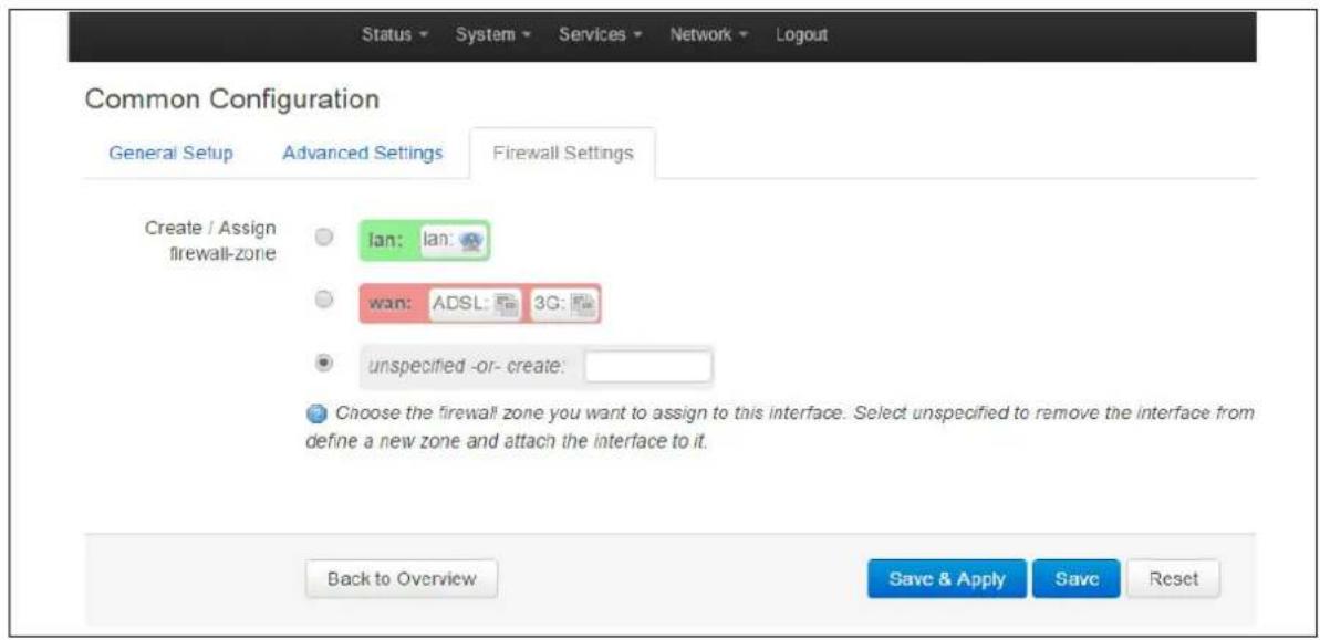
text_image
Status System Services Network Logout Common Configuration General Setup Advanced Settings Firewall Settings Create / Assign firewall-zone Ian: Ian: wan: ADSL: 3G: unspecified -or- create: Choose the firewall zone you want to assign to this interface. Select unspecified to remove the interface from define a new zone and attach the interface to it. Back to Overview Save & Apply Save ResetFigure 82: GRE firewall settings
Click Save and Apply. This will save the current settings and return you to the Interface Overview page. To configure further settings on the GRE interface select EDIT for the relevant GRE interface.
17.2.4 GRE connection: adding a static route
After you have configured the GRE interface, you must configure a static route to route the desired traffic over the GRE tunnel. To do this, browse to Network->Static Routes. For more information, read the chapter 'Configuring Static Routes'.
17.3 GRE configuration using command line
The configuration file is stored on /etc/config/network
For the examples below tunnel1 is used as the interface logical name.
17.4 GRE configuration using UCI
root@VA_router:~# uci show network
network.tunnel1=interface
network.tunnel1.proto=gre
network.tunnel1.monitored=0
network.tunnel1.ipaddr=172.255.255.2
network.tunnel1.mask_length=24
network.tunnel1.local_interface=wan
network.tunnel1.remote_ip=172.255.255.100
network.tunnel1.ttl=128
network.tunnel1.key=1234
network.tunnel1.mtu=1472
network.tunnel1.auto=1
17.5 GRE configuration using package options
root@VA_router:~# uci export network
config interface 'tunnel1'
option proto 'gre'
option monitored '0'
option ipaddr '172.255.255.2'
option mask_length '24'
option local_interface 'wan'
option remote_ip '172.255.255.100'
option ttl '128'
option key '1234'
option mtu '1472'
option auto '1'
To change any of the above values use uci set command.
17.6 GRE diagnostics
17.6.1 GRE interface status
To show the current running interfaces, enter:
root@VA_router:~# ifconfig
base0 Link encap:Ethernet HWaddr 00:00:00:00:01:01
inet6 addr: fe80::200:ff:fe00:101/64 Scope:Link
UP BROADCAST RUNNING MULTICAST MTU:1504 Metric:1
RX packets:39810 errors:0 dropped:0 overruns:0 frame:0
TX packets:365 errors:0 dropped:0 overruns:0 carrier:0
collisions:0 txqueuelen:1000
RX bytes:10889090 (10.3 MiB) TX bytes:68820 (67.2 KiB)
eth4 Link encap:Ethernet HWaddr 00:1E:10:1F:00:00
inet addr:10.68.66.54 Bcast:10.68.66.55 Mask:255.255.255.252
inet6 addr: fe80::21e:10ff:felf:0/64 Scope:Link
UP BROADCAST RUNNING MULTICAST MTU:1500 Metric:1
RX packets:81 errors:0 dropped:0 overruns:0 frame:0
TX packets:127 errors:0 dropped:0 overruns:0 carrier:0
collisions:0 txqueuelen:1000
RX bytes:8308 (8.1 KiB) TX bytes:12693 (12.3 KiB)
gre-Tunnel1 Link encap:UNSPEC HWaddr 0A-44-42-36-DB-B0-00-48-00-00-00-00-00-00-00
inet addr:13.13.13.2 Mask:255.255.255.248
inet6 addr: fe80::5efe:a44:4236/64 Scope:Link
UP RUNNING MULTICAST MTU:1472 Metric:1
RX packets:7 errors:0 dropped:0 overruns:0 frame:0
TX packets:7 errors:0 dropped:0 overruns:0 carrier:0
collisions:0 txqueuelen:0
RX bytes:912 (912.0 B) TX bytes:884 (884.0 B)
lo Link encap:Local Loopback
inet addr:127.0.0.1 Mask:255.0.0.0
inet6 addr::1/128 Scope:Host
UP LOOPBACK RUNNING MTU:16436 Metric:1
RX packets:1465 errors:0 dropped:0 overruns:0 frame:0
TX packets:1465 errors:0 dropped:0 overruns:0 carrier:0
collisions:0 txqueuelen:0
RX bytes:166202 (162.3 KiB) TX bytes:166202 (162.3 KiB)
To display a specific GRE interface, enter ifconfig gre-
root@VA_router:~# ifconfig gre-Tunnel1
gre-Tunnel1 Link encap:UNSPEC HWaddr 0A-44-42-36-00-00-7F-E2-00-00-00-00-00-00-00-00
inet addr:13.13.13.2 Mask:255.255.255.248
inet6 addr: fe80::5efe:a44:4236/64 Scope:Link
UP RUNNING MULTICAST MTU:1472 Metric:1
RX packets:7 errors:0 dropped:0 overruns:0 frame:0
TX packets:7 errors:0 dropped:0 overruns:0 carrier:0
collisions:0 txqueuelen:0
RX bytes:912 (912.0 B) TX bytes:8GRE route status
To show the current GRE route status, enter:
root@VA_router:~# route -n
Kernel IP routing table
Destination Gateway Genmask Flags Metric Ref Use
Iface
0.0.0.0 10.68.66.53 0.0.0.0 UG 0 0 0 eth4
0.0.0.0 13.13.13.1 0.0.0.0 UG 1 0 0 gre-
Tunnel1
10.68.66.52 0.0.0.0 255.255.255.252 U 0 0 0 eth4
13.13.13.0 0.0.0.0 255.255.255.248 U 0 0 0 gre-
Tunnel1
172.19.101.3 13.13.13.1 255.255.255.255 UGH 0 0 0 gre-
Tunnel1
Note: a GRE route will only be displayed in the routing table when the interface is up.
18 Configuring static routes
It is possible to define arbitrary IPv4 routes on specific interfaces using route sections. As for aliases, multiple sections can be attached to an interface. These types of routes are most commonly known as static routes.
You can add static routes to the routing table to forward traffic to specific subnets when dynamic routing protocols are not used or they are not configured for such subnets. They can be created based on outgoing interface or next hop IP address.
18.1 Configuration package used
| Package | Sections |
| network | route |
18.2 Configuring static routes using the web interface
In the top menu, select Network -> Static Routes. The Routes page appears.
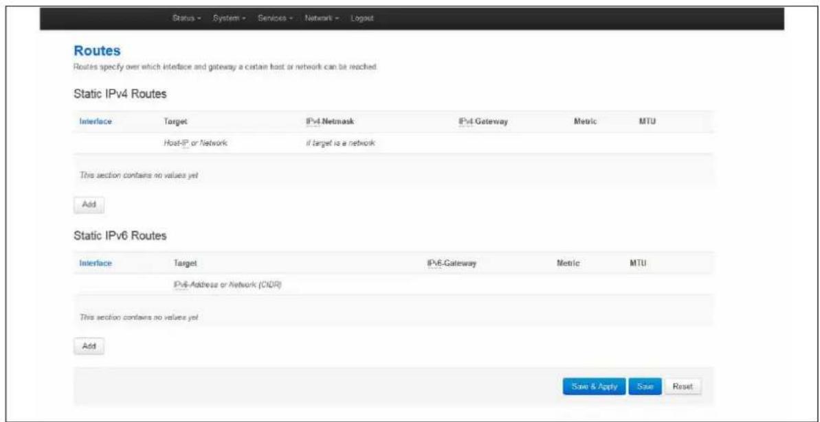
text_image
Status - System - Services - Network - Logout Routes Routes specify over which interface and gateway a certain host or network can be reached Static IPv4 Routes Interface Target IPv4 Netmask IPv4 Gateway Metric MTU Host-IP or Network if target is a network This section contains no values yet Add Static IPv6 Routes Interface Target IPv6-Gateway Metric MTU IPv6-Address or Network (CIIR) This section contains no values yet Add Save & Apply Save ResetFigure 83: The routes page
In the IPv4 Routes section, click Add.
| Web Field/ UCI / Package Option | Description | |
| Web: InterfaceUCI: network.@route[0].interfaceOpt: Interface | Specifies the logical interface name of the parent or master interface this route belongs to. It must refer to one of the defined interface sections. | |
| Web: targetUCI: network.@route[0].targetOpt: target | Specifies the route network IP address. | |
| Web: netmaskUCI: network.@route[0].netmaskOpt: netmask | Defines the route netmask. If omitted, 255.255.255.255 is assumed, which makes the target a host address. | |
| Web: GatewayUCI: network.@route[0].gatewayOpt: Gateway | Network gateway. If omitted, the gateway from the parent interface is taken. If set to 0.0.0.0 no gateway will be specified for the route. | |
| Web: MetricUCI: network.@route[0].metricOpt: metric | Specifies the route metric to use. | |
| 0 | ||
| Range | ||
| Web: MTUUCI: network.@route[0].mtuOpt:mtu | Defines a specific MTU for this route. If omitted, the MTU from the parent interface will be taken. | |
| Blank | ||
| Range | ||
Table 50: Information table for IPv4 static routes section
18.3 Configuring IPv6 routes using the web interface
You can also specify IPv6 routes by defining one or more IPv6 routes. In the IPv6 routes section, click Add.
| Web Field/ UCI / Package Option | Description | |
| Web: InterfaceUCI: network.@route[1].interfaceOpt: interface | Specifies the logical interface name of the parent or master interface this route belongs to. It must refer to one of the defined interface sections. | |
| Web: targetUCI: network.@route[1].targetOpt: target | Specifies the route network IP address, or subnet in CIDR notation:Example: 2001:0DB8:100:F00:BA3::1/64 | |
| Web: GatewayUCI: network.@route[1].gatewayOpt: Gateway | Network gateway. If omitted, the gateway from the parent interface is taken. If set to 0.0.0.0 no gateway will be specified for the route. | |
| Web: MetricUCI: network.@route[1].metricOpt: metric | Specifies the route metric to use. | |
| Web: MTUUCI: network.@route[1].mtuOpt:mtu | Defines a specific MTU for this route. If omitted the MTU from the parent interface will be taken. | |
| Empty | ||
| Range | ||
Table 51: Information table for IPv6 routes
When you have made your changes, click Save & Apply.
18.4 Configuring routes using command line
By default all routes are named 'route', it is identified by @route then the route's position in the package as a number. For example, for the first route in the package using UCI:
network.@route[0]=route
network.@route[0].interface=lan
Or using package options:
config route option 'interface' 'lan'
However, you can give a route a name if desired. For example, a route named 'myroute' will be network.myroute.
To define a named route using UCI, enter:
network.name_your_route=route
network.name_your_route.interface=lan
To define a named route using package options, enter:
config route 'name_your_route'
option 'interface' 'lan'
18.5 IPv4 routes using UCI
The command line example routes in the subsections below do not have a configured name.
root@VA_router:~# uci show network
network.@route[0]=route
network.@route[0].interface=lan
network.@route[0].target=3.3.3.10
network.@route[0].netmask=255.255.255.255
network.@route[0].gateway=10.1.1.2
network.@route[0].metric=3
network.@route[0].mtu=1400
18.6 IPv4 routes using package options
root@VA_router:~# uci export network
package network
...
config route
option interface 'lan'
option target '2.2.2.2'
option netmask '255.255.255.255'
option gateway '192.168.100.1'
option metric '1'
option mtu '1500'
18.7 IPv6 routes using UCI
root@VA_router:~# uci show network
network.@route[1]=route
network.@route[1].interface=lan
network.@route[1].target=2001:0DB8:100:F00:BA3::1/64
network.@route[1].gateway=2001:0DB8:99::1
network.@route[1].metric=1
network.@route[1].mtu=1500
18.8 IPv6 routes using packages options
root@VA_router:~# uci export network
package network
...
config route
    option interface 'lan'
    option target '2001:0DB8:100:F00:BA3::1/64'
    option gateway '2001:0DB8:99::1'
    option metric '1'
    option mtu '1500'
18.9 Static routes diagnostics
18.9.1 Route status
To show the current routing status, enter:
root@VA_router:~# route -n
Kernel IP routing table
Destination Gateway Genmask Flags Metric Ref Use Iface
192.168.100.0 * 255.255.255.0 U 0 0 0 eth0
Note: a route will only be displayed in the routing table when the interface is up.
19 Configuring BGP (Border Gateway Protocol)
BGP is a protocol for exchanging routing information between gateway hosts, each with its own router, in a network of autonomous systems. BGP is often the protocol used between gateway hosts on the internet. The routing table contains a list of known routers, the addresses they can reach, and a cost metric associated with the path to each router so that the best available route is chosen.
19.1 Configuration package used
| Package | Sections |
| bgpd | routing |
| peer | |
| routemap |
19.2 Configuring BGP using the web interface
In the top menu, select Network -> BGP. BGP configuration page appears. The page has three sections: Global Settings, BGP Neighbours and BGP Route Map.
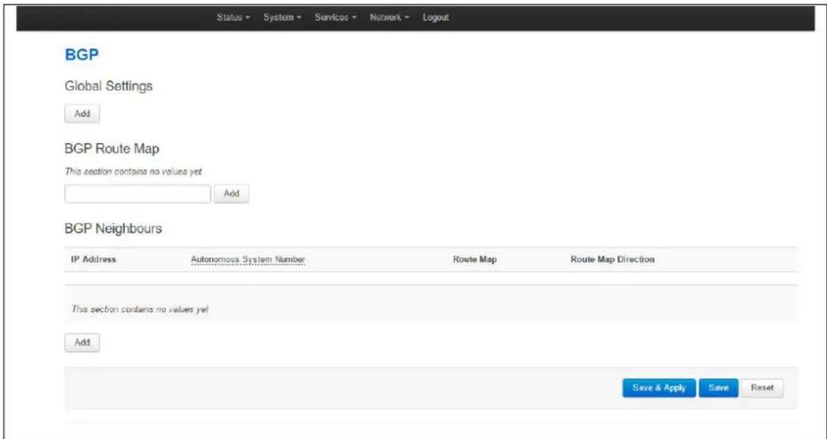
text_image
Status System Services Network Logout BGP Global Settings Add BGP Route Map This section contains no values yet Add BGP Neighbours IP Address Autonomous System Number Route Map Route Map Direction This section contains no values yet Add Save & Apply Save ResetFigure 84: The BGP page
19.2.1 BGP global settings
To configure global BGP settings, click Add. The Global Settings page appears.

text_image
BGP Global Settings BGP Enabled ✓ Router ID 192.168.210.1 Scan Time 60 The interval in seconds between RIB scans Autonomous System 1 Number Network 10.1.0.0 These networks will be announced to neighboursFigure 85: The BGP global settings page
| Web Field/ UCI / Package Option | Description | |
| Web: BGP EnabledUCI: bgpd.bgpd.enabledOpt: enabled | Enables or disables BGP protocol. | |
| 1 | Enabled. | |
| 0 | Disabled. | |
| Web: Router IDUCI: bgpd.bgpd.router_idOpt: router_id | Sets a Unique Router ID in 4 byte format 0.0.0.0. | |
| Web: Scan TimeUCI: bgpd.bgpd.scan_timeOpt: scan_time | Defines the interval in seconds between RIB scans. | |
| 60 | 60 seconds | |
| Range | ||
| Web: Autonomous System NumberUCI: bgpd.bgpd.asnOpt: asn | Defines the ASN for the local router. Type in the ASN. | |
| Blank | ||
| Range | 1-4294967295 | |
| Web: NetworkUCI: bgpd.bgpd.networkOpt: list network | Sets the list of networks that will be advertised to neighbours in prefix format 0.0.0.0/0. Separate multiple networks by a space using UCI. Ensure the network prefix matches the one shown in the routing table. See 'Routes' section below. | |
Table 52: Information table for BGP global settings
19.2.2 Optionally configure a BGP route map
Route maps provide a means to both filter and/or apply actions to a route. This allows a policy to be applied to routes. Route maps are an ordered list of route map entries each with a set of criteria that must be matched before specific attributes of the route are modified.
Scroll down to the BGP Route Map section.
Type in a name for the BGP route map name and then click Add. The ROUTEMAP configuration section appears. You can configure multiple route maps.
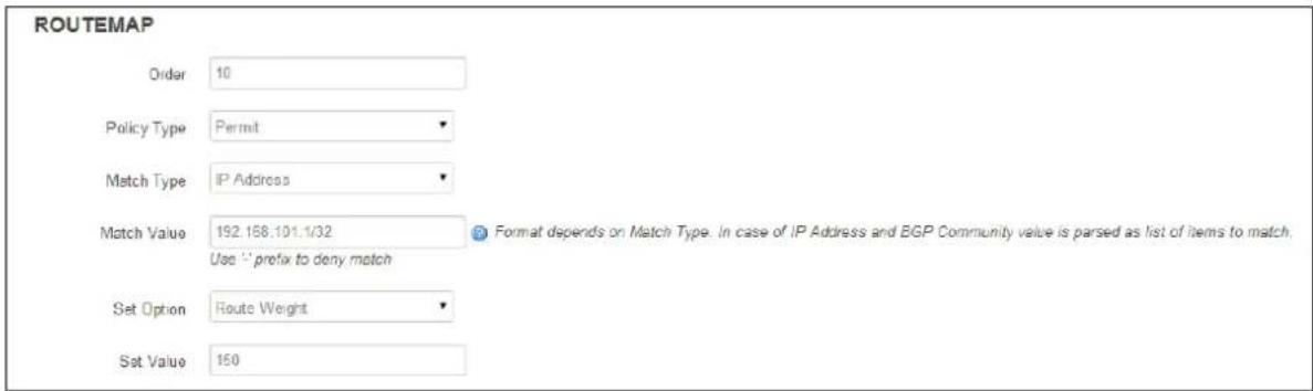
text_image
ROUTE MAP Order 10 Policy Type Permit Match Type IP Address Match Value 192.158.101.1/32 Use "" prefix to deny match Set Option Route Weight Set Value 150 Format depends on Match Type. In case of IP Address and BGP Community value is parsed as list of items to match.Figure 86: The routemap section
| Web Field/ UCI / Package Option | Description | |
| Web: OrderUCI: bgpd. ROUTEMAP.orderOpt: order | Defines the Route Map order number. | |
| Blank | ||
| Range | 1-65535 | |
| Web: Policy TypeUCI: bgpd. ROUTEMAP permitOpt: permit | Defines the actions taken if the entry is matched. | |
| Deny | Denies the route. | |
| Permit Permits the route so process the set actions for this entry. | ||
| Web: Match TypeUCI: bgpd. ROUTEMAP.match_typeOpt: match_type | Defines match type. Available options are as follows: | |
| IP address | Matches IP address. | |
| IP Next Hop | Matches next hop IP address. | |
| AS-Path | Matches AS-path. | |
| Route Metric | Matches route metric. | |
| BGP Community | Matches BGP community. | |
| Web: Match valueUCI: bgpd. ROUTEMAP.matchOpt: match | Defines the value of the match type. Format depends on the Match Type selected. In the case of IP address and BGP Community values, the match value is parsed as a list of items to match. | |
| Web: Set OptionUCI: bgpd. ROUTEMAP.set_typeOpt: set_type | Defines the set option to be processed on a match. Available options are shown below. | |
| None | ||
| IP Next Hop | Setting option for IP next hop. | |
| Local Preference | Setting option for Local Preference. | |
| Route Weight | Setting option for Route Weight. | |
| BGP MED | Setting option for BGP multi-exit discriminator (BGP metric). | |
| AS Path to Prepend | Setting option to prepend AS to AS path. | |
| BGP Community | Setting option for BGP community. | |
| IPv6 Next Hop Global | Setting option for IPv6 Next Hop Global. | |
| IPv6 Next Hop Local | Setting option for IPv6 Next Hop Local. | |
| Web: ValueUCI: bgpd. ROUTEMAP.setOpt: set | Defines the set value when a match occurs. Value format depends on the set option you have selected. | |
Table 53: Information table for routemap
19.2.3 Configure BGP neighbours
To configure BGP neighbours, in the BGP neighbours section, click Add. The BGP Neighbours page appears. Multiple BGP neighbours can be configured.
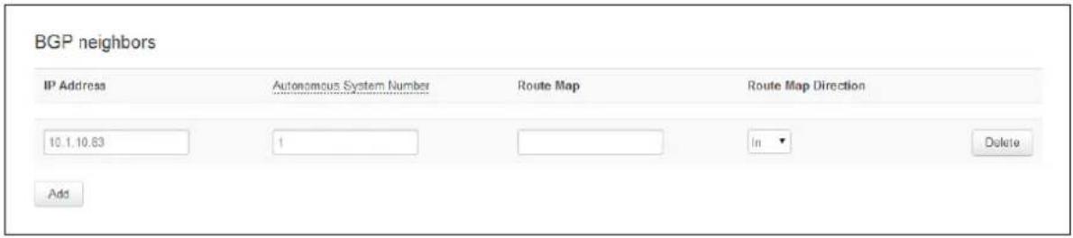
text_image
BGP neighbors IP Address Autonomous System Number Route Map Route Map Direction 10.1.10.63 1 In Delete AddFigure 87: The BGP neighbours section
| Web Field/ UCI / Package Option | Description | |
| Web: IP AddressUCI: bgpd.@peer[0].ipaddrOpt: ipaddr | Sets the IP address of the neighbour. | |
| Web: Autonomous System NumberUCI: bgpd.@peer[0].asnOpt: asn | Sets the ASN of the remote peer. | |
| Blank | ||
| Range | 1-4294967295 | |
| Web: Route MapUCI: bgpd.@peer[0].route_mapOpt: route_map | Sets route map name to use with this neighbour. | |
| Web: Route Map DirectionUCI: bgpd.@peer[0].route_map_inOpt: route_map_in | Defines the direction the route map should be applied. | |
| 1 | In | |
| 0 | Out | |
Table 54: Information table for BGP neighbours
19.3 Configuring BGP using UCI
You can also configure BGP using UCI. The configuration file is stored on /etc/config/bgpd
root@VA_router:~# uci show bgpd
bgpd.bgpd=routing
bgpd.bgpd.enabled=yes
bgpd.bgpd.router_id=3.3.3.3
bgpd.bgpd.asn=1
bgpd.bgpd.network=11.11.11.0/29 192.168.103.1/32
bgpd.@peer[0]=peer
bgpd.@peer[0].route_map_in=yes
bgpd.@peer[0].ipaddr=11.11.11.1
bgpd.@peer[0].asn=1
bgpd.@peer[0].route_map=ROUTEMAP
bgpd.ROUTEMAP=routemap
bgpd.ROUTEMAP.order=10
bgpd.ROUTEMAP.permit=yes
bgpd.ROUTEMAP.match_type=ip address
bgpd.ROUTEMAP.match=192.168.101.1/32
bgpd.ROUTEMAP.set_type=ip next-hop
bgpd.ROUTEMAP.set='192.168.101.2/32'
To change any of the above values use UCI set command.
19.4 Configuring BGP using packages options
root@VA_router:~# uci export bgpd
package bgpd

config routing 'bgpd'
    option enabled 'yes'
    option router_id '3.3.3.3'
    option asn '1'
    list network '11.11.11.0/29'
    list network '192.168.103.1/32'

config peer
    option route_map_in 'yes'
    option ipaddr '11.11.11.1'
    option asn '1'
    option route_map 'ROUTEMAP'

config routemap 'ROUTEMAP'
    option order '10'
    option permit 'yes'
    option match_type 'ip address'
    option match '192.168.101.1/32'
    option set_type 'ip next-hop'
    option set '192.168.101.2/32'
19.5 View routes statistics
To view routes statistics, in the top menu click Status -> Routes. The routing table appears.
Routes
The following rules are currently active on this system.
ARP
| IPy4-Address | MAC-Address | Interface |
| 192.168.210.100 | 50.b7:c3.0c:1e:4b | br-lan |
| 10.1.1.124 | d4:ae:52:cd:61:21 | eth1 |
| 10.1.10.83 | 00:13:60:51:39:58 | eth1 |
Active IPv4-Routes
| Network | Target | IPv4-Gateway | Metric |
| wan | 0.0.0.0/0 | 10.64.64.64 | 0 |
| wan | 0.0.0.0/0 | 10.64.64.64 | 1 |
| LAN2 | 10.1.0.0/16 | 0.0.0.0 | 0 |
| wan | 10.64.64.64 | 0.0.0.0 | 0 |
| LAN2 | 192.168.101.1 | 10.1.10.83 | 0 |
| lan | 192.168.210.0/24 | 0.0.0.0 | 0 |
| wan | 217.67.129.143 | 10.64.64.64 | 0 |
Active IPv6-Routes
| Network | Target | IPv6-Gateway | Metric |
| loopback | 0:0:0:0:0:0:0:0/0 | 0:0:0:0:0:0:0:0/0 | FFFFFFF |
| loopback | 0:0:0:0:0:0:0:0/0 | 0:0:0:0:0:0:0:0/0 | FFFFFFF |
| loopback | 0:0:0:0:0:0:0:1 | 0:0:0:0:0:0:0:0/0 | 00000000 |
| LAN2 | FF02:0:0:0:0:0:FB | 0:0:0:0:0:0:0:0/0 | 00000000 |
| (base0) | FF00:0:0:0:0:0:0:8 | 0:0:0:0:0:0:0:0/0 | 00000100 |
| Ian | FF00:0:0:0:0:0:0:8 | 0:0:0:0:0:0:0:0/0 | 00000100 |
| LAN2 | FF00:0:0:0:0:0:0:8 | 0:0:0:0:0:0:0:0/0 | 00000100 |
| loopback | 0:0:0:0:0:0:0:0/0 | 0:0:0:0:0:0:0:0/0 | FFFFFFF |
Figure 88: The routing table
To view routes via the command line, enter:
root@support:~# route -n
Kernel IP routing table
Destination Gateway Genmask Flags Metric Ref Use Iface
10.1.0.0 0.0.0.0 255.255.0.0 U 0 0 0 br-lan2
20 Configuring OSPF (Open Shortest Path First)
20.1 Introduction
OSPF is a standardised Link State routing protocol, designed to scale efficiently to support larger networks. Link State protocols track the status and connection type of each link and produce a calculated metric based on these and other factors, including some set by the network administrator. Link State protocols will take a path which has more hops, but that uses a faster medium over a path using a slower medium with fewer hops.
- OSPF adheres to the following Link State characteristics:
- OSPF employs a hierarchical network design using areas.
- OSPF will form neighbour relationships with adjacent routers in the same area.
- Instead of advertising the distance to connected networks, OSPF advertises the status of directly connected links using Link-State Advertisements (LSAs).
- OSPF sends updates (LSAs) when there is a change to one of its links, and will only send the change in the update. LSAs are additionally refreshed every 30 minutes.
- OSPF traffic is multicast either to address 224.0.0.5 (all OSPF routers) or 224.0.0.6 (all designated routers).
- OSPF uses the Dijkstra Shortest Path First algorithm to determine the shortest path.
- OSPF is a classless protocol, and therefore supports variable Length Subnet Masks (VLSMs).
Other characteristics of OSPF include:
• OSPF supports only IP routing.
- OSPF routes have an administrative distance is 110.
- OSPF uses cost as its metric, which is computed based on the bandwidth of the link. OSPF has no hop-count limit.
The OSPF process builds and maintains three separate tables:
- A neighbour table containing a list of all neighbouring routers
- A topology table containing a list of all possible routes to all known networks within an area
- A routing table containing the best route for each known network
20.1.1 OSPF areas
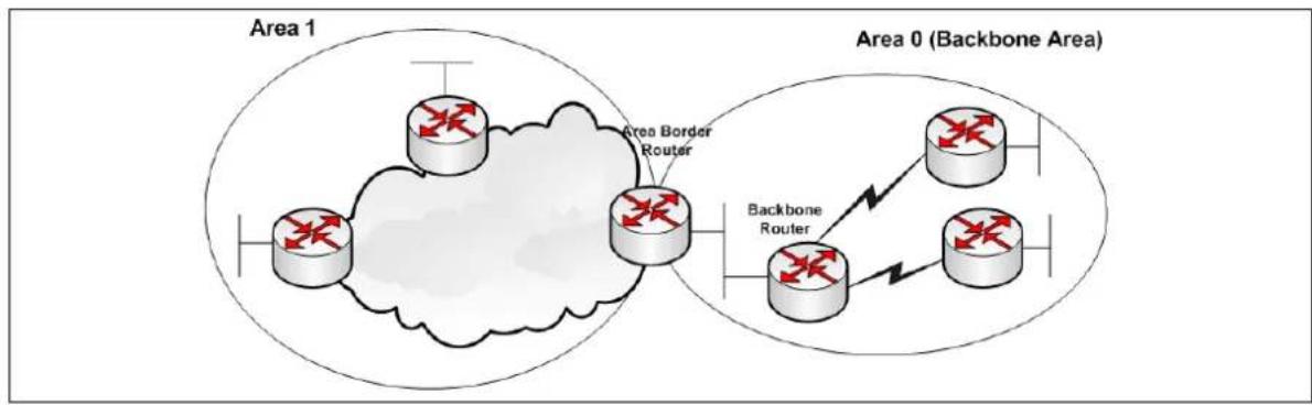
flowchart
graph TD
    subgraph Area 0 (Backbone Area)
        A["Router"] --> B["Router"]
        B --> C["Router"]
        C --> D["Router"]
        D --> E["Router"]
        E --> F["Router"]
        F --> G["Router"]
    end
    subgraph Area 1
        H["Router"] --> I["Router"]
        I --> J["Router"]
        J --> K["Router"]
        K --> L["Router"]
        L --> M["Router"]
        M --> N["Router"]
        N --> O["Router"]
        O --> P["Router"]
        P --> Q["Router"]
        Q --> R["Router"]
        R --> S["Router"]
        S --> T["Router"]
        T --> U["Router"]
        U --> V["Router"]
        V --> W["Router"]
        W --> X["Router"]
        X --> Y["Router"]
        Y --> Z["Router"]
        Z --> A
    end
    style Area 0 fill:#f9f,stroke:#333
    style Area 1 fill:#ccf,stroke:#333
    style Area 2 fill:#cfc,stroke:#333
    style Area 3 fill:#fcc,stroke:#333
    style Area 4 fill:#cff,stroke:#333
    style Area 5 fill:#ffc,stroke:#333
    style Area 6 fill:#cfc,stroke:#333
    style Area 7 fill:#fcc,stroke:#333
    style Area 8 fill:#ffc,stroke:#333
    style Area 9 fill:#cfc,stroke:#333
    style Area 10 fill:#fcc,stroke:#333
    style Area 11 fill:#cfc,stroke:#333
    style Area 12 fill:#fcc,stroke:#333
    style Area 13 fill:#cfc,stroke:#333
    style Area 14 fill:#fcc,stroke:#333
    style Area 15 fill:#cfc,stroke:#333
    style Area 16 fill:#fcc,stroke:#333
    style Area 17 fill:#cfc,stroke:#333
    style Area 18 fill:#fcc,stroke:#333
    style Area 19 fill:#cfc,stroke:#333
    style Area 20 fill:#fcc,stroke:#333
Figure 89: OSPF areas
OSPF has a number of features that allow it to scale well for larger networks. One of these features is OSPF areas. OSPF areas break up the topology so that routers in one area know less topology information about the subnets in the other area, and they do not know anything about the routers in the other area at all. With smaller topology databases, routers consume less memory and take less processing time to run SPF.
The Area Border Router (ABR) is the border between two areas. The ABR does not advertise full topology information about the part of the network in area 0 to routers in area 1. Instead the ABR advertises summary information about the subnets in area 0. Area 1 will just see a number of subnets reachable via area 0.
20.1.2 OSPF neighbours
OSPF forms neighbour relationships, called adjacencies, with other routers in the same Area by exchanging 'Hello' packets to multicast address 224.0.0.5. Only after an adjacency is formed can routers share routing information.
Each OSPF router is identified by a unique router ID. The router ID can be determined in one of three ways:
• The router ID can be manually specified.
- If not manually specified, the highest IP address configured on any Loopback interface on the router will become the router ID.
- If no loopback interface exists, the highest IP address configured on any physical interface will become the router ID.
By default, Hello packets are sent out OSPF-enabled interfaces every 10 seconds for broadcast and point-to-point interfaces, and 30 seconds for non-broadcast and point-to-multipoint interfaces.
OSPF also has a 'Dead Interval', which indicates how long a router will wait without hearing any hellos before announcing a neighbour as 'down'. The default setting for the Dead Interval is 40 seconds for broadcast and point-to-point interfaces, and 120 seconds for non-broadcast and point-to-multipoint interfaces. By default, the Dead Interval timer is four times the Hello interval.
OSPF routers will only become neighbours if the following parameters within a Hello packet are identical on each router:
- Area ID
• Area Type (stub, NSSA, etc.) - Prefix
- Subnet Mask
- Hello Interval
- Dead Interval
• Network Type (broadcast, point-to-point, etc.) - Authentication
The Hello packets also serve as keepalives to allow routers to quickly discover if a neighbour is down. Hello packets also contain a neighbour field that lists the router IDs of all neighbours the router is connected to. A neighbour table is constructed from the OSPF Hello packets, which includes the following information:
• The router ID of each neighbouring router
- The current ‘state’ of each neighbouring router
• The interface directly connecting to each neighbour
• The IP address of the remote interface of each neighbour
20.1.3 OSPF designated routers
In multi-access networks such as Ethernet, there is the possibility of many neighbour relationships on the same physical segment. This leads to a considerable amount of unnecessary Link State Advertisement (LSA) traffic. If a link of a router were to fail, it would flood this information to all neighbours. Each neighbour, in turn, would then flood that same information to all other neighbours. This is a waste of bandwidth and processor load.
To prevent this, OSPF will elect a Designated Router (DR) for each multi-access networks, accessed via multicast address 224.0.0.6. For redundancy purposes, a Backup Designated Router (BDR) is also elected.
OSPF routers will form adjacencies with the DR and BDR. If a change occurs to a link, the update is forwarded only to the DR, which then forwards it to all other routers. This greatly reduces the flooding of LSAs. DR and BDR elections are determined by a router's OSPF priority, which is configured on a per-interface basis (a router can have interfaces in multiple multi-access networks). The router with the highest priority becomes the DR; second highest becomes the BDR. If there is a tie in priority, whichever router has the highest Router ID will become the DR.
20.1.4 OSPF neighbour states
Neighbour adjacencies will progress through several states, described in the table below.
| State | Description | |
| Down | Indicates that no Hellos have been heard from the neighbouring router | |
| Init | Indicates a Hello packet has been heard from the neighbour, but two-way communication has not yet been initialized. | |
| 2-Way | Indicates that bidirectional communication has been established. Recall that Hello packets contain a neighbour field. Thus, communication is considered 2-Way once a router sees its own Router ID in its neighbour's Hello Packet. Designated and Backup Designated Routers are elected at this stage. | |
| ExStart | Indicates that the routers are preparing to share link state information. Master/slave relationships are formed between routers to determine who will begin the exchange. | |
| Exchange | Indicates that the routers are exchanging Database Descriptors (DBDs). DBDs contain a description of the router's Topology Database. A router will examine a neighbour's DBD to determine if it has information to share. | |
| Loading | Indicates the routers are finally exchanging Link State Advertisements, containing information about all links connected to each router. Essentially, routers are sharing their topology tables with each other. | |
| Full | Indicates that the routers are fully synchronized. The topology table of all routers in the area should now be identical. Depending on the role of the neighbour, the state may appear as: | |
| Full/DR | Indicating that the neighbour is a Designated Router (DR) | |
| Full/BDR | Indicating that the neighbour is a Backup Designated Router (BDR) | |
| Full/DROther | Indicating that the neighbour is neither the DR nor BDR. On a multi-access network, OSPF routers will only form Full adjacencies with DRs and BDRs. Non-DRs and non-BDRs will still form adjacencies, but will remain in a 2-Way State. This is normal OSPF behaviour. | |
Table 55: Neighbour adjacency states
20.1.5 OSPF network types
OSPF's functionality is different across several different network topology types.
| State | Description |
| Broadcast Multi-Access | Indicates a topology where broadcast occurs. Examples include Ethernet, Token Ring and ATM. OSPF characteristics are:OSPF will elect DRs and BDRsTraffic to DRs and BDRs is multicast to 224.0.0.6. Traffic from DRs and BDRs to other routers is multicast to 224.0.0.5Neighbours do not need to be manually specified. |
| Point-to-Point | Indicates a topology where two routers are directly connected. An example would be a point-to-point T1. OSPF characteristics are:OSPF will not elect DRs and BDRsAll OSPF traffic is multicast to 224.0.0.5Neighbours do not need to be manually specified |
| Point-to-Multipoint | Indicates a topology where one interface can connect to multiple destinations. Each connection between a source and destination is treated as a point-to-point link. An example would be point to Point-to-Multipoint Frame Relay. OSPF characteristics are:OSPF will not elect DRs and BDRs.All OSPF traffic is multicast to 224.0.0.5.Neighbours do not need to be manually specified. |
| Non-broadcast Multi-access Network (NBMA) | Indicates a topology where one interface can connect to multiple destinations; however, broadcasts cannot be sent across a NBMA network. An example would be Frame Relay. OSPF characteristics are:OSPF will elect DRs and BDRs.OSPF neighbours must be manually defined, so all OSPF traffic is unicast instead of multicast.Note: on non-broadcast networks, neighbours must be manually specified, as multicast Hello's are not allowed |
Table 56: OSPF functionality over different topology types
20.1.6 The OSPF hierarchy
OSPF is a hierarchical system that separates an autonomous system into individual areas. OSPF traffic can either be:
• intra-area (within one area),
• inter-area (between separate areas), or
• external (from another AS).
OSPF routers build a topology database of all links within their area, and all routers within an area will have an identical topology database. Routing updates between these routers will only contain information about links local to their area. Limiting the topology database to include only the local area conserves bandwidth and reduces CPU loads.
Area 0 is required for OSPF to function, and is considered the backbone area. As a rule, all other areas must have a connection into area 0, though this rule can be bypassed using virtual links. Area 0 is often referred to as the transit area to connect all other areas.
OSPF routers can belong to multiple areas, and therefore contain separate topology databases or each area. These routers are known as Area Border Routers (ABRs).
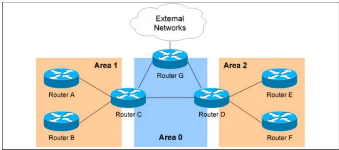
flowchart
graph TD
    External_Networks["External Networks"] --> Router_G["Router G"]
    Router_G --> Router_C["Router C"]
    Router_G --> Router_D["Router D"]
    Router_C --> Router_A["Router A"]
    Router_C --> Router_B["Router B"]
    Router_C --> Router_C
    Router_D --> Router_E["Router E"]
    Router_D --> Router_F["Router F"]
    Router_C --> Area_0["Area 0"]
    Router_D --> Area_0
    Router_C --> Area_1["Area 1"]
    Router_D --> Area_2["Area 2"]
Figure 90: OSPF hierarchy
In the above example three areas exist: Area 0, Area 1, and Area 2.
Area 0 is the backbone area for this autonomous system.
Both Area 1 and Area 2 must directly connect to Area 0. Routers A and B belong fully to Area 1, while Routers E and F belong fully to Area 2. These are known as Internal Routers.
Router C belongs to both Area 0 and Area 1; so it is an ABR. Because it has an interface in Area 0, it can also be considered a Backbone Router (BR). The same can be said for Router D, as it belongs to both Area 0 and Area 2.
Router G also belongs to Area 0 however it also has a connection to the internet, which is outside this autonomous system. This makes Router G an Autonomous System Border Router (ASBR).
A router can become an ASBR in one of two ways:
- By connecting to a separate Autonomous System, such as the internet
- By redistributing another routing protocol into the OSPF process.
ASBRs provide access to external networks. OSPF defines two types of external routes, as shown in the table below.
| Type 2 (E2) | Includes only the external cost to the destination network. External cost is the metric being advertised from outside the OSPF domain. This is the default type assigned to external routes. |
| Type 1 (E1) | Includes both the external cost, and the internal cost to reach the ASBR, to determine the total metric to reach the destination network. Type 1 routes are always preferred over Type 2 routes to the same destination. |
Table 57: Types of external routes
20.1.7 OSPF router types
The four separate OSPF router types are shown in the table below.
| Route Type | Description |
| Internal Router | All router interfaces belong to only one area. |
| Area Border Router (ABR) | Have interfaces in at least two separate areas. |
| Backbone Router | Have at least one interface in area 0. |
| Autonomous SystemBorder Router (ABR) | Have a connection to a separate autonomous system. |
20.2 Configuration package used
| Package | Sections |
| ospfd routing | networkinterface |
20.3 Configuring OSPF using the web interface
Select Network -> OSPF. The OSPF page appears.
There are three sections in the OSPF page:
| Section | Description |
| Global Settings | Enables OSPF and configures the OSPF routing section containing global configuration parameters. The web automatically names the routing section ospfd |
| Topology Configuration | Configures the network sections. |
| Interfaces Configuration | Configures the interface sections. Defines interface configuration for OSPF and interface specific parameters |
20.3.1 Global settings
The Global Settings section configures the ospfd routing section. The web automatically names the routing section 'ospfd'.
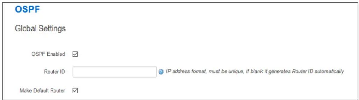
text_image
OSPF Global Settings OSPF Enabled ✓ Router ID IP address format, must be unique, if blank it generates Router ID automatically Make Default Router ✓Figure 91: The OSPF global settings configuration page
| Web Field/ UCI / Package Option | Description | |
| Web: OSPF EnabledUCI: ospfd.ospfd.enabledOpt: enabled | Enables OSPF advertisements on router. | |
| 0 | Disabled. | |
| 1 | Enabled. | |
| Web: Router IDUCI: ospfd.ospfd.router_idOpt: router_id | This sets the Router ID of the OSPF process. The Router ID may be an IP address of the router, but need not be - it can be any arbitrary 32bit number. However it MUST be unique within the entire OSPF domain to the OSPF speaker. If one is not specified, then ospfd will obtain a router-ID automatically from the zebra daemon. | |
| Empty | ||
| Range | ||
| Web: Make Default RouterUCI: ospfd.ospfd.default_info_originateOpt: default_info_originate | Defines whether to originate an AS-External (type-5) LSA describing a default route into all external-routing capable areas, of the specified metric and metric type. | |
| 0 | Disabled. | |
| 1 | Enabled. | |
| Web: n/aUCI: ospfd.ospfd.vty_enabledOpt: vty_enabled | Enable vty for OSPFd (telnet to localhost:2604) | |
Table 58: Information table for OSPF global settings
20.3.2 Topology configuration
The Topology section configures the ospfd network section. This section specifies the OSPF enabled interface(s). The router can provide network information to the other OSPF routers via this interface.
Note: to advertise OSPF on an interface, the network mask prefix length for the topology configuration statement for the desired interface advertisement must be equal or smaller (IE. larger network) than the network mask prefix length for the interface.
For example, the topology configuration statement in the screenshot below does not enable OSPF on an interface with address 12.1.1.1/23, but it would on an interface with address 12.1.1.129/25.
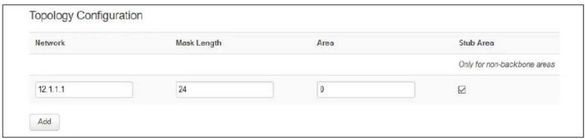
text_image
Topology Configuration Network Mask Length Area Stub Area Only for non-backbone areas 12.1.1.1 24 0 ✓ AddFigure 92: The OSPF topology configuration page
| Web Field/ UCI / Package Option | Description | |
| Web: NetworkUCI: ospfd.@network[0].ip_addrOpt: ip_addr | Specify the IP address for OSPF enabled interface.Format: A.B.C.D | |
| Web: Mask LengthUCI: ospfd.@network[0].mask_lengthOpt: mask_length | Specify the mask length for OSPF enabled interface. The mask length should be entered in CIDR notation. | |
| Web: AreaUCI: ospfd.@network[0].areaOpt: area | Specify the area number for OSPF enabled interface. | |
| Web: Stub AreaUCI: ospfd.@network[0].stub_areaOpt: stub_area | Only for non-backbone areas.Configure the area to be a stub area. That is, an area where no router originates routes external to OSPF and hence an area where all external routes are via the ABR(s).ABRs for such an area do not need to pass AS-External LSAs (type-5s) or ASBR-Summary LSAs (type-4) into the area. They need only pass Network-Summary (type-3) LSAs into such an area, along with a default-route summary. | |
| 0 | Disabled. | |
| 1 | Enabled. | |
Table 59: Information table for OSPF topology configuration
20.3.3 Interfaces configuration
The Interfaces section contains settings to configure the OSPF interface. It defines interface configuration for OSPF and interface specific parameters.
OSPFv2 allows packets to be authenticated using either an insecure plain text password, included with the packet, or by a more secure MD5 based HMAC (keyed-Hashing for Message Authentication). Enabling authentication prevents routes being updated by
unauthenticated remote routers, but still can allow routes, that is, the entire OSPF routing table, to be queried remotely, potentially by anyone on the internet, via OSPFv1.
This section defines key_chains to be used for MD5 authentication.
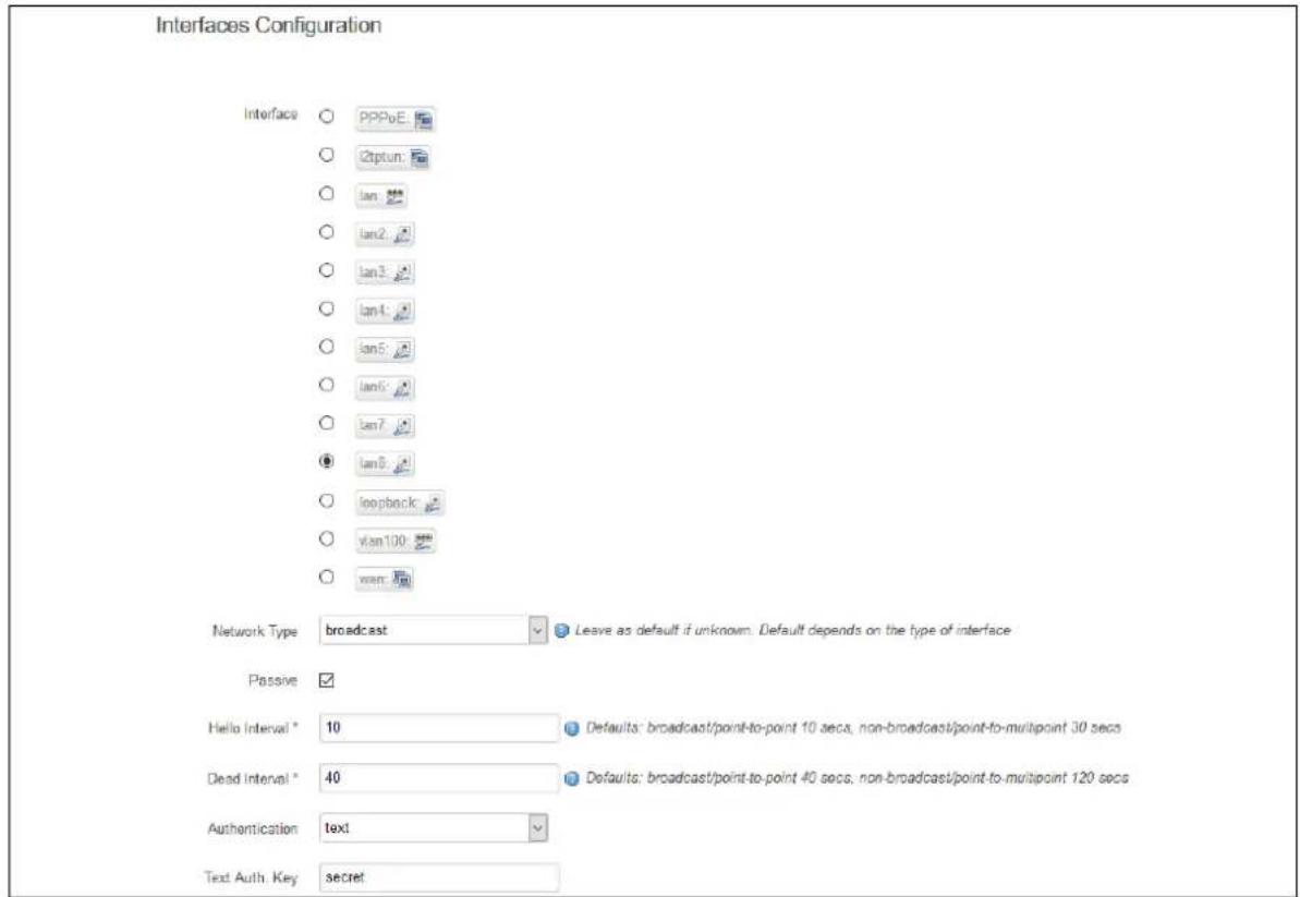
text_image
Interfaces Configuration Interface ○ PPPoE ○ 2ptun: ○ Ian ○ Ian2: ○ Ian3: ○ Ian4: ○ Ian5: ○ Ian6: ○ Ian7: ● Ian8: ○ loopback: ○ vlan100: ○ wan: Network Type broadcast Leave as default if unknown. Default depends on the type of interface Passive ✓ Hello Interval * 10 Defaults: broadcast/point-to-point 10 secs, non-broadcast/point-to-multipoint 30 secs Dead Interval * 40 Defaults: broadcast/point-to-point 40 secs, non-broadcast/point-to-multipoint 120 secs Authentication text Text Auth Key secretFigure 93: The OSPF interfaces configuration section
| Web Field/ UCI / Package Option | Description | |
| Web: InterfaceUCI: ospfd.@interface[0].ospf_interfaceOpt: ospf_interface | Defines the interface name | |
| Web: Network TypeUCI: ospfd.@interface[0].network_typeOpt: network_type | Defines network type for specified interface. | |
| Default Autodetect: it | will be broadcast. Ifbroadcast is not supported on thatinterface then use point-to-point. | |
| broadcast | ||
| non-broadcast | ||
| point-to-point | ||
| point-to-multipoint | ||
| Web: PassiveUCI: ospfd.@interface[0].passiveOpt: passive | Do not send hello packets on the given interface, but doadvertise the interface as a stub link in the router-LSA (LinkState Advertisement) for this router.This allows you to advertise addresses on such connectedinterfaces without having to originate AS-External/Type-5 LSAs,which have global flooding scope, as would occur if connectedaddresses were redistributed into OSPF. This is the only way toadvertise non-OSPF links into stub areas. | |
| 0 | Disabled. | |
| 1 | Enabled. | |
| Web: Hello IntervalUCI: ospfd.@interface[0].hello_intervalOpt: hello_interval | Defines the number of seconds for the Hello Interval timer value.A Hello packet will be sent every timer value seconds on the specified interface. This value must be the same for all routers attached to a common network.The default is every 10 seconds for broadcast and point-to-point interfaces, and 30 seconds for non-broadcast and point-to-multipoint interfaces. | ||
| 10 | 10 seconds | ||
| Range | |||
| Web: Dead IntervalUCI: ospfd.@interface[0].dead_intervalOpt: dead_interval | Defines the number of seconds for the Dead Interval timer value used for Wait Timer and Inactivity Timer. This value must be the same for all routers attached to a common network.The default is 40 seconds for broadcast and point-to-point interfaces, and 120 seconds for non-broadcast and point-to-multipoint interfaces. By default, the Dead Interval timer is four times the Hello interval. | ||
| 40 | 40 seconds | ||
| Range | |||
| Web: AuthenticationUCI: ospfd.@interface[0].auth_modeOpt: auth_mode | OSPFv2 (only) allows packets to be authenticated via either an insecure plain text password, included with the packet, or via a more secure MD5 based HMAC (keyed-Hashing for Message AuthentiCation). Enabling authentication prevents routes being updated by unauthenticated remote routers, but still can allow routes, that is, the entire OSPF routing table to be queried remotely, potentially by anyone on the internet, via OSPFv1. | ||
| no | Default value. No authentication. | ||
| md5 | Set the interface with OSPF MD5 authentication. | ||
| text Set the interface with OSPF simple password authentication. | |||
| Web: Text Auth. KeyUCI: ospfd.@interface[0].text_auth_keyOpt: text_auth_key | This command sets authentication string for text authentication. text_auth_key option can have length up to 8 characters. Displayed only when Authentication is set to text. | ||
| Web: Key IDUCI: ospfd.@interface[0].key_idOpt: key_id | Specifies key ID. Must be unique and match at both ends. Displayed only when Authentication is set to MD5. | ||
| Web: MD5 Auth. KeyUCI: ospfd.@interface[0].md5_auth_keyOpt: md5_auth_key | Specify Keyed MD5 chain. Displayed only when Authentication is set to MD5. | ||
Table 60: Information table for OSPF interface commands
20.4 Configuring OSPF using the command line
OSPF is configured under the ospfd package /etc/config/ospfd.
There are three config sections: ospfd, interface and network.
You can configure multiple interface and network sections.
By default, all OSPF interface instances are named interface, instances are identified by @interface then the interface position in the package as a number. For example, for the first interface in the package using UCI:
ospfd.@interface[0]=interface
ospfd.@interface[0].ospf_interface=lan
Or using package options:
config interface option ospf_interface 'lan'
By default, all OSPF network instances are named network, it is identified by @network then the interface position in the package as a number. For example, for the first network in the package using UCI:
ospfd.@network[0]=network
ospfd.@network[0].ip_addr=12.1.1.1
Or using package options:
config network
option ip_addr '12.1.1.1'
20.5 OSPF using UCI
root@VA_router:~# uci show ospfd
ospfd.ospfd=routing
ospfd.ospfd.enabled=yes
ospfd.ospfd.default_info_originate=yes
ospfd.ospfd.router_id=1.2.3.4
ospfd.@network[0]=network
ospfd.@network[0].ip_addr=12.1.1.1
ospfd.@network[0].mask_length=24
ospfd.@network[0].area=0
ospfd.@network[0].stub_area=yes
ospfd.@interface[0]=interface
ospfd.@interface[0].ospf_interface=lan8
ospfd.@interface[0].hello_interval=10
ospfd.@interface[0].dead_interval=40
ospfd.@interface[0].network_type=broadcast
ospfd.@interface[0].passive=yes
ospfd.@interface[0].auth_mode=text
ospfd.@interface[0].text_auth_key=secret
ospfd.@interface[1]=interface
ospfd.@interface[1].ospf_interface=lan7
ospfd.@interface[1].network_type=point-to-point
ospfd.@interface[1].passive=no
ospfd.@interface[1].hello_interval=30
ospfd.@interface[1].dead_interval=120
ospfd.@interface[1].auth_mode=md5
ospfd.@interface[1].key_id=1
ospfd.@interface[1].md5_auth_key=test
20.6 OSPF using package options
root@VA_router:~# uci export ospfd
package ospfd

config routing 'ospfd'
    option enabled 'yes'
    option default_info_originate 'yes'
    option router_id '1.2.3.4'

config network
    option ip_addr '12.1.1.1'
    option mask_length '24'
    option area '0'
    option stub_area 'yes'

config interface
    option ospf_interface 'lan8'
    option hello_interval '10'
    option dead_interval '40'
    option network_type 'broadcast'
    option passive 'yes'
    option auth_mode 'text'
    option text_auth_key 'secret'

config interface
    option ospf_interface 'lan7'
    option network_type 'point-to-point'
    option passive 'no'
    option hello_interval '30'
    option dead_interval '120'
option auth_mode 'md5'
option key_id '1'
option md5_auth_key 'test'
20.7 OSPF diagnostics
20.7.1 Route status
To show the current routing status, enter:
| root@VA_router:~# route -n | ||||||
| Kernel IP routing table | ||||||
| Destination | Gateway | Genmask | Flags | Metric | Ref | Use Iface |
| 0.0.0.0 | 10.206.4.65 | 0.0.0.0 | UG | 1 | 0 | 0 usb0 |
| 10.1.0.0 | 0.0.0.0 | 255.255.0.0 | U | 0 | 0 | 0 eth1 |
| 10.206.4.64 | 0.0.0.0 | 255.255.255.252 | U | 0 | 0 | 0 usb0 |
| 11.11.11.0 | 0.0.0.0 | 255.255.255.248 | U | 0 | 0 | 0 gre- |
| GRE | ||||||
| 89.101.154.151 | 10.206.4.65 | 255.255.255.255 | UGH | 0 | 0 | 0 usb0 |
| 192.168.100.0 | 0.0.0.0 | 255.255.255.0 | U | 0 | 0 | 0 eth0 |
| 192.168.101.1 | 11.11.11.1 | 255.255.255.255 | UGH | 11 | 0 | 0 gre- |
| GRE | ||||||
| 192.168.104.1 | 11.11.11.4 | 255.255.255.255 | UGH | 20 | 0 | 0 gre- |
| GRE | ||||||
Note: a route will only be displayed in the routing table when the interface is up.
20.7.2 Tracing OSPF packets
Typically, OSPF uses IP as its transport protocol. The well-known IP protocol type for OSPF traffic is 0x59. To trace OSPF packets on any interface on the router, enter: tcpdump -i any -n proto ospf &
root@VA_router:~# tcpdump -i any -n proto ospf &
root@VA_router:~# tcpdump: verbose output suppressed, use -v or -vv for full protocol decode
listening on any, link-type LINUX_SLL (Linux cooked), capture size 65535 bytes
To stop tracing enter fg to bring tracing task to foreground, and then
root@VA_router:~# fg
tcpdump -i any -n proto ospf
^C
33 packets captured
33 packets received by filter
0 packets dropped by kernel
20.8 Quagga/ Zebra console
Quagga is the routing protocol suite embedded in the router firmware. Quagga is split into different daemons for implementation of each routing protocol. Zebra is a core daemon for Quagga, providing the communication layer to the underlying Linux kernel, and routing updates to the client daemons.
Quagga has a console interface to Zebra for advanced debugging of the routing protocols.
To access, enter:
root@VA_router:~# telnet localhost zebra
Entering character mode
Escape character is '^]'.
Hello, this is Quagga (version 0.99.21).
Copyright 1996-2005 Kunihiro Ishiguro, et al.
User Access Verification
Password:
To see OSPF routing from Zebra console, enter:
root@VA_router:~# sh ip route
Codes: K - kernel route, C - connected, S - static, R - RIP,
O - OSPF, I - IS-IS, B - BGP, P - PIM, H - HSLS, o - OLSR,
b - BATMAN, A - Babel,
> - selected route, * - FIB route
K>* 0.0.0.0/0 via 10.206.4.65, usb0
O 10.1.0.0/16 [110/11] via 11.11.11.1, gre-GRE, 02:35:28
C>* 10.1.0.0/16 is directly connected, eth1
C>* 10.206.4.64/30 is directly connected, usb0
O 11.11.11.0/29 [110/10] is directly connected, gre-GRE, 02:35:29
C>* 11.11.11.0/29 is directly connected, gre-GRE
K>* 89.101.154.151/32 via 10.206.4.65, usb0
C>* 127.0.0.0/8 is directly connected, lo
C>* 192.168.100.0/24 is directly connected, eth0
O>* 192.168.101.1/32 [110/11] via 11.11.11.1, gre-GRE, 02:35:28
O>* 192.168.104.1/32 [110/20] via 11.11.11.4, gre-GRE, 02:30:45
O 192.168.105.1/32 [110/10] is directly connected, lo, 02:47:52
C>* 192.168.105.1/32 is directly connected, lo
20.8.1 OSPF debug console
When option tty_enabled (see Global settings section above) is enabled in the OSPF configuration, OSPF debug console can be accessed for advanced OSPF debugging.
To access OSPF debug console enter: telnet localhost ospfd (password zebra)
root@VA_router:~# telnet localhost ospfd
Entering character mode
Escape character is '^]'.
Hello, this is Quagga (version 0.99.21).
Copyright 1996-2005 Kunihiro Ishiguro, et al.
User Access Verification
Password:
To see OSPF routing from OSPF debug console, enter: sh ip ospf route
UUT> sh ip ospf route
==================== OSPF network routing table ===================
N 10.1.0.0/16 [11] area: 0.0.0.0
via 11.11.11.1, gre-GRE
N 11.11.11.0/29 [10] area: 0.0.0.0
directly attached to gre-GRE
N 192.168.101.1/32 [11] area: 0.0.0.0
via 11.11.11.1, gre-GRE
N 192.168.104.1/32 [20] area: 0.0.0.0
via 11.11.11.4, gre-GRE
N 192.168.105.1/32 [10] area: 0.0.0.0
directly attached to lo
================ O SPF router routing table ====================
================ OSPF external routing table ====================
To see OSPF neighbours from OSPF debug console, enter: sh ip ospf neighbour
root@VA_router:~# sh ip ospf neighbor
Neighbor ID Pri State Dead Time Address Interface RXmtL RqstL DBsmL
1.1.1.1 255 Full/DR 33.961s 11.11.11.1 gre-GRE:11.11.11.5
0 0 0
To see OSPF interface details from OSPF debug console, enter: sh ip ospf interface
root@VA_router:~# sh ip ospf interface
base0 is up
ifindex 8, MTU 1518 bytes, BW 0 Kbit <UP,BROADCAST,RUNNING,MULTICAST>
OSPF not enabled on this interface
eth0 is up
ifindex 9, MTU 1500 bytes, BW 0 Kbit <UP,BROADCAST,RUNNING,MULTICAST>
OSPF not enabled on this interface
eth1 is up
ifindex 10, MTU 1500 bytes, BW 0 Kbit
<UP,BROADCAST,RUNNING,PROMISC,MULTICAST>
OSPF not enabled on this interface
eth2 is down
ifindex 11, MTU 1500 bytes, BW 0 Kbit <BROADCAST,MULTICAST>
OSPF not enabled on this interface
eth3 is down
ifindex 12, MTU 1500 bytes, BW 0 Kbit <BROADCAST,MULTICAST>
OSPF not enabled on this interface
eth4 is down
ifindex 13, MTU 1500 bytes, BW 0 Kbit <BROADCAST,MULTICAST>
OSPF not enabled on this interface
eth5 is down
ifindex 14, MTU 1500 bytes, BW 0 Kbit <BROADCAST,MULTICAST>
OSPF not enabled on this interface
eth6 is down
ifindex 15, MTU 1500 bytes, BW 0 Kbit <BROADCAST,MULTICAST>
OSPF not enabled on this interface
eth7 is down
ifindex 16, MTU 1500 bytes, BW 0 Kbit <BROADCAST,MULTICAST>
OSPF not enabled on this interface
gre-GRE is up
ifindex 19, MTU 1472 bytes, BW 0 Kbit <UP,RUNNING,MULTICAST>
Internet Address 11.11.11.5/29, Area 0.0.0.0
MTU mismatch detection:enabled
Router ID 192.168.105.1, Network Type BROADCAST, Cost: 10
Transmit Delay is 1 sec, State Backup, Priority 1
Designated Router (ID) 1.1.1.1, Interface Address 11.11.11.1
Backup Designated Router (ID) 192.168.105.1, Interface Address 11.11.11.5
Multicast group memberships: OSPFAllRouters OSPFDesignatedRouters
Timer intervals configured, Hello 10s, Dead 40s, Wait 40s, Retransmit 5
Hello due in 3.334s
Neighbor Count is 1, Adjacent neighbor count is 1
gre0 is down
ifindex 6, MTU 1476 bytes, BW 0 Kbit <NOARP>
OSPF not enabled on this interface
ifb0 is down
ifindex 2, MTU 1500 bytes, BW 0 Kbit <BROADCAST,NOARP>
OSPF not enabled on this interface
ifb1 is down
ifindex 3, MTU 1500 bytes, BW 0 Kbit <BROADCAST,NOARP>
OSPF not enabled on this interface
lo is up
ifindex 1, MTU 16436 bytes, BW 0 Kbit <UP,LOOPBACK,RUNNING>
Internet Address 192.168.105.1/32, Broadcast 192.168.105.1, Area 0.0.0.0
MTU mismatch detection:enabled
Router ID 192.168.105.1, Network Type LOOPBACK, Cost: 10
Transmit Delay is 1 sec, State Loopback, Priority 1
No designated router on this network
No backup designated router on this network
Multicast group memberships: <None>
Timer intervals configured, Hello 10s, Dead 40s, Wait 40s, Retransmit 5
Hello due in inactive
Neighbor Count is 0, Adjacent neighbor count is 0
sit0 is down
ifindex 7, MTU 1480 bytes, BW 0 Kbit <NOARP>
OSPF not enabled on this interface
teql0 is down
ifindex 4, MTU 1500 bytes, BW 0 Kbit <NOARP>
OSPF not enabled on this interface
tunl0 is down
ifindex 5, MTU 1480 bytes, BW 0 Kbit <NOARP>
OSPF not enabled on this interface
usb0 is up
ifindex 17, MTU 1500 bytes, BW 0 Kbit <UP,BROADCAST,RUNNING,MULTICAST>
OSPF not enabled on this interface
To see OSPF database details from OSPF debug console, enter: sh ip ospf database
root@VA_router:~# sh ip ospf database
OSPF Router with ID (192.168.105.1)
Router Link States (Area 0.0.0.0)
Link ID ADV Router Age Seq# CkSum Link count
1.1.1.1 1.1.1.1 873 0x80006236 0xd591 3
192.168.104.1 192.168.104.1 596 0x8000000a 0x3a2d 2
192.168.105.1 192.168.105.1 879 0x8000000b 0x4919 2
Net Link States (Area 0.0.0.0)
Link ID ADV Router Age Seq# CkSum
11.11.11.1 1.1.1.1 595 0x80000004 0x5712
21 Configuring VRRP
21.1 Overview
Virtual Router Redundancy Protocol (VRRP) is a networking protocol designed to eliminate the single point of failure inherent in the static default routed environment.
VRRP specifies an election protocol that dynamically assigns responsibility for a virtual router to one of the VRRP routers on a LAN. The VRRP router controlling the IP address(es) associated with a virtual router is called the Master, and forwards packets sent to these IP addresses. The election process provides dynamic failover in the forwarding responsibility from the Master to a backup router should the Master become unavailable. This process allows the virtual router IP address(es) on the LAN to be used as the default first hop router by end hosts. The advantage gained from using VRRP is a higher availability default path without requiring configuration of dynamic routing or router discovery protocols on every end host.
Two or more routers forming the redundancy cluster are configured with the same Router ID and Virtual IP address. A VRRP router group operates within the scope of the single LAN. Additionally, the VRRP routers are configured with its initial role (Master or Backup) and the router priority, which is a factor in the master router election process. You can also configure a password authentication to protect VRRP protocol messages against spoofing.
The VRRP protocol is implemented according to internet standard RFC2338.
21.2 Configuration package used
| Package | Sections |
| vrrp main | vrrp_group |
21.3 Configuring VRRP using the web interface
To configure VRRP through the web interface, in the top menu, select Network ->VRRP. The VRRP page appears.
There are two sections in the VRRP page:
| Section | Description |
| Global Settings | Enables VRRP |
| VRRP Group Configuration | Configures the VRRP group settings. |
21.3.1 Global settings
The Global Settings section configures vrrp package main section.
To access configuration settings, click ADD.

text_image
VRRP Global Settings VRRP EnabledFigure 94: The VRRP global settings configuration page
| Web Field/ UCI / Package Option | Description | |
| Web: VRRP EnabledUCI: vrrp.main.enabledOpt: Enabled | Globally enables VRRP on the router. | |
| 0 | Disabled. | |
| 1 | Enabled. | |
21.3.2 VRRP group configuration settings
The VRRP Group Configuration section configures vrrp package vrrp_group section. To access configuration settings, click ADD.
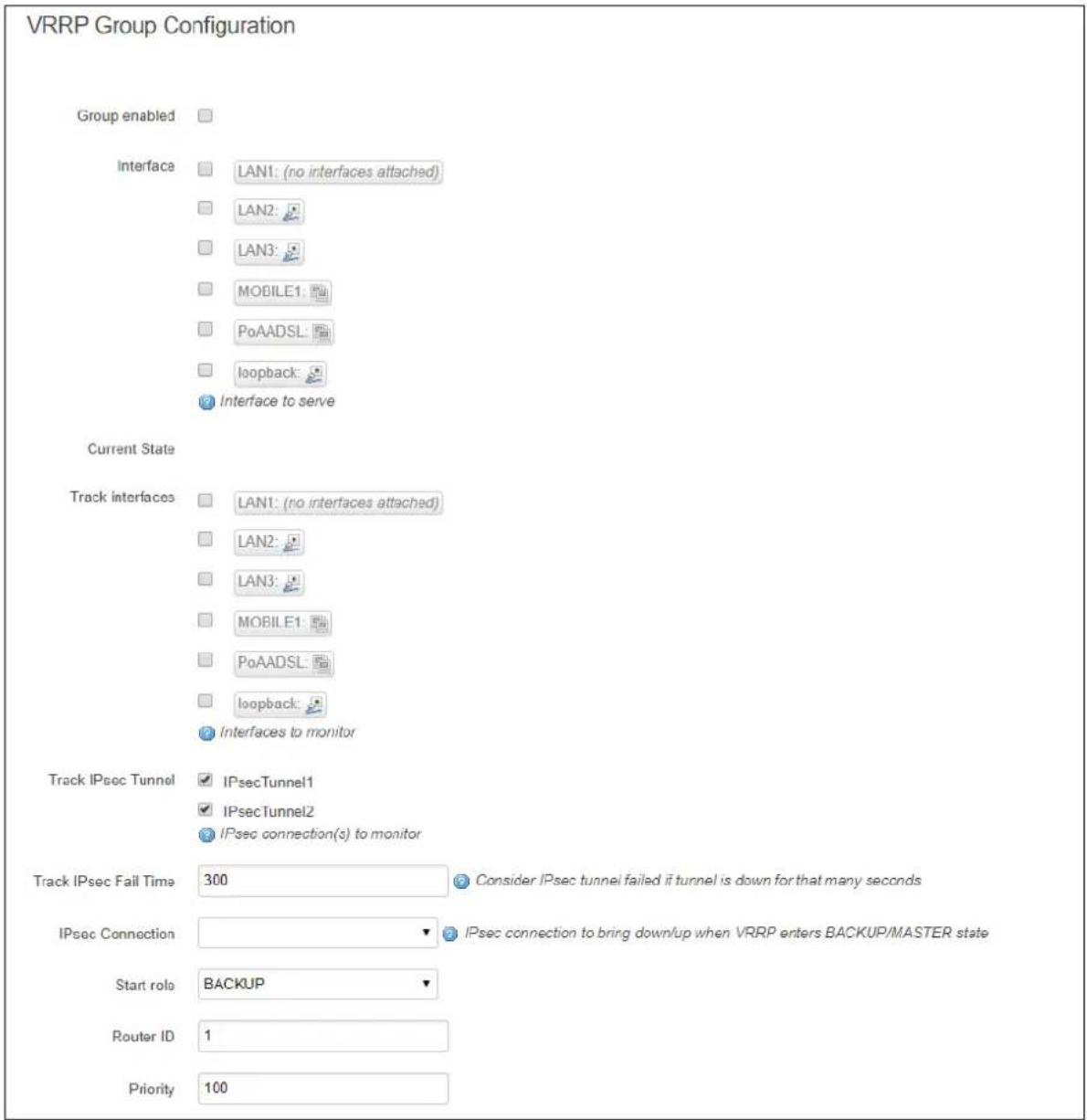
text_image
VRRP Group Configuration Group enabled Interface LAN1: (no interfaces attached) LAN2: LAN3: MOBILE1: PoAADSL: loopback: Interface to serve Current State Track interfaces LAN1: (no interfaces attached) LAN2: LAN3: MOBILE1: PoAADSL: loopback: Interfaces to monitor Track IPsec Tunnel IPsecTunnel1 IPsecTunnel2 IPsec connection(s) to monitor Track IPsec Fail Time 300 Consider IPsec tunnel failed if tunnel is down for that many seconds IPsec Connection IPsec connection to bring down/up when VRRP enters BACKUP/MASTER state Start role BACKUP Router ID 1 Priority 100Figure 95: The VRRP group configuration page
| Web Field/ UCI / Package Option | Description | |
| Web: Group EnabledUCI: vrrp.@vrrp_group[X].enabledOpt: Enabled | Enables a VRRP group on the router. | |
| 0 | Disabled. | |
| 1 | Enabled. | |
| Web: InterfaceUCI: vrrp.@vrrp_group[X].interfaceOpt: interface | Sets the local LAN interface name in which the VRRP cluster is to operate. For example, 'lan'. The interface name is taken from the network package and all configured interfaces will be displayed.. | |
| lan | ||
| Range | ||
| Web: Track InterfacesUCI: vrrp.@vrrp_group[X].track_ifaceOpt: list track_iface | Defines one or more WAN interfaces that VRRP should monitor. If a monitored interface goes down on the Master VRRP router, it goes into 'Fault' state and the Backup VRRP router becomes the Master.Multiple interfaces are entered using uci set and uci add_list commands. Example:uci set vrrp.@vrrp_group[0].track_iface=wan1uci add_list vrrp.@vrrp_group[0].track_iface=wan2or using a list of options via package optionslist track_iface 'wan1'list track_iface 'wan2' | |
| wan | ||
| Range | ||
| Web: Track IPsec TunnelUCI: vrrp.@vrrp_group[X].track_ipsecOpt: list track_ipsec | Defines one or more IPsec tunnels that VRRP should monitor. If a monitored tunnel goes down on the Master VRRP router for the configured Track IPsec Fail Time, it goes into 'Fault' state and the Backup VRRP router becomes the Master.Multiple IPsec connections are entered using uci set and uci add_list commands. Example:uci set vrrp.@vrrp_group[0].track_ipsec=Tunnel1uci add_list vrrp.@vrrp_group[0].track_ipsec=Tunnel2or using a list of options via package optionslist track_ipsec 'Tunnel1'list track_ipsec 'Tunnel2' | |
| Blank | No IPSec connection to track. | |
| Range | ||
| Web: Track IPsec Fail TimeUCI: vrrp.@vrrp_group[X].track_ipsec_fail_secOpt: track_ipsec_fail_sec | Defines duration in seconds to determine IPsec tunnel failure | |
| 300 | 300 seconds | |
| Range | ||
| Web: IPSec connectionUCI:vrrp.@vrrp_group[X].ipsec_connectionOpt: ipsec_connection | Sets which IPSec connection to bring up or down when VRRP enters 'Backup/Master' state.Multiple IPSec connections are entered via the package option using a space separator. Example:option ipsec_connection 'IPSecTunnel1 IPSecTunnel2' | |
| Blank | No IPSec connection to toggle. | |
| Range | ||
| Web: Start roleUCI: vrrp.@vrrp_group[X].init_stateOpt: init_state | Sets the initial role in which a VRRP router starts up. In a cluster of VRRP routes, set one as a Master and the others as Backup. | |
| BACKUP | ||
| MASTER | ||
| Web: Router IDUCI: vrrp.@vrrp_group[X].router_idOpt: router_id | Sets the VRRP router ID (1 to 255). All co-operating VRRP routers serving the same LAN must be configured with the same router ID. | |
| 1 | ||
| Range | 1-255 | |
| Web: PriorityUCI: vrrp.@vrrp_group[X].priorityOpt: priority | Sets the VRRP router's priority. Higher values equal higher priority. The VRRP routers must use priority values between 1-254. The Master router uses a higher priority. | |
| 100 | ||
| Range | 0-255 | |
| Web: Advert intvlUCI: vrrp.@vrrp_group[X].advert_int_secOpt: advert_int_sec | Sets the VRRP hello value in seconds. This value must match the value set on a peer. | |
| 120 | 120 seconds | |
| Range | ||
| Web: PasswordUCI: vrrp.@vrrp_group[X].passwordOpt: password | Sets the password to use in the VRRP authentication (simple password authentication method). This field may be left blank if no authentication is required. | |
| Web: Virtual IPUCI: vrrp.@vrrp_group[X].virtual_ipaddrOpt: virtual_ipaddr | Sets the virtual IP address and mask in prefix format. For example, '11.1.1.99/24'. All co-operating VRRP routers serving the same LAN must be configured with the same virtual IP address. | |
| Web: GARP delayUCI:vrrp.@vrrp_group[X].garp_delay_secOpt: garp_delay_sec | Sets the Gratuitous ARP message sending delay in seconds. | |
| 5 | 5 seconds | |
| Range | ||
| Web: n/aUCI: vrrp.@vrrp_group[X].track_ipsecOpt: list track_ipsec | Sets one or more IPSec connection that VRRP should monitor. If a monitored IPSec connection goes down on the Master VRRP router, it goes into 'Fault' state and the Backup VRRP router becomes the Master.Multiple IPsec connections are entered using uci set and uci add_list commands. Example:uci set vrrp.@vrrp_group[0].track_ipsec=Tunnel1uci add_list vrrp.@vrrp_group[0].track_ipsec=Tunnel2or using a list of options via package optionslist track_ipsec 'Tunnel1'list track_ipsec 'Tunnel2' | |
| Blank | No IPSec connection to track. | |
| Range | ||
Table 61: Information table for VRRP group settings
21.4 Configuring VRRP using command line
The configuration file is stored on /etc/config/vrrp.
There are two config sections - main and vrrp_group.
Multiple VRRP groups can be configured. By default, all VRRP group instances are named 'vrrp_group'. It is identified by @vrrp_group then the vrrp_group position in the package as a number. For example, for the first vrrp_group in the package using UCI:
However, to better identify, it is recommended to give the vrrp_group instance a name. For example, to define a vrrp_group instance named 'g1' using UCI, enter:
vrrp.gl.vrrp_group
vrrp.gl.enabled=1
To define a named keepalive instance using package options, enter:
config vrrp_group 'gl'
option enabled '1'
21.4.1 VRRP using UCI
To view the configuration in UCI format, enter:
root@VA_router:~# uci show vrrp
vrrp.main=vrrp
vrrp.main.enabled=yes
vrrp.gl=vrrp_group
vrrp.gl.enabled=yes
vrrp.gl.interface=lan
vrrp.gl.track_iface=WAN MOBILE
vrrp.gl.init_state=BACKUP
vrrp.gl.router_id=1
vrrp.gl.priority=100
vrrp.gl.advert_int_sec=120
vrrp.gl.password=secret
vrrp.gl.virtual_ipaddr=10.1.10.150/16
vrrp.gl.garp_delay_sec=5
vrrp.gl.ipsec_connection=Test
vrrp.gl.track_ipsec=conn1 conn2
21.4.2 VRRP using package options
To view the configuration in package option format, enter:
root@VA_router:~# uci export vrrp
package vrrp

config vrrp 'main'
    option enabled 'yes'

config vrrp_group 'gl'
    option enabled 'yes'
    option interface 'lan'
    list track_iface 'WAN'
    list track_iface 'MOBILE'
option init_state 'BACKUP'
option router_id '1'
option priority '100'
option advert_int_sec '120'
option password 'secret'
option virtual_ipaddr '10.1.10.150/16'
option garp_delay_sec '5'
option ipsec_connection 'Test'
list track_ipsec 'conn1'
list track_ipsec 'conn2'
22 Configuring Routing Information Protocol (RIP)
22.1 Introduction
RIP is a dynamic routing algorithm used on IP-based internet networks.
A distance-vector routing algorithm is used by RIP to assist in maintaining network convergence. It uses a metric or 'hop' count as the only routing criteria. Each route is advertised with the number of hops a datagram would take to reach the destination network. The maximum metric for RIP is 15. This limits the size of the network that RIP can support. Smaller metrics are more efficient-based on the cost associated with each metric.
RIP protocol is most useful as an Interior Gateway Protocol (IGP). An IGP refers to the routing protocol used within a single autonomous system. There may be a number of autonomous systems, using different routing protocols, combined together to form a large network.
In most networking environments, RIP is not the preferred choice for routing as its time to converge and scalability are poor compared to EIGRP or OSPF.
22.1.1 RIP characteristics
RIP is a standardised distance vector protocol, designed for use on smaller networks. RIP was one of the first true distance vector routing protocols, and is supported on a wide variety of systems.
RIP adheres to the following distance vector characteristics:
- RIP sends out periodic routing updates, every 30 seconds
- RIP sends out the full routing table every periodic update
- RIP uses a form of distance as its metric, in this case, hopcount
- RIP uses the Bellman-Ford distance vector algorithm to determine the best path to a particular destination
Other characteristics of RIP include:
• RIP supports IP and IPX routing
- RIP utilizes UDP port 520
- RIP routes have an administrative distance of 120
- RIP has a maximum hopcount of 15 hops. Any network that is 16 hops away or more is considered unreachable to RIP, thus the maximum diameter of the network is 15 hops. A metric of 16 hops in RIP is considered a poison route or infinity metric.
If multiple paths exist to a particular destination, RIP will load balance between those paths, by default, up to 4, only if the metric (hopcount) is equal. RIP uses a round-robin system of load-balancing between equal metric routes, which can lead to pinhole congestion.
For example, two paths might exist to a particular destination, one going through a 9600 baud link, the other via a T1. If the metric (hopcount) is equal, RIP will load-balance, sending an equal amount of traffic down the 9600 baud link and the T1. This will cause the slower link to become congested.
22.1.2 RIP versions
RIP has two versions, Version 1 (RIPv1) and Version2 (RIPv2).
RIPv1 (RFC 1058) is classful, and therefore does not include the subnet mask with its routing table updates. Because of this, RIPv1 does not support Variable Length Subnet Masks (VLSMs). When using RIPv1, networks must be contiguous, and subnets of a major network must be configured with identical subnet masks. Otherwise, route table inconsistencies or worse will occur.
RIPv1 sends updates as broadcasts to address 255.255.255.255.
RIPv2 (RFC 2453) is classless, and therefore does include the subnet mask with its routing table updates. RIPv2 fully supports VLSMs, allowing discontinuous networks and varying subnet masks to exist.
Other enhancements offered by RIPv2 include:
- Routing updates are sent via multicast, using address 224.0.0.9
- Encrypted authentication can be configured between RIPv2 routers
- Route tagging is supported
RIPv2 can interoperate with RIPv1. By default:
- RIPv1 routers will sent only Version 1 packets
- RIPv1 routers will receive both Version 1 and 2 updates
- RIPv2 routers will both send and receive only Version 2 updates
Virtual Access ripd package supports RIP version 2 as described in RFC2453 and RIP version 1 as described in RFC1058. It is part of Quagga suite of applications for routing.
22.2 Configuration package used
| Package | Sections |
| ripd routing | interfacekey_chainoffset |
22.3 Configuring RIP using the web interface
To configure RIP using the web interface, select Network->RIP. The RIP page appears. There are four sections in the RIP page.
| Section | Description |
| Global Settings | Enables RIP and configures the RIP routing section containing global configuration parameters. The web automatically names the routing section ripd |
| Interfaces Configuration | Configures the interface sections. Defines interface configuration for RIP and interface specific parameters. |
| Offset Configuration | Configures the offset sections for metric manipulation. |
| MD5 Authentication Key Chains | Configures the key_chain sections. Defines MD5 authentication settings. |
22.3.1 Global settings
The web browser automatically names the routing section 'ripd'.
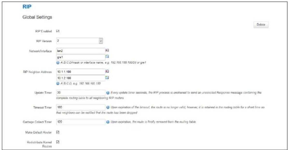
text_image
RIP Global Settings Delete RIP Enabled ✓ RIP Version 2 Network/Interface lan2 gre1 A.B.C.D/mask or interface name, e.g. 192.168.100.100/24 or gre1 RIP Neighbor Address 10.1.1:100 10.1.2:100 A.B.C.D, e.g. 192.168.100.100 Update Timer 30 Every update timer seconds, the RIP process is awakened to send an unsolicited Response message containing the complete routing table to all neighboring RIP routers Timeout Timer 180 Upon expiration of the timeout, the route is no longer valid; however, it is retained in the routing table for a short time so that neighbors can be notified that the route has been dropped Garbage Collect Timer 120 Upon expiration, the route is finally removed from the routing table Make Default Router ✓ Redistribute Kernel ✓ Routes ✓Figure 96: The RIP global settings configuration page
| Web Field/ UCI/ Package Option | Description | |
| Web: RIP EnabledUCI: ripd.ripd.enabledOpt: enabled | Enables RIP advertisements on router. | |
| 0 | Disabled. | |
| 1 | Enabled. | |
| Web: RIP VersionUCI: ripd.ripd.versionOpt: version | Specifies the RIP version that will be used. Version 2 is recommended. | |
| 1 | RIP version 1 | |
| 2 | RIP version 2 | |
| Web: Network/InterfaceUCI: ripd.ripd.networkOpt: list network | Defines the list of the interfaces that will be used to advertise RIP packets.Format: A.B.C.D/mask or interface nameMultiple RIP interfaces are entered using uci set and uci add_list commands. Example:uci set ripd.ripd.network=lan1uci add_list ripd.ripd.network=lan2or using a list of options via package optionslist network 'lan1'list network 'lan2' | |
| Web: RIP Neighbor AddressUCI: ripd.ripd.neighborOpt: list neighbor | Specifies the list of RIP neighbours. When a neighbour doesn't understand multicast, this command is used to specify neighbours. In some cases, not all routers will be able to understand multicasting, where packets are sent to a network or a group of addresses. In a situation where a neighbour cannot process multicast packets, it is necessary to establish a direct link between routers. The neighbour command allows the network administrator to specify a router as a RIP neighbour.Multiple RIP neighbours are entered using uci set and uci add_list commands. Example:uci set ripd.ripd.neighbor=1.1.1.1uci add_list ripd.ripd.neighbor=2.2.2.2or using a list of options via package optionslist neighbor '1.1.1.1'list neighbor '2.2.2.2' | |
| Web: Update TimerUCI: ripd.ripd.tb_update_secOpt: tb_update_sec | Every update timer seconds, the RIP process is awakened to send an unsolicited response message containing the complete routing table to all neighbouring RIP routers. | |
| 30 | ||
| Range | ||
| Web: Timeout TimerUCI: ripd.ripd.tb_timeout_secOpt: tb_timeout_sec | Defines timeout in seconds. Upon expiration of the timeout, the route is no longer valid; however, it is retained in the routing table for a short time so that neighbours can be notified that the route has been dropped. | |
| 180 | ||
| Range | ||
| Web: Garbage Collect TimerUCI: ripd.ripd.tb_garbage_secOpt: tb_garbage_sec | Upon expiration of the Garbage-Collection timer, the route is finally removed from the routing table. This timer starts when Timeout timer expires or when route is advertised as "unreachable".The reason for using this two-stage removal method (marking-deleting) is to give the router that declared the route no longer reachable a chance to propagate this information to other routers. When the timer expires the route is deleted. If during the garbage collection period a new RIP Response for the route is received, then the deletion process is aborted: the Garbage-Collection timer is cleared, the route is marked as valid again, and a new Timeout timer starts. | |
| 120 | ||
| Range | ||
| Web: Make Default RouterUCI: ripd.ripd.default_info_originateOpt: default_info_originate | Advertising a default route via RIP. | |
| 0 | Disable. | |
| 1 | Enable. | |
| Web: Redistribute Kernel RoutesUCI: ripd.ripd.redistribute_kernel_routes routesOpt: redistribute_kernel_routes routes | Redistributes routing information from kernel route entries into the RIP tables. | |
| 0 | Disable. | |
| 1 | Enable. | |
| Web: n/aUCI: ripd.ripd.vty_enabledOpt: vty_enabled | Enable vty for RIPd (telnet to localhost:2602). | |
Table 62: Information table for RIP global settings
22.3.2 Offset configuration
This section is used for RIP metric manipulation. RIP metric is a value for distance in the network. Usually, ripd package increments the metric when the network information is received. Redistributed routes' metric is set to 1.
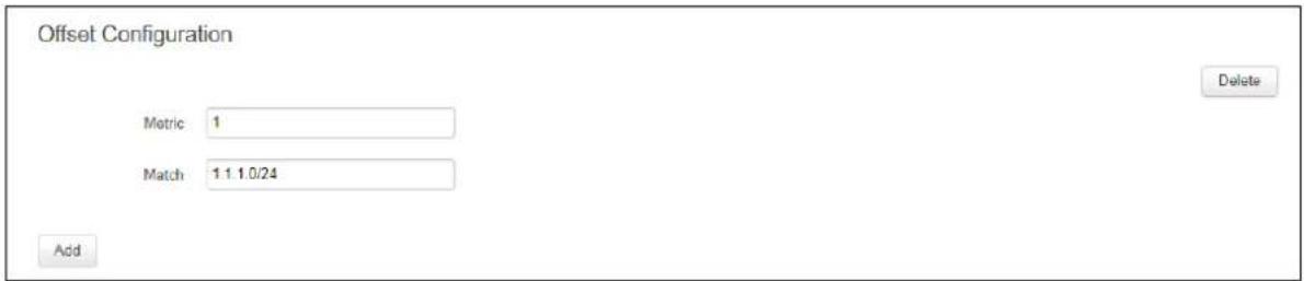
text_image
Offset Configuration Metric 1 Match 1.1.1.0/24 Add DeleteFigure 97: The RIP global settings configuration page
| Web Field/ UCI / Package Option | Description | |
| Web: MetricUCI: ripd.@offset[0].metricOpt: metric | Defines the metric offset value. This modifies the default metric value for redistributed and connected routes. | |
| 1 | ||
| Range | ||
| Web: MatchUCI: ripd.@offset[0].match_networkOpt: match_network | Defines the prefixes to match.Format: A.B.C.D/mask | |
Table 63: Information table for RIP offset commands
22.3.3 Interfaces configuration
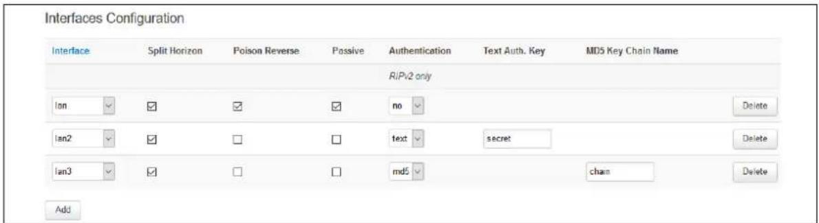
text_image
Interfaces Configuration Interface Split Horizon Poison Reverse Passive-Augustentication(Text Auth. Key MDS Key Chain Name RIPv2 only Ian ✓ ✓ ✓ ✓=no ✓ Delete Ian2 ✓ ✓ □ □ funds ✓ secret Delete Ian3 ✓ ✓ □ □ md5 ✓ chain Delete AddFigure 98: The RIP interfaces configuration page
| Web Field/ UCI / Package Option | Description | |
| Web: InterfaceUCI: ripd.@interface[0].rip_interfaceOpt: rip_interface | Specifies the interface name. | |
| Web: Split HorizonUCI: ripd.@interface[0].split_horizonOpt: split_horizon | Prohibits the router from advertising a route back onto the interface from which it was learned. | |
| 0 | Disable. | |
| 1 | Enable. | |
| Web: Poison ReverseUCI: ripd.@interface[0].poison_reverseOpt: poison_reverse | Router tells its neighbour gateways that one of the gateways is no longer connected. Notifies the gateway, setting the hop count to the unconnected gateway to 16 which would mean "infinite". | |
| 0 | Disable. | |
| 1 | Enable. | |
| Web: PassiveUCI: ripd.@interface[0].passiveOpt: passive | Sets the specified interface to passive mode. On passive mode interface, all receiving packets are processed as normal and ripd does not send either multicast or unicast RIP packets except to RIP neighbour specified with a neighbour command. | |
| 0 | Disable | |
| 1 | Enable | |
| Web: AuthenticationUCI: ripd.@interface[0].auth_modeOpt: auth_mode | RIPv2 (only) allows packets to be authenticated via either an insecure plain text password, included with the packet, or via a more secure MD5 based HMAC (keyed-Hashing for Message AuthentiCation). Enabling authentication prevents routes being updated by unauthenticated remote routers, but still can allow routes, that is, the entire RIP routing table, to be queried remotely, potentially by anyone on the internet, via RIPv1. | |
| no | Default value. No authentication. | |
| md5 | Sets the interface with RIPv2 MD5 authentication. | |
| text | Sets the interface with RIPv2 simple password authentication. | |
| Web: Text Auth. KeyUCI: ripd.@interface[0].auth_keyOpt: auth_key | This command sets the authentication string for text authentication. The string must be shorter than 16 characters. | |
| Web: MD5 Key Chain NameUCI: ripd.@interface[0].key_chainOpt: key_chain | Specify Keyed MD5 chain. | |
Table 64: Information table for RIP interface configuration
22.3.4 MD5 authentication key chains
RIPv2 (only) allows packets to be authenticated using either an insecure plain text password, included with the packet, or by a more secure MD5 based HMAC (keyed-Hashing for Message AuthentiCation). Enabling authentication prevents routes being updated by unauthenticated remote routers, but still can allow routes, that is, the entire RIP routing table, to be queried remotely, potentially by anyone on the internet, using RIPv1.
This section defines key_chains to be used for MD5 authentication.
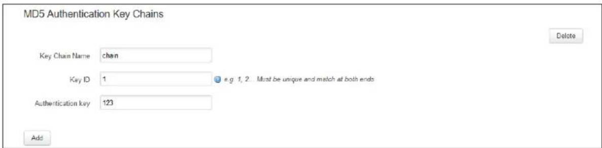
text_image
MD5 Authentication Key Chains Key Chain Name chain Key ID 1 e.g. 1, 2. Must be unique and match at both ends Authentication key 123 Add DeleteFigure 99: The MD5 authentication key chains configuration section
| Web Field/ UCI / Package Option | Description |
| Web: Key Chain NameUCI: ripd.@key_chain[0].key_chain_nameOpt: key_chain_name | Specifies chain name |
| Web: Key IDUCI: ripd.@key_chain[0].key_idOpt: key_id | Specifies key ID. Must be unique and match at both ends. |
| Web: Authentication keyUCI: ripd.@key_chain[0].auth_keyOpt: auth_key | Specify Keyed MD5 chain. |
Table 65: Information table for MD5 authentication key chains commands
22.4 Configuring RIP using command line
RIP is configured under the ripd package / etc/ config/ ripd.
There are four config sections ripd, interface, key_chain and offset.
You can configure multiple interface, key_chain and offset sections.
By default, all RIP interface instances are named interface, it is identified by @interface then the interface position in the package as a number. For example, for the first interface in the package using UCI:
ripd.@interface[0]=interface
ripd.@interface[0].rip_interface=lan
Or using package options:
config interface
option rip_interface 'lan'
By default, all RIP key_chain instances are named key_chain, it is identified by @key_chain then the key_chain position in the package as a number. For example, for the first key_chain in the package using UCI:
ripd.@key_chain[0]=key_chain
ripd.@key_chain[0].key_chain_name=Keychain1
Or using package options:
config key_chain
option key_chain_name 'Keychain1'
By default, all RIP offset instances are named offset, it is identified by @offset then the offset position in the package as a number. For example, for the first offset in the package using UCI:
ripd.@offset[0]=offset
ripd.@offset[0].metric=1
Or using package options:
config offset option metric '1'
22.4.1 RIP using UCI
root@VA_router:~# uci show ripd
ripd.ripd=routing
ripd.ripd.version=2
ripd.ripd.enabled=yes
ripd.ripd.network=lan2 gre1
ripd.ripd.neighbor=10.1.1.100 10.1.2.100
ripd.ripd.tb_update_sec=30
ripd.ripd.tb_timeout_sec=180
ripd.ripd.tb_garbage_sec=120
ripd.ripd.default_info_originate=yes
ripd.ripd redistribution_kernel_routes=yes
ripd.@interface[0]=interface
ripd.@interface[0].rip_interface=lan
ripd.@interface[0].auth_mode=no
ripd.@interface[0].split_horizon=1
ripd.@interface[0].poison_reverse=0
ripd.@interface[0].passive=0
ripd.@interface[1]=interface
ripd.@interface[1].rip_interface=lan2
ripd.@interface[1].split_horizon=1
ripd.@interface[1].poison_reverse=0
ripd.@interface[1].passive=0
ripd.@interface[1].auth_mode=text
ripd.@interface[1].auth_key=secret
ripd.@interface[2]=interface
ripd.@interface[2].rip_interface=lan3
ripd.@interface[2].split_horizon=1
ripd.@interface[2].poison_reverse=0
ripd.@interface[2].passive=0
ripd.@interface[2].auth_mode=md5
ripd.@interface[2].key_chain=Keychain1
ripd.@key_chain[0]=key_chain
ripd.@key_chain[0].key_chain_name=Keychain1
ripd.@key_chain[0].key_id=1
ripd.@key_chain[0].auth_key=123
ripd.@offset[0]=offset
ripd.@offset[0].metric=1
ripd.@offset[0].match_network=10.1.1.1/24
22.4.2 RIP using package options
root@VA_router:~# uci export ripd
package ripd

config routing 'ripd'
    option version '2'
    option enabled 'yes'
    list network 'lan2'
    list network 'gre1'
    list neighbor '10.1.1.100'
    list neighbor '10.1.2.100'
    option tb_update_sec '30'
    option tb_timeout_sec '180'
    option tb_garbage_sec '120'
    option default_info_originate 'yes'
    option redistribute_kernel_routes 'yes'

config interface
    option rip_interface 'lan'
option auth_mode 'no'
option split_horizon '1'
option poison_reverse '0'
option passive '0'

config interface
option rip_interface 'lan2'
option split_horizon '1'
option poison_reverse '0'
option passive '0'
option auth_mode 'text'
option auth_key 'textsecret'

config interface
option rip_interface 'lan3'
option split_horizon '1'
option poison_reverse '0'
option passive '0'
option auth_mode 'md5'
option key_chain 'keychain1'

config key_chain
option key_chain_name 'Keychain1'
option key_id '1'
option auth_key '123'

config offset
option metric '1'
option match_network '10.1.1.1/24'
22.5 RIP diagnostics
22.5.1 Route status
To show the current routing status, enter route -n:
root@VA_router:~#
route -n
Kernel IP routing table
Destination Gateway Genmask Flags Metric Ref Use
Iface
0.0.0.0 10.205.154.65 0.0.0.0 UG 1 0 0 usb0
10.1.0.0 0.0.0.0 255.255.0.0 U 0 0 0 eth1
10.205.154.64 0.0.0.0 255.255.255.252 U 0 0 0 usb0
11.11.11.0 0.0.0.0 255.255.255.248 U 0 0 0 gre-
GRE
89.101.154.151 10.205.154.65 255.255.255.255 UGH 0 0 0 usb0
192.168.100.0 0.0.0.0 255.255.255.0 U 0 0 0 eth0
192.168.104.1 11.11.11.4 255.255.255.255 UGH 3 0 0 gre-
GRE
192.168.154.154 11.11.11.1 255.255.255.255 UGH 2 0 0 gre-
GRE
Note: a route will only be displayed in the routing table when the interface is up.
22.5.2 Tracing RIP packets
RIP uses UDP port 520. To trace RIP packets on any interface on the router, enter:
tcpdump -i any -n -p port 520 &
root@VA_router:~# tcpdump -i any -n -p port 520 &
tcpdump: verbose output suppressed, use -v or -vv for full protocol decode listening on any, link-type LINUX_SLL (Linux cooked), capture size 65535 bytes
To stop tracing enter fg to bring tracing task to foreground, and then
root@VA_router:~# fg
tcpdump -i any -n -p port 67
^C
33 packets captured
33 packets received by filter
0 packets dropped by kernel
22.5.3 Quagga/ zebra console
Quagga is the routing protocol suite embedded in the router firmware. Quagga is split into different daemons for implementation of each routing protocol. Zebra is a core daemon for Quagga, providing the communication layer to the underlying Linux kernel, and routing updates to the client daemons.
Quagga has a console interface to Zebra for advanced debugging of the routing protocols.
To access, enter: telnet localhost zebra (password: zebra)
root@VA_router:~# telnet localhost zebra
Entering character mode
Escape character is '^]'.
Hello, this is Quagga (version 0.99.21).
Copyright 1996-2005 Kunihiro Ishiguro, et al.
User Access Verification
Password:
To see RIP routing information from Zebra console, enter: sh ip route
root@VA_router:~# sh ip route
Codes: K - kernel route, C - connected, S - static, R - RIP,
    O - OSPF, I - IS-IS, B - BGP, P - PIM, H - HSLS, o - OLSR,
    b - BATMAN, A - Babel,
    > - selected route, * - FIB route
K>* 0.0.0.0/0 via 10.205.154.65, usb0
C>* 10.1.0.0/16 is directly connected, eth1
C>* 10.205.154.64/30 is directly connected, usb0
C>* 11.11.11.0/29 is directly connected, gre-GRE
K>* 89.101.154.151/32 via 10.205.154.65, usb0
C>* 127.0.0.0/8 is directly connected, lo
C>* 192.168.100.0/24 is directly connected, eth0
R>* 192.168.104.1/32 [120/3] via 11.11.11.4, gre-GRE, 15:54:47
C>* 192.168.105.1/32 is directly connected, lo
R>* 192.168.154.154/32 [120/2] via 11.11.11.1, gre-GRE, 16:09:51
22.5.4 RIP debug console
When option tty_enabled (see Global settings section above) is enabled in the RIP configuration, RIP debug console can be accessed for advanced RIP debugging.
To access RIP debug console enter: telnet localhost ripd (password zebra)
root@VA_router:~# telnet localhost ripd
Entering character mode
Escape character is '^]'.
Hello, this is Quagga (version 0.99.21).
Copyright 1996-2005 Kunihiro Ishiguro, et al.
User Access Verification
Password:
To see RIP status from RIP debug console, enter: sh ip rip
root@VA_router:~# show ip rip
Codes: R - RIP, C - connected, S - Static, O - OSPF, B - BGP
Sub-codes:
(n) - normal, (s) - static, (d) - default, (r) - redistribute,
(i) - interface

Network Next Hop Metric From Tag Time
C(i) 11.11.11.0/29 0.0.0.0 1 self 0
R(n) 192.168.104.1/32 11.11.11.4 3 11.11.11.1 0 02:48
C(i) 192.168.105.1/32 0.0.0.0 1 self 0
R(n) 192.168.154.154/32 11.11.11.1 2 11.11.11.1 0 02:48
To see RIP status from RIP debug console, enter: sh ip rip status
root@VA_router:~# sh ip rip status
Routing Protocol is "rip"
Sending updates every 30 seconds with +/-50%, next due in 17 seconds
Timeout after 180 seconds, garbage collect after 120 seconds
Outgoing update filter list for all interface is not set
Incoming update filter list for all interface is not set
Default redistribution metric is 1
Redistributing:
Default version control: send version 2, receive version 2
Interface Send Recv Key-chain
gre-GRE 2 2
lo 2 2
Routing for Networks:
11.0.0.0/8
192.168.105.1/32
Routing Information Sources:
Gateway BadPackets BadRoutes Distance Last Update
11.11.11.1 0 0 120 00:00:20
Distance: (default is 120)
23 Configuring Multi-WAN
Multi-WAN is used for managing WAN interfaces on the router, for example, 3G interfaces to ensure high-availability. You can customise Multi-WAN for various needs, but its main use is to ensure WAN connectivity and provide a failover system in the event of failure or poor coverage.
Multi-WAN periodically does a health check on the interface. A health check comprises of a configurable combination of the following:
- interface state
• pings to an ICMP target - signal level checks using signal threshold, RSCP threshold and ECIO threshold option values
A fail for any of the above health checks, results in a fail. After a configurable number of health check failures, Multi-WAN will move to the next highest priority interface. Multi-WAN will optionally stop the failed interface and start the new interface, if required.
In some circumstances, particularly in mobile environments, it is desirable for a primary interface to be used whenever possible. In this instance Multi-WAN will perform a health check on the primary interface after a configurable period. If the health checks pass for the configured number of recovery health checks then the primary will be used.
23.1 Configuration package used
| Package | Sections |
| multiwan config | wan |
23.2 Configuring Multi-WAN using the web interface
In the top menu, select Network -> Multi-Wan. The Multi-WAN page appears.
Multi-WAN
Multi-WAN allows for the use of multiple uplinks for load balancing and failover.
Enable

Preempt

Alternate Mode

It will use alternate interface after reboot
Figure 100: The multi-WAN page
| Web Field/ UCI / Package Option | Description | |
| Web: EnableUCI: multiwan.config.enabledOpt: enabled | Enables or disables Multi-WAN. | |
| 0 | Disabled. | |
| 1 | Enabled. | |
| Web: PreemptUCI: multiwan.config.preemptOpt: preempt | Enables or disables pre-emption for Multi-WAN. If enabled the router will keep trying to connect to a higher priority interface depending on timer set by ifup_retry_sec | |
| 0 | Disabled. | |
| 1 | Enabled. | |
| Web: Alternate ModeUCI: multiwan.config.alt_modeOpt: alt_mode | Enables or disables alternate mode for Multi-WAN. If enabled the router will use an alternate interface after reboot. | |
| 0 | Disabled. | |
| 1 | Enabled. | |
Table 66: Information table for multi-WAN page
When you have enabled Multi-WAN, you can add the interfaces that will be managed by Multi-WAN, for example 3G interfaces.
The name used for Multi-WAN must be identical, including upper and lowercases, to the actual interface name defined in your network configuration. To check the names and settings are correct, select Network -> Interfaces and view the Interfaces Overview page.
In the WAN interfaces section, enter the name of the WAN interface to configure, and then click Add. The new section for configuring specific parameters appears.
WAN Interfaces
Health Monitor detects and corrects network changes and failed connections.
WAN
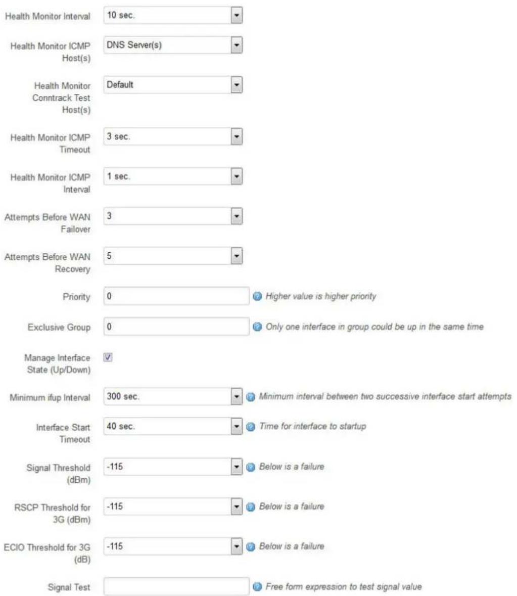
text_image
Health Monitor Interval 10 sec. Health Monitor ICMP Host(s) DNS Server(s) Health Monitor Conntrack Test Host(s) Default Health Monitor ICMP Timeout 3 sec. Health Monitor ICMP Interval 1 sec. Attempts Before WAN Failover 3 Attempts Before WAN Recovery 5 Priority 0 Higher value is higher priority Exclusive Group 0 Only one interface in group could be up in the same time Manage Interface State (Up/Down) ✓ Minimum ifup Interval 300 sec. Minimum interval between two successive interface start attempts Interface Start Timeout 40 sec. Time for interface to startup Signal Threshold (dBm) -115 Below is a failure RSCP Threshold for 3G (dBm) -115 Below is a failure ECIO Threshold for 3G (dB) -115 Below is a failure Signal Test Free form expression to test signal valueFigure 101: Example interface showing failover traffic destination as the added multi-WAN interface
| Web Field/ UCI/ Package Option | Description | |
| Web: Health Monitor IntervalUCI: multiwan.wan.health_intervalOpt: health_interval | Sets the period to check the health status of the interface. The Health Monitor interval will be used for:Interface state checksPing intervalSignal strength checks | |
| Web: Health Monitor ICMP Host(s)UCI: multiwan.wan icmp_hostsOpt: icmp_hosts | Sends health ICMPs to configured value DNS servers by default. Configure to any address. | |
| Disable | Disables the option. | |
| DNS servers | DNS IP addresses will be used. | |
| WAN Gateway | Gateway IP address will be used. | |
| Custom | Ability to provide IP address. Multiple pings targets can be entered, comma separated. Pings to both must fail for health check to fail. Example:option icmp_hosts '1.1.1.1,2.2.2.2' | |
| Web: Health Monitor Conntrack Test Host(s)UCI: multiwan.wan.conntrack_hostsOpt: conntrack_hosts | Conntrack is the feature used to track if there is any traffic to and from an IP destination within the health interval.The Conntrack_hosts option defines the IP for conntrack to track, usually the icmp_host IP is used.If traffic to the conntrack_hosts IP is detected then multiwan does not send a ping health check to the icmp_host; otherwise a ping is sent as normal to the icmp_host.By default the conntrack_hosts is checked if the health interval is greater than 5 minutes. This time threshold currently cannot be manipulated.Conntrack is generally used to limit the traffic sent on a GSM network. | |
| Default Conntrack checks for traffic from icmp_host IP when health interval is greater than 5 minutes. | ||
| Disable | Conntrack disabled. | |
| Custom Specifies an IP other than the icmp_host for conntrack to track. | ||
| Web: Health Monitor ICMP TimeoutUCI: multiwan.wan.timeoutOpt: timeout | Sets Ping timeout in seconds. Choose the time in seconds that the health monitor ICMP will timeout at. | |
| 3 | Wait 3 seconds for ping reply. | |
| Range | ||
| Web: Health Monitor ICMP IntervalUCI: multiwan.wan icmp_intervalOpt: icmp_interval | Defines the interval between multiple pings sent at each health check | |
| 1 | ||
| Range | ||
| Web: Health Monitor ICMP CountUCI: multiwan.wan icmp_countOpt: icmp_count | Defines the number of pings to send at each health check. | |
| 1 | ||
| Range | ||
| Web: Attempts Before WAN FailoverUCI: multiwan.wan.health_fail_retriesOpt: health_fail_retries | Sets the amount of health monitor retries before interface is considered a failure. | |
| 3 | ||
| Range | ||
| Web: Attempts Before WAN RecoveryUCI: multiwan.wan.health_recovery_retriesOpt: health_recovery_retries | Sets the number of health monitor checks before the interface is considered healthy. Only relevant if pre-empt mode is enabled. | |
| 5 | ||
| Range | ||
| Web: PriorityUCI: multiwan.wan.priorityOpt: priority | Specifies the priority of the interface. The higher the value, the higher the priority. | |
| 0 | ||
| Range | ||
| Web: Manage Interface State (Up/Down)UCI: multiwan.wan.manage_stateOpt: manage_state | Defines whether multi-wan will start and stop the interface. | |
| 1 | Enabled. | |
| 0 | Disabled. | |
| Web: Exclusive GroupUCI: multiwan.wan.exclusive_groupOpt: exclusive_group | Defines the group to which the interface belongs; only one interface can be active. | |
| 0 | ||
| Range | ||
| Web: Minimum ifup IntervalUCI: multiwan.wan.ifup_retry_secOpt: ifup_retry_sec | Specifies the interval in seconds before retrying the primary interface when pre-empt mode is enabled. | |
| 300 | Retry primary interface every 300 seconds. | |
| Range | ||
| Web: Interface Start TimeoutUCI: multiwan.wan.ifup_timeoutOpt: ifup_timeout | Specifies the time in seconds for interface to start up. If it is not up after this period, it will be considered a fail. | |
| 40 | 40 seconds. | |
| Range | ||
| Web: Signal Threshold (dBm)UCI: multiwan.wan.signal_thresholdOpt: signal_threshold | Specifies the minimum signal strength in dBm before considering if the interface fails signal health check. Uses the value stored for sig_dbm in mobile diagnostics.-115. | |
| Disabled | ||
| Range | -46 to -115 dBm | |
| Web: RSCP Threshold (dBm)UCI: multiwan.wan.rscp_thresholdOpt: rscp_threshold | Specifies the minimum RSCP signal strength in dBm before considering if the interface fails signal health check. Uses the value stored for rscp_dbm in mobile diagnostics. | |
| -115 | Disabled | |
| Range | -46 to -115 dBm | |
| Web: ECIO Threshold (dB)UCI: multiwan.wan.ecio_thresholdOpt: ecio_threshold | Specifies the minimum ECIO signal strength in dB before considering if the interface fails signal health check. Uses the value stored for ecio_db in mobile diagnostics. | |
| -115 | Disabled | |
| Range | -46 to -115 dB | |
| Web: Signal TestUCI: multiwan.wan.signal_testOpt: signal_test | Defines a script to test various signal characteristics in multiwan signal test. For example:option signal_test '(tech == 0) then (sig_dbm > -70) else (rscp_dbm > -105 and ecio_db > -15)'This states that when technology is GSM, a health fail is determined when signal strength is less than -70dBm. When technology is not GSM a health fail occurs when either rscp_dbm falls below -105dBm or ecio_db falls below -15dBTech values are: | |
| 0 | GSM | |
| 1 | GSM Compact | |
| 2 | UTRAN | |
| 3 | GSM w/EGPRS | |
| 4 | UTRAN w/HSPDA | |
| 5 | UTRAN w/HSUPA | |
| 6 | UTRAN w/HSUPA and HSDPA | |
| 7 | E-UTRAN | |
Table 67: Information table for multi-WAN interface page
23.3 Configuring Multi-WAN using UCI
Multi-WAN UCI configuration settings are stored on /etc/config/multiwan
Run UCI export or show commands to see multiwan UCI configuration settings. A sample is shown below.
root@VA_router:~# uci export multiwan

package multiwan

config multiwan 'config'
    option preempt 'yes'
    option alt_mode 'no'
    option enabled 'yes'

config interface 'wan'
    option disabled '0'
    option health_interval '10'    option health_fail_retries '3'
    option health_recovery_retries '5'
    option priority '2'
    option manage_state 'yes'
    option exclusive_group '0'
    option ifup_retry_sec '40'
    option icmp_hosts 'disable'
    option icmp_interval '1'
    option timeout '3'
    option icmp_count '1'
    option conntrack_hosts 'disable'    option signal_threshold '-111'

    option rscp_threshold '-90'
    option ecio_threshold '-15'
    option ifup_timeout_sec '120'

root@VA_router:~# uci show multiwan
multiwan.config=multiwan
multiwan.config.preempt=yes
multiwan.config.alt_mode=no
multiwan.config.enabled=yes
multiwan.wan=interface
multiwan.wan.disabled=0
multiwan.wan.health_interval=10multiwan.wan.health_fail_retries=3
multiwan.wan.health_recovery_retries=5
multiwan.wan.priority=2
multiwan.wan.manage_state=yes
multiwan.wan.exclusive_group=0
multiwan.wan.ifup_retry_sec=36000
multiwan.wan.icmp_hosts=disable
multiwan.wan.timeout=3
multiwan.wan.icmp_interval '1'
multiwan.wan.timeout '3'
multiwan.wan.icmp_count '1'
multiwan.wan.conntrack_hosts 'disable'
multiwan.wan.signal_threshold=-111
multiwan.wan.rscp_threshold=-90
multiwan.wan.ecio_threshold=-15
23.4 Multi-WAN diagnostics
The multi-WAN package is linked to the network interfaces within /etc/config/network.
Note: multi-WAN will not work if the WAN connections are on the same subnet and share the same default gateway.
To view the multi-WAN package, enter:
root@VA_router:~# uci export multiwan
package multiwan

config multiwan 'config'
    option enabled 'yes'
    option preempt 'yes'
    option alt_mode 'no'

config interface 'ADSL'
    option health_interval '10'
    option icmp_hosts 'dns'
    option timeout '3'
    option health_fail_retries '3'
    option health_recovery_retries '5'
    option priority '1'
    option manage_state 'yes'
    option exclusive_group '0'
    option ifup_retry_sec '300'
    option ifup_timeout_sec '40'
config interface 'Ethernet'
option health_interval '10'
option icmp_hosts 'dns'
option timeout '3'
option health_fail_retries '3'
option health_recovery_retries '5'
option priority '2'
option manage_state 'yes'
option exclusive_group '0'
option ifup_retry_sec '300'
option ifup_timeout_sec '40'
The following output shows the multi-WAN standard stop/start commands for troubleshooting.
root@VA_router:~# /etc/init.d/multiwan
Syntax: /etc/init.d/multiwan [command]
Available commands:
start Start the service
stop Stop the service
restart Restart the service
reload Reload configuration files (or restart if that fails)
enable Enable service autostart
disable Disable service autostart
When troubleshooting, make sure that the routing table is correct using
route -n.
Ensure all parameters in the multi-WAN package are correct. The name used for multi-WAN interfaces must be identical, including upper and lowercases, to the interface name defined in the network configuration.
To check the names and settings are correct, browse to Network -> interfaces (or alternatively, run: cat/etc/config/network through CLI).
Enter the name of the WAN interface to configure, and then click Add. The new section for configuring specific parameters will appear.
24 Automatic operator selection
This section describes how to configure and operate the Automatic Operator Selection feature of a Virtual Access router.
When the roaming SIM is connected, the radio module has the ability to scan available networks. The router, using mobile and multi-WAN packages, finds available networks to create and sort interfaces according to their signal strength. These interfaces are used for failover purposes.
24.1 Configuration package used
| Package | Sections |
| Multiwan | General, interfaces |
| Mobile | Main, Template interface |
| Network | 2G/3G/4G interface |
24.2 Configuring automatic operator selection via the web interface
While the router boots up it checks for mobile networks. Based on available networks, the router creates interfaces and the multiwan package is used to run failover between interfaces. Typically these auto-generated interfaces are sorted by signal strength.
Details for these interfaces are provided in the mobile package. When you have created the interfaces, Multi-WAN manages the operation of primary (predefined) and failover (auto created) interfaces.
Multi-WAN periodically does a health check on the active interface. A health check comprises of a configurable combination of the following:
- interface state
• pings to an ICMP target - signal level checks using signal threshold, RSCP threshold and ECIO threshold option values
A fail for any of the above health checks results in an overall fail. After a configurable number of health check failures, multiwan will move to the next highest priority interface. Multi-WAN will optionally stop the failed interface and start the new interface, if required.
In some circumstances, particularly in mobile environments, it is desirable for a primary interface to be used whenever possible. In this instance, if the active interface is a not the primary interface, multiwan will perform a health check on the primary interface after a configurable period. If the health checks pass for the configured number of recovery health checks then the primary interface will be used.
There are typically three scenarios:
• Primary Mobile Provider (PMP) + roaming: pre-empt enabled
• PMP + roaming: pre-empt disabled
- No PMP + roaming
24.2.1 Scenario 1: PMP + roaming: pre-empt enabled
24.2.1.1 Overview
In this scenario, the PMP interface is used whenever possible.
The PMP interface is attempted first. When the health checks fail on the PMP interface, and Multi-WAN moves to an autogenerated interface, a timer is started multiwan option ifup_retry_sec. On expiration of this timer, multiwan will disconnect the current interface and retry the PMP interface.
The PMP interface will then be used if the configurable number of health checks pass the checks.
24.2.1.2 Software operation
- Multiwan first attempts to bring up the PMP interface. If the PMP interface connects within the time set by multiwan option ifup_timeout continue to step 2. Otherwise go to step 4.
- A health check is periodically done on the PMP interface as determined by the multiwan option health_interval. If the health check fails for the number of retries (multiwan option health_fail_retries), disconnect the PMP interface.
- Connect the first auto-generated interface.
- If the interface connects within the time set by multiwan option ifup_timeout continue to step 5, otherwise multiwan moves to the next auto-generated interface.
- Wait until the health check fails on the auto-generated interface, or until the PMP interface is available to connect after it was disconnected in step 2. (multiwan option ifup_retry_sec).
- Disconnect auto-generated interface.
- If the interface was disconnected due to health check failure then connect the next auto-generated interface and repeat step 4. If the interface was disconnected because ifup_retry_sec of PMP interface timed out, then go back to step 1 and repeat the process.
The PMP predefined interface is defined in the network package. Ensure the interface name matches the interface name defined in the multiwan package.
24.2.1.3 Create a primary predefined interface
In the web interface top menu, go to Network -> Interfaces. The Interfaces page appears.
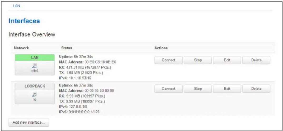
text_image
LAN Interfaces Interface Overview Network Status Actions LAN Uptime: 6h 37m 34s MAC Address: 00 E0 C8 10:0E E6 RX: 431.31 MB (4672877 Pkts.) TX: 1.68 MB (21023 Pkts.) IPv4: 10.1.10.93/16 Connect Stop Edit Delete LOOPBACK Uptime: 6h 37m 38s MAC Address: 00:00:00:00:00:00 RX: 9.99 MB (109997 Pkts.) TX: 9.99 MB (109997 Pkts.) IPv4: 127.0.0.1/8 IPv6: 0:0:0:0:0:0:0:1/128 Connect Stop Edit Delete Add new interface...Figure 102: The interface overview page
Click Add new interface... The Create Interface page appears.
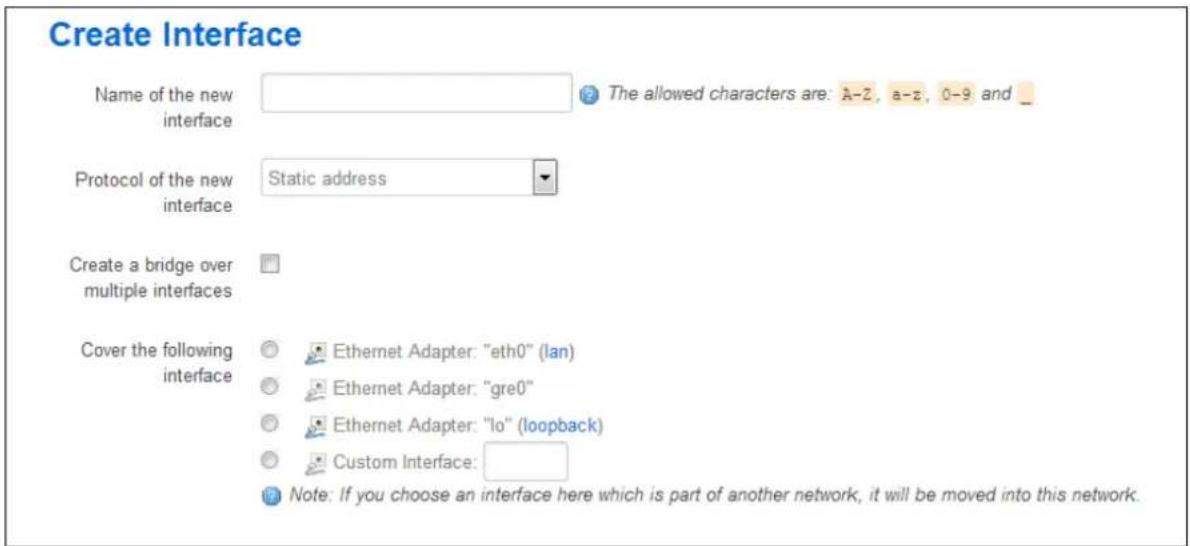
text_image
Create Interface Name of the new interface The allowed characters are: A-2, a-z, 0-9 and _ Protocol of the new interface Static address Create a bridge over multiple interfaces Cover the following interface Ethernet Adapter: "eth0" (lan) Ethernet Adapter: "gre0" Ethernet Adapter: "lo" (loopback) Custom Interface: Note: If you choose an interface here which is part of another network, it will be moved into this network.Figure 103: The create interface page
| Web Field/ UCI / Package Option | Description | |
| Web: Name of the new interfaceUCI: network.3g_s<sim-number>_<short-operator-name>.Opt: 3g_s<sim-number>_<short-operator-name>. | Type the name of the new interface.Type the interface name in following format:3g_s<sim-number>_<short-operator-name>. Whereis number of roaming SIM (1 or 2) andis first four alphanumeric characters of operator name (as reported by 'AT+COPS=?' command).Type the short operator name in lower case, for example: | |
| Operator name | First four alphanumeric numbers | |
| Vodafone UK | voda | |
| O2 – UK | o2uk | |
| Orange | oran | |
| Web: Protocol of the new interfaceUCI: network.[..x..].protoOpt: proto | Protocol type. Select LTE/ UMTS/ GPRS/ EV-DO. | |
| Option | Description | |
| Static Static configuration with fixed address and netmask. | ||
| DHCP Client | Address and netmask are assigned by DHCP. | |
| Unmanaged | Unspecified | |
| IPv6-in-IPv4 (RFC4213) | IPv4 tunnels that carry IPv6. | |
| IPv6 over IPv4 | IPv6 over IPv4 tunnel. | |
| GRE | Generic Routing Encapsulation. | |
| IOT | ||
| L2TP | Layer 2 Tunnelling Protocol. | |
| PPP | Point to Point Protocol. | |
| PPPoE | Point to Point Protocol over Ethernet. | |
| PPPoATM | Point to Point Protocol over ATM. | |
| LTE/UMTS/ GPRS/EV-DO | CDMA, UMTS or GPRS connection using an AT-style 3G modem. | |
| Web: Create a bridge over multiple interfacesUCI: network.[..x..].typeOpt: type | Enables bridge between two interfaces. | |
| 0 | Disabled. | |
| 1 | Enabled. | |
| Web: Cover the following interfaceUCI: network.[..x..].ifnameOpt: ifname | Selects interfaces for bridge connection. | |
Table 68: Information table for the create interface page
Click Submit. The Common Configuration page appears.
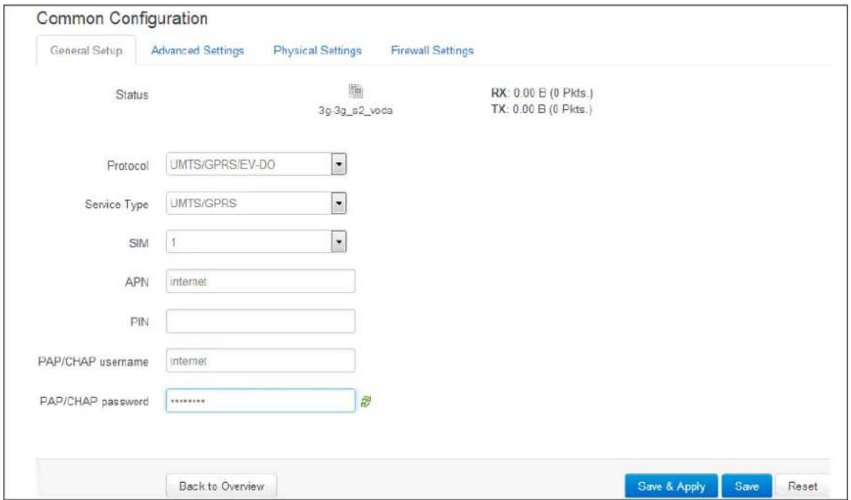
text_image
Common Configuration General Setup Advanced Settings Physical Settings Firewall Settings Status 3g-3g_s2_voda RX: 0.00 B (0 Pkts.) TX: 0.00 B (0 Pkts.) Protocol UMTS/GPRS/EV-DO Service Type UMTS/GPRS SIM 1 APN internet PIN PAP/CHAP username internet PAP/CHAP password ............. Back to Overview Save & Apply Save ResetFigure 104: The common configuration page
| Web Field/ UCI/ Package Option | Description | |
| Web: ProtocolUCI: network[..x..].protoOpt: proto | Protocol type. Select LTE/ UMTS/ GPRS/ EV-DO. | |
| Option | Description | |
| Static Static configuration with fixed address and netmask. | ||
| DHCP Client | Address and netmask are assigned by DHCP. | |
| Unmanaged | Unspecified | |
| IPv6-in-IPv4 (RFC4213) | IPv4 tunnels that carry IPv6. | |
| IPv6 over IPv4 | IPv6 over IPv4 tunnel. | |
| GRE | Generic Routing Encapsulation. | |
| IOT | ||
| L2TP | Layer 2 Tunnelling Protocol. | |
| PPP | Point to Point Protocol. | |
| PPPoE | Point to Point Protocol over Ethernet. | |
| PPPoATM | Point to Point Protocol over ATM. | |
| LTE/UMTS/ GPRS/EV-DO | CDMA, UMTS or GPRS connection using an AT-style 3G modem. | |
| Web: Service TypeUCI: network[..x..].serviceOpt: service | Service type that will be used to connect to the network. | |
| gprs_only | Allows GSM module to only connect to GPRS network. | |
| lte_only Allows | GSM module to only connect to LTE network. | |
| cdma Allows GSM module to only connect to CDMA network. | ||
| auto GSM module will automatically detect the best available technology code. | ||
| Web: SIMUCI: network[..x..].simOpt: sim | Select SIM 1 or SIM 2. | |
| auto Automatically detects which SIM slot is used. | ||
| SIM 1 | Selects Sim from slot 1. | |
| SIM 2 | Selects Sim from slot 2. | |
| Web: APNUCI: network[..x..].apnOpt: apn | APN name of Mobile Network Operator. | |
| Web: APN usernameUCI: network[..x..].usernameOpt: username | Username used to connect to APN. | |
| Web: APN passwordUCI: network[..x..].passwordOpt: password | Password used to connect to APN. | |
| Web: Modem ConfigurationUCI: N/AOpt: N/A | Click the link if you need to configure additional options from Mobile Manager. | |
Table 69: Information table for the general set up section
Click Save & Apply.
24.2.1.4 Set multi-WAN options for primary predefined interface
On the web interface go to Network ->Multi-Wan. The Multi-WAN page appears.
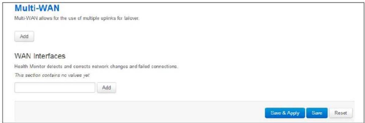
text_image
Multi-WAN Multi-WAN allows for the use of multiple uplinks for failover. Add WAN Interfaces Health Monitor detects and corrects network changes and failed connections. This section contains no values yet Add Save & Apply Save ResetFigure 105: The multi-WAN page
In the WAN Interfaces section, type in the name of the Multi-WAN interface.
Click Add. The Multi-WAN page appears.
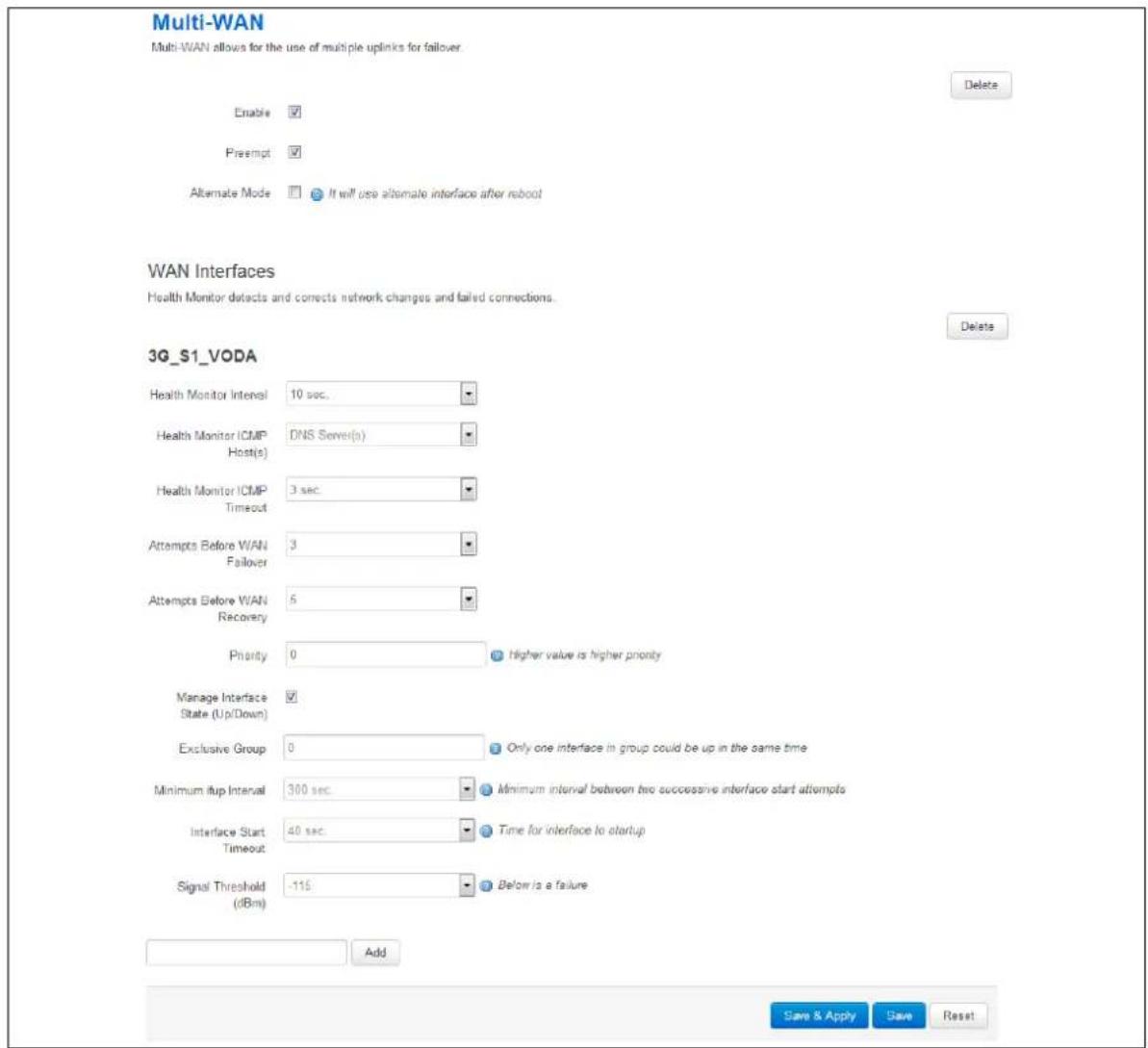
text_image
Multi-WAN Multi-WAN allows for the use of multiple uplinks for failover. Enable ✓ Preempt ✓ Alternate Mode ☐ It will use alternate interface after reboot WAN Interfaces Health Monitor detects and corrects network changes and failed connections. Delete 3G_S1_VODA Health Monitor Interval 10 sec. Health Monitor ICMP Host(s) DNS Server(s) Health Monitor ICMP Timeout 3 sec. Attempts Before WAN Failover 3 Attempts Before WAN Recovery 5 Priority 0 Higher value is higher priority Manage Interface State (Up/Down) Exclusive Group 0 Only one interface in group could be up in the same time Minimum ifup Interval 300 sec Minimum interval between two successive interface start attempts Interface Start Timeout 40 sec Time for interface to startup Signal Threshold -116 Below is a failure (dBm) Add Save & Apply Save ResetFigure 106: The multi-WAN page
| Web Field/ UCI / Package Option | Description | |
| Web: EnableUCI: multiwan.config.enabledOpt: enabled | Enables multiwan. | |
| 0 | Disabled. | |
| 1 | Enabled. | |
| Web: PreemptUCI: multiwan.config.preemptOpt: preempt | Enables or disables pre-emption for multiwan. If enabled the router will keep trying to connect to a higher priority interface depending on timer set. | |
| 0 | Disabled. | |
| 1 | Enabled. | |
| Web: Alternate ModeUCI: multiwan.config.altOpt: alt | Enables or disables alternate mode for multiwan. If enabled the router will use an alternate interface after reboot. | |
| 0 | Disabled. | |
| 1 | Enabled. | |
| Web: WAN InterfacesUCI: multiwan.3g_s< sim-number> _Opt: 3g_s< sim-number> _ | Provide the same interface name as chosen in multiwan section below and click Add. | |
| Web: Health Monitor IntervalUCI: multiwan[..x..].health_intervalOpt: health_interval | Sets the period to check the health status of the interface. The Health Monitor interval will be used for:Interface state checksPing intervalSignal strength checks | |
| Web: Health Monitor ICMP Host(s)UCI: multiwan[..x..].icmp_hostsOpt: icmp_hosts | Specifies the target IP address for ICMP packets. | |
| Disable | Disables the option. | |
| DNS servers | DNS IP addresses will be used. | |
| WAN Gateway | Gateway IP address will be used. | |
| custom | Ability to provide IP address. | |
| Web: Health Monitor Conntrack Test Host(s)UCI: multiwan.wan.conntrack_hostsOpt: conntrack_hosts | Conntrack is the feature used to track if there is any traffic to and from an IP destination within the health interval.Conntrack_hosts option defines the IP for conntrack to track - usually the icmp_host IP is used.If traffic to the conntrack_hosts IP is detected then multiwan does not send a ping health check to the icmp_host otherwise a ping is sent as normal to the icmp_host.By default the conntrack_hosts is checked if the health interval is greater than 5 minutes. This time threshold currently cannot be manipulated.Conntrack is generally used to limit the traffic sent on a GSM network. | |
| Default Conntrack checks for traffic from icmp_host IP when health_interval is greater than 5 minutes. | ||
| Disable | Conntrack disabled. | |
| Custom Specifies an IP other than the icmp_host for conntrack to track. | ||
| Web: Health Monitor ICMP TimeoutUCI: multiwan[..x..].timeoutOpt: timeout | Sets ping timeout in seconds. Choose the time in seconds that the health monitor ICMP will timeout at. | |
| 3 | Wait 3 seconds for ping reply. | |
| Range | ||
| Web: Health Monitor ICMP IntervalUCI: multiwan.wan.icmp_intervalOpt: icmp_interval | Defines the interval between multiple pings sent at each health check. | |
| 1 | ||
| Range | ||
| Web: Health Monitor ICMP CountUCI: multiwan.wan.icmp_countOpt: icmp_count | Defines the number of pings to send at each health check. | |
| 1 | ||
| Range | ||
| Web: Attempts Before WAN FailoverUCI: multiwan. [..x..].health_fail_retriesOpt: health_fail_retries | Sets the amount of health monitor retries before interface is considered a failure. | |
| 3 | ||
| Range | ||
| Web: Attempts Before WAN RecoveryUCI: multiwan.[..x..].health_recovery_retriesOpt: health_recovery_retries | Sets the number of health monitor checks before the interface is considered healthy. Only relevant if pre-empt mode is enabled. | |
| 5 | ||
| Range | ||
| Web: PriorityUCI: multiwan[..x..].priorityOpt: priority | Specifies the priority of the interface. The higher the value, the higher the priority.This multiwan interface priority must be higher than the one specified in the priority field in the 'Roaming Interface Template' page described in the following section. | |
| 0 | ||
| Range | ||
| Web: Exclusive GroupUCI: multiwan[..x..].exclusive_groupOpt: exclusive_group | Defines the group to which the interface belongs; only one interface can be active. | |
| 0 | ||
| Range | ||
| Web: Manage Interface State (Up/Down)UCI: multiwan[..x..].manage_stateOpt: manage_state | Defines whether multi-WAN will start and stop the interface.Select Enabled. | |
| 0 | Disabled. | |
| 1 | Enabled. | |
| Web: Minimum ifup IntervalUCI: multiwan[..x..].ifup_retry_secOpt: ifup_retry_sec | Specifies the interval in seconds before retrying the primary interface when pre-empt mode is enabled. | |
| Web: Interface Start TimeoutUCI: multiwan[..x..].ifup_timeoutOpt: ifup_timeout | Specifies the time in seconds for interface to start up. If it is not up after this period, it will be considered a fail.Choose timer greater than 120 seconds. | |
| 40 | 40 seconds | |
| Range | ||
| Web: Signal Threshold (dBm)UCI: multiwan[..x..].signal_thresholdOpt: signal_threshold | Specifies the minimum signal strength in dBm before considering if the interface fails signal health check. Uses the value stored for sig_dbm in mobile diagnostics. | |
| -115 | Disabled. | |
| Range | -46 to -115 dBm | |
| Web: RSCP Threshold (dBm)UCI: multiwan[..x..].rscp_thresholdOpt: rscp_threshold | Specifies the minimum RSCP signal strength in dBm before considering if the interface fails signal health check. Uses the value stored for rscp_dbm in mobile diagnostics. | |
| -115 | Disabled. | |
| Range | -46 to -115 dBm | |
| Web: ECIO Threshold (dB)UCI: multiwan[..x..].ecio_thresholdOpt: ecio_threshold | Specifies the minimum ECIO signal strength in dB before considering if the interface fails signal health check. Uses the value stored for ecio_db in mobile diagnostics. | |
| -115 | Disabled. | |
| Range | -46 to -115 dB | |
| Web: Signal TestUCI: multiwan[..x..].signal_testOpt: signal_test | Defines script to test various signal characteristics in multiwan signal test. For example:option signal_test '(tech == 0) then (sig_dbm > -70) else (rscp_dbm > -105 and ecio_db > -15)'This states that when technology is GSM a health fail is determined when signal strength is less than -70dBm. When technology is not GSM a health fail occurs when either rscp_dbm falls below -105dBm or ecio_db falls below -15dB.Tech values are: | |
| 0 | GSM | |
| 1 | GSM Compact | |
| 2 | UTRAN | |
| 3 | GSM w/EGPRS | |
| 4 | UTRAN w/HSPDA | |
| 5 | UTRAN w/HSUPA | |
| 6 | UTRAN w/HSUPA and HSDPA | |
| 7 | E-UTRAN | |
Table 70: Information table for Multi-WAN page
Click Save.
24.2.2 Set options for automatically created interfaces (failover)
From the top menu on the web interface page, select Services -> Mobile Manager. The Mobile Manager page appears.
There are four sections in the mobile manager page:
| Section | Description |
| Basic settings | Enable SMS, configure SIM pin code, select roaming SIM, collect ICCCIDs and set IMSI. |
| CDMA* | CDMA configuration |
| Callers | Configure callers that can use SMS. |
| Roaming Interface Template | Configure Preferred Roaming List options |
| * Option available only for Telit CE910-SL module. | |
24.2.3 Mobile manager: basic settings
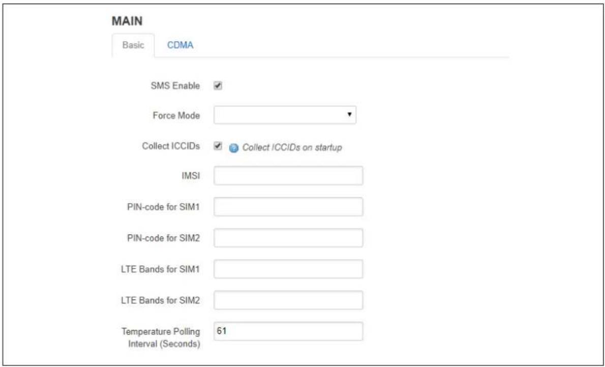
text_image
MAIN Basic CDMA SMS Enable ✓ Force Mode ✓ Collect ICCIDs ✓ Collect ICCIDs on startup IMSI PIN-code for SIM1 PIN-code for SIM2 LTE Bands for SIM1 LTE Bands for SIM2 Temperature Polling Interval (Seconds) 61Figure 107: The mobile manager basic page
| Web Field/ UCI / Package Option | Description | |
| Web: SMS EnableUCI: mobile.main.smsOpt: sms | Enables or disables SMS functionality. | |
| 0 | Disabled. | |
| 1 | Enabled. | |
| Web: Force ModeUCI: mobile.main.force_modeOpt: force_mode | Defines whether to operate mobile modem in TTY or Ethernet mode. The mode will be dependent on the service provided by the mobile provider. In general, this is Ethernet mode (default). | |
| Blank | Ethernet mode (option not present). | |
| tty | Enable TTY mode. | |
| Web: Collect ICCIDsUCI: mobile.main.init_get_iccidsOpt: init_get_iccids | Enables or disables integrated circuit card identifier ICCID's collection functionality. If enabled then both SIM 1 and SIM 2 ICCIDs will be collected otherwise it will default to SIM 1. This will be displayed under mobile stats. | |
| 0 | Disabled. | |
| 1 | Enabled. | |
| Web: IMSIUCI: mobile.main.imsiOpt: imsi | Allows the IMSI (International Mobile Subscriber Identity) to be changed. | |
| Default | Programmed in module. | |
| Digits | Up to 15 digits. | |
| Web: PIN code for SIM1UCI: mobile.main.sim1pinOpt: sim1pin | Depending on the SIM card specify the pin code for SIM 1. | |
| Blank | ||
| Range | Depends on the SIM provider. | |
| Web: PIN code for SIM2UCI: mobile.main.sim2pinOpt: sim2pin | Depending on the SIM card specify the pin code for SIM 2. | |
| Blank | ||
| Range | Depends on the SIM provider. | |
| Web: LTE bands for SIM1UCI: mobile.main.sim1_lte_bandsOpt: sim1_lte_bands | Depending on the SIM card specify the LTE bands for SIM 1. Comma delimiter. Example: option sim1_lte_bands '3,20' Limits LTE bands to 3 and 20. Note: currently only supported by Hucom/Wetelcom, SIMCom7100, Cellient MPL200 and Asiatel. | |
| Blank | ||
| Range | LTE bands range from 1 to 70. | |
| Web: LTE bands for SIM2UCI: mobile.main.sim2_lte_bandsOpt: sim2_lte_bands | Depending on the SIM card specify the LTE bands for SIM 2. Comma delimiter. Example: option sim1_lte_bands '3,20' Limits LTE bands to 3 and 20. Note: currently only supported by Hucom/Wetelcom, SIMCom7100, Cellient MPL200 and Asiatel. | |
| Blank | ||
| Range | LTE bands range from 1 to 70. | |
| Web: Temperature Polling IntervalUCI: mobile.main.temp_poll_interval_secOpt: temp_poll_interval_sec | Defines the time in seconds to poll the mobile module for temperature. Set to 0 to disable. | |
| 61 | 61 seconds. | |
| Range | ||
| Web: n/aUCI: mobile.main.disable_timeOpt: disable_time | Defines whether to use time obtained from the mobile carrier to update the system clock when NTP is enabled. | |
| 0 | Disabled. | |
| 1 | Enabled. | |
| Web: n/aUCI: mobile.main.service_orderOpt: service_order | Defines a space separated list of services, in preferred order. Valid options are gprs, umts, lte, auto.If no valid_service order is defined, then the configured Service Type is used. Example:mobile.main.service_order="gprs umts lte auto" | |
| Blank | Use configured service type. | |
| Range | gprs umts lte auto. | |
Table 71: Information table for mobile manager basic settings
24.2.4 Mobile manager: CDMA settings
This configuration page is only supported for the Telit CE910-SL CDMA module.
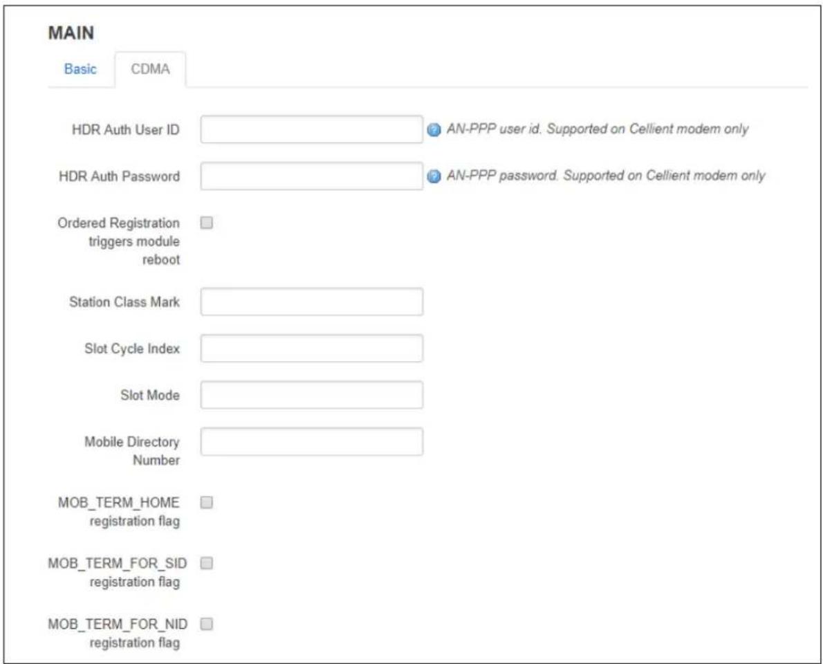
text_image
MAIN Basic CDMA HDR Auth User ID ● AN-PPP user id. Supported on Cellient modem only HDR Auth Password ● AN-PPP password. Supported on Cellient modem only Ordered Registration triggers module reboot Station Class Mark Slot Cycle Index Slot Mode Mobile Directory Number MOB_TERM_HOME registration flag MOB_TERM_FOR_SID registration flag MOB_TERM_FOR_NID registration flagFigure 108: The mobile manager CDMA page
| Web Field/ UCI / Package Option | Description | |
| Web: HDR Auth User IDUCI: mobile.main.hdr_useridOpt: hdr_userid | AN-PPP user ID. Supported on Cellient (CDMA) modem only. | |
| Blank | ||
| Range | Depends on the CDMA provider. | |
| Web: HDR Auth User PasswordUCI: mobile.main.hdr_passwordOpt: hdr_password | AN-PPP password. Supported on Cellient (CDMA) modem only. | |
| Blank | ||
| Range | Depends on the CDMA provider. | |
| Web: Ordered Registration triggers module rebootUCI: mobile.main.mobile.main.cdma_ordered_registration_reboot_enabledOpt:cdma Fijieds registration reboot enabled | Enables or disables rebooting the module after Order Registration command is received from a network. | |
| 0 | Disabled. | |
| 1 | Enabled. | |
| Web: Station Class MarkUCI: mobile.main.cdma station class markOpt: cdma station class mark | Allows the station class mark for the MS to be changed. | |
| 58 | ||
| 0-255 | ||
| Web: Slot Cycle IndexUCI: mobile.main.cdma slot cycle indexOpt: cdma slot cycle index | The desired slot cycle index if different from the default. | |
| 2 | ||
| 0-7 | ||
| Web: Slot ModeUCI: mobile.main.cdma slot modeOpt: cdma slot mode | Specifies the slot mode. | |
| 0 | ||
| Web: Mobile Directory NumberUCI:mobile.main.cdma mobile directory numberOpt: cdma mobile directory number | Allows the mobile directory number (MDN) to be changed | |
| Default | Programmed in module. | |
| Digits | Up to 15 digits. | |
| Web: MOB TERM HOME registration flagUCI: mobile.main.cdma mob term home registration flagOpt:cdma mob term home registration flag | The MOB TERM HOME registration flag | |
| 0 | Disabled. | |
| 1 | Enabled. | |
| Web: MOB TERM FOR SID registration flagUCI: mobile.main.cdma mob term for sid registration flagOpt:cdma mob term for sid registration flag | The MOB TERM FOR SID registration flag | |
| 0 | Disabled. | |
| 1 | Enabled. | |
| Web: MOB TERM FOR NID registration flagUCI: mobile.main.cdma mob term for nid registration flagOpt:cdma mob term for nid registration flag | The MOB TERM FOR NID registration flag | |
| 0 | Disabled. | |
| 1 | Enabled. | |
| Web: Access Overload ControlUCI:mobile.main.cdma access overload controlOpt: cdma access overload control | Allows the access overload class to be changed | |
| Default | Programmed into module as part of IMSI | |
| Range | 0-7 | |
| Web: Preferred Serving SystemUCI:mobile.main.cdma preferred serving systemOpt: cdma preferred serving system | The CDMA Preferred Serving System(A/B) | |
| 5 | ||
| Web: Digital Analog Mode PreferenceUCI: cdma digital analog mode preferenceOpt: cdma digital analog mode preference | Digital/Analog Mode Preference. | |
| 4 | ||
| Web: Primary Channel AUCI: mobile.main.cdma_primary_channel_aOpt: cdma_primary_channel_a. | Allows the primary channel (A) to be changed. | |
| 283 | ||
| 1-2016 | Any band class 5 channel number. | |
| Web: Primary Channel BUCI: mobile.main.cdma_primary_channel_bOpt: cdma_primary_channel_b | Allows the primary channel (B) to be changed. | |
| 384 | ||
| 1-2016 | Any band class 5 channel number | |
| Web: Secondary Channel AUCI:mobile.main.cdma_secondary_channel_aOpt: cdma_secondary_channel_a | Allows the secondary channel (A) to be changed. | |
| 691 | ||
| 1-2016 | Any band class 5 channel number. | |
| Web: Secondary Channel BUCI:mobile.main.cdma_secondary_channel_bOpt: cdma_secondary_channel_b | Allows the secondary channel (B) to be changed. | |
| 777 | ||
| 1-2016 | Any band class 5 channel number. | |
| Web: Preferred Forward & Reverse RCUCI:mobile.main.cdma_preferred_forward_and_reverse_rcOpt: cdma_preferred_forward_and_reverse_rc | The Preferred Forward & Reverse RC value, this takes the form "forward_rc,reverse_rc"Format: forward radio channel, reverse radio channelDefault: 0,0 | |
| Web: SID-NID pairsUCI: mobile.main.cdma_sid_nid_pairsOpt: cdma_sid_nid_pairs | Allows specification of SID:NID pairs, this takes the form "SID1,NID1,SID2,NID2,...Format: SID1 (0-65535),NID (0-65535)Default: 0,65535 | |
Table 72: Information table for mobile manager CDMA settings
24.2.5 Mobile manager: callers
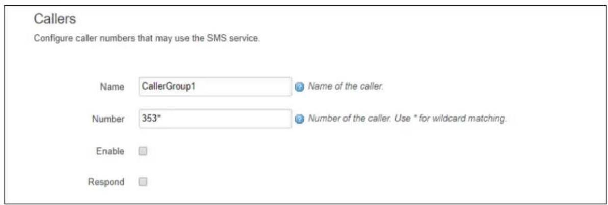
text_image
Callers Configure caller numbers that may use the SMS service. Name CallerGroup1 Name of the caller. Number 353* Number of the caller. Use * for wildcard matching. Enable RespondFigure 109: The mobile manager CDMA page
| Web Field/ UCI / Package Option | Description | |
| Web: Name | Name assigned to the caller. | |
| UCI: mobile.@caller[0].name | Blank | |
| Opt:name | Range | No limit |
| Web: Number | Number of the caller allowed to SMS the router. Add in specific caller numbers, or use the * wildcard symbol. | |
| UCI: mobile.@caller[0].number | ||
| Opt:number | Blank | |
| Range | No limit | |
| Characters | Global value (*) is accepted.International value (+) is accepted. | |
| Web: Enable | Enables or disables incoming caller ID. | |
| UCI: mobile.@caller[0].enabled | 0 | Disabled. |
| Opt:enabled | 1 | Enabled. |
| Web: Respond | If checked, the router will return an SMS. Select Respond if you want the router to reply. | |
| UCI: mobile.@caller[0].respond | 0 | Disabled. |
| Opt: respond | 1 | Enabled. |
Table 73: Information table for mobile manager callers settings
24.2.6 Roaming interface template
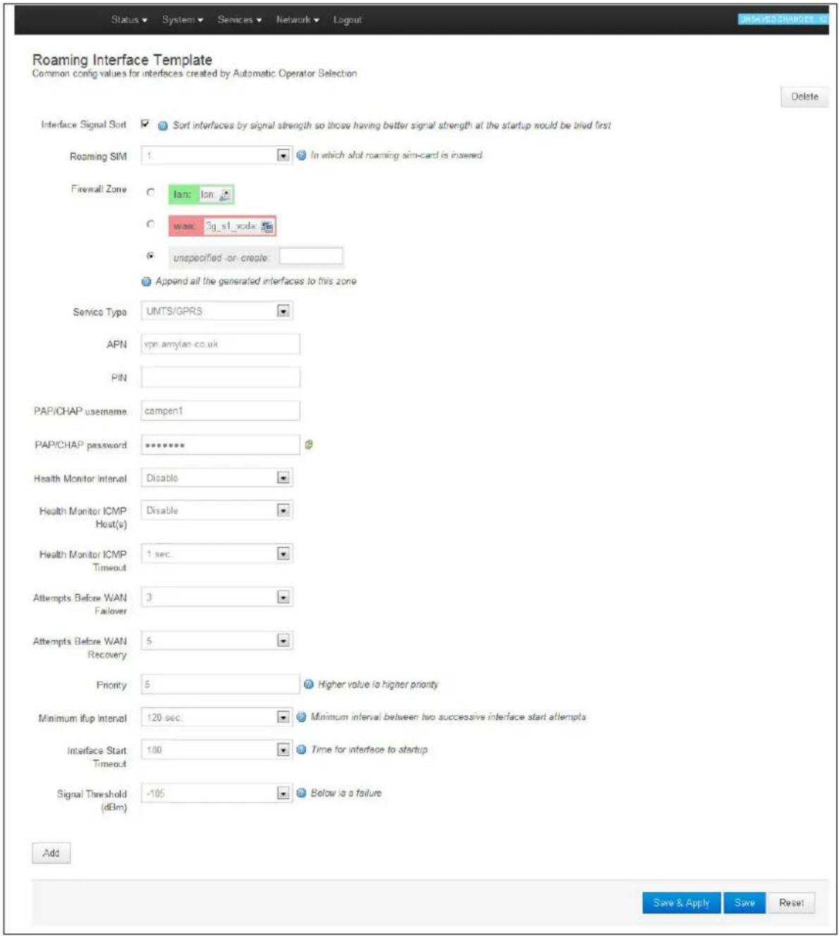
text_image
Roaming Interface Template Common config values for interfaces created by Automatic Operator Selection Delete Interface Signal Sort ✓ Sort interfaces by signal strength so those having better signal strength at the startup would be tried first Roaming SIM 1 In which slot roaming sim-card is inserted Firewall Zone ○ Ian: lon ○ want 3g_s1_node ✓ unspecified-or-create Append all the generated interfaces to this zone Service Type UMTS/GPRS APN vpn.amylan.co.uk PIN PAP/CHAP username: campen1 PAP/CHAP password ********* Health Monitor interval Disable Health Monitor ICMP Host(s) Disable Health Monitor ICMP Timeout 1 sec Attempts Before WAN Failover 3 Attempts Before WAN Recovery 5 Priority 5 Higher value is higher priority Minimum ifup interval 120 sec Minimum interval between two successive interface start attempts Interface Start Timeout 100 Time for interface to startup Signal Threshold (dBm) -105 Below is a failure Add Save & Apply Save ResetFigure 110: The roaming interface template page
| Web Field/ UCI / Package Option | Description | |
| Web: Interface Signal SortUCI:mobile.@roaming_template[0].sort_sig_strengthOpt: sort_sig_strength | Sorts interfaces by signal strength priority so those that have a better signal strength will be tried first. | |
| 0 | Disabled. | |
| 1 | Enabled. | |
| Web: Roaming SIMUCI: mobile.main.roaming_simOpt: roaming_sim | Sets in which slot to insert roaming SIM card. | |
| 1 | SIM slot 1. | |
| 2 | SIM slot 2. | |
| Web: Firewall ZoneUCI:mobile.@roaming_template[0].firewall_zoneOpt: firewall_zone | Adds all generated interfaces to this zone. Select existing zone or click unspecified or create to create new zone. | |
| Web: Service TypeUCI:mobile.@roaming_template[0].serviceOpt: service | Specifies the service type that will be used to connect to the network. | |
| Auto GSM module will automatically detect the best available technology code. | ||
| Ite_only Allows GSM module to only connect to LTE network. | ||
| umts_only Allows GSM module to only connect to 3G network. | ||
| gprs_only Allows GSM module to only connect to GPRS network. | ||
| cdma Allows GSM module to only connect to cdma network. | ||
| Web: APNUCI: mobile.@roaming_template[0].apnOpt: apn | APN name of Mobile Network Operator. | |
| Web: PINUCI:mobile.@roaming_template[0].pincodeOpt: pincode | SIM card's PIN number. | |
| Web: PAP/CHAP usernameUCI:mobile.@roaming_template[0].usernameOpt: username | Username used to connect to APN. | |
| Web: PAP/CHAP passwordUCI:mobile.@roaming_template[0].passwordOpt: password | Password used to connect to APN. | |
| Web: Health Monitor IntervalUCI:mobile.@roaming_template[0].health_intervalOpt: health_interval | Sets the period to check the health status of the interface. The Health Monitor interval will be used for:Interface state checksPing intervalSignal strength checks | |
| Web: Health Monitor ICMP Host(s)UCI:mobile.@roaming_template[0].icmp_hostsOpt: icmp_hosts | Specifies target IP address for ICMP packets. | |
| Disable | Disables the option. | |
| DNS servers | DNS IP addresses will be used. | |
| WAN gateway | Gateway IP address will be used. | |
| custom | Ability to provide IP address. | |
| Web: Health Monitor ICMP TimeoutUCI:mobile.@roaming_template[0].timeoutOpt: timeout | Specifies the time in seconds that Health Monitor ICMP will timeout at.Sets ping timeout in seconds. Choose the time in seconds that the health monitor ICMP will timeout at. | |
| 3 | Wait 3 seconds for ping reply. | |
| Range | ||
| Web: Attempts Before WAN Failover UCI: mobile.@roaming_template[1].health_fail_retries Opt: health_fail_retries | Defines the number of health check failures before interface is disconnected. | |
| 3 | ||
| Range | ||
| Web: Attempts Before WAN Recovery UCI: mobile.@roaming_template[0].health_recovery_retries Opt: health_recovery_retries | Sets the number of health check passes before the interface is considered healthy. This field is not used for a roaming template. | |
| 5 | ||
| Range | ||
| Web: Priority UCI: mobile.@roaming_template[0].priority Opt: priority | Type the priority number. The higher the value, the higher the priority. This multi-WAN interface priority must be lower than the one specified in the priority field for the PMP interface. | |
| 0 | ||
| Range | ||
| Web: Minimum ifup interval UCI: multiwan.wan.ifup_retry_sec Opt: ifup_retry_sec | Not used for a roaming interface. | |
| 300 | Retry primary interface every 300 seconds | |
| Range | ||
| Web: Interface Start Timeout UCI: mobile.@roaming_template[0].ifup_timeout_sec Opt: ifup_timeout | Specifies the time in seconds for interface to start up. If it is not up after this period, it will be considered a fail. | |
| 40 | 40 seconds | |
| Range | ||
| Web: Signal Threshold (dBm) UCI: mobile.@roaming_template[0].signal_threshold Opt: signal_threshold | Specifies the minimum RSCP signal strength in dBm before considering if the interface fails signal health check. Uses the value stored for rscp_dbm in mobile diagnostics. | |
| Range | -46 to -115 dBm | |
| -115dBm | ||
| Web: n/a UCI: mobile.main.service_order Opt: service_order | Defines a space separated list of services, in preferred order. Valid options are gprs, umts, lte, auto. If no valid service order is defined, then the configured Service Type is used. Example: mobile.@roaming_template[0].service_order="gprs umts lte auto" | |
| Blank | Use configured service type. | |
| Range | gprs umts lte auto | |
Table 74: Information table for roaming interface template
When you have configured your settings, click Save & Apply.
In the top menu, select System -> Reboot. The System page appears.
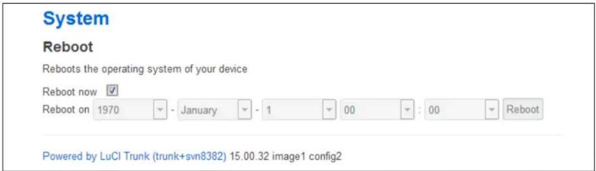
text_image
System Reboot Reboots the operating system of your device Reboot now ✓ Reboot on 1970 - January - 1 00 : 00 Reboot Powered by LuCI Trunk (trunk+svn8382) 15.00.32 image1 config2Figure 111: The reboot page
Check the Reboot now check box and then click Reboot.
24.2.7 Scenario 2: PMP + roaming: pre-empt disabled
As in the previous section, multi-WAN connects the PMP interface and uses auto created interfaces for failover.
However, in this scenario, the auto-created interface will not be disconnected as soon as the ifup_retry_sec expires for the PMP interface. The primary interface will be reconnected when the current auto-created interface fails multiwan health checks after expiration of the ifup_retry_sec timer.
Follow the instructions in the section above for creation of the PMP interface, multi-WAN and Mobile Manager roaming interfaces. The only change in configuration compared to the PMP + roaming: pre-empt enabled scenario is that you must disable the pre-empt option in the multi-WAN package.
24.2.7.1 Set multi-WAN options for pre-empt disabled
To disable PMP + roaming pre-empt, in the top menu, select Network -> Multi-Wan. In the Multi-WAN page, ensure Preempt is not selected.
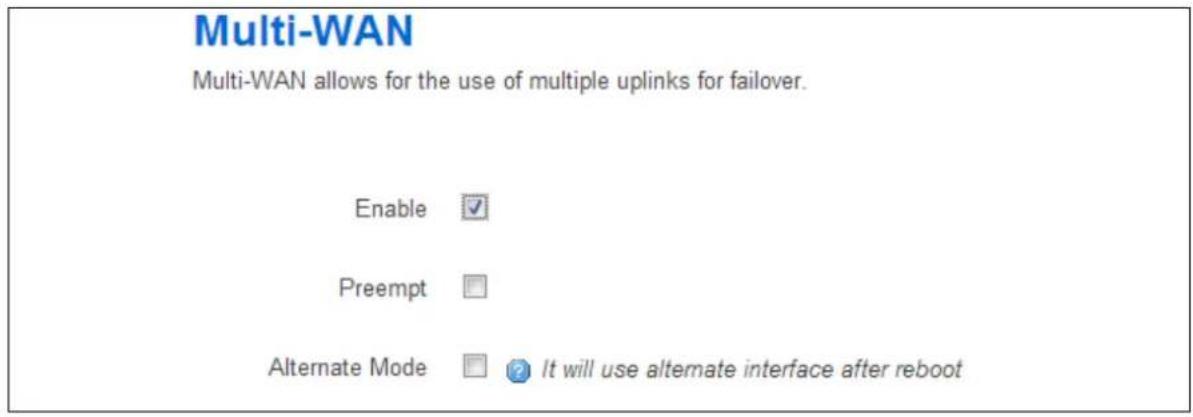
text_image
Multi-WAN Multi-WAN allows for the use of multiple uplinks for failover. Enable ✓ Preempt Alternate Mode ☐ It will use alternate interface after rebootFigure 112: The multi-wan page, pre-empt not selected
Click Save & Apply.
In the top menu, select System -> Reboot. The System Reboot page appears.
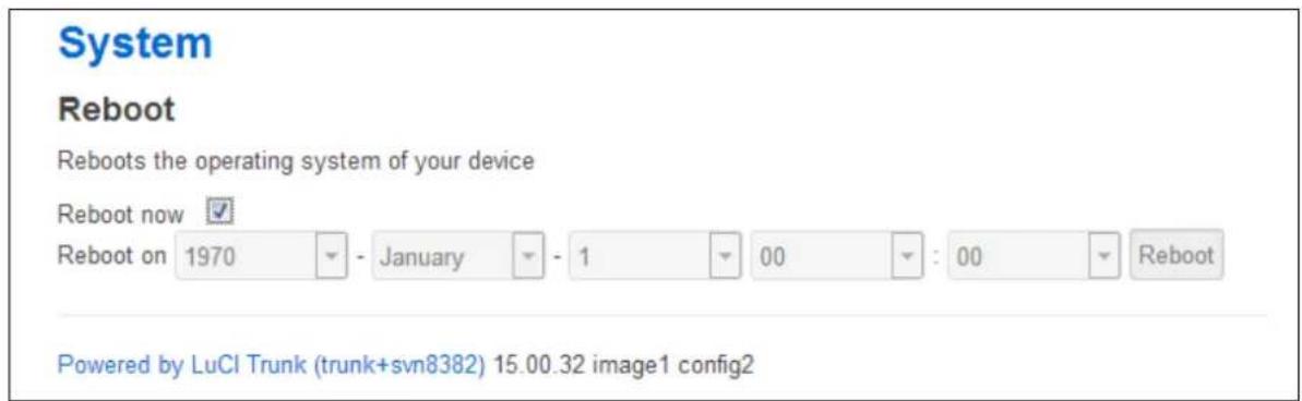
text_image
System Reboot Reboots the operating system of your device Reboot now ✓ Reboot on 1970 - January - 1 00 : 00 Reboot Powered by LuCI Trunk (trunk+svn8382) 15.00.32 image1 config2Figure 113: The system reboot page
Check the Reboot now check box and then click Reboot.
24.2.8 Scenario 3: No PMP + roaming
In this scenario there is no PMP interface that can be used for a connection. The router scans the available mobile networks at boot and sorts the networks according to signal strength.
The network that offers the best signal strength will be the first to connect. Multi-WAN then controls the failover between the available networks.
Multiwan periodically does a health check on the interface. A health check comprises of a configurable combination of the following:
- Interface state
• Pings to an ICMP target - Signal level checks using signal threshold, RSCP threshold and ECIO threshold option values
A fail for any of the above health checks results in a fail. After a configurable number of health check failures, Multi-WAN will disconnect the failed interface and attempt to connect to the next best roaming interface.
24.2.9 Set options for automatically created interfaces (failover)
In the top menu on the web interface page, select Services -> Mobile Manager. The Mobile Manager page appears.
There are three sections:
| Basic settings | Configure SMS, select roaming SIM and collect ICCCIDs |
| Callers | Configure callers that can use SMS. |
| Roaming Interface Template | Configure common values for interface created by Automatic Operator Selection. |
24.2.9.1 Basic settings
| Web Field/ UCI / Package Option | Description | |
| Web: SMS EnableUCI: mobile.main.smsOpt: sms | Enables SMS. | |
| no | Disabled. | |
| yes | Enabled. | |
| Web: Collect ICCIDsUCI: mobile.main.init_get_iccidsOpt: init_get_iccids | Enables or disables integrated circuit card identifier ICCID's collection functionality. If enabled then both SIM 1 and SIM 2 ICCID's will be collected otherwise it will default to SIM 1. This will be display under mobile stats. | |
| no | Disabled. | |
| yes | Enabled. | |
| Web: PIN code for SIM1UCI: mobile.main.sim2pinOpt: sim2pin | Depending on the SIM card specify the pin code for SIM 1. | |
| Blank | ||
| range | ||
| Web: PIN code for SIM2UCI: mobile.main.sim2pinOpt: sim2pin | Depending on the SIM card specify the pin code for SIM 2. | |
| Blank | ||
| Range | ||
| Web: HDR Auto User IDUCI: mobile.main.hdr_useridOpt: hdr_userid | AN-PPP user ID. Supported on Cellient (CDMA) modem only. | |
| Blank | ||
| Range | ||
Table 75: Information table for mobile manager basic settings
24.2.9.2 Caller settings
| Web Field/ UCI / Package Option | Description | |
| Web: Name | Name assigned to the caller. | |
| UCI: mobile.@caller[0].name | Blank | |
| Opt: name | Range | |
| Web: Number | Number of the caller allowed to SMS the router. Add in specific caller numbers, or use the wildcard symbol. | |
| UCI: mobile.@caller[0].number | Blank | |
| Opt: number | Range | |
| Web: Enable | Enables or disables incoming caller ID. | |
| UCI: mobile.@caller[0].enabled | no | Disabled. |
| Opt: enabled | yes | Enabled. |
| Web: Respond | If checked, the router will return an SMS. Select Respond if you want the router to reply. | |
| UCI: mobile.@caller[0].respond | 0 | Disabled. |
| Opt: respond | 1 | Enabled. |
Table 76: Information table for mobile manager caller settings
24.2.10 Roaming interface template
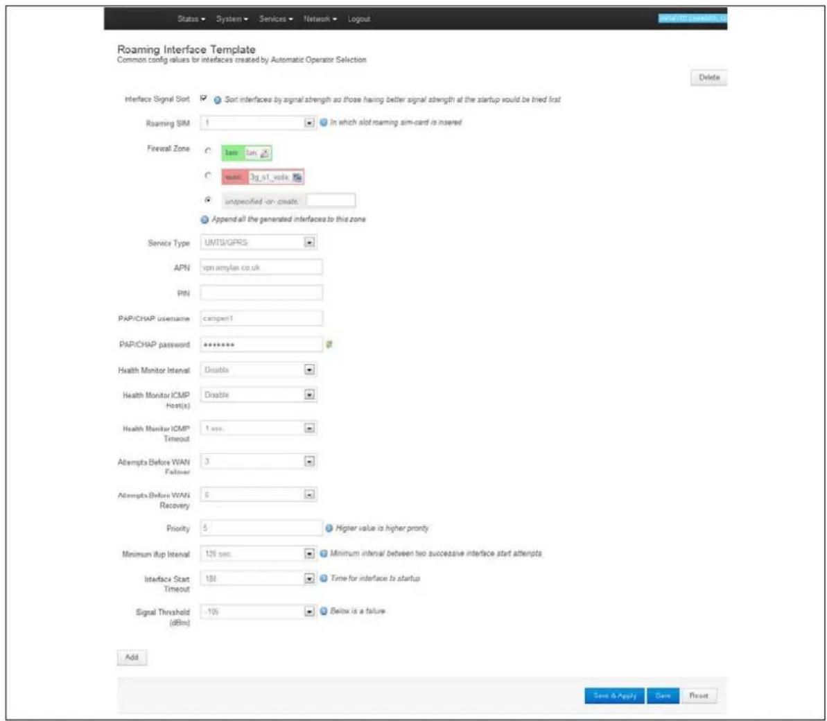
text_image
Roaming Interface Template Common config values for interfaces created by Automatic Operator Selection Delete Interface Signal Sort Sort interfaces by signal strength so those having better signal strength at the startup would be tried first Roaming SIM 1 In which slot roaming sim-card is inserted Firewall Zone low low value: 3g_s1_value unspecified -on create: Append all the generated interfaces to this zone Service Type UMTS/GPRS APN vpn amylan co.uk PIN PAP/CHAP username cangpen1 PAP/CHAP password ****** Health Monitor Interval Disable Health Monitor ICMP Host(s) Disable Health Monitor ICMP Timeout 1 sec. Attempts Before WAN Failuser 3 Attempts Before WAN Recovery 6 Priority 5 Higher value is higher priority Minimum ifup Interval 12% sec Minimum interval between two successive interface start attempts Interface Start Timeout 180 Time for interface to startup Signal Threshold (dBm) -10% Below is a failure Add Save & Apply Save ResetFigure 114: The roaming interface template page
| Web Field/ UCI / Package Option | Description | |
| Web: Interface Signal SortUCI:mobile.@roaming_template[0].sort_sig_strengthOpt: sort_sig_strength | Sorts interfaces by signal strength priority so those that have a better signal strength will be tried first. | |
| Web: Roaming SIMUCI: mobile.main.roaming_simOpt: roaming_sim | Sets which slot to insert roaming SIM card. | |
| 1 | SIM slot 1. | |
| 2 | SIM slot 2. | |
| Web: Firewall ZoneUCI:mobile.@roaming_template[0].firewall_zoneOpt: firewall_zone | Adds all generated interfaces to this zone.Select existing zone or click unspecified or create to create a new zone. | |
| Web: Service TypeUCI:mobile.@roaming_template[0].serviceOpt: service | Specifies the service type that will be used to connect to the network. | |
| UMTS/GPRS GSM module will automatically detect the best available technology code. | ||
| Umts_only Allows GSM module to only connect to 3G network. | ||
| GPRS_only Allows GSM module to only connect to GPRS network. | ||
| cdma Allows GSM module to only connect to cdma network. | ||
| Web: APNUCI: mobile.@roaming_template[0].apnOpt: apn | APN name of Mobile Network Operator. | |
| Web: PINUCI:mobile.@roaming_template[0].pincodeOpt: pincode | SIM card's PIN number. | |
| Web: PAP/CHAP usernameUCI:mobile.@roaming_template[0].usernameOpt: username | Username used to connect to APN. | |
| Web: PAP/CHAP passwordUCI:mobile.@roaming_template[0].passwordOpt: password | Password used to connect to APN. | |
| Web: Health Monitor IntervalUCI:mobile.@roaming_template[0].health_intervalOpt: health_interval | Sets the period to check the health status of the interface. The Health Monitor interval will be used for:Interface state checksPing intervalSignal strength checks | |
| Web: Health Monitor ICMP Host(s)UCI:mobile.@roaming_template[0].icmp_hostsOpt: icmp_hosts | Specifies target IP address for ICMP packets. | |
| Disable | Disables the option | |
| DNS servers | DNS IP addresses will be used. | |
| WAN gateway | Gateway IP address will be used. | |
| custom | Ability to provide IP address. | |
| Web: Health Monitor ICMP TimeoutUCI:mobile.@roaming_template[0].timeoutOpt: timeout | Sets ping timeout in seconds. Choose the time in seconds that the health monitor ICMP will timeout at. | |
| 3 | Wait 3 seconds for ping reply | |
| Range | ||
| Web: Attempts Before WAN FailoverUCI:mobile.@roaming_template[1].health_fail_retriesOpt: health_fail_retries | Defines the number of health check failures before interface is disconnected. | |
| 3 | ||
| Range | ||
| Web: Attempts Before WAN RecoveryUCI:mobile.@roaming_template[0].health_recovery_retriesOpt: health_recovery_retries | Sets the number of health check passes before the interface is considered healthy. This field is not used for a roaming template. | |
| Web: PriorityUCI:mobile.@roaming_template[0].priorityOpt: priority | Type the priority number. The higher the value, the higher the priority. | |
| 0 | ||
| Range | ||
| Web: Minimum ifup intervalUCI:mobile.@roaming_template[0].ifup_retry_secOpt: ifup_retry_sec | Specifies the interval in seconds before retrying the primary interface when pre-empt mode is enabled. | |
| 300 | Retry primary interface every 300 seconds. | |
| Range | ||
| Web: Interface Start TimeoutUCI:mobile.@roaming_template[0].ifup_timeout_secOpt: ifup_timeout | Specifies the time in seconds for interface to start up. If it is not up after this period, it will be considered a fail It is recommended to configure a value greater than 120 seconds. | |
| 40 | ||
| Range | ||
| Web: Signal Threshold (dBm)UCI:mobile.@roaming_template[0].signal_thresholdOpt: signal_threshold | Specifies the minimum signal strength in dBm before considering if the interface fails signal health check. Uses the value stored for sig_dbm in mobile diagnostics.-115 dBm. | |
| Disabled | ||
| Range | -46 to -115 dBm | |
Table 77: Information table for roaming interface template
When you have configured your settings, click Save & Apply.
24.2.10.1 Set multi-WAN operation
From the top menu, select Network -> Multi-Wan. The Multi-WAN page appears.
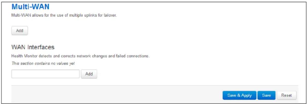
text_image
Multi-WAN Multi-WAN allows for the use of multiple uplinks for failover. Add WAN Interfaces Health Monitor detects and corrects network changes and failed connections. This section contains no values yet Add Save & Apply Save ResetFigure 115: The multi-WAN page
In the Multi-WAN section click Add.
| Web Field/ UCI / Package Option | Description | |
| Web: EnableUCI: multiwan.config.enabledOpt: enabled | Enables multiwan.Select this option. | |
| 0 | Disabled. | |
| 1 | Enabled. | |
| Web: PreemptUCI: multiwan.config.preemptOpt: pre-empt | Enables or disables pre-emption for multiwan. If enabled the router will keep trying to connect to a higher priority interface depending on timer set by ifup_retry_sec.Leave this option unselected. | |
| 0 | Disabled. | |
| 1 | Enabled. | |
| Web: Alternate ModeUCI: multiwan.config.altOpt: alt | Enables or disables alternate mode for multiwan. If enabled the router will use an alternate interface after reboot.Leave this option unselected. | |
| 0 | Disabled. | |
| 1 | Enabled. | |
Table 78: Information table for multi-WAN operation
24.3 Configuring via UCI
24.3.1 PMP + roaming: pre-empt enabled & disabled via UCI
24.3.1.1 PMP interface configuration
The PMP interface is configured in the network package /etc/config/network. To view the network configuration file, enter:
root@VA_router:~# uci export network
package network

config interface 'loopback'
    option ifname 'lo'
    option proto 'static'
    option ipaddr '127.0.0.1'
    option netmask '255.0.0.0'

config interface 'lan'
    option ifname 'eth0'
    option proto 'static'
    option ipaddr '192.168.100.1'
    option netmask '255.255.255.0'

config interface '3g_s1_voda'
    option auto '0'
    option proto '3g'
    option service 'umts'
    option apn 'testIE'
    option username 'test'
    option password 'test'
    option sim 'l'    option operator 'vodafone IE'
To view uci commands, enter:
root@VA_router:~# uci show network
network.loopback=interface
network.loopback.ifname=lo
network.loopback.proto=static
network.loopback.ipaddr=127.0.0.1
network.loopback.netmask=255.0.0.0
network.lan=interface
network.lan.ifname=eth0
network.lan.proto=static
network.lan.ipaddr=192.168.100.1
network.lan.netmask=255.255.255.0
network.3g_s1_voda=interface
network. 3g_s1_voda.auto=0
network. 3g_s1_voda.proto=3g
network. 3g_s1_voda.service=umts
network. 3g_s1_voda.apn=test IE
network. 3g_s1_voda.username=test
network. 3g_s1_voda.password=test
network. 3g_s1_voda.sim=1
network. 3g_s1_voda.operator=vodafone IE
24.3.1.2 Roaming interface configuration
The roaming interface configurations are stored in the mobile package /etc/config/mobile.
To view the mobile configuration file, enter: root@VA_router:\~# uci export mobile
config mobile 'main'
    option sms 'yes'
    option roaming_sim '1'
    option init_get_iccids 'no'
config caller
    option name 'Test'
    option number '*'
    option enabled 'yes'
    option respond 'yes'
config roaming_template
    option roaming_sim '1'
    option firewall_zone 'wan'
    option apn 'test IE'
    option username 'test'
    option password 'test'
    option service 'umts'
    option health_interval '4'
    option icmp_hosts 'disable'
option timeout 'disable'
option health_fail_retries '3'
option signal_threshold '-95'
option priority '5'
option ifup_retry_sec '120'
option ifup_timeout_sec '180'
option defaultroute 'yes'
option sort_sig_strength 'yes'
To view the uci command of package mobile, enter:
root@VA_router:~#uci show mobile
mobile.main=mobile
mobile.main.sms=yes
mobile.main.roaming_sim=1
mobile.main.init_get_iccids=no
mobile.@caller[0]=caller
mobile.@caller[0].name=Test
mobile.@caller[0].number=*
mobile.@caller[0].enabled=yes
mobile.@caller[0].respond=yes
mobile.@roaming_template[0]=roaming_template
mobile.@roaming_template[0].roaming_sim=1
mobile.@roaming_template[0].firewall_zone=wan
mobile.@roaming_template[0].apn=test IE
mobile.@roaming_template[0].username=test
mobile.@roaming_template[0].password=test
mobile.@roaming_template[0].service=umts
mobile.@roaming_template[0].health_interval=4
mobile.@roaming_template[0].icmp_hosts=disable
mobile.@roaming_template[0].timeout=disable
mobile.@roaming_template[0].health_fail_retries=3
mobile.@roaming_template[0].signal_threshold=-95
mobile.@roaming_template[0].priority=5
mobile.@roaming_template[0].ifup_retry_sec=120
mobile.@roaming_template[0].ifup_timeout_sec=180
mobile.@roaming_template[0].defaultroute=yes
mobile.@roaming_template[0].sort_sig_strength=yes
24.3.1.3 Multi-WAN configuration using UCI
The configuration file for package multiwan is stored on /etc/config/multiwan
To see configuration file of mobile package, enter:
root@VA_router:~# cat /etc/config/multiwan
config multiwan 'config'
    option enabled '1'
    option preempt '1'

config interface '3g_s1_voda'
    option health_fail_retries '3'
    option health_interval '3'
    option timeout '1'
    option icmp_hosts 'disable'
    option priority '10'
    option exclusive_group '3g'
    option signal_threshold '-95'
    option ifup_retry_sec '350'
    option ifup_timeout_sec '180'
    option manage_state '1'
To view the uci command of package multiwan, enter:
root@VA_router:~# uci show multiwan
multiwan.config=multiwan
multiwan.config.enabled=1
multiwan.config.preempt=1
multiwan.main_voda=interface
multiwan.main_voda.health_fail_retries=3
multiwan.main_voda.health_interval=3
multiwan.3g_s1_voda.timeout=1
multiwan.3g_s1_voda.icmp_hosts=disable
multiwan.3g_s1 main _voda.priority=10
multiwan.3g_s1_voda.exclusive_group=3g
multiwan.3g_s1_voda.signal_threshold=-95
multiwan.3g_s1_voda.ifup_retry_sec=350
multiwan.3g_s1_voda.ifup_timeout_sec=180
multiwan.3g_s1_voda.manage_state=1
The difference between PMP + roaming: pre-empt enabled and disabled is setting one option parameter. To disable pre-empt, enter:
uci set multiwan.config.preempt=0
uci commit
Note: available values are:
| 0 | Disabled |
| 1 | Enabled |
24.4 Configuring no PMP + roaming using UCI
The roaming interface configuration file is stored in the mobile package /etc/config/mobile. To view the mobile package, enter:
root@VA_router:~# uci export mobile
package mobile
config mobile 'main'
    option sms 'yes'
    option roaming_sim '1'
    option debug '1'

config caller
    option name 'Eval'
    option number '*'
    option enabled 'yes'
    option respond 'yes'

config roaming_template
    option roaming_sim '1'
    option firewall_zone 'wan'
    option apn 'test IE'
    option username 'test'
    option password 'test'
    option service 'umts'
    option health_fail_retries '2'
    option signal_threshold '-100'
    option priority '5'
    option ifup_timeout_sec '180'
    option defaultroute 'yes'
option sort_sig_strength 'yes'
option ifup_retry_sec '200'
option health_interval '120'
option icmp_hosts '172.31.4.129'
option timeout '3'
option health_recovery_retries '3'
To view the mobile package via uci commands, enter:
root@VA_router:~# uci show mobile
mobile.main=mobile
mobile.main.sms=yes
mobile.main.roaming_sim=1
mobile.main.debug=1
mobile.@caller[0]=caller
mobile.@caller[0].name=Eval
mobile.@caller[0].number=*
mobile.@caller[0].enabled=yes
mobile.@caller[0].respond=yes
mobile.@roaming_template[0]=roaming_template
mobile.@roaming_template[0].roaming_sim=1
mobile.@roaming_template[0].firewall_zone=wan
mobile.@roaming_template[0].apn=stream.co.uk
mobile.@roaming_template[0].username=default
mobile.@roaming_template[0].password=void
mobile.@roaming_template[0].service=umts
mobile.@roaming_template[0].health_fail_retries=2
mobile.@roaming_template[0].signal_threshold=-100
mobile.@roaming_template[0].priority=5
mobile.@roaming_template[0].ifup_timeout_sec=180
mobile.@roaming_template[0].defaultroute=yes
mobile.@roaming_template[0].sort_sig_strength=yes
mobile.@roaming_template[0].ifup_retry_sec=200
mobile.@roaming_template[0].health_interval=120
mobile.@roaming_template[0].icmp_hosts=172.31.4.129
mobile.@roaming_template[0].timeout=3
mobile.@roaming_template[0].health_recovery_retries=3
The multiwan package is stored on /etc/config/multiwan. To view the multiwan package, enter:
root@VA_router:~# uci export multiwan
package multiwan

config multiwan 'config'
    option enabled 'yes'
    option preempt 'no'
    option alt_mode 'no'

To see multiwan package via uci, enter:
root@VA_router:~# uci show multiwan
multiwan.config=multiwan
multiwan.config.enabled=yes
multiwan.config.preempt=no
multiwan.config.alt_mode=no
24.5 Automatic operator selection diagnostics via the web interface
24.5.1 Checking the status of the Multi-WAN package
When interfaces are auto-created they are presented in the network and in the Multi-WAN package.
To check interfaces created in the Multi-WAN package, from the top menu, select Network -> Multi-WAN.
To check interfaces that have been created in the network package, from the top menu, select Network -> Interfaces.
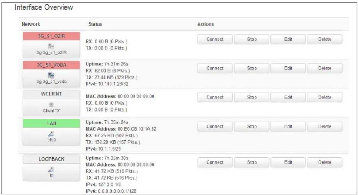
text_image
Interface Overview Network Status Actions 3G_S1_O2IR 3g-3g_a1_o2IR 3G_S1_VODA 3g-3g_a1_voda WCLIENT Client "0" LAN eth0 LOOPBACK lo RX: 0.00 B (0 Pkts.) TX: 0.00 B (0 Pkts.) Uptime: 7h 31m 25s RX: 62.00 B (8 Pkts.) TX: 23.44 KB (329 Pkts.) IPv4: 10.140.1.23/32 MAC Address: 00.00.00.00.00.00 RX: 0.00 B (0 Pkts.) TX: 0.00 B (0 Pkts.) Uptime: 7h 35m 24s MAC Address: 00 E0 C8.10.1A.62 RX: 67.25 KB (502 Pkts.) TX: 132.29 KB (157 Pkts.) IPv4: 10.1.1.9/29 Uptime: 7h 35m 30s MAC Address: 00.00.00.00.00.00 RX: 41.72 KB (516 Pkts.) TX: 41.72 KB (516 Pkts.) IPv4: 127.0.0.1/8 IPv6: 0.0.0.0.0.0.1/128 Connect Stop Edit Delete Connect Stop Edit Delete Connect Stop Edit Delete Connect Stop Edit DeleteFigure 116: The interface overview page
To check the status of the interface you are currently using, in the top menu, click Status. The Interface Status page appears.
Scroll down to the bottom of the page to view Multi-WAN Stats.
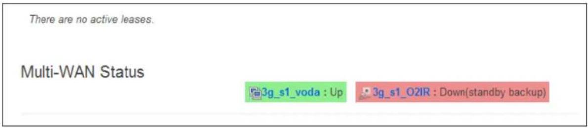
text_image
There are no active leases. Multi-WAN Status 3g_s1_voda : Up 3g_s1_O2IR : Down(standby backup)Figure 117: The status page: multi-WAN status section page
24.6 Automatic operator selection diagnostics via UCI
To check interfaces created in the multi-WAN package, enter:
root@VA_router:~# cat /var/const_state/multiwan
root@VA_GW2021:~# cat /var/const_state/multiwan
multiwan.3g_s1_voda=interface
multiwan.3g_s1_voda.dns=auto
multiwan.3g_s1_voda.health_recovery_retries=5
multiwan.3g_s1_voda.exclusive_group=3g
multiwan.3g_s1_voda.manage_state=yes
multiwan.3g_s1_voda.health_fail_retries=5
multiwan.3g_s1_voda.ifup_retry_sec=80
multiwan.3g_s1_voda.ifup_timeout_sec=80
multiwan.3g_s1_voda.icmp_hosts=disable
multiwan.3g_s1_voda.health_interval=5
multiwan.3g_s1_voda.priority=10
multiwan.3g_s1_voda.timeout=disable
multiwan.3g_s1_voda.signal_threshold=-90
multiwan.3g_s1_o2IR=interface
multiwan.3g_s1_o2IR.dns=auto
multiwan.3g_s1_o2IR.health_recovery_retries=5
multiwan.3g_s1_o2IR.exclusive_group=3g
multiwan.3g_s1_o2IR.manage_state=yes
multiwan.3g_s1_o2IR.health_fail_retries=5
multiwan.3g_s1_o2IR.ifup_retry_sec=80
multiwan.3g_s1_o2IR.ifup_timeout_sec=80
multiwan.3g_s1_o2IR.icmp_hosts=disable
multiwan.3g_s1_o2IR.health_interval=5
multiwan.3g_s1_o2IR.priority=10
multiwan.3g_s1_o2IR.timeout=disable
multiwan.3g_s1_o2IR.signal_threshold=-90
Figure 118: Example of output from the command: cat /var/const_stat/multiwan
To check interfaces created in the network package, enter:
root@VA_router:~# cat /var/const_state/network
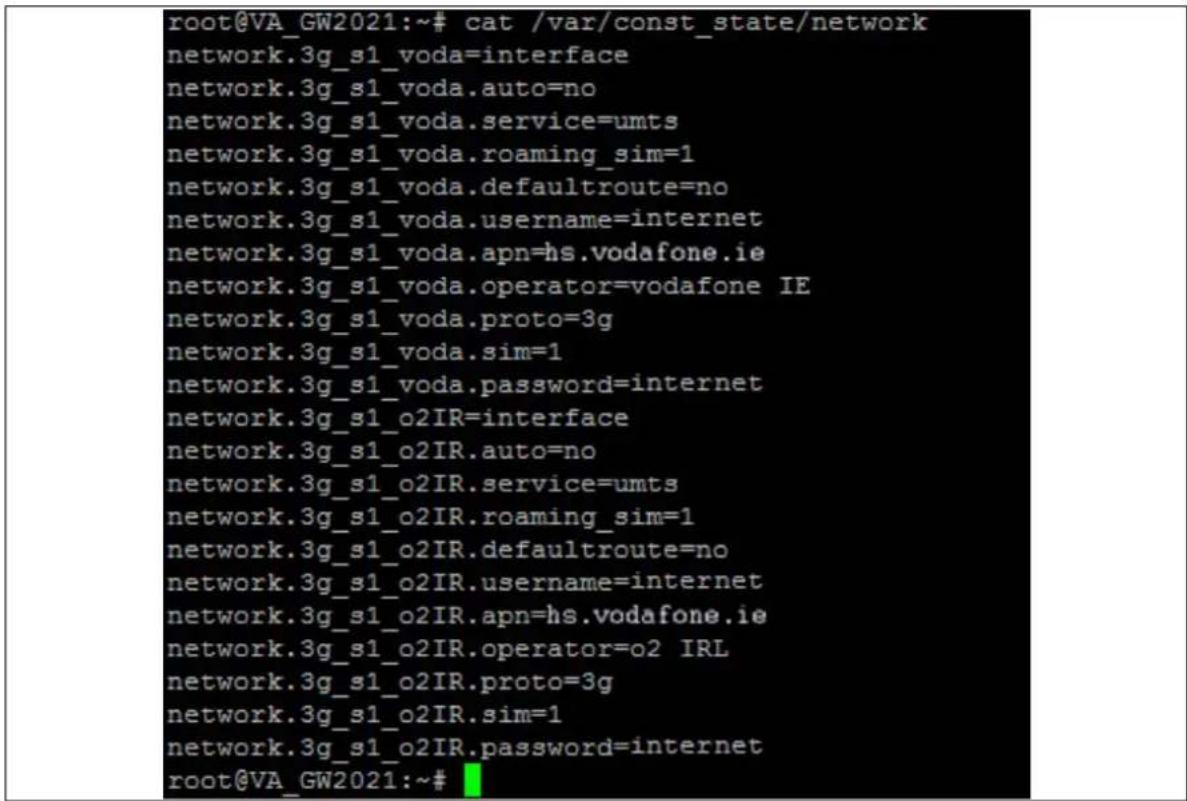
text_image
root@VA_GW2021:~# cat /var/const_state/network network.3g_s1_voda=interface network.3g_s1_voda.auto=no network.3g_s1_voda.service=umts network.3g_s1_voda.roaming_sim=1 network.3g_s1_voda.defaultroute=no network.3g_s1_voda.username=internet network.3g_s1_voda.apn=hs.vodafone.ie network.3g_s1_voda.operator=vodafone IE network.3g_s1_voda.proto=3g network.3g_s1_voda.sim=1 network.3g_s1_voda.password=internet network.3g_s1_o2IR=interface network.3g_s1_o2IR.auto=no network.3g_s1_o2IR.service=umts network.3g_s1_o2IR.roaming_sim=1 network.3g_s1_o2IR.defaultroute=no network.3g_s1_o2IR.username=internet network.3g_s1_o2IR.apn=hs.vodafone.ie network.3g_s1_o2IR.operator=o2 IRL network.3g_s1_o2IR.proto=3g network.3g_s1_o2IR.sim=1 network.3g_s1_o2IR.password=internet root@VA_GW2021:~#Figure 119: Example of output from the command cat /var/const_state/network
To check the status of the interface you are currently using, enter:
root@VA_router:~# cat /var/const_state_/mobile
root@VA_GW2021:~# cat /var/const_state/mobile
mobile.3g_0=status
mobile.3g_0.sim1_iccid=89314404000039480265
root@VA_GW2021:~#
root@VA_GW2021:~#
root@VA_GW2021:~# cat /var/state/mobile
mobile.3g_0=status
mobile.3g_0.sim_slot=1
mobile.3g_0.sim_in=yes
mobile.3g_0.registered=5, Roaming
mobile.3g_0.reg_code=5
mobile.3g_0.imei=357784040034322
mobile.3g_0.imsi=204043726270034
mobile.3g_0.registered_pkt=5, Roaming
mobile.3g_0.reg_code_pkt=5
mobile.3g_0.area=BCC
mobile.3g_0.tech=2
mobile.3g_0.technology=UTRAN
mobile.3g_0.operator=1,0,"vodafone IE",2
mobile.3g_0.cell=AA787
mobile.3g_0.sig_dbm=-113
root@VA_GW2021:~#
Figure 120: Example of output from the command cat /vat/const_state_/mobile
25 Configuring Connection Watch (cwatch)
Connection Watch is a recovery feature to enable dynamic recovery of an interface. You can configure multiple instances of Connection Watch.
Connection Watch consists of the following configurable instances:
- Interface(s) to be monitored
- Failure periods
- Recovery actions
If no data is received over the monitored interface during the configured duration, then the recovery action is performed. If more than one interface is specified under a single Connection Watch, the recovery action will be performed only if no data is received on both of the interfaces for the defined period.
Currently three configurable periods and associated recovery actions can be defined.
25.1 Configuration package used
| Package | Sections |
| cwatch | watch |
25.2 Configuring Connection Watch using the web interface
To configure Connection Watch using the web interface, select Services->Connection Watch. The Connection Watch page appears.
If no Connection Watch configuration exists in the configuration file, first enter a name for the Connection Watch instance and select Add.
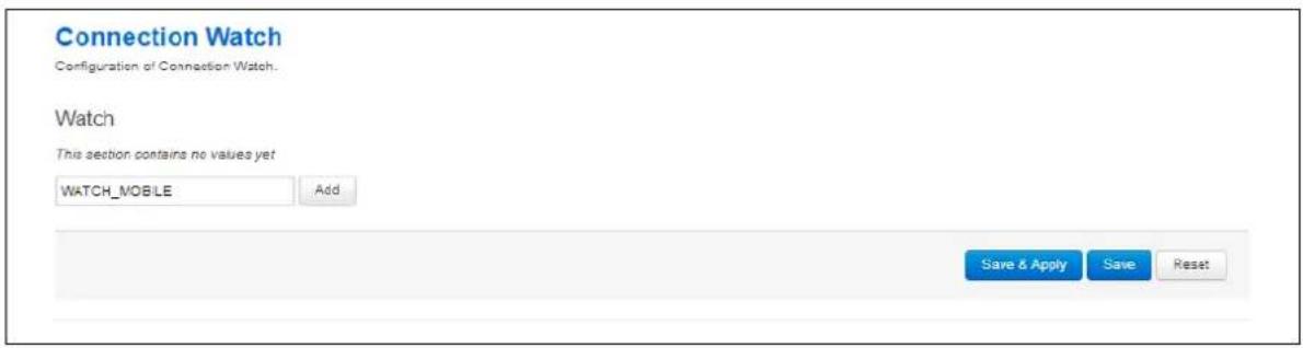
text_image
Connection Watch Configuration of Connection Watch. Watch This section contains no values yet WATCH_MOBLE Add Save & Apply Save ResetFigure 121: The add connection watch configuration page
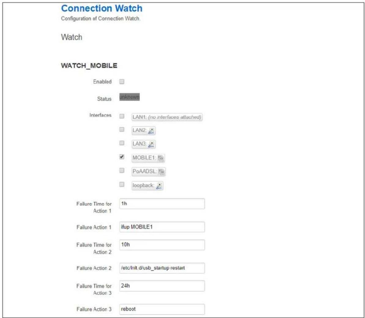
text_image
Connection Watch Configuration of Connection Watch. Watch WATCH_MOBILE Enabled Status unknown Interfaces LAN1: (no interfaces attached) LAN2 LAN3 MOBILE1 PoAADSL loopback Failure Time for Action 1 1h Failure Action 1 ifup MOBILE1 Failure Time for Action 2 10h Failure Action 2 /etc/init.d/usb_startup restart Failure Time for Action 3 24h Failure Action 3 rebootFigure 122: The connection watch configuration page
| Web Field/ UCI / Package Option | Description | |
| Web: EnabledUCI: cwatch.@watch[0].enabledOpt: enabled | Enables a cwatch instance. | |
| 0 | Disabled. | |
| 1 | Enabled. | |
| Web: InterfacesUCI: cwatch.@watch[0].test_ifacesOpt: test_ifaces | Defines the interface name(s) to monitor. Multiple interfaces are delimited by space separator. Example:option test_ifaces 'WANADSL WANMOBILE'If multiple interfaces are defined the failure action will only be triggered if no traffic is received on all interfaces for the defined period. | |
| Web: Failure Time for Action 1UCI: cwatch.@watch[0].failure_time_1Opt: failure_time_1 | Defines a duration to monitor an interface for receive traffic.Duration can be specified in seconds, minutes, hours, days. | |
| 1h | ||
| Range | s; m; h; d; | |
| Web: Failure Action 1UCI: cwatch.@watch[0].failure_action_1Opt: failure_action_1 | Defines the failure action associated with failure_time_1.Example to force up interface:option failure_action_1 'ifup wan' | |
| blank | ||
| Range | ||
| Web: Failure Time for Action 2UCI: cwatch.@watch[0].failure_time_2Opt: failure_time_2 | Defines a second duration to monitor an interface for receive traffic. Duration can be specified in seconds, minutes, hours, days. | |
| 10h | ||
| Range | s; m; h; d; | |
| Web: Failure Action 2UCI: cwatch.@watch[0].failure_action_2Opt: failure_action_2 | Defines the failure action associated with failure_time_2. Example to reset usb:option failure_action_1 '/etc/init.d/usb_startup restart' | |
| blank | ||
| Range | ||
| Web: Failure Time for Action 3UCI: cwatch.@watch[0].failure_time_3Opt: failure_time_3 | Defines a third duration to monitor an interface for receive traffic. Duration can be specified in seconds, minutes, hours, days. | |
| 24h | ||
| Range | s; m; h; d; | |
| Web: Failure Action 3UCI: cwatch.@watch[0].failure_action_3Opt: failure_action_3 | Defines the failure action associated with failure_time_3. Example to reset usb:option failure_action_3 'reboot' | |
| blank | ||
| Range | ||
Table 79: Information table for cwatch section
25.3 Configuring cwatch using command line
By default, all cwatch instances are named 'watch', the cwatch instance is identified by @watch then the watch position in the package as a number. For example, for the first route in the package using UCI:
cwatch.@watch[0]=watch
cwatch.@watch[0].enabled=1
Or using package options:
config watch
option enabled '1'
However, to better identify it, we recommend giving the cwatch instance a name. For example, a watch named 'WATCH_MOBILE' will be cwatch.WATCH_MOBILE.
To define a named cwatch instance using UCI, enter:
cwatch.WATCH_MOBILE=watch
cwatch.WATCH_MOBILE.enabled=1
To define a named cwatch instance using package options, enter:
config watch 'WATCH_MOBILE'
option 'enabled' '1'
25.3.1 cwatch using UCI
root@VA_router:~# uci show cwatch
cwatch.WATCH_MOBILE=watch
cwatch.WATCH_MOBILE.enabled=1
cwatch.WATCH_MOBILE.test_ifaces=wan
cwatch.WATCH_MOBILE.failure_time_1=1h
cwatch.WATCH_MOBILE.failure_action_1=ifup wan
cwatch.WATCH_MOBILE.failure_time_2=10h
cwatch.WATCH_MOBILE.failure_action_2=/etc/init.d/usb_startup restart
cwatch.WATCH_MOBILE.failure_time_3=24h
cwatch.WATCH_MOBILE.failure_action_3=reboot
25.3.2 cwatch using package options
root@VA_router:~# uci export cwatch
package cwatch

config watch 'WATCH_MOBILE'
    option enabled '1'
    option test_ifaces wan
    option failure_time_1 '1h'
    option failure_action_1 'ifup wan
    option failure_time_2 '10h'
    option failure_action_2 '/etc/init.d/usb_startup restart'
    option failure_time_3 '24h'
    option failure_action_3 'reboot'
25.4 cwatch diagnostics
25.4.1 Syslog
A syslog message will be generated when cwatch starts:
cwatch[x]: cwatch configuration OK. Entering main loop...
Syslog messages will be generated when the failure action is triggered:
cwatch[x]: Watch WATCH_MOBILE executed action 1
cwatch[x]: Watch WATCH_MOBILE executed action 2
cwatch[x]: Watch WATCH_MOBILE executed action 3
26 Configuring DHCP server and DNS (Dnsmasq)
Dynamic Host Configuration Protocol (DHCP) server is responsible for assigning IP addresses to hosts. IP addresses can be given out on different interfaces and different subnets. You can manually configure lease time as well as setting static IP to host mappings.
Domain Name Server (DNS) is responsible for resolution of IP addresses to domain names on the internet.
Dnsmasq is the application which controls DHCP and DNS services. Dnsmasq has two sections; one to specify general DHCP and DNS settings and one or more DHCP pools to define DHCP operation on the desired network interface.
26.1 Configuration package used
| Package | Sections |
| dhcp | dnsmasq |
| dhcp | |
| host |
26.2 Configuring DHCP and DNS using the web interface
In the top menu, select Network -> DHCP and DNS. The DHCP and DNS page appears. There are three sections: Server Settings, Active Leases, and Static Leases.
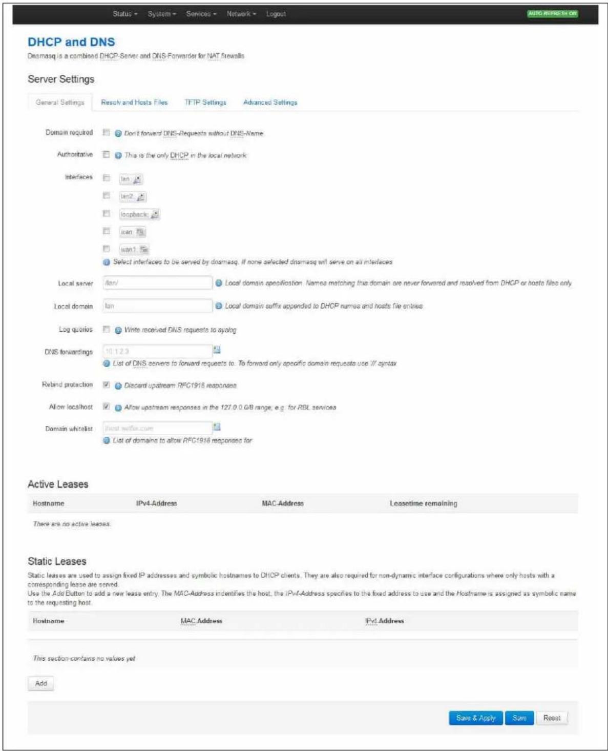
text_image
DHCP and DNS Dnsmasq is a combined DHCP-Server and DNS-Forwarder for NAT firewalls Server Settings General Settings Resolve and Hosts Files TFTP Settings Advanced Settings Domain required Don't forward DNS-Requests without DNS-Name Authoritative This is the only DHCP in the local network Interfaces lan lcn2 loopback wan File wan1 File Select interfaces to be served by dnsmasq. If none selected dnsmasq will serve on all interfaces Local server lan/ Local domain specification. Names matching this domain are never forwarded and resolved from DHCP or hosts files only. Local domain lan Local domain suffix appended to DHCP names and hosts file entries Log queries Write received DNS requests to ayolog DNS forwardings 10.12.9 List of DNS servers to forward requests to. To forward only specific domain requests use // syntax Rebind protection Discard upstream RFC1918 responses Allow localhost Allow upstream responses in the 127.0.0 GB range, e.g. for RBL services Domain whitelist Host wifi.com List of domains to allow RFC1916 responses for Active Leases Hostname IPv4-Address MAC-Address Leasetime remaining There are no active leases. Static Leases Static leases are used to assign fixed IP addresses and symbolic hostnames to DHCP clients. They are also required for non-dynamic interface configurations where only hosts with a corresponding lease are served. Use the Add Button to add a new lease entry. The MAC-Address identifies the host, the IPv4-Address specifies to the fixed address to use and the Hostname is assigned as symbolic name to the requesting host. Hostname MAC-Address IPv4-Address This section contains no values yet Add Save & Apply Save ResetFigure 123: The DHCP and DNS page
26.2.1 Dnsmasq: general settings
| Web Field/ UCI/ Package Option | Description | |
| Web: Domain requiredUCI: dhcp.@dnsmasq[0].domainneededOpt: domainneeded | Defines whether to forward DNS requests without a DNS name. Dnsmasq will never forward queries for plain names, without dots or domain parts, to upstream nameservers. If the name is not known from /etc/hosts or DHCP then a "not found" answer is returned. | |
| 1 | Enabled. | |
| 0 | Disabled. | |
| Web: AuthoritativeUCI: dhcp.@dnsmasq[0]. authoritativeOpt: authoritative | Forces authoritative mode, this speeds up DHCP leasing. Used if this is the only server in the network. | |
| 1 | Enabled. | |
| 0 | Disabled. | |
| Web: InterfacesUCI: dhcp.@dnsmasq[0].interfaceOpt: list interface | Defines the list of interfaces to be served by dnsmasq. If you do not select a specific interface, dnsmasq will serve on all interfaces. Configured interfaces are shown via the web GUI. | |
| Lan | Serve only on LAN interface. | |
| Range | ||
| Web: Local ServerUCI: dhcp.@dnsmasq[0].localOpt: local | Specifies the local domain. Names matching this domain are never forwarded and are resolved from DHCP or host files only. | |
| /lan/ | ||
| Range | ||
| Web: Local DomainUCI: dhcp.@dnsmasq[0].domainOpt: domain | Specifies local domain suffix appended to DHCP names and hosts file entries. | |
| lan | ||
| Range | ||
| Web: Log QueriesUCI: dhcp.@dnsmasq[0].logqueriesOpt: logqueries | Writes received DNS requests to syslog. | |
| 0 | Disabled. | |
| 1 | Enabled. | |
| Web: DNS ForwardingsUCI: dhcp.@dnsmasq[0].serverOpt: list server | List of DNS server to forward requests to. To forward specific domain requests only, use // syntax. When using UCI, enter multiple servers with a space between them. | |
| No DNS server configured. | ||
| Range | ||
| Web: Rebind ProtectionUCI: dhcp.@dnsmasq[0].rebind_protectionOpt: rebind_protection | Enables DNS rebind attack protection by discarding upstream RFC1918 responses. | |
| 0 | Disabled. | |
| 1 | Enabled. | |
| Web: Allow LocalhostUCI: dhcp.@dnsmasq[0].rebind_localhostOpt: rebind_localhost | Defines whether to allow upstream responses in the 127.0.0.0/8 range. This is required for DNS based blacklist services. Only takes effect if rebind protection is enabled. | |
| 0 | Disabled. | |
| 1 | Enabled. | |
| Web: Domain WhitelistUCI: dhcp.@dnsmasq[0].rebind_domainOpt: list rebind_domain | Defines the list of domains to allow RFC1918 responses to. Only takes effect if rebind protection is enabled. When using UCI multiple servers should be entered with a space between them. | |
| No list configured. | ||
| Range | ||
Table 80: Information table for general server settings
26.2.2 Dnsmasq: resolv and host files
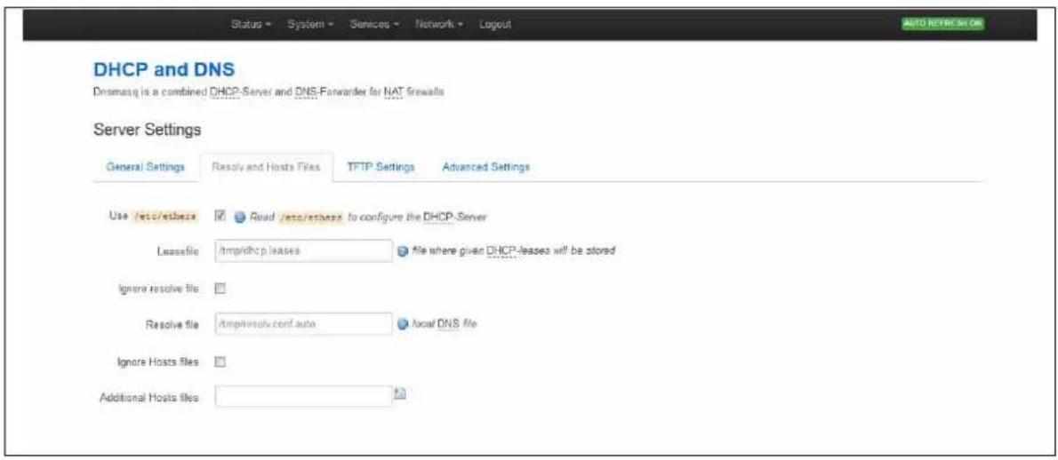
text_image
Status - System - Services - Network - Logout DHCP and DNS DNSmaxq is a combined DHCP-Server and DNS-Forwarder for NAT firewalls Server Settings General Settings Resolv and Hosts Files TFTP Settings Advanced Settings Use /etc/ethers Read /etc/ethers to configure the DHCP Server Leasefile Ampridhcp leases File where given DHCP-leases will be stored Ignore resolve file Resolve file Ampheresolv.conf auto focal DNS file Ignore Hosts files Additional Hosts files AUTO RETIRE SET ORFigure 124: The resolv and host files section
| Web Field/ UCI / Package Option | Description | |
| Web: Use /etc/ethersUCI: dhcp@dnsmasq[0].readethersOpt: readethers | Defines whether static lease entries are read from /etc/ethers. | |
| 1 | Enabled. | |
| 0 | Disabled. | |
| Web: LeasefileUCI: dhcp@dnsmasq[0].leasefileOpt: leasefile | Defines the file where given DHCP leases will be stored. The DHCP lease file allows leases to be picked up again if dnsmasq is restarted. | |
| /tmp/dhcp.leases | Store DHCP leases in this file. | |
| Range | ||
| Web: Ignore resolve fileUCI: dhcp@dnsmasq[0].noresolvOpt: noresolv | Defines whether to use the local DNS file for resolving DNS. | |
| 0 | Use local DNS file. | |
| 1 | Ignore local DNS file. | |
| Web: Resolve fileUCI: dhcp@dnsmasq[0].resolvfileOpt: resolvfile | Defines the local DNS file. Default is /tmp/resolv.conf.auto | |
| Web: Ignore Hosts filesUCI: dhcp@dnsmasq[0].nohostsOpt: nohosts | Defines whether to use local host's files for resolving DNS. | |
| 0 | Use local hosts file. | |
| 1 | Ignore local hosts file. | |
| Web: Additional Hosts filesUCI: dhcp@dnsmasq[0].addnhostsOpt: list addnhosts | Defines local host's files. When using UCI multiple servers should be entered with a space between them. | |
Table 81: Information table for resolv and host files section
26.2.3 Dnsmasq: TFTP settings
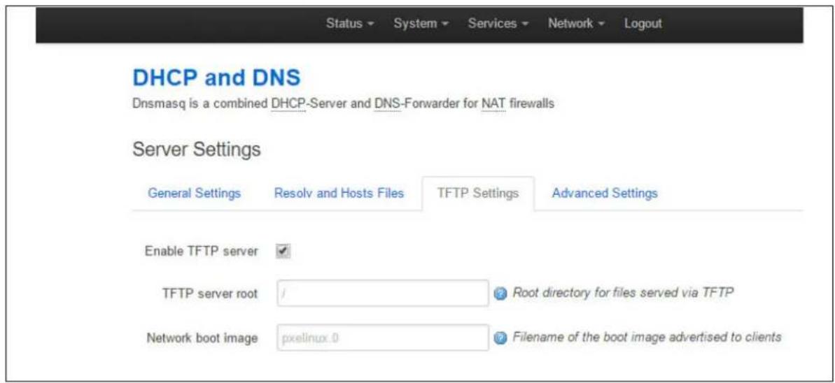
text_image
Status ▼ System ▼ Services ▼ Network ▼ Logout DHCP and DNS Dnsmasq is a combined DHCP-Server and DNS-Forwarder for NAT firewalls Server Settings General Settings Resolv and Hosts Files TFTP Settings Advanced Settings Enable TFTP server ✓ TFTP server root / ? Root directory for files served via TFTP Network boot image pxelinux .0 ? Filename of the boot image advertised to clientsFigure 125: The TFTP settings section
| Web Field/ UCI / Package Option | Description | |
| Web: Enable TFTP ServerUCI: dhcp.@dnsmasq[0].enable_tftpOpt: enable_tftp | Enables the TFTP server. | |
| 0 | Disabled. | |
| 1 | Enabled. | |
| Web: Enable TFTP ServerUCI: dhcp.@dnsmasq[0].tftp_rootOpt: tftp_root | Defines root directory for file served by TFTP. | |
| Web: Enable TFTP ServerUCI: dhcp.@dnsmasq[0].dhcp_bootOpt: dhcp_boot | Defines the filename of the boot image advertised to clients. This specifies BOOTP options, in most cases just the file name. | |
Table 82: Information table for TFTP settings
26.2.4 Dnsmasq: advanced settings
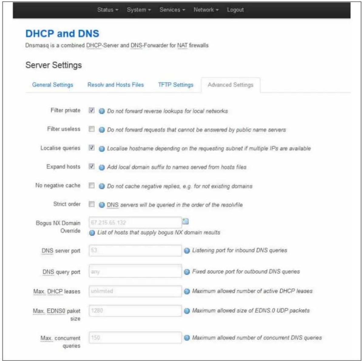
text_image
Status ▼ System ▼ Services ▼ Network ▼ Logout DHCP and DNS Dnsmasq is a combined DHCP-Server and DNS-Forwarder for NAT firewalls Server Settings General Settings Resolv and Hosts Files TFTP Settings Advanced Settings Filter private ✓ Do not forward reverse lookups for local networks Filter useless ☐ Do not forward requests that cannot be answered by public name servers Localise queries ✓ Localise hostname depending on the requesting subnet if multiple IPs are available Expand hosts ✓ Add local domain suffix to names served from hosts files No negative cache ☐ Do not cache negative replies, e.g. for not existing domains Strict order ☐ DNS servers will be queried in the order of the resolvfile Bogus NX Domain 67.215.65.132 Override List of hosts that supply bogus NX domain results DNS server port 53 Listening port for inbound DNS queries DNS query port any Fixed source port for outbound DNS queries Max. DHCP leases unlimited Maximum allowed number of active DHCP leases Max. EDNS0 paket size 1280 Maximum allowed size of EDNS.0 UDP packets Max. concurrent queries 150 Maximum allowed number of concurrent DNS queriesFigure 126: The advanced settings page
| Web Field/ UCI / Package Option | Description | |
| Web: Filter privateUCI: dhcp.@dnsmasq[0].Opt: boguspriv | Enables disallow option for forwarding reverse lookups for local networks. This rejects reverse lookups to private IP ranges where no corresponding entry exists in /etc/hosts. | |
| 1 | Enabled. | |
| 0 | Disabled. | |
| Web: Filter uselessUCI: dhcp.@dnsmasq[0].filterwin2kOpt: filterwin2k | Enables disallow option for forwarding requests that cannot be answered by public name servers. Normally enabled for dial on demand interfaces. | |
| 1 | Enabled. | |
| 0 | Disabled. | |
| Web: Localise queriesUCI: dhcp@dnsmasq[0].localise_queriesOpt: localise_queries | Defines whether to uses IP address to match the incoming interface if multiple addresses are assigned to a host name in /etc/hosts. | |
| 1 | Enabled. | |
| 0 | Disabled. | |
| Web: Expand hostsUCI: dhcp@dnsmasq[0].expandhostsOpt: expandhosts | Adds a local domain suffix to names served from host files. | |
| 1 | Enabled. | |
| 0 | Disabled. | |
| Web: No negative cacheUCI: dhcp@dnsmasq[0].nonegcacheOpt: nonegcache | Enable this to stop caching of negative replies. For example, non-existing domains. | |
| 1 | Enabled. | |
| 0 | Disabled. | |
| Web: Strict orderUCI: dhcp@dnsmasq[0].strictorderOpt: strictorder | Enable this to query DNS servers in the order of the resolve file. | |
| 1 | Enabled. | |
| 0 | Disabled. | |
| Web: Bogus NX Domain overrideUCI: dhcp@dnsmasq[0].bogusnxdomainOpt: list bogusnxdomain | A list of hosts that supply bogus NX domain results. When using UCI multiple servers should be entered with a space between them. | |
| Empty list | ||
| Range | ||
| Web: DNS server portUCI: dhcp@dnsmasq[0].portOpt: port | Listening port for inbound DNS queries. | |
| 53 | Set to 0 to disable DNS functionality. | |
| Range | 0 - 65535 | |
| Web: DNS query portUCI: dhcp@dnsmasq[0].queryportOpt: queryport | Defines fixed source port for outbound DNS queries. | |
| any | ||
| Range | any; 0 - 65535 | |
| Web: Max DHCP leasesUCI: dhcp@dnsmasq[0].dhcpleasemaxOpt: dhcpleasemax | Defines the maximum allowed number of active DHCP leases. | |
| unlimited | ||
| Range | ||
| Web: Max EDNS0 packet sizeUCI: dhcp@dnsmasq[0].ednspacket_maxOpt: ednspacket_max | Defines the maximum allowed size of EDNS.0 UDP packets in bytes. | |
| 1280 | 1280 bytes | |
| Range | ||
| Web: Max concurrent queriesUCI: dhcp@dnsmasq[0].dnsforwardmaxOpt: dnsforwardmax | Maximum allowed number of concurrent DNS queries. | |
| 150 | 1280 bytes | |
| Range | ||
Table 83: Information table for advanced settings
26.2.5 Active leases
This section displays all currently active leases.
| Active Leases | |||
| Active Leases | |||
| Hostname | IPv4 Address | MAC-Address | Leasotime remaining |
| There are no active leases. | |||
Figure 127: The active leases section
| Web Field/ UCI / Package Option | Description |
| Web: HostnameUCI: dhcp.@host[0].nameOpt: name | Displays the hostname of the client. |
| Web: IPv4 AddressUCI: dhcp.@host[0].ipOpt: ip | Displays the IP address of the client. |
| Web: MAC AddressUCI: dhcp.@host[0].macOpt: mac | Displays the MAC address of the client. |
| Web: Lease time remainingUCI: n/aOpt: n/a | Displays the remaining lease time. |
Table 84: Information table for active leases section
26.2.6 Static leases
Use static leases to assign fixed IP addresses and symbolic hostnames to DHCP clients. Static leases are also required for non-dynamic interface configurations where only hosts with a corresponding lease are served. Click Add to add a new lease entry.
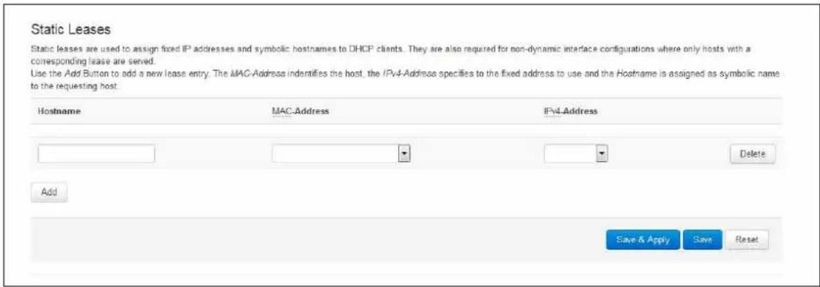
text_image
Static Leases Static leases are used to assign fixed IP addresses and symbolic hostnames to DHCP clients. They are also required for non-dynamic interface configurations where only hosts with a corresponding lease are served. Use the Add Button to add a new lease entry. The MAC-Address identifies the host, the IPv4-Address specifies to the fixed address to use, and the Hostname is assigned as symbolic name to the requesting host. Hostname MAC-Address IPv4-Address Add Save & Apply Save ResetFigure 128: The static leases section
| Web Field/ UCI / Package Option | Description | |
| Web: HostnameUCI: dhcp.@host[0].nameOpt: name | Defines the optional symbolic name to assign to this static DHCP entry. | |
| 1 | Enabled. | |
| 0 | Disabled. | |
| Web: MAC AddressUCI: dhcp.@host[0].macOpt: mac | Defines the hardware address that identifies the host. | |
| Web: IPv4 AddressUCI: dhcp.@host[0].ipOpt: ip | The IPv4 address specifies the fixed address to use for this host. | |
Table 85: Information table for static leases
26.3 Configuring DHCP and DNS using UCI
26.3.1 Common options section
Possible section types of the DHCP configuration file are defined below. Not all types may appear in the file and most of them are only needed for special configurations. Common configurations are Common Options, DHCP Pools and Static Leases.
The configuration section type dnsmasq determines values and options relevant to the overall operation of dnsmasq and the DHCP options on all interfaces served. The following table lists all available options, their default value, as well as the corresponding dnsmasq command line option.
These are the default settings for the common options:
root@VA_router:~# uci show dhcp
dhcp.@dnsmasq[0]=dnsmasq
dhcp.@dnsmasq[0].domainneeded=1
dhcp.@dnsmasq[0].boguspriv=1
dhcp.@dnsmasq[0].filterwin2k=0
dhcp.@dnsmasq[0].localise_queries=1
dhcp.@dnsmasq[0].logqueries=1
dhcp.@dnsmasq[0].rebind_protection=1
dhcp.@dnsmasq[0].rebind_localhost=1
dhcp.@dnsmasq[0].local=/lan/
dhcp.@dnsmasq[0].domain=lan
dhcp.@dnsmasq[0].expandhosts=1
dhcp.@dnsmasq[0].nonegcache=0
dhcp.@dnsmasq[0].authoritative=1
dhcp.@dnsmasq[0].readethers=1
dhcp.@dnsmasq[0].leasefile=/tmp/dhcp.leases
dhcp.@dnsmasq[0].noresolve=0
dhcp.@dnsmasq[0].resolvfile=/tmp/resolv.conf.auto
dhcp.@dnsmasq[0].nohosts=0
dhcp.@dnsmasq[0].addnhosts=hostfile1 hostfile2
dhcp.@dnsmasq[0].interface=lan
dhcp.@dnsmasq[0].server=1.1.1.1 2.2.2.2
dhcp.@dnsmasq[0].rebind domain=tes.domain
dhcp.@dnsmasq[0].enable_tftp=0
dhcp.@dnsmasq[0].tftp_root=/tmp/tftp
dhcp.@dnsmasq[0].dhcp_boot=boot.image
dhcp.@dnsmasq[0].nonegcache=0
dhcp.@dnsmasq[0].strictorder=0
dhcp.@dnsmasq[0].bogusnxdomain=1.1.1.1 2.2.2.2
dhcp.@dnsmasq[0].port=53
dhcp.@dnsmasq[0].dhcpleasemax=150
dhcp.@dnsmasq[0].ednspacket_max=1280
dhcp.@dnsmasq[0].dnsforwardmax=150
root@VA_router:~# uci show dhcp
config 'dnsmasq'
option domainneeded '1'
option rebind_protection '1'
option rebind_localhost '1'
option local '/lan/'
option domain 'lan'
option authoritative '1'
option readethers '1'
option leasefile '/tmp/dhcp.leases'
list interface 'lan'
list server '1.2.3.4'
list server '4.5.6.7'
list rebind_domain 'test1.domain'
list rebind_domain 'tes2.domain'
option logqueries '1'
option resolvfile '/tmp/resolv1.conf.auto'
list addnhosts 'hosts1'
list addnhosts 'hosts2'
option enable_tftp '1'
option tftp_root '/tmp/tftp'
option dhcp_boot 'boot.image'
option filterwin2k '1'
option nonegcache '1'
option strictorder '1'
list bogusnxdomain '1.1.1.1'
list bogusnxdomain '2.2.2.2'
option port '53'
option dhcpleasemax '150'
option ednspacket_max '1280'
option dnsforwardmax '150'
Options local and domain enable dnsmasq to serve entries in /etc/hosts as well as the DHCP client's names as if they were entered into the LAN DNS domain.
For options domainneeded, boguspriv, localise_queries, and expandhosts make sure that requests for these local host names (and the reverse lookup) never get forwarded to the upstream DNS servers.
26.4 Configuring DHCP pools using UCI
Sections of the type dhcp specify per interface lease pools and settings. Typically there is at least one section of this type present in the /etc/config/dhcp file to cover the LAN interface.
You can disable a lease pool for a specific interface by specifying the ignore option in the corresponding section.
A minimal example of a dhcp section is shown below.
root@VA_router:~# uci show dhcp.lan
dhcp.lan=dhcp

dhcp.lan.interface=lan
dhcp.lan.start=100
dhcp.lan.limit=150
dhcp.lan.leasetime=12h
dhcp.lan.ignore=0
root@VA_router:~# uci export dhcp
config 'dhcp' 'lan'
option 'interface' 'lan'
option 'start' '100'
option 'limit' '150'
option 'leasetime' '12h'
option ignore 0
| UCI / Package Option | Description | |
| Web: n/aUCI: dhcp. .interfaceOpt: interface | Defines the interface that is served by this DHCP pool. This must be one of the configured interfaces. | |
| lan | Enabled. | |
| Range | ||
| Web: n/aUCI: dhcp. .startOpt: start | Defines the offset from the network address for the start of the DHCP pool. It may be greater than 255 to span subnets. | |
| 100 | ||
| Range | ||
| Web: n/aUCI: dhcp. .limitOpt: limit | Defines the offset from the network address for the end of the DHCP pool. | |
| 150 | ||
| Range | 0 - 255 | |
| Web: n/aUCI: dhcp.leasetimeOpt: leasetime | Defines the lease time of addresses handed out to clients, for example 12h or 30m. | |
| 12h | 12 hours | |
| Range | ||
| Web: n/aUCI: dhcp.ignoreOpt: ignore | Defines whether this DHCP pool is enabled. | |
| 0 | DHCP pool enabled. | |
| 1 | DHCP pool disabled. | |
| Web: n/aUCI: dhcp. .forceOpt: force | Forces DHCP serving on the specified interface even if another DHCP server is detected on the same network segment. | |
| 0 | Disabled. | |
| 1 | Enabled. | |
| Web: n/aUCI: dhcp. .dhcp_optionOpt: list dhcp_option | Defines additional options to be added for this dhcp pool. For example with 'list dhcp_option 26,1470' or 'list dhcp_option mtu, 1470' you can assign a specific MTU per DHCP pool. Your client must accept the MTU option for this to work. | |
| No options defined. | ||
| Syntax | Option_number, option value. | |
| Web: n/aUCI: dhcp. dynamicdhcpOpt: dynamicdhcp | Defines whether to allocate DHCP leases. | |
| 1 | Dynamically allocate leases. | |
| 0 Use /etc/ethers file for serving DHCP leases. | ||
| Web: n/aUCI: dhcp. dynamicdhcpOpt: networkid | Assigns a network-id to all clients that obtain an IP address from this pool. | |
Table 86: Information table for DHCP pool UCI and package options
26.5 Configuring static leases using UCI
You can assign fixed IP addresses to hosts on your network, based on their MAC (hardware) address.
root@VA_router:~# uci show dhcp.mypc
dhcp.mypc=host

root@VA_router:~# uci show dhcp.mypc
dhcp.mypc.ip=192.168.1.2
dhcp.mypc.mac=00:11:22:33:44:55
dhcp.mypc.name=mypc

root@VA_router:~# uci export dhcp
config host 'mypc'
option ip '192.168.1.2'
option mac '00:11:22:33:44:55'
option name 'mypc'
This adds the fixed IP address 192.168.1.2 and the name "mypc" for a machine with the (Ethernet) hardware address 00:11:22:33:44:55.
27 Configuring DHCP client
This section describes how to configure an interface as a DHCP client. This section will only detail the configuration for DHCP client. For information on how to configure other interface options such as firewall zone, mapping of switch ports, etc, refer to standard interface configuration document.
27.1 Configuration packages used
| Package | Sections |
| network | interface |
27.2 Configuring DHCP client using the web interface
DHCP client is configured under the interface configuration by setting the interface protocol to DHCP Client. To create and edit interfaces via the web interface, in the top menu, click Network -> Interfaces. The Interfaces overview page appears.
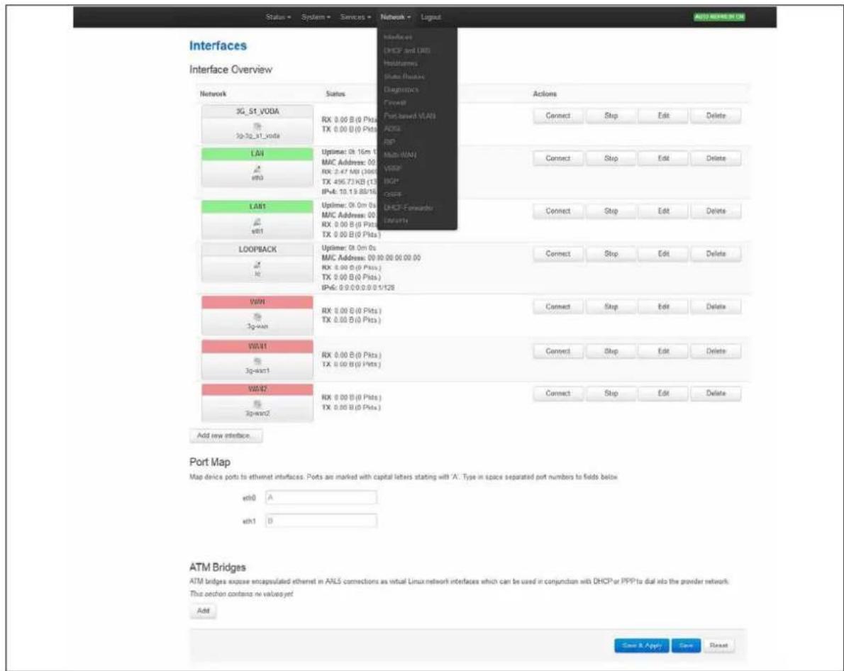
text_image
Status - System - Services - Network - Lignat Auto REFERENCE ON Interfaces UNICP and IAC Holdemms State Busines Diagnostics Forward 3G_51_VODA 3g-3g_51_voda LAN w00 LAN1 w01 LOOPBACK w0 WIN 3g-wan WIN1 3g-wan1 WIN2 3g-wan2 Add new interface. Port Map Map device ports to ethernet interfaces. Ports are marked with capital letters stating with 'A'. Type in space separated port numbers to fields below w00 A w01 B ATM Bridges ATM bridges expose encapsulated ethernet in ALS connections as virtual Linux network interfaces which can be used in conjunction with DHCP or PPP to dial into the powder network. This oeshon contains no values yet. Add Save & Apply Save ResetFigure 129: The interfaces overview page
There are three sections in the Interfaces page.
| Section | Description |
| Interface Overview | Shows existing interfaces and their status. You can create new, and edit existing interfaces here. |
| Port Map | In this section you can map device ports to Ethernet interfaces. Ports are marked with capital letters starting with 'A'. Type in space-separated port character in the port map fields. |
| ATM Bridges | ATM bridges expose encapsulated Ethernet in AAL5 connections as virtual Linux network interfaces, which can be used in conjunction with DHCP or PPP to dial into the provider network. |
27.2.1 Editing an existing interface for DHCP client
To edit an existing interface, from the interface tabs at the top of the page, select the interface you wish to configure. Alternatively, click Edit in the interface's row.
27.2.2 Creating a new interface for DHCP client
To create a new interface, in the Interface Overview section, click Add new interface. The Create Interface page appears.
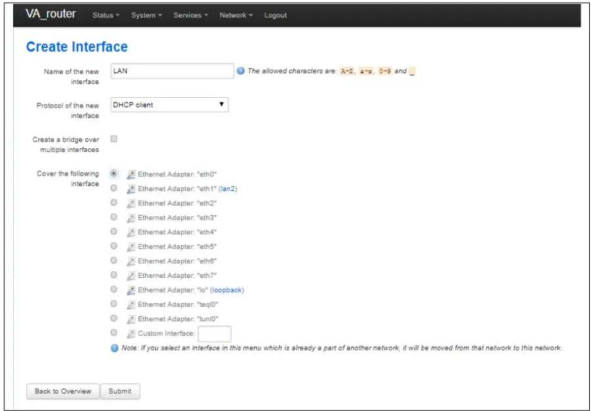
text_image
VA_router Status System Services Network Logout Create Interface Name of the new interface LAN The allowed characters are: A=2, a=3, 0=9 and _ Protocol of the new interface DHCP client Create a bridge over multiple interfaces Cover the following interface Ethernet Adapter: "eth0" Ethernet Adapter: "eth1" (lan2) Ethernet Adapter: "eth2" Ethernet Adapter: "eth3" Ethernet Adapter: "eth4" Ethernet Adapter: "eth5" Ethernet Adapter: "eth6" Ethernet Adapter: "eth7" Ethernet Adapter: "lo" (loopback) Ethernet Adapter: "teq10" Ethernet Adapter: "tuni0" Custom Interface: Note: If you select an interface in this menu which is already a part of another network, it will be moved from that network to this network. Back to Overview SubmitFigure 130: The create interface page
| Web Field/ UCI / Package Option | Description | ||
| Web: Name of the new interfaceUCI: network.<if name>.opt: config interface | Assigns a logical name to the interface. The network interface section will assign this name ( ).Type the name of the new interface.Allowed characters are A-Z, a-z, 0-9 and _ | ||
| Web: Protocol of the new interfaceUCI: network.<if name>.protoOpt: proto | Specifies what protocol the interface will operate on. Select DHCP Client. | ||
| Option | Description | UCI | |
| Static Static configuration with fixed address and netmask. | Static | ||
| DHCP Client Address and netmask are assigned by DHCP. | dhcp | ||
| Unmanaged | Unspecified | Empty | |
| IPv6-in-IPv4 (RFC4213) | Used with tunnel brokers. | ||
| IPv6-over-IPv4 | Stateless IPv6 over IPv4 transport. | ||
| GRE Generic Routing Encapsulation protocol | |||
| IOT | |||
| L2TP | Layer 2 Tunnelling Protocol | ||
| PPP | Point to Point Protocol | ||
| PPPoE | PPP over Ethernet | ||
| PPPoATM | PPP over ATM | ||
| LTE/UMTS/GPRS/EV-DO | CDMA, UMTS or GPRS connection using an AT-style 3G modem. | ||
| Web: Create a bridge over multiple interfacesUCI: network.<if name>.typeOpt: type | If you select this option, then the new logical interface created will act as a bridging interface between the chosen existing physical interfaces. | ||
| Empty | |||
| Bridge Configures a bridge over multiple interfaces. | |||
| Web: Cover the following interfaceUCI: network.<if name>.ifnameOpt: ifname | Physical interface name to assign to this logical interface. If creating a bridge over multiple interfaces select two interfaces to bridge. When using UCI, the interface names should be separated by a space e.g. option ifname ‘eth2 eth3’. | ||
Table 87: Information table for the create new interface page
Click Submit. The Interface configuration page appears. There are three sections:
| Section | Description |
| Common Configuration | Configure the interface settings such as protocol, IP address, gateway, netmask, custom DNS servers, MTU and firewall configuration. |
| IP-Aliases | Assign multiple IP addresses to the interface. |
| DHCP Server | Configure DHCP server settings for this interface. |
27.2.3 Common configuration
The common configuration section has four sub sections.
| Section | Description |
| General Setup | Configure the basic interface settings such as protocol, IP address, gateway, netmask, custom DNS servers. |
| Advanced Settings | 'Bring up on boot', 'Monitor interface state', Override MAC address, Override MTU and 'Use gateway metric'. |
| Physical Settings | Bridge interfaces, VLAN PCP to SKB priority mapping. |
| Firewall settings | Assign a firewall zone to the interface. |
Only General setup and Advanced Settings have DHCP client option configuration options
27.2.3.1 Common configuration – general setup
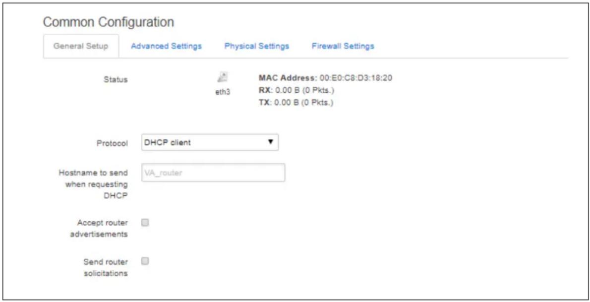
text_image
Common Configuration General Setup Advanced Settings Physical Settings Firewall Settings Status eth3 MAC Address: 00:E0:C8:D3:18:20 RX: 0.00 B (0 Pkts.) TX: 0.00 B (0 Pkts.) Protocol DHCP client ▼ Hostname to send when requesting DHCP VA_router Accept router advertisements □ Send router solicitations □Figure 131: The interface general setup configuration page for DHCP client protocol
| Web Field/ UCI / Package Option | Description | |
| Web: Status | Shows the current status of the interface. | |
| Web: ProtocolUCI: network..protoOpt: proto | Protocol type. The interface protocol may be one of the options shown below. The protocol selected in the previous step will be displayed as default but can be changed if required.Select DHCP Client. | |
| Option | Description | |
| Static Static configuration with fixed address and netmask. | ||
| DHCP Client | Address and netmask are assigned by DHCP. | |
| Unmanaged | Unspecified | |
| IPv6-in-IPv4 (RFC4213) | Used with tunnel brokers. | |
| IPv6-over-IPv4 | Stateless IPv6 over IPv4 transport. | |
| GRE | Generic Routing Encapsulation protocol | |
| IOT | ||
| L2TP | Layer 2 Tunnelling Protocol. | |
| PPP | Point-to-Point protocol | |
| PPPoE | PPP over Ethernet | |
| PPPoATM | PPP over ATM | |
| LTE/UMTS/GPRS/EV-DO | CDMA, UMTS or GPRS connection using an AT-style 3G modem. | |
| Web: Hostname to send when requesting DHCPUCI: network..hostnameOpt: hostname | Defines the hostname to include in DHCP requests | |
| Web: Accept router advertisementsUCI: network..accept_raOpt: accept_ra | Specifies whether to accept IPv6 Router Advertisements on this interface (optional).Note: default is 1 if protocol is set to DHCP, otherwise the setting defaults to 0. | |
| 0 | Does not accept IPv6 router advertisements. | |
| 1 | Accept IPv6 router advertisements. | |
| Web: Send router solicitationsUCI: network..send_rsOpt: send_rs | Specifies whether to send router Solicitations on this interface (optional).Note: defaults to 1 for Static protocol, otherwise the setting defaults to 0. | |
| 0 | Do not send router solicitations | |
| 1 | Send router solicitations | |
Table 88: Information table for general setup configuration settings for DHCP client protocol
27.2.3.2 Common configuration: advanced settings
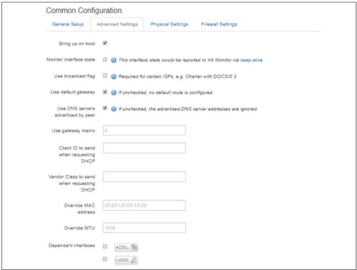
text_image
Common Configuration General Setup Advanced Settings Physical Settings Firewall Settings Bring up on boot ✓ Monitor interface state This interface state would be reported to VA Monitor via keep-alive Use broadcast flag Required for certain ISPs, e.g. Charter with DOCSIS 3 Use default gateway If unchecked, no default route is configured Use DNS servers advertised by peer If unchecked, the advertised DNS server addresses are ignored Use gateway metric 0 Client ID to send when requesting DHCP Vendor Class to send when requesting DHCP Override MAC address 00:E0:C8:D3:18:20 Override MTU 1500 Dependant interfaces ADSL: LAN3:Figure 132: The interface advanced settings page for DHCP client protocol
| Web Field/ UCI / Package Option | Description | |
| Web: Bring up on bootUCI: network.<if name>.autoOpt: auto | Enables the interface to connect automatically on boot up. | |
| 0 | Disabled. | |
| 1 | Enabled. | |
| Web: Monitor interface stateUCI: network.<if name>.monitoredOpt: monitored | Enabled if status of interface is presented on Monitoring platform. | |
| 0 | Disabled. | |
| 1 | Enabled. | |
| Web: Use broadcast flagUCI: network.<if name>.broadcastOpt: broadcast | Enables the broadcast flag in DHCP requests (required for certain ISPs). | |
| 0 | Disabled. | |
| 1 | Enabled. | |
| Web: Use default gatewayUCI: network.<if name>.gatewayOpt: gateway | Defines whether to suppress the DHCP assigned default gateway.When disabled via web option gateway is set to 0.0.0.0. | |
| 0 | Disabled (option gateway set to 0.0.0.0) | |
| 1 | Enabled. | |
| Web: Use DNS servers advertised by peerUCI: n/aOpt: n/a | Defines whether to override DHCP assigned DNS servers with configured list of DNS servers. When unchecked allows configuration of custom DNS servers via web. There is no uci option set when checking or unchecking this option. | |
| Web: Use custom DNS serversUCI: network.<if name>.dnsOpt: dns | Defines whether to override DHCP assigned DNS servers with configured list of DNS servers.Multiple DNS Servers are separated by a space if using UCI.Example: option dns '1.1.1.1 2.2.2.2' | |
| 0 | Disabled (option gateway set to 0.0.0.0) | |
| 1 | Enabled. | |
| Web: Use gateway metricUCI: network.<if name>.metricOpt: metric | Specifies the default route metric to use for this interface. | |
| 0 | Disabled. | |
| Range | ||
| Web: Client ID to send when requesting DHCPUCI: network.<if name>.clientidOpt: clientid | Defines whether to override the client identifier in DHCP requests. | |
| Blank | Do not override. | |
| Range | Override. | |
| Web: Vendor Class to send when requesting DHCPUCI: network.<if name>.vendoridOpt: vendorid | Defines whether to override the vendor class in DHCP requests. | |
| Blank | Do not override. | |
| Range | Override. | |
| Web: Override MAC addressUCI: network.<if name>.macaddrOpt: macaddr | Override the MAC address assigned to this interface. Must be in the form: hh:hh:hh:hh:hh:hh, where h is a hexadecimal number. | |
| Web: Override MTUUCI: network.<if name>.mtuOpt: mtu | Defines the value to override the default MTU on this interface. | |
| 1500 | 1500 bytes | |
| Web: Dependant InterfacesUCI: network.[if_name].dependantsOpt: dependants | Lists interfaces that are dependent on this parent interface.Dependant interfaces will go down when parent interface is down and will start or restart when parent interface starts.Separate multiple interfaces by a space when using UCI.Example: option dependants 'PPPADSL MOBILE'This replaces the following previous options in child interfaces. | |
| gre | option local interface | |
| It2p | option src_ipaddr | |
| iot | option wan1 wan2 | |
| 6in4 | option ipaddr | |
| 6to4 | option ipaddr | |
| Web: SNMP Alias ifIndexUCI:network.@interface[X].snmp_alias_ifindexOpt: snmp_alias_ifindex | Defines a static SNMP interface alias index for this interface, that can be polled using via the SNMP interface index(snmp alias ifindex+1000) | |
| Blank | No SNMP interface alias index | |
| Range | 0 - 4294966295 | |
Table 89: Information table for advanced settings for DHCP client protocol
27.3 Configuring DHCP client using command line
The configuration files for DHCP client are stored on /etc/config/network
27.3.1 DHCP client using UCI
root@VA_router:~# uci show network
.....
network.DHCPCLIENTLAN=interface
network.DHCPCLIENTLAN.proto=dhcp
network.DHCPCLIENTLAN.ifname=eth3
network.DHCPCLIENTLAN.monitored=0
network.DHCPCLIENTLAN.broadcast=0
network.DHCPCLIENTLAN.accept_ra=1
network.DHCPCLIENTLAN.send_rs=0
network.DHCPCLIENTLAN.metric=1
27.3.2 DHCP client using package options
root@VA_router:~# uci export network
package network
......
config interface 'DHCPCLIENTLAN'
option proto 'dhcp'
option ifname 'eth3'
option monitored '0'
option broadcast '0'
option accept_ra '1'
option send_rs '0'
option metric '1'
27.4 DHCP client diagnostics
27.4.1 Interface status
To see IP address of DHCP client interface, enter ifconfig:
root@VA_router:~# ifconfig
3g-CDMA Link encap:Point-to-Point Protocol
inet addr:10.33.152.100 P-t-P:178.72.0.237 Mask:255.255.255.255
UP POINTOPOINT RUNNING NOARP MULTICAST MTU:1400 Metric:1
RX packets:6 errors:0 dropped:0 overruns:0 frame:0
TX packets:23 errors:0 dropped:0 overruns:0 carrier:0
collisions:0 txqueuelen:3
RX bytes:428 (428.0 B) TX bytes:2986 (2.9 KiB)
eth0 Link encap:Ethernet HWaddr 00:E0:C8:12:12:15
inet addr:192.168.100.1 Bcast:192.168.100.255
Mask:255.255.255.0
inet6 addr: fe80::2e0:c8ff:fe12:1215/64 Scope:Link
UP BROADCAST RUNNING MULTICAST MTU:1500 Metric:1
RX packets:6645 errors:0 dropped:0 overruns:0 frame:0
TX packets:523 errors:0 dropped:0 overruns:0 carrier:0
collisions:0 txqueuelen:1000
RX bytes:569453 (556.1 KiB) TX bytes:77306 (75.4 KiB)
lo Link encap:Local Loopback
inet addr:127.0.0.1 Mask:255.0.0.0
inet6 addr: ::1/128 Scope:Host
UP LOOPBACK RUNNING MTU:16436 Metric:1
RX packets:385585 errors:0 dropped:0 overruns:0 frame:0
TX packets:385585 errors:0 dropped:0 overruns:0 carrier:0
collisions:0 txqueuelen:0
RX bytes:43205140 (41.2 MiB) TX bytes:43205140 (41.2 MiB)
To display a specific interface, enter:
root@VA_router:~# ifconfig eth0
eth0 Link encap:Ethernet HWaddr 00:E0:C8:12:12:15
inet addr:192.168.100.1 Bcast:192.168.100.255
Mask:255.255.255.0
inet6 addr: fe80::2e0:c8ff:fe12:1215/64 Scope:Link
UP BROADCAST RUNNING MULTICAST MTU:1500 Metric:1
RX packets:7710 errors:0 dropped:0 overruns:0 frame:0
TX packets:535 errors:0 dropped:0 overruns:0 carrier:0
collisions:0 txqueuelen:1000
RX bytes:647933 (632.7 KiB) TX bytes:80978 (79.0 KiB)
27.4.2 ARP table status
To show the current ARP table of the router, enter:
root@GW7314:~# arp
? (10.67.253.141) at 30:30:41:30:43:36 [ether] on eth8
? (10.47.48.1) at 0a:44:b2:06 [ether] on gre-grel
27.4.3 Route status
To show the current routing status, enter:
root@VA_router:~# route -n
Kernel IP routing table
Destination Gateway Genmask Flags Metric Ref Use Iface
192.168.100.0 * 255.255.255.0 U 0 0 0 eth0
Note: a route will only be displayed in the routing table when the interface is up.
28 Configuring DHCP forwarding
This section describes how to configure the router to forward DHCP requests from an interface to a network DHCP server.
28.1 Configuration packages used
| Package | Sections |
| dhcp fwd | dhcpfwd |
28.2 Configuring DHCP forwarding using the web interface
To configure DHCP forwarding using the web interface, in the top menu, click Network -> DHCP-Forwarder.
The DHCP forwarder page appears. The web GUI creates a dhcpfwd section called main so this will be used in the uci examples below.
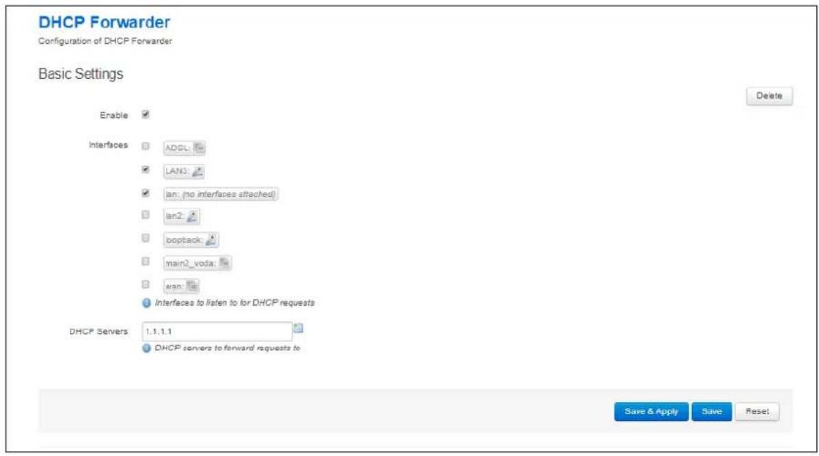
text_image
DHCP Forwarder Configuration of DHCP Forwarder Basic Settings Enable Interfaces ADGL LAN: lan: (no interfaces attached) lan2 bopback: main2_voda wan Interfaces to listen to for DHCP requests DHCP Servers 1.1.1.1 DHCP servers to forward requests to Delete Save & Apply Save Reset.Figure 133: The DHCP forwarder configuration page
| Web Field/ UCI / Package Option | Description | |
| Web: EnabledUCI: dhcp_fwd.main.enabledOpt: enabled | Defines whether DHCP forwarding is enabled or disabled. | |
| 0 | Do not send router solicitations. | |
| 1 | Send router solicitations. | |
| Web: InterfacesUCI: dhcp_fwd.main.listen_interfaceOpt: list listen_interface | Defines a list of the source interface name(s) to forward DHCP messages from. Multiple interface_name(s) are entered using uci set and uci add_list commands. Example:uci set dhcp_fwd.main.listen_interface=LAN1uci add_list dhcp_fwd.main.listen_interface=LAN2or using a list of options via package optionslist listen_interface 'LAN1'list listen_interface 'LAN2' | |
| Web: DHCP ServersUCI: dhcp_fwd.main.serverOpt: list server | Defines a list of the network DHCP servers to forward DHCP messages to. Multiple interface_name(s) are entered using uci set and uci add_list commands. Example:uci set dhcp_fwd.main.server=1.1.1.1uci add_list dhcp_fwd.main.main.server=2.2.2.2or using a list of options via package optionslist server '1.1.1.1'list server '2.2.2.2' | |
Table 90: Information table for the DHCP forwarder section
28.3 Configuring DHCP forwarding using command line
The configuration files for DHCP client are stored in /etc/config/dhcp_fwd
28.3.1 DHCP forwarding using UCI
root@VA_router:~# uci show dhcp_fwd
dhcp_fwd.main=dhcpfwd
dhcp_fwd.main.enabled=1
dhcp_fwd.main.listen_interface=LAN3 lan2
dhcp_fwd.main.server=1.1.1.1
28.3.2 DHCP forwarding using package options
root@VA_router:~# uci export dhcp_fwd
package dhcp_fwd

config dhcpfwd 'main'
    option enabled '1'
    list listen_interface 'LAN3'
    list listen_interface 'lan2'
    list server '1.1.1.1'
28.4 DHCP forwarding over IPSec
DHCP messages are forwarded over the WAN interface using the IP address of the WAN interface as the source IP for the transmitted packet. This means that when forwarding over an IPSec tunnel a source NAT firewall rule is required to change the source IP to match an IPSec connection rule.
28.4.1 Configuration packages used
| Package | Sections |
| firewall | redirect |
28.4.2 Configuring source NAT for DHCP forwarding over IPsec
To enter a source NAT rule, browse to Network -> Firewall. Select Traffic Rules tab. The Firewall - Traffic Rules page appears. Configure a source NAT rule that changes the source IP for UDP destination port 67 from the required LAN.
For more information on configuring a source NAT rule, read the 'Configuring Firewall' section of the User Manual.
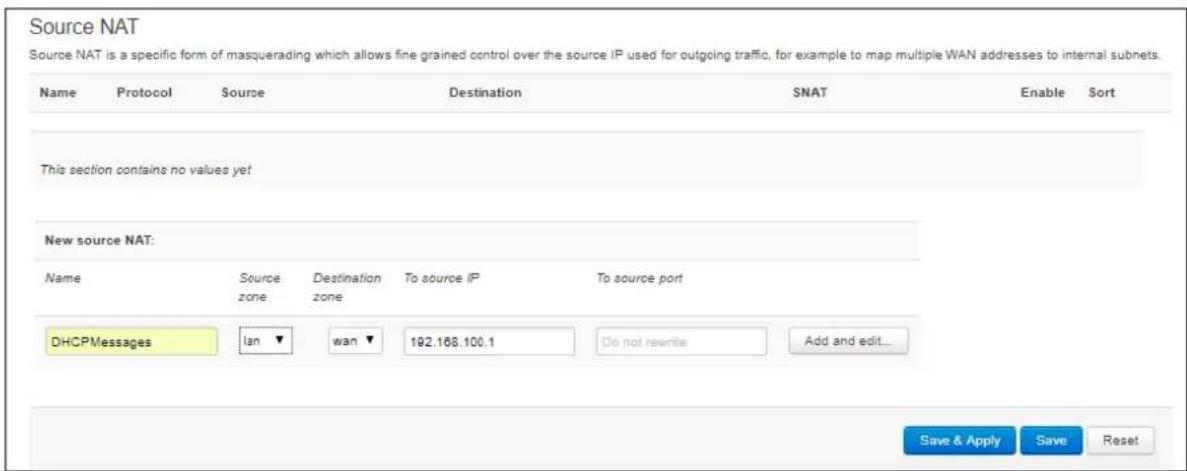
text_image
Source NAT Source NAT is a specific form of masquerading which allows fine grained control over the source IP used for outgoing traffic, for example to map multiple WAN addresses to internal subnets. Name Protocol Source Destination SNAT Enable Sort This section contains no values yet New source NAT: Name Source Destination To source IP To source port zone zone zone DHCPMessages lan wan 192.168.100.1 Do not rewrite Add and edit... Save & Apply Save ResetFigure 134: The firewall – traffic rules configuration page
| Web Field/ UCI / Package Option | Description |
| Web: NameUCI: firewall.@redirect[X].nameOpt: name | Defines a name for the source NAT rule. |
| Web: Source ZoneUCI: firewall.@redirect[X].srcOpt: src | Defines the source interface for the source NAT rule.Select the interface where the DHCP requests are originating. |
| Web: Destination ZoneUCI: firewall.@redirect[X].destOpt: dest | Defines destination interface for the source NAT rule.Select the interface where the DHCP requests are intended to be transmitted. |
| Web: To source IPUCI: firewall.@redirect[X].src_dipOpt: src_dip | Defines the IP address to rewrite matched traffic source IP.Select the source IP address to match the required IPSec rule. |
| Web: To source portUCI: firewall.@redirect[X].src_dportOpt: src_dport | Defines the port number to rewrite matched traffic source port number.Leave empty. |
Table 91: Information table for the source NAT configuration
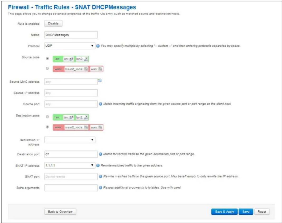
text_image
Firewall - Traffic Rules - SNAT DHCPMessages This page allows you to change advanced properties of the traffic rule entry, such as matched source and destination hosts. Rule is enabled Disable Name DHCPMessages Protocol UDP You may specify multiple by selecting "--" custom --* and then entering protocols separated by space. Source zone lan: lan: lan2: wan: main2_voda: wan: Source MAC address any Source IP address any Source port any Match incoming traffic originating from the given source port or port range on the client host. Destination zone lan: lan: lan2: wan: main2_voda: wan: Destination IP address Destination port 67 Match forwarded traffic to the given destination port or port range. SNAT IP address 1.1.1.1 Rewrite matched traffic to the given address. SNAT port Do not rewrite Rewrite matched traffic to the given source port. May be left empty to only rewrite the IP address. Extra arguments Passes additional arguments to iptables. Use with care! Back to Overview Save & Apply Save ResetFigure 135: The firewall – traffic rules – SNAT configuration page
| Web Field/ UCI / Package Option | Description | ||
| Web: Rule is enabledUCI: firewall.@redirect[X].enabledOpt: enabled | Defines whether source NAT rule is enabled. | ||
| 0 | Disabled | ||
| 1 | Enabled | ||
| Web: NameUCI: firewall.@redirect[X].nameOpt: name | Defines a name for the source NAT rule. | ||
| Web: ProtocolUCI: firewall.@redirect[X].protoOpt: proto | Defines the protocol for the source NAT rule to match.Select UDP. | ||
| Option | Description | UCI | |
| All protocols | Match all protocols | all | |
| TCP+ UDP | Match TCP and UDP protocols | tcp upd | |
| TCP | Match TCP protocol | tcp | |
| UDP | Match UDP protocol | udp | |
| ICMP | Match ICMP protocol | icmp | |
| Custom | Enter custom protocol | ||
| Web: Source ZoneUCI: firewall.@redirect[X].srcOpt: src | Defines the source interface for the source NAT rule.Select the interface where the DHCP requests are originating. | ||
| Web: Destination ZoneUCI: firewall.@redirect[X].destOpt: dest | Defines destination interface for the source NAT rule.Select the interface where the DHCP requests are intended to be transmitted. | ||
| Web: Destination portUCI: firewall.@redirect[X].portOpt: port | Defines the destination port number to match.Select 67. | ||
| Web: SNAT IP addressUCI: firewall.@redirect[X].src_dipOpt: src_dip | Defines the IP address to rewrite matched traffic.Select the source IP address to match the required IPSec rule. | ||
Table 92: Information table for the advanced source NAT configuration
28.4.3 Configuring source NAT for DHCP forwarding over IPSec using command line
28.4.3.1 Source NAT for DHCP forwarding over IPSec using UCI
root@VA_router:~# uci show firewall
......
firewall.@redirect[0]=redirect
firewall.@redirect[0].target=SNAT
firewall.@redirect[0].src=lan
firewall.@redirect[0].dest=wan
firewall.@redirect[0].src_dip=192.168.100.1
firewall.@redirect[0].name=DHCPMessages
firewall.@redirect[0].proto=udp
firewall.@redirect[0].dest_port=67
28.4.3.2 Source NAT for DHCP forwarding over IPSec using package options
root@VA_router:~# uci export firewall
package firewall
......
config redirect
    option target 'SNAT'
    option src 'lan'
    option dest 'wan'
    option src_dip '192.168.100.1'
    option name 'DHCPMessages'
    option proto 'udp'
    option dest_port '67'
28.5 DHCP forwarding diagnostics
28.5.1 Tracing DHCP packets
To trace DHCP packets on any interface on the router, enter tcpdump -i any -n -p port 67 &
root@VA_router:~# tcpdump -i any -n -p port 67 &
root@VA_router:~# tcpdump: verbose output suppressed, use -v or -vv for full protocol decode
listening on any, link-type LINUX_SLL (Linux cooked), capture size 65535 bytes
16:39:20.666070 IP 0.0.0.0.68 > 255.255.255.255.67: BOOTP/DHCP, Request from 00:e0:c8:13:02:3d, length 360
16:39:20.666166 IP 0.0.0.0.68 > 255.255.255.255.67: BOOTP/DHCP, Request from 00:e0:c8:13:02:3d, length 360
To trace stop tracing enter fg (to bring tracing task to foreground), and then
root@VA_router:~# fg
tcpdump -i any -n -p port 67
^C
33 packets captured
33 packets received by filter
0 packets dropped by kernel
16:39:20.666166 IP 0.0.0.0.68 > 255.255.255.255.67: BOOTP/DHCP, Request from 00:e0:c8:13:02:3d, length 360
28.5.2 ARP table status
To show the current ARP table of the router, enter arp
root@VA_router:~# arp
? (10.67.253.141) at 30:30:41:30:43:36 [ether] on eth8
? (10.47.48.1) at 0a:44:b2:06 [ether] on gre-grel
29 Configuring Dynamic DNS
29.1 Overview
Dynamic DNS (DDNS) functionality on a Virtual Access router will dynamically perform DDNS updates to a server so it can associate an IP address with a correctly associated DNS name. Users can then contact a machine, router, device and so on with a DNS name rather than a dynamic IP address.
An account is required with the provider, and one or more domain names are associated with that account. A dynamic DNS client on the router monitors the public IP address associated with an interface and whenever the IP address changes, the client notifies the DNS provider to update the corresponding domain name.
When the DNS provider responds to queries for the domain name, it sets a low lifetime, typically a minute or two at most, on the response so that it is not cached. Updates to the domain name are thus visible throughout the whole Internet with little delay.
Note: most providers impose restrictions on how updates are handled: updating when no change of address occurred is considered abusive and may result in an account being blocked. Sometimes, addresses must be refreshed periodically, for example, once a month, to show that they are still in active use.
29.2 Configuration packages used
| Package | Sections |
| ddns | service |
29.3 Configuring Dynamic DNS using the web interface
In the top menu, select Services -> Dynamic DNS. The Dynamic DNS Configuration page appears.
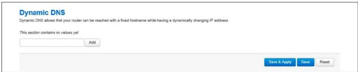
text_image
Dynamic DNS Dynamic DNS allows that your router can be reached with a fixed hostname while having a dynamically changing IP address. This section contains nc values yet Add Save & Apply Save ResetFigure 136: The Dynamic DNS configuration page
Enter a text name that will be used for the dynamic DNS section in the configuration. Select Add. The Dynamic DNS configuration options appear.
29.3.1 Dynamic DNS settings
Dynamic DNS
Dynamic DNS allows that your router can be reached with a fixed hostname while having a dynamically changing IP address.
DDNS1
Enable

Service


Custom update-URL

Hostname

Username

Password


Source of IP address


Network


Check for changed IP

every

Check-time unit


Force update every


Force-time unit


Listen on


Figure 137: The dynamic DNS main settings page
| Web Field/ UCI / Package Option | Description | |
| Web: EnableUCI: ddns..enabledOpt: enabled | Enables a Dynamic DNS entry on the router. | |
| 0 | Disabled. | |
| 1 | Enabled | |
| Web: ServiceUCI: ddns..service_nameOpt: service_name | Defines the Dynamic DNS provider. | |
| Web: Customer update-URLUCI: ddns..update_urlOpt: update_url | Defines the customer DNS provider.Displayed when the service is set to custom in the web interface. | |
| Web: HostnameUCI: ddns..domainOpt: domain | Defines the fully qualified domain name associated with this entry. This is the name to update with the new IP address as needed. | |
| Web: UsernameUCI: ddns..usernameOpt: username | Defines the user name to use for authenticating domain updates with the selected provider. | |
| Web: PasswordUCI: ddns..passwordOpt: password | Defines the password to use for authenticating domain name updates with the selected provider. | |
| Web: Source of IP addressUCI: ddns..ip_sourceOpt: ip_source | Defines the type of interface whose IP needs to be updated. | |
| network | IP is a associated with a network configuration. | |
| interface | IP is associated with an interface. | |
| web | IP is associated with a URL. | |
| Web: NetworkUCI: ddns.<name>.ip_networkOpt: ip_network | Defines the network whose IP needs to be updated.Displayed when the Source of IP address option is set to network.All the configured network interfaces will be shown. | |
| Web: InterfaceUCI: ddns.<name>.ip_interfaceOpt: ip_interface | Defines the interface whose IP needs to be updated.Displayed when the Source of IP address option is set to interface.All the configured interfaces will be shown. | |
| Web: URLUCI: ddns<name>.ip_urlOpt: ip_url | Defines the URL where the IP downloaded from.Displayed when the Source of IP address option is set to URL. | |
| Web: Check for changed IP everyUCI: ddns.<name>.check_intervalOpt: check_interval | Defines how often to check for an IP change. Used in conjunction with check unit. | |
| 10 | ||
| Range | ||
| Web: Check-time unitUCI: ddns.<name>.check_unitOpt: check_unit | Defines the time unit to use for check for an IP change. Used in conjunction with check interval. | |
| Minutes | ||
| hours | ||
| Web: Force update everyUCI: ddns.<name>.force_intervalOpt: force_interval | Defines how often to force an IP update to the provider. Used in conjunction with force unit. | |
| 72 | Disabled. | |
| Range | Enabled | |
| Web: Force-time unitUCI: ddns.<name>.force_unitOpt: force_unit | Defines the time unit to use for check for an IP change. Used in conjunction with force interval. | |
| Minutes | ||
| Hours | ||
| Web: Listen onUCI: ddns.<name>.interfaceOpt: interface | Defines the interface for ddns monitoring. Typically this will be the same as the interface whose IP is being updated – as defined ip_network or ip_interface.All configured interfaces will be displayed. | |
Table 93: Information table for dynamic DNS settings
29.4 Dynamic DNS using UCI
Dynamic DNS uses the ddns package / etc/ config/ ddns
29.4.1 UCI commands for DDNS
root@VA_router:~# uci show ddns
ddns.ddns1=service
ddns.ddns1.enabled=1
ddns.ddns1.service_name=dyndns.org
ddns.ddns1.domain=fqdn_of_interface
ddns.ddns1.username=testusername
ddns.ddns1.password=testpassword
ddns.ddns1.ip_source=network
ddns.ddns1.ip_network=ds10
ddns.ddns1.check_interval=10
ddns.ddns1.check_unit=minutes
ddns.ddns1.force_interval=72
ddns.ddns1.force_unit=hours
ddns.ddns1.interface=ds10
Package options for DDNS
root@VA_router:~# uci export ddns
package ddns

config service 'ddns1'
option enabled '1'
option service_name 'dyndns.org'
option domain 'fqdn_of_interface'
option username 'test'
option password 'test'
option ip_source 'network'
option ip_network 'dsl0'
option check_interval '10'
option check_unit 'minutes'
option force_interval '72'
option force_unit 'hours'
option interface 'dsl0'
30 Configuring hostnames
30.1 Overview
Hostnames are human-readable names that identify a device connected to a network. There are several different ways in which hostnames can be configured and used on the router.
- Local host file records
- PTR records
• Static DHCP leases
30.2 Local host file records
The hosts file is an operating system file that maps hostnames to IP addresses. It is used preferentially to other name resolution methods such as DNS.
The hosts file contains lines of text consisting of an IP address in the first text field followed by one or more host names. Each field is separated by white space – tabs are often preferred for historical reasons, but spaces are also used. Comment lines may be included; they are indicated by an octothorpe (#) in the first position of such lines.
Entirely blank lines in the file are ignored.
By default, the routers local host file contains:
127.0.0.1 localhost
::1 ip6-localhost ip6-loopback
The local host file is stored at / etc/ hosts
30.2.1 Configuration packages used
Package
network
Sections
host
30.2.2 Configuring local host files entries using the web interface
In the top menu, select Network -> Interfaces. The Interfaces configuration page appears.
Browse to Host Records section at the bottom of the page.

text_image
Host Records Hostname IP Address This section contains no values yet AddFigure 138: The host records add page
Select Add. Enter a hostname and IP address and select Save & Apply.

text_image
Host Records Hostname IP-Address Hostname1 1.1.1.1 Delete AddFigure 139: The host records configuration page
| Web Field/ UCI / Package Option | Description |
| Web: HostnameUCI: network.host.hostnameOpt: hostname | Defines the hostname. |
| Web: IP-AddressUCI: network.host.addrOpt: addr | Defines the IP address associated with the hostname. |
Table 94: Information table for host records settings
30.2.3 Local host records using command line
Local host records are configured in the host section of the network package / etc/ config/ network.
Multiple hosts can be configured.
By default, all host instances are named host and are identified by @host then the host position in the package as a number. For example, for the first host in the package using UCI:
network.@host[0]=host
network.@host[0].hostname=Device1
Or using package options:
config host
option hostname 'Device1'
30.2.3.1 Local host records using uci
root@VA_router:~# uci show network
......
network.@host[0]=host
network.@host[0].hostname=Device1
network.@host[0].addr=1.1.1.1
30.2.3.2 Local host records using package option
root@VA_router:~# uci export network
package network
......
config host
option hostname 'Device1'
option addr '1.1.1.1'
30.2.4 Local host records diagnostics
30.2.4.1 Hosts file
Local host records are written to the local hosts file stored at /etc/hosts. To view the local hosts file, enter:
root@VA_router:~# cat /etc/hosts
127.0.0.1 localhost
::1 ip6-localhost ip6-loopback
1.1.1.1 Device1
30.3 PTR records
PTR records are used for reverse DNS.
The primary purpose for DNS is to map domains to IP addresses. A pointer record works in the opposite way; it associates an IP address with a domain name.
30.3.1 Configuration packages used
| Package | Sections |
| dhcp | domain |
30.3.2 Configuring PTR records using the web interface
In the top menu, select Network -> Hostnames. The Hostnames configuration page appears.
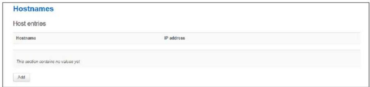
text_image
Hostnames Host entries Hostname IP address This section contains no values yet AddFigure 140: The hostnames add page
Select Add. Enter a hostname and IP address for the PTR record and select Save & Apply.
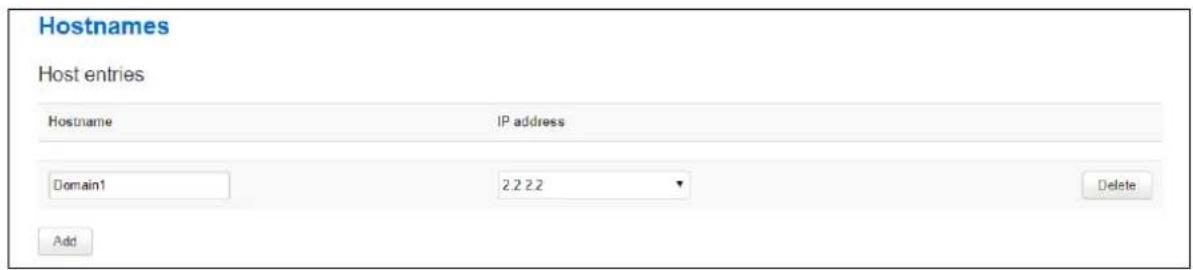
text_image
Hostnames Host entries Hostname IP address Domain1 2.2 2.2 Delete AddFigure 141: The hostnames configuration page
| Web Field/ UCI / Package Option | Description |
| Web: HostnameUCI: dhcp.domain.nameOpt: name | Defines the domain name for the PTR record. |
| Web: IP-AddressUCI: dhcp.domain.ipOpt: ip | Defines the IP address associated with the domain name. |
Table 95: Information table for hostnames settings
30.3.3 PTR records using command line
PTR records are configured in the domain section of the dhcp package. /etc/config/dhcp.
Multiple domains can be configured.
By default, all domain instances are named domain and are identified by @domain then the domain position in the package as a number. For example, for the first domain in the package using UCI:
dhcp.@domain[0]=domain
dhcp.@domain[0].name=Domain1
Or using package options:
config domain
option name 'Domain1'
30.3.3.1 PTR records using uci
root@VA_router:~# uci show dhcp
......
dhcp.@domain[0]=domain
dhcp.@domain[0].name=Domain1
dhcp.@domain[0].ip=2.2.2.2
30.3.3.2 PTR records using package option
root@VA_router:~# uci export dhcp
package dhcp
......
config domain
option name 'Domain1'
option ip '2.2.2.2'
30.3.4 PTR records diagnostics
30.3.4.1 PTR records table
To view PTR records, enter:
root@VA_router:~# pgrep -fl dnsmasq
4724 /usr/sbin/dnsmasq -K -D -y -Z -b -E -s lan -S /lan/ -l /tmp/dhcp.leases -r /tmp/resolv.conf.auto --stop-dns-rebind --rebind-localhost-ok -A /Device1.lan/1.1.1.1 --ptr-record=1.1.1.1.in-
addr.arpa,Device1.lan -A /Device2.lan/2.2.2.2 --ptr-record=2.2.2.2.in-
addr.arpa,Device2.lan
30.4 Static leases
Static leases are used to assign fixed IP addresses and symbolic hostnames to DHCP clients based on their MAC (hardware) address.
They are also required for non-dynamic interface configurations where only hosts with a corresponding lease are served.
30.4.1 Configuration packages used
| Package | Sections |
| dhcp | host |
30.4.2 Configuring static leases using the web interface
In the top menu, select Network -> DHCP and DNS. The DHCP and DNS configuration page appears.
Browse to Static leases section.
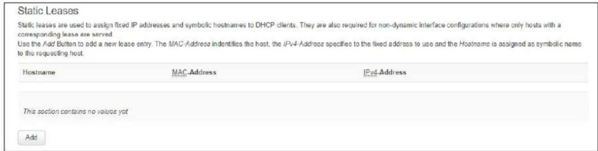
text_image
Static Leases Static leases are used to assign fixed IP addresses and symbolic hostnames to DHCP clients. They are also required for non-dynamic interface configurations where only hosts with a corresponding lease are served Use the Add Button to add a new lease entry. The MAC-Address identifies the host, the IPv4-Address specifies to the fixed address to use and the Hostname is assigned as symbolic name to the requesting host. Hostname MAC-Address IPv4-Address This section contains no values yet AddFigure 142: The static leases add page
Select Add. Enter a hostname, MAC address and IP address for the static lease. Select Save & Apply.
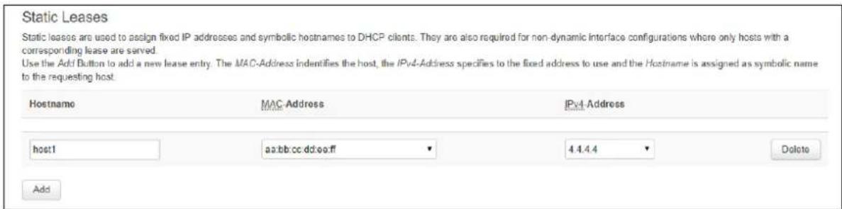
text_image
Static Leases Static leases are used to assign fixed IP addresses and symbolic hostnames to DHCP clients. They are also required for non-dynamic interface configurations where only hosts with a corresponding lease are served. Use the Addi Button to add a new lease entry. The MAC-Address identifies the host, the IPv4-Address specifies to the fixed address to use and the Hostname is assigned as symbolic name to the requesting host. Hostname MAC-Address IPv4-Address host1 aa:bb:cc:dd:ee:ff 4.4.4.4 Delete AddFigure 143: The static leases configuration page
| Web Field/ UCI / Package Option | Description |
| Web: HostnameUCI: dhcp.host.nameOpt: name | Defines the symbolic hostname to assign. |
| Web: MAC-AddressUCI: dhcp.host.macOpt: mac | Defines the MAC address for this host. MAC addresses should be entered in the format aa:bb:cc:dd:ee:ff |
| Web: IPv4-AddressUCI: dhcp.host.ipOpt: ip | Defines the IP address to be used for this host. |
Table 96: Information table for static leases settings
30.4.3 Static leases using command line
Static leases are configured in the host section of the dhcp package / etc/ config/ dhcp. Multiple hosts can be configured.
By default, all dhcp host instances are named host. It is identified by @host then the host position in the package as a number. For example, for the first host in the package using UCI:
dhcp.@host[0]=host
dhcp.@host[0].name=Host1
Or using package options:
config host option name 'Host1'
30.4.3.1 Static leases using uci
root@VA_router:~# uci show dhcp
......
dhcp.@host[0]=host
dhcp.@host[0].name=Host1
dhcp.@host[0].mac=aa:bb:cc:dd:ee:ff
dhcp.@host[0].ip=4.4.4.4
30.4.3.2 Static leases using package option
root@VA_router:~# uci export dhcp
package dhcp
......
config host
option name 'Host1'
option mac 'aa:bb:cc:dd:ee:ff'
option ip '4.4.4.4'
31 Configuring firewall
The firewall itself is not required. It is a set of scripts which configure Netfilter. If preferred, you can use Netfilter directly to achieve the desired firewall behaviour.
Note: the UCI firewall exists to simplify the configuration of Netfilter for many scenarios, without requiring the knowledge to deal with the complexity of Netfilter.
The firewall configuration consists of several zones covering one or more interfaces. Permitted traffic flow between the zones is controlled by forwardings. Each zone can include multiple rules and redirects (port forwarding rules).
The Netfilter system is a chained processing filter where packets pass through various rules. The first rule that matches is executed often leading to another rule-chain until a packet hits either ACCEPT or DROP/REJECT.
Accepted packets pass through the firewall. Dropped packets are prohibited from passing. Rejected packets are also prohibited but an ICMP message is returned to the source host.
A minimal firewall configuration for a router usually consists of one 'defaults' section, at least two 'zones' (LAN and WAN) and one forwarding to allow traffic from LAN to WAN. Other sections that exist are 'redirects', 'rules' and 'includes'.
31.1 Configuration package used
| Package | Sections |
| firewall |
31.2 Configuring firewall using the web interface
In the top menu, select Network -> Firewall. The Firewall page appears. It is divided into four sections:
| Section | Description |
| General Zone Settings | Defines the firewall zones, both global and specific. |
| Port Forwards | Port Forwards are also known as Redirects. This section creates the redirects using DNAT (Destination Network Address Translation) with Netfilter. |
| Traffic Rules | Defines rules to allow or restrict access to specific ports, hosts or protocols. |
31.2.1 Firewall: zone settings
The Zone settings section is divided into two:
| Section | Description |
| General Settings | Defines the global firewall settings that do not belong to any specific zones. |
| Zones | The zones section groups one or more interfaces and serves as a source or destination for forwardings, rules and redirects. Masquerading (NAT) of outgoing traffic is controlled on a per-zone basis. |
31.2.1.1 Firewall general settings
The General Settings page, or defaults section declares global firewall settings that do not belong to any specific zones. These default rules take effect last and more specific rules take effect first.
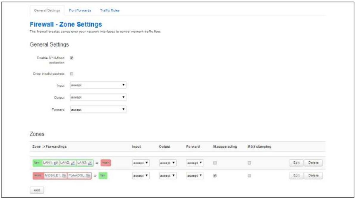
text_image
General Settings Port Forwards Traffic Rules Firewall - Zone Settings The firewall creates zones over your network interfaces to control network traffic flow. General Settings Enable SYM-fixed protection Drop Invalid packets Input: accept Output: accept Forward: accept Zones Zone → Forwardings Input Output Forward Masquerading M3S clamping lan LAN1: LAN2: LAN3: ≈ wan accept ▼ accept ▼ accept ▼ □ □ Edit Delete wan MOBILE1: POADSL: ≈ tan accept ▼ accept ▼ accept ▼ □ □ Edit Delete AddFigure 144: The firewall zone general settings page
| Web Field/ UCI / Package Option | Description | |
| Web: Enable SYN-flood protectionUCI: firewall.defaults.syn_floodOpt: syn_flood | Enables SYN flood protection. | |
| 0 Disabled. | ||
| 1 Enabled. | ||
| Web: Drop invalid packetsUCI: firewall.defaults.drop_invalidOpt: drop_invalid | Drops packets not matching any active connection. | |
| 0 | Disabled. | |
| 1 Enabled. | ||
| Web: InputUCI: firewall.defaults.inputOpt: input | Default policy for the Input chain. | |
| Accept Accepted packets pass through the firewall. | ||
| Reject | Rejected packets are blocked by the firewall and ICMP message is returned to the source host. | |
| Drop Dropped packets are blocked by the firewall. | ||
| Web: OutputUCI: firewall.defaults.outputOpt: output | Default policy for the Output chain. | |
| Accept | Accepted packets pass through the firewall. | |
| Reject Rejected packets are blocked by the firewall and ICMP message is returned to the source host. | ||
| Drop Dropped packets are blocked by the firewall. | ||
| Web: ForwardUCI: firewall.defaults.forwardOpt: forward | Default policy for the Forward chain. | |
| Accept Accepted packets pass through the firewall. | ||
| Reject Rejected packets are blocked by the firewall and ICMP message is returned to the source host. | ||
| Drop | Dropped packets are blocked by the firewall. | |
Table 97: Information table for general zone general settings page
31.2.1.2 Firewall zones
The Zones section groups one or more interfaces and serves as a source or destination for forwardings, rules and redirects. Masquerading (NAT) of outgoing traffic is controlled on a per-zone basis. To view a zone's settings, click Edit.
The number of concurrent dynamic/static NAT entries of any kind
(NAT/PAT/DNAT/SNAT) is not limited in any way by software; the only hardware limitation is the amount of RAM installed on the device.
31.2.1.3 Firewall zone: general settings
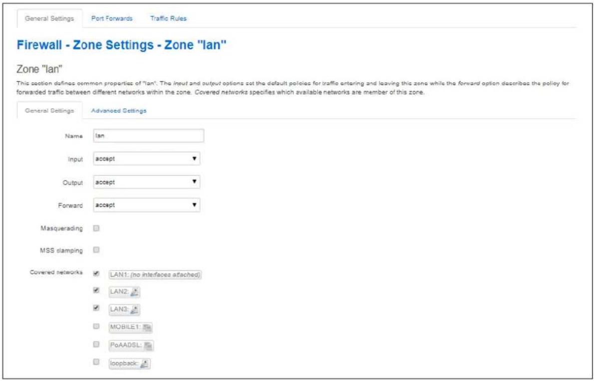
text_image
Firewall - Zone Settings - Zone "lan" Zone "lan" This section defines common properties of "lan". The input and output options set the default policies for traffic entering and leaving this zone while the forward option describes the policy for forwarded traffic between different networks within the zone. Covered networks specifies which available networks are member of this zone. General Settings Advanced Settings Name lan Input accept Output accept Forward accept Masquerading MSS clamping Covered networks LAN1: (no interfaces attached) LAN2 LAN3 MOBILE1 PoAADSL loopbackFigure 145: The firewall zone general settings
| Web Field/ UCI / Package Option | Description | |
| Web: nameUCI: firewall.<zone label>.nameOpt: name | Sets the unique zone name. Maximum of 11 characters allowed.Note: the zone label is obtained by using the 'uci show firewall' command and is of the format '@zone[x]' where x is an integer starting at 0. | |
| Web: InputUCI: firewall.<zone label>.inputOpt: input | Default policy for incoming zone traffic. Incoming traffic is traffic entering the router through an interface selected in the 'Covered Networks' option for this zone. | |
| Accept Accepted packets pass through the firewall. | ||
| Reject | Rejected packets are blocked by the firewall and ICMP message is returned to the source host. | |
| Drop Dropped packets are blocked by the firewall. | ||
| Web: OutputUCI: firewall.<zone label>.outputOpt: output | Default policy for outgoing zone traffic. Outgoing traffic is traffic leaving the router through an interface selected in the 'Covered Networks' option for this zone. | |
| Accept Accepted packets pass through the firewall. | ||
| Reject Rejected packets are blocked by the firewall and ICMP message is returned to the source host. | ||
| Drop Dropped packets are blocked by the firewall. | ||
| Web: ForwardUCI: firewall.<zone label>.forwardOpt: forward | Default policy for internal zone traffic between interfaces.Forward rules for a zone describe what happens to traffic passing between different interfaces within that zone. | |
| Accept Accepted packets pass through the firewall. | ||
| Reject Rejected packets are blocked by the firewall and ICMP message is returned to the source host. | ||
| Drop Dropped packets are blocked by the firewall. | ||
| Web: MasqueradingUCI: firewall.<zone label>.masqOpt: masq | Specifies whether outgoing zone traffic should be masqueraded (NATTED). This is typically enabled on the wan zone. | |
| Web: MSS ClampingUCI: firewall.<zone label>.mtu_fixOpt: mtu_fix | Enables MSS clamping for outgoing zone traffic. Subnets are allowed. | |
| 0 Disabled. | ||
| 1 | Enabled. | |
| Web: Covered networksUCI: firewall<zone label>.networkOpt: network | Defines a list of interfaces attached to this zone, if omitted, the value of name is used by default.Note: use the uci list syntax to edit this setting through UCI. | |
Table 98: Information table for firewall zone general settings
31.2.1.4 Firewall zone: advanced settings
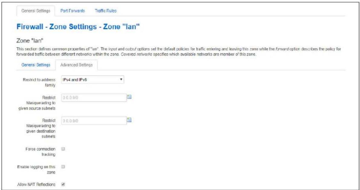
text_image
General Settings Port Forwards Traffic Rules Firewall - Zone Settings - Zone "lan" Zone "lan" This section defines common properties of "lan". The input and output options set the default policies for traffic entering and leaving this zone while the forward option describes the policy for forwarded traffic between different networks within the zone. Covered networks specifies which available networks are member of this zone. General Settings Advanced Settings Restrict to address IPv4 and IPv6 family Restrict 0.0.0.0 Masquerading to given source subnets Restrict 0.0.0.0 Masquerading to given destination subnets Force connection tracking Enable logging on this zone Allow NAT ReflectionsFigure 146: Firewall zone advanced settings
| Web Field/ UCI / Package Option | Description | ||
| Web: Restrict to address familyUCI: firewall.<zone label>.familyOpt: family | Restricts zone to IPv4, IPv6 or both IPv4 and IPv6. | ||
| Option | Description | UCI | |
| IPv4 andIPv6 | Any address family any | ||
| IPv4 only | IPv4 only | ipv4 | |
| IPv6 only | IPv6 only | IPv6 | |
| Web: Restrict Masquerading to given source subnets.UCI: firewall.<zone label>.masq_srcOpt: masq_src | Limits masquerading to the given source subnets. Negation is possible by prefixing the subnet with 'I'. Multiple subnets are allowed. | ||
| Web: Restrict Masquerading to given destination subnets.UCI: firewall.<zone label>.masq_destOpt: masq_dest | Limits masquerading to the given destination subnets. Negation is possible by prefixing the subnet with 'I'. Multiple subnets are allowed. Multiple IP addresses/subnets should be separated by a space, for example: option masq_dest '1.1.1.1 2.2.2.0/24'. | ||
| Web: Force connection trackingUCI: firewall.<zone label>.conntrackOpt: conntrack | Forces connection tracking for this zone. | ||
| 0 | Disabled. | ||
| 1 If masquerading is used. Otherwise, default is 0. | |||
| Web: Enable logging on this zoneUCI: firewall.<zone label>.logOpt: log | Creates log rules for rejected and dropped traffic in this zone. | ||
| Web: Allow NAT reflectionsUCI: firewall.<zone label>.reflectionOpt: reflection | Enable/disable all NAT reflections for this zone.Note: For configs with a large number of firewall rules, disabling NAT reflection will speed up load of firewall rules on interface start. | ||
| 0 | Disable reflection. | ||
| 1 | Enable reflection. | ||
| Web: n/aUCI: firewall.<zone label>.log_limitOpt: log_limit | Limits the amount of log messages per interval. |
Table 99: Information table for firewall zone advanced settings
31.2.1.5 Inter-zone forwarding
This section controls the traffic flow between zones. Selecting a source or destination zone generates a Forwarding rule. Only one direction is covered by any forwarding rule. Hence for bidirectional traffic flow between two zones then two rules are required, with source and destination alternated.
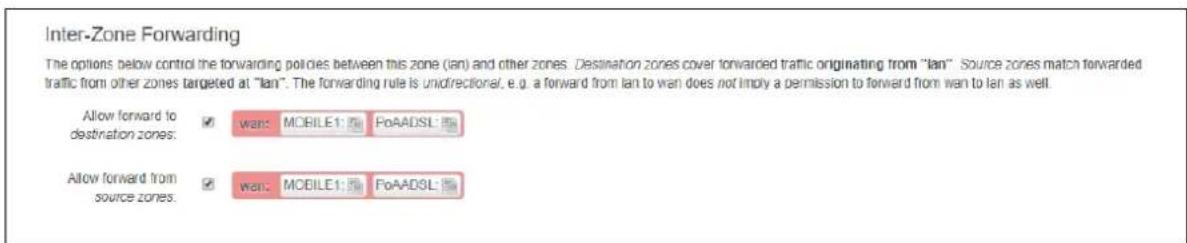
text_image
Inter-Zone Forwarding The options below control the forwarding policies between this zone (lan) and other zones. Destination zones cover forwarded traffic originating from "lan". Source zones match forwarded traffic from other zones targeted at "lan". The forwarding rule is unidirectional, e.g. a forward from lan to wan does not imply a permission to forward from wan to lan as well. Allow forward to destination zones: □ wan: MOBILE1: □ FoAADSL: Allow forward from source zones: □ wan: MOBILE1: □ FoAADSL:Figure 147: The inter-zone forwarding section
| Web Field/ UCI / Package Option | Description |
| Web: Allow forward to destination zonesUCI: firewall.<forwarding label>.destOpt: dest | Allows forward to other zones. Enter the current zone as the source.Enabling this option puts two entries into the firewall file: destination and source. |
| UCI firewall.<forwarding label>.srcOpt: src | |
| Web: Allow forward from source zonesUCI: firewall.<forwarding label>.destOpt: dest | Allows forward from other zones. Enter the current zone as the destination.Enabling this option puts two entries into the firewall file: destination and source. |
| UCI: firewall.<forwarding label>.srcOpt: src |
Table 100: Information table for inter-zone forwarding settings
Note: the rules generated for forwarding traffic between zones relay connection tracking to be enabled on at least one of the source or destination zones. This can be enabled through the conntrack option or through masq.
31.2.2 Firewall port forwards
Port Forwards are also known as Redirects. This section creates the redirects using DNAT (Destination Network Address Translation) with Netfilter. The redirects are from the firewall zone labelled as wan to the firewall zone labelled as lan. These zones can refer to multiple external and internal interfaces as defined in the Firewall Zone settings.
To edit an existing port forward select edit.
To add a new port forward select add.
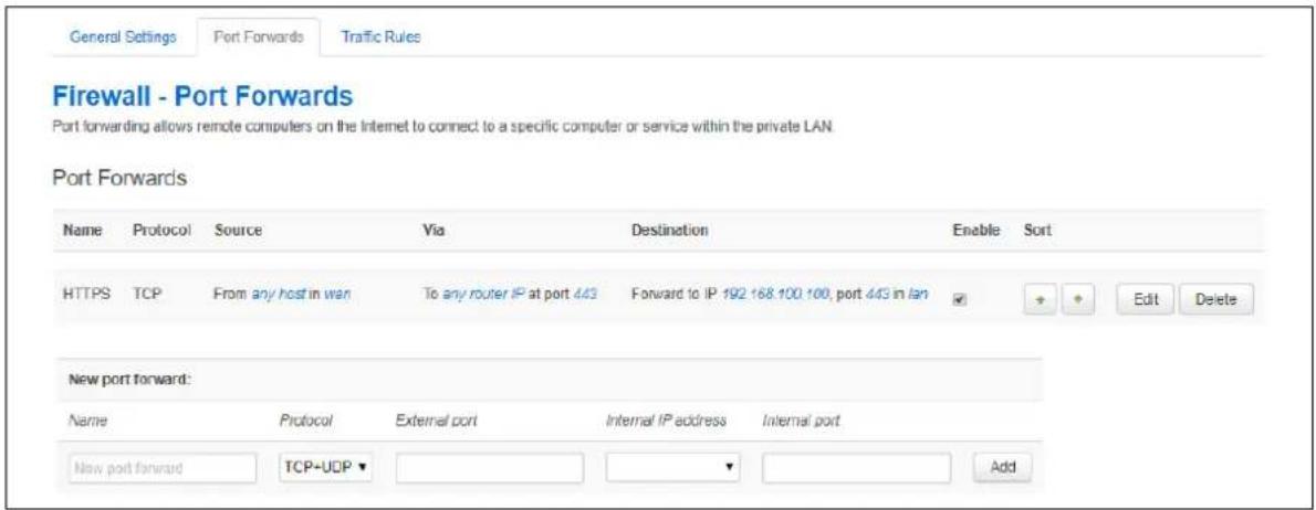
text_image
General Settings Port Forwards Traffic Rules Firewall - Port Forwards Port forwarding allows remote computers on the Internet to connect to a specific computer or service within the private LAN. Port Forwards Name Protocol Source Via Destination Enable Sort HTTPS TCP From any host in wan To any router IP at port 443 Forward to IP 192 168.100.100, port 443 in lan New port forward: Name Protocol External port Internal IP address Internal port New port forward TCP=UDP AddFigure 148: The firewall port forward page
| Web Field/ UCI / Package Option | Description | ||
| Web: nameUCI: firewall.<redirect label>.nameOpt: name | Sets the port forwarding name. For Web UI generated redirects the<redirect label> takes the form of @redirect[x], where x is an integer starting from 0. | ||
| Web: ProtocolUCI: firewall.<redirect label>.protoOpt: proto | Defines layer 4 protocol to match incoming traffic. | ||
| Option | Description | UCI | |
| tcp+ udp | Match either TCP or UDP packets. | tcp udp | |
| tcp | Match TCP packets only. | tcp | |
| udp | Match UDP packets only. | udp | |
| Web: External portUCI: firewall.<redirectlabel>.src_dportOpt: src_dport | Specifies the incoming TCP/UDP port or port range to match. This is the incoming destination port specified by the external host. Port ranges specified as start:stop, for example, 2001:2020. | ||
| Blank | Match traffic to any port. | ||
| Range | 1 - 65535 | ||
| Web: Internal IP addressUCI: firewall.<redirectlabel>.dest_ipOpt: dest_ip | Specifies the internal (LAN) IP address for the traffic to be redirected to. | ||
| Web: Internal portUCI: firewall.<redirectlabel>.dest_portOpt: dest_port | Specifies the destination tcp/udp port for the redirect traffic. | ||
| Option | Description | UCI |
| tcp+udp | Match either TCP or UDP packets. | tcp udp |
| tcp | Match TCP packets only. | tcp |
| udp | Match UDP packets only. | udp |
Table 101: Information table for firewall port forward settings
The defined redirects can be sorted into a specific order to be applied. More specific rules should be placed first.
After the redirect is created and saved, to make changes, click Edit. This will provide further options to change the source/destination zones; specify source mac addresses and enable NAT loopback (reflection).
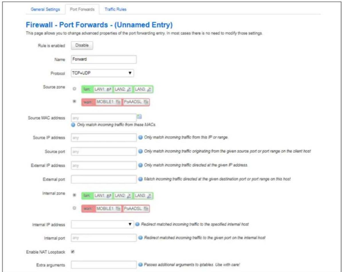
text_image
General Settings Port Forwards Traffic Rules Firewall - Port Forwards - (Unnamed Entry) This page allows you to change advanced properties of the port forwarding entry. In most cases there is no need to modify those settings. Rule is enabled Disable Name Forward Protocol TCP+UDP Source zone lan: LAN1: LAN2: LAN3: wan: MOBILE1: PoAADSL Source MAC address any Only match incoming traffic from these MACs. Source IP address any Only match incoming traffic from this IP or range. Source port any Only match incoming traffic originating from the given source port or port range on the client host External IP address any Only match incoming traffic directed at the given IP address. External port Internal zone lan: LAN1: LAN2: LAN3: wan: MOBILE1: PoAADSL Internal IP address ▼ Redirect matched incoming traffic to the specified internal host Internal port any Redirect matched incoming traffic to the given port on the internal host Enable NAT Loopback ✓ Extra arguments Passes additional arguments to iptables. Use with care!Figure 149: The firewall port forwards edits page
| Web Field/ UCI / Package Option | Description | ||
| Web: Rule is enabledUCI: firewall..enabledOpt: enabled | Specifies if this redirect should be enabled or disabled. | ||
| 0 Disabled. | |||
| 1 | Enabled. | ||
| Web: nameUCI: firewall..nameOpt: name | Sets the port forwarding name. For Web UI generated redirects thetakes the form of @redirect[x], where x is an integer starting from 0. | ||
| Web: ProtocolUCI: firewall..protoOpt: proto | Defines layer 4 protocol to match incoming traffic. | ||
| Option | Description | UCI | |
| tcp+ udp | Match either TCP or UDP packets. | tcp udp | |
| tcp | Match TCP packets only. | tcp | |
| udp | Match UDP packets only. | udp | |
| Web: Source zoneUCI: firewall..srcOpt: src | Specifies the traffic source zone. It must refer to one of the defined zone names. When using the web interface, this is set to WAN initially. | ||
| Web: Source MAC addressUCI: firewall.<redirect label>.src_macOpt: list src_mac | Defines the list of source MAC addresses that this redirect will match.Format: aa:bb:cc:dd:ee:ffMultiple RIP interfaces are entered using uci set and uci add_list commands. Example:uci set firewall.@redirect[0].src_mac=aa:bb:cc:dd:ee:ffuci add_listfirewall.@redirect[0].src_mac=12:34:56:78:90:12or using a list of options via package optionslist network 'aa:bb:cc:dd:ee:ff'list network '12:34:56:78:90:12' | ||
| Web: Source IP addressUCI: firewall.<redirect label>.src_ipOpt: src_ip | Defines a source IP address that this redirect will match. | ||
| Blank | Match traffic from any source IP. | ||
| Range A.B.C.D/mask. | |||
| Web: Source portUCI: firewall.<redirect label>.src_portOpt: src_port | Defines a source IP port that this redirect will match. You can enter multiple ports, using a space separator.For example: option src_port '22 23'* see note below on use with options src_dport and dest_port | ||
| Blank | Match traffic from any source port. | ||
| Range 1 - 655 | 35 | ||
| Web: External portUCI: firewall.<redirect label>.src_dportOpt: src_dport | Specifies the incoming TCP/UDP port or port range to match. This is the incoming destination port specified by the external host. Port ranges specified in format start:stop, for example, 2001:2020.You can enter multiple ports, using a space separator.For example: option src_dport '22 23'* see note below on use with options src_port and dest_port | ||
| Blank Match traffic to any port. | |||
| Range 1 - 655 | 35 | ||
| Web: Internal zoneUCI: firewall.<redirect label>.destOpt: dest | Specifies the traffic destination zone, must refer to one of the defined zone names. | ||
| Web: Internal IP addressUCI: firewall.<redirect label>.dest_ipOpt: dest_ip | Specifies the internal (LAN) IP address for the traffic to be redirected to. | ||
| Web: Internal portUCI: firewall.<redirect label>.dest_portOpt: dest_port | Specifies the destination tcp/udp port for the redirect traffic. You can enter multiple ports, using a space separator.* For example: option dest_port '22 23'* See note below table on use with options src_port and src_dport. | ||
| Web: Enable NAT LoopbackUCI: firewall<redirect label>.reflectionOpt: reflection | Enable or disable NAT reflection for this redirect. | ||
| 0 Reflection d | sabled. | ||
| 1 | Reflection enabled. | ||
| Web: Extra argumentsUCI: firewall<redirect label>.extraOpt: extra | Passes extra arguments to IP tables. This is useful to specify additional match options, like -m policy --dir in for IPSec. The arguments are entered as text strings. | ||
Table 102: Information table for port forward edits fields
* Note: redirect rule options src_port and src_dport/dest_port accept space-separated lists of ports. If src_port is a list, then src_dport/dst_port cannot be, to avoid ambiguity.
If src_dport/dest_port are lists of different lengths, then the missing values of the shorter list default to the corresponding port in the other list. For example, if configuration file is:
option src_dport '21 22 23'
option dest_port '21 22 23 24'
then the firmware will interpret the values as:
option src_dport '21 22 23 24'
option dest_port '21 22 23 24'
31.2.3 Firewall traffic rules
Rules can be defined to allow or restrict access to specific ports, hosts or protocols.
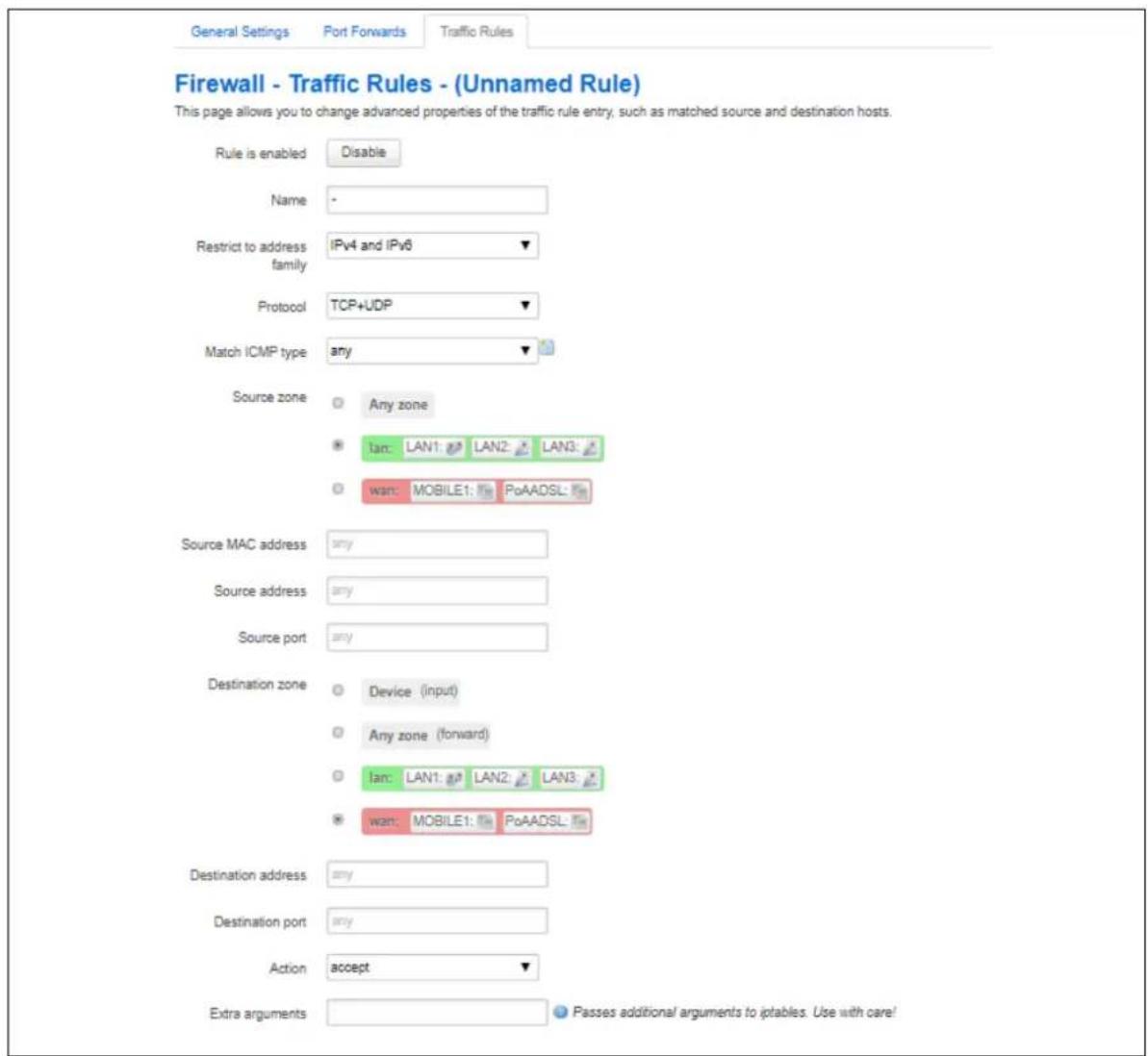
text_image
Firewall - Traffic Rules - (Unnamed Rule) This page allows you to change advanced properties of the traffic rule entry, such as matched source and destination hosts. Rule is enabled Disable Name - Restrict to address family IPv4 and IPv6 Protocol TCP+UDP Match ICMP type any Source zone Any zone lan: LAN1: LAN2: LAN3: wan: MOBILE1: PoAADSL Source MAC address any Source address any Source port any Destination zone Device (input) Any zone (forward) lan: LAN1: LAN2: LAN3: wan: MOBILE1: PoAADSL Destination address any Destination port any Action accept Extra arguments Passes additional arguments to iptables. Use with care!Figure 150: The firewall traffic rules page
| Web Field/ UCI / Package Option | Description | ||
| Web: Rule is enabledUCI: firewall..enabledOpt: enabled | Enables or disables traffic rule. | ||
| 0 | Rule is disabled. | ||
| 1 Rule is enabled. | |||
| Web: NameUCI: firewall..nameOpt: name | Select a descriptive name limited to less than 11 characters. No spaces are allowed in the naming convention. | ||
| Web: Restrict to address familyUCI: firewall..familyOpt: family | Restrict to protocol family. | ||
| Option | Description | UCI | |
| IPv4 andIPv6 | Traffic rule applies to anyaddress family | any | |
| IPv4 only | IPv4 only | ipv4 | |
| IPv6 only | IPv6 only | IPv6 | |
| Web: ProtocolUCI: firewall..protoOpt: proto | Matches incoming traffic using the given protocol. | ||
| Option | Description | UCI | |
| TCP+ UDP Applies rule to TCP and UDPonly | tcp udp | ||
| TCP | Applies rule to TCP only | tcp | |
| UDP | Applies rule to UDP only | udp | |
| ICMP | Applies rule to ICMP only | icmp | |
| custom Specify protocol from/etc/protocols | |||
| Web: Match ICMP typeUCI: firewall..icmp_typeOpt: icmp_type | Match specific icmp types.This option is only valid when ICMP is selected as the protocol.ICMP types can be listed as either type names or type numbers.Note: for a full list of valid ICMP type names, see the ICMP Options table below. | ||
| Web: Source zoneUCI: firewall..srcOpt: src | Specifies the traffic source zone, must refer to one of the defined zone names. For typical port forwards, this is usually WAN. | ||
| Web: Source MAC addressUCI: firewall..src_macOpt: src_mac | Matches incoming traffic from the specified MAC address.The MAC address must be entered in the following format:aa:bb:cc:dd:ee:ff:To only match the first portion of the MAC address append /prefix to the option value, where prefix defines the bits from the start of the MAC to match on.Example:option src_mac 00:E0:C8:12:34:56/24will match on all packets with prefix 00:E0:C8. | ||
| Web: Source addressUCI: firewall..src_ipOpt: src_ip | Matches incoming traffic from the specified source IP address. | ||
| Web: Source portUCI: firewall..src_portOpt: src_port | Matches incoming traffic originating from the given source port or port range on the client host. | ||
| Web: Destination zoneUCI: firewall..destOpt: dest | Specifies the traffic destination zone. Must refer to one of the defined zone names. | ||
| Web: Destination addressUCI: firewall..dest_ipOpt: dest_ip | For DNAT, redirects matched incoming traffic to the specified internal host.For SNAT, matches traffic directed at the given address. | ||
| Web: Destination portUCI: firewall.<rule label>.dest_portOpt: dest_port | For DNAT, redirects matched incoming traffic to the given port on the internal host.For SNAT, matches traffic directed at the given ports. | ||
| Web: ActionUCI: firewall.<rule label>.targetOpt: target | Action to take when rule is matched. | ||
| Option | Description | UCI | |
| drop | Drop matching traffic | DROP | |
| accept | Allow matching traffic | ACCEPT | |
| reject | Reject matching traffic | REJECT | |
| don't track Disable connection tracking for the rule. See the 'Connection tracking' section below for more information. | NOTRACK | ||
| Web: Extra argumentsUCI: firewall.<rule label>.extraOpt: extra | Passes extra arguments to IP tables. This is useful to specify additional match options, like -m policy --dir in for IPSec. | ||
| Web: n/aUCI: firewall.<rule label>.reflectionOpt: reflection | Disables NAT reflection for this redirect if set to 0. Applicable to DNAT targets. | ||
| Web: n/aUCI: firewall.<rule label>.limitOpt: limit | Sets maximum average matching rate; specified as a number, with an optional /second, /minute, /hour or /day suffix. Example: 3/hour. | ||
| Web: n/aUCI: firewall.<rule label>.limit_burstOpt: limit_burst | Sets maximum initial number of packets to match. This number gets recharged by one every time the limit specified above is not reached, up to this number. | ||
| Web: n/aUCI: firewall.<rule label>.recentOpt: recent | Sets number of allowed connections within specified time. This command takes two values e.g. recent=2 120 will allow 2 connections within 120 seconds. | ||
Table 103: Information table for firewall traffic rules
| ICMP Options | ICMP Options | ICMP Options | ICMP Options |
| address-mask-reply | host-redirect | pong | time-exceeded |
| address-mask-request | host-unknown | port-unreachable | timestamp-reply |
| any | host-unreachable | precedence-cutoff | timestamp-request |
| communication-prohibited | ip-header-bad | protocol-unreachable | TOS-host-redirect |
| destination-unreachable | network-prohibited | redirect | TOS-host-unreachable |
| echo-reply | network-redirect | required-option-missing | TOS-network-redirect |
| echo-request | network-unknown | router-advertisement | TOS-network-unreachable |
| fragmentation-needed | network-unreachable | router-solicitation | ttl-exceeded |
| host-precedence-violation | parameter-problem | source-quench | ttl-zero-during-reassembly |
| host-prohibited | ping | source-route-failed | ttl-zero-during-transit |
Table 104: Information table for match ICMP type drop-down menu
31.3 Configuring firewall using UCI
Firewall is configured under the firewall package /etc/config/firewall.
There are three config sections: defaults, zone, forwarding, redirect, rule and include.
You can configure multiple zone, forwarding and redirect sections.
31.3.1 Firewall general settings
To set general (default) settings, enter:
uci add firewall defaults
uci set firewall.@defaults[0].syn_flood=1
uci set firewall.@defaults[0].drop_invalid=1
uci set firewall.@defaults[0].input=ACCEPT
uci set firewall.@defaults[0].output=ACCEPT
uci set firewall.@defaults[0].forward=ACCEPT
Note: this command is only required if there is no defaults section.
31.3.2 Firewall zone settings
By default, all firewall zone instances are named zone, instances are identified by @zone then the zone position in the package as a number. For example, for the first zone in the package using UCI:
firewall.@zone[0]=zone
firewall.@zone[0].name=lan
Or using package options:
config zone option name 'lan'
To set up a firewall zone, enter:
uci add firewall zone
uci set firewall.@zone[1].name=lan
uci set firewall.@zone[1].input=ACCEPT
uci set firewall.@zone[1].output=ACCEPT
uci set firewall.@zone[1].forward=ACCEPT
uci set firewall.@zone[1].network=lan1 wifi_client
uci set firewall.@zone[1].family=any
uci set firewall.@zone[1].masq_src=10.0.0.0/24
uci set firewall.@zone[1].masq_dest=20.0.0.0/24
uci set firewall.@zone[1].conntrack=1
uci set firewall.@zone[1].masq=1
uci set firewall.@zone[1].mtu_fix=1
uci set firewall.@zone[1].log=1
uci set firewall.@zone[1].log_limit=5
31.3.3 Inter-zone forwarding
By default, all inter-zone instances are named 'forwarding'; instances are identified by @forwarding then the forwarding position in the package as a number. For example, for the first forwarding in the package using UCI:
firewall.@forwarding[0]=forwarding
firewall.@forwarding[0].src=lan
Or using package options:
config forwarding
option src 'lan'
To enable forwarding of traffic from WAN to LAN, enter:
uci add firewall forwarding
uci set firewall.@forwarding[1].dest=wan
uci set firewall.@forwarding[1].src=lan
31.3.4 Firewall port forwards
By default, all port forward instances are named 'redirect'; instances are identified by @redirect then the redirect position in the package as a number. For example, for the first redirect in the package using UCI:
firewall.@redirect[0]=redirect
firewall.@redirect[0].name=Forward
Or using package options:
config redirect
option name 'Forward'
To set port forwarding rules, enter:
uci add firewall redirect
uci set firewall.@redirect[1].name=Forward
uci set firewall.@redirect[1].proto=tcp
uci set firewall.@redirect[1].src=wan # <- zone names
uci set firewall.@redirect[1].dest=lan # <- zone names
uci set firewall.@redirect[1].src_dport=2001
uci set firewall.@redirect[1].dest_ip=192.168.0.100
uci set firewall.@redirect[1].dest_port=2005
uci set firewall.@redirect[1].enabled=1
31.3.5 Firewall traffic rules
By default, all traffic rule instances are named rule, instances are identified by @rule then the rule position in the package as a number. For example, for the first rule in the package using UCI:
firewall.@rule[0]=rule
firewall.@rule[0].enabled=1
Or using package options:
config rule option enabled '1'
To set traffic rules, enter:
uci add firewall rule
uci set firewall.@rule[1].enabled=1
uci set firewall.@rule[1].name=Allow_ICMP
uci set firewall.@rule[1].family=any
uci set firewall.@rule[1].proto=ICMP
uci set firewall.@rule[1].icmp_type=any
uci set firewall.@rule[1].src=wan
uci set firewall.@rule[1].src_mac=ff:ff:ff:ff:ff:ff
uci set firewall.@rule[1].src_port=
uci set firewall.@rule[1].dest=lan
uci set firewall.@rule[1].dest_port=
uci set firewall.@rule[1].dest_ip=192.168.100.1
uci set firewall.@rule[1].target=ACCEPT
uci set firewall.@rule[1].extra=
uci set firewall.@rule[1].src_ip=8.8.8.8
uci set firewall.@rule[1].src_dip=9.9.9.9
uci set firewall.@rule[1].src_dport=68
uci set firewall.@rule[1].reflection=1
uci set firewall.@rule[1].limit=3/second
uci set firewall.@rule[1].limit_burst=30
31.3.5.1 Custom firewall scripts: includes
It is possible to include custom firewall scripts by specifying one or more include sections in the firewall configuration.
There is only one possible parameter for includes:
| Parameter | Description |
| path | Specifies a shell script to execute on boot or firewall restarts. |
Custom scripts are executed as shell scripts and are expected to contain iptables commands.
31.4 IPv6 notes
As described above, the option family is used for distinguishing between IPv4, IPv6 and both protocols. However, the family is inferred automatically if a specific IP address family is used. For example; if IPv6 addresses are used then the rule is automatically treated as IPv6 only rule.
config rule
option src wan
option src_ip fdca:f00:ba3::/64
option target ACCEPT
Similarly, the following rule is automatically treated as IPv4 only.
config rule
option src wan
option dest_ip 88.77.66.55
option target REJECT
Rules without IP addresses are automatically added to iptables and ip6tables, unless overridden by the family option. Redirect rules (port forwards) are always IPv4 since there is no IPv6 DNAT support at present.
31.5 Implications of DROP vs. REJECT
The decision whether to drop or to reject traffic should be done on a case-by-case basis. Many people see dropping traffic as a security advantage over rejecting it because it exposes less information to a hypothetical attacker. While dropping slightly increases security, it can also complicate the debugging of network issues or cause unwanted side-effects on client programs.
If traffic is rejected, the router will respond with an icmp error message ("destination port unreachable") causing the connection attempt to fail immediately. This also means that for each connection attempt a certain amount of response traffic is generated. This can actually harm if the firewall is attacked with many simultaneous connection attempts, the resulting backfire of icmp responses can clog up all available upload and make the connection unusable (DoS).
When connection attempts are dropped the client is not aware of the blocking and will continue to re-transmit its packets until the connection eventually times out. Depending on the way the client software is implemented, this could result in frozen or hanging programs that need to wait until a timeout occurs before they're able to continue.
DROP
• less information is exposed
- less attack surface
- client software may not cope well with it (hangs until connection times out)
- may complicate network debugging (where was traffic dropped and why)
REJECT
- may expose information (like the IP at which traffic was actually blocked)
- client software can recover faster from rejected connection attempts
• network debugging easier (routing and firewall issues clearly distinguishable)
31.6 Connection tracking
By default, the firewall will disable connection tracking for a zone if no masquerading is enabled. This is achieved by generating NOTRACK firewall rules matching all traffic passing via interfaces referenced by the firewall zone. The purpose of NOTRACK is to speed up routing and save memory by circumventing resource intensive connection tracking in cases where it is not needed. You can check if connection tracking is disabled by issuing iptables -t raw -S, it will list all rules, check for NOTRACK target.
NOTRACK will render certain iptables extensions unusable, for example the MASQUERADE target or the state match will not work.
If connection tracking is required, for example by custom rules in /etc/firewall.user, the conntrack option must be enabled in the corresponding zone to disable NOTRACK. It should appear as option 'conntrack' '1' in the right zone in /etc/config/firewall.
31.7 Firewall examples
31.7.1 Opening ports
The default configuration accepts all LAN traffic, but blocks all incoming WAN traffic on ports not currently used for connections or NAT. To open a port for a service, add a rule section:
config rule
option src wan
option dest_port 22
option target ACCEPT
option proto tcp
This example enables machines on the internet to use SSH to access your router.
31.7.2 Forwarding ports (destination NAT/ DNAT)
This example forwards http, but not HTTPS, traffic to the web server running on 192.168.1.10:
config redirect
option src wan
option src_dport 80
option proto tcp
option dest_ip 192.168.1.10
The next example forwards one arbitrary port that you define to a box running SSH behind the firewall in a more secure manner because it is not using default port 22.
config 'redirect'
option 'name' 'ssh'
option 'src' 'wan'
option 'proto' 'tcpudp'
option 'src_dport' '5555'
option 'dest_ip' '192.168.1.100'
option 'dest_port' '22'
option 'target' 'DNAT'
option 'dest' 'lan'
31.7.3 Source NAT (SNAT)
Source NAT changes an outgoing packet destined for the system so that is looks as though the system is the source of the packet.
Define source NAT for UDP and TCP traffic directed to port 123 originating from the host with the IP address 10.55.34.85. The source address is rewritten to 63.240.161.99.
config redirect
option src lan
option dest wan
option src_ip 10.55.34.85
option src_dip 63.240.161.99
option dest_port 123
option target SNAT
When used alone, Source NAT is used to restrict a computer's access to the internet, but allows it to access a few services by manually forwarding what appear to be a few local
services; for example, NTP to the Internet. While DNAT hides the local network from the Internet, SNAT hides the Internet from the local network.
Source NAT and destination NAT are combined and used dynamically in IP masquerading to make computers with private (192.168.x.x, etc.) IP addresses appear on the internet with the system's public WAN IP address.
31.7.4 True destination port forwarding
This usage is similar to SNAT, but as the destination IP address is not changed, machines on the destination network need to be aware that they'll receive and answer requests from a public IP address that is not necessarily theirs. Port forwarding in this fashion is typically used for load balancing.
config redirect
option src wan
option src_dport 80
option dest lan
option dest_port 80
option proto tcp
31.7.5 Block access to a specific host
The following rule blocks all connection attempts to the specified host address.
config rule
option src lan
option dest wan
option dest_ip 123.45.67.89
option target REJECT
31.7.6 Block access to the internet using MAC
The following rule blocks all connection attempts from the client to the internet.
config rule
option src lan
option dest wan
option src_mac 00:00:00:00:00:00
option target REJECT
31.7.7 Block access to the internet for specific IP on certain times
The following rule blocks all connection attempts to the internet from 192.168.1.27 on weekdays between 21:00pm and 09:00am.
config rule
option src lan
option dest wan
option src_ip 192.168.1.27
option extra '-m time --weekdays Mon, Tue, Wed, Thu, Fri --timestart 21:00 --timestop 09:00'
option target REJECT
31.7.8 Restricted forwarding rule
The example below creates a forward rule rejecting traffic from LAN to WAN on the ports 1000-1100.
config rule
option src lan
option dest wan
option dest_port 1000-1100
option proto tcpudp
option target REJECT
31.7.9 Denial of service protection rule
The example below shows a sample configuration of SSH DoS attack where if more than two SSH connections are attempted within 120 seconds, every further connection will be dropped. You can configure this for any port number.
config rule 'sshattack'
option src 'lan'
option dest_port '22'
option proto 'tcp'
option recent '2 120'
option target 'DROP'
31.7.10 IP spoofing prevention mechanism
Configure IP spoofing protection on a per interface basis in the /etc/config/network configuration file. The example below shows the ipv4_rp_filter option enabled on the Vlan12 interface in the network file. When reverse path filtering mechanism is enabled, the router will check whether a receiving packet source address is routable.
If it is routable through the interface from which it came, then the machine will accept the packet
If it is not routable through the interface from which it came, then the machine will drop that packet.
config interface 'Vlan12'
option type 'bridge'
option proto 'static'
option monitored '0'
option ipaddr '10.1.28.122'
option netmask '255.255.0.0'
option ifname 'eth1 eth3.12'
option ipv4_rp_filter '1'
31.7.11 Simple DMZ rule
The following rule redirects all WAN ports for all protocols to the internal host 192.168.1.2.
config redirect
option src wan
option proto all
option dest_ip 192.168.1.2
31.7.12 Transparent proxy rule (external)
The following rule redirects all outgoing HTTP traffic from LAN through an external proxy at 192.168.1.100 listening on port 3128. It assumes the router LAN address to be 192.168.1.1 - this is needed to masquerade redirected traffic towards the proxy.
config redirect
option src lan
option proto tcp
option src_ip !192.168.1.100
option src_dport 80
option dest_ip 192.168.1.100
option dest_port 3128
option target DNAT
config redirect
option dest lan
option proto tcp
option src_dip 192.168.1.1
option dest_ip 192.168.1.100
option dest_port 3128
option target SNAT
31.7.13 Transparent proxy rule (same host)
The rule below redirects all outgoing HTTP traffic from LAN through a proxy server listening at port 3128 on the router itself.
config redirect
option src lan
option proto tcp
option src_dport 80
option dest_port 3128
31.7.14 IPSec passthrough
This example enables proper forwarding of IPSec traffic through the WAN.
<h1 id="ah-protocol">AH protocol</h1>
config rule
option src wan
option dest lan
option proto ah
option target ACCEPT
<h1 id="esp-protocol">ESP protocol</h1>
config rule
option src wan
option dest lan
option proto esp
option target ACCEPT
For some configurations you also have to open port 500/UDP.
<h1 id="isakmp-protocol">ISAKMP protocol</h1>
config rule
option src wan
option dest lan
option proto udp
option src_port 500
option dest_port 500
option target ACCEPT
31.7.15 Manual iptables rules
You can specify traditional iptables rules, in the standard iptables UNIX command form, in an external file and included in the firewall config file. It is possible to use this process to include multiple files.
config include
option path /etc/firewall.user
config include
option path /etc/firewallvpn
The syntax for the includes is Linux standard and therefore different from UCIs.
31.7.16 Firewall management
After a configuration change, to rebuild firewall rules, enter:
root@VA_router:/# /etc/init.d/firewall restart
Executing the following command will flush all rules and set the policies to ACCEPT on all standard chains:
root@VA_router:/# /etc/init.d/firewall stop
To manually start the firewall, enter:
root@VA_router:/# /etc/init.d/firewall start
To permanently disable the firewall, enter:
root@VA_router:/# /etc/init.d/firewall disable
Note: disable does not flush the rules, so you might be required to issue a stop before.
To enable the firewall again, enter:
root@VA_router:/# /etc/init.d/firewall enable
31.7.17 Debug generated rule set
It is possible to observe the iptables commands generated by the firewall programme. This is useful to track down iptables errors during firewall restarts or to verify the outcome of certain UCI rules.
To see the rules as they are executed, run the fw command with the FW_TRACE environment variable set to 1:
root@VA_router:/# FW_TRACE=1 fw reload
To direct the output to a file for later inspection, enter:
root@VA_router:/# FW_TRACE=1 fw reload 2>/tmp/iptables.lo
32 Configuring IPSec
Internet Protocol Security (IPSec) is a protocol suite used to secure communications at IP level. Use IPSec to secure communications between two hosts or between two networks. Virtual Access routers implement IPSec using strongSwan software.
If you need to create an IPSec template for DMVPN, read the chapter 'Dynamic Multipoint Virtual Private Network (DMVPN)'.
The number of IPSec tunnels supported by Virtual Access' routers is not limited in any way by software; the only hardware limitation is the amount of RAM installed on the device.
32.1 Configuration package used
| Package | Sections |
| strongswan general | connectionsecret |
32.2 Configuring IPSec using the web interface
To configure IPSec using the web interface, in the top menu, select Services -> IPSec. The strongSwan IPSec VPN page appears. There are three sections:
| Common Settings | Control the overall behaviour of strongSwan. This behaviour is common across all tunnels. |
| Connection Settings | Together, these sections define the required parameters for a two-way IKEv1 tunnel. |
| Secret Settings |
32.2.1 Configure common settings
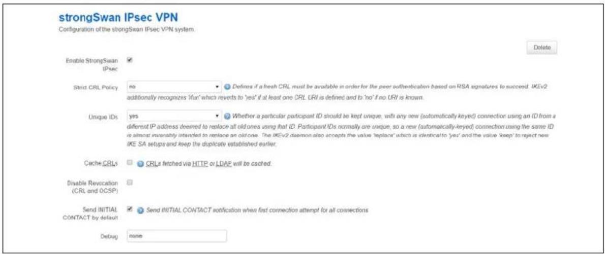
text_image
strongSwan IPsec VPN Configuration of the strongSwan IPsec VPN system. Enable StrongSwan IPsec ✓ Strict CRL Policy: no ✓ Defines if a fresh CRL must be available in order for the peer authentication based on RSA signatures to succeed. IKEv2 additionally recognizes 'ifun' which reverts to 'yes' if at least one CRL URI is defined and to 'no' if no URI is known. Unique IDs: yes ✓ Whether a particular participant ID should be kept unique, with any new (automatically keyed) connection using an ID from a different IP address deemed to replace all old ones using that ID. Participant IDs normally are unique, so a new (automatically-keyed) connection using the same ID is almost inversely intended to replace an old one. The IKEv2 daemon also accepts the value 'replace' which is identical to 'yes' and the value 'keep' to reject new IKE SA setups and keep the duplicate established earlier. Cache CRLs ✓ CRLs fetched via HTTP or LDAP will be cached. Disable Revocation (CRL and OCSP) ✓ Send INITIAL CONTACT by default ✓ Send INITIAL CONTACT notification when first connection attempt for all connections Debug: noneFigure 151: The common settings section
| Web Field/ UCI / Package Option | Description | |
| Web: Enable strongswanUCI: strongswan.general.enableOpt: enabled | Enables or disables IPSec. | |
| 0 | Disabled. | |
| 1 | Enabled. | |
| Web: Strict CRL PolicyUCI: strongswan.general.strictcrlpolicyOpt: strictcrlpolicy | Defines if a fresh CRL must be available for the peer authentication based on RSA signatures to succeed. | |
| 0 | Disabled. | |
| 1 | Enabled. | |
| ifuri The IK | Ev2 application additionally recognizes the "ifuri" option which reverts to 'yes' if at least one CRL URI is defined and to 'no' if no URI is known. | |
| Web: Unique IDsUCI: strongswan.general.uniqueidsOpt: uniqueids | Defines whether a particular participant ID should be kept unique, with any new (automatically keyed) connection using an ID from a different IP address deemed to replace all old ones using that ID.Participant IDs normally are unique, so a new (automatically-keyed) connection using the same ID is almost invariably intended to replace an old one. | |
| 0 | Disabled. | |
| 1 | Enabled. | |
| replace | Identical to Yes. | |
| keep Rejects new IKE SA and keep the duplicate established earlier | ||
| Web: Cache CRLsUCI: strongswan.general.cachecrlsOpt: cachecrls | Certificate Revocation Lists (CRLs) fetched via HTTP or LDAP will be cached in /etc/ipsec.d/crls/ under a unique file name derived from the certification authority's public key. | |
| 0 | Disabled. | |
| 1 | Enabled. | |
| Web: Disable RevocationUCI:strongswan.general revocation_disabledOpt: revocation_disabled | Defines whether disable CRL and OCSP checking for revoked certificates. | |
| 0 | Disabled. | |
| 1 | Enabled. | |
| Web: Send INITIAL CONTACT by defaultUCI: strongswan.general.initial_contactOpt: initial_contact | Defines whether the first attempt to contact a remote peer by this strongswan instance sets the initial_contact flag, which should cause compliant peers to automatically bring down any previous sessions. This can also be enabled/disabled per connection. | |
| 0 | Does not set initial contact flag. | |
| 1 | Sets initial contact flag on first attempt. | |
| Web: DebugUCI: strongswan.general.debugOpt: debug | Enables debugging. This option is used for trouble shooting issues. It is not suitable for a production environment. | |
| None | Debug disabled. | |
| Control Debug enabled. Shows generic control flow with errors and very basic auditing logs. | ||
| All Debug enabled. Most verbose logging also includes sensitive information such as keys. | ||
Table 105: Information table for IPSec common settings
32.2.2 Common settings: configure connection
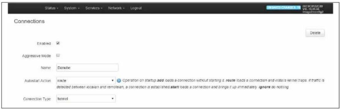
text_image
Status - System - Services - Network - Logout 00E-BCB122CRI VIE-10.00.65 imga2v3n2fig2 Connections Enabled Aggressive Mode Name: Danube Autostart Action: route Operation on startup.add loads a connection without starting it. route loads a connection and installs kernel traps. If traffic is detected between locasian and remotesian, a connection is established.start loads a connection and brings it up immediately. ignore do nothing Connection Type: tunnelFigure 152: The configuring IPSec settings
| Web Field/ UCI/ Package Option | Description | |
| Web: EnabledUCI: strongswan.@connection[X].enabledOpt: enable | Enables or disables IPSec connection. | |
| 0 | Disabled. | |
| 1 | Enabled. | |
| Web: AggressiveUCI: strongswan.@connection[X].aggressiveOpt: aggressive | Enables or disables IKE aggressive mode.Note: using aggressive mode along with PSK authentication is less secure method than main mode and should be avoided. | |
| 0 | Disabled. | |
| 1 | Enabled. | |
| Web: NameUCI: strongswan.@connection[X].nameOpt: name | Specifies a name for the tunnel. | |
| Web: Autostart ActionUCI: strongswan.@connection[X].autoOpt: auto | Specifies when the tunnel is initiated. | |
| start | On start up. | |
| route | When traffic routes this way. | |
| add | Loads a connection without starting it. | |
| ignore | Ignores the connection. | |
| always Actively retries to establish the tunnel if it went down. | ||
| Web: Connection TypeUCI: strongswan.@connection[X].typeOpt: type | Defines the type of IPSec connection. | |
| tunnel | Connection uses tunnel mode. | |
| transport | Connection uses transport mode. | |
| pass Connection does not perform any IPSec processing. | ||
| drop | Connection drops all the packets. | |
Table 106: Information table for connection settings
32.2.3 Common settings: IP addressing
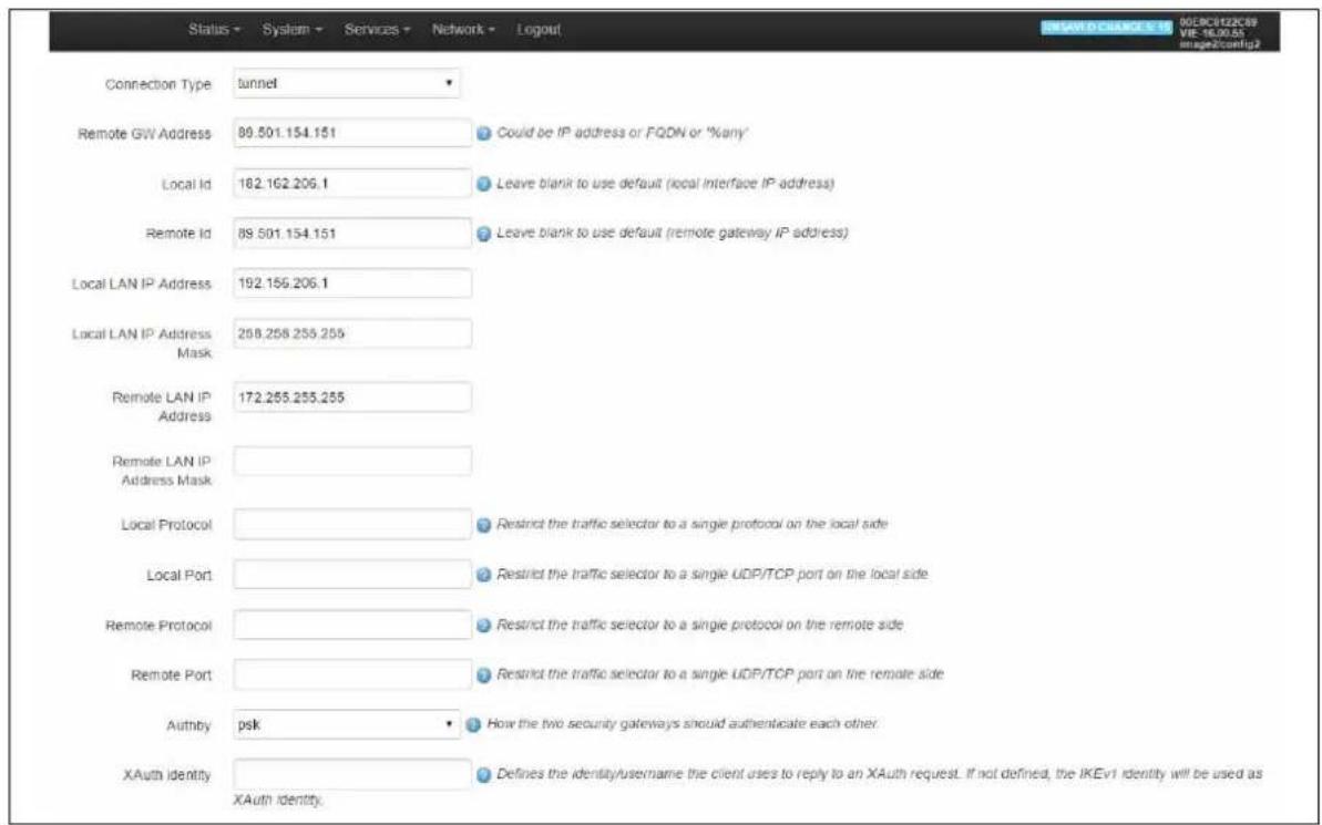
text_image
Status - System - Services - Network - Logout Connection Type tunnel Remote GW Address 89.501.154.151 Could be IP address or FQDN or %any' Local Id 182.162.206.1 Leave blank to use default (local Interface IP address) Remote Id 89.501.154.151 Leave blank to use default (remote gateway IP address) Local LAN IP Address 192.156.206.1 Local LAN IP Address Mask Remote LAN IP Address 258.258.255.255 Remote LAN IP Address Mask Local Protocol Restrict the traffic selector to a single protocol on the local side Local Port Restrict the traffic selector to a single UDP/TCP port on the local side Remote Protocol Restrict the traffic selector to a single protocol on the remote side Remote Port Restrict the traffic selector to a single UDP/TCP port on the remote side Authby psk How the two security gateways should authenticate each other XAuth identity Defines the identity/username the client uses to reply to an XAuth request. If not defined, the IKEv1 identity will be used as XAuth identity.Figure 153: The IP addressing settings
| Web Field/ UCI / Package Option | Description | |
| Web: Remote GW AddressUCI: strongswan.@connection[X].remoteaddressOpt: remoteaddress | Sets the public IP address of the remote peer. | |
| Web: Local IDUCI: strongswan.@connection[X].localidOpt: localid | Defines the local peer identifier. | |
| Web: Remote IDUCI: strongswan.@connection[X].remoteidOpt:remoteid | Defines the remote peer identifier. | |
| Web: Local LAN IP AddressUCI: strongswan.@connection[X].localanOpt: localan | Defines the local IP of LAN. | |
| Web: Local LAN IP Address MaskUCI: strongswan.@connection[X].localanmaskOpt: localanmask | Defines the subnet of local LAN. | |
| Web: Remote LAN IP AddressUCI: strongswan.@connection[X].remotelanOpt:remotelan | Defines the IP address of LAN serviced by remote peer. | |
| Web: Remote LAN IP Address MaskUCI: strongswan.@connection[X].remotelanmaskOpt:remotelanmask | Defines the Subnet of remote LAN. | |
| Web: Local ProtocolUCI: strongswan.@connection[X].localprotoOpt: localproto | Restricts the connection to a single protocol on the local side. | |
| Web: Local PortUCI: strongswan.@connection[X].localportOpt: localport | Restricts the connection to a single port on the local side. | |
| Web: Remote ProtocolUCI:strongswan.@connection[X].remoteprotoOpt: remoteproto | Restricts the connection to a single protocol on the remote side. | |
| Web: Remote PortUCI: strongswan.@connection[X].remoteportOpt: remoteport | Restricts the connection to a single port on the remote side. | |
| Web: AuthbyUCI: strongswan.@connection[X].authbyOpt: authby | Defines how the two secure gateways should authenticate.Note: using aggressive mode along with PSK authentication is unsecure and should be avoided. | |
| Pubkey | For public key signatures. | |
| Rsasig | For RSA digital signatures. | |
| ecdsasig | For Elliptic Curve DSA signatures. | |
| Psk | Using a preshared key. | |
| xauthrsasig | Enables eXtended Authentication (XAuth) with addition to RSA signatures. | |
| xauthpsk Using extended authentication and preshared key. | ||
| never Can be used if negotiation is never to be attempted or accepted (shunt connections). | ||
Table 107: Information table for IP addressing settings
32.2.4 Common settings: IPSec settings
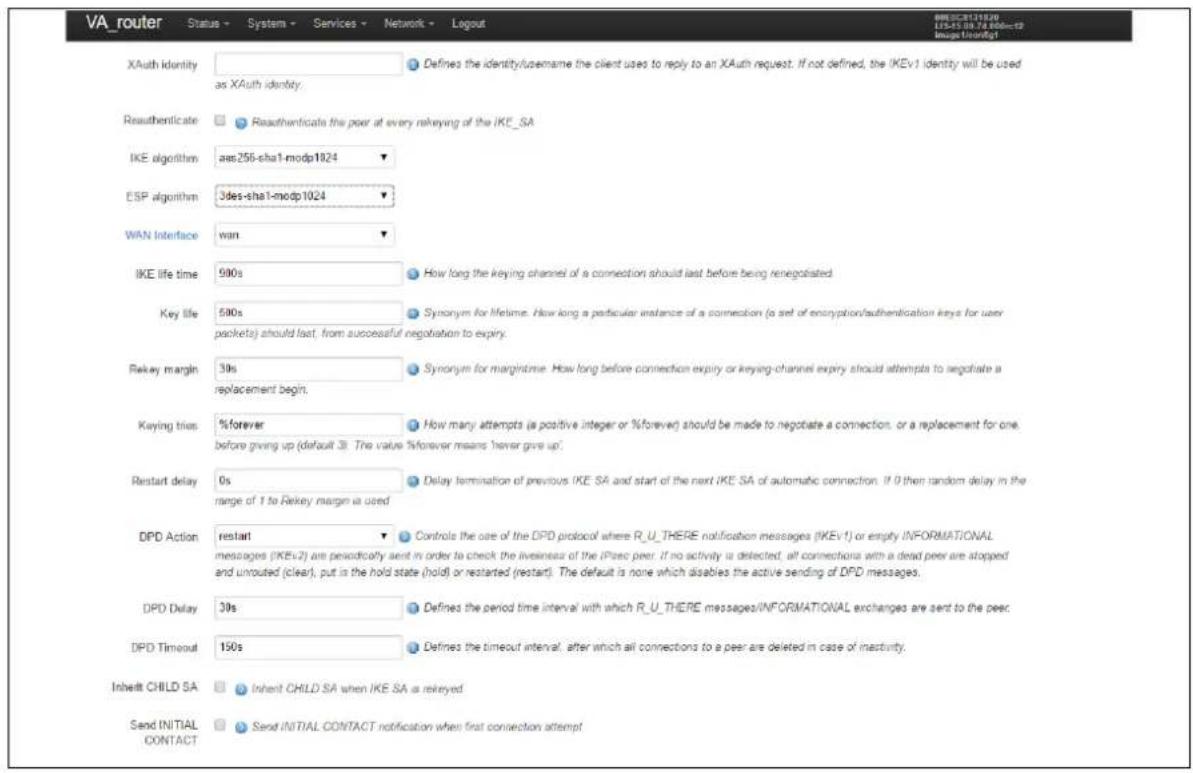
text_image
VA_router Status - System - Services - Network - Logout XAuth identity Defines the identity/username the client uses to reply to an XAuth request. If not defined, the IKEv1 identity will be used as XAuth identity. Reauthenticate Reauthenticals the peer at every rekeying of the IKE_SA IKE algorithm aes256-sha1-modp1024 ESP algorithm 3des-sha1-modp1024 WAN Interface wan IKE life time 900s How long the keying channel of a connection should last before being renegotiated Key life 500s Synonym for lifetime. How long a particular instance of a connection (a set of encryption/authentication keys for user packets) should last, from successful negotiation to expiry. Rekey margin 30s Synonym for margintime. How long before connection expiry or keying-channel expiry should attempts to negotiate a replacement begin. Kaying trias %forever How many attempts (a positive integer or %forever) should be made to negotiate a connection, or a replacement for one, before giving up (default 3). The value %forever means 'never give up' Restart delay 0s Delay termination of previous IKE SA and start of the next IKE SA of automatic connection. If 0 then random delay in the range of 1 to Rekey margin is used DPD Action restart Controls the case of the DPD protocol where R_U_THERE notification messages (IKEv1) or empty INFORMATIONAL messages (IKEv2) are periodically sent in order to check the livesnear of the iPsec peer. If no activity is detected, all connections with a dead peer are stopped and unroated (clear), put in the hold state (hold) or restarted (restart). The default is none which disables the active sending of DPD messages. DPD Delay 30s Defines the period time interval with which R_U_THERE messages/INFORMATIONAL exchanges are sent to the peer. DPD Timeout 150s Defines the timeout interval, after which all connections to a peer are deleted in case of inactivity. Inherit CHILD SA Inherit CHILD SA when IKE SA is rekeyed Send INITIAL CONTACT Send INITIAL CONTACT notification when first connection attemptFigure 154: The IPSec connections settings
| Web Field/ UCI / Package Option | Description | |
| Web: XAuth IdentityUCI:strongswan.@connection[X].xauth_identityOpt: xauth_identity | Defines Xauth ID. | |
| Web: IKE AlgorithmUCI: strongswan.@connection[X].ikeOpt: ike | Specifies the IKE algorithm to use.The format is: encAlgo | authAlgo | DHGroupencAlgo:3desaes128aes256serpenttwofishblowfishauthAlgo:md5shasha2DHGroup:modp1024modp1536modp2048modp3072modp4096modp6144modp8192For example, a valid IKE algorithm is aes128-sha-modp1536. | |
| Web: ESP algorithmUCI:strongswan.@connection[X].espOpt:esp | Specifies the esp algorithm to use.The format is: encAlgo | authAlgo | DHGroupencAlgo:3desaes128aes256serpenttwofishblowfishauthAlgo:md5shasha2DHGroup:modp1024modp1536modp2048modp3072modp4096modp6144modp8192For example, a valid encryption algorithm is:aes128-sha-modp1536.If no DH group is defined then PFS is disabled. | |
| Web: WAN InterfaceUCI:strongswan.@connection[X].wanifaceOpt:waniface | This is a space-separated list of the WAN interfaces the routerwill use to establish a tunnel with the secure gateway.On the web, a list of the interface names is automaticallygenerated. If you want to specify more than one interface usethe “custom” value.Example: if you have a 3G WAN interface called ‘wan and aWAN ADSL interface called ‘dsl’ and wanted to use one ofthese interfaces for this IPSec connection, you would use:‘wan adsl’. | |
| Web: IKE Life TimeUCI:strongswan.@connection[X].ikelifetimeOpt:ikelifetime | Specifies how long the keyring channel of a connection(ISAKMP or IKE SA) should last before being renegotiated. | |
| 3h | ||
| Timespec | 1d, 3h, 25m, 10s. | |
| Web: Key LifeUCI:strongswan.@connection[X].keylifeOpt:keylife | Specifies how long a particular instance of a connection (a setof encryption/authentication keys for user packets) shouldlast, from successful negotiation to expiry.Normally, the connection is renegotiated (via the keyingchannel) before it expires (see rekeymargin). | |
| 1h | ||
| Timespec | 1d, 1h, 25m, 10s. | |
| Web: Rekey MarginUCI:strongswan.@connection[X].rekeymarginOpt:rekeymargin | Specifies how long before connection expiry or keying-channel expiry should attempt to negotiate a replacementbegin.Relevant only locally, other end need not agree on it. | |
| 9m | ||
| Timespec | 1d, 2h, 9m, 10s. | |
| Web: Restart DelayUCI:strongswan.@connection[X].restartdelayOpt:restartdelay | Defines specific delay when re-establishing a connection.Previously if close_action=restart, then new optionrestartdelay controls how many seconds it waits beforeattempting to re-establish the tunnel (to allow head-endsome time to tidy up).If not set, it defaults to zero, which means that the previousbehaviour of choosing a random time interval in the range0..RekeyMargin seconds takes effect.Relevant only locally, other end need not agree on it. | |
| 0 | ||
| Timespec | 1d, 2h, 9m, 10s. | |
| Web: Keying TriesUCI:strongswan.@connection[X].keyringtriesOpt:keyringtries | Specifies how many attempts (a positive integer or %forever)should be made to negotiate a connection, or a replacementfor one, before giving up. The value %forever means 'nevergive up'. Relevant only locally, other end need not agree onit. | |
| Web: DPD ActionUCI:strongswan.@connection[X].dpdactionOpt:dpdaction | Defines DPD (Dead Peer Detection) action. | |
| None | Disables DPD. | |
| Clear Clear | down the tunnel if peer does not respond.Reconnect when traffic brings the tunnel up. | |
| Hold Clear | down the tunnel and bring up as soon asthe peer is available. | |
| Restart | Restarts DPD when no activity is detected. | |
| Web: DPD DelayUCI:strongswan.@connection[X].dpddelayOpt:dpddelay | Defines the period time interval with which R_U_THEREmessages and INFORMATIONAL exchanges are sent to thepeer.These are only sent if no other traffic is received. | |
| 30s | ||
| Timespec | 1d, 2h, 25m, 10s. | |
| Web: DPD TimeoutUCI:strongswan.@connection[X].dpdtimeoutOpt:dpdtimeout | Defines the timeout interval, after which all connections to apeer are deleted in case of inactivity. | |
| 150s | ||
| Timespec | 1d, 2h, 25m, 10s. | |
| Web: Inherit CHILD SAUCI:strongswan.@connection[X].inherit_childOpt:inherit_child | Defines whether the existing phase two IPSEC SA ismaintained through IKE rekey for this tunnel. This is normallyset to match the behaviour on the IPSEC headend. | |
| 0 | Delete the existing IPSEC SA on IKE rekey | |
| 1 | Maintain the existing IPSEC SA on IKE rekey | |
| Web: Send INITIAL CONTACTUCI:strongswan.@connection[X].initial_contactOpt:initial_contact | Defines whether the first attempt to contact a remote peer bythis strongswan instance sets the initial_contact flag whichshould cause compliant peers to automatically bring downany previous sessions. | |
| 0 | Do not set initial contact flag | |
| 1 | Set initial contact flag on first attempt | |
Table 108: Information table for IPSec connections settings
32.2.5 Configure secret settings
Each tunnel requires settings to configure how the local end point of the tunnel proves its identity to the remote end point.
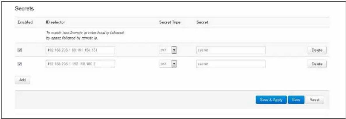
text_image
Secrets Enabled ID selector Secret Type Secret To match local/remote ip enter local ip followed by space followed by remote ip ✓ 192.168.208.1 89.101.154.151 psk secret Delete ✓ 192.168.208.1 192.168.100.2 psk secret Delete Add Save & Apply Save ResetFigure 155: IPSec secrets settings
| Web Field/ UCI / Package Option | Description | |
| Web: EnabledUCI: strongswan.@secret[X].enabledOpt: enabled | Defines whether this set of credentials is to be used or not. | |
| 0 | Disabled. | |
| 1 | Enabled. | |
| Web: ID selectorUCI: strongswan.@secret[X].idtypeOpt: idtype | Defines whether IP address or userfqdn is used. | |
| Web: ID selectorUCI: strongswan.@secret[X].localaddressOpt: localaddress | Defines the local address this secret applies to. | |
| Web: ID selectorUCI: strongswan.@secret[X].remoteaddressOpt: remoteaddress | Defines the remote address this secret applies to. | |
| Web: N/AUCI: strongswan.@secret[X].userfqndOpt: userfqnd | FQDN or Xauth name used of Extended Authentication. This must match xauth_identity from the configuration connection section. | |
| Web: Secret TypeUCI: strongswan.@secret[X].secrettypeOpt: secrettype | Specifies the authentication mechanism to be used by the two peers. | |
| Psk | Preshared secret | |
| Pubkey | Public key signatures | |
| Rsasig | RSA digital signatures | |
| Ecdsasig | Elliptic Curve DSA signatures | |
| Xauth | Extended authentication | |
| Web: SecretUCI: strongswan.@secret[X].secretOpt: secret | Defines the secret. | |
Table 109: Information table for IPSec secrets settings
32.3 Configuring IPSec using UCI
32.3.1 Common settings
<h1 id="commands">Commands</h1>
touch /etc/config/strongswan
uci set strongswan.general=general
uci set strongswan.general.enabled=yes
uci set strongswan.general.strictcrlpolicy=no
uci set strongswan.general.uniqueids=yes
uci set strongswan.general.cachecrls=no
uci set strongswan.general.debug=none
uci set strongswan.general.initial_contact=0
uci commit
This will create the following output:
config general 'general'
option enabled 'yes'
option strictcrlpolicy 'no'
option uniqueids 'yes'
option cachecrls 'no'
option debug 'none'
option initial_contact '0'
32.3.2 Connection settings
touch /etc/config/strongswan
uci add strongswan connection
uci set strongswan.@connection[0].ikelifetime=3h
uci set strongswan.@connection[0].keylife=1h
uci set strongswan.@connection[0].rekeymargin=9m
uci set strongswan.@connection[0].keyingtries=3
uci set strongswan.@connection[0].restartdelay=0
uci set strongswan.@connection[0].dpdaction=none
uci set strongswan.@connection[0].dpddelay=30s
uci set strongswan.@connection[0].dpdtimeout=150s
uci set strongswan.@connection[0].enabled=yes
uci set strongswan.@connection[0].name=3G_Backup
uci set strongswan.@connection[0].auto=start
uci set strongswan.@connection[0].type=tunnel
uci set strongswan.@connection[0].remoteaddress=100.100.100.100
uci set strongswan.@connection[0].localid=192.168.209.1
uci set strongswan.@connection[0].remoteid=100.100.100.100
uci set strongswan.@connection[0].locallan=192.168.209.1
uci set strongswan.@connection[0].locallanmask=255.255.255.255
uci set strongswan.@connection[0].remotelan=172.19.101.3
uci set strongswan.@connection[0].remotelanmask=255.255.255.255
uci set strongswan.@connection[0].authby=xauthpsk
uci set strongswan.@connection[0].xauth_identity=testxauth
uci set strongswan.@connection[0].ike=3des-md5-modp1024
uci set strongswan.@connection[0].esp=3des-md5
uci set strongswan.@connection[0].waniface=wan
uci set strongswan.@connection[0].inherit_child=0
uci set strongswan.@connection[0].initial_contact=0
uci commit
This will create the following output:
config connection
option ikelifetime '3h'
option keylife '1h'
option rekeymargin '9m'
option keyingtries '3'
option restartdelay '0'
option dpdaction 'none'
option dpddelay '30s'
option dpdtimeout '150s'
option enabled 'yes'
option name '3G_Backup'
option auto 'start'
option type 'tunnel'
option remoteaddress '100.100.100.100'
option localid '192.168.209.1'
option remoteid '100.100.100.100'
option locallan '192.168.209.1'
option locallanmask '255.255.255.255'
option remotelan '172.19.101.3'
option remotelanmask '255.255.255.255'
option authby 'xauthpsk'
option xauth_identity 'testxauth'
option ike '3des-md5-modp1024'
option esp '3des-md5'
option waniface 'wan'
option inherit_child '0'
option initial_contact '0'
32.3.3 Shunt connection
If the remote LAN network is 0.0.0.0/0 then all traffic generated on the local LAN will be sent via the IPSec tunnel. This includes the traffic destined to the router's IP address. To avoid this situation you must include an additional config connection section.
<h1 id="commands-2">Commands</h1>
touch /etc/config/strongswan
uci add strongswan connection
uci set strongswan.@connection[1].name=local
uci set strongswan.@connection[1].enabled=yes
uci set strongswan.@connection[1].locallan=10.1.1.1
uci set strongswan.@connection[1].locallanmask=255.255.255.255
uci set strongswan.@connection[1].remotelan=10.1.1.0
uci set strongswan.@connection[1].remotelanmask=255.255.255.0
uci set strongswan.@connection[1].type=pass
uci set strongswan.@connection[1].auto=route
uci commit
This will create the following output:
config connection
option name 'local'
option enabled 'yes'
option locallan '10.1.1.1'
option locallanmask '255.255.255.255'
option remotelan '10.1.1.0'
option remotelanmask '255.255.255.0'
option type 'pass'
option auto 'route'
Traffic originated on remotelan and destined to localan address is excluded from VPN IPSec policy.
32.3.4 Secret settings
Each tunnel also requires settings for how the local end point of the tunnel proves its identity to the remote end point.
A sample secret section, which could be used with the connection section in 'Connection Settings', is shown below.
<h1 id="commands-to-add-a-secret-for-psk-auth">Commands to add a secret for psk auth</h1>
touch /etc/config/strongswan
uci add strongswan secret
uci set strongswan.@secret[0].enabled=yes
uci set strongswan.@secret[0].localaddress=192.168.209.1
uci set strongswan.@secret[0].remoteaddress= 100.100.100.100
uci set strongswan.@secret[0].secrettype=psk
uci set strongswan.@secret[0].secret=secret
uci commit
This will create the following output:
config secret
option enabled 'yes'
option localaddress '192.168.209.1'
option remoteaddress '100.100.100.100'
option secrettype 'psk'
option secret 'secret'
If xauth is defined as the authentication method then you must include an additional config secret section, as shown in the example below.
<h1 id="commands-to-add-a-secret-for-xauth-auth">Commands to add a secret for xauth auth</h1>
touch /etc/config/strongswan
uci add strongswan secret
uci set strongswan.@secret[1].enabled=yes
uci set strongswan.@secret[1].idtype=userfqdn
uci set strongswan.@secret[1].userfqdn=testxauth
uci set strongswan.@secret[1].remoteaddress=100.100.100.100
uci set strongswan.@secret[1].secret=xauth
uci set strongswan.@secret[1].secrettype=XAUTH
uci commit
This will create the following output:
config secret
option enabled 'yes'
option idtype 'userfqdn'
option userfqdn 'testxauth'
option remoteaddress '100.100.100.100'
option secret 'xauth'
option secrettype 'XAUTH'
32.4 Configuring an IPSec template for DMVPN via the web interface
To configure IPSec using the web interface, in the top menu, select Services -> IPSec. The strongSwan IPSec VPN page appears. There are three sections:
| Common Settings | Control the overall behaviour of strongSwan. This behaviour is common across all tunnels. |
| Connection Settings | Together, these sections define the required parameters for a two-way IKEv1 tunnel. |
| Secret Settings |
32.4.1 Configure common settings
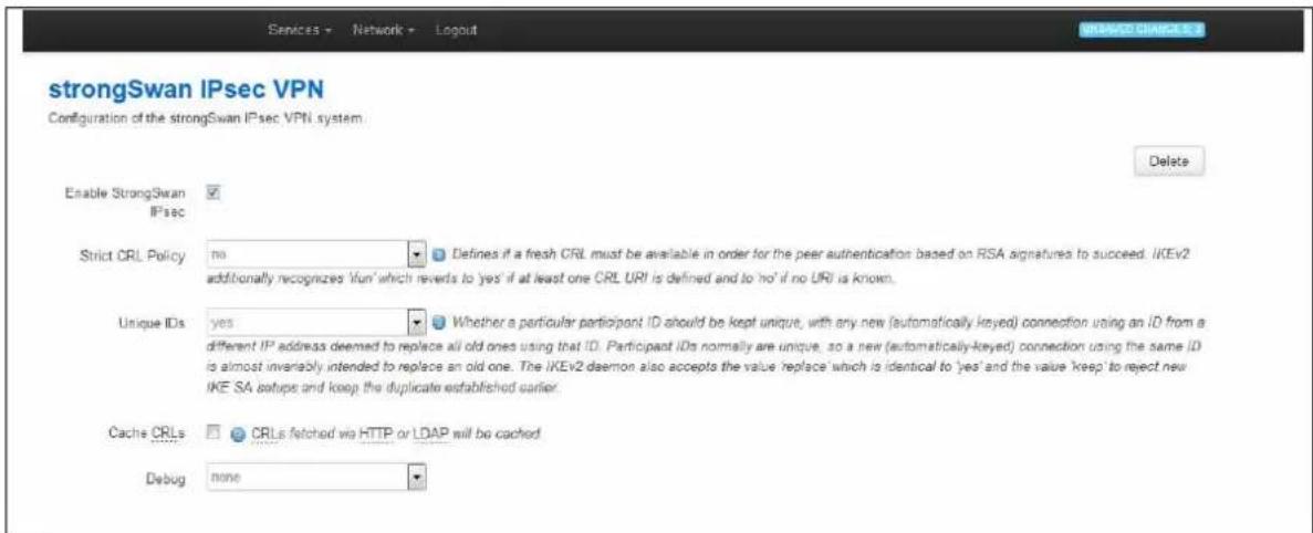
text_image
Services - Network - Logout INCREASE CHANGE 5.3 strongSwan IPsec VPN Configuration of the strongSwan IPsec VPN system Enable StrongSwan IPsec Strict CRL Policy no Defines if a fresh CRL must be available in order for the peer authentication based on RSA signatures to succeed. IKEv2 additionally recognizes 'fun' which reverts to 'yes' if at least one CRL URI is defined and to 'no' if no URI is known. Unique IDs yes Whether a particular participant ID should be kept unique, with any new (automatically keyed) connection using an ID from a different IP address deemed to replace all old ones using that ID. Participant IDs normally are unique, so a new (automatically-keyed) connection using the same ID is almost invariably intended to replace an old one. The IKEv2 daemon also accepts the value 'replace' which is identical to 'yes' and the value 'keep' to reject new IKE SA setups and keep the duplicate established earlier. Cache CRLs CRLs fetched we HTTP or LDAP will be cached Debug noneFigure 156: The common settings section
| Web Field/ UCI / Package Option | Description | |
| Web: Enable strongswanUCI: strongswan.general.enableOpt: enabled | Enables or disables IPSec. | |
| 0 | Disabled. | |
| 1 | Enabled. | |
| Web: Strict CRL PolicyUCI: strongswan.general.strictcrlpolicyOpt: strictcrlpolicy | Defines if a fresh CRL must be available for the peer authentication based on RSA signatures to succeed. | |
| 0 | Disabled. | |
| 1 | Enabled. | |
| ifuri The IK | Ev2 application additionally recognizes the "ifuri" option which reverts to 'yes' if at least one CRL URI is defined and to 'no' if no URI is known. | |
| Web: Unique IDsUCI: strongswan.general.uniqueidsOpt: uniqueids | Defines whether a particular participant ID should be kept unique, with any new (automatically keyed) connection using an ID from a different IP address deemed to replace all old ones using that ID.Participant IDs normally are unique, so a new (automatically-keyed) connection using the same ID is almost invariably intended to replace an old one. | |
| 0 | Disabled. | |
| 1 | Enabled. | |
| replace | Identical to Yes | |
| keep | Rejects new IKE SA and keep the duplicate established earlier | |
| Web: Cache CRLsUCI: strongswan.general.cachecrlsOpt: cachecrls | Certificate Revocation Lists (CRLs) fetched via HTTP or LDAP will be cached in /etc/ipsec.d/crls/ under a unique file name derived from the certification authority's public key. | |
| 0 | Disabled. | |
| 1 | Enabled. | |
| Web: DebugUCI: strongswan.general.debugOpt: debug | Enable debugging. This option is used for trouble shooting issues. It is not suitable for a production environment. | |
| None | Debug disabled. | |
| Control Debug enabled. Shows generic control flow with errors and very basic auditing logs. | ||
| All Debug enabled. Most verbose logging also includes sensitive information such as keys. | ||
Table 110: Information table for IPSec common settings
32.4.2 Configure connection settings
Scroll down to view the connection settings section.
If you want to create a DMVPN, you do not need to configure all settings as the DMVPN will automatically create them using the template. Leave the following sections blank:
- Remote GW Address
- Local ID
- Remote Id
- Local LAN IP Address
- Local LAN IP Address Mask
- Remote LAN IP Address
- Remote LAN IP Address Mask
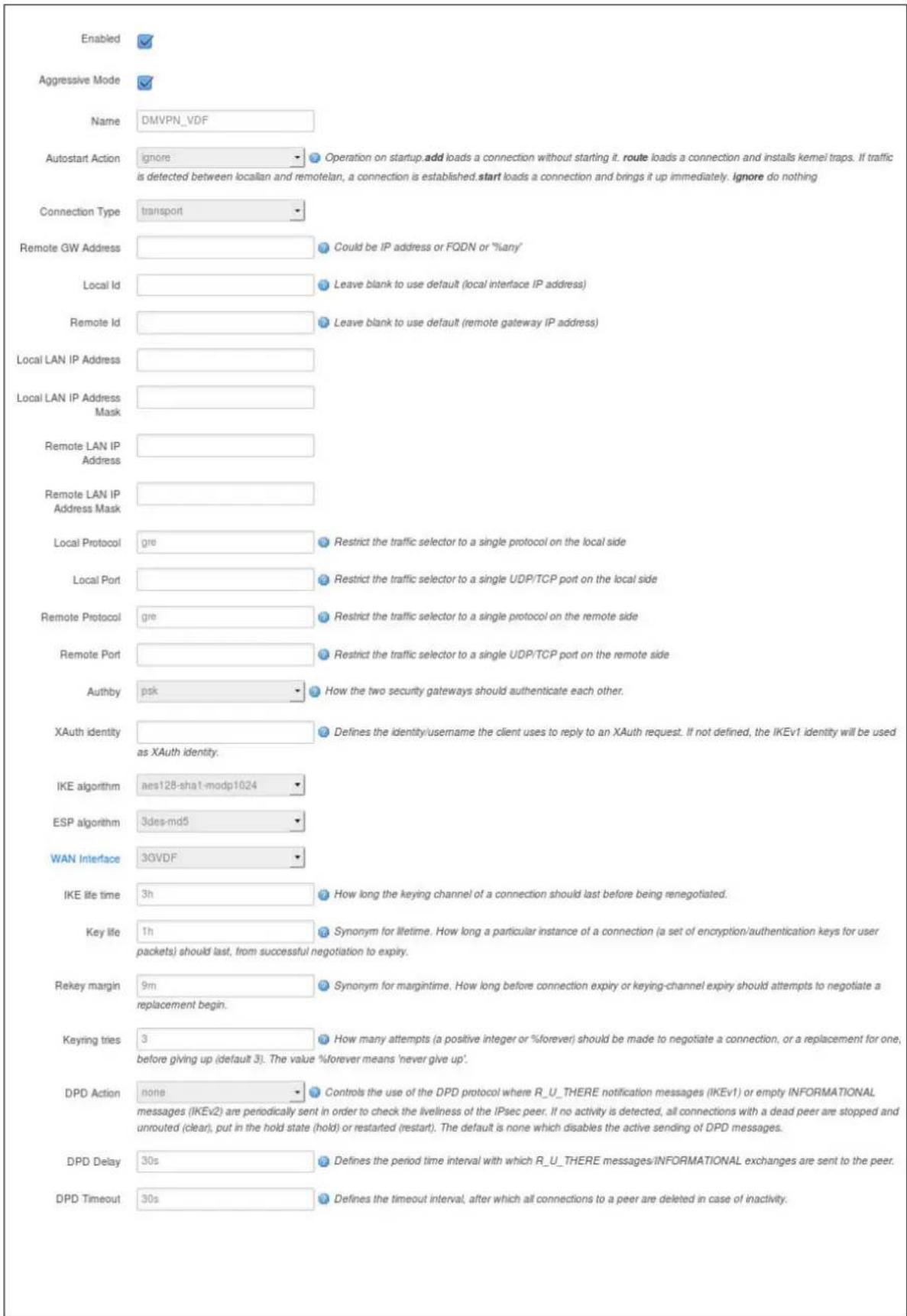
text_image
Enabled Aggressive Mode Name DMVPN_VDF Autostart Action ignore Operation on startup.add loads a connection without starting it. route loads a connection and installs kernel traps. If traffic is detected between localian and remotelan, a connection is established.start loads a connection and brings it up immediately. ignore do nothing Connection Type transport Remote GW Address Could be IP address or FQDN or "%any" Local Id Leave blank to use default (local interface IP address) Remote Id Leave blank to use default (remote gateway IP address) Local LAN IP Address Local LAN IP Address Mask Remote LAN IP Address Remote LAN IP Address Mask Local Protocol gre Restrict the traffic selector to a single protocol on the local side Local Port Restrict the traffic selector to a single UDP/TCP port on the local side Remote Protocol gre Restrict the traffic selector to a single protocol on the remote side Remote Port Restrict the traffic selector to a single UDP/TCP port on the remote side Authby psk How the two security gateways should authenticate each other. XAuth identity Defines the identity/username the client uses to reply to an XAuth request. If not defined, the IKEv1 identity will be used as XAuth identity. IKE algorithm aes128-sha1-modp1024 ESP algorithm 3des-md5 WAN Interface 3GVDF IKE life time 3h How long the keying channel of a connection should last before being renegotiated. Key life 1h Synonym for lifetime. How long a particular instance of a connection (a set of encryption/authentication keys for user packets) should last, from successful negotiation to expiry. Rekey margin 9m Synonym for margintime. How long before connection expiry or keying-channel expiry should attempts to negotiate a replacement begin. Keyring tries 3 How many attempts (a positive integer or %forever) should be made to negotiate a connection, or a replacement for one, before giving up (default 3). The value %forever means 'never give up'. DPD Action none Controls the use of the DPD protocol where R_U_THERE notification messages (IKEv1) or empty INFORMATIONAL messages (IKEv2) are periodically sent in order to check the liveliness of the IPsec peer. If no activity is detected, all connections with a dead peer are stopped and unrouted (clear), put in the hold state (hold) or restarted (restart). The default is none which disables the active sending of DPD messages. DPD Delay 30s Defines the period time interval with which R_U_THERE messages/INFORMATIONAL exchanges are sent to the peer. DPD Timeout 30s Defines the timeout interval, after which all connections to a peer are deleted in case of inactivity.Figure 157: The connections settings section
| Web Field/ UCI/ Package Option | Description | |
| Web: EnabledUCI: strongswan.@connection[X].enabledOpt: enable | Enables or disables IPSec connection. | |
| 0 | Disabled. | |
| 1 | Enabled. | |
| Web: AggressiveUCI:strongswan.@connection[X].aggressiveOpt: aggressive | Enables or disables IKE aggressive mode.Note: using aggressive mode along with PSK authentication is less secure method than main mode and should be avoided. | |
| 0 | Disabled. | |
| 1 | Enabled. | |
| Web: NameUCI: strongswan.@connection[X].nameOpt: name | Specifies a name for the tunnel. | |
| Web: Autostart ActionUCI: strongswan.@connection[X].autoOpt: auto | Specifies when the tunnel is initiated. | |
| start | On start up. | |
| route | When traffic routes this way. | |
| add | Loads a connection without starting it. | |
| ignore | Ignores the connection. | |
| always Actively retries to establish the tunnel if it went down. | ||
| Web: Connection TypeUCI: strongswan.@connection[X].typeOpt: type | Defines the type of IPSec connection. | |
| tunnel | Connection uses tunnel mode. | |
| transport | Connection uses transport mode. | |
| pass | Connection does not perform any IPSec processing. | |
| drop | Connection drops all the packets. | |
| Web: Remote GW AddressUCI: strongswan.@connection[X].remoteaddressOpt: remoteaddress | Sets the public IP address of the remote peer.Leave blank for DMVPN. | |
| Web: Local IDUCI: strongswan.@connection[X].localidOpt: localid | Defines the local peer identifier.Leave blank for DMVPN. | |
| Web: Remote IDUCI: strongswan.@connection[X].remoteidOpt: remoteid | Defines the remote peer identifier.Leave blank for DMVPN. | |
| Web: Local LAN IP AddressUCI: strongswan.@connection[X].localianOpt: localian | Defines the local IP of LAN.Leave blank for DMVPN. | |
| Web: Local LAN IP Address MaskUCI: strongswan.@connection[X].localianmaskOpt: localianmask | Defines the subnet of local LAN.Leave blank for DMVPN. | |
| Web: Remote LAN IP AddressUCI: strongswan.@connection[X].remotelanOpt: remotelan | Defines the IP address of LAN serviced by remote peer.Leave blank for DMVPN. | |
| Web: Remote LAN IP Address MaskUCI: strongswan.@connection[X].remotelanmaskOpt: remotelanmask | Defines the Subnet of remote LAN.Leave blank for DMVPN. | |
| Web: Local ProtocolUCI: strongswan.@connection[X].localprotoOpt: localproto | Restricts the connection to a single protocol on the local side. | |
| Web: Local PortUCI:strongswan.@connection[X].localportOpt: localport | Restricts the connection to a single port on the local side. | |
| Web: Remote ProtocolUCI:strongswan.@connection[X].remoteprotoOpt:remoteproto | Restricts the connection to a single protocol on the remote side. | |
| Web: Remote PortUCI:strongswan.@connection[X].remoteportOpt: remoteport | Restricts the connection to a single port on the remote side. | |
| Web: AuthbyUCI:strongswan.@connection[X].authbyOpt: authby | Defines how the two secure gateways should authenticate.Note: using aggressive mode along with PSK authentication is unsecure and should be avoided. | |
| Pubkey | For public key signatures. | |
| Rsasig | For RSA digital signatures. | |
| ecdsasig | For Elliptic Curve DSA signatures. | |
| Psk | Using a preshared key. | |
| xauthrsasig | Enables eXtended Authentication (XAuth) with addition to RSA signatures. | |
| xauthpsk Using extended authentication and preshared key. | ||
| never Can be used if negotiation is never to be attempted or accepted (shunt connections). | ||
| Web: XAuth IdentityUCI:strongswan.@connection[X].xauth_identityOpt: xauth_identity | Defines Xauth ID. | |
| Web: IKE AlgorithmUCI:strongswan.@connection[X].ikeOpt: ike | Specifies the IKE algorithm to use.The format is: encAlgo | authAlgo | DHGroup:encAlgo:3desaes128aes256serpenttwofishblowfishauthAlgo:md5shasha2DHGroup:modp1024modp1536modp2048modp3072modp4096modp6144modp8192For example, a valid IKE algorithm is: aes128-sha-modp1536. | |
| Web: ESP algorithmUCI:strongswan.@connection[X].espOpt:esp | Specifies the esp algorithm to use.The format is:encAlgo | authAlgo | DHGroupencAlgo:3desaes128aes256serpenttwofishblowfishauthAlgo:md5shasha2DHGroup:modp1024modp1536modp2048modp3072modp4096modp6144modp8192For example, a valid encryption algorithm is:aes128-sha-modp1536.If no DH group is defined then PFS is disabled. | |
| Web: WAN InterfaceUCI:strongswan.@connection[X].wanifaceOpt:waniface | This is a space separated list of the WAN interfaces the router will use to establish a tunnel with the secure gateway.On the web, a list of the interface names is automatically generated. If you want to specify more than one interface use the "custom" value.Example:If you have a 3G WAN interface called 'wan and a WAN ADSL interface called 'dsl' and wanted to use one of these interfaces for this IPSec connection, you would use: 'wan adsl'. | |
| Web: IKE Life TimeUCI:strongswan.@connection[X].ikelifetimeOpt:ikelifetime | Specifies how long the keyring channel of a connection (ISAKMP or IKE SA) should last before being renegotiated. | |
| 3h | ||
| Timespec | 1d, 3h, 25m, 10s. | |
| Web: Key LifeUCI:strongswan.@connection[X].keylifeOpt:keylife | Specifies how long a particular instance of a connection (a set of encryption/authentication keys for user packets) should last, from successful negotiation to expiry.Normally, the connection is renegotiated (via the keying channel) before it expires (see rekeymargin). | |
| 1h | ||
| Timespec | 1d, 1h, 25m, 10s. | |
| Web: Rekey MarginUCI:strongswan.@connection[X].rekeymarginOpt:rekeymargin | Specifies how long before connection expiry or keying-channel expiry should attempt to negotiate a replacement begin.Relevant only locally, other end need not agree on it. | |
| 9m | ||
| Timespec | 1d, 2h, 9m, 10s. | |
| Web: Keyring TriesUCI:strongswan.@connection[X].keyringtriesOpt:keyringtries | Specifies how many attempts (a positive integer or %forever) should be made to negotiate a connection, or a replacement for one, before giving up. The value %forever means 'never give up'. Relevant only locally, other end need not agree on it. | |
| Web: DPD ActionUCI: strongswan.@connection[X].dpdactionOpt: dpdaction | Defines DPD (Dead Peer Detection) action. | |
| None | Disables DPD. | |
| Clear | Clear down the tunnel if peer does not respond. Reconnect when traffic brings the tunnel up. | |
| Hold Clear down the tunnel and bring up as soon as the peer is available. | ||
| Restart | Restarts DPD when no activity is detected. | |
| Web: DPD DelayUCI: strongswan.@connection[X].dpddelayOpt: dpddelay | Defines the period time interval with which R_U_THERE messages and INFORMATIONAL exchanges are sent to the peer. These are only sent if no other traffic is received. | |
| 30s | ||
| Timespec | 1d, 2h, 25m, 10s. | |
| Web: DPD TimeoutUCI:strongswan.@connection[X].dpdtimeoutOpt: dpdtimeout | Defines the timeout interval, after which all connections to a peer are deleted in case of inactivity. | |
| 150s | ||
| Timespec | 1d, 2h, 25m, 10s. | |
Table 111: Information table for IPSec connections settings
32.4.3 Configure secret settings
Each tunnel requires settings to configure how the local end point of the tunnel proves its identity to the remote end point.
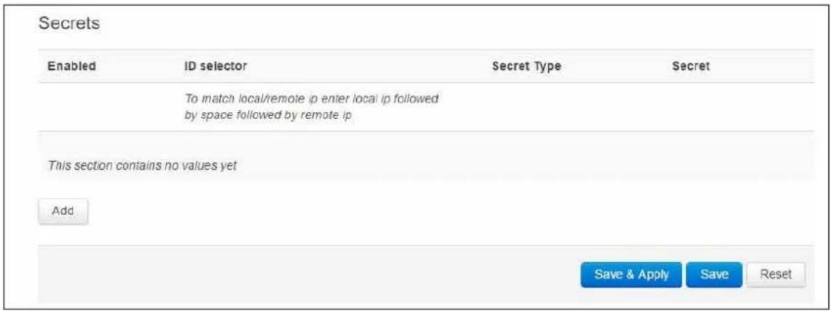
text_image
Secrets Enabled ID selector Secret Type Secret To match local/remote ip enter local ip followed by space followed by remote ip. This section contains no values yet Add Save & Apply Save ResetFigure 158: IPSec secrets settings
| Web Field/ UCI / Package Option | Description | |
| Web: EnabledUCI: strongswan.@secret[X].enabledOpt: enabled | Defines whether this set of credentials is to be used or not. | |
| 0 | Disabled. | |
| 1 | Enabled. | |
| Web: ID selectorUCI: strongswan.@secret[X].idtypeOpt: idtype | Defines whether IP address or userfqdn is used. | |
| Web: ID selectorUCI: strongswan.@secret[X].localaddressOpt: localaddress | Defines the local address this secret applies to. | |
| Web: ID selectorUCI: strongswan.@secret[X].remoteaddressOpt: remoteaddress | Defines the remote address this secret applies to. | |
| Web: N/AUCI: strongswan.@secret[X].userfqndOpt: userfqnd | FQDN or Xauth name used of Extended Authentication. This must match xauth_identity from the configuration connection section. | |
| Web: Secret TypeUCI: strongswan.@secret[X].secrettypeOpt: secrettype | Specifies the authentication mechanism to be used by the two peers. | |
| Psk | Preshared secret | |
| Pubkey | Public key signatures | |
| Rsasig | RSA digital signatures | |
| Ecdsasig | Elliptic Curve DSA signatures | |
| Xauth | Extended authentication | |
| Web: SecretUCI: strongswan.@secret[X].secretOpt: secret | Defines the secret. | |
Table 112: Information table for IPSec secret settings
32.5 Configuring an IPSec template to use with DMVPN
The following example shows how to configure an IPSec connection template to use with DMVPN.
<h1 id="commands-3">Commands</h1>
touch /etc/config/strongswan
uci set strongswan.general=general
uci set strongswan.general.enabled=yes
uci set strongswan.general.strictcrlpolicy=no
uci set strongswan.general.uniqueids=yes
uci set strongswan.general.cachecrls=yes
uci set strongswan.general.nattraversal=yes
uci add strongswan connection
uci set strongswan.@connection[0].enabled=yes
uci set strongswan.@connection[0].name=dmvpn
uci set strongswan.@connection[0].type=transport
uci set strongswan.@connection[0].localproto=gre
uci set strongswan.@connection[0].remoteproto=gre
uci set strongswan.@connection[0].ike=aes-sha1-modp1024
uci set strongswan.@connection[0].esp=aes128-sha1
uci set strongswan.@connection[0].waniface=lan4
uci set strongswan.@connection[0].auto=ignore
uci set strongswan.@connection[0].ikelifetime=28800s
uci set strongswan.@connection[0].keylife=300s
uci set strongswan.@connection[0].rekeymargin=30s
uci set strongswan.@connection[0].keyingtries=%forever
uci set strongswan.@connection[0].dpdaction=hold
uci set strongswan.@connection[0].dpddelay=30s
uci set strongswan.@connection[0].dpdtimeout=150s
uci add strongswan secret
uci set strongswan.@secret[0].enabled=yes
uci set strongswan.@secret[0].secrettype=psk
uci set strongswan.@secret[0].secret=secret
This will create package strongswan.
config general 'general'
option enabled 'yes'
option strictcrlpolicy 'no'
option uniqueids 'yes'
option cachecrls 'yes'
option nattraversal 'yes'
config connection
option enabled 'yes'
option name 'dmvpn'
option type 'transport'
option localproto 'gre'
option remoteproto 'gre'
option ike 'aes-shal-modp1024'
option esp 'aes128-shal'
option waniface 'lan4'
option auto 'ignore'
option ikelifetime '28800s'
option keylife '300s'
option rekeymargin '30s'
option keyingtries '%forever'
option dpdaction 'hold'
option dpddelay '30s'
option dpdtimeout '150s'
config secret
option enabled 'yes'
option secrettype 'psk'
option secret 'secret'
32.6 IPSec diagnostics using the web interface
32.6.1 IPSec status
In the top menu, click Status -> IPSec. The IPSec Connections page appears.
| IPsec Connections | |||||||||
| Name | IKE | SA | |||||||
| Status | Remote | Established | Encryption | Integrity | Status | Policy | Data In/Out | Reloy in | |
| dmvpn_213_233_148_2 | ESTABLISHED | 213.233.148.2 | 2 hours ago | 3DES_CBC | HMAC_MDE_96 | INSTALLED | |||
| dmvpn_89_101_154_151 | ESTABLISHED | 89.101.154.161 | 2 hours ago | 3DES_CBC | HMAC_MDE_96 | INSTALLED | |||
Figure 159: The IPSec connections page
In the Name column, the syntax contains the IPSec Name defined in package dmvpn and the remote IP address of the hub, or the spoke separated by an underscore; for example, dmvpn_213.233.148.2.
32.7 IPSec diagnostics using UCI
32.7.1 IPSec configuration
To view IPSec configuration via UCI, enter:
root@VA_router:~# uci export strongswan
To restart strongSwan, enter:
root@VA_router:~# etc/init.d/strongswan restart
32.7.2 IPSec status
32.7.3 To view IPSec status, enter:
root@VA_router:~# ipsec statusall
Security Associations (1 up, 0 connecting):
dmvpn_89_101_154_151[1]: ESTABLISHED 2 hours ago,
10.68.234.133[10.68.234.133]...89.101.154.151[89.101.154.151]
dmvpn_89_101_154_151{1}: REKEYING, TRANSPORT, expires in 55 seconds
dmvpn_89_101_154_151{1}: 10.68.234.133/32[gre] === 192.168./32[gre]
dmvpn_89_101_154_151{1}: INSTALLED, TRANSPORT, ESP in UDP SPIs: cca7b970_i
d874dc90_o
dmvpn_89_101_154_151{1}: 10.68.234.133/32[gre] === 89.101.154.151/32[gre]
To view a list of IPSec commands, enter:
root@VA_router:~# ipsec -help
33 Dynamic Multipoint Virtual Private Network (DMVPN)
Dynamic Multipoint Virtual Private Network (DMVPN) is a scalable method of creating VPN IPSec Networks. DMVPN is a suite of three protocols: NHRP, GRE and IPSec, used to dynamically create VPN tunnels between different endpoints in the network without having to pre-configure each device with VPN details of the rest of endpoints in the network.
33.1 Prerequisites for configuring DMVPN
Before configuring DMVPN, you must first configure:
- A GRE interface; the previous chapter,' Configuring GRE interfaces'
- An IPSec connection to use as a template; read the chapter, 'Configuring IPSec'.
33.2 Advantages of using DMVPN
Using DMVPN eliminates the need of IPSec configuration to the physical interface. This reduces the number of lines of configuration required for a VPN development. For example, for a 1000-site deployment, DMVPN reduces the configuration effort at the hub from 3900 lines to 13.
- Adding new peers (spokes) to the VPN requires no changes at the hub.
• Better scalability of the network.
• Dynamic IP addresses can be used at the peers' site. - Spokes can be connected in private or public network.
- NHRP NAT extension allows spoke-to-spoke tunnels to be built, even if one or more spokes is behind a Network Address Translation (NAT) device.
- New hubs can be added to the network to improve the performances and reliability.
- Ability to carry multicast and main routing protocols traffic (RIP, OSPF, BGP).
- DMVPN can be deployed using Activator, the Virtual Access automated provisioning system.
- Simplifies branch communications by enabling direct branch to branch connectivity.
- Simplifies configuration on the spoke routers. The same IPSec template configuration is used to create spoke-to-hub and spoke-to-spoke VPN IPSec tunnel.
- Improves business resiliency by preventing disruption of business-critical applications and services by incorporating routing with standards-based IPsec technology.
33.3 DMVPN scenarios
33.3.1 Scenario 1
Spoke1, spoke2 and a hub are in the same public or private network.

flowchart
graph TD
A["Spoke1/GW6600"] -->|ADSL| B["INTERNET OR PRIVATE NETWORK"]
C["Spoke2/GW2020"] -->|3G| B
D["IPSEC/GRE TUNNEL"] -->|HUB| B
E["IPSEC/GRE TUNNEL"] -->|Internet or Private Network| B
Figure 160: Network diagram for DMVPN spoke to spoke
- Spoke1 and spoke2 connect on their WAN interface: ADSL, 3G and initiate main mode IPSec in transport mode to the hub.
- After an IPSec tunnel is established, spokes register their NHRP membership with the hub.
• GRE tunnels come up.
• Hub caches the GRE tunnel and real IP addresses of each spoke.
- When spoke1 wants to talk to spoke2, it sends an NHRP resolution request to the hub.
• The hub checks its cache table and forwards that request to spoke2.
- Spoke2 caches spoke1's GRE and real IP address and sends an NHRP resolution reply via the hub.
- Spoke1 receives an NHRP resolution reply and updates its NHRP table with spoke2 information. Then it initiates VPN IPSec connection to spoke2.
- When an IPSec tunnel is established, spoke1 and spoke2 can send traffic directly to each other.
33.3.2 Scenario 2
Spoke1 is in a private (NAT-ed) network, spoke2 and hub are in public network.
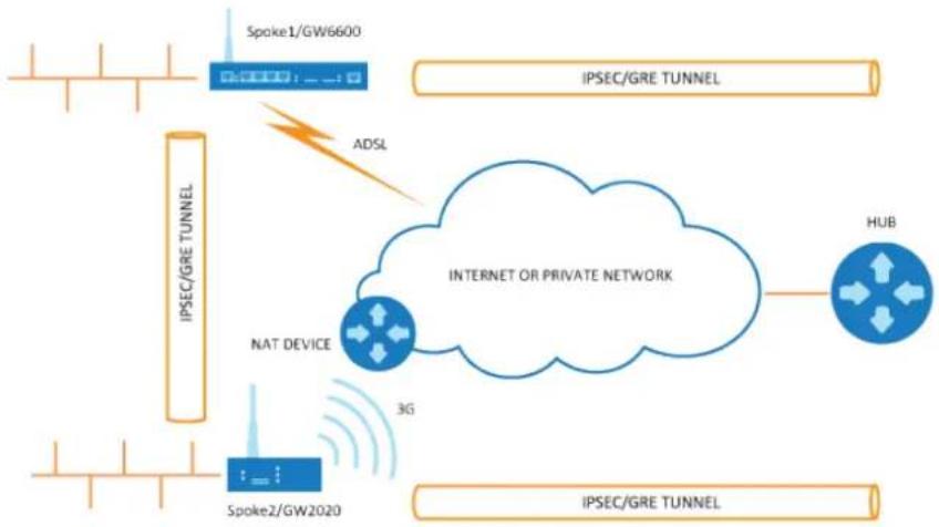
flowchart
graph TD
A["Spoke1/GW6600"] --> B["IPSEC/GRE TUNNEL"]
C["Spoke2/GW2020"] --> D["NAT DEVICE"]
E["3G"] --> F["INTERNET OR PRIVATE NETWORK"]
G["ADSL"] --> H["Internet OR PRIVATE NETWORK"]
I["HUB"] --> J["IPSEC/GRE TUNNEL"]
K["IPSEC/GRE TUNNEL"] --> L["IPSEC/GRE TUNNEL"]
Figure 161: Network diagram for DMVPN spoke behind NAT
- Spoke1 sends an NHRP registration request to the hub.
- Hub receives this request and compares the source tunnel address of the spoke with the source of the packet.
- Hub sends an NHRP registration reply with a NAT extension to spoke1.
• The NAT extension informs spoke1 that it is behind the NAT-ed device. - Spoke1 registers its pre- and post-NAT address.
- When spoke1 wants to talk to spoke2, it sends an NHRP resolution request to the hub.
- Hub checks its cache table and forwards that request to spoke2.
- Spoke2 caches spoke1's GRE pre- and post-NAT IP address and sends an NHRP resolution reply via the hub.
- Spoke1 receives the NHRP resolution reply and updates its NHRP table with spoke2 information. It initiates a VPN IPSec connection to spoke2.
- When the IPSec tunnel is established, spoke1 and spoke2 can send traffic directly to each other.
Note: if an IPSec tunnel fails to be established between the spokes then packets between the spokes are sent via the hub.
33.4 Configuration packages used
| Package | Sections |
| network | For configuring the GRE tunnels. |
| strongswan For enabling and configuring the IPSec connection template | |
| dmvpn | |
33.5 Configuring DMVPN using the web interface
The DMVPN section contains fields required to configure the parameters relative to the DMVPN Hub. These are used for DMVPN tunnels, such as GRE tunnels, GRE tunnel remote IP, DMVPN Hub IP and password.
33.5.1 DMVPN general settings
In the top menu, select Network -> DMVPN. The DMVPN page appears. There are two sections: General and DMVPN Hub Settings.
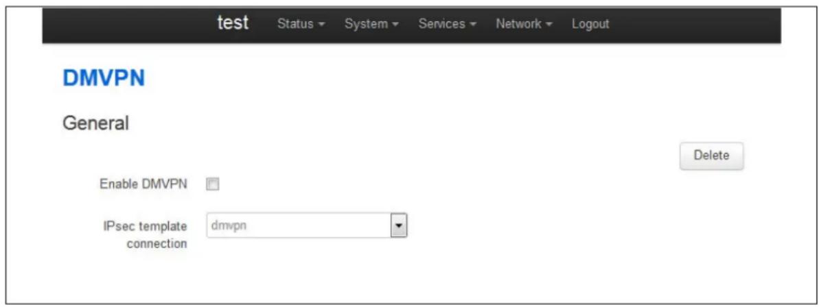
text_image
test Status System Services Network Logout DMVPN General Enable DMVPN IPsec template connection dmvpn DeleteFigure 162: The DMVPN general section
| Web Field/ UCI / Package Option | Description | |
| Web: Enable DMVPNUCI: dmvpn.common.enabledOpt: enable | Enables DMVPN. | |
| 0 | Disabled. | |
| 1 | Enabled. | |
| Web: IPSec template connectionUCI:dmvpn.common.ipsec_template_nameOpt: ipsec_template_name | Selects the IPSec connection, defined in strongSwan, to be used as a template. | |
Table 113: Information table for DMVPN general settings
33.5.2 DMVPN hub settings
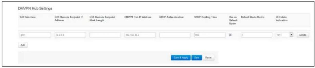
text_image
DMVPN Hub Settings GRE Interface GRE Remote Endpoint IP Address GRE Remote Endpoint Mask Length DMVPN Hub IP Address NHRP Authentication NHRP Holding Time Use as Default Route Default Route Metric LED state indication gs1 10.2.5.6 192.168 15.2 000 (F) 1 gn1 Delete Add Save & Apply Save ResetFigure 163: The DMVPN hub settings
| Web Field/ UCI / Package Option | Description | |
| Web: GRE InterfaceUCI: dmvpn.@interface[X].gre_interfaceOpt: gre_interface | Specifies which GRE interface will be used with this DMVPN configuration. | |
| Web: GRE Remote Endpoint IP AddressUCI:dmvpn.@interface[X].gre_endpoint_ipOpt: gre_endpoint_ip | Configures the GRE IP address of the hub. | |
| Web: GRE Remote Endpoint Mask LengthUCI:dmvpn.@interface[X].gre_endpoint_mask_lengthOpt: gre_endpoint_mask_length | Configures the length of the mask of the GRE interface on the hub. For example if the mask is 255.255.0.0 the length will be 16. | |
| Web: DMVPN Hub IP AddressUCI: dmvpn.@interface[X].nhs_ipOpt: nhs_ip | Configures the physical IP address for the DMVPN hub. | |
| Web: NHRP AuthenticationUCI: dmvpn.@interface[X].cisco_authOpt: cisco_auth | Enables authentication on NHRP. The password will be applied in plaintext to the outgoing NHRP packets. Maximum length is 8 characters. | |
| Web: NHRP Holding TimeUCI: dmvpn.@interface[X].holding_timeOpt: holding_time | Timeout for cached NHRP requests. | |
| Web: Use As Default RouteUCI: dmvpn.@interface[X].defaultrouteOpt: defaultroute | Adds a default route into tunnel interface. | |
| 0 | Disabled. | |
| 1 | Enabled. | |
| Web: Default Route MetricUCI:dmvpn.@interface[X].defaulttroutemetricOpt: defaulttroutemetric | Metric to use for the default route. | |
| Web: LED state indicationUCI: dmvpn.@interface[X].ledOpt: led | LED to use for indicating if the VPN is up. | |
| 0 | Disabled. |
| 1 | Enabled. |
Table 114: Information table for DMVPN hub settings
33.5.3 Configuring an IPSec template for DMVPN using the web interface
Configuring an IPSec template is covered in the chapter 'Configuring IPSec'.
33.6 DMVPN diagnostics
In the top menu, click Status -> IPSec. The IPSec Connections page appears.
| IPsec Connections | |||||||||
| Name | IKE | SA | |||||||
| Status | Remote | Established | Encryption | Integrity | Status | Policy | Data In/Out | Rekey in | |
| dmvpn_213_233_148_2 | ESTABLISHED | 213.233.148.2 | 2 hours ago | 3DES_CBC | HMAC_MD6_96 | INSTALLED | |||
| dmvpn_89_101_154_151 | ESTABLISHED | 89.101.154.161 | 2 hours ago | 3DES_CBC | HMAC_MD6_96 | INSTALLED | |||
Figure 164: The IPSec connections page
In the Name column, the syntax contains the IPSec name defined in package dmvpn and the remote IP address of the hub, or the spoke separated by an underscore; for example, dmvpn_213.233.148.2.
To check the status of DMVPN, in the top menu, click Status -> DMVPN.
| NBMA peers | |||
| NBMA Address | Interface | Address | Type |
| 213.233.140.2 | GRE | 11.11.11.3/32 | spoke |
| 89.101.164.161 | GRE | 11.11.11.1/29 | hub |
| Powered by LuCI Trunk (trunk+svm8382) VIE-16 00 28 image1 config2 | |||
Figure 165: The NBMA peers page
To check DMVPN status, enter:
:~# opennhrpctl show
Status: ok
Interface: gre-GRE
Type: local
Protocol-Address: 11.11.11.7/32
Alias-Address: 11.11.11.3
Flags: up
Interface: gre-GRE
Type: local
Protocol-Address: 11.11.11.3/32
Flags: up
Interface: gre-GRE
Type: cached
Protocol-Address: 11.11.11.2/32
NBMA-Address: 178.237.115.129
NBMA-NAT-OA-Address: 172.20.38.129
Flags: used up
Expires-In: 0:18
Interface: gre-GRE
Type: static
Protocol-Address: 11.11.11.1/29
NBMA-Address: 89.101.154.151
Flags: up
| Interface | Description | ||
| Type | incomplete | Resolution request sent. | |
| negative | Negative cached. | ||
| cached | Received/relayed resolution reply. | ||
| shortcut_route | Received/relayed resolution for route. | ||
| dynamic | NHC resolution. | ||
| dynamic_nhs | Dynamic NHS from dns-map. | ||
| static | Static mapping from config file. | ||
| dynamic_map | Static dns-map from config file. | ||
| local_route | Non-local destination, with local route. | ||
| local_addr | Local destination (IP or off-NBMA subnet). | ||
| Protocol Address | Tunnel IP address | ||
| NBMA-Address | Pre-NAT IP address if NBMA-NAT-OA-Address is present or real address if NAT is not present. | ||
| NBMA-NAT-OA-Address | Post NAT IP address. This field is present when Address is translated in the network. | ||
| Flags | up | Can send all packets (registration ok). | |
| unique | Peer is unique. | ||
| used | Peer is kernel ARP table. | ||
| lower-up | openhrp script executed successfully. | ||
| Expires-In | Expiration time. | ||
Table 115: Information table for DMVPN status
You can check IPSec status using UCI commands.
root@VA-router:~# ipsec status
Security Associations (1 up, 0 connecting):
dmvpn_89_101_154_151[1]: ESTABLISHED 2 hours ago,
10.68.234.133[10.68.234.133]...89.101.154.151[89.101.154.151]
dmvpn_89_101_154_151{1}: REKEYING, TRANSPORT, expires in 55 seconds
dmvpn_89_101_154_151{1}: 10.68.234.133/32[gre] === 192.168./32[gre]
dmvpn_89_101_154_151{1}: INSTALLED, TRANSPORT, ESP in UDP SPIs: cca7b970_i d874dc90_o
dmvpn_89_101_154_151{1}: 10.68.234.133/32[gre] === 89.101.154.151/32[gre]
You can check DMVPN status using UCI commands.
:~# opennhrpctl show
Status: ok
Interface: gre-GRE
Type: local
Protocol-Address: 11.11.11.7/32
Alias-Address: 11.11.11.3
Flags: up
Interface: gre-GRE
Type: local
Protocol-Address: 11.11.11.3/32
Flags: up
Interface: gre-GRE
Type: cached
Protocol-Address: 11.11.11.2/32
NBMA-Address: 178.237.115.129
NBMA-NAT-OA-Address: 172.20.38.129
Flags: used up
Expires-In: 0:18
Interface: gre-GRE
Type: static
Protocol-Address: 11.11.11.1/29
NBMA-Address: 89.101.154.151
Flags: up
34 Configuring multicasting using PIM and IGMP interfaces
34.1 Overview
IP multicast is a bandwidth-conserving technology that reduces traffic by simultaneously delivering a single stream of information to potentially thousands of corporate recipients. Applications that take advantage of multicast include video conferencing and corporate communications.
IP multicast delivers application source traffic to multiple receivers without burdening the source or the receivers while using a minimum of network bandwidth.
PIM (Protocol Independent Multicast) and IGMP (Internet Group Management Protocol) are protocols used to create multicasting networks within a regular IP network.
A multicast group is an arbitrary group of receivers that expresses an interest in receiving a particular data stream. The receivers (the designated multicast group) are interested in receiving a data stream from the source. They indicate this by sending an Internet Group Management Protocol (IGMP) host report to their closest router in the network. The routers are then responsible for delivering the data from the source to the receivers. The routers use Protocol Independent Multicast (PIM) between themselves to dynamically create a multicast distribution tree. The data stream will then be delivered only to the network segments that are in the path between the source and the receivers.
To summarize: PIM is used between routers while IGMP is used between a receiver and its router only. As a result, PIM must be enabled on all the interfaces on the route from the multicast source to the multicast client while IGMP must be enabled on the interface to the multicast client only.
34.2 Configuration package used
| Package | Sections |
| pimd pimd | interface |
34.3 Configuring PIM and IGMP using the web interface
To configure PIM through the web interface, in the top menu, select Network -> PIM. The PIM page appears. To access the Global settings, click Add.
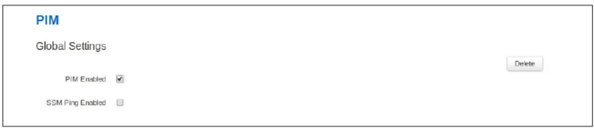
text_image
PIM Global Settings PIM Enabled ✓ SSM Ping Enabled □ DeleteFigure 166: The global settings interface
34.3.1 Global settings
| Web Field/ UCI / Package Option | Description | |
| Web: PIM EnabledUCI: pimd.pimd.enabledOpt: enabled | Globally enables PIM on the router. | |
| 0 Disabled. | ||
| 1 | Enabled. | |
| Web: SSM Ping EnabledUCI: pimd.pimd.ssspingdOpt: ssmpingd | Enables answers to SSM pings. | |
| 0 | Disabled. | |
| 1 Enabled. | ||
Table 116: Information table for PIM global settings
34.3.2 Interfaces configuration
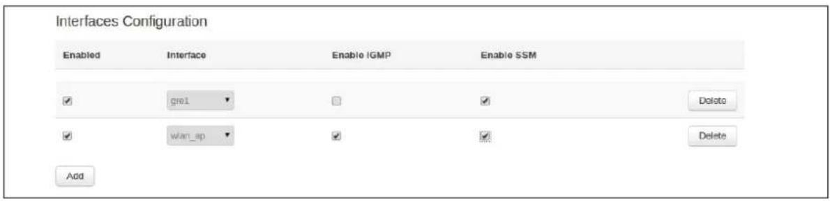
text_image
Interfaces Configuration Enabled Interface Enable IGMP Enable SSM ✓ gre1 □ ✓ Delete ✓ wan_ap ✓ ✓ Delete AddFigure 167: The interfaces configuration section
| Web Field/ UCI / Package Option | Description | |
| Web: EnabledUCI: pimd.interface[x].enabledOpt: enabled | Enables multicast management of the given interface by the PIM application. | |
| 0 | Disabled. | |
| 1 Enabled. | ||
| Web: InterfaceUCI: pimd.interface[x].interfaceOpt: interface | Selects the interface to apply PIM settings to. | |
| Web: Enable IGMPUCI: pimd.interface[x].igmpOpt: igmp | Enable IGMP on given interface. | |
| 0 Disabled. | ||
| 1 | Enabled. | |
| Note: you must enable PIM SSM and/or IGMP depending on your requirements.ICMP must be enabled on the interface to the multicast client only. | ||
| Web: Enable SSMUCI: pimd.interface[x].ssmOpt: ssm | Enable SSM on given interface. | |
| 0 Disabled. | ||
| 1 Enabled. | ||
Table 117: Information table for interface settings
To save your configuration updates, click Save & Apply.
34.4 Configuring PIM and IGMP using UCI
You can configure PIM and IGMP through CLI using UCI.
The configuration file is stored on /etc/config/pimd
To view the configuration file, enter:
uci export pimd
root@VA_router:/etc/config1# uci export pimd
package pimd
config routing 'pimd'
option enabled 'yes'
config interface
option enabled 'yes'
option interface 'lan'
option ssm 'yes'
option igmp 'yes'
config interface
option enabled 'yes'
option interface 'wan'
option ssm 'yes'
option igmp 'no'
Alternatively, enter:
uci show pimd
root@VA_router:/etc/config1# uci show pimd
pimd.pimd=routing
pimd.pimd.enabled=yes
pimd.@interface[0]=interface
pimd.@interface[0].enabled=yes
pimd.@interface[0].interface=lan
pimd.@interface[0].ssm=yes
pimd.@interface[0].igmp=yes
pimd.@interface[1]=interface
pimd.@interface[1].enabled=yes
pimd.@interface[1].interface=wan
pimd.@interface[1].ssm=yes
pimd.@interface[1].igmp=no
To change any of the above values use uci set command.
35 QoS: VLAN 802.1Q PCP tagging
35.1 Configuring VLAN PCP tagging
Virtual Access routers have the capability to respect and set PCP priority values inside 802.1Q VLAN tagged frames. The following partial export of network configuration shows how to configure VLAN priorities for specific interfaces (VLANs).
root@VA_router:~# uci export network package network
config va_switch
option eth0 'A E'
option eth1 'B F'
option eth2 'C G'
option eth3 'D'
option eth4 'H'
config interface 'VLAN_1'
option type 'bridge'
option proto 'static'
option ipaddr '10.1.28.99'
option netmask '255.255.0.0'
option ifname 'eth0 eth4'
config interface 'VLAN_2'
option type 'bridge'
option proto 'static'
option ipaddr '192.168.2.1'
option netmask '255.255.255.0'
option ifname 'eth1 eth4.2'
option vlan_qos_map_ingress '1:1'
option vlan_qos_map_egress '0:1'
config interface 'VLAN_3'
option ifname 'eth2 eth4.3'
option type 'bridge'
option proto 'static'
option ipaddr '192.168.3.1'
option netmask '255.255.255.0'
option vlan_qos_map_ingress '3:3'
option vlan_qos_map_egress '0:3'
config interface 'VLAN_4'
option ifname 'eth3 eth4.4'
option type 'bridge'
option proto 'static'
option ipaddr '192.168.3.1'
option netmask '255.255.255.0'
option vlan_qos_map_ingress '5:5'
option vlan_qos_map_egress '0:5'
| UCI / Package Option | Description |
| UCI: network.vlan_qos_map_ingressOpt: list vlan_qos_map_ingress | VLAN priority code point to socket buffer mapping.Example: network.vlan_qos_map_ingress = 1:1 |
| UCI: network.vlan_qos_map_egressOpt: list vlan_qos_map_egress | Socket buffer to VLAN priority code point mapping.Example: network.vlan_qos_map_egress = 0:1 |
The above sample configuration specifies that any frames on VLAN2, VLAN3 and VLAN4 will be processed or have their PCP value adjusted according to QoS values set.
VLAN1
• VLAN1 is an untagged VLAN so there are no 802.1Q tags on the frames.
VLAN2
- Any frames received on VLAN2 destined to VLAN2 with PCP priority of 1 will be forwarded without altering the priority; it will be still set to 1.
- Any frames received on VLAN2 destined to VLAN2 with a PCP priority set to 0 will have a priority of 1 set as they leave the router on VLAN2.
VLAN3
- Any frames received on VLAN3 destined to VLAN3 with a PCP priority of 3 will be forwarded without altering the priority; it will be still set to 3.
- Any frames received on VLAN3 destined to VLAN2 with PCP priority set to 0 will have a priority of 3 set as they leave the router on VLAN3.
VLAN4
- Any frames received on VLAN4 destined to VLAN2 with PCP priority of 5 will be forwarded without altering the priority; it will be still set to 5.
- Any frames received on VLAN4 destined to VLAN2 with PCP priority set to 0 will have a priority of 5 set as they leave the router on VLAN4.
Four queues are supported and are structured as follows:
- Queue 1: PCP values 0 and 1 - Default
- Queue 2: PCP values 2 and 3 - Normal
• Queue 3: PCP values 4 and 5 - High
• Queue 4: PCP values 6 and 7 - Express
Value 7 is the highest priority and 0 is the lowest. These queues prioritise 802.1Q tagged frames as they are received on the port, these are hardware defined.
When 802.1Q frames are received on the port they are processed according to the above queues on arrival (even if not defined in the configuration). Then if value 'vlan_qos_map_ingress' is configured you can modify the PCP priority for egress if the frame was to be forwarded on another tagged interface.
When frames are received on an untagged VLAN interface configured with 'vlan_qos_map_egress' and are destined to tagged interface, 802.1Q tag will be created with a default priority of 0 and then the priority will be set according to the PCP value specified as the frames leave port.
36 QoS: type of service
Virtual Access routers are capable of implementing quality of service configurations on a per interface basis, which allows traffic prioritisation based on type of service criteria parameters.
36.1 QoS configuration overview
A minimal QoS configuration usually consists of:
• One interface section
• Some rules allocating packets to at least two buckets
- Configuration of the buckets
36.2 Configuration packages used
| Package | Sections |
| qos | interface |
| classgroup | |
| class | |
| classify |
36.3 Configuring QoS using the web interface
Browse to the router's IP address and login.
Select Network tab -> QoS. The QoS page appears. From this page you can configure interfaces that QoS is applied to as well as classification rules.
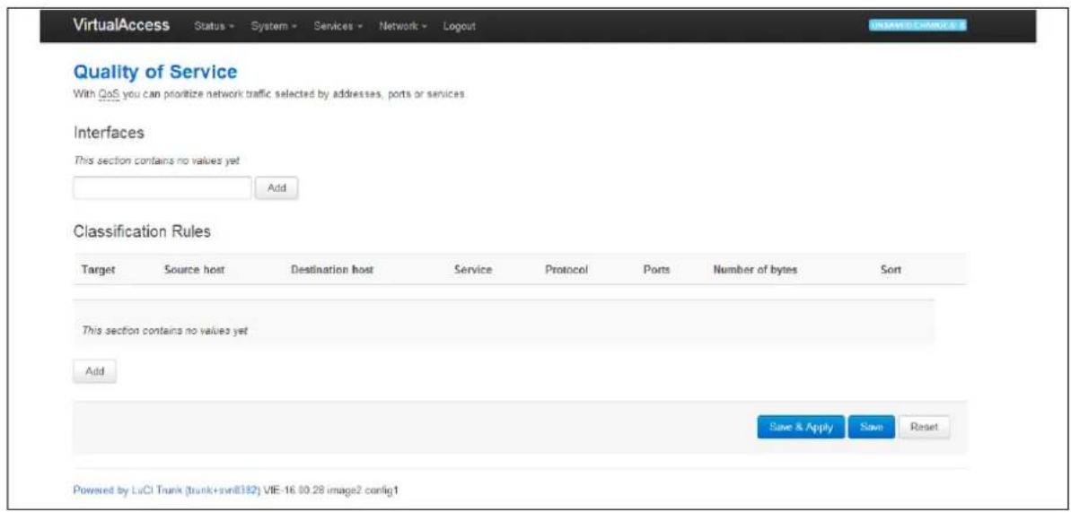
text_image
VirtualAccess Status - System - Services - Network - Logout Quality of Service With QoS you can prioritize network traffic selected by addresses, ports or services. Interfaces This section contains no values yet Add Classification Rules Target Source host Destination host Service Protocol Ports Number of bytes Sort This section contains no values yet Add Save & Apply Save Reset Powered by LuCI Trunk (trunk+svn8182) VIE-16.00.28 image2 config1Figure 168: The quality of service page
To configure an interface, enter a relevant interface name and click Add. The Quality of Service page for that interface appears.
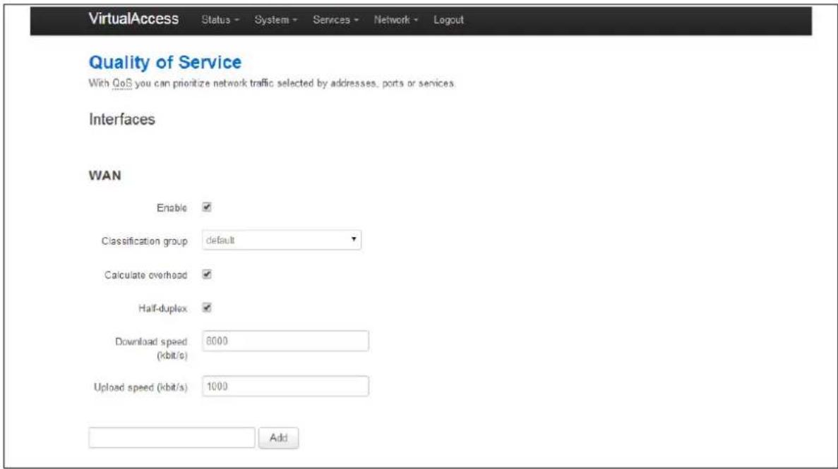
text_image
VirtualAccess Status - System - Services - Network - Logout Quality of Service With QoS you can prioritize network traffic selected by addresses, ports or services. Interfaces WAN Enable ✓ Classification group default ✓ Calculate overhead ✓ Half-duplex ✓ Download speed 6000 (kbit/s) Upload speed (kbit/s) 1000 AddFigure 169: The quality of service page for WAN interface
The following parameters can be configured for the interface you have chosen. The name of the interfaces should match with the logical name given to the interface in the network configuration.
| Web Field/ UCI/ Package Option | Description | |
| Web: EnabledUCI: qos.[interface].enabledOpt: enabled | Enables or disables QoS interface. | |
| 1 | Enabled. | |
| 0 | Disabled. | |
| Web: Classification groupUCI: qos. [interface].classgroupOpt: classgroup | Creates a mapping before previously created classgroup and interface to which it should be assigned to. | |
| Web: Calculate overheadUCI: qos. [interface].overheadOpt: overhead | Decreases upload and download ratio to prevent link saturation. | |
| Web: Half-duplexUCI: qos [interface].halfduplexOpt: halfduplex | Enables or disables half-duplex operation. | |
| 1 | Enabled. | |
| 0 | Disabled. | |
| Web: Download speedUCI: qos.[interface].downloadOpt: download | Download speed limit in kbits/sec. | |
| Web: Upload speedUCI: qos.[interface].upload=2000Opt: upload | Upload speed limit in kbits/sec. | |
Table 118: Information table for QoS page
To add classification rules, click Add. The Classification Rules section appears. Configure each classification rule with the following parameters.
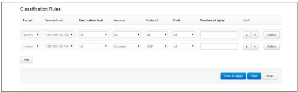
text_image
Classification Rules Target Source host Destination host Service Protocol Ports Number of bytes Sort priority ▼ 192.168.100 100 ▼ all ▼ all ▼ all ▼ all ▼ normal ▼ 192.168.100 100 ▼ all ▼ bicontent ▼ UDP ▼ all ▼ Add Save & Apply Save ResetFigure 170: Parameters for classification rules
| Web Field/ UCI / Package Option | Description | |
| Web: TargetUCI:Opt: | Creates and configures selected target bucket. | |
| Normal | ||
| Priority | ||
| Low | ||
| Express | ||
| Web: Source hostUCI:Opt: | Source host. | |
| Web: Destination hostUCI:Opt: | Destination host. | |
| Web: ServiceUCI:Opt: | Selectable service. | |
| Web: ProtocolUCI:Opt: | Protocol to classify. | |
| Web: PortsUCI:Opt: | Upload speed kbits/sec. | |
| Web: Number of bytesUCI:Opt: | Number of bytes for bucket. | |
Table 119: Information table for classification rules
36.4 Configuring QoS using UCI
You can also configure QoS using UCI. The configuration file is stored on:
/etc/config/qos
36.4.1 Interface
Defines the interface on which configured QoS settings will take place.
Each interface can have its own buffer. The interface section declares global characteristics of the connection on which the specified interface is communicating. The following options are defined within this section:
config interface 'ADSL'
option classgroup 'Default'
option enabled '1'
option overhead '1'
option halfduplex '0'
option download '900'
option upload '245'
| Web Field/ UCI / Package Option | Description | |
| Web: EnabledUCI: qos.[interface].enabledOpt: enabled | Enables or disables QoS interface. | |
| 1 | Enabled. | |
| 0 | Disabled. | |
| Web: Classification groupUCI: qos. [interface].classgroupOpt: classgroup | Creates a mapping before previously created classgroup and interface to which it should be assigned to. | |
| Web: Calculate overheadUCI: qos. [interface].overheadOpt: overhead | Decrease upload and download ratio to prevent link saturation. | |
| Web: Half-duplexUCI: qos [interface].halfduplexOpt: halfduplex | Enables or disables half-duplex operation. | |
| 1 | Enabled. | |
| 0 | Disabled. | |
| Web: Download speedUCI: qos.[interface].downloadOpt: download | Download speed limit in kbits/sec. | |
| Web: Upload speedUCI: qos.[interface].upload=2000Opt: upload | Upload speed limit in kbits/sec. | |
36.4.2 Classgroup
As there is more than one interface you can have more than one classgroup.
config classgroup 'Default'
option classes 'Express Normal'
option default 'Normal'
| UCI / Package Option | Description |
| UCI: qos.Default= classgroupOpt: Default | Specifies name of classgroup. |
| UCI: qos.Default.classes= Express NormalOpt: classes | Specifies the list of names of classes which should be part of classgroup. |
| qos.Default.default= NormalOpt: default | Defines which class is considered default. |
36.4.3 Classes
Each bucket has its own configuration.
config class 'Normal'
option packetsize '1500'
option avgrate '30'
option priority '5'
config class 'Express'
option packetsize '1000'
option maxsize '800'
option avgrate '50'
option priority '10'
option limitrate '10'
| UCI / Package Option | Description |
| UCI: qos.Normal=classOpt: Normal | Specifies class name. |
| UCI: qos.Normal.packetsize=1500Opt: packetsize | Specifies packet size for the class in bytes. |
| UCI: qos.Normal.avgrate=30Opt: avgrate | Average rate for this class, value in % of bandwidth in %. |
| UCI: qos.Normal.priority=5Opt: priority | Specifies priority for the class in %. |
| UCI: qos.Express=classOpt: Express | Specifies class name. |
| UCI: qos.Express.packetsize=1000Opt: packetsize | Specifies packet size for the class in bytes. |
| UCI: qos.Express.maxsize=800Opt: maxsize | Specify max packet size in bytes. |
| UCI: qos.Express.avgrate=50Opt: avgrate | Average rate for this class, value in % of bandwidth in %. |
| UCI: qos.Express.priority=10Opt: priority | Specifies priority for the class in %. |
| UCI: qos.Express.limitrate=10Opt: limitrate | Defines to how many % of the available bandwidth this class is capped to. |
36.4.4 Classify
Classifiers match the traffic for desired class.
config classify
option target 'Express'
option proto 'udp'
| UCI / Package Option | Description |
| UCI: qos.@classify[0]=classifyOpt: classify | Part of classify rule. |
| UCI: qos.@classify[0].target=ExpressOpt: target | Specifies target class. |
| UCI: qos.@classify[0].proto=udpOpt: proto | Specifies protocol. |
36.5 Example QoS configurations
config interface 'ADSL'
option classgroup 'Default'
option enabled '1'
option overhead '1'
option download '900'
option upload '245'
config classgroup 'Default'
option classes 'Express Normal'
option default 'Normal'
config class 'Normal'
option packetsize '1500'
option avgrate '30'
option priority '5'
config class 'Express'
option packetsize '1000'
option maxsize '800'
option avgrate '50'
option priority '10'
option limitrate '10'
config classify
option target 'Express'
option proto 'udp'
37 Management configuration settings
This chapter contains the configuration sections and parameters required to manage and monitor your device using Activator and Monitor.
37.1 Activator
Activator is a Virtual Access proprietary provisioning system, where specific router configurations and firmware can be stored to allow central management and provisioning. Activator has two distinct roles in provisioning firmware and configuration files to a router.
- Autoload activation of firmware and configuration files on router boot up:
- Autoload is generally used for router installation. In this scenario the router will initiate the request for firmware and configuration files when it boots up. The router is installed with a factory config that will allow it to contact Activator. The autoload feature controls the behaviour of the router in requesting firmware and configuration files; this includes when to start the Activation process and the specific files requested. The HTTP Client (uhttpd) contains information about the Activator server and the protocol used for activation.
- Deployment of firmware to routers after installation:
- In this scenario, Activator initiates the process. This process, known as Active Updates, allows for central automatic deployment of firmware and configuration files. It is used when configuration or firmware changes need to be pushed to live routers.
37.2 Monitor
Monitor is a Virtual Access proprietary tool, based on SNMP protocol, to monitor wide networks of deployed routers. The router will be configured to send information to Monitor, which is then stored and viewed centrally via the Monitor application. This includes features such as traffic light availability status, syslog and SLA monitoring.
37.3 Configuration packages used
| Package | Sections |
| autoload | main |
| httpclient | default |
| management_users | user |
37.4 Autoload: boot up activation
Autoload configurations specify how the device should behave with respect to activation when it boots up. Autoload entries contain information about the specific files to be downloaded and the destination for the downloaded file. Standard autoload entry configurations to download are:
• A firmware file (\\.img)
• A configuration file (\\.ini)
- A .vas file (\\.vas). This file signals the end of the autolaod sequence to Activator
Activator identifies the device using the serial number of the router. \\ syntax is used to denote the serial number of the router when requesting a file. The requested files are written to the alternate image or config segment.
You can change the settings either directly in the configuration file or via appropriate UCI set commands. It is normal procedure for autoload to be enabled in the router's factory settings and disabled in running configurations (config 1 and 2).
Autoload may already have been set at factory config level. If you wish to enable autoload services, proceed through the following steps.
37.5 Autoload packages
| Package | Sections |
| autoload | main |
37.5.1 Create a configuration file
In the top menu, select Services -> Autoload. The Autoload page has two sections: Basic Settings and Entries. Click Add to access configuration settings for each section.
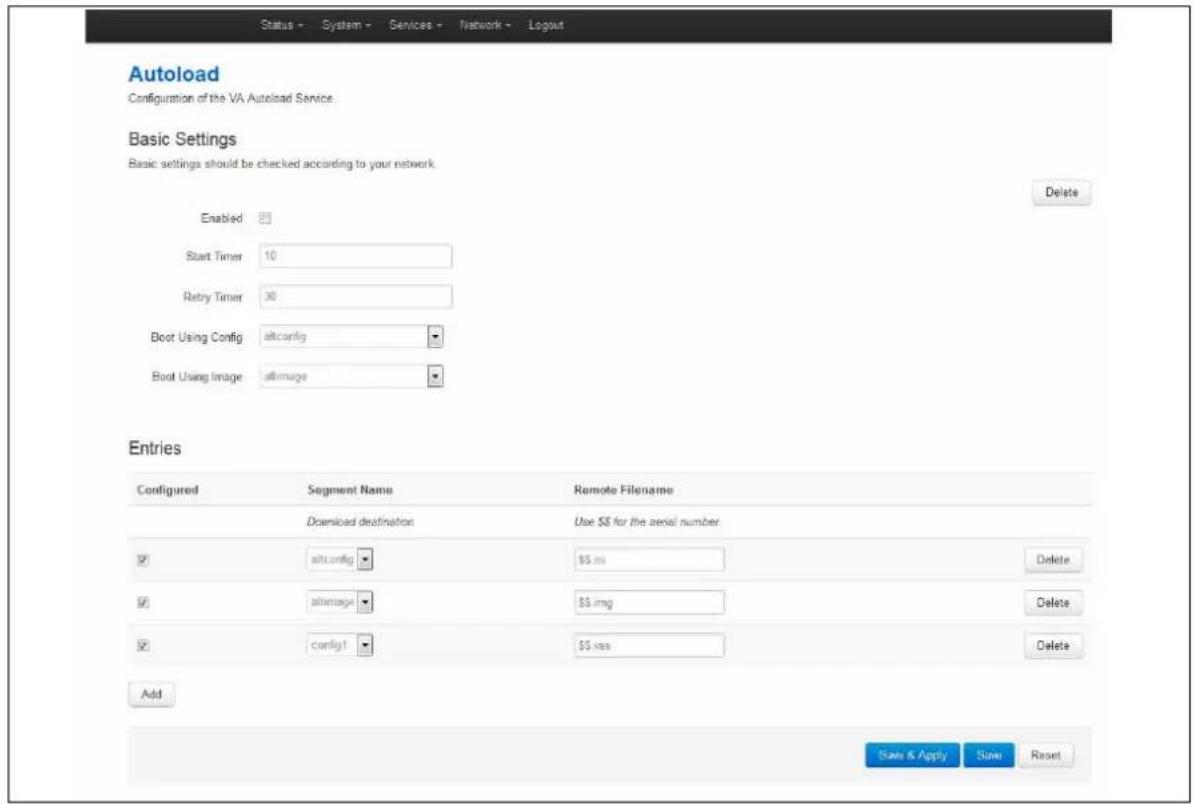
text_image
Status - System - Services - Network - Logout Autoload Configuration of the VA Autoload Service. Basic Settings Basic settings should be checked according to your network. Enabled Start Timer 10 Retry Timer 30 Boot Using Config altconfig Boot Using Image altimage Delete Entries Configured Segment Name Remote Filename Download destination Use $$ for the serial number altconfig $5 mi Delete altimage $5 img Delete config1 $5 vss Delete Add Save & Apply Save ResetFigure 171: The autoload settings page
| Web Field/ UCI / Package Option | Description | |
| Basic settings | ||
| Web: EnabledUCI: autoload.main.enabledOpt: Enabled | Enables activation at system boot. | |
| 1 | Enabled. | |
| 0 | Disabled. | |
| Web: Start TimerUCI: autoload.main.StartTimerOpt: StartTimer | Defines how long to wait after the boot up completes before starting activation. | |
| 10 | ||
| Range | 0-300 secs | |
| Web: Retry TimerUCI: autoload.main.RetryTimerOpt: RetryTimer | Defines how many seconds to wait between retries if a download of a particular autoload entry fails. | |
| 30 | ||
| Range | 0-300 secs | |
| Web: N/AUCI: autoload.main.NumberOfRetriesOpt: Numberofretries | Defines how many retries to attempt before failing the overall activation sequence, backing off and trying the whole activation sequence again. | |
| 5 | ||
| Range | ||
| Web: N/AUCI: autoload.main.BackoffTimerOpt: Backofftimer | Defines how many minutes to back off for if a download and all retires fail. After the backoff period, the entire autoload sequence will start again. | |
| 15 | ||
| Range | ||
| Web: Boot Using ConfigUCI: autoload.main.BotUsingConfigOpt: BootUsingConfig | Specifies which configuration to boot up with after the activation sequence. | |
| Altconfig | Alternative configuration | |
| Config1 | Configuration 1 | |
| Config2 | Configuration 2 | |
| Factconf | Factory configuration | |
| Web: Boot Using ImageUCI: autoload.main.BotUsingImageOpt: BootUsingImage | Specifies which image to boot up with after the activation sequence completes successfully. | |
| Altimage | Alternative image | |
| Image 1 | image 1 | |
| Image 2 | image 2 | |
| Entries | ||
| Web: ConfiguredUCI: autoload.@entry[x].ConfiguredOpt: Configured | Enables the autoload sequence to process this entry. | |
| 1 | Enabled. | |
| 0 | Disabled. | |
| Web: Segment NameUCI: autoload.@entry[x].SegmentNameOpt: SegmentName | Defines where the downloaded file should be stored:(config1 | config2 | altconfig | image1 | image2 | altimage).Typically only altconfig and altimage are used. | |
| Web: RemoteFilenameUCI: autoload.@entry[x].RemoteFilenameOpt: RemoteFilename | Defines the name of the file to be downloaded from Activator. | |
| $.vas | Notifies activator sequence is complete. | |
| ini | Request configuration | |
| img | Request firmware | |
| Note:$.vas should always be requested last. | ||
Table 120: Information table for autoload
37.6 Autoload using UCI
root@VA_router:/# uci show autoload
autoload.main=core
autoload.main.Enabled=yes
autoload.main.StartTimer=10
autoload.main.RetryTimer=30
autoload.main.NumberOfRetries=5
autoload.main.BackoffTimer=15
autoload.main.BotUsingConfig=altconfig
autoload.main.BotUsingImage=altimage
autoload.@entry[0]=entry
autoload.@entry[0].Configured=yes
autoload.@entry[0].SegmentName=altconfig
autoload.@entry[0].RemoteFilename=$$.ini
autoload.@entry[1]=entry
autoload.@entry[1].Configured=yes
autoload.@entry[1].SegmentName=altimage
autoload.@entry[1].RemoteFilename=$$.img
autoload.@entry[2]=entry
autoload.@entry[2].Configured=yes
autoload.@entry[2].SegmentName=config1
autoload.@entry[2].RemoteFilename=$$.vas
Autoload using package options
root@VA_router:/# uci export autoload
package 'autoload'
config 'core' 'main'
option 'Enabled' "yes"
option 'StartTimer' "10"
option 'RetryTimer' "30"
option 'NumberOfRetries' "5"
option 'BackoffTimer' "15"
option 'BootUsingConfig' "altconfig"
option 'BootUsingImage' "altimage"
config 'entry'
option 'Configured' "yes"
option 'SegmentName' "altconfig"
option 'RemoteFilename' "\.ini"
config 'entry'
option 'Configured' "yes"
option 'SegmentName' "altimage"
option 'RemoteFilename' "\.img"
config 'entry'
option 'Configured' "yes"
option 'SegmentName' "config1"
option 'RemoteFilename' "\.vas"
37.7 HTTP Client: configuring activation using the web interface
This section contains the settings for the HTTP Client used during activation and active updates of the device.
The httpclient core section configures the basic functionality of the module used for retrieving files from Activator during the activation process.
37.7.1 HTTP Client configuraton packages
| Package | Sections |
| Httpclient | default |
37.7.2 Web configuration
To configure HTTP Client for Activator, in the top menu, click Services -> HTTP Client. The HTTP Client page has two sections: Basic Settings and Advanced Settings.
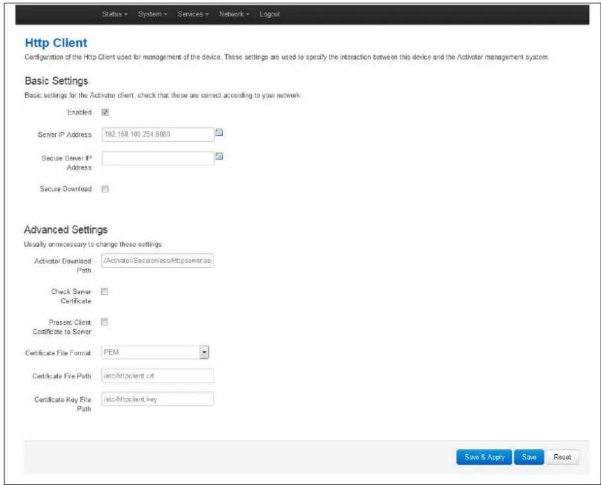
text_image
Http Client Configuration of the Http Client used for management of the device. These settings are used to specify the interaction between this device and the Activator management system. Basic Settings Basic settings for the Activator client, check that these are correct according to your network. Enabled Server IP Address 192.168.100.254.8080 Secure Server IP Address Secure Download Advanced Settings Usually unnecessary to change these settings. Activator Download /Activator/Session/ess/Httpserver.asp Path Check Server Certificate Present Client Certificate to Server Certificate File Format PEM Certificate File Path /etc/httpclient.crt Certificate Key File Path /etc/httpclient.key Save & Apply Save ResetFigure 172: The HTTP client page
| Web Field/ UCI / Package Option | Description | |
| Basic settings | ||
| Web: EnabledUCI: httpclient.default.enabledOpt: Enabled | Enables the HTTP client. | |
| 1 | Enabled. | |
| 0 | Disabled. | |
| Web: Server IP AddressUCI: httpclient.default.FileserverOpt: list Fileserver | Specifies the address of Activator that uses http port 80. This can be an IP address or FQDN. The syntax should be x.x.x.x:80 or FQDN:80. Multiple servers should be separated by a space using UCI. | |
| Web: Secure Server IP AddressUCI: httpclient.default.SecureFileServerOpt: list SecureFileServer | Specifies the address of Secure Activator that uses port 443. This can be an IP address or FQDN. The syntax should be x.x.x.x:443 or FQDN:443. Multiple servers should be separated by a space using UCI. | |
| Web: Secure DownloadUCI: httpclient.default.SecureDownloadOpt: SecureDownload | Enables Secure Download (port 443). | |
| 1 | Enabled. | |
| 0 | Disabled. | |
| Advanced settings | ||
| Web: ActivatorDownloadPathUCI:httpclient.default.ActivatorDownloadPathOpt: ActivatorDownloadPath | Specifies the URL on Activator to which the client should send requests. | |
| /Activator/Sessionless/Httpserver.asp | ||
| Range | ||
| Web: Check Server CertificateUCI:httpclient.default.ValidateServerCertificateEnabledOpt: ValidateServerCertificateEnabled | Checks for the certificates presence and validity. | |
| 1 | Enabled. | |
| 0 | Disabled. | |
| Web: Present Client Certificate to Server UCI: httpclient.default.PresentCertificateEnabledOpt: PresentCertificateEnabled | Specifies if the client presents its certificate to the server to identify itself. | |
| 1 | Enabled. | |
| 0 | Disabled. | |
| Web: CertificateFile Format UCI: httpclient.default.CertificateFormatOpt: CertificateFormat | Specifies the value the client expects to see in the specified field in the server certificate. | |
| PEM | ||
| DER | ||
| Web: Certificate File Path UCI: httpclient.default.CertificateFileOpt: CertificateFile | Defines the directory/location of the certificate./etc/httpclient.crt | |
| Range | ||
| Web: Certificate Key File Path UCI: httpclient.default.CertificateKeyOpt: CertificateKey | Specifies the directory/location of the certificate key./etc/httpclient.key | |
| Range | ||
| Web: N/A UCI: ValidateServerCertificateFieldEnabledOpt: ValidateServerCertificate | Defines the field in the server certificate that the client should check. | |
| 1 | Enabled. | |
| 0 | Disabled. | |
| Web: N/A UCI: httpclient.default.ActivatorChunkyDownloadPathOpt: ActivatorChunkyDownloadPath | Enables partial download activations and active updates.The default value is httpclient.default.ActivatorChunkyDownloadPath=/activator/partial/downloadThe url (on activator) to which the client should send requests for chunky image download. | |
| Web: N/A UCI: httpclient.defaultthereLimitOpt: RateLimit | Specifies the size of each packet payload | |
| 100k | 100K Bytes | |
| 1-infinite | Available values | |
| Web: N/A UCI: httpclient.default.CAFileOpt: CAFile | Throttle activation/active updates traffic received by device to specified limit | |
| None | By default there is no limit | |
| 1-infinite | Available values in kbps | |
| Web: N/A UCI: httpclient.default.IgnoreServerCertificateStatusOpt: IgnoreServerCertificateStatus | Defines path to the certificate authority file stored on the router | |
| 1 | Enabled. | |
| 0 | Disabled. | |
Table 121: Information table for HTTP client
37.8 Httpclient: Activator configuration using UCI
root@VA_router:~# uci show httpclient
httpclient.default=core
httpclient.default.Enabled=yes
httpclient.default.FileServer=10.1.83.36:80 10.1.83.37:80
httpclient.default.SecureFileServer=10.1.83.36:443 10.1.83.37:443
httpclient.default.ActivatorDownloadPath=/Activator/Sessionless/Httpserver.asp
httpclient.default.SecureDownload=no
httpclient.default.PresentCertificateEnabled=no
httpclient.default.ValidateServerCertificateEnabled=no
httpclient.default.CertificateFile=/etc/httpclient.crt
httpclient.default.CertificateFormat=PEM
httpclient.default.CertificateKey=/etc/httpclient.key
httpclient.default.ActivatorChunkyDownloadPath=/activator/partial/download
httpclient.defaultthereLimit=2
httpclient.default.CAFile='/'
httpclient.default.IgnoreServerCertificateStatus=0
37.9 Httpclient: Activator configuration using package options
root@VA_router:~# uci export httpclient
package httpclient
config core 'default'
option Enabled 'yes'
list FileServer '1.1.1.1:80'
list FileServer '1.1.1.2:80'
listSecureFileServer '1.1.1.1:443'
list SecureFileServer '1.1.1.2:443'
option ActivatorDownloadPath '/Activator/Sessionless/Httpserver.asp'
option SecureDownload 'no'
option PresentCertificateEnabled 'no'
option ValidateServerCertificateEnabled 'no'
option CertificateFile '/etc/httpclient.crt'
option CertificateFormat 'PEM'
option CertificateKey '/etc/httpclient.key'
option ActivatorChunkyDownloadPath '/activator/partial/download'
option ChunkSize '100k'
option RateLimit '2'
option CAFile \\
option IgnoreServerCertificateStatus '0'
37.10 User management using UCI
User management is not currently available using the web interface. You can configure the feature using UCI or Activator.
37.10.1 User management packages
| Package | Sections |
| management_users | Users |
37.10.2 Configuring user management
You can create different users on the system by defining them in the user management configuration file. This gives users access to different services.
| Web Field/ UCI / Package Option | Description | ||
| General settings | |||
| Web: n/aUCI: management_users.@user[x].enabledOpt: enable | Enables/creates the user. | ||
| 0 | Disabled. | ||
| 1 | Enabled. | ||
| Web: n/aUCI:management_users.@user[x].usernameOpt: username | Specifies the user's username. | ||
| Web: n/aUCI:management_users.@user[x].passwordOpt: password | Specifies the user's password. When entering the user password enter in plain text using the password option. After reboot the password is displayed encrypted via the CLI using the hashpassword option.UCI: management_users.@user[x].hashpasswordOpt: hashpassword. Note: a SRP user password will be displayed using the srphash option | ||
| Web: n/aUCI: management_users.@user[x].webuserOpt: webuser | Specifies web access permissions for the user. Note: webuser will only work if linuxuser is set to Enabled. | ||
| 0 | Disabled. | ||
| 1 | Enabled. | ||
| Web: n/aUCI:management_users.@user[x].chapuserOpt: chapuser | Specifies CHAP access permissions for the PPP connection.Note: chapuser will only work if linux user is set to Enabled. | ||
| 0 | Disabled. | ||
| 1 | Enabled. | ||
| Web: n/aUCI: management_users.@user[x].papuserOpt: papuser | Specifies PAP access permissions for the PPP connection. | ||
| 0 | Disabled. | ||
| 1 | Enabled. | ||
| Web: n/aUCI: management_users.@user[x].srpuserOpt: srpuser | Specifies SRP access permissions for the PPP connection. | ||
| 0 | Disabled. | ||
| 1 | Enabled. | ||
| Web: n/aUCI: management_users.@user[x].smsuserOpt: smsuser | Specifies SMS access permissions for the user. | ||
| 0 | Disabled. | ||
| 1 | Enabled. | ||
| Web: n/aUCI: linuxuserOpt: linuxuser | Specifies linuxuser access permissions for the user. | ||
| 0 | Disabled. | ||
| 1 | Enabled. | ||
| Web: n/aUCI: List allowed_pagesOpt: list allowed_pages | Specifies which pages the user can view. Multiple pages should be entered using a space to separate if using UCI. | ||
Table 122: Information table for config user commands
Note:
- webuser will only work if linuxuser is set to yes
- chapuser will only work if linuxuser is set to no
When a new user is created on the system and given web access, you will no longer be able to login to the router web interface with the default root user details. The user must use their new user login details.
37.11 Configuring the management user password using UCI
The user password is displayed encrypted via the CLI using the hashpassword option.
root@VA_router:~# uci show management_users
management_users.@user[0].username=test
management_users.@user[0].hashpassword=1XVzDHHPQ$SKK4geFonctihuffMjS4U0
If you are changing the password via the UCI, enter the new password in plain text using the password option.
root@VA_router:~# uci set management_users.@user[0].username=newpassword
root@VA_router:~# uci commit
The new password will take effect after reboot and will now be displayed in encrypted format through the hashpassword option.
37.12 Configuring management user password using package options
The root password is displayed encrypted via CLI using the hashpassword option.
root@VA_router:~# uci export management_users
package management_users
config user
option hashpassword '1wRYYiJOz$EeHN.GQcxXhRgNPVbqxVw
If you are changing the password using UCI, enter the new password in plain text using the password option.
package management_users
config user
option hashpassword '1wRYYiJOz$EeHN.GQcxXhRgNPVbqxVw
option password 'newpassword'
The new password will take effect after reboot and will now be displayed in encrypted format via the hashpassword option.
37.13 User management using UCI
root@VA_router:~# uci show management_users
management_users.@user[0]=user
management_users.@user[0].enabled=1
management_users.@user[0].username=test
management_users.@user[0].hashpassword=1XVzDHHPQ$SKK4geFonctihuffMjS4U0
management_users.@user[0].webuser=1
management_users.@user[0].linuxuser=1
management_users.@user[0].papuser=0
management_users.@user[0].chapuser=0
management_users.@user[0].srpuser=0
management_users.@user[0].smsuser=0
37.14 User management using package options
root@VA_router:~# uci export management_users
package management_users
config user
option enabled '1'
option username 'test'
option hashpassword '1XVzDHHPQ$SKK4geFonctihuffMjS4U0'
option webuser '1'
option linuxuser '1'
option papuser '0'
option chapuser '0'
option srpuser '0'
options smsuser '0'
37.15 Configuring user access to specific web pages
To specify particular pages a user can view, add the list allowed_pages. Examples are:
listallowed_pages '/admin/status'
The user can view admin status page only.
listallowed_pages 'admin/system/flashops'
The user can view flash operation page only.
To specify monitor widgets only, enter:
listallowed_pages 'monitor/<widgetname>'
Example widget names are: dhcp, arp, 3gstats, interfaces, memory, multiwan, network, openvpn, routes, system, ipsec, dmvpn, tservd.
38 Configuring Monitor
38.1 Introduction
Virtual Access monitoring system (Monitor) is a secure portal that provides:
• Centralised monitoring of devices
- Device status
- GPS location
- Syslog reporting
• Real time diagnostics
- Email notification
- Advanced statistics
- Dashboard graph reporting
You must configure each router in the network to send the required information to Monitor. This chapter explains how to configure the different information that can be sent to Monitor, including the required router configuration for:
• Reporting device status to Monitor
• Reporting GPS location to Monitor
• Reporting syslog to Monitor
- Configuration of interface statistics collection (ISAD)
For detailed information on operating Monitor, read the Monitor User Manual.
38.2 Reporting device status to Monitor
To allow Monitor to track the IP address and ongoing presence of a device, a keepalive heartbeat SNMP trap is sent from the router. The router is capable of sending SNMP in version 1, 2c and 3.
The SNMP keepalive heartbeat sends basic information on interface status but can also be configured to contain more detailed information such as GPS location.
The basic heartbeat configuration consists of two parts:
• enabling the heartbeat keepalive
• enabling the interface(s) to be monitored
38.2.1 Configuration package used
| Package | Sections |
| monitor | keepalive |
| network | interface |
38.2.2 Configuring keepalive heartbeat using the web interface
Select Services -> Monitor. The Monitor Keepalive & ISAD page appears.
The keepalive heartbeat is configured under the Basic Settings section.
A single instance keepalive can be configured to multiple monitor address using the same reference, heartbeat interval and other options. Or alternatively multiple keepalive instances can be configured with unique options.
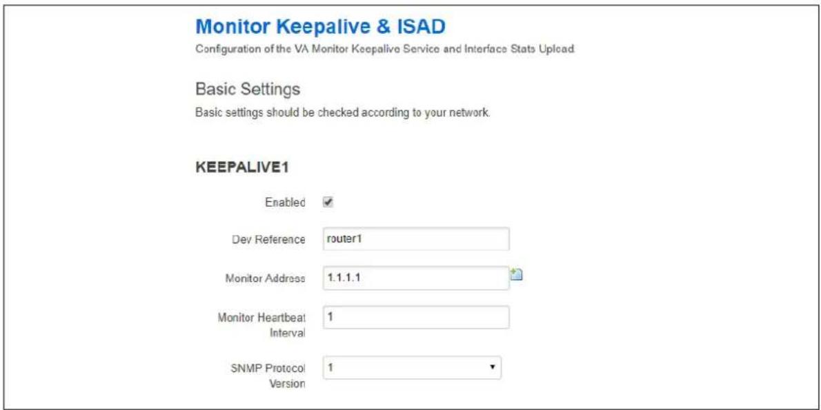
text_image
Monitor Keepalive & ISAD Configuration of the VA Monitor Keepalive Service and Interface Stats Upload Basic Settings Basic settings should be checked according to your network. KEEPALIVE1 Enabled ✓ Dev Reference router1 Monitor Address 1.1.1.1 Monitor Heartbeat Interval 1 SNMP Protocol Version 1 ▼Figure 173: The Monitor & ISAD keepalive page
38.2.2.1 Basic settings
| Web Field/ UCI / Package Option | Description | |
| Web: EnabledUCI: monitor.@keepalive[0].enabledOpt: Enabled | Enables Monitor to send heartbeats to the router. | |
| 0 | Disabled. | |
| 1 | Enabled. | |
| Web: Dev ReferenceUCI:monitor.@keepalive[0].dev_referenceOpt: dev_reference | Sets a unique identification for this device known to Monitor. | |
| Web: Monitor AddressUCI: monitor.@keepalive[0].monitor_ipOpt: list monitor_ip | Defines the IP address of Monitor. It is possible to specify multiple addresses to which SNMP heartbeat traps will be sent.To configure via UCI use a space separator. Example:monitor.@keepalive[0].monitor_ip=1.1.1.1 2.2.2.2 | |
| Web: Monitor Heartbeat IntervalUCI: monitor.@keepalive[0].interval_minOpt: interval_min | Specifies the interval, in minutes, at which traps are sent. | |
| 1 | Trap set every 1 minute. | |
| Range | ||
| Web: SNMP Protcol VersionUCI:monitor.@keepalive[0].snmp_versionOpt: snmp_version | Specifies what SNMP version is sent to remote Manager. | |
| 1 | snmp version 1 | |
| 2c | SNMP version 2c | |
| 3 | SNMP version 3 | |
Table 123: Information table for Monitor & ISAD basic configuration
The figure below shows options that are relevant only if you have selected SNMP version 3.
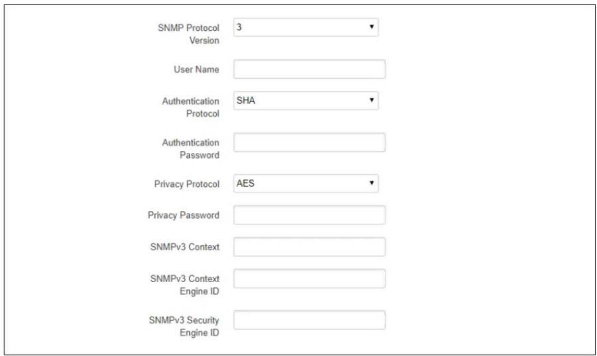
text_image
SNMP Protocol Version User Name Authentication Protocol Authentication Password Privacy Protocol Privacy Password SNMPv3 Context SNMPv3 Context Engine ID SNMPv3 Security Engine IDFigure 174: The Monitor & ISAD keepalive page for SNMP v3
| Web Field/ UCI / Package Option | Description | |
| Web: User NameUCI: monitor.@keepalive[0].snmp_unameOpt: snmp_uname | Specifies user name. | |
| Blank | Default value | |
| String | ||
| Web: Authentication PasswordUCI:monitor.@keepalive[0].snmp_auth_passOpt: snmp_auth_pass | Specifies snmpv3 authentication password. | |
| Web: Authentication ProtocolUCI:monitor.@keepalive[0].snmp_auth_protoOpt: snmp_auth_proto | Specifies snmpv3 authentication protocol. | |
| Blank | Default value | |
| MD5 | MD5 as authentication protocol | |
| SHA | SHA as authentication protocol | |
| Web: Privacy ProtocolUCI:monitor.@keepalive[0].snmp_priv_protoOpt: snmp_priv_proto | Specifies snmpv3 privacy protocol | |
| Blank | Default value | |
| AES | AES as privacy protocol | |
| DES | MD5 as privacy protocol | |
| Web: Privacy PasswordUCI:monitor.@keepalive[0].snmp_priv_passOpt: snmp_priv_pass | Specifies snmpv3 privacy password. | |
| Web: SNMPv3 ContextUCI:monitor.@keepalive[0].snmp_contextOpt: snmp_context | Specifies snmpv3 context name. | |
| Web: SNMPv3 Context Engine IDUCI:monitor.@keepalive[0].snmp_context_eidOpt: snmp_context_eid | Specifies snmpv3 context engine ID. | |
| Web: SNMPv3 Security Engine IDUCI:monitor.@keepalive[0].snmp_sec_eidOpt: snmp_sec_eid | Specifies snmpv3 security engine ID. | |
Table 124: Information table for SNMP v3 reporting device commands
38.2.3 Configuring keepalive heartbeat using command line
Keepalive is configured under the monitor package.
By default, all keepalive instances are named 'keepalive', it is identified by @keepalive then the keepalive position in the package as a number. For example, for the first keepalive in the package using UCI:
monitor.@keepalive[0]=keepalive
monitor.@ keepalive[0].enabled=1
Or using package options:
config keepalive
option enabled '1'
However, to better identify, it is recommended to give the keepalive instance a name. For example, to create a keepalive instance named keepalivev1.
To define a named keepalive instance using UCI, enter:
monitor.keepalivev1=keepalive
monitor.keepalivev1.enable=1
To define a named keepalive instance using package options, enter:
config keepalive 'keepalivev1'
option enabled '1'
38.2.4 Keepalive using UCI
root@VA_router:~# uci show monitor
monitor.keepalivev1=keepalive
monitor.keepalivev1enabled=1
monitor.keepalivev1.interval_min=1
monitor.keepalivev1.dev_reference=router1
monitor.keepalivev1.monitor_ip=10.1.83.36
monitor.keepalivev1.snmp_version=1
monitor.keepalivev2=keepalive
monitor.keepalivev2.enable=1
monitor.keepalivev2.interval_min=1
monitor.keepalivev2.monitor_ip=172.16.250.100
monitor.keepalivev2.dev_reference=TEST
monitor.keepalivev2.snmp_version=2c
monitor.keepalivev3=keepalive
monitor.keepalivev3.enable=1
monitor.keepalivev3.interval_min=1
monitor.keepalivev3.monitor_ip=172.16.250.101
monitor.keepalivev3.dev_reference=TEST
monitor.keepalivev3.snmp_version=3
monitor.keepalivev3.snmp_uname=TEST
monitor.keepalivev3.snmp_auth_pass=vasecret
monitor.keepalivev3.snmp_auth_proto=MD5
monitor.keepalivev3.snmp_priv_pass=vasecret
monitor.keepalivev3.snmp_priv_proto=DES
38.2.5 Keepalive using package options
root@VA_router:~# uci export monitor
package 'monitor'
config keepalive 'keepalivev1'
option enabled '1'
option interval_min '1'
option dev_reference 'router1'
option enabled 'yes'
list monitor_ip '10.1.83.36'
config keepalive 'keepalivev2'
option enable '1'
option interval_min '1'
list monitor_ip '172.16.250.100'
option dev_reference 'TEST'
option snmp_version '2c'
config keepalive 'keepalivev3'
option enable '1'
option interval_min '1'
list monitor_ip '172.16.250.101'
option dev_reference 'TEST'
option snmp_version '3'
option snmp_uname 'TEST'
option snmp_auth_pass 'vasecret'
option snmp_auth_proto 'MD5'
option snmp_priv_pass 'vasecret'
option snmp_priv_proto 'DES'
38.2.6 Enabling interface status in keepalive heartbeat via web interface
The keepalive heartbeat can send information on multiple interfaces. In order to send an interface status to Monitor, select Network -> Interfaces, then under the required interface select Edit. Under Advanced Settings enable the Monitor interface state option.
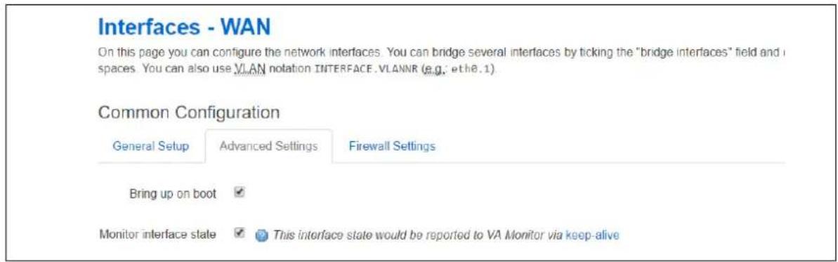
text_image
Interfaces - WAN On this page you can configure the network interfaces. You can bridge several interfaces by ticking the "bridge interfaces" field and spaces. You can also use VLAN notation INTERFACE.VLANNR (e.g.: eth8.1). Common Configuration General Setup Advanced Settings Firewall Settings Bring up on boot Monitor interface state ✓ ✓ This interface state would be reported to VA Monitor via keep-aliveFigure 175: The interface common configuration page
| Web Field/ UCI / Package Option | Description | |
| Web: Monitor interface stateUCI: network.@interface[0].monitoredOpt: monitored | Enables interface status to be sent in the heartbeat trap to Monitor. | |
| 0 | Disabled. | |
| 1 | Enabled. | |
Table 125: Information table for enabling interface status command
38.2.7 Enabling interface status using command line
Interface status is configured under the network package.
38.2.7.1 Enable interface status using UCI
root@VA_router:~# uci show network
network.@interface[0]=interface
.....
network.@interface[0].monitored=1
.....
38.2.7.2 Enable interface status using package option
root@VA_router:~# uci export network
package network
config interface 'WAN'
......
option monitored '1'
......
38.3 Reporting GPS location to Monitor
To allow Monitor to display a router GPS location, the GPS coordinates can be configured to be sent in the heartbeat keepalive from the router.
GPS location is only available in supported hardware models.
Ensure monitor keepalive heartbeat is correctly configured as in section 35.2 above.
38.3.1 Configuration package used
| Package | Sections |
| gpsd | gpsd |
38.3.2 Configuring GPS location via the web interface
Select Services -> GPS. The GPS configuration page appears.
The web interface configures a gpsd section named core.

text_image
Main Settings Enable GPS ✓Figure 176: The GPS configuration page
| Web Field/ UCI / Package Option | Description | |
| Web: Enable GPSUCI: monitor.core.enabledOpt: enabled | Enables GPS coordinates to be sent in the heartbeat keepalive to Monitor. | |
| 0 | Disabled. | |
| 1 | Enabled. | |
Table 126: Information table for reporting GPS commands
38.3.3 Configuring GPS using command line
GPS location is configured under the gpsd package.
38.3.3.1 GPS using UCI
root@VA_router:~# uci show gpsd
gpsd.core=gpsd
gpsd.core.enabled=1
38.3.3.2 GPS using package options
root@VA_router:~# uci export gpsd
package gpsd
config gpsd 'core'
option enabled '1'
38.3.4 GPS diagnostics
To view information on GPS coordinates via the web interface, select Status -> GPS Information.
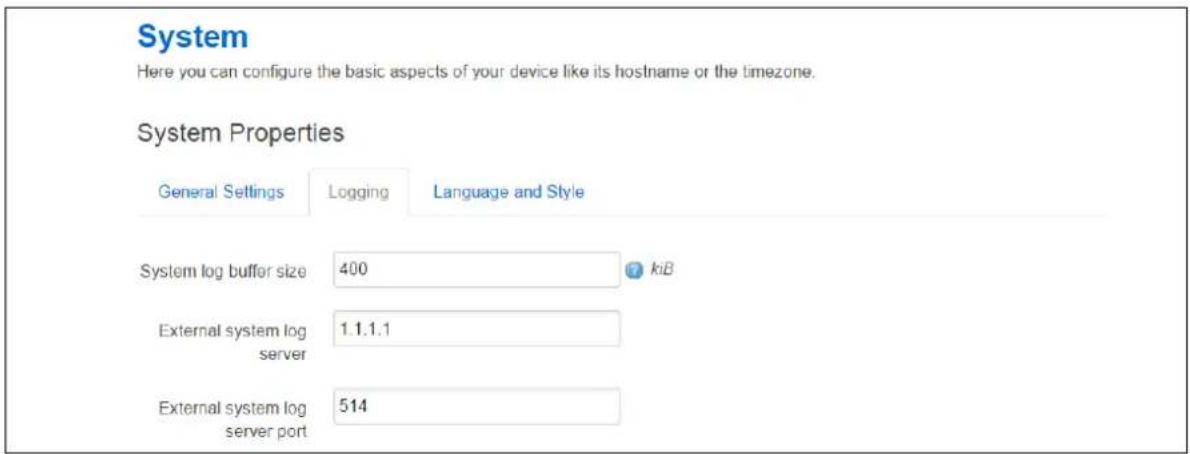
text_image
System Here you can configure the basic aspects of your device like its hostname or the timezone. System Properties General Settings Logging Language and Style System log buffer size 400 kiB External system log server 1.1.1.1 External system log server port 514Figure 177: The GPS status page
To view GPS coordinates via command line, enter gpspeek:
root@VA_router:~# gpspeek
Fix: 3D,1495467700,53.342529,-
6.241236,27.700000,202.600000,0.000000,0.000000
38.4 Reporting syslog to Monitor
38.4.1 Configuration package used
| Package | Sections |
| system | main |
38.4.2 Configuring syslog to Monitor via the web interface
Monitor can display syslog events sent from the router. To configure the router to send syslog events, select System -> System -> Logging and set External system log server to the Monitor IP. You can also configure the syslog server port if required.
All syslog events are sent to the syslog server.
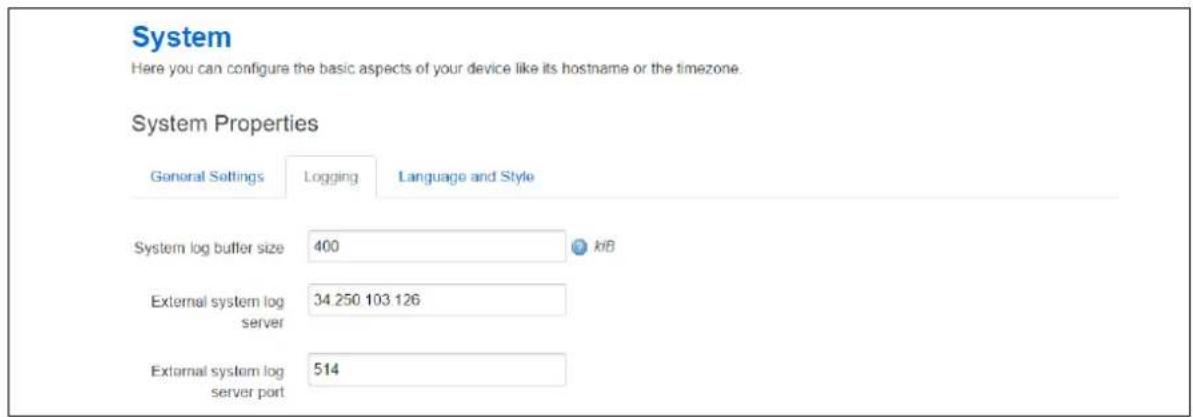
text_image
System Here you can configure the basic aspects of your device like its hostname or the timezone. System Properties General Settings Logging Language and Style System log buffer size 400 kB External system log server 34 250 103 126 External system log server port 514Figure 178: The system properties page
| Web Field/ UCI / Package Option | Description | |
| Web: External system log serverUCI: system.main.log_ipOpt: log_ip | Defines the external syslog server IP address. | |
| Web: External system log serverUCI: system.main.log_portOpt: log_port | Defines the external syslog server destination port number for syslog messages. | |
| 514 | ||
| Range | ||
Table 127: Information table for syslog properties commands
38.4.3 Configuring syslog events to Monitor using command line
Syslog is configured under the system package.
38.4.3.1 Syslog events to Monitor using UCI
root@VA_router:~# uci show system
system.main=system
......
system.main.log_ip=1.1.1.1
system.main.log_port=514
......
38.4.3.2 Syslog events to Monitor using package options
root@VA_router:~# uci export system
package system
config system 'main'
.....
option log_ip '1.1.1.1'
option log_port '514'
.....
38.5 Configuring ISAD
ISAD is a system for collecting interface stats to be displayed on Monitor.
The following section explains how to configure interface statistics collection (iSAD). Statistical data is collected in bins with each bin containing interface transmit and receive packets/bytes/errors for a period. Signal strength and also temperature parameters are also stored in the bins. Bins are uploaded to Monitor periodically.
Note: Ensure monitor keepalive heartbeat and interface status is correctly configured as in section 30.2 above. Interfaces should have option monitored enabled as part of the collection.
ISAD replaces the deprecated SLA feature.
38.5.1 Configuration package used
| Package | Sections |
| monitor | interface_stats |
38.5.2 Configuring ISAD using the web interface
Select Services -> Monitor. The Monitor Keepalive & ISAD page appears. ISAD is configured under the Interface Stats section.
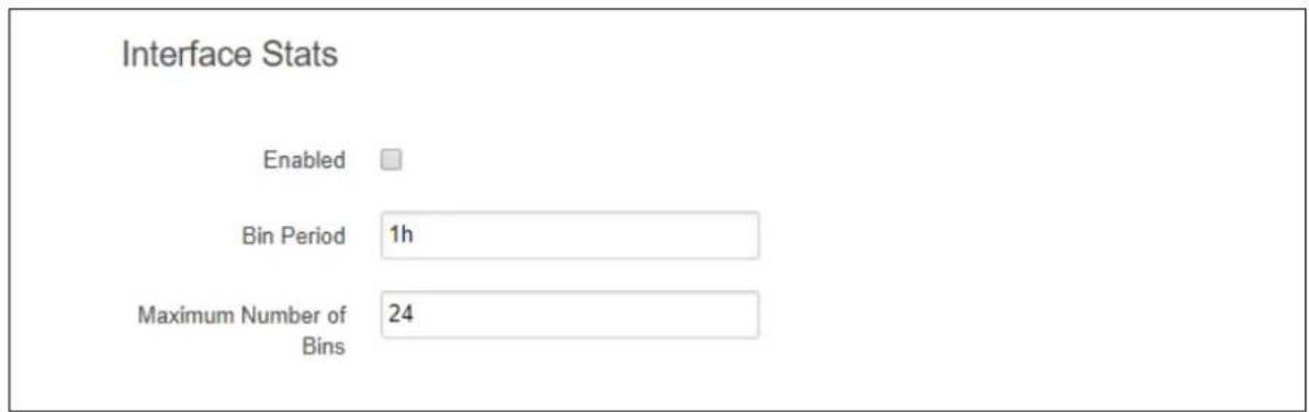
text_image
Interface Stats Enabled Bin Period 1h Maximum Number of Bins 24Figure 179: The Monitor Keepalive & ISAD Interface Stats page
| Web Field/ UCI / Package Option | Description | |
| Web: Enabled | Enables ISAD. | |
| UCI: monitor.stats.enabled=1 | 0 | Disabled. |
| Opt: enabled | 1 | Enabled. |
| Web: Bin PeriodUCI: monitor.stats.bin_periodOpt: time | Specifies how long to collect data for one bin.Specifies the interval, in minutes, at which traps are sent. | |
| 1h | Bin collected for 1 hour | |
| Range | ||
| Web: Maximum Number of BinsUCI: monitor.stats.bin_cache_sizeOpt: bin_cache_size | Specifies the maximum number of bins to store. | |
| Empty | 24 | |
| Range | ||
Table 128: Information table for ISAD Monitor Keepalive & ISAD Interface Stats section
38.5.3 Configuring ISAD using the command line
ISAD is configured under the Monitor package.
38.5.3.1 ISAD using UCI
root@VA_router:~# uci show monitor
monitor.keepalivev1=keepalive
monitor.keepalivev1enabled=1
monitor.keepalivev1.interval_min=1
monitor.keepalivev1.dev_reference=router1
monitor.keepalivev1.monitor_ip=10.1.83.36
monitor.keepalivev1.snmp_version=1
monitor.stats=interface_stats
monitor.stats.enabled=1
monitor.stats.bin_period=1h
monitor.stats.bin_cache_size=24
38.5.3.2 ISAD using package options
root@VA_router:~# uci export monitor
package monitor
config keepalive 'keepalivev1'
option interval_min '1'
option enabled '1'
list monitor_ip '10.1.83.36'
option dev_reference 'router1'
config interface_stats 'stats'
option enabled '1'
option bin_period '1h'
option bin_cache_size '24'
38.5.4 ISAD diagnostics
38.5.4.1 Checking process
To check to see if ISAD is running, enter pgrep -fl isad:
root@VA_router:~# pgrep -fl isad
5303 /usr/sbin/isad -b 60 -s 10 -c 200 -u /var/state /var/const_state
38.5.4.2 Checking bin statistics
To check if stats are being collected, enter cat /var/state/monitor:
root@VA_router:~# cat /var/state/monitor
monitor.bin_0=isad
monitor.bin_0.end_ts=85020
monitor.bin_0.start_ts=84960
monitor.bin_1=isad
monitor.bin_1.end_ts=85080
monitor.bin_1.start_ts=85020
monitor.bin_2=isad
monitor.bin_2.end_ts=85140
monitor.bin_2.start_ts=85080
38.5.5 ISAD operation
The bin statistics stored on the router must be periodically pushed statistics to Monitor.
This is normally done centrally when statistics are enabled on Monitor. Monitor contacts each router and auto-generates a script that will automatically schedule the upload of the bin statistics.
However, if Monitor cannot access the router WAN IP, you must do this manually on each router using a UDS script. An example is shown below where the bins are uploaded every hour to a Monitor server IP 89.101.154.154 using TFTP.
package uds
config script 'isb_upload_scr'
option enabled '1'
option exec_type 'periodic'
option period '1h'
list text '/usr/sbin/isb_upload.lua 89.101.154.154:69'
39 Configuring SNMP
SNMP (Simple Network Management Protocol) is an internet-standard protocol for managing devices on IP networks. SNMP exposes management data in the form of a hierarchy of variables in a MIB (Management Information Base). These variables can be queried individually, or in groups using their OIDs (Object Identifiers) defined in MIBs. In addition, information from the router can be pushed to a network management station in the form of SNMP traps.
39.1 Configuration package used
| Package | Sections | ||||
| snmpd access | agent | exec | inventory | monitor_load | system |
| group | inventory_iftable | monitor_memory | trapreceiver | ||
| com2sec | heartbeat | monitor_disk | monitor_process | usm_user | |
| constant | informreceiver | monitor_ioerror | pass | view | |
The SNMP application has several configuration sections:
| System and Agent | Configures the SNMP agent. |
| Com2Sec | Maps SNMP community names into an arbitrary security name. |
| Group Assigns community names and SNMP protocols to groups. | |
| View and Access | Creates views and sub views of the whole available SNMP tree and grants specific access to those views on a group by group basis. |
| usm_user | Define a user for SNMPv3 USM |
| Trap receiver | Address of a notification receiver that should be sent SNMPv1 TRAPs and SNMPv2c TRAP2s. |
| Inform receiver | Address of a notification receiver that should be sent SNMPv2 INFORM notifications respectively |
39.2 Configuring SMNP using the web interface
In the top menu, select Services -> SNMP. The SNMP Service page appears.
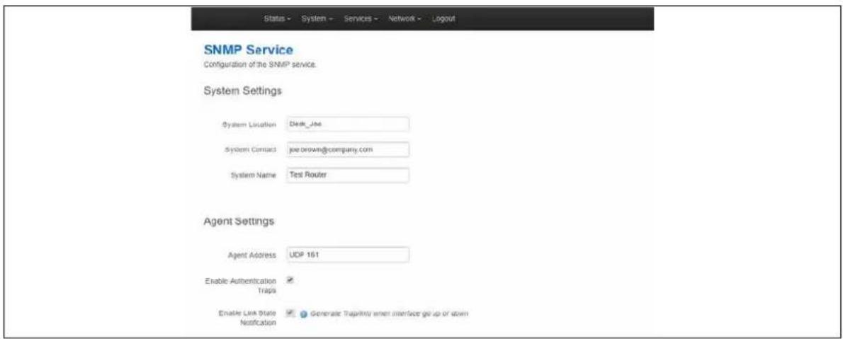
text_image
Status - System - Services - Network - Logout SNMP Service Configuration of the SNMP service. System Settings System Location Desk_Joe System Contact joe.brown@company.com System Name Test Router Agent Settings Agent Address UDP 161 Enable Authentication Traps Enable Link State Notification Generate Trajectories when interface go up or stormFigure 180: The SNMP service page
39.2.1 System and agent settings
| Web Field/ UCI / Package Option | Description | |
| System settings | ||
| Web: System LocationUCI: snmpd.system[0].sysLocationOpt: sysLocation | Sets the system location, system contact or system name for the agent. This information is reported in the 'system' group in the mibll tree. | |
| Web: System ContactUCI: snmpd.system[0].sysContactOpt: sysContact | ||
| Web: System NameUCI: snmpd.system[0].sysNameOpt: sysName | ||
| Agent Settings | ||
| Web: Agent AddressUCI: snmpd.agent[0].agentaddressOpt: agentaddress | Specifies the address(es) and port(s) on which the agent should listen.[(udp|tcp):]port[@address][,...] | |
| Web: Enable Authentication TrapsUCI: snmpd.agent[0].authtrapenabledOpt: authtrapenabled | Enables or disables SNMP authentication trap. | |
| 0 | Disabled. | |
| 1 Enabled. | ||
| Note: this is the SNMP poll authentication trap to be set when there is a community mismatch. | ||
| Web: Enable Link State NotificationUCI: snmpd.agent[0].link_updown_notifyOpt: link_updown_notify | Generates trap/info when interface goes up or down. When enabled, the router sends a trap notification link up or down. | |
| 0 | Disabled. | |
| 1 Enabled. | ||
Table 129: Information table for system and agent settings
39.2.2 Com2Sec settings
To access Com2Sec settings, scroll down the SNMP Services page.
Use the COM2Sec section to map SNMP community names into an arbitrary security name. Map community names into security names based on the community name and the source subnet. Use the first source/community combination that matches the incoming packet.
A community string is a password that is applied to a device to restrict both read-only and read-write access to the SNMP data on the device. These community strings should be chosen carefully to ensure they are not trivial. They should also be changed at regular intervals and in accordance with network security policies.
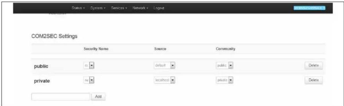
text_image
Status - System - Services - Network - Logout COM2SEC Settings Security Name Source Community public m default public private m localhost priative Add Delete AddFigure 181: The COM2Sec settings section
| Web Field/ UCI / Package Option | Description |
| Web: Security NameUCI: snmpd.com2sec[x].secnameOpt: secname | Specifies an arbitrary security name for the user. |
| Web: SourceUCI: snmpd.com2sec[x].sourceOpt: source | A hostname, localhost or a subnet specified as a.b.c.d/mask or a.b.c.d/bits or 'default' for no restrictions. |
| Web: CommunityUCI: snmpd.com2sec[x].communityOpt: community | Specifies the community string being presented in the request. |
Table 130: Information table for Com2Sec settings
39.2.3 Group settings
Group settings assign community names and SNMP protocols to groups.
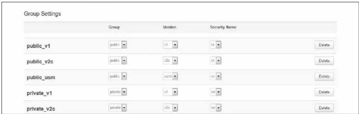
text_image
Group Settings Group Version Security Name public_v1 public\v1 r0 Delete public_v2c public\v2c r0 Delete public_usm public------------------------------ ruDelete private_v1 private\v1 rvDelete private_v2c private\v2c rvDeleteFigure 182: The group settings section
| Web Field/ UCI / Package Option | Description | |
| Web: GroupUCI: snmpd.group[x].groupOpt: group | Specifies an arbitrary group name. | |
| Web: VersionUCI: snmpd.group[x].versionOpt: version | Specifies the SNMP version number being used in the request:v1, v2c and usm (User-based Security Module) are supported. | |
| v1 | SNMP v1 | |
| v2v SNMP v2 | ||
| usm SNMP | v3 | |
| any | Any SNMP version | |
| Web: Security NameUCI: snmpd.group[x].secnameOpt: secname | An already defined security name that is being included in this group. | |
Table 131: Information table for group settings
39.2.4 View settings
View settings define a named "view", which is a subset of the overall OID tree. This is most commonly a single subtree, but several view directives can be given with the same view name, to build up a more complex collection of OIDs.

text_image
View Settings Name Type OID all all Included 1 Delete AddFigure 183: The view settings section
| Web Field/ UCI / Package Option | Description | |
| Web: NameUCI: snmpd.view[x].viewnameOpt: viewname | Specifies an arbitrary view name. Typically it describes what the view shows. | |
| Web: TypeUCI: snmpd.view[x].typeOpt: type | Specifies whether the view lists oids that are included in the view or lists oids to be excluded from the view (in which case all other oids are visible apart from those ones listed). | |
| included | ||
| excluded | ||
| Web: OIDUCI: snmpd.view[x].oidOpt: oid | OID to be included in or excluded from the view. Only numerical representation is supported.Example | |
| 1 | Everything | |
| 1.3.6.1.2.1.2 | Interfaces table | |
Table 132: Information table for view settings
39.2.5 Access settings
Access settings map from a group of users/communities, in a specific context and with a particular SNMP version and minimum security level, to one of three views, depending on the request being processed.
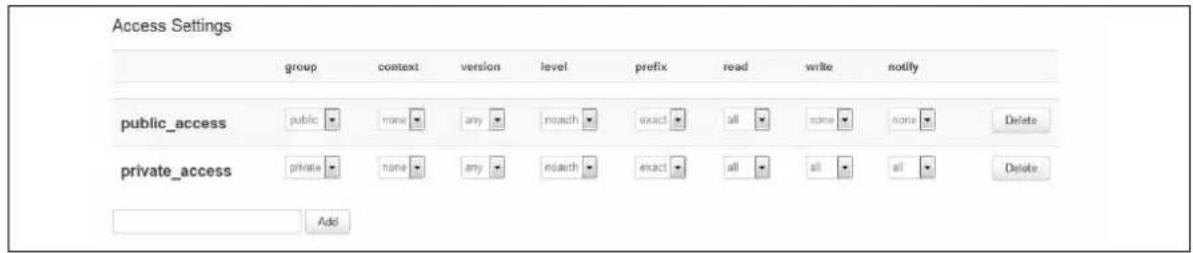
text_image
Access Settings group context version level prefix read write notify public_access public none any noauth exact all none none Delete private_access private none any noauth exact all all all Delete AddFigure 184: The access settings section
| Web Field/ UCI / Package Option | Description | |
| Web: GroupUCI: snmpd.access[x].groupOpt: group | Specifies the group to which access is being granted. | |
| Web: ContextUCI: snmpd.access[x].contextOpt: context | SNMPv3 request context is matched against the value according to the prefix below. For SNMP v1 and SNMP v2c, the context must be none. | |
| none | ||
| all | ||
| Web: VersionUCI: snmpd.access[x].versionOpt: version | Specifies the SNMP version number being used in the request: any, v1, v2c and usm are supported. | |
| v1 SNMP v1 | ||
| v2v SNMP v2 | ||
| usm SNMP v3 | ||
| any Any SNMP version | ||
| Web: LevelUCI: snmpd.access[x].levelOpt: level | Specifies the security level. For SNMP v1 and SNMP v2c level must be noauth. | |
| noauth | ||
| auth | ||
| priv | ||
| Web: PrefixUCI: snmpd.access[x].prefixOpt: prefix | Prefix specifies how context (above) should be matched against the context of the incoming pdu. | |
| exact | ||
| any | ||
| all | ||
| Web: ReadUCI: snmpd.access[x].readOpt: read | Specifies the view to be used for read access. | |
| Web: WriteUCI: snmpd.access[x].writeOpt: write | Specifies the view to be used for write access. | |
| Web: NotifyUCI: snmpd.access[x].notifyOpt: notify | Specifies the view to be used for notify access. | |
| v1 SNMP v1 | |
| v2v | SNMP v2 |
| usm SNMP | v3 |
| any Any SNMP version | |
| noauth | |
| auth | |
| priv | |
| Prefix specifies how context (above) should be matched against the context of the incoming pdu. | |
| exact | |
| any | |
| all | |
Table 133: Information table for access settings
39.2.6 Trap receiver
Trap receiver settings define a notification receiver that should be sent SNMPv1 TRAPs and SNMPv2c TRAP2.

text_image
Trap Receiver Host Port Version Community 192.168.190.254 v1 public Delete AddFigure 185: The trap receiver settings page
| Web Field/ UCI / Package Option | Description | |
| Web: HostUCI: snmpd.trapreceiver[x].hostOpt: host | Host address. Can be either an IP address or an FQDN. | |
| Web: PortUCI: snmpd.trapreceiver[x].portOpt: port | UDP port to be used for sending traps. | |
| Range | ||
| 162 | ||
| Web: VersionUCI: snmpd.trapreceiver[x].versionOpt: version | SNMP version. | |
| v1 | ||
| V2 | ||
| Web: CommunityUCI: snmpd.trapreceiver[x].communityOpt: community | Community to use in trap messages for this host. | |
Table 134: Information table for trap receiver settings
39.2.7 Inform receiver
Inform receiver settings define a notification receiver that should be sent SNMPv2c INFORM notifications.

text_image
Inform Receiver Host Port Community This section contains no values yetFigure 186: The inform receiver settings page
| Web Field/ UCI / Package Option | Description | |
| Web: HostUCI: snmpd.informreceiver[x].hostOpt: host | Host address. Can be either an IP address or an FQDN. | |
| Web: PortUCI: snmpd.informreceiver[x].portOpt: port | UDP port to be used for sending traps. | |
| Range | ||
| 162 | ||
| Web: CommunityUCI: snmpd.informreceiver[x].communityOpt: community | Community to use in inform messages for this host. | |
Table 135: Information table for trap receiver settings
39.3 Configuring SNMP using command line
The configuration files are stored on /etc/config/snmpd.
39.3.1 System settings using UCI
root@VA_router:~# uci show snmpd
snmpd.system=system
snmpd.system.sysLocation=Office 123
snmpd.system.sysContact=Mr White
snmpd.system.sysName=Backup Access 4
snmpd.agent=agent
snmpd.agent.agentaddress=UDP:161
snmpd.agent.authtrapenabled=yes
snmpd.agent.link_updown_notify=yes
39.3.2 System settings using package options
root@VA_router:~# uci export snmpd
package snmpd
config 'system'
option sysLocation 'Office 123'
option sysContact 'Mr White'
option sysName 'Backup Access 4'
config 'agent'
option agentaddress 'UDP:161'
option authtrapenabled '1'
option link_updown_notify '1'
Another sample agent configuration shown below causes the agent to listen on UDP port 161, TCP port 161 and UDP port 9161 on only the interface associated with the localhost address.
config 'agent'
option agentaddress 'UDP:161,tcp:161,9161@localhost'
39.3.3 com2sec settings
The following sample specifies that a request from any source using “public” as the community string will be dealt with using the security name “ro”. However, any request from the localhost itself using “private” as the community string will be dealt with using the security name “rw”.
Note: the security names of "ro" and "rw" here are simply names – the fact of a security name having read only or read-write permissions is handled in the access section and dealt with at a group granularity.
39.3.3.1 Com2sec using UCI
snmpd.c2s_1=com2sec
snmpd.c2s_1.source=default
snmpd.c2s_1.community=public
snmpd.c2s_1.secname=rw
snmpd.c2s_2=com2sec
snmpd.c2s_2.source=localhost
snmpd.c2s_2.community=private
snmpd.c2s_2.secname=ro
39.3.3.2 Com2sec using package options
config 'com2sec' 'public'
option secname 'ro'
option source 'default'
option community 'public'
config 'com2sec' 'private'
option secname 'rw'
option source 'localhost'
option community 'private'
39.3.4 Group settings
The following example specifies that a request from the security name "ro" using snmp v1, v2c or USM (User Based Security Model for SNM P v3) are all mapped to the "public"
group. Similarly, requests from the security name "rw" in all protocols are mapped to the "private" group.
39.3.4.1 Group settings using UCI
snmpd.grp_1_v1=group
snmpd.grp_1_v1.version=v1
snmpd.grp_1_v1.group=public
snmpd.grp_1_v1.secname=ro
snmpd.grp_1_v2c=group
snmpd.grp_1_v2c.version=v2c
snmpd.grp_1_v2c.group=public
snmpd.grp_1_v2c.secname=ro
snmpd.grp_1_usm=group
snmpd.grp_1_usm.version=usm
snmpd.grp_1_usm.group=public
snmpd.grp_1_usm.secname=ro
snmpd.grp_1_access=access
snmpd.grp_1_access.context=none
snmpd.grp_1_access.version=any
snmpd.grp_1_access.level=noauth
snmpd.grp_1_access.prefix=exact
snmpd.grp_1_access.read=all
snmpd.grp_1_access.write=none
snmpd.grp_1_access.notify=none
snmpd.grp_1_access.group=public
snmpd.grp_2_v1=group
snmpd.grp_2_v1.version=v1
snmpd.grp_2_v1.group=public
snmpd.grp_2_v1.secname=ro
snmpd.grp_2_v2c=group
snmpd.grp_2_v2c.version=v2c
snmpd.grp_2_v2c.group=public
snmpd.grp_2_v2c.secname=ro
snmpd.grp_2_usm=group
snmpd.grp_2_usm.version=usm
snmpd.grp_2_usm.group=public
snmpd.grp_2_usm.secname=ro
snmpd.grp_2_access=access
snmpd.grp_2_access.context=none
snmpd.grp_2_access.version=any
snmpd.grp_2_access.level=noauth
snmpd.grp_2_access.prefix=exact
snmpd.grp_2_access.read=all
snmpd.grp_2_access.write=all
snmpd.grp_2_access.notify=all
snmpd.grp_2_access.group=public
39.3.4.2 Group settings using package options
config 'group' 'public_v1'
option group 'public'
option version 'v1'
option secname 'ro'
config 'group' 'public_v2c'
option group 'public'
option version 'v2c'
option secname 'ro'
config 'group' 'public_usm'
option group 'public'
option version 'usm'
option secname 'ro'
config 'group' 'private_v1'
option group 'private'
option version 'v1'
option secname 'rw'
config 'group' 'private_v2c'
option group 'private'
option version 'v2c'
option secname 'rw'
config 'group' 'private_usm'
option group 'private'
option version 'usm'
option secname 'rw'
39.3.5 View settings
The following example defines two views, one for the entire system and another for only mib2.
39.3.5.1 View settings using UCI
snmpd.all=view
snmpd.all.viewname=all
snmpd.all.oid=.1
snmpd.mib2=view
snmpd.mib2.viewname=mib2
snmpd.mib2.type=included
snmpd.mib2.oid=.iso.org.dod.Internet.mgmt.mib-2
39.3.5.2 View settings using package options
config 'view' 'all'
option viewname 'all'
option type 'included'
option oid '.1'
config 'view' 'mib2'
option viewname 'mib2'
option type 'included'
option oid '.iso.org.dod.Internet.mgmt.mib-2'
39.3.6 Access settings
The following example shows the “public” group being granted read access on the “all” view and the “private” group being granted read and write access on the “all” view. Although it is possible to write some settings using SNMP write permission, it is not recommended, as any changes to the configuration made through an snmpset command may conflict with the UCI configuration. In this instance the changes will be overwritten by other processes and will not persist after a reboot.
39.3.6.1 Access using package options
config 'access' 'public_access'
option group 'public'
option context 'none'
option version 'any'
option level 'noauth'
option prefix 'exact'
option read 'all'
option write 'none'
option notify 'none'
config 'access' 'private_access'
option group 'private'
option context 'none'
option version 'any'
option level 'noauth'
option prefix 'exact'
option read 'all'
option write 'all'
option notify 'all'
39.3.7 SNMP traps settings
39.3.7.1 SNMP trap using UCI
snmpd.@trapreceiver[0]=trapreceiver
snmpd.@trapreceiver[0].host=1.1.1.1:161
snmpd.@trapreceiver[0].version=v1
snmpd.@trapreceiver[0].community=public
39.3.7.2 SNMP trap using package options
<h1 id="for-snmpv1-or-v2c-trap-receivers">for SNMPv1 or v2c trap receivers</h1>
config trapreceiver
option host 'IPADDR[:PORT]'
option version 'v1|v2c'
option community 'COMMUNITY STRING'
<h1 id="for-snmpv2c-inform-request-receiver">for SNMPv2c inform request receiver</h1>
config informreceiver
option host 'IPADDR[:PORT]'
option community 'COMMUNITY STRING'
39.4 Configuring SNMP interface alias with static SNMP index
A Linux interface index changes dynamically. This is not ideal for SNMP managers that require static interface indexes to be defined.
The network package interface section allows defining a static SNMP interface alias index for this interface.
An alias entry is created in the SNMP ifEntry table at index (snmp_alias_ifindex + 1000). This entry is a shadow of the real underlying Linux interface corresponding to the UCI definition. You may use any numbering scheme you wish; the alias values do not need to be consecutive.
39.4.1 Configuration package used
| Package | Sections |
| network | interface |
39.4.2 Configuring SNMP interface alias
To enter and SNMP alias for an interface, select Network->Interfaces->Edit->Common Configuration->Advanced Settings.
Enter a small index value for SNMP Alias ifindex that is unique to this interface. To retrieve SNMP statistics for this interface, the SNMP manager should be configured to poll (snmp_alias_ifindex + 1000). For example, if an interface is configured with an snmp_alias_ifindex of 11, then the SNMP manager should poll ifIndex = 1011. The ifIndex will remain fixed regardless of how many times the underlying interface is added or removed.
If the Linux interface associated with the UCI entry is active when the alias index is polled, the normal ifEntry information for that interface is reported. Otherwise, a dummy entry is created with the same ifDescr, and its ifOper field set to DOWN.
Note: if you are using SIM roaming, where mobile interfaces are created dynamically, you need to specify a fixed snmp_alias_ifindex value and a fixed ifName value in the roaming template. All roaming entries will then map to the same Linux interface name and underlying device.

text_image
SNMP Alias findex Alias indexx SNMP agent. Alias indexes are present at 1000 offset. So setting 1 here will create snmp iTable entry 1001. Useful when interface creates new linux interface on every startup (e.g. popp interface). With this set the interface could be monitored via constant snmp agent interface table entry.Figure 187: The interface SNMP Alias ifindex field advanced settings page
| UCI / Package Option | Description | |
| Web: SNMP Alias ifindexUCI:network.@interface[X].snmp_alias_ifindexOpt: snmp_alias_ifindex | Defines a static SNMP interface alias index for this interface, that can be polled using via the SNMP interface index(snmp_alias_ifindex+ 1000) | |
| Blank | No SNMP interface alias index | |
| Range | 0 - 4294966295 | |
| Web: n/aUCI:network.@interface[X].snmp_alias_ifdescrOpt: snmp_alias_ifdescr | Defines an alias name to be reported for the UCI name in the enterprise MIB for UCI interfaces, and in alias entries in the ifIndex table. If present, this option supercedes the default ifDescr value (usually the UCI interface name, or configured ifName) | |
| Blank | No SNMP interface alias name | |
| Range | ||
Table 136: Information table for static SNMP alias interface
39.4.3 Configuring SNMP interface alias using the command line
SNMP interface alias is configured under the network package / etc/ config/ network The following examples use an interface section named MOBILE.
39.4.3.1 SNMP interface alias using UCI
root@VA_router:~# uci show network
network.MOBILE=interface
......
network.MOBILE.snmp_alias_ifindex=11
network.MOBILE.snmp_alias_ifdescr=primary_mobile
......
39.4.3.2 SNMP interface alias using package options
root@VA_router:~# uci show network
config interface 'MOBILE'
......
option snmp_alias_ifindex '11'
option snmp_alias_ifdescr 'primary_mobile'
......
39.4.4 SNMP interface alias MI BS
| OID Name | OID |
| interface alias table | .1.3.6.1.2.1.2.2.1.1. |
| snmp_alias_ifindex | .1.3.6.1.2.1.2.2.1.1.< snmp_alias_ifindex+ 1000> |
| snmp_alias_ifdescr | 1.3.6.1.4.1.2078.3.2.66.1.1.< index>.{5,6} |
39.5 SNMP diagnostics
39.5.1 SNMP process
To check the SNMP process is running correctly, enter pgrep -fl snmpd.
root@VA_router:~# pgrep -fl snmpd
6970 /usr/sbin/snmpd -Lsd0-6 -p /var/run/snmpd.pid -m -c /var/conf/snmpd.conf
39.5.2 SNMP port
To check that SNMP service is listening on the configured port, enter netstat -pantu | grep snmp
root@VA_router:~# netstat -pantu | grep snmp
udp 0 0 0.0.0.0:161 0.0.0.0:* 6970/snmpd
39.5.3 Retrieving SNMP values
SNMP values can be queried by an snmpwalk or snmpget either locally or remotely.
39.5.3.1 snmpwalk
To do an snmpwalk locally, use snmpwalk. An example snmpwalk is shown below:
root@VA_router:~# snmpwalk -c public -v 1 localhost .1.3.6.1.2.1.1
iso.3.6.1.2.1.1.1.0 = STRING: "Virtual Access GWXXXX, SN# 00E0C812D1A0,
EDG-21.00.07.008"
iso.3.6.1.2.1.1.2.0 = OID: iso.3.6.1.4.1.2078
iso.3.6.1.2.1.1.3.0 = Timeticks: (71816) 0:11:58.16
iso.3.6.1.2.1.1.4.0 = STRING: "info@virtualaccess.com"
iso.3.6.1.2.1.1.5.0 = STRING: "GWXXXX"
iso.3.6.1.2.1.1.6.0 = STRING: "UK"
iso.3.6.1.2.1.1.7.0 = INTEGER: 79
iso.3.6.1.2.1.1.8.0 = Timeticks: (60) 0:00:00.60
iso.3.6.1.2.1.1.9.1.2.1 = OID: iso.3.6.1.2.1.4
iso.3.6.1.2.1.1.9.1.2.2 = OID: iso.3.6.1.6.3.1
iso.3.6.1.2.1.1.9.1.2.3 = OID: iso.3.6.1.2.1.49
iso.3.6.1.2.1.1.9.1.2.4 = OID: iso.3.6.1.2.1.50
iso.3.6.1.2.1.1.9.1.2.5 = OID: iso.3.6.1.6.3.16.2.2.1
iso.3.6.1.2.1.1.9.1.2.6 = OID: iso.3.6.1.6.3.10.3.1.1
iso.3.6.1.2.1.1.9.1.2.7 = OID: iso.3.6.1.6.3.11.3.1.1
iso.3.6.1.2.1.1.9.1.2.8 = OID: iso.3.6.1.6.3.15.2.1
iso.3.6.1.2.1.1.9.1.2.9 = OID: iso.3.6.1.2.1.10.131
iso.3.6.1.2.1.1.9.1.4.4 = Timeticks: (35) 0:00:00.35
iso.3.6.1.2.1.1.9.1.4.5 = Timeticks: (38) 0:00:00.38
iso.3.6.1.2.1.1.9.1.4.6 = Timeticks: (38) 0:00:00.38
iso.3.6.1.2.1.1.9.1.4.7 = Timeticks: (38) 0:00:00.38
iso.3.6.1.2.1.1.9.1.4.8 = Timeticks: (38) 0:00:00.38
iso.3.6.1.2.1.1.9.1.4.9 = Timeticks: (60) 0:00:00.60
.....
39.5.3.2 snmpget
To do an snmpget locally, use snmpget. An example snmpget is shown below.
root@VA_router:~# snmpget -c public -v 1 localhost .1.3.6.1.4.1.2078.3.14.2
iso.3.6.1.4.1.2078.3.14.2 = STRING: "EDG-21.00.07.008"
39.5.4 SNMP status
To view an overview including tx/rx packets and uptime of the SNMP process, enter snmpstatus.
root@VA_router:~# snmpstatus -c public -v 2c localhost
[UDP: [0.0.0.0]->[127.0.0.1]:161] => [Virtual Access GWXXXX, SN# 00E0C812D1A0, EDG-21.00.07.008] Up: 0:17:05.87
Interfaces: 21, Recv/Trans packets: 47632/9130 | IP: 15045/8256
15 interfaces are down!
40 Event system
Virtual Access routers feature an event system. It allows you to forward Virtual Access specific router events to predefined targets for efficient control and management of devices.
This chapter explains how the event system works and how to configure it using UCI commands.
40.1 Configuration package used
| Package | Section |
| va_eventd | main |
| forwarding | |
| target | |
| conn_tester |
40.2 Event system overview
40.2.1 Implementation of the event system
The event system is implemented by the va_eventd application.
The va_eventd application defines three types of object:
| Forwardings | Rules that define what kind of events should be generated. For example, you might want an event to be created when an IPSec tunnel comes up or down. |
| Targets | Define the targets to send the event to. The event may be sent to a target via a syslog message, a snmp trap or email. |
| Connection testers | Define methods to test the target is reachable. IP connectivity to a server and link state may be checked prior to sending events. |
For example, if you want to configure an SNMP trap to be sent when an IPSec tunnel comes up, you will need to:
- Define a forwarding rule for IPSec tunnel up events.
- Set an SNMP manager as the target.
- Optionally use a connection tester to ensure the SNMP manager is reachable.
40.2.2 Supported events
Events have a class, ID, name and a severity. These properties are used to fine tune which events to report.
Note: only VA events can be forwarded using the event system. A comprehensive table of events is available from the CLI by entering 'vae_cli -d'.
40.2.3 Supported targets
The table below describes the targets currently supported.
| Target | Description |
| Syslog | Event sent to syslog server. |
| Email Event sent via email. | |
| SNMP | Event sent via SNMP trap. |
| Exec Command executed when event occurs. | |
| SMS Event sent via SMS. | |
| File | Events written to a file |
Table 137: Targets currently supported
The attributes of a target vary significantly depending on its type.
40.2.4 Supported connection testers
The table below describes the methods to test a connection that are currently supported.
| Type | Description |
| link | Checks if the interface used to reach the target is up. |
| ping | Pings the target. And then assumes there is connectivity during a configurable amount of time. |
Table 138: Event system - supported connection tester methods
40.3 Configuring the event system using the web interface
To configure the event system, select Services->VA Event System. The VA Event System page appears.
There are four sections in the VA Event System page.
| Section | Description |
| Basic Settings | Configures basic global event system parameters. |
| Connection Tester | Configures the connection testers. |
| Events Destination | Configures the event targets. |
| Event Filters | Configures the forwarding rules. |
40.3.1 Basic settings
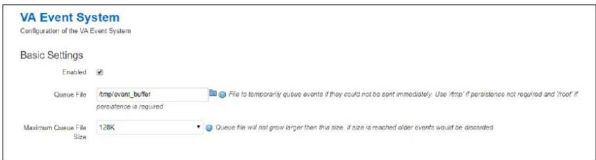
text_image
VA Event System Configuration of the VA Event System Basic Settings Enabled ✓ Queue File /tmp/ovont_buffer File to temporarily queue events if they could not be sent immediately. Use '/tmp' if persistence not required and 'roof' if persistence is required Maximum Queue File 128K Queue file will not grow larger then this size. If size is reached older events would be discarded SizeFigure 188: The VA event system basic settings configuration page
| Web Field/ UCI / Package Option | Description | |
| Web: EnabledUCI: va_eventd.main.enabledOpt: enabled | Enables VA Event System. | |
| 0 | Disabled. | |
| 1 | Enabled. | |
| Web: EnabledUCI: va_eventd.main.event_queue_fileOpt: event_queue_file | Defines the file to temporarily queue events when they cannot be sent immediately.Note: Use /tmp path if persistence is not required and /root if persistence is required. | |
| /tmp/event buffer | Disabled. | |
| 1 | Enabled. | |
| Web: EnabledUCI: va_eventd.main.event_queue_sizeOpt: event_queue_size | Defines the file size for the temporary queue. Older events are discarded once file size is reached. | |
| 128K | 128 Kilobytes | |
| Range | ||
Table 139: Information table for event system basic settings
40.3.2 Connection tester
A connection tester is used to verify the event destination before forwarding the event. Connection testers configure the uci conn_tester section rules. Multiple connection testers can be configured. There are two types of connection tester:
| Type | Description |
| IInk | Checks if the interface used to reach the target is up. |
| ping | Pings the target. And then assumes there is connectivity during a configurable amount of time. |
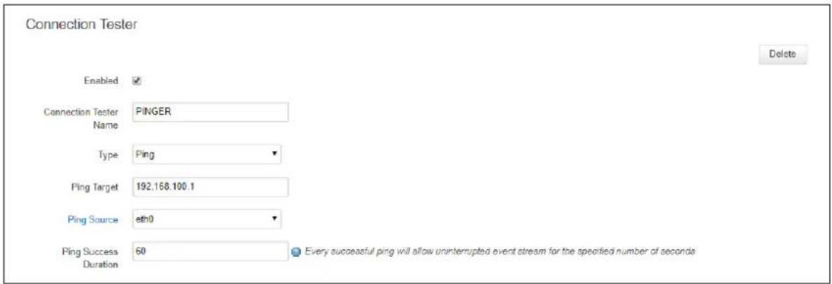
text_image
Connection Tester Enabled ✓ Connection Tester Name PINGER Type Ping Ping Target 192.168.100.1 Ping Source eth0 Ping Success 60 Every successful ping will allow uninterrupted event stream for the specified number of seconds Duration Every successful ping will allow uninterrupted event stream for the specified number of seconds DeleteFigure 189: The VA event system connection tester configuration page
| Web Field/ UCI / Package Option | Description | ||
| Web: EnabledUCI: va_eventd.@conn_tester[0].enabledOpt: enabled | Enables a connection tester. | ||
| 0 | Disabled. | ||
| 1 | Enabled. | ||
| Web: Connection Tester NameUCI: va_eventd.@conn_tester[0].nameOpt: name | Defines the connection tester name.This is used when configuring a connection tester for an event destination. | ||
| Web: TypeUCI: va_eventd.@conn_tester[0].typeOpt: type | Defines the connection tester type. | ||
| Web Value | Description | UCI | |
| Ping | Verifies target by ping | ping | |
| Link Verifies target by checking routed interface is up | link | ||
| Web: Ping TargetUCI:va_eventd.@conn_tester[0].ping_dest_addrOpt: ping_dest_addr | Defines the IP address for the target ping.Note: only displayed if connection tester type is set to ‘Ping’. | ||
| Range | |||
| Web: Ping SourceUCI:va_eventd.@conn_tester[0].ping_sourceOpt: ping_source | Defines an interface or IP address to source the pings from.Note: only displayed if connection tester type is set to ‘Ping’. | ||
| eth0 | Use eth0 IP for ping source | ||
| Range | |||
| Web: Ping Success DurationUCI:va_eventd.@conn_tester[0].ping_success_duration_secOpt: ping_success_duration_sec | Defines the duration, in seconds, for which a successful ping defines a connection tester as up.Note: only displayed if connection tester type is set to ‘Ping’. | ||
| 60 | |||
| Range | |||
| Web: Link InterfaceUCI:va_eventd.@conn_tester[0].link_ifaceOpt: link_iface | Defines the interface to monitor when the connection tester type is set to ‘link’. Configured interfaces are listed.Note: only displayed if connection tester type is set to ‘Link’. | ||
| Range | |||
Table 140: Information table for event system connection tester settings
40.3.3 Event Destination
An event destination is the target for the event. Event destinations configure the uci target section rules. Multiple event destinations can be configured. There are currently six configurable event destinations
| Target Type | Description |
| Syslog | Event sent to syslog server. |
| Email Event sent via email. | |
| SNMP | Event sent via SNMP trap. |
| Execute | Command executed when event occurs. |
| SMS Event sent via SMS. | |
| File | Event written to a file |
The available configuration options differ depending on the event destination type.
40.3.3.1 Syslog target
When a syslog target receives an event, it sends it to the configured syslog server.
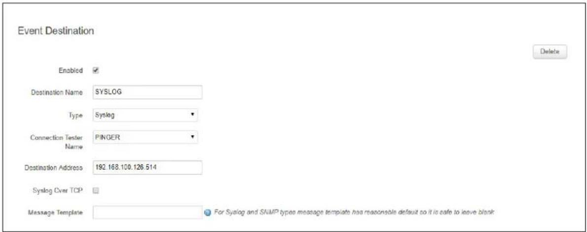
text_image
Event Destination Enabled ✓ Destination Name SYSLOG Type Syslog Connection Tester PINGER Name Destination Address 192.168.100.126.514 Syslog Over TCP Message Template For Syslog and SNMP types message templates has reasonable default so it is safe to leave blankFigure 190: The VA event system syslog event destination configuration page
| Web Field/ UCI / Package Option | Description | ||
| Web: EnabledUCI: va_eventd.@target[0].enabledOpt: enabled | Enables an event destination. This is used in the event filters section. | ||
| 0 | Disabled. | ||
| 1 | Enabled. | ||
| Web: Destination nameUCI: va_eventd.@target[0].nameOpt: name | Defines a name for the event destination. | ||
| Range | |||
| Web: TypeUCI: va_eventd.@target[0].typeOpt: type | Defines the event destination type. For syslog server choose Syslog. | ||
| Web Value | Description | UCI | |
| Syslog | syslog | ||
| SNMP Trap | snmptrap | ||
| Execute | exec | ||
| SMS | sms | ||
| n/a | File target | file | |
| Web: Connection Tester NameUCI: va_eventd.@target[0].conn_testerOpt: conn_tester | Defines the connection tester (if any) to use to verify the syslog target. | ||
| None | No connection tester. UCI option not present. | ||
| Range | |||
| Web: Destination AddressUCI: va_eventd.@target[0].target_addrOpt: target_addr | Defines the syslog target IP/FQDN and port. | ||
| Range | a.b.c.d:port or fqdn:port | ||
| Web: Syslog Over TCPUCI: va_eventd.@target[0].tcp_syslogOpt: tcp_syslog | Defines whether to use TCP for delivery of the syslog event. | ||
| 0 | Use UDP | ||
| 1 | Use TCP | ||
| Web: Message TemplateUCI: va_eventd.@target[0].templateOpt: template | Defines the message template to use for the event. In general, this should be left empty.See the section on message templates below. | ||
| Range | |||
40.3.3.2 Email target
When an email target receives an event, it sends it to the configured email address.
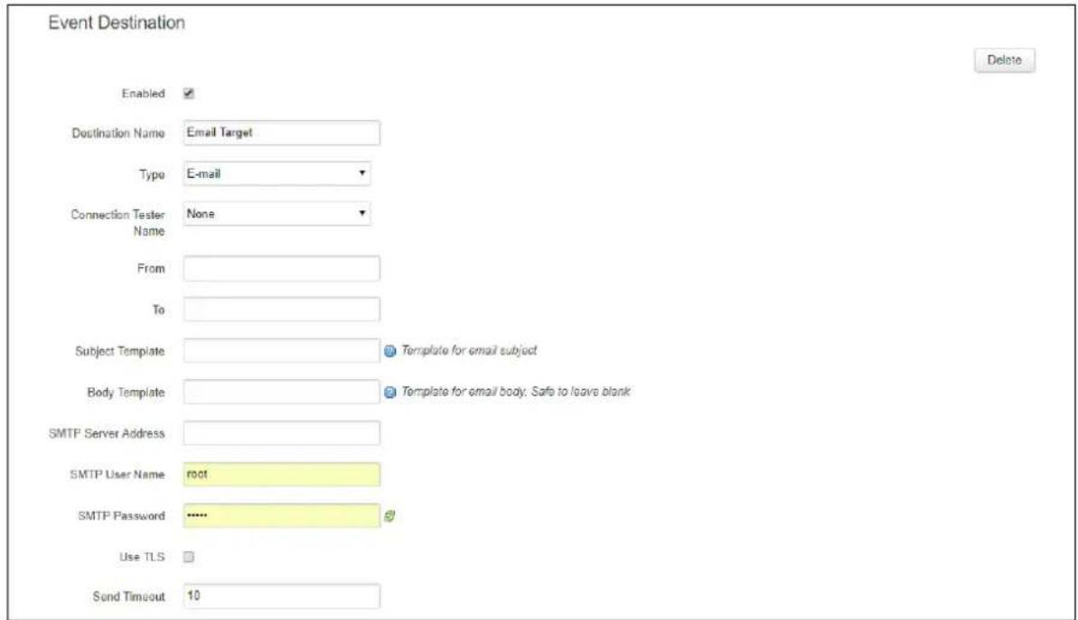
text_image
Event Destination Enabled ✓ Destination Name Email Target Type E-mail Connection Tester None Name From To Subject Template Template for email subject Body Template Template for email body. Safe to leave blank SMTP Server Address SMTP User Name root SMTP Password ...... Use TLS Send Timeout 10 DeleteFigure 191: The VA event system email event destination configuration page
| Web Field/ UCI / Package Option | Description | ||
| Web: EnabledUCI: va_eventd.@target[0].enabledOpt: enabled | Enables an event destination. | ||
| 0 | Disabled. | ||
| 1 | Enabled. | ||
| Web: Destination nameUCI: va_eventd.@target[0].nameOpt: name | Defines a name for the event destination. | ||
| Range | |||
| Web: TypeUCI: va_eventd.@target[0].typeOpt: type | Defines the event destination type. For an email server choose Email. | ||
| Web Value | Description | UCI | |
| Syslog | Syslog target | syslog | |
| SNMP Trap | SNMP target | snmptrap | |
| Email target | |||
| Execute | Execute target | exec | |
| SMS | SMS target | sms | |
| n/a | File target | file | |
| Web: Connection Tester NameUCI: va_eventd.@target[0].conn_testerOpt: conn_tester | Defines the connection tester (if any) to use to verify the email target. | ||
| None | No connection tester. UCI option not present. | ||
| Range | |||
| Web: FromUCI: va_eventd.@target[0].fromOpt: from | Defines the from address for the email. | ||
| Range | |||
| Web: ToUCI: va_eventd.@target[0].toOpt: to | Defines to address for the email. | ||
| Range | |||
| Web: Subject TemplateUCI:va_eventd.@target[0].subject_templateOpt: subject_template | Defines subject template for the email. In general, this should be left empty. Example:va_eventd.@target[0].subject_template %"{{severityName} %{eventName} ! ! ! "See the section on message templates below. | ||
| Range | |||
| Web: Body TemplateUCI:va_eventd.@target[0].body_templateOpt: body_template | Defines the email body template. In general, this should be left blank. Example:va_eventd.@target[0].body_template %"{{eventName} (%{class}.%{subclass}) happened!"See the section on message templates below. | ||
| Range | |||
| Web: SMTP Server AddressUCI: va_eventd.@target[0].smtp_addrOpt: smtp.addr | Defines the email server address and port. | ||
| Range | a.b.c.d:port or fqdn:port | ||
| Web: SMTP User NameUCI: va_eventd.@target[0].smtp_userOpt: smtp_user | Defines user name for SMTP authentication. | ||
| Range | name@site.com | ||
| Web: SMTP PasswordUCI:va_eventd.@target[0].smtp_passwordOpt: smtp_password | Defines the password for SMTP authentication. | ||
| Range | |||
| Web: Use TLSUCI: va_eventd.@target[0].use_tlsOpt: use_tls | Enables TLS (Transport Layer Security) support. | ||
| 0 | |||
| 1 | |||
| Web: Send TimeoutUCI: va_eventd.@target[0].timeout_secOpt: timeout_sec | Defines the email send timeout in seconds. | ||
| 10 | |||
| Range | |||
| Web: Use StartTLSUCI: va_eventd.@target[0].tls_starttlsOpt: tls_starttls | Enables StartTLS support for TLS.(Only displayed when TLS is enabled) | ||
| 0 | |||
| 1 | |||
| Web: Force SSLv3UCI: va_eventd.@target[0].tls_forcessl3Opt: tls_forcessl3 | Enables force SSLv3 for TLS.(Only displayed when TLS is enabled) | ||
| 0 | |||
| 1 | |||
Table 142: Information table for event system email event destination settings
40.3.3.3 SNMP target
When a SNMP target receives an event, it sends it in a trap to the configured SNMP manager.
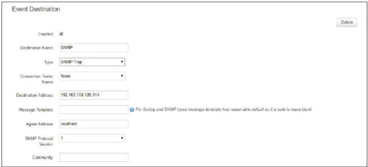
text_image
Event Destination Enabled ✓ Destination Name SNMP Type SNMP Trap Connection Tester None Name Destination Address 192.168.100.126.514 Message Template For Syslog and SNMP types message template has reasonable default so it is safe to leave blank Agent Address localhost SNMP Protocol Version 1 CommunityFigure 192: The VA event system SNMP event destination configuration page
| Web Field/ UCI / Package Option | Description | ||
| Web: EnabledUCI: va_eventd.@target[0].enabledOpt: enabled | Enables an event destination. | ||
| 0 | Disabled. | ||
| 1 | Enabled. | ||
| Web: Destination nameUCI: va_eventd.@target[0].nameOpt: name | Defines a name for the event destination. | ||
| Range | |||
| Web: TypeUCI: va_eventd.@target[0].typeOpt: type | Defines the event destination type. For SNMP server choose SNMP Trap. | ||
| Web Value | Description | UCI | |
| Syslog | Syslog target | syslog | |
| SNMP Trap | SNMP target | snmptrap | |
| Email target | |||
| Execute | Execute target | exec | |
| SMS | SMS target | sms | |
| n/a | File target | file | |
| Web: Connection Tester NameUCI: va_eventd.@target[0].conn_testerOpt: conn_tester | Defines the connection tester (if any) to use to verify the SNMP target. | ||
| None | No connection tester. UCI option not present. | ||
| Range | |||
| Web: Destination AddressUCI: va_eventd.@target[0].target_addrOpt: target_addr | Defines the SNMP target IP/FQDN and port. | ||
| Range | a.b.c.d:port or fqdn:port | ||
| Web: Message TemplateUCI: va_eventd.@target[0].templateOpt: template | Defines the message template to use for the event. In general, this should be left empty. Example:va_eventd.@target[0].template %" {eventName} % {eventSpecificTemplate}" | ||
| See the section on message templates below. | |||
| Range | |||
| Web: Agent AddressUCI: va_eventd.@target[0].agent_addrOpt: agent_addr | Defines the IP address to source the SNMP trap. (optional) | ||
| localhost | |||
| Range | |||
| Web: SNMP Protocol VersionUCI: va_eventd.@target[0].snmp_versionOpt: snmp_version | Defines the SNMP version. | ||
| 1 | SNMPv1 | ||
| 2c | SNMPv2c | ||
| 3 | SNMPv3 | ||
| Web: CommunityUCI: va_eventd.@target[0].communityOpt: community | Defines the community string for SNMPv1. | ||
| Range | |||
| Web: UsernameUCI: va_eventd.@target[0].snmp_unameOpt: snmp_uname | Defines the username for SNMPv3.(Only displayed when SNMP protocol version is SNMPv3) | ||
| Range | |||
| Web: Authentication ProtocolUCI:va_eventd.@target[0].snmp_auth_protoOpt: snmp_auth_proto | Defines the SNMPv3 authentication protocol(Only displayed when SNMP protocol version is SNMPv3) | ||
| MD5 | |||
| SHA | |||
| Web: Authentication PasswordUCI:va_eventd.@target[0].snmp_auth_passOpt: snmp_auth_pass | Defines the SNMPv3 authentication password(Only displayed when SNMPv3 authentication protocol is configured) | ||
| MD5 | |||
| SHA | |||
| Web: Privacy ProtocolUCI:va_eventd.@target[0].snmp_priv_protoOpt: snmp_priv_proto | Defines the SNMPv3 privacy protocol.(Only displayed when SNMP authentication protocol is configured) | ||
| DES | |||
| AES | |||
| Web: Privacy PasswordUCI:va_eventd.@target[0].snmp_priv_passOpt: snmp_priv_pass | Defines SNMPv3 privacy password.(Only displayed when SNMP privacy protocol is configured) | ||
| Range | |||
| Web: SNMPv3 ContextUCI: va_eventd.@target[0].snmp_contextOpt: snmp_context | Defines the SNMPv3 context.(Only displayed when SNMP authentication protocol is configured) | ||
| Range | |||
| Web: SNMPv3 Context Engine IDUCI:va_eventd.@target[0].snmp_context_eidOpt: snmp_context_eid | Defines the SNMPv3 context engine ID.(Only displayed when SNMP authentication protocol is configured) | ||
| Range | |||
| Web: SNMPv3 Security Engine IDUCI: va_eventd.@target[0].snmp_sec_eidOpt: snmp_sec_eid | Defines the SNMPv3 security engine ID.(Only displayed when SNMP authentication protocol is configured) | ||
| Range | |||
Table 143: Information table for event system SNMP event destination settings
40.3.3.4 Exec target
When an Execute target receives an event, it executes a shell command.

text_image
Event Destination Enabled ✓ Destination Name ExecTarget Type Execute Connection Tester None Name Command Template Template for the command to be executed DeleteFigure 193: The VA event system Exec event destination configuration page
| Web Field/ UCI / Package Option | Description | ||
| Web: EnabledUCI: va_eventd.@target[0].enabledOpt: enabled | Enables an event destination. | ||
| 0 | Disabled. | ||
| 1 | Enabled. | ||
| Web: Destination nameUCI: va_eventd.@target[0].nameOpt: name | Defines a name for the event destination. | ||
| Range | |||
| Web: TypeUCI: va_eventd.@target[0].typeOpt: type | Defines the event destination type. For shell command execution, choose Execute. | ||
| Web Value | Description | UCI | |
| Syslog | Syslog target | syslog | |
| SNMP Trap | SNMP target | snmptrap | |
| Email target | |||
| Execute | Execute target | exec | |
| SMS | SMS target | sms | |
| n/a | File target | file | |
| Web: Connection Tester NameUCI: va_eventd.@target[0].conn_testerOpt: conn_tester | Defines the connection tester (if any) to use to verify the execute target. | ||
| None | No connection tester. UCI option not present. | ||
| Range | |||
| Web: Command TemplateUCI: va_eventd.@target[0].cmd_templateOpt: cmd_template | Defines the command template to use for the event.Example to log a syslog message:va_eventd.@target[0].cmd_template="logger -t eventer ${eventName}"See the section on message templates below. | ||
| Range | |||
Table 144: Information table for event system Execute event destination settings
40.3.3.5 SMS target
When an SMS target receives an event, it sends an SMS message.
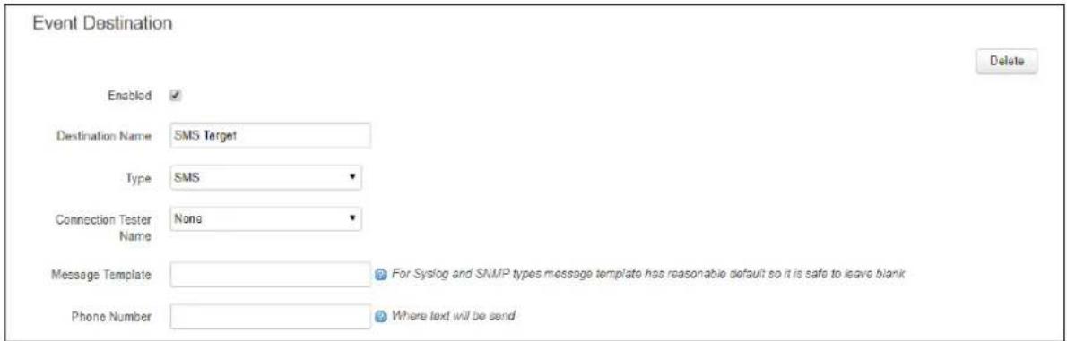
text_image
Event Destination Enabled ✓ Destination Name SMS Target Type SMS Connection Tester None Message Template For Syslog and SNMP types message template has reasonable default so it is safe to leave blank Phone Number Where text will be sendFigure 194: The VA event system SMS event destination configuration page
| Web Field/ UCI / Package Option | Description | ||
| Web: EnabledUCI: va_eventd.@target[0].enabledOpt: enabled | Enables an event destination. | ||
| 0 | Disabled. | ||
| 1 | Enabled. | ||
| Web: Destination nameUCI: va_eventd.@target[0].nameOpt: name | Defines a name for the event destination. | ||
| Range | |||
| Web: TypeUCI: va_eventd.@target[0].typeOpt: type | Defines the event destination type. For SMS destination choose SMS. | ||
| Web Value | Description | UCI | |
| Syslog | syslog | ||
| SNMP Trap | snmptrap | ||
| Execute | exec | ||
| SMS | sms | ||
| n/a | file | ||
| Web: Connection Tester NameUCI: va_eventd.@target[0].conn_testerOpt: conn_tester | Defines the connection tester (if any) to use to verify the SMS target. | ||
| None | No connection tester. UCI option not present. | ||
| Range | |||
| Web: Message TemplateUCI: va_eventd.@target[0].templateOpt: template | Defines the message template to use for the event. In general, this should be left empty. Example:va_eventd.@target[0].template %" {eventName}"See the section on message templates below. | ||
| Range | |||
| Web: Phone NumberUCI: va_eventd.@target[0].calleeOpt: callee | Defines the phone number for sending SMS to. | ||
| Range | |||
Table 145: Information table for event system SMS event destination settings
40.3.3.6 File target
When file target receives an event, it logs to a file.
There is currently no web support for a file target.
| Web Field/ UCI / Package Option | Description | ||
| Web: n/aUCI: va_eventd.@target[0].enabledOpt: enabled | Enables an event destination. | ||
| 0 | Disabled. | ||
| 1 | Enabled. | ||
| Web: n/aUCI: va_eventd.@target[0].nameOpt: name | Defines a name for the event destination. | ||
| Range | |||
| Web: n/aUCI: va_eventd.@target[0].typeOpt: type | Defines the event destination type. For file choose Syslog. | ||
| Web Value | Description | UCI | |
| Syslog | syslog | ||
| SNMP Trap | snmptrap | ||
| Execute | exec | ||
| SMS | sms | ||
| n/a | file | ||
| Web: n/aUCI: va_eventd.@target[0].file_nameOpt: file_name | Defines a file name for the event destination. (full path) | ||
| Range | |||
| Web: n/aUCI: va_eventd.@target[0].max_size_kbOpt: file_name | Defines a file size in kilobits. | ||
| 2048 | |||
| Range | |||
| Web: n/aUCI: va_eventd.@target[0].templateOpt: template | Defines the message template to use for the event. In general, this should be left empty.See the section on message templates below. | ||
| Range | |||
Table 146: Information table for event system file event destination settings
40.3.4 Event filters
Event filters are use to classify the events to be sent to the event destination. Multiple event filters can be defined. Event filters configure the uci forwarding section rules.
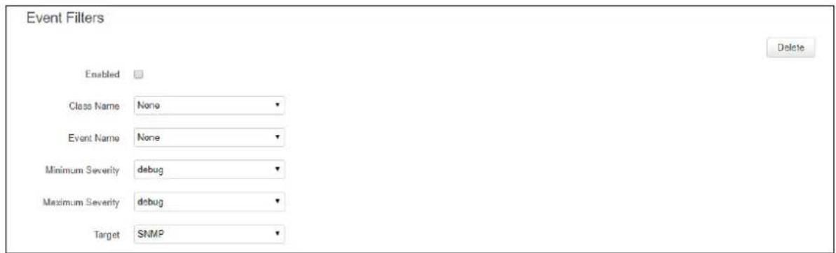
text_image
Event Fillers Enabled Class Name None Event Name None Minimum Severity debug Maximum Severity debug Target SNMP DeleteFigure 195: The VA event system event filters configuration page
| Web Field/ UCI / Package Option | Description | |
| Web: EnabledUCI: va_eventd.@forwarding[0].enabledOpt: enabled | Enables an event filter. | |
| 1 | Disabled. | |
| 0 | Enabled. | |
| Web: Class NameUCI:va_eventd.@forwarding[0].classNameOpt: className | Only match events with the given class name. Available class names are listed or can be viewed using the command vae_cli-d | |
| Web: Event NameUCI:va_eventd.@forwarding[0].eventNameOpt: eventName | Only match events with the given event name. Available event names are listed. The event name is optional and can be omitted. | |
| Web: Minimum SeverityUCI: va_eventd.@forwarding[0].severityOpt: severity | Defines the minimum event severity. The minimum severity event is DEBUG. Events generated within the minimum and maximum event severity will be matched.Minimum and maximum severity are specified in the one UCI option and entered using a dash (-) separator in the form minimum-maximum. Example:va_eventd.@forwarding[0].severity=debug-error | |
| debug | minimum severity | |
| info | ||
| notice | ||
| warning | ||
| error | ||
| critical | ||
| alert | ||
| emergency | maximum severity | |
| Web: Maximum SeverityUCI: va_eventd.@forwarding[0].severityOpt: severity | Defines the maximum event severity. The maximum event severity is EMERGENCY. Events generated within the minimum and maximum event severity will be matched.The UCI command for specifying minimum and maximum severity is the same and is entered with two parameters using a dash (-) separator minimum-maximum. Example:va_eventd.@forwarding[0].severity=debug-error | |
| debug | minimum severity | |
| info | ||
| notice | ||
| warning | ||
| error | ||
| critical | ||
| alert | ||
| emergency | maximum severity | |
| Web: TargetUCI: va_eventd.@forwarding[0].targetOpt: target | Defines the event destination to forward the event to. All configured event destinations will be displayed. | |
| Range | ||
Table 147: Information table for event system event filters settings
40.4 Configuring the event system using command line
The event system configuration files are stored at /etc/config/va_eventd
There are four config sections main, conn_tester, target and forwarding.
You can configure multiple conn_tester, target and forwarding sections.
By default, all conn_tester instances are named conn_tester, it is identified by @conn_tester then the conn_tester position in the package as a number. For example, for the first conn_tester in the package using UCI:
va_eventd.@conn_tester[0]=conn_tester
va_eventd.@conn_tester[0].enabled=1
Or using package options:
config conn_tester
option enabled '1'
By default, all target instances are named target. The target instance is identified by @target then the target position in the package as a number. For example, for the first target in the package using UCI:
va_eventd.@target[0]=target
va_eventd.@target[0].enabled=1
Or using package options:
config target
option enabled '1'
By default, all forwarding instances are named forwarding. The forwarding instance is identified by @forwarding then the forwarding position in the package as a number. For example, for the first forwarding rule in the package using UCI:
va_eventd.@lforwarding[0]=forwarding
va_eventd.@forwarding[0].enabled=1
Or using package options:
config forwarding
option enabled '1'
40.4.1 Event system using UCI
root@VA_router:~# uci show va_eventd
#Sample basic settings
va_eventd.main=va_eventd
va_eventd.main.event_queue_file=/tmp/event_buffer
va_eventd.main.event_queue_size=128K
#Sample SNMP
va_eventd.@conn_tester[0]=conn_tester
va_eventd.@conn_tester[0].type=ping
va_eventd.@conn_tester[0].ping_dest_addr=192.168.100.1
va_eventd.@conn_tester[0].ping_success_duration_sec=60
va_eventd.@conn_tester[0].name=SNMPTest
va_eventd.@conn_tester[0].ping_source=LAN1
va_eventd.@target[0]=target
va_eventd.@target[0].suppress_duplicate_forwardings=no
va_eventd.@target[0].type=snmp
va_eventd.@target[0].agent_addr=localhost
va_eventd.@target[0].name=SNMPTarget
va_eventd.@target[0].conn_tester=SNMPTest
va_eventd.@target[0].target_addr=192.168.100.126:68
va_eventd.@target[0].snmp_version=3
va_eventd.@target[0].snmp_uname=v3username
va_eventd.@target[0].snmp_auth_proto=MD5
va_eventd.@target[0].snmp_auth_pass=md5password
va_eventd.@target[0].snmp_priv_proto=AES
va_eventd.@target[0].snmp_priv_pass=aespassword
va_eventd.@target[0].snmp_context=v3context
va_eventd.@target[0].snmp_context_eid=v3contextID
va_eventd.@target[0].snmp_sec_eid=v3SecurityID
va_eventd.@forwarding[0]=forwarding
va_eventd.@forwarding[0].enabled=yes
va_eventd.@forwarding[0].className=mobile
va_eventd.@forwarding[0].target=SNMPTarget
va_eventd.@forwarding[0].eventName=LinkUp
va_eventd.@forwarding[0].severity=notice-notice
#Sample Syslog
va_eventd.@conn_tester[1]=conn_tester
va_eventd.@conn_tester[1].name=SyslogTest
va_eventd.@conn_tester[1].type=ping
va_eventd.@conn_tester[1].ping_dest_addr=192.168.100.2
va_eventd.@conn_tester[1].ping_source=LAN1
va_eventd.@conn_tester[1].ping_success_duration_sec=60
va_eventd.@target[1]=target
va_eventd.@target[1].name=SyslogTarget
va_eventd.@target[1].type=syslog
va_eventd.@target[1].conn_tester=SyslogTest
va_eventd.@target[1].target_addr=192.168.100.2:514
va_eventd.@target[1].tcp_syslog=0
va_eventd.@forwarding[1]=forwarding
va_eventd.@forwarding[1].enabled=yes
va_eventd.@forwarding[1].severity=debug-error
va_eventd.@forwarding[1].target=SyslogTarget
#Sample Email
va_eventd.@conn_tester[2]=conn_tester
va_eventd.@conn_tester[2].name=EmailTest
va_eventd.@conn_tester[2].type=link
va_eventd.@conn_tester[2].link_iface=PoAADSL
va_eventd.@target[2]=target
va_eventd.@target[2].timeout_sec=10
va_eventd.@target[2].name=EmailTarget
va_eventd.@target[2].type=email
va_eventd.@target[2].conn_tester=EmailTest
va_eventd.@target[2].from=from@example.com
va_eventd.@target[2].to=to@example.com
va_eventd.@target[2].subject_template={serial} %{severityName} %{eventName} !!!
va_eventd.@target[2].body_template={%/eventName} (%{class}.%{subclass})
happened!
va_eventd.@target[2].smtp_addr=192.168.100.3:25
va_eventd.@target[2].smtp_user=root
va_eventd.@target[2].smtp_password=admin
va_eventd.@target[2].use_tls=0
va_eventd.@target[2].tls_starttls=0
va_eventd.@target[2].tls_forcessl3=0
va_eventd.@forwarding[2]=forwarding
va_eventd.@forwarding[2].enabled=yes
va_eventd.@forwarding[2].className=power
va_eventd.@forwarding[2].eventName=IgnitionOff
va_eventd.@forwarding[2].severity=notice-notice
va_eventd.@forwarding[2].target=EmailTarget
#Sample SMS
va_eventd.@target[3]=target
va_eventd.@target[3].name=SMSTarget
va_eventd.@forwarding[3].target=SMSTarget
va_eventd.@target[3].type=sms
va_eventd.@target[3].template={serial} %{severityName} %{eventName}!!!
va_eventd.@target[3].callee=0123456789
va_eventd.@forwarding[3]=forwarding
va_eventd.@forwarding[3].enabled=yes
va_eventd.@forwarding[3].target=SMSTarget
va_eventd.@forwarding[3].className=auth
va_eventd.@forwarding[3].eventName=LoginSSH
va_eventd.@forwarding[3].severity=notice-notice
#Sample Execute
va_eventd.@target[4]=target
va_eventd.@target[4].name=ExecTarget
va_eventd.@target[4].type=exec
va_eventd.@target[4].cmd_template=logger -t eventer %{eventName}
va_eventd.@forwarding[4]=forwarding
va_eventd.@forwarding[4].enabled=yes
va_eventd.@forwarding[4].target=ExecTarget
va_eventd.@forwarding[4].className=ppp
va_eventd.@forwarding[4].severity=debug-error
#Sample File
va_eventd.@target[5]=target
va_eventd.@target[5].name=FileTarget
va_eventd.@target[5].type=file
va_eventd.@target[5].file_name=\tmp\eventfile
va_eventd.@target[5].max_size_kb=1028
va_eventd.@forwarding[5]=forwarding
va_eventd.@forwarding[5].enabled=yes
va_eventd.@forwarding[5].target=FileTarget
va_eventd.@forwarding[5].severity=debug-error
40.4.1.1 Event system using package options
root@VA_router:~# uci export va_eventd
package va_eventd
config va_eventd 'main'
option event_queue_file '/tmp/event_buffer'
option event_queue_size '128K'
<h1 id="sample-snmp">Sample SNMP</h1>
config conn_tester
option type 'ping'
option ping_dest_addr '192.168.100.1'
option ping_success_duration_sec '60'
option name 'SNMPTest'
option ping_source 'LAN1'
config target
option suppress_duplicate_forwardings 'no'
option type 'snmp'
option agent_addr 'localhost'
option name 'SNMPTarget'
option conn_tester 'SNMPTest'
option target_addr '192.168.100.126:68'
option snmp_version '3'
option snmp_uname 'v3username'
option snmp_auth_proto 'MD5'
option snmp_auth_pass 'md5password'
option snmp_priv_proto 'AES'
option snmp_priv_pass 'aespassword'
option snmp_context 'v3context'
option snmp_context_eid 'v3contextID'
option snmp_sec_eid 'v3SecurityID'
config forwarding
option enabled 'yes'
option className 'mobile'
option severity 'notice-notice'
option target 'SNMPTarget'
option eventname 'LinkUp'
<h1 id="sample-syslog">Sample Syslog</h1>
config conn_tester
option name 'SyslogTest'
option type 'ping'
option ping_dest_addr '192.168.100.2'
option ping_source 'LAN1'
option ping_success_duration_sec '60'
config target
option name 'SyslogTarget'
option type 'syslog'
option conn_tester 'SyslogTest'
option target_addr '192.168.100.2:514'
option tcp_syslog '0'
config forwarding
option enabled 'yes'
option severity 'debug-error'
option target 'SyslogTarget'
<h1 id="sample-email">Sample Email</h1>
config conn_tester
option name 'EmailTest'
option type 'link'
option link_iface 'PoAADSL'
config target
option timeout_sec '10'
option name 'EmailTarget'
option type 'email'
option conn_tester 'EmailTest'
option from 'from@example.com'
option to 'to@example.com'
option subject_template '%{serial} %{severityName} %{eventName}!!!'
option body_template '%{eventName} (%{class}.%{subclass})
happened!'
option smtp_addr '192.168.100.3:25'
option smtp_user 'root'
option smtp_password 'admin'
option use_tls 'no'
option tls_starttls 'no'
option tls_forcessl3 'no'
config forwarding
option enabled 'yes'
option target 'EmailTarget'
option className 'power'
option eventName 'IgnitionOff'
option severity 'notice-notice'
<h1 id="sample-sms">Sample SMS</h1>
config target
option name 'SMSTarget'
option type 'sms'
option template '%{serial} %{severityName} %{eventName}!!!!'
option callee '0123456789'
config forwarding
option enabled 'yes'
option target 'SMSTarget'
option className 'auth'
option eventName 'LoginSSH'
option severity 'notice-notice'
<h1 id="sample-execute">Sample Execute</h1>
config target
option name 'ExecTarget'
option type 'exec'
option cmd_template 'logger -t eventer %{eventName}'
config forwarding
option enabled 'yes'
option target 'ExecTarget'
option className 'ppp'
option severity 'debug-error'
<h1 id="sample-file">Sample File</h1>
config target
option name 'FileTarget'
option type 'file'
option file_name '\tmp\eventfile'
option max_size_kb '1028'
config forwarding
option enabled 'yes'
option target 'FileTarget'
option severity 'debug-error'
40.5 Event system diagnostics
40.5.1 Displaying VA events
To view a list of all available class names, events and severity levels, enter:
root@VA_router:~# vae_cli -d
The following is an example of the output from this command:
| Class | ID | Name | Severity | Specific Template
| internal | 1 | EventdConfigErr | error
| %{p1} %{p2}: %{p3} has bad value..
| internal | 2 | EventdConfigWarn | warning
| %{p1} %{p2}: %{p3} has bad value..
| internal | 3 | EventdConfigUnknown | informat | %{p1} %{p2}: field '%{p3}' is no..
| internal | 4 | EventdSystemErr | error
| %{p1} %{p2}: %{p3} %{p4} %{p5} ..
| internal | 5 | EventdSystemWarn | error
| %{p1} %{p2}: %{p3} %{p4} %{p5} ..
| internal | 6 | EventdUpAndRunning | informat |
| internal | 7 | EventdStopped | warning | %{p1}
| mobile | 1 | SIMin | notice | SIM card #%{p1}inserted
| mobile | 2 | SIMout | notice | SIM card #%{p1} removed
| mobile | 3 | LinkUp | notice | 3g link %{p1} up using sim
#%{p2.}
| mobile | 4 | LinkDown | notice | 3g link %{p1} down
| mobile | 5 | SMSByPassword | notice | Received SMS from %{p1} (by pass.).
| mobile | 6 | SMSByCaller | notice | Received SMS from %{p1}
(%{p2}):..
| mobile | 7 | SMSFromUnknown | warning | Received SMS from unknown sender..
| mobile | 8 | SMSSendSuccess | informat | SMS send success: %{p1}
| mobile | 9 | SMSSendError | warning | SMS send error: %{p1}
| mobile | 10 | SMSSent | notice | Sent SMS
to %{p1}: %{p2}
| ethernet | 1 | LinkUp | notice | Ethernet %{p1} up
| ethernet | 2 | LinkDown | notice | Ethernet %{p1} down
| auth | 2 | BadPasswordSSH | warning | SSH login attempt from %{p2}: ba..
| auth | 3 | BadUserConsole | warning | Console login attempt on %{p1}: ..
| auth | 4 | BadPasswordConsole | warning | Console login attempt on %{p2}: ..
| auth | 5 | BadUserTelnet | warning | Telnet login attempt: bad username
| auth | 6 | BadPasswordTelnet | warning | Telnet login attempt: bad passwo..
| auth | 7 | BadUserLuCI | warning | LuCI login attempt: bad username..
| auth | 8 | BadPasswordLuCI | warning | LuCI login attempt: bad password..
| auth | 9 | LoginSSH | notice | SSH login: user %{p2}
from %{p3}
| auth | 10 | LogoffSSH | notice | SSH logoff: user %{p1} due to "%."
| auth | 11 | LoginConsole | notice | Console login:
user %{p1} on %{p2}
| auth | 12 | LogoffConsole | notice | Console logoff on %{p1}
| auth | 13 | LoginTelnet | notice | Telnet login:
user %{p1}
| auth | 14 | LoginLuCI | notice | LuCI login: user %{p1}
| auth | 15 | ConsoleCommand | informat | %{p1}@%{p2} %{p3}
| auth | 16 | LuCIAction | informat
| %{p1}@%{p2} %{p3} %{p4} %{p5}
| ipsec | 6 | IPSecInitIKE | informat | IPSec IKE ${p1}
established
| ipsec | 7 | IPSecInitSA | informat | IPSec SA ${p1}
established
| ipsec | 8 | IPSecCloseIKE | informat | IPSec IKE ${p1} deleted
| ipsec | 9 | IPSecCloseSA | informat | IPSec SA ${p1} closed
| ipsec | 10 | IPSecDPDTimeOut | informat | IPSec IKE ${p1} DPD
timed out
| wifi | 1 | WiFiConnectedToAP | notice | WiFi p1 connected to AP{p2}
| wifi | 1 | WiFiConnectedToAP | notice | WiFi p1 connected to AP{p2}
| wifi | 2 | WiFiDisconnectedFromAP | notice | WiFi ${p1}
disconnected from AP
| wifi | 2 | WiFiDisconnectedFromAP | notice | WiFi ${p1}
disconnected from AP
| wifi | 3 | WiFiStationAttached | notice | WiFi
station ${p2} connected to ..
| wifi | 3 | WiFiStationAttached | notice | WiFi
station ${p2} connected to ..
| wifi | 4 | WiFiStationDetached | notice | WiFi
station ${p2} disconnected ..
| wifi | 4 | WiFiStationDetached | notice | WiFi
station ${p2} disconnected ..
| wifi | 5 | WiFiStationAttachFailed | notice | WiFi
station ${p2} failed to con..
| wifi | 5 | WiFiStationAttachFailed | notice | WiFi
station ${p2} failed to con..
| ppp | 1 | LinkUp | informat | PPP for interface ${p2} (protocol..
| ppp | 2 | LinkDown | informat | PPP for interface ${p2} (protocol..
| ppp | 3 | ConnEstablished | informat | PPP connection for interface ${p..}
| adsl | 1 | LinkUp | notice | ADSL trained.
Starting interface..
| adsl | 2 | LinkDown | notice | ADSL down.
Stopping interface ${..}
| adsl | 3 | Silent | debug | ADSL silent
| adsl | 4 | Training | debug | ADSL training
| adsl | 5 | TrainingSuccess | notice | ADSL training successful: data ..
| system | 1 | BootSuccess | informat | Success booting into ${p1}
| system | 2 | DigitalInputChange | notice | Digital
Input %{p1} changed valu..
| ntp | 1 | InitialSync | notice | Initial NTP sync:
time: %{p1}; o..
| ntp | 2 | Adjust | informat | NTP adjust by %{p1}
| ntp | 3 | QueryTimeout | warning | NTP query to %{p1} timed
out. Ne..
| ntp | 4 | QueryFailed | warning | NTP query failed: %{p1}
41 Configuring data usage monitor
41.1 Introduction
Virtual Access software provides support for monitoring of data usage on mobile interfaces and to disable if the monthly limit is exceeded. This allows an element of control over data usage for SIMs with a limited data plan.
DISCLAIMER: data usage statistics calculated by Virtual Access data usage feature are best estimates and may vary from the mobile carrier statistics that are used for billing. Virtual Access cannot be held liable for any fees charged by the carrier to the customer for their data usage. We recommend that the configured data usage is lower than the allowance and that traffic percentage alerts are used.
41.2 Configuration package used
| Package | Sections |
| procrustes | limit |
41.3 Configuring data usage using the web interface
Select Services -> Data Usage. The Data Usage page appears.
You can monitor interfaces as a collective group, so enter a name for the group and select Add. The examples below show a group name configured as 'wan'.
You can configure multiple groups.
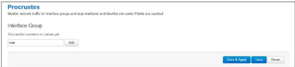
text_image
Procrustes Monitor network traffic for interface groups and stop interfaces and blacklist sim cards if limits are reached Interface Group This section contains no values yet wan Add Save & Apply Save ResetFigure 196: The data usage page
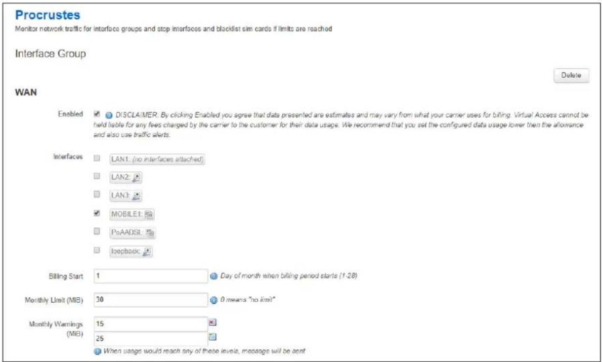
text_image
Procrustes Monitor network traffic for interface groups and stop interfaces and blacklist sim cards if limits are reached Interface Group Delete WAN Enabled ✓ DISCLAIMER: By clicking Enabled you agree that data presented are estimates and may vary from what your carrier uses for billing. Virtual Access cannot be held liable for any fees charged by the carrier to the customer for their data usage. We recommend that you set the configured data usage lower then the allowance and also use traffic alerts. Interfaces □ LAN1: (no interfaces attached) □ LAN2: □ LAN3: ✓ MOBILE1: □ PoAADSL: □ loopbook: Billing Start 1 Day of month when billing period starts (1-28) Monthly Limit (MiB) 30 0 means "no limit" Monthly Warnings 15 (MiB) 25 When usage would reach any of these levels, message will be sentFigure 197: The data usage configuration page
| Web Field/ UCI / Package Option | Description | |
| Web: EnabledUCI: procrustes.@limit[0].enabledOpt: enabled | Enable Data Usage monitor on this interface group. | |
| 0 | Disabled. | |
| 1 | Enabled. | |
| Web: Billing StartUCI:procrustes.@limit[0].billing_period_start_dayOpt: billing_period_start_day | Day of month on which the billing period starts. | |
| 1 | ||
| Range | 1 - 28 | |
| Web: InterfacesUCI: procrustes.@limit[0].interfacesOpt: interfaces | Monitor and apply limits to these interfaces as a group.Configure multiple interfaces via UCI using a space separator.Example:uci set procrustes.@limit[0].interfaces="lan wan" | |
| Web: Monthly Limit (MiB)UCI:procrustes..@limit[0].monthly_data_limitOpt: monthly_data_limit | Defines monthly data traffic limit in mebibytes (MiB). This is total RX and TX on the interface. | |
| 0 | Zero means no limit. | |
| Range | ||
| Web: Monthly Warnings (MiB)UCI:procrustes.@limit[0].monthly_warning_levelsOpt: monthly_warning_levels | Defines data usage limits for generating a log message and a VA event alert when used traffic reaches specified levels. Levels are specified in MiB.Set multiple limits via UCI using a space separator. Example:uci set procrustes.@limit[0].monthly_warning_levels="1525" | |
| 0 | Zero means no limit. | |
| Range | ||
Table 148: Information table for data usage commands
41.3.1 Configuring data usage using command line
Data Usage is configured under the procrustes package / etc/ config/ procrustes.
By default, all limit instances are named 'limit', it is identified by @limit followed by the limit position in the package as a number. For example, for the first limit in the package using UCI:
procrustes.@limit[0]=limit
procrustes.@limit[0].enabled=1
Or using package options:
config limit option enabled '1'
However, to better identify, it is recommended to give the limit instance a name. For example, create a limit instance named MOBILE1.
To define a named limit instance using UCI, enter:
procrustes.@limit[0]=wan
procrustes.wan.enabled=1
To define a named limit instance using package options, enter:
config limit 'wan'
option enabled '1'
The following examples show two limit groups wan and lan.
41.3.2 Procrustes using UCI
root@VA_router:~# uci show Procrustes
procrustes.lan=limit
procrustes.lan.enabled=1
procrustes.lan.interfaces=LAN1
procrustes.lan.billing_period_start_day=1
procrustes.lan.monthly_data_limit=30
procrustes.lan.monthly_warning_levels=15 25
procrustes.wan=limit
procrustes.wan.enabled=1
procrustes.wan.interfaces=MOBILE1
procrustes.wan.billing_period_start_day=1
procrustes.wan.monthly_data_limit=30
procrustes.wan.monthly_warning_levels=15 25
41.3.3 Procrustes using package options
root@VA_router:~# uci export procrustes
package procrustes
config limit 'lan'
option enabled '1'
option interfaces 'LAN1'
option billing_period_start_day '1'
option monthly_data_limit '30'
option monthly_warning_levels '15 25'
config limit 'wan'
option enabled '1'
option interfaces 'MOBILE1'
option billing_period_start_day '1'
option monthly_data_limit '30'
option monthly_warning_levels '15 25'
41.4 Data usage status
Select System -> Overview. The Status page appears.
To check current data usage, scroll to Network -> Data Usage (MiB) row.
Data usage is presented as progress bar.

bar
Data Usage (MiB) | Category | Value (MiB) | Percentage (%) | |---|---|---| | Ian: | 1358981 / 10485760 | 12 | | wan: | 433436 / 1048576 | 41 |Figure 198: The data usage status progress bar
41.5 Data usage diagnostics
41.5.1 Syslog events
The following events can be generated in logs by the data usage feature:
| Severity Tag Text | ||
| NOTICE | procrustes | : using counter 1404674 saved on 2017-09-30 16:26:57 |
| NOTICE | procrustes | : warning level 2097152 is reached |
| WARNING | procrustes | : hard limit 10485760 is reached |
| NOTICE procrustes | Data limit on SIM < iccid> exceeded and sim will be banned until the next month | |
| ERROR | procrustes | Could not get iccid for <ifname> |
| DEBUG | procrustes | Interface <ifname> is not up |
| WARNING | procrustes | network.<ifname>.ifname is not defined |
| NOTICE | procrustes | <ifname>: reached billing start. Resetting... |
| DEBUG | procrustes | Saving current limit values |
| NOTICE | procrustes | <if_group_name>: not enabled |
| WARNING | procrustes | <if_group_name>: defines no interfaces |
| DEBUG | procrustes | <if_group_name>: sim interface <ifname> |
| ERROR | procrustes | Daemonization failed |
| ERROR | procrustes | another procrustes is running. Exiting... |
| NOTICE | procrustes | No limits defined. Exiting... |
| ERROR | mobile | SIM < iccid> is blacklisted, not establishing connection |
41.5.2 Viewing data usage
The router has monitoring application named procrustatus.lua that can be used for viewing data usage.
This application displays data statistics used for different interface groups, percentage of time left to next billing period start and percentage of data left for use before the interface will be shut down.
To view the application, enter the command procrustes.lua
root@VA_router:~# procrustatus.lua
name current/ max time left data left
lan: 1404674/ 10485760 1.03% 86.60%
wan: 433436/ 1048576 1.03% 58.66%
Alternatively, total data usage can be checked via the command cat
/var/state/procrustes
root@VA_router:~# cat /var/state/procrustes
procrustes.lan.total_bytes=215780
procrustes.wan.total_bytes=433436
41.5.3 Additional debugging commands
Additional useful debug commands via the command line are described in the table below.
| Diagnostic Command Description | |
| logread | grep procrustes | Shows logs related to “procrustes” only |
| Is /root/procrustes/sim_blacklist/ | Shows list of blacklisted SIM iccids |
42 Configuring Terminal Server
42.1 Overview
Terminal Server is a background application whose main task is to forward data between TCP connections or UDP streams and asynchronous or synchronous serial ports.
The Terminal Server application serves up to four sessions simultaneously, one for each serial port, depending on the device. Each Terminal Server session has an IP endpoint and an associated specific serial port.
You can configure the IP endpoint of each Terminal Server session to be a:
- TCP server: each session is listening on a unique port.
- TCP client: Terminal Server makes a TCP connection to external TCP server.
- UDP endpoint: Terminal Server forwards data between a UDP stream and a serial port.
42.2 Configuration packages used
| Package | Sections |
| tservd | main |
| port |
42.3 Configuring Terminal Server using the web interface
In the top menu, select Services -> Terminal Server. The Terminal Server Configuration page appears. You must configure two main sections:
Main Settings to enable Terminal Server, syslog settings, and to enable log setting.
Port Settings section is for general port settings, serial settings such as port mode, port speed, parity stip bit and so on; and finally, network settings to configure the network side of the Terminal Server.
42.3.1 Configure main settings
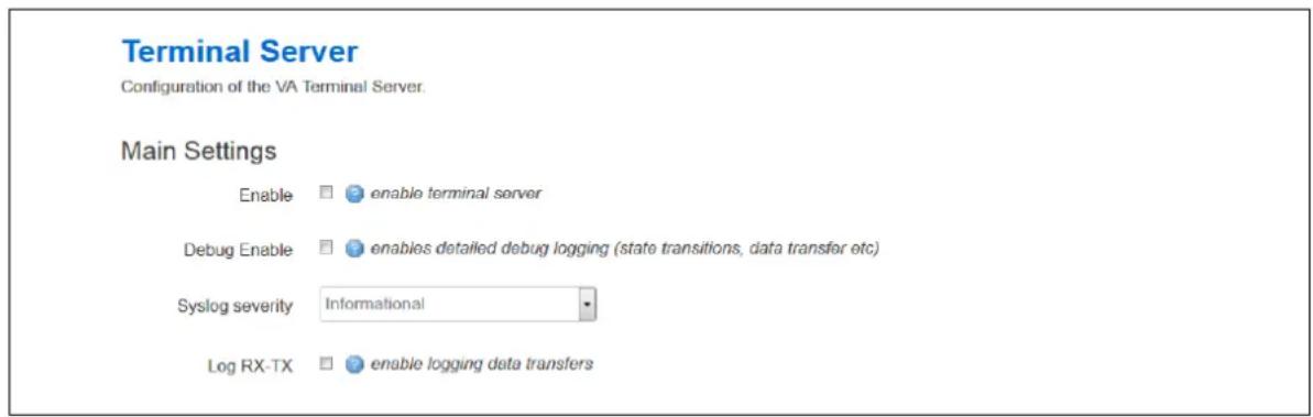
text_image
Terminal Server Configuration of the VA Terminal Server. Main Settings Enable enable terminal server Debug Enable enables detailed debug logging (state transitions, data transfer etc) Syslog severity Informational Log RX-TX enable logging data transfersFigure 199: The terminal server main settings page
| Web Field/ UCI / Package Option | Description | |
| Web: EnableUCI: tservd.main.enableOpt: enable | Enables Terminal Server on the router. | |
| 0 | Disabled. | |
| 1 | Enabled. | |
| Web: Debug EnableUCI: tservd.main.debug_ev_enableOpt: debug_ev_enable | Enables detailed debug logging. | |
| 0 | Disabled. | |
| 1 | Enabled. | |
| Web: Syslog severityUCI: tservd.main.log_severityOpt: log_severity | Determines the syslog level. Events up to this priority will be logged. | |
| 0 | Emergency | |
| 1 | Alert | |
| 2 | Critical | |
| 3 | Error | |
| 4 | Warning | |
| 5 | Notice | |
| 6 | Informational | |
| 7 | Debug | |
| Web: Log RX-TXUCI: tservd.main.debug_rx_tx_enableOpt: debug_rx_tx_enable | Enables logging data transfers. | |
| 0 | Disabled. | |
| 1 | Enabled. | |
Table 149: Information table for main settings
42.3.2 Configure port settings
The Port Settings section is divided into 3 sub-sections:
- General
- Serial
- Network
42.3.2.1 Port settings: general section
In this section you can configure general port settings. The settings are usually the same for the central and the remote site.
Port Settings
PORT1
General
Serial
Network
Enable

enable port
Network Forwarding Buffer Size


Forwarding buffer size (serial to network)
Network Forwarding Timeout (ms)


Forwarding timeout in milliseconds (serial to network)
Network Forwarding timer mode


Forwarding timer mode (serial to network)
Serial Forwarding Butter Size


forwarding buffer size (network to serial)
Serial Forwarding Timeout (ms)


forwarding timeout in milliseconds (network to serial)
Serial Forwarding timer mode


Forwarding timer mode (network to serial)
Proxy mode


[Non-Text]
Disable remote client's local echo (Telnet option)

Teinet COM port control (RFC2217)

Enable HDLC Pseudowire over UDP (RFC4618)

Serial receive debug log size


bytes (0=disable)
Serial transmit debug log size


yes (0-dilatino)
Figure 200: The general tab fields
| Web Field/ UCI / Package Option | Description | |
| Web: EnableUCI: tservd.@port[0].enableOpt: enable | Enables Terminal Server port. | |
| 0 | Disabled. | |
| 1 | Enabled. | |
| Web: Network Forwarding Buffer SizeUCI: tservd.@port[0].fwd_buffer_sizeOpt: fwd_buffer_size | Forwarding buffer size in bytes (serial to network). | |
| 256 | 256 bytes | |
| Range | 0-2048 | |
| Web: Network Forwarding Timeout(ms)UCI: tservd.@port[0].fwd_timeoutOpt: fwd_timeout | Forwarding timeout in milliseconds (serial to network). | |
| 30 | 30 ms | |
| Range | 0-10000 | |
| Web: Network Forwarding Timer ModeUCI: tservd.@port[0].fwd_timer_modeOpt: fwd_timer_mode | Forwarding timer mode (serial to network). | |
| Idle | Timer is re-started on each received data. | |
| Aging | Timer started on the first Rx. | |
| Web: Serial Forwarding Buffer SizeUCI: tservd.@port[0].sfwd_buffer_sizeOpt: sfwd_buffer_size | Forwarding buffer size in bytes (network to serial).Set to 0 to use maximum possible network Rx buffer size. | |
| 0 | 2048 bytes | |
| Range | 0-2048 | |
| Web: Serial Forwarding Timeout (ms)UCI: tservd.@port[0].sfwd_timeoutOpt: sfwd_timeout | Forwarding timeout in milliseconds (network to serial).Set to 0 to forward to serial immediately. | |
| 20 | 20 ms | |
| Range | 0-10000 | |
| Web: Serial Forwarding Timer ModeUCI: tservd.@port[0].sfwd_timer_modeOpt: sfwd_timer_mode | Forwarding timer mode (network to serial). | |
| Idle | Timer is re-started on each received data | |
| Aging | Timer started on the first Rx. | |
| Web: Proxy ModeUCI: tservd.@port[0].proxy_modeOpt: proxy_mode | Defines if special proxy mode is configured to allow 'hijacking' of the terminal server. It allows a connection to be made from a remote location and redirect terminal server data temporarily for troubleshooting.When enabled, a TCP proxy server is started which listens for an incoming TCP connection from a remote peer. Once an incoming new TCP connection on the proxy server TCP port is accepted:The existing terminal server TCP client connection is disconnected.The terminal server automatically reconnects the TCP client side but this time to the local loopback address 127.0.0.1 and to the local proxies TCP port number.Once the proxy server has both local and remote TCP sessions connected it simply forwards the data between the two connections, taking into account the flow control.When either side TCP socket closes, the main terminal server client re-connects to the normal IP destination and the server proxy returns to listening for another connection from the far end. | |
| 0 | Disabled. | |
| 1 | Enabled. | |
| Web: Disable Remote Client's Local Echo (Telnet option)UCI: tservd.@port[0].disable_echoOpt: disable_echo | Set to 1 to send IAC WILL ECHO Telnet option to remote client forcing it to disable local echo. For server mode only. | |
| 0 | Disabled. | |
| 1 | Enabled. | |
| Web: Telnet COM Port ControlUCI: tservd.@port[0].com_port_controlOpt: com_port_control | Set to 1 to enable support for Telnet COM port control (RFC2217). | |
| 0 | Disabled. | |
| 1 | Enabled. | |
| Web: Enable HDLC Pseudowire over UDP (RFC4618)UCI: tservd.@port[0].hdlc_pw_enabledOpt: hdlc_pw_enabled | Set to 1 to enable HDLC pseudowire over UDP support based on RFC4618. Requires Transport Mode (udpmode) to be enabled. | |
| 0 | Disabled. | |
| 1 | Enabled. | |
| Web: Serial Receive Debug Log SizeUCI: tservd.@port[0].serialRxLogSizeOpt: serialRxLogSize | Configures serial receive log size in bytes and enables receive data logging. | |
| 0 | Disabled. | |
| 1 | Enabled. | |
| Web: Serial Transmit Debug Log SizeUCI: tservd.@port[0].serialTxLogSizeOpt: serialTxLogSize | Configures serial transmit log size in bytes and enables transmit data logging. | |
| 0 | Disabled. | |
| 1 | Enabled. | |
Table 150: Information table for port settings section
42.3.2.2 Port settings: serial section
In this section you can configure serial interface settings, such as port mode, port speed, parity stip bit and so on.
Note:
- The displayed settings vary depending on options selected.
- DTR <--> DSR signalling is not available on GW2028 router models.
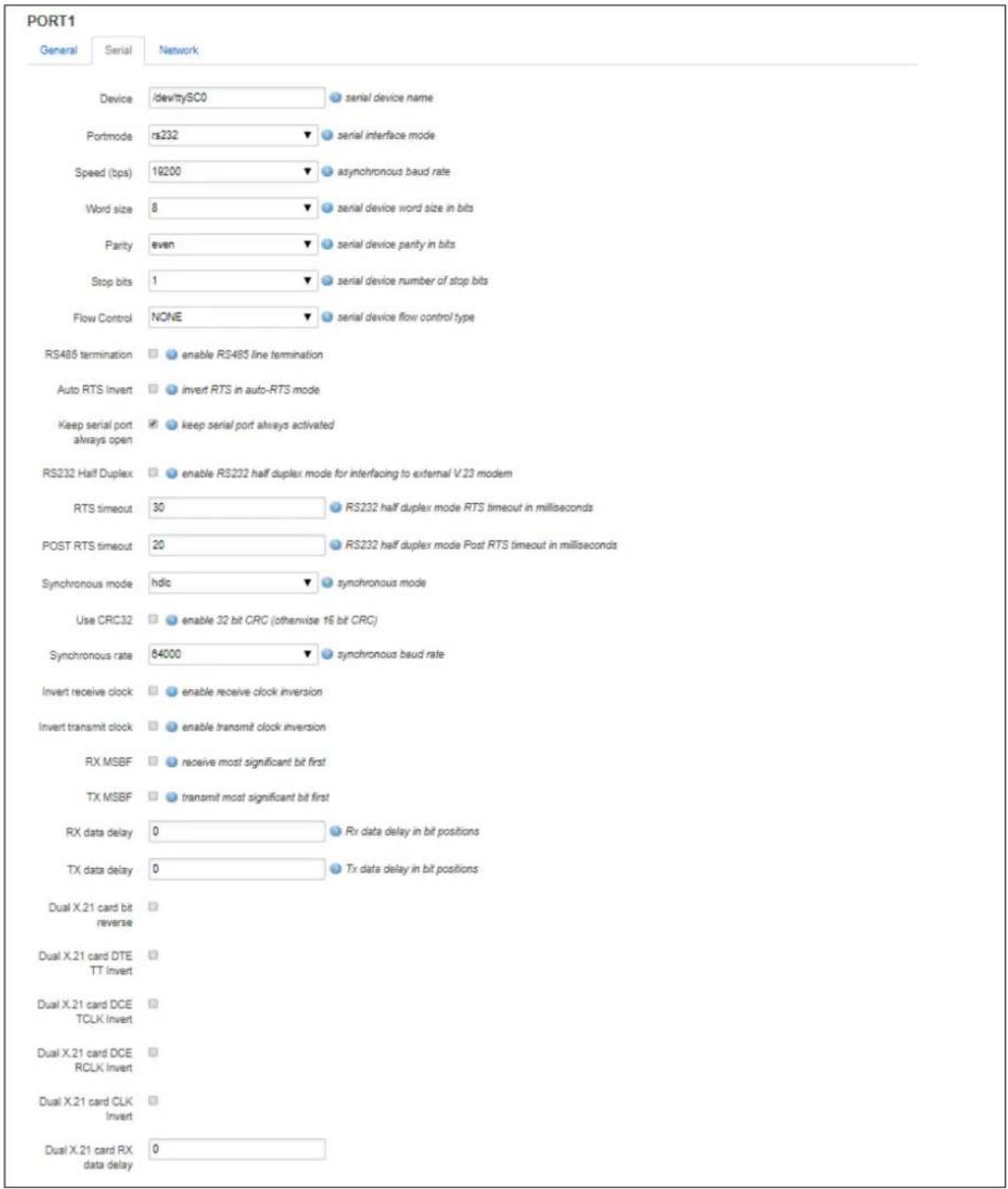
text_image
PORT1 General Serial Network Device /dev/tty/SC0 serial device name Portmode rs232 serial interface mode Speed (bps) 19200 asynchronous baud rate Word size 8 serial device word size in bits Parity even serial device parity in bits Stop bits 1 serial device number of stop bits Flow Control NONE serial device flow control type RS465 termination enable RS465 line termination Auto RTS Invert invert RTS in auto-RTS mode Keep serial port always open keep serial port always activated RS232 Half Duplex enable RS232 half duplex mode for interfacing to external V.23 modem RTS timeout 30 RS232 half duplex mode RTS timeout in milliseconds POST RTS timeout 20 RS232 half duplex mode Post RTS timeout in milliseconds Synchronous mode hdic synchronous mode Use CRC32 enable 32 bit CRC (otherwise 16 bit CRC) Synchronous rate 84000 synchronous baud rate Invert receive clock enable receive clock inversion Invert transmit clock enable transmit clock inversion RX MSBF receive most significant bit first TX MSBF transmit most significant bit first RX data delay 0 Rx data delay in bit positions TX data delay 0 Tx data delay in bit positions Dual X.21 card bit reverse Dual X.21 card DTE TT Invert Dual X.21 card DCE TCLK Invert Dual X.21 card DCE RCLK Invert Dual X.21 card CLK Invert Dual X.21 card RX data delay 0Figure 201: The serial section fields (port mode RS232)
| Web Field/ UCI/ Package Option | Description | |
| Web: DeviceUCI: tservd.@port[0].devNameOpt: devName | Serial device name. | |
| /dev/ttySC0 | serial port 1 | |
| /dev/ttySC1 | serial port 2 | |
| /dev/ttySC2 | serial port 3 | |
| /dev/ttySC3 | serial port 4 | |
| Web: Port modeUCI: tservd.@port[0].port_modeOpt: port_mode | Sets the serial interface mode. | |
| rs232 | RS232 mode. | |
| rs485hdx RS485 2 wire half duplex mode in which transmitter drives RTS. | ||
| rs485fdx | Rs485 4 wire full duplex mode. | |
| v23 | Uses V.23 leased line card driver. | |
| x21 | Uses USB serial card in sync mode. | |
| Web: Speed (bps)UCI: tservd.@port[0].speedOpt: speed | Serial device speed in baud (bps). | |
| 9600 | ||
| Range | 115200; 57600; 38400; 19200; 96004800; 2400; 1800; 1200; 600; 300; 200;150; 134; 110; 75; 50 | |
| Web: Word sizeUCI: tservd.@port[0].wsizeOpt: wsize | Serial device word size. | |
| 8 | ||
| Range | 5-8 | |
| Web: ParityUCI: tservd.@port[0].parityOpt: parity | Serial device parity. | |
| 0 | None | |
| 1 | Even | |
| 2 | Odd | |
| 3 | Space | |
| Web: Stop BitsUCI: tservd.@port[0].stopsOpt: stops | Serial device number of stop bits. | |
| 1 | ||
| Range | 1-2 | |
| Web: Flow ControlUCI: tservd.@port[0].fc_modeOpt: fc_mode | Serial flow control mode. | |
| 0 | None | |
| 1 | RTS/CTS | |
| 2 | XON/XOFF | |
| Web: RS485 TerminationUCI: tservd.@port[0].rs485_line_terminationOpt: rs485_line_termination | Enables or disable RS485 termination. Applies only if port mode is set to RS485. | |
| 0 | Disabled. | |
| 1 | Enabled. | |
| Web: Auto RTS InvertUCI: tservd.@port[0].rtsinvertOpt: rtsinvert | Invert RTS in auto-RTS mode, if port mode is set to RS485. | |
| 0 | Disabled. | |
| 1 | Enabled. | |
| Web: Keep Serial Port Always OpenUCI: tservd.@port[0].tty_always_openOpt: tty_always_open | Keep serial port always open. | |
| 0 | Disabled. | |
| 1 | Enabled. | |
| Web: RS232 Half DuplexUCI: tservd.@port[0].hd_modeOpt: hd_mode | Defines whether to enable special mode in the asynchronous serial driver for communication to an externally connected V.23 half-duplex modem. Note: this setting does not enable half-duplex mode in the serial hardware of the router. | |
| 0 | Full duplex mode. | |
| 1 | Half duplex mode. | |
| Web: RTS TimeoutUCI: tservd.@port[0].rts_timeoutOpt: rts_timeout | In RS232 half-duplex mode, time in milliseconds between raising RTS and enabling the transmitter. For use with an externally connected V.23 modem. | |
| 30 | 30ms | |
| Range | ||
| Web: POST RTS TimeoutUCI: tservd.@port[0].post_rts_timeoutOpt: post_rts_timeout | In RS232 half duplex mode, time in milliseconds between dropping RTS (transmission finished) and enabling the receiver. For use with externally connected V.23 modem. | |
| 20 | 20 ms | |
| Range | ||
| Web: Synchronous modeUCI: tservd.@port[0].sync modeOpt: sync mode | Defines synchronous frame mode. This setting is only displayed if an Atmel USB serial card is enabled. | |
| hdlc | HDLC frame mode. | |
| transp | Transparent mode. | |
| Web: Use CRC32UCI: tservd.@port[0].sync_crc32Opt: sync_crc32 | Defines whether to use CRC32 or CRC16 in HDLC mode. This setting is only displayed if an Atmel USB serial card is enabled. | |
| 0 | Use CRC16. | |
| 1 | Use CRC32. | |
| Web: DTR control modeUCI: tservd.@port[0].dtr_control_modeOpt: dtr_control_mode | Defines DTR line control modes. This setting is only displayed if an Atmel USB serial card is enabled and port mode is X21. | |
| auto DTR set | to on when port is open. Off when the port is closed. | |
| on | DTR always on. | |
| off | DTR always off. | |
| app | DTR controlled by the application. | |
| ontx In HDLC | mode DTR is on during frame transmission. | |
| Web: RTS control modeUCI: tservd.@port[0].rts_control_modeOpt: rts_control_mode | Defines RTS line control modes. Only displayed if Atmel USB serial card is enabled and port mode is X21. | |
| auto RTS set | to on when port is open. Off when the port is closed. | |
| on | RTS always on. | |
| off | RTS always off. | |
| app | RTS controlled by the application. | |
| ontx In HDLC | mode RTS is on during frame transmission. | |
| Web: Synchronous rateUCI: tservd.@port[0].sync_speedOpt: sync_speed | Defines the synchronous speed in bps. Set to 0 for external clock. If not set to 0, an internal clock is used. This setting is only displayed if an Atmel USB serial card is enabled. | |
| 64000 | 64 kbps | |
| Range 2048000; 1024000; 768000; 512000; 384000; 256000; 128000; 19200; 9600 | ||
| Web: Invert receive clockUCI: tservd.@port[0].sync_invert_rxclkOpt: sync_invert_rxclk | Defines receive clock inversion. Normal clock data is sampled on falling edge. Inverted clock data is sampled on rising edge. This setting is only displayed if an Atmel USB serial card is enabled. | |
| 0 | Normal. | |
| 1 | Invert. | |
| Web: Invert transmit clockUCI: tservd.@port[0].sync_invert_txclkOpt: sync_invert_txclk | Defines transmit clock inversion. Normal clock data transmitted on falling edge. Inverted clock data transmitted on rising edge. Only displayed if Atmel USB serial card is enabled. | |
| 0 | Normal. | |
| 1 | Invert. | |
| Web: RX MSBFUCI: tservd.@port[0].sync_rx_msbfOpt: sync_rx_msbf | Defines whether most significant bit is received first. This setting is only displayed if an Atmel USB serial card is enabled. | |
| 0 | Receive least significant bit first. | |
| 1 | Receive most significant bit first. | |
| Web: TX MSBFUCI: tservd.@port[0].sync_tx_msbfOpt: sync_tx_msbf | Defines whether most significant bit is transmitted first. This setting is only displayed if an Atmel USB serial card is enabled. | |
| 0 | Transmit least significant bit first. | |
| 1 | Transmit most significant bit first. | |
| Web: RX data delayUCI: tservd.@port[0].sync_rxdata_dlyOpt: sync_rxdata_dly | Defines the number of bit positions to delay sampling data from the detecting clock edge. This setting is only displayed if an Atmel USB serial card is enabled. | |
| 0 | ||
| Range | ||
| Web: TX data delayUCI: tservd.@port[0].sync_txdata_dlyOpt: sync_txdata_dly | Defines the number of bit positions to delay output of data from the detecting clock edge. This setting is only displayed if an Atmel USB serial card is enabled. | |
| 0 | ||
| Range | ||
| Web: Dual X.21 card bit reverseUCI: tservd.@port[0].bit_reverseOpt: bit_reverse | Enables bit reversal of all bits in 8 byte word during transmission. | |
| 0 | Normal. | |
| 1 | Reverse. | |
| Web: Dual X.21 card DTE TT InvertUCI: tservd.@port[0].dte_tt_invOpt: dte_tt_inv | Enables X.21 TT clock signal inversion. | |
| 0 | Normal. | |
| 1 | Invert. | |
| Web: Dual X.21 card DCE TCLK InvertUCI: tservd.@port[0].dce_tclk_invOpt: dce_tclk_inv | Enables X.21 DCE TCLK signal inversion. | |
| 0 | Normal. | |
| 1 | Invert. | |
| Web: Dual X.21 card DCE RCLK InvertUCI: tservd.@port[0].dce_rclk_invOpt: dce_rclk_inv | Enables X.21 DCE RCLK signal inversion. | |
| 0 | Normal. | |
| 1 | Invert. | |
| Web: Dual X.21 card CLK InvertUCI: tservd.@port[0].x21_clk_invertOpt: x21_clk_invert | Enables X.21 DCE CLK signal inversion. | |
| 0 | Normal. | |
| 1 | Invert. | |
| Web: Dual X.21 card RX data delayUCI: tservd.@port[0] x21_data_delayOpt: x21_data_delay | Sets X.21 card RX data delay in number of bit positions. | |
| 0 | ||
| Range | 0 - 7 | |
| Web: n/aUCI: tservd.@port[0].sync_tx_idleOpt: sync_tx_idle | Defines the value of idle character (decimal) to transmit in case of transmit underrun. In HDLC mode, this configures inter-frame fill. | |
| 0 | Tranmit 0 (in HDLC mode) | |
| 126 | Transmit flags (in HDLC mode) | |
| 255 | Tranmit 1 (in HDLC mode) | |
| Range | 0 - 255 | |
| Web: n/aUCI: tservd.@port[0].v23_inband_carrier_signallingOpt: v23_inband_carrier_signalling | Enables signalling of carrier by sending special characters. | |
| 0 | Disabled. | |
| 1 | Enabled. | |
| Web: n/aUCI: tservd.@port[0].v23_inband_carrier_on_charOpt: v23_inband_carrier_on_char | Defines the character decimal to signal remote carrier on. | |
| 255 | ||
| Range | 0 - 255 | |
| Web: n/aUCI: tservd.@port[0].v23_tx_gainOpt: v23_tx_gain | Defines the transmit gain for v23 mode. | |
| 2 | Transmit samples multiplied by 2 | |
| Range | ||
| Web: n/aUCI: tservd.@port[0].v23_rx_lossOpt: v23_rx_loss | Defines the receive loss for v23 mode. | |
| 1 | Receive samples divided by 1. | |
| Range | ||
| Web: n/aUCI: tservd.@port[0].v23_rts_to_cts_delayOpt: v23_rts_to_cts_delay | Defines the v23 modem RTS to CTS delay in milliseconds. | |
| 20 | ||
| Range | ||
| Web: n/aUCI: tservd.@port[0].v23_is_four_wireOpt: v23_is_four_wire | Defines the V23 modem LIM operation. | |
| 0 | 2-wire | |
| 1 | 4-wire | |
| Web: n/aUCI: tservd.@port[0].v23_tx_timeoutOpt: v23_tx_timeout | Defines the V23 modem receive echo suppression timeout in milliseconds. | |
| 20 | ||
| Range | ||
| Web: n/aUCI: tservd.@port[0].v23_tx_rampdownOpt: v23_tx_rampdown | Defines the time in milliseconds it takes the V23 transmitter to rampdown carrier from peak to zero. | |
| 30 | ||
| Range | ||
| Web: n/aUCI: tservd.@port[0].v23_tx_maxfillOpt: v23_tx_maxfill | Defines the maximum transmit queue fill level in bytes. | |
| 127 | ||
| Range | 0 - 255 | |
Table 151: Information table for port settings serial section
42.3.2.3 Port settings: network section
In this section you can configure the network side of the Terminal Server.
Note: the displayed settings vary depending on options selected.
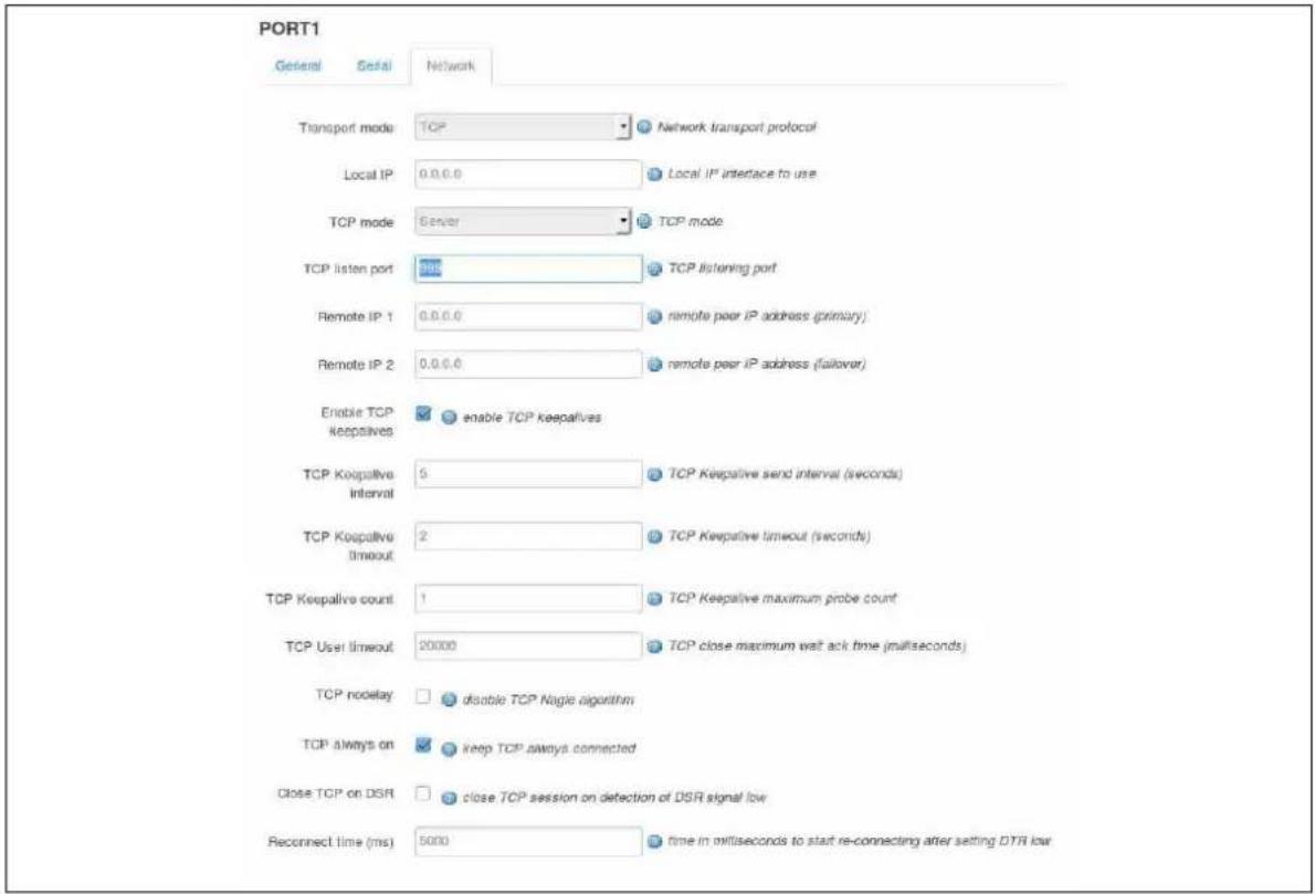
text_image
PORT1 General Serial Network Transport mode: TCP Network transport protocol Local IP 0.0.0.0 Local IP interface to use TCP mode Server TCP mode TCP listen port 385 TCP listening port Remote IP 1 0.0.0.0 remote peer IP address (primary) Remote IP 2 0.0.0.0 remote peer IP address (allover) Enable TCP keepalive enable TCP keepalive TCP Keepalive interval 5 TCP Keepalive send interval (seconds) TCP Keepalive timeout 2 TCP Keepalive timeout (seconds) TCP Keepalive count 1 TCP Keepalive maximum probe count TCP User timeout 20000 TCP close maximum wait ack time (milliseconds) TCP nodule disable TCP Nagle algorithm TCP always on keep TCP always connected Close TCP on DSR close TCP session on detection of DSR signal low Reconnect time (ms) 5000 time in milliseconds to start re-connecting after setting DTR lowFigure 202: The port settings network fields (TCP server mode)
| Web Field/ UCI / Package Option | Description | |
| Web: Transport ModeUCI: tservd.@port[0].udpModeOpt: udpMode | Selects the transport mode. | |
| 0 | TCP | |
| 1 | UDP | |
| Web: Local IPUCI: tservd.@port[0].local_ipOpt: local_ip | Local IP address to listen on. | |
| 0.0.0.0 | Listen on any interface. | |
| Range | IPv4 address. | |
| Web: TCP ModeUCI: tservd.@port[0].server_modeOpt: server_mode | Select between server and client modes of TCP. Only displayed if Transport Mode is TCP. | |
| 0 | Client Mode. | |
| 1 | Server Mode. | |
| Web: TCP Listen PortUCI: tservd.@port[0].listen_portOpt: listen_port | TCP listen port for server mode. Only displayed if Transport Mode is TCP and server mode is enabled. | |
| 999 | ||
| Range | 1 - 65535 | |
| Web: Remote TCP Port 1UCI: tservd.@port[0].ip_port1Opt: ip_port1 | Destination peer port IP 1 number. Only displayed if client mode is enabled. | |
| 951 | ||
| Range | 1 - 65535 | |
| Web: Remote TCP Port 2UCI: tservd.@port[0].ip_port2Opt: ip_port2 | Destination peer port IP 2 number for failover. Only displayed if client mode is enabled. | |
| 951 | ||
| Range | 1 - 65535 | |
| Web: Remote IP 1UCI: tservd.@port[0].remote_ip1Opt: remote_ip1 | Destination peer IP 1 address. | |
| 0.0.0.0 | ||
| Range | IPv4 address. | |
| Web: Remote IP 2UCI: tservd.@port[0].remote_ip2Opt: remote_ip2 | Destination peer IP 2 address for failover. | |
| 0.0.0.0 | ||
| Range | IPv4 address. | |
| Web: Enable TCP KeepalivesUCI:tservd.@port[0].tcp_keepalives_enabledOpt: tcp_keepalives_enabled | Enable or disables TCP keepalives. Only displayed if Transport Mode is TCP. | |
| 0 | Disabled. | |
| 1 | Enabled. | |
| Web: TCP Keepalive IntervalUCI:tservd.@port[0].tcp_keepalive_intervalOpt: tcp_keepalive_interval | Interval in seconds between TCP keepalive probes. Only displayed if Transport Mode is TCP. | |
| 5 | 5 seconds. | |
| Range | 0-65535 | |
| Web: TCP Keepalive TimeoutUCI:tservd.@port[0].tcp_keepalive_timeoutOpt: tcp_keepalive_timeout | Time in seconds to wait for response to a TCP keepalive probe. Only displayed if Transport Mode is TCP. | |
| 2 | 2 seconds. | |
| Range | 0-65535 | |
| Web: TCP Keepalive CountUCI:tservd.@port[0].tcp_keepalive_countOpt: tcp_keepalive_count | Number of TCP keepalive probes to send before connection is closed. Only displayed if Transport Mode is TCP. | |
| 1 | ||
| Range | 0-65535 | |
| Web: TCP User TimeoutUCI:tservd.@port[0].tcp_user_timeoutOpt: tcp_user_timeout | Maximum time in milliseconds for TCP to wait for transmitted data to be 'acked' before closing connection in established state. Set to 0 to use kernel defaults. Only displayed if Transport Mode is TCP. | |
| 20000 | 20 seconds. | |
| Range | 0-65535 | |
| Web: TCP NodelayUCI: tservd.@port[0].tcp_nodelayOpt: tcp_nodelay | Sets TCP to delay behaviour. Only displayed if Transport Mode is TCP. | |
| 0 | Normal operation. | |
| 1 Disable TCP | Nagle algorithm. Only displayed if Transport Mode is TCP. | |
| Web: TCP Always onUCI: tservd.@port[0].tcp_always_onOpt: tcp_always_on | Keep TCP session always connected. Only displayed if Transport Mode is TCP and client mode is enabled. | |
| 0 Disabled. | TCP connection / UDP session is initiated on detecting high state on the DSR interface signal. | |
| 1 Enabled. | it disconnects in the established state the TCP connection / UDP session is re-initiated. | |
| Web: Close TCP on DSRUCI:tservd.@port[0].close_tcp_on_dsrOpt: close_tcp_on_dsr | Close TCP session on detection of DSR signal low. Only displayed if Transport Mode is TCP and client mode is enabled. | |
| 0 Disabled. | Detecting DSR down does not affect the TCP connection. | |
| 1 Enabled. | Detecting DSR down closes the established TCP connection. | |
| Web: Reconnect Time (ms)UCI: tservd.@port[0].disc_time_msOpt: disc_time_ms | Time in milliseconds to start reconnecting after setting DTR low. | |
| 5000 | 5 seconds. | |
| Range | 0 - 10000 | |
| Web: UDP Keepalive IntervalUCI: tservd.@port[0].udpKalIntervalMsOpt: udpKalIntervalMs | Defines time in milliseconds to send UDP keepalives (empty UDP packets) when no data to send. Only displayed if transport mode is UDP. | |
| 0 | Disabled. | |
| Range | 0-65535 | |
| Web: UDP Keepalive CountUCI: tservd.@port[0].udpKaCountOpt: udpKaCount | Defines the maximum number of remote UDP keepalives not received before UDP stream is considered broken. Only displayed if transport mode is UDP. | |
| 3 | ||
| Range | 0-65535 | |
| Web: local UDP PortUCI: tservd.@port[0].udpLocalPortOpt: udpLocalPort | Local UDP port used by terminal server. Only displayed if transport mode is UDP. | |
| 0 | ||
| Range | 0-65535 | |
| Web: remote UDP PortUCI: tservd.@port[0].udpRemotePortOpt: udpRemotePort | Remote UDP port used by terminal server. Only displayed if transport mode is UDP. | |
| 0 | ||
| Range | 0-65535 | |
Table 152: Information table for port settings network section
42.4 Terminal Server using UCI
root@VA_router:~# uci show tservd
tservd.main=tservd
tservd.main.log_severity=0
tservd.main.debug_rx_tx_enable=1
tservd.main.debug_ev_enable=1
tservd.@port[0]=port
tservd.@port[0].devName=/dev/ttySCO
tservd.@port[0].remote_ip1=0.0.0.0
tservd.@port[0].remote_ip2=0.0.0.0
42.5 Terminal Server using package options
root@VA_router:~# uci export tservd
package tservd
config tservd 'main'
option log_severity '0'
option debug_rx_tx_enable '1'
option debug_ev_enable '1'
config port
option devName '/dev/ttySC0'
option remote_ip1 '0.0.0.0'
option remote_ip2 '0.0.0.0'
42.6 Terminal server DSR signal management based on network configuration
On the IP network side, the terminal server can operate in one of three modes:
- TCP Client
- TCP Server
• UDP
Based on the chosen network configuration the DSR behaviour may vary.
42.6.1 DSR signal behaviour in TCP client mode
42.6.1.1 TCP connection management
Initial TCP connection initiation or next TCP connection initiation after disconnection is affected by configuration options tcp_always_on and close_tcp_on_dsr.
When option tcp_always_on is enabled terminal server keeps the TCP session always connected. If it disconnects in the established state, the TCP session is reinitiated.
If tcp_always_on is disabled TCP connection is initiated on detection of a high state on the DSP interface signal.
When option close_tcp_on_dsr is enabled terminal server detecting DSR down signal and closes the established TCP connection.
If option close_tcp_on_dsr is disabled then detecting DSR down does not affect the TCP connection.
42.6.1.2 TCP connection initiation at startup
If you have set option tcp_always_on1, or DSR state is UP, the TCP connection setup is initiated immediately.
If you have set option tcp_always_on0, and DSR is DOWN, the terminal server waits for a DSR UP signal. When DSR UP is detected, the TCP connection is initiated.
42.6.1.3 TCP connection clearing
The TCP connection is cleared either by the network or by the terminal server application itself.
The TCP connection is cleared by the terminal server when it detects DSR interface signal DOWN and option close_tcp_on dsr is 1.
42.6.1.4 TCP connection reinitiation
After TCP connection clearing, the terminal server takes action to re-setup the TCP connection after a hand off timeout.
If you have set option tcp_always_on1, or DSR state is UP, the TCP connection setup is initiated.
If you have set option tcp_always_on0, and DSR is DOWN, the terminal server waits for a DSR UP signal and then initiates a new TCP connection.
42.6.2 DSR signal behaviour in TCP server mode
42.6.2.1 TCP connection initiation at startup
After a short startup delay, the terminal server starts listening for an incoming TCP connection from the remote peer.
42.6.2.2 TCP connection clearing
When in a TCP connection state, the TCP connection is cleared only by the network. Serial interface signals such as DSR do not cause TCP disconnection.
42.6.2.3 TCP connection re-initiation
When a TCP session goes down in the connected state, the terminal server immediately restarts listening for a new TCP connection from a remote peer.
42.6.3 DSR signal behaviour in UDP mode
42.6.3.1 UDP session setup at startup
If you have set option tcp_always_on1, or DSR state is UP, the UDP session is setup immediately on startup.
If you have set option tcp_always_on0, and DSR is DOWN, the terminal server waits for a DSR UP signal. When DSR UP is detected, the UDP session is setup.
42.6.3.2 UDP session clearing
A UDP session is normally never cleared, but if it is closed by the network sub-system, it gets re-setup after a hand off timeout.
A DSR signal DOWN event does not clear UDP session in the connected state.
42.6.3.3 UDP session reset
After UDP session clearing the terminal server takes action to reset up a UDP session after a hand off timeout.
If you have set option tcp_always_on1, or DSR state is UP, the UDP session is setup.
If you have set option tcp_always_on0, and DSR is DOWN, the terminal server waits for a DSR UP signal and then it resets up the UDP session.
42.7 Terminal Server diagnostics
The tservd process has to be running otherwise diagnostics options for terminal server will not be available.
42.7.1 Checking Terminal Server process
To check if Terminal Server is running, enter:
root@VA_router:~# ps | grep tservd
1264 root 1032 S tservd
1769 root 1496 S grep tservd
If Terminal Server is running it will be shown with its process ID.
42.7.2 Terminal Server statistics
To see Terminal Server statistics, enter:
root@VA_router:~# tserv show stats
TERMINAL 1, Dev: /dev/ttySCO
State: LISTENING
Serial Bytes Rx (0) Tx (0) TxErrs (0)
TCP Packets Rx (0) Tx (0) TxErrs (0) TxBlocked (0)
TCP Bytes Rx (0) Tx (0)
UDP Datagrams Rx (0) Tx (0) TxErrs (0)
UDP Bytes Rx (0) Tx (0)
DSR Up (0) Down (0)
42.7.3 Terminal Server debug statistics
To see debug statistics about Terminal Server, enter:
root@VA_router:~# tserv show debug all
TERMINAL 1, Dev: /dev/ttySCO
State: LISTENING
netRxBuf length=0 offset=0 hdrsz=0
ttyRxBuf length=0 offset=16 hdrsz=16
line_status_mask = 0x0 line_status = 0x0
RFC2217 negotiated=0
Tcp tx last error: 0
42.7.4 Terminal Server serial signals debugging
To see Terminal Server serial signals statistics, enter:
root@VA_router:~# tserv show serial
TERMINAL-1, Dev: /dev/ttySC1
DSR=0 DTR=1 RTS=1 CTS=0 CAR=0 CD=0 RNG=0 LE=0 RI=0 ST=0 SR=0
TERMINAL-2, Dev: /dev/ttySC0
DSR=0 DTR=1 RTS=1 CTS=0 CAR=0 CD=0 RNG=0 LE=0 RI=0 ST=0 SR=0
42.7.5 Terminal Server advanced debugging
To see Terminal Server advanced debug commands for the terminal server, enter:
root@VA_router:~# tserv
=== Termserv diagnostics. Command syntax: ===
tserv show stats - show statistics
tserv clear stats - clear statistics
tserv show serial - show serial interface status
tserv send serial0 <data>- send data to serial port 0
tserv start capture N, N=port number (0 to 3) - start capturing rx serial data
tserv print capture N, N=port number (0 to 3) - print captured rx serial data
tserv show serial txlog-hex <Port> [length], Port=port cfg index (0 to 3), length=length to show
tserv show serial rxlog-hex <Port> [length], Port=port cfg index (0 to 3), length=length to show
tserv show serial txlog-asc <Port> [length], Port=port cfg index (0 to 3), length=length to show
tserv show serial rxlog-asc <Port> [length], Port=port cfg index (0 to 3), length=length to show
tserv show debug - show debug info
tserv start userial rxlog - start USB serial card rx log
tserv show userial rxlog <offs> <length> - show USB serial card rx log
tserv quit - terminate termserv process
43 Configuring terminal package
Terminal package is used to automatically add entries for getty to inittab for extra incoming console/terminal connections.
43.1 Configuration packages used
| Package | Sections |
| terminal | terminal |
43.2 Configuring terminal package using the web interface
Terminal package is not available to configure using the web interface.
| Web Field/ UCI / Package Option | Description | |
| Web: n/aUCI: terminal.console.enabledOpt: enabled | Enables Terminal on the router. | |
| 0 | Disabled. | |
| 1 | Enabled. | |
| Web: n/aUCI: terminal.console.deviceOpt: device | String value point at the tty device in /dev folder. | |
| None | Default. | |
| < string> Device name.( e.g. ttySC0 to use serial port 0) | ||
| Web: n/aUCI: terminal.console.speedOpt: speed | Set the speed of serial connection. | |
| 115200 | Default. | |
| Supported port speed. | ||
| Web: n/aUCI: terminal.console.typeOpt: type | String value represents supported terminal emulation mode.vt100 | Default. |
| Supported terminal type. | ||
| Web: n/aUCI: terminal.console.flowcontrolOpt: flowcontrol | Enables hardware flow control RTS/CTS. | |
| 0 | Disabled. | |
| 1 | Enabled. | |
Table 153: Information table for terminal settings
43.3 Configuring terminal package using UCI
root@VA_router:~# uci show terminal
terminal/ttySCO=terminal
terminal/ttySCO.enabled=1
terminal/ttySCO.device=ttySCO
terminal/ttySCO.speed=115200
terminal/ttySCO.type=vt100
terminal/ttySCO.flowcontrol=1
43.4 Configuring terminal using package options
root@VA_router:~# uci export terminal
package terminal
config terminal 'ttySC0'
option enabled '0'
option device 'ttySC0'
option speed '115200'
option type 'vt100'
option flowcontrol '1'
43.5 Terminal diagnostics
43.5.1 Checking terminal entry in inittab
To check if terminal configuration is running, enter the following commands and confirm the line referring to the device name is present and looks similar to the last line below:
root@VA_router:~# cat /etc/inittab
::sysinit:/etc/init.d/rcS S boot
::shutdown:/etc/init.d/rcS K stop
ttyLTQ0::askfirst:getty -L 115200 ttyLTQ0 vt100
ttyLTQ1::askfirst:getty -L 115200 ttyLTQ1 vt100
ttySC0::respawn:getty -h -L 115200 ttySC0 vt100
44 Configuring SAToP and CESoPSN
SAToP and CESoPSN are supported on all hardware models that have synchronous serial cards such as X.21, E1 and analogue Leased Line (LL).
44.1 What are SAToP and CESoPSN?
SAToP is an abbreviation for “Structure-Agnostic Time Division Multiplexing (TDM) over Packet (SAToP)”. It is defined in IETF RFC4553 and is currently supported on Virtual Access router models fitted with an E1 interface. It is used to carry an entire E1 signal over a packet switched network.
CESoPSN is an abbreviation for “Circuit Emulation Services over Packet Switched Network”. It is defined in IETF RFC5086 and is currently supported on Virtual Access router models fitted with LL, X.21 or E1/T1 interfaces. It is used to carry an analogue leased line, an X.21 interface, an E1 timeslot or a group of E1 timeslots over a packet switched network.
Both SAToP and CESoPSN are pseudowire protocols.
44.2 Clocking
For the SAToP/CESoPSN function to work satisfactory it is essential that you synchronize the clocks used for the TDM signals of the routers. That is, run at exactly the same frequency, otherwise over-runs and under-runs in the packet buffers will occur.
Router models supporting SAToP/CESoPSN can use the following clock sources:
- Internal clock
• Clock recovered from E1 interface in TE mode
• Clock input on X.21 interface in DTE mode
• Clock recovered from pseudo-wire
When there is a SAToP or CESoPSN connection between two routers then one of them should use clock recovered from pseudo-wire.
It is also necessary to configure the customer equipment correctly so that the same clock is used by the two routers and two customer equipments.
Note:
• E1 interfaces in TE mode are clock slaves
• E1 interfaces in NT mode are clock masters
• X.21 interfaces in DTE mode are clock slaves
• X.21 interfaces in DCE mode are clock masters
• LL interfaces do not carry a clock
- Ensure you enable clock recovery on the clock slave only
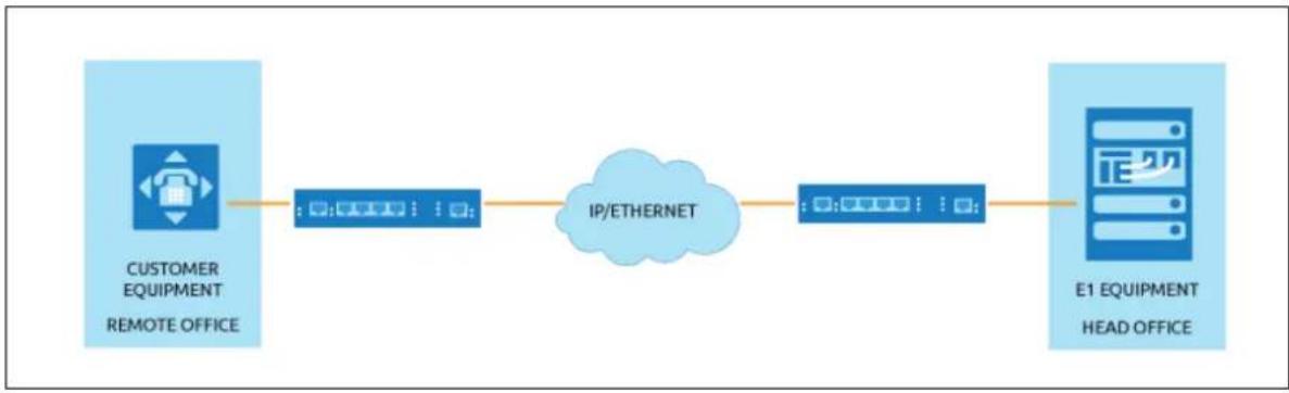
flowchart
graph LR
A["CUSTOMER EQUIPMENT\nREMOTE OFFICE"] --> B["IP/ETHERNET"]
B --> C["E1 EQUIPMENT\nHEAD OFFICE"]
Figure 203: SAToP/CESoPSN P2P architecture
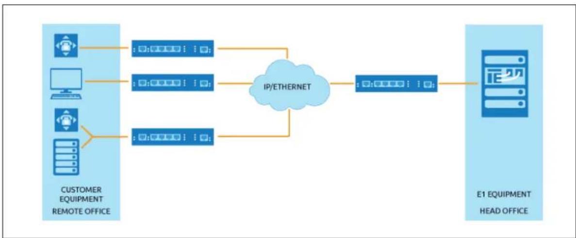
flowchart
graph LR
A["Customer Equipment Remote Office"] --> B["IP/ETHERNET"]
C["Computer"] --> B
D["Desktop"] --> B
E["Mobile Device"] --> B
F["Server"] --> B
B --> G["E1 EQUIPMENT HEAD OFFICE"]
Figure 204: SAToP/CESoPSN P2MP architecture
44.3 Virtual Access proprietary SAToP/ CESoPSN protocol extension
To compensate for packet loss in the network, Virtual Access implemented a proprietary extension to SAToP/CESoPSN. When enabled, a copy of the previous packet payload is added to the end of the packet. With the help of this mechanism it is possible to overcome the loss of single packets. However, the loss of consecutive packets cannot be compensated by this mechanism.
Note: enabling this redundancy mechanism nearly doubles the required bandwidth for the CESoPSN service.
44.4 Configuration package used
| Package | Sections |
| Cesopd Main | Port |
44.5 Configuring SAToP/ CESoPSN
To configure SAToP/ CESoPSN using the web interface, in the top menu, select Services -> CESoPSN. The SAToP/CESoPSN page appears.
44.5.1 Configuring main settings using the web interface
The web interface is divided into 3 sections: Basic, Blackbox and Advanced.
Note: the Blackbox tab only appears if Blackbox is configured on your router.
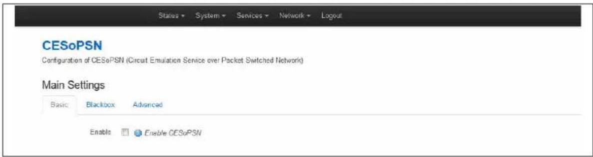
text_image
Status → System → Services → Network → Logout CESoPSN Configuration of CESoPSN (Circuit Emulation Service over Packet Switched Network) Main Settings Basic Blackbox Advanced Enable Enable CESoPSNFigure 205: SAToP/CESoPSN basic settings
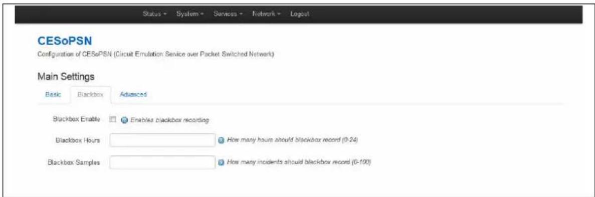
text_image
Status • System • Services • Network • Layout CESoPSN Configuration of CESoPSN (Circuit Emulation Service over Packet Switched Network) Main Settings Basic Blackbox Advanced Blackbox Enable Enables blackbox recording Blackbox Hours How many hours should blackbox record (0-24) Blackbox Samples How many incidents should blackbox record (0-100)Figure 206: SAToP/CESoPSN blackbox settings
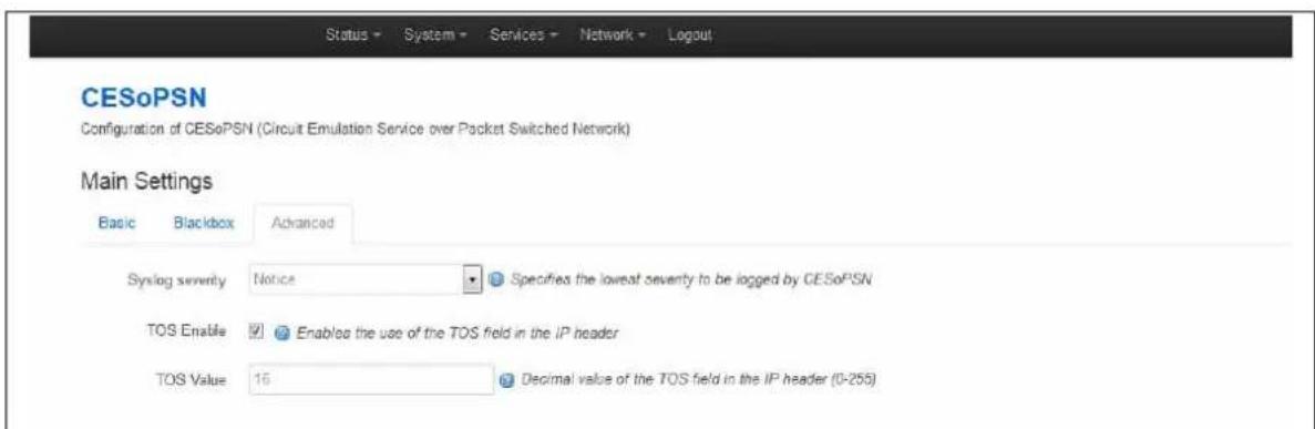
text_image
Status → System → Services → Network → Logout CESoPSN Configuration of CESoPSN (Circuit Emulation Service over Packet Switched Network) Main Settings Basic Blackbox Advanced Syslog severity Notice Specifies the lowest severity to be logged by CESoPSN TOS Enable Enabled the use of the TOS field in the IP header TOS Value 16 Decimal value of the TOS field in the IP header (0-255)Figure 207: SAToP/CESoPSN advanced settings
Use the information table below to configure your main settings.
| Web Field/ UCI / Package Option | Description | |
| Basic settings | ||
| Web: EnableUCI: cesopd.main.enableOpt: enable | Enables SAToP/CESoPSN services. | |
| 0 | Disabled. | |
| 1 | Enabled. | |
| Advanced settings | ||
| Web: Syslog SeverityUCI: cesopd.main.severityOpt: log_severity | Selects the severity used for logging events for SAToP/CESoPSN in syslog. The following levels are available: | |
| 0 | Emergency | |
| 1 | Alert | |
| 2 | Critical | |
| 3 | Error | |
| 4 | Warning | |
| 5 | Notice | |
| 6 | Informational | |
| 7 | Debug | |
| Web: TOS EnableUCI: cesopd.main.tos_enabledOpt: tos_enabled | Enables the use of the TOS field in the IP header. | |
| 0 | Disabled. | |
| 1 | Enabled. | |
| Web: TOS ValueUCI: cesopd.main.tos_enabledOpt: tos_value | Note: before changing this value, consult with Virtual Access support. | |
| 16 Decimal value of the TOS field in the IP header. | ||
| Range | 0-255 | |
| Blackbox settings | ||
| Web: Blackbox EnableUCI: cesopd.main.blackbox_enabledOpt: blackbox_enabled | Enables blackbox recordings. See section 'cesop blackbox show' for more information. | |
| 0 | Disabled. | |
| 1 | Enabled. | |
| Web: Blackbox HoursUCI: cesopd.main.blackbox_hoursOpt: blackbox_hours | ||
| 10 Defines the time period contained in the blackbox. Entries older than the specified period will be overwritten. | ||
| Range | 1-24 | |
| Web: Blackbox SamplesUCI: cesopd.main.blackbox_samplesOpt: blackbox_samples | 20 Maximum number of instances recorded in the blackbox. When the capacity is full the oldest entry will be overwritten. | |
| Range | 1-24 | |
Table 154: Information table for CESoPSN main settings
44.6 Configuring main settings using UCI
The CESoPSN configuration file is stored on /etc/config/cesopd
The main settings are stored in the cesopd section of /etc/config/cesopd. There is only one cesopd section.
config cesopd 'main'
option log_severity '5'
option enable '1'
option tos_enabled '1'
option tos_value '1'
option blackbox_enabled '0'
option blackbox_hours '10'
option blackbox_samples '20'
44.7 Configuring port settings using the web interface
The web interface for port settings is divided into 5 sections: Basic, Advanced, E1, Dual X.21 and Analog LL.
Note: for E1 CESoPSN, a port represents a timeslot or group of timeslots.
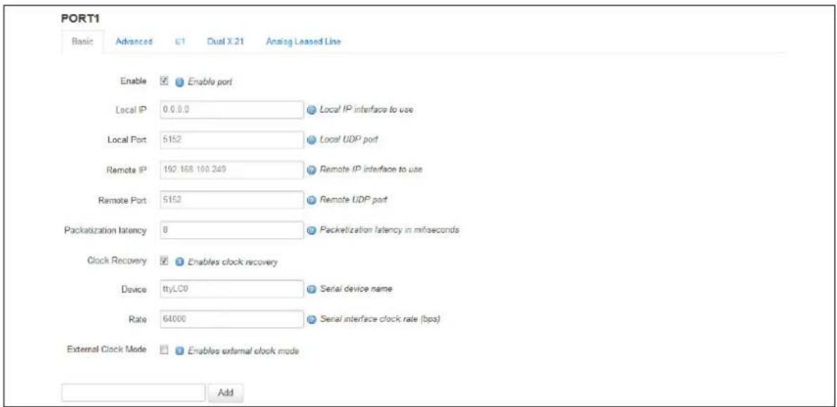
text_image
PORT1 Basic Advanced C1 Dual X 21 Analog Leased Line Enable Enable port Local IP 0.0.0.0 Local IP interface to use Local Port 5152 Local UDP port Remote IP 192 168 100 249 Remote IP interface to use Remote Port 5152 Remote UDP port Packetization latency 8 Packetization latency in milliseconds Clock Recovery Enables clock recovery Device ttyLC0 Serial device name Rate 64000 Serial interface clock rate (bps) External Clock Mode Enables external clock mode AddFigure 208: CESoPSN basic port settings
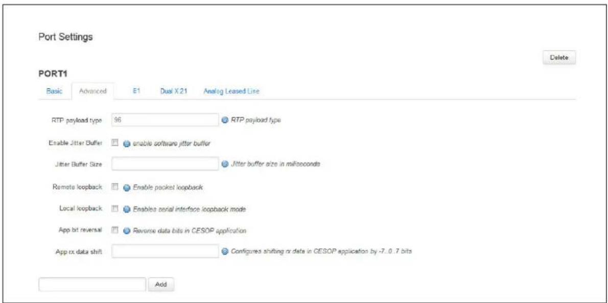
text_image
Port Settings Delete PORT1 Basic Advanced E1 Dual X 21 Analog Leased Line RTP payload type 96 RTP payload type Enable Jitter Buffer enable software jitter buffer Jitter Buffer Size Jitter buffer size in milliseconds Remote loopback Enable packet loopback Local loopback Enables serial interface loopback mode App bit reversal Reverse data bits in CESOP application Approx data shift Configures shifting or data in CESOP application by -7..0..7 bits AddFigure 209: CESoPSN advanced port settings
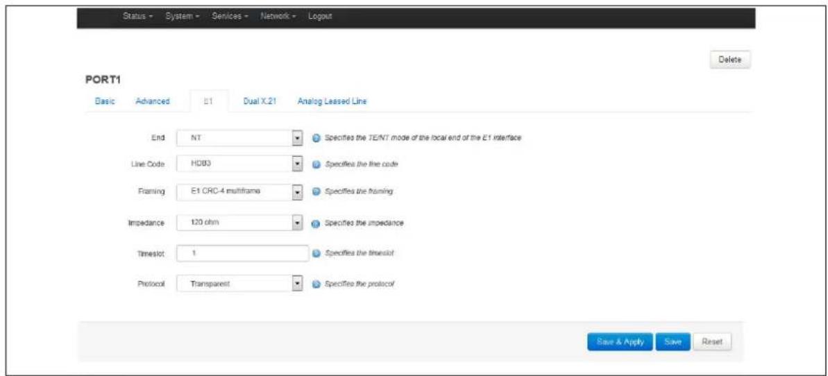
text_image
Status - System - Services - Network - Logout PORT1 Delete Basic Advanced E1 Dual X.21 Analog Leased Line End NT Specifies the TE/NT mode of the local end of the E1 interface Line Code HD03 Specifies the line code Flaming E1 CRC-4 multiframe Specifies the framing Impedance 120 ohm Specifies the impedance Timeslot 1 Specifies the timeslot Protocol Transparent Specifies the protocol Save & Apply Save ResetFigure 210: CESoPSN E1 port settings
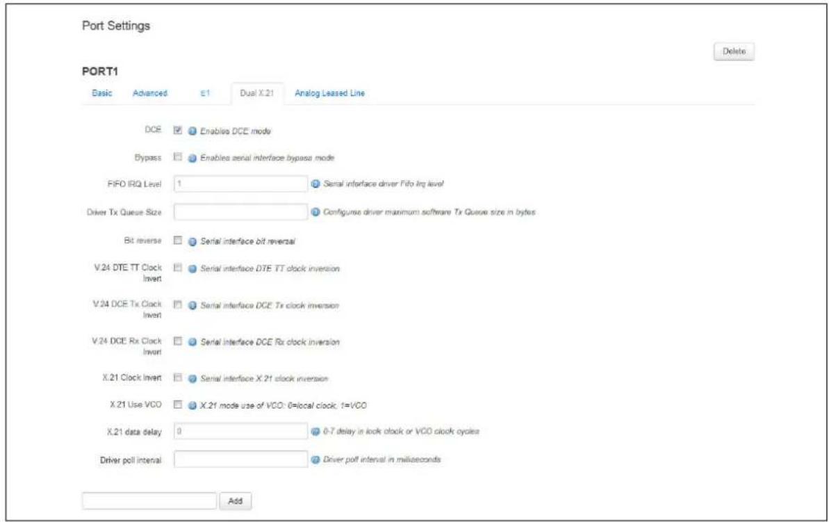
text_image
Port Settings PORT1 Basic Advanced E1 Dual X.21 Analog Leased Line DCE Enables DCE mode Bypass Enables aerial interface bypass mode FIFO IRQ Level 1 Serial interface driver Fifo Irq level Driver Tx Queue Size Configurse driver maximum software Tx Queue size in bytes Bit reverse Serial interface bit reversal V.24 DTE TT Clock Invert Serial interface DTE TT clock inversion V.24 DCE Tx Clock Invert Serial interface DCE Tx clock inversion V.24 DCE Rx Clock Invert Serial interface DCE Rx clock inversion X.21 Clock Invert Serial interface X.21 clock inversion X.21 Use VCO X.21 mode use of VCO: 0=local clock; 1=VCO X.21 data delay 0 0-7 delay in lock clock or VCO clock cycles Driver poll interval Driver poll interval in milliseconds Add DeleteFigure 211: CESoPSN dual X.21 port settings
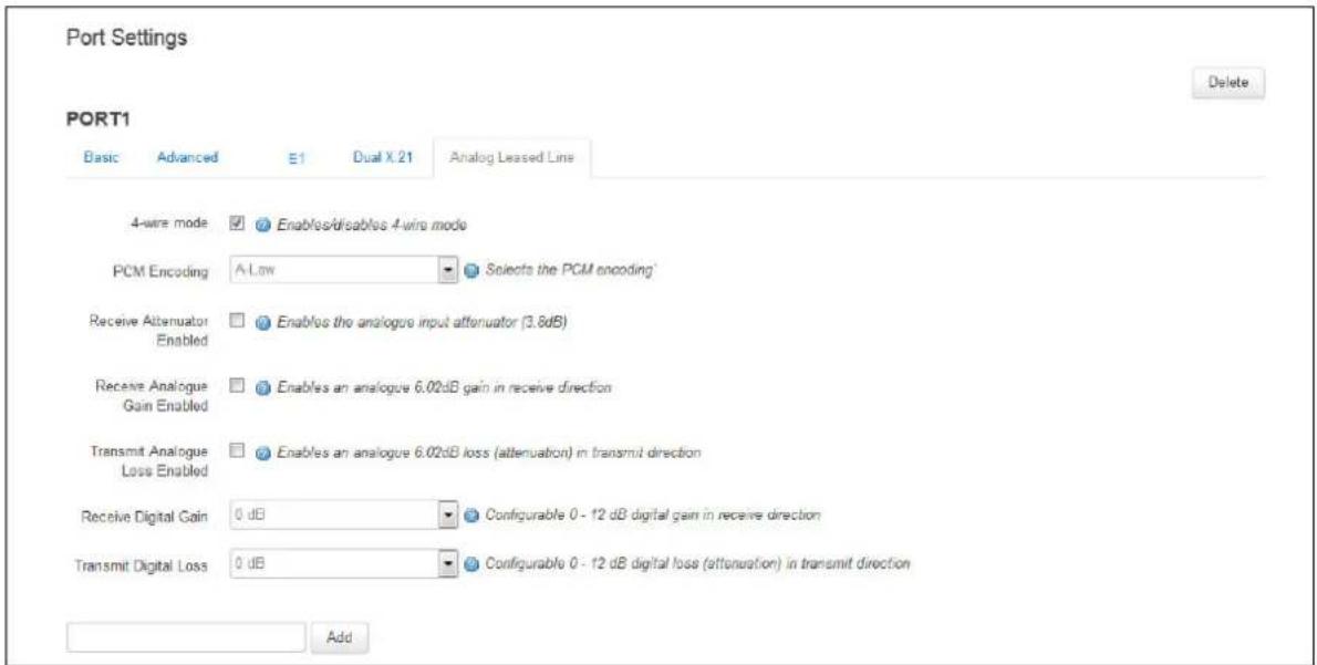
text_image
Port Settings Delete PORT1 Basic Advanced E1 Dual X 21 Analog Leased Line 4-wire mode Enables/disables 4-wire mode PCM Encoding A-Low Selects the PCM encoding Receive Alternator Enabled Enables the analogue input attenuator (3.8dB) Receive Analogue Gain Enabled Enables an analogue 6.02dB gain in receive direction Transmit Analogue Loss Enabled Enables an analogue 6.02dB loss (alternuation) in transmit direction Receive Digital Gain 0 dB Configurable 0 - 12 dB digital gain in receive direction Transmit Digital Loss 0 dB Configurable 0 - 12 dB digital loss (alternuation) in transmit direction AddFigure 212: CESoPSN analog LL port settings
| Web Field/ UCI / Package Option | Description | |
| Web: EnableUCI: cesopd.[port].enableOpt: enable | Enables the port. | |
| 0 | Disabled. | |
| 1 | Enabled. | |
| Web: Local IPUCI: cesopd.[port].udp_local_ipaddrOpt: udp_local_ipaddr | Specifies the interface IP address to listen on for incoming packets. | |
| 127.0.0.1 | Specific interface IP address. | |
| 0.0.0.0 | Listens on all available interfaces. | |
| Web: Local PortUCI: cesopd.[port].udp_local_portOpt: udp_local_port | UDP port to listen for incoming packets on. | |
| 5566 | 49152-65535 recommended. | |
| Range | 0-65535 | |
| Web: Remote IPUCI: cesopd.[port].udp_remote_ipaddrOpt: udp_remote_ipaddr | Specifies the remote IP address to send packets to. | |
| 127.0.0.1 | Specific remote interface IP address. | |
| Range Packets are accepted from all sources and received source IP address will be used as the destination. | ||
| Web: Remote PortUCI: cesopd.[port].udp_remote_portOpt: udp_remote_port | UDP port to send packets to. The port can be 0; in which case the source port of the incoming packets will be used as the destination. | |
| 6655 | 49152-65535 recommended. | |
| Range | 0-65535 | |
| Web: Packetization LatencyUCI: cesopd.[port].packetization_latencyOpt: packetization_latency | ||
| 8 | Specifies the packetization latency. | |
| Range | 5-20 milliseconds. | |
| Web: Clock RecoveryUCI:cesopd.[port].clock_recovery_enabledOpt: clock_recovery_enabled | Enables the port to use the received packet data to adjust the TDM data clock of the router.Note: enable clock recovery on one port only. | |
| 0 | Disabled. | |
| 1 | Enabled. | |
| Web: Enable RTP HeaderUCI: cesopd.[port].rtp_header_enabledOpt: rtp_header_enabled | Enables the use of RTP header as specified in RFC5086.Note: before disabling the use of RTP header, ensure that the peer supports this. | |
| 0 | Disabled. | |
| 1 | Enabled. | |
| Web: Enable Packet RedundancyUCI:cesopd.[port].va_prop_payload_redundancy_enabledOpt:va_prop_payload_redundancy_enabled | Enables a Virtual Access proprietary CESoPSN protocol extension, which can help to overcome packet loss. See the section 'Virtual Access proprietary CESoPSN protocol extension' for more information.Note: this mechanism can only overcome single, but not consecutive, packet losses.Note: only enable when this mechanism is supported by the peer. This might require a software upgrade on the peer. | |
| 0 | Disabled. | |
| 1 | Enabled. | |
| Web: DeviceUCI: cesopd.[port]. devnameOpt: devname | Selects the linux device associated with the TDM interface to be used with this port.Note: for E1 CESoPSN, set all ports to ttyU0 | |
| 'ttyLC0': | analogue LL interface | |
| 'ttyXHFC0' | First dual X.21 port | |
| 'ttyXHFC1' | Second dual X.21 port | |
| 'ttyU0' | E1 interface. | |
| Web: RateUCI: cesopd.[port].rateOpt: rate | Selects the interface rate.N/A for E1. | |
| 64000 The rate has to be a multiple of 64000.For the analogue LL interface only 64000 is supported. | ||
| Range | 64000-2048000 | |
| Web: External clock modeUCI: cesopd.[port].ext_clockOpt: ext_clock | Enables the use of an external clock.N/A for E1 and analogue LL. | |
| 0 | Disabled. | |
| 1 | Enabled. | |
Table 155: Information table for basic port settings
| Web Field/ UCI / Package Option | Description | |
| Web: RTP Payload TypeUCI:cesopd.[port].rtp._payload_typeOpt: rtp_payload_type | RTP payload types are specified by IANA (Internet Assigned Numbers Authority); see http://www.lana.org/assignments/rtp-parameters/rtp-parameters.txt for the complete range of available types.Note: this setting only applies if the use of the RTP header is enabled. | |
| 96(Dynamic) | Specifies the RTP payload header type. | |
| Range | 0-127 | |
| Web: Enable Jitter BufferUCI:cesopd.[port].rx_jitter_buffer_enabledOpt: rx_jitter_buffer_enabled | Enables the network jitter buffer. | |
| 0 | Disabled. | |
| 1 | Enabled. | |
| Web: Jitter Buffer SizeUCI:cesopd[port].rx_jitter_buffer_size_msOpt: rx_jitter_buffer_size_ms | Specifies the size of the network jitter buffer. | |
| 16 Defines the size of the network jitter buffer in bytes. | ||
| Range | 0-160 | |
| Web: Remote LoopbackUCI: cesopd.[port].local_loopbackOpt: remote_loopback | Enables remote loopback (loops back received pseudo-wire payload data). | |
| 0 | Disabled. | |
| 1 | Enabled. | |
| Web: Local LoopbackUCI: cesopd.[port].local_loopbackOpt: remote_loopback | Enables local loopback (loops back received TDM data). | |
| 0 | Disabled. | |
| 1 | Enabled. | |
| Web: N/AUCI: cesopd.[port].app_bit_reverseOpt:app_bit_reverse | Enables reverse bit order of TDM data.N/A for E1 and analogue LL.For X.21 it is more efficient to use the bit reverse option. | |
| 0 | Disabled. | |
| 1 | Enabled. | |
| Web: N/AUCI: cesopd.[port].app_rx_shiftOpt:app_rx_shift | Specified shifts of TDM data.N/A for E1. | |
| 0 | Specifies the shift. | |
| Range | -7 to 7. | |
| E1 port settings Note: for CESoPSN an E1 port is a timeslot or group of timeslots on the E1. | ||
| Web: EndUCI: cesopd.[port].e1t1_endOpt: e1t1_end | Specifies the TE/NT mode of the local end of the E1 interface.For CESoPSN this should be defined for first port only. | |
| 0 | TE. | |
| 1 | NT. | |
| Web: Line CodeUCI: cesopd.[port].e1t1_line_codeOpt: e1t1_line_code | Specifies the line code.For CESoPSN this should be defined for first port only. | |
| 0 | AMI. | |
| 1 | HDB3. | |
| Web: FramingUCI: cesopd.[port].e1t1_framingOpt: e1t1_framing | Specifies the framing. For SATOP this should be set for E1 unframed.For CESoPSN this should be set for E1 double frame or E1 CRC-4 multiframe.For CESoPSN this should be defined for first port only. | |
| 0 | E1 unframed. | |
| 1 | E1 double frame (basic frame). | |
| 2 | E1 CRC-4 multi-frame | |
| Web: ImpedanceUCI: cesopd.[port].e1t1_line_codeOpt: e1t1_line_code | Specifies the impedance.For CESoPSN this should be defined for first port only. | |
| 0 | 75 ohm. | |
| 1 | 120 ohm. | |
| Web: TimeslotUCI: cesopd.[port].e1t1_line_codeOpt: e1t1_line_code | Specifies the timeslot(s).For multiple timeslots use a colon separated list of timeslots and/or timeslot ranges e.g. 1:5:15-20:30-31 | |
| 0 | Specifies the timeslot | |
| Range SAToP: 0CESoPSN: 1-31 | ||
| Web: ProtocolUCI: cesopd.[port].e1t1_protocolOpt: e1t1_protocol | Specifies the protocol.If set for HDLC the timeslot or timeslot group is configured for HDLC and the pseudo-wire is an HDLC pseudo-wire. | |
| 0 | Transparent (for SAToP/CESoPSN). | |
| 1 | HDLC. | |
Table 156: Information table for advanced port settings
| Web Field/ UCI / Package Option | Description | |
| Web: DCEUCI: cesopd.[port].dceOpt: dce | Enables DCE mode.N/A for E1 and analogue LL. | |
| 0 | Disabled. | |
| 1 | Enabled. | |
| Web: FIFO IRQ LevelUCI: cesopd.[port].fifo_irq_levelOpt: fifo_irq_level | Specifies the FIFO IRQ Level.Note: before changing this value, consult with Virtual Access support. | |
| 1 | Specifies the IRQ level. | |
| Range | 1-5. | |
| Web:Bit reverseUCI:cesopd.[port].bit_reverseOpt:bit_reverse | Enables reverse bit order of TDM data. | |
| 0 | Disabled. | |
| 1 | Enabled. | |
| Web:X.21 Clock InvertUCI:cesopd.[port].x21_clk_invertOpt:x21_clock_invert | Enables inversion of X.21 clock. | |
| 0 | Disabled. | |
| 1 | Enabled. | |
| Web:X.21 Use VCOUCI:cesopd.[port].x21_use_vcoOpt:x21_use_vco | Enables inversion of voltage controlled oscillator.Enable this when using clock recovery. | |
| 0 | Disabled. | |
| 1 | Enabled. | |
| Web:X.21 data delayUCI:cesopd.[port].x21_data_delayOpt:x21_data_delay | Specifies the X.21 data delay in clock cycles. | |
| 0 | Specifies the data delay. | |
| Range | 0-7. | |
| Web:Driver Poll IntervalUCI:cesopd.[port].tdm_intvl_msOpt:tdm_intvl_ms | Specifies the driver poll interval in milliseconds.Note: before changing this value, consult with Virtual Access support. | |
| 2 | Specifies the poll interval. | |
| Range | 1-10. | |
Table 157: Dual X.21 port settings
| Web Field/ UCI / Package Option | Description | |
| Web: 4-Wire ModeUCI:cesop.[port].all_four_wire_modeOpt: all_four_wire_mode | Specifies the analogue LL interface mode. | |
| 0 | Analogue LL interface operates in 2-wire mode. | |
| 1 | Analogue LL interface operates in 4-wire mode. | |
| Web: PCM EncodingUCI: cesop.[port].all_pcm_encodingOpt: all_pcm_encoding | Selects the PCM companding algorithm. For more information, see ITU-T G.711 | |
| alaw | Selects the A-law algorithm. | |
| ulaw | Selects the μ-law algorithm. | |
| Web: Receive Attenuator EnabledUCI:cesop.[port].all_rx_attenuator_enabledOpt: all_rx_attenuator_enabled | Enables the analogue input attenuator (3.8dB) | |
| 0 | Disabled. | |
| 1 | Enabled. | |
| Web: Receive Analogue GainUCI:cesop.[port].all_rx_analogue_gain_enabledOpt: all_rx_analogue_gain_enabled | Enables an analogue 6.02dB input gain. | |
| 0 | Disabled. | |
| 1 | Enabled. | |
| Web: Transmit Analogue LossEnabledUCI:cesop.[port].tx_analogue_loss_enabledOpt: all_tx_analogue_loss_enabled | Enables an analogue 6.02dB output loss (attenuation) | |
| 0 | Disabled. | |
| 1 | Enabled. | |
| Web: Receive Digital GainUCI: cesop.[port].all_rx_digital_gainOpt: all_rx_digital_gain | Specifies the input digital gain in dB. | |
| 0 | Disabled. | |
| Range | 0-12dB | |
| Web: Transmit Digital LossUCI: cesop.[port].all_tx_digital_lossOpt: all_tx_digital_loss | Specifies the output digital loss in dB. | |
| 0 | Disabled. | |
| Range | 0-12dB | |
Table 158: Information table for analogue LL port settings
44.8 Configuring port settings using UCI
Settings for the individual ports are stored in the port sections of /etc/config/cesopd Each port has its own section.
For analogue LL and X.21 and an unframed E1, the port configuration is the configuration for that interface.
For a framed E1, the first port configuration is the configuration for the interface. The first timeslot or group of timeslots, and subsequent ports configurations are the configuration for further timeslots or groups of timeslots. All the ports have the same devname in this case.
The examples below show a port section labelled 'Port 1'.
config port 'Port1'
option enable '1'
option devname 'ttyLC0'
option udp_local_ipaddr '0.0.0.0'
option udp_remote_ipaddr '10.1.42.63'
option udp_local_port '5152'
option udp_remote_port '5152'
option rtp_payload_type '96'
option rx_jitter_buffer_size_ms '24'
option rate '64000'
option clock_recovery_enabled '1'
option packetization_latency '5'
......
<port config also contains port specific options>
44.8.1 E1 interface settings
config port 'Port1'
option enable '1'
option devname 'ttyU0'
<generic port options>
......
option elt1_end '1'
option elt1_line_code '1'
option elt1_framing '2'
option elt1_impedance '1'
option elt1_timeslot '1'
option elt1_protocol '0'
44.8.2 Analogue LL interface settings
config port 'Port1'
option enable '1'
option devname 'ttyLC0'
......
<generic port options>
......
option all_four_wire_mode '0'
option all_pcm_encoding 'alaw'
option all_tx_analogue_loss_enabled '1'
option all_tx_digital_loss '6'
option all_rx_analogue_gain_enabled '1'
option all_rx_digital_gain '2'
option all_rx_attenuator_enabled '1'
44.8.3 Dual X.21 interface settings
config port 'Port1'
option fifo_irq_level '1'
option bit_reverse '0'
option x21_clk_invert '0'
option x21_data_delay '0'
option x21_use_vco '0'
44.9 CESoPSN diagnostics
SAToP/CESoPSN uses one package: cesopd.
To view the SAToP/CESoPSN configuration, enter:
root@VA_router:~# # uci export cesopd
package cesopd
config cesopd 'main'
option log_severity '5'
option enable '1'
config port 'Port1'
option enable '1'
option devname 'ttyLC0'
The cesop command provides several options to investigate the operation of the SAToP/CESoPSN service. The output provided by these commands will allow the Virtual Access support team to assist you.
root@VA_router:~# cesop
=== CESOPD disgnostics. Command syntax: ===
cesop show all - show all
cesop show config - show configuration
cesop show status - show status
cesop show stats - show statistics
cesop clear stats - clear statistics
cesop quit - terminate cesopd process
cesop show debug - show diagnostical information
cesop blackbox - show blackbox information
cesop upgrade usbcard - upgrade usb card
cesop show usbcard status - show USB serial card status
cesop show usbcard stats - show USB serial card statistics
cesop clear usbcard stats - clear USB serial card statistics
cesop show usbcard version - show USB serial card firmware version
cesop show usbcard cpld status - show USB serial card CPLD programming status
cesop bert - configure bit error rate test
cesop show bert stats - show bit error rate test statistics
cesop clear bert stats - clear bit error rate test statistics
44.9.1 cesop show config
To show the currently running configuration, enter:
root@VA_router:~# cesop show config
Main Config
----
enable : 1
nodaemon : 0
log_severity : 5
tos_enabled : 1
tos_value : 16
blackbox_enabled : 0
blackbox_hours : 10
blackbox_samples : 20
adjust_mtu_enable : 0
Port 1 config
----
cardType : USB E1/T1 card
enable : 1
clock_recovery_enabled : 1
clock_recovery_debug : 0
remote_loopback : 0
udp_local_ipaddr : 1.1.1.1
udp_local_port : 50151
udp_remote_ipaddr : 1.1.1.2
udp_remote_port : 50152
rtp_header_enabled : 1
rtp_payload_type : 100
packetization_latency : 8
rx_jitter_buffer_enabled : 0
rx_jitter_buffer_size_ms : 16
app_bit_reverse : 0
app_rx_shift : 0
va_prop_payload_redundancy_enabled: 0
devname : ttyU0
local_loopback : 0
dce : 1
rate : 0
ext_clock : 0
fifo_irq_level : 1
bit_reverse : 0
dte_tt_inv : 0
dce_tclk_inv : 0
dce_rclk_inv : 0
x21_clk_invert : 0
x21_data_delay : 0
x21_use_vco : 0
tdm_intvl_ms : 2
all_four_wire_mode : 0
all_pcm_encoding : alaw
all_rx_attenuator_enabled : 1
all_rx_analogue_gain_enabled : 0
all_tx_analogue_loss_enabled : 0
all_rx_digital_gain : 0
all_tx_digital_loss : 0
elt1_end : 1
elt1_line_code : 1
elt1_framing : 2
elt1_impedance : 1
elt1_timeslot : 1
elt1_protocol : 0
44.9.2 cesop show status
To show the current operating configuration, enter:
root@VA_router:~# cesop show status
Port 1
=====
Clock Recovery Status
----
Output Voltage 1.769998V
Protocol Status
----
UDP Session Open
Remote IP Address 1.1.1.2
Remote UDP Port 50152
Protocol CESoP
Rx CESoPSN Header L-Bit 0
Rx CESoPSN Header R-Bit 0
Rx CESoPSN Header M-Bits 0
Rx TDM Payload [55][D5]...
Tx CESoPSN Header L-Bit 0
Tx CESoPSN Header R-Bit 0
Tx CESoPSN Header M-Bits 0
Tx TDM Payload [D4][51]...
Uptime 40 hrs 45 mins 47 secs
44.9.3 cesop show stats
To view SAToP/CESoPSN service statistical information, enter:
root@VA_router:~# cesop show stats
Port 1
-------->
------
Serial statistics
------------------
-------->
Frames read 18359581
Frames written 18359581
Bytes read 1175013184
Bytes written 1468766480
UDP statistics
------------------
Datagrams transmitted 18359581
Datagrams received 18359581
Bytes transmitted 1468766480
Bytes received 1468766480
Transmit failures 0
Receive failures 0
SAToP/CESoP statistics
------------------
Rx: header errors 0
Rx: packets lost 1
Rx: lost packets recovered 0
Rx: TDM payload length errors 0
44.9.4 cesop clear stats
To reset the statistical counters, enter:
root@VA_router:~# cesop clear stats
cesopd stats cleared
cesop show debug
The output provided by cesop show debug is intended for Virtual Access support technicians and therefore the interpretation of the output produced by cesop show debug command is not explained here.
root@VA_router:~# cesop show debug
Port 1
Clock Recovery Status
Output Voltage 1.763998V
Protocol Status
UDP Session Open
Remote IP Address 1.1.1.2
Remote UDP Port 50152
Protocol CESoP
Rx RTP Payload Type 100
Rx RTP SSRC 87654321
Rx Payload Size 64
Rx CESoPSN Header L-Bit 0
Rx CESoPSN Header R-Bit 0
Rx CESoPSN Header M-Bits 0
Rx TDM Payload [55][D5]...
Tx RTP Payload Type 100
Tx RTP SSRC 863d24f9
Tx Payload Size 64
Tx CESoPSN Header L-Bit 0
Tx CESoPSN Header R-Bit 0
Tx CESoPSN Header M-Bits 0
Tx TDM Payload [D5][53]...
Uptime 40 hrs 47 mins 36 secs
Port 1
Serial statistics
----
Frames read 1134
Empty frames read 0
Frame read failures 0
Frames written 1135
Frame write failures 0
Incomplete frames written 0
Bytes read 72576
Bytes written 90800
UDP statistics
----
Datagrams transmitted 1136
Datagrams received 1136
Bytes transmitted 90880
Bytes received 90880
Transmit failures 0
Receive failures 0
Receive address errors 0
SAToP/CESoP statistics
----
Rx: header errors 0
Rx: packets lost 0
Rx: lost packets recovered 0
Rx: TDM payload length errors 0
Tx: TDM payload length errors 0
44.9.5 cesop blackbox show
If enabled, the blackbox records instances of packet loss or the late transmission and reception of packets. The information stored in the blackbox can help Virtual Access support analyse problems such as excessive jitter and packet loss. The information in the blackbox is intended for Virtual Access technicians and therefore, the interpretation of the output produced by cesop blackbox show command is not explained here.
root@VA_router:~# cesop blackbox show 1
1 1 31 0 1 28 0 2016/01/29@09:51:18
active
| TX Ticks delta (min/mean/max) us: | 282 | 7991 | 63796 | ||
| RX Ticks delta (min/mean/max) us: | 297 | 7991 | 56167 | ||
| Transmit sample buffers: | |||||
| 2016/01/29@09:51:18 | 53346 | min/mean/max: | 282 | 17846 | 500728 |
| Local Lost | |||||
| active 0 | min/mean/max: | 293 | 7998 | 15715 | |
| Receive sample buffers: | |||||
| 2016/01/29@09:51:18 | 2846 | min/mean/max: | 366 | 17737 | 495308 |
| Local Lost | |||||
| active 0 | min/mean/max: | 7446 | 7987 | 8534 | |
44.9.6 cesop upgrade usbcard
The command cesop upgrade usbcard re-programs the E1 card with the image in /lib/firmware/va-userial.bin
The command is used for software upgrade of the E1 card. If an upgrade is necessary the image will be provided by Virtual Access.
The upgrade process is logged on syslog.
root@VA_router:~# cesop upgrade usbcard
cesop show usbcard status
To view E1 card status, enter:
root@VA_router:~# cesop show usbcard status
USB-elt1 card status
Line:
LOS off
LOF off
LOMF off
AIS off
RDI off
Unavailable off
44.9.7 cesop show usbcard stats
To view E1 card statistical information, enter:
root@VA_router:~# cesop show usbcard stats
USB-elt1 card stats
Line:
Frame Alignment Signal Errors 0
Line Code Errors 0
CRC Errors 1
Remote CRC Errors 0
TX Slips 275
RX Slips 0
Errored Seconds 0
Severely Errored Seconds 0
Unavailable Seconds 0
Flow 0:
Bytes TX 1806272 RX 1806336
Frames TX 0 RX 0
rxCrcErrors 0 rxLengthErrors 0
txUnderrunErr 4 txFifoErr 0
rxOverrunErr 0 rxCrcErr 0 rxLengthErr 0 rxAborts 0
44.9.8 cesop clear usbcard stats
To reset the E1 card statistical counters, enter:
root@VA_router:~# cesop clear usbcard stats
USB card stats cleared
44.9.9 cesop show usbcard version
To see the E1 card's software, enter:
root@VA_router:~# cesop show usbcard version
USB card firmware version: 2.0.0
44.9.10 cesop show usbcard cpld status
The E1 card has a CPLD which is programmed on startup.
To see the result of E1 card's CPLD programming, enter:
root@VA_router:~# cesop show usbcard cpld status
USB card CPLD programming status: 0
The status should be 0.
44.9.11 cesop bert
Use this command to configure bit error rate testing.
Currently supported for E1 card only. The BER pattern is transmitted towards the E1 interface and checked against the received data from the E1 interface. If the E1 is configured as framed the first configured timeslot or group of timeslots is used.
To start the bit error rate test, enter:
root@VA_router:~# cesop bert start
To stop the bit error rate test, enter:
root@VA_router:~# cesop bert stop
44.9.12 cesop show bert stats
To view the bit error rate test status and statistical counters, enter:
root@VA_router:~# cesop show bert stats
Bit Error Rate Test Status
----
BERT Sync OK
Bit errors 0
Bit rate 64000 bps
Elapsed time 23 seconds
44.9.13 cesop clear bert stats
To reset the bit error rate test statistical counters, enter:
root@VA_router:~# cesop clear bert stats
bert stats cleared
45 Serial interface
45.1 Overview
Many different applications and device drivers use the serial interface. You configure the serial interface using the relevant application; for example Terminal Server, therefore there is no standalone serial configuration page.
You can monitor the various serial interfaces using either the command line or the web interface.
45.2 Monitoring serial interfaces using the web interface
In the top menu, select Status -> Serial Interfaces. Depending on the number of serial interfaces present in the device, a number of tabs will appear giving access to information about each interface. The information presented will also depend on the actual type of the serial interface.
45.2.1 Serial statistics
| ttyU0 | |
| Statistics | Status |
| Counter | Value |
| Tx Frames | 0 |
| Tx Bytes | 9 |
| Tx Underruns | 0 |
| Tx Discards | 0 |
| Rx Frames | 0 |
| Rx Bytes | 258856 |
| Rx Overruns | 0 |
| Rx CRC Errors | 0 |
| Rx Too Big | 0 |
| Rx Discards | 0 |
Figure 213: The serial statistics page for serial-0
45.2.2 Serial status
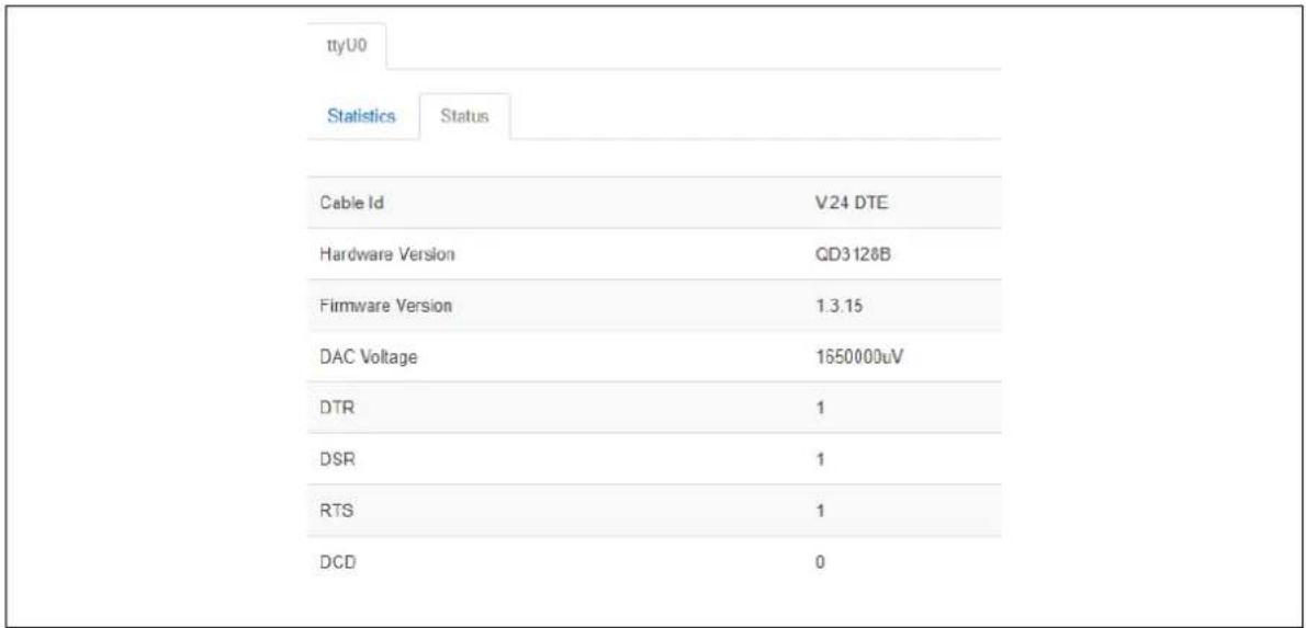
text_image
ttyU0 Statistics Status Cable Id V24 DTE Hardware Version QD3128B Firmware Version 1.3.15 DAC Voltage 1650000uV DTR 1 DSR 1 RTS 1 DCD 0Figure 214: The serial status page for serial-0
45.3 Monitoring serial interfaces using command line
45.3.1 Serial statistics using command line
To view serial statistics, enter: serial_stats.
root@VirtualAccess:~# serial_stats
ttyU0 statistics
Tx Frames 0
Tx Bytes 9
Tx Underruns 0
Tx Discards 0
Rx Frames 0
Rx Bytes 258856
Rx Overruns 0
Rx CRC Errors 0
Rx Too Big 0
Rx Discards 0
45.3.2 Serial status using command line
To view serial statistics, enter: serial_status.
root@VirtualAccess:~# serial_status
ttyU0 status
Cable Id V.24 DTE
Hardware Version QD3128B
Firmware Version 1.3.15
DAC Voltage 1650000uV
DTR 1
DSR 1
RTS 1
DCD 0
45.3.3 Resetting serial statistics
To reset serial statistics, enter: serial_stats_reset.
root@VirtualAccess:~# serial_stats_reset ttyU0
Serial interface statistics reset
You can reset statistics for all or individual serial interfaces.
_END OF DOCUMENT