
COM3 - Receiver Audac - Free user manual and instructions
Find the device manual for free COM3 Audac in PDF.


| Product Type | Public Address Amplifier (Receiver) |
| Model | COM3 |
| Dimensions (W x H x D) | 270 mm x 76 mm x 230 mm |
| Net Weight | 4.5 kg |
| Power Supply | 230V AC, 50/60Hz |
| Power Consumption | 42 W |
| Rated Output Power | 30 W (at THD < 0.5%) |
| Available Output Taps | 4 Ω (11V), 25V, 70V (163 Ω), 100V (333 Ω) |
| Input Sensitivity | Mic: -50 dB ± 3 dB; AUX: -30 dB ± 3 dB; Tele-Paging: -21 dB ± 3 dB |
| Frequency Response | 80 Hz – 18 kHz (+1.5 / -3 dB at 1W) |
| Tone Controls | Bass (100 Hz) and Treble (10 kHz), ±12 dB each |
| Total Harmonic Distortion | < 0.5% at rated power, 1 kHz |
| Signal-to-Noise Ratio | > 90 dB at rated output |
| Inputs | 3 x Mic (balanced, EURO block/1/4" phone), 2 x AUX (RCA), 1 x Tele-Paging (Euro block) |
| Outputs | Speaker outputs: COM and 4 Ω, 25V, 70V, 100V (Euro block) |
| Protection Features | Over-current, short-circuit, thermal protection with auto-limiting |
| Cooling | Convection (no fan) |
| Mounting | Desktop or 19" rack mount (brackets included) |
| Indicators | Power ON (blue LED), Signal, -20dB, Clip, Protect |
| Priority Muting | 2-layer: MIC2~CH3, AUX1~AUX2 are muted by MIC1, Tele-Paging, and Chime |
| Built-in Chime | Selectable pre-announce chime |
| Fuse | T1A / 250V (5x20mm) |
| Operating Temperature | 0°C to 40°C, 95% humidity non-condensing |
Frequently Asked Questions - COM3 Audac
User questions about COM3 Audac
0 question about this device. Answer the ones you know or ask your own.
Ask a new question about this device
Download the instructions for your Receiver in PDF format for free! Find your manual COM3 - Audac and take your electronic device back in hand. On this page are published all the documents necessary for the use of your device. COM3 by Audac.
USER MANUAL COM3 Audac
PROFESSIONAL AUDIO EQUIPMENT
Public Address Amplifier COM3 / COM6
User Manual & Installation Guide
AUDAC PROFESSIONAL AUDIO EQUIPMENT
User Manual & Installation Guide
© AUDAC
http://www.audac.eu
info@audac.cu
Index
INTRODUCTION....3
ENVIRONMENT 4
SAFETY REQUIREMENTS 5
CAUTION-SERVICING 5
OVERVIEW FRONT AND REAR PANEL OF THE COM3/6 6
FRONT 6
REAR 6
DETAILS FRONT AND REAR PANEL OF THE COM3/6 7
FRONT PANEL CONTROLS 7
REAR PANEL....7
GETTING STARTED 8
CONNECTIONS....10
OPERATION....12
BLOCK DIAGRAM 13
ADDITIONAL INFORMATION COM3/6....14
PERSONAL NOTES....15
Introduction
This section briefly describes the possibilities of the COM3/6 public address amplifier.
The COM3/6 public address amplifier was developed as an easy to use, flexible solution for flexible solution for multifunctional use.
During the development of the COM3/6, the AUDAC-engineers wanted to achieve four goals:
- Delivering a flexible audio solution to control multiple functions
- Easy to use
- Excellent sound quality
- Modern and advanced design
The COM3/6 has 1 Telephone paging input with EURO block terminal, 3 microphone and 2 line inputs with 14 inch phone and RCA jacks, a 30W(COM3)/60W(COM6) rated power output, an acceptable wide range input level (up to 44dB), 2-layer priority muting, a protection system which detects over current and provides current limiting and thermal protection, a built-in user selectable preannounce chime, 2 band tone controls and a low distortion and low noise level. Thanks to its external brackets, the COM3/6 can be mounted on a desktop or in a 19 inch rack.
The COM3/6 can be used in commercial applications such as restaurants, hotels, shops, warehouses, professional offices, public buildings, ...
A simple example: when installed in a shop, you could connect: a tuner to play your favorite radio-station, a microphone to make announcements, a telephone pager, ... and off course the doorbell of the shop.
Chapter 1
Environment
Do not place this unit in an enclosed environment such as a bookshelf or closet. Ensure that there is adequate ventilation to cool the unit. Do not block the ventilation openings.
Do not place the unit in environments which contain high levels of dust, heat, moisture or vibration.
Do not use the unit near water or other liquids. Make sure no water or other liquids can be spilled, dripped or splashed on the unit.
This unit was developed for indoor use only. Do not use it outdoors.
Do not place objects on top of the unit.
Place the unit on a stable base.
Safety Requirements
Always handle the unit with care.
Only use a grounded socket outlet and a power cord with grounding plug to plug in the unit.
This unit is not a toy. It should not be operated by children.
Do not stick objects through the openings of the COM3/6.
Do not open the unit (risk for electrical shock).
The COM3/6 contains several < jumpers > which can be set. These settings may only be done by qualified people.

CAUTION - SERVICING
This unit contains no user serviceable parts. Refer all servicing to qualified service personnel. Do not perform any servicing unless you are qualified to do so.
Note
This product conforms to the following European Standards: EN 50081-1: 1992, EN 50082-1: 1992, EN 60065: 199

Overview front and rear panel of the COM3/6
FRONT

REAR
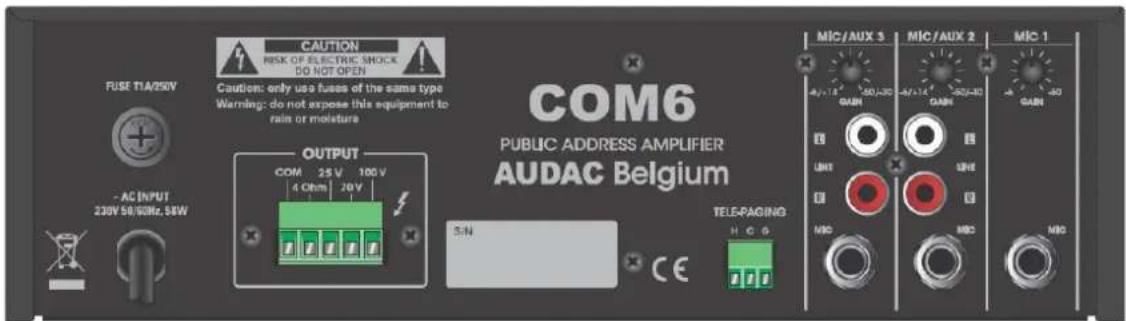
Details front and rear panel of the COM3/6
FRONT PANEL

REAR PANEL
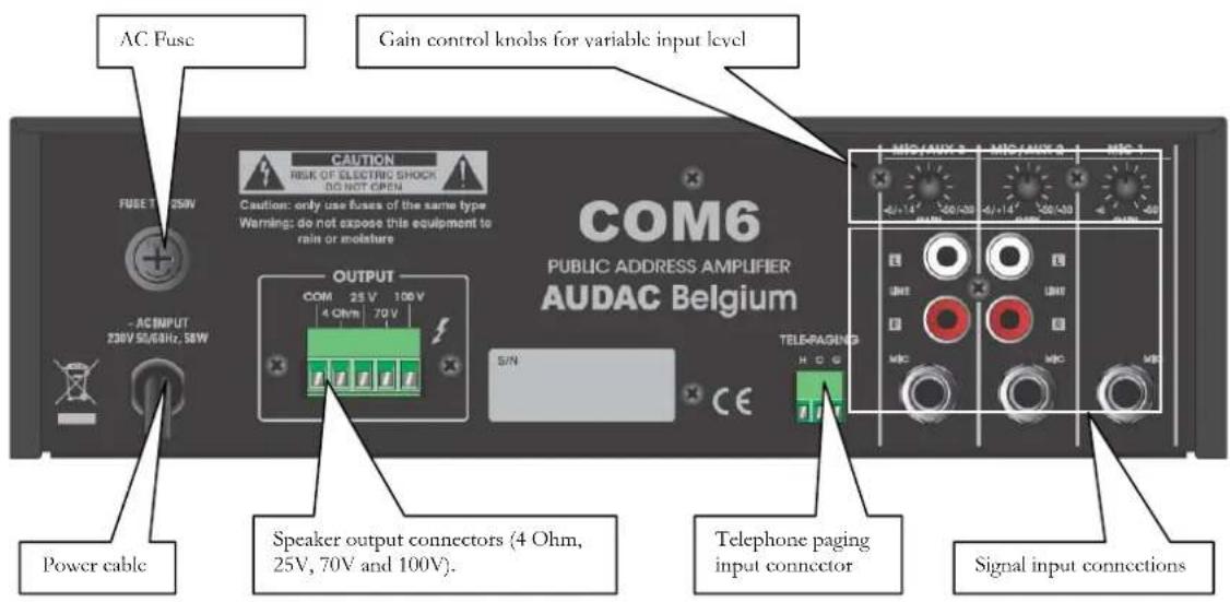
Getting Started
Before you install the COM3/6 amplifier, make sure you disconnect it: put the power button in the 'OFF' position and turn all level controls down by turning them counterclockwise. When installed, the COM3/6 public address amplifier can be switched on by pressing the power button on the front panel. The blue
WIRING
Select the input wire and the connectors.
The use of pre-built or professionally wired balanced line 22 to 24 gauge cables is recommended. The figure on the next page shows the connector pin assignments for wiring. You can also use the RCA input connections for unbalanced inputs.
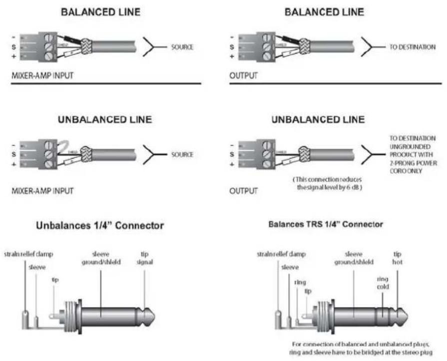
Select the output wire and the connectors.
For the output connectors of the amplifier, the use of pre-built or professionally wired, high-quality and heavy gauge speaker wires is recommended. EURO blocks can be used for the output connectors. Prevent short circuits: wrap or insulate exposed loudspeaker cable connectors.
Use the guidelines below to select the appropriate wire size, based on the distance from the amplifier to the speaker. The wire sizes apply to the 4 Ohm tap.
| Distance | Wire size |
| Up to 25 ft. | 16 AWG |
| 26~40 ft. | 14 AWG |
| 41~60 ft. | 12 AWG |
| 61~100 ft. | 10 AWG |
| 101~150 ft. | 8 AWG |
| 151~200 ft. | 6 AWG |
Note: Leave custom wiring to qualified personnel. Class 2 wiring is required.
Caution: NEVER use shielded cable for output power wiring.
Connections
Select the input wire and the connectors
INPUT
Connect microphones or balanced line-level sources to the balanced inputs of the mixer-amplifier. Set the Gain Volume accordingly. Connect unbalanced line-level signals to RCA input connectors.
OUTPUT
Maintain proper polarity on the output connectors.
For each output channel, you connect the output EURO block terminals to the loudspeaker loads. Use terminals that are marked with COM and 4Ω for a 4 Ohm loudspeaker load, or use terminals marked with COM and 25V, 70V or 100V for constant-voltage loudspeaker loads.
Connect the COM terminal to the speaker negative (-) lead. Connect one of the other terminals to the speaker positive (+) lead.
Impedance and output voltage:
| COM3 | COM6 |
| 4 Ω / 11V | 4 Ω / 15.5V |
| 21 Ω / 25V | 10.5 Ω / 25V |
| 163 Ω / 70V | 81.6 Ω / 70 V |
| 333 Ω / 100V | 166 Ω / 100V |
The impedances as indicated above represent the total speaker system impedances. The speaker connection is shown in the figure below.

Caution: Never use both the Low-Z (4Ω) and Hi-Z (25V, 70V and 100V) terminals at the same time.
Following image shows a WRONG connection.

Operation
TELEPHONE PAGING
Connect the TELE-PAGING connector of the mixer-amplifier to the telephone interface unit/PBX like telephone pager. Announcing by telephone is possible, after you've dialled up to telephone interface unit/PBX.
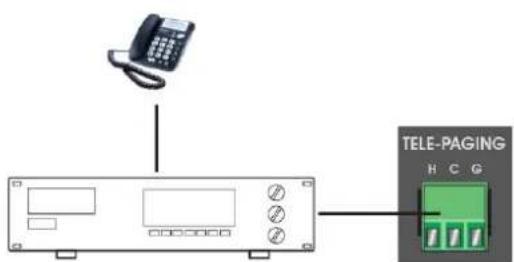
Telephone pager/PBX
SIGNAL INPUT GAIN CONTROL
The COM3/6 public address amplifiers are able to accept a variable and wide range of input signals with trim pot. To accept variable external equipment, you adjust the trim pot in a range of 44dB. Following image shows the acceptable input sensitivity per channel.

PRIORITY CONTROL
The COM3/6 has a 2-layer priority mute function. When a higher level source is activated, other input signals are muted automatically, except for the same priority level source.
MIC2\~CH3, AUX1\~AUX2> MIC1, Telephone Paging, Chime
BLOCK DIAGRAM

flowchart
graph TD
    A["TEL-PACE"] --> B["Amplifier"]
    B --> C["TRM(4+dB)"]
    C --> D["Ground"]
    D --> E["INPUT LEVEL"]
    E --> F["Low(100Hz)"]
    F --> G["High(10kHz)"]
    G --> H["MASTER"]
    H --> I["FAULT DETECTION AND PROTECTION"]
    I --> J["INDICATOR"]
    J --> K["OUTPUT TRANS"]
    K --> L["TDXV 70V 25V 4ohm CCW"]
    M["CH-5dB/-5dB"] --> N["Amplifier"]
    N --> O["TRM(4+dB)"]
    O --> P["Ground"]
    P --> Q["INPUT LEVEL"]
    Q --> R["Low"]
    R --> S["FAULT DETECTION AND PROTECTION"]
    T["DUE-6dB/-5dB"] --> U["Amplifier"]
    U --> V["TRM(4+dB)"]
    V --> W["Ground"]
    W --> X["INPUT LEVEL"]
    X --> Y["Low"]
    Y --> Z["FAULT DETECTION AND PROTECTION"]
    AA["DUE-8dB/-5dB"] --> AB["Amplifier"]
    AB --> AC["TRM(4+dB)"]
    AC --> AD["Ground"]
    AD --> AE["INPUT LEVEL"]
    AE --> AF["Low"]
    AF --> AG["FAULT DETECTION AND PROTECTION"]
    AH["POWER TRANS"] --> AI["AC COND"]
    AJ["+15V"] --> AK["SW POWER:"]
    AL["-15V"] --> AM["GND"] --> AN["Power Trans"]
    AO["FUSE"] --> AP["AC COND"]
Chapter
4
Additional
information
COM3/6
TECHNICAL SPECIFICATIONS
| PERFORMANCE | ||
| Input sensitivity | ||
| COM3 | COM6 | |
| Balanced microphone channels -50dB ± 3dB | ||
| Unbalanced AUX channels -30dB ± 3dB | ||
| Tele-Paging -21dB ± 3dB | ||
| At 1W from speaker out tap, 80Hz ~ 18kHz +1.5/-3dB | ||
| Tone Controls | ||
| 100Hz, 10kHz ± | 12dB ± 3dB | |
| Signal to Noise Ratio at rated power output | Less than 90dB | |
| Crosstalk at all control maximum -70dB at 1kHz | ||
| Rated output power at THD 0.5% 30 | W | 60 W |
| Total Harmonic Distortion (THD) at 1kHz rated power | Less than 0.5% | |
| Power Band width at 1 kHz from speaker out tap | 80Hz ~ 18kHz with less than 0.5% THD | |
| DC Output Offset | Less than ± 3mV | |
| Operating Temperature/Humidity at non-condensing | 0° ~ 40°C at 95% humidity | |
| Output Voltage and Impedance | ||
| 4 Ω | 11V | 15.5 V |
| 25V | 21 | 10.5 Ω |
| 70V | 163 Ω | 81.6 Ω |
| 100V | 333 Ω | 166 Ω |
Ω
| CONSTRUCTION | ||
| COM3 | COM6 | |
| Cooling | Convection | |
| Dimensions (W x H x D) | 270 mm x 76 mm x 230 mm | |
| Net Weight | 4.5 Kg | 5.1 Kg |
| Power Consumption | 42 W | 85 W |
Cooled
Personal notes

- User Manual & Installation Guide
- Index
- Introduction
- Chapter 1
- Environment
- Safety Requirements
- CAUTION - SERVICING
- Note
- Overview front and rear panel of the COM3/6
- Details front and rear panel of the COM3/6
- Getting Started
- WIRING
- Connections
- INPUT
- OUTPUT
- Operation
- TELEPHONE PAGING
- SIGNAL INPUT GAIN CONTROL
- PRIORITY CONTROL
- Chapter
- 4
- Additional
- information
- COM3/6
Brand : Audac
Model : COM3
Category : Receiver