
232FX Keypad - Système de contrôle d'accès sécurisé Nortek - Free user manual and instructions
Find the device manual for free 232FX Keypad Nortek in PDF.


User questions about 232FX Keypad Nortek
0 question about this device. Answer the ones you know or ask your own.
Ask a new question about this device
Download the instructions for your Système de contrôle d'accès sécurisé in PDF format for free! Find your manual 232FX Keypad - Nortek and take your electronic device back in hand. On this page are published all the documents necessary for the use of your device. 232FX Keypad by Nortek.
USER MANUAL 232FX Keypad Nortek
Installation & Programming Instructions
Note: This product is designed to be installed and serviced by security and lock industry professionals.
Specifications
Keypad Case Dimensions:
5-1/8" L x 3-3/8" W x 5/8" D
Electrical:
Voltage: 12-24 VAC/VDC (controller)
Current (max): 54mA @ 12VDC;
65mA @ 24VDC; 118mA @ 12VAC;
157mA @ 24VAC

text_image
1 2 3 4 5 6 7 8 9 * 0 #Relay Contacts:
Main Relay (controller): 12-24 VAC/DC, 2A
Aux Relays (controller): 12-24 VAC/DC, 1A
Environmental:
Temperature: -20^ F to 130^ F
232 Controller: For Indoor use Only
SSW-FX Keypad: For Indoor or Outdoor Use
Features
- Two-Piece Unit for Secured Applications
• Vandal Resistant Metal Case
• Sealed for Indoor or Outdoor Applications - No Moving Parts
- Touch Sensitive Piezo Keys
• LED's for Relay Status Indication - Surface Mount
• Rated for Greater than One Million Key Cycles
Applications
• Heavy Traffic Areas
- Rough Service Environments
- Low Profi le
Description:
Combining elegant looks and flush mount design in a ruggedized vandal resistant case, the Door♦Gard Series 232FX keypad can be utilized for almost any application. Designed to perform in high traffic c and rough duty environments, the keypad has solid state, touch sensitive piezo keys surrounded by an aesthetically appealing protective metal case. Encapsulated electronics make the keypad suitable for indoor or outdoor installations.
A complete 232FX access control system consists of two pieces: an SSW-FX keypad front end and a 232 Access Control Module.
Basic Operation:
To gain access through the door enter your code (1-6 digits) followed by the * key on the keypad.
Packing List:
(1) SSW-FX Keypad
(1) 232 Access Control Module
(1) Six-Conductor Wire Harness
(4) Three-Conductor Wire Harness
(1) Four-Conductor Wire Harness
(1) Controller Hardware Pack
(2) 6-32 x 1-1/2 Machine Screws
(2) # 6 1-1/2 Sheet Metal Screws
(1) 11/64" Allen Wrench
(1) Anti-Oxidant Grease Pack
(1) 232FX Installation/Programming Manual
(1) Self-Contained Access Control Programming Guide
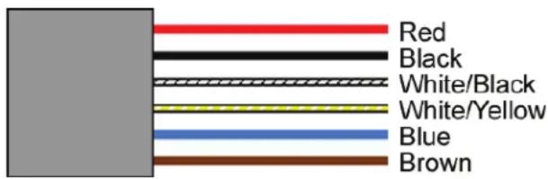
Wire Harness Confi guration:
text_image
Red Black White/Black White/Yellow Blue Brown| Pin Wire Color Signal Name | |
| 1 Red Power (+) | |
| 2 Black Power (-) | |
| 3 White/Black Data 0 | |
| 4 White/Yellow Data 1 | |
| 5 Blue LED1 | |
| 8 Brown Not Used | |
TECHNICAL SUPPORT
DEALERS/INSTALLERS ONLY! End users must contact the dealer/installer for support. If the keypad still does not work after troubleshooting, please call the Technical Services department at 1-855-546-3351.
Keypad Installation Procedure:
Step 1: If you are mounting the keypad directly to a wall, drill a 3/4" hole into the mounting surface to allow the wire harness connector and wires to fit through.
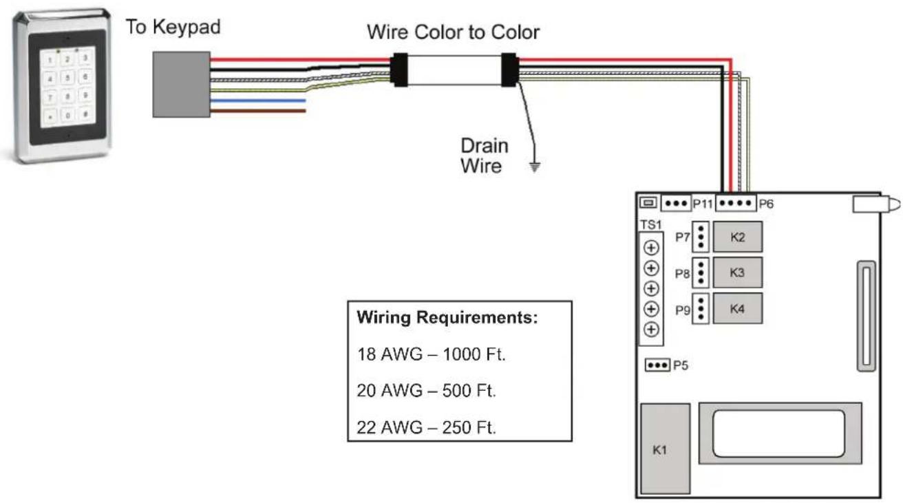
Step 2: On the keypad end, strip back the insulator from the wire and tape the drain wire (shield) to the jacket. Now connect the four (see below) wires to the 6-conductor wire harness provided. The wire harness plugs into the 6-position connector on the keypad. At the other end of your wire run, strip back the insulator from the wire but do not tape the drain wire to the jacket. The drain wire must be connected to ground at the controller end. See the diagrams.
Step 3: Finally mount the SSW-FX keypad onto the mounting surface using the provided #6 screws. Do no over-tighten the screws, which may result in damage.
Note: The controller is designed for indoor mounting only and is intended for mounting in a secure location. It should be accessible for programming purposes, but should not be used as an entry or exit device.
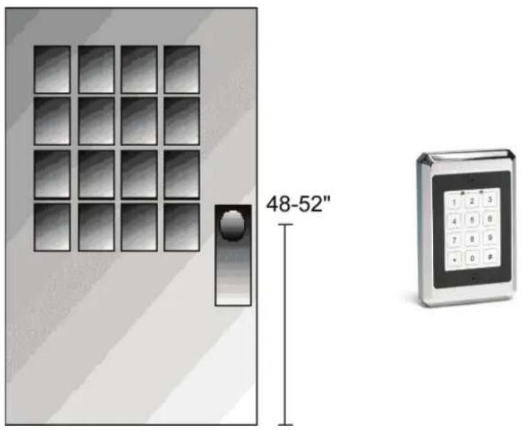
Keypad Mounting Height
Mounting height can vary depending on requirements. An appropriate range is typically between 48 and 52 inches on center off the floor.
text_image
48-52"Wiring the SSW-FX Keypad to a 232 Access Control Module
The connection between the SSW-FX keypad and the 232 Controller requires a 4-conductor, stranded wire with overall foil shield. The 6-conductor wire harness from the keypad connects to connector P6 on the controller. Connect the wires, color to color (red to red, black to black, white/black to white/black and white/yellow to white/yellow). Refer to the wire lengths below. As mentioned in Step 2 previously, the drain wire must be attached to Ground on the controller side, which is the V-terminal or negative of your power supply.
text_image
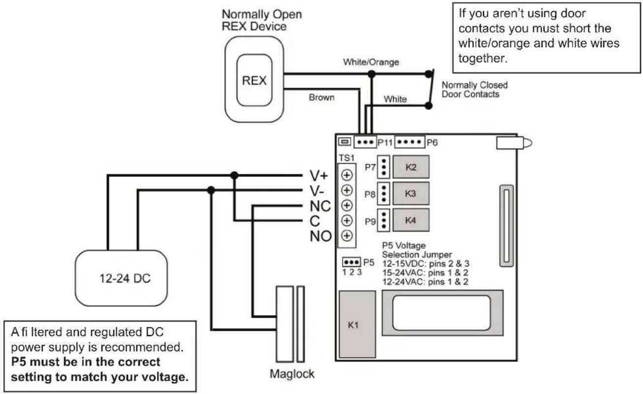
To Keypad Wire Color to Color Drain Wire Wiring Requirements: 18 AWG – 1000 Ft. 20 AWG – 500 Ft. 22 AWG – 250 Ft.Basic Access Control Using an Electromagnetic Lock (Maglock)
flowchart
graph TD
    A["12-24 DC"] --> B["Maglock"]
    B --> C["V+ V- NC C NO"]
    C --> D["Brown"]
    D --> E["White/Orange"]
    E --> F["Normally Open REX Device"]
    F --> G["TS1 P7 K2"]
    G --> H["P5 Voltage Selection Jumper 12-15VDC: pins 2 & 3"]
    H --> I["12-24VAC: pins 1 & 2"]
    I --> J["K1"]
    J --> K["If you aren't using door contacts you must short the white/orange and white wires together."]
    style A fill:#f9f,stroke:#333
    style F fill:#ccf,stroke:#333
    style G fill:#cfc,stroke:#333
    style H fill:#fcc,stroke:#333
    style I fill:#cff,stroke:#333
    style J fill:#ffc,stroke:#333
    style K fill:#fcc,stroke:#333
Basic Access Control Using an Electric Door Strike
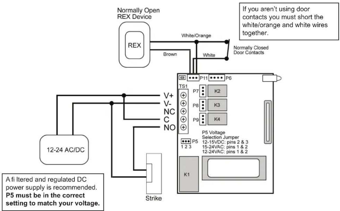
flowchart
graph TD
    A["Normally Open REX Device"] -->|Brown| B["12-24 AC/DC"]
    A -->|White/Orange| C["Normally Closed Door Contacts"]
    C --> D["P5 Voltage Selection Jumper"]
    D --> E["12-15VDC: pins 2 & 3"]
    D --> F["15-24VAC: pins 1 & 2"]
    D --> G["12-24VAC: pins 1 & 2"]
    D --> H["K1"]
    I["A fi Itered and regulated DC power supply is recommended. P5 must be in the correct setting to match your voltage."] --> J["Strike"]
Integrated Access Control Wiring
Follow the diagram below for integrated access control wiring. This includes connecting door contacts, request-to-exit (REX), propped door alarm and forced door alarm.
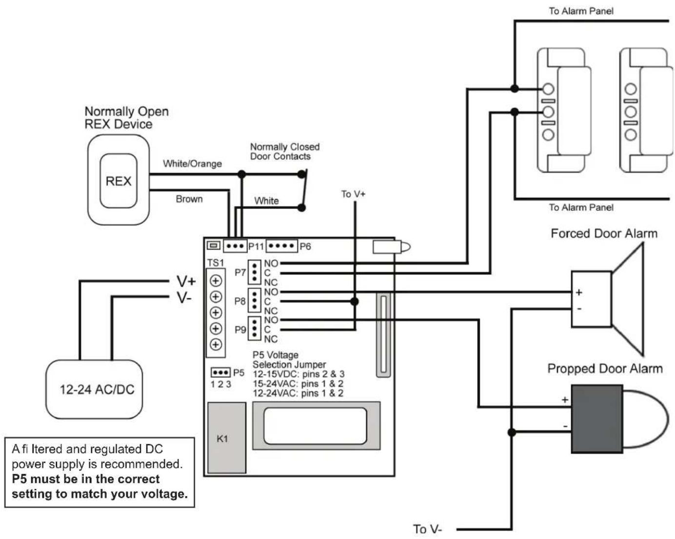
flowchart
graph TD
    A["REM"] -->|White/Orange| B["Normally Open REX Device"]
    A -->|Brown| C["To V+"]
    B --> D["To Alarm Panel"]
    C --> D
    D --> E["Forced Door Alarm"]
    E --> F["Propped Door Alarm"]
    F --> G["To V-"]
    H["12-24 AC/DC"] --> I["V+ V-"]
    I --> J["Normal Closed Door Contacts"]
    J --> K["P5 Voltage Selection Jumper"]
    K --> L["12-15VDC: pins 2 & 3"]
    K --> M["15-24VAC: pins 1 & 2"]
    K --> N["12-24VAC: pins 1 & 2"]
    K --> O["K1"]
    O --> P["P5"]
    style A fill:#f9f,stroke:#333
    style B fill:#ccf,stroke:#333
    style C fill:#ccf,stroke:#333
    style D fill:#cfc,stroke:#333
    style E fill:#fcc,stroke:#333
    style F fill:#cff,stroke:#333
    style G fill:#ffc,stroke:#333
    style H fill:#fff,stroke:#333
    style I fill:#fff,stroke:#333
    style J fill:#fff,stroke:#333
    style K fill:#fff,stroke:#333
    style L fill:#fff,stroke:#333
    style M fill:#fff,stroke:#333
    style N fill:#fff,stroke:#333
    style O fill:#fff,stroke:#333
    style P fill:#fff,stroke:#333
| Wire Color Relay | Connection |
| Gray Normally Closed | |
| Blue Common | |
| Green Normally Open | |
Programming the Keypad
Note: This section contains details about programming the SSW-FX keypad only. All user codes and other access control features are programmed into the controller. Please refer to the Door♦Gard Self-Contained Access Control Systems Keypad Programming Guide for details about programming the controller.
The SSW-FX keypad has it's own local programming options. The programming options chart below shows all the programming commands available in the SSW-FX.
To program the SSW-FX you first must enter program mode.
To enter program mode enter the following on the keypad: 099 # program code * (default program code is 6789).
Programming Options Chart
| Command/Action Keys to Enter/Details | |
| Command 90Change Local Program Code | 90 # 0 # 0 # new code * new code * (default = 6789) |
| Command 91Set/Clear Keypad Options(options below, defaults in bold) | 91 # option # set/clear # ** |
| Option Clear Set0 – Visual Keypress Feedback 0 = Disabled 1 = Enabled1 – Audio Keypress Feedback 0 = Disabled 1 = Enabled | |
| Command 96Reset Keypad to Default Settings | 96 # 0 # 0 # ** |
| Exit Program Mode | Press the * Key |
Note: Auto-Entry is not available in this model.
LED Indications
| LED State Description | |
| Red Solid Door Locked | |
| Green Solid Door Unlocked | |
| Yellow Solid Programming Error | |
| Yellow Flashing Slowly (single flash) Controller Program Mode | |
| Yellow Flashing Slowly (double flash) | Front End Program Mode |
| Yellow Momentary Flash (key press) | Visual Keypress Feedback |
Testing the Keypad
After installing the keypad, it is recommended that you perform the keypad self-test once a year, to ensure that the keypad is working properly.
To perform the self-test, with the unit powered up, press the following keys on the keypad: 7890 # 123456 *
- If all 12 keypresses are accepted, the keypad enters self-test mode.
• The LEDs alternate three times followed by the sounder beeping three times. - When finished the yellow LED starts flickering rapidly.
- Press * to clear.
Program Mode Loopback
If you've forgotten the local program code use the following loopback connection to enter program mode. Power down the unit, short the wires in the configuration illustrated, then power the unit back up. The yellow LED should be flashing. Now change your local program code or reset the unit. Power the keypad down and reconnected the wire harness in the original configuration.
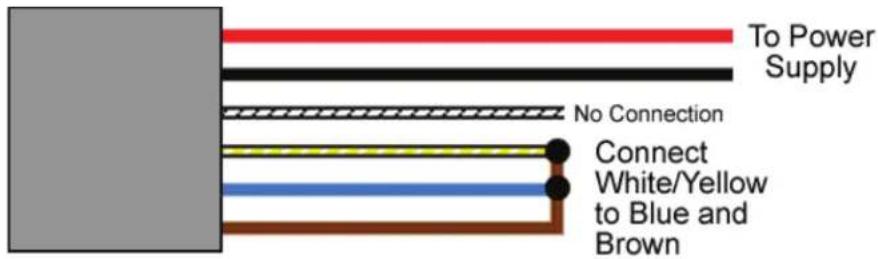
text_image
To Power Supply No Connection Connect White/Yellow to Blue and BrownFront End Default Loopback Connection
The following loopback connection allows you to default the keypad in front end mode. Power down the unit, short the wires in the configuration illustrated, then power the unit back up. After you hear the three beeps, remove power and reconnect the wires in the proper configuration.
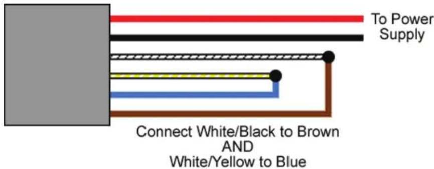
text_image
To Power Supply Connect White/Black to Brown AND White/Yellow to BlueLimited Warranty
This Nortek Security & Control product is warranted against defects in material and workmanship for twenty four (24) months. This warranty extends only to wholesale customers who buy direct from Nortek Security & Control or through Nortek Security & Control's normal distribution channels. Nortek Security & Control does not warrant this product to consumers. Consumers should inquire from their selling dealer as to the nature of the dealer's warranty, if any. There are no obligations or liabilities on the part of Nortek Security & Control LLC for consequential damages arising out of or in connection with use or performance of this product or other indirect damages with respect to loss of property, revenue, or profit, or cost of removal, installation, or reinstallation. All implied warranties, including implied warranties for merchantability and implied warranties for fitness, are valid only until the warranty expires. This Nortek Security & Control LLC Warranty is in lieu of all other warranties express or implied.
All products returned for warranty service require a Return Authorization Number (RA#). Contact Returns at 1-855-546-3351 for an RA# and other important details.
Technical Support
DEALERS/INSTALLERS ONLY! End users must contact the dealer/installer for support. If the keypad still does not work after troubleshooting, please call the Technical Services department at 1-800-421-1587.