
SW-FUSION-EM - Electrical measuring device Crestron - Free user manual and instructions
Find the device manual for free SW-FUSION-EM Crestron in PDF.


| Product Type | Video Processor / Switcher |
| Brand | Crestron |
| Model | SW-FUSION-EM |
| Dimensions (W x D x H) | 8.4 in x 5.2 in x 1.7 in (213 mm x 132 mm x 43 mm) |
| Weight | 1.5 lbs (0.68 kg) |
| Power Supply | 12V DC, 1.5A (included) |
| Power Consumption | 18W max |
| Video Inputs | 4x HDMI, 2x DisplayPort |
| Video Outputs | 2x HDMI, 1x HDBT |
| Max Resolution | 4K@60Hz (4:4:4) |
| Audio Support | Embedded HDMI audio, analog stereo out |
| Control Interface | Ethernet, RS-232, IR |
| Key Features | Video wall processing, multi-window, seamless switching |
| Operating Temperature | 32°F to 104°F (0°C to 40°C) |
| Storage Temperature | -4°F to 140°F (-20°C to 60°C) |
| Mounting | Rack-mountable (1U) with included brackets |
| Cleaning Instructions | Wipe with a dry, soft cloth. Do not use liquids or solvents. |
| Safety | CE, FCC, UL listed. Use only supplied power adapter. |
| Spare Parts / Repairability | Contact Crestron service for replacement parts. No user-serviceable parts inside. |
| Warranty | 3-year limited warranty |
Frequently Asked Questions - SW-FUSION-EM Crestron
User questions about SW-FUSION-EM Crestron
0 question about this device. Answer the ones you know or ask your own.
Ask a new question about this device
Download the instructions for your Electrical measuring device in PDF format for free! Find your manual SW-FUSION-EM - Crestron and take your electronic device back in hand. On this page are published all the documents necessary for the use of your device. SW-FUSION-EM by Crestron.
USER MANUAL SW-FUSION-EM Crestron
Specifier: The Specifier/Design Professional is responsible for the accuracy of all project specifications, including system application and coordination with related sections. This guide specification is provided as a convenience and requires editing to match actual project requirements. CRESTRON ELECTRONICS, INC. SHALL NOT BE LIABLE FOR ANY DAMAGES ARISING OUT OF THE USE OF ANY OF ITS GUIDE SPECIFICATIONS. For Crestron design assistance and design review please contact Sales Support Services Department at 800.237.2041 or techsales@crestron.com.
PART 1 GENERAL
1.1 SUMMARY
A. Section Includes:
Power meter unit integrated with the following:
Specifier: Edit paragraph to correspond to components and features required for this Project.
- Automation and control server.
- Electrical breaker panel.
- Network power switching controls.
- Network lighting controls.
- Network management and control systems.
B. Related Requirements:
Specifier: Related Information paragraph is optional. If retaining, edit and coordinate list of sections below to correspond to Project requirements.
- Division 25 Section "Integrated Automation Software for Control and Monitoring Networks" for software and integration hardware for network automation and monitoring controls.
- Division 25 Section "Integrated Automation Controls" for software and integration hardware for network lighting controls.
- Division 25 Section "Integrated Automation Network Equipment".
- Division 26 Section "Common Work Results For Electrical".
- Division 26 Section "Programmable Controllers".
- Division 26 Section "Digital-Network Lighting Controls"
- Division 26 Section "Wiring Devices".
1.2 REFERENCES
A. California Energy Commission (CEC):
- CEC CCR Title 24, Part 6: California Energy Efficiency Standards for Residential and Nonresidential Buildings, California's Appliance Efficiency Program: Listed lighting control devices.
B. National Fire Protection Association (NFPA):
- NFPA 70 - National Electrical Code.
C. Underwriters Laboratories (UL):
- UL 916 – Energy Management Equipment.
D. National Electrical Code (NEC):
- NEC Article 410.134 – Direct Current Equipment.
E. ABBREVIATIONS:
- BAS: Building Automation System.
- AV: Audio Visual.
- RF: Radio Frequency.
- CT: Current Transformer.
1.3 SYSTEM DESCRIPTION
Specifier: Edit description below to correspond to Project requirements.
A. Power metering system integrated with lighting, building automation, and Audio-Visual systems utilizing a single control protocol and network infrastructure.
- Power meter system with central master control processor integrates the following controls:
a. Native communication with building wide Audio Visual systems control network.
b. Emergency Lighting Control when used with UL 924 devices.
c. Multiple Lighting Control Systems.
d. Touch panel controls.
e. Window treatment controls.
f. Timed room lighting.
g. HVAC controls.
h. Centralized facility management server:
1) Web-accessible, network-connected, Windows-based lighting management software running on a Microsoft Exchange Server communicating over TCP/IP networks to provide lighting and window shade control, daylight harvesting, load shedding, occupancy sensing, and occupied/unoccupied lighting schedules.
2) Store, evaluate and report power usage data.
i. Building Management Systems Interface – Direct communications through master controller with BACnet, Modbus, LonWorks and Metasys management protocols.
B. Unified System Integration – Controller supports native communication protocol utilized by the lighting and AV control systems.
- Communication protocol adaptors or translation interfaces between energy management devices, energy management servers, lighting control systems, and AV control systems will not be accepted.
1.4 ACTION SUBMITTALS
Specifier: Action submittals require responsive action by A/E or Owner.
A. Product Data: For each type of product required for energy metering system, demonstrating compliance with requirements.
B. Shop Drawings: Indicate the following:
- Schematic diagram of controlled and non-controlled circuits and peripherals.
- Circuits and emergency circuits with capacity and phase, control zones, load type and voltage per circuit.
1.5 INFORMATIONAL SUBMITTALS
Specifier: Informational submittals require review, but not response, by A/E or Owner. Edit list below based on project requirements.
A. Buy American Act certificate.
B. CEC CCR Title 24 appliance efficiency listing certification.
C. Sample of manufacturer's warranty.
1.6 CLOSEOUT SUBMITTALS
A. Operating and maintenance instructions.
1.7 QUALITY ASSURANCE
A. Source Requirements: Provide lighting control, and power metering hardware and software through a single source from a single manufacturer.
B. Manufacturer Qualifications:
Specifier: Retain paragraph below if Owner allows substitutions but requires strict control over qualifying of substitutions.
- Approval of Comparable Products: Submit the following in accordance with project substitution requirements, within time allowed for substitution review:
a. Product data indicating compliance with requirements of this Section.
b. Samples of each component.
c. Sample submittals from similar project.
d. Project references: Minimum of 5 completed installations, with Owner and Architect contact information.
e. Sample warranty.
-
Substitutions following award of contract are not allowed except as stipulated in Division 01 General Requirements.
-
Approved manufacturers must comply with separate requirements of Submittals Article.
C. Electrical Components, Devices, and Accessories: UL listed and labeled.
D. Regulatory Requirements: Provide components and systems that comply with requirements of the following:
- NFPA 70.
- Underwriters Laboratory (UL) standards.
- Applicable codes and regulations.
1.8 COORDINATION
Specifer: Edit list below to reference sections controlled by lighting controls for Project. Crestron lighting control system is able to integrate with Crestron's Cresnet building-wide automation network, BAS, building security systems, and a variety of equipment and devices.
A. Coordinate integrated dimming controls with systems and components specified in the following sections:
- Division 11 Section "Audio-Visual Equipment".
- Division 12 Section "Window Treatments".
- Division 23 Section "Instrumentation and Control for HVAC".
- Division 25 Section "Integrated Automation Software for Control and Monitoring Networks"
- Division 25 Section "Integrated Automation Control of Electrical Systems".
- Division 26 Section "Wiring Devices".
- Division 26 Section "Lighting Devices".
- Division 26 Section "Interior Lighting".
- Division 27 Section "Communications Horizontal Cabling".
- Division 27 Section "Audio-Visual Communications".
- Division 27 Section "Audio-Video Systems".
- Division 28 Section "Electronic Access Control and Intrusion Detection".
1.9 PROJECT CONDITIONS
A. Environmental Conditions Range:
- Temperature: 32 - 104 deg F (0 - 40 deg C).
- Relative Humidity: 0 – 95 percent, non-condensing.
1.10 WARRANTY
A. Special Warranty: Manufacturer's standard form in which manufacturer agrees to repair or replace components of modular dimming controls system the fail in materials or workmanship within the specified warranty period following substantial completion.
-
Warranty Period: Touch screen display and overlay components: 90 days.
-
Warranty Period: Disc drives and other moving parts, pan/tilt heads, and power supplies: 1 year.
- Warranty Period: Other components, 3 years.
B. Special Warranty: Manufacturer's standard form in which manufacturer agrees to repair or replace components of modular dimming controls system that fail in materials or workmanship within the specified warranty period following substantial completion.
C. Manufacturer's Extended Support Service: Extended telephone support: Unlimited period.
PART 2 PRODUCTS
2.1 MANUFACTURERS
A. Basis-of-Design Manufacturer: Subject to compliance with requirements, provide products of Crestron Electronics, Inc., Rockleigh, NJ 07647, Phone (800)237-2041, Fax: (201)767-1903, www.crestron.com[or comparable products from a single manufacturer approved by Architect prior to bidding], with the following components and characteristics.
2.2 POWER METER
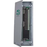
A. Basis of Design Product: Crestron, Green Light GLS-EM-MCU power meter unit.
B. Scalability:
- Monitor main circuit and up to 84 branch circuits.
a. Branch circuits added in sets of 6, 15 or 21. - Monitor up to 4 external devices through configurable built-in digital inputs.
C. Integration:
- Networked to central control processor specified in Division 25 Section "Integrated Automation Network Equipment".
a. Ethernet: 10/100 Mbps
D. Meter data:
- Reported in real-time.
- Logged in non-volatile internal memory.
a. In case of network failure data is maintained in internal memory.
b. Capacity: 4000 records at 5, 10, 0r 15 minute intervals.
c. Internal memory data shall be periodically uploaded to server through system control processor.
E. Verification:
- Real-time data shall be viewable on integrated user interfaces and administration software.
F. Meter Characteristics:
- Built-in microprocessor:
a. Stand-alone operation when network is not available.
b. Process input data for real-time transmission and local storage.
- Each meter channel reports the following data:
a. RMS voltage (100 - 347 VAC)
b. RMS current (A)
c. Active power (kW)
d. Reactive power (kVAR)
e. Apparent power (kVA)
f. Power factor
g. Total energy used (kWh)
- Power Supply:
a. Internal power supply derived from voltage and neutral inputs, 100 to 347 VAC, 50/60Hz
- Voltage Inputs:
a. 3 voltage inputs.
b. Factory calibrated.
- Current Inputs:
a. 3 current transformer inputs.
b. Factory calibrated.
c. Current Transformers:
1) Main current transformers available in multiple factory calibrated current ratings and accuracy levels including:
a) 200A
b) 400A
c) 600A
d) 20A
e) 50A
f) 200A high accuracy
g) 400A high accuracy
h) 600A high accuracy
i) 20A high accuracy
j) 50A high accuracy
- Power meter shall be available in 2 Phase or 3 Phase versions:
a. Voltage Inputs for 3 Phase unit:
1) 3 inputs and Neutral
a) Phase A, 100 to 347 VAC, 50/60Hz
b) Phase B, 100 to 347 VAC, 50/60Hz
c) Phase C, 100 to 347 VAC, 50/60Hz
b. Voltage Inputs for 2 Phase unit:
1) 2 inputs and Neutral
a) Phase A, 100 to 347 VAC, 50/60Hz
b) Phase B, 100 to 347 VAC, 50/60Hz
- Digital input channels:
a. 4 digital pulse inputs:
1) Input voltage: 0-24 VDC
2) Frequency: 0.02 - 100 Hz
- User Interface and Indicators:
a. 1 USB Type B port for communication with configuration computer.
b. 1 setup button and LED indicator.
c. 1 network control processor communication LED indicator.
d. 1 LED indicator per current input.
e. 1 LED indicator per voltage input.
- Expansion circuit data link:
a. Support for 0-4 expansion units.
1) Expansion unit input capability:
a) 6 circuits
b) 15 circuits
c) 21 circuits
- Mounting:
a. Surface mount metal box enclosure.
b. Suitable for mounting in plenum airspace.
2.3 ACCESSORIES
A. Current Transformers
- 200 Amp Split core transformer
a. Factory tested and characterized.
b. Basis of Design Product: Crestron, GLS-EM-CT-200A 200A split core current transformer.
- 400 Amp Split core transformer
a. Factory tested and characterized.
b. Basis of Design Product: Crestron, GLS-EM-CT-400A 400A split core current transformer.
- 600 Amp Split core transformer
a. Factory tested and characterized.
b. Basis of Design Product: Crestron, GLS-EM-CT-600A 600A split core current transformer.
- 20 Amp Split core transformer
a. Factory tested and characterized.
b. Basis of Design Product: Crestron, GLS-EM-CT-20A 20A solid core current transformer.
- 50 Amp Split core transformer
a. Factory tested and characterized.
b. Basis of Design Product: Crestron, GLS-EM-CT-50A 50A solid core current transformer.
B. Branch power meter expansion units – 2 Phase Panels:
- 15 Channel branch circuit expander
a. 2 Phase 15 circuits
b. Basis of Design Product: Crestron, GLS-EM-CTI-2P15 15 channel 2 Phase branch power meter.
- 21 Channel branch circuit expander
a. 2 Phase 21 circuits
b. Basis of Design Product: Crestron, GLS-EM-CTI-2P21 21 channel 2 Phase branch power meter.
- 6 Channel branch circuit expander
a. 2 Phase 6 circuits
b. Basis of Design Product: Crestron, GLS-EM-CTI-2P6 6 channel 2 Phase branch power meter.
C. Branch power meter expansion units - 3 Phase Panels:
- 15 Channel branch circuit expander
a. 3 Phase 15 circuits
b. Basis of Design Product: Crestron, GLS-EM-CTI-3P15 15 channel 3 Phase branch power meter.
- 21 Channel branch circuit expander
a. 3 Phase 21 circuits
b. Basis of Design Product: Crestron, GLS-EM-CTI-3P21 21 channel 3 Phase branch power meter.
- 6 Channel branch circuit expander
a. 3 Phase 6 circuits
b. Basis of Design Product: Crestron, GLS-EM-CTI-3P6 6 channel 3 Phase branch power meter.
2.4 CENTRAL SIGNAL PROCESSOR
A. Control Processor: Network connected dual bus programmable control processor for low voltage controls, devices, and subsystems through multiple control interfaces. SNMP support, with built-in firewall, NAT, and router. 4-wire bus providing 24 VDC power to network devices, with two independent sensing inputs. In separate enclosure.
Specifier: The Crestron PAC2 works seamlessly with Crestron's entire line of lighting dimmers and shade controls, keypads and touch panels, thermostats, wireless gateways, control cards, and expansion modules.
- Basis of Design: Crestron Professional Automation Control System Model PAC2.
- Mounting: [Surface-mounted][Modular enclosure-mounted, in array indicated].
B. Ethernet communication card:
- Basis of Design: Crestron 10/100BaseT half/full duplex Ethernet card Model C2ENET-1.
C. Control Processor: Integrates sensors and other low voltage controls, devices, and subsystems through multiple control interfaces with control network. Enables addition of relays, 8 separate I/O ports in 2 isolated segments supporting up to 20 devices each, serial COM ports, DTMF interfaces, and shade controllers. MMC memory expansion card slot. 4-wire bus providing 24 VDC power to network devices, with two independent sensing inputs. Use with separate power supply.
Specifier: The Crestron PAC2M is a compact, low-cost alternative to the PAC2 designed for small lighting and automation applications. At half the size of a PAC2, the PAC2M is perfect for apartments and smaller homes as well as individual meeting rooms and lecture halls.
- Basis of Design: Crestron Professional Automation Mini-Control System Model PAC2M.
- Mounting:
a. Surface-mounted
b. Modular enclosure-mounted in array indicated
PART 3 EXECUTION
3.1 EXAMINATION
A. Prior to installation, examine work area to verify measurements, and that commencing installation complies with manufacturer's requirements.
3.2 INSTALLATION
A. Comply with requirements of Division 26 Sections "Common Work Results for Electrical."
B. Do not install dimming controls until space is enclosed, HVAC systems are running, and overhead and wet work in dimming control work space are complete.
C. Install dimming controls in accordance with manufacturer's instructions.
D. Grounding: Provide electrical grounding in accordance with NFPA 70.
E. Perform setup for each lighting scene, window shade controller, and audio-visual equipment component.
3.3 SYSTEM STARTUP
A. Provide system startup and adjustment to occupied conditions in accordance with manufacturer's recommendations.
B. Perform operational testing to verify compliance with Specifications. Adjust as required.
C. Calibrate power monitor during commissioning using current transformers characteristics codes.
3.4 CLOSEOUT ACTIVITIES
Specifier: On projects with more complex installations, consider retaining both demonstration and training by manufacturer's authorized representative. Consult Crestron representative for costs associated with these services.
A. Demonstration: Schedule metering system demonstration with Owner to allow verification that metering unit functions as required.
B. Training: Train Owner's personnel to operate, maintain, and program integrated system.
END OF SECTION 26 09 13
- PART 1 GENERAL
- SUMMARY
- Section Includes:
- Related Requirements:
- REFERENCES
- California Energy Commission (CEC):
- SYSTEM DESCRIPTION
- ACTION SUBMITTALS
- INFORMATIONAL SUBMITTALS
- CLOSEOUT SUBMITTALS
- QUALITY ASSURANCE
- COORDINATION
- PROJECT CONDITIONS
- WARRANTY
- PART 2 PRODUCTS
- MANUFACTURERS
- POWER METER
- Meter Characteristics:
- ACCESSORIES
- CENTRAL SIGNAL PROCESSOR
- PART 3 EXECUTION
- EXAMINATION
- INSTALLATION
- SYSTEM STARTUP
- CLOSEOUT ACTIVITIES
- END OF SECTION 26 09 13
Brand : Crestron
Model : SW-FUSION-EM
Category : Electrical measuring device