H6D - Camera HASSELBLAD - Free user manual and instructions
Find the device manual for free H6D HASSELBLAD in PDF.


User questions about H6D HASSELBLAD
0 question about this device. Answer the ones you know or ask your own.
Ask a new question about this device
Download the instructions for your Camera in PDF format for free! Find your manual H6D - HASSELBLAD and take your electronic device back in hand. On this page are published all the documents necessary for the use of your device. H6D by HASSELBLAD.
USER MANUAL H6D HASSELBLAD
natural_image
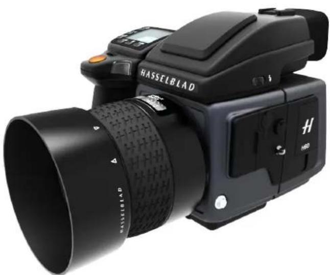
Exterior view of a black H6D DSLR camera with 100c lens and control panel (no text or symbols on body)USER GUIDE
Content
1 Introduction 8
1.1 New in this version 1.7 9
1.2 System Requirements 9
1.3 General Technical Specifications 10
1.4 H6D-50c 11
Technical Specifications 11
1.5 H6D-100c 12
Technical Specifications 12
2 Safety 13
2.1 Warnings 14
2.2 Cautions 14
2.3 Disposal 15
2.4 FCC 16
2.5 ISED 16
3 Overview 17
3.1 The H6D Interaction Displays 18
3.2 Main Camera Parts 19
3.3 Parts, Components, Buttons and Controls 20
3.4 Grip Buttons and Controls 23
3.5 Camera Body Buttons and Controls 24
3.6 Sensor Unit 25
3.7 Viewfinder 26
3.8 Lenses 27
3.9 Display Information 28
3.10 Sensor Unit Display and Controls 29
3.11 Grip Display 30
3.12 Viewfinder Display 31
Viewfinder Display Example 31
3.13 Re-assignable Grip Buttons Options 33
3.14 Shortcuts 34
3.15 Phocus Overview 35
3.16 Battery and Battery Grip 36
3.17 Battery Charger 37
Charge the Battery 37
Rechargeable Battery Grip Specification 38
Battery Life and Battery Warning 39
3.18 Temperature Warning 39
3.19 Power & Timeout Modes 40
3.20 Remove and Attach the Viewfinder 41
3.21 Eyepiece Adjustment 42
USER GUIDE
3.22 Rubber Eye Cup 42
3.23 Accessory Connection 43
3.24 PC Flash Connector 43
3.25 Protective Baseplate 44
Remove the Protective Baseplate 44
Attach the Protective Baseplate 44
3.26 Memory Cards 45
To Insert a Memory Card 46
To Remove a Memory Card 47
Formatting Memory Cards 48
Format Button 48
Format Memory Cards via Sensor Unit 48
3.27 Carrying Strap 49
3.28 Remove the Carrying Strap 50
3.29 Change Lens 51
Attach a Lens 51
Remove a Lens 51
4 To Prepare 52
4.1 Delivery Check 53
4.2 Set Date and Time 54
4.3 Set Language 55
4.4 Connect to a Computer 56
4.5 Camera Interval Settings Example 57
4.6 Set Brightness of the Display 58
4.7 Set Drive Mode 59
5 To Use 60
5.1 Navigating the Menus 61
Overview of Menus and Settings on Sensor Unit 61
Touch Screen Navigation 61
Button Navigation 61
5.2 The Main Menu 62
Add Favourite Functions to MAIN MENU Screen 62
Remove Favourites FROM the MAIN MENU Screen 62
Display Control Screen 63
Control Screen Description 64
5.3 Camera Settings Menu 68
5.4 Camera Exposure Settings 69
Increment Step Size Settings 70
Exposure Compensation / Quick Adjust 71
Flash Adjustment 71
ISO and White Balance 72
USER GUIDE
Light Metering Settings 73
Shutter Function Settings 74
Manual Exposure Mode 75
Automatic Exposure Mode 76
Automatic Exposure - P and PV Mode 77
AE-L Button 78
Light Metering Mode 79
5.5 True Exposure explained 80
White Balance Settings - Presets and Manual 81
Flash Settings 82
Flash and Strobe Settings 83
Integral Flash 84
Separate Flash Unit Connection 85
Flash Measure of Separate Flash Unit 86
Exposure Lock 87
AE-L / Quick Adjust 88
Mirror Settings 89
5.6 Camera Image Settings 90
5.7 Camera Quality Settings 92
5.8 Camera Focus Settings 93
Focusing Distance Calculation 94
Stop Down / Depth-of-Field Preview 94
Infrared Focus Setting 95
Focus Assist 96
Manual Focus 97
Manual Override in Autofocus Mode 97
Auto / Manual Focus Setting 97
Autofocus 98
Autofocus Check in Manual Mode 98
Single Shot Focus 99
Continuous Focus 99
5.9 Camera True Focus 100
True Focus and Absolute Position Lock 101
True Focus and Camera Handling 102
Focus Checking 102
5.10 Camera True Focus Methods 103
Activated By True Focus Button 103
Activated By Shutter Release 104
5.11 Camera Self Timer 105
5.12 Camera Interval Settings 106
5.13 Camera Bracketing Settings 107
Bracketing Function 107
USER GUIDE
5.14 Camera Live View Settings 108
Live View 109
Zooming in Live View 110
Focus in Live View 110
Focus in Live View using Focus Peaking 111
Live View with HDMI External Screen 112
Live View with HTS 1.5x Tilt/Shift Adapter 113
5.15 Camera Custom Buttons 114
5.16 Camera Configuration Settings 115
5.17 Camera Body Settings 116
5.18 Video Settings Menu QUALITY 117
Video Quality Settings 117
5.19 Video Settings Menu Live View 118
Live View Settings 118
5.20 Video Recording 119
5.21 General Settings Menu 120
General Settings Wi-Fi 121
5.22 General Settings Display 122
5.23 General Settings Storage 123
Format CFast and SD cards 124
Format Button 124
Format Memory Cards via Sensor Unit 124
Image and Video Destination 125
5.24 General Settings Date and Time 126
5.25 General Settings Power and Timeouts 127
Set Display Off Mode 128
Power Off 128
Power from USB 128
5.26 General Settings Spirit Level 129
Calibrate Spirit Level 130
5.27 General Settings HTS 131
5.28 General Settings Language 132
5.29 General Settings Service 133
5.30 General Settings Check for Update 134
Update H6D Firmware Procedure 134
5.31 General Settings About 135
5.32 Grip Display Navigation 136
Buttons and Controls on Grip Display 136
To Adjust Shutter and Aperture on Grip 137
Grip Display Navigation 138
5.33 Viewfinder Display Navigation 141
Typical Viewfinder Display 141
Viewfinder Display Navigation Overview 142
Viewfinder Display Examples 143
USER GUIDE
5.34 Remove / Attach Viewfinder 146
Remove the Viewfinder 146
Attach the Viewfinder 146
Adjust the Eyepiece 147
Change Focusing Screen 148
5.35 Preview, Histogram and Browsing 149
Preview Modes 149
Standard Preview 150
9 View Mode 150
Histogram Types 151
Histogram Mode 151
Luminance Histogram Mode 151
Separate Histogram RBG Mode 151
Capture Details Mode 151
Histogram Mode - Exposure 152
Browsing 153
Zoom in and out 154
Select Card to Browse 155
Create New Folder 156
5.36 Phocus 157
Features in Phocus 157
Phocus Mobile 157
Phocus and Hasselblad Capture Files 158
5.37 Lenses 159
Remove the Lens 159
Attach the Lens 160
Remove the Lens Cap 161
Attach the Lens Cap 161
Remove the Lens Shade 162
Attach the Lens Shade 162
Filters 163
To Set Focus Distance 164
5.38 Battery 165
Charge the Battery 165
Check the Battery Status 166
5.39 Protective Baseplate 167
Remove the Protective Baseplate 167
Attach the Protective Baseplate 167
5.40 Store the Camera 168
USER GUIDE
6 View Camera Connectivity 169
6.1 View camera operation 170
Power Solution 170
Flash Sync Mode 171
Pinhole Mode 172
Video 173
7 Accessories 174
7.1 Accessories Connectivity Diagram 175
7.2 HC Lens Range 176
7.3 Optional HC Lens Accessories 177
HTS 1.5 177
H 13, 26 and 52 Extension tubes 177
Converter H 1.7X 177
Macro Converter H 177
7.4 Optional Accessories 178
CF Lens Adapter 178
HVM waist level viewfinder 178
Pro shade V/H 60 – 95 178
Pro shade adapters 178
Tripod quick coupling H 178
Flash adapter SCA 3902 179
UV-sky filters 179
Pola filters 179
Support strap with Quick plate H 179
Camera strap H 179
Focusing screens 179
Release cord H 180
HVM correction lens holder 180
HVD 90x / HV 90x & 90x-II viewfinders 180
Angle finder H 180
7.5 HM 16-32 Film Magazine 181
8 Troubleshooting 189
8.1 Error Messages 191
8.2 Change Language on Sensor Unit from Unknown Language 192
8.3 Clean the Lens Glass 193
Remove Dust 193
Remove Smear 193
8.4 Clean the Sensor Unit Filter 194
text_image
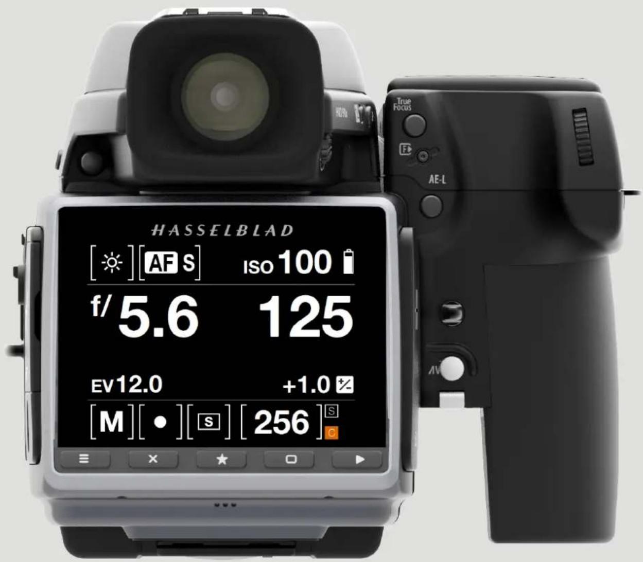
HASSELBLAD [★][AF S] Iso 100 # f/5.6 125 EV12.0 +1.0# [M][•][S] [256] True Focus AE-LIntroduction
USER GUIDE
1.1 NEW IN THIS VERSION 1.7
New features described in this manual, requires firmware version 1.20.0 or later.
- Crop Modes added to Live View and the RAW file.
See page 90.
• Backup option added in Storage menu.
See page 125.
• Order of Overlays In Live View changed.
See page 109.
• New Camera Menu item: "Image".
See page 90.
• Image Orientation setting moved to the
new Image Menu.
See page 91.
• Support for additional Cards.
See page 45.
1.2 SYSTEM REQUIREMENTS
Storage and editing of RAW images requires certain minimum computer capabilities. Large images require a reasonably high performance computer with sufficient memory, advanced graphics capabilities, and a recent operating system.
It is recommended that the computer has a USB 3 connector, which allows you to load images more quickly from the camera.
A USB CFast or SD card reader must be used for image transfer from the CFast and SD cards.
natural_image
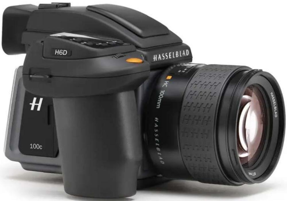
Black HASSELBIAD DSLR camera with H6D branding and 100mm lens, no visible text or symbols on body beyond brand name and lens specifications.Introduction
USER GUIDE
1.3 GENERAL TECHNICAL SPECIFICATIONS
| Camera Type Medium Format Digital SLR camera with Auto-focus, Auto-exposure, interchangeable Viewfinders and Lenses. | |
| Construction | One piece stainless steel shell. Die-cast aluminium internal structure. Tripod sockets (1/4 and 3/8") and quick coupling tripod plate for rapid mounting. |
| Display 3 inch TFT type, 24 bit colour, 920K pixels; Touch functionality: Yes, full support | |
| Live View On camera, host and iOS device with high frame rate | |
| Wi-Fi | 802.11 a, ac, b, g, n (a and ac are depending on region). |
| Lenses | Hasselblad HC/HCD lenses with built-in electronically controlled shutter and aperture. Automatic or manual focusing with instant manual focus override. All HC/HCD lenses meet the exacting requirements of digital photography. Lens shades can be mounted in reverse for transport. |
| Viewfinder | A 90° reflex viewfinder, providing 100% field of view even when wearing eyeglasses, and built-in multi-mode light metering system. Image magnification 3.1x for H6D-50c and 2.7x for H6D-100c. Integrated fill-in flash with guide number 12. Hot-shoe for automatic flash (Metz SCA3002 system / adapter SCA3902). Dot matrix display with presentation of all relevant information. Built in dioptre adjustment from -5 to +3.5D. Interchangeable. |
| Focusing | Automatic and manual focusing with electronic focus aid in manual mode. Instant manual focus override. Automatic focusing using passive central cross type phase detection sensor. AF metering range EV 1 to 19 (ISO 100). |
| Shutter | Electronically controlled lens shutter with speeds up to 1/2000 (H6D only. 1/1000 with other H System Cameras). Flash sync at all speeds. |
| Flash Control | TTL centre-weighted system. Can be used with the built-in flash or a wide variety of flashes compatible with the SCA3002 (Metz) system using adapter SCA3902. ISO range 16 to 6400. Flash output can be adjusted (-3 to +3EV) for fill-in purposes independent of ambient light. Synch at all shutter speeds. |
| Exposure Metering | Multi-mode exposure metering using 90° reflex viewfinder. Metering options are: Spot (diameter 7.5 mm), Centre Weighted, and Centre Spot. Metering range at f/2.8 and ISO100: Spot: EV2 to 21, Centre-weighted: EV1 to 21, Centre Spot: EV1 to 21. |
| Auto Bracketing | Bracketing using predetermined number of captures (2, 3, 5, 7 or 9) in 1/3, 1/2, or 1 EV step difference intervals. |
| Interval Timer Number of captures | from 2 to No Limit and interval from 1 second to 1 hour. |
| Displays | The camera features two dot-matrix displays that provide clear and easy-to-understand information to the user. One is located on the grip and the other in the 90° viewfinder. The sensor unit has a high resolution full touch 3 inch TFT display. |
| Focusing Screen | Bright Spherical Acute-Matte type D with sensor format markings. Grid marked type also available as option. |
| Customization | A large number of the H6D's functions can be customized by the user to suit specific styles or situations through the built-in menu system. |
| User Interface | Full touch user interface, including swipe, scroll and pinch/spread to zoom. Camera grip with buttons and control wheels. Many camera functions and settings can be controlled from a tethered computer or iPhone/iPad over Wi-Fi. |
| Power supply | Rechargeable Li-ion battery (7.2 VDC/3200 mAh); Socket for external power. A USB Host can partly supply power. Camera battery is required. |
Introduction
USER GUIDE
1.4 H6D-50C
TECHNICAL SPECIFICATIONS
| Sensor Type CMOS, 50 mega pixels (8272 x 6200 pixels, 5.3 x 5.3 μm) | |
| Sensor Dimensions 43.8 x 32.9mm | |
| Image Size Stills: RAW 3FR capture 108MB on average. TIFF 8 bit: 154MB; Video: HD (1920 x 1080p), Hasselblad RAW 2,7k | |
| File Format | Stills: Hasselblad 3FR, 1/4 size JPEG.Video: H.264 Compressed (25 fps), Hasselblad RAW (25 fps) |
| Shooting Mode Single shot stills, Video | |
| Colour Definition 16 bit; Dynamic range approx. 14 stops | |
| ISO Speed Range ISO 100, 200, 400, 800, 1600, 3200, 6400 | |
| Storage Options CFast card, SD card (UHS-I) or tethered to Mac or PC | |
| Colour Management Hasselblad Natural Colour Solution, HNCS | |
| Storage Capacity 16GB card holds 140 images on average | |
| Histogram Feedback Yes, on Sensor Unit Display | |
| IR Filter | Mounted in front of sensor |
| Software | Phocus for Mac and Windows |
| Platform Support Macintosh: mac OS version 10.9 or later; PC: XP/Vista/Windows 7 (64 bit)/ 8 / 10 or later. | |
| Host Connection Type | USB 3.0 (5 Gbit/s) Type-C connector, Mini HDMI, Audio In/Out |
| Additional Connections | Mini HDMI, Audio In/Out, Flash sync In/Out, Power In |
| View camera compatibility | Yes, Mechanical shutters controlled via flash sync. |
| Film compatibility | Yes |
| Shutter Speed Range | 60 minutes to 1/2000 sec (depending on lens type used) |
| Flash Sync Speed | Flash can be used at all shutter speeds |
| Viewfinder Options | HVD 90x: 90° eye-level viewfinder w. dioptre adjustment (-5 to +3.5D). Image magnification 3.1x.Integral fill-flash (GN. 12 @ ISO100). Hot shoe for SCA3002 system flashes from MetzTMHVM: Waist-level viewfinder. Image magnification 3.2x |
| Focusing | Autofocus metering with passive central cross-type sensor. Ultra focus digital feedback.Instant manual focus override. Metering range EV 1 to 19 at ISO 100 |
| Flash Control | Automatic TTL centre weighted system. Uses built-in flash or flashes compatible with SCA3002 (MetztM).Output can be adjusted from -3 to +3EV. For manual flashes a built-in metering system is available |
| Exposure Metering | Spot, Centre Weighted and Centre SpotMetering range Spot: EV2 to 21, Centre Weighted: EV1 to 21, Centre Spot: EV1 to 21 |
| Operating Temperature | -10 - 45 °C / 14 - 113 °F |
| Dimensions | Complete camera w/ HC80 lens: 153 x 131 x 205mm [W x H x D] |
| Weight | 2105g (Complete camera w/ HC80 lens, Li-Ion battery and card) |
Introduction
USER GUIDE
1.5 H6D-100C
TECHNICAL SPECIFICATIONS
| Sensor Type CMOS, 100 mega pixels (11600 x 8700 pixels, 4.6 x 4.6 μm) | |
| Sensor Dimensions 53.4 x 40.0mm | |
| Image Size Stills: RAW 3FR capture | 210MB on average. TIFF 8 bit: 289MB; Video: HD (1920 x 1080p), UHD (3840 x 2160p) |
| File Format | Stills: Hasselblad 3FR, JPEG (12.5 MPixel)Video: Hasselblad RAW (UHD, 25 fps), H.264 Compressed (HD, 25 fps) |
| Shooting Mode Single shot stills, | Video |
| Colour Definition 16 bit; Dynamic range approx. 15 stops | |
| ISO Speed Range ISO: 64, 100, 200, 400, 800, 1600, 3200, 6400, 12800 | |
| Storage Options CFast card, SD card (UHS-I) or tethered to Mac or PC | |
| Colour Management Hasselblad Natural Colour Solution, HNCS | |
| Storage Capacity 16GB card holds | 72 images on average |
| Histogram Feedback Yes, on Sensor Unit Display | |
| IR Filter | Mounted in front of sensor |
| Software | Phocus for Mac and Windows |
| Platform Support Macintosh: mac OS version 10.9 or later; PC: XP/Vista/Windows 7 (64 bit)/ 8 / 10 or later. | |
| Host Connection Type | USB 3.0 (5 Gbit/s) Type-C connector, Mini HDMI, Audio In/Out |
| Additional Connections | Mini HDMI, Audio In/Out, Flash sync In/Out, Power In |
| View camera compatibility | Yes, Mechanical shutters controlled via flash sync. |
| Film compatibility | Yes |
| Shutter Speed Range | 60 minutes to 1/2000 sec (depending on lens type used) |
| Flash Sync Speed | Flash can be used at all shutter speeds |
| Viewfinder Options | HV 90x II: 90° eye-level viewfinder w. dioptre adjustment (-4 to +2.5D). Image magnification 2.7x.Integral fill-flash (GN. 12 @ ISO100). Hot shoe for SCA3002-system flashes from MetzTMHVM: Waist-level viewfinder. Image magnification 3.2x |
| Focusing | Autofocus metering with passive central cross-type sensor. Ultra focus digital feedback.Instant manual focus override. Metering range EV 1 to 19 at ISO 100 |
| Flash Control | Automatic TTL centre weighted system. Uses built-in flash or flashes compatible with SCA3002 (MetzTM).Output can be adjusted from -3 to +3EV. For manual flashes a built-in metering system is available |
| Exposure Metering | Spot, Centre Weighted and Centre SpotMetering range Spot: EV2 to 21, Centre Weighted: EV1 to 21, Centre Spot: EV1 to 21 |
| Operating Temperature | -10 - 45 °C / 14 - 113 °F |
| Dimensions | Complete camera w/ HC80 lens: 153 x 131 x 205mm [W x H x D] |
| Weight | 2105g (Complete camera w/ HC80 lens, Li-Ion battery and card) |
natural_image
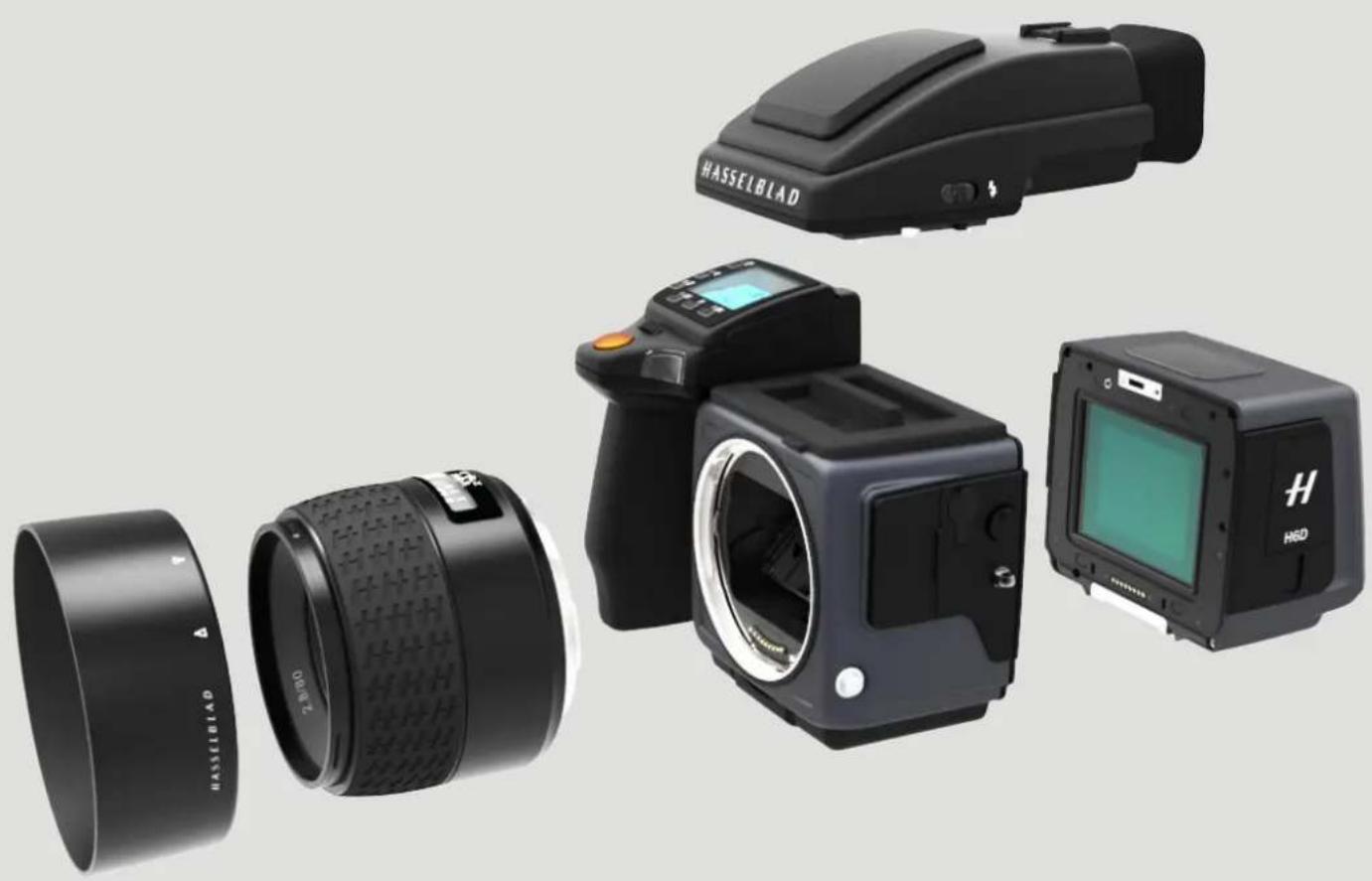
Product photos of a HasSELBlad DSLR camera showing external lens, front-mounted screen, and control panel (no text or symbols visible)Safety
USER GUIDE
2.1 WARNINGS
Warning!
Do not place cables between camera and computer so that there is a risk for people to trip and fall. This can cause personal injury and/or damage to the equipment.
Warning!
If you use spare battery packs, make sure to use protective caps on the contacts. The contacts can short-circuit and catch fire if not protected. This can cause personal injury and/or damage to the equipment.
Warning!
Do not expose batteries (battery pack and batteries installed) to excessive heat such as sunshine, fire or similar. If exposed, the batteries can catch fire. This can cause personal injury, damage to the equipment and the surrounding environment.
Warning!
Be careful when working with strobe and flash units. This will prevent personal injury and/or damage to the equipment.
2.2 CAUTIONS
Caution!
Be careful when you use the camera. The camera is a precision instrument. This will help prevent damage to the camera.
Caution!
Danger of explosion if battery is incorrectly replaced. Replace only with the same or equivalent type.
Caution!
Do not use batteries other than specified. This can cause damage to the batteries.
Caution!
Use protective covers as much as possible. The protective covers will help prevent damage to the equipment.
Caution!
Use a protective case or camera bag when you transport the equipment. This will help prevent damage to the equipment.
Caution!
Protect the equipment from oil fumes, steam, humid conditions and dust. This will help prevent damage to the equipment.
Caution!
Seal all equipment in a plastic bag or similar if you enter damp
and humid condition from dry and cold condition. Wait until the equipment has acclimatized to the new temperature before you remove the equipment from bag. This will help prevent damage to the equipment.
Caution!
Avoid frequent and high temperature changes. This can cause damage to the equipment.
Caution!
Keep camera and equipment away from moisture. If your camera becomes wet, disconnect from electric power and let camera dry before further use. This will help prevent damage to the equipment.
Caution!
Store the equipment in a dry environment. This will help prevent damage to the equipment.
Caution!
Be careful when you attach/detach the components to/from the camera. This will help prevent damage to the data bus connections.
Caution!
Use the grip or strap when you lift and handle to camera. This will help prevent damage to the camera.
Caution!
Do not insert fingers into the camera body. This can cause damage to the equipment.
Caution!
Do not touch the glass surface with your fingers. This can cause damage to the equipment.
Caution!
Do not touch the CMOS/Sensor with your fingers. This can cause damage to the equipment.
Caution!
When you remove the sensor unit, keep foreign objects away from the camera opening. The camera opening is very sensitive. This will help prevent damage to the equipment.
Caution!
When you remove the sensor unit, make sure to be careful with the CMOS sensor protective filter. The CMOS sensor protective filter is very sensitive. This will help prevent damage to the equipment.
Safety
USER GUIDE
Caution!
Keep all equipment out of reach of small children. This will prevent damage to the equipment.
Caution!
When cleaning the camera, remove the batteries. This will prevent damage to the camera.
Caution!
If you leave the camera unused for a long period, remove the batteries. This will prevent damage to the equipment.
Caution!
Do not open the sensor unit. This can cause damage to the sensor unit.
Caution!
Do not try to remove the glass IR filter from the front of the CMOS (due to dust or similar). This can cause damage to the equipment. Always contact your local Hasselblad Authorized Service Centre.
Caution!
If you use canned compressed air to clean the glass of IR filter, read the instructions very carefully before use. This will help prevent damage to the filter.
2.3 DISPOSAL
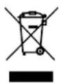
This product must be put in municipal waste. Check local regulations for disposal.
Safety
USER GUIDE
2.4 FCC
Federal Communication Commission Interference Statement: This equipment has been tested and found to comply with the limits for a Class B digital device, pursuant to Part 15 of the FCC Rules. These limits are designed to provide reasonable protection against harmful interference in a residential installation.
This equipment generates, uses and can radiate radio frequency energy and, if not installed and used in accordance with the instructions, may cause harmful interference to radio communications. However, there is no guarantee that interference will not occur in a particular installation. If this equipment does cause harmful interference to radio or television reception, which can be determined by turning the equipment off and on, the user is encouraged to try to correct the interference by one of the following measures:
Reorient or relocate the receiving antenna.
Increase the separation between the equipment and receiver. Connect the equipment into an outlet on a circuit different from that to which the receiver is connected.
Consult the dealer or an experienced radio/TV technician for help.
FCC Caution: Any changes or modifications not expressly approved by the party responsible for compliance could void the user's authority to operate this equipment.
This device complies with Part 15 of the FCC Rules. Operation is subject to the following two conditions:
This device may not cause harmful interference, and this device must accept any interference received, including interference that may cause undesired operation.
FCC Radiation Exposure Statement:
This equipment complies with FCC radiation exposure limits set forth for an uncontrolled environment. The highest SAR value as reported to the authorities for the H6D-50c and H6D-100c when tested for use by the Body is 0.024W/kg against a limit of 1.6W/kg.
2.5 ISED
RSS-Gen Information for the Certification of Radio Apparatus This device complies with ISED licence-exempt RSS standard(s). Operation is subject to the following two conditions:
This device may not cause interference, and this device must accept any interference, including interference that may cause undesired operation of the device.
RSS-102 RF Exposure Compliance of Radiocommunication Apparatus.
The H6D-50c / H6D-100c has been designed to comply with safety requirements for exposure to radio waves. SAR testing has been performed in accordance with RSS-102, with the H6D-50c / H6D-100c transmitting at its highest certified power level in all used frequency bands. The highest SAR value for the H6D-50c / H6D-100c when tested was 0.024W/kg against a limit of 1.6W/kg.
Please follow the instructions included in the user guide for product installation and use.
natural_image
Top-down view of a black H6D camera with visible branding and control buttons (no text-heavy elements)Overview
USER GUIDE
text_image
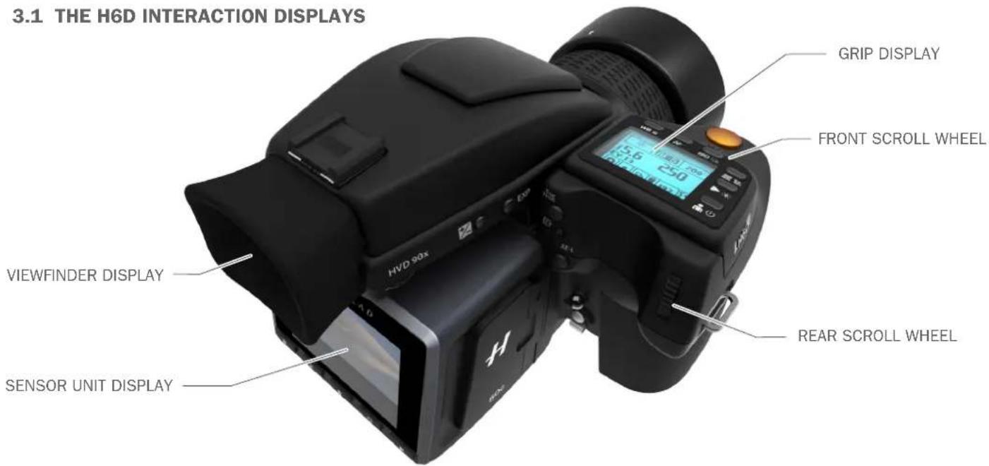
3.1 THE H6D INTERACTION DISPLAYS GRIP DISPLAY FRONT SCROLL WHEEL VIEWFINDER DISPLAY REAR SCROLL WHEEL SENSOR UNIT DISPLAYSensor Unit Display
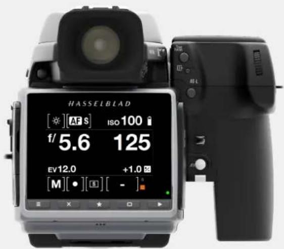
This display is touch sensitive and you can use it in the same way you navigate on a smart phone. Swipe, select, pinch and spread to zoom for example. You can also navigate by using the 5 soft buttons under the display and scroll wheels on the Camera Grip.
Grip Display and Viewfinder Display
Press the WB, AF, ISO, Menu, Play or Profile buttons near the Grip display. The + / - and EXP buttons on the side of the Viewfinder are part of the Grip interaction. Change settings by scrolling the Front Scroll Wheel or the Rear Scroll Wheel. Press the same button again to Exit and Save.
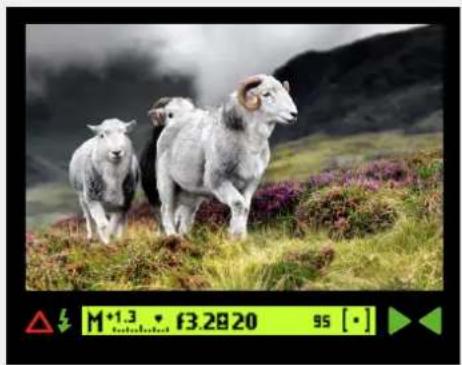
Viewfinder Display
natural_image
Three sheep walking across a grassy hillside with purple flowers, mountains in background (no text or symbols)Sensor Unit Display Grip Display
text_image
HASSELBLAD [★][AF S] Iso100 i f/5.6 125 EV12.0 +1.0 Σ [M][●][(●)][-]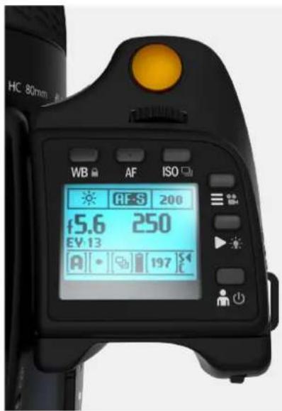
text_image
HC 80mm WB AF ISO 45.6 250 EV 13 A 197Overview
USER GUIDE
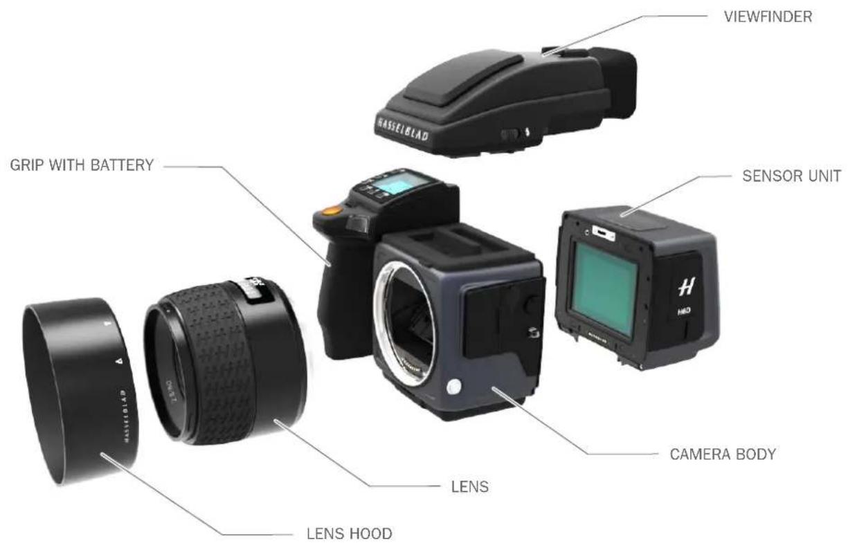
3.2 MAIN CAMERA PARTS
text_image
VIEWFINDER HASSCILBLAD GRIP WITH BATTERY SENSOR UNIT CAMERA BODY LENS LENS HOOD LENSOverview
USER GUIDE
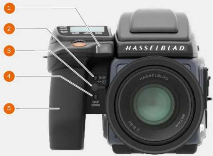
3.3 PARTS, COMPONENTS, BUTTONS AND CONTROLS
All parts listed in this Chapter, are described in detail in other specific sections.
1 Focus assist Illuminator
2 Mirror Up button
3 Remote release port
4 Stop Down button
5 Battery grip
text_image
1 2 3 4 5 HASSELBLAD STOP DOWN HASSELBLAD 0x10.2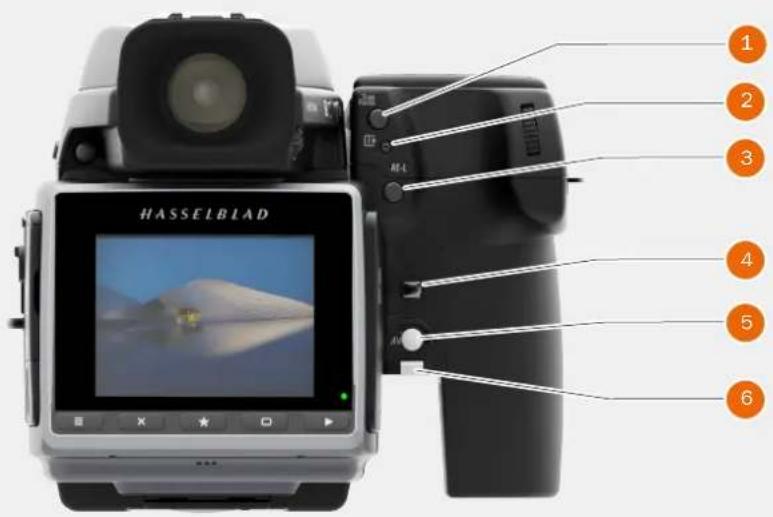
text_image
HASSELBLAD 1 2 3 4 5 61 True Focus button
2 Card Format button
3 AE-L button
4 Camera strap holder
5 Grlp lever release button
6 Battery grip locking lever
1 Speaker
2 Product number
3 Sensor unit

text_image
1 2 3 OUT $ - E+ IN HASSIEBLAD MADE IN SWITCHOverview
USER GUIDE
text_image
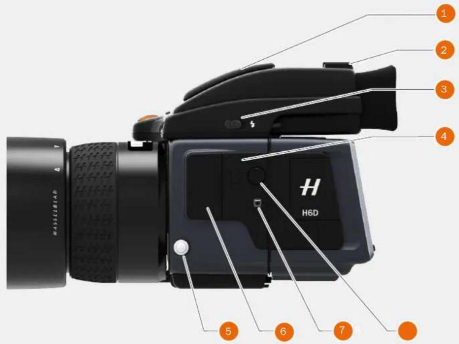
HASSLEDBAD H6D 1 2 3 4 5 6 71 Integral flash
2 Hot shoe
3 Integral flash release
4 PC connect port
5 Lens release button
6 Accessory port cover
7 Camera strap lug
8 Sensor unit
release button
text_image
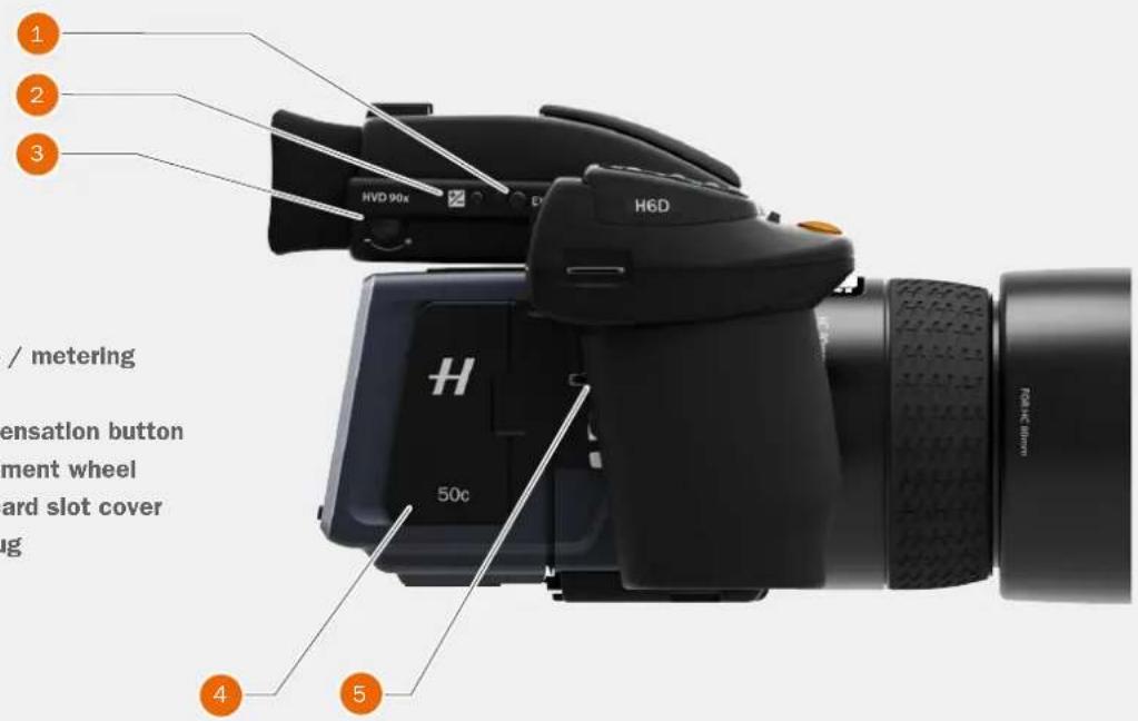
1 2 3 HVD 90x H6D / metering ensation button ment wheel ard slot cover ing 4 51 Exposure mode / metering mode button
2 Exposure compensation button
3 Eyesight adjustment wheel
4 CFast and SD card slot cover
5 Camera strap lug
Overview
USER GUIDE
text_image
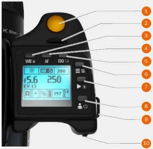
HC 80mm WB AF ISO 45.6 250 EV 13 A 3 200 197 10 1 2 3 4 5 6 7 8 9 101 Shutter release button
2 Front scroll wheel
3 White balance and lock button
4 AF button
5 ISO button
6 MENU and Video button
7 Play / Browse button
8 ON / OFF button
9 Hand strap lug
10 Rear scroll wheel
text_image
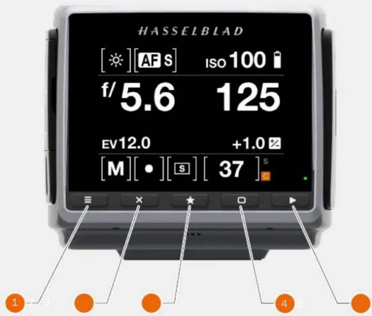
HASSELBLAD [★][AF S] Iso 100 i f/5.6 125 EV12.0 +1.0 % [M][•][S][37] s 1 - 4 41 Menu button - activates main menu. If the main menu is already active, the Control Screen is shown.
2 Soft button - function depends on screen information.
3 Select button
4 Soft button - function depends on screen information.
5 Browse button - starts display and shows the last image. The user can review images, browse and zoom.
Overview
USER GUIDE
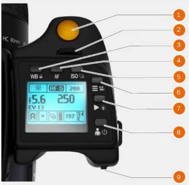
3.4 GRIP BUTTONS AND CONTROLS
Note!
Some of the buttons have multiple functions according to the settings made.
1 Shutter Release Button
This button has two positions. Press halfway (or softly) to activate the camera, auto focus function and exposure meter. Press all the way down (or more firmly) to release the shutter. The chosen exposure procedure and the self timer are also activated with this button.
2 Front Scroll Wheel
The front scroll wheel is used to make changes in exposure settings, to provide access to the grip menu for settings, to navigate the sensor unit's menu as well as acting as browse control.
3 WB / Lock Button
A short press on this button displays the WB preset selection menu on the grip display.
A long press will activate Button Lock which will disable the following buttons for unintentional activation:
Camera Body: True Focus, Format, AE-L, rear Scroll Wheel, WB, AF, ISO/Drive Mode, Menu/Video Mode, Browse/Backlight, M-UP/Self Timer, Stop Down.
Viewfinder: Exp adjust and EXP.
4 AF Button
Press this button to directly access the autofocus/manual focus selection screen from the main screen. See the Lenses section for full details.
5 ISO / Drive Mode Button
The ISO button has two functions. It provides direct access to the ISO settings (see Light Metering & Exposure Control for full details). A long press on the ISO button toggles Drive Mode between Single and Continuous.
6 Menu / Video Button
Press this button to activate the Sensor Unit Display. A long press activates Video Recording Mode. A long press again returns to Camera Mode.
text_image
HC 80mm WB AF ISO f5.6 250 EV-13 197 200 ① ② ③ ④ ⑤ ⑥ ⑦ ⑧ ⑨7 Browse Mode / Grip Display Illumination Button
One click enters Browse mode. Click again to exit Browse mode. In Browse mode the front wheel is used to change image and the rear to change overlay (Preview Mode). A long press illuminates the grip display. Remains active until the camera enters Display Off mode.
8 ON / OFF Button
Press the button for 1 second to activate the camera. The H6D start-up logo will appear and then the main screen. After a few seconds (customizable) the camera will enter Display Off mode. A long press of the button turns the camera off completely (even from Display Off mode).
9 Rear Scroll Wheel
The rear scroll wheel is used to make changes in exposure settings, to provide access to the grip menu for settings, to navigate the sensor unit's menu as well as acting as browse control.
Note!
For the soft buttons 3 to 8 there is a difference between a short click and a long press. A long press is at least one second. Soft button 4 does not have any long press function.
Overview
USER GUIDE
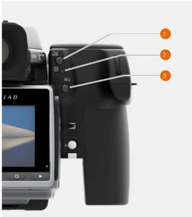
3.5 CAMERA BODY BUTTONS AND CONTROLS
1 True Focus Button
As default setting, this button activates True Focus (see separate section for description), but it also acts as a Zoom in button when browsing or as selector button when making a setting change on the sensor unit, according to mode. The button can be programmed to have other functions.
2 CFast and SD Card Format Button
This button displays the Format Dialogue on the Sensor Unit Display. It is recessed to prevent unintentional use.
3 AE-L Button
As default setting, this button activates AE-L that locks a light reading made in both automatic and manual exposure modes. It also acts as a Zoom out button when browsing or as Exit button when making a setting change on the sensor unit, according to mode. This button can be programmed to have other functions. See Light Metering and Exposure Control/AE-L button for full details.
4 M.UP Button
This button has a toggle function. Press to raise the mirror and press again to lower it. A quick double press of the button (two within a half second) will access the Self timer function. This button can be programmed to have other functions.
5 Remote Release Cord Port
Port to attach a remote release cord (electrical). The socket is protected by a captive rubber plug.
6 STOP DOWN Button
Press to make a visual check of the depth-of-field on the viewfinder screen at the chosen aperture. The aperture will close according to the setting and remain closed as long as the pressure is maintained. You can alter the aperture at the same time to see the changes taking place. This button can be programmed to have other functions.
Note!
Some buttons can be reassigned to other functions. There are three control buttons on the rear of the grip.
text_image
1 2 3 LAD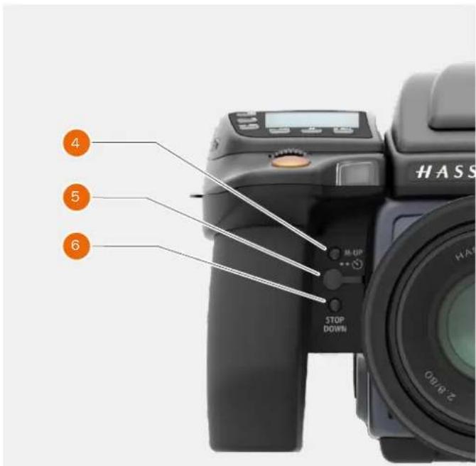
text_image
4 5 6 M-UP STOP DOWN HASS 2.4/40Note!
Customizable buttons True Focus, AE-L, M.UP and STOP DOWN, are very useful and can save you a great deal of time and effort. See separate sections for full details.
Overview
USER GUIDE
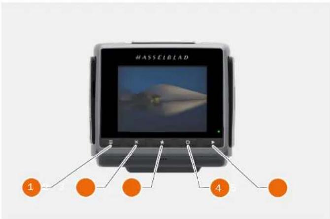
3.6 SENSOR UNIT
1 MENU / (EXIT) Button
This button displays the Main Menu.
2 Soft Button
This button is "delete image" in browse mode. Can also be soft button depending on screen information.
3 Select Button
In Browse Mode this button is used to zoom out to 9 View mode. In Live View it zooms in to 50/100% (depending on setting)
4 SoftButton
Function depends on screen information.
5 Browse Button
Starts the display and shows the last image. The user can review images, browse and zoom. Preview images and zoom in to view close-ups of previews for focus checking. Zoom out to view several at once and finally to view and select folders and media.
6 CMOS and IR Filter
The sensor is positioned behind a permanently mounted IR filter. Always be very careful not to touch or scratch the surface of the filter when it is exposed. Replace the protective cover whenever the sensor unit is not mounted on a camera.
7 Data Bus Connectors
Connectors for digital communication with the camera body.
8 Retalning Bar
Main support for the sensor unit.
9 Storage Media Cover
CFast or SD cards.
10 Connections Cover
Cover for External Connections.
11 Audio Out
Connector for external 3.5 mm Stereo Audio output Plug.
12 Flash Sync Input
Connector for 2.5 mm Flash Sync input plug.
13 Audio In
Connector for Audio Microphone 3.5 mm Stereo input plug.
14 Flash Sync Output
Connector for 3.5 mm Flash Sync output plug.
15 External Power In
Connector for External Power input plug.
16 HDMI
Connector for Mini HDMI output plug.
17 USB 3 TetherIng Plug
Connector behind protective door for USB 3 plug.
text_image
HASSELBLAD 1 2 3 4
text_image
6 7 8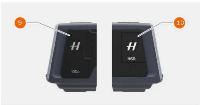
text_image
9 10 H 100c H H6D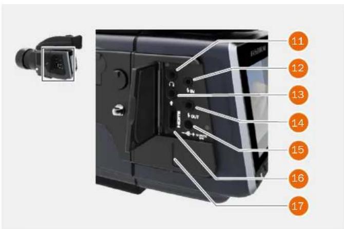
text_image
11 12 13 14 15 16 17Overview
USER GUIDE
3.7 VIEWFINDER
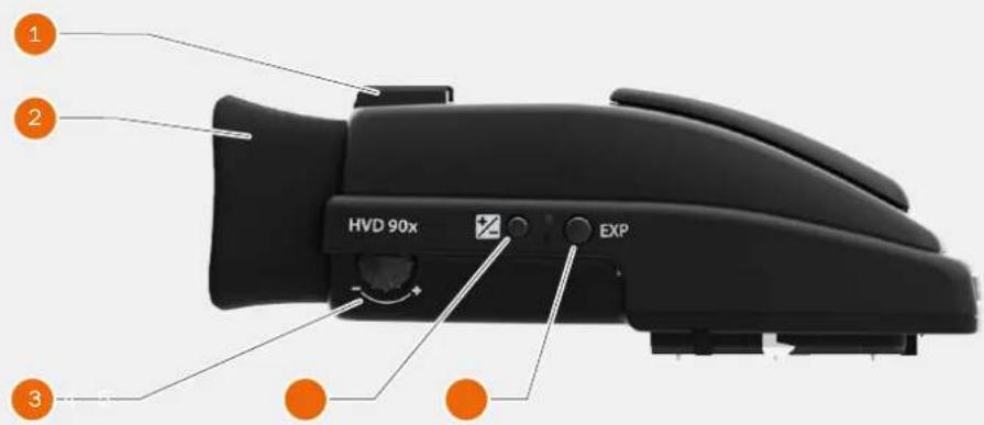
text_image
HVD 90x EXP1 Hot Shoe
Connection for automatic flash unit (with SCA 3902 adapter) or for wireless flash trigger.
2 Rubber Eye Cup
Can be exchanged for another model.
3 Eyesight Adjustment Wheel
The personal eyesight adjustment facility has a dioptre range of -5 to +3.5, to suit most users.
4 Exposure and Flash Compensation Button
Press the button to access the EV compensation screen. Flash settings are made with the front scroll
wheel. Exposure settings are made with the rear wheel. The EV correction values are shown on the grip. In the viewfinder display, a plus or minus symbol is shown, if the value differs from zero.
5 Exposure Mode / Metering Mode
The EXP (Exposure) button accesses the exposure and metering mode options screen. Settings are made with the front and rear scroll wheels and the appropriate symbols appear on the grip and viewfinder displays accordingly.
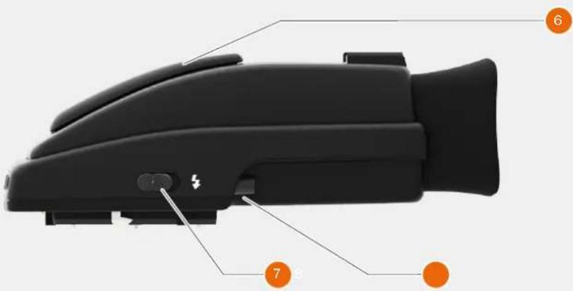
text_image
Diagram of a black automotive headgear device with numbered components labeled 6, 7, and 86 Integral Flash Unit
Manually opened with flash unit release button.
7 Integral Flash Unit Release Button
Slide the button towards the rear of the camera to raise the integrated flash. Activation is automatic.
8 Viewfinder Release Button
Press towards the front of the camera and lift the viewfinder upwards. Mount protection lid.
Overview
USER GUIDE
3.8 LENSES

text_image
1 2 3 4 5 6 10 m : 2 3 ft 11 10 11 22 10 4 m 22 HC 80mm1 Lens Shade Index
2 Manual Focus Ring
3 Focusing Distance Scales
4 Depth of Field Scales
5 Lens Index
You can download technical data sheets from the Hasselblad website, www.hasselblad.com.
You can download a lens booklet that contains a round up of the available lenses and some general information.
Overview
USER GUIDE
3.9 DISPLAY INFORMATION
Viewfinder
Metering method
Aperture setting
Shutter speed
Exposure method
Capture counter
Exposure compensation
Focus assist
Warning triangle
Flash warning
Spirit level
ISO
WB
Focus Mode
Grip LCD
Metering method
Aperture setting
Shutter speed
Exposure method
Capture counter
ISO
White Balance
Flash indication
Focus Mode
Drive
EV
Battery status
Histogram (optional)
Memory Card Status
USB 3


Wi-Fi
text_image
HASSELDLAD AF S 150 100 f/ 5.6 125 EV12.0 +1.0 M B 492Phocus/Phocus Mobile
Metering method
Aperture setting
Shutter speed
Exposure method
ISO
White Balance
Flash indication
Focus
Drive
EV
Rear LCD
White Balance
Focus Mode
ISO
Battery Status
Aperture
Shutter Speed
EV Value
Exposure adjustment
Exposure Mode
Light Metering Mode
Drive mode
Remaining Captures
Storage Medium Status
Depending on mode, the LCD
can also show other info, such as:
Preview images, Histogram,
Live View and Spirit Level
Overview
USER GUIDE
3.10 SENSOR UNIT DISPLAY AND CONTROLS
When shooting, the Sensor Unit can display the information most often required, for a quick settings check. The unit's buttons, grip scroll wheels and camera buttons together with the touch display are used to navigate the main menu and change settings.
The touch display can show all saved captures on CFast or SD cards. You can Browse and Zoom the Captures for detailed inspection.
When shooting, you can control the amount of information visible together with the current preview by choosing various modes.
text_image
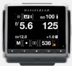
HASSELBLAD [★][AF S] Iso 100 i f/5.6 125 EV12.0 +1.0 [M][●][S] [536] sButtons and Scroll Wheels
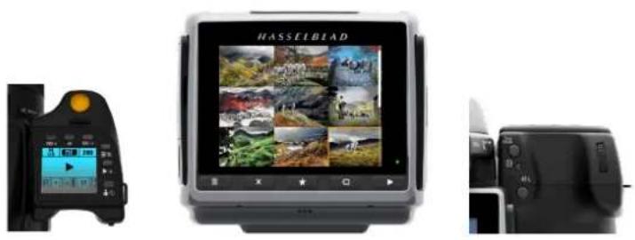
In Browse mode, the Scroll Wheels, True Focus and AE-L buttons are used for navigation.
Activate Browse mode by pressing on the right button below the Sensor Unit Display or on the Browse button on the Grip.
natural_image
Three-panel image showing a camera interface, a digital display screen with landscape photos, and a camera module (no visible text or symbols)Control Screen
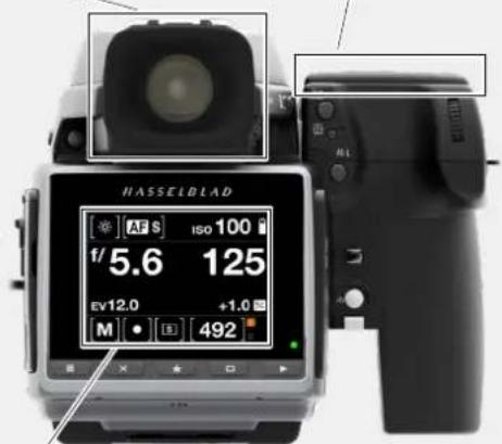
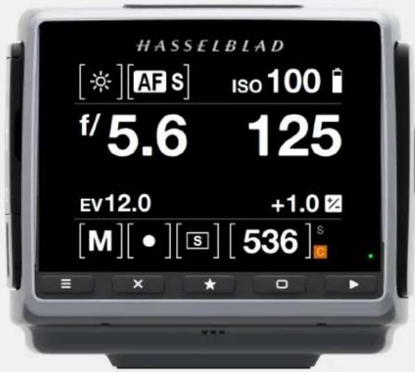
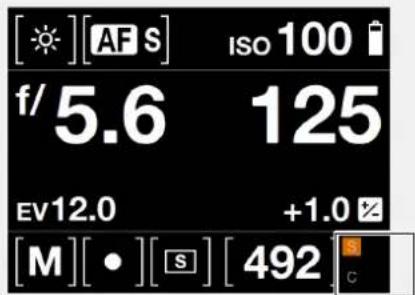
The Control Screen is interactive. From any screen you can swipe down to display the Control Screen. Select any of the settings by tapping and change the value in the dialogue that appears. Aperture setting, shutter speed, focus setting, drive mode, exposure mode, ISO, exposure adjustment and white balance can be changed on the Control Screen. EV value, battery status, storage media status and remaining capture counter are for information only and cannot be changed
text_image
HASSELDAD ※ [AFS] ISO 100 i f/5.6 125 EV12.0 +1.0 Ω M [•] [B] [536]Overview
USER GUIDE
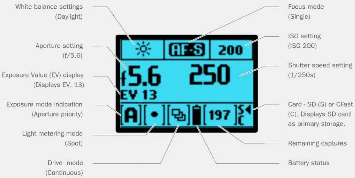
3.11 GRIP DISPLAY
GRIP DISPLAY EXAMPLE
text_image
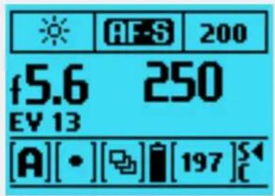
White balance settings (Daylight) Aperture setting (f/5.6) Exposure Value (EV) display (Displays EV, 13) Exposure mode indication (A) [•] [☐] [197] S Light metering mode (Spot) Drive mode (Continuous) Focus mode (Single) ISO setting (ISO 200) Shutter speed setting (1/250s) Card - SD (S) or CFast (C). Displays SD card as primary storage. Remaining captures Battery statusGRIP DISPLAY EXAMPLE WHEN CHANGING SETTINGS
text_image
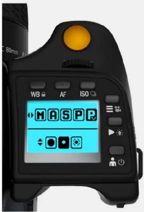
WB AF ISO MASPRExposure Mode change:
1 Click the "EXP" button on the Viewfinder.
2 From the top row with available exposure modes, use the front wheel to select exposure mode. Here "Pv" is selected.
3 From the bottom row with available light metering modes, select by turning the rear wheel.
4 Accept the selection with a half-press on the shutter relase button
Note!
Scroll wheel description and direction
Arrowheads symbolize which scroll wheel should be used to change setting.
Left and right arrow = Front Scroll Wheel. Up and down arrow = Rear Scroll Wheel.
Overview
USER GUIDE
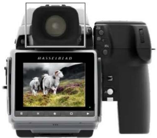
3.12 VIEWFINDER DISPLAY
VIEWFINDER DISPLAY EXAMPLE
natural_image
Exterior view of a modern digital camera with a screen displaying sheep grazing in a grassy field (no visible text or symbols on the device body)Viewfinder Display User Interface
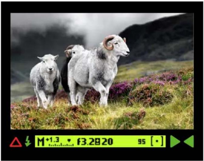
natural_image
Three sheep standing on a grassy hillside with purple flowers, under a cloudy sky (no text or symbols visible)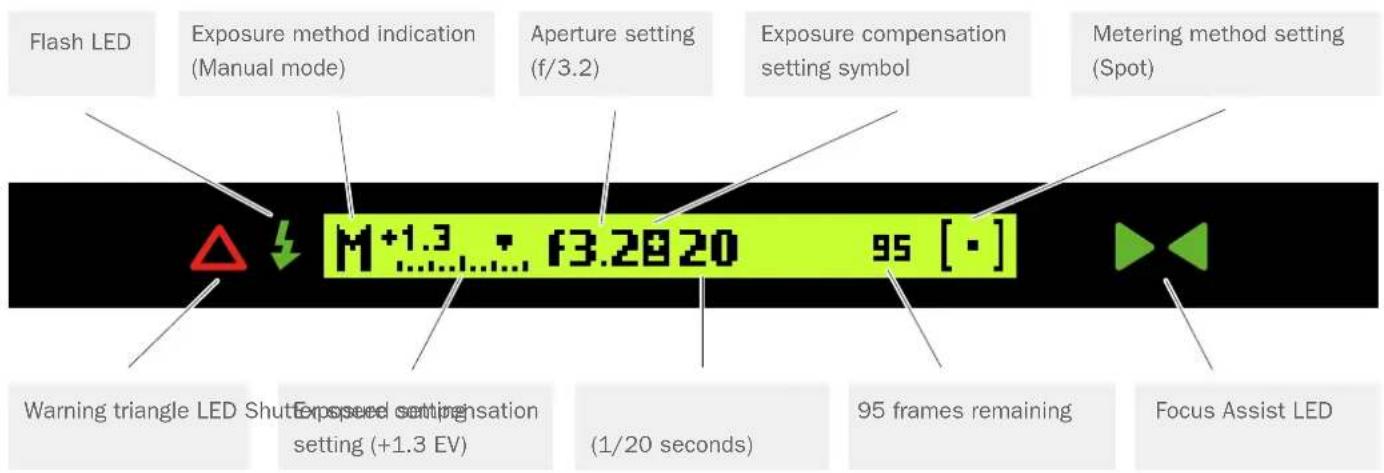
text_image
Flash LED Exposure method indication (Manual mode) Aperture setting (f/3.2) Exposure compensation setting symbol Metering method setting (Spot) Warning triangle LED Shutter Exposed setting setting (+1.3 EV) f3.2820 95 [·] (1/20 seconds) 95 frames remaining Focus Assist LEDNote!
The LED's will only be visible when activated by the camera or a setting.
Overview
USER GUIDE
VIEWFINDER DISPLAY ACCORDING TO SETTING
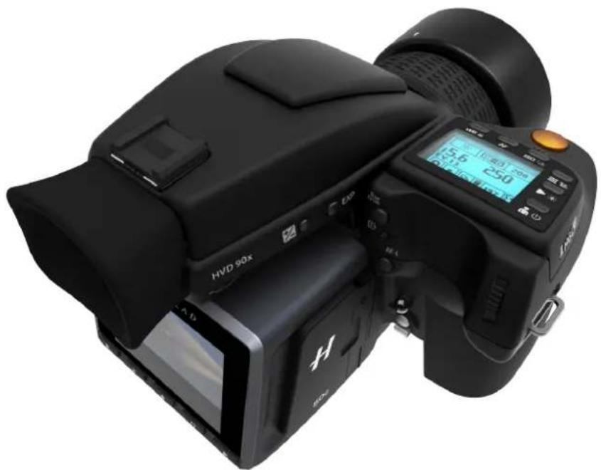
natural_image
Black HVD 90X DSLR camera with LCD display and control buttons (no visible text or symbols on body)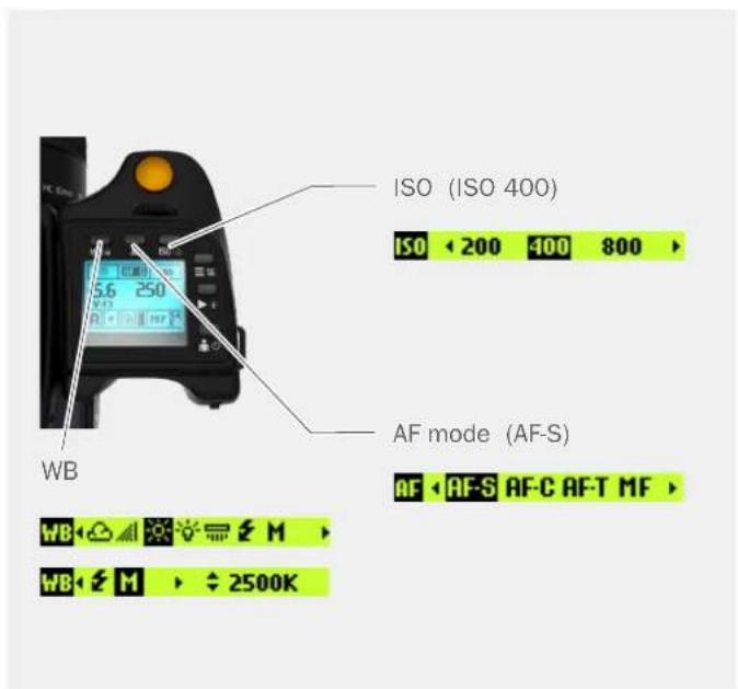
text_image
ISO (ISO 400) ISO < 200 400 800 > AF mode (AF-S) AF < AF-S AF-C AF-T MF > WB 2500K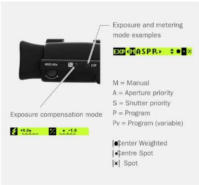
text_image
Exposure and metering mode examples EXP M A S P R M = Manual A = Aperture priority S = Shutter priority P = Program Pv = Program (variable) Exposure compensation mode +0.0 -1.0 turbulated turbulated [●] Center Weighted [●] Centre Spot [●] SpotOverview
USER GUIDE
3.13 RE-ASSIGNABLE GRIP BUTTONS OPTIONS
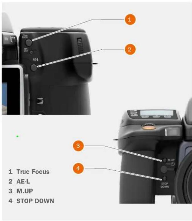
These four grip buttons are by default assigned according to name but can be reassigned (in Main Menu > Camera Settings > Custom Buttons to various other functions listed here.
Control Screen
Activates the Control Screen on the rear display.
Start Live View
Starts Live View on the rear screen.
AE-L
Locks a light reading in auto or manual modes. Also used in Zone metering.
AF Drive
Activates AF Drive.
Mirror Up
Locks Mirror Up for minimal vibration.
True Focus
Activates True Focus function.
Browse Card (Not with True Focus and AE-L Buttons)
Activates Browse Mode.
Delete Image (Not with True Focus and AE-L Buttons)
Delete current image.
Stop Down
Activates stop down function for depth of field checking.
Expose
Provides alternative to shutter release button.
Light Meter Mode Cycle
Selects next light metering mode.
Show Hlstogram
Shows the latest histogram on the grip display.
Spirit Level
Activates the Spirit Level function on the rear display and viewfinder display.
Self Timer
Sets Self Timer mode. Provides a timed remote shutter release function with the option of a change in sequence of the mirror movement (to reduce vibration).
text_image
1 True Focus 2 AE-L 3 M.UP 4 STOP DOWNInterval
Activates interval function start screen.
Bracketing
Sets Bracketing mode. This function provides an automatic series of captures; one at the standard exposure setting, Manual or Auto, and the others with predetermined deviations in EV from the standard exposure.
Mark Overexposure On/Off (Not with True Focus and AE-L Buttons)
Enables or disables visual overexposure warning.
Flash Measure
Makes a Flash Measure exposure.
B-Mode
Activates B-mode.
T-Mode
Activates T-Mode.
None
No function.
Overview
USER GUIDE
3.14 SHORTCUTS
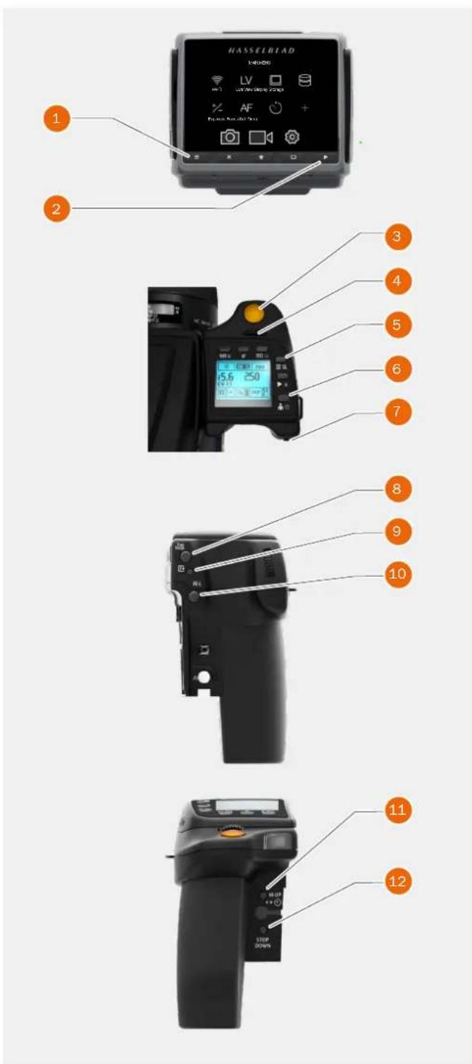
1 Menu button
Setting option access. Press MENU button on the Sensor Unit.
2 Browse button
Starts image browse mode.
3 Shutter release button
Camera activation. Re-activates camera from Display Off mode. After making any changes, press EXIT (Menu button) or shutter release button to save the new setting.
A half-press exits all menus and returns to shooting mode.
4 Front scroll wheel
Menu navigator / Browser. Functions as a horizontal navigator on sensor unit menu as well as a capture browser in Browse mode.
5 Menu button
Toggles the Grip Menu Mode On and Off. When in Menu Mode the wheel is used to navigate the menus of the Sensor Unit. When not in Menu Mode the wheel controls the Aperture and Shutter speed. A long press on this button toggles the camera between video and camera mode.
6 ON / OFF button
Camera activation ON and OFF. Re-activates camera from Display Off mode.
7 Rear Scroll wheel
Menu navigator. Functions as a vertical navigator on sensor unit menu while in menu mode. When not in Menu Mode the wheel controls the Aperture or Shutter speed.
8 True Focus button
Camera activation. Re-activates camera from Display Off mode. Automatically acts as Zoom-in button when in Browse mode. Automatically acts as value selector on sensor unit menu when in Menu mode.
9 CFast and SD Card format button
Formats the current inserted CFast or SD card (requires confirmation).
10 AE-L button
Re-activates camera from Display Off mode.
Zoom-out button. Automatically acts as zoom-in button when in Browse mode.
Automatically a value selector when in Menu mode.
text_image
HASSELBIAD (H-HDD) LV AV AF FX 2000/1999 1 2 3 4 5 6 7 8 9 10 11 12 STEP 20/PM11 Mirror Up button
Camera activation. Re-activates camera from Display Off mode.
12 Stop Down button
Re-activates camera from Display Off mode.
Overview
USER GUIDE
3.15 PHOCUS OVERVIEW
text_image
Photo by Handbird File Edit Image View Window Help Place by Handbird Export Modify Image Display Reference Landscape Sites Format landscapes Adjournments Search MF ISO 200 f/ 11 125 EV 14.0 0.0 [M] AF HBD 100: 2015 Anders Espersen 2015 ISO 200 Skiengio Cravens Kevin Tran Anders Espersen Salso Chang AF S ISO 200 f/ 11 125 EV 14.0 0.0 [M] AF HBD 100:Phocus
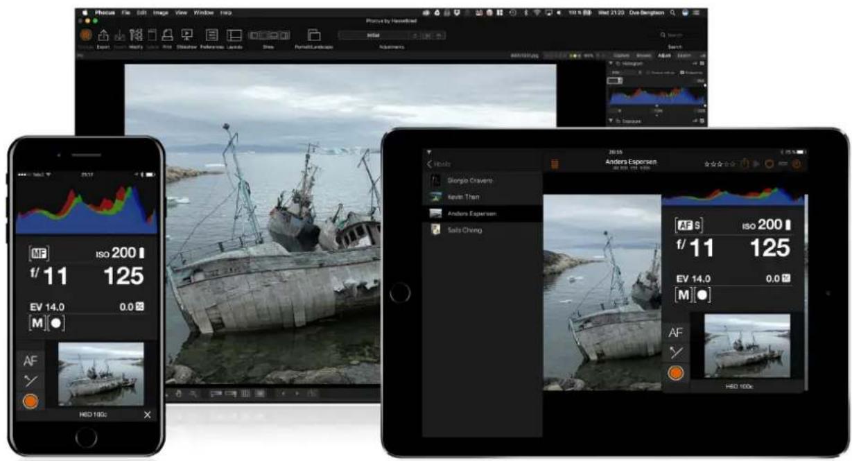
Phocus is the Capture Processing and File Management application aimed primarily at Hasselblad 3F file handling. Phocus is available for both Mac and Windows.
Professional Image Quality
Phocus combines Hasselblad Natural Colour Solution (HNCS) with Digital Auto Correction (DAC) to provide high digital image quality in the images you create. With Phocus, the moiré effect that can occur on even extremely high resolution images is effectively removed automatically and directly on the raw data, leaving the image quality intact and saves time in post production work. Tethered shooting is efficient with Phocus Remote camera controls providing a number of remote functions. For example remote focusing, live view, aperture and exposure time controls.
Phocus Mobile
Phocus Mobile is available for iPhone ^ , iPad ^ and iPod Touch ^ . It enables you to connect wireless to a computer running Phocus and to remotely browse your high-resolution RAW, JPEG and TIFF images. This provides a solution for working with clients in the studio, enabling each person to view images on an individual iOS device, rather than all gathering around a single computer. Phocus Mobile also allows users to remotely operate and trigger a tethered camera, giving control of many parameters, all neatly presented in a virtual camera display. This feature is very convenient for remote control of the camera when it's located in a difficult to access position.
Phocus Mobile is available for free download in the Apple App Store. www.apple.com.
Overview
USER GUIDE
3.16 BATTERY AND BATTERY GRIP
Rechargeable battery grip
The environmentally approved Battery grip Li-ion (3043357) is the standard power source for the H6D camera. The H6D requires a power supply for all actions as there is no mechanical reserve facility. It is therefore advisable to keep a reserve rechargeable battery grip at hand. As is the case with most batteries, problems might be encountered when used in very low temperatures. In this situation it is advisable to keep the reserve battery in an inside pocket, for example, to maintain it near body temperature.
Remove a battery
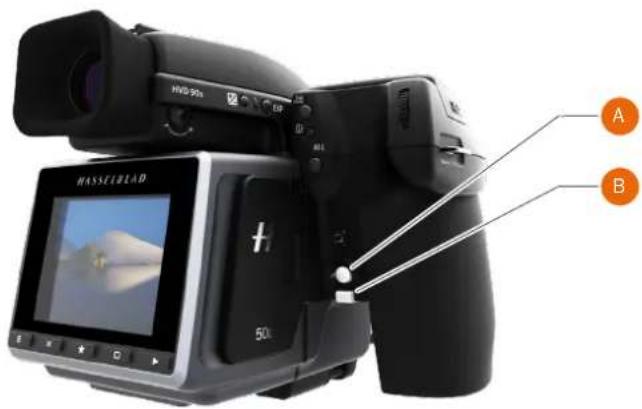
1 Remove the battery from the camera by pressing the battery holder button (A) and simultaneously swinging the battery holder retaining lever (B) down until it stops.
2 Pull the battery downwards (C).
Attach a battery
1 To fit, hold the battery flat against the camera body and align the two upper lugs with the slot.
2 Slide the battery back into position.
3 Rotate the battery holder retaining lever (B) back until it clicks into place.
Store a battery
If you intend to store the battery separate from the camera, ensure the safety cover is mounted over the electric connections on the battery to prevent short circuits. It snaps into place and is removed by pulling outwards and upwards on the locking clip.
text_image
HASSEBLAD 50x A B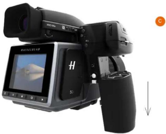
natural_image
Black HVS 90X digital camera with LCD screen and control panel, shown in studio setting (no visible text or symbols on device body)Connect battery to charger
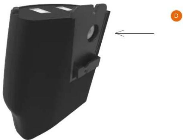
1 Connect the charger plug to the plug connector on the inside of the battery (D).
2 Connect the charger to the wall socket.
See next page for more in depth information.
natural_image
3D model of a black plastic enclosure with mounting holes and a directional arrow indicator (no text or symbols)Overview
USER GUIDE
3.17 BATTERY CHARGER
The battery charger is supplied with a number of plug attachments to suit various types of domestic electrical sockets available worldwide. Other types of sockets will require a domestic socket converter.
Attach the chosen plug by sliding it into position. Removal is by the reverse procedure.
Note!
The Battery charger BCH-2 (3053572) is designed for use with Battery grip Li-ion 3200 (3043357) but can also be used together with the Battery grip rechargeable 7.2V Li-Ion 2900 (3043356) intended for H5D use.

natural_image
Two black electronic devices with attached power plugs and terminal blocks, shown from different angles (no visible text or symbols)CHARGE THE BATTERY
1 With the battery removed from the camera, insert the jack plug from the battery charger into the socket on the battery grip (1).
2 Insert the battery charger into a standard (100–240V\~/50–60 Hz) domestic socket.
During the charging procedure, the lamp on the charger signifies the following:
Steady Green light: Standby (no battery connected).
Steady Yellow light: Charging.
Steady Green light: Ready.
NOTE!
It can take about 6 hours to charge the battery completely up to 100% the first time.
See next page for more details and precautions.
Overview
USER GUIDE
RECHARGEABLE BATTERY GRIP SPECIFICATION
LI-ION/ Battery Charger 3053572 BCH-2
– Precautions and General
The battery should be charged for approximately 6 hours before first time use.
The battery must be charged at room temperature.
Maximum battery capacity is reached only after the battery has been charged and discharged several times.
Avoid frequent full discharges (a full discharge is signalled by the appearance of the Replace battery warning on the grip display). As the battery is a Li-ion type, it has no memory effect of practical importance and therefore frequent recharges will cause no problems such as loss of capacity or poor performance. It is therefore better policy to recharge the battery at very regular intervals, regardless of use.
Remove the battery if you intend to store the camera for some while as it will eventually become completely drained, even though the camera is turned off.
The battery has an integrated fuel gauge capability that supports the Replace Battery and Battery Status functions on the grip display. As with most Li-ion batteries, this capability should be occasionally calibrated, depending on how much the battery is used. To do this, leave the camera on (or use it), until the “Replace Battery” warning appears. Then, recharge the battery for 6 hours. This will improve the accuracy of the measurements.
When removing a battery from the charger and immediately replacing it with another, allow a few seconds to elapse so that the charger can automatically reset for the next charging procedure.
It is perfectly normal for the battery to become warm when being charged.
A slight temporary loss of battery performance might be noticed at very high or low temperatures. Take the appropriate measures if this is the case.
If you do not intend to use the battery for a while, it is best to store it at room temperature with an approximate 30% to 40% charge.
The battery should have a usable service life of around 400 recharge/discharge cycles.
Connect the battery grip to the camera correctly.
Keep the protective cover in place when not in use. (Short circuiting across keys in a pocket, for example, could cause a fire risk).
Do not immerse the battery grip in liquids.
Do not incinerate the battery grip.
Please recycle or discard in an environmentally approved manner.
Use indoors only (protect against moisture).
Do not short circuit the jack plug.
Do not alter the charger in any way other than changing the plug attachment.
Note!
You can save battery consumption by changing the Display Off / Sleep / Power Off settings as well as the brightness settings of the display.
Overview
USER GUIDE
BATTERY LIFE AND BATTERY WARNING
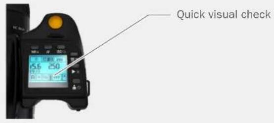
Battery life is dependent on a number of variable factors and therefore cannot be exactly predicted. If the camera is left in the active state instead of Display Off or Sleep modes for long periods, for example, then the battery will become exhausted much faster. A low camera battery state is indicated by a symbol on the grip display, in the viewfinder as well as on the sensor unit display. In addition, an audible signal sounds. When the battery is almost completely exhausted, a warning message “Replace battery” will appear on the grip display.
The Battery will be exhausted faster if you use Live View and Video Recording often.
3.18 TEMPERATURE WARNING
If you take several captures within a short period of time, the processor in the Camera will produce more heat. This, particularly in combination with high ambient temperature, can result in noise in the image files. To prevent this, the sensor unit displays a warning icon when the temperature rises. At 60 °C a warning dialogue appears notifying that the sensor unit is temporarily shutting down to allow the unit to cool. The Sensor Unit will be warm quickly if you use Live View and Video Recording often.
text_image
Quick visual check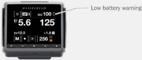
text_image
NASSELBIAD [★] AF S ISO 100 1/5.6 125 EV12.0 +1.0 [M][●][O][256] Low battery warning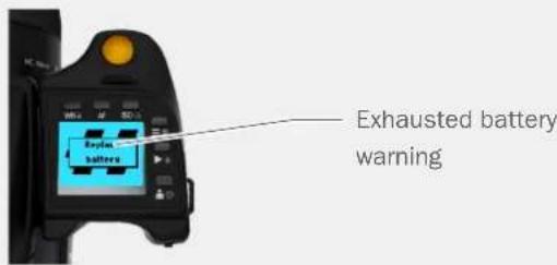
text_image
Exhausted battery warning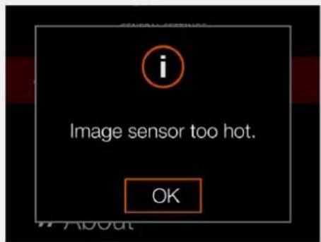
text_image
i Image sensor too hot. OKHigh temperature warning
Overview
USER GUIDE
3.19 POWER & TIMEOUT MODES
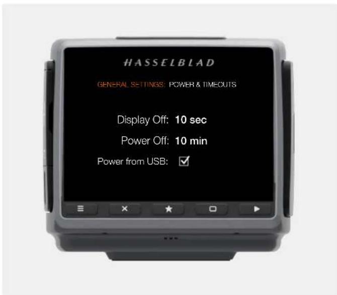
MAIN MENU > GENERAL SETTINGS > POWER & TIMEOUT
The H6D Camera can be set to automatically turn off the Sensor Unit Display after a set amount of seconds to save battery.
Change Display Off or Power Off settings
1 Press the General Settings icon on the Sensor unit display.
2 The General Settings Menu appears.
3 Press the Power and Timeouts icon.
4 Tap the timeout value to change.
Swipe right or press Menu / EXIT button to get back to Main Menu.
text_image
HASSELBLAD GENERAL SETTINGS: POWER & TIMEOUTS Display Off: 10 sec Power Off: 10 min Power from USB: ✓Power and Timeouts Menu
Display Off
Select Display Off Settings.
- 3 seconds.
- 5 seconds.
- 10 seconds.
- 20 seconds.
- 30 seconds.
- 60 seconds.
- Never.
Power Off
Select Display Power Off Settings.
- 5 minutes.
- 10 minutes.
- 30 minutes.
- Never.
Power from USB
Select on or off. Allows the camera to take power from a USB host device.
Overview
USER GUIDE
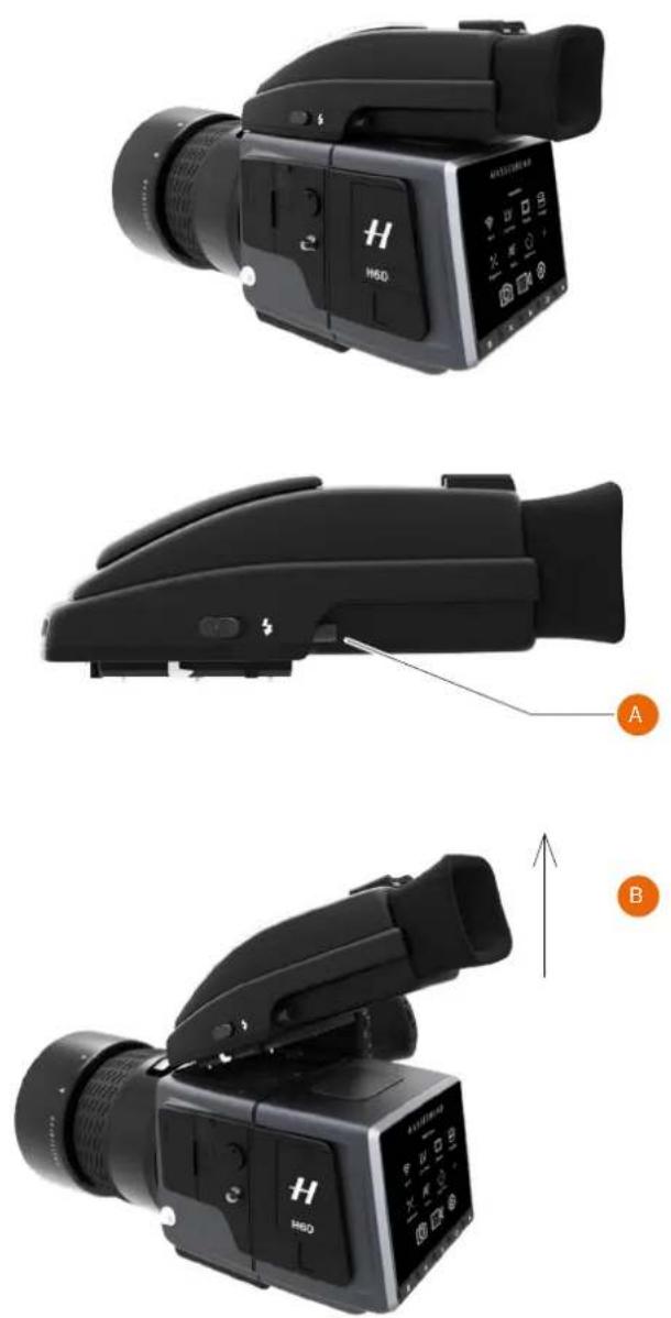
3.20 REMOVE AND ATTACH THE VIEWFINDER
How to remove the Viewfinder
1 Hold the viewfinder steady.
2 Press the viewfinder release button (A).
3 Lift the rear of the viewfinder up and away from the camera body (B).
How to attach the Viewfinder
1 Hold the viewfinder at a slight angle and rest it on the top of the camera.
2 Slide the viewfinder forward until the front locating pin is in position in the recess in the front edge of the viewfinder screen aperture on camera body.
3 Press the rear part of the viewfinder firmly downwards until it clicks into place.
4 Ensure that both sides of the viewfinder are seated correctly and that it has been firmly attached and locked into position.
Warning!
Failure to do so could cause an intermittent malfunction if the data bus interface connections between the viewfinder and camera body are not positively secured.
Note!
Do not lift or hold the camera by the viewfinder alone.
text_image
H M60 A BOverview
USER GUIDE
3.21 EYEPIECE ADJUSTMENT
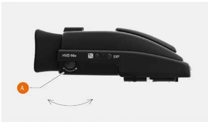
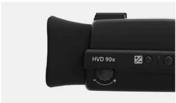
No corrective lenses are needed to adjust the eyepiece to suit most requirements. The dioptre range is from -5 to +3.5D. Eyeglass wearers can rapidly and accurately change the settings if they wish to wear eyeglasses for viewing or not.
1 Hold the camera in your left hand.
2 Point the camera at the sky or a similar smoothly toned area.
3 Turn the adjustment wheel (A) until the markings on the Viewfinder screen are as sharp as possible for your eyesight.
Note!
If you normally wear eyeglasses for distance viewing and intend to wear them for camera use then do not remove them for the above procedure. If, on the other hand, you prefer to remove your eyeglasses for camera work, then repeat the above procedure without wearing your eyeglasses.
natural_image
Close-up of a black HVD 90x device with labeled control buttons and an orange circular indicator (no text or symbols on the device body)3.22 RUBBER EYE CUP
Two rubber eye cups are available for the H6D. The one supplied with the camera is suitable for users who do not intend to use eyeglasses when photographing.
The second shorter eye cup is for those who either prefer to position their eye further from the viewfinder and those who wish to wear eyeglasses.
The eye cups can be changed at a Hasselblad Authorized Service Centre.
natural_image
Close-up of a black HVD 90x camera lens with adjustment knob (no text or symbols on device body)Overview
USER GUIDE
3.23 ACCESSORY CONNECTION
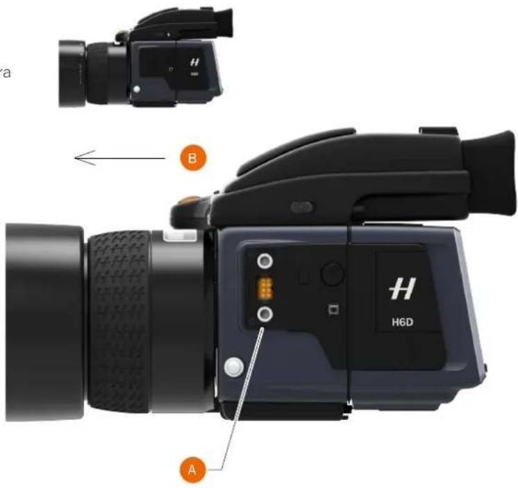
There are two accessory retaining screw threads (M5) as well as a databus connector on the left hand side of the camera body, protected beneath a cover (A).
How to remove the Databus Connector cover
1 Remove the cover by first lifting the left hand edge (A) a little.
2 Slide the cover to the left (B).
3 Lift the front edge of the cover first (A).
4 Remove the cover.
5 Attach the Databus cable.
text_image
a B H H6D A3.24 PC FLASH CONNECTOR
A PC connector for non TTL flash synchronisation (3) is located on the left side of the body. It is protected by a captive rubber plug.
natural_image
Close-up of a black video camera with a display screen and lens (no visible text or symbols)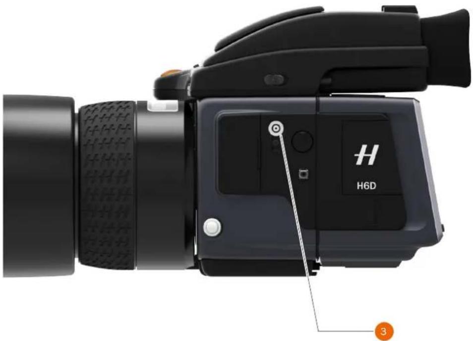
natural_image
Close-up of a black H6D camera with labeled buttons and textured lens (no readable text beyond branding)Overview
USER GUIDE
3.25 PROTECTIVE BASEPLATE
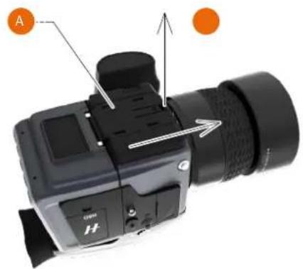
REMOVE THE PROTECTIVE BASEPLATE
1 To remove the Protective Base Plate (A), lift the securing catch (B) while pushing the plate towards the lens.
natural_image
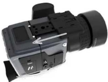
Close-up of a DSLR camera with orange circular markers and directional arrows indicating components (no text or symbols on body)ATTACH THE PROTECTIVE BASEPLATE
1 To attach the Protective Base Plate (A) again, slide it over the camera foot until it stops and the securing catch (B) snaps into place.
natural_image
Close-up of a black DSLR camera with attached lens and control buttons (no visible text or symbols)Overview
USER GUIDE
3.26 MEMORY CARDS
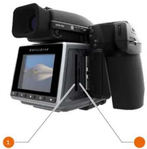
There are two types of memory cards that can be used with the H6D camera.
1 CFast card.
2 SD card (UHS-I).
When using a CFast card or SD card, the H6D is completely self contained. No additional wires or connectors needs to be attached.
The recommended type is UDMA/type 4 /60MBs (400x) or better.
The H6D is shipped with an 16 GB SDXC SD card, which is capable of holding approximately 75 - 150 captures (according to model).
Note!
All cards should be formatted in the camera before first use!
Memory Card Status on Grip Display
CFast card
C Inserted, non active.
C< Inserted, active.
C[0] Full.
C! Card Error.
No Symbol No Card inserted.
SD card
S Inserted, non active.
S< Inserted, active.
S[0] Full.
S! Card Error.
Lock Symbol Card Write Protected.
No Symbol No Card inserted.
natural_image
Black Hasselblad camera with display screen and orange buttons, no visible text or symbols on device bodyGrip Display View
text_image
AFS 200 f5.6 250 EV 13 [A][•][☐][197]S4 CControl Screen on Sensor Unit Display
text_image
[☀][AF S] ISO 100 f/5.6 125 EV12.0 +1.0 [M][•][S] [492]Currently Approved Cards
CFast Card
San Disk Extreme PRO CFast 2.0
Lexar Professional 3400x CFast 2.0
Wise CFAST 2.0 Green
Wise CFAST 2.0 Blue*
*Only newer blue cards with a letter "H" in the top right of the card sticker are supported.
SD Card
SanDisk Extreme PRO 95MB/s (SDHC-I)
SanDisk Extreme PRO 300MB/s (SDHC UHS-II)
Lexar Professional 2000x (SDXC UHS-II)
Delkin SD1900X
(UHS-II cards at UHS-I speed, 80 MB/s)
Overview
USER GUIDE
TO INSERT A MEMORY CARD
Insert CFast card
1 Open the CFast card cover (A) on the sensor unit by inserting a thumb in the recess and then sliding the slot cover backwards. Behind the cover, you will see a slot for the CFast card (B) and a slot for the smaller SD card (C).
2 Hold the CFast card so that the connector holes face into the slot and you can read the brand label when you are behind the camera.
3 Gently press the CFast card into the slot. If you encounter resistance, it might be because you are holding the card backwards or upside down. If the card can be easily inserted nearly all the way into the back, then you are inserting it correctly.
4 Press the card another couple of millimetres firmly into place.
5 Close the slot cover (A) and slide it forward to lock it.
Insert SD card
1 When the card slot cover door is opened, mount the SD card in the SD card slot (C).
2 Close the slot cover and slide it forward to lock it.
text_image
BASSELBIAD 50x A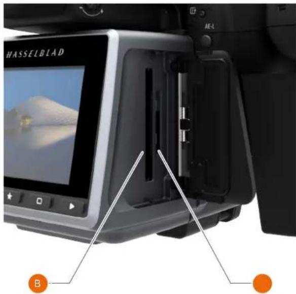
text_image
HASSELBLAD AE-L BOverview
USER GUIDE
TO REMOVE A MEMORY CARD
Remove CFast card
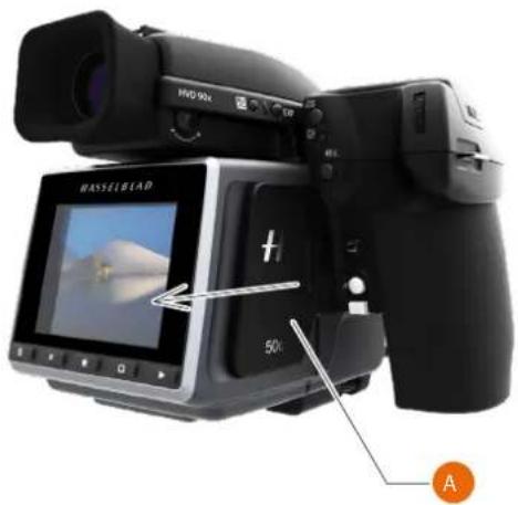
1 Open the memory card slot cover on the sensor unit (A).
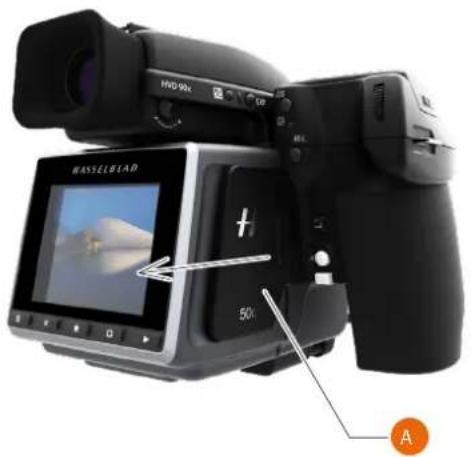
2 Press the CFast card (B) a little way in and then release it.
3 The card is then pushed out a few millimeters.
4 Grab the card and pull it away from the sensor unit.
5 Close the slot cover door.
text_image
HVD-90x HASSELBLAD 50x ARemove SD card
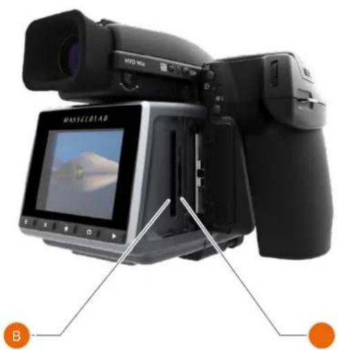
1 Open the memory card slot cover on the sensor unit (A).
2 Press the SD card a little way in and then release it. The SD card will then move out from the SD card slot (C).
3 Grab the card and pull it away from the sensor unit.
4 Close the slot cover door.
natural_image
Exterior view of a Hasselblad camera with display screen and orange buttons (no readable text or symbols)Note!
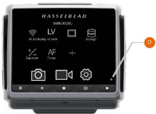
Do not remove a CFast or SD card from the Sensor Unit if the ready-light (D) is blinking! The ready-light (D) is displayed in the lower right corner on the Sensor Unit display.
All files on the card may become corrupted (and consequently lost) if you do so and new formatting may also be necessary.
text_image
HASSELBLAD MAIN MENU Wi-Fi Display & View LV Storage + Exposure AF Focus + Camera Sensor DOverview
USER GUIDE
FORMATTING MEMORY CARDS
MAIN MENU > GENERAL SETTINGS > STORAGE
The camera is only able to read and write to storage media that have been formatted correctly. New cards sometimes have no formatting, or you might want to convert a card that is currently using a format that the camera cannot read. In either case, you must reformat both CFast cards and SD cards in the sensor unit for H6D use.
There are two ways to format cards. Use either the format button on the grip (quickest), or the sensor unit menu.
FORMAT BUTTON
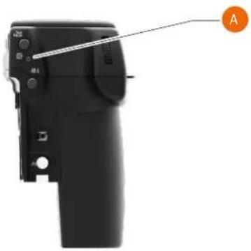
Press the Format button (A) on the camera grip. It is purposely recessed to avoid unintentional use, so use a ballpoint pen or similar. It is also possible to click the button with a hard press with the tip of your thumb. A pop up is displayed on the sensor unit for confirmation.
FORMAT MEMORY CARDS VIA SENSOR UNIT
MAIN MENU > GENERAL SETTINGS > STORAGE
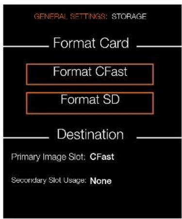
1 Press MENU.
2 Navigate to General Settings.
3 Choose Storage.
4 Navigate to Format Card.
5 Navigate to Format CFast or Format SD.
6 Confirm by pressing Format (Display button).
Note!
Only UDMA/type 4/60MBs (or 400x) cards or better are recommended for H6D use.
Note!
All CFast and SD memory cards should be formatted in the sensor unit before using them the first time.
Note!
You can add a Favourite function on the Main Menu if you often use formatting.
natural_image
Close-up of a black DSLR camera with a handle and control buttons, labeled 'A' pointing to the right side (no text or symbols on the device itself)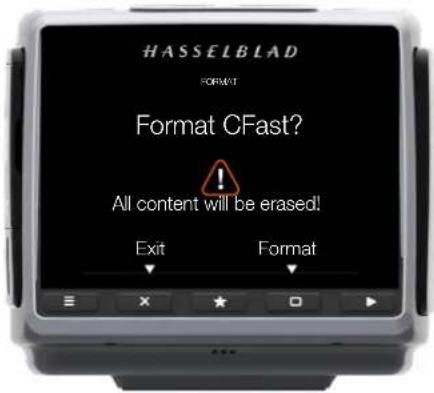
text_image
HASSELBLAD FORMAT Format CFast? All content will be erased! Exit FormatStorage Menu
text_image
GENERAL SETTINGS: STORAGE Format Card Format CFast Format SD Destination Primary Image Slot: CFast Secondary Slot Usage: NoneOverview
USER GUIDE
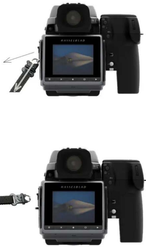
3.27 CARRYING STRAP
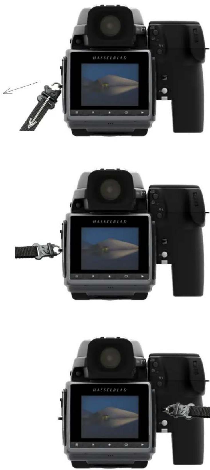
Carrying strap
1 Withdraw the safety collar, to free the hook.
2 Attach the hook to the strap lug.
3 Slide back the safety collar to ensure the hook remains in the locked position between the small protruding lugs.
The collar is purposely a tight t to avoid unintentionally slipping back and therefore might need some effort to slide.
Overview
USER GUIDE
3.28 REMOVE THE CARRYING STRAP
1 Withdraw the safety collar.
2 Detach the freed hook from the strap lug.
natural_image
Two black-and-white photos of a HASSELBIAD digital camera with display screens, showing front and side views (no text or symbols on device body)Overview
USER GUIDE
3.29 CHANGE LENS
ATTACH A LENS
1 Push the lens removal button (A) and remove protection cover lid (B) from the camera body.
2 Rotate the lens so that the red mark on the lens (C) lines up with the red mark (D) on the camera body.
3 Mount the lens into the camera body (E) and turn the lens clockwise to lock its position.
4 Make sure the lens is locked to the camera body before using or moving the camera.
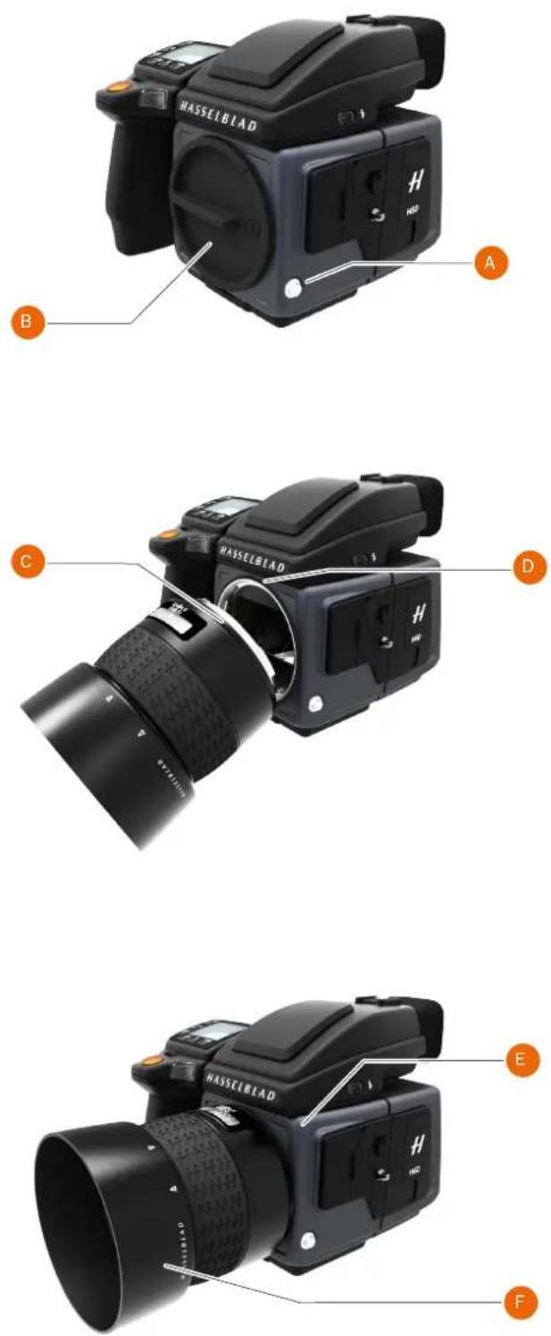
REMOVE A LENS
- Hold the lens with one hand and hold the camera body (E) still.
2 Push the lens removal button (A).
3 Rotate the lens counter clockwise.
4 Push the lens away from the camera body.
5 Attach the protection cover lid (B) on the camera body directly.
6 Attach a lens protection lid on the detached lens to prevent damage.
7 Store the lens with both lens protection lids on and the lens hood (F) inverted over the lens instead of in front of the lens.
natural_image
Black HVD 90X digital camera with visible screen display and control buttons (no text-heavy elements)To Prepare
USER GUIDE
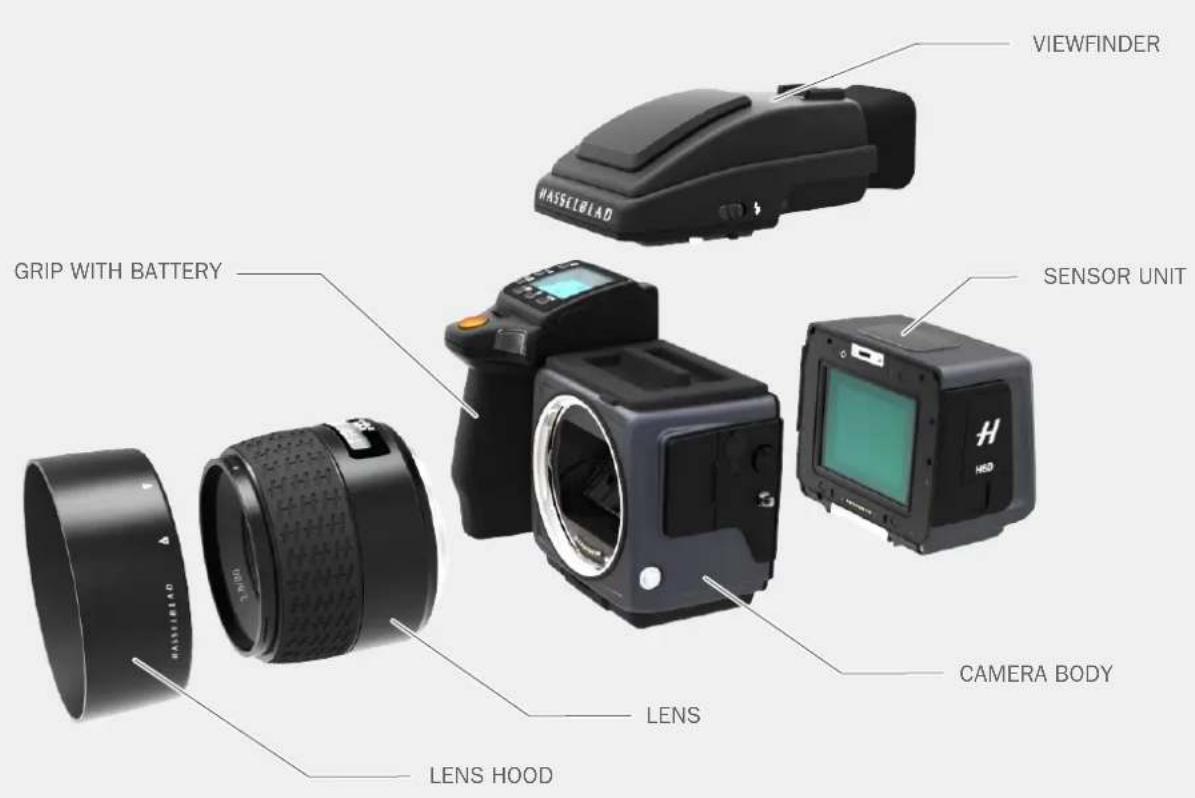
4.1 DELIVERY CHECK
text_image
VIEWFINDER WASSELBIAD GRIP WITH BATTERY SENSOR UNIT LENS CAMERA BODY LENS LENS HOODDelivery Check
1 Unpack all items.
2 Make sure that all the items listed on the attached package information are supplied.
3 Inspect all the items for damage.
4 If any items are missing or damaged, write down the product number of that item. If not, proceed to step 6.
5 Contact your Hasselblad dealer or distributor and tell them the product number of the item missing or damaged.
6 Keep the purchase details and the warranty in a safe place.
In the package
USB stick with User Guide and Phocus software.
Viewfinder. Grip with battery. Sensor unit. Sensor unit protection lid.
Camera body. Camera body protection lid.
Lens (if included in purchase). Lens hood. Lens protection lid x2.
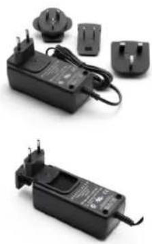
Battery. Battery electric socket protection lid. Battery charger plus connectors and cable.
natural_image
Two black electrical components with attached switches and power plugs, shown from different angles (no visible text or symbols)1 SD card included.
USB 3 cable.
Carrying strap.
To Prepare
USER GUIDE
4.2 SET DATE AND TIME
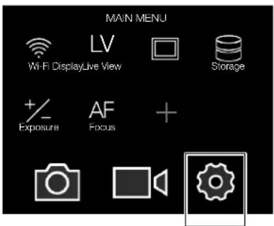
MAIN MENU > GENERAL SETTINGS > DATE & TIME
Main Menu
text_image
MAIN MENU Wi-Fi DisplayLive View Storage + Exposure AF Focus +General
Settings icon
Set Date and Time
1 Press the General Settings icon on the Sensor Unit Display.
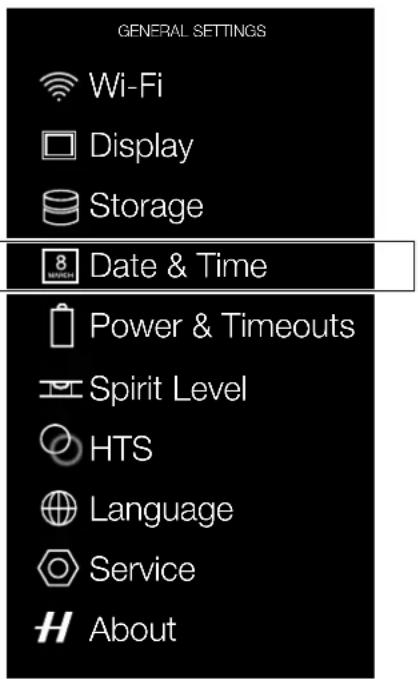
2 The General Settings Menu appears.
3 Press the Date & Time icon.
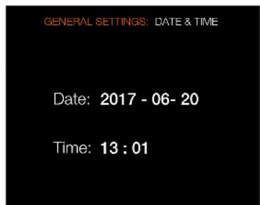
4 Select Date or Time.
5 Set Date and Time to desired settings.
Swipe right or press Menu / EXIT button to get back to Main Menu.
Date and Time Menu Settings
Date
Set Date by changing year, month and day using the pop up menus.
Time
Set Time by changing hour and minute using the pop up menus.
General Settings Menu
text_image
GENERAL SETTINGS Wi-Fi Display Storage 8 Date & Time Power & Timeouts Spirit Level HTS Language Service AboutDate and Time Menu
text_image
GENERAL SETTINGS: DATE & TIME Date: 2017 - 06- 20 Time: 13 : 01To Prepare
USER GUIDE
4.3 SET LANGUAGE
MAIN MENU > GENERAL SETTINGS > LANGUAGE
Main Menu
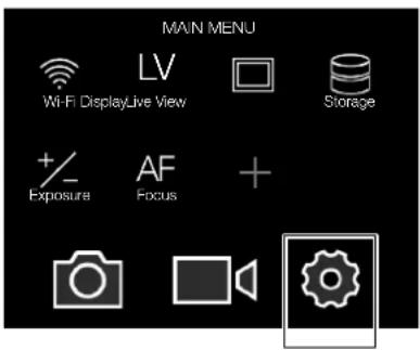
text_image
MAIN MENU Wi-Fi DisplayLive View LV Storage + Exposure AF Focus + Camera Speaker GearGeneral
Settings icon
Language Menu Settings
Available Languages:
English
Español
Français
Deutsch
Italian
Chinese
Russian
Japanese
Korean
Swedish
General Settings Menu
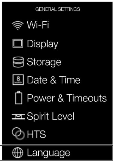
text_image
GENERAL SETTINGS Wi-Fi Display Storage 8 MARCH Date & Time Power & Timeouts Spirit Level HTS Language
Service

About
Language Menu

text_image
GENERAL SETTINGS: LANGUAGE Language: EnglishHow to change Language
1 Press MENU button on the Sensor Unit Display.
2 Navigate to General Settings.
3 Navigate to Language.
4 Select Language.
5 Close the pop up Menu by a click outside the pop up.
Note!
If the sensor unit has been set to a language you do not understand (a rented camera, for example), see Chapter Troubleshooting on page 192 for a solution.
To Prepare
USER GUIDE
4.4 CONNECT TO A COMPUTER
1 Connect a USB 3 cable to the USB port on the computer.
2 Connect the USB 3 cable to the USB port on the camera.
Note!
When connected to a computer, the following applies:
- The destination medium and location are controlled from Phocus.
- Exposure settings, including ISO, aperture and exposure time, can be controlled from Phocus or from the camera. In addition extra tools such as Live Video, remote focus control are available. See Phocus User Manual for full description.
Note!
The buttons on the Sensor Unit have no functions when the Camera is connected to a computer.
When initiating a shot from Phocus, the computer sends a signal to the Sensor Unit, which triggers the shutter (and strobe/flash, if any). The camera then sends the capture over the USB connection to the computer, where it is displayed on the computer screen and saved as a 16-bit 3F file in the currently selected folder on the computer hard disk.
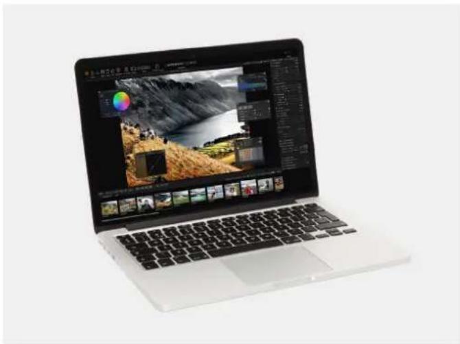
natural_image
Laptop displaying a landscape photo editing interface with multiple thumbnail previews (no visible text or symbols on the device itself)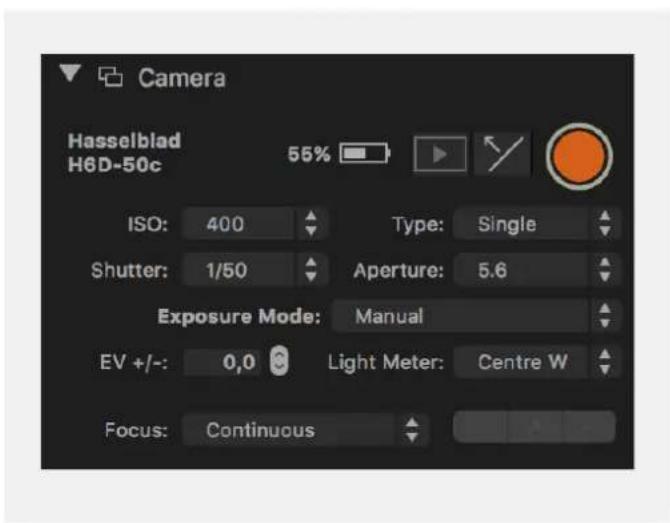
text_image
Camera Hasselblad H6D-50c 55% ISO: 400 Type: Single Shutter: 1/50 Aperture: 5.6 Exposure Mode: Manual EV +/-: 0,0 Light Meter: Centre W Focus: Continuous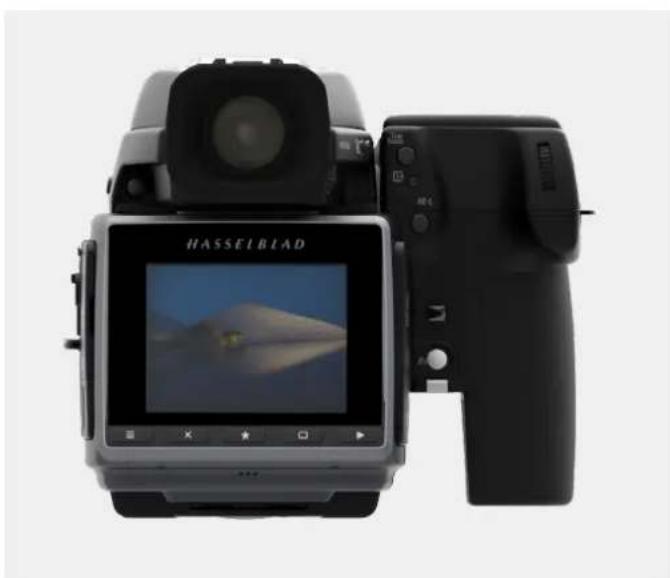
natural_image
Front and back view of a Haselblad digital camera with display screen showing mountain landscape (no text or symbols on device body)To Prepare
USER GUIDE
4.5 CAMERA INTERVAL SETTINGS EXAMPLE
Main Menu
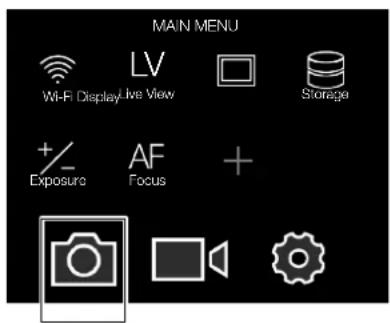
text_image
MAIN MENU Wi-Fi Display Live View LV Storage + Exposure AF Focus +Camera
Settings icon
MAIN MENU > CAMERA SETTINGS > INTERVAL
1 Press the Camera icon on the Sensor Unit Display.
2 The Camera Settings Menu appears.
3 Select the Interval Settings Menu.
Swipe right or press Menu / EXIT button to get back to Main Menu.
Camera Settings Menu
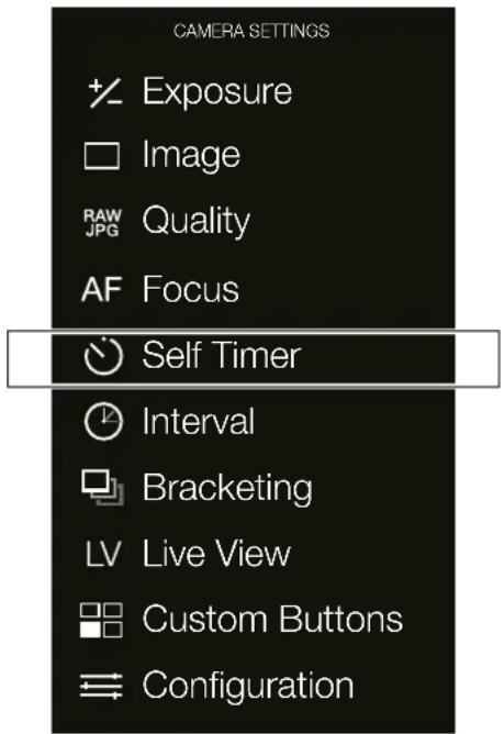
text_image
CAMERA SETTINGS Exposure Image RAW Quality AF Focus Self Timer Interval Bracketing LV Live View Custom Buttons ConfigurationInterval Settings Menu
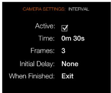
text_image
CAMERA SETTINGS: INTERVAL Active: ✓ Time: 0m 30s Frames: 3 Initial Delay: None When Finished: ExitInterval Settings Menu
Active
On or Off.
Time
Select time between exposures in minutes and seconds.
Frames
Select number of Frames.
Initial Delay
Select initial Delay.
When Finished
Settings for Action When Finished.
To Prepare
USER GUIDE
4.6 SET BRIGHTNESS OF THE DISPLAY
MAIN MENU > GENERAL SETTINGS > DISPLAY
Main Menu
text_image
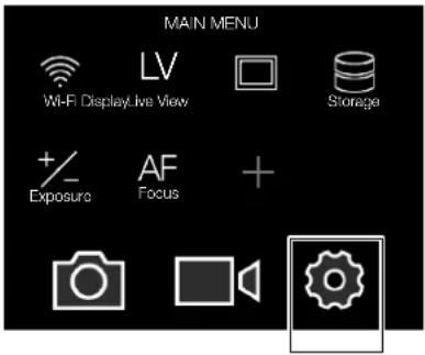
MAIN MENU Wi-Fi Display Live View Storage + Exposure AF Focus +General Settings icon
Set Display Brightness
1 Press the Settings icon on the Sensor Unit Display.
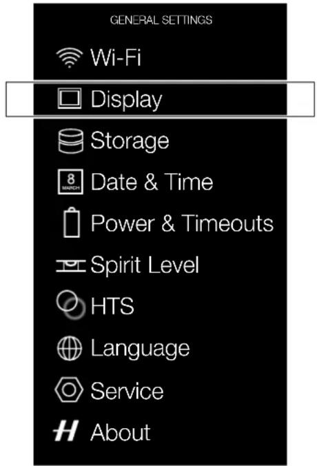
2 The General Settings Menu appears.
3 Select Display.
Swipe right or press Menu / EXIT button to get back to Main Menu.
General Settings Menu
text_image
GENERAL SETTINGS Wi-Fi Display Storage 8 MARCH Date & Time Power & Timeouts Spirit Level HTS Language Service AboutDisplay Menu
text_image
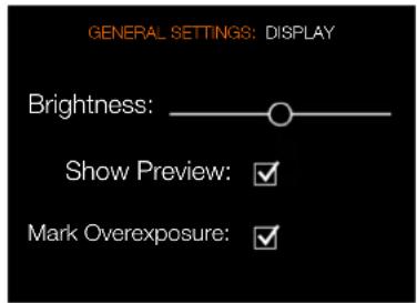
GENERAL SETTINGS: DISPLAY Brightness: Show Preview: ✓ Mark Overexposure: ✓Display Menu Settings
Brightness
Slide Left or Right to change Brightness.
Show Preview
Select On or Off. On displays a preview of the capture after every exposure.
Mark Overexposure
Highlights overexposed areas in the preview images.
To Prepare
USER GUIDE
4.7 SET DRIVE MODE
There are two drive modes, Single Drive Mode and Continuous Drive Mode.
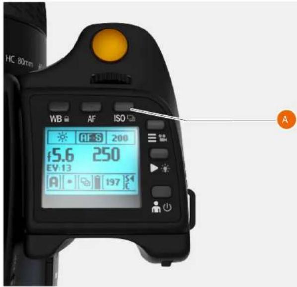
A Long press on ISO button (A) toggles between Single Drive Mode and Continuous Drive Mode. It can also be set from the Control Screen.
Single Drive Mode
In Single Drive Mode, a capture is made when the shutter release button is pressed.
To make the next capture, you must first release the shutter release button and then press the shutter release button again.
Continuous Drive Mode
In Continuous Drive Mode, the camera automatically captures images. The Camera is ready for the next capture in a Continuous Drive Mode as long as you keep the shutter release button pressed down.
Note!
The speed is dependent on the time it takes to save the capture according to equipment.
Note!
Drive Mode can also be changed from the Control Screen on the rear display.
text_image
HC 80mm WB AF ISO f5.6 250 EV:13 A 197 A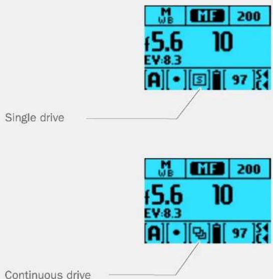
text_image
M WB MF 200 f5.6 10 EV:8.3 A[•] [S] [97] S Single drive M WB MF 200 f5.6 10 EV:8.3 A[•] [S] [97] S Continuous drive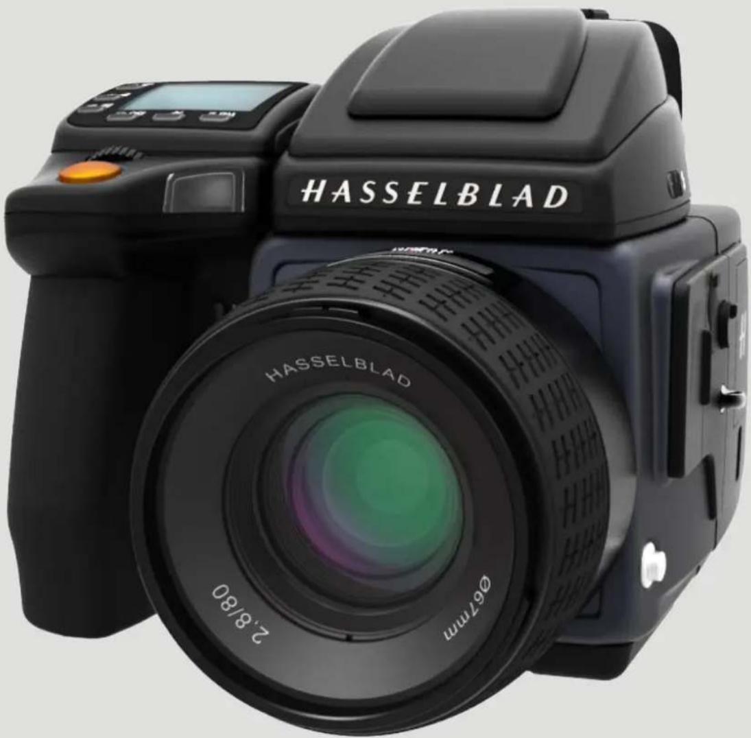
text_image
HASSELBLAD 2.8/80 Ø67mmTo Use
USER GUIDE
5.1 NAVIGATING THE MENUS
OVERVIEW OF MENUS AND SETTINGS ON SENSOR UNIT
The Sensor Unit Menu can be controlled directly on the touch sensitive screen by pressing the menus and icons. You can scroll up, down and from left to right. You can also navigate the on screen menus by using the buttons and scroll wheels.
The following gestures can be used to navigate and control the camera:
Action
Function
Swipe right Move back / Move image right.
Swipe left Move image left. Only in Browse
mode.
Swipe down Scroll / Display Control Screen.
Swipe up Scroll / Hide Control Screen.
Tap / press Select action / button / setting.
Double tap Zoom in to 50% or 100%. Double tap again to Zoom out to full View.
Function
Action
Select Tap / Press with one finger.
Display Control Screen Swipe down from the top of the screen.
Hide Control Screen Swipe up.
Move back Swipe right.
Zoom in Spread (move two fingers apart).
Zoom out Pinch (move two fingers together).
BUTTON NAVIGATION
By using the buttons on the sensor unit and the scroll wheels on the grip you can navigate through the various levels in the menu.
Button
Screen function
1 MENU button Back to Main Menu
2 Soft button Up
3 Select button Select
4 Soft button Down
5 Browse button Go to image browse
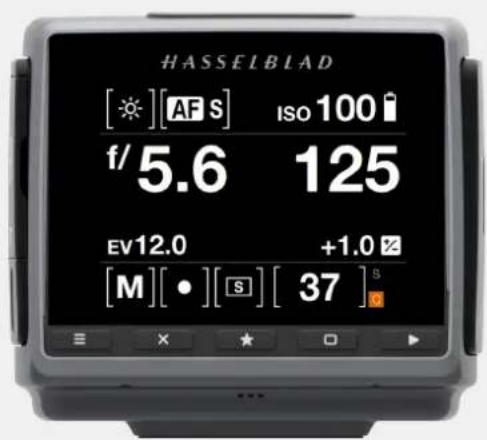
text_image
HASSELBLAD [★][AF S] Iso 100 i f/5.6 125 EV12.0 +1.0 Z [M][•][S][37] SSwipe right
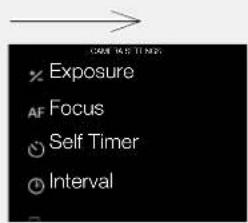
text_image
CASH 14.5 TIN N × Exposure AF Focus ○ Self Timer ○ IntervalSwipe left
natural_image
Three sheep standing in a grassy field with misty mountains in the background (no text or symbols visible)Swipe down
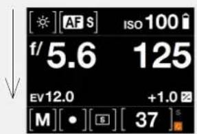
text_image
[*][AF S] ISO 100 f/5.6 125 EV12.0 +1.0 [M][•][S][37]⁵Swipe up

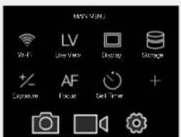
text_image
MAX MENU Wi-Fi LV Display Storage + Exposure AF Sound Timer +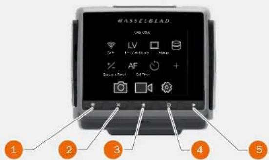
text_image
HASSELBIAD MIN V24G LV Laser Block Snap AF + Details Found Self-Photo 1 2 3 4 5To Use
USER GUIDE
5.2 THE MAIN MENU
The Main Menu consists of two areas:
One bottom row with the three Main Menu items:
1 Camera Settings.
2 Video Settings.
3 General Settings.
The area above (4) shows the Favourite Settings Shortcuts. You can add Shortcuts to access your most used functions directly from the Main Menu for better workflow. Shortcuts can also be deleted and replaced by other Favourite Settings.
ADD FAVOURITE FUNCTIONS TO MAIN MENU SCREEN
1 Add a favourite function by selecting the + icon (A) on the Main Menu.
2 Select any of the function in the pop up menu (B). In this case Quality is selected.
REMOVE FAVOURITES FROM THE MAIN MENU SCREEN
1 To remove a function from the Main Menu, press and hold the selected functions icon until an encircled x (C) appears.
2 Press the x within an orange circle (C) to remove the Quality Function.

text_image
Main Menu MAIN MENU Wi-Fi DisplayLive View LV Storage +/- Exposure AF Focus + 1 2 3Add Favourite
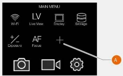
text_image
MAIN MENU Wi-Fi LV Live View Display Storage + Exposure AF Focus + Camera Camera Gear AAdd Favourite pop up Menu
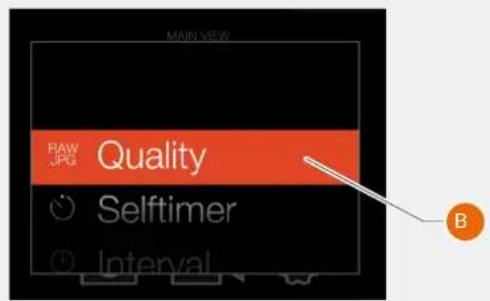
text_image
MAIN VIEW RAW JPG Quality Selftimer IntervalRemove Favourite
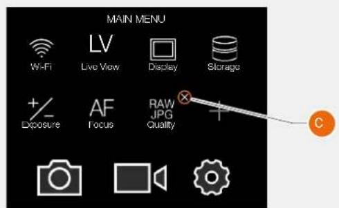
text_image
MAIN MENU Wi-Fi Liv View Display Storage +/- AF RAW Exposure Focus JPG Quality Camera Audio GearTo Use
USER GUIDE
DISPLAY CONTROL SCREEN
1 From any screen you can swipe down to display the Control Screen. Swipe down by starting on the upper part of the Sensor Unit Display near the top edge.
2 The Control Screen displays the current Settings of the camera. The Control Screen is interactive, select any of the settings to make a quick adjustment.
3 Swipe Up to hide the Control Screen and display the Main Menu.
4 The Main Menu appears.
See following pages for possible settings.
1 Swipe down 2 Control Screen
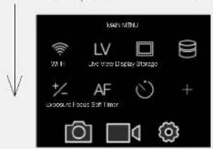
text_image
KARE MENU Wi-Fi LV TV Storage + AF + Capture Focus Soft Timer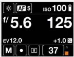
text_image
[*][AF S] ISO 100 f/5.6 125 EV12.0 +1.0 [M][•][$] [37]3 Swipe up 4 Main Menu
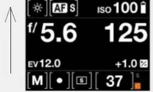
text_image
AFS ISO 100 f/5.6 125 EV12.0 +1.0 [M][•][S][37]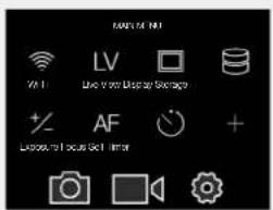
text_image
RANGE WITH Wi-Fi LV Live View Display Protection +/- AF + Belize to focus Get TimorTo Use
USER GUIDE
CONTROL SCREEN DESCRIPTION
The Control screen is a quick way to adjust settings. Tap / Select the desired function and change the setting directly in the Control Screen.
Locked Values on the Control Screen
P and Pv Mode
When you select P or Pv, the Aperture (5.6) and Shutter (125) are automatic and displayed in grey colour that indicates that you cannot change these settings.
A Mode
For Aperture priority (A) you can change the Aperture value and the Shutter value will be automatic and displayed in grey.
S Mode
For Shutter priority (S) you can change the Shutter value and the Aperture value will be automatic and displayed in grey.
Control Screen
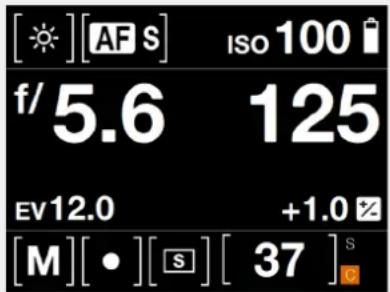
text_image
[☀][AF S] ISO 100 f/5.6 125 EV12.0 +1.0 [M][•][S] [37] SControl Screen
P Mode
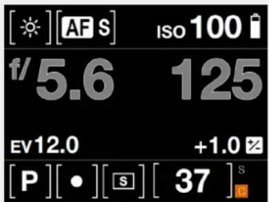
text_image
[☀][AF S] Iso 100 f/5.6 125 EV12.0 +1.0 [P][•][S] [37]SControl Screen
A Mode
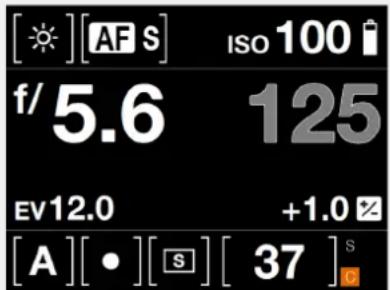
text_image
[☀][AF S] ISO 100 f/5.6 125 EV12.0 +1.0 [A][•][S][37]SControl Screen
S Mode
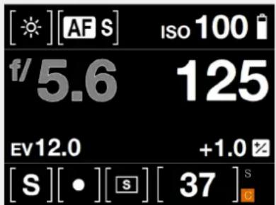
text_image
[☀][AF S] ISO 100 f/5.6 125 EV12.0 +1.0 [S][•][S][37]STo Use
USER GUIDE
Settings on the Control Screen
White Balance
- Cloudy.
- Shade.
- Daylight.
- Tungsten.
- Fluorescent.
- Flash.
- Manual.
Focus Mode
- MF Manual Focus.
- AF-S Single Focus.
- AF-C Continuous Focus.
- AF-T True Focus.
ISO
- Select ISO value.
Aperture
- Select Aperture value.
This section continues on the next page.
White Balance
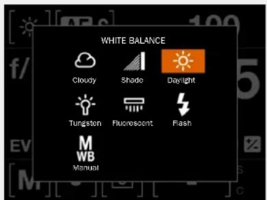
text_image
WHITE BALANCE Cloudy Shade Daylight Tungsten Fluorescent Flash WB ManualAF Focus

text_image
FOCUS MODE MF Manual Focus AF S Single Focus AF C Continuous Focus AFT True FocusISO
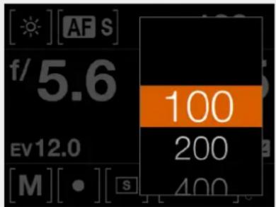
text_image
[☀][AF S] f/5.6 EV12.0 [M][•][S] 100 200 400Aperture

other
| Value | ISO 100 | ISO 125 | |-------|---------|---------| | 4 | | | | 4.8 | | | | 5.6 | | | | 6.8 | | | | 8 | | |To Use
USER GUIDE
Settings on the Control Screen
Shutter Speed
- Select Shutter Speed value.
Exposure Adjust
- Adjust Flash Exposure by sliding right (+) or left (-).
- Adjust Exposure by sliding right (+) or left (-).
Note!
Double tap the +/- or flash icon to reset value to zero.
Exposure Mode
- M Manual.
- A Aperture Priority.
- S Shutter Priority.
- P Program.
- Pv Program Variable.
- V Video
Metering Mode
- Centre Weighted.
- Spot.
- Centre Spot.
This section continues on the next page.
Shutter Speed
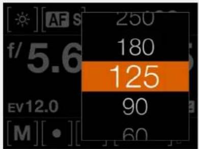
text_image
[AF S] f/5.6 EV12.0 [M][•] 250 180 125 90 60Exposure Adjust
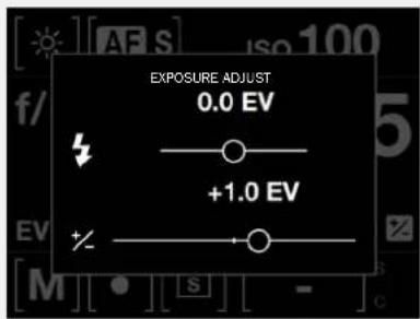
text_image
EXPOSURE ADJUST 0.0 EV +1.0 EVExposure Mode
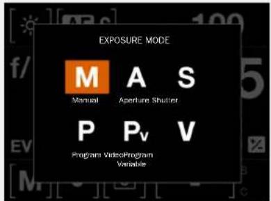
text_image
EXPOSURE MODE M A S Manual Aperture Shooter P Pv V Program VideoProgram VariableMetering Mode
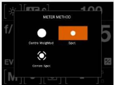
text_image
METER METHOD Centre Weighted Spot Centre SpotTo Use
USER GUIDE
Settings on the Control Screen
Drive Mode
- Single Drive Mode.
- Continuous Drive Mode.
Remaining Captures
- Displays the number of remaining Captures.
Memory Card
- S for SD Card.
- C for CFast Card.
Drive Mode
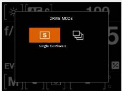
text_image
DRIVE MODE Single ContinuousRemaining
Captures
37 down to the right indicates
37 remaining captures on the CFast Card.
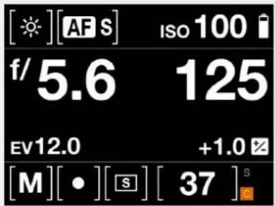
text_image
[☀][AF S] Iso 100 f/5.6 125 EV12.0 +1.0 [M][•][S] [37] SMemory Card
S - SD Card.
C - CFast Card.
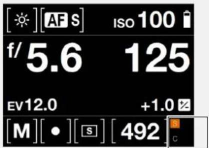
text_image
[☀][AF S] ISO 100 f/5.6 125 EV12.0 +1.0 [M][•][S] [492]To Use
USER GUIDE
5.3 CAMERA SETTINGS MENU
Main Menu
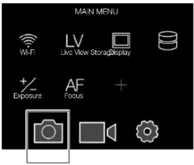
text_image
MAIN MENU Wi-Fi LV Live View Storage Display +/- Exposure AF Focus + CameraCamera icon
MAIN MENU > CAMERA SETTINGS
1 Press the Camera icon on the Sensor Unit display.
2 The Camera Settings Menu appears.
Swipe right or press MENU button to get back to Main Menu.
Camera Settings Menu
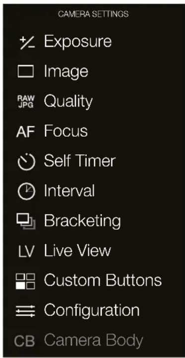
text_image
CAMERA SETTINGS + Exposure Image RAW Quality JPG AF Focus Self Timer Interval Bracketing LV Live View Custom Buttons Configuration CB Camera BodyTo Use
USER GUIDE
5.4 CAMERA EXPOSURE SETTINGS
MAIN MENU > CAMERA SETTINGS > EXPOSURE
1 Press the Camera icon on the Sensor Unit display.
2 The Camera Settings Menu appears.
3 Press the Exposure Settings Menu.
Swipe right or press MENU button to get back to Main Menu.
Camera Settings Menu Exposure Settings Menu
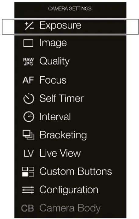
text_image
CAMERA SETTINGS Exposure Image RAW JPG Quality AF Focus Self Timer Interval Bracketing LV Live View Custom Buttons Configuration CB Camera Body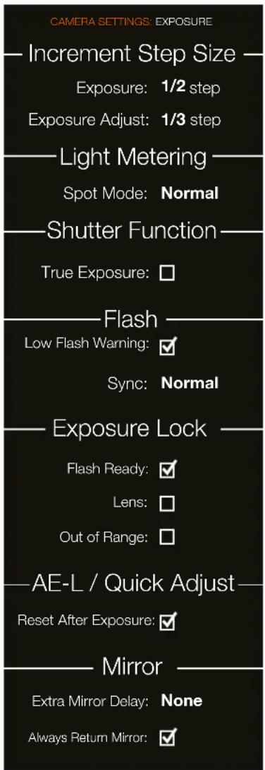
text_image
CAMERA SETTINGS: EXPOSURE — Increment Step Size — Exposure: 1/2 step Exposure Adjust: 1/3 step — Light Metering — Spot Mode: Normal — Shutter Function — True Exposure: □ — Flash — Low Flash Warning: ✓ Sync: Normal — Exposure Lock — Flash Ready: ✓ Lens: □ Out of Range: □ — AE-L / Quick Adjust — Reset After Exposure: ✓ — Mirror — Extra Mirror Delay: None Always Return Mirror: ✓To Use
USER GUIDE
INCREMENT STEP SIZE SETTINGS
MAIN MENU > CAMERA SETTINGS > EXPOSURE > INCREMENT STEP SIZE
1 Press the Camera icon on the Sensor Unit display.
2 The Camera Settings Menu appears.
3 Press the Exposure Settings Menu.
4 Select Increment Step Size.
Swipe right or press MENU button to get back to Main Menu.
Exposure Increment Step Size Settings
Select the Increment Step Size setting.
Exposure
1
1/2
1/3
Exposure Adjust
1
1/2
1/3
Exposure Settings Menu
CAMERA SETTINGS: EXPOSURE
— Increment Step Size —
Exposure: 1/2 step
Exposure Adjust: 1/3 step
Light Metering
Spot Mode: Normal
Shutter Function
True Exposure: □
Flash
Low Flash Warning:

Sync: Normal
Exposure Lock
Flash Ready: √
Lens: □
Out of Range: □
AE-L / Quick Adjust
Reset After Exposure: √
Mirror
Extra Mirror Delay: None
Always Return Mirror: √
To Use
USER GUIDE
EXPOSURE COMPENSATION / QUICK ADJUST
The exposure compensation function, for both manual and automatic modes can be set from -5 to +5 EV, in 1/3, 1/2 or 1 EV increments and is visible above the scale in the viewfinder and as a ± symbol on the grip display.
Exposure adjustment can be divided into two separate parts:
1 Fixed Adjustment.
Press the +/- button on the viewfinder (A).
Turn the rear scroll wheel (B) to select the chosen amount of compensation.
2 Quick Adjustment.
In any of the automatic exposure modes (A, S, P or Pv) rotate the rear scroll wheel to add a Quick Adjustment. In the Exposure Menu you can control if this adjustment shall be used for just the next exposure or for all following exposures.
The combined amount of fixed and Quick Adjust is displayed in the viewfinder as both an EV figure complete with a minus or plus prefix and as a marker above a minus to plus scale.
Default settings provide 1/3 EV compensation steps and an immediate clearing of the setting after capture.
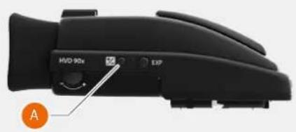
text_image
MVO 90x EXP A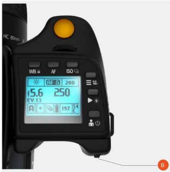
text_image
HC 80mm WB AF ISO ØS 200 f5.6 250 EV 13 A 197 S CFLASH ADJUSTMENT
1 Activate the camera and press the +/- button on the Viewfinder.
2 Turn the Front Scroll Wheel (A) to set the amount of compensation required from +3 EV through -3 EV.

Viewfinder Display View
Exposure compensation EV -1.3
Grip Display View
Flash Exposure
Camera Exposure

text_image
+1.0 - + -0.7 EVViewfinder Display View
Exposure compensation EV -1.3

Flash Exposure Camera Exposure
To Use
USER GUIDE
ISO AND WHITE BALANCE
ISO and White Balance are set either via the Grip, the Sensor Unit Display, or using Phocus, when tethered.
- On the grip, the WB (B) and ISO button (C) provides immediate access to ISO and White Balance settings. The front scroll wheel (A) and rear scroll wheel (D) are used to make the desired changes. These appears on the grip display, the sensor unit display and in the viewfinder.
- For the Sensor Unit display, settings are changed on the Touch Display or via the soft buttons under the display.
- In Phocus there is a specific tool to control camera settings.
The settings are automatically and simultaneously transferred from the grip to the Sensor Unit. Likewise all changes on the Sensor Unit are automatically transferred to the grip display.
Note!
The changes are only displayed on the Sensor Unit when the settings have been saved by halfpressing the shutter release.
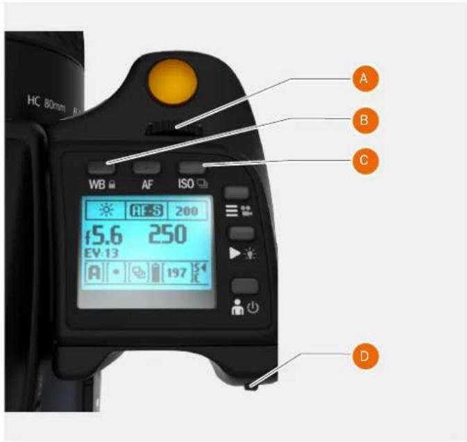
text_image
HC 80mm WB AF ISO 5.6 200 EV:13 A 250 197 A B C D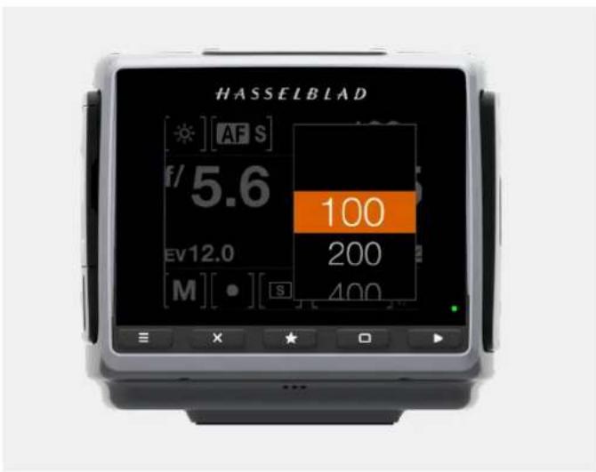
text_image
HASSELBLAD [ sun ] [ AF S ] f/ 5.6 100 EV12.0 200 [M] [ • ] [ S ] 400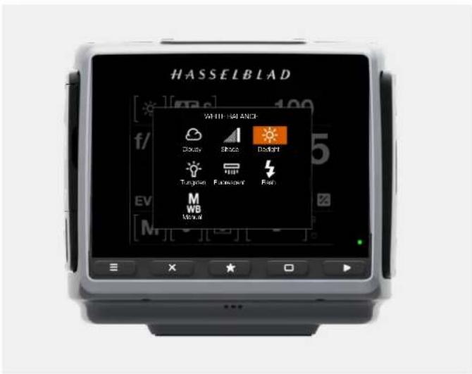
text_image
HASSELBLAD WHIP - 100 ANCH Doway Shock Drought Tungsten Fungsten Fire M WB WindTo Use
USER GUIDE
LIGHT METERING SETTINGS
MAIN MENU > CAMERA SETTINGS > EXPOSURE > Exposure Mode
1 Press the Camera icon on the Sensor Unit display.
2 The Camera Settings Menu appears.
3 Press the Exposure Settings Menu.
4 Select Light Metering.
Swipe right or press MENU button to get back to Main Menu.
Spot Mode Settings
Controls how the camera works if spot light metering mode is selected.
Spot Mode
Normal
Zone
Shutter Function Settings
Controls True Exposure function will be used or not to adjust short shutter speeds for aperture dependency. See more on page 80.
True Exposure
On
Off
Exposure Settings Menu
CAMERA SETTINGS: EXPOSURE
Increment Step Size
Exposure: 1/2 step
Exposure Adjust: 1/3 step
Light Metering
Spot Mode: Normal
Shutter Function
True Exposure: □
Flash
Low Flash Warning:

Sync: Normal
Exposure Lock
Flash Ready: √
Lens: □
Out of Range: □
AE-L / Quick Adjust
Reset After Exposure: √
Mirror
Extra Mirror Delay: None
Always Return Mirror: √
To Use
USER GUIDE
SHUTTER FUNCTION SETTINGS
MAIN MENU > CAMERA SETTINGS > EXPOSURE > Exposure Mode
1 Press the Camera icon on the Sensor Unit display.
2 The Camera Settings Menu appears.
3 Press the Exposure Settings Menu.
4 Select Shutter Function.
Swipe right or press MENU button to get back to Main Menu.
Shutter Function Settings
Controls True Exposure function will be used or not to adjust short shutter speeds for aperture dependency. See more on page 80.
True Exposure
On
Off
Exposure Settings Menu
CAMERA SETTINGS: EXPOSURE
Increment Step Size
Exposure: 1/2 step
Exposure Adjust: 1/3 step
Light Metering
Spot Mode: Normal
-Shutter Function
True Exposure: □
Flash
Low Flash Warning:

Sync: Normal
Exposure Lock
Flash Ready: √
Lens: □
Out of Range: □
AE-L / Quick Adjust
Reset After Exposure: √
Mirror
Extra Mirror Delay: None
Always Return Mirror: √
To Use
USER GUIDE
MANUAL EXPOSURE MODE
To change the Exposure mode Swipe Down to display the Control Screen or press the EXP button on the Viewfinder.
Manual mode provides total user control of the shutter and aperture settings. In this mode the shutter speed and aperture settings are manually chosen by turning the front and rear scroll wheels.
The standard exposure setting is obtained when the pointer over the exposure scale is positioned above the central index (in the viewfinder display).
Any deviation from this standard setting is displayed by:
- the pointer appearing elsewhere than above the central index.
- figures above the scale representing the amount of adjustment in EV's.
Exposure Modes
Grip Display.
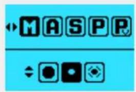
text_image
MASPRExposure Modes
Sensor Unit Display.
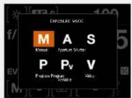
text_image
EXPOSURE MODE M A S Mance Aperture Shunt P Pv V Program Program + 100% VideoA + 1.3 above the scale in the display, would indicate a 1.3 EV overexposure setting. Conversely, a -2, for example, would indicate a 2EV underexposure setting. Note that the appearance of a +/- symbol on the grip and viewfinder displays in manual mode means that a change has been made to the exposure compensation setting. See later section on Exposure compensation.
The actual aperture settings and shutter speeds are indicated to the right of the exposure scale in the conventional manner. (Note: full-stops, half-stops and third-stops are also displayed, according to setting (see increment setting). For example, a setting between f/8 and f/11 will appear as f/9,5 if half-stop is chosen).
Viewfinder Display Visual User Interface
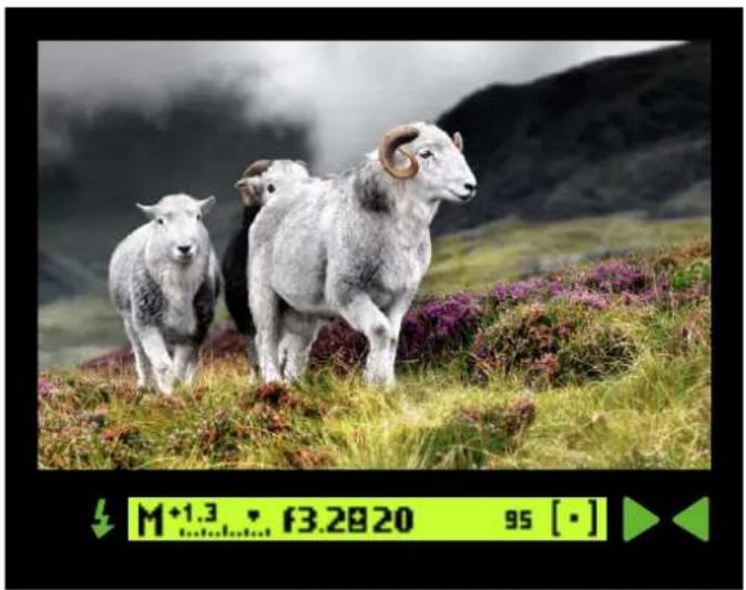
natural_image
Three sheep standing in a grassy field with purple flowers, mountains in background (no text or symbols)To Use
USER GUIDE
AUTOMATIC EXPOSURE MODE
To change the Exposure mode Swipe Down to display the Control Screen or press the EXP button on the Viewfinder.
Automatic exposure provides a choice of two ways to control the shutter speed and aperture settings semi automatically and two ways fully automatically.
Aperture priority A
The aperture is manually set by turning the front scroll wheel, and the shutter speed is automatically set by the camera.
Shutter priority S
The shutter speed is manually set by turning the front scroll wheel, and the aperture is automatically set by the camera.
Programmed P
In this mode, an aperture/shutter combination is automatically set according to the EV measured (metering method remains as set).
Programmed variable Pv
This mode is very similar to Programmed, except with the additional parameters of lens focal length being automatically set. For example, long shutter speeds will automatically be avoided with a long focal length lens (see illustration on the following page).
In Automatic mode the front scroll wheel sets alternative aperture/shutter combinations while maintaining the same EV and the rear scroll wheel alters the amount of exposure compensation. The compensation appears as a +/- symbol on the grip display and viewfinder display.
Note!
Aperture and shutter speed settings can both be changed even while the ready light on Sensor Unit is flashing.
Exposure Modes
Grip Display.
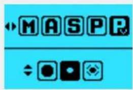
text_image
MASPRExposure Modes
Sensor Unit Display.
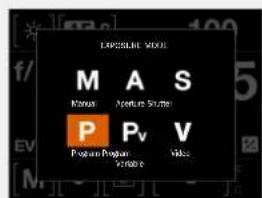
text_image
EXPOSIBLE VIEW M A S Nanus Aperture Skimber P Pv V Program Program Version eTo Use
USER GUIDE
AUTOMATIC EXPOSURE - P AND PV MODE
P Mode
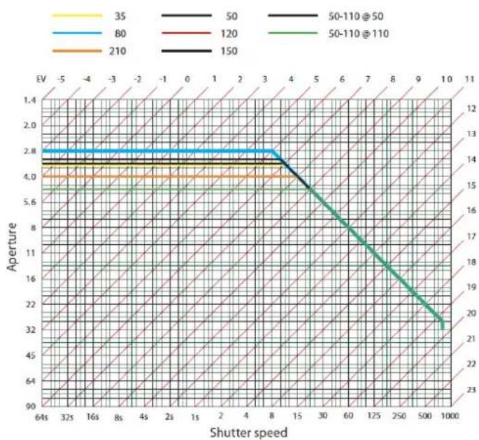
line
| Shutter speed | 35 | 80 | 210 | 50 | 120 | 150 | | ------------- | ---- | ---- | ---- | ---- | ---- | ---- | | 64s | | | | | | | | 32s | | | | | | | | 16s | | | | | | | | 8s | | | | | | | | 4s | | | | | | | | 2s | | | | | | | | 1s | | | | | | | | 2 | | | | | | | | 4 | | | | | | | | 8 | | | | | | | | 15 | | | | | | | | 30 | | | | | | | | 60 | | | | | | 8 | | 125 | | | | | | | | 250 | | | | | | | | 500 | | | | | | | | 1000 | | | | | | 32 |Pv Mode
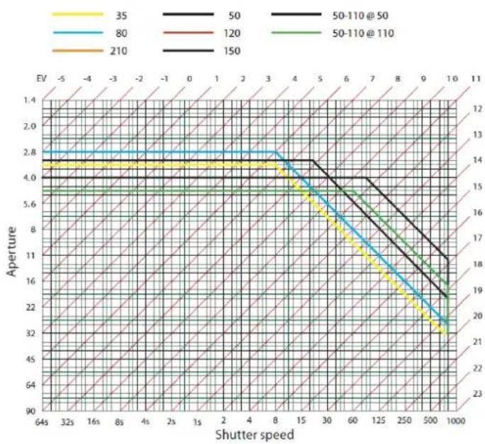
line
| Shutter speed | 35 | 80 | 210 | 50 | 120 | 50-110@50 | 50-110@110 | | ------------- | ----- | ----- | ----- | ----- | ----- | --------- | ---------- | | 64s | 4.0 | 2.8 | 4.0 | 4.0 | 4.0 | 4.0 | 4.0 | | 32s | 4.0 | 2.8 | 4.0 | 4.0 | 4.0 | 4.0 | 4.0 | | 16s | 4.0 | 2.8 | 4.0 | 4.0 | 4.0 | 4.0 | 4.0 | | 8s | 4.0 | 2.8 | 4.0 | 4.0 | 4.0 | 4.0 | 4.0 | | 4s | 4.0 | 2.8 | 4.0 | 4.0 | 4.0 | 4.0 | 4.0 | | 2s | 4.0 | 2.8 | 4.0 | 4.0 | 4.0 | 4.0 | 4.0 | | 1s | 4.0 | 2.8 | 4.0 | 4.0 | 4.0 | 4.0 | 4.0 | | 2r | 4.0 | 2.8 | 4.0 | 4.0 | 4.0 | 4.0 | 4.0 | | 4r | 4.0 | 2.8 | 4.0 | 4.0 | 4.0 | 4.0 | 4.0 | | 8r | 4.0 | 2.8 | 4.0 | 4.0 | 4.0 | 4.0 | 4.0 | | 15r | 4.0 | 2.8 | 4.0 | 4.0 | 4.0 | 4.0 | 4.0 | | 30r | 4.0 | 2.8 | 4.0 | 4.0 | 4.0 | 4.0 | 4.0 | | 60r | 4.0 | 2.8 | 4.0 | 4.0 | 4.0 | 4.0 | 4.0 | | 125r | 4.0 | 2.8 | 4.0 | 4.0 | 4.0 | 4.0 | 4.0 | | 250r | 4.0 | 2.8 | 4.0 | 4.0 | 4.0 | 4.0 | 4.0 | | 500r | 4.0 | 2.8 | 4.0 | 4.0 | 4.0 | 4.0 | 4.0 | | 1000r | 4.0 | 2.8 | 4.0 | 4.0 | 4.0 | 4.0 | 4.0 | | EV | - | - | - | - | - | - | - | | - | - | - | - | - | - | - | - | | -5 | - | - | - | - | - | - | - | | - | - | - | - | - | - | - | - | | -3 | - | - | - | - | - | - | - | | - | - | - | - | - | - | - | - | | -2 | - | - | - | - | - | - | - | | - | - | - | - | - | - | - | - | | - (top) | - | - | - | - | - | - | - | | EV (top) (top) (top) (top) (top) (top) (top) (top) (top) (top) (top) (top) (top) (top) (top) (top) (top) (top) (top) (top) (top) (top) (top) (top) (top) (top) (top) (top) (top) | | EV (bottom) (bottom) (bottom) (bottom) (bottom) (bottom) (bottom) (bottom) (bottom) (bottom) (bottom) (bottom) (bottom) (bottom) (bottom) (bottom) (bottom) (bottom) (bottom) (bottom) (bottom) (bottom) (bottom) (bottom) (bottom) (bottom) (bottom) | | EV (-1) (-1) (-1) (-1) (-1) (-1) (-1) (-1) (-1) (-1) (-1) (-1) (-1) (-1) (-1) (-1) (-1) (-1) (-1) (-1) (-1) (-1) (-1) (-1) (-1) (-1) (-1) | | EV (+1) (-1) (-1) (-1) (-1) (-1) (-1) (-1) (-1) (-1) (-1) (-1) (-1) (-1) (-1) (-1) (-1) (-1) (-1) (-1) (-1) (-1) (-1) (-1) (-1) (-1) (-1) (-1) | | EV (+3)| +3 | +3 | +3 | +3 | +3 | +3 | +3 | | EV (+5)| +3 | +3 | +3 | +3 | +3 | +3 | +3 | | EV (+7)| +3 | +3 | +3 | +3 | +3 | +3 | +3 | | EV (+9)| +3 | +3 | +3 | +3 | +3 | +3 | +3 | | EV (+11)| +3 | +3 | +3 | +3 | +3 | +3 | +3 | | EV (+13)| +3 | +3 | +3 | +3 | +3 | +3 | +3 | | EV (+15)| +3 | +3 | +3 | +3 | +3 | +3 | +3 | | EV (+17)| +3 | +3 | +3 | +3 | +3 | +3 | +3 | | EV (+19)| +3 | +3 | +3 | +3 | +3 | +3 | +3 | | EV (+21)| +3 | +3 | +3 | +3 | +3 | +3 | +3 | | EV (+23)| +3 | +3 | +3 | +3 | +3 | +3 | +3 | | EV (+25)| +3 | +3 | +3 | +3 | +3 | +3 | +3 | | EV (+27)| +3 | +3 | +3 | +3 | +3 | +3 | +3 | | EV (+29)| +3 | +3 | +3 | +3 | +3 | +3 | +3 | | EV (+31)| +3 | +3 | +3 | +3 | +3 | +3 | +3 | | EV (+33)| +3 | +3 | +3 | +3 | +3 | +3 | +3 | | EV (+35)| +3 | +3 | +3 | +3 | +3 | +3 | +3 | | EV (+37)| +3 | +3 | +3 | +3 | +3 | +3 | +3 | | EV (+39)| +3 | +3 | +3 | +3 | +3 | +3 | +3 | | EV (+41)| +3 | +3 | +3 | +3 | +3 | +3 | +3 | | EV (+43)| +3 | +3 | +3 | +3 | +3 | +3 | +3 | | EV (+45)| +3 | +3 | +3 | +3 | +3 | +3 | +3 | | EV (+47)| +3 | +3 | +3 | +3 | +3 | +3 | +3 | | EV (+49)| +3 | +3 | +3 | +3 | +3 | +3 | +3 | | EV (+51)|+5*6*6*6*6*6*6*6*6*6*6*6*6*6*6*6*6*6*6*6*6*6*6*6*6*6*6*6*6*6*6*6*6*6*6*6*6*6*6*6*6*6*6*6*6*6*6*6*6*6*6*7| | EV (+51)|+5*6*6*6*6*6*6*6*6*6*6*6*6*6*6*6*6*6*6*6*6*6*6*6*6*6*6*6*6*6*6*6*6*6*6*6*6*6*6*6*6*6*6*6*6*6 | EV (+51)|+5*6*6*6*6*6*6*6*6*6*6*6*6*6*6*6*6*6*6*6*6*6*6*6*6*6*6*6*6*6*6*6 *| | EV (+51)|+5*6*6*6*6*6*6*6*6*6*6 *| | EV (+51)|+5/5 *| | EV (+51)|+5/5 *| | EV (+51)|+5/5 *| | EV (+51)|+5/5 *| | EV (+51)|+5/5 *| | EV (+51)|+5/5 *| | EV (+51)|+5/5 *| | EV (+51)|+5/5 *| | EV (+51)*| | EV (+51)*| | EV (+51)*| | EV (+51)*| | EV (+51)*| | EV (+51)*| | EV (+51)*| | EV (+51)*| | EV (+51)*| | EV (+51)*| | EV (+51)*| | EV (+51)*| | EV (+51)*| | EV (end)*| | EV (end)*| | EV (end)*| | EV (end)*| | EV (end)*| | EV (end)*| | EV (end)*| | EV (end)*| | EV (end)*| | EV (end)*| | EV (end)*| | EV (end)*| | EV (end)*| | EV (end)*| | EV (end)*|To Use
USER GUIDE
AE-L BUTTON
The AE-L button (A) has two main functions that can be incorporated in various working methods involving exposure locking. It also has an extra function for the flash measure capability (see AE-L section under Flash). The AE-L button can:
Lock an EV setting in manual and automatic modes
When the button is pressed, the light metering facility is locked to the EV setting at that moment. An L (=locked) symbol appears between the shutter speed and the aperture indication on the grip display and viewfinder display to confirm the status. Press the AE-L button again to unlock (a toggle function).
In the locked setting, the aperture and shutter speed become interlocked. In this way, a new aperture/shutter combination that still represents the same EV, can be rapidly chosen. For example, if the shutter is set to 1/125s and the aperture to f/8 and are locked together, you can access new EV-equivalent combinations of, for example, 1/30s a f/16 or 1/500s at f/4 just by moving the front scroll wheel.
In practice this means you can, for example, in auto mode position the metering area (spot setting) over an area in the subject that you determine to be equivalent to a mid-grey and lock it with the AE-L button. You can then recompose the picture with the metering zone positioned over an area much brighter or darker while still retaining the original exposure setting and choose a new combination of aperture and shutter speed settings.
Be used as a Zone System placement button
The AE-L button also allows the spot metering function to make zone placements. When the AE-L button is pressed, the metered area is saved as a mid-grey (Zone 5). When the spot area is placed over another part of the scene, the new area is compared to the saved area and the difference can be read off the scale seen in the viewfinder. For example, in a landscape situation you could meter the foreground, lock the reading with the AE-L button (thereby locking that area to be reproduced as the equivalent to a mid grey 18%), point the camera at some rocks to see by how much darker they are compared to the foreground by the EV difference read off the scale.
If you have chosen Spot together with Zone display as well as one of the automatic modes A, S, P or Pv, point the spot marking at an area that you decide should be a Zone 5 and click the AE-L button. The meter will now display different parts of the subject as zone values in the viewfinder display, instead of EV deviations, as you move the spot marking over the subject. (Included are Lo and Hi to signify areas beyond the range of the sensor).
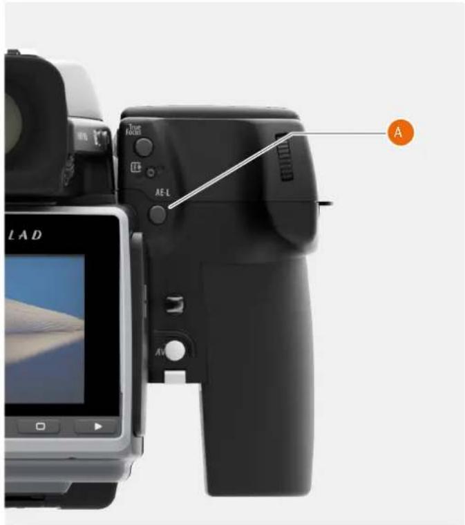
natural_image
Close-up of a black digital camera with attached screen and control buttons, no visible text or symbols on the device itself.Grip Display View
Lock symbol L.
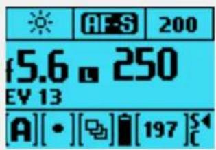
text_image
AF-S 200 f5.6 ■ 250 EV 13 [A][•][☐][197]SAlternatively you can choose to re-classify an area as another zone and then check the rest of the subject to see how other areas fall on the zone scale. Do this by following the above procedure and then turning the rear scroll wheel until you see the new desired zone value in the viewfinder display. You will also see the new exposure that will now produce that new zone. For example, you might have measured a rock at zone 5 but wish to make it darker. By moving the rear scroll wheel you could re-classify it as zone 4. You will then be able to see, for example, whether white clouds are now falling within the exposure range by their new zone classification.
Alternatively, you can also pre set the initial zone reading in order to save time and effort where there is no freely available zone 5 subject for light measuring. For example, you might be on a sandy beach where you know that sand is normally classified as zone 6. You can pre-programme the zone placement by holding down the AE-L button while choosing the new zone value and turning the front scroll wheel until zone 6 appears. All new placements will then be zone 6.
To Use
USER GUIDE
LIGHT METERING MODE
The Light Metering Mode can be changed on the Control Screen or by pressing the EXP button on the Viewfinder. Use the Rear Scroll Wheel to select Mode.
Available Light Metering Modes
There are three reflective metering modes available. Centre Weighted, Centre Spot and Spot metering.
Spot Mode
In Camera Settings / Exposure Mode you can select the Spot Mode to be
- Normal Mode.
- Zone Mode. (See page 78)
Exposure Settings Menu
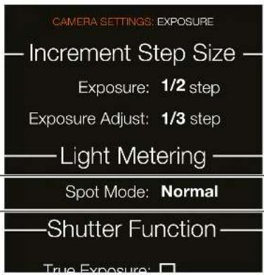
text_image
CAMERA SETTINGS: EXPOSURE — Increment Step Size — Exposure: 1/2 step Exposure Adjust: 1/3 step — Light Metering — Spot Mode: Normal — Shutter Function — True Exposure: □Light Metering Modes
Sensor Unit Display.
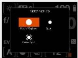
text_image
VETER VET-100 Current/Analyze Back Back/AnalyzeLight Metering ModesSymbol Light Metering Distribution

Centre Weighted
Used for light situations where there is no particular dominance of light or dark areas across the tonal range. Takes into account approximately 25% of the image seen in the viewfinder.
natural_image
3D wireframe surface plot with grid lines, no text or symbols present
Centre Spot
Emphasizes the central section of the focusing screen equivalent to approximately 25% of the image. This provides a balanced assessment and is a typical choice where the main subject is in the centre.
natural_image
3D wireframe surface plot with grid lines, no text or symbols present
Spot
The sensitive area is equivalent to approximately 2.5% of the image area (the central spot on the viewfinder screen). Any parts of the image outside of this area will not affect the exposure reading. This provides a very accurate measurement of specific tones. Typically used in the zone system and similar light measuring situations where maximum control is required. Also excellent for tonal comparison measurements. The spot mode can display zones instead of EV's in the viewfinder display.
natural_image
3D geometric shape resembling a conical pyramid on a grid plane (no text or symbols)To Use
USER GUIDE
5.5 TRUE EXPOSURE EXPLAINED
Light level at image plane
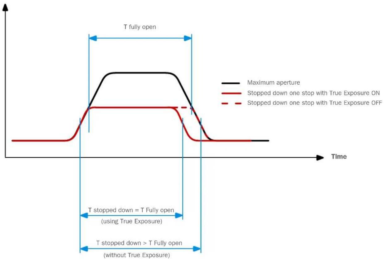
line
| Time Segment | Maximum Aperture | Stopped Down Only with True Exposure ON | Stopped Down Only with True Exposure OFF | | ------------------------- | ---------------- | --------------------------------------- | ---------------------------------------- | | Start | Low | Low | Low | | Peak | High | Low | Low | | Mid-End | High | Low | Low | | Final | Low | Low | Low |True Exposure is an HC/HCD lens function that allows the shutter speed to remain unaffected when stopping down. This effect is perhaps not so commonly understood as it is restricted specifically to integral lens shutters as opposed to focal plane shutters.
When a lens is stopped down, the effective shutter speed becomes longer, consequently affecting the set exposure. At slow shutter speeds the effect is minimal but at faster speeds, 1/500s, the effect becomes clearly visible. Automatic compensatory measures in speed setting adjustments are employed.
As compensation can only be put into effect where speeds can be adjusted, this prevents the possibility of adjusting the fastest speed of 1/800s or 1/1000, depending on lens
type. To counter this, compensatory adjustments are therefore made to the aperture instead to retain the set exposure. This compensation is not always required and when using flash or strobe as the main light source it is actually undesirable because compensation will result in underexposure. Therefore, when using flash/strobe as the main light source, you should set True Exposure to OFF in Main Menu > Camera Settings > Exposure > True Exposure in the Camera Sensor Unit Display.
You can download a complete explanation of this situation from www.hasselblad.com.
To Use
USER GUIDE
WHITE BALANCE SETTINGS - PRESETS AND MANUAL
White Balance can be set from the Control Screen, the Camera Grip Menu and the Viewfinder.
White Balance Options
There are six White Balance presets plus a Manual setting to choose from.
Cloudy.
Shade.
Daylight.
Tungsten.
Fluorescent.
Flash.
Manual (M WB).
Temp [°K] Tint
| Cloudy 6500 10 |
| Shade 7500 10 |
| Daylight 5500 10 |
| Tungsten 2850 0 |
| Fluorescent 3800 21 |
| Flash 5500 0 |
| Manual Variable 0 |
Control Screen View
White Balance Daylight mode selected.
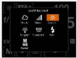
text_image
WHITE RAIN ANCE Clock Starts Default Tungsten Flatten/Normal Flick M WB NormalGrip Display View
White Balance Manual mode selected.
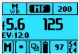
text_image
M WB MF 200 f5.6 125 EV:12.0 [M][•][◀][97]SGrip Display View
White Balance menu with Cloudy mode selected.
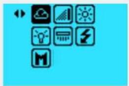
natural_image
Grid of eight icons on a blue background, including weather, solar, lightbulb, lightning bolt, and megaphone (no text or labels)To Use
USER GUIDE
FLASH SETTINGS
MAIN MENU > CAMERA SETTINGS > EXPOSURE > FLASH
1 Press the Camera icon on the Sensor Unit display.
2 The Camera Settings Menu appears.
3 Press the Exposure Settings Menu.
4 Select Flash.
Swipe right or press MENU button to get back to Main Menu.
Flash
Low Flash Warning
Select On or Off. Controls the display of the "Low flash" warning message and triangle.
Sync
Select Flash Sync Settings.
- Normal sync. Flash triggered just after the shutter opens.
- Rear sync. Flash triggered just before the shutter closes.
This section continues on next page.
Exposure Settings Menu
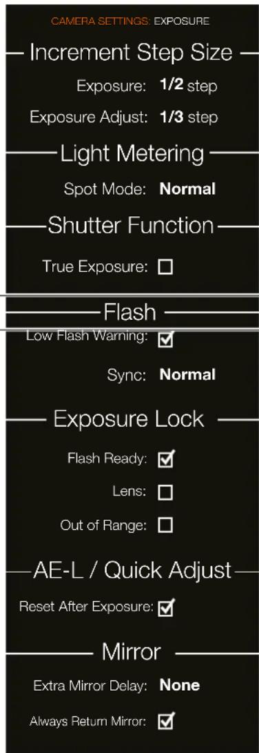
text_image
CAMERA SETTINGS: EXPOSURE — Increment Step Size — Exposure: 1/2 step Exposure Adjust: 1/3 step — Light Metering — Spot Mode: Normal — Shutter Function — True Exposure: □ — Flash — Low Flash Warning: ✓ Sync: Normal — Exposure Lock — Flash Ready: ✓ Lens: □ Out of Range: □ — AE-L / Quick Adjust — Reset After Exposure: ✓ — Mirror — Extra Mirror Delay: None Always Return Mirror: ✓To Use
USER GUIDE
FLASH AND STROBE SETTINGS
The H6D can be used together with most manual flash units. However, to make use of a TTL automatic function, it must ensure that the flash unit is compatible with the SCA 3002 system. Connection is either by the PC socket or by the hot shoe (see warning below).
The viewfinder houses an integral fill-flash with a guide number of 12 and features OTF/TTL flash control. This flash is capable of providing enough illumination for many fill flash functions outdoors as well as simple indoor shots at shorter distances.
General information
When using the A or S setting together with flash, the exposure requirements of the camera will dominate which might produce slow shutter speeds indoors, for example, requiring the use of a tripod. If P or Pv is selected instead, a shutter speed of 1/60 or faster is automatically chosen by the camera enabling the camera to be hand held.
When using flash close up or when using larger aperture settings, remember that the flash unit's output has a specific minimum duration which might still be too great for correct exposure. Read the back's output specifications for further information regarding any potential restrictions.
It is possible to use the flash metering capability with external flash units of all kinds (TTL flashes must be set to Manual mode).
Rear sync is a useful feature used either for effect or to produce a more natural look when combining long exposures involving light trails and flash.
When using suitable dedicated backs (compatible with SCA3002 compatible flash unit regarding the two functions, exposure compensation and shutter sync, is via the grip. The flash measure function can be used for flash units that are not SCA 3002 compatible or for SCA 3002 compatible backs at manual setting.
To change the balance between flash output and camera exposure requirements to produce a variety of effects, use the exposure compensation function. For various long exposure effects use the sync function.
WARNING!
Only flash units specially adapted for use with the H6D can be connected to the hot shoe on the camera.
WARNING!
Do not attempt to connect a flash unit, dedicated for use with other camera brands, to the hot shoe. The flash unit or the camera could be damaged.
Note!
If using flash or strobe as the main light source and 1/800s or 1/1000s shutter speed, remember to turn off the True Exposure function.
As with all strobe or studio flash use, very particular attention should be taken to ensure correct connections and general handling practice. Potential dangers might increase when cameras are also connected to electronic peripherals (computers and lighting backs) and should diminish when IR and similar wireless flash release devices are used.
Victor Hasselblad AB cannot accept any responsibility what so ever for accidents that might occur or damage caused when Hasselblad equipment is used in combination with third party backs of any description.
To Use
USER GUIDE
INTEGRAL FLASH
The integral flash unit (A) features the following specifications:
Guide number: 12
Coverage: 56° horizontal, 44° vertical
Maximum light fall-off at side centres: - 1EV (50%)
Colour temperature (full flash): 5,000 - 5,600 °K
The flash unit is automatically activated when it is in the operative position and deactivated when returned to its stored position.
The green LED flash symbol blinks in the viewfinder when the flash unit is charging and remains stationary when fully charged. The flash output can also be adjusted for optimum light balance in fill flash situations.
How to use the integral flash
1 Slide the Integral Flash Release (B) backwards in the direction of the flash symbol.
2 On the Camera Sensor Unit Display select Camera Settings > Exposure and scroll down to Flash.
3 Choose between Normal or Rear sync.
4 Set Low Flash Warning to On or Off.
5 Exit the Main Menu to Save and make an exposure.
6 If the settings were incorrect to match the output of the flash unit, the viewfinder display shows a red triangle alongside a flashing green Flash LED Symbol plus a warning message "Low flash". The grip display will also show a warning message "Low flash".
Conventional measures should then be taken to correct the situation. Move closer to the main subject, use a larger aperture setting or use a higher ISO setting.
WARNING!
Do not use the integral flash (A) together when another external TTL flash unit is connected (and used in TTL or A mode).
Note!
For full coverage with the integral flash, use 80mm or longer lenses (without a lens shade).
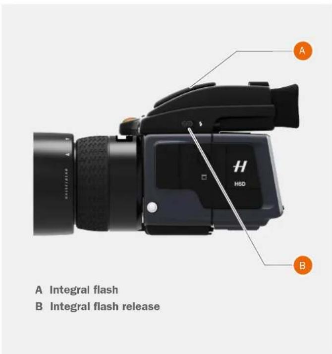
text_image
A Integral flash B Integral flash release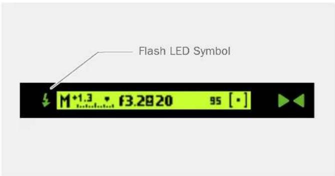
text_image
Flash LED Symbol M+1.3 - f3.2820 95 [·]To Use
USER GUIDE
SEPARATE FLASH UNIT CONNECTION
Separate flash units can be electrically connected by the Hot Shoe accessory holder (see Warnings below) on the top of the Viewfinder (A) or by a cord to the PC Connection Port (B) on the left hand side of the camera body. Slave unit switches and transmitters can also be connected to the unit (see specific User Guides for details).
Keep the plastic safety cover in place in the Hot Shoe (A) when not in use.
WARNING!
Only flash units specially adapted for use with the H6D can be connected to the Hot Shoe on the camera.
WARNING!
Do not attempt to connect a flash unit, dedicated for use with other camera brands, to the Hot Shoe. The flash unit or the camera could be damaged.

text_image
A H HED BA Hot Shoe
B PC Connection Port
To Use
USER GUIDE
FLASH MEASURE OF SEPARATE FLASH UNIT
You can measure the effect of an attached flash unit (with PC connected flash units and SCA3902 compatible flash units set to M mode), where the camera acts as a flash meter. The aperture setting can be adjusted and more trial exposures made until the information on the grip display is satisfactory.
To use Flash Measure:
1 Assign a button as Flash Measure button in Camera Settings > Custom Buttons.
2 Press the Assigned button to access the flash option screen.
3 Make preliminary required aperture setting by turning the front control wheel.
4 Press the AE-L button. The camera closes the aperture, raise the mirror and fire the flash. Light reflected from the flash lit subject is reflected off a white spot on the auxiliary shutter to the meter sensor.
5 Deviations from a normal exposure are displayed as differences in EV on the grip display and the viewfinder display. If "High" or "Low" appears, change the aperture accordingly and make a new test reading.
Change the aperture until Diff EV: 0 appears, or the desired amount of deviation from the normal exposure.
Diff EV
Low = more than 2 EV below.
Diff EV
High = more than 2 EV above.
Note!
The "Low Flash" warning can be disabled in Camera Settings > Exposure > Flash - Low Flash Warning.
Exposure Settings Menu
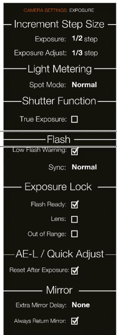
text_image
CAMERA SETTINGS: EXPOSURE — Increment Step Size — Exposure: 1/2 step Exposure Adjust: 1/3 step ——Light Metering — Spot Mode: Normal ——Shutter Function — True Exposure: □ ——Flash — Low Flash Warning: ✓ Sync: Normal ——Exposure Lock — Flash Ready: ✓ Lens: □ Out of Range: □ ——AE-L / Quick Adjust — Reset After Exposure: ✓ ——Mirror — Extra Mirror Delay: None Always Return Mirror: ✓To Use
USER GUIDE
EXPOSURE LOCK
MAIN MENU > CAMERA SETTINGS > EXPOSURE > EXPOSURE LOCK
1 Press the Camera icon on the Sensor Unit display.
2 The Camera Settings Menu appears.
3 Press the Exposure Settings Menu.
4 Scroll down to Exposure Lock.
Swipe right or press MENU button to get back to Main Menu.
Exposure Lock
Flash Ready Exposure Lock
Select On or Off.
On blocks the shutter until flash is ready.
Off allows shutter release before flash is ready.
Allows you to make a capture be fore the flash is fully charged.
For use with integral flash unit or other TTL compatible flash units connected to the hot shoe. Not valid for flash units connected by the PC connector.
Lens Exposure Lock
Select On or Off.
On blocks the release of auxiliary shutter in camera body if there is no lens attached. Generates message on grip display if attempted.
Off allows a release of auxiliary shutter in camera body without a lens attached.
If Lens is selected, it is not possible to expose without the Lens mounted. Allows you to release the auxiliary shutter in camera body without a lens attached.
Out of Range Exposure Lock
Select On or Off.
On blocks the shutter if beyond the working range.
Off allows the shutter to be released (1/2000s or 1h08m) if beyond the working range.
Allows you to release the camera when either the aperture or shutter speed setting is beyond the working range (indicated on the displays by “-”).
Exposure Settings Menu
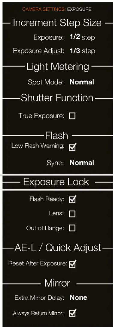
text_image
CAMERA SETTINGS: EXPOSURE — Increment Step Size — Exposure: 1/2 step Exposure Adjust: 1/3 step ——Light Metering — Spot Mode: Normal ——Shutter Function — True Exposure: □ ——Flash — Low Flash Warning: ✓ Sync: Normal ——Exposure Lock — Flash Ready: ✓ Lens: □ Out of Range: □ ——AE-L / Quick Adjust — Reset After Exposure: ✓ ——Mirror — Extra Mirror Delay: None Always Return Mirror: ✓To Use
USER GUIDE
AE-L / QUICK ADJUST
MAIN MENU > CAMERA SETTINGS > EXPOSURE > AE-L / QUICK ADJUST
1 Press the Camera icon on the Sensor Unit display.
2 The Camera Settings Menu appears.
3 Press the Exposure Settings Menu.
4 Scroll down to AE-L / Quick Adjust.
Swipe right or press MENU button to get back to Main Menu.
AE-L / Quick Adjust
Reset After Exposure
Select On or Off.
On clears any AE-L state and any Quick Exposure Adjustment made by the rear control wheel after the exposure.
Off keeps both AE-L state and Quick Adjust value even after an exposure.
Exposure Settings Menu
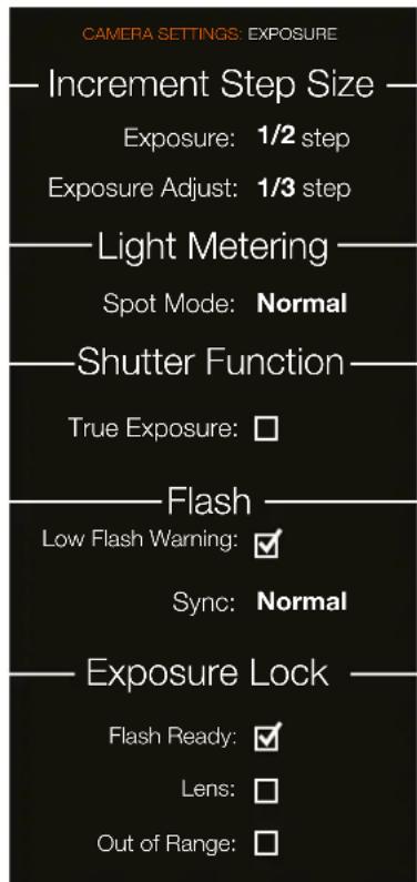
text_image
CAMERA SETTINGS: EXPOSURE —Increment Step Size — Exposure: 1/2 step Exposure Adjust: 1/3 step —Light Metering — Spot Mode: Normal —Shutter Function — True Exposure: □ —Flash — Low Flash Warning: ✓ Sync: Normal —Exposure Lock — Flash Ready: ✓ Lens: □ Out of Range: □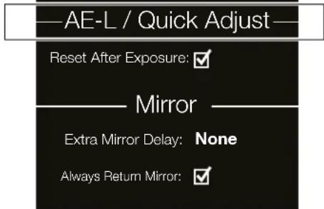
text_image
AE-L / Quick Adjust Reset After Exposure: ✓ Mirror Extra Mirror Delay: None Always Return Mirror: ✓To Use
USER GUIDE
MIRROR SETTINGS
MAIN MENU > CAMERA SETTINGS > EXPOSURE > MIRROR SETTINGS
1 Press the Camera icon on the Sensor Unit display.
2 The Camera Settings Menu appears.
3 Press the Exposure Settings Menu.
4 Scroll down to Mirror Settings.
Swipe right or press MENU button to get back to Main Menu.
Mirror Settings
Extra Mirror Delay
Select Extra Mirror Delay Settings.
- None.
- 25 ms.
- 50 ms.
- 100 ms.
- 200 ms.
Always Return Mirror
Select On or Off.
Automatically lowers mirror again for viewing at the end of every mir ror up sequence.
Exposure Settings Menu
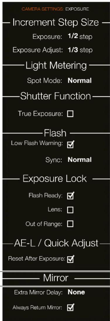
text_image
CAMERA SETTINGS: EXPOSURE — Increment Step Size — Exposure: 1/2 step Exposure Adjust: 1/3 step — Light Metering — Spot Mode: Normal — Shutter Function — True Exposure: □ — Flash — Low Flash Warning: ✓ Sync: Normal — Exposure Lock — Flash Ready: ✓ Lens: □ Out of Range: □ — AE-L / Quick Adjust — Reset After Exposure: ✓ — Mirror — Extra Mirror Delay: None Always Return Mirror: ✓To Use
USER GUIDE
5.6 CAMERA IMAGE SETTINGS
MAIN MENU > CAMERA SETTINGS > IMAGE
1 Press the Camera icon on the Sensor Unit display.
2 The Camera Settings Menu appears.
3 Press the Image Menu.
Swipe right or press MENU button to get back to Main Menu.
Image Format
Adds a crop mask to Live View and the RAW file. When imported to Phocus, the crop mask can be modified or removed.
Crop Mode
No Crop (645)
1:1 (6x6)
7:6 (6x7)
5:4 (4×5)
11:8,5 (Letter)
297:210 (A4)
3:2 (6x9)
3:2 Crop (24x36). See Notes below.
16:9 (Screen)
2:1 (6x12)
65:24 (XPan)
Mask Opacity
Sets the opacity of the mask between 20% and 100%.
Notes:
- JPG files are not cropped.
- Crop Modes are disabled in USB tethered mode.
- Crop Modes are not supported in Phocus Mobile.
Camera Settings Menu
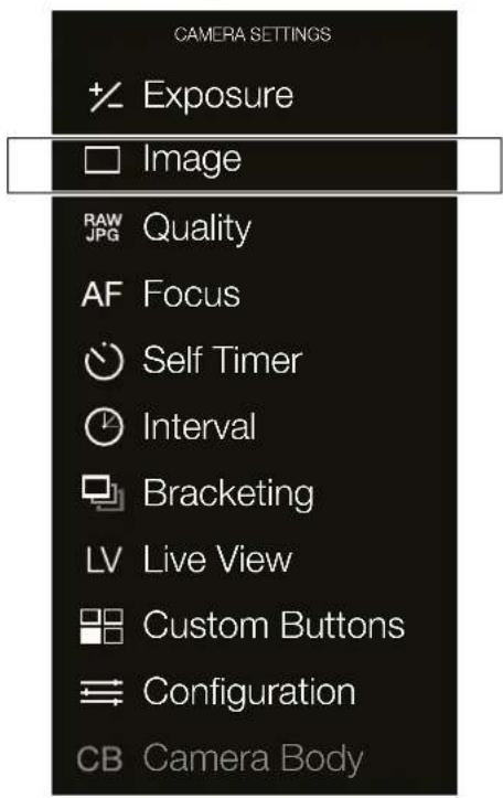
text_image
CAMERA SETTINGS Exposure Image RAW JPG Quality AF Focus Self Timer Interval Bracketing LV Live View Custom Buttons Configuration CB Camera BodyImage Settings Menu
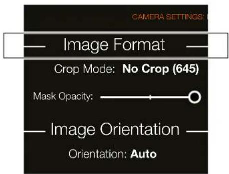
text_image
CAMERA SETTINGS: Image Format Crop Mode: No Crop (645) Mask Opacity: Image Orientation Orientation: AutoXPan crop with 100% Opacity
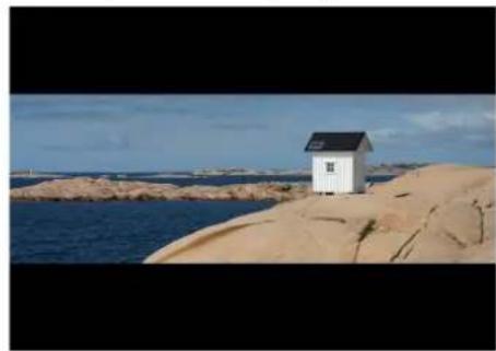
natural_image
White house-shaped cabin perched on a rocky coastline with blue water and distant islands under a clear sky (no text or symbols visible)XPan crop with 60% Opacity
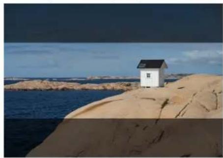
natural_image
Simple white house on a sandy hill overlooking the sea under a cloudy sky (no text or symbols visible)1:1 (6x6) crop with 100% Opacity
natural_image
White house on a rocky coastline overlooking the sea under a clear blue sky (no text or symbols visible)To Use
USER GUIDE
MAIN MENU > CAMERA SETTINGS > IMAGE
1 Press the Camera icon on the Sensor Unit display.
2 The Camera Settings Menu appears.
3 Press the Image Menu.
Swipe right or press MENU button to get back to Main Menu.
Image Orientation
Sets the viewing orientation of captures when they appear in Phocus. To avoid unintentional orientation changes when the camera is pointing straight up or down, the orientation setting can be locked.
Orientation Settings
Auto.
Lock at 0 degrees.
Lock at 90 degrees.
Lock at 180 degrees.
Lock at 270 degrees.
Image Settings Menu
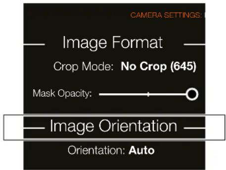
text_image
CAMERA SETTINGS: Image Format Crop Mode: No Crop (645) Mask Opacity: Image Orientation Orientation: AutoTo Use
USER GUIDE
5.7 CAMERA QUALITY SETTINGS
MAIN MENU > CAMERA SETTINGS > QUALITY
1 Press the Camera icon on the Sensor Unit display.
2 The Camera Settings Menu appears.
3 Press the Quality Settings Menu.
Swipe right or press MENU button to get back to Main Menu.
Quality Settings
Image Format
RAW.
RAW + JPG.
JPG Quality
High.
Normal.
Colour Profile
sRGB.
Adobe RGB.
Camera Settings Menu
CAMERA SETTINGS

Exposure

Image

Quality

Focus

Self Timer

Interval

Bracketing

Live View

Custom Buttons

Configuration

Camera Body
Quality Settings Menu RAW + JPG
CAMERA SETTINGS: QUALITY
Image Format: RAW + JPG
JPG Quality: High
Colour Profile: sRGB
Quality Settings Menu RAW
CAMERA SETTINGS: QUALITY
Image Format: RAW
JPG Quality: High
Colour Profile: sRGB
Quality Settings Menu H6D 100c
CAMERA SETTINGS: QUALITY
Image Format: RAW + JPG
JPG Quality: High
Colour Profile: sRGB
Bit Depth: 16 bit
Bit Depth H6D 100c only
On the H6D-100c you can select
between:
14 bit.
16 bit.
To Use
USER GUIDE
5.8 CAMERA FOCUS SETTINGS
MAIN MENU > CAMERA SETTINGS > FOCUS
1 Select the Camera icon on the Sensor Unit display.
2 The Camera Settings Menu appears.
3 Press the Focus Settings Menu.
Swipe right or press MENU button to get back to Main Menu.
Camera Settings Menu
CAMERA SETTINGS

Exposure

Image

Quality

Focus

Self Timer

Interval

Bracketing

Live View

Custom Buttons

Configuration

Camera Body
Focus Settings Menu
CAMERA SETTINGS: FOCUS
Scan: Full
AF Assist Light: Ext.flash
Focus aid in MF: Half-press
True Focus in AF-S: □
Focus Settings Menu Contents
Scan
Settings for Scan Range (for Macro Lens only).
- Near.
- Far.
- Full.
AF Assist Light
Autofocus Assist Light. Allows projection of light pattern to assist the autofocus system in poor light or low contrast situations.
- Camera sets the integral AF assist illumination to be always active.
- Ext. Flash (External Flash) activates the AF assist illumination projected by a suitable attached external flash unit. When detached, the integral system is automatically used.
- Off sets the AF assist illumination to remain always inactive.
Focus Ald In MF
This is a Focus Aid in Manual Focus Mode MF. Indicates how the Focus Aid arrowhead LED symbols appear in the view finder display in Manual Focus Mode.
- Always. Makes them visible all of the time when camera is active.
- Half-press. Makes them visible when the shutter release button is pressed half way.
- Off. Disables them completely.
True Focus In AF-S
Select True Focus in AF-S mode. When set to On, a half press on the shutter release will activate True Focus.
- On or Off.
To Use
USER GUIDE
FOCUSING DISTANCE CALCULATION
There are two distance scales (in feet and metres) visible through the window on the upper part of the lens barrel. The focusing distance is read off the chosen scale from the central lens index (A).
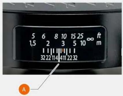
text_image
5 6 8 10 15 25 ∞ ft 1,5 2 3 5 10 m 32 22 114 411 22 32 ASTOP DOWN / DEPTH-OF-FIELD PREVIEW
A visual depth-of-field preview can be made by pressing the STOP DOWN button (B) while viewing the image in the viewfinder.
Depth-of-field is calculated as follows:
1 Focus the lens as required.
2 Make an exposure reading (auto or manual) and note the aperture setting.
3 Find the markings on either side of the central index that correspond to the chosen aperture.
4 From these two markings, read off on the required lens distance scale the two corresponding distances.
5 The depth-of-field (at that particular aperture and focus setting) is the area included between these two distances.
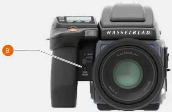
natural_image
Side view of a Hasselblad DSLR camera with lens and control panel (no visible text or symbols on body)In the example to the right, the focusing distance is set at nearly 3m (three metres). At an aperture of f/22, the depth-of-field would therefore extend from just over 2m to approximately 4.5m.
Note!
The depth-of-field is not absolute. Perception of it depends on several factors and so it should be seen only as a rough guide.
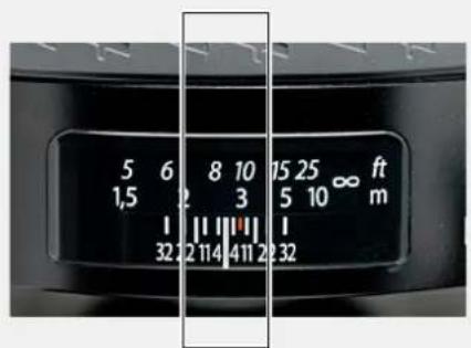
text_image
5 6 8 10 15 25 ∞ ft 1,5 2 3 5 10 m 1 || || || | 32 2 1 4 11 2 3 2 32To Use
USER GUIDE
INFRARED FOCUS SETTING
As infrared rays form an image at a plane different to that formed by visible light, the normal focus settings do not apply. Proceed as follows in manual focus mode:
1 Focus the lens.
2 Note the distance setting at the central lens index.
3 Realign this distance setting against the infrared mark (coloured red) instead of to the central lens index.
If the distance is calculated, a manual distance setting with use of the distance scales together with the infrared mark is made.
Note!
Please contact your Hasselblad dealer for information about sensor units adapted solely for "near infrared" Photography.
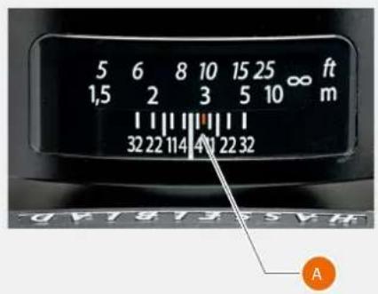
text_image
5 6 8 10 15 25 ∞ ft 1,5 2 3 5 10 m 32 22 114 411 22 32 ATo Use
USER GUIDE
FOCUS ASSIST
The camera features a LED focus assist. Two arrowheads are displayed to the right of the viewfinder display (except for lenses with a maximum aperture of f/6.7 or smaller). The arrowheads provides confirmation of a precision focus setting and are a useful aid when making a setting with eyesight only.
Manual focus setting
When the left arrowhead appears by itself, the focus setting is too far beyond the chosen distance (the area framed within the central zone in the viewfinder). When the right arrowhead appears alone it means the focus setting is too close. Focus is correct when both arrowheads appear together. If the focus cannot be established, then both arrowheads flash.
Automatic focus setting
Focus is correct when both arrowheads are visible together. Focus is incorrect if only one arrowhead is visible. If the focus cannot be established, then both arrowheads flash.
Note!
The autofocus range on the HC 4/120 Macro lens can be limited by a specific setting on the camera allowing for near range, far range or full range. This information is displayed on the grip display together with that particular lens, in the Sensor Unit Display and in the Viewfinder Display. Further information can be found in the “H-system Lenses & H-system Lens Accessories” booklet that accompanies each lens. The booklet can also be downloaded from the Hasselblad website. Additionally see the following note below regarding HCD lenses.
Note!
HCD lenses were formulated for use with the smaller size Sensors in the H-series, resulting in a reduced coverage for the larger sensors used in some models. So, if you use HCD Lenses, be aware of the restrictions (vignetting and diminished quality at the edges). As notification of this situation, an auto crop function is employed and an HCD crop icon appears on the right hand side of the viewfinder display when an HCD lens is fitted. When in Phocus, however, the auto crop function can be turned off in Preferences if you wish.
Note!
Lens corrections can be applied when captures are imported into Phocus. Guided by the information in the meta data included with each individual capture, the DAC (digital lens correction) tool uses lens model specific calculations by default to adjust for chromatic aberration, distortion and vignetting. Not only model specifications but also capture parameters are taken into consideration for analysis. This extremely capable refinement of captures should not be overlooked when processing files! See Phocus user manual for details.
Lens focus setting too far beyond the distance of the subject framed by the central section in the viewfinder.
Focus setting too close for the distance of the subject framed by the central section in the viewfinder.
Focus setting correct.


Info!
For users who prefer manual focus control but would like the benefits of autofocus, one method is to set the AE-L button (or any customizable button) to AF (Single) drive. The main subject can then be centred and the AE-L pressed, to ensure correct focus. The camera reverts immediately to manual focus control when the button is released. Therefore, you can recompose the picture without having to maintain pressure on the release button in order to retain the newly automatically made focus setting (AF-T can also be used).
Info!
The True Focus function can also be combined with other autofocus modes for specific situations.
Note!
The autofocus function is not possible with certain combinations of lenses and accessories. However, a warning is displayed which disappears after confirmation.
To Use
USER GUIDE
MANUAL FOCUS
There is both a Manual focus mode setting and a manual override capability.
In Manual focus mode, focusing is carried out by rotating the focus ring on the lens. The focus setting remains until changed as with a conventional non-autofocus lens. This means that pressing the shutter release button will not activate a focus setting change as it does in autofocus. To change back to autofocus, press the AF button (B) and select AF-S, AF-C or AF-T.
MANUAL OVERRIDE IN AUTOFOCUS MODE
Manual override is always possible in automatic focus mode without any need to make a new setting. Just rotate the focusing ring in the conventional manner. As the lens barrel does not rotate in autofocus mode, you can hold the focusing ring for instant manual adjustments. However, to retain the new manual focus adjustments, you must maintain the pressure on the shutter release button. You can instantly return to the automatic focusing mode by releasing the pressure on the shutter release button first and then pressing the release button halfway again. The instant manual override function produces a convenient way of working. You can take advantage of autofocus while retaining an instantly adjustable manual focus check if preferred for pinpoint accuracy without making any changes in the settings.
With manual override in autofocus mode you can manually alter a focus setting that has been made, by rotating the lens barrel and without having to change modes. As long as the shutter release button is kept at the half-press position, the new focus setting is maintained.
To reactivate the autofocus function, release the shutter release button and press again.
AUTO / MANUAL FOCUS SETTING
1 Press AF Button (B).
2 Turn the Front Scroll Wheel (A) to select Manual, Single Shot, Continuous and True Focus.
3 Press AF Button (B) to Save.
Note!
In manual focus, the infinity and closest distance marks on the lens scale can appear to be positioned beyond the central index. This is only an apparent effect and does not change the focusing range of the lens.
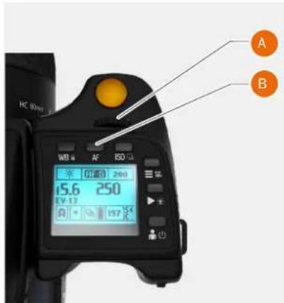
text_image
A B WC 80mm WD 80 AF ISO 52 15.6 250 EV 13 A 197.5K CA Front Scroll Wheel B AF Button
Manual Focus Mode
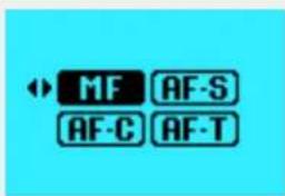
text_image
MF AF-S AF-C AF-TTo Use
USER GUIDE
AUTOFOCUS
Autofocus modes Single Shot or Continuous are activated by pressing the shutter release to the half-press position.
The operative range is from EV 1 to EV 19 at ISO 100.
The point of focus is determined according to the vertical and horizontal areas (see illustration to the right) within the central rectangular zone on the focusing screen.
True Focus is classified as an autofocus function and is normally activated by its own button on the grip. See later section.
AF Assist light
When light levels are too low or the contrast of the subject is too low, AF assist light is automatically activated if selected. The operative distance is approximately up to six metres from the camera.
AUTOFOCUS CHECK IN MANUAL MODE
See page 103 for a description of how to use the advantages of a quick autofocus check while remaining in Manual mode.
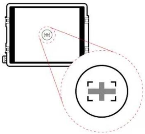
natural_image
Diagram showing a square frame with a circular target symbol and a crosshair overlay (no text or labels)To Use
USER GUIDE
SINGLE SHOT FOCUS
At Single Shot setting (AF S), the shutter release will be blocked until the camera finds the optimum focus setting. This ensures that no captures are made that are not finely focused. However, this delay is normally only a fraction of a second in good lighting conditions with a clear focusing pattern.
In this mode the lens will focus at one distance and will remain focused at that distance while pressure remains on the shutter release button. In this way, you can focus on a nearby object, temporarily positioned within the focusing zone on the viewing screen and then without releasing pressure on the shutter release button, recompose knowing that the focus remains on the object chosen even though it is now outside the focusing zone. Releasing the pressure on the shutter release button and pressing again half way would now change the focus setting to the distance of the object within the focusing zone.
See Manual Override in Autofocus Mode for a useful way of working with manual and autofocus settings in a combined manner.
AF-S Single Shot Mode
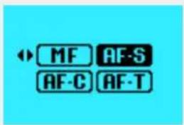
text_image
MF AF-S AF-C AF-TCONTINUOUS FOCUS
At Continuous setting (AF C), the shutter can be released rapidly before the lens is focused in order to capture a split second shot (in Single Shot, a capture cannot be made until the camera has had time to focus). However, the camera will continue to focus if a moving subject is within the focusing zone or if you recompose, even though the shutter release button is half-pressed.
One method to use this feature when photographing in fast changing situations is to keep the shutter release button pressed down. The lens focus continuously, and by momentarily releasing the pressure on the shutter release and then immediately pressing again, you minimize the amount of time needed for the lens to check focus ensuring a split second shot with optimum focus.
AF-C Continuous Mode
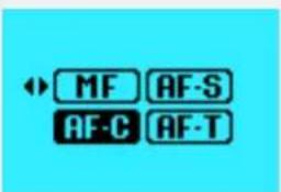
text_image
MF AF-S AF-C AF-TTo Use
USER GUIDE
5.9 CAMERA TRUE FOCUS
The True Focus setting (AF-T) is generally used in specific circumstances to automatically correct for camera angle and focus setting discrepancies, but it can also be combined with other autofocus settings.
To use True Focus correctly, a few important points should be studied in order to obtain a full understanding of how and when to use it. Basically, there are four variables to pay attention to:
(a) proximity of camera to subject,
(b) focal length of lens,
(c) aperture setting and
(d) movement of camera and/or subject after setting.
The closer you remain to the ideal situation with regard to these variables, the more noticeable the effect of True Focus will be.
- The closer you are to the subject, the worse the original problem becomes. Consequently, the need for True Focus solution becomes greater and its application thereby becomes more noticeable.
- Short focal length (wide angle) lenses naturally decrease camera to subject distances and therefore, following the point in (a), produce a greater need for True Focus adjustments. For lenses 80mm or longer, True Focus will not produce better results than a normal AF drive.
- Smaller aperture increase the depth of field and therefore would lessen the need for a True Focus solution. However, smaller apertures produce a different visual effect, so True Focus therefore allows the exploitation of the shallow depth of field (produced by larger apertures) without the fear of unwanted focus restrictions.
- The calculations involved in True Focus use, amongst other things, camera to subject distances to calculate the required amount of adjustment. It therefore follows that if the camera or the subject moves after the initial setting has been made, the calculations will not be applicable anymore. So, to ensure the optimum correction, both the photographer and the subject should restrict movement as much as possible. Please note that with some lenses (particularly longer length lenses) just a few centimetres movement can essentially ruin the result.
True Focus can be used with longer lenses, smaller apertures but the further you come from situations similar to the ideal as described above, the less the effect will be until it has no visible effect at all. Please remember that although True Focus can noticeably improve a demanding shoot it will only work effectively in the specific circumstances it was designed for.
AF-T True Focus Mode
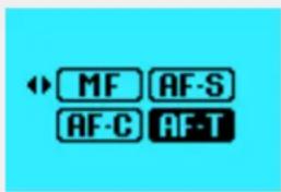
text_image
MF AF-S AF-C AF-TTo Use
USER GUIDE
TRUE FOCUS AND ABSOLUTE POSITION LOCK
The obvious situation that would most benefit from using True Focus would be a fashion shoot with a fairly wide angle lens at a large aperture setting and where the central area of the image is clothing while retaining focus on the model's face. Ideally a fairly controlled and static flow should be planned. A change of pose by the model should take place only after captures. The photographer must also resist crouching down, or leaning forwards or backwards too much before capture.
With the lens at its widest aperture setting, a normal autofocus setting is made on the model's face (A), and the camera focus locked. The composition is then changed to include more of the clothing (B), but the locked focus setting now extends beyond the model's face at (B) according to the laws of geometry. This will naturally result in an image where much of the subject closest to the camera and the model's face will be unsharp. Solutions involving manual focus, focus lock and resetting of multi-point sensors are distracting the workflow and prone to error. Making a True Focus setting at (A) will ensure that focus is automatically adjusted in accordance with the change of camera angle.
True Focus uses yaw rate technology and by way of the Absolute Position Lock (APL) processor, logs camera movement as the basis for an extremely rapid compensated focus reset without any shutter lag. The Camera firmware further perfects the focus using the precise data retrieval system found on all HC/HCD lenses.
A
A normal autofocus setting is made on the model's face and locked.
The focus setting is approximately 2.5m.
B
When the camera is rotated back down, B, the locked focusing distance of 2.5m, according to the laws of geometry, extends beyond a perpendicular line drawn down from the face, creating unsharpness.
If a True Focus setting instead of a normal autofocus setting is now made at A and the composition is changed back to B again, the camera will automatically calculate and adjust the focus of 2.5m to approximately 2.4m, which is the actual perpendicular distance. The model's face remains sharp.
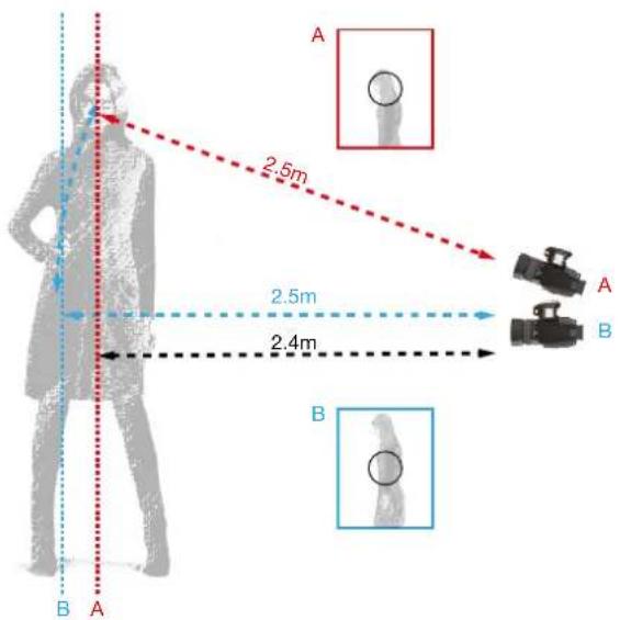
text_image
A 2.5m 2.5m 2.4m B A BTo Use
USER GUIDE
TRUE FOCUS AND CAMERA HANDLING
To obtain the maximum benefit from True Focus work within the requirements of the system. This might need a little practice but it will improve the accuracy of the measurements and thereby provide better results.
1 Remain as still as possible when making the first True Focus measurement and wait for the audio signal or ready light to show green again before continuing. This will not only speed up the process but also increase accuracy.
2 When recomposing the shot stay in the same position as closely as possible. That is, try to avoid moving your head or body forwards or backwards as this will move the camera away from the measured position.
In the upper example to the right, the photographer has swung the camera from the first measurement to recompose the shot as normal. But as you can see that the camera has now moved away from the original position.
The lower example illustrates essentially the same situation except this time the camera is rotated around its central axis, rather than swung. Practice shows that this method retains the original position more accurately and therefore results in better focusing accuracy.
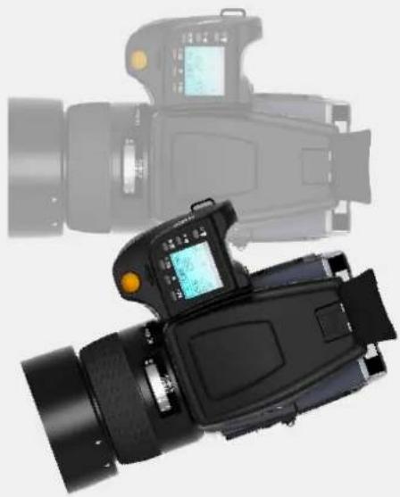
natural_image
Black and white photo of a digital camera with LCD screen, shown from front and side (no visible text or symbols)Incorrect rotation of camera away from original position.
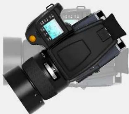
natural_image
Black and white photo of a DSLR camera with thermal imaging display (no visible text or symbols)Correct rotation of camera around it's own centre.
FOCUS CHECKING
In browse mode or after a capture you can either double tap on the Sensor Unit Display to zoom in to 100% or spread two fingers apart to zoom in. To zoom out you can double tap again or pinch two fingers together.
To Use
USER GUIDE
5.10 CAMERA TRUE FOCUS METHODS
ACTIVATED BY TRUE FOCUS BUTTON
In this mode the Autofocus function is effectively converted into the True Focus function.
1 Aim camera to the important area of the subject and press the True Focus button (A).
2 Wait for the True Focus icon to appear in the viewfinder and the audio confirmation signal.
3 Recompose the picture. Press shutter release fully to make the capture. The True Focus icon disappears from the viewfinder.
4 The camera will return to the previous focusing mode.
Note!
If the camera is set to MF before activating True Focus, focus position will be kept for all following exposures. This method is useful when many shots are required with the same focus setting.
Note!
If any of the programmable buttons are set to True Focus, they will work exactly like the True Focus button.
Note!
If focus mode is set to AF-T, the True Focus button will always have the True Focus function.
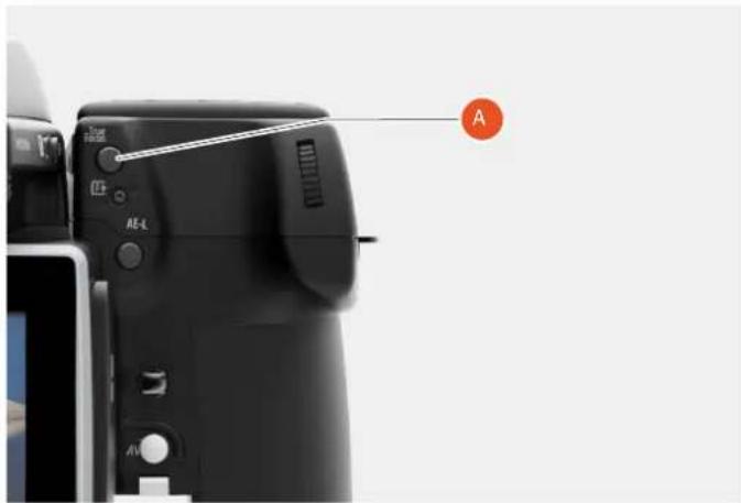
natural_image
Close-up of a black DSLR camera with control buttons and an orange pointer labeled 'A' (no text or symbols on the device body)
Normal Viewfinder display

Viewfinder display with True Focus active
To Use
USER GUIDE
ACTIVATED BY SHUTTER RELEASE
MAIN MENU > CAMERA SETTINGS > FOCUS > TRUE FOCUS IN AF-S
In this mode the True Focus function is activated by half-pressing the shutter release button (A).
1 Set Camera Focus mode to AF-S
2 On the Sensor Unit Display, select Camera Settings.
3 Select Focus.
4 Select True Focus in AF-S On.
5 Aim camera to the important area of the subject and half-press the shutter release button (A).
6 Wait for the True Focus icon to appear in the viewfinder and the audio confirmation signal.
7 Maintain the half-press (A) and recompose the picture. Press fully to make the capture. The True Focus icon disappears from the viewfinder.
Focus Settings Menu
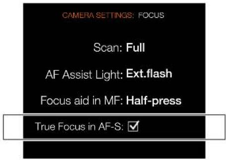
text_image
CAMERA SETTINGS: FOCUS Scan: Full AF Assist Light: Ext.flash Focus aid in MF: Half-press True Focus in AF-S: ✓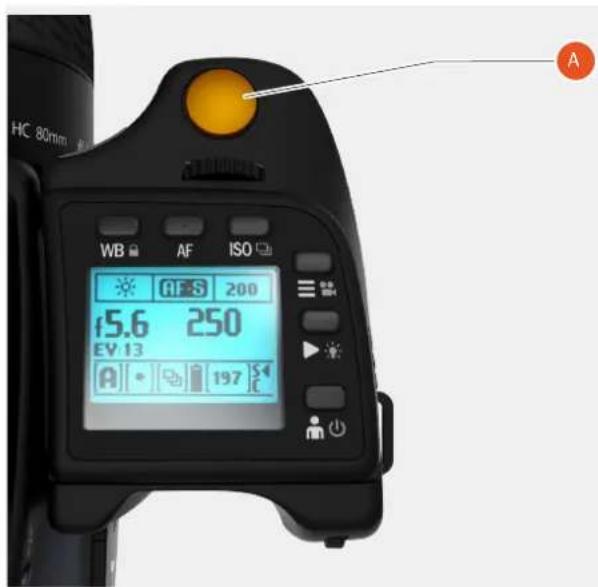
text_image
HC 80mm WB AF ISO 45.6 250 EV 13 197 A
Normal Viewfinder display

Viewfinder display with True Focus active
To Use
USER GUIDE
1 Press the Camera icon on the Sensor Unit display.
2 The Camera Settings Menu appears.
3 Press the Self Timer Settings Menu.
Swipe right or press MENU button to get back to Main Menu.
Self Timer Settings Menu
Active
On or Off.
Time
Select time in seconds. Select between 2 up to 60 seconds with a one second interval.
Sequence
Delay / Mirror Up.
Mirror Up / Delay.
Mirror behaviour
Mirror goes down.
Mirror remains up.
When Finished
Exit or Stay.
Note!
When Self Timer is activated, a Self
Timer Icon is displayed on most screens
Camera Settings Menu
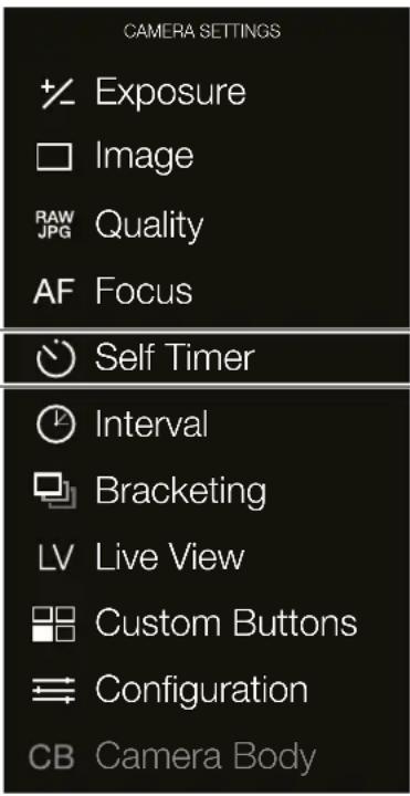
text_image
CAMERA SETTINGS Exposure Image Quality AF Focus Self Timer Interval Bracketing Live View Custom Buttons Configuration CB Camera BodySelf Timer Settings Menu
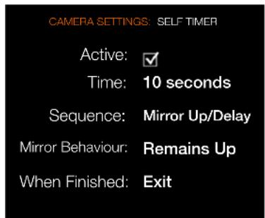
text_image
CAMERA SETTINGS: SELF TIMER Active: ✓ Time: 10 seconds Sequence: Mirror Up/Delay Mirror Behaviour: Remains Up When Finished: ExitGrip Display View
Self Timer Settings
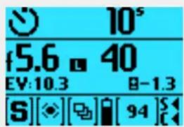
text_image
10⁵ f5.6 40 EV:10.3 B-1.3 [S][◆][◆][94]STo Use
USER GUIDE
5.12 CAMERA INTERVAL SETTINGS
MAIN MENU > CAMERA SETTINGS > INTERVAL
1 Press the Camera icon on the Sensor Unit display.
2 The Camera Settings Menu appears.
3 Select the Interval Settings Menu.
Swipe right or press MENU button to get back to Main Menu.
Interval Settings Menu
Active
On or Off.
Time
Select time between Exposures in minutes and seconds.
0m (zero minutes) 2s (two seconds) up to 0m 10s with one second interval.
0m 10s up to 1m 0s with five seconds interval.
1m 0s up to 2m 0s with ten seconds interval.
2m 0s up to 3m 0s with fifteen seconds interval.
3m 0s up to 4m 0s with thirty seconds interval.
After 4 minutes there are 5m, 6m, 8m, 10m, 12m, 15m, 20m, 25m, 30m, 40m, 50m and 1h 0m settings available.
Frames
Select number of Frames from 2 - 99 or no limit.
Initial Delay
Select initial Delay. None or Interval time 60s, 10s, 2s.
When Finished
Settings for Action When Finished. Exit or Stay.
Note!
When Interval Timer is activated, an Interval Timer Icon is displayed on most screens
Camera Settings Menu
CAMERA SETTINGS

Exposure

Image

Quality

Focus

Self Timer

Interval

Bracketing

Live View

Custom Buttons

Configuration

Camera Body
Interval Settings Menu
CAMERA SETTINGS: INTERVAL
Active:

Time: 0m 30s
Frames: 3
Initial Delay: None
When Finished: Exit
To Use
USER GUIDE
5.13 CAMERA BRACKETING SETTINGS
MAIN MENU > CAMERA SETTINGS > BRACKETING
1 Press the Camera icon on the Sensor Unit display.
2 The Camera Settings Menu appears.
3 Press the Bracketing Settings Menu.
Swipe right or press MENU button to get back to Main Menu.
Bracketing Settings Menu
Active
On or Off.
Amount
Select Amount of Bracketing.
1/3, 1/2, 1, 2, or 3.
Frames
Select number of Frames.
2, 3, 5, 7, or 9 frames.
Camera Settings Menu
CAMERA SETTINGS

Exposure

Image

Quality

Focus

Self Timer

Interval

Bracketing

Live View

Custom Buttons

Configuration

Camera Body
Bracketing Settings Menu
CAMERA SETTINGS: BRACKETING
Active: √
Amount: 1/2 step
Frames: 3
Parameter in M: Shutter Speed
Sequence: 0, +, -
Parameter
Aperture or Shutter speed.
Selects either the shutter speed or the aperture as the parameter which changes in a bracketing sequence when in Manual exposure mode.
Shutter speed selects changes in shutter speed.
Aperture selects changes in aperture settings.
Sequence
Select the sequence of the overexposures (+) and the underexposures (-).
A: +0 -
B: -0 +
C: 0 + -
D: 0 - +
Example
Alternative B (- 0 +) with the Amount 1/3 and 3 Frames, results in the capture order:
Capture 1 is underexposed (-1/3 EV).
Capture 2 is correct exposed (0 EV).
Capture 3 is overexposed (+ 1/3 EV).
BRACKETING FUNCTION
The bracketing function provides an automatic series of captures, one at the standard exposure setting (Manual or Auto)
and the others with predetermined deviations in EV from the standard exposure. This is particularly useful for images containing a very wide tonal range, for example. First you make an assessment concerning the number of extra frames required, the order in which they should be taken, and by how much the EV deviation there should be and the setting made accordingly. The first metered exposure (Manual or Auto) is the EV that determines the calculations for the bracketing sequence.
Note the difference in operation between Single and Continuous drive settings:
- At the Single setting you must press the shutter release button separately for every separate capture until the sequence is finished.
- At the Continuous setting you can either maintain the pressure on the button to take all frames without stopping or you can release the pressure on the button and press again to continue to the end of the sequence without losing any frames within the set sequence.
Note!
When Bracketing is activated, a Bracketing Icon is displayed on most screens.
To Use
USER GUIDE
5.14 CAMERA LIVE VIEW SETTINGS
MAIN MENU > CAMERA SETTINGS > LIVE VIEW
1 Press the Camera icon on the Sensor Unit display.
2 The Camera Settings Menu appears.
3 Press the Live View Settings Menu.
Swipe right or press MENU button to get back to Main Menu.
Live View Settings Menu
Start
Start Live View Mode.
MF Assist
Focus Peaking, None
Peaking Color
Orange, Yellow, Cyan, Magenta
Zoom Level
50%, 100%
Selects the zoom level in Live View when you double-tap the screen or press the middle button under the display.
This section continuous on the next page.
Camera Settings Menu
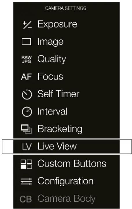
text_image
CAMERA SETTINGS + Exposure Image RAW Quality AF Focus Self Timer Interval Bracketing LV Live View Custom Buttons Configuration CB Camera BodyLive View Settings Menu

text_image
CAMERA SETTINGS: LIVE VIEW Start MF Assist: Focus Peaking Peaking Color: Magenta Zoom Level: 50%MF Assist dialogue
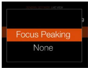
text_image
GENERAL SETTINGS LIVE VIEW Focus Peaking NonePeaking Colour dialogue
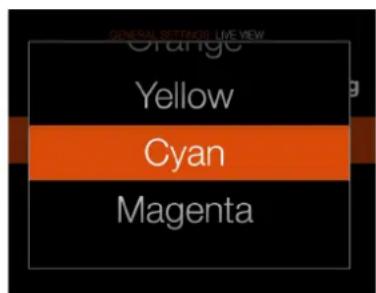
text_image
GENERAL RETENTION LIVE VIEW Orange Yellow Cyan MagentaZoom Level dialogue
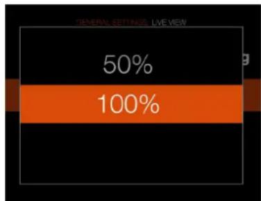
bar
| Category | Value (%) | |---|---| | General Settings, Live Web | 50 | | Total | 100 |To Use
USER GUIDE
LIVE VIEW
This feature is useful for accurate focusing, composition and depth of field preview.
1 Select Camera Settings > Live View or select the Live View icon on the Main Menu (if Live View is set to be a favourite on the Main Menu).
2 Press Start to activate Live View.
3 Press soft button (C) to toggle overlay forward.
4 Press Menu button (A), Play button (D) or, swipe right to Exit Live View.
Live View Settings
Overlay
To select overlay displayed during Live View, scroll between options with button soft button (C). This toggles between:
- Exposure Information (E).
- Exposure Information and Grid (F).
- Exposure Information and Spirit Level (G).
- HTS (If attached) (H).
- None (1).
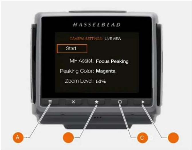
text_image
HASSELBLAD CAMERA SETTINGS: LIVE VIEW Start MF Assist: Focus Peaking Peaking Color: Magenta Zoom Level: 50%E
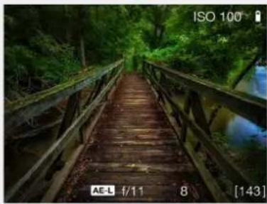
natural_image
Wooden bridge over a river with green forest background (no text or symbols visible)●
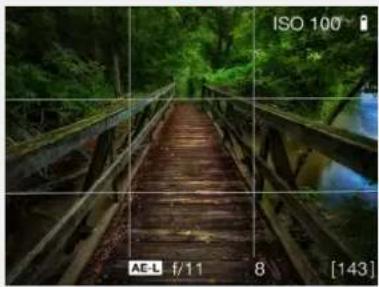
natural_image
Wooden bridge over a river with green forest background, captured via ISO 100 grid overlay (no text or symbols on the structure itself)G
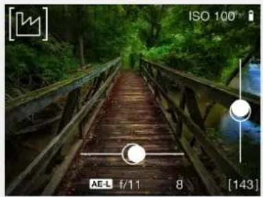
natural_image
Wooden bridge over a forested area with visible water reflection and measurement overlays (no readable text or symbols)H
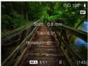
text_image
ISO 100 Shift: 0.0 mm Tilt: 5.0° Rotation: 0° AE-L f/11 8 [143]●
natural_image
Wooden bridge over a river with lush green forest background (no text or symbols visible)To Use
USER GUIDE
ZOOMING IN LIVE VIEW
1 Double click on Sensor Unit Display or press button (B) to Zoom in to actual pixel size (100%) to that specific area. Note you can change the zoom factor to 50% in the Camera Settings - Live View menu.
2 Move the image with press, hold and move finger to view different areas. A Navigator window briefly appears to indicate current position.
3 Double click again to Zoom out to display the entire capture.
FOCUS IN LIVE VIEW
1 Double click on the Sensor Unit Display to Zoom in to the selected focus area.
2 Adjust the focal point manually on the lens.
3 Double click again to Zoom out to display the entire capture.
Note!
Live View demands higher power consumption than normal operation. Working with Live View will shorten the usage time of the camera when on battery power supply only.
Note!
AF is not available in Live View.
Capture before zoom in to 100%
natural_image
Vintage digital camera with black and silver casing (no visible text or symbols)100% view before Focusing
natural_image
Close-up of a car wheel rim with visible red markings (no text or symbols)100% view after Focusing
text_image
S 0.6 0.5 0.4 0.3 0.2 0.1 0.0 0.0 0.0 0.0 0.0 0.0 0.0 0.0 0.0 0.0 0.0 0.0 0.0 0.0 0.0 0.0 0.0 0.0 0.0 0.0 0.0 0.0 0.0 0.0 0.0 0.1To Use
USER GUIDE
FOCUS IN LIVE VIEW USING FOCUS PEAKING
The Focus Peaking function is a Manual Focus tool to help you identify what areas of the subject that are in focus. Focus Peaking is not active in Auto Focus mode.
When the Focus Peaking is active and you adjust the focus manually, the focused area of the subject (magenta in this case) moves in depth as you move the focus.
Subject not in focus when Focus Peaking is active
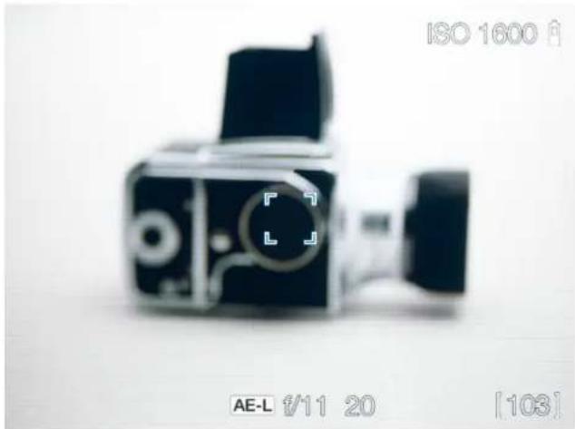
natural_image
Black and white photo of a vintage camera with visible lens and control buttons (no readable text or symbols)Focus Peaking display when subject parts are in focus
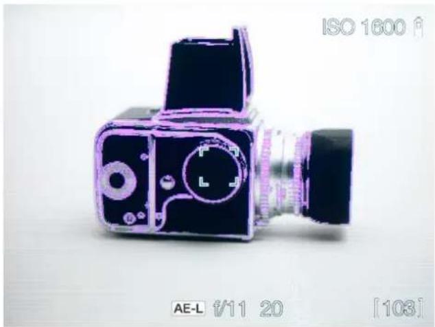
natural_image
Illustration of a vintage camera with purple outline and black body, no visible text or symbols on the device itself.To Use
USER GUIDE
LIVE VIEW WITH HDMI EXTERNAL SCREEN
How to Connect and use the Live View with HDMI
1 Connect an external Video Screen with HDMI cable and start the Live View.
2 The interface HDMI Live View (to the right on this page) is displayed on the Sensor Unit Display.
3 To enter 100% zoom, press the soft button marked with a star.
4 To toggle between the overlays, press the soft button marked with a rectangle.
Note!
Live View demands higher power consumption than normal operation. Working with Live View will shorten the usage time of the Camera when on battery power supply only.
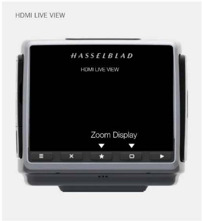
text_image
HDMI LIVE VIEW HASSELBLAD HDMI LIVE VIEW Zoom DisplayTo Use
USER GUIDE
LIVE VIEW WITH HTS 1.5X TILT/SHIFT ADAPTER
When the HTS 1.5x Tilt/Shift Adapter is used, one additional overlay is available to show the settings on the adapter in real-time.
1 Attach the HTS adapter.
2 Activate Live View on the rear display.
3 Press the soft button (A) until the overlay to the right is shown.
4 Stop Live View by pressing the Menu button (B).
For more information about the HTS Tilt/Shift adapter, please read the HTS User Manual which can be downloaded from www.hasselblad.com.
HTS 1.5x LIVE VIEW
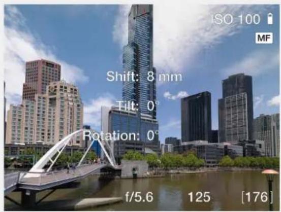
text_image
ISO 100 MF Shift: 8 mm Tilt: 0° Rotation: 0° f/5.6 125 [176]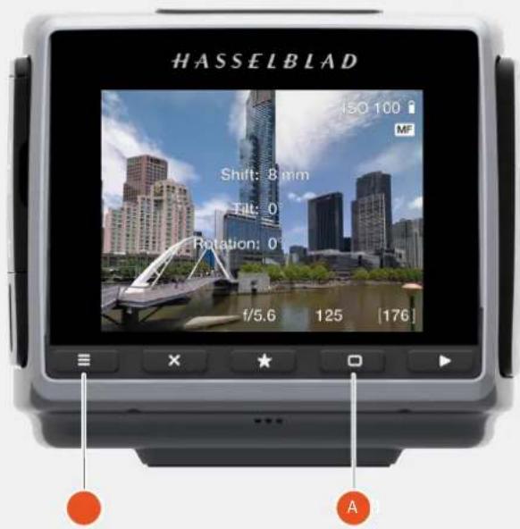
text_image
HASSELBLAD ISO 100 MF Shift: 8 mm Filt: 0 Rotation: 0 f/5.6 125 [176] ATo Use
USER GUIDE
5.15 CAMERA CUSTOM BUTTONS
MAIN MENU > CAMERA SETTINGS > CUSTOM BUTTONS
1 Press the Camera icon on the Sensor Unit display.
2 The Camera Settings Menu appears.
3 Press the Custom Buttons Settings Menu.
Swipe right or press MENU button to get back to Main Menu.
Custom Buttons Settings Menu
The available list of functions differers slightly between rear and front buttons. See lists below.
Camera Settings Menu
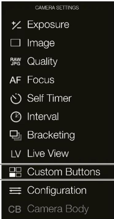
text_image
CAMERA SETTINGS Exposure Image Quality AF Focus Self Timer Interval Bracketing Live View Custom Buttons Configuration CB Camera BodyCustom Buttons Settings Menu
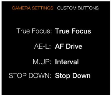
text_image
CAMERA SETTINGS: CUSTOM BUTTONS True Focus: True Focus AE-L: AF Drive M.UP: Interval STOP DOWN: Stop DownTrue Focus, AE-L can be selected to function with any of these settings:
- Start Live View
- AE-L
- AF Drive
- Mirror Up
- True Focus
- Stop Down
- Expose
- Light Meter Mode Cycle
- Show Histogram
- Spirit Level
- Self Timer
- Interval
- Bracketing
- Flash Measure
- B-Mode
- T-Mode
- None
M.UP and STOP DOWN can be selected to function with any of these settings:
- Control Screen
- Start Live View
- AE-L
- AF Drive
- Mirror Up
- True Focus
- Browse Card
- Delete Image
- Stop Down
- Expose
- Light Meter Mode Cycle
- Show Histogram
- Spirit Level
- Self Timer
- Interval
- Bracketing
- Mark Overexposure On/Off
- Flash Measure
- B-Mode
- T-Mode
- None
To Use
USER GUIDE
5.16 CAMERA CONFIGURATION SETTINGS
MAIN MENU > CAMERA SETTINGS > CONFIGURATION
1 Press the Camera icon on the Sensor Unit display.
2 The Camera Settings Menu appears.
3 Press the Configuration Settings Menu.
Swipe right or press MENU button to get back to Main Menu.
Camera Configuration Settings Menu
Front Wheel
-Aperture.
-Shutter speed.
Hide B/T mode
Select On or Off. Hides access to B and T shutter speeds allowing smoother transition from 1s to 1.4s when making shutter speed changes.
Camera Settings Menu
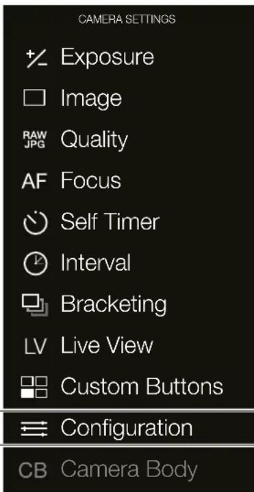
text_image
CAMERA SETTINGS Exposure Image Quality AF Focus Self Timer Interval Bracketing Live View Custom Buttons Configuration CB Camera BodyConfiguration Settings Menu
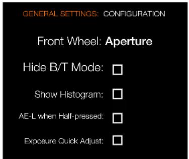
text_image
GENERAL SETTINGS: CONFIGURATION Front Wheel: Aperture Hide B/T Mode: Show Histogram: AE-L when Half-pressed: Exposure Quick Adjust:Show Histogram
Select On or Off. Controls the histogram display on the grip display On or Off.
AE-L (AE-Lock) when Half-pressed
Select On or Off. Allows access to AE-Lock without having to use customizable button assigned to other required functions.
Exposure Quick Adjust
Select On or Off.
To Use
USER GUIDE
5.17 CAMERA BODY SETTINGS
MAIN MENU > CAMERA SETTINGS > CAMERA BODY
This setting is only used when the sensor unit is detached from the H6D camera body and used on other cameras (view cameras). This is described further in the chapter "View Cameras" on page 170.
1 Press the Camera icon on the Sensor Unit display.
2 The Camera Settings Menu appears.
3 Press the Configuration Settings Menu.
Swipe right or press MENU button to get back to Main Menu.
Camera Body Settings Menu
Camera Body
- Pinhole
- Flash sync
Camera Settings Menu
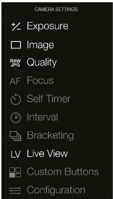
text_image
CAMERA SETTINGS + Exposure Image RAW Quality JPG AF Focus Self Timer Interval Bracketing LV Live View Custom Buttons ConfigurationCB Camera Body
Camera Body Settings Menu
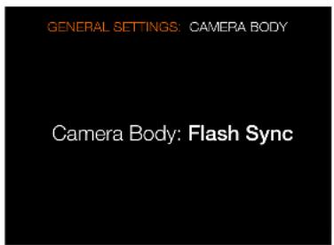
text_image
GENERAL SETTINGS: CAMERA BODY Camera Body: Flash Sync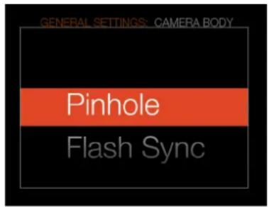
text_image
GENERAL SETTINGS: CAMERA BODY Pinhole Flash SyncTo Use
USER GUIDE
5.18 VIDEO SETTINGS MENU QUALITY
Main Menu
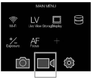
text_image
MAIN MENU Wi-Fi LV Live View StorageDisplay +/- AF + Exposure Focus +Video icon
Video Settings Menu
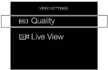
text_image
VIDEO SETTINGS 100p Quality Live ViewVideo Quality Settings
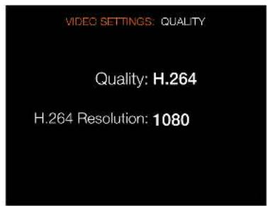
text_image
VIDEO SETTINGS: QUALITY Quality: H.264 H.264 Resolution: 1080Video Quality Settings dialogue
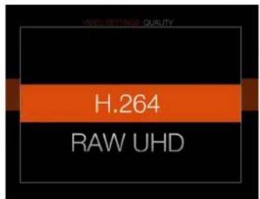
text_image
HOLD BETTING QUALITY H.264 RAW UHDMAIN MENU > VIDEO SETTINGS > VIDEO QUALITY
1 Press the Video icon on the Sensor Unit display.
2 The Video Settings Menu appears.
3 Press the Video Quality icon.
Swipe right or press MENU button to get back to Main Menu.
H.264 Resolution dialogue
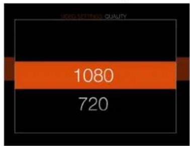
bar
| Category | Value | |---|---| | 1080 | 1080 | | 720 | 720 |VIDEO QUALITY SETTINGS
Video Quality Settings H6D-50c
- H.264. (1920×1080 or 1280×720).
- RAW FHD (Full HD, 1920×1080).
Video Quality Settings H6D-100c
- H.264. (1920×1080 or 1280×720).
- RAW UHD (Ultra HD, 3840×2160).
H.264 Resolution
Select the H.264 Resolution.
-1080.
-720.
Grip Display
H.264 Video Coding:
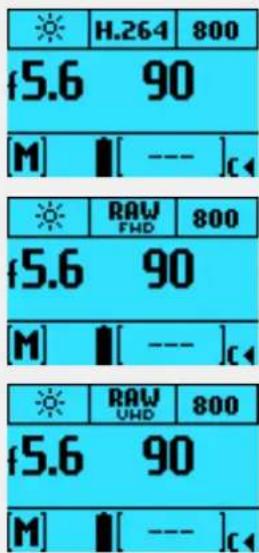
text_image
H.264 800 f5.6 90 [M] [ --- ]c RAW FMD 800 f5.6 90 [M] [ --- ]c RAW UMD 800 f5.6 90 [M] [ --- ]cRAW Full HD (H6D-50c):
RAW UHD (H6D-100c):
To Use
USER GUIDE
5.19 VIDEO SETTINGS MENU LIVE VIEW
Video Settings Menu
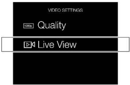
text_image
VIDEO SETTINGS 1080p Quality Live ViewLive View Settings
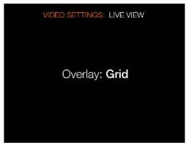
text_image
VIDEO SETTINGS: LIVE VIEW Overlay: GridMAIN MENU > VIDEO SETTINGS > LIVE VIEW
1 Press the Video icon on the Sensor Unit display.
2 The Video Settings Menu appears.
3 Press the Live View icon.
Swipe right or press MENU button to get back to Main Menu.
Overlay Settings dialogue
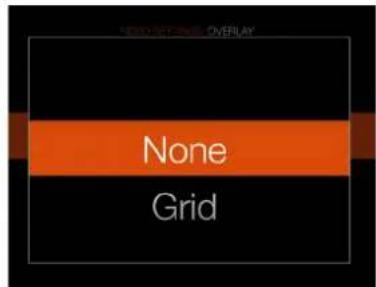
text_image
None GridLIVE VIEW SETTINGS
Overlay
Select between:
- None.
- Grid. This option adds a 1/3 grid.
Note!
You can toggle the overlay On or Off by pressing the Display button while in Video Live View.
Video Live View screen with grid enabled
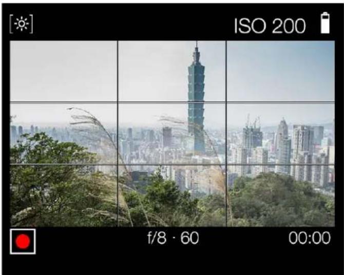
natural_image
Panoramic cityscape photo showing Taiwan Tower and surrounding greenery, captured in a grid coordinates (no text or symbols on the city itself)To Use
USER GUIDE
- Enter Video mode by a long press on the Video button (A) on the Grip Display or by selecting "V" as exposure mode from the control screen.
2 The Video Control Screen is displayed.
3 Adjust aperture and/or shutter speed with front and rear scroll wheel to get desired exposure level.
4 Start the Live Video Stream by pressing the Live Video icon (C) in the bottom left corner on the Video Control Screen.
5 The Video Stream is displayed on the Sensor Unit Display.
6 Start Recording by pressing the Shutter Release Button (B) or by pressing the red recording icon on the sensor unit display.
7 Stop the Recording by pressing the Shutter Release Button (B) or by pressing the stop icon (grey square icon) in the bottom left corner on the sensor unit display.
8 When the recording is finished, press the Browse button to display the last recorded video. You can now play the video to review the result.
How to Focus In Video Mode
1 In Video Live View before recording, double click on the screen to zoom in to 50% or 100% depending on setting.
2 Adjust the Focus manually in the zoom-in mode.
Note!
You can change White balance and ISO from the Video Live View screen by tapping the values.
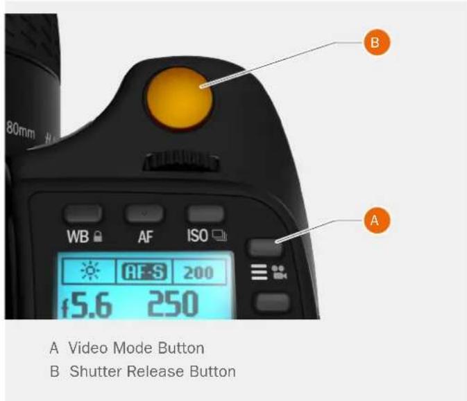
text_image
A Video Mode Button B Shutter Release ButtonVideo Control Screen
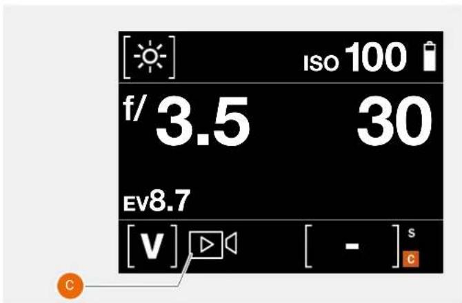
text_image
[Sun] ISO 100 f/ 3.5 30 EV8.7 [v] [ - ] s CVideo Display when recording videoVideo Live View before recording video
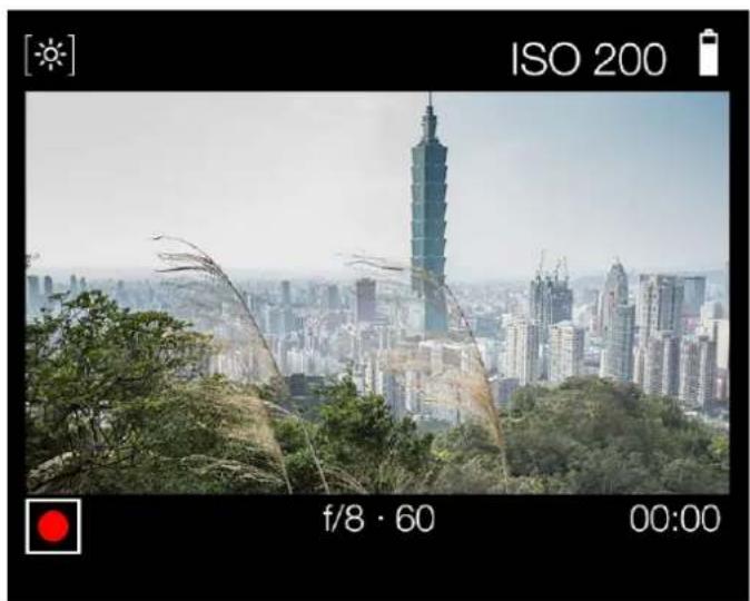
natural_image
City skyline with a prominent skyscraper in the background, surrounded by greenery and trees (no visible text or symbols)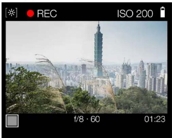
natural_image
Cityscape photo of Taiwan with a prominent skyscraper and surrounding greenery, captured via a camera lens (no text or symbols on the city itself)To Use
USER GUIDE
5.21 GENERAL SETTINGS MENU
Main Menu
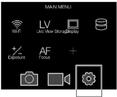
text_image
MAIN MENU Wi-Fi LV Live View StorageDisplay +/- Exposure AF Focus + Camera Audio GearGeneral
Settings icon
MAIN MENU > GENERAL SETTINGS
1 Press the General Settings icon on the Sensor Unit display.
2 The General Settings Menu appears.
Swipe right or press MENU button to get back to Main Menu.
General Settings Menu
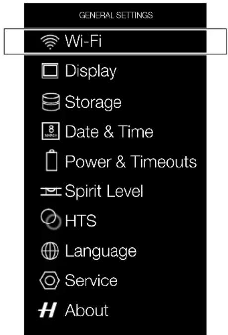
text_image
GENERAL SETTINGS Wi-Fi Display Storage 8 MONTH Date & Time Power & Timeouts Spirit Level HTS Language Service AboutContinues on the next Page.
To Use
USER GUIDE
GENERAL SETTINGS WI-FI
The Wi-Fi mode allows the Hasselblad Phocus Mobile application on an Apple iPhone, iPad or iPod to function in the same way as when a camera is tethered to a computer.
MAIN MENU > GENERAL SETTINGS > WI-FI
1 Select General Settings in the Main Menu on the Sensor Unit Display.
2 Select Wi-Fi.
3 Select settings:
Wi-Fi: On or Off.
Modes: 2.4 GHz or 5 GHz.
Note!
Some regions do not allow 5 GHz Wi-Fi.
Note!
When Wi-Fi is activated, a Wi-Fi icon is displayed on most screens.
Note!
No images are stored on the iPhone/iPad/iPod. To send a Photo using e-mail, select the Share function in Phocus Mobile or use Screen Shot function on the iPhone/iPad.
WI-FI MODES
The Wi-Fi function has one mode of operation, Direct Access.
Direct Access is when the camera creates a new Wi-Fi network and an iPhone/iPad(iPod is connected to it. The name of the network contains the camera serial number. For example: "H6D-50c SQ34000123"
Wi-Fi Settings Menu
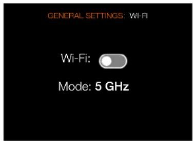
text_image
GENERAL SETTINGS: WI-FI Wi-Fi: Mode: 5 GHzTo Use
USER GUIDE
5.22 GENERAL SETTINGS DISPLAY
MAIN MENU > GENERAL SETTINGS > DISPLAY
Press the General Settings icon on the Sensor Unit display.
The General Settings Menu appears. Select Display.
Swipe right or press MENU button to get back to Main Menu.
Display Menu Settings
Brightness
Slide left or right to change brightness. Left decreases the brightness and right increases the brightness.
Show Preview
Select On or Off. On displays a preview of the capture after every exposure. Off displays no preview after every capture.
Mark Overexposure
Select On or Off. If set to On, overexposed areas in the image will alternate between white and black. Active on previews in both 1- and 9-view.
General Settings Menu
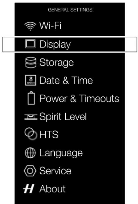
text_image
GENERAL SETTINGS Wi-Fi Display Storage 8 MARCH Date & Time Power & Timeouts Spirit Level HTS Language Service AboutDisplay Menu
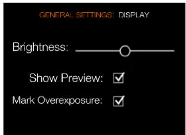
text_image
GENERAL SETTINGS: DISPLAY Brightness: Show Preview: ✓ Mark Overexposure: ✓To Use
USER GUIDE
5.23 GENERAL SETTINGS STORAGE
MAIN MENU > GENERAL SETTINGS > STORAGE
1 Press the General Settings icon on the Sensor Unit display.
2 The General Settings Menu appears.
3 Press the General Settings Storage icon.
Swipe right or press MENU button to get back to Main Menu.
Storage Menu Settings
Format Card
- Format CFast.
- Format SD.
Image Destination
- Primary slot: CFast or SD.
- Secondary slot usage.
General Settings Menu
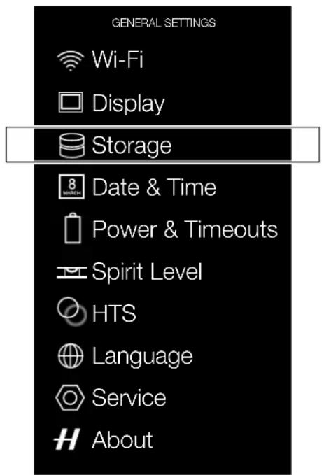
text_image
GENERAL SETTINGS Wi-Fi Display Storage 8 MARCH Date & Time Power & Timeouts Spirit Level HTS Language Service AboutStorage Menu
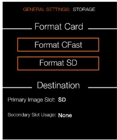
text_image
GENERAL SETTINGS: STORAGE Format Card Format CFast Format SD Destination Primary Image Slot: SD Secondary Slot Usage: NoneSee next page for more information.
To Use
USER GUIDE
FORMAT CFAST AND SD CARDS
MAIN MENU > GENERAL SETTINGS > STORAGE > FORMAT CARD
The camera is only able to read and write to storage media that have been formatted correctly. New cards sometimes have no formatting, or you might want to convert a card that is currently using a format that the camera cannot read. In either case, you must reformat both CFast cards and SD cards in the sensor unit for H6D use.
There are two ways to format cards. The quickest way is to use the Format card button on the grip but if you prefer, you can also use the menu on the sensor unit.
FORMAT BUTTON
Press the Format button (A) on the camera grip. It is purposely recessed to avoid unintentional use, so use a ballpoint pen or similar. A dialogue is displayed on the sensor unit for confirmation. It is also possible to press the format button with a hard press with a fingertip.
FORMAT MEMORY CARDS VIA SENSOR UNIT
MAIN MENU > GENERAL SETTINGS > STORAGE > FORMAT CARD
1 Press MENU.
2 Navigate to General Settings > Storage.
3 Navigate to Format Card.
4 Click the button CFast or SD. SD in this case.
5 Confirm by pressing Format.
Swipe right or press MENU button to get back to Main Menu.
Note!
All CFast and SD memory cards should be formatted in the sensor unit before using them the first time.
Note!
Only UDMA/type 4/60MBs (or 400x) cards or better are recommended for H6D use.
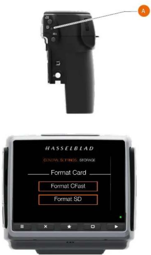
text_image
HASSELBLAD GENERAL SETTINGS STORAGE Format Card Format CFast Format SDFormat Card Dialogue
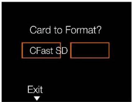
text_image
Card to Format? CFast SD ExitConfirmation Dialogue to Format SD Card.
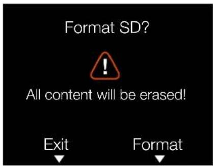
text_image
Format SD? All content will be erased! Exit FormatTo Use
USER GUIDE
IMAGE AND VIDEO DESTINATION
MAIN MENU > GENERAL SETTINGS > STORAGE > DESTINATION
Destination Settings.
1 Press the General Settings icon on the Sensor Unit display.
2 The General Settings Menu appears.
3 Press the General Settings Storage icon.
4 Select Destination.
Swipe right or press MENU button to get back to Main Menu.
Image Destination
- Primary slot: CFast or SD.
- Secondary slot usage:
- None.
- Overflow.
- Backup
If Overflow is selected, the camera will automatically switch to the secondary card when the primary card is full.
If Backup is selected, the camera will save the image to both cards (RAW and RAW + JPG). Video in H.264 format will be saved to both cards. RAW video can only be saved to the CFast card.
General Settings Menu
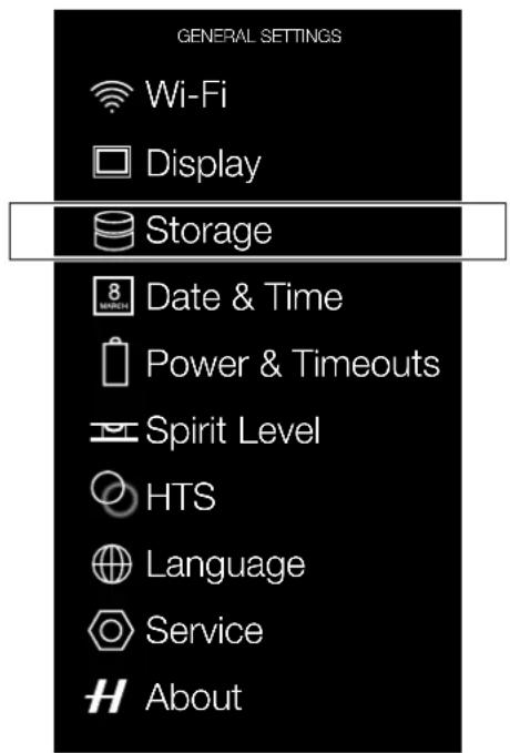
text_image
GENERAL SETTINGS Wi-Fi Display Storage 8 MARCH Date & Time Power & Timeouts Spirit Level HTS Language Service AboutStorage Menu
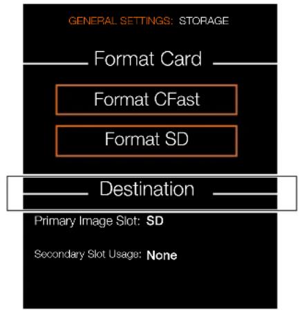
text_image
GENERAL SETTINGS: STORAGE Format Card Format CFast Format SD Destination Primary Image Slot: SD Secondary Slot Usage: NoneTo Use
USER GUIDE
5.24 GENERAL SETTINGS DATE AND TIME
MAIN MENU > GENERAL SETTINGS > DATE & TIME
1 Press the General Settings icon on the Sensor Unit display.
2 The General Settings Menu appears.
3 Press the Date & Time icon.
Swipe right or press MENU button to get back to Main Menu.
Date and Time Menu Settings
Date
Set Date by changing year, month and day, using the pop up menus.
Time
Set Time by changing hour and minute, using the pop up menus.
General Settings Menu
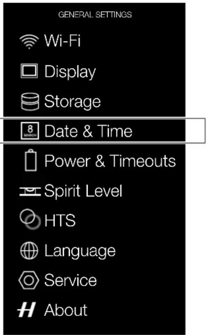
text_image
GENERAL SETTINGS Wi-Fi Display Storage 8 MINI-34 Date & Time Power & Timeouts Spirit Level HTS Language Service AboutDate and Time Menu
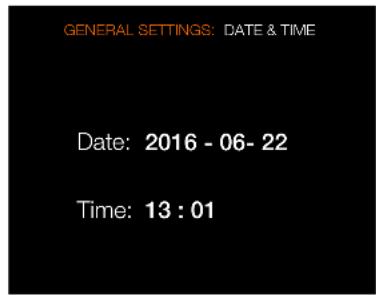
text_image
GENERAL SETTINGS: DATE & TIME Date: 2016 - 06- 22 Time: 13 : 01To Use
USER GUIDE
5.25 GENERAL SETTINGS POWER AND TIMEOUTS
MAIN MENU > GENERAL SETTINGS > POWER & TIMEOUTS
The H6D Camera can be set to automatically turn off the Sensor Unit Display after a set amount of seconds to save battery for example.
It can also be set to Power Off after 10, 30 or 60 minutes.
If Power from USB is checked, the camera will take part of the power from the USB connection.
See the following page for a detailed description of the Power and Timeouts Settings.
Note!
If an external power source is attached to the DC power input, the "Power Off" item will be greyed out and cannot be selected.
General Settings Menu
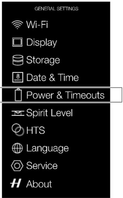
text_image
GENERAL SETTINGS Wi-Fi Display Storage Date & Time Power & Timeouts Spirit Level HTS Language Service AboutPower and Timeouts Menu
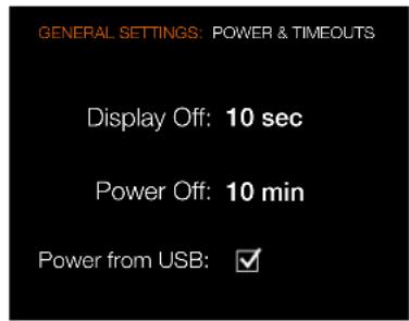
text_image
GENERAL SETTINGS: POWER & TIMEOUTS Display Off: 10 sec Power Off: 10 min Power from USB: ✓To Use
USER GUIDE
SET DISPLAY OFF MODE
MAIN MENU > GENERAL SETTINGS > DISPLAY > POWER & TIMEOUTS
1 Press the General Settings icon on the Sensor Unit display.
2 The General Settings Menu appears.
3 Press the General Settings Power & Timeouts icon.
4 Select Display Off.
In this mode the camera turns off the grip and sensor unit displays but remains ready to be immediately reactivated to the ON mode.
The time Intervals are:
3, 5, 10, 20, 30, 60 seconds or Never.
POWER OFF
MAIN MENU > GENERAL SETTINGS > DISPLAY > POWER MODES AND TIMEOUTS > POWER OFF
Sets the amount of elapsed time before the camera enters complete Power Off mode.
Power Off options
Power Off after 5, 10, 30 minutes or Never.
RE-ACTIVATE CAMERA FROM DISPLAY OFF POWER MODE
Do any of the following actions:
1 Press the Shutter Release button half way.
2 Press the STOP DOWN button.
3 Click the ON / OFF button.
4 Press the Mirror Up button.
POWER FROM USB
MAIN MENU > GENERAL SETTINGS > DISPLAY > POWER MODES AND TIMEOUTS > POWER FROM USB
When checked, the camera will take power from the USB device. This is indicated by a symbol (A) next to the battery on the Control Screen and on the Live View screen.
Note!
The camera will only be partially powered from USB. A charged camera battery is still required. Only power from a USB host device is supported.
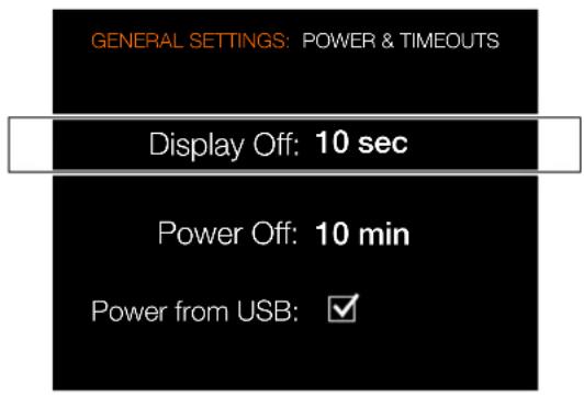
text_image
GENERAL SETTINGS: POWER & TIMEOUTS Display Off: 10 sec Power Off: 10 min Power from USB: ✓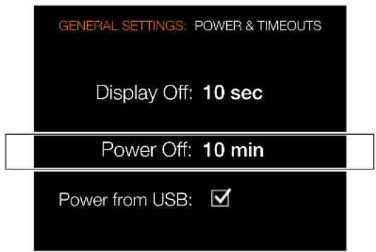
text_image
GENERAL SETTINGS: POWER & TIMEOUTS Display Off: 10 sec Power Off: 10 min Power from USB: ✓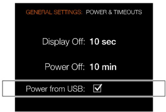
text_image
GENERAL SETTINGS: POWER & TIMEOUTS Display Off: 10 sec Power Off: 10 min Power from USB: ✓Indication of active USB power.
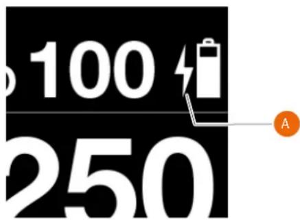
text_image
100 250To Use
USER GUIDE
5.26 GENERAL SETTINGS SPIRIT LEVEL
MAIN MENU > GENERAL SETTINGS > SPIRIT LEVEL
The camera is equipped with an accelerometer. The accelerometer is used to measure the tilt of the camera relative to the horizontal axis (A) and vertical axis (B).
How to align Camera with Spirit Level
1 Press the General Settings icon on the Sensor Unit display.
2 The General Settings Menu appears.
3 Press the General Settings Spirit Level icon.
4 Adjust the tilt of the camera left/right and up/down until the white filled circle is in the centre and turns green.
Swipe right or press MENU button to get back to Main Menu.
General Settings Menu
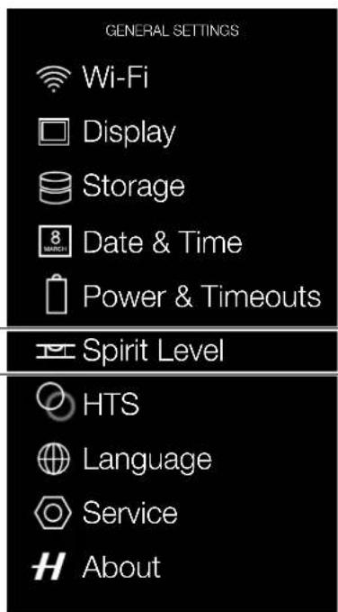
text_image
GENERAL SETTINGS Wi-Fi Display Storage 8 MARCH Date & Time Power & Timeouts Spirit Level HTS Language Service AboutSpirit Level when camera is aligned
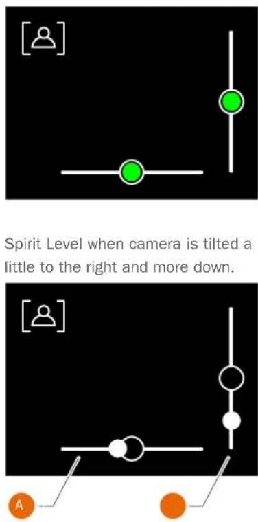
text_image
[?] Spirit Level when camera is tilted a little to the right and more down. [?] ACamera tilted to the left.
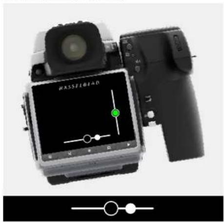
Camera aligned horizontally and vertically.
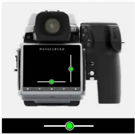
text_image
HASSEBLADCamera tilted to the right.
natural_image
Front view of a Nassifread device with control panel and indicator lights (no readable text or symbols)Camera tilted up.
natural_image
Black DSLR camera with lens and attached strap, shown alongside a vertical black line with circular symbol (no text or labels visible)Camera aligned vertically.
natural_image
Close-up of a black DSLR camera with lens and control panel, next to a green circular indicator light (no text or symbols visible)Camera tilted down.
natural_image
Close-up of a black digital camera with attached lens and control knob (no visible text or symbols)To Use
USER GUIDE
CALIBRATE SPIRIT LEVEL
MAIN MENU > GENERAL SETTINGS > SPIRIT LEVEL
The Spirit Level can be set to Factory or User mode. In User mode, the Spirit Level can be calibrated by the user. In Factory mode, the calibration from the Factory is used.

ctory mode with Factory settings.

er mode with User settings.
How to calibrate Spirit Level
1 Press the General Settings icon on the Main Menu display.
2 The General Settings Menu appears.
3 Press the General Settings Spirit Level icon.
4 Press the icon in the top left corner (A).
5 The Spirit Level dialogue appears.
6 Align the camera carefully both horizontally and vertically.
7 Press Calibrate (B).
8 The two white circles are now moved to their centre position. When in their centre position, they turn green.
Swipe right or press MENU button to get back to Main Menu.
How to reset Spirit Level to Factory calibration
1 Press the General Settings icon on the Main Menu display.
2 The General Settings Menu appears.
3 Press the General Settings Spirit Level icon.
4 Press the icon in the top left corner (A).
5 The Spirit Level dialogue appears.
6 Press the Factory settings icon (C).
7 The Factory settings icon (D) is now displayed and the Spirit Level is reset to Factory calibration settings.
Swipe right or press MENU button to get back to Main Menu.
General Settings Menu
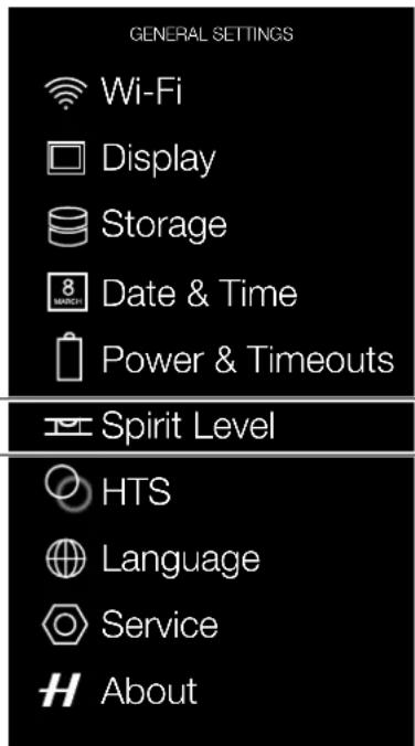
text_image
GENERAL SETTINGS Wi-Fi Display Storage Date & Time Power & Timeouts Spirit Level HTS Language Service AboutSpirit Level when camera is aligned
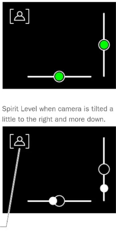
text_image
Spirit Level when camera is tilted a little to the right and more down.Spirit Level when calibrated by user.
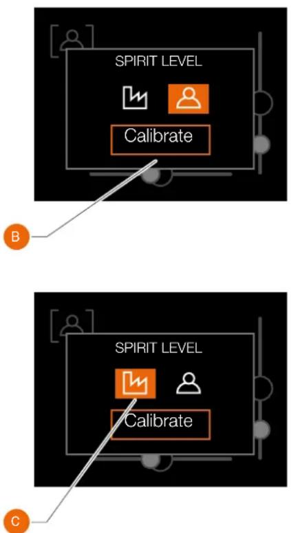
flowchart
graph TD
    A["SPIRIT LEVEL"] --> B["Calibrate"]
    B --> C["Step B"]
    D["SPIRIT LEVEL"] --> E["Calibrate"]
    E --> F["Step C"]
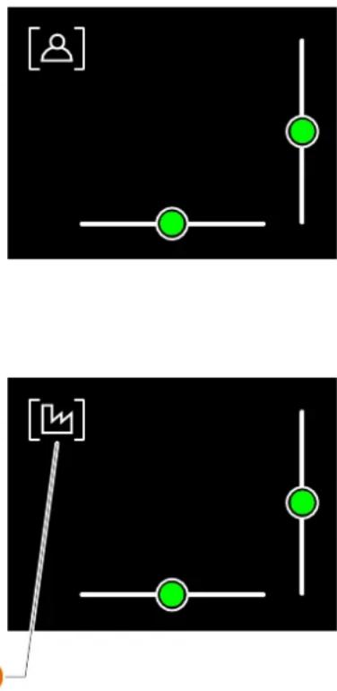
flowchart
graph TD
    A["User Icon"] --> B["Node"]
    B --> C["Node"]
    C --> D["Node"]
    D --> E["Node"]
    E --> F["Node"]
    F --> G["Node"]
    G --> H["Node"]
    H --> I["Node"]
    I --> J["Node"]
    J --> K["Node"]
    K --> L["Node"]
    L --> M["Node"]
    M --> N["Node"]
    N --> O["Node"]
    O --> P["Node"]
    P --> Q["Node"]
    Q --> R["Node"]
    R --> S["Node"]
    S --> T["Node"]
    T --> U["Node"]
    U --> V["Node"]
    V --> W["Node"]
    W --> X["Node"]
    X --> Y["Node"]
To Use
USER GUIDE
5.27 GENERAL SETTINGS HTS
MAIN MENU > GENERAL SETTINGS > HTS
When the HTS1.5x Tilt/Shift adapter is used on the camera, this menu item brings up a status screen that dynamically shows the settings on the HTS: Shift, Tilt and Rotation.
Note!
If an HTS adapter is not used, this menu item is greyed out.
Note!
You can also see the HTS info on the Live View screen. See page 113.
For more information about the HTS Tilt/Shift adapter, please read the HTS User Manual which can be downloaded from www.hasselblad.com.
General Settings Menu
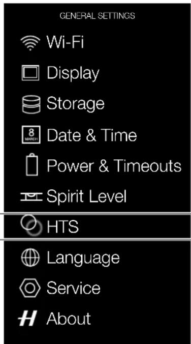
text_image
GENERAL SETTINGS Wi-Fi Display Storage Date & Time Power & Timeouts Spirit Level HTS Language Service AboutHTS Status Screen
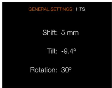
text_image
GENERAL SETTINGS: HTS Shift: 5 mm Tilt: -9.4° Rotation: 30°To Use
USER GUIDE
5.28 GENERAL SETTINGS LANGUAGE
MAIN MENU > GENERAL SETTINGS > LANGUAGE
1 Press the General Settings icon on the Sensor Unit display.
2 The General Settings Menu appears.
3 Press the General Settings Language icon.
Swipe right or press MENU button to get back to Main Menu.
Language Menu Settings
Available Languages:
English.
Español.
Français.
Deutsch.
Italian.
Chinese.
Russian.
Japanese.
Korean.
General Settings Menu
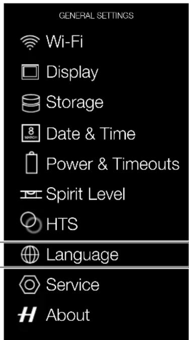
text_image
GENERAL SETTINGS Wi-Fi Display Storage Date & Time Power & Timeouts Spirit Level HTS Language Service AboutLanguage Menu
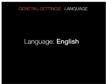
text_image
GENERAL SETTINGS: LANGUAGE Language: EnglishHow to change Language
1 Press MENU button on the Sensor Unit Display.
2 Navigate to General Settings.
3 Navigate to Language.
4 Select Language.
5 Close the pop up menu by tapping outside the pop up menu.
Note!
If the sensor unit has been set to a language you do not understand
(a rented camera, for example), see
Chapter Troubleshooting for a solution.
To Use
USER GUIDE
5.29 GENERAL SETTINGS SERVICE
MAIN MENU > GENERAL SETTINGS > SERVICE
1 Press the General Settings icon on the Sensor Unit display.
2 The General Settings Menu appears.
3 Press the General Settings Service icon.
Swipe right or press MENU button to get back to Main Menu.
Service Menu Settings
Firmware Update
Check For Update.
Log Data
Press Save to Log Data for Service.
Default Settings
To reset all settings back to factory default.
File Counter
Reset image sequence number. Format memory card before you use this function.
How to save Log Data:
1 Press MENU button.
2 Select General Settings.
3 Select Service.
4 Select Log Data.
5 Press the Save button.
6 Save Log Data saves a log file on the CFast card or on the SD card.
7 Save the chosen selection by pressing EXIT (MENU button).
General Settings Menu
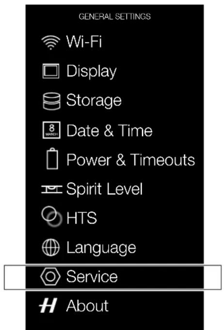
text_image
GENERAL SETTINGS Wi-Fi Display Storage 8 MARCH Date & Time Power & Timeouts Spirit Level HTS Language Service AboutService Menu
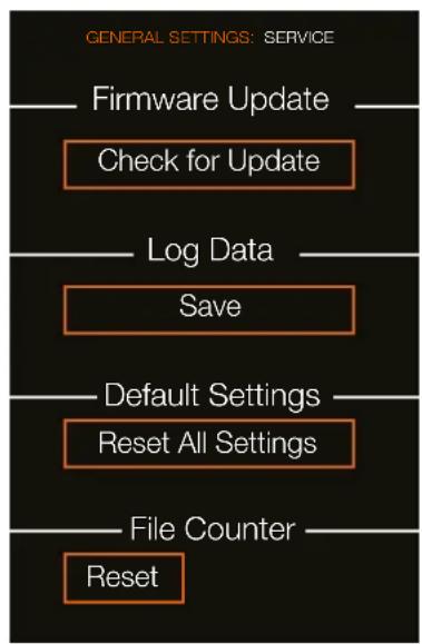
flowchart
graph TD
    A["File Counter Reset"] --> B["Reset All Settings"]
    B --> C["Default Settings"]
    C --> D["Save"]
    D --> E["Log Data"]
    E --> F["Check for Update"]
    F --> G["Firmware Update"]
    style A fill:#f9f,stroke:#333
    style G fill:#f9f,stroke:#333
Reset Settings Dialogue
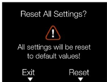
text_image
Reset All Settings? ! All settings will be reset to default values! Exit ResetReset File Counter Dialogue
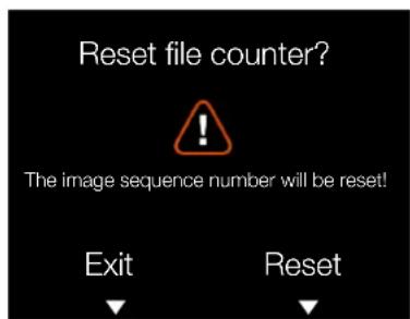
text_image
Reset file counter? ! The image sequence number will be reset! Exit ResetTo Use
USER GUIDE
5.30 GENERAL SETTINGS CHECK FOR UPDATE
MAIN MENU > GENERAL SETTINGS > CHECK FOR UPDATE
1 Press the General Settings icon on the Sensor Unit display.
2 The General Settings Menu appears.
3 Press the General Settings Check for Update button.
4 The camera will now check the inserted card or cards for update files.
Swipe right or press MENU button to get back to Main Menu.
Note!
The battery needs to be charged over 50%, to enable the Camera to perform a complete Firmware Update.
UPDATE H6D FIRMWARE PROCEDURE
1 Download the latest H6D Firmware from www.hasselblad.com.
2 Save the Firmware file to the root on a CFast or SD Card. Do not save the Firmware file in a folder (or subfolder).
3 Insert the CFast or SD Card in the H6D Camera.
4 Select General Settings from the Main Menu.
5 Select Service.
6 Select Firmware Update.
7 Select Check for Update.
8 Make sure the Firmware File Name and Number corresponds to the latest Firmware File you have downloaded.
9 Select Update.
10 During the update the text "Update in progress" and "Do not turn off!" is displayed on the H6D Camera Display.
11 Do not turn off the H6D Camera during the Update Progress.
12 The Update will take several minutes.
13 When the Update is finished this text will be displayed: "Update Finished. Please remove and reinsert battery!".
14 Remove and reinsert the battery.
15 Start the H6D Camera.
16 The new Firmware will now be installed!
General Settings Menu
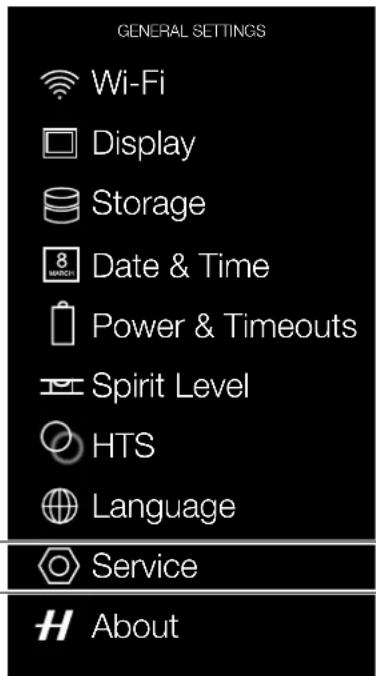
text_image
GENERAL SETTINGS Wi-Fi Display Storage Date & Time Power & Timeouts Spirit Level HTS Language Service AboutService Menu
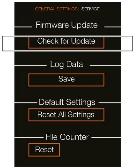
flowchart
graph TD
    A["File Counter"] --> B["Reset"]
    C["Default Settings"] --> D["Reset All Settings"]
    E["Log Data"] --> F["Save"]
    G["Check for Update"] --> H["Firmware Update"]
    I["GENERAL SETTINGS: SERVICE"] --> J["End"]
Check for Update
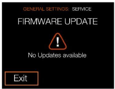
text_image
GENERAL SETTINGS: SERVICE FIRMWARE UPDATE ! No Updates available ExitFirmware Update dialogue when no Firmware Updates are available.
Firmware Update
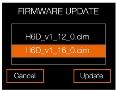
text_image
FIRMWARE UPDATE H6D_v1_12_0.cim H6D_v1_16_0.cim Cancel UpdateFirmware Update dialogue when two Firmware Updates are available.
To Use
USER GUIDE
5.31 GENERAL SETTINGS ABOUT
MAIN MENU > GENERAL SETTINGS > ABOUT
1 Press the General Settings icon on the Sensor Unit display.
2 The General Settings Menu appears.
3 Press the General Settings About icon.
Swipe right or press MENU button to get back to Main Menu.
About Menu Settings
Firmware
The About box will tell you which firmware version is present so you can see if you have the latest firmware (can be downloaded from the Hasselblad website). Firmware version is listed for Camera Body, Lens and Viewfinder (if attached).
Serial number
The serial number is displayed here. Refer to your serial number in case Hasselblad Support need it for problem solving.
Licenses
Displays the available Licenses.
Usage
Displays the amount of exposures for the camera body and lens (if attached)
General Settings Menu
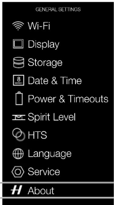
text_image
GENERAL SETTINGS Wi-Fi Display Storage Date & Time Power & Timeouts Spirit Level HTS Language Service AboutAbout Menu
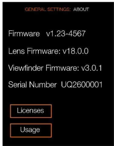
text_image
GENERAL SETTINGS: ABOUT Firmware v1.23-4567 Lens Firmware: v18.0.0 Viewfinder Firmware: v3.0.1 Serial Number UQ2600001 Licenses UsageUsage

text_image
GENERAL SETTINGS: ABOUT: USAGE —— Exposures ——— Body: 1234 Lens : 5678To Use
USER GUIDE
5.32 GRIP DISPLAY NAVIGATION
BUTTONS AND CONTROLS ON GRIP DISPLAY
Press the buttons that surrounds the display and turn the scroll wheels to navigate the menu and access the settings on the grip.
Note that some of the buttons have several functions which is indicated by the designation that appears closest to that particular button when navigating.
For example, the Menu button (F) also acts as a Video button. The Play button (G) also acts as Illumination On for the Grip Display.
Quick save
To save settings quick, half-press Shutter Release button (A).
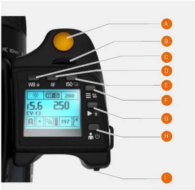
text_image
HC 80mm WB AF ISO f5.6 250 EV 13 A 197 A B C D E F G H I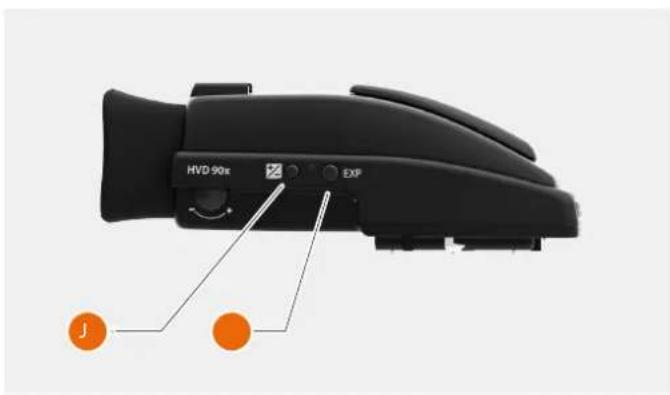
text_image
HVD-90x EXFA Shutter Release button
B Front Scroll Wheel
C WB button
D AF button
E ISO
F MENU and Video button
G PLAY and Illumination
H ON and OFF button
I Rear Scroll Wheel
J Exposure and Flash Compensation button
K Exposure mode and Metering mode
To Use
USER GUIDE
TO ADJUST SHUTTER AND APERTURE ON GRIP
Note!
In manual mode both the shutter and aperture are electronically controlled and are adjusted by the scroll wheels on the grip.
Note!
There are no separate manual setting rings on the lenses or camera body. The settings are displayed both on the grip display and in the viewfinder display.
How to adjust shutter and aperture
1 Turn the front scroll wheel (A) to adjust the shutter and aperture according to selected mode described below.
2 Turn the rear scroll wheel (B) to adjust the shutter and aperture according to selected mode described below.
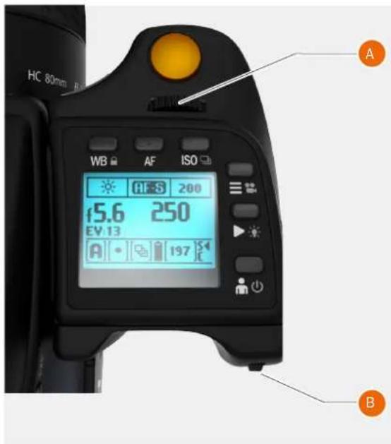
text_image
HC 80mm WB AF ISO HES 200 45.6 250 EV 13 A 197 BIn Manual mode (M):
Front wheel Aperture.
Rear wheel Shutter speed.
In Aperture priority (A) mode:
Front wheel Aperture and Shutter Speed in combination.
Rear wheel Quick exposure adjustment of Shutter speed.
In Shutter priority (S) mode:
Front wheel Aperture and Shutter Speed in combination.
Rear wheel Quick exposure adjustment of Aperture.
In P or Pv mode:
Front wheel Aperture and Shutter Speed in combination.
Rear wheel Aperture and Shutter Speed in combination.
See under Light Metering and Exposure Control/Exposure Method for a complete description.
To Use
USER GUIDE
GRIP DISPLAY NAVIGATION
Main Screen
This is the Main Screen of the Camera Grip Display. These are the most important camera settings. The top row displays WB, AF and ISO. The middle displays Aperture, Shutter Speed, EV (Exposure Value) and Exposure Compensation values are displayed. At the bottom of the screen Exposure Mode, Light Meter Method, Drive Mode, Battery Level, Exposure Counter and Status of the memory cards are displayed.
Menu
Normally the front and rear wheels are used to control aperture and shutter speed values. If you would like to use the wheels to navigate the menus of the Sensor Unit, first press the MENU button. Then the Menu symbol is shown in the centre of the display.
When Menu Mode is active it is possible to use the wheels to navigate the menu system of the Sensor Unit. To leave the Menu Mode (and use the wheels for aperture and shutter speed) press the Menu button again or half-press the Shutter Release button.
White Balance (WB)
1 Press the WB button above the Grip Display to show the WB Menu.
2 Select WB mode by scrolling left or right with the front wheel.
3 Get back to the Main Screen by half-press on the Shutter Release button or by clicking the WB button again.
White Balance Manual (WB)
1 To set the Colour Temperature manually, scroll the Front Scroll Wheel until "M" is displayed.
2 Then the Colour temperature value is displayed at the bottom of the screen.
3 Use the Rear Scroll Wheel to select Colour Temperature in Kelvin, K.
ISO
1 Press the ISO button to show the ISO menu.
2 Use the Front Scroll Wheel to scroll up and down between available ISO numbers.
3 Half-press or click the ISO button once again to leave the menu.
Main Screen
Grip Display Main Screen.
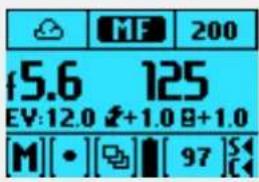
text_image
MF 200 f5.6 125 EV:12.0 +1.0 B+1.0 M[•][□][97]SMenu
Grip Display Menu symbol on Screen.
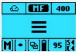
text_image
MF 400 ≡ M[•][ ] [95]SWB
Grip Display White Balance (WB) Screen.
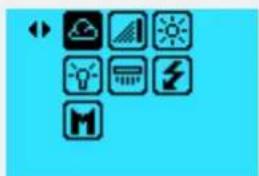
natural_image
Grid of nine icons on a blue background, including weather, sunshine, lightbulb, and lightning bolt (no text or labels)WB Manual
Grip Display Manual
White Balance (WB)
Screen.
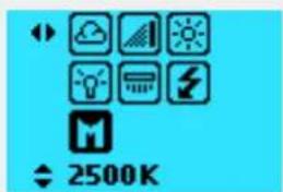
text_image
2500KISO
Grip Display Manual
ISO Screen. ISO 400
displayed.
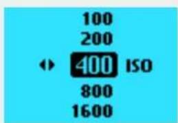
text_image
100 200 400 ISO 800 1600To Use
USER GUIDE
Auto Focus (AF)
1 Press the AF button above the Grip Display to show the AF menu.
2 Select AF mode by scrolling the Front or Rear Scroll Wheel left or right / up or down, until the desired mode is selected.
Auto Focus (AF)
Grip Display Auto Focus (AF) Screen.
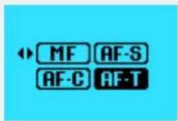
text_image
MF AF-S AF-C AF-TAuto Focus (AF) with Macro Lens 120mm
When the 120mm Macro Lens is used the AF menu displays an additional setting, Focus Range. To limit the large focus range of the Macro Lens can improve the AF performance significantly. It is possible to select one of the three modes below for Focus Range.
The first limits the AF to scan the close-up range only (less than 1 meter).
The second scans far away distances only (between 1 meter and infinity).
The third option is to scan the Full Range.
Close-up Scan
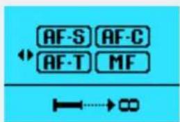
text_image
AF-S AF-C AF-T MF I→8Far Away Scan
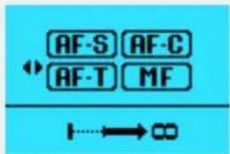
text_image
AF-S AF-C AF-T MF →8Full Range Scan
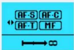
text_image
AF-S AF-C ← AF-T MF →8Browse
To easily reach Image Browse mode, click the Browse (Play) button to right of the Grip Display. The Browse Mode is activated and it is possible to browse images using the Front Scroll Wheel. To Exit Browse Mode half-press or press the Browse button again.
Use the Rear Scroll Wheel to alter between image overlays with capture information and histogram modes.
Browse
Grip Display Browse Screen.
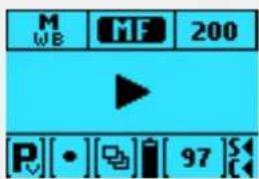
text_image
M WB MF 200 P[•][Di][97]SVideo Display
Press and hold the Video Mode button on the grip. In Video Mode the Grip displays some essential settings for example White Balance (WB M selected), H.264 selected, ISO (200), Aperture (f5.6), Shutter Speed (10), Aperture priority mode (A), battery level, Time (1:21:18) and Memory Card status (SD and CFast inserted).
Video Display
Display when in Video Mode.
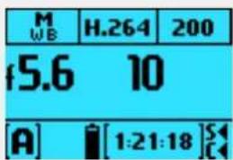
text_image
M WB H.264 200 f5.6 10 [A] [1:21:18]STo Use
USER GUIDE
+/- Button on Viewfinder
Press the +/- button on the Viewfinder to reach the Exposure Adjust menu. Use the Front Scroll Wheel to set the exposure compensation for flash and the rear wheel to set the exposure compensation. The exposure compensation can be set between -5.0 and 5.0 stops and the flash compensation between -3.0 and 3.0 stops. Leave the menu by a half-press on the Shutter Release button, or by pressing the +/- button again.
+/- Button
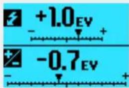
text_image
+1.0 - + -0.7 EVEXP Button on Viewfinder
Press the EXP button on the Viewfinder to the menu for Exposure Mode and Light Meter Mode. Set the Exposure Mode using the front wheel and the Light Meter Mode using the rear wheel Leave the menu by half-press or pressing the EXP button again.
EXP Button
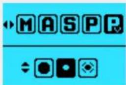
text_image
MASPRExposure Modes
M = Manual.
A = Aperture priority.
S = Shutter priority.
P = Program.
Pv = Program (variable).
Light Meter Modes
Centre Weighted.
Centre Spot.
Spot.
To Use
USER GUIDE
5.33 VIEWFINDER DISPLAY NAVIGATION
TYPICAL VIEWFINDER DISPLAY
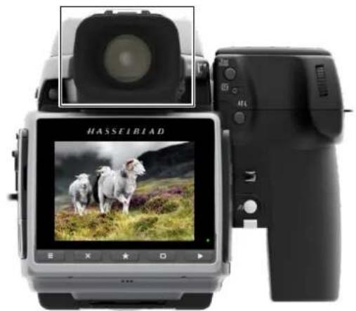
natural_image
Rear view of a Hasseblad camera displaying a landscape photo with sheep on grass (no visible text or symbols on the device body)Viewfinder Display User Interface
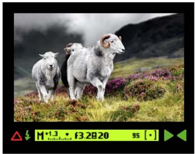
natural_image
Three sheep standing on a grassy hillside with purple flowers, no visible text or symbols in the image itself.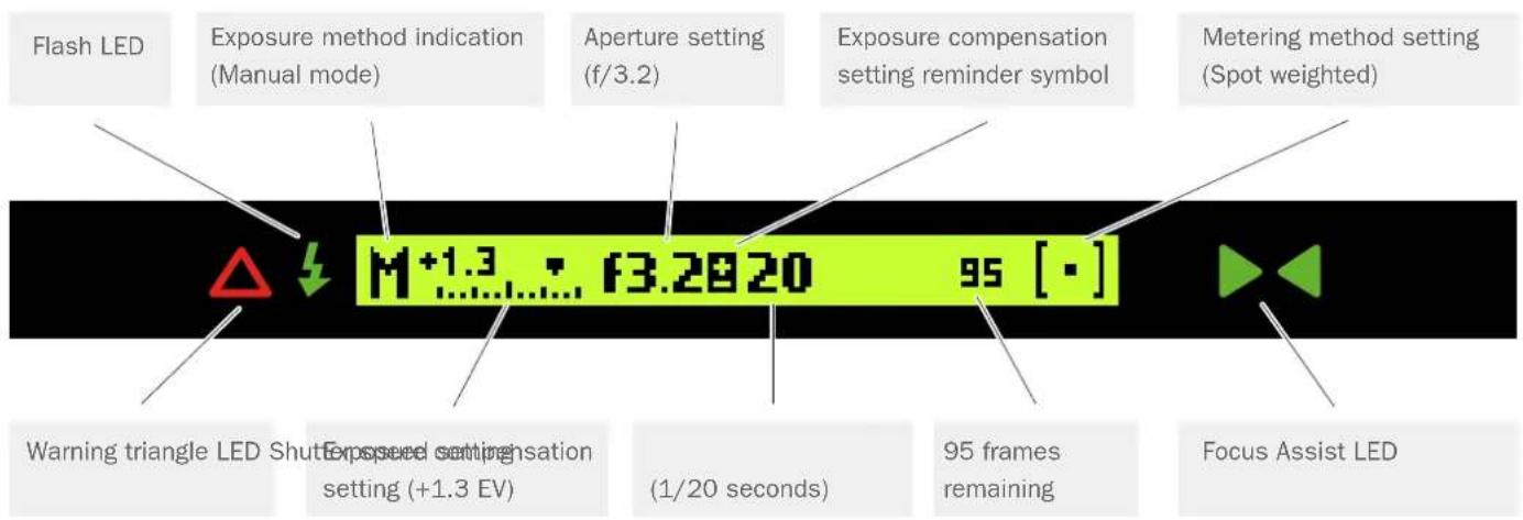
text_image
Flash LED Exposure method indication (Manual mode) Aperture setting (f/3.2) Exposure compensation setting reminder symbol Metering method setting (Spot weighted) Warning triangle LED Shutter Setting (+1.3 EV) Exposed setting setting (1/20 seconds) 95 frames remaining Focus Assist LED M+1.3 • f3.2820 95 [·]Note!
The LED indicator symbols will only be visible when activated by the camera or a setting.
Photo: Ian Lawson
To Use
USER GUIDE
VIEWFINDER DISPLAY NAVIGATION OVERVIEW
How to Navigate the Viewfinder Display
Select WB, AF, or ISO near the Grip Display or Exposure Compensation mode and Exposure and Metering Modes on the right side of the Viewfinder.
The front scroll wheel (A) and the rear scroll wheel (B) adjusts specific settings according to selected mode.
On the right side of the Viewfinder you can select:
+ / - button Exposure Compensation. EXP button Exposure and Metering Modes.
ISO, WB and AF modes
ISO
Change ISO mode by scrolling the Front Scroll Wheel (A) left or right or the Rear Scroll Wheel up or down.
WB Mode
Change WB mode by scrolling the Front Scroll Wheel (A) left or right. When selecting Manual WB use the Rear Scroll wheel to select Colour Temperature in Kelvin, K.
AF Mode
Change AF mode by scrolling the Front or Rear Scroll Wheel (A) left or right.
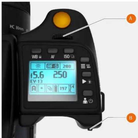
text_image
HC 80mm WB AF ISO 15.6 250 EV 13 A 197 S B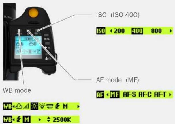
text_image
ISO (ISO 400) ISO < 200 400 800 > AF mode (MF) AF < MF AF-S AF-C AF-T > WB mode WB < M > 2500KExposure and metering mode examples
M = Manual.
A = Aperture priority.
S = Shutter priority.
P = Program.
Pv = Program (variable).
Centre Weighted.
Centre Spot.
Spot.
Change Exposure by scrolling the Front Wheel (A) up and down. Change Metering mode by scrolling the Rear Scroll Wheel (B) up or down.
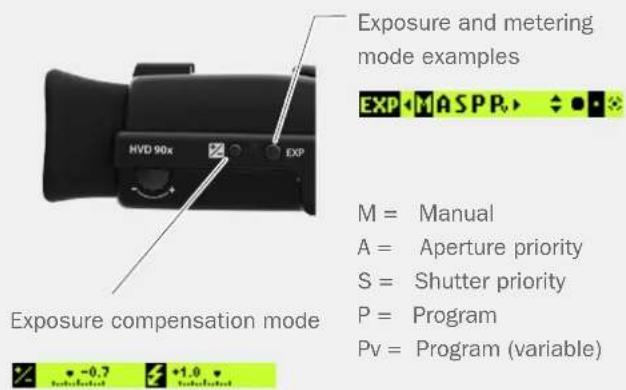
text_image
Exposure and metering mode examples EXP[Centre Weighted
Centre Spot
[•] Spot
To Use
USER GUIDE
VIEWFINDER DISPLAY EXAMPLES
Main Screen
This is the Main Screen of the Viewfinder Display. It shows the most important exposure information.
To the left the exposure mode is displayed, Manual Mode in this case. The scale with an arrow shows the exposure compensation setting. In the centre of the display the aperture and shutter speed are displayed. If an exposure compensation is set, a sign with a plus and minus is displayed between the aperture and shutter speed value. Second from the right the exposure counter is shown. To the far right the light meter mode is displayed, Spot meter mode in this case.
Menu Mode
Normally the Front and Rear Scroll Wheels are used to control aperture and shutter speed values. If you would like to use the wheels to navigate the menus of the Sensor Unit, first press the MENU button. Then the menu symbol is shown in the centre of the display to remind you that the camera is now in menu mode.
As long as the menu mode is active it is possible to use the wheels to navigate the menu system of the sensor unit. If you would like to leave the menu mode, and use the wheels for aperture and shutter speed, press the menu button again or half-press the shutter release button.
Browse
To reach Image Browse Mode, press the Browse (play) button on the right side of the Grip Display. Then the Browse Mode is activated and it is possible to Browse Images on the Sensor Unit using the wheels. To exit Browse Mode half-press or press the Browse button again.
ISO Settings
Press the ISO button to display the ISO Settings Menu. Use the Front or Rear Scroll Wheel to scroll left and right between available ISO numbers. Half-press or press the ISO button once again to leave the menu and save the new value.

Manual mode selected.

Menu symbol.

Browse Mode icon.

ISO settings, ISO 400 selected.
To Use
USER GUIDE
Exposure settings
Press the EXP button on the Viewfinder to display the Exposure Mode and Light Meter Mode menu.
Set the Exposure Mode using the Front Scroll Wheel and the Light Meter Mode using the Rear Scroll Wheel. Leave the Menu by half-pressing or by pressing the EXP button again.
Exposure compensation, adjust screen
Displays the Camera Exposure compensation to the left and the Flash Exposure compensation to the right.
Press the +/- button on the Viewfinder to reach the Exposure Adjust menu. Use the Front Scroll Wheel to set the Exposure Compensation for Flash and the Rear Scroll Wheel to set the Exposure Compensation. The Exposure Compensation can be set between -5.0 and 5.0 stops and the flash compensation between -3.0 and 3.0 stops. Leave the menu by half-press or by pressing the +/- button again.
White balance WB settings
Press the WB button above the Grip Display to show the WB Settings Display. Select WB mode by scrolling left or right with the Front Scroll Wheel. When in Manual (M) mode, use the Rear Scroll wheel to select Colour Temperature in Kelvin, K.
Return to the main screen by a half-press or press the WB button again.
White balance WB mode, Manual
To set the Colour Temperature manually, scroll the Front Scroll Wheel until "M" is displayed. Then the Colour Temperature value is displayed in the right upper part of the screen. Change the value by scrolling the Rear Scroll wheel up or down. It is possible to set values between 2000 K and 10000 K, in steps of hundred K. Leave the WB menu by half-pressing or by pressing the WB button again.

Front Scroll Wheel
Rear Scroll Wheel
Exposure settings, Manual mode selected.

Rear Scroll Wheel
Front Scroll Wheel
Exposure Settings, adjust screen.

White balance WB, Daylight selected.

White balance WB mode, Manual selected. Temperature in K can be adjusted with the Rear Scroll wheel.
To Use
USER GUIDE
Focus Settings
Press the AF button above the Grip Display to show the AF menu. Select AF mode by scrolling the Front or Rear Scroll Wheel until the desired mode is selected.

Focus Settings, AF-S selected.
AF with Macro 120mm
When the 120mm Macro Lens is used the AF menu displays an additional setting, Focus Range. It is possible to select one of the three modes below for Focus Range.
The first limits the AF to scan only the close-up range (less than 1 meter).
The second option scans only far away distances (between 1 meter and infinity).

Macro Autofocus settings, Close-up Scan.

Macro Autofocus settings, Far Away Scan.
The third option is to scan the full range. The Macro Lens has a large focus range and to limit the scan range can improve the AF performance significantly.

Macro Autofocus settings, Full Range Scan.
Information Screen
This is the Information Screen with Storage medium missing displayed.

Information Screen, Storage medium missing.
Frame Count
This is the Frame Count with more than 1000 frames left displayed. 1k9 = 1900 images left.

Frame Count, more than 1000. 1k9 = 1900.
To Use
USER GUIDE
5.34 REMOVE / ATTACH VIEWFINDER
REMOVE THE VIEWFINDER
Caution!
Be careful when you attach/detach the components to/from the camera. This will help prevent damage to the data bus connections.
Caution!
Use the grip or strap when you lift and handle to camera. This will help prevent damage to the camera.
1 Hold the Viewfinder in your right hand.
2 Press and hold down the Viewfinder release button (A).
3 Lift the rear of the Viewfinder up and away from the camera body.
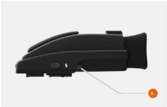
natural_image
Close-up of a black athletic device with labeled component A, showing handle and buttons (no text or symbols on body)ATTACH THE VIEWFINDER
Caution!
Be careful when you attach and remove the components to and from the camera. This will help prevent damage to the data bus connections.
Caution!
Use the grip or strap when you lift and handle to camera. This will help prevent damage to the camera.
1 Hold the Viewfinder at a slight angle and rest it on the top of the camera.
2 Slide the Viewfinder forward until the front locating pin is in position in the recess in the front edge of the viewfinder screen aperture (B) on camera body.
3 Press the rear part of the Viewfinder firmly downwards until it clicks into place.
4 Make sure that both sides of the Viewfinder are seated correctly and that it has been firmly attached and locked into position.
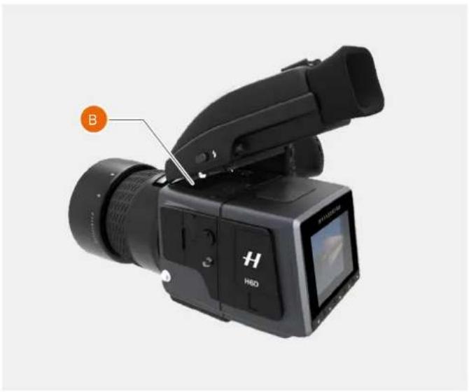
natural_image
Black HED video camera with external lens and screen, labeled B (no text or symbols on device body)To Use
USER GUIDE
ADJUST THE EYEPIECE
No corrective lenses are needed to adjust the eyepiece to suit most requirements. The dioptre range is from -5 to +3.5D. Eyeglass wearers can rapidly and accurately change the settings if they wish to wear eyeglasses for viewing or not.
1 Hold the camera in your left hand.
2 Point the camera at the sky or a similar smoothly toned area.
3 Turn the adjustment wheel (A) until the markings on the Viewfinder screen are sharp as possible for your eyesight.
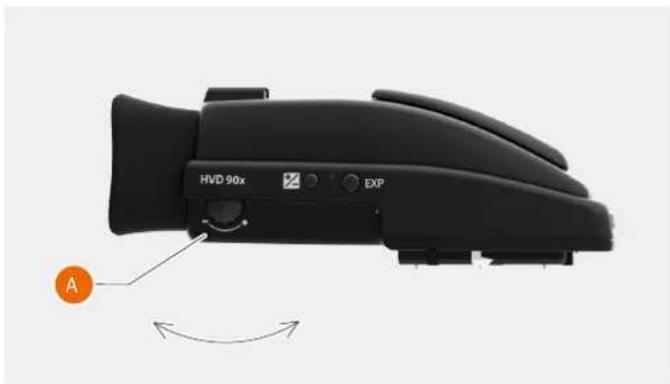
natural_image
Close-up of a black HVD 90x device with labeled control buttons and an orange circular indicator (no text or symbols on the device body)Note!
If you normally wear eyeglasses for distance viewing and intend to wear them for camera use then do not remove them for the above procedure. If, on the other hand, you prefer to remove your eyeglasses for camera work, then repeat the above procedure without wearing your eyeglasses.
To Use
USER GUIDE
CHANGE FOCUSING SCREEN
The H6D is fitted with a Spherical Acute Matte D Focusing Screen for extreme brightness, clarity and even illumination. An optional accessory screen with a grid pattern is also available.
To change the Focusing Screen, remove the viewfinder to access the Focusing Screen.
To remove the screen, place the tip of a ballpoint pen or similar in the Focusing Screen removal lug and pull upwards. To replace the Screen, position the right side of the Screen in place so that it sits correctly in the recess. Place the tip of a ballpoint pen or similar in the Focusing Screen replacement indentation and press downwards until the Screen snaps into position. Try to avoid touching either surface of the Screen with bare fingers.
Note!
Do not attempt to clean the Focusing Screen by immersing it in water.
Do not use any kind of cleaning fluid.
If the Screen becomes damp, do not use hot air to dry it.
Use a soft cloth on the upper surface only.
Seek advice from an Authorized Hasselblad Service Centre if the Screen becomes particularly soiled.
Remember that particles or greasy marks on the Screen might impair the viewfinder image but have no effect on the recorded image.
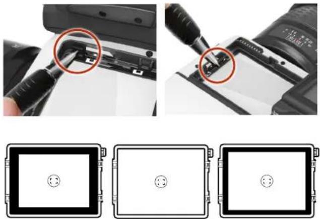
Focusing Screens showing the difference in masking and composition frame marking. Type varies according to sensor size. See under Accessories for other types (with grid pattern, for example).
To Use
USER GUIDE
5.35 PREVIEW, HISTOGRAM AND BROWSING
PREVIEW MODES
Use the Rear Scroll Wheel or the button marked with a rectangle to scroll through the available Preview Modes when in Browse Mode. You can also single tap on the bottom of the image to change Preview Mode.
- Standard Preview: Displays a Preview Image with the most important settings. Note that the information covers some of the image. Go to Full Screen mode to see the complete Capture area.
Full Screen Preview: Displays the preview only with no frame or settings information. - Capture Details Mode: Displays a Preview Image with camera settings details in a layer in front of the Preview Image.
- Combined Histogram: Displays a Preview Image with a combined histogram of the three components red, green and blue.
- Separate Histogram: Displays three separate histograms for red, green and blue.
- Luminance Histogram: Displays a Preview Image with a Luminance Histogram.
Note!
A single tap above the Meta Data toggles overlay information on and off.
Full Screen Preview
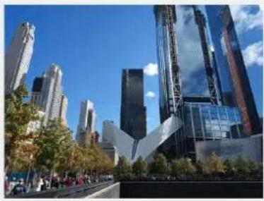
natural_image
Exterior view of a modern city skyline with skyscrapers and a distinctive tower under a clear blue sky (no signage or text visible)Capture Details Mode
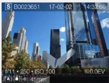
natural_image
City skyline with modern skyscrapers under a clear blue sky, captured in a fisheye lens (no text or symbols on the buildings themselves)Combined
Histogram
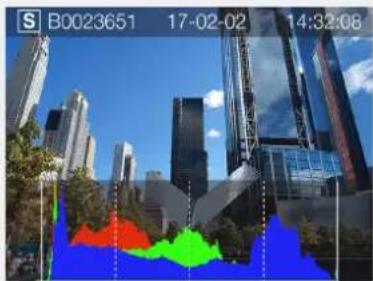
natural_image
City skyline with modern skyscrapers and a colorful abstract overlay (no readable text or symbols)Separate
Histogram
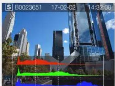
natural_image
City skyline with modern skyscrapers and green spaces, overlaid with a 3D color histogram (no readable text or symbols)Standard Preview
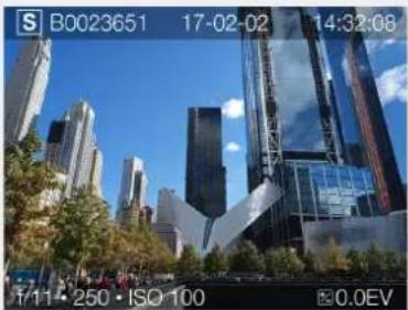
natural_image
Exterior view of a modern city skyline with skyscrapers and greenery under a clear blue sky (no signage)Luminance Histogram
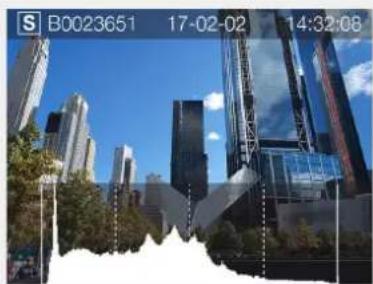
natural_image
Cityscape with modern skyscrapers and greenery under a clear blue sky (no visible text or symbols)To Use
USER GUIDE
STANDARD PREVIEW
The Standard Preview is displayed when you first turn the camera on and is probably the view you will use most often.
Displays a preview of your most recent capture and basic information about the settings.
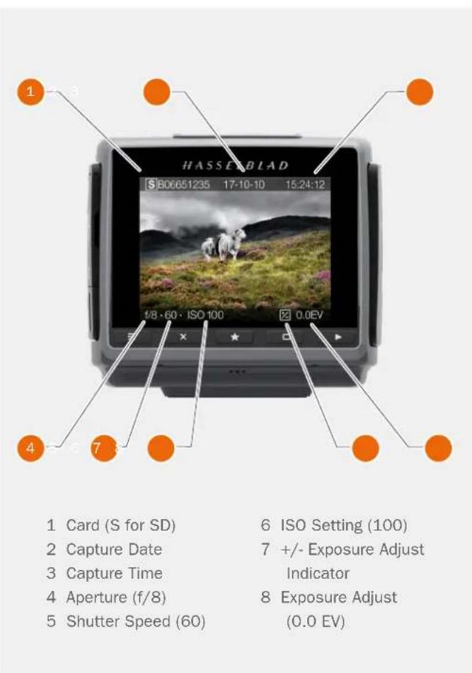
text_image
HASSEBLAD S:806651235 17:10-10 15:24:12 1/8 · 60 · ISO 100 0.0EV 2 Card (S for SD) 6 ISO Setting (100) 2 Capture Date 7 +/- Exposure Adjust 3 Capture Time Indicator 4 Aperture (f/8) 8 Exposure Adjust 5 Shutter Speed (60) (0.0 EV)9 VIEW MODE
How to display 9 View Mode
1 To display 9 View Mode, pinch with two fingers on the Touch Display, press the AE-L or the star marked button when in Browse Mode.
2 In this Mode you can see an overview of up to 9 captures.
3 If you have more than 9 captures, swipe down at the right side of the Display to scroll through all captures.
4 Select one capture to display information and histogram.
natural_image
Collage of nine scenic and agricultural landscapes featuring sheep, forests, and landscapes (no text or symbols)To Use
USER GUIDE
HISTOGRAM TYPES
There are different types of Histogram representations available. Histogram Mode, Capture Details Mode, Combined Histogram Mode and Separate Histogram RGB Mode.
HISTOGRAM MODE
Histogram mode displays RGB Histogram with separate RGB channels visible. The RGB details are stored with the capture file, and can be referred to in Phocus and other applications.
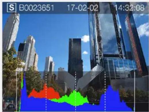
text_image
S B0023651 17-02-02 14:32:08SEPARATE HISTOGRAM RBG MODE
In Separate Histogram RGB Mode, the individual RBG channels are displayed. The Red R channel first, the Green G channel in the middle and the Blue B channel below the Red and Green channels.
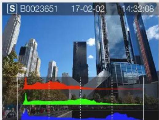
text_image
S B0023651 17-02-02 14:32:08LUMINANCE HISTOGRAM MODE
In Luminance Histogram mode, the RBG channels displays the luminosity Histogram. The RGB info is represented by a White Combined RGB Graph.
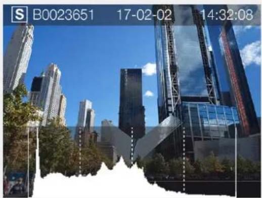
natural_image
Cityscape with modern skyscrapers under a clear blue sky, no visible text or symbolsCAPTURE DETAILS MODE
This mode displays SD Card (S), Date (17-02-02), Time (14:32:08), selected Aperture (f/11), Shutter Speed (1/250), ISO (100), Exposure adjustment (+/- 0.0), Exposure Mode (A), Meter Method (Centre Weighted), White Balance (Daylight) and Lens info (45mm).
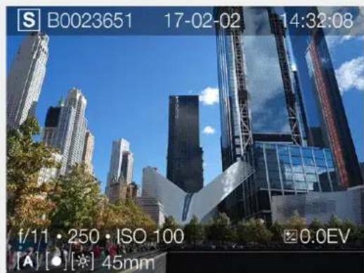
text_image
S B0023651 17-02-02 14:32:08 f/11 • 250 • ISO 100 0.0EV [A] [●][※] 45mmTo Use
USER GUIDE
HISTOGRAM MODE - EXPOSURE
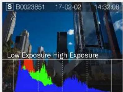
text_image
S B0023651 17-02-02 14:32:08 Low Exposure High ExposureUnderexposure Even exposure Overexposure
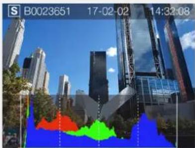
text_image
S B0023651 17-02-02 14:32:08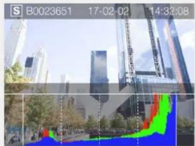
text_image
S B0023651 17-02-02 14:32:08Histogram Exposure
The Histogram provides a graph that indicates the total number of pixels at each brightness level, with brightness in range from black on the left to white on the right. It is a valuable tool for evaluating captures.
A well exposed shot usually has a full range of levels, while underexposed and overexposed Captures tend to show levels concentrated at the left or right part of the scale.
The histogram is only an indicator that should be interpreted. There are several situations in which a bad histogram will match an exposure that could be perfect for the intended effect.
Study the Histogram examples and the explanations below.
Underexposure
Histogram display concentrated on the left with few pixels elsewhere indicates a likely underexposure. Many details will be lost in the shadows.
Even exposure
Histogram display spread across the full range indicates a likely good exposure. There may still be a few pixels at the extremes, indicating a few spectral highlights and saturated shadows, but this is often normal in a good exposure.
Overexposure
Histogram display concentrated on the right with few pixels elsewhere indicates a likely overexposure. Many details will be lost in the highlights.
To Use
USER GUIDE
BROWSING
Browse mode shows the last image. The user can review images, browse and zoom. Use zoom in to view close-ups of images for focus checking. Zoom out to view several images at once.
Press Play button (B) on the Grip Display or on the Sensor Unit (G) to enter Browse mode.
In Browse mode swipe right or left on the Sensor Unit display to browse captures. You can also use the Front Scroll Wheel on the Grip (A).
Captures can be deleted with the Soft Button (D).
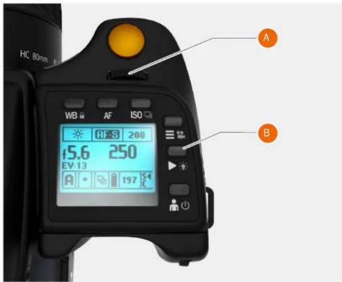
text_image
HC 80mm WB AF ISO 45.6 200 EV 13 A 250 197 A B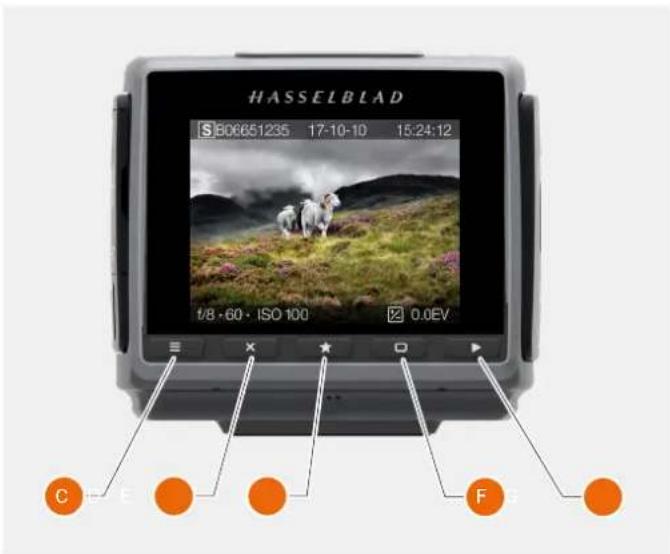
text_image
HASSELBLAD S:806651235 17-10-10 15:24:12 1/8 - 60 · ISO 100 0.0EV C E F GTo Use
USER GUIDE
ZOOM IN AND OUT
The Touch Screen on the H6D Sensor Unit is similar to a Phone or Tablet with touch sensitivity. The following gestures can be used to navigate and control the H6D Camera:
Function
Action
Zoom in Spread (move two fingers apart).
Zoom out Pinch (move two fingers together).
Select Tap / Press with one finger.
Move back Swipe right.
Display Control Screen Swipe down from the top of the screen.
Hide Control Screen Swipe up.
Action
Function
Double Tap Zoom in to 100%. Double Tap again to Zoom out to full View.
Swipe Right Move back / Move image right.
Swipe Left Move image left. Only in Browse mode.
Swipe Down Display Control Screen.
Swipe Up Hide Control Screen.
Tap / Press Select action / button / setting.
9 View Mode
9 View Mode displays an overview of up to 9 captures. Scroll down to display all Captures in the Folder. Press the star marked button under the Touch Display or Pinch with two fingers, to display 9 View Mode when browsing captures.
Folder View
Folder View displays the list of folders saved. The highlighted folder is the current folder and contains the images you are browsing. Navigate to another folder and then zoom in to reveal its contents if desired.
On the Touch Display when in 9 View Mode, select the "Folder Up" button (A) in the top left corner, or press the AE-L button when in Browse Mode.
Zoomed View
natural_image
Three sheep standing in a grassy field with purple flowers and distant mountains (no text or symbols visible)Standard Preview
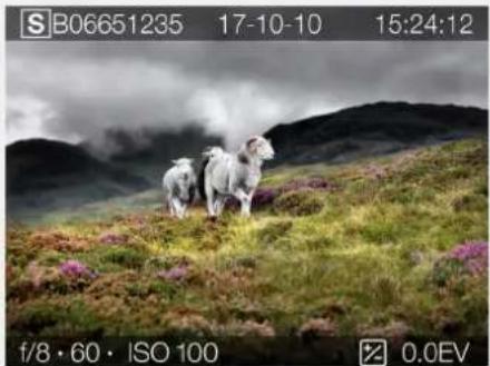
natural_image
Rats grazing on a grassy hillside with pink flowers, no visible text or symbols9 View Mode
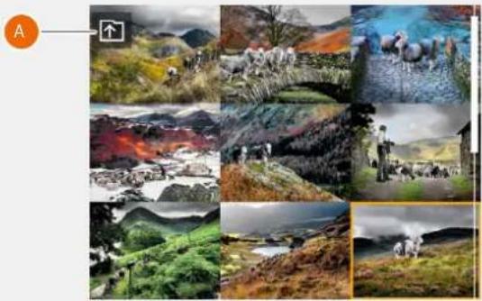
natural_image
Collage of nature and livestock scenes in various mountainous and rural settings, including forests, rivers, and fields (no text or symbols visible)Folder View
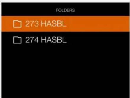
text_image
FOLDERS 273 HASBL 274 HASBLTo Use
USER GUIDE
SELECT CARD TO BROWSE
You can select SD 1 Card or SD 2 Card to Browse Captures.
To select which card to review, navigate up in the folder structure until you reach the "Select Card to Browse" dialog.
The folder structure is the following:
Memory Cards
Folders
9 images
1 image
It is possible to navigate to the card selection dialog either using touch or buttons and scroll-wheels.
By touch:
1 When viewing one image (1) Pinch inwards to go to the 9 images view (2).
2 In the 9 images view - Press the "Folder Up" button (A) in the top left corner to go to folders.
3 In the folders view - Press the "Folder Up" button in the top left corner to go to folder level above.
4 Select Card to Browse.
5 Select folder by clicking the folder name (332HASBL).
6 Select the image you want to view from the 9 images view.
7 The selected image is shown.
Or using buttons:
8 When viewing one image (1) - Press the AE-L button to go to the 9 images view (2).
9 Continue to press the AE-L button repeatedly to go up in folder structure.
10 Select Card to Browse using any of the scroll-wheels
11 Use the AF-D button to select card.
12 Repeatedly use scroll-wheels and AF-D button to select folder to review.
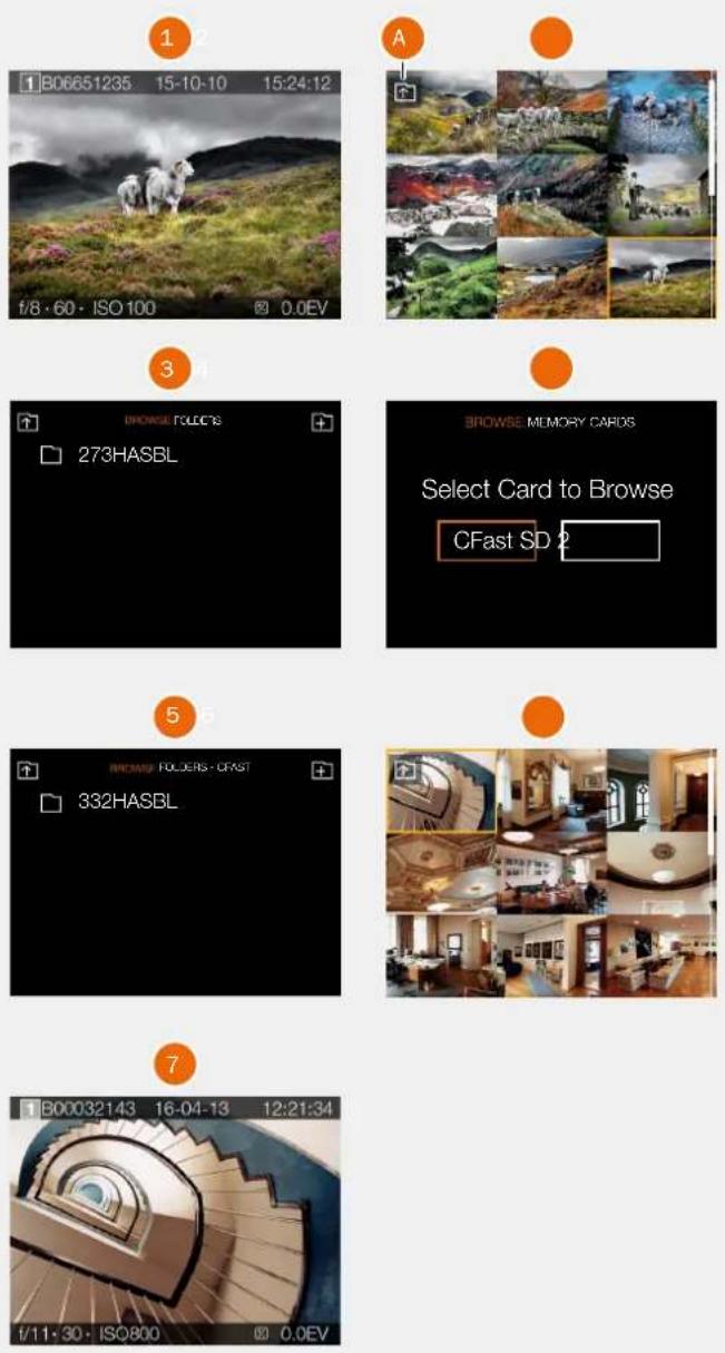
To Use
USER GUIDE
CREATE NEW FOLDER
It is possible to create a new folder on the currently active memory card. When a new folder is created, all new images will be stored in that folder. The folder name is auto-generated and cannot be changed. It is not possible to store images in previous folder.
By touch:
1 When viewing one image (A), pinch inwards to go to the 9 images view (C).
2 In the 9 images view - Press the "Folder Up" button (B) in the top left corner to go to folders.
3 In the folders view - Press the "Add folder" button (D) in the top right corner to create a new folder.
4 In the Create Folder dialogue (E), choose Create to create a new folder or Exit to skip.
Or using buttons:
1 When viewing one image (A) - press the AE-L button to go to the 9 images view (C).
2 Press the AE-L button again to view the folder structure.
3 Select the "Add folder" icon (D) in the top right corner using any of the scroll-wheels
4 Use the AF-D button to show the Create Folder dialogue (E).
5 In the dialogue, choose Create to create a new folder or Exit to skip.
When the new folder is created, the folder view (F) will show the new folder. To view images in the previous folder (332HASBL), proceed as described on the previous page. New images will automatically be stored in the new folder.
Note!
It is only possible to create a new folder on the currently active card. When browsing the other card, the "Add Folder" icon will not be available.
1-view
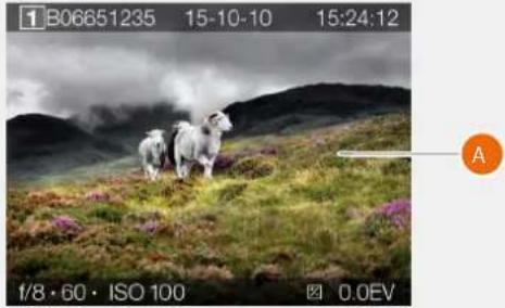
natural_image
Rural landscape photo with three sheep on a hillside, no visible text or symbols9-view
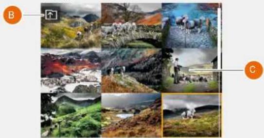
natural_image
Collage of ten landscape photos labeled B and C, showing various landscapes including mountains, forests, rivers, and people (no text or symbols in the images themselves)Folder view
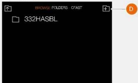
text_image
BROWSE FOLDERS CFAST 332HASBLCreate folder dialogue
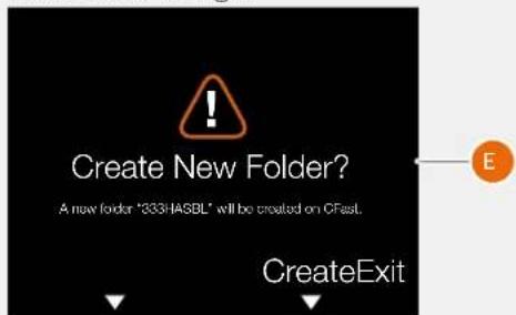
text_image
Create New Folder? A new folder "333 HASBL" will be created on CFast. CreateExitFolder view
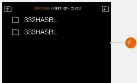
text_image
BROWSE FOLDERS - CFAST 332HASBL 333HASBLTo Use
USER GUIDE
5.36 PHOCUS
Phocus is the Capture Processing and File Management application aimed primarily at Hasselblad 3F file handling.
Phocus Mobile offers remote viewing and control when shooting tethered. Phocus mobile is free to download at the Apple App Store for both iPhone and iPad.
FEATURES IN PHOCUS
Professional Image Quality
• Hasselblad Natural Colour Solution (HNCS).
- Lens corrections for H and V system lenses (DAC).
Specialized Tools
• Advanced Tethered Camera Controls.
- Phocus Mobile*.
• Scene calibration & reproduction tools.
• Leading edge Moiré removal.
- Highlight recovery, shadow fill, clarity and dust spot removal tools.
• Capture Sequencer.
- Keystone correction.
• Support for Hasselblad video files
- Easy-to-use interface.
- Extensive customization options for individual workflow scenarios.
- Import/Export of Image Adjustments, Keywords, Workflow settings.
• High quality printing.
- Slideshow.
- Basic RAW file support from more than 150 DSLR cameras. (On Mac OS-X platforms only).
Ultimate Image Quality
Phocus combines Hasselblad Natural Colour Solution (HNCS) with Digital Auto Correction (DAC) to provide high digital image quality in the images you create. With Phocus, the moiré effect that can occur on even extremely high resolution images is effectively removed automatically and directly on the raw data, leaving the image quality intact and saves time in post production work. Tethered shooting is efficient with Phocus Remote camera controls providing a number of remote functions. For example remote focusing, live view, aperture and exposure time controls.
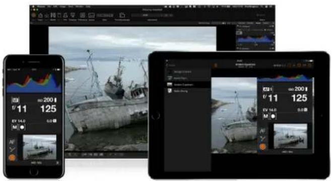
text_image
Screenshot of a photo editing software interface displaying three screens: a weather image, a grayscale photo of a fishing boat on water, and a tablet displaying camera settings.PHOCUS MOBILE
Phocus Mobile is available for iPhone ^® , iPad ^® and iPod Touch ^® . It enables you to connect wireless to a computer running Phocus and to remotely browse your high-resolution RAW, JPEG and TIFF images. This provides a solution for working with clients in the studio, enabling each person to view images on an individual iOS device, rather than all gathering around a single computer. Phocus Mobile also allows users to remotely operate and trigger a tethered camera, giving control of many parameters, all neatly presented in a virtual camera display. This feature is very convenient for remote control of the camera when it's located in a difficult to access position.
Any File from Anywhere
Phocus allows you to view image files and work in the same intuitive processing environment, no matter where your files are coming from. You can browse, handle, adjust, and process all kinds of RAW and non-RAW formats.
Phocus supports RAW files from more than 150 cameras (On Mac OS-X platforms only), including Canon, Nikon, Leica, Sony, Fuji, Olympus **.
The most common file formats can be processed for example TIFF, JPEG, DNG, and PNG. Some processing tools have no function on non-Hasselblad files.
* Phocus Mobile is available for free download in the Apple App Store.
** Full list available at http://www.apple.com/aperture/specs/raw.html
Note!
Phocus is a license free software with unlimited installations and there is no registration needed.
To Use
USER GUIDE
PHOCUS AND HASSELBLAD CAPTURE FILES
The H6D can capture files and store them as Hasselblad RAW format files or Hasselblad RAW + JPEG formats simultaneously.
Hasselblad RAW files are initially stored in the 3FR format which is a proprietary Hasselblad format for in-camera storage of captures. A 3FR file contains the complete digitized raw image exactly as it was captured by the camera. 3FR information requires further computing power (typically by way of Phocus) to obtain complete development. If developed in Phocus, 3FR files become Hasselblad 3F files – denoted by each file now bearing the suffix “.fff”. If developed by other RAW processors, the 3FR files are not converted to 3F but can be exported directly to TIFF, PSD according to requirements.
However, when working tethered – which necessitates using Phocus – 3FR files are automatically processed and stored in the background on a computer appearing as 3F files on the hard disk ready for selective adjustment and export. 3FR files stored on a Memory card can be processed to completion using:
• Hasselblad Phocus
- Adobe Camera Raw
- Adobe Lightroom
Apple Aperture
Capture files can be stored as 3FR files (from a CFast or SD card) for later processing in Phocus or other software, or they can be stored as 3F files (as a result of tethered shooting or 3FR files processed and converted in Phocus). In all cases if you keep the original 3FR/3F files, you will also retain the possibility of reprocessing them in the future in later versions of Phocus or other software to take advantage of eventual improvements and developments.
Mixed formats
Phocus can also process most other capture formats, generic and proprietary. This means you can include other formats in your normal Phocus workflow if you choose. Or if you prefer, you can include Hasselblad files in Adobe / Apple workflows as stated above.
Video file support
Phocus can process and export RAW video files from H6D-50c and 100c to Cinema DNG and Apple ProRes format for use in video editing software. Video files in MP4 format can also be previewed in Phocus.
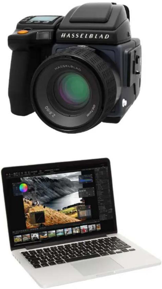
natural_image
Two technology devices: a black Hasselblad camera and a laptop displaying a photo editing interface (no text or symbols on the devices themselves)Note!
Using Phocus is the most comprehensive method and provides the highest image quality. The Phocus and Adobe methods can produce almost identical results (in most cases, but not all) regarding RAW conversion so it is a matter of personal choice regarding which method would best suit your preferred ways of working. Alternatively you can use Apple Aperture though the benefits of DAC and HNCS, will be lost in this case.
To Use
USER GUIDE
5.37 LENSES
REMOVE THE LENS
Caution!
Be careful when you attach/detach the components to/from the camera. This will help prevent damage to the data bus connections.
Caution!
Do not insert fingers into the camera body. This can cause damage to the equipment.
1 Hold the lens with one hand and hold the camera body (A) still.
2 Push the lens removal button (B).
3 Rotate the lens counter-clockwise.
4 Push the lens (C) away from the camera body.
5 Attach the protection cover lid (D) on the camera body directly.
6 Attach a lens protection lid on the detached lens to prevent damage.
7 Store the lens with both lens protection lids on and the lens hood (E) inverted over the lens instead of in front of the lens.
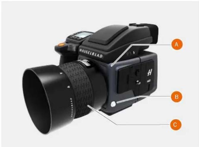
text_image
HASSELBLAD A B C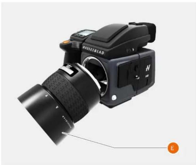
natural_image
Black Hasselblad DSLR camera with lens and external adjustment knobs, shown from front and side (no text or symbols on device body)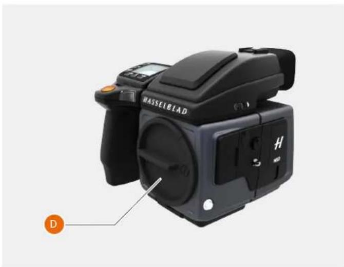
natural_image
Black Maselblad camera with labeled buttons and a D button, shown without any text or symbols on the device itself.To Use
USER GUIDE
ATTACH THE LENS
Caution!
Be careful when you attach/detach the components to/from the camera. This will help prevent damage to the data bus connections.
Caution!
Do not insert fingers into the camera body. This can cause damage to the equipment.
1 Push the lens removal button (A) and remove protection cover lid (B) from the camera body.
2 Rotate the lens so that the red mark on the lens (C) lines up with the red mark (D) on the camera body.
3 Mount the lens into the camera body (E) and then turn the lens clockwise to lock its position.
4 Make sure the lens is locked to the camera body before using or moving the camera.
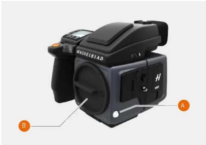
natural_image
Black NASSEBIAD camera with labeled parts A and B, shown from front and side (no text or symbols on body)
natural_image
Black Hasselblad camera with labeled parts (C, D), no visible text or symbols on body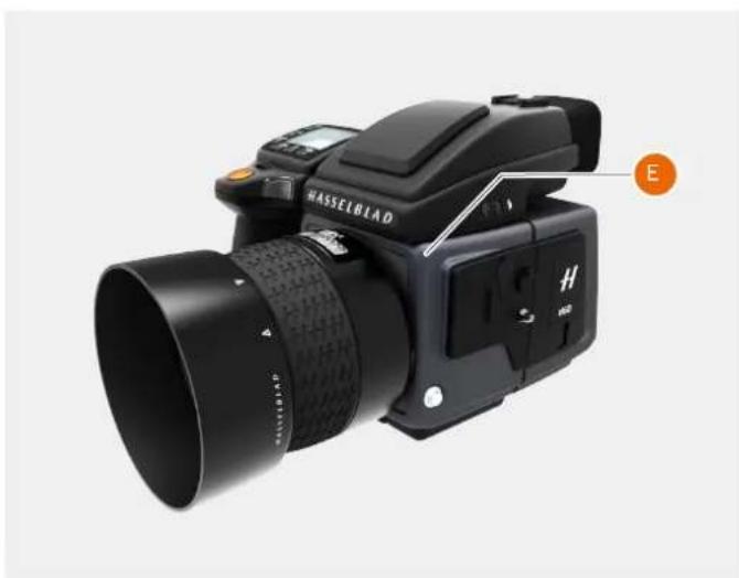
natural_image
Black Hasselblad DSLR camera with lens and control panel, no visible text or symbols on bodyTo Use
USER GUIDE
REMOVE THE LENS CAP
1 Insert thumb and index finger into the recesses (A).
2 Pinch the recesses (A) together.
3 Remove the front lens cap.
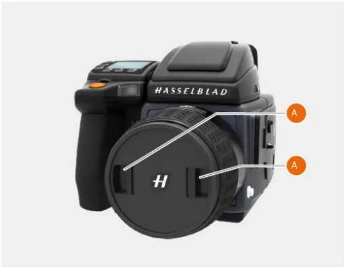
text_image
HASSELBLAD A H AATTACH THE LENS CAP
1 Insert thumb and index finger into the recesses (A).
2 Attach the front lens cap on the lens until it snaps into place.
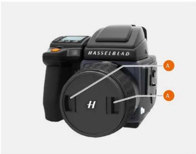
text_image
HASSELBLAD A H ATo Use
USER GUIDE
REMOVE THE LENS SHADE
All lenses are supplied with lens shades that additionally provides extra protection for transport and storage when mounted in reverse.
1 Turn the lens shade (A) counter-clockwise.
2 Remove the lens shade (A).
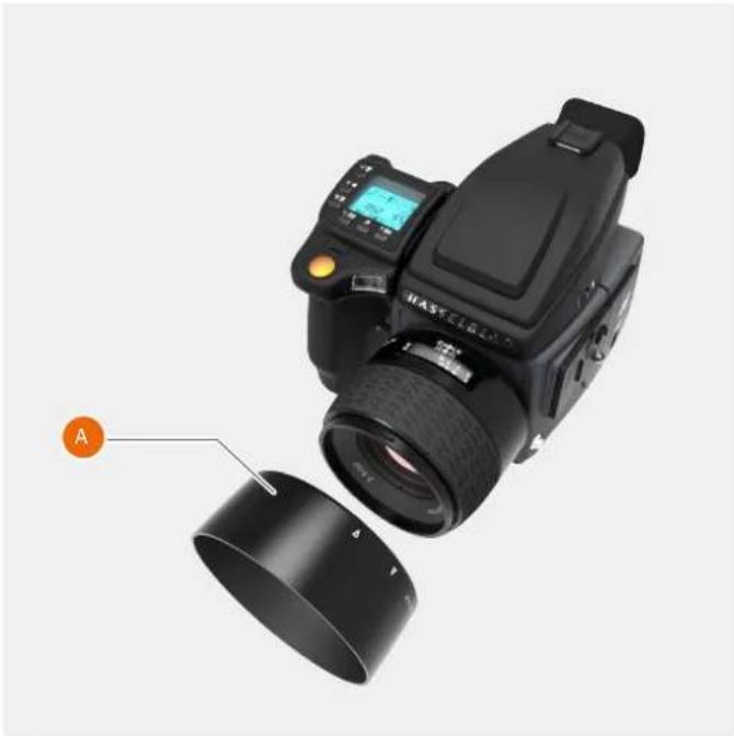
natural_image
Black HASSFELIX DSLR camera with lens and external lens assembly (no visible text or symbols)ATTACH THE LENS SHADE
All lenses are supplied with lens shades that additionally provides extra protection for transport and storage when mounted in reverse.
1 Place the lens shade on the lens.
2 Make sure that the index on the lens shade (A) aligns with the index on the front of the lens (B).
3 Turn the lens cap clockwise until it snaps into place.
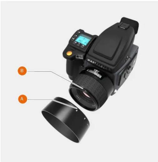
text_image
B ATo Use
USER GUIDE
FILTERS
The filters have a threaded fitting (67/77/95 mm, according to lens) and are rotated clockwise into place.
As there is no rotation of the front section of the lens when the focus is changed, the filter do not rotate either.
This is particularly useful when using polarizing or graduated filters where the orientation is critical.
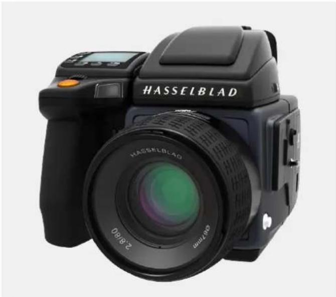
natural_image
Black Hasselblad camera with lens and control panel (no visible text or symbols on body)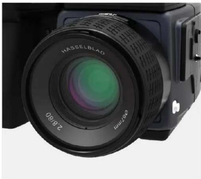
natural_image
Close-up of a black Hasselblad camera with lens and aperture (no visible text or symbols beyond brand name)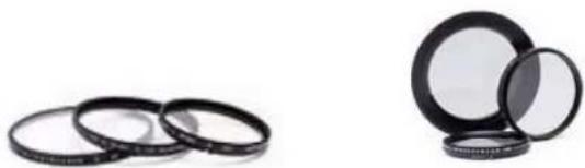
natural_image
Two black circular objects with reflective surfaces, one stacked and one partially filled (no text or symbols visible)To Use
USER GUIDE
TO SET FOCUS DISTANCE
1 Estimate the distance to the target.
2 Inspect the focus distance scale (A) and turn the manual focus ring (B) to adjust the focus distance.
Note!
There are two distance scales (in feet and metres) visible through the window on the upper part of the lens barrel.
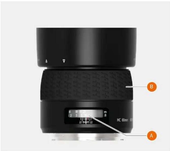
text_image
6 10 mm [2] 3.5 mm 22 14 47 22 A B HC 80mm
text_image
6 10 15 25 6 2 3 5 10 m ft 22 14 411 22 HC ATo Use
USER GUIDE
5.38 BATTERY
CHARGE THE BATTERY
Note!
The battery will become fully charged after approximately 6 hours before first use.
1 Remove the battery (A) from the camera.
2 Insert the jack plug from the battery charger into the socket on the battery grip (B).
3 Insert the battery charger into a standard (100–240V\~/50–60 Hz) domestic socket.
During the charging procedure, the lamp on the charger shows the following:
Standby (no battery connected).
Charging.
Ready.
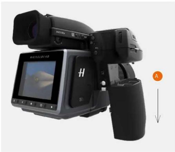
natural_image
Black Hasselbead camera with LCD screen and external camera, no visible text or symbols on device body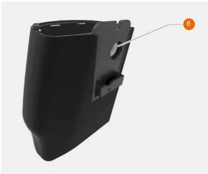
natural_image
3D model of a black plastic enclosure with mounting bracket and label B pointing to a feature (no text or symbols on the object itself)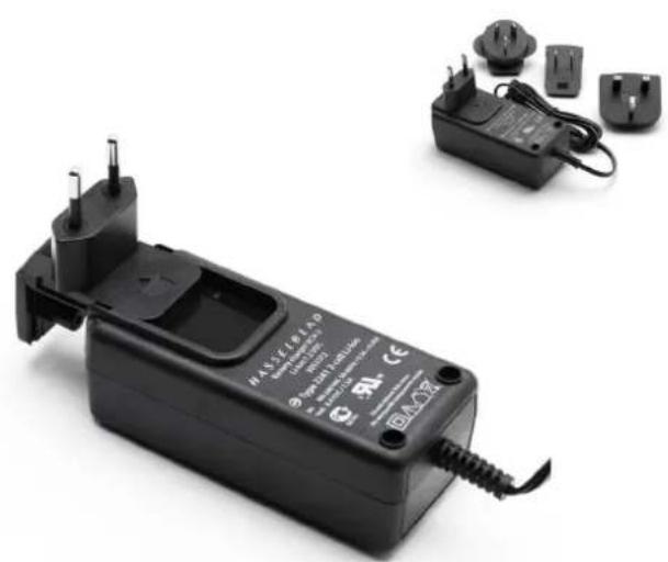
natural_image
Black handheld electrical device with terminal connectors and a small charging plug (no visible text or symbols)To Use
USER GUIDE
CHECK THE BATTERY STATUS
Battery status is indicated on both display and on grip display as a small battery icon. The fill level is a visual indication of charge level. When the remaining capacity is 25-30%, the fill changes color to red. The battery should be replaced with a freshly charged as soon as possible.
Note!
Remember that these are only estimates and that there are a number of factors affecting remaining battery charge, ambient temperature for example, as well as general practice.
Note!
You can save battery consumption by changing the Display Off/Sleep/Power Off settings as well as the brightness settings of the display.
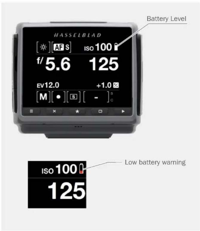
text_image
HASSELBLAD [★][AF S] ISO 100 f/5.6 125 EV12.0 +1.0 [M][●][S][-]s Low battery warning ISO 100 125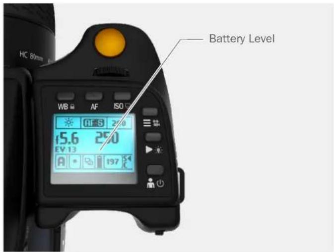
text_image
Battery Level WB AF ISO 15.6 250 EV 13 A 197To Use
USER GUIDE
5.39 PROTECTIVE BASEPLATE
REMOVE THE PROTECTIVE BASEPLATE
1 Lift the securing catch while pushing the Protective Base Plate (A) towards the lens.
Note!
Some larger lenses will require to remove the lens before the baseplate can be removed.
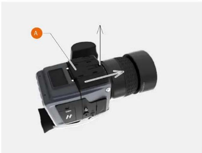
natural_image
Close-up of a DSLR camera with labeled component A and directional arrows (no text or symbols beyond labels)ATTACH THE PROTECTIVE BASEPLATE
1 Slip the Protective Base Plate (A) over the camera foot until it stops and the securing catch snaps into place.
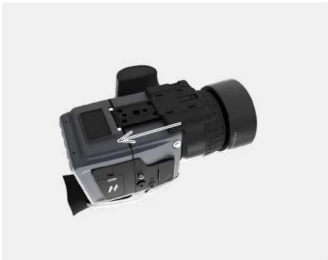
natural_image
Close-up of a black DSLR camera with lens and control buttons (no visible text or symbols)To Use
USER GUIDE
5.40 STORE THE CAMERA
Caution!
If you leave the camera unused for a long period, remove the battery. This will prevent damage to the equipment.
Caution!
Keep camera and equipment away from moisture. If your camera becomes wet, disconnect from electric power and let camera dry before further use. This will help prevent damage to the equipment.
Caution!
Store the equipment in a dry environment. This will help prevent damage to the equipment.
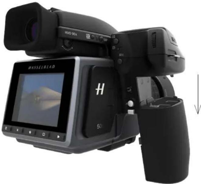
natural_image
Black HVR 90X digital camera with a screen displaying a landscape image, no visible text or symbols on the device itself.Remove battery from Camera Grip when storing the Camera.
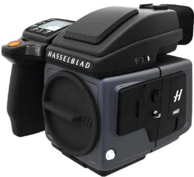
natural_image
Black HASSELBLAD digital camera with external lens and control buttons (no visible text beyond brand name)Attach the Protection Cover Lid when the Camera is not in use.
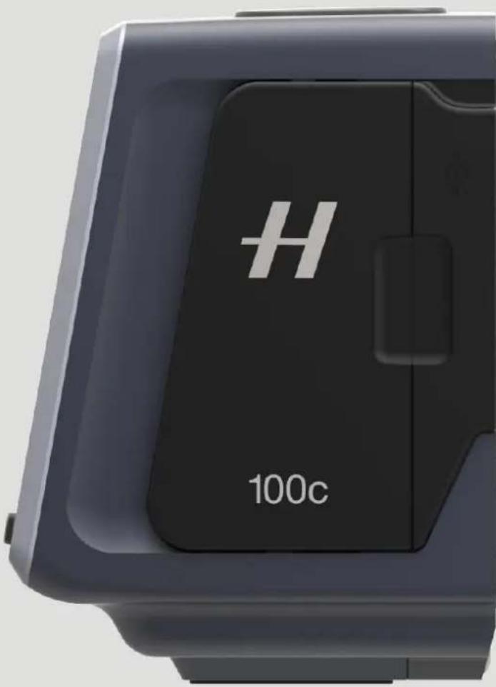
text_image
H 100cView Camera Connectivity
USER GUIDE
The Sensor Unit of the H6D camera can be detached and used on other types of cameras, e.g. View Cameras, with an H System magazine interface. This will enable the use of additional functionality such as extended Tilt and Shift using lenses with large image circle.
The current firmware of the H6D camera enables the following modes of operation:
1 Flash Sync Mode
2 Pinhole Mode
For more detailed information about Technical Camera use, please see the separate document TCC, "Technical Camera Options" available for download from www.hasselblad.com.
POWER SOLUTION
When the Sensor Unit is detached from the H6D camera body, external power will have to be provided to the DC input (A). The input voltage range is 12 to 24 VDC.
A good external power solution is a Laptop Powerbank. This has normally an adjustable output voltage and sufficient power for extended use. One model that has been tested and qualified to work is the "XT-20000QC2 Power Bank" from XTPower. See "https://www.xtpower.de".
Hasselblad will on request and free of charge supply a DC Cable between the Power Bank and the Camera (Item number 3054180). Please contact your dealer.
An alternative power source for US customers is the "GBTIGER 50000mAh Power Bank" (model: B01N1SHRB1) available from Amazon.com. If using the supplied cables and tips an additional 3.5mm x 1.35mm male plug to 5.5mm x 2.1mm female socket DC power cable will be required.
Note!
When using power banks other than the XT-20000QC2, please make sure that the minimum output power before automatic shut-off is equal to or lower than 2.5W. A higher value can turn off the battery when the camera goes to standby mode.
Note!
If power from USB is activated, an external power source like the above is still required as USB cannot supply full power for the camera.
Power Connection
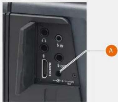
text_image
H30TM $ IN $ CL - → $ 2000 UNExternal Power solutions
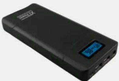
natural_image
Black rectangular electronic device with a blue LCD display and 'BPG' logo, no visible text or symbols on the body.XT-20000QC2
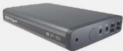
natural_image
Exterior view of a black electronic device labeled 'Ginger' with ports and buttons (no readable text beyond branding)GBTIGER 50000mAh
View Camera Connectivity
USER GUIDE
FLASH SYNC MODE
Camera: A View Camera with an H System magazine interface that is fitted with mechanical shutter lens.
Procedure:
1 Detach the Sensor Unit from the H6D camera body. Be careful not to damage the IR filter in front of the sensor.
2 Attach the Sensor Unit to the View Camera. Follow instructions from the manufacturer.
3 Connect the supplied Flash Sync input cable between the flash sync port of the lens and the flash sync input (A) on the Sensor Unit.
4 Connect external power to the DC input socket (B). The Sensor Unit will automatically start.
5 From the Camera Menu, select Camera Body. In the pop-up, select "Flash Sync". Press Menu button or tap outside pop-up to save and close.
6 When the LED on the Sensor Unit is green, the Sensor Unit is ready for a capture. If it is orange, click any of the buttons below the display to activate the Sensor Unit before capture.
7 Exposure parameters (Aperture and Shutter Speed) are set on the lens and cannot be set on the Sensor Unit.
Control Screen
In Flash Sync Mode, the Control Screen has fewer items than when used on an H camera. From this screen you can change:
White Balance
ISO
• Exposure Mode (Manual or Video)
You can also start Live View by tapping the "LV" icon (C). Note that the lens must be open for Live View.
Camera Body Settings Menu
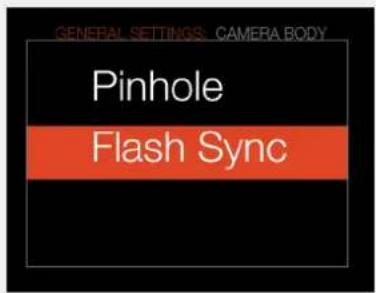
text_image
GENERAL SETTINGS: CAMERA BODY Pinhole Flash SyncFlash Sync and Power Connections
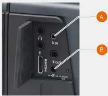
text_image
A BControl Screen in Flash Sync mode
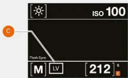
text_image
[Sun] ISO 100 C Flash Sync [M] LV [212] sFlash Sync Connection
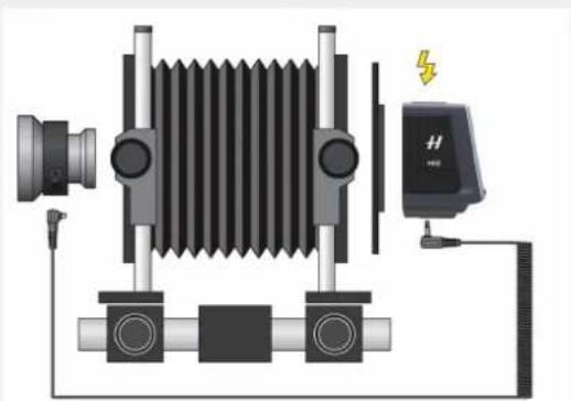
natural_image
Technical diagram of a mechanical device with spring-loaded housing and connected to a power outlet (no text or symbols)View Camera Connectivity
USER GUIDE
PINHOLE MODE
Pinhole mode can be used when the optical system does not have a flash sync terminal.
Procedure:
1 Detach the Sensor Unit from the H6D camera body. Be careful not to damage the IR filter in front of the sensor.
2 Attach the Sensor Unit to the Camera. Follow instructions from the manufacturer.
3 Connect external power to the DC input socket (A). The Sensor Unit will automatically start.
4 From the Camera Menu, select Camera Body. In the pop-up, select "Pinhole". Press Menu button or tap outside pop-up to save and close.
5 Exposure time is set on the Control Screen.
Control Screen
In Pinhole Mode, the Control Screen has fewer items than when used on an H camera. From this screen you can change:
White Balance
ISO
- Exposure Time
• Exposure Mode (Manual or Video)
An exposure is triggered by pressing the orange button (B). It can be made both from the Control Screen and from the Live View screen.
You can also activate Live View by tapping the "LV" icon (C). When Live View is active, an orange exposure button is shown.
Note!
The button in Live View can be dragged to any location by pressing and holding.
Camera Body Settings Menu
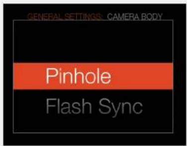
text_image
GENERAL SETTINGS: CAMERA BODY Pinhole Flash SyncPower Connection
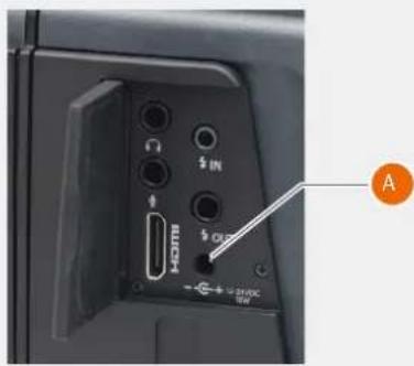
text_image
HOTM $ IN $ ON - + - 20%DC TWControl Screen in Flash Sync mode
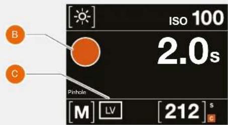
text_image
B C Pinhole M LV [212] s ISO 100 2.0sLive View in Pinhole mode
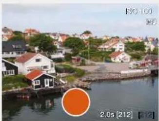
natural_image
Rural riverside scene with houses, boats, and a highlighted orange circle (no readable text or symbols)View Camera Connectivity
USER GUIDE
VIDEO
Video can be recorded onto the storage media in the Sensor Unit when attached to the View Camera. Follow the procedure below.
1 Open the Control Screen by swiping down from the top on the Main Menu screen.
2 Tap the Exposure Mode and tap the "V" icon to activate Video Mode.
3 From the Control Screen you can change:
- White Balance
- ISO
- Shutter Speed (1/30 to 1/8000)
- Exposure mode
4 Make sure that the lens is open.
5 To start Video Live View, tap the icon (A).
6 In Video Live View you can set Shutter Speed by pressing the corresponding buttons under "-" and "+".
7 Double tap the screen to zoom in to 50% or 100% (depending on setting) for critical focusing.
8 Start video recording by tapping the button (B).
9 Stop video recording by tapping the button (C).
Exposure Mode selection
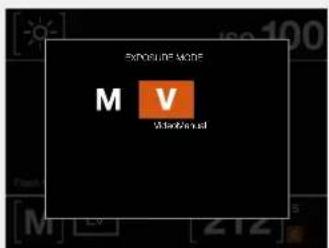
text_image
EXPOUSE MORE M V M 212Control Screen in Flash Sync/Pinhole Mode
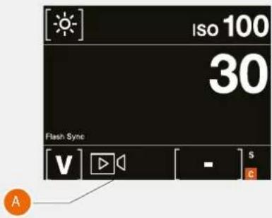
text_image
ISO 100 30 Flash Sync V - s AVideo Live View
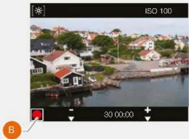
natural_image
Scenic coastal view of a residential area with houses and greenery, no visible text or symbolsVideo recording
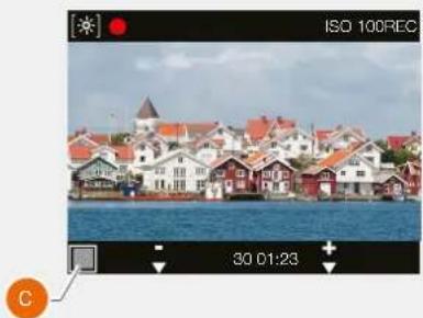
natural_image
Scenic view of a riverside town with colorful houses and red roofs, captured at 30:01:23 (no text or symbols on the scene itself)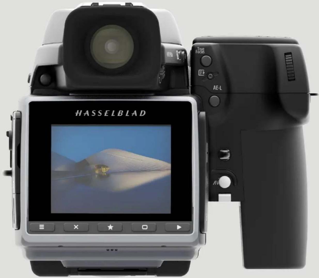
text_image
HASSELBLAD True Focus AE-LAccessories
USER GUIDE
7.1 ACCESSORIES CONNECTIVITY DIAGRAM
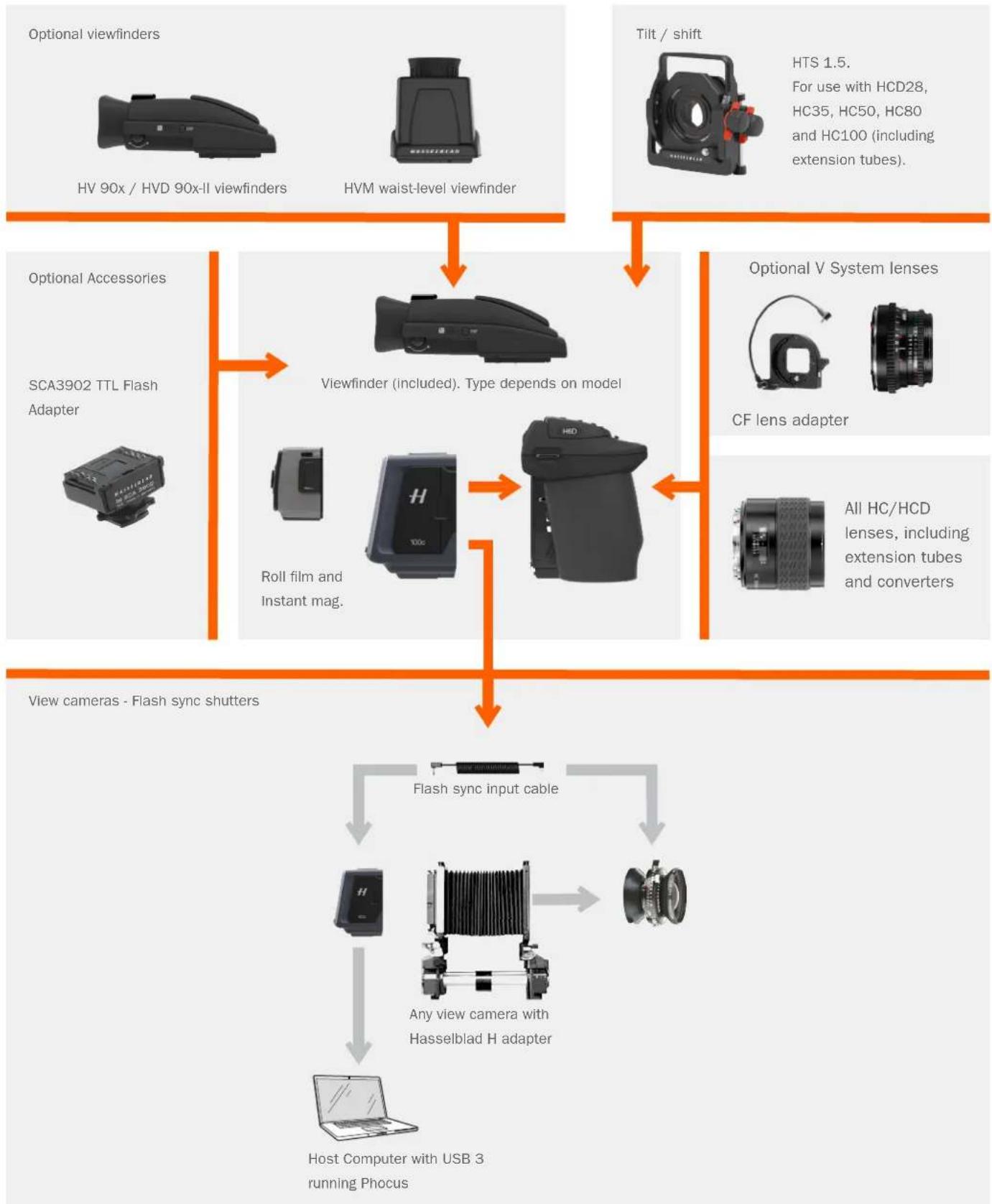
flowchart
graph TD
    A["Optional viewfinders"] --> B["HV 90x / HVD 90x-II viewfinders"]
    C["Tilt / shift"] --> D["HVM waist-level viewfinder"]
    E["Optional Accessories"] --> F["Viewfinder (included). Type depends on model"]
    G["Optional V System lenses"] --> H["CF lens adapter"]
    I["Roll film and Instant mag."] --> J["Flash sync input cable"]
    K["All HC/HCD lenses, including extension tubes and converters"] --> L["Any view camera with Hasselblad H adapter"]
    M["Host Computer with USB 3 running Phocus"] --> N["Flash sync input cable"]
    B --> J
    D --> J
    F --> J
    H --> J
    L --> J
    N --> J
Accessories
USER GUIDE
7.2 HC LENS RANGE
HCD 4.8/24mm
HCD 4/28mm
HC 3.5/35mm
HC 3.5/50-11mm
HC 2.8/80mm
HC 2.2/100mm
natural_image
Close-up of a black and textured optical lens (no visible text or symbols)HC Macro 4/120-11mm
HC 3.2/150mm
natural_image
Close-up of a black mechanical lens with no visible text or symbols on the body (pure branding)HC 4/210mm

natural_image
Close-up of a black optical lens with adjustable focal length and aperture (no visible text or symbols)HC 4.5/300mm
natural_image
Close-up of a black and gray compact lens with visible texture and control knobs (no text or symbols)HC 3.5-4.5/50-110mm
natural_image
Close-up of a black compact lens with visible texture and focal bands (no text or symbols)HCD 4.0-5.6/35-90mm
Accessories
USER GUIDE
7.3 OPTIONAL HC LENS ACCESSORIES
HTS 1.5
(3043400)
The HTS 1.5 is a tilt and shift adapter designed for the HCD24mm, HCD28mm, HC35mm, HC50mm, HC80mm and the HC100mm lenses. It not only solves technical challenges but also provides exciting opportunities for creative solutions.
H 13, 26 AND 52 EXTENSION TUBES
(3053513, 3053526 and 3053542)
The Extension tubes attach between the lens and the body to reduce the close focusing distance for close up photography. They are available in three sizes: 13 mm, 26 mm and 52 mm. As the H6D has a TTL light metering system, exposure compensation is automatic.
CONVERTER H 1.7X
(3023717)
The Converter attaches between the lens and the body to increase the focal length by a factor of 1.7. This provides a convenient way to expand your range of lenses. The Converter H 1.7 X features the same outstanding optical and mechanical quality as all the lenses in the Hasselblad H system. The optical design consists of 6 elements in 4 groups.
COMPATIBILITY
The converter 1.7x can be combined with all HC lenses except for the following: · HCD 4.8/24mm · HCD 4/28mm · HC 3.5/35 mm · HC 3.5-4.5/50-110 mm · HCD 4-5.6/35-90 mm When the H1.7X converter is used together with the HC Macro 120 mm or the HC300 mm lens, the autofocus function of the camera is disabled.
MACRO CONVERTER H
(5023720)
The Macro Converter is designed to improve the close range performance of wide angle H system lenses. Although primarily aimed for use in conjunction with the HC 50-II lens for optimum performance, it can also be used with any of the other H system wide angle lenses.
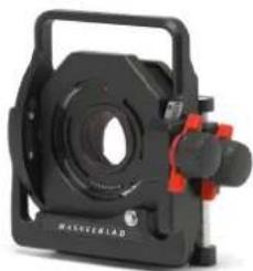
natural_image
Black masterlead camera module with red adjustment knobs and a circular lens (no text or symbols visible)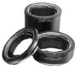
natural_image
Three black cylindrical mechanical components with flanges, no visible text or symbols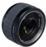
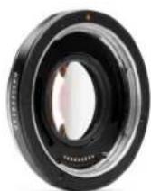
Accessories
USER GUIDE
7.4 OPTIONAL ACCESSORIES
CF LENS ADAPTER
(3043500)
The CF Lens Adapter allows the use of most V System lenses on the H6D camera. All settings are fully manual and the adapter features a lever for cocking the lens. Requires firmware 1.19.0 or later. Please download the latest User Manual for the CF Lens Adapter before use.
HVM WAIST LEVEL VIEWFINDER
(3053328)
The HVM waist level viewfinder allows a comfortable lower viewing angle either for effect or where eye contact with the subject is desirable in portrait photography, for example. Autofocus function of all lenses fully retained. Intended for horizontal format shooting and not suitable for vertical format use.
An adjustable bellows lens shade that provides highly efficient protection against stray light. Its compact, flat folding design saves space in the equipment case. With adapters it fits all HC lenses and virtually all V system lenses. Also features a filter holder for glass, gelatin, or plastic filters.
PRO SHADE ADAPTERS
(3043415, 3043417, 3043419)
67mm, 77mm and 95mm adapters with bayonet mount for HC lenses. Features lock to provide positive and secure attachment.
TRIPOD QUICK COUPLING H
(3043326)
Mounted on a tripod, this accessory facilitates rapid attachment and removal of the camera. The camera is firmly held in an exact and repeatable position. Two integrated spirit levels make horizontal positioning of the camera easy. The Tripod quick coupling H fits 1/4" and 3/8" tripod threads and has a safety catch.
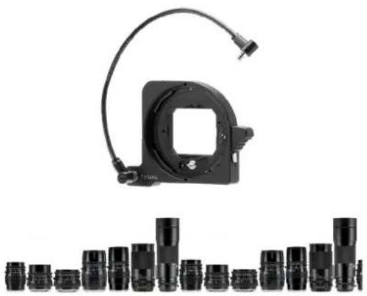
natural_image
Product display showing a black mechanical component with attached cable and multiple camera lens modules below (no text or symbols visible)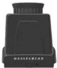
natural_image
Black plastic object with 'HASSELBID' label, no other text or symbols visible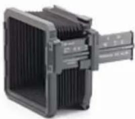
natural_image
Exterior view of a black rectangular electronic device with ventilation grilles and a gray handle (no visible text or symbols)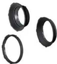
natural_image
Three black plastic ring components arranged on a white background (no text or symbols visible)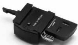
natural_image
Close-up of a black plastic electrical connector with a metallic clip and cable (no visible text or symbols)Accessories
USER GUIDE
FLASH ADAPTER SCA 3902
(3053393)
For connecting flashes compatible with the SCA 3002 system to the Hasselblad H6D.
UV-SKY FILTERS
Absorbs UV radiation and reduces blue haze without affecting colours. Also protects the front lens surface. Particularly recommended when the camera is used in harsh conditions.
Available in three sizes to suit various lenses.
67mm: 3053470, 77mm: 3053474 and 95mm: 3053478
POLA FILTERS
Reduces non-specular reflections and glare. Increases colour saturation in general. Can intensify a blue sky. Available in three sizes.
67mm: 3053482, 77mm: 3053486 and 95mm: 3053490.
SUPPORT STRAP WITH QUICK PLATE H
(3045154)
Improves comfort and security with hand held photography.
Complete with quick plate H.
CAMERA STRAP H
(3053616)
Extra wide camera strap with anti slip backing. Supplied with the camera.
FOCUSING SCREENS
All focusing screens are of the Spherical Acute-Matte D type with or without grid and central markings for spot (∅ 7.5 and AF metering area. Grid patterns provide aid in technical, architectural, documentation and other similar fields.
H6D-50c (3043336), H6D-50c Grid (3043338)
H6D-100c (3043332), H6D-100c Grid (3043334)
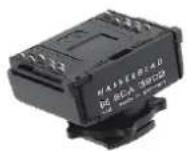
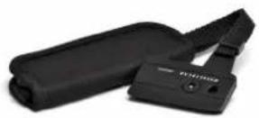
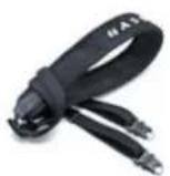
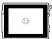
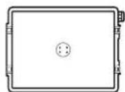
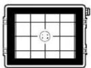
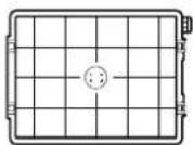
Accessories
USER GUIDE
RELEASE CORD H
(3043370)
Remote release cord with a cable length of 0.5 m.
HVM CORRECTION LENS HOLDER
(3053348)
Lens holder for custom made eyesight correction (lenses available from opticians). To be used for optimal viewing comfort and accuracy.
HVD 90X / HV 90X & 90X-II VIEWFINDERS
(3053330, 3053326, 3053334)
90 degrees reflex viewfinder, providing 100% field of view even when wearing eyeglasses. Includes built-in fill flash and multi-mode light metering system.
ANGLE FINDER H
(S100A12359A00)
Angle finder for the HV 90x and the HVD 90x viewfinders.
Enables vertical viewing angle regardless of camera position.
Requires a minor modification to the viewfinder eyepiece.
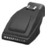
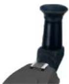
Accessories
USER GUIDE
7.5 HM 16-32 FILM MAGAZINE
The Hasselblad HM 16-32 film magazine is a sophisticated semi-independent unit within the H system. It has its own power supply for individual information storage, LCD panel, illumination, etc. It features: automatic 120/220 compatibility, automatic wind on/wind off, automatic film advance, LCD information panel, integral dark slide, customizable data imprinting, illuminated LCD, bar code recognition, count-up or countdown film frame reminder choice and multi shot option.
Parts and components
1 LCD panel
2 LCD illumination button
3 Change up button
4 Change down button
5 Function selector
6 Film plane index
7 Dark slide key
8 Dark slide indicator
9 Film tab holder
10 Film holder key
11 Magazine settings lock
12 Data bus interface
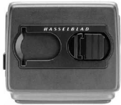
natural_image
Close-up of a black rectangular electronic device casing with a central plastic housing and 'HASSEIBLAD' branding (no readable text beyond label)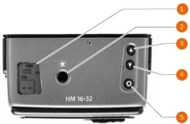
text_image
1 2 3 4 5 HM 16·32Note!
The film magazine is discontinued and can no longer be ordered.
Note!
Information is transmitted and received between the Magazine and the camera body, so ensure the data bus connection is kept clean and not damaged in any way. It is advisable to fit the magazine protective cover when storing a film magazine to protect both the data bus connection and the dark slide.
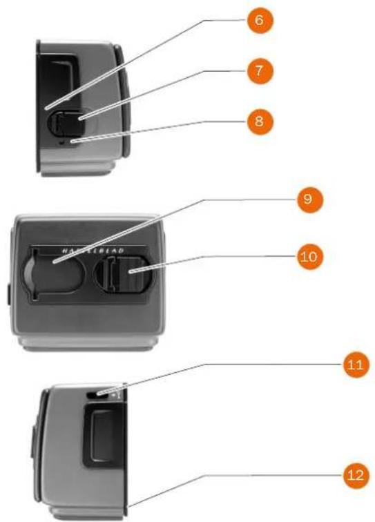
text_image
6 7 8 9 10 11 12Accessories
USER GUIDE
LCD Panel
The various functions are accessed by repeatedly pressing the function selector button (loop menu) and changes made by the 'change-up' and 'change-down' buttons. Any settings are automatically saved. At very low temperatures the LCD will require a few seconds to display new settings.
LCD illumination button
The LCD can be illuminated by pressing the display illumination button, which is accessible when the magazine is not attached to the camera. The LCD will remain illuminated all the time you keep the button depressed, up to a maximum of 10 seconds. After 10 seconds has expired, you must release the pressure on the button and press again to obtain a further 10 second period of illumination. Remember that using the illumination function very often will noticeably shorten the life of the battery in the magazine. When the magazine is attached to the camera, the button on the magazine is inaccessible but you can still illuminate the LCD by pressing the illumination button on the grip instead.
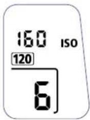
text_image
160 ISO 120 6
natural_image
Simple icon of a light bulb with a sun symbol, no text or labels presentAccessories
USER GUIDE
Change Up / Change Down Button
Can alter the settings 'upwards'. For example, to increase the film speed setting. Toggle action.
Can alter the settings 'downwards'. For example, to decrease the film speed setting. Toggle action.
Function Selector
Selects the four functions that can be changed on the magazine. The functions are on a menu loop so that repeated pressing of the selector button will successively access all functions in turn. After a time-out of five seconds of non-activity, the display returns to the main screen.
Note!
Changes can only be made when the settings lock switch is in the unlocked position.
Film Plane Index
Provides a measuring point for the actual position of the film plane in the magazine. Used for calculations in critical applications.
Dark slide Key
Withdraws and replaces the dark slide. Fold out the key and turn it counter-clockwise 360^ (towards the open symbol) to withdraw it and clockwise 360^ (towards the closed symbol) to replace it.
Note!
The dark slide can only be withdrawn when the magazine is attached to the camera.
Dark slide Indicator
Indicates whether the dark slide is in place or withdrawn:
RED = stop != exposure CANNOT be made (magazine can be removed from camera)
WHITE = ok != exposure CAN be made (magazine cannot be removed from camera)
If you attempt to make an exposure when the dark slide is closed, however, you will receive a warning message in the viewfinder and grip LCD's – 'The dark slide is closed'.
natural_image
Close-up of a black circular button with two white triangular buttons, no text or symbols visible.
natural_image
Close-up of a circular mechanical component with concentric rings (no text or symbols visible)
natural_image
Close-up of a mechanical component with no visible text or symbols
natural_image
Close-up of a black electrical socket with a circular button and a small symbol on the socket (no readable text or labels)
natural_image
Close-up of a mechanical component with a black handle and circular opening, no visible text or symbolsAccessories
USER GUIDE
Film Tab Holder
Holds an ID tab from the film roll pack as a reminder of the type of film loaded. Remember to change it if you change film type!
Film Holder Key
Secures the film holder in the magazine. Fold out the key and turn counter-clockwise 90° to remove the film holder and turn clockwise 90° to lock the film holder in place.
Magazine Settings Lock
All settings can be locked to avoid inadvertent changes. To change the settings, slide the settings lock (see illustration) to the right until it stops. After the changes have been made, slide the settings lock to the left (see symbol on magazine) again to secure the new settings.
Data bus Interface
Data interface between magazine and camera. Ensure the contacts are kept clean and protected from damage. Keep the protective cover on when the magazine is being stored or transported.
Battery
The magazine uses a battery to retain information and settings when unattached from the camera. When attached to the camera body, the magazine takes its power requirements from the camera batteries. The magazine battery will normally be effective for 1-2 years depending on use (off camera illumination, for example). When the battery is in a very low condition, (approx. 1 month of use left), a low battery symbol appears on the magazine LCD as a warning. The magazine will continue to function with no battery power left as long as it remains attached to the camera body. However, when detached, the settings will not be stored.
Battery Replacement
Release the film holder by folding out the film holder key and rotating it 90° in a counter-clockwise direction. Withdraw the film holder completely. On the bottom plate on the inside of the film magazine housing you will find a slotted circular battery cover. Insert a small coin or similar into the slot and rotate the cover about 20° in a counter-clockwise direction. The cover will be freed and the battery can be removed. Replace with a fresh CR2032 / 3V lithium (or equivalent) battery. Observe the polarity and ensure the positive (+) face is uppermost and replace the cover (ensure the retaining lugs are inserted in the battery compartment slots), locking it into place by rotating it in a clockwise direction until it stops. If you inadvertently
text_image
HASSEIBLAD
natural_image
Close-up of a black object with a red circle highlighting a small rectangular feature, possibly a button or knob (no text or symbols visible)
natural_image
Close-up of a black electronic device with a red circular annotation highlighting a component (no visible text or symbols)
natural_image
Black-and-white photo of a closed open box containing a coin held by an open lid, with no visible text or symbols.
natural_image
Interior view of a white microwave oven with black plastic casing and a circular vent, plus a perforated cover (no text or symbols visible)insert the battery incorrectly, the film magazine will not be damaged though it will not function. Try to avoid touching the surface of the battery with your bare fingers as sweat residue can decrease the electrical conductivity of the battery casing and might cause corrosion. After battery replacement, the magazine's parameters return to the default settings (Bar code, 120, Data-on, Count up).
Accessories
USER GUIDE
Attach and Remove the Magazine
You cannot remove a magazine from the camera body if the magazine dark slide is not in place, (when the magazine dark slide indicator on the magazine shows white). Neither can you withdraw the magazine dark slide when the magazine is not attached to the camera. Both these restrictions therefore prevent accidental film loss caused by fogging.
Attachment
Position the magazine retention groove onto the magazine support on the camera body ensuring that they are correctly positioned. Swing the magazine towards the camera body and firmly press into place with a click. If there is resistance, the magazine retaining catch on the camera has probably been inadvertently released. In that case, push the release button again to reset the catch. You can attach and remove the magazine with or without the film holder in place. If you just want to change to a new film, you can remove and reload the film holder without having to remove the whole magazine.
Removal
Ensure that the dark slide indicator on the magazine shows red (signifying that the dark slide is closed). Firstly push the lever of the magazine release button to the right (fig. 4/1) and while maintaining that position press the centre of the button firmly inwards towards the camera body (fig. 4/2) to finally release the magazine.
- Ensure you press on the centre of the button, not on the lever.
- You cannot remove a magazine if the dark slide is not closed.
- If the film holder is inadvertently removed mid-film, then exposed frames will naturally be lost due to light fogging. However, if the film holder is reinserted, the film will automatically be advanced by three frames to position fresh unexposed film. The film counter will also correspondingly add on three frames to the original number recorded before the film holder was removed.
Press the function selector button repeatedly to successively access:
A Film speed (ISO / Bar Code)
B Film length (120/220/ Number of frames)
C Data (on/off)
D Frame counter (count down / count up)
E Low-battery warning symbol
natural_image
Close-up of two metallic mechanical components with internal features, no visible text or symbols
natural_image
Close-up of a car's door panel with two circular buttons and a spherical knob, labeled 'HASSELBIAD' (no other text or symbols visible)
text_image
A B DATA 150 ISO 120 220 REMAIN 18 C E DAccessories
USER GUIDE
Film Speed Setting / Bar code
The film speed (ISO / ASA) can be set automatically or manually. Automatic setting uses a Bar code (only some films have this feature, notably Fujifilm). This is the default setting.
Film settings (ISO / film length) are automatic only if the magazine is set at Bar code automatic. That is, a bar coded film cannot override a manual film speed setting but a manual setting can override the film speed of a bar coded film.
Films without a bar code must have their speed set manually. A manual setting must also be made if you want to override the speed setting of a bar coded film.
To access Manual setting:
1 Ensure the magazine settings lock is in the unlocked position.
2 Press the 📄 button until a figure (or bar code symbol) appears together with ISO.
3 Press either the or the button to reach the required setting.
4 The new setting will be saved automatically after a time out of five seconds.
5 Return the LCD settings lock to the locked position.
Note!
If you use both standard and bar coded films (or overridden bar coded films), check that you have changed the settings accordingly.
Film Length / Number of Frames
Both 120 and 220 films can be used. 120 film will produce 8 (for use with 'half length' 120 films only) or 16 frames and 220 film will produce 32 frames. If the film has a bar code, then film length setting (and film speed setting) is automatic. The LCD will automatically show the bar code symbol and the appropriate film length. (Note that film speed can be overridden with bar coded films, but not film length).
If, however, the film has no bar code then proceed as follows:
To access film type setting:
1 Ensure the magazine settings lock is in the unlocked position.
2 Press the Button until the 120 or 220 symbol appears.
3 Press either the or the button to change the desired setting.
4 The new setting will be saved automatically after timeout.
5 Return the magazine settings lock to the locked position.
natural_image
Close-up of a metallic door handle with a key inserted, no visible text or symbols
natural_image
Close-up of a camera's door button with three circular buttons (no text or symbols visible)
natural_image
Close-up of a camera control panel with three circular buttons and a black square button (no text or symbols visible)EXAMPLE
32F,
220
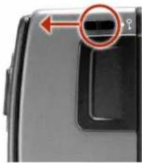
natural_image
Close-up of a camera lens with a red circular icon highlighting the lens (no text or symbols visible)Film speed
Film length
Data
Frame counter
Accessories
USER GUIDE
Data Imprint Setting
Data imprinting can be activated or deactivated through the magazine menu.
Access data setting:
1 Ensure the magazine settings lock is in the unlocked position.
2 Press the Button until the Data symbol appears.
3 Press either the or the button to reach On or Off.
4 The new setting will be saved automatically after a time out of five seconds.
5 Return the magazine settings lock to the locked position.
Note!
Operation and changes made to the data imprinting function are accessed through the camera menu. Please see separate section for full details.
Frame Counter Setting
The frame counter can be set to show either how many unexposed frames remain on a film or how many frames have already been exposed. The LCD shows your choice of setting by adding the word Remain as a reminder of the number of frames remaining or 'countdown'. Absence of this word implies the opposite, namely, 'count-up', so it denotes the number of the next frame to be used (for example, the figure 4 means three frames have already been exposed). This information is also automatically displayed on the grip LCD and viewfinder LCD though only as a figure above a symbol.
Access frame counter setting:
1 Ensure the magazine settings lock is in the unlocked position.
2 Press the 📄 button until Remain appears.
3 Press either the ☑ or the button to reach the desired setting (toggle function).
'on' will show the number of frames remaining on the roll. 'off' will show the number of the next frame in the series.
4 The new setting will be saved automatically after a time out of five seconds.
5 Return the magazine settings lock to the locked position.
Low Battery Symbol
The low-battery symbol only appears on the magazine LCD when the battery needs changing.
Example
• 120 film length set manually
• the film speed (ISO160) has been set manually
- 5 frames already been exposed (with regular 120 film, 11 frames remain)
• the battery is functional
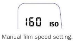
text_image
160 ISO Manual film speed setting.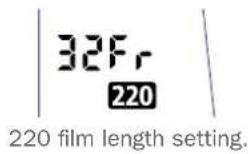

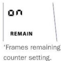
text_image
on REMAIN 'Frames remaining' counter setting.
natural_image
Simple line drawing of a battery and a resistor (no text or symbols)
text_image
160 ISO 120 6Accessories
USER GUIDE
Film Loading
The film magazine can be loaded either on or off the camera. Regularly check the interior of the magazine and remove dust, particles or any scraps of paper from previous rolls of film. Load and unload film magazines away from direct light sources.
- Fold out the film holder key and turn it counter-clockwise 90° A. Withdraw the film holder completely.
- Place an empty take-up spool in the upper spool holder by placing one end over the fixed stud in the holder and the other end underneath the sprung spool retaining arm. Rotate the spool a little if necessary until it clicks into position.
- Completely remove the retaining paper band from a new roll of film and place it in the lower spool holder. See diagram for correct orientation. Ensure you do not place the film spool the wrong way around!
- Pull 8–10 cm (3–4 in.) of paper backing from the film roll and insert the tongue of the backing paper into the slot in the take-up spool. Turn the spool one complete turn to ensure the tongue is firmly held in place by the overlying paper backing.
- Re-insert the film holder into the main body of the film magazine ensuring the correct orientation. Press firmly inwards towards the magazine and pay particular attention to see that both sides are level with the magazine body before turning the film holder key clockwise 90° to lock the film holder in place and fold the key back into its stored position B. You might find that increased pressure on the left hand side of the film holder will more easily ensure a positive and correct positioning in the magazine. If the camera is active or in standby mode the film will be wound automatically by the camera to position the first frame.
Beeper
The beeper sounds immediately after last-but-one frame has been exposed. This function can be turned off in Options.
Unloading a film
Remove the film holder in the same manner as when loading a film. Grip the exposed roll of film firmly and remove. Ensure the paper backing is wound tightly and that it is sealed with the band properly (the band may need to be moistened to activate the adhesive depending on type). Store exposed films away from strong light sources and contact with sharp objects. Move the remaining empty spool to the take-up spool compartment.
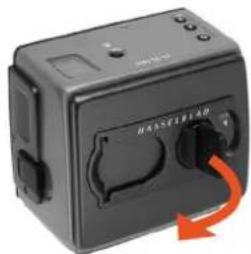
natural_image
Close-up of a black industrial electrical switch with a red arrow indicating clockwise motion (no visible text or symbols)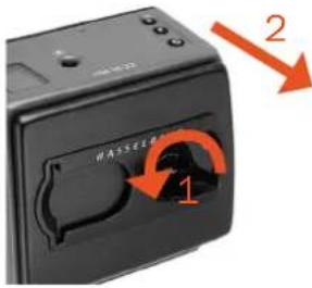
text_image
1 2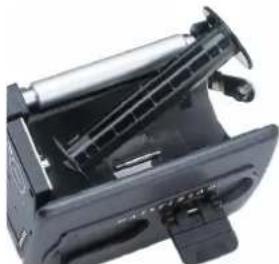
natural_image
Close-up of a black mechanical device with a cylindrical component and mounting bracket (no visible text or symbols)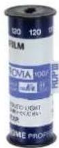
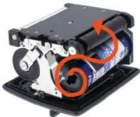
natural_image
Mechanical device with orange spiral arrow indicating motion or rotation (no visible text or symbols)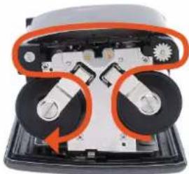
natural_image
Close-up of a mechanical device with orange circular components and black wheels, no visible text or symbols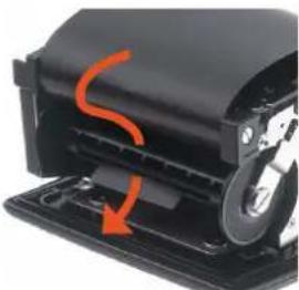
natural_image
Close-up of a mechanical device with orange motion arrow indicating rotation (no text or symbols visible)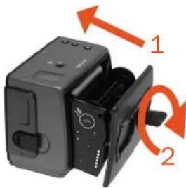
natural_image
Diagram of a black electronic device with two orange arrows indicating rotation or movement (no text or symbols present)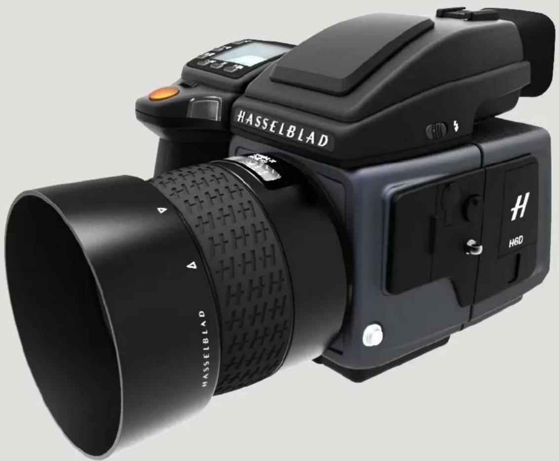
natural_image
Black HASSELBLAD H6D camera with visible lens and control buttons (no text beyond brand name)Troubleshooting
USER GUIDE
Problem Possible cause Suggested correction
| Error massage - See chapter “8.1 Error Messages” on | page 191. | |
| Camera is deactivated The camera can be affected by a discharge of electricity. This can happen when the area around the control buttons on the grip accidentally touches a conductive cord or material connected to earth.This can deactivate the camera and does not cause any damage. | Press the ON - OFF button on the grip to activate the camera. | |
| Wrong language If the sensor unit has been set to a language you don’t understand (on a rented camera, for example), you can navigate to your preferred language by following the actions and appearance in the illustrations here. | See chapter 8.2 on page 192 to Change Language On Sensor Unit From Unknown Language. | |
| Dark or coloured spots or lines in your images | Dirt or particles on the surface of the camera lens | See chapter “8.3 Clean the Lens Glass” on page 193. |
| Dirt or particles on the surface of the sensor unit’s infrared (IR) filter | See “8.4 Clean the Sensor Unit Filter” on page 194. | |
| Temperature warning icon appears Rapidly taken captures make heavy demands on the processor in the sensor unit which in turn produces heat. This can in combination with high ambient temperature result in noise in the image files.At ca. 60 °C a warning dialogue appears notifying that the sensor unit is temporarily shutting down to allow the sensor unit to cool. | Let the sensor unit cool down for at least 20 minutes. | |
| Time and date settings on the sensor unit does not work | Time and date settings on the sensor unit (which are included with files and folder labels) are updated automatically through a USB3/Phocus connection. These settings are retained for about two consecutive weeks by a small rechargeable cell that is automatically recharged by the main battery or USB3 with regular use. | Leave the sensor unit ON for 12 hours. |
Troubleshooting
USER GUIDE
8.1 ERROR MESSAGES
If any error message is displayed on the Sensor Unit Display or on the Camera Grip Display, follow these instructions.
Caution!
Be careful when you attach and remove the components to, and from, the camera. This will help prevent damage to the data-bus connections.
1 Remove the components from the camera.
2 Attach the components to the camera again.
If the error message is still displayed, do as follows:
1 Remove the battery grip.
2 Wait 10 seconds.
3 Attach the battery grip again.
The camera's processor has now been reset.
If the error message is still displayed, do as follows:
1 Write down the error message.
2 Contact your local Hasselblad dealer.
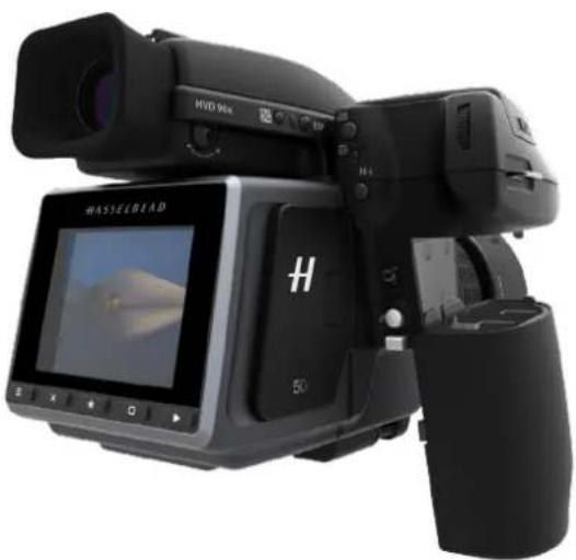
natural_image
Black HVSLEOLED video camera with LCD screen and external camera (no visible text or symbols on device body)Troubleshooting
USER GUIDE
8.2 CHANGE LANGUAGE ON SENSOR UNIT FROM UNKNOWN LANGUAGE
Main Menu
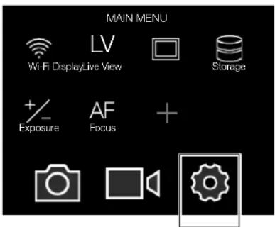
text_image
MAIN MENU Wi-Fi DisplayLive View Storage + Exposure AF Focus +General
Settings icon
MAIN MENU > GENERAL SETTINGS > LANGUAGE
1 Press the General Settings icon on the Sensor Unit display.
2 The General Settings Menu appears.
3 Navigate to the menu item with a Globe icon (number 8 on the list from the top, Language).
4 Scroll down to select your Language.
Swipe right or press Menu / EXIT button to get back to Main Menu.
General Settings Menu
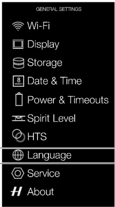
text_image
GENERAL SETTINGS Wi-Fi Display Storage 8 MARCH Date & Time Power & Timeouts Spirit Level HTS Language Service AboutLanguage Menu
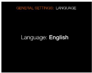
text_image
GENERAL SETTINGS: LANGUAGE Language: EnglishTroubleshooting
USER GUIDE
8.3 CLEAN THE LENS GLASS
REMOVE DUST
Caution!
Do not touch the glass surface with your fingers. This can cause damage to the equipment.
If there is dust on the lens glass, do as follows:
1 Remove the dust with a blower brush or very soft lens brush.
REMOVE SMEAR
Caution!
Do not touch the glass surface with your fingers. This can cause damage to the equipment.
If there is smear on the lens glass, do as follows:
1 If you are not sure how to remove the smear, contact your local Hasselblad Authorized Service Centre.
2 Clean the lens glass with a high quality lens cleaning solution on a tissue.
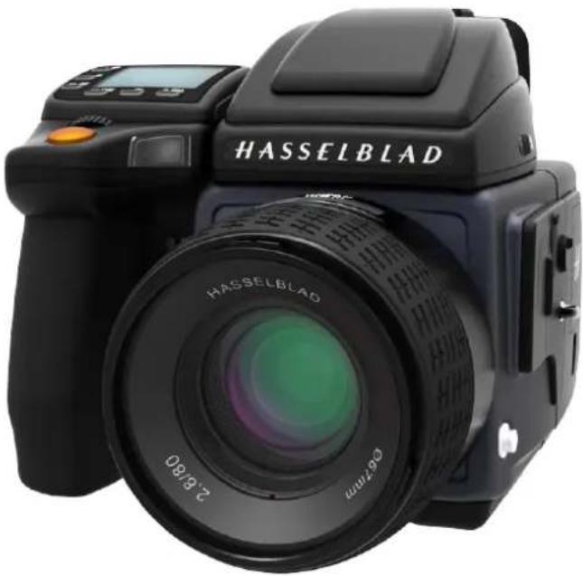
natural_image
Black HASSELBLAD digital camera with lens and control panel (no visible text or symbols beyond brand name)Troubleshooting
USER GUIDE
8.4 CLEAN THE SENSOR UNIT FILTER
Caution!
Be careful when you attach/detach the components to/from the camera. This will help prevent damage to the data bus connections.
Caution!
When you remove the sensor unit, keep foreign objects away from the camera opening. The camera opening is very sensitive. This will help prevent damage to the equipment.
1 Remove USB 3 cable if connected.
2 Rotate the sensor unit release button to the right.
3 Maintain the position and press the centre of the button firmly inwards towards the camera body (X) to finally release the magazine.
4 Carefully clean the outside surface of IR filter by using clean compressed air.
Caution!
If you use canned compressed air to clean the glass of IR filter, read the instructions very carefully before use. This will help prevent damage to the filter.
If compressed air did not remove all the problems on the filter, use an E-wipe. Do as follows:
1 Tear at the notch to break seal.
2 Remove an E-wipe from the package and fold the tissue to match the width of the IR filter.
3 Apply firm pressure using two or three fingers at the edge of the wipe to ensure an even, firm contact with filter surface.
4 Wipe the surface in one unbroken motion.
Note!
Do not use same side of the E-wipe twice as you will be likely to reapply particles removed in the first pass.
1 Attach the sensor unit again to the camera immediately after cleaning.
2 Capture a number of images.
3 Inspect the images.
If you still see spots on your images, you may have dust either on the inside of the IR filter or on the CMOS itself. Do as follows:
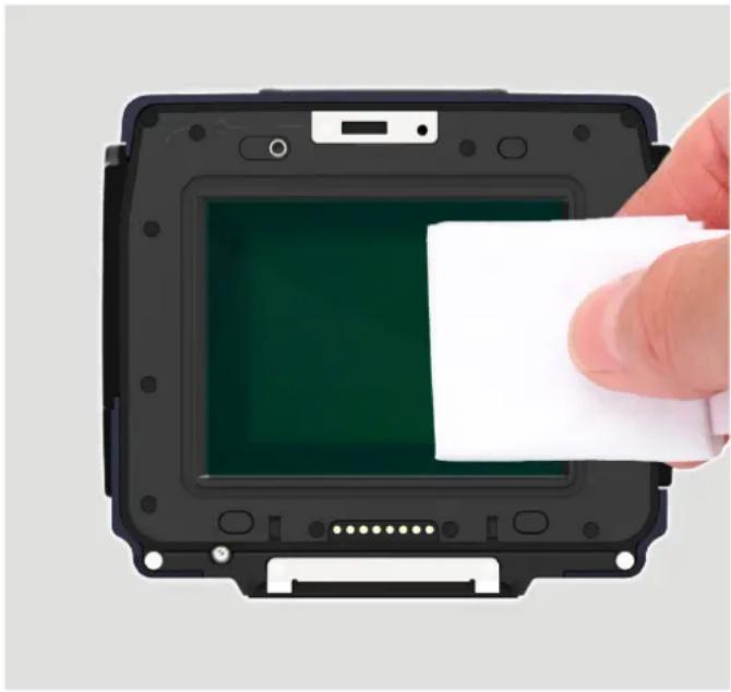
natural_image
Hand placing a white rectangular object into a black electronic device casing with green screen (no text or symbols visible)Caution!
Do not try to remove the glass IR filter from the front of the sensor (due to dust or similar). This can cause damage to the equipment. Always contact your local Hasselblad Authorized Service Centre.
Contact your local Hasselblad Authorized Service Centre.
Troubleshooting
USER GUIDE
User Guide for Hasselblad H6D
The information in this User Guide is intended for informational use only, is subject to change without notice, and should not be construed as a commitment by Victor Hasselblad AB.
The H6D Product Images in this User Guide were not taken with a Hasselblad H6D. They are produced in 3D as visualization. They are used for illustrative purposes only and are not intended to represent the image quality produced by a Hasselblad H6D.
The text in this manual cannot be reprinted or reused without the express permission of Victor Hasselblad AB.
The images in this manual cannot be reprinted or reused without the express permission of the photographers who took them.
All text in this User Guide: © Victor Hasselblad AB. All images in this User Guide not credited to a specific photographer: © Victor Hasselblad AB.
Victor Hasselblad AB assumes no responsibility or liability for any errors or inaccuracies that may appear in this manual.
Victor Hasselblad AB assumes no responsibility or liability for loss or damage incurred during or as a result of using Hasselblad software or products.
Hasselblad, Phocus and Phocus Mobile are trademarks of Victor Hasselblad AB.
Adobe and Adobe Photoshop are trademarks of Adobe Systems, Inc. Macintosh, Mac OS, iPhone ^® , iPad ^® and iPod Touch ^® .
InfoLithium is a registered trademark of Sony Corporation. Canon, Nikon, Leica, Sony, Fuji and Olympus are trademarks of their respective corporations. Qp Card is a trademark of Qp Card AB. E-Wipe is a trademark of Photosol Inc.
Photo Credits:
Ian Lawson
Copyright © 2018
Victor Hasselblad AB
All rights reserved.
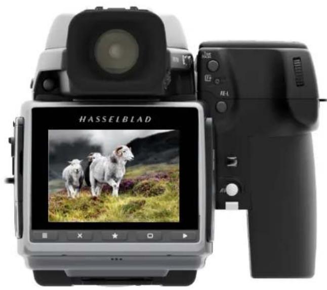
natural_image
Rear view of a Hasselblad camera displaying a landscape photo with three sheep in the field (no visible text or symbols on device body)