
CQ-R223 - Car stereo PANASONIC - Free user manual and instructions
Find the device manual for free CQ-R223 PANASONIC in PDF.


User questions about CQ-R223 PANASONIC
0 question about this device. Answer the ones you know or ask your own.
Ask a new question about this device
Download the instructions for your Car stereo in PDF format for free! Find your manual CQ-R223 - PANASONIC and take your electronic device back in hand. On this page are published all the documents necessary for the use of your device. CQ-R223 by PANASONIC.
USER MANUAL CQ-R223 PANASONIC
High-Power Cassette Player/Receiver with Changer Control
Operating Instructions
使用说明书
Matsushita Electric Industrial Co., Ltd.
Web site:http://www.panasonic.co.jp/global/

natural_image
Black-and-white landscape photo of a winding mountain road through forested valleys (no text or symbols visible)- Please read these instructions carefully before using this product and keep this manual for future reference.
TO REDUCE THE RISK OF FIRE OR ELECTRIC SHOCK, DO NOT EXPOSE THIS PRODUCT TO RAIN OR MOISTURE.
中文
TO REDUCE THE RISK OF FIRE OR ELECTRIC SHHOCK, AND ANNOYING INTERFERENCE, USE ONLY THE INCLUDED COMPONENTS.
警告
Safety Information 2
Precautions 9
Accessories 5
General 12
Clock setting 13
Radio 14
Cassette Tape Player 16
CD Charger Control 18
Remote control 27
Remote control 20
Installation 21
Ant-Theft System 24
Electrical Connections 25
Speaker Connections 28
Fuse 26 Maintenance 26
Troubleshooting 27
Specifications. 29
CQ-R223WA

目录
页
Panasonic welcomes you to our ever growing family of electronic product owners. We know that this product will bring you many hours of enjoyment. Our reputation is built on precise electronic and mechanical engineering, manufactured with carefully selected components and assembled by people who take pride in their work. Once you discover the quality, reliability, and value we have built into this product, you too will be proud to be a member of our family.
Precautions
When Driving
Keep the volume level low enough product to be aware of road and traffic conditions.
When Car Washing
Do not expose the product, including the speakers and tapes, to water or excessive moisture. This could cause electrical shorts, fire, or other damage.
When Parked
Parking in direct sunlight can produce very high temperatures inside your car. Give the interior a chance to cool down before switching the unit on.
Use the Proper Power Supply
This product is designed to operate of a 12 volt DC, negative ground battery system.
Protect the Tape Mechanism
Keep magnets, screwdrivers, or other metallic objects away from the tape mechanism and tape head to prevent poor performance or malfunctions.
Note: The preset memory is cleared to return to the original factory setting when the power connector or battery is disconnected.
Accessories
| 1. Operating Instructions | 1 |
| 2. Supplied Hardware | 1 set (= page 21) |
| 3. Removable face plate case | 1 |
Note: The optional remote control is available from your local dealer (YEFX9992013A) (= page 20) *For details consult your nearest Panasonic Service center.
8
CQ-R223WA
CQ-R223WA
9

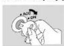
Turn the key in the ignition until the accessory indicator lights.
Power on: Press [PWR].
Power off: Press [PWR] again.
text_image
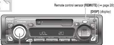
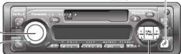
Remote control sensor (REMOTE) (← page 20) [DISP] (display)Volume
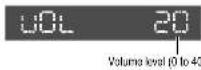
Turn the knob clockwise to increase volume, and counterclockwise to decrease volume.

Mute
Press [MUTE] to mute the sound completely
Mute indicator
Press [MUTE] again to cancel.
Loudness (LOUD)
Press and hold for more than 2 seconds [MUTE] (LOUD) to enhance bass and treble tones at low or medium volume.
Loudness indicator
Press and hold for more than 2 seconds [MUTE] (LOUD) again to cancel.
Note: If no operation takes place for more than 5 seconds in audio mode (2 seconds in volume mode), the display returns to the regular mode.
Clock Setting
Audio Mode
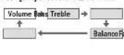
(Bass/Treble/Balance/Fader)
① Push [SEL] to select the audio mode.

text_image
50Hz Format: CD 1.222.8.4 Control buttons 12% 13%[
② Turn [VOL] (volume) clockwise or counterclockwise to change each level.
Bass:
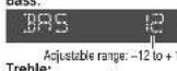
default: 0 dB
Treble:
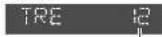
default: 0 dB
Adjustable range: -12 to +12 dB (by 3 dB step)
R (right speaker) or L (left speaker)
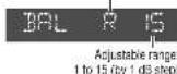

Fader:
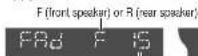
Adjustable range: 1 to 15 (by 1 dB step)

The 24-hour system is used for the clock.
Initial Time
① Press [DISP] (clock). AdJ *AdJ* is displayed when the clock is not adjusted.

(Hours alink.)

(Hours set.)
Minutes
④ Press [DISP] (clock).

(Minutes blink)
Press [< TUNE] or [> TUNE]

(Minutes set.)
⑥ Press [DISP] (clock).

(End.)
Note: Press and hold [< TUNE] or [> TUNE] to change numbers rapidly.
Time Reset
Press and hold [DISP] (clock) for more than 2 seconds to activate the time setting mode to reset the time.
Then, repeat steps ③ to ⑥.
12
CQ-R223WA
CQ-R223WA
13
Radio

flowchart
graph TD
    A["Radio mode"] --> B["FM stereo indicator"]
    B --> C["Band"]
    C --> D["Manual Tuning"]
    D --> E["Seek Tuning"]
    E --> F["Mono Selection"]
    F --> G["Mono Indicator"]
CQ-R223WA
Preset Station Setting
Up to 6 stations can be saved in each of the FM1, FM2, FM3 and AM preset station memories.
Note: Existing saved stations are overwritten with new stations after following this procedure.
① Band
Press [BAND] to select a desired band. (= page 14)
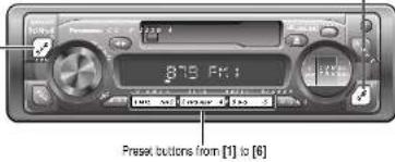
text_image
875.00:1 Preset buttons from [1] to [6]Auto Preset Memory (APM)
Press and hold [BAND] (APM: auto preset memory) for more than 2 seconds.
- The 6 stations with good reception will be automatically saved in the memory under preset buttons [1] - [6]
- Once set, the preset stations are sequentially scanned for 5 seconds each.
Manual Preset Memory
① Use manual or seek tuning to find a station. (→ page 14) ② Press and hold one of the preset buttons from [1] to [6] until the display blinks once.
Preset Station Calling
Press the corresponding preset button from [1] to [6] to tune in a preset station.
Display Change
Press [DISP] (display) to switch to the clock display.

Frequency

Stock display
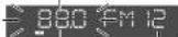
blinks once
preset number
Caution: To ensure safety, never attempt to preset stations while you are driving.
CQ-R223WA
Cassette Tape Player
Loading a Cassette
Insert the cassette with the exposed tape side facing to the right. Gently push the cassette in until the loading begins. The cassette will be loaded in place and playback starts.
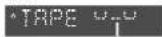
Program Indicator (This indication "C" rotates.)
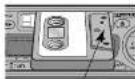
Exposed Tape end
Caution: Do not insert a tape when "tape" indicator "△" or "▽" lights.
Note: To maintain your cassette player in top condition, avoid using tapes that are longer than 90 minutes (C 90).
Notes on Cassette Tapes
Tape Slack:
Use a pencil or similar object to take up the stack as shown. If a loose tape is used, this may result in the tape becoming tangled in the rotating parts of the unit.

Ejecting the Tape
Press [▲] and the cassette will eject for removal, and the previous mode of operation will be resumed.
- If power is switched off before [▲] is pressed, the cassette will not eject. Switch on again and press [▲] to eject the cassette.
- The cassette tape should always be removed from the cassette slot when not in use.
Play Side Change
Press [◀▶] to switch to the program on the other side of the tape.
The display changes to indicate which program is playing.
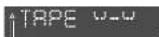
Top Side Playing

Bottom Side Playing
Rewind and Fast Forward
Press [▶▶ TRACK] or [▶▶ TRACK] to activate rewind or fast forward of the tape.
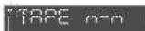
clinks
Press [◀] to stop rewind or last forward.
If you rewind the tape fully, it will play on the same program side again. If you fast forward to the end, play will resume from the beginning of the other side of the tape.
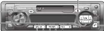
Metal Tape
Press [1] (MTL) when playing metal or chromium dioxide (CrO _2 ) tapes. Press [1] (MTL) again to cancel.

Note: Playing normal tapes in the metal tape mode causes high frequency imbalance, which affects tone quality.
Dolby B Noise Reduction
Press [2] (NR) to set the Dolby B NR Press [2] (NR) again to cancel.

Note: Set the Dolby B NR when playing back a tape recorded with Dolby B Noise Reduction.
Tape Program Search (TPS) Operation
① Press [3] (TPS) to activate the tape program search.

② To select a desired program, press [▶▶ TRACK] or [▶▶ TRACK] corresponding times to go forward (up to 9) or backward (up to 8).
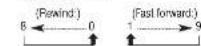
③ To turn it off, press [3] (TPS) again.
Blank Skip
Press [5] (B-S) to skip unrecorded portions longer than 15 seconds on the tape.
Press [5] (B·S) again to cancel.

Note: When repeat is on, the blank skip does not work because the repeat has priority over the blank skip.
Repeat Play
Press [4] (REP) to repeat the current program.
Press [4] (REP) again to cancel

Note: The TPS and B-S may not work correctly in the following cases. This, however, does not mean that the unit is defective.
- There is an interval less than 3 seconds (15 seconds in B-S) or having a high level of noise or blur between programs.
- There is particularly low-level passage during the program.
Display Change
Press [DISP] (display) to switch to the clock display.

Tape
Clock display
CQ-R223WA
CQ-R223WA
CD Changer Control
①CD Changer mode
While a disc magazine is inserted in the CD changer, press [MODE]. Play starts from the first track.
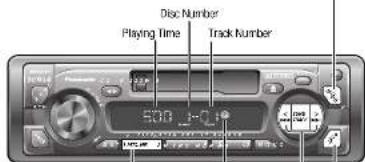
text_image
Disc Number Playing Time Track Number 530 J-01②Disc Selection
[1] (∨ DISC): Previous disc [2] (∧ DISC): Next disc.
lights when a CD changer is connected.
③Track Selection
Press [TRACK ▶▶] once to go to the next track. Press repeatedly to step forward through all the tracks. Press [TRACK ▶▶] once to play from the beginning of the current track, Press twice to play the previous track. Press repeatedly to step backward through all the tracks.
Track Search
Press and hold [TRACK▶▶] or [TRACK▶▶] for more than 0.5 second to activate fast forward or reverse through a track. Release it to resume the normal CD play from that position.
Display change
Press [DISP] (display) to switch to the clock display.

CQ-R223WA
Notes:
- CD charger functions are applicable to units with optional CD charger unit. (sold separately)
- This unit can neither play MP3 and WMA nor display CD-TEXT even if the CD changer unit support them.
Scan Play Tracks
+ Press [3] (SCAN). The track number blinks and
the first 10 seconds of each track on the disc play in sequence
• To stop scanning and continue with the current track, press [3] (SCAN) again.
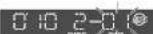
blies
Scan Play Discs
seconds. The first track of all the discs in the magazine is played for 17 organic each. Air
- Disc Number blinks at the same time. - To stop the current play of the disc scanning, press and hold [3] (SCAN) for more than 2 seconds again.
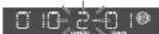
blinks
Repeat Play
- Press [4] (REPEAT) to repeat the current
selection. "REP" indicator lights. • The current selection continues to repeat until you press [4] (REPEAT) again.
Repeat indicator
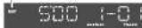
lights

Repeat Play
Disc
Random Play
- Press [5] (RANDOM) to random selection of music is played from all available CDs. *R▶* indicator lights.
• To cancel, press [5] (RANDOM) again.
Random indicator

lights

Random Play Disc
- Press and hold [5] (RANDOM) for more than 2 seconds to random selection of music is played from the original Pie 1.0 (RIPD) in favor of radio
from the current disc: ▶/DISC indicator lights. To cancel, press [5] (RANDOM) for more than 2 seconds again.
Error Display Messages
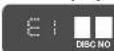
Disc is dirty, or is upside down.
→ Select the next available compact disc. Check the disc.

Disc has scratches.
→ Select the next available compact disc. Check the disc.

No operation by some cause.
→ Eject the magazine. If failure persists, press the reset switch on the CD changer. If normal operation is not restored yet, call the shop where you purchased the unit or the nearest Panasonic Service center to ask for repairs.

No also in the changer (magazine)
→ Insert discs into the changer (magazine).
CQ-R223WA
Remote Control
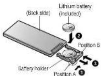
Battery Installation
① Remove the battery holder.
Press and book A of the battery holder and then pull it out.
② Install the battery on the battery holder.
Set a new battery properly with its "+" side facing up as shown in the figure.
③ Insert the battery holder.
Push the battery holder back into its original position.
Battery Notes
Remove and dispose of an old battery immediately.
Battery Information:
- Battery type: Panasonic lithium battery (CR2125) (Included)
- Battery life: Approximately 5 months with normal use (at room temperature)
Caution: Improper use of batteries may cause overheating, an explosion or ignition, resulting in injury or a fire. Battery leakage may damage the unit.
- Do not disassemble or short the battery. Do not throw a battery into a tire.
- Keep batteries away from children to avoid the risk of accidents.
- Be careful to observe proper local disposal rules when you dispose of batteries
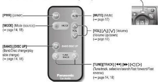
Control Reference Guide
Buttons of the remote control function in the same way as the controls on the main unit of the reference page.
Point the remote control unit at the main unit's sensor (REMOTE).
text_image
[PWR] (power) [MUTE] (Mute) (→ page 12) [MODE] (Mode (source)) (→ page 14, 18) [VOL] [A] [V] (Volume) (Volume Up/down) (→ page 12) [BAND] [DISC UP] (Band/Disc change( play side change) (→ page 14, 18) TUNE[TRACK] (<>) [▶] [<] (>] (Tune-track, selection/search/Fast forward/Fast reverse) (→ page 14, 18)CQ-R223WA
Installation
Preparation
- Before installation, check the radio operation with antenna and speakers.
- Disconnect the cable from the negative (−) battery terminal (see caution below).
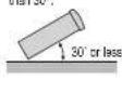
- Unit should be installed in a horizontal position with the front end up at a convenient angle, but not more than 30°.
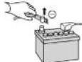
Caution: Do not disconnect the battery terminals of a car with trip or navigational computer since all user settings stored in memory will be lost. Instead take extra care with installing the unit to prevent shorts.
Dashboard Installation
Installation Opening
The unit can be installed
in any dashboard having an opening as shown at right. The dashboard
should be 4.5 mm - 6 mm thick in order to be able to support the unit.
Installation Precautions
This product should be installed by a professional installer, if possible.
In case of difficulty, please consult your nearest authorized Panasonic Service Center.
1. This system is to be used only in a 12-volt, DC battery system (car) with negative ground.
2. Follow the electrical connections carefully (→ page 25). Failure to do so may result in damage to the unit.
3. Connect the power load (red) after all other connections are made.
4. Be sure to connect the battery lead (yellow) to the positive terminal (+) of the battery or fuse block (BAT) terminal.
5. Insulate all exposed wires to prevent short circuiting.
6. Secure all loose wires after installing the unit.
7. Please carefully read the operating and installation instructions of the respective equipment before connecting it to this unit.
Installation Hardware
| No. | Item | Diagram | Q'ty |
| 1 | Mounting Collar | 1 | |
| 2 | Hex. Nut (5 mm) | 1 | |
| 3 | Pear Support Strip | 1 | |
| 4 | Tipping Screw(5 mm - 16 mm) | 1 | |
| 5 | Mounting Bolt (5 mm) | 1 | |
| 6 | Power Connector | 1 | |
| 7 | Dismounting Plate | 2 | |
| 8 | Trim Plate | 1 |
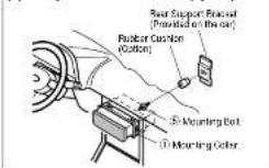
(a) Using the Rear Support Strap
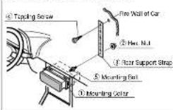
(b) Using the Rubber Cushion (option)
CQ-R223WA
Installation (Continued)
Cautions:
• We strongly recommend that you wear gloves for installation work to protect yourself from injuries.
- When bending the mounting tab of the mounting collar with a screwdriver, be careful not to injure your hands and fingers.
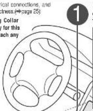
First complete the electrical connections, and then check them for correctness.(→page 25)
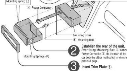
The included Mounting Collar
① Is designed specially for this unit. Do not use it to attach any other model.
text_image
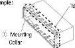
local connections, and lines(→page 25) Collar for this each any 1Insert Mounting Collar ① Into the dashboard, and bend the mounting tabs out with a screwdriver.
The tabs to be bent vary depending on the car. To securely install the unit, fully bend a number of the tabs so that there is no railing.
Example:
text_image
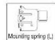
Mounting Spring (C) Power Connector Mounting Holes Mounting Bolt Mounting Springs (R) Establish the rear of the unit. After fixing Mounting Bolt connection Power Connector (S), fix the rear of the car body by either method (a) or (b) show previous page. Insert Trim Plate (S)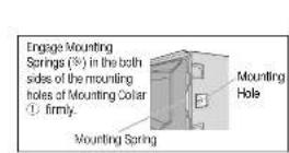
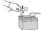
4 After installation reconnect the negative (−) battery terminal.
To Remove the Unit
Switch off the power of the unit.

Remove the removable face plate.
① Press [↑] . (release button). The removable face plate will be released.
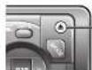
-Release button
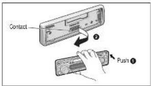
text_image
Contact ② Push ①
Remove the Trim Plate® with a screwdriver.
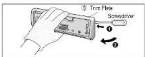

Insert the Dismountling Plates (7) along the grooves on both sides of the main unit until "click" is heard.
② Pull out the unit while pushing the plates further inside.
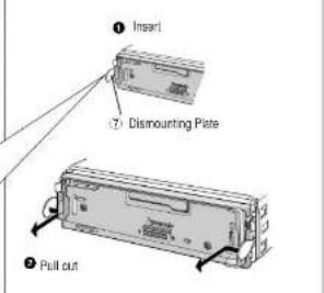
text_image
① Insert ⑦ Dismounting Plate ② Pull out
Remove the unit pulling with both hands.

Anti-Theft System
This unit is equipped with a removable face plate. Removing this face plate makes the radio totally inoperable.
Place the Removable Face Plate into Case
Switch off the power of the unit.
② Remove the removable face plate. (= page 23)
Gently press the bottom of the case and open the cover. Place the face plate into the case and take it with you when you leave the car.
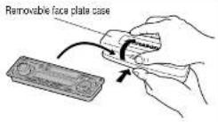
Install Removable Face Plate
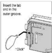
① Slide the left side of the removable face plate in place. ② Press the right end of the removable face plate until "click" is heard.
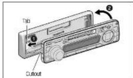
text_image
Tab CutoutCautions:
- This face plate is not waterproof. Do not expose it to water or excessive moisture.
- Do not remove the face plate while driving your car.
- Do not place the face plate on the dashboard or nearby areas where the temperature rises to high level.
- Do not touch the contacts on the face plate or the main unit, since this may result in poor electrical contacts.
- If dirt or other foreign substances get on the contacts, wipe them off with a clean and dry cloth
Electrical Connections
Preparation:
- This unit can be connected to an optional CD changer (CX-DP68). For details consult your nearest Panasonic Service center.
- For connection to a CD changer, refer to the operating instructions of the CD Changer (CX-DP68).
Cautions:
• This product is designed to operate with a 12 V DC, negative ground battery system.
• To prevent damage to the unit, be sure to follow the connection diagram below.
- Strip about 5mm of the lead ends for connection (only non-ISO connector cords).
• Do not insert the power connector into the unit until the wiring is completed.
- Be sure to insulate any exposed wires from a possible short-circuit from the car chassis. Bundle all cables and iron, silver, titanium-free iron by steel any metal cards.
Keep cable terminals free from touching any metal parts.
- For example, if your car has a drive computer or a navigation computer, the data of its memory may be erased when the battery terminals are disconnected.
□ Wiring Diagram
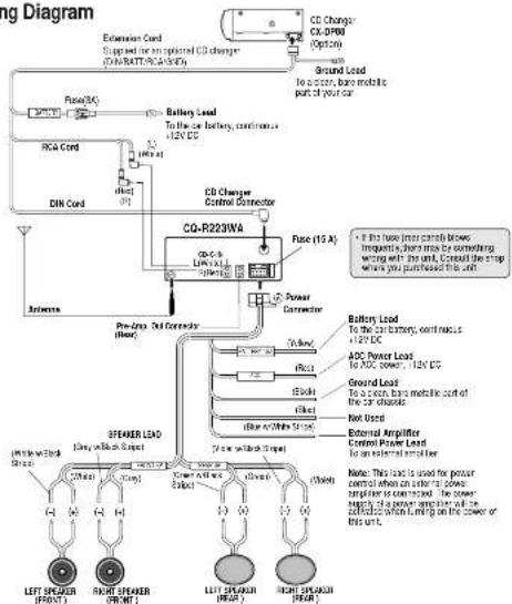
flowchart
graph TD
    A["Speaker Lead"] --> B["Ground Load"]
    A --> C["Power Connector"]
    A --> D["Control Power Lead"]
    A --> E["External Amplifier"]
    A --> F["Ground Load"]
    A --> G["Power Connector"]
    H["CO-223WA"] --> I["Co-4/6 LTR1A1"]
    H --> J["Co-4/6 LTR1A2"]
    H --> K["Co-4/6 LTR1A3"]
    H --> L["Co-4/6 LTR1A4"]
    H --> M["Co-4/6 LTR1A5"]
    H --> N["Co-4/6 LTR1A6"]
    H --> O["Co-4/6 LTR1A7"]
    H --> P["Co-4/6 LTR1A8"]
    H --> Q["Co-4/6 LTR1A9"]
    H --> R["Co-4/6 LTR1A10"]
    H --> S["Co-4/6 LTR1A11"]
    H --> T["Co-4/6 LTR1A12"]
    H --> U["Co-4/6 LTR1A13"]
    H --> V["Co-4/6 LTR1A14"]
    H --> W["Co-4/6 LTR1A15"]
    H --> X["Co-4/6 LTR1A16"]
    H --> Y["Co-4/6 LTR1A17"]
    H --> Z["Co-4/6 LTR1A18"]
    H --> AA["Co-4/6 LTR1A19"]
    H --> AB["Co-4/6 LTR1A20"]
    H --> AC["Co-4/6 LTR1A21"]
    H --> AD["Co-4/6 LTR1A22"]
    H --> AE["Co-4/6 LTR1A23"]
    H --> AF["Co-4/6 LTR1A24"]
    H --> AG["Co-4/6 LTR1A25"]
    H --> AH["Co-4/6 LTR1A26"]
    H --> AI["Co-4/6 LTR1A27"]
    H --> AJ["Co-4/6 LTR1A28"]
    H --> AK["Co-4/6 LTR1A29"]
    H --> AL["Co-4/6 LTR1A30"]
    H --> AM["Co-4/6 LTR1A31"]
    H --> AN["Co-4/6 LTR1A32"]
    H --> AO["Co-4/6 LTR1A33"]
    H --> AP["Co-4/6 LTR1A34"]
    H --> AQ["Co-4/6 LTR1A35"]
    H --> AR["Co-4/6 LTR1A36"]
    H --> AS["Co-4/6 LTR1A37"]
    H --> AT["Co-4/6 LTR1A38"]
    H --> AU["Co-4/6 LTR1A39"]
    H --> AV["Co-4/6 LTR1A40"]
    H --> AW["Co-4/6 LTR1A41"]
    H --> AX["Co-4/6 LTR1A42"]
    H --> AY["Co-4/6 LTR1A43"]
    H --> AZ["Co-4/6 LTR1A44"]
    H --> BA["Co-4/6 LTR1A45"]
    H --> BB["Co-4/6 LTR1A46"]
    H --> BC["Co-4/6 LTR1A47"]
    H --> BD["Co-4/6 LTR1A48"]
    H --> BE["Co-4/6 LTR1A49"]
    H --> BF["Co-4/6 LTR1A50"]
    H --> BG["Co-4/6 LTR1A51"]
    H --> BH["Co-4/6 LTR1A52"]
    H --> BI["Co-4/6 LTR1A53"]
    H --> BJ["Co-4/6 LTR1A54"]
    H --> BK["Co-4/6 LTR1A55"]
    H --> BL["Co-4/6 LTR1A56"]
    H --> BM["Co-4/6 LTR1A57"]
    H --> BN["Co-4/6 LTR1A58"]
    H --> BO["Co-4/6 LTR1A59"]
    H --> BP["Co-4/6 LTR1A60"]
    H --> BQ["Co-4/6 LTR1A61"]
    H --> BR["Co-4/6 LTR1A62"]
    H --> BS["Co-4/6 LTR1A63"]
    H --> BT["Co-4/6 LTR1A64"]
    H --> BU["Co-4/6 LTR1A65"]
    H --> BV["Co-4/6 LTR1A66"]
    H --> BW["Co-4/6 LTR1A67"]
    H --> BX["Co-4/6 LTR1A68"]
    H --> BY["Co-4/6 LTR1A69"]
    H --> BZ["Co-4/6 LTR1A70"]
    H --> CA["Co-4/6 LTR1A71"]
    H --> CB["Co-4/6 LTR1A72"]
    H --> CC["Co-4/6 LTR1A73"]
    H --> CD["Co-4/6 LTR1A74"]
    H --> CE["Co-4/6 LTR1A75"]
    H --> CF["Co-4/6 LTR1A76"]
    H --> CG["Co-4/6 LTR1A77"]
    H --> CH["Co-4/6 LTR1A78"]
    H --> CI["Co-4/6 LTR1A79"]
Speaker Connections
Caution: Please follow the instructions given below. Failure to do so will cause damage to the unit and speakers.
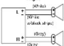
withblack slope
• Use ungrounded speaker only.
- The maximum speaker input should be 50 W or more. (If used with the optional power amplifier, the speaker input should be higher than the maximum amplifier output.)
• The speaker impedance should be 4 - 8 Ω.
- This unit uses the BTCL circuit, so each speaker should be connected separately using parallel vinyl insulated cords.
- The speaker cords and the power amplifier unit should be kept away (about 30 cm apart) from the antenna and antenna extension cord.
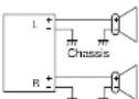
Chassis
- Never connect the speaker cord to the body of the car.
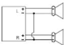
- Do not use a 3-wire type speaker system having a common earth lead.
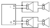
• Do not connect more than one speaker to one set of speaker leads.
Fuse
Use fuses of the same specified rating (15 A). Using different substitutes or fuses with higher ratings, or connecting the unit directly without a fuse, could cause fire or damage to the unit. If the fuse replacement falls, consult your nearest Panasonic Service center.
Maintenance
Your product is designed and manufactured to ensure the minimum of maintenance. Use a soft cloth for routine exterior cleaning. Never use benzine, thinner, or other solvents.
CQ-R223WA
Troubleshooting
Preliminary Steps
Check and take steps as described in the tables below.
If You Suspect Something Wrong
Immediately switch the power off.
Disconnect the power connector and check that there is neither smoke nor heat from the unit before asking for repairs. Never try to repair the unit by yourself because it is dangerous to do so.
Troubleshooting Tips
Common
Trouble
No power.

Cause'Step
Car's ignition switch is not on.
—Turn your car's ignition switch to ACC or ON.
Cables are not correctly connected.
—Connect the cables correctly.
Battery cable is not correctly connected.
—Connect the battery cable to the terminal that is always active.
Accessory cable is not correctly connected
—Connect the accessory cable to your car's ACC source.
Grounding utility is not correctly connected.
—Connect the grounding wire to a metal part of the car.
Fuse is burnt
—Call the store where you purchased the unit, or your nearest Service center and ask for fuse replacement.
Mute is set to ON
→Set It to OFF.
Cables are not correctly connected.
=Connect the cables correctly.
The ground lead is not connected properly.
—Connect the ground lead properly.

No sound.
Noise.

□ Sound Setting
Trouble


Troubleshooting (continued)
□ Radio
Trouble
Much noise in FM stereo and monaural broadcasts.
Preset station is reset.
□ Cassette Tape
Trouble
No sound.
Tape sound quality is poor.
High tones are improperly emphasized.
Reproduction of high tones is poor.
Wow and flutter level is very high.
Remote Control Trouble
Buttons are invalid for operation.
Cause/Step
The antenna ground lead is not connected properly.
→Connect the antenna ground lead property.
The radio antenna is not extended enough.
→Extend fully the radio antenna.
Battery cable is not correctly connected.
→Connect the battery cable to the terminal that is always active.
Cause'Slop
Blank tape is inserted in the unit
→Insert recorded tape into the unit.
Heads are dirty.
→Clean heads. (Ask a service representative for advice.)
Poor quality tape.
=Use better quality tape.
Dolby B NR face plays with Dolby B NR off
→Set Dolby B NR to ON.
Metal type face plays with normal mode.
→Change Normal mode to Metal mode.
Non-Dolby B NR tape plays with Dolby B NR on
→Set Dolby B NR to OFF.
Normal type tape plays with Metal mode.
→Change Metal mode to Normal mode.
Heads are magnetized.
→Demagnetize heads. (Ask a service representative for advice.)
Tape running mechanism is dirty or out of order
→Clean tape running mechanism, or repair it. (Ask a service
representative for advice.)
Cause:Step
Battery poles (-) (-) are reversed
→Insert the battery correctly.
Wrong callery.
→Check the battery.
Battery has run down.
→Replace the battery
Remote control is in the wrong direction
→Direct the remote control at sensor (REMOTE) on the panel.
Specifications
□ General
Power Supply: 12 V DC (11 V - 16 V) Test Voltage 14.4 V, Negative ground
Maximum Power Output: 50 W 4 (at 4Ω)
Tone Action : Bass : ± 12 dB at 100 Hz
Treble: ± 12 dB at 10 kHz
Current Consumption: Less than 2.5 A (tape mode, 0.5 W 4-speaker)
Pre-WHP Output Voltage: 2.0 V (3D Play Mode, 18HZ 5 dB)
Speaker impedance : 4 Ω (4 - 9 Ω acceptable)
Dimensions : 178/W0 : 50(H): 155(D) mm
Weight:1.4k
2
□ AM Radio
Frequency Range : 531 - 1 602 kHz
Useable Sensitivity : 28 dB μV (S/N 20 dB)
□ FM Stereo Radio
Frequency Range: 87.5 - 106.0 MHz
Useable Sensitivity : 13.2 dB μV (S/N 30 dB)
Stereo Separation: 35 dB (at 1 KHz)
□ Tape Player
Reproduction System : 4-track, 2-program stereo
Tape Speed: 4.76 cm/sec
FFREW Time
: Less than 110 sec (C-60)
:35 - 14.000 Hz = 3 dB (normal)
:35 - 17000 Hz ±3 dB (metal)
Wow and Flutter
:0.12%(WRMS)
:52 dB (Doby B NR OFF)
Note: Specifications and design are subject to modification without notice due to improvements in technology.
Dolloy noise reduction manufactured under license from Dolloy Laboratories Licensing Corporation.
"DOLBY" and the double-D symbol are trademarks of Delby Laboratories Licensing Corporation.