Director Set - Tripod Grip Gear - Free user manual and instructions
Find the device manual for free Director Set Grip Gear in PDF.


User questions about Director Set Grip Gear
0 question about this device. Answer the ones you know or ask your own.
Ask a new question about this device
Download the instructions for your Tripod in PDF format for free! Find your manual Director Set - Grip Gear and take your electronic device back in hand. On this page are published all the documents necessary for the use of your device. Director Set by Grip Gear.
USER MANUAL Director Set Grip Gear
Congratulations on acquiring your Directors Set! If you have any questions regarding the parts, set up or usage please email us anytime, we are happy to help! Email: gripgear@gripgear.com
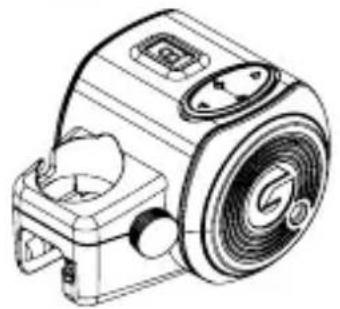
A Movie Maker 2
natural_image
Line drawing of a mechanical device with no visible text or symbols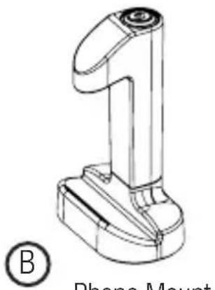
natural_image
Technical line drawing of a handheld device with a 14-pin base and circular head (no text or symbols)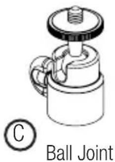
text_image
C Ball Joint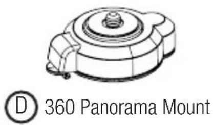
text_image
D 360 Panorama Mount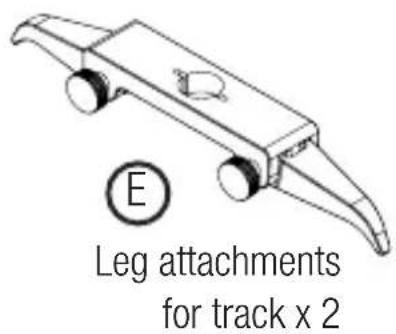
text_image
E Leg attachments for track x 2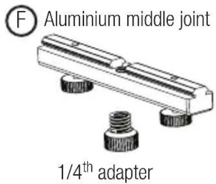
text_image
F Aluminium middle joint 1/4th adapter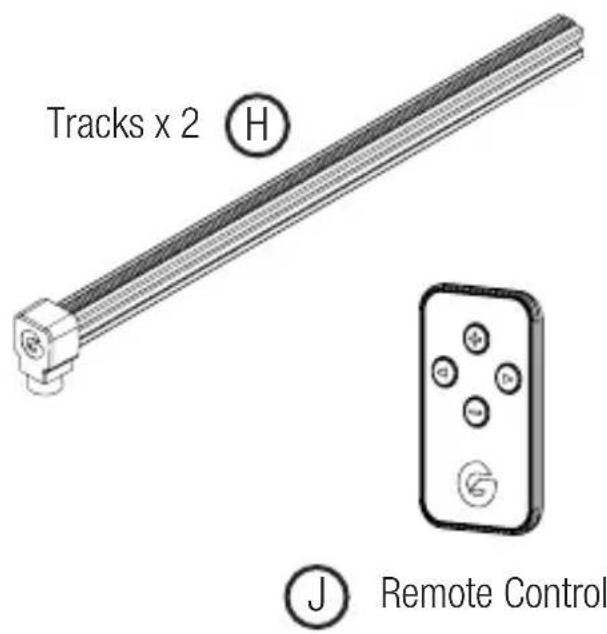
text_image
Tracks x 2 Ⓗ Remote Control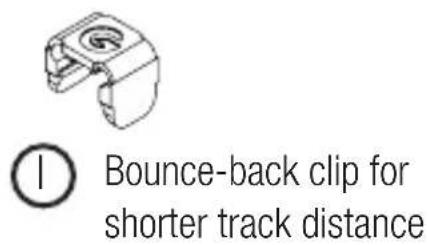
text_image
① Bounce-back clip for shorter track distance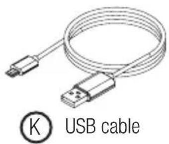
text_image
K USB cable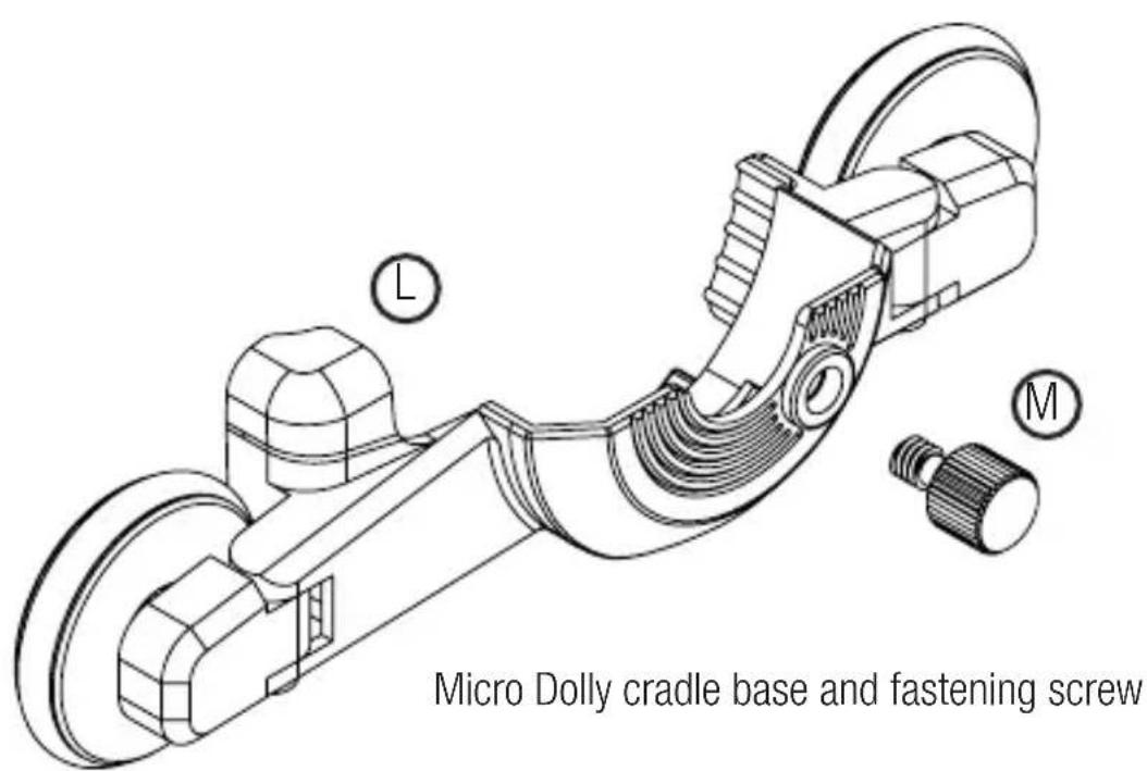
text_image
Micro Dolly cradle base and fastening screwMD 360 Mount
natural_image
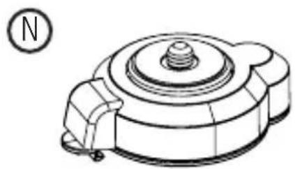
Technical line drawing of a mechanical component with a circular indicator labeled 'N' (no text or symbols on the diagram itself)0
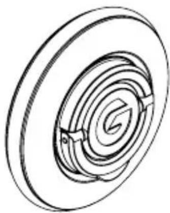
Power Wheel
natural_image
Pure technical line drawing of a circular mechanical component with concentric rings and a central arrow (no text or symbols)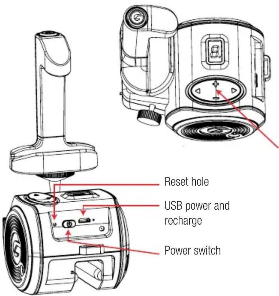
text_image
Reset hole USB power and recharge Power switchManual D-pad for direction (arrows) and speed choice (1-9)
To stop manually, press arrows in same direction the Movie Maker is going
natural_image
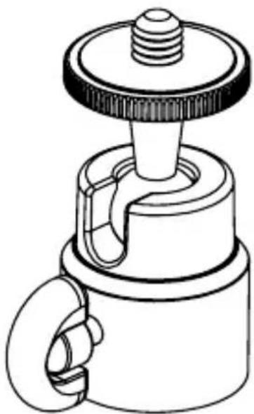
Technical line drawing of a mechanical component with a knob and handle (no text or symbols)© Install Ball Joint
natural_image
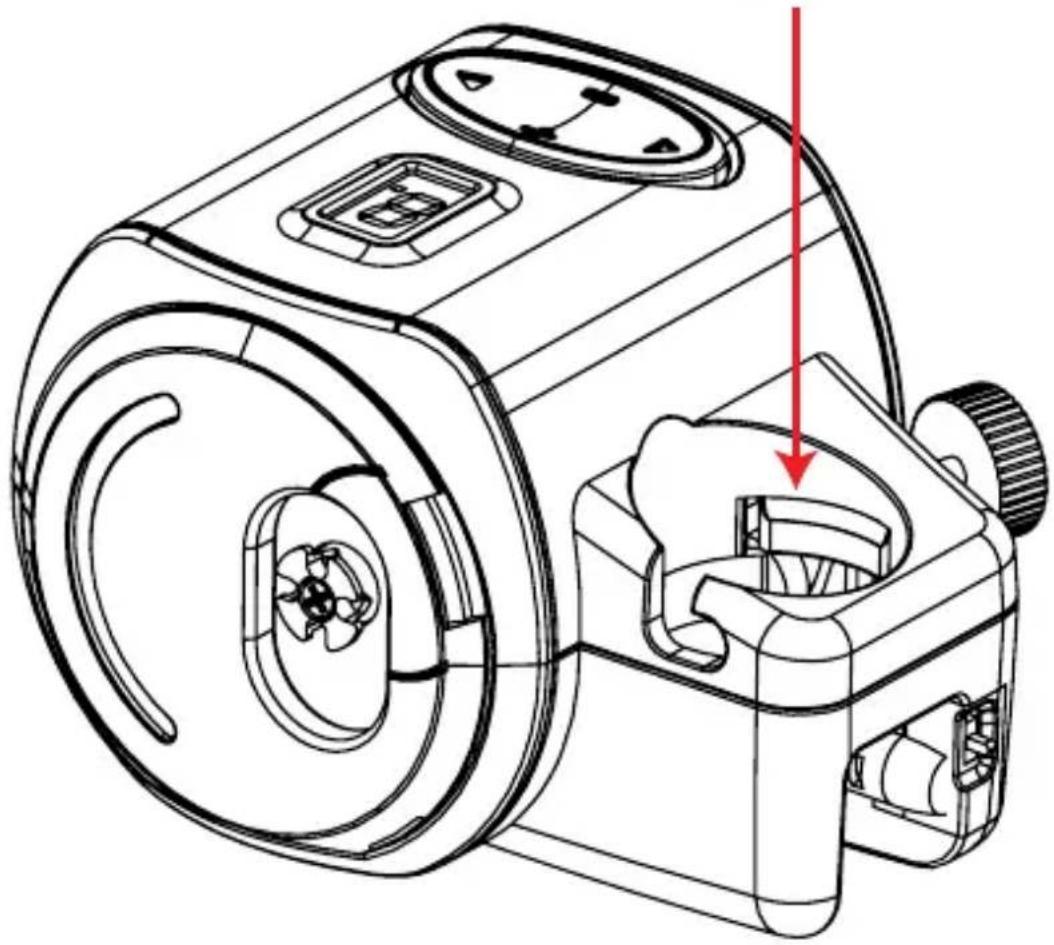
Technical line drawing of a mechanical device with internal components and a red arrow indicating a specific part (no text or symbols present)STEP 2
text_image
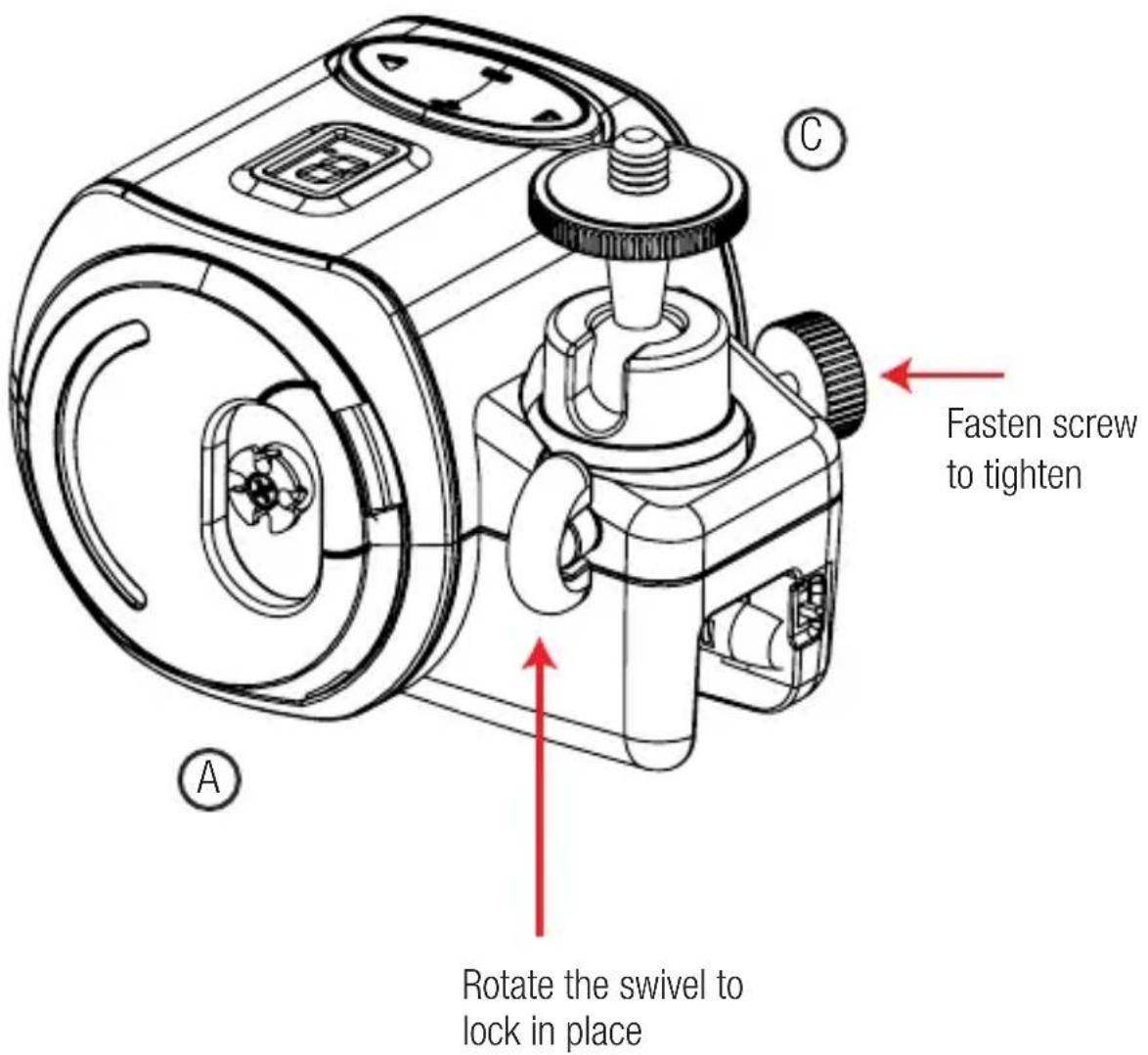
A Rotate the swivel to lock in place C Fasten screw to tighten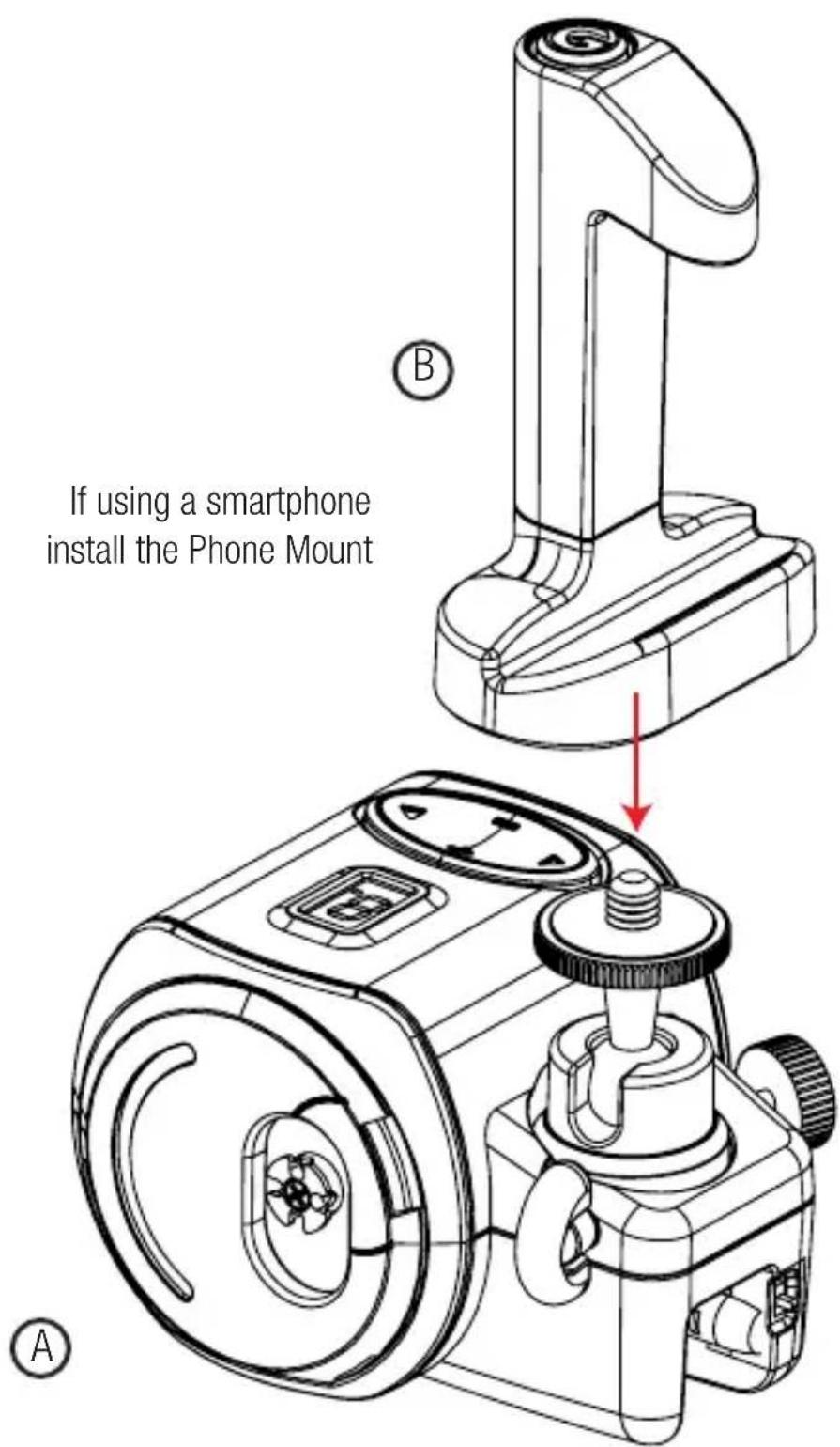
text_image
If using a smartphone install the Phone Mount A BSTEP 4
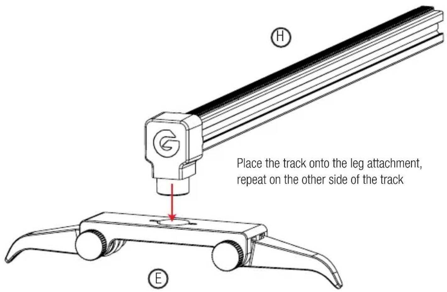
text_image
Place the track onto the leg attachment, repeat on the other side of the track H ESlide the aluminium joint onto the track

natural_image
Mechanical component diagram with a red arrow indicating direction and a circle labeled 'F' in the top-left corner (no text or symbols on the component itself)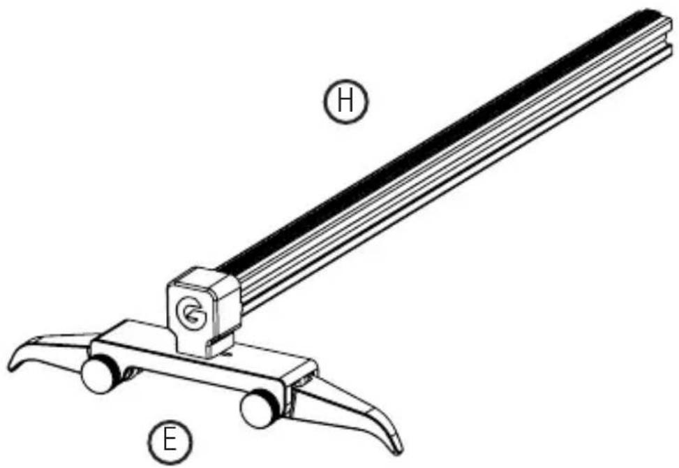
text_image
Technical diagram of a mechanical tool with labeled parts H and E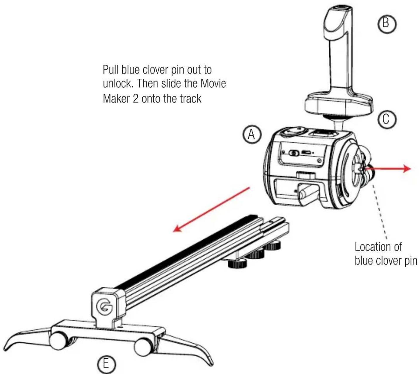
text_image
Pull blue clover pin out to unlock. Then slide the Movie Maker 2 onto the track Location of blue clover pinSTEP 7
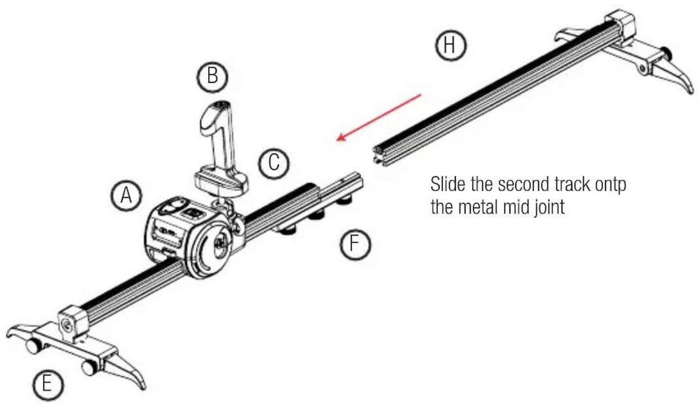
text_image
Slide the second track ontp the metal mid jointFor optimal track alignment, hold the joint then fasten screws
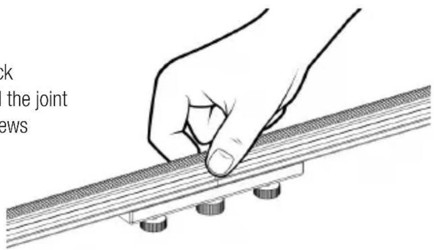
text_image
ck the joint ews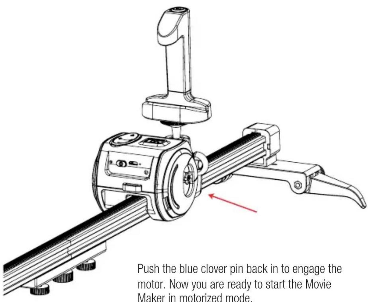
text_image
Push the blue clover pin back in to engage the motor. Now you are ready to start the Movie Maker in motorized mode.Push the blue clover pin back in to engage the motor. Now you are ready to start the Movie Maker in motorized mode.
text_image
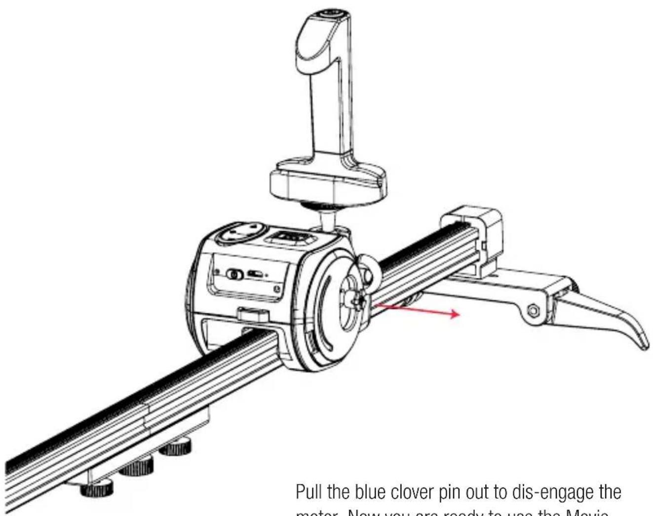
Pull the blue clover pin out to dis-engage the meter. Now you are ready to use the Movie.Pull the blue clover pin out to dis-engage the motor. Now you are ready to use the Movie Maker in manual mode.
text_image
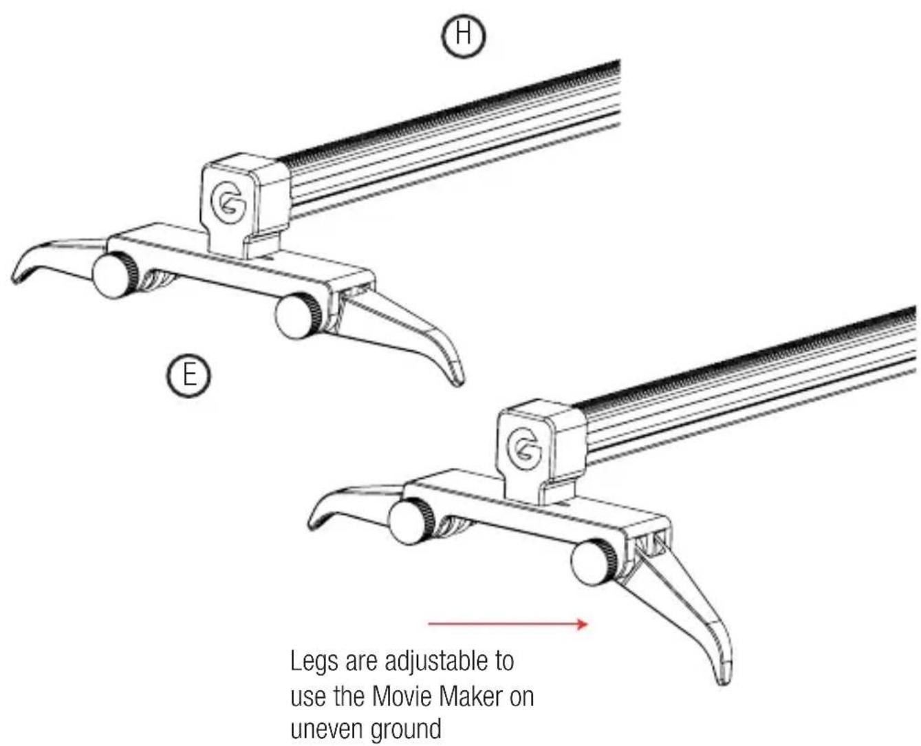
Legs are adjustable to use the Movie Maker on uneven ground
text_image
Fasten the legs with the hand screwsFold the legs fully inside when using the Movie Maker on a flat surface
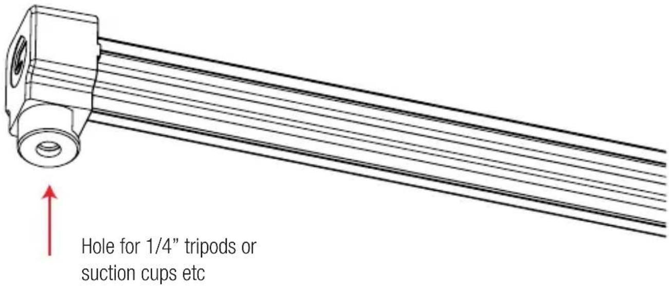
1/4" COMPATIBILITY AT ALL TOUCHPOINTS
text_image
Hole for 1/4" tripods or suction cups etcSHOOTING VERTICAL OR INVERTED
text_image
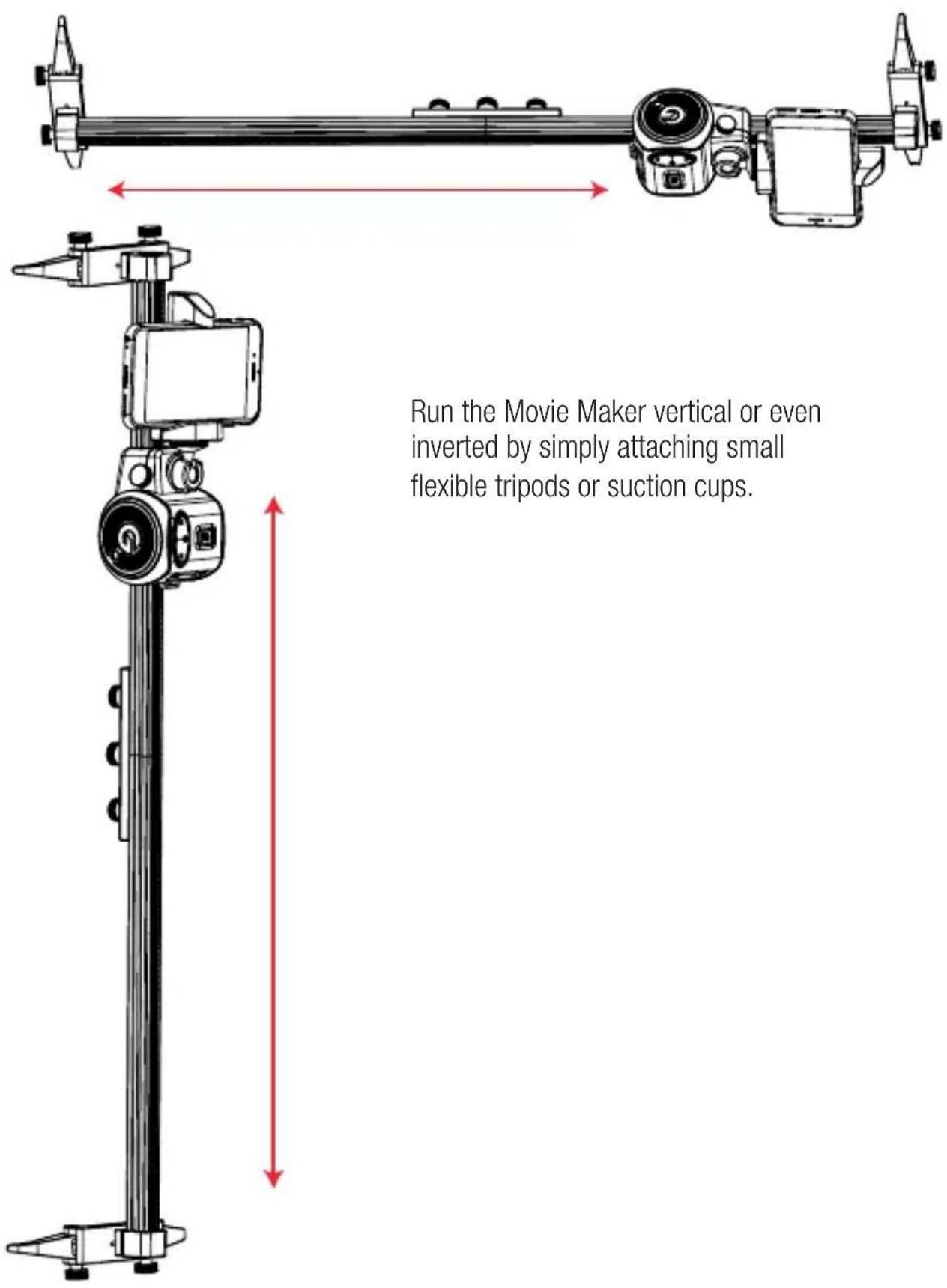
Run the Movie Maker vertical or even inverted by simply attaching small flexible tripods or suction cups.Run the Movie Maker vertical or even inverted by simply attaching small flexible tripods or suction cups.
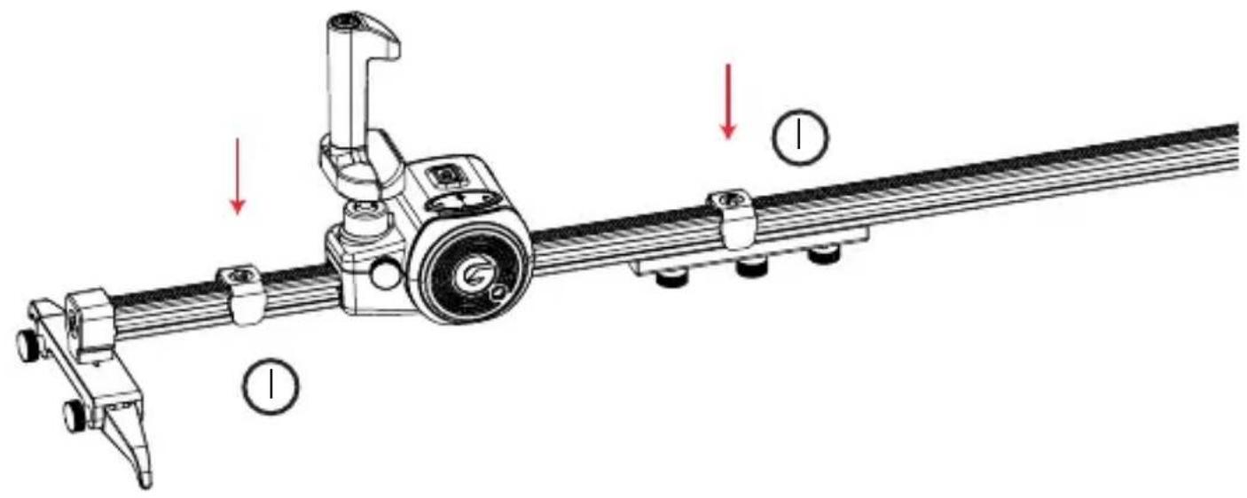
Attach bounce-back clips on track for desired shorter distance
text_image
Technical diagram of a mechanical assembly with labeled parts and directional arrows indicating motion or assembly.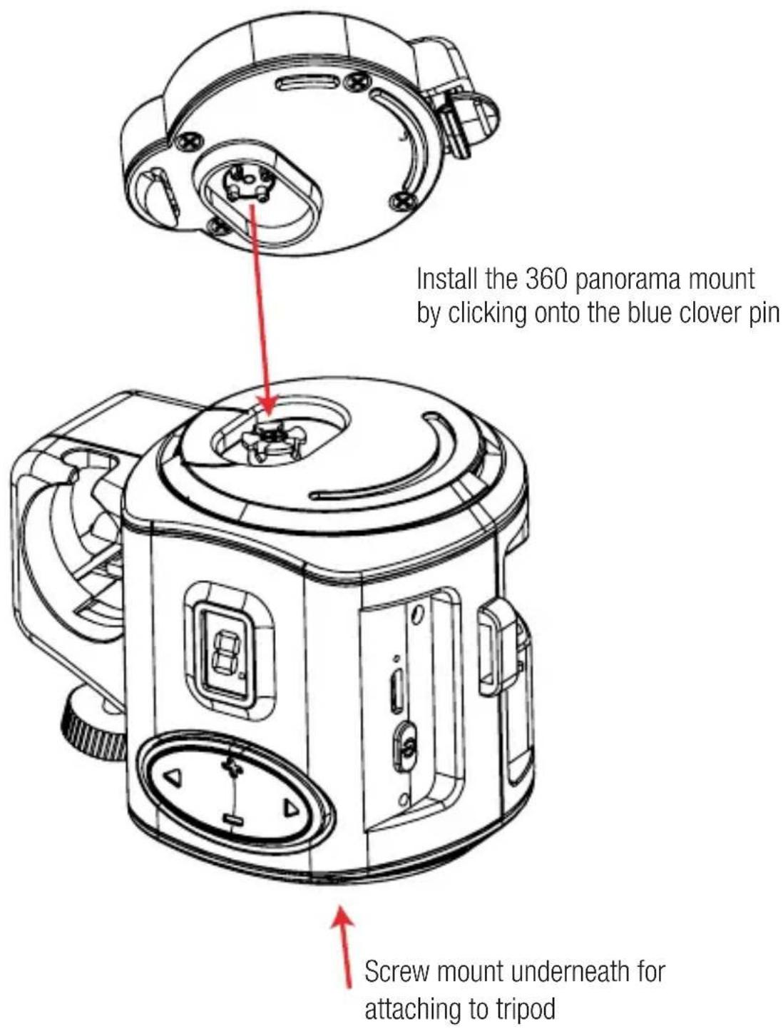
text_image
Install the 360 panorama mount by clicking onto the blue clover pin Screw mount underneath for attaching to tripodSTEP 2
text_image
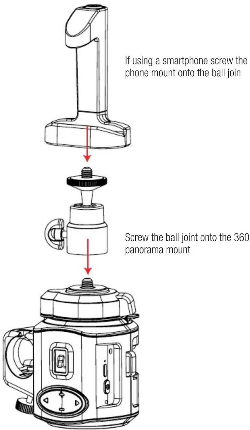
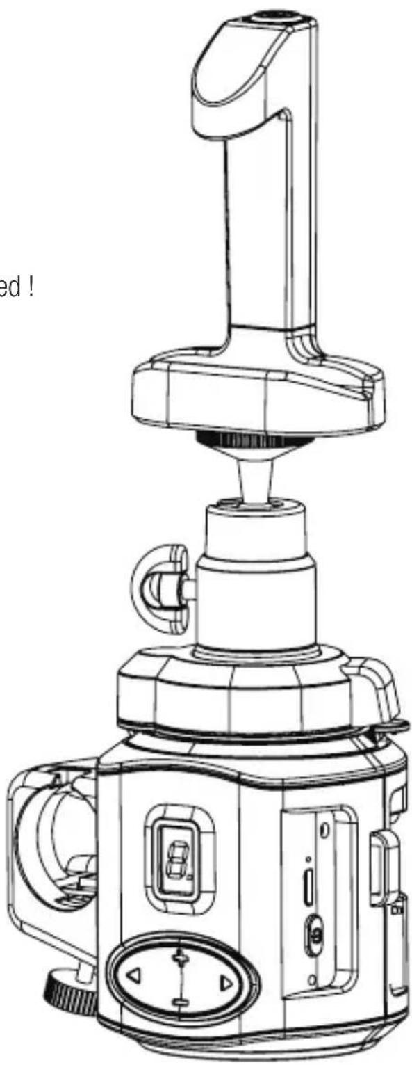
If using a smartphone screw the phone mount onto the ball join Screw the ball joint onto the 360 panorama mountFinished !
natural_image
Line drawing of a modern kitchen brush head with handle and control panel (no text or symbols)SETTING UP THE MICRO DOLLY- STEP 1
text_image
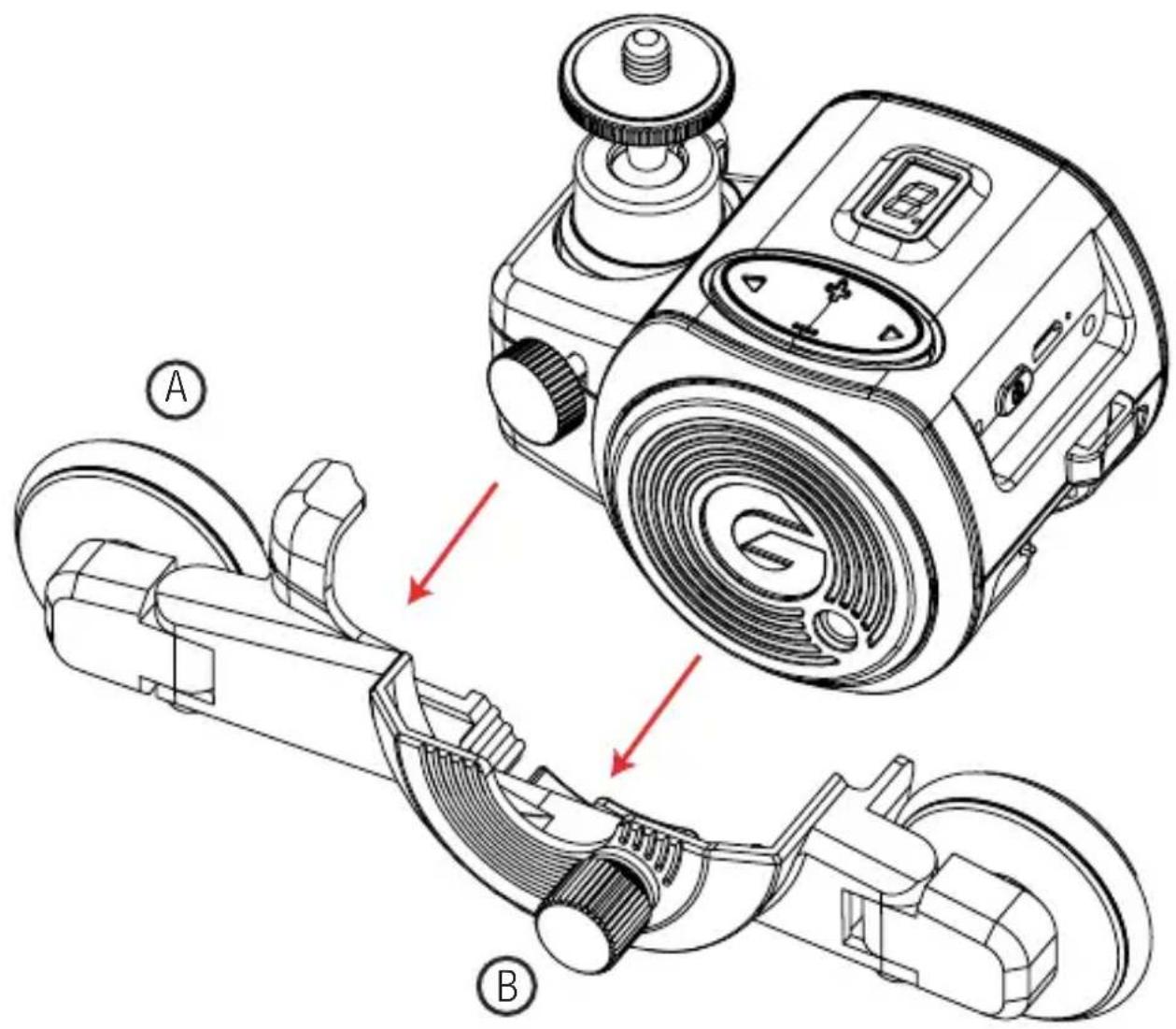
Technical diagram showing mechanical assembly with labeled parts A and B, including a motor and gear mechanism.Place the Movie Maker into the Micro Dolly cradle base and fasten using the fastening screw
STEP 2
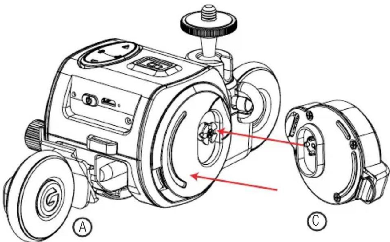
text_image
Technical diagram of a robotic device with labeled parts A and C, showing internal components and red directional arrows indicating motion or flow.Attach the MD 360 Mount to the blue clover pin
STEP 3
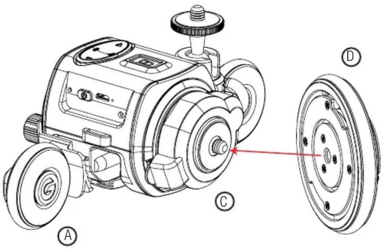
text_image
Technical diagram of a robotic device with labeled parts A, C, D and a red pointer indicating a specific component.Screw and fasten the power wheel

natural_image
Technical line drawing of a mechanical device with visible gears and wheels, no text or symbols presentWhen the ring is down, the power wheel is engaged with the motor

natural_image
Technical line drawing of a mechanical device with visible gears and a red directional arrow indicating motion (no text or symbols)Pull handle upwards to a 90° angle to disengage the motor for use in manual mode
FILMING IN STRAIGHT LINE
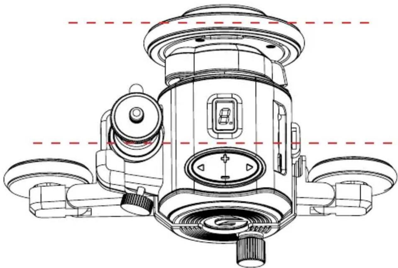
natural_image
Technical line drawing of a mechanical device with multiple ports and a central control panel (no text or symbols)For straight movement keep wheels aligned parallel
SHOOTING A CURVE
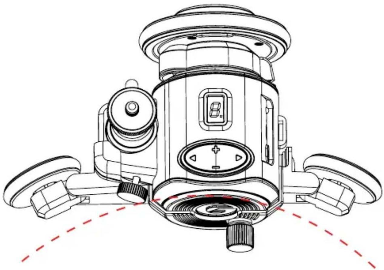
natural_image
Technical line drawing of a mechanical device with multiple wheels and central hub (no text or symbols)Adjust wheel angle for desired curved movement
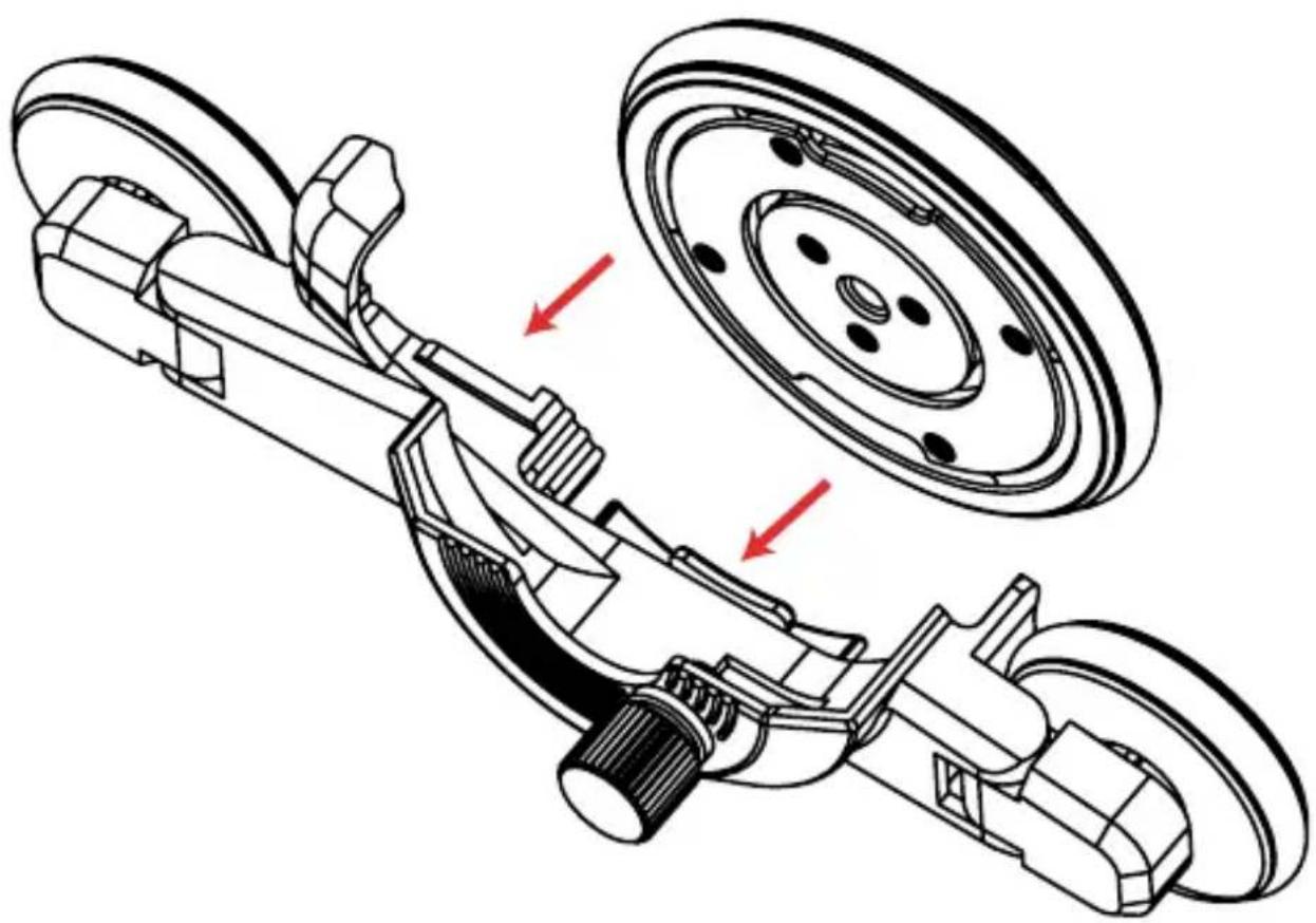
natural_image
Technical illustration of a vehicle suspension system showing brake and wheel assembly (no text or labels)Place the Power Wheel into the Micro Dolly cradle base
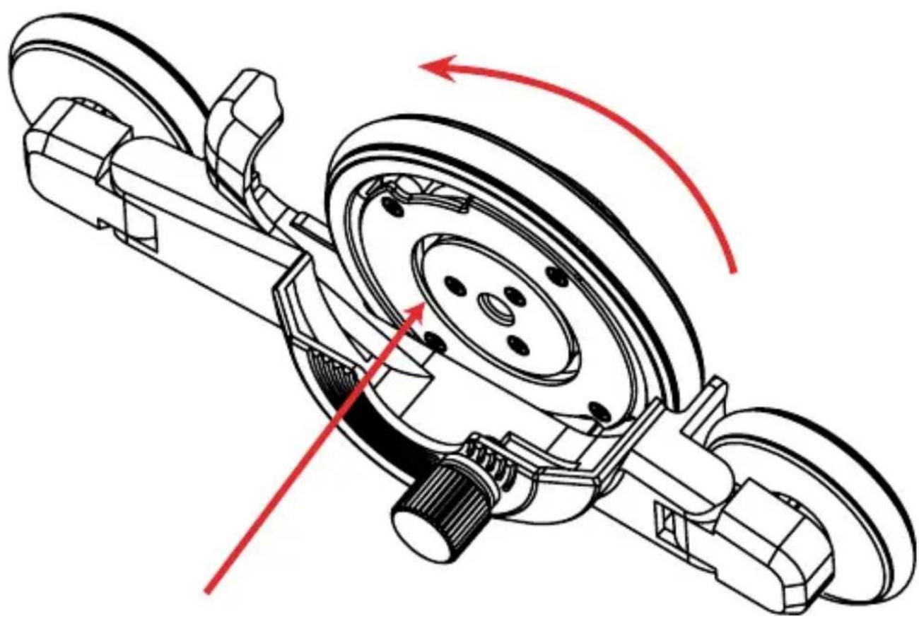
natural_image
Technical line drawing of a mechanical assembly with red directional arrows indicating motion or force (no text or symbols)Rotate the wheel to lock into place
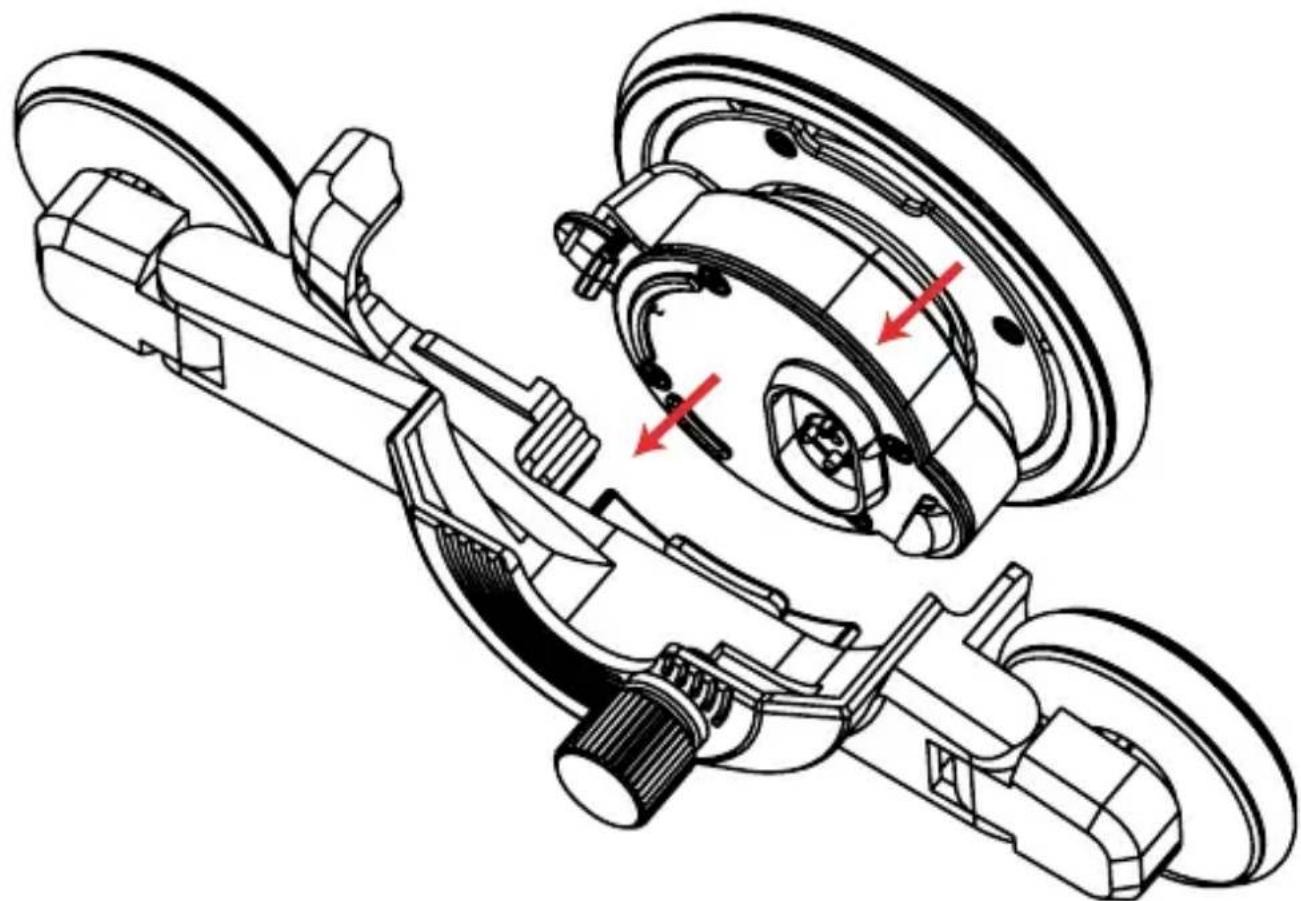
natural_image
Technical line drawing of a vehicle suspension system with brake and wheel components (no text or labels)Store option together with the MD 360 Mount
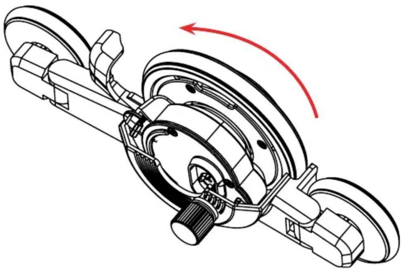
natural_image
Technical line drawing of a mechanical assembly with no visible text or symbolsRotate Power Wheel to lock into place.
- Important: The Movie Maker will automatically turn off when in speed "0", but not in speed 1-9.
- You can enable or disable the bounce-back function: On the D-Pad, hold “+” for 3 seconds. When the dot is flashing very fast it is disabled, slow flashing means is enabled. (When motor is idle, Dot off is disabled, Dot on is enabled).
- Use USB power for long time lapse shots. Some time lapse videos take longer than 2 hours. Keep the unit fully charged as you never know when inspiration strikes.
- Keep your camera secure and in sight at all times.
- Time Lapse shots are enhanced when the foreground is a static object and the background is moving with clouds, water or people. Visit our Facebook or YouTube pages for examples.
- The fold out legs are for non-flat surfaces and rarely used.
-
When recording sound on speed 8 & 9, point the microphone away from the motor or use a separate sound recorder.
-
Charging time is approximately 2 hours.
- Optimal performance is between 0-50 degrees Celsius. Below or above these temperatures may affect performance.
- Make sure the surface in front of your shot is smooth
- Work out the proper shooting angle in manual mode first before recording
-
Use the blue 360 panorama mount come with Movie Maker/Movie Maker 2 set for super slow motion (1/5 speed compared with orange unit)
If you have any other questions please feel free to email us anytime!
service@gripgear.com -
Speeds of Dolly in straight line using dark grey gear and light grey gear.
- Rotation speed in Panorama mode for dark grey and light grey gear.
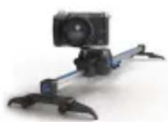
natural_image
Photograph of a mounted camera or optical instrument with dual-mounted legs (no visible text or symbols)
Slider mode Micro Dolly Panorama Mode
| Speed Travel mm/ minute Travel MM/Minute Rotation 1 turn of 360/ minute | ||||
| 1 4 8 1.6 28.2 141 | ||||
| 2 8 16 3.2 14.12 70.6 | ||||
| 3 16 32 6.4 7.06 35.3 | ||||
| 4 32 64 12.8 3.54 17.7 | ||||
| 5 64 128 25.6 1.764 8.82 | ||||
| 6 128 256 51.2 0.904 4.52 | ||||
| 7 256 500 100 0.452 2.26 | ||||
| 8 512 1000 200 0.226 1.13 | ||||
| 9 1024 2000 400 0.114 0.57 | ||||

text_image
GripGear™MOTION CONTROL FOR SMALL CAMERAS