Vector 430i - Tripod Vinten - Free user manual and instructions
Find the device manual for free Vector 430i Vinten in PDF.


User questions about Vector 430i Vinten
0 question about this device. Answer the ones you know or ask your own.
Ask a new question about this device
Download the instructions for your Tripod in PDF format for free! Find your manual Vector 430i - Vinten and take your electronic device back in hand. On this page are published all the documents necessary for the use of your device. Vector 430i by Vinten.
USER MANUAL Vector 430i Vinten
Vector 430 / 430i Pan and Tilt Head
V4006-0001
V4089-0001
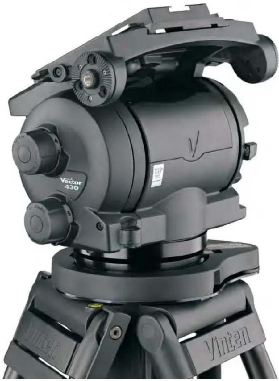
natural_image
Close-up of a black Vinten optical instrument mounted on a tripod, showing mechanical components and no visible text or symbols.EN
Operators Guide
V4006-4980/2
Vinten
Vector 430/430i
Pan & Tilt Head
Publication Part No.V4006-4980
Issue 2
September 2010
Published by
Vitec Group Videocom Division
Technical Publications Department
William Vinten Building
Western Way
Bury St Edmunds
Suffolk IP33 3TB
UK
Email: technical.publications@vitecgroup.com
Copyright © Vitec Group plc 2010
All rights reserved throughout the world. No part of this document may be stored in a retrieval system, transmitted, copied or reproduced in any way, including, but not limited to, photocopy, photograph, magnetic or other record without the prior agreement and permission in writing of Vitec Group plc.
Trademark Acknowledgements
Vinten Radamec Broadcast Robotics™ and Vinten™ are registered trademarks of Vitec Group plc.
Disclaimer
Camera Dynamics Limited reserves the right, without notice, to revise this documentation and make changes in content from time to time without obligation to provide notification of such revision or change. Revised documentation may be obtainable from Vinten or downloadable from the website
(www.vinten.com). Camera Dynamics Limited reserves the right, without notice, to make changes in equipment design or performance as progress in engineering, manufacturing or technology may warrant.
Safety - read this first
Understanding these instructions
English

The original instructions presented in this operators guide were written in English, and subsequently translated into other languages. If you are unable to understand these instructions, contact Vinten or your distributor to obtain a translation of the original instructions (EU Countries).
БЪЛГАРСКИ

Warning symbols in this Operators Guide

Where there is a risk of personal injury or injury to others, comments appear highlighted by the word WARNING!—supported by the warning triangle symbol.
Where there is a risk of damage to the product, associated equipment, process or surroundings, comments appear highlighted by the word CAUTION!
Usage
The Vector 430/430i pan & tilt head is designed for use by professional camera operators working with lightweight cameras configured with compact box lenses or large EFP barrel lenses in studio or OB applications. The Vector 430/430i pan & tilt head can support and balance a camera system weighing up to 43 kg (94.8 lbs). It is important that the head is mounted onto equipment designed to support the head and its maximum payload.
For use in VR/AR tracking applications the Vector 430i should be partnered with the VRi box.

Warning!
- Do NOT attempt to use this product if you do not understand how to operate it.
- Do NOT use this product for any other purpose than that specified in this Usage statement.
- Maintenance beyond that detailed in this Operators Guide must be performed only by competent personnel.
Disposal of waste batteries
Any batteries included with this product must not be treated as household waste. By ensuring these batteries are disposed of correctly, you will help prevent potentially negative consequences for the environment and human health, and help conserve natural resources. Please view the section on how to remove the batteries from the product safely. Hand the batteries over to the applicable collection point for recycling waste batteries.
Technical specification
Height....208 mm (8.1 in.)
Length 200 mm (7.8 in.)
Width 285 mm (11.2 in.)
Weight 12.1 kg (26.7 lbs)
Temperature range. -40°C to +60°C (-40°F to +140°F)
Tilt range. ±90^
Pan range 360°
Typical payload @ 150 mm C of G. 10–43 kg (22–94.8 lbs)
Pedestal/tripod fixing .... Four-hole flat base with integral Quickfix groove
Camera attachment EFP Quickfit™ adaptor
Levelling bubble ..... illuminated, blue
Pan bar.....single telescopic
Vector 430i
Pan / tilt resolution 1,480,000 counts/360°
Slide plate resolution tracking to 0.25 mm
Contents
Safety - read this first. 3
Warning symbols in this Operators Guide 5
Usage....5
Disposal of waste batteries 5
Technical specification 6
Components 9
Introduction and description....12
Vector 430i (encoded manual head) ..... 12
Perfect Balance 12
Digital numeric display....14
Thin film (TF) drag 14
Pan and tilt brakes....14
Illuminated level bubble 14
Four-hole mounting base....14
Pan bar 14
EFP Quickfit™ adaptor 15
Carrying handle 15
Operation 16
Mounting the head 16
Locking the platform....16
Fitting the pan bar 17
Fitting the pan bar 17
Fitting a camera and payload.... 17
Adjusting the slide plate.... 19
Balancing the head 20
Fore and aft balance 21
Payload weight and C of G height adjustment 21
Transportation 22
Connecting the Vector 430i head and the VRi box 22
Maintenance 23
General 23
Routine maintenance....23
Cleaning....23
Battery replacement....23
Adjustments....25
Repositioning the EFP Quickfit™ adaptor....25
Slide plate clamp adjustment....25
Pan and tilt brake adjustment 26
Balance and slide plate sensor calibration....26
Slide plate calibration (Vector 430i)....27
Parts list 28
Main assemblies 28
User-replaceable spare parts....28
Optional accessories 28
Vector 430i....28
Components

text_image
Labeled diagram of a robotic camera with numbered parts for identificationFig. 1 Vector 430/430i pan & tilt head (right-hand side)
[1] ..... Slide plate retractable handle (Tommy bar)
[2] Centre lock
[3][ Digital numeric display
[4] Digital numeric display push button
[5] Perfect Balance knob with fold-out handle
[6] Tilt brake lever
[7] Pan brake lever
[8] Level bubble illumination push button
[9]Level bubble
[10] Pan bar mount
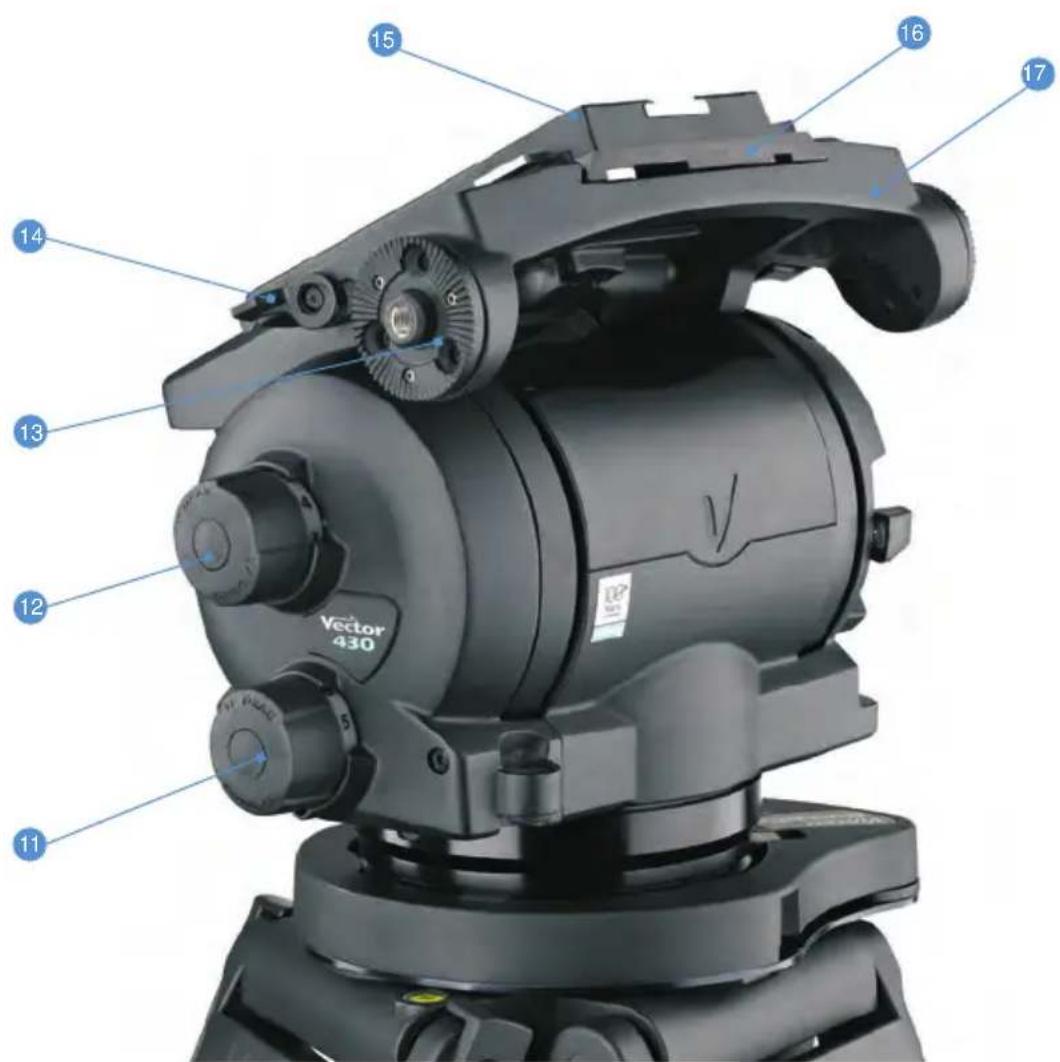
text_image
Vector 430 11 12 13 14 15 16 17Fig. 2 Vector 430/430i pan & tilt head (left-hand side)
[11] Pan drag adjustment knob
[12] Tilt drag adjustment knob
[13] Pan bar mount
[14] Slide plate clamp
[15]....EFP Quickfit™ adaptor
[16] Slide plate
[17] Platform
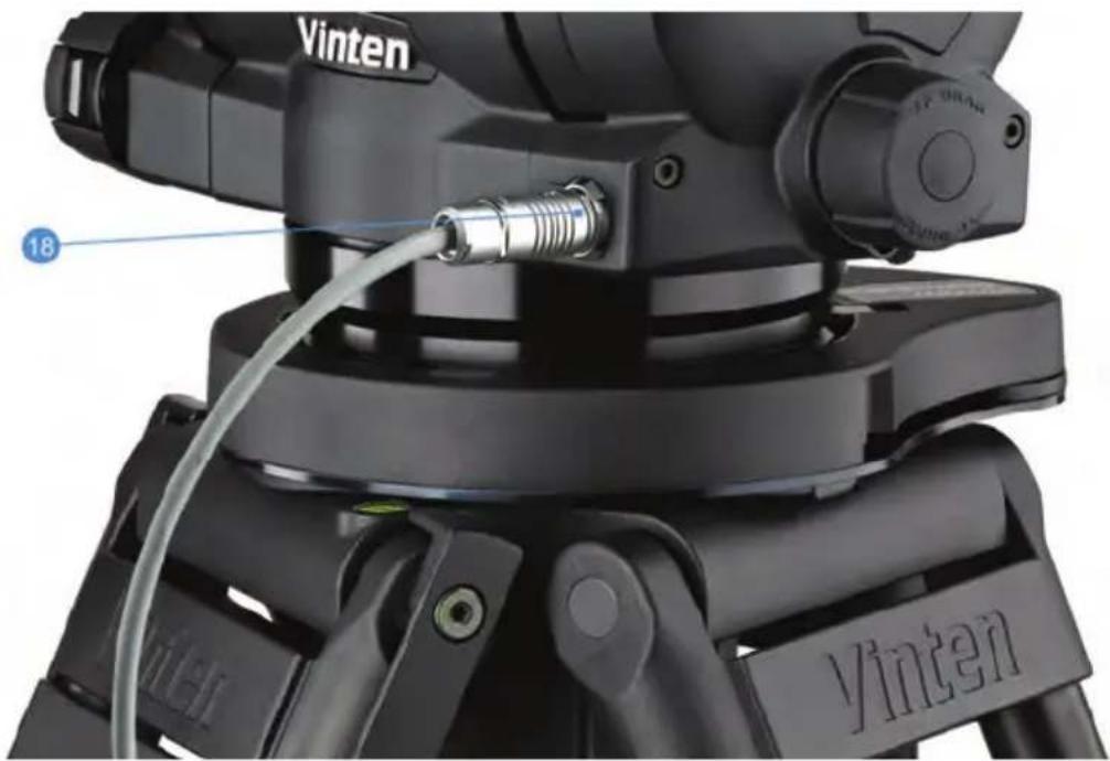
text_image
Vinten 18 VintenFig. 3 Vector 430i manual encoded head (left-hand front)
[18] devicelink.i port (shown with 430i-to-VRi interface cable)
Introduction and description
The Vector 430/430i pan & tilt head is designed for use by professional camera operators working with lightweight cameras configured with compact box lenses or large EFP barrel lenses in studio or OB applications, and supports and balances a camera system weighing up to 43 kg (94.8 lbs). The Vector 430/430i pan & tilt head embodies a unique and patented spring counterbalancing mechanism, thin film (TF) drag assemblies for pan and tilt motions and an adjustable camera mounting plate with an EFP Quickfit™ adaptor for rapid and secure attachment of the camera.
Vector 430i (encoded manual head)
The Vector 430i encoded manual pan & tilt head (Fig. 3) is designed to work with the Virtual Reality interface (VRi) box to allow computer-generated objects to be rendered into a video from the correct viewpoint.
The Vector 430i features upgradable optical encoders on both the pan and tilt axis. In addition to tracking pan and tilt angles, it also monitors the position of the camera slide plate allowing tracking and adjustment of the camera position without the need to recalibrate the tracking.
The system is designed to allow the most critical information (pan and tilt angles) to be passed directly to the VRi in real-time, while ancillary information is packaged by the head and downloaded by the VRi as required. The information is passed to the VRi via the devicelink.i port at the front of the head [18].
The Vector 430i pan & tilt head features white position guide markings and lines that are required for the configuration of the VRi box (to measure the optical VR axis offset). Please consult the VRi box Operators Guide for further information.
Perfect Balance
The unique spring counterbalancing mechanism comprises six springs operating against cams connected to the camera mounting platform. The balance mechanism is adjusted using the Perfect Balance knob [5] on the lower right-hand side of the head, which varies the mechanical advantage between the cam and the springs.
For ease of use the Perfect Balance knob [5] incorporates a fold-out handle (Fig. 4). Note that the Perfect Balance knob can be used without the fold-out handle.

CAUTION
Do not attempt to adjust the Perfect Balance knob below 0% or above 100% as damage could occur.
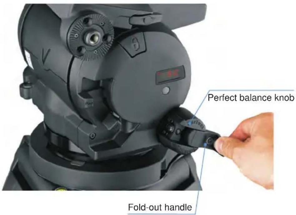
text_image
Perfect balance knob Fold-out handleFig. 4 Perfect Balance knob with fold-out handle
Maximum and minimum payloads that can be balanced are dependent on the weight of the camera system and on the centre of gravity (C of G) height. The counterbalance chart (Fig. 5) shows the range of payloads and C of G heights that can be maintained in balance. The shaded area on the chart shows the payload/C of G combinations that can be maintained in balance. Where a payload/C of G combination falls outside of those shaded areas it will be necessary to increase or decrease the weight or the C of G height—if possible—to enable the head to balance the load. A digital numeric display [3] indicates the setting of the counterbalance mechanism.

area
| Total Payload kg | Centre of Gravity Height (above platform) mm | | ---------------- | ------------------------------------------- | | 0 | 300 | | 15 | 275 | | 30 | 250 | | 45 | 225 | | 60 | 200 | | 75 | 175 | | 80 | 150 |Fig. 5 Counterbalance chart
Digital numeric display
The digital numeric display [3] located above the Perfect Balance knob [5] provides a simple numeric reference for camera balance, available tilt angle and—for the Vector 430i only—slide plate position. The unit comprises a single-row digital display and a push button [4] that illuminates the LED display for 15 seconds.
Press the push button [4] once to display the setting of the counterbalance mechanism on a scale of 0–100%. Pressing the push button [4] twice indicates the available angle of tilt at the current balance setting and—for the Vector 430i pan & tilt head only—pressing it three times displays the position of the slide plate (for information on calibrating the slide plate see page 27).
The batteries powering the electronic system are housed in a compartment located in the base of the head.
Thin film (TF) drag
Both the pan and tilt mechanisms incorporate the Vinten thin film (TF) system to ensure smooth movement of the camera about these axes and are fitted with adjustment knobs ([11], [12]) to adjust the drag setting. The whip-pan facility is unaffected by the pan drag setting. Both drag adjustment knobs are provided with scales that illuminate when the level bubble [9] is illuminated.
Pan and tilt brakes
Friction brakes on each axis allow the head to be locked at any chosen position. The levers ([6], [7]) for both brakes are located side-by-side on the right-hand side of the head. Pressing the brake levers down and locking into position applies the brakes. The brake levers are clearly labelled 'Pan' and 'Tilt'.
Illuminated level bubble
A level bubble [9], illuminated by pressing the illumination button [8] located underneath the bubble, is fitted to the rear of the head. When the level bubble [9] is illuminated, the scales on the pan and tilt drag adjustment knobs ([11], [12]) are also illuminated. The light extinguishes after approximately 15 seconds.
Four-hole mounting base
The head is provided with a standard Vinten four-hole mounting base, which includes a Quickfix mounting groove and provision for use of a Mitchell adaptor.
Pan bar
Pan bar mounting points ([10], [13]) are located at the rear of the head, on either side of the camera mounting platform. A single telescopic pan bar is supplied and can be attached using a pan bar clamp, with angular adjustment available on the mount serrations. A second pan bar may be fitted.
EFP Quickfit™ adaptor
The camera is attached to the head by means of a EFP Quickfit™ adaptor [15], which is mounted onto the slide plate [16] ex factory. The adaptor is supplied with a wedge plate and two 3/8 in. camera screws for rapid mounting of the camera.
Carrying handle
A carrying handle is provided at the rear of the platform under the slide plate. To access the handle, the slide plate may need to be repositioned further along the platform (for more information see ‘Transportation’ on page 22). Before attempting to transport the head using the carrying handle, the camera system must be removed and the head dismounted from the pedestal.
Operation
Mounting the head
It is important that the Vector 430/430i pan & tilt head is mounted onto a suitable pedestal or tripod designed to support the head and its maximum payload. The head is supplied with four mounting bolts and washers for mounting onto a pedestal or a suitable heavy-duty tripod with a flat mounting plate. Alternatively, the head can be mounted using either the EFP Quickfix™ adaptor provided or a Mitchell adaptor.

CAUTION
Before installing the head, hold a fixing bolt in position and check that the threaded end does not project more than 12 mm (0.47 in.) above the mounting face.

CAUTION
When mounting the head on a tripod, it is possible to set the tripod legs so that the C of G of the tilted payload lies outside the footprint of the tripod, leading to instability.
Use a mid-level or floor spreader to ensure that the tripod legs are spread sufficiently so that the C of G of the tilted payload remains within the footprint of the tripod.
Use the tie-down hook on the tripod for additional stability.
Locking the platform
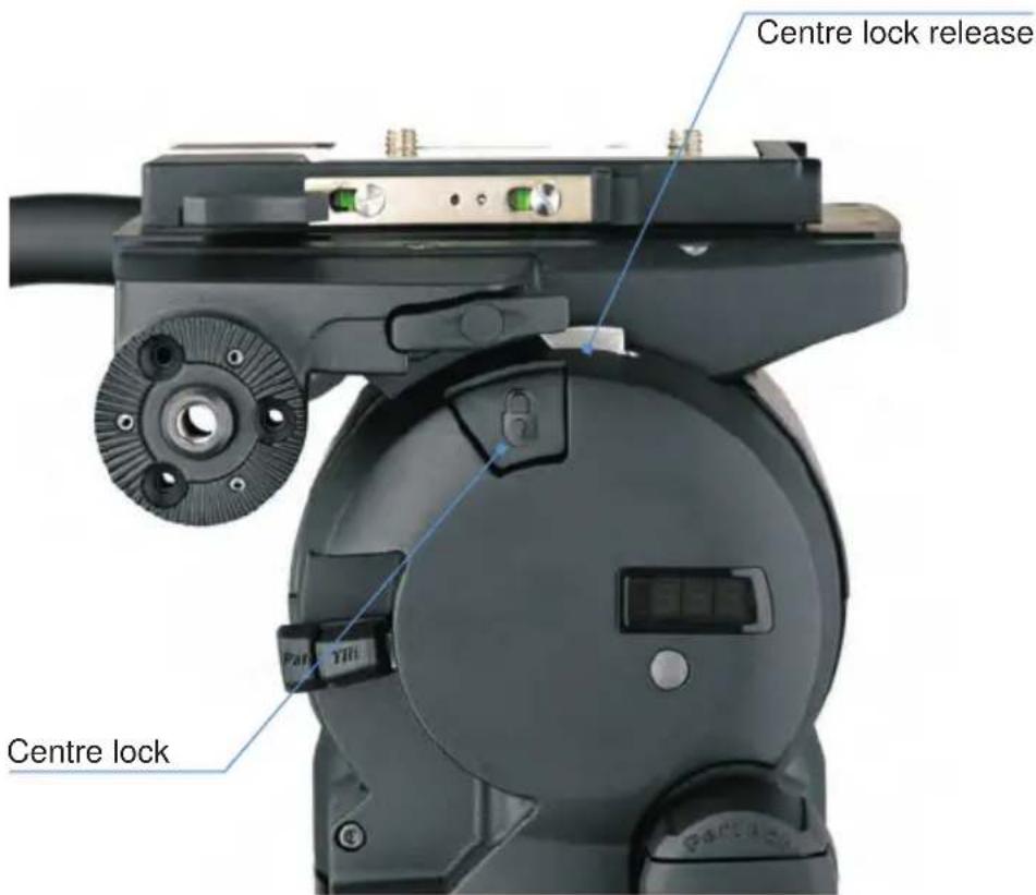
The centre lock [2] mechanism is operated by a plunger on the right-hand side of the head (Fig. 6). To engage the centre lock, hold the platform in the horizontal position and push the plunger inwards until it latches and the release lever appears. Use the pan bar to rock the platform [17] slightly whilst pushing the button.
To release the centre lock [2], rock the platform [17] slightly and push down on the release lever.
Pan and tilt brakes
The pan and tilt brakes ([6], [7]) are operated by levers on the right of the head (Fig. 1). The brakes are applied by pushing the appropriate lever down and released by pulling the lever up. The brakes should be applied whenever the camera is left unattended.
text_image
Centre lock release Centre lockFig. 6 Centre lock operation
Fitting the pan bar
A single pan bar is supplied and can be fitted to either the right- or left-hand side of the head onto the pan bar mounting ([10], [13]).
Position the pan bar onto the pan bar mounting ([10], [13]).
Rotate the pan bar clamp clockwise until the pan bar is secured.
A second pan bar may be fitted to the other side of the head (if required).
Fitting a camera and payload

CAUTION
Do not rely on the tilt brake when changing the payload. Always engage the centre lock.
Ensure that the weight and C of G height of the total payload is within the range for which the head is designed.
When installing on a pedestal, lock the pedestal in the fully depressed position before fitting the camera and payload.
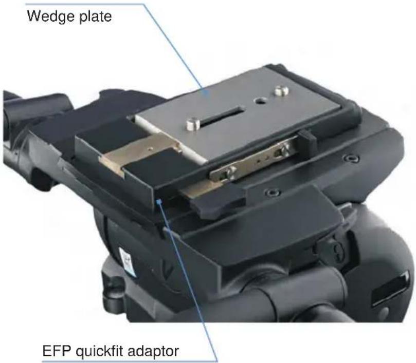
The EFP Quickfit™ adaptor [15] is installed on the slide plate ex factory (Fig. 7). To mount the camera attach the wedge adaptor in the middle position on the camera slide plate using the two 3/8 in. BSW camera screws in accordance with the instructions supplied with the camera.
text_image
Wedge plate EFP quickfit adaptorFig. 7 EFP Quickfit adaptor and wedge adaptor
To fit the camera to the head, proceed as follows:
Engage the centre lock [2] (Fig. 6).
Insert the forward edge of the camera wedge into the EFP Quickfit™ adaptor [15] (Fig. 7).
Push the wedge down until the lock bar clicks out.
Slide the safety lock plate backwards to hold the lock bar in position.
Install the remainder of the payload (lens, zoom and focus controls, viewfinder, prompter etc).
Adjusting the slide plate
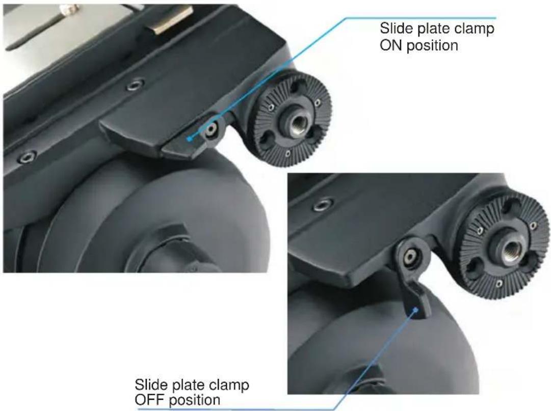
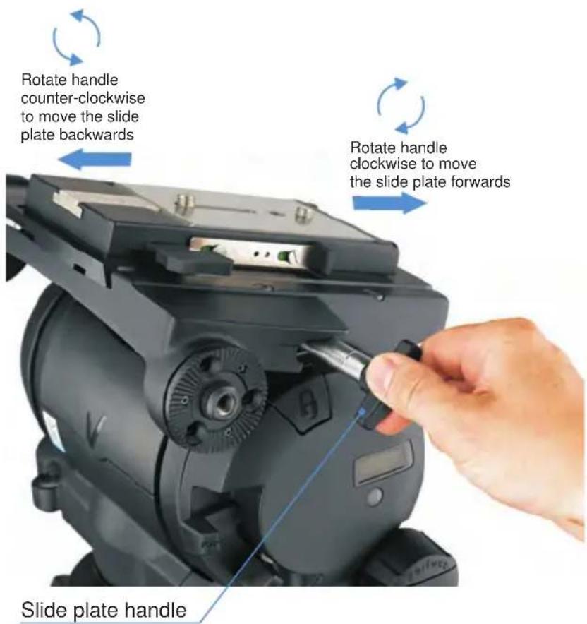
The position of the slide plate [16] can be adjusted using the retractable slide plate handle [1] (often referred to as the 'Tommy bar') located on the left-hand side of the head. The slide plate [16] is secured into position using the slide plate clamp [14] (Fig. 8).
text_image
Slide plate clamp ON position Slide plate clamp OFF positionFig. 8 Slide plate clamp (ON/OFF positions)
To release the slide plate, proceed as follows:
Release the slide plate clamp [14].
Pull out the sliding plate retractable handle [1] until it engages with the platform drive. Turn the handle clockwise to move the slide plate [16] in the fore direction. Turning the handle counter-clockwise moves the slide plate [16] in the aft direction (Fig. 9).
When the slide plate [16] is in position, secure using the slide plate clamp [14].
text_image
Rotate handle counter-clockwise to move the slide plate backwards Rotate handle clockwise to move the slide plate forwards Slide plate handleFig. 9 Slide plate retractable handle (Tommy bar)
Balancing the head
NOTE: It is important that the pan bar(s) and all camera accessories (lens, zoom and focus controls, viewfinder, prompter etc.) are fitted in their operational position BEFORE balancing the head. Any equipment fitted or adjusted later will unbalance the head.
Balancing the head achieves two objectives. Firstly, when a head is correctly balanced the operator will need a minimum amount of even effort to move the head. Secondly, once balanced, the head and its payload can be set to any tilt position and the head will maintain this position with 'hands off'.
The counterbalance chart (Fig. 5) shows the range of payload and C of G height that can be maintained in balance.
Fore and aft balance

CAUTION
Always refer to the counterbalance chart (Fig. 5) before attempting to balance the payload. Always apply a suitable amount of counterbalance BEFORE releasing the centre lock or the tilt brake lever.
When positioning the payload it is important to be aware of the potential danger of an unbalanced payload falling away suddenly. Before disengaging the centre lock [2], adjust the Perfect Balance knob [5] to its mid-point setting ('50' on the digital display). Depending on the payload weight, it may be necessary to increase or decrease this setting to enable the payload to be correctly balanced fore and aft.
Balance the payload fore and aft as follows:
Ensure that the centre lock [2] is engaged and that the camera and all accessories are fitted.
Turn the tilt drag adjustment knob [12] to its minimum setting.
Press the digital numeric display push button once to [4] display the counterbalance setting.
Turn the Perfect Balance knob [5] until the mid-point setting is reached (approximately '50' on the numeric display).

WARNING!
Be prepared to prevent the head falling away suddenly. In the event of the head falling away violently, increase the amount of counterbalance. When the head is mounted on a tripod, always steady the payload by holding on to the pan bar.
Holding the pan bar to steady the platform [17], disengage the centre lock [2].
Release the slide plate clamp [14] and pull out the slide plate adjustment handle [1] until it engages with the platform drive. Turn the handle to move the slide plate fore and aft to achieve horizontal balance.
The horizontal balance is correct when no perceptible tilting force can be felt on the pan bar with the platform level. Apply the slide plate clamp [14] and push in the slide plate adjustment handle [1] to its stowed position.
If there is insufficient movement in the slide plate to achieve balance, reposition the wedge adaptor, refit the payload and repeat the horizontal balancing procedure.
Payload weight and C of G height adjustment
When fore and aft balance has been achieved, carry out the payload weight and centre of gravity (C of G) height adjustment as follows:
NOTE: If the digital balance setting of the payload is known, turn the Perfect Balance knob until the digital numeric display indicates that setting.
Using the pan bar, tilt the platform [17] forward and backward. When correctly balanced, there should be no perceptible tilting force on the pan bar at any angle of tilt and the head should remain in any tilt position to which it is set.
NOTE: Setting the platform level will facilitate adjusting the balance setting.
If the head tends to fall away when the platform [17] is tilted, set the platform level and turn the Perfect Balance knob [5] clockwise to increase the balance setting. If the head tends to spring back to centre, set the platform [17] level and turn the Perfect Balance knob [5] counter-clockwise to decrease the balance setting.
When the payload weight and C of G height adjustment is complete, check that the fore and aft balance remains satisfactory. Readjust the position of the slide plate [16] if necessary.
The digital numeric display [3] will display the balance setting while balance is being adjusted. Make a note of the final setting to facilitate rebalancing this particular payload.
After balancing, exercise the head through both axes to confirm that it operates smoothly.
Transportation
A carrying handle is provided at the rear of the platform under the slide plate. Before attempting to transport the head using the carrying handle, the camera and payload must be removed and the head dismounted from the pedestal.
Engage the centre lock [2].
Release the slide plate clamp [14].
Pull out the slide plate adjustment handle [1] until it engages with the platform drive. Turn the handle clockwise to move the slide plate [16] in the fore direction.
When the slide plate [16] is clear of the carrying handle, lock the slide plate clamp [14].
Connecting the Vector 430i head and the VRi box
The VRi box is installed on the Vector 430i pan & tilt head using mount bars fitted to a support bracket that is attached to the underside of the head. The bracket offers the shoulder mounts used to attach the mount bars which are included with the VRi box (part no. V4083-0001).
Once installed, the VRi box is connected to the Vector 430i using the 430i-to-VRi interface cable (part no. V3980-5052). The interface cable is included with the VRi box and fitted with a Fischer connector at each end.
To connect the VRi box to the Vector 430i head, proceed as follows:
Plug one Fischer connector into the devicelink.i port on the VRi box, the other into the devicelink.i port on the head [18].
Verify that the VRi box is connected; using the Vinten Radamec PDA or a laptop check that the DEVICELINK.i check box at the bottom of the main menu screen is ticked.
For more information, please refer to the Vinten Radamec PDA or VRi box user documentation.
Maintenance
General
The Vector 430/430i pan & tilt head is robustly made to high engineering standards and little attention is required to maintain serviceability except regular cleaning.
Routine maintenance
Replace the batteries whenever the low battery indicator flashes on the digital numeric display [3] (Fig. 1).
During use, check the following:
Check the effectiveness of the pan and tilt brakes ([6], [7]). Reset as necessary.
Check the effectiveness of the slide plate clamp [14]. Reset as necessary.
Check the operation of the balance mechanism digital numeric display [3] and the illumination of the LEDs, level bubble [9] and drag adjustment knobs ([11], [12]). Replace the batteries if necessary.
No further routine maintenance is required.
Cleaning
During normal use the only cleaning required should be a regular wipe over with a lint-free cloth. Dirt accumulated during storage or periods of disuse may be removed with a vacuum cleaner. Particular attention should be paid to the wedge location faces of the wedge adaptor.
NOTE: Use only detergent-based cleaners. DO NOT use solvent- or oil-based cleaners, abrasives or wire brushes to remove accumulations of dirt as these damage the protective surfaces.
Use out-of-doors under adverse conditions may require special attention and the head should be covered when not in use. Salt spray should be washed off using fresh water at the earliest opportunity. Sand and dirt act as an abrasive and should be removed using a vacuum cleaner or a dry, clean supply of air.
Battery replacement
The head has three batteries powering the digital numeric display [3] and illuminate the level bubble [9] and the scales on the drag adjustment knobs ( [11] , [12] ). Batteries should be replaced whenever the low battery indicator flashes on the digital numeric display [3] .
The camera system must be removed and the head dismounted from the pedestal or tripod to access the battery compartment located under the head (Fig. 10).
NOTE: After a battery change, both the balance and the slide plate sensors of the Vector 430i pan & tilt head will need calibrating (see page 27 for instructions).
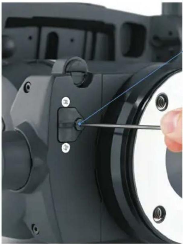
natural_image
Close-up of a mechanical component with a hand adjusting a screwdriver (no visible text or symbols)Use an allen key to remove the screw securing the battery tray
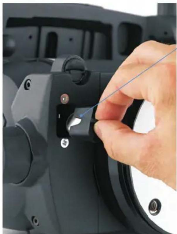
natural_image
Close-up of a hand using a tool to adjust or install a mechanical component (no visible text or symbols)Carefully pull-out the battery tray
Fig. 10 Removing the battery tray
To remove the battery, proceed as follows:
Using an allen key (2.5 mm) remove the screw securing the battery tray (Fig. 10).
Carefully pull-out the battery tray from the compartment.
Remove the old batteries from the battery tray.
Install three new batteries into the battery tray. The batteries must be positioned vertically (stacked left to right) in the tray, with the positive (+) side of the batteries facing towards the battery tray fixing screw hole.
Holding the battery tray by the handle, carefully insert the tray into the battery compartment in the base of the head.
Using an allen key (2.5 mm), refit the screw to secure the battery tray into position.
Press the level bubble illumination button [8] and ensure that the level bubble [9] and drag knob scales ([11], [12]) are lit for approximately 15 seconds. Press the digital numeric display push button [4] to ensure that the digital numeric display [3] illuminates.
Adjustments
To enable the payload to be correctly balanced, the EFP Quickfix™ adaptor [15] (Fig. 2) may require repositioning. The following adjustments may also be necessary after prolonged use; the slide plate clamp [14] may require adjustment and the pan and tilt brakes ([6], [7]) may require adjustment.
Repositioning the EFP Quickfit™ adaptor
The EFP Quickfit™ adaptor [15] is secured by six screws which pass through the adaptor into the slide plate [16]. The adaptor [15] may be fitted in three positions.

CAUTION
Overlong screws will prevent the sliding plate from operating. Always use the screws (M4 x 12 mm) provided with the adaptor.
To reposition the EFP Quickfit adaptor [15]:
Engage the centre lock [2] and remove the camera and payload.
Hold the body of the EFP Quickfit adaptor [15] and remove the six securing screws.
Reposition the adaptor [15] on the slide plate [16], ensuring that the lock bar is towards the rear of the head.
Secure into position using the six screws.
Slide plate clamp adjustment
The slide plate clamp [14] should be set so that in the up or clamped position it prevents the slide plate [16] from moving, while in the down or released position it allows free adjustment of the slide plate. To adjust the slide plate clamp [14], proceed as follows:
Lock the slide plate clamp [14].
Using an allen key (2.5 mm), remove the slide plate clamp fixing screw.
Remove the slide plate clamp [14].
The slide plate clamp [14] fits onto a splined shaft. Rotate the clamp and then carefully refit onto the splined shaft. To increase the torque, rotate the slide plate clamp counterclockwise before refitting.
Turn the slide plate clamp [14] fully clockwise to the ON position until it is level with the platform [17].
Refit the fixing screw to the slide plate clamp [14].
Move the slide plate clamp [14] over its full range and ensure that, in the clamped position, it prevents the slide plate [16] from being moved, while in the released position it allows free adjustment of the slide plate. Readjust if necessary.
Pan and tilt brake adjustment
The pan and tilt brakes are operated by levers ([6], [7]) on the right-hand side of the head (Fig. 1). The brakes are applied by pushing the appropriate lever down and released by pulling the lever up.
If the brakes become ineffective, adjustment should be carried out by qualified personnel. Contact Vinten or your local Vinten distributor for service of the Vector 430/430i pan & tilt head.
Balance and slide plate sensor calibration
The digital numeric display [3] indicates the setting of the balance mechanism on a scale of 0 (minimum setting) to 100 (maximum setting) and the available tilt angle (90° to 40°). On the Vector 430i pan & tilt head the display also shows the position of the slide plate (0–300 mm). In the event that the balance mechanism and slide plate sensor require calibration in the field, the following procedure should be followed.
NOTE: If more than 5 minutes elapse before completion, the system will shut down and revert to its previous settings. If no movement has been detected on either sensor within 15 seconds, the calibration mode is aborted and no calibration limits are stored.
To calibrate the head, proceed as follows:
Level the platform [17] and apply the centre lock [2].
Press and hold the level bubble illumination button [8] and the digital numeric display button [4] simultaneously until 'CAL' is displayed, flashing slowly.
Once in calibration mode, move the slide plate to its mechanical extremes in both directions and wind the Perfect Balance knob [5] to its mechanical extremes in both directions. The controller monitors the measurements and stores the maximum and minimum values.
To complete the calibration, press and hold the digital numeric display push button [4] for 2 seconds until the display flashes 'CAL' five times rapidly.
After calibration, rebalance the head.
Slide plate calibration (Vector 430i)
On the Vector 430i pan & tilt head both the balance and slide plate sensors will need calibrating, either in the factory or in the field, on first setup or after a battery change, for instance.
To enter calibration mode, hold down the level bubble illumination button [8] and the numeric display button [4] simultaneously for 2 seconds. The display will change to show 'CAL', flashing slowly.
Once in calibration mode, move the slide plate to its mechanical extremes in both directions and wind the Perfect Balance knob [5] to its mechanical extremes in both directions. The controller monitors the measurements and stores the maximum and minimum values.
To complete calibration, press and hold the display button for 2 seconds. The software then stores the calibration limits in flash memory and flashes 'CAL' five times rapidly.
NOTE: Calibration limits for a given sensor are only stored if sufficient movement has been detected on that sensor. This allows one sensor to be calibrated at a time. If no movement has been detected on either sensor within 15 seconds, the calibration mode is aborted and no calibration limits are stored.
Parts list
The following list includes the main assemblies, user-replaceable spare parts and optional accessories. For further information regarding repair or spare parts, please contact Vinten or your local distributor. For information online, visit our website at www.vinten.com.
Main assemblies
Vector 430 pan & tilt head - flat base V4006-0001
Vector 430i pan & tilt head - flat base. V4089-0001
EFP Quickfit™ adaptor.... 3761-3
Standard EFP Quickfit™ wedge plate 3761-13
Telescopic pan bar and clamp 3219-115
Fixing bolt....L054-714
Washer - for fixing bolt .... L602-122
Spanner - for fixing bolts. J551-001
User-replaceable spare parts
Battery - CR2032 (3V/230mAh) . . . . . . . . . . . . . . . . . . . . . . . . . . . . . . . . . . . . . . . . . . . . . . . . . . . . . . . . . . . . . . . . . . . . . . . . . . . . . . . . . . . . . . . . EEBA000009
Optional accessories
Heavy-duty Quickfix adaptor 3490-3
Levelling adaptor Quickfix to four-bolt flat base 3328-30
Lightweight Mitchell adaptor....3103-3
Heavy-duty Mitchell adaptor - for Vinten pedestal mounting in conjunction with Hi-hat adaptor, part no. 3055-3 3724-3
Vector 430i
VRi box....V4083-0001
430i-to-VRi (interface) cable....V3980-5052

Vector 430 / 430i Pan and Tilt Head
V4006-0001
V4089-0001
CHINA
The Vitec Group plc China
Rm 706, Tower B
Derun Building
YongAn Dongli A No. 8
Jianwai Ave, Chaoyang District
Beijing, China 100022
Tel. +86 10 8528 8748
Fax +86 10 8528 8749
FRANCE
Vitec Group Videocom Division
Vitec Group Videocom Division
Gebäude 16
Planiger Straße 34
55543 Bad Kreuznach
Germany
Tel. +49 671 483 43 30
Fax +49 671 483 43 50
Vitec Group Videocom Division
Erfurter Straße 16
85386 Eching
Germany
Tel. +49 89 321 58 200
Fax +49 89 321 58 227
JAPAN
Vinten Japan KK
P.A. Bldg. 5F
3-12-6 Aobadai
Meguro-ku Tokyo 153-0042
Japan
Tel. +81 3 5456 4155
Fax +81 3 5456 4156
SINGAPORE
Vitec Group Videocom Division
6 New Industrial Road
02-02 Hoe Huat Industrial Building
Singapore 536199
Tel. +65 6297 5776
Fax +65 6297 5778
UK
Vitec Group Videocom Division
William Vinten Building
Western Way
Bury St Edmunds
Suffolk IP33 3TB
Tel. +44 1284 752 121
Fax +44 1284 750 560
Sales Fax +44 1284 757 929
USA
Vitec Group Videocom Division
709 Executive Blvd
Valley Cottage
NY 10989
USA
Tel. +1 845 268 0100
Fax +1 845 268 0113
Toll Free Sales: +1 888 2 Vinten
Operators Guide
V4006-4980/2

THE QUEEN'S AWARDS
FOR ENTERPRISE:
INNOVATION
2010

Vinten ^TM
A Vitec Group brand
for more information, visit
www.vinten.com