
D16WU-HS - Vidéo-projecteur Christie - Free user manual and instructions
Find the device manual for free D16WU-HS Christie in PDF.


User questions about D16WU-HS Christie
0 question about this device. Answer the ones you know or ask your own.
Ask a new question about this device
Download the instructions for your Vidéo-projecteur in PDF format for free! Find your manual D16WU-HS - Christie and take your electronic device back in hand. On this page are published all the documents necessary for the use of your device. D16WU-HS by Christie.
USER MANUAL D16WU-HS Christie
The CD included with this printed manual contains an electronic copy in English. Please read all instructions before using or servicing this product.
Copyright © 2017 Christie Digital Systems USA Inc. All rights reserved.
All brand names and product names are trademarks, registered trademarks or trade names of their respective holders.
REGULATORY
The product has been tested and found to comply with the limits for a Class A digital device, pursuant to Part 15 of the FCC Rules. These limits are designed to provide reasonable protection against harmful interference when the product is operated in a commercial environment. The product generates, uses, and can radiate radio frequency energy and, if not installed and used in accordance with the instruction manual, may cause harmful interference to radio communications. Operation of the product in a residential area is likely to cause harmful interference in which case the user will be required to correct the interference at the user's own expense.
WARNING! Changes or modifications not expressly approved by Christie could void the user's authority to operate the product.
FOR COMMERCIAL USE ONLY - POUR USAGE COMMERCIAL UNIQUEMENT
THIS DEVICE COMPLIES WITH PART 15 OF THE FCC RULES. OPERATION IS SUBJECT TO THE FOLLOWING 2 CONDITIONS: (1) THIS DEVICE MAY NOT CAUSE HARMFUL INTERFERENCE (2) THIS DEVICE MUST ACCEPT ANY INTERFERENCE RECEIVED, INCLUDING ANY INTERFERENCE THAT MAY CAUSE UNDESIRED OPERATION.
THIS CLASS A DIGITAL APPARATUS MEETS ALL REQUIREMENTS OF THE CANADIAN INTERFERENCE-CAUSING EQUIPMENT REGULATIONS.
CET APPAREIL NUMÉRIQUE DE CLASSE A EST CONFORME AUX NORMES DÉFINIES DANS LES RÉGLEMENTATIONS CANADIENNES SUR LES APPAREILS CAUSANT DES INTERFÉRENCES RADIO (CANADIAN INTERFERENCE-CAUSING EQUIPMENT REGULATIONS, ICES-003, CLASS A).
Every effort has been made to ensure accuracy, however in some cases changes in the products or availability could occur which may not be reflected in this document. Christie reserves the right to make changes to specifications at any time without notice. Performance specifications are typical, but may vary depending on conditions beyond Christie's control such as maintenance of the product in proper working conditions. Performance specifications are based on information available at the time of printing. Christie makes no warranty of any kind with regard to this material, including, but not limited to, implied warranties of fitness for a particular purpose. Christie will not be liable for errors contained herein or for incidental or consequential damages in connection with the performance or use of this material.
The product is designed and manufactured with high-quality materials and components that can be recycled and reused. This symbol means that electrical and electronic equipment, at their end-of-life, should be disposed of separately from regular waste. Please dispose of the product appropriately and according to local regulations. In the European Union, there are separate collection systems for used electrical and electronic products. Please help us to conserve the environment we live in!
Canadian manufacturing facility is ISO 9001 and 14001 certified.
GENERAL WARRANTY STATEMENTS
For complete information about Christie's limited warranty, please contact your Christie dealer. In addition to the other limitations that may be specified in Christie's limited warranty, the warranty does not cover:
a. Damage occurring during shipment, in either direction.
b. Problems caused by combination of the product with non-Christie equipment, such as distribution systems, cameras, video tape recorders, etc., or use of the product with any non-Christie interface device.
c. Damage caused by misuse, improper power source, accident, fire, flood, lightening, earthquake or other natural disaster.
d. Damage caused by improper installation/alignment, or by product modification, if by other than a Christie authorized repair service provider.
e. For LCD projectors, the warranty period specified applies only where the LCD projector is in "normal use". "Normal use" means the LCD projector is not used more than 8 hours a day, 5 days a week. For any LCD projector where "normal use" is exceeded, warranty coverage under this warranty terminates after 6000 hours of operation.
f. Failure due to normal wear and tear.
PREVENTATIVE MAINTENANCE
Preventative maintenance is an important part of the continued and proper operation of your product. Failure to perform maintenance as required, and in accordance with the maintenance schedule specified by Christie, will void the warranty.
Content
Safety 8
Laser safety warnings 9
Laser label 10
Light intensity hazard distance 11
Introduction 13
Projector components 13
Front view 13
Rear view 14
Left view 15
Right view 16
Built-in keypad 16
Input/Output (I/O) panel 17
IR remote keypad 18
LED status indicators 20
Status LED 20
Shutter LED 20
Installation 21
Connecting to a computer 22
Connecting to video equipment 23
Turning the projector on 24
Turning the projector off 25
Adjusting the projector position 26
Calculating the lens offset 27
WUXGA projectors 27
HD Projectors 29
Removing and installing the lens 30
Installing the fuse 31
Cleaning or replacing the filter 32
Installing the ceiling mount ....33
Installing the projector in the rigging frame ....33
Operation 34
Size and Position menu 35
Geometry correction 37
Image Settings menu 39
Configuration Menu 42
Color matching 47
Light Source menu 49
Status menu 50
For DHD models 50
For DWU models 51
Input Switching & PIP menu 52
PIP/PBP layout and size 53
Language menu 54
Test Pattern menu 54
Web user interface 55
Logging on to the web user interface 55
Main tab-General 56
Main tab-Status 56
Main tab-Lens 57
Network 58
Tools 61
Administrator Page 61
About Page 61
Christie Presenter 62
Connecting to the Projector 62
Installing the Christie Presenter software 63
Using the Christie Presenter 65
Connecting and searching the network display ....66
Selecting the display region 67
Configuring Christie Presenter 68
Managing all connected network displays....69
Operating the card reader 70
Troubleshooting 73
No image appears on screen 73
Incorrectly displayed image 73
Presentation is not displayed 74
Unstable or flickering images 75
Vertical flickering bar 75
Image is out of focus 75
Image is stretched 75
Image is not the correct size 76
Specifications 77
Inputs 78
PIP/PBP compatibility 82
Key features 82
List of components 83
Physical specifications 84
Physical operating environment 84
Power requirements 85
Warnings 85
Regulatory 86
Safety 86
Laser safety 86
Electro-Magnetic Compatibility 87
Environmental 87
Federal Communications Commission (FCC) warning 87
On-screen display tree 88
Safety
Read through this document in its entirety and understand all warnings and precautions before attempting to operate the projector.

Warning! Failure to comply with the following could result in death or serious injury.
- Please carefully review and follow the installation instruction included in this manual.
- Do not look into the projector lens when the laser is on. The bright light may result in permanent eye damage.
- To reduce the risk of fire or electric shock, do not expose this projector to rain or moisture.
- Do not open or disassemble the projector as this may cause electric shock.
- All installations must be performed by Christie qualified authorized trained installers.
- Keep all combustible material away from the concentrated light beam of the projector.
- Position all cables where they cannot contact hot surfaces or be pulled or tripped over.
• Always power down the projector and disconnect all power sources before servicing or cleaning. - Use a soft cloth moistened with a mild detergent to clean the display housing.
- Disconnect the power plug from the AC outlet if the product is not being used for an extended period of time.
- Only use the AC power cord supplied. Do not attempt operation if the AC supply and cord are not within the specified voltage and power range for your region.
- Remove the lens plug from the lens opening in the projector before installing the lens. Retain the lens plug to protect the optical components from dust and debris during transport.
- Do not block the ventilation slots and openings on the projector.
- Do not use abrasive cleaners, waxes, or solvents to clean the projector.
- Do not allow anything to rest on the power cord.
• Not for household use. - No direct exposure to beam shall be permitted.
Laser safety warnings
This product is classified as CLASS 1 LASER PRODUCT - RISK GROUP 3 according to IEC 60825-1:2014 and IEC 62471:2006.
text_image
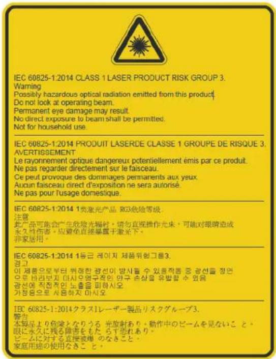
Christie Digital Systems Canada Inc. 809 Wellington Street North Kitchener, ON N2G 4Y7 Canada This product complies with performance standards for laser products under 21 CFR Part 1040 except with respect to those characteristics authorized by Variance Number 2016-V-1838 effective June 20, 2017. U.S.A OnlyLaser label
CLASS 1 LASER PRODUCT IEC 60825-1:2014

Warning! Failure to comply with the following could result in death or serious injury.
- Please carefully review and follow the installation instruction included in this manual.
- This product must be installed to prevent exposure to the RG3 hazard zone. If human access is possible, additional safety measures must be taken. See Installation section for additional details.
- PERMANENT/TEMPORARY BLINDNESS HAZARD! Operators must control access to the beam within the hazard distance or install the product preventing potential exposure of the spectators' eyes from being in the hazard distance. Hazard zone shall be no lower than 3.0 meters above the floor. In addition, horizontal clearance to the hazard zone shall be a minimum 2.5 meters.
- Possibly hazardous optical radiation emitted from this product. (Risk group 3).
- This projector has a built-in Class 4 laser module. Never attempt to disassemble or modify the projector.
- Any operation or adjustment not specifically instructed in the User manual creates the risk of hazardous laser radiation exposure.
- Do not open or disassemble the projector as this may cause damage from exposure of laser radiation.
- PERMANENT/TEMPORARY BLINDNESS HAZARD! No direct exposure to the beam must be permitted. RG3 IEC 62471:2006.
• Install the product so users and the audience cannot enter the restricted area at eye level. - Follow the control, adjustment, or operation procedures to avoid damage or injury from exposure of laser radiation.
- The instructions for the assembly, operation, and maintenance include clear warnings concerning precautions to avoid possible exposure to hazardous laser radiation.
- Installing or replacing a lens must be done by a Christie qualified authorized service technicians or installers to avoid exposure to dangerous emission levels.
• Not for household use.
Light intensity hazard distance
This projector has been classified as Risk Group 3 per the IEC 62471:2006 standard due to possible hazardous optical and thermal radiation being emitted.

Warning! Failure to comply with the following could result in serious injury.
- PERMANENT/TEMPORARY BLINDNESS HAZARD! No direct exposure to the beam must be permitted. RG3 IEC 62471:2006.
- PERMANENT/TEMPORARY BLINDNESS HAZARD! Operators must control access to the beam within the hazard distance or install the product preventing potential exposure of the spectators' eyes from being in the hazard distance. Hazard zone shall be no lower than 3.0 meters above the floor. In addition, horizontal clearance to the hazard zone shall be a minimum 2.5 meters.
- EXTREME BRIGHTNESS! Do not place reflective objects in the product light path.
- The bright light may result in permanent eye damage.
- The use of the projector with lenses PN: 140-109101-XX, 140-110103-XX, 140-114107-XX, and 140-115108-XX, where the throw ratio is less than or equal to 2.0:1 result in risk group 2 emissions from the projector. No hazard distance has been identified for use of the projector with these lenses. Precautions must be taken to follow the warnings listed above to avoid serious injury.
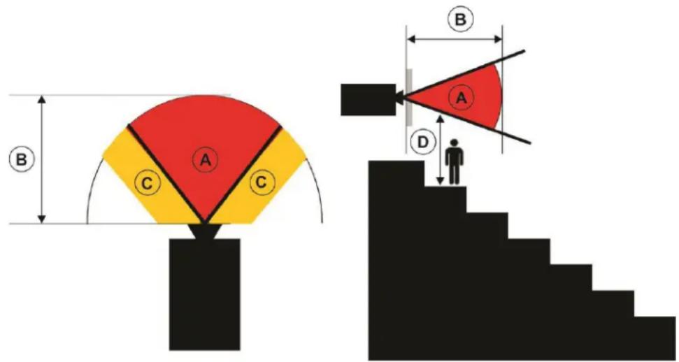
The following diagram and table shows the zones for optical and thermal radiation hazard distances:
text_image
A B C C B A D- A — Hazard zone. The region of space where the projection light from the laser illuminated projector is above emission limits for Risk Group 2. The light intensity may cause eye damage after a momentary or brief exposure (before a person can avert his or her eyes away from the light source). The light may cause skin burns to occur.
- B — Hazard distance. Operators must control access to the beam within the hazard distance or install the product preventing potential exposure of the spectators' eyes from being in the hazard distance.
- C — No access zone. Horizontal clearance of the no access zone shall be a minimum of 2.5 meters.
- D — Vertical distance to hazard zone. The hazard zone shall be no lower than 3.0 meters above the floor.
For US market only, hazard distances based upon FDA guidance document 1400056, Classification and Requirements for Laser Illuminated Projectors (LIPs), dated February 18, 2015:
| Projection lens | Part number | Hazard distance (m) | Category |
| 0.84:1 - 1.02:1 140-114107-XX - RG2 | |||
| 1.02:1 - 1.36:1 140-115108-XX - RG2 | |||
| 1.2:1 - 1.5:1 140-109101-XX - RG2 | |||
| 1.5:1 - 2.0:1 140-110103-XX - RG2 | |||
| 2.0:1 - 4.0:1 140-111104-XX 2.1 RG3 | |||
| 4.0:1 - 7.2:1 140-116109-XX 4.1 RG3 |
For all other markets, hazard distances based upon IEC 62471-5:2015, Photobiological safety of lamps and lamp systems - Part 5: Image projectors:
| Projection lens | Part number | Hazard distance (m) | Category |
| 0.84:1 - 1.02:1 140-114107-XX - | RG2 | ||
| 1.02:1 - 1.36:1 140-115108-XX - | RG2 | ||
| 1.2:1 - 1.5:1 140-109101-XX - | RG2 | ||
| 1.5:1 - 2.0:1 140-110103-XX - | RG2 | ||
| 2.0:1 - 4.0:1 140-111104-XX | 1.9 | RG3 | |
| 4.0:1 - 7.2:1 140-116109-XX | 3.3 | RG3 |
Introduction
The HS Series is a high brightness, high-resolution video graphics one-chip laser-based projector. The projector is available in HD and WUXGA resolutions and uses Digital Light Processing (DLP ^® ) technology from Texas Instruments. It is primarily designed for fixed installation and secondary applications including rental-staging and LBE (Location Based Entertainment). This product is used for professional applications and is not for domestic use.
Projector components
Identify the main components of the projector.
Front view
Identify the main components on the front of the projector.

text_image
Technical diagram of a mechanical assembly with numbered components and labeled partsID Part name Description
| 1 | Front IR sensors | Receives signals from the IR remote keypad. Keep the signal path to the sensor unobstructed for uninterrupted communication with the projector. |
| 2 | Projection lens | Allows automated lens control and adjustment: vertical and horizontal offsets, zoom, and focus. |
| 3 | Adjustable feet Raises or lowers the feet to level the projector. | |
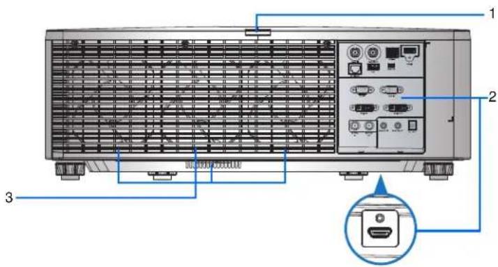
Rear view
Identify the main components on the rear of the projector.
text_image
Diagram of a server rack with labeled components and an inset showing the internal connector.ID Part name Description
| 1 Rear | IR sensor Receives signals from the IR remote keypad. Keep the signal path unobstructed for uninterrupted communication with the projector. | |
| 2 Input/Output (I/O) panel Connects the projector to external devices. | ||
| 3 | Cooling air vents (exhaust) | Provides cooling to the projector. Keep these vents unobstructed to prevent the projector from overheating. |
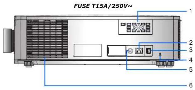
Left view
Identify the main components on the left side of the projector.
text_image
FUSE T15A/250V~ 1 2 3 4 5 6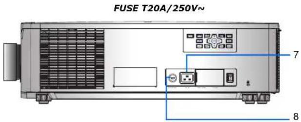
text_image
FUSE T20A/250V~ 7 8ID Part Name Description
| 1 Built-in keypad Controls the projector. | ||
| 2 AC input Connects to the supplied power adapter (200 to 240V~). | ||
| 3 Power button Powers the projector on or off. | ||
| 4 Kensington lock Secures the projector to counter tops, tables, and so on. | ||
| 5 Fuse FUSE T15A/250V~. | ||
| 6 | Cooling air vents (intake) | Provides cooling to the projector. Keep these vents unobstructed to prevent the projector from overheating. |
| 7 AC input Connects to the supplied power adapter (100V to 120V~). | ||
| 8 Fuse FUSE T20A/250V~. | ||
Right view
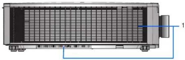
Identify the main component on the right side of the projector.
natural_image
Technical diagram of a heat exchanger or cooling unit with labeled component 1 (no text or symbols beyond label)ID Part Name Description
| 1 | Cooling air vents (intake) | Provides cooling to the projector. Keep these vents unobstructed to prevent the projector from overheating. |
Built-in keypad
The built-in keypad controls the projector.
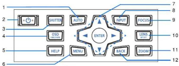
flowchart
graph TD
    A["SHUTTER"] --> B["AUTO"]
    C["OSD"] --> D["ENTER"]
    E["HELP"] --> F["MENU"]
    G["INPUT"] --> H["FOCUS"]
    I["BACK"] --> J["ZOOM"]
    K["LENS"] --> L["OFFSET"]
    M["7"] --> N["1"]
    O["8"] --> P["2"]
    Q["9"] --> R["3"]
    S["10"] --> T["4"]
    U["11"] --> V["5"]
    W["12"] --> X["6"]
ID Part Name Description
| 1 Auto Automatically optimizes an image. | ||
| 2 Power | Turns the projector on or off. | |
| 3 Shutter | Displays or blanks the video image. | |
| 4 OSD | Hides or shows the on-screen display (OSD) menus. | |
| 5 Help | Displays the instructions for source connection. | |
| 6 Menu | Displays the menus. | |
| 7 | Arrow keys | Adjusts a setting up or down, or navigate within a menu. |
| 8 Input | Selects an input for the main or PIP/PBP image. | |
| 9 Focus | Adjusts the focus. | |
| 10 | Lens | Adjusts the lens vertical or horizontal offset setting. |
| ID | Part Name | Description |
| 11 Zoom | Adjusts the zoom. | |
| 12 Back | Returns to the previous | level or exits the menus if at top level. |
Input/Output (I/O) panel
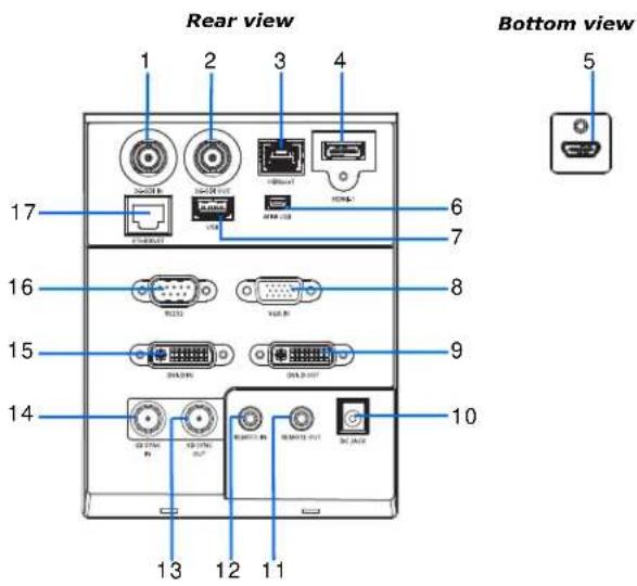
Identify the components of the Input/Output (I/O) panel.
text_image
Rear view 1 2 3 4 17 6 7 16 8 15 9 14 10 13 12 11 Bottom view 5ID Connector name ID Connector name
| 1 3G-SDI IN 10 DC JACK | ||||||||
| 2 3G-SDI OUT 11 REMOTE OUT | ||||||||
| 3 | H | D | B | a | s | e | T | |
| 4 | H | D | M | I | - | 1 | 1 | |
| 5 | H | D | M | I | - | 2 | 1 | |
| 6 MINI USB 15 DVI-D IN | ||||||||
| 7 | USB | 16 | ||||||
| 8 VGA IN 17 ETHERNET | ||||||||
| 9 | D | V | I | - | D | O | U | T |
| 1 | 2 | R | E | M | O | |
| 3 | 3 | D | S | Y | N | C |
| 4 | 3 | D | S | Y | N | C |
IR remote keypad
The IR remote keypad communicates with the projector by way of wireless communications.
Use a cable length of 20 m or less. If the length of cable exceeds 20 m, the IR remote keypad may not work correctly.
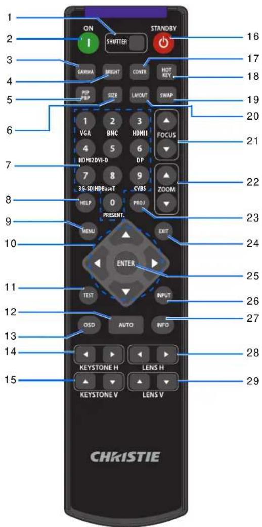
text_image
1 2 3 4 5 6 7 8 9 10 11 12 13 14 15 ON SHUTTER STANDBY 16 17 18 19 20 21 22 23 24 25 26 27 28 29 CHKISTIEID Part Name Description
1 SHUTTER Displays or blanks the video image.
2 Power on Turns the projector on.
3 Gamma Adjusts the mid-range levels.
4 Bright Adjusts the amount of light in the image.
5 PIP/PBP Turns PIP/PBP on or off.
| ID | Part Name | Description |
| 6 Size Adjusts the PIP/PBP size. | ||
| 7 Number | Keys Enter a number, such as a channel, value, and so on. The on-screen display indicates if a function is not supported. | |
| 8 Help Displays the instructions for source connection. | ||
| 9 Menu Displays the menus. | ||
| 10 Arrow | Keys Adjusts a setting up or down to navigate within a menu. | |
| 11 Test Displays a test pattern. | ||
| 12 Auto Automatically optimizes an image. | ||
| 13 OSD Use to hide or show on-screen display (OSD) menus. | ||
| 14 Keystone H Adjusts the horizontal keystone. | ||
| 15 Keystone V Adjusts the vertical keystone. | ||
| 16 Standby Turns the projector off. | ||
| 17 Contrast Adjusts the difference between dark and light. | ||
| 18 Hot key | Selects your preset key quickly. | |
| 19 Swap | Swaps the main and PIP/PBP images. | |
| 20 Layout | Adjusts the PIP/PBP layout. | |
| 21 Focus | Adjusts the focus to improve image clarity as required. | |
| 22 Zoom | Adjusts the zoom to achieve a required image size. | |
| 23 Proj Changes the IR remote keypad ID. | ||
| 24 Exit | Returns to previous level or exit menus if at top level. | |
| 25 | Enter | Selects a highlighted menu item, or changes or accepts a value. |
| 26 Input | Selects an input for the main or PIP/PBP image. | |
| 27 Info Displays the source image information. | ||
| 28 Lens H | Adjusts the position of the image horizontally. | |
| 29 Lens V | Adjusts the position of the image vertically. | |
LED status indicators
LEDs are defined below.
Status LED
Identify the LED state colors and meaning.
LED Status Projector State
| Off AC power is off (without AC plugged in). |
| Green (flashing) Projector is in startup or cool down mode. |
| Green (solid) System is operating normally. |
| Blue (flashing) Projector is cooling down. |
| Blue (solid) AC has been applied, projector is in standby mode. |
| Yellow (flashing) A problem exists with the projector that does not cause it to shut down.Examples of warnings include: filter needs changing, one of the pumps is damaged, or a fan is operating at full speed due to over temperature of LD driver. |
| Yellow (solid) The end user is turning off the projector while it is in a warning state. |
| Red (flashing) An error with the projector exists that has caused or may inevitably cause it to shut down.Examples of errors include: fan failure, over temperature, wrongly installed filter, color wheel (CW) failure. |
| Red (solid) The end user is turning off the projector while it is in an error state. |
| White (flashing) Projector is in a flash (LAN) update state. |
Shutter LED
Identify the shutter LED state colors and meaning.
LED Status Projector State
| Off | Projector is on and an image is displayed. Shutter is open. |
| Magenta (solid) | Projector is on and the image is blank. Shutter is closed. |
Installation

- A Hazard Zone is the region of space where the projection light from the LIP is above Emission Limits for RG2. RG3 LIPs for installations other than in cinema theaters shall be installed at a height vertically above the floor such that the bottom plane of the Hazard Zone shall be no lower than 3.0 meters above the floor. Horizontal clearance to the hazard zone shall be 2.5 meters. If human access is possible in an unsupervised environment, the horizontal or vertical clearances shall be increased to prevent exposure to the RG3 hazard zone.
For Installations in the United States
- Any human access horizontally to the Hazard Zone, if applicable, shall be restricted by barriers.
- Permanent show installations containing RG3 LIPs shall be installed by Christie or by Christie-authorized and trained installers. Show installations must be performed in accordance with Christie's instructions. The projection system shall be securely mounted or immobilized to prevent unintended movement or misalignment of the projections.
- Temporary show installations containing RG3 LIPs may be installed by Christie or sold or leased only to valid laser light show variance holders (laser light show manufacturers) for image projection applications. Such manufacturers may currently hold a valid variance for production of Class IIIb and IV laser light shows and/or for incorporation of the RG3 LIPs into their shows. This requirement applies also to dealers and distributors of these LIPs.
- Christie Laser Projection System (Enterprise) Installation Checklist needs to be filled out completely after the installation and sent to .lasercompliance@christiedigital.com. A copy can remain onsite. This checklist can be found as a separate document in the accessory box with the manual.
- If you are installing in the following US states: Arizona, Florida, Georgia, Illinois and Massachusetts, please see www.christiedigital.com for additional regulatory requirements.
Learn how to install, connect, and optimize the projector display.
Connecting to a computer
Learn what cables/connectors that may be used to connect to various devices.
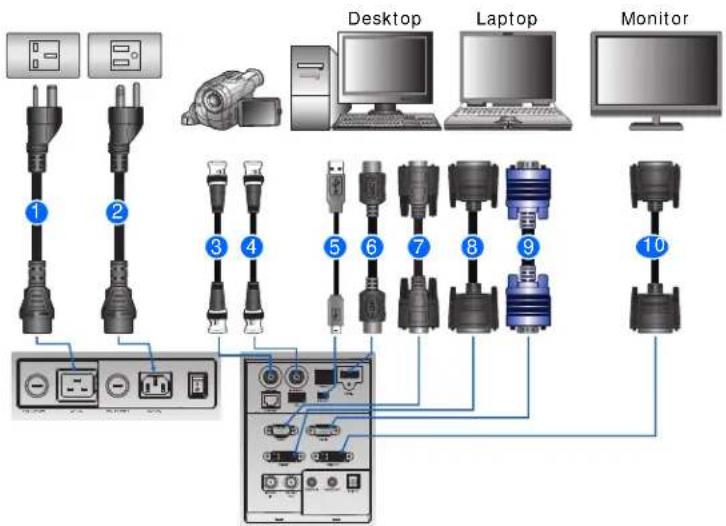
text_image
1 2 3 4 5 6 7 8 9 10 Desktop Laptop Monitor| ID | Connector name | ID | Connector name | ID | Connector name |
| 1 Power | Cord (100-120V).Power cord (100-120V)rated for North America and Japan. | 5 USB type B Mini cable 9 VGA in cable | |||
| 2 Power | Cord (200 to 240V).Power cord (200 to 240V)rated for North America, UK, EU, Russia, Korea, India, Australia/Nz, South Africa, and Argentina. | 6 HDMI cable 10 DVI-D out cable | |||
| 3 3G-SDI | In with BNC cable+ Camcorder | 7 | R S 2 | 3 | 2 c a |
| 4 3G-SDI | Out with BNC cable 8 DVI-D in cable | ||||

- Due to the difference in applications for each country, the accessories required in some regions may differ from those shown.
- This diagram is for illustrative purposes only and does not indicate that these accessories are supplied with the projector.
Connecting to video equipment
Learn what cable/connectors may be used to connect to various devices.

text_image
Component video output equipment DVD player Video cassette recorder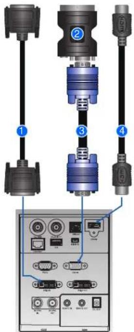
text_image
Diagram showing connected audio equipment components with numbered labels pointing to ports and connectors| Ind. | Connector name | Ind. | Connector name |
| 1 DVI-D | IN Cable 3 VGA IN Cable | ||
| 2 VGA | to Component 4 HDMI Cable |

- Due to the difference in applications for each country, the accessories required in some regions may differ from those shown.
- This diagram is for illustrative purposes only, and does not indicate that these accessories are supplied with the projector.
Turning the projector on
The projector cables must be securely connected before turning the power on.

Warning! Failure to comply with the following could result in death or serious injury.
- Do not look into the projector lens when the laser is on. The bright light may result in permanent eye damage
- Ensure the correct power input has been selected.
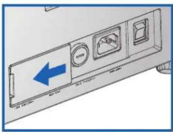
text_image
Diagram of a device rear panel with labeled ports and directional arrow indicating left side| Condition Power Input | AC Inlet selected | Projector Behavior Applicable Regions | |
| 1 100-120V 100-120V Full | power (100%) • North America | • Japan | |
| 2 100-120V 200-240V • Warning message appears on screen• ECO 2 mode (50% power) | |||
| 3 200-240V 100-120V • Warning message appears on screen• ECO 2 mode (50% power) | |||
| 4 200-240V 200-240V Full | power (100%) • North America | • UK• EU• Russia• Korea• India• Australia/Nz• South Africa• Argentina | |
The Power button on the built-in keypad is illuminated when the power cables are connected.
- Ensure the lens has been installed in the projector by a Christie qualified service technician.

Warning! Failure to comply with the following could result in death or serious injury.
- Installing or replacing a lens must be done by a Christie qualified service technician to avoid exposure to dangerous emission levels.
-
Ensure that no one or no objects are in the beam path before turning on the projector.
-
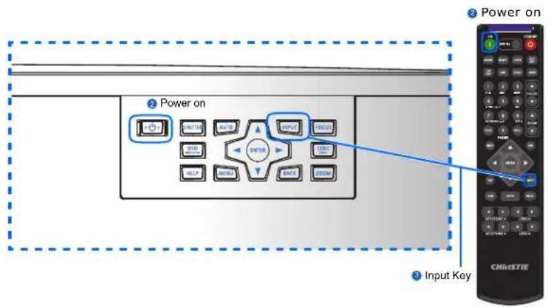
To turn on the projector, on the IR remote keypad press ⏻ or on the built-in keypad press ⏻.
The status LED is green with a long blink.
- To select an input source and turn it on, on the IR remote keypad select Input Key.
Available input sources are VGA, HDMI1, HDMI2, DVI, 3G-SDI, and HD-BaseT.
The projector detects the source you selected and displays the image.
text_image
Power on 2 Power on 3 Input Key CHISTIE
The first time the projector is used, select the preferred language from the Main Menu after the startup screen is displayed.
Turning the projector off
Power off the projector in preparation for inspection or maintenance.
- To turn the projector off, on the IR remote keypad or built-in keypad press ⏻
A warning message appears on the displayed image.
- To confirm your selection, press 📊 again.
If you do not press again, the warning message disappears after three seconds and the projector remains on.
Adjusting the projector position
When you select a position for the projector, consider the size and shape of your screen, the location of your power outlets, and the distance between the projector and the rest of your equipment. Follow these general guidelines:
- Position the projector on a flat surface at a right angle to the screen. The projector (with the standard lens) must be at least 3 feet (0.9 m) from the projection screen.
-
Position the projector to the required distance from the screen. The distance from the lens of the projector to the screen, the zoom setting, and the video format determine the size of the projected image.
• Determine the lens throw ratio: -
Lens 0.84\~1.02 (WU/HD)
- Lens 1.02\~1.36 (WU/HD)
- Lens 1.2\~1.5 (WU/HD)
- Lens 1.5\~2.0 (WU/HD)
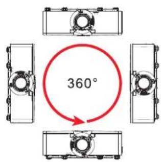
• 360 degree free orientation operation
text_image
360°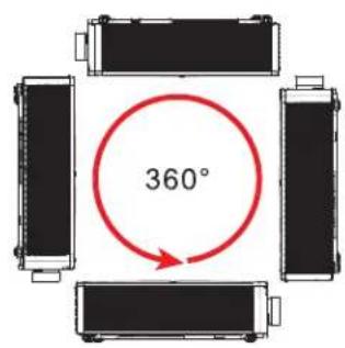
text_image
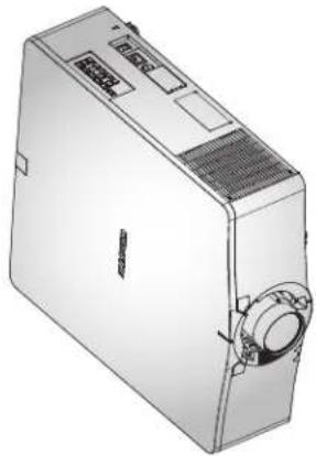
360°When installing the projector in portrait orientation, it is recommended that the built-in keypad and power inputs face upwards. This allows access to the built-in keypad and power connections during operation.
natural_image
Line drawing of a rectangular electronic device with ventilation slots and a circular button (no text or symbols)Calculating the lens offset
Adjust the offset to align the image on the screen with full image size.
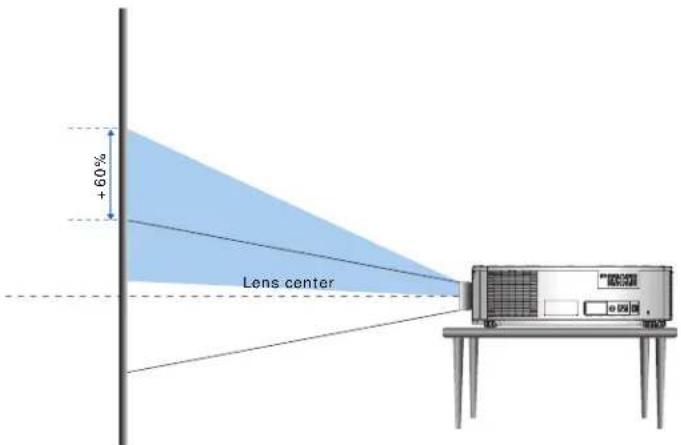
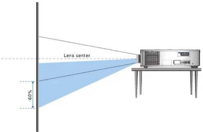
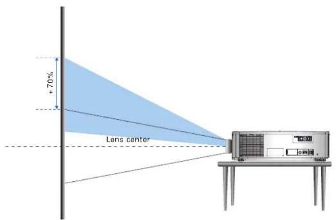
- The vertical image offset (shift) ranges for the projector are +/-60% (WUXGA) and +/-70% (HD).
- The horizontal image offset (shift) range for the projector is + / - 25% (HD/WUXGA).
-
The method for calculating lens offset complies with industry standards. For example for Vertical lens offset:
-
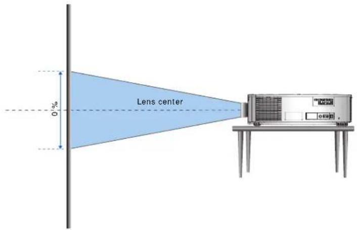
At 0% offset (or on axis), the center of the image is on the lens center, so half of the image appears above and half appears below the lens center.
- At +50% offset, all of the image appears above the lens center.
-
The percentage (%) offset is calculated as the ratio of the number of pixels shifted up or down to full image size. For example for WUXGA:
-
Shifting up 600 pixels gives an offset of 600 / 1200 * 100% = 50%
- Shifting down 600 pixels gives an offset of -600/1200 * 100% = -50%
- Shifting up 720 pixels gives an offset of 720 / 1200 * 100% = 60%
- Shifting up 240 pixels gives an offset of 240 / 1200 * 100% = 20%
WUXGA projectors
The following show vertical image offsets for the WUXGA projectors:
• Vertical image offset: 0%
text_image
Lens center 0%• Vertical image offset: +60%
text_image
+60% Lens center• Vertical image offset: -60%
text_image
Lens center -60%HD Projectors
The following show vertical and horizontal image offset for HD projectors:
• Vertical image offset: +70%
text_image
+70% Lens center• Vertical image offset: -70%
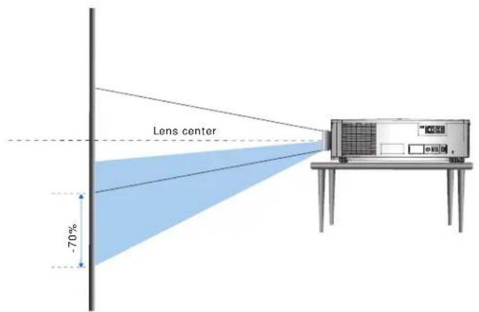
text_image
Lens center -70%• Horizontal image offset: +/-25%
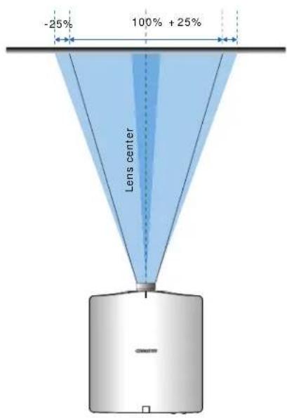
text_image
-25% 100% + 25% Lens centerRemoving and installing the lens

Warning! Failure to comply with the following could result in death or serious injury.
- Installing or replacing a lens must be done by a Christie qualified authorized service technicians or installers to avoid exposure to dangerous emission levels.
- Turn off the projector and remove the power cord, before installing or replacing a lens.
Installing the fuse
A fuse must be installed in the projector for it to power on.
- Turn the projector off.
- Choose the 20A or 15A fuse by sliding the AC cover to the right or to the left.
- Remove the screw on the fuse with a flat-head screwdriver.
- Remove the fuse and replace it with the new one.
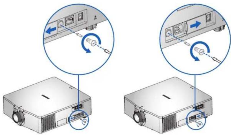
text_image
Diagram showing two views of a projector with labeled components and directional arrows indicating rotation or adjustment.
- For regions using 200 to 240V-15A fuse.
- For regions using 100 to 120V-20A fuse.
• To order a fuse, see page 83.
Cleaning or replacing the filter
Regularly clean or replace the filters in the projector to ensure dust and other foreign materials are kept out of the projector.
- Turn off the projector.
- Remove the screws on the filter cover using a 3 mm hex key.
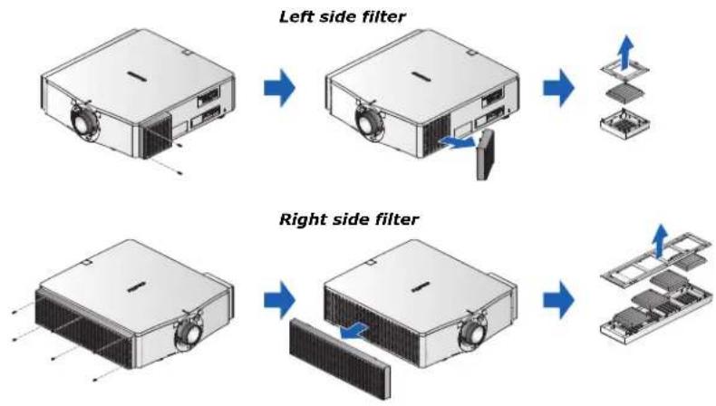
flowchart
graph TD
    A["Left side filter"] --> B["Device with fan"]
    B --> C["Component with switch"]
    C --> D["Stacked components"]
    E["Right side filter"] --> F["Device with solar panel"]
    F --> G["Component with circuit board"]
    G --> H["Stacked components"]
- Remove the filter cover.
- Remove the filter from its compartment.
- Clean or replace the filter.
Fog filters should be replaced after each use of the projector to a maximum of 20 hours. The life of the filter is approximately 20 hours based on environmental conditions. Leave the filters in their sealed packaging until ready for use.

Do not re-use the fog filters as they clog up with oil and the projector overheats and shuts down. For more details, see page 83.
Installing the ceiling mount
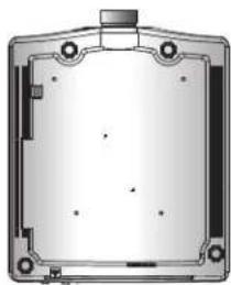
Mount the projector with a Christie-approved mount (such as the Christie One Mount Plus, P/N: 140-117100-XX), using the four mounting points on the underside of the projector.

Warning! Failure to comply with the following could result in death or serious injury.
- When not mounted properly, the projector may fall.
- The warranty on this projector does not cover damage caused by the use of a non-recommended ceiling mount kit or installation of the ceiling mount kit in an improper location.
natural_image
Pure technical diagram of a rectangular enclosure or housing with mounting holes and internal features (no text or symbols)- Refer to the installation instructions and safety guidelines provided in the kit (such as the Christie One Mount Plus, P/N: 140-117100-XX).
Installing the projector in the rigging frame
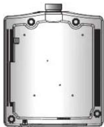
Install the projector in a Christie-approved rigging frame (such as the Christie One Rigging Frame, P/N: 140-113106-XX), using the four mounting points on the underside of the projector.

Warning! Failure to comply with the following could result in death or serious injury.
- When not mounted properly, the projector may fall.
- The warranty on this projector does not cover damage caused by the use of a non-recommended ceiling mount kit or installation of the ceiling mount kit in an improper location.
natural_image
Technical diagram of a mechanical component with mounting holes and central housing (no text or symbols)- Refer to the installation instructions and safety guidelines provided in the kit (such as the Christie One Rigging Frame, P/N: 140-113106-XX).
Operation
The projector has multilingual on-screen display (OSD) menus so you can make image adjustments and change a variety of settings.
Most of the projector controls are accessed from within the projector menu system. Several groups of related functions are selectable from the Main Menu as shown below.
- To display the Main Menu, on the IR remote keypad or on the built-in keypad on the rear of the projector, press MENU.
- To navigate within the menu and adjust a setting up or down, use the arrow keys.
• To select a highlighted menu item or use it to change or accept a value, press ENTER.
You can then select the next item that you want to adjust in the menu and adjust it.
• To return to the previous menu or exit menus if at top level, press EXIT.
| Main Menu | |
| 1. Size & Position | |
| 2. Image Settings | |
| 3. Configuration | |
| 4. Light Source | |
| 5. Status | |
| 6. Input Switching & PIP | |
| 7. Language | English |
| 8. Test Pattern | Off |
Size and Position menu
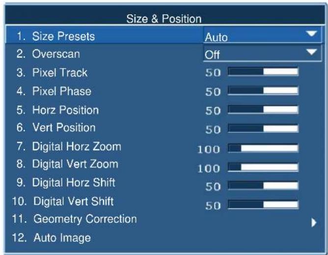
The Size and Position menu determines the size and position of the image on the screen.
text_image
Size & Position 1. Size Presets Auto 2. Overscan Off 3. Pixel Track 50 4. Pixel Phase 50 5. Horz Position 50 6. Vert Position 50 7. Digital Horz Zoom 100 8. Digital Vert Zoom 100 9. Digital Horz Shift 50 10. Digital Vert Shift 50 11. Geometry Correction 12. Auto ImageMenu item Description Options
| Size Presets Displays an image with the detected size, orresizes the image by maximizing either theheight, width, both, or resizes to the maximumsize possible while keeping the original aspectratio. | · Auto—Displays with the detected size.· Native—Displays in its native resolution.· 4:3—Retains 4:3 aspect ratio.· Letterbox—Make the active content enlargeto the full screen.· Full Size—Fills the screen (regardless of thesource).· Full Width—Fills display width and keepaspect ratio.· Full Height—Fills display height and keepaspect ratio.· Custom—Stretches the display horizontallyor vertically without cutting the imagedisplay.· 3D Mode—Displays 3D content.If 3D Mode is selected, all other SizePresets items are grayed out. |
| Overscan Removes noise around the image. · Overscan Zoom enlarges image 6% fromthe original size.· Overscan Crop cuts 6% of the active pixelsin four edges of original image. | |
Menu item Description Options
| Pixel Track Steady flickering or several soft vertical stripes or bands across the entire image indicates poor pixel tracking. Proper pixel tracking ensures that the image quality is consistent across the screen, the aspect ratio is maintained, and that the pixel phase can be optimized. (Analog RGB signals only.) | |
| Pixel Phase Adjust the pixel phase when the image shows shimmer or noise after pixel tracking is optimized. Pixel phase can adjust the phase of the pixel-sampling clock relative to the incoming signal. (Analog RGB signals only.) | |
| Horz Position Moves the image right or left within the area of available pixels. | |
| Vert Position Moves the image up or down within the area of available pixels. | |
| Digital Horz Zoom | Changes the size of projector's display area horizontally. If the display area has been resized by this setting, it can be moved by changing the Digital Horz Shift and Digital Vert Shift settings. |
| Digital Vert Zoom | Changes the size of projector's display area vertically. If the display area has been resized by this setting, it can be moved by changing the Digital Horz Shift and Digital Vert Shift settings. |
| Digital Horz Shift | Moves the display area horizontally if its size has been changed by the Digital Zoom setting. |
| Digital Vert Shift | Moves the display area vertically if its size has been changed by the Digital Zoom setting. |
| Geometry Correction | Provides two ways for warping control. • PC Mode off—User can do simple horizontal and vertical keystone, pincushion, and 4-corner control by using the on-screen display.• PC Mode on—User can do arbitrary warping or blending control by using PC APP provided separately. |
| Auto Image Forces the projector to reacquire and lock to the input signal. This is useful when signal quality is marginal. | • Normal mode—Supports all of the 4:3 input sources.• Wide mode—Supports all of the 16:9 input source and most of the 4:3 input source. For the 4:3 input sources not recognized by Wide mode (for example, 1400 x 1050), perform Auto Image using Normal mode. |
Geometry correction
Geometry correction provides two ways for warping control:
- PC Mode off—User can do simple horizontal and vertical keystone, pincushion, and 4-corner control by using the on-screen display.
- PC Mode on—User can do arbitrary warping or blending control by using the PC APP provided separately.
The following table provides information about the geometry correction feature compatibility:
| Warp Function | 4-Corner | Keystone | Pincushion |
| 4-Corner -- √ | √ | ||
| Keystone √ -- √ | |||
| Pincushion √ | √ | -- |
Horz Keystone
Adjust the keystone horizontally to make the image more square. Horz Keystone corrects a keystoned image shape in which the left and right borders of the image are unequal in length, and the top and bottom are slanted to one of the sides. Use Horz Keystone with horizontally on-axis applications. For horizontally offset applications, use 4-Corner correction using the OSD control or the PC APP provided separately.
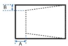
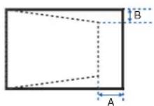
| Ind. | 1080P WUXGA | |
| A | 30.60% | 30.34% |
| B | 14.20% | 12.86% |
Vert Keystone
Adjust the keystone vertically to make the image more square. Vert Keystone corrects a keystoned image shape in which the left and right borders of the image are unequal in length, and the top and bottom are slanted to one of the sides. Use with vertically on-axis applications. For vertically offset images, use 4-Corner correction using the OSD control or the PC APP provided separately.
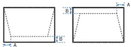
text_image
Geometric diagram showing two 2D squares with labeled dimensions A and B, likely illustrating a perspective or projection.| Ind. | 1080P | WUXGA |
| A | 5.12% | 5.04% |
| B | 11.00% | 10.52% |
Horz Pincushion
Adjust the pincushion horizontally and make the image more square.

| Ind. | 1080P WUXGA | |
| A 5 | 17% | 5.39% |
| B 5 | 17% | 4.24% |
Vert Pincushion
Adjust the pincushion vertically and make the image more square.

| Ind. 1080P WUXGA | |
| A | 9.67% 7.44% |
| B | 9.83% 7.58% |
4-Corner
Allow the image to be squeezed to fit an area defined by moving each of the four corners' x and y position.
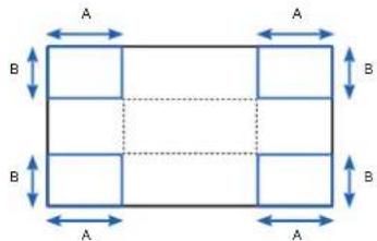
| Ind. 1080P WUXGA | |
| A | 6.25% 6.25% |
| B | 6.67% 6.67% |
Wrap Filter
Warp filter corrects the distorted image, which is caused by projection to a curved surface or by lens distortion.
Auto Warp Filter
- Auto warp filter on —Apply preset warp filter values for distortion correction.
- Auto warp filter off —Disable the warp filter functions.
Manual Warp Filter
- Horz Filter —Adjust horizontal filter for distortion correction.
- Vert Filter—Adjust vertical filter for distortion correction.
Reset
Reset all Geometry Correction parameters.
Image Settings menu
The Image Settings menu sets the brightness, contrast, and other settings for images.
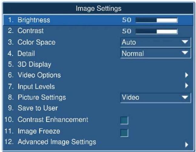
text_image
Image Settings 1. Brightness 50 2. Contrast 50 3. Color Space Auto 4. Detail Normal 5. 3D Display 6. Video Options 7. Input Levels 8. Picture Settings Video 9. Save to User 10. Contrast Enhancement 11. Image Freeze 12. Advanced Image SettingsMenu item Description Options
| Brightness Adjusts the intensity of the image. — | ||
| Contrast Adjusts the degree of difference between the lightest and darkest parts of the image and changes the amount of black and white in the image. | — | |
| Color Space Selects a color space specifically tuned for the input signal. Only useful for analog signals and certain digital sources. | — | |
| Detail Selects the edge clarity of the image. — | ||
| 3D Display | Selects the 3D relating settings. | · 3D Enable—Sets the 3D format. Supports mandatory 3D formats and frame sequential 3D@60/120Hz.· 3D Invert—Inverts the 3D sync signal when using a single projector.· Toggle 3D Blending—Inverts 3D sync signal when using multiple projectors for 3D blending.· 3D Sync Out—Transmit 3D sync signal by 3D sync out corrector to emitter or to next projector for 3D blending purpose.· Frame Delay—Correct asynchronous displaying image under 3D blending. |
Menu item Description Options
| Video Options Applies only to video sources. • Color—Adjusts a video image from blackand white to fully saturated color. (Video sources only.)• Tint—Adjusts the red-green color balance in the image of NTSC video images. (NTSC video sources only.)• Detect Film—Controls film mode detection and determine whether the original source of the input video was film or video. | ||
| Input Levels | Applies to VGA or component signals only. | • Gain—Adjusts the gain of the red, green, or blue channel of the image. It affects the black and white.• Offset—Adjusts the offset of the red, green, or blue channel of the image. It affects the black and white.• Sync Threshold—Helps to sync when connecting to the projector, if a hardware device, such as a DVD player, is not syncing properly with the projector. (Progressive signals only.) |
| Picture Settings | Optimizes the projector for displaying images under certain conditions, such as:• Presentation• Video• Bright• Enhanced• REC709• Real• DICOM SIM• 2D High Speed• 3D• Blending• User-definable preset.It affects the following:• Gamma• Sharpness• White Peaking• Overscan• Brightness• Contrast• Color• Tint• Red Gain• Green Gain• Blue Gain• Red Offset• Green Offset• Blue Offset | — |
Menu item Description Options
| Save to User Saves the user settings. Adjust the image settings and Select Save to User as a picture setting. To recall these settings in the future, select the User in the Picture Settings menu. You can save the following settings: ·Brightness ·Contrast ·Color ·Tint ·Red Gain ·Green Gain ·Blue Gain ·Red Offset ·Green Offset ·Blue Offset ·Color Temperature ·Gamma ·Detail ·White Peaking ·Overscan | — |
| Contrast Enhancement | Enables or disables the contrast enhancement function. Enable this function to raise the contrast ratio. ·DynamicBlackTM—Auto adjust the contrast ratio for video contents. ·RealBlack—Lower down the black level for dark images to raise the contrast ratio. |
| Image Freeze Pauses the screen image. — | |
| Advanced Image Settings | Provides access to advanced image settings such as gamma, white peaking, and so on. ·Gamma—Selects the appropriate gamma from Video, Film, Bright, CRT, and DICOM. ·White Peaking—Increases the brightness of whites near 100%. (Video source only.) ·Color Temperature—Changes the intensity of the colors. Select a listed relative warmth value. ·Edge Enhancement—Applies the edge enhancement process. ·Color Wheel Speed—Selects the color wheel speed from 2x or 3x. The color wheel speed defines the delay between the color wheel and the DMD. The higher the speed, the less rainbow effect on the screen. |
Configuration Menu
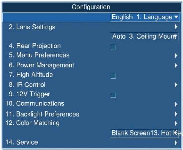
The Configuration menu sets the language, projection orientation, power usage, and other preferences for the projector.
text_image
Configuration English 1. Language 2. Lens Settings Auto 3. Ceiling Mount 4. Rear Projection 5. Menu Preferences 6. Power Management 7. High Altitude 8. IR Control 9. 12V Trigger 10. Communications 11. Backlight Preferences 12. Color Matching Blank Screen13. Hot Key 14. ServiceMenu item Description Options
| Language Selects an available language for the on-screen display. | · English· French· German· Italian· Spanish· Chinese (Simplified)· Japanese· Korean· Russian |
| Lens Settings Adjusts the lens. · Focus and Zoom—Adjust the focus and zoom the image in or out.· Lens Shift—Shifts the lens up and down, or left and right.· Lens Shift Memory—Applies zoom, focus, and lens position according to the chosen set of lens memory position. Save the current zoom, focus, and lens position to the projector memory.· Lock All Lens Motors—Selects this function to prevent all lens motors from moving. It may disable the zoom, focus, horizontal and vertical position settings, locking any changes and overriding all other lens features. This helps to prevent accidental lens position changes in multi-projector installations.· Lens Calibration—Calibrates the lens center. | |
Menu item Description Options
| Ceiling Mount Turns the image upside down for ceiling-mounted projection. | — | |
| Rear Projection Reverse the image so you can project from behind a translucent screen. | — | |
| Menu Preferences | Sets the on-screen display menu preferences, and the password for the projector. | ·Menu Horz Offset—Changes the horizontal position of the on-screen display.·Menu Vert Offset—Changes the vertical position of the on-screen display.·Show Messages—Displays status messages on the screen.·Menu Transparency—Changes the on-screen display menu background to be transparent.As the value increases, more of the image behind the menu is visible.·Splash Screen Setup—Selects the splash screen.·PIN Protect—Protects your projector with a password. Once enabled, you must enter the password before you can project an image.·Change PIN—Allows you to change the password. |
| Power Management | Determines the power modes for the projector. | ·Standby Mode—Determines if the projector is in standby mode when connected to AC power (<0.5 W).·AC Power On—Automatically turns the projector on when electrical power is connected.·Auto Shutdown—Automatically turns the projector off after no signals are detected for a preset number of minutes. If an active signal is received before the projector powers down, the image is displayed.·Sleep Timer—Allows the projector to automatically power off after it has been on for a specified amount of time (two, four, or six hours).·Cool Down—Configure the cool down time period (instantly off, after 1 minute, or after 2 minutes). |
| High Altitude Enables or disables high altitude mode. | ·On—Enables high altitude mode for altitudes >/= 2000 m. The fan operates at high speed to ensure sufficient air flow for high altitudes.·Off—Disables high altitude mode. For altitudes below 2000 m. | |
| IR Control Enables or disables the IR sensors. | ·Top—Enables or disables the signal from the top IR sensor.·Front—Enables or disables the signal from the front IR sensor.·HDBaseT—Enables or disables the signal from the HDBaseT Box. | |
Menu item Description Options
| 12V Trigger Sets the 12V trigger on or off.The 12V trigger is used for electrical projector screens. The projector screen is automatically lowered or raised when the projector is switched on or off. | — |
| Communications Determines the communication settings such as network setup, serial port information, and so on. | Network—Allow you to set up network settings.DHCP—Turns the DHCP on or off.IP Address—Assigns the network IP address.Subnet Mask—Assigns the network subnet mask.Default Gateway—Assigns the network default gateway.MAC Address—Displays the network MAC address value.Apply—Triggers the modifying of the LAN setting.Enable—Enables or disables the WLAN functionality.Start IP—Enter the start IP address for wireless network.End IP—Enter the end IP address for wireless network.SSID—Enter a unique wireless network name (SSID).Show Network Messages—Turns network messages on or off.Restart Network—Restarts the network.Network Factory Reset—Performs factory reset on the network settings. The Projector Name, IP Address (LAN), Start IP and End IP, and SNMP settings can be reset.Serial Port Baud Rate—Selects the serial port and baud rate.Serial Port Echo—Controls whether the serial port echoes characters.Serial Port Path—Sets the serial port path to RS232 or HDBaseT.Projector Address—Sets the projector address (0 to 9). The projector responds to the IR remote set to the same address as the projector or to the IR remote set to address 0. |
| Backlight Preferences | Controls the back light behavior and timeout setting for the keypad and status LED. |
Menu item Description Options
| Color Matching Enables the selected method(Manual Adjustment or HSG)to define the precise hue ofeach primary colorcomponent (red, green, blueand white).When one method is enabled,the other method isautomatically disabled. Forboth methods, if Auto TestPattern is enabled, the solidcolored test pattern can bedisplayed according to themenu item on which you arepositioned.For more information on colormatching, seeColormatchingon page 47. | · Manual Adjustment—Manually defines the precise hue ofeach primary color component.· HSG Adjustment—Adjusts the hue, saturation, and gain(HSG) of the projected image. The HSG functionindependently controls each of the color regions R, G, B, C,M, Y, and W.· Wall Color—Sets the wall color so the projector can enhancethe color performance customized for the specific wall. |
| Hot Key Settings Assigns a different function tothe hot key on the IR remotekeypad by highlighting thefunction in the list andpressingENTER.Choose a function that doesnot already have a dedicatedbutton, and assign the hotkey to that function, allowingyou to quickly and easily usethe chosen function. | — |
Menu item Description Options
| Service Displays projector information, sets test patterns, error logs, and high temperature warnings. | Projector Info—Displays the current projector settings. (Read-only)Factory Reset—Restores all settings to their default value. It does not reset network but it resets RS232.Test Pattern—Sets the required internal test pattern to display. To turn off a test pattern, select Off.Wheel Index (2X)—Sets the wheel index to Speed 2X. Only use this setting when a new main board is installed, and the picture quality needs to be optimized.Wheel Index (3X)—Sets the wheel index to Speed 3X. Only use this setting when a new main board is installed, and the picture quality needs to be optimized.Error Log—Shows the projector error log for debug.Mode Adjustment—Fine tunes the horizontal (H) and vertical (V) start position for a signal in the EDID timing table and record the values in the system to override the timing table. To keep the settings, before exiting the menu, select Saved to Record. To revert to original timing table settings, manually clear each setting. Factory Defaults do not clear these override settings.Laser Diode Info—Displays the information of each laser diode bank including its voltage, current, and temperature.ADC Calibration—Calibration Condition—Displays required equipment for ADC Calibration.ADC Calibration—Calibrates RGB Gain or offset for analog signal only.Light Sensor—Calibration must be performed before using Rental mode or after laser diode driver board replacement. |
Color matching
You may require a unique color gamut (range) for a single projector or application, or you may need to precisely match colors across multiple adjacent displays. Use color matching by Manual Adjustment or HSG to define the precise hue of each primary color component (red, green, blue and white).
HSG
Hue, Saturation, and Gain (HSG) software controls the color regions R, G, B, C, M, Y, and W independently.
- Select HSG, select Color Matching > HSG.
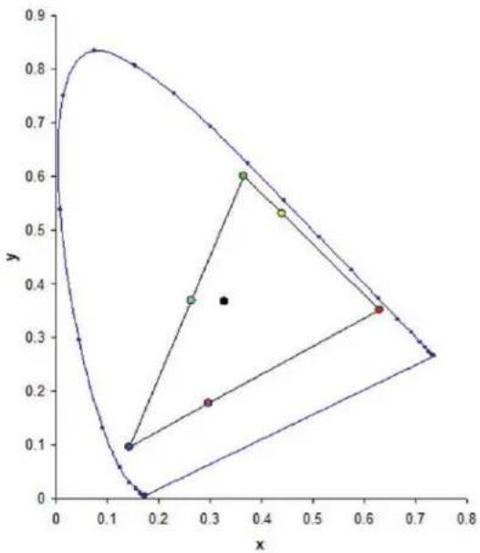
Hue
Note the following about adjusting hue:
- Adjust the hue independently for each color (R.G.B.C.M. and Y).
- White does not have a hue input.
- A negative hue input provides a clockwise rotation of the color's hue.
- A positive hue input provides a counter-clockwise rotation of the color's hue.
- A zero input does not change the hue of the color.
scatter
| x | y | | ---- | ---- | | 0.15 | 0.10 | | 0.25 | 0.38 | | 0.35 | 0.60 | | 0.45 | 0.54 | | 0.65 | 0.36 |Saturation
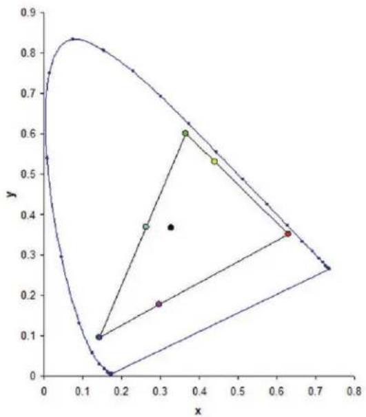
Note the following about adjusting saturation:
- The saturation can be adjust independently for each color (R,G,B,C,M, and Y).
- A saturation level of 0 removes all color from that region.
- A saturation level of 254 sets the color region to have maximum color.
• A saturation level of 127 does not change the saturation.
line
| x | y | | ---- | ---- | | 0.15 | 0.85 | | 0.20 | 0.00 | | 0.25 | 0.10 | | 0.30 | 0.18 | | 0.35 | 0.38 | | 0.40 | 0.60 | | 0.45 | 0.55 | | 0.60 | 0.35 | | 0.70 | 0.28 | | 0.75 | 0.27 |Gain
Note the following about adjusting gain:
- The gain can be adjust independently for each color (R,G,B,C,M,Y, and W).
• The range of input is 0 to 254. - The gain changes the intensity level of the respective color.
• A gain level of 127 disables the HSG controls for that color. - A gain level less than 127 darkens the respective color.
- A gain level of 254 sets the color region to have maximum gain; however, clipping occurs on the signal.
- A gain of 127 is the nominal setting.
- White provides three gain level controls, one each for the R,G,B component of white.
Light Source menu
The Light Source menu sets the light source mode and power preferences.
| Light Source | |
| 1. Light Source Mode | Constant Power |
| 2. Constant Power | 99 |
| 3. Light Source Info | |
| 4. Light Sensor Calibration | Default |
Menu item Description Options
| Light Source Mode | Sets the light source mode. • Constant Power | • Constant Intensity—Set the value in Constant Power mode and change to Constant Intensity mode to maintain constant brightness and color settings.The light sensor monitors the light level and consumes more power than the laser brightness decays naturally over time. When the laser setting sets to maximum power, it remains at this setting for longer period of time than Constant Power mode.Note the following:• This mode is used for long term projecting or blending purpose.When Constant Intensity is enabled, Dynamic Black and RealBlack function are automatically disabled.When Picture Settings is changed under Constant Intensity mode, it would automatically change back to Constant Power mode.ECO 1/ECO 2Rental Mode—Remains at 90% constant brightness and color settings. Light sensor calibration must be performed before enable Rental mode. |
| Constant Power Sets the value of the laser diode power. — | ||
| Light Source Info | Display information about the light source in the projector. | • Total Projector Hours—Displays the current total number of hours the projector has been used.LD Hours—Displays the current total number of hours the laser diode has been used. |
| Light Sensor Calibration | Set the time for light calibration. • Default—Process light calibration at cooling stage.Auto—Process light calibration for every 168 hours.Manual—User performs light calibration manually. | |
Status menu
The read-only Status menu lists a variety of details about the standard and optional components currently detected in the projector.
For DHD models
| Status | |
| Model Name | D13HD-HS |
| Serial Number | H1YYWWXXX |
| Native Resolution | 1920 x 1080 |
| Firmware | V02.00,A02.00,B01.00 |
| Main Input | VGA 1 |
| Main Signal Format | 720P |
| Main Pixel Clock | 74.256 MHzSync On GreenMain Syn |
| Main Horz Refresh | 45.1 KHz |
| Main Vert Refresh | 60.0 Hz |
| PIP/PBP Input | - |
| PIP/PBP Signal Format | - |
| PIP/PBP Pixel Clock | - |
| PIP/PBP Sync Type | - |
| PIP/PBP Horz Refresh | - |
| PIP/PBP Vert Refresh | - |
| Light Source Power | 99 |
| Total Projector Hours | 0 |
| Light Source Hours | 0 |
| LC Hours | 0 |
| Standby Mode | 0.5W Mode |
| Lens Lock Settings | Allow |
| IP Address | 192.168.0.100 |
| DHCP | No |
| System Temperature | 29 C, No Filter |
For DWU models
| Status | |
| Model Name | D13WU-HS |
| Serial Number | H1YYWWXXX |
| Native Resolution | 1920 x 1200 |
| Firmware | V02.00,A02.00,B01.00 |
| Main Input | VGA 1 |
| Main Signal Format | 720P |
| Main Pixel Clock | 74.256 MHzSync On GreenMain Syn |
| Main Horz Refresh | 45.1 KHz |
| Main Vert Refresh | 60.0 Hz |
| PIP/PBP Input | - |
| PIP/PBP Signal Format | - |
| PIP/PBP Pixel Clock | - |
| PIP/PBP Sync Type | - |
| PIP/PBP Horz Refresh | - |
| PIP/PBP Vert Refresh | - |
| Light Source Power | 99 |
| Total Projector Hours | 0 |
| Light Source Hours | 0 |
| LC Hours | 0 |
| Standby Mode | 0.5W Mode |
| Lens Lock Settings | Allow |
| IP Address | 192.168.0.100 |
| DHCP | No |
| System Temperature | 29 C, No Filter |
Input Switching & PIP menu
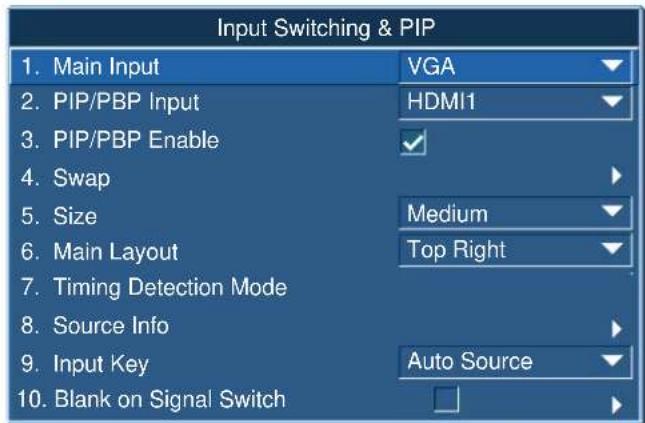
The Input Switching & PIP menu determines how the main and PIP/PBP inputs are handled.
text_image
Input Switching & PIP 1. Main Input VGA 2. PIP/PBP Input HDMI1 3. PIP/PBP Enable ✓ 4. Swap 5. Size Medium 6. Main Layout Top Right 7. Timing Detection Mode 8. Source Info 9. Input Key Auto Source 10. Blank on Signal SwitchMenu item Description Options
| Main Input Selects | an active input to be used as the main image. | — |
| PIP/PBP Input Selects | an active input to be used as the PIP/PBP. | — |
| PIP/PBP Enable Toggles between displaying two sources at once (main and PIP/PBP images) or one source only.Refer to Inputs on page 78 and PIP/PBP compatibility on page 82. | • Selected checkbox—Turns the PIP/PBP source on.• Cleared checkbox—Turns the PIP/PBP source off. | |
| Swap Changes the main image to PIP/PBP, and the PIP/PBP to main image.Swapping is available only when PIP/PBP is enabled. | — | |
| Size Selects the PIP/PBP size to small, medium, or large. | — | |
| Main Layout Sets the location of the PIP/PBP image on the screen. | — | |
| Timing Detection Mode | Sets timing detection mode to wide or normal to support additional PC timings. When the projected picture is not completed, this function is used to adjust the picture.For 4:3 input sources not recognized by Wide mode (for example 1400 x 1050), perform Auto Image using Normal mode. | • Normal mode—Supports 4:3 input sources.• Wide mode—Supports the 16:9 input source and most 4:3 input sources. |
| Source Info Displays the current source settings. (Read-only) | — | |
| Input Key Lists or changes the sources. — | ||
Menu item Description Options
| Blank On Signal Switch | Blanks the screen before timing is stable when changing the source. | • Enabled—Blanks the screen before timing is stable when charging source.• Disabled—Disables blanking the screen. |
PIP/PBP layout and size
A P indicates the primary source region (lighter color) and an asterisk (*) indicates both regions are the same size.
PIP/PBP Layout PIP/PBP Size
| Small Medium Large | |||
| PBP, Main Left |  |  |  |
| PBP, Main Top |  |  |  |
| PBP, Main Right |  |  |  |
| PBP, Main Bottom |  |  |  |
| PIP-Bottom Right |  |  |  |
| PIP-Bottom Left |  |  |  |
| PIP-Top Left |  |  |  |
| PIP-Top Right |  |  |  |
Language menu
Select an available language for the on-screen display.
Language
- English
- 简体中文
- Français
- Deutsch
- Italiano
6.日本語
7.한국어 - Русский
- Español
Test Pattern menu
Choose the required internal test pattern to display, or select Off to turn off a test pattern.
Test Pattern
- Off
- Grid
- White
- Black
- Checkerboard
- Color Bars
Web user interface
The web user interface provides an alternate way to access the menu functionality on the projector.
Logging on to the web user interface
Log onto the web user interface by following the steps below.
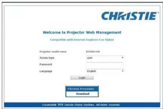
- Open a web browser and type the IP address (in the address bar) assigned to your projector.
text_image
CHRISTIE® Welcome to Projector Web Management Compatible with Internet Explorer 8 or higher Projector model name D13WU-HS Access type Taiwan Password Language English Login Christie Presenter Download Copyright© 2016 Christie Digital Systems. All rights reserved.- From the Access type list, select the log in level.
- In the Password field, type the password.
- From the Language list, select the appropriate language.
- To access the Main window, click Login.
Main tab-General
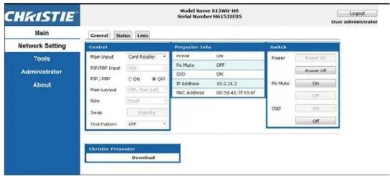
Displays information about the projector, its power status, and what is selected for the main and PIP/PBP input sources.
text_image
CHRISTIE Model Name 013WU-HS Serial Number H61532E05 Login User administrator Main Network Setting Tools Administrator About Control Main Input PSP/RBP Input PSP / DSP Main Layout Size Swap Test Pattern Card Reader ON OFF None Left Off Execute Off Projector Info Power On PiC Mute OFF OSD ON IP Address 10.2.24.2 MAC Address 00:30:41:7f:13:of Switch Power Power On Power Off PiC Mute On Off OSD On Off Christie Presenter DownloadPanel Description
| Control | Selects main source/PIP source, enables or disables PIP/PBP, changes the layout or PIP size, swap, and change the test pattern. |
| Projector Information | Check the projector information for power status, Pic mute status, on-screen display status, IP address, and MAC address. |
| Switch Switches the on or off status of Power, Pic Mute, and on-screen display. | |
Main tab-Status
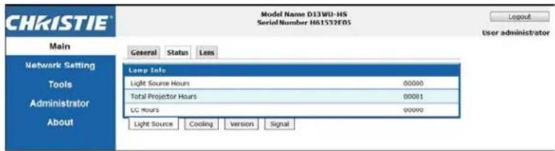
Displays the current status of light source, cooling (fans), version numbers and signal (source) information.
text_image
CHRISTIE® Model Name D13WU-HS Serial Number H81532E05 Login User administrator Main Network Setting Tools Administrator About General Status Lens Lamp Info Light Source Hours 00000 Total Projector Hours 00001 LC Hours 00000 Light Source Cooling Version SignalMain tab-Lens
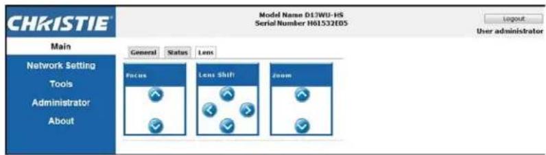
Controls the focus, lens shift, and zoom adjustments for the lens.
text_image
CHRISTIE® Model Name D1JWU-HS Serial Number H61532E05 Main Network Setting Tools Administrator About General Status Lens Focus Lens Shift Zoom User administrator Layout User administratorNetwork
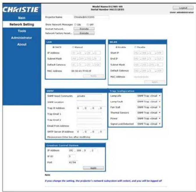
If you change a setting, the network subsystem of the projector may restart, and you may be logged off.
text_image
CHRISTIE Main Network Setting Tools Administrator About Model Name: D13W0-HS Serial Number H01552E05 Projector Name: Christie@6153005 Show Network Messages ON OFF Connect network Exercise Network Factory Reset Exercise LAN IP Address Manual Submit Mask 147.000.000.000.000.000.000.000.000.000.000.000.000.000.000.000.000.000.000.000.000.000.000.000.000.000.00 WLAN IP Address Manual Submit Mask 147.000.000.000.000.000.000.000.000.000.000.000.000.000.000.00 IP Address Manual Submit Mask 147.000.001.999.999.999.999.999.999.999.999.999.999.999.999.999.999.999.999.999.999.999.999.999.999.999.999.999.99 SNMP SNMP lead Community private SNMP location Trap IP Address 8 8 8 8 8 Trap Email 1 Trap Email 2 Email From Address SNTP Server IP Address 8 8 8 8 8 Please press Enter key after modification Trap Configuration LampLife SNMP Trap + Email LampFault SNMP Trap + Email Fan Staff SNMP Trap + Email Thermal Sensors SNMP Trap + Email Power SNMP Trap + Email Signal Lost/Detected SNMP Trap + Email Creatress Control System IP Address 192 168 8 2 IP ID 3 Port 41764 Apply Note: If you change the setting, the projector's network subsystem will restart, and you will be logged offPanel Description
| Restart Network | Execute a network restart. This does not change any of the network settings. |
Panel Description
| Network Factory Reset | Execute a network factory reset. Network settings may be reset to the following default values.Projector Name = Christie@ + Serial NumberShow Network Messages = ONLAN settings:ManualIP Address = 192.168.0.100Subnet Mask = 255.255.255.0Default Gateway = 192.168.0.100WLAN settings:EnabledStart IP = 192.168.1.100End IP = 192.168.1.120Subnet Mask = 255.255.255.0Default Gateway = 192.168.1.100SNMP settings:SNMP Read Community = privateTrap IP Address = 0.0.0.0SMTP IP Address = 0.0.0.0All other settings are cleared or blankedTrap Configuration:All items = SNMP Trap + Email |
| LAN Setting Panel | Sets if the projector must obtain an automatically assigned IP address through DHCP or if the user sets the address manually.For the TCP/IP setting, enter the IP address, netmask, and default gateway address. |
| WLAN Setting Panel | Enables or disables the wireless LAN of the projector.Enter the IP address range, netmask, and default gateway for the wireless LAN. |
Panel Description
| SNMP Panel | Provides network administrators with a common way to manage their network devices from a single remote location. Administrators can use the Simple Network Management Protocol (SNMP) interface to query a number of devices to see their current status or configuration. Operators can change configuration values and configure trap notifications to be sent when certain events occur (for example, loss of signal, power state change, and so on).Emails are sent to the mail server configured in the projector settings. Up to two user email accounts can be selected. Important information regarding the event is located in the body content of the email.SNMP Traps are notifications that are sent from the projector. They are only received by a trap receiver (MIB Browser) in the computer.SNMP Read Community (default setting: private)—Plain text password that must also be entered in the MIB browser. This password allows various settings in the projector to be queried.SNMP Location (default setting: blank)—Use as a description to where a projector is located in a building. SNMP emails sent specify this location.Trap IP Address (default setting: 0.0.0.0)—Fill in this field with the IP address of the computer, on which you want to view received traps from the projector.Trap Email 1/2 (default setting: Blank)—Set the Trap Email 1 and 2 to an email address configured under the mail server entered in the SMTP Server IP Address field.Email from Address (default setting: blank)—Set the name of the source of the SNMP emails.SMTP Server IP Address (default setting: 0.0.0.0)—Enter the IP address of the mail server. |
| TrapConfigurationPanel | Set the SNMP actions for the system events. The options are:SNMP Trap+ EmailEmailSNMP TrapDisabled |
| CrestronControl SystemPanel | Enter the IP address, IP ID, and port of Crestron device for the connection. |
Tools
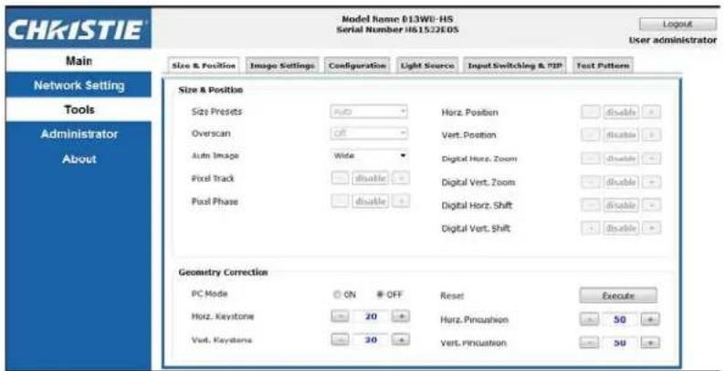
Use the Tools pages to control size and position, image settings, configuration, light source, input switching, PIP, and test patterns.
text_image
CHRISTIE Model Name: 013WU-HS Serial Number: H61522EOS Login User administrator Main Size & Position Image Settings Configuration Light Source Input Switching & POP Text Patterns Network Setting Tools Administrator About Size & Position Size Presets Auto Horz. Position Disable Overscan Off Vert. Position Disable Auto Image Wide Digital Horz. Zoom Disable Pixel Track Disable Digital Vert. Zoom Disable Pixel Phase Disable Digital Horz. Shift Disable Digital Vert. Shift Disable Geometry Correction PC Mode ON OFF Reset Execute Horz. Keystone 20 Horz. Pincushion 50 Vert. Keystone 20 Vert. Pincushion 50Administrator Page
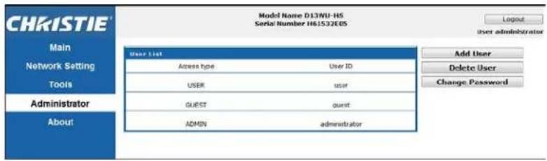
Add or delete a user or change password.
text_image
CHRISTIE® Model Name D13WU-HS Serial Number H61532EOS Login user administrator Main Network Setting Tools Administrator About User List Access type User ID USER user GUEST qunit ADMIN administrator Add User Delete User Change PasswordAbout Page
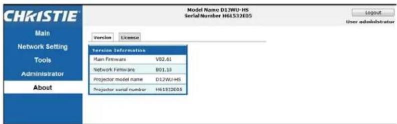
The About page provides version and license information about HS Series.
text_image
CHRISTIE Model Name D12WU-HS Serial Number H61532E05 Login User administrator Main Network Setting Tools Administrator About Version License Service Information Main Firmware V02.61 Network Firmware B01.19 Projector model name D12WU-HS Projector serial number H61532E05Tab Description
| Version | Views the main firmware version, network firmware version, projector model name, and projector serial number. |
| License Displays the license information of the computer program. | |
Christie Presenter
The Christie Presenter application allows a remote desktop from a host PC to be displayed on the network display through Ethernet or wireless transports. It can adapt to different network settings (DHCP, fixed IP, and direct link by Ethernet cable).
Download Christie Presenter from the Christie website or from the web page of the projector.
Connecting to the Projector
Before using Christie Presenter, you must connect to the projector.
- Connect to the projector using WiFi or Ethernet.
Ethernet connection:
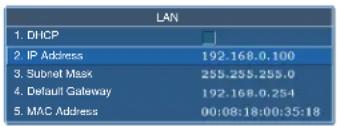
a. To determine the projector's IP address, select Main Menu > Configuration > Communications > LAN.
text_image
LAN 1. DHCP 2. IP Address 192.168.0.100 3. Subnet Mask 255.255.255.0 4. Default Gateway 192.168.0.254 5. MAC Address 00:08:18:00:35:18b. Configure your PC IP address to be on the same network as the projector.
c. The projector and computer must be connected directly or over the network using Ethernet.
WiFi Wireless connection:
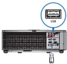
a. Insert the WiFi USB dongle (1DWUSB-BGN) into the USB port on the projector input panel.
For more information about the WiFi USB dongle, see page 83.
text_image
USBb. Power on the projector.
c. Obtain the WiFi SSID from Main Menu > Configuration > Communications > WLAN.
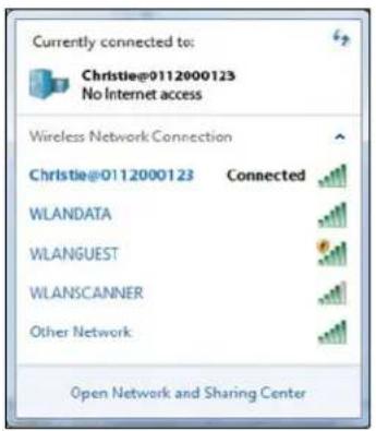
d. Connect your PC device to the wireless SSID for the selected projector, for example: Christie@0111000123.
text_image
Currently connected to: Christie@0112000123 No Internet access Wireless Network Connection Christie@0112000123 Connected WLANDATA WLANGUEST WLANSCANNER Other Network Open Network and Sharing CenterInstalling the Christie Presenter software
Install and configure the Christie Presenter software.
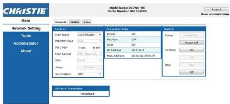
- In a web browser, connect to the projector's network address. The default address is 192.168.1.100.
- Download and install the Christie Presenter software.
text_image
CHKISTIE Model Name D12WU-HS Serial Number H61532E05 Login User administrator Main General Status Less Network Setting Tools Administrator About Control Projection Info Switch Main Input Card Reader Power Off Power On PIP/PBP Input OSD Off Power Off PIP / PBP ON OFF Pie Mute Off Main Layout PBP, Main Left IP Address 10.2.24.2 Size的小计 MAC Address 00:30:41:76:93:df Swap Cancela Test Pattern OFF Switch Power Power On Power Off PIC Mute On PID OSD On Off Christie Presenter Download- Configure the Christie Presenter software.
The name entered identifies all computers connected to the projector by the Christie Presenter software—either wired or wireless connections. The Network Display Management > Device Management tab shows all current connections.
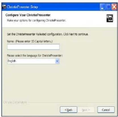
text_image
ChristiePresenter Setup Configure Your ChristiePresenter Make your options for configuring ChristiePresenter. Set the ChristiePresenter listed configuration. Click next to continue. Name: (Please enter 15 Capital letters.) Please select the language for ChristiePresenter: English < Back Next > CancelUsing the Christie Presenter
After starting the Christie Presenter application, the main window appears.
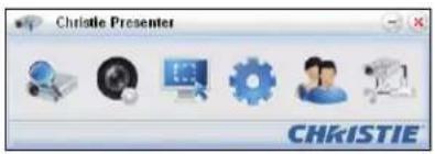
text_image
Christie Presenter CHKISTIE| Icon Description | |
 | Connects and searches the network display. |
 | Stops or starts displaying desktop contents to the connected network display. |
 | Selects a display region. |
 | Configures Christie Presenter. |
 | Manages all connected network displays. |
 | Disconnects all connections. |
Connecting and searching the network display
- To enter into the connection menu section, click

-
If the IP address of the projector is known, type the IP address and click Connect.
-
If the IP address is not known:
a. To search for the projector on the network, click Search.
b. Select the projector to which you want to connect.
c. To access the Login dialog, click Connect directly.

text_image
Christie Presenter 192.168.1.100 Directly Via webpage Connect Search Search result: Christie Φ1155.004 Christie Φ0112000123 Select all Connect directly CHKISTIE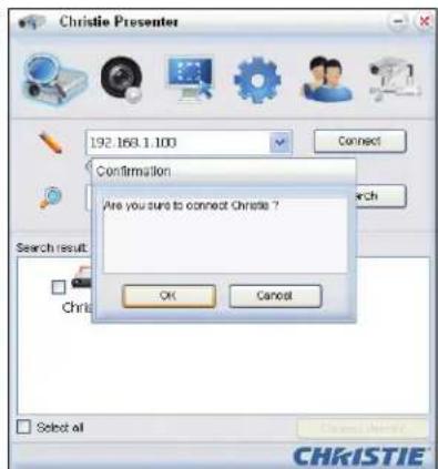
text_image
Christie Presenter 192.163.1.100 Confirmation Are you sure to connect Christie ? OK Cancel Search result: Christie Select all CHRISTIE- In the Login dialog, select the user type and type the password.
The default password for the Normal user is left blank. If the password was previously set, it appears in the bottom-left corner of the on-screen display. The default password for the Admin user is admin.
- In the Select display port window, select the display port.
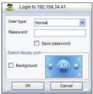
text_image
Login to 192.168.34.41 User type: Normal Password: Save password Select display port Background OK CancelSelecting the display region
When the connection is set up, you must select the display region.
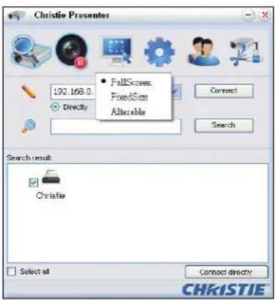
- To select the size of the projection region, click and select an option: FullScreen, FixedSize, or Alterable.
text_image
Christie Presenter 192.168.0 Directly • FullScreen FixedSize Allovable Connect Search Search result Christie Select all Connect directly CHRISTIETab Description
| FullScreen | Turns the default capture mode to full screen when the program is launched. If screen capture starts, the image of the entire screen is transferred to a remote network display. |
| FixedSize | Transfers on the image enclosed inside the frame (after a user places a frame on the desktop) to remote network display. |
| Alterable | Encloses only the captured region by the frame. To enlarge or downsize the region, drag the eight small black squares scattered on eight edges of the frame. |
Configuring Christie Presenter
Set the language for Christie Presenter, the region size of fixed size capture mode, if a notification message dialog is allowed, the quality of JPEG images, YUV sample formats, and the network port setting.
- To configure Christie Presenter for basic and advanced settings, click

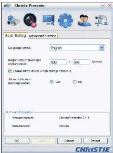
text_image
Christie Presenter Basic Setting Advanced Setting Language select: English Region size of fixed size capture mode: 800 x 592 (pixels) Enable mirror driver when startup if there is. Allow notification message some: Yes No Software Information Version number: ChristiePresenter 2.1.4 Manufacturer: Christie OK Cancel Default CHKISTIE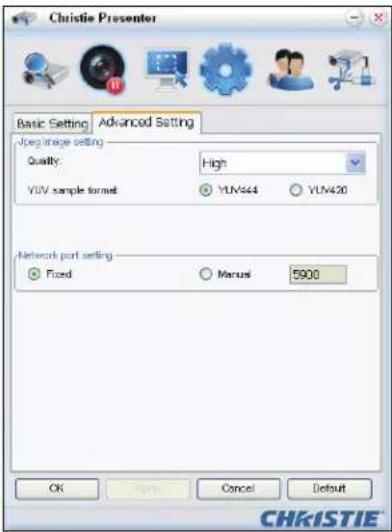
text_image
Christie Presenter Basic Setting Advanced Setting JPEG image setting Quality: High YUV sample format YUV444 YUV420 Network port setting Fixed Manusl 5900 OK Cancel Default CHKISTIETab Description
| Basic Setting Selects the language, changes the region size of fixed size capture mode, and selects if a notification message dialog is allowed. | |
| Advanced Setting | Selects the quality of JPEG image, YUV sample formats and the network port setting. The fixed port is port 5900. |
Managing all connected network displays
You can manage all connected network displays and users at the same time.
- To control all users connected to the same projector, click

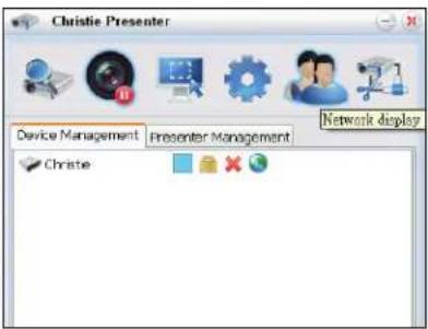
text_image
Christie Presenter Device Management Presenter Management Network display ChristieIcon Description
| Indicates the administrator is logged in. | |
| Indicates a normal user logged in. | |
| Indicates the device is connected. | |
| Indicates the device is not connected. | |
| Shows the current status and display position of the local screen on the network display. Click to change the display position. A dialog appears. | |
| Changes the password to the target network display. Only an Administrator user can change the password. | |
| Does not require a response. If user logs in as Admin, the key icon is displayed and the Presenter password can be changed. If user log in as Normal, the lock icon is displayed and the Presenter password cannot be changed. | |
| Disconnects from the target network display. | |
| Connects to a target network display using a web page. |
Operating the card reader
The Card Reader application has four available operation modes:
- Thumbnail Display mode
- Images Display mode
- Images Slide Show mode
• USB Flash Devices Detection screen
USB Flash Device Detection screen
In this mode, the Card Reader application detects any USB flash devices hot-plug events and displays the flash device icon. When the flash device is removed from USB, the icon disappears. Christie recommends removing the USB flash devices only when the Card Reader is changed to the USB Flash Devices Detection Screen state.
text_image
Image Viewer CHRISTIE™Thumbnail Display mode
- To access the Thumbnail Display mode, press the Enter. Different photos in different folders can be chosen.
- To access the Card Reader operation UI, press Menu.
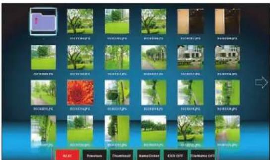
text_image
Screenshot of a file browser interface displaying a grid of image thumbnails with Chinese labels and a color selection panel below.- Operate the Card Reader application with the Enter, Left, Right, Up, and Down keys. The following buttons are supported in the user interface:
Button Description
| Previous | Moves the selected item left or goes to previous page when this is the left-most item. |
Button Description
| Next | Moves the selected item right or goes to next page when this is the right most item. |
| Display Displays the selected image or folder. | |
| Thumbnail Enter the Thumbnail Display mode. | |
| SlideShow Enter the Slide Show mode. | |
| NameOrder Sorts files and folders by name. | |
| ExtendOrder Sorts files and folders by extended order. | |
| SizeOrder Sorts files and folders by size. | |
| TimeOrder Sorts files and folders by time. | |
| EXIF ON/OFF Enables or disables the auto image rotate accordingly to EXIF information. | |
| FileName ON/OFF Enables or disables the filename display in Thumbnail Display mode. | |
Image Display mode
- In the Thumbnail Display mode, to enter the Image Display mode, press ENTER.
- To display the last or next image in the Image Display mode, use the Left and Right keys.
- To exit Image Display mode and return to Thumbnail Display mode, press ENTER.
natural_image
Park pathway lined with green grass and trees, no visible text or symbols- To display an image in the Image Display mode use the operation UI.
The following operations are supported in the operation UI.
Button Description
| Display | Enter the Image Display mode. |
| Thumbnail Enter the Thumbnail Display mode. | |
| SlideShow Enter the Slide Show mode. | |
| Actual Size | Displays the image in actual size. |
| Best Fit | Display the image in a size that best fits the screen. |
| EXIFDisp OFF/On | Enables or disables the EXIF information display. |
| +90deg | Rotates the image 90 degrees. |
| -90deg | Rotates the image -90 degrees. |
Image Slide Show mode
- In the Thumbnail Display mode, to enter the Slide Show mode, press SlideShow.
- In the Slide Show mode, to enter the Image Display Mode, press ENTER.
- To display an image in the Slide Show mode use the operation UI.
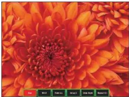
natural_image
Close-up of a vibrant orange chrysanthemum flower with red petals and dense center (no text or symbols visible)The following operations are supported in the Slide Show Mode operation UI.
Button Description
| Stop Stops Slide Show mode. |
| Next Displays the next image. |
| Previous Displays the previous image. |
| Delay 3/4/5 Sets a slide show delay in seconds. |
| Slide Effect Supports for the following slide effects:Slide RightBlocksRightDownXLinesSlide UpYlines |
| Repeat ON/OFF Enables or disables Slide Show Repeat mode. |
When the image cannot be displayed due to a memory limitation or an unsupported image format, the specific image is displayed on the center of the screen.
natural_image
A small, isolated white square centered on a black background with no visible text or symbols.Troubleshooting
If you cannot resolve an issue using the information provided in this section, contact your reseller or service center.
No image appears on screen
The image does not appear on the screen.
Resolution
- Make sure all the cables and power connections are correctly and securely connected.
See Installation on page 21 for more details. - Make sure the projector is switched on.
Incorrectly displayed image
The image is partial, is scrolling, or is otherwise incorrectly displayed.
Resolution
If using a PC (for Windows 95, 98, 2000, XP, Windows 7):
- On control panel or IR remote keypad, press AUTO.
- Select My Computer > Control Panel.
- Double-click Display.
- Select the Settings tab.
- Verify your display resolution setting is lower than or equal to WUXGA (1920 × 1200).
-
Click Advanced Properties.
-
If the projector is still not projecting the entire image, change the monitor display:
a. Verify the resolution setting is lower than or equal to WUXGA (1920 × 1200).
b. Switch to the Monitor tab.
c. Click Change.
d. Click Show all devices.
e. Under the SP box, select Standard monitor types.
f. Under the Models box, select the appropriate resolution mode.
g. Verify that the resolution setting of the monitor display is lower than or equal to WUXGA (1920 × 1200).
If using a Notebook:
- On control panel or IR remote keypad, press AUTO.
- Adjust resolution of the computer.
- To send signal out from notebook to projector, press the keys listed below for your Notebook manufacturer (for example, [Fn]+[F4]):
Notebook brand Function keys
| Acer [Fn]+[F5] | |
| Asus [Fn]+[F8] | |
| Dell [Fn]+[F8] | |
| Gateway [Fn]+[F4] | |
| IBM/Lenovo [Fn]+[F7] | |
| HP/Compaq [Fn]+[F4] | |
| NEC [Fn]+[F3] | |
| Toshiba | [Fn]+[F5] |
| Mac Apple | System Preference > Display > Arrangement > Mirror display |
- If you experience difficulty changing resolutions or your monitor freezes, restart all equipment including the projector.
Presentation is not displayed
The screen of the Notebook or PowerBook computer is not displaying your presentation.
Details
Some Notebook PCs may deactivate their own screens when a second display device is in use. Each has a different method of reactivation.
Resolution
Refer to your computer manual for information on changing the method of reactivation.
Unstable or flickering images
The image is unstable or is flickering when projected.
Resolution
- To correct the pixels, use Pixel Track and Pixel Phase.
- Change the monitor color setting on your computer.
Vertical flickering bar
The image has a vertical, flickering bar when projected.
Resolution
- To make an adjustment, use Auto Image.
- Check and reconfigure the display mode of your graphic card to make it compatible with the projector.
Image is out of focus
The image is out of focus on the screen.
Resolution
- Make sure both lens caps (front and back) are removed.
- Adjust the lens focus to fit the screen.
- Make sure the projection screen is between the required distance.
Image is stretched
The image is stretched when displaying a 16:9 DVD title.
Details
When you play anamorphic DVD or 16:9 DVD, the projector shows the best image if the projector display mode is set to 16:9 in the on-screen display.
Resolution
- If you play 4:3 format DVD titles, change the format to 4:3 in the projector on-screen display.
- If the image is still stretched, adjust the aspect ratio by setting the display format as 16:9 (wide) aspect ratio type on your DVD player. For more details, see Size and Position menu on page 35.
Image is not the correct size
The image is too small or too large.
Resolution
- Adjust the lens zoom to fit.
- Verify you are using the correct lens.
- Change the position of the projector.
CHRISTIE®
Specifications
Learn about the product specifications. Due to continuing research, specifications are subject to change without notice.
Inputs
The following table details the inputs for HS Series. RB in the Resolution column indicates reduced blanking.
| Signal Type | Resolution | Frame rate (Hz) | VGA | HDMI | DVI | 3G-SDI | HDBaseT |
| PC 640x480 60 | ● | ● | ● | ||||
| 640x480 72 | ● | ● | ● | ||||
| 640x480 75 | ● | ● | ● | ||||
| 640x480 85 | ● | ● | ● | ||||
| 640x480 66.6 | ● | ● | ● | ||||
| 720x400 70 | ● | ● | ● | ||||
| 800x600 60 | ● | ● | ● | ||||
| 800x600 72 | ● | ● | ● | ||||
| 800x600 75 | ● | ● | ● | ||||
| 800x600 85 | ● | ● | ● | ||||
| 800x600 | 120 | ● | ● | ● | |||
| 832x624 75 | ● | ● | ● | ||||
| 848x480 50 | ● | ● | ● | ||||
| 848x480 60 | ● | ● | ● | ||||
| 848x480 75 | ● | ● | ● | ||||
| 848x480 85 | ● | ● | ● | ||||
| 1024x768 | 60 | ● | ● | ● | |||
| 1024x768 | 75 | ● | ● | ● | |||
| 1024x768 | 85 | ● | ● | ● | |||
| 1024x768 | 120 | ● | ● | ● | |||
| 1152x720 | 50 | ● | ● | ● | |||
| 1152x720 | 60 | ● | ● | ● | |||
| 1152x720 | 75 | ● | ● | ● | |||
| 1152x720 | 85 | ● | ● | ● | |||
| 1152x864 | 60 | ● | ● | ● | |||
| 1152x864 | 70 | ● | ● | ● | |||
| 1152x864 | 75 | ● | ● | ● | |||
| 1152x864 | 85 | ● | ● | ● | |||
| 1152x870 | 75 | ● | ● | ● | |||
| 1280x720 | 50 | ● | ● | ● | |||
| 1280x720 | 60 | ● | ● | ● | |||
| PC 1280x720 75 | ● | ● | ● | ||||
| 1280x720 85 | ● | ● | ● | ● | |||
| 1280x720 120 | ● | ● | ● | ● | |||
| 1280x768 60 | ● | ● | ● | ● | |||
| 1280x768 75 | ● | ● | ● | ● | |||
| 1280x768 85 | ● | ● | ● | ● | |||
| 1280x800 50 | ● | ● | ● | ● | |||
| 1280x800 60 | ● | ● | ● | ● | |||
| 1280x800 75 | ● | ● | ● | ● | |||
| 1280x800 85 | ● | ● | ● | ● | |||
| 1280x960 50 | ● | ● | ● | ||||
| 1280x960 60 | ● | ● | ● | ● | |||
| 1280x960 75 | ● | ● | ● | ● | |||
| 1280x960 85 | ● | ● | ● | ● | |||
| 1280x1024 50 | ● | ● | ● | ||||
| 1280x1024 60 | ● | ● | ● | ● | |||
| 1280x1024 75 | ● | ● | ● | ● | |||
| 1280x1024 85 | ● | ● | ● | ● | |||
| 1360x768 50 | ● | ● | ● | ||||
| 1360x768 60 | ● | ● | ● | ||||
| 1360x768 75 | ● | ● | ● | ||||
| 1360x768 85 | ● | ● | ● | ||||
| 1368x768 60 | ● | ● | ● | ● | |||
| 1400x1050 50 | ● | ● | ● | ||||
| 1400x1050 60 | ● | ● | ● | ||||
| 1400x1050 75 | ● | ● | ● | ● | |||
| 1440x900 60 | ● | ● | ● | ● | |||
| 1440x900 75 | ● | ● | ● | ||||
| 1600x900 60 | ● | ● | ● | ||||
| 1600x1200 60 | ● | ● | ● | ● | |||
| 1680x1050 60 | ● | ● | ● | ● | |||
| 1920X1080 50 | ● | ● | ● | ||||
| 1920X1080 60 | ● | ● | ● | ● | |||
| 1920X1200RB 60 | ● | ● | ● | ● | |||
| PC 1920X1200RB 50 ● | ● | ● | |||||
| NTSC NTSC (M, 4.43) 60 | |||||||
| PAL PAL (B,G,H,I) 50 | |||||||
| PAL (N) 50 | |||||||
| PAL (M) 60 | |||||||
| SECAM SECAM (M) 50 | |||||||
| SDTV 480i 60 ● | ● | ● | ● | ||||
| 576i 50 ● | ● | ● | ● | ||||
| EDTV | 480p | 60 ● | ● | ● | ● | ||
| 576p | 50 ● | ● | ● | ● | |||
| HDTV | 1080i | 25 ● | ● | ● | ● | ||
| 1080i | 29 ● | ● | ● | ● | |||
| 1080i | 30 ● | ● | ● | ● | |||
| 720p | 50 ● | ● | ● | ● | |||
| 720p | 59 ● | ● | ● | ● | |||
| 720p | 60 ● | ● | ● | ● | |||
| 1080p | 23 ● | ● | ● | ● | |||
| 1080p | 24 ● | ● | ● | ● | |||
| 1080p | 25 ● | ● | ● | ● | |||
| 1080p | 29 ● | ● | ● | ● | |||
| 1080p | 30 ● | ● | ● | ● | |||
| 1080p | 50 ● | ● | ● | ● | |||
| 1080p | 59 ● | ● | ● | ● | |||
| 1080p | 60 ● | ● | ● | ● | |||
| Mandatory 3D | Frame Packing 1080p | 24 | ● | ● | |||
| Frame Packing 720p | 50 | ● | ● | ||||
| Frame Packing 720p | 60 | ● | ● | ||||
| Side by Side 1080i | 50 | ● | ● | ||||
| Side by Side 1080i | 60 | ● | ● | ||||
| Top and Bottom 720p | 50 | ● | ● | ||||
| Mandatory 3D | Top and Bottom 720p | 60 ● | ● | ||||
| Top and Bottom 1080p | 24 ● | ● | |||||
| Frame sequential 3D | 800x600 120 | ● | ● | ||||
| 1024x768 120 | ● | ● | |||||
| 1280x720 120 | ● | ● | |||||
| SD-SDI 480i YCbCr422 10bit | 59.94 ● | ||||||
| HD-SDI 720p YCbCr422 10bit | 50 ● | ||||||
| 59.94 ● | |||||||
| 60 ● | |||||||
| 1080i YCbCr422 10bit | 50 ● | ||||||
| 59.94 ● | |||||||
| 60 ● | |||||||
| 1080p YCbCr422 10bit | 23.98 ● | ||||||
| 24 ● | |||||||
| 25 ● | |||||||
| 29.97 ● | |||||||
| 30 ● | |||||||
| 1080sF YCbCr422 10bit | 25 ● | ||||||
| 29.97 ● | |||||||
| 30 ● | |||||||
| 3GA-SDI 1080p | YCbCr422 10bit | 50 ● | |||||
| 59.94 ● | |||||||
| 60 ● | |||||||
| 3GB-SDI 1080p | YCbCr422 10bit With 352M Payload ID | 50 | |||||
| 59.94 ● | |||||||
| 60 ● | |||||||
PIP/PBP compatibility
The following table details the PIP/PBP compatibility.
| PIP/PBP Matrix | 3G-SDI | VGA | DVI | HDMI1 | HDMI2 | HDBaseT RJ45-1 | USB A Mini USB | Ethernet RJ45-2 |
| 3G-SDI - - - ● | ● | ● | ● | ● | ||||
| VGA | - | - | - | ● | ● | ● | ● | ● |
| DVI | - | - | - | ● | ● | ● | ● | ● |
| HDMI 1 | ● | ● | ● | - | - | - | - | - |
| HDMI 2 | ● | ● | ● | - | - | - | - | - |
| HDBaseT RJ45-1 | ● | ● | ● | - | - | - | - | - |
| USB A | ● | ● | ● | - | - | - | - | - |
| Mini USB | ● | ● | ● | - | - | - | - | - |
| Ethernet RJ45-2 | ● | ● | ● | - | - | - | - | - |
- D o t (●): PIP/PBP combinations are enabled.
- Dash (-): PIP/PBP combinations are disabled.
Key features
- HD 0.95" 1920 × 1080 resolution or WUXGA 0.96" 1920 × 1200 resolution
- Projection lens compatibility:
• Horizontal offset ranges with full image size: +/-25%
• Vertical offset ranges with full image size: +/-60% (WUXGA) and +/-70% (HD)
Measurements comply with industry standards where offset is calculated as a ratio of the number of pixels shifted up or down to full image size.
• 360 degree orientation
• 3D blending and auto warping
• Supports fog filter as an optional accessory
- Wireless desktop display using wireless dongle (optional)
• SNMP traps and email notifications
• 10-bit image processor electronics with modular design - All video formats can be resized to full screen either horizontally or vertically while maintaining aspect ratio
- The projector can be operated using any of the following:
- The built-in keypad, the infrared (IR) remote keypad, a wired remote keypad, a PC/device using serial communications (Ethernet or RS232)
- A web page using Ethernet or from a PC or device using a wireless USB dongle (optional)
List of components
This projector comes with all the items listed below. Check to make sure your package is complete. If anything is missing, contact your dealer.
• IR remote keypad (P/N: 003-004468-XX)
• Power cords supplied with the projector:
• UK
• North America (125V)
• North America (250V)
• Europe, Korea, and Russia
- Japan
- l n d i a
- South Africa
• Australia and New Zealand
• Argentina
- User manual (CD)
Due to the difference in applications for each country, some regions may have different accessories.
The following accessories are available for the projector:
• 2.0-4.0:1 long zoom lens (P/N: 140-111104-XX)
• 4.0-7.2:1 long zoom lens (P/N: 140-116109-XX)
• 0.84-1.02:1 short zoom lens (P/N: 140-114107-XX)
• 1.02-1.36:1 short zoom lens (P/N: 140-115108-XX)
• 1.2-1.5:1 short zoom lens (P/N: 140-109101-XX)
• 1.5-2.0:1 short zoom lens (P/N: 140-110103-XX)

Warning! Failure to comply with the following could result in death or serious injury.
- Installing or replacing a lens must be done by a Christie qualified authorized trained service technicians or installers to avoid exposure to dangerous emission levels.
• 1DWUSB-BGN/wireless dongle (P/N: 133-113106-XX)
• H-Series adapter For E Series lenses (P/N:140-112105-XX)
• Christie One Mount Plus (P/N: 140-117100-XX)
• One Mount extender rod (P/N: 121-125109-XX)
• One Mount Rigging kit (P/N: 121-126100-XX)
• Christie One rigging frame (P/N: 140-113106-XX)
- Fog filter with frame (P/N: 003-005714-XX)
- Fog filter module (003-005715-XX)
Physical specifications
Learn the dimensions and weight of the projector.
Description Dimensions
Projector size
| Overall size (L x W x H) (excluding lens, feet) 677 mm (26.6 in) x packaging | 596 mm (23.5 in) x 203 mm (8.0 in) |
| Overall size, shipping without lens (L x W x H) (includes packaging) | 923 mm (36.3 in) x 843 mm (22.2 in) x 513 mm (20.2 in) |
| Projector Weight | |
| Without lens 42.5 kg (93.7 lb) | |
| Shipping without lens (includes packaging) 54.0 kg (119.0 lb) | |
| Operating position | |
| 360 degrees front to back and portrait capable Free orientation and constraint. | no tilt range constraint. |
Physical operating environment
Provides specifications for the operating environment.
-
Operating: 0^ to 40^
• 0 to 40 degrees C (0 to 2500 ft)
• 0 to 35 degrees C (2500 to 5000 ft)
• 0 to 30 degrees C (5000 to 10000 ft) -
Storage temperature range: -10^ to 60^
• Humidity range: 10% to 85% RH (maximum), non condensing - Storage humidity range: 5% to 90% RH (maximum), non condensing
- Operating altitude: 10,000 ft maximum
Power requirements
Learn the power requirements for the projector.
Parameter Requirement
| Rated voltage | |
| Input 1 100V-120V | |
| Input 2 200V-240V | |
| Rated current | |
| Input 1 14A | |
| Input 2 7A | |
| Line frequency 50/60Hz | |
| AC input coupler | |
| Input 1 C20 | |
| Input 2 C14 | |
| Inrush current 80A max | |
| Maximum power consumption | |
| Input 1 1500W | |
| Input 2 1400W | |
Warnings
- If the condition of the power input is abnormal, the projector displays the following warning:
Incorrect AC power detected. The projector is running in reduced brightness mode (ECO 2). Ensure the proper power is being provided to the selected projector input.
The following table provides information about the power input behavior.
Condition Input Projector Behavior (Light Source Mode)
| AC Socket Input Voltage | |||
| Normal 110V 110V Full (100% power) | |||
| Abnormal | 110V 220V ECO 2 (50% power); displays warning message | ||
| Normal 220V 220V Full (100% power) | |||
| Abnormal | 220V 110V ECO 2 (50% power); displays warning message | ||
- If the filter is installed incorrectly, the projector displays the following warning:
Filter is installed incorrectly.
Power off the projector and check the filter installation.
- Pump is malfunctioning, for example the motor or pump has stopped operating. The projector displays one of the following warnings:
Pump 1 is not working as expected. Check pump functionality.
Pump 2 is not working as expected. Check pump functionality.
- If the end-user presses the source key on the IR remote keypad that is not supported, for example BNC(2), the projector displays the following warning:
Not supported
Regulatory
This product conforms to the following regulations related to product safety, environmental requirements and electromagnetic compatibility (EMC).
Safety
• CSA C22.2 No. 60950-1
- UL 60950-1
- IEC 60950-1
• EN 60950-1
Laser safety
• IEC 60825-1
• IEC 62471
• FDA CDRH CFR 1040.10
• FDA CDRH CFR 1040.11
Electro-Magnetic Compatibility
Emissions
• FCC CFR47, Part 15, Subpart B/ANSI C63.4, Class A - Unintentional Radiators
• CISPR32/EN55032 Class A - Information Technology Equipment
• ICES/NMB003 (A) - Information Technology Equipment
Immunity
• CISPR 24/EN55024 EMC Requirements - Information Technology Equipment
Environmental
• The product conforms to:
- EU Directive (2011/65/EU) on the restriction of the use of certain hazardous substances (RoHS) in electrical and electronic equipment and the applicable official amendment(s).
- EU Regulation (EC) No. 1907/2006 on the registration, evaluation, authorization and restriction of chemicals (REACH) and the applicable official amendment(s).
- EU Directive (2012/19/EU) on waste and electrical and electronic equipment (WEEE) and the applicable official amendment(s).
- China Ministry of Information Industry Order No.39 (02/2006) on the control of pollution caused by electronic information products, the hazardous substances concentration limits (SJ/T11363-2006), and the applicable product marking requirement (SJ/T11364-2006).
Federal Communications Commission (FCC) warning
- Only use the supplied power cord.
On-screen display tree
The following table provides the on-screen display menu tree.
| Level 1 Level 2 Level 3 | (Or List) | Level 4 (Or List) | Level 5 (Or List) | Level 6 (Or List) | Default | |
| Size & Position | Size Presets Auto | Auto | ||||
| Native | ||||||
| 4:3 | ||||||
| Letterbox | ||||||
| Full Size | ||||||
| Full Width | ||||||
| Full Height | ||||||
| Custom | ||||||
| 3D Mode | ||||||
| Overscan Off By source set | ||||||
| Zoom | ||||||
| Crop | ||||||
| Pixel Track 0 to 100 50 | ||||||
| Pixel Phase 0 to 100 50 | ||||||
| Horz Position 0 to 100 50 | ||||||
| Vert Position 0 to 100 50 | ||||||
| Digital Horz Zoom | 50% to 400% 100 | |||||
| Digital Vert Zoom | 50% to 400% 100 | |||||
| Digital Horz Shift | 0 to 100 50 | |||||
| Digital Vert Shift | 0 to 100 50 | |||||
| Geometry Correction | PC Mode | On/Off | Off | |||
| Warp | Keystone | Horz Keystone | 0 to 40 | 20 | ||
| Vert Keystone | 0 to 40 | 20 | ||||
| Pincushion | Horz Pincushion | 0 to 100 | 50 | |||
| Vert Pincushion | 0 to 100 | 50 | ||||
| Level 1 | Level 2 | Level 3 (Or List) | Level 4 (Or List) | Level 5 (Or List) | Level 6 (Or List) | Default |
| Size & Position | Geometry Correction | Warp 4-Corner Top | Left | Horz Adjust | 0 to 120 (pixel) | 0 |
| Top Left Vert Adjust | 0 to 80 (pixel) | 0 | ||||
| Top Right Horz Adjust | 0 to 120 (pixel) | 0 | ||||
| Top Right Vert Adjust | 0 to 80 (pixel) | 0 | ||||
| Bottom Left Horz Adjust | 0 to 120 (pixel) | 0 | ||||
| Bottom Left Vert Adjust | 0 to 80 (pixel) | 0 | ||||
| Bottom Right Horz Adjust | 0 to 120 (pixel) | 0 | ||||
| Bottom Right Vert Adjust | 0 to 80 (pixel) | 0 | ||||
| Auto Warp Filter | Off On | |||||
| On | ||||||
| Horz Filter 0 to 9 | ||||||
| Vert Filter 0 to 9 | ||||||
| Reset Command | ||||||
| Auto Image Normal Wide | ||||||
| Wide | ||||||
| Image settings | Brightness 0 to 100 50 | |||||
| Contrast 0 to 100 By source set | ||||||
| Color Space Auto | Auto | |||||
| RGB | RGB Full | RGB Full | ||||
| RGB Limited | ||||||
| REC709 | ||||||
| YUV | REC709 | REC709 | ||||
| REC601 | ||||||
| Image settings | Detail Maximum | By source set | ||||
| High | ||||||
| Normal | ||||||
| Low | ||||||
| Minimum | ||||||
| 3D Display 3D Enable Auto Auto | ||||||
| Frame Packing | ||||||
| Side by Side | ||||||
| Top and Bottom | ||||||
| Frame Sequential | ||||||
| Off | ||||||
| 3D Invert Off Off | ||||||
| On | ||||||
| Toggle 3D Blending | Enter key N/A | |||||
| 3D Sync Out To Emitter To Emitter | ||||||
| To Next Projector | ||||||
| Frame Delay 1~n (by timing,Max 200) | 1 | |||||
| Video Options | Color | 0 to 100 | 50 | |||
| Tint | 0 to 100 | 50 | ||||
| Detect Film | Off Off | |||||
| On | ||||||
| Input Levels | Red Gain | 0 to 100 | 50 | |||
| Green Gain | 0 to 100 | 50 | ||||
| Blue Gain | 0 to 100 | 50 | ||||
| Red Offset | 0 to 100 | 50 | ||||
| Green Offset 0 to 100 | 50 | |||||
| Blue Offset | 0 to 100 | 50 | ||||
| Sync Threshold | 0 to 100 | 50 | ||||
| Reset RGB Gain/Offset | Command | |||||
| Image settings | Picture Settings | Presentation By source set | ||||
| Video | ||||||
| Bright | ||||||
| Enhanced | ||||||
| REC709 | ||||||
| Real | ||||||
| DICOM SIM | ||||||
| 2D High Speed | ||||||
| 3D | ||||||
| Blending | ||||||
| User | ||||||
| Save to User command | ||||||
| Contrast Enhancement | Off Off | |||||
| DynamicBlackTM | ||||||
| RealBlack | ||||||
| Image Freeze Off | Off | |||||
| On | ||||||
| Advanced Image Settings | Gamma Video By source set | |||||
| Command | ||||||
| Command | ||||||
| Configuration | Lens Settings Lens | Shift Command | ||||
| Lens Shift Memory | Apply Position Record 1 | |||||
| Record 2 | ||||||
| Record 3 | ||||||
| Record 4 | ||||||
| Record 5 | ||||||
| Save Current Position | Record 1 | |||||
| Record 2 | ||||||
| Record 3 | ||||||
| Record 4 | ||||||
| Record 5 | ||||||
| Lock All Lens Motors | Allow Allow | |||||
| Locked | ||||||
| Lens Calibration Command | ||||||
| Ceiling Mount Off | Auto | |||||
| On | ||||||
| Auto | ||||||
| Rear Projection Off Off | ||||||
| On | ||||||
| Menu Preferences | Menu Horz Offset | 0 to 100 0 | ||||
| Menu Vert Offset | 0 to 100 0 | |||||
| Show Messages Off On | ||||||
| On | ||||||
| Menu Transparency | 0 to 90 | 0 | ||||
| Splash Screen Setup | Factory Logo | Factory Logo | ||||
| Blue | ||||||
| Black | ||||||
| White | ||||||
| PIN Protect | Command | |||||
| Change PIN | Command | |||||
| Configuration | Power Management | Standby Mode 0.5 | W Mode Communication | Mode | ||
| Communication Mode | ||||||
| AC Power On Off | Off | |||||
| On | ||||||
| Auto Shutdown Never Never | ||||||
| 5 Mins | ||||||
| 10 Mins | ||||||
| 15 Mins | ||||||
| 20 Mins | ||||||
| 25 Mins | ||||||
| 30 Mins | ||||||
| Sleep Timer Off Off | ||||||
| 2 Hrs | ||||||
| 4 Hrs | ||||||
| 6 Hrs | ||||||
| Cool Down Instant | Off Instant Off | |||||
| 1 Min | ||||||
| 2 Min | ||||||
| High Altitude Off | Off | |||||
| On | ||||||
| IR Control Top | Off On | |||||
| On | ||||||
| Front | Off On | |||||
| On | ||||||
| HDBaseT | Off On | |||||
| On | ||||||
| 12V Trigger | Off Off | |||||
| On | ||||||
| Communications | LAN | DHCP | By set | |||
| IP Address | ||||||
| Subnet Mask | ||||||
| Default Gateway | ||||||
| MAC Address | ||||||
| Configuration | Communications | WLAN Enable By set | ||||
| Start IP | ||||||
| End IP | ||||||
| Subnet Mask | ||||||
| Default Gateway | ||||||
| MAC Address | ||||||
| SSID | ||||||
| Network Projector | Name By set | |||||
| Show Network Messages | ||||||
| Restart Network | By set | |||||
| Network Factory Reset | ||||||
| Serial Port Baud Rate | 2400 115200 | |||||
| 4800 | ||||||
| 9600 | ||||||
| 14400 | ||||||
| 19200 | ||||||
| 38400 | ||||||
| 57600 | ||||||
| 115200 | ||||||
| 1200 | ||||||
| Serial Port Echo Off Off | ||||||
| On | ||||||
| Serial Port Path RS232 RS232 | ||||||
| HDBaseT | ||||||
| Projector Address | 0 to 9 0 | |||||
| Level 1 Level 2 Level 3 (Or List) | Level 4 (Or List) | Level 5 (Or List) | Level 6 (Or List) | Default | ||
| Configuration | Backlight Preferences | Keypad Backlight | Timeout 5 Secs | Timeout 5 Secs | ||
| Timeout 10 Secs | ||||||
| Timeout 20 Secs | ||||||
| Timeout 30 Secs | ||||||
| Always On | ||||||
| Always Off | ||||||
| Status LED Always | On Always On | |||||
| Always Off | ||||||
| Warnings/ Errors Only | ||||||
| Color Matching Manual Adjustment | Enable On Off | |||||
| Off | ||||||
| Auto Test Pattern | On On | |||||
| Off | ||||||
| Red Part of Red | 0 to 1000 1000 | |||||
| Green Part of Red | 0 to 1000 0 | |||||
| Blue Part of Red | 0 to 1000 0 | |||||
| Green Part of Green | 0 to 1000 1000 | |||||
| Red Part of Green | 0 to 1000 0 | |||||
| Blue Part of Green | 0 to 1000 0 | |||||
| Blue Part of Blue | 0 to 1000 1000 | |||||
| Red Part of Blue | 0 to 1000 0 | |||||
| Green Part of Blue | 0 to 1000 0 | |||||
| Red Part of White | 0 to 1000 1000 | |||||
| Green Part of White | 0 to 1000 1000 | |||||
| Level 1 | Level 2 | Level 3 (Or List) | Level 4 (Or List) | Level 5 (Or List) | Level 6 (Or List) | Default |
| Configuration | Color Matching Manual | Adjustment | Blue Part of White | 0 to 1000 1000 | ||
| Reset to Default | Yes | |||||
| No | ||||||
| HSG Adjustment | HSG Enable On Off | |||||
| Off | ||||||
| Auto Test Pattern | On On | |||||
| Off | ||||||
| Red Hue 0 to 254 | 127 | |||||
| Saturation 0 to 254 | 127 | |||||
| Gain 0 to 254 | 127 | |||||
| Green Hue 0 to 254 | 127 | |||||
| Saturation 0 to 254 | 127 | |||||
| Gain 0 to 254 | 127 | |||||
| Blue | Hue 0 to 254 | 127 | ||||
| Saturation 0 to 254 | 127 | |||||
| Gain 0 to 254 | 127 | |||||
| Cyan | Hue 0 to 254 | 127 | ||||
| Saturation 0 to 254 | 127 | |||||
| Gain 0 to 254 | 127 | |||||
| Magenta | Hue 0 to 254 | 127 | ||||
| Saturation 0 to 254 | 127 | |||||
| Gain 0 to 254 | 127 | |||||
| Yellow | Hue | 0 to 254 | 127 | |||
| Saturation 0 to 254 | 127 | |||||
| Gain 0 to 254 | 127 | |||||
| White Gain | Red | 0 to 254 | 127 | |||
| Green | 0 to 254 | 127 | ||||
| Blue | 0 to 254 | 127 | ||||
| Reset to Default | Yes | |||||
| No | ||||||
| Color Enhance | Off | CE 1 | ||||
| CE 1 | ||||||
| CE 2 | ||||||
| Level 1 Level 2 Level 3 (Or List) | Level 4 (Or List) | Level 5 (Or List) | Level 6 (Or List) | Default | ||
| Configuration | Color Matching Wall | Color White White | ||||
| Gray 130 | ||||||
| Hot Key Settings | Blank Screen | |||||
| Aspect Ratio | ||||||
| Freeze Screen | ||||||
| Projector Info | ||||||
| Overscan | ||||||
| Service Projector | Info Model Name | |||||
| Serial Number | ||||||
| Native Resolution | ||||||
| Firmware | ||||||
| Configuration | ||||||
| Boot Code | ||||||
| Standby Mode | ||||||
| Lens Lock Settings | ||||||
| Input Power Rating | ||||||
| Wheel Index | ||||||
| FactoryReset Command | ||||||
| Test Pattern Off | ||||||
| Grid | ||||||
| White | ||||||
| Black | ||||||
| Checkerboard | ||||||
| Color Bars | ||||||
| Red | ||||||
| Green | ||||||
| Blue | ||||||
| Yellow | ||||||
| Magenta | ||||||
| Cyan | ||||||
| Boresight | ||||||
| Configuration | Service Wheel Index | (2X) | Phosphor Index | 0 to 719 | ||
| Filter Index 0 to | 719 | |||||
| Wheel Index (3X) | Phosphor Index | 0 to 719 | ||||
| Filter Index 0 to | 719 | |||||
| Error Log Show Log | ||||||
| Clear Log | ||||||
| Mode Adjustment | ||||||
| Laser Diode Info | LD1 Voltage/ | Current/ Temperature | ||||
| LD2 Voltage/ | Current/ Temperature | |||||
| LD3 Voltage/ | Current/ Temperature | |||||
| LD4 Voltage/ | Current/ Temperature | |||||
| LD5 Voltage/ | Current/ Temperature | |||||
| LD6 Voltage/ | Current/ Temperature | |||||
| LD7 Voltage/ | Current/ Temperature | |||||
| LD8 Voltage/ | Current/ Temperature | |||||
| LD9 Voltage/ | Current/ Temperature | |||||
| LD10 Voltage/ | Current/ Temperature | |||||
| LD11 Voltage/ | Current/ Temperature | |||||
| Level 1 | Level 2 | Level 3 (Or List) | Level 4 (Or List) | Level 5 (Or List) | Level 6 (Or List) | Default |
| Configuration | Service Laser Diode | Info LD12 Voltage/ | Current/Temperature | |||
| LD13 Voltage/ | Current/Temperature | |||||
| ADC Calibration | Calibration Condition | |||||
| ADC Calibration | ||||||
| Light Sensor Light | Sensor Info | |||||
| Calibration | ||||||
| Light Source | Light Source Mode | Constant Power | Constant Power | |||
| Constant Intensity | ||||||
| ECO 1 (80%) | ||||||
| ECO 2 (50%) | ||||||
| Rental Mode (90%) | ||||||
| Constant Power 0 | to 99 (30% to 100%) | 99 | ||||
| Light Source Info | Total Projector Hours | |||||
| LD Hours | ||||||
| Light Sensor Calibration | Default | Default | ||||
| Auto | ||||||
| Manual | ||||||
| Status | Model Name | |||||
| Serial Number | ||||||
| Native Resolution | ||||||
| Firmware | Vxx, Ayy, Bzz | |||||
| Main Input | ||||||
| Main Signal Format | ||||||
| Main Pixel Clock | ||||||
| Main Sync Type | ||||||
| Level 1 Level 2 Level 3 | (Or List) | Level 4 (Or List) | Level 5 (Or List) | Level 6 (Or List) | Default | |
| Status Main Horz | Refresh | |||||
| Main Vert Refresh | ||||||
| PIP/PBP Input | ||||||
| PIP/PBP Signal Format | ||||||
| PIP/PBP Pixel Clock | ||||||
| PIP/PBP Sync Type | ||||||
| PIP/PBP Horz Refresh | ||||||
| PIP/PBP Vert Refresh | ||||||
| Light Source Power | ||||||
| Total Projector Hours | ||||||
| Light Source Hours | BLD/RLD | |||||
| LC Hours | ||||||
| Standby Mode | ||||||
| Lens Lock Settings | ||||||
| IP Address | ||||||
| DHCP | ||||||
| System Temperature | ||||||
| Input Switching & PIP | Main Input SPEC define | |||||
| PIP/PBP Input SPEC define | ||||||
| PIP/PBP Enable Off Off | ||||||
| On | ||||||
| Swap | ||||||
| Size (Small/Medium/Large) | ||||||
| Level 1 | Level 2 | Level 3 (Or List) | Level 4 (Or List) | Level 5 (Or List) | Level 6 (Or List) | Default |
| Input Switching & PIP | Main Layout (PBP) | Main Left/ PBP, Main Top/ PBP, Main Right/ PBP, Main Bottom/PIP-Bottom Right/ PIP-Bottom Left/ PIP-Top Left/ PIP-Top Right) | ||||
| Timing Detection Mode | Normal Wide | |||||
| Wide | ||||||
| Source Info Active | Source | |||||
| Signal Format | ||||||
| Aspect Ratio | ||||||
| Resolution | ||||||
| Vert Refresh | ||||||
| Horz Refresh | ||||||
| Pixel Clock | ||||||
| Sync Type | ||||||
| Color Space | ||||||
| PIP/PBP (When PIP/PBP active) | ||||||
| (When PIP/PBP active) | ||||||
| Input key Change | Sources Auto Source | |||||
| List All Sources | ||||||
| Auto Source | ||||||
| Blank on Signal Switch | Off Off | |||||
| On | ||||||
| Language SPEC define English | ||||||
| Test pattern Off | ||||||
| Grid | ||||||
| White | ||||||
| Black | ||||||
| Checkerboard | ||||||
| Color Bars | ||||||
Corporate offices
USA-Cypress
ph:714-236-8610
Canada - Kitchener
ph:519-744-8005
Consultant offices
Italy
ph:+39(0)299021161
Worldwide offices
Australia
ph:+61(0)736244888
Brazil
ph:+55(11)25484753
China (Beijing)
ph:+86 10 6561 0240
China (Shanghai)
ph:+86 21 6278 7708
Eastern Europe and
Russian Federation
ph:+36(0)14748100
France
ph:+33(0)141214404
Germany
ph:+492161664540
India
ph:+91(080)67089999
Japan
ph:81-3-3599-7481
Korea (Seoul)
ph:+82 2 702 1601
Republic of South Africa
ph:+27(0)115100094
Singapore
ph:+656877-8737
Spain
ph:+34916339990
United Arab Emirates
ph:+97143206688
United Kingdom
ph:+441189778000