Valvryn - Remote control toy Pro Boat - Free user manual and instructions
Find the device manual for free Valvryn Pro Boat in PDF.


User questions about Valvryn Pro Boat
0 question about this device. Answer the ones you know or ask your own.
Ask a new question about this device
Download the instructions for your Remote control toy in PDF format for free! Find your manual Valvryn - Pro Boat and take your electronic device back in hand. On this page are published all the documents necessary for the use of your device. Valvryn by Pro Boat.
USER MANUAL Valvryn Pro Boat
natural_image
Illustration of a futuristic speedboat with '55' branding and stylized design (no text or symbols on the aircraft body)NOTICE
All instructions, warranties and other collateral documents are subject to change at the sole discretion of Horizon Hobby, LLC. For up-to-date product literature, visit http://www.horizonhobby.com and click on the support tab for this product.
MEANING OF SPECIAL LANGUAGE
The following terms are used throughout the product literature to indicate various levels of potential harm when operating this product:
WARNING: Procedures, which if not properly followed, create the probability of property damage, collateral damage, and serious injury OR create a high probability of superficial injury.
CAUTION: Procedures, which if not properly followed, create the probability of physical property damage AND a possibility of serious injury.
NOTICE: Procedures, which if not properly followed, create a possibility of physical property damage AND little or no possibility of injury.

WARNING: Read the ENTIRE instruction manual to become familiar with the features of the product before operating. Failure to operate the product correctly can result in damage to the product, personal property and cause serious injury.
This is a sophisticated hobby product and NOT a toy. It must be operated with caution and common sense and requires some basic mechanical ability. Failure to operate this Product in a safe and responsible manner could result in injury or damage to the product or other property. This product is not intended for use by children without direct adult supervision. Do not use with incompatible components or alter this product in any way outside of the instructions provided by Horizon Hobby, LLC. This manual contains instructions for safety, operation and maintenance. It is essential to read and follow all the instructions and warnings in the manual, prior to assembly, setup or use, in order to operate correctly and avoid damage or serious injury.
Age Recommendation: Not for children under 14 years. This is not a toy.
Safety Precautions and Warnings
As the user of this product, you are solely responsible for operating in a manner that does not endanger yourself and others or result in damage to the product or the property of others.
- When handling and/or transporting your boat, always pick up the boat from the sides, keeping all moving parts pointed away from you.
- Always keep a safe distance in all directions around your model to avoid collisions or injury. This model is controlled by a radio signal subject to interference from many sources outside your control. Interference can cause momentary loss of control.
-
Always operate your model in open spaces away from full-size vehicles, traffic and people.
-
Always carefully follow the directions and warnings for this and any optional support equipment (chargers, rechargeable battery packs, etc.).
- Always keep all chemicals, small parts and anything electrical out of the reach of children.
- Always avoid water exposure to all equipment not specifically designed and protected for this purpose. Moisture causes damage to unprotected electronics.
- Never place any portion of the model in your mouth as it could cause serious injury or even death.
- Never operate your model with low transmitter batteries.
Table of Contents
Water-Resistant Boat with Waterproof Electronics ..... 3
General Precautions 3
Wet Conditions Maintenance 3
Specifications....3
Product Inspection.... 3
Box Contents.... 4
Recommended Tools and Materials 4
Transmitter Controls.... 4
Installing Transmitter Batteries....4
Installing the Battery Pack....5
Low Voltage Cutoff (LVC) 5
Battery Chemistry....5
Getting Started....6
Control Check....6
Boat Characteristics....6
Boating Tips....7
Self-Righting 7
When You Are Finished 7
Maintenance....8
Drivetrain Lubrication 8
Propeller Service 9
Steering Servo Replacement....9
Steering Rudder Adjustment....9
Rudder Service 10
Rudder Trim....11
Binding 11
Failsafe 11
ESC Calibration.... 12
ESC Programming with Transmitter 12
Troubleshooting Guide 13
Limited Warranty.... 14
Contact Information 15
FCC Information.... 15
IC Information 15
EU Compliance Statement.... 15
Instructions for Disposal of WEEE.... 15
Replacement Parts 58
Optional Parts 58
Water-Resistant Boat with Waterproof Electronics
Your new Horizon Hobby boat has been designed and built with a combination of waterproof and water-resistant components to allow you to operate the product in calm, fresh water conditions.
While the entire boat is highly water-resistant, it is not completely waterproof and your boat should NOT be treated like a submarine. The various electronic components used in the boat, such as the servo(s) and receiver are waterproof, however, most of the mechanical components are water-resistant and require additional maintenance after use.
Metal parts, including the bearings, pins, screws and nuts, propeller, rudder, rudder mounts, prop struts, as well as the contacts in the electrical cables, will be susceptible to corrosion if additional maintenance is not performed after running in wet conditions. To maximize the long-term performance of your boat and to keep the warranty intact, the procedures described in the "Wet Conditions Maintenance" section must be performed regularly.
CAUTION: Failure to exercise caution while using this product and complying with the following precautions could result in product malfunction and/or void the warranty.
General Precautions
- Read the WET CONDITIONS MAINTENANCE procedures and make sure that you have all the tools you will need to properly maintain your boat.
- Not all batteries can be used in wet conditions. Consult the battery manufacturer before use. Caution should be taken when using Li-Po batteries in wet conditions.
- Most transmitters are not water-resistant. Consult your transmitter's manual or the manufacturer before operation.
- Never operate your transmitter or boat when lightning is present.
- Salt water is very conductive and highly corrosive. If you choose to run your boat in salt water, immediately rinse the boat in fresh water after each use. Operating your boat in salt water is at the sole discretion of the modeler.
Wet Conditions Maintenance
- Drain any water that has collected in the hull by removing the drain plug or canopy and tilting the boat in the appropriate direction to drain the water.
CAUTION: Always keep hands, fingers, tools and any loose or hanging objects away from rotating parts.
- Remove the battery pack(s) and dry the contacts. If you have an air compressor or a can of compressed air, blow out any water that may be inside the recessed connector housings.
- Dry and lubricate parts after every 30 minutes of operation or if the boat becomes submerged.
NOTICE: Never use a pressure washer to clean your boat.
- Use an air compressor or a can of compressed air to dry the boat and help remove any water that may have gotten into small crevices or corners.
- Spray the bearings, fasteners and other metal parts with a water-displacing light oil or lubricant.
- Let the boat air dry before you store it. Water (and oil) may continue to drip for a few hours.
Specifications
Length 25 in (635mm)
Beam (width) 9.25 in (234.9mm)
Hull Material ABS
Motor Dynamite® 4-Pole Brushless Marine Motor (DYNM3898)
ESC Dynamite® 30A Brushless Marine 2–3S (DYNM3860)
Transmitter Spektrum ^TM STX2 ^® 2CH 2.4GHz FHSS (SPMSTX200)
Receiver Spektrum™ Marine 2CH 2.4GHz FHSS (SPMMRX200)
Batteries Required, not included: 11.1V 3200mAh 3S 30C LiPo with EC3 ^TM connector
(4) AA batteries are required to operate the transmitter
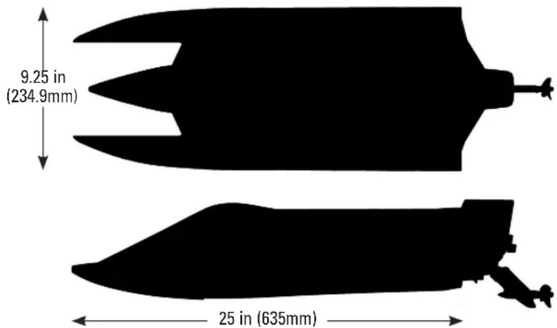
text_image
9.25 in (234.9mm) 25 in (635mm)Product Inspection
Carefully remove the boat and radio transmitter from the box. Inspect the boat for damage. If you find damage is present, please contact the retailer where you purchased your boat.
Box Contents
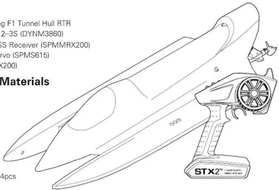
• Pro Boat® Valvryn™ 25-Inch Self-Righting F1 Tunnel Hull RTR
• Dynamite® 30A Brushless Marine ESC 2-3S (DYNM3860)
- Spektrum™ Marine 2-CH 2.4 GHz FHSS Receiver (SPMMRX200)
- Spektrum™ 2.2KG Mini Waterproof Servo (SPMS615)
• Spektrum™ STX2 2-CH Radio (SPMSTX200)
Recommended Tools and Materials
- Needle nose pliers
- Paper towel
- Rubbing alcohol
• Phillips screwdriver: #2
• Hex drivers: 1.5mm and 2mm
• Clear tape (DYNM0102)
• ProBoat® Marine Grease and Gun (DYNE4200)
- Hook and Loop Tape Set, 75 x 25mm 4pcs (DYNK0300)
text_image
g F1 Tunnel Hull RTR 2-3S (DYNM3860) GS Receiver (SPMMRX200) rvo (SPMS615) (200) Materials 4pcs STX2™ 3.0 GB P DUTTM HARDIC SYSTEMTransmitter Controls
text_image
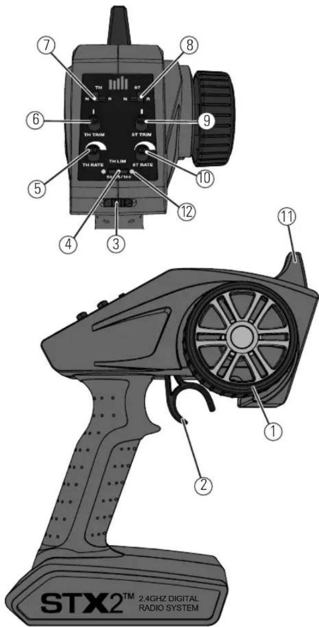
STX2™ 2.4GHz DIGITAL RADIO SYSTEM ① ② ③ ④ ⑤ ⑥ ⑦ ⑧ ⑨ TH TRIM ST TRIM TH RATE ST LIM ST RATE ST/16/100 10 11- Steering Wheel Controls direction (left/right) of the model
- Throttle Trigger Controls speed and direction (forward/brake/reverse) of the model
- ON/OFF Switch Turns the power ON/OFF
- Throttle Limiting Switch Adjusts the throttle limit from 50%, 75%, and 100%
- TH Rate Adjusts the end point of the throttle
- TH Trim Adjusts the throttle neutral point
- TH REV Reverses the function of the speed control when pulled back or pushed forward
- ST REV Reverses the function of the steering when the wheel is turned left or right
- ST Trim Adjusts the steering center point
- ST Rate Adjusts the end point of the steering
- Antenna Transmits the signal to the model
- Indicator Lights
- Solid red lights—Indicates radio connectivity and adequate battery power
- Flashing red lights—Indicates the battery voltage is critically low. Replace batteries
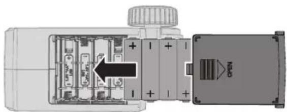
Installing Transmitter Batteries
natural_image
Cross-sectional diagram of a mechanical device showing internal components and a labeled component (no text or symbols present)This transmitter requires 4 AA batteries.
- Remove the battery cover from the transmitter.
- Install the batteries as shown.
- Install the battery cover.
CAUTION: If using rechargeable batteries, charge only rechargeable batteries. Charging non-rechargeable batteries may cause the batteries to burst, resulting in injury to persons and/or damage to property.
CAUTION: Risk of explosion if battery is replaced by an incorrect type. Dispose of used batteries according to national regulations.
Installing the Battery Pack
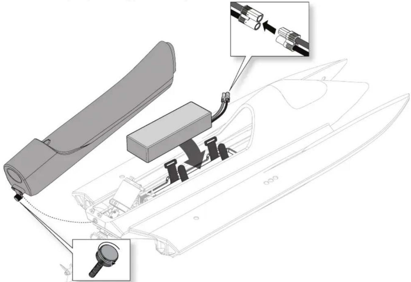
- Loosen the screw on the rear of the canopy.
- Disengage the front of the canopy from the hull and remove the canopy.
- Install the battery in the compartment. Secure it with the hook and loop straps. If running your boat in rougher
water conditions, the use of hook and loop tape may also be needed to fully secure the battery.
- Connect the battery pack to the ESC power connector.
text_image
Technical diagram showing assembly of a motor with labeled components and directional arrows indicating motion or assembly steps.Low Voltage Cutoff (LVC)
Discharging a Li-Po battery below 3V per cell may damage your battery. The included ESC protects the boat battery from over-discharge using Low Voltage Cutoff (LVC). Before the battery charge decreases too much, LVC removes power supplied to the motor. Power to the motor pulses, showing that some battery power is reserved for boat control and safe landing.
Disconnect and remove the Li-Po battery from the boat after use to prevent trickle discharge. Charge your Li-Po battery to about half capacity before storage. During storage, make sure the battery charge does not fall below 3V per cell. LVC does not prevent the battery from over-discharge during storage.
NOTICE: Repeated operation to LVC will damage the battery.
Tip: Monitor your boat battery's voltage before and after boating by using a Li-Po Cell Voltage Checker (EFLA111, sold separately).
Battery Chemistry
The ESC comes from the factory in Li-Po Mode. To change battery chemistry:
- Keep the throttle at neutral and power ON the ESC.
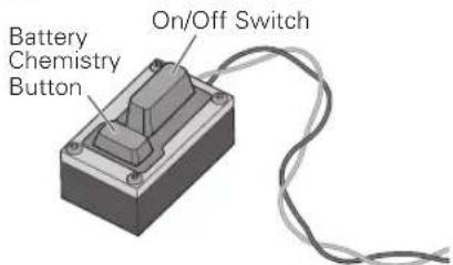
- Press and hold the Battery Chemistry Button on the power switch for 3 seconds. The LED flashes the current battery chemistry (red = Ni-MH, green = Li-Po).
- Continue holding the Battery Chemistry Button for another 6 seconds. The ESC changes battery chemistry and the LED flashes the new battery chemistry.
- Power OFF the ESC. The ESC saves the setting until it is changed.
text_image
Battery Chemistry Button On/Off SwitchCAUTION: Never change the battery chemistry to NiMH when using a LiPo battery. Damage to the battery will occur, which could result in a fire.
Getting Started
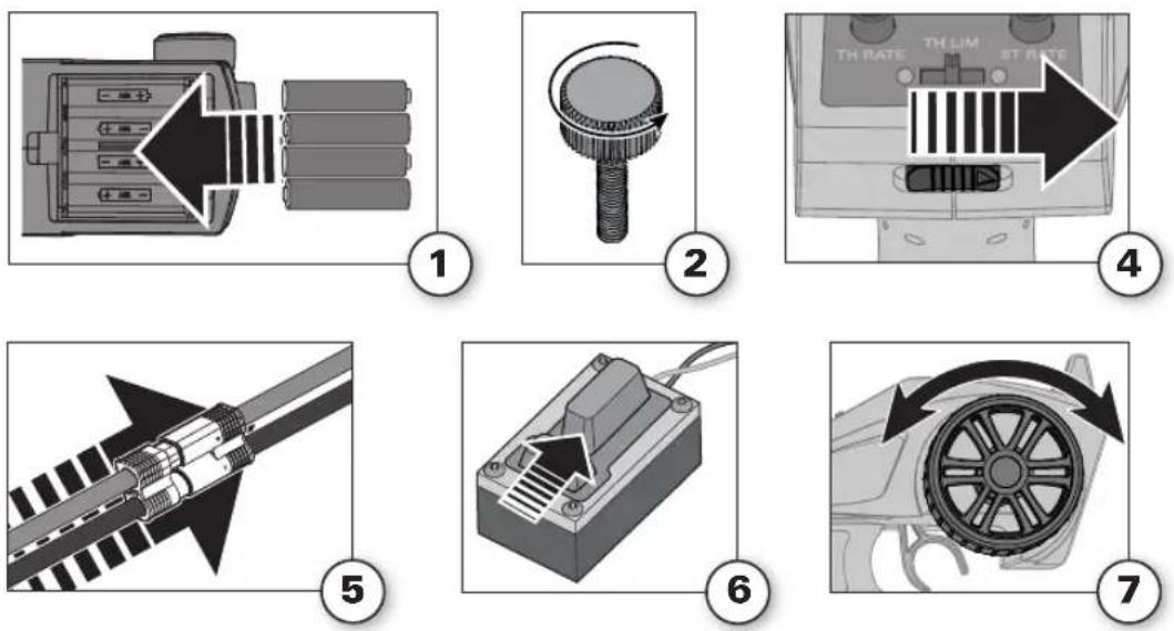
- Install 4 AA batteries into the transmitter.
- Remove the canopy from the hull.
- Install the fully charged battery in the compartment and secure it with the hook and loop strap.
-
Power on the transmitter. Ensure the throttle is not reversed and the throttle trim is neutral.
-
Connect the battery to the ESC.
-
Keep the throttle at neutral and power ON the ESC. The ESC automatically calibrates the throttle range after 3 seconds. A beep will sound, indicating battery chemistry and cell count:
• 1 beep: Ni-MH or Ni-Cd
• 2 beeps: 2S Li-Po
• 3 beeps: 3S Li-Po
One short beep will sound when the ESC is ready to run.
- Test the transmitter's control of the boat with the boat on the display stand.
- Install the canopy on the hull.
Tip: We suggest taping around the canopy hatch with Clear Flex Marine Tape (DYNM0102) to further protect the inside of the hull from water.
NOTICE: Using tape with adhesive stronger than the recommended marine tape may damage your boat's finish by pulling the paint off the hull. Use pliable, low adhesion tape for the best outcome.

WARNING: Keep all body parts, hair, and loose clothing away from the propeller. When armed, the will turn in response to any throttle input.
Control Check
IMPORTANT: Perform a control check at the beginning of each boating session, after repair, or after installation of new batteries.
Ensure the receiver antenna is extended properly and all batteries are fully charged.
- Power ON the transmitter and the boat. Do not install the boat canopy.
- Place the boat securely on the boat stand.
NOTICE: Do not operate the motor for more than 10 seconds without water-cooling circulation or damage may result.
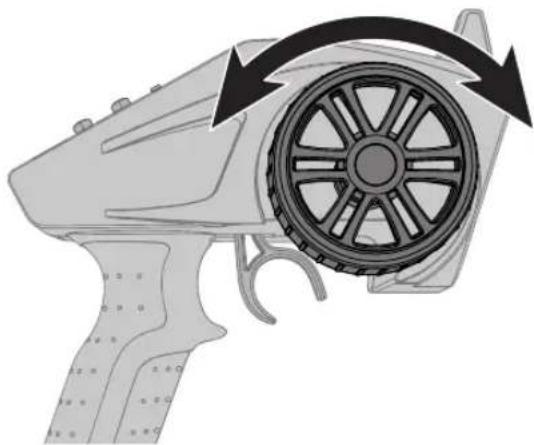
- Check steering and throttle on the transmitter.
natural_image
Diagram of a handheld device with a circular wheel and directional arrows indicating motion (no text or symbols)Boat Characteristics
This boat is tuned for a variety of wind and water conditions. F1 boats are known for straight-line speed and neck snapping turns. When boating in a straight line, there is very little contact between your boat's hull and the water, yielding maximum speed and handling. Before turning your
boat, decrease the throttle to 75% power. This allows the ride pad to "grip" the water, carrying your boat through the turn. After entering a turn, increase throttle to 100% power. Entering a turn at full speed may cause the boat to flip over.
Boating Tips
When running your boat for the first time, we recommend calm wind and water conditions so that you can learn how the boat responds to your control.
Consult local laws and ordinances before choosing a location to pilot your boat.
- Carefully place the boat in the water.
- Operate the boat at slow speeds near the shoreline. Avoid objects in the water at all times. When the boat is moving forward, ensure water flows out of the coolant outlet.
- Once you are comfortable operating the boat at slow speeds, it is safe to operate the boat farther from the shore at higher speeds.
- Bring the boat back to shore when power is limited by the Low Voltage Cutoff. After LVC has kicked in, the ESC will allow you throttle the boat at a fraction of normal operation allowing enough power to return to shore.

CAUTION: Never operate your boat in less than 12 inches (30.5 cm) of water.

CAUTION: Never attempt to retrieve a downed boat by swimming. If you need to retrieve your boat from water, use fishing equipment or another boat.
Avoid boating near:
- watercraft
• people (swimming areas, fishing areas)
• stationary objects
• rapidly moving water - wildlife
- floating debris
• overhanging trees - vegetation
NOTICE: If the propeller and rudder are blocked with debris or vegetation, remove the boat from the water and clear any debris before continuing operation. Remove any blockage from the coolant system or the motor and ESC (electronic speed control) may overheat.
NOTICE: When running at full speed in choppy water, the propeller may exit and re-enter the water quickly and repeatedly, subjecting the propeller and drive shaft to stress. Frequent stress may damage the propeller and drive shaft.
Self-Righting
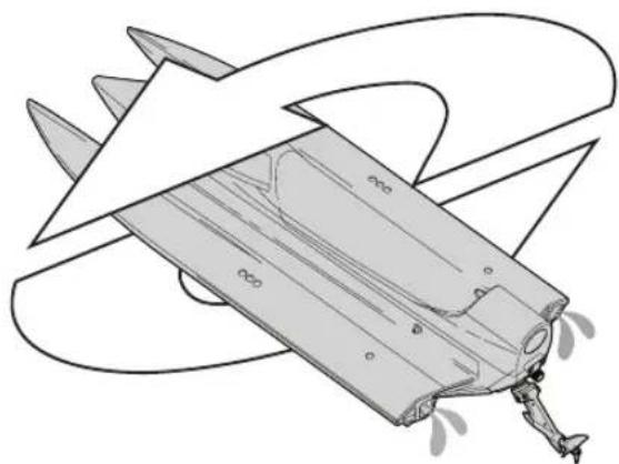
The self-righting feature of your boat uses a water ballast system. The ballast works as a controlled breach in the hull. As the ballast fills with water, the weight of the water forces the boat to sink, while the air trapped inside the hull causes enough buoyancy to right the boat.
The boat will self-right automatically, using water ballast.
Once the boat is upright, it will lean to one side. Apply full throttle. The trapped water will be forced out of the ballast tanks by the boat's forward momentum.
IMPORTANT: Applying throttle during the self-righting process may prevent the boat from turning over.
natural_image
Line drawing of a mechanical component with triangular blades and internal structure (no text or symbols)When You Are Finished
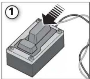
- Power off the receiver by pressing the power button for 2 seconds.
- Power off the transmitter.
- Disconnect and remove the battery from the boat.
Tip: Always remove the canopy before storage or moisture may allow mold and mildew to grow in the boat. Drain water from inside the hull using the drain plug.
- Fully dry the inside and outside of the boat, including the water cooling lines and jacket around the motor
- Remove the hatch before storing your boat
• Repair any damage or wear to the boat - Lubricate the drive shaft using Dynamite Marine Grease (DYNE4200)
• Make note of lessons learned from trimming, including water and wind conditions
natural_image
3D diagram of a mechanical component with a black arrow pointing to a textured surface, connected by wires (no text or symbols)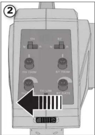
text_image
② TH M R ST N R TH THIM ST THIM TH LIM ST RATE 1 0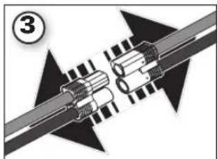
natural_image
Mechanical assembly diagram showing two connected components with arrows indicating motion (no text or symbols)Tip: The hook and loop strips in the boat retain water. Dry them with a cloth.
NOTICE: When you are finished boating, never leave the boat in direct sunlight or in a hot, enclosed area such as a car. Doing so can damage the boat.
Maintenance
Drivetrain Lubrication
Always replace the drivetrain parts when they are damaged or show visible wear or injury and damage may result.
Lubricating the flex shaft is vital to the life of the drivetrain. The lubricant also acts as a seal, keeping water from entering the hull through the stuffing tube.
Lubricate the flex shaft, drive strut, and all moving parts after every 30 minutes of operation.
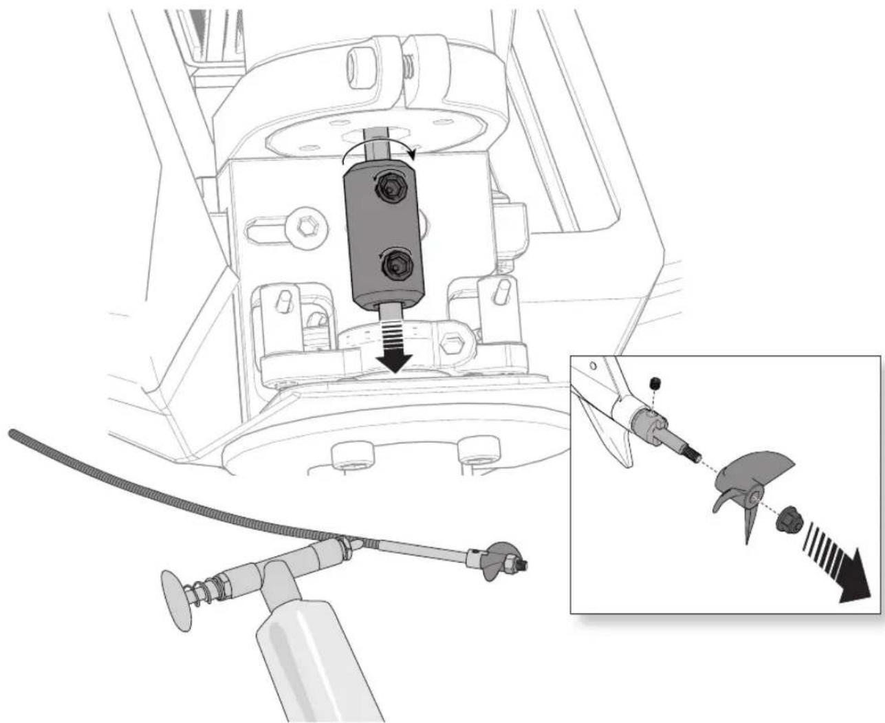
- Use a 5.5mm nut driver to remove the propeller nut from the propeller shaft.
- Carefully remove the propeller from the propeller shaft.
- Use a 2mm hex driver to loosen the set screw on the motor coupler.
- Carefully remove the flex shaft from the boat.
Tip: If the flex shaft is difficult to remove, use small tongue-and-groove pliers (multi-grip) to hold the motor coupling while rotating the shaft clockwise as you remove the flex shaft from the boat.
NOTICE: Rotating the shaft counter clockwise inside of the motor coupler will damage the flex shaft, requiring flex shaft replacement.
NOTICE: The outer bearing and composite spacer can dislodge from the rudder housing when removing the flex shaft. Take care not to drop the bearing and spacer.
- Inspect the bearing for signs of wear. Use Dynamite Precision Oiler: Medium (DYNE0100) to lubricate the bearing if it does not need to be replaced. Use new bearings and seals (PRB286053) as a replacement.
Tip: The spacer dimensions are 6mm x 2.66mm x 4.17mm.
-
Remove the old lubricant and material from the flex shaft.
-
Lubricate the full length of the flex shaft assembly up to the drive dog using marine grease (DYNE4200 or DYNE4201).
NOTICE: When lubricating the flex shaft, do not lubricate the first 20mm of the flex shaft. If grease gets into the motor coupler, it may cause the flex shaft to slip inside of the coupler, thereby damaging it and requiring replacement.
-
Insert the flex shaft into the stuffing tube.
-
Use a 2mm hex wrench to tighten set screw.
NOTICE: Running the boat in saltwater could cause some corrosion. If you run the boat in saltwater, rinse it thoroughly in freshwater after each use and lubricate the drive system. Use water displacement spray sparingly.
NOTICE: Because of its corrosive effects, running RC boats in saltwater is at the discretion of the modeler.
natural_image
Technical diagram of a mechanical assembly with a central component and a separate inset showing a blade-like component (no text or symbols present)Propeller Service
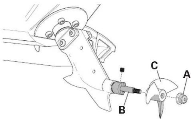
- Use an 5.5mm nut driver to loosen the nut (A) from the propeller shaft (B).
- Remove the nut and propeller (C) from the flex shaft.
- Assemble in reverse order. Correctly align the propeller with the drive dog on the flex shaft.
text_image
Technical diagram of a mechanical assembly with labeled parts A, B, and CSteering Servo Replacement
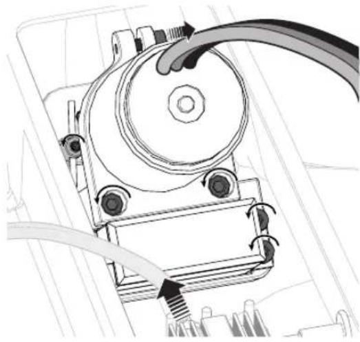
- Carefully disconnect the water lines from the motor cooling sleeve. Rotate the cooling line back and forth, while pulling away, to loosen it.
- Disconnect the motor wires from the ESC.
- Disconnect the servo lead from the receiver.
- Use a 2.5mm driver to loosen the bolt that attaches the motor to the motor mount and remove the motor.
Tip: Loosen the screw 1–1¼ turns but do not completely remove the screw. - Use a 2mm hex driver and loosen the set screw on the motor coupler.
- Remove the motor.
- Use a 1.5mm hex driver to loosen the set screws, holding the servo steering links to the swivel barrels mounted to the composite push-pull lever.
- Use a 2mm hex driver to remove the screws that hold the servo mount to the aluminum motor mount.
- Move the rudder to the left and then right to remove the steering links from the swivel barrels.
-
Remove the servo away from aluminum mount.
-
Use a 2mm hex wrench to loosen the bolts holding the servo to the composite servo mount. Service the servo as needed.
- To reassemble the rudder, follow these instructions in reverse order.
natural_image
Mechanical assembly diagram showing a motor with rotating components and a cable (no text or labels)Steering Rudder Adjustment
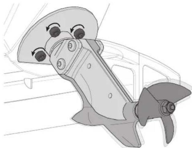
- Place a ruler on top of the strut to measure the distance between the aluminum swivel mount and the composite rudder.
- Use a 2mm hex driver to loosen the top screws (2) that hold the composite rudder to the aluminum swivel mount. Only 12 turn is necessary to loosen the bolts.
- Use a 2mm hex driver to loosen the bottom screws (2) that hold the composite rudder to the aluminum swivel mount. Only 1/8 turn is necessary to loosen the bolts.
Tip: Loosening the bottom bolts too much will make adjustment difficult. Slight friction is needed to hold the adjustment.
Lowering the Strut will lower the bow, increasing the boat's contact with the water. Use this setting for rough water and/or strong winds. This setting increases steering input.
Raising the Strut lifts the bow, decreasing the boat's contact with the water. Use this setting for calm wind and water conditions. This setting increases speed and bounce. Applying throttle during a turn in this setting makes turning difficult.
natural_image
Technical illustration of a mechanical component with rotating eyes and a propeller (no text or symbols)Rudder Service
- Use a 5.5mm nut driver to loosen the propeller nut from the propeller shaft.
- Carefully remove the propeller from the propeller shaft.
- Use a 2mm hex driver and loosen the set screw on the motor coupler.
- Carefully remove the flex shaft from the boat.
Tip: If the flex shaft is difficult to remove, use small tongue-and-groove pliers (multi-grip) to hold the motor coupling while rotating the shaft clockwise as you remove the shaft from the boat.
NOTICE: Rotating the shaft counter clockwise inside of the motor coupler will damage the flex shaft, requiring flex shaft replacement.
Tip: The outer bearing and composite spacer can dislodge from the rudder housing when removing the flex shaft. Do not to drop the bearing and spacer.
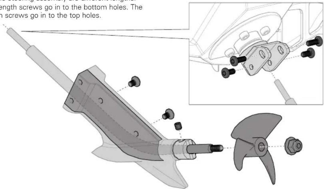
- Use a 2mm hex driver to remove the 4 button head screws holding the composite rudder assembly to the aluminum steering base.
Tip: The button head screws holding the composite rudder to the steering assembly are different lengths. The 6mm length screws go in to the bottom holes. The 8mm length screws go in to the top holes.
NOTICE: Using the 8mm length screws in the bottom holes will damage the channel in the rudder that houses the flex shaft. Damage to the flex shaft may occur.
- Once you have removed the screws, remove the composite rudder assembly from the boat. Apply downward force while pulling it away from the boat.
- Use a 2mm hex wrench to remove the 2mm counter sunk screws joining the 2 pieces of the composite rudder assembly.
- Inspect the non-stick liner for wear and tear. Replace it when necessary.
- Use a hex driver to push the 7 × 2.5 × 4 mm bearing away from the housing.
- Inspect the bearing for signs of wear. Use Dynamite Precision Oiler: Medium (DYNE0100) to lubricate the bearing if it does not need to be replaced. Use new bearings and seals (PRB286053) as a replacement.
Tip: The spacer dimensions are 6mm x 2.66mm x 4.17mm.
- To reassemble the rudder, follow these instructions in reverse order.
text_image
length screws go in to the bottom holes. The screws go in to the top holes.Rudder Assembly Removal
- Carefully disconnect the water lines from the motor cooling sleeve. Rotate the cooling line back and forth, while pulling away, to loosen it.
- Disconnect the motor wires from the ESC.
- Use a 2.5mm driver to loosen the bolt that attaches the motor to the motor mount.
Tip: Loosen the screw 1–1¼ turns but do not completely remove the screw.
-
Remove the motor.
-
Use a 3–4mm flat tip driver to remove the e clip holding the steering push-pull lever on the aluminum steering hub.
-
Carefully remove the steering hub from its housing.
-
Inspect the bearing and O-ring for signs of wear and tear. Use Dynamite Precision Oiler: Medium (DYNE0100) to lubricate the bearing. Use new bearings and seals
(PRB286053) if the bearing or O-ring needs to be replaced. Use Dynamite Marine Grease (DYNE4200) to lubricate the O-ring.
- Use a 1.5mm hex driver to loosen the set screws holding the servo steering links to the swivel barrels mounted to the composite push-pull lever.
- Use a 2.5mm hex driver to remove the 4 screws holding the motor/servo mount to the hull.
- Remove the aluminum motor/servo mount from the boat.
- Use a 2mm hex driver to remove the screws holding the servo mount to the aluminum mount.
- Inspect the servo for proper operation. Replace it when necessary.
- To reassemble the rudder, follow these instructions in reverse order.
Rudder Trim
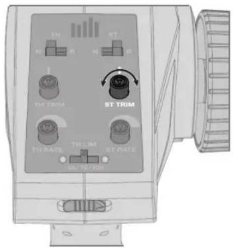
If the boat does not go straight, adjust the steering trim dial on the transmitter.
- Use a 1.5mm hex driver to loosen the set screws on the 2 servo swivel barrels.
- Adjust the linkage until the rudder is centered.
- Use a 1.5mm hex driver to tighten the 2 servo swivel barrels.
text_image
Tm ST M R M R ST TRIM ST TRIM TH RATE TH LIM ST RATE 500 / 700 / Max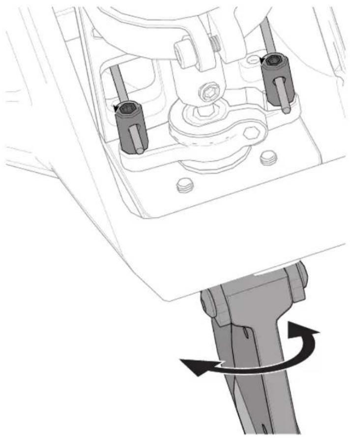
natural_image
Technical line drawing of a mechanical assembly with no visible text or symbolsBinding
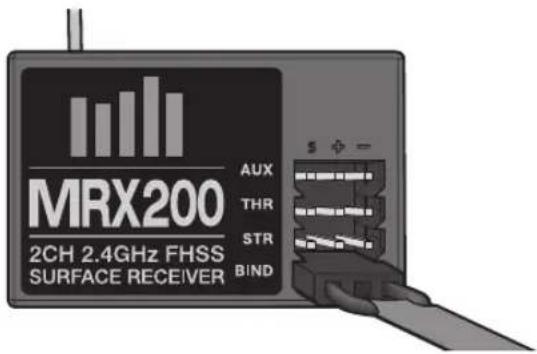
Binding is the process of programming the receiver to recognize the GUID (Globally Unique Identifier) code of a single specific transmitter. The STX2 ^® transmitter and SPMMRX200 receiver are bound at the factory. If you need to rebind, follow the instructions below:
text_image
MRX200 2CH 2.4GHz FHSS SURFACE RECEIVER AUX THR STR BIND- Insert the Bind Plug in the BIND port of the receiver.
- Connect a fully charged battery to the ESC.
- Power on the ESC. The red receiver LED flashes, indicating the receiver is in bind mode.
Failsafe
In the unlikely event that the radio connection is lost during use, the receiver will drive the servos to their pre-programmed failsafe positions (normally no throttle and straight steering).
- Center the ST TRIM and TH TRIM dials on the transmitter.
- Turn the Steering Wheel to Full Right. Power ON the transmitter while holding the Steering Wheel to the Right.
- Release the Steering Wheel when the receiver LED goes solid.
- Remove the Bind Plug and store it in a convenient place.
- Power OFF the ESC to save the settings.
- Power OFF the transmitter.
You must rebind when:
- You want different failsafe positions (e.g. when throttle or steering reverse has been changed).
• Binding the receiver to a different transmitter.
NOTICE: Do not attempt to bind the transmitter and receiver if there are other compatible transmitters in bind mode within 400 feet. Doing so may result in unexpected binding.
If the receiver is powered on before powering on the transmitter, the receiver will enter this failsafe mode. When the transmitter is powered on, normal control is resumed.
ESC Calibration
The radio system is calibrated to the ESC at the factory. To calibrate to a different radio or ESC, follow these steps:
- Remove the propeller.
- Ensure that the throttle trim is neutral.
- Power on transmitter.
- Move the transmitter's throttle lever to full throttle, holding that position.
-
Press the power button to turn on the ESC while holding full throttle on the transmitter.
-
The ESC will emit 2 tones, acknowledging full throttle.
- Return the throttle to a neutral position. The ESC will emit one tone.
- Move the transmitter's throttle lever to full reverse. The ESC will emit 3 tones.
- Return the throttle to a neutral position. The ESC is now calibrated to the transmitter throttle range.
CAUTION: Never change the battery chemistry to NiMH when using a LiPo battery. Damage to the battery will occur, which could result in a fire.
ESC Programming with Transmitter
- Pull and hold the Throttle Trigger to full throttle and turn the ESC on.
- After 2 seconds a "-B-B" will sound. Wait another 5 seconds and the ESC will give a rising tone to indicate you have entered Programming Mode.
-
After entering Programming Mode, you will hear 4 tones in a loop, indicating Programmable Items. Push the Throttle Trigger to full brake within 3 seconds after the tone sounds matching the programmable item you want to select.
-
After selecting a programmable item, you will hear several tones in a loop indicating Programmable Values. Pull Throttle Trigger to full throttle to select the value matching the tone. The ESC will give an alternating tone to indicate the item is selected.
- Keep the trigger in Full Throttle to return to Step 3 and continue item selection. Move the throttle to full brake position within 2 seconds to exit the Program Mode.
NOTICE: Maximum voltage is 12.6V.
The black-shaded setting is the factory default
| Programmable Items | Programmable Value | -B Single Beep B—Long Beep | ||||||
| -B -B-B | -B-B-B -B-B-B | -B B— | B—-B | B—-B-B | B—-B-B-B | |||
| Running Mode -B | Forward Only | Forward/ Backward | ||||||
| Li-Po Cells -B-B | Auto Calc. | 2s 3s | ||||||
| Low Voltage Cutoff -B-B-B | None | 2.8V/Cell | 3.0V/Cell | 3.2V/Cell | 3.4V/Cell | |||
| Timing -B-B-B-B | 0.00^ | 3.75^ | 7.50^ | 11.25^ | 15.00^ | 18.75^ | 22.50^ | 26.25^ |
Troubleshooting Guide
| Problem Possible Cause Solution | ||
| Boat will not respond to throttle but responds to other controls | Throttle channel is reversed Reverse throttle channel on transmitter | |
| Extra noise or extra vibration | Damaged propeller, shaft or motor Replace damaged parts | |
| Propeller is out of balance Balance or replace propeller | ||
| Reduced runtime or boat underpowered | Boat battery charge is low Completely recharge battery | |
| Boat battery is damaged Replace boat battery and follow battery instructions | ||
| Blocking or friction on shaft or propeller Disassemble, lubricate and correctly align parts | ||
| Boat conditions may be too cold | Make sure the battery is warm (above 10°C [50°F]) before use | |
| Battery capacity may be too low for conditions | Replace battery or use a larger capacity battery | |
| Drive dog is too near the stuffing tube | Loosen drive shaft side of the motor coupling and move drive shaft small amount back | |
| Too little lubrication on drive shaft Fully lubricate drive shaft | ||
| Vegetation or other obstacles block the rudder or propeller | Remove vegetation or obstacles from rudder or propeller | |
| Boat will not bind (during binding) to transmitter | Transmitter is too near boat during binding process | Move powered transmitter a few feet from boat, disconnect and reconnect battery to boat |
| Boat or transmitter is too close to large metal object, wireless source or another transmitter | Move the boat and transmitter to another location and attempt binding again | |
| Another compatible transmitter is powered on within range of the receiver | Power off all compatible transmitters except the one you are trying to bind | |
| Boat battery/Transmitter battery charge is too low | Replace/recharge batteries | |
| ESC switch is off Power on ESC switch | ||
| Boat will not connect (after binding) to transmitter | Transmitter is too near boat during connecting process | Move powered transmitter a few feet from boat, disconnect and reconnect battery to boat |
| Boat or transmitter is too close to large metal object, wireless source or another transmitter | Move boat or transmitter to another location and attempt to connect again | |
| Boat battery/transmitter battery charge is too low | Replace/recharge batteries | |
| ESC switch is off Power on ESC switch | ||
| Boat tends to dive in the water or takes on water | The boat hull is not completely closed | Dry out the boat and ensure the hatch is fully closed on the hull before returning the boat to the water |
| Center of gravity is too far forward Move batteries back in the hull | ||
| Trim tabs are angled incorrectly | Angle each trim tab up a small amount to lift the bow or down a small amount to lower the bow | |
| Boat tends to turn one direction | Rudder or rudder trim is not centered | Repair rudder or adjust rudder and rudder trim for straight running when control is at neutral |
| Vertical fins are angled incorrectly | Adjust the right or left fin angle for straight running when control is at neutral | |
| Boat does not self right | Ballast water intake holes are obstructed Remove obstruction/clear debris | |
| Water in the electronic compartment | Check water cooler tubes for obstruction/damage; check canopy seal | |
| Boat does not get up on plane | Ballast water intake holes are obstructed Remove obstruction/clear debris | |
| Water in the electronic compartment | Check water cooler tubes for obstruction/damage; check canopy seal | |
| Rudder does not move | Rudder, linkage or servo damage Replace or repair damaged parts and adjust controls | |
| Steering servo wire is damaged or connections are loose | Do a check of steering servo wires and connections, connect or replace as needed | |
| Transmitter is not bound correctly | Re-bind | |
| BEC (Battery Elimination Circuit) of the ESC is damaged | Replace ESC | |
| ESC switch is off Power on ESC switch | ||
| Controls reversed | Transmitter settings are reversed | Perform the Control Direction Test and adjust controls on transmitter appropriately |
| Motor overheats | Blocked water cooler tubes | Clean or replace water tubes |
| Motor power pulses then motor loses power | Weather conditions might be too cold | Postpone until weather is warmer |
| Battery is old, worn out or damaged | Replace battery | |
Limited Warranty
What This Warranty Covers
Horizon Hobby, LLC, (Horizon) warrants to the original purchaser that the product purchased (the "Product") will be free from defects in materials and workmanship at the date of purchase.
What is Not Covered
This warranty is not transferable and does not cover (i) cosmetic damage, (ii) damage due to acts of God, accident, misuse, abuse, negligence, commercial use, or due to improper use, installation, operation or maintenance, (iii) modification of or to any part of the Product, (iv) attempted service by anyone other than a Horizon Hobby authorized service center, (v) Product not purchased from an authorized Horizon dealer, or (vi) Product not compliant with applicable technical regulations or (vii) use that violates any applicable laws, rules, or regulations.
OTHER THAN THE EXPRESS WARRANTY ABOVE, HORIZON MAKES NO OTHER WARRANTY OR REPRESENTATION, AND HEREBY DISCLAIMS ANY AND ALL IMPLIED WARRANTIES, INCLUDING, WITHOUT LIMITATION, THE IMPLIED WARRANTIES OF NON-INFRINGEMENT, MERCHANTABILITY AND FITNESS FOR A PARTICULAR PURPOSE. THE PURCHASER ACKNOWLEDGES THAT THEY ALONE HAVE DETERMINED THAT THE PRODUCT WILL SUITABLY MEET THE REQUIREMENTS OF THE PURCHASER'S INTENDED USE.
Purchaser's Remedy
Horizon's sole obligation and purchaser's sole and exclusive remedy shall be that Horizon will, at its option, either (i) service, or (ii) replace, any Product determined by Horizon to be defective. Horizon reserves the right to inspect any and all Product(s) involved in a warranty claim. Service or replacement decisions are at the sole discretion of Horizon. Proof of purchase is required for all warranty claims. SERVICE OR REPLACEMENT AS PROVIDED UNDER THIS WARRANTY IS THE PURCHASER'S SOLE AND EXCLUSIVE REMEDY.
Limitation of Liability
HORIZON SHALL NOT BE LIABLE FOR SPECIAL, INDIRECT, INCIDENTAL OR CONSEQUENTIAL DAMAGES, LOSS OF PROFITS OR PRODUCTION OR COMMERCIAL LOSS IN ANY WAY, REGARDLESS OF WHETHER SUCH CLAIM IS BASED IN CONTRACT, WARRANTY, TORT, NEGLIGENCE, STRICT LIABILITY OR ANY OTHER THEORY OF LIABILITY, EVEN IF HORIZON HAS BEEN ADVISED OF THE POSSIBILITY OF SUCH DAMAGES. Further, in no event shall the liability of Horizon exceed the individual price of the Product on which liability is asserted. As Horizon has no control over use, setup, final assembly, modification or misuse, no liability shall be assumed nor accepted for any resulting damage or injury. By the act of use, setup or assembly, the user accepts all resulting liability. If you as the purchaser or user are not prepared to accept the liability associated with the use of the Product, purchaser is advised to return the Product immediately in new and unused condition to the place of purchase.
Law
These terms are governed by Illinois law (without regard to conflict of law principals). This warranty gives you specific legal rights, and you may also have other rights which vary from state to state. Horizon reserves the right to change or modify this warranty at any time without notice.
WARRANTY SERVICES
Questions, Assistance, and Services
Your local hobby store and/or place of purchase cannot provide warranty support or service. Once assembly, setup or use of the Product has been started, you must contact your local distributor or Horizon directly. This will enable Horizon to better answer your questions and service you in the event that you may need any assistance. For questions or assistance, please visit our website at www.horizonhobby.com, submit a Product Support Inquiry, or call the toll free telephone number referenced in the Warranty and Service Contact Information section to speak with a Product Support representative.
Inspection or Services
If this Product needs to be inspected or serviced and is compliant in the country you live and use the Product in, please use the Horizon Online Service Request submission process found on our website or call Horizon to obtain a Return Merchandise Authorization (RMA) number. Pack the Product securely using a shipping carton. Please note that original boxes may be included, but are not designed to withstand the rigors of shipping without additional protection. Ship via a carrier that provides tracking and insurance for lost or damaged parcels, as Horizon is not responsible for merchandise until it arrives and is accepted at our facility. An Online Service Request is available at http://www.horizonhobby.com/content/service-center_render-service-center. If you do not have internet access, please contact Horizon Product Support to obtain a RMA number along with instructions for submitting your product for service. When calling Horizon, you will be asked to provide your complete name, street address, email address and phone number where you can be reached during business hours. When sending product into Horizon, please include your RMA number, a list of the included items, and a brief summary of the problem. A copy of your original sales receipt must be included for warranty consideration. Be sure your name, address, and RMA number are clearly written on the outside of the shipping carton.
NOTICE: Do not ship LiPo batteries to Horizon. If you have any issue with a LiPo battery, please contact the appropriate Horizon Product Support office.
Warranty Requirements
For Warranty consideration, you must include your original sales receipt verifying the proof-of-purchase date. Provided warranty conditions have been met, your Product will be serviced or replaced free of charge. Service or replacement decisions are at the sole discretion of Horizon.
Non-Warranty Service
Should your service not be covered by warranty, service will be completed and payment will be required without notification or estimate of the expense unless the expense exceeds 50% of the retail purchase cost.
By submitting the item for service you are agreeing to payment of the service without notification. Service estimates are available upon request. You must include this request with your item submitted for service. Non-warranty
service estimates will be billed a minimum of 12 hour of labor. In addition you will be billed for return freight. Horizon accepts money orders and cashier's checks, as well as Visa, MasterCard, American Express, and Discover cards. By submitting any item to Horizon for service, you are agreeing to Horizon's Terms and Conditions found on our website http://www.horizonhobby.com/content/service-center_render-service-center.
ATTENTION: Horizon service is limited to Product compliant in the country of use and ownership. If received, a non-compliant Product will not be serviced. Further, the sender will be responsible for arranging return shipment of the un-serviced Product, through a carrier of the sender's choice and at the sender's expense. Horizon will hold non-compliant Product for a period of 60 days from notification, after which it will be discarded.
10/15
Contact Information
| Country of Purchase | Horizon Hobby Contact Information Address | ||
| United States of America | Horizon Service Center (Repairs and Repair Requests) | servicecenter.horizonhobby.com/RequestForm/ | 4105 Fieldstone RdChampaign, Illinois61822 USA |
| Horizon Product Support (Product Technical Assistance) | productsupport@horizonhobby.com877-504-0233 | ||
| Sales | sales@horizonhobby.com888-959-2306 | ||
| European Union | Horizon Technischer Service Sales: Horizon Hobby GmbH | service@horizonhobby.eu+49 (0) 4121 2655 100 | Hanskampring 9D 22885 Barsbüttel, Germany |
FCC Statement
FCC ID: 2AI3D-SS0001 This equipment has been tested and found to comply with the limits for Part 15 of the FCC rules. These limits are designed to provide reasonable protection against harmful interference in a residential installation. This equipment generates uses and can radiate radio frequency energy and, if not installed and used in accordance with the instructions, may cause harmful interference to radio communications.
However, there is no guarantee that interference will not occur in a particular installation. If this equipment does cause harmful interference to radio or television reception, which can be determined by turning the equipment off and on, the user is encouraged to try to correct the interference by one or more of the following measures:
• Reorient or relocate the receiving antenna.
- Increase the separation between the equipment and receiver.
- Connect the equipment to an outlet on a circuit different from that to which the receiver is connected.
This device complies with part 15 of the FCC rules. Operation is subject to the following two conditions: (1) This device may not cause harmful interference, and (2) this device must accept any interference received, including interference that may cause undesired operation.
NOTICE: Modifications to this product will void the user's authority to operate this equipment.
IC Information
IC ID: 21682-SSTC9202 This device complies with Industry Canada licence-exempt RSS standard(s). Operation is subject to the following two conditions: (1) this device may not cause interference, and (2) this device must accept any interference, including interference that may cause undesired operation of the device.
CE EU Compliance Statement: Horizon Hobby, LLC hereby declares that this product is in compliance with the essential requirements and other relevant provisions of the RED and EMC Directives.
A copy of the EU Declaration of Conformity is available online at: http://www.horizonhobby.com/content/support-render-compliance.

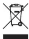
Instructions for disposal of WEEE by users in the European Union
This product must not be disposed of with other waste. Instead, it is the user's responsibility to dispose of their waste equipment by handing it over to a designated collections point for the recycling of waste electrical and electronic equipment. The separate collection and recycling of your waste equipment at the time of disposal will help to conserve natural resources and ensure that it is recycled in a manner that protects human health and the environment. For more information about where you can drop off your waste equipment for recycling, please contact your local city office, your household waste disposal service or where you purchased the product.
56453 Created: 04/2018
©2018 Horizon Hobby, LLC.
Pro Boat, the Pro Boat logo, Valvryn, STX2, Dynamite, ECX, Reaction, Prophet, EC3, and the Horizon Hobby logo are trademarks or registered trademarks of Horizon Hobby, LLC. The Spektrum trademark is used with permission of Bachmann Industries, Inc. Patents pending.
PRB08033