HX120R - Audio/video extender Uniclass - Free user manual and instructions
Find the device manual for free HX120R Uniclass in PDF.


User questions about HX120R Uniclass
0 question about this device. Answer the ones you know or ask your own.
Ask a new question about this device
Download the instructions for your Audio/video extender in PDF format for free! Find your manual HX120R - Uniclass and take your electronic device back in hand. On this page are published all the documents necessary for the use of your device. HX120R by Uniclass.
USER MANUAL HX120R Uniclass
Connecting the local unit (Transmitter) 6
Connecting the remote unit (Receiver) 7
Connecting the local (Transmitter) and remote (Receiver) unit ......7
Point to point 7
Point to multipoint....8
Video Wall 8
Matrix connection....8
Bi-directional IR connection....9
Remote control....10
HDMI CEC remote....10
Remote control (optional) 10
RS-232 control 11
Operation 12
Control manually....12
Setup from web user interface 12
IP detection 12
Identify the unit....13
IP address assignment....13
Web UI 15
OSD control 24
Remote control (optional) 24
Remote controller 24
Basic operation 24
Additional options....25
HDMI CEC....25
Technical support 26
FCC / CE Statements 26
Thanks for purchasing HDMI AV Matrix Extender (Transmitter, Receiver and Video Wall Receiver). With our highly reliable and quality product, you can enjoy countless benefits by using this KVM Extender.
Introduction
The HDMI AV Matrix Extender comprises three distinct units, the Transmitter, Receiver and Video Wall Receiver. It is a LAN based KVM Extender system and allowed accessing a computer from a remote console anywhere on your existing network infrastructure. Keyboard, mouse, USB 2.0 devices, audio and video can be extended away from your local PC or source by using single Cat5 cable transmission. For convenience of control, the IR is built-in and the connected AV device can be remote from either end of connection. In additional, RS232/UART extension is supported as well.
Note: In case of to extend another 100M range, it needs to install the Gigabit Network Switch.
Features
Support direct connection of 100M/330ft with Gigabit Ethernet Switch
2 x USB 2.0 port over IP extension
Support Digital Video resolution of 1920x1200 @60Hz
Bi-directional IR pass-through for added convenience
Complaint to HDMI 1.3 CEC specification
Support 7.1 audio channel
Support A/V Matrix up to 256x256 (HX120T/HX120R Combo)
Support RS232/UART Extension function
Support 8x8 Video Wall (HX120T/HX120W Combo)
Specification
| Model No. HX120T HX120R HX120W | |||
| Product Description HDMI AV Matrix Extender &Video Wall - Transmitter | HDMI AV Matrix Extender -Receiver | HDMI AV Matrix Extender &Video Wall - Receiver | |
| Console USB Hub Ports 2 x USB 2.0 Type A Female 2 x USB 2.0 Type A Female | |||
| PC USB Port Type B Female | |||
| IR support Yes Yes Yes | |||
| Video Input Port HDMI Female via RJ45 via RJ45 | |||
| Video Output Port via RJ45 HDMI Female HDMI Female | |||
| Audio Input Port via HDMI | via RJ45 via RJ45 | ||
| Audio Output Port | via RJ45 via HDMI | via HDMI | |
| RS-232 Extension Support | Yes | Yes | Yes |
| Ethernet Connectors | Yes | Yes | Yes |
| Cable media | CAT5e/ CAT6 | CAT5e/ CAT6 | CAT5e/ CAT6 |
| Power LED | 1 (Red) | 1 (Red) 1 (Red) | |
| Video LED | 1 (Green) | 1 (Green) | 1 (Green) |
| Device LED | 1 (yellow) | 1 (yellow) | |
| Operation Temperature | 0 ~ 40°C | 0 ~ 40°C | 0 ~ 40°C |
| Storage Temperature | -20 ~ 60°C | -20 ~ 60°C | -20 ~ 60°C |
| Humidity | 0~90% RH, Non-Condensing | 0~90% RH, Non-Condensing | 0~90% RH, Non-Condensing |
| Safety / Emission | CE, FCC CE, FCC | CE, FCC | |
Package contents
Transmitter Unit x 1
Receiver Unit x 1
Video Wall Unit (optional) x 1
Power Adapter (DC9V) x 3
CD-ROM (Driver & User's Manual) x 1
Remote Control (optional) x 1
IR Remote Control Unit Pack (Include: Wired Transmitter and Wired Receiver, Optional) x 1
Product overview
Transmitter
Front panel
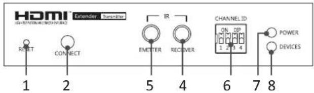
text_image
HDMI EXTENDER Transmitter 1 2 3 4 5 6 7 8 IR EMITTER RECOVER CHANNEL ID ON. DP 1 2 3 4 POWER DEVICESRear panel
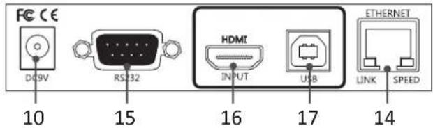
text_image
FCC CE DQ9V RS32 HDMI INPUT USB ETHERNET LINK SPEED 10 15 16 17 14Receiver
Front panel
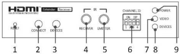
text_image
HDMI EXTender Received RESET CONNECT DEVICES IR RECEIVER EMITTER CHANNEL ID ON DP 1 2 3 4 5 6 7 8 9 POWER VIDEO DEVICESRear panel
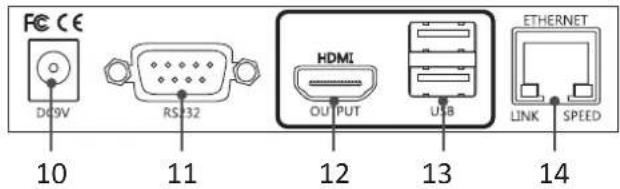
text_image
FCC CE DQ9V RS32 HDMI OUTPUT USB ETHERNET LINK SPEED 10 11 12 13 14Video Wall
Front panel
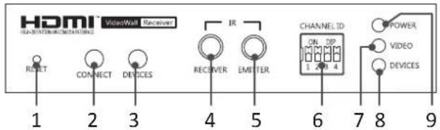
text_image
HDMI™ VideoWall Receiver 1 2 3 4 5 6 7 8 9 RESET CONNECT DEVICES IR RECEIVER EMITTER CHANNEL ID ON DP 1 2 3 4 POWER VIDEO DEVICESRear panel
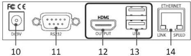
text_image
FCC CE DC9V RS32 HDMI OUTPUT USB ETHERNET LINK SPEED 10 11 12 13 14No. Item Description
1 Reset Press to re-start the unit.
2 Connect Press to re-connect the Transmitter/Receiver if the DIP switch has been reset.
3 Devices
■ Press to connect the device which plugged into Receiver's USB port to console.
Note: Please check the Devices indicator (No. 8) after USB device has been plugged in to the unit. No device will be found if the Device indicator (No. 8) lights off. If it happens, press this button to light it up and re-connect.
■ Press to update the EDID of connected monitor. To update the EDID, remove the Receiver's power. Hold the device button and then power on the unit. Release the Device button when the Device indicator flashes.
4 IR receiver Connect to a IR receiver.
5 IR Emitter Connect to a IR emitter.
6 DIP switch 4-position dip switch for pairing with Transmitter and Receiver.
7 Video indicator Lights when video is transferring.
8 Devices indicator Lights when the device is connected to console (Devices button is pressed).
9 Power indicator Lights when power is on.
10 Power jack Connect to the power adapter.
11 RS232 male connector Connect to RS232 device.
12 HDMI Output Connect to a display device.
13 USB Type-A connector Connect to USB devices.
14 RJ45 connector Connect to Transmitter/Receiver.
15 RS232 female connector Connect to a host PC.
16 HDMI input Connect to a video source/PC.
17 USB Type-B connector Connect to a host PC.
Connection
Before connecting the HDMI AV Matrix Extender with an Ethernet Hub/Switch, please read the notices mentioned below
- When grouping the network of HDMI AV matrix Extender/Video wall, a Gigabit Ethernet Hub/Switch is necessary due to the requirement of bandwidth. The required bandwidth for each channel may up to 200mb/sec. To ensure the better quality of transmission, a reputable name brand hub/switch is recommended.
- The functions of IGMP snooping and Jumbo frame are supported by this HDMI AV matrix Extender/Video wall. If user wish to enable these functions in extension, matrix or video wall mode, please connect the Ethernet Hub/Switch which supports IGMP snooping and Jumbo frame. For more setting details of these functions, refer to the Hub/Switch's instruction manual.
Note: The diagrams below are examples, the actual applications may vary.
Connecting the local unit (Transmitter)
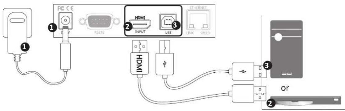
text_image
FC CE RS232 HDMI INPUT USB ETHORNET LINK SPEED 1 2 3 or 2 HDMI① Connect the power adapter to a wall outlet.
② Connect a video source to HDMI input of Transmitter using a HDMI cable.
3 Connect a computer to USB type B connector of Transmitter using a USB cable.
Connecting the remote unit (Receiver)
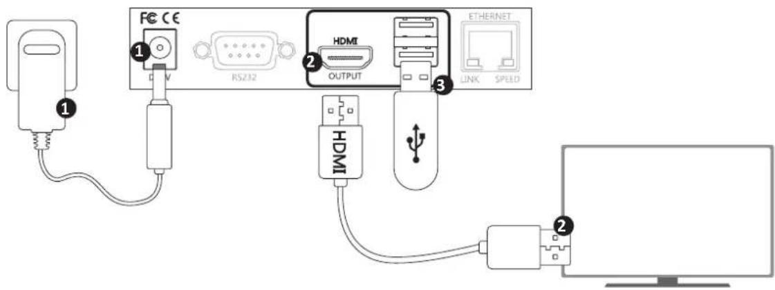
text_image
1 2 3 FC CE RS232 HDMI OUTPUT ETHERNET LINK SPEED 1 2 HDMI① Connect the power adapter to a wall outlet.
② Connect a display to HDMI output of Receiver using a HDMI cable.
3 Connect a USB device to USB type A connector of Receiver using a USB cable.
Connecting the local (Transmitter) and remote (Receiver) unit Point to point
flowchart
graph TD
    A["Receiver"] -->|DC:IN| B["USB device"]
    B -->|OUTPUT| C["USB"]
    B -->|USB| D["Ethernet"]
    D --> E["Transmitter"]
    E --> F["Switch"]
    F --> G["Switch"]
    G --> H["Switch"]
    H --> I["Switch"]
    I --> J["Switch"]
    J --> K["Switch"]
    K --> L["Switch"]
    L --> M["Switch"]
    M --> N["Switch"]
    N --> O["Switch"]
    O --> P["Switch"]
    P --> Q["Switch"]
    Q --> R["Switch"]
    R --> S["Switch"]
    S --> T["Switch"]
    T --> U["Switch"]
    U --> V["Switch"]
    V --> W["Switch"]
    W --> X["Switch"]
    X --> Y["Switch"]
    Y --> Z["Switch"]
    Z --> AA["Switch"]
    AA --> AB["Switch"]
    AB --> AC["Switch"]
    AC --> AD["Switch"]
    AD --> AE["Switch"]
    AE --> AF["Switch"]
    AF --> AG["Switch"]
    AG --> AH["Switch"]
    AH --> AI["Switch"]
    AI --> AJ["Switch"]
    AJ --> AK["Switch"]
    AK --> AL["Switch"]
    AL --> AM["Switch"]
    AM --> AN["Switch"]
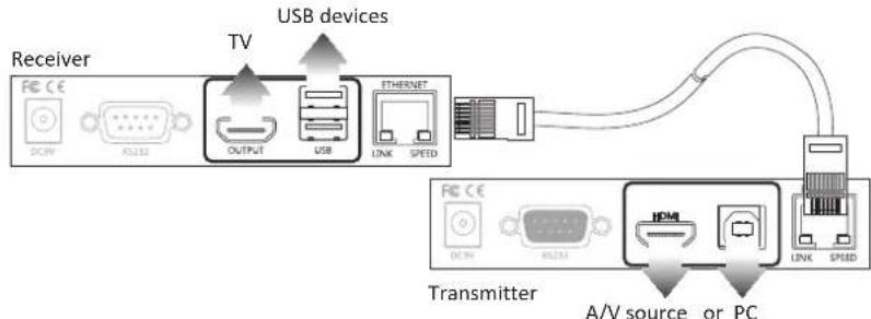
■ To connect the Transmitter and Receiver, simply connect both units using CATx cable directly and the distance can be extended up to 100m.
flowchart
graph TD
    A["Transmitter"] -->|A/V source or PC| B["Receiver"]
    B -->|USB devices| C["USB device"]
    C --> D["USB"]
    D --> E["OUTPUT"]
    E --> F["USB"]
    F --> G["INTERNET"]
    G --> H["INTERNET"]
    H --> I["Output"]
    I --> J["Switch"]
    J --> K["Switch"]
    K --> L["Switch"]
    L --> M["Switch"]
    M --> N["Switch"]
    N --> O["Switch"]
    O --> P["Switch"]
    P --> Q["Switch"]
    Q --> R["Switch"]
    R --> S["Switch"]
    S --> T["Switch"]
    T --> U["Switch"]
    U --> V["Switch"]
    V --> W["Switch"]
    W --> X["Switch"]
    X --> Y["Switch"]
    Y --> Z["Switch"]
    Z --> AA["Switch"]
    AA --> AB["Switch"]
    AB --> AC["Switch"]
    AC --> AD["Switch"]
    AD --> AE["Switch"]
    AE --> AF["Switch"]
    AF --> AG["Switch"]
    AG --> AH["Switch"]
    AH --> AI["Switch"]
    AI --> AJ["Switch"]
    AJ --> AK["Switch"]
    AK --> AL["Switch"]
    AL --> AM["Switch"]
    AM --> AN["Switch"]
    AN --> AO["Switch"]
    AO --> AP["Switch"]
    AP --> AQ["Switch"]
    AQ --> AR["Switch"]
    AR --> AS["Switch"]
    AS --> AT["Switch"]
    AT --> AU["Switch"]
    AU --> AV["Switch"]
    AV --> AW["Switch"]
    AW --> AX["Switch"]
    AX --> AY["Switch"]
    AY --> AZ["Switch"]
    AZ --> BA["Switch"]
    BA --> BB["Switch"]
    BB --> BC["Switch"]
    BC --> BD["Switch"]
    BD --> BE["Switch"]
    BE --> BF["Switch"]
    BF --> BG["Switch"]
    BG --> BH["Switch"]
    BH --> BI["Switch"]
    BI --> BJ["Switch"]
    BJ --> BK["Switch"]
    BK --> BL["Switch"]
    BL --> BM["Switch"]
    BM --> BN["Switch"]
    BN --> BO["Switch"]
    BO --> BP["Switch"]
    BP --> BQ["Switch"]
    BQ --> BR["Switch"]
    BR --> BS["Switch"]
    BS --> BT["Switch"]
    BT --> BU["Switch"]
    BU --> BV["Switch"]
    BV --> BW["Switch"]
    BW --> BX["Switch"]
    BX --> BY["Switch"]
    BY --> BZ["Switch"]
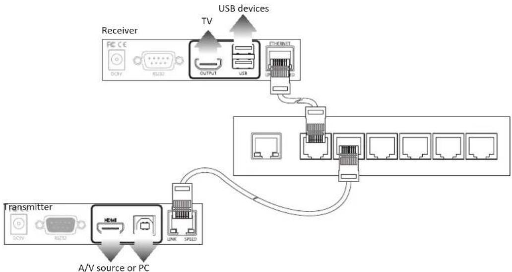
■ Alternatively, the Receiver can be extended another 100m using a Gigabit Ethernet hub (not included).
Point to multipoint
flowchart
graph TD
    A["Transmitter"] -->|A/V source or PC| B["Receiver"]
    B --> C["Gigabit Ethernet Switch"]
    C --> D["USB devices"]
    D --> E["TV"]
    E --> F["OUTPUT"]
    F --> G["USB"]
    G --> H["Ethernet"]
    H --> I["Switch"]
    I --> J["Receiver"]
    J --> K["Receiver"]
    K --> L["Receiver"]
    L --> M["Gigabit Ethernet Switch"]
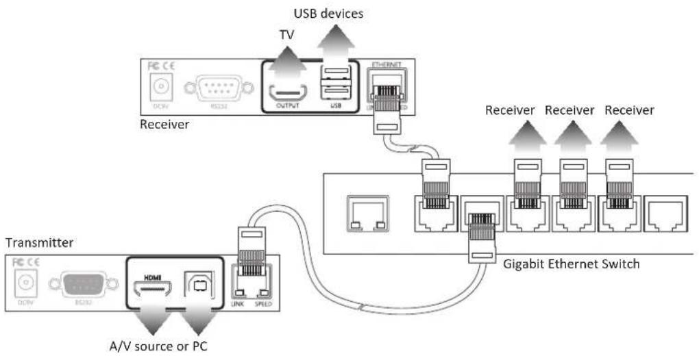
■ Except the point to point connection, the Transmitter can be extended to several Receivers using a gigabit Ethernet switch.
Video Wall
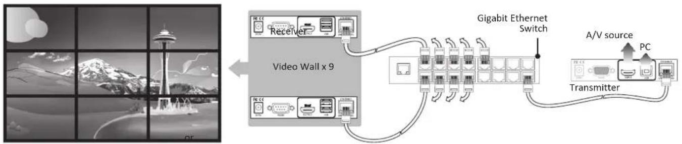
With the combination of Transmitter and Video Wall, the HDMI signal can be sent to one or multi HDMI display up to 8x8 using a single Cat5 cable.
flowchart
graph LR
    A["Video Wall x 9"] --> B["Gigabit Ethernet Switch"]
    B --> C["A/V source"]
    B --> D["Transmitter"]
    style A fill:#f9f,stroke:#333
    style B fill:#ccf,stroke:#333
    style C fill:#cfc,stroke:#333
    style D fill:#fcc,stroke:#333
Matrix connection
The HDMI AV Matrix Extender provides varied and flexible extension for diversity requirements. The display of A/V sources or PC can be mixed with matrix switch function through the pair of the Transmitters and Receivers in the same channel. User can extend the matrix switch up to 16x16 works with a Ethernet Gigabit Switch/Hub. Please refer to the illustrations below for the connection diagram.

flowchart
graph LR
    A["Image frames"] --> B["Receiver x 8"]
    B --> C["Gigabit Ethernet Switch"]
    C --> D["A/V source"]
    C --> E["Transmitter"]
    D --> F["PC"]
    E --> F
    style A fill:#f9f,stroke:#333
    style B fill:#ccf,stroke:#333
    style C fill:#cfc,stroke:#333
    style D fill:#fcc,stroke:#333
    style E fill:#cff,stroke:#333
Note: For the better performance of video and matrix display, using the same brand, size and model monitors are strongly recommended.
Note: The lag of displays may occur sometimes. The image quality is depending on the speed of network or the equipments, such as the grade of hub.
Bi-directional IR connection
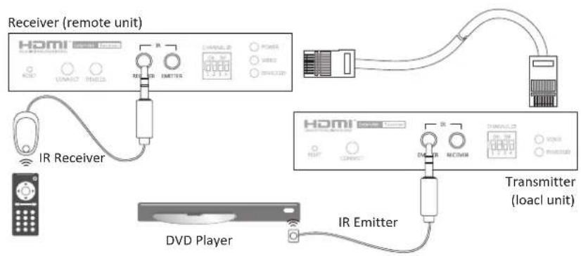
The HDMI AV Matrix Extender provides bi-directional IR extension between the transmitter and receiver over the CATx cable. Place the IR receiver near the sender unit, such as a remote control, and the other end to the jack of IR RECEIVER (remote or local unit of HDMI AV Matrix Extender). Place the IR Emitter to somewhere face the IR receiver of A/V source, and the other end to the jack of IR EMITTER (remote or local unit of HDMI AV Matrix Extender). The IR signal can be transmitted forward or backward. Refer to the illustration below to outline the connection of transmitter and receiver.
text_image
Receiver (remote unit) HDMI IR Receiver DVD Player IR Emitter TRANSMITTER (loac unit)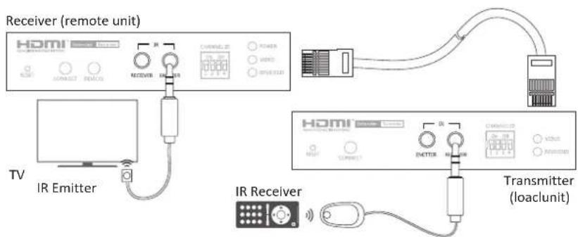
text_image
Receiver (remote unit) HOMI IR Emitter TV IR Receiver Transmitter (loaclunit)Caution: Plug the IR Receiver and IR Emitter into the respective jacks, otherwise the IR sensor on the IR Receiver and IR Emitter will be invalid.
Remote control HDMI CEC remote
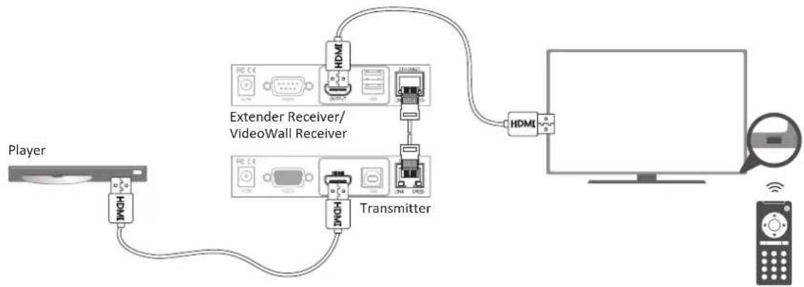
CEC (Consumer Electronics Control) is one of features of HDMI that allows HDMI devices to control each other using only one remote control. To achieve the HDMI CEC remote by the HDMI AV Matrix Extender, please refer to the notes below.
flowchart
graph TD
    A["Player"] --> B["Extender Receiver/VideoWall Receiver"]
    B --> C["Transmitter"]
    C --> D["HDML"]
    D --> E["Computer"]
-
Make sure the connected AV equipments and TV/monitors are compatible with HDMI CEC.
-
The name of HDMI CEC (for example, Bravia sync control, VieraLink, Kuro Link, Aquos Link, etc.) and operating settings may vary depending on the brands of AV equipment. For more details, please refer to the corresponding instruction manual.
-
Connect to a Gigabit Ethernet hub (not included) between Transmitter and Extender Receiver/VideoWall Receiver if extending the distance.
Remote control (optional)
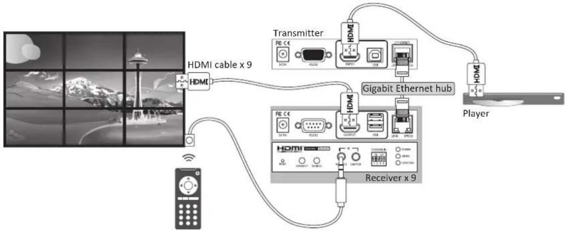
If CEC is not supported by the connected devices, please follow the steps below to remote.
flowchart
graph TD
    A["Receiver x 9"] -->|HDMI cable x 9| B["HDMI"]
    B --> C["Gigabit Ethernet hub"]
    C --> D["Transmitter"]
    D --> E["Player"]
    C --> F["Receiver x 9"]
    F --> G["HDMI"]
    G --> H["Radio"]
    H --> I["Mobile Device"]
    style A fill:#f9f,stroke:#333
    style B fill:#ccf,stroke:#333
    style C fill:#cfc,stroke:#333
    style D fill:#fcc,stroke:#333
    style E fill:#cff,stroke:#333
    style F fill:#ffc,stroke:#333
    style G fill:#fcf,stroke:#333
    style H fill:#cff,stroke:#333
    style I fill:#ffc,stroke:#333
-
Set a desired display mode (1 to 1, matrix or video wall).
-
Connect to a Gigabit Ethernet hub (not included) between Transmitter and Extender Receiver/VideoWall Receiver if setting to matrix or video wall mode.
-
Place the IR Receiver to a desired location, and plug the other end of connector into IR RECEIVER jack of Extender Receiver/VideoWall Receiver.
RS-232 control
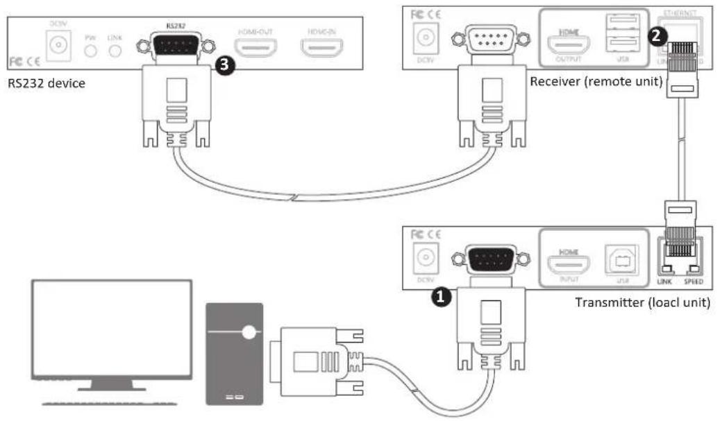
The HDMI AV Matrix Extender not only extends HDMI signal but also RS-232, and allows user to control from local PC remotely.
text_image
RS232 device Receiver (remote unit) Transmitter (load unit)1 Connect RS232 connector to a PC, and plug the other end of connector into the female connector of Transmitter.
② Connect Transmitter and Receiver using Cat5 cable. Alternatively, the Receiver can be extended another 100m using a Gigabit Ethernet hub (not included).
3 Connect RS-232 connector to a RS-232 device, and plug the other end of connector into the male connector of Receiver.
Operation
To operate the HDMI AV Matrix Extender, two ways are provided.
- Operate by adjusting the DIP manually.
- Setup from web user interface.
Control manually
With the convenient push button and DIP Switch on the front panel, user can quickly and easily to operate the HDMI AV Matrix Extender directly. Please follow the steps below to setup.
- Follow the previous chapter (Connection) to connect all devices according to your desired mode.
- Adjust the DIP switches of transmitter and receiver/Video to the same positions.
- Power the transmitter, Extender Receiver/VideoWall Receiver and AV devices/computers to on.
Note: Press the CONNECT button on the front panel of unit once the DIP switch has been adjusted.
Setup from web user interface
IP detection
- Adjust the DIP switch of Transmitter and Receiver to the same position.
- Group the Transmitter and Extender Receiver/VideoWall Receiver units to a network with a PC. The actual connection may vary depending on requirements. For more connection details, refer to the Connection chapter.
- Turn on the power of all connected devices.
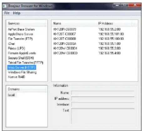
- Insert the bundled CD/DVD into CD/DVD ROM, Find and double click the "Bonjour Browser" from the bundled CD/DVD after completing the steps above.
-
Click Web Server (HTTP) to detect all the connected Transmitter and Extender Receiver/VideoWall Receiver units.
-
Enter the IP address which detected from Bonjour Browser into a web browser.
text_image
Bonjour Browser for Windows File Help Services AirPort Base Station AppleShare Server File Translets (FTP) iCloud Palmir (LPD) Remote AppelEvents Secure Shell (SSH) Teksid File Translets (FTP) Wnt Server (HTTP) Windows File Sharing Klserver RAID Name IP Address H1:20F-C50009 192.168.55.2.80 H1:20T-C30007 192.168.55.101.80 H1:20T-C30000 192.168.55.100.90 H1:20F-C5000A 192.168.55.1.80 H1:20W-C80004 192.168.55.3.80 H1:20W-C30003 192.168.55.4.60 Information Name: IP address: Interlocer: Text:Alternatively, remove the Cat5 cable from the unit you wish to know the IP, and then re-connect to the unit. The screen will re-detect the input source and show the IP information before the image source appears.

text_image
Cannabis, writing in English THE 19-DEC 2015### 1734-2016 15:38
## 19-DEC 2016 05:30
### 1734-2016 15:38
Identify the unit
The naming rule of these units is based on the MAC address which labeled on the bottom of the devices. For example, if the MAC address of Transmitter is 00:11:AA:CB:00:01, the device will be named to HX120T-CB0001. T is for Transmitter, R is for Receiver and W is for Video Wall.
IP address assignment
If the PC cannot access the Transmitter and Extender Receiver/VideoWall Receiver using web UI, please follow the steps below to join the PC to the network.
Note: The example shown here is using Windows 7. For other operating systems, please refer to the respective user guides.
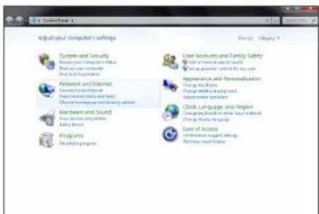
- Click Control Panel to bring up Adjust your computer's settings window, and then click Network and Internet item.
text_image
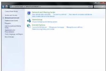
Adjust your computer's settings System and Security New user computer tools Find up user resources Find an information Network and Internet Connect to Internet Enter screen data and text Chinese Programming and trading system Hardware and Sound Use device resources Add items Programs Installed programs User Accounts and Family Safety Get more useful for users Make personal services for any use Appearance and Personalization Change the shares Change the links being used Adjustment variables Click Language and Region Change the boundaries within the local Change the language Ease of Access Use Windows setup settings Systems used features- Click Network and Sharing Center.
text_image
Control Panel Options System and Security Networks and Internet Hardware and Cloud Programs User Accounts and Family Safety Appearance and Personalization Clock, Languages, and Remote Data of Access Networks and Sharing Center Your network includes all links. Next to the following: Your network computer and device Add a server link to the website. Name Group Choose programming and coding system Internet Options Connect to other networks. Change your webpage. More than how did you Show programming settings and updates.- Click Change adapter settings from left side.
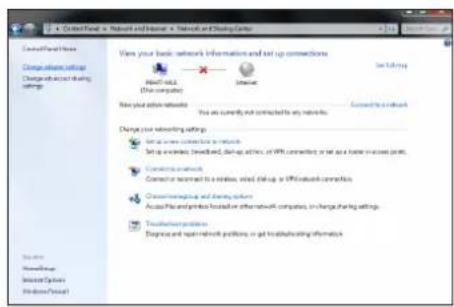
text_image
C:\Users\Panel1 - Network and Internet - Network and Coding Centers View your basic network information and set up connections New York's (The computer) Internet Set History New your basic networks You are currently not connected to any network. Connecting a network Change your networking settings Set up existing networking to networks Setup excludes, networked, setup active, or WiFi connected or set up home in excess points. Connecting network Connector or recommend to a wireless, static backup or WiFi network connection. Change networking and coding system Access Pack and packets foundation or other network computers, or change sharing settings. Touchover platforms Degree and spot network partitions, or get troubleshooting information.- Click Local Area Connection.
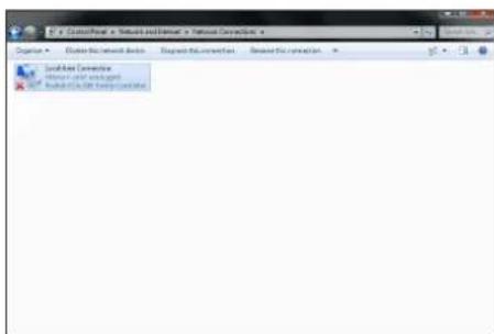
text_image
Network Connection Network device configuration- Mouse right click Local Area Connection to bring upa pop-up window, and then select Properties.
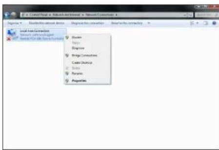
text_image
S - Create a Web-based Web Framework Category 1 Create Web Framework Select Web Framework Create Web Framework Browse Apply Remove Bridge Connections Create Options Remove Properties- Click Internet Protocol Version 4 (TCP/IPv4), and then click Properties.
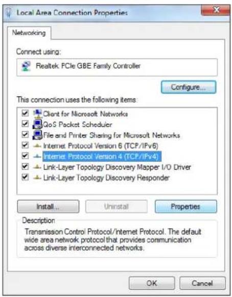
text_image
Local Area Connection Properties Networking Connect using: Realtek PCIe GBE Family Controller Configure... This connection uses the following items: ✓ Client for Microsoft Networks ✓ QoS Packet Scheduler ✓ File and Printer Sharing for Microsoft Networks ✓ Internet Protocol Version 6 (TCP/IPv6) ✓ Internet Protocol Version 4 (TCP/IPv4) ✓ Link-Layer Topology Discovery Mapper I/O Driver ✓ Link-Layer Topology Discovery Responder Install... Uninstall Properties Description Transmission Control Protocol/Internet Protocol. The default wide area network protocol that provides communication across diverse interconnected networks. OK Cancel- Click Use the following IP address to specify an IP address that is on the same subnet as Transmitter/Extender Receiver/VideoWall Receiver.
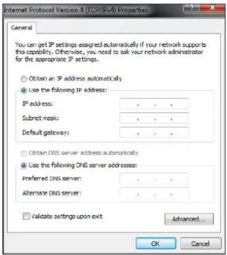
text_image
Internet Protocol Version 4 (TCP/IPA) Properties General You can get IP settings assigned automatically if your network supports this capability. Otherwise, you need to ask your network administrator for the appropriate IP settings. Obtain an IP address automatically Use the following IP address: IP address: . . Subnet mask: . . Default gateway: . . Obtain DNS server address automatically Use the following DNS server addresses: Preferred DNS server: . . Alternate DNS server: . . Validate settings upon exit Advanced... OK CancelWeb UI
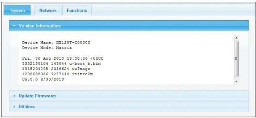
■ To configure each unit of HDMI AV Matrix AV Extender, open a browser and type the IP address which you got from Bonjour Browser. The corresponding web page will appear on the screen as following.
■ Click Apply once you have changed the settings.
Transmitter
text_image
System Network Functions Version Information: Device Name: HX120T-C00000 Device Mode: Matrix Fri, 30 Aug 2013 18:38:36 +0800 3332130104 143044 u-boot_h.bin 1015294208 2338624 uuImage 1208688386 9277440 initrd2m U5.0.0 8/30/2013 Update Firmware: Utilities:Item Sub-item Option Description
System Version information Display the information of unit.
Update Firmware Update the firmware. The browser will be reloaded after updating. Please contact the technical support if you have problem to upload.
Utilities Factory Default Restore to the factory default settings.
Reboot Restart the system.
Reset EDID Reset EDID to factory default setting.
text_image
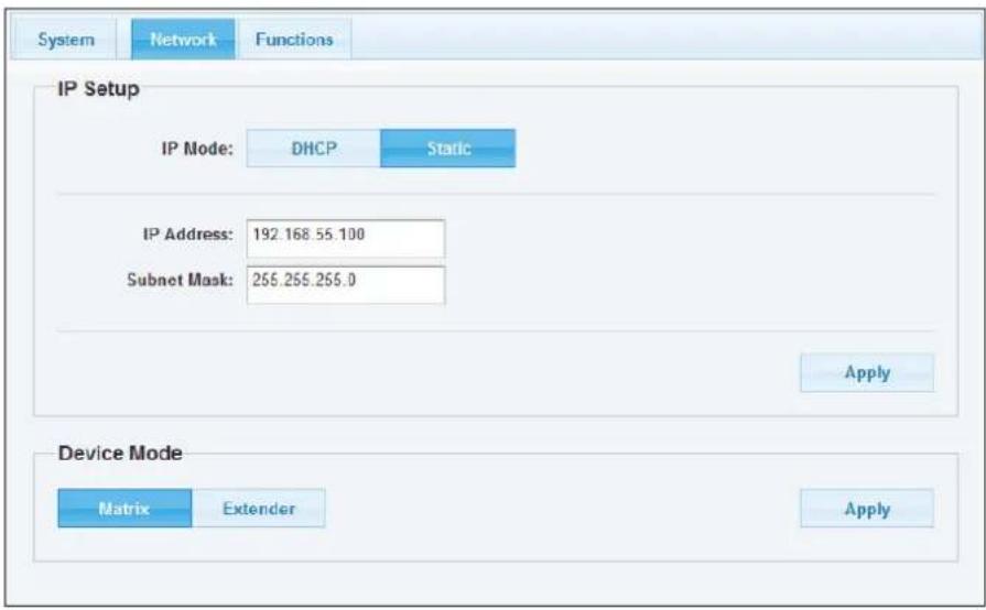
System Network Functions IP Setup IP Mode: DHCP Static IP Address: 192.168.55.100 Subnet Mask: 255.255.255.0 Apply Device Mode Matrix Extender ApplyItem Sub-item Option Description
Network IP Setup DHCP/Static Select DHCP to obtain IP address automatically or select
Device Mode Matrix/Extender
Static to assign an IP manually.
Select the operation mode depending on the connection requirements.
text_image
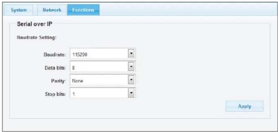
System Network Functions Serial over IP Baudrate Setting: Baudrate: 115200 Data bits: 8 Parity: None Stop bits: 1 ApplyItem Sub-item Option Description
Function Serial over IP Baudrate setting Setup the baudrate settings.
Baudrate settings
■ This option allows to set the baudrate of Transmitter, Extender Receiver/VideoWall Receiver manually. Make sure the settings must match with the RS-232 device you have connected. By default, the system settings are as following:
Baudrate: 115200
Data bits: 8
Parity: None
Stop bits: 1
■ Click the Apply once the baudrate settings have been changed.
Receiver
text_image
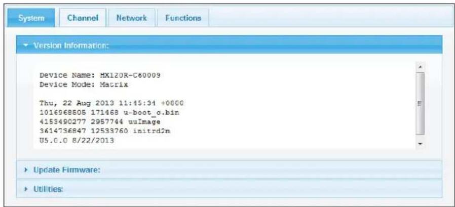
System Channel Network Functions Version Information: Device Name: HX120R-C60009 Device Mode: Matrix Thu, 22 Aug 2013 11:45:34 +0800 1016968505 171468 u-boot_c.bin 4153490277 2957744 uuImage 3614736847 12533760 initrd2m U5.0.0 8/22/2013 Update Firmware: Utilities:Item Sub-item Option Description
System Version information Display the information of unit.
Update Firmware Update the firmware. The browser will be reloaded after updating. Please contact the technical support if you have problem to upload.
Utilities Factory Default Restore to the factory default settings.
Reboot Restart the system.
text_image
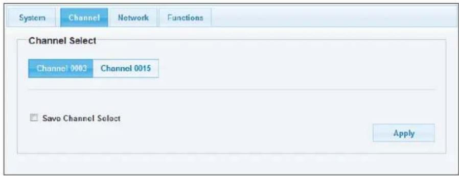
System Channel Network Functions Channel Select Channel 0003 Channel 0015 □ Save Channel Select ApplyItem Sub-item Option Description
Channel Select a desired channel from the Transmitters.
Pairing the Transmitter and Receiver
■ When grouping the network of HDMI AV Matrix Extender/Video Wall using multipoint to multipoint, the channel selections may be complicated. This option allows user to select the channel more intuitively. User can click the desired channel on the web oriented user interface directly.
■ Click Apply after selecting the desired channel.
■ The channels may vary, it depends on the number of connected Transmitters.
■ If the option of Save channel select has been ticked, the channel will be saved and based on the selection of web page, even the settings of DIP switch are different between Transmitter and Receiver.
■ If the option of Save channel select has not been ticked, the channel will be switched to the selection. Note that this selected channel will not be saved once the power is unplugged. The actual connected channel is depending on the DIP switch when the power is re-plugged.
■ Reload the channels in the browser once the connection of Transmitter is changed.
text_image
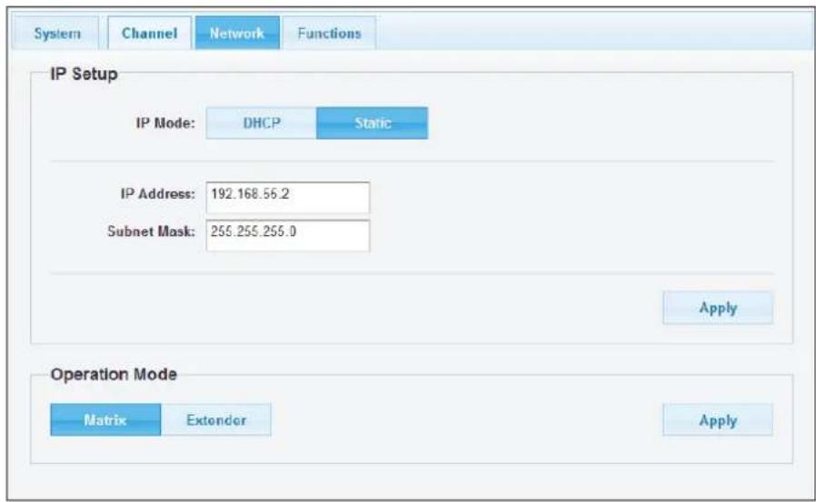
System Channel Network Functions IP Setup IP Mode: DHCP Static IP Address: 192.168.56.2 Subnet Mask: 255.255.255.0 Apply Operation Mode Matrix Extender ApplyItem Sub-item Option Description
Network IP Setup DHCP/Static Select DHCP to obtain IP address automatically or select
Static to assign an IP manually.
Operation Mode Matrix/Extender Select the operation mode depending on the connection requirements.
text_image
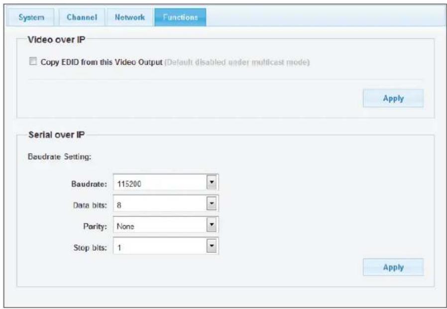
System Channel Network Functions Video over IP Copy EDID from this Video Output (Default disabled under multicast mode) Apply Serial over IP Baudrate Setting: Baudrate: 115200 Data bits: 8 Parity: None Stop bits: 1 ApplyItem Sub-item Option Description
Function Video over IP Enable/disable the copy function from EDID compliant monitors automatically.
Serial over IP Baudrate setting Setup the baudrate settings.
Baudrate settings
■ This option allows to set the baudrate of Transmitter, Extender Receiver/VideoWall Receiver manually. Make sure the settings must match with the RS-232 device you have connected. By default, the system settings are as following:
Baudrate: 115200
Data bits: 8
Parity: None
Stop bits: 1
■ Click the Apply once the baudrate settings have been changed.
Video Wall
text_image
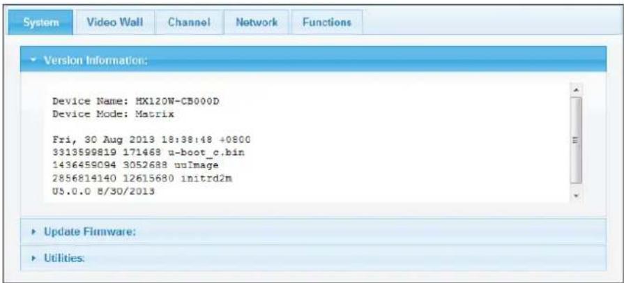
System Video Wall Channel Network Functions Version Information: Device Name: MX120W-CB000D Device Mode: Matrix Fri, 30 Aug 2013 18:38:48 +0800 3313599819 171468 u-boot_c.bin 1436459094 3052688 uuImage 2856814140 12615680 initrd2m U5.0.0 8/30/2013 Update Firmware: Utilities:Item Sub-item Option Description
System Version information Display the information of unit.
Update Firmware Update the firmware. The browser will be reloaded after updating. Please contact the technical support if you have problem to upload.
Utilities Factory Default Restore to the factory default settings.
Reboot Restart the system.
text_image
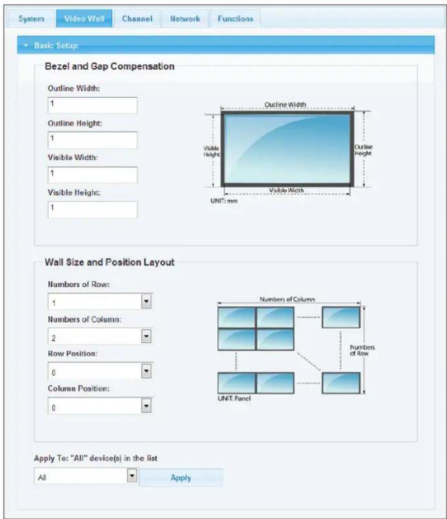
System Video Wall Channel Network Functions Basic Setup: Bezel and Gap Compensation Outline Width: 1 Outline Height: 1 Visible Width: 1 Visible Height: 1 Outline Width Visible Height Visible Width UNIT: mm Outline Height Wall Size and Position Layout Numbers of Row: 1 Numbers of Column: 2 Row Position: 0 Column Position: 0 Numbers of Column Numbers of Row UNIT: Panel Apply To: "All" device(s) in the list All ApplyItem Sub-item Option Description
Video Wall Bezel and Gap
Adjust the compensation for bezel between panels.
Compensation
Wall Size and Position Setup the display quantities, and specify the positions for each display.
Layout
Bezel and Gap Compensation
text_image
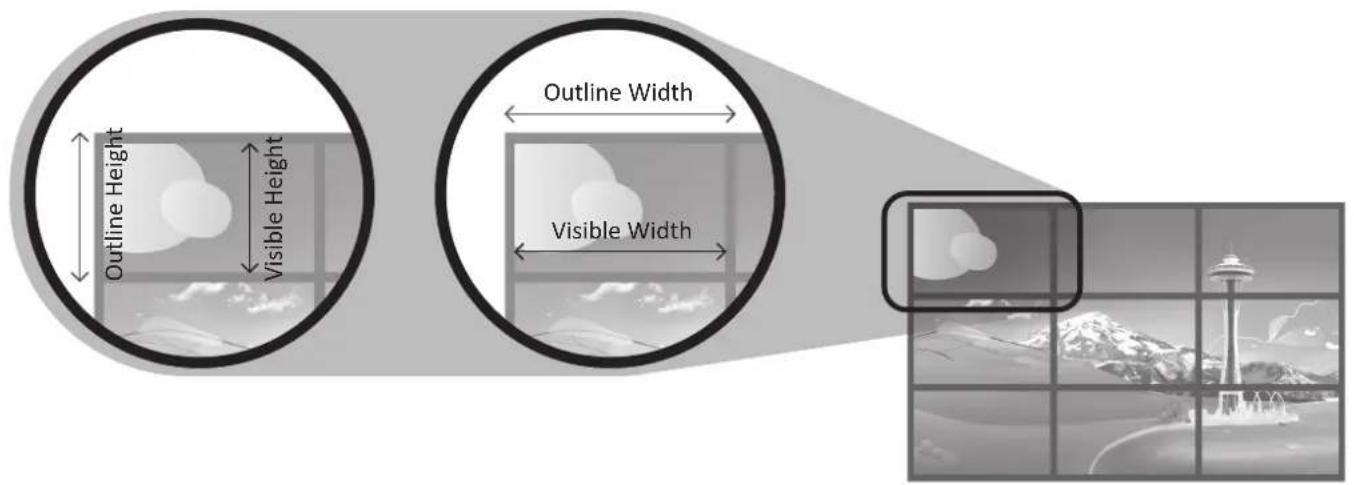
Outline Height Visible Height Outline Width Visible Width■ Enter the values to the outline width, visible height, outline height and visible width respectively according to the bezels of monitors.
■ Click the Apply once the values have been set.
■ Note that the values should be integer.
Wall Size and Position Layout
■ Numbers of Row: The monitor number of row and up to 8.
■ Numbers of Column: The monitor number of column and up to 8.
■ Row Position: Specify the row position of monitor. The row order from top to bottom is 0-7.
■ Column Position: Specify the column position of monitor. The row order from left to right is 0-7.
■ Apply: You can specify the monitor you wish to apply from this drop down menu or apply the settings to all monitors.
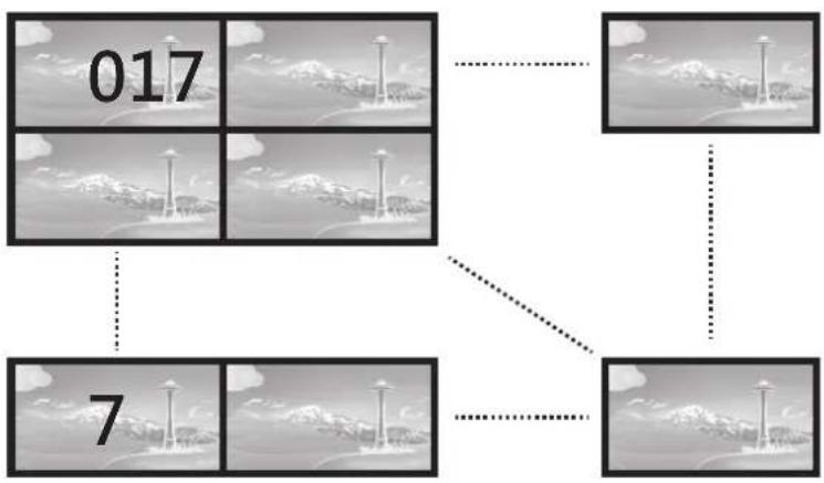
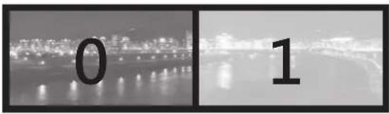
The Video Wall is built by multiple rows and column. The minimum matrix of Video Wall is 1x2. To setup the Video Wall, please refer to the examples below.
flowchart
graph TD
    A["017"] --> B[" "]
    C["7"] --> D[" "]
    E[" "] --> F[" "]
    G[" "] --> H[" "]
1x2 Video Wall (example)
To extend the display on the Video Wall, setup the Wall Size and Position Layout by following the table below:
Monitor 1
| Numbers of Row | 1 |
| Numbers of Column | 2 |
| Row Position | 0 |
| Column Position | 0 |
text_image
0 1Monitor 2
| Numbers of Row | 1 |
| Numbers of Column | 2 |
| Row Position | 0 |
| Column Position | 1 |

text_image
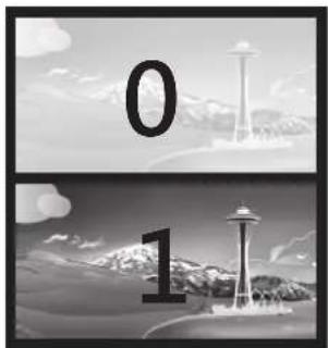
0 12x1 Video Wall (example)
To duplicate the image on the Video Wall, setup the Wall Size and Position Layout by following the table below:
Monitor 1
| Numbers of Row | 2 |
| Numbers of Column | 1 |
| Row Position | 0 |
| Column Position | 0 |

natural_image
Two black-and-white photos: top shows a snow-covered tower with '0' and bottom shows a tall tower with number 1, both against mountain and cloud backgrounds (no text or symbols)Monitor 2
| Numbers of Row | 2 |
| Numbers of Column | 1 |
| Row Position | 1 |
| Column Position | 0 |
natural_image
Two black-and-white images: top shows a white tower with the number '0', bottom shows a white station tower with the number '1' against a cloudy sky background (no text or symbols on the figures themselves)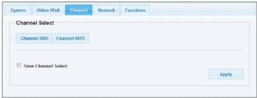
text_image
System Video Wall Channel Network Functions Channel Select Channel 0003 Channel 0015 Save Channel Select ApplyItem Sub-item Option Description
Channel Select a desired channel from the Transmitters.
text_image
System Video Wall Channel Network Functions IP Setup IP Mode: DHCP Static IP Address: 192.168.55.4 Subnet Mask: 255.255.255.0 Apply Device Mode Matrix Extender ApplyItem Sub-item Option Description
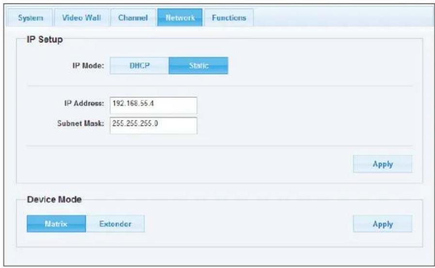
Network IP Setup DHCP/Static Select DHCP to obtain IP address automatically or select
Static to assign an IP manually.
Device Mode Matrix/Extender Select the operation mode depending on the connection requirements.
text_image
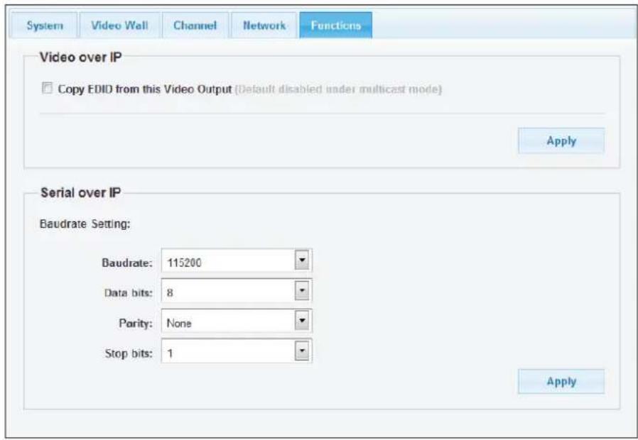
System Video Wall Channel Network Functions Video over IP Copy EDID from this Video Output (Default disabled under multicast mode) Apply Serial over IP Baudrate Setting: Baudrate: 115200 Data bits: 8 Parity: None Stop bits: 1 ApplyItem Sub-item Option Description
Function Video over IP Enable/disable the copy function from EDID compliant monitors automatically.
Serial over IP Baudrate setting Setup the baudrate settings.
EDID configuration
■ To copy the EDID information, tick the option of Copy EDID from this Video Output. The EDID information will be copied each time power on the Receiver.
■ Alternatively, remove the power of Receiver. Hold the devices button and then power on the unit again. Release the Deceive button when the Device indicator flashes.
■ Click the Apply after ticking/unticking the Copy EDID from this Video Output.
Baudrate settings
■ This option allows to set the baudrate of Transmitter, Extender Receiver/VideoWall Receiver manually. Make sure the settings must match with the RS-232 device you have connected. By default, the system settings are as following:
Baudrate: 115200
Data bits: 8
Parity: None
Stop bits: 1
■ Click the Apply once the baudrate settings have been changed.
OSD control
Two OSD control are provided, both operations are almost the same. One is using the remote control (optional), and the other is through HDMI CEC. For more operations, refer to the description below.
Remote control (optional)
The description below is an example for switching between different channels. The operation may vary depending on actual usage and connection. Before using the function of remote control, refer to the chapter of Connection - Remote control to set the desired display mode (1 to 1, matrix or video wall).
Remote controller
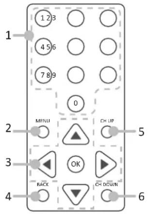
text_image
1 123 456 789 0 MFNU CH UP 2 3 OK BACK CH DOWN 4 6- Numeric buttons
- MENU button
- Cursor and OK buttons:
Cursor buttons: Move the cursor up, down, right, and left. OK: Confirm the selection.
- BACK button: Return to the upper page.
- CH UP: Tunes up one channel.
- CH DOWN: Tunes down one channel.
Basic operation
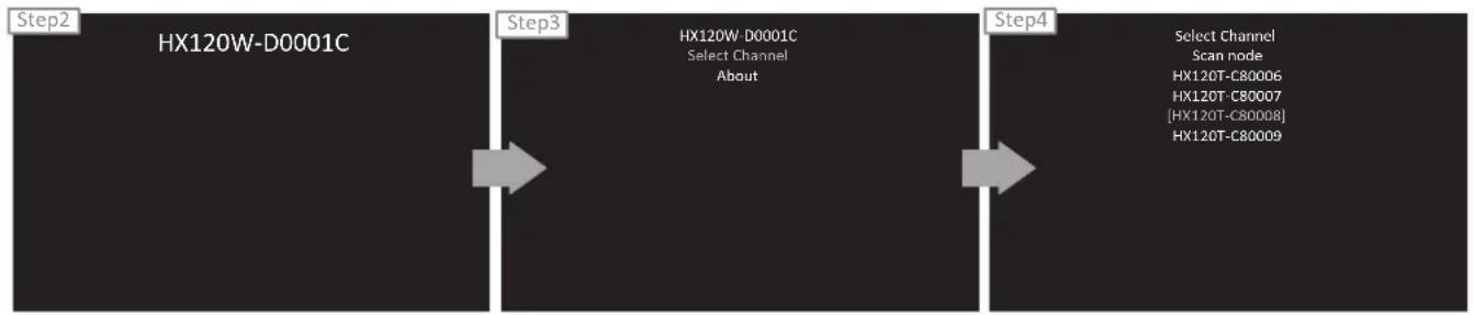
- Press Menu button to bring up the device ID.
flowchart
graph LR
    A["Step2: HX120W-D0001C"] --> B["Step3: HX120W D0001C\nSelect Channel\nAbout"]
    B --> C["Step4: Select Channel\nScan node\nHX120T-C80006\nHX120T-C80007\n[HX120T-C80008"]\nHX120T-C80009]
- The device ID will appear on the screen. To specify the desired device, press Left or Right button. Once the device has been confirmed, press OK to bring up more options.
- Select Select Channel, and then press OK.
- The available sources will be listed on the screen. Press Up or Down button to select the desired source, and then press OK.
- The screen will display to the new source you have selected.
Additional options
■ Select Scan node to refresh if more devices have been connected.
■ Select About to show the firmware version.
HDMI CEC
Except the remote control (optional), remote the device through HDMI CEC is supported as well. The operation is similar with the remote control described above. Note that the definition of Menu button on the remote control and name of HDMI CEC may vary (for example, Bravia sync control, VieraLink, Kuro Link, Aquos Link, etc.). For more details, please refer to the corresponding instruction manual or manufacturer.
Technical support
Please contact with your local distributor for more information or technical support.
FCC / CE Statements
FCC Statement : This equipment has been tested and found to comply with the regulations for a Class B digital device, pursuant to Part 15 of the FCC Rules. These limits are designed to provide reasonable protection against harmful interference when the equipment is operated in a commercial environment. This equipment generates, uses, and can radiate radio frequency energy and, if not installed and used in accordance with this User Guide, may cause harmful interference to radio communications. Operation of this equipment in a residential area is likely to cause harmful interference in which case, the user will be required to correct the interference at his/her own expense.
CE Statement : This is a Class B product in a domestic environment, this product may cause radio interference, in which case the user may be required to take adequate measures.
