SPR-2800X - Installation solaire SunPower - Free user manual and instructions
Find the device manual for free SPR-2800X SunPower in PDF.


User questions about SPR-2800X SunPower
0 question about this device. Answer the ones you know or ask your own.
Ask a new question about this device
Download the instructions for your Installation solaire in PDF format for free! Find your manual SPR-2800X - SunPower and take your electronic device back in hand. On this page are published all the documents necessary for the use of your device. SPR-2800X by SunPower.
USER MANUAL SPR-2800X SunPower
| SUNPOWER | |
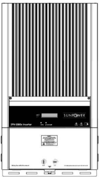 | SPR-2800xSPR-3300xSPR-4000xSPR-5000xOwner's Manual |
| SunPower Solar Inverter |

text_image
SUNPOWERSunPower Solar Inverter
Owner's Manual
Trademarks
SunPower Solar Inverter is a trademark of SunPower Corporation.
Other trademarks, registered trademarks, and product names are the property of their respective owners and are used herein for identification purposes only.
Notice of Copyright
SunPower Solar Inverter Owner's Manual © May 2007. All rights reserved.
Disclaimer
UNLESS SPECIFICALLY AGREED TO IN WRITING, SunPower Corporation:
(a) MAKES NO WARRANTY AS TO THE ACCURACY, SUFFICIENCY OR SUITABILITY OF ANY TECHNICAL OR OTHER INFORMATION PROVIDED IN ITS MANUALS OR OTHER DOCUMENTATION.
(b) ASSUMES NO RESPONSIBILITY OR LIABILITY FOR LOSS OR DAMAGE, WHETHER DIRECT, INDIRECT, CONSEQUENTIAL OR INCIDENTAL, WHICH MIGHT ARISE OUT OF THE USE OF SUCH INFORMATION. THE USE OF ANY SUCH INFORMATION WILL BE ENTIRELY AT THE USER'S RISK.
Date and Revision
May 2007 Revision B
Manual Part Number
975-0335-01-01
SunPower Document Number
001-11872 Rev *B
Product Part Number
864-1012 (SPR-2800x), 864-1013 (SPR-3300x), 864-1014 (SPR-4000x), 864-1015 (SPR-5000x)
Contact Information
Telephone: 1 877 SUN 0123
Fax: (408) 877 1808
Email: information@sunpowercorp.com
Web: www.sunpowercorp.com
About This Manual
This Owner's Manual provides explanations and procedures for installing, operating, maintaining, and troubleshooting the SunPower Solar InverterTM.
Scope
The manual provides safety guidelines, detailed planning and setup information. It provides procedures for installing the inverter and information about operating and troubleshooting the unit. It does not provide details about particular brands of photovoltaic (PV) panels. You need to consult individual PV manufacturers for this information.
Audience
This manual does not provide sufficient information for anyone but a qualified installer to install this product. Installers should be electricians or technicians fully educated on the hazards of installing electrical equipment. The monitoring and operation information in this manual is intended for anyone who needs to operate a SunPower Inverter.
Organization
This manual is organized into 6 chapters and an appendix.
Chapter 1 contains information about the features and functions of the SunPower Solar Inverter.
Chapter 2 provides information about installing the SunPower Solar Inverter. It contains information on determining a suitable location for installation, PV array requirements, and procedures for mounting the unit.
Chapter 3 provides information about DC and AC wiring, and grounding the SunPower Solar Inverter and the PV array.
Chapter 4 contains information on starting up the SunPower Solar Inverter and performing a functional test.
Chapter 5 contains information for understanding the LCD screens and the LED indicators.
Chapter 6 contains information about how to provide general maintenance for the SunPower Solar Inverter. It also provides information about troubleshooting the unit.
Appendix A contains information about the specifications of the SunPower Solar Inverter.
Conventions Used
The following conventions are used in this guide.

WARNING
Warnings identify conditions that could result in personal injury or loss of life.

CAUTION
Cautions identify conditions or practices that could result in damage to the unit or other equipment.
Important: These notes describe things which are important for you to know, but not as serious as a caution or warning.
Abbreviations and Acronyms
CEC California Energy Commission
CSA Canadian Standards Association
GFDI Ground Fault Detector/Interrupter
LCD Liquid Crystal Display
LED Light Emitting Diode
MPPT Maximum Power Point Tracking
NEC US National Electrical Code NFPA-70
PV Photovoltaic
PVGFP PV Ground Fault Protection
STC Standard Test Condition
UL Underwriters Laboratories
Vac Volts AC
Vdc Volts DC
V_MPP Voltage at Maximum Power
V_OC Open Circuit Voltage
Symbols Used
 | Ground |
 | In this guide: Important information, warnings, or cautions.On the product: Important information, warnings or cautions with further explanation in the product guide. |
 | Caution, risk of electric shock. |
 | Hot surface—risk of burns. |
 | Refer to the operating instructions. |
Related Information
You can find more information about SunPower Corporation at www.sunpowercorp.com.
Important Safety Instructions
SAVE THESE INSTRUCTIONS—This manual contains important instructions that must be followed during the installation and maintenance of the SunPower Solar Inverter.

WARNING
The following warnings identify conditions or practices that could result in personal injury or loss of life.
- Before installing and using the inverter, read all instructions and cautionary markings on the inverter, wiring box, and all appropriate sections of this guide.
- To reduce risk of fire hazard, do not cover or obstruct the heat sink.
- Under some conditions, the inverter heat sink can reach temperatures hot enough to cause skin burns if accidentally touched. Ensure that the inverter is located away from normal traffic areas.
- Use only accessories recommended or sold by the manufacturer. Doing otherwise may result in a risk of fire, electric shock, or injury to persons.
- To avoid a risk of fire and electric shock, make sure that existing wiring is in good condition and that wire is not undersized. Do not operate the inverter with damaged or substandard wiring.
- Do not operate the inverter if it has received a sharp blow, been dropped, or otherwise damaged in any way. If the inverter is damaged, consult your product warranty.
- Do not disassemble the inverter. It contains no user-serviceable parts. See warranty for instructions on obtaining service. Attempting to service the inverter yourself may result in a risk of electrical shock or fire and will void the factory warranty.
- Authorized service personnel should reduce the risk of electrical shock by disconnecting both AC and DC power from the inverter before attempting any maintenance or cleaning or working on any circuits connected to the inverter. Turning off controls will not reduce this risk. Internal capacitors remain charged for 5 minutes after disconnecting all sources of power.
- Normally grounded conductors may be ungrounded and energized when a ground fault is indicated.
- The inverter must be connected to an AC equipment-grounding conductor directly and a DC grounding electrode conductor to a single point ground.
- The AC Neutral connection is for voltage sensing only and is not used as a current carrying conductor, nor is it bonded to ground.

CAUTION
The following caution identifies conditions or practices that could result in damage to the unit or other equipment.
Observe the clearance recommendations as described on page 2–7. Do not install the inverter in a zero-clearance or non-ventilated compartment. Overheating may result.
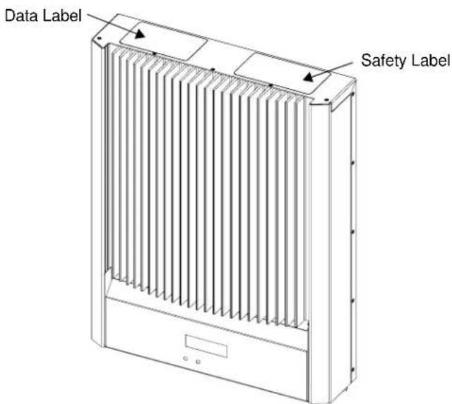
Location of Safety and Data Labels
The figure below shows the location of the safety label and the data label with model, serial number and part number information.
text_image
Data Label Safety LabelFCC Information to the User
This equipment has been tested and found to comply with the limits for a Class B digital device, pursuant to part 15 of the FCC Rules. These limits are designed to provide reasonable protection against harmful interference in a residential installation. This equipment generates, uses and can radiate radio frequency energy and, if not installed and used in accordance with the instructions, may cause harmful interference to radio communications. However, there is no guarantee that interference will not occur in a particular installation. If this equipment does cause harmful interference to radio or television reception, which can be determined by turning the equipment off and on, the user is encouraged to try to correct the interference by one or more of the following measures:
- Reorient or relocate the receiving antenna.
- Increase the separation between the equipment and the receiver.
- Connect the equipment into an outlet on a circuit different from that to which the receiver is connected.
- Consult the dealer or an experienced radio/TV technician for help.
Contents
Important Safety Instructions - - - - - - - - - - - - - - - - - - - - - - - - - - - - - - - - - - - - - - - - - - - - - - vii
Location of Safety and Data Labels ---- viii
FCC Information to the User ---- viii
1 Introduction
About the SunPower Solar Inverter 1-1
Standard Features 1-2
Front Panel Features 1-3
Wiring/Disconnect Box 1-3
2 Installation
Installation Options 2-1
Planning the Installation 2-1
Inverter Location 2-1
PV Array Voltage and MPPT Requirements 2-3
Mounting the Inverter 2-5
Dimensions and Knockout Locations 2-5
Installing the Mounting Bracket 2-6
Mounting the Inverter on the Bracket 2-8
3 Wiring the Inverter
Grounding Requirements 3-1
Ground Fault Fuse 3-3
Wiring Requirements 3-4
AC Circuit Breaker Requirements 3-4
DC/AC Disconnect Switch 3-4
Accessing the Wiring Terminals 3-5
Connecting the DC Wiring 3-7
DC Wiring for Multiple Inverters 3-9
Connecting the AC Wiring 3-10
DC and AC Wiring for Multiple Inverters 3-11
Communications Wiring for Multiple Inverters 3-12
Network Layout 3-12
Guidelines for Routing the Network Cables 3–15
Connecting Network Cable Between Multiple Inverters 3-15
4 Starting the Inverter
Startup Procedure 4-1
Checking the PV Array DC Voltage 4-1
Checking the AC Utility Voltage 4-2
Replacing the Wiring/Disconnect Box Cover 4-3
Starting up the Inverter 4-3
Commissioning Multiple Inverters 4-4
Disconnect Test 4-6
Locating the Firmware Version Number- 4-6
5 Monitoring the Inverter
Monitoring the Front Panel Display---- 5-1
Front Panel Display Screens and What They Mean 5-2
Startup Mode 5-2
Normal Operation Mode 5-4
Offline Mode 5-6
Fault Mode 5-8
Special Screens 5–10
Custom Screens 5-10
Status Indicator Lights- 5–11
6 Maintenance and Troubleshooting
Factors Affecting Inverter Performance 6-1
PV Array Factors 6-1
Other Factors 6-2
Performing General Maintenance 6-3
Replacing Parts 6-4
Replacing the Ground Fault Protection Fuse 6-4
Replacing the Inverter 6-6
Identifying Error/Fault Conditions and Solutions 6-9
A Specifications
Electrical Specifications A-2
SPR-5000x A-2
SPR-4000x A-4
SPR-3300x A-6
SPR-2800x A-8
Adjustable Voltage, Frequency and Reconnection Settings A-10
Output Power Versus Ambient Temperature A-10
Environmental Specifications - A-11
User Display A-11
Display Accuracy A-11
Mechanical Specifications A-11
Regulatory Approvals A-12
Information About Your System A-13
Index - IX-1
1
Introduction
Chapter 1 contains information about the features and functions of the SunPower Solar Inverter.
About the SunPower Solar Inverter
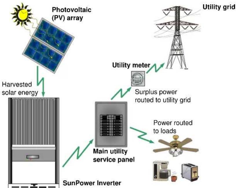
The SunPower Solar Inverter is designed to convert solar electric (photovoltaic or PV) power into utility-grade electricity that can be used by the home or sold to the local power company.
Installing the inverter consists of mounting it to the wall and connecting the DC input to a PV array and the AC output to the utility. See Figure 1-1 for a simple diagram of a typical installation.
In order to operate, the inverter must have grid power available and connected. It will not provide backup power if the AC grid fails.
flowchart
graph TD
    A["Photovoltaic (PV) array"] -->|Harvested solar energy| B["SunPower Inverter"]
    C["Utility grid"] --> D["Main utility service panel"]
    D -->|Surplus power routed to utility grid| E["Utility meter"]
    D -->|Power routed to loads| F["Power supply unit"]
Figure 1-1 Basic System Overview
PV compatibility
The inverter is designed to take advantage of solar modules configured as high-voltage PV string arrays—single crystalline, poly crystalline, or thin film—with an input voltage Maximum Power Point range (depending on inverter model) of 195 to 550 Vdc, 240 to 550 Vdc, 240 to 480, or 200 to 400 Vdc. See “Electrical Specifications” on page A–2 for more information.
Utility grid compatibility
The inverter can operate on either 240 V or 208 V nominal grid voltage. The inverter senses the phase-to-phase voltage and automatically changes the power limit value for each grid voltage. The disconnect thresholds (see “Adjustable Voltage, Frequency and Reconnection Settings” on page A–10) remain the same because both nominal voltages have the same 120 Vac phase-to-neutral thresholds.
Maximum Power Point Tracking (MPPT)
The inverter uses a proprietary Maximum Power Point Tracking (MPPT) technology to harvest the maximum amount of energy from the solar array. MPPT learns your array's specific characteristics, maximizing its output at all times.
High efficiency
The high-frequency, solid-state design of the inverter is extremely efficient. See Appendix A, “Specifications” for the efficiency ratings of each model.
Expandable
Multiple inverters may be networked together for increased net metering capacity or future system growth. The inverter has adjustable voltage and frequency disconnect settings and can be aggregated above 30 kW on a single point-of-common-coupling (PCC). See “Adjustable Voltage, Frequency and Reconnection Settings” on page A–10.
Standard Features
The inverter has the following standard features:
- Sealed inverter section protecting power electronic components;
- Liquid Crystal Display (LCD) providing easy-to-read system status and daily cumulative energy production information;
- Two LED indicator lights providing status and ground fault indication;
- Wiring/disconnect box providing protection for all AC and DC connections and eliminating exposed “live” wiring if the inverter is removed.
The wiring/disconnect box has been designed to be physically mated to the electronics section of the SunPower Inverter at the factory, but remains in place as a non-serviceable item in the event that the inverter electronics section is ever required to be removed. The inverter and wiring/disconnect box together form an NEMA 3R enclosure to allow outdoor installation.

WARNING: Shock hazard
The 600 volt DC/AC disconnect in the wiring/disconnect box meets NEC Article 690. It is a non-serviceable component and shall remain in place. Separating the inverter and wiring/disconnect box, or removing the wiring/disconnect box cover can expose energized conductors. PV input circuits in the wiring box ahead of the switch remain energized even when the switch is in the “off” position—hazardous voltage will still be present on the DC input (PV) terminals under the clear plastic insulation barrier inside the wiring/disconnect box.
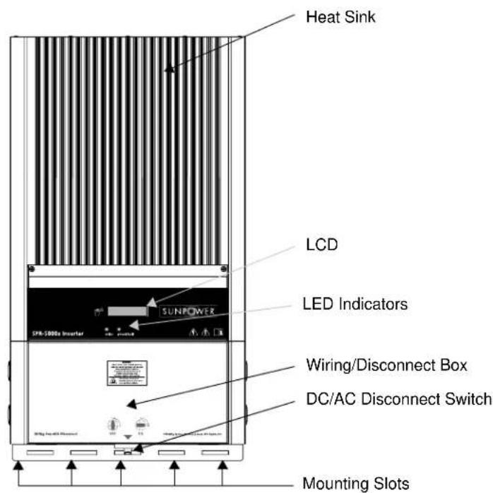
Front Panel Features
text_image
Heat Sink LCD LED Indicators SUNPOWER Wiring/Disconnect Box DC/AC Disconnect Switch Mounting SlotsFigure 1-2 Front Panel Features
Wiring/Disconnect Box
The wiring/disconnect box is standard for all North American models of the inverter. The wiring/disconnect box provides a location for making AC, DC and ground connections. It also contains the DC/AC (PV array/utility) disconnect switch. When used with the inverter, the DC/AC disconnect switch is 600V AC and DC rated and is identified on the outside by an illustration showing the open and closed switch positions. The switch is lockable, and meets NEC Section 690 requirements as a means of disconnect.
In jurisdictions where the local utility requires that the AC disconnect be capable of being locked in the open position by its service personnel, this disconnect switch can also serve as a lockable isolating device.
Important: In North America and other locations the wiring/disconnect box is an electrical code requirement. Regulatory approval is based on the wiring/disconnect box always being attached to the inverter during operation. Any attempt to remove this box will invalidate the approvals and create an electrical hazard.
2
Installation
Chapter 2 provides information about installing the SunPower Solar Inverter. It contains information on determining a suitable location for installation, PV array requirements, and procedures for mounting the unit.
Installation Options
The inverter may be installed as a single inverter for a single PV array of one to three PV strings. Only SPR-5000x models can accept three PV strings. An external fuse box may be required when three PV strings are connected.
The inverter can also be installed in a multiple inverter configuration. If multiple inverters are used, each inverter must be wired to an independent PV array.
Communications between inverters can be enabled by installing network cabling to the inverter RJ-45 ports. See “Connecting Network Cable Between Multiple Inverters” on page 3–15.
Planning the Installation
Ensure that you have obtained all permits required by local authorities or utilities before beginning installation.
Inverter Location

WARNING: Burn hazard
Do not install in a location where people can accidentally come into contact with the front of the inverter. High temperatures can be present on the face of the inverter, causing a potential burn hazard.
In extreme conditions, the inverter chassis can reach temperatures over 70^ C ( 158^ F), which can cause skin burns if accidentally touched. Ensure that the inverter is located away from normal traffic areas.
Inverter failure due to improper installation will void the inverter warranty.
Consider the following when determining where to install the inverter.
Indoor/Outdoor
- The inverter uses a Type 3R-rated enclosure (vertical mount only) that can be mounted indoors or outdoors. (Type 3R enclosures are intended for outdoor use primarily to provide a degree of protection against falling rain; and to be undamaged by the formation of ice on the enclosure.)
- While the 3R-rated enclosure protects the inverter from moisture, outdoor installations should be located away from lawn sprinklers and other sources of spray.
- A sun shade is recommended for outdoor installations. In bright sun conditions, when the inverter is at or near full output with an ambient temperature above 40 °C (104 °F), shading the unit will help increase inverter performance. A sun shade can also protect the inverter from dust, debris, and birds. The sun shade should be made from an opaque material to provide shade for the heat sink. It should be large enough and positioned so that it shades the heat sink when the inverter is operating at full power—usually a four-hour time period centered around noon. Ensure that the shade is installed according to the minimum clearances specified on page 2–7.
Orientation
- The inverter must be mounted vertically on a wall or pole.
- Do not mount the inverter horizontally.
- If mounting the inverter indoors on a south-facing wall, ensure the wall is insulated to reduce the amount of heat absorbed by the inverter. Unless walls are properly insulated, avoid mounting the inverter indoors on any wall that is directly exposed to the sun.
Temperature
- Ensure that the inverter is mounted in a location where the ambient temperature range is -25 to +65 °C (-13 to +149 °F).
- Above 40 °C (104 °F), the inverter may derate power output. See “Output Power vs. Ambient Temperature” on page A–3 and “Environmental Specifications” on page A–4.
- At extreme cold temperatures, the front panel LCD may not function normally.
Ground Clearance
- Outdoors, the inverter requires at least 100cm (39 inches) of clearance between the bottom of the unit and the ground.
Distance
- To minimize resistance and resulting power loss, ensure that wire lengths between the PV array and the inverter and between the inverter and the main utility service panel are kept to a minimum.
- Maximum distances will depend on wire gauges used and PV array output voltages.
Debris free
- Excessive debris (such as dust, leaves, and cobwebs) can accumulate on the unit, interfering with wiring connections and ventilation. Do not install in a location where debris can accumulate (under a tree, for example).
PV Array Voltage and MPPT Requirements

WARNING: Shock hazard
Whenever a PV array is exposed to sunlight, a shock hazard exists at the output wires or exposed terminals. To reduce the risk of shock during installation, cover the array with an opaque (dark) material before making any connections, and always test for voltage before touching exposed wiring or devices.
MPPT operational window
The MPPT software maximizes the output energy of solar arrays as long as the operating voltage is within the MPPT operational window. Ensure that the open circuit voltage ( V_oc ) of the PV array is within the MPPT operational window. See “Input voltage, Maximum Power Point Range” in Appendix A, “Specifications” for the MPPT operational window of each inverter model.
Effects of array voltages outside of the MPPT operational window are shown in Table 2-1.
Table 2-1 MPPT Operational Window
| Voltage Effect of Array Voltage Inverter Mode | ||
| V_oc < Lower limit of MPPT range Inverter | not operating. Off-line | |
| V_MPP < Lower limit of MPPT range (V_oc > Lower limit of MPPT range) | Operating voltage shifts to lower limit of MPPT range; the array is not at its maximum power point. | On-line (low power) |
| V_MPP within MPPT range Maximum harvest of solar energy. On-line (MPPT window) | ||
| V_MPP between upper limit of MPPT range and absolute maximum V_oc | Does not allow maximum harvest of solar energy. | On-line (power derating) |
| V_MPP > absolute maximum V_oc (or V_oc > absolute maximum V_oc) | Inverter stops delivering power and shuts down. Inverter may be damaged. | Off-line (shutdown) |
Voltage requirements
The maximum power point voltage (VMPP) of a string connected to the inverter should preferably be above the lower limit of the MPPT range for that model. If it is below the lower limit of the MPPT range, the inverter continues to operate, but it regulates the PV voltage to the lower limit of the MPPT range. Because the array is not operating at its maximum power point, this may result in lower than expected energy harvest. If V_oc is below the lower limit of the MPPT range, the inverter remains off-line and does not deliver power.

CAUTION: Equipment damage
To prevent damage to the inverter, the array voltage must never exceed 600 V_oc (open circuit voltage) under any condition.
The short circuit current ( I_sc ) rating of the array at any temperature must not exceed the I_sc rating of the inverter. For maximum solar energy harvest, it is recommended that the effective power output of the array be matched with the input power capacity of the inverter.
Guidelines for Matching PV Array Size to SunPower Solar Inverter Input
- Consider the expected V_oc of the string under all possible conditions. The panel manufacturer provides a V_oc rating per panel, but it is usually rated at 25 °C (77 °F). Ensure that the V_oc rating at the coldest ambient temperature does not exceed 600 Vdc. Panel voltage increases in cold temperatures—the panel manufacturer should be able to provide a coefficient of voltage increase per degree.
- The NEC also has required temperature/voltage deratings that must be used; these can be found in Article 690 of the NEC. You need to determine the coldest temperatures expected on the site, and size the array strings accordingly. To prevent inverter damage, the array's maximum DC voltage in the coldest expected temperature, with both manufacturer coefficient and NEC derating, must not exceed 600 Vdc.
- Panel voltage decreases in high temperatures. This will affect the panels' V_MPP and V_oc . Again, the manufacturer's coefficient must be used with the highest expected temperature to determine the minimum V_MPP and V_oc .
Mounting the Inverter
Dimensions and Knockout Locations
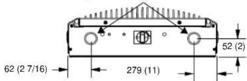
Inverter dimensions and knockout locations are shown in Figure 2-1.
Four 27 or 35 mm (1 or 1-3/8 inch) dual knockouts are provided on the back and bottom of the unit to accommodate wiring. -POS models have four 22 mm (7/8 inch) knockouts on the back of the wiring/disconnect box.
Four 27 mm (1 inch) conduit holes on the sides of the wiring/disconnect box (two on each side) are filled with plastic plugs (thread size Pg 21). These plugs can be removed to insert conduit nipples as required for multiple inverter installations.
Side conduit holes may be used to accommodate network communication cables connected between multiple inverters.
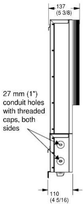
text_image
27 mm (1") conduit holes with threaded caps, both sides 137 (5 3/8) 110 (4 5/16)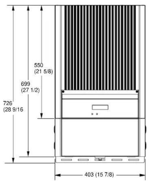
text_image
550 (21 5/8) 699 (27 1/2) 726 (28 9/16) 403 (15 7/8)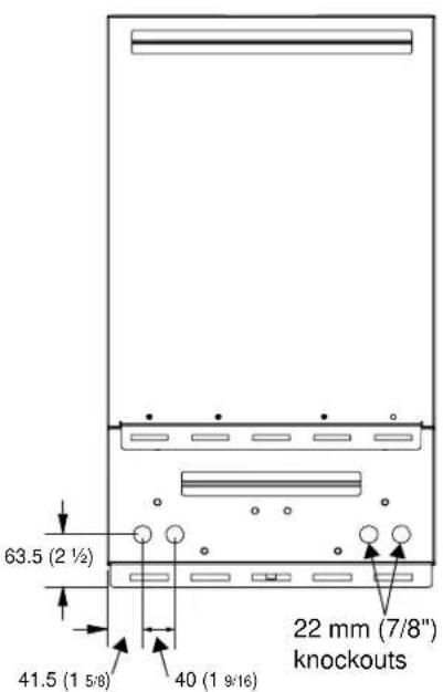
text_image
63.5 (2 ½) 41.5 (1 5/8) 40 (1 9/16) 22 mm (7/8") knockoutsDual 35 mm or 27 mm (1 3/8" or 1") knockouts
text_image
62 (2 7/16) 279 (11) 52 (2)All measurements in mm (inches).
Figure 2-1 Inverter Dimensions and Knockout Locations
Installing the Mounting Bracket
Secure the mounting bracket to a vertical structure or surface. The inverter mounting hooks attach to the flanges on the mounting bracket. Mounting bracket dimensions are shown in Figure 2-2.
If mounting more than one inverter, install each mounting bracket at least 150mm (6 inches) apart to provide enough space for the inverters to hang side by side.
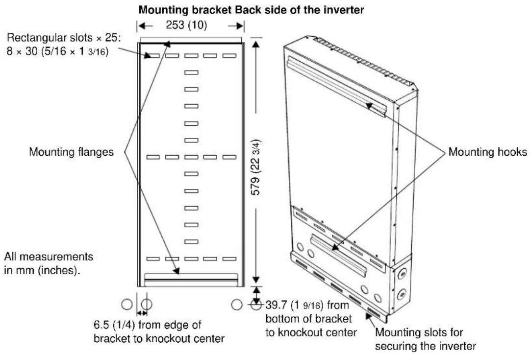
text_image
Mounting bracket Back side of the inverter 253 (10) Rectangular slots × 25: 8 × 30 (5/16 × 1 3/16) Mounting flanges All measurements in mm (inches). 6.5 (1/4) from edge of bracket to knockout center 579 (22 3/4) 39.7 (1 9/16) from bottom of bracket to knockout center Mounting hooks Mounting slots for securing the inverterFigure 2-2 Mounting Bracket and Inverter
Clearance Requirements
For optimal and safe operation, ensure there is adequate clearance around the inverter. If the minimum clearances in Table 2-2 are not met, rated power may not be achieved.
Table 2-2 Inverter Clearance Requirements
Location Minimum Clearance
| Above 300 mm (12 inches) | ||
| Below:• I n v• Bracket | Outdoors:• 100 cm (39 inches)• 110 cm (43 inches)For indoor installations, there is no clearance requirement between the bottom of the inverter and the ground. | The inverter extends below the bracket by approximately 100 mm (4 inches) |
| In front 300 mm (12 inches) minimum. 910 mm (36 inches) are recommended for easy access for reading the display, avoiding accidental contact with hot surface, and servicing the inverter. | ||
| On sides | Units can be mounted side by side with no clearance between them, but 150 mm (6 inches) of clearance around the outside edges of the outermost two units is recommended. In hot climates, some clearance between units may be needed to prevent thermal derating. | |
Surfaces for Mounting
The inverter can be mounted to a vertical surface such as wallboard, wood siding, concrete wall or pole assembly. Ensure the mounting surface or structure can support the weight of the inverter (26 kg/58 lb) as well as the associated wiring and conduit. Installation onto wallboard requires either the use of a supporting material such as plywood or securing the mounting screws to supporting wall studs.
Important:
- Local codes may impose additional mounting requirements in earthquake or other high-risk areas.
- No mounting hardware is supplied with the inverter. It is recommended to use 6 mm (¼ inch) diameter fasteners. However, because mounting surfaces can vary, installers must select appropriate hardware for each installation.
Mounting the Inverter on the Bracket
Place the inverter's mounting hooks over the flanges on the bracket. Ensure the inverter is seated properly, then secure the bottom of the inverter with appropriate screws or anchors through the mounting slots.
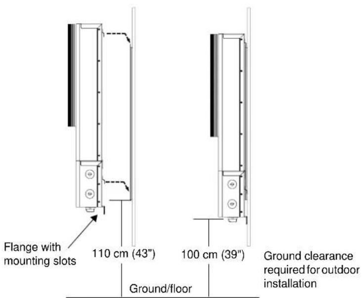
text_image
Flange with mounting slots 110 cm (43") Ground/floor 100 cm (39") Ground clearance required for outdoor installationFigure 2-3 Placing the Inverter on the Mounting Bracket
3
Wiring the Inverter
Chapter 3 provides information about DC and AC wiring, and grounding the SunPower Solar Inverter and the PV array.
This chapter does not provide sufficient information for anyone but a qualified installer to install this product. Installers should be electricians or technicians fully educated on the hazards of installing electrical equipment.
Grounding Requirements
AC grounding
The inverter must be connected to the AC ground from the utility via the inverter ground bar.
PV grounding
The PV array (frame) ground should be connected to the inverter ground bar (see Figure 3-1 on page 3–2). The size for the conductor is usually based on the size of the largest conductor in the DC system.
A DC grounding electrode conductor is required per NEC 690.47(C) (2005). Consult with the Authority Having Jurisdiction (AHJ) for specifics on your installation. Use the inverter ground bar for this connection (see Figure 3-2 on page 3–3).

CAUTION: Equipment damage
Provide adequate clearance for grounding wires inside the inverter wiring box. Ensure that the bare copper grounding wire is more than 12 inch clear of the DC/AC interconnect circuit board.
Two 14 -inch (7 mm) knockouts in the bottom of the wiring box are intended for routing the ground conductors to the ground bar. See Figure 3-1.
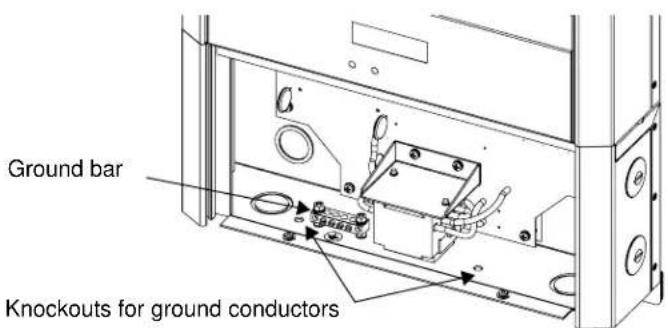
text_image
Ground bar Knockouts for ground conductorsFigure 3-1 Ground Conductor Knockouts
The ground bar accepts wires up to #4 AWG. Use wire size #12 to #4 AWG, copper conductors only, rated 90 °C minimum. Torque ground wires as specified in Table 3-1.
Table 3-1 Torque Values for Ground Wiring Wire Size Torque Value
| AWG mm | 2 | in-lb Nm | |
| 12-10 4.0 | -6.0 25-35 | 3.0-4.0 | |
| 8 10 30-40 | 3.4-4.5 | ||
| 6-4 16-25 | 35-45 4.0 | -5.0 |
Important: SunPower inverters have the positive PV conductor internally bonded to the ground system through the inverter's ground fault protection circuit. It is important that the positive PV conductor is not bonded to the ground at any other point in the system.
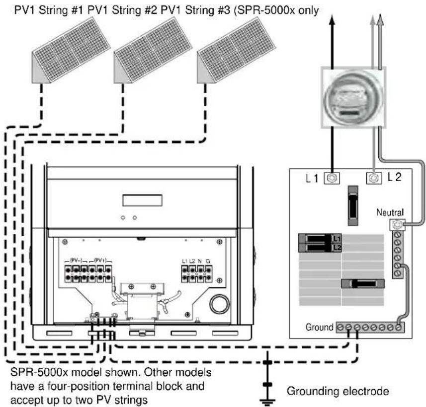
text_image
PV1 String #1 PV1 String #2 PV1 String #3 (SPR-5000x only) SPR-5000x model shown. Other models have a four-position terminal block and accept up to two PV strings Grounding electrode L 1 L 2 Neutral GroundFigure 3-2 Grounding Diagram
Ground Fault Fuse
The inverter is equipped with a 600 volt 1-amp ground fault protection fuse (replace with Littelfuse KLKD 1 or equivalent).

WARNING: Shock hazard
Do not attempt to service the ground fault protection fuse yourself. This should only be done by qualified service personnel, such as certified electricians or technicians. See "Replacing the Ground Fault Protection Fuse" on page 6-4.
Wiring Requirements

WARNING: Shock hazard
Check for existing electrical or plumbing prior to drilling holes in the walls.
Use wire size #12 to #6 AWG, copper conductors only, rated 90 °C minimum.
Strip all wires 9 mm (3/8 inch) and torque to a maximum 16 in-lb (1.8 Nm).
For safety and compliance with the NEC, run AC, DC, and communication wires in separate conduits.

WARNING: Fire hazard
Wiring should not be undersized. Wire sizes must be coordinated with the array maximum short circuit current or the AC breaker sizes used. Ensure wiring is in accordance with the NEC or applicable codes.
AC Circuit Breaker Requirements
The main utility service panel must dedicate a double pole breaker to operate each inverter installed. This breaker must be sized to handle the rated maximum output voltage and current of the inverter (see “Electrical Specifications” on page A–2).
DC/AC Disconnect Switch
The wiring box includes a 600 volt PV/Utility disconnect switch that switches both AC and DC at the same time.
Depending on the installation, an external AC and/or DC disconnect may be required if the inverter is installed in a location not easily accessible to utility or fire personnel. Consult local authorities for additional information.
Important: SPR-5000x models only: The DC terminal block has six inputs for connecting up to three PV strings. In accordance with applicable codes, if the array consists of more than two strings, external fusing may be required to prevent conductor overloads.

WARNING: Shock hazard
Do not remove the wiring/disconnect box. The 600 volt DC/AC disconnect in the wiring box meets NEC Article 690. It is a non-serviceable component and shall remain in place. Removal can expose energized conductors.
Use caution when working around sources of DC power. Although the DC/AC disconnect switch disconnects the inverter from DC power, hazardous voltages from paralleled PV strings will still be present upstream of the switch and inside the wiring box. To reduce the risk of shock during installation, cover the array with an opaque (dark) material before making any connections, and always test for voltage before touching exposed wiring or devices.
Accessing the Wiring Terminals
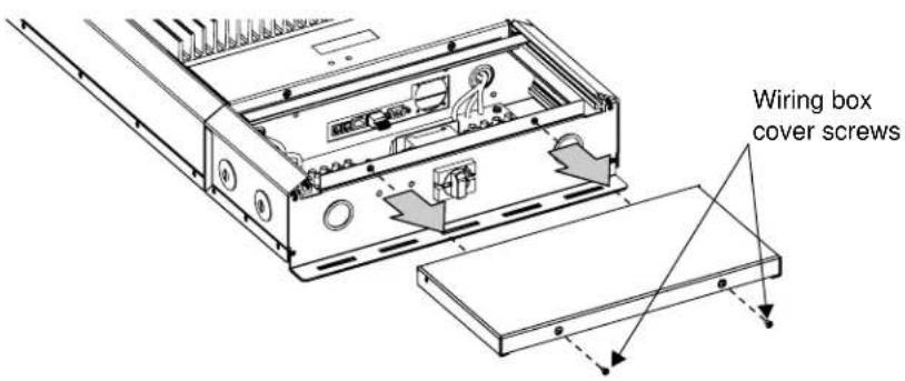
You must remove the inverter wiring box cover to access the terminal blocks, ground bar and communications ports.
To remove the wiring box cover:
- Using a Phillips screwdriver, remove the two screws on the bottom side of the wiring box and lift the cover off the wiring box (see Figure 3-3).
text_image
Wiring box cover screwsFigure 3-3 Removing the Wiring Box Cover
Insulating barrier
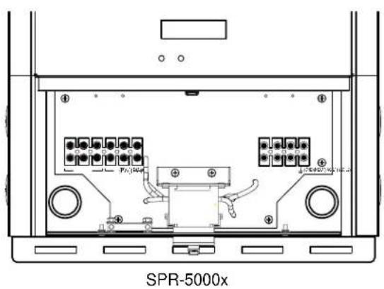
AC and DC connections are made at the wiring terminals shown in Figure 3-5.
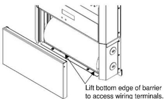
The clear plastic insulating barrier inside the wiring box is a permanent component. It is intended to separate the high-voltage AC and DC wiring from any communications cabling.
When wiring the unit, it is necessary to pull the barrier back to access the wiring terminals. See Figure 3-4. After completing the wiring, return the insulating barrier to its original position.
text_image
Lift bottom edge of barrier to access wiring terminals.Figure 3-4 Insulating Barrier Location
text_image
SPR-5000x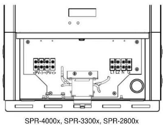
text_image
SPR-4000x, SPR-3300x, SPR-2800xFigure 3-5 AC and DC Terminal Block Location
Connecting the DC Wiring

WARNING: Shock hazard
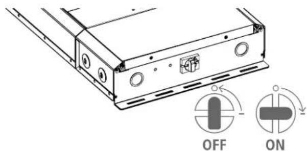
Use caution when working around sources of DC power. Although the DC/AC disconnect switch disconnects the inverter from DC power, hazardous voltages from paralleled PV strings will still be present upstream of the switch and inside the wiring box. To reduce the risk of shock during installation, cover the array with an opaque (dark) material before making any connections, ensure the DC/AC disconnect switch is set to OFF (see Figure 3-6), and always test for voltage before touching exposed wiring or devices.
text_image
OFF ONFigure 3-6 DC/AC Disconnect Switch Positions
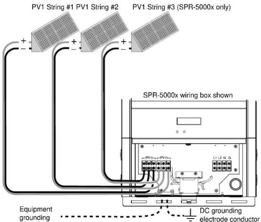
The following procedure is illustrated in Figure 3-7. If there is more than one PV string, label the positive and negative wire pairs appropriately (for example: PV1-String #1 POS, PV1-String #1 NEG, PV1-String #1 GND, PV1-String #2 POS, etc.).
To wire the PV array to the inverter:
- Connect the POSITIVE (+) wire from the PV1 string #1 to one of the PV+ terminals.
- Connect the NEGATIVE (−) wire from the PV1 string #1 to one of the PV- terminals.
- Repeat for the PV1 string #2, if there is one.
- Repeat for the PV1 string #3 (SPR-5000x only), if there is one.
- Ensure all connections are correctly wired and properly torqued to a maximum 16 in-lb (1.8 Nm).
- Install the DC grounding electrode conductor in the ground bar shown in Figure 3-7.
text_image
PV1 String #1 PV1 String #2 PV1 String #3 (SPR-5000x only) SPR-5000x wiring box shown Equipment grounding DC grounding electrode conductorFigure 3-7 DC Connections for Multiple PV Strings
Important: Depending upon installation and local codes, fusing and/or a combiner box may be required. This fusing and combiner box are to be provided by the installer.
DC Wiring for Multiple Inverters
For installations with multiple inverters, separate solar arrays are required for each unit. The output of each inverter feeds a separate dual-pole circuit breaker (L1 and L2) in the main utility service panel.
For such installations, complete the wiring and perform the commissioning procedure for each inverter one at a time. For the commissioning procedure, see "Commissioning Multiple Inverters" on page 4–4.

WARNING: Shock hazard and equipment failure
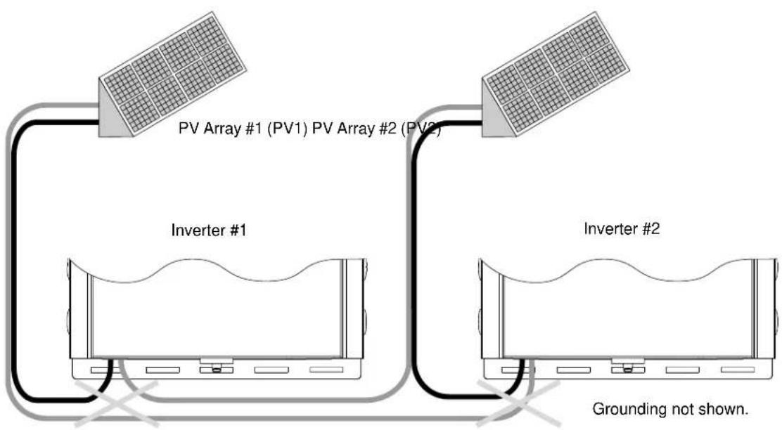
Ensure each inverter is correctly connected to its own PV array(s) and that no wires are crossed. If inverters "share" more than one PV array, an input current difference of over 1 A between arrays can cause each inverter to fail—the ground fault protection fuse will blow, followed by short circuit failure. This failure will also generate hazardous voltages at the DC/AC disconnect switch on each unit.
For example, connect PV1 positive (+) and PV1 negative (−) to inverter 1 and PV2 positive (+) and PV2 negative (−) to inverter 2.
Do not connect PV1 positive (+) and PV2 negative (−) to inverter 1 and PV2 positive (+) and PV1 negative (−) to inverter 2. See Figure 3-6.
text_image
PV Array #1 (PV1) PV Array #2 (PV2) Inverter #1 Inverter #2 Grounding not shown.Figure 3-8 Improper Multiple Inverter Connections
Connecting the AC Wiring

WARNING: Shock hazard
Before wiring the inverter, ensure the main breaker in the primary utility breaker box is switched off. Switch this breaker on only after all wiring is completed as instructed in the procedures.
The inverter can be connected to a single bi-directional meter, or to dual meters, where one meter indicates power used and the second meter indicates power sold (power supplied back to the utility). Consult the local utility to determine the proper components to install, and obtain any permits required prior to installation.
Ensure all connections are correctly wired and properly torqued to a maximum 16 in-lb (1.8 Nm).
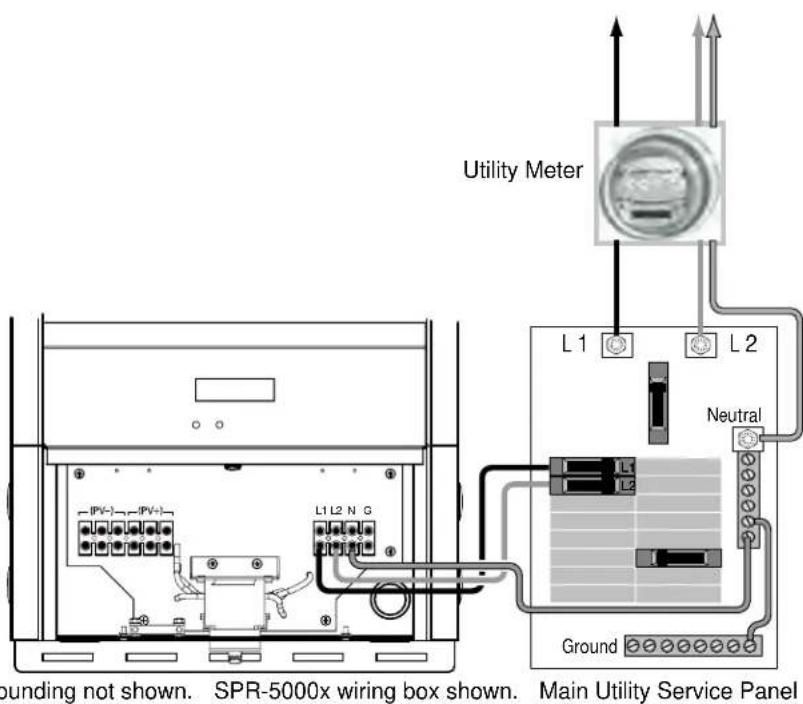
The AC wiring procedure is illustrated in Figure 3-9.
Important: The neutral conductor must be attached to the inverter in all cases. The neutral conductor is used for phase-to-neutral voltage sensing only and is not a current carrying conductor. This conductor is not bonded to ground in the inverter.
text_image
Utility Meter L1 L2 Neutral Ground SPR-5000x wiring box shown. Main Utility Service Panel bounding not shown. SPR-5000x wiring box shown.Figure 3-9 AC Connections from Inverter to Utility Service Panel
DC and AC Wiring for Multiple Inverters
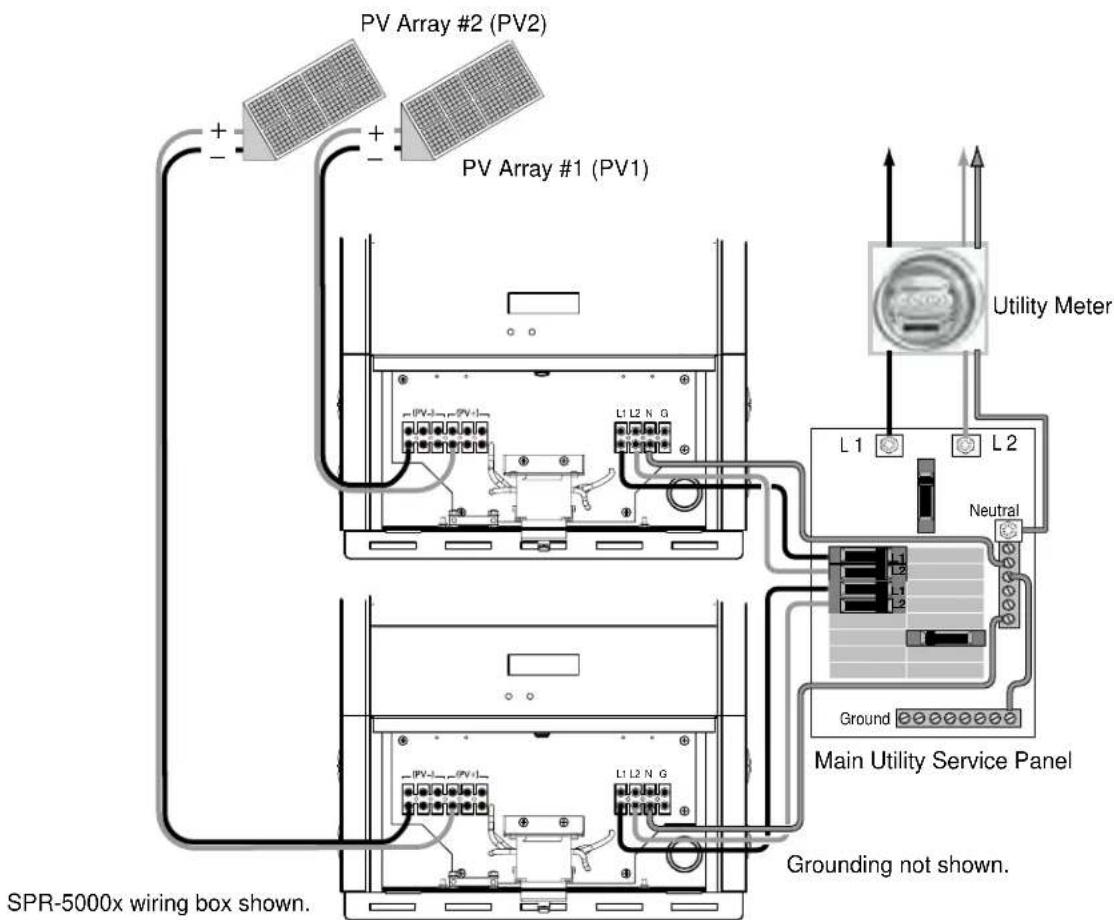
DC and AC wiring for multiple inverters is illustrated in Figure 3-10. This illustration is an example, not a requirement. Some installations may use a subpanel before the main utility service panel.
If there is more than one PV array, label the positive and negative wire pairs appropriately (for example: PV1 POS, PV1 NEG, PV1 GND, PV2 POS, etc.).
If required by the AHJ, connect a DC grounding conductor to each inverter's ground bar. One inverter will connect to a common grounding conductor. The other inverters will use tap connectors. Then connect the DC or AC grounding electrode as per NEC 690.47.
Ensure all connections are correctly wired and properly torqued to a maximum 16 in-lb (1.8 Nm).
text_image
PV Array #2 (PV2) PV Array #1 (PV1) Utility Meter L 1 L 2 Neutral Ground Main Utility Service Panel SPR-5000x wiring box shown. Grounding not shown.Figure 3-10 DC and AC Wiring With Multiple Inverters
Communications Wiring for Multiple Inverters
Communications wiring between multiple inverters allows information about each inverter and its associated PV array to be communicated between all of the inverters in the system. Information about the entire system can be displayed on any inverter LCD in the system.
For example, in a two-inverter system, if inverter #1 is producing 1500 W and inverter #2 is producing 2000 W, both inverters display a total system power of 3500 W. The cumulative energy produced by both inverters that day is also displayed.
You can also view information for an individual inverter in a system. See “To view unit-specific screens in a multiple unit system:” on page 5–5.
Without communications wiring (network cables) each inverter in a system will only display information pertinent to the unit and its associated PV array.
Network Layout
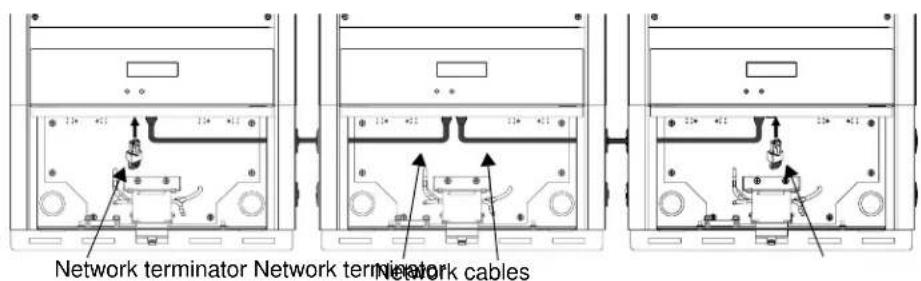
Network connections for multiple inverters are laid out in a “daisy chain” pattern, with each device on the network linked by separate lengths of cable, as shown in Figure 3-11.
text_image
Network terminator Network terminetwork cablesFigure 3-11 Daisy Chain Layout

CAUTION: Equipment damage
Connect inverters only.
Although the cabling and connectors used in this network system are the same as ethernet connectors, this network is not an ethernet system. Equipment damage may result from attempting to connect the inverter to different systems.
Terminators
The network terminator supplied with each inverter (Figure 3-12) is required at each end of the network to ensure the communication signal quality on the network.
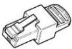
Figure 3-12 Network Terminator
Network ports
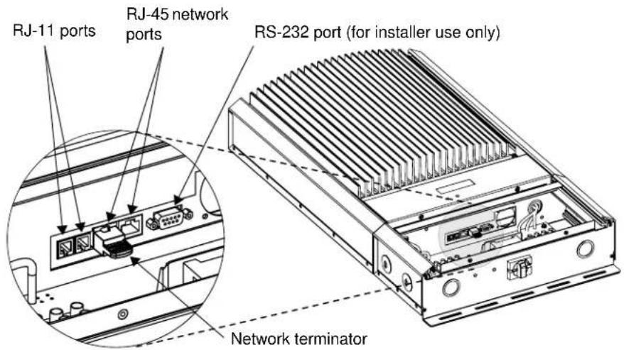
Two RJ-45 ports are provided in the inverter, accessible from the wiring box. See Figure 3-13 for the location of these ports.
RJ-11 ports The RJ-11 ports allow the interconnection of multiple inverters for 3-phase configurations where the requirement is to avoid high unbalanced generating conditions on the transformer. Any inverter disconnecting from the grid also forces the remaining inverters offline. This condition remains until grid parameters for all inverters are within operating specifications.
text_image
RJ-11 ports RJ-45 network ports RS-232 port (for installer use only) Network terminatorFigure 3-13 RJ-45 Ports in the Inverter Wiring Box
Cabling Requirements

CAUTION: Equipment damage
Do not use crossover cable.
The network uses Category 5 (CAT5 or CAT5e) cable, a standard cable available from any computer supply store. The cable consists of eight conductors in four twisted pairs with an RJ-45 modular connector wired to the T568A standard.
Table 3-2 contains the arrangements of wire colors to pin numbers for the T568A standard.
Table 3-2 T568A Standard Wiring
| Pin Number | Conductor Name | CAT5 Cable Insulation Color | CAT5e Cable Insulation Color |
| 1 | NET_S | White/Green White/Orange | |
| 2 NET_S | Green Orange | ||
| 3 NET_C | White/Orange White/Green | ||
| 4 CAN_L | Blue Blue | ||
| 5 CAN_H | White/Blue White/Blue | ||
| 6 NET_C | Orange Green | ||
| 7 NET_S | White/Brown | White/Brown | |
| 8 NET_C | Brown | Brown |
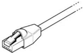
natural_image
Line drawing of a USB connector with two leads (no text or symbols)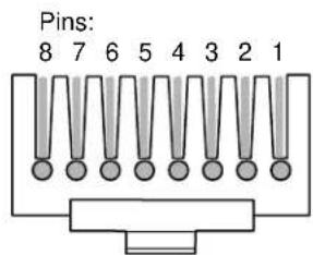
text_image
Pins: 8 7 6 5 4 3 2 1Figure 3-14 RJ-45 Connector
Guidelines for Routing the Network Cables

WARNING: Shock hazard
Do not route the network cables in the same conduit or panel as the AC and DC power cabling. The cables should run on top of the insulation barrier inside the wiring/disconnect box and out the side conduit hole, avoiding any contact with the AC and DC wiring.

CAUTION: Unpredictable device behavior
Do not connect one end of the network to the other to make a ring or loop.
Connecting Network Cable Between Multiple Inverters
The procedure assumes only two inverters are connected. However, up to five inverters can be connected in this configuration.

WARNING: Shock hazard
Before opening the inverter wiring/disconnect box, turn OFF the breaker switches connected to the inverter AC output, and turn the DC/AC disconnect switch to the OFF position. Hazardous voltage will still be present on the DC input (PV) terminals located under the clear plastic insulation barrier. Do not remove the insulation barrier during this procedure. To reduce the risk of shock, cover the array with an opaque (dark) material.
To provide communication between multiple inverters:
- Remove the wiring/disconnect box cover from each unit.
- Connect the network cable to an RJ-45 port in Inverter #1.
- Route the cable along the top of the insulation barrier and through a side conduit hole to Inverter #2.
- Connect the network cable to an RJ-45 port in Inverter #2.
- For more than two inverters, continue connecting cable as described above.
- Insert network terminators into the empty RJ-45 ports in the inverters at the beginning and end of the network. There should be no empty RJ-45 ports in any of the inverters. See Figure 3-11.
4
Starting the Inverter
Chapter 4 contains information on starting up the SunPower Solar Inverter and performing a functional test.
The topics in this chapter are organized as follows:
- “Startup Procedure” on page 4–1
- “Commissioning Multiple Inverters” on page 4–4
- “Disconnect Test” on page 4–6
Startup Procedure
Starting up the inverter requires several steps. You will need to:
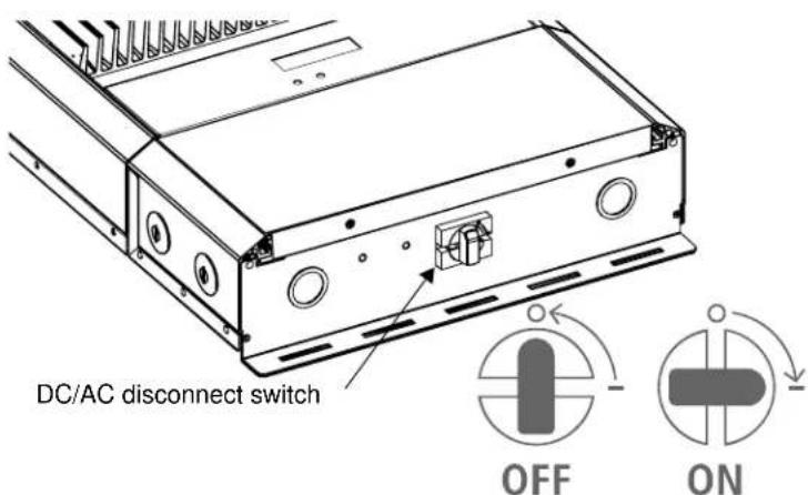
- Ensure the DC/AC disconnect switch is in the OFF position (see Figure 4-1).
- Check the PV array DC voltage (see procedure below).
- Check the AC utility voltage (see procedure below).
- Replace the cover on the wiring box (see "Replacing the Wiring/Disconnect Box Cover" on page 4–3).
- Start up the inverter by switching the DC/AC disconnect switch ON.

WARNING: Shock hazard
Hazardous voltages are present from two sources. Use extreme caution during startup procedure. Before applying power to the inverter, ensure all AC and DC wiring is correct.
Checking the PV Array DC Voltage
To check the PV array DC voltage:
- Uncover the PV arrays and expose them to full sunlight. The sunlight must be intense enough to produce the required output voltage.
- Measure the PV array open circuit DC voltage across the DC positive (+) and negative (−) terminals. This voltage must be greater than 150 volts DC (to energize the electronics) and less than 600 volts DC (to prevent damage to the inverter).
Checking the AC Utility Voltage
To check the AC utility voltage:
- Switch on the main and inverter breakers in the main electrical service panel.
- Using an AC voltmeter, measure the AC open circuit utility voltage between L1 and L2. Ensure this voltage is at approximately the nominal value. The inverter operates with a line-to-line voltage (L1 to L2) range around the nominal value.
- Measure the phase-to-neutral voltage. Phase-to-neutral voltage should be 120 Vac (nominal) for each phase-to-neutral measurement, whether the grid is 120/240 V split-phase or 208 V three-phase WYE.
Phase-to-phase voltage may rise 3 to 4 Vac (at the field wiring points, depending upon grid impedance) when current is flowing to a typical 240 V grid. If the grid voltage is within 1 to 2 Vac of the high voltage disconnect threshold when the inverter is at full rated power output (see “Adjustable Voltage, Frequency and Reconnection Settings” on page A–10), the inverter may disconnect more frequently than it normally should. If the grid is normally high, the unit may disconnect and then refuse to reconnect due to the required reconnect voltage of 106 per cent of nominal.
If this occurs, consult the utility about reducing the utility voltage or to get permission to allow the installer to adjust the disconnect threshold to gain additional margin.
See “Electrical Specifications” on page A–2 for the utility voltage operating range for your inverter model.
Replacing the Wiring/Disconnect Box Cover
After performing the voltage checks, replace all covers that were removed during installation and startup.

WARNING: Shock hazard
Before reattaching covers, turn off the breaker switches in the main utility service panel and the DC/AC disconnect switch on the inverter.
To replace the wiring/disconnect box cover:
- Ensure the clear plastic insulating barrier is properly positioned in the wiring box.
- Place the cover in position on the wiring box, being careful not to pinch any wires inside.
- Ensure that the two screw holes in the bottom of the wiring box cover are aligned with the corresponding holes in the bottom of the wiring box.
- Replace the two screws removed when the cover was removed (see "Accessing the Wiring Terminals" on page 3-5), and tighten securely.
Starting up the Inverter
To start up the inverter:
- Turn the DC/AC disconnect switch to the ON position (see Figure 4-1).
- Check the inverter LCD. The startup screens (see Table 5-1 on page 5–2) should appear for five seconds each, and then the “Reconnecting in sss seconds” special screen (see Table 5-10 on page 5–10) will appear until the 305 second (default value) protection timer countdown is completed.
text_image
DC/AC disconnect switch OFF ONFigure 4-1 DC/AC Disconnect Switch Positions
Commissioning Multiple Inverters
In an installation with multiple inverters, special commissioning procedures must be followed in order to safely determine if any DC wiring problems exist.
Important: Before performing this procedure, all inverters should be off, with the DC/AC disconnect switch in the OFF position.
To commission multiple inverters:
- Uncover the PV arrays and/or close the main DC disconnect switch, if one is installed.
- Start the first inverter by turning the DC/AC disconnect switch to the ON position.
- Wait for the input current to rise above 1 A.
This information is displayed on the Array Readings screen. To display the Array Readings screen, tap the unit four times.
- After the input current has risen above 1 A, if the inverter is still operating normally, switch off the inverter by turning the DC/AC disconnect switch to the OFF position. Proceed to step 5.
If the inverter stops operating after the input current has risen above 1 A, turn the unit off, remove DC power, and have a certified electrician or technician inspect the ground fault protection fuse. If the fuse has blown, a DC wiring problem may exist. Check all DC wiring to ensure that the unit is connected to a single PV array.
- Proceed to the next inverter and perform the same test. See Figure 4-2 for an example of the recommended commissioning sequence.
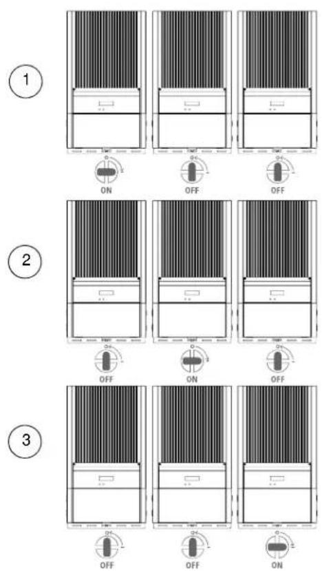
Figure 4-2 Commissioning Sequence for Multiple Inverters
Disconnect Test
The disconnect test is designed to verify correct operation of the inverter both on initial operation and periodically through its life as required by the utilities. This test ensures that the SunPower Solar Inverter does not send electricity to the utility grid when the local utility has shut off the grid for repairs, or when the utility wiring is damaged.
When operation of the inverter has been verified and the unit is producing power, run the disconnect test as described in this procedure.
To run the disconnect test:
- Switch off the AC circuit for the inverter. This can be accomplished by switching the breaker on the main panel that feeds the inverter(s). The disconnect for the home or business may be used as well.
-
Have someone watch the front panel of the inverter to ensure the green light on the front of the inverter goes out within two seconds.
The green light goes out when the AC circuit is switched off, disconnecting the inverter from the AC grid. The front panel display will show an AC Fault display, indicating that the AC is out of the operating range. -
Switch on the AC circuit for the inverter.
The inverter responds by starting its 305 second protection timer. Ensure that the inverter does not produce power before the countdown is over. After completing the countdown, the green light turns on and the inverter begins delivering power. The display returns to showing the power being produced and the total kWh produced to date.
Important: The default voltage, frequency and reconnect delay values are programmed into the unit at the time of shipment from the factory. These settings can be adjusted only with the approval and assistance of SunPower and the local utility. See “Adjustable Voltage, Frequency and Reconnection Settings” on page A–3.
- If you have another inverter to commission, switch off the AC circuit for the inverter you have just commissioned and tested by switching off the breaker on the main panel. You can then run the commissioning procedure and disconnect test on the next inverter.
Locating the Firmware Version Number
The firmware version number for the protection processor is visible on a screen that appears when the unit starts up or is powered up after switching the DC/AC disconnect switch to “on.” The screen reads:
$$ \begin{array}{r l} \text { Flash } & = 0 3. 0 1 \ \text { ROM } & = 0 3. 0 0 \end{array} $$
The number appearing after “ROM” is the firmware version number for the protection processor.
5
Monitoring the Inverter
Chapter 5 contains information for understanding the LCD screens and the LED indicators.
Monitoring the Front Panel Display
During startup
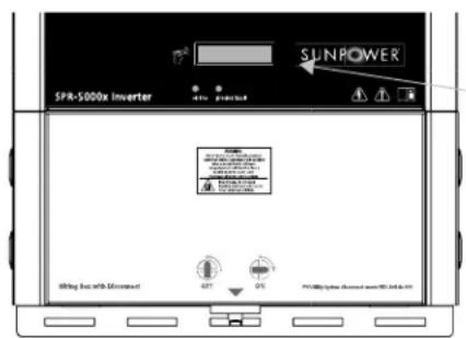
During startup, the front panel LCD (see Figure 5-1) shows the screens described in Table 5-1, “Startup Screens” on page 5–2.
During waiting period
When the 305 second protection timer begins, the SunPower Solar Inverter displays “Reconnecting in sss seconds” (see Table 5-10, “Special Message Screens” on page 5–10).
During operation
When the protection timer stops, the inverter begins delivering power, indicated by the power output reading in the display (see Table 5-2, “Normal Operation Screens” on page 5–4).
When the inverter is offline or there is fault condition
When the inverter is offline (at night, for example) or a fault condition has been detected, the LCD displays a message to indicate that the inverter is offline and to identify the specific fault condition. See Table 5-5, “Offline Mode Default Display” on page 5–6 and Table 5-8, “Fault Message Screens” on page 5–8.
text_image
SPA-5000x Inverter SUNPOWER Wiring Bus with Microcact QRT Q1 PVC@System Channel 198.4.6 & 201Tap front panel for backlight and status screens
Figure 5-1 Front Panel LCD
Viewing more information
Additional screens of information about the performance of the inverter can be displayed by tapping the inverter front panel. This causes the LCD to cycle through a series of information screens in Normal Operation, Offline or Fault modes. These are described in detail in the following section, “Front Panel Display Screens and What They Mean”.
Front Panel Display Screens and What They Mean
The front panel display shows different message screens during different modes of operation (Startup, Normal, Offline, and Fault). All single units display a basic set of message screens; multiple unit systems display additional screens in Normal Operation and Offline modes.
In addition there are Special message screens that may appear in any operational mode. All of these message screens are described in more detail in the following tables.
Startup Mode
During startup, the inverter displays several message screens on its front panel LCD. These screens appear in the following order (Table 5-1).
Table 5-1 Startup Screens
| Display Duration | Description | |
| Power 5000WNA-240/208V | 5 seconds Startup message 1: Maximum output power and Region-nominal output voltage | |
| Flash = 03.01ROM = 03.00 | 5 seconds Startup message 2: Model and revision numbers for Flash and ROM memory on the inverter. The ROM revision number applies to the protection processor. | |
| Vh= 266VClr t < 1.00s | 3 seconds | Vh: phase-to-phase (rms) high threshold voltage setting, the threshold at which the inverter disconnects itself from the power grid when abnormally high phase-to-phase AC voltage is detected.*Clr t: clear time.† |
| Vl= 177VClr t < 2.00s | 3 seconds | Vl: phase-to-phase (rms) low threshold voltage setting, the threshold at which the inverter disconnects itself from the power grid when abnormally low phase-to-phase AC voltage is detected.Clr t: clear time. |
Table 5-1 Startup Screens
| Display Duration | Description | |
| Vph= 130VClr t < 1.00s | 3 seconds Vph: phase-to-neutral (rms) high threshold voltage setting, the threshold at which the inverter disconnects itself from the power grid when abnormally high phase-to-neutral AC voltage is detected.Clr t: clear time. | |
| Vpl= 107VClr t < 2.00s | 3 seconds Vpl: phase-to-neutral (rms) low threshold voltage setting, the threshold at which the inverter disconnects itself from the power grid when abnormally low phase-to-neutral AC voltage is detected.Clr t: clear time. | |
| Fh= 60.4HzClr t < 0.16s | 3 seconds Fh: frequency high threshold setting, the threshold at which the inverter disconnects itself from the power grid when abnormally high frequency is detected.Clr t: clear time. | |
| Fl= 59.4HzClr t < 0.16s | 3 seconds Fl: frequency low threshold setting, the threshold at which the inverter disconnects itself from the power grid when abnormally low frequency is detected.Clr t: clear time. | |
| Reconnect Delay305.00s | 3 seconds Setting for the reconnect delay for the protection timer. After a fault clears for the specified clear time, the protection timer starts counting down before the inverter attempts to deliver power to the grid. | |
* The voltage and frequency thresholds, clear times and reconnect delay in Table 5-1 can be adjusted for multi-unit installations producing 30 kW or more (with the approval and assistance of SunPower and the local utility).
† The clear time is the total time to disconnect the output from the grid. It is the sum of the debounce time and the hardware delay time. The debounce time is the protection processor waiting time before it declares a fault. This delay is necessary to avoid nuisance trips.
The protection timer begins counting down the reconnect delay during startup and the “Reconnecting in sss seconds” screen appears until the timer countdown is complete.
Normal Operation Mode
The LCD on the inverter is refreshed every two seconds, so all readings are current to within two seconds. There is a default display available at all times, and a series of additional screens that can be displayed by tapping the inverter front panel to change the display.
Normal Operation default display
After the protection timer has completed its countdown and during normal operation, the inverter displays the normal operation message screen shown in Table 5-2.
Table 5-2 Normal Operation Screens
| Display Description | |
| System 5000W Today 9.875kWh | Default screen.Line1: Power being produced by the system now.Line 2: Cumulative energy produced by the system today. |
| Insufficient Solar Energy | Indicates the inverter is not producing power due to insufficient solar energy during low light conditions in early morning or late afternoon or when the PV array is in shade. This screen flashes alternately with the Normal Operation default screen. |
More screens for all systems
If there is sufficient energy from the PV array, the default screen is displayed continuously while the system is operating normally. In a multiple unit system with communications cables properly connected, the power and cumulative energy values displayed are for the entire system.
During low light conditions when the inverter cannot produce any power, the Normal Operation default screen flashes alternately (every two seconds) with the Insufficient Solar Energy screen.
Besides the default normal operation display, more system information messages can be viewed.
To view more Normal Operation information:
- Tap the front panel to advance the display to the next screen. Normal operation screens shown in Table 5-3 are displayed in the order given, as you tap successively on the unit. They are common to all inverter systems, no matter how many units are installed.
If you continue to tap the front panel, the LCD continues to cycle through all of the available normal operation screens. Each screen is displayed for a maximum of 30 seconds. If you do not tap again during that time period, the LCD backlight turns off and the display reverts to the default system message screen.
Table 5-3 Normal Operation Screens
| Tap Display* | Description | |
| 1st time System 5000W Today 2.500kWh | LCD backlight turns on for better readability and default Normal Operation screen is displayed. | |
| 2nd time System Lifetime 305kWh | Lifetime energy produced by the inverter system. | |
| 3rd time Time Online Today hh:mm:ss | Length of time inverter has been online today, in hours (hh), minutes (mm) and seconds (ss). | |
| 4th time Array Readings 350.5V 8.4A | Immediate DC voltage and current readings from the PV array. | |
| 5th time Grid Readings 242.6V 60.0Hz | Immediate AC voltage and frequency readings from the grid. | |
* In a multiple unit system with network cables properly installed, the system values displayed are for the entire system. For example, in a two-inverter system, if inverter #1 is producing 1500 W and inverter #2 is producing 2000 W, both inverters display a total system power of 3500 W. Time online and array readings are for the local inverter and PV array associated with that inverter.
Additional screens for multiple units
In addition to the normal system message screens, additional screens specific to each inverter can be displayed when the inverter is networked to other units. These screens are only available on multiple unit systems.
To view unit-specific screens in a multiple unit system:
- Tap the inverter front panel to advance the display to the next screen. Continue tapping until the final system message screen (“Grid Readings”, in Table 5-3 above) is displayed.
- Tap again. Normal operation screens shown in Table 5-4 are displayed in the order given, as you tap successively on the unit.
If you continue to tap the unit, the LCD will cycle through all of the available normal operation screens. Each message is displayed for up to 30 seconds. If you do not tap again within that time period, then the LCD backlight turns off and the display reverts to the default normal operation screen (Table 5-2).
Table 5-4 Additional Normal Operation Screens for Each Inverter in a Multiple Unit System
| Tap Display | Description | |
| 6th time | Unit 5000WToday 1.250kWh | Power being produced by this unit now.Cumulative energy produced by this unit today. |
| 7th time | Unit Lifetime150kWh | Lifetime energy produced by this unit. |
Offline Mode
Offline default display
At night and when no power is being produced by the PV array (offline mode), the inverter displays the screen shown in Table 5-5.
Table 5-5 Offline Mode Default Display
| Display Description | |
| Inverter | Displayed at all times while the system is offline. |
| Offline | |
Offline messages for all systems
Additional message screens can be viewed when the system is offline by tapping the inverter front panel. Each additional tap displays the next screen, in the order shown in Table 5-6.
These message screens are common to all inverter systems, no matter how many units are installed. If you continue to tap the unit, then the LCD will continue to cycle through all of the available offline mode screens.
Table 5-6 Offline Mode Screens for All Units
| Tap Display* | Description | |
| 1st time InverterOffline | LCD back light turns on for better readability and default Offline Mode screen is displayed. | |
| 2nd time System OWToday 2.50kWh | Power being produced by the system now.Cumulative energy produced by the system today. | |
| 3rd time System Lifetime305kWh | Lifetime energy produced by the system. | |
| 4th time Time Onlinehh:mm:ss | Total time that the system was online today, in hours (hh), minutes (mm) and seconds (ss). | |
* In a multiple unit system with communications cables installed, the system values displayed are for the entire system. Time online is for the local inverter.
Additional Offline messages for multiple unit systems
Multiple unit systems in offline mode display all of the message screens shown in Table 5-6, plus the additional screens shown in Table 5-7. These additional screens are displayed following the “Time Online” screen.
These screens are only displayed on multiple unit systems with communications cables installed. If you continue to tap the unit, then the LCD continues to cycle through all of the available offline mode screens.
Table 5-7 Additional Offline Mode Screens for Each Unit in a Multiple Unit System
| Tap Display Description | ||
| 5th time Unit OW Today 1.25kWh | Power being produced by this unit now.Cumulative energy produced by this unit today. | |
| 6th time Unit Lifetime 150kWh | Lifetime energy produced by this unit. | |
Fault Mode
When a fault state is detected, the appropriate fault message appears on the front panel display at the next screen refresh (within 2 seconds). The inverter fault message screens are shown in Table 5-8.
Fault Mode causes These message screens only appear when there is a fault, and then flash alternately with the Inverter Offline default screen (Table 5-5) until the fault is corrected.
Table 5-8 Fault Message Screens
| Display Appears | When... |
| DC Voltage Fault145.5V | The actual DC voltage is over or under the allowable range. Self-clearing, no action required.The PV array should be configured such that DC voltage falls within the input voltage maximum power point range as specified for your model in “Electrical Specifications” on page A-2.* |
| AC Voltage Fault280V | The actual AC voltage is over or under the allowable range, as specified in “Electrical Specifications” on page A-2. This is a utility fault; it will clear itself when the AC voltage comes within the specified range.† If the fault does not clear, a phase-to-neutral line may not be connected properly. |
| AC Current Fault | The AC output current is over the allowable limit, which is 0.5 A less than the maximum output fault current. See “Electrical Specifications” on page A-2. The message clears after 15 seconds if the output current falls below the limit. |
| Frequency Fault0.0Hz | The actual frequency is over or under the allowable range, as specified in “Electrical Specifications” on page A-2. This is a utility fault; it will clear itself when the frequency comes within the specified range.† |
| Over Temp Fault81.4C 178.5F | The unit’s internal temperature is greater than 80°C (176°F), the unit will shut down automatically and only restart when the temperature has dropped to less than 70°C (158°F). |
| Ground FaultReset System | A grounding fault is detected. The ground fault fuse will be blown. The system must be shut down completely, the fault corrected, the fuse replaced (see “Replacing the Ground Fault Protection Fuse” on page 6-4) and then the system restarted. Troubleshooting a grounding fault should be performed by qualified personnel, such as a certified electrician or technician. |
| Unit Shutdown via Remote | The unit has been shut down via a computer connected to the RS-232 port. |
| Protection uPNot Responding | The protection microprocessor is not responding. |
* It is normal to receive this fault during low light conditions at dawn or dusk. At such times, the array does not have sufficient energy to power the inverter, so the PV voltage drops below the lower limit of the maximum power point range occasionally.
† Grid fault. When this fault is cleared the protection timer will begin its countdown and the “Reconnecting in sss seconds” and “Inverter Offline” special screens (see Table 5-10) flash alternately until the countdown is complete.
Additional Fault messages for all systems
Additional message screens can be viewed in fault mode by tapping the inverter front panel. Each additional tap displays the next screen in the order shown in Table 5-9.
Table 5-9 Additional Fault Mode Screens
| Tap Display* | Description | |
| 1st time Current fault message screen (see Table 5-8) | LCD backlight turns on for better readability. | |
| 2nd time System OW Today 2.500kWh | Energy being produced by the system now.Cumulative energy produced by the system today. | |
| 3rd time System Lifetime 305kWh | Lifetime energy produced by the inverter system. | |
| 4th time Time Online Today hh:mm:ss | Length of time inverter was online today, in hours (hh), minutes (mm) and seconds (ss). | |
| 5th time Array Readings 350-5V 8-4A | Immediate DC voltage and current readings of power from the PV array. | |
| 6th time Grid Readings 242.6V 60.0Hz | Immediate AC voltage and frequency readings of power from the grid. | |
* In a multiple unit system with network cables installed, the system values displayed are for the entire system. Time online and array readings are for the local inverter and PV array associated with that inverter.
Special Screens
Special message screens are displayed in specific situations that are not considered fault situations. They can appear in any mode of operation. These screens are described in Table 5-10.
Table 5-10 Special Message Screens
| Display Description | |
| Reconnecting in sss seconds | Time remaining in seconds (sss) before the inverter reconnects to the grid. This is a protection timer; it runs for approximately five minutes at startup and after any grid fault. |
| Inverter Offline | Inverter switching (or has switched) from Normal Operation to Offline mode. This screen may flash alternately with a Fault message screen. |
| System *9600W Today 15.56kWh | The “*” in these two screens (see Table 5-2 and Table 5-4) indicates that the unit is derating its output power because the inverter heat sink temperature is above 75^ C ( 167^ F). |
| Unit *4800W Today 7.82kWh | The asterisk only appears when the power is actually being limited by the inverter. |
| Insufficient Solar Energy | Indicates the inverter is not producing power due to insufficient solar energy during low light conditions in early morning or late afternoon or when the PV array is in shade. This screen flashes alternately with the Normal Operation default screen. |
Custom Screens
Two custom screens are available. The inverter does not display them unless they are configured using a software tool available from SunPower. If programmed, the custom screens display as the fourth and fifth screens during the startup sequence. They can also be viewed by tapping the unit during normal operation and fault mode.
The first custom screen is intended for the home owner to display information such as the name or location of the PV array associated with the inverter.
The second custom screen is intended for installers, who can configure the screen to display, for example, contact information for service.
Status Indicator Lights
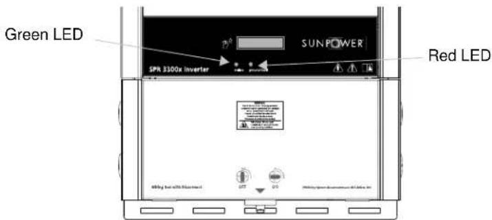
The inverter has two status indicator lights (LEDs) located below the front panel LCD (Figure 5-2). These LEDs indicate the inverter's status (Table 5-11) and assist in troubleshooting the performance of the unit.
Only one indicator light will be lit at any time.
Table 5-11 Status Indicator LEDs
| LED on Means | |
| GREEN The inverter is on (DC voltage and AC voltage are qualified and the protection timer has finished) and delivering power. No action required. Turns off when a fault state is detected. | |
| RED Ground fault condition detected. Check for any fault messages on the display (see Table 5-8), and refer also to Table 6-1, “Troubleshooting the inverter” on page 6–9 to resolve the fault condition. | |
text_image
Green LED SUN POWER SPR 3300x Inverter Red LED 480kg feed & 500g feed QUT Q1 480kg feed & 500g feedFigure 5-2 Status Indicator Lights
6
Maintenance and Troubleshooting
Chapter 6 contains information about how to provide general maintenance for the SunPower Solar Inverter. It also provides information about troubleshooting the unit.
The topics in this chapter are organized as follows:
- “Factors Affecting Inverter Performance” on page 6–1
- “Performing General Maintenance” on page 6–3
- “Replacing Parts” on page 6–4
- “Identifying Error/Fault Conditions and Solutions” on page 6–9.
Factors Affecting Inverter Performance
This section describes several factors that will affect the amount of power that a properly installed and operating inverter can produce.
PV Array Factors
PV array ratings
PV arrays are rated at ideal factory conditions, such as specified illumination (1000 W/m ^2 ), spectrum of the light and specified temperature (25 °C / 77 °F), which seldom reflect real-world installations. This is called the STC (Standard Test Condition) rating and is the figure that appears on the PV module nameplate label.
Expected performance
Because of several unavoidable environmental factors, you can expect your PVarray to produce around 60% to 70% of its peak STC-rated output for a properly designed and installed PV system on a typical day.
Temperature and reduced output
PV array temperature affects the output of the entire system. As the temperature on the array surface heats up, its energy output goes down. Roof-mounted arrays also collect the heat generated by the roof surface (or trapped under the array) and will produce less output than pole-mounted arrays, which allow greater air circulation behind the panels.
Important: The inverter will reduce its energy output to protect its electronic circuits from overheating and possible damage in high heat conditions. For maximum output in hot climates, mount the inverter in a shaded location with good air flow.
Angle of the sun The angle of the sun in relation to the PV array surface—the array
orientation—can dramatically affect the PV array output. The array energy output will vary depending on the time of day and time of year as the sun's angle in relation to the array changes. Sunlight output decreases as the sun approaches the horizons (such as in winter in North America) due to the greater atmospheric air mass it must penetrate, reducing both the light intensity that strikes the array's surface and spectrum of the light. In general, you can expect only four to six hours of direct sunlight per day.
Partial shade
Shading of only a single module of the array will reduce the output of the entire system. Such shading can be caused by something as simple as the shadow of a utility wire or tree branch on part of the array's surface. This condition, in effect, acts like a weak battery in a flashlight, reducing the total output, even though the other batteries are good. However, the output loss is not proportionate to shading.
The inverter is designed to maximize its energy production in all of the above situations using its MPPT algorithm.
Other Factors
Other factors that contribute to system losses are:
- Dust or dirt on the array
- Fog or smog
- Mismatched PV array modules, with slight inconsistencies in performance from one module to another.
- Inverter efficiency
- Wire losses
- Utility grid voltage.
Performing General Maintenance
Follow these simple routines to ensure many years of service and optimal performance of your solar energy system.
- Keep the heat sink clear of dust and debris.

WARNING: Shock and fire hazard
Do not use a pressure washer to clean the inverter, or use other cleaning methods that could allow water to enter the unit.
- Clean the PV array, during the cool part of the day, whenever it is visibly dirty.
- Periodically inspect the system to make sure that all wiring and supports are securely in place.
- On a sunny day near noon on March 21 and September 21 of each year, review the output of the system and compare with previous year's reading. Maintain a log of system performance readings so that you can recognize when system performance becomes inconsistent.
Replacing Parts

WARNING: Shock hazard
There are no user-replaceable parts on the inverter. Do not attempt to service the unit yourself.
Replacing the Ground Fault Protection Fuse

WARNING: Shock and fire hazard
Fuses should only be replaced by qualified service personnel, such as a certified electrician or technician. For continued protection against risk of fire, replace only with same type and ratings of fuse.

WARNING: Shock hazard
After disconnecting both AC and DC power from the inverter, wait five minutes before attempting any maintenance or cleaning or working on any circuits connected to the inverter. Internal capacitors remain charged for five minutes after disconnecting all sources of power.

WARNING: Shock hazard
- Dangerous voltages can exist inside the inverter. If there is leakage current from the ungrounded conductor to ground at the array, touching the grounded lead could cause a life-threatening shock even with the disconnect switch turned off. Ungrounded DC current within the inverter presents an extreme shock hazard.
- Cover PV arrays with an opaque material during this procedure.
- When the fuse has blown due to a fault, incorrect handling can be life-threatening. Use an insulated fuse puller.
The ground fault protection fuse will blow when severe leakage occurs between the PV array and earth ground, or when the system has been installed with faulty wiring. Before replacing the fuse, it is important to have qualified service personnel, such as a certified electrician or technician, determine the cause of the ground fault.
To replace a ground fault protection fuse:
- Remove the wiring/disconnect box cover, as described on page 3–5.
- Remove the display front panel cover (see Figure 6-2), located below the heat sink. Use a Phillips screwdriver to remove the two external panhead screws and washers and the two screws along the bottom edge of the cover.
The ground fault protection fuse is located to the left side of the LCD panel (see Figure 6-1), on the left side of the DC interconnect board.
- Using an insulated fuse puller, remove the blown fuse and replace it with a new AC/DC midget cartridge, rated 600 Vdc, 1A (Littelfuse KLKD 1 or equivalent).
-
Replace the display front panel cover and tighten all four screws securely.
-
Replace the wiring/disconnect box cover.
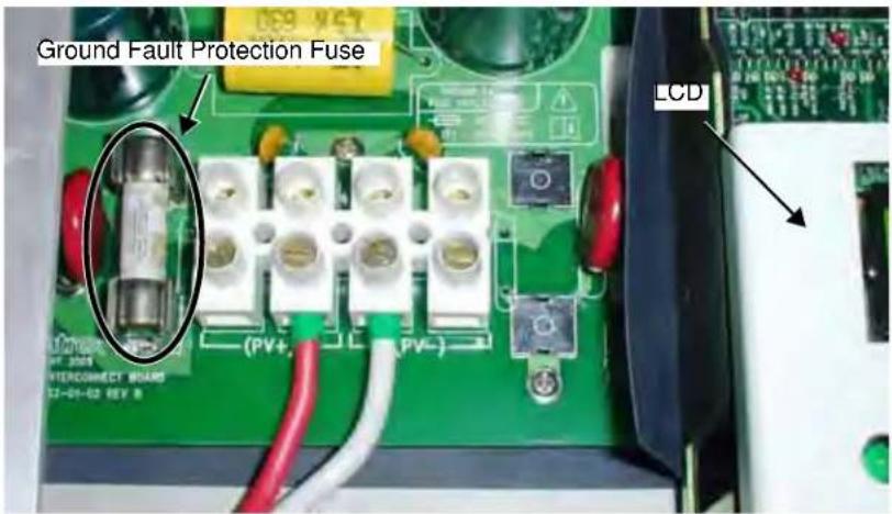
text_image
Ground Fault Protection Fuse LCDFigure 6-1 Location of Fuse, Front Panel Cover Removed
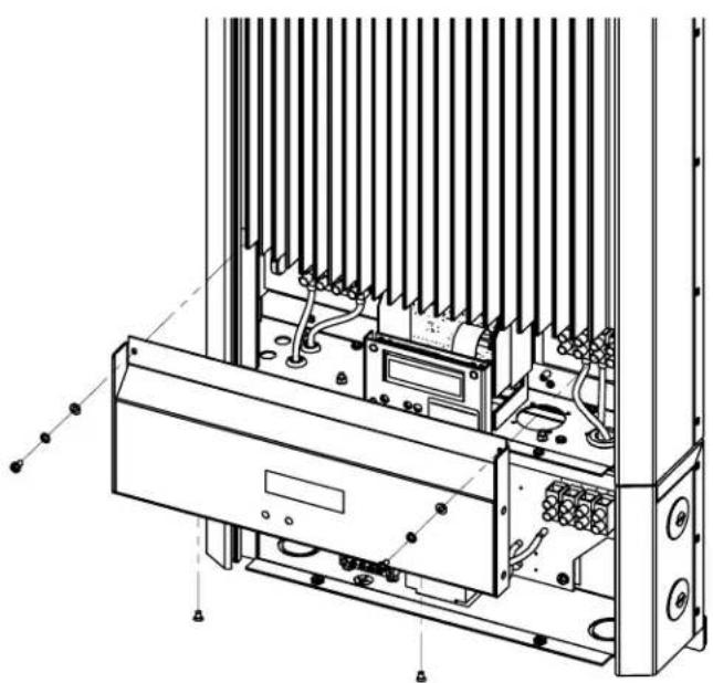
natural_image
Technical line drawing of an electronic device with internal components and mounting points (no text or symbols)Figure 6-2 Display Front Panel Assembly
Replacing the Inverter
If your inverter requires servicing, you can replace it with another inverter, leaving the existing wiring box in place. This means that you do not have to disturb DC and AC connections inside the wiring/disconnect box. However, you do have to disconnect wiring between the inverter and the wiring/disconnect box.

WARNING: Shock hazard
- Replacing the inverter according to these procedures should only be performed by qualified service personnel, such as a certified electrician or technician.
- Separating the inverter from the wiring box breaks the ground path between the PV grounded conductor and earth ground. When the wires between the inverter and wiring box are disconnected and exposed, both PV leads are floating at the array open circuit voltage. If there is leakage current from the POSITIVE PV lead to ground at the array, touching the NEGATIVE PV lead could cause a life-threatening shock even with the disconnect switch turned off. Ungrounded DC current within the inverter presents an extreme shock hazard.
- Cover PV arrays with an opaque material during this procedure.
- Use insulated tools only when disconnecting wires between the inverter and wiring box. Cap all disconnected wires with wire nuts.
Recommended tools:
- Insulated screwdriver
- Wire nuts
- 7 mm socket and small ratchet, or 7 mm open wrench.

WARNING: Shock hazard
The inverter should only be removed from the wiring box when a replacement inverter is immediately available. When replacing an inverter, ensure the DC/AC disconnect switch is locked (or otherwise secured) in the OFF position. Do not leave the top of the wiring box exposed for extended periods of time.
Before replacing the inverter, turn OFF the breaker switches in the main utility service panel and the DC/AC disconnect switch on the inverter. Cover the PV arrays with an opaque material.
To remove the inverter from the wiring box:
- Turn OFF the breaker switches in the main utility service panel and the DC/AC disconnect switch on the inverter. Disable the output of the PV arrays by covering them with an opaque material.
- Remove the wiring/disconnect box cover and the display front panel cover (described on page 3–5 and page 6–4).
-
Using an insulated screwdriver, disconnect the PV NEGATIVE (−) wire from the terminal block inside the inverter. Cap the wire immediately with a wire nut.
-
Disconnect the remaining AC, DC and network cables between the inverter and the wiring box, inside the inverter. Cap all disconnected AC and DC wires with wire nuts.
-
Inside the inverter, remove the four nuts attaching the wiring box to the inverter. See Figure 6-3.
-
Push the connecting DC and AC wires down inside the wiring box.
-
Lift the inverter off the mounting bracket, leaving the wiring box in place.
-
Ensure the gasket on the wiring/disconnect box is clean and undamaged. The gasket must create a water-tight seal between the inverter and wiring/disconnect box.
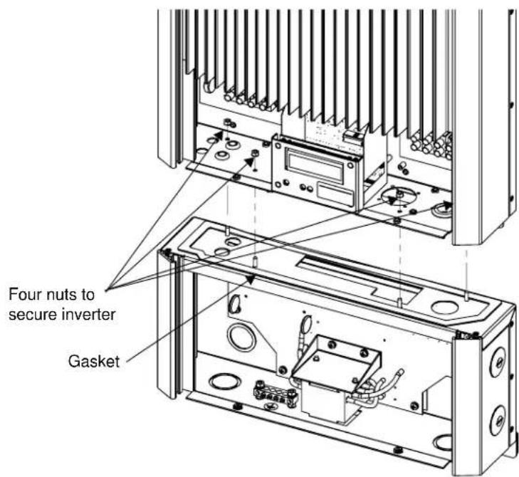
text_image
Four nuts to secure inverter GasketFigure 6-3 Wiring/Disconnect Box and Removable Inverter
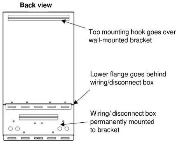
text_image
Back view Top mounting hook goes over wall-mounted bracket Lower flange goes behind wiring/disconnect box Wiring/ disconnect box permanently mounted to bracketFigure 6-4 Inverter and Wiring/Disconnect Box Sections
To replace the inverter on the wiring box:
- If it has not already been removed, remove the display front panel cover on the inverter.
- Mount the inverter on the upper mounting bracket above the wiring/disconnect box, ensuring that the inverter's lower flange goes behind the wiring/disconnect box. See Figure 6-4.
- Pull the connecting DC and AC wires back out of the wiring box and into the inverter.
- Replace the nuts that connect the inverter and the wiring/disconnect box. Tighten each nut alternately to clamp the gasket between the inverter and wiring/disconnect box. Secure all nuts tightly.
- Remove the wire nut from the PV NEGATIVE (−) wire and reconnect it to the terminal block inside the inverter.
- Uncap the remaining DC and AC wires and reconnect them to the terminal blocks inside the inverter.
- Ensure all connections are correctly wired and properly torqued to a maximum 16 in-lb (1.8 Nm).
- Follow the startup procedure as described on page 4-1.
Identifying Error/Fault Conditions and Solutions
Most error or fault conditions will be identified by fault message screens on the inverter front panel LCD. These are described in the “Fault Mode” section on page 5–8 of this manual. Most of these fault conditions are self-correcting and require no user action to remedy.
See “Front Panel Display Screens and What They Mean” on page 5–2 for more information.
Table 6-1 is intended to assist in determining fault conditions that may require user action to remedy.
Table 6-1 Troubleshooting the inverter
| Problem Possible Cause Solution | ||
| The inverter's LEDs and display are blank and the inverter does not operate in sufficient sunlight. | DC/AC disconnect switch is off. Turn | on DC/AC disconnect switch and breakers in the sequence described in “Startup Procedure” on page 4-1. |
| The display reads “Inverter Offline” and “AC Voltage Fault.” | Utility service panel breakers are switched off. AC grid voltage is not present or incorrect. | Turn on utility panel breakers. Check AC connections at the inverter's terminals. Ensure AC voltage within the range specified for your model in “Electrical Specifications” on page A-2 is present. |
| The display reads “Inverter Offline” with sufficient sunlight. | DC breakers are switched off (if installed), or external DC fuses are blown (if installed). DC array voltage is not present. | Turn on any DC breakers and check any DC fuses. Check DC connections at the inverter's positive and negative DC terminals. Check for incorrectly wired PV arrays. |
| The display reads “Inverter Offline” and “DC Voltage Fault” with sufficient sunlight. | DC voltage is present but incorrect. | Check DC connections at the inverter's positive and negative DC terminals. Check for incorrectly wired PV arrays. Ensure a voltage within the Maximum Power Point range is present at the inverter's terminals. |
| Only the inverter RED LED is illuminated and the display reads “Ground Fault.” | Ground fault condition detected on the PV array. | The PV system should be checked by a qualified electrician and repaired. See Table 5-8 on page 5-8. |
A
Specifications
Appendix A contains information about the specifications of the SunPower Solar Inverter.
The topics in this appendix are organized as follows:
- “Electrical Specifications” on page A–2
- “Output Power Versus Ambient Temperature” on page A–10
- “Environmental Specifications” on page A–11
- “User Display” on page A–11
- “Mechanical Specifications” on page A–11
- “Regulatory Approvals” on page A–12
- “Information About Your System” on page A–13.
Electrical Specifications
SPR-5000x
Input
| SPR-5000x | |
| Model number 864-1015 | |
| Input voltage, Maximum Power Point range Certified operating range: 240–550 Vdc. (Unit is operable as low as 235 Vdc.) | |
| Absolute maximum array open circuit voltage 600 Vdc | |
| Maximum input current 22.0 Adc (240 V), 20.0 Adc (208 V) | |
| Maximum array short circuit current 24 Adc | |
| Reverse polarity protection Short circuit diode | |
| Ground fault protection GF detection, I | _DIF > 1 A |
Output
| Nominal output voltage | 240 V 208 V | |
| Maximum output power 5000 W 4500 W | ||
| Operating range, utility voltage* | 211–264 Vac 183–229 Vac | |
| Nominal output frequency | 60 Hz | |
| Operating range, utility frequency* | 59.3–60.5 Hz | |
| Startup current | 0 Aac | |
| Maximum continuous output current | 21 A | 22 A |
| Maximum output fault current | 25 A | |
| Maximum output overcurrent protection | 30 A RMS | |
| Maximum utility backfeed current | 0 A | |
| Total Harmonic Distortion | <3% | |
| Power factor | >0.99% (at rated power), >0.95% (full power range) | |
| Utility monitoring—islanding protection | Vac, fac as per UL 1741 (2005) | |
| Output characteristics | Current source | |
| Output current waveform | Sine wave | |
* Factory settings can be adjusted with the approval of the utility. This unit is provided with adjustable trip limits and may be aggregated above 30 kW on a single Point of Common Coupling. See “Adjustable Voltage, Frequency and Reconnection Settings” on page A–10.
Efficiency
| 240 V | 208 V | |
| Maximum efficiency | 95.9% | 95.5% |
| CEC efficiency | 95.5% | 95.0% |
| Night-time tare loss 1 W | ||
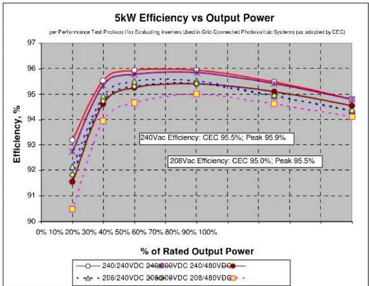
line
| % of Rated Output Power | 240Vac Efficiency: CEC 95.5%; Peak 95.9% | 208Vac Efficiency: CEC 95.0%; Peak 95.5% | | ----------------------- | -------------------------------------- | -------------------------------------- | | 20% | 91.5 | 90.5 | | 40% | 95.5 | 94.5 | | 60% | 96.0 | 95.0 | | 100% | 95.5 | 94.5 |Figure A-1 SPR-5000x Typical Efficiency
SPR-4000x
Input
| SPR-4000x | |
| Model number 864-1014 | |
| Input voltage, Maximum Power Point range Certified operating range: 240–480 Vdc. (Unit is operable as low as 235 Vdc and as high as 550 Vdc.) | |
| Absolute maximum array open circuit voltage 600 Vdc | |
| Maximum input current 18 Adc (240 V), 17 Adc (208V) | |
| Maximum array short circuit current 24 Adc | |
| Reverse polarity protection Short circuit diode | |
| Ground fault protection GF detection, I | _DIF > 1 A |
Output
| Nominal output voltage | 240 V 208 V | |
| Maximum output power 4000 W 3800 W | ||
| Operating range, utility voltage* | 211–264 Vac | 183–229 Vac |
| Nominal output frequency | 60 Hz | |
| Operating range, utility frequency* | 59.3–60.5 Hz | |
| Startup current | 0 Aac | |
| Maximum continuous output current | 16.7 A | 18.3 A |
| Maximum output fault current | 20 A | |
| Maximum output overcurrent protection | 25 A RMS | |
| Maximum utility backfeed current | 0 A | |
| Total Harmonic Distortion | <5% | |
| Power factor | >0.99% (at rated power), >0.95% (full power range) | |
| Utility monitoring— islanding protection | Vac, fac as per UL 1741 (2005) | |
| Output characteristics | Current source | |
| Output current waveform | Sine wave | |
* Factory settings can be adjusted with the approval of the utility. This unit is provided with adjustable trip limits and may be aggregated above 30 kW on a single Point of Common Coupling. See “Adjustable Voltage, Frequency and Reconnection Settings” on page A–10.
Efficiency
| 240 V 208 V | ||
| Maximum efficiency | 96% 95.7% | |
| CEC efficiency | 95% | |
| Night-time tare loss 1 | W |
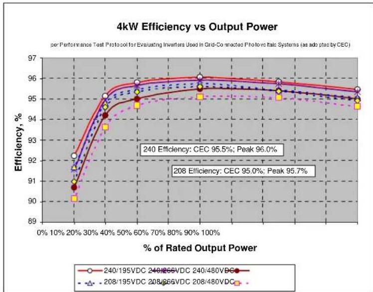
line
| % of Rated Output Power | 240/195VDC 240/266VDC 240/480VDC | 208/195VDC 208/266VDC 208/480VDC | 208 Efficiency CEC 95.5%; Peak 96.0% | 208 Efficiency CEC 95.0%; Peak 95.7% | | ----------------------- | ----------------------------------- | ----------------------------------- | ------------------------------------ | ------------------------------------ | | 0% | 92.0 | 91.5 | 91.0 | 90.5 | | 10% | 92.5 | 91.8 | 91.5 | 91.0 | | 20% | 93.0 | 92.0 | 91.8 | 91.5 | | 30% | 94.5 | 93.5 | 93.0 | 92.5 | | 40% | 95.0 | 94.5 | 94.0 | 93.5 | | 50% | 95.5 | 95.0 | 94.5 | 94.0 | | 60% | 95.8 | 95.3 | 95.0 | 94.5 | | 70% | 96.0 | 95.5 | 95.3 | 95.0 | | 80% | 96.1 | 95.6 | 95.4 | 95.2 | | 90% | 96.2 | 95.7 | 95.5 | 95.3 | | 100% | 96.3 | 95.8 | 95.6 | 95.4 |Figure A-2 SPR-4000x Typical Efficiency
SPR-3300x
Input
| SPR-3300x | |
| Model number 864-1013 | |
| Input voltage, Maximum Power Point range Certified operating range: 200–400 Vdc. (Unit is operable as high as 550 Vdc.) | |
| Absolute maximum array open circuit voltage 600 Vdc | |
| Maximum input current 17.5 Adc (240 V), 16.5 Adc (208 V) | |
| Maximum array short circuit current 24 Adc | |
| Reverse polarity protection Short circuit diode | |
| Ground fault protection GF detection, I | _DIF > 1 A |
Output
| Nominal output voltage | 240 V 208 V | |
| Maximum output power 3300 W 3100 W | ||
| Operating range, utility voltage^* | 211–264 Vac | 183–229 Vac |
| Nominal output frequency | 60 Hz | |
| Operating range, utility frequency^* | 59.3–60.5 Hz | |
| Startup current | 0 Aac | |
| Maximum continuous output current | 13.8 A | 14.9 A |
| Maximum output fault current | 20 A | |
| Maximum output overcurrent protection | 20 A RMS | |
| Maximum utility backfeed current | 0 A | |
| Total Harmonic Distortion | <5% | |
| Power factor | >0.99% (at rated power), >0.95% (full power range) | |
| Utility monitoring— islanding protection | Vac, fac as per UL 1741 (2005) | |
| Output characteristics | Current source | |
| Output current waveform | Sine wave | |
* Factory settings can be adjusted with the approval of the utility. This unit is provided with adjustable trip limits and may be aggregated above 30 kW on a single Point of Common Coupling. See “Adjustable Voltage, Frequency and Reconnection Settings” on page A–10.
Efficiency
| Output voltage | 240 V 208 V | |
| Maximum efficiency | 95.9% 95.6% | |
| CEC efficiency | 95% | |
| Night-time tare loss 1 | W |
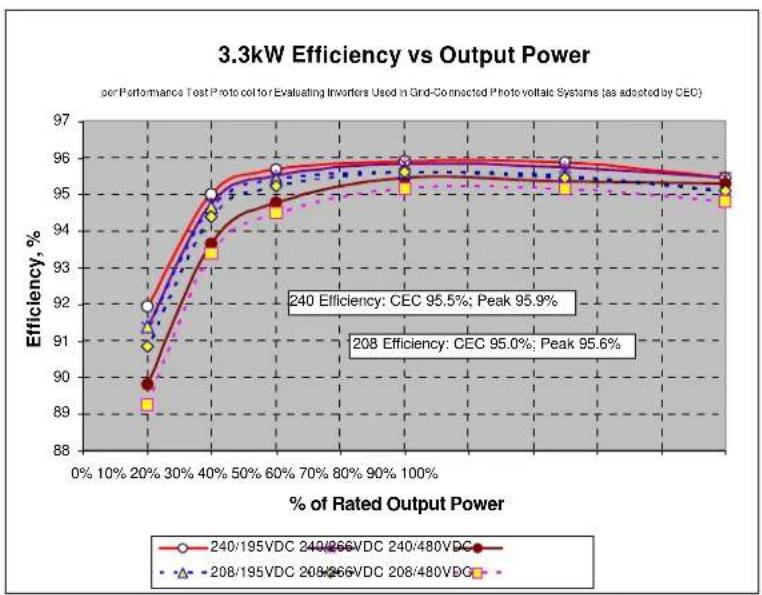
Figure A-3 SPR-3300x Typical Efficiency
SPR-2800x
Input
| SPR-2800x | |
| Model number 864-1012 | |
| Input voltage, Maximum Power Point range C | Certified operating range: 195–550 Vdc.(Unit is operable as low as 193 Vdc.) |
| Absolute maximum array open circuit voltage | 600 Vdc |
| Maximum input current 15.4 Adc (240 V), 14.9 | Adc (208 V) |
| Maximum array short circuit current 24 Adc | |
| Reverse polarity protection Short circuit diode | |
| Ground fault protection GF detection, I | _DIF > 1 A |
Output
| Nominal output voltage | 240 V 208 V | |
| Maximum output power 2800 W 2700 W | ||
| Operating range, utility voltage* | 211–264 Vac | 183–229 Vac |
| Nominal output frequency | 60 Hz | |
| Operating range, utility frequency* | 59.3–60.5 Hz | |
| Startup current | 0 Aac | |
| Maximum continuous output current | 11.7 A | 13.0 A |
| Maximum output fault current | 15 A | |
| Maximum output overcurrent protection | 20 A RMS | |
| Maximum utility backfeed current | 0 A | |
| Total Harmonic Distortion | <5% | |
| Power factor | >0.99% (at rated power), >0.95% (full power range) | |
| Utility monitoring— islanding protection | Vac, fac as per UL 1741 (2005) | |
| Output characteristics | Current source | |
| Output current waveform | Sine wave | |
* Factory settings can be adjusted with the approval of the utility. This unit is provided with adjustable trip limits and may be aggregated above 30 kW on a single Point of Common Coupling. See “Adjustable Voltage, Frequency and Reconnection Settings” on page A–10.
Efficiency
| 240 V | 208 V | |
| Maximum efficiency | 95% | 94.6% |
| CEC efficiency | 94% | 93.5% |
| Night-time tare loss 1 W | ||
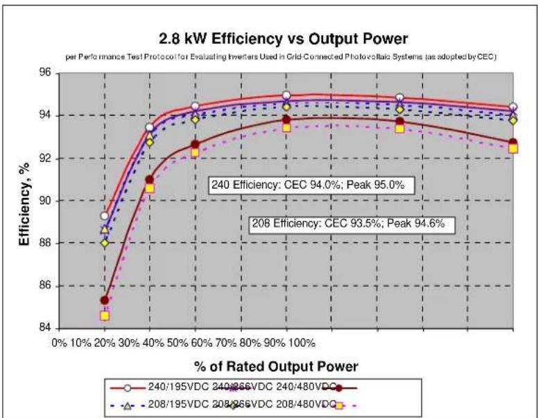
line
| % of Rated Output Power | 240 Efficiency: CEC 94.0%; Peak 95.0% | 208 Efficiency: CEC 93.5%; Peak 94.6% | | ----------------------- | -------------------------------------- | -------------------------------------- | | 0% | 89.5 | 88.0 | | 10% | 89.0 | 87.5 | | 20% | 89.5 | 88.5 | | 30% | 90.5 | 90.0 | | 40% | 91.5 | 91.0 | | 50% | 92.5 | 92.0 | | 60% | 93.5 | 93.0 | | 70% | 94.0 | 93.5 | | 80% | 94.5 | 94.0 | | 90% | 94.5 | 94.0 | | 100% | 94.5 | 94.0 |Figure A-4 SPR-2800x Typical Efficiency
Adjustable Voltage, Frequency and Reconnection Settings
Utility disconnect settings can be adjusted with the approval and assistance of SunPower and the local utility.
| Setting Default Range Tolerance | |||
| Phase-to-Neutral (rms) High Threshold Voltage | 130.50 130.50–132.00 | ±1.5 VPhase-to-Neutral (rms) Lo | |
| Phase-to-Neutral (rms) Reconnect Voltage 126.96 | 126.96–132.00 | ||
| Frequency High Threshold 60.40 60.40–60.60 | ±0.1 Hz | ||
| Frequency Low Threshold 59.40 57.00–59.80 | |||
| Voltage (rms) High Clearing Time (ms) | <1000 | 1000–2000 | +0, -0.1 s |
| Voltage (rms) Low Clearing Time (ms) | <2000 | 2000–5000 | |
| Frequency High Clearing Time (ms) | <160 | 160–200 | |
| Frequency Low Clearing Time (ms) | <160 | 160–300000 | |
| Reconnect Delay (ms) | 305000 | 60000–305000 n/a | |
Output Power Versus Ambient Temperature
After the inverter heat sink reaches a maximum temperature limit, the inverter reduces its energy output to ensure component ratings are not exceeded.
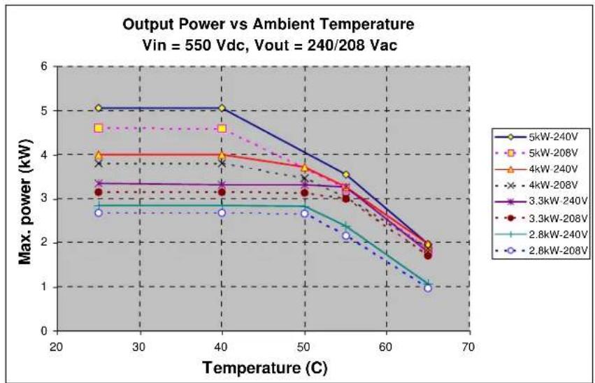
line
| Temperature (C) | 5kW-240V | 5kW-208V | 4kW-240V | 4kW-208V | 3.3kW-240V | 3.3kW-208V | 2.8kW-240V | 2.8kW-208V | | --------------- | -------- | -------- | -------- | -------- | ---------- | ---------- | ---------- | ---------- | | 25 | 5.0 | 4.6 | 4.0 | 3.9 | 3.3 | 3.1 | 2.7 | 2.6 | | 40 | 5.0 | 4.6 | 4.0 | 3.9 | 3.3 | 3.1 | 2.7 | 2.6 | | 50 | 4.0 | 3.7 | 3.7 | 3.5 | 3.1 | 3.1 | 2.7 | 2.6 | | 65 | 1.9 | 1.8 | 1.8 | 1.7 | 1.7 | 1.7 | 1.0 | 1.0 |Figure A-5 Output Power vs. Ambient Temperature
Environmental Specifications
Operating temperature range -25^ to +65^ C (-13^ to +149^ F)
Storage temperature range -40^ to +85^ C (-40^ to +185^ F)
Power derating See Figure A-5 on page A-10
Tolerable relative humidity limit | Operating: <95%, non-condensing
Storage: 100% condensing
User Display
Type alphanumeric liquid crystal display with backlight
Size 2 lines by 16 characters
Display Accuracy
Instantaneous Power +/- (30 W + 1% of reading)
Voltage +/- (1% of rating + 1% of reading)
Current +/- (1% of rating + 1% of reading)
System Lifetime energy +/− 5%
Mechanical Specifications
Outdoor enclosure NEMA|3R, Rainproof
| Inverter dimensions (H × W × D) | 28 1/2 × 16 × 5 3/4 inches (724 × 403 × 145 mm) |
| Shipping dimensions (H × W × D) | 34 × 20 1/2 × 10 1/3 inches (866 × 518 × 262 mm) |
| Inverter weight | 58 lb (26.3 kg) |
| Shipping weight | 76 lb (34.5 kg) |
| Input and output terminals | AC and DC terminals accept wire sizes of 2.5 to 16 mm^2 (#14 to #6 AWG) |
| Disconnect switch | Integrated switch, disconnects both AC and DC(meets NEC Article 690), rated @ 600 Vdc |
Regulatory Approvals
The inverter has complete on-board over-current, over-temperature and anti-islanding protection, and meets U.S., Canadian and international safety operating standards and code requirements:
- UL 1741 1st Edition 2005 Revision – Standard for Inverters, Converters, Controllers and Interconnection System Equipment for Use with Distributed Energy Resources (Includes IEEE 1547 and 1547.1)
• CSA C22.2 No. 107.1-01 General Use Power Supplies - IEEE C62.41.2 – IEEE Recommended Practice on the Characterization of surges in Low-Voltage AC Power Circuits (Location Category B). Part of UL 1741-2005. Refer to approval certificate for details.
Note: This inverter is compliant with IEEE 1547 for those requirements referenced in UL1741 (2005), section 46.1.1.:
A utility interactive inverter and interconnection system equipment (ISE) shall comply with the Standard for Interconnecting Distributed Resources With Electric Power Systems, IEEE 1547, and the Standard for Conformance Test Procedures for Equipment Interconnecting Distributed Resources with Electric Power Systems, IEEE 1547.1, excluding the requirements for Interconnection Installation Evaluation, Commissioning Tests, and Periodic Interconnection Tests.
Information About Your System
After unpacking your inverter, record the following information and fax this page to 408 877 1808, Attention: Warranty Registration. Be sure to keep your proof of purchase.
Model Number
(circle one) 864-1012 (SPR-2800x), 864-1013 (SPR-3300x), 864-1014 (SPR-4000x), 864-1015 (SPR-5000x)
Serial Number
Purchased From
Purchase Date
Contact Information
Name ____
Street 1
Street 2
City, State
Zip Code ____
If you need to contact Customer Service, please record the following details before calling. This information will help our representatives give you better service.
Inverter Details
Type of installation (e.g. Residential/Commercial) ____
Length of time inverter has been installed
AC wiring size and length
DC wiring size and length ____
Description of fault messages and/or indicators on front panel ____
Description of problem
PV Details
Solar Panel Mount:

Roof

Pole

Ground
Solar Panel Model:
Nominal Voltage Range: ____ Vdc
Peak Open Circuit Voltage: ____ Vdc
Nominal Current Rating: ____ Adc
Maximum Current Rating: ____ Adc
Solar Tracker?

Yes

No

Parallel
String #1:# of Panels:
String #2:# of Panels:
String #3:# of Panels:
String #4:# of Panels:

(No text)

Series

Parallel

(No text)

Series

Parallel

(No text)

Series

Parallel

m = 311

Series

Parallel
Index
A
abbreviations and acronyms iv
AC circuit breaker requirements 3–4
AC grounding requirements 3–1
AC output voltage ratings A-2, A-4, A-6, A-8
AC utility voltage 4–2
AC wiring instructions 3–10
acceptable wire sizes A–11
accessing AC and DC terminals 3–5
C
CAT5 and CAT5e conductor identification 3–14
checking AC utility voltage 4–2
checking PV array DC voltage 4–1
communication between multiple inverters 3–12
communications cabling 3–14
Customer Service
preparing to call A-13
D
DC wiring instructions 3–7
derating chart A–10
dimensions A-11
display accuracy A-11
E
electrical specifications A-2
enclosure type A-11
error messages and solutions 6–9
F
fault conditions and solutions 6–9
FCC information to the user viii
features and options 1–2
front panel display 1–2, 5–1
fault messages 5–8
normal operation messages 5–4
offline mode messages 5–6
reading messages 5–2
special messages 5–10
startup messages 5–2
fuse, location of ground fault protection 6–5
G
general maintenance 6–3
ground clearance required for installation 2–2, 2–7
ground fault protection fuse 3–3
replacing 6–4
grounding requirements 3–1
H
humidity limits A–11
|
installation
grounding requirements 3–1
location concerns 2–2
mounting 2–7
options 2–1
PV array requirements 2–3
inverter
about 1–1
features and options 1–2
removing from wiring box 6–6
serial number A-13
L
LEDs, See status LEDs
M
maintenance, general 6–3
maximum power point tracking, See MPPT
mechanical specifications A-11
messages, See front panel display
model number A-13
mounting the inverter
clearance requirements 2–7
MPPT
operational window 2–3
technology 1–2
multiple inverters
AC and DC wiring 3–11
communication between 3–12
configuration 2-1
messages in normal operation 5–5
messages in offline mode 5–7
0
operation
factors affecting performance 6–1
inverter startup 4–3
messages at startup 5–2
reassembling the unit 4–3
startup procedure 4–1
P
parallel configuration
communication between inverters 3–12
photovoltaic (PV) power 1–1
power derating A-11
proof of purchase A-13
purchase date A-13
PV arrays
angle of the sun 6–2
checking DC voltage 4–1
effect of shade on performance 6–2
factory ratings 6–1
requirements 2–3
temperature affecting performance 6–1
types of modules 2–3
R
RJ-11 ports 3–13
RJ-45 ports
communication between inverters 3–13
location in wiring box 3–6
RS-232 port 5–8
S
safety instructions vii
serial number A-13
specifications
electrical A-2
mechanical A-11
standard features and options 1–2
standard test condition 6–1
startup procedure
check PV array DC voltage 4–1
check utility AC voltage 4–2
monitor front panel display 5–1
overview 4–1
replace wiring box cover 4–3
start the inverter 4–3
status LEDs
description 5–11
do not illuminate 6–9
red LED is on 6–9
T
temperature
affecting PV array performance 6–1
recommended range for locating the inverter 2–2
terminal blocks in wiring box 3–6
terminators, network 3–13
thermal derating chart A-10
torque values for wires 3–7
troubleshooting the inverter 6–9
V
voltmeter
measuring PV array DC at startup 4–1
measuring utility AC at startup 4–2
W
weight A-11
wiring
acceptable wire sizes A–11
PV array to inverter 3–7
torquing 3–7
wire sizes 3–4
wiring box
description 1–3
removing the cover 3–5
removing the inverter from 6–6
RJ-45 ports 3–6
terminal block location 3–6
| SunPower CorporationTechnical Support: 1 877 SUN 0123Customer Service Fax: (408) 877 1808www.sunpowercorp.com975-0335-01-01 | Printed in China |