CPF390i - Uncategorized Standard Horizon - Free user manual and instructions
Find the device manual for free CPF390i Standard Horizon in PDF.


| Product Type | Fixed-mount VHF marine transceiver with DSC and AIS |
| Brand | Standard Horizon |
| Model | CPF390i |
| Dimensions (W x H x D) | 7.5 x 5.7 x 2.4 inches (190 x 145 x 61 mm) |
| Weight | 2.5 lbs (1.13 kg) |
| Power Supply | 13.8 V DC (nominal), negative ground |
| Frequency Range | 156 – 174 MHz (VHF marine band) |
| Output Power | 25 W (high) / 1 W (low) |
| Waterproof Rating | IPX7 (submersible to 1 m for 30 minutes) |
| Display | 2.7-inch monochrome LCD with backlight |
| Built-in GPS | Yes, 50-channel GPS receiver |
| AIS Receiver | Built-in AIS 70-channel dual receiver |
| DSC Class | Class D Digital Selective Calling |
| Key Functions | DSC distress call, AIS target display, weather alerts, intercom, hailer |
| Memory Channels | All US, International, and Canadian marine channels |
| Optional Accessories | External speaker, remote microphone, GPS antenna |
| Maintenance | Wipe with damp cloth; avoid solvents; check antenna connections |
| Safety | Complies with FCC and international marine radio regulations |
| Spare Parts | Microphone, mounting bracket, DC power cable, fuse |
| Warranty | 3 years (limited) from date of purchase |
Frequently Asked Questions - CPF390i Standard Horizon
User questions about CPF390i Standard Horizon
0 question about this device. Answer the ones you know or ask your own.
Ask a new question about this device
Download the instructions for your Uncategorized in PDF format for free! Find your manual CPF390i - Standard Horizon and take your electronic device back in hand. On this page are published all the documents necessary for the use of your device. CPF390i by Standard Horizon.
USER MANUAL CPF390i Standard Horizon
USA (including Alaska, Hawaii and Great Lakes) Canada, Mexico, Bahamas, Caribbean, Cuba, Puerto Rico, and Central America
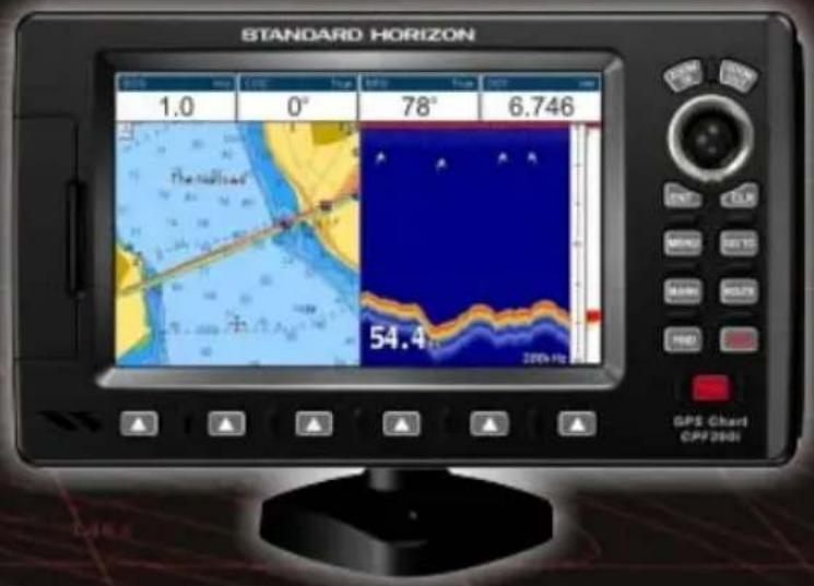
CPF390i
text_image
STANDARD HORIZON 1.0 0° 78° 6.746 The rs#t#ed 54.4 200h Fts GPS Chart CPF2001CP390i - GPS Chart Plotters
CPF390i - GPS Chart Plotters/Fish Finder
Owner's Manual
text_image
BUILT-IN CHARTS COASTAL NAVIGATION USA (including Alaska, Hawaii and Great Lakes) Canada, Mexico, Bahamas, Caribbean, Cuba, Puerto Rico, and Central America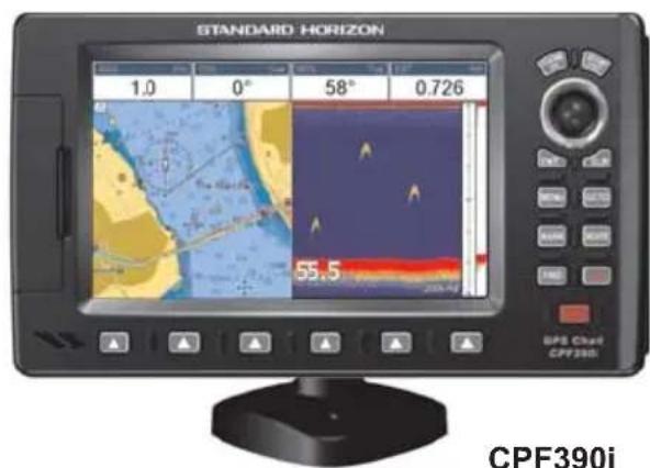
text_image
STANDARD HORIZON 1.0 0° 58° 0.726 55.5 GPS Cloud CPF390i CPF390i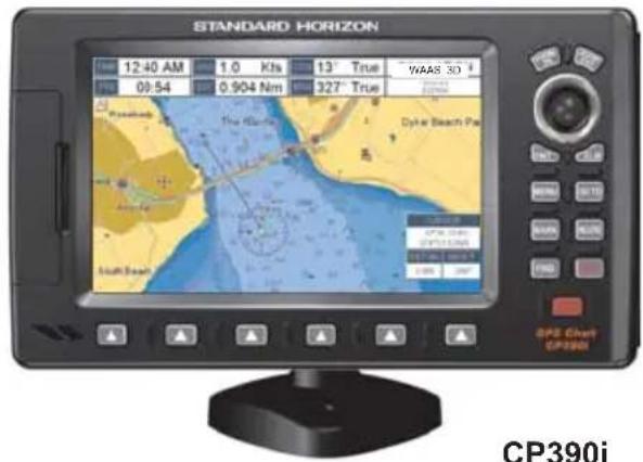
text_image
STANDARD HORIZON 12:40 AM 1.0 Kts 13° True WAAS 30 09:54 0.904 Nm 327° True Cyber Beach Pe South Beach GPS Chart CP390i CP390iCP390i
WARNING!!!
Electronic charts displayed by the GPS Chart Plotter are believed to be accurate and reliable, but are not intended to be a substitute for the official charts, which should remain your main reference for all matters related to the execution of safe navigation.
For this reason you should always keep the official published and approved nautical charts on board.

FCC Compliance Statement
This device complies with Part 15 of the FCC limits for Class A digital devices. This equipment generates, uses and can radiate radio frequency energy and, if not installed or used in accordance with the instructions may cause harmful interference with radio communications.
There is no guarantee that interference will not occur in a particular instance. If this equipment does cause harmful interference to other equipment, try to correct the problem by relocating the equipment.
Consult an authorized STANDARD HORIZON dealer or other qualified service technician if the problem cannot be corrected. Operation is subject to the following conditions: (1) This device cannot cause harmful interference, and (2) this device must accept any interference received, including interference that may cause undesired operation.
CAUTION
- The GPS Chart Plotter is designed for maritime use. To avoid water intrusion, ensure the C-MAP BY JEPPESEN C-CARD door is completely closed.
- Extensive exposure to heat may result in damage to the GPS Chart Plotter.
- The GPS Chart Plotter contains dangerous high-voltage circuits which only experienced technicians can handle.
- STANDARD HORIZON will not be liable for errors contained herein, or for incidental or consequential damages in connection with the performance or use of this material.
CLEANING PROCEDURE FOR THE GPS CHART PLOTTER SCREEN
Cleaning of the chart plotter screen is a very important operation and must be done carefully. Since the surface is covered by a antireflective coating, the procedure for cleaning all the surfaces can be performed using the following procedure: Use a clean, soft, lint-free cloth to clean the glass. We recommend using a micro-fiber cloth. Spray a small amount of ammonia-free cleaner (isopropyl alcohol) onto the cloth. Spraying on the cloth will prevent overspray. Fold the cloth or lens cloth into a triangular shape, moisten the tip and use the index finger behind a corner to move the cloth across the surface in overlapping side to side strokes. If the cloth is too wet, a noticeable wet film will be left in its path and you will need to repeat the process. If too dry, the cloth won't glide easily, and may damage the surface.
TABLE OF CONTENTS
1. INTRODUCTION ...... 13
1.0 GENERAL INFORMATION 13
1.1 PACKING LIST 14
1.1.0 Packing List.... 14
1.2 OPTIONAL DOME OR OPEN ARRAY RADAR ANTENNAS.... 14
1.3 OPTIONAL ACCESSORIES 15
2. INSTALLATION....17
2.0 MOUNTING THE GPS CHART PLOTTER 17
2.1 BRACKET MOUNTING 17
2.2 FLUSH MOUNTING....18
2.3 MOUNTING THE OPTIONAL EXTERNAL GPS ANTENNA 19
2.3.0 Flush mounting the antenna 19
2.4 CONNECTIONS 20
2.4.0 CP390i Connection Table 21
2.4.1 CP390i Connections 21
2.4.2 CPF390i Connection Table 23
2.4.3 CPF390i Connections 23
2.5 BATTERY CONNECTIONS 24
2.6 NMEA CONNECTIONS 24
2.7 GPS POSITION ON A VHF RADIO 25
2.8 CP390i: OPTIONAL BLACK BOX FISH FINDER 25
2.9 RADAR ANTENNA (USA ONLY) 25
2.10 PERSONAL COMPUTER CONNECTIONS 26
2.11 NMEA DATA PAGE 26
2.12 CPF300i VIDEO INPUT 27
2.12.0 Video Camera Input 27
2.12.1 VCR or DVD Input 27
2.13 DEMO MODE (For DEALER USE) 29
3. CONTROLS AND INDICATORS 31
3.0 CONTROLS AND CONNECTIONS 31
3.0.0 The Soft Keys 32
3.1 GETTING STARTED 32
3.1.0 Power On, Off and ShuttlePoint Knob operation 33
3.1.1 Cursor Vs. Home Mode 34
3.1.2 Cursor and Menu selection speed 34
3.1.3 Changing the Ship Icons 35
3.1.4 Changing the backlight and contrast 35
3.1.5 Selecting North Up or Course Up 36
3.2 AUTOMATIC TIME 36
3.3 SELECTING LORAN TD OR OTHER COORDINATE SYSTEM 38
3.4 CHANGING THE CHART COLOR 38
3.5 SELECTING LANGUAGE 39
3.6 SELECTING PAGES USING SOFT KEYS 40
3.7 CUSTOMIZING THE SOFT KEYS 40
3.8 SETTINGS IN GENERAL SETUP MENU 41
3.9 ABOUT PAGE 43
4. FIND SERVICES 45
4.0 USING FIND SERVICES & MORE FUNCTIONS 45
4.0.0 Port Services 45
4.0.1 Port 46
4.0.2 Tide Stations 46
4.0.3 Wrecks 47
4.0.4 Obstructions 48
4.0.5 Lakes Information 49
4.0.6 Lakes By Name 51
4.0.7 Points Of Interest 51
4.0.8 User Points 52
4.0.9 Coordinates 52
4.0.10 Information 53
5. MAX CARTOGRAPHY OVERVIEW 55
5.0 BUILT-IN CHARTS 55
5.0.0 Coverage areas and details 55
5.0.1 Updating Built-In Charts 55
5.1 INSERTING THE OPTIONAL MAX C-CARD 56
6. MAP FUNCTIONS 59
6.0 MAX FUNCTIONS MENU 59
6.0.0 Zoom Type 59
6.0.1 Icon Size 60
6.0.2 Place Name Size 60
6.0.3 Perspective View 61
6.0.4 Dynamic Nav-Aids 62
6.0.5 Safety Status Bar (DSI - Data Safety Indicator) 62
6.0.6 Satellite Imagery 63
6.0.7 Currents Prediction 64
6.0.8 Chart Language 65
6.0.9 Pictures or Diagrams 65
How to show the Pictures or Diagrams of a Object 66
6.0.10 Enhanced Port Info 67
7. CREATING MARKS 69
7.0 CREATING A NEW MARK USING THE CHART PAGE 69
7.1 EDITING A MARK 69
7.1.0 Deleting a Mark or Waypoint 70
7.1.1 Moving a Mark or Waypoint 70
7.2 MARKS/WAYPOINTS LIST 71
7.3 CREATING A NEW MARK WITH THE USER POINTS LIST 72
7.4 GOTO CURSOR, ROUTE AND MARK 73
8. MAN OVER BOARD (MOB) FUNCTION 75
8.0 PLACING A MOB POINT 75
8.1 DELETING A MOB POINT 75
9. ROUTES 77
9.0 CREATING A ROUTE USING WAYPOINTS 77
9.1 CHANGING THE NAME OF A ROUTE 78
9.2 CREATING AN OLYMPIC ROUTE 78
9.3 MAKING ADDITIONAL ROUTES 79
9.4 CREATING A ROUTE USING MARKS ON THE CHART PAGE 79
9.5 INSERTING A WAYPOINT INTO A ROUTE 80
9.6 GOTO A ROUTE 80
9.6.0 Using [GOTO] to select Route 80
9.6.1 Using the ShuttlePoint knob 81
9.7 DELETING A ROUTE 81
9.8 OTHER SETTINGS IN ROUTE MENU 82
9.8.0 Route Check 82
10. TRACKS 85
10.0 TRACKING 85
10.0.0 Saving and starting a new Track 86
10.0.1 Deleting a Track 86
10.0.2 Other settings....86
10.1 TRIP LOG 87
10.1.0 Using the Trip Log 87
10.1.1 Setup / Reset 87
11. USER C-CARD 89
11.0 USER C-CARD MENU 89
11.0.0 Formatting the optional User C-CARD 89
11.0.1 Transferring files to the optional User C-CARD 89
11.0.2 Loading a file from the optional User C-CARD 90
11.0.3 Deleting a file from the optional User C-CARD 90
11.0.4 Refreshing the optional User C-CARD 90
12. PAGES 91
12.0 CHART PAGE 92
12.0.0 Focus Soft Key on Dual Chart Page 93
12.0.1 Single Chart Page 94
12.0.2 Window Selections 94
12.0.3 Customizing the Data Windows 95
12.0.4 Additional Functions on Chart Page 96
12.0.5 Turning Off Information on Icon Points 96
12.0.6 Display Mode 97
12.0.7 Marine Settings 98
12.0.8 Depth Settings 98
12.0.9 Land Settings 99
12.0.10 Chart Settings 99
12.0.11 Underwater Objects Settings 100
12.1 CUSTOMIZING CHART SETTINGS 101
12.2 NAVIGATION PAGE 101
12.3 HIGHWAY PAGE 102
12.4 CELESTIAL PAGE 102
12.5 GPS STATUS PAGE 103
12.5.0 WAAS/EGNOS Setting 104
12.5.1 Setup Menu 104
12.6 NMEA DISPLAY PAGE 105
12.7 NMEA DATA PAGE 105
12.8 NMEA TREND PAGES 106
12.9 VHF DIGITAL SELECTIVE CALLING 107
12.9.0 Interfacing 108
12.9.1 Distress Call 108
12.9.2 Position Request 108
13. ADVANCED SETTINGS .... 111
13.0 INPUT/OUTPUT (NMEA, AIS, RADAR) 111
13.0.0 Input 111
13.0.1 Ouput 111
13.1 NAVIGATE 112
13.1.0 Loran TD 113
13.2 COMPASS 113
13.3 ALARMS 114
13.4 SIMULATION 114
13.4.0 Navigating a Route in Simulation mode .... 115
13.5 DSC POLLING 115
14. AIS 117
14.0 SYSTEM DEFINITIONS 117
14.1 MENU 118
14.2 AIS SETUP 118
14.3 QUICK INFO ON AIS TARGET 118
14.4 LIST....119
14.5 AIS TARGET COLORS 119
15. C-WEATHER SERVICE.... 121
15.0 C-WEATHER SERVICE MENU 121
15.0.0 Download 121
15.0.1 Copy From User C-CARD 122
15.0.2 Weather Forecast 122
15.0.3 Real Time View 122
15.0.4 Type of Data 122
16. MOBILARM 123
16.0 MOBILARM-GPS CHART PLOTTER CONNECTION 123
16.1 SOFTWARE SETUP 124
16.2 MOBILARM STATUS 124
16.3 MOBILARM PTX 125
16.3.0 MOBILARM MOB alert is received 125
16.4 PLACING CURSOR ON THE PTX ICON 126
16.4.0 Delete PTX 126
16.4.1 Goto PTX 126
16.4.2 The MOBILARM Alarm Status List 127
17. FISH FINDER 129
17.0 ENABLE/DISABLE 129
17.1 UNDERSTANDING THE FISH FINDER PAGE 130
17.1.1 Understanding the Fish Finder display 131
17.2 DISPLAYING THE FISH FINDER PAGE 132
17.2.0 Auto Full Page 133
17.2.1 200 kHz Full, 50 kHz Full and 50&200kHz Display Pages 133
17.2.2 200 kHz and 50 kHz Zoom Pages 133
17.2.3 200 kHz and 50 kHz Fish/Chart Pages 134
17.2.3.0 Focus Soft Key on FISH/CHART Page 134
17.2.4 Radar Pages 134
17.2.4.0 Fish/Radar/Chart Page 134
17.2.4.1 Radar Combo Page 135
17.2.4.2 Focus Soft Key 135
17.12 DISPLAY SETUP 142
17.12.0 Color Settings 142
17.12.1 Scrolling Speed 142
17.12.2 White Line 142
17.12.3 Fish Symbols 143
17.12.4 A-Scope 143
17.13 TRANSDUCER SETUP 143
17.13.0 Keel Offset 143
17.13.1 Calibrate Water Speed 143
17.13.2 Calibrate Water Temp 143
17.13.3 Set Defaults 143
17.14 ALARMS 144
17.14.0 Shallow Water 144
17.14.1 Deep Water 144
17.14.2 Fish 144
17.14.3 Temperature Upper 144
17.14.4 Temperature Lower 144
17.14.5 Temperature Rate 144
17.15 SAVE SETTINGS TO USER C-CARD 145
17.16 LOAD SETTINGS FROM USER C-CARD 145
17.17 RESTORE CURRENT PRESET DEFAULTS 145
-
TROUBLESHOOTING....147
-
TECHNICAL TESTS 149
19.0 SYSTEM TEST 149
19.0.0 RAM Menu (reset) 149
19.0.1 DIM Menu 149
19.0.2 Cartridges 150
19.0.3 Serial Ports 150
- SPECIFICATIONS 151
20.0 CP390i/CPF390i SPECIFICATIONS 151
20.1 CPF390i FISH FINDER SPECIFICATIONS.... 151
20.2 CP390i/CPF390i DIMENSIONS 152
20.3 OPTIONAL FF525 FISH FINDER SPECIFICATIONS (use with CP390i) ..... 152
20.4 OPTIONAL WAAS GPS RECEIVER SPECIFICATIONS 153
- APPENDIX: TERMS 155
ANALYTICAL INDEX 159
1. INTRODUCTION
Congratulations on your purchase of the Standard Horizon GPS Chart Plotter. Whether this is your first Navigation device, or if you have other STANDARD HORIZON equipment, STANDARD HORIZON organization is committed to ensuring your enjoyment of this Navigation device. STANDARD HORIZON technical support personnel stand behind every product we sell. Our Product Support team invites you to contact us should you require technical advice or assistance, at 800/767-2450 or marinetech@vxstdusa.com.
1.0 GENERAL INFORMATION
The CP390i (with internal GPS antenna) and CPF390i (with internal GPS antenna and Fish Finder) are precision-crafted high-performance receivers for the Global Positioning System (WAAS GPS) constellation of satellites that provide precise location data with a host of navigation features and are ideal for nautical use and sealed against water ingress. The CP390i and CPF390i are housed in rugged, impact-resistant cases with outstanding ergonomic design for effortless operation. The CP390i and CPF390i are IP56 water resistant.
The advanced features of the GPS Chart Plotter/Fish Finder include:
- Built-In Charts for coastal navigation of USA including Alaska, Hawaii and Great Lakes, Canada, Bahamas, Caribbean, Cuba, Puerto Rico, and Central America
- 7" 800x480 high resolution sunlight-readable display
- Internal 50 channel WAAS GPS antenna
- Optional connection for external 50 channels WAAS GPS antenna with 30 feet of cable
- Video Input with "picture-in-picture" display
- Dual chart window with independent zoom levels
- CP390i: Fish Finder capable when the optional FF525 50/200kHz (Black Box Fish Finder) are installed. Radar / AIS capable
- CPF390i: Built-in Fish Finder. Radar and AIS capable
- Selectable sailboat and power boat ship icons with red and green for port and starboard
- Compass Rose indication around ship icon
- Satellite images on base chart
- Route Checking
- Color Targets AIS
• Dedicated AIS List page - Navigate to an Olympic Route
- SOG Speed Filter function to resolve erratic speed redings in rough seas
• Dedicated MARK, ROUTE and FIND keys - Supplied swivel mounting bracket and flush mounting hardware
- CP390i: NMEA 0183 connections: 4 Inputs, 5 Outputs
· CPF390i: NMEA 0183 connections: 3 Inputs, 3 Outputs
· 3000 Marks / 50 Routes / 10000 Track Points
· 3 year Waterproof Warranty
CPF390i: Fish Finder features: - 16/256 colors display user selectable
• Built-in 600W Dual Frequency Fish Finder
· 50 and 200kHz Frequency selection
- 2x and 4x Zoom
- Bottom Lock and White Line selections
- Sensitivity Time Control (STC) and Surface Noise Filter
- Speed through water (if available on transducer)
- Alarms - Shallow, Depth, Temp Upper and Lower
- Temperature (if available on transducer)
1.1 PACKING LIST
When the package containing the Navigation device is first opened, please check for the following contents. If any parts are missing contact the dealer this Navigation device was purchased from.
Accessories and replacement parts may be ordered from STANDARD HORIZON's Parts Department at 741/827-7600 extension 6800 or e-mail at yaesuparts@vxstdusa.com.
1.1.0 Packing List
PART CODE ITEM
| S8002224A External bracket |
| S8002225 Mounting knob with two washers |
| S8002235 Dust cover |
| T9101553 Power & Accessory cable |
| S8002223 Flush mounting screws |
| EM022U500 Flush mount template |
| XUCMP0052 2 Amp fuse and holder |
| EM051U100 Owner's Manual |
| EM023U511 Quick Reference Guide |
1.2 OPTIONAL DOME OR OPEN ARRAY RADAR ANTENNAS
The Radar antennas are supplied by SI-TEX (631) 996-2690 in the USA and Canada. Refer to the table below for compatible models:
MODEL NUMBER DESCRIPTION
| MDS-1 2kW 24 Mile 12.4" diameter Radome antenna |
| MDS-8 2kW 24 Mile 20" diameter Radome antenna |
| MDS-9 4kW 36 Mile 23.5" diameter Radome antenna |
| MDS-10-4 4kW 48 Mile 4FT Open Array |
| MDS-10-5 4kW 48 Mile 5FT Open Array |
NOTE
For additional information, refer to the Radar Installation and Radar Operation Manuals located at www.standardhorizon.com.
| ACCESSORIES | PARTS NAME | ITEM |
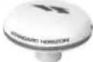 | Q7000619A | 50 Channel GPS Antenna Unit GSU-5H Series UXOGSU51SD |
 | ACVC10 Video Adapter cable (AAF69X001) | |
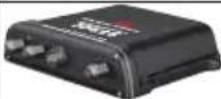 | FF525 50/200kHz Black Box Fish Finder (CP390i ONLY) | |
 | DST520 600W 2" Nylon Thru-hull depth temp Transducer | |
 | DST521 600W Transom mount depth, speed temp Transducer | |
 | DST523 600W 2" Bronze Thru-hull depth temp Transducer | |
 | DST525 600W In-hull Transducer | |
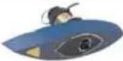 | DST526 | 600W 2" Bronze Thru-hull depth, speed temp Transducer |
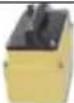 | DST527 1000W In-hull depth Transducer (FF525 ONLY) | |
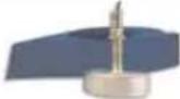 | DST528A 1000W Bronze long stem depth temp Transd. ( ) | |
2. INSTALLATION
NOTE
Throughout this Owner's Manual same conventions are used. See the legend below:
[MENU]If you see brackets around a bold and capital letter word this refers to a key press.
[CHART] If you see brackets around a bold and small capital letter word this refers to a Soft Key press.
GENERAL SETUP When a word(s) is bold capital letters and underlined, this refers to a menu selection item.
A GPS receiver and antenna are located inside the CP390i and CPF390i and are designed to be bracket mounted. Both models may be flush mounted, however an optional external GPS antenna may be needed to receive GPS satellite signals.
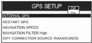
To use the external GPS antenna, the internal GPS antenna must be turned off, using the procedure below:
- Turn the CP390i and CPF390i On and select the GPS STATUS page.
- Press [ENT] to show the GPS SETUP menu.
- Move the ShuttlePoint knob to highlight INTERNAL GPS and press [ENT].
- Move the ShuttlePoint knob to highlight OFF and press [ENT].
text_image
GPS SETUP Off On INTERNAL GPS RESTART GPS NAVIGATION SPEED NAVIGATION FILTER High DIFF CORRECTION SOURCE WAAS/EGNOSFigure 2 - GPS Setup menu
- Press [CLR] to exit the GPS SETUP menu.
- Confirm the GPS Status page is showing satellite signal strength bars and receive a fix.
2.0 MOUNTING THE GPS CHART PLOTTER
The CP390i and CPF390i are supplied with a swivel mounting bracket which allows them to be dash mounted. When flush mounting, the optional GPS antenna may be needed to receive GPS satellite signals. Refer to the images below for Bracket and Flush mounting.
NOTE
The CP390i and CPF390i are designed to be bracket and flush mounted. However when bracket mounting the CP390i and CPF390i in an area where satellite reception is not possible with the internal antenna or when flush mounted, the optional GPS antenna must be installed.
2.1 BRACKET MOUNTING
Before installing ensure the area the bracket is mounted to is strong enough to support the weight of the GPS Chart Plotter especially while under way. After the location is found,
attach the mounting base to the area using the supplied hardware.
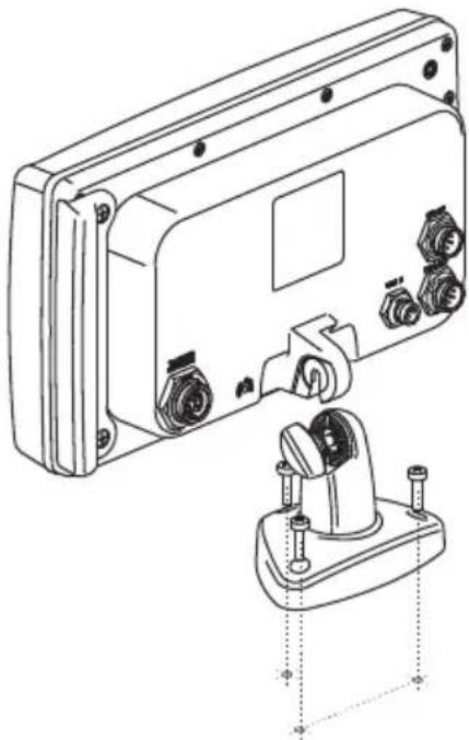
natural_image
Technical line drawing of a mechanical device with mounting holes and a separate view showing internal components (no text or symbols)Figure 2.1 - Example of Bracket installation
2.2 FLUSH MOUNTING
The CP390i and CPF390i are supplied with a flush mount template for the cutout hole and screw holes required to install the GPS Chart Plotter.
NOTE
Before drilling holes make sure there is enough room to mount the GPS Chart Plotter and there are no obstructions.
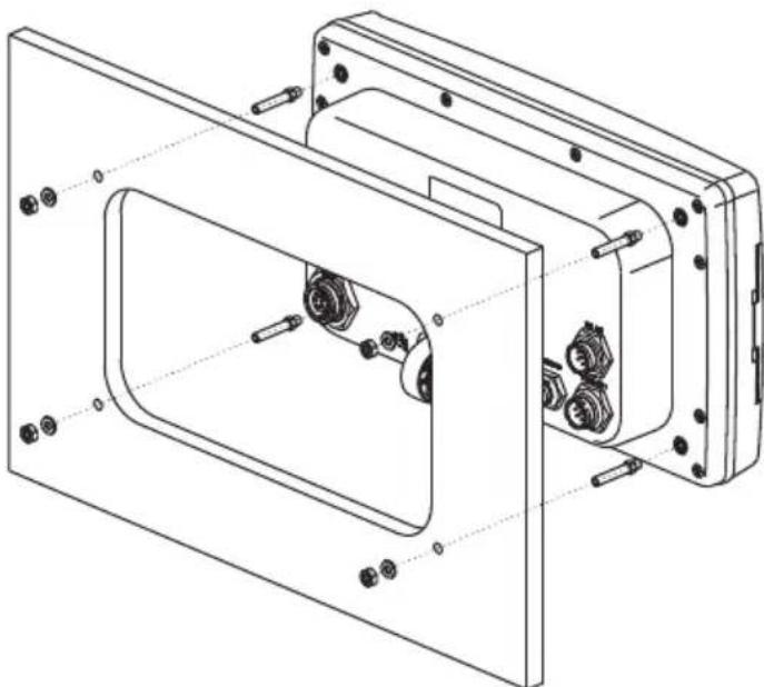
natural_image
Technical line drawing of a mechanical assembly with bolted components and housing (no text or symbols)Figure 2.2 - Example of Flush installation
- After a location is found, peel the template label from the backing and apply the label to the mounting area.
- Drill a hole in one area of the cutout area that will allow the blade of a jig saw to be inserted. Insert and cut out the area on the panel using the jig saw.
- Next drill the four holes required to insert the GPS Chart Plotter with the mounting studs.
- Install the mounting studs on the GPS Chart Plotter and insert into the mounting hole.
- Attach the GPS Chart Plotter to the mounting location by attaching the supplied hardware to the mounting studs.
2.3 MOUNTING THE OPTIONAL EXTERNAL GPS ANTENNA
An external WAAS GPS antenna is available when the CP390i and CPF390i is flush mounted or mounted in an area where satellite reception is not possible with the internal antenna. This antenna is designed to be mounted on a base, installed on an extension or flush mounted.
Choose a location for the antenna that has a clear view of the sky and is not located within 3Feet of a Radar or other transmitting antennas. Ensure there are no major obstructions or fixtures in the immediate proximity to the antenna. The antenna relies on direct "line of sight" satellite reception. If you are unsure of the chosen location, temporarily mount the antenna in the desired location to verify correct operation. If mounted close to Radar, after the GPS Chart Plotter has a fix, turn on the Radar to ensure the GPS Chart Plotter holds the fix (use the GPS Status Page).
The thread used on the antenna is an industry standard (1inch 14TPI) used on a wide range of mounting brackets.
NOTE
The antenna cable can be cut and spliced to ease installation. Care must be taken when reconnecting the antenna cable to protect from water and corrosion.
2.3.0 Flush mounting the antenna
NOTE
Before drilling holes, it is recommended the antenna be positioned where the location is planned, cable connected to the GPS Chart Plotter and power turned on to ensure a GPS Fix is received.
- Remove the threaded base from the antenna dome.
- To ease installation a flush mounting template for the antenna has been included.
- Apply the mounting template sticker to the area that was verified for GPS reception.
- Then, drill out the 0.78" (20mm) and 0.13" (3.2mm) holes, and remove the template.
- Insert the cable into the 0.78" (20mm) hole and route to the GPS Chart Plotter.
- Apply a small amount or RTV to the underside of the antenna.
- Place the antenna and then screw it into place using the screws.
NOTE
In some cases the screw may not be long enough. If this happens simply apply more RTV to the underside of the antenna to glue it into place.
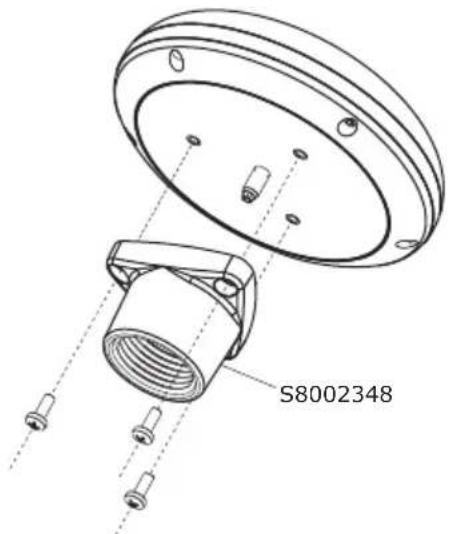
text_image
S8002348Figure 2.3.0 - Installing the External GPS antenna (I)
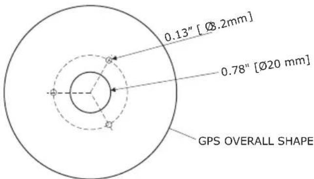
text_image
0.13" [Ø2mm] 0.78" [Ø20 mm] GPS OVERALL SHAPEFigure 2.3.0a - Installing the External GPS antenna (II)
Smart GPS Cable
| Pin Wire Color Description | |
| 1 Red Battery Positive | |
| 2 Green Smart GPS NMEA Input | |
| 3 Brown Smart GPS NMEA Output | |
| 4 | NC |
| 5 | NC |
| 6 Black/Yellow Battery Ground | |
2.4 CONNECTIONS
The CP390i and CPF390i have connectors that allow them to be connected to a power supply, optional WAAS GPS antenna, optional FF525 50/200kHz BLACK BOX FISH FINDER (only for CP390i) and NMEA Devices* such as Optional Video Camera, VHFs, AIS Receiver, Digital Instruments and autopilots.
NOTE*
RS232 not opto-isolated electrical interface
NOTE
The GPS Chart Plotter can send many sentences to external NMEA devices*. The NMEA Output wires are yellow and white. If you have connected devices as shown in the table on the next page and need to feed NMEA to other devices (Autopilot, RADAR...) you can parallel wires from the yellow, brown or white wires to other devices.
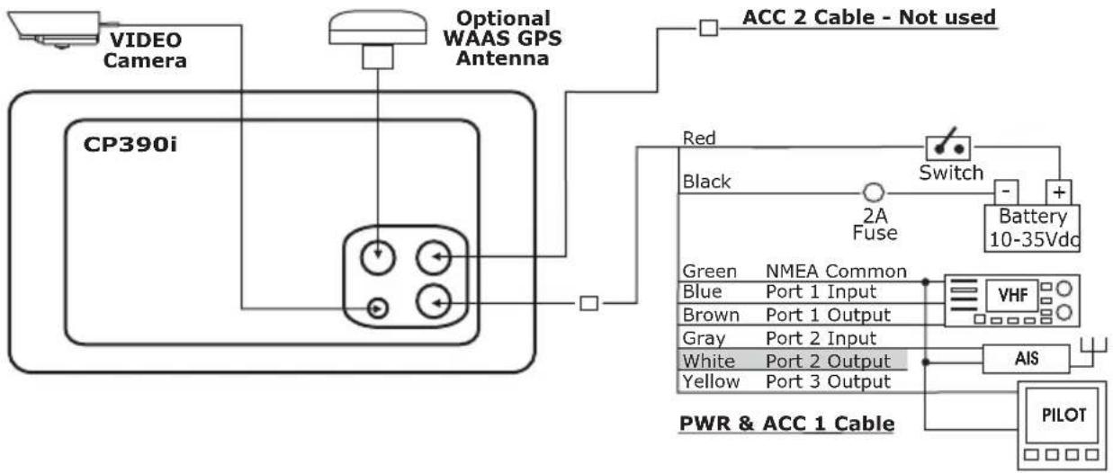
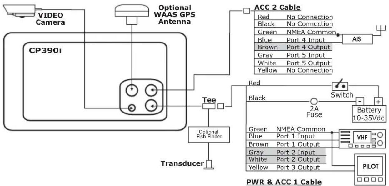
2.4.0 CP390i Connection Table
12VDC Power Cable
Pin Wire Color Description Connection Example Additional Comments
| 1 Black Battery Ground Connect to Battery Ground | ||||
| 2 Red Battery Positive Connect to Battery Positive | ||||
| 3 Green NMEA Common Common (ground) for NMEA devices* | ||||
| 4 Blue Port 1 Input Connect to Output of NMEA devices* Default is NMEA0183 | ||||
| 5 | Brown | Port 1 Output | Connect to Input of NMEA devices* | Default is NMEA0183 with GGA, GLL, RMC, XTE, DBT, DPT, MTW, VHW sentences |
| 6 | Grey | Port2 Input | Connect to FF525 | Default is Fish Finder |
| 7 | White | Port2 Output | Connect to FF525 | Default is Fish Finder |
| 8 | Yellow | Port 3 Output | Connect to Input of NMEA devices* | Default is NMEA0183 with APA, APB, BOD, GGA, GLL, RMC and BOD sentences |
NMEA ACC 2 Cable
Pin Wire Color Description Connection Example Additional Comments
| 1 Black NC | ||||
| 2 Red NC | ||||
| 3 Green NMEA Common Common (ground) for NMEA devices* | ||||
| 4 Blue Port 4 Input Connect to Output of NMEA devices* Default is NMEA0183* | ||||
| 5 Brown | Port 4 Output | Connect to Input of NMEA devices* | Default is NMEA0183 with GLL, RMB, RMC and XTE sentences | |
| 6 Grey | Port 5 Input | Connect to Output of NMEA devices* | Default is NMEA0183 | |
| 7 White | Port 5 Output | Connect to Input of NMEA devices* | Default is NMEA0183 with GLL, RMB, RMC and XTE sentences | |
| 8 Yellow | NC | |||
\*NOTE
RS232 not opto-isolated electrical interface.
2.4.1 CP390i Connections
2.4.1.0 DC Power Connection
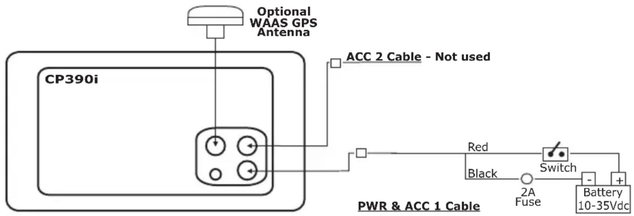
text_image
Optional WAAS GPS Antenna CP390i ACC 2 Cable - Not used Red Black Switch 2A Fuse Battery 10-35Vdc PWR & ACC 1 Cable2.4.1.1 Connection a VideoCamera, FF525, AIS receiver, VHF and Autopilot
flowchart
graph TD
    A["VIDEO Camera"] --> B["CP390i"]
    C["Optional WAAS GPS Antenna"] --> B
    B --> D["Red"]
    D --> E["Switch"]
    E --> F["Battery 10-35Vdc"]
    F --> G["AIS"]
    G --> H["PW R & ACC 1 Cable"]
    H --> I["PILOT"]
    J["Green NMEA Common"] --> K["VHF"]
    L["Blue Port 1 Input"] --> K
    M["Brown Port 1 Output"] --> K
    N["Gray Port 2 Input"] --> K
    O["White Port 2 Output"] --> K
    P["Yellow Port 3 Output"] --> K
    Q["Other Components"] --> R["Red"]
    S["ACC 2 Cable - Not used"] --> T["Red"]
flowchart
graph TD
    A["VIDEO Camera"] --> B["CP390i"]
    B --> C["Optional WAAS GPS Antenna"]
    C --> D["Tee"]
    D --> E["Transducer"]
    D --> F["Optional Fish Finder"]
    F --> G["PWR & ACC 1 Cable"]
    G --> H["PILOT"]
    H --> I["VHF"]
    I --> J["Battery 10-35Vdc"]
    J --> K["Switch"]
    K --> L["Red"]
    K --> M["Black"]
    K --> N["Green"]
    K --> O["Brown"]
    K --> P["Gray"]
    K --> Q["White"]
    K --> R["Yellow"]
    K --> S["No Connection"]
    T["AIS"] --> U["AISA"]
    V["ACC 2 Cable"] --> W["Red: No Connection"]
    V --> X["Black: No Connection"]
    V --> Y["Green: NMEA Common"]
    V --> Z["Blue: Port 4 Input"]
    V --> AA["Brown: Port 4 Output"]
    V --> AB["Gray: Port 5 Input"]
    V --> AC["White: Port 5 Output"]
    V --> AD["Yellow: No Connection"]
NOTE
Port2 Input and Output is used by the optional FF525. In the diagram above you will notice Port2 Input and Output wires are shown in gray and not used.
Port4, and 5 Outputs are can be connected to NMEA devices*capable of listening to NMEA0183 sentences.
Port4, and 5 Inputs can be connected to NMEA devices* capable of outputting to NMEA0183 sentences.
The Input and Output baud rate for each Port is set using the Advanced Setup>In/Out Connections menu. For example if Port1 is set for AIS 38400, the Input Port operates at 38400 baud and the Output Port is disabled.
NOTE\*
RS232 not opto-isolated electrical interface.
2.4.1.2 AIS Setup
The CP390i has to be set up to be able to receive NMEA information from the AIS receiver.
The GPS Chart Plotter reads the AIS NMEA message VMD, type 1, 2, 3 and 5 for AIS Class A and type 18, 19, 24 for AIS Class B. Select the used port and transmission speed by following the procedure:
The CP390i has to be setup to be able to receive NMEA information from the AIS receiver.
- Press [MENU], move the ShuttlePoint knob to highlight SETUP MENU and press [ENT].
- Move the ShuttlePoint knob to highlight ADVANCED SETUP and press [ENT] or move the ShuttlePoint knob to the right.
- Move the ShuttlePoint knob to highlight IN/OUT CONNECTIONS and press [ENT] or move the ShuttlePoint knob to the right.
- Move the ShuttlePoint knob to highlight PORT4 INPUT (or other Port the AIS is connected to) and press [ENT] or move the ShuttlePoint knob to the right.
- Move the ShuttlePoint knob up/down to select AIS 38400 and press [ENT] or move the ShuttlePoint knob to the right.
2.4.2 CPF390i Connection Table
12VDC Power
| Pin Wire Color Description Connection Example Additional Comments | ||||
| 1 Black Battery Ground & Common for and signal ground NMEA devices* | Connect to Battery Ground and | |||
| 2 Red Battery Positive Connect to Battery Positive | ||||
| 3 Green Port3 Input Connect to Output of NMEA devices* Default is NMEA0183 | ||||
| 4 Blue Port1 Input Connect to Output of NMEA devices* Default is NMEA0183 | ||||
| 5 | Brown | Port1 Output | Connect to Input of NMEA devices* | Default is NMEA0183 with GGA, GLL, RMC, XTE, DBT, DPT, MTW, VHW sentences |
| 6 | Gray | Port2 Input | Connect to Output of NMEA devices* | Default is NMEA0183 |
| 7 | White | Port2 Output | Connect to Input of NMEA devices* | Default is NMEA0183 with GGA, GLL, RMC and XTE sentences |
| 8 | Yellow | Port3 Output | Connect to Input of NMEA devices* | Default is NMEA0183 with APA, APB, BOD, GGA, GLL, RMC and BOD sentences |
\*NOTE
RS232 not opto-isolated electrical interface.
2.4.3 CPF390i Connections
2.4.3.0 DC Power Connection
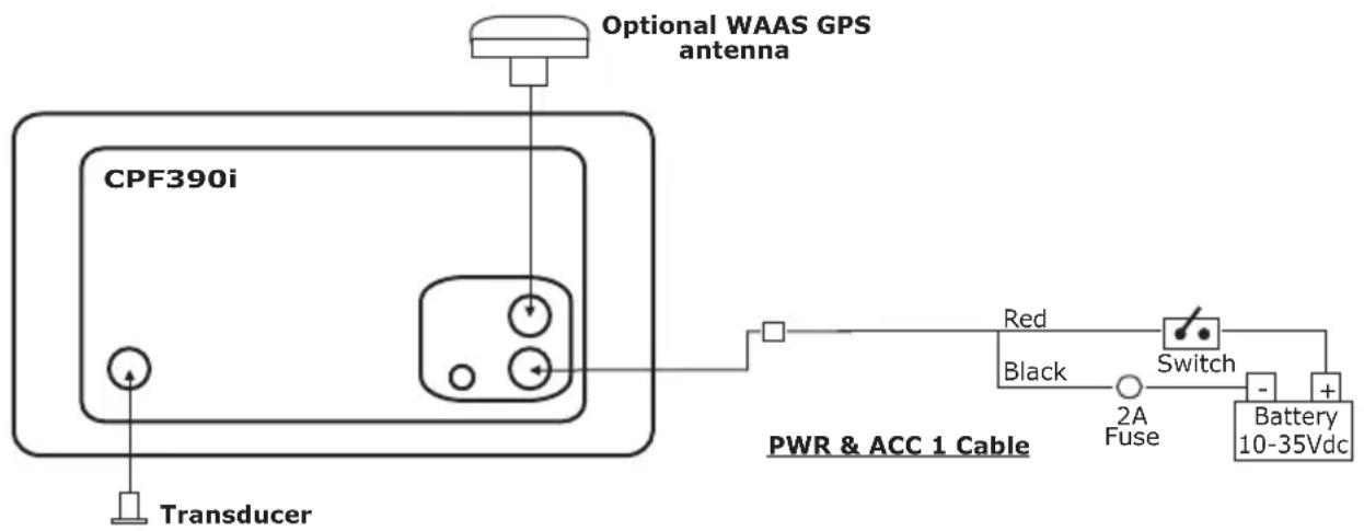
text_image
Optional WAAS GPS antenna CPF390i Transducer Red Black Switch 2A Fuse Battery 10-35Vdc PWR & ACC 1 Cable2.4.3.1 Connection a VideoCamera, AIS Receiver, VHF and Autopilot
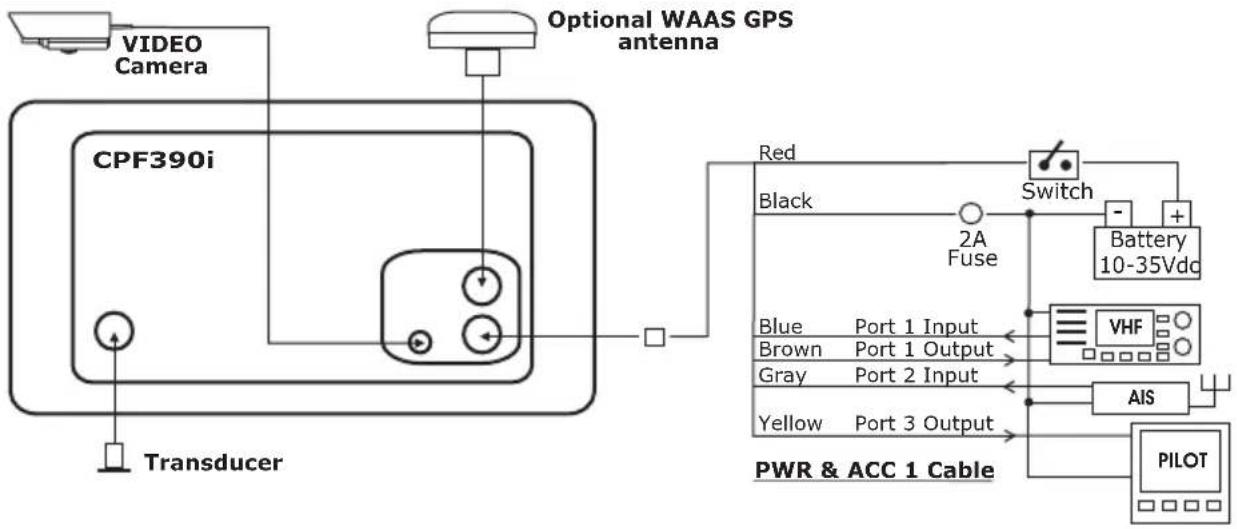
flowchart
graph TD
    A["VIDEO Camera"] --> B["Optional WAAS GPS antenna"]
    B --> C["Transducer"]
    C --> D["CPF390i"]
    D --> E["Red"]
    D --> F["Black"]
    D --> G["Switch"]
    G --> H["Battery 10-35Vdc"]
    G --> I["VHF"]
    G --> J["AIS"]
    G --> K["PILOT"]
    D --> L["Blue Port 1 Input"]
    D --> M["Brown Port 1 Output"]
    D --> N["Gray Port 2 Input"]
    D --> O["Yellow Port 3 Output"]
NOTE
The Input and Output baud rate for each port is set using the Advanced Setup>In/Out Connections menu. For example if Port1 is set for AIS 38400, the Input and Output both operate at 38400 baud.
2.4.3.2 AIS Setup
The CPF390i has to be set up to be able to receive NMEA information from the AIS receiver. The GPS Chart Plotter reads the AIS NMEA message VMD, type 1, 2, 3 and 5. Select the used port and transmission speed by following the procedure:
- Press [MENU], move the ShuttlePoint knob to highlight SETUP MENU and press [ENT].
- Move the ShuttlePoint knob to highlight ADVANCED SETUP and press [ENT] or move the ShuttlePoint knob to the right.
- Move the ShuttlePoint knob to highlight IN/OUT CONNECTIONS and press [ENT] or move the ShuttlePoint knob to the right.
- Move the ShuttlePoint knob to highlight PORT2 INPUT and press [ENT] or move the ShuttlePoint knob to the right.
- Move the ShuttlePoint knob up/down to select AIS 38400 and press [ENT] or move the ShuttlePoint knob to the right.
2.5 BATTERY CONNECTIONS
-
The GPS Chart Plotters are supplied with a fuse and holder. This fuse should be installed into the Black wire to protect the NMEA Output/Input circuits from possible damaged.
-
Connect the Red and Black wires from the GPS Chart Plotter to a 12VDC source as directly as possible.
2.6 NMEA CONNECTIONS
The GPS Chart Plotter can be connected to external devices with NMEA and display information, examples:
· DSC VHF Radio
- Depth Sounder, Speed Log, Wind Instrument, Autopilot etc.
- Radar (USA ONLY)
- Personal Computer
- AIS Receiver
- MOBILARM System
2.7 GPS POSITION ON A VHF RADIO
STANDARD HORIZON has pioneered Digital Selective Calling (DSC) on VHF radios. Advancements in DSC have made it possible to show the coordinates of a vessel that has transmitted a DSC Distress Call or even Polled the location of another vessel and show the position of that vessel on the display of STANDARD HORIZON VHFs.
STANDARD HORIZON has taken this feature one step further. If a CP390i or CPF390i is connected to a DSC capable VHF, the vessel in Distress or the polled position of the vessel is shown on the display of the GPS Chart Plotter, making it easy to navigate to the location of the vessel. This is a great feature that could save someone's life or for anyone wanting to know the position of another vessel.
Other DSC VHF Manufactures
GPS Chart Plotter Description VHF
| Green NMEA Common Ground Connect to NMEA Ground |
| Brown NMEA Positive Output Connect to NMEA Input |
| Blue NMEA Positive Input * Connect to NMEA Output (if available) |
* Some manufacturers of DSC VHF's are not capable of outputting NMEA DSC and DSE sentences to the CP390i or CPF390i. Refer to the Owner's Manual and confirm the VHF can output NMEA DSC and DSE sentences.
NOTE
Refer to VHF Digital Selective Calling Section for operation.
2.8 CP390i: OPTIONAL BLACK BOX FISH FINDER
STANDARD HORIZON offers an optional BLACK BOX FISH FINDER called the FF525. Please refer to the Owner's Manual supplied with the Fish Finder for connections and operation.
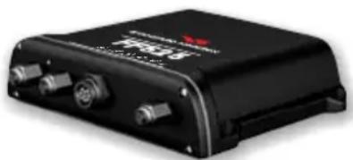
natural_image
Black electronic device with two connectors and a red logo on top (no visible text or symbols on body)Figure 2.8 - FF525 50/200kHz BLACK BOX FISH FINDER
NOTE
The FF520 is also compatible.
2.9 RADAR ANTENNA (USA ONLY)
Please refer to Par. "1.3 Radar Unit supplied by SI-TEX USA". The Radar antenna includes the necessary electronics to deliver Radar information to a compatible STANDARD HORIZON GPS Chart Plotter, and is supplied with mounting hardware kit, interconnection cable and a Radar Junction Box.
Please refer to the Radar Installation Manual and Radar Operation Manual available at www.standardhorizon.com.
2.10 PERSONAL COMPUTER CONNECTIONS
The GPS Chart Plotter can be connected to output Marks and Routes to many available PC programs. To send or receive User Points the PC Program must be able to receive NMEA WPL and RTE sentences. Refer to the table below for connection to a Serial DB9 connector.
Pin PC DB9 connection Port 1 connection
| 2 Receive Brown |
| 3 Transmit Blue |
| 5 Signal ground Green |
By default Port1 is set to receive or send User Points to and from a PC. The GPS Chart Plotter may be set up to send and receive the User Points on a different Port using the following procedure:
- Press [MENU], move the ShuttlePoint knob to highlight SETUP MENU and press [ENT].
- Move the ShuttlePoint knob to highlight ADVANCED SETUP and press [ENT] or move the ShuttlePoint knob to the right.
- Move the ShuttlePoint knob to highlight IN/OUT CONNECTIONS and press [ENT] or move the ShuttlePoint knob to the right.
- Move the ShuttlePoint knob to highlight SEND/REC RTE & MARKS and press [ENT] or move the ShuttlePoint knob to the right to show the popup window.
- Move the ShuttlePoint knob to desired Port and press [ENT].
The PC COM settings are:
The format of the sentences that are sent:
· MARK \$GPWPL,3249.061,N,00710.651,E,MRK002*22
• WAYPOINT \$GPWPL,3933.008,N,00639.969,E,WPT012*22
• ROUTE \$GPWPL,2544.362,N,08011.672,W,WPT003*32
\$GPWPL,2543.921,N,08011.481,W,WPT004*31
\$GPWPL,2543.493,N,08011.768,W,WPT005*37
\$GPRTE,2,1,c,ROUTE01,WPT003,WPT004,WPT005*21
2.11 NMEA DATA PAGE
The NMEA Data page is very useful to see if an external device (example: Depth Sounder) is transmitting NMEA sentences to the GPS Chart Plotter. This page can also be used to see if the GPS Chart Plotter NMEA Output is being loaded down by an external NMEA device the GPS Chart Plotter is connected to. Example: A VHF radio is connected but the radio is not receiving a GPS Position. Usually the VHF radio will be connected to the Green and Brown wires. To check to see if the GPS Chart Plotter is transmitting the sentences:
- Press [MENU], move the ShuttlePoint knob to highlight NMEA DISPLAY and press [ENT].
- Move the ShuttlePoint knob to highlight DATA and press [ENT].
- The NMEA DATA page is shown.
- Connect the Blue Wire on the GPS Chart Plotter to the junction of the Brown wire and the VHF wire. The display should look similar to the following picture.
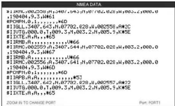
text_image
$I IRMC,002558,H,3407.543,N,07702.028,W,003.2,000.0,190404,9.3,W*61 *PCMPN,0,1,,,,,*6D $I IGLL,3407.643,N,07702.028,N,002558,A*2C $I IUTG,000.0,T,009.3,M,003.2,N,005.9,K*5E $I IXTE,A,A,,,*65 $I IRMB,A,,,,,,,,U*66 $I IRMC,002559,A,3407.644,N,07702.028,W,003.2,000.0,190404,9.3,W*67 $I IRMB,A,,,,,,,,U*66 $I IRMC,002556,A,3407.641,N,07702.028,W,003.2,000.0,190404,9.3,W*6D *PCMPN,0,1,,,,,*6D $I IAPB,A,A,,,,,,,,*53 $I IGLL,3407.642,N,07702.028,N,002557,A*22 $I IUTG,000.0,T,009.3,M,003.2,N,005.9,K*5E $I IXTE,A,A,,,*65 ZOOM IN TO CHANGE PORT Port: PORT1Figure 2.11 - NMEA Data page
2.12 CPF300i VIDEO INPUT
By accessing this menu it is possible to see images on the CP390i or CPF390i display from an external video signal source, if connected to the CP390i or CPF390i.
It allows the "picture-in-picture" functionality, so a Video Input image can be shown on a window and placed over the Chart, Navigation, Highway, Celestial and NMEA pages image at full screen.
NOTE
If the Video Input signals is not detected (E.g. the video camera is not connected to the Video Input connector), the VIDEO INPUT menu item will be grayed out.
Video Connector
Pin Description Connection Example
| 1 Ground Connect to Video Signal Ground of DVD/VCR/Video Cameras |
| 2 + 9 / 12 VDC Connect to Video Cameras Power Input |
| 3 Video Signal + Connect to Video Signal + (NTSC/PAL) of DVD/VCR/Video Cameras |
2.12.0 Video Camera Input
The CP390i or CPF390i has one connection for video camera. Any NTSC or PAL camera will operate correctly. To connect use the video output of the camera and connect to the optional ACVC10 cable.
2.12.1 VCR or DVD Input
A VCR or DVD may be connected to Video port. The CP390i or CPF390i does not have speakers so the audio from the VCR or DVD would have to be routed to a stereo system. STANDARD HORIZON offers an optional cable called ACVC10 that allows any VCR or DVD to simply be plugged into the CP390i or CPF390i.

flowchart
graph LR
    A["VCR/DVD"] -->|Audio OUT| B["STEREO SYSTEM"]
    A --> C["Video Signal GND"]
    A --> D["Video Signal OUT"]
    B --> E["VIDEO CONNECTOR"]
    E --> F["1=GND"]
    E --> G["2=PWR+"]
    E --> H["3=SIGNAL"]
Figure 2.12.1 - VCR/DVD Input
The CP390i or CPF390i has the capability to select the Video Input in three ways.
I. From the menu
- Press [MENU], move the ShuttlePoint knob to highlight SETUP and press [ENT].
- Move the ShuttlePoint knob to highlight VIDEO INPUT and press [ENT] or move the ShuttlePoint knob to the right. A menu appears with the following options:
a. ACTIVATE VIDEO, the possible choices are Full Screen View, PiP (Picture in Picture) View and Auto Switch (*).
If Full Screen View is chosen, the GPS Chart Plotter will show a warning message with the instructions to adjust the image from the Video Input. If the user agrees to proceed, the image from the video input will be shown.
If Picture in Picture (PiP) View is chosen, a Video Input image can be shown on a window and placed over the selected page at full screen. By moving the ShuttlePoint knob, the PiP image is moved. When the focus is on the PiP image, press [CLR] to close the PiP image.
If Auto Switch is chosen, all the menus will be closed and the video input will be shown switching between the Video Input Full View (if connected) and the selected page. See next section for details of setting up the switching times. If the user agrees to proceed, the image from the Video Input and the CP390i or CPF390i page will be shown intermittently. The intermittence time is selected by Switching Timeout item.
b. SWITCHING TIMEOUT, the possible choices are 5,10,30 sec, 1, 5, 10 min. Allows selecting the timing to change from Video Input and CP390i or CPF390i display.
c. RESTORE DEFAULTS, allows restoring the factory defaults for the Input picture adjustment. When Restore default is executed, the message "OK" is shown next to the selected menu item.
NOTE (\*)
If the video signal is not present on the video connector, the corresponding item in the menu will be shown with a light color (to identify that the option is not available).
II. Quick Activation by pressing [CLR] for 1 second
Pressing and holding [CLR] for 1 second from the Chart page Display or from any main page (Navigation, Highway, Celestial, GPS Status, DSC, NMEA DISPLAY); the following Soft Keys are shown: [FULL SCREEN], [PIP VIEW], [AUTO SWITCH]. If no video signal is detected on the Video Input connector, the Soft Keys will be shown in light color in order to identify that they are not active.
III. Quick Activation by Soft Keys
It is possible to assign the Video Input mode to any of the Soft Keys. Press one of the Soft Keys, the Soft Keys functions are shown. Pressing and holding for 1 second one of the Soft Keys, the Soft Keys customization list will be shown. By selecting VIDEO option it will be possible to assign the Soft Key to execute the Video Input function. Once the Soft Key has been assigned to Video Input, its label will show the message [VIDEO]. If [VIDEO] is pressed,
the Soft Keys will be assigned this way: [FULL SCREEN], [PIP VIEW], [AUTO SWITCH]. From now on, the functioning is identical to case II.
NOTE
When the PIP video window is shown, the ShuttlePoint knob can be used to move the position of the PIP window or move the cursor around the Chart page. By default the PIP window is controlled by the ShuttlePoint knob. To change so the chart cursor can be moved, press any Soft Key, then press [VIDPAGE]. To change back to control the PIP window press any Soft Key, then press [VIDPAGE] again.
NOTE
When the PIP window is shown, the cursor and the vessels position may be shown under the PIP window.
2.13 DEMO MODE (FOR DEALER USE)
In Demonstration Mode the GPS Chart Plotter automatically places a Destination point on the Chart page and simulates navigation to the point. Also, the active page displayed on the screen changes every 10 seconds. The pages are shown in the following order: Start-up screen, GPS Status page, Chart/Compass tape page, Chart/Fish Finder page, Fish Finder Full page, Radar page, Navigation page, Highway Page, Celestial page, NMEA Display page.
NOTE
This mode is used by dealers to promote the features of the CP390i or CPF390i when on a retail shelf.
The Demo mode can be selected from the Simulation Menu following the procedure:
- Press [MENU], move the ShuttlePoint knob to highlight SETUP MENU and press [ENT].
- Move the ShuttlePoint knob to highlight ADVANCED SETUP and press [ENT] or move the ShuttlePoint knob to the right.
- Move the ShuttlePoint knob to highlight SIMULATION and press [ENT] or move the ShuttlePoint knob to the right.
- Move the ShuttlePoint knob to highlight DEMO MODE and press [ENT] or move the ShuttlePoint knob to the right to show the popup window.
- Move the ShuttlePoint knob to select ON and press [ENT] or move the ShuttlePoint knob to the right.
- Demo mode is now activated.
Once the Demo Mode is enabled, it is possible to temporally exit Demo Mode by pressing a key and return to the GPS Chart Plotter normal operation. If a key in not touched for 30 seconds the Demo Mode will re-start.
To disable the Demo Mode follow the procedure above selecting OFF at point 5.
3. CONTROLS AND INDICATORS
NOTE
This section defines each control of the CP390i or CPF390i. For instructions, refer to Getting Started and Advanced Settings sections of this Owner's Manual.
NOTE
Throughout this Owner's Manual same conventions are used. See the legend below:
[MENU]If you see brackets around a bold and capital letter word this refers to a key press.
[CHART] If you see brackets around a bold and small capital letter word this refers to a Soft Key press.
GENERAL SETUP When a word(s) is bold capital letters and underlined, this refers to a menu selection item.
3.0 CONTROLS AND CONNECTIONS
The CP390i or CPF390i is controlled by using the keys located on the front panel. These labeled keys are dedicated to specific functions. As you press a key, a single audio beep confirms the key action; every time a key press is not valid, three rapid beeps sound to indicate that the key action is not valid. There is also a ShuttlePoint knob to move the cursor across the screen.
The ZOOM IN and ZOOM OUT keys
Pressing [ZOOM IN] shows more detail of a smaller area, by changing the chart scale and zooming in on your display. Press [ZOOM OUT] to change the scale and show a wider, otherwise less detailed view. Pressing and holding [ZOOM IN]/[ZOOM OUT] allows for quick zoom, that is the fast change of the chart scale where only the land areas are drawn. When [ZOOM IN]/[ZOOM OUT] is released all chart details are shown.
NOTE
The GPS Chart Plotter contains a Worldwide background that allows you to zoom in to 2NM. For more detail, a C-MAP BY JEPPESEN NT+/MAX C-CARD must be purchased and installed.
The ShuttlePoint knob
The ShuttlePoint knob moves the cursor around the Chart Page (cursor mode) and highlights menu items. It changes the GPS Chart Plotter from Home mode to Cursor mode on the Chart Screen. For a detailed explanation of Cursor VS Home mode refer to Par. 3.1.1.
The ENT key
Press [ENT] to select the desired option or to confirm the selection.
The CLR key
When on the Chart Page, press [CLR] to set Home Mode, clear a selected function, leave a menu, step backwards in a menu or exit a menu.
The MENU key
Selects the Main Menu. When in the Setup Menu mode, moving the ShuttlePoint knob to the right enters a selection and moving the knob to the left clears the function.
Pressing and holding [MENU] for 3 seconds allows you to change the fields contained within
the data windows while on the Chart, Navigation, Highway, GPS Status or NMEA Display page.
The GOTO key
This key is very useful when you desire to start navigating (goto) to a destination point. When pressed, a popup window will be shown allowing you to select to start navigating to the Mark, a Route or the position of the cursor.
To stop navigation to a point, press [GOTO] and select Stop in the popup window.
The MARK key
This key places a Mark under the ship's position when in Home Mode. When the cursor is shown and [MARK] is pressed it will place a Mark under the location of the cursor.
The ROUTE key
When pressed places a Waypoint. Succeeding presses place more Waypoints to form a Route.
The PWR key (Backlight and Contrast)
Press and hold [PWR] to turn the GPS Chart Plotter On or Off. Once on, press [PWR] to show and change the Contrast and Backlight settings.
The MOB key
When pressed the GPS Chart Plotter automatically places a Mark on the Chart Page under the boat's position to aid in the rescue or a person that may have fallen aboard. To stop navigating, press [GOTO], select STOP and press [ENT].
The FIND key
A dedicated key that allows searching the optional C-MAP BY JEPPESEN NT ^+ /MAX C-CARD for Port Services, Ports, Tide Stations, Wrecks, Obstructions, Points Of Interest, Lakes Information, Lakes By Name, User Points, GPS Coordinates or Information on any point on the chart.
3.0.0 The Soft Keys
The 6 keys in the bottom of the front panel (hereinafter named Soft Keys) have different functions associated depending on the software: their labels are shown on the screen immediately above the soft keys (the user can customize the function associated with each soft key).
The Soft Keys
These keys allow quick selection to the many pages the GPS Chart Plotter has. These keys can be customized to your preference, however from the factory the keys are preprogrammed with the following pages. From left to right VIDEO, NAV, HIGHWAY, CELEST, CHART, LIST. Press any of the keys and you will see popup windows above the keys. To goto a specific page press the key with the desired popup window. The popup windows will automatically disappear if a key is not pressed or can be removed by pressing [CLR].
3.1 GETTING STARTED
The Getting Started section will take you through the frequently used operations and assist you to customize the look of the GPS Chart Plotter.
3.1.0 Power On, Off and ShuttlePoint Knob operation
- Press and hold [PWR] until the display shows the Start-Up page (see the following picture). To turn Off, press and hold [PWR] until the display turns Off.
text_image
CPF390i GPS Chart Plotter STANDARD HORIZON Software V16.30 00RFigure 3.1.0 - Example of Start-Up page on CPF390i
- When the power is first turned on two pages the start-up page and the Caution pages are briefly shown before the GPS Status page.
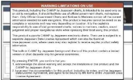
text_image
WARNING-LIMITATIONS ON USE This product, including the C-MAP by Jappesee charts, is intended to be used only as an aid to navigation. It should facilitate use of official government charts, not replace them. Only Official Government Charts and Notices to Members under all the current information needed for date navigation. This product is seizures cannot be relied on as complete or accurate and may vary depending on location. It is the capital responsibility to use official government charts, notices to partners, creditors, sound judgment and proper navigations styles when operating their best using this product. The product supports C-MAP by Jappesee electronic charts. Their use is subject to a separate Jappesee Data License Agreement which can also be found at www.jappesee.com, where lands may also neglect to secure regular product safety information. The built-in C-MAP by Jappesee background charts of this product combine a limited version of third datasets only for general awareness. By growing ENTER you confirm your help: 1. Acknowledge the above warning and accept the limitations of this product and the C-MAP by Jappesee charts 2. Have need the documentation for this product, including the bases, and the Jappesee Data License Agreement, and agree to be bound by life terms of the Jappesee Data License Agreement.
text_image
GPS STATUS LATITUDE LONOTICE WARNING EM-M041.11, EM-M74.05, EW-M010.01, NA-M022.06, NA This product contains a limited set of built-in C- MAP by Jeppesen Charts. Contact your dealer or Jeppesen for upgrade options. Register with Jeppesen to receive regular product safety information. Press ENTER to proceed.Figure 3.1.0a - Caution pages
NOTE
The Caution page on the left is shown only if the data C-CARD is over one year old.
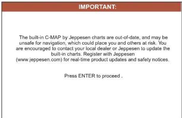
text_image
IMPORTANT: The built-in C-MAP by Jeppesen charts are out-of-date, and may be unsafe for navigation, which could place you and others at risk. You are encouraged to contact your local dealer or Jeppesen to update the built-in charts. Register with Jeppesen (www.jeppesen.com) for real-time product updates and safety notices. Press ENTER to proceed.Figure 3.1.0b - Built-In Charts warning pages
- When the GPS Chart Plotter is first turned on it will take some time for the GPS to acquire a fix of your position. Look closely at the GPS Status page and you will see satellites and relative signal strengths of each satellite. After a fix is received the GPS Chart Plotter will automatically switch to the Chart Page with the ship icon centered on the screen.
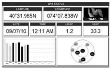
text_image
GPS STATUS LATITUDE 40°31.965N LONGITUDE 074°07.838W WAAS 3D EATE 09/07/10 TIME 12:11 AM HDGP 1.2 VHDP 33.3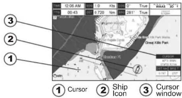
text_image
① Cursor ② Ship Icon ③ Cursor windowFigure 3.1.0c - GPS Status and Chart pages
- On the Chart page the ShuttlePoint knob is used to pan around the chart. Move the ShuttlePoint knob to the left and you will notice a cross hair ✦ appear, this is called the cursor.
- When you move the ShuttlePoint knob you will notice DST and BRG values in the Data window change. This shows the Distance and Bearing from the GPS Fix of your vessel to the position of the Cursor.
- If the cursor is moved to the edge of the screen the GPS Chart Plotter will automatically pan in the desired direction.
3.1.1 Cursor Vs. Home Mode
Cursor Mode
When the ✦ cursor is shown on the Chart Page, the chart plotter is in Cursor Mode. In Cursor Mode the position of the vessel will not stay in the center of the page and will move right off the edge of the screen (as your boat moves). Cursor Mode allows you to pan around and look at areas on the chart. In this mode you can also create Marks, Routes, measure distance and bearings from your current position.
Home Mode
When the ship icon is shown on the Chart Page (cursor is not shown) you are in Home Mode. Now as the ship moves through the water the vessel's position will be kept in the center of the display.
NOTE
To change from Cursor Mode to Home Mode press [CLR].
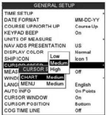
3.1.2 Cursor and Menu selection speed
The CP390i and CPF390i allow you to control the speed the Cursor moves when the ShuttlePoint knob is pressed. To change the speed:
text_image
GENERAL SETUP TIME SETUP DATE FORMAT MM-DD-YY COURSE UP/NORTH UP Course Up KEYPAD BEEP On UNITS OF MEASURE NAV AIDS PRESENTATION US DISPLAY COLOR Normal SHIP ICON Low Icon 1 CURSOR S Medium MEAS CURSOR S High Off WIND CHART Medium LANG MENU Medium English AUTO INFO On Points CURSOR WINDOW On CURSOR POSITION Bottom COG TIME LINE Off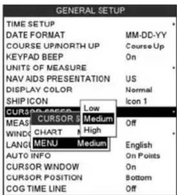
text_image
GENERAL SETUP TIME SETUP DATE FORMAT MM-DD-YY COURSE UP/NORTH UP Course Up KEYPAD BEEP On UNITS OF MEASURE NAV AIDS PRESENTATION US DISPLAY COLOR Normal SHIP ICON Icon 1 CURSOR GREEN Low MEAS CURSOR Medium Off WIND CHART High LANG MENU Medium English AUTO INFO On Points CURSOR WINDOW On CURSOR POSITION Bottom COG TIME LINE OffFigure 3.1.2 - Cursor Speed menu
- Press [MENU], move the ShuttlePoint knob to highlight SETUP MENU and press [ENT].
- Move the ShuttlePoint knob to highlight GENERAL SETUP and press [ENT] or move the ShuttlePoint knob to the right.
- Move the ShuttlePoint knob to highlight CURSOR SPEED and press [ENT] or move the ShuttlePoint knob to the right.
- The menu now shows two selections, Chart and Menu which allow the Cursor Speed to be selected as High, Medium or Low on the Chart Page or within the menus.
- With CHART or MENU selected, press [ENT] or move the ShuttlePoint knob to the right. Move the ShuttlePoint knob to the desired setting and press [ENT] or move the ShuttlePoint knob to the right.
- Press [CLR] until the menu disappears or an easier method is to press the ShuttlePoint knob to the left a few times.
- Move the cursor on the Chart Page and see if the speed is to your liking.
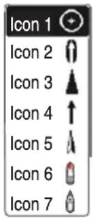
3.1.3 Changing the Ship Icons
The cursor may be changed to any of the following. The default setting is Icon 6.
text_image
Icon 1 Icon 2 Icon 3 Icon 4 Icon 5 Icon 6 Icon 7Figure 3.1.3 - Ship icons
- Press [MENU], move the ShuttlePoint knob to highlight SETUP MENU and press [ENT].
- Move the ShuttlePoint knob to highlight the ShuttlePoint knob to the right. GENERAL SETUP and press [ENT] or move
- Move the ShuttlePoint knob to highlight SHIP ICON and press [ENT] or move the ShuttlePoint knob to the right to show the popup window with ship icons.
- Move the ShuttlePoint knob to select the desired icon and press [ENT] or move the ShuttlePoint knob to the right to select a new icon.
- Press [CLR] or move the ShuttlePoint knob to the left to exit the menu and show the Chart Page.
3.1.4 Changing the backlight and contrast
With the CP390i and CPF390i turned on, briefly press [PWR] to show the backlight and contrast popup window. Move the ShuttlePoint knob to the left or right to adjust the LCD backlight intensity or up or down to change the LCD contrast. Press [ENT] to set.
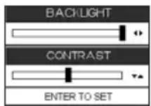
Figure 3.1.4 - Backlight and Contrast adjustment
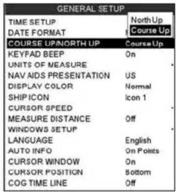
3.1.5 Selecting North Up or Course Up
The default selection is COURSE UP: the top of the Chart page oriented so it will always show the area ahead of the direction your vessel is travelling.
text_image
GENERAL SETUP TIME SETUP DATE FORMAT North Up Course Up COURSE UP/NORTH UP Course Up KEYPAD BEEP ON UNITS OF MEASURE NAV AIDS PRESENTATION US DISPLAY COLOR Normal SHIP ICON Icon 1 CURSOR SPEED MEASURE DISTANCE Off WINDOWS SETUP LANGUAGE English AUTO INFO On Points CURSOR WINDOW On CURSOR POSITION Bottom COG TIME LINE OffFigure 3.1.5 - Course Up/North Up menu
- Press [MENU], move the ShuttlePoint knob to highlight SETUP MENU and press [ENT].
- Move the ShuttlePoint knob to highlight GENERAL SETUP and press [ENT] or move the ShuttlePoint knob to the right.
- Move the ShuttlePoint knob to highlight COURSE UP/NORTH UP and press [ENT] or move the ShuttlePoint knob to the right.
- Another popup window will be shown with NORTH UP and COURSE UP, move the ShuttlePoint knob to the desired selection and press [ENT] or move the ShuttlePoint knob to the right.
- Press [CLR] or move the ShuttlePoint knob to the left to exit the menu and show the Chart page.
NOTE
When the CP390i and CPF390i are in Course Up mode a small arrow icon will be shown on the Chart page indicating North.
3.2 AUTOMATIC TIME
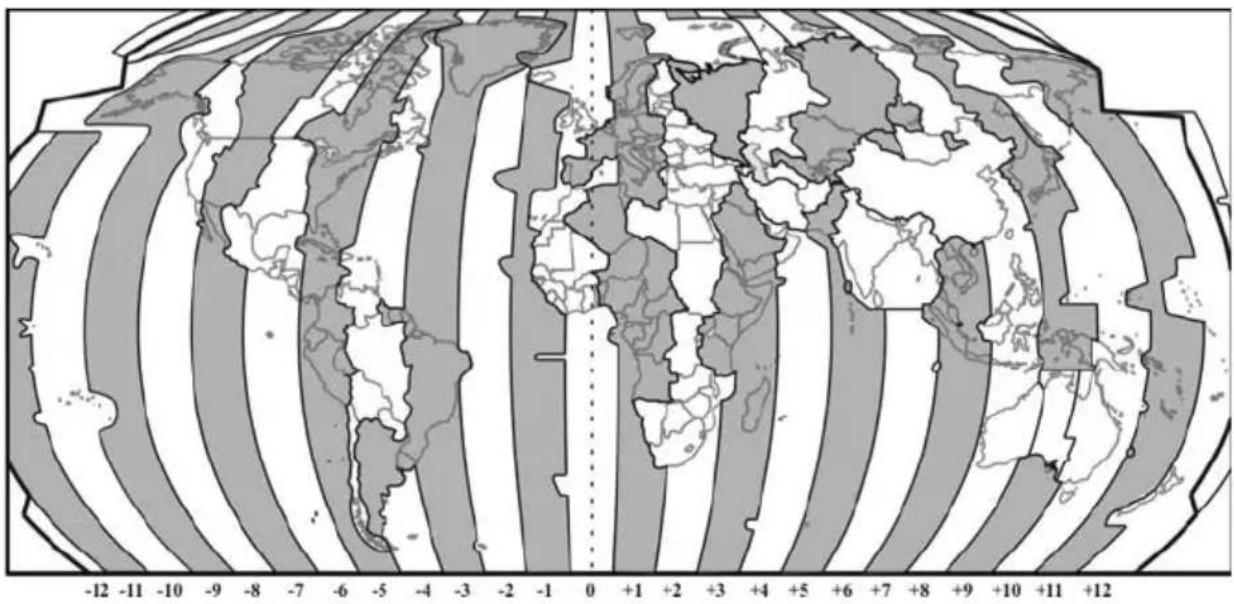
The time information supplied by the GPS satellites is in Universal Time Coordinates (UTC or Greenwich England Mean Time). To change the GPS Chart Plotter to read the correct time, first you must figure out the offset and if it is Daylight Savings Time. For example on the West coast of the United States or Pacific Standard Time the offset needed would be -08:00 or -07:00 for Daylight Savings Time, Eastern Standard Time -05:00 or -04:00 for Daylight Savings Time.
geo
| Region | Value | | -------------- | ----- | | North America | +12 | | Europe | +10 | | Asia | +9 | | Africa | +8 | | South America | +7 | | Australia | +6 | | Oceania | +5 | | Central Asia | +4 | | Middle East | +3 | | Southeast Asia | +2 | | Eastern Europe | +1 | | Southern Europe| -1 | | Western Europe | -2 | | Eastern Europe | -3 | | Northern Europe| -4 | | Southern Europe| -5 | | Central Asia | -6 | | Middle East | -7 | | Southeast Asia | -8 | | Eastern Europe | -9 | | Western Europe | -10 | | Central Asia | -11 | | Northern Europe| -12 |Figure 3.2 - Adjusting Time
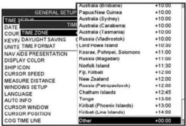
The Time Setup menu allows you to enter a time zone offset for your location, selection to automatically adjust the time for daylight savings and to configure the time in 12 or 24 hour formats.
text_image
GENERAL SETUP TIME SETUP DATE TIME COUR TIME ZONE KEYP/ DAYLIGHT SAVING ( UNITS TIME FORMAT NAV AIDS PRESENTATION DISPLAY COLOR SHIP ICON CURSOR SPEED MEASURE DISTANCE WINDOWS SETUP LANGUAGE AUTO INFO CURSOR WINDOW CURSOR POSITION COG TIME LINE Australia (Brisbane) +10:00 Papua New Guinea +10:00 Australia (Sydney) +10:00 Australia (Canaberra) +10:00 Australia (Tasmania) +10:00 Russia (Vladivostok) +10:00 Lord Howe Island +10:30 Kosrae, Pohnpei, Solomons +11:00 Russia (Magadan) +11:00 Norfolk Island +11:30 Fiji, Kiribati +12:00 New Zealand +12:00 Russia (Petropavlovsk) +12:00 Chatham Islands +12:45 Tonga +13:00 Kiribati (Phoenix Islands) +13:00 Kiribati (Line Islands) +14:00 Other +00:00Figure 3.2a - Time Setup menu
NOTE
By setting the time in the steps below, the time shown on the Celestial page is automatically set up.
- Press [MENU], move the ShuttlePoint knob to highlight SETUP MENU and press [ENT].
- Move the ShuttlePoint knob to highlight GENERAL SETUP and press [ENT] or move the ShuttlePoint knob to the right.
- Move the ShuttlePoint knob to highlight TIME SETUP and press [ENT] or move the ShuttlePoint knob to the right.
- Move the ShuttlePoint knob to highlight TIME ZONE and press [ENT] or move the ShuttlePoint knob to the right.
- Look at the table and find the time zone for your area. Move the ShuttlePoint knob up or down to select the desired zone and press [ENT].
- Next move the ShuttlePoint knob to highlight DAYLIGHT SAVING and press [ENT] or move the ShuttlePoint knob to the right.
- Daylight Saving menu has 3 options:
7.1 OFF Select Off when your location does not recognize Daylight Savings Time;
7.2 ON Select On to manually turn Daylight Savings Time On. This is the default selection;
7.3 AUTO When selected the Daylight Savings Time offset is automatically changed. 8. Press [CLR] or move the ShuttlePoint knob to the left until the Chart Page is shown.
3.3 SELECTING LORAN TD OR OTHER COORDINATE SYSTEM
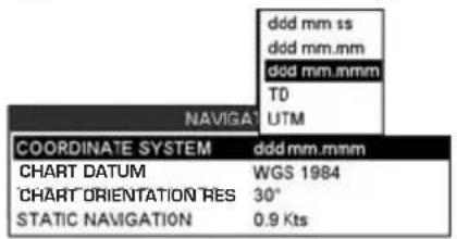
The GPS Fix coordinates can be changed to show Latitude/Longitude, Loran TDs or UTM. Below is the window that will appear when customizing the Coordinate System.
text_image
NaviGAT COORDINATE SYSTEM ddd mm.mmm CHART DATUM WGS 1984 CHART ORIENTATION RES 30° STATIC NAVIGATION 0.9 Kts ddd mm ss ddd mm.mm ddd mm.mmm TD UTMFigure 3.3 - Coordinate System menu
- Press [MENU], move the ShuttlePoint knob to highlight SETUP MENU and press [ENT].
- Move the ShuttlePoint knob to highlight ADVANCED SETUP and press [ENT] or move the ShuttlePoint knob to the right.
- Move the ShuttlePoint knob to highlight NAVIGATE and press [ENT] or move the ShuttlePoint knob to the right.
- Move the ShuttlePoint knob to highlight COORDINATE SYSTEM and press [ENT] or move the ShuttlePoint knob to the right.
- Move the ShuttlePoint knob to highlight the desired coordinate type and press [ENT] or move the ShuttlePoint knob to the right.
- Press [CLR] or move the ShuttlePoint knob to the left until the Chart page is shown.
NOTE
If the TD is selected, you should set the Chain, Pair, ASF1, ASF2 and Alter. If the TD numbers are not correct the Pair letters may be backwards. Reversing the two letters usually solves this issue. Example: Y/Z change to Z/Y.
3.4 CHANGING THE CHART COLOR
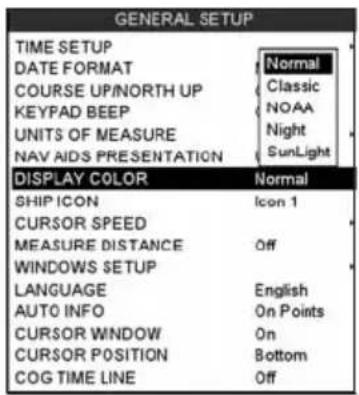
The CP390i and CPF390i have preprogrammed settings allowing you to customize the look of the Chart page. The default is Sunlight, however there are other settings: Classic, NOAA, Night and Normal. Night is very useful during evening hours so not to impair night vision.
text_image
GENERAL SETUP TIME SETUP DATE FORMAT COURSE UP/NORTH UP KEYPAD BEEP UNITS OF MEASURE NAV AIDS PRESENTATION Normal Classic NOAA Night SunLight DISPLAY COLOR Normal SHIP ICON Icon 1 CURSOR SPEED MEASURE DISTANCE Off WINDOWS SETUP LANGUAGE English AUTO INFO On Points CURSOR WINDOW On CURSOR POSITION Bottom COG TIME LINE OffFigure 3.4 - Display Color menu
- Press [MENU], move the ShuttlePoint knob to highlight SETUP MENU and press [ENT].
- Move the ShuttlePoint knob to highlight GENERAL SETUP and press [ENT] or move the ShuttlePoint knob to the right.
- Move the ShuttlePoint knob to highlight DISPLAY COLOR and press [ENT] or move the ShuttlePoint knob to the right.
- A popup window will be shown with Normal, Classic, NOAA, Night and Sunlight. Move the ShuttlePoint knob to the desired selection and press [ENT] or move the ShuttlePoint knob to the right.
- Press [CLR] or move the ShuttlePoint knob to the left to exit the menu and show the Chart page.
3.5 SELECTING LANGUAGE
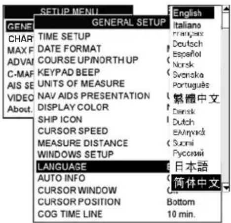
To ease operation in different countries, the software includes translation and display of the following 16 languages:
· English · Italian · French
· German · Spanish · Norwegian
- Swedish
- Portuguese
- Chinese (Traditional)
- Danish · Dutch · Greek
- Finnish
- Russian
- Chinese (Simplified)
· Japanese
The translations are included in Menu descriptions, Soft Key labels and on Info Functions to ease operation. See also Par. 6.0.7. Set the language to be displayed on menus, data pages, warning/alarm messages, full/quick info, list of objects found by find/nearest function, and on charts (such as place's names and buoy's names and so on). The selection now includes the capability to display languages in non-Latin characters (UNICODE format).
To select the language you want:
-
Press [MENU], move the ShuttlePoint knob to highlight SETUP MENU and press [ENT].
-
Move the ShuttlePoint knob to highlight GENERAL SETUP and press [ENT] or move the ShuttlePoint knob to the right.
-
Move the ShuttlePoint knob to highlight LANGUAGE and press [ENT] or move the ShuttlePoint knob to the right.
-
Another popup window will be shown with the available languages, move the Shuttle-Point knob to the desired language and press [ENT] or move the ShuttlePoint knob to the right.
-
Press [CLR] or move the ShuttlePoint knob to the left to exit the menu and show the Chart page.
text_image
GENE CHAR MAX F ADVA C-MAF AIS SE VIDEO About. SETUP MENU GENERAL SETUP TIME SETUP DATE FORMAT COURSE UP/NORTH UP KEYPAD BEEP UNITS OF MEASURE NAV AIDS PRESENTATION DISPLAY COLOR SHIP ICON CURSOR SPEED MEASURE DISTANCE WINDOWS SETUP LANGUAGE AUTO INFO CURSOR WINDOW CURSOR POSITION COG TIME LINE English Italiano frangas Deutsch Español Norsk Svenska Português 繁體中文 Dansk Dutch EALynixká Suomi Pycesný 日本語 简体中文 Bottom 10 min.Figure 3.5 - Language Selection menu
NOTE
If the selected language is not available on cartographic data, English is used.
WARNING
If you have accidentally selected a language and are unable to return to the Language Selection menu, perform the following procedure:
a. Select the Chart page.
b. Press [MENU] two times, move the Shuttlepoint knob to highlight the first (top) selection in the menu and press [ENT].
c. Move the Shuttlepoint knob to highlight the LANGUAGE item and press [ENT].
d. A language window will be shown, select your language and press [ENT].
3.6 SELECTING PAGES USING SOFT KEYS
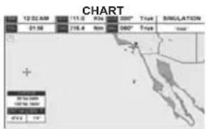
The Soft Keys located under the LCD are used to select the pages quickly without the need to go into the menu. The default pages are VIDEO, NAV, HIGHWAY, CELESTIAL, CHART and LIST.
When one of the Soft Keys is pressed popup windows above each Soft Key are shown with the key description. Press the Soft Key with the desired page description and the GPS Chart Plotter will change to that page.
text_image
CHART 12:02 AM 113.0 Kpc 900° Traps SIMULATION 01:56 716.4 Nm 080° Traps Total + 90 to 500 100 to 1000 47/12 1/4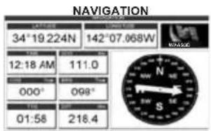
text_image
NAVIGATION 34°19 224N 142°07.068W 12:18 AM 111.0 000° 098° 01:58 218.4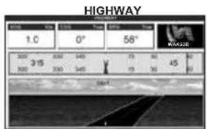
text_image
HIGHWAY 1.0 0° 58° 300 315 300 300 340 19 30 45 19 30 340 240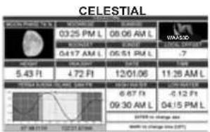
text_image
CELESTIAL 03:25 PM L 08:06 AM L WASCO 04:17 AM L 05:51 PM L .7 5.43 Ft 4.72 Ft 12/01/06 11:38 AM L 6.67 Ft -0.12 Ft 09:30 AM L 04:15 PM L 07:08 PM L 02:31 AM M WATER CHANGE AS WATER CHANGE AS (20%)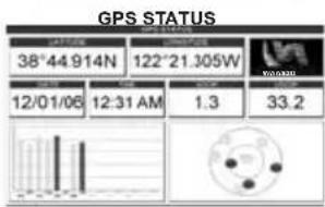
text_image
GPS STATUS 38°44.914N 122°21.305W 12/01/06 12:31 AM 1.3 33.2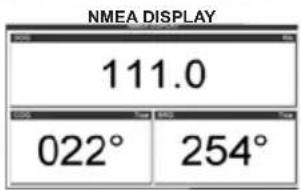
text_image
NMEA DISPLAY 111.0 022° 254°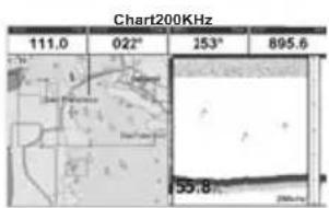
text_image
Chart200KHz 111.0 022° 253° 895.6 55.8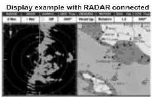
text_image
Display example with RADAR connected 0 Max 1 Max 2 Min 3 Min 4 Min 5 Min 6 Min 7 Min 8 Min 9 Min 10 Min 11 Min 12 Min 13 Min 14 Min 15 Min 16 Min 17 Min 18 Min 19 Min 20 Min 21 Min 22 Min 23 Min 24 Min 25 Min 26 Min 27 Min 28 Min 29 Min 30 Min 31 Min 32 Min 33 Min 34 Min 35 Min 36 Min 37 Min 38 Min 39 Min 40 Min 41 Min 42 Min 43 Min 44 Min 45 Min 46 Min 47 Min 48 Min 49 Min 50 Min 51 Min 52 Min 53 Min 54 Min 55 Min 56 Min 57 Min 58 Min 59 Min 60 Min 61 Min 62 Min 63 Min 64 Min 65 Min 66 Min 67 Min 68 Min 69 Min 70 Min 71 Min 72 Min 73 Min 74 Min 75 Min 76 Min 77 Min 78 Min 79 Min 80 Min 81 Min 82 Min 83 Min 84 Min 85 Min 86 Min 87 Min 88 Min 89 Min 90 Min 91 Min 92 Min 93 Min 94 Min 95 Min 96 Min 97 Min 98 Min 99 MinFigure 3.6 - Screen display pages
3.7 CUSTOMIZING THE SOFT KEYS
The Soft Keys can be individually customized from the default pages (discussed above) to
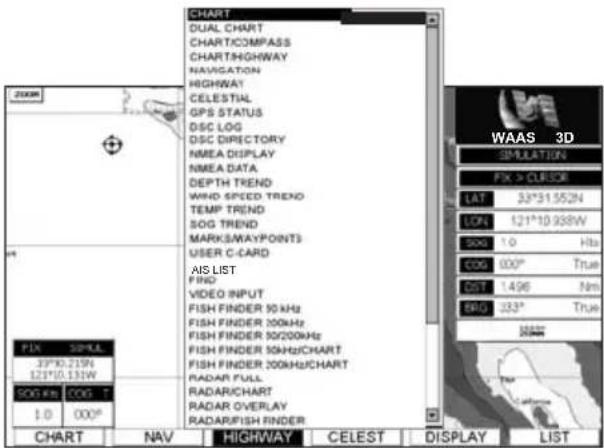
the following: CHART, DUAL CHART, CHART/COMPASS, CHART/HIGHWAY, NAVIGATION, HIGHWAY, CELESTIAL, GPS STATUS, DSC LOG, DSC DIRECTORY, NMEA DISPLAY, NMEA DATA, DEPTH TREND, WIND SPEED TREND, TEMP TREND, SOG TREND, MARKS/WAYPOINTS, USER C-CARD, AIS LIST, FIND, VIDEO INPUT, 50kHz FULL PAGE, 200kHz FULL PAGE, 50kHz/CHART PAGE or 200kHz/CHART PAGE. Also when a SI-TEX RADAR antenna is connected (USA ONLY), any Soft Key can be customized to show Radar pages, RADAR FULL, RADAR/CHART, RADAR OVERLAY and RADAR/FISH FINDER.
text_image
CHART DUAL CHART CHARTICOMPASS CHARTHIGHWAY NAVIGATION HIGHWAY CELESTIAL GPS STATUS OSC LOG OSC DIRECTORY NMEA DISPLAY NMEA DATA DEPTH TREND WWD SPEED TREND TEMP TREND SOG TREND MARKS/WAYPOINTS USER C-CARD AIS LIST FIND VIDEO INPUT FISH FINDER 90 kHz FISH FINDER 100 kHz FISH FINDER 100/200 kHz FISH FINDER 50Hz/CHART FISH FINDER 100kHz/CHART RADAR FULL RADAR/CHART RADAR OVERLAY RADAR/FISH FINDER CHAART NAV HIGHWAY CELEST DISPLAY LIST WAAS 3D SPULATION FIX > CURSOE LAT 33°31.552N LON 121°10.938W 500 1.0 Hbs COG 000° True CST 1.496 Nm BHD 233° TrueFigure 3.7 - Window options of the selected Soft Key
- To change, momentarily press any of the Soft Keys, then press and hold the Soft Key you want to customize.
- A popup window will be shown with the above settings.
- Move the ShuttlePoint knob up or down to select the desired page.
- Press [ENT] or move the ShuttlePoint knob to the right to save the page to the selected Soft Key.
3.8 SETTINGS IN GENERAL SETUP MENU
The GENERAL SETUP menu has other selections that allow you to customize the display. All selections are listed below:
| TIME SETUP | Select the Time Zone offset, enable or disable Daylight Savings Time and select the Time Format and switch between 12 or 24 hours time format. |
| DATE FORMAT | Select the Date format among MM-DD-YY (default), DD-MM-YY or YY-MM-DD. |
| COURSE UP/NORTH UP | Select North Up (the top of the page is fixed to North) or Course Up (the top of the page is orientated to the direction the vessel is heading. This is the default). |
| KEYPAD BEEP | Allows the beep produced when a key is pressed to be turned On (default) or Off. |
| UNITS OF MEASURE | Units of Measure can be selected for Distance*, Speed, Depth, Altitude and Temperature. |
| NAV AIDS PRESENTATION | Allows the Nav Aids presentation to be drawn using NOAA symbology when US (default) is selected or International symbols when International is selected. When selected these functions affect how the icons for Lights, Signals, Buoys and Beacons are displayed. |
| DISPLAY COLOR | Changes the background colors of the chart page to enhance the visibility of the screen depending on the surrounding light conditions. Normal is recommended when the GPS Chart Plotter is not exposed to the direct sunlight. When this mode is set the charts are displayed in order to use colors as similar as possible to ones used in the original paper charts. Classic uses vivid chart colors presentation. NOAA allows setting NOAA paper chart colors presentation. Night is recommended when the environment is dark in order to reduce the glare of the display. The GPS Chart Plotter displays charts and screen in darker colors. SunLight (default) is designed to enhance the visibility of the screen when the GPS Chart Plotter is exposed to sunlight. The charts are much brighter than in theother modes and the depth areas are filled with the white color so different depth areas are not easily distinguishable. |
| SHIP ICON | Select from a variety of ship icons that represent your vessels position on the Chart Page.The default is Icon 6. |
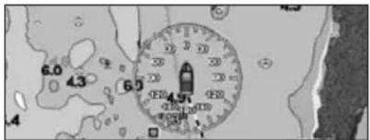
| COMPASS ROSE | Allows selection of compass direction indication around ship icon. The default is On. |
text_image
6.0 4.3 6.5 4.95 4.4| CURSOR SPEED | Selects the speed among Low, Medium (default) and High for the cursor in the CHART page and within the MENU. |
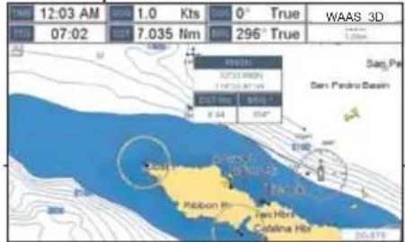
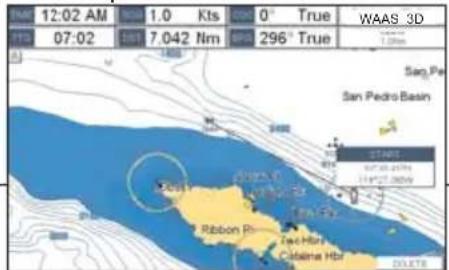
| MEASURE DISTANCE | When this function is On, and the ShuttlePoint knob is moved to a location where you want to start measuring a distance and press [ENT]. Move the ShuttlePoint knob to move the cursor to a second location where you want to finish measuring a distance and press [ENT]. A line will appear between the Start and Finish points and a popup window will be shown indicating the distance and bearing from the Start and Finish points. Press [ENT] to delete both points. (Off is the default). |
START point
text_image
12:03 AM 1.0 Kts 0° True WAAS 3D 07:02 7.035 Nm 296° True Sao Pe San Pedro Basin 4/18/2019 Cayman Road 8-04 304° Pabbon Ph Two Hbrs Catalina Hbr 20-679FINISH point
text_image
12:02 AM 07:02 1.0 Kts 7.042 Nm 0° True 296° True WAAS 3D 1.0km Sao Pe San Pedro Basin 2018 2019 2020 2021 2022 2023 2024 2025 2026 2027 2028 2029 2030 2031 2032 2033 2034 2035 2036 2037 2038 2039 2040 2041 2042 2043 2044 2045 2046 2047 2048 2049 2050 2051 2052 2053 2054 2055 2056 2057 2058 2059 2060 2061 2062 2063 2064 2065 2066 2067 2068 2069 2070 2071 2072 2073 2074 2075 2076 2077 2078 2079 2080 2081 2082 2083 2084 2085 2086 2087 2088 2089 2090 2091 2092 2093 2094 2095 2096 2097 2098 2099 31/18/18/18/18/18/18/18/18/18/18/18/18/18/18/18/18/18/18/18/18/18/18/18/18/18/18/18/18/18/18/18/18/18/18| WINDOWS SETUP | This menu selection allows the data windows to be customized on the CHART PAGE and NAVIGATION PAGE (refer to section 12.0.0). |
LANGUAGE Allows changing the language for menus and data screens.
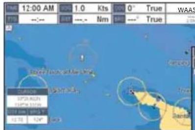
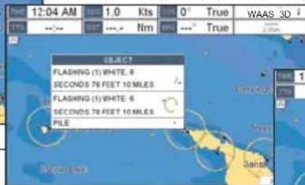
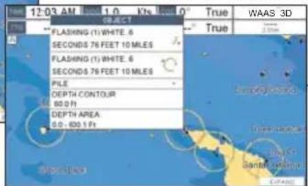
AUTO INFO When the cursor is moved over a buoy, Mark or other item a popup window will show information of the item. This menu item allows the window to be turned Off, On Points (default) or On All.
Auto Info OFF
text_image
TIME 12:00 AM BOS 1.0 Kts 0° True WAAS FTD -:- OUT -:- Nm SHT -: True 2.0% Tight Forward/Max HSD Balance 37" 80" 25" 34" 90" 100" 11" 12" 13" 12" 13" 14"Auto Info ON POINTS
text_image
12:04 AM 0.00 1.0 Kts 0% True WAAS 3D TTS 0.00 0.00 Nm 0% True OBJECT FLASHING (1) WHITE. 6 SECONDS 76 FEET 10 MILES FLASHING (1) WHITE. 6 SECONDS 76 FEET 10 MILES PILEAuto Info ON ALL
text_image
12:03 AM 1.0 Kts 1.0° True WAAS 3D FLASHING (T) WHITE 6 SECONDS 76 FEET 10 MILES FLASHING (T) WHITE 6 SECONDS 76 FEET 10 MILES PILE DEPTH CONTOUR 80.0 Ft DEPTH AREA 0.0 -100.0 FtCURSOR WINDOW
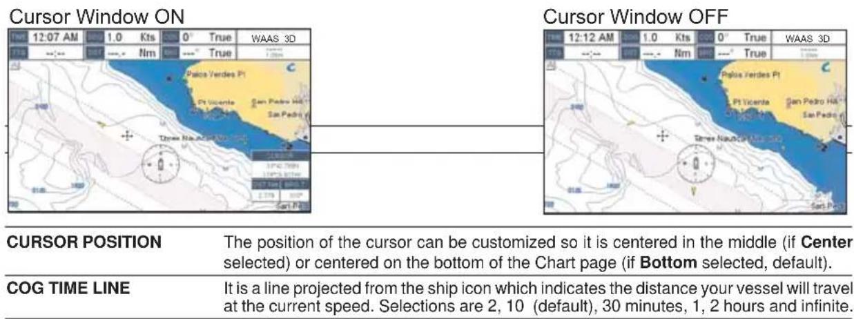
By default when the cursor is moved a window is shown with the Lat/Lon Distance and Bearing from the vessels location to the cursor. This selection allows the window to be turned On (default) or Off. The Cursor Window is automatically disabled when General is set in Windows Setup option.
text_image
Cursor Window ON True 12:07 AM 1.0 Kts 0° True WAAS 3D True - - - Nm - - - True Palos Verdes Pl Pt Vicente San Pedro Ha San Pedro Three Nauchon Sar Pd CurSOR POSITION The position of the cursor can be customized so it is centered in the middle (if Center selected) or centered on the bottom of the Chart page (if Bottom selected, default). COG TIME LINE It is a line projected from the ship icon which indicates the distance your vessel will travel at the current speed. Selections are 2, 10 (default), 30 minutes, 1, 2 hours and infinite.NOTE\*
The available Units of Measure for Distance are: Nm, Sm, Km, Nm+Ft, Nm+m. Note when "Nm+Ft" is selected if the distance is less than 1.0 Nm, it turns to Feet. When "Nm+m" is selected if the distance is less than 1.0 Nm, it turns to Meters.
3.9 ABOUT PAGE
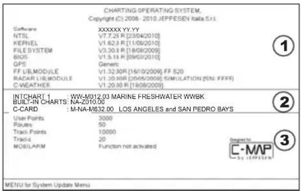
From Main Menu page it is possible to select the About page containing Software, Chart and optional devices information.
① Software System Information
② Cartography Information
③ Storage Capacity
text_image
CHARTING OPERATING SYSTEM, Copyright (C) 2008 - 2010 JEPPESEN Italia S.r.l. Software NTSL KERNEL FILE SYSTEM BIOS GPS FF LIB.MODULE RADAR LIB.MODULE C-WEATHER INTCHART 1 : WW-M012.03 MARINE FRESHWATER WWBK BUILT-IN CHARTS: NA-Z010.00 C-CARD : M-NA-M632.00 LOS ANGELES and SAN PEDRO BAYS User Points Routes Track Points Tracks MOBILARM 3000 50 10000 20 Function not activated ① ② ③ MENU for System Update MenuFigure 3.9 - Example of About page
- Press [MENU], move the ShuttlePoint knob to highlight SETUP MENU and press [ENT].
- Move the ShuttlePoint knob to highlight About... and press [ENT] or move the ShuttlePoint knob to the right.
- The Information page appears on the screen (see the previous Figure).
- Press [CLR] or move the ShuttlePoint knob to the left to exit and show the Chart page.
4. FIND SERVICES
4.0 USING FIND SERVICES & MORE FUNCTIONS
The CP390i and CPF390i have a dedicated [FIND] key that allows searching the optional C-MAP BY JEPPESEN NT+/MAX C-CARD for Port Services, Ports, Tide Stations, Wrecks, Obstructions, Points Of Interest, Lakes, User Points, GPS Coordinates or Information on any point on the Chart.
4.0.0 Port Services
This feature is used to locate Port Services nearest the position of your vessel.
- Press [FIND].
-
Move the ShuttlePoint knob to highlight PORT SERVICES and press [ENT] or move the ShuttlePoint knob to the right.
-
A popup window will be shown with a list of different Port Services. The table below shows a list of the available Port Services:
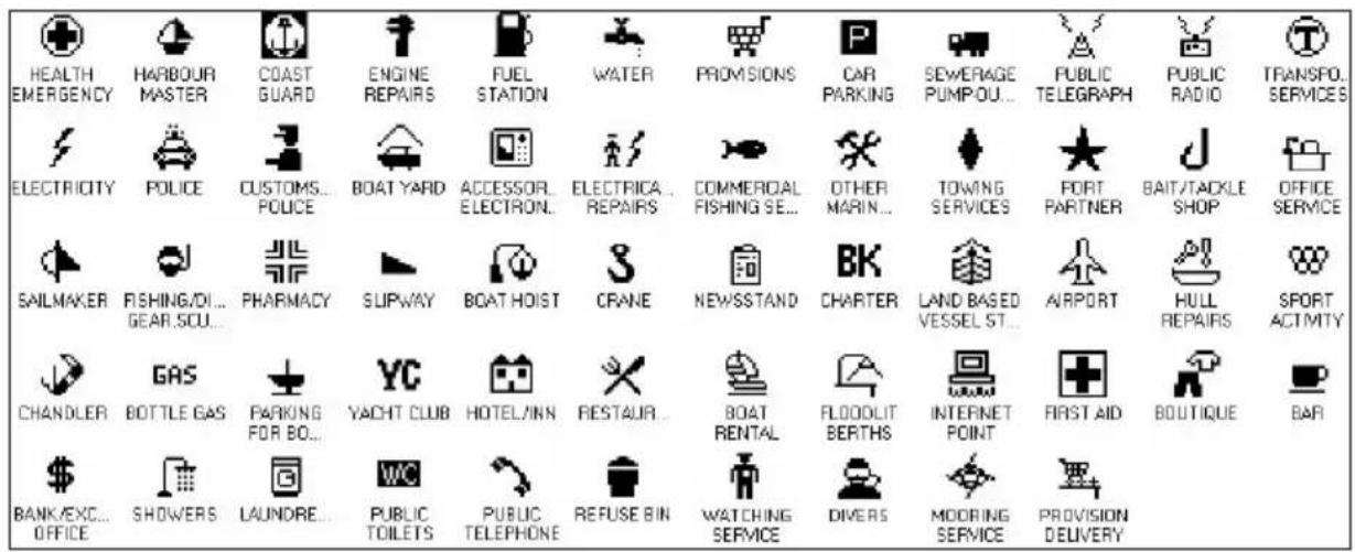
text_image
HEALTH EMERGENCY HARBOUR MASTER COAST GUARD ENGINE REPAIRS FUEL STATION WATER PROVISIONS CAR PARKING SEWERAGE PUMPOU... PUBLIC TELEGRAPH PUBLIC RADIO TRANSPO. SERVICES ELECTRICITY POLICE CUSTOMS... POLICE BOAT YARD ACCESSOR. ELECTRON. ELECTRICA... REPAIRS COMMERCIAL FISHING SE... OTHER MARIN... TOWING SERVICES PORT PARTNER BAIT/TACKLE SHOP OFFICE SERVICE SAILMAKER FISHING/DI... GEAR.SOU... PHARMACY SUPWAY BOAT HOIST CRANE NEWSSTAND CHARTER LAND BASED VESSEL ST... AIRPORT HULL REPAIRS SPORT ACTMTY CHANDLER BOTTLE GAS PARKING FOR BO... YC HOTEL/INN RESTAUR... BOAT RENTAL FLOODLIT BERTHS INTERNET POINT FIRST AID BOUTIQUE BAR BANK/EXC... OFFICE SHOWERS LAUNORE... WC PUBLIC TOILETS PUBLIC TELEPHONE REFUSE BIN WATCHING SERVICE DIVERS MOORING SERVICE PROVISION DELIVERYFigure 4.0.0 - Port Services Table
- Move the ShuttlePoint knob to highlight the desired type of service and press [ENT].
- Another popup window will appear displaying the distance and position of the services closest to your location.
- Using the ShuttlePoint knob, highlight the desired service and press [ENT]. This will show information about the service.
- Press [CLR] to show the actual position of the service on the Chart Page.
- Press [CLR] again at any time to return your cursor to your vessel's position.
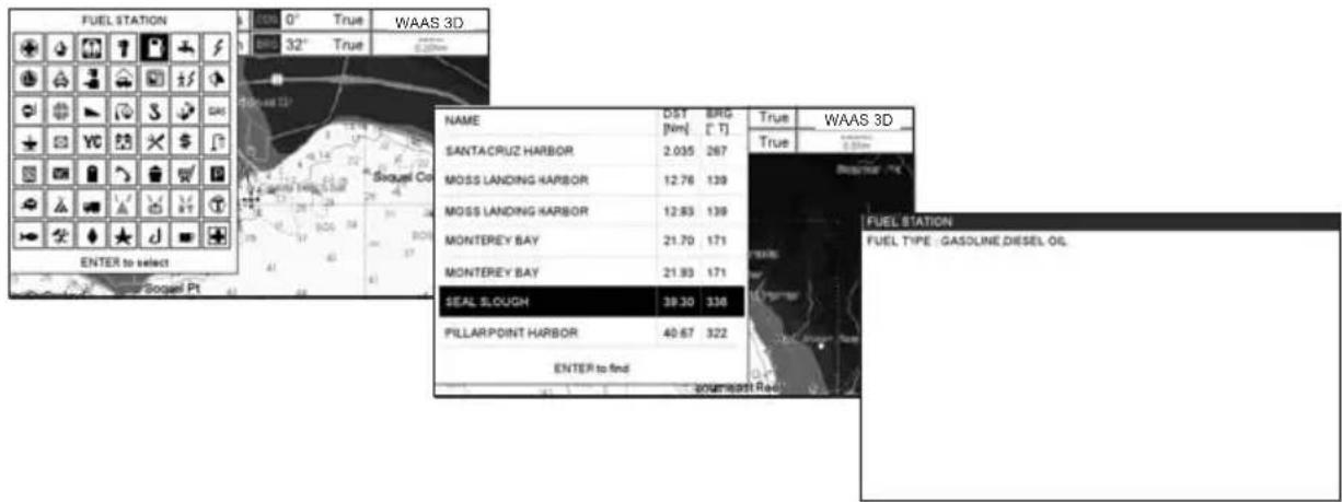
text_image
FUEL STATION WAAS 3D 0° True 32° True SANTACRUZ HARBOR MOSS LANDING HARBOR MOSS LANDING HARBOR MONTEREY BAY MONTEREY BAY SEAL SLOUGH PILLARPOINT HARBOR ENTER to find True WAAS 3D FUEL STATION FUEL TYPE / GASOLINE DIESEL OIL ENGLISH ROADFigure 4.0.0 - Find Port Services
4.0.1 Port
This feature is used to locate the 10 nearest Ports to the position of your vessel.
A Port is represented with a 📁 on the Chart page.
- Press [FIND].
- Move the ShuttlePoint knob to highlight PORT and press [ENT] or move the ShuttlePoint knob to the right.
- A popup window will be shown with a list of nearest Ports.
- Move the ShuttlePoint knob to highlight the desired Port and press [ENT].
- Another window will appear displaying the details of the selected Port.
- Press [CLR] to show the actual position of the Port on the Chart Page.
- Press [CLR] again at any time to return your cursor to your vessel's position.
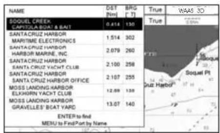
text_image
NAME SOUEL CREEK CAPITOLA BOAT & BJT 0.414 130 SANTACRUZ HARBOR MARITIME ELECTRONICS SANTACRUZ HARBOR HARBOR MARINE, INC. SANTACRUZ HARBOR SANTA CRUZ YACHT CLUB SANTACRUZ HARBOR SANTA CRUZ HARBOR OFFICE MOSS LANDING HARBOR ELKHORN YACHT CLUB MOSS LANDING HARBOR GRAVELLES' BOAT YARD ENTER to find MESU to FindPort by Name True True WAAS 3D 2.50m Soquel Pt Ruiz Harbor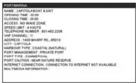
text_image
PORT/MARINA NAME : CAPITOLABOAT & SAIT OPENING TIME : 00:00 CLOSING TIME : 00:00 ACCESS : NO WAVE ZONE SPEED LIMIT : 4 KNOTS TELEPHONE NUMBER : 831-462.2208 VHF CHANNEL : 11 ADDRESS : 1400 WHARF RD , 95010 CITY : CAPITOLA HARBOUR TYPE : COASTAL (NATURAL) PORT MANAGEMENT : PRIVATE PORT PORT TYPE : COMMERCIAL PORT CAUTION : NEAR NATURE RESERVE INTERNET CONNECTION : CONNECTION TO INTERNET NOT AVAILABLE MULTIMEDIA INFORMATION :Figure 4.0.1 - Find a Port
4.0.2 Tide Stations
This feature is used to locate the 10 nearest Tide Stations to the position of your vessel. Once a Tide Station is selected the Tide Graph can be used to determine Tide height and draught of the Tide based on a user-specified time.
A Tide Station is represented with a T on the Chart page.
- Press [FIND].
- Move the ShuttlePoint knob to highlight TIDE STATIONS and press [ENT] or move the ShuttlePoint knob to the right.
- A popup window will be shown with a list of nearest Tide Stations.
- Move the ShuttlePoint knob to highlight the desired Tide Station and press [ENT].
- Another window will be shown detailing the selected Tide Station information.
-
Press [CLR] to show the actual position of the Tide Station on the Chart Page.
-
Press [CLR] again at any time to return your cursor to your vessel's position.

text_image
NAME DST Niml BRG (1) True WAAS 3D NEWPORT BAY ENTRANCE, CORO 1.342 67 True Balboa PIER, NEWPORT SEACH 1.342 67 NEWPORT BAY 2.126 78 LOS PATOS (HIGHWAY BRIDGE) 9.718 316 LONG SEACH, OUTER HARBOR, PL. 17.29 305 LONG SEACH, INNER HARBOR 17.88 307 LONG SEACH, MOBILE HARBOR 18.13 302 SAN CLEMENTE 18.61 124 LOS ANGELES HARBOUR 18.65 294 COMMA DAY ENTER to find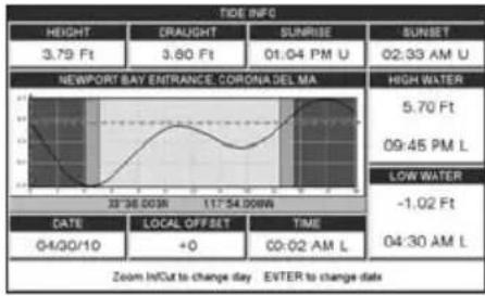
line
TIDE INFO | Category | Value | |---|---| | HEIGHT | 3.79 Ft | | CRAUGHT | 3.60 Ft | | SUNRISE | 01:04 PM U | | SUNSET | 02:33 AM U | | NEWPORT BAY ENTRANCE, CORONA DEL MA | High Water | | DATE | 04/30/10 | | LOCAL OFFSET | +0 | | TIME | 00:02 AM L | | LOW WATER | -1.02 Ft | | 09:45 PM L | | | 04:30 AM L | |Figure 4.0.2 - Tide Stations
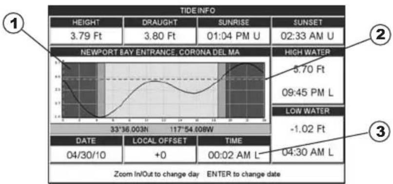
text_image
TIDE INFO HEIGHT 3.79 Ft DRAUGHT 3.80 Ft SUNRISE 01:04 PM U SUNSET 02:33 AM U NEWPORT BAY ENTRANCE, CORONA DEL MA HIGH WATER 5.70 Ft 09:45 PM L LOW WATER -1.02 Ft 33°36.003N 117°54.008W DATE LOCAL OFFSET TIME 04/30/10 +0 00:02 AM L 04:30 AM L Zoom In/Out to change day ENTER to change dateFigure 4.0.2a - Tide Graph page
Refer to the image above. The time (3) displayed corresponds to the location of the cross-hair cursor (2) in the Tide Graph (1). Moving the ShuttlePoint knob to the left or right changes the time, and moving the ShuttlePoint knob up or down selects the Tide height and Tide draught on the Tide Graph.
NOTE
The Local Offset matches the Time Offset entered in the Time Setup menu (see Par. 3.2)
4.0.3 Wrecks
This feature is used to locate the 10 nearest Wrecks to the position of your vessel. A Wreck is represented with an icon on the chart. See the following table:
| ICONDESCRIPTION | |
| ++ | non-dangerouswreck |
| ++ | dangerouswreck |
| # | distributedremainsofwreck |
| ++Masts | wreckshowingmast/masts |
| ✓ | wreckshowinganyportionofhull orsuperstructure |
Figure 4.0.3 - Wreck icons Table
- Press [FIND].
-
Move the ShuttlePoint knob to highlight WRECKS and press [ENT] or move the ShuttlePoint knob to the right.
-
A popup window will be shown with a list of nearest Wrecks.
- Move the ShuttlePoint knob to highlight the desired Wreck and press [ENT].
- Another window will be shown detailing the Wreck information.
- Press [CLR] to show the actual position of the Wreck on the Chart Page.
- Press [CLR] again at any time to return your cursor to your vessel's position.
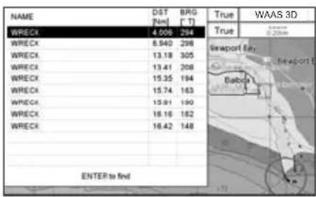
text_image
NAME WRECK 6.940 13.18 13.41 15.35 15.74 15.91 16.16 16.42 DIST Fuel BRG (FT) True True WAAS 3D 0.20km Viewport Air Babba ENTER to find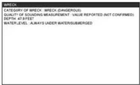
text_image
WRECK CATEGORY OF WRECK : WRECK (DANGEROUS) QUALITY OF SOUNDING MEASUREMENT : VALUE REPORTED (NOT CONFIRMED) DEPTH 47.9 FEET WATER LEVEL : ALWAYS UNDER WATER/SUBMERGEDFigure 4.0.3a - Find Wrecks
4.0.4 Obstructions
This feature is used to locate the 10 nearest Obstructions to the position of your vessel. An Obstruction is represented with an icon on the chart, see the following table:
| ICONDESCRIPTION | |
| Obstn | snag/stump |
| Mast (12) Wk | wellhead |
| # | diffuser |
| # | crib |
| fishhaven | |
| foul area | |
| # | foul ground |
| iceboom | |
| Obstn | groundtackle |
Figure 4.0.4 - Obstruction icons Table
- Press [FIND].
- Move the ShuttlePoint knob to highlight OBSTRUCTIONS and press [ENT] or move the ShuttlePoint knob to the right.
- A popup window will be shown with a list of nearest Obstructions.
- Move the ShuttlePoint knob to highlight the desired Obstruction and press [ENT].
- Another window will be shown detailing the Obstruction information.
- Press [CLR] to show the actual position of the Obstruction on the Chart page.
- Press [CLR] again at any time to return your cursor to your vessel's position.
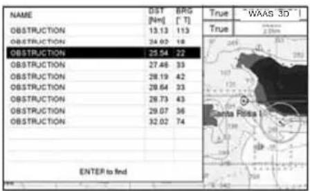
text_image
NAME OBSTRUCTION OBSTRUCTION OBSTRUCTION OBSTRUCTION OBSTRUCTION OBSTRUCTION ENTER to find DIST [Nm] BPG [T] True "WAAS 3D" True 2.00mm Santa Rossa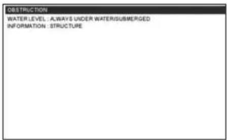
text_image
OBSTRUCTION WATER LEVEL : ALWAYS UNDER WATER/SUBMERGED INFORMATION : STRUCTUREFigure 4.0.4a - Find Obstructions
4.0.5 Lakes Information
This feature is used to find information on the 10 closest Lakes near the position of your vessel.
A Lake Info is represented with a ⓘ on the Chart Page.
NOTE
An optional MAX Lake CARD must be inserted into the GPS Chart Plotter to take advantage Lakes Information. The available MAX Lake CARDs are: NA-M017 USA: North; NA-M018 USA: East; NA-M019 USA: South; NA-M020 USA: West; NA-M029: Alaska; NA-M048: Canada.
- Press [FIND].
- Move the ShuttlePoint knob to highlight LAKES INFORMATION and press [ENT] or move the ShuttlePoint knob to the right.
- A popup window will be shown with a list of Outdoor Recreational Area objects.
- Move the ShuttlePoint knob to highlight the desired object and press [ENT].
- Another popup window will appear displaying the distance and position of the Lakes closest to your location.
- Using the ShuttlePoint knob, highlight the desired Lake and press [ENT]. This will show information on the Lake.
- Press [CLR] to show the actual position of the Lake on the Chart Page.
- Press [CLR] twice to return your cursor to your vessel's position.
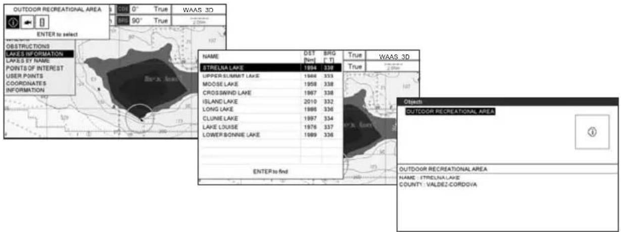
text_image
OUTDOOR RECREATIONAL AREA 0° 0° True WAAS 3D 80° 90° True ENTER to select OBSTRUCTIONS LAKES INFORMATION LAKES BY NAME POINTS OF INTEREST USER POINTS COORDINATES INFORMATION NAME DST BRG True WAAS 3D True STRELIA LAKE 1994 338 UPPER SUMMIT LAKE 1994 333 MOOSE LAKE 1958 338 CROSSWIND LAKE 1967 338 ISLAND LAKE 2010 332 LONG LAKE 1986 336 CLUNIE LAKE 1997 334 LAKE LOUSE 1976 337 LOWER BONNIE LAKE 1989 336 ENTER to find Objectb OUTDOOR RECREATIONAL AREA OUTDOOR RECREATIONAL AREA NAME : ETRELNA LAKE COUNTY : VALDEZ-CORDOVAFigure 4.0.5 - Find Lakes Information
4.0.5.0 Quick Info On Lakes
Upon viewing the chart of a lake, you can click on the Lake Info icon to query the available information immediately displayed with many details. For example, see the following picture:
Lakes Info Icon
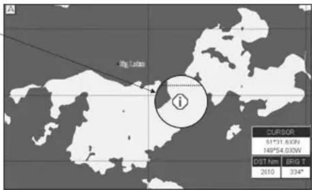
text_image
A Fig. 1400m i CURSOR 51°31.620N 149°54.030W DST Nm 8RG T 2610 334°Figure 4.0.5.0 - Example of Lakes info
When the cursor is placed over the icon, the icons of the available services are shown:
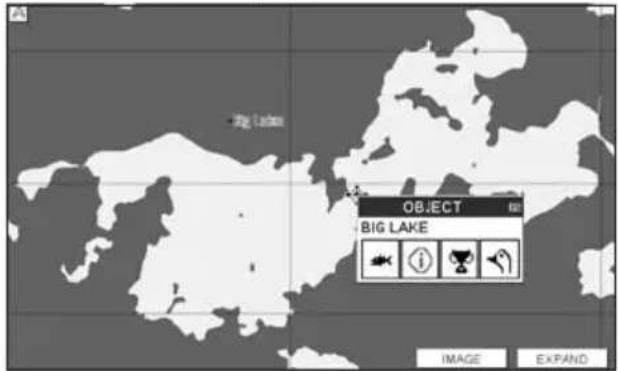
text_image
Object BIG LAKE IMAGE EXPANDFigure 4.0.5.0a - Quick Info: available services
If you press [ENT] all available information about the cartographic point under the cursor will be shown. See the next paragraph.
4.0.5.1 Full Info On Lakes
The following is an example of Full Info on Lakes:
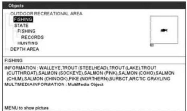
text_image
Objects OUTDOOR RECREATIONAL AREA FISHING STATE FISHING RECORDS HUNTING DEPTH AREA FISHING INFORMATION : WALLEYE,TROUT (STEELHEAD),TROUT (LAKE),TROUT (CUTTHROAT),SALMON (SOCKEYE),SALMON (PINK),SALMON (COHO),SALMON (CHUM),SALMON (CHINOOK),PIKE (NORTHERN),BURBCT,ARCTIC GRAYLING MULTIMEDIA INFORMATION : MultiMedia Object MENU to show pictureFigure 4.0.5.1 - Example of Full Info page
To see the "Fishing" object press [MENU] (when the "Fishing" object is highlighted). On the screen appears:
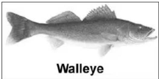
natural_image
Side-view photograph of a Walleye fish, labeled with the name below (no other text or symbols visible)Figure 4.0.5.1a - Example of picture associated to the Fishing object
4.0.6 Lakes By Name
This feature is used to locate Lakes By Name nearest the position of your vessel.
- Press [FIND].
- Move the ShuttlePoint knob to highlight LAKES BY NAME and press [ENT] or move the ShuttlePoint knob to the right.
- A popup window will be shown with a list of nearest Lakes.
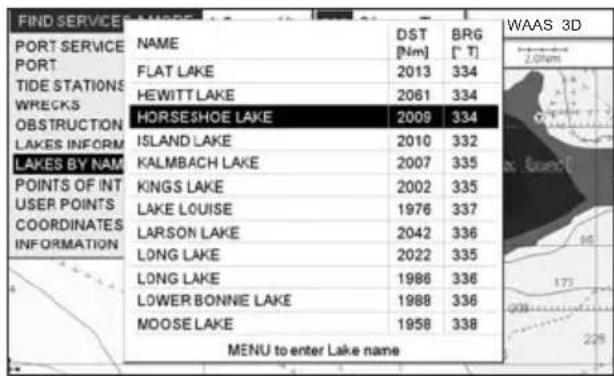
text_image
FIND SERVICE NAME DST BRG PORT [Nm] [T] PORT FLAT LAKE 2013 334 TIDE STATIONS HEWITTLAKE 2061 334 WRECKS HORSESHOE LAKE 2009 334 OBSTRUCTION ISLAND LAKE 2010 332 LAKES INFORM KALMBACH LAKE 2007 335 POINTS OF INT KINGS LAKE 2002 335 USER POINTS LAKE LOUISE 1976 337 COORDINATES LARSON LAKE 2042 336 INFORMATION LONG LAKE 2022 335 LONG LAKE 1986 336 LOWER BONNIE LAKE 1988 336 MOOSE LAKE 1958 338 MENU to enter Lake name WAAS 3DFigure 4.0.6 - Find Lakes By Name
-
Move the ShuttlePoint knob to highlight the desired Lake. Otherwise press [MENU] to enter the desired Lake name. A window will be shown: move the ShuttlePoint knob to highlight the edit of Lake name and press [ENT] to accept: another popup window will appear displaying the distance and position of the Lake.
-
Press [ENT] to show the actual position of the Lake on the Chart Page.
-
Press [CLR] twice to return your cursor to your vessel's position.
4.0.7 Points Of Interest
This feature is used to locate Points Of Interest nearest the position of your vessel.
- Press [FIND].
- Move the ShuttlePoint knob to highlight POINTS OF INTEREST and press [ENT] or move the ShuttlePoint knob to the right.
- A (Category) popup window will be shown with a list of Category types (i.e. attractions, emergency, entertainment).
- Move the ShuttlePoint knob to highlight the desired Category and press [ENT].
- A (Type) popup window will be shown with a list of types.
- Move the ShuttlePoint knob to highlight the desired Type and press [ENT].
- A popup window will be shown with a list of nearest Points Of Interest that fall into the Category and Type you have selected.
- Move the ShuttlePoint knob up/down to highlight the desired Point Of Interest and press [ENT].
- Another window will be shown with detailing the Point Of Interest information.
- Press [CLR] to show the actual position of the Point Of Interest on the Chart Page.
- Press [CLR] again at any time to return your cursor to your vessel's position.
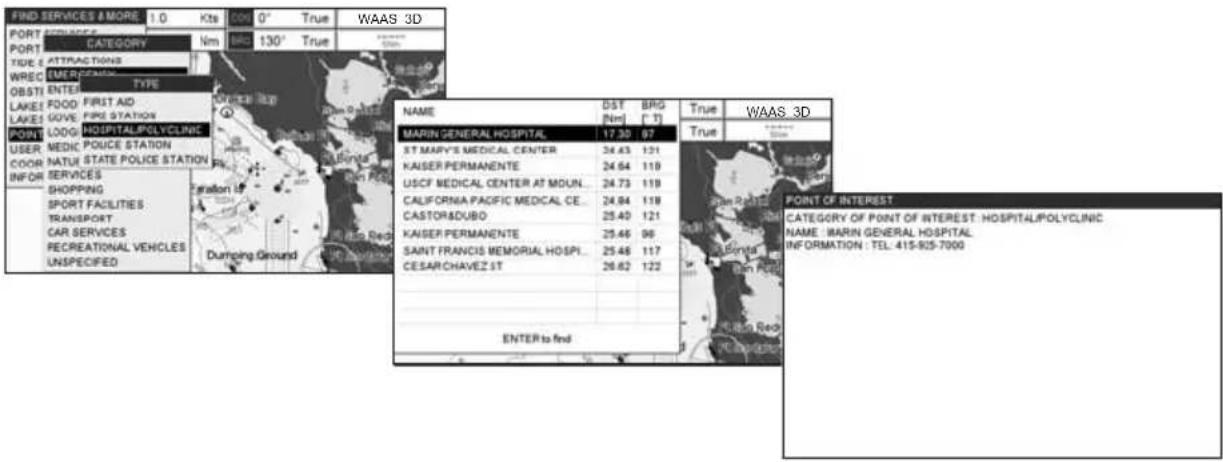
text_image
FIND SERVICES & MORE 10 Kts 500 0° True WAAS 3D PORT PORT CATEGORY Nm 130° True TIDE: ATTRAG STINGS WREC UER FONION OBSTI ENTER TYPE LAKES FOOD FIRST AID LAKES GIVE FIRE STATION LOGG HOSPITAL/POLYCLINIC USER MEDIC POLICE STATION COOR NATUE STATE POLICE STATION INFOR SERVICES SHOPPING SPORT FACILITIES TRANSPORT CAR SERVICES RECREATIONAL VEHICLES UNSPECIFIED NAME DST BRG True WAAS_3D MARIN GENERAL HOSPITAL 17.30 97 True ST MARY'S MEDICAL CENTER 24.43 121 KAISER PERMANENTE 24.64 119 USCF MEDICAL CENTER AT MOUN... 24.73 119 CALIFORNIA PACIFIC MEDICAL CE... 24.84 118 CASTORDUBO 25.40 121 KAISER PERMANENTE 25.46 96 SAINT FRANCIS MEMORIAL HOSPI... 25.48 117 CESARCHAVEZ ST 26.62 122 ENTER to find POINT OF INTEREST CATEGORY OF POINT OF INTEREST : HOSPITAL/POLYCLINIC NAME MARIN GENERAL HOSPITAL INFORMATION : TEL. 415-825-7000Figure 4.0.7 - Find Points Of Interest
4.0.8 User Points
This feature is used to search for User Points (Marks and Waypoints you have created and stored) by name quickly and efficiently.
- Press [FIND].
- Move the ShuttlePoint knob to highlight USER POINTS and press [ENT] or move the ShuttlePoint knob to the right.
- The (Select Name) popup window will appear. This window will allow you to enter in the name of the User Point you wish to locate.
- Move the ShuttlePoint knob up/down to change each number or letter and left/right to move to the next or previous position in the name of the Mark.
- Once the name of the desired Mark reads in the (Select Name) window, press [ENT] to show the location the Mark on the Chart Page.
- Press [CLR] at any time to return your cursor to your vessel's position.
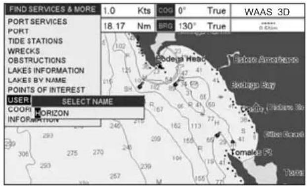
text_image
FIND SERVICES & MORE 1.0 Kts COG 0° True WAAS 3D PORT SERVICES PORT TIDE STATIONS WRECKS OBSTRUCTIONS LAKES INFORMATION LAKE'S BY NAME POINTS OF INTEREST USER SELECT NAME COOR HORIZON INFORMATION BROG 130° True Rodega Head Estate America Bodega Bay Cockay, Bokame Bo Tamales P2 TurboFigure 4.0.8 - Find User Points (Marks and Waypoints)
4.0.9 Coordinates
This feature allows you to enter Coordinates (Latitude/Longitude) and view the entered position on the Chart Page.
- Press [FIND].
- Move the ShuttlePoint knob to highlight COORDINATES and press [ENT] or move the ShuttlePoint knob to the right.
-
A (Coordinate) popup window will be shown to allow you to enter in a specified Latitude and Longitude.
-
Move the ShuttlePoint knob up/down to change each number or letter and left/right to move to the next or previous position in the Coordinates.
- Once the Coordinates are entered, press [ENT] to show the location the Mark on the Chart page.
- Press [CLR] at any time to return your cursor to your vessel's position.
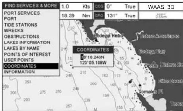
text_image
FIND SERVICES & MORE 1.0 Kts 0° True PORT SERVICES PORT TIDE STATIONS WRECKS OBSTRUCTIONS LAKES INFORMATION LAKES BY NAME POINTS OF INTEREST USER POINTS COORDINATES INFORMATION 18.39 Nm Bnd 131° True Rodega Head 58°16.243N 123°05.108W COORDINATES Etofoa Ave#h#ace Rodega Bay Ollon Board Tomales F#Figure 4.0.9 - Find GPS Coordinates
4.0.10 Information
This feature allows you to obtain information on any position on the Chart page.
- Press [FIND].
- Move the ShuttlePoint knob to highlight INFORMATION and press [ENT] or move the ShuttlePoint knob to the right.
- A page will be shown with objects information. The upper side of the page contains the Info Tree and the lower side contains the expanded information. While moving the ShuttlePoint knob through the Info Tree, all the relevant information of the selected object is shown on the lower part of the page.
- Press [CLR] again at any time to return your cursor to your vessel's position.

text_image
Objects DEPTH AREA DATA SOURCE DEPTH AREA MINIMUM DEPTH : 60.0 FEETFigure 4.0.10 - Find Information
5. MAX CARTOGRAPHY OVERVIEW
5.0 BUILT-IN CHARTS
5.0.0 Coverage areas and details
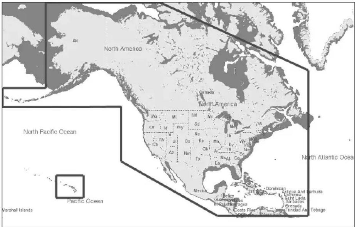
text_image
North America Canada North America North Pacific Ocean Pacific Ocean Marshall Islands North Atlantic Oceae Antigua And Barbuda Dominica Saint Lucia Barbados Grenada Trinidad An TobagoFigure 5.0.1 - Coverage Area
The CP190i and CPF190i have Built-In Charts for coastal navigation of USA including Alaska, Hawaii and Great Lakes, Canada, Bahamas, Caribbean, Cuba, Puerto Rico, and Central America which include:
a. Depth contours and spot soundings to 66 feet (20 meter) on lower scale charts and 33 feet (10 meters) on higher scale charts
b. All nav-aids with icon
c. Tidal diamond symbols on Chart Page
- Marina symbol with name and the list of services symbols
5.0.1 Updating Built-In Charts
The Built-In Charts can be updated by purchasing a Chart Update Card from your local marine electronics dealer or C-MAP USA at (800) 424-2627.
This Chart Update Card may be used ONE time to update the charts in a GPS Chart Plotter. After the updating, the Chart Update Card will not update other GPS Chart Plotters.
After purchasing the Chart Update Card, follow the procedure below to update the charts.
- Turn Off the GPS Chart Plotter.
- Insert the Chart Update Card into the slot.
- Press and hold [PWR] to turn the GPS Chart Plotter On.
- The GPS Chart Plotter's display will show a message that the Built-In Charts are being uploaded.
- After uploading the GPS Chart Plotter will check to ensure the charts have been loaded correctly and show a message.
NOTE
If the message shows the charts were not updated correctly, follow steps 1-4 again. If the GPS Chart Plotter shows a error message again, contact C-MAP USA at (800) 424-2627 for assistance.
5.1 INSERTING THE OPTIONAL MAX C-CARD
Hold the C-CARD by the long inclined side so that you can see the C-MAP BY JEPPESEN label.
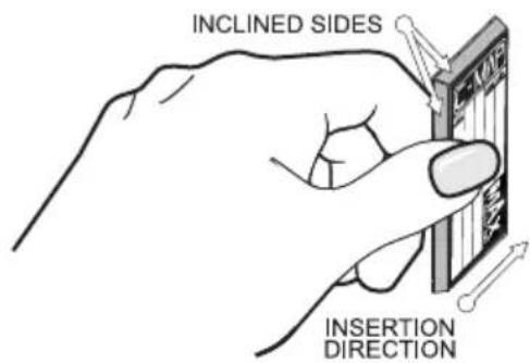
text_image
INCLINED SIDES INSERTION DIRECTIONFigure 5.1 - Inserting C-CARD
Open the door, gently push the C-CARD into the slot: push the C-CARD in as far as it will go, then close the door.
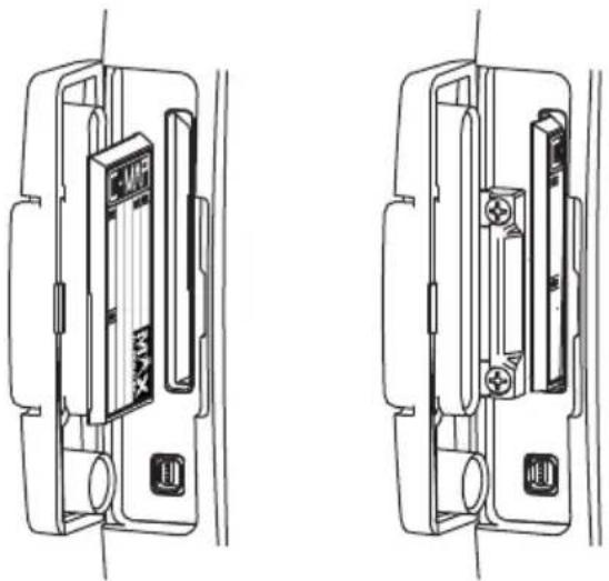
natural_image
Technical line drawing of two mechanical components with mounting holes and internal components (no text or symbols)Figure 5.1a - Inserting C-CARD (details)
NOTE
The small connector below the C-CARD is only used by Standard Horizon repair technicians.
Key points are:
Data Features
• ISO Certification (electronic chart production process with quality certification)
- Extra Large Coverage (all the C-Map electronic chart detail and a huge coverage without having to change cartridge)
· Official data source (data based on use of official data sources Hydrographic Offices Release)
- Detailed World Background (worldwide background chart with details)
- Depths & Land Elevation (color shading of sea depth and land altitude for improved chart appearance)
- Bathymetric & Spot Soundings (Data Base with depth and bathy information for an extraordinary view of the seabed depth)
- Detailed Port Plan to information (complete port and marina charts with detail)
- Search & Find (quickly locates chart contents and objects)
- Tides Preview (allows viewing of current, future and past tide cycles of specific NOAA Tide Stations)
- Dynamic Currents (current arrows showing speed and direction of current, future and past currents)
- Dynamic Nav-Aids (selection to enable the Nav-Aids to blink to their specifications and appear on the chart in color)
- Port Info (searchable data base of service in ports)
- Enhanced Port Info & Roads (searchable data base of detailed information that include facilities and services in ports and surrounding areas)
- Object Info (moving cursor over object to show restricted area details and related information)
- Quick Info (moving cursor over wrecks, shoals, Nav-Aids to show restricted area details and related information and object to show details)
- Photos & Diagrams (high definition pictures of ports, piers, bridge diagrams and nav-aids)
- Multilanguage Support (allows the plotter to show language of your choice in using proper character set for Asian and other countries)
- True-Type Font (improves text on chart for optimal reading)
Presentation Features
- Clear View (advanced legibility techniques providing more chart data on the screen)
- Clear Info (sophisticated "Human Dictionary" to translate Nav-Aid abbreviations found on paper charts)
- Flexi-Zoom (increased Under and Over Zoom between chart levels, resulting in optimal scale display for any situation)
- Perspective View ("Real World" perspective view of the chart, updated real-time during navigation)
- Enhanced Mixing Levels (seamless data presentation)
- Off-line redraw (cartography level transition without image construction)
Cartographic Data related Features
- Guardian Alarm (the Guardian Alarm is a user defined area in front of your vessel to alert you while navigating of possible obstacles on the chart)
- Safety Status Bar (a status bar with six boxes to show the status of certain functions. Any warning or alarm condition is identified by the red color to indicate possible risk)
- Safety Route Check (sophisticated function that checks for dangerous objects along your navigation route)
MAX and NT/NT ^+ C-CARD coexistence
- When NT ^+ data and MAX data cover different areas, the GPS Chart Plotter receives data from both charts (depending on the current position).
- When NT ^+ data and MAX data cover the same area, the GPS Chart Plotter receives data only from MAX chart.
6. MAP FUNCTIONS
6.0 MAX FUNCTIONS MENU
- Press [MENU], move the ShuttlePoint knob to highlight SETUP MENU and press [ENT].
- Move the ShuttlePoint knob to highlight MAX FUNCTIONS and press [ENT] or move the ShuttlePoint knob to the right. The MAX Functions menu appears on the screen:
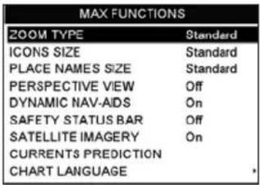
text_image
MAX FUNCTIONS ZOOM TYPE Standard ICONS SIZE Standard PLACE NAMES SIZE Standard PERSPECTIVE VIEW Off DYNAMIC NAV-AIDS On SAFETY STATUS BAR Off SATELLITE IMAGERY On CURRENTS PREDICTION CHART LANGUAGEFigure 6.0 - Max Functions Menu
The available Max Functions menu is described in the following.
6.0.0 Zoom Type
Zoom Type refers to the chart scale selection. It has two options: Standard (default) or Flexi-Zoom. When Zoom Type is set to Flexi-Zoom, a short [ZOOM IN]/[ZOOM OUT] push causes a change of chart level, while a long [ZOOM IN]/[ZOOM OUT] push (press and hold) causes an expansion or compression of the chart image, without a chart level change.
CHART: US, NOS, GRAPH, 11428D
SCALE: 1:40000
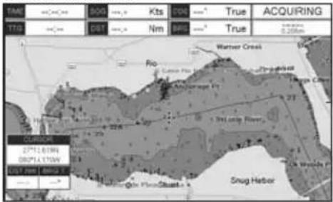
text_image
SMR 200G Kts BNG True ACQUIRING TTB DBT Nm BNG True Warner Creek Rio Cuneo Pia Thirteenth Majaharapa Fy 131 Long River CUCURENE 27th11.01W DRP14.17W CLV 7mm Lanes E Snug Harbor
text_image
LONGPUSH ZOOM OUTCHART: US, NOS, GRAPH, 11428D
SCALE: 1:40000
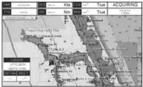
text_image
TIME T10 ACQUIRING BOP Kts COP True DIST Nm BRG True LIMITED ROOMS 14 Taygon Bay Valley Club Gard St. Howard Creek Cle 2.7 CURSOR 2P12.58TN 08PM 17PM DIST km BRG T 2P12.58TN 08PM 17PM
text_image
SHORT PUSH ZOOM OUTCHART: US, NOS, GRAPH, 11474
SCALE: 1:80000
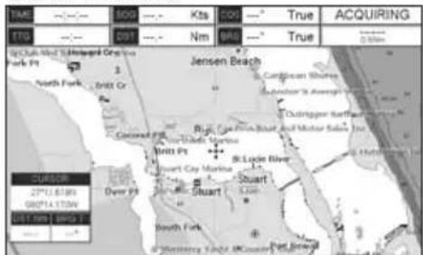
text_image
TAM 100 200 300 400 500 600 700 800 900 1000 1100 1200 1300 1400 1500 1600 1700 1800 1900 2000 2100 2200 2300 2400 2500 2600 2700 2800 2900 3000 3100 3200 3300 3400 3500 3600 3700 3800 3900 4000 4100 4200 4300 4400 4500 4600 4700 4800 4900 5000 5100 5200 5300 5400 5500 5600 5700 5800 5900 6000 6100 6200 6300 6400 6500 6600 6700 6800 6900 7000 7100 7200 7300 7400 7500 7600 7700 7800 7900 8000 8100 8200 8300 8400 8500 8600 8700 8800 8900 9000 9100 9200 9300 9400 9500 9600 9700 9800 9900 1 2 3 4 5 6 7 8 9 1 2 3 4 5 6 7 8 9 1 2 3 4 5 6 7 8 9 1 2 3 4 5 6 7 8 9 1 2 3 4 5 6 7 8 9 1 2 3 4 5 6 7 8 9 1 2 3 4 5Figure 6.0.0 - Zoom Type
Note that in the top of the previous picture the chart scale remains the same but it is graphically compressed.
By pressing [ZOOM IN]/[ZOOM OUT] a popup window is displayed on a corner of the chart screen. The window shows the current zoom factor: Normal is the original chart level (1:1 scale), Over-Zoom x2, x4, x16, x32, Under-Zoom x1/2, x1/4.
To activate this function follow the procedure:
- Press [MENU], move the ShuttlePoint knob to highlight SETUP MENU and press [ENT].
- Move the ShuttlePoint knob to highlight MAX FUNCTIONS and press [ENT] or move the ShuttlePoint knob to the right.
- Move the ShuttlePoint knob to highlight ZOOM TYPE and press [ENT] or move the ShuttlePoint knob to the right.
- The menu now shows two selections, STANDARD or FLEXI-ZOOM.
- Move the ShuttlePoint knob to select the selection and press [ENT].
- Press [CLR] until the menu disappears or an easier method is to move the ShuttlePoint knob to the left a few times.
6.0.1 Icon Size
On MAX charts it is possible to set the size of all icons drawn on the charts, selecting between Standard (default) and Large size.
ICONS SIZE standard
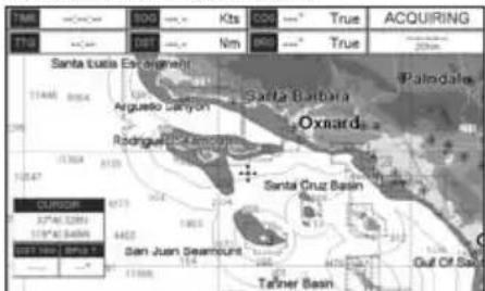
text_image
ACQUIRING TTO SANTA TUCIA Est. Grisnerell Palmola Santa Barbara Arguesto Canyon Oxnard Rodriguez Santa Cruz Basin San Juan Geamount Gulf Of San Telmer BasinICONS SIZE large
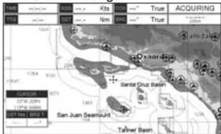
text_image
TME 2000 Kbs COB True ACQUIRING TTE Dist Nm Avg True 1824 1364 8190 Santa Cruz Basin San Juan Seamount Tahmer Basin Esturier 37°N 320V 31°N 5488N Dist Nm 800 TFigure 6.0.1 - Icons Size
To activate this function follow the procedure:
- Press [MENU], move the ShuttlePoint knob to highlight SETUP MENU and press [ENT].
- Move the ShuttlePoint knob to highlight MAX FUNCTIONS and press [ENT] or move the ShuttlePoint knob to the right.
- Move the ShuttlePoint knob to highlight ICONS SIZE and press [ENT] or move the ShuttlePoint knob to the right.
- The menu now shows two selections, STANDARD or LARGE.
- Move the ShuttlePoint knob to select the selection and press [ENT].
- Press [CLR] until the menu disappears or an easier method is to move the ShuttlePoint knob to the left a few times.
6.0.2 Place Name Size
On MAX charts it is possible to set the size of all names drawn on the charts, selecting between Standard (default), Medium and Large size.
PLACE NAMES SIZE standard
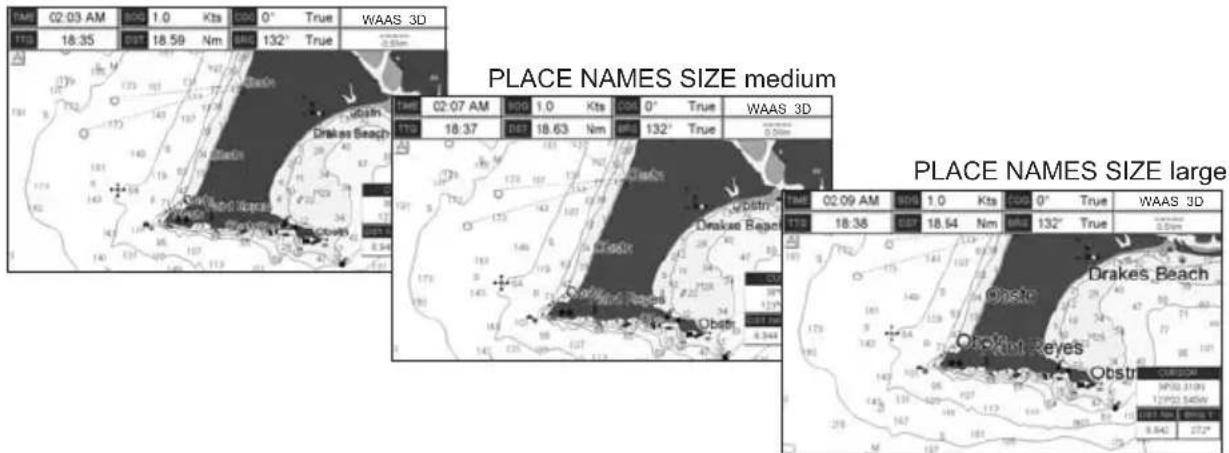
text_image
LAM 02:03 AM 800 1.0 Kts 600 0° True WAAS 3D TTB 18:35 DT 18.59 Nm BIG 132° True PLACE NAMES SIZE medium WAAS 3D TIME 02:07 AM 900 1.0 Kts 600 0° True WAAS 3D TTB 18:37 DT 18.63 Nm BIG 132° True PLACE NAMES SIZE large TIME 02:09 AM 800 1.0 Kts 600 0° True WAAS 3D TTB 18:38 DT 18.54 Nm BIG 132° True Drakes Beach Ostre Ostre Reyes OstreFigure 6.0.2 - Place Names Size
To activate this function follow the procedure:
- Press [MENU], move the ShuttlePoint knob to highlight SETUP MENU and press [ENT].
- Move the ShuttlePoint knob to highlight MAX FUNCTIONS and press [ENT] or move the ShuttlePoint knob to the right.
- Move the ShuttlePoint knob to highlight PLACE NAMES SIZE and press [ENT] or move the ShuttlePoint knob to the right.
- The menu now shows three selections, STANDARD, MEDIUM or LARGE.
- Move the ShuttlePoint knob to select the selection and press [ENT].
- Press [CLR] until the menu disappears or an easier method is to move the ShuttlePoint knob to the left a few times.
6.0.3 Perspective View
The Chart page may be show in a perspective (fly over) or normal mode during navigation. Perspective view of the chart is a type of "bird's eye" view of a chart, and give you a more realistic perspective of the chart. As the upper side of the chart is more compressed than the lower side, a wider chart area is visible, so it allows showing more chart information immediately ahead and around the cursor.
Perspective View ON
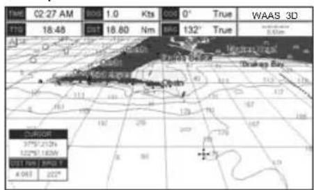
text_image
1am 02:27 AM 8:00 1.0 Kts 00° True WAAS 3D F10 18.48 0:5 18.60 Nm Mio 132° True A Midwest River Bulna River Drakee Bay Capean 37° 212m 122m 185m 31 km 34km A 963 222°Perspective View OFF
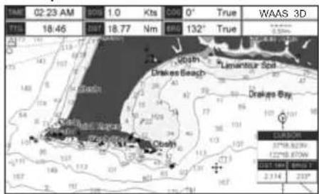
text_image
1AM 02:23 AM 00:00 1.0 Kts 00' 0° True WAAS 3D 718 18:46 197 18.77 Nm 685 132° True COSH Drakes Beach Lavantour Spd Drakes Bay COSH Drakes Beach COSH Drakes Beach COSH Drakes Beach COSH Drakes Beach COSH Drakes Beach COSH Drakes Beach COSH Drakes Beach COSH Drakes Beach COSH Drakes Beach COSH Drakes Beach COSH Drakes Beach COSH Drakes Beach COSH Drakes Beach COSO Drakes Beach COSO Drakes Beach COSO Drakes Beach COSO Drakes Beach COSO Drakes Beach COSO Drakes Beach COSO Drakes Beach COSO Drakes Beach COSO Drakes Beach COSO Drakes Beach COSO Drakes Beach COSO Drakes Beach COSO Drakes Bay COSO Drakes Bay COSO Drakes Bay COSO Drakes Bay COSO Drakes Bay COSO Drakes Bay COSO Drakes Bay COSO Drakes Bay COSO Drakes Bay COSO Drakes Bay COSO Drakes Bay COSO Drakes Bay COSO Drakes Bay COSCO Drakes Bay COSCO Drakes Bay COSCO Drakes Bay COSCO Drakes Bay COSCO Drakes Bay COSCO Drakes Bay COSCO Drakes Bay COSCO Drakes Bay COSCO Drakes Bay COSCOFigure 6.0.3 - Perspective View
To activate this function follow the procedure:
- Press [MENU], move the ShuttlePoint knob to highlight SETUP MENU and press [ENT].
- Move the ShuttlePoint knob to highlight MAX FUNCTIONS and press [ENT] or move the ShuttlePoint knob to the right.
- Move the ShuttlePoint knob to highlight PERSPECTIVE VIEW and press [ENT] or move the ShuttlePoint knob to the right.
-
The menu now shows two selections, ON or OFF.
-
Move the ShuttlePoint knob to select the selection and press [ENT].
- Press [CLR] until the menu disappears or an easier method is to move the ShuttlePoint knob to the left until the chart page is shown.
6.0.4 Dynamic Nav-Aids
This function allows the blinking of the Nav-Aids to be turned On or Off. The blink period and color of each Nav-aid is read from the Nav-Aid attributes stored on the optional C-MAP BY JEPPESEN C-CARD. When the ship is inside the Nav-Aid nominal range, the light of the Nav-Aid will start blinking. When Dynamic Nav-Aids option is set to On, when the flashing light is Off, or when fix position is out of the sector, the light color is displayed by using a faint light color.
To activate this function follow the procedure below:
- Press [MENU], move the ShuttlePoint knob to highlight SETUP MENU and press [ENT].
- Move the ShuttlePoint knob to highlight MAX FUNCTIONS and press [ENT] or move the ShuttlePoint knob to the right.
- Move the ShuttlePoint knob to highlight DYNAMIC NAV-AIDS and press [ENT] or move the ShuttlePoint knob to the right.
- The menu now shows two selections, ON or OFF.
- Move the ShuttlePoint knob to select the selection and press [ENT].
- Press [CLR] until the menu disappears or an easier method is to move the ShuttlePoint knob to the left until the chart page is shown.
6.0.5 Safety Status Bar (DSI - Data Safety Indicator)
When the Safety Status Bar is enabled, a status bar with six boxes show the status of certain functions. Any warning or alarm condition is identified by the red color to indicate possible risk.
To activate this function follow the procedure:
- Press [MENU], move the ShuttlePoint knob to highlight SETUP MENU and press [ENT].
- Move the ShuttlePoint knob to highlight MAX FUNCTIONS and press [ENT] or move the ShuttlePoint knob to the right.
- Move the ShuttlePoint knob to highlight SAFETY STATUS BAR and press [ENT] or move the ShuttlePoint knob to the right.
- The menu now shows the following selections: ON (The Safety Status Bar is shown), OFF (The Safety Status Bar is not shown), ICON (The Safety Status Bar is not shown, but a Warning alarm Icon is shown on the corner of the chart page as soon as any item controlled by the DSI function returns an alarm condition. The Warning Icon remains displayed until the alarm condition persists. Placing the cursor over this Icon, a quick help message is shown next to the Icon, allowing the Safety Status Bar to be shown. In this case - when the Safety Status Bar is opened via Warning alarm Icon - it is allowed to obtain information about each "active" Safety Status box (the red ones): it is possible to select them by ShuttlePoint knob movement left/right, and a list of active alarms is shown underneath the selected box. By pressing [CLR], the Safety Status Bar is removed from the screen.
- Move the ShuttlePoint knob to select the selection and press [ENT].
- Press [CLR] until the menu disappears or an easier method is to press the ShuttlePoint knob to the left a few times.

flowchart
graph LR
    A["1 O.ZOOM"] --> B["2 BEST MAP"]
    B --> C["3 DATA OFF"]
    C --> D["4 DECLUT."]
    D --> E["5 DANGERS"]
    E --> F["6 CAUTIONS"]
① Normal: when the chart is displayed at normal scale.
U. Zoom: red when the chart is underzoomed out more than twice normal scale, gray otherwise.
O. Zoom: red when the chart is over-zoomed in more than twice normal scale, gray otherwise.
No Chart: red when the chart is zoomed in more than twice normal scale, gray otherwise.
Safety Status Bar
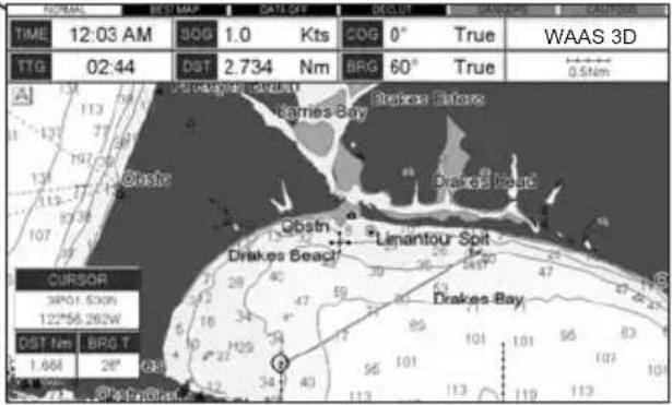
text_image
NORMAL BET MAP DATI-0FT DECOF GANGUO CAUTIONS TIME 12:03 AM 80G 1.0 Kts COG 0° True WAAS 3D TTG 02:44 DST 2.734 Nm BRG 60° True 0.5Nm Al 113 77 97 131 113 107 CurSOR 3P01 630N 12256 262W DST nm BRG T 1.668 28" GB Barrie Bay Drakes Beach Obstn Limantour Spit Drakes Bay② Red when a more detailed chart is available under the cursor position.
③ Red when at least one of the following objects or layers is turned off (by the user) Depths/soundings; Wrecks/obstructions; Tracks/routes; Attention Areas; Nav-Aids.
④ Displays red when clearing overlapping objects.
⑤ Red when "Guardian Technology" detects one of the following objects: Land, Intertidal, Depth Area, Rocks, Obstructions, Shoreline Constructions, Fishing Facility, Wrecks, Dragged area, Diffusion area, Mooring facilities, Pingos and Production installations.
⑥ Red when "Guardian Technology" detects cautionary or restricted area.
Figure 6.0.5 - Safety Status Bar
6.0.6 Satellite Imagery
This function allows to overlay the Satellite image for background chart. When it is set On, the Palette is set to Normal to display the proper colors.
NOTE
The satellite image is only shown on 100NM, 50NM and 20NM scales.
To activate this function follow the procedure below:
- Press [MENU], move the ShuttlePoint knob to highlight SETUP MENU and press [ENT].
- Move the ShuttlePoint knob to highlight MAX FUNCTIONS and press [ENT] or move the ShuttlePoint knob to the right.
- Move the ShuttlePoint knob to highlight SATELLITE IMAGERY and press [ENT] or move the ShuttlePoint knob to the right.
- The menu now shows two selections, ON or OFF.
- Move the ShuttlePoint knob to select the selection and press [ENT].
- Press [CLR] until the menu disappears or an easier method is to move the ShuttlePoint knob to the left until the chart page is shown.
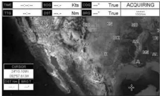
text_image
TIME TTG --:-- --:-- BDG --:- Kts COG ---° True ACQUIRING DST --:- Nm BRG ---° True 100km XV UT GO XS NO GX AB TR AX NY TX MR AL LA CURSOR 24°10.10'W 092°57.61'W DST Nm BRG T --:- --:~Figure 6.0.6 - Example of Satellite Imagery
6.0.7 Currents Prediction
The worldwide database with Tidal stream information is available with MAX C-CARDs. When data/time is available, Tidal stream arrows are shown on the charts, indicating the direction and strength of the Tide:
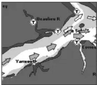
text_image
Beaulieu R Yarnouth Cowies R
text_image
Beaulieu R Yarmouth Cowe T T T T T T Ry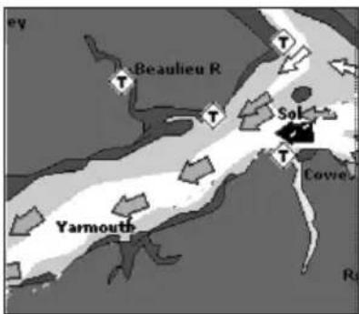
text_image
Beaulieu R Sol Yarmouth Cove RFigure 6.0.7 - Tidal stream arrows
If no data/time is available from the GPS or the GPS Chart Plotter is not in Simulation mode, the icon on the chart is generic one. The color of the arrow denotes the strength of the current as follows:
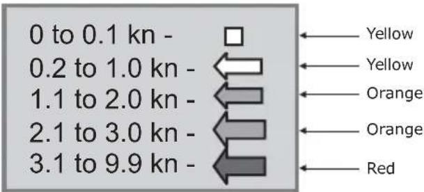
text_image
0 to 0.1 kn - 0.2 to 1.0 kn - 1.1 to 2.0 kn - 2.1 to 3.0 kn - 3.1 to 9.9 kn - Yellow Yellow Orange Orange RedFigure 6.0.7a - Tidal stream arrows table
When the GPS Chart Plotter receives a valid position fix, the Tide icons are shown on the charts on the basis of the current date and time: the screen displays and changes arrows as date/time changes.
It is possible to see the variation of the Tidal arrows on the selected area at any given time. To activate this function follow the procedure:
- Press [MENU], move the ShuttlePoint knob to highlight SETUP MENU and press [ENT].
-
Move the ShuttlePoint knob to highlight MAX FUNCTIONS and press [ENT] or move the ShuttlePoint knob to the right.
-
Move the ShuttlePoint knob to highlight CURRENTS PREDICTION and press [ENT] or move the ShuttlePoint knob to the right.
-
A window is shown on the low-left side of the chart. Press [S ET TIME] to set the date and time manually, and [INCR. TIME]/[DECR. TIME] to decrease/increase time; press [EXIT] to exit.
6.0.8 Chart Language
The CP390i and CPF390i may be customized to show the local language of the chart. To select the Chart Language you want:
-
Press [MENU], move the ShuttlePoint knob to highlight SETUP MENU and press [ENT].
-
Move the ShuttlePoint knob to highlight MAX FUNCTIONS and press [ENT] or move the ShuttlePoint knob to the right.
-
Move the ShuttlePoint knob to highlight CHART LANGUAGE and press [ENT] or move the ShuttlePoint knob to the right. A new popup window will appear on the screen. The available functions are described in the table below.
| Language | : Allows setting the language to display chart information. The language is chosen among the list of languages available on the cartographic data (data cartridge or embedded charts). |
| Mode : Defines how objects are translated. Selections are:Off : Enables the language chosen in the Language menu above. If the selected language is not present on the objects information, English is used.English: Always uses English.Local : Uses the Local language present on C-MAP B Y JEPPESEN C-CARD. If no Local language is available, English is used. | |
- After the selection is made, press [CLR] repeatedly or move the ShuttlePoint knob to the left repeatedly until the Chart page is shown.
NOTE
a. When the Chart Language is changed, the following settings are automatically selected: MODE is set to Off and Chart Language is set to your selection.
b. If the C-CARD is removed or changed, the Chart Language should be confirmed and changed if necessary.
6.0.9 Pictures or Diagrams
Using optional C-MAP BY JEPPSEEN MAX data cards allows you to show pictures or diagrams on the CP390i and CPF390i display. These Pictures are typically used to facilitate the identification of cartographic objects or places around the chart: they can be the landscape layout nearby a harbor, the shape of a bridge or of a buoy etc. On some objects, such as bridges, the image associated can represent the Diagram representing the shape of the objects and the various characteristics (length, height, type of bridge etc.).
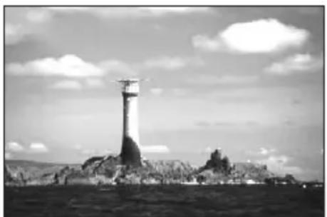
natural_image
Black-and-white photo of a lighthouse on a rocky outcrop under a cloudy sky (no text or symbols visible)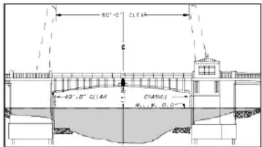
text_image
80°-0' CLEA 40°,0' CLEAR CHANNEL M.L.W. O.D.Figure 6.0.9 - Pictures and Diagrams
How to show the Pictures or Diagrams of a Object
They are shown on the Chart page with the camera icon see the figure below:
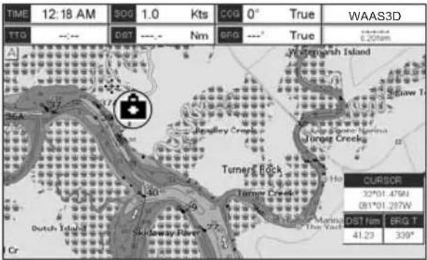
text_image
TIME 12:18 AM 500 1.0 Kts COG 0° True WAAS3D TTG --- Dist --- Nm BFG --- True E:2076m A Jharkangsh Island Tumers Creek CurSOR 32°01.475W GB1°01.297W DIST Nm BFG T 41.23 339° CrFigure 6.0.9a - Example of camera icon
Move the cursor over the camera icon. You are get the quick info on the object and there is the camera icon on the top bar of the window:
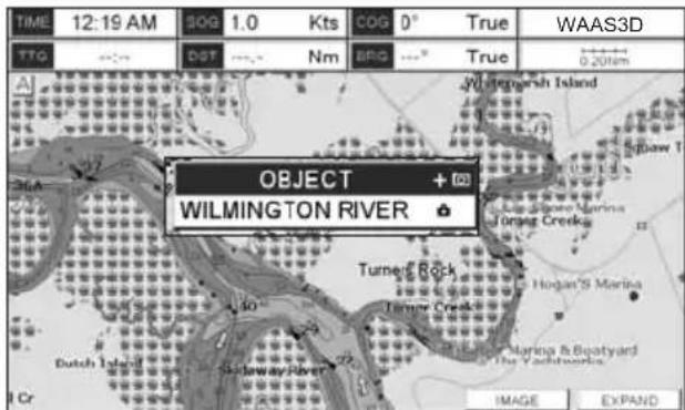
text_image
TIME 12:19 AM SOG 1.0 Kts COG 0° True WAAS3D TTG --- DST --- Nm BRG --- True 0.20km OBJECT + WILMINGTON RIVER ▼ Turner Rock Hogan's Marina Terry Creek Hogan's Marina & Boatyard The Yachtworks Image EXPANDFigure 6.0.9b - Example of Quick Info on camera icon
Press [IMAGE] for 1 second to display the image on the screen:
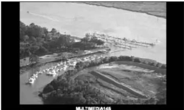
natural_image
Aerial black-and-white photo of a river with boats and agricultural fields, labeled 'MULTIMEDIA145' at bottom (no other text or symbols visible)Figure 6.0.9c - Example of displayed image
Otherwise press [EXPAND] to open the Full Info on the object. Note that on the Full Info, there is the small camera icon on a corner of the square containing the object icon. To see the picture press [MENU] when the object with a picture is highlighted.
When the picture is shown, it is possible to fit it to screen by pressing [ENT], to change the contrast by pressing [ZOOM IN] or [ZOOM OUT] and to display the next picture associated, if any, by moving the ShuttlePoint knob left or right.
6.0.10 Enhanced Port Info
Optional C-MAP BY JEPPESEN MAX C-Cards include additional Port Services that were not present before.
Additional attributes of Port Areas and Port Marinas have been included as Location, Country, Region, State, Harbour master telephone number etc., see the following figure.
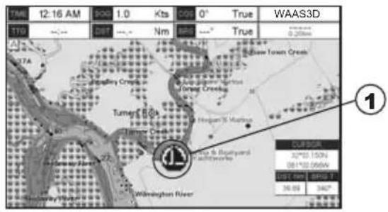
text_image
12:16 AM 1.0 Kts 0° True WAAS3D TTD DIST Nm BRD True 0.200mm A 77A Tunert Bay Tunert Creek Buller Town Creek Buller Town Creek Buller Town Creek Buller Town Creek Buller Town Creek Buller Town Creek Buller Town Creek Buller Town Creek Buller Town Creek Buller Town Creek Buller Town Creek Buller Town Creek Buller Town Creek Buller Town Creek Buller Town Creek Buller Town Creek Buller Town Creek Bollers River Wilmington River CUB SUR 30°00' 150"N 30°100' 050"N CUB REP 100% 1" 30.00' 342"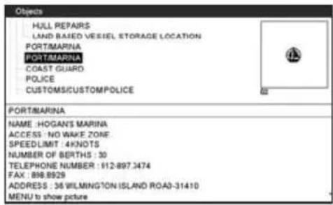
text_image
HULL REPAIRS LAND BASED VESIEL STORAGE LOCATION PORT/MARINA PORT/MARINA COAST GUARD POLICE CUSTOMS/CUSTOM POLICE PORT/MARINA NAME : HOGAN'S MARINA ACCESS : NO WAKE ZONE SPEEDLIMIT : 4KNOTS NUMBER OF BERTHS : 30 TELEPHONE NUMBER : 912-897.3474 FAX : 898-8929 ADDRESS : 36 WILMINGTON ISLAND ROAD-31410 MENU to show picture① PORT icon
Figure 6.0.10 - Example of enhanced Port Info
7. CREATING MARKS
Definitions:
MARK
Can be a stand alone position or be linked to a Route. A Mark is place on the Chart Page using [MARK] or by entering in information in the MARK/WAYPONTS menu and selecting NEW MARK.
WAYPOINTS
Always linked to a Route. Are placed on the Chart page using [ROUTE].
NOTE
The difference between a Mark and a Waypoint is
a. When a Route is created using WAYPOINTS and the ROUTE is deleted the WAYPOINTS are also deleted.
b. If a Route is created using MARKS and the ROUTE is deleted the MARKs remain.
7.0 CREATING A NEW MARK USING THE CHART PAGE
- Move the ShuttlePoint knob to the desired or approx. Lat/Lon and press [MARK].
- You will notice a Mark is placed under the location of the Cursor and a popup window is shown with the exact Lat/Lon of the Mark.
- If the position is incorrect press [E DIT] that will allow you to change the position, Mark name and icon type.Refer to Par. 7.1 for details.
① Mark placed under Cursor
② Lat/Lon of Mark, DST/BRG from vessel location
③ Press Soft Key to show the Marks/Waypoint List, to edit, to move or to delete Mark
④ Vessel location
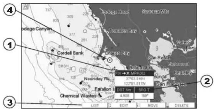
text_image
④ Sodega Canyon ① Cordell Bank SMSH 800 120 377 369 357 228 300 485 377 300 120 377 369 357 228 300 485 377 369 357 228 300 485 377 369 357 228 300 485 377 369 357 228 300 485 377 369 357 228 300 485 378 369 357 228 300 485 378 369 357 228 300 485 378 369 357 228 300 485 378 369 357 228 300 485 378 36Figure 7.0 - Mark creation
NOTE
After entering in all the Marks it is a good practice to back up the points to an User C-CARD. Refer to Section 11.
7.1 EDITING A MARK
If a Mark has previously been created and you wish to Edit it, move Cursor over the top of the Mark.
- After a Mark is created press [E dIT] to show the edit popup window.
text_image
MARK MRK004 33°53.448N 119°20.905WFigure 7.1 - Mark editing
- The Mark Icon is selected, press [ENT]. A popup window appears:
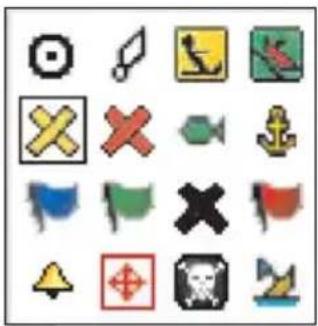
natural_image
Grid of 16 pixelated icons including camera, gear, and warning symbols (no text or labels)Figure 7.1a - Mark Icons
- Move the ShuttlePoint knob to select the desired Mark Icon, when finished press [ENT].
- Move the ShuttlePoint knob to the right to select the Mark Name. Press [ENT] and the first digit in the name will be highlighted.
- Move the ShuttlePoint knob up or down to select the first character.
- Move the ShuttlePoint knob to the right to select the next character.
- Repeat steps 4 and 5 until the Mark name is shown. Press [ENT].
- Move the ShuttlePoint knob to the right to select the Lat/Lon and press [ENT].
- Move the ShuttlePoint knob up or down to select the first character.
- Move the ShuttlePoint knob to the right to select the next character.
- Repeat steps 9 and 10 until the desired position is shown. Press [ENT] and [CLR] to store the Mark.
7.1.0 Deleting a Mark or Waypoint
- Move the ShuttlePoint knob over the Mark or Waypoint to delete.
- Press [D ELETE]. A popup window will be shown to confirm deleting the point.
- Move the ShuttlePoint knob to highlight YES and press [ENT].
7.1.1 Moving a Mark or Waypoint
- Move the ShuttlePoint knob over the Mark or Waypoint you want to move.
- Press [M ove].
- Use the ShuttlePoint knob to move the cursor. A dotted line, connecting the previous Waypoint position to the new position, is shown:
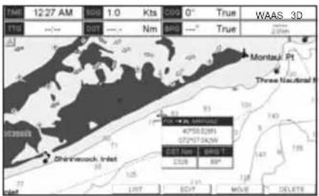
text_image
12/27 AM 806 1.0 Kts C09 0° True WAAS 3D NTG RDT Nm BPG True Montau, Ft Three Nasional 47583291 527973479 EST Net BPG T 2508 BP Shri-Veock, Inlet LRT EDT MAVE DELETE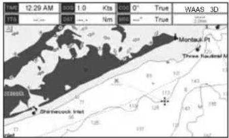
text_image
17M 12:29 AM 000 1.0 Kts 006 0° True WAAS 3D 17B Saturn 047 Nm 885 True Montau P1 Three Nautical M 000003 Shirinecock Iriet 113 128 143 188 177 178 189 190Figure 7.1.1 - Moving Mark or Waypoint (1)
- Press [ENT] ([CLR] to abort the move), the Waypoint appears in the new position.
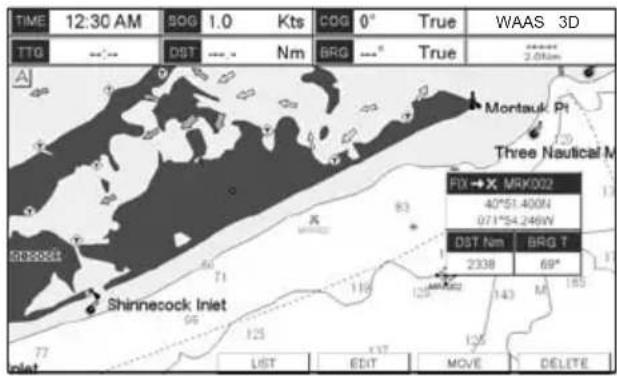
text_image
TIME 12:30 AM SOG 1.0 Kts COG 0° True WAAS 3D TTG --- DST --- Nm BRG ---° True 2.08km Montauk Pt Three Nautical M FX→X MRK002 40°51.400N 97°54.249W DST Nm BRG T 2338 69° Shinecock Inlet LIST EDIT MOVE DELETEFigure 7.1.1a - Moving Mark or Waypoint (2)
7.2 MARKS/WAYPOINTS LIST
The MARKS/WPTS List shows all the Marks and Waypoints that have been stored into the GPS Chart Plotter. This page also allows you to:
| ICON | Allows sorting by icon type. Selections are:a. SELECT - Only User Points with the selected icon are shownb. ALL - All User Points are shown |
| FIND | Searches through the Marks or Waypoints to find a point by name using the ShuttlePoint knob |
| LOCATE Shows the position of a Mark or Waypoint on the Chart page | |
| EDIT Allows you to edit a previous stored Mark or Waypoint | |
| SORT Allows sorting the name of User Points. Selections are:a. A-Z ASCENDING - Sorts the name of the Mark or Waypoint in ascending orderb. Z-A DESCENDING - Sorts the name of the Mark or Waypoint in descending order | |
| NEW MARK | Allows you to create and edit a new Mark. Useful when entering many Marks from a list. |
| MODE | This selection controls how the Marks or Waypoints are shown on the Chart page. Selections are:a. SHOW - icon and name are shownb. ICON - only icon (no name) is shownc. HIDE - Mark or Waypoint is hiddend. SHOW ALL - All Marks or Waypoints are showne. ICON ALL - All Icons are shown without namef. HIDE ALL - All Marks or Waypoints are hidden |
| DELETE Allows to delete the selected point. | |
| DEL ALL Allows to delete all stored points. | |
| SEND* | Sends the stored points to a external device (PC) capable of listening to NMEA WPL and RTE sentences. |
| RECEIVE* | When selected, receives points from an external device (PC) that is capable of sending NMEA WPL sentence. |
NOTE\*
The SEND and RECEIVE functions are used to receive or transmit User Points (Marks and Waypoints) to and from a Personal Computer (see also Par. 2.9).
| MARKS / WAYPOINTS | |||||
| SYM | NAME | TYPE | LATITUDE LONGITUDE | DST[Nm] DRG(T) | MODE |
| * | HORIZON | MARK | 33°48.328N 116°02.215W | 2220 274° | SHOWN |
| 其 | MRK002 | MARK | 40°51.400N 071°54.246W | 6.560 232° | SHOWN |
| 其 | MRK003 | MARK | 28°33.362N 080°29.224W | 856.0 213° | SHOWN |
| 其 | MRV004 | MARK | 40°53.687N 071°58.314W | 8.408 258° | SHOWN |
| 其 | MRK006 | MARK | 40°52.404N 071°49.596W | 3.469 208° | ICON |
| @ | WPT008 | WPT | 40°56.470N 071°47.441W | 0.000 0° | SHOWN |
| @ | WPT007 | WPT | 40°52.404N 071°47.441W | 3.056 180° | SHOWN |
Figure 7.2 - Example of Marks/Waypoints List
7.3 CREATING A NEW MARK WITH THE USER POINTS LIST
NOTE
This function is very useful if you have a list of Marks that you want to enter into the GPS Chart Plotter.
- Press [MENU], move the ShuttlePoint knob to highlight USER POINTS and press [ENT].
- Move the ShuttlePoint knob to highlight MARKS/WPTS and press [ENT].
- The MARKS/WAYPOINTS List page will be shown (see previous Figure).
- To create a New Mark, move the ShuttlePoint knob to the right to highlight NEW MARK and press [ENT]. A row is added for the new Mark.
- Move the ShuttlePoint knob to highlight EDIT and press [ENT]; then press [ENT] again to display a popup icons window and change the icon.
- Move the ShuttlePoint knob to highlight the desired Icon and press [ENT].
- Move the ShuttlePoint knob to the right to select the Mark name. Press [ENT] and the first digit in the name will be highlighted.
- Move the ShuttlePoint knob up or down to select the first character.
- Move the ShuttlePoint knob to the right to select the next character.
- Repeat steps 8 and 9 until the Mark name is shown. Press [ENT].
- Move the ShuttlePoint knob to the right to select the Lat/Lon and press [ENT].
- Move the ShuttlePoint knob up or down to select the first character.
- Move the ShuttlePoint knob to the right to select the next character.
- Repeat steps 12 and 13 until the desired position is shown. Press [ENT].
- Move the ShuttlePoint knob to the right to select the Mode field and press [ENT].
- Move the ShuttlePoint knob up or down to select the mode to show the Mark. You can choose among SHOW to show on the chart the name and icon of Mark, ICON to show on the chart only the icon of Mark or HIDE to hide on the Chart page the created Mark. Press [ENT].
- Press [CLR] to save the created Mark.
- Press [CLR] again and the new Mark appears on the Chart page.
WARNING
After entering in all the Marks it is a good practice to backup the points to a User C-CARD. Refer to Section 11.
The CP390i and CPF390i can easily be set to start navigating to the Cursor on the chart page, a saved Mark or a Route that was created.
GOTO CURSOR
- Move the ShuttlePoint knob to the exact position you want to navigate to.
- Press [GOTO] and a GOTO popup window will be shown.

text_image
TIME 12:00 AM 90G 1.0 Kts 0° True WAAS 3D TTG -- -- DST ---- Nm BFG ---- True A River Ship Shoal Inlet Sape Charles GO TO CURSOR ROUTE MARK Fish Haven FortNews Cape Henry Virginia Beach Three Nautical Mile LimitFigure 7.4 - GOTO menu (1)
- Move the ShuttlePoint knob to highlight CURSOR and press [ENT].
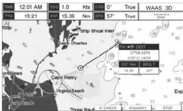
text_image
TIME 12:01 AM S00 1.0 Kts C00 0° True WAAS 3D TTG 15:21 DST 15.36 Nm BFG 57° True 5Nm A River Ship Shoal Inlet Cape Charles FIX → P DEBT 37°08.347N 075°31.147W DST Nm BRG T 16.36 67° Fort News Cape Henry Virginia Beach Three Naut R CHECK HIGHWAY STOPFigure 7.4a - GOTO menu (2)
-
The GPS Chart Plotter is now navigating from your current position to the location selected at step 1. A bearing line between the vessels location and the destination point is shown. A popup window shows the Distance (DST) and Bearing (BRG) from the vessels location to the destination point. Soft Keys are also shown that allow you to quickly switch to the Highway page, to Route Check or to stop navigation.
-
Moving the ShuttlePoint knob, the popup window disappears.
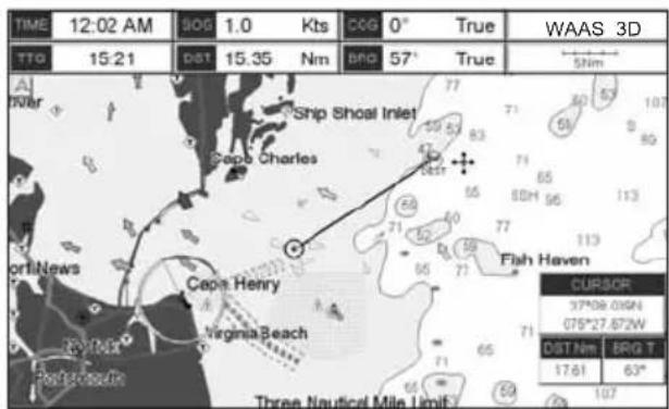
text_image
TIME 12:02 AM SOG 1.0 Kts CCG 0° True WAAS 3D TTG 15:21 DST 15.35 Nm BPG 57° True 5Nm A Inter Ship Shoal Inlet Cape Charles Fish Haven Cape Henry Virginia Beach Three Nautical Mile Limb CURSOR 37°08.0194 075°27.672W DST Nm BRG T 17.61 63°Figure 7.4b - GOTO menu (3)
-
The GPS Chart Plotter is in Cursor mode, to switch to Home mode press [CLR] so the vessel will stay in the center of the page.
-
To STOP Navigation, press [GOTO] and a WARNING window is shown. Move the ShuttlePoint knob to highlight STOP and press [ENT].
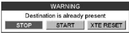
text_image
WARNING Destination is already present STOP START XTE RESETFigure 7.4c - Warning window
GOTO ROUTE
When a Route is shown on the Chart page, move the cursor over the designed Waypoint and press [GOTO]. For more information about Routes refer to Section 9.
GOTO MARK
- Move the ShuttlePoint knob to an open position (no buoy, warning etc. under the cursor) on the Chart page.
- Press [GOTO] to show the GOTO popup window.
- Move the ShuttlePoint knob to highlight MARK and press [ENT] to show the MARKS/WAYPOINTS List.
- Move the ShuttlePoint Knob to the highlight the desired Mark or Waypoint and press [GOTO].
- You will notice a circle is drawn around the Icon Symbol. This means the GPS Chart Plotter is now navigating to the point.
- Press [CLR] to switch to the Chart page or Highway page to start navigating to the point.
8. MAN OVER BOARD (MOB) FUNCTION
During navigation, the "MOB" feature provides a one-touch method of storing a location, such as a point were a crew member fell overboard. In this mode, the CP380i or CPF390i places a MOB point on the Chart page and all the navigation data shown is related to navigating back to this point, allowing you to retrace your path to the MOB point efficiently.
8.0 PLACING A MOB POINT
- On the Chart page, press [MOB] to start navigating back to the point.
- You will notice a MOB Mark will be on the Chart page and all navigation is referring back to this point.
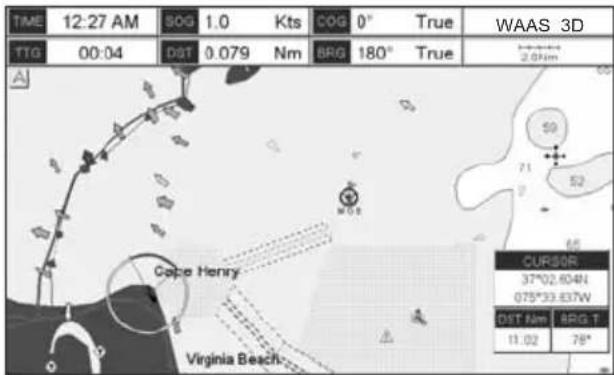
text_image
TIME 12:27 AM SOG 1.0 Kts COG 0° True WAAS 3D TTG 00:04 DST 0.079 Nm BRG 180° True 2.01km Cape Henry Virginia Beach CURSOB 37°02.604N 075°33.637W DIST Nm ARG T 11.02 78°Figure 8.0 - MOB point
- If the cursor is moved over the MOB Icon, the popup windows over Soft Keys will be shown allowing quick access to the Highway or Navigation page, or to Route Check.
- To stop navigating to the MOB point, press [GOTO], select STOP and press [ENT].
8.1 DELETING A MOB POINT
- Move the ShuttlePoint knob until the cursor is over the top of the MOB icon.
- Press [D ELETE], a popup window will be shown to confirm deleting the MOB point.
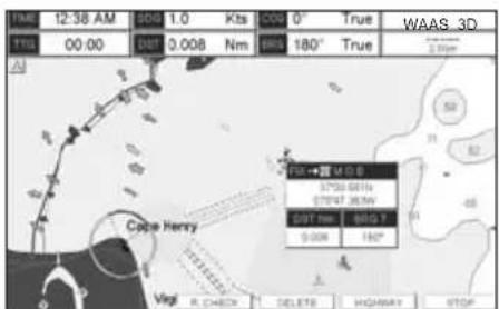
text_image
12:38 AM 00:00 0.008 Nm 0° 180° True WAAS_3D T10 00:00 00:00 0.008 Nm 180° True Cape Henry Vegl R CHECK DELETE HIGHWAY STOP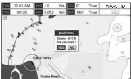
text_image
TIME 12:41 AM 9:00 1.0 Kts 00 0° True WAAS 3D T18 00:03 SET 8.052 Nm 165 180° True 2.00pm WARNING Delete MOB Are you sure? YES NO Cape Henry Virginia BeachFigure 8.1 - Deleting MOB point
- Move the ShuttlePoint knob to highlight YES and press [ENT].
9. ROUTES
The CP190i and the CPF390i have the capability to store 50 Routes with 100 Waypoints or Marks in each Route. A Route can consist of Waypoints or Marks. The difference is when a Route is made using Waypoints and the Route is deleted the Waypoints are also deleted. However if a Route is made of Marks and the Route is deleted the Marks stay in memory.
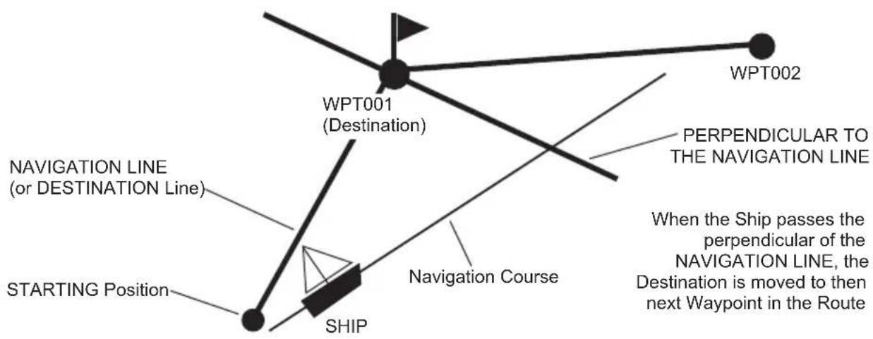
flowchart
graph TD
    A["SHIP"] --> B["Starting Position"]
    B --> C["WPT001 (Destination)"]
    C --> D["WPT002"]
    D --> E["Navigation Course"]
    E --> F["PERPENDICULAR TO THE NAVIGATION LINE"]
    F --> G["When the Ship passes the perpendicular of the NAVIGATION LINE, the Destination is moved to then next Waypoint in the Route"]
Figure 9 - Example to show how the plotter switches from one Waypoint to another
9.0 CREATING A ROUTE USING WAYPOINTS
- On the Chart page move the ShuttlePoint knob to the Lat/Lon of the starting Waypoint in the Route.
- Press [ROUTE], you will notice the Starting Waypoint ⚙ will be placed under the cursor.
- Move the ShuttlePoint knob to the second Lat/Lon of the next leg - in the Route.
- Press [ROUTE]. You will notice another Waypoint is shown under the cursor and a line joins the starting Waypoint to the Second Waypoint.
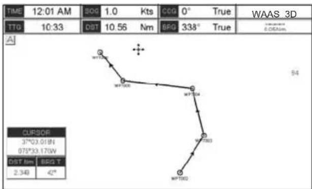
text_image
TIME 12:01 AM 900 1.0 Kts C0G 0° True WAAS_3D TTG 10:33 DST 10.56 Nm BPG 338° True 6.06A/mm A CURSOR 37°03.01'N 075°33.17'W DIST Nm BRQT 2.348 42°Figure 9.0 - Creating a Route using Waypoints
- Repeat steps 3 and 4 until all Waypoints are entered into the Route.
NOTE
At this point the Route is saved as ROUTE01. If you would like to save the Route under a specific name follow the next steps.
9.1 CHANGING THE NAME OF A ROUTE
To name the Route:
- Press [MENU], move the ShuttlePoint knob to highlight USER POINTS and press [ENT].
- Move the ShuttlePoint knob to highlight ROUTE and press [ENT].
- Move the ShuttlePoint knob to highlight EDIT ROUTE and press [ENT] or move the ShuttlePoint knob to the right.
- Move the ShuttlePoint knob to highlight NAME and press [ENT]. A popup window will be shown.
- Move the ShuttlePoint knob up/down to change the characters and left/right to select a different character in the Routes Name.
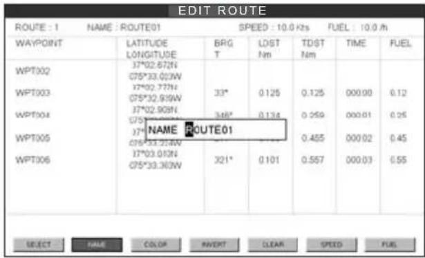
text_image
EDIT ROUTE ROUTE : 1 NAME : ROUTE01 SPEED : 10.0 Kzs FUEL : 10.0 M WAYPOINT LATITUDE BRG LDST TDST TIME FUEL LONGITUDE T Nm Nm WPT002 37°02.572N C75°33.023W 37°02.772N C75°32.919W 37°02.903N 37°02.903N 346° 0.125 0.125 000.00 0.12 WPT003 WPT004 WPT005 NAME ROUTE01 C75°33.219W 37°03.010N C75°33.363W 321° 0.101 0.455 000.02 0.45 WPT006 SELECT NAME COLOR AVERT CLEAR SPEED FUELFigure 9.1 - Edit Route (Route Report)
- When finished press [ENT] to save.
- Press [CLR] to show the Chart page.
9.2 CREATING AN OLYMPIC ROUTE
This feature allows the starting point in a Route to be saved as the final destination point.
- On the Chart page move the ShuttlePoint knob to the Lat/Lon of the starting Waypoint in the Route.
- Press [ROUTE], the starting Waypoint will be placed under the cursor.
- Move the ShuttlePoint knob to the second Lat/Lon of the next leg in the Route.
- Press [ROUTE]. Another Waypoint is shown under the cursor and a line joins the starting Waypoint to the second Waypoint.
- Repeat steps 3 and 4 until all Waypoints are entered into the Route.
- Then move the ShuttlePoint knob to the last Waypoint.
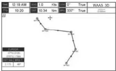
text_image
TIME 12:19 AM 800 1.0 Kts 0° True WAAS 3D Time 10:20 Sat 10.34 Nm BSC 337° True 0.000mm CURSOR 37°52'01" 0" 025°51.17mm DIST Nm | WAG T 2.175 48°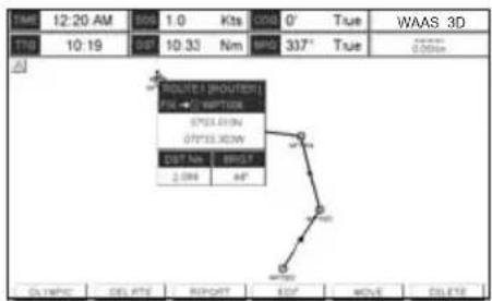
text_image
TIME 12:20 AM 8:50 1.0 Kts 0' True WAAS_3D TNG 10:19 0° 10:33 Nm 880 337° True ROUTE | ROUTERI FN + C VIRTOR 0°23.01N 0°23.02N 0°23.03N 0°23.04N 0°23.05N 0°23.06N 0°23.07N 0°23.08N 0°23.09N 0°23.10N 0°23.11N 0°23.12N 0°23.13N 0°23.14N 0°23.15N 0°23.16N 0°23.17N 0°23.18N 0°23.19N 0°23.20N 0°23.21N 0°23.22N 0°23.23N 0°23.24N 0°23.25N 0°23.26N 0°23.27N 0°23.28N 0°23.29N 0°23.30N 0°23.31N 0°23.32N 0°23.33N 0°23.34N 0°23.35N 0°23.36N 0°23.37N 0°23.38N 0°23.39N 0°23.40N 0°23.41N 0°23.42N 0°23.43N 0°23.44N 0°23.45N 0°23.46N 0°23.47N 0°23.48N 0°23.49N 0°23.50N 0°23.51N 0°23.52N 0°23.53N 0°23.54N 0°23.55N 0°23.56N 0°23.57N 0°23.58N 0°23.59N 0°23.60N 0°23.61N 0°23.62N 0°23.63N 0°23.64N 0°23.65N 0°23.66N 0°23.67N 0°23.68N 0°23.69N 0°23.70N 0°23.71N 0°23.72N 0°23.73N 0°23.74N 0°23.75N 0°23.76N 0°23.77N 0°23.78N 0°23.79N 0°23.80N 0°23.81N 0°23.82N 0°23.83N 0°23.84N 0°23.85N 0°23.86N 0°23.87N 0°23.88N 0°23.89N 0°23.90N 0°23.91N 0°23.92N 0°23.93N 0°23.94N 0°23.95N 0°23.96N 0°23.97N 0°23.98N 0°23.99N 0°24.00NFigure 9.2 - Olympic Route creation (1)
- Press [OLYMPIC]. A line joins the starting Waypoint and the last Waypoint.
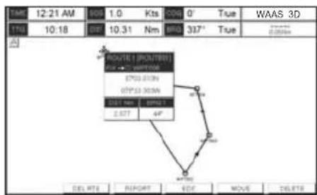
flowchart
graph TD
    A["Route1: POUTER"] --> B["STATION"]
    B --> C["STATION"]
    C --> D["SPR"]
    D --> E["2.67T"]
    E --> F["4F"]
    F --> G["DO"]
    G --> H["REPORT"]
    H --> I["MOVE"]
    I --> J["DELETE"]
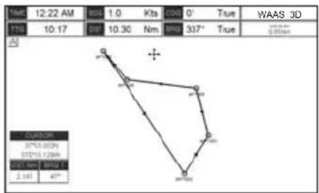
text_image
12:22 AM 1.0 Kts 0' True WAAS 3D 10:17 0.97 10.30 Nm 337° True 0.0044 0.0044 0.0044 0.0044 0.0044 0.0044 0.0044 0.0044 0.0044 0.0044 2.161 47°Figure 9.2a - Olympic Route creation (2)
9.3 MAKING ADDITIONAL ROUTES
To create another Route the GPS Chart Plotter must be told that you want to create a second Route.
- Press [MENU], move the ShuttlePoint knob to highlight USER POINTS and press [ENT].
- Move the ShuttlePoint knob to highlight ROUTE and press [ENT].
- Move the ShuttlePoint knob to highlight SELECT and press [ENT] or move the ShuttlePoint knob to the right.
- Move the ShuttlePoint knob to an open Route number example Route 2.
- Press [ENT] or move the ShuttlePoint knob to the right.
- Press [CLR] or move the ShuttlePoint knob to the left until the Chart page is shown.
- To create the new Route, follow the steps in Creating a Route using Waypoints or Marks sections.
9.4 CREATING A ROUTE USING MARKS ON THE CHART PAGE
To create a Route containing Marks you first must create the Marks and show them on the Chart page.
- Move the ShuttlePoint knob over the top of a Mark that you wish to be the starting point in the Route and press [ROUTE].
- Next move the ShuttlePoint knob until the cursor is over the Mark that you want to be the next leg in the Route.
- Press [ROUTE]. You will notice a bearing line joins the first and second Mark which means these Marks are selected into the Route.
- Repeat steps 3 and 4 until all Marks are entered into the Route.
NOTE
At this point the Route is saved as ROUTE01. If you would like to save the Route under a specific name follow the remaining steps.
- To name the Route press [MENU]. Move the ShuttlePoint knob to highlight USER POINTS and press [ENT].
- Move the ShuttlePoint knob to highlight ROUTE and press [ENT].
- Move the ShuttlePoint to highlight EDIT ROUTE and press [ENT] or move the ShuttlePoint knob to the right.
- Move the ShuttlePoint knob to highlight NAME and press [ENT] or move the Shuttle-Point knob to the right. A popup window will be shown.
- Move the ShuttlePoint knob up/down to change the characters and left/right to select a different character in the Routes Name.
- When finished press [ENT] to save.
- Press [CLR] to show the Chart page is shown.
9.5 INSERTING A WAYPOINT INTO A ROUTE
Place the cursor on the navigation line between two Waypoints and press [INSERT]. The line between the two Waypoints is turned into a dotted line, see the following picture.
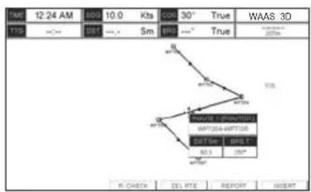
flowchart
graph TD
    A["1"] --> B["WNT204-WNT205"]
    B --> C["OUT 3m"]
    C --> D["10.0 Kts"]
    D --> E["30° True"]
    E --> F["WAAS 3D"]
    style A fill:#f9f,stroke:#333
    style B fill:#ccf,stroke:#333
    style C fill:#cfc,stroke:#333
    style D fill:#fcc,stroke:#333
    style E fill:#cff,stroke:#333
    style F fill:#ffc,stroke:#333
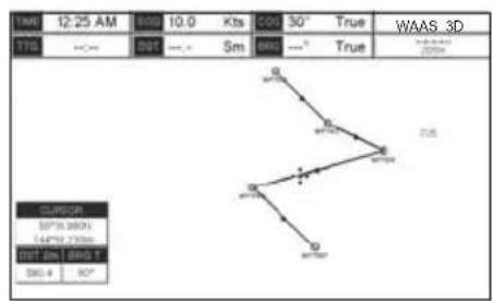
text_image
17:00 12:25 AM 8:00 10.0 Kts 400 30° True WAAS_3D TTG --- Dot --- Sm BSC ---° True CLIPOR 50°/5.00'N 144°/5.73'N pst' bim' dgn' t 505.4 80°Figure 9.5 - Inserting Waypoint procedure (1)
Move the ShuttlePoint knob to the desired location for the new Waypoint: the line will "rubber-band", drawing a dotted line between the previous Waypoint and the cursor, and another dotted line between the cursor and the next Waypoint (see the left side of the above picture). Once you have positioned the cursor at the location you want, press [ENT] (see the right side of the above picture).
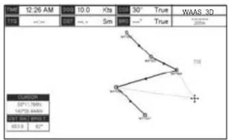
text_image
14:00 12:26 AM 00:00 10.0 Kts 01:00 30° True WAAS_3D TTO 00:00 00:00 5m RMS True CURSOR 52°(11.789) 142°(25.444) 00:00 00:00 SPT.00 - BNO. 5° 623.0 52°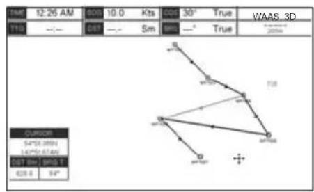
text_image
12:26 AM 10:0 Kts 30° True WAAS_3D T10 --- SBT --- Sm BBS --- True 200km CURSOR 54°32.289N 147°50.674N 207 km / BBS 1 628.6 34°Figure 9.5a - Inserting Waypoint procedure (2)
9.6 GOTO A ROUTE
By having created some Routes, you can choose one of them to place a GOTO on.
9.6.0 Using [GOTO] to select Route
- Move the ShuttlePoint knob to an open position (no buoy, warning etc. under the cursor) on the Chart page.
- Press [GOTO] to show the GOTO popup window.
-
Move the ShuttlePoint knob to highlight ROUTE and press [ENT].
-
The SELECT ROUTE popup window will be shown.
![Standard Horizon CPF390i - Using [GOTO] to select Route - 1](/content/2026/05/794397/images/5d874c30347a9b4ac5601ab8ac2dd0fc83d9b9f1ab0b57f752d55eda5d27b40c.jpg)
text_image
14:0 12:31 AM 00:0 10:0 Kts 00:0 30° True WAAS 3D TIB --/--- DF --- - Sm BHS —° True GO TO CURSOR POLTE MARK![Standard Horizon CPF390i - Using [GOTO] to select Route - 2](/content/2026/05/794397/images/da99c858281807cff03c33a1f072258531d277f81805fd71501643d2c47b6642.jpg)
text_image
DATE: 12:32 AM ITEM: ---- SELECT ROUTE 1 ROUTE01 2 ROUTE02 3 ---- 4 ---- 5 ---- 6 ---- 7 ---- 8 ---- 9 ---- 10 ---- 11 ---- 12 ---- 13 ---- 14 ---- 15 ---- 16 ---- True True WAAS 3D CURSOR SPY2.200N 154°0' 0000A DIST 9th 880 T 178 B 130°Figure 9.6.0 - GOTO ROUTE procedure (1)
- Move the ShuttlePoint knob to the highlight the desired Route and press [ENT].
- On the Chart page a circle with a flag is shown on the first leg of the Route and a navigation line is shown, indicating the GPS Chart Plotter is navigating to the first Waypoint in the Route.
![Standard Horizon CPF390i - Using [GOTO] to select Route - 3](/content/2026/05/794397/images/c65d37759985f72cd7f70caad0c15952cddd2b0e6615b2b237bb891761b52b08.jpg)
text_image
TIME 12:01 AM SOG 10.0 Kts COG 30° True WAAS 3D TTG 04:19 DST 49.76 Sm BRG 68° True CURSOR 55*26.256N 151*51.990W DIST Sm BRG T 32.56 90°Figure 9.6.0a - GOTO ROUTE procedure (2)
9.6.1 Using the ShuttlePoint knob
- On the Chart page move the ShuttlePoint knob until the cursor reaches the starting point of the Route.
- Press [GOTO] to start following the Route.
- Press [CLR] twice to revert to Home mode.
9.7 DELETING A ROUTE
To delete a Route follow the procedure below:
- Press [MENU], move the ShuttlePoint knob to highlight USER POINTS and press [ENT].
- Move the ShuttlePoint knob to highlight ROUTE and press [ENT].
- Move the ShuttlePoint knob to highlight DELETE and press [ENT] or move the ShuttlePoint knob to the right.
- A Warning message appears to confirm. Move the ShuttlePoint knob to highlight YES and press [ENT]. The Route has been deleted.
WARNING
An active Route (one that you are navigating to) cannot be deleted until you stop navigating to the Route.
You will notice the ROUTE menu has other selections.
| SELECT | Choose an available Route to create or choose a stored Route to show and follow on the Chart page. |
| REVERSE | Reverses the Route, when chosen Starting point is at the end of the Route. |
| COLOR | Allows changing the color of the navigation lines between each leg in the Route. |
| EDIT | The Edit Route (Route Report) menu is useful to show details of the Waypoints contained within the Route. This menu also allows you to enter in your average speed and fuel consumption and calculate the approximate fuel used when following the Route. |
| SEND | Sends the stored points to a external device (PC) capable of listening to NMEA RTE sentence. |
| RECEIVE | Receive the points from an external device (PC) capable of sending NMEA RTE sentence. |
| THICKNESS | Selection that allows the Route line to be easily seen; default selection is Thick. |
9.8.0 Route Check
The Route Check function is used after you have created a Route to ensure you and your vessel will not have problems while navigating. This is done by the CP390i and CPF390i by reviewing the Route and looking for the following hazards that may effect safe navigation.
- Land Areas
- Shallow Water
- Rocks
- Wrecks
- Obstructions
- Shoreline Constructions
· Fishing Facility
· Dredged Areas - Diffusers (submarine pipeline)
- Mooring/Warping Facility
- Intertidal Areas (areas emerged at low tide)
• Production Installation (an installation for the exploitation of natural resources)
- Pingos (small conical hills having a large central core of ice formed from the encroachment of permafrost and the resulting hydrostatic pressure)
- No Data Available (no adequate data coverage)
If any of these alarm conditions is detected, the function returns the list of dangerous objects and the relative dangerous Route leg, that is drawn with a different color.
- Route legs which were classified as dangerous are displayed in RED. It means that there is at least one dangerous object in the vicinity of this leg and it has been found.
- Route legs which were classified as safe are displayed in GREEN. It means that the data was checked on detailed chart levels and no problems were found for all segments of the leg.
- Route legs for which there was not sufficient data to be checked are displayed in YELLOW. It means that no problems were found but the data was not sufficient or not available at all to classify such a leg as safe.
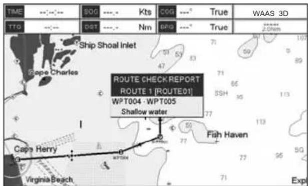
text_image
TIME TTO Ship Shoal Inlet Bope Charles ROUTE CHECK REPORT ROUTE 1 [ROUTE01] WPT004 · WPT005 Shallow water Cape Henry Virginia Beach Fish Haven Expt True True WAAS 3D 2.0kmFigure 9.8.0 - Example of dangerous objects found on the chart
To activate this function:
| AUTOMATIC CHECK | Turns the Route Check feature On or Off. Turn the Automatic Route Check on after you have created a new Route, or if you inserted a new Waypoint, deleted, moved or edited any Waypoint in a saved Route to confirm the Route can be safely navigated. |
| ROUTE WIDTH | This selection allows you to select the width from the left and right of the Route leg where the GPS Chart Plotter will check to confirm navigation threats. See the picture below. The default for this selection is 0.04NM. |
| DEPTH LIMIT | This selection allows you to select the water depth in the Route width area so the GPS Chart Plotter can check and confirm underwater threats. It checks if some objects with the depth attribute (like Shallow Water, Dredged Areas, Diffusers, Obstructions, Pingos, Production Installationand Wrecks) are above this depth level. Only if the depth attribute is above the depth limit are they found and considered as dangerous. See the picture below. The default setting is 10FT. |
| ACCURACY | Defines a segment length into which a leg of the Route is divided in order to execute the search for dangerous objects with better accuracy. When accuracy is maximal, a segment length is the shortest. When accuracy is minimal, a segment length is the longest. Selects among Minimum, Low, Medium, High and Maximum. See the picture below. The default setting is Medium. |
| ROUTE CHECK REPORT | Shows the list of the dangerous objects found on the charts crossed by the Route. |
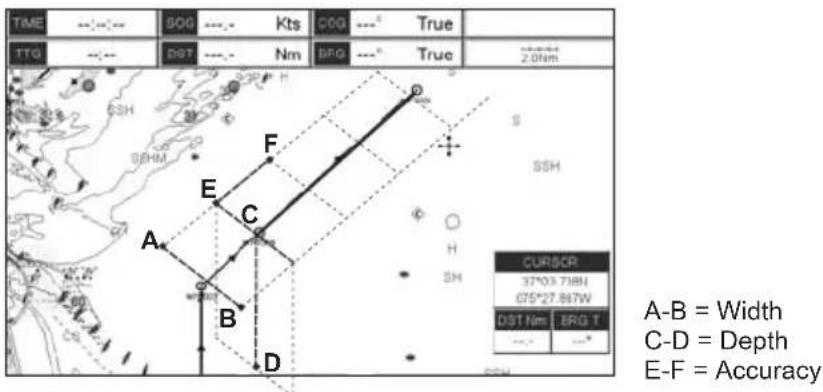
text_image
TIME 90G --- Kts C6G --- True TTG --- DST --- Nm BFG --- True 2.0Nm A-B = Width C-D = Depth E-F = Accuracy CURSCP 37°03.718N 075°27.867W DST Nm BRG T A-A = Width C-D = Depth E-F = AccuracyFigure 9.8.0a - Route Check parameters
NOTE
Although the functionality is called Route Check, it can also be activated when the navigation is set to a single point (like DSC, MOB, Mark). In the case of checking a single point towards which the navigation is started, the leg for which the Route Check is executed is defined by the current position (the leg's starting point) and the destination point (the leg's ending point).
10. TRACKS
The CP390i and the CPF390i have the capability to store 20 individual Tracks and record up to 10000 Track Points.
Before using the Track function you will need to setup the Track function that suits your boat. The Track function records your tracks your vessels location as it moves through the water. The Track function can be setup to lay down a Track for a predetermined time or distance interval. If you have a fast moving boat you may want to setup the CP390i or CPF390i to record a Track point every 0.5NM or if you have a sail boat you may want to setup to lay down a Track point once every 1 minute.
NOTE
Please note the Track point memory capacity is 10,000 points. This means for a long journey you may have to adjust the time or distance to be able to track your journey. It should be noted when the 10,000 Track points are used up, the first Track point layed down will be deleted when a new point is placed on the chart.
- Press [MENU], move the ShuttlePoint knob to highlight USER POINTS and press [ENT].
- Move the ShuttlePoint knob to highlight TRACK and press [ENT].
- Move the ShuttlePoint knob to highlight STEP UNIT and press [ENT] or move the ShuttlePoint knob to the right.
- Move the ShuttlePoint knob to highlight Dist or Time and press [ENT] or move the ShuttlePoint knob to the right.
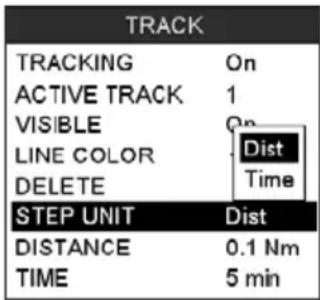
text_image
TRACK TRACKING On ACTIVE TRACK 1 VISIBLE On LINE COLOR Dist DELETE Time STEP UNIT Dist DISTANCE 0.1 Nm TIME 5 minFigure 10 - Distance Units and Time Units
- Move the ShuttlePoint knob to highlight DISTANCE or TIME step interval and press [ENT] or move the ShuttlePoint knob to the right.
- Move the ShuttlePoint knob up/down to the desired step value and press [ENT] or move the ShuttlePoint knob to the right.
- Press [CLR] or move the ShuttlePoint knob to the left until the Chart page is shown.
10.0 TRACKING
When using the tracking feature you will notice every time a Track Point is layed down on the Chart page a small filled in circle is shown on the Track line. If you move the cursor over the top of the circle a popup window will be shown with the Time, Water Temperature, Speed and Course Over Ground (COG). This is very useful if you are fishing and want to review the conditions where the fish were being caught.
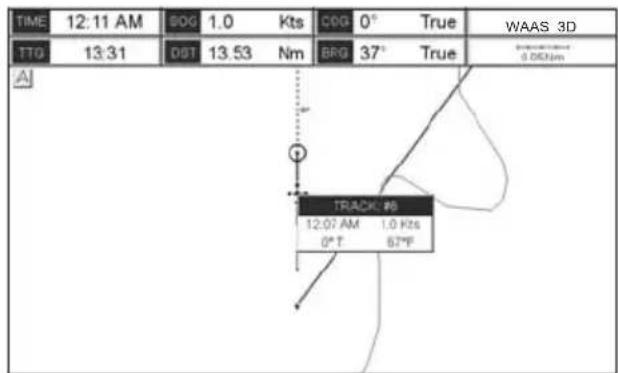
text_image
TIME 12:11 AM 50G 1.0 Kts C6G 0° True WAAS 3D TTG 13:31 08T 13.53 Nm BRG 37° True TRACK: #6 12:07 AM 1.0 Kts 0° T 63°FFigure 10.0 - Tracking
10.0.0 Saving and starting a new Track
A Track is automatically saved and retained in memory when the power is turned off. To start a new Track:
- Press [MENU], move the ShuttlePoint knob to highlight USER POINTS and press [ENT].
- Move the ShuttlePoint knob to highlight TRACK and press [ENT].
- Move the ShuttlePoint knob to highlight ACTIVE TRACK and press [ENT] or move the ShuttlePoint knob to the right.
- Move the ShuttlePoint knob up/down to select the next available open Track and press [ENT] or move the ShuttlePoint knob to the right.
- Move the ShuttlePoint knob to highlight TRACKING and press [ENT] or move the ShuttlePoint knob to the right to set On.
- Press [CLR] or move the ShuttlePoint knob to the left until the Chart page is shown.
- A new Track now will be laid down.
10.0.1 Deleting a Track
To delete a Track:
- Press [MENU], move the ShuttlePoint knob to highlight USER POINTS and press [ENT].
- Move the ShuttlePoint knob to highlight TRACK and press [ENT].
- Move the ShuttlePoint knob to highlight DELETE and press [ENT] or move the ShuttlePoint knob to the right.
- A warning popup window will be shown to confirm if you want to reset the Track. Move the ShuttlePoint knob to highlight YES and press [ENT] or move the ShuttlePoint knob to the right. The Track is now deleted.
- Press [CLR] or move the ShuttlePoint knob to the left until the Chart page is shown.
10.0.2 Other settings
You will notice the Track menu has other selections:
| TRACKING Allows turning on or off the tracking function | |
| ACTIVE TRACK | This selection allows you to save a Track to one of the 20 Tracks available |
| VISIBLE Shows or hides a Track shown in ACTIVE TRACK menu | |
| LINE COLOR Selects the color of the Track line | |
| DELETE Deletes a Track selected in the ACTIVE TRACK menu | |
| STEP UNIT Allowable selection are Distance or Time | |
10.1 TRIP LOG
10.1.0 Using the Trip Log
On the Chart, Navigation, Highway and NMEA Data pages the windows may be customized to show Trip Log information.
- Select one of the pages listed above, press and hold [MENU]. You will notice one of the data boxes will be highlighted.
- Press [ENT] and move the ShuttlePoint knob to highlight TLOG, press [ENT] or move the ShuttlePoint knob to the right.
- A popup window will be shown with Nm (Nautical Mile), Sm (Statute Mile), Km (Kilometer) and RESET. Move the ShuttlePoint knob to select the desired units of measure and press [ENT] or move the ShuttlePoint knob to the right.
- Press [CLR] or move the ShuttlePoint knob to the right until the selected page (Chart, Navigation, Highway or NMEA Data Page) is shown.
10.1.1 Setup / Reset
When Trip Log is selected in one of the data windows and you want to reset the log:
- Press and hold [MENU] until a field is highlighted (it will be shown in a yellow frame).
- Move the ShuttlePoint knob to highlight the Trip Log window TLOG and press [ENT].
- A popup window will be shown. Move the ShuttlePoint knob to TLOG and press [ENT].
- Another popup window will be shown. Move the ShuttlePoint knob to RESET and press [ENT].
- A warning popup window will be shown to confirm if you want to reset the Trip Log. Move the ShuttlePoint knob to highlight YES and press [ENT]. The Trip Log is now reset.
- Press [CLR] to store and exit the editing mode
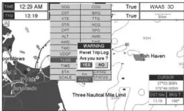
text_image
TIME 12:29 AM TG 13.19 SOG COG DST BRG XTE TTG STR HDG DPT SPD ALT AWS AWD TWE TWD VDOP TLOG TIME YES NO ETA CKNG SCALE KM STATUS WARNING Reset Trip Log Are you sure ? CurSOR 37°03.959N 073°49.062W DST NM BRG T 13.79 198° Fish Haven Three Nautical Mile LimitFigure 10.1.1 - Trip Log Reset
11. USER C-CARD
The optional User C-CARD is used to back up Marks, Routes, and Tracks stored in your GPS Chart Plotter's memory. In the USA the User C-CARD is available directly from Jeppesen Marine at 800/424-2627. The User C-CARD is similar to a backup disk used with a PC, in case you have to clear the RAM to resolve an issue or load new software, or if you would like to transfer Waypoint, Track and Route information from one STANDARD HORIZON GPS Chart Plotter to another.
11.0 USER C-CARD MENU
This optional card is similar to using a floppy disk or memory stick on a PC to backup your files or to transfer the information that you have stored to a friends GPS Chart Plotter. The information shown below will assist you to transfer the User Points, Routes and Track history to the optional User C-CARD.
① Time of file creation
② Date of file creation
③ Type of data contained in the file (Mark file, Waypoint file...)
④ File name
⑤ Number of Selected file
⑥ Information on stored User Points on Internal Memory
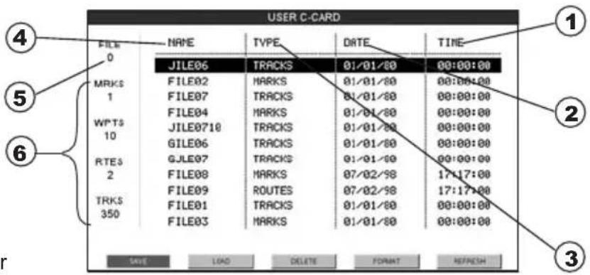
text_image
USER C-CARD FILE 0 MRKS 1 WPTS 10 RTE3 2 TRKS 350 NAME TYPE DATE TIME JILE06 TRACKS 01/01/80 00:00:00 FILE02 MARKS 01/01/80 00:00:00 FILE07 TRACKS 01/01/80 00:00:00 FILE04 MARKS 01/01/80 00:00:00 JILE0710 TRACKS 01/01/80 00:00:00 GILE06 TRACKS 01/01/80 00:00:00 GJLE07 TRACKS 01/01/80 00:00:00 FILE08 MARKS 07/02/98 17:17:00 FILE09 ROUTES 07/02/98 17:17:00 FILE01 TRACKS 01/01/80 00:00:00 FILE03 MARKS 01/01/80 00:00:00 SAVE LOAD DELETE FORMAT REFRESHFigure 11.0 - User C-CARD Menu
11.0.0 Formatting the optional User C-CARD
- Press [MENU], move the ShuttlePoint knob to highlight USER POINTS and press [ENT].
- Move the ShuttlePoint knob to highlight USER C-CARD and press [ENT].
- Move the ShuttlePoint knob to highlight FORMAT and press [ENT].
- A popup Warning window will to confirm you want to format the User C-CARD.
- Select YES and press [ENT] to confirm (select NO otherwise). The format of User C-CARD must be done before using a new User C-CARD: this operation prepares the User C-CARD to receive and store information.
NOTE
Formatting permanently erases all files previously saved on the User C-CARD.
11.0.1 Transferring files to the optional User C-CARD
-
Remove a C-MAP BY JEPPESEN NT+/MAX C-CARD if present and insert the optional User C-CARD into the slot.
-
Press [MENU], move the ShuttlePoint knob to highlight USER POINTS and press [ENT].
- Move the ShuttlePoint knob to highlight USER C-CARD and press [ENT].
- A screen will appear. Move the ShuttlePoint knob to the left to highlight SAVE and press [ENT].
- A popup SAVE FILE window will appear. In this window you can change the name and the file type by using the ShuttlePoint knob and pressing [ENT], when finished press [CLR] once.
- To save the file, move the ShuttlePoint knob to SAVE in window and press [ENT].
- A Information pop window will momentarily be shown "SAVING" then show SAVING OK.
- Press [ENT] to confirm.
11.0.2 Loading a file from the optional User C-CARD
If you have a problem and accidentally loose the User Points in the GPS Chart Plotter with the optional User C-CARD it is possible to load the data back into the GPS Chart Plotter using the following procedure:
- Press [MENU], move the ShuttlePoint knob to highlight USER POINTS and press [ENT].
- Move the ShuttlePoint knob to highlight USER C-CARD and press [ENT].
- Select the saved file from the User C-CARD list by using the ShuttlePoint knob and press [ENT].
- Move the ShuttlePoint knob to the left to highlight LOAD and press [ENT].
- A popup information window will appear when loading is complete.
- Press [ENT] to confirm.
11.0.3 Deleting a file from the optional User C-CARD
You may want to delete a saved file on the User C-CARD.
- Press [MENU], move the ShuttlePoint knob to highlight USER POINTS and press [ENT].
- Move the ShuttlePoint knob to highlight USER C-CARD and press [ENT].
- Select the saved file from the User C-CARD list by using the ShuttlePoint knob and press [ENT].
- Move the ShuttlePoint knob to the left to highlight DELETE and press [ENT].
- A popup Warning window will to confirm you want to delete the file.
- Press [ENT] to confirm.
11.0.4 Refreshing the optional User C-CARD
You may want to change the User C-CARD inserted in the slot with a new one.
- Press [MENU], move the ShuttlePoint knob to highlight USER POINTS and press [ENT].
- Move the ShuttlePoint knob to highlight USER C-CARD and press [ENT].
- Open the door, remove the User C-CARD from the slot and insert another User C-CARD into the same slot.
- Move the ShuttlePoint knob to highlight REFRESH and press [ENT]. This "new" User C-CARD is now ready to receive and store information.
12. PAGES
The CP390i and CPF390i have many pages that are designed to ease your navigation.
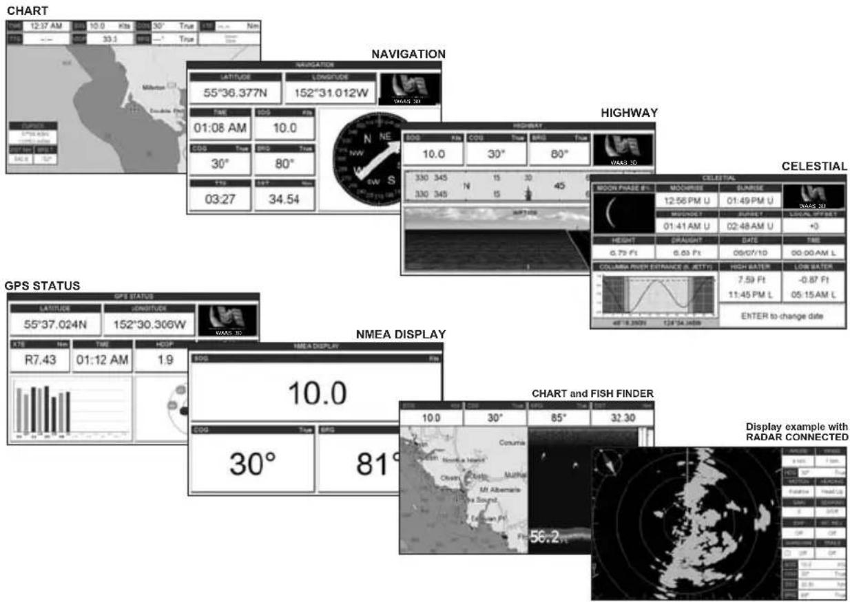
text_image
CHART 12:37 AM 10.0 Kts 30° True NM 33.1 True TEQ MILKON Double River SAR GPS NAVIGATION LATITUDE L Longitude 55°36.377N 152°31.012W TIME COS FEE 01:08 AM 10.0 COS Time BRS True 30° 80° FEE SFF 03:27 34.54 HIGHWAY 300 Kts COS True BRS True 10.0 30° 80° 330 345 N 15 30 45 330 345 N 15 NE VEE CELESTIAL MOON PHASE FL MOOPREE SURRISE 12:56 PM U 01:49 PM U MOODGET RUBSET SOUTHERS WIRE E 01:41 AM U 02:48 AM U +0 HEIGHT DRAUGHT DATE FIRE 0.79 Ft 0.63 Ft 09/07/10 00:00 AM L COLUMA RIVER EXTRAANCE (L JETTY) HIGH WATER LOW WATER 7.59 Ft -0.87 Ft 11:45 PM L 05:15 AM L EHTER to-change date GPS STATUS GPS STATUS LATITUDE JENOTIVER 55°37.024N 152°30.306W TIME HOSP R7.43 01:12 AM 1.9 NMEA DISPLAY 10.0 NMEA Display COG True BRS 30° 81° CHART and FISH FINDER 10.0 30° 85° 32.30 COMUNA Sound a Heart Overta Heart Muthip Mt Abemarle Iva Sound. Eccum Ft 56.2 Display example with RADAR CONNECTEDFigure 12 - Example of screen display pages
The pages can be selected in the following way:
Selection by MENU
- Press [MENU]. The following menu is shown on the screen:
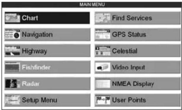
text_image
MAIN MENU Chart Find Services Navigation GPS Status Highway Celestial Fishfinder Video Input Radar NMEA Display Setup Menu User PointsFigure 12a - Main Menu
- Move the ShuttlePoint knob to highlight the desired page and press [ENT].
Selection by SOFT KEY
Press one of the Soft Keys under the display, then press the Soft Key to show the desired page.
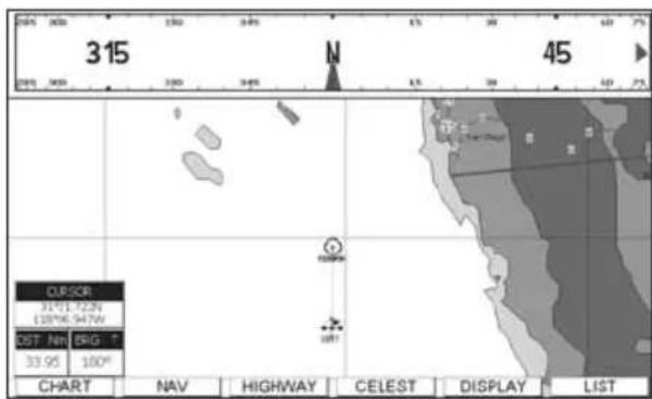
text_image
315 45 CURSOR 31°11'12.2" 180°06'94.7W CST: Nw ESG: T 33.95 100° CHART NAV HIGHWAY CELEST DISPLAY LISTFigure 12c - Screen display pages (by Soft Keys)
12.0 CHART PAGE
The Chart page is the main page of the GPS Chart Plotter. From this page the user can zoom in/out, pan around the chart, show information about cartographic objects, see the exact vessel position with the COG and SOG, place points, GOTO a destination point, show Track history etc. The GPS Chart Plotter come with Built-In Charts for coastal navigation of USA including Alaska, Hawaii and Great Lakes, Canada, Bahamas, Caribbean, Cuba, Puerto Rico, and Central America. For detail refer to Par. 5.0. For more detail, optional C-MAP BY JEPPSESEN NT+/MAX C-CARDs or to update the Built-In Charts, refer to Par. 5.1.
It is possible to set the chart as a single or two charts side by side.
- Press [MENU], move the ShuttlePoint knob to highlight CHART and press [ENT]. Two Chart page types are available: Single and Dual.
- Move the ShuttlePoint knob to highlight Single or Dual and press [ENT].
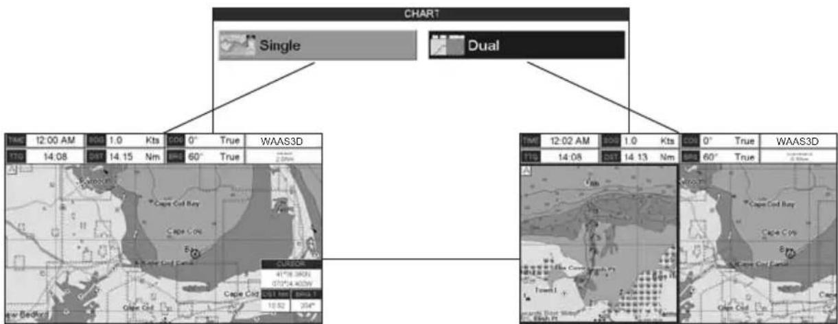
text_image
CHART Single Dual TIME 12:00 AM 80G 1.0 Kts CO6 0° True WAAS3D TTO 14.08 DIST 14.15 Nm 60° True 2.00mm CURSOR 41°18.39'25 07'04.40'29" Cape Cod Cape Cod DIST 100 80% 1 10.52 20° TIM 12:02 AM 80G 1.0 Kts CO6 0° True WAAS3D TTO 14.08 DIST 14.13 Nm 60° True 2.00mm TWO 14.08 DIST 14.13 Nm 60° True WAAS3D Cape Cod Bay Cape Cod Town I Open Cod Open CodFigure 12.0 - Chart selection menu
NOTE
may appear on the unused window of the Dual Chart page. It happens when the GPS Chart Plotter updates the displayed chart in the not active window. So the user understands that the GPS Chart Plotter is busy.
12.0.0 Focus Soft Key on Dual Chart Page
When Dual Chart is selected, you will notice one of the chart windows will have a red boarder around it. This red boarder indicates which chart window the chart plotter has the Focus on, meaning if the ShuttlePoint knob is moved the cursor on chart window will move. The focus may be changed to to the other chart window with the procedure below:
- Press any Soft Key. The Soft Key labels appear on the bottom of the screen. A [F ocus] Soft Key will be shown.
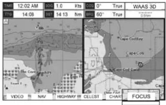
text_image
TMS 12:02 AM 10G 1.0 Kts 0° True WAAS 3D TTO 14:08 007 14 13 Nm 60° 60° True 0.5mm The Cove Beach Pt Video NAV HIGHWAY IM CELEST CHART FOCUSFigure 12.0.0 - Example of Dual Chart page with [Focus] shown
- Press [Focus]. A popup window appears where the active focus window label is highlighted.
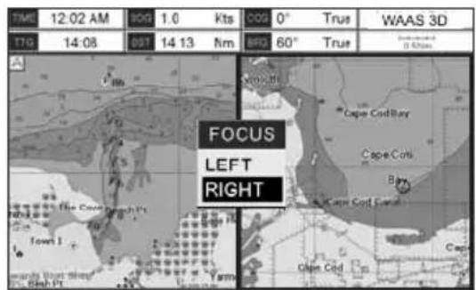
text_image
TIME 12:02 AM 90G 1.0 Kts 00G 0° Trus WAAS 3D TTO 14:08 05T 14 13 Nm BRG 60° Trus A FOCUS LEFT RIGHT Town I Cape Cod Bay Cape Cols Bt Cape Cod Cana Cape Cod Oise Cod Shah PtFigure 12.0.0a - Example of Dual Chart page with [Focus] window shown
- Move the ShuttlePoint knob up and down to highlight the desired item and press [ENT]. The red boarder is moved to the focused window.
12.0.1 Single Chart Page
① Time
② Speed Over Ground
③ Course Over Ground
④ Fix status
Time To Go
⑤ (If plotter is not navigating to a point will show --:--)TTG
Distance from Fix to Destination
⑥ (If plotter is not navigating to a point DST will show ---.)
⑦ Bearing from Fix to Destination (If plotter is not navigating to a point BRG will show ---)
⑧ Chart Scale
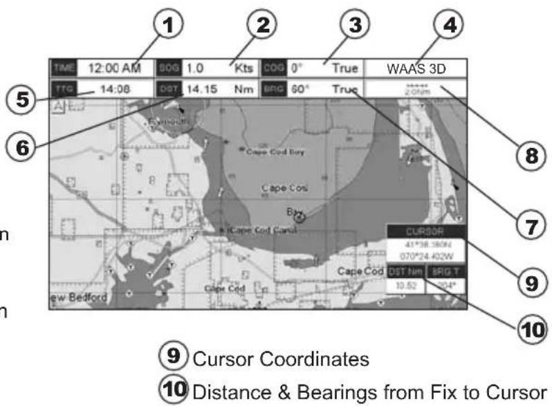
text_image
TIME 12:00 AM SOG 1.0 Kts COG 0° True WAAS 3D TTG 14:08 DST 14.15 Nm BRG 60° True CurSOR 41°*58.380W 070°*24.402W Cape Cod Bay Cape Cod Bay Cape Cod Canal Cape Cod DST Nm BRG T 10.52 10.4" 9 Cursor Coordinates 10 Distance & Bearings from Fix to CursorFigure 12.0.1 - Example of Single Chart Page
12.0.2 Window Selections
The default is the Two Line Small window. The CP390i and CPF390i windows may be changed by the procedure below.
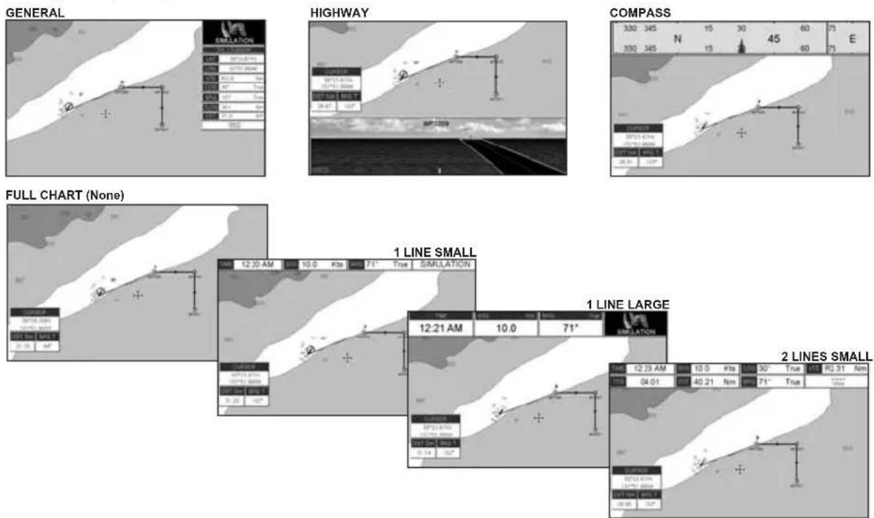
text_image
GENERAL HIGHWAY COMPASS 330 345 N 15 30 45 60 75 E 330 345 N 15 30 45 60 75 WF LOW FULL CHART (None) 1 LINE SMALL 12:20 AM 10.0 Kts 71° True SIMULATION 12:21 AM 10.0 71° 1 LINE LARGE SMILLATION 2 LINES SMALL 12:23 AM 10.0 Kts 30° True R2.31 Nm 04:01 40.21 Nm 71° TrueFigure 12.0.2 - Data window layout
- To change, press [MENU], move the ShuttlePoint knob to highlight SETUP MENU and press [ENT].
- Move the ShuttlePoint knob to highlight GENERAL SETUP and press [ENT] or move the ShuttlePoint knob to the right.
- Move the ShuttlePoint knob to highlight WINDOWS SETUP and press [ENT] or move
the ShuttlePoint knob to the right.
- Move the ShuttlePoint knob to highlight CHART PAGE and press [ENT] or move the ShuttlePoint knob to the right.
- Select the desired window, HIGHWAY or COMPASS, and press [ENT] or move the ShuttlePoint knob to the right.
- Press [CLR] or move the ShuttlePoint knob to exit the menu and show the Chart page.
12.0.3 Customizing the Data Windows
The data fields contained on the General, 1 Line Small/Large and 2 Line Small data windows can be changed to the following selections:
· MAX SPD = Max Speed
· SOG = Speed Over Ground
· COG = Course Over Ground
· DST = Distance to Destination 1
· BRG = Bearing to Destination 1
· XTE = Cross Track Error
· TTG = Time To Go
- STR = Steering
· HDG = Heading from Electronic Compass
· DTP = Depth
- SPD = Speed
- ALT = Altitude
- AWS = Apparent Wind Speed
· AWD = Apparent Wind Direction
· TWS = True Wind Speed
· TWD = True Wind Direction
· HDOP = Horizontal Dilution of Precision
· VDOP = Vertical Dilution of Precision
· Temp = Water Temperature
· TLOG = Trip Log
· DATE = Current Date
· TIME = Current Time
- VMG = Velocity Made Good
· ETA = Estimated Time of Arrival
- TRACKING = Tracking
· SCALE = Chart Scale
· GPS Status = Shows GPS Fix Status (WAAS, 3D, 2D, ...)
NOTE ^1
When the GENERAL window is selected and the GPS chart plotter is in Home Mode, the BRG will show - - -, unless the GPS chart plotter is navigating to a point. When in Cursor Mode, the BRG shows the Bearing from the ship's position to the cursor location.
To select the desired field, follow the procedure:
- Press and hold [MENU] until a field is highlighted (it will be shown in a yellow frame).
- Move the ShuttlePoint knob to the desired data field (the yellow frame is moved to the desired data field) and press [ENT]. The popup window will be shown.
- Move the ShuttlePoint knob up/down or left/right to choose the desired setting and press [ENT].
- Press [CLR] to store and exit the editing mode.
NOTE
Data window field on the NAVIGATION, HIGHWAY, GPS STATUS, and NMEA pages may be customized in the above manner.
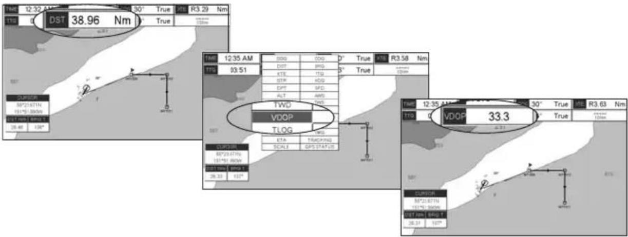
text_image
12:32 AM DST 38.96 Nm TWD 0.51 12:35 AM TWD VDOP TLOG TWD VDOP 33.3 12:35 AM TWD VDOP TLOG TWD VDOP 33.3Figure 12.0.3 - Customizing the Data Windows
NOTE
See Par. 10.1.0 if Trip Log is selected in one of the data windows and you want to reset the log.
12.0.4 Additional Functions on Chart Page
When on the Chart page you will notice icons of Buoys, Towers, Lights, Wrecks, Tide Stations and Port Icons. If the cursor is moved over the top of these icons a popup window will be shown with information about the icon.
12.0.5 Turning Off Information on Icon Points
The GPS Chart Plotter allows you to select to see information On Points, On All items or to turn this function off. The default setting is On Points.
- Press [MENU], move the ShuttlePoint knob to highlight SETUP MENU and press [ENT].
- Move the ShuttlePoint knob to highlight GENERAL SETUP and press [ENT] or move the ShuttlePoint knob to the right.
- Move the ShuttlePoint knob to highlight AUTO INFO and press [ENT] or move the ShuttlePoint knob to the right.
- Move the ShuttlePoint knob up or down to highlight OFF, ON POINTS or ON ALL and press [ENT] or move the ShuttlePoint knob to the right.
- Press [CLR] or move the ShuttlePoint knob to the left until the Chart page appears.
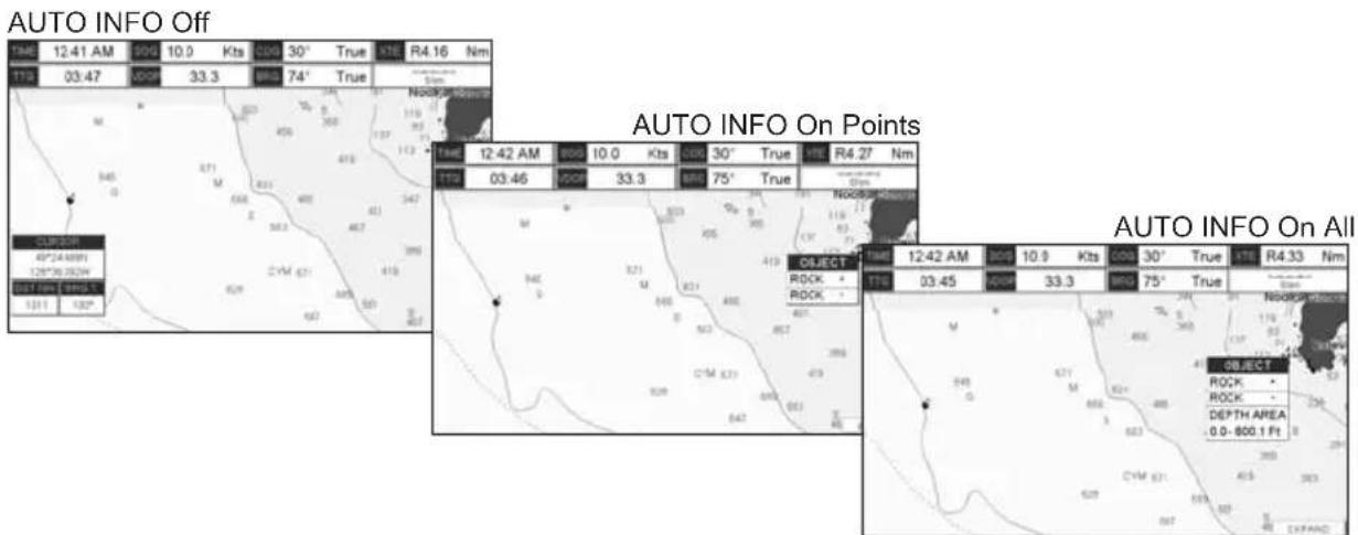
text_image
AUTO INFO Off 1946 12:41 AM 000 10.0 Kts 000 30° True XTE R4.16 Nm TTS 03:47 VCOM 33.3 BMS 74° True NOCO-500mm AUTO INFO On Points TTS 12:42 AM 000 10.0 Kts 000 30° True HTE R4.27 Nm TTS 03:46 VCOM 33.3 BMS 75° True NOCO-500mm AUTO INFO On All TTS 12:42 AM 000 10.9 Kts 000 30° True XTE R4.33 Nm TTS 03:45 VCOM 33.3 BMS 75° True OBJECT ROCK + ROCK - OBJECT ROCK + DEPTH AREA 0.0 - 800.1 Ft EXPANSFigure 12.0.5 - Example of Auto Info settings
12.0.6 Display Mode
Selects from a pre-defined table what cartographic objects are displayed and which display options are set. Pre-programmed settings are user selectable from Full, Medium, Low, Radar (reduces the information on the display to simulate items that would be shown on a RADAR display. Please note this function is not actually showing RADAR information it is only showing what typically would be shown by a separate dedicated RADAR display), Tides, Custom (default mode).
To change to one of the pre-programmed settings:
- Press [MENU], move the ShuttlePoint knob to highlight SETUP MENU and press [ENT].
- Move the ShuttlePoint knob to highlight CHART CONFIGURATIONS and press [ENT] or move the ShuttlePoint knob to the right.
- Move the ShuttlePoint knob to highlight DISPLAY MODE and press [ENT] or move the ShuttlePoint knob to the right.
- Move the ShuttlePoint knob up or down to select the preset and press [ENT].
- Press [CLR] or move the ShuttlePoint knob to the right until the Chart page is shown.

text_image
SET GENERAL SET CHART CON MAX FUNCTION ADVANCED C-MAP WEA AIS SETUP VIDEO INPUT About... CHART CONFIGURATION DISPLAY MODE MARINE SETTINGS PLACE NAMES NAME TAGS NAV AIDS & LIGHT SECTORS ATTENTION AREAS TIDES & CURRENTS SEABED TYPE PORTS & SERVICES TRACKS & ROUTES DEPTH SETTINGS DEPTH RANGE MIN DEPTH RANGE MAX LAND SETTINGS LAND ELEVATIONS LAND ELEVATION VALUES Full Medium Low Radar Tides Custom 3.80 Nm 1000 FtFigure 12.0.6 - Display Mode settings
The table below shows the selections for each mode:
| SettingFullMediumLow RadarTidesCustom | (Default values) | |||||
| Place Names On On On On | On | |||||
| Name Tags | On | Off | Off | Off | Off | Off |
| Nav Aids & Light Sectors | On | No Sectors | No Sectors | No Sectors | Off | On |
| Attention Areas On On Off | Off | Off | Off | |||
| Tides & Currents | On | Off | Off | Off | On | On |
| Seabed Type On Off Off Off On | ||||||
| Ports & Services On On Off On Off On | ||||||
| Tracks & Routes On Off Off Off On | ||||||
| Depth Range Min 0FT 0FT 0FT 0FT | 0FT | 0 Ft | ||||
| Depth Range Max | 32804FT | 32804FT | 32804FT | 32804FT | 32804FT | 32804FT |
| Land Elevations On On Off Off Off | Off | |||||
| Land Elevation Values | On Off Off Off Off | On | ||||
| Roads | On Off Off | Off Off | On | |||
| Points Of Interest On Off Off Off Off | On | |||||
| Lat/Lon Grid | On Off Off Off Off | Off | ||||
| Chart Boundaries | On | Auto | Off | Off | Off | Off |
| Value-Added Data | On Off Off Off On | On | ||||
| Chart Lock | On On On | On On | On | |||
| Mixing Levels | On On On | On On | On | |||
| Underwater Ob. Limit | 1000FT | 32FT | 32FT | 32FT | 32FT | 1000FT |
| Rocks | Icon + Depth | Icon | Icon | Icon | Icon | Icon |
| Obstructions | Icon + Depth | Icon | Icon | Icon | Icon | Icon |
| Diffusers | Icon + Depth | Icon | Icon | Icon | Icon | Icon |
| Wrecks | Icon + Depth | Icon | Icon | Icon | Icon | Icon |
12.0.7 Marine Settings
To control the display on the chart of the marine features.
| Place Names | : Turns the Local area names On or Off. |
| Names Tags | : Turns a tag for particular chart objects that either includes the Name of the chart object or the Depth of an Underwater chart object On or Off. |
| Nav Aids & Light Sectors: | Turns the presentation of Lights, Signals, Buoys and Beacons On (Nav-Aids & Light Sectors are shown), Off (Nav-Aids & Light Sectors are not shown) or No Sector (Nav-Aids are shown, Light Sectors are hidden). |
| Attention Areas | : Turns the Attention Areas (areas in which special attention by the mariner is required because of natural or man-made hazards sailing regulations and restrictions) On or Off. |
| Tides & Currents | : Turns the Tides and Currents On or Off.When data/time is available, Tidal stream arrows are shown on the charts, indicating the direction and strength of the Tide. If no data/time is available from the GPS or the GPS Chart Plotter is not in Simulation mode, the icon on the chart is generic one. The color of the arrow denotes the strength of the current as follows: |
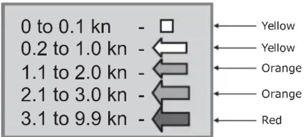
text_image
0 to 0.1 kn - □ 0.2 to 1.0 kn - ← 1.1 to 2.0 kn - ← 2.1 to 3.0 kn - ← 3.1 to 9.9 kn - ← Yellow Yellow Orange Orange Red| When the GPS Chart Plotter receives a valid position fix, the Tide icons are shown on the charts on the basis of the current date and time: the screen displays and changes arrows as date/time changes. | |
| Seabed Type | : Turns the Seabed type On or Off. |
| Ports & Services | : Turns the Ports and Service icons On of Off. Areas along the shore with facilities for mooring, downloading and uploading of ships, generally sheltered from waves and winds. Port installations are piers, wharves, pontoons, dry docks, cranes.... |
| Tracks & Routes | : Turns the underwater objects On or Off. Objects are obstructions, wrecks, cable etc. |
12.0.8 Depth Settings
To control the display on the chart of the depth informations.
| Depth Range Min | : Sets the minimum depth limit to show Depth Sounding, Bathymetric Lines and Depth Area. |
| Depth Range Max | : Sets the max depth limit to show Depth Sounding, Bathymetric Lines and Depth Area. |
0-1000 Ft
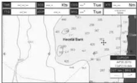
Figure 12.0.8 - Depth Settings
12.0.9 Land Settings
To control the display on the map of the terrestrial features.
Land Elevations : Turns the Land Elevations On or Off.
Land Elevation Values : Turns the Land Elevation Values On or Off.
Roads : Turns the Roads On or Off.
Points Of Interest : Turns the Points of Information On or Off.
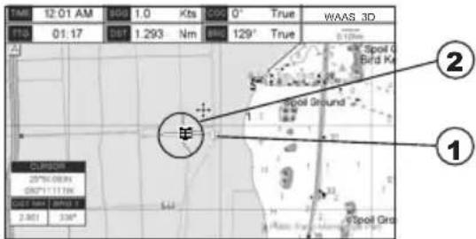
text_image
14M 12:01 AM 800 1.0 Kts 0° True WAAS 3D T10 01:17 1.293 Nm 800 129° True Spot Ground Spot Ground 1 2 1 Curator 25°N/0.0"N 60°1"1.1"N Spot Grid 2.801 3.90°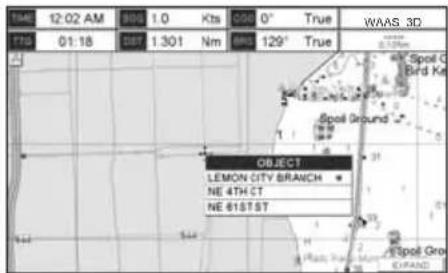
text_image
1046 12:02 AM 855 1.0 Kts 050 0° True WAAS 3D 719 01:18 857 1.301 Nm 895 129° True Object LEMON CITY BRANCH NE 4TH CT NE 61ST ST Spot Ground Spot Gro EXPAND① ROAD
② POINT OF INTEREST (LIBRARY)
Figure 12.0.9 - Example of Roads and Points Of Interest
12.0.10 Chart Settings
Settings that control how the chart features will be shown on the Chart page of the GPS Chart Plotter.
Lat/Lon Grid : Turns the Latitude and Longitude grid lines on or off on the chart page. See the figure below:
Lat/Lon Grid ON
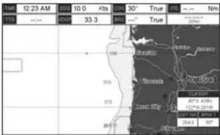
text_image
12:23 AM 800 10.0 Kts 600 30° True SE --- Nm T10 --- 800 33.3 ARC ---° True Portayana ELISA 45°/4.47km 122°/4.25W UST 1 km amp 7 2014-0 95°Lat/Lon Grid OFF
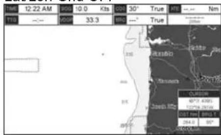
text_image
T10 12:22 AM 10.0 Kts 30° True MTI --- Nm --- 2008 33.3 HRC --- True CLERSON 40°7 4300 122°56 2610 GST Nm BRG 1 284.9 85° 2008/02/28Chart Boundaries : Turns the Chart Boundaries On, Off or Auto. The Chart Boundaries are the "ticked" boxes sourround the coastline. Each box indicates an area where more detail is available. The Chart Boundaries are only show when a C-MAP BY JEPPESEN NT+ or MAX CARD is inserted into the GPS Chart Plotter. See the pictures below:
Chart Boundaries ON Chart Boundaries OFF
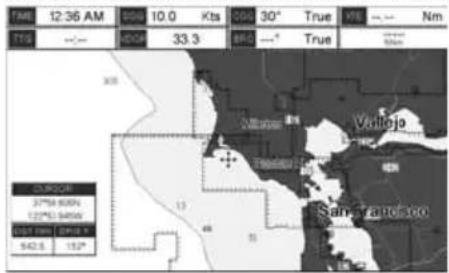
text_image
14M 12:36 AM 00M 10.0 Kts 00G 30° True X8 --- Nm T19 --- 00M 33.3 M/s ---° True Min 2050R 37PM 60KN 122PM 548KN UST PM EPH 5 942.5 15° Sarbanato 1000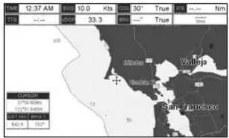
text_image
12:37 AM 10.0 Kts 30° True 178 NDOX 33.3 BNG True Vallejo San Francisco 542.6 132° CUPSOH 37°50'00"N 122°51'04"N UST 1951 / 1956.5 542.6 132°Value Added Data : Turns the Value Added Data On or Off. The Value Added Data (VAD) is a collection of additional cartographic objects which are not present on the original paper chart (from which the electronic chart derives). These objects have been obtained from other sources and then merged to the electronic charts in order to provide more information useful for the navigation. VAD object can be any cartographic objects and it can be distinguished from the official-chart-objects from the Quick Info. A dedicated icon is shown on the Quick Info window to indicate that the object queried is a VAD. The same icon is also shown on the Full Info page and in addition the extended text Value Added Data is shown on the details of the VAD object. See the figure below:
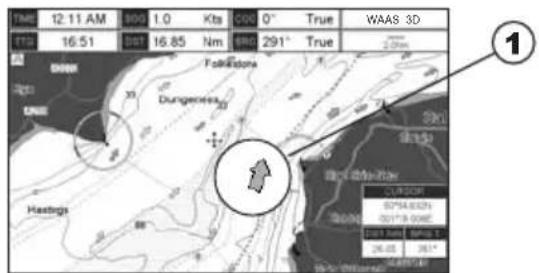
text_image
12:11 AM 000 1.0 Kts C00 0° True WAAS 3D 16:51 16.85 Nm 291° True Fokkstone Dungenees Hastings 1 1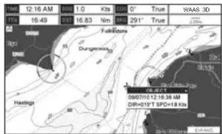
text_image
Time: 12:16 AM TTS: 16.49 000 1.0 Kts 000 0° True 16.83 Nm SPD 291° True 2.25% Folkswagen Dungemeans Hastings 09/07/10 12:16:36 AM DIR+018 T SPD=1.8 Kts SELECT 09/07/10 12:16:36 AM EVEAUC① Example of VAD object
| Chart Lock (*) | : Turns the chart function On/Off. When Chart Lock is On, the available zoom scales are only the ones containing cartographic data. Instead when Chart Lock is Off, it is possible to zoom down into zoom scales not covered by cartographic data after the last available zoom scale covered by cartographic data. The DSI (Data Safety Indicator) window, if present, will show “NO CHART”, when an empty level is entered in the location of chart expansion mode. |
| Mixing Levels | : When the chart coverage at the current chart scale does not fill the entire display, the GPS Chart Plotter draws the rest of the chart using charts from above and below the current scale. When this function is turned on you will notice the display may redraw 2 to 3 times to show all the details. |
NOTE(\*)
When an empty level is entered, the message "No cartographic coverage" is shown on a window in a corner of the chart display. The warning message is always displayed as long as the current zoom has no data coverage.
12.0.11 Underwater Objects Settings
The following selections are used to control which Underwater Objects are shown on the Chart Page.
| Underwater Object Limit | : Selects the max depth value to display Underwater Objects. If value is set to 0 Feet, the Underwater Objects are not shown on the charts. Menu options are grayed out. If value is more than 0 Feet (i.e. 10 Feet), in the Range from 0 Feet to the selected value the Underwater Objects are displayed according to their setting below. |
| Rocks | : Sets Off/Icon/Icon+Depth* the displaying of the Rocks. |
| Obstructions | : Sets Off/Icon/Icon+Depth* the displaying of the Obstructions. |
| Diffusers | : Sets Off/Icon/Icon+Depth* the displaying of Diffusers (Diffuser is a structure on an outfall through which liquids are discharged. The structure will usually project above the level of the outfall and can be an obstruction to navigation). |
| Wrecks | : Sets Off/Icon/Icon+Depth* the displaying of Wrecks. |
NOTE(\*)
Choose the options: OFF (the object is not visible independently of the selected "Underwater Object Depth Value"); ICON (the object icon is visible without tags, in the range selected from "Underwater Object Depth Value" option); ICON+DEPTH (the object icon and tag is visible, in the range selected from "Underwater Object Depth Value" option).
12.1 CUSTOMIZING CHART SETTINGS
The GPS Chart Plotter also allows you to customize items shown on the chart (discussed in above sections) instead of using a pre-defined table discussed in Par. 12.0.4 Display Mode.
- Press [MENU], move the ShuttlePoint knob to highlight SETUP MENU and press [ENT].
- Move the ShuttlePoint knob to highlight CHART CONFIGURATIONS and press [ENT] or move the ShuttlePoint knob to the right.
- Move the ShuttlePoint knob to highlight DISPLAY MODE and press [ENT] or move the ShuttlePoint knob to the right.
- Move the ShuttlePoint knob to highlight Custom and press [ENT] or move the ShuttlePoint knob to the right.
- Move the ShuttlePoint knob up or down to select the desired item within the groups Marine Settings, Depth Settings, Land Settings, Chart Settings or Underwater Settings and press [ENT]. See the above sections for details on selections.
12.2 NAVIGATION PAGE
This page is useful to show information when heading to a destination, following a compassa heading or navigating to a Mark or a Route. The default page is shown with a Compass Rose, however this can be customized to show a Compass Tape.
- To change to show the Compass Tape, select the Chart page, press [MENU]. Move the ShuttlePoint knob to highlight SETUP MENU and press [ENT].
- Move the ShuttlePoint knob to highlight GENERAL SETUP and press [ENT] or move the ShuttlePoint knob to the right.
- Move the ShuttlePoint knob to highlight WINDOW SETUP and press [ENT] and press [ENT] or move the ShuttlePoint knob to the right.
- Move the ShuttlePoint knob to highlight NAVIGATION PAGE and press [ENT] and press [ENT] or move the ShuttlePoint knob to the right.
- Move the ShuttlePoint up or down to select COMPASS TAPE and press [ENT].
- Press [CLR] or move the ShuttlePoint knob to the right until the Chart page is shown.
① Fix position
② Time
③ Speed Over Ground
④ Course Over Ground
⑤ Bearing to Destination
⑥ Time To Go
⑦ Distance to Destination
⑧ Compass Rose
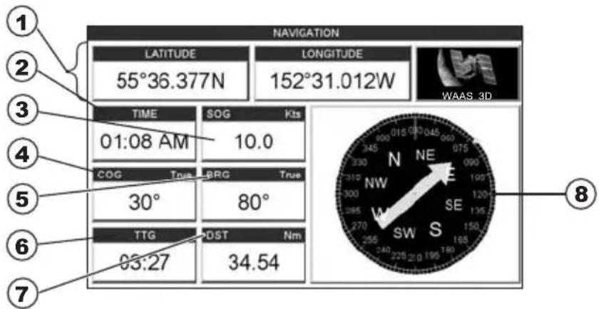
text_image
NAVIGATION LATITUDE 55°36.377N LONGITUDE 152°31.012W WAAS 3D TIME 01:08 AM SOG 10.0 Kts COG True BRG True 30° 80° TTG 03:27 PDT Nm 34.54 ① ② ③ ④ ⑤ ⑥ ⑦ ⑧Figure 12.2 - Navigation page with Compass Rose
① Fix position
② Compass Tape
③ Time
④ Time To Go
⑤ Speed Over Ground
⑥ Distance to Destination
⑦ Course Over Ground
⑧ Bearing to Destination
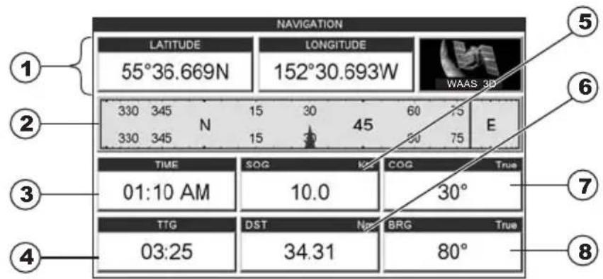
text_image
NAVIGATION LATITUDE 55°36.669N LONGITUDE 152°30.693W WAAS 3D 330 345 N 15 30 45 60 75 E 330 345 15 30 45 60 75 TIME SOG KCO True 01:10 AM 10.0 30° TTG DST NBRG True 03:25 34.31 80° ① ② ③ ④ ⑤ ⑥ ⑦ ⑧Figure 12.2a - Navigation page with Compass Tape
NOTE
The COG heading is computed and supplied to the plotter from the internal GPS or external GPS.
12.3 HIGHWAY PAGE
Shows a 3D view of the vessel travelling through the water when Navigating to a destination point, Mark or following a Route. Press [ZOOM IN] or [ZOOM OUT] to change the highway scale.
① Speed Over Ground
② Course over ground
③ Bearing
④ Highway Display
⑤ Highway Scale
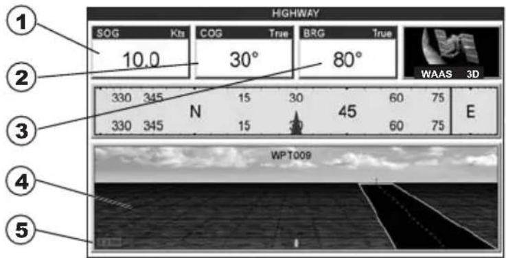
text_image
HIGHWAY 1 SOG Kts COG True BRG True 10.0 30° 80° WAAS 3D 330 345 N 15 30 60 75 E 330 345 15 30 60 75 WP T009Figure 12.3 - Highway page
12.4 CELESTIAL PAGE
The Celestial page contains Tide information critical for safe navigation. This page is also useful for boaters that are concerned about the height of the water under a bridge or by fisherman that wish to know the tide and moon phase of a specific date.
Changing date
- Press [ENT] and a popup window will be shown.
- Moving the ShuttlePoint knob up or down changes the digits and left and right selects the month, day and year.
- Press [CLR] to exit and view the information.
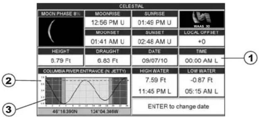
text_image
CELESTIAL MOON PHASE 8% MOONRISE 12:56 PM U SUNRISE 01:49 PM U WAAS 3D MOORSET 01:41 AM U SUNSET 02:48 AM U LOCAL OFFSET +0 HEIGHT 6.79 Ft DRAUGHT 6.83 Ft DATE 09/07/10 TIME 00:00 AM L COLUMBIA RIVER ENTRANCE (N JETTY) HIGH WATER 7.59 Ft LOW WATER -0.87 Ft 11:45 PM L 05:15 AM L ENTER to change date 46°16.390N 124°04.346WFigure 12.4 - Celestial page
Refer to the image above. The time (1) displayed corresponds to the location of the cross-hair cursor (3) in the Tide Graph (2). Moving the ShuttlePoint knob to the left or right changes the time, moving the ShuttlePoint knob up or down selects the Tide height and draught (draft) on the Tide Graph.
NOTE
The draught window shows the height of the tide water during a 24hr period of time. For example if the ShuttlePoint knob is pressed up to move the cursor to the top of the Tide Graph this is the High Water Level and if the cursor is moved to the bottom of the Tide Graph the draught will show the Low Water Level.
Example 1
You anchor in 15Feet of water (under your keel) at a time of day where the water is the highest (High Water). Let's say the High Water window shows 5Feet and the Low Water window shows 1Feet this means the water under your vessel over a 24 hour period of time could fall 4Feet (High Water - Low Water). With your vessel in 15Feet of water and with a maximum water change of 4Feet during the day, the worst case situation there will be 11Feet of water under your vessel.
12.5 GPS STATUS PAGE
This page is used as a reference to see how well the GPS is receiving satellites.
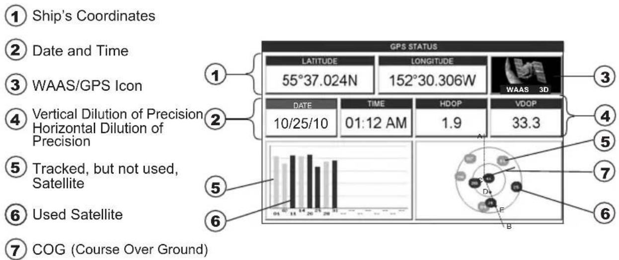
text_image
① Ship's Coordinates ② Date and Time ③ WAAS/GPS Icon ④ Vertical Dilution of Precision Horizontal Dilution of Precision ⑤ Tracked, but not used, Satellite ⑥ Used Satellite ⑦ COG (Course Over Ground) GPS STATUS LATITUDE 55°37.024N LONGITUDE 152°30.306W WAAS 3D DATE 10/25/10 TIME 01:12 AM HDOP 1.9 VDOP 33.3Figure 12.5 - GPS Status page
The WAAS/GPS Icon area may change due to the satellite reception:
ACQUIRING : the GPS is trying to receive a valid position fix.
GPS2D : The GPS is receiving at least 2 valid Satellites
GPS3D : the GPS is receiving at least 3 Satellites.
WAAS 2D/3D : the GPS is receiving a 2D or 3D position and the correction from the WAAS Satellite.
HDOP : Horizontal Dilution of Precision
VDOP : Vertical Dilution of Precision
12.5.0 WAAS/EGNOS Setting
From this page it is possible to disable the WAAS/EGNOS function following this procedure:
- Press [MENU], move the ShuttlePoint knob to enter GPS STATUS page and press [ENT].
- Press and hold [ENT]. The GPS SETUP menu appears on the screen.
- Move the ShuttlePoint knob to highlight DIFF CORRECTION SOURCE and press [ENT].
- Move the ShuttlePoint knob to highlight None (to disable) and press [ENT].
- Press [CLR] until the menu disappears or an easier method is to move the ShuttlePoint knob to the left until the menu disappears.
12.5.1 Setup Menu
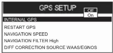
text_image
GPS SETUP Off On INTERNAL GPS RESTART GPS NAVIGATION SPEED NAVIGATION FILTER High DIFF CORRECTION SOURCE WAAS/EGNOSFigure 12.5.1 - Setup menu
From this page it is possible to activate the GPS Setup menu following this procedure:
- Press [MENU], move the ShuttlePoint knob to enter GPS STATUS page and press [ENT].
- Press and hold [ENT]. The GPS SETUP menu appears on the screen. See the following table:
| Internal GPS | : Enables (On) or disables (Off) the Internal GPS. The default setting is On. |
| Restart GPS | : Restarts all GPS processes. Once executed, the message "Done" is shown. |
| Navigation Speed | : Allows setting the Navigation Speed among Low and High. The default setting is High. |
| Speed Filter | : Allows to resolve erratic speed readings in rough seas. Available values are Off, Low, Medium, High. The default setting is Off. |
| Differential Correction Source | : Allows setting what kind of Differential Correction will be used by the GPS between WAAS-EGNOS and none. The default setting is WAAS-EGNOS. |
-
Move the ShuttlePoint knob to highlight the preferred item and press [ENT].
-
Press [CLR] until the menu disappears or an easier method is to move the ShuttlePoint knob to the left until the menu disappears.
The GPS Chart Plotter is capable of displaying information in the customizable data windows from external NMEA 0183 devices. Depth sounder, Speed Log with temp, Wind speed and direction, Flux gate compass, and GPS information can be shown in any of the boxes. The default NMEA Display shows 3 windows. When going to a destination, this screen is useful to navigate as to get to the destination keep the Course Over Ground (COG) and Bearing (BRG) figures the same.
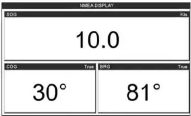
text_image
NMEA DISPLAY SOG Kts 10.0 COG True BRG True 30° 81°Figure 12.6 - NMEA Display page
The NMEA sentences read from external devices are: BWC, DSC, DSE, GGA, GLL, GSA, GSV, HDG, HDM, HDT, RMC, VHW, VTG, DPT, DBT, MTW, VWR, VWT, TLL, WPL, RTE. CHANGING the NMEA PAGE Windows
- Press [MENU], move the ShuttlePoint knob to highlight NMEA DISPLAY and press [ENT]. Otherwise, from the factory the right most Soft Key is programmed for direct access. Press this key two times to show the NMEA Display page.
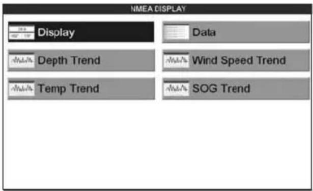
text_image
NMEA DISPLAY Display Data Depth Trend Wind Speed Trend Temp Trend SOG TrendFigure 12.6a - NMEA Display menu
- Move the ShuttlePoint knob to highlight DISPLAY and press [ENT].
- To change the 5 different pages move the ShuttlePoint knob to the left or right.
12.7 NMEA DATA PAGE
The NMEA Data page is very useful to see if a External device (example: Depth Sounder) is transmitting NMEA sentences to the GPS Chart Plotter. This page can also be used to see if the GPS Chart Plotter NMEA output is being loaded down by a external NMEA device the GPS Chart Plotter is connected to.
Scenario: VHF Radio connected but the Radio is not receiving a GPS Position.
Usually the VHF Radio will be connected to the Green and Brown wires. To check to see if the GPS Chart Plotter is transmitting the sentences:
- Press [MENU], move the ShuttlePoint knob to highlight NMEA DISPLAY and press [ENT].
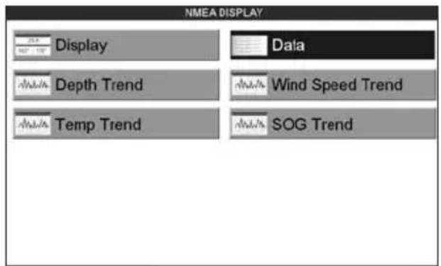
text_image
NMEA DISPLAY Display Data Depth Trend Wind Speed Trend Temp Trend SOG TrendFigure 12.7 - NMEA Display menu
- Move the ShuttlePoint knob to highlight DATA and press [ENT].
- Connect the BLUE Wire on the GPS Chart Plotter to the junction of the Brown wire and the VHF wire. The display should look similar to the following picture.
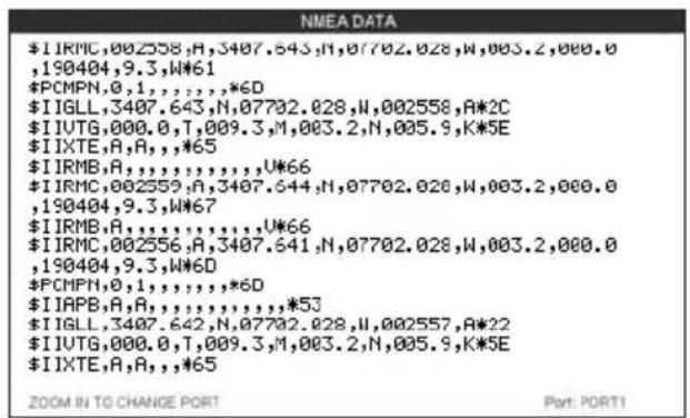
text_image
$I IRMC,002558,A,3407.643,N,07702.028,W,003.2,000.0,190404,9.3,W*61 *PCMPN,0,1,,,,,*6D $I IGLL,3407.643,N,07702.028,N,002558,A*2C $I IUTG,000.0,T,009.3,M,003.2,N,005.9,K*5E $I IXTE,A,R,,,*65 $I IRMB,A,,,,,,,,U*66 $I IRMC,002559,A,3407.644,N,07702.028,W,003.2,000.0,190404,9.3,W*67 $I IRMB,A,,,,,,,,U*66 $I IRMC,002556,A,3407.641,N,07702.028,W,003.2,000.0,190404,9.3,W*6D $PCHPN,0,1,,,,,*6D $I IAPB,A,R,,,,,,,,*53 $I IGLL,3407.642,N,07702.028,N,002557,A*22 $I IUTG,000.0,T,009.3,M,003.2,N,005.9,K*5E $I IXTE,A,R,,,*65 ZOOM IN TO CHANGE PORT Port: PORT1Figure 12.7a - NMEA Data page
- Press [ENT] to freeze the data on the display so it is easy to read and understand.
- Press [ENT] again to receive data again.
- View data from a device connected to another data port, press the [ZOOM IN].
12.8 NMEA TREND PAGES
The CP390i* and CPF390i have the following NMEA Trend pages.
Trends will be shown for Depth, Temp and Speed (DST521 or DST526 must be connected to show speed through the water) when a Standard Horizon transducer is connected. To show Wind trend information the CP390i and CPF390i must be connected to the NMEA output of a external Wind instrument.
NOTE\*
The CP390i must be connected to the Optional FF525 (or FF520) 50/200kHz BLACK BOX FISH FINDER.
To select a NMEA Trend Page:
- Press [MENU], move the ShuttlePoint knob to highlight NMEA DISPLAY and press [ENT].

text_image
NMEA DISPLAY Display Data Depth Trend Wind Speed Trend Temp Trend SOG TrendFigure 12.8 - NMEA Display menu
- Move the ShuttlePoint knob to select DEPTH TREND, WIND SPEED TREND, TEMP TREND or SOG TREND and press [ENT].
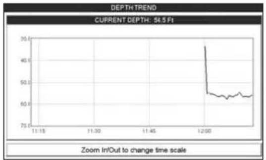
line
| Time | Depth | | ------ | ----- | | 12:00 | 56.5 |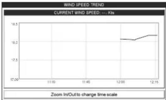
line
| Time | Current Wind Speed (Kts) | | ------ | ------------------------ | | 12:00 | 16.1 | | 12:15 | 16.2 |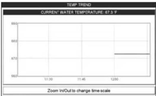
line
| Time | Temperature | | ------ | ----------- | | 12:00 | 67.3°F |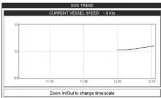
line
| Time | Value | |-------|-------| | 12:30 | 1.0 | | 12:15 | 1.1 |Figure 12.8a - NMEA Trend pages
12.9 VHF DIGITAL SELECTIVE CALLING
Digital Selective Calling is a semi-automated method of establishing a VHF radio call. DSC had also been designated as part of the Global Maritime Distress and Safety System (GMDSS).
This new system allows mariners to instantly send a distress call with GPS position (when connected to the transceiver) to the US Coast Guard and other vessels within range of the transmission. DSC will also allow mariners to initiate POSITION Request, POSITION Report calls to or from another vessel equipped with a DSC transceiver.
Compatible VHF Marine Radios with Digital Selective Calling are able to be interfaced with the GPS Chart Plotter which feeds GPS data to the VHF and listens for DSC calls from the VHF. By connecting a few wires between the compatible DSC VHF radios and the GPS Chart Plotter it will receive:
-
a vessel that has transmitted a DSC Distress call
-
a vessel that has transmitted a DSC Position Send Call
- The position of a vessel that transmitted a DSC Position Request Call
12.9.0 Interfacing
To take advantage of these functions the GPS chart plotter must be interfaced (wired) to a STANDARD HORIZON or compatible DSC VHF.
For additional information refer to Par. 2.4 Connections.
12.9.1 Distress Call
STANDARD HORIZON GPS chart plotters are able to display the location of a vessel in distress when interfaced to a compatible DSC VHF with NMEA 0183 output and the radio receives a DSC Distress Call. STANDARD HORIZON GPS chart plotter also log DSC Distress calls to review at a later date.
- Press [MENU] and move the ShuttlePoint knob to highlight USER POINTS and press [ENT].
- Move the ShuttlePoint knob to highlight DSC Log and press [ENT].
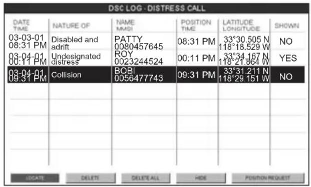
text_image
DSC LOG - DISTRESS CALL DATE TIME NATURE OF NAME 03-03-01 Disabled and 08:31 PM adrift PATTY 00:04-01 Undesignated 00:11 PM distress ROY 00:11 PM 33°30.505 N 118°18.529 W NO 03-04-01 Collision BOBI 33°34.167 N 09:31 PM 0056477743 09:31 PM 33°31.211 N 118°29.151 W NO LOCATE DELETE DELETE ALL HIDE POSITION REQUESTFigure 12.9.1 - DSC Log - Distress Call
12.9.2 Position Request
STANDARD HORIZON GPS chart plotters are able to display the location of a vessel when connected DSC VHF radio and when a Position Request or Report call is received. STANDARD HORIZON GPS also log DSC Distress calls to review at a later date.
- Press [MENU] and move the ShuttlePoint knob to highlight USER POINTS and press [ENT].
- Move the ShuttlePoint knob to highlight DSC Log and press [ENT].
- Move the ShuttlePoint knob to the right to select POSITION REQUEST and press [ENT].
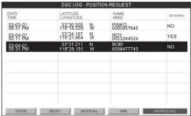
text_image
DSC LOG - POSITION REQUEST DATE TIME LATITUDE LONGITUDE NAME MMSI SHOWN 03-03-01 08:31 PM 33°30.505 N 118°18.529 W PINKO 0080457645 NO 03-04-01 00:11 PM 33°34.167 N 118°21.864 W ROY 0023244524 YES 03-04-01 09:31 PM 33°31.211 N 118°29.151 W BOBI 0056477743 NO SOCIATE DELETE DELETE ALL HOME DISTRESS CALLFigure 12.9.2 - DSC Log - Position Request
13. ADVANCED SETTINGS
The Advanced Setup menu allows customization of many GPS functions, Alarms and NMEA interfacing.
- Press [MENU], move the ShuttlePoint knob to highlight SETUP MENU and press [ENT].
- Move the ShuttlePoint knob to highlight ADVANCED SETUP and press [ENT] or move the ShuttlePoint knob to the right.
While in this menu you will see many selections which are described in the next sections.
13.0 INPUT/OUTPUT (NMEA, AIS, RADAR)
13.0.0 Input
The CP390i has 4 Inputs and 5 Outputs connections. The CPF390i has 3 Inputs and 3 Outputs connections.
These ports may be set up to receive and output the following.
- NMEA-0183 - NMEA devices* set to 4800 Baud (default setting)
- Fish Finder: Only for CP390i: FF525 50/200kHz BLACK BOX FISH FINDER - refer to Fish Finder Owner's Manual
· C-Com - C-Weather refer to Section 15 - Radar - SI-TEX optional Radar refer to Radar Owner's Manual
- AIS38400 - AIS Receiver, refer to Section 14
- MOBILARM - Mobil-arm receiver, refer to Section 16
- Disabled - allow the port to be disabled.
NOTE*
RS232 not opto-isolated electrical interface
NOTE
| When a Port is configured, both the Input and Output have the same setting. |
| Port1 is set to Radar, both the Input and Output wires are set to SI-TEX proprietary Radar sentences. This means other devices should not be connected to the Input or Output wires. |
13.0.1 Ouput
The ports may be setup to output NMEA sentences. The table below shows the default setting each port.
CP390i
| Sentence Port1 Port2 Port3 Port4 Port5 |
| GLL On On On On On |
| VTG Off Off Off Off Off |
| BWC Off Off Off Off Off |
| WCV Off Off Off Off Off |
| APA Off Off On Off Off |
| APB Off Off On Off Off |
| HDG Off Off Off Off Off |
| BOD Off Off On Off Off |
| XTE On On On On On |
| RMA Off Off Off Off Off |
| RMB Off Off Off Off Off |
| RMC On On On On On |
| GGA On On On On On |
| HSC Off Off Off Off Off |
| DBT On Off Off Off Off |
| DPT On Off Off Off Off |
| MTW On Off Off Off Off |
| VHW On Off Off Off Off |
| GSA On Off Off Off Off |
| GSV On Off Off Off Off |
CPF390i
| Sentence Port1 Port2 Port3 |
| GLL On On On |
| VTG Off Off Off |
| BWC Off Off Off |
| WCV Off Off Off |
| APA Off Off Off |
| APB Off Off Off |
| HDG Off Off Off |
| BOD Off Off Off |
| XTE On On On |
| RMA Off Off Off |
| RMB Off Off Off |
| RMC On On On |
| GGA On On On |
| HSC Off Off Off |
| DBT On Off Off |
| DPT On Off Off |
| MTW On Off Off |
| VHW On Off Off |
| GSA On Off Off |
| GSV On Off Off |
13.1 NAVIGATE
The Navigate Menu allows customization of the Coordinate System (Loran TD's), Chart Datum, Chart Orientation Resolution (angle the vessel has to change before the chart is redrawn) and Static Navigation. See the following table
Coordinate System : Selections are:
| a. TD: Time Difference, based on Loran (see the following Par. 13.1.0)b. UTM: Universal Transverse Mercator Gridc. ddd mm.mmm: Degrees Minutes and Thousands of Minutesd. ddd mm.mm: Degrees Minutes and Hundredths of Minutese. ddd mm.ss: Degrees Minutes and Seconds (default) | |
| Chart Datum | : Allows selection of Chart Datums. The default Datum is WGS84 as C-MAP BY JEPPESENCartography has been compiled using the WGS84 Datum. A datum is a mathematicalmodel of the Earth which approximates the shape of the Earth, and enables calculations such as position and area to be carried out in a consistent and accurate manner. |
| Chart Orientation Resolution: | Sets the angle the vessel has to change before the chart is redrawn. The default setting is 30 degrees. Example: if the vessel is heading 000T at a speed of 25 Knots, the display will redraw:a. In Home mode the GPS Chart Plotter centers the location of the vessel in the center of the display. To keep the vessel in the center of the display the GPS Chart Plotter will occasionally redraw.b. If the vessel changes course greater than 330T or more than 30T the chart will be redrawn. |
| Static Navigation: | Sets up a threshold for the speed. When the speed received from the positioning device is under that threshold, the GPS Chart Plotter displays zero. The default setting is 0.9 Kts. |
13.1.0 Loran TD
The Loran TD selection allows the GPS Chart Plotter to be set up so the user can enter in LORAN TD's directly into the GPS Chart Plotter. After the TD's have been entered, and the user changes to ddd mm.sss (Degrees Minutes and Seconds) the TD's will be converted to Lat / Lon coordinates.
To use the TD Coordinate System the user must setup the Chain and Pair information of the TD's. If you do not know this information, refer to paper charts that show the Chain and Pair information.
| ASF1/2 | : Additional Secondary phase Factor (TD Coordinate System)Correction to TD1/2 values which can be inserted by the user to take in account the additional signal propagation delay aver a mixed land/seawater path compared to on all-seawater path. Normally the user does not enter a ASF value. However for experienced users this function allows entering of signal delay values to fine adjust the calculated position. The user should enter delay values to fine adjust the position calculated. |
| Alter : Alternate Solution (TD Coordinate System)Parameter selected by the user that is applied in the conversion of geographical coordinates Lat/Lon to TD values. To be used if the position displayed is roughly not correct. | |
13.2 COMPASS
The GPS Chart Plotter computes compass direction from the constellation of GPS Satellites. For the GPS Chart Plotter to compute direction the vessel must be moving through the water unless connected to an optional Flux Gate Compass sensor. The Compass menu allows the GPS Chart Plotter to customize the following selections:
| Bearings | : Selects between True and Magnetic. When Magnetic bearings is enabled, the GPS Chart Plotter applies the selected MagneticVariation (Auto or Manual, see next paragraph) to compute Magnetic bearing. |
| Variation | : Allows the user to select Auto or Manual. When Auto mode is selected the GPS Chart Plotter computes the offset by the current GPS fixed location. Manual mode allows the user to enter in a magnetic variation that is applied in the True conversion. |
| Calibration | : This function allows a user to enter in the offset for areas that the vessel may cruise instead of entering in a manual offset for one location. This offset is useful for cruising vessels or vessels that travel internationally often. |

text_image
N N/E E S/E S S/W W N/W +01° +02° +00° -01° -01° +01° +03° +02°Figure 13.2 - Compass Table
The Alarms menu is used to select and setup audible and visual Alarms. Available alarms are Arrival, XTE, Depth, Anchor and Grounding Alarm.
| Arrival Alarm | : Alerts when the vessel is approaching a single destination point or when arriving at a leg in a Route. Available selections: 0.00 to 9.99NM. |
| XTE Alarm | : Alerts when the vessel is deviating from a defined course. Available selections: 0.00 to 9.99NM. |
| Depth Alarm | : Alerts when the received depth Value is lower than the selected value. Available selections: 0000 to 3000FT. |
| Anchor Alarm | : Alerts when the ships moves off a selected locations by a selected distance. Available selections: 0.00 to 9.99NM. |
| Audble Alarm : Enables or disables the alarm beep. | |
| Grounding Alarm | : This function looks ahead of the vessels heading to see if a potential danger exists. When the Grounding Alarm is enabled the GPS Chart Plotter will draw a triangle in front of the vessel on the Chart page showing the area that is being searched as shown below. The depth and range (distance) of the area the GPS Chart Plotter looks ahead for a shallow area can be set using this function. |
| Grounding Alarm Range | : This function allows setting the distance of the grounding alarm zone (the length of the sector to be detected) among the 0.25, 0.5, 1.0 Nm selections. When a depth or any of the searched objects is found in the scanned area, a tick marker is printed on the relative box in the Grounding Alarm Report page to identify which dangerous objects have been currently detected. |
Grounding Alarm Report: This function allows displaying a report of the dangerous objects currently detected.
The following warning appears when the Grounding Alarm is enabled.
NOTES
The Grounding Alarm function is available only if a NT ^+ /MAX C-CARD is inserted. It also affects the screen redraw speed so we suggest to disable it when not used.
When any of the objects checked are found for the first time, the GPS Chart Plotter shows a pop up window to alert the user of the possible danger. The name of each new dangerous object found is reported in the warning window. In the Grounding Alarm Report page the relative item has a tick marker next to it, to identify the dangerous object currently detected. If in the next search cycle the same objects are found again, the alarm window will not be shown. Instead, if in the next searches the objects found before are no longer detected, their relevant item in the Grounding Alarm Report page is cleared (note that in this case, if the same object type is found again later, the Alarm will be shown). The GPS Chart Plotter shows an icon on the charts that identifies when a Grounding Alarm is detected.
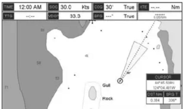
text_image
TIME 12:00 AM SOG 30.0 Kts COG 30° True XTE --- Nm TTG --- VDO 33.3 BFG ---° True 5.051nm Gull Rock CURSOR 44°45.508N 124°04.491W DST Nm BRG T 0.384 336°Figure 13.3 - Grounding Alarm
13.4 SIMULATION
The built-in Simulator function allows you to become proficient in the use of the GPS Chart
Plotter, see the Simulation menu below:
| Simulation Mode : Three selections: |
| a. Off - turn the simulation mode Off |
| b. On - enable the simulator mode, where the speed and course are adjusted by entering in values in the Course and Speed selection discussed later in this table. |
| c. Route - this selection allows you to navigate to a saved route. |
Course : To start the simulator you can insert the Course value.
| Speed : To start the simulator you can insert the Speed value. | |
| Date : To start the simulator you can insert the date. | |
| Time : To start the simulator you can insert the time. | |
| Cursor Control | : Enables (On)/disables (Off) the cursor control. Moving the ShuttlePoint knob up or down will change the SOG and left or right will change the COG of the simulated vessel. |
| Demo Mode | : In Demo mode the GPS Chart Plotter automatically places a Destination point on the Chart page and simulates navigation to the point. Also, the active page changes automatically every 10 seconds. The pages are shown in the following order: Start-up screen, GPS Status, Chart/Compass tape, Chart/Fish Finder, Full page Fish Finder, Full page Radar, Navigation, Highway, Celestial, NMEA. Once the Demo mode is enabled, pressing any key it is possible to temporally exit and returns to GPS Chart Plotter normal operation, but if you do not touch any key for 30 seconds Demo mode re-starts. |
13.4.0 Navigating a Route in Simulation mode
This selection allows you to navigate to a saved Route to see how data windows on the Chart page and how the Navigation and Highway pages operate.
- Create a Route. Refer to Par. 9.0 Route.
- Press [MENU], move the ShuttlePoint knob to highlight SETUP MENU and press [ENT].
- Move the ShuttlePoint knob down to highlight ADVANCED SETUP, then press [ENT].
- Move the ShuttlePoint knob to highlight SIMULATION and press [ENT].
- Move the ShuttlePoint knob to highlight SIMULATION MODE and press [ENT] to show a popup window.
- Move the ShuttlePoint knob to highlight ROUTE and press [ENT] which will show a popup window with the Route(s) that are stored in the GPS Chart Plotter's memory.
- Highlight the desired Route and press [ENT].
- Move the ShuttlePoint knob to highlight SPEED and press [ENT].
- Enter in the speed you want to vessel to travel at in simulation mode, by moving the ShuttlePoint knob left or right to select a number and up or down to change a number.
- When the speed is adjusted, press [ENT].
- Press [CLR] multiple times until the chart page is shown.
13.5 DSC POLLING
This menu is used to enable or disable features related to the DSC function.
| Auto Position | : Selects between Manual or Auto. See also the Par. 12.8.1. When Auto Position item is set toManualand receiving the Position Request, the Position Request pop-up window is not displayed and the cursor does not move to the position of the received Position Request data point. Otherwise when Auto Position item is set toAuto, the GPS chart plotter works as follows:1: when receiving the Position Request, the Position Request popup window is displayed;2: when selecting VIEW ON CHART, the position is indicated on the chart marked with “P”. The cursor is moved to the point “P” and shows the point in the center of the screen;3: when moving the cursor from “P”, the location can be confirmed. At this time, the same MMSI Position Request data that were received before are remaining and displayed. |
Auto Info
: Enables or disables the Auto Info. This selection is available only when Auto Position is set to Manual. If Auto Info is set to On, when receiving the Position Request it is possible to center the cursor over the top of the Position Request icon and show the Position Request popup window
14. AIS
AIS is an Automatic Identification System. It has been introduced to improve the safety of navigation by assisting in the efficient operation of ship-to-ship location reporting and VTS applications. The system should enable operators to obtain information from the ship automatically, requiring a minimum of involvement of ship's personnel, and should have a high level of availability. AIS transponders installed on IMO vessels use VHF frequencies to:
- Transmit details of their own vessel
- Receive details from other vessels or navigation aids within VHF range.
STANDARD HORIZON GPS Chart Plotters are able to display AIS target (for collision avoidance) on the Chart Page and AIS list pages when connected to a AIS receiver (GX2100 or GX2150 STANDARD HORIZON VHF/AIS transceiver) or transponders which output NMEA 0183 VDM sentence at 38400 or 4800 baud. The Chart Plotters are able to show targets from both Class A (commercial) and Class B targets.
14.0 SYSTEM DEFINITIONS
- Target: It is a vessel equipped with AIS. Information about the targets is being received by AIS Receiver and displayed on the screen.
- CPA : Closest Point of Approach is the closest distance that will be achieved between your vessel and the tracked target, based on your vessel's speed and direction and the target's speed and direction.
- CPA Limit: This is the distance from your vessel that a target may reach before a target is deemed a threat.
- CPA Alarm: Occurs if CPA is less or equal to CPA Limit. This test is done for active targets only.
- TCPA: Time to closest Point of Approach is the time remaining until the CPA will occur.
- TCPA Limit: This is the time remaining before the CPA is reached.
- TCPA Alarm: Occurs if TCPA is less or equal to TCPA Limit. This test is done for active targets only and if CPA value is less or equal to CPA Limit.
• Radio Call Sign: International call sign assigned to vessel, often used on voice radio. - Name: Name of ship, 20 characters.
• MMSI: Maritime Mobile Service Identity. - MMSI number: A unique 9 digit number that is assigned to a DSC radio station. It primarily registers the boat information in the U.S. Coast Guard's national distress database for use in emergency situations.
- Active Target: Target located within the Activation Range. Active target is represented by oriented triangle with COG and Heading vectors. Rate of turn may also be displayed.
- Dangerous Target: Target detected by CPA or TCPA Alarm. Dangerous target is Active Target by definition. For better visibility Dangerous Target symbol is flashing.
- Sleeping Target: Target located outside the Activation Range. Sleeping target is represented by a small oriented triangle.
- Lost Target: When the AIS info is not received from that vessel for 3.5 minutes. The presentation will be a flashing black triangle with a cross through.
- Activation Range: Range around your boat where targets become active. AIS target
become active within this range. Activation Range should be greater than CPA Limit by definition.
NOTE
A target is removed from the screen if data is not received for 10 minutes.
The maximum number of tracked Class A or B targets is 200.
This information is updated every 3 seconds to 6 minutes depending on speed and rate of turn, enabling the track of the vessels in range to be plotted.
| TARGET STATUS | DESCRIPTION | SYMBOL |
| ACTIVE TARGET | Target located within the Activation Range. | |
| DANGEROUS TARGET | Target detected by CPA or TCPA Alarm.Dangerous Target is Active Target by definition. | [Δ]Flashing |
| SLEEPING TARGET | Target located outside the Activation Range. | Δ |
| LOST TARGET | Ais info is not received from that vessel for 3.5 minutes. | Δ |
Figure 14.0 - AIS Symbols
14.1 MENU
To configure the GPS Chart Plotter to receive AIS data, follow the procedure:
- Press [MENU], move the ShuttlePoint knob to highlight SETUP MENU and press [ENT].
- Move the ShuttlePoint knob to highlight AIS SETUP and press [ENT] or move the ShuttlePoint knob to the right. The new AIS menu appears on the screen. The available functions are described in the following table.
Display : Turns the display of AIS Targets overlay on the cartography On or Off. The default setting is On.
Activation Range : Defines the range from the fix within which the AIS Target becomes active. The values allowed are from 0.1 to 20 Nm. The default setting is 5 Nm.
CPA Alarm : Turns On or Off the alarm. The default setting is On.
CPA Limit : The values allowed are from 0.1 to 10 Nm. The default setting is 0.5 Nm.
TCPA Alarm : Turns On or Off the alarm. The default setting is On.
TCPA Limit : The values allowed are from 1 to 30 Min. The default setting is 10 Min.
14.2 AIS SETUP
Refer to Par. 2.4 for connections.
14.3 QUICK INFO ON AIS TARGET
By placing the cursor over a AIS Target icon using the ShuttlePoint knob, the following information is displayed (see the following picture):
· Vessel Name
· MMSI number
· Radio Call Sign
· SOG
· COG
- CPA and TCPA values
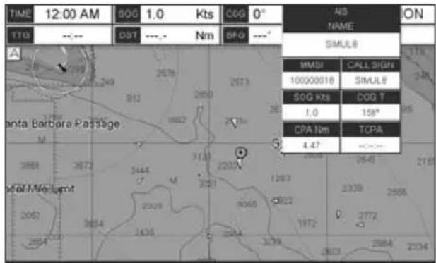
text_image
TIME 12:00 AM SOG 1.0 Kts COG 0° TTG --- DST --- Nm BFG --- A Santa Barbara Passage MMGI CALL SIGNS 100000018 SIMULE SOG Kts COG T 1.0 158° CPA Nm TCPA 4.47 Fall Mid Light 2063 3654 2328 2065 1972 2772 2664 3654 2328 2065 1972 2772 2664 3654 2328 2065 1972 2772 2664 3654 2328 2065 1972 2772 2664 3654 2329 2065 1972 2772 2664 3654 2329 2065 1972 2772 2664 3654 2329 2065 1972 2772 2664 3654 2329 2065 1973 2664 3654 2329 2065 1973 2664 3654 2329 2065 1973 2664 3654 2329 2065 1973 2664 3654 2329 2065 1974 2664 3654 2329 2065 1974 2664 3654 2329 2065 1974 2664 3654 2329 2065 1974 2664 3654 2329 2065 1975 2664 3654 2329 2065 1975 2664 3654 2329 2065 1975 2664 3654 2329 2065 2664 3654 2329 2664 3654 2329 2664 3654 2329 2664 3654 2329 2664 3654 2329 2664 3654 2329 2664 3654 2329 2664 365Figure 14.3 - Quick Info on AIS
NOTE
The selected AIS Target icon is surrounded by a square frame when user places the cursor over the icon.
14.4 LIST
It is possible to show the AIS List page that show basic information of the Target ship with the ability to select a Target ship and locate it on the chart.
Follow the procedure:
- Press [MENU], move the ShuttlePoint knob to highlight USER POINTS and press [ENT].
- Move the ShuttlePoint knob to highlight AIS LIST and press [ENT].
| AIS LIST | |||||||
| NAME | CALL SIGN | MMSI | INO NUMSER | SCG KIS | CDG T | CPA Nth | TCPA |
| SIMUL0 | SIMUL0 | 100000000 | 10000003 | 1.0 | 55° | 1.04 | 06:30 |
| SIMUL6 | SIMUL6 | 10000006 | 10000009 | 3.0 | 288° | 1.07 | 01:01 |
| SIMUL6 | SIMUL6 | 10000006 | 10000006 | 4.6 | 3° | 1.61 | -<---> |
| SIMUL8 | SIMUL8 | 10000009 | 10000012 | 3.1 | 200° | 3.25 | -<---> |
| SIMUL8 | SIMUL6 | 10000008 | 10000011 | 1.0 | 186° | 3.87 | -<---> |
| SIMUL1 | SIMUL1 | 10000001 | 10000004 | 3.7 | 79° | -.-.- | -<---> |
| SIMUL2 | SIMUL2 | 10000002 | 10000005 | 4.6 | 255° | -.-.- | -<---> |
| SIMUL3 | SIMUL3 | 10000003 | 10000006 | 1.0 | 311° | -.-.- | -<---> |
| SIMUL4 | SIMUL4 | 10000004 | 10000007 | 1.2 | 256° | -.-.- | -<---> |
Figure 14.4 - AIS List page
- Move the ShuttlePoint knob up or down to select the Target and scroll the page up or down. Press [ENTER] exits the page and shows the Target ship on the Chart page along with the current position of the GPS Chart Plotter.
14.5 AIS TARGET COLORS
The received AIS Targets are shown in color. The color depicts the type of AIS ship shown on the Chart Page. Refer to following table.
| TYPE OF SHIP GRAPHICAL PRESENTATION | |
| Undefined (yellow) | ▲ |
| Fishing (white) | ▲ |
| Pleasure Craft (light green) | ▲ |
| Tanker (dark blue) | ▲ |
| Pilot Vessel (light gray) | ▲ |
| SAR (black) | ▲ |
| Tug (pale green) | ▲ |
| Port tenders (brown) | ▲ |
| Vessels with antipollution facilities or equipment (light blu) | |
| Low enforcement vessels (light red) | ▲ |
| Medical transport (dark green) | ▲ |
| Vessels according to Resolution N°18 (Mob-83) | ▲(cyan) |
| HSC | ▲(red) |
| Passenger ship | ▲(magenta) |
| Cargo ship | ▲(dark gray) |
Figure 14.5 - Color AIS Targets
15. C-WEATHER SERVICE
C-Weather is a free service available on the CP390i and CPF390i. C-Weather service gives excellent coverage for the whole World. Weather forecasts are based on data received from the leading meteorological centers. This data is processed by Jeppesen server and made available via INTERNET connection to be transferred by using the C-Map BY JEPPESEN PC-Planner Windows Application. Then the weather data can be saved into a User C-CARD to be loaded by the GPS Chart Plotter (see Par. 15.0.1).
Features: 5-day weather forecast updated every 6 hours; coverage of 180x180 Nm with information frequency of 0.5° Lat/Lon; wind direction and strength; wave height and direction; ground temperature; level of humidity; visibility in miles.
| Data Type | Display |
| WIND(Speed&Dir)0 | - ➔ |
| WAVEHeight&Dir1 | - ➔ |
| TEMPERATURE18° | |
| HUMIDITY (%) | 30 |
| VISIBILITY | 20 |
| WEATHERTYPE:Sun | |
| WEATHERTYPE:Rain | |
| WEATHER TYPE: Fog | |
| WEATHERTYPE:Snow | |
| WEATHER TYPE: Clouds | |
| WEATHER TYPE: Partly Cloudy | |
| WEATHER TYPE: Thunderstorm |
Figure 15 - Weather data package
15.0 C-WEATHER SERVICE MENU
To select the menu:
- Press [MENU], move the ShuttlePoint knob to highlight SETUP MENU and press [ENT].
- Move the ShuttlePoint knob to highlight C-WEATHER SERVICE and press [ENT] or move the ShuttlePoint knob to the right.
The C-Weather menu is shown on the screen, the items are described in the following paragraphs.
15.0.0 Download
Allows to connect the software to the weather server and to download weather data directly via C-COM.
| Select Country To Call : Allows the selection of the country to call. The whole telephone number set is automatically updated after every download. | |
| SIM Pin | : Allows inserting of the Pin of the SIM. |
| Download Area | : Allows the weather download: a squared grey area, where the weather data will be downloaded, is centered on cursor position. See the following picture. |
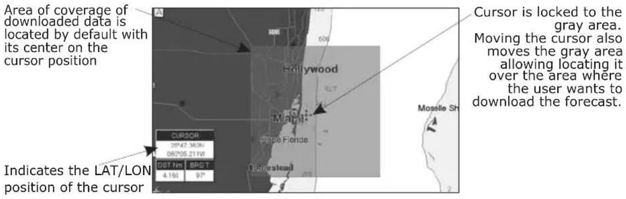
text_image
Area of coverage of downloaded data is located by default with its center on the cursor position Cursor is locked to the gray area. Moving the cursor also moves the gray area allowing locating it over the area where the user wants to download the forecast. Indicates the LAT/LON position of the cursor CURSOR 05°47.36'2N 08°05.21'W OST Nm BRGT 4.16l 97° Hollywood Maurit Price Florida Moselle ShFigure 15.0.0 - Example of Download Area
Press [LOAD] to activate the C-Weather Download: the whole data package (see the previous "Weather data package" table) are downloaded. [STOP] allows to interrupt the data download. At the end of the operation press [EXIT] to close the window.
15.0.1 Copy From User C-CARD
Allows the whole data package C-Weather loading from the User C-CARD.
15.0.2 Weather Forecast
Allows selecting the Layer of specific weather data to be displayed on the screen and to change date and time of the forecast preview. The following functions are available:
- Panning: default usage of the cursor key is the normal panning function.
- Zoom in/out: zoom in/out functions are allowed as usual by using [ZOOM IN]/[ZOOM OUT].
- Set of date and time: [D ATE] to modify date and time values.
- Layer selection: [LAYER] to cycle of the weather layers.
- Exit: [Exit] to close the weather prediction page.
15.0.3 Real Time View
The following selections are available:
- Real Time View On: the data is shown (the area of the download) at the current date and time (received from the GPS).
- Real Time View Off: the Weather data is not displayed. The layer displayed is the one selected into the previous menu item.
15.0.4 Type of Data
Allows selecting the type of data, refer to the table in the Figure 15.
16. MOBILARM
The MOBILARM is an automated crew monitoring system dedicated to monitoring onboard crew by maintaining a constant link between the crew member and the boat. When a man over-board event happens, an automatic alarm is sounded, and the vessels position is shown on the Standard Horizon GPS Chart Plotter.
16.0 MOBILARM-GPS CHART PLOTTER CONNECTION
Connect the MOBILARM system to one of the Ports on the Standard Horizon GPS Chart Plotter. Refer to Par. 2.4.0 "Connection Table" for CP390i, Par. 2.4.2 "Connection Table" for CPF390i and MOBILARM Owner's Manuals for connections.
Connection Example
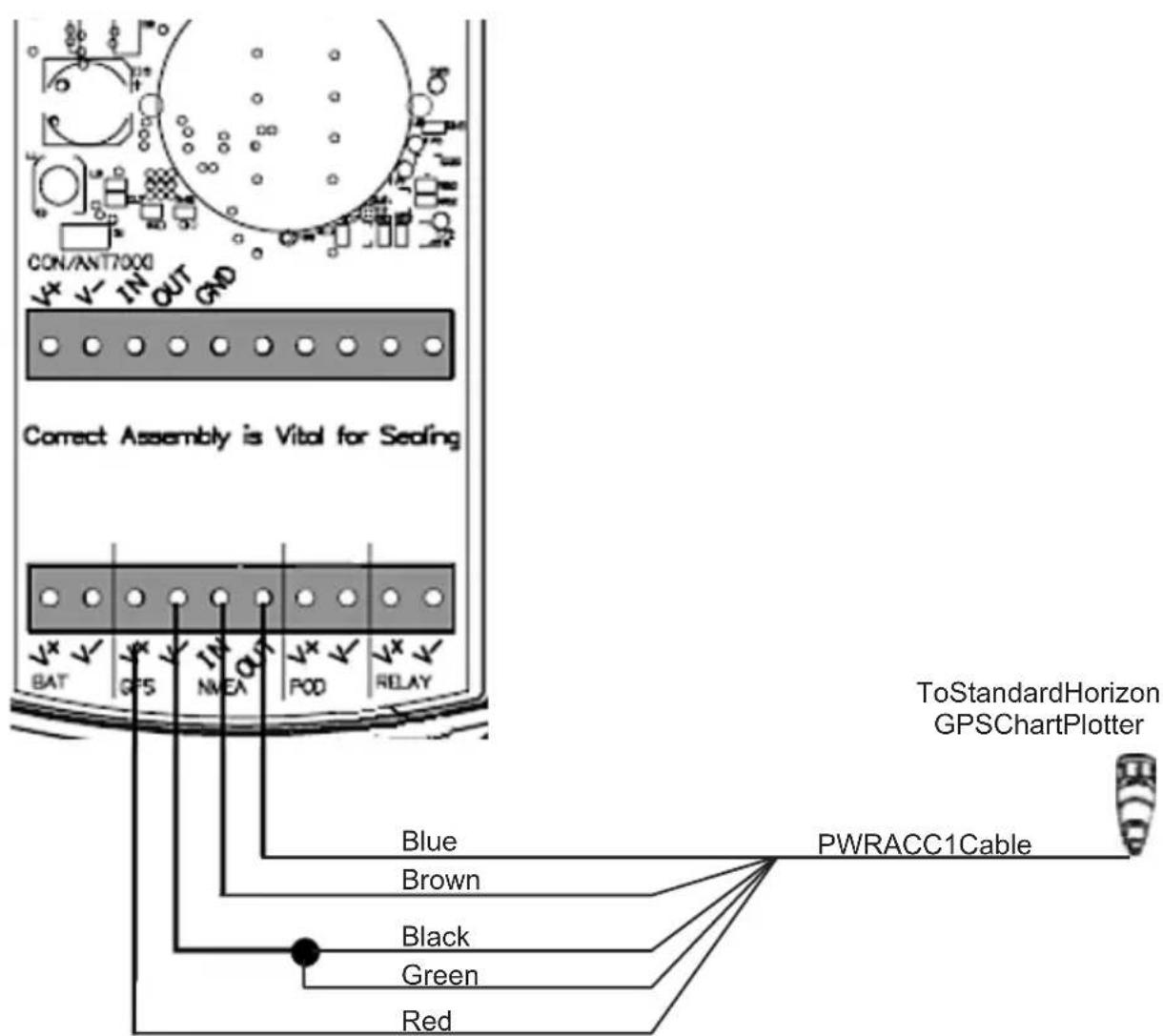
text_image
CON/ANT7000 V+ V- IN OUT GND Correct Assembly is Vital for Sealing BAT GFS IN MEA POD RELAY ToStandardHorizon GPSChartPlotter Blue PWRACC1Cable Brown Black Green RedFigure 16.0 - Connection Example
NOTE
Note the CP390i and CPF390i have 3 Ports so Port 1, 2 or 3 can be used.
Port 1 Example
| Chart Plotter MOBILARM |
| Blue NMEA Out |
| Brown NMEA In |
| Red GPS V+ |
| Black GPS V- |
NOTE
Refer to the Figure 16.0, the Blue and Brown wires are from Port1. If these wires are being used to connect to another NMEA device, choose another wire pair and configure the port associated with the wires.
16.1 SOFTWARE SETUP
After the Port has been chosen and connected in Par. 16.0, the GPS Chart Plotter must be setup to communicate with the MOBILARM.
Use the steps below to set up the Port the MOBILARM is connected to the GPS Chart Plotter.
- Select the Chart page.
- Press [MENU], move the ShuttlePoint knob to highlight SETUP MENU and press [ENT].
- Move the ShuttlePoint knob to highlight ADVANCED SETUP and press [ENT] or move the ShuttlePoint knob to the right.
- Move the ShuttlePoint knob to highlight IN/OUT CONNECTIONS and press [ENT] or move the ShuttlePoint knob to the right.
- Move the ShuttlePoint knob to highlight any input port and press [ENT] or move the ShuttlePoint knob to the right.
- Move the ShuttlePoint knob up/down to select MOBILARM and press [ENT] or move the ShuttlePoint knob to the right. Selecting MOBILARM format, activates the function.
- Press [CLR] or move the ShuttlePoint knob to the left until the Chart page is shown.
The GPS Chart Plotter continuously verifies the communication status with MOBILARM PTX (Personal Transponder) device. When a signal from the PTX is lost for more than one minute, the MOBILARM sends a NMEA message to the GPS Chart Plotter which will produce an alarm and a popup window will be shown on Standard Horizon GPS Chart Plotter.
16.2 MOBILARM STATUS
To confirm the status of the MOBILARM, select the About page:
- Select the Chart page.
- Press [MENU] two times. Move the ShuttlePoint knob to highlight About... and press [ENT].
On the About page you can see the status of the MOBILARM, below are the possible messages.
a. Function not Activated
: MOBILARM has not been setup in the I/O Connections menu. Refer to Par. 16.1.
b. Not connected/detected : possible wiring problem, confirm wires are correct connected from the GPS Chart Plotter to the MOBILARM device.
c. Connected : the communication with MOBILARM device is Ok.
d. Signal Lost : the MOBILARM has been connected in the past, however no signal is being detected from the MOBILARM. Check wire connections from the GPS Chart Plotter to the MOBILARM.
e. No valid GPS position : the communication with MOBILARM device is Ok, but the GPS position fix is not received from the GPS Chart Plotter.
See the following example of About page:
① MOBILARM status Information
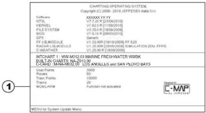
text_image
CHARTING OPERATING SYSTEM, Copyright (C) 2006 - 2010 JEPPESEN Italia S.I. Software XXXXXXX YY.YY NTSL V7.7.25 R [23/04/2010] KERNEL V1.623 R [11/08/2010] FILE SYSTEM V3.203 R [18/08/2009] BIOS V1.5.15 R [59/03/2010] GPS Generic FF LIB, MODULE V1.32.30R [16/10/2009] FF 620 RADAR LIB, MODULE V1.20.30R [20/05/2008] SIMULATION (SN: FFFF) C-WEATHER V1.20.30 R [18/08/2009] INTCHART 1 : WW-M012.03 MARINE FRESHWATER WWBK BUILT-IN CHARTS: NA-Z010.00 C-CARD : M-NA-M632.00 LOS ANGELES and SAN PEDRO BAYS User Points 3000 Routes 50 Track Points 10000 Trads 20 MOBILARM Function not activated MENI for System Update MenuFigure 16.2 - Example of About page with MOBILARM information
16.3 MOBILARM PTX
A PTX is the Personal Transponder device that is worn by the crew. If a crew member falls in the water the MOBILARM sends a signal to the GPS Chart Plotter which creates and displays a PTX icon on the Chart page.
16.3.0 MOBILARM MOB alert is received
When crew member falls in the water, the MOBILARM sends a signal to the GPS Chart Plotter which creates and displays a PTX MOB icon on the Chart page.
Figure 16.3.0 - The PTX icon
On the GPS Chart Plotter all menus and/or pages are closed and the chart is centered on the PTX MOB received position. A Audible Alarm is heard and a pop-up warning window appears to notify that a PTX has been received:
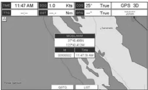
text_image
TIME 11:47 AM SOG 1.0 Kts COG 25° True GPS 3D TTG --- DST --- Nm BPG ---° True MODELAM 37°45.495N 122°40.412W Id Time 00900002 11:47:39 AM GOTO LISTFigure 16.3.0a - Example of PTX warning window
It is possible to Goto (navigate) to the received MOBILARM PTX position (see Par. 16.4.1) or open the MOBILARM Alarm Status List page (see Par. 16.4.2). Selecting Goto or Alarm Status List will mute the Audible Alarm.
NOTE
When the same PTX is received again:
a. If the received PTX is not the active one, the user must confirm to navigate to it.
b. If the received PTX is the active one, navigation data is updated. The PTX icon appears at the new position and a pop-up warning window appears.
16.4 PLACING CURSOR ON THE PTX ICON
Moving the ShuttlePoint knob so the cursor is over the PTX icon on the Chart page will show an information window and allow you to Goto the location of the PTX, delete the PTX icon or show the Alarm Status list as shown below.
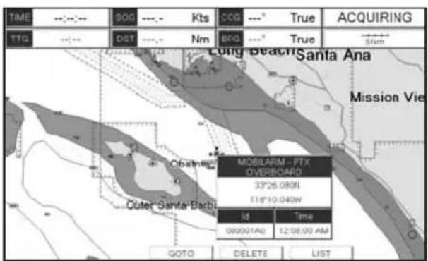
text_image
TIME SOG --- Kts COG --- True ACQUIRING TTG DST --- Nm BFG --- True Long Beach Santa Ana Mission Vie Obstning Cuter Santa-Barbi MOBILARM - PTX OVERBOARD 33°26.080N 11°10.040W Time 08:00:01:00 12:08:09 AM GOTO DELETE LISTFigure 16.4 - Example of PTX information window
16.4.0 Delete PTX
The Delete PTX function permanently removes the selected PTX from the MOBILARM Alarm Status List and from the Chart page.
Using the ShuttlePoint knob, move the cursor over the PTX icon and then press [DELETE] A warning pop-up window will be shown. Select YES and press [ENT].
16.4.1 Goto PTX
When Goto is selected on the GPS Chart Plotter, navigation will start to the PTX icon
location. After the GPS Chart Plotter has received a PTX MOB alarm, using the ShuttlePoint knob move the cursor over the PTX to navigate to and then two Soft Keys under the display will be shown:
a.[Goto], when pressed will start navigating to the PTX MOB location
b.[L ist], when pressed will show the MOBILARM Alarm Status List page. Refer to Par. 16.4.2 for Alarm Status List.
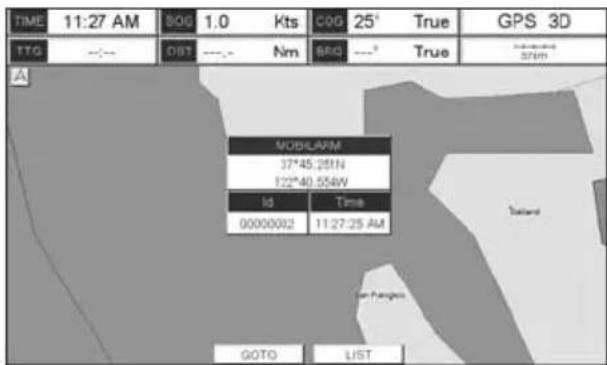
text_image
TIME 11:27 AM $0G 1.0 Kts C0G 25° True GPS 3D TTG --- DBT --- Nm SRQ ---° True 37PM A NOBLAFM 37*45.29IN 122*40.554W Id Time 0000002 11:27:25 AM Taland GOTO LISTFigure 16.4.1 - Example of Goto PTX
If the navigation is set to the selected PTX icon, to terminate the navigation press [STOPGOTO].
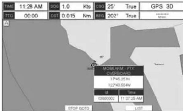
text_image
TIME 11:28 AM SOG 1.0 Kts COG 25° True GPS 3D TTG 00:00 DST 0.015 Nm BIG 202° True A MOBILARM - PTX OVERBOARD 37*45.251N 122*40.554N ID Time 0000000 11:27:25 AM STOP GOTO LISTFigure 16.4.1a - Example of Stop Goto PTX
16.4.2 The MOBILARM Alarm Status List
The MOBILARM Alarm Status List shows the list of all PTX that the GPS Chart Plotter has received an alarm from. To review the page:
- Select the Chart Page.
- Press [MENU] to show the Main menu.
- Move the ShuttlePoint knob to highlight USER POINTS and press [ENT].
- Move the ShuttlePoint knob to highlight MOBILARM and press [ENT].
① PTXnumber
② Time the PTX alarm was received
③ PTXposition
④ PTXstatus
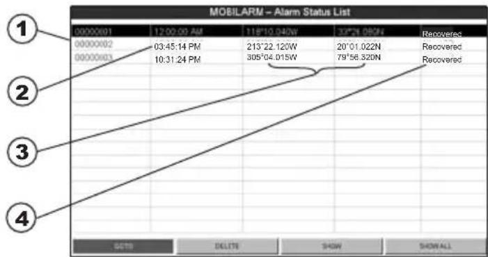
Figure 16.4.2 - Example of MOBilarm PTX List page
This page allows you to:
| GOTO | Activates navigation to the selected PTX. Once the navigation has been activated, close all menus/data pages (if open) and center the chart selected PTX. |
| DELETE Deletes the selected PTX. | |
| SHOW Centers the chart on the selected PTX. | |
| SHOW ALL | Selects the best chart scale to see al PTX icons on the chart at the same time. |
17. FISH FINDER
The Fish Finder consists of a high power transmitter, sensitive receiver and a transducer. The Fish Finder sends an electrical pulse to the transducer, which contains an element that converts the pulse into acoustic (sound) waves, which is sent through the water. As this wave travels from the transducer to the bottom, it may strike fish, structures, thermalclines (temperature changes in the water). When the wave strikes an object(s) a certain amount of the wave is reflected back to the transducer depending on the composition and shape of the object. When the reflected wave is returned to the transducer it is converted into a voltage and is amplified by the receiver, processed and sent to the display. The speed of sound in water is roughly 4800FT/sec, so the time lapse between the transmitted signal and the received echo can be measured and the distance to the object determined.
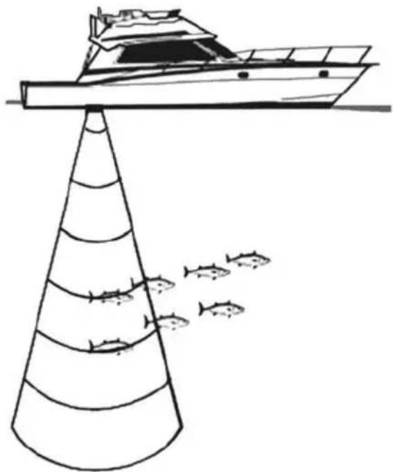
natural_image
Line drawing of a boat on a conical platform with fish swimming nearby (no text or symbols)Figure 17 - Fish Finder working principle
17.0 ENABLE/DISABLE
The internal Fish Finder may be enabled (default setting) or disabled by the following procedure:
- From the Chart page, press [MENU], move the ShuttlePoint knob to highlight SETUP MENU and press [ENT].
- Move the ShuttlePoint knob to highlight ADVANCED SETUP and press [ENT] or move the ShuttlePoint knob to the right.
- Move the ShuttlePoint knob to highlight IN/OUT CONNECTIONS and press [ENT] or move the ShuttlePoint knob to the right.
- Move the ShuttlePoint knob to highlight FISH FINDER and press [ENT] or move the ShuttlePoint knob to the right.
- Move the ShuttlePoint knob up/down to select OFF and press [ENT] or move the
ShuttlePoint knob to the right.
- Press [CLR] or move the ShuttlePoint knob to the left until the Chart page is shown.
17.1 UNDERSTANDING THE FISH FINDER PAGE
The display on CPF390i shows a time history of the echoes received by the transducer. The CPF390i have a menu that allows adjustments to receiver sensitivity, depth range and scrolling speed of the Fish Finder display.
① Warning message
② Fish Finder window
③ Digital Depth
④ Water temperature
⑤ Shallow Alarm Bar
⑥ Range Bar
⑦ Variable Depth Marker (VDM)
⑧ A-Scope
⑨ Deep Alarm Bar
10 Transmit Frequency
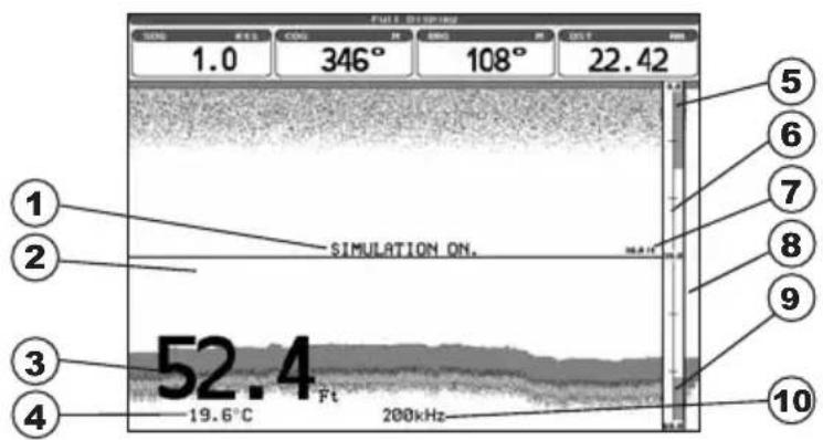
text_image
1.0 346° 108° 22.42 5 6 7 8 9 10 SIMULATION ON. 52.4 19.6°C 200kHzFigure 17.1 - The Fish Finder page
The following is a brief description of terms listed in the previous Figure:
① Warning Message
Flashing label that is turned On when the echo sounder is in Simulation mode.
The following is the list of the warning messages (see also Par. 5.8):
- SHALLOW WATER
· DEEP WATER
· HIGH WATER TEMP - LOW WATER TEMP
· WATER TEMP RATE
· FISH SPOT - NO DATA
② Fish Finder window
Graphic presentation of sonar soundings recorded as a continuous profile scrolling across the screen from right to left. Such recordings represent the image of the water beneath your boat, items appear as they pass under your transducer; the items on the right side of the screen are closer to you than those on the left. The correct interpretation of the Fish Finder page allows retrieving useful information about what is under the boat.
③ Digital Depth
Readout of the current bottom depth.
④ Water Temperature
Readout of the current water temperature returned by the temperature sensor included in DST520, DST521, DST523, DST525, DST526, DST527, DST528A.
⑤ Shallow Alarm Bar
Located on the right side of the Range Bar, the Shallow Alarm Bar shows the range outside of which the depth measurement will trigger a Shallow Alarm.
⑥ Range Bar
Vertical graduated bar that is located along the right side of the screen. It is a scale which reflects the depth of the area being displayed.
⑦ Variable Depth Marker (VDM)
Horizontal line on to the Fish Finder page window with a depth label. Move the ShuttlePoint knob Up or Down to change the position of the VDM. The label displays the depth of the cursor position. The VDM can be moved to any location pinpointing the depth of a target.
⑧ A-Scope
Real time representation of fish and bottom features passing through the beam of the transducer, drawn as column of horizontal lines whose length and hue is proportional to the echo strength returned. The color of the echo strength depends on the selected display color. When the default palette is selected, the strongest sonar returns will be shown as red and weaker returns will be shown blue.
⑨ Deep Alarm Bar
Bar located on the left side of the Range Bar, showing the portion of the Echogram currently represented in the zoomed window (on the left part of the screen). It is turned. On selecting the Echosounder Split page.
⑩ Transmit Frequency
Shows the selected depth transmit frequency. As a reference, 200kHz selection is normally used to see targets in depth up to 400FT, and 50kHz is used in water over 400FT.
17.1.1 Understanding the Fish Finder display
① Fish
② Thermoclines
③ White Line
④ Surface Clutter
⑤ Structures
⑥ Bottom Echo Profile
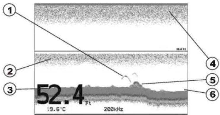
text_image
1 2 3 52.4 Ft 19.6°C 200kHz 36.8 Ft 4 5 6Figure 17.1.1 - The Fish Finder display
① Fish
Fish are usually represented by small dots on the display when using 200kHz and by arches when using 50kHz.
② Thermoclines
Are the zones where two layers of different water temperatures meet. The greater the temperature differential, the denser the thermocline shows on the screen. Thermoclines are represented as horizontal stripes of noise. They are very important for fishing
since often many species of game fish like to suspend in, just above, or just below the thermoclines.
③ White Line
The White Line shows the difference between hard, soft bottoms and even distinguishes between fishes and structures located near the bottom. In this way it is easier to tell the difference between a hard and soft bottom and even to distinguish fishes and structures located nearby the bottom.
④ Surface Clutter
Appears like noise at the top of the screen extending many feet below the surface. It's caused by many things, including air bubbles, bait fish, plankton and algae.
⑤ Structures
Generally, the term "structure" is used to identify objects like wrecks and weeds rising from the bottom.
⑥ Bottom Echo Profile
Bottom profile recorded by the Fish Finder. When the echo sounder is set in Auto Range mode, the bottom is kept in the lower half in the display.
17.2 DISPLAYING THE FISH FINDER PAGE
This section explains how to show and customize the selection of the Fish Finder display pages.
- From all pages (except the Fish Finder page), press [MENU]. From Fish Finder page, press [MENU] two times.
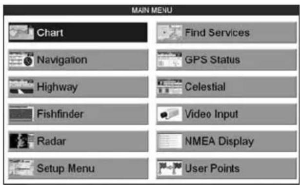
text_image
MAIN MENU Chart Find Services Navigation GPS Status Highway Celestial Fishfinder Video Input Radar NMEA Display Setup Menu User PointsFigure 17.2 - Main Menu
- Move the ShuttlePoint knob to highlight FISH FINDER and press [ENT].
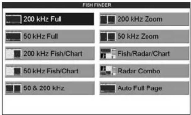
text_image
FISH FINDER 200 kHz Full 50 kHz Full 200 kHz Fish/Chart 50 kHz Fish/Chart 50 & 200 kHz 200 kHz Zoom 50 kHz Zoom Fish/Radar/Chart Radar Combo Auto Full PageFigure 17.2a - Fish Finder page selection menu
- Move the ShuttlePoint knob to select the desired display and press [ENT]. The Page options are shown in the following paragraphs.
17.2.0 Auto Full Page
When this page is selected, the Fish Finder automatically changes the transmit frequency to show depths. Automatic switching occurs when depth of water is less than 400FT (200kHz) and greater than 400FT (50kHz).
17.2.1 200 kHz Full, 50 kHz Full and 50&200kHz Display Pages
Allows the user to setup the GPS Chart Plotter display to show 200kHz, 50kHz or 200/50 kHz split screen Fish Finder.
200kHz
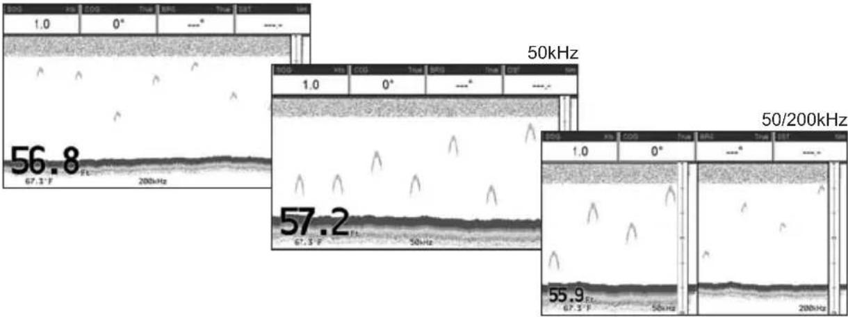
text_image
1.0 0° --- --- 56.8 67.3 F 200kHz 57.2 67.3 F 50kHz 50/200kHz 55.9 67.3 F 50kHz 50kHzFigure 17.2.1 - Full Display pages
17.2.2 200 kHz and 50 kHz Zoom Pages
Allows the user to zoom into the 200kHz or 50kHz Fish Finder display to show detail of the area selected by the VRM (Variable Range Marker). Referring to Figure 17.2.2, the left display shows the zoomed display and the right display shown the unzoomed display.
To select the area to be zoomed in move the ShuttlePoint knob Up or Down which moves the VRM line.
To zoom In or Out, press [ZOOM IN] or [ZOOM OUT].
The zoom ranges are 2x and 4x the normal Fish Finder display.
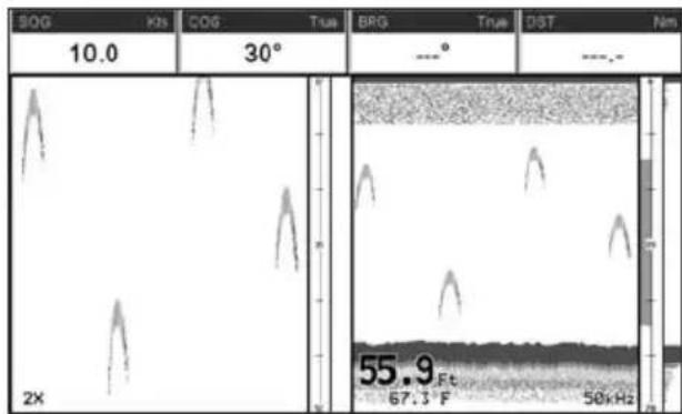
text_image
SOG 10.0 Kts COG 30° True BRG ---° True DIST Nm 55.9 Ft 67.3 F 50kHzFigure 17.2.2 - Zoom Full page
17.2.3 200 kHz and 50 kHz Fish/Chart Pages
Selects the GPS Chart Plotter display to show the Chart page on the left half of the screen and the Fish Finder on the right half of the screen. 200kHz or 50 kHz Fish Finder can be selected on the right half of the display.
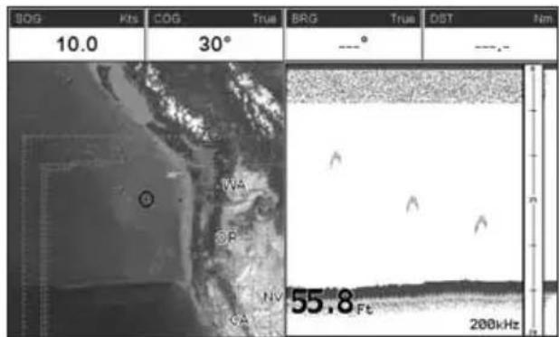
text_image
BCG Kts COG True BRG True DIST Nm 10.0 30° ---° ---. 55.8 Ft 200kHzFigure 17.2.3 - Fish/Chart page
17.2.3.0 Focus Soft Key on FISH/CHART Page
When the Fish/Chart Page has been selected and one of the Soft Keys is pressed, a [Focus] Soft Key will be shown.
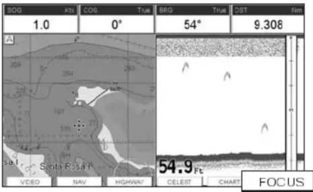
text_image
BOG 1.0 COG 0° BRG 54° DST 9.308 A Santa Rosa 54.9 Fc VIDEO NAV HIGHWAY CELEST CHART FOCUSFigure 17.2.3.0 - Example of Chart/Fish page with [Focus] shown
When [Focus] is pressed the Chart Plotter places the focus on the Chart page or on the Fish Finder window. With the focus on the Chart page the cursor may be moved and all chart menus can be selected. When focus is on the Fish Finder window the Variable Range Marker can be moved to see the depths of targets and Fish Finder menus can be accessed.
17.2.4 Radar Pages
17.2.4.0 Fish/Radar/Chart Page
Selects the GPS Chart Plotter display to show the Chart, the Fish Finder and the Radar page on the screen.
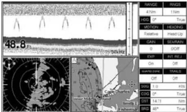
text_image
48.8 50 Hz RANGE RNGS 4 Nm 1 Nm HOG 0° True MOTION HEADING Relative Head Up GAIN SEARAIN 0 Off EXP INT REL. On Off GUARD ZING TRAILS Off Off SOG 1.0 kts COG 0° True DST 14.71 Nm SRG 46° TrueFigure 17.2.4.0 - Fish/Radar/Chart page
17.2.4.1 Radar Combo Page
Selects the GPS Chart Plotter display to show the Chart, the Fish Finder, the Radar and the Higway page on the screen.
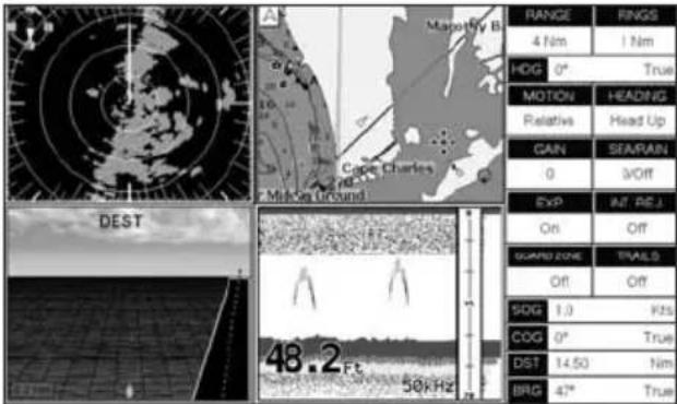
text_image
Mapestry B Cape Charles Minder ground DEST 48.2 Ft 50 kHz RANGE 4 Nm 1 Nm HOG 0° True MOTION HEADING Relative Head Up GAIN SEARAIN 0 Off EXP INT. PEJ On Off GUARID ZONE TRAILD Off Off SDG 1.0 Kfs COG 0° True DST 14.50 Nm BRG 4° TrueFigure 17.2.4.1 - Radar Combo Page
17.2.4.2 Focus Soft Key
When the Fish/Radar/Chart page or the Combo page has been selected, the active window is highlighted a "red" boarder around the window. The keyboard commands are related to that focused view. To move the focus to a different window follow the procedure:
- Press any Soft Key. The Soft Key labels appear on the bottom of the screen.
- Press [Focus]. A popup window appears where the active focus window label is highlighted.
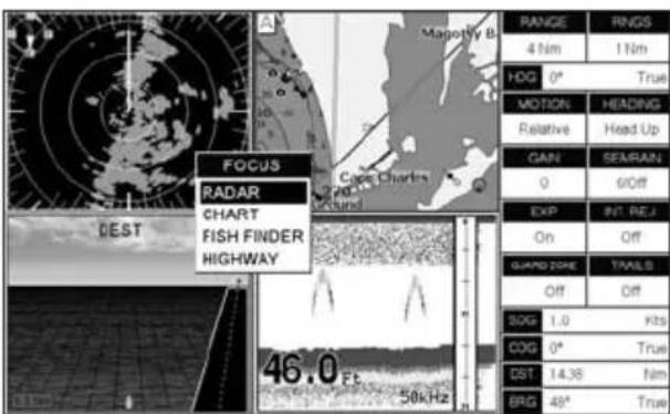
text_image
FOCUS RADAR CHART FISH FINDER HIGHWAY 46.0 Ft. 58kHz RANGE 4 Nm 1 Nm HOG 0° True MOTION Relative SEAMAIN 0 6/Off EXP On Off GUARD ZONE Off Off SOG 1.0 Kts COG 0° True DST 14.38 Nm BRG 49° TrueFigure 17.2.4.2 - Example of Combo page with [Focus] shown
-
Move the ShuttlePoint knob to highlight the desired window and press [ENT]. The red boarder is moved to the focused window.
-
Press any of the Soft Keys to show the key descriptions, then press the [200kHz] Soft Key if it has been customized (for detail see the Par. 3.7).
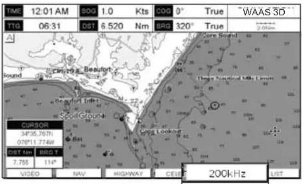
text_image
TIME 12:01 AM 90G 1.0 Kts COG 0° True "WAAS 3D" TTG 06:31 DST 6.520 Nm BRG 320° True CurSOR 34°36.767N 076°11.774W DST Nm BRG T 7.756 114° VIDEO NAV HIGHWAY CELE 200kHz LISTFigure 17.3 - Example of Fish Finder page selection by Soft Keys
17.4 SETUP MENU
This section explains how to show the Fish Finder Setup menu and describe the Fish Finder Setup menu sub-options.
- From the Full Fish Finder page, press [MENU]. The following menu appears:
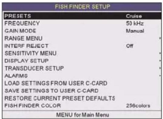
text_image
FISH FINDER SETUP PRESETS Cruise FREQUENCY 50 kHz GAIN MODE Manual RANGE MENU INTERF REJECT Off SENSITIVITY MENU DISPLAY SETUP TRANSDUCER SETUP ALARMS LOAD SETTINGS FROM USER C-CARD SAVE SETTINGS TO USER C-CARD RESTORE CURRENT PRESET DEFAULTS FISH FINDER COLOR 256colors MENU for Main MenuFigure 17.4 - Fish Finder Setup menu
17.5 FISH FINDER COLOR
Allows you to choose the Fish Finder color between 16 and 256 colors.
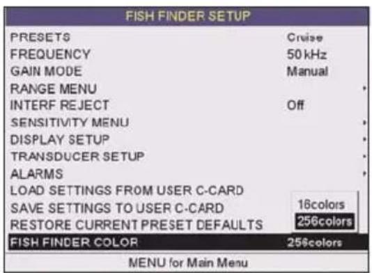
text_image
FISH FINDER SETUP PRESETS Cruise FREQUENCY 50 kHz GAIN MODE Manual RANGE MENU INTERF REJECT Off SENSITIVITY MENU DISPLAY SETUP TRANSDUCER SETUP ALARMS LOAD SETTINGS FROM USER C-CARD SAVE SETTINGS TO USER C-CARD 16colors RESTORE CURRENT PRESET DEFAULTS 256colors FISH FINDER COLOR 256colors MENU for Main MenuFigure 17.5 - Fish Finder Color menu
17.6 PRESETS
To simply menu selections, the Fish Finder has two presets that can be easily selected for Fishing or Cruising:
| FISH CRUISE | ||
| GainAutoAuto | ||
| RangemodeAutoAuto | ||
| Gainoffset0% 10% | ||
| Shift00 | ||
| STCShortShort | ||
| Noise level | 2 | 4 |
| ScrollingSpeed1010 | ||
| FishSymbols | EchoEcho | |
| A-Scope | On | On |
| Surface Declutter | 4 | 4 |
Figure 17.6 - Presets table
NOTE
For Gain and Gain Offset settings refer to Sensitivity menu (see Par. 17.11).
For Range and Shift settings refer to Range menu (see Par. 17.9).
17.7 FREQUENCY
Allows you to choose the frequency among Auto, 50 kHz, 200 kHz or 50&200 kHz when single frequency page is selected.
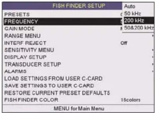
text_image
FISH FINDER SETUP PRESETS 50 kHz FREQUENCY 200 kHz GAIN MODE 50&200 kHz RANGE MENU INTERF REJECT Off SENSITIVITY MENU DISPLAY SETUP TRANSDUCER SETUP ALARMS LOAD SETTINGS FROM USER C-CARD SAVE SETTINGS TO USER C-CARD RESTORE CURRENT PRESET DEFAULTS FISH FINDER COLOR 16colors MENU for Main MenuFigure 17.7 - Frequency menu
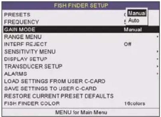
text_image
FISH FINDER SETUP PRESETS FREQUENCY Manual Auto GAIN MODE MANUAL RANGE MENU INTERF REJECT Off SENSITIVITY MENU DISPLAY SETUP TRANSDUCER SETUP ALARMS LOAD SETTINGS FROM USER C-CARD SAVE SETTINGS TO USER C-CARD RESTORE CURRENT PRESET DEFAULTS FISH FINDER COLOR 16colors MENU for Main MenuFigure 17.8 - Gain Mode menu
17.8.0 Auto Mode
Allows the Fish Finder to automatically adjust receiver Gain depending on water depth.
17.8.1 Manual Mode
Allows the user to change the Gain manually to fine tune the Fish Finder's receiver.
17.9 RANGE MENU
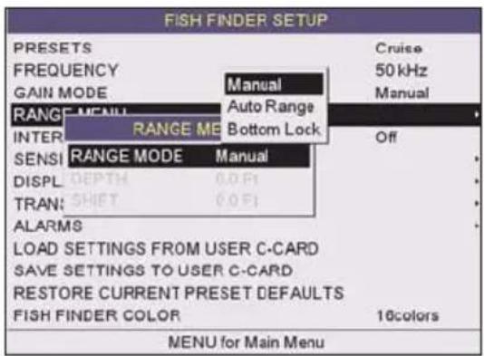
text_image
FISH FINDER SETUP PRESETS Cruise FREQUENCY 50 kHz GAIN MODE Manual Manual RANGE MENU Auto Range INTER RANGE ME Bottom Lock Off SENSI RANGE MODE Manual DISPL DEPTH 0.0 Fi TRAN: SHIFT 0.0 Fi ALARMS LOAD SETTINGS FROM USER C-CARD SAVE SETTINGS TO USER C-CARD RESTORE CURRENT PRESET DEFAULTS FISH FINDER COLOR 16colors MENU for Main MenuFigure 17.9 - Range menu
17.9.0 Range Mode
Selects among Manual, Auto Range and Bottom Lock.
17.9.0.0 Manual Mode
Used to set the depth Range (from the surface) the Fish Finder display will show.
17.9.0.1 Auto Range
The Fish Finder determines automatically the Range as to keep the bottom visible in the lower bottom of the screen. In this mode, Shift is always set to 0.
17.9.0.2 Bottom Lock
The Bottom Lock function keeps the screen display locked onto a certain Range around the
bottom. Let's say the bottom is 400FT and the Bottom Lock Range is set to display 30FT around the bottom, the screen (instead of displaying from 0FT to e.g. 450FT) will display only a Range of 30FT around the bottom, e.g. from 380FT to 410FT.
17.9.1 Depth
Moves the display from showing the bottom to the depth value entered.
17.9.2 Shift
Shifts the display from the bottom of the transducer to the depth value entered.
Example: Your vessel is in about 57FT of water, however there is fish suspended in 35FT of water. You want to display to 10FT area around the fish. Shift would be set to 30FT and Depth would be set to 40FT shown in example below.
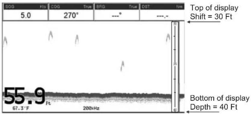
text_image
5.0 270° ---° 30 35 40 Top of display Shift = 30 Ft Bottom of display Depth = 40 Ft 55.9 67.3°F 200kHzFigure 17.9.2 - Example of Depth and Shift
17.10 INTERFERENCE REJECTION
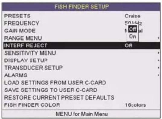
text_image
FISH FINDER SETUP PRESETS Cruise FREQUENCY 50Hz GAIN MODE Off RANGE MENU On INTERF REJECT Off SENSITIVITY MENU DISPLAY SETUP TRANSDUCER SETUP ALARMS LOAD SETTINGS FROM USER C-CARD SAVE SETTINGS TO USER C-CARD RESTORE CURRENT PRESET DEFAULTS FISH FINDER COLOR 16colors MENU for Main MenuFigure 17.10 - Interference Rejection menu
Turns On or Off a filter to remove noise from other Fish Finder or Depth Sounders that may be near by when fishing.
17.11 SENSITIVITY MENU
All settings in the Sensitivity menu are related to the selected Fish Finder transmit frequency (50 or 200kHz).
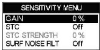
text_image
SENSITIVITY MENU GAIN 0 % STC Off STC STRENGTH 0 % SURF NOISE FILT OffFigure 17.11 - Sensitivity menu
17.11.0 Gain
Allows you to control the Sensitivity of the unit's receiver from 0 to 100% . To see more detail, increase the receiver Sensitivity by selecting a higher Gain percentage. If there is too much detail or if the screen is cluttered, lowering the Sensitivity may increase the clarity of the display.
NOTE
When the Gain Mode option is set to Auto, the receivers Gain cannot be changed.
When the Gain Mode option is set to Manual, the Gain can be manually adjusted. When switching from Automatic to Manual Mode, the Gain + Offset value is copied into the Manual Gain setting of the receiver.
17.11.1 STC (Sensitivity Time Control)
The STC function attenuates echos from surface down to the specified STC depth by changing the sensitivity of the receiver, decreasing it near the surface and gradually increasing it as the depth increases.
STC impacts bottom finding so can be particularly useful i.e. to better track a rock sea bottom distinguishing it from the mud in suspension over it for example when close to rivers outlet to the sea (consider to use at same time also Dual Frequency mode and White Line for an easier identification of real sea bottom), as well as to solve issues in false bottom detection when in presence of significant surface clutter.
Its default value is SHORT for the 200 kHz frequency and MID for the 50 KHz frequency. Such values are good in most conditions. However when navigating in very shallow waters it may be necessary to switch it to OFF, while in very deep waters with a lot of Surface Clutter it may be better to increase it to MID or LONG.
NOTE
In some situations it may be necessary to adjust the STC so the sounder can read through the surface noise and show the bottom. One indication that the STC needs to be changed is when the display intermittently changes the depth from the correct depth to a very shallow depth.
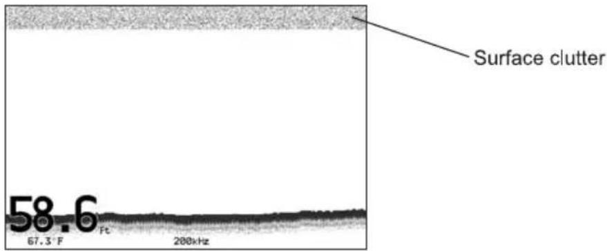
text_image
Surface clutter 58.6 67.3° F Ft 200kHzFigure 17.11.1 - STC - Surface Clutter
The STC can be changed from Short, Mid, Long and Custom.
17.11.1.0 STC Length
This is the depth range which the STC operates. In custom mode it can be varied from 0FT to 1000FT (60FT or 255FT on previous software versions). In preset mode it's value is reported in the following table (See Par. 17.11.1.2).
17.11.1.1 STC Strength
It is the starting attenuation value of the STC. It acts by attenuating the Gain of the given percentage value. In custom mode it can be varied from 0% to 100%. The STC effect is maximum near the surface, to mitigate the Surface Clutter and it progressively diminishes to 0 at the selected STC depth.
17.11.1.2 Preset values table
| OFF | Short | Mid | Long | |
| STCDepth(Ft)16060255 | ||||
| STC Length | 0 | 10% | 30% | 57% |
Figure 17.11.1.2 - STC Preset values table
If in VERY SHALLOW WATER the Fish Finder display is showing a bottom or digital readout deeper than the actual depth this situation may occur if STC is set to LONG or MID when the bottom is shallow. This issue may be resolved by adjusting the STC value to SHORT or even to OFF in very shallow waters.
If in DEEP WATER the Fish Finder display is showing a very shallow bottom or digital readout this may happen because in conditions of strong Surface Clutter the Fish Finder may erroneously look on to the Surface Clutter. To solve this situation try to increase the STC to LONG or to CUSTOM increasing the STC length and strength.
If in DEEP WATER the Fish Finder doesn't see the bottom, this may happen because the bottom is out of range or is very near to the maximum depth that can be tracked by the Fish Finder. In the latter case this may happen if the bottom composition is soft as mud, if the sea conditions are bad, there are thermoclines or the water is full of suspended materials (silt, plankton). All these factors may affect considerably the performance of the Fish Finder to be able to see the bottom. In these cases change the RANGE MODE from AUTO to MANUAL Range and manually adjust the depth range until the bottom echo becomes visible on the Fish Finder display.
17.11.2 Surface Noise Filter
An automatic filter that attempts to dynamically remove Surface Clutter that causes the screen to be filled up with strong return echoes just below the surface. It may seem that the same functionality could be archived using on the STC control however there is main difference between such control in fact the STC control impacts the capability to detect and track the bottom and is not designed to cancel completely the surface noise, on the other side the Surface Noise Filter attempts to cancel completely the surface noise but it doesn't affect the capability to detect and track the bottom.
Filter gradually attenuates surface noises. The Surface Noise Filter has 9 settings: OFF, 1, ..., 8. When it is set to OFF the Surface Noise is not cancelled. When it is set to 1 the Surface Noise is attenuated from surface down to a depth of 5 Ft, increasing the Surface Noise increases the depth in which the Surface Noise is attenuated as well as the attenuation level increases; when the preset is set to 8 the attenuation is maximum and is applied from surface level down to a depth of 255 Ft, as shown in the following Surface Noise Filter Table:
| Surface Noise Filter Depth | ||||||||
| Preset | 1 | 2 | 3 | 4 | 5 | 6 | 7 | 8 |
| Depth (Ft) | 5 | 10 | 15 | 20 | 30 | 60 | 130 | 255 |
Figure 17.11.2 - Surface Noise Filter Depth table
17.12 DISPLAY SETUP
Allows the Fish Finder's display page appearance to be changed.

text_image
FISH FINDER SETUP PRESETS Cruise FREQUENCY 50 kHz GAIN MODE Manual RANGE MENU INTERF REJECT Off SENSITIVITY MENU DISPLAY SETUP TRAN: COLOR SETTINGS Blue Background LOAD: SCROLLING SPEED 0 % SAVE: WHITE LINE Off REST: FISH SYMBOLS Echo FISH F: A-SCOPE On WATER TEMPERATURE PrimaryFigure 17.12 - Display Setup menu
17.12.0 Color Settings
Allows you to change the color of the Fish Finder display from Blue (default), White, Black, Gray scale.
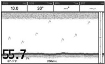
text_image
10.0 30° 55.7 67.5°F Pt 2000Hz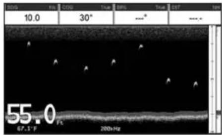
text_image
10.0 30° 55.0 67.1°F 200HzFigure 17.12.0 - White and Blue background examples
17.12.1 Scrolling Speed
Controls the rate the Fish Finder scrolls and updates the Fish Finder display.
17.12.2 White Line
Controls how the bottom type (hard or soft) is shown on the display. When the White Line is Off the bottom return will display as red. When the White Line is On it can be used to determine bottom hardness.
NOTE
The White Line option is not available in the 50 & 200 kHz page.
17.12.3 Fish Symbols
Controls the graphical representation of underwater-suspended targets.
Echo : shown as arches (echoes)
Icon + Echo : shown as arches with the Fish icon
Icon + Echo + Depth : shown as arches with the Fish icon and relative depth values
Echo + Depth : shown depth values
Icon : shown as Fish icons without the arches
Icon + Depth : shown as Fish icons and their relative depth values (shown accordingly to currently selected depth unit)
17.12.4 A-Scope
Shows the real time display of the echo from the bottom.
17.13 TRANSDUCER SETUP
This menu allows you to calibrate the speed through the water, water temperature and the keel/prop offset of the transducer.
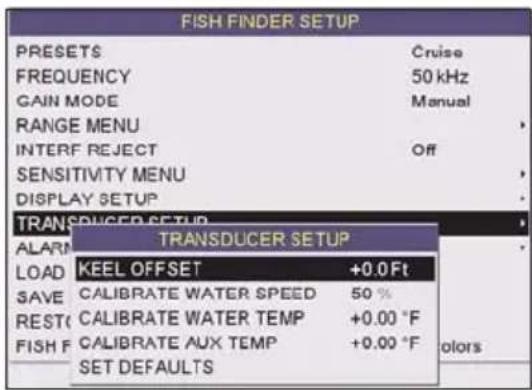
text_image
FISH FINDER SETUP PRESETS Cruise FREQUENCY 50 kHz GAIN MODE Manual RANGE MENU INTERF REJECT Off SENSITIVITY MENU DISPLAY SETUP TRANSPUCER SETUP ALARM TRANSDUCER SETUP LOAD KEEL OFFSET +0.0 Ft SAVE CALIBRATE WATER SPEED 50 % REST(C) CALIBRATE WATER TEMP +0.00 °F FISH F CALIBRATE AUX TEMP +0.00 °F SET DEFAULTS ColorsFigure 17.13 - Transducer Setup menu
17.13.0 Keel Offset
The keel offset can be set to cause the Fish Finder to display an offset depth below the keel or the actual water depth from the surface. To setup to show the depth below the keel, enter a negative depth value or a positive depth to show offset from the transducers face to the water surface.
17.13.1 Calibrate Water Speed
Used to calibrate the Water Speed readings from the transducer. Adjustment can be made from -10% to +10%.
17.13.2 Calibrate Water Temp
Used to calibration on the Water Temperature sensor in the transducer.
17.13.3 Set Defaults
Restores the factory settings.
The Alarms menu allows you to define alarm settings for Shallow Alarm, Depth Alarm and Temperature Upper/Lower/Rate.
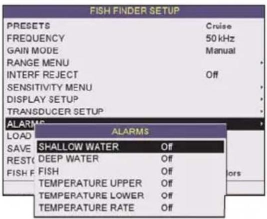
text_image
FISH FINDER SETUP PRESETS Cruise FREQUENCY 50 kHz GAIN MODE Manual RANGE MENU INTERF REJECT Off SENSITIVITY MENU DISPLAY SETUP TRANSDUCER SETUP ALARMS LOAD ALARMS SAVE SHALLOW WATER Off REST DEEP WATER Off FISH FISH Off TEMPERATURE UPPER Off TEMPERATURE LOWER Off TEMPERATURE RATE OffFigure 17.14 - Alarms menu
To set an Anchor Alarm, enter in a shallow water and deep water value above and below your actual anchoring depth. The alarm will sound when the depth becomes shallower or deeper than the settings.
17.14.0 Shallow Water
Triggers an alarm when depth becomes shallower than the set depth.
17.14.1 Deep Water
Triggers an alarm when depth becomes deeper than the set depth.
17.14.2 Fish
The Fish Alarm can be set to detect and alert you depending on the size of fish. The options are: Off, Small, Medium, Big and Huge. The alarm sounds if the set size (or bigger) is detected.
17.14.3 Temperature Upper
Triggers an alarm when the transducer reports a temperature above the set temperature.
17.14.4 Temperature Lower
Triggers an alarm when the transducer reports a temperature below the set temperature.
17.14.5 Temperature Rate
Triggers an alarm when the transducer reports a temperature variation rate above the set temperature.
17.15 SAVE SETTINGS TO USER C-CARD
This option saves the complete set of Fish Finder settings to an optional User C-CARD. This is useful to avoid the user having to retune up Fish Finder after a RAM Clear operation or a software update.
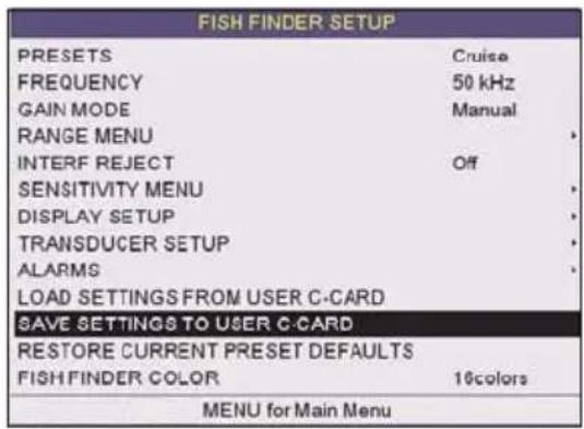
text_image
FISH FINDER SETUP PRESETS Cruise FREQUENCY 50 kHz GAIN MODE Manual RANGE MENU INTERF REJECT Off SENSITIVITY MENU DISPLAY SETUP TRANSDUCER SETUP ALARMS LOAD SETTINGS FROM USER C-CARD SAVE SETTINGS TO USER C-CARD RESTORE CURRENT PRESET DEFAULTS FISH FINDER COLOR 16colors MENU for Main MenuFigure 17.15 - C-CARD - Save settings
17.16 LOAD SETTINGS FROM USER C-CARD
This option loads the complete set of Fish Finder settings from the User C-CARD (Memory Card that may be used to backup the User Points and Tracks too).
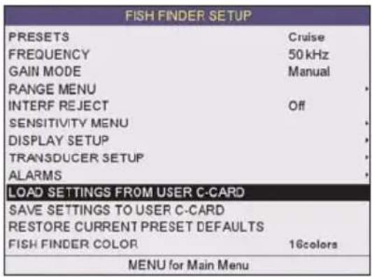
text_image
FISH FINDER SETUP PRESETS Cruise FREQUENCY 50 kHz GAIN MODE Manual RANGE MENU INTERF REJECT Off SENSITIVITY MENU DISPLAY SETUP TRANSDUCER SETUP ALARMS LOAD SETTINGS FROM USER C-CARD SAVE SETTINGS TO USER C-CARD RESTORE CURRENT PRESET DEFAULTS FISH FINDER COLOR 16colors MENU for Main MenuFigure 17.16 - C-CARD - Load settings
17.17 RESTORE CURRENT PRESET DEFAULTS
This option restores the default values only for the current presets and does not affect the other presets.
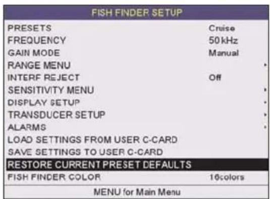
text_image
FISH FINDER SETUP PRESETS Cruise FREQUENCY 50 kHz GAIN MODE Manual RANGE MENU * INTERF REJECT Off SENSITIVITY MENU * DISPLAY SETUP * TRANSDUCER SETUP * ALARMS * LOAD SETTINGS FROM USER C-CARD SAVE SETTINGS TO USER C-CARD RESTORE CURRENT PRESET DEFAULTS FISH FINDER COLOR 16colors MENU for Main MenuFigure 17.17 - C-Card - Restore settings
18. TROUBLESHOOTING
The GPS Chart Plotter does not turn On. The voltage or the polarity may not be correct. Make sure that the correct voltage (10-35 volt dc) is present. Check also that the polarity is correct.
The GPS Chart Plotter does not get a valid fix. The external WAAS GPS antenna may not be in a open sky position or the antenna cable may not be properly connected. Make sure that no metal obstacle (solar panel about the plotter) is placed around the chart plotter (or external antenna when connected) acting as a shield for the antenna and disconnect and connect again the antenna cable to the GPS Chart Plotter. If, after 15 minutes, the GPS Chart Plotter does not get the fix, turn it Off and On again.
The GPS Chart Plotter does not turn Off. The GPS Chart Plotter may be in an unpredictable status. If, after pressing [PWR] (for at least 3 seconds) the GPS Chart Plotter does not turn Off, turn Off the voltage.
The GPS Chart Plotter screen becomes very dark after a long exposure to direct sunlight. The internal temperature is very high. Protect the GPS Chart Plotter from direct sunlight.
The GPS Chart Plotter does not respond to any command. The GPS Chart Plotter may be in an unpredictable status. Try to turn Off, and then turn On. If the problem persists, reset the RAM or remove power from the battery.
The location of my fix is not shown correctly on the Chart page. Please report to C-Map USA (800/424-2627) the Latitude & Longitude of your vessels position, the position where you think your vessels should be and details of the cartography such as "Compilation scale", "Notice to mariners" and "Horizontal datum" (which can be seen by selecting the Chart page, press [FIND], move the ShuttlePoint knob to Data Source and press [ENT]).
After storing the Chart Plotter over the winter, It takes a long time to receive a fix.
This is usually caused by the internal rechargeable memory battery from becoming low which could cause the Internal RAM memory to become corrupted. To solve this issue, perform a RAM clear (refer to Section 19).
NOTE
After performing a RAM Clear all Marks, Routes and tracks will be erased. To back up these points refer to Section 11 for details.
19. TECHNICAL TESTS
19.0 SYSTEM TEST
If you have connected your GPS Chart Plotter according to the instructions, and chosen the proper menu selection for your device, and are still having problems with your GPS Chart Plotter, the extended auto-test should help determine the problem. Make sure the GPS Chart Plotter is turned Off. While pressing and holding any other key, turn the GPS Chart Plotter On. A new menu will appear on the display:
① Software name and version
② NT+ Software Library version
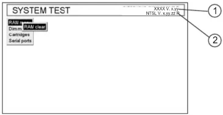
text_image
SYSTEM TEST XXXX V. x,yy NTSL V. x.yy.zz_R RAM n Dim m RAM clear Cartridges Serial ports 1 2Figure 19.0 - System Test
Use the ShuttlePoint knob to select the desired test. Choose the test, press [ENT]. To exit from any submenu press [CLR]. To exit from the System Test turn Off the GPS Chart Plotter.
19.0.0 RAM Menu (reset)
This test verifies the integrity of the memories and if desired during this test all the internal memory can be erased and the default setting restored.
RAM Clear
To clear internal memory. If the GPS Chart Plotter exhibits unusual operations, or appears to be malfunctioning, it may be possible to correct the problem by clearing RAM.
This operation will erase all Marks, Routes, stored Track plots and Destinations. It will also return all selections (Input Data Format, Autopilot selection, etc.) to original default values. To confirm clear RAM press [ENT] again (but if at this time you do not wish to clear RAM press [CLR]).
19.0.1 DIM Menu
To select the desired value for brightness and keypad light.
Contrast
Each time you move the ShuttlePoint knob to right, the screen will decrease brightness, move it to the left to increase brightness.
Backlight
The second option allows to set the backlight. Operates in similar mode as Contrast.
19.0.2 Cartridges
To check the C-CARD and its connector.
Internal Data Base Test
To test the Worldwide background.
C-CARD Test
To test the C-CARD. There are the possible situations:
- if there is a C-CARD inserted in the slot and there is not a malfunction, the name of the C-CARD zone and the message "OK" are shown.
- if there is a C-CARD inserted in the slot, but it is a defective C-CARD, the name of the C-CARD zone and the message "Faulty" are shown.
- if there is not any C-CARD inserted in the slot, the message "not present" is shown.
- if there is a User C-CARD inserted in the slot, the message USER C-CARD is shown.
C-CARD Connector
Indicates if there is a malfunction in the connector.
19.0.3 Serial Ports
If you are having problems receiving data from the position-finding instrument, this test should help determine the problem.
Change Parameters
To change the parameters of the serial interface. This menu allows to select the Port (Signal Source) between PORT 1, PORT 2, PORT 3, PORT4 and PORT 5; the Baud Rate between 300, 1200, 2400, 4800, 9600, 38400, 115200; the Data Bits (Word Length) between 7 or 8, the Parity between even, odd or none, the Stop Bits between 1 or 2. Default settings are: Port = PORT 2, Baud Rate = 4800, Data Bits = 8, Parity = none, Stop Bits = 1.
Input Data Display
To allow the GPS Chart Plotter to act as a computer terminal and display the incoming data exactly as it is received.
If the data displayed on the screen are unrecognizable, you may have selected the wrong input parameters for your particular receiver, for example, Baud Rate 9600 instead of Baud Rate 4800. Check your receiver manual to be sure that you have selected the proper parameter. If the screen is blank, you may have a broken connection, and no data is being received or you may have connected the device to the other input port.
Use [ZOOM IN] to stop (or continue after pause) data displaying, [ENT] to show data in hex or ASCII mode (normal or small) and [CLR] to exit.
Loop-Back Test
This is a special test done during the production phase to check the serial ports integrity. This function is only required by Standard Horizon.
20.0 CP390i/CPF390i SPECIFICATIONS
Power Consumption Max Backlight : CP390i = 1A@12VDC
: CPF390i = 1.75A@12VDC
Power supply : 10-35 Volt DC
Interface : Input/Output Interface NMEA-0183
Display : TFT Color LCD
(active area 7") sunviewable technology
Display Resolution : 800 x 480 pixels
Cartography : C-MAP B
Y JEPPESEN NT+/MAX C-CARD
Operating temperature range : 32^ F/+131°F ( 0^ C/+55°C)
Storage temperature : -4°F/+158°F (-20°C/+70°C)
Water Resistance : splash-proof
Memory : Permanent
Keyboard : Silicon rubber, backlight
Weight (without bracket)
: 2,428 lb (1100 g)
User Points (Marks/Waypoints)
:3000
Routes
: 50 (max 100 Waypoints each)
Track Points
: 10000 (recordable in 20 Tracks)
NMEA Output sentences
: GLL, VTG, BWC, WCV, APA, APB, HTG, BOD, XTE, RMA, RMB, RMC, GGA, HSC, DBT, DPT, MTW, VHW, WPL, RTE, GSA, GSV
NMEA Input sentences
: BWC, DSC, DSE, GGA, GLL, GSA, GSV, HDG, HDM, HDT, RMC, VHW, VTG, DPT, DBT, MTW, VWR, VWT, TLL, WPL, RTE
20.1 CPF390i FISH FINDER SPECIFICATIONS
Power Output : 600W
Frequency : 50 and 200kHz
Minimum Depth : 5Feet at 50kHz, 2.5Feet at 200kHz
Maximum Depth : 1500Feet at 50kHz, 700Feet at 200kHz
Airmar X-DUCER ID : Must use Standard Horizon transducers
Advanced Digital Signal Processing
Speed & Temperature Sensor (if available on transducer)
Alarms (shallow water, depth, Fish, temp)
Trip Log, Fish Symbols
STC, Interference Rejection, Automatic noise reduction
A-Scope, White Line, Zoom x2/x4
Auto range/gain/frequency/shift/ping rate
16/256 colors display user selectable
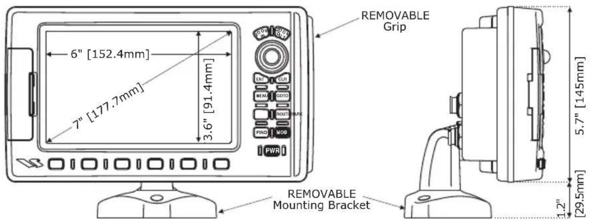
text_image
6" [152.4mm] 7" [177.7mm] 3.6" [91.4mm] REMOVABLE Grip REMOVABLE Mounting Bracket 5.7" [145mm] 1.2" [29.5mm]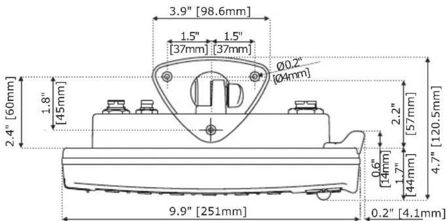
text_image
3.9" [98.6mm] 1.5" 1.5" [37mm] [37mm] Ø0.2" [Ø4mm] 2.4" [60mm] 1.8" [45mm] 2.2" [57mm] 4.7" [120.5mm] 0.6" [14mm] 1.7" [44mm] 9.9" [251mm] 0.2" [4.1mm]Figure 20.2 - CP390i/CPF390i Dimensions [inch/mm]
20.3 OPTIONAL FF525 FISH FINDER SPECIFICATIONS (USE WITH CP390i)
Power Output : 600W or 1kW depending on connected transducer
Frequency : 50 and 200kHz
Minimum Depth : 5Feet at 50kHz, 2.5Feet at 200kHz
Maximum Depth : 1500FT at 50kHz, 700FT at 200kHz
Airmar X-DUCER ID : Must use Standard Horizon transducers
Advanced Digital Signal Processing
Speed & Temperature Sensor (if available on transducer)
Alarms (shallow water, depth, Fish, temp)
Trip Log, Fish Symbols
STC, Interference Rejection, Automatic noise reduction
A-Scope, White Line, Zoom x2/x4
Auto range/gain/frequency/shift/ping rate
16/256 colors display user selectable
20.4 OPTIONAL WAAS GPS RECEIVER SPECIFICATIONS
This optional WAAS GPS Receiver is based on a ultimate GPS engine that delivers accuracy better than three meters by decoding the GPS correction signals from the satellite-based WAAS (Wide Area Augmentation System). The GPS engine, interface electronics and the passive antenna are enclosed inside the water-proof plastic housing. This provides advanced state of the art GPS performance in an easy to use package.
Physical Characteristics
| Color Ivory white | ||
| Dimensions 97mm in diameter x 32mm in height (flush mounted) or 61,5mm on flag-pole mount | ||
| Weight (without cable) 0,35 lb (160 g) | ||
| Cable white 15 meter 8x28AWG cable with 6 pins female connector | ||
| Electrical Characteristics | ||
| Input Voltage 10 Vdc to 35 Vdc unregulated | ||
| Input Current 0.8 Wmax | ||
| GPS Receiver Sensitivity Tracking, Navigation :-160 dBm | ||
| Acquisition, Reacquisition :-160 dBm | ||
| Cold Starts :-145 dBm | ||
| GPS Performance | ||
| GNSS Systems GPS : L1 C/A | ||
| GALILEO | : L1 | |
| SBAS | : WAAS (North America), EGNOS (Europe), MSAS (Asia), GAGAN (Indian) | |
| Geodetic Datum | WGS84 | |
| Channels | 32 + 18 | |
| Acquisition Time | ||
| Reacquisition | < 1 second | |
| Hot Start | 1 second outdoor, 10 seconds indoor | |
| Warm Start | 29 seconds | |
| Cold Start | 29 seconds | |
| Accuracy | ||
| GPS | < 2.5m | |
| with SBAS < 2.0m | ||
| NMEA Output | ||
| Messages | GGA, RMC, GSA, GSV, TXT | |
21. APPENDIX: TERMS
ALT (Altitude) – Shows the Altitude of the GPS Antenna on the mean sea level. It i received from GPS, sentence GGA.
APP Wind DIR SPD (Apparent Wind Direction) – Shows the Apparent Wind Direction when a external wind instrument with NMEA is connected.
APP Wind SPD (Apparent Wind Speed) – Shows the Apparent Wind Speed when a external wind instrument with NMEA is connected.
BRG (Bearing) – The direction from your current position to a Destination point.
COG (Course Over Ground) – The course your vessel is heading.
DATE – Shows the current date received by the GPS.
DEPTH – Shows the water depth when the optional Digital Depth Sounder is connected.
DEPTH AREAS – Depth Areas are the sea areas included in the user selectable range of minimum and maximum depth limits. The sea area that is beyond the selected range is filled by an uniform white color, the sea area that is inside the selected range is filled by ordinary multicolor shading. The Spot Soundings and Depth Contours are displayed on the range only.
DRAUGHT – Depth of water the vessel draws.
The definition of draught (or draft) of a ship's hull is the vertical distance between the waterline and the bottom of the hull (keel). Draught determines the minimum depth of water a ship or boat can safely navigate.
On the Celestial page the “draught” window shows the height of the tidal water during a 24hr period of time. This height is dependant on the time of day selected using the ShuttlePoint knob.
DSC (Digital Selective Calling) – Digital Selective Calling is a semi-automated method of establishing a VHF Radio call. DSC had also been designated as part of the Global Maritime Distress and Safety System (GMDSS). It is planned that DSC will eventually replace aural watches on distress frequencies and will be used to announce routine and urgent maritime safety information broadcasts.
DST (Distance) – The distance from your current position to a Destination point.
ETA – Estimated Time of Arrival
GPS Constellation – The Global Positioning System (GPS) is a space-based radio-navigation system consisting of a constellation of satellites and a network of ground stations used for monitoring and control. A minimum of 24 GPS satellites orbit the Earth at an altitude of approximately 11,000 miles providing users with accurate information on position, velocity and time anywhere in the world and in all weather conditions.
GPS2D – The GPS is receiving at least 3 valid satellites.
GPS3D – The GPS is receiving at least 4 Satellites.
HDG (Heading) – Shows heading from a External Flux Gate Compass when connected.
HDOP/VDOP - Horizontal/Vertical Dilution of Precision. It is a parameter indicating the
precision of the positioning system (GPS). The smaller the HDOP/VDOP value, the more accurately the position fix is provided.
HEIGHT – The current tide height referred to the vertical cursor.
HIGH WATER – The maximum level of the tide height in 24 hours.
LOW WATER – The minimum level of the tide height in 24 hours.
PINGO – It is a mound of earth-covered ice found in the Arctic and subarctic that can reach up to 70 metres (230FT) in Height and up to 600 metres (2.000 FT) in diameter.
Position Request – Marine DSC VHF Function of transmitting a GPS position to another Marine DSC VHF. When GPS Chart Plotter is connected to STANDARD HORIZON GPS the position of another vessel is shown on the Chart page.
SPEED – Shows the Speed Thru the Water when a Digital Speed Log is connected.
SOG (Speed Over Ground) – The speed you vessel is travelling at.
STEER – Heading to steer to destination Waypoint.
TIME – Shows the current time received by the GPS.
TRIP LOG – Shows the distance the vessel has travelled since the trip log was reset.
TRU Wind DIR (True Wind Direction) – Shows the True Wind Direction when an external wind instrument with NMEA is connected.
TRU Wind SPD (True Wind Speed) – Shows the True Wind Speed when an external wind instrument with NMEA is connected.
TTG (Time To Go) – Shows time to go to reach a Destination point.
UNITS
Nm Nautical Mile (1 NM = 1.15 Sm or 1.85Km)
Sm Statue Mile (1Sm = 0.87Nm or 1.61Km)
Km Kilometer (1 Kilometer = 0062 Sm or 0.54Nm)
FT Feet (1 Foot = 0.167 Fathoms or 0.305 Meters)
FA Fathom (1 Fathom = 6 Feet or 1.83 Meters)
Mt Meter (1 Meter = 3.28 Feet or 0.55 Fathoms)
Kts Knot (1 Knot = 1.15 MPH or 1.85 KPH)
MPH Miles Per Hour (1 MPH = 0.87 Knots or 1.61 KPH)
Kmh Kilometer Per Hour (1 KPH = 0.54 Knots or 0.62 MPH)
VMG – It is the destination closing Velocity. The VMG is calculated using the current speed of the vessel (SOG) and the difference between the current vessel course and the bearing to the Destination.
WAAS 2D/3D – The GPS is receiving a 2D or 3D position and the correction from the WAAS Satellite. WAAS consists of approximately 25 ground reference stations positioned across the United States that monitor GPS satellite data. Two master stations, located on either coast, collect data from the reference stations and create a GPS correction message. This correction accounts for GPS satellite orbit and clock drift plus signal delays caused by the atmosphere and ionosphere. The corrected differential message is then broadcast through one of two geostationary satellites, or satellites with a fixed position over the equator. The information is compatible with the basic GPS signal structure, which means any WAAS-enabled GPS receiver can read the signal.
WATER TEMP – Shows the sea water temperature for when a Digital Speed Log/Temp instrument with NMEA is connected.
XTE (Cross Track Error) – The distance your vessel is off course (left or right) to a Destination point.
12VDC Power 23
16/256 colors display ..... 13, 151, 152
200kHz FULL PAGE 41
200kHz/CHART PAGE 41
3D view 102
50kHz FULL PAGE 41
50kHz/CHART PAGE 41
A
A-Scope 131, 143
About page.... 43, 124
Accessory 14
Accuracy 153
ACCURACY (route) 83
ACQUIRING.... 104
Activation Range 117, 118
Active Target 117
ACTIVE TRACK 86, 87
ACVC10 27
Adjusting Time 37
Advanced Setup menu.... 111
AIS 13, 22, 24, 41, 117
AIS LIST...... 41
AIS List.... 13, 119, 120
AIS List page.... 13, 119, 120
AIS NMEA message 23, 24
AIS Receiver 24, 25, 111
AIS Setup 22, 24
AIS Symbols 118
alarm 57,62,123
alarm condition.... 62
Alarm Status List.... 127
Alarms 114, 144
Alarms menu 114, 144
Alaska 55,92
ALT 95
Alter.... 38, 113
Alternate Solution.... 113
Altitude 41, 95, 155
Anchor Alarm 114
antenna .....17, 19, 25, 41, 153
APA 111, 112, 151
APB 112, 151
Apparent Wind Direction ..... 95, 155
Apparent Wind Speed.... 95, 155
Arrival Alarm 114
ASF 38
ASF1/2 113
assistance 13
Attention Areas 97, 98
Audible Alarm.... 114
Auto Full page 133
AUTO INFO 42
Auto Info.... 97, 116
Auto Position 115
Automatic Route Check 83
AUTOMATIC TIME 36
Autopilot 22, 24
available languages 39
AWD 95
AWS....95
B
background 31
Backlight 35,149
Bahamas 55, 92
Bathymetric 57
BATTERY CONNECTIONS ...... 24
Beacons 98
Bearing.... 95, 155
Bearings 113
BOD 112, 151
Bottom Echo Profile 132
Bottom Lock 138
bracket 14, 17
Bracket installation.... 18
BRACKET MOUNTING 17
BRG 95,155
Built-in Coastal maps 13
Buoys 96, 98
BWC 105, 111, 112, 151
C
C-CARD 32, 55, 56, 150
C-CARD Connector 150
C-CARD Test 150
C-COM 111
C-Weather 111, 121
C-Weather menu 121
Calibrate Water Speed 143
Calibrate Water Temp.... 143
Calibration 113
camera icon 66
Canada 55,92
Caribbean 55,92
Cartographic Data 57
Cartography 55, 151
Cartridges 150
CAUTION 5
Caution page.... 33
CELESTIAL.... 41
Celestial page 102, 155
Central America 55, 92
Chain.... 38
change the fields.... 31
CHART 41
Chart Boundaries 98, 99
CHART CONFIGURATIONS ..... 101
Chart Datum.... 112
Chart Language 65
chart level.... 57, 59
Chart Lock.... 98, 100
Chart Orientation Resolution ..... 113
CHART PAGE 42
Chart page 33
chart scale 31,95
Chart selection menu 92
Chart Settings 99, 101
CHART/COMPASS.... 41
CHART/HIGHWAY 41
Classic 38, 39, 41
Clear Info 57
Clear View.... 57
CLR 31
COG 85, 92, 95, 155
COLOR (route)...... 82
Color AIS Targets 120
Color Settings 142
COLOR TARGET AIS 119
Color Targets AIS 13
Compass menu 113
COMPASS ROSE 42
Compass Rose 13, 101
Compass Table 114
Compass Tape.... 101
Connection ......21, 23, 26, 123
Connection Table 21, 23
CONNECTIONS 20
Contrast 35,149
convention.... 17, 31
Coordinate System 112
Coordinate System menu 38
Coordinates.... 32, 52
Course 115
Course Over Ground ..... 85, 95, 155
COURSE UP....41
Course Up 36
Course Up/North Up menu 36
CPA.... 117
CPA Alarm 117, 118
CPA Limit 117, 118
Creating a Route 77
CREATING MARK 69
crew monitoring system 123
Cross Track Error 95, 157
Cruising 137
Cuba 55,92
Current Date 95
Current Time 95
Currents Prediction 64
Cursor Control 115
Cursor mode 31, 34
CURSOR SPEED 42
Cursor Speed menu 34
CURSOR WINDOW 42
customize 32
Customizing Data Windows 95
CUSTOMIZING SOFT KEYS...... 40
D
dangerous objects.... 82
dangerous Route leg.... 82
Dangerous Target 117
Data Features 57
Data Safety Indicator 62
Data window layout 94
DATE 95,155
Date (simulation)...... 115
DATE FORMAT 41
DBT 105, 112, 151
DC Power Connection 21, 23
Deep Alarm Bar 131
Deep Water.... 144
default pages 40
DELETE 71
delete a Route.... 81
Delete PTX.... 126
Delete Track.... 86
Deletes the selected PTX 128
Deleting a Mark 70
Deleting a Waypoint.... 70
Deleting file 90
Deleting MOB.... 75
deleting User Points.... 71
Demo Mode 29,115
Demonstration Mode 29
Depth 41, 95, 139, 155
Depth Alarm 114
DEPTH AREAS.... 155
Depth contours.... 55
DEPTH LIMIT (route) 83
Depth Range Max 98
Depth Range Min 98
Depth Settings 98, 101
Depth Sounder 24,105
DEPTH TREND 41, 107
Depths.... 57
desired page 91
destination.... 32, 73, 156
Detailed Port Plan 57
Diagrams.... 57, 65
Differential Correction Source...... 104
Diffusers 82, 98, 100
Digital Depth 130
DIM Menu 149
Dimensions 152
disable Demo mode 29
Display 151
display 13
Display (AIS) 118
DISPLAY COLOR 41
Display Color 17, 104
Display Color menu.... 38
Display Mode 97
Display Resolution 151
Display Setup menu 142
Distance 41,95
DISTANCE (track) 87
Distress call 107
Download 121
Download Area 121
DPT 105, 112, 151
DRAUGHT 155
draught 103
Dredged Areas 82
DSC .... 105, 107, 115, 151, 155, 156
DSC DIRECTORY 41
DSC Distress Call 108
DSC LOG 41
DSC POLLING 115
DSC VHF 25,108
DSC VHF Radio 24
DSE.... 105, 151
DSI 62
DST 95,155
DST521 106
DST526 106
DTP 95
Dual (charts) 92
Dual chart.... 13, 41
Dust cover 14
DVD 27
Dynamic Currents 57
Dynamic Nav-Aids 57, 62
E
EDIT 71,82
EDIT ROUTE 78,80
Edit Route 78
EDITING A MARK.... 69
electronic chart 57
Enhanced Mixing Levels 57
Enhanced Port Info 67
ENT 31
Estimated Time of Arrival.... 95
ETA 95,155
External bracket 14
Extra Large Coverage 57
F
FA Fathom 156
FF MODULE 152
FF525....13, 22, 25, 106, 111
FIND.... 13, 32, 41, 45, 57, 71
Find a Port 46
Find GPS Coordinates 53
Find Information 53
Find Lakes By Name.... 51
Find Lakes Information 49
Find Obstructions.... 49
Find Points Of Interest 52
Find Port Services 46
Find User Points 52
Find Wrecks 48
Fish 144
Fish Alarm 144
FISH FINDER 13,25
Fish Finder 13, 129
Fish Finder display 131
Fish Finder page 130
Fish Finder page selection...... 132
Fish Finder Setup menu 136
Fish Finder window 130
Fish Symbols 143
Fish/Chart Page 134
Fish/Radar/Chart page 135
Fishes 131
Fishing 137
Fishing Facility 82
fix 147
Fix Status 95
Flexi-Zoom 57, 59
Flush mount template 14
FLUSH MOUNTING.... 18
Flush mounting 19
Flush mounting screws 14
Flux gate compass 105
Focus Soft Key...... 134, 135
Format User C-CARD 89
Frequency 131
Frequency menu 137
FT Feet 156
Full Display pages.... 133
Full Info 66
Full Info On Lakes.... 50
fuse 14
G
Gain 138,140
Gain Mode menu 138
Getting Started 32
GGA 105, 112, 151, 155
GLL 105, 111, 112, 151
GMDSS 155
GNSS 153
GOTO 32,73,92
GOTO A ROUTE 80
GOTO CURSOR 73
Goto PTX 126
GOTO ROUTE 74
GPS 17,20,25,153,155
GPS antenna 17, 19
GPS Cable 20
GPS Constellation.... 155
GPS information.... 105
GPS Performance.... 153
GPS Receiver 153
GPS Setup Menu 104
GPS Status 17, 41, 95
GPS Status page 103
GPS2D 104, 155
GPS3D 104, 155
Great Lakes 55,92
Grounding Alarm 114
Grounding Alarm Range 114
Grounding Alarm Report 114
GSA 105,151
GSV 105, 151
Guardian Alarm 57
H
Hawaii 55,92
HDG 95,105,112,151,155
HDM 105,151
HDOP....95,104,155
HDT.... 105, 151
Heading.... 95, 155
HEIGHT 156
HIGH WATER 156
High Water 103
HIGHWAY 41
Highway page 102
Home mode 31, 34
Horizontal Dilution Prec .. 95, 104, 155
HSC 112, 151
HTG 151
|
ICON 71
Icons Size 60
Info Tree.... 53
Information 32, 53, 96
INPUT/OUTPUT 111
Inserting C-CARD 55, 56
Inserting Waypoint 80
INSTALLATION 17
Installing the antenna.... 20
Interface 151
Interference Rejection...... 139
Internal GPS 104
Intertidal Areas.... 82
ISO Certification.... 57
J
Japanese 39
K
Keel Offset 143
key 31
Keyboard.... 151
KEYPAD BEEP 41
Km Kilometer 156
Kmh Kilometer Per Hour 156
knob 14
Kts Knot 156
L
Lake 49
Lakes By Name.... 32, 51
Lakes Information 32,49
Land Areas....82
Land Elevation Values 98, 99
Land Elevations 57, 98
Land Settings 99, 101
LANGUAGE 42
Language 39,65
Language Selection menu 40
Lat/Lon Grid 98, 99
Latitude 99
LINE COLOR (track) 86
Load settings.... 145
Loading a file.... 90
local language 65
LOCATE....71
locate Port 46
locate Tide Stations 46
locate Wrecks 47
Longitude 99
Loran TD 38,113
Lost Target 117
LOW WATER 156
Low Water.... 103
M
Main Menu 31, 91, 132
MAN OVER BOARD 75
Marine Settings 98, 101
MARK.... 13, 32, 69
Mark ...... 13, 32, 52, 69, 77, 79, 151
Mark creation 69
Mark editing 70
Mark Icons 70
MARKS/WAYPOINTS 41
Marks/Waypoints List 71, 72
MARKS/WPTS....71
MAX 55, 59
Max Functions Menu.... 59
Max Speed 95
MEASURE DISTANCE 42
Memory 151
MENU 31
Mixing Levels 57, 98, 100
MMSI.... 117
MMSI number 117, 118
MOB 32,75
MOBILARM 25,111,123
MOBILARM Alarm Status List ...... 127
MODE 71
moon phase 102
Mooring/Warping Facility 82
mounting bracket 13
Moving a Mark 70
Moving a Waypoint 70
MPH Miles Per Hour 156
Mt Meter 156
MTW 105, 112, 151
Multilanguage.... 57
N
Name 117
name the Route 78
NAME TO A ROUTE 78
Names Tags.... 97, 98
Nav Aids & Light Sectors 97, 98
NAV AIDS PRESENTATION ...... 41
Nav-Aids 57,62
nav-aids 55
Navigate Menu 112
Navigating a Route 115
NAVIGATION 41
NAVIGATION PAGE 42
Navigation page 101
Navigation Speed.... 104
new Mark 71
new Route 79
new Track 86
new User C-CARD 89
Night.... 38, 39, 41
Nm Nautical Mile 156
NMEA....24, 26, 71, 82
NMEA CONNECTION 24
NMEA DATA 41
NMEA Data page 26, 105, 106
NMEA DISPLAY 41
NMEA Display menu ..... 105, 106, 107
NMEA Input sentences 151
NMEA Output 21
NMEA Output sentences 151
NMEA sentences 26, 105
NMEA Trend pages 106, 107
NMEA-0183 111
No Data Available 82
NOAA 38, 39, 41, 57
non-Latin characters 39
Normal 39,41
NORTH UP 41
North Up.... 36
NT/NT+ 58
NTSC 27
0
Object Info.... 57
Obstruction icons Table 48
Obstructions...... 32, 48, 82, 98, 100
Off-line redraw 57
Official data source 57
Olympic Route 13
OPTIONAL ACCESSORIES 15
Over Zoom 57,60
P
Packing List.... 14
pages 40,91
Pair.... 38
PAL 27
Palette 63
PC 71
PC COM settings 26
PC-Planner 121
Personal Computer 25,71
Personal Transponder 124
Perspective View 57, 61
Photos 57
picture-in-picture 13, 27
Pictures 65
Pingo 82,156
PiP 28
Place Names.... 97, 98
Place Names Size.... 60
places a MOB 75
PLACING A MOB.... 75
Points Of Interest ......32, 51, 98, 99
Port 46
Port Info 57, 67, 69
Port Plan 57
Port Services 32, 45, 67
Port Services Table 45
Ports.... 32
Ports & Services 98
POSITION Request 107
Position Request 108, 156
Position Request Call 108
POSITION Send 107
Position Send Call.... 108
Power & Accessory cable 14
Power Consumption.... 151
Power Off 33
Power On 33
Power supply 151
Presentation Features 57
Preset values table 141
Presets table 137
Production Installation 82
PTX 124
PTX icon 125
PTX information window 126
PTX List page 128
PTX warning window 126
Puerto Rico 55, 92
PWR 32
Q
Quick Info 57,118
Quick Info On Lakes 49
Quick Reference Guide 14
R
Radar 13, 14, 25, 41, 111
RADAR FULL.... 41
RADAR OVERLAY 41
Radar page 41, 134
RADAR/CHART 41
RADAR/FISH FINDER 41
Radio Call Sign 117
RAM Clear 149
RAM Menu (reset) 149
Range 138
Range Bar 131
Range menu 138
Real Time View 122
RECEIVE 71
RECEIVE (route) 82
Refresh User C-CARD.... 90
replacement part 14
Restart GPS 104
Roads.... 57, 98, 99
Rocks 82, 98, 100
ROUTE 13,32
Route .... 13, 32, 69, 77, 78, 79, 81,
82, 115, 151
Route Check 13, 58, 82
Route Check parameters 83
ROUTE CHECK REPORT 83
Route containing Marks 79
ROUTE MENU 82
Route Report.... 82
ROUTE WIDTH 83
RTE 26,71,82,105,151
S
Safety Route Check 58
Safety Status Bar 57, 62, 63
Satellite 13, 63, 104, 156
Satellite Imagery 63
SAVE (user C-CARD) 90
SAVE FILE 90
Save settings 145
SCALE 95
screen 5,147
screen display pages 40, 91
Scrolling Speed 142
Seabed Type.... 98
Search.... 57
SELECT (route) 82
select the language 39
SELECTING PAGES 40
Selection (pages) 91
SEND 71
SEND (route) 82
Sensitivity menu 140
sentences.... 26
Serial Ports 150
Set Defaults 143
Shallow Alarm Bar 131
Shallow Water.... 82, 144
Shift 139
SHIP ICON 42
Ship Icons 35
Ship icons 13, 35
Shoreline Constructions.... 82
ShuttlePoint knob 31
SI-TEX 14, 41, 111
Signals 98
SIM Pin 121
Simulation menu 115
Simulation Mode 115
Single (chart) 92
single chart.... 92
Size (icon) 60
Sleeping Target.... 117, 118
slot 56
Sm Statue Mile.... 156
Smart GPS Cable 20
Soft Key 40, 92, 136
Software 43
SOG 92, 95, 156
SOG TREND.... 41, 107
SORT 71
SPD....95
SPECIFICATIONS 151, 152
Speed....41, 85, 95, 115, 156
Speed Filter.... 13, 104
Speed Log.... 24, 105
Speed Over Ground 95,156
Spot Soundings.... 57
spot soundings 55
start a new Track 86
start navigating.... 32
Start-Up page.... 33
Static Navigation 113
Status Bar 62
status of MOBILARM 124
STC 140
STC Length 141
STC Strength 141
STEER 156
Steering....95
STEP UNIT 86
stop navigation 32
STR 95
Structures 132
SunLight 38,41
Sunlight 39
Surface Clutter 132
Surface Noise Filter 141
System Test 149
T
Target.... 117
TCPA 117
TCPA Alarm 117, 118
TCPA Limit 117, 118
TD 38,112,113
technical support.... 13
Temp 95
TEMP TREND.... 41, 107
Temperature 41, 151
Temperature Lower.... 144
Temperature Rate 144
Temperature Upper...... 144
TERMS 155
Thermoclines 131
THICKNESS (route) 82
Tidal 55
Tidal stream arrows 64
Tide 64,102
Tide draught 47
Tide Graph 103
Tide Graph page 47
Tide height 47,103
Tide Stations ....32, 46, 47, 57
Tides & Currents 97, 98
Tides Preview 57
TIME 95,156
Time 85
Time (simulation) 115
TIME (track) 87
Time Difference.... 112
Time Format.... 41
TIME SETUP 41
Time To Go 95,156
Time Units (track) 85
Time Zone 37
TLL 105,151
TLOG 87,95
Track 13,85,92
Track line 86
Track memory capacity.... 85
Track Points 85, 151
Tracking 85, 86, 95
Tracks & Routes 98
transducer 106
Transducer Setup menu 143
Transmit Frequency 131
Trip Log 87, 95, 156
Trip Log Reset 87
Trip Log selection 87
TROUBLESHOOTING 147
True Wind Direction 95, 156
True Wind Speed 95,156
True-Type Font 57
TTG 95,156
turn the GPS Chart Plotter On ... 32, 56
TWD 95
two charts.... 92
TWS 95
Type of Data 122
U
Under Zoom 57,60
Underwater Ob. Limit 98
Underwater Object Limit 100
Underwater Objects Settings ...... 100
Underwater Settings 101
UNICODE 39
UNITS 156
UNITS OF MEASURE 41
Updating Built-In Charts.... 55
User C-CARD ..41, 89, 121, 122, 145
User C-CARD Menu 89
User Points 32, 52, 151
UTC.... 36
UTM 38,112
V
VAD....100
Value Added Data 98,100
Variable Depth Marker 131
Variation 113
VCR 27
VCR/DVD Input 28
VDM 131
VDOP 95,104,155
Velocity Made Good.... 95
Vertical Dilution of Precision
95, 104, 155
vessel position 92
VHF 22, 24, 25
VHF Radio 105
VHF radio 107
VHW 105, 112, 151
video camera 24, 27
Video Connector 27
Video Input 27,41
VideoCamera 22
VISIBLE (track) 86
VMG 95,156
VTG....105, 111, 112, 151
VWR 105,151
VWT 105, 151
W
WAAS 19, 95, 153
WAAS 2D....156
WAAS 2D/3D 104
WAAS 3D.... 156
WAAS GPS.... 13
WAAS/EGNOS 104
WARNING 4
Warning Message 130
Water Resistance 151
WATER TEMP 157
Water Temperature...... 85, 95, 130
Waypoint ..... 32, 52, 69, 77, 78, 80,
81, 89, 151
WCV 111, 112, 151
Weather data package.... 121
Weather Forecast 122
Weight.... 151
WGS84 112
White Line 132, 142
Wind Instrument.... 24
Wind speed 105
WIND SPEED TREND...... 41, 107
Window Selections 94
WINDOWS SETUP 42, 94
World Background 57
Worldwide background 150
WPL 26,71,105,151
Wreck icons Table 47
Wrecks ...... 32, 47, 55, 82, 98, 100
X
XTE .....95, 111, 112, 151, 157
XTE Alarm.... 111, 112, 114
Z
Zoom 31,60,133
zoom factor 60
Zoom Full Page.... 133
ZOOM IN.... 31
ZOOM OUT 31
Zoom Pages.... 133
Zoom Type 59
PLEASE NOTE
The following "Limited Warranty" is for customers that have purchased products in the United States. For Limited Warranty details outside the United States, contact the dealer in your country.
STANDARD HORIZON LIMITED WARRANTY
STANDARD HORIZON (a division of Vertex Standard USA) warrants, to the original purchaser only, each new Marine Product ("Product") manufactured and/or supplied by STANDARD HORIZON against defects in materials and workmanship under normal use and service for a period of 3 years from the date of purchase.
In the event of a defect, malfunction or failure of the Product during the warranty period, Standard Horizon's liability for any breach of contract or any breach of express or implied warranties in connection with the sale of Products shall be limited solely to repair or replacement, at its option, of the Product or part(s) therein which, upon examination by STANDARD HORIZON, appear to be defective or not up to factory specifications. STANDARD HORIZON may, at its option, repair or replace parts or subassemblies with or reconditioned parts and subassemblies.
To receive warranty service, the purchaser must deliver the Product, transportation and Insurance prepaid, to STANDARD HORIZON (Marine Division of Vertex Standard) - Attention Factory Service - 10900 Walker Street - Cypress, CA 90630, include proof of purchase indicating model, serial number and date of purchase.
STANDARD HORIZON will not warrant installation, maintenance or service of the Products. In all instances, STANDARD HORIZON's liability for damages shall not exceed the purchase price of the defective Product. This warranty only extends to Products sold within the 50 States of the United States of America and the District of Columbia.
STANDARD HORIZON will pay all labor and replacement parts charges incurred in providing the warranty repair service except where purchaser abuse or other qualifying exceptions exist. The purchaser must pay any transportation expenses incurred in returning the Product to STANDARD HORIZON for service.
This limited warranty does not extend to any Product which has been subjected to misuse, neglect, accident, incorrect wiring by anyone other than STANDARD HORIZON, improper installation, or subjected to use in violation of instructions furnished by STANDARD HORIZON, nor does this warranty extend to Products on which the serial number has been removed, defaced, or changed. STANDARD HORIZON cannot be responsible in any way for ancillary equipment not furnished by STANDARD HORIZON which is attached to or used in connection with Products, or for the operation of the Product with any ancillary equipment, and all such equipment is expressly excluded from this warranty. STANDARD HORIZON disclaims liability for range, coverage, or operation of the Product and ancillary equipment as a whole under this warranty.
STANDARD HORIZON reserves the right to make changes or improvements in Products, during subsequent production, without incurring the obligation to install such changes or improvements on previously manufactured Products. The implied warranties which the law imposes on the sale of this Product are expressly LIMITED, in duration, to the time period specified above. STANDARD HORIZON shall not be liable under any circumstances for consequential damages resulting from the use and operation of this Product, or from the breach of this LIMITED WARRANTY, any implied warranties, or any contract with STANDARD HORIZON. IN CONNECTION WITH THE SALE OF ITS PRODUCTS, STANDARD HORIZON MAKES NO WARRANTIES, EXPRESS OR IMPLIED AS TO THE MERCHANTABILITY OR FITNESS FOR A PARTICULAR PURPOSE OR OTHERWISE, EXCEPT AS EXPRESSLY SET FORTH HEREIN.
Some states do not allow the exclusion or limitation of incidental or consequential damages, or limitation on how an implied warranty lasts, so the above limitation or exclusions may not apply. This warranty gives specific legal right, and there may be other right which may vary from state to state.
VERTEX STANDARD CO., LTD.
4-8-8 Nakameguro, Meguro-Ku, Tokyo 153-8644, Japan
VERTEX STANDARD
US Headquarters
10900 Walker Street, Cypress, CA 90630, U.S.A.
YAESU UK LTD.
Unit 12, Sun Valley Business Park, Winnall Close
Winchester, Hampshire, SO230LB, U.K.
VERTEX STANDARD HK LTD.
Unit 1306-1308, 13/F., Millennium City 2, 378 Kwun Tong Road,
Kwun Tong, Kowloon, Hong Kong
VERTEX STANDARD (AUSTRALIA) PTY. LTD
Tally Ho Business Park, 10 Wesley Court, East Burwood, VIC, 3151
Copyright 2011
Vertex Standard Co., LTD.
All right reserved.
No portion of this manual may be reproduced
without the permission of
Vertex Standard Co, LTD.
Printed In Italy
EM051U100