
DS-2TD4166-50 - Security Camera Hikvision - Free user manual and instructions
Find the device manual for free DS-2TD4166-50 Hikvision in PDF.


User questions about DS-2TD4166-50 Hikvision
0 question about this device. Answer the ones you know or ask your own.
Ask a new question about this device
Download the instructions for your Security Camera in PDF format for free! Find your manual DS-2TD4166-50 - Hikvision and take your electronic device back in hand. On this page are published all the documents necessary for the use of your device. DS-2TD4166-50 by Hikvision.
USER MANUAL DS-2TD4166-50 Hikvision
natural_image
Abstract geometric design with red diamonds, gray squares, and a white globe icon (no text or symbols)Thermal Bi-spectrum Network Speed dome
User Manual
User Manual
COPYRIGHT § 2017 Hangzhou Hikvision Digital Technology Co., Ltd.
ALL RIGHTS RESERVED.
Any and all information, including, among others, wordings, pictures, graphs are the properties of Hangzhou Hikvision Digital Technology Co., Ltd. or its subsidiaries (hereinafter referred to be "Hikvision"). This user manual (hereinafter referred to be "the Manual") cannot be reproduced, changed, translated, or distributed, partially or wholly, by any means, without the prior written permission of Hikvision. Unless otherwise stipulated, Hikvision does not make any warranties, guarantees or representations, express or implied, regarding to the Manual.
About this Manual
This Manual is applicable to Thermal Bi-spectrum Network Speed dome.
The Manual includes instructions for using and managing the product. Pictures, charts, images and all other information hereinafter are for description and explanation only. The information contained in the Manual is subject to change, without notice, due to firmware updates or other reasons. Please find the latest version in the company website
(http://overseas.hikvision.com/en/).
Please use this user manual under the guidance of professionals.
Trademarks Acknowledgement
HIKVISION and other Hikvision's trademarks and logos are the properties of Hikvision in various jurisdictions. Other trademarks and logos mentioned below are the properties of their respective owners.
Legal Disclaimer
TO THE MAXIMUM EXTENT PERMITTED BY APPLICABLE LAW, THE PRODUCT DESCRIBED, WITH ITS HARDWARE, SOFTWARE AND FIRMWARE, IS PROVIDED "AS IS", WITH ALL FAULTS AND ERRORS, AND HIKVISION MAKES NO WARRANTIES, EXPRESS OR IMPLIED, INCLUDING WITHOUT LIMITATION, MERCHANTABILITY, SATISFACTORY QUALITY, FITNESS FOR A PARTICULAR PURPOSE, AND NON-INFRINGEMENT OF THIRD PARTY. IN NO EVENT WILL HIKVISION, ITS DIRECTORS, OFFICERS, EMPLOYEES, OR AGENTS BE LIABLE TO YOU FOR ANY SPECIAL, CONSEQUENTIAL, INCIDENTAL, OR INDIRECT DAMAGES, INCLUDING, AMONG OTHERS, DAMAGES FOR LOSS OF BUSINESS PROFITS, BUSINESS INTERRUPTION, OR LOSS OF DATA OR DOCUMENTATION, IN CONNECTION WITH THE USE OF THIS PRODUCT, EVEN IF HIKVISION HAS BEEN ADVISED OF THE POSSIBILITY OF SUCH DAMAGES.
REGARDING TO THE PRODUCT WITH INTERNET ACCESS, THE USE OF PRODUCT SHALL BE WHOLLY AT YOUR OWN RISKS. HIKVISION SHALL NOT TAKE ANY RESPONSIBILITES FOR ABNORMAL OPERATION, PRIVACY LEAKAGE OR OTHER DAMAGES RESULTING FROM CYBER ATTACK, HACKER ATTACK, VIRUS INSPECTION, OR OTHER INTERNET SECURITY RISKS; HOWEVER, HIKVISION WILL PROVIDE TIMELY TECHNICAL SUPPORT IF REQUIRED.
SURVEILLANCE LAWS VARY BY JURISDICTION. PLEASE CHECK ALL RELEVANT LAWS IN YOUR JURISDICTION BEFORE USING THIS PRODUCT IN ORDER TO ENSURE THAT YOUR USE
CONFORMS THE APPLICABLE LAW. HIKVISION SHALL NOT BE LIABLE IN THE EVENT THAT THIS PRODUCT IS USED WITH ILLEGITIMATE PURPOSES.
IN THE EVENT OF ANY CONFLICTS BETWEEN THIS MANUAL AND THE APPLICABLE LAW, THE LATER PREVAILS.
Regulatory Information
FCC Information
Please take attention that changes or modification not expressly approved by the party responsible for compliance could void the user's authority to operate the equipment.
FCC compliance: This equipment has been tested and found to comply with the limits for a Class A digital device, pursuant to part 15 of the FCC Rules. These limits are designed to provide reasonable protection against harmful interference when the equipment is operated in a commercial environment. This equipment generates, uses, and can radiate radio frequency energy and, if not installed and used in accordance with the instruction manual, may cause harmful interference to radio communications. Operation of this equipment in a residential area is likely to cause harmful interference in which case the user will be required to correct the interference at his own expense.
FCC Conditions
This device complies with part 15 of the FCC Rules. Operation is subject to the following two conditions:
- This device may not cause harmful interference.
- This device must accept any interference received, including interference that may cause undesired operation.
EU Conformity Statement

This product and - if applicable - the supplied accessories too are marked with "CE" and comply therefore with the applicable harmonized European standards listed under the Low Voltage Directive 2006/95/EC, the EMC Directive 2014/30/EU, the RoHS Directive 2011/65/EU.

2012/19/EU (WEEE directive): Products marked with this symbol cannot be disposed of as unsorted municipal waste in the European Union. For proper recycling, return this product to your local supplier upon the purchase of equivalent new equipment, or dispose of it at designated collection points. For more information see: www.recyclethis.info.

2006/66/EC (battery directive): This product contains a battery that cannot be disposed of as unsorted municipal waste in the European Union. See the product documentation for specific battery information. The battery is marked with this symbol, which may include lettering to indicate cadmium
(Cd), lead (Pb), or mercury (Hg). For proper recycling, return the battery to your supplier or to a designated collection point. For more information see: www.recyclethis.info. Industry Canada ICES-003 Compliance
This device meets the CAN ICES-3 (A)/NMB-3(A) standards requirements.
Safety Instruction
These instructions are intended to ensure that the user can use the product correctly to avoid danger or property loss.
The precaution measure is divided into 'Warnings' and 'Cautions':
Warnings: Serious injury or death may be caused if any of these warnings are neglected.
Cautions: Injury or equipment damage may be caused if any of these cautions are neglected.
 |  |
| Warnings Follow these safeguards to prevent serious injury or death. | Cautions Follow these precautions to prevent potential injury or material damage. |

Warnings
- The device should be used in compliance with local laws and electrical safety regulations. Refer to the appropriate documentation for detailed information.
- The input voltage should conform to IEC60950-1 standard: SELV (Safety Extra Low Voltage) and the Limited Power Source (24 VAC/12 VDC). Refer to the appropriate documentation for detailed information.
- DO NOT connect multiple devices to one power adapter, to avoid over-heating or fire hazards caused by overload.
● Make sure the plug is properly connected to the power socket. - If smoke, odor, or noise arises from the device, immediately turn off the power, unplug the power cable, and contact the service center.
● The installer and user are responsible for password and security configuration and its settings. - Both internal and external grounds should be connected properly. (The cross section area of the grounding wire must be no less than 4mm^2 , and no less than that of the phase connector).

Cautions
- Do not drop the device or subject it to physical shock.
- Wipe the device gently with a clean cloth and a small quantity of ethanol, if necessary.
- Do not aim the lens at the sun or any other bright light.
- When any laser equipment is in use, make sure that the device lens is not exposed to the laser beam, or it may burn out.
- Do not expose the device to high electromagnetic radiation or extremely hot, cold, dusty, or damp environments.
- Place the device in a dry and well-ventilated environment.
- Keep non-waterproof devices away from liquids.
- Keep the device in original or similar packaging while transporting it.
- A few device components (e.g., electrolytic capacitor) require regular replacement. The average lifespan varies, so periodic checking is recommended. Contact your dealer for details.
- Improper use or replacement of the battery may result in explosion hazard. Replace with the same or equivalent type only. Dispose of used batteries in conformance with the instructions provided by the battery manufacturer.
● Never attempt to disassemble the device.
0504001070316
Table of Contents
Chapter 1 Overview....1
1.1 Overview....1
1.2 System Requirement....1
1.3 Functions....2
Chapter 2 Network Connection ....4
2.1 Setting the Network Speed dome over the LAN....4
2.1.1 Wiring over the LAN 4
2.1.2 Activating the Speed dome 5
2.2 Setting the Network Speed dome over the WAN 10
2.2.1 Static IP Connection....10
2.2.2 Dynamic IP Connection 11
Chapter 3 Access to the Network Speed dome ....14
3.1 Accessing by Web Browsers....14
3.2 Accessing by Client Software....15
Chapter 4 Basic Operations....17
4.1 Configuring Local Parameters ..... 17
4.2 Live View Page....18
4.3 Starting Live View....19
4.4 Operating PTZ Control 21
4.4.1 PTZ Control Panel 22
4.4.2 Auxiliary Functions....23
4.4.3 Setting / Calling a Preset 25
4.4.4 Setting / Calling a Patrol....27
4.4.5 One-touch Patrol 29
4.4.6 Setting / Calling a Pattern 29
4.5 Playback 30
4.5.1 Play Back Video Files 31
4.5.2 Downloading Video Files 32
4.6 Pictures....33
Chapter 5 System Configuration....35
5.1 Storage Settings 35
5.1.1 Configuring Recording Schedule....35
5.1.2 Configuring Capture Schedule....37
5.1.3 Configuring Net HDD 39
5.2 Basic Event Configuration 41
5.2.1 Configuring Motion Detection....41
5.2.2 Configuring Video Tampering Alarm 46
5.2.3 Configuring Alarm Input 47
5.2.4 Configuring Alarm Output 49
5.2.5 Handling Exception 50
5.3 Smart Event Configuration 50
5.3.1 Detecting Audio Exception 51
5.3.2 Configuring Fire and Smoke Detection 52
5.3.3 Configuring Fire Source Detection Shield 54
5.3.4 Configuring Smoke Detection Shield 55
5.3.5 Ship Detection....57
5.4 Temperature Measurement....58
5.4.1 Temperature Measurement Configuration....58
5.4.2 Temperature Measurement and Alarm 60
Chapter 6 VCA Configuration....65
6.1 Configuring VCA Information 65
6.2 Advanced Configuration 66
6.3 Behavior Analysis 67
6.4 Rule Configuration Demonstration....71
6.4.1 Line Crossing....71
6.4.2 Intrusion 73
6.4.3 Region Entrance 74
6.4.4 Region Exiting 75
Chapter 7 Speed dome Configuration ....76
7.1 Configuring Network Settings 76
7.1.1 Basic Settings....76
7.1.2 Advanced Settings 82
7.2 Configuring Video and Audio Settings 90
7.2.1 Configuring Video Settings....90
7.2.2 Configuring Audio Settings 92
7.2.3 Configuring ROI Settings 92
7.3 PTZ Configuration 94
7.3.1 Configuring Basic PTZ Parameters 94
7.3.2 Configuring PTZ Limits....96
7.3.3 Configuring Initial Position 97
7.3.4 Configuring Park Actions....98
7.3.5 Configuring Privacy Mask 99
7.3.6 Configuring Scheduled Tasks....100
7.3.7 Clearing PTZ Configurations....101
7.3.8 Prioritize PTZ....102
7.3.9 Position Settings 102
7.3.10 Configuring Linear Scan....104
7.4 Configuring Image Settings....105
7.4.1 Configuring Display Settings....105
7.4.2 Configuring OSD Settings....114
7.4.3 Configuring Text Overlay Settings....115
7.4.4 VCA Rule Display....116
7.4.5 Configuring DPC Settings....116
7.4.6 Picture in Picture 117
7.5 Configuring System Settings 118
7.5.1 System Settings 118
7.5.2 Maintenance 122
7.5.3 Security....126
7.5.4 User Management....128
Appendix....133
SADP Software Introduction....133
Chapter 1 Overview
1.1 Overview
Thermal bi-spectrum network speed dome (named as speed dome in the chapters below) integrates the function of the decoder, thermal camera, and the high-definition zoom camera. It performs temperature measurement, dynamic fire source detection and other smart detections in the remote surveillance of the power system, metallurgy system, and petrochemical engineering, and so on.
You can get a high-quality live view via web browser or client software.
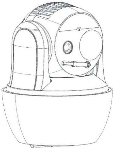
The figure below shows one type of the speed dome series.
natural_image
Line drawing of a mechanical device with a dome-shaped top and circular ports (no text or symbols)Figure 1-1 Overview of Thermal Speed dome
1.2 System Requirement
System requirement of web browser accessing is as follows:
Operating System: Microsoft Windows XP SP1 and above version / Vista / Win7 / Server
2003 / Server 2008 32bits
CPU: Intel Pentium IV 3.0 GHz or higher
RAM: 1G or higher
Display: 1024x 768 resolution or higher
Web Browser: Internet Explorer 8.0 and above version, Apple Safari 5.02 and above version,
Mozilla Firefox 5 and above version and Google Chrome 18 and above versions.
1.3 Functions

The functions vary depending on the models of speed dome.
- Bi-spectrum
The speed dome has two lens, an optical one and a thermal one, and two images are respectively provided by each lens.
- PTZ Limits
The speed dome can be programmed to move within the PTZ limits (left/right, up/down).
- Scan Modes
The speed dome provides 5 scan modes: auto scan, tilt scan, frame scan, random scan and panorama scan.
- Presets
A preset is a predefined image position. When the preset is called, the speed dome will automatically move to the defined position. The presets can be added, modified, deleted and called.
- Label Display
The on-screen label of the preset title, azimuth/elevation, zoom, time and speed dome name can be displayed on the monitor. The displays of time and speed dome name can be programmed.
- Auto Flips
In manual tracking mode, when a target object goes directly beneath the speed dome, the video will automatically flips 180 degrees in horizontal direction to maintain continuity of tracking. This function can also be realized by auto mirror image depending on different camera models.
- Privacy Mask
This function allows you to block or mask certain area of a scene, for preventing the personal privacy from recording or live viewing. A masked area will move with pan and tilt functions and automatically adjust in size as the lens zooms telephoto and wide.
- 3D Positioning
In the client software, use the left key of mouse to click on the desired position in the video image and drag a rectangle area in the lower right direction, then the speed dome will move the position to the center and allow the rectangle area to zoom in. Use the left key of mouse to drag a rectangle area in the upper left direction to move the position to the center and allow the rectangle area to zoom out.
● Proportional Pan/Tilt
Proportional pan/tilt automatically reduces or increases the pan and tilt speeds according to the amount of zoom. At telephoto zoom settings, the pan and tilt speeds will be slower than at wide zoom settings. This keeps the image from moving too fast on the live view image when there is a large amount of zoom.
- Auto Focus
The auto focus enables the camera to focus automatically to maintain clear video images.
● Day/Night Auto Switch
The speed domes deliver color images during the day. And as light diminishes at night, the
speed domes switch to night mode and deliver black and white images with high quality.
- Slow Shutter
In slow shutter mode, the shutter speed will automatically slow down in low illumination conditions to maintain clear video images by extending the exposure time. The feature can be enabled or disabled.
● Backlight Compensation (BLC)
If you focus on an object against strong backlight, the object will be too dark to be seen clearly. The BLC (Backlight Compensation) function can compensate light to the object in the front to make it clear, but this causes the over-exposure of the background where the light is strong.
● Wide Dynamic Range (WDR)
The wide dynamic range (WDR) function helps the camera provide clear images even under back light circumstances. When there are both very bright and very dark areas simultaneously in the field of view, WDR balances the brightness level of the whole image and provide clear images with details.
● White Balance (WB)
White balance can remove the unrealistic color casts. White balance is the white rendition function of the camera to adjust the color temperature according to the environment automatically.
- Patrol
A patrol is a memorized series of pre-defined preset function. The scanning speed between two presets and the dwell time at the preset are programmable.
- Pattern
A pattern is a memorized series of pan, tilt, zoom, and preset functions. By default the focus and iris are in auto status during the pattern is being memorized.
● Power Off Memory
The speed dome supports the power off memory capability with the predefined resume time. It allows the speed dome to resume its previous position after power is restored.
- Scheduled Task
A time task is a preconfigured action that can be performed automatically at a specific date and time. The programmable actions include: auto scan, random scan, patrol 1-8, pattern 1-4, preset 1-8, frame scan, panorama scan, tilt scan, day, night, reboot, PT adjust, Aux Output, etc.
- Park Action
This feature allows the speed dome to start a predefined action automatically after a period of inactivity.
● 3D Digital Noise Reduction
Comparing with the general 2D digital noise reduction, the 3D digital noise reduction function processes the noise between two frames besides processing the noise in one frame. The noise will be much less and the video will be clearer.
Chapter 2 Network Connection
Before you start:
- If you want to set the network speed dome via a LAN (Local Area Network), please refer to Section 2.1.
- If you want to set the network speed dome via a WAN (Wide Area Network), please refer to Section 2.2.
2.1 Setting the Network Speed dome over the LAN
Purpose:
To view and configure the speed dome via a LAN, you need to connect the network speed dome in the same subnet with your computer, and install the SADP or client software to search and change the IP of the network speed dome.

For the detailed introduction of SADP, please refer to Appendix.
2.1.1 Wiring over the LAN
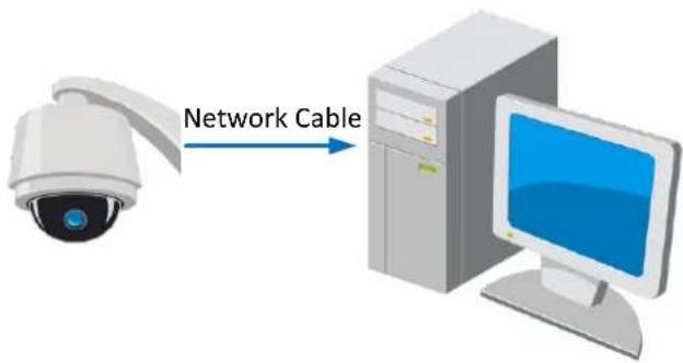
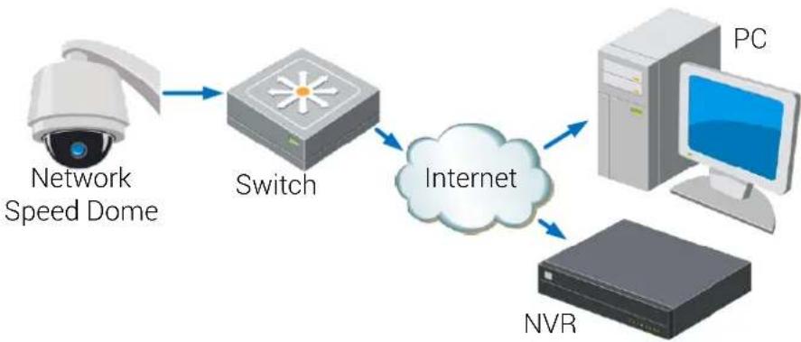
The following figures show the two ways of cable connection of a network speed dome and a computer:
Purpose:
- To test the network speed dome, you can directly connect the network speed dome to the computer with a network cable as shown in Figure 2-1.
- Refer to the Figure 2-2 to set the network speed dome over the LAN via a switch or a router.
text_image
Network CableFigure 2-1 Connecting Directly
flowchart
graph LR
    A["Security Camera"] --> B["Switch"]
    B --> C["Internet"]
    C --> D["PC"]
    C --> E["NVR"]
    F["Network Speed Dome"] --> B
Figure 2-2 Connecting via a Switch or a Router
2.1.2 Activating the Speed dome
Purpose:
You are required to activate the speed dome first before you can use the speed dome.
Activation via Web Browser, Activation via SADP, and Activation via client software are supported. In the following sections, activation via web browser and SADP will be taken as examples. You may refer to the user manual of the speed dome for the details of activation via client software.
◆ Activation via Web Browser
Steps:
- Power on the speed dome, and connect the speed dome to the network.
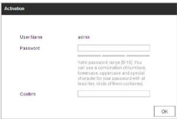
- Input the IP address into the address bar of the web browser, and click Enter to enter the activation interface.

The default IP address of the speed dome is 192.168.1.64.
text_image
Activation User Name admin Password Valid password range [0-16]. You can use a combination of numbers, lowercase, uppercase and special character for your password with at least two kinds of them contained. Confirm OKFigure 2-3 Activation Interface(Web)
- Create a password and input the password into the password field.

STRONG PASSWORD RECOMMENDED-We highly recommend you create a strong password of your own choosing (Using a minimum of 8 characters,
© Hikvision
including at least three of the following categories: upper case letters, lower case letters, numbers, and special characters.) in order to increase the security of your product. And we recommend you reset your password regularly, especially in the high security system, resetting the password monthly or weekly can better protect your product.
-
Confirm the password.
-
Click OK to activate the speed dome and enter the live view interface.
◆ Activation via SADP Software
SADP software is used for detecting the online device, activating the device, and resetting the password.
Get the SADP software from the supplied disk or the official website, and install the SADP according to the prompts. Follow the steps to activate the speed dome.
Steps:
- Run the SADP software to search the online devices.
- Check the device status from the device list, and select an inactive device.
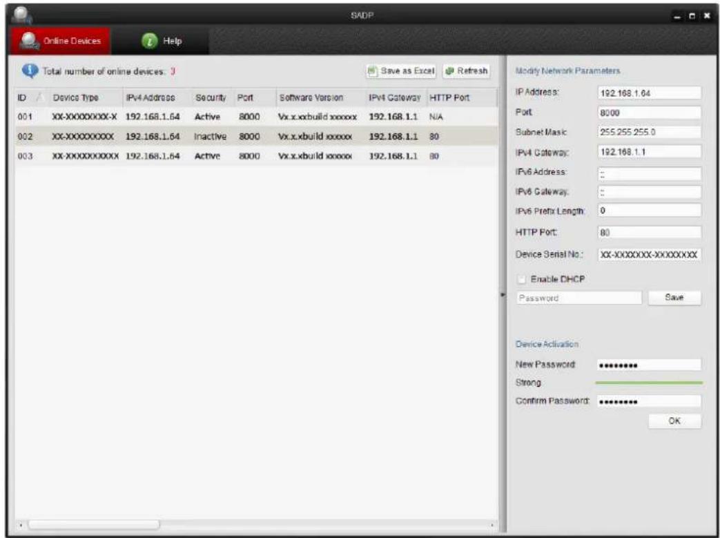
text_image
SADP Online Devices Help Total number of online devices: 3 ID Device Type IPv4 Address Security Port Software Version IPv4 Gateway HTTP Port 001 XX-XXXXXXXX-X 192.168.1.64 Active 8000 Vx.x.xbuild xxxxxx 192.168.1.1 N/A 002 XX-XXXXXXXX 192.168.1.64 Inactive 8000 Vx.x.xbuild xxxxxx 192.168.1.1 80 003 XX-XXXXXXXX 192.168.1.64 Active 8000 Vx.x.xbuild xxxxxx 192.168.1.1 80 Modify Network Parameters IP Address: 192.168.1.64 Port 8000 Subnet Mask: 255.255.255.0 IPv4 Gateway: 192.168.1.1 IPv6 Address: : IPv6 Gateway: : IPv6 Prefix Length: 0 HTTP Port: 80 Device Serial No: XX-XXXXXX-XXXXXXX Enable DHCP Password Save Device Activation New Password ********** Strong Confirm Password ********** OKFigure 2-4 SADP Interface
- Create a password and input the password in the password field, and confirm the password.

STRONG PASSWORD RECOMMENDED-We highly recommend you create a strong password of your own choosing (Using a minimum of 8 characters, including at least three of the following categories: upper case letters, lower case letters, numbers, and special characters.) in order to increase the security of your product. And we recommend you reset your password
regularly, especially in the high security system, resetting the password monthly or weekly can better protect your product.
- Click OK to save the password.
You can check whether the activation is completed on the popup window. If activation failed, please make sure that the password meets the requirement and then try again.
- Change the device IP address to the same subnet with your computer by either modifying the IP address manually or checking the checkbox of Enable DHCP.
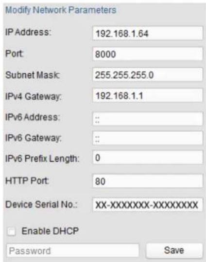
text_image
Modify Network Parameters IP Address: 192.168.1.64 Port: 8000 Subnet Mask: 255.255.255.0 IPv4 Gateway: 192.168.1.1 IPv6 Address: : : IPv6 Gateway: : : IPv6 Prefix Length: 0 HTTP Port: 80 Device Serial No.: XX-XXXXXXXX-XXXXXXXXX Enable DHCP Password SaveFigure 2-5 Modify the IP Address
- Input the password and click Save to activate your IP address modification.
◆ Activation via Client Software
The client software is versatile video management software for multiple kinds of devices. Get the client software from the supplied disk or the official website, and install the software according to the prompts. Follow the steps to activate the camera.
Steps:
- Run the client software and the control panel of the software pops up, as shown in the figure below.
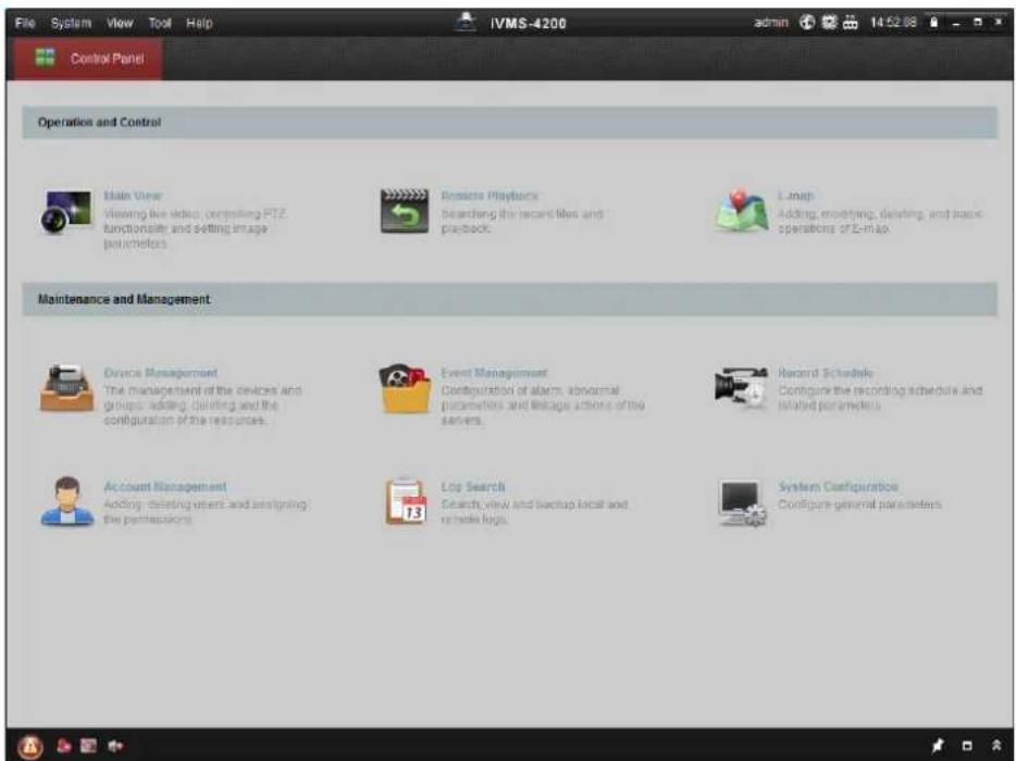
text_image
File System View Tool Help IVMS-4200 admin 14:52:08 Control Panel Operation and Control Main View Viewing live video, controlling PTZ functionality and setting image parameters Recreate Playbacks Searching the recent files and playback. E-mail Adding, mounting, deleting, and basic operations of E-mail Maintenance and Management Device Management The management of the devices and groups, adding, deleting and the configuration of the resources. Event Management Configuration of alarms, abnormal patterns and linkage actions of the servers. Record Schedule Configure the recording schedule and related parameters Account Management Adding, deleting users and assigning the performances Log Search Search, view and backup local and remote logs. System Configuration Configure general parametersFigure 2-6 Control Panel
- Click Device Management to enter the Device Management interface, as shown in the figure below.
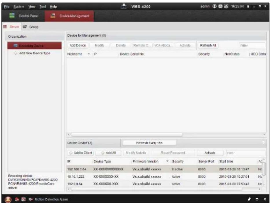
text_image
Device for Management (0) Add Device Modify Delete Remote C VCA Apache Activate Refresh All Filter Nickname IP Device Serial No. Security Net Status HDD Statu Online Device (3) Refresh Every 15s Add to Client Add All Modify Netinfo Reset Password Activate Filter IP Device Type Firmware Version Security Server Port Start time AC 192.168.1.64 XX-XXXXXXXXXX Vx.x.xbuild xxxxxx Inactive 8000 2015-03-20 16:13:47 No 10.16.1.222 XX-XXXXXXXX-XX Vx.x.xbuild xxxxxx Active 8000 2015-03-20 10:27:51 No 192.0.0.64 XX-XXXXXXXX-XXX Vx.x.xbuild xxxxxx Active 8000 2015-03-20 07:53:43 No Encoding device: DVREVISN/RIPCPDVMIS-4200 PCNVRIVMS-4200 EncodeCard server Motion Detection AlarmFigure 2-7 Device Management Interface
- Check the device status from the device list, and select an inactive device.
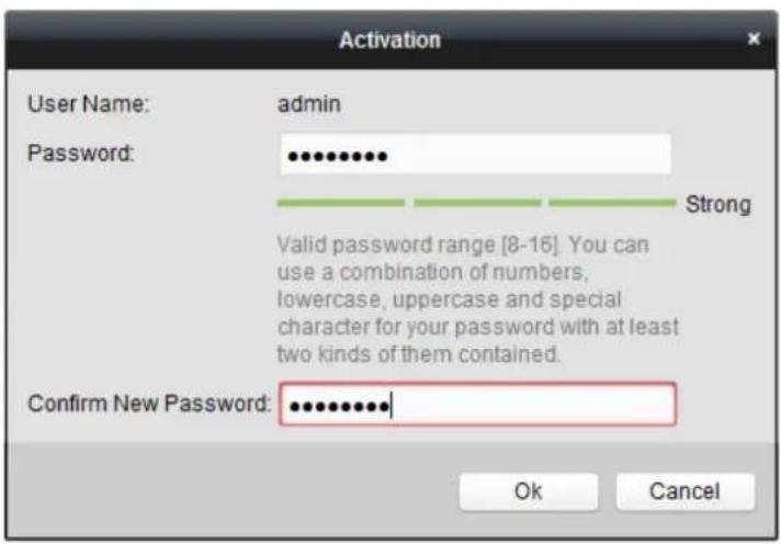
- Click Activate to pop up the Activation interface.
- Create a password and input the password in the password field, and confirm the password.

STRONG PASSWORD RECOMMENDED-We highly recommend you create a strong password of your own choosing (Using a minimum of 8 characters, including at least three of the following categories: upper case letters, lower case letters, numbers, and special characters.) in order to increase the security of your product. And we recommend you reset your password regularly, especially in the high security system, resetting the password monthly or weekly can better protect your product.
text_image
Activation User Name: admin Password: •••••••••• Strong Valid password range [8-16]. You can use a combination of numbers, lowercase, uppercase and special character for your password with at least two kinds of them contained. Confirm New Password: •••••••••••• Ok CancelFigure 2-8 Activation Interface
- Click OK to start activation.
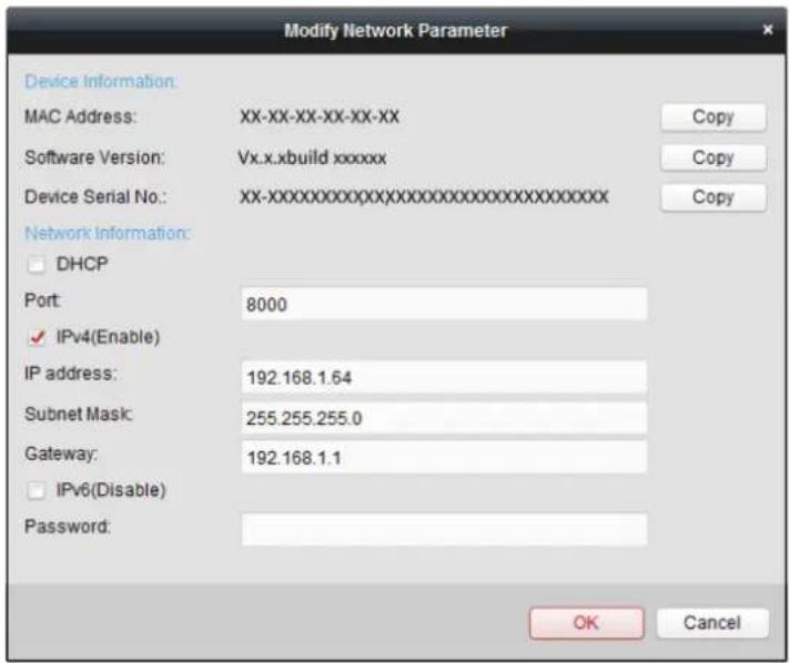
- Click Modify Netinfo to pop up the Network Parameter Modification interface, as shown in the figure below.
text_image
Modify Network Parameter Device Information: MAC Address: XX-XX-XX-XX-XX Software Version: Vx.x.xbuild xxxxxx Device Serial No.: XX-XXXXXXXXXXXXXXXXXXXXXXXXXXXXX Network Information: DHCP Port: 8000 IPv4(Enable) IP address: 192.168.1.64 Subnet Mask: 255.255.255.0 Gateway: 192.168.1.1 IPv6(Disable) Password: OK CancelFigure 2-9 Modifying the Network Parameters
- Change the device IP address to the same subnet with your computer by either modifying the IP address manually or checking the checkbox of Enable DHCP.
- Input the password to activate your IP address modification.
2.2 Setting the Network Speed dome over the WAN
Purpose:
This section explains how to connect the network speed dome to the WAN with a static IP or a dynamic IP.
2.2.1 Static IP Connection
Before you start:
Please apply a static IP from an ISP (Internet Service Provider). With the static IP address, you can connect the network speed dome via a router or connect it to the WAN directly.
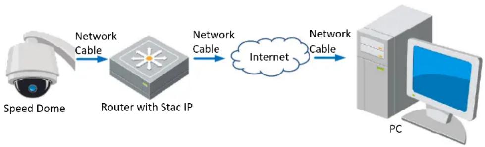
- Connecting the network speed dome via a router
Steps:
- Connect the network speed dome to the router.
- Assign a LAN IP address, the subnet mask and the gateway. Refer to Section 2.1.2 for detailed IP address configuration of the speed dome.
- Save the static IP in the router.
- Set port mapping, E.g., 80, 8000 and 554 ports. The steps for port mapping vary depending on different routers. Please call the router manufacturer for assistance with port mapping.
- Visit the network speed dome through a web browser or the client software over the internet.
flowchart
graph LR
    A["Speed Dome"] -->|Network Cable| B["Router with Stac IP"]
    B -->|Network Cable| C["Internet"]
    C -->|Network Cable| D["PC"]
Figure 2-10 Accessing the Speed dome through Router with Static IP
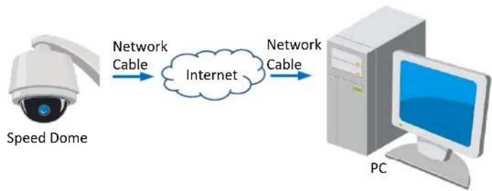
- Connecting the network speed dome with static IP directly
You can also save the static IP in the speed dome and directly connect it to the internet without using a router. Refer to Section 2.1.2 for detailed IP address configuration of the speed dome.
flowchart
graph LR
    A["Speed Dome"] -->|Network Cable| B(Internet)
    B -->|Network Cable| C["PC"]
Figure 2-11 Accessing the Speed dome with Static IP Directly
2.2.2 Dynamic IP Connection
Before you start:
Please apply a dynamic IP from an ISP. With the dynamic IP address, you can connect the network speed dome to a modem or a router.
- Connecting the network speed dome via a router
Steps:
- Connect the network speed dome to the router.
- In the speed dome, assign a LAN IP address, the subnet mask and the gateway. Refer to Section 2.1.2 for detailed LAN configuration.
- In the router, set the PPPoE user name, password and confirm the password.

- For your privacy and to better protect your system against security risks, we strongly recommend the use of strong passwords for all functions and network devices. The password should be something of your own choosing (using a minimum of 8 characters, including upper case letters, lower case letters, numbers and special characters) in order to increase the security of your product.
-
Proper configuration of all passwords and other security settings is the responsibility of the installer and/or end-user.
-
Set port mapping. E.g. 80, 8000 and 554 ports. The steps for port mapping vary depending on different routers. Please call the router manufacturer for assistance with port mapping.
-
Apply a domain name from a domain name provider.
-
Configure the DDNS settings in the setting interface of the router.
-
Visit the speed dome via the applied domain name.
- Connecting the network speed dome via a modem
Purpose:
This speed dome supports the PPPoE auto dial-up function. The speed dome gets a public IP address by ADSL dial-up after the speed dome is connected to a modem. You need to configure the PPPoE parameters of the network speed dome. Refer to Section 7.1.1 Configuring PPPoE Settings for detailed configuration.

flowchart
graph LR
    A["Speed Dome"] -->|Network Cable| B["Modem"]
    B -->|Network Cable| C["Internet"]
    C -->|Network Cable| D["Computer"]
Figure 2-12 Accessing the Speed dome with Dynamic IP

The obtained IP address is dynamically assigned via PPPoE, so the IP address always changes after rebooting the speed dome. To solve the inconvenience of the dynamic IP, you need to get a domain name from the DDNS provider (E.g. DynDns.com). Please follow below steps for normal domain name resolution and private domain name resolution to solve the problem.
♦ Normal Domain Name Resolution
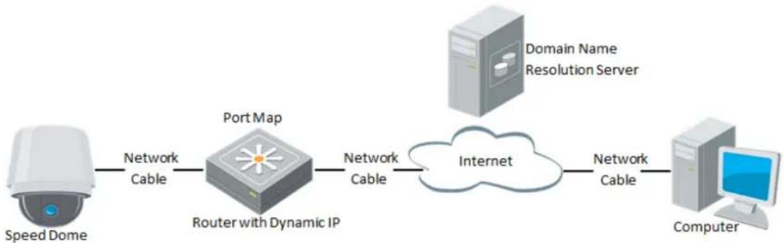
flowchart
graph LR
    A["Speed Dome"] -->|Network Cable| B["Port Map"]
    B -->|Network Cable| C["Internet"]
    D["Domain Name Resolution Server"] --> C
    C -->|Network Cable| E["Computer"]
    B -->|Router with Dynamic IP| B
Figure 2-13 Normal Domain Name Resolution
Steps:
- Apply a domain name from a domain name provider.
- Configure the DDNS settings in the DDNS Settings interface of the network speed dome. Refer to Section 7.1.1 Configuring DDNS Settings for detailed configuration.
- Visit the speed dome via the applied domain name.
◆ Private Domain Name Resolution
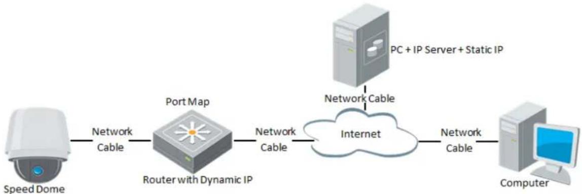
flowchart
graph LR
    A["Speed Dome"] -->|Network Cable| B["Port Map"]
    B -->|Network Cable| C["Internet"]
    C -->|Network Cable| D["PC + IP Server + Static IP"]
    C -->|Network Cable| E["Computer"]
Figure 2-14 Private Domain Name Resolution
Steps:
- Install and run the IP Server software in a computer with a static IP.
- Access the network speed dome through the LAN with a web browser or the client software.
- Enable DDNS and select IP Server as the protocol type. Refer to Section 7.1.1 Configuring DDNS Settings for detailed configuration.
Chapter 3 Access to the Network Speed dome
3.1 Accessing by Web Browsers
Steps:
- Open the web browser.
- In the address field, input the IP address of the network speed dome, e.g., 192.168.1.64 and press the Enter key to enter the login interface.
- Activate the speed dome for the first time using, refer to the section 2.1.2 Activating the Speed dome.
-
Select English as the interface language on the top-right of login interface.
-
Input the user name and password and click

The admin user should configure the device accounts and user/operator permissions properly. Delete the unnecessary accounts and user/operator permissions.

The device IP address gets locked if the admin user performs 7 failed password attempts (5 attempts for the user/operator).
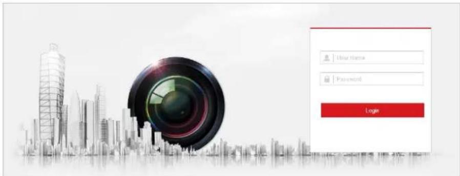
text_image
User Name Password LoginFigure 3-1 Login Interface
- Install the plug-in before viewing the live video and operating the speed dome. Please follow the installation prompts to install the plug-in.

You may have to close the web browser to install the plug-in. Please reopen the web browser and log in again after installing the plug-in.
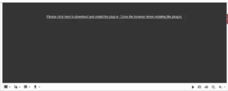
text_image
Please click here to download and install the plug-in. Close the browser when installed the plug-in.Figure 3-2 Download and Install Plug-in
3.2 Accessing by Client Software
The product CD contains the client software. You can view the live video and manage the speed dome with the client software.
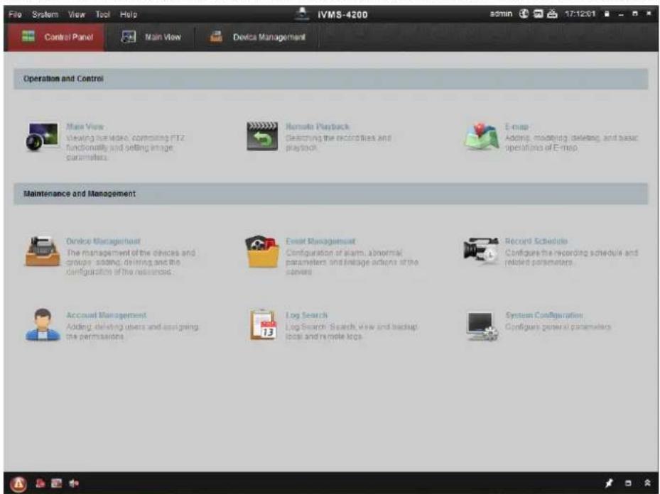
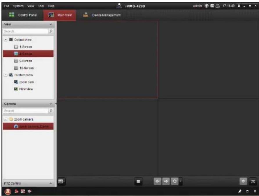
Follow the installation prompts to install the client software and WinPcap. The configuration interface and live view interface of client software are shown below.
text_image
File System View Tool Help IVMS-4200 semin 17:12:01 Control Panel Main View Device Management Operation and Control Main View Viewing the video, computing PTZ functionality and setting image parameters. Remote Playback Searching the record files and playback. E-mail: Adding, modeling, deleting, and basic operations of E-mail Maintenance and Management Device Managerheet The management of the devices and groups, adding, delivering and the configuration of the resources. Event Management Configuration of alarm, abnormal parameters and linkage agents of the screens. Record Schedule Configure the recording schedule and related parameters Account Management Adding, delivering users and assigning the permissions. Log Search Log Search - Search view and backup, local and remote logs. System Configuration Configure general parametersFigure 3-3 iVMS-4200 Control Panel
text_image
File System View Tool Help Control Panel Main View Device Management View Search Default View 1-Screen 4-Screen 9-Screen 16-Screen Custom View zoom cam New View Camera Search zoom camera zoom camera_Games PTZ ControlFigure 3-4 iVMS-4200 Live View Interface
NOTE
- If you use third party VMS software, please contact technical support of our branch for camera firmware.
- For detailed information about client software of our company, please refer to the user manual of the software. This manual mainly introduces accessing to the network speed dome by web browser.
Chapter 4 Basic Operations
In this and the following chapters, operation of the speed dome by the web browser will be taken as an example.
4.1 Configuring Local Parameters

The local configuration refers to the parameters of the live view and other operations using the web browser.
Steps:
- Enter the Local Configuration interface:
Configuration > Local

text_image
Live View Parameters Protocol TCP UDP MULTICAST HTTP Play Performance Shortest Delay Auto Rules Enable Disable Image Format JPEG BMP Record File Settings Record File Size 256M 512M 1G Save record files to Browse Open Save downloaded files to Browse Open Picture and Clip Settings Save snapshots in live view to Browse Open Save snapshots when playback to Browse Open Save clips to Browse Open SaveFigure 4-1 Local Configuration Interface
- Configure the following settings:
- Live View Parameters: Set the protocol type, play performance, rules and image format.
◆ Protocol Type: TCP, UDP, MULTICAST and HTTP are selectable.
TCP: Ensures complete delivery of streaming data and better video quality, yet the real-time transmission will be affected.
UDP: Provides real-time audio and video streams.
MULTICAST: It's recommended to select the protocol type to MULTICAST when using the Multicast function.
HTTP: Allows the same quality as of TCP without setting specific ports for streaming under some network environments.
◆ Play Performance: Set the play performance to Shortest Delay, or Auto.
◆ Rules: You can enable or disable the rules of dynamic analysis for motion here.
◆ Image Format: The captured pictures can be saved as different format. JPEG and BMP are available.
- Record File Settings: Set the saving path of the video files.
Record File Size: Select the packed size of manually recorded and downloaded video files. The size can be set to 256M, 512M or 1G.
◆ Save record files to: Set the saving path for the manually recorded video files.
◆ Save downloaded files to: Set the saving path for the downloaded video files in
interface.
- Picture and Clip Settings: Set the saving paths of the captured pictures and clipped video files.
◆ Save snapshots in live view to: Set the saving path of the manually captured
pictures in
Live View interface
◆ Save snapshots when playback to: Set the saving path of the captured pictures in
Playback
interface.
- Save clips to: Set the saving path of the clipped video files in interface.

- You can click Browse to change the directory for saving video files, clips and pictures.
-
You can click Open to directly open the video files, clips and pictures.
-
Click to save the settings.
4.2 Live View Page
Purpose:
The live video page allows you to view live video, capture images, realize PTZ control, set/call presets and configure video parameters.
Log in the network speed dome to enter the live view page, or you can click Live View on the menu bar of the main page to enter the live view page.
Descriptions of the live view page:
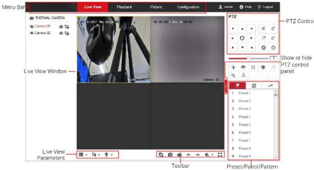
text_image
Menu Bar THERMAL CAMERA Camera 01 Camera 02 Live View Window PTZ Control Show or hide PTZ control panel Live View Parameters Toolbar Preset/Palrol/PatternFigure 4-2 Live View Page
Menu Bar:
Click each tab to enter Live View, Playback, Picture, and Configuration page respectively.
Click to display the help file of the speed dome.
Click to logout the system.
Live View Window:
Display the live video.
Toolbar:
Operations on the live view page, e.g., live view, capture, record, audio on/off, regional exposure, regional focus, etc.
PTZ Control:
Panning, tilting, focusing and zooming actions of the speed dome. The lighter, wiper, one-touch focus and lens initialization control.
Preset/patrol/pattern:
Set and call the preset/patrol/pattern for the speed dome.

Pattern function varies depending on the models of speed dome.
Live View Parameters:
Configure the image size, stream type, plug-in type, and two-way audio of the live video.
4.3 Starting Live View
In the live view window as shown in Figure 4-3, click ▶ on the toolbar to start the live view of the speed dome.
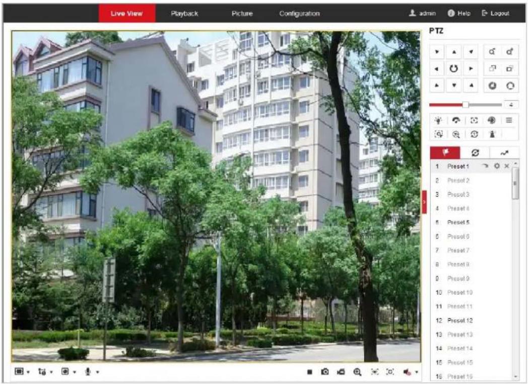
text_image
Live View Playback Picture Configuration admin Help Logout PTZ 1 Preset 1 2 Preset 2 3 Preset 3 4 Preset 4 5 Preset 5 6 Preset 6 7 Preset 7 8 Preset 8 9 Preset 9 10 Preset 10 11 Preset 11 12 Preset 12 13 Preset 13 14 Preset 14 15 Preset 15 16 Preset 16Figure 4-3 Start Live View
Table 4-1 Descriptions of the Toolbar
| Icon | Description | Icon | Description |
 | Start/Stop Live view. | Manually capture the pictures. | |
  | Display in 4:3/16:9/original/Self-adaptive window size. | Live view with the main/sub/third stream. | |
 | Play via webcomponents/quick time. | Start/Stop Two-way Audio. | |
 | Manual start/stop recording. | Mute/Audio on and adjust volume | |
 | Start/stop digital zoom. | Enable/Disable Regional Exposure | |
 | Enable / Disable Regional Focus |
- Double-click on the live video to switch the current live view into full-screen or return to normal mode from the full-screen.
- Click □ to select from 4:3 16:9 1× and display live video in 4:3/16:9/original/self-adaptive window size.
- Click t_0^ to select from t_0^ and display live video with the main/sub/third stream. The main stream is with a relatively high resolution and needs much bandwidth. The default setting of stream type is .
- Click to select between and play the live video via player Webcomponents or Quick Time. The live video is played via webcomponents by default, and other types of players are supported for the browser, such as MJPEG, and VLC. You are required to download and install the player to play the live video.
- Click 🖼 and it displays 🔒. Click 🔒 to enable two-way audio and the icon turns into .Click the icon again to stop two-way audio.
- Click ▶ to start live view and the icon turns into ■. Click the icon again to stop live view.
- Click to capture the picture.
- Click ➤ to start recording and the icon turns into ➤. Click the icon again to stop recording.
- Click 📍 to enable digital zoom function and the icon turns into 🔒. Then click and drag the mouse towards low right direction to draw a rectangle on the image as the desired zoom. After viewing it you can click any place of the picture to get back to normal picture.
- Click the 🧑️ on the toolbar to enter the regional exposure operation mode and the icon turns into . Then click and drag the mouse to draw a rectangle on the image as the desired exposure region.
- Click the 📋 on the toolbar to enter the regional focus operation mode and the icon turns into . Then click and drag the mouse to draw a rectangle on the image as the desired focus region.
- Click to display the . Drag the slider to adjust the volume.

Before using the two-way audio or recording with audio functions, please set the Stream Type to Video & Audio referring to Section 7.2.1 Configuring Video Settings.
Please refer to the following sections for more information:
- Configuring remote recording in Section 5.1.1 Configuring Recording Schedule.
- Setting the image quality of the live video in Section 7.4 Configuring Image Settings.
● and Section 7.2.1 Configuring Video Settings. - Setting the OSD text on live video in Section 7.4.2 Configuring OSD Settings.
4.4 Operating PTZ Control
Purpose:
In the live view interface, you can use the PTZ control buttons to control panning, tilting and zooming.
4.4.1 PTZ Control Panel
On the live view page, click < to show the PTZ control panel or click > to hide it. Click the direction buttons to control the pan/tilt movements. Click the zoom/iris/focus buttons to realize lens control.
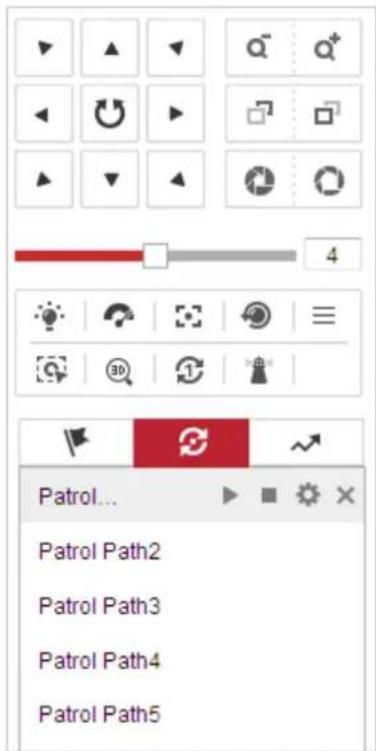
text_image
Patrol... Patrol Path2 Patrol Path3 Patrol Path4 Patrol Path5Figure 4-4 PTZ Control Panel
Table 4-2 Descriptions of PTZ Control Panel
| Button | Name | Description |
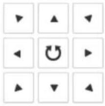 | PTZ Control Panel | Hold and press the direction button to pan/tilt the speed dome.Click and the speed dome keeps panning, the icon turns intoClick the icon again to stop the speed dome. |
 | Zoom out/in | Click , the lens zooms in, click , and the lens zooms out. |
 | Focus near/far | Click , the lens focus far and the items far away gets clear. Click , the lens focus near and the items nearby gets clear. |
 | Iris close/open | When the image is too dark, click to open the iris. When the image is too bright, click to close the iris. |
 | Auxiliary Functions | The auxiliary functions include light, wiper, auxiliary focus, lens initialization, manual tracking, 3D positioning, one-touch patrol, and one-touch park. |
 | Speed Adjustment | Adjust speed of pan/tilt movements. |
| Source1 | Preset | Refer to 4.4.3 for detailed information of setting preset. |
| Source2 | Patrol | Refer to 4.4.4 for detailed information of setting patrol. |
| Source3 | Pattern | Refer to4.4.6 for detailed information of setting pattern. |
- Buttons on the Preset/Patrol/Patterns interface:
Table 4-3 Descriptions of Buttons
| Buttons | Description |
| Start the selected patrol/pattern. | |
| Stop current patrol/pattern. | |
| Set the selected preset/patrol. | |
| × | Delete the selected preset/patrol/pattern. |
| Start recording a pattern. | |
| Stop recording the pattern. |
4.4.2 Auxiliary Functions
The Auxiliary functions panel is shown in the figure below:
text_image
Toolbar with icons for lighting, weather, refresh, and email servicesFigure 4-5 Auxiliary Functions
• Light
Click to enable/disable the light supplement of the speed dome. This function is reserved.
• Wiper
Click to move the wiper once.
- Auxiliary Focus
The auxiliary focus function is reserved.
• 燃
Click to enable manual De-Icing function of the device.

The de-icing function takes effect when the device inner temperature is ≤ 30°C (86°F).
- Manual Tracking
Before you start:
Please enter the Smart Tracking settings interface and enable smart tracking first.
Configuration > PTZ > Smart Tracking
Steps:
-
Click 📋 on the toolbar of live view interface.
-
Click a moving object in the live video. The speed dome will track the object automatically.
- 3D Positioning
Steps:
-
Click 30 on the toolbar of live view interface.
-
Operate the 3D positioning function:
-
Click a position of the live video. The corresponding position will be moved to the center of the live video.
-
Hold down the left mouse button and drag the mouse to the lower right on the live video. The corresponding position will be moved to the center of the live video and zoomed in.
-
Hold down the left mouse button and drag the mouse to the upper left on the live video. The corresponding position will be moved to the center of the live video and zoomed out.
- One-touch Patrol
Click to call one-touch patrol. For detailed information of setting one-touch patrol, refer to 4.4.5 One-touch Patrol.
- One-touch Park
Click to save the current view as the preset No. 32 and start park at the the current position.
4.4.3 Setting / Calling a Preset
Purpose:
A preset is a predefined image position. For the defined preset, you can click the calling button to quickly view the desired image position.
- Setting a Preset:
Steps:
- In the PTZ control panel, select a preset number from the preset list.
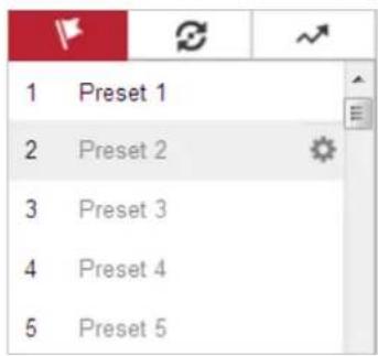
text_image
1 Preset 1 2 Preset 2 3 Preset 3 4 Preset 4 5 Preset 5Figure 4-6 Setting a Preset
-
Use the PTZ control buttons to move the lens to the desired position.
-
Pan the speed dome to the right or left.
- Tilt the speed dome up or down.
- Zoom in or out.
-
Refocus the lens.
-
Click ⚙ to finish the setting of the current preset.
- Edit a preset name by double clicking on the default name such as preset 1. (The pre-defined presets are named already and not configurable. Please refer to the user manual for detailed function description.)
- You can click to delete the preset.

You can configure up to 256 presets.
- Calling a Preset:
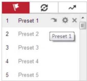
In the PTZ control panel, select a defined preset from the list and click to call the preset.
text_image
1 Preset 1 2 Preset 2 Preset 1 3 Preset 3 4 Preset 4 5 Preset 5Figure 4-7 Calling a Preset
For convenient preset selection, refer to the following steps to navigate to the preset you want.
Steps:
- Select any preset from the list.
- Click the preset number you need on the keyboard.

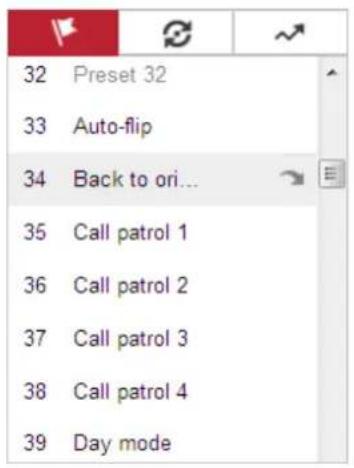
- The following presets are predefined with special commands. You can only call them but not configure them. For instance, preset 99 is the "Start auto scan". If you call the preset 99, the speed dome starts auto scan function.
● Pattern function varies depending on the models of speed dome.
Table 4-4 Special Presets
| Preset | Function | Preset | Function |
| 33 | Auto flip | 92 | Start to set limit stops |
| 34 | Back to initial position | 93 | Set limit stops manually |
| 35 | Call patrol 1 | 94 | Remote reboot |
| 36 | Call patrol 2 | 95 | Call OSD menu |
| 37 | Call patrol 3 | 96 | Stop a scan |
| 38 | Call patrol 4 | 97 | Start random scan |
| 39 | Day mode (IR cut filter in) | 98 | Start frame scan |
| 40 | Night mode (IR cut filter out) | 99 | Start auto scan |
| 41 | Call pattern 1 | 100 | Start tilt scan |
| 42 | Call pattern 2 | 101 | Start panorama scan |
| 43 | Call pattern 3 | 102 | Call patrol 5 |
| 44 | Call pattern 4 | 103 | Call patrol 6 |
| 45 | One-touch Patrol | 104 | Call patrol 7 |
| 90 | Wiper | 105 | Call patrol 8 |
text_image
32 Preset 32 33 Auto-flip 34 Back to ori... 35 Call patrol 1 36 Call patrol 2 37 Call patrol 3 38 Call patrol 4 39 Day modeFigure 4-8 Special Preset

You may need to use the OSD (On Screen Display) menu when controlling the speed dome remotely. To display the OSD menu on the live view screen, you can call the preset number 95.
4.4.4 Setting / Calling a Patrol
Purpose:
A patrol is a memorized series of preset function. It can be configured and called on the patrol settings interface. There are up to 8 patrols for customizing. A patrol can be configured with 32 presets.
Before you start:
Please make sure that the presets you want to add into a patrol have been defined.
- Setting a Patrol:
Steps:
- In the PTZ control panel, click 🔒 to enter the patrol settings interface.
- Select a patrol number from the list and click
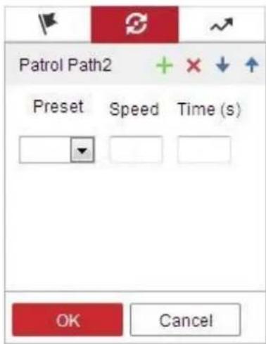
- Click + to enter the adding interface of preset, as shown in Figure 4-9.
text_image
Patrol Path2 Preset Speed Time (s) OK CancelFigure 4-9 Adding Presets
- Configure the preset number, patrol time and patrol speed.
| Name | Description |
| Patrol Time | It is the duration staying on one patrol point. The speed dome moves to another patrol point after the patrol time. |
| Patrol Speed | It is the speed of moving from one preset to another. |
- Click OK to save a preset into the patrol.
- Repeat the steps from 3 to 5 to add more presets.
- Click OK to save all the patrol settings.
- Calling a Patrol:
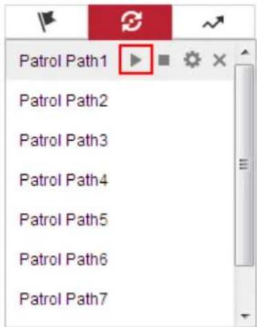
In the PTZ control panel, select a defined patrol from the list and click to call the patrol, as shown in Figure 4-10.
text_image
Patrol Path1 Patrol Path2 Patrol Path3 Patrol Path4 Patrol Path5 Patrol Path6 Patrol Path7Figure 4-10 Calling a Preset
4.4.5 One-touch Patrol
Purpose:
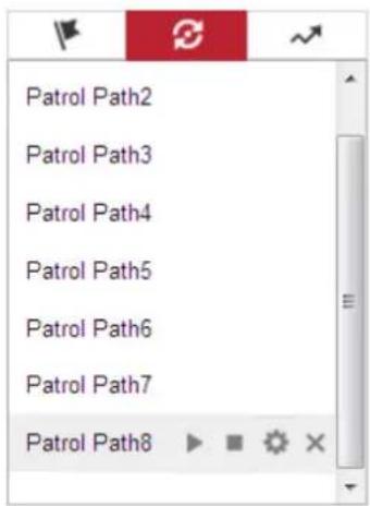
One-touch patrol is an automatically created patrol. The system automatically add preset No.1 to No.32 to the patrol path 8. You can call the one-touch patrol and the speed dome moves as the patrol path 8 automatically.
Steps:
-
Set preset No.1 to No.32. Refer to 4.4.3 Setting / Calling a Preset for detailed information of setting preset.
-
Call preset No. 45, and the speed dome moves as patrol path 8.
-
Click to enter the patrol settings interface and start/stop one-touch patrol, edit the patrol time and the speed.
-
You can click 📋 of the PTZ control panel to start one-touch patrol.
text_image
Patrol Path2 Patrol Path3 Patrol Path4 Patrol Path5 Patrol Path6 Patrol Path7 Patrol Path8Figure 4-11 Patrol Path 8
4.4.6 Setting / Calling a Pattern
Purpose:
A pattern is a memorized series of pan, tilt, zoom, and preset functions. It can be called on the pattern settings interface. There are up to 4 patterns for customizing.

Pattern function varies depending on speed dome models.
- Setting a Pattern:
Steps:
-
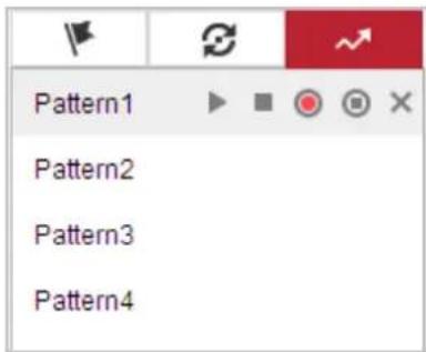
In the PTZ control panel, click → to enter the pattern settings interface.
-
Select a pattern number from the list as shown in Figure 4-12.
text_image
Pattern1 Pattern2 Pattern3 Pattern4Figure 4-12 Patterns Settings Interface
3. Click ☐ to enable recording the panning, tilting and zooming actions.
4. Use the PTZ control buttons to move the lens to the desired position after the information of PROGRAM PATTERN REMAINNING MEMORY(%) is displayed on the screen.
- Pan the speed dome to the right or left.
● Tilt the speed dome up or down.
- Zoom in or out.
- Refocus the lens.
- Click to save all the pattern settings.
- Buttons on the Patterns interface:
| Buttons | Description |
| Start the selected patrol/pattern. | |
| Stop current patrol/pattern. | |
| Set the selected preset/patrol. | |
| × | Delete the selected preset/patrol/pattern. |
| Start recording a pattern. | |
| Stop recording the pattern. |

● These 4 patterns can be operated separately and with no priority level.
- When configuring and calling the pattern, proportional pan is valid; the limit stops and auto flip will be invalid; and the 3D positioning operation is not supported.
4.5 Playback
Purpose:
This section explains how to view the video files stored in the network disks or memory cards.
4.5.1 Play Back Video Files
Steps:
Playback
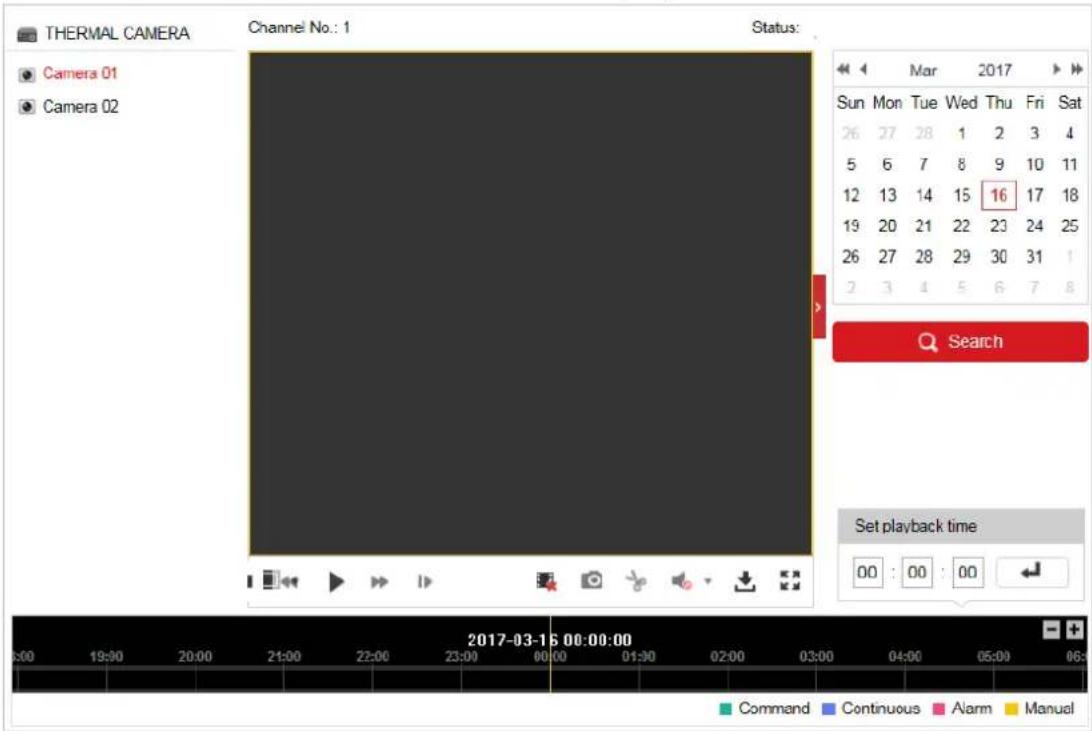
1. Click 📋 Playback on the menu bar to enter playback interface.
text_image
THERMAL CAMERA Camera 01 Camera 02 Channel No.: 1 Status: Mar 2017 Sun Mon Tue Wed Thu Fri Sat 26 27 28 1 2 3 4 5 6 7 8 9 10 11 12 13 14 15 16 17 18 19 20 21 22 23 24 25 26 27 28 29 30 31 1 2 3 4 5 6 7 8 Search Set playback time 00 : 00 : 00 Command Continuous Alarm Manual 2017-03-16 00:00:00Figure 4-13 Playback Interface
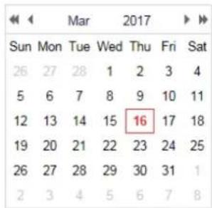
2. Select the date and click .
Search
text_image
Mar 2017 Sun Mon Tue Wed Thu Fri Sat 26 27 28 1 2 3 4 5 6 7 8 9 10 11 12 13 14 15 16 17 18 19 20 21 22 23 24 25 26 27 28 29 30 31 1 2 3 4 5 6 7 8Figure 4-14 Search Video
3. Click ▶ to play the video files found on this date.
The toolbar on the bottom of Playback interface can be used to control playing process.

text_image
Media playback control bar with playback buttons and media iconsFigure 4-15 Playback Toolbar
Table 4-5 Description of the buttons
| Button | Operation | Button | Operation |
| Play | Capture a picture | ||
| Pause | Start/Stop clipping video files | ||
| Stop | Audio on and adjust volume/Mute | ||
| Speed down | Download | ||
| Speed up | Playback by frame | ||
| Enable/Disable digital zoom |
NOTE
You can choose the file paths locally for downloaded playback video files and pictures in Local Configuration interface. Please refer to Section 4.1 Configuring Local Parameters for details.
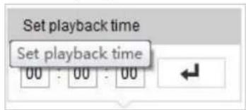
Drag the progress bar with the mouse to locate the exact playback point. You can also input the time and click ← to locate the playback point in the Set playback time field. You can also click to zoom out/in the progress bar.
text_image
Set playback time Set playback time 00 : 00 : 00Figure 4-16 Set Playback Time

text_image
2015-06-15 05:34:54 03:00 04:00 05:00 06:00 07:00 08:00 09:00Figure 4-17 Progress Bar
The different colors of the video on the progress bar stand for the different video types as shown in Figure 4-18.

Figure 4-18 Video Types
4.5.2 Downloading Video Files
Steps:
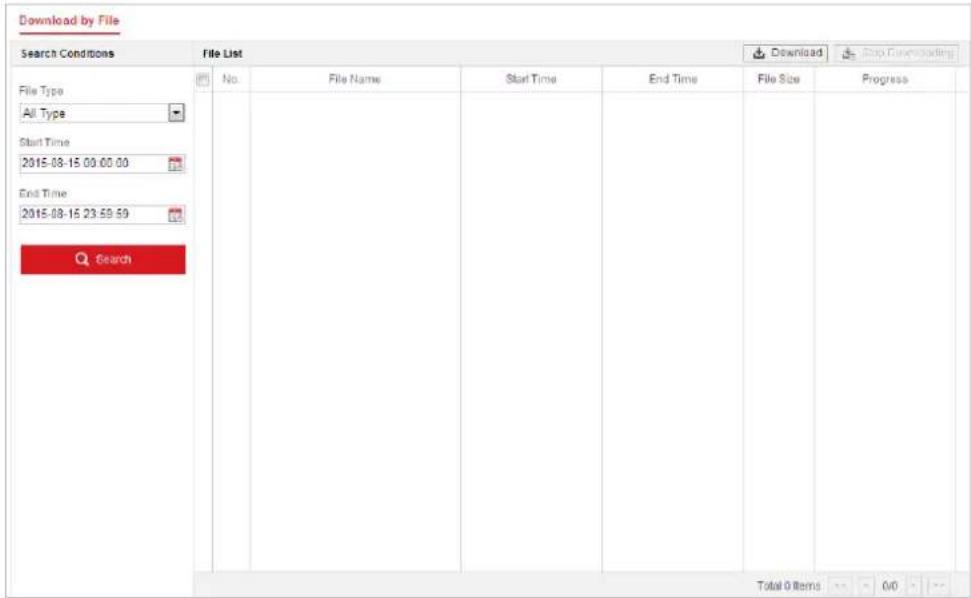
- Click ↓ on the playback interface. The pop-up menu is shown in Figure 4-19.
- Set the start time and end time. Click Search. The corresponding video files are listed on the left.
text_image
Download by File Search Conditions File List File Type All Type Start Time 2015-08-15 00:00:00 End Time 2015-08-15 23:59:59 Search No. File Name Start Time End Time File Size Progress Total 0 Items 0/0Figure 4-19 Video Downloading interface
-
Check the checkbox in front of the video files that you need to download.
-
Click to download the video files.
4.6 Pictures
Purpose:
This section explains how to view the captured picture files stored in the network disks or the memory cards and download the captured pictures.
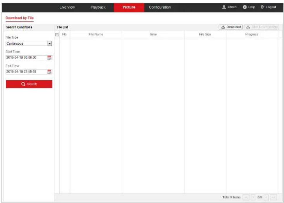
Steps:
- Click on the menu bar to enter picture interface.
text_image
Download by File Search Conditions File List File Type Continuous Start Time 2016-04-18 00:00:00 End Time 2016-04-18 23:59:59 Search No. File Name Time File Size Progress Total 0 Items 0/0Figure 4-20 Picture Interface
- Select the file type of capturing the pictures from the list as timing, alarm, motion, etc.
- Set the start time and end time. Click Search. The corresponding picture files will be listed.
- Check the checkbox in front of the files that you need to download.
- Click to download the files.
Chapter 5 System Configuration
5.1 Storage Settings
Before you start:
To configure record settings, please make sure that you have the network storage device within the network or the memory card inserted in your speed dome.
5.1.1 Configuring Recording Schedule
Purpose:
There are two kinds of recording for the speed domes: manual recording and scheduled recording. In this section, you can follow the instructions to configure the scheduled recording. By default, the record files of scheduled recording are stored in the memory card (if supported) or in the network disk.
Steps:
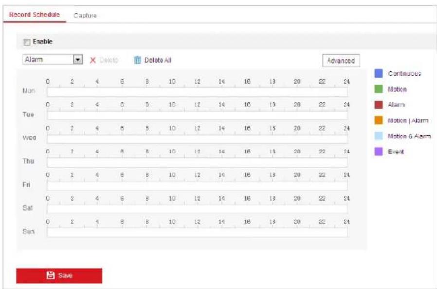
- Enter the Record Schedule settings interface:
Configuration > Storage > Schedule Settings > Record Schedule
text_image
Record Schedule Capture Enable Alarm Delete Delete All Advanced Continuous Motion Alarm Motion | Alarm Motion & Alarm Event Mon 0 2 4 6 9 10 12 14 16 18 20 22 24 Tue 0 2 4 6 9 10 12 14 16 18 20 22 24 Wed 0 2 4 6 9 10 12 14 16 18 20 22 24 Thu 0 2 4 6 9 10 12 14 16 18 20 22 24 Fri 0 2 4 6 9 10 12 14 16 18 20 22 24 Sat 0 2 4 6 9 10 12 14 16 18 20 22 24 Sun 0 2 4 6 9 10 12 14 16 18 20 22 24 SaveFigure 5-1 Recording Schedule Interface
-
Check the checkbox of Enable to enable scheduled recording.
-
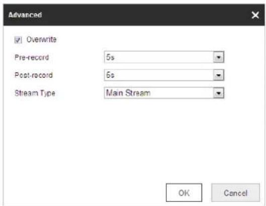
To set the advanced settings of the speed dome, click Advanced to enter the advanced settings interface.
text_image
Advanced ✓ Overwrite Pre-record 5s Post-record 5s Stream Type Main Stream OK CancelFigure 5-2 Record Parameters
- Pre-record: The time you set to start recording before the scheduled time or the event. For example, if an alarm triggers recording at 10:00, and the pre-record time is set as 5 seconds, the speed dome starts to record at 9:59:55.
The Pre-record time can be configured as No Pre-record, 5 s, 10 s, 15 s, 20 s, 25 s, 30 s or not limited.

The pre-record time changes according to the video bitrate.
- Post-record: The time you set to stop recording after the scheduled time or the event. For example, if an alarm triggered recording ends at 11:00, and the post-record time is set as 5 seconds, the speed dome records until 11:00:05. The Post-record time can be configured as 5 s, 10 s, 30 s, 1 min, 2 min, 5 min or 10 min.
- Stream Type: You can select the stream type for recording; Main Stream, Sub Stream and Third Stream are selectable. If you select the sub stream, you can record for a longer time with the same storage capacity.

The Pre-record and Post-record parameters vary depending on the models of speed dome.
-
Click OK to save the advanced setting.
-
Select a Record Type. The record type can be Continuous, Motion, Alarm, Motion | Alarm, Motion & Alarm, and Event.
- Normal: If you select Continuous, the video will be recorded automatically according to the time of the schedule.
- Record Triggered by Motion Detection: If you select Motion, the video will be recorded when the motion is detected. Besides configuring the recording schedule, you have to set the motion detection area and check the checkbox of Trigger Channel in the Linkage Method of Motion Detection settings interface. For detailed information, please refer to Section Motion Detection.
- Record Triggered by Alarm: If you select Alarm, the video will be recorded when the alarm is triggered via the external alarm input channels. Besides configuring the recording schedule, you have to set the Alarm Type and check the checkbox of
Trigger Channel in the Linkage Method of Alarm Input settings interface. For detailed information, please refer to Section Alarm Input.
- Record Triggered by Motion & Alarm: If you select Motion & Alarm, the video will be recorded when the motion and alarm are triggered at the same time. Besides configuring the recording schedule, you have to configure the settings on the Motion Detection and Alarm Input settings interfaces.
- Record Triggered by Motion | Alarm: If you select Motion | Alarm, the video will be recorded when the external alarm is triggered or the motion is detected. Besides configuring the recording schedule, you have to configure the settings on the Motion Detection and Alarm Input settings interfaces.
- Record Triggered by VCA events: If you select VCA, the video will be recorded when the either of the VCA events is triggered. Besides configuring the recording schedule, you have to configure the settings on the VCA interface.

VCA function varies depending on the models of speed dome.
- Record Triggered by Event: If you select to record by event, the video will be recorded when any of the events is triggered.
- Click

5.1.2 Configuring Capture Schedule
Purpose:
You can configure the scheduled snapshot and event-triggered snapshot. The captured picture can be stored in the local storage or network storage.
Steps:
- Enter the Snapshot settings interface:
Configuration > Storage > Storage Settings > Capture
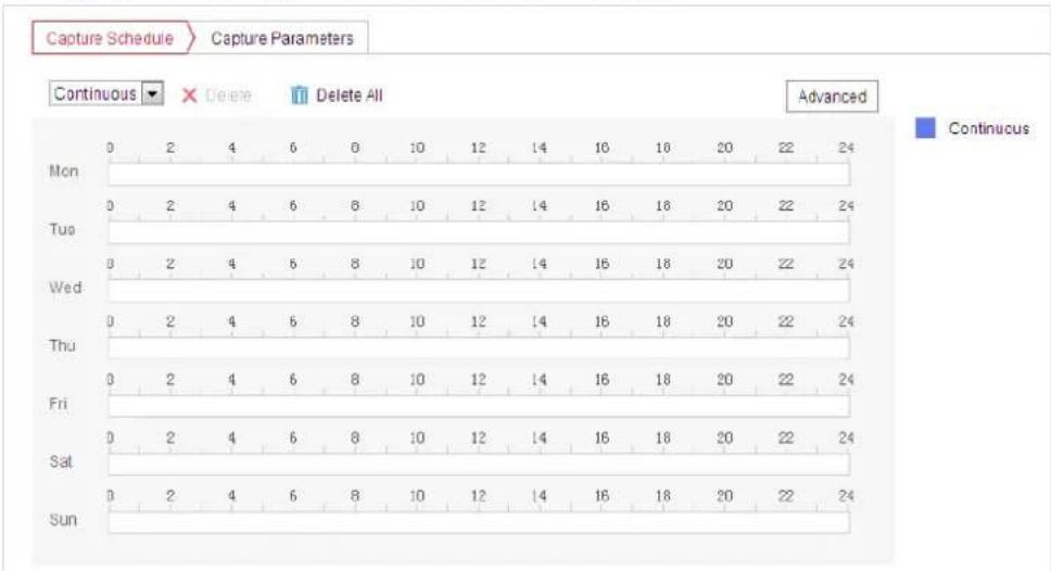
line
Capture Schedule Capture Parameters | Day | Start Time (s) | End Time (s) | |---|---|---| | Mon | 0 | 2 | | Mon | 2 | 4 | | Mon | 6 | 6 | | Mon | 0 | 0 | | Mon | 10 | 12 | | Mon | 14 | 14 | | Mon | 18 | 18 | | Mon | 20 | 20 | | Mon | 22 | 22 | | Mon | 24 | 24 | | Tue | 0 | 2 | | Tue | 2 | 4 | | Tue | 6 | 6 | | Tue | 8 | 8 | | Tue | 10 | 10 | | Tue | 12 | 12 | | Tue | 14 | 14 | | Tue | 16 | 16 | | Tue | 18 | 18 | | Tue | 20 | 20 | | Tue | 22 | 22 | | Tue | 24 | 24 | | Wed | 0 | 2 | | Wed | 2 | 4 | | Wed | 6 | 6 | | Wed | 8 | 8 | | Wed | 10 | 10 | | Wed | 12 | 12 | | Wed | 14 | 14 | | Wed | 16 | 16 | | Wed | 18 | 18 | | Wed | 20 | 20 | | Wed | 22 | 22 | | Wed | 24 | 24 | | Thu | 0 | 2 | | Thu | 2 | 4 | | Thu | 6 | 6 | | Thu | 8 | 8 | | Thu | 10 | 10 | | Thu | 12 | 12 | | Thu | 14 | 14 | | Thu | 16 | 16 | | Thu | 18 | 18 | | Thu | 20 | 20 | | Thu | 22 | 22 | | Thu | 24 | 24 | | Fri | 0 | 2 | | Fri | 2 | 4 | | Fri | 6 | 6 | | Fri | 8 | 8 | | Fri | 10 | 10 | | Fri | 12 | 12 | | Fri | 14 | 14 | | Fri | 16 | 16 | | Fri | 18 | 18 | | Fri | 20 | 20 | | Fri | 22 | 22 | | Fri | 24 | 24 | | Sat | 0 | 2 | | Sat | 2 | 4 | | Sat | 6 | 6 | | Sat | 8 | 8 | | Sat | 10 | 10 | | Sat | 12 | 12 | | Sat | 14 | 14 | | Sat | 16 | 16 | | Sat | 18 | 18 | | Sat | 20 | 20 | | Sat | 22 | 22 | | Sat | 24 | 24 | | Sun | 0 | 2 | | Sun | 2 | 4 | | Sun | 6 | 6 | | Sun | 8 | 8 | | Sun | 10 | 10 | | Sun | 12 | 12 | | Sun | 14 | 14 | | Sun | 16 | 16 | | Sun | 18 | 18 | | Sun | 20 | 20 | | Sun | 22 | 22 | | Sun | 24 | 24 | ContinuusFigure 5-3 Snapshot Settings
-
Click Capture Schedule to enter the Capture Schedule interface.
-
Select the timeline of a certain day, click and drag the left button of the mouse to set the capture schedule (the start time and end time of the recording task).
-
After you set the scheduled task, you can click and copy the task to other days (optional).
-
After setting the capture schedule, you can click a capture segment to display the segment capture settings interface to edit the segment capture parameters. (optional)

text_image
Continuous 07 : 40 - 19 : 12 Delete | SaveFigure 5-4 Segment Snapshot Settings
-
Click Advanced to enter the advanced setting interface. You can select the stream type of the capture.
-
Click Capture Parameters to enter the Capture Parameters Interface.
-
Check the Enable Timing Snapshot checkbox to enable continuous snapshot, and configure the schedule of timing snapshot. Check the Enable Event-triggered Snapshot checkbox to enable event-triggered snapshot.
-
Select the format, resolution, quality of the snapshot.
-
Set the time interval between two snapshots.
-
Click Save to save the settings.
Uploading to FTP

Please make sure that the FTP server is online. You can follow below configuration instructions to upload the snapshots to FTP.
- Upload continuous snapshots to FTP
Steps:
1) Configure the FTP settings and check Upload Picture checkbox in FTP Settings interface. Please refer to Section 7.1.2 Configuring FTP Settings for more details to configure FTP parameters.
2) Check the Enable Timing Snapshot checkbox.
3) Click Edit to set the snapshot schedule. Refer to Section 5.2.1 Configuring Motion Detection.
- Upload event-triggered snapshots to FTP
Steps:
1) Configure the FTP settings and check Upload Picture checkbox in FTP Settings interface. Please refer to Section 7.1.2 Configuring FTP Settings for more details to configure FTP parameters.
2) Check Upload to FTP checkbox in Motion Detection Settings or Alarm Input interface. Refer to Section 5.2.1 Configuring Motion Detection.
3) Check the Enable Event-triggered Snapshot checkbox.
5.1.3 Configuring Net HDD
Before you start:
The network disk should be available within the network and properly configured to store the recorded files, log files, etc.
Steps:
- Add the network disk
- Enter the NAS (Network-Attached Storage) settings interface:
Configuration > Storage > Storage Management > Net HDD
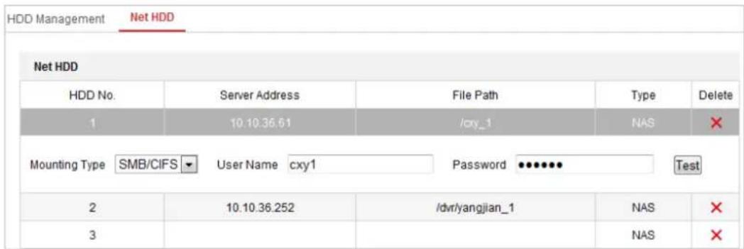
text_image
HDD Management Net HDD Net HDD HDD No. Server Address File Path Type Delete 1 10.10.36.61 /cxy_1 NAS ✗ Mounting Type SMB/CIFS User Name cxy1 Password Test 2 10.10.36.252 /dvr/yangjian_1 NAS ✗ 3 NAS ✗Figure 5-5 Select Net HDD Type
- Enter the IP address and the file path of the network disk.
- Select the mounting type. NFS and SMB/CIFS are selectable. You can set the user name and password to guarantee the security if SMB/CIFS is selected.

Please refer to the NAS User Manual for creating the file path.

- For your privacy and to better protect your system against security risks, we strongly recommend the use of strong passwords for all functions and network devices. The password should be something of your own choosing (using a minimum of 8 characters, including upper case letters, lower case letters, numbers and special characters) in order to increase the security of your product.
- Proper configuration of all passwords and other security settings is the responsibility of the installer and/or end-user.
4. Click
Save
to add the network disk.

After having saved successfully, you need to reboot the speed dome to activate the settings.
- Initialize the added network disk.
- Enter the HDD settings interface (Configuration > Storage > Storage Management > HDD Management), in which you can view the capacity, free space, status, type and property of the disk.
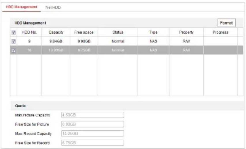
text_image
HDD Management Net1-HDD HDD Management Format ✓ HDD No. Capacity Free space Status Type Property Progress ✓ 9 9.84GB 0.00GB Normal NAS RW ✓ 10 10.00GB 0.75GB Normal NAS RW Quote Max.Picture Capacity 4.50GB Free Size for Picture 0.00GB Max. Record Capacity 14.25GB Free Size for Record 6.75GBFigure 5-6 Storage Management Interface
- If the status of the disk is Uninitialized, check the corresponding checkbox to select the disk and click Format to start initializing the disk.
- When the initialization completed, the status of disk will become Normal as shown in Figure 5-7.

text_image
HDD Management Set Format ✓ HDD No. Capacity Free space Status Type Property Progress ✓ 9 20.00GB 0.00GB Formatting NAS R/WFigure 5-7 View Disk Status
- Define the Quota for Record and Pictures
- Input the quota percentage for picture and for record.
- Click Save and refresh the browser page to activate the settings.
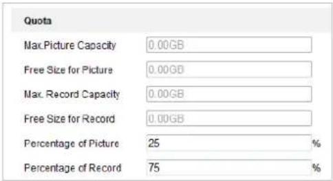
text_image
Quota Max.Picture Capacity 0.00GB Free Size for Picture 0.00GB Max. Record Capacity 0.00GB Free Size for Record 0.00GB Percentage of Picture 25 % Percentage of Record 75 %Figure 5-8 Quota Settings

- Up to 8 NAS disks can be connected to the speed dome.
- To initialize and use the memory card after insert it to the speed dome, please refer to the steps of NAS disk initialization
5.2 Basic Event Configuration
Purpose:
This section explains how to configure the network speed dome to respond to alarm events, including motion detection, video tampering alarm input, alarm output and exception. These events can trigger the alarm actions, such as Send Email, Notify Surveillance Center, etc.
For example, when motion detection is triggered, the network speed dome sends a notification to an e-mail address.

- On the event configuration page, click to show the PTZ control panel or click to hide it.
- Click the direction buttons to control the pan/tilt movements.
- Click the zoom/iris/focus buttons to realize lens control.
● The functions vary depending on the models of speed dome.
5.2.1 Configuring Motion Detection
Purpose:
Motion detection is a feature which can trigger alarm actions and actions of recording videos when the motion occurred in the surveillance scene.
Steps:
- Enter the motion detection setting interface:
Configuration > Event > Basic Event > Motion Detection - Select the channel to set the motion detection.
- Check the checkbox of the Enable Motion Detection to enable this function.
You can check the Enable Dynamic Analysis for Motion checkbox if you want the detected object get marked with rectangle in the live view. - Select the configuration mode as Normal or Expert and set the corresponding motion detection parameters.
- Normal
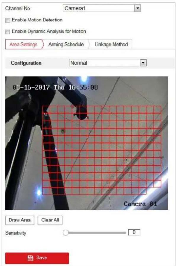
text_image
Channel No. Camera1 Enable Motion Detection Enable Dynamic Analysis for Motion Area Settings Arming Schedule Linkage Method Configuration Normal 03-16-2017 Thu 16:55:08 Camera 01 Draw Area Clear All Sensitivity 0 SaveFigure 5-9 Motion Detection Settings-Normal
Steps:
(1) Click Draw Area and drag the mouse on the live video image to draw a motion detection area.
(2) Click to finish drawing.

- You can draw up to 8 motion detection areas on the same image.
- You can click to clear all of the areas.
(3) Move the slider to set the 0
sensitivity of the detection.
- Expert
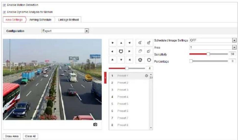
text_image
Enable Motion Detection Enable Dynamic Analysis for Motion Area Settings Arming Schedule Linkage Method Configuration Expert Scheduled Image Settings OFF Area 1 Sensitivity 50 Percentage 0 Draw Area Clear All 1 Preset 1 2 Preset 2 3 Preset 3 4 Preset 4 5 Preset 5 6 Preset 6 7 Preset 7 8 Preset 8Figure 5-10 Motion Detection Settings-Expert
Steps:
(1) Set the Schedule Image Settings, there are OFF, Auto-Switch and Scheduled-Switch selectable. If the schedule image switch mode is enabled, you can configure the detection rule for the day and night separately.
OFF: Disable the day and night switch.
Auto-Switch: Switch the day and night mode according to the illumination automatically.
Scheduled-Switch: Switch to the day mode at 6:00 a.m., and switch to the night mode at 18:00 p.m..
(2) Select Area No. to configure in the dropdown list.
(3) Set the values of sensitivity and proportion of object on area.
Sensitivity: The greater the value is, the easier the alarm will be triggered.
Proportion of Object on Area: When the size proportion of the moving object exceeds the predefined value, the alarm will be triggered. The less the value is, the easier the alarm will be triggered.
- Set the Arming Schedule for Motion Detection.
(1) Click tab to enter the arming schedule setting interface.
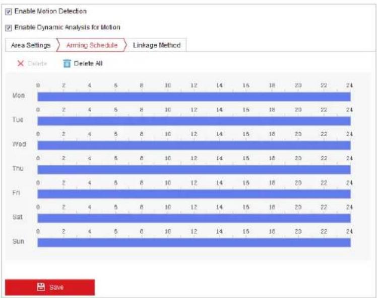
bar
| Day | Enable Motion Detection | Enable Dynamic Analysis for Motion | |---|---|---| | Mon | 0 | 2 | | Tue | 0 | 2 | | Wed | 0 | 2 | | Thu | 0 | 2 | | Fri | 0 | 2 | | Sat | 0 | 2 | | Sun | 0 | 2 | | Mon | 4 | 6 | | Tue | 4 | 6 | | Wed | 4 | 6 | | Thu | 4 | 6 | | Fri | 4 | 6 | | Sat | 4 | 6 | | Sun | 4 | 6 | | Mon | 8 | 10 | | Tue | 8 | 10 | | Wed | 8 | 10 | | Thu | 8 | 10 | | Fri | 8 | 10 | | Sat | 8 | 10 | | Sun | 8 | 10 | | Mon | 12 | 14 | | Tue | 12 | 14 | | Wed | 12 | 14 | | Thu | 12 | 14 | | Fri | 12 | 14 | | Sat | 12 | 14 | | Sun | 12 | 14 | | Mon | 16 | 18 | | Tue | 16 | 18 | | Wed | 16 | 18 | | Thu | 16 | 18 | | Fri | 16 | 18 | | Sat | 16 | 18 | | Sun | 16 | 18 | | Mon | 20 | 22 | | Tue | 20 | 22 | | Wed | 20 | 22 | | Thu | 20 | 22 | | Fri | 20 | 22 | | Sat | 20 | 22 | | Sun | 20 | 22 | | Mon | 24 | - | | Tue | - | - | | Wed | - | - | | Thu | - | - | | Fri | - | - | | Sat | - | - | | Sun | - | - | SaveFigure 5-11 Arming Schedule
(2) Select the timeline of a certain day, click and drag the mouse to set the arming schedule (the start time and end time of the arming task).
(3) After you set the scheduled task, you can click and copy the task to other days (optional).
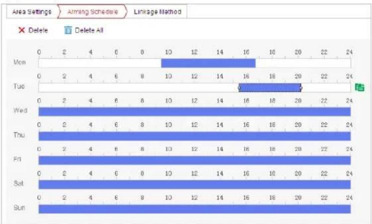
bar
| Day | Delete | Delete All | |---|---|---| | Mon | 0 | 2 | | Tue | 0 | 2 | | Wed | 0 | 2 | | Thu | 0 | 2 | | Fri | 0 | 2 | | Sat | 0 | 2 | | Sun | 0 | 2 | | Mon (Time) | 16 | 0 | | Tue (Time) | 18 | 0 | | Wed (Time) | 18 | 0 | | Thu (Time) | 18 | 0 | | Fri (Time) | 18 | 0 | | Sat (Time) | 18 | 0 | | Sun (Time) | 18 | 0 |Figure 5-12 Arming Time Schedule
(4) After setting the arming schedule, you can click a segment to display the segment arming settings interface to edit the segment record parameters (optional).
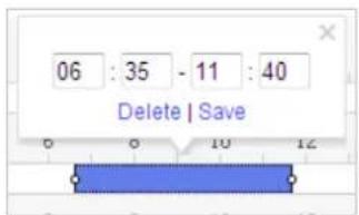
text_image
06 : 35 - 11 : 40 Delete | SaveFigure 5-13 Segment Arming Settings
(5) Click


The time of each period cannot be overlapped. Up to 8 periods can be configured for each day.
- Set the Alarm Actions for Motion Detection.
Click tab to enter the Linkage Method interface.
You can specify the linkage method when an event occurs. The following contents are about how to configure the different types of linkage method.
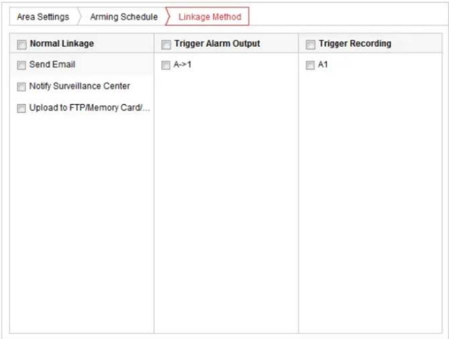
text_image
Area Settings > Arming Schedule > Linkage Method Normal Linkage Trigger Alarm Output Trigger Recording Send Email A->1 A1 Notify Surveillance Center Upload to FTP/Memory Card/...Figure 5-14 Linkage Method
Check the checkbox to select the linkage method. Notify Surveillance Center, Send Email, Upload to FTP/Memory/NAS, Trigger Alarm Output and Trigger Recording are selectable.
- Notify Surveillance Center
Send an exception or alarm signal to remote management software when an event occurs.
- Send Email
Send an email with alarm information to a user or users when an event occurs.

To send the Email when an event occurs, you need to refer to Section Configuring Email Settings to set the Email parameters.
- Upload to FTP/Memory/NAS
Capture the image when an alarm is triggered and upload the picture to a FTP server.

You need a FTP server and set FTP parameters first. Refer to Section Configuring FTP Settings for setting FTP parameters.
- Trigger Alarm Output
Trigger one or more external alarm outputs when an event occurs.

To trigger an alarm output when an event occurs, please refer to Section 5.2.4 Configuring Alarm Output to set the alarm output parameters.
- Trigger Recording
Record a video when an event occurs.

You have to set the recording schedule to realize this function. Please refer to Section 5.1.1 Configuring Recording Schedule for settings the recording schedule.
5.2.2 Configuring Video Tampering Alarm
Purpose:
You can configure the speed dome to trigger the alarm actions when the lens is covered.
Steps:
- Enter the Video Tampering settings interface :
Configuration > Event > Basic Event > Video Tampering - Select the channel to set the video tampering alarm.
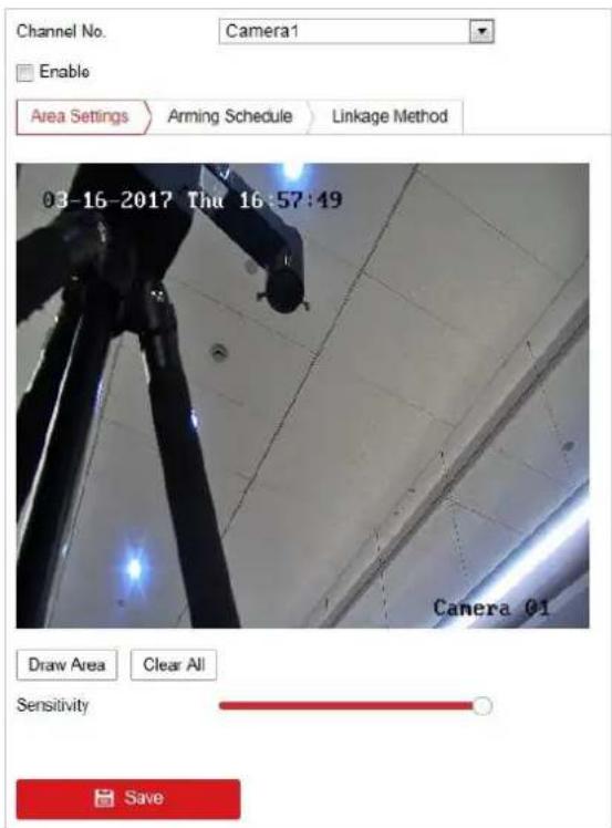
text_image
Channel No. Camera1 Enable Area Settings Arming Schedule Linkage Method 03-16-2017 Thu 16:57:49 Camera 01 Draw Area Clear All Sensitivity SaveFigure 5-15 Tampering Alarm
-
Check Enable checkbox to enable the tampering detection.
-
Click Schedule tab to enter the arming schedule setting interface. The arming schedule configuration is the same as the setting of the arming schedule for motion detection. Refer to Section 5.2.1 Configuring Motion Detection.
-
Click Linkage Method tab to select the linkage method taken for tampering, notify surveillance center, send email and trigger alarm output are selectable. Refer to Section 5.2.1 Configuring Motion Detection.
-
Click Save to save the settings.
5.2.3 Configuring Alarm Input
Steps:
- Enter the Alarm Input settings interface:
Configuration > Event > Basic Event > Alarm Input -
Choose the alarm input No. and the Alarm Type. The alarm type can be NO (Normally Open) and NC (Normally Closed).
-
Edit the name in Alarm Name (cannot copy) to set a name for the alarm input (optional).
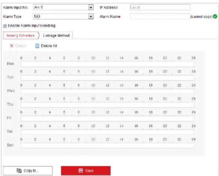
text_image
Alarm Input No. A<-1 IP Address Local Alarm Type NO Alarm Name (cannot copy) Enable Alarm Input Handling Arming Schedule Linkage Method Delete All Mon 0 2 4 6 8 10 12 14 16 18 20 22 24 Tue 0 2 4 6 8 10 12 14 16 18 20 22 24 Wed 0 2 4 6 8 10 12 14 16 18 20 22 24 Thu 0 2 4 6 8 10 12 14 16 18 20 22 24 Fri 0 2 4 6 8 10 12 14 16 18 20 22 24 Sat 0 2 4 6 8 10 12 14 16 18 20 22 24 Sun Copy to SaveFigure 5-16 Alarm Input Settings
-
Click Arming Schedule tab to enter the arming schedule setting interface. The arming schedule configuration is the same as the setting of the arming schedule for motion detection. Refer to Section 5.2.1 Configuring Motion Detection.
-
Click Linkage Method tab to select the linkage method taken for alarm input, including Notify Surveillance Center, Send Email, Upload to FTP/Memory Card/NAS, Trigger Alarm Output and Trigger Recording. Refer to Section 5.2.1 Configuring Motion Detection.
-
You can also choose the PTZ linking for the alarm input. Check the relative checkbox and select the No. to enable Preset Calling, Patrol Calling or Pattern Calling.
-
You can copy your settings to other alarm inputs.
-
Click

to save the settings.
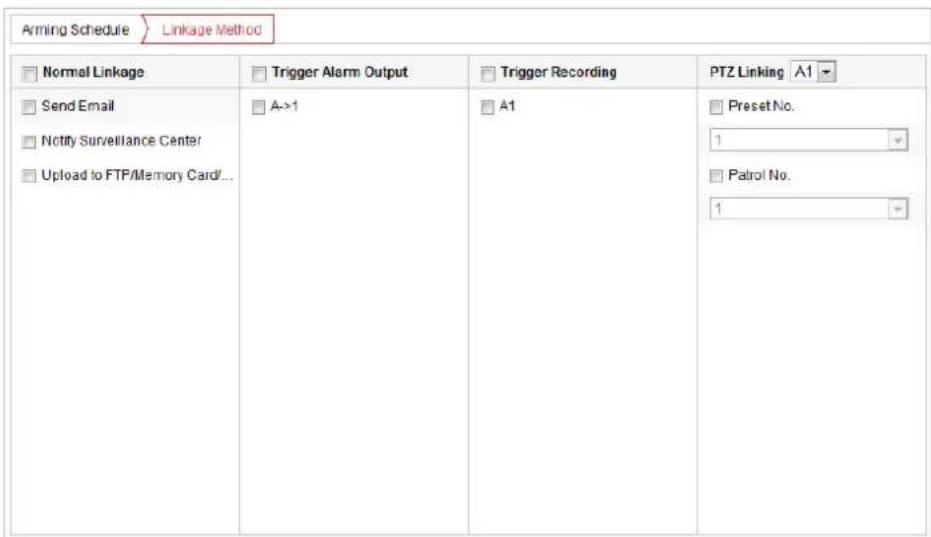
text_image
Arming Schedule Linkage Method Normal Linkage Trigger Alarm Output Trigger Recording PTZ Linking A1 Send Email A->1 A1 Preset No. Notify Surveillance Center Upload to FTP/Memory Card... 1 Patrol No. 1Figure 5-17 Linkage Method
5.2.4 Configuring Alarm Output
Steps:
- Enter the Alarm Output settings interface:
Configuration> Event > Basic Event > Alarm Output
-
Select one alarm output channel in the Alarm Output dropdown list.
-
Set a name in for the alarm output (cannot copy)
(optional).
-
The Delay time can be set to 5sec, 10sec, 30sec, 1min, 2min, 5min, 10min or Manual. The delay time refers to the time duration that the alarm output remains in effect after alarm occurs.
-
Click Arming Schedule tab to enter the arming schedule setting interface. The time schedule configuration is the same as the settings of the arming schedule for motion detection. Refer to Section 5.2.1 Configuring Motion Detection.
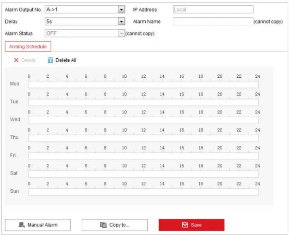
text_image
Alarm Output No. A->1 IP Address Local Delay 5s Alarm Name (cannot copy) Alarm Status OFF (cannot copy) Arming Schedule Delete Delete All Mon 0 2 4 6 8 10 12 14 16 18 20 22 24 Tue 0 2 4 6 8 10 12 14 16 18 20 22 24 Wed 0 2 4 6 8 10 12 14 16 18 20 22 24 Thu 0 2 4 6 8 10 12 14 16 18 20 22 24 Fri 0 2 4 6 8 10 12 14 16 18 20 22 24 Sat 0 2 4 6 8 10 12 14 16 18 20 22 24 Sun 0 2 4 6 8 10 12 14 16 18 20 22 24 Manual Alarm Copy to... SaveFigure 5-18 Alarm Output Settings
-
You can copy the settings to other alarm outputs.
-
Click to save the settings.
5.2.5 Handling Exception
The exception type can be HDD full, HDD error, network disconnected, IP address conflicted and illegal login to the speed domes.
Steps:
- Enter the Exception settings interface:
Configuration > Event > Basic Event > Exception - Check the checkbox to set the actions taken for the Exception alarm. Refer to Section 5.2.1 Configuring Motion Detection.
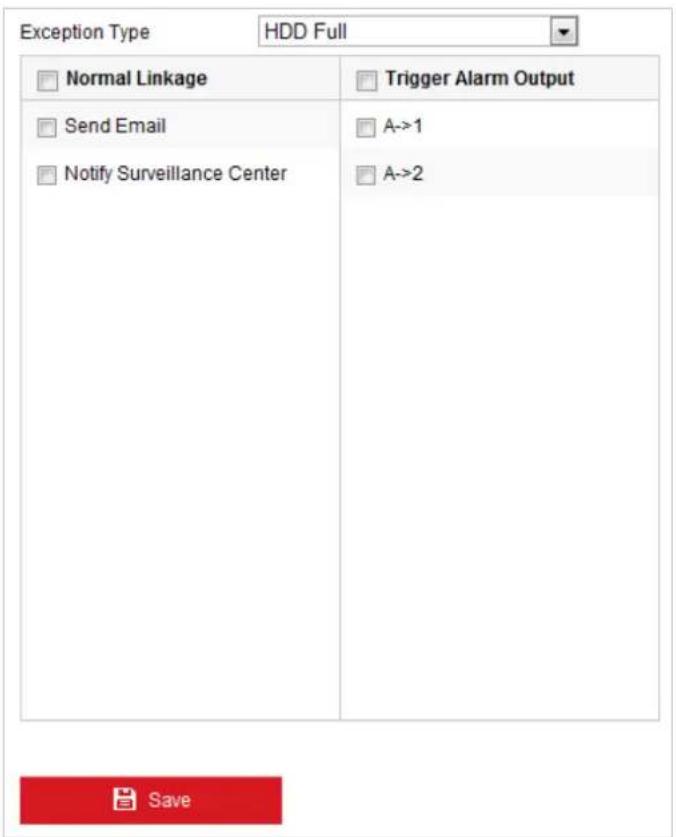
text_image
Exception Type HDD Full Normal Linkage Trigger Alarm Output Send Email A->1 Notify Surveillance Center A->2 SaveFigure 5-19 Exception Settings
- Click
Save to save the settings.
5.3 Smart Event Configuration

The functions vary depending on the models of speed dome.
5.3.1 Detecting Audio Exception
Purpose:
When you enable this function and audio exception occurs, the alarm actions will be triggered.
Steps:
- Enter the video audio exception detection interface:
Configuration > Event > Smart Event > Audio Exception Detection
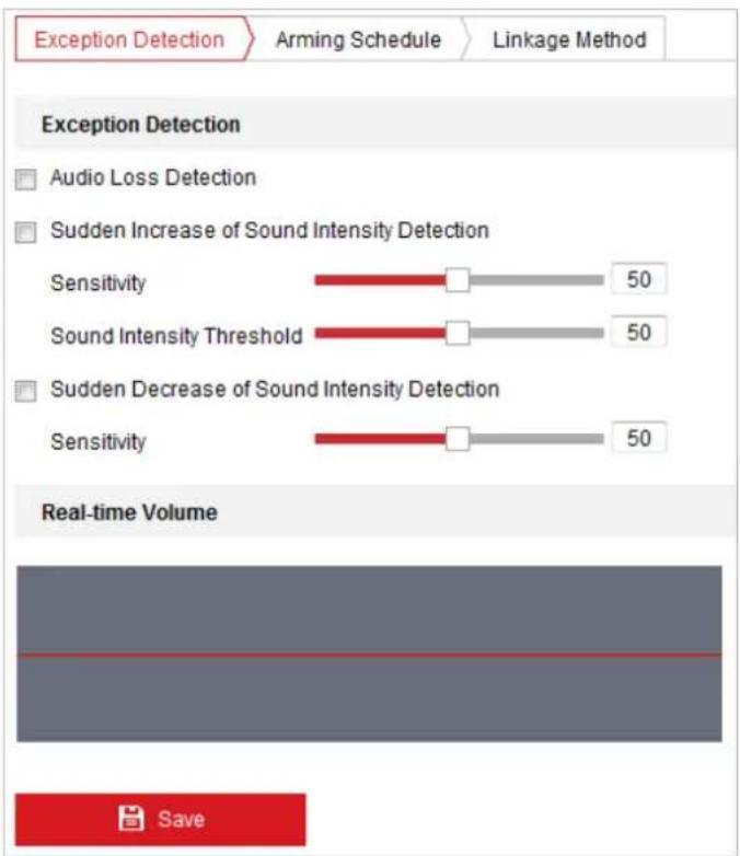
text_image
Exception Detection Arming Schedule Linkage Method Exception Detection Audio Loss Detection Sudden Increase of Sound Intensity Detection Sensitivity 50 Sound Intensity Threshold 50 Sudden Decrease of Sound Intensity Detection Sensitivity 50 Real-time Volume SaveFigure 5-20 Audio Exception Detection
- Check the checkbox of Audio Loss Detection to enable the audio input exception detection.
- Check the checkbox of Sudden Increase of Sound Intensity Detection checkbox to enable the sudden rise detection.
- Sensitivity: Range [1-100], the smaller the value the more severe the sound change will trigger the detection.
● Sound Intensity Threshold: Range [1-100], it can filter the sound in the environment, the louder the environment sound, the higher the value should be. You can adjust it according to the actual environment.
- Check the checkbox of Sudden Decrease of Sound Intensity Detection checkbox to enable the sudden drop detection.
Sensitivity: Range [1-100], the smaller the value the more severe the sound change will trigger the detection.
- Click Arming Schedule tab to enter the arming schedule setting interface. The time schedule configuration is the same as the settings of the arming schedule for motion detection. Refer to Section 5.2.1 Configuring Motion Detection.
- Click Linkage Method tab to select the linkage method taken for the audio input exception, Notify Surveillance Center, Send Email, Trigger Alarm Output and Trigger Recording are selectable. Refer to Section 5.2.1 Configuring Motion Detection.
- Click to save the settings.
5.3.2 Configuring Fire and Smoke Detection
Purpose:
When you enable this function and fire source or smoke is detected, the alarm actions will be triggered. You can set different detection mode, fire source zoom mode, and so on.
Steps:
- Enter Configuration>Advanced Configuration>System>VCA Resource Type to select Fire and Smoke Detection as VCA Resource Type.
- Enter the fire and smoke detection interface:
Configuration > Event > Smart Event > Dynamic Fire and Smoke Detection
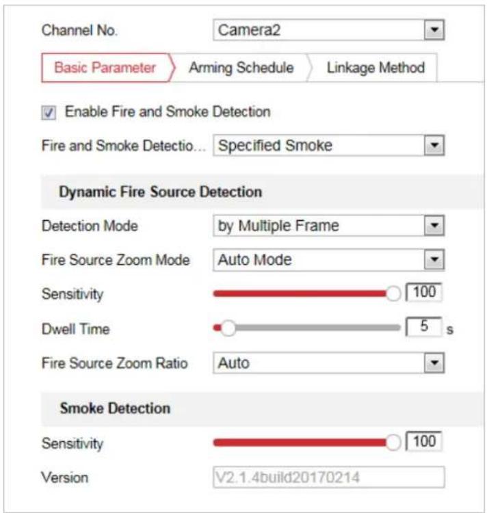
text_image
Channel No. Camera2 Basic Parameter Arming Schedule Linkage Method Enable Fire and Smoke Detection Fire and Smoke Detectio... Specified Smoke Dynamic Fire Source Detection Detection Mode by Multiple Frame Fire Source Zoom Mode Auto Mode Sensitivity 100 Dwell Time 5 s Fire Source Zoom Ratio Auto Smoke Detection Sensitivity 100 Version V2.1.4build20170214Figure 5-21 Fire and Smoke Detection
- Check the checkbox of Enable Fire and Smoke Detection to enable the fire and smoke detection function.

The function of dynamic fire source detection can only be enabled for camera 2.
● Fire and Smoke Detection Mode:
1) Select Fire or Smoke, and the system alarms when device is either triggered by Fire Source Detection or Smoke Detection.
2) Select Fire and Smoke, the system holds when device is triggered by Fire Source Detection or Smoke Detection. When target is detected by both rules, the system sends two alarms, otherwise, the system sends single alarm.
3) Select Double Confirm, the system alarms when device is both triggered by Fire Source Detection and Smoke Detection.
4) Select Specified Fire Source, and the system alarms when device is triggered by fire source detection.
5) Select Specified Smoke, and the system alarms when device is triggered by smoke.
- Detection Mode: Select detection mode as by Multiple Frame, and the system alarms with high accuracy. Select detection mode as by Single Frame, and the system alarms with short delay.
- Fire Source Zoom Mode: In Auto mode, the system moves and locates at the fire source, and then it zooms according to the predefined focus mode. To set the focus mode, go to Configuration>Advanced Configuration>Image>Channel No.2>Focus Mode.
- Sensitivity: Range [1-100], the smaller the value is, the fire source of lower temperature can be detected.
- Dwell Time(s): Range [0-120]. You can set the dwell time of the speed dome staying the position where detects the fire source when performing auto scan, patrol, pattern, scheduled task, and park action.
- Fire Source Zoom Ratio: Set the zoom ratio of the optical channel when it detects the fire source. In Auto mode, the optical channel changes its zoom ratio until two channels have the same field of view. In Manual mode, you can set the optical zoom ratio.
- Smoke Detection: Set the sensitivity of the smoke detection. The greater the value is, the easier the alarm will be triggered. (reserved)
-
Check the checkbox of Display Fire Source Frame on Stream to display a red frame around the fire source on stream when fire occurs. (Optional)
-
Check the checkbox to select the linkage method taken for the alarm input. Refer to Step 3 in Section 5.2.1 Configuring Motion Detection. In the field of Other Linkage, you can check the checkbox to enable the alarm output (The alarm output number varies depending on device ability).
-
Click to save the settings.


5.3.3 Configuring Fire Source Detection Shield
Purpose:
Fire Source Shield enables you to shield certain areas from being detected in fire source detection.

The privacy mask function is supported by the optical lens only.
Steps:
- Enter the Fire Source Detection Shield Setting interface:
Configuration > Event > Smart Event > Fire Source Detection Shield
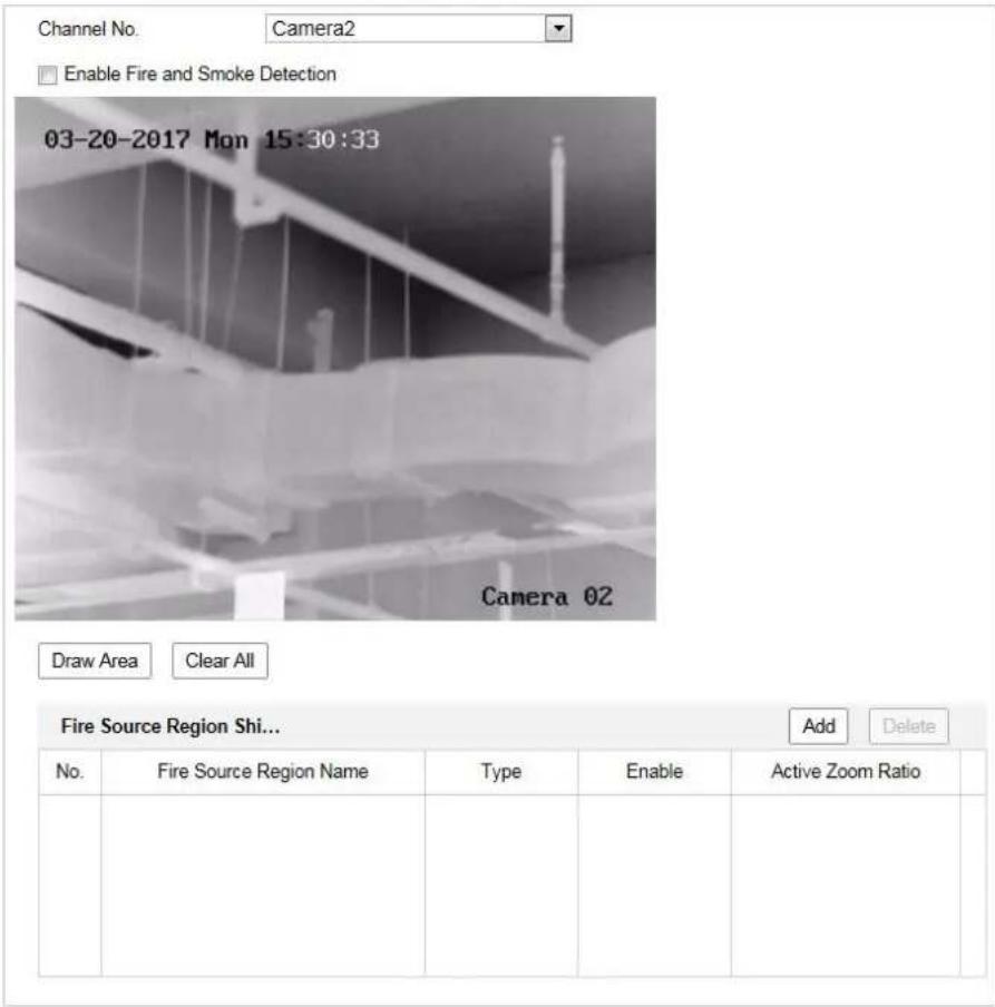
text_image
Channel No. Camera2 Enable Fire and Smoke Detection 03-20-2017 Mon 15:30:33 Camera 02 Draw Area Clear All Fire Source Region Shi... Add Delete No. Fire Source Region Name Type Enable Active Zoom Ratio No. Fire Source Region Name Type Enable Active Zoom RatioFigure 5-22 Fire Source Detection Shield
- Click the PTZ control buttons to find the area you want to shield from the smoke detection.
- Click Draw Area and drag the mouse in the live video window to draw the area.
- You can drag the corners of the red rectangle area to change its shape and size.
- Click Stop Drawing to finish drawing or click Clear All to clear all of the areas you set without saving them.
-
Set the value of Active Zoom Ratio on your demand, and then the shield will only appear when the zoom ratio is greater than the predefined value.
-
Click Add to save the smoke detection shield, and it will be listed in the Fire Source Detection Shield List area; you can select a region and click Delete to delete it from the list; you can also define the color of the regions.
- Check the checkbox of Enable Fire Source Detection Shield to enable this function.

You are allowed to draw up to 24 areas on the same image.
- Click to save the settings.

For some models, the smoke detection function is not supported and you cannot select Fire and Smoke Detection Mode.

5.3.4 Configuring Smoke Detection Shield
Purpose:
Smoke Detection Shield enables you to shield certain areas from being detected in smoke detection.

● The privacy mask function is supported by the optical lens only.
● The smoke detection shield function is only supported for some models.
Steps:
- Enter the Smoke Detection Shield Setting interface:
Configuration > Event > Smart Event > Smoke Detection Shield
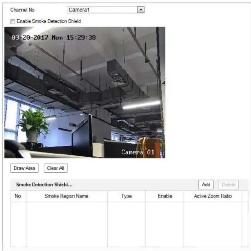
text_image
Channel No Camera1 Enable Smoke Detection Shield 03-20-2017 Mon 15:29:38 Camera 01 Draw Area Clear All Smoke Detection Shield... Add Delete No Smoke Region Name Type Enable Active Zoom RatioFigure 5-23 Smoke Detection Shield
- Click the PTZ control buttons to find the area you want to shield from the smoke detection.
- Click Draw Area and drag the mouse in the live video window to draw the area.
- You can drag the corners of the red rectangle area to change its shape and size.
- Click Stop Drawing to finish drawing or click Clear All to clear all of the areas you set without saving them.
- Set the value of Active Zoom Ratio on your demand, and then the shield will only appear when the zoom ratio is greater than the predefined value.
- Click Add to save the smoke detection shield, and it will be listed in the Smoke Detection Shield List area; you can select a region and click Delete to delete it from the list; you can also define the color of the regions.
- Check the checkbox of Enable Smoke Detection Shield to enable this function.

You are allowed to draw up to 24 areas on the same image.
- Click

5.3.5 Ship Detection
Purpose:
When you enable this function and ship is detected, the alarm actions will be triggered.
Steps:
-
Enter Configuration>Advanced Configuration>System>VCA Resource Type to select Ship Detection as VCA Resource Type.
-
Enter the ship detection interface:
Configuration > Advanced Configuration > Smart Event > Ship Detection
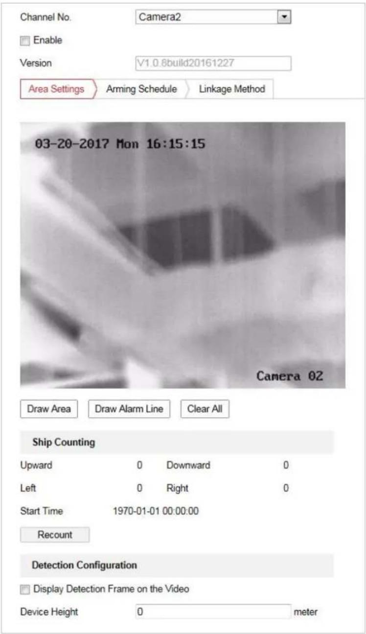
text_image
Channel No. Camera2 Enable Version V1.0.8build20161227 Area Settings Arming Schedule Linkage Method 03-20-2017 Mon 16:15:15 Camera 02 Draw Area Draw Alarm Line Clear All Ship Counting Upward 0 Downward 0 Left 0 Right 0 Start Time 1970-01-01 00:00:00 Recount Detection Configuration Display Detection Frame on the Video Device Height 0 meterFigure 5-24 Ship Detection
-
Check the checkbox of Enable to enable the ship detection function.
-
Check the checkbox of Display Detection Frame on Video to display the frame and alarm line on stream. (Optional)

● The function of ship detection is only supported for some models.
● For better effect, make sure there is no sky in your scene.
- If you moved the camera to other direction when you enabled the ship detection function, the device will move back to the saved scene 15 s later.
-
Enter the device height in the textbox as the height of device above the water level.
-
Draw the ship detection area and the alarm lines.
(1) Click Draw Area. Click the mouse on the live video image to draw a ship detection area and right click to finish the drawing. The alarm will be uploaded when ship is detected in this area.
(2) Click Draw Alarm Line. Click the mouse on the live video to draw an alarm line and right click to finish the drawing. The device alarms and counts the ship number when ships are detected in the area and the ship information will be displayed on the right.

Make sure the alarm line is longer than the width of ship detection area.
-
Check the checkbox to select the linkage method taken for the alarm input. Refer to Step 3 in Section 5.2.1 Configuring Motion Detection. In the field of Other Linkage, you can check the checkbox to enable the alarm output (The alarm output number varies depending on device ability).
-
Click


5.4 Temperature Measurement
Purpose:
When you enable this function, it measures the actual temperature of the spot being monitored. The device alarms when temperature exceeds the temperature threshold value.
Before You Start:
Enter Configuration > Advanced Configuration > System > VCA Resource Type to select Temperature Measurement + Behavior Analysis as VCA Resource Type.
5.4.1 Temperature Measurement Configuration
Steps:
- Enter Configuration > Temperature Measurement > Basic Settings Configuration.
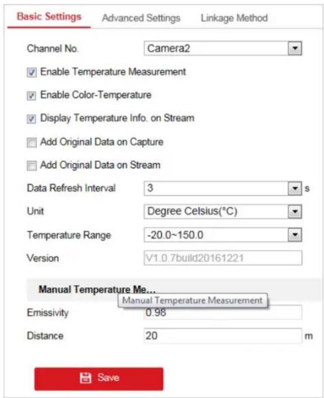
text_image
Basic Settings Advanced Settings Linkage Method Channel No. Camera2 Enable Temperature Measurement Enable Color-Temperature Display Temperature Info. on Stream Add Original Data on Capture Add Original Data on Stream Data Refresh Interval 3 s Unit Degree Celsius(℃) Temperature Range -20.0~150.0 Version V1.0.7build20161221 Manual Temperature Me... Manual Temperature Measurement Emissivity 0.98 Distance 20 m SaveFigure 5-25 Dynamic Fire Source Detection
-
Check the checkboxes of the interface to set the temperature measurement configurations.
-
Enable Temperature Measurement: Check the checkbox to enable temperature measurement function.
- Enable Color-Temperature: Check the checkbox to display Temperature-Color Ruler in live view.
- Display Temperature Info. on Stream: Check the checkbox to display temperature information in live view.
- Add Original Data on Capture: Check the checkbox to add original data on capture.
- Add Original Data on Stream: Check the checkbox to add original data on stream.
● Data Refresh Interval: Select the data refresh interval from 1s to 5s. - Unit: Display temperature with Degree Celsius (°C)/Degree Fahrenheit (°F)/Degree Kelvin (K).
● Temperature Range: Set the temperature range. - Emissivity: Set the emissivity of your target. Note: The emissivity of each object is different.
-
Distance (m): The straight-line distance between the target and the device.
-
Clcik Save to save the settings .

5.4.2 Temperature Measurement and Alarm
Purpose:
This function is used for measuring the temperature of detected spot and the device compares temperature of selected regions and alarms.
Steps:
- Enter Configuration > Temperature Measurement > Advanced Settings.
- Select the temperature measurement and alarm configuration as Normal or Expert.
- Normal Mode:
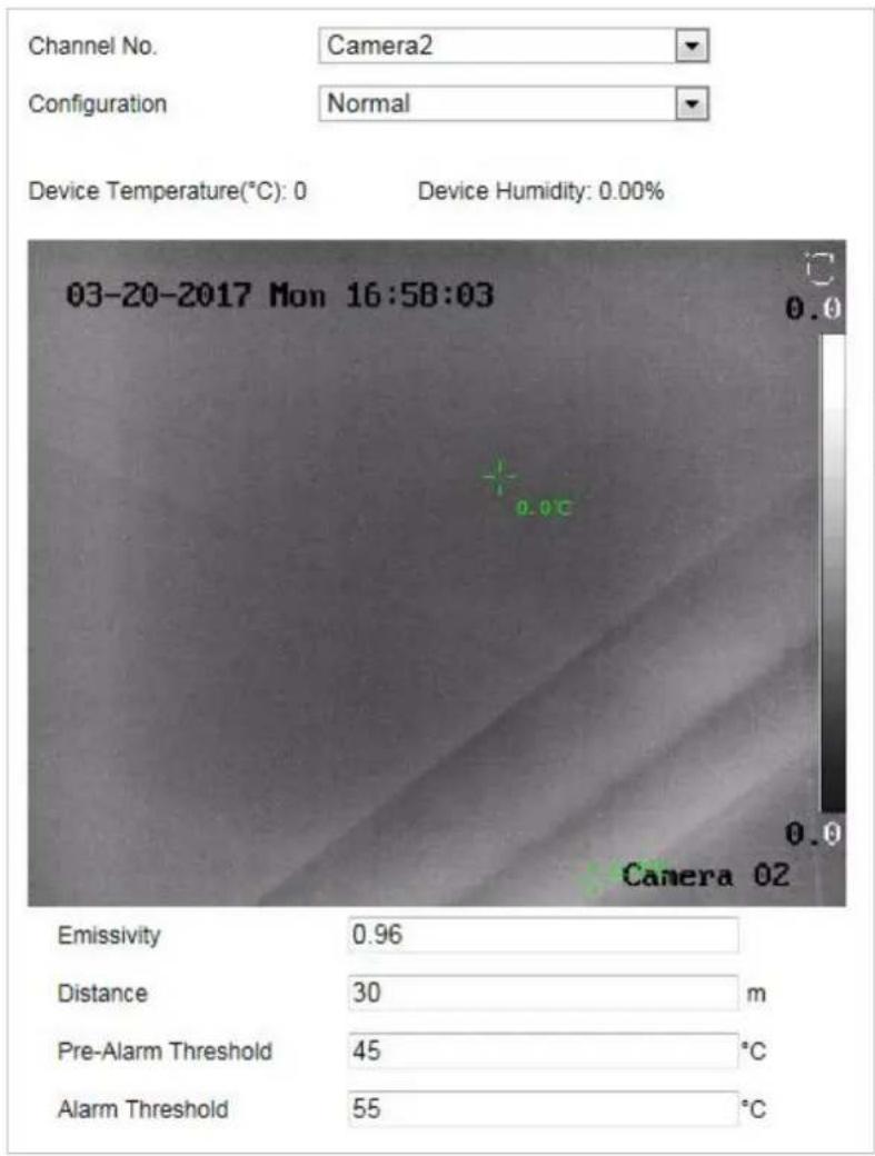
text_image
Channel No. Camera2 Configuration Normal Device Temperature(°C): 0 Device Humidity: 0.00% 03-20-2017 Mon 16:58:03 0.0 0.0 Camera 02 Emissivity 0.96 Distance 30 m Pre-Alarm Threshold 45 °C Alarm Threshold 55 °CFigure 5-26 Temperature Measurement Configuration
Emissivity: Set the emissivity of your target. Note: The emissivity of each object is different.
Distance (m): The straight-line distance between the target and the device.
Pre-Alarm Threshold: Set the pre-alarm temperature and the device sends pre-alarm when its rule temperature exceeds pre-alarm temperature.
Alarm Threshold: Set the alarm temperature and the device sends alarm when its rule temperature exceeds alarm temperature.
- Expert Mode:

text_image
Channel No. Camera2 Configuration Expert Device Temperature(℃): 0 Device Humidity: 0.00% 03-20-2017 Mon 16:20:23 Canera 02 Clear All Region Temperature Difference Alarm Enable ID Name Type Emissivity Distance... Reflective Temp... Alarm Rule 1 Point 0.96 30 20 ✓ 2 Point 0.96 30 20 ✓ 3 Point 0.96 30 20 ✓ 4 Point 0.96 30 20 ✓ 5 Point 0.96 30 20 ✓ 6 Point 0.96 30 20 ✓ 7 Point 0.96 30 20 ✓ 8 Point 0.96 30 20 ✓ 9 Point 0.96 30 20 ✓ 10 Point 0.96 30 20 ✓Figure 5-27 Temperature Measurement Configuration
1) Adjust the image to the scene for temperature measurement with the PTZ control panel. Save current scene as certain preset.

- You can set the preset in live view interface before and call the preset in the temperature measurement and alarm interface.
- You can set/ call/ clear the preset in temperature measurement interface.
2) Set the alarm rule: Select a temperature measurement rule from the rule list and configure the parameters.
Name: You can customize the rule name.
Type: Select Point, Line, or Frame as rule type.
Emissivity: Set the emissivity of your target. The emissivity of each object is different, you can refer to the Quick Start Guide Appendix for details.
Distance (m): The straight-line distance between the target and the device.
Reflective Temperature: If there is any target with high emissivity in the scene, check the checkbox and set the reflective temperature to correct the temperature. If no such target exists, uncheck the checkbox.
Tolerance Temperature: The device judges whether the triggered alarm stops until the device temperature/temperature difference is lower than rule temperature by tolerance temperature. E.g., set tolerance temperature as 3^ C, set alarm temperature as 55^ C, and set pre-alarm temperature as 50^ C. The device sends pre-alarm when its temperature reaches 50^ C and it alarms when its temperature reaches 55^ C and only when the device temperature is lower than 52^ C will the alarm be cancelled.
3) Set the alarm rules.
For Point Rule:
a) Click ☐ to show the Alarm Rule setting interface.
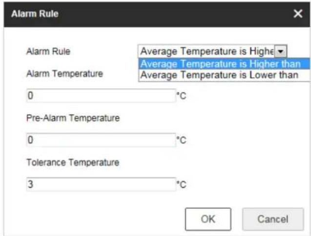
text_image
Alarm Rule Average Temperature is Higher Average Temperature is Higher than Average Temperature is Lower than 0 °C Pre-Alarm Temperature 0 °C Tolerance Temperature 3 °C OK CancelFigure 5-28 Alarm Rule Settings (Point)
b) Set the alarm rule.
c) Set the Alarm Temperature, Pre-Alarm Temperature, and Tolerance Temperature.
E.g., select Alarm Rule as Average Temperature is Higher than, and set the Alarm Temperature to 50 °C, and the device alarms when its average temperature is higher than 50 °C.
For Line Rule:
a) Click 🔍 to show the Alarm Rule setting interface.
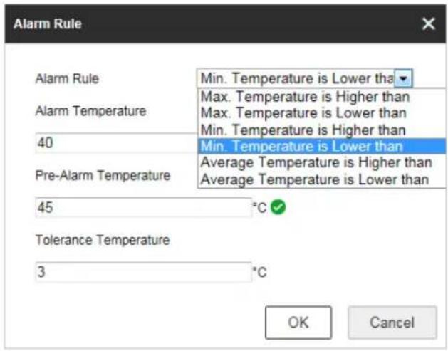
text_image
Alarm Rule Alarm Rule Alarm Temperature 40 Pre-Alarm Temperature 45 Tolerance Temperature 3 Min. Temperature is Lower than Max. Temperature is Higher than Max. Temperature is Lower than Min. Temperature is Higher than Min. Temperature is Lower than Average Temperature is Higher than Average Temperature is Lower than OK CancelFigure 5-29 Alarm Rule Settings (Line)
b) Set the alarm rule.
c) Set the Alarm Temperature, Pre-Alarm Temperature, and Tolerance Temperature.
E.g., select Alarm Rule as Min. Temperature is Lower than, and set the Alarm Temperature to 40 °C, and the device alarms when the minimum temperature is lower than 40 °C.
For Frame Rule:
Task 1.
a) Click ☐ to show the Alarm Rule setting interface.
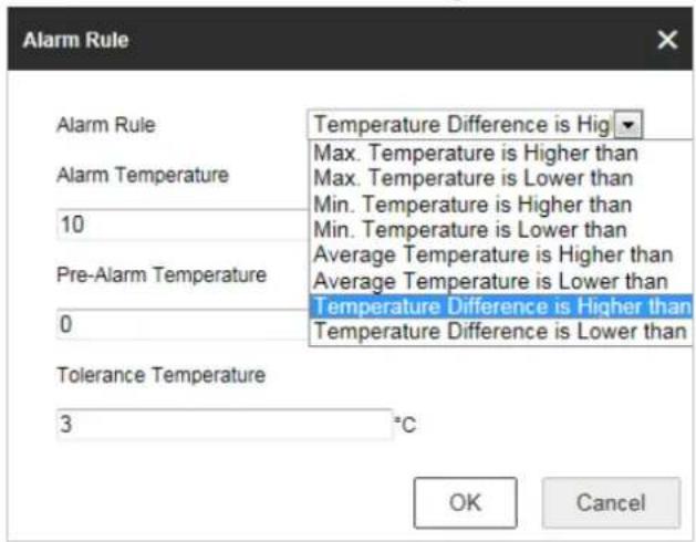
text_image
Alarm Rule Alarm Rule 10 Pre-Alarm Temperature 0 Tolerance Temperature 3 °C Temperature Difference is High ▼ Max. Temperature is Higher than Max. Temperature is Lower than Min. Temperature is Higher than Min. Temperature is Lower than Average Temperature is Higher than Average Temperature is Lower than Temperature Difference is Higher than Temperature Difference is Lower than OK CancelFigure 5-30 Alarm Rule Settings (Frame)
b) Set the alarm rule.
c) Set the Alarm Temperature, Pre-Alarm Temperature, and Tolerance Temperature.
E.g., select Alarm Rule as Temperature Difference is Higher than, and set the Alarm Temperature to 10 °C , and the device alarms when the difference between the minimum temperature and the maximum temperature of the region is higher than 10 °C .
Task 2.
For two alarm rules of frame, you can set the alarm for region temperature difference.
a) Set the frame alarm rules.
b) Click Region Temperature Difference Alarm to show the region temperature difference alarm interface.
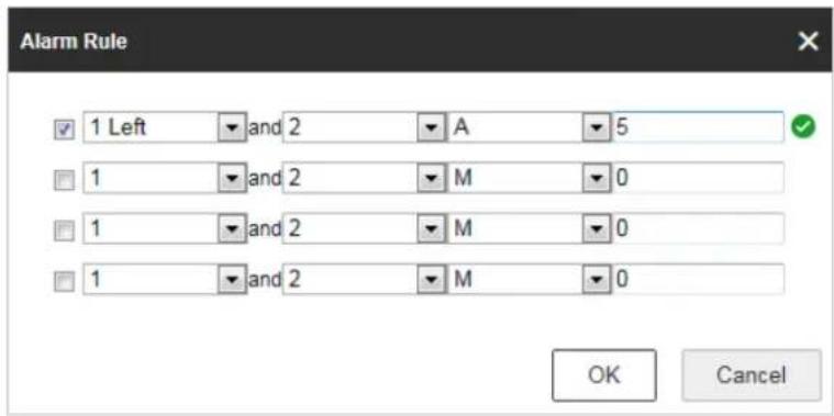
text_image
Alarm Rule 1 Left and 2 A 5 1 and 2 M 0 1 and 2 M 0 1 and 2 M 0 OK CancelFigure 5-31 Region Temperature Difference Alarm
c) Select two rules to compare the saved regions.
d) Set the alarm rules and the temperature.
E.g., select Alarm Rule as Temperature Difference is Higher than, and enter 10 °C, the device alarms when the difference between the minimum temperature and the maximum temperature of the region is higher than 10 °C.

Temperature Difference Alarm only applies to the targets set by frame.
-
Set Alarm Linkage: Click Alarm Linkage to enter the alarm linkage interface and set the linkage methods. Refer to Step 3 in Section 5.2.1 Configuring Motion Detection. In the field of Other Linkage, you can check the checkbox to enable the alarm output (The alarm output number varies depending on device ability).
-
Click to save the settings.

Chapter 6 VCA Configuration
Before you start:
Go to Configuration > System > Maintenance > VCA Resource Type and select the VCA Resource as Temperature Measurement + Behavior Analysis.
Purpose:
You can do intelligent analysis, such as behavior analysis, with the speed dome. Multiple rules can be configured for different requirements.

The VCA (Video Content Analysis) function only supported by the thermal channel.
6.1 Configuring VCA Information
Steps:
- Enter the VCA Information Configuration interface: Configuration > VCA Configuration > VCA Info.
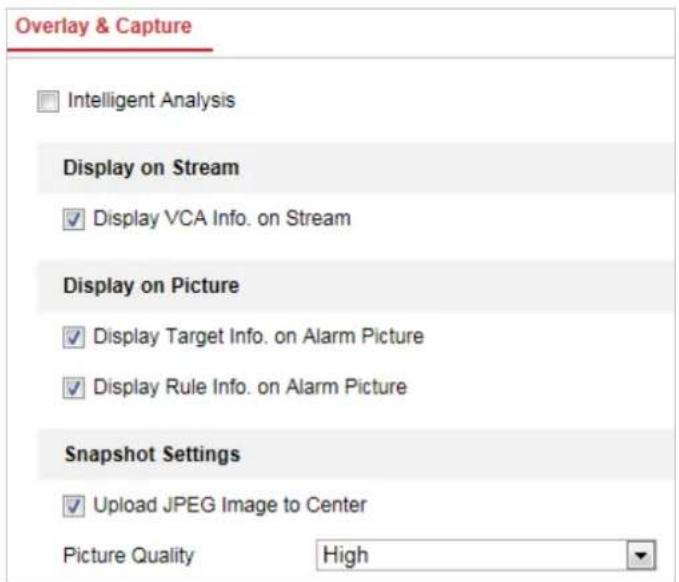
text_image
Overlay & Capture Intelligent Analysis Display on Stream ✓ Display VCA Info. on Stream Display on Picture ✓ Display Target Info. on Alarm Picture ✓ Display Rule Info. on Alarm Picture Snapshot Settings ✓ Upload JPEG Image to Center Picture Quality HighFigure 6-1 VCA Information
- Check the checkbox to enable the Intelligent Analysis. And you can view the current version for the behavior analysis.
- Set the display information:
- If you select to display the target info and rule info on the alarm picture are supported; you can enable the functions by ticking the corresponding checkbox on your demand.
- And if you tick the checkbox of display target info and rule on stream, the information will be added to the video stream, and the overlay will be displayed if you get live view or play back by the VS Player.
- Set the Snapshot:
- You can configure the Notify Surveillance Center function which is used for uploading the picture to the surveillance center when and VCA alarm occurs.
● You can also set the quality and resolution of the picture separately.
5. Click

6.2 Advanced Configuration
All the parameters for both behavior analysis and face capture are collected in the advanced configuration page. You can configure these parameters for different VCA types on your demand.
Steps:
- Enter the Advanced Configuration interface: Configuration > VCA > Advanced Configuration
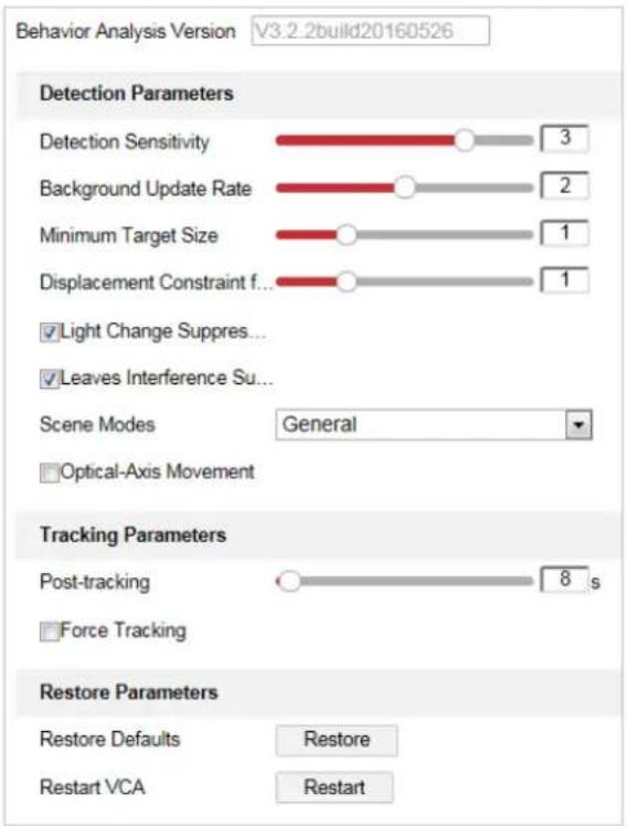
text_image
Behavior Analysis Version V3.2.2build20160526 Detection Parameters Detection Sensitivity 3 Background Update Rate 2 Minimum Target Size 1 Displacement Constraint f... 1 Light Change Suppres... Leaves Interference Su... Scene Modes General Optical-Axis Movement Tracking Parameters Post-tracking 8 s Force Tracking Restore Parameters Restore Defaults Restore Restart VCA RestartFigure 6-2 Advanced Configuration
- Adjust the Detection Parameters.
Detection Sensitivity: Range [0-4], the higher the sensitivity is, the easier the target will be detected.
Background Update Rate: Range [0-4], if a detected target remains in the monitoring scene for a certain time, the system will count the target as the background automatically. The greater the value is, the faster the target will be counted as the background.
Minimum Target Size: Range [0-4], The system will filter out the object smaller than the minimum target size.
Displacement Constraint for Target Generation: Range [0-4], the higher the value is, the slower the target is generated, and the higher accuracy the analysis will get.
Light Change Suppression: Check the checkbox to suppress the impact caused by the illumination change.
Leave Interference Suppression: Check this checkbox to stop the interference caused by the leaves in the configured area.
Scene Modes: The scene mode is set to be General by default. Select Distant View when you are far from the targets. Select Indoor when you are indoor.
Optical-axis Movement: Check the checkbox when the target moves in the direction of camera's optical -axis.
- Adjust the Tracking Parameters.
Post-Tracking: Range [2-600], you can configure the tracking duration after the target is still.
Force Tracking: Check the checkbox to enable the function to prevent the object to be blocked. After the function being enabled, the speed dome will continue locating and tracking the blocked target.
Restore Default: Click Restore to restore the parameters to the default.
Restart VCA: Click Restart to restart the VCA function.
6.3 Behavior Analysis
Purpose:
The speed dome supports patrol tracking for multiple scenes. At most 8 rules can be configured for a single scene. You can configure the rules for the scene on your demand.
Steps:
- Configure the VCA Info: For details, see 7.2 Configuring VCA Information.
- Configure the Zooming Ratio parameters: Set the appropriate tracking zooming ratio
with the PTZ control panel. Click on to save the settings.
The optical camera will track the target when the VCA rule is triggered which is configured on the thermal camera.
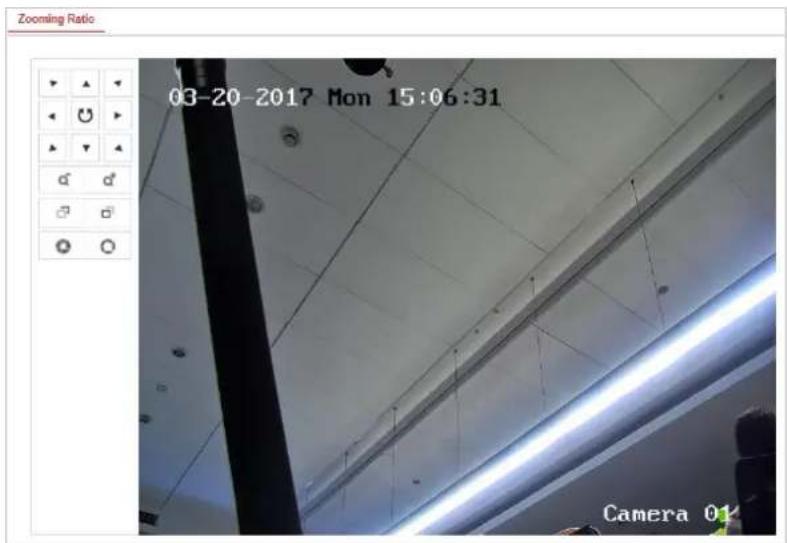
text_image
Zooming Ratio 03-20-2017 Mon 15:06:31 Camera 01Figure 6-3 Zoom Ratio
3. Configure the Scene:
Go to VCA > Scene Parameters
At most 10 scenes can be added. Different rules and properties can be configured for each scene.
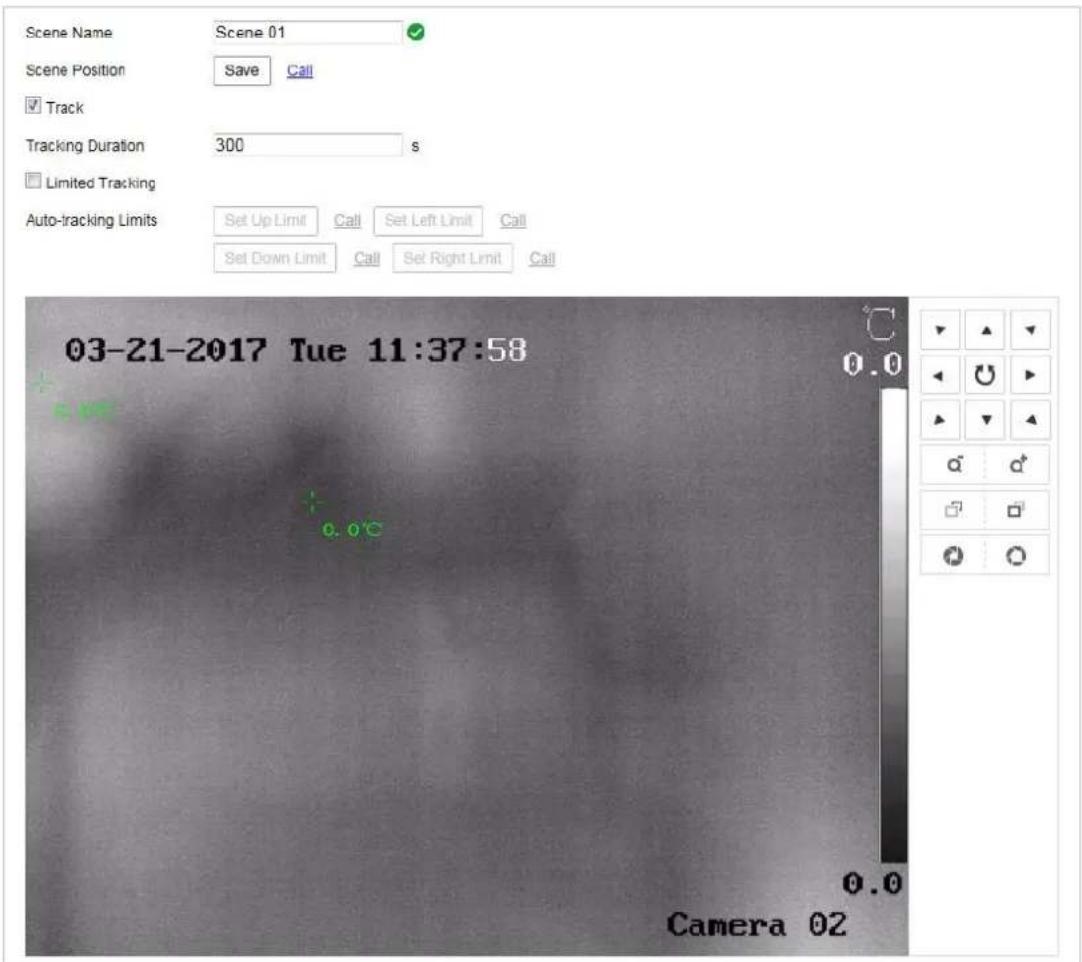
text_image
Scene Name Scene 01 Scene Position Save Call Track Tracking Duration 300 s Limited Tracking Auto-tracking Limits Set Up Limit Call Set Left Limit Call Set Down Limit Call Set Right Limit Call 03-21-2017 Tue 11:37:58 0.0 0.0 Camera 02Figure 6-4 Scene Parameters
- Create a Scene:
1) Add New Scene: Click New Scene to create a new scene.
2) Control the PTZ to get the required scene.
3) Set the scene parameters:
Scene Name: Enter a custom scene name.
Patrol Sequence: Set the sequence for the scene when doing patrol tracking. If the sequence is selected as 0, this scene will not be configured for patrol tracking.
Duration: Set the dwell time of the scene when doing patrol tracking. The intelligent analysis will be enabled during the period. If the alarm is triggered, the speed dome will start to track automatically.
Enable Track: Check the checkbox to enable the tracking function for the scene. Tracking Duration: Set the duration of the tracking. If the value is selected as 0, the tracking duration will not be limited.
Limited Tracking: You can check the checkbox to enable/disable the function. If the function is enabled, you can set the limited position for the tracking.
4) Click to save the settings.
- Rule Configuration:
At most 8 rules can be configured for a single scene. Follow the steps below to configure the rule for the scene.
1) Click the Rule tab to enter the rule settings interface.
2) Create new rule: Click on the button + to add a new rule.
3) Select rule type: Click the dropdown menu to select the rule type. Line Crossing, Intrusion, Region Entrance, and Region Exiting are selectable.
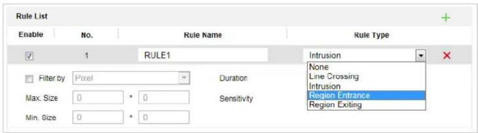
text_image
Rule List Enable No. Rule Name Rule Type ✓ 1 RULE1 Intrusion Filter by Pixel Duration None Max. Size 0 * 0 Sensitivity Line Crossing Min. Size 0 * 0 Sensitivity Region Entrance Sensitivity Region ExitingFigure 6-5 Rule List
4) Configure the rule area: Click the Draw Line or Draw Area button on the tool bar of the live view panel. Click the mouse on the live view panel. Right click the mouse to finish drawing. For details, see 6.4 Rule Configuration Demonstration.
5) Configure the filtering size: The filtering function is supported for all rules. You can set the minimum and maximum size of the object needs to be filtered. The system will only detect the object in a size between the configured minimum and maximum value. For details, see6.4 Rule Configuration Demonstration.
6) Enable rules: Check the Enable checkbox of each rule in the rule list to enable the rule.
7) Click

to save the settings.

Create multiple rules: You can create more rules by repeating the above steps.
- Configure Arming schedule:
1) Click the Arming Schedule tab.
2) Select a rule from the rule list.
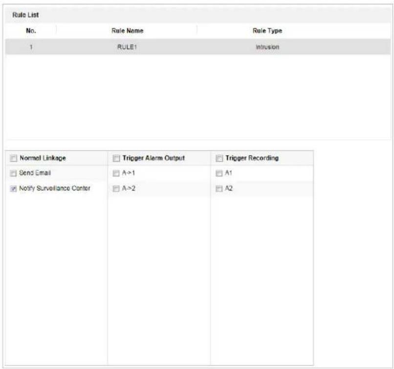
text_image
Rule List No. Rule Name Rule Type 1 RULE1 Intrusion Normal Linkage Trigger Alarm Output Trigger Recording Send Email A->1 A1 Notify Surveillance Center A->2 A2Figure 6-6 Arming Schedule
3) Click on the Edit button to edit the arming time segment.
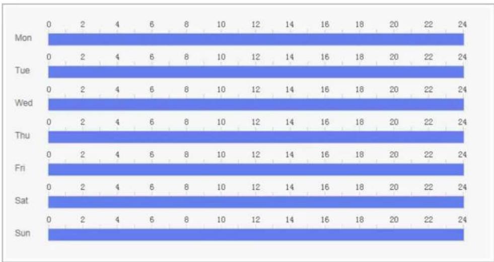
bar
| Day | 0 | 2 | 4 | 6 | 8 | 10 | 12 | 14 | 16 | 18 | 20 | 22 | 24 | |---|---|---|---|---|---|---|---|---|---|---|---|---|---| | Mon | 0 | 0 | 0 | 0 | 0 | 0 | 0 | 0 | 0 | 0 | 0 | 0 | 0 | | Tue | 0 | 0 | 2 | 4 | 6 | 8 | 10 | 12 | 14 | 16 | 18 | 20 | 22 | | Wed | 0 | 0 | 2 | 4 | 6 | 8 | 10 | 12 | 14 | 16 | 18 | 20 | 22 | | Thu | 0 | 0 | 2 | 4 | 6 | 8 | 10 | 12 | 14 | 16 | 18 | 20 | 22 | | Fri | 0 | 0 | 2 | 4 | 6 | 8 | 10 | 12 | 14 | 16 | 18 | 20 | 22 | | Sat | 0 | 0 | 2 | 4 | 6 | 8 | 10 | 12 | 14 | 16 | 18 | 20 | 22 | | Sun | 0 | 0 | 2 | 4 | 6 | 8 | 10 | 12 | 14 | 16 | 18 | 20 | 22 | The chart displays a single data series with 'Mon' to 'Sun' as rows and 'Mon' to 'Sun' as columns. The values are explicitly labeled on each bar. There is no additional data series or trends present.Figure 6-7 Schedule Time

You can select to copy the settings to whole week or are specific days of the week. At most 8 segments can be configured.

4) Click to save the settings.
- Configure Arming schedule:
1) Click the Alarm Linkage tab.
2) Select a rule from the rule list.
| Rule List | ||
| No. | Rule Name | Rule Type |
| 1 | RULE1 | Intrusion |
| Normal Linkage | Trigger Alarm Output | Trigger Recording |
| Send Email | A->1 | A1 |
| Notify Surveillance Center | A->2 | A2 |
Figure 6-8 Alarm Linkage
3) Check the checkbox of corresponding linkage actions to enable it.
- Advanced Configuration: For details, see section 6.2 Advanced Configuration. Click

to save the settings.
6.4 Rule Configuration Demonstration
Purpose:
This section provides detailed configuration steps for each rule.
6.4.1 Line Crossing
Purpose:
This function can be used for detecting people, vehicles and objects traversing a set virtual
plane. The traversing direction can be set as bidirectional, from left to right or from right to left. The alarm will be triggered if the rule is broken.
Steps:
-
Create new rule: Click on the button + to add a new rule.
-
Select rule type: Click the dropdown menu and select Line Crossing as the rule type.
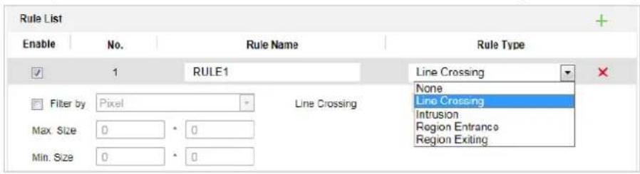
text_image
Rule List Enable No. Rule Name Rule Type ✓ 1 RULE1 Line Crossing Filter by Pixel Line Crossing Max. Size 0 * 0 Min. Size 0 * 0 None Line Crossing Intrusion Region Entrance Region ExitingFigure 6-9 Select Rule Type
- (Optional) Configure the size filter, if you want to narrow the detection target to a desired range.
a. Check the checkbox of the Filter by, and only filer by pixel is available.
b. Click the button and draw a rectangle on the live view image as the Min. size filter.
c. Click the ☐ button and draw a rectangle on the live view image as the Max. size filter.
- Configure the rule area:
Click on the tool bar of the live view panel. Specify a point of the line by clicking the mouse on the live view image, and then specify the other one.
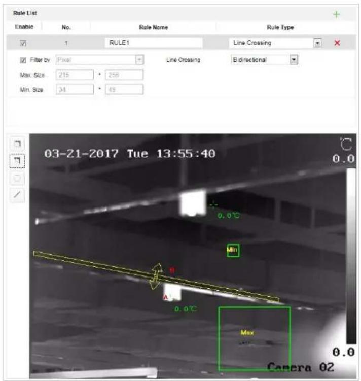
text_image
Rule List Enable No. Rule Name Rule Type 1 RULE1工程项目 Filter by:Pixel Line Crossing Bidirectional Max. Size:215 256 Min. Size:34 49 03-21-2017 Tue 13:55:40 0.0°C Min B A 0.0°C Max 0.0 Camera 02Figure 6-10 Draw Line
-
Click the dropdown menu in the rule list to select the crossing direction.
-
Enable rules: Check the Enable checkbox of each rule in the rule list to enable the rule.
-
Click to save the settings.
6.4.2 Intrusion
Purpose:
This function can be used for detecting whether there are people, vehicles and objects intrude into the pre-defined region longer than the set duration. The alarm will be triggered if the rule is broken.
Steps:
- Create new rule: Click on the button + to add a new rule.
- Select rule type: Click the dropdown menu and select Intrusion as the rule type.
- Configure the filtering size: for details, see step 3 in section 6.4.1 Line Crossing.
- Configure the rule area:
Click on the tool bar of the live view panel. Click the mouse on the live view image to specify a corner of the area. After you specify all the corners, right click the mouse to connect the first corner and the last corner, which means the polygonal area is drawn.
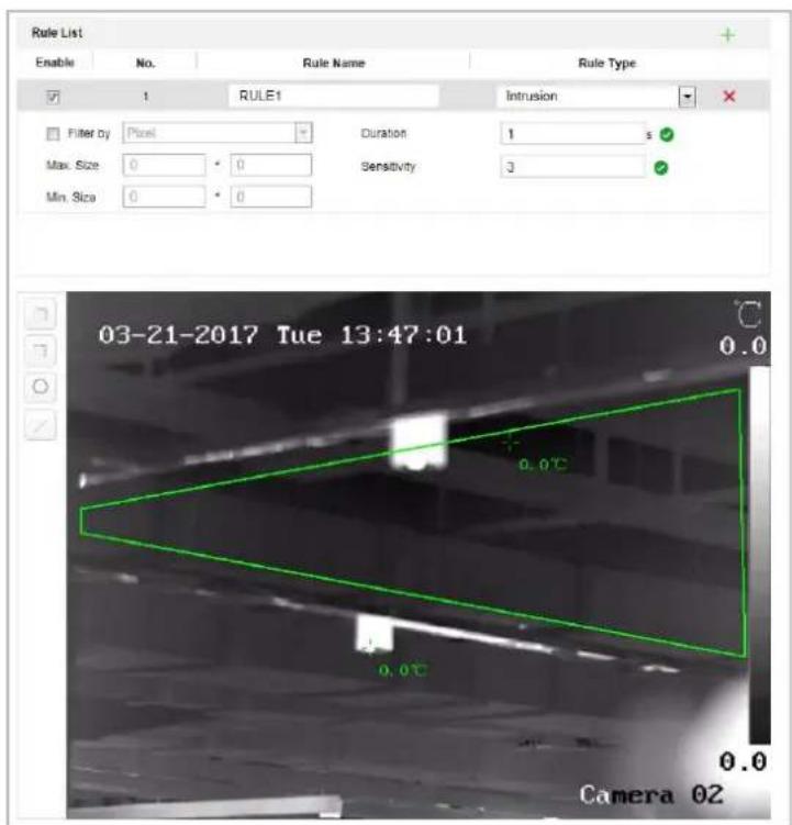
text_image
Rule List Enable No. Rule Name Rule Type 1 RULE1 Intrusion Filter by Pixel Duration 1 s Max. Size 0 0 Sensitivity 3 Min. Size 0 0 03-21-2017 Tue 13:47:01 0.0 0.0°C 0.0°C Camera 02Figure 6-11 Draw Area
- Set the duration from 1 to 100.
- Enable rules: Check the Enable checkbox of each rule in the rule list to enable the rule
- Click to save the settings.
6.4.3 Region Entrance
Purpose:
This function can be used for detecting people, vehicles and objects entering the pre-defined region. The alarm will be triggered if the rule is broken.
Steps:
- Create new rule: Click on the button + to add a new rule.
- Select rule type: Click the dropdown menu and select Region Entrance as the rule type.
- Configure the rule area:
Click on the tool bar of the live view panel. Click the mouse on the live view panel.
Right click the mouse to finish drawing.
- Configure the filtering size: for details, see step 3 in section 6.4.1 Line Crossing.
-
Enable rules: Check the Enable checkbox of each rule in the rule list to enable the rule
-
Click to save the settings.
6.4.4 Region Exiting
Purpose:
This function can be used for detecting people, vehicles and objects exiting the pre-defined region. The alarm will be triggered if the rule is broken.
Steps:
- Create new rule: Click on the button + to add a new rule.
- Select rule type: Click the dropdown menu and select Region Exiting as the rule type.
- Configure the rule area:
Click ☐ on the tool bar of the live view panel. Click the mouse on the live view panel. Right click the mouse to finish drawing.
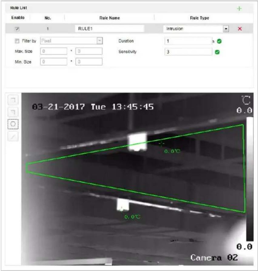
text_image
Rule List Enable No. Rule Name Rule Type 1 RULE1 Intrusion Filter by Pixel Duration 1 s Max. Size 0 * 0 Sensitivity 3 Min. Size 0 * 0 03-21-2017 Tue 13:45:45 0.0°C 0.0°C 0.0 Camera 02Figure 6-12 Draw Area
- Configure the filtering size: for details, see step 3 in section 6.4.1 Line Crossing.
-
Enable rules: Check the Enable checkbox of each rule in the rule list to enable the rule.
-
Click to save the settings.
Chapter 7 Speed dome Configuration
7.1 Configuring Network Settings

The functions vary depending on the models of speed dome.
7.1.1 Basic Settings
Configuring TCP/IP Settings
Purpose:
TCP/IP settings must be properly configured before you operate the speed dome over network. IPv4 and IPv6 are both supported.
Steps:
- Enter TCP/IP settings interface:
Configuration > Network > Basic Settings > TCP/IP
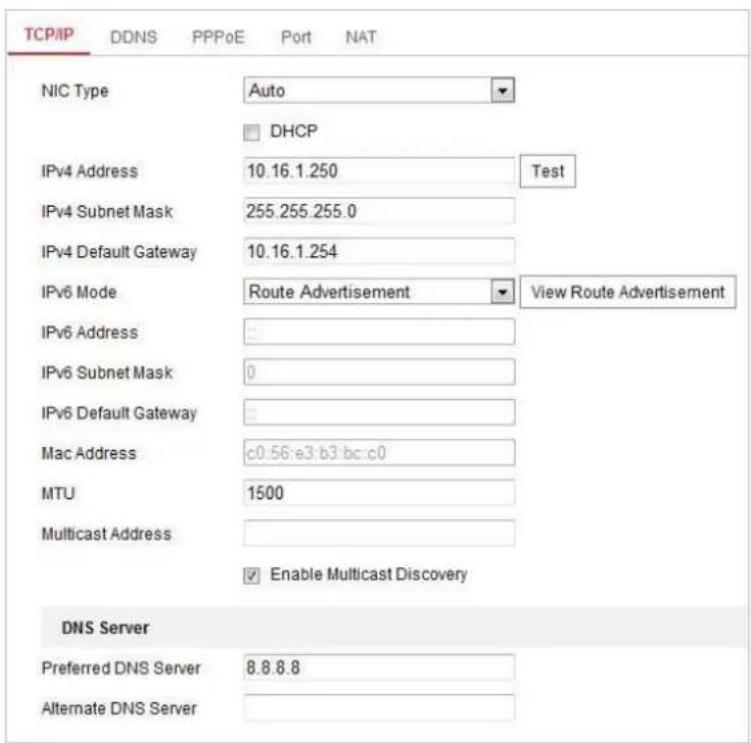
text_image
TCP/IP DDNS PPPoE Port NAT NIC Type Auto DHCP IPv4 Address 10.16.1.250 Test IPv4 Subnet Mask 255.255.255.0 IPv4 Default Gateway 10.16.1.254 IPv6 Mode Route Advertisement View Route Advertisement IPv6 Address IPv6 Subnet Mask 0 IPv6 Default Gateway Mac Address c0:56:e3:b3:bc:c0 MTU 1500 Multicast Address Enable Multicast Discovery DNS Server Preferred DNS Server 8.8.8.8 Alternate DNS ServerFigure 7-1 TCP/IP Settings
-
Configure the NIC settings, including the IPv4(IPv6) Address, IPv4(IPv6) Subnet Mask and IPv4(IPv6) Default Gateway.
-
Click Save to save the above settings.
You can click Test to make sure that the IP address is valid.

- If the DHCP server is available, you can check ☐ DHCP to automatically obtain an IP address and other network settings from that server.
- The valid value range of Maximum Transmission Unit (MTU) is 500 \~ 1500. The default value is 1500.
- The Multicast sends a stream to the multicast group address and allows multiple clients to acquire the stream at the same time by requesting a copy from the multicast group address.
Before utilizing this function, you have to enable the Multicast function of your router and configure the gateway of the network speed dome. - If the DNS server settings are required for some applications (e.g., sending email), you should properly configure the Preferred DNS Server and Alternate DNS server.
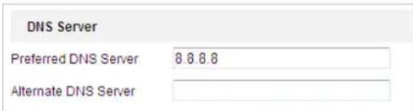
text_image
DNS Server Preferred DNS Server 8.8.8.8 Alternate DNS ServerFigure 7-2 DNS Server Settings

The router must support the route advertisement function if you select Route Advertisement as the IPv6 mode.
Configuring DDNS Settings
Purpose:
If your speed dome is set to use PPPoE as its default network connection, you can use the Dynamic DNS (DDNS) for network access.
Before you start:
Registration on the DDNS server is required before configuring the DDNS settings of the speed dome.

- For your privacy and to better protect your system against security risks, we strongly recommend the use of strong passwords for all functions and network devices. The password should be something of your own choosing (using a minimum of 8 characters, including upper case letters, lower case letters, numbers and special characters) in order to increase the security of your product.
- Proper configuration of all passwords and other security settings is the responsibility of the installer and/or end-user.
Steps:
- Enter the DDNS settings interface:
Configuration > Network > Basic Settings > DDNS

text_image
Enable DDNS DDNS Type HiDDNS Locality Custom Server Address Domain User Name Port 0 Password ConfirmFigure 7-3 DDNS Settings
- Check the Enable DDNS checkbox to enable this feature.
- Select DDNS Type. Three DDNS types are selectable: IPServer, HiDDNS, NO-IP and DynDNS.
• DynDNS:
Steps:
(1) Enter Server Address of DynDNS (e.g. members.dyndns.org).
(2) In the Domain text field, enter the domain name obtained from the DynDNS website.
(3) Enter the Port of DynDNS server.
(4) Enter the User Name and Password registered on the DynDNS website.
(5) Click to save the settings.
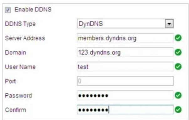
text_image
Enable DDNS DDNS Type DynDNS Server Address members.dyndns.org Domain 123.dyndns.org User Name test Port 0 Password ••••••••••• Confirm ••••••••••••Figure 7-4 DynDNS Settings
- IP Server:
Steps:
(1) Enter the Server Address of the IP Server.
(2) Click

The Server Address should be entered with the static IP address of the computer that runs the IP Server software. For the IP Server, you have to apply a static IP, subnet mask, gateway and preferred DNS from the ISP.
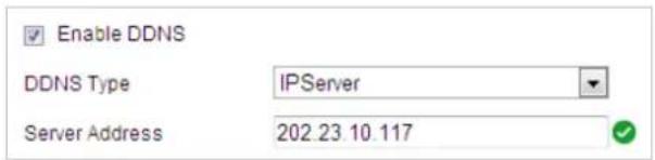
text_image
Enable DDNS DDNS Type IPServer Server Address 202.23.10.117Figure 7-5 IPServer Settings
- HiDDNS:
Steps:
(1) Enter the Server Address.
(2) Enter the Domain name of the camera. The domain is the same with the device alias in the HiDDNS server.
(3) Click to save the settings.
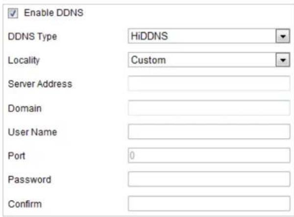
text_image
Enable DDNS DDNS Type HiDDNS Locality Custom Server Address Domain User Name Port 0 Password ConfirmFigure 7-6 HiDDNS Settings
NO-IP:
Steps:
(1) Enter Server Address of NO-IP.
(2) In the Domain text field, enter the domain name obtained from the NO-IP website.
(3) Enter the Port of NO-IP server.
(4) Enter the User Name and Password registered on the NO-IP website.
(5) Click to save the settings.
Configuring PPPoE Settings
Purpose:
© Hikvision
If you have no router but only a modem, you can use Point-to-Point Protocol over Ethernet (PPPoE) function.
Steps:
- Enter the PPPoE settings interface:
Configuration > Network > Basic Settings > PPPoE
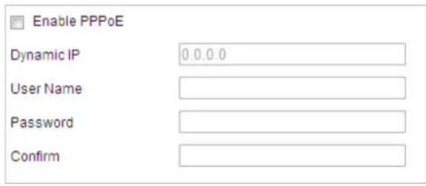
text_image
Enable PPPoE Dynamic IP 0.0.0.0 User Name Password ConfirmFigure 7-7 PPPoE Settings
- Check the Enable PPPoE checkbox to enable this feature.
- Enter User Name, Password, and Confirm password for PPPoE access.

The User Name and Password should be assigned by your ISP.

- For your privacy and to better protect your system against security risks, we strongly recommend the use of strong passwords for all functions and network devices. The password should be something of your own choosing (using a minimum of 8 characters, including upper case letters, lower case letters, numbers and special characters) in order to increase the security of your product.
-
Proper configuration of all passwords and other security settings is the responsibility of the installer and/or end-user.
-
Click

to save and exit the interface.
Configuring Port Settings
Purpose:
If there is a router and you want to access the speed dome through Wide Area Network (WAN), you need to forward the 3 ports for the speed dome.
Steps:
- Enter the Port settings interface:
Configuration > Network > Basic Settings > Port
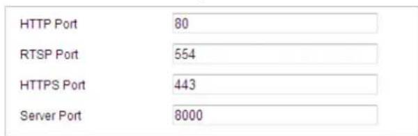
text_image
HTTP Port 80 RTSP Port 554 HTTPS Port 443 Server Port 8000Figure 7-8 Port Settings
- Set the HTTP port, RTSP port and port of the speed dome.
HTTP Port: The default port number is 80.
RTSP Port: The default port number is 554.
HTTPS Port: The default port number is 443.
Server Port: The default port number is 8000.
- Click to save the settings.
Configuring NAT (Network Address Translation) Settings
Purpose:
Universal Plug and Play (UPnP™) is a networking architecture that provides compatibility among networking equipment, software and other hardware devices. The UPnP protocol allows devices to connect seamlessly and to simplify the implementation of networks in the house and corporate environments.
With the function enabled, you don't need to configure the port mapping for each port, and the camera is connected to the Wide Area Network via the router.
Steps:
- Enter the UPnP™ settings interface.
Configuration >Network > Basic Settings > NAT
- Check the checkbox to enable the UPnP™ function.

You can edit the Friendly Name of the speed dome. This name can be detected by corresponding device, such as a router.
- Set the port mapping mode:
To port mapping with the default port numbers:
Choose Port Mapping Mode Auto
To port mapping with the customized port numbers:
Choose Port Mapping Mode Manual
And you can customize the value of the port number by yourself.
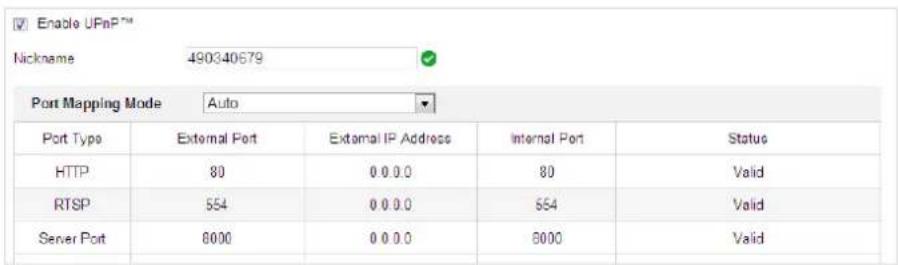
text_image
Enable UPnP™ Nickname 490340679 Port Mapping Mode Auto Port Type External Port External IP Address Internal Port Status HTTP 80 0 0 0.0 80 Valid RTSP 554 0 0 0.0 554 Valid Server Port 8000 0 0 0.0 8000 ValidFigure 7-9 Port Mapping Mode
- Click to save the settings.
7.1.2 Advanced Settings
Configuring SNMP Settings
Purpose:
You can use SNMP to get speed dome status and parameters related information.
Before you start:
Before setting the SNMP, please use the SNMP software and manage to receive the speed dome information via SNMP port. By setting the Trap Address, the speed dome can send the alarm event and exception messages to the surveillance center.

The SNMP version you select should be the same as that of the SNMP software.
Steps:
- Enter the SNMP settings interface:
Configuration > Network > Advanced Settings > SNMP
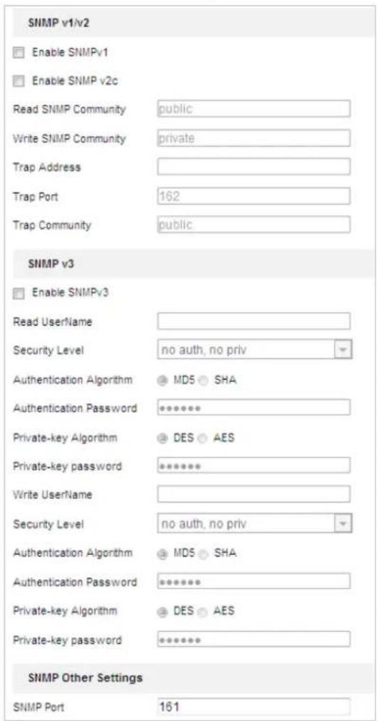
text_image
SNMP v1/v2 Enable SNMPv1 Enable SNMP v2c Read SNMP Community public Write SNMP Community private Trap Address Trap Port 162 Trap Community public SNMP v3 Enable SNMPv3 Read UserName Security Level no auth, no priv Authentication Algorithm MD5 SHA Authentication Password ****** Private-key Algorithm DES AES Private-key password ****** Write UserName Security Level no auth, no priv Authentication Algorithm MD5 SHA Authentication Password ****** Private-key Algorithm DES AES Private-key password ****** SNMP Other Settings SNMP Port 161Figure 7-10 SNMP Settings
- Check the corresponding version checkbox (Enable SNMP v1, Enable SNMP v2c,
Enable SNMP v3) to enable the feature.
- Configure the SNMP settings.

The configuration of the SNMP software should be the same as the settings you configure here.
- Click Save to save and finish the settings.
Configuring FTP Settings
Purpose:
You can set a FTP server and configure the following parameters for uploading captured pictures.
Steps:
- Enter the FTP settings interface:
Configuration > Network > Advanced Settings > FTP
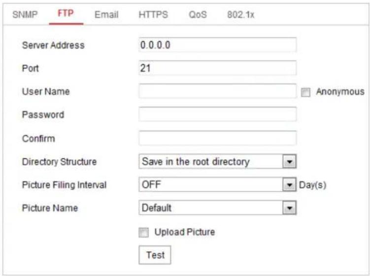
text_image
SNMP FTP Email HTTPS QoS 802.1x Server Address 0.0.0.0 Port 21 User Name Anonymous Password Confirm Directory Structure Save in the root directory Picture Filing Interval OFF Day(s) Picture Name Default Upload Picture TestFigure 7-11 FTP Settings
- Configure the FTP settings, including server address, port, user name, password, directory, and upload type.

The server address supports both the domain name and IP address formats.

- For your privacy and to better protect your system against security risks, we strongly recommend the use of strong passwords for all functions and network devices. The password should be something of your own choosing (using a minimum of 8 characters, including upper case letters, lower case letters, numbers and special characters) in order to increase the security of your product.
● Proper configuration of all passwords and other security settings is the responsibility of the installer and/or end-user.
- Setting the directory in FTP server for saving files:
In the Directory Structure field, you can select the root directory, parent directory and child directory.
◆ Root directory: The files will be saved in the root of FTP server.
◆ Parent directory: The files will be saved in a folder in FTP server. The name of folder can be defined as shown in following Figure 7-12.
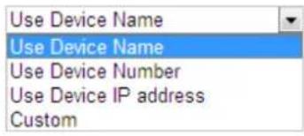
text_image
Use Device Name Use Device Name Use Device Number Use Device IP address CustomFigure 7-12 Parent Directory
◆ Child directory: It is a sub-folder which can be created in the parent directory. The files will be saved in a sub-folder in FTP server. The name of folder can be defined as shown in following Figure 7-13.
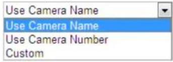
text_image
Use Camera Name Use Camera Name Use Camera Number CustomFigure 7-13 Child Directory
- Upload type: To enable uploading the captured picture to the FTP server.
-
Click Save to save the settings.
-
You can click Test to confirm the configuration.

If you want to upload the captured pictures to FTP server, you also have to enable the continuous snapshot or event-triggered snapshot in Snapshot interface.
Configuring Email Settings
Purpose:
The system can be configured to send an Email notification to all designated receivers if an alarm event is detected, e.g., motion detection event, video loss, video-tampering, etc.
Before you start:
Please configure the DNS Server settings under Configuration> Network > Basic
Settings > TCP/IP before using the Email function.
Steps:
- Enter the Email settings interface:
Configuration> Network > Advanced Settings > Email
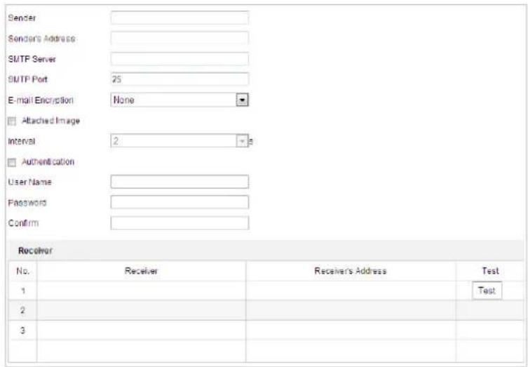
text_image
Sender Sender's Address SMTP Server SMTP Port 25 E-mail Encryption None Attached Image Interval 2 s Authentication User Name Password Confirm Receiver No. Receiver Receiver's Address Test 1 2 3 TestFigure 7-14 Email Settings
- Configure the following settings:
Sender: The name of the email sender.
Sender's Address: The email address of the sender.
SMTP Server: The SMTP Server IP address or host name (e.g., smtp.263xmail.com).
SMTP Port: The SMTP port. The default TCP/IP port for SMTP is 25.
E-mail encryption: None, SSL, and TLS are selectable. When you select SSL or TLS and disable STARTTLS, e-mails will be sent after encrypted by SSL or TLS. The SMTP port should be set as 465 for this encryption method. When you select SSL or TLS and enable STARTTLS, emails will be sent after encrypted by STARTTLS, and the SMTP port should be set as 25.

STARTTLS protocol must be supported by the email server for e-mail encryption with STARTTLS. When it is not supported by the email server and the checkbox of Enable STARTTLS is checked, the email will not be encrypted.
Attached Image: Check the checkbox of Attached Image if you want to send emails with attached alarm images.
Interval: The interval refers to the time between two actions of sending attached pictures.
Authentication (optional): If your email server requires authentication, check this checkbox to use authentication to log in to this server and enter the login user name and password.

- For your privacy and to better protect your system against security risks, we strongly recommend the use of strong passwords for all functions and network devices. The password should be something of your own choosing (using a minimum of 8 characters, including upper case letters, lower case letters, numbers and special characters) in order to increase the security of your product.
● Proper configuration of all passwords and other security settings is the responsibility of the installer and/or end-user.
Receiver: Select the receiver to which the email is sent. Up to 2 receivers can be configured.
Receiver: The name of the user to be notified.
Receiver's Address: The email address of user to be notified. (Optional: click Test to make sure that the email server can send email out.)
3. Click

to save the settings.
Configuring Platform Access
Purpose:
Platform access provides you an option to manage the devices via platform.
Steps:
- Enter the Platform Access interface.
Configuration > Network > Advanced Settings > Platform Access
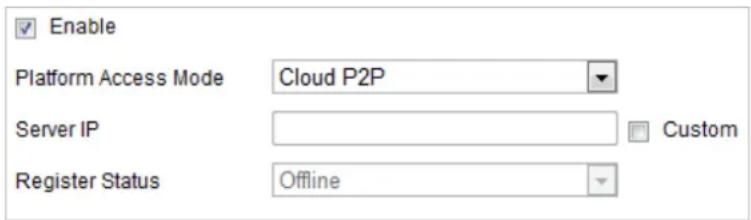
text_image
Enable Platform Access Mode Cloud P2P Server IP Custom Register Status OfflineFigure 7-15 Platform Access Settings
-
Check the checkbox of Enable to enable the platform access function of the device.
-
Select the Platform Access Mode from the dropdown list.
-
Set the Server IP.
5. Click

to save the settings
Configuring HTTPS Settings
Purpose:
HTTPS is consisted by SSL&HTTP. It is used for encryption transmission, identity authentication network protocol which enhances the security of WEB accessing.

- For your privacy and to better protect your system against security risks, we strongly recommend the use of strong passwords for all functions and network devices. The password should be something of your own choosing (using a minimum of 8 characters, including upper case letters, lower case letters, numbers and special characters) in order to increase the security of your product.
- Proper configuration of all passwords and other security settings is the responsibility of the installer and/or end-user.
Steps:
- Enter the HTTPS settings interface.
Configuration > Network > Advanced Settings > HTTPS
- Create the self-signed certificate or authorized certificate.
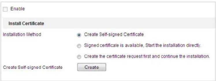
text_image
Enable Install Certificate Installation Method Create Self-signed Certificate Signed certificate is available, Start the installation directly. Create the certificate request first and continue the installation. Create Self-signed Certificate CreateFigure 7-16 Create Certificate
OPTION 1: Create the self-signed certificate
1) Select Create Self-signed Certificate.
2) Click Create to create the following dialog box.
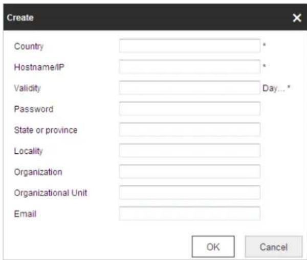
text_image
Create Country Hostname/IP Validity Password State or province Locality Organization Organizational Unit Email OK CancelFigure 7-17 Create Self-signed Certificate
3) Enter the country, host name/IP, validity and other information.
4) Click OK to save the settings.
OPTION 2: Start the installation when signed certificate is available.
1) Select Signed certificate is available, Start the installation directly.
2) Click Browse to upload the available certificate.
3) Click Install button to install the certificate.
4) Click OK to save the settings.
OPTION 3: Create certificate request first and continue the installation.
1) Select Create certificate request first and continue the installation.
2) Click Create to create the certificate request, and fulfill the required information.
3) Download the certificate request and submit it to the trusted certificate authority for signature.
4) After receiving the signed valid certificate, import the certificate to the device.
5) Click OK to save the settings.
- There will be the certificate information after you successfully create and install the certificate.
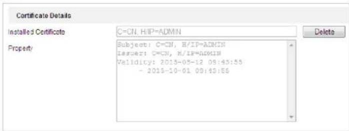
text_image
Certificate Details Installed Certificate C=CN, H/IP=ADMIN Property Subject: C=CN, H/IP=ADMIN Issuer: C=CN, H/IP=ADMIN Validity: 2015-05-12 09:43:55 - 2015-10-01 09:43:56 DeleteFigure 7-18 Installed Certificate Property
NOTE
● The default port number of HTTPS is 443. The port value ranges from 1 to 65535.
- When the port number is the default number 443, the format of the URL is https://IP address, eg., https://192.168.1.64.
- When the port number is not the default number 443, the format of the URL is https://IP address:port number, eg., https://192.168.1.64:81.
Configuring QoS Settings
Purpose:
QoS (Quality of Service) can help solve the network delay and network congestion by configuring the priority of data sending.
Steps:
- Enter the QoS settings interface: Configuration >Advanced Configuration >Network >QoS
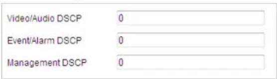
text_image
Video/Audio DSCP 0 Event/Alarm DSCP 0 Management DSCP 0Figure 7-19 QoS Settings
- Configure the QoS settings, including video / audio DSCP, event / alarm DSCP and Management DSCP.
The valid DSCP value ranges from 0 to 63. The DSCP value is bigger, the priority is higher.
- Click Save to save the settings.
NOTE
● Make sure that you enable the QoS function of your network device (such as a router).
- It will ask for a reboot for the settings to take effect.
Configuring 802.1X Settings
Purpose:
The speed dome supports IEEE 802.1X standard.
IEEE 802.1X is a port-based network access control. It enhances the security level of the LAN. When devices connect to this network with IEEE 802.1X standard, the authentication is needed. If the authentication fails, the devices don't connect to the network.
The protected LAN with 802.1X standard is shown as follows:
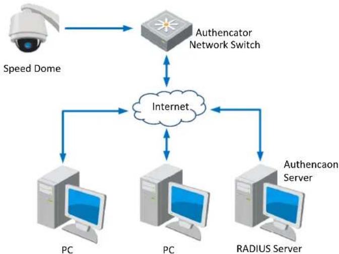
flowchart
graph TD
    A["Speed Dome"] --> B["Authenticator Network Switch"]
    B <--> C["Internet"]
    C <--> D["Authencaon Server"]
    C <--> E["PC"]
    C <--> F["PC"]
    C <--> G["RADIUS Server"]
Figure 7-20 Protected LAN
- Before connecting the Network Camera to the protected LAN, please apply a digital certificate from a Certificate Authority.
- The network camera requests access to the protected LAN via the authenticator (a switch).
- The switch forwards the identity and password to the authentication server (RADIUS server).
- The switch forwards the certificate of authentication server to the network camera.
- If all the information is validated, the switch allows the network access to the protected network.

- For your privacy and to better protect your system against security risks, we strongly recommend the use of strong passwords for all functions and network devices. The password should be something of your own choosing (using a minimum of 8 characters, including upper case letters, lower case letters, numbers and special characters) in order to increase the security of your product.
- Proper configuration of all passwords and other security settings is the responsibility of the installer and/or end-user.
Steps:
- Connect the network camera to your PC directly with a network cable.
- Enter the 802.1X settings interface:
Configuration > Network > Advanced Settings > 802.1X
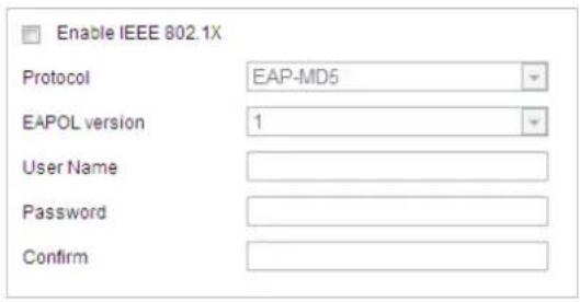
text_image
Enable IEEE 802.1X Protocol EAP-MD5 EAPOL version 1 User Name Password ConfirmFigure 7-21 802.1X Settings
- Check the Enable IEEE 802.1X checkbox to enable it.
- Configure the 802.1X settings, including user name and password.

The EAP-MD5 version must be identical with that of the router or the switch.
- Click


The camera reboots when you save the settings.
- After the configuration, connect the camera to the protected network.
7.2 Configuring Video and Audio Settings
7.2.1 Configuring Video Settings
Steps:
- Enter the Video settings interface:
Configuration > Video/Audio > Video
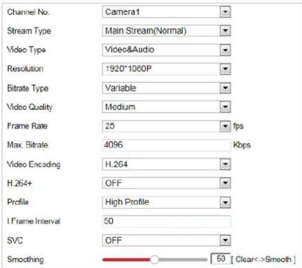
text_image
Channel No. Camera1 Stream Type Main Stream(Normal) Video Type Video&Audio Resolution 1920*1060P Bitrate Type Variable Video Quality Medium Frame Rate 25 fps Max Bitrate 4096 Kbps Video Encoding H.264 H.264+ OFF Profile High Profile I Frame Interval 50 SVC OFF Smoothing 50 [ Clear->Smooth ]Figure 7-22 Configure Video Settings
-
Select the Channel No. in the dropdown list you want to configure.
-
Select the Stream Type of the speed dome to main stream (normal), sub-stream or third stream. The main stream is usually for recording and live viewing with good bandwidth, and the sub-stream can be used for live viewing when the bandwidth is limited. Refer to the Section 4.1 Configuring Local Parameters for switching the main stream and sub-stream for live viewing.
-
You can customize the following parameters for the selected stream.

The parameters vary depending on the models of the speed dome.
Video Type:
Select the stream type to video stream, or video & audio composite stream. The audio signal will be recorded only when the Video Type is Video & Audio.
Resolution:
Select the resolution of the video output.
Bitrate Type:
Select the bitrate type to constant or variable.
Video Quality:
When bitrate type is selected as Variable, 6 levels of video quality are selectable.
Frame Rate:
The frame rate is to describe the frequency at which the video stream is updated and it is measured by frames per second (fps). A higher frame rate is advantageous when there is movement in the video stream, as it maintains image quality throughout.
Max. Bitrate:
Set the max. bitrate to 256\~16384Kbps. The higher value corresponds to the higher video quality, but the higher bandwidth is required.
Video Encoding:
The Video Encoding standard can be set to H.264.
H.264+:
Set it as ON or OFF.
Profile:
Basic Profile, Main Profile and High Profile are selectable.
I Frame Interval:
Set the I-Frame interval from 1 to 400.
SVC:
Scalable Video Coding is an extension of the H.264/AVC standard. Select OFF/ON to disable/enable the SVC function. Select Auto, and the device will automatically extract frames from the original video when the network bandwidth is insufficient.
Smoothing:
It refers to the smoothness of the stream. The higher value of the smoothing, the better fluency of the stream, though, the video quality may not be so satisfied. The lower value of the smoothing, the higher quality of the stream, though it may appear not fluent.
- Click Save to save the settings.

7.2.2 Configuring Audio Settings
Steps:
- Enter the Audio settings interface
Configuration > Video/Audio > Audio
- Select the channel No. from the dropdown list.
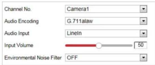
text_image
Channel No. Camera1 Audio Encoding G.711alaw Audio Input Lineln Input Volume 50 Environmental Noise Filter OFFFigure 7-23 Audio Settings
- Configure the following settings.
Audio Encoding: G.722.1, G.711ulaw, G.711alaw, MP2L2, G.726 and PCM are selectable.
Audio Input: When an intercom is connected to the speed dome, you need to set this option to LineIn. When a microphone is connected to the speed dome, you need to set this option to MicIn.
Audio Stream Bitrate: When the Audio Encoding is selected as MP2L2, you can configure the Audio Stream Bitrate in the dropdown list. The greater the value is, the better the audio quality will be.
Sampling Rate: When the Audio Encoding is selected as MP2L2, you can configure the Sampling Rate in the dropdown list. The greater the value is, the better the audio quality will be.
Input Volume: Slid the bar to turn up/down the volume. The value ranges from 0 to 100.
Environmental Noise Filter: Select ON or OFF in the dropdown list to enable or disable the function. It's recommended to enable the function when the sampling rate is lower than 32kHz.
- Click Save to save the settings.
7.2.3 Configuring ROI Settings
Purpose:
ROI (Region of Interest) encoding is used to enhance the quality of images which are specified in advance. There are two different ROI methods: Fixed Region and Dynamic Region. When Fixed Region is enabled, image quality of ROI area will be enhanced and image quality of other areas will be reduced. When Dynamic Region is enabled, image quality of tracking target will be enhanced.

ROI function varies depending on the models of speed dome.
Steps:
- Enter the ROI settings interface:
Configuration >Video/Audio >ROI
- Select the channel No. from the drop-down list.

text_image
Channel No Camera1 03-16-2017 Thu 18:46:02 Stop Drawing Clear Stream Type Stream Type Main Stream(Normal) Fixed Region Enable Region No 1 ROI Level 3 Region NameFigure 7-24 Region of Interest (1)
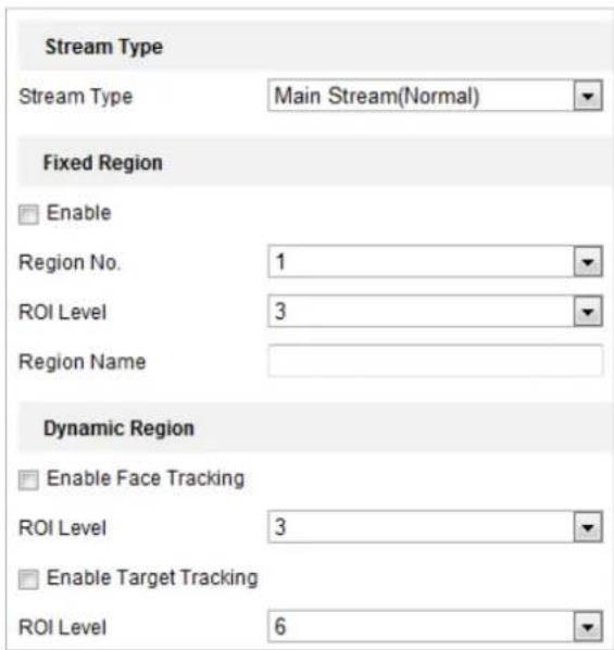
text_image
Stream Type Stream Type Main Stream(Normal) Fixed Region Enable Region No. 1 ROI Level 3 Region Name Dynamic Region Enable Face Tracking ROI Level 3 Enable Target Tracking ROI Level 6Figure 7-25 Region of Interest (2)
- ROI for Fixed Region
Steps:
- Check Enable checkbox to enable the Fixed Region function.
- Select a stream type. You can set the ROI function for main stream, sub stream or third stream.
- Click Draw Area and then click-and-drag the mouse to draw a red frame in the live
view image. You can click to clear it.

The number of areas supported in ROI function varies depending on the models of speed dome.
-
Select the Region No. from the dropdown list.
-
Adjust the ROI level from 1 to 6. The higher the value, the better image quality in the red frame.
-
Enter a Region Name.
- ROI for Dynamic Region
-
Check Enable Face Tracking checkbox to enable face tracking, and the captured face picture is set as region of interest. Adjust the ROI level from 1 to 6.
-
Check Enable Target Tracking checkbox to enable target tracking, and the target is set as region of interest. Adjust the ROI level from 1 to 6.
-
Click Save to save the settings.

This function varies according to models.
7.3 PTZ Configuration

- On the event configuration page, click to show the PTZ control panel or click to hide it.
- Click the direction buttons to control the pan/tilt movements.
- Click the zoom/iris/focus buttons to realize lens control.
● The functions vary depending on the models of speed dome.
7.3.1 Configuring Basic PTZ Parameters
Purpose:
You can configure the basic PTZ parameters, including proportional pan, preset freezing, preset speed, etc.
- Enter the Basic PTZ Parameter Configuration interface:
Configuration > PTZ > Basic Settings
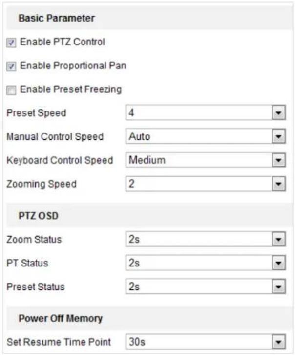
text_image
Basic Parameter Enable PTZ Control Enable Proportional Pan Enable Preset Freezing Preset Speed 4 Manual Control Speed Auto Keyboard Control Speed Medium Zooming Speed 2 PTZ OSD Zoom Status 2s PT Status 2s Preset Status 2s Power Off Memory Set Resume Time Point 30sFigure 7-26 Basic PTZ Configuration Interface
- Configure the following settings:
- Basic Parameters: Enable/disable PTZ control, proportional pan and preset freezing, set the preset speed, keyboard control speed, and auto scan speed.
◆ PTZ Control: By default, PTZ Control function is enabled. You can uncheck the checkbox to disable the PTZ control function.

The PTZ Control function varies depending on the models of speed dome.
Proportional Pan: If you enable this function, the pan/tilt speeds change according to the amount of zoom. When there is a large amount of zoom, the pan/tilt speed will be slower for keeping the image from moving too fast on the live view image.
◆ Preset Freezing: This function enables the live view to switch directly from one scene defined by a preset to another, without showing the middle areas between these two, to ensure the surveillance efficiency. It can also reduce the use of bandwidth in a digital network system.

Preset freezing function is invalid when you calling a pattern.
◆ Preset Speed: You can set the speed of a defined preset from 1 to 8.
◆ Manual Control Speed: The speed dome provides 5 control speed modes: Compatible, Pedestrian, Non-motor Vehicle, Motor Vehicle and Auto. Select it from the dropdown list.
◆ Keyboard Control Speed: Define the speed of PTZ control by a keyboard as Low, Medium or High.
◆ Auto Scan Speed: The scan speed can be set from level 1 to 40.
Max. Tilt-angle: Set the tilt-angle of the speed dome from the dropdown list.
◆ Zooming Speed: The speed of zooming is adjustable.
- PTZ OSD: Set the on-screen display duration of the PTZ status.
◆ Zoom Status: Set the OSD duration of zooming status as 2 seconds, 5 seconds, 10 seconds, Always Close or Always Open.
◆ PT Status: Set the azimuth angle display duration while panning and tilting as 2 seconds, 5 seconds, 10 seconds, Always Close or Always Open.
◆ Preset Status: Set the preset name display duration while calling the preset as 2 seconds, 5 seconds, 10 seconds, Always Close or Always Open.
- Power-off Memory: The speed dome can resume its previous PTZ status or actions after it restarted from a power-off. You can set the time point of which the speed dome resumes its PTZ status. You can set it to resume the status of 30 seconds, 60 seconds, 300 seconds or 600 seconds before power-off.
- Click

7.3.2 Configuring PTZ Limits
Purpose:
The speed dome can be programmed to move within the configurable PTZ limits (left/right, up/down).
Steps:
- Enter the Limit configuration interface:
Configuration > PTZ > Limit
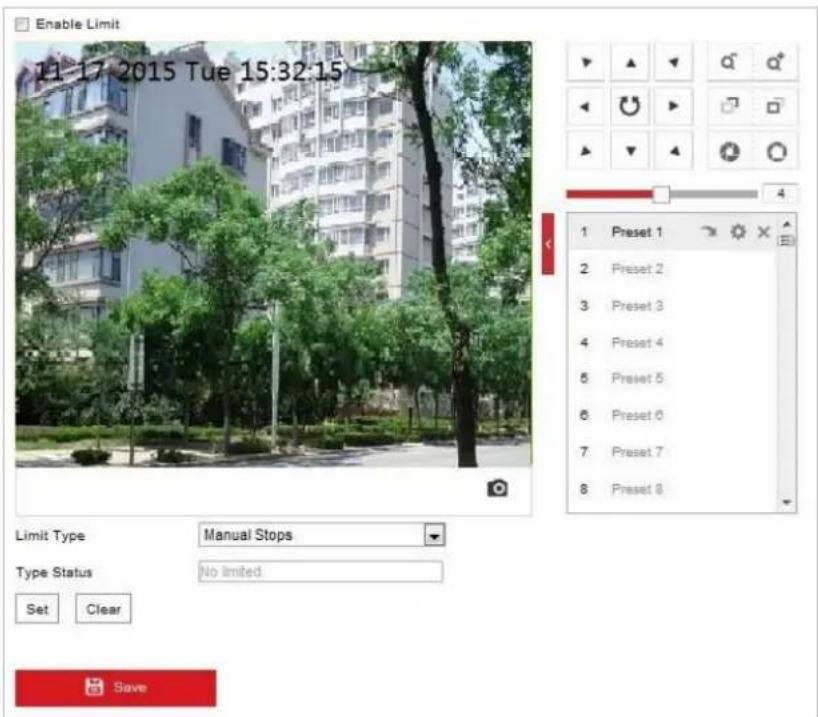
text_image
Enable Limit 11-17 2015 Tue 15:32:15 Limit Type Manual Stops Type Status No limited Set Clear SaveFigure 7-27 Configure the PTZ Limit
- Click the checkbox of Enable Limit and choose the limit type as manual stops or scan stops.
- Manual Stops:
When manual limit stops are set, you can operate the PTZ control panel manually only in the limited surveillance area.
- Scan Stops:
When scan limit stops are set, the random scan, frame scan, auto scan, tilt scan, panorama scan is performed only in the limited surveillance area.

Manual Stops of Limit Type is prior to Scan Stops. When you set these two limit types at the same time, Manual Stops is valid and Scan Stops is invalid.
-
Click the PTZ control buttons to find the left/right/up/down limit stops; you can also call the defined presets and set them as the limits of the speed dome.
-
Click Set to save the limits or click Clear to clear the limits.
7.3.3 Configuring Initial Position
Purpose:
The initial position is the origin of PTZ coordinates. It can be the factory default initial position. You can also customize the initial position according to your own demand.
- Customize an Initial Position:
Steps:
- Enter the Initial Position Configuration interface:
Configuration > PTZ > Initial Position
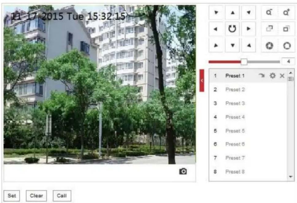
text_image
11 17 2015 Tue 15:32:15 1 Preset 1 2 Preset 2 3 Preset 3 4 Preset 4 5 Preset 5 6 Preset 6 7 Preset 7 8 Preset 8 Set Clear CallFigure 7-28 PTZ Configuration
- Click the PTZ control buttons to find a position as the initial position of the speed dome; you can also call a defined preset and set it as the initial position of the speed dome.
- Click Set to save the position.
- Call/delete an Initial Position:
You can click ↗ to call the initial position. You can click ✗ to delete the initial position and restore the factory default initial position.
7.3.4 Configuring Park Actions
Purpose:
This feature allows the speed dome to start a predefined park action (scan, preset, pattern and etc.) automatically after a period of inactivity (park time).

- Scheduled Tasks function is prior to Park Action function. When these two functions are set at the same time, only the Scheduled Tasks function takes effect.
● Pattern function varies depending on speed dome models.
Steps:
- Enter the Park Action settings interface:
Configuration > PTZ > Park Action
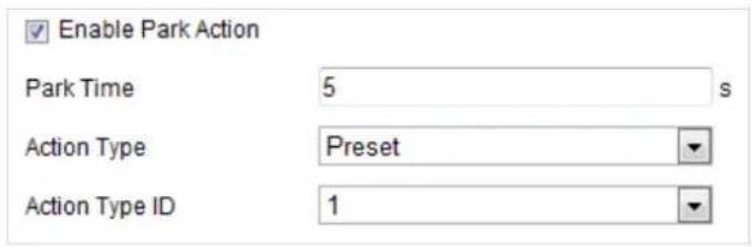
text_image
Enable Park Action Park Time 5 s Action Type Preset Action Type ID 1Figure 7-29 Set the Park Action
- Check the checkbox of Enable Park Action.
- Set the Park Time as the inactivity time of the speed dome before it starts the park actions.
- Choose Action Type the from the dropdown list.
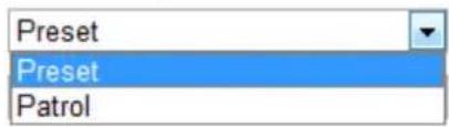
text_image
Preset Preset PatrolFigure 7-30 Action Types
-
Select the Action Type ID from the dropdown list.
-
Click

to save the settings.
7.3.5 Configuring Privacy Mask
Purpose:
Privacy mask enables you to cover certain areas on the live video to prevent certain spots in the surveillance area from being live viewed and recorded.
Steps:
- Enter the Privacy Mask settings interface:
Configuration > PTZ > Privacy Mask
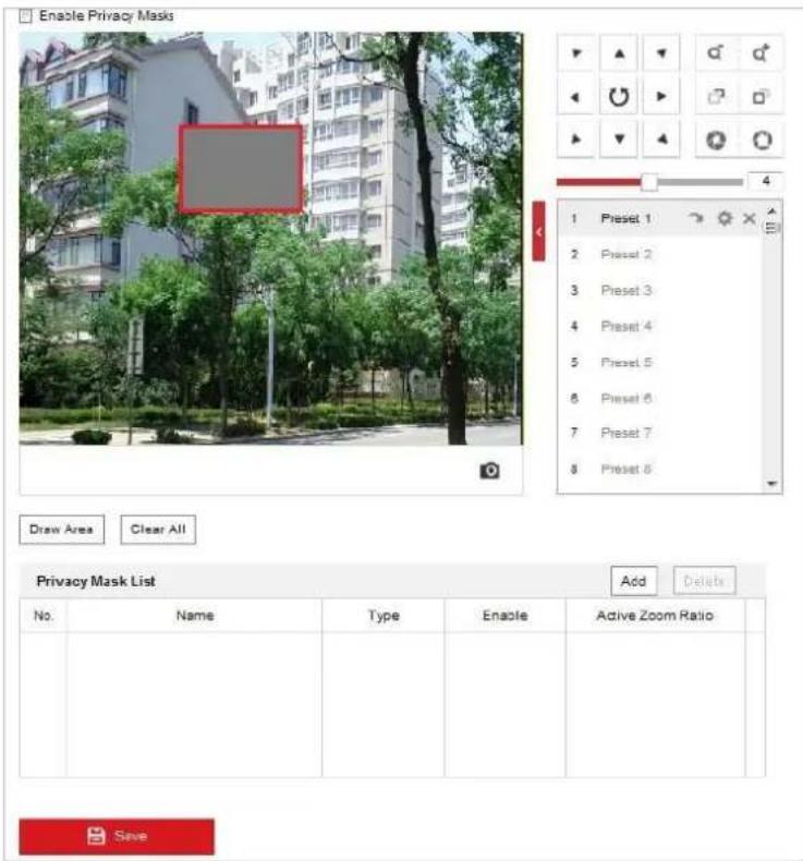
text_image
Enable Privacy Masks 1 Preset 1 2 Preset 2 3 Preset 3 4 Preset 4 5 Preset 5 6 Preset 6 7 Preset 7 8 Preset 8 Draw Area Clear All Privacy Mask List Add Delete No. Name Type Enable Active Zoom Ratio SaveFigure 7-31 Draw the Privacy Mask
- Click the PTZ control buttons to find the area you want to set the privacy mask.
- Click Draw Area; click and drag the mouse in the live video window to draw the area.
- You can drag the corners of the red rectangle area to draw a polygon mask.
- Click Stop Drawing to finish drawing or click Clear All to clear all of the areas you set without saving them.
- Click Add to save the privacy mask, and it will be listed in the Privacy Mask List area; set the value of Active Zoom Ratio on your demand, and then the mask will only appear when the zoom ratio is greater than the predefined value.
| Privacy Mask List | Add Delete | ||||
| No. | Name | Type | Enable | Active Zoom Ratio | |
| 1 | Privacy Mask 1 | gray | Yes | 1 | |
Figure 7-32 Privacy Mask List
- Check the checkbox of Enable Privacy Mask to enable this function.

You are allowed to draw up to 8 areas for the speed dome.
7.3.6 Configuring Scheduled Tasks
Purpose:
You can configure the network speed dome to perform a certain action automatically in a user-defined time period.
Steps:
- Enter the Scheduled Task settings interface:
Configuration> PTZ > Scheduled Tasks
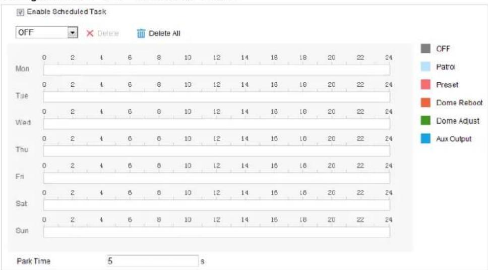
Figure 7-33 Configure Scheduled Tasks
- Check the checkbox of Enable Scheduled Task.
- Set the Park Time. You can set the park time (a period of inactivity) before the speed dome starts the scheduled tasks.
- Select the task type from the dropdown list. You can choose scan, preset, pattern and etc.

text_image
OFF OFF Patrol Preset Dome Reboot Dome Adjust Aux OutputFigure 7-34 Task Types
- Select the timeline of a certain day, click and drag the mouse to set the recording schedule (the start time and end time of the recording task).
- After you set the scheduled task, you can click 📄 and copy the task to other days (optional).
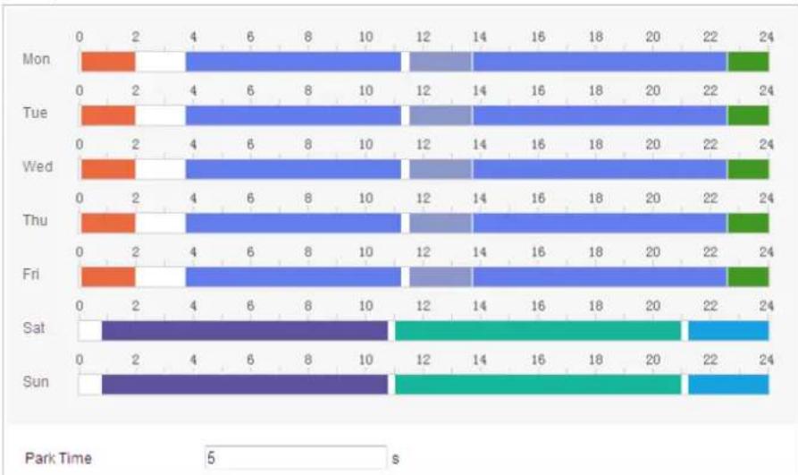
bar_stacked
| Day | 0 | 2 | 4 | 6 | 8 | 10 | 12 | 14 | 16 | 18 | 20 | 22 | 24 | |-------|------|------|------|------|------|------|------|------|------|------|------|------|------| | Mon | | | | | | | | | | | | | | | Tue | | | | | | | | | | | | | | | Wed | | | | | | | | | | | | | | | Thu | | | | | | | | | | | | | | | Fri | | | | | | | | | | | | | | | Sat | 0 | 2 | 4 | 6 | 8 | 10 | 12 | 14 | 16 | 18 | 20 | 22 | 24 | | Sun | 0 | 2 | 4 | 6 | 8 | 10 | 12 | 14 | 16 | 18 | 20 | 22 | 24 |Figure 7-35 Edit the Schedule and Task Type

The time of each task cannot be overlapped. Up to 10 tasks can be configured for each day.
7. Click

7.3.7 Clearing PTZ Configurations
Purpose:
You can clear PTZ configurations in this interface, including all presets, patrols, privacy masks, PTZ limits, scheduled tasks and park actions.

Pattern function varies depending on speed dome models.
Steps:
- Enter the Clearing Configuration interface:
Configuration > PTZ > Clear Config

© Hikvision
-
Check the checkbox of the items you want to clear.
-
Click Save to clear the settings.
7.3.8 Prioritize PTZ
Steps:
- Enter the Prioritize PTZ interface: Configuration > PTZ > Prioritize PTZ.

text_image
Prioritize PTZ Network Delay 10 sFigure 7-36 Position Settings
-
Select Network or RS-485 from the dropdown list
-
Set the delay time (Range 2-200s).
-
Click Save to save the settings.
7.3.9 Position Settings
Steps:
- Enter the Position Settings interface:
Configuration > PTZ > Position Settings.

The actual interface may vary from model to model.
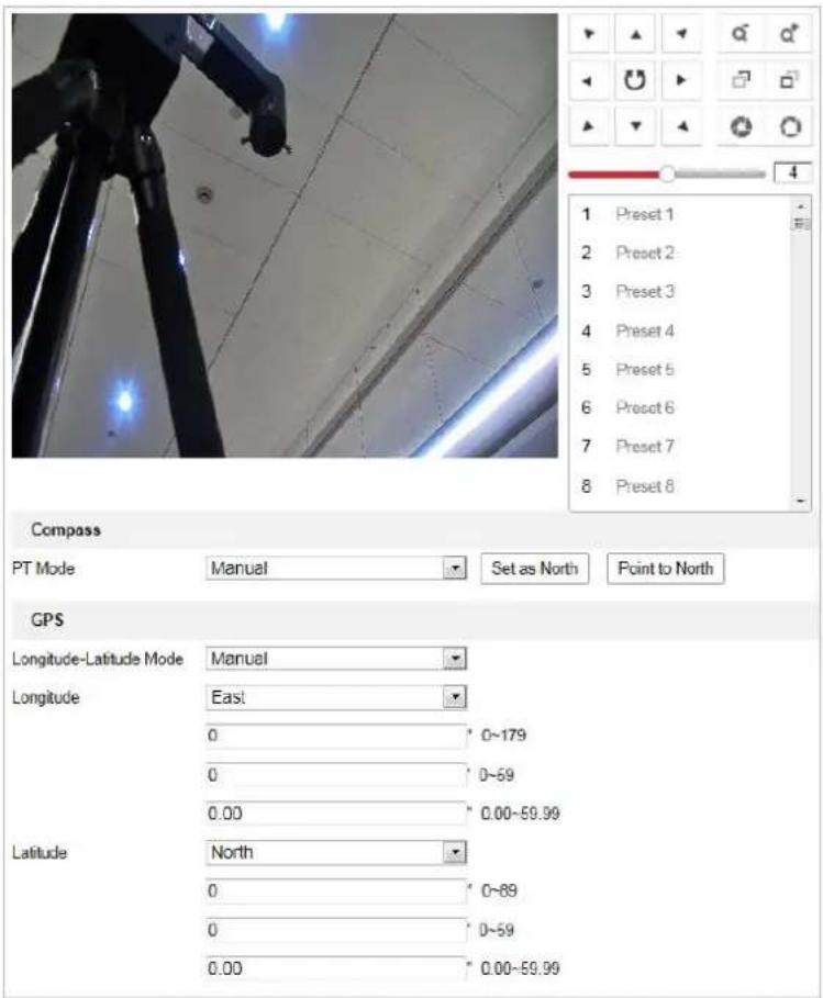
text_image
Compass PT Mode Manual Set as North Point to North GPS Longitude-Latitude Mode Manual Longitude East 0 0~179 0 0~59 0.00 0.00~59.99 Latitude North 0 0~89 0 0~59 0.00 0.00~59.99Figure 7-37 Position Settings
- Set the compass parameters.
(1) Select PT Mode as Manual.
(2) Click the PTZ control buttons to find the north direction; you can also call a defined preset and set it as the north direction.
(3) Click Set as North to save the position.
(4) Optionally, you can click Point to North to move the device to the north direction if the north direction was once saved.
- Set the vandal-resistance alarm.
(1) Slide the bar to adjust the sensitivity of vandal-resistance detection.
(2) Check the checkbox of Upload Vandal-Resistance Alarm to upload the vandal-resistance alarm.
(3) Check the checkbox of Enable Vandal-Resistance Alarm Voice Warning to enable the voice warning of vandal-resistance alarm.
- Set GPS settings.
(1) Select Longitude-Latitude Mode as Manual.
(2) Select longitude and latitude as East or West according to the actual position.
(3) Enter the value of longitude and latitude in three textboxes.
- Click

7.3.10 Configuring Linear Scan
Steps:
- Get to the linear scan interface:
Configuration > Advanced Configuration> PTZ > Linear Scan.
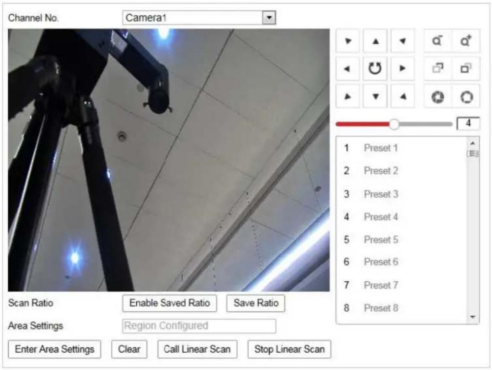
text_image
Channel No. Camera1 Scan Ratio Enable Saved Ratio Save Ratio Area Settings Region Configured Enter Area Settings Clear Call Linear Scan Stop Linear Scan 1 Preset 1 2 Preset 2 3 Preset 3 4 Preset 4 5 Preset 5 6 Preset 6 7 Preset 7 8 Preset 8Figure 7-38 Linear Scan
- Select Camera 1 or Camera 2 from the Channel No. list.
- Zoom in and zoom out the camera to the appropriate zoom ratio.
- Click Save Ratio to save the zoom ratio.
- Optionally, you can click Enable Saved Ratio to set the camera to the saved zoom ratio.
- Click Set Scan Area and set the left/right/up/down limits with the PTZ control panel and Iris+/- button.
- Optionally, you can click Clear to delete the saved scan area.
- Click Save to save the settings and the Linear Scan Area shows Scan area saved.
- Click Start Linear Scan and Stop Linear Scan to start and stop the saved linear scan.
7.4 Configuring Image Settings

- On the event configuration page, click to show the PTZ control panel or click to hide it.
- Click the direction buttons to control the pan/tilt movements.
- Click the zoom/iris/focus buttons to realize lens control.
● The functions vary depending on the models of speed dome.
7.4.1 Configuring Display Settings
Purpose:
You can set the image quality of the speed dome, including brightness, contrast, saturation, sharpness, etc.

- The parameters in Display Settings interface vary depending on the models of speed dome.
- You can double click the live view to enter full screen mode and double click it again to exit.
Steps:
- Enter the Display settings interface:
Configuration > Image> Display Settings
- Select the channel No. from the dropdown list.
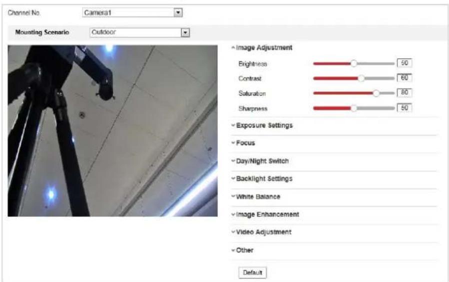
text_image
Channel No. Camera1 Mounting Scenario Outdoor • Image Adjustment Brightness 50 Contrast 60 Saturation 80 Sharpness 50 • Exposure Settings • Focus • Day/Night Switch • Backlight Settings • White Balance • Image Enhancement • Video Adjustment • Other DefaultFigure 7-39 Display Settings
- You can select the Scene in the dropdown list with different predefined image
parameters.
- Set the image parameters of the speed dome.
◆ Setting the Channel Camera 2
Image Adjustment
- Brightness
This feature is used to adjust brightness of the image. The value ranges from 0 to 100.
- Contrast
This feature enhances the difference in color and light between parts of an image. The value ranges from 0 to 100.
- Saturation
This feature is used to adjust color saturation of the image. The value ranges from 0 to 100.
- Sharpness
Sharpness function enhances the detail of the image by sharpening the edges in the image. The value ranges from 0 to 100.

The parameters vary depending on the models of speed dome.
Exposure Settings
- Exposure Mode
The Exposure Mode can be set to Auto, Iris Priority, Shutter Priority, and Manual.
Auto:
The iris, shutter and gain values will be adjusted automatically according to the brightness of the environment.
◆ Iris Priority:
The value of iris needs to be adjusted manually. The shutter and gain values will be adjusted automatically according to the brightness of the environment.
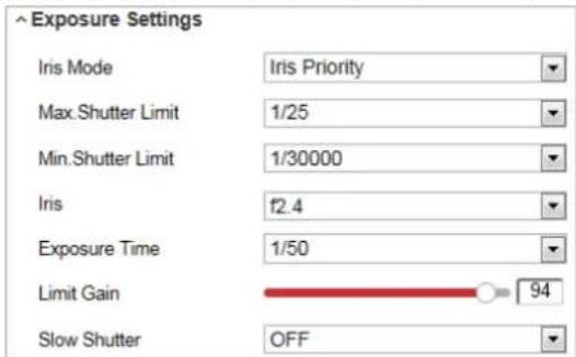
text_image
Exposure Settings Iris Mode Iris Priority Max.Shutter Limit 1/25 Min.Shutter Limit 1/30000 Iris f2.4 Exposure Time 1/50 Limit Gain 94 Slow Shutter OFFFigure 7-40 Manual Iris
◆ Shutter Priority:
The value of shutter needs to be adjusted manually. The iris and gain values will be adjusted automatically according to the brightness of the environment.
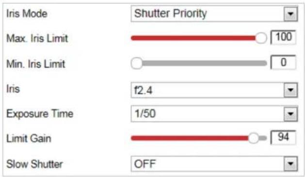
text_image
Iris Mode Shutter Priority Max. Iris Limit 100 Min. Iris Limit 0 Iris f2.4 Exposure Time 1/50 Limit Gain 94 Slow Shutter OFFFigure 7-41 Manual Shutter
◆ Manual:
In Manual mode, you can adjust the values of Gain, Shutter, Iris manually.
- Limit Gain
This feature is used to adjust gain of the image. The value ranges from 0 to 100.
- Slow Shutter
This function can be used in underexposure condition. It lengthens the shutter time to ensure full exposure.
- Slow Shutter Level
When slow shutter is set as ON, you can select the slow shutter level from the dropdown list. The slow shutter lever can be set to Slow Shutter*2, *3, *4, *6, *8.

text_image
Slow Shutter ON Slow Shutter Level Slow Shutter*2Figure 7-42 Slow Shutter

The parameters vary depending on the models of speed dome.
Focus Settings
- Focus Mode
The Focus Mode can be set to Auto, Manual, Semi-auto.
Auto:
The speed dome focuses automatically at any time according to objects in the scene.
◆ Semi-auto:
The speed dome focuses automatically only once after panning, tilting and zooming.
◆ Manual:
In Manual mode, you need to use ☐ on the control panel to focus manually.
- Min. Focus Distance
This function is used to limit the minimum focus distance.

The minimum focus value varies depending on the models of speed dome.
Day/Night Switch
- Day/Night Switch
The Day/Night Switch mode can be set to Auto, Day, Night and Scheduled-Switch.

This function varies depending on the models of speed dome.
Auto:
In Auto mode, the day mode and night mode can switch automatically according to the light condition of environment.
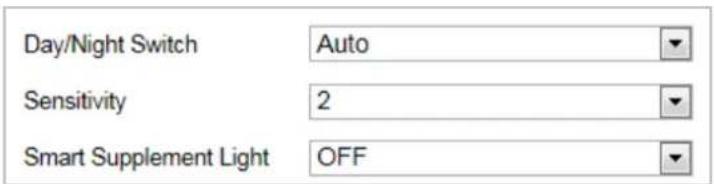
text_image
Day/Night Switch Auto Sensitivity 2 Smart Supplement Light OFFFigure 7-43 Auto Mode Sensitivity
Day:
In Day mode, the speed dome displays color image. It is used for normal lighting conditions.
◆ Night:
In Night mode, the image is black and white. Night mode can increase the sensitivity in low light conditions.
◆ Scheduled-Switch:
In Schedule mode, you can set the time schedule for day mode as shown in Figure 7-44. The rest time out of the schedule is for night mode.
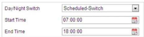
text_image
Day/Night Switch Scheduled-Switch Start Time 07:00:00 End Time 18:00:00Figure 7-44 Day Night Schedule
Backlight Settings
● BLC (Back Light Compensation)
If there's a bright backlight, the subject in front of the backlight appears silhouetted or dark. Enabling BLC(back light compensation) function can correct the exposure of the subject. But the backlight environment is washed out to white.
● WDR (Wide Dynamic Range)
The wide dynamic range (WDR) function helps the camera provide clear images even
under back light circumstances. When there are both very bright and very dark areas simultaneously in the field of view, WDR balances the brightness level of the whole image and provide clear images with details.
You can enable or disable the WDR function as shown in Figure 7-45. The wide dynamic level ranges from 0 to 100.

text_image
WDR ON Wide Dynamic Level 11Figure 7-45 WDR

This function varies depending on the models of speed dome.
HLC
HLC (High Light Compensation) makes the camera identify and suppress the strong light sources that usually flare across a scene. This makes it possible to see the detail of the image that would normally be hidden.
White Balance
The White Balance mode can be set to Auto, MWB, Outdoor, Indoor, Fluorescent Lamp, Sodium Lamp and Auto-Tracking.
Auto:
In Auto mode, the camera retains color balance automatically according to the current color temperature.
◆ Manual White Balance:
In MWB mode, you can adjust the color temperature manually to meet your own demand as shown in Figure 7-46.
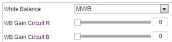
text_image
White Balance MWB WB Gain Circuit R 0 WB Gain Circuit B 0Figure 7-46 Manual White Balance
◆ Outdoor
You can select this mode when the speed dome is installed in outdoor environment.
Indoor
You can select this mode when the speed dome is installed in indoor environment.
◆ Fluorescent Lamp
You can select this mode when there are fluorescent lamps installed near the speed dome.
◆ Sodium Lamp
You can select this mode when there are sodium lamps installed near the speed dome.
◆ Auto-Tracking
In Auto-Tracking mode, white balance is continuously being adjusted in real-time according to the color temperature of the scene illumination.

This function varies depending on the models of speed dome.
Image Enhancement

This function varies depending on the models of speed dome.
● 3D Digital Noise Reduction
You can set Digital Noise Reduction function to Normal and adjust the Noise Reduction Level as shown in Figure 7-47. The level ranges from 0 to 100.

text_image
Digital Noise Reduction Normal Noise Reduction Level 50Figure 7-47 3D Digital Noise Reduction
If you are a professional technician, you can set it to Expert Mode then adjust Space DNR Level and Time DNR Level. The level ranges from 0 to 100.
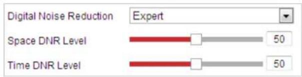
text_image
Digital Noise Reduction Expert Space DNR Level 50 Time DNR Level 50Figure 7-48 Expert Mode
- Defog Mode
You can set the Defog Mode to ON or OFF as you need.

Figure 7-49 Defog Mode
● EIS (Electronic Image Stabilization)
You can set theEIS to ON or OFF as you need.

Figure 7-50 Electronic Image Stabilization
Video Adjustment
- Mirror
If you turn the MIRROR function on, the image will be flipped. It is like the image in the mirror. The flip direction can be set to OFF or CENTER.

This function varies depending on the models of speed dome.
- Video Standard
You can set the Video Standard to 50hz(PAL) or 60hz(NTSC) according to the video system in your country.

This function varies depending on the models of speed dome.
- Capture Mode
You can disable this function or select the capture mode from the list..

This function varies depending on the models of speed dome.
Other
- Lens Initialization
The lens operates the movements for initialization when you check the check box of Lens Initialization.
- Zoom Limit
You can set Zoom Limit value to limit the maximum value of zooming. The value can be selected from the list.
- Local Output
You can enable or disable the video output through the BNC interface on your demand.

The functions vary depending on the models of speed dome.
◆ Setting the Channel Camera 2
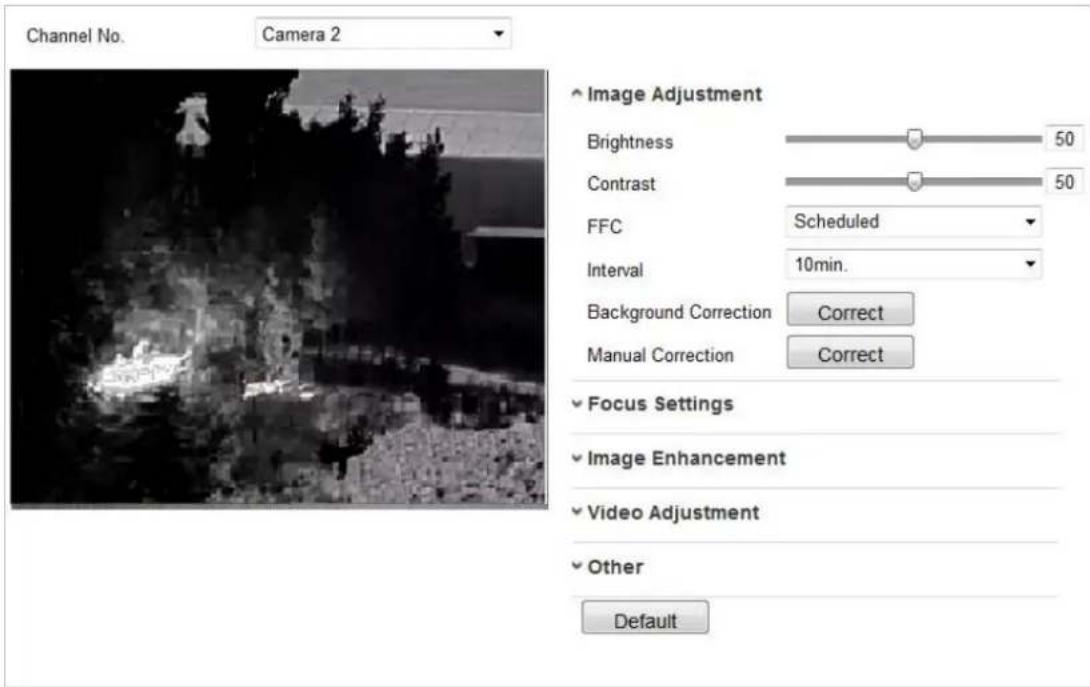
text_image
Channel No. Camera 2 Image Adjustment Brightness 50 Contrast 50 FFC Scheduled Interval 10min. Background Correction Correct Manual Correction Correct Focus Settings Image Enhancement Video Adjustment Other DefaultFigure 7-51 Camera No. 2 Image Settings
■ Image Adjustment
- Brightness
This feature is used to adjust brightness of the image. The value ranges from 0 to 100.
- Contrast
This feature enhances the difference in color and light between parts of an image. The value ranges from 0 to 100.
- FFC
The FFC (Flat Field Correction) improves the quality in digital imaging. It can remove artifacts from 2-D images that are caused by variations in the pixel-to-pixel sensitivity of the detector or by distortions in the optical path. Schedule, Temperature, and OFF are selectable.
◆ Schedule
You can select the correction interval among "10", "20", "30", "40", "50", "60", "120", "180", and "240" minutes.
◆ Temperature
Camera adjusts the image according to the temperature.
● Manual Background Correction
Fully cover the lens with an object (lens cover is recommended) and click the Manual Background Correction button, and then the speed dome adjusts the image according to the current environment.
- Manual Shutter Correction
Click the Manual Shutter Correction button and then the speed dome adjusts the image according to the temperature of the camera itself.
■ Image Enhancement
● Digital Noise Reduction:
DNR reduces the noise in the video stream. OFF, Normal Mode and Expert Mode are selectable.
OFF: DNR is disabled.
Normal Mode: Set the DNR level from 0\~100, and the default value is 50.
Expert Mode: Set the DNR level from both space DNR level [0\~100] and time DNR level [0\~100] in Expert Mode.
- Palettes
The palettes allow you to select the desired colors. white hot, black hot, fusion 1, rainbow, fusion 2, ironbow 1, ironbow2, sepia, color 1, color 2, ice fire, rain, red hot, and green hot are selectable.
DDE
The DDE (Digital Detail Enhancement) can adjust the details of the image. And you can set it to OFF or Normal mode. And DDE Level can be adjust from 1 to 100 when in normal mode.
■ Video Adjustment
- Mirror
If you turn the Mirror function on, the image will be flipped. You can set the mirror direction to Center or disable it.

This function varies depending on the models of speed dome.
- Video Standard
The Video Standard is configurable.

This function varies depending on the models of speed dome.
- Capture Mode:
You can set the Capture Mode to OFF and 384*288@25fps.
- Digital Zoom
The digital zoom is available for the thermal sensor, there are x2 and X4 selectable.

This function varies depending on the models of speed dome.
7.4.2 Configuring OSD Settings
Purpose:
The speed dome supports following on screen displays:
Time: Supports for time display.
Camera Name: Identifies the name of speed dome.
You can customize the on screen display of time.
Steps:
- Enter the OSD settings interface:
Configuration > Image > OSD Settings
- Select the channel No..

text_image
Channel No. Camera1 Display Name Display Date Display Week Camera Name: Camera 01 Time Format: 24-hour Date Format: MM-DD-YYYY Text OverLay 1 2 3 4 5 6 7 8 Display Mode Not transparent & Not flashing OSD Size Auto Font Color Black&White Self-adaptiveFigure 7-52 OSD Settings
- Check the corresponding checkbox to select the display of speed dome name, date or week if required.
- Edit the speed dome name in the text field of Camera Name.
- Select from the dropdown list to set the time format, date format, display mode, OSD size and Font color.
- You can use the mouse to click and drag the text frame IPdome in the live view window to adjust the OSD position.
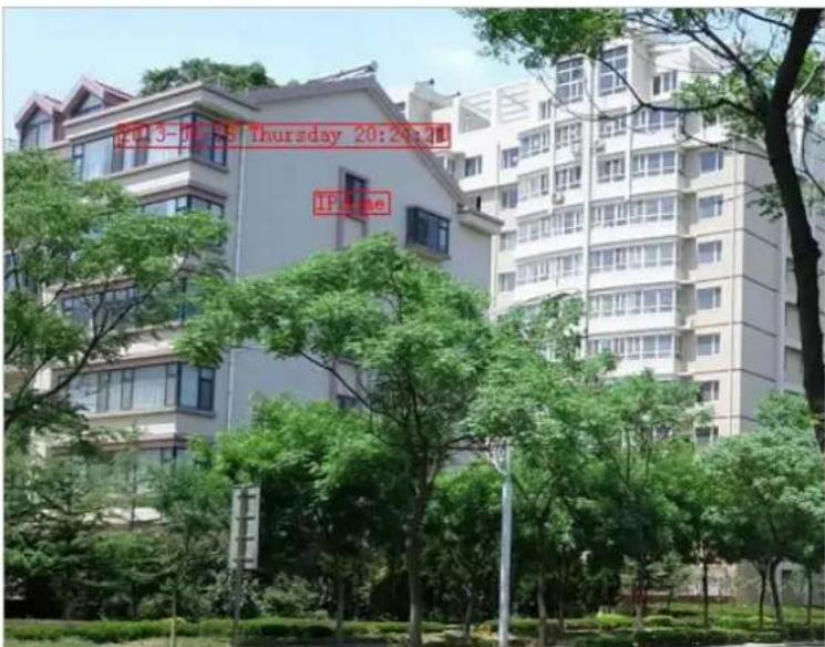
text_image
12:30-55 Thursday 20:20:21 IF:55 meFigure 7-53 Adjust OSD Location
- Click

to activate above settings.
7.4.3 Configuring Text Overlay Settings
Purpose:
You can customize the text overlay.
Steps:
- Enter the Text Overlay settings interface:
Configuration > Image > OSD Settings
-
Check the checkbox in front of textbox to enable the on-screen display.
-
Input the characters in the textbox.
-
Use the mouse to click and drag the red text frame Text in the live view window to adjust the text overlay position.
-
Click to save the settings.

There are up to 4 text overlays configurable. When the video resolution is 1080p, only one text overlay is supported. When PTZ direction, preset OSDs are displayed, the text overlay is disabled.
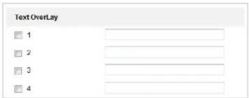
text_image
Text OverLay 1 2 3 4Figure 7-54 Text Overlay Settings
7.4.4 VCA Rule Display
Purpose:
You can customize the VCA rule display information format.
Step:
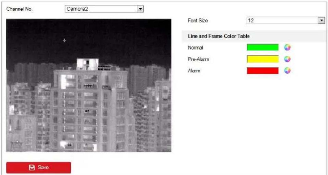
text_image
Channel No. Camera2 Font Size 12 Line and Frame Color Table Normal Pre-Alarm Alarm SaveFigure 7-55 VCA Rule Display
- Set the font size of the VCA rules.
- Customize the color of line and frame for Normal, Pre-Alarm, and Alarm.
- Click to save the settings.
7.4.5 Configuring DPC Settings
DPC (Defective Pixel Correction) refers to the function that the camera can correct the defective pixels on the LCD which are not performing as expected.
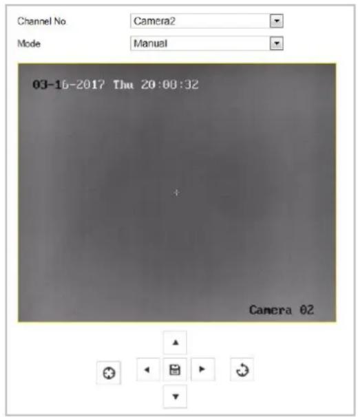
text_image
Channel No Camera2 Mode Manual 03-16-2017 Thu 20:08:32 Camera 02Figure 7-56 Defective Pixel Correction
◆ Auto DPC Correction
Steps:
- Select Auto from the modes.
- Click to start correction.
◆ Manual DPC Correction
Steps:
- Select Manual from the modes.
- Point to the defective pixel, and click 🔊 to adjust the position.
- Click to start correction.
- (Optional) Click ✿ to cancel the correction.

This function varies depending on the models of speed dome.
7.4.6 Picture in Picture
Before you start:
Enter Configuration > System > System Maintenance > VCA Resource Type to select Picture in Picture as VCA Resource Type.
Purpose:
The system plays the live view of thermal channel and optical channel at the same time.
Steps:
- Select the channel No. from the list.

Select Camera 1 and the device plays the live view of Camera 2 inside the live view of Camera 1.
- Check the checkbox of Enable.
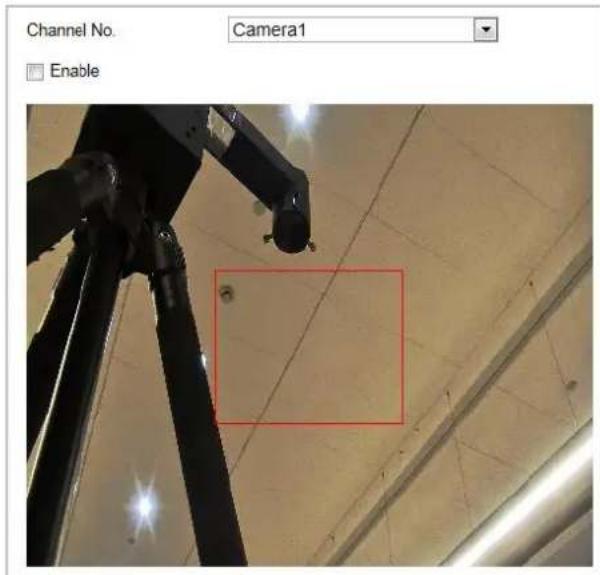
text_image
Channel No. Camera1 EnableFigure 7-57 Picture in Picture
- Drag the red frame to adjust the picture in picture site.
- Click Save to activate above settings.

The Picture in Picture function is reserved.
7.5 Configuring System Settings
7.5.1 System Settings
Viewing Basic Information
Enter the Device Information interface:
Configuration > System > System Settings > Basic Information
In the Basic Information interface, you can edit the Device Name and Device No..
Other information of the network zoom camera, such as Model, Serial No., Firmware Version, Encoding Version, Web Version, Plugin Version, Number of Channels, Number of HDDs, Number of Alarm Input and Number of Alarm Output are displayed. The information cannot be changed in this menu. It is the reference for maintenance or modification in future.

text_image
Device Name IP DOME Device No. 88 Model Serial No. Firmware Version Encoding Version Web Version Plugin Version Number of Channels Number of HDDs Number of Alarm Input Number of Alarm OutputFigure 7-58 Device Information
Time Settings
Purpose:
You can follow the instructions in this section to configure the time which can be displayed on the video. There are Time Zone, Time Synchronization, Daylight Saving Time (DST) functions for setting the time. Time Synchronization consists of auto mode by Network Time Protocol (NTP) server and manual mode.
Enter the Time Settings interface:
Configuration > System > System Settings > Time Settings
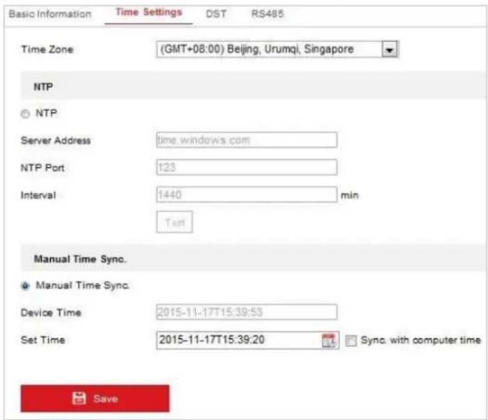
text_image
Basic Information Time Settings DST RS485 Time Zone (GMT+08:00) Beijing, Urumqi, Singapore NTP © NTP Server Address time.windows.com NTP Port 123 Interval 1440 min Text Manual Time Sync. ● Manual Time Sync. Device Time 2015-11-17T15:39:53 Set Time 2015-11-17T15:39:20 Sync. with computer time SaveFigure 7-59 Time Settings
- Configuring Time Synchronization by NTP Server
Steps:
(1) Check the radio button to enable the NTP function.
(2) Configure the following settings:
Server Address: IP address of NTP server.
NTP Port: Port of NTP server.
Interval: The time interval between the two synchronizing actions by NTP server. It can be set from 1 to 10080 minutes.
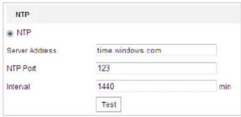
text_image
NTP ● NTP Server Address time windows.com NTP Port 123 Interval 1440 min TestFigure 7-60 Time Sync by NTP Server
You can click ☐ to make sure that the NTP server is connected.

If the speed dome is connected to a public network, you should use a NTP server that has a time synchronization function, such as the server at the National Time Center (IP Address: 210.72.145.44). If the speed dome is set in a customized network, NTP software can be used to establish a NTP server for time synchronization.
- Configuring Time Synchronization Manually
Steps:
(1) Check the Manual Time Sync radio button.
(2) Click to set the system time from the pop-up calendar.
(3) Click to save the settings.

You can also check the Sync with local time checkbox to synchronize the time of the speed dome with the time of your computer.
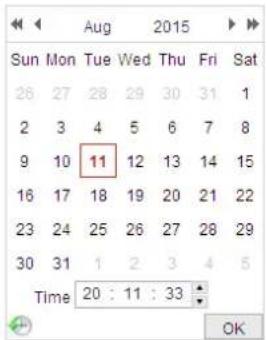
text_image
Sun Mon Tue Wed Thu Fri Sat 28 27 28 29 30 31 1 2 3 4 5 6 7 8 9 10 11 12 13 14 15 16 17 18 19 20 21 22 23 24 25 26 27 28 29 30 31 1 2 3 4 5 Time 20 : 11 : 33 OK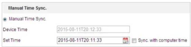
text_image
Manual Time Sync. ● Manual Time Sync. Device Time 2015-08-11T20:12:33 Set Time 2015-08-11T20:11:33 Sync. with computer timeFigure 7-61 Time Sync Manually
- Select the Time Zone

Purpose:
When the speed dome is taken to another time zone, you can use the Time Zone function to adjust the time. The time will be adjusted according to the original time and the time difference between the two time zones.
From the Time Zone dropdown menu as shown in Figure 7-62, select the Time Zone in which the speed dome locates.

text_image
Time Zone (GMT+08:00) Beijing, Urumqi, SingaporeFigure 7-62 Time Zone Settings
Configuring DST (Daylight Saving Time)
Purpose:
If there is the habit of adjusting clocks forward in your country in certain time period of a year, you can turn this function on. The time will be adjusted automatically when the Daylight Saving Time (DST) comes.
Steps:
- Enter the DST interface by Configuration > Advanced Configuration > System > DST
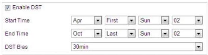
text_image
Enable DST Start Time Apr First Sun 02 End Time Oct Last Sun 02 DST Bias 30minFigure 7-63 DST Settings
- Check to enable the DST function.
- Set the date of the DST period.
- Click to save the settings.
Configuring RS-485
Purpose:
The RS-485 serial port is used to control the PTZ of the camera. The configuring of the PTZ parameters should be done before you control the PTZ unit.
Steps:
- Enter RS-485 Port Setting interface:
Configuration> Advanced Configuration> System > RS-485
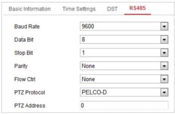
text_image
Basic Information Time Settings DST RS485 Baud Rate 9600 Data Bit 8 Stop Bit 1 Parity None Flow Ctrl None PTZ Protocol PELCO-D PTZ Address 0Figure 7-64 RS-485 Settings
- Set the RS-485 parameters and click
Save
to save the settings.

The Baud rate, PTZ Protocol and PTZ Address parameters of the speed dome should be exactly the same as those of the control device.
7.5.2 Maintenance
Upgrade & Maintenance
● Rebooting the Speed dome
Steps:
- Enter the Maintenance interface:
- Configuration > System > Maintenance > Upgrade & Maintenance:
- Click Reboot to reboot the network speed dome.
- Restoring Default Settings
Steps:
- Enter the Maintenance interface:
Configuration > System > Maintenance > Upgrade & Maintenance: - Click Restore or Default to restore the default settings.

Clicking restores all the parameters to default settings including the IP address and user information. Please use this button with caution.

text_image
Default Restore Reset all the parameters, except the IP parameters and user information, to the default settings. Default Restore all parameters to default settings.Figure 7-65 Restore Default Settings
- Importing/Exporting Configuration File
Steps:
- Enter the Maintenance interface:
Configuration > System > Maintenance > Upgrade & Maintenance:
- Click Browse to select the local configuration file and then click Import to start importing configuration file.

You need to reboot the speed dome after importing configuration file.

text_image
Import Config. File Device Parameters Browse Import StatusFigure 7-66 Import Configuration File
- Upgrading the System
Steps:
- Enter the Maintenance interface:
Configuration >System > Maintenance > Upgrade & Maintenance
-
Select Firmware or Firmware Directory.
-
Firmware: when you select Firmware, you need to find the firmware in your computer to upgrade the device.
● Firmware Directory: You need to find the directory where the firmware locates.
The device can find the firmware in the directory automatically.
- Click Browse to select the local upgrade file and then click Upgrade to start remote upgrade.

The upgrading process will take 1 to 10 minutes. Please don't disconnect power of the speed dome during the process. The speed dome reboots automatically after upgrading.

text_image
Upgrade Firmware ▼ 3de Package\IPD_R3_EN_NEU_5.3.10_150729\digicap.dav Browse Upgrade Status Note: The upgrading process will be 1 to 10 minutes, please don't disconnect power to the device during the process. The device reboots after upgrading.Figure 7-67 Remote Upgrade
Log Searching
Purpose:
The operation, alarm, exception and information of the speed dome can be stored in log files. You can also export the log files on your demand.
Before you start:
Please configure network storage for the speed dome or insert a memory card in the speed dome.
Steps:
1. Enter the Log interface:
Configuration >System > Maintenance > Log
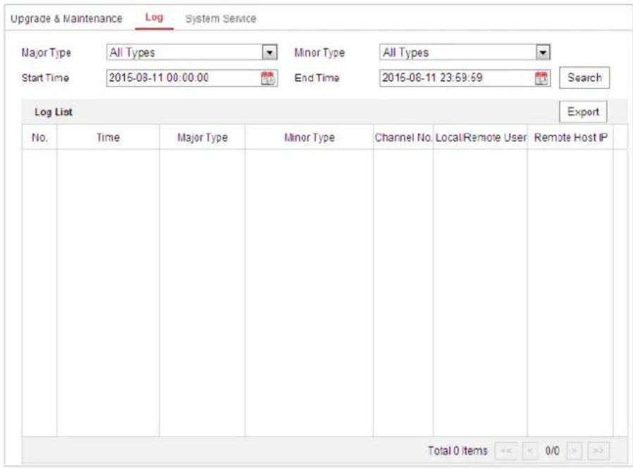
text_image
Upgrade & Maintenance Log System Service Major Type All Types Minor Type All Types Start Time 2015-03-11 00:00:00 End Time 2015-08-11 23:59:59 Search Log List Export No. Time Major Type Minor Type Channel No. Local/Remote User Remote Host IP Total 0 Items << < 0/0 >> >Figure 7-68 Log Searching Interface
-
Set the log search conditions to specify the search, including the Major Type, Minor Type, Start Time and End Time as shown in Figure 7-68.
-
Click Search to search log files. The matched log files will be displayed on the Log interface.
-
To export the log files, click Save Log to save the log files in your computer.
System Service
Steps:
- Enter the interface of configuring the remote connection:
Configuration > System > Maintenance > System Service
-
Check the checkbox of Enable Supplement Light on your demand.
-
Check the checkbox of Enable Automatic De-icing on your demand.

The de-icing heater is only supported under POE+, 24VAC, or 12VDC power supply.
- Select the power saving mode between manual and scheduled.
● Power Saving Mode: Select power saving mode as manual, and you can turn on
and off the power saving function. Select power saving mode as scheduled, you can customize the schedule for enabling the automatic de-icing function.
● Electric Current Limit: The function
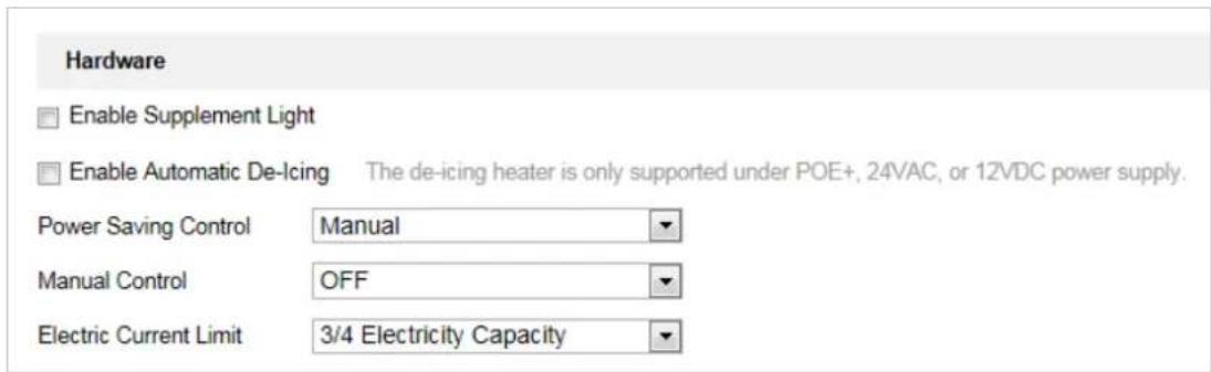
text_image
Hardware Enable Supplement Light Enable Automatic De-Icing The de-icing heater is only supported under POE+, 24VAC, or 12VDC power supply. Power Saving Control Manual Manual Control OFF Electric Current Limit 3/4 Electricity Capacity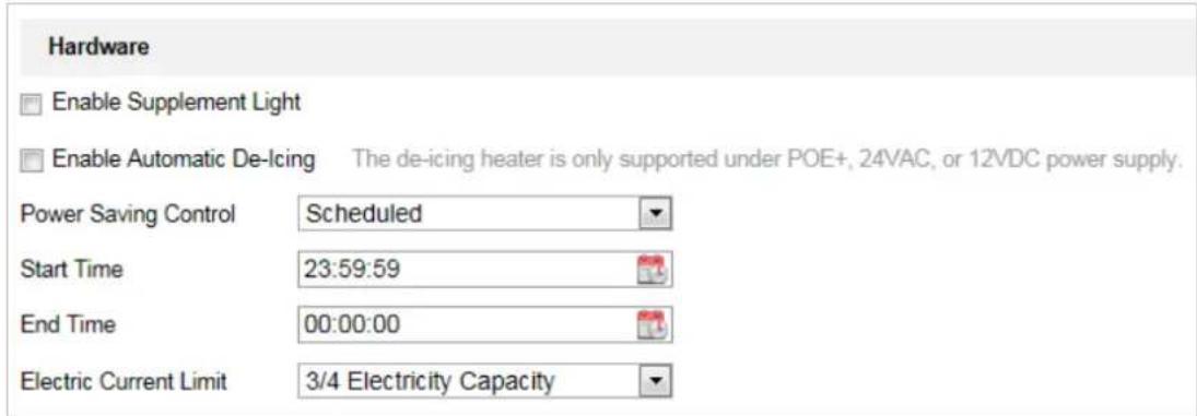
text_image
Hardware Enable Supplement Light Enable Automatic De-Icing The de-icing heater is only supported under POE+, 24VAC, or 12VDC power supply. Power Saving Control Scheduled Start Time 23:59:59 End Time 00:00:00 Electric Current Limit 3/4 Electricity CapacityFigure 7-69 Hardware Settings
- Click Save button to activate the settings.
VCA Resource Type
Purpose:
Before using the VCA function of the camera, you should select the VCA resource type first. To use Temperature Measurement and Behavior Analysis, select Temperature Measurement and Behavior Analysis. To use Dynamic Fire Source Detection function, select Dynamic Fire Source Detection. To use Ship Detection function, select Ship Detection.
Steps:
- Enter the VCA Resource Type interface:
Configuration > Advanced Configuration > System > VCA Resource Type

text_image
VCA Resource Configuration Temperature Measurement + Behavior Analysis Ship Detection Dynamic Fire Source DetectionFigure 7-70 VCA Information
- Check the checkbox to enable the VCA resource type.
- The system reboots and the selected VCA resource will be enabled.

Once you select any of the resources, the other VCA rules cannot be enabled.
7.5.3 Security
Configuring Authentication Security
Purpose:
You can specifically secure the stream data of live view.
Steps:
- Enter the Authentication interface:
Configuration> System> Security > Authentication -
Set the authentication mode for each authentication type.
RTSP Authentication: Select the authentication mode as basic or disable in the dropdown list to enable or disable the RTSP authentication. -
Click Save to save the settings.
Configuring IP Address Filter
Purpose:
With this function on, the camera allows certain IP addresses whether to log in or not.
Steps:
- Enter IP Address Filter interface: Configuration > System > Security > IP Address Filter
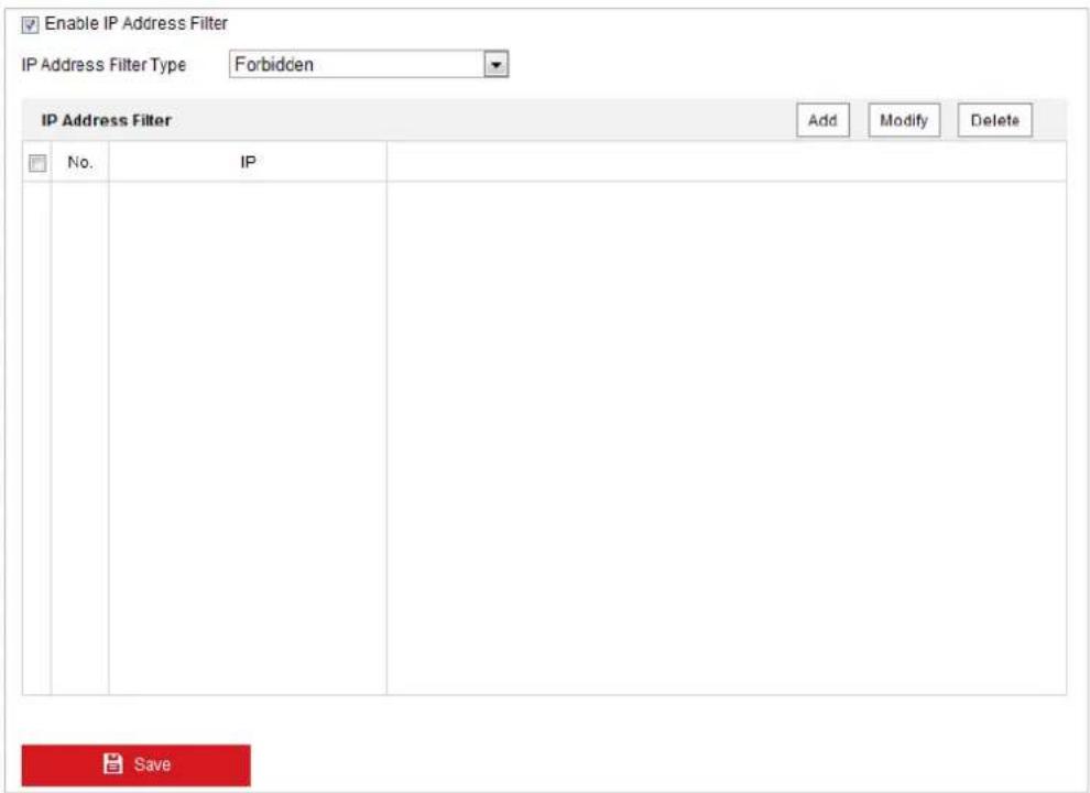
text_image
Enable IP Address Filter IP Address Filter Type Forbidden IP Address Filter Add Modify Delete No. IP SaveFigure 7-71 IP Address Filter
- Check the checkbox of Enable IP Address Filter.
- Select the type of IP Address Filter in the dropdown list, Forbidden and Allowed are selectable.
- Set the IP Address Filter list.
- Add an IP Address
Steps:
(1) Click Add to add an IP.
(2) Input the IP Adreess.
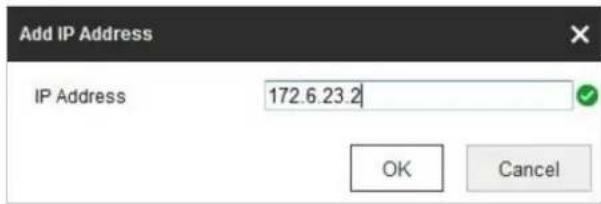
text_image
Add IP Address IP Address 172.6.23.2 OK CancelFigure 7-72 Add an IP
(3) Click OK to finish adding.
- Modify an IP Address
Steps:
(1) Left-click an IP address from filter list and click Modify.
(2) Modify the IP address in the text filed.
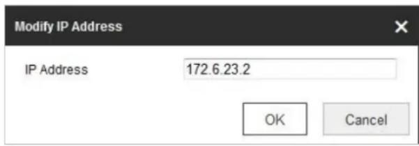
text_image
Modify IP Address IP Address 172.6.23.2 OK CancelFigure 7-73 Modify an IP
(3) Click OK to finish modifying.
- Delete an IP Address
Left-click an IP address from filter list and click Delete. -
Delete all IP Addresses
Click Clear to delete all the IP addresses. -
Click to save the settings.
Configure Security Service Settings
Steps:
- Enter the Security Service interface: Configuration> System > Security > Security Service
- Check the checkbox to enable the SSH function.
Enable SSH: Enabling SSH (Secure Shell) function is to encrypt and compress the data and to reduce the transmission time. -
Check the checkbox to enable the Illegal Login Lock function.
Illegal Login Lock: Enabling illegal login lock function is to automatically lock the device IP after the admin user performing 7 failed password attempts (5 attempts for the user/operator). -
Click Save to save the settings.
7.5.4 User Management
Enter the User Management interface:
Configuration > System > User Management
The admin user has access to create, modify or delete other accounts. Up to 32 user accounts can be created.
Figure 7-74 User Information
- Add a User
Steps:
- Click to add a user.
-
Input the new User Name, select Level and input Password.
-
For your privacy and to better protect your system against security risks, we strongly recommend the use of strong passwords for all functions and network devices. The password should be something of your own choosing (Using a minimum of 8 characters, including at least three of the following categories: upper case letters, lower case letters, numbers, and special characters.) in order to increase the security of your product.
● Proper configuration of all passwords and other security settings is the responsibility of the installer and/or end-user.
The level indicates the permissions you give to the user. You can define the user as Operator or User.
- In the Basic Permission field and Camera Configuration field, you can check or uncheck the permissions for the new user.
- Click to finish the user addition.
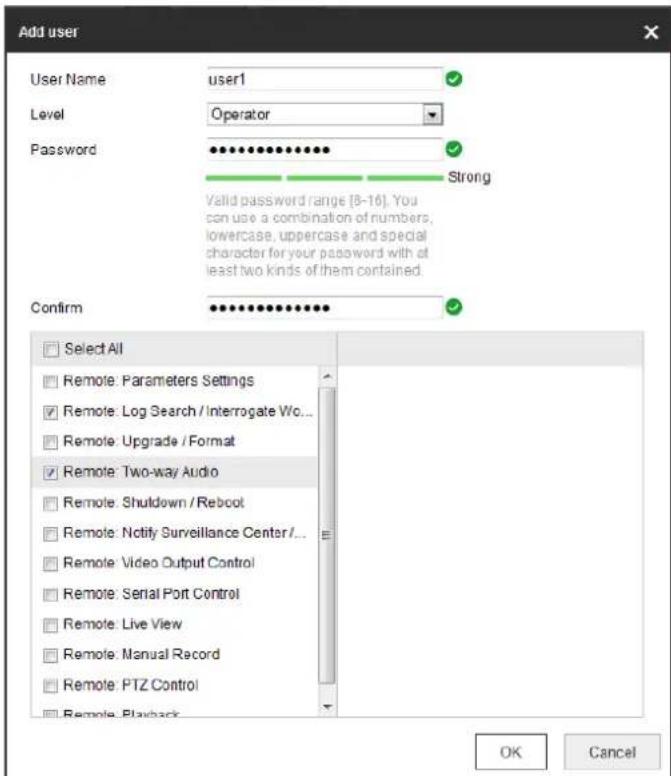
text_image
Add user User Name user1 Level Operator Password ••••••••••••••••••••••••••••••••••••••••••••••••••••••••••••••••••••••••••••••••••••• Valid password range [8-16]. You can use a combination of numbers, lowercase, uppercase and special character for your password with at least two kinds of them contained. Confirm ••••••••••••••••••••••••••••••••••••••• Select All Remote: Parameters Settings Remote: Log Search / Interrogate Wo... Remote: Upgrade / Format Remote: Two-way Audio Remote: Shutdown / Reboot Remote: Notify Surveillance Center/... Remote: Video Output Control Remote: Serial Port Control Remote: Live View Remote: Manual Record Remote: PTZ Control Remote: Playback OK CancelFigure 7-75 Add a User
- Modify a User
Steps:
- Left-click to select the user from the list and click . Modify
- Modify the User Name, Level or Password.
- In the Basic Permission field and Camera Configuration field, you can check or uncheck the permissions.
- Click OK to finish the user modification.
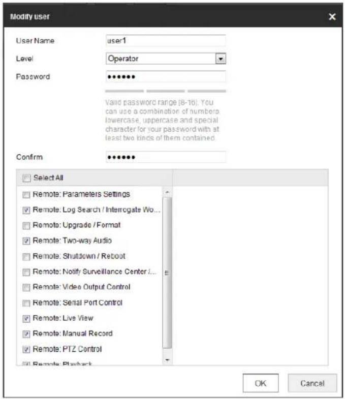
text_image
Modify user User Name user-1 Level Operator Password ••••••• Valid password range (8-16). You can use a combination of numbers lowercase, uppercase and special character for your password with at least two kinds of them contained. Confirm ••••••• Select All Remote: Parameters Settings Remote: Log Search / Interrogate Wo... Remote: Upgrade / Format Remote: Two-way Audio Remote: Shutdown / Reboot Remote: Notify Surveillance Center / Remote: Video Output Control Remote: Serial Port Control Remote: Live View Remote: Manual Record Remote: PTZ Control Remote: Playback OK CancelFigure 7-76 Modify a User
- Delete a User
Steps:
- Left-click the user name you want to delete and click . Delete
- Click OK on the pop-up dialogue box to delete the user.
Online Users
Enter the Online Users configuration interface:
Configuration > System > User Management > Online Users
| User List | Refresh | ||||
| No. | User Name | Level | IP Address | User Operation Time | |
| 1 | admin | User | 10.16.1.101 | 2015-11-12 20:53:38 | |
Figure 7-77 Online Users
You can see the current users who are visiting the device through this interface.
User information, such as user name, level, IP address, and operation time, is displayed in the User List. Click Refresh to refresh the list.
Appendix
SADP Software Introduction
- Description of SADP
SADP (Search Active Devices Protocol) is a kind of user-friendly and installation-free online device search tool. It searches the active online devices within your subnet and displays the information of the devices. You can also modify the basic network information of the devices using this software.
- Search active devices online
◆ Search online devices automatically
After launch the SADP software, it automatically searches the online devices every 15 seconds from the subnet where your computer locates. It displays the total number and information of the searched devices in the Online Devices interface. Device information including the device type, IP address and port number, etc. will be displayed.
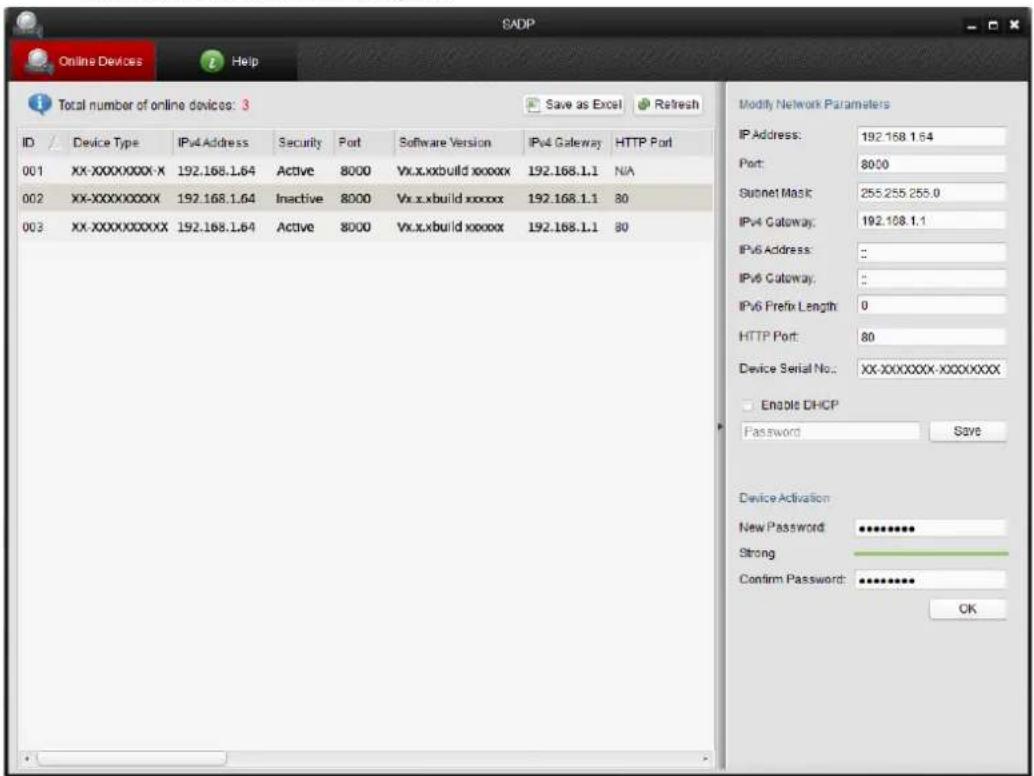
text_image
SADP Online Devices Help Total number of online devices: 3 ID Device Type IPv4 Address Security Port Software Version IPv4 Gateway HTTP Port 001 XX-XXXXXXX-X 192.168.1.64 Active 8000 Vx.x.xbuild xxxxxx 192.168.1.1 N/A 002 XX-XXXXXXX 192.168.1.64 Inactive 8000 Vx.x.xbuild xxxxx 192.168.1.1 80 003 XX-XXXXXXX 192.168.1.64 Active 8000 Vx.x.xbuild xxxxx 192.168.1.1 80 Modify Network Parameters IP Address: 192.168.1.64 Port: 8000 Subnet Mask: 255.255.255.0 IPv4 Gateway: 192.168.1.1 IPv6 Address: :\ IPv6 Gateway: :\ IPv6 Prefix Length: 0 HTTP Port: 80 Device Serial No.: XX-XXXXXXX-XXXXXXX Enable DHCP Password Save Device Activation New Password: ********** Strong Confirm Password: ********** OKFigure A.1.1 Searching Online Devices

Device can be searched and displayed in the list in 15 seconds after it went online; it will be removed from the list in 45 seconds after it went offline.
◆ Search online devices manually
You can also click to refresh the online device list manually. The newly searched devices will be added to the list.

You can click △ or ▽ on each column heading to order the information; you can click ▶ to expand the device table and hide the network parameter panel on the right side, or click ▶ to show the network parameter panel.
- Modify network parameters
Steps:
- Select the device to be modified in the device list and the network parameters of the device will be displayed in the Modify Network Parameters panel on the right side.
- Edit the modifiable network parameters, e.g. IP address and port number.
- Enter the password of the admin account of the device in the Password field and click to save the changes.

- For your privacy and to better protect your system against security risks, we strongly recommend the use of strong passwords for all functions and network devices. The password should be something of your own choosing (using a minimum of 8 characters, including upper case letters, lower case letters, numbers and special characters) in order to increase the security of your product. - Proper configuration of all passwords and other security settings is the responsibility of the installer and/or end-user.
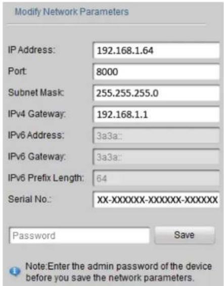
text_image
Modify Network Parameters IP Address: 192.168.1.64 Port: 8000 Subnet Mask: 255.255.255.0 IPv4 Gateway: 192.168.1.1 IPv6 Address: 3a3a: IPv6 Gateway: 3a3a: IPv6 Prefix Length: 64 Serial No.: XX-XXXXXX-XXXXXX-XXXXXX Password Save Note:Enter the admin password of the device before you save the network parameters.Figure A.1.2 Modify Network Parameters