
Legacy (2002) - Automobile SUBARU - Free user manual and instructions
Find the device manual for free Legacy (2002) SUBARU in PDF.


| Product Type | Automobile |
| Brand | Subaru |
| Model | Legacy (2002) |
| Variants | Legacy Sedan, Legacy Station Wagon, Outback Sedan, Outback Station Wagon |
| Overall Length (Legacy Sedan) | 184.4 in (4,685 mm) |
| Overall Width | 68.7 in (1,745 mm) |
| Overall Height (Legacy Sedan) | 56.6 in (1,435 mm) |
| Wheelbase | 104.3 in (2,650 mm) |
| Ground Clearance (Legacy Sedan) | 6.3 in (160 mm) |
| Engine Options | 2.5L 4-cylinder (EJ251) or 3.0L 6-cylinder (EZ30D) |
| Fuel Tank Capacity | 16.9 US gal (64 L) |
| Transmission | Manual or Automatic |
| Drive System | All-Wheel Drive (AWD) |
| Front Seatbelts | Driver: Emergency Locking Retractor (ELR); Passenger: Automatic/Emergency Locking Retractor (A/ELR) |
| SRS Airbags | Front airbags (driver and passenger), optional side airbags |
| Child Restraint System | Lower anchorages (LATCH) and top tether anchorages |
| Battery (2.5L) | 12V, type 55D23L (MT) or 75D23L (AT) |
| Alternator (2.5L) | 12V-90A |
| Engine Oil Capacity (2.5L) | 4.2 US qt (4.0 L) |
| Engine Coolant Capacity (2.5L MT) | 7.2 US qt (6.8 L) |
| Tire Size (Legacy GT) | P205/55R16 |
| Tire Pressure (Legacy GT Front) | 32 psi (220 kPa) |
| User Manual | 466 pages, PDF available for download |
Frequently Asked Questions - Legacy (2002) SUBARU
User questions about Legacy (2002) SUBARU
0 question about this device. Answer the ones you know or ask your own.
Ask a new question about this device
Download the instructions for your Automobile in PDF format for free! Find your manual Legacy (2002) - SUBARU and take your electronic device back in hand. On this page are published all the documents necessary for the use of your device. Legacy (2002) by SUBARU.
USER MANUAL Legacy (2002) SUBARU
natural_image
Side profile illustration of a modern sedan (no text or symbols visible)2002 OWNER'S MANUAL
Always wear your seatbelt.
Foreword
Congratulations on choosing a SUBARU vehicle. This Owner's Manual has all the information necessary to keep your SUBARU in excellent condition and to properly maintain the emission control system for minimizing emission pollutants. We urge you to read this manual carefully so that you may understand your vehicle and its operation. For information not found in this Owner's Manual, such as details concerning repairs or adjustments, please contact the dealer from whom you purchased your SUBARU or the nearest SUBARU dealer.
The information, specifications and illustrations found in this manual are those in effect at the time of printing. FUJI HEAVY INDUSTRIES LTD. reserves the right to change specifications and designs at any time without prior notice and without incurring any obligation to make the same or similar changes on vehicles previously sold. This Owner's Manual applies to all models and covers all equipment, including factory installed options. Some explanations, therefore may be for equipment not installed in your vehicle.
Please leave this manual in the vehicle at the time of resale. The next owner will need the information found herein.
This manual describes the following types of the Legacy series.
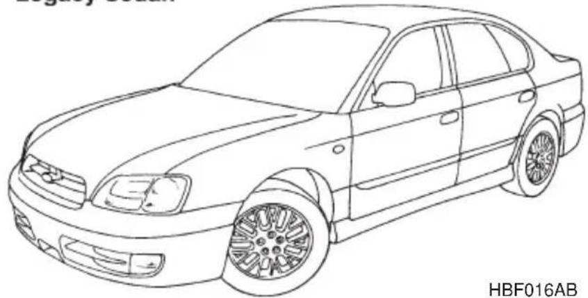
Legacy Sedan
natural_image
Line drawing of a classic sedan car (no text or symbols on the car body)HBF016AB
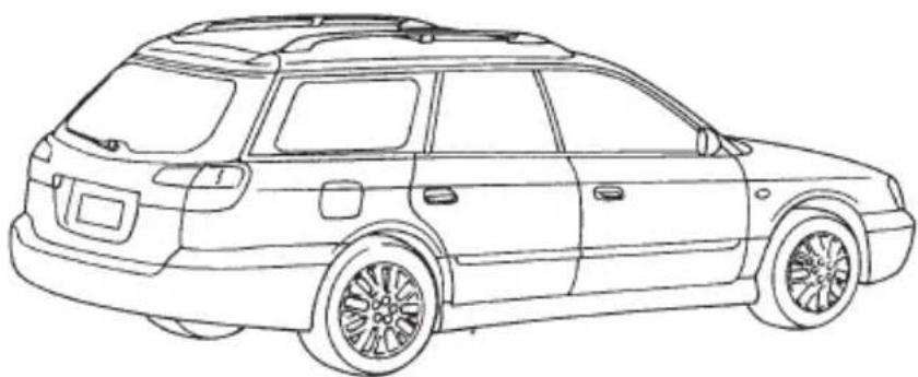
Legacy Station Wagon
natural_image
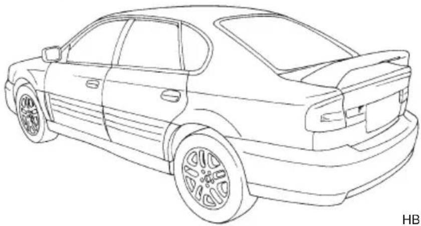
Line drawing of a modern SUV (no text or symbols present)OUTBACK Sedan
HBF017AB
natural_image
Line drawing of a sedan car viewed from rear angles (no text or symbols)HBF018AB
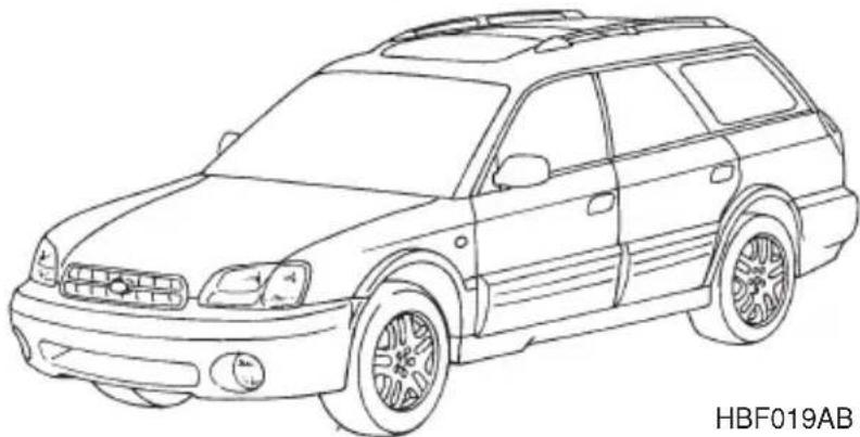
OUTBACK Station Wagon
natural_image
Line drawing of a car with no visible text, numbers, or symbols on the vehicle itselfHBF019AB
▼Warranties for U.S.A.
All SUBARU vehicles distributed by Subaru of America, Inc. and sold at retail by an authorized SUBARU dealer in the United States come with the following warranties:
- SUBARU Limited Warranty
●Emission Control Systems Warranty
●Emissions Performance Warranty
All warranty information, including details of coverage and exclusions, is in the “Warranty and Maintenance Booklet”. Please read these warranties carefully.
▼Warranties for Canada
All SUBARU vehicles distributed by Subaru Canada, Inc. and sold at retail by an authorized SUBARU dealer in Canada come with the following warranties:
●SUBARU Limited Warranty
●Anti-Corrosion Warranty
●Emission Control Warranty
All warranty information, including details of coverage and exclusions, is in the “Warranty and Service Booklet”. Please read these warranties carefully.

NOTE
This vehicle does not contain mercury devices or parts.
■Using your Owner's manual
Before you operate your vehicle, carefully read this manual. To protect yourself and extend the service life of your vehicle, follow the instructions in this manual. Failure to observe these instructions may result in serious injury and damage to your vehicle.
This manual is composed of fourteen chapters. Each chapter begins with a brief table of contents, so you can usually tell at a glance if that chapter contains the information you want.
Chapter 1: Seat, seatbelt and SRS airbags
This chapter informs you how to use the seat and seatbelt and contains precautions for the SRS airbags.
Chapter 2: Keys and doors
This chapter informs you how to operate the keys, locks and windows.
Chapter 3: Instruments and controls
This chapter informs you about the operation of instrument panel indicators and how to use the instruments and other switches.
Chapter 4: Climate control
This chapter informs you how to operate the climate control.
Chapter 5: Audio
This chapter informs you how to operate your audio system.
Chapter 6: Interior equipment
This chapter informs you how to operate interior equipment.
Chapter 7: Starting and operating
This chapter informs you how to start and operate your SUBARU.
Chapter 8: Driving tips
This chapter informs you how to drive your SUBARU in various conditions and explains some safety tips on driving.
Chapter 9: In case of emergency
This chapter informs you what to do if you have a problem while driving, such as a flat tire or engine overheating.
Chapter 10: Appearance care
This chapter informs you how to keep your SUBARU looking good.
Chapter 11: Maintenance and service
This chapter informs you when you need to take your SUBARU to the dealer for scheduled maintenance and informs you how to keep your SUBARU running properly.
Chapter 12: Specifications
This chapter informs you about dimension and capacities of your SUBARU.
Chapter 13: Consumer information and Reporting safety defects
This chapter informs you about Uniform tire quality grading standards and Reporting safety defects.
Chapter 14: Index
This is an alphabetical listing of all that's in this manual. You can use it to quickly find something you want to read.
■Safety warnings
You will find a number of WARNINGS, CAUTIONs and NOTES in this manual.
These safety warnings alert you to potential hazards that could result in injury to you or others.
Please read these safety warnings as well as all other portions of this manual carefully in order to gain a better understanding of how to use your SUBARU vehicle safely.

WARNING
A WARNING indicates a situation in which serious injury or death could result if the warning is ignored.

CAUTION
A CAUTION indicates a situation in which injury or damage to your vehicle, or both, could result if the caution is ignored.
NOTE
A NOTE gives information or suggestions how to make better use of your vehicle.
- CONTINUED -
■Safety symbol

natural_image
Prohibition symbol with no accompanying text or labelsHS0008
You will find a circle with a slash through it in this manual. This symbol means "Do not", "Do not do this", or "Do not let this happen", depending upon the context.
Safety precautions when driving
SEATBELT AND SRS AIRBAG
WARNING
- All persons in the vehicle should fasten their seatbelts BEFORE the vehicle starts to move. Otherwise, the possibility of serious injury becomes greater in the event of a sudden stop or accident.
- To obtain maximum protection in the event of an accident, the driver and all passengers in the vehicle should always wear seatbelts when the vehicle is moving. The SRS (Supplemental Restraint System) airbag does not do away with the need to fasten seatbelts. In combination with the seatbelts, it offers the best combined protection in case of a serious accident.
Not wearing a seatbelt increases the chance of severe injury or death in a crash even when the car has the SRS airbag.
●The SRS airbags deploy with considerable speed and force. Occupants who are out of proper position when the SRS airbag
deploys could suffer very serious injuries. Because the SRS air-bag needs enough space for deployment, the driver should always sit upright and well back in the seat as far from the steering wheel as practical while still maintaining full vehicle control and the front passenger should move the seat as far back as possible and sit upright and well back in the seat.
Carefully read the sections “Seat, seatbelts and SRS airbag” in chapter 1 of this owner’s manual for instructions and precautions concerning the seatbelt system and SRS airbag system.
CHILD SAFETY
WARNING
- Never hold a child on your lap or in your arms while the vehicle is moving. The passenger cannot protect the child from injury in a collision, because the child will be caught between the passenger and objects inside the vehicle.
- While riding in the vehicle, infants and small children should always be placed in the REAR seat in an infant or child restraint system which is appropriate for the child's age, height and weight. If a child is too big for a child restraint system, the child should sit in the REAR seat and be restrained using the seatbelts. According to accident statistics, children are safer when properly restrained in the rear seating positions than in the front seating positions. Never allow a child to stand up or kneel on the seat.
- Put children aged 12 and under in the REAR seat properly restrained at all times in a child restraint device or in a seatbelt. The SRS airbag deploys with considerable speed and force and can injure or even kill children, especially if they are 12 years of age and under and are not restrained or improperly restrained. Because children are lighter and weaker than adults, their risk being injured from deployment is greater.
- NEVER INSTALL A REARWARD FACING CHILD SAFETY SEAT IN THE FRONT SEAT. DOING SO RISKS SERIOUS INJURY OR DEATH TO THE CHILD BY PLACING THE CHILD'S HEAD TOO
- CONTINUED -
CLOSE TO THE SRS AIRBAG.
- Always use the child safety locks whenever a child rides in the rear seat. Serious injury could result if a child accidentally opened the door and fell out. Refer to the “Door locks” section in chapter 2.
- Always lock the passenger's windows using the lock switch when children are riding in the vehicle. Failure to follow this procedure could result in injury to a child operating the power window. Refer to the “Power windows” section in chapter 2.
- Never leave unattended children in the vehicle. They could accidentally injure themselves or others through inadvertent operation of the vehicle. Also, on hot or sunny days, temperature in a closed vehicle could quickly become high enough to cause severe or possibly fatal injuries to them.
- Help prevent young children from locking themselves in the trunk. When leaving the vehicle, either close all windows and lock all doors or cancel the inside trunk lid release. Also make certain that the trunk is closed. On hot or sunny days, the temperature in a trunk could quickly become high enough to cause death or serious heat-related injuries including brain damage, particularly for small children.
Carefully read the sections “Child restraint systems”, “SRS airbag”, and “Seatbelts” in chapter 1 of this owner’s manual for instructions and precautions concerning the child restraint system, seatbelt system and SRS airbag system.
ENGINE EXHAUST GAS (CARBON MONOXIDE)

WARNING
-
Never inhale engine exhaust gas. Engine exhaust gas contains carbon monoxide, a colorless and odorless gas which is dangerous, or even lethal, if inhaled.
●Always properly maintain the engine exhaust system to prevent engine exhaust gas from entering the vehicle. -
Never run the engine in a closed space, such as a garage, except for the brief time needed to drive the vehicle in or out of it.
- Avoid remaining in a parked vehicle for a lengthy time while the engine is running. If that is unavoidable, then use the ventilation fan to force fresh air into the vehicle.
●Always keep the front ventilator inlet grille free from snow, leaves or other obstructions to ensure that the ventilation system always works properly. - If at any time you suspect that exhaust fumes are entering the vehicle, have the problem checked and corrected as soon as possible. If you must drive under these conditions, drive only with all windows fully open.
- Keep the trunk lid or rear gate closed while driving to prevent exhaust gas from entering the vehicle.
DRINKING AND DRIVING

WARNING
Drinking and then driving is very dangerous. Alcohol in the bloodstream delays your reaction and impairs your perception, judgment and attentiveness. If you drive after drinking – even if you drink just a little – it will increase the risk of being involved in a serious or fatal accident, injuring or killing yourself, your passengers and others. In addition, if you are injured in the accident, alcohol may increase the severity of that injury.
Please don't drink and drive.
Drunken driving is one of the most frequent causes of accidents. Since alcohol affects all people differently, you may have consumed too much alcohol to drive safely even if the level of alcohol in your blood is below the legal limit. The safest thing you can do is never drink and drive. However if you have no choice but to drive, stop drinking and sober up completely before getting behind the wheel.

WARNING
There are some drugs (over the counter and prescription) that can delay your reaction time and impair your perception, judgment and attentiveness. If you drive after taking them, it may increase your, your passengers' and other persons' risk of being involved in a serious or fatal accident.
If you are taking any drugs, check with your doctor or pharmacist or read the literature that accompanies the medication to determine if the drug you are taking can impair your driving ability. Do not drive after taking any medications that can make you drowsy or otherwise affect your ability to safely operate a motor vehicle. If you have a medical condition that requires you to take drugs, please consult with your doctor.
Never drive if you are under the influence of any illicit mind-altering drugs. For your own health and well-being, we urge you not to take illegal drugs in the first place and to seek treatment if you are addicted to those drugs.
DRIVING WHEN TIRED OR SLEEPY

WARNING
When you are tired or sleepy, your reaction will be delayed and your perception, judgment and attentiveness will be impaired. If you drive when tired or sleepy, your, your passengers' and other persons' chances of being involved in a serious accident may increase.
Please do not continue to drive but instead find a safe place to rest if you are tired or sleepy. On long trips, you should make periodic rest stops to refresh yourself before continuing on your journey. When possible, you should share the driving with others.

CAUTION
A driver's use of a car phone can be distracting and if special care is not taken, can lead to an accident. If you use a car phone while driving, make an extra effort to pay attention to the road and to traffic at all times. If you can safely do so, it is best to pull off to the side of the road before using your car phone.
MODIFICATION OF YOUR VEHICLE

CAUTION
Your vehicle should not be modified. Modification could affect its performance, safety or durability, and may even violate governmental regulations. In addition, damage or performance problems resulting from modification may not be covered under warranties.
DRIVING WITH PETS
Unrestrained pets can interfere with your driving and distract your attention from driving. In a collision or sudden stop, unrestrained pets or cages can be thrown around inside the vehicle and hurt you or your passengers. Besides, the pets can be hurt under these situations. It is also for their own safety that pets should be properly restrained in your vehicle. Restrain a pet with a special traveling harness which can be secured to the rear seat with a seatbelt or use a pet carrier which can be secured to the rear seat by routing a seatbelt through the carrier's handle. Never restrain pets or pet carriers in the front passenger's seat. For further information, consult your veterinarian, local animal protection society or pet shop.
TIRE PRESSURES

WARNING
Driving at high speeds with excessively low tire pressures can cause the tires to deform severely and to rapidly become hot. A sharp increase in temperature could cause tread separation, and destruction of the tires. The resulting loss of vehicle control could lead to an accident.
Check and, if necessary, adjust the pressure of each tire (including the spare) at least once a month and before any long journey.
Check the tire pressure when the tires are cold.
Use a pressure gauge to adjust the tire pressures to the values shown on the tire placard.
Refer to the “Tires and wheels” section in chapter 11 for detailed information.
CALIFORNIA PROPOSITION 65 WARNING

WARNING
Engine exhaust, some of its constituents, and certain vehicle components contain or emit chemicals known to the State of California to cause cancer and birth defects or other reproductive harm.
Table of contents
| Seat, seatbelt and SRS airbags | 1 |
| Keys and doors | 2 |
| Instruments and controls | 3 |
| Climate control | 4 |
| Audio | 5 |
| Interior equipment | 6 |
| Starting and operating | 7 |
| Driving tips | 8 |
| In case of emergency | 9 |
| Appearance care | 10 |
| Maintenance and service | 11 |
| Specifications | 12 |
| Consumer information and Reporting safety defects | 13 |
| Index | 14 |
Seat, seatbelt and SRS airbags
Front seats 1-2
Seat heater (if equipped) 1-9
Rear seats 1-10
Armrest (if equipped) 1-10
Headrest adjustment — Rear center seating position on Station wagon 1-12
Folding down the rear seat — Station wagon 1-12
Seatbelts 1-16
Seatbelt safety tips 1-16
Emergency Locking Retractor (ELR) 1-17
Automatic/Emergency Locking Retractor (A/ELR) 1-18
Seatbelt warning light and chime 1-18
Fastening the seatbelt 1-18
Seatbelt maintenance 1-28
Front seatbelt pretensioners 1-29
Child restraint systems 1-33
Top tether anchorages.... 1-40
SRS airbag (Supplemental Restraint System airbag) ..... 1-43
Vehicle with driver's and front passenger's SRS airbags and lap/shoulder restraints 1-43
SRS frontal airbag 1-48
SRS side airbag (if equipped) 1-55
SRS airbag system monitors 1-62
SRS airbag system servicing 1-63
Precautions against vehicle modification 1-64

WARNING
- Never adjust the seat while driving to avoid the possibility of loss of vehicle control and of personal injury.
- Never drive the vehicle with the head restraints removed because they are designed to reduce the risk of serious neck injury in the event that the vehicle is struck from the rear.
- Before adjusting the seat, make sure the hands and feet of rear seat passengers are clear of the adjusting mechanism.
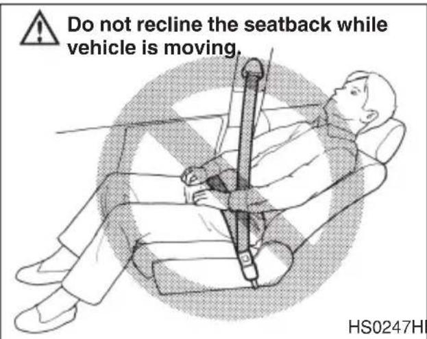
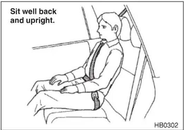
- Seatbelts provide maximum restraint when the occupant sits well back and upright in the seat. To reduce the risk of sliding under the seatbelt in a collision, the front seatbacks should be always used in the upright position while the vehicle is running. If the front seatbacks are not used in the upright position in a collision, the risk of sliding under the lap belt and of the lap belt sliding up over the abdomen will increase, and both can result in serious internal injury or death.
- Do not put cushions or any other materials between occupants and seatbacks or seat cushions. If you do so, the risk of sliding under the lap belt and of the lap belt sliding up over the abdomen will increase, and both can result in serious internal injury or death.
- The SRS airbags deploy with considerable speed and force. Occupants who are out of proper position when the SRS airbag deploys could suffer very serious injuries. Because the SRS airbag needs enough space for deployment, the driver should always sit upright and well back in the seat as far from the steering wheel as practical while still maintaining full vehicle control and the front passenger should move the seat as far back as possible and sit upright and well back in the seat.
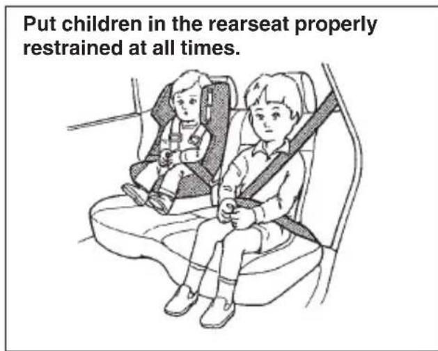
- Put children aged 12 and under in the rear seat properly restrained at all times. The SRS airbag deploys with considerable speed and force and can injure or even kill children, especially if they are 12 years of age and under and are not restrained or improperly restrained. Because children are lighter and weaker than
adults, their risk of being injured from deployment is greater. For that reason, we strongly recommend that ALL children (including those in child seats and those that have outgrown child restraint devices) sit in the REAR seat properly restrained at all times in a child restraint device or in a seatbelt, whichever is appropriate for the child's age, height and weight.
Secure ALL types of child restraint devices (including forward facing child seat) in the REAR seats at all times.
NEVER INSTALL A REARWARD FACING CHILD SEAT IN THE FRONT SEAT. DOING SO RISKS SERIOUS INJURY OR DEATH TO THE CHILD BY PLACING THE CHILD'S HEAD TOO CLOSE TO THE SRS AIRBAG.
According to accident statistics, children are safer when properly restrained in the rear seating positions than in the front seating positions. For instructions and precautions concerning child restraint systems, see the “Child restraint systems” section in this chapter.
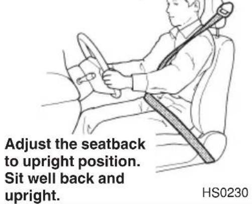
Adjust the seatback to upright position. Sit well back and upright.
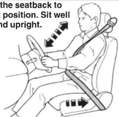
Move the seat as far from the steering wheel as practical.
Adjust the seatback to upright position. Sit well back and upright.
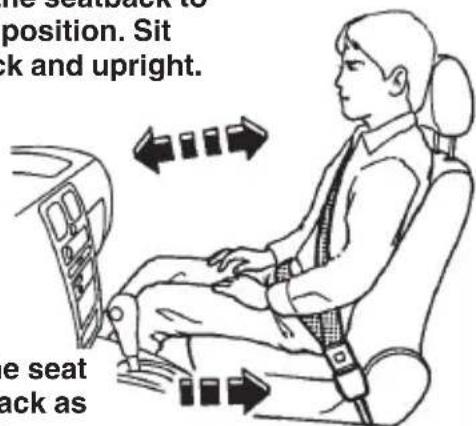
Move the seat as far back as possible.
HB0290HS0233
30291
▼Fore and aft adjustment
▽ Manual type
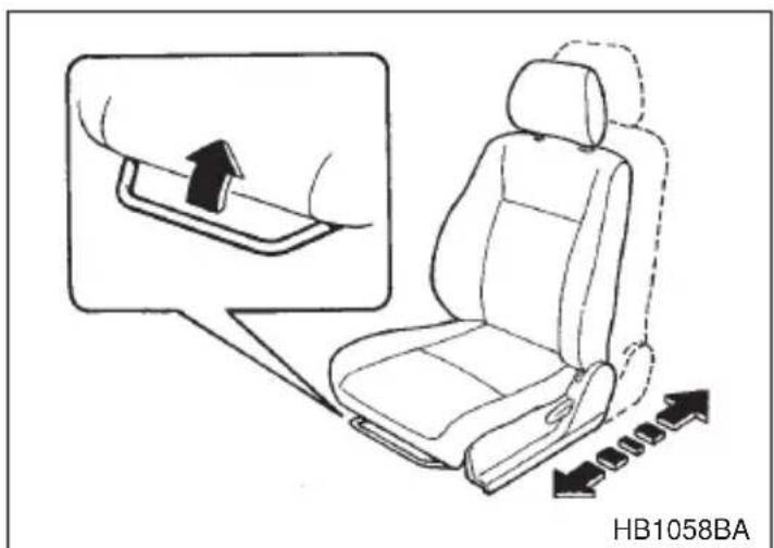
Pull the lever upward and slide the seat to the desired position. Then release the lever and move the seatback and forth to make sure that it is securely locked into place.
▽ Power seat (if equipped)
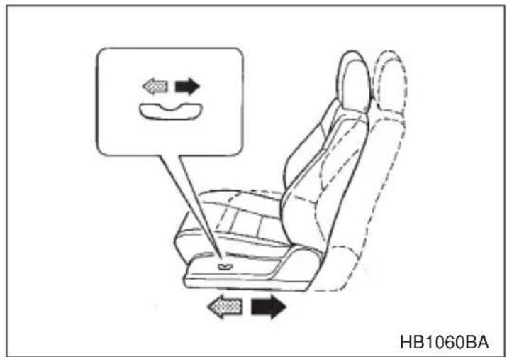
To adjust the seat forward or backward, move the control switch forward or backward.
▼Seat cushion angle and height adjustment (Power seat only)
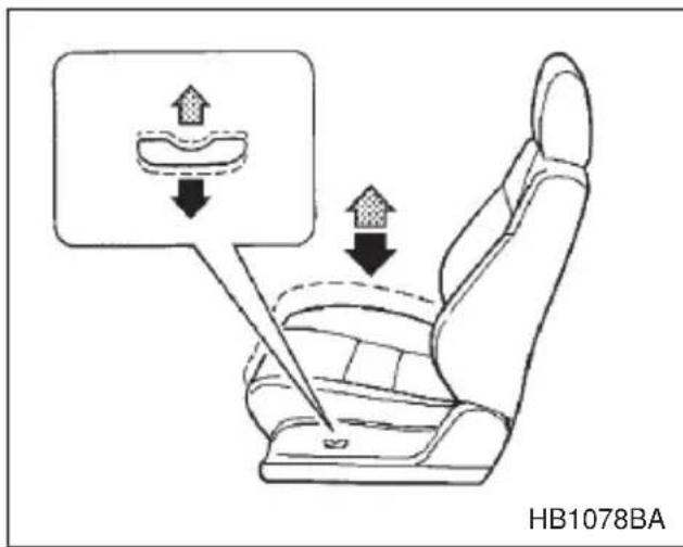
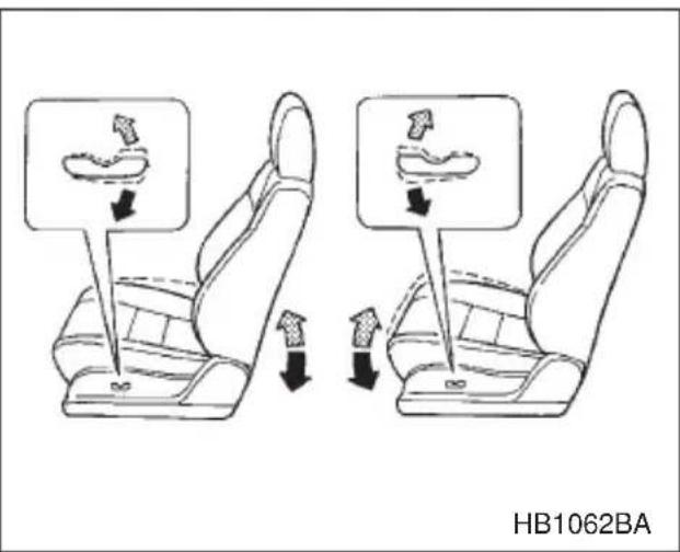
To adjust the angle and height of the seat cushion, move the control switch in the corresponding direction.
▼Reclining the seatback
▽ Manual type
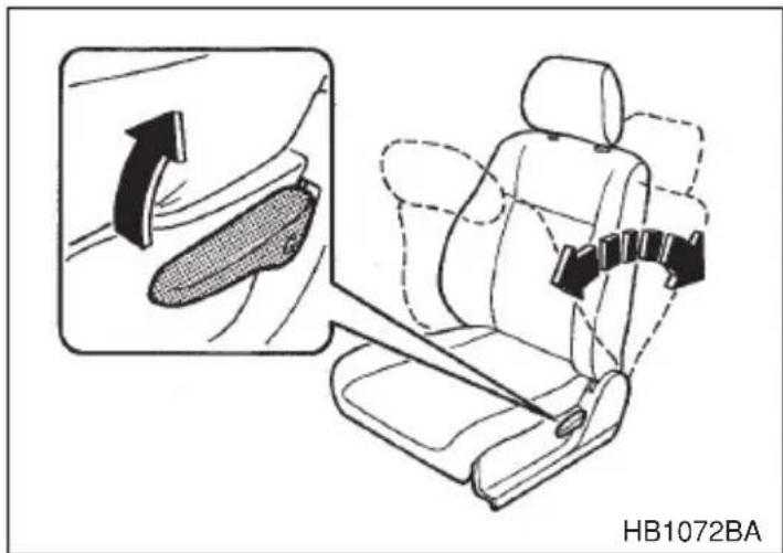
Pull the reclining lever up and adjust the seatback to the desired position. Then release the lever and make sure the seat is securely locked into place.
The seatback placed in a reclined position can spring back upward with force when released. When operating the reclining lever to return the seatback, hold it lightly so that it may be raised back gradually.
▽ Power seat (if equipped)
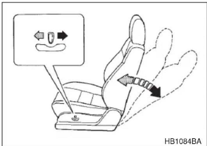
To adjust the angle of the seatback, move the control switch.
NOTE
While adjusting the seatback, you can not at the same time adjust the seat position or the seat cushion angle and height.
▼Head restraint adjustment
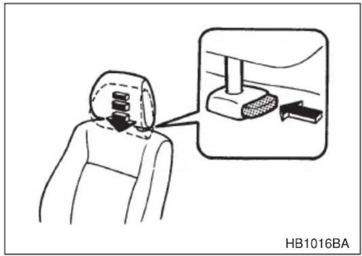
To raise the head restraint, pull it up. To lower it, push the head restraint down while pressing the release button on the top of the seatback.
The head restraint should be adjusted so that the center of the head restraint is closest to the top of the occupant's ears.
NOTE
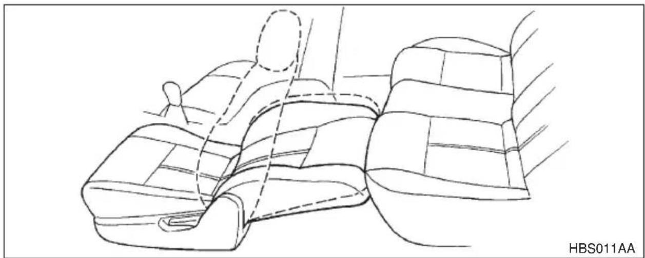
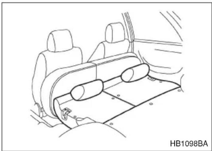
If the seatback is reclined rearward to the same level as the rear seat cushion with the head restraint removed, a wide flat bed is made available.
WARNING
- Never drive your car with the seats converted in a flat bed position. If you do so, occupants will have a greater chance of being injured even during simple deceleration, acceleration and cornering since no firm restraint will be available for them.
- Before you lie on the flat bed to take a rest, read the description “Parking your vehicle” in Chapter 7 carefully and follow the instructions.
natural_image
Line drawing of a car interior showing dashboard and seat structure (no text or symbols)- Slide the front seat forward as far as possible.
- Pull off the head restraint while pressing the release button.
- Recline the seatback rearward up to the lowest position. Remember to reinstall the head restraint whenever the seatback is raised back.
▼ Lumbar support (if equipped)
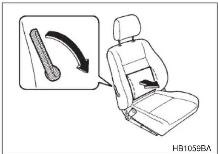
Pull the lever forward or backward.
Pulling the lever forward will increase the amount of support for your lower back.
Seat heater (if equipped)

CAUTION
- Use of the seat heater for a long period of time while the engine is not running can cause battery discharge.
- Do not put anything on the seat which insulates against heat, such as a blanket, cushion, or similar items. This may cause the seat heater to overheat.
- When cleaning the seat, do not use benzine, paint thinner, or any similar materials.
The seat heater operates when the ignition switch is either in the "ACC" or "ON" position.
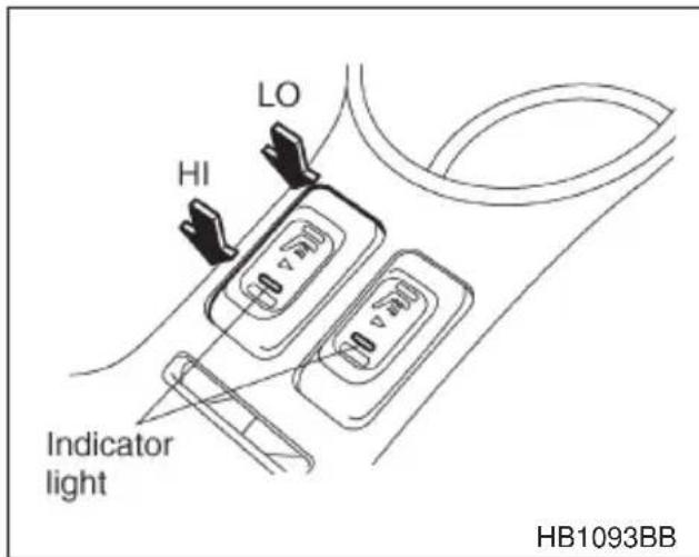
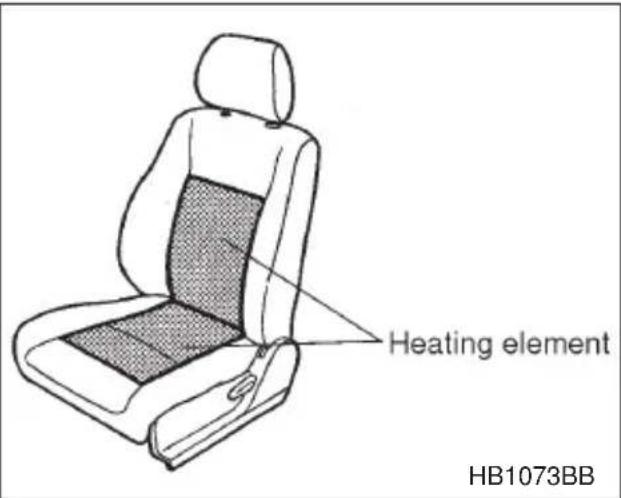
To turn on the seat heater, push the "LO" or "HI" position on the switch, as desired, depending on the temperature.
LO: Normal heating
HI: Rapid heating
The indicator located on the switch comes on when the seat heater is in operation. When the vehicle's interior is warmed enough or before you leave the vehicle, be sure to turn the switch off.
Rear seats

WARNING
- Seatbelts provide maximum restraint when the occupant sits well back and upright in the seat. Do not put cushions or any other materials between occupants and seatbacks or seat cushions. If you do so, the risk of sliding under the lap belt and of the lap belt sliding up over the abdomen will increase, and both can result in serious internal injury or death.
●Never allow passengers to ride on the folded rear seatback, in the cargo area. Doing so may result in serious injury or death. - Never stack luggage or other cargo higher than the top of the seatback because it could tumble forward and injure passengers in the event of a sudden stop or accident.
- Secure skis and other lengthy items properly to prevent them from being thrown around inside the vehicle and causing serious injury during a sudden stop, a sudden steering or a rapid acceleration.
Armrest (if equipped)

WARNING
To avoid the possibility of serious injury, passengers must never be allowed to sit on the center armrest while the vehicle is in motion.
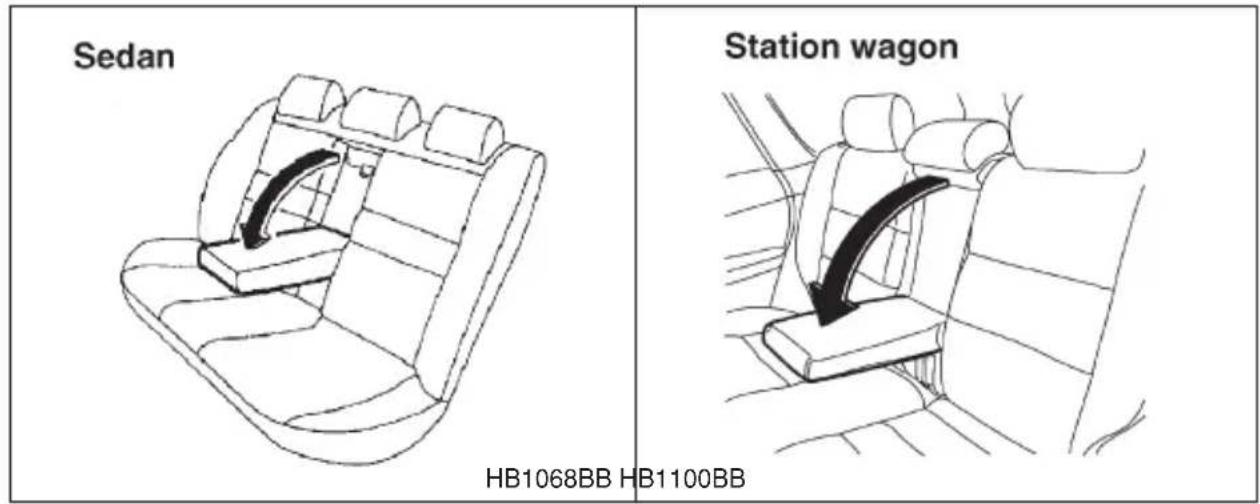
To lower the armrest, pull on the top edge of the armrest.
▼Loading long objects (Sedan)
WARNING
- Secure long objects properly to prevent them from shooting forward and causing serious injury during a sudden stop or sharp cornering. Tie long objects down with a rope or something equivalent.
- Avoid loading objects longer than 6.6 ft (2 m) and heavier than 55 lb (25 kg). Such objects can interfere with the driver's proper operation of the car, possibly causing an accident and serious injury.
natural_image
Technical line drawing showing two car seat compartments with a belt switch, no text or symbols presentHB1053BAHB1052BA
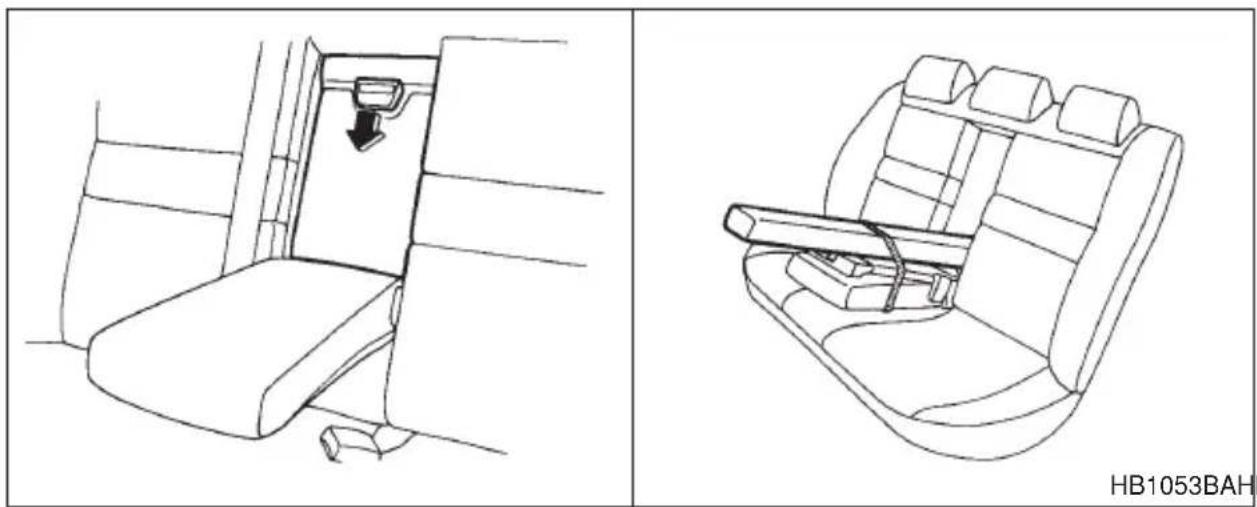
Folding down the armrest and opening the seatback panel affords a loading space for long objects.
To open the seatback panel, pull the panel down while pressing the release tab down.
■ Headrest adjustment — Rear center seating position on Station wagon
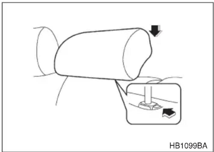
To raise the headrest, pull it up. To lower it, push the headrest down while pressing the release button on the top of the seatback.
When the rear center seating position is occupied, place the headrest in its highest position. When the rear center seating position is not occupied, lower the headrest to improve rearward visibility.
■ Folding down the rear seat — Station wagon

WARNING
●After returning the rear seat to its original position, be certain to place all of the seatbelts and the tab attached to the seat cushion above the seat cushion. And make certain that the shoulder belts are fully visible.
●Never permit anyone to ride in the cargo area.
▼Folding down the seatback
-
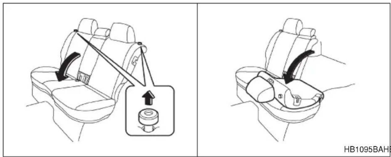
Lower the headrests.
-
Unlock the seatback by pulling the release knob and then fold the seatback down.
▼Folding down the seat cushion and seatback
- Move the front seat forward.
- Close the rear passengers' cup holder and ashtray.
- Remove the headrests (if so equipped).
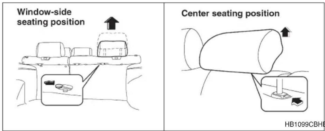
Window-side seating positions: Pull the headrest up while pressing the release button located on the backside of the seatback.
Center seating position: Pull the headrest up while pressing the release button located on the top of the seatback.
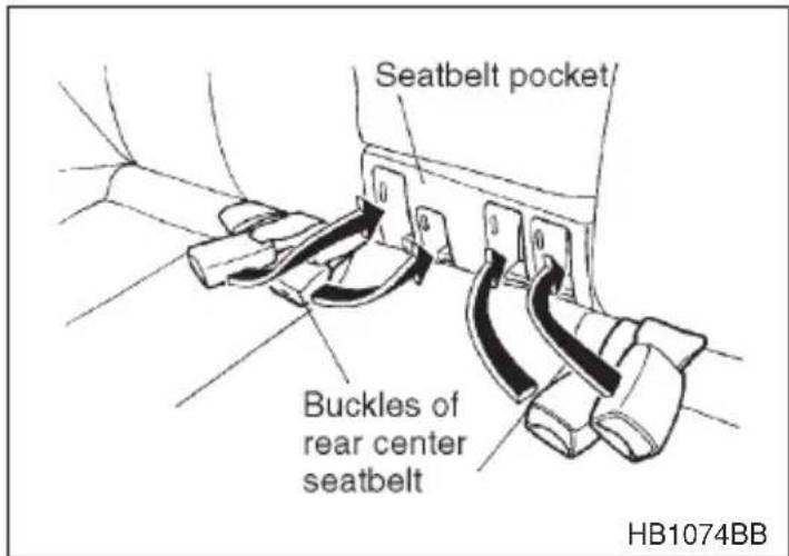
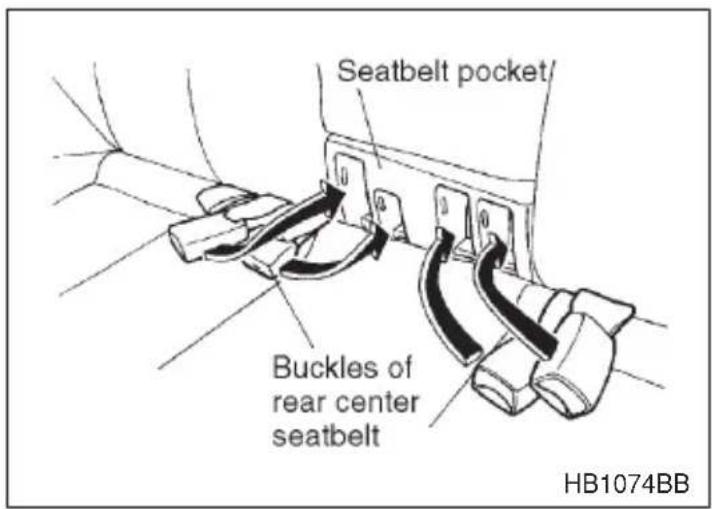
- Store the seatbelts in the seatbelt pockets to prevent them from falling below the cushion.
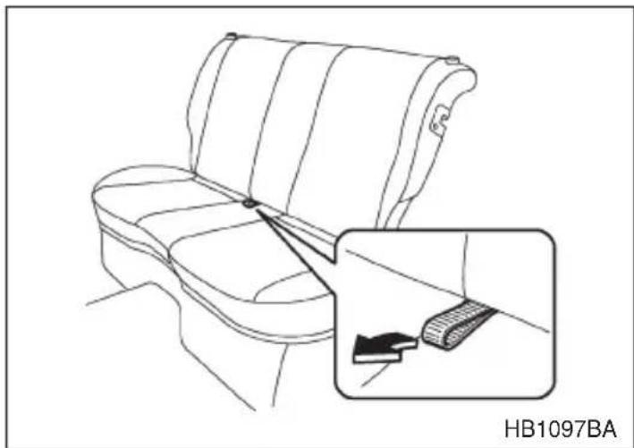
- Raise the seat cushion by pulling up the tab.
Make certain that the rear passenger's cup holder is fully retracted before raising the seat cushion.
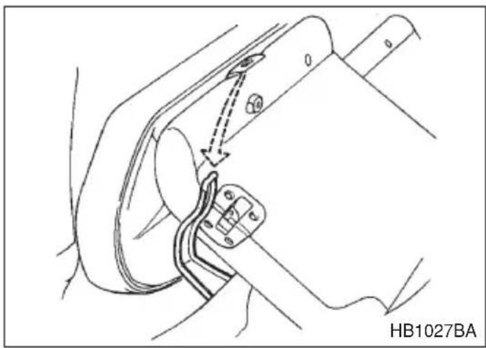
natural_image
Line drawing of a car seat with a close-up inset showing a cable clamp (no text or symbols)- Unlock the seatback by pulling the release knob and fold the seat-back down. Confirm that the pin located at the bottom of the seat cushion is inserted into the slot at the top of the seatback.
natural_image
Technical line drawing of a mechanical component with a dashed arrow indicating a connection or assembly (no text or symbols present)- Install the headrests (if so equipped) onto the backside of the seat-back (window-side positions only).
natural_image
Line drawing of a car interior showing rear seats and side panels (no text or symbols)To return the rear seat to its original position, raise the seatback and seat cushion until they lock into place and make sure that they are securely locked.
Make sure that the rear seatbelts are not under the seat cushion or seat-back.
Place the headrests (if so equipped) back in their normal position.
■Seatbelt safety tips

WARNING
- All persons in the vehicle should fasten their seatbelts BEFORE the vehicle starts to move. Otherwise, the possibility of serious injury becomes greater in the event of a sudden stop or accident.
- All belts should fit snugly in order to provide full restraint. Loose fitting belts are not as effective in preventing or reducing injury.
- Each seatbelt is designed to support only one person. Never use a single belt for two or more persons — even children. Otherwise, in an accident, serious injury or death could result.
- Replace all seatbelt assemblies including retractors and attaching hardware worn by occupants of a vehicle that has been in a serious accident. The entire assembly should be replaced even if damage is not obvious.
- Put children aged 12 and under in the rear seat properly restrained at all times. The SRS airbag deploys with considerable speed and force and can injure or even kill children, especially if they are 12 years of age and under and are not restrained or improperly restrained. Because children are lighter and weaker than adults, their risk of being injured from deployment is greater. For that reason, we strongly recommend that ALL children (including those in child seats and those that have outgrown child restraint devices) sit in the REAR seat properly restrained at all times in a child restraint device or in a seatbelt, whichever is appropriate for the child's height and weight.
Secure ALL types of child restraint devices (including forward facing child seats) in the REAR seats at all times.
NEVER INSTALL A REARWARD FACING CHILD SEAT IN THE FRONT SEAT. DOING SO RISKS SERIOUS INJURY OR DEATH TO THE CHILD BY PLACING THE CHILD'S HEAD TOO CLOSE TO THE SRS AIRBAG.
According to accident statistics, children are safer when properly restrained in the rear seating positions than in the front seating positions. For instructions and precautions concerning the child restraint system, see the “Child restraint systems” section in this chapter.
▼ Infants or small children
Use a child restraint system that is suitable for your vehicle. See information on “Child restraint systems” in this chapter.
Children
If a child is too big for a child restraint system, the child should sit in the rear seat and be restrained using the seatbelts. According to accident statistics, children are safer when properly restrained in the rear seating positions than in the front seating positions. Never allow a child to stand up or kneel on the seat.
If the shoulder portion of the belt crosses the face or neck, move the child closer to the belt buckle to help provide a good shoulder belt fit. Care must be taken to securely place the lap belt as low as possible on the hips and not on the child's waist. If the shoulder portion of the belt cannot be properly positioned, a child restraint system should be used. Never place the shoulder belt under the child's arm or behind the child's back.
▼Expectant mothers
Expectant mothers also need to use the seatbelts. They should consult their doctor for specific recommendations. The lap belt should be worn securely and as low as possible over the hips, not over the waist.
Emergency Locking Retractor (ELR)
The driver's seatbelt has an Emergency Locking Retractor (ELR).
The emergency locking retractor allows normal body movement but the retractor locks automatically during a sudden stop, impact or if you pull the belt very quickly out of the retractor.
■Automatic/Emergency Locking Retractor (A/ELR)
Each passenger's seatbelt has an Automatic/Emergency Locking Retractor (A/ELR). The Automatic/Emergency Locking Retractor normally functions as an Emergency Locking Retractor (ELR). The A/ELR has an additional locking mode “Automatic Locking Retractor (ALR) mode” intended to secure a child restraint system. When the seatbelt is once drawn out completely and is then retracted even slightly, the retractor locks the seatbelt in that position and the seatbelt cannot be extended. As the belt is rewinding, clicks will be heard which indicate the retractor functions as ALR. When the seatbelt is retracted fully, ALR mode is released.
When securing a child restraint system on the passengers' seats, the seatbelt must be changed over to the Automatic Locking Retractor (ALR) mode.
When the child restraint system is removed, make sure that the retractor is restored to the Emergency Locking Retractor (ELR) function by allowing the seatbelt to retract fully.
For instructions on how to convert the retractor to the ALR mode and restore it to the ELR mode, see the “Child restraint systems” section in this chapter.
■Seatbelt warning light and chime

Your vehicle is equipped with a seatbelt warning device at the driver's seat.
This device causes the seatbelt warning light on the instrument panel to light up for about six seconds when the ignition switch is turned to the "ON" position to remind the driver to wear the seatbelt. If the driver's seatbelt is not fastened, a warning chime sounds at the same time.
■Fastening the seatbelt

WARNING
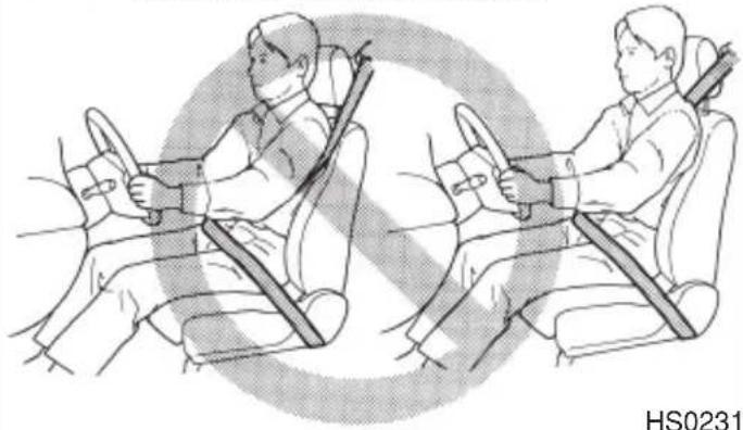
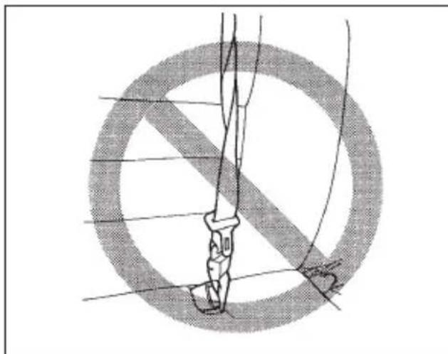
- Never use a belt that is twisted or reversed. In an accident, this can increase the risk or severity of injury.
●Never place the shoulder belt under the arm or behind the back.
If an accident occurs, this can increase the risk or severity of injury.
- Keep the lap belt as low as possible on your hips. In a collision, this spreads the force of the lap belt over stronger hip bones instead of across the weaker abdomen.
- Seatbelts provide maximum restraint when the occupant sits well back and upright in the seat. To reduce the risk of sliding under the seatbelt in a collision, the front seatbacks should be always used in the upright position while the vehicle is running. If the front seatbacks are not used in the upright position in a collision, the risk of sliding under the lap belt and of the lap belt sliding up over the abdomen will increase, and both can result in serious internal injury or death.
- Do not put cushions or any other materials between occupants and seatbacks or seat cushions. If you do so, the risk of sliding under the lap belt and of the lap belt sliding up over the abdomen will increase, and both can result in serious internal injury or death.
Always wear the seatbelts correctly.

Never place the shoulder belt under the arm or behind the back.
natural_image
Illustration of a person using a steering wheel and seatbelt, showing two scenarios (no text or symbols)HS0231
CAUTION
Metallic parts of the seatbelt can become very hot in a vehicle that has been closed up in sunny weather; they could burn an occupant. Do not touch such hot parts until they cool.
▼Front seatbelts
natural_image
Illustration of a person adjusting a cable with a belt, no text or symbols present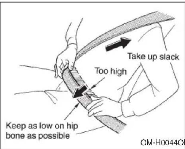
OM-H0044OM-H0043
- Adjust the seat position:
Driver's seat: Adjust the seatback to the upright position. Move the seatback as far from the steering wheel as practical while still maintaining full vehicle control.
Front passenger's seat: Adjust the seatback to the upright position. Move the seat as far back as possible.
- Sit well back in the seat.
- Pick up the tongue plate and pull the belt out slowly. Do not let it get twisted. If the belt stops before reaching the buckle, return the belt slightly and pull it out more slowly. If the belt still cannot be unlocked, let the belt retract slightly after giving it a strong pull, then pull it out slowly again.
- Insert the tongue plate into the buckle until you hear a click.
- To make the lap part tight, pull up on the shoulder belt. And place the lap belt as low as possible on your hips, not on your waist.
Adjusting the front seat shoulder belt anchor height
WARNING
When wearing the seatbelts, make sure the shoulder portion of the webbing does not pass over your neck. If it does, adjust the seatbelt anchor to a lower position. Placing the shoulder belt over the neck may result in neck injury during sudden braking or in a collision.
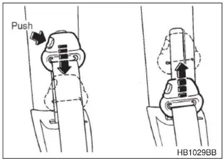
The shoulder belt anchor height should be adjusted to the position best suited for you. To lower the anchor height, push the release button and slide the anchor down. To raise the anchor height, slide the anchor up. Pull down on the anchor to make sure that it is locked in place.
Always adjust the anchor height so that the shoulder belt passes over the middle of the shoulder without touching the neck.
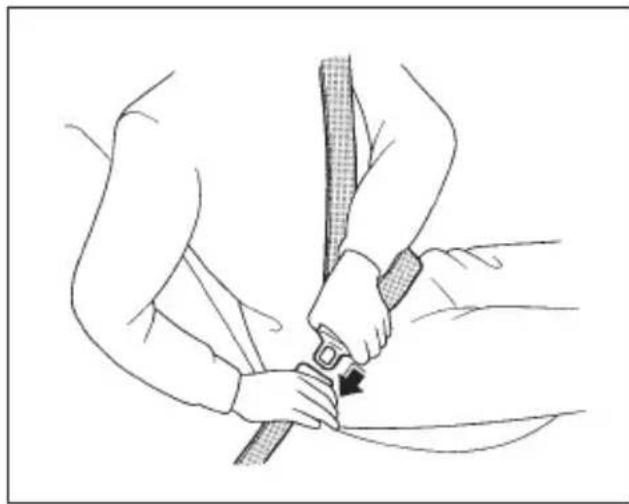
∇ Unfastening the seatbelt
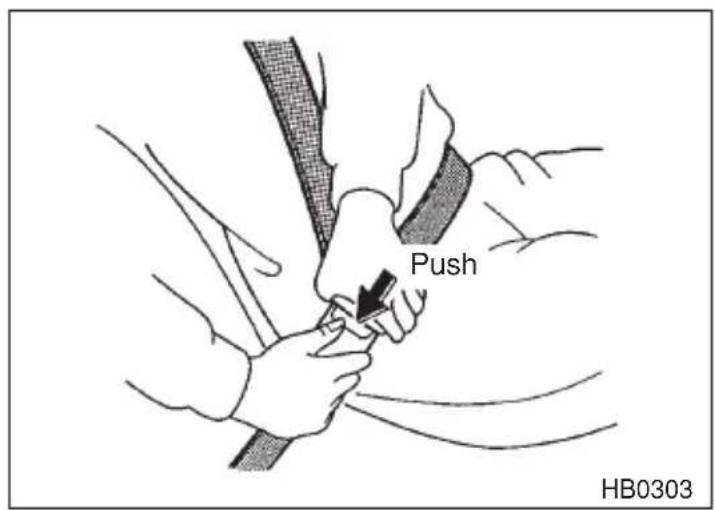
Push the button on the buckle.
Before closing the door, make sure that the belts are retracted properly to avoid catching the belt webbing in the door.
▼Rear seatbelts (except rear center seatbelt on wagon)
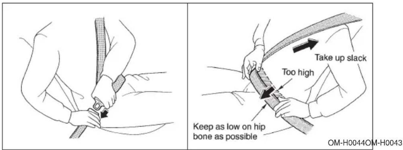
- Sit well back in the seat.
- Pick up the tongue plate and pull the belt out slowly. Do not let it get twisted. If the belt stops before reaching the buckle, return the belt slightly and pull it out more slowly. If the belt still cannot be unlocked, let the belt retract slightly after giving a strong pull on it, then pull it out slowly again.
- Insert the tongue plate into the buckle until you hear a click.
- To make the lap part tight, pull up on the shoulder belt. And place the lap belt as low as possible on your hips, not on your waist.
∇ Unfastening the seatbelt
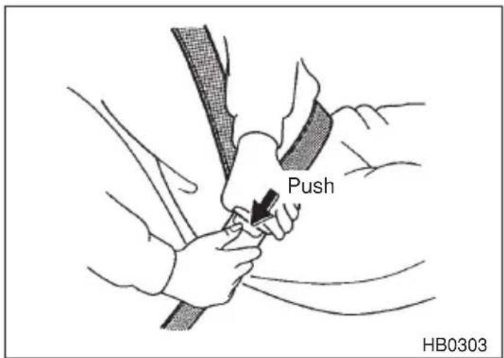
Push the button on the buckle.
Before closing the door, make sure that the belts are retracted prop-
erly to avoid catching the belt webbing in the door.
▼Rear center seatbelt on wagon model
WARNING
- Fastening the seatbelt with the webbing twisted can increase the risk or severity of injury in an accident. When fastening the belt after it is pulled out from the retractor, especially when inserting the connector's tongue plate into the mating buckle (on right-hand side), always check that the webbing is not twisted.
- Be sure to fasten both tongue plates to the respective buckles. If the seatbelt is used only as a shoulder belt (with the connector's tongue plate not fastened to the connector's buckle on the right-hand side), it cannot properly restrain the wearer in position in an accident, possibly resulting in serious injury or death.
natural_image
Diagram of a surgical instrument with surgical hardware and surgical tools, enclosed in a circular cross-section (no text or labels)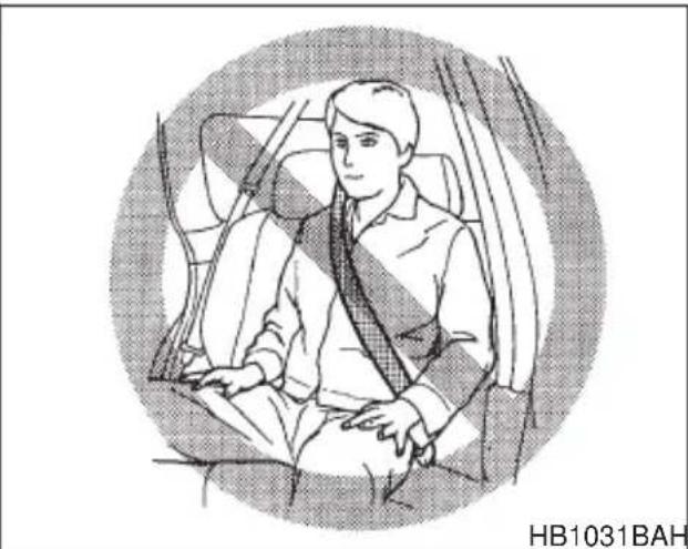
natural_image
Illustration of a person seated in a car seat, wearing a seatbelt and shirt (no text or symbols)HB1031BAHB1030BA
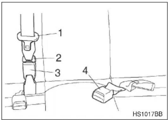
- Center seatbelt tongue plate
- Connector (tongue)
- Connector (buckle)
- Center seatbelt buckle
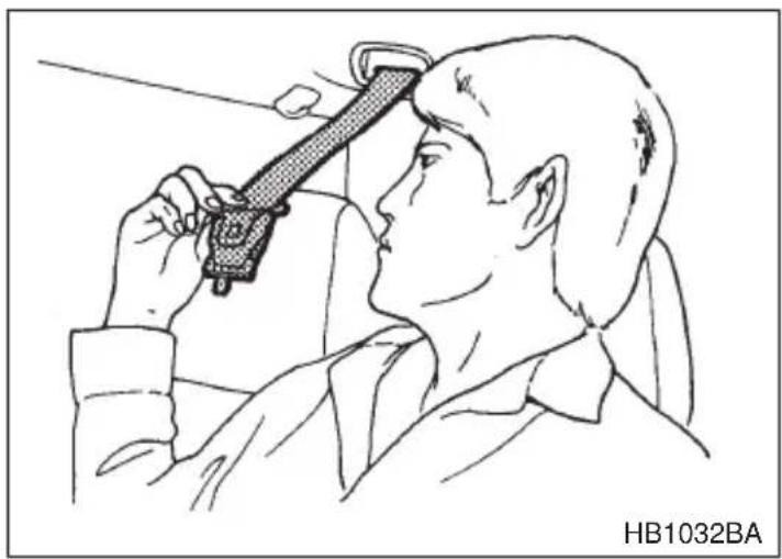
natural_image
Line drawing of a person using a handheld device to measure their eye area (no text or symbols)- Pull out the seatbelt slowly from the overhead retractor.
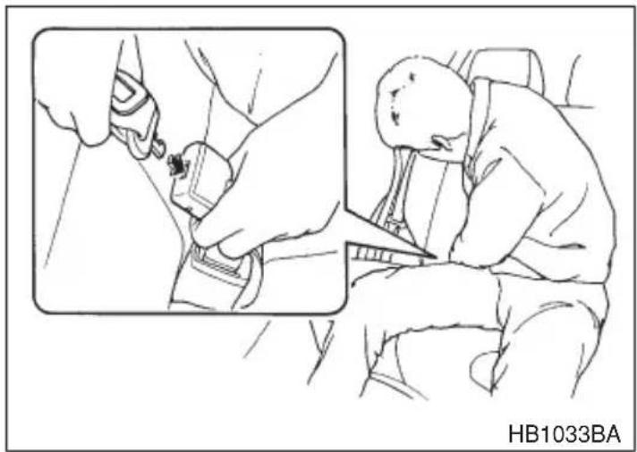
natural_image
Illustration of a car seatbelting a passenger seatbelt, showing hand placement and seatbelting (no text or symbols)- After confirming that the webbing is not twisted, insert the connec-
tor (tongue) attached at the webbing end into the buckle on the right-hand side until a click is heard. If the belt stops before reaching the buckle, return the belt slightly and pull it out more slowly. If the belt still cannot be unlocked, let the belt retract slightly after giving it a strong pull, then pull it out slowly again.
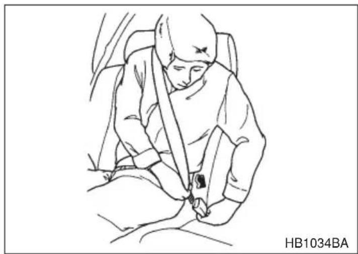
natural_image
Line drawing of a person sitting in a seat, wearing a full-sleeved vest (no text or symbols)- Insert the center seatbelt tongue plate in the center seatbelt buckle marked "CENTER" on the left-hand side until it clicks. To make the lap part tight, pull up on the shoulder belt. And place the lap belt as low as possible on your hips, not on your waist.
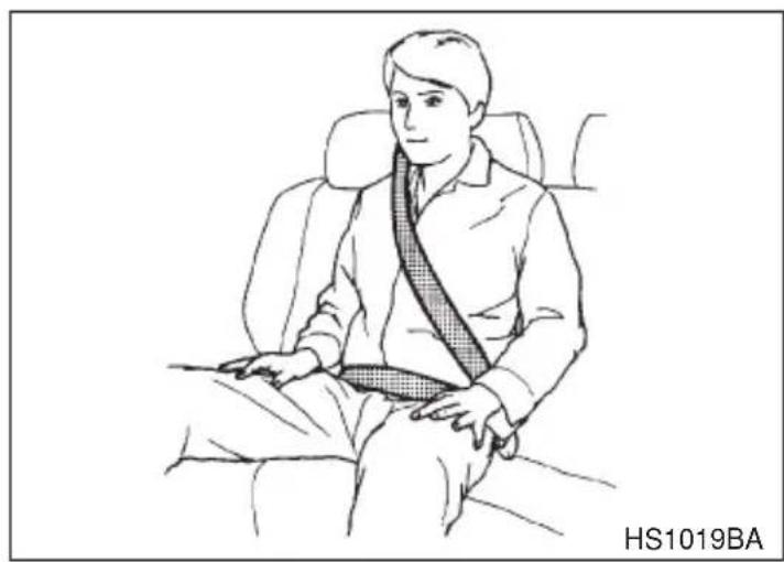
natural_image
Line drawing of a person sitting in a chair wearing a seatbelt, no text or symbols present∇ Unfastening the seatbelt
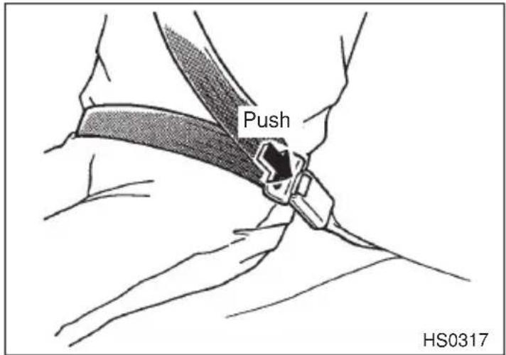
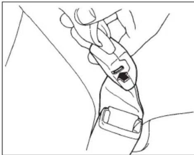
Push the release button of the center seatbelt buckle (on the left-hand side) to unfasten the seatbelt.
NOTE
When the seatback is folded down for greater luggage space, it is necessary to disconnect the connector.

CAUTION
- Do not allow the retractor to roll up the seatbelt too quickly. Otherwise, the metal tongue plates may hit against the trim, resulting in damaged trim.
●Have the seatbelt fully rolled up so that the tongue plates are neatly stored. A hanging tongue plate can swing and hit against the trim during driving, causing damage to the trim.
natural_image
Line drawing of a hand gripping a car seatbelt (no text or symbols)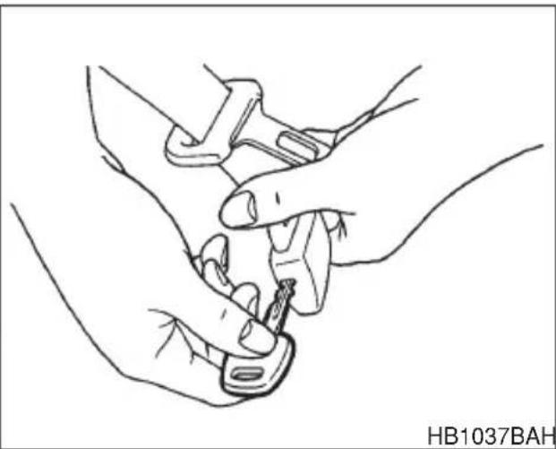
natural_image
Line drawing of two hands adjusting a small object, no text or symbols presentHB1037BAHB1036BA
- Insert a key or other hard pointed object into the slot in the connector (buckle) on the right-hand side and push it in, and the connector (tongue) plate will disconnect from the buckle.
natural_image
Line drawing of a car seatbelt with a magnified inset showing the interior frame (no text or symbols)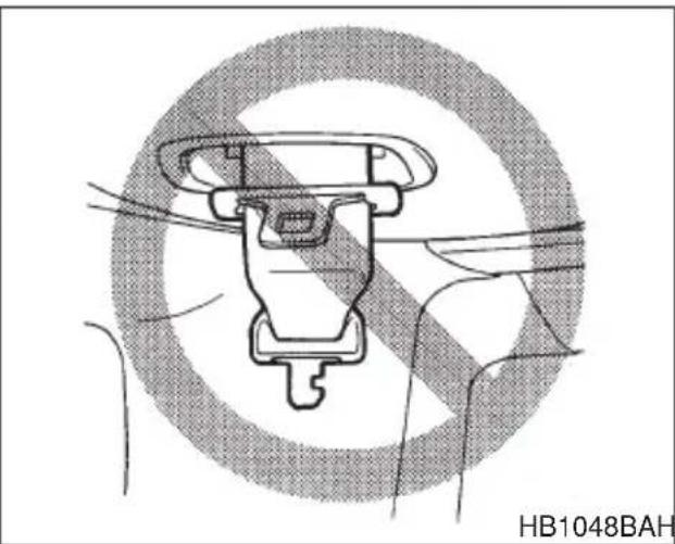
natural_image
Technical line drawing of a mechanical component with no visible text or symbolsHB1048BAHB1038CA
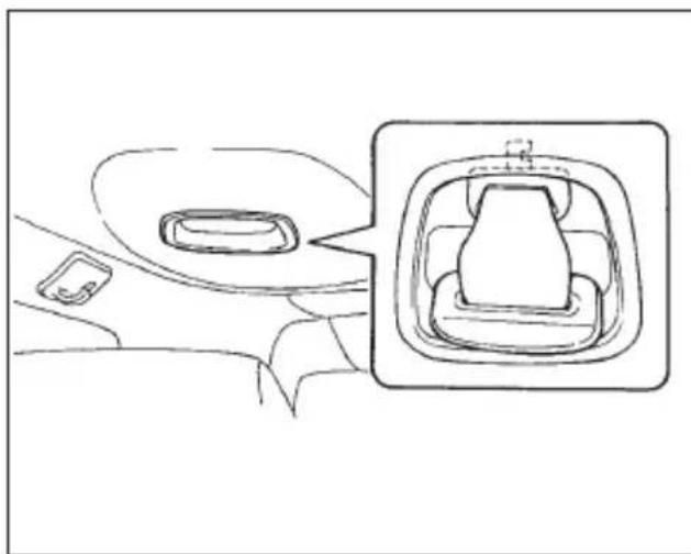
- Allow the retractor to roll up the belt. You should hold the webbing end and guide it back into the retractor while it is rolling up. Neatly store the tongue plates in the recess in the retractor and then insert the connector (tongue) plate into the slot located at the front of the recess.
NOTE
When folding down the rear seat cushion, store the seatbelts in the seatbelt pocket to prevent them falling below the cushion.
■Seatbelt maintenance

CAUTION
- Keep the belts free of polishes, oils, chemicals and particularly battery acid.
●Never attempt to make modifications or changes that will prevent the seatbelt from operating properly.
To clean the seatbelts, use a mild soap and lukewarm water. Never bleach or dye the belts because this could seriously affect their strength.
Inspect the seatbelts and attachments including the webbing and all hardware periodically for cracks, cuts, gashes, tears, damage, loose bolts or worn areas. Replace the seatbelts even if only minor damage is found.
Front seatbelt pretensioners

WARNING
- To obtain maximum protection, occupants should sit in an upright position with their seatbelts properly fastened. Refer to "Seatbelts" section in this chapter.
- Do not modify, remove or strike the front seatbelt retractor assemblies or surrounding area. This could result in accidental activation of the seatbelt pretensioners or could make the system inoperative, possibly resulting in serious injury. Seatbelt pretensioners have no user-serviceable parts. For required servicing of front seatbelt retractors equipped with seatbelt pretensioners, see your nearest SUBARU dealer.
- When discarding front seatbelt retractor assemblies or scrapping the entire car due to collision damage or for other reasons, consult your SUBARU dealer.
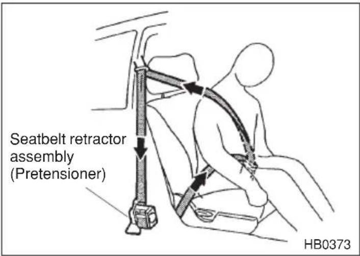
The driver's and front passenger's seatbelts have a seatbelt pretensioner. The seatbelt pretensioners are designed to be activated in the event of an accident involving a moderate to severe frontal collision.
The pretensioner sensor also serves as a SRS frontal airbag sensor. If the sensor detects a certain predetermined amount of force during a frontal collision, the front seatbelt is quickly drawn back in by the retractor to take up the slack so that the belt more effectively restrains
- CONTINUED -
the front seat occupant.
When a seatbelt pretensioner is activated, an operating noise will be heard and a small amount of smoke will be released. These occurrences are normal and not harmful. This smoke does not indicate a fire in the vehicle.
Once the seatbelt pretensioner has been activated, the seatbelt retractor remains locked. Consequently, the seatbelt can not be pulled out and retracted and therefore must be replaced.
NOTE
- Seatbelt pretensioners are not designed to activate in minor frontal impacts, in side or rear impacts or in roll-over accidents.
- The driver's seat and passenger's seat pretensioners and frontal airbag operate simultaneously.
- Pretensioners are designed to function on a one-time-only basis. In the event that a pretensioner is activated, both the driver's and front passenger's seatbelt retractor assemblies must be replaced and only by an authorized SUBARU dealer. When replacing seatbelt retractor assemblies, use only genuine SUBARU parts.
- If either front seatbelt does not retract or cannot be pulled out due to a malfunction or activation of the pretensioner, contact your SUBARU dealer as soon as possible.
- If the front seatbelt retractor assembly or surrounding area has been damaged, contact your SUBARU dealer as soon as possible.
- When you sell your vehicle, we urge you to explain to the buyer that it has seatbelt pretensioners by alerting him to the contents of this section.
▼System monitors
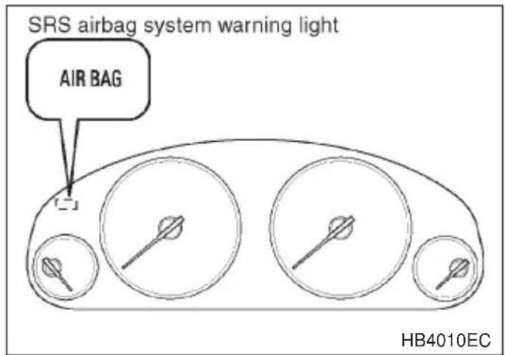
A diagnostic system continually monitors the readiness of the seatbelt pretensioner while the vehicle is being driven. The seatbelt pretensioners share the control module with the airbag system. Therefore, if any malfunction occurs in a seatbelt pretensioner, the SRS airbag system warning light will illuminate. The SRS airbag system warning light will show normal system operation by lighting for about 6 seconds when the ignition key is turned to the “ON” position.
The following components are monitored by the indicator:
●Front sub sensor (Right hand side)
●Front sub sensor (Left hand side)
●Airbag control module (including impact sensors)
- Seatbelt pretensioner (Driver's side)
- Seatbelt pretensioner (Passenger's side)
●All related wiring
In the event of a malfunction indicated by any of following, the vehicle should be taken promptly to your nearest SUBARU dealer to have the system checked. Unless checked and repaired, the seatbelt pretensioners and airbags will not function reliably:
●Flashing or flickering of the indicator light.
- No illumination of the warning light when the ignition switch is first turned to the "ON" position.
●Continuous illumination of the warning light.
●Illumination of the warning light while driving.
- CONTINUED -
▼System servicing
WARNING
- When discarding a seatbelt retractor assembly or scrapping the entire car damaged by a collision, consult your SUBARU dealer.
- Tampering with or disconnecting the system's wiring could result in accidental activation of the seatbelt pretensioner and/or airbag or could make the system inoperative, which may result in serious injury. The wiring harnesses of the seatbelt pretensioner and SRS airbag systems are covered with yellow insulation and the connectors of the system are yellow for easy identification. Do not use electrical test equipment on any circuit related to the seatbelt pretensioner and airbag systems. For required servicing of the seatbelt pretensioner, see your nearest SUBARU dealer.
CAUTION
The front sub sensors are located in both front fenders and the airbag control module including the impact sensors is located under the center console. If you need service or repair in those areas or near the front seatbelt retractors, we recommend that you have an authorized SUBARU dealer perform the work.
NOTE
If the front part of the vehicle is damaged in an accident to the extent that the seatbelt pretensioner does not operate, contact your SUBARU dealer as soon as possible.
▼Precautions against vehicle modification
CAUTION
Do not perform any of the following modifications. Such modifications can interfere with proper operation of the seatbelt pertensioners.
- Attachment of any equipment (bush bar, winches, snow plow, skid plate, etc.) other than SUBARU genuine accessory parts to the front end.
- Modification of the suspension system or front end structure.
●Installation of a tire of different size and construction from the tires specified on the tire placard attached to the door jamb.
Always consult your SUBARU dealer if you want to install any accessory parts to your vehicle.
Child restraint systems
WARNING
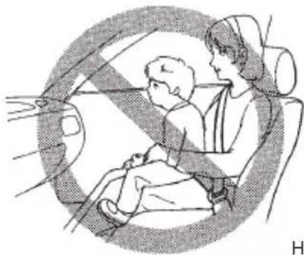
- Never let a passenger hold a child on his or her lap while the vehicle is moving. The passenger cannot protect the child from injury in a collision, because the child will be caught between the passenger and objects inside the vehicle. Additionally, holding a child in your lap or arms in the front seat exposes that child to another serious danger. Since the SRS airbag deploys with considerable speed and force, the child could be injured or even killed.
- Put children aged 12 and under in the rear seat properly restrained at all times. The SRS airbag deploys with considerable speed and force and can injure or even kill children, especially if they are 12 years of age and under and are not restrained or improperly restrained. Because children are lighter and weaker than adults, their risk of being injured from deployment is greater.
For that reason, be sure to secure ALL types of child restraint devices (including forward facing child seats) in the REAR seats at all times. You should choose a restraint device which is appropriate for the child's age, height and weight. According to accident statistics, children are safer when properly restrained in the rear seating positions than in the front seating positions.
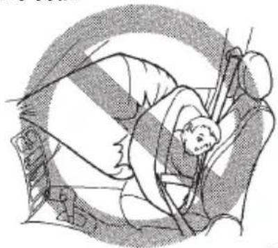
- SINCE YOUR VEHICLE IS EQUIPPED WITH A PASSENGER'S SRS AIRBAG, DO NOT INSTALL A REARWARD FACING CHILD SAFETY SEAT IN THE FRONT PASSENGER'S SEAT. DOING SO RISKS SERIOUS INJURY OR DEATH TO THE CHILD BY PLACING THE CHILD'S HEAD TOO CLOSE TO THE SRS AIRBAG.
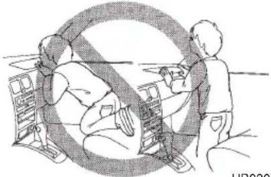
- Children should be properly restrained in the rear seat at all times. Never allow a child to stand up, or to kneel on the front passenger's seat. The SRS airbag deploys with considerable force and can injure or even kill the child.

Never hold a child on your lap or in your arms in the front passenger's seat or any other seat.
natural_image
Illustration of a child and an adult sitting in a car seat, no text or symbols presentHB0308
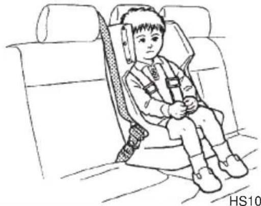
Secure child restraint devices in the REAR seat at all times.
natural_image
Line drawing of a child wearing a seatbelt and headband, seated in a car seat (no text or symbols)HS1031BB

Never install rearward facing child safety seat in the front passenger's seat.
natural_image
Illustration of a person climbing a rope with a striped background (no text or symbols)HB0306

Never allow a child to stand up, or to kneel on the front passenger's seat or any other seat
natural_image
Illustration of two people working together with a large circular symbol in the background (no text or symbols present)HB0307

WARNING
- Child restraint systems and seatbelts can become hot in a vehicle that has been closed up in sunny weather; they could burn a small child. Check the child restraint system before you place a child in it.
- Do not leave an unsecured child restraint system in your vehicle. Unsecured child restraint systems can be thrown around inside of the vehicle in a sudden stop, turn or accident; it can strike and injure vehicle occupants as well as result in serious injuries or death to the child.
Infants and small children should always be placed in an infant or child restraint system in the rear seat while riding in the vehicle. You should use an infant or child restraint system that meets Federal Motor Vehicle Safety Standards or Canada Motor Vehicle Safety Standards, is compatible with your vehicle and is appropriate for the child's age and size. All child restraint systems are designed to be secured in vehicle seats by lap belts or the lap belt portion of a lap/shoulder belt (except those covered under the section in this manual, entitled “Instruction of child restraint systems by use of lower and tether anchorages”).
Children could be endangered in an accident if their child restraints are not properly secured in the vehicle. When installing the child restraint system, carefully follow the manufacturer's instructions.
According to accident statistics, children are safer when properly restrained in the rear seating positions than in the front seating positions.
All U.S. states and Canadian provinces require that infants and small children be restrained in an approved child restraint system at all times while the vehicle is moving.
▼Installing child restraint systems with seatbelt
NOTE
When the child restraint system is no longer in use, remove it and restore the ELR function of the retractor. That function is restored by allowing the seatbelt to retract fully.
- CONTINUED -

CAUTION
When you install a child restraint system, follow the manufacturer's instructions supplied with it. After installing the child restraint system, check to ensure that it is held securely in position. If it is not held tight and secure, the danger of your child suffering personal injury in the event of an accident may be increased.
natural_image
Line drawing of a person seated inside a car seat, no text or symbols present-
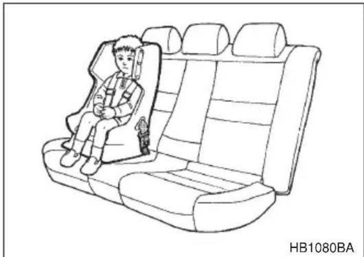
Set the child restraint system in the seating position.
-
Run the lap and shoulder belt through or around the child restraint system following the instructions provided by its manufacturer. If the shoulder belt goes in front of the child's face or neck, put it behind the child restraint system.
-
Insert the tongue plate into the buckle.
-
Take up the slack in the lap belt.
-
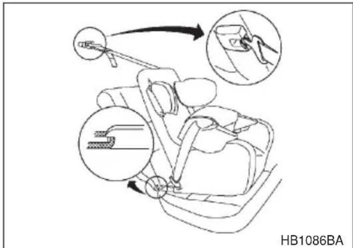
Pull out the seatbelt fully from the retractor to change the retractor over from the Emergency Locking Retractor (ELR) to the Automatic Locking Retractor (ALR) function. Then, allow the belt to rewind into the retractor. As the belt is rewinding, clicks will be heard which indicate the retractor functions as ALR.
-
Before having a child sit in the child restraint system, move it back and forth to check if it is firmly secured. Sometimes a child restraint can be more firmly secured by pushing it down into the seat cushion and then tightening the seatbelt.
-
Pull at the shoulder portion of the belt to confirm that it cannot be pulled out (ALR properly functioning).
If the child restraint system requires a top tether, latch the hook onto the top tether anchorage and tighten the top tether. See the "Top tether anchorages" for additional instructions.
- To remove the child restraint system, press the release button on the seatbelt buckle and allow the belt to retract completely. The belt will return to the ELR mode.
If you have any question concerning this type of child restraint system, ask your SUBARU dealer.
▼Installation of child restraint systems by use of lower and tether anchorages
Some types of child restraint systems can be installed on the rear seat of your vehicle without use of the seatbelts. Such child restraint systems are secured to the dedicated anchorages provided on the vehicle body.
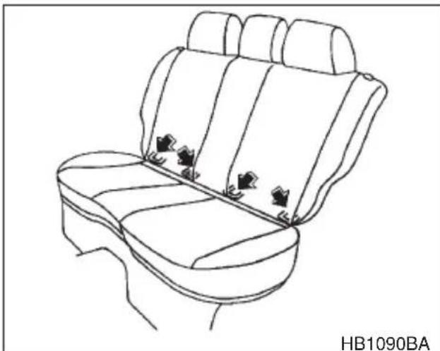
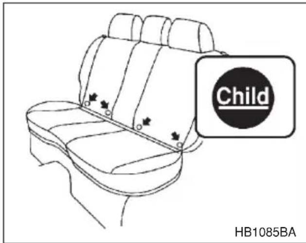
Your vehicle is equipped with four lower anchorages (bars) and three upper anchorages (tether anchorages) for accommodating such child restraint systems.
natural_image
Line drawing of a car backseat with seat covers and three small accessories (no text or symbols)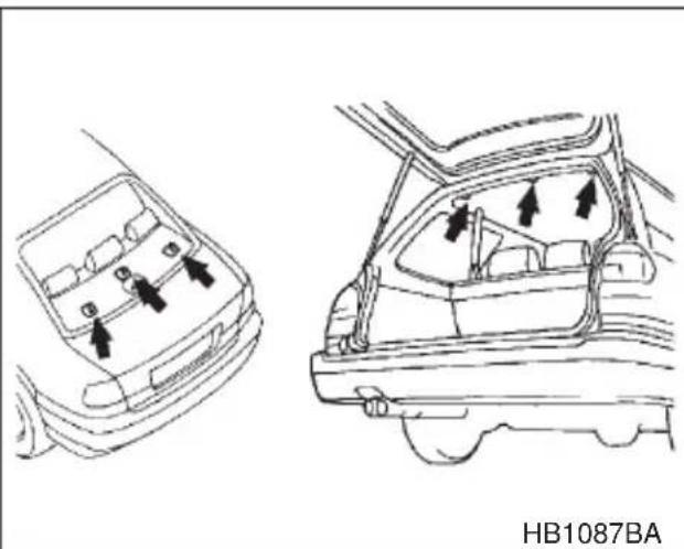
natural_image
Technical line drawing of a car interior showing front and rear views with directional arrows (no text or symbols)The lower anchorages (bars) are used for installing a child restraint system only on the rear seat window-side seating positions. For each window-side seating position, two lower anchorages are provided. The tether anchorages (upper anchorages) are provided for all the seating positions (middle and both window-side ones) of the rear seat.
natural_image
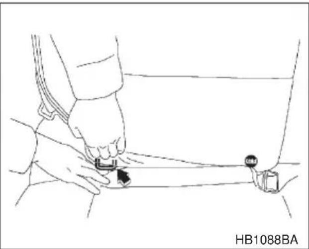
Line drawing of a person adjusting a cable or connector with a belt, no text or symbols presentYou will find marks "Child" at the bottom of the rear seat seatbacks. These marks indicate the positions of the lower anchorages (bars). Each lower anchorage is located where the seat cushion meets the seatback.

CAUTION
When you install a child restraint system, follow the manufacturer's instructions supplied with it. After installing the child restraint system, check to ensure that it is held securely in position. If it is not held tight and secure, the danger of your child suffering personal injury in the event of an accident may be increased.
- Use the "Child" marks to locate the two lower anchorages (bars) for the position where you want to install the child restraint system.
- While following the instructions supplied by the child restraint system manufacturer, connect the connectors of the child restraint system to the lower anchorages.
When the connectors are fastened, make sure that the adjacent seat-belts are not caught.
If your child restraint system is of a flexible attachment type (which uses tether straps to connect the child restraint system proper to the lower anchorages), firmly tighten the straps after connecting the connectors.
- Connect the top tether hook to the tether anchorage and firmly tighten the tether.
- CONTINUED -
For information on how to set the top tether, read the following "Top tether anchorages".
- Before seating a child in the child restraint system, try to move seat back and forth to verify that it is held securely in position.
If you have any question concerning this type of child restraint system, ask your SUBARU dealer.
■Top tether anchorages
▼Anchorage location
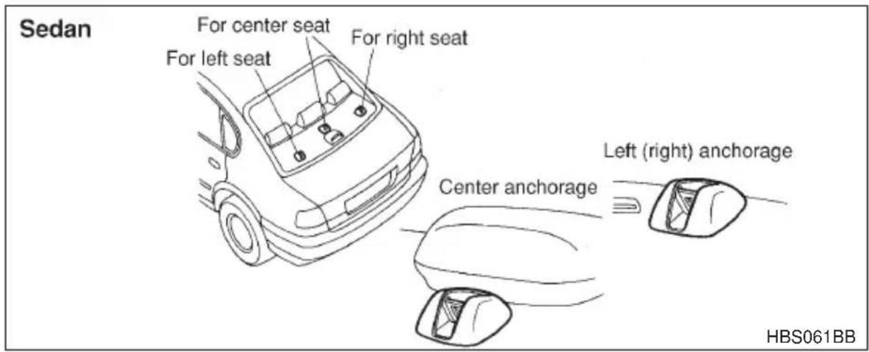
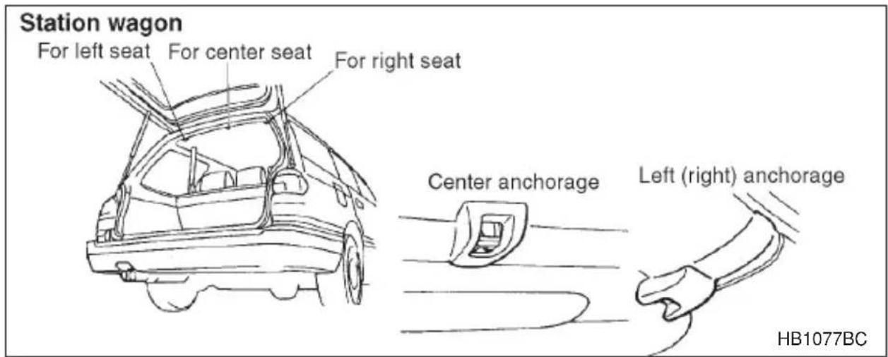
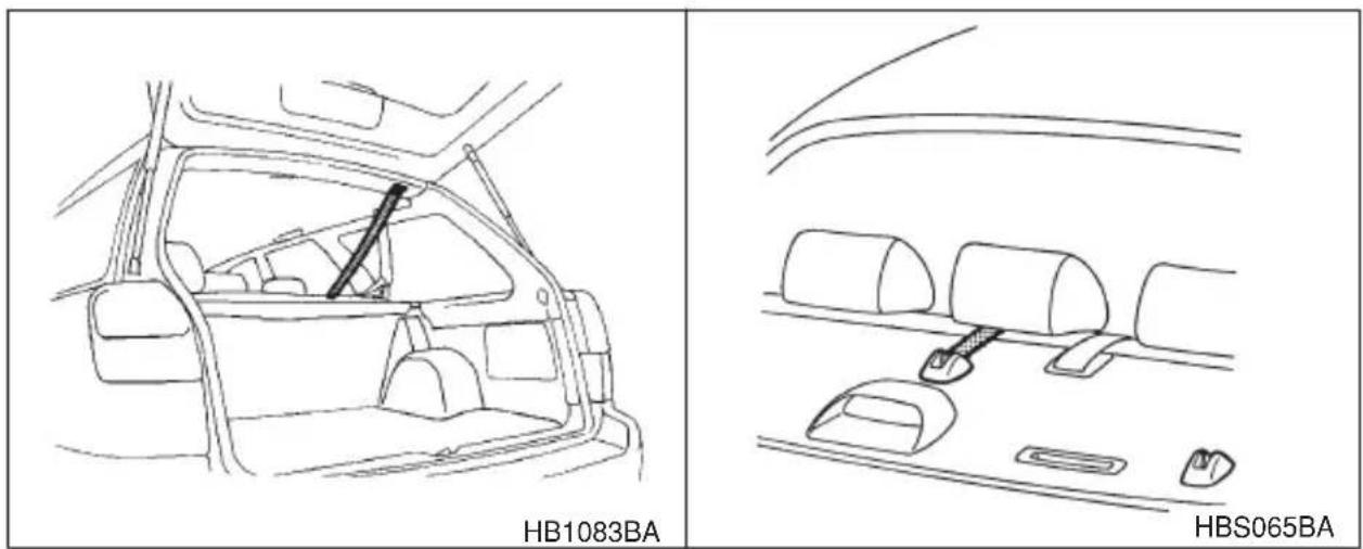
Three anchorages, i.e., ones for the right, center and left positions, are already installed on the rear shelf (on Sedan) or on the rear edge of the roof (on Staion wagon).
▼To hook the top tether
▽ Sedan
CAUTION
When the child restraint system is to be secured using the top tether, always pass the top tether under the headrest between the headrest stay posts. If the top tether is routed over the headrest, it may not be properly tensioned, resulting in an unsteady child restraint system.
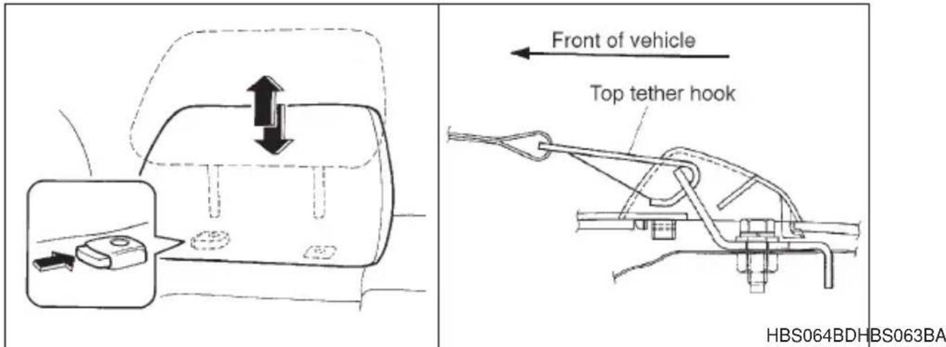
- Remove the headrest at the seating position where the child seat has been installed with the seatbelt or lower anchorages; lift up the headrest while pressing the release button.
- Fasten the top tether hook of the child restraint system to the appropriate upper anchorage.
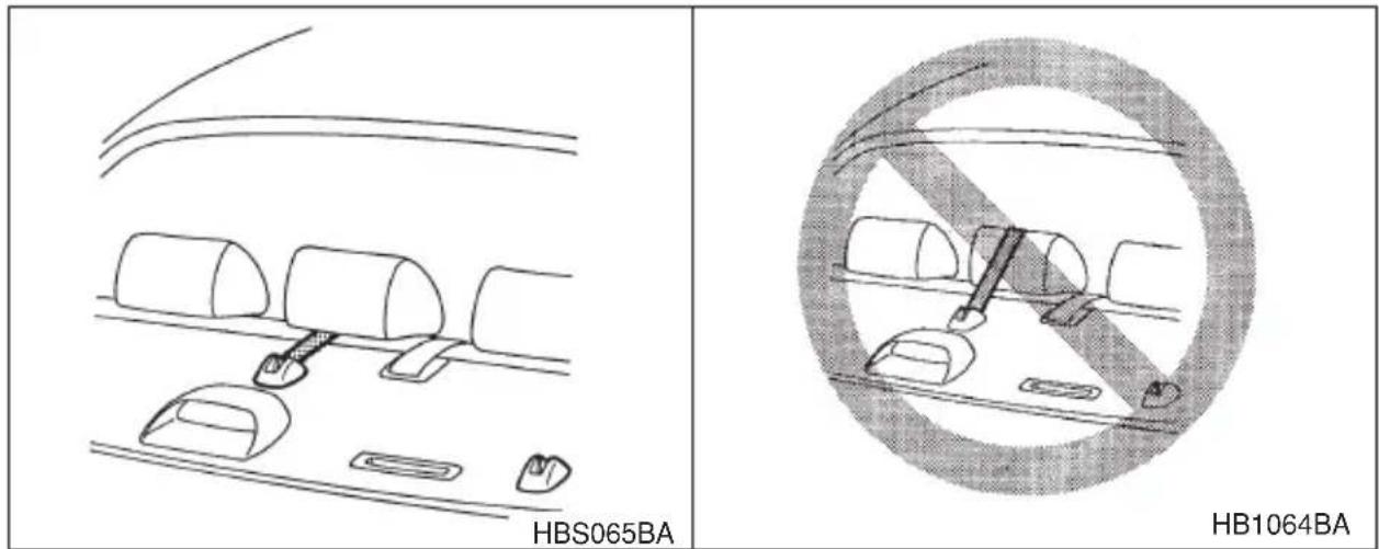
- Tighten the top tether securely.
- Reinstall the headrest in such a way that the top tether is routed between the headrest stay posts.
▽ Station wagon

CAUTION
Always remove the headrest when mounting a child restraint system with a top tether. Otherwise, it may happen that the top tether cannot be fastened tightly.
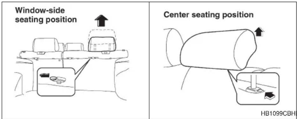
- Remove the headrest (if so equipped) at the seating position where the child restraint system has been installed with the seatbelt or lower anchorages; lift up the headrest while pressing the release but-
ton. Store the headrest in the cargo area. Avoid placing the headrest in the passenger compartment to prevent it from being thrown around in the passenger compartment in a sudden stop or a sharp turn.
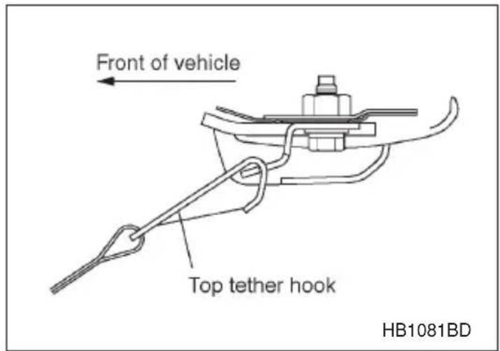
-
Fasten the top tether hook of the child restraint system to the appropriate upper anchorage.
-
Tighten the top tether securely.
\*SRS airbag (Supplemental Restraint System airbag)
*SRS: This stands for supplemental restraint system. This name is used because the airbag system supplements the vehicle's seatbelts.
■ Vehicle with driver's and front passenger's SRS airbags and lap/shoulder restraints
WARNING
- To obtain maximum protection in the event of an accident, the driver and all passengers in the vehicle should always wear seatbelts when the vehicle is moving. The SRS airbag is designed only as a supplement to the primary protection provided by the seatbelt. It does not do away with the need to fasten seatbelts. In combination with the seatbelts, it offers the best combined protection in case of a serious accident.
Not wearing a seatbelt increases the chance of severe injury or death in a crash even when the car has the SRS airbag.
For instructions and precautions concerning the seatbelt system, see the “Seatbelts” sections in this chapter.
- Do not sit or lean unnecessarily close to the SRS airbag. Because the SRS airbag deploys with considerable speed – faster than the blink of an eye – and force to protect in high speed collisions, the force of an airbag can injure an occupant whose body is too close to SRS airbag.
It is also important to wear your seatbelt to help avoid injuries that can result when the SRS airbag contacts an occupant not in proper position such as one thrown forward during pre-accident braking.
Even when properly positioned, there remains a possibility that an occupant may suffer minor injury such as abrasions and bruises to the face or arms because of the SRS airbag deployment force.
- The SRS airbags deploy with considerable speed and force. Occupants who are out of proper position when the SRS airbag deploys could suffer very serious injuries. Because the SRS airbag needs enough space for deployment, the driver should always sit upright and well back in the seat as far from the steering wheel as practical while still maintaining full vehicle control and the front passenger should move the seat as far back as possible and sit upright and well back in the seat.
- Do not place any objects over or near the SRS airbag cover or between you and the SRS airbag. If the SRS airbag deploys, those objects could interfere with its proper operation and could be propelled inside the car and cause injury.
- Put children aged 12 and under in the rear seat properly restrained at all times. The SRS airbag deploys with considerable speed and force and can injure or even kill children, especially if they are 12 years of age and under and are not restrained or improperly restrained. Because children are lighter and weaker than adults, their risk of being injured from deployment is greater.
For that reason, we strongly recommend that ALL children
(including those in child seats and those that have outgrown child restraint devices) sit in the REAR seat properly restrained at all times in a child restraint device or in a seatbelt, whichever is appropriate for the child's age, height and weight.
Secure ALL types of child restraint devices (including forward facing child seats) in the REAR seats at all times.
According to accident statistics, children are safer when properly restrained in the rear seating positions than in the front seating positions.
For instructions and precautions concerning the child restraint system, see the “Child restraint systems” section in this chapter.
- NEVER INSTALL A REARWARD FACING CHILD SEAT IN THE FRONT SEAT. DOING SO RISKS SERIOUS INJURY OR DEATH TO THE CHILD BY PLACING THE CHILD'S HEAD TOO CLOSE TO THE SRS AIRBAG.
- Never allow a child to stand up, or to kneel on the front passenger's seat, or never hold a child on your lap or in your arms. The SRS airbag deploys with considerable force and can injure or even kill the child.
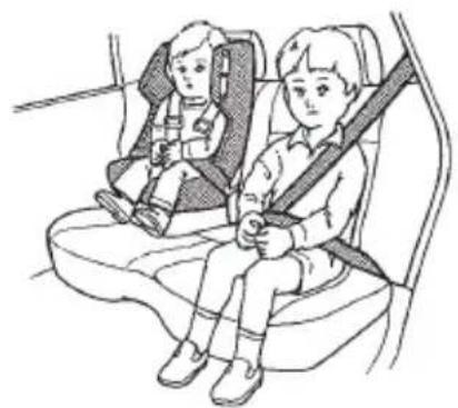
Put children in the REAR seat properly restrained at all times.
natural_image
Illustration of two children seated in a car seat, one wearing a seatbelt and the other holding a child's seatbelt (no text or symbols present)HB0291

CAUTION
- When the SRS airbag deploys, some smoke will be released. This smoke could cause breathing problems for people with a history of asthma or other breathing trouble. If you or your passengers have breathing problems after SRS airbag deploys, get fresh air promptly.
●A deploying SRS airbag releases hot gas. Occupants could get burnt if they come into direct contact with the hot gas.
The supplemental restraint system (SRS) consists of two airbags (driver's and front passenger's frontal airbags) or four airbags (driver's and front passenger's frontal airbags and driver's and front passenger's side airbags).
These SRS airbags are designed only as a supplement to the primary protection provided by the seatbelt.
The system also controls front seatbelt pretensioners. For operation, instructions are precautions concerning the seatbelt pretensioner, see the “Front seatbelt pretensioner” section in this chapter.
NOTE
When you sell your vehicle, we urge you to explain to the buyer that it is equipped with SRS airbags by alerting him to the applicable section in this owner's manual.
Components
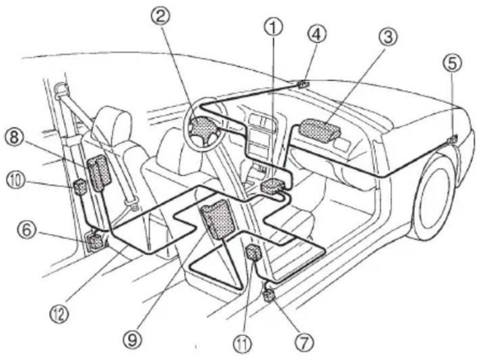
HB1079DB
① Airbag control module (including impact sensors)
② Airbag module (driver's side)
③ Airbag module (passenger's side)
④ Front sub sensor (left hand side)
⑤ Front sub sensor (right hand side)
⑥ Seatbelt pretensioner (driver's side)
⑦ Seatbelt pretensioner (passenger's side)
⑧ Side airbag module (driver's side — if equipped)
⑨ Side airbag module (passenger's side — if equipped)
⑩ Side airbag sensor (driver's side)
⑪ Side airbag sensor (passenger's side)
⑫ Airbag wiring (yellow)
■SRS frontal airbag
WARNING
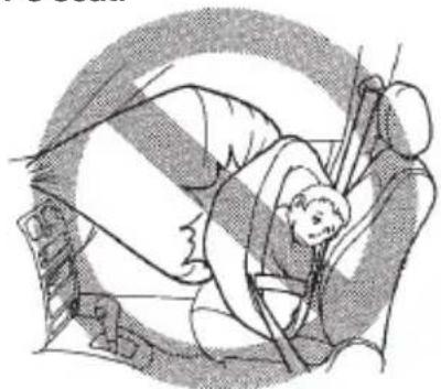
- NEVER INSTALL A REARWARD FACING CHILD SAFETY SEAT IN THE FRONT SEAT. DOING SO RISKS SERIOUS INJURY OR DEATH TO THE CHILD BY PLACING THE CHILD'S HEAD TOO CLOSE TO THE SRS AIRBAG.
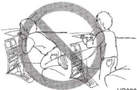
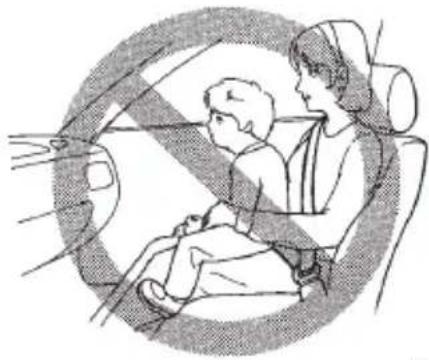
- Never allow a child to stand up, or to kneel on the front passenger's seat, or never hold a child on your lap or in your arms. The SRS airbag deploys with considerable force and can injure or even kill the child.
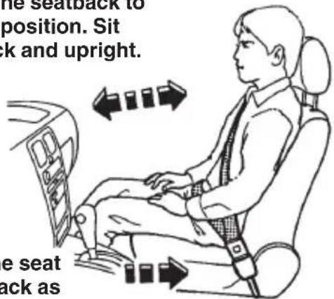
- The SRS airbag deploys with considerable speed and force. Occupants who are out of proper position when the SRS airbag deploys could suffer very serious injuries. Because the SRS airbag needs enough space for deployment, the driver should always sit upright and well back in the seat as far from the steering wheel as practical while still maintaining full vehicle control and the front passenger should move the seat as far back as possible and sit upright and well back in the seat.
It is also important to wear your seatbelt to help avoid injuries that can result when the SRS airbag contacts an occupant not in proper position such as one thrown toward the front of the car during pre-accident braking.

Never install rearward facing child restraint system in the front passenger's seat.
natural_image
Medical illustration showing a patient undergoing an abdominal procedure (no text or labels)HB0306

Never allow a child to stand up, or to kneel on the front passenger's seat
natural_image
Illustration of three people working in a car with a large 'no' symbol overlay (no text or symbols present)HB0307

Never hold a child on your lap or in your arms.
natural_image
Illustration of a child and an adult sitting in a car seat, viewed from inside (no text or symbols)HB0308
Adjust the seatback to upright position. Sit well back and upright.
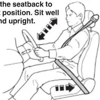
Move the seat as far from the steering wheel as practical.
HS0233
Adjust the seatback to upright position. Sit well back and upright.
HB0290
Move the seat as far back as possible.

WARNING
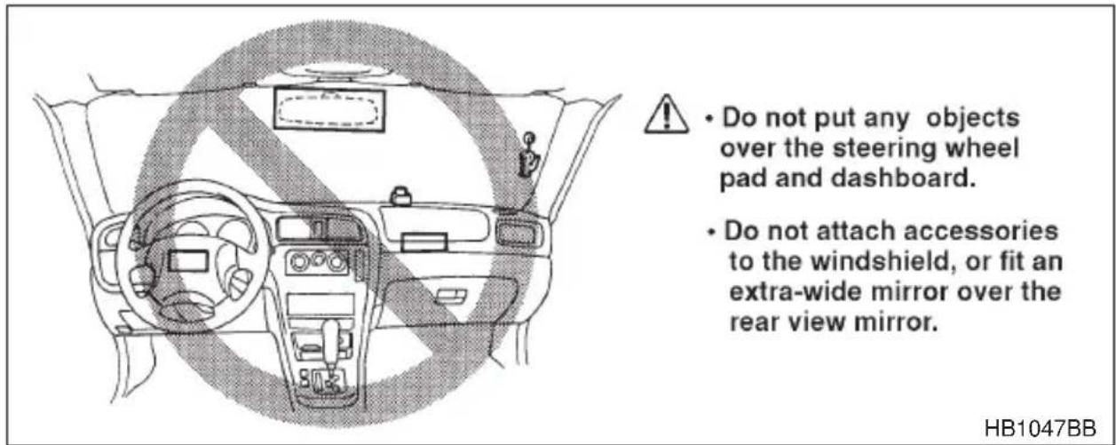
- Do not put any objects over the steering wheel pad and dashboard. If the SRS frontal airbag deploys, those objects could interfere with its proper operation and could be propelled inside the vehicle and cause injury.
- Do not attach accessories to the windshield, or fit an extra-wide mirror over the rear view mirror. If the SRS airbag deploys, those objects could become projectiles that could seriously injure vehicle occupants.
The driver's SRS frontal airbag is stowed in the center portion of the steering wheel. The passenger's SRS frontal airbag is stowed near the top of the dashboard under an "SRS AIRBAG" mark.
In a moderate to severe frontal collision, the driver's and front passenger's SRS frontal airbags deploy and supplement the seatbelts by reducing the impact on the driver's and front passenger's head and chest.
Operation

CAUTION
Do not touch the SRS airbag system components around the steering wheel and dashboard with bare hands right after deployment. Doing so can cause burns because the components can be very hot as a result of deployment.
Driver's side Passenger's side
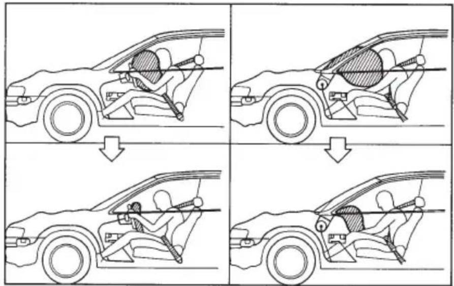
SRS airbags deploy as soon as a collision occurs.
After deployment, SRS airbags start to deflate immediately so that the driver's vision is not obstructed.
OM-H0384
The SRS airbag can function only when the ignition switch is in the "ON" position.
If the front sub sensors inside the both front fenders and the impact sensors in the airbag control module detect a certain predetermined amount of force during a frontal collision, the control module sends signals to the frontal airbag modules instructing them to inflate the SRS frontal airbags. Then both airbag modules produce gas, which instantly inflates driver's and passenger's SRS frontal airbags. After the deployment, the SRS airbags immediately start to deflate so that the driver's vision is not obstructed. The time required from detecting impact to the deflation of the SRS airbag after deployment is shorter than the blink of an eye.
The front passenger's SRS frontal airbag deploys together with driver's SRS frontal airbag even when no one occupies the front passenger's seat.
When the SRS frontal airbags deploy, the driver's and front passenger's seatbelt pretensioners operate at the same time.
Although it is highly unlikely that the SRS airbag would activate in a non-accident situation, should it occur, the SRS airbag will deflate quickly, not obscuring vision and will not interfere with the driver's ability to maintain control of the vehicle.
- CONTINUED -
When the SRS airbag deploys, a sudden, fairly loud inflation noise will be heard and some smoke will be released. These occurrences are normal result of the deployment. This smoke does not indicate a fire in the vehicle.
The SRS frontal airbag is designed to deploy in the event of an accident involving a moderate to severe frontal collision. It is basically not designed to deploy in lesser frontal impacts because the necessary protection can be achieved by the seatbelt alone. Also, it is basically not designed to deploy in side or rear impacts or in roll-over accidents because deployment of the SRS frontal airbag would not help the occupant in those situations. The SRS airbag is designed to function on a one-time-only basis.
SRS airbag deployment depends on the level of force experienced in the passenger compartment during a collision. That level differs from one type of collision to another, and it may have no bearing on the visible damage done to the vehicle itself.
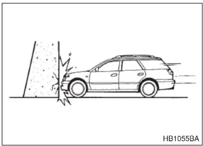
Examples of accident in which the SRS frontal airbag will most likely deploy.
A head-on collision against a thick concrete wall at a vehicle speed of 12 to 19 mph (20 to 30 km/h) or higher activates the SRS frontal airbag. The SRS frontal airbag will also be activated when the vehicle is exposed to a frontal impact similar in fashion and magnitude to the above-mentioned collision.
natural_image
Line drawing of a car approaching a vertical surface with motion blur, labeled HB1055BA (no text on diagram)Examples of the types of accidents in which it is possible that the SRS frontal airbag will deploy.
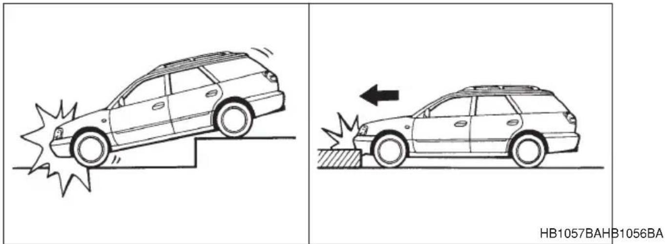
The SRS frontal airbag may be activated when the vehicle sustains a hard impact in the undercarriage area from the road surface (such as when the vehicle plunges into a deep ditch, is severely bumped or knocked hard against an obstacle on the road such as a curb).
Examples of the types of accidents in which the SRS frontal airbag is unlikely to deploy.
There are many types of collisions which might not necessarily require SRS frontal airbag deployment. If the vehicle strikes an object, such as a telephone pole or sign pole, or if it slides under a truck's load bed, or if it sustains an oblique offset frontal impact, the SRS frontal airbag may not deploy depending on the level of accident forces involved.
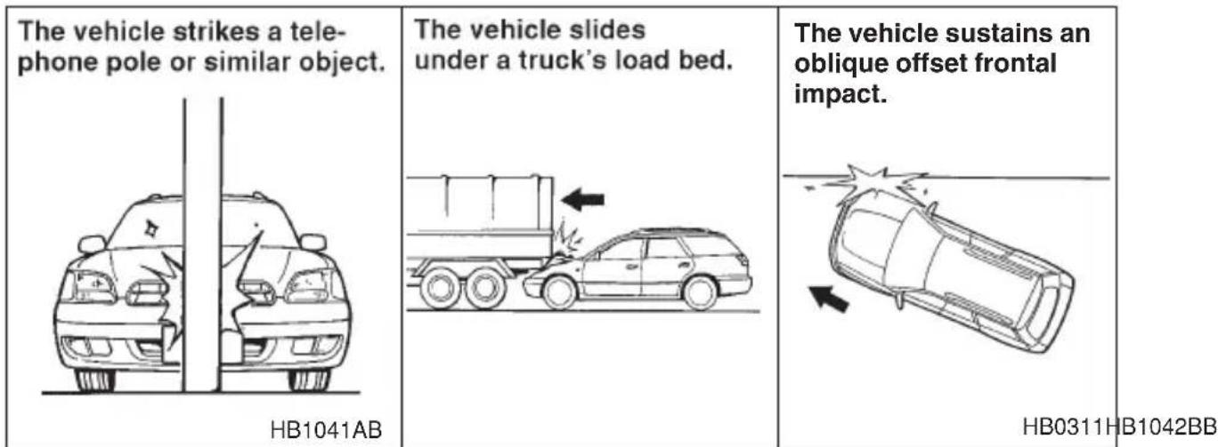
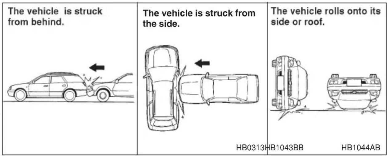
Examples of the types of accidents in which the SRS frontal airbag will basically not deploy.
The SRS frontal airbag is basically not designed to deploy if the vehicle is struck from side or from behind, or if it rolls onto its side or roof, or if it is involved in a low-speed frontal collision.
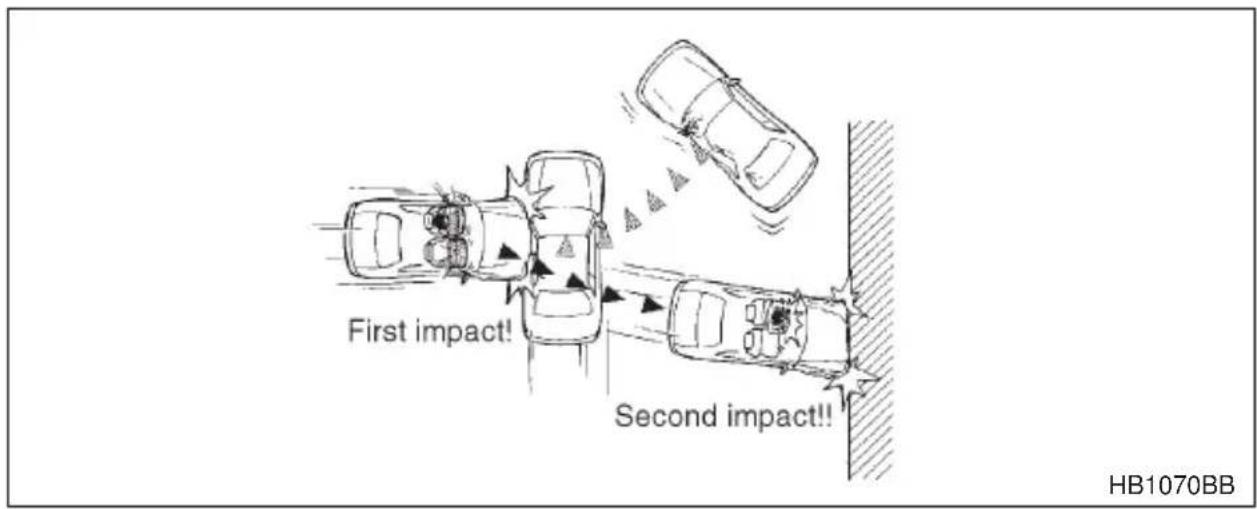
In an accident where the vehicle is impacted more than once, the SRS frontal airbag deploys only once.
Example: In the case of a double collision, first with another vehicle, then against a concrete wall in immediate succession, once the SRS frontal airbag is activated on the first impact, it will not be activated on the second.
■SRS side airbag (if equipped)
WARNING
- The SRS side airbag is designed as only a supplement to the primary protection provided by the seatbelt. It does not do away with the need to fasten seatbelts. It is also important to wear your seatbelt to help avoid injuries that can result when an occupant is not seated in a proper upright position.
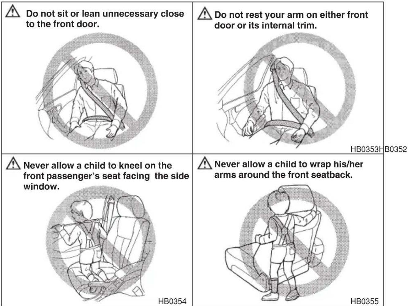
- Do not sit or lean unnecessarily close to either front door. The SRS side airbag is stored in both front seat seatbacks next to the door, and it provides protection by deploying rapidly (faster than the blink of an eye) in the event of a side impact collision. However, the force of SRS side airbag deployment may cause injuries if your head or other body parts are too close to the SRS side airbag.
- Do not rest your arm on either front door or its internal trim. It could be injured in the event of SRS side airbag deployment.
- Never allow a child to kneel on the front passenger's seat facing the side window or to wrap his/her arms around the front seat seatback. In the event of an accident, the force of SRS side airbag deployment could seriously injure or even kill the child because his/her head or arms or other body parts are close to the side airbag. Since your vehicle is also equipped with a passenger's SRS frontal airbag, children aged 12 and under should be placed in the rear seat anyway and should be properly restrained at all times.
HB0353HB0352
HB0355

WARNING
- Do not attach accessories to the door trim or near either SRS side airbags and do not place objects near the SRS side airbags. In the event of the SRS side airbag deployment, they could be propelled dangerously toward the vehicle's occupants and cause injuries.
- Do not put any kind of cover or clothes or other objects over either front seatback and do not attach labels or stickers to the front seat surface on or near the SRS side airbag. They could prevent proper deployment of the SRS side airbag, reducing protection available to the front seat's occupant.

Do not put any kind of cover over either seatback.
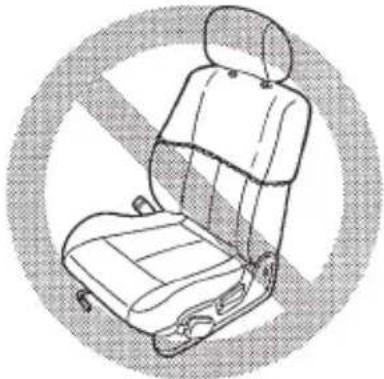
natural_image
Line drawing of a car seat with open lid and seatbelt, enclosed in a circular border (no text or symbols)HB0366

Do not attach accessories to the door trim or near either side airbag and do not place objects near either side airbag.
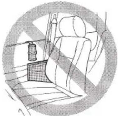
natural_image
Interior view of a car with a passenger seat, dashboard, and seatbelt (no text or symbols visible)HS0353
The SRS side airbag is stored in the door side of each front seatback, which bears an "SRS AIRBAG" label.
In a moderate to severe side impact collision, the SRS side airbag on the impacted side of the vehicle deploys between the occupant and the door panel and supplements the seatbelt by reducing the impact on the occupant's chest.

Operation

CAUTION
Do not touch the SRS side airbag system components around the front seatback with bare hands right after deployment. Doing so can cause burns because the components can be very hot as a result of deployment.
SRS side airbag deploys as soon as a collision occurs.
After deployment, SRS side airbag starts to deflate immediately.
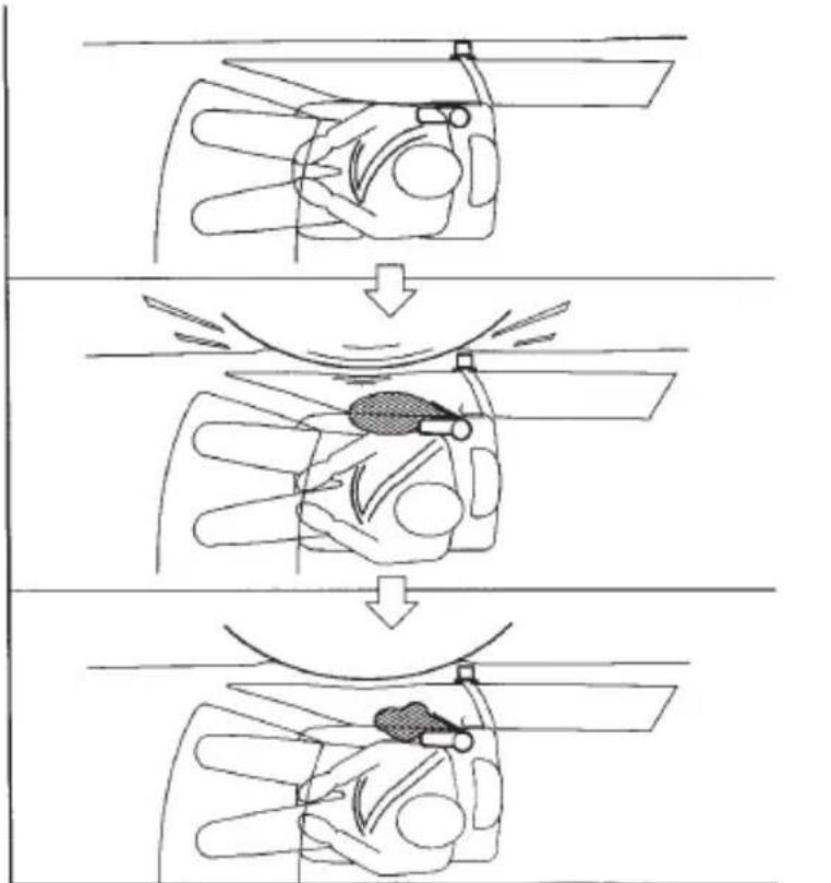
flowchart
graph TD
    A["Wheel"] --> B["Blade"]
    B --> C["Screw"]
    C --> D["Seat Assembly"]
HB0359
The SRS side airbag can function only when the ignition switch is in the "ON" position.
The driver's and front passenger's SRS side airbags deploy independently of each other since each has its own impact sensor. Also, the SRS side airbag deploys independently of the frontal airbags in the steering wheel and instrument panel.
An impact sensor is incorporated into each of the vehicle's center pillars. If either sensor detects a certain predetermined amount of force during a side impact collision, the control module sends a signal to the side airbag module on the impacted side of the vehicle, instructing it to inflate the SRS side airbag. Then the side airbag module produces gas, which instantly inflates the SRS side airbag. After the deployment, the SRS side airbag immediately starts to deflate. The time required from detecting impact to the deflation of the SRS side airbag after deployment is shorter than the blink of an eye.
The SRS side airbag deploys even when no one occupies the seat on the side of which an impact is applied.
When the SRS side airbag deploys, a sudden, fairly loud inflation noise will be heard and some smoke will be released. These occurrences are normal result of the deployment. This smoke does not indicate a fire in the vehicle.
The SRS side airbag is designed to deploy in the event of an accident involving a moderate to severe side impact collision. It is basically not designed to deploy in lesser side impact. Also, it is basically not designed to deploy in frontal or rear impacts because SRS side airbag deployment would not help the occupant in those situations.
Each SRS side airbag is designed to function on a one-time-only basis.
SRS side airbag deployment depends on the level of force experienced in the passenger compartment during a side impact collision. That level differs from one type of collision to another, and it may have no bearing on the visible damage done to the vehicle itself.
Example of the type of accident in which the SRS side airbag will most likely deploy.
A severe side impact near the front seat activates the SRS side air-bag.
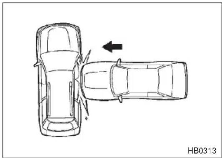
natural_image
Top-down line drawing of two cars with a directional arrow indicating collision or movement (no text or symbols on the car bodies)Examples of the types of accidents in which the SRS side airbag is unlikely to deploy.
There are many types of collisions which might not necessarily require SRS side airbag deployment. In the event of accidents like those illustrated below, the SRS side airbag may not deploy depending on the level of accident forces involved.
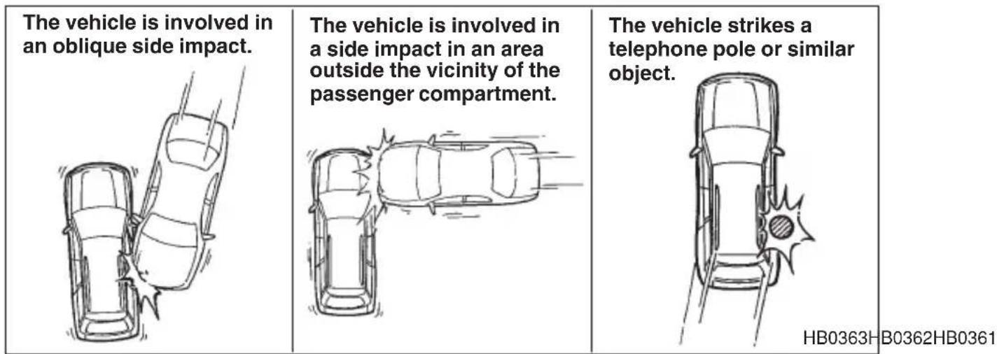
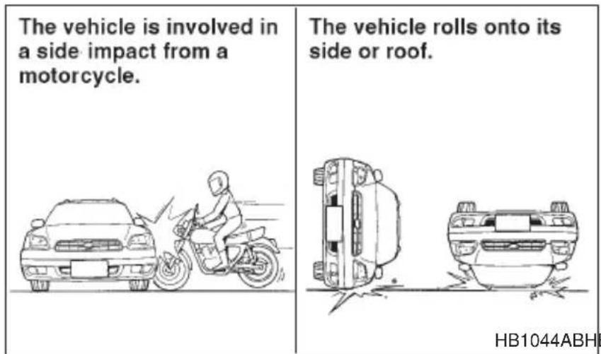
Examples of the types of accidents in which the SRS side air-bag will basically not deploy.
The SRS side airbag is basically not designed to deploy if the vehicle is involved in a frontal collision or is struck from behind. Examples of such accidents are illustrated below.
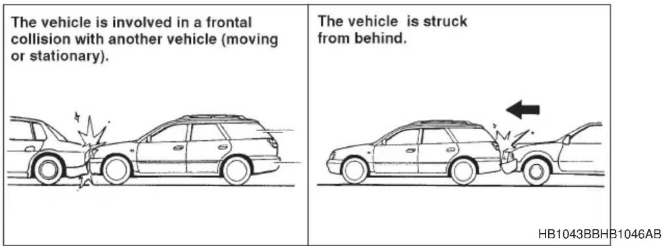
In an accident where the vehicle is struck from the side more than once, the SRS side airbag deploys only once.
Example: In the case of a double side impact collision, first with one vehicle and immediately followed by another from the same direction, once the SRS side airbag is activated on the first impact, it will not be activated on the second.
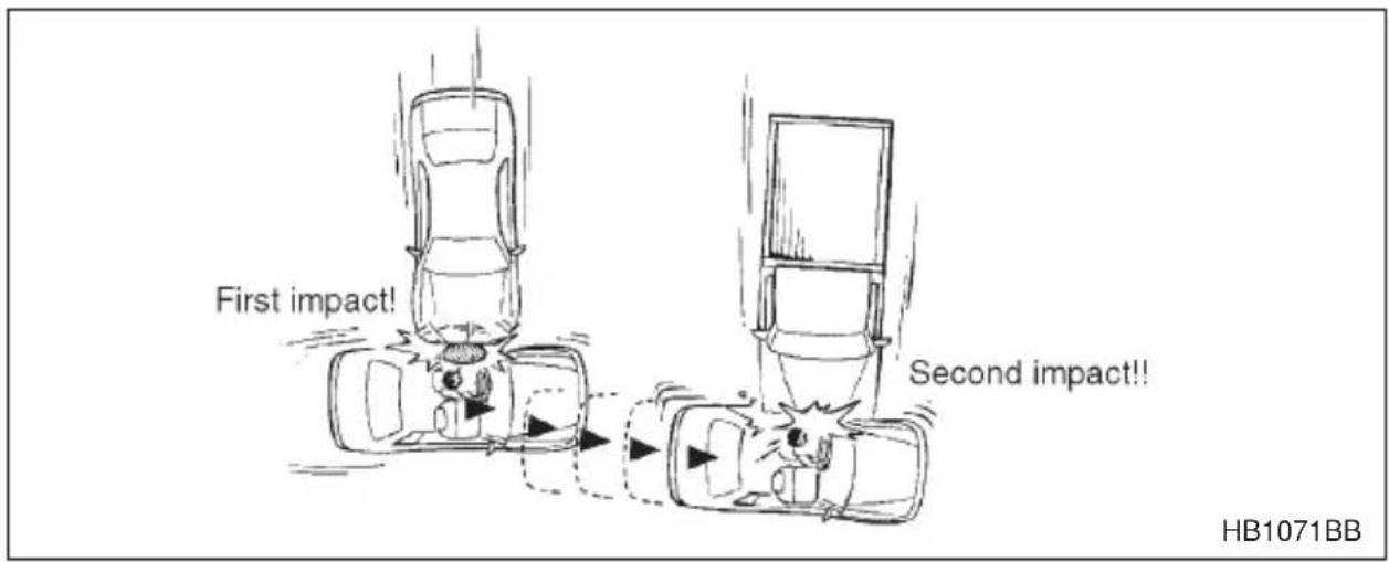
■SRS airbag system monitors
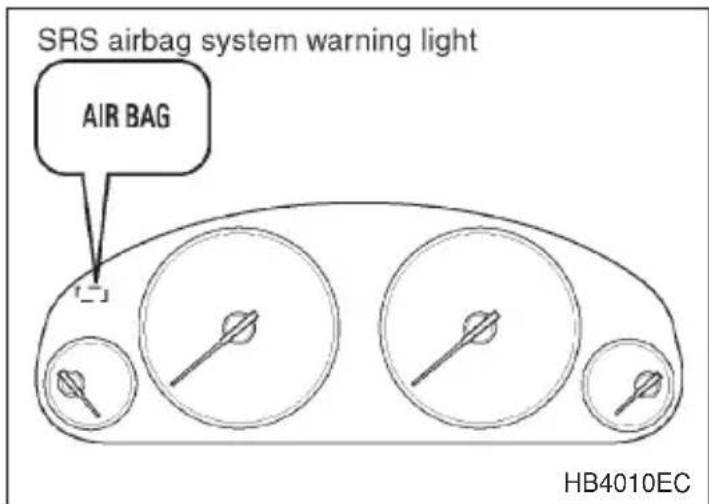
A diagnostic system continually monitors the readiness of the SRS airbag system (including front seatbelt pretensioners) while the vehicle is being driven. The SRS airbag system warning light “AIRBAG” will show normal system operation by lighting for about 6 seconds when the ignition key is turned to the “ON” position.
The following components are monitored by the indicator:
●Front sub sensor (Right hand side)
●Front sub sensor (Left hand side)
●Airbag control module (including impact sensors)
●Frontal airbag module (Driver's side)
- Frontal airbag module (Passenger's side)
- Side airbag sensor (Driver's side — if equipped)
- Side airbag sensor (Passenger's side — if equipped)
- Side airbag module (Driver's side — if equipped)
- Side airbag module (Passenger's side — if equipped)
- Seatbelt pretensioner (Driver's side)
- Seatbelt pretensioner (Passenger's side)
●All related wiring
In the event of a malfunction indicated by any of following, the vehicle should be taken promptly to your nearest SUBARU dealer to have the system checked. Unless checked and repaired, the SRS airbags will not function reliably:
●Flashing or flickering of the indicator light.
- No illumination of the warning light when the ignition switch is first turned to the “ON” position.
●Continuous illumination of the warning light.
●Illumination of the warning light while driving.
■SRS airbag system servicing

WARNING
- When discarding an airbag module or scrapping the entire car damaged by a collision, consult your SUBARU dealer.
- The SRS airbag has no user-serviceable parts. Do not use electrical test equipment on any circuit related to the SRS airbag system. For required servicing of the SRS airbag, see your nearest SUBARU dealer. Tampering with or disconnecting the system's wiring could result in accidental inflation of the SRS airbag or could make the system inoperative, which may result in serious injury. The wiring harnesses of the SRS airbag system are covered with yellow insulation and system connectors are yellow for easy identification.

CAUTION
If you need service or repair in areas listed below, we recommend that you have an authorized SUBARU dealer perform the work. The SRS airbag control module, impact sensors and airbag modules are stored in these areas.
●Under the center console
●Inside each front fender
●Steering wheel and column and nearby areas
- Top of the dashboard on front passenger's side and nearby areas
- Each front seat and nearby area (only for vehicles with SRS side airbags)
●Inside each center pillar
In the event that the SRS airbag is deployed, replacement of the system should be performed only by an authorized SUBARU dealer. When the components of the SRS airbag system are replaced, use only genuine SUBARU parts.
To ensure their long-term reliability, the SRS airbags must be inspected by a SUBARU dealer ten years after the date of manufacture, which is shown on the certification label attached to the driver's door.
NOTE
In the following cases, contact your SUBARU dealer as soon as possible.
●The front part of the vehicle was involved in an accident in which the SRS frontal airbags did not deploy.
- The pad section of the steering wheel or front passenger's frontal airbag cover is scratched, cracked, or otherwise damaged.
In addition, if your vehicle is equipped with SRS side airbags, contact your SUBARU dealer as soon as possible in the following cases.
- Either center pillar or a nearby area of the vehicle was involved in an accident in which the SRS side airbag did not deploy.
- The fabric or leather of either front seatback is cut, frayed, or otherwise damaged.
■Precautions against vehicle modification

WARNING
- To avoid accidental activation of the system or rendering the system inoperative, which may result in serious injury, no modifications should be made to any components or wiring of the SRS airbag system.
This includes following modifications:
●Installation of custom steering wheels
- Attachment of additional trim materials to the dashboard
- Installation of custom seats (only for vehicles with SRS side airbags)
●Replacement of seat fabric or leather (only for vehicles with SRS side airbags)
●Installation of additional fabric or leather on the front seat (only for vehicles with SRS side airbags)
- Installation of additional electrical/electronic equipment such as a mobile two-way radio on or near the SRS airbag system components and/or wiring is not advisable. This could interfere with proper operation of the SRS airbag system.

CAUTION
Do not perform any of the following modifications. Such modifications can interfere with proper operation of the SRS airbag system.
- Attachment of any equipment (brush bar, winches, snow plow, skid plate, etc.) other than SUBARU genuine accessory parts to the front end.
- Modification of the suspension system or front end structure.
- Installation of a tire of different size and construction from the tires specified on the tire placard attached to the driver's door jamb.
- Attachment of any equipment (side steps or side sill protectors, etc.) other than SUBARU genuine accessory parts to the side body (only for vehicles with side airbags).
Always consult your SUBARU dealer if you want to install any accessory parts to your vehicle.
Keys and doors
Keys 2-2
Door locks 2-3
Power door locking switches (if equipped) 2-6
Keyless entry system (if equipped) 2-7
Security system (if equipped) 2-13
Child safety locks 2-20
Windows 2-21
Power windows 2-21
Trunk lid (Sedan) 2-24
Internal trunk lid release handle 2-26
Rear gate (Station wagon) 2-29
Moonroof (if equipped) 2-30
Tilting/sliding moonroof (Sedan) 2-30
Dual moonroofs (Station wagon) 2-32
Keys
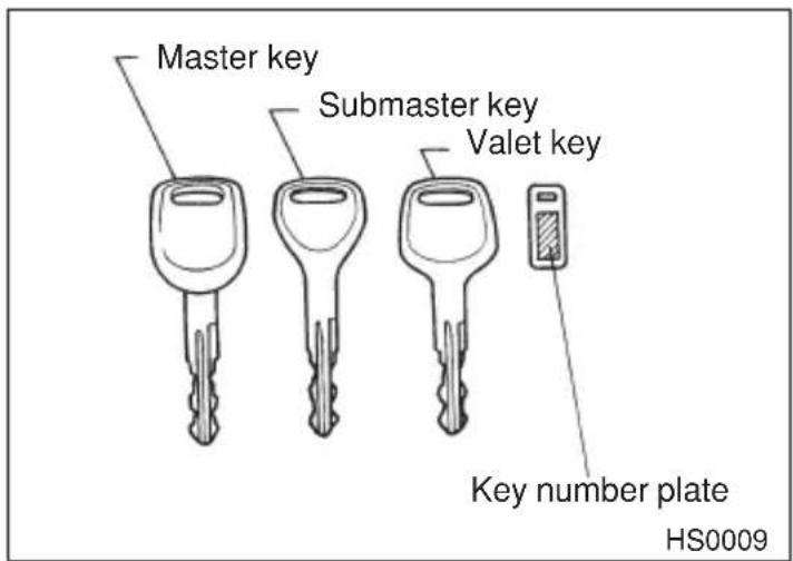
Three types of keys are provided for your vehicle.
Master key, submaster key and valet key.
The master key and submaster key fit all locks on your vehicle.
- Ignition switch
- Doors
●Trunk (sedan) or Rear gate (station wagon)
●Glove compartment
The valet key fits only the ignition switch and door locks. You can keep the trunk and glove compartment locked when you leave your vehicle and valet key at a parking facility.
▼Key number
The key number is stamped on the metal plate attached to the key set. Write down the key number and keep it in another safe place, not in the vehicle. This number is needed to make a replacement key if you lose your key or lock it inside the vehicle.
Door locks
▼Locking and unlocking from the outside
For vehicles with power door locking switches
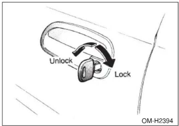
To lock the door from the outside with the key, turn the key toward the rear. To unlock the door, turn the key toward the front.
Lift the outside door handle to open an unlocked door.
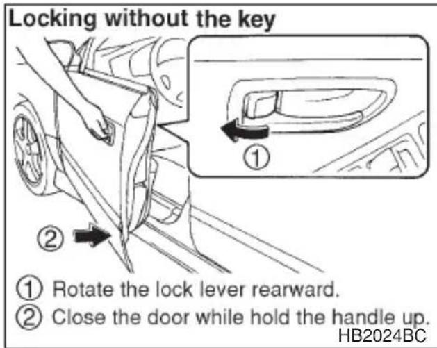
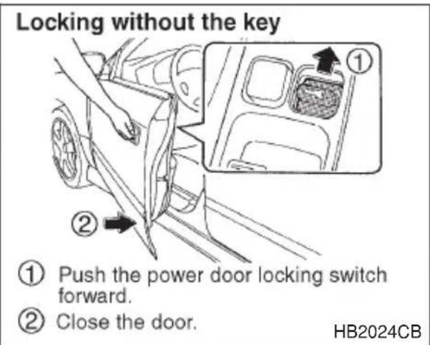
To lock the door from the outside without the key, rotate the lock lever rearward and then close the door.
To lock the door from the outside using the power door locking switch, push the switch forward ("LOCK" side) and then close the door. In this case, all closed doors and the rear gate (for station wagon) are
- CONTINUED -
locked at the same time.
Always make sure that all doors and the rear gate are locked before leaving your vehicle.
NOTE
Make sure that you do not leave the key inside the vehicle before locking the doors from the outside without the key.
For vehicles without power door locking switches
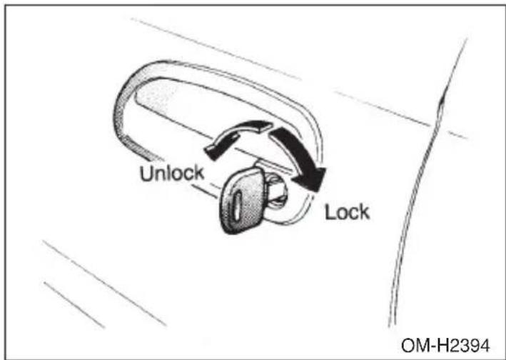
To lock the door from the outside with the key, turn the key toward the rear. To unlock the door, turn the key toward the front.
Lift the outside door handle to open an unlocked door.
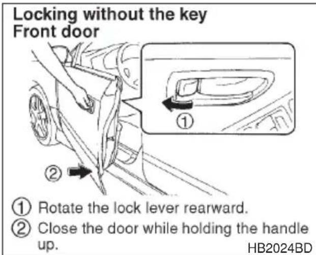
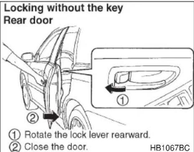
To lock the front door from the outside without the key, rotate the lock lever rearward and hold the outside door handle up while closing the
door.
To lock the rear door from the outside without the key, rotate the lock lever rearward and then close the door.
Always make sure that all doors and the rear gate (station wagon) are locked before leaving your vehicle.
NOTE
Make sure that you do not leave the key inside the vehicle before locking the doors from the outside without the key.
▼Locking and unlocking from the inside

WARNING
Keep all doors locked when you drive, especially when small children are in your vehicle.
Along with the proper use of seat belts and child restraints, locking the doors reduces the chance of being thrown out of the vehicle in an accident.
It also helps prevent passengers from falling out if a door is accidentally opened, and intruders from unexpectedly opening doors and entering your vehicle.
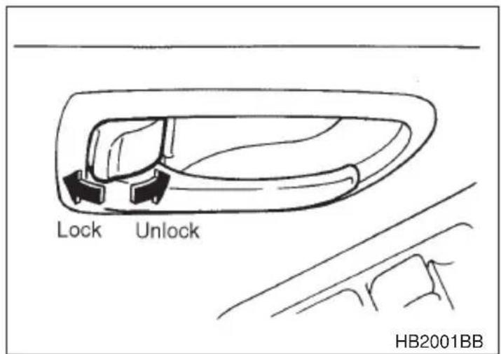
To lock the door from the inside, rotate the lock lever rearward. To unlock the door from the inside, rotate the lock lever forward.
The red mark on the lock lever appears when the door is unlocked.
- CONTINUED -
Pull the inside door handle to open an unlocked door.
Always make sure that all doors and the rear gate (station wagon) are closed and locked before starting to drive.
■Power door locking switches (if equipped)
Driver's switch
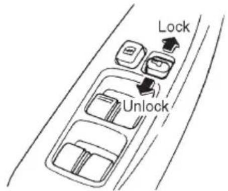
Front passenger's switch
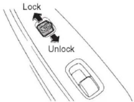
HB2009BBHB2008CB
All doors and the rear gate (station wagon) can be locked and unlocked by the power door locking switches located at the driver's side and the front passenger's side doors.
To lock the doors, push the switch forward.
To unlock the doors, push the switch rearward.
When you close the doors after you set the door locks, the doors remain locked.
NOTE
Make sure that you do not leave the key inside the vehicle before locking the doors from the outside using power door locking switches.
Keyless entry system (if equipped)

CAUTION
- Do not expose the transmitter to severe shocks, such as those experienced as a result of dropping or throwing.
- Do not take the transmitter apart except when replacing the battery.
- Do not get the transmitter wet. If it gets wet, wipe it dry with a cloth immediately.
This device complies with Part 15 of the FCC Rules and with RSS-210 of Industry Canada. Operation is subject to the following two conditions: (1) This device may not cause harmful interference, and (2) this device must accept any interference received, including interference that may cause undesired operation.
Changes or modifications not expressly approved by the party responsible for compliance could void the user's authority to operate the equipment.
Two transmitters are provided for your vehicle.
The keyless entry system has the following functions.
- Locking and unlocking the doors (and rear gate on the station wagon) without a key
●Sounding a panic alarm - Arming and disarming the security system (if your vehicle is equipped with an optional security system). See the next section “Security system (if equipped)” for detailed information.
The operable distance of the keyless entry system is approximately 30 feet (10 meters). However, this distance will vary depending on environmental conditions. Range may be reduced near sources of RF interference such as power plants and radio/television broadcasting towers.
The keyless entry system does not operate when the key is inserted in the ignition switch.
- CONTINUED -
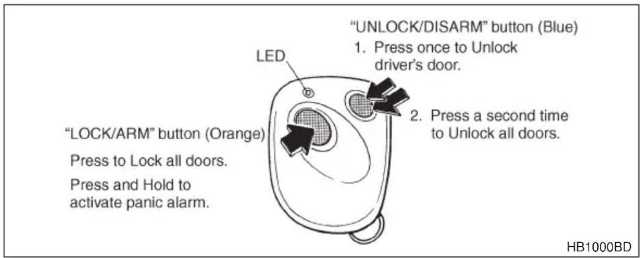
▼Locking the doors
Briefly press the "LOCK/ARM" button (for less than two seconds) to lock all doors (and rear gate on the station wagon). The horn will sound one time.
If any of the doors (or the rear gate) is not fully closed, the horn will sound three times to alert you that the doors (or the rear gate) are not properly closed. When you close the door, it will automatically lock.
NOTE
If the “LOCK/ALARM” button is pressed for two seconds or longer, the panic alarm will sound. When locking the doors in normal circumstances, press the “LOCK/ALARM” button for less than two seconds. For details on the panic alarm, refer to “Sounding the panic alarm”.
▼Unlocking the doors
Briefly press the “UNLOCK/DISARM” button (for less than two seconds) to unlock the driver's door. The horn will sound two times. To unlock all doors (and rear gate on the station wagon), briefly press the “UNLOCK/DISARM” button a second time within 5 seconds.
▼Illuminated entry
The interior (dome) light and ignition switch light will illuminate when the “UNLOCK/DISARM” button is pressed. These lights stay illuminated for approximately 30 seconds if any of the doors (or the rear gate on the station wagon) is not opened.
If the “LOCK/ARM” button is pressed before 30 seconds have elapsed, these lights will go out. Also, these lights will go out if the key is inserted in the ignition switch. The interior light must be set to the middle position in order for this function to operate.
▼Sounding a panic alarm
To activate the alarm, keep the "LOCK/ARM" button pressed for more than two seconds.
To deactivate it, press the “LOCK/ARM” button or “UNLOCK/DISARM” button. Unless a button on the remote is pressed, the alarm will be deactivated after approximately 30 seconds.
▼Selecting audible signal operation
Using the horn, the system will give you an audible signal when the doors lock and unlock. If desired, you may turn the audible signal off. To turn the audible signal off, unlock the doors by pushing “UNLOCK/DISARM” button and then simultaneously depress “LOCK/ARM” and “UNLOCK/DISARM” buttons for more than two seconds. The horn will sound two times to inform you that the audible signal has been turned off.
To turn the audible signal on, unlock the doors by pushing “UNLOCK/DISARM” button and then simultaneously depress “LOCK/ARM” and “UNLOCK/DISARM” buttons for more than two seconds. The horn will sound one time to inform you that the audible signal has been turned on.
▼Replacing the battery

CAUTION
Do not let dust, oil or water get on or in the transmitter when replacing the battery.
When the transmitter battery begins to get weak, transmitter range will begin to decrease and the LED will not illuminate. Replace the battery as soon as possible.
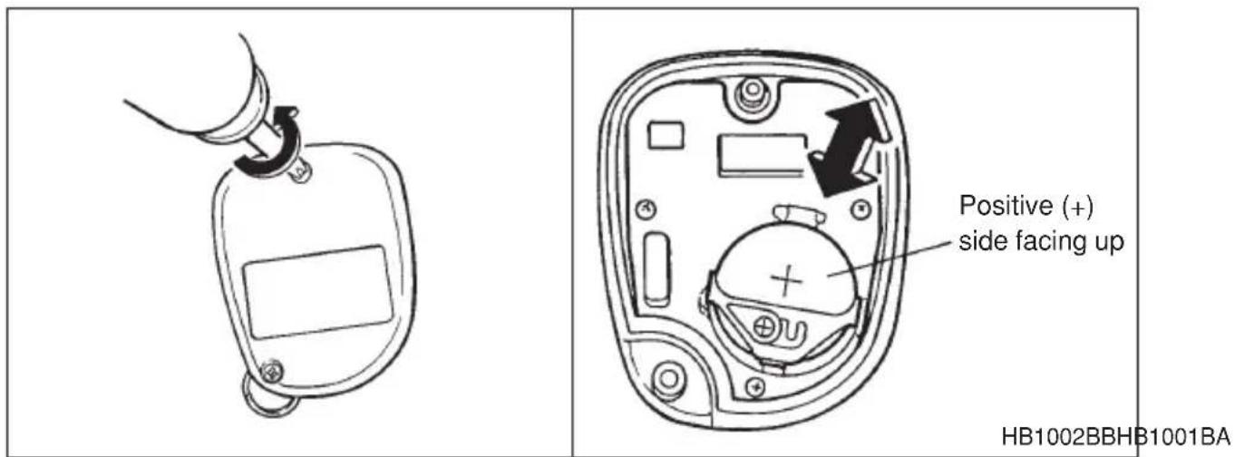
To replace the battery:
- Remove the two screws on the back of the transmitter case by using a phillips screwdriver.
- Separate the case.
- Remove the old battery from the holder.
- Replace with a new battery (Type CR2032 or equivalent) making sure to install the new battery with the positive (+) side facing up.
- Install the back half of the transmitter case.
- Reinstall the two screws on the back of the transmitter case.
After the battery is replaced, the transmitter must be synchronized with the keyless entry system's control unit. Press either the "LOCK/ARM" or "UNLOCK/DISARM" button six times to syn- chronize the unit.
▼Replacing lost transmitters
If you lose a transmitter or want to purchase additional transmitters (up to four can be programmed), you should re-program all of your transmitters for security reasons. It is recommended that you have your dealer program all of your transmitters into your system.
▽ Programming the transmitters
The keyless entry system is equipped with a special code learning feature that allows you to program new transmitter codes into the system or to delete old ones. The system can learn up to four unique transmitter codes. The four transmitter codes may be the same or different.
To enter the programming mode:
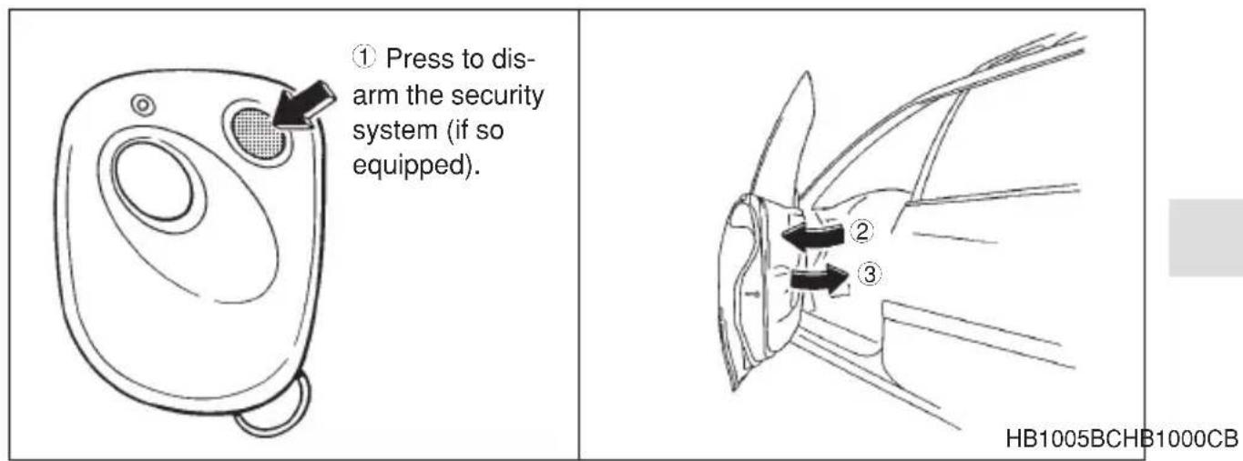
-
Disarm the security system. (if your vehicle is equipped with the optional security system.)
-
Open the driver's door and sit in the driver's seat.
-
Close the driver's door.
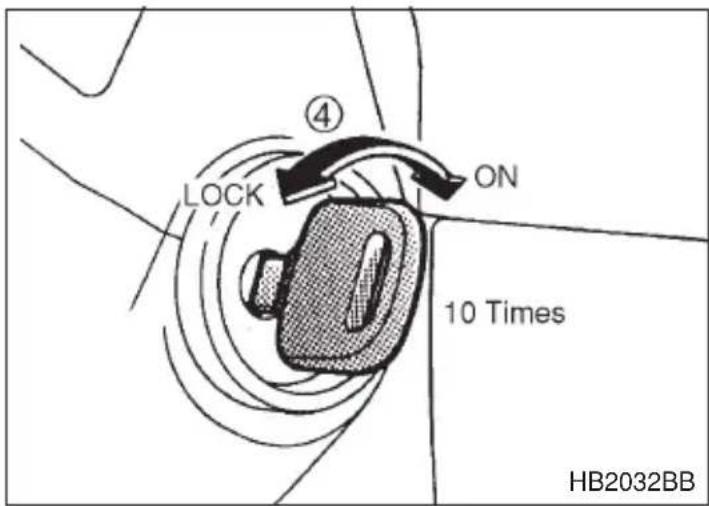
- Place the ignition key into the ignition switch and cycle the switch from LOCK to ON ten times within 15 seconds. Be sure to stop at the LOCK position. The horn will sound once to indicate that you are in the transmitter programming mode.
NOTE
You must finish the next step (opening the driver's door) within 45 seconds of starting this procedures.
To program the transmitters:
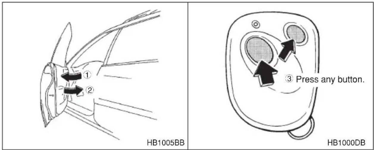
- Open the driver's door.
- Close the driver's door.
- Press and release any button on the transmitter that you wish to program into the system. The horn will sound two times to indicate that the transmitter has been programmed.
Any additional transmitters can also be programmed at this time. Repeat steps 1 through 3 for an additional transmitter.
To exit the programming mode:
- After all of your transmitters are programmed, remove the key from the ignition switch.
The horn will sound three times to indicate that the system has exited the programming mode.
- Make sure that the keyless entry system properly operates by operating each transmitter.
∇ Deleting old transmitter codes
The control unit of the keyless entry system has four memory locations to store transmitter codes, giving it the ability to operate with up to four transmitters. When you lose a transmitter, the lost transmitter's code remains in the memory. For security reasons, lost transmitter codes should be deleted from the memory.
To delete old transmitter codes, program four transmitter codes into the system. If you have only one current transmitter, program it four
times. If you have two current transmitters, program each one twice. If you have three current transmitters, program two of them once and the third one twice. This process will leave only current transmitter codes in the system's memory.
NOTE
Make sure no one else is operating their keyless entry system within range of your vehicle when programming transmitters. If someone else were to operate their remote transmitter while you are programming your transmitters, it is possible that their transmitter code will be programmed into your system, allowing them unauthorized access to your vehicle.
Security system (if equipped)
The security system helps to protect your vehicle and valuables from theft. The horn sounds and the parking lights flash if someone attempts to break into your vehicle. The starter motor is also interrupted to prevent starting the vehicle without a key.
The system can be armed and disarmed with the remote transmitter.
The system does not operate when the key is inserted into the ignition switch.
▼ System operation
The security system will give the following alarm indications when triggered:
●The parking lights will flash and the horn will sound intermittently. In addition, the starter motor will not operate.
- The alarm automatically resets after 30 seconds; however, the alarm will reactivate if the vehicle is tampered with again. The alarm will continue for six times if any sensor continues to be activated.
The alarm is triggered by:
- Opening a door, the rear gate or trunk lid.
- Application of physical shock to the vehicle (e.g. breaking glass or forced entry). Note that there are two alarm levels for shock: warning
- CONTINUED -
and alarm. In warning mode, the alarm detects lower level vibrations and triggers 2 warning chirps on the horn and two flashes on the lights as a deterrent to would be vandals. In alarm mode, higher levels of shock are detected and the system will go into full alarm.
●Ignition switch being turned on while in armed state.
NOTE
With the valet mode selected, the security system does not operate and the parking lights do not flash when the remote transmitter is used for locking and unlocking.
The security system indicator light in the combination meter flashes twice per second to show that the valet mode is selected. For details, refer to “Valet mode” in this section.
Arming the system
To arm the system using remote transmitter
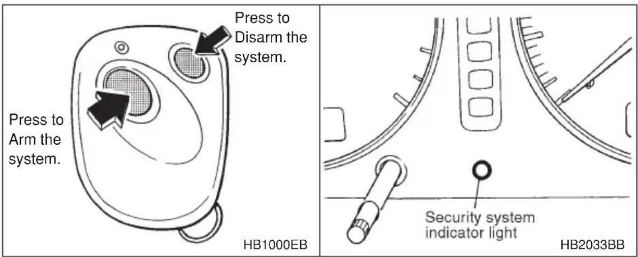
-
Close all windows and moonroofs (if so equipped).
-
Remove the key from the ignition switch.
-
Open the doors and get out of the vehicle.
-
Make sure that the engine hood (and the trunk lid) are locked.
-
Close all doors (and the rear gate on the station wagon).
-
Briefly press the "LOCK/ARM" button (for less than two seconds). All doors (and the rear gate on the station wagon) will lock, the horn will sound one time, the parking lights will flash one time and the indicator light starts flashing slowly (approximately once every two
seconds).
If any of the doors, (rear gate or trunk lid) is not fully closed, the horn sounds three times, the parking lights flash three times and the indicator light flashes rapidly to alert you that the doors (or the rear gate) are not properly closed. When you close the door, the system will automatically arm and doors will automatically lock.
To arm the system using power door locking switches
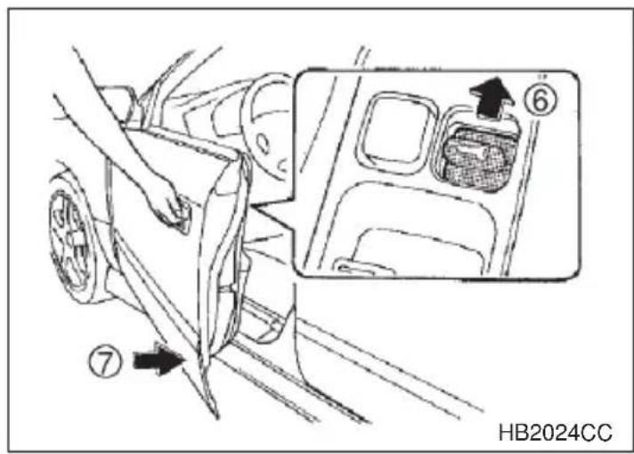
- Close all windows and moonroofs (if so equipped).
- Remove the key from the ignition switch.
- Open the doors and get out of the vehicle.
- Make sure that the engine hood (and the trunk lid) are locked.
- Close the doors (and the rear gate on the station wagon) but leave only the driver's door or the front passenger's door open.
- Push the power door locking switch forward ("LOCK" side) to set the door locks.
- Close the door. The horn will sound one time, the parking lights will flash one time and the indicator light will start flashing slowly (approximately once every two seconds) to inform you that the system has armed.
NOTE
The system can be armed even if the engine hood, the windows and/or moonroofs are opened. Always make sure that they are fully closed before arming the system.
- CONTINUED -
▼Disarming the system
Briefly press the “UNLOCK/DISARM” button (for less than two seconds) on the remote transmitter. The driver’s door will unlock, the horn will sound two times, the parking lights will flash two times and the indicator light will go off.
To unlock all doors (and the rear gate on the station wagon), briefly press the “UNLOCK/DISARM” button a second time.
Emergency disarming
If you cannot disarm the system using the transmitter (i.e. the transmitter is lost, broken or the transmitter battery is too weak), you can disarm the system without using the transmitter.
To disarm the system:
- Unlock the door with the key and then open the door.
- The alarm will sound.
- Insert the key into the ignition switch and cycle it from the "LOCK" to the "ON" position three (3) times within 5 seconds.
▼Sounding a panic alarm
To activate the alarm, keep the "LOCK/ARM" button pressed for more than two seconds.
To deactivate it, press the "LOCK/ARM" button or "UNLOCK/DISARM" button.
The parking lights will also flash when the alarm is activated.
Unless a button on the remote is pressed, the alarm will be deactivated after approximately 30 seconds.
▼Valet mode
When you choose the valet mode, the security system does not operate. In valet mode, the remote transmitter is used only for locking and unlocking the doors (and rear gate on the station wagon) and panic activation. The parking lights do not flash when the remote transmitter is used for locking and unlocking.
To enter the valet mode, open the driver's door and keep the "UNLOCK/DISARM" button depressed for more than two seconds. The security system indicator light will continue to flash 2 times per
second indicating that the system is in the valet mode.
To exit valet mode, open the driver's door and keep the "UNLOCK/DISARM" button pressed for more than two seconds. The indicator will stop flashing.
▼Passive arming
When passive arming mode has been programmed by the dealer, arming of the system is automatically accomplished without using the remote transmitter. Note that in this mode, DOORS MUST BE MANU-ALLY LOCKED.
∇ To enter the passive mode
WARNING
Do not disconnect or tamper with any yellow connector and/or any harness covered with yellow insulation and/or tape.
Doing so could result in accidental inflation of the SRS airbag or could make the SRS airbag system inoperative, which may result in serious injury.
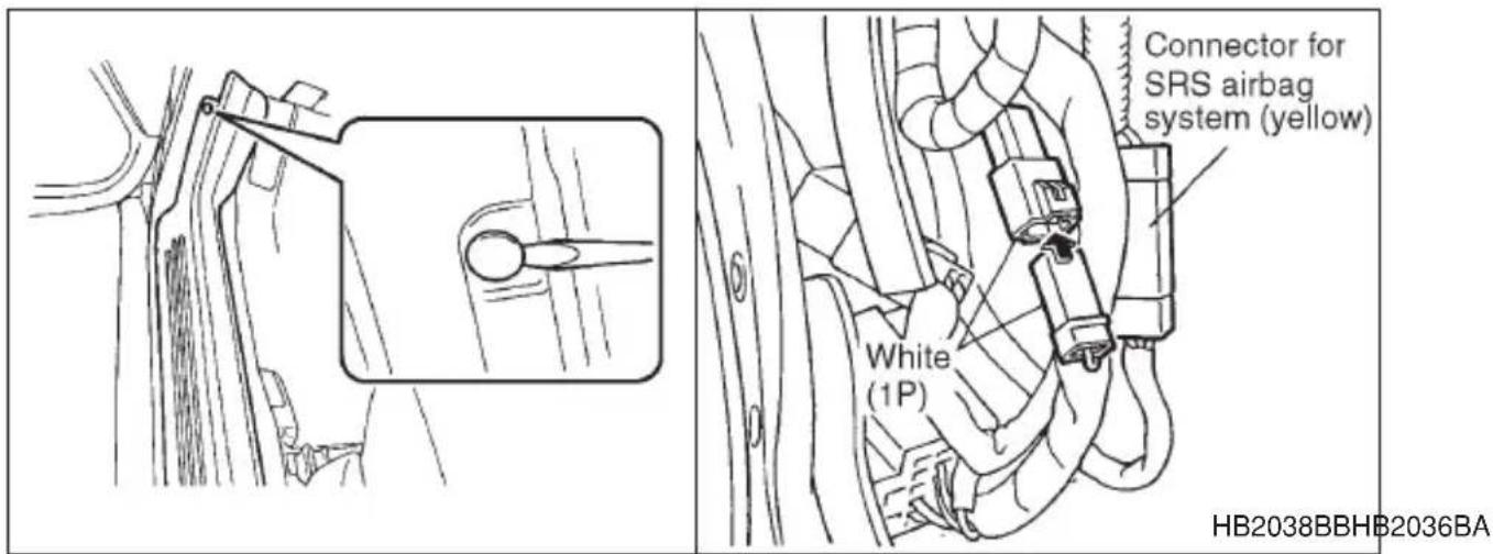
- Remove the side sill cover on the driver's side.
1) Open the driver's door.
2) Remove the two clips fastening the front portion of the cover with a screwdriver.
3) Remove the side sill cover by pulling it up.
- CONTINUED -
- Connect the white (1 pole) connector.
- Turn the ignition switch from the "LOCK" to the "ON" position.
- Install the side sill cover.
To place the system in active arming mode (remote required for activation), disconnect the white connector.
Arming the system

CAUTION
In passive mode, the system will automatically activate the alarm but WILL NOT automatically lock the doors. In order to lock the doors you must either lock them as indicated in step 4 below or with the key once they have been closed. Failure to lock the doors manually will result in a higher security risk.
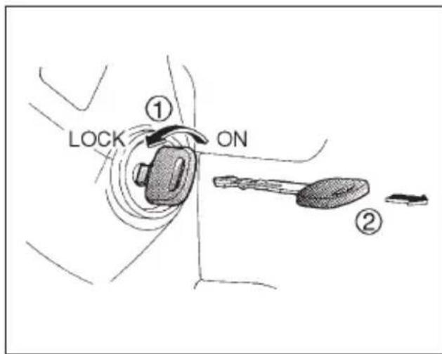
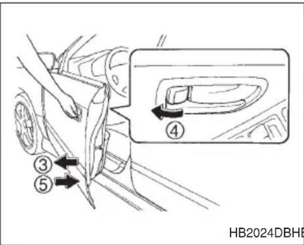
HB2024DBHB2031BB
- Turn the ignition switch to the "ON" position.
- Turn the ignition switch from "ON" to "LOCK" position and remove the key from the ignition switch.
- Open the doors and get out of the vehicle.
- Before closing the doors, lock all doors with the inside door lock levers.
- Close the doors. The system will automatically arm after one minute.
In the passive mode, the system can also be armed with the remote transmitter or with the power door locking switches. If the remote transmitter or power door lock switch is used to lock the vehicle, arming will take place immediately regardless of whether or not the passive mode has been selected.
▼Disarming the system
To disarm the system, briefly press the “UNLOCK/DISARM” button on the transmitter.
▼Tripped sensor identification
If the horn sounds four times and the parking lights flash four times when you disarm the system, this indicates that the alarm was triggered. The number of times the indicator light flashes indicates what sensor caused the alarm condition.
To enter identification mode:
- Open the driver's door and leave it open.
- Turn the ignition switch to the "ON" position two times. ("LOCK" → "ON" → "LOCK" → "ON" → "LOCK")
- The indicator light will start flashing.
The indicator light provides the following indications.
Flashing one time: Any door, the rear gate or the trunk lid has been opened.
Flashing three times: The impact sensor in the system's unit has been activated. This may indicate that your vehicle has been shocked or tampered with by some outside force and/or unauthorized person.
Flashing four times: The ignition switch has been turned on or the battery has been disconnected.
NOTE
The battery must be reconnected before the indicator light will flash.
To exit this mode, close the door and turn the ignition switch to the "ON" position.
Child safety locks

WARNING
Always use the child safety lock whenever a child rides in the rear seat. Serious injury could result if a child accidentally opened the door and fell out.
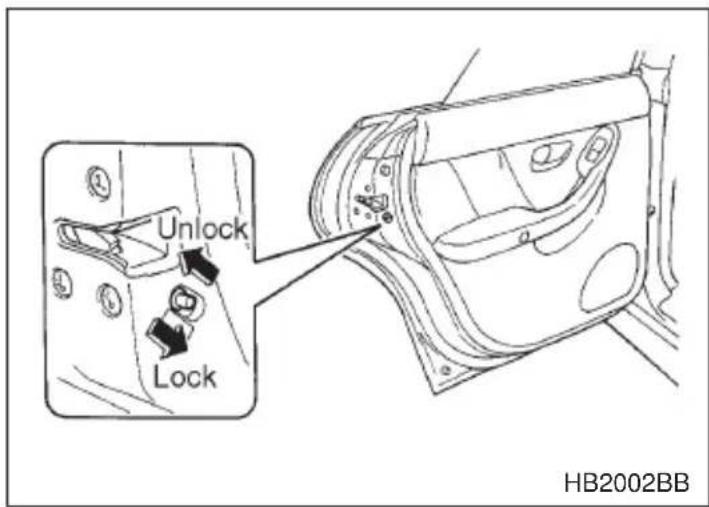
Each rear door has a child safety lock that prevents the doors from being opened even if the inside door handle is pulled.
When the child safety lock lever is in the lock position, the door cannot be opened from inside regardless of the position of the inner door handle lock lever. The door can only be opened from the outside.
Windows
Power windows

WARNING
- When operating power windows, be extremely careful to prevent anyone's fingers, arms or head from being caught in the window.
- Always lock the passengers' windows using the lock switch when children are riding in the vehicle.
- Before leaving the vehicle, always remove the key from the ignition switch for safety and never allow an unattended child to remain in the vehicle. Failure to follow this procedure could result in injury to a child operating the power window.
The power windows operate only when the ignition switch is in the "ON" position.
▼Driver's side switches
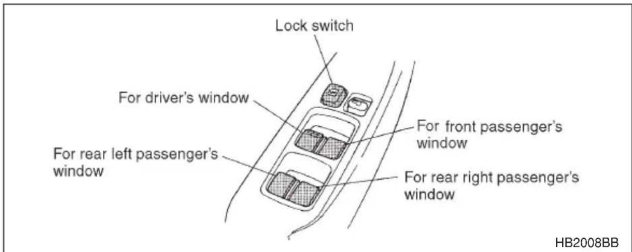
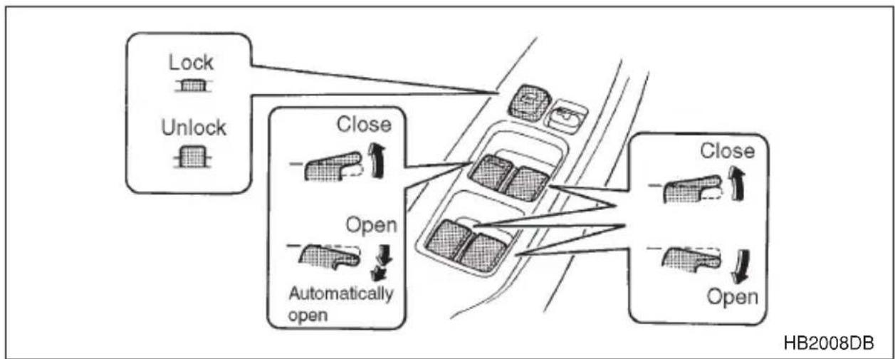
flowchart
graph TD
    A["Lock"] --> B["Open"]
    C["Unlock"] --> B
    B --> D["Automatically open"]
    D --> E["Close"]
    E --> F["Open"]
    F --> G["HB2008DB"]
All door windows can be controlled by the power window switch cluster at the driver side door.
Operating the driver's window
AUTO switch: This switch has two functions.
Push the switch down until it clicks and release it, and the window will fully open. To stop the window halfway, pull the switch up slightly.
Push the switch down lightly and hold it. The window will open as long as the switch is held.
Pull the switch up lightly and hold it. The window will close as long as the switch is held.
▽ Operating the passengers' windows
To open the passengers' windows, push the appropriate switch down and hold it until the window reaches the desired position. To close the window, pull the switch up and hold it until it reaches the desired position.
∇ Locking the passengers' windows
To lock the passengers' windows, push the lock switch. When the lock switch is in the "LOCK" position, the passengers' windows cannot be opened or closed.
▼Passengers' side switches
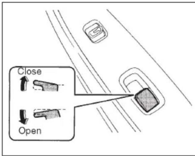
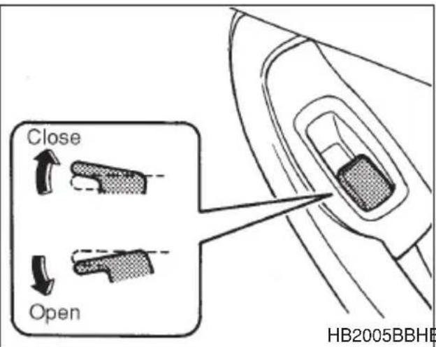
HB2005BBHB2009CB
To open the window, push the switch down and hold it until the window reaches the desired position. To close the window, pull the switch up and hold it until the window reaches the desired position.
When the lock switch on the power window switch cluster, located on the driver's side door, is in the "LOCK" position, the passengers' windows cannot be operated with the passengers' switches.
Trunk lid (Sedan)

WARNING
●To prevent dangerous exhaust gas from entering the vehicle, always keep the trunk lid closed while driving.
- Help prevent young children from locking themselves in the trunk. When leaving the vehicle, either close all windows and lock all doors or cancel the inside trunk lid release. Also make certain that the trunk is closed. On hot or sunny days, the temperature in the trunk could quickly become high enough to cause death or serious heat-related injuries including brain damage, particularly for small children.
▼To open and close the trunk lid from outside
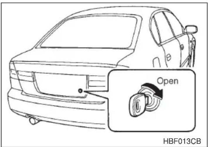
To open the trunk lid from outside, insert the key and turn it clockwise. To close the trunk lid, lightly press the trunk lid down until the latch engages.
▼To open the trunk lid from inside
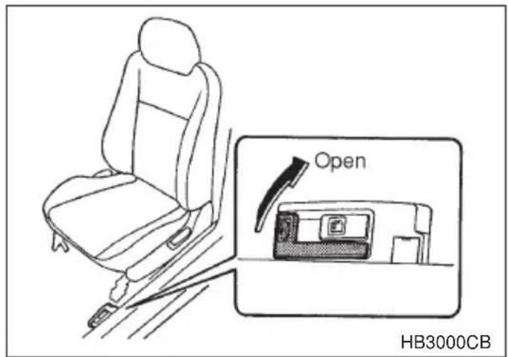
Pull the trunk lid release lever upward.
▼To cancel the trunk lid release
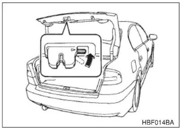
natural_image
Line drawing of a car trunk with an inset showing a gear assembly (no text or symbols)The inside trunk lid release can be cancelled to help prevent unauthorized entry into the trunk. To cancel the trunk lid release, set the lid release cancel lever (located on the inside of the trunk lid, mounted to the trunk lid latch) to the "CANCEL" position. When this lock is in the "CANCEL" position, the trunk can be opened only with the key.
■Internal trunk lid release handle
The internal trunk lid release handle is a device designed to open the trunk lid from inside the trunk. In the event children or adults become locked inside the trunk, the handle allows them to open the lid. The handle is located on the inside of the trunk lid.

WARNING
Never allow any child to get in the trunk and play with the release handle. If the driver starts the vehicle without knowing that a child is inside the trunk and the child opens the lid using the release handle, the child could fall out and be killed or seriously injured.

CAUTION
- Do not close the lid while gripping the release handle. The handle may be damaged.
- Do not use the handle as a hook to fasten straps or ropes to secure your cargo in the trunk. Such use may result in damage of the handle.
- Load the trunk so that cargo can not strike the release handle. If the cargo hits the handle while the vehicle is being driven, the handle may be pushed down and the trunk lid may open. That may cause cargo to fall out of the trunk, which could create a traffic safety hazard.
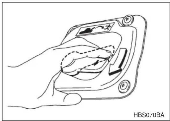
natural_image
Line drawing of a hand pressing a button on a device (no text or symbols)To open the trunk lid from inside the trunk, press the yellow handle downward as indicated by the arrow on the handle. This operation unlocks the trunk lid. Then, push up the lid.
The handle is made of material that remains luminescent for approximately an hour in the dark trunk space after it is exposed to ambient light even for a short time.
Inspection
Perform the following steps at least twice a year to check the release handle for correct operation.
- Open the trunk lid.
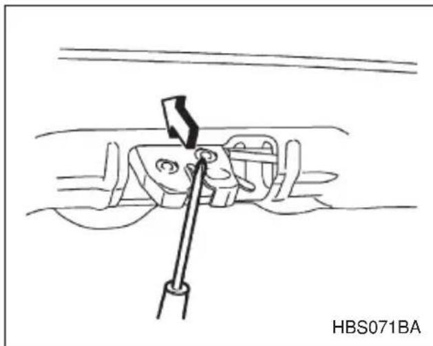
natural_image
Technical line drawing of a mechanical component with a tool inserted, no visible text or symbols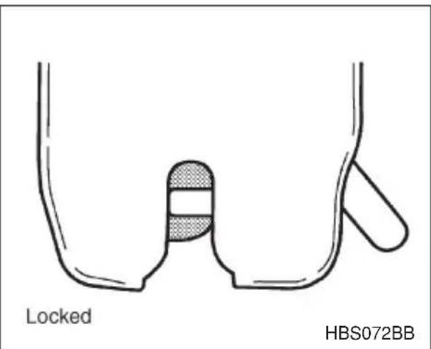
- Use a screwdriver with a thin blade. Slide the screwdriver blade from the slit aperture of the lock assembly fully to the end until you hear a click. This places the latch in the locked position.
- CONTINUED -
- Move the release handle, from outside the vehicle, in the direction of the arrow to check if the latch is released.
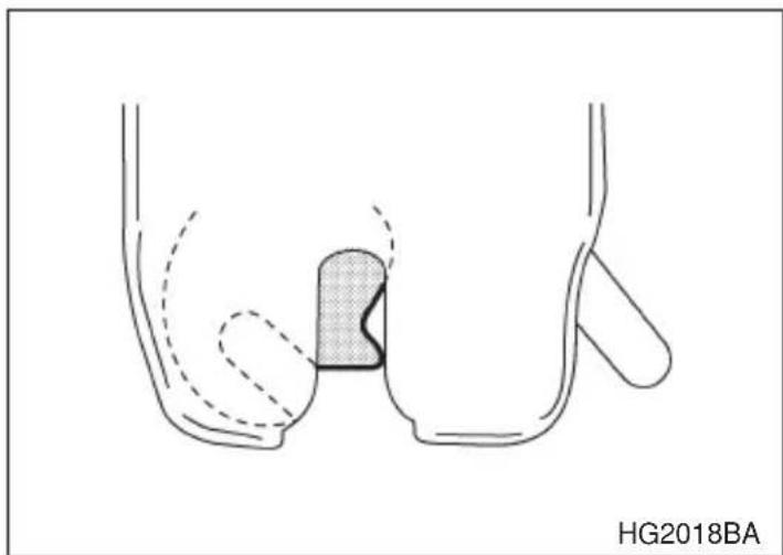
natural_image
Anatomical diagram of pelvic and hip joint structures, no text or labels presentIf the latch is not released, contact your SUBARU dealer.
In that case, use the key to release the latch, then close the trunk lid. Also, if the movements of the release handle feel restricted or not entirely smooth during operation, or the handle and/or handle base is cracked, contact your SUBARU dealer.
Rear gate (Station wagon)

WARNING
To prevent dangerous exhaust gas from entering the vehicle, always keep the rear gate closed while driving.
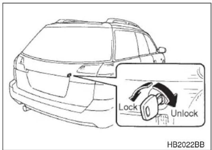
To unlock the rear gate, insert the key in the keyhole and turn it clockwise. To lock the rear gate, insert the key in the keyhole and turn it counterclockwise. If your vehicle is equipped with power door locking switches, the rear gate can also be locked and unlocked through use of the power door locking switches. Refer to “Power door locking switches” section in this chapter.
To open the rear gate, first unlock the rear gate lock then pull the outside handle up. To close the rear gate, lower it slowly and push down firmly until the latch engages.
Moonroof (if equipped)

WARNING
- Never let anyone's hands, arms, head or any objects protrude from the moonroof.
- Before closing the moonroof, make sure that no one's hands, arms, head or other objects will be accidentally caught in the moonroof.

CAUTION
- Do not sit on the edge of the open moonroof.
- Do not operate the moonroof if falling snow or extremely cold conditions have caused it to freeze shut.
■Tilting/sliding moonroof (Sedan)
The moonroof has both tilting and sliding functions.
The moonroof operates only when the ignition switch is in the "ON" position.
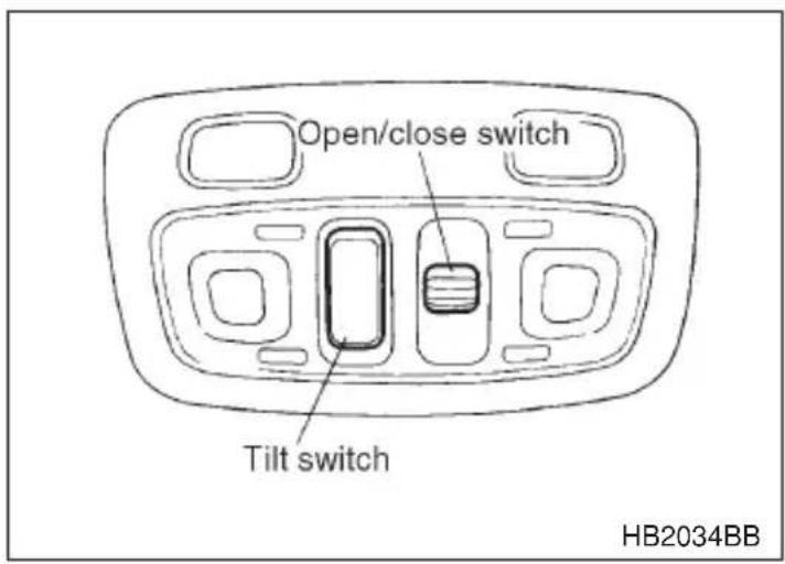
▼To raise or lower the moonroof
The tilting function will only operate when the moonroof is fully closed.
Push the rear side of the "Tilt" switch to raise the moonroof.
Push the front side of the "Tilt" switch to lower the moonroof.
Release the switch after the moonroof has been raised or has been lowered completely. Pushing the switch continuously may cause damage to the moonroof.
▼To open or close the moonroof
Push the "Open/Close" switch rearward to open the moonroof. The sun shade will be also opened together with the moonroof.
Push the “Open/Close” switch forward to close the moonroof. The moonroof will stop halfway if you continue to press on the switch. Release the switch once and push it again to close the moonroof completely.
After washing the vehicle or after it rains, wipe away water on the roof prior to opening the moonroof to prevent water drops from falling into the passenger compartment.
NOTE
If the moonroof cannot be closed through the switch operation because of system failure, it can be closed manually using a hex-headed wrench. For the procedure, refer to “Moonroof — if the moonroof cannot be closed” in Chapter 9 “In case of emergency”.
Sun shade
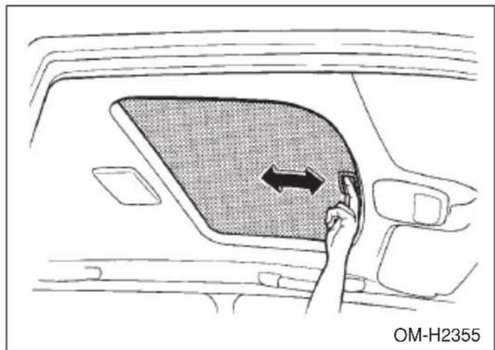
natural_image
Interior view of a car showing a hand pressing a button into the back panel with an arrow indicating left motion (no text or symbols on the diagram itself)The sun shade can be slid forward or backward by hand while the moonroof is closed.
If the moonroof is opened, the sun shade also moves back.
- CONTINUED -
■Dual moonroofs (Station wagon)
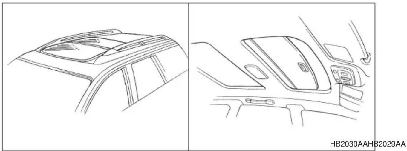
HB2030AAHB2029AA
The front moonroof has a tilting function and the rear moonroof has a sliding function.
Both moonroofs operate only when the ignition switch is in the "ON" position.
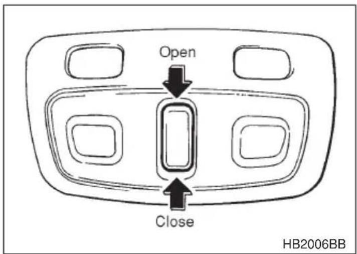
To open the moonroof(s)
- Open the front sunshade.
- Continually push the rear side (OPEN) of the switch, and the front moonroof will tilt up and stop automatically.
-
If you want to open the rear moonroof as well, release the switch once and then push the rear side of the switch continuously.
The rear moonroof will begin to slide open together with the rear sunshade, then stop automatically at 7.9 in (20 cm) in a partially open position. -
To fully open it, release the switch once, then push the rear side of the switch again and keep it depressed until the full open position is reached.
To close the moonroof(s)
- Push the front side (CLOSE) of the switch. The rear moonroof will slide to close together with the rear sunshade while the switch is being pressed, then stop automatically at a position 5.9 in (15 cm) away from the fully closed position.
- To close the rear moonroof fully, release the switch once, then push the front side of the switch continuously again.
- If you want to close the front moonroof as well, push the switch again.
After washing the vehicle or after it rains, wipe away water on the roof prior to opening the moonroof to prevent water drops from falling into the passenger's compartment.
NOTE
- Driving with the moonroof fully open can cause a great deal of wind noise. If such a condition has been encountered, close the moonroof up to the initial stop position of 7.9 in (20 cm), and the wind noise should diminish.
- If the moonroof cannot be closed through switch operation because of system failure, it can be closed manually using a hex-headed wrench. For the procedure, refer to “Moonroof — if the moonroof cannot be closed” in Chapter 9 “In case of emergency”.
Sun shades
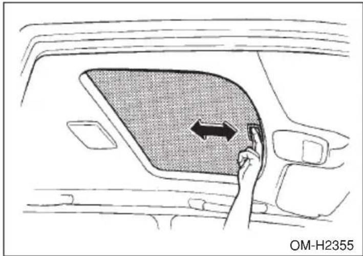
natural_image
Interior view of a car showing a hand pointing to the back panel with an arrow indicating leftward movement (no text or symbols)▽ Front sun shade
The front sun shade can be slid forward or backward by hand regardless of the moonroof position.
▽ Rear sun shade
The rear sun shade can be slid forward or backward by hand while the rear moonroof is closed. If the rear moonroof is opened, the sun shade also moves back.
Instruments and controls
Ignition switch 3-3
Key reminder chime 3-5
Ignition switch light 3-5
Key interlock release (AT vehicles only) 3-6
Hazard warning flasher 3-7
Meters and gauges 3-7
Speedometer 3-7
Odometer/Trip meter 3-7
Tachometer 3-9
Outside temperature indicator (if equipped) 3-9
Fuel gauge 3-9
Temperature gauge 3-10
Warning and indicator lights 3-10
Seatbelt warning light and chime 3-11
SRS airbag system warning light 3-11
CHECK ENGINE warning light/Malfunction indicator lamp 3-12
Charge warning light 3-13
Oil pressure warning light 3-13
AT OIL TEMPerature warning light (for AT vehicles) 3-14
ABS warning light 3-14
VDC (Vehicle Dynamics Control) warning light (if equipped) 3-15
Brake system warning light 3-16
Door open warning lights 3-17
Low fuel warning light 3-17
Front-wheel drive warning light (for AT vehicles) 3-17
VDC (Vehicle Dynamics Control) operation indicator light (if equipped) 3-17
VDC (Vehicle Dynamics Control) OFF indicator light (if equipped) 3-18
Security system status indicator light (if equipped) 3-18
Shift position indicator (for AT vehicles) 3-18
Turn signal indicator lights 3-18
High beam indicator light 3-19
Clock 3-19
Light control switch 3-19
Daytime running light system 3-21
Turn signal lever 3-21
Illumination brightness control 3-22
Parking light switch 3-23
Fog light switch (if equipped) 3-24
Wiper and washer 3-24
Windshield wiper and washer switches 3-26
Rear window wiper and washer switch (if equipped) 3-28.....
Rear window defogger switch 3-29
Windshield wiper deicer (if equipped) 3-30
Mirrors 3-31
Inside mirror 3-31
Outside mirrors 3-34
Tilt steering wheel 3-36
Horn 3-37
Ignition switch

WARNING
Never turn the ignition switch to “LOCK” while the vehicle is being driven or towed because that will lock the steering wheel, preventing steering control. And when the engine is turned off, it takes a much greater effort than usual to steer.
The ignition switch has four positions: LOCK, ACC, ON and START.
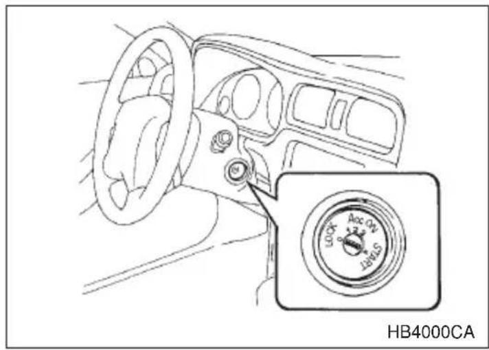
▼LOCK
The key can only be inserted or removed in this position. The ignition switch will lock the steering wheel when you remove the key.
If turning the key is difficult, turn the steering wheel slightly to the right and left as you turn the key.
∇ Automatic transmission vehicles
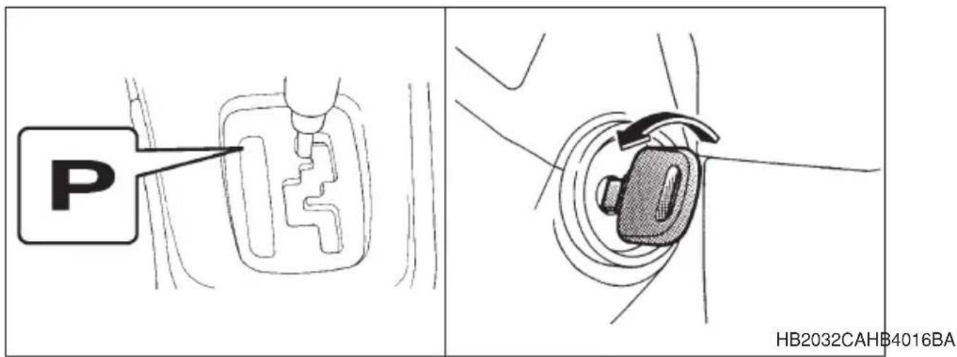
The key can be turned from “ACC” to “LOCK” only when the selector lever is in the “P” position.
▽ Manual transmission vehicles
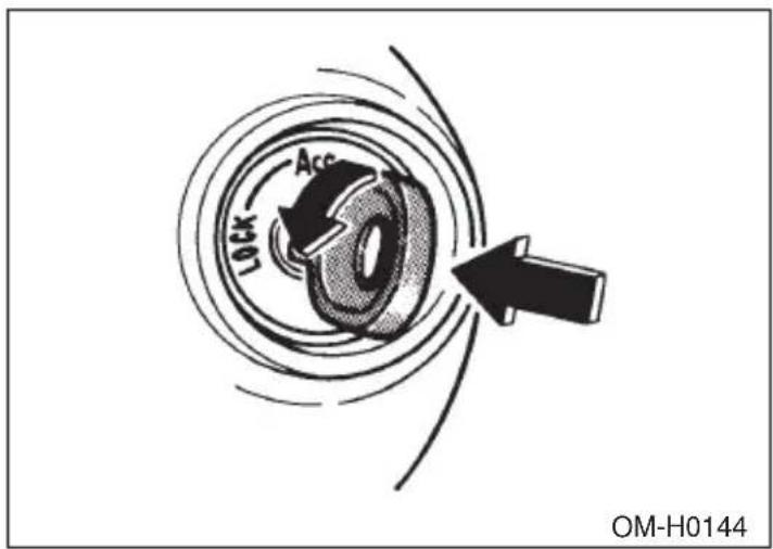
The key can be turned from "ACC" to "LOCK" only when the key is pushed in while turning it.
▼ACC
In this position the electrical accessories (radio, accessory power socket, etc.) can be used.
VON
This is the normal operating position after the engine is started.
▼START

CAUTION
Do not turn the ignition switch to the “START” position while the engine is running.
The engine is started in this position. The starter cranks the engine to start it. When the key is released (after the engine has started), the key automatically returns to the “ON” position.
■Key reminder chime
The reminder chime sounds when the driver's door opens and the key is in the "LOCK" or "ACC" positions. The chime stops when the key is removed from the ignition switch.
■Ignition switch light
For easy access to the ignition switch in the dark, the ignition switch light comes on when any of the doors (or the rear gate on the wagon) is opened. The light remains on for a several seconds and gradually goes out after all doors (and the rear gate on the wagon) are closed or if the key is inserted in the ignition switch.
The ignition switch light also can be turned on by use of the keyless entry transmitter. See the “Keyless entry system” in chapter 2 for detailed information.
■Key interlock release (AT vehicles only)
If the key can not be turned to the "LOCK" position even when the selector lever is in the "P" position:
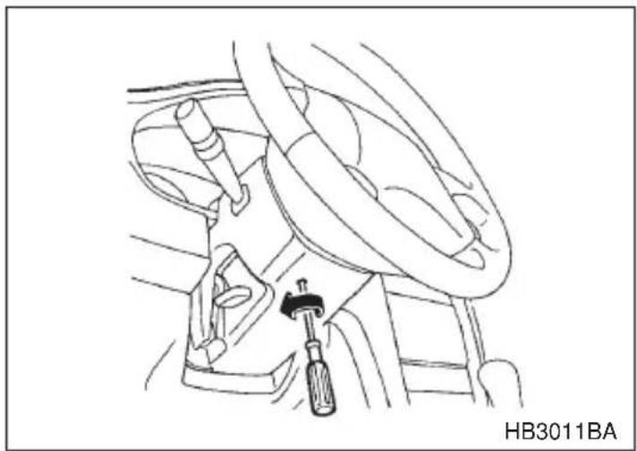
natural_image
Line drawing of a car interior showing steering wheel, gear shift, and screwdriver (no text or symbols)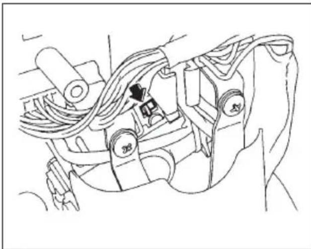
natural_image
Technical line drawing of a mechanical assembly with wires and components (no text or symbols)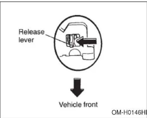
OM-H0146HB3012BA
- Take out the screwdriver from the tool bag.
- Remove the cover under the steering column using a phillips screwdriver.
- Turn the ignition key while pressing the key interlock release lever.
Take your vehicle to the nearest SUBARU dealer immediately to have the key interlock system repaired.
Hazard warning flasher
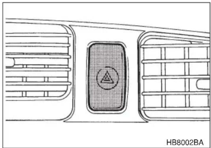
natural_image
Technical line drawing of a vehicle air vent with a circular component labeled 'HB8002BA' (no other text or symbols)The hazard warning flasher is used to warn other drivers when you have to park your vehicle under emergency conditions. The hazard warning flasher works with the ignition switch in any position.
To turn on the hazard warning flasher, push the hazard warning button on the instrument panel. To turn off the flasher, push the button again.
NOTE
When the hazard warning flasher is on, the turn signals do not work.
Meters and gauges
■Speedometer
The speedometer shows the vehicle speed.
■Odometer/Trip meter

CAUTION
To ensure safety, do not attempt to change the function of the indicator during driving, as an accident could result.
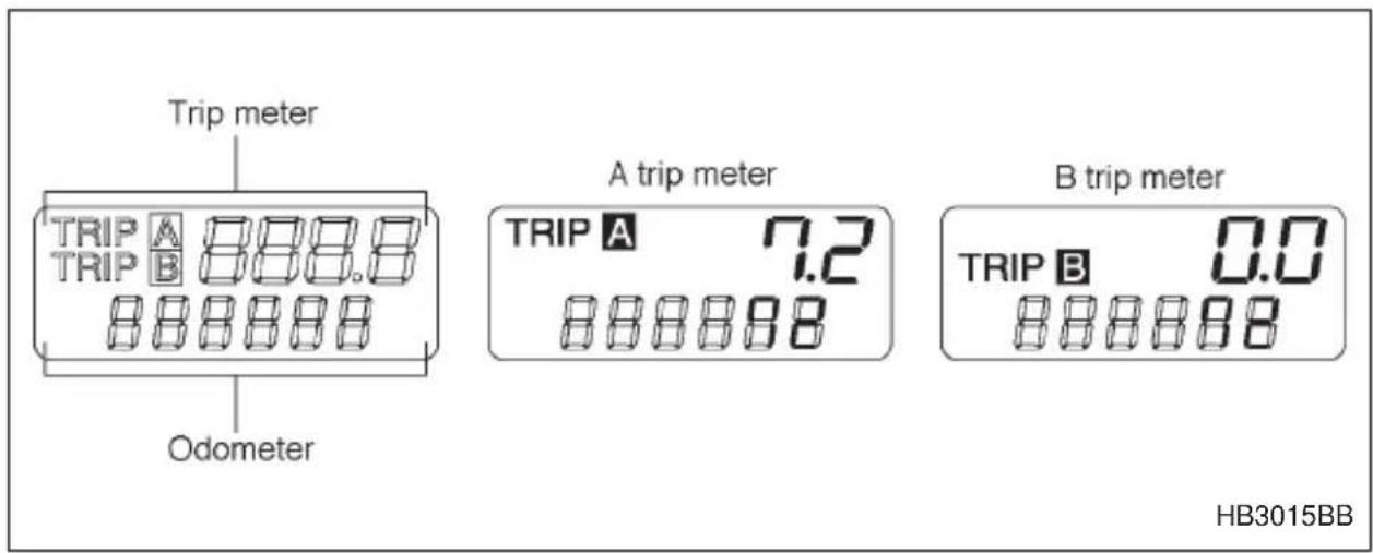
▼Odometer
The odometer shows the total distance that the vehicle has been driven.
▼Double trip meter
The trip meter shows the distance that the vehicle has been driven since you last set it to zero.
To change the mode indication, briefly push the knob.
Each press of the knob changes the function in the following order.
A trip meter B trip meter
To set the trip meter to zero, select either the A trip or B trip meter and push the knob and keep it pushed for more than 1 second.
NOTE
If the connection between the combination meter and battery is broken for any reason such as vehicle maintenance or fuse replacement, the data recorded on the trip meter will be lost.
Tachometer
CAUTION
Do not operate the engine with the pointer of the tachometer in the red zone. In this range, fuel injection will be cut by the engine control module to protect the engine from overrevving. The engine will resume running normally after the engine speed is reduced below the red zone.
The tachometer shows the engine speed in thousands of revolutions per minute.
■Outside temperature indicator (if equipped)
The outside temperature indicator shows the outside temperature in a range from -22^ to 122^ ( -30^ to 50^ ).
The indicator can give a false reading under any of the following conditions:
- When there is too much sun.
- During idling; while running at low speeds in a traffic jam; when the engine is restarted immediately following a shutdown.
- When the actual outside temperature falls outside the specified indicator range.
For vehicles with an automatic climate control, outside temperature can be displayed on the climate control display panel. Refer to the “Automatic climate control system” in chapter 4.
Fuel gauge
The fuel gauge shows the approximate amount of fuel remaining in the tank.
The gauge does not return to “E” even though the ignition switch is in the “ACC” or “LOCK” position.
The gauge may move slightly during braking, turning or acceleration due to fuel level movement in the tank.
- CONTINUED -
■Temperature gauge
CAUTION
If the pointer exceeds the normal operating range, safely stop the vehicle as soon as possible.
See "In case of emergency" in chapter 9.
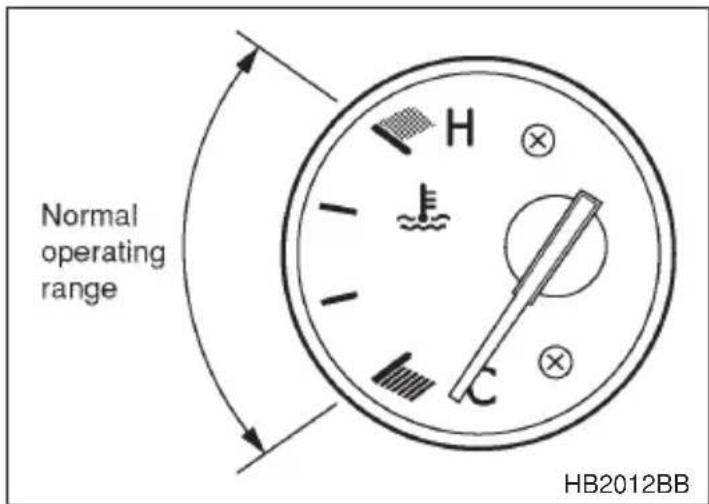
The temperature gauge shows engine coolant temperature when the ignition switch is in the "ON" position.
The coolant temperature will vary in accordance with the outside temperature and driving conditions.
We recommend that you drive moderately until the pointer of the temperature gauge reaches near the middle of the range. Engine operation is optimum with the engine coolant at this temperature range and high revving operation when the engine is not warmed up enough should be avoided.
Warning and indicator lights
Several of the warning and indicator lights come on momentarily and then go out when the ignition switch is initially turned to the “ON” position. This permits checking the operation of the bulbs.
Apply the parking brake and turn the ignition switch to the "ON" position. The following lights come on:
Seatbelt warning light
SRS airbag system warning light
CHECK ENGINE warning light / Malfunction indicator lamp
Charge warning light
Oil pressure warning light
AT OIL temperature warning light (AT vehicles)
ABS warning light
VDC warning light (if equipped)
VDC operation indicator light (if equipped)
VDC OFF indicator light (if equipped)
Brake system warning light
If any lights fail to come on, it indicates a burned-out bulb or a malfunction of the corresponding system.
Consult your authorized SUBARU dealer for repair.
■Seatbelt warning light and chime

When the ignition switch is turned to the “ON” position, the seatbelt warning light will come on and the reminder chime will sound for about six seconds to remind the driver to fasten the seatbelt.
The seatbelt warning light remains on for about six seconds and turns off automatically after six seconds.
The seatbelt reminder chime will turn off when the driver's side seatbelt is buckled or it will turn off automatically after six seconds.
■SRS airbag system warning light AIRBAG
When the ignition switch is turned to the “ON” position, the SRS airbag system warning light will come on for about six seconds and go out. This shows the SRS frontal airbag and SRS side airbag (if equipped) and seatbelt pretensioners are in normal operation.
If this light comes on while driving or remains illuminated even after a period of about 6 seconds from when the ignition has been turned on, it may indicate that the SRS frontal airbag system or SRS side airbag system (if equipped) or seatbelt pretensioner system is not working properly. Contact your nearest SUBARU dealer immediately.
■CHECK ENGINE warning light/Malfunction indicator lamp
CHECK ENGINE
CAUTION
If the CHECK ENGINE light comes on while you are driving, have your vehicle checked/ repaired by your SUBARU dealer as soon as possible. Continued vehicle operation without having the emission control system checked and repaired as necessary could cause serious damage, which may not be covered by your vehicle's warranty.
If this light comes on steadily or blinks while the engine is running, it may indicate that there is a problem or potential problem somewhere in the emission control system.
▼If the light comes on steadily:
If the light comes on steadily while driving or does not go out after the engine starts, an emission control system malfunction has been detected.
You should have your vehicle checked by an authorized SUBARU dealer immediately.
NOTE
This light also comes on when the fuel filler cap is not tightened until it clicks.
If you have recently refueled your vehicle, the cause of the CHECK ENGINE warning light/malfunction indicator lamp coming on could be a loose or missing fuel filler cap. Remove the cap and retighten it until it clicks. Make sure nothing is interfering with the sealing of the cap. Tightening the cap will not make the CHECK ENGINE warning light turn off immediately. It may take several driving trips. If the light does not go out, take your vehicle to your authorized SUBARU dealer immediately.
▼ If the light is blinking:
If the light is blinking while driving, an engine misfire condition has
been detected which may damage the emission control system.
To prevent serious damage to the emission control system, you should do the following:
- Reduce vehicle speed.
- Avoid hard acceleration.
- Avoid steep uphill grades.
- Reduce the amount of cargo, if possible.
- Stop towing a trailer as soon as possible.
The CHECK ENGINE warning light may stop blinking and come on steadily after several driving trips. You should have your vehicle checked by an authorized SUBARU dealer immediately.
■Charge warning light
If this light comes on when the engine is running, it may indicate that the charging system is not working properly.
If the light comes on while driving or does not go out after the engine starts, stop the engine at the first safe opportunity and check the alternator belt. If the belt is loose, broken or if the belt is in good condition but the light remains on, contact your nearest SUBARU dealer immediately.
■Oil pressure warning light
CAUTION
Do not operate the engine with the oil pressure warning light on. This may cause serious engine damage.
If this light comes on when the engine is running, it may indicate that the engine oil pressure is low and the lubricating system is not working properly.
If the light comes on while driving or does not go out after the engine starts, stop the engine at the first safe opportunity and check the engine oil level. If the oil level is low, add oil immediately. If the engine oil is at the proper level but the light remains on, contact your nearest SUBARU dealer immediately.
■AT OIL TEMperature warning light (for AT vehicles)
AT OIL TEMP
If this light comes on when the engine is running, it may indicate that the automatic transmission fluid temperature is too hot.
If the light comes on while driving, it is unnecessary to stop the vehicle, but avoid driving up steep grades or in stop and go traffic.
▼Automatic transmission control system warning
If the light flashes after the engine starts, it may indicate that the automatic transmission control system is not working properly. Contact your nearest SUBARU dealer for service immediately.
■ABS warning light
ABS (U.S.) (ABS) (Canada)
The ABS warning light comes on when the ignition switch is turned to the "ON" position and goes out after about two seconds.
This is an indication that the ABS system is working properly.

CAUTION
If the warning light behaves as follows, the ABS system may not work properly.
When the warning light is on, the ABS function shuts down; however, the conventional brake system continues to operate normally.
- The warning light does not come on when the ignition switch is turned to the “ON” position.
- The warning light comes on when the ignition switch is turned to the “ON” position, but it does not go out even when the vehicle speed exceeds approximately 8 mph (12 km/h).
- The warning light comes on during driving. If these occur, have the ABS system repaired at the first available opportunity by your SUBARU dealer.
NOTE
If the warning light behavior is as shown below, the ABS system may be considered normal.
- The warning light comes on right after the engine is started but goes out immediately, remaining off.
- The warning light remains on after the engine has been started, but it goes out when the vehicle speed reaches about 8 mph (12 km/h).
- The warning light comes on during driving, but it goes out immediately and remains off.
When driving with an insufficient battery voltage such as when the engine is jump started, the ABS warning light may come on. This is due to the low battery voltage and does not indicate a malfunction. When the battery becomes fully charged, the light will go out.
■VDC (Vehicle Dynamics Control) warning light (if equipped)
VDC
This warning light comes on when the ignition switch is turned to the "ON" position and goes out after the engine has started. It indicates that the VDC system is operational.
The VDC system is probably inoperative under any of the following conditions. Immediately have your vehicle checked at a SUBARU dealer.
- The VDC warning light does not come on when the ignition switch is turned to the “ON” position.
- The VDC warning light remains on after the engine has started and stays lit even when the vehicle speed reaches about 8 mph (12 km/h).
●The VDC warning light comes on while the vehicle is running. - If the electrical circuit of the VDC system itself becomes faulty, the VDC warning light only comes on. At this time, the ABS (Anti-lock Brake System) remains fully operational.
●The warning light comes on when the electronic control system of the ABS/VDC system becomes faulty.
The VDC system provides its ABS control through the electrical circuit of the ABS system. Accordingly, if the ABS is inoperative, the VDC system also becomes unable to provide ABS control. As a result, the VDC system becomes inoperative, causing the VDC warning light to come on. Though both the VDC and ABS systems are inoperative in this case, the ordinary functions of the brake system are still available. You will be safe
- CONTINUED -
while driving with this condition, but you should have your vehicle checked at a SUBARU dealer as soon as possible.
NOTE
If the warning light behavior is as shown below, the VDC system may be considered normal.
- The warning light comes on right after the engine is started but goes out immediately, remaining off.
- The warning light remains on after the engine has been started, but it goes out when the vehicle speed reaches 8 mph about (12 km/h).
- The warning light comes on during driving, but it goes out immediately and remains off.
■Brake system warning light
BRAKE (U.S.)
(①) (Canada)

WARNING
- Driving with the brake system warning light on is dangerous. This indicates your brake system may not be working properly. If the light remains on, have the brakes inspected by a SUBARU dealer immediately.
- If at all in doubt about whether the brakes are operating properly, do not drive the vehicle. Have your vehicle towed to the nearest SUBARU dealer for repair.
This light has the following two functions:
▼Parking brake warning
The light comes on with the parking brake applied while the ignition switch is in the “ON” position. It goes out when the parking brake is fully released.
▼Brake fluid level warning
This light comes on when the brake fluid level has dropped to near the “MIN” level of the brake fluid reservoir with the ignition switch in the “ON” position and with the parking brake fully released.
If the brake system warning light should come on while driving (with the parking brake fully released and with the ignition switch posi-
tioned in “ON”), it could be an indication of leaking of brake fluid or worn brake pads. Have your vehicle checked by a SUBARU dealer immediately.
■ Door open warning lights
The specific door open warning light comes on if any door or the rear gate is not fully closed.
Always make sure this light is out before you start to drive.
■Low fuel warning light

The low fuel warning light comes on when the tank is nearly empty about 2.6 U.S. gal. (10.0 liters, or 2.2 Imp. gal.). It only operates when the ignition switch is in the “ON” position.
NOTE
This light does not go out unless the tank is replenished up to an internal fuel quantity of about 3.7 U.S. gal. (14 liters, 3.1 Imp. gal.).
■Front-wheel drive warning light (for AT vehicles) FWD
This light comes on when All Wheel Drive is disengaged and the drive mechanism is switched to Front Wheel Drive for maintenance or similar purposes.
■ VDC (Vehicle Dynamics Control) operation indicator light (if equipped)
This light comes on when the ignition switch is ON and goes out about 2 seconds later.
It blinks when the skid suppression function is activated. It illuminates when only the traction control function is operating.
The VDC system is probably faulty under any of the following conditions. Have your vehicle checked at a SUBARU dealer immediately.
- The light does not come on when the ignition switch is turned to the "ON" position.
- The light does not go out even after a period of about 2 seconds after the ignition switch has been turned to the “ON” position.
- CONTINUED -
■VDC (Vehicle Dynamics Control) OFF indicator light (if equipped)
VDC OFF
●This indicator light comes on when the ignition switch is turned ON and goes out about 6 seconds after the engine has started.
- It comes on when the VDC system is deactivated (by operating “VDC OFF” switch or in the standby state).
NOTE
- The light may stay on for a while after the engine has been started, especially in cold weather. This does not indicate the existence of a problem. The light should go out as soon as the engine has warmed up.
- The “VDC OFF” indicator light comes on when the engine has developed a problem and the CHECK ENGINE warning light is on.
The VDC system is probably faulty under any of the following conditions. Have your vehicle checked at a SUBARU dealer as soon as possible.
- The VDC OFF indicator light does not come on when the ignition switch is turned to the “ON” position.
●The light does not go out even after several minutes have passed (the engine has warmed up) after the engine has been started.
■Security system status indicator light (if equipped)
SECURITY
This light is found at the bottom center of the combination meter panel. On vehicles equipped with a security system, it blinks to show the driver the operational status of the security system. For detailed information, refer to the “Security system” in Chapter 2.
■Shift position indicator (for AT vehicles)
This indicator shows the position of the shift lever.
■Turn signal indicator lights
These lights show the operation of the turn signal or lane change signal. If the indicator lights do not blink or blink rapidly, the turn signal bulb may be burned out. Replace the bulb as soon as possible. Refer to the
"Replacing bulbs" section in chapter 11.
■High beam indicator light

This light shows that the headlights are in the high beam mode.
This indicator light also comes on when operating headlight flasher.
Clock
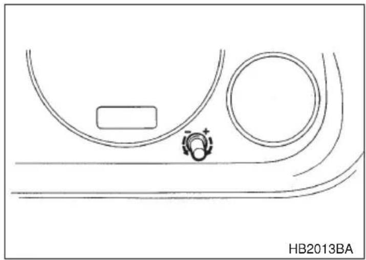
natural_image
Diagram of a vehicle interior with curved surfaces and a circular component, no text or symbols presentTo set the time, turn the setting knob clockwise to advance and counterclockwise to retard the time.
Light control switch

WARNING
To prevent battery discharge resulting from accidentally leaving your lights on when your vehicle is parked, the light switch operates only when the ignition switch is in the “ON” position. In any other position, the vehicle’s lights will be out.
If you park your vehicle on a roadside at night, use the hazard warning flasher to alert the other drivers.
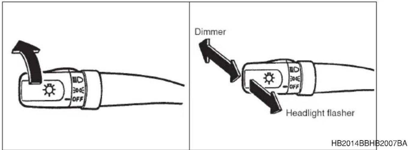
The light switch operates only when the ignition switch is in the "ON" position.
▼ Headlights
To turn on the headlights, turn the knob on the end of the turn signal lever.
EDGE first position
Parking lights, instrument panel illumination, tail lights and license plate light are on.
ED second position
Headlights, parking lights, instrument panel illumination, tail lights, and license plate light are on.
▼High/low beam change (dimmer)
To change from low beam to high beam, push the turn signal lever forward. When the headlights are on high beam, the high beam indicator light “≡D” on the instrument panel is also on.
To switch back to low beam, pull the lever back to the detent position.
▼Headlight flasher
CAUTION
Do not hold the lever in the flashing position for more than just a few seconds.
To flash the headlights, pull the lever toward you and then release it. The high beam will stay on for as long as you hold the lever. The headlight flasher works even though the lighting switch is in the "OFF" position.
When the headlights are on high beam, the high beam indicator light “≡D” on the instrument panel also comes on.
■Daytime running light system
WARNING
The tail lights, parking lights, and side marker lights are not turned on by the daytime running light system. The light switch must always be turned to the “≡∅” position when it is dark outside.
The low beam headlights will automatically come on at reduced brightness when the engine has started, under the following conditions:
●The parking brake is fully released.
- The light switch is in the "OFF" or "≡00≡" position.
Turn signal lever
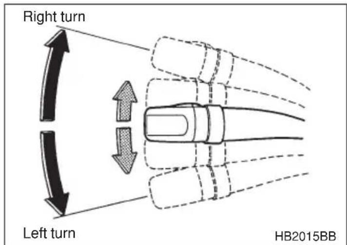
To activate the right turn signal, push the turn signal lever up. To activate the left turn signal, push the turn signal lever down. When the turn is fin-
- CONTINUED -
ished, the lever will return automatically. If the lever does not return after cornering, return the lever to the neutral position by hand.
To signal a lane change, push the turn signal lever up or down slightly and hold it during the lane change. The turn signal indicator lights will flash in the direction of the turn or lane change. The lever will return automatically to the neutral position when you release it.
Illumination brightness control
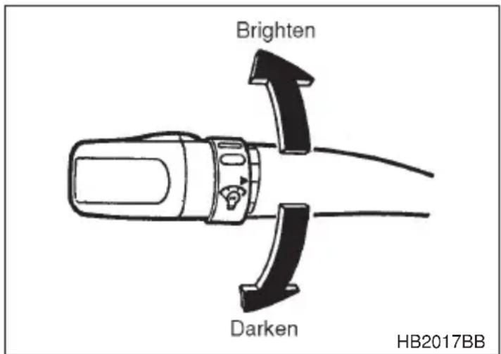
When the lighting switch is in the “ ≥slant 0 < ” or “ D ” position, you can adjust brightness of the instrument panel illumination for better visibility.
To brighten, turn the control dial counterclockwise.
To darken, turn the control dial clockwise.
Parking light switch
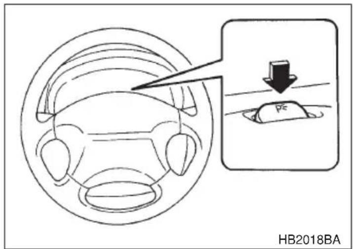
The parking light switch operates regardless of the ignition switch position.
By pushing the front end of this switch, following lights will come on.
- Parking lights
– Front and rear side marker lights - Tail lights
- License plate lights
To turn off, push the rear end of the parking light switch.
Avoid leaving these lights on for a long time because that will run down the battery.
Fog light switch (if equipped)
The fog lights operate only when the headlights are on low beam. Push the fog light switch to turn the fog lights on.
Press the switch again to turn them off.
HB2025BB
The indicator light located on the switch will illuminate when the fog lights are on.
Wiper and washer

WARNING
In freezing weather, do not use the windshield washer until the windshield is sufficiently warmed by the defroster.
Otherwise the washer fluid can freeze on the windshield, blocking your view.

CAUTION
- Do not operate the washer continuously for more than ten seconds, or when the washer fluid tank is empty. This may cause overheating of the washer motor. Check the washer fluid level frequently, such as at fuel stops.
- Do not operate the wipers when the windshield or rear window is dry. This may scratch the glass, damage the wiper blades and cause the wiper motor to burn out. Before operating the wiper on a dry windshield or rear window, always use the windshield washer.
- In freezing weather, be sure that the wiper blades are not frozen to the windshield or rear window before switching on the wipers. Attempting to operate the wiper with the blades frozen to the window glass could cause not only the wiper blades to be damaged but also the wiper motor to burn out. If the wiper blade is frozen to the window glass, be sure to operate the defroster, wiper deicer (if equipped) or rear window defogger before turning on the wiper.
- If the wipers stop during operation because of ice or some other obstruction on the window, the wiper motor could burn out even if the wiper switch is turned off. If this occurs, promptly stop the vehicle in a safe place, turn the ignition switch to the “LOCK” position and clean the window glass to allow proper wiper operation.
- Use clean water if windshield washer fluid is unavailable. In areas where water freezes in winter, use SUBARU Windshield Washer Fluid or the equivalent. (See “Windshield washer fluid” section in chapter 11.)
Also, when driving the vehicle when there are freezing temperatures, use non-freezing type wiper blades. - Do not clean the wiper blades with gasoline or a solvent, such as paint thinner or benzene. This will cause deterioration of the wiper blades.
NOTE
- The wiper operates only when the ignition switch is in the “ON” or “ACC” position.
- Clean your wiper blades and window glass periodically with a washer solution to prevent streaking, and to remove accumulations of road salt or road film. Keep the washer button depressed at least for 1 second so that washer solution will be sprinkled all over the
- CONTINUED -
windshield or rear window.
- Grease, wax, insects or other material on the windshield or the wiper blades results in jerky wiper operation and streaking on the glass. If you cannot remove those streaks after operating the washer or if the wiper operation is jerky, clean the outer surface of the windshield or rear window and the wiper blades using a sponge or soft cloth with a neutral detergent or mild-abrasive cleaner. After cleaning, rinse the window glass and wiper blades with clean water. The glass is clean if no beads form on the glass when you rinse with water.
- If you cannot eliminate the streaking even after following this procedure, replace the wiper blades with new ones. Refer to the “Wiper blade replacement” section (chapter 11) for replacement instructions.
■ Windshield wiper and washer switches
▼Windshield wipers
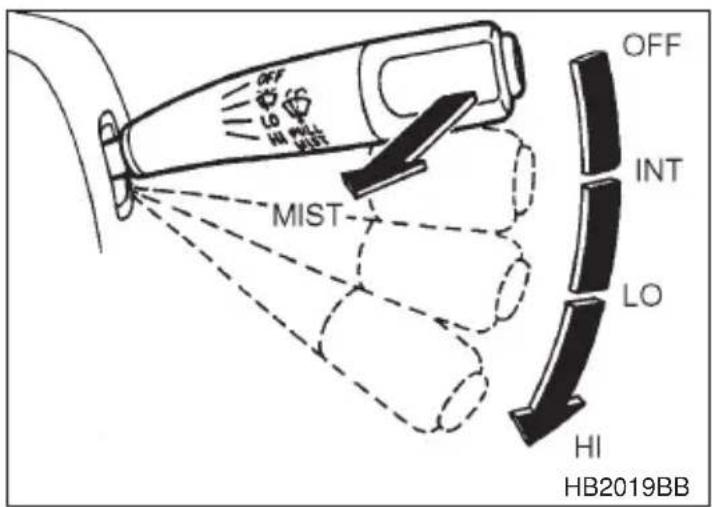
To turn the wipers on, push the wiper control lever down.

Intermittent
LO: Low speed
HI : High speed
To turn the wipers off, return the lever to the "OFF" position.
▼Wiper intermittent time control (if equipped)
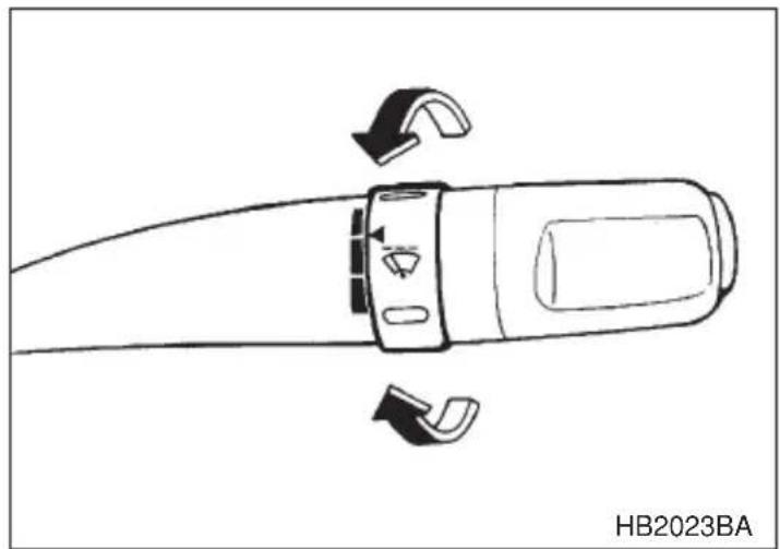
natural_image
Diagram of a handheld device with directional arrows indicating rotation or movement (no text or symbols on the device itself)When the wiper switch is in the “position, turn the dial to adjust the operating interval of the wiper.
The operating interval can be adjusted continuously from the shortest interval to the longest.
Two click stop positions of the dial may help you to aim at your desired interval.
▼Mist (for a single wipe)
For a single wipe of the wipers, pull the lever toward you. The wipers operate until you release the lever.
Washer
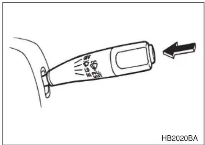
To wash the windshield, push the washer button at the end of the wip-
er control lever. The washer fluid sprays until you release the washer button. The wipers operate while you push the button.
■Rear window wiper and washer switch (if equipped)
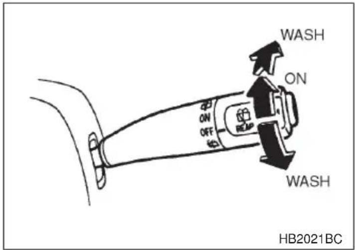
Rear wiper
The rear wiper offers intermittent operation only.
To turn the rear wiper on, turn the knob on the end of the wiper control lever upward.
To turn the wiper off, return the knob on the end of the lever to the "OFF" position.
Washer
To wash the rear window while the rear wiper is operating, turn the knob on the end of the wiper control lever upward to the “☐” position. The washer fluid sprays until you release the knob.
To wash the rear window when the rear wiper is not in use, turn the knob on the end of the wiper control lever downward to the “☐” position. The washer fluid sprays and the wiper operates until you release the knob.
Rear window defogger switch

CAUTION
- Do not use sharp instruments or window cleaner containing abrasives to clean the inner surface of the rear window. They may damage the conductors printed on the window.
●To prevent the battery from being discharged, do not operate the defogger continuously for any longer than necessary.
The rear window defogger operates only when the ignition switch is in the "ON" position.
The rear window defogger switch is located on the climate control panel.
The defogger will automatically shut off after about 15 minutes. If the window clears before that time, push the switch to turn it off. It also turns off when the ignition switch is turned to the "ACC" or "LOCK" position. If defrosting or defogging is desired when you restart your vehicle, you have to push the switch to turn it on again.

For vehicles with manual heating and air conditioning systems
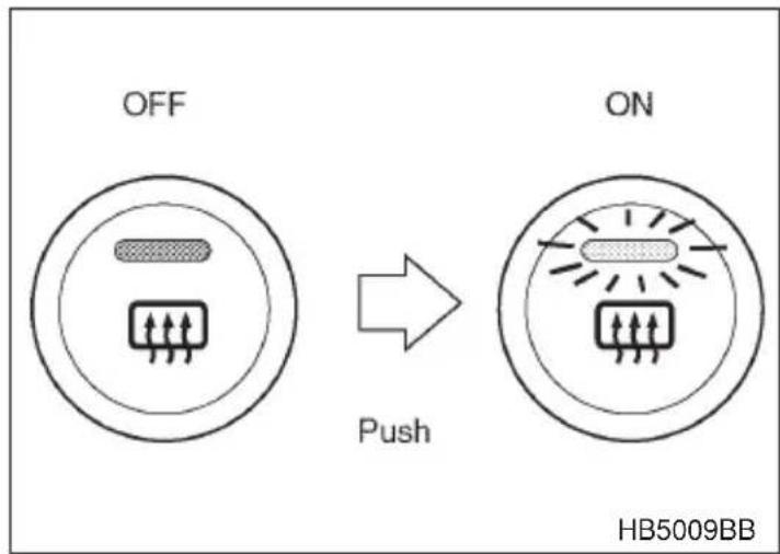
flowchart
graph LR
    A["OFF"] -->|Push| B["ON"]
    style A fill:#f9f,stroke:#333
    style B fill:#bbf,stroke:#333
    note right of B HB5009BB
To turn on the defogger, push the switch. To turn it off, push the switch again.
The indicator light located on the switch lights up while the rear window defogger is operating.
For vehicles with automatic climate control
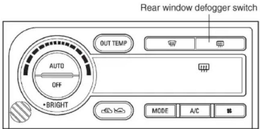
HB3016BB
To turn on the defogger, push the switch. To turn it off, push the switch again.
The indicator light “###” lights up on the climate control display panel while the rear window defogger is operating.
Windshield wiper deicer (if equipped)

CAUTION
To prevent the battery from being discharged, do not operate the windshield wiper deicer continuously for any longer than necessary.
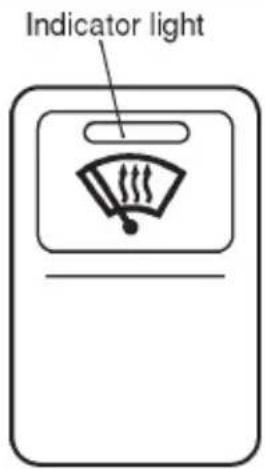
HB2027BB
The windshield wiper deicer operates only when the ignition switch is in the "ON" position.
Before turning on the windshield wiper deicer, remove any snow from the windshield. To turn on the windshield wiper deicer, push the switch. The indicator light located on the switch lights up while the windshield wiper deicer is operating.
The windshield wiper deicer will automatically shut off after about 15 minutes. If the wiper blades have been deiced completely before that time, push the switch to turn it off. It also turns off when the ignition switch is turned to the “ACC” or “LOCK” position. If deicing is not complete when you restart your vehicle, you have to push the switch to turn the deicer on again.
Mirrors
Always check that the inside and outside mirrors are properly adjusted before you start driving.
Inside mirror
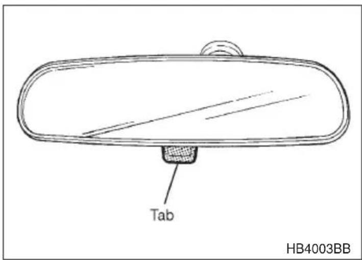
The inside mirror has a day and night position. Pull the tab at the bottom of the mirror toward you for the night position. Push it away for the day position. The night position reduces glare from headlights.
▼Compass mirror (if equipped)
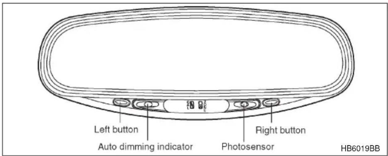
The inside electronic compass mirror has an anti-glare feature which automatically reduces glare coming from headlights of vehicles behind you. It also contains a built-in compass.
- By pressing and releasing the left button, the automatic dimming function is toggled on or off. When the automatic dimming function is on, the auto dimming indicator light (green) located to the right of the button will illuminate.
- By pressing and releasing the right button, the compass display is toggled on or off. When the compass is on, an illuminated compass reading will appear in the lower part of the mirror.
Even with the mirror in anti-glare mode, the mirror surface turns bright if the transmission is shifted into reverse. This is to ensure good rearward visibility during reversing.
▼ Photosensors
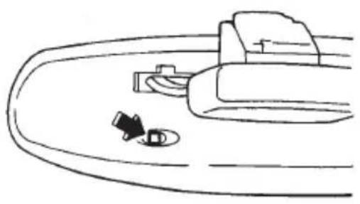
natural_image
Simple line drawing of a car interior with a vehicle and a small object (no text or symbols)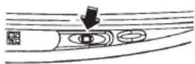
natural_image
Diagram showing a car on a curved road with a downward arrow indicating motion (no text or symbols)HB6020BA
The mirror has a photosensor attached on both the front and back sides. If the glare from the headlights of vehicles behind you strikes the mirror, these sensors detect it and make the reflection surface of the mirror dimmer to help prevent you from being blinded. For this reason, use care not to cover the sensors with stickers, or other similar items. Periodically wipe the sensors clean using a piece of dry soft cotton cloth or an applicator.
▽ Compass calibration
- For optimum calibration, switch off all nonessential electrical accessories (rear window defogger, heater/air conditioning system, spotlight, etc.) and ensure all doors are shut.
- Drive to an open, level area away from large metallic objects or structures and make certain the ignition switch is in the "ON" position.
- Press and hold the left button for 3 seconds then release, and the compass will enter the calibration mode. "CAL" and direction will be displayed.
- Drive slowly in a circle until "CAL" disappears from the display (about two or three circles).
- The compass is now calibrated. Further calibration is not required. The compass will automatically calibrate from this point forward.
▽ Compass zone adjustment
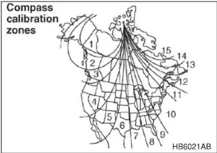
-
The zone setting is factory preset to Zone 8. Refer to the “Compass calibration zone” map shown above or one attached to the end of this manual to verify that the compass zone setting is correct for your geographical location.
-
Press and hold the right button for 3 seconds then release, and the word "ZONE" will briefly appear and then the zone number will be displayed.
-
Press the right hand button repeatedly to cycle the display through all possible zone settings. Stop cycling when the correct zone setting for your location is displayed.
-
Releasing the button for 3 seconds will exit the zone setting mode.
■Outside mirrors
▼Convex mirror (Passenger side)

WARNING
Objects look smaller in a convex mirror and farther away than when viewed in a flat mirror. Do not use the convex mirror to judge the distance of vehicles behind you when changing lanes. Use the inside mirror (or glance backwards) to determine the actual size and distance of objects that you view in convex mirror.
▼Adjusting mirrors
To adjust the mirrors by hand, push where indicated by the arrows.
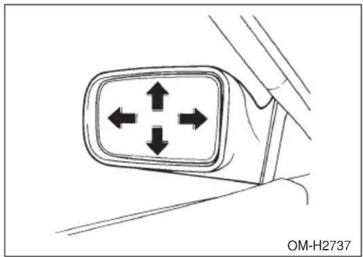
▼Remote control mirror switch (if equipped)
The remote control mirrors operate only when the ignition switch is in the "ON" or "ACC" position.
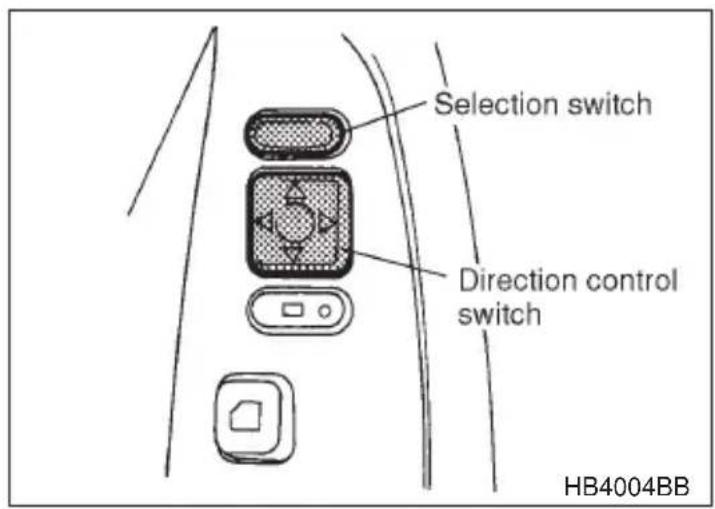
- Press either end of the selection switch, "L" for the left, "R" for the right.
- Move the direction control switch in the direction you want to move the mirror.
- Return the selection switch to the neutral position to prevent unintentional operation.
The mirrors can also be adjusted manually.
▼Outside mirror defogger (if equipped)
CAUTION
To prevent the battery from being discharged, do not operate the defogger continuously for any longer than necessary.
The outside mirror defogger operates only when the ignition switch is in the "ON" or "ACC" position.
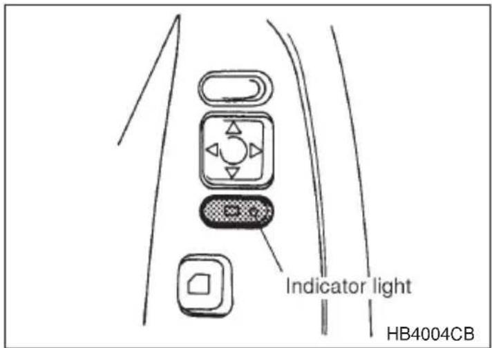
To turn on the outside mirror defogger, push the switch while the engine is running.
The indicator light located on the switch will come on when the outside mirror defogger heater in operation.
To turn it off, push the switch again.
Tilt steering wheel
WARNING
Do not adjust the steering wheel tilt position while driving. This may cause loss of vehicle control and result in personal injury.
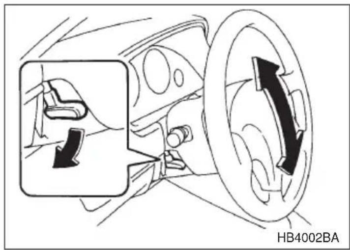
- Adjust the seat position. Refer to the "Front seat" section (chapter 1).
- Pull the tilt lock lever down.
- Move the steering wheel to the desired level.
- Push the lever up to lock the steering wheel in place.
- Make sure that the steering wheel is securely locked by moving it up and down.
Horn
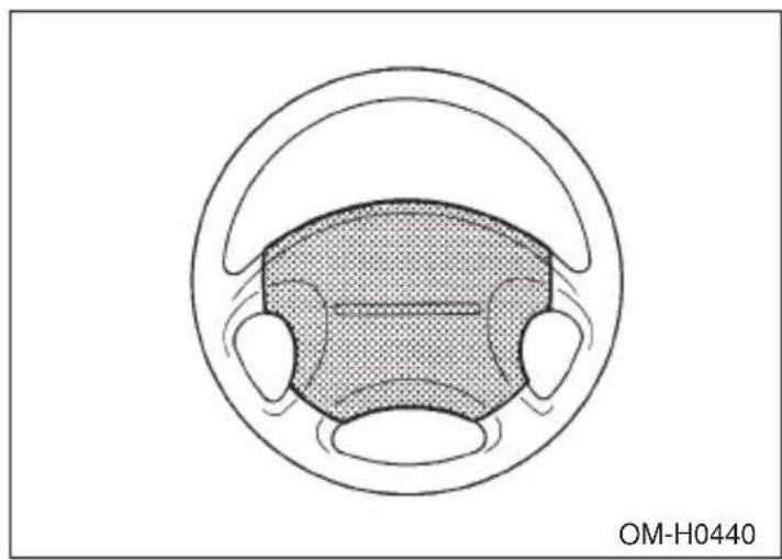
natural_image
Diagram of a car's wheel and head assembly (no text or symbols)To sound the horn, push the horn pad.
Climate control
Ventilator 4-2
Manual heating and air conditioning system 4-4....
Heater operation 4-7
Air conditioner operation 4-10
Automatic climate control system (if equipped) 4-12......
Operating tips for heater and air conditioner 4-20
Air filtration system (if equipped) 4-21
Ventilator
▼Center and side ventilators
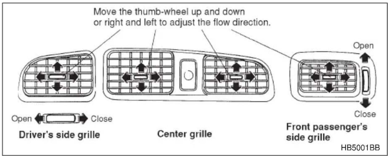
Adjustable side defroster grille (for driver's side only)
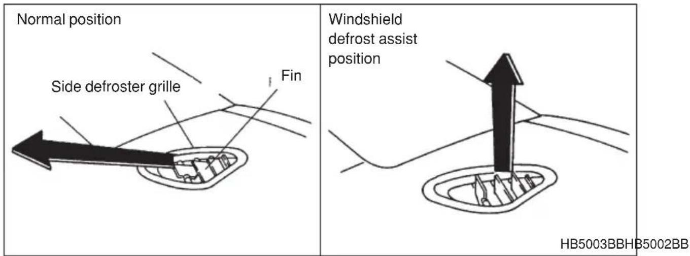
The driver's side defroster grille is adjustable. The normal position as shown in the diagram directs warm air to the side glass. When more rapid defrosting of the windshield is desired, the air flow can be directed temporarily toward the windshield to assist the windshield defroster. If this is done, the driver's side grille should always be returned to its normal position so that the warm air flow can then be used to defrost the driver's side window.
Air flow selection
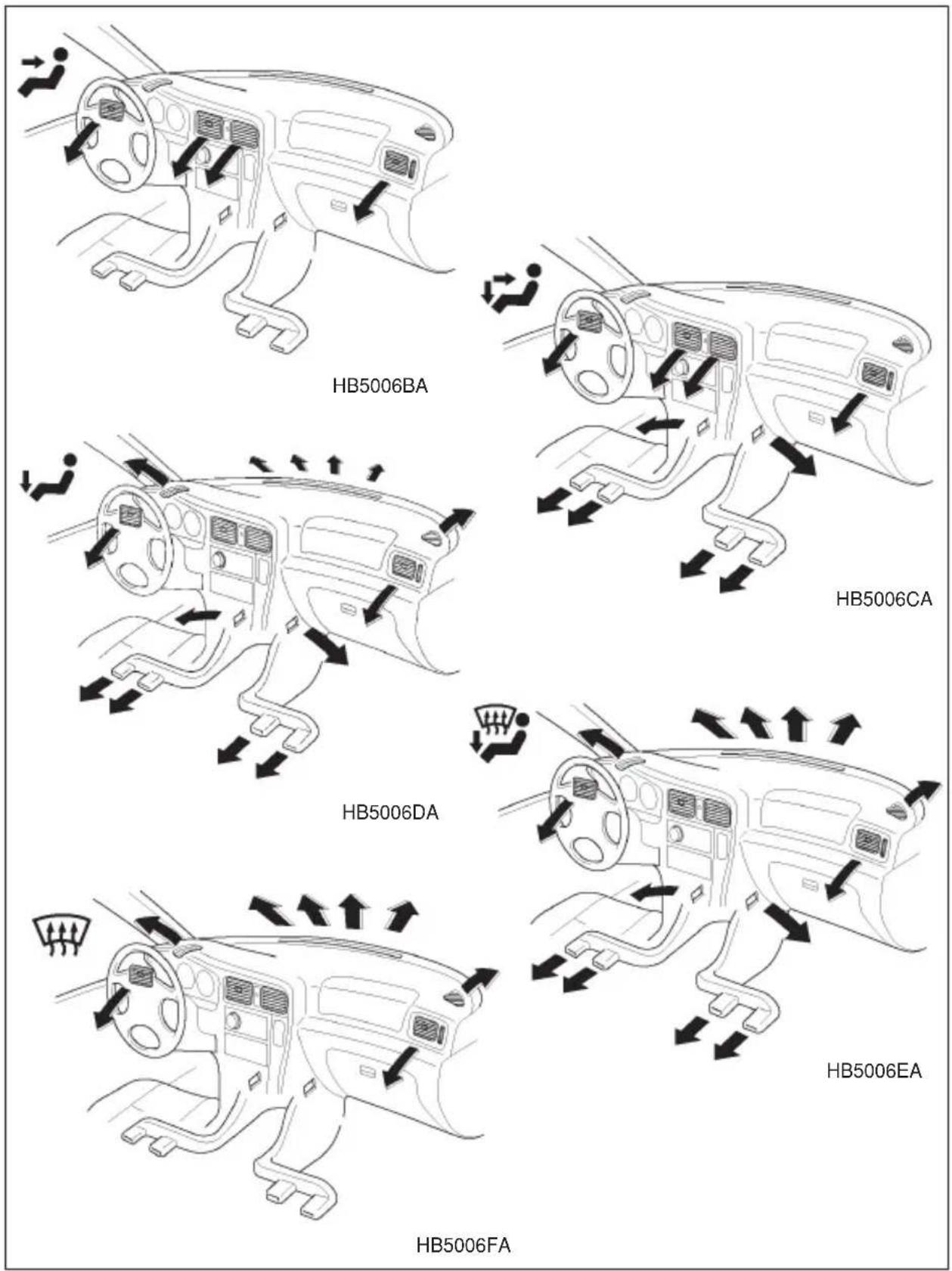
Manual heating and air conditioning system
▼Control panel
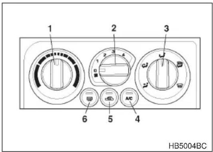
-
Temperature control dial
-
Fan speed control dial
-
Air flow control dial
-
Air conditioner button
-
Air inlet selection button
-
Rear window defogger button (Refer to "Rear window defogger" in chapter 3.)
▽ Temperature control dial
This dial regulates the temperature of air flow from the air outlets over a range from the blue area (cool) to red area (warm).
▽ Fan speed control dial
The fan operates only when the ignition switch is turned to the "ON" position. The fan speed control dial is used to select four fan speeds.
▽ Air flow control dial
This dial has the following five positions:

: Air flows through the instrument panel outlets.

: Air flows through the instrument panel outlets and the foot outlets.

: Air flows through the foot outlets and some through the wind-shield defroster outlets.

: Air flows through the windshield defroster outlets and foot outlets.

: Air flows through the windshield defroster outlets.
NOTE
When the dial is placed in the “ ” or “ ” position, the air conditioner compressor operates automatically regardless of the position of the air conditioner button to defog the windshield quickly. At the same time, the air inlet selection is automatically set to “fresh air” mode.
In this state, you cannot select “recirculation” mode by manually pressing the air inlet selection button.
Air conditioner button
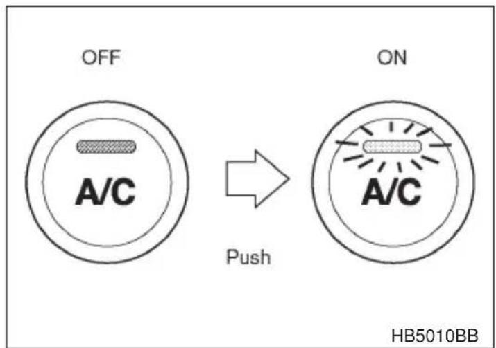
The air conditioner operates only when the engine is running.
Push the air conditioner button while the fan is in operation to turn on the air conditioner. The indicator light will come on.
Push it again to turn off the air conditioner.
▽ Air inlet selection button
WARNING
Continued operation in the ON position may fog up the windows. Switch to the OFF position as soon as the outside dusty condition clears.
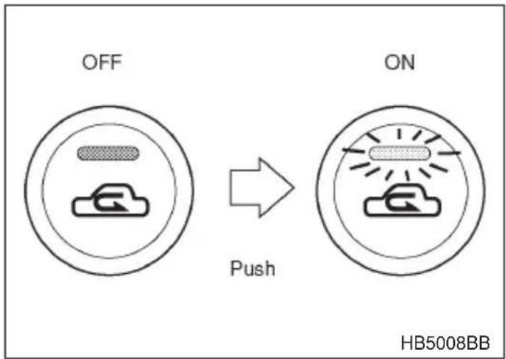
ON position (Recirculation): Interior air is recirculated inside the vehicle. Push the air inlet selection button to the ON position. The indicator light will come on.
OFF position (Fresh Air): Outside air is drawn into the passenger compartment. Push the air inlet selection button again to the OFF position. The indicator light will go off.
■Heater operation
▼Defrosting or defogging the windshield
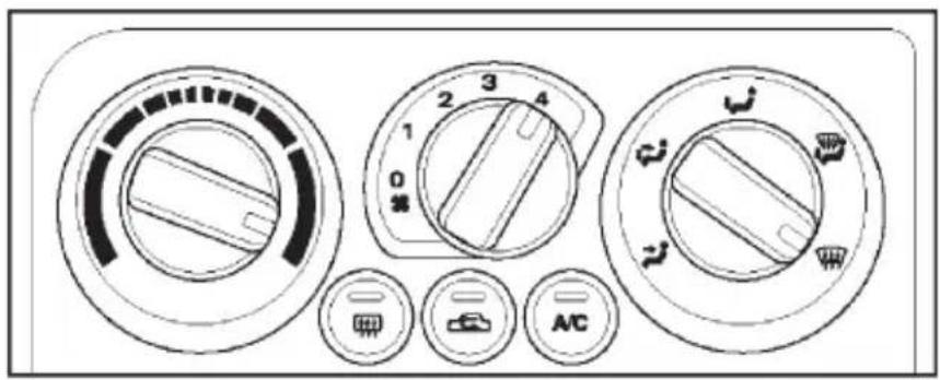
HB5011AA
To direct warm air to the windshield and front door windows:
- Set the air flow control dial to the “ ” position.
- Turn the temperature control dial all the way to the right.
- Set the fan speed control dial to the highest speed.
NOTE
Warm air also comes out from the right and left air outlets. To stop warm air flow from these outlets, turn the corresponding thumb-wheel to the “☒” position.
▼Heating and defrosting
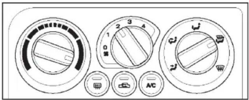
HB5012AA
To direct warm air toward the floor and the windshield:
- Set the air flow control dial to the “↓” position.
- Set the temperature control dial to the most comfortable level.
- Set the fan speed control dial to the desired speed.
NOTE
Warm air also comes out from the right and left air outlets. To stop warm air flow from these outlets, turn the corresponding thumb-wheel to the “☒” position.
Heating
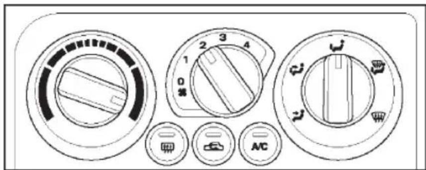
HB5013AA
To direct warm air toward the floor:
- Set the air inlet selection button to the "OFF" position
2 Set the air flow control dial to the “↓” position. - Set the temperature control dial to the most comfortable level.
- Set the fan speed control dial to the desired speed.
NOTE
Warm air also comes out from the right and left air outlets. To stop warm air flow from these outlets, turn the corresponding thumb-wheel to the “☒” position.
▼Bi-level heating
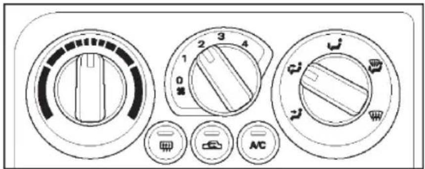
HB5014AA
This setting allows you to direct air of different temperatures from the instrument panel and foot outlets. The air from the foot outlets is slightly warmer than from the instrument panel outlets.
- Set the air inlet selection button to the "OFF" position.
- Set the air flow control dial to the “↓” position.
- Set the temperature control dial to the desired temperature level.
- Set the fan speed control dial to the desired speed.
Setting the temperature control dial fully turned to the red area or blue area decreases the temperature difference between the air from the instrument panel outlets and the air from the foot outlets.
Ventilation
! WARNING
Continued operation in the “ON” position may fog up the windows. Switch to the “OFF” position as soon as the outside dusty condition clears.
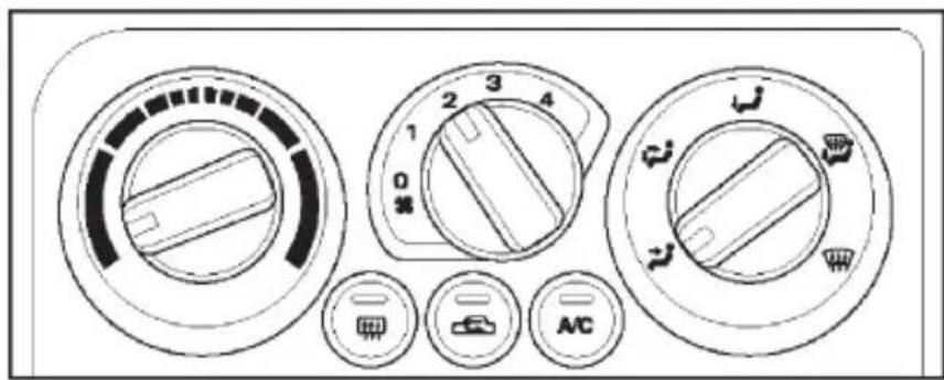
HB5015AA
To force outside air through the instrument panel outlets:
- Set the air inlet selection button to the "OFF" position.
- Set the air flow control dial to the “ ” position.
- Set the temperature control dial all the way left.
- Set the fan speed control dial to the desired speed.
When driving on a dusty road, set the air inlet control lever to the "ON" position.
■Air conditioner operation
▼Cooling or dehumidifying
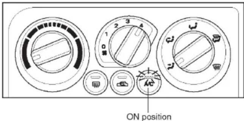
HB5016BB
For cooling and dehumidification of the passenger compartment, air flows through the instrument panel outlets:
- Set the air inlet selection button to the "OFF" position.
- Set the air flow control dial to the “3” position.
- Set the air conditioner button to the "ON" position.
- Set the temperature control dial to the blue area.
- Set the fan speed control dial at the highest speed.
▼Defrosting or defogging
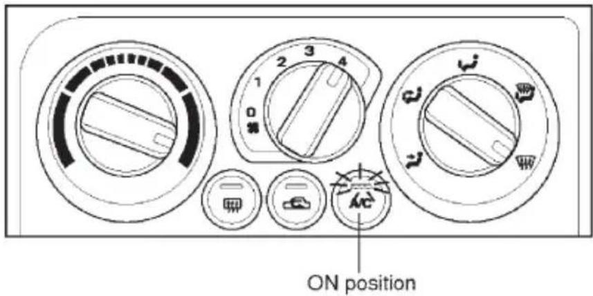
HB5011BB
To direct warm air to the windshield and front door windows:
- Set the air outlet control dial to the “ ” position.
- Set the temperature control dial to the red area.
- Set the fan speed control dial at the highest speed.
Automatic climate control system (if equipped)
NOTE
- Operate the automatic climate control system when the engine is running.
- When the engine coolant is cold, for instance in cold weather, the air flows through the windshield defroster outlets and the blower runs at the lowest speed to prevent cold air from blowing directly against the driver and front passenger.
- In the “AUTO” mode, if the air temperature in the passenger compartment is cooled down to the specified temperature, the air conditioner compressor stops automatically. For efficient defogging or dehumidifying in cold weather, press the “A/C” switch on.
- Even when cooling is not necessary, setting the temperature much lower than the current outlet air temperature turns on the air conditioner compressor automatically and the “A/C” indicator light on the control panel comes on.
The automatic climate control system automatically controls outlet air temperature, fan speed, air flow distribution air-inlet control, and air conditioner compressor operation. It activates when the “AUTO” switch is pressed, and is used in conjunction with the Temperature control dial to maintain a constant, comfortable climate within the passenger compartment.
The temperature can be set within a range of 65 – 85°F (18 – 32°C).
NOTE
The temperature is shown in units of Fahrenheit for US model and in Centigrade for Canadian model.
▼Control panel
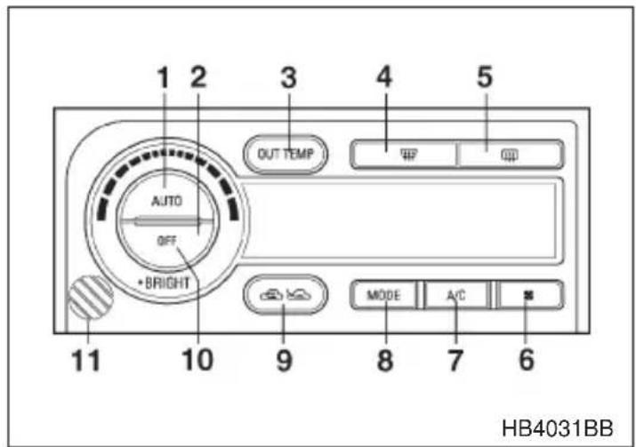
- AUTO switch
- OFF switch/BRIGHT
- Outside air temperature switch
- Defroster switch
- Fan speed control switch
- Air conditioner switch
- Air flow control switch
- Air inlet selection switch
- Temperature control dial
-
In-vehicle temperature sensor.
-
Rear window defogger switch (Refer to the "Rear window defogger" in chapter 3.)
▼ AUTO switch
AUTO mode operation:
The Automatic Climate Control system automatically controls the air temperature of the passenger compartment in the AUTO mode. When the “AUTO” switch is pressed, the indicator light “AUTO” on the control panel comes on. In this state, outlet air temperature, fan speed, air flow distribution, air-inlet control, and air conditioner compressor operation are automatically controlled.
ECON (economy) mode:
When you press the “AUTO” switch while the system is in the AUTO mode, it selects the ECON (economy) mode, turning on the “ECON” indicator light. In the ECON mode, the compressor runs to be thrifty with energy consumption. Interior windows tend to fog in this energy-saving operation. It is therefore recommended that the AUTO mode be used only in high humidity conditions.
Manual mode operation:
When the Automatic Climate Control system is operating in the AUTO mode, pressing the “ ”, “ ”, “MODE”, “A/C” or “ ” switch shifts the operation into the “MANUAL” mode and the indicator light “AUTO” on the control panel will go out.
When the “ ”, “ ”, “MODE”, “A/C” or “ ” switch is pressed, the corresponding function can be controlled independently, while automatic control of the other functions are maintained.
To change the system back to the AUTO mode, press the “AUTO” switch.
▽ OFF switch
The Automatic Climate Control system turns off (the air conditioner compressor and fan turn off) when the “OFF” switch is pressed.
When the “OFF” switch is pressed, the outside air introduction mode (“ ” position) is automatically selected.
NOTE
Display illumination dimness cancellation (BRIGHT):
Setting the light switch to the “≡0≡” or “≡D” position causes the illuminating icons on the display panel to dim. When traveling with the lights on in gloomy daylight or in twilight, press the OFF switch for 1 second or longer if you feel it is too hard to identify the icons clearly. The brightness comes back to normal.
If you wish to dim the icons again, hold down the OFF switch again or if you can safely do so, turn the light switch OFF and then place it in the “≡D” or “≡D” position.
▼ OUT.TEMP switch
To check the outside air temperature, push the “OUT.TEMP” switch. The outside air temperature will be displayed for five seconds, and then the display automatically changes back to the inside air temperature.
The display changes over from the inside air temperature to the outside air temperature as its normal indication if you keep the switch pressed for more than 2 seconds.
NOTE
- You can check the outside air temperature even when the Automatic Climate Control is off. (The ignition switch should be in the “ON” position.)
-
In the following cases, the display can indicate a higher temperature than the actual outside air temperature:
-
In direct sunlight
- When the vehicle is parked for a long period of time with the engine kept running.
– During stop and go driving
▽ — Defroster switch
To defrost or dehumidify the windshield and side window, push the defroster switch “ 🎩 ”. When the “ ” switch is pushed, regardless whether the air conditioner is operating or not, outside air is drawn into the passenger compartment, the air conditioner compressor turns on, air flow is directed towards the windshield and side windows, and the indicator light “ 🎩 ” on the control panel comes on. After eliminating the fogging from the windshield, set the air conditioner back in the AUTO mode by pushing the “AUTO” switch or turn off by pushing the “OFF” switch or “ 🎩 ” switch.

— fan speed control switch
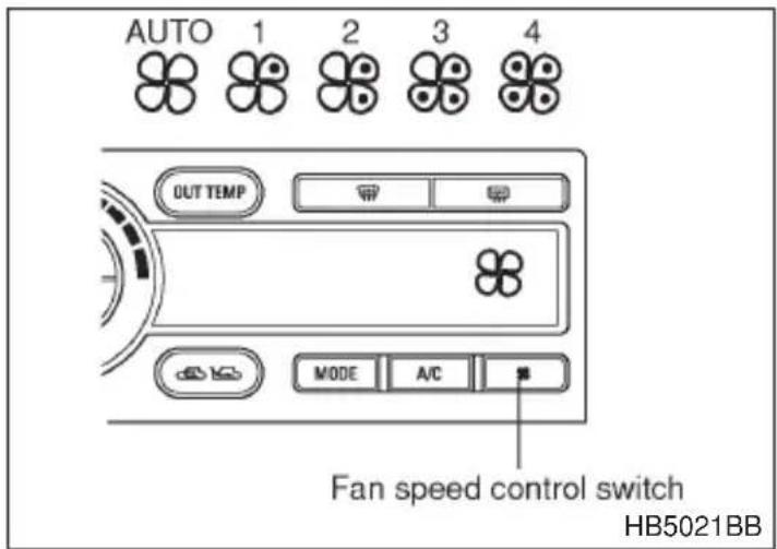
The fan speed control switch has the 5 positions: AUTO position and 4 different fan speed positions.
With the fan speed control switch in the AUTO position, the fan speed changes automatically corresponding to various conditions: air temperature inside and outside of the passenger compartment, intensity of the sunlight, etc.
Use this switch to select desired fan speed. Fan speed increases with each press of the switch and returns to the AUTO position.

A/C — Air conditioner switch
NOTE
The air conditioner compressor does not operate when the outside air temperature is below 32^ F ( 0^ C).
If the windshield starts to fog when the air conditioner is operated in the AUTO mode, push the air conditioner switch "A/C" to defog and dehumidify.
When this switch is pushed, the air conditioner compressor turns on and the indicator light “A/C” on the control panel comes on. After eliminating the fogging from the windshield, set the air conditioner back in the AUTO mode by pushing the “AUTO” switch.
▽ MODE — Air flow control switch
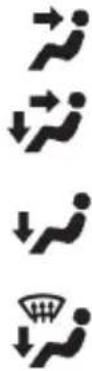
(Ventilation): Air flows through the instrument panel outlets.
(Bi-level) : Air flows through the instrument panel outlets and the foot outlets.
(Heat) : Air flows through the foot outlets and some through the windshield defroster outlets.
(Heat-def) : Air flows through the windshield defroster outlets and foot outlet.
▽ Air inlet selection switch
WARNING
Continued operation in the “☐” position may fog up the windows. Switch to the “☐” position as soon as the outside dusty condition clears.
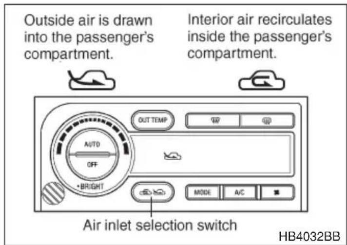
Select the air inlet by pushing the air inlet selection switch.
: Interior air recirculates inside the passenger's compartment. Use this position when quickly warming up the passenger compartment or cooling it down or when preventing outside air from entering the passenger compartment from the outside air. The indicator light " [icon] " on the control panel comes on when this switch is pushed.
: Outside air is drawn into the passenger compartment. When the air conditioning system is operated in the "AUTO" mode, this position is selected automatically. The indicator light "☐" on the control panel comes on when this switch is pushed.
▽ Temperature control dial
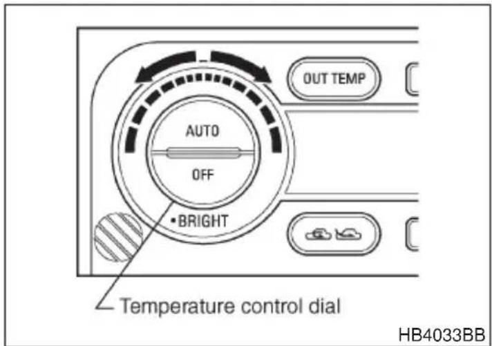
NOTE
- A setting of about 77°F (25°C) throughout the year is recommended.
- The temperature setting remains even after the ignition switch is turned to the “OFF”. However, if the battery cables are disconnected, the temperature will be set to 77°F (25°C) automatically.
Set desired temperature by turning the temperature control dial; turn the dial clockwise to raise the temperature setting and turn it counterclockwise to lower it.
The temperature can be set in increments of 1^ F within a range of 65 – 85°F for US models and in increments of 0.5^ C within a range of 18 – 32°C for Canadian models.
Even when quick cooling or warming is necessary, you do not have to change the temperature setting. The Automatic Climate Control system operates at maximum performance until the air in the passenger compartment reaches to the specified temperature.
▼Temperature sensors
This Automatic Climate Control system employs the several sensors. These are very delicate parts. Therefore, if these sensors are damaged, it is possible that the Automatic Climate Control system will not properly control the air temperature in the passenger compartment. To prevent possible damage to the sensors, please observe the following:
- Do not allow anything to impact the sensors.
- Be careful not to let water contact the sensors.
- Do not cover the sensors.
The sensors are found at the following locations:
– Sun-load sensor (beside the windshield defroster grille)
- In-vehicle temperature sensor (beside the temperature control dial.)
– Ambient sensor (at the backside of the front grille)
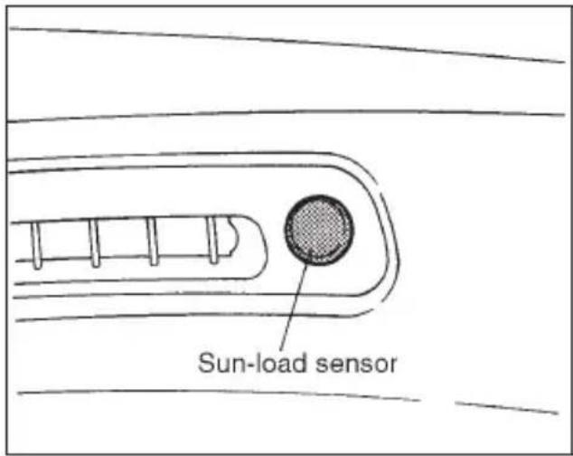
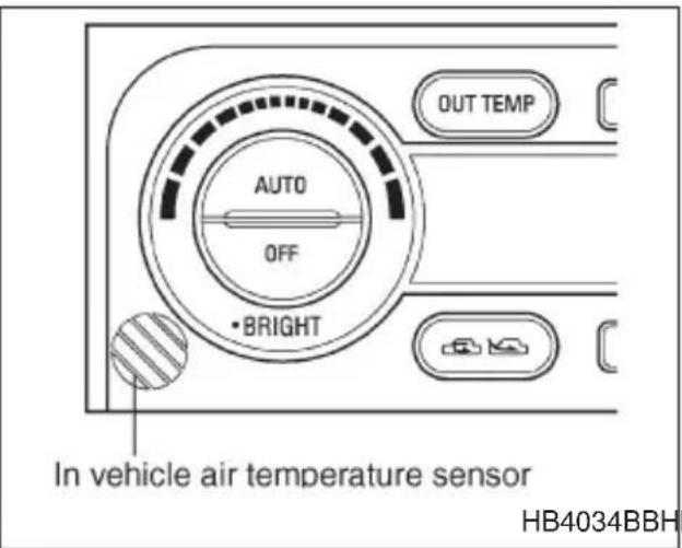
Operating tips for heater and air conditioner
▼Cleaning ventilator grille
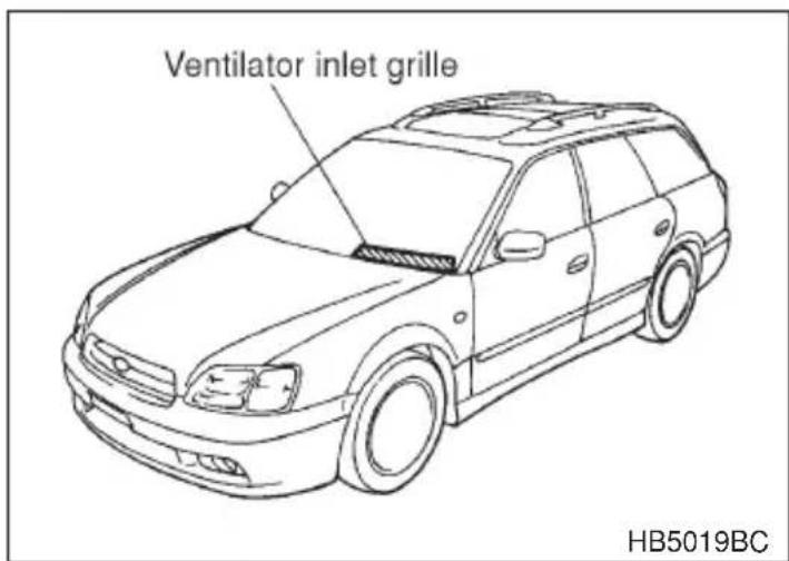
Always keep the front ventilator inlet grille free of snow, leaves, or other obstructions to ensure efficient heating and defrosting. Since the condenser is located in front of the radiator, this area should be kept clean because cooling performance is impaired by any accumulation of insects and leaves on the condenser.
▼Efficient cooling after parking in direct sunlight
After parking in direct sunlight, drive with the windows open for a few minutes to allow outside air to circulate into the heated interior. This results in quicker cooling by the air conditioner. Keep the windows closed during the operation of the air conditioner for maximum cooling efficiency.
▼Lubrication oil circulation in the refrigerant circuit
Operate the air conditioner compressor at a low engine speed (at idle or low driving speeds) a few minutes each month during the off-season to circulate its oil.
▼Checking air conditioning system before summer season
Check the air conditioner unit for refrigerant leaks, hose conditions, and proper operation each spring. This check is best performed by your SUBARU dealer.
▼Cooling and dehumidifying in high humidity and low temperature weather condition
Under certain weather conditions (high relative humidity, low temperatures, etc.) a small amount of water vapor emission from the air outlets may be noticed. This condition is normal and does not indicate any problem with the air conditioning system.
▼Air conditioner compressor shut-off when engine is heavily loaded
To improve acceleration and gas mileage, the air conditioner compressor is designed to temporarily shut off during air conditioner operation whenever the accelerator is fully depressed such as during rapid acceleration or when driving on a steep upgrade.
▼Refrigerant for your climate control system
Your air conditioner uses ozone friendly refrigerant HFC134a. Therefore, the method of adding, changing or checking the refrigerant is different from the method for CFC12 (freon). Consult your SUBARU dealer for service. Repairs needed as a result of using the wrong refrigerant are not covered under warranty.
Air filtration system (if equipped)
If your vehicle's air conditioning system is equipped with a optional air filtration system, replace the filter element according to the replacement schedule shown below. This schedule should be followed to maintain the filter's dust collection ability. Under extremely dusty conditions, the filter should be replaced more frequently. Since the filter element is a viscous type, it is unnecessary to clean or wash the element. Have your filter checked or replaced by your SUBARU dealer.
Replacement schedule:
Every 12 months or 9,300 miles (15,000 km) whichever comes first
NOTE
The filter can influence the air conditioning, heating and defroster performance.
Audio
Antenna system 5-2
Installation of accessories 5-3
Audio set 5-3
Type A and B audio set (if equipped) 5-8
Type C audio set (if equipped) 5-20
Type D and E audio set (if equipped) 5-34
Type F audio set (if equipped) 5-44
McIntosh audio set (if equipped) 5-50
CD player 1 (if equipped) 5-60
CD player 2 (if equipped) 5-62
In-dash 6 CD auto changer (if equipped) 5-65
Precautions to observe when handling a compact disc (CD) 5-68
Antenna system
▼Printed antenna

CAUTION
Do not use sharp instruments or window cleaner containing abrasives to clean the inner surface of the window on which the antenna is printed. Doing so may damage the antenna printed on the window.
The antenna is printed on the inside of the rear window glass (sedan) or the left side rear quarter window glass (station wagon).
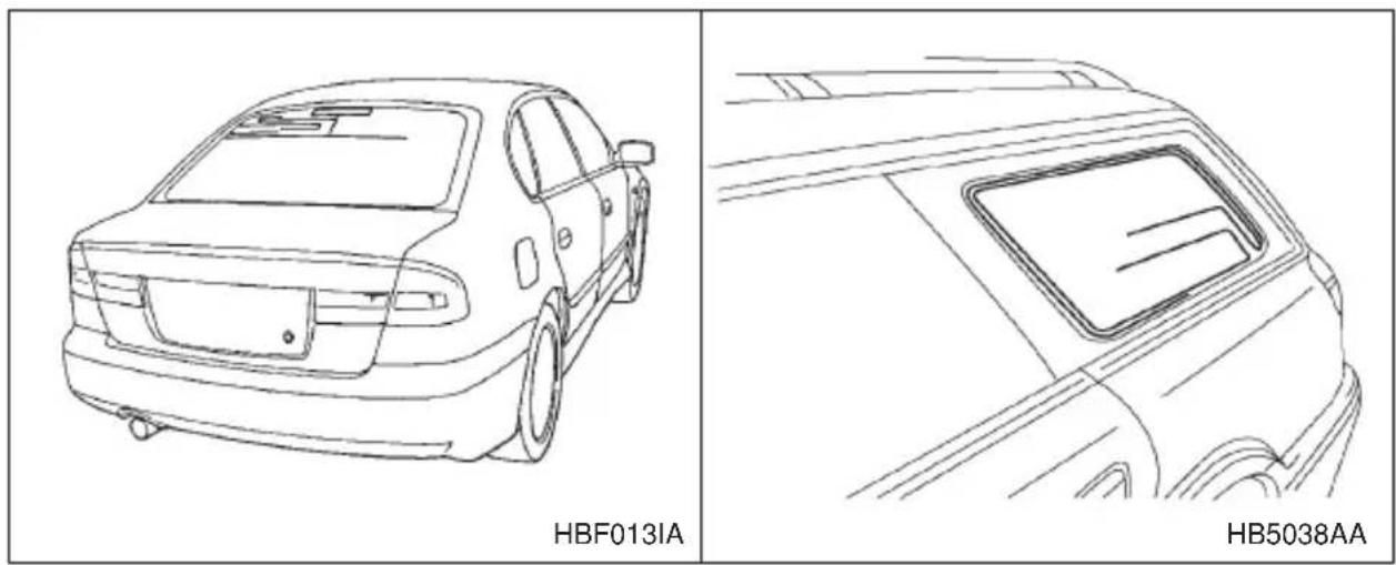
▼Pillar mounted antenna
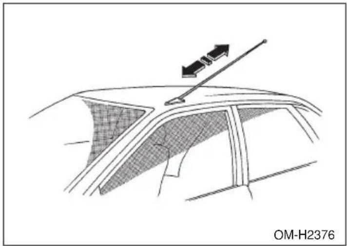
natural_image
Diagram of a car interior showing a steering wheel and directional arrows indicating motion (no text or symbols)Pull the antenna out to extend it to its full length.
▼FM reception
Although FM is normally static free, reception can be affected by the surrounding area, atmospheric conditions, station strength and transmitter distance. Buildings or other obstructions may cause momentary static, flutter or station interference. If reception continues to be unsatisfactory, switch to a stronger station.
Installation of accessories
Always consult your SUBARU dealer before installing a citizen band radio or other transmitting device in your vehicle. Such devices may cause the electronic control system to malfunction if they are incorrectly installed or if they are not suited for the vehicle.
Audio set
Your SUBARU may be equipped with one of the following audio sets. See the pages indicated in this section for operating details.
▼Type A and type B audio set
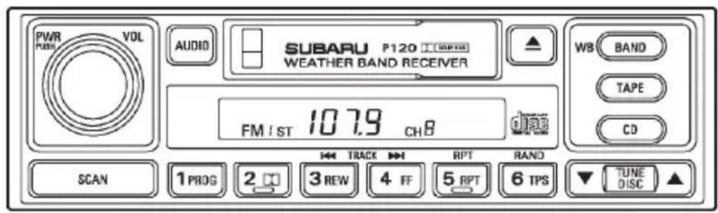
HB5041AA
●Radio operation: refer to page 5-8
●Cassette player operation: refer to page 5-12
- CD player control: refer to page 5-15
- CD changer control: refer to page 5-17
▼Type C audio set
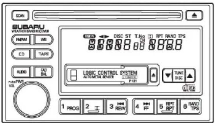
HB5042AA
●Radio operation: refer to page 5-20
●Cassette player operation: refer to page 5-25
- CD (compact disc) player operation: refer to page 5-28
- CD changer control: refer to page 5-31
▼Type D and type E audio set
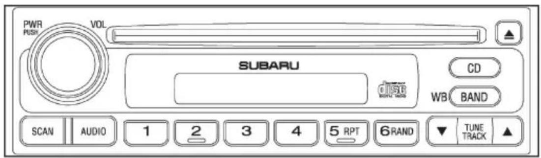
HB5052AA
●Radio operation: refer to page 5-34
- CD (compact disc) player operation: refer to page 5-38
- CD changer control: refer to page 5-41
▼Type F audio set
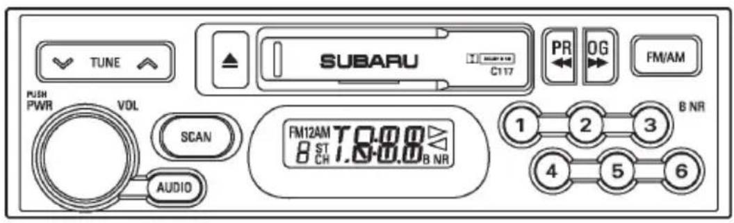
HB5043AA
●Radio operation: refer to page 5-44
●Cassette player operation: refer to page 5-48
- CD player control: refer to page 5-49
▼McIntosh audio set
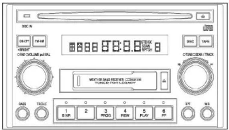
HB5053AA
●Radio operation: refer to page 5-50
●Cassette player operation: refer to page 5-55
- CD player operation: refer to page 5-57
▼CD player 1 (Optional audio unit — if equipped)
HB5039AA
- Inserting and removing a disc: refer to page 5-60
▼CD player 2 (Optional audio unit — if equipped)
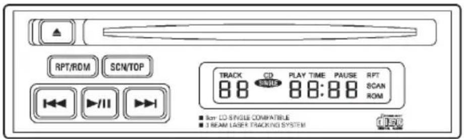
HB5044AA
- CD (compact disc) player operation: refer to page 5-62
In-dash 6 CD auto changer (Optional audio unit — if equipped)
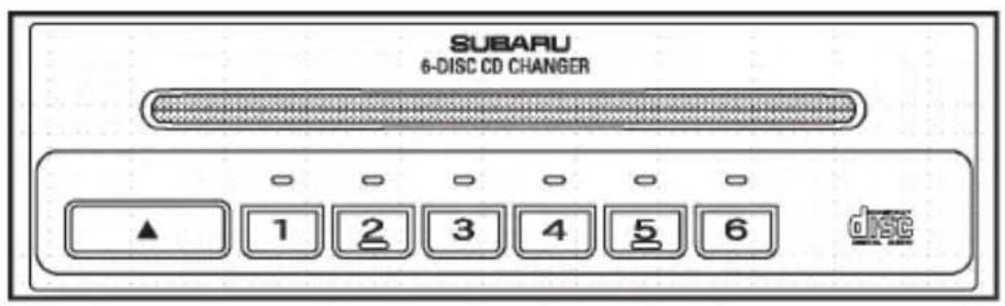
HB5040AA
- Inserting and removing a disc or all discs: refer to page 5-65
Type A and B audio set (if equipped)
Type A: Without weather band
Type B: With weather band
The audio set will operate only when the ignition switch is in the “ACC” or “ON” position.
Radio operation
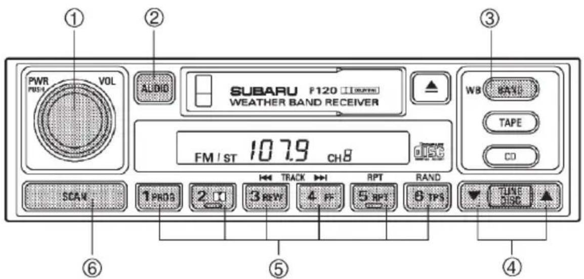
HB5041BC
① Power switch/Volume, Tone, Balance, Fader control dial
② AUDIO button
③ BAND button
④ Tuning buttons
⑤ Preset buttons
⑥ SCAN button
▼Power switch and volume/bass/treble/fader/balance control
▼ Power switch and volume control (PWR/VOL)
The dial ① is used for both power (ON/OFF) and volume control. The radio is turned ON and OFF by pushing the dial and the volume is controlled by turning the dial.
∇ Tone and balance control (AUDIO)
The volume control dial ① normally functions as a volume control. This dial becomes a control for Bass, Treble, Fader or Balance when you select the appropriate tone and balance control mode.
Choose desired volume level for each mode by turning the volume control dial. The control function returns to volume control mode after about 5 seconds.
To change control modes: Each brief press of the “AUDIO” button ② changes control modes in the following sequence starting from volume control mode. (When the radio is first turned on, the control mode is in the volume control.)
Volume Bass Treble Fader Balance (VOL) (BAS) (TRE) (FAd) (BAL)


The “AUDIO” button ② is used for selecting the following control modes:
| Display | Control mode |  HB5036BA HB5036BA | |
| Turn counterclockwise Turn clockwise | |||
| BAS | Bass control | For less bass | For more bass |
| TRE | Treble control | For less treble | For more treble |
| FAd | Fader control | To increase rear speaker volume and decrease front speaker volume | To increase front speaker volume and decrease rear speaker volume |
| BAL | Balance control | To increase left speaker volume and decrease right speaker volume | To increase right speaker volume and decrease left speaker volume |
| VOL | Volume control | For less volume | For more volume |
- CONTINUED -
B Waveband selection
n FM/AM selection
Push the “BAND” button ③ to select FM1, FM2 or AM reception. The display indicates which one is currently selected.
n FM/AM/Weather band selection
Push the “BAND” button ③ to select FM1, FM2, AM or Weather band (WB) reception. The display indicates which is currently selected.
B Stereo indicator
The stereo indicator “ST” will come on when an FM stereo broadcast is received.
B Tuning (TUNE)
n Manual tuning (TUNE)
Press the tuning button ④ marked “Y” to increase the tuning frequency and press the tuning button marked “B” to decrease it.
Each time the button is pressed, the frequency interval can be changed between 10 kHz in the AM mode and 0.2 MHz in the FM mode.
Constant pressure on the button causes a continuous change in the frequency.
n Manual tuning for weather band
When weather band mode is selected, press the tuning button marked “Y” to change the WB channel up and press the tuning button marked “B” to change the WB channel down. Each time the button is pressed, the WB channel changes to the next channel. Constant pressure on the button causes a continuous change in the frequency.
n Automatic tuning (SCAN)
Press the “SCAN” button ⑥ to change the radio to the SCAN mode. In this mode, the radio scans through the radio band until a station is found. The radio will stop at the station for five seconds while displaying the frequency, after which scanning will continue until the entire band has been scanned from the low end to the high end.
Press the “SCAN” button again to cancel the SCAN mode and to stop on any displayed frequency.
When the “SCAN” button is pressed for automatic tuning, stations are scanned in the direction of low frequencies to high frequencies only.
Automatic tuning may not function properly if the station reception is weakened by distance from the station or proximity to tall buildings and hills.
▼Selecting preset stations
Presetting a station with a “preset button” ⑤ allows you to select that station in a single operation. Up to six WB (if equipped), AM, FM1 and FM2 stations each may be preset.
▼How to preset stations
- Press the “BAND” button ③ to select FM1, FM2, AM or WB (if equipped) reception.
- Press the “SCAN” button or tune the radio manually until the desired station frequency is displayed.
- Press one of the preset buttons for more than 2 seconds to store the frequency. At this time, there will momentarily be no sound from the radio. If the button is pressed for less than 2 seconds, the preceding selection will remain in memory.
NOTE
If the connection between the radio and battery is broken for any reason such as vehicle maintenance or radio removal, all stations stored in the preset buttons are cleared. If this occurs, it is necessary to reset the preset buttons.
Cassette player operation
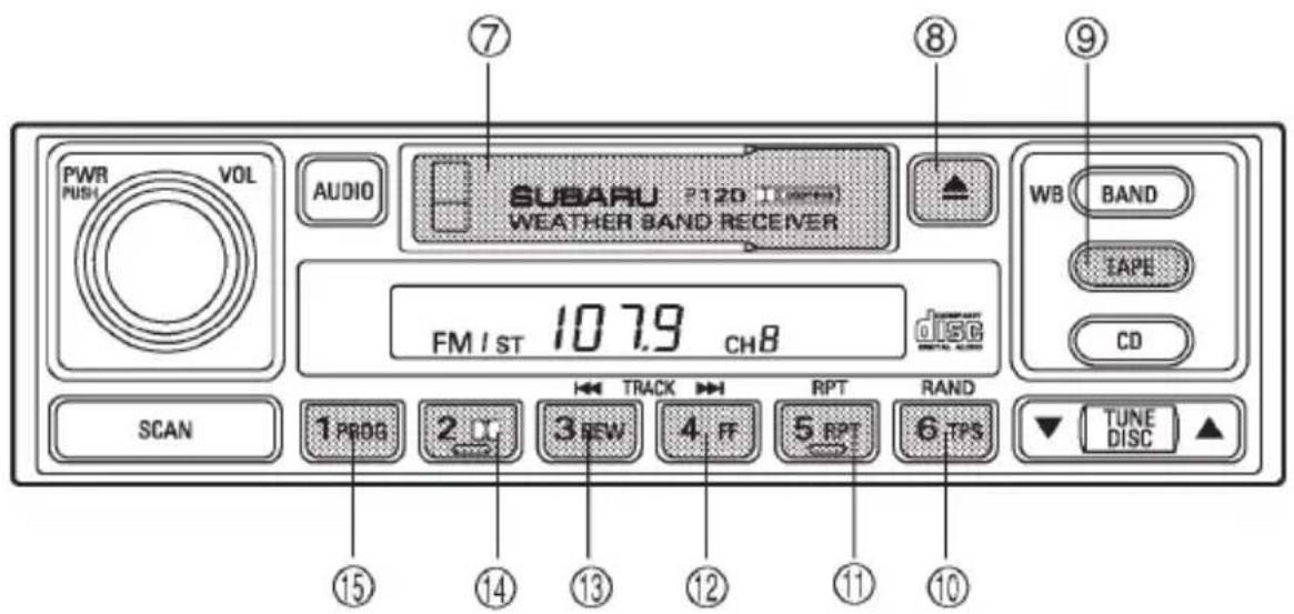
HB5041CB
⑦ Cassette slot
⑧ Eject button
⑨ TAPE button
⑩ TPS (Tape Program Search)
⑪ Repeat button
⑫ Fast-forward button
⑬ Rewind button
⑭ Dolby B NR button
⑮ Program button
NOTE
- Only use good quality cassettes (cassettes longer than C-90 are not recommended).
- Put cassettes back in their boxes immediately after use to protect them from dust and dirt and to prevent the tape from unwinding.
●Never expose cassettes to heat, direct sunlight or moisture. - Clean the tape head (once or twice a month) using a wet-type cleaning cassette.
▼Cassette slot
Insert a cassette with the exposed tape side facing to the right. After insertion, playback starts.
▼TAPE button
Press the "TAPE button" ⑨ when the cassette left in the cassette slot is to be played back again.
▼Tape travel indicators
These indicate the direction the cassette tape is moving.
▶ : Indicates that the top side of the cassette is being played back.
◀ : Indicates that the bottom side of the cassette is being played back.
▼ Program button (PROG)
When the program button ⑮ is pressed during playback, the tape travel indicators will switch and the player will begin playing back the opposite side of the tape. The same mechanism is automatically activated when the end of the tape is reached. This allows the opposite side of the tape to play, providing continuous playback.
▼Fast-forward button (FF)
To fast-forward the tape, press the "FF" button ⑫. To stop fast-forwarding, lightly press the "▲" ⑧ button.
▼Rewind button (REW)
To rewind the tape, press the “REW” button ⑬. To stop rewinding, lightly press the “▲” ⑧ button.
▼Eject button ( △ )
When “▲” button ⑧ is pressed, playback stops and the cassette tape is ejected.
The ejection function is also active when the ignition switch is in the "LOCK" position. Always make certain that you remove the cassette tape.
▼Tape program sensor button (TPS)
Blank skip
When the “TPS” button ⑩ is pressed, the “TPS” indicator will come on and the player will automatically skip any blank portion of 15 second or more and play the next program, even if it is on the other side. To cancel blank skip mode, press the “TPS” button again.
Blank search
Press “TPS” button ⑩ during playback to return to the beginning of the current selection or to skip to the beginning of the next selection.
To use this function, press the “TPS” button to turn on the “TPS” indicator. If the fast-forward button “FF” ⑫ is then pressed, the player advances the tape to the beginning of the next selection and starts playing it. If the rewind button “REW” ⑬ is pressed instead, the player rewinds the tape to the beginning of the current selection and starts replaying it. The “TPS” function may not operate properly under the following conditions:
- When the recording level is low.
- When there are long pauses in the middle of a selection.
- When the tape contains verbal material such as conversations.
- When the blanks between selections are shorter than five seconds.
- When there are no blanks between selections (live concerts, etc.).
▼Repeat (RPT)
Press the “RPT” button ⑪ while a song is playing to play the song repeatedly. The “RPT” indicator will come on and the song will be played continuously. To cancel the repeat mode, press the button again. Then the “RPT” indicator goes out, and normal playback mode is restored.
▼Dolby B NR button ( □□ )
Press the “☐☐” button ⑭ when playing tapes recorded using the Dolby NR system*. The “☐☐” indicator will light up and high-frequency noise on the tape will be reduced for clearer sound reproduction.
*Noise reduction system manufactured under license from Dolby Laboratories Licensing Corporation. “Dolby” and the double-D Symbol are trade marks of Dolby Laboratories Licensing Corporation.
CD player control (If optional CD player is connected)
An optional CD player can be connected to this audio unit. See your SUBARU dealer for more information. For procedures for loading and unloading CDs, refer to “CD player 1” in this chapter.
HB5041DB
⑯ CD button
⑰ RAND (Random) button
⑱ RPT (Repeat) button
⑲ Track selection buttons
⑳ SCAN button
▼To start playback
When CD is not in the CD player
Hold a disc with a finger in the center hole while gripping the edge of the disc, then insert it in to the slot (with the label side up) on the CD player and the player will automatically pull the disc into position.
After insertion, the CD player mode indicator "CD" will come on and playback will start.
When CD is in the CD player
Press the "CD" button ⑯. The "CD" indicator will come on, and the track number will appear on the display and the CD player will start playback.
NOTE
- If the “CD” button is pressed during a radio broadcast, the disc will interrupt the broadcast.
- After playback on the last song finishes, the player will automatically return to track 1 (the first song on the disc).
▼To select a song from its beginning
Briefly press the “▶▶▶” button ⑲ to skip to the beginning of the next track and briefly press the “◀◀◀” button to skip to the beginning of the current track.
▼Fast-forwarding and fast-reverse
Press the “▶▶▶” button ⑲ continuously for more than a half second to fast-forward the disc.
Press the “◀◀◀” button continuously for more than a half second to fast reverse the disc.
Release the button to stop fast forwarding or fast reverse.
Repeat
Press the “RPT” button ⑱ while a song is playing to play the song repeatedly. The “RPT” indicator will come on and the song will be played continuously. To cancel the repeat mode, press the button again. Then the “RPT” indicator goes out, and normal playback mode is restored.
▼Random playback
Press the “RAND” button ⑰ while a disc is being played back to play all songs on the disc in a random order. The “RAND” indicator will come on and all songs on the disc will be played in a random order.
To cancel the random mode, press the button again. Then the "RAND" indicator goes out, and normal playback mode is restored.
▼Scan (a convenient way to become familiar with a disc)
-
Press the "SCAN" button ⑳.
-
The display shows "SCAN" and the track number being scanned.
- You hear the first 10 seconds of each track.
- The operation is automatically cleared after playing all pro-
grams. Then, normal playback starts.
- Press the "SCAN" button again when you hear a track you like.
- Normal playback resumes.
▼To stop playback
To stop playback and switch over to the radio mode, press the "BAND" button. To stop playback and switch over to the cassette player mode, press the "TAPE" button.
CD changer control (If optional in dash CD changer is connected)
An optional CD changer can be connected to this audio unit. See your SUBARU dealer for more information. For procedures for loading and unloading CDs, refer to “In-dash 6 CD auto changer” in this chapter.
HB5041EB
②1 CD button
⑳ Disc up/down buttons
②3 RAND (Random) button
⑳ RPT (Repeat) button
⑲ Track selection buttons
②6 SCAN button
▼To start playback
Press the "CD" button ②1. The "CD" indicator will come on and the disc number will appear on the display and the CD changer will start playback.
NOTE
- If the “CD” button is pressed during a radio broadcast, the CD changer will interrupt the broadcast.
- At the end of the disc, playback automatically continues with the next disc.
●After playback on the last disc finishes, the player will automatically return to the first disc. - If you have loaded fewer than 6 discs, any missing disc is automatically skipped.
▼Selection of a desired disc
Briefly press the “▲” button ② to skip to the next disc and briefly press the “▼” button to skip to the previous disc.
▽ Operation with the in-dash CD changer unit
Press the desired “Disc select” button (numbered from 1 to 6) and the disc will begin to play.
▼To select a song from its beginning
Briefly press the “▶▶▶” button ^25 to skip to the beginning of the next track and briefly press the “◀◀◀” button to skip to the beginning of the current track.
▼Fast-forwarding and fast-reverse
Press the “▶▶▶” button ②5 continuously for more than a half second to fast-forward the disc.
Press the “◀◀◀” button continuously for more than a half second to fast reverse the disc.
Release the button to stop fast forwarding or fast reverse.
Repeat
Press the “RPT” button 24 while a song is playing to play the song repeatedly. The “RPT” indicator will come on and the song will be played continuously. To cancel the repeat mode, press the button again. Then the “RPT” indicator goes out, and normal playback mode is restored.
▼Random playback
Press the "RAND" button ② while a disc is being played back to play
all songs on the disc in a random order. The “RAND” indicator will come on and all songs on the disc will be played in a random order.
To cancel the random mode, press the button again. Then the "RAND" indicator goes out, and normal playback mode is restored.
▼Scan (a convenient way to become familiar with a disc)
-
Press the "SCAN" button ②6.
-
The display shows "SCAN" and the track number being scanned.
- You hear the first 10 seconds of each track.
-
The operation is automatically cleared after playing all programs. Then, normal playback starts.
-
Press the "SCAN" button again when you hear a track you like.
– Normal playback resumes.
▼To stop playback
To stop playback and switch over to the radio mode, press the "BAND" button. To stop playback and switch over to the cassette player mode, press the "TAPE" button.
Type C audio set (if equipped)
The radio will operate only when the ignition switch is in the “ACC” or “ON” position.
Radio operation
HB5042BB
① FM/AM selection button
② SCAN button
③ WB (weather band) button
④ Tuning buttons
⑤ Preset buttons
⑥ Fader/Balance selection button
⑦ Power switch, Volume control, Bass/Middle/Treble control and Fader/Balance control dial
⑧ AUDIO (audio mode) button
▼Power switch and volume/bass/treble/fader/balance control (PWR/VOL)
The dial ⑦ is used for both power (ON/OFF) and volume control. The radio is turned ON and OFF by pushing the dial and the volume is controlled by turning the dial.
This dial is used for bass/middle/treble controls when the “AUDIO” button ⑧ is in the depressed position. It is also used for fader/balance controls when the “FAD/BAL” button ⑥ is in the depressed position.
| Display | Control mode |  HB5036BA HB5036BA | |
| Turn counterclockwise Turn clockwise | |||
| BAS | Bass control | For less bass | For more bass |
| MId Middle | note control | For less middle note For more middle note | |
| TRE | Treble control | For less treble | For more treble |
| FAd Fader | control To increase | rear speaker volume and decrease front speaker volume | To increase front speaker volume and decrease rear speaker volume |
| BAL Balance | control To increase | ase left speaker volume and decrease right speaker volume | To increase right speaker volume and decrease left speaker volume |
| VOL | Volume control | For less volume | For more volume |
∇ Tone control
The volume control dial ⑦ normally function as volume control. The dial become a control for Bass, Middle note or Treble when you select the appropriate tone control mode.
Choose desired level for each mode by turning the volume control dial. The control function returns to volume control mode after about 5 seconds.
To change control modes: Each brief press of the "AUDIO" button ⑧ changes control modes in the following sequence starting from bass control mode. (When the radio is first turned on, the control mode is in the volume control.)
- CONTINUED -
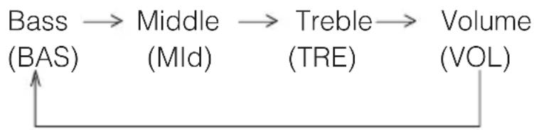
flowchart
graph LR
    A["Bass (BAS)"] --> B["Middle (MId)"]
    B --> C["Treble (TRE)"]
    C --> D["Volume (VOL)"]
∇ Fader and balance control
The volume control dial ⑦ normally function as volume control. The dial become the controls for Fader or Balance when you select the appropriate fader and balance control mode.
Choose desired setting for each mode by turning the volume control dial. The control function returns to volume control mode after about 5 seconds.
To change control modes: Each brief press of the “FAD/BAL” button ⑥ changes control modes in the following sequence starting from fader control mode. (When the radio is turned on, the control mode is in the volume control.)
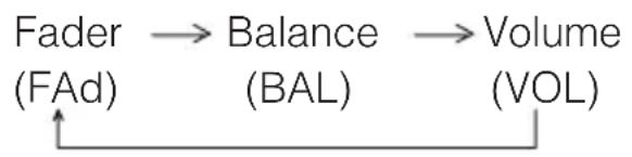
flowchart
graph LR
    A["Fader (FAd)"] --> B["Balance (BAL)"]
    B --> C["Volume (VOL)"]
▽ Display illumination dimness cancellation (BRIGHT)
The brightness of the radio display dims when the light switch is in the “ ≥ 0.0 ≤ ” or “ D ” positions. If this makes the display difficult to read, press the volume dial for more than two seconds to return the display to original brightness.
Subsequently pressing the volume dial again for more than two seconds or if you can safely do so, turning the light switch to the OFF position and back to the “☐” or “≡D” position makes the radio display dim again.
▼FM/AM selection button (FM/AM)
Push the “FM/AM” button ① when the radio is off to turn on the radio. Push the “FM/AM” button when the radio is on to select FM1, FM2 or AM reception. Each time this button is pressed, the band will change in the following order:
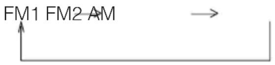
flowchart
graph TD
    A["FM1 FM2 AM"] --> B["→"]
The display indicates which one is currently selected.
▼Stereo indicator
The stereo indicator “ST” will come on when an FM stereo broadcast is received.
▼Weather band button (WB)
Push the “WB” button ③ when the radio is off to turn on the radio in the weather band.
Press the "WB" button when the radio is on to select the weather band.
▼ Manual tuning (TUNE)
▽ Manual tuning for AM and FM waveband
Push the tuning button ④ marked “▲” to increase the tuning frequency and press the tuning button marked “▼” to decrease it.
Each time the button is pressed, the frequency changes 10 KHz in the AM waveband and 0.2 MHz in the FM waveband.
Constant pressure on the button causes a continuous change in the frequency.
▼ Manual tuning for weather band
When weather band mode is selected, press the tuning button ④ marked “▲” to change the WB channel up and press the tuning button marked “▼” to change the WB channel down. Each time the button is pressed, the WB channel changes to the next channel. Constant pressure on the button causes a continuous change in the channel.
▼ Automatic tuning (SCAN)
Press the “SCAN” button ② to change the radio to the SCAN mode. In this mode, the radio scans through the radio band until a station is found. The radio will stop at the station for five seconds while displaying the frequency, after which scanning will continue until the entire
band has been scanned from the low end to the high end.
Press the “SCAN” button again to cancel the SCAN mode and to stop on any displayed frequency.
When the “SCAN” button is pressed for automatic tuning, stations are scanned in the direction of low frequencies to high frequencies only.
Automatic tuning may not function properly if the station reception is weakened by distance from the station or proximity to tall buildings and hills.
▼Selecting preset stations
Presetting a station with a preset button ⑤ allows you to select that station in a single operation. Up to six AM, FM1, FM2 and WB stations each may be preset.
▼How to preset stations
- Press the "FM/AM" selection button to select AM, FM1 or FM2 reception.
OR
Press the "WB" button ③ to select the weather band.
- Press the "SCAN" button ② or tune the radio manually until the desired station frequency is displayed.
- Press one of the preset buttons ⑤ for at least 1.5 seconds to store the frequency. The frequency of the station will flash once on the display at this time. If the button is pressed for less than 1.5 seconds, the preceding selection will remain in memory.
NOTE
If the connection between the radio and battery is broken for any reason such as vehicle maintenance or radio removal, all stations stored in the preset buttons are cleared. If this occurs, it is necessary to reset the preset buttons.
Cassette player operation
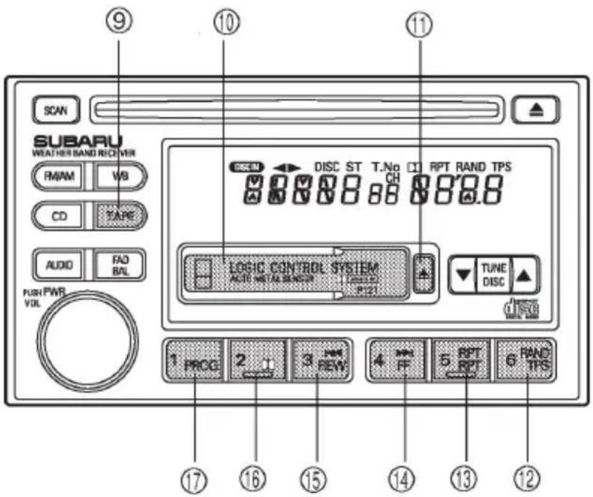
HB5042CB
⑨ TAPE (cassette player selection) button
⑩ Cassette slot
⑪ Eject button
⑫ TPS button
⑬ Repeat button
⑭ Fast forward button
⑮ Rewind button
⑯ Dolby B NR button
⑰ Program switching button
NOTE
- Only use good quality cassettes (cassettes longer than C-90 are not recommended).
- Put cassettes back in their boxes immediately after use to protect them from dust and dirt and to prevent the tape from unwinding.
●Never expose cassettes to heat, direct sunlight or moisture. - Clean the tape head (once or twice a month) using a wet-type cleaning cassette.
▼To play back a cassette tape
When cassette tape is not in the player
When a cassette is partially inserted, it is automatically drawn in and starts tape playback.
- CONTINUED -
When cassette tape is in the player
When the “TAPE” button ⑨ is pressed, the display will show “PLAY” and the player will start playback.
▼Tape travel indicators
These indicate the direction the cassette tape is moving.
▶ : indicates that the top side of the cassette is being played back.
◀ : indicates that the bottom side of the cassette is being played back.
▼ Program switching button (PROG)
When the program switching button “PROG” ⑰ is pressed during playback, the tape travel indicators will switch and the player will begin playing back the opposite side of the tape. The same mechanism is automatically activated when the end of the tape is reached. This allows the opposite side of the tape to play, providing continuous playback.
▼ Fast-forward button (FF)
To fast-forward the tape, press the "FF" button ⑭. The display will show "FF". To stop fast-forwarding, press the "FF" or "TAPE" ⑨ button.
▼Rewind button (REW)
To rewind the tape, press the “REW” button ⑮. The display will indicate “REW”. To stop rewinding, press the “REW” or “TAPE” ⑨ button.
▼Eject button ( ▲ )
When “▲” button ⑪ is pressed, play back stops and the cassette tape is ejected.
The ejection function also operates when the ignition switch is in the "LOCK" position. Always make certain that you remove the cassette tape.
▼Tape program sensor button (TPS)
Blank skip
When the “TPS” button ⑫ is pressed, the “TPS” indicator will come on and the player will automatically skip any blank portion of 15 second or more and play the next program, even if it is on the other side. To cancel blank skip mode, press the “TPS” button again.
Blank search
Press “TPS” button ⑫ during playback to return to the beginning of the current selection or to skip to the beginning of the next selection. To use this function, press the “TPS” button to turn on the “TPS” indicator. If the fast-forward button “FF” ⑭ is then pressed, the player advances the tape to the beginning of the next selection and starts playing it. If the rewind button “REW” ⑮ is pressed instead, the player rewinds the tape to the beginning of the current selection and starts replaying it. The “TPS” function may not operate properly under the following conditions:
- When the recording level is low.
- When there are long pauses in the middle of a selection.
- When the tape contains verbal material such as conversations.
- When the blanks between selections are shorter than five seconds.
- When there are no blanks between selections (live concerts, etc.).
▼Repeat button (RPT)
Push the “RPT” button ^13 to repeat the piece of music being listened to. To use this function, push the “RPT” button while the piece you want to hear again is being played. “RPT” will be indicated on the display. When the selection ends, the cassette player automatically re-winds to the beginning of the piece and the selection begins again. To cancel the repeat function, push the “RPT” button again. Until the repeat function is cancelled, the same piece of music will be repeated indefinitely. The “RPT” function may not operate properly under the following conditions:
- When the recording level is low.
- When there are long pauses in the middle of a selection.
- When the tape contains verbal material such as conversations.
- When the blanks between selections are shorter than five seconds.
- When there are no blanks between selections (live concerts, etc).
▼Dolby B NR button ( □□ )
Press “☐” button ⑯ when playing tapes recorded using the Dolby NR system*. The “☐” indicator will light up and high-frequency noise on the tape will be reduced for clearer sound reproduction.
* Noise reduction system manufactured under license from Dolby Laboratories Licensing Corporation. “Dolby” and the double-D Symbol are trade marks of Dolby Laboratories Licensing Corporation.
▼Auto metal sensor
The cassette player automatically adjusts for metal or CrO_2 tape.
Compact disc player operation
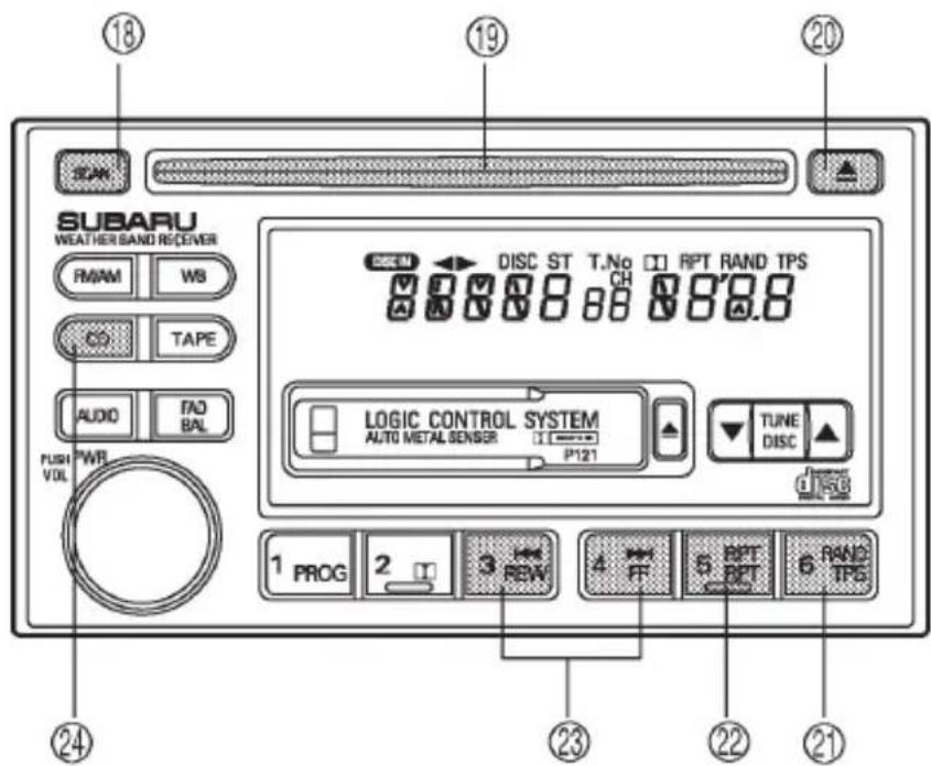
HB5042DB
⑱ SCAN button
⑲ Disc slot
⑳ Eject button
②1 Random button
⑳ Repeat button
②3 Track selection buttons
⑳ CD (CD player selection)
button
▼To play back a compact disc
When CD is not in the player
Hold a disc with a finger in the center hole while gripping the edge of the disc, then insert it in to the slot (with the label side up) and the player will automatically pull the disc into position.
A single CD (8 cm/3 inch CD) may also be used without any adapter.
After insertion, the DISC indicator “DISC” will come on and “CD” will appear on the display and the player will start playback.
NOTE
- Make sure to always insert a disc with the label side up. If a disc is inserted with the label side down, it might be ejected or the player might shut off.
●After the last song finishes, the player will automatically return to track 1 (the first song on the disc).
When CD is in the player
Press the “CD” button 24 . The display will show “CD” and the player will start playback.
NOTE
After the last song finishes, playback will automatically return to track 1 (the first song on the disc).
▼To select a song from its beginning
▽ Forward direction
Briefly press the “▶▶▶” button ②3 to skip to the beginning of the next track. Each time the button is pressed, the indicated track number will increase.
Backward direction
Briefly press the “◀◀◀” button ②3 to skip to the beginning of the current track. Each time the button is pressed, the indicated truck number will decrease.
▼Fast forwarding and fast reverse
∇ Fast forwarding
Press the “▶▶” button ②3 continuously for more than 0.5 second to fast forward the disc.
Release the button to stop fast forwarding.
∇ Fast reverse
Press the “◀◀◀” button ②3 continuously for more than 0.5 second to fast reverse the disc.
Release the button to stop fast reverse.
- CONTINUED -
▼Repeat playback
Press the “RPT” button ② while a song is playing to play the song repeatedly. The “RPT” indicator will come on and the song will be played continuously. To cancel the repeat mode, press the button again. Then the “RPT” indicator goes out, and normal playback mode is restored.
▼Random playback
Press the “RAND” button ② while a disc is being played back to play all songs on the disc in a random order. The “RAND” indicator will come on and all songs on the disc will be played in a random order. To cancel the random mode, press the button again. Then the “RAND” indicator goes out, and normal playback mode is restored.
Scan
When the “SCAN” button ^18 is pressed while the disc is being played back, you can hear the first 10 seconds of each track to seach for the desired program. To continue listening to the program, press the “SCAN” button again. After all tracks on the disc have been scanned, normal playback mode is restored.
▼To eject a disc from the player
When a disc is being played back or when a disc is in the player, press the eject button “▲” ⑳. The disc will be ejected.
The disc may be removed even when the ignition switch is in the "LOCK" position.
NOTE
Avoid driving the vehicle with a CD sticking out, because vibration might make it fall out.
CD changer control (If optional in-dash CD changer is connected)
An optional CD changer can be connected to this audio unit. See your SUBARU dealer for more information. For procedures for loading and unloading CDs, refer to “In-dash 6 CD auto changer” in this chapter.
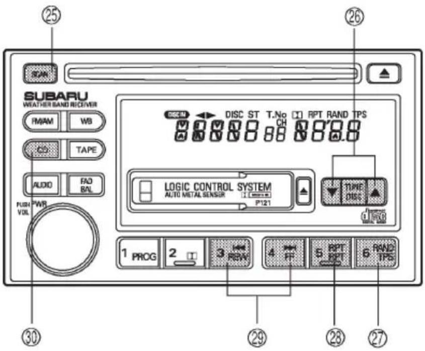
HB5042EB
⑳ SCAN button
②6 Disc up/down button
⑳ Random button
⑳ Repeat button
⑲ Track selection buttons
③0 CD button
▼To start playback
When the "CD" button ③0 is pressed, the CD changer will start play-back. The display shows the current disc number, track number and the elapsed time during playback.
NOTE
- If a disc is in the player, the “CD” button is used to change from CD player operation to CD changer operation. Each time the “CD” button is pressed, the operating mode will change alternately.
- At the end of the disc, the player automatically continues with the next disc.
●After playback on the last disc finishes, playback will automatically return to the first disc. - If you have loaded fewer than 6 discs, any missing disc is automatically skipped.
▼Selection of a desired disc
Briefly press the “▲” button ② to skip to the next disc and briefly press the “▼” button to skip to the previous disc.
▽ Operation with the in-dash CD changer unit
Press the desired “Disc select” button (numbered from 1 to 6) and the disc will begin to play.
▼To select the desired disc
Press either the disc up button “DISC ▲” ②6 or disc down button “DISC ▼” to select the desired disc. Each time the “DISC ▲” ②6 button is pressed, the indicated disc number will increase. Each time the “DISC ▼” button is pressed, the indicated disc number will decrease. Constant pressure on these buttons causes a continuous change in the disc number.
▼To select a song from its beginning
▽ Forward direction
Briefly press the “▶▶▶” button ⑲ to skip to the beginning of the next track. Each time the button is pressed, the indicated track number will increase.
▽ Backward direction
Briefly press the “◀◀◀” button ⑲ to skip to the beginning of the current track. Each time the button is pressed, the indicated track number will decrease.
▼Fast forwarding and fast reverse
∇ Fast forwarding
Press the “▶▶▶” button ⑲ continuously for more than 0.5 second to fast forward the disc.
Release the button to stop fast forwarding.
If you continue fast forwarding to the end of the disc, the CD changer will automatically stop fast forwarding and start playback beginning with the first track on the current disc.
∇ Fast reverse
Press the “◀◀◀” button ⑲ continuously for more than 0.5 second to fast reverse the disc.
Release the button to stop fast reverse.
If you continue fast reverse to the beginning of the disc, the CD changer will automatically stop fast reverse and start playback beginning with the first track on the current disc.
▼Repeat playback
Press the “RPT” button ⑳ while a song is playing to play the song repeatedly. The “RPT” indicator will come on and the song will be played continuously. To cancel the repeat mode, press the button again. Then the “RPT” indicator goes out, and normal playback mode is restored.
▼Random playback
Press the “RAND” button ②7 while a disc is being played back to play all songs on the disc in a random order. The “RAND” indicator will come on and all songs on the disc will be played in a random order.
To cancel the random mode, press the button again. Then the "RAND" indicator goes out, and normal playback mode is restored.
Scan
When the “SCAN” button 25 is pressed while the disc is being played back, you can hear the first 10 seconds of each track to search for the desired program. To continue listening to the program, press the “SCAN” button again. After all tracks on the disc have been scanned, normal playback mode is restored.
Type D and E audio set (if equipped)
Type D: Without weather band
Type E: With weather band
The audio set will operate only when the ignition switch is in the "ACC" or "ON" position.
Radio operation
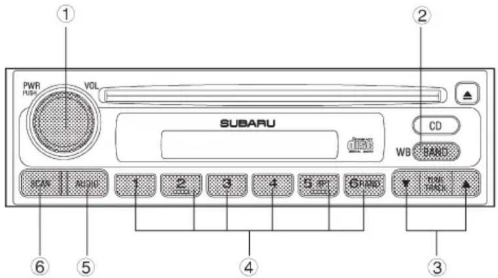
HB5052BB
① Power switch/Volume, Tone, Balance, Fader control dial
④ Preset buttons
② BAND button
⑤ AUDIO button
③ Tuning buttons
⑥ SCAN button
▼Power switch and volume/bass/treble/fader/balance control
▼ Power switch and volume control (PWR/VOL)
The dial ① is used for both power (ON/OFF) and volume control. The radio is turned ON and OFF by pushing the dial and the volume is controlled by turning the dial.
∇ Tone and balance control (AUDIO)
The volume control dial ① normally functions as a volume control. This dial becomes a control for Bass, Treble, Fader or Balance when you select the appropriate tone and balance control mode.
Choose desired volume level for each mode by turning the volume control dial. The control function returns to volume control mode after about 5 seconds.
To change control modes: Each brief press of the “AUDIO” button ⑤ changes control modes in the following sequence starting from volume control mode. (When the radio is first turned on, the control mode is in the volume control.)
Volume Bass Treble Balance Fader (VOL) (BAS) (TRE) (BAL) (FAD)


The “AUDIO” button ⑤ is used for selecting the following control modes:
| Display | Control mode |  HB5036BA HB5036BA | |
| Turn counterclockwise Turn clockwise | |||
| BAS | Bass control | For less bass | For more bass |
| TRE | Treble control | For less treble | For more treble |
| FAD | Fader control | To increase rear speaker volume and decrease front speaker volume | To increase front speaker volume and decrease rear speaker volume |
| BAL | Balance control | To increase left speaker volume and decrease right speaker volume | To increase right speaker volume and decrease left speaker volume |
| VOL | Volume control | For less volume | For more volume |
▼Waveband selection
▽ FM/AM selection
Push the “BAND” button ② to select FM1, FM2 or AM reception. The display indicates which one is currently selected.
▽ FM/AM/Weather band selection
Push the “BAND” button ② to select FM1, FM2, AM or Weather band (WB) reception. The display indicates which is currently selected.
▼Stereo indicator
The stereo indicator “ST” will come on when an FM stereo broadcast is received.
▼Tuning (TUNE)
▽ Manual tuning (TUNE)
Press the tuning button ③ marked “▲” to increase the tuning frequency and press the tuning button marked “▼” to decrease it.
Each time the button is pressed, the frequency interval can be changed between 10 kHz in the AM mode and 0.2 MHz in the FM mode.
Constant pressure on the button causes a continuous change in the frequency.
▼ Manual tuning for weather band
When weather band mode is selected, press the tuning button ③ marked “▲” to change the WB channel up and press the tuning button marked “▼” to change the WB channel down. Each time the button is pressed, the WB channel changes to the next channel. Constant pressure on the button causes a continuous change in the frequency.
▼ Automatic tuning (SCAN)
Press the “SCAN” button ⑥ to change the radio to the SCAN mode. In this mode, the radio scans through the radio band until a station is found. The radio will stop at the station for five seconds while displaying the frequency, after which scanning will continue until the entire band has been scanned from the low end to the high end.
Press the “SCAN” button again to cancel the SCAN mode and to stop on any displayed frequency.
When the “SCAN” button is pressed for automatic tuning, stations are scanned in the direction of low frequencies to high frequencies only.
Automatic tuning may not function properly if the station reception is weakened by distance from the station or proximity to tall buildings and hills.
▼Selecting preset stations
Presetting a station with a “preset button” ④ allows you to select that station in a single operation. Up to six WB (if equipped), AM, FM1 and FM2 stations each may be preset.
▼How to preset stations
- Press the “BAND” button ② to select FM1, FM2, AM or WB (if equipped) reception.
- Press the “SCAN” button or tune the radio manually until the desired station frequency is displayed.
- Press one of the preset buttons for more than 2 seconds to store the frequency. At this time, there will momentarily be no sound from the radio. If the button is pressed for less than 2 seconds, the preceding selection will remain in memory.
NOTE
If the connection between the radio and battery is broken for any reason such as vehicle maintenance or radio removal, all stations stored in the preset buttons are cleared. If this occurs, it is necessary to reset the preset buttons.
Compact disc player operation
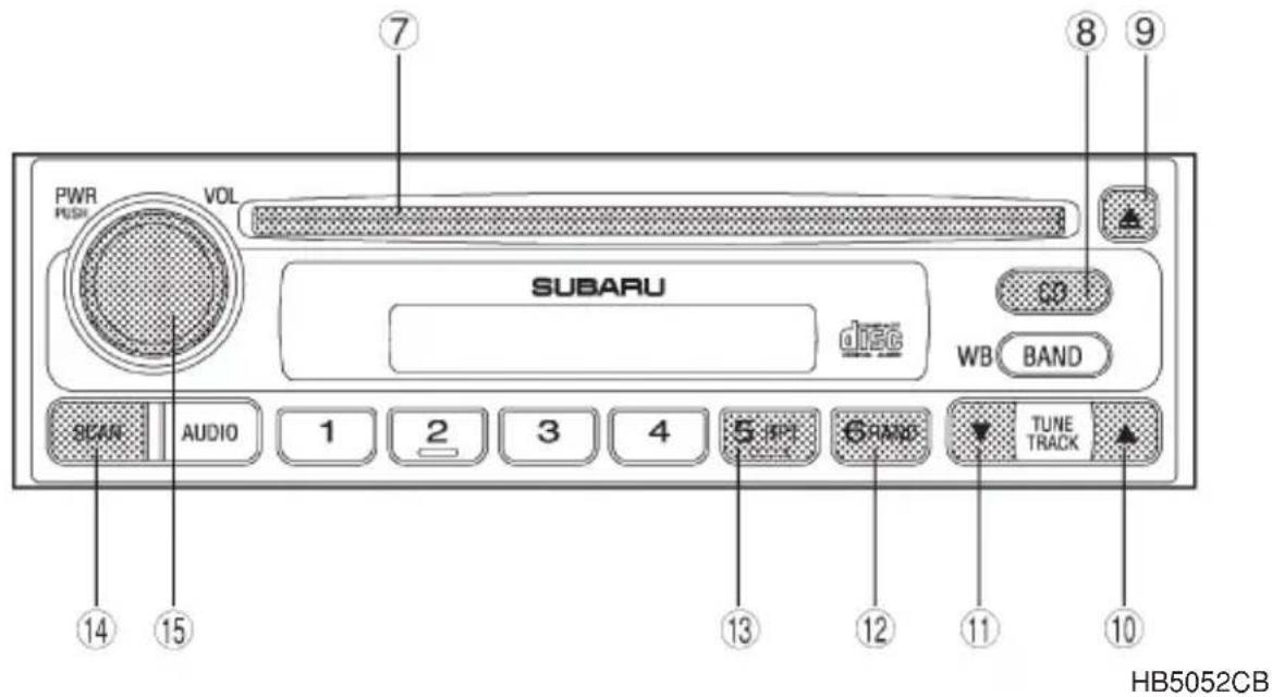
⑦ Disc slot
⑧ CD button
⑨ Eject button
⑩ Fast forward and track up button
⑪ Fast reverse and track down button
⑫ Random button
⑬ Repeat button
⑭ Scan button
⑮ PWR (power) switch
▼To playback a compact disc
When CD is not in the player
Hold a disc with a finger in the center hole while gripping the edge of the disc, then insert it in to the slot (with the label side up) and the player will automatically pull the disc into position.
A 8 cm/3 inch CD may also be used without any adapter.
NOTE
- DO NOT INSERT TWO DISCS INTO THE DISC INSERTION SLOT AT A TIME.
- Be sure to always insert a disc with the label side up. If a disc is inserted with the label side down, it might be ejected or the player might shut off.
●After the last song finishes, the player will automatically return to track 1 (the first song on the disc).
When CD is in the player
When the "CD" button ⑧ is pressed, the player will start playback.
NOTE
After the last song finishes, the player will automatically return to track 1 (the first song on the disc).
▼To stop playback of a CD
When the “PWR” button ^15 is pressed during playback of a CD, the CD stops playing temporarily. To let the CD resume playing, press the button again.
▼To select a song from its beginning
▽ Forward direction
Briefly press the “▲” button ⑩ to skip to the beginning of the next track. Each time the button is pressed, the indicated track number will increase.
Backward direction
Briefly press the “▼” button ⑪ to skip to the beginning of the current track. Each time the button is pressed, the indicated truck number will decrease.
▼Fast forwarding and fast reverse
∇ Fast forward
Press the “▲” button ⑩ continuously for more than 0.5 second to fast forward the disc.
Release the button to stop fast forwarding.
∇ Fast reverse
Press the “▼” button ⑪ continuously for more than 0.5 second to fast reverse the disc.
Release the button to stop fast reverse.
▼Repeat playback
Use this to play a certain track repeatedly. During playback, press the "RPT" button ⑬ and release it in less than 2 seconds. The "RPT" indicator will come on and the song will be played continuously. To can-
cel the repeat mode, press the button again. Then the "RPT" indicator goes out, and normal playback mode is restored.
▼Random playback
Use this to play the tracks on the disc in random order. During playback, press the “RDM” button ⑫ and hold it in for more than 2 seconds. The “RDM” indicator will come on and all songs on the disc will be played in a random order.
To cancel the random mode, press the button again. Then the “RDM” indicator goes out, and normal playback mode is restored.
Scan
Press the “SCAN” button ^14 and release it in less than 2 seconds, and you can hear the first 10 seconds of each track to seach for the desired program. To continue listening to the program, press the “SCAN” button again. After all tracks on the disc has been scanned, normal playback mode is restored.
▼To eject a disc from the player
When a disc is being played back or when a disc is in the player, press the eject button “▲” ⑨. The disc will be ejected.
The disc may be removed even when the ignition switch is in the "LOCK" position.
NOTE
- Avoid driving the vehicle with a CD sticking out, because vibration might make it fall out.
- To protect the disc, the disc is automatically loaded if it is left in the ejected position for more than approximately 15 seconds (Auto Reload). In this case, the disc is not played.
CD changer control (If optional in dash CD changer is connected)
An optional CD changer can be connected to this audio unit. See your SUBARU dealer for more information. For procedures for loading and unloading CDs, refer to “In-dash 6 CD auto changer” in this chapter.
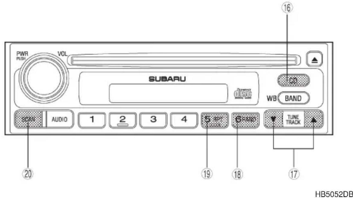
⑯ CD button
⑲ RPT (Repeat) button
⑰ Track selection buttons
⑳ SCAN button
⑱ RAND (Random) button
▼To start playback
Press the "CD" button ⑯. The "CD" indicator will come on and the disc number will appear on the display and the CD changer will start playback.
NOTE
- If the “CD” button is pressed during a radio broadcast, the CD changer will interrupt the broadcast.
- At the end of the disc, playback automatically continues with the next disc.
●After playback on the last disc finishes, the player will automatically return to the first disc. - If you have loaded fewer than 6 discs, any missing disc is automatically skipped.
- CONTINUED -
▼Selection of a desired disc
Discs cannot be selected using the main audio unit. To select a disc, press one of the “Disc select” buttons (these are numbered from 1 to 6) on the CD changer unit. The disc will begin to play.
▼To select a song from its beginning
Briefly press the “▲” button ⑰ to skip to the beginning of the next track and briefly press the “▼” button to skip to the beginning of the current track.
▼Fast-forwarding and fast-reverse
Press the “▲” button ⑰ continuously for more than a half second to fast-forward the disc.
Press the “▼” button continuously for more than a half second to fast reverse the disc.
Release the button to stop fast forwarding or fast reverse.
Repeat
Press the “RPT” button ⑲ while a song is playing to play the song repeatedly. The “RPT” indicator will come on and the song will be played continuously. To cancel the repeat mode, press the button again. Then the “RPT” indicator goes out, and normal playback mode is restored.
▼Random playback
Press the “RAND” button ^18 while a disc is being played back to play all songs on the disc in a random order. The “RAND” indicator will come on and all songs on the disc will be played in a random order.
To cancel the random mode, press the button again. Then the "RAND" indicator goes out, and normal playback mode is restored.
▼Scan (a convenient way to become familiar with a disc)
-
Press the "SCAN" button ⑳.
-
The display shows “SCAN” and the track number being scanned.
- You hear the first 10 seconds of each track.
-
The operation is automatically cleared after playing all programs. Then, normal playback starts.
-
Press the "SCAN" button again when you hear a track you like.
- Normal playback resumes.
▼To stop playback
To stop playback and switch over to the radio mode, press the "BAND" button.
Type F audio set (if equipped)
The audio set will operate only when the ignition switch is in the “ACC” or “ON” positions.
Radio operation
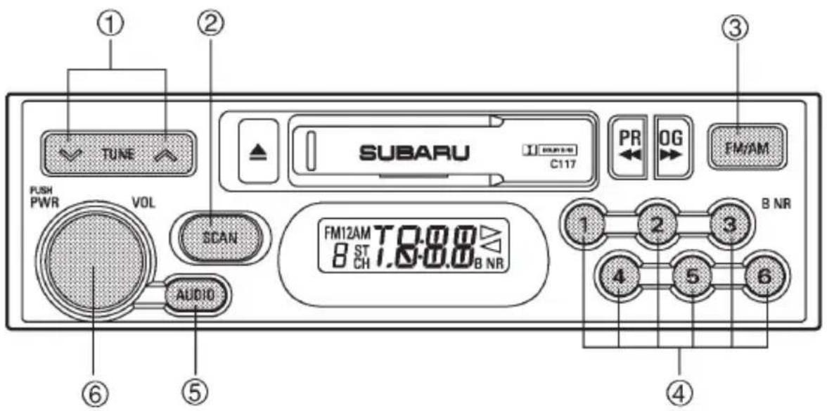
HB5043BB
① Tuning buttons
② SCAN button
③ FM/AM selection button
④ Preset buttons
⑤ AUDIO button
⑥ Power switch and volume control
▼Power switch and volume/bass/treble/fader/balance control
▼ Power switch and volume control (PWR/VOL)
The dial ⑥ is used for both power (on/off) and volume control. The radio is turned on and off by pushing the dial and the volume is controlled by turning the dial.
▼Tone and balance control
The volume control dial ⑥ normally functions as a volume control. This dial becomes a control for Bass, Treble, Fader or Balance when you select the appropriate tone and balance control mode.
Choose desired volume level for each mode by turning the volume control dial. The control function returns to volume control mode after about 5 seconds.
To change control modes: Each brief press of the “AUDIO” button ⑤ changes control modes in the following sequence starting from volume control mode. (When the radio is first turned on, the control mode is in the volume control.)

flowchart
graph TD
    A["Volume Bass Treble Fader Balance (VOL) (BAS) (TRE) (FAD) (BAL)"] --> B["→"]
    B --> C["→"]
The “AUDIO” button ⑤ is used for selecting the following control modes:
| Display | Control mode |  HB5036BA HB5036BA | |
| Turn counterclockwise Turn clockwise | |||
| BAS | Bass control | For less bass | For more bass |
| TRE | Treble control | For less treble | For more treble |
| FAD | Fader control | To increase rear speaker volume and decrease front speaker volume | To increase front speaker volume and decrease rear speaker volume |
| BAL | Balance control | To increase left speaker volume and decrease right speaker volume | To increase right speaker volume and decrease left speaker volume |
| VOL | Volume control | For less volume | For more volume |
▼FM/AM selection button (FM/AM)
Push the “FM/AM” button ③ when the radio is on to select FM1, FM2 or AM reception. Each time this button is pressed, the band will change in the following order:
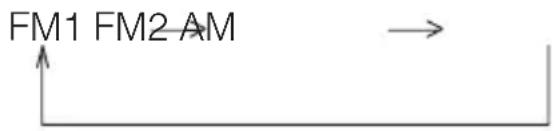
flowchart
graph TD
    A["FM1 FM2 AM"] --> B["→"]
The display indicates which one is currently selected.
▼Stereo indicator
The stereo indicator “ST” will come on when an FM stereo broadcast is received.
▼Manual tuning (TUNING)
Press the tuning button ① marked “∧” to increase the tuning frequency and press the tuning button marked “∨” to decrease it.
Each time the button is pressed, the frequency changes 10 kHz in the AM mode and 0.2 MHz in the FM mode.
Constant pressure on the button causes a continuous change in the frequency.
▼ Automatic tuning (SCAN)
Press the “SCAN” button ② to change the radio to the SCAN mode. In this mode, the radio scans through the radio band until a station is found. The radio will stop at the station for five seconds while displaying the frequency, after which scanning will continue until the entire band has been scanned from the low end to the high end.
Press the “SCAN” button again to cancel the SCAN mode and to stop on any displayed frequency.
When the “SCAN” button is pressed for automatic tuning, stations are scanned in the direction of low frequencies to high frequencies only.
Automatic tuning may not function properly if the station reception is weakened by distance from the station or proximity to tall buildings and hills.
▼Selecting preset stations
Presetting a station with a preset button ④ allows you to select that station in a single operation. Up to six AM, FM1 and FM2 stations each may be preset.
▼How to preset stations
- Press the "FM/AM" selection button ③ to select FM1, FM2 or AM reception.
- Press the "SCAN" button ② or tune the radio manually until the desired station frequency is displayed.
- Press one of the preset buttons ④ for at least two seconds to store the frequency. The frequency of the station will flash once on the display at this time. If the button is pressed for less than two seconds, the preceding selection will remain in memory.
NOTE
If the connection between the radio and battery is broken for any reason such as vehicle maintenance or radio removal, all stations stored in the preset buttons are cleared. If this occurs, it is necessary to reset the preset buttons.
Cassette player operation
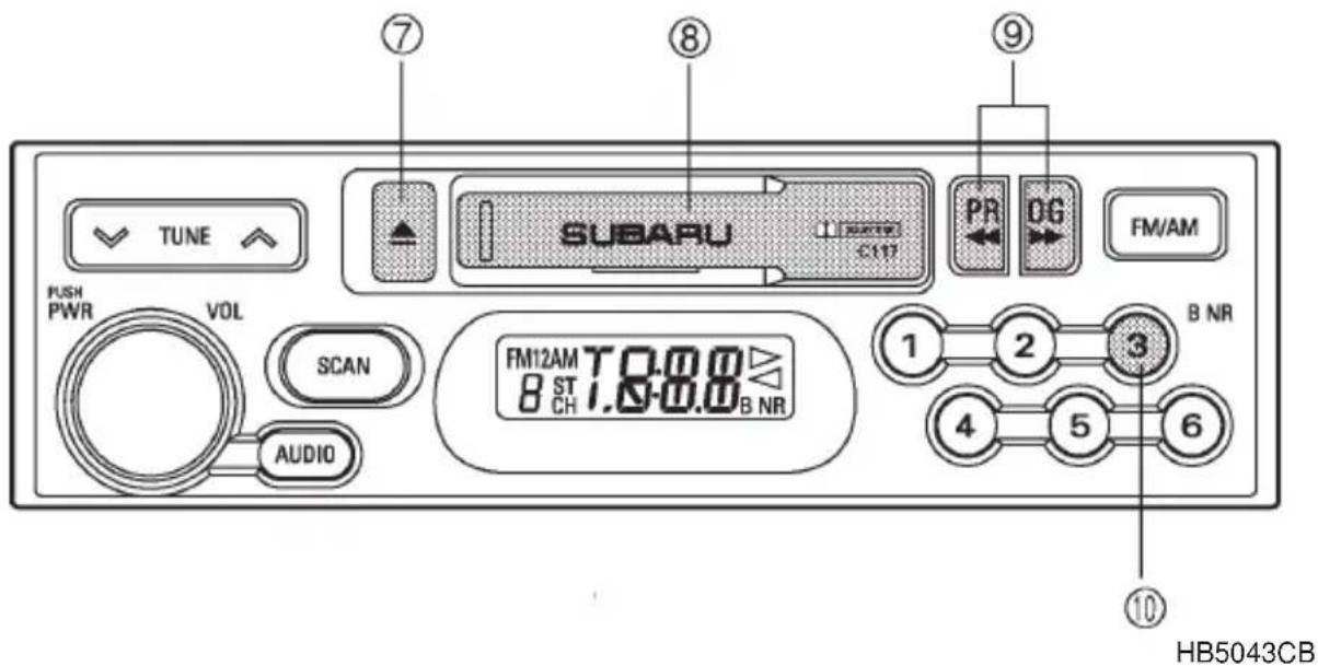
⑦ Eject button
⑧ Cassette slot
⑨ Fast-forward/Rewind button (Program switching buttons)
⑩ Dolby B NR button
NOTE
- Only use good quality cassettes (cassettes longer than C-90 are not recommended).
- Put cassettes back in their boxes immediately after use to protect them from dust and dirt and to prevent the tape from unwinding.
●Never expose cassettes to heat, direct sunlight or moisture. - Clean the tape head (once or twice a month) using a wet-type cleaning cassette.
▼Cassette slot
Insert a cassette with the exposed tape side facing to the right. After inserting, playback starts.
▼Tape travel indicators
The tape travel indicators indicate the direction the cassette tape is moving.
▶ : Indicates that the top side of the cassette is being played back.
◀ : Indicates that the bottom side of the cassette is being played back.
▼Program switching buttons
When the program switching buttons “◀◀” and “▶”⑨, are pressed at the same time during playback, the tape travel indicators will switch and the player will begin playing back the opposite side of the tape. The same mechanism is automatically activated when the end of the tape is reached. This allows the opposite side of the tape to play, providing continuous playback.
▼Fast-forward button
To fast-forward the tape, press the “◀◀” or “▶▶” button ⑨ in the same direction as the tape travel indicator. To stop fast-forwarding, lightly press the opposite side of the “◀◀” or “▶” button.
▼Rewind button
To rewind the tape, press the “◀◀” or “▶▶” button ⑨ in the direction opposite to the tape travel indicator. To stop rewinding, lightly press the opposite side of the “◀◀” or “▶▶” button.
▼Eject button ( ▲ )
When the “▲” button ⑦ is pressed, playback stops and the cassette tape is ejected.
Before the ignition switch is turned to the “OFF” position, eject the tape from the player. Always make certain that you remove the cassette tape.
▼Dolby BNR button (BNR)
Press “BNR” button ⑩ when playing tapes recorded using the Dolby NR system*. The “BNR” indicator will light up and high-frequency noise on the tape will be reduced for clearer sound reproduction.
* Noise reduction system manufactured under license from Dolby Laboratories Licensing Corporation. “Dolby” and the double-D Symbol are trade marks of Dolby Laboratories Licensing Corporation.
CD player operation (if optional CD player is connected)
An optional CD player can be connected to this audio unit. See your SUBARU dealer for more information. For CD player operation procedures, refer to “CD player 2” in this chapter.
McIntosh audio set (if equipped)
The audio set will operate only when the ignition switch is in the “ACC” or “ON” positions.

CAUTION
The power amplifier for this audio set is mounted under the front passenger's seat. The amplifier will become hot if the audio continues to operate.
Never touch the amplifier. Doing so could cause burns.
Radio operation
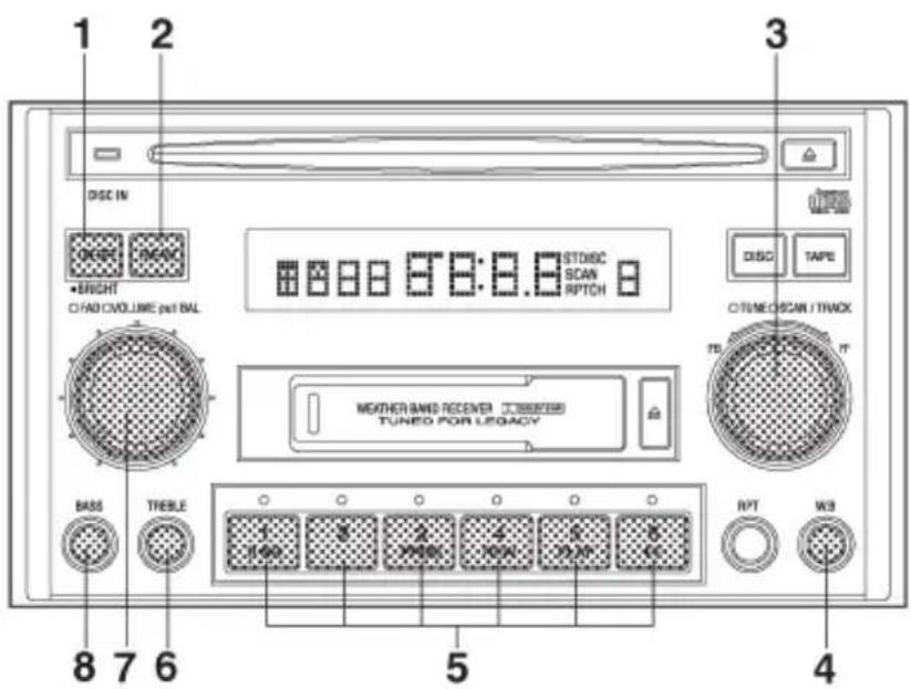
HB5053BB
① POWER ON/OFF/BRIGHT button
② FM/AM selection button
③ Tuning/FF·FB dial
④ Weather band button
⑤ Preset buttons
⑥ Treble sound control knob
⑦ Volume and fader/balance control dial
⑧ Bass sound control knob
▼ON-OFF switch
The audio system can be turned on by pressing the POWER button when the ignition key is in the ACC or ON position. Pressing the POWER button once again will turn off the power. In addition, the following six operations will also result in the audio system's power being turned on:
- Pressing the FM/AM selector button
- Pressing the Tape Mode selector button
- Pressing the Disc Mode selector button (provided that a CD has been inserted or that a CD multi-changer is connected to the system)
- Inserting a cassette
- Inserting a CD
- Pressing the Traffic information button
Volume control
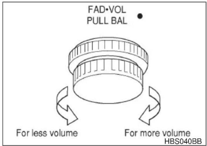
Turn clockwise to increase the audio-system volume.
Turn counterclockwise to reduce the audio-system volume.
▼Tone control
Bass and treble adjustments are made using separate knobs. To make an adjustment, press the knob to make it pop out then turn the knob as desired. Then push the knob back in.
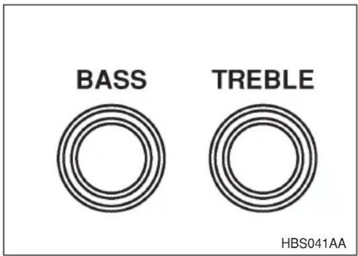
BASS control
The bass control adjusts the level of low pitch sounds. The bass is adjusted by turning the knob from left to right in this condition.
Turn clockwise to increase the level of bass tones.
Turn counterclockwise to reduce the level of bass tones.
TREBLE control
The treble control adjusts the level of high pitch sounds. The treble is adjusted by turning the knob from left to right in this condition.
Turn clockwise to increase the level of treble tones.
Turn counterclockwise to reduce the level of treble tones.
▼Balance control
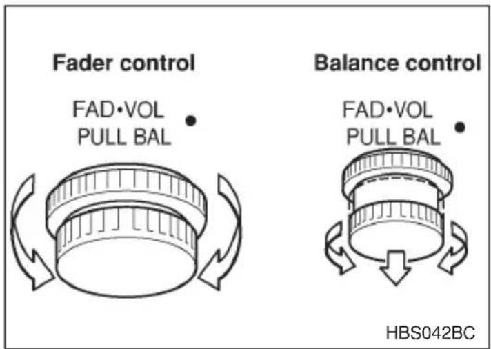
▼ FADER control
The balance control adjusts the volume balance between the front and rear speakers.
The balance is adjusted by turning the knob from left to right in this condition.
Turn clockwise to increase the relative sound volume in the front of the vehicle.
Turn counterclockwise to increase the relative sound volume in the rear of the vehicle.
▼ BALANCE control
The balance control adjusts the volume balance between the left and right speakers. Pull the knob out until it stops. The balance is adjusted by turning the knob from left to right in this condition.
Turn clockwise to make the sound louder on the right of the vehicle.
Turn counterclockwise to make the sound louder on the left of the vehicle.
▽ Display illumination dimness cancellation (BRIGHT)
The brightness of the radio display dims when the light switch is in the “ ≥slant 0.0 ≤slant ” or “ D ” positions. If this makes the display difficult to read, press the POWER ON/OFF button for more than two seconds to return the display to original brightness.
Subsequently pressing the POWER ON/OFF button again for more than two seconds or if you can safely do so, turning the light switch to the OFF position and back to the “☐” or “≡D” position makes the radio display dim again.
▼FM/AM selection button
Press the FM/AM selector button to choose either FM or AM broadcasts. The display will show FM or AM accordingly.
Use the tuning dial to select the station to which you wish to listen.
▼Manual tuning
Turn the tuning dial's outer tuner to increase or decrease the reception frequency in individual steps.
FM band: 0.2 MHz steps
AM band: 10 kHz steps
▼Seek tuning (SEEK)
If the Tuning dial's outer tuner is turned for longer than half of a second, the radio will begin to automatically search for receivable frequencies and will stop at the first one found. This function may not be available, however, when radio signals are weak. In such a situation, perform manual tuning to select the desired station.
▼Scan tuning (SCAN)
Turn the tuning dial inner tuner to change the radio to the SCAN mode. In this mode, the radio scans through the radio band until a station is found. The radio will stop at the station for five seconds while displaying the frequency, after which scanning will continue until the entire band has been scanned.
Turn the tuning dial's inner tuner again to cancel the SCAN mode and to stop on any displayed frequency.
Scan tuning may not function properly if the station reception is weakened by distance from the station or proximity to tall buildings and hills.
▼ Preset tuning
Press any one of the preset buttons to select the corresponding, previously-registered radio station. The LED at the top of that button will turn on.
▼ Manual preset
- Use the tuning dial to select the radio station which you wish to register.
- Choose the preset button to which you wish to assign that station and press it continuously for a period of more than 2 seconds. When the radio station has been successfully registered, the display will flash the corresponding radio frequency on and off once.
NOTE
- Each preset button can be used to store both an FM station and an AM station.
- If the power supply is interrupted by disconnection of the battery, memory presets will be cleared and will be required to be re-input.
▼Weather band button (WB)
Push the "WB" button when the radio is off to turn on the radio in the weather band.
Press the "WB" button when the radio is on to select the weather band.
Cassette player operation
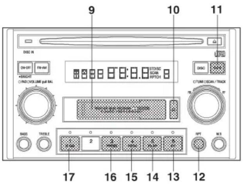
HB5053DB
⑨ Cassette slot
⑩ Eject button
⑪ TAPE (cassette player selection) button
⑫ Repeat button
⑬ Fast forward button
⑭ Play button
⑮ Rewind button
⑯ Program switching button
⑰ Dolby B NR button
If a cassette is inserted into the cassette slot while the ignition switch is in the ACC or the ON position, that tape will start to play automatically. Press the TAPE button when you want to play a cassette that has previously been inserted.
▼Cassette tape stop and eject button
When “▲” button is pressed, playback stops and the cassette tape is ejected.
Before the ignition switch is turned to the “OFF” position, eject the tape from the player. Always make certain that you remove the cassette tape.
▼Program button (PROG)
If a cassette is currently being played, the PROG button can be pressed to switch from the A-side to the B-side or vice-versa.
▼Fast-forward button (FF)
To fast-forward the tape, press the "FF" button. To stop fast-forwarding, lightly press the "PLAY" button.
If the “FF” button is pressed twice successively during playback, the player will fast-forward the tape to the end of the current song and resume the playback from the beginning of the next song.
▼Rewind button (REW)
To rewind the tape, press the “REW” button. To stop rewinding, lightly press the “PLAY” button.
If the “REW” button is pressed twice successively during playback, the player will rewind the tape up to the beginning of the current song and resume the playback from its beginning.
▼Repeat button (RPT)
If the RPT button is pressed while a song on a cassette tape is being played, the cassette player will then begin to play that song repeatedly. Press the RPT button once again to return to normal playback.
▼Dolby B NR button (B NR)
Press “B NR” button when playing tapes recorded using the Dolby NR system*. High-frequency noise on the tape will be reduced for clearer sound reproduction.
*Noise reduction system manufactured under license from Dolby Laboratories Licensing Corporation. "Dolby" and double-D Symbol are trade marks of Dolby Laboratories Licensing Corporation.
Compact disc player operation
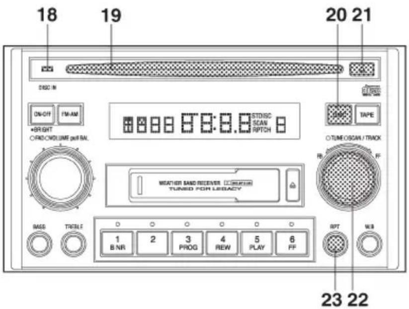
HB5053CB
⑱ DISC IN indicator light
⑲ Disc slot
⑳ Disc button
②1 Eject button
⑳ FF·FB dial
②3 Repeat button
▼To play back a compact disc
When CD is not in the player
Hold a disc with a finger in the center hole while gripping the edge of the disc, then insert it in to the slot (with the label side up) and the player will automatically pull the disc into position.
Single CDs (8 cm/3 inch CD) may also be used without an adapter.
After inserting, the DISC IN indicator (LED) will come on and playback start.
NOTE
●Make sure to always insert a disc with the label side up. If a disc is inserted with the label side down, it might be ejected or the player might shut off.
- CONTINUED -
- If a disc is inserted during a radio broadcast, the disc will interrupt the broadcast.
●After the last song finishes, the disc will automatically return to track 1 (the first song on the disc) and will automatically play back.
When CD is in the player
When the "DISC" button is pressed, the player will start playback.
▼To select a song from its beginning
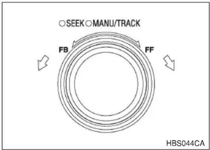
flowchart
graph TD
    A["○SEEK ○MANU/TRACK"] --> B["FB"]
    B --> C["FF"]
    C --> D["↓"]
    style A fill:#fff,stroke:#000
    style B fill:#fff,stroke:#000
    style C fill:#fff,stroke:#000
    style D fill:#fff,stroke:#000
▽ Forward direction
Turn the “FF·FB” dial clockwise and release it immediately to skip to the beginning of the next track. Each time the knob is turned and released, the indicated track number will increase.
▽ Backward direction
Turn the "FF·FB" dial counterclockwise and release it immediately to skip to the beginning of the current track. If you continue to turn and release the knob, the indicated a number will decrease.
▼Fast forwarding and fast reverse
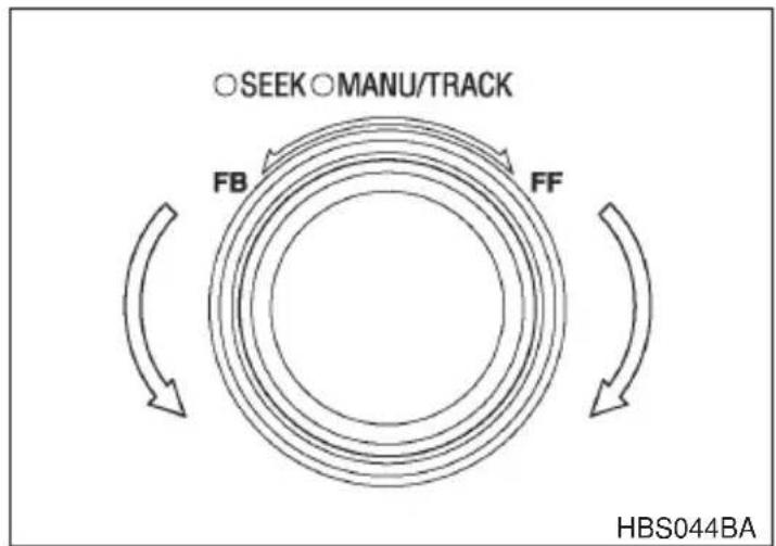
flowchart
graph TD
    A["SEEK"] --> B["MANU/TRACK"]
    B --> C["FB"]
    C --> D["FF"]
    D --> E["HBS044BA"]
∇ Fast forward
Turn the "FF·FB" dial clockwise and hold it continuously for more than 2 seconds to fast forward the disc.
Release the knob to stop fast forwarding.
∇ Fast reverse
Turn the “FF·FB” dial counterclockwise and hold it continuously for more than 2 seconds to fast reverse the disc.
Release the knob to stop fast reverse.
Repeat
Press the “RPT” button while a song is playing to play the song repeatedly. The “RPT” indicator will come on and the song will be played continuously. To cancel the repeat mode, press the button again. Then the “RPT” indicator goes out, and normal playback mode is restored.
▼To stop playback
Press the power switch to stop playback.
▼To eject a disc from the player
When a disc is being played back or when a disc is in the player, press the eject button “▲”. The disc will be ejected.
The disc may be removed even when the ignition switch is in the "LOCK" position.
NOTE
Avoid driving the vehicle with a CD sticking out, because vibration might make it fall out.
CD player 1 (if equipped)
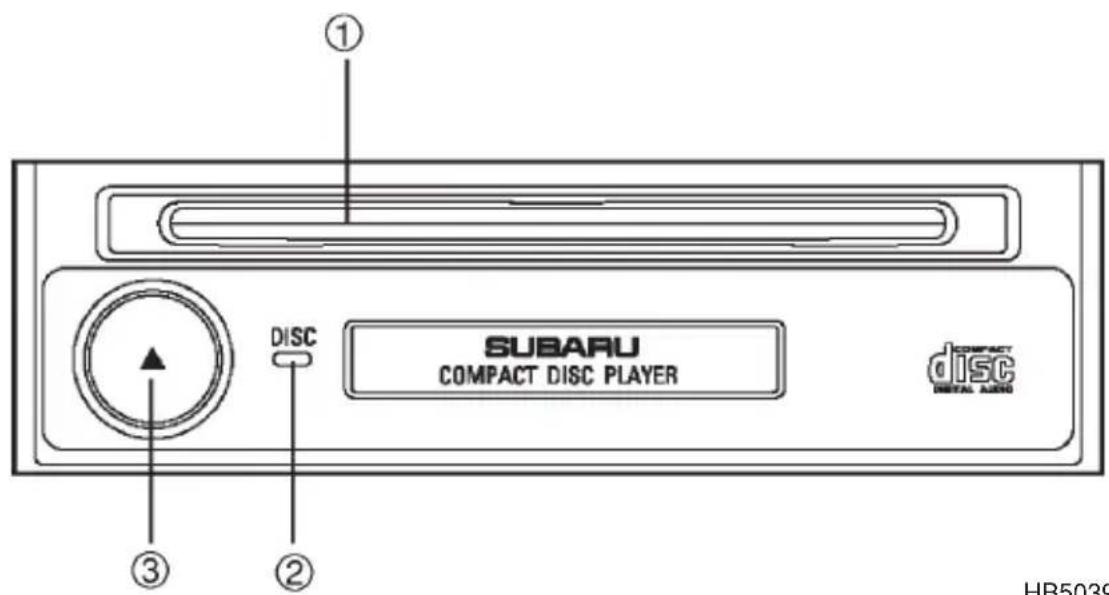
HB5039BB
① Disc slot
② Disc indicator
③ Eject button

CAUTION
- Use only music CDs identified by disc mark. - Do not use CDs listed below which could cause damage to the CD player.
- Any disc with a peel-off or seal on it.
●Any disc with scratches and/or dust. - Bent disc.
- Cleaning disc.
- CD accessory. (E.g., 3-inch (8 cm) disc adapter)
- Do not insert or remove any disc when the automatic transmission selector lever is in the park position; the selector lever in that position can interfere with disc insertion or removal, causing scratches on the disc surface (for AT vehicles).
▼To insert a disc
Be sure to hold a disc with the label side (the side where titles are printed) up.
Push the disc into the slot.
The disc will be automatically set in position by the auto-loading mechanism and begin playing.
The disc indicator will turn on as the CD begins playing.
▽ Disc indicator
Lit: A disc is in the slot (When the ignition switch is in the "ON" or "ACC" position).
OFF: No disc is loaded or the ignition switch is in the "Lock" position.
▼To remove disc left in slot
Simply press the “Eject button” ③ and the disc will be ejected. This procedures is effective even when the ignition switch is in the “LOCK” position.
▽ Function control
Refer to CD player control operating instructions described in the "Type A and B audio sets" section.
CD player 2 (if equipped)
Compact disc player operation
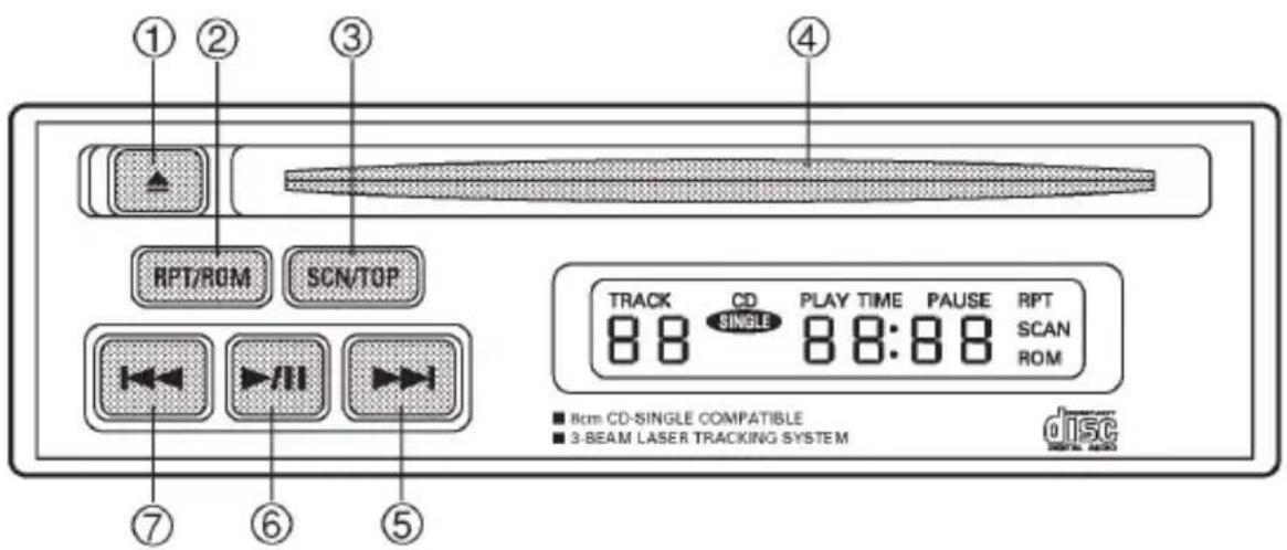
HB5044BB
① Eject button
② Repeat/random button
③ Scan/top button
④ Disc slot
⑤ Fast forward and track up button
⑥ Play/pause button
⑦ Fast reverse and track down button
▼To playback a compact disc
When CD is not in the player
Hold a disc with a finger in the center hole while gripping the edge of the disc, then insert it in to the slot (with the label side up) and the player will automatically pull the disc into position.
A 8 cm/3 inch CD may also be used without any adapter.
NOTE
- DO NOT INSERT TWO DISCS INTO THE DISC INSERTION SLOT AT A TIME.
- Be sure to always insert a disc with the label side up. If a disc is inserted with the label side down, it might be ejected or the player might shut off.
●After the last song finishes, the player will automatically return to track 1 (the first song on the disc).
When CD is in the player
When the “▶/■” button ⑥ is pressed, the player will start playback.
NOTE
After the last song finishes, the player will automatically return to track 1 (the first song on the disc).
▼To stop playback of a CD
When the “▶/■” button ⑥ is pressed during playback of a CD, the CD stops playing temporarily. To let the CD resume playing, press the button again.
▼To select a song from its beginning
▽ Forward direction
Briefly press the “▶▶” button ⑤ to skip to the beginning of the next track. Each time the button is pressed, the indicated track number will increase.
Backward direction
Briefly press the “◀◀◀” button ⑦ to skip to the beginning of the current track. Each time the button is pressed, the indicated truck number will decrease.
▼Fast forwarding and fast reverse
∇ Fast forward
Press the “▶▶▶” button ⑤ continuously for more than 0.5 second to fast forward the disc.
Release the button to stop fast forwarding.
∇ Fast reverse
Press the “◀◀◀” button ⑦ continuously for more than 0.5 second to fast reverse the disc.
Release the button to stop fast reverse.
▼Repeat playback
Use this to play a certain track repeatedly. During playback, press the "RPT/RDM" button ② and release it in less than 2 seconds. The "RPT" indicator will come on and the song will be played continuously. To
cancel the repeat mode, press the button again. Then the "RPT" indicator goes out, and normal playback mode is restored.
▼Random playback
Use this to play the tracks on the disc in random order. During play-back, press the “RPT/RDM” button ② and hold it in for more than 2 seconds. The “RDM” indicator will come on and all songs on the disc will be played in a random order.
To cancel the random mode, press the button again. Then the “RDM” indicator goes out, and normal playback mode is restored.
Scan
Press the “SCN/TOP” button ③ and release it in less than 2 seconds, and you can hear the first 10 seconds of each track to seach for the desired program. To continue listening to the program, press the “SCAN” button again. After all tracks on the disc has been scanned, normal playback mode is restored.
▼Top
Use this to return to the first track on the disc during playback. Press the “SCN/TOP” button ③ and hold it in for more than 2 seconds. Play-back returns to the beginning of the first track on the disc.
▼To eject a disc from the player
When a disc is being played back or when a disc is in the player, press the eject button “▲”. The disc will be ejected.
The disc may be removed even when the ignition switch is in the "LOCK" position.
NOTE
- Avoid driving the vehicle with a CD sticking out, because vibration might make it fall out.
- To protect the disc, the disc is automatically loaded if it is left in the ejected position for more than approximately 15 seconds (Auto Reload). In this case, the disc is not played.
In-dash 6 CD auto changer (if equipped)
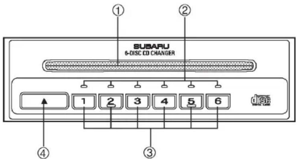
HB5040BB
① Disc slot
② Disc indicators (disc No.1 to 6)
③ Disc select buttons (disc No.1 to 6)
④ Eject button

CAUTION
- Do not attempt to insert two or more discs into the slot at a time. Doing so can cause mechanical damage to the CD changer.
- Use only music CDs identified by a disc mark.
- Do not use CDs listed below which could cause damage to the CD player.
●3-inch (8 cm) compact disc.
●Any disc with a peel-off or seal on it.
●Any disc with scratches and/or dust.
- Bent disc.
- Cleaning disc.
- CD accessory. (E.g., 3-inch (8 cm) disc adapter)
- Do not insert or remove any disc when the automatic transmission selector lever is in the park position; the selector lever in that position can interfere with disc insertion or removal, causing scratches on the disc surface (for AT vehicles).
▼To insert a disc
- Press one of the "Disc select" buttons ③ (numbered from 1 to 6) for which the disc indicator light ② is "OFF".
The Disc indicator lights are located directly above the corresponding "Disc select" buttons.
- The indicator will begin blinking. The blinking will last for 15 seconds.
During this period, insert a desired disc, and the disc will begin to play. (If any disc is not inserted during this period, the “Disc slot” ① door will close. Repeat step 1.)
Be sure to hold a disc with the label side (the side where titles are printed) up.
- To insert another disc, repeat step 1 and 2 choosing a different disc select button.
▼To insert six discs at a time
-
Press and hold the "Disc select" button number 1 until all disc indicators begin blinking (about 1.5 seconds).
-
The indicators will blink for 15 seconds. During this period, insert desired six discs.
-
When all discs are loaded, the first disc will begin to play. (If no disc is inserted within this 15 seconds, the entire disc load sequence will be canceled.)
▼To remove a disc
- Press the desired one of the "Disc select" buttons ③ (numbered from 1 to 6) for which the disc indicator light is on.
- Press the “Eject button” ④. The selected disc will be ejected and the indicator light will begin blinking.
- To remove another disc, repeat step 1 and 2 choosing a different "Disc select" button.
(To remove discs when the ignition switch is in the “Lock” position, press the “Eject” button, and the first disc will be ejected. Press the “Eject” button again, and the next disc will be ejected and so on. At this time, the “Disc select” buttons are disabled.)
▼To remove all discs at one time
- Press and hold the "Eject" button ④ until all "Disc" indicators begin blinking (about 1.5 seconds), and the first disc will be ejected.
- When the disc is removed, the next one will be ejected, and so on.
▼To replace a playing disc with another
Simply press the desired one of “Disc select” buttons ③ (numbered from 1 to 6) or press the “DISC UP” or “DISC DOWN” button on the radio unit to select the desired disc, and the disc will begin to play.
▼Disc indicators
Lit: when the corresponding storage tray is occupied by a disc.
Blinking: Disc player is either in loading, eject or changing mode.
OFF: No disc is loaded or the ignition switch is in the "LOCK" position.
▼Function control
Refer to CD player control operating instructions described in the "Type A and B audio sets" or "Type C audio set" section.
Precautions to observe when handling a compact disc (CD)
Use only compact discs (CDs) that have the mark shown below. CD-RWs cannot be used. Also, some CD-Rs cannot be played.
- In cold and/or rainy weather, dew can form inside the CD player, preventing normal operation. If this happens, eject the CD and wait for the player to dry out.
●Skipping may occur when the CD player is subjected to severe vibration (for example, when the vehicle is driven on a rough surface).
- To remove a disc from the case, press the center of the case and hold both edges of the disc. If the disc surface is touched directly, contamination could cause poor tone quality. Do not touch the disc surface.
- Use a clean disc whenever possible. If there are deposits, wipe the disc surface from the center outward with a dry, soft cloth. Be sure not to use a hard cloth, thinner, benzene, alcohol, etc.
- Do not use any disc that is scratched, deformed, or cracked. Also, do not use any disc that has a non-standard shape (for example, a heart shape). Malfunctions or problems might result.
●A disc is vulnerable to heat. Never keep it either in places exposed to direct sunlight, near heaters or in vehicles parked in the sun or hot days.
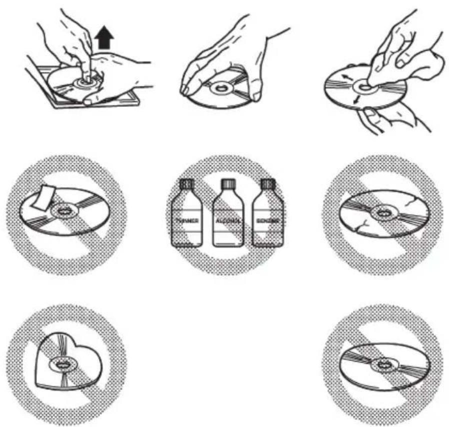
HB5061BA
Interior equipment
Interior light 6-2
Dome light 6-2
Cargo area light (if equipped) 6-3
Spotlight (if equipped) 6-3
Sun visors 6-4
Vanity mirror (if equipped) 6-5
Storage compartment 6-5
Glove compartment 6-6
Center console 6-6
Coin tray 6-7
Overhead console (if equipped) 6-7
Cup holder 6-8
Cigarette lighter socket (if equipped) 6-9
Ashtray 6-12
Accessory power socket 6-13
Convenience hook 6-14
Floor mat (if equipped) 6-15
Luggage cover (if equipped) 6-16
Cargo anchorage eyelets (if equipped) 6-18
Storage tray (if equipped) 6-18
Interior light
Dome light
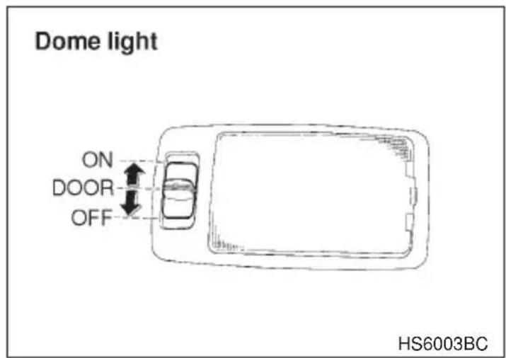
The dome light switch has three positions:
ON: The light stays on continuously.
DOOR (middle position): The light comes on when any of the doors (or the rear gate on the wagon) is opened. The light remains on for several seconds and gradually goes out after all doors (and the rear gate on the wagon) are closed or if the key is inserted in the ignition switch.
The light also can be turned on by use of the keyless entry transmitter. See the "Keyless entry system" in chapter 2 for detailed information.
OFF: The light stays off.
When leaving your vehicle, make sure the light goes out to avoid battery discharge.
■ Cargo area light (if equipped)
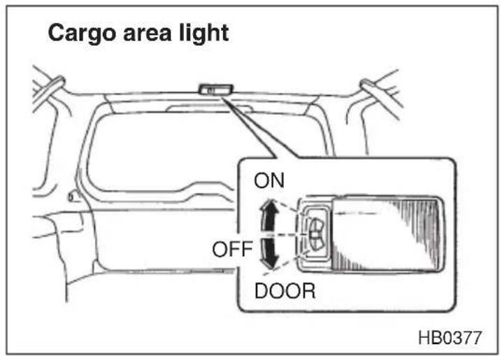
The cargo area light switch has three positions:
ON: The light stays on continuously.
OFF: The light stays off.
DOOR: The light comes on only when the rear gate is opened.
When leaving your vehicle, make sure the light is turned off to avoid battery discharge.
Spotlight (if equipped)
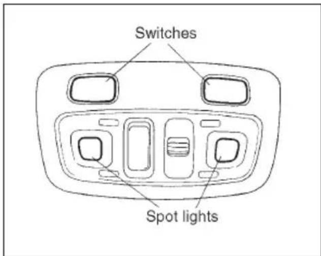
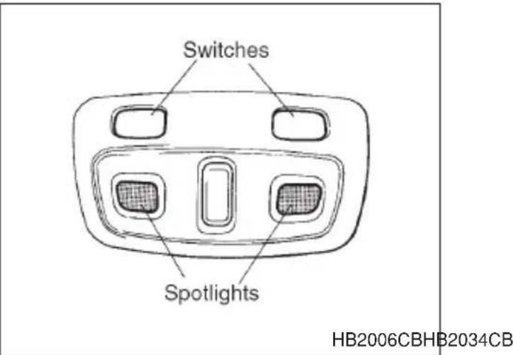
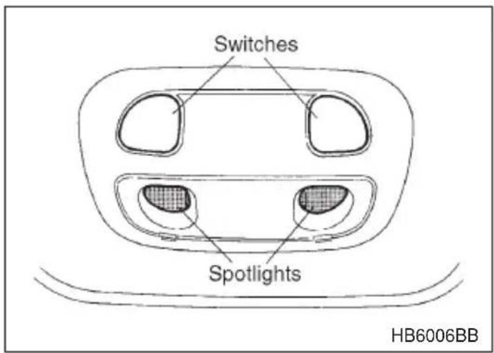
To turn on the spotlight, push the switch. To turn it off, push the switch again.
When leaving the vehicle, make sure the light is turned off to avoid battery discharge.
Sun visors
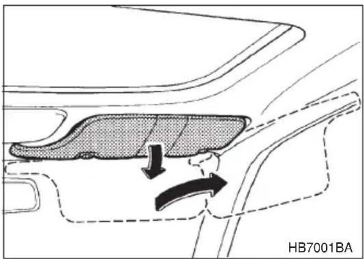
To block out glare, swing down the visors. To use the sun visor at a side window, swing it down and move it sideways.
■Vanity mirror (if equipped)
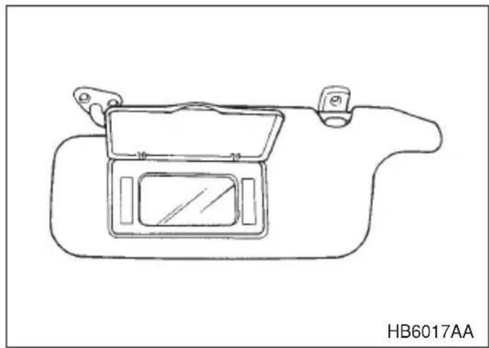
natural_image
Line drawing of a device with an open lid and handle, labeled HB6017AA (no text or symbols on the diagram itself)To use the vanity mirror, swing down the sunvisor and open the vanity mirror cover.
▼Vanity mirror with light (if equipped)
The light beside the vanity mirror comes on when the ignition switch is either in the “ACC” or “ON” position and the mirror cover is opened.
Storage compartment
CAUTION
●Always keep the storage compartment closed while driving to reduce the risk of injury in the event of sudden stops or an accident.
- Do not store spray cans, containers with flammable or corrosive liquids or any other dangerous items in the storage compartment.
Glove compartment
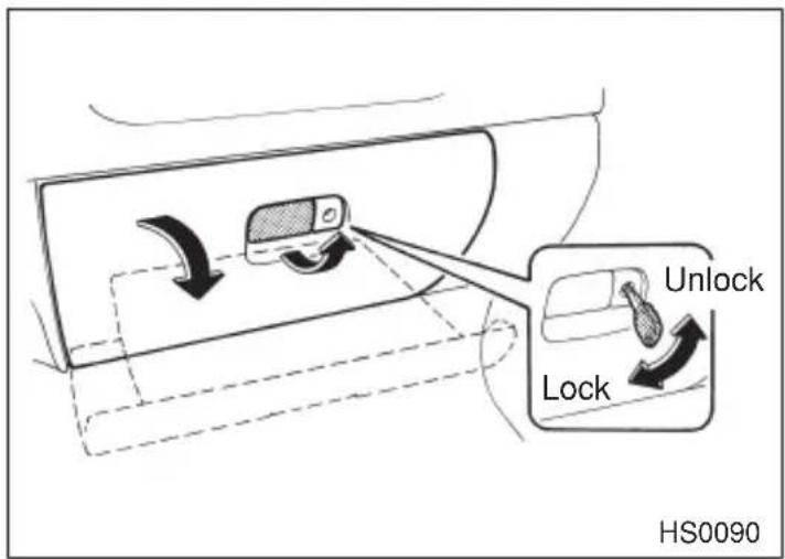
To open the glove compartment, pull the handle. To close it, push the lid firmly upward.
To lock the glove compartment, insert the key and turn it clockwise.
■Center console
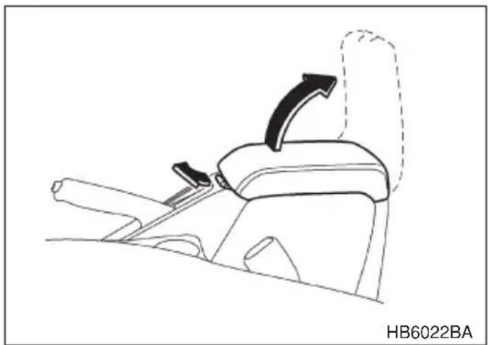
natural_image
Line drawing of a car seatbelt with an arrow indicating clockwise motion (no text or symbols)To open the lid, pull up the lock release.
If the console lid is fully opened when a large cup is put in the rear passenger's cup holder, the lid may hit the cup and beverage may be spilled.
Coin tray
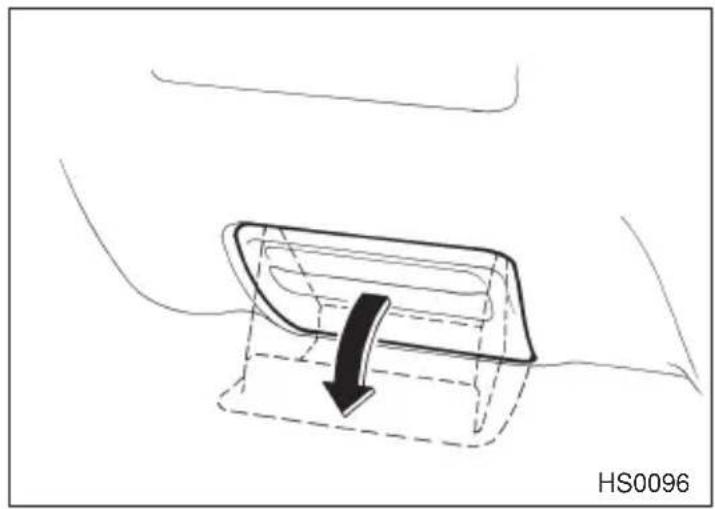
natural_image
Diagram of a car interior showing a curved object with a black arrow indicating direction, no text or symbols present.To open the coin tray, pull the upper edge of the lid.
■Overhead console (if equipped)
CAUTION
When your vehicle is parked in the sun or a warm day, the inside of the overhead console heats up. Avoid storing plastic or other heat-vulnerable or flammable articles such as a lighter in the overhead console.
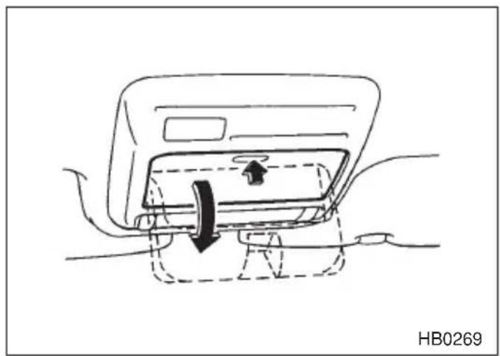
natural_image
Line drawing of a car interior showing a door handle and seat with directional arrows indicating movement (no text or symbols)To open the console, push on the lid lightly and it will automatically open.
Cup holder

CAUTION
- Do not pick up a cup from the cup holder or put a cup in the holder while you are driving, as this may distract you and lead to an accident.
●Take care to avoid spills. Beverages, if hot, might burn you or your passengers. Spilled beverages may also damage upholstery, carpets or audio equipment.

Front cup holder
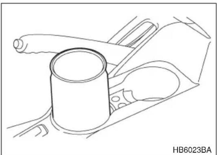
natural_image
Technical line drawing of a mechanical component with no visible text or symbolsA dual cup holder is built in the center console, beside the parking brake lever.
▼ Rear passenger's cup holder (if equipped)
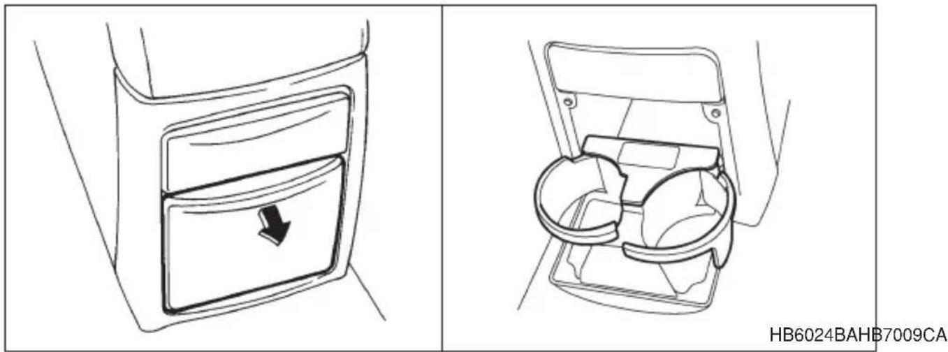
The rear passenger's cup holder is located on the lower side of the back of the center console. To use the cup holder, open the lid by pulling its upper edge.
Cigarette lighter socket (if equipped)
CAUTION
- The electrical power socket located on the lower part of the instrument panel is originally designed to use a SUBARU genuine cigarette lighter plug. Do not use non-genuine cigarette lighter plugs in the socket. Doing so may cause a short-circuit and overheating, resulting in a fire. - If the socket is ever used for a plug-in accessory such as a mobile phone, they may damage the portion of the socket's internal mechanism that causes a cigarette lighter plug to "pop out" after its lighter element is heated. Therefore, do not place a cigarette lighter plug in a socket that has been used, even once, to power a plug-in accessory. Doing so may cause the plug to stick and overheat, creating a potential fire hazard.
- Do not place any foreign objects, especially metal ones such as coins or aluminum foil, into the socket. That could cause a short circuit.
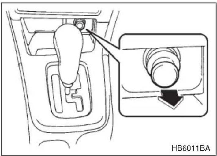
The electrical power socket located on the lower part of the instrument panel can be used as cigarette lighter socket. A cigarette lighter plug is an optional accessory. It is available from your SUBARU dealer.
The cigarette lighter socket may also be used as a power source for an in-car use electrical appliance.
▼Use with a cigarette lighter
WARNING
To avoid being burned, never grasp the lighter by the end with the heating element. Doing so could result in injury and could also damage the heating element.
CAUTION
Do not hold the lighter pushed in, because it will overheat.
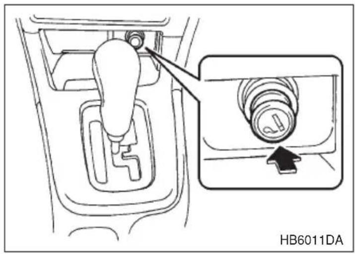
The cigarette lighter operates only when the ignition switch is in the "ON" and "ACC" positions.
To use the cigarette lighter, push in the knob and wait a few moments. It will automatically spring up when ready for use.
▼Using as an accessory power socket
Electrical power (12V DC) from the battery is on tap at the socket when the ignition switch is either in the “ACC” or “ON” position.
If you use the socket as an accessory power socket, take the following precautions.
When the socket is not in use, always put the cap on the socket to prevent any foreign object from entering it.
CAUTION
- Use only in-car use electrical appliances which are designed for 12V DC and which consume less than 120W. Overloading the socket can cause a short circuit. Do not use double adapters or more than one electrical appliance.
- If the plug on your electric appliance is either too loose or too tight for the socket, this can result in a poor contact or cause the plug to get stuck. Only use plugs that fit properly.
- Use of an electric appliance in the socket for a long period of time while the engine is not running can cause battery discharge.
●Before driving your vehicle, make sure that the plug and the cord on your electrical appliance will not interfere with your shift-
ing gears and operating the accelerator and brake pedals. If they do, do not use the electrical appliance while driving.
If the socket has been used for electrical appliances, damage may have been done to the internal mechanism that cause a cigarette lighter to “pop-out” after its element has been heated. For that reason, a cigarette lighter, even if it is a genuine part, should not be used in the socket. If you want to use the socket for a cigarette lighter again, or to protect your purchaser before you sell your car, have your SUBARU dealer replace the socket with a new one.
Ashtray

CAUTION
Do not use ashtrays as waste receptacles or leave a lighted cigarette in an ashtray. This could cause a fire.
Fully close the ashtray after using it to help reduce residual smoke.
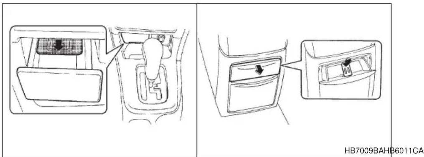
Front ashtray
To open the ashtray, pull the lid out.
▼Rear ashtray (if equipped)
The rear ashtray is located on the upper side of the back of the center console. To open the ashtray, pull the upper edge of the lid.
To remove the ashtray for cleaning, open it and pull it out while pushing the inner plate down.
Accessory power socket
▼In the luggage compartment (if equipped)

CAUTION
- Do not attempt to use a cigarette lighter in the accessory power socket.
- Do not place any foreign objects, especially metal ones such as coins or aluminum foil, into the accessory power socket. That could cause a short circuit. Always put the cap on the accessory power socket when it is not in use.
- Use only electrical appliances which are designed for 12V DC and which consume less than 120W. Overloading the accessory power socket can cause a short circuit. Do not use double adapters or more than one electrical appliance.
- If the plug on your electric appliance is either too loose or too tight for the accessory power socket, this can result in a poor contact or cause the plug to get stuck. Only use plugs that fit properly.
- Use of an electric appliance in the accessory power socket for a long period of time while the engine is not running can cause battery discharge.
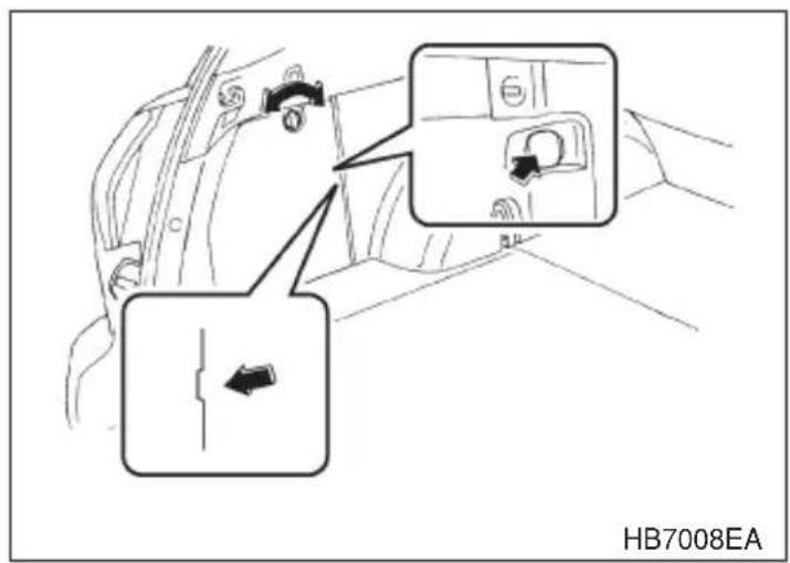
Electrical power (12V DC) from the battery is on tap at the socket when the ignition switch is either in the “ACC” or “ON” position.
You can use an in-car use electrical appliance by connecting it to the socket.
NOTE
The trim cover has a notch through which the connected electrical appliance's cord can be passed.
Convenience hook
▼Coat hook

CAUTION
Never hang anything on the coat hook that might obstruct the driver's view or that could cause injury in sudden stops or in a collision. And do not hang items on the coat hook that weigh 2.2 lb (1 kg) or more.
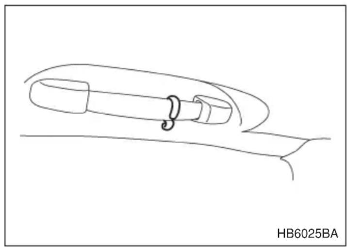
natural_image
Simple line drawing of a mechanical component with a spring-like loop, no text or symbols presentThe coat hook is attached to each rear passenger's hand grip.
▼Shopping bag hook

CAUTION
Do not hang items on the shopping bag hook that weigh 2.2 lb (1 kg) or more.
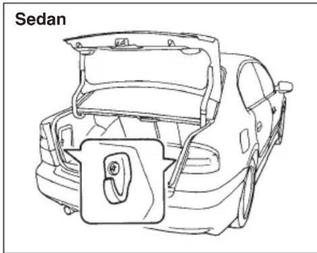
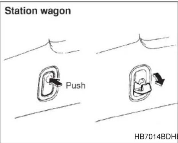
HB7014BDHBF014CB
For sedan models
A shopping bag hook is attached to each inner side wall of the trunk near the trunk lid opening.
For station wagon models
A shopping bag hook is attached to each side of the cargo area.
To use the hook, push the upper portion and the shopping bag hook will appear.
Floor mat (if equipped)
CAUTION
Make sure the driver's floor mat is placed back in its proper location and correctly secured on its retaining pin. If the floor mat slips forward and interferes with the movement of the pedals during driving, it could cause an accident.
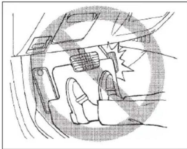
natural_image
Diagram of a car interior showing dashboard, steering wheel, and dashboard frame (no text or labels)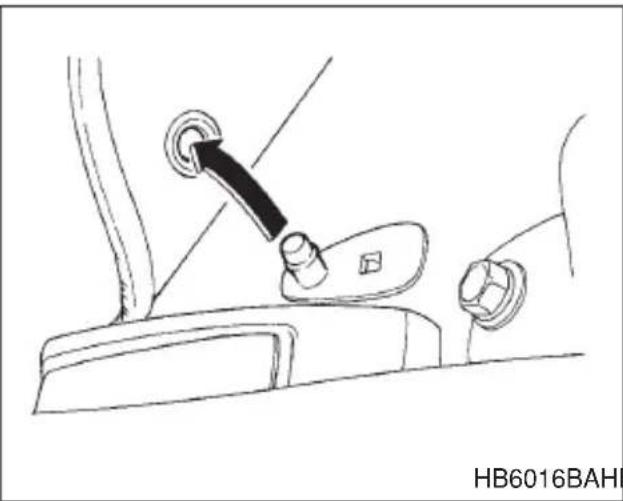
natural_image
Line drawing of a car seatbelt switch with a black arrow pointing to the grip (no text or symbols)HB6016BAHB6015BA
A retaining pin is located on the driver's side of the vehicle next to the fuel filler door release. The floor mat is secured using the built-in grommet, by placing the grommet over the pin and pushing downward.
Luggage cover (if equipped)

WARNING
Do not place anything on the extended cover. Putting excessive weight on the extended cover can break it and an object on the cover could tumble forward in the event of a sudden stop or collision. This could cause serious injury.
The luggage cover is provided for covering the cargo area and to protect its contents from direct sunlight. This cover is detachable to make room for additional cargo.
▼Using the cover
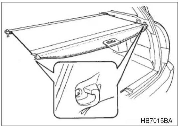
natural_image
Technical line drawing of a car interior showing seatbelt and dashboard components (no text or symbols)To extend the cover, pull the end of the cover out of the housing, then insert its hooks into the catches as shown. To rewind it, unhook it from the catches and it will rewind automatically. You should hold on to the cover and guide it back into the cover housing while it is rewinding.
▼To remove the cover
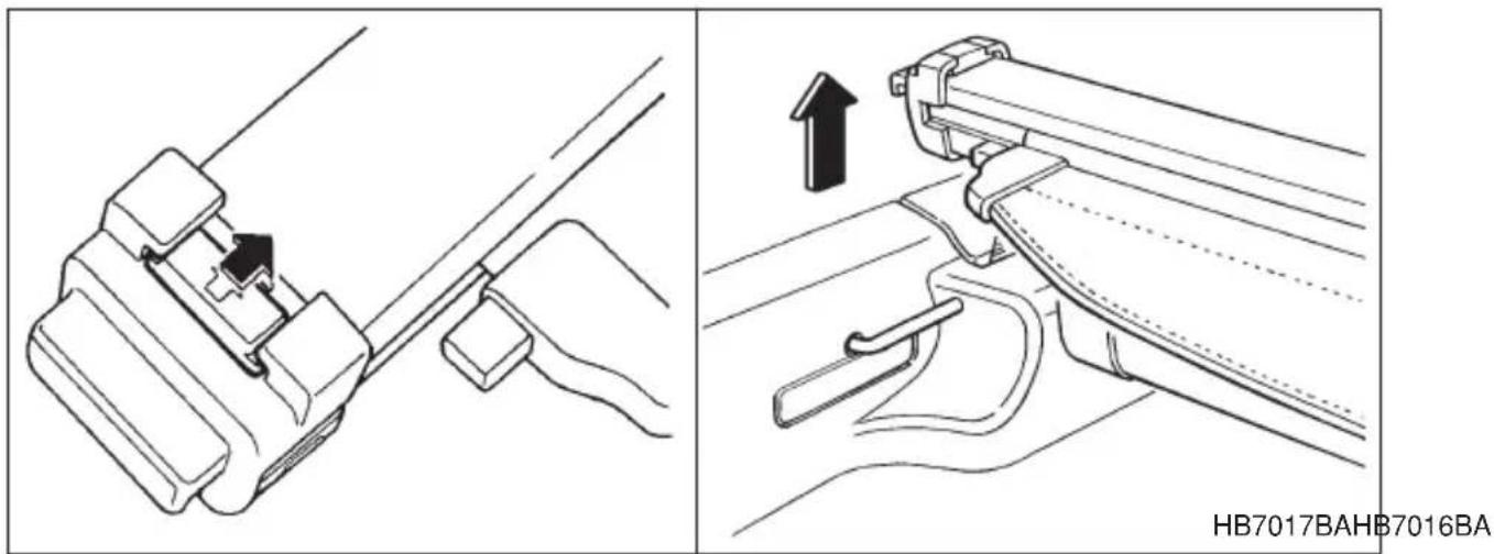
- Rewind the cover.
- To take it off the cover rails, lift it out while pressing the release knobs located both sides of the cover housing.
- Store the cover in the cargo area.
To install the cover:
Hang the both ends of the cover housing on the cover rails. Make sure that the cover is mounted securely by pulling it up.
Cargo anchorage eyelets (if equipped)

CAUTION
The cargo anchorage eyelets are designed only for securing light cargo. Never try to secure cargo that exceeds the capacity of the hooks. The maximum load capacity is 44 lb (20 kg) per eyelet.
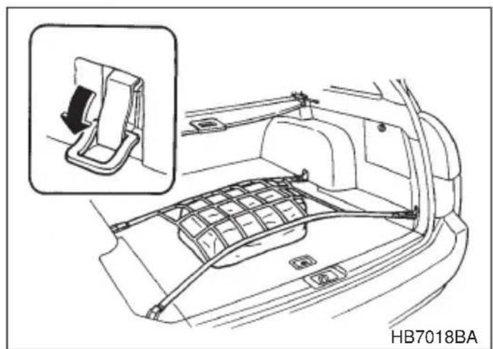
natural_image
Line drawing of a car interior showing seatbelt and dashboard structure (no text or symbols)The cargo area is equipped with four anchorage eyelets so that cargo can be secured with a luggage net or ropes.
When using the anchorage eyelets, turn them down out of the storing recesses. When not in use, put the eyelets up into the storing recesses.
Storage tray (if equipped)

CAUTION
●Always keep the lid of the storage tray closed while driving to reduce the risk of injury in the event of sudden stop or an accident.
- Do not store spray cans, containers with flammable or corrosive liquids or any other dangerous items in the storage tray.
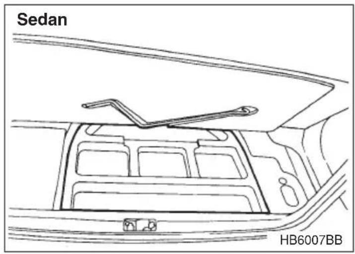
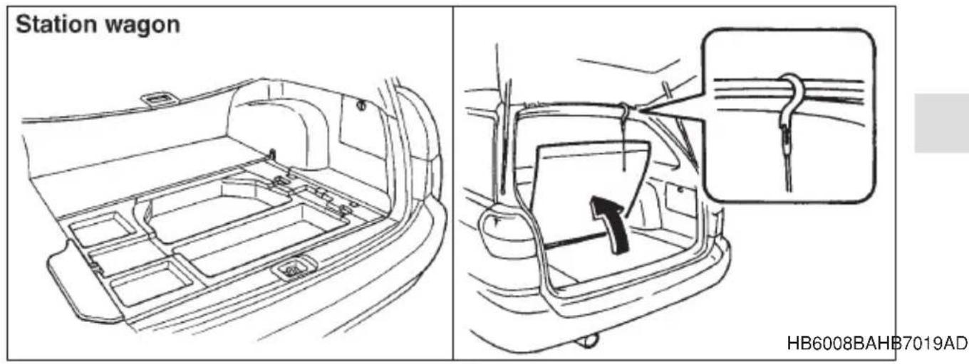
The storage tray is located under the floor of the trunk or cargo area and can be used to store small items. To open the lid, pull the tab or handle up.
Station wagon: Hang the hook provided on the underside of the lid on the rear edge of the roof to keep the lid open.
NOTE
When storing a flat tire, put the storage tray in the trunk or cargo area.
Starting and operating
Fuel 7-2
Fuel requirements 7-2
Fuel filler lid and cap 7-4
State emission testing (U.S. only) 7-7
Preparing to drive 7-8
Starting the engine 7-9
Starting the engine for a manual transmission vehicle 7-9......
Starting the engine for an automatic transmission vehicle 7-9.....
Starting the engine during cold weather below -4^ ( -20^ ) ... 7-10
Starting a flooded engine 7-10
Stopping the engine 7-11
Manual transmission 7-11
Automatic transmission 7-14
Selector lever for automatic transmission 7-15
Shift lock release 7-19
Rear viscous limited slip differential (LSD) (if equipped) ... 7-20
Power steering 7-21
Braking 7-21
Braking tips 7-21
Brake system 7-22
Disc brake pad wear warning indicators 7-23
ABS (Anti-lock Brake System) 7-23
VDC (Vehicle Dynamics Control) system (if equipped) ..... 7-26
VDC OFF switch 7-31
Parking your vehicle 7-32
Cruise control (if equipped) 7-34
Fuel

CAUTION
Use of a fuel which is low in quality or use of an inappropriate fuel additive may cause engine damage.
■Fuel requirements
▼2.5 Liter models
The 2.5 Liter engine is designed to operate using unleaded gasoline with an octane rating of 87 AKI or higher.
▼3.0 Liter models
The 3.0 Liter engine is designed to operate using premium unleaded gasoline with an octane rating of 91 AKI or higher. Regular unleaded gasoline with an octane rating of 87 AKI may be used if necessary. For optimum engine performance and driveability, it is recommended that you use premium grade unleaded gasoline.
▼Fuel octane rating
This octane rating is the average of the Research Octane and Motor Octane numbers and is commonly referred to as the Anti Knock Index (AKI).
Using a gasoline with a lower octane rating can cause persistent and heavy knocking, which can damage the engine. Do not be concerned if your vehicle sometimes knocks lightly when you drive up a hill or when you accelerate. See your dealer or a qualified service technician if you use a fuel with the specified octane rating and your vehicle knocks heavily or persistently.
▼Unleaded gasoline
The neck of the fuel filler pipe is designed to accept only an unleaded gasoline filler nozzle. Under no circumstances should leaded gasoline filler nozzle because it will damage the emission control system and may impair driveability and fuel economy.
▼Gasoline for California-certified LEV
Your vehicle was certified to California's low emission vehicle (LEV) standards as indicated on the underhood tune-up label. It is designed to optimize engine and emission performance with gasoline that meets the clean burning low-sulfur California gasoline specifications. If you live in any other state than California, your vehicle will operate on gasoline meeting Federal specifications. Gasoline sold outside California is permitted to have higher sulfur levels, which may affect the performance of your vehicle's catalytic converter and may produce a sulfur exhaust odor or smell. SUBARU recommends that you try a different brand of unleaded gasoline having lower sulfur to determine if the problem is fuel related before returning your vehicle to an authorized dealer for service.
▼Gasoline for cleaner air

CAUTION
Do not let fuel spill on the exterior surfaces of the vehicle. Fuels containing alcohol may cause paint damage, which is not covered under the SUBARU Limited Warranty.
Your use of gasoline with detergent additives will help prevent deposits from forming in your engine and fuel system. This helps keep your engine in tune and your emission control system working properly, and is a way of doing your part for cleaner air. If you continuously use a high quality fuel with the proper detergent and other additives, you should never need to add any fuel system cleaning agents to your fuel tank.
Many gasolines are now blended with materials called oxygenates. Use of these fuels can also help keep the air cleaner. Oxygenated blend fuels, such as MTBE (Methyl Tertiary Butyl ether) or ethanol (ethyl or grain alcohol) may be used in your vehicle, but should contain no more than 15% MTBE or 10% ethanol for the proper operation of your SUBARU.
In addition, some gasoline suppliers are now producing reformulated gasolines, which are designed to reduce vehicle emissions. SUBARU approves the use of reformulated gasoline.
If you are not sure what the fuel contains, you should ask your service station operators if their gasolines contain detergents and oxygenates and if they have been reformulated to reduce vehicle emissions.
As additional guidance, only use fuels suited for your vehicle as explained below.
- Fuel should be unleaded and have an octane rating no lower than that specified in this manual.
- Methanol (methyl or wood alcohol) is sometimes mixed with unleaded gasoline. Methanol can be used in your vehicle ONLY if it does not exceed 5% of the fuel mixture AND if it is accompanied by sufficient quantities of the proper cosolvents and corrosion inhibitors required to prevent damage to the fuel system. Do not use fuel containing methanol EXCEPT under these conditions.
- If undesirable driveability problems are experienced and you suspect they may be fuel related, try a different brand of gasoline before seeking service at your SUBARU dealer.
- Fuel system damage or driveability problems which result from the use of improper fuel are not covered under the SUBARU Limited Warranty.
■Fuel filler lid and cap
Refueling

WARNING
●Gasoline vapor is highly flammable. Before refueling, always first stop the engine and make sure that there are no lighted cigarettes, open flames or electrical sparks in the adjacent area.
- When opening the cap, do not remove the cap quickly. Fuel may be under pressure and spray out of the fuel filler neck especially in hot weather, which may cause injury.

CAUTION
●Never add any cleaning agents to the fuel tank. The addition of a cleaning agent may cause damage to the fuel system.
●Make sure that the cap is tightened until it clicks to prevent fuel spillage in the event of an accident.
- Do not let fuel spill on the exterior surfaces of the vehicle.
Fuels may cause paint damage, which is not covered under the SUBARU Limited Warranty.
●Always use a genuine SUBARU fuel filler cap. If you use the wrong cap, it may not fit or have proper venting, and your fuel tank and emission control system might be damaged.
Sedan
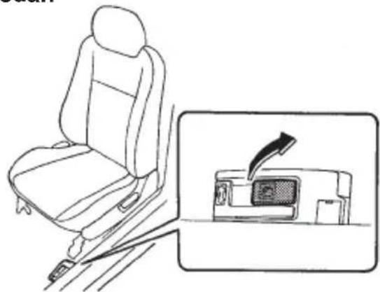
natural_image
Line drawing of a car seatbelt with an inset showing a device with a right-handled lever (no text or symbols)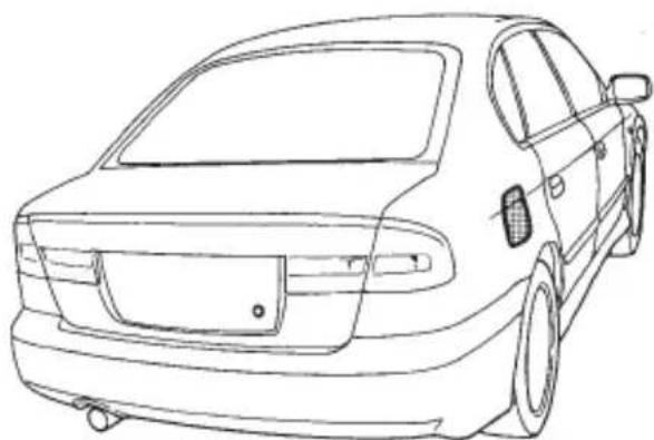
natural_image
Line drawing of a sedan car front view (no text or symbols)HBF013DAHB3000BB
Station wagon
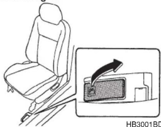
natural_image
Line drawing of a car seat with a magnified inset showing a device with an arrow (no text or symbols)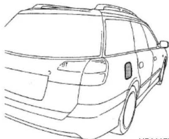
natural_image
Line drawing of a car front view showing the rear side and side profile (no text or symbols)HB3007BA
- To open the fuel filler lid, pull the lid release lever up.
- CONTINUED -
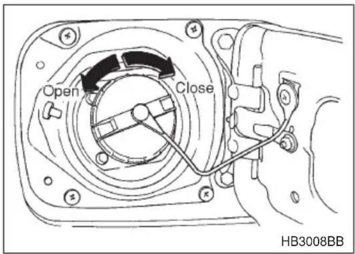
- Remove the fuel filler cap by turning it slowly counterclockwise.
- Stop filling the tank after the fuel filler pump automatically clicks off. Do not add any more fuel.
- Put the cap back on, turn it clockwise until you hear a clicking noise. Be certain not to catch the tether under the cap while tightening.
- Close the fuel filler lid completely.
If you spill any fuel on the painted surface, rinse it off immediately. Otherwise, the painted surface could be damaged.
NOTE
FUEL DOOR
HG3016AA
- You will see the “FUEL DOOR ▷” sign in the combination meter. This indicates that the fuel filler door (lid) is located on the right side of the vehicle.
- If the fuel filler cap is not tightened until it clicks or if the tether is caught under the cap, the CHECK ENGINE warning light may come on. Refer to the “Warning and indicator lights” section located in chapter 3.
State emission testing (U.S. only)
WARNING
Testing of an All-Wheel Drive vehicle must NEVER be performed on a single two-wheel dynamometer. Attempting to do so will result in uncontrolled vehicle movement and may cause an accident or injuries to persons nearby.
CAUTION
Resultant vehicle damage due to improper testing is not covered under the SUBARU Limited Warranty and is the responsibility of the state inspection program or its contractors or licensees.
At state inspection time, remember to tell your inspection or service station in advance not to place your Subaru AWD vehicle on a two-wheel dynamometer. Otherwise, serious transmission damage will result.
Some states have started using dynamometers in their state inspection programs in order to meet their obligation under federal law to implement stricter vehicle emission standards to reduce air pollution from cars. A dynamometer is a treadmill or roller-like testing device that allows your car's wheels to turn while the car remains in one place. Depending on the severity of a state's air pollution problems, the states must adopt either a "basic" or "enhanced" vehicle emission inspection test. Normally, a portion of the basic emission test consists of an emission inspector inserting an analyzer probe into the exhaust pipe of an idling vehicle for a short period of time. States with more severe air pollution problems are required to adopt an enhanced vehicle emission test. This test simulates actual driving conditions on a dynamometer and permits
- CONTINUED -
more accurate measurement of tailpipe emitted pollution than the basic emission test.
The U.S. Environmental Protection Agency (EPA) and states using two-wheel dynamometers in their emission testing programs have
EXEMPTED Subaru AWD vehicles from the portion of the testing program that involves a two-wheel dynamometer.
There are some states that use four-wheel dynamometers in their testing programs. When properly used, that equipment will not damage an AWD Subaru vehicle.
Under no circumstances should the rear wheels be jacked off the ground, nor should the driveshaft be disconnected for state emission testing.
Preparing to drive
You should perform the following checks and adjustments every day before you start driving.
- Check that all windows, mirrors, and lights are clean and unobstructed.
- Check the appearance and condition of the tires. Also check tires for proper inflation.
- Look under the vehicle for any sign of leaks.
- Check that the hood, trunk and rear gate are fully closed.
- Check the adjustment of the seat.
- Check the adjustment of the inside and outside mirrors.
- Fasten your seatbelt. Check that your passengers have fastened their seatbelts.
- Check the operation of the warning and indicator lights when the ignition switch is turned to the "ON" position.
- Check the gauges, indicator and warning lights after starting the engine.
NOTE
Engine oil, engine coolant, brake fluid, washer fluid and other fluid levels should be checked daily, weekly or at fuel stops.
Starting the engine

CAUTION
Do not operate the starter motor continuously for more than ten seconds. If the engine fails to start after operating the starter for five to ten seconds, wait for ten seconds or more before trying again.
■ Starting the engine for a manual transmission vehicle
- Apply the parking brake.
- Turn off unnecessary lights and accessories.
- Press the clutch pedal to the floor and shift the shift lever into neutral. Hold the clutch pedal to the floor while starting the engine. The starter motor will only operate when the clutch pedal is pressed fully to the floor.
- Turn the ignition switch to the "ON" position and check the operation of the warning and indicator lights. Refer to the "Warning and indicator light" section (chapter 3).
- Turn the ignition switch to the "START" position without depressing the accelerator pedal. Release the key immediately after the engine has started.
If the engine does not start within ten seconds, wait a while and then turn the ignition switch to the “START” position again while depressing the accelerator pedal half way down.
- Confirm that all warning and indicator lights have gone off after the engine has started. The fuel injection system automatically lowers the idle speed as the engine warms up.
■Starting the engine for an automatic transmission vehicle

CAUTION
If you restart the engine while the vehicle is moving, shift the selector lever into the “N” position. Do not attempt to place the selector lever of a moving vehicle into the “P” position.
- CONTINUED -
- Apply the parking brake.
- Turn off unnecessary lights and accessories.
- Shift the selector lever to the "P" or "N" position (preferably "P" position). The starter will only operate when the select lever is at the "P" or "N" position.
- Turn the ignition switch to the "ON" position and check the operation of the warning and indicator lights. Refer to the "Warning and indicator lights" section (chapter 3).
- Turn the ignition switch to the "START" position without depressing the accelerator pedal. Release the key immediately after the engine has started.
If the engine does not start within ten seconds, wait a while and then turn the ignition switch to the “START” position again while depressing the accelerator pedal half way down.
- Confirm that all warning and indicator lights have gone out after the engine has started. The fuel injection system automatically lowers the idle speed as the engine warms up.
While the engine is warming up, make sure that the selector lever is at the “P” or “N” position and that the parking brake is applied.
■Starting the engine during cold weather below -4^ ( -20^ )
If the engine is difficult to start using the normal method (without depressing the accelerator pedal), turn the ignition switch to the “START” position while slightly depressing the accelerator pedal.
■Starting a flooded engine
If the engine does not start, it may be flooded (excessive fuel in the engine).
In case of a flooded engine, turn the starter motor for five seconds with the accelerator pedal fully depressed. Repeat this two or three times until the engine starts. Release the ignition switch and accelerator pedal as soon as the engine starts.
Stopping the engine

WARNING
Do not stop the engine when the vehicle is moving. This will cause loss of power to the power steering and the brake booster, making steering and braking more difficult. It could also result in accidental activation of the “LOCK” position on the ignition switch, causing the steering wheel to lock.
The ignition switch should be turned off only when the engine is idling.
Manual transmission

WARNING
Do not drive the vehicle with the clutch disengaged (i.e., when the clutch pedal is depressed) or with the shift lever in the neutral position. Engine braking has no effect in either of these conditions and the risk of an accident is consequently increased.

CAUTION
Shift into reverse ONLY when the vehicle has completely stopped. It may cause damage to the transmission to try shifting into reverse when the vehicle is moving.
The manual transmission is a fully synchromeshed 5-forward and 1-reverse speed transmission.
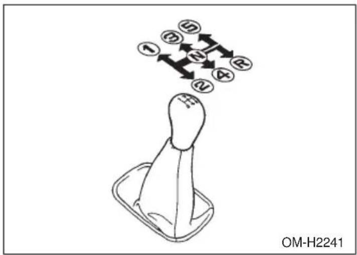
The shift pattern is shown on the shift lever knob. When shifting from 5th gear to reverse gear, first return the shift lever to the neutral position then shift into reverse gear.
To change gears, fully depress the clutch pedal, move the shift lever, and gradually let up on the clutch pedal.
If it is difficult to shift into gear, put the transmission in neutral, release the clutch pedal momentarily, and then try again.
▼Shifting speeds
▼ Recommended shifting speeds
The best compromise between fuel economy and vehicle performance during normal driving is ensured by shifting up at the speeds listed in the following table.
| Shift up | mph (km/h) |
| 1st to 2nd 15 (24) | |
| 2nd to 3rd 25 (40) | |
| 3rd to 4th 40 (65) | |
| 4th to 5th 45 (73) |
▽ Maximum allowable speeds
WARNING
When shifting down a gear, ensure that the vehicle is not travelling at a speed exceeding the Maximum Allowable Speed for the gear which is about to be selected. Failure to observe this precaution can lead to engine over-revving and this in turn can result in engine damage.
In addition, sudden application of engine brakes when the vehicle is travelling on a slippery surface can lead to wheel locking; as a consequence, control of the vehicle may be lost and the risk of an accident increased.
The following table shows the maximum speeds that are possible with each different gear.
Never exceed the speed limit below for each gear position except for brief acceleration in an emergency. The tachometer's needle (if so equipped) will enter the red area if these speeds are exceeded. Failure to observe this precaution can lead to excessive engine wear and poor fuel economy.
mph (km/h)
| Gear\Vehicle type | Brighton L GT | OUT-BACK | |
| 1st 30 (48) 30 (49) | 29 (47) 31 (50) | ||
| 2nd 50 (81) 51 (82) | 49 (79) 52 (84) | ||
| 3rd 71 (115) 73 (117) | 70 (112) 74 (119) |
▼Driving tips
Do not drive with your foot resting on the clutch pedal and do not use the clutch to hold your vehicle at a standstill on an upgrade. Either of those actions may cause clutch damage.
Do not drive with your hand resting on the shift lever. This may cause wear on the transmission components.
When it is necessary to reduce vehicle speed due to slow traffic, turning corners, or driving up steep hills, downshift to a lower gear before the engine starts to labor.
On steep downgrades, downshift the transmission to 4th, 3rd or 2nd gear as necessary; this helps to maintain a safe speed and to extend brake pad life.
In this way, the engine provides a braking effect. Remember, if you “ride” (over use) the brakes while descending a hill, they may over-heat and not work properly.
Automatic transmission

WARNING
Do not shift from the “P” or “N” position into the “D”, “3”, “2”, “1” or “R” position while depressing the accelerator pedal. This may cause the vehicle to jump forward or backward.

CAUTION
- Shift into the “P” or “R” position only after the vehicle is completely stopped. Shifting while the vehicle is moving may cause damage to the transmission.
- Do not race the engine for more than five seconds in any position except the “N” or “P” position when the brake is set or the tires are on blocks. This may cause the automatic transmission fluid to overheat.
- Avoid shifting from one of the forward driving positions into the “R” position or vice versa until the vehicle has completely stopped. Such shifting may cause damage to the transmission.
The automatic transmission is electronically controlled with 4-forward speeds and 1-reverse speed.
NOTE
Immediately after a disconnected battery is reconnected or ATF (automatic transmission fluid) is replaced, you may feel that the automatic transmission operation is somewhat unusual.
This results from erasure or invalidation of data the on-board computer has collected and stored in memory to allow the transmission to shift at the most appropriate times for the current condition of your vehicle. Optimized shifting will be restored as the vehicle continues to be driven for a while.
■Selector lever for automatic transmission
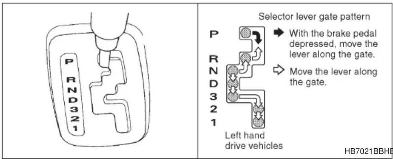
The selector lever has seven positions.
▼P (Park)
This position is for parking the vehicle and starting the engine.
In this position, the transmission is mechanically locked to prevent the vehicle from rolling freely.
When you park the vehicle, first set the parking brake fully, then shift into the "P" position. Do not hold the vehicle with only the transmission.
A shift interlock function is employed in the automatic transmission system to ensure safe starting of the vehicle.
To shift the selector lever from the “P” to the any other position, you have to depress the brake pedal fully when the ignition switch is in the “ON” position. This prevents the vehicle from lurching when it is started.
If the shift lever does not move from the “P” position with the brake pedal depressed, refer to the “Shift lock release” section in this chapter.
▼R (Reverse)
This position is for backing the vehicle.
To shift from the “N” to “R” position, first stop the vehicle completely then move the lever to the “R” position.
▼N (Neutral)
WARNING
Do not drive the vehicle with the selector lever in the “N” (neutral) position. Engine braking has no effect in this condition and the risk of an accident is consequently increased.
This position is for restarting a stalled engine.
In this position the wheels and transmission are not locked. In this position, the transmission is neutral; the vehicle will roll freely, even on the slightest incline unless the parking brake or foot brake is on.
▼D (Drive)
This position is for normal driving.
The transmission automatically shifts into a suitable gear from 1st to 4th according to the vehicle speed and the acceleration you require.
When more acceleration is required in this position, press the accelerator pedal fully to the floor and hold that position. The transmission will automatically downshift to 3rd, 2nd or 1st gear. When you release the pedal, the transmission will return to the original gear position.
While climbing a grade
When driving up a hill, undesired upshift to 4th gear is prevented from
taking place when the accelerator is released. This minimizes the chance of subsequent downshifting to a lower gear when accelerating again. This prevents repeated upshifting and downshifting resulting in a smoother operation of the vehicle.
NOTE
The transmission may downshift to 2nd or 1st gear, depending on the way the accelerator pedal is pressed to accelerate the vehicle again.
While going down a hill
When descending a steep hill, depressing the brake pedal will cause the transmission to downshift to 3rd gear, thus applying engine braking. Reacceleration for a short time will cause the transmission to upshift normally.
NOTE
In some cases, depressing the brake pedal on a downhill grade does not result in an automatic downshift to 3rd gear. This can happen when the automatic transmission fluid temperature is very low, for example, during driving shortly after the vehicle has been parked for an extended period of time. When the ATF temperature has risen to a certain level, automatic downshift normally takes place. In the meantime, downshift manually for engine braking as required.
Also, downshifting when braking downhill will not occur at speeds above approximately 50 mph (80 km/h).
▼3 (Third)
This position is for using engine braking when going down a hill or for climbing a grade.
The transmission automatically shifts into a suitable gear from 1st to 3rd according to the vehicle speed and the acceleration you require.
When more acceleration is required in this position, press the accelerator pedal fully to the floor and hold that position. The transmission will automatically downshift to 2nd or 1st gear. When you release the pedal, the transmission will return to the original gear position.
- CONTINUED -
▼2 (Second)
This position is for using engine braking when going down a hill or for climbing a steep grade.
In this position, the transmission holds in the 2nd gear.
Use this position when starting off from a standstill on slippery road surfaces such as mud or snow. It will ensure greater traction.
▼1 (First)
This position is for driving up or down very steep grades, or driving through mud or sand, or on slippery surfaces. In this position, the transmission holds in the 1st gear.
▼Maximum speeds

WARNING
When shifting down a gear, ensure that the vehicle is not travelling at a speed exceeding the Maximum Allowable Speed for the gear which is about to be selected. Failure to observe this precaution can lead to engine over-revving and this in turn can result in engine damage.
In addition, sudden application of engine brakes when the vehicle is travelling on a slippery surface can lead to wheel locking; as a consequence, control of the vehicle may be lost and the risk of an accident increased.
The following tables show the maximum speeds that are possible with each different gear. The tachometer's (if so equipped) needle will enter the red area if these speeds are exceeded.
When shifting down a gear, it is important to confirm that the current vehicle speed is not in excess of the Maximum Allowable Speed of the gear which is about to be selected.
Exceeding the Maximum Allowable Speeds will result in over-revving of the engine. In addition a powerful engine brake will engage and control of the vehicle may be lost.
mph (km/h)
| Position\Vehicle type | Brighton, I_L | GT | OUTBACK | |
| 2.5 liter 3.0 | liter | |||
| 1 35 (56) | 29 (47) 31 (50) | 35 (57) | ||
| 2 | 64 (103) | 58 (93) | 62 (100) | 69 (111) |
| 3 100 (1) | 61) 96 (154) 102 | (164) 111 (178) | ||
NOTE
In order to prevent over-revving during deceleration of the vehicle, the transmission will remain in the current gear if the speed of the vehicle is in excess of the Maximum Allowable Speed for the gear to which the selector lever has been moved.
▼Driving tips
- Always apply the foot or parking brake when the vehicle is stopped in the “D”, “3”, “2”, “1” or “R” position.
- Always set the parking brake when parking your vehicle. Do not hold the vehicle with only the transmission.
- Do not keep the vehicle in a stationary position on an uphill grade by using the “D”, “3”, “2”, or “1” position. Use the brake instead.
Shift lock release
If the selector lever does not move from the "P" position with the brake pedal depressed and the ignition switch in the "ON" position, perform the following steps:
To override the shift lock:
- Set the parking brake and stop the engine.
- Take out the screwdriver from the tool bag.
- Remove the cover by prying on the edge with the regular screwdriver.
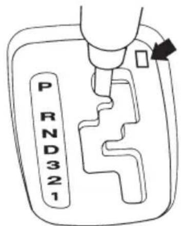
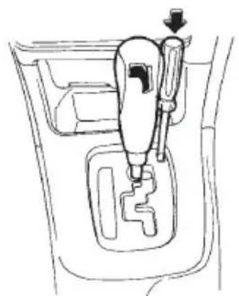
natural_image
Line drawing of a mechanical device inside a car gear shift lever (no text or symbols)HB7020BAHB7010CA
- Insert the screwdriver into the hole.
- Push down on the screwdriver and move the selector lever from the "P" to the "N" position.
- Remove the screwdriver from the hole. Depress the brake pedal and start the engine.
Take your vehicle to the nearest SUBARU dealer immediately to have the system repaired.
Rear viscous limited slip differential (LSD) (if equipped)

CAUTION
●Never start the engine while a tire on one side is jacked up, as the vehicle may move.
- If one rear tire is spinning in mud, avoid continued spinning at high speed as this could adversely affect the LSD.
- If a different size rear tire is temporarily used (as in an emergency), it will adversely affect the LSD. Always replace it with a regular size tire as soon as possible.
The LSD provides optimum distribution of power according to the difference in revolutions between the right and left rear wheels that may be caused by certain driving conditions, thereby improving driving stability on snow-covered, muddy or other slippery roads.
Power steering

CAUTION
Do not hold the steering wheel at the fully locked position left or right for more than five seconds. This may damage the power steering pump.
The power steering system operates only when the engine is running. If you lose power steering assist because the engine stops or the system fails to function, you can steer but it will take much more effort.
NOTE
Right after the engine has been started and before it has warmed up, you may hear a noise coming from areas adjacent to the power steering pump which is located at the right-front area of the engine compartment. This noise is normal. It does not indicate power steering system trouble.
Braking
Braking tips

WARNING
Never rest your foot on the brake pedal while driving. This can cause dangerous overheating of the brakes and needless wear on the brake pads and linings.
▼When the brakes get wet
When driving in rain or after washing the vehicle, the brakes may get wet. As a result, brake stopping distance will be longer. To dry the brakes, drive the vehicle at a safe speed while lightly depressing the brake pedal to heat up the brakes.
▼Use of engine braking
Remember to make use of engine braking in addition to foot braking. When descending a grade, if only the foot brake is used, the brakes may start working improperly because of brake fluid overheating, caused by overheated brake pads. To help prevent this, shift into a lower gear to get stronger engine braking.
▼Braking when a tire is punctured
Do not depress the brake pedal suddenly when a tire is punctured. This could cause a loss of control of the vehicle. Keep driving straight ahead while gradually reducing speed. Then slowly pull off the road to a safe place.
Brake system
▼Two separate circuits
Your vehicle has two separate circuit brake systems. Each circuit works diagonally across the vehicle. If one circuit of the brake system should fail, the other half of the system still works. If one circuit fails, the brake pedal will go down much closer to the floor than usual and you will need to press it down much harder. And a much longer distance will be needed to stop the vehicle.
▼Brake booster
The brake booster uses engine manifold vacuum to assist braking force. Do not turn off the engine while driving because that will turn off the brake booster, resulting in poor braking power.
The brakes will continue to work even when the brake booster completely stops functioning. If this happens, however, you will have to push the pedal much harder than normal and the braking distance will increase.
■Disc brake pad wear warning indicators
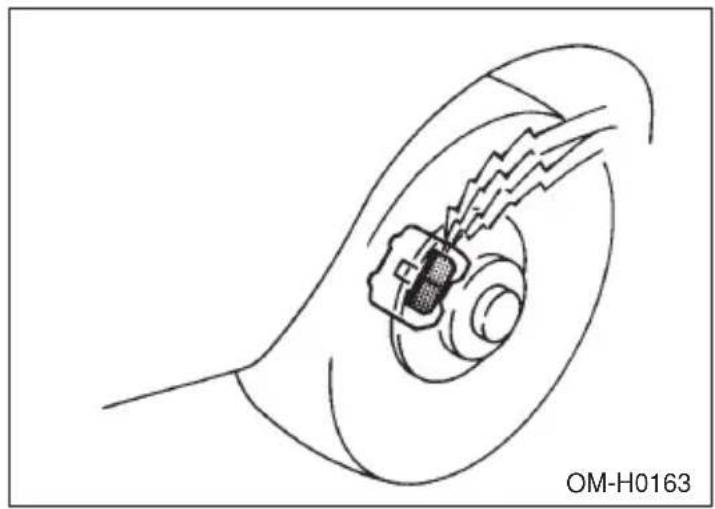
natural_image
Diagram of a mechanical or electrical component inside a circular housing, with no visible text or symbols.The disc brake pad wear warning indicators on the disc brakes give a warning noise when the brake pads are worn.
If a squeaking or scraping noise is heard from the disc brakes while braking, immediately have your vehicle checked by your SUBARU dealer.
ABS (Anti-lock Brake System)

WARNING
Always use the utmost care in driving – overconfidence because you are driving with an ABS equipped vehicle could easily lead to a serious accident.

CAUTION
●The ABS system does not always decrease stopping distance. You should always maintain a safe following distance from other vehicles.
- When driving on badly surfaced roads, gravel roads, icy road, or over deep newly fallen snow, stopping distances may be longer for a vehicle with the ABS system than one without. When driving under these conditions, therefore, reduce your speed and
leave ample distance from other vehicles.
- When you feel the ABS system operating, you should maintain constant brake pedal pressure. Do not pump the brake pedal since doing so may defeat the operation of the ABS system.
The ABS system prevents the lock-up of wheels which may occur during sudden braking or braking on slippery road surfaces. This helps prevent the loss of steering control and directional stability caused by wheel lock-up.
When the ABS system is operating, you may hear a chattering noise or feel a slight vibration in the brake pedal. This is normal when the ABS operates.
The ABS system will not operate when the vehicle speed is below approximately 6 mph (10 km/h).
▼ABS system self-check
You may feel a slight shock in the brake pedal and hear the operating sound of ABS from the engine compartment just after the vehicle is started. This is caused by an automatic functional test of the ABS system being carried out and does not indicate any abnormal condition.
▼ABS warning light
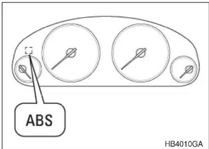
The ABS warning light comes on when the ignition switch is turned to the "ON" position and goes out after about two seconds.
This is an indication that the ABS system is working properly.

CAUTION
If the warning light behaves as follows, the ABS system may not be working properly.
When the warning light is on, the ABS function shuts down; however, the conventional brake system continues to operate normally.
- The warning light does not come on when the ignition switch is turned to the “ON” position.
- The warning light comes on when the ignition switch is turned to the “ON” position, but it does not go out even when the vehicle speed exceeds approximately 8 mph (12 km/h).
- The warning light comes on during driving. If these occur, have the ABS system repaired at the first available opportunity by your SUBARU dealer.
NOTE
If the warning light behavior is as described below, the ABS system may be considered normal.
●The warning light comes on right after the engine is started but goes out immediately, remaining off.
- The warning light remains on after the engine has been started, but it goes out when the vehicle speed reaches about 8 mph (12 km/h).
●The warning light comes on during driving, but it goes out immediately and remains off.
When driving with an insufficient battery voltage such as when the engine is jump started, the ABS warning light may come on. This is due to the low battery voltage and does not indicate a malfunction. When the battery becomes fully charged, the light will go out.
VDC (Vehicle Dynamics Control) system (if equipped)

WARNING
Always use the utmost care in driving — overconfidence because you are driving with a VDC system equipped vehicle could easily lead to a serious accident.

CAUTION
- Even if your vehicle is equipped with VDC, winter tires should be used when driving on snow-covered or icy roads; in addition, vehicle speed should be reduced considerably. Simply having a VDC system does not guarantee that the vehicle will be able to avoid accidents in any situation.
- Activation of the VDC system is an indication that the road being travelled on has a slippery surface; since having VDC is no guarantee that full vehicle control will be maintained at all times and under all conditions, its activation should be seen as a sign that the speed of the vehicle should be reduced considerably.
-
Whenever suspension components, steering components, or an axle are removed from a vehicle equipped with VDC, have an authorized SUBARU dealer perform an inspection of that system.
●The following precautions should be observed in order to ensure that the VDC system is operating properly: -
All four wheels should be fitted with tires of the same size, type, and brand. Furthermore, the amount of wear should be the same for all four tires.
- Keep the tire pressure at the proper level as shown on the label attached to the vehicle's door pillar.
- Use only the special temporary spare tire to replace a flat tire. With a temporary spare tire, the effectiveness of the VDC system is reduced and this should be taken into account when driving with vehicle.
In the event of wheelspin and/or skidding on a slippery road surface and/or during cornering and/or an evasive maneuver, the VDC system adjusts the engine's output and the wheels' respective braking forces to help maintain traction and directional control.
●Traction Control Function
The traction control function is designed to prevent spinning of the driving wheels on slippery road surfaces, thereby helping to maintain traction and directional control. Activation of this function is shown by steady illumination of the VDC operation indicator light.
●Skid Suppression Function
The skid suppression function is designed to help maintain directional stability by suppressing the wheels' tendency to slide sideways during steering operations. Activation of this function is shown by flashing of the VDC operation indicator light.
NOTE
- Slight twitching of the brake pedal may be felt when the VDC-system operates; a small degree of vehicle or steering wheel shaking may also be noticed in this situation. These are normal characteristics of VDC operation and are no cause for alarm.
- When driving off immediately after starting the engine, a short-lived operation noise may be noticed coming from the engine compartment. This noise is generated as a result of a check being performed on the VDC system and is normal.
- Depending on the timing of activation of the brakes, certain situations may occur just after driving off where the brake pedal seems to exhibit a jolting motion. This too is a consequence of the VDC operational check and is normal.
- Activation of the VDC system will cause operation of the steering wheel to feel slightly different compared to that for normal conditions.
- Even if the vehicle is equipped with a VDC system, it is important that winter tires be used when driving on snow-covered or icy roads. (All four wheels should be fitted with tires of the same size and brand).
- It is always important to reduce speed when approaching a corner, even if the vehicle is equipped with VDC.
- All four wheels should be fitted with tires of the same size, type, and brand; furthermore, the amount of wear should be the same for all four tires. If these precautions are not observed and non-matching tires are used, it is quite possible that the VDC system will be unable to operate correctly as intended.
●Always turn off the engine before replacing a tire as failure to do so may render the VDC system unable to operate correctly.
▼VDC system monitor
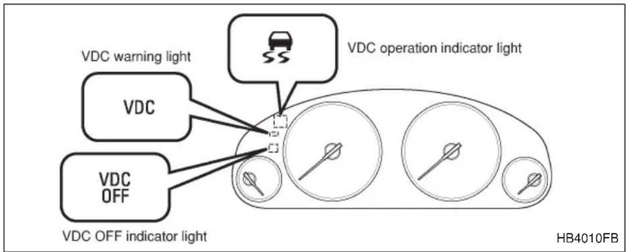
▽ VDC OFF indicator light
●The VDC OFF indicator light turns on initially when the ignition key is turned to the ON position; it subsequently turns off 6 seconds after the engine is started.
●This light turns on to indicate that the VDC system is in non-operation mode. This does not constitute failure of the VDC system.
NOTE
●The VDC OFF indicator light may stay on for a while after the engine has been started, especially in cold weather. This occurs because the engine has not yet warmed up and is completely normal. The light will turn off when the engine has reached a suitable operating temperature.
- When an engine problem occurs and the CHECK ENGINE
warning light turns on, the VDC OFF indicator light will also turn on.
The following two situations could indicate malfunction of the VDC system; if either should occur, have an authorized SUBARU dealer carry out an inspection of that system at the first available opportunity.
- The VDC OFF indicator light does not turn on when the ignition key is turned to the ON position.
- The VDC OFF indicator light fails to turn off after the engine is started, even when several minutes have passed to allow the engine to heat up sufficiently.
▽ VDC operation indicator light
The VDC operation indicator light turns on when the ignition key is turned to the ON position; it turns off approximately two seconds later. This indicator light flashes during activation of the skid suppression function and is illuminated steadily during activation of the traction control function.
The following two situations could indicate a malfunction of the VDC system; if either should occur, have an authorized SUBARU dealer carry out an inspection of that system at the first available opportunity.
●The VDC operation indicator light does not turn on when the ignition key is turned to the ON position.
●The VDC operation indicator light does not turn off approximately two seconds after the ignition key has been turned to the ON position.
▽ VDC warning light
The VDC warning light turns on when the ignition key is turned to the ON position and off when the engine is started. This lighting pattern indicates that the VDC system is operating normally.
The following situations could indicate a malfunction of the VDC system; if any should occur, have an authorized SUBARU dealer carry out an inspection of the system at the first available opportunity.
●The VDC warning light does not turn on when the ignition key is turned to the ON position.
●The VDC warning light does not turn off either when the engine is
started or when the vehicle reaches a speed of approximately 8 mph (12 km/h).
●The VDC warning light turns on while the vehicle is being driven.
- When a malfunction has occurred in the VDC electrical system, only the VDC warning light will turn on. In such an event, the ABS will still be operating normally.
●The VDC warning light will also turn on when a problem occurs with the ABS or VDC electronic control systems.
Because the VDC system controls each brake through the ABS, whenever the ABS stops operating due to a malfunction in that electrical system, the VDC will also become unable to control all four brakes. Thus VDC system operation halts and the VDC warning light turns on. Although both the VDC system and the ABS will be inoperable in this situation, it will still be possible to stop the vehicle using normal braking. The VDC system and the ABS do not adversely affect operation of the vehicle in any way when they are inoperable; however should such a situation occur, drive with care and have an authorized SUBARU dealer carry out an inspection of those systems at the first available opportunity.
NOTE
When the VDC warning light turns on and off in the following way, it indicates that the VDC system is operating normally.
- Although turning on after the engine has been started, the warning light quickly turns off and stays off.
●The warning light turns on after the engine is started and does not turn off until the vehicle reaches a speed of 8 mph (12 km/h).
●The warning light turns on when the vehicle is being driven; it then turns off and stays off.
■VDC OFF switch
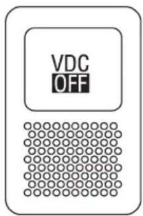
HB7022AA
Note: Even when the lighting switch is turned to the “ ∅ or “ ≡D ” position, the “OFF” portion of the symbol stamped on the switch will not illuminate in the dark. Only “VDC” portion will illuminate.
Pressing the VDC OFF switch to deactivate the VDC system can facilitate the following operations:
- a standing start on a steeply sloping road with a snowy, gravel-covered, or otherwise slippery surface
●extrication of the vehicle when its wheels are stuck in mud or deep snow
When the VDC OFF switch is pressed during engine operation, the VDC OFF indicator light illuminates.
The VDC system will be deactivated and the vehicle will behave like a model not equipped with the VDC system.
When the VDC OFF switch is pressed again to reactivate the VDC system, the VDC OFF indicator light goes off.
If the vehicle reaches a speed of approximately 37 mph (60 km/h) after the VDC OFF switch is pressed to deactivate the VDC system, the VDC system automatically reactivates itself and the VDC OFF indicator light goes off. While the vehicle is moving at a speed of approximately 37 mph (60 km/h) or higher, it is not possible to deactivate the VDC system by pressing the VDC OFF switch.
With the VDC system deactivated, traction and stability enhancement offered by VDC system is unavailable. Therefore you should not deactivate
- CONTINUED -
the VDC system except under above-mentioned situations.
NOTE
- When the VDC switch has been pressed to deactivate the VDC system, the VDC system automatically reactivates itself the next time the ignition key is turned to the OFF position and the engine is restarted.
- If the VDC OFF switch is held down for 10 seconds or longer, the VDC OFF indicator light goes off, the VDC system is activated, and the system ignores any further pressing of the VDC OFF switch. To make the VDC OFF switch usable again, turn the ignition key to the OFF position and restart the engine.
Parking your vehicle

WARNING
- Never leave unattended children or pets in the vehicle. They could accidentally injure themselves or others through inadvertent operation of the vehicle. Also, on hot or sunny days, the temperature in a closed vehicle could quickly become high enough to cause severe or possibly fatal injuries to them.
- Do not park the vehicle over flammable materials such as dry grass, waste paper or rags, as they may burn easily if they come near hot engine or exhaust system parts.
- Be sure to stop the engine if you take a nap in the vehicle. If engine exhaust gas enters the passenger compartment, occupants in the vehicle could die from carbon monoxide (CO) contained in the exhaust gas.

CAUTION
Never drive while the parking brake is set because this will cause unnecessary wear on the brake linings. Before starting to drive, always make sure that the parking brake has been fully released.
To set the parking brake, press the brake pedal firmly and hold it down while fully pulling up the parking brake lever.
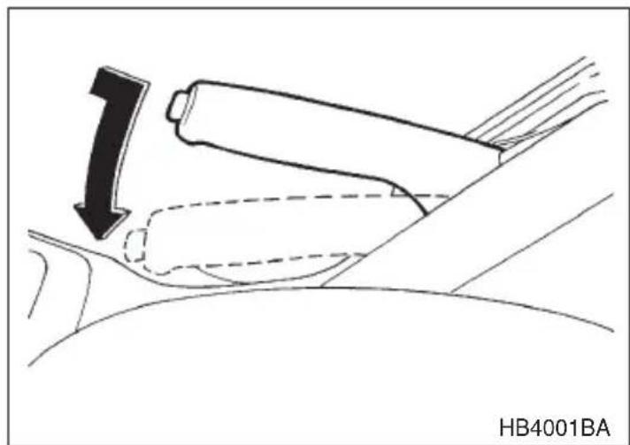
natural_image
Diagram of a car seatbelt mechanism with a downward arrow indicating force or motion (no text or symbols)To release the parking brake, pull the lever up slightly, press the release button, then lower the lever while keeping the button pressed.
When the parking brake is set while the engine is running, the parking brake warning light comes on. After starting the vehicle, be sure that the warning light has gone out before the vehicle is driven. Refer to the "Warning and indicator lights" section (chapter 3).
When parking your vehicle, always set the parking brake firmly and put the shift lever in the “1” (1st) for an upgrade or “R” (Reverse) for a downgrade for manual transmission vehicles, or in the “P” (Park) position for automatic transmission vehicles. Always set the parking brake firmly when parking your vehicle. Never rely on the transmission alone to hold the vehicle.
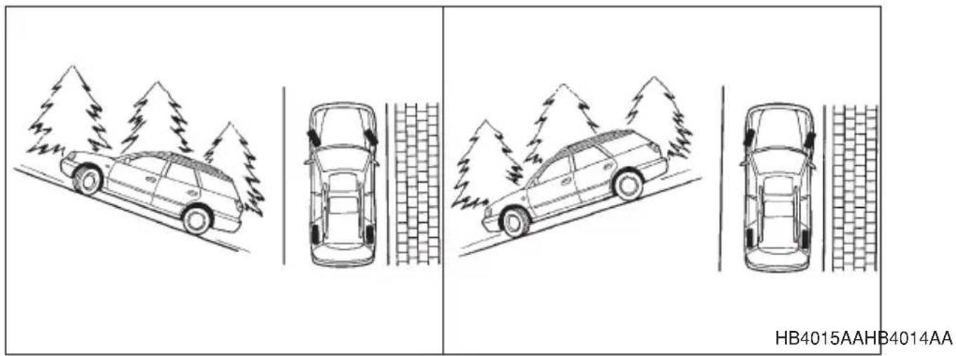
When parking on a hill, always turn the steering wheel. When the vehicle is headed up the hill, the front wheels should be turned away from the curb. When facing downhill, the front wheels should be turned into the curb.
Cruise control (if equipped)
WARNING
Do not use the cruise control under any of the following conditions. This may cause loss of vehicle control:
●driving up or down a steep grade
●driving on slippery or winding roads
●driving in heavy traffic
Cruise control enables you to maintain a constant vehicle speed without holding your foot on the accelerator pedal and it is operative when the vehicle speed is 25 mph (40 km/h) or more. Make sure the main switch is turned “OFF” when the cruise control is not in use to avoid unintentionally by setting the cruise control.
▼To set cruise control
Main switch
Cruise control lever
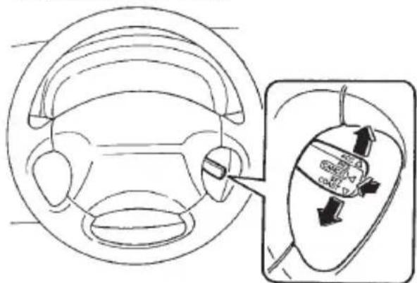
natural_image
Diagram of a car steering wheel and its internal gear mechanism (no text or labels)HG0312HB3002BB
- Push the "CRUISE" main switch. The indicator light on the switch will come on.
- Depress the accelerator pedal until the vehicle reaches the desired speed.
- Push the control lever downward in the "SET, COAST" direction and release it. Then release the accelerator pedal.
The vehicle will maintain the desired speed.
Vehicle speed can be temporarily increased while driving with the cruise control activated. Simply depress the accelerator pedal to accelerate the vehicle. When the accelerator pedal is released, the vehicle will return to and maintain the previous cruising speed.
▼To temporarily cancel the cruise control
There are four ways to cancel the cruise control temporarily:
●Depress the brake pedal.
- Pull the control lever in the "CANCEL" direction. (if so equipped)
- Depress the clutch pedal (manual transmission vehicles only).
- Shift the selector lever into the "N" position (automatic transmission vehicles only).
To resume the cruise control after it has been temporarily canceled and with vehicle speed of about 20 mph (32 km/h) or more, push the control lever upward in the “ACCEL, RESUME” direction to return to the original cruising speed automatically.
- CONTINUED -
▼To turn off the cruise control
There are two ways to turn off the cruise control:
- Push the main switch again.
- Turn the ignition switch to the “ACC” position (but only when the vehicle is completely stopped).
▼To change the cruising speed
∇ To increase the speed (by control lever)
Push the control lever upward in the “ACCEL, RESUME” direction and hold it until the vehicle reaches the desired speed. Then, release the control lever. The vehicle speed at that moment will be memorized and treated as the new set speed.
When the difference between the actual vehicle speed and the set speed is less than 4 mph (6.8 km/h), the set speed can be increased 1 mph (1.6 km/h) each time by pressing the control lever upward in the “ACCEL, RESUME” direction quickly within a half second.
∇ To increase the speed (by accelerator pedal)
- Depress the accelerator pedal to accelerate the vehicle to the desired speed.
- Push the control lever downward in the “SET, COAST” direction once. Now the desired speed is set and the vehicle will keep running at that speed without depressing the accelerator pedal.
NOTE
If the difference between the actual vehicle speed when the control lever is pushed downward and the speed last time you set is less than 4 mph (6.8 km/h), the vehicle speed will be lowered by 1 mph (1.6 km/h). This occurs because the cruise control system unit regards this lever operation as that intended to decrease the vehicle speed.
∇ To decrease the speed (by control lever)
Push the control lever downward in the “SET, COAST” direction and hold it until the vehicle reaches the desired speed. Then, release the control lever. The vehicle speed at that moment will be memorized and treated as the new set speed.
When the difference between the actual vehicle speed and the set speed is less than 4 mph (6.8 km/h), the set speed can be lowered 1 mph (1.6 km/h) each time by pressing the control lever downward in the “SET, COAST” direction quickly within a half second.
∇ To decrease the speed (by brake pedal)
- Depress the brake pedal to release cruise control temporarily.
- When the speed decreases to the desired speed, press the control lever downward in the “SET, COAST” direction once. Now the desired speed is set and the vehicle will keep running at that speed without depressing the accelerator pedal.
Driving tips
New vehicle break-in driving – the first 1,000 miles (1,600 km) 8-2
Fuel economy hints 8-3
Engine exhaust gas (Carbon monoxide) 8-3
Catalytic converter 8-4
Periodic inspections 8-5
Driving in foreign countries 8-5
Driving tips for AWD vehicles 8-6
Off road driving 8-7
Winter driving 8-10
Snow tires 8-14
Tire chains 8-16
Rocking the vehicle 8-16
Loading your vehicle 8-17
Vehicle capacity weight 8-18
GVWR and GAWR (Gross Vehicle Weight Rating and Gross Axle Weight Rating) 8-19
Roof rail and crossbar (if equipped) 8-20
Trailer hitch (if equipped) 8-24
Trailer towing 8-28
New vehicle break-in driving – the first 1,000 miles (1,600 km)
The performance and long life of your vehicle are dependent on how you handle and care for your vehicle while it is new. Follow these instructions during the first 1,000 miles (1,600 km):
- Do not race the engine.
▼Break-in engine speed limit
●Vehicle with tachometer
Never exceed 4,000 rpm engine speed except for brief acceleration in an emergency.
●Vehicle without tachometer (for manual transmission)
Do not exceed the speed limits below for each gear position except for brief acceleration in an emergency.
mph (km/h)
| 1st | 2nd 3rd 4th | ||
| 22 (35) 37 (60) | 50 (80) 65 (105) |
●Vehicles without tachometer (for automatic transmission)
Try to drive at moderate speeds while accelerating and braking smoothly. Proper gears are selected automatically according to the driving conditions.
- Do not drive at one constant engine or vehicle speed for a long time, either fast or slow.
- Avoid starting suddenly and rapid acceleration, except in an emergency.
- Avoid hard braking, except in an emergency.
The same break-in procedures should be applied to a newly installed or overhauled engine or when brake pads or brake linings are replaced with new ones.
Fuel economy hints
The following suggestions will help to save your fuel.
- Select the proper gear position for the speed and road conditions.
- Avoid sudden acceleration or deceleration. Always accelerate gently until you reach the desired speed. Then try to maintain that speed for as long as possible.
- Do not pump the accelerator and avoid racing the engine.
- Avoid unnecessary engine idling.
- Keep the engine properly tuned.
- Keep the tires inflated to the correct pressure shown on the tire placard, which is located under the door latch on the driver's side. Low pressure will increase tire wear and fuel consumption.
- Use the air conditioner only when necessary.
- Keep the front and rear wheels in proper alignment.
- Avoid carrying unnecessary luggage or cargo.
Engine exhaust gas (Carbon monoxide)

WARNING
- Never inhale engine exhaust gas. Engine exhaust gas contains carbon monoxide, a colorless and odorless gas which is dangerous, or even lethal, if inhaled.
●Always properly maintain the engine exhaust system to prevent engine exhaust gas from entering the vehicle. - Never run the engine in a closed space, such as a garage, except for the brief time needed to drive the vehicle in or out of it.
- Avoid remaining in a parked vehicle for a lengthy time while the engine is running. If that is unavoidable, then use the ventilation fan to force fresh air into the vehicle.
●Always keep the front ventilator inlet grille free from snow, leaves or other obstructions to ensure that the ventilation system always works properly.
- CONTINUED -
- If at any time you suspect that exhaust fumes are entering the vehicle, have the problem checked and corrected as soon as possible. If you must drive under these conditions, drive only with all windows fully open.
- Keep the trunk lid or rear gate closed while driving to prevent exhaust gas from entering the vehicle.
NOTE
Due to the expansion and contraction of the metals used in the manufacture of the exhaust system, you may hear a crackling sound coming from the exhaust system for a short time after the engine has been shut off. This sound is normal.
Catalytic converter

WARNING
- Avoid fire hazards. Do not drive or park the vehicle anywhere near flammable materials (e.g. grass, paper, rags or leaves), because the catalytic converter operates at very high temperatures.
- Keep everyone and flammable materials away from the exhaust pipe while the engine is running. The exhaust gas is very hot.
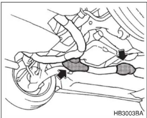
natural_image
Mechanical assembly diagram showing a car wheel and attached components with directional arrows (no text or symbols)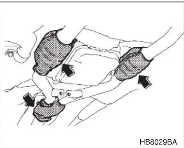
The catalytic converter is installed in the exhaust system. It serves as catalyst to reduce HC, CO and NOx in exhaust gases, thus providing cleaner exhaust.
To avoid damage to the catalytic converter:
- Use only unleaded gasoline. Even a small amount of leaded gasoline will damage the catalytic converter.
●Never start the engine by pushing or pulling the vehicle. - Avoid racing the engine.
●Never turn off the ignition switch while the vehicle is moving. - Keep your engine tuned-up. If you feel the engine running rough (mis-firing, backfiring or incomplete combustion), have your vehicle checked and repaired by an authorized SUBARU dealer.
- Do not apply undercoating or rust prevention treatment to the heat shield of catalytic converter and the exhaust system.
Periodic inspections
To keep your vehicle in the best condition at all times, always have the recommended maintenance services listed in the maintenance schedule in the “Warranty and Maintenance Booklet” performed at the specified time or mileage intervals.
Driving in foreign countries
When planning to use your vehicle in another country:
- Confirm the availability of the correct fuel. (Refer to the “Fuel requirement” section in chapter 7.)
- Comply with all regulations and requirements of each country.
Driving tips for AWD vehicles

WARNING
●Always maintain a safe driving speed according to the road and weather conditions in order to avoid having an accident on a sharp turn, during sudden braking or under other similar conditions.
- Always use the utmost care in driving – overconfidence because you are driving an all wheel drive vehicle could easily lead to a serious accident.
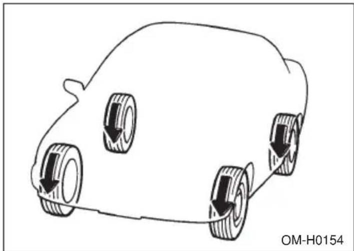
natural_image
Line drawing of a car with three wheels and downward arrows indicating motion or movement (no text or symbols)All wheel drive distributes the engine power to all four wheels. AWD vehicles provide better traction when driving on slippery, wet or snow-covered roads and when moving out of mud, dirt and sand. By shifting power between the front and rear wheels, SUBARU AWD can also provide added traction during acceleration, and added engine braking force during deceleration.
Therefore, your SUBARU AWD vehicle may handle differently than an ordinary two wheel drive vehicle and it contains some features unique to AWD. For safety purposes as well as to avoid damaging the AWD system, you should keep the following tips in mind:
- An AWD vehicle is better able to climb steeper roads under snowy or slippery conditions than a two wheel drive vehicle. There is little difference in handling, however, during extremely sharp turns or sudden brak-
ing. Therefore, when driving down a slope or turning corners, be sure to reduce your speed and maintain an ample distance from other vehicles.
- When replacing a tire, make sure you use only the same size, circumference, construction, brand, and load range as the original tires listed on the tire placard. Using other sizes, circumferences or construction may result in severe mechanical damage to the drive train of your vehicle and may affect ride, handling, braking, speedometer/odometer calibration, and clearance between the body and tires. It also may be dangerous and lead to loss of vehicle control.
- If you use a temporary spare tire to replace a flat tire, be sure to use the original temporary spare tire stored in the vehicle. Using other sizes may result in severe mechanical damage to the drive train of your vehicle.
- Always check the cold tire pressure before starting to drive. The recommended tire pressure is provided on the tire placard, which is located under the door latch on the driver's side.
●Tire chains should always be placed on the front wheels only. - There are some precautions that you must observe when towing your vehicle. For detail information, see “Towing” section in chapter 9.
Off road driving

WARNING
●Always maintain a safe driving speed according to the road and weather conditions in order to avoid having an accident on a sharp turn, during sudden braking or under other similar conditions.
- Always use the utmost care in driving – overconfidence because you are driving an all wheel drive vehicle could easily lead to a serious accident.
▼All AWD models except OUTBACK
Your AWD vehicle is neither a conventional off-road vehicle nor an all terrain vehicle. It is a passenger car designed primarily for on-road use. The AWD feature gives it some limited off-road capabilities in situations in which driving surfaces a relatively level, obstruction-free
- CONTINUED -
and otherwise similar to on-road driving conditions. Operating it under other than those conditions could subject the vehicle to excessive stress which might result in damage not eligible for repair under warranty. If you do take your SUBARU off road, you should review the common sense precautions in the next section (applicable to the OUTBACK) for general guidance. But please keep in mind that your vehicle's off-road capabilities are more limited than those of the OUTBACK.
Never attempt to drive through pools and puddles, or roads flooded with water. Water entering the engine air intake or the exhaust pipe or water splashing onto electrical parts may damage your vehicle and may cause it to stall.
▼OUTBACK
Because of the AWD feature and higher ground clearance, your Subaru can be driven on ordinary roads or off-road. But please keep in mind that an AWD Subaru is a passenger car and is neither a conventional off-road vehicle nor an all-terrain vehicle. If you do take your Subaru off-road, certain common sense precautions such as the following should be taken:
- Make certain that you and all of your passengers are wearing seat belts.
- Carry some emergency equipment, such as a towing rope or chain, a shovel, wheel blocks, first aid kit and portable phone or citizens band radio.
- Drive carefully. Do not take unnecessary risks by driving in dangerous areas or over rough terrain.
- Slow down and employ extra caution at all times. When driving off-road, you will not have the benefit of marked traffic lanes, banked curves, traffic signs and the like.
- Do not drive across steep slopes. Instead, drive either straight up or straight down the slopes. A vehicle can much more easily tip over sideways than it can end over end. Avoid driving straight up or down slopes that are too steep.
- Avoid sharp turning maneuvers, especially at higher speeds.
- Do not grip the inside or spokes of the steering wheel. A bad
bump could jerk the wheel and injure your hands. Instead drive with your fingers and thumbs on the outside of the rim.
- If driving through water, such as when crossing shallow streams, first check the depth of the water and the bottom of the stream bed for firmness and ensure that the bed of the stream is flat. Drive slowly and completely through the stream. The water should be shallow enough that it does not reach the vehicle's undercarriage. Water entering the engine air intake or the exhaust pipe or water splashing onto electrical parts may damage your vehicle and may cause it to stall. Never attempt to drive through rushing water; regardless of its depth, it can wash away the ground from under your tires, resulting in possible loss of traction and even vehicle rollover.
●Always check your brakes for effectiveness immediately after driving in sand, mud or water. Do this by driving slowly and stepping on the brake pedal. Repeat that process several times to dry out the brake discs and brake pads.
- Do not drive or park over or near flammable materials such as dry grass or fallen leaves, as they may burn easily. The exhaust system is very hot while the engine is running and right after engine stops. This could create a fire hazard.
- After driving through tall grass, mud, rock, sand, rivers, etc., check that there is no grass, bush, paper, rags, stones, sand, etc. adhering to or trapped on the underbody. Clear off any such matter from the underbody. If the vehicle is used with these materials trapped or adhering to the underbody, a mechanical breakdown or fire could occur.
- Secure all cargo carried inside the vehicle and make certain that it is not piled higher than the seatbacks. During sudden stops or jolts, unsecured cargo could be thrown around in the vehicle and cause injury. Do not pile heavy loads on the roof. Those loads raise the vehicle's center of gravity and make it more prone to tip over.
- If you must rock the vehicle to free it from sand or mud, depress the accelerator pedal slightly and move the selector lever back and forth between “D” and “R” repeatedly. Do not race the engine. For the best possible traction, avoid spinning the wheels when trying to free the vehicle.
- When the road surface is extremely slippery, you can obtain better
- CONTINUED -
traction by starting the vehicle with the transmission in 2nd than 1st (both for MT and AT).
●Never equip your vehicle with tires larger than those specified in this manual.
- Frequent driving of an AWD vehicle under hard-driving conditions such as rough roads or off roads will necessitate more frequent replacement of engine oil, brake fluid and transmission oil than that specified in the maintenance schedule described in the “Warranty and Maintenance Booklet”.
Remember that damage done to your Subaru while operating it off-road and not using common sense precautions such as those listed above is not eligible for warranty coverage.
Winter driving
natural_image
Line drawing of a snowman standing in a snowy mountain landscape with a car driving on the road (no text or symbols)▼Operation during cold weather
Carry some emergency equipment, such as tire chains, a window scraper, a bag of sand, flares, a small shovel, and jumper cables.
Check the battery and cables. Cold temperatures reduce battery capacity. The battery must be in good condition to provide enough power for cold winter starts.
Use an engine oil of proper grade and viscosity for cold weather. Heavy summer oil will cause harder starting.
Keep the door locks from freezing by squirting them with deicer or glycerin.
Forcing a frozen door open may damage or separate the rubber weather strips around the door. If the door is frozen, use hot water to melt the ice, and afterwards thoroughly wipe the water away.
Use a windshield washer fluid that contains an antifreeze solution. Do not use engine antifreeze or other substitutes because they may damage the paint of the vehicle.
∇ Before driving your vehicle
Before entering the vehicle, remove any snow or ice from your shoes because that could make the pedals slippery and dangerous.
While warming up the vehicle before driving, check that the accelerator pedal, brake pedal, and all other controls operate smoothly.
Clear away ice and snow that has accumulated under the fenders to avoid making steering difficult. During severe winter driving, stop when and where it is safe to do so and check under the fenders periodically.
∇ Parking in cold weather
WARNING
Snow can trap dangerous exhaust gases under your vehicle. Keep snow clear of the exhaust pipe and from around your vehicle if you park the vehicle in snow with the engine running.
Do not use the parking brake when parking for long periods in cold weather since it could freeze in that position. Instead, observe the following:
- Place the shift lever in “1” or “R” for manual transmission vehicles, and in “P” for automatic transmission vehicles.
- Use tire stops under the tires to prevent the vehicle from moving.
When the vehicle is parked in snow or when it snows, raise the wiper blades off the glass to prevent damage to them.
- CONTINUED -
When the vehicle has been left parked after use on roads heavily covered with snow, or has been left parked during a snowstorm, icing may develop on the brake system, which could cause poor braking action. Check for snow or ice buildup on the suspension, disc brakes and brake hoses underneath the vehicle.
If there is caked snow or ice, remove it, being careful not to damage the disc brakes and brake hoses and ABS harness.
Refueling in cold weather
To help prevent moisture from forming in the fuel system and the risk of its freezing, use of an antifreeze additive in the fuel tank is recommended during cold weather.
Use only additives that are specifically designed for this purpose. When an antifreeze additive is used, its effect lasts longer if the tank is refilled whenever the fuel level reaches half empty.
If your SUBARU is not going to be used for an extended period, it is best to have the fuel tank filled to capacity.
▼Driving on snowy and icy roads

WARNING
Do not use the cruise control on slippery roads such as snowy or icy roads. This may cause loss of vehicle control.
To prevent skidding and slipping, avoid sudden braking, abrupt acceleration, high-speed driving, and sharp turning when driving on snowy or icy roads.
Always maintain ample distance between your vehicle and the vehicle ahead of you to avoid the need for sudden braking.
To supplement the foot brake, use the engine brake effectively to control the vehicle speed. (Shift into a lower gear when necessary.)
Avoid shifting down abruptly. Such behavior can cause the wheels to lock, possibly leading to loss of vehicle control.
An anti-lock brake system (ABS) enhances your vehicle's braking performance on snowy and icy roads. Refer to the “ABS (Anti-Lock Brake System)” and “VDC (Vehicle Dynamics Control) system” section in chapter 7 for information on braking on slippery surfaces.
▽ Wiper operation when snowing
Before driving in cold weather, make sure the wiper blades are not frozen to the windshield or rear window. If the wiper blades are frozen to the windshield or rear window, use the defroster with the airflow control button/dial in the “☐” position and the temperature control dial set for maximum warmth until the wiper blades are completely thawed out. If your vehicle is equipped with a wiper deicer, it is helpful to thaw the windshield wiper blades. To thaw out the rear wiper blade, use the rear window defogger.
When driving in snow, if frozen snow starts to stick on the surface of the windshield despite wiper operation, use the defroster with the airflow control button/dial in “” and the temperature control dial set for maximum warmth. After the windshield gets warmed enough to melt the frozen snow on it, wash it away using the windshield washer.
Snow stuck on the wiper arm prevents the wiper from working effectively. If snow is stuck on the wiper arm, pull off the road to a safe place, then remove it. If you stop the car at road side, use the hazard warning flasher to alert other drivers.
We recommend use of non-freezing type wiper blades (winter blades) during the seasons you could have snow and sub-zero temperatures. Blades of this type give superior wiping performance in snowy conditions. Be sure to use blades that are suitable for your vehicle.
▼Corrosion protection
Refer to the “Corrosion protection” section (chapter 10).
■Snow tires
▼All models except Outback
WARNING
- When replacing original tires with winter (snow) tires, make sure you use only the same size, construction and load range as the original tires listed on the tire placard. Using other sizes and construction may affect speedometer/odometer calibration and clearance between the body and tires. It also may be dangerous and lead to loss of vehicle control.
- You must install four winter tires that are of the same size, circumferences, construction, brand, and load range. Mixing other sizes, circumferences or constructions may result in severe mechanical damage to the drive train of your vehicle and may affect ride, handling, braking and speedometer/odometer calibration. It also may be dangerous and lead to loss of vehicle control.
- Do not use a combination of radial, belted bias or bias tires since it may cause dangerous handling characteristics and lead to an accident.
Your vehicle is equipped with “all season tires” which are designed to provide an adequate measure of traction, handling and braking performance in year-round driving. In winter, it may be possible to enhance performance through use of tires designed specifically for winter driving conditions.
If you choose to install winter tires on your vehicle, be sure to use the correct tire size and type. You must install four winter tires that are of the same size, construction, brand and load range and you should never mix radial, belted bias or bias tires since this may result in dangerous handling characteristics. When you choose a tire, make sure that there is enough clearance between the tire and vehicle body.
Remember to drive with care at all times regardless of the type of tires on your vehicle.
▼Outback models only
WARNING
- When replacing original tires with winter (snow) tires, make sure you use only the same size and construction as recommended. Using other sizes or construction may affect speedometer/odometer calibration and clearance between the body and tires. It also may be dangerous and lead to loss of vehicle control.
- You must install four winter tires that are of the same size, circumferences, construction, brand, and load range. Mixing other sizes, circumferences or constructions may result in severe mechanical damage to the drive train of your vehicle and may affect ride, handling, braking and speedometer/odometer calibration. It also may be dangerous and lead to loss of vehicle control.
- Do not use a combination of radial, belted bias or bias tires since it may cause dangerous handling characteristics and lead to an accident.
Your vehicle is equipped with “all season tires” which are designed to provide an adequate measure of traction, handling and braking performance in year-round driving. In winter, it may be possible to enhance performance through use of tires designed specifically for winter driving conditions.
If you choose to install winter tires on your vehicle, be sure to use the correct tire size and type. You must install four winter tires that are of the same size, construction, brand and load range and you should never mix radial, belted bias or bias tires since this may result in dangerous handling characteristics. When you choose a tire, make sure that there is enough clearance between the tire and vehicle body.
Remember to drive with care at all times regardless of the type of tires on your vehicle.
Your Outback comes with P225/60R16 “all season tires” as original equipment. You should be aware that some winter tires with that same size designation may actually be too large for the
- CONTINUED -
vehicle and may cause rubbing on sharp turns. Listed below is the winter tire size that we recommend.
Recommended winter (snow) tire size P215/60R16 Studless
Tire chains

CAUTION
Tire chains cannot be used on tires listed below because of lack of clearance between the tires and vehicle body.
●P205/55R16 tires for GT models
●P225/60R16 tires for OUTBACK models
●P215/60R16 winter (snow) tires for OUTBACK models
Driving on snowy grades or icy roads may require the use of tire chains, in which case put the chains on the front wheels only. Use only SAE class S type chains that are of the correct size for your tires so as not to damage the vehicle body or suspension.
When driving with tire chains, drive at speeds below 19 mph (30 km/h). When a temporary spare tire is on a front wheel, replace the temporary spare tire with the rear tire on the same side of the vehicle, and then fit chains on the front tires.
Always use the utmost care when driving with tire chains – overconfidence because you are driving with tire chains could easily lead to a serious accident.
■Rocking the vehicle
If you must rock the vehicle to free it from snow, sand, or mud, depress the accelerator pedal slightly and move the selector lever back and forth between “D” and “R” repeatedly. Do not race the engine. For the best possible traction, avoid spinning the wheels when trying to free the vehicle.
When the road surface is extremely slippery, you can obtain better traction by starting the vehicle with the transmission in 2nd than 1st (both for MT and AT).
Refer to the “Automatic transmission” section in chapter 7 for information on holding the transmission in 2nd position.
Loading your vehicle

WARNING
- Never allow passengers to ride on the folded rear seatback, in the trunk or in the cargo area. Doing so may result in serious injury.
- Never stack luggage or other cargo higher than the top of the seatback because it could tumble forward and injure passengers in the event of a sudden stop or accident. Keep luggage or cargo low, as close to the floor as possible.
- When you carry something inside the vehicle, secure it whenever you can to prevent it from being thrown around inside the vehicle during sudden stops, sharp turns or in an accident.
- Do not pile heavy loads on the roof. These loads raise the vehicle’s center of gravity and make it more prone to tip over.
- Secure lengthy items properly to prevent them from shooting forward and causing serious injury during a sudden stop.
- Never exceed the maximum load limit. If you do, some parts on your vehicle can break, or it can change the way your vehicle handles. This could result in loss of control and cause personal injury. Also, overloading can shorten the life of your vehicle.
- Do not place anything on the rear shelf behind the rear seat-back (for sedan) or the extended luggage cover (for station wagon). Such items could tumble forward in the event of a sudden stop or a collision. This could cause serious injury.

CAUTION
Do not carry spray cans, containers with flammable or corrosive liquids or any other dangerous items inside the vehicle.
NOTE
For better fuel economy, do not carry unneeded cargo.
■Vehicle capacity weight
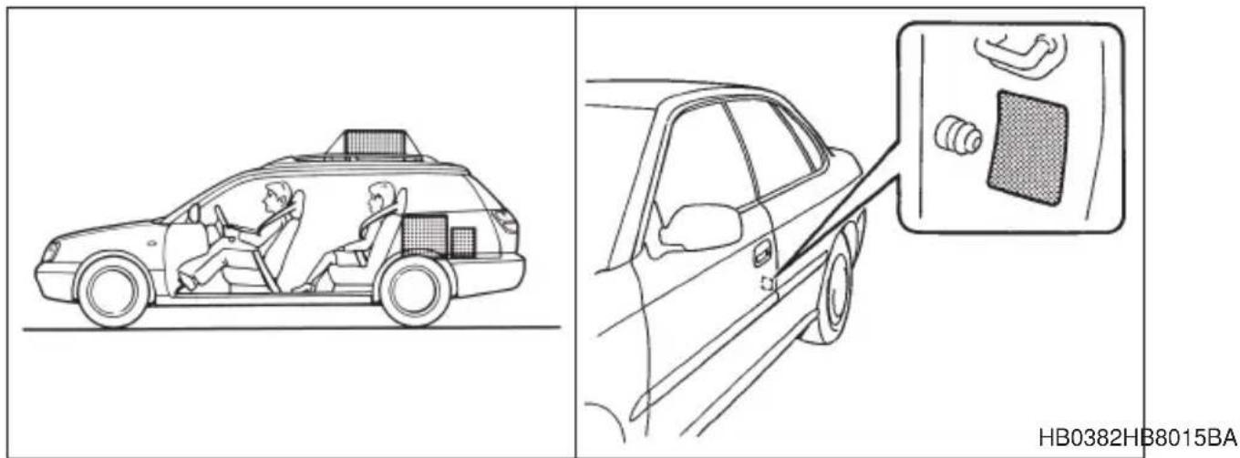
The load capacity of your vehicle is determined by weight, not by available cargo space. The maximum load you can carry in your vehicle is shown as the Vehicle Capacity Weight on the tire information label attached to the driver's side door jamb. It includes the total weight of driver and all passengers and their belongings, any optional equipment such as a trailer hitch, roof rack or bike carrier, etc., and the tongue load of a trailer.
■GVWR and GAWR (Gross Vehicle Weight Rating and Gross Axle Weight Rating)
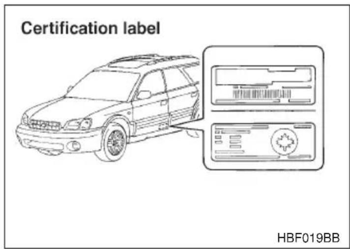
The certification label attached to the driver's side door shows GVWR (Gross Vehicle Weight Rating) and GAWR (Gross Axle Weight Rating).
The GVW (Gross Vehicle Weight) must never exceed the GVWR. GVW is the combined total of weight of the vehicle, fuel, driver, all passengers, luggage, any optional equipment and trailer tongue load. Therefore, the GVW changes depending on the situation. The GVWR equals Curb Weight (actual weight of your vehicle – including standard equipment, fluids, emergency tools and spare tire assembly) plus the vehicle capacity weight.
In addition, the total weight applied to each axle (GAW) must never exceed the GAWR. The front and rear GAWs can be adjusted by relocating luggage inside the vehicle.
Even if the total weight of your luggage is lower than the vehicle capacity weight, either front or rear GAW may exceed the GAWR, depending on the distribution of the luggage.
If you carry heavy loads in the vehicle, you should confirm that GVW and front and rear GAWs are within the GVWR and GAWR by putting your vehicle on a vehicle scale, found at a commercial weighing station.
Do not use replacement tires with a lower load range than the originals because they may lower the GVWR and GAWR limitations. Replacement tires with a higher load range than the originals do not increase the GVWR and GAWR limitations.
- CONTINUED -
■Roof rail and crossbar (if equipped)
CAUTION
- For cargo carrying purposes, the roof rail must be used together with a roof crossbar kit and the appropriate carrying attachment. The roof rail must never be used alone to carry cargo. Otherwise, damage to the roof or paint or a dangerous road hazard due to loss of cargo could result.
- When using the roof crossbar kit, make sure that the total weight of the crossbars, carrying attachment and cargo does not exceed the maximum load limit. Overloading may cause damage to the vehicle and create a safety hazard.
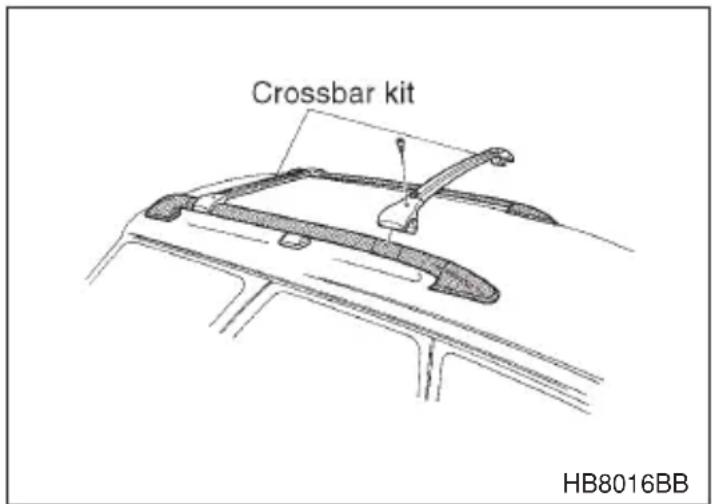
The roof rail is not designed to carry cargo by itself. Cargo can be carried after securing the roof crossbar kit to the roof rail and installing the appropriate carrying attachment. When installing the roof crossbar kit, follow the manufacturer's instructions.
Roof slats are not designed to carry or hold cargo, but are designed as the protector to prevent the roof from being damaged by cargo while it is being loaded and unloaded on the roof crossbar or on any carrying attachment.
When you carry cargo on the roof using the roof crossbar kit and a carrying attachment, never exceed the maximum load limit explained below. You should also be careful that your vehicle does not exceed the Gross
Vehicle Weight Rating (GVWR) and front and rear Gross Axle Weight Rating (GAWR). See the “Loading your vehicle” section in this chapter for information on loading cargo into or onto your vehicle. The maximum load limit of the cargo, crossbars and carrying attachment must not exceed 100 lb. (45 kg). Place the heaviest load at the bottom, nearest the roof, and evenly distribute the cargo. Always properly secure all cargo.
▼Installing carrying attachments on the crossbars
When installing any carrying attachment such as a bike carrier, ski carrier, kayak carrier, cargo basket, etc. on the crossbars, follow the manufacturer's instructions and make sure that the attachment is securely fixed to the crossbars. Use only attachments designed specifically for the crossbars. A set of the crossbars is designed to carry loads (cargo and attachment) of not more than 100 lb. (45 kg). Before operating the vehicle, make sure that the cargo is properly secured on the attachment.
NOTE
Remember that the vehicle's center of gravity is altered with the weight of the load on the roof, thus affecting the driving characteristics.
Drive carefully. Avoid rapid starts, hard cornering and abrupt stops. Crosswind effects will be increased.
▼Removal and installation of the crossbars

CAUTION
Do not carry cargo on the roof when the crossbars are removed. Luggage on the roof will be thrown forward or backward in sudden stops or rapid accelerations, resulting in a dangerous road hazard.
The crossbars can be removed when you do not use the roof to carry cargo.
∇ To remove the crossbar
- Loosen and remove the T-30 torx® head screw from the top of each crossbar end support.
- Rotate the lower clamp on the bottom of each end support downward approximately 90°.
- Carefully raise the crossbar from roof rails.
▽ To install the crossbar
Front crossbar:
Front crossbar has 100 LBS. Load Label on left-hand side.
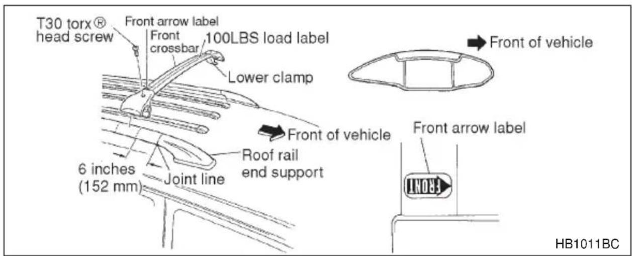
- Before placing the crossbar on the roof rails, make sure that the T-30 torx® head screw is removed from the top of each crossbar end support.
- Rotate the lower clamp on the bottom of each end support downward approximately 90°.
- With the front direction arrow label on the top right side of the crossbar pointing toward the front of the vehicle, carefully place the crossbar across the top of the vehicle so that the crossbar end supports rest on the top of the roof rails approximately 6 inches (152 mm) rearward from the seam (joint) between the front roof rail support and the roof rail.
- Rotate (raise) the lower clamp up to the bottom of the roof rail and loosely tighten the T-30 torx® head screw with the torx® wrench provided, through the top of the end support and into the threaded insert in the lower clamp on each end of the crossbar.
NOTE
It may be necessary to squeeze the lower clamp and the end support together to compress the pads and gain a better alignment of the pieces while trying to start the screw. Use care not to crossthread the screw in the insert.
- Adjust the alignment of the crossbar on the roof rails, and if available, use a T-30 torx® bit and torque wrench and tighten the T-30 torx® head screws to 30 to 35 inch lbs. (3.4 to 4.0 N-m, 0.35 to 0.41 kg-m) of torque (or tighten securely with the torx® wrench provided).
Rear crossbar:
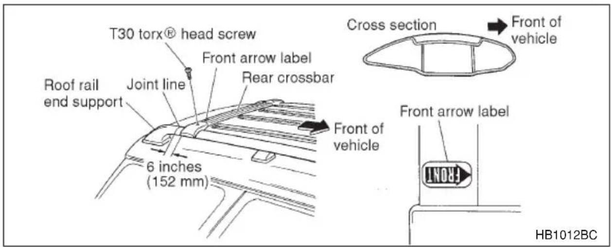
Install the rear crossbar in the same manner as the front crossbar.
NOTE
The rear crossbar should be positioned 6 inches (152 mm) forward of the rear seam (joint) between the rear roof rail support and the roof rail.
NOTE
Before each use of the roof crossbar, make sure the four T-30 cross-bar clamp screws have been checked, and retightened if necessary to 35 inch lbs. (4.0 N-m, 0.41 kg-m), as outlined in Step #5 above.

WARNING
- Never exceed the maximum weight specified for the trailer hitch. Exceeding the maximum weight could cause an accident resulting in serious personal injuries. Permissible trailer weight changes depending on the situation. Refer to the next section “Trailer towing” for possible recommendations and limitations.
- Trailer brakes are required when the towing load exceeds 1,000 lbs. (453 kg). Be sure your trailer has safety chains and that each chain will hold the trailer's maximum gross weight. Towing trailers without safety chains could create a traffic safety hazard if the trailer separates from the hitch due to coupling damage or hitch ball damage.
- Be sure to check the hitch pin and safety pin for positive locking placement before towing a trailer. If the ball mount comes off the hitch receiver, the trailer could get loose and create a traffic safety hazard.
- Use only the ball mount supplied with this hitch. Use the hitch only as a weight carrying hitch. Do not use with any type of weight distributing hitch.
The trailer hitch is designed to tow a Class 1 rated load. A maximum of 2,000 lbs. (906 kg) gross trailer weight and a maximum of 200 lbs. (90 kg) gross tongue weight are permissible for the trailer hitch.
When you tow a trailer, follow the instructions in the next section “Trailer towing”.
▼Connecting a trailer
- Remove the receiver cover from the hitch receiver tube. Then insert the ball mount into the hitch receiver tube.
- Insert the hitch pin into the hole on the hitch receiver tube so that the pin passes through the ball mount.
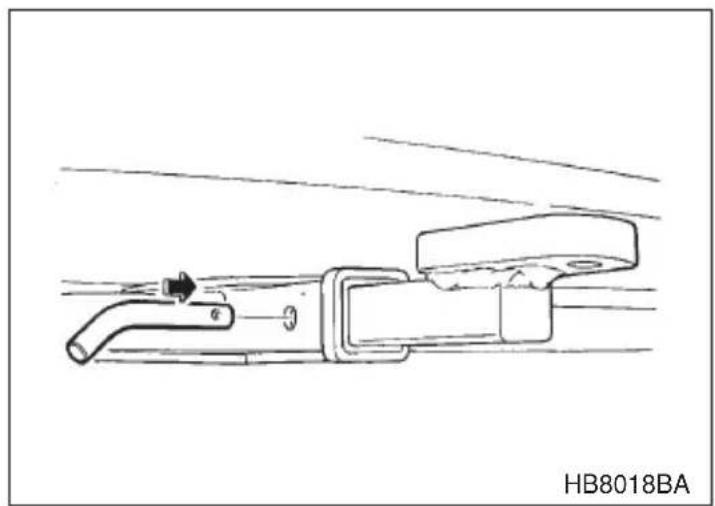
natural_image
Technical line drawing of a mechanical component with no visible text or symbols- Insert the safety pin into the hitch pin securely.
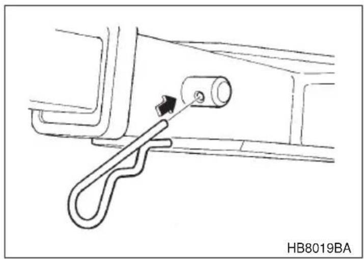
natural_image
Technical line drawing of a mechanical component with a lever and adjustment knob (no text or symbols)- Pull the ball mount to make sure it does not come off the hitch receiver.
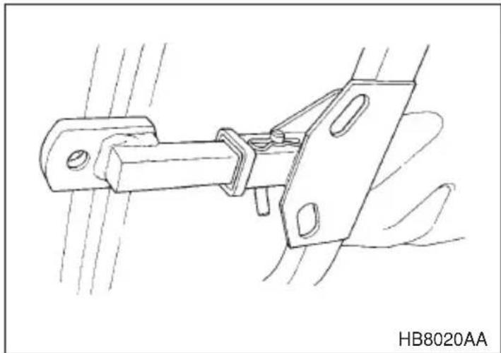
natural_image
Technical line drawing of a mechanical clamp or bracket assembly (no text or symbols)-
Use only a hitch ball that is appropriate for the ball mount and your trailer. The hitch ball must be securely installed on the ball mount.
-
Connect your trailer to the hitch ball.
-
Connect the trailer and the hitch with safety chains that will hold the trailer's maximum gross weight. The chains should cross under the trailer tongue to prevent the tongue from dropping onto the ground in case it should disconnect from the hitch ball. Allow sufficient slack in the chains taking tight-turn situations into account; however, be careful not to let them drag on the ground.
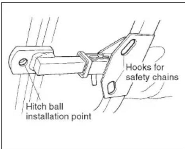
⚠ Do not connect safety chains to improper positions such as those shown in this picture.
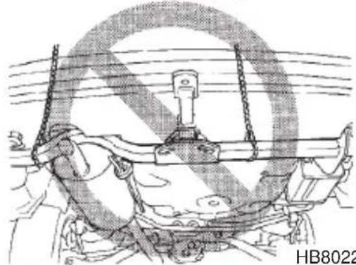
natural_image
Technical line drawing of a mechanical assembly with no visible text or symbolsHB8022BBHB8020BB
- Connect the hitch wire harness's black four-pin wire connector to the towing trailer's wire harness
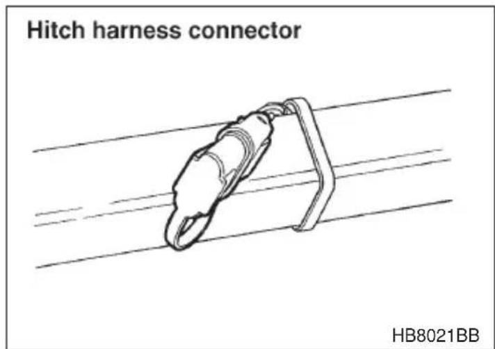
- Confirm proper function of the hitch wire harness by individually activating the brake, right turn signal, left turn signal, stop, and parking lights on the trailer.
NOTE
Always disconnect the trailer wire harness before launching or retrieving a watercraft.
▼When you do not tow a trailer
- Remove the ball mount from the hitch receiver tube and insert the receiver cover onto the hitch receiver tube.
- Place the dust cap over the four-pin connector of the hitch wire harness to protect against possible damage.
- Occasionally lubricate terminals of the four-pin connector using the terminal grease.
Trailer towing
Your car is designed and intended to be used primarily as a passenger-carrying vehicle. Towing a trailer puts additional loads on your car's engine, drivetrain, brakes, tires and suspension and has an adverse effect on fuel economy.
If you do decide to tow a trailer, your safety and satisfaction depend upon proper use of correct equipment and cautious operation of your vehicle. Seek the advice of your SUBARU dealer to assist you in purchasing a hitch and other necessary towing equipment appropriate for your vehicle. In addition, be sure to follow the instructions on correct installation and use provided by the trailer and other towing equipment manufacturers.
SUBARU assumes no responsibility for injuries or vehicle damage that result from trailer towing equipment, or from any errors or omissions in the instructions accompanying such equipment or for your failure to follow the proper instructions.
▼Warranties and maintenance
SUBARU warranties do not apply to vehicle damage or malfunction caused by trailer towing. If you use your vehicle to tow a trailer, more frequent maintenance will be required due to the additional load. (Refer to “Maintenance schedule under severe driving conditions” in the “Warranty and Maintenance Booklet”.)
Under no circumstances should a trailer be towed with a new vehicle or a vehicle with any new powertrain component (engine, transmission, differential, wheel bearings, etc.) for the first 1,000 miles (1,600 km) of driving.
▼Maximum load limits

WARNING
Never exceed the maximum load limits explained below. Exceeding the maximum load limits could cause personal injury and/or vehicle damage.

CAUTION
- Adequate size trailer brakes are required when the trailer and its cargo exceed 1,000 lbs (453 kg) total weight.
- Before towing a trailer, check the trailer total weight, GVW, GAWs and tongue load. Make sure the load and its distribution in your vehicle and trailer are acceptable.
▽ Total trailer weight
The total trailer weight (trailer weight plus its cargo load) must never exceed the maximum weight shown below.
| Model | Conditions Maximum total | trailer weight |
| MT models W | When towing a trailer without brakes. 1,000 lbs | (453 kg) |
| When towing a trailer with brakes. 2,000 lbs | (906 kg) | |
| AT models | When towing a trailer without brakes. | 1,000 lbs (453 kg) |
| When towing a trailer with brakes. 2,000 lbs | (906 kg) | |
| When towing a trailer on a long uphill grade continuously for over 5 miles (8 km) with an outside temperature of 104°F (40°C) or above. | 1,000 lbs (453 kg) |
Total trailer weight
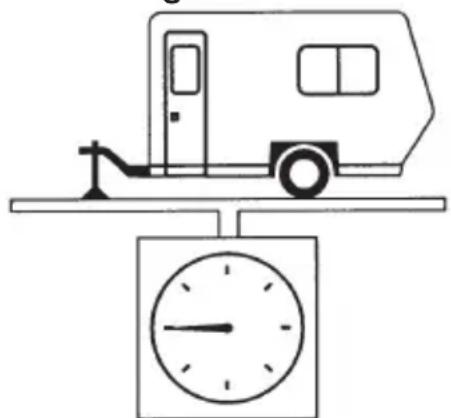
natural_image
Simple line drawing of a vehicle on a balance scale with a clock below (no text or symbols)OM-H2781
∇ Gross Vehicle Weight (GVW) and Gross Vehicle Weight Rating (GVWR)
The Gross Vehicle Weight (GVW) must never exceed the Gross Vehicle Weight Rating (GVWR).
Gross Vehicle Weight (GVW) is the combined total of the weight of the vehicle, driver, passengers, luggage, trailer hitch, trailer tongue load and any other optional equipment installed on your vehicle. Therefore, the GVW changes depending on the situation. Determine the GVW each time before going on a trip by putting your vehicle and trailer on a vehicle scale.
GVWR is shown on the certification label located on the driver's door of your vehicle.
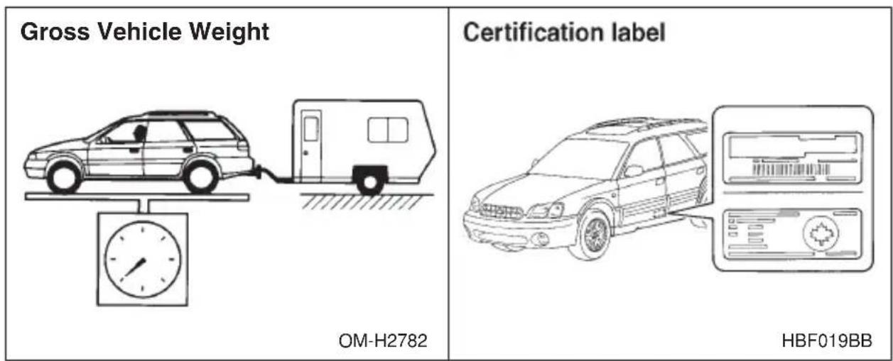
▼Gross Axle Weight (GAW) and Gross Axle Weight Rating (GAWR)
The total weight applied to each axle (GAW) must never exceed the Gross Axle Weight Rating (GAWR). The front and rear GAWs can be adjusted by relocating passengers and luggage inside the vehicle. The front and rear GAWR are also shown on the certification label.
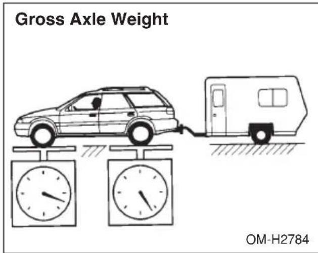
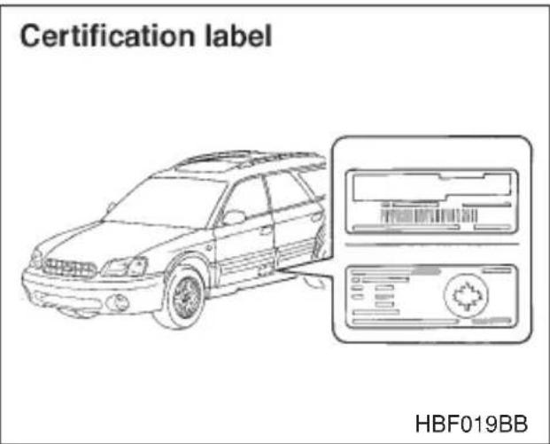
To check both GVWR and GAWR and to confirm that the total weight and weight distribution are within safe driving limits, you should have your vehicle and trailer weighed at a commercial weighing station.
Be sure that all cargo is firmly secured to prevent a change in weight distribution while driving.
∇ Tongue load
WARNING
If the trailer is loaded with more weight in the back of trailer's axle than in the front, the load is taken off the rear axle of the towing vehicle. This may cause the rear wheels to skid, especially during braking or when vehicle speed is reduced during cornering, resulting in over-steer, spin out and/or jackknifing.
Ensure that the trailer tongue load is from 8 to 11 percent of the total trailer weight and does not exceed the maximum value of 200 lbs (90 kg).
The tongue load can be weighed with a bathroom scale as shown in the illustration below. When weighing the tongue load, be sure to position the towing coupler at the height at which it would be during actual towing, using a jack as shown.
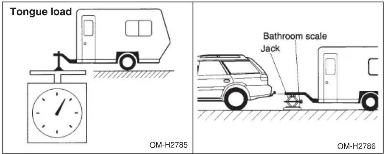
The tongue load can be adjusted by proper distribution of the load in the trailer. Never load the trailer with more weight in the back than in the front; approximately 60 percent of the trailer load should be in the front and approximately 40 percent in the rear. Also, distribute the load as evenly as possible on both the left and right sides.
Be sure that all cargo is firmly secured to prevent a change in weight distribution while driving.
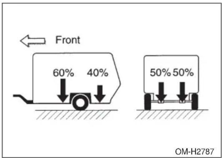
▼Trailer hitches
WARNING
Never drill the frame or under-body of your vehicle to install a commercial trailer hitch. If you do, dangerous exhaust gas, water or mud may enter the passenger compartment through the drilled hole. Exhaust gas contains carbon monoxide, a colorless and odorless gas which is dangerous, or even lethal, if inhaled. Also, drilling the frame or under-body of your vehicle could cause deterioration of strength of your vehicle and cause corrosion around the drilled hole.
CAUTION
- Do not modify the vehicle exhaust system, brake system, or other systems when installing a hitch or other trailer towing equipment.
- Do not use axle-mounted hitches as they can cause damage to the axle housing, wheel bearings, wheels or tires.
Choose a proper hitch for your vehicle and trailer.
▼OUTBACK wagon
The use of a genuine SUBARU trailer hitch is recommended. A genuine SUBARU hitch is available from your SUBARU dealer.
If use of a non-genuine hitch is unavoidable, be sure the hitch is suited to your vehicle and trailer. Consult with a professional hitch supplier to assist you in choosing an appropriate hitch for your vehicle. Be sure to follow all of the hitch manufacturer's instructions for installation and use.
Never use a hitch that mounts only to the rear bumper. The bumper is not designed to handle that type of load.
For all types of hitches, regularly check that the hitch mounting bolts and nuts are tight.
▼All vehicles except OUTBACK wagon
SUBARU does not offer accessory trailer hitches. Consult with a professional hitch supplier to assist you in choosing an appropriate hitch for your vehicle. Be sure to follow all of the hitch manufacturer's instructions for installation and use.
Never use a hitch that mounts only to the rear bumper. The bumper is not designed to handle that type of load.
Regularly check that the hitch mounting bolts and nuts are tight.
▼Connecting a trailer
▼ Trailer brakes

WARNING
- Adequate size trailer brakes are required when the trailer and its cargo exceed 1,000 lbs (453 kg) total weight.
- Do not directly connect your trailer's hydraulic brake system to the hydraulic brake system in your vehicle. Direct connection would cause the vehicle's brake performance to deteriorate and could lead to an accident.
If your trailer's total weight (trailer weight plus its cargo weight) exceeds 1,000 lbs (453 kg), the trailer is required to be equipped with its own brake system. Electric brakes or surge brakes are recommended, and must be installed properly. Check that your trailer's brakes conform with Federal, state/province and/or other applicable regulations. Your SUBARU's brake system is not designed to be tapped into the trailer's hydraulic brake system. Please ask your SUBARU dealer and professional trailer supplier for more information about the trailer's brake system.
▼ Trailer safety chains

WARNING
Always use safety chains between your vehicle and the trailer. Towing trailer without safety chains could create a traffic safety hazard if the trailer separates from the hitch due to coupling damage or hitch ball damage.
In case the trailer hitch connector or hitch ball should break or become disconnected, the trailer could get loose and create a traffic safety hazard.
For safety, always connect the towing vehicle and trailer with trailer safety chains. Pass the chains crossing each other under the trailer tongue to prevent the trailer from dropping onto the ground in case the trailer tongue should disconnect from the hitch ball. Allow sufficient slack in the chains taking tight-turn situations into account; however, be careful not to let them drag on the ground.
For more information about the safety chain connection, refer to the instructions for your hitch and trailer.
▽ Side mirrors
After hitching a trailer to your vehicle, check that the standard side mirrors provide a good rearward field of view without significant blind spots. If significant blind spots occur with the vehicle's standard side mirrors, use towing mirrors that conform with Federal, state/province and/or other applicable regulations.
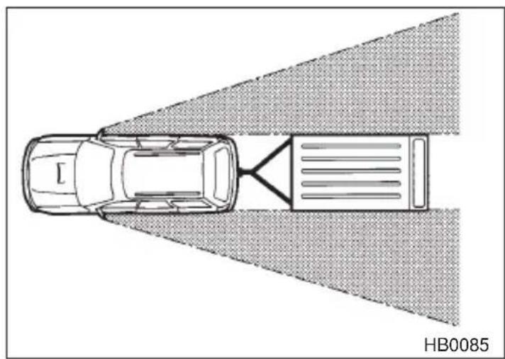
natural_image
Top-down schematic of a car with a road marking and a vehicle labeled HB0085 (no text or symbols on the diagram itself)Trailer lights
CAUTION
Direct splicing or other improper connection of trailer lights may damage your vehicle's electrical system and cause a malfunction of your vehicle's lighting system.
Connection of trailer lights to your vehicle's electrical system requires modifications to the vehicle's lighting circuit to increase its capacity and accommodate wiring changes. To ensure the trailer lights are connected properly, please consult your SUBARU dealer. Check for proper operation of the turn signals, the brake lights and parking lights each time you hitch up.
Tires

WARNING
Never tow a trailer when the temporary spare tire is used. The temporary spare tire is not designed to sustain the towing load. Use of the temporary spare tire when towing can result in failure of the spare tire and/or less stability of the vehicle.
Make sure that all the tires on your vehicle are properly inflated.
OUTBACK: The recommended cold tire pressure under trailer towing conditions is indicated on the tire placard located under the door striker on the driver's side. Adjust the rear tire pressure to the recommended pressure shown on the tire placard when the tires are cold. Normal pressure should be maintained in the front tires.
Other models: It is recommended to inflate the rear tires to 3 psi (20 kPa, 0.2 kg/cm ^2 ) above their normal operating pressure when the tires are cold. Normal pressure should be maintained in the front tires.
Trailer tire condition, size, load rating and proper inflation pressure should be in accordance with the trailer manufacturer's specifications.
In the event your vehicle gets a flat tire when towing a trailer, ask a commercial road service to repair the flat tire.
If you carry a regular size spare tire in your vehicle or trailer as a precaution against getting a flat tire, be sure that the spare tire is firmly secured.
▼Trailer towing tips
CAUTION
●Never exceed 45 mph (72 km/h) when towing a trailer in hilly country on hot days.
- When towing a trailer, steering, stability, stopping distance and braking performance will be different from normal operation. For safety's sake, you should employ extra caution when towing a trailer and you should never speed. You should also keep the following tips in mind:
∇ Before starting out on a trip
- Check that the vehicle and vehicle-to-hitch mounting are in good condition. If any problems are apparent, do not tow the trailer.
- Check that the vehicle sits horizontally with the trailer attached. If the vehicle is tipped sharply up at the front and down at the rear, check the total trailer weight, GVW, GAWs and tongue load again, then confirm that the load and its distribution are acceptable.
- Check that the tire pressures are correct.
- Check that the vehicle and trailer are connected properly. Confirm that.
– the trailer tongue is connected properly to the hitch ball.
- the trailer lights connector is connected properly and trailer's brake lights illuminate when the vehicle's brake pedal is pressed, and that the trailer's turn signal lights flash when the vehicle's turn signal lever is operated.
– the safety chains are connected properly.
– all cargo in the trailer is secured safety in position.
– the side mirrors provide a good rearward field of view without a significant blind spot.
- Sufficient time should be taken to learn the “feel” of the vehicle/trailer combination before starting out on a trip. In an area free of traffic, practice turning, stopping and backing up.
∇ Driving with a trailer
- You should allow for considerably more stopping distance when towing a trailer. Avoid sudden braking because it may result in skidding or jackknifing and loss of control.
- Avoid abrupt starts and sudden accelerations. If your vehicle has a manual transmission, always start out in first gear and release the clutch at moderate engine revolution.
●Avoid uneven steering, sharp turns and rapid lane changes.
- Slow down before turning. Make a longer than normal turning radius because the trailer wheels will be closer than the vehicle wheels to the inside of the turn. In a tight turn, the trailer could hit your vehicle.
- Crosswinds will adversely affect the handling of your vehicle and trailer, causing sway. Crosswinds can be due to weather conditions on the passing of large trucks or buses. If swaying occurs, firmly grip the steering wheel and slow down immediately but gradually.
- When passing other vehicles, considerable distance is required because of the added weight and length caused by attaching the trailer to your vehicle.
- Backing up with a trailer is difficult and takes practice. When backing up with a trailer, never accelerate or steer rapidly. When turning back, grip the bottom of the steering wheel with one hand and turn it to the left for a left turn, and turn it to the right for a right turn.
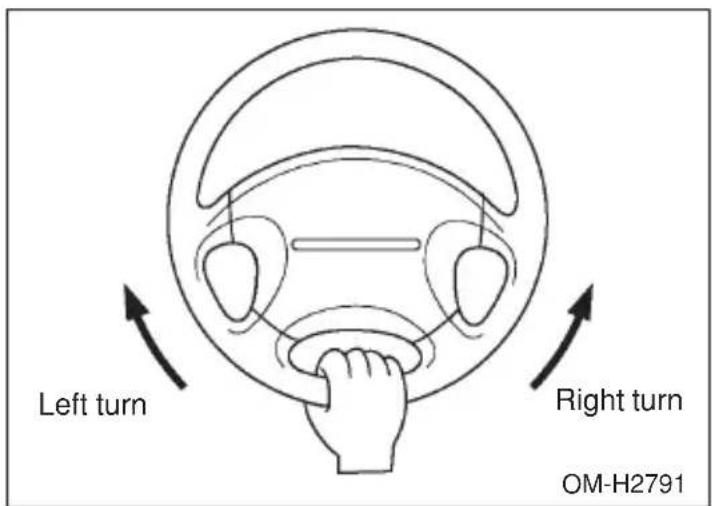
- If the ABS warning light illuminates while the vehicle is in motion, stop towing the trailer and have repairs performed immediately by the
nearest SUBARU dealer.
∇ Driving on grades
- Before going down a steep hill, slow down and shift into lower gear (if necessary, use 1st gear) in order to utilize the engine braking effect and prevent overheating of your vehicle's brakes. Do not make sudden downshifts.
- When driving uphill in hot weather, the air conditioner may turn off automatically to protect the engine from overheating.
- When driving uphill in hot weather, pay attention to the water temperature gauge pointer (for all vehicles) and AT OIL TEMP warning light (for AT vehicles) since the engine and transmission are relatively prone to overheating under these conditions. If the water temperature gauge pointer approaches the OVERHEAT zone or the AT OIL TEMP warning light illuminates, immediately switch off the air conditioner and stop the vehicle at the nearest safe place. Refer to the “Engine overheat” section in chapter 9, and “Warning and indicator lights” section in chapter 3.
- If your vehicle has a automatic transmission, avoid using the accelerator pedal to stay stationary on an uphill slope instead of using the parking brake or foot brake. That may cause the transmission fluid to overheat. Also, if your vehicle is equipped with an automatic transmission, avoid driving with the gear selector lever in “D” when towing a heavy trailer to prevent fluid overheating.
▼ Parking on a grade
Always block the wheels under both vehicle and trailer when parking. Apply the parking brake firmly. You should not park on a hill or slope. But if parking on a hill or slope cannot be avoided, you should take the following steps:
- Apply the brakes and hold the pedal down.
- Have someone place wheel blocks under both the vehicle and trailer wheels.
- When the wheel blocks are in place, release the regular brakes slowly until the blocks absorb the load.
- Apply the regular brakes and then apply the parking brake; slowly release the regular brakes.
- CONTINUED -
- Shift into 1st or reverse gear (manual transmission) or "P" (automatic transmission) and shut off the engine.
In case of emergency
If you park your vehicle in an emergency 9-2
Temporary spare tire 9-3
Flat tires 9-4
Jump starting 9-11
Engine overheating 9-14
Towing 9-15
Moonroof — if the moonroof cannot be closed 9-25
Maintenance tools 9-26
Jack and jack handle 9-27
If you park your vehicle in an emergency
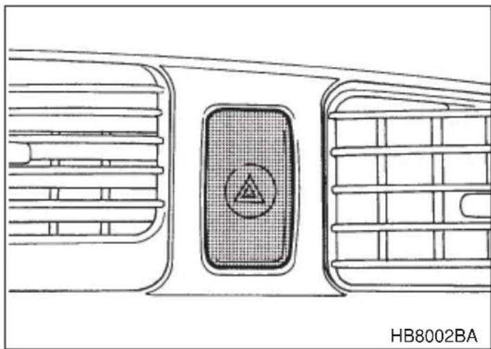
natural_image
Technical line drawing of a vehicle air vent with a circular component and grid structure (no text or symbols)The hazard warning flasher should be used in day or night to warn other drivers when you have to park your vehicle under emergency conditions. Avoid stopping on the road. It is best to safely pull off the road if a problem occurs.
The hazard warning flasher can be activated regardless of the ignition switch position.
Turn on the hazard warning by pushing the hazard warning flasher switch. Turn it off by pushing the switch again.
NOTE
When the hazard warning flasher is on, the turn signals do not work.
Temporary spare tire

WARNING
Never tow a trailer when the temporary spare tire is used. The temporary spare tire is not designed to sustain the towing load. Use of the temporary spare tire when towing can result in failure of the spare tire and/or less stability of the vehicle and may lead to an accident.

CAUTION
Never use any temporary spare tire other than the original. Using other sizes may result in severe mechanical damage to the drive train of your vehicle.
The temporary spare tire is smaller and lighter than a conventional tire and is designed for emergency use only. Remove the temporary spare tire and re-install the conventional tire as soon as possible because the spare tire is designed only for temporary use.
Check the inflation pressure of the temporary spare tire periodically to keep the tire ready for use. The correct pressure is 60 psi (420 kPa, 4.2 kg/cm ^2 ).
When using the temporary spare tire, note the following:
- Do not exceed 50 mph (80 km/h).
- Do not put a tire chain on the temporary spare tire. Because of the smaller tire size, a tire chain will not fit properly.
- Do not use two or more temporary spare tires at the same time.
- Do not drive over obstacles. This tire has a smaller diameter, so road clearance is reduced.
- When the wear indicator appears on the tread, replace the tire.
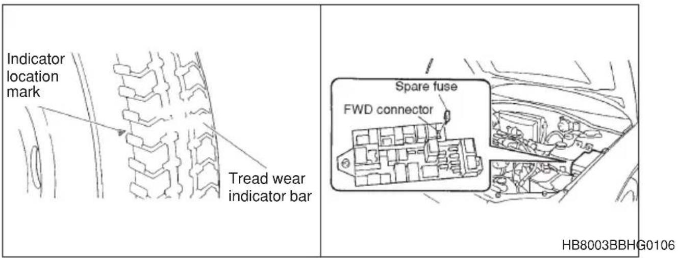
NOTE
[Automatic transmission vehicle not equipped with VDC (Vehicle Dynamics Control)] Before driving your vehicle with the temporary spare tire, put a spare fuse inside the FWD connector located in the engine compartment and confirm that the Front-wheel drive warning light comes on. The all wheel drive capability of the vehicle has now been deactivated. After re-installing the conventional tire, remove the spare fuse from the FWD connector in order to reactivate all wheel drive.
Flat tires

WARNING
- Do not jack up the vehicle on an incline or a loose road surface. The jack can come out of the jacking point or sink into the ground and this can result in a severe accident.
-
Use only the jack provided with your vehicle. The jack supplied with the vehicle is designed only for changing a tire. Never get under the vehicle while supporting the vehicle with this jack.
●Always turn the engine off before raising the flat tire off the ground using the jack. Never swing or push the vehicle supported with the jack. The jack can come out of the jacking point due to a jolt and this can result in a severe accident. -
Do not use oil or grease on the wheel studs or nuts when the spare tire is installed. This could cause the nuts to become loose and lead to an accident.
- Never place a tire or tire changing tools in the passenger compartment after changing wheels. In a sudden stop or collisions, loose equipment could strike occupants and cause injury. Store the tire and all tools in the proper place.
If you have a flat tire while driving, never brake suddenly; keep driving straight ahead while gradually reducing speed. Then slowly pull off the road to a safe place.
- Park on a hard, level surface, whenever possible, then stop the engine.
- Set the parking brake securely and shift a manual transmission vehicle in reverse or an automatic transmission vehicle in the "P" (Park) position.
- Turn on the hazard warning flasher and have everyone get out of the vehicle.
- Put wheel blocks at the front and rear of the tire diagonally opposite the flat tire.
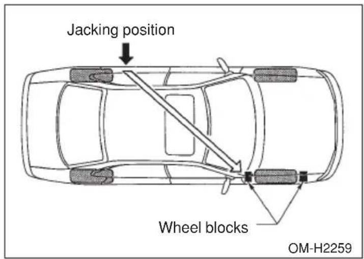
- Take out the spare tire, jack, and wheel nut wrench.
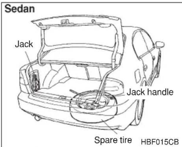
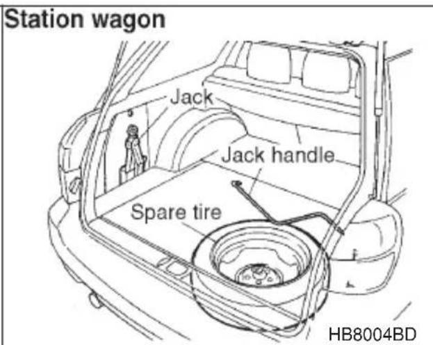
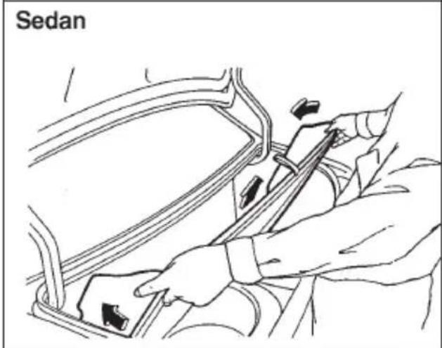
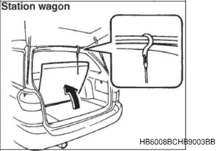
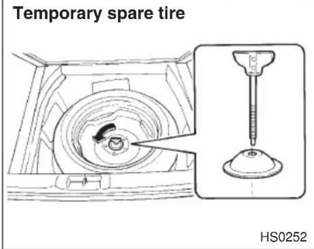
The spare tire is stored under the floor of the trunk or cargo area.
To remove the spare tire, proceed as follows:
Sedan: Remove the floor cover from the trunk. Remove the storage tray.
Turn the attaching bolt counterclockwise, then take the spare tire out.
Station wagon: Open the lid and hang the hook provided on the under-
side of the lid on the rear edge of the roof to keep the lid open.
Remove the storage tray. Turn the attaching bolt counterclockwise, then take spare tire out.
If the spare tire provided in your vehicle is a temporary spare tire, carefully read the section “Temporary spare tire” in this chapter and strictly follow the instructions.
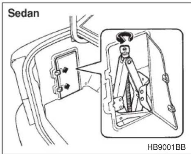
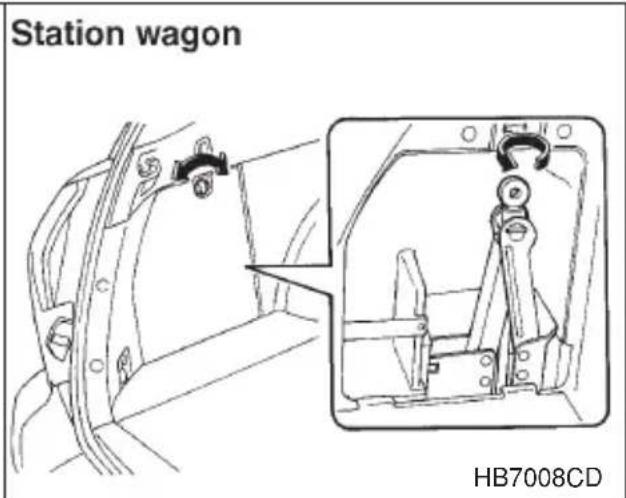
The jack is stored on the left side of the trunk or cargo area.
To take out the jack:
Remove the cover, turn the jackscrew counterclockwise to loosen it, then remove the jack.
The jack handle is stored under the spare tire cover.
NOTE
Make sure the jack is well lubricated before using it.
- (If your vehicle has wheel covers) Insert the wheel nut wrench into the notch provided in the wheel cover, and pry it off.
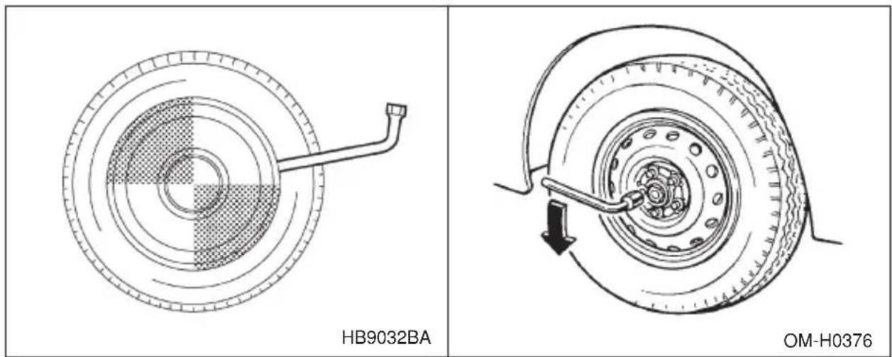
- Loosen the wheel nuts using the wheel nut wrench but do not remove the nuts.
- Place the jack under the side sill at the front or rear jack-up point closest to the flat tire.
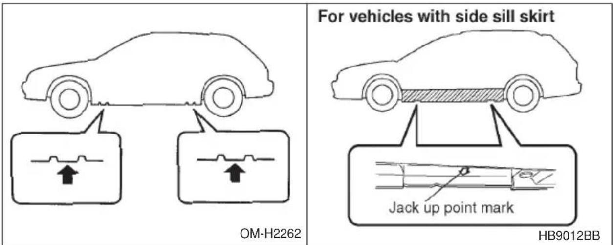
Turn the jackscrew by hand until the jack head engages firmly into the jack-up point.
If your vehicle is equipped with side sill skirts, jack-up points are pointed to by arrow marks on the underside of the side sill skirt. Place the jack under the front or rear jack-up point closest to flat tire.
- Insert the jack handle into the jackscrew, and turn the handle until the tire clears the ground. Do not raise the vehicle higher than necessary.
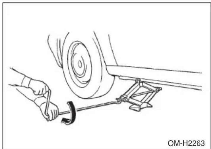
natural_image
Line drawing of a car tire being adjusted to a wheel, with hands using a tool (no text or symbols)- Remove the wheel nuts and the flat tire.
- Before putting the spare tire on, clean the mounting surface of the wheel and hub with a cloth.
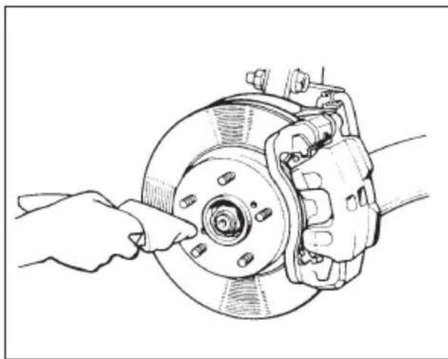
natural_image
Line drawing of a car brake assembly with hands adjusting the wheel (no text or symbols)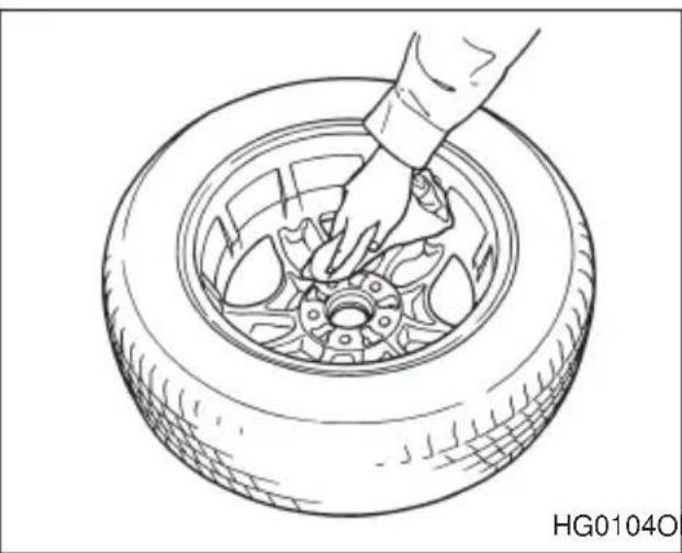
natural_image
Line drawing of a hand placing a tire component into a car wheel (no text or symbols)- Put on the spare tire. Replace the wheel nuts. Tighten them by hand.
-
Turn the jack handle counterclockwise to lower the vehicle.
-
Use the wheel nut wrench to securely tighten the wheel nuts to the specified torque, following the tightening order in the illustration.
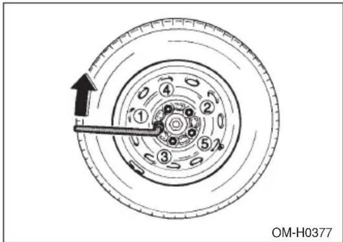
The torque for tightening the nuts is 58 to 72 ft-lb (78 to 98 N-m, 8 to 10 kg-m). This torque is equivalent to applying about 88 to 110 lbs (40 to 50 kg) at the top of the wheel nut wrench. Never use your foot on the wheel nut wrench or a pipe extension on the wrench because you may exceed the specified torque. Have the wheel nut torque checked at the nearest automotive service facility.
- Store the flat tire in the spare tire compartment.
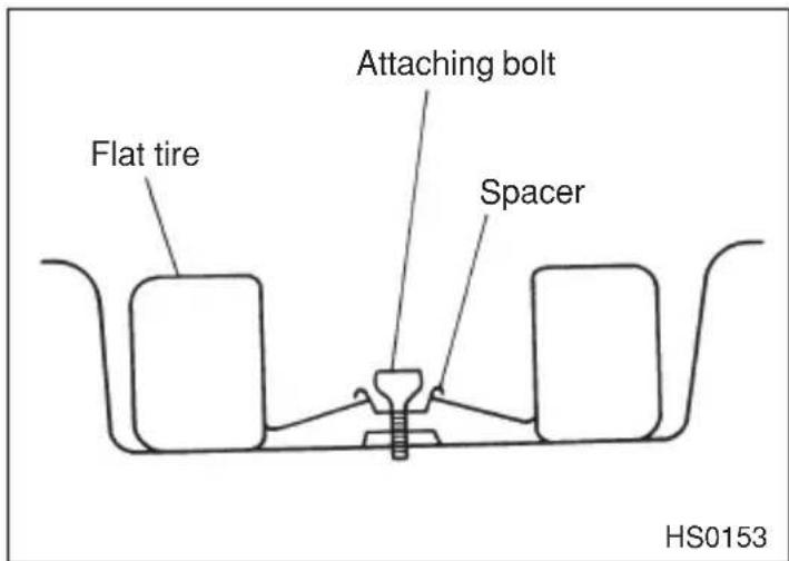
When storing a conventional tire, put the spacer upside down and tighten the attaching bolt firmly.
Also store the jack and wheel nut wrench in their storage locations.
Jump starting

WARNING
●Battery fluid is SULFURIC ACID. Do not let it come in contact with the eyes, skin, clothing or the vehicle.
If battery fluid gets on you, thoroughly flush the exposed area with water immediately. Get medical help if the fluid has entered your eyes.
If battery fluid is accidentally swallowed, immediately drink a large amount of milk or water, and obtain immediate medical help.
Keep everyone including children away from the battery.
- The gas generated by a battery explodes if a flame or spark is brought near it. Do not smoke or light a match while jump starting.
- Never attempt jump starting if the discharged battery is frozen. It could cause the battery to burst or explode.
- Whenever working on or around a battery, always wear suitable eye protectors, and remove metal objects such as rings, bands or other metal jewelry.
- Be sure the jumper cables and clamps on them do not have loose or missing insulation.
Do not jump start unless cables in suitable condition are available.
- A running engine can be dangerous. Keep your fingers, hands, clothing, hair and tools away from the cooling fan, belts and any other moving engine parts. Removing rings, watches and ties is advisable.
When your vehicle does not start due to a run down (discharged) battery, the vehicle may be jump started by connecting your battery to another battery (called the booster battery) with jumper cables.
Jump starting is dangerous if it done incorrectly. If you are unsure about the proper procedure for jump starting, consult a competent mechanic.
- CONTINUED -
▼How to jump start
- Make sure the booster battery is 12 volts and the negative terminal is grounded.
- If the booster battery is in another vehicle, do not let the two vehicles touch.
- Turn off all unnecessary lights and accessories.
- Connect the jumper cables exactly in the sequence illustrated.
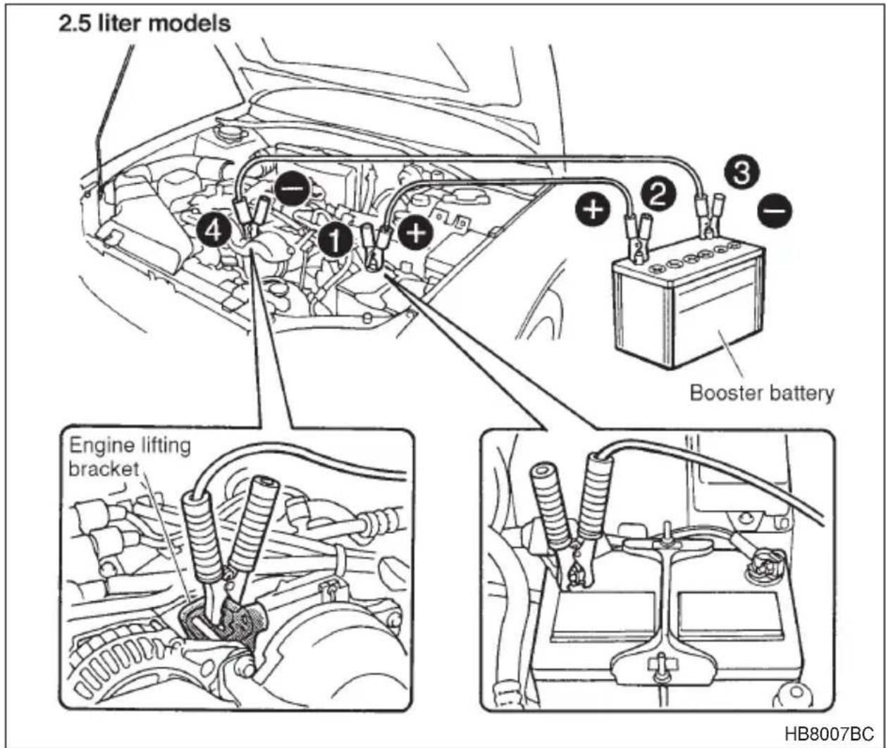
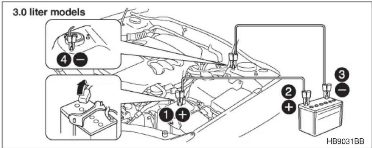
① Connect one jumper cable to the positive (+) terminal on the discharged battery.
② Connect the other end of the jumper cable to the positive (+) terminal of the booster battery.
③ Connect one end of the other cable to the negative (−) terminal of the booster battery.
④ Connect the other end of the cable.
2.5 liter models: To the engine lifting bracket.
3.0 liter models: To the strut mounting nut.
Make sure that the cables are not near any moving parts and that the cable clamps are not in contact with any other metal.
- Start the engine of the vehicle with the booster battery and run it at moderate speed. Then start the engine of the vehicle that has the discharged battery.
- When finished, carefully disconnect the cables in exactly the reverse order.

WARNING
Never attempt to remove the radiator cap until the engine has been shut off and has fully cooled down. When the engine is hot, the coolant is under pressure. Removing the cap while the engine is still hot could release a spray of boiling hot coolant, which could burn you very seriously.
If the engine overheats, safely pull off the road and stop the vehicle in a safe place.
▼If steam is coming from the engine compartment
Turn the engine off and get everyone away from the vehicle until it cools down.
▼If no steam is coming from the engine compartment
- Keep the engine running at idling speed.
- Open the hood to ventilate the engine compartment.
Confirm that the cooling fan is turning. If the fan is not turning, immediately turn the engine off and contact your authorized dealer for repair. - After the engine coolant temperature has dropped, turn off the engine.
If the temperature gauge stays at the overheated zone, turn the engine off. - After the engine has fully cooled down, check the coolant level in the reserve tank.
If the coolant level is below the "MIN" mark, add coolant up to the "MAX" mark. - If there is no coolant in the reserve tank, add coolant to the reserve tank. Then remove the radiator cap and fill the radiator with coolant.
If you remove the radiator cap from a hot radiator, first wrap a thick cloth around the radiator cap, then turn the cap counterclockwise slowly without pressing down until it stops. Release the pressure from
the radiator. After the pressure has been fully released, remove the cap by pressing down and turning it.
Towing

WARNING
Never tow AWD vehicles (both AT and MT) with the front wheels raised off the ground while the rear wheels are on the ground, or with the rear wheels raised off the ground while the front wheels are on the ground. This will cause the vehicle to spin away due to the operation or deterioration of the center differential.
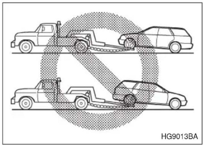
natural_image
Diagram showing three vehicles with a diagonal line crossing, no text or symbols presentIf towing is necessary, it is best done by your SUBARU dealer or a commercial towing service. Observe the following procedures for safety.
▼Towing and tie-down hooks

CAUTION
- Use only specified towing hooks and tie-down hooks. Never use suspension parts or other body parts for towing or tie-down purposes.
- Never use the tie-down hook closest to the muffler under the vehicle for towing purposes.
- Do not apply excessive lateral load to the towing hooks.
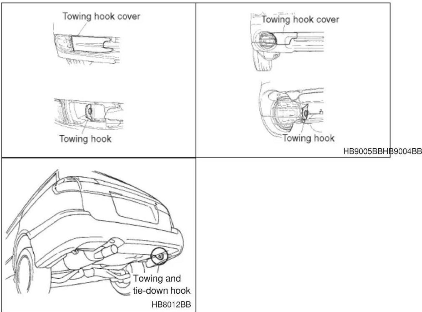
HB9005BBHB9004BB
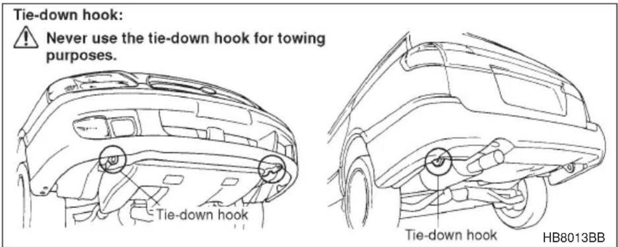
HB8013BB
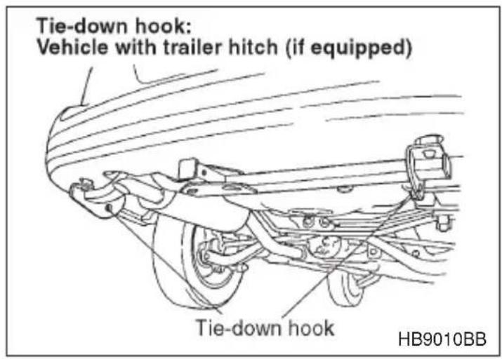
The towing hooks should be used only in an emergency (e.g., to free a stuck vehicle from mud, sand or snow).
The front towing hook is located on the inside of the towing hook cover below the right-hand headlight.
▽ Towing hook cover removal procedure For except OUTBACK models:
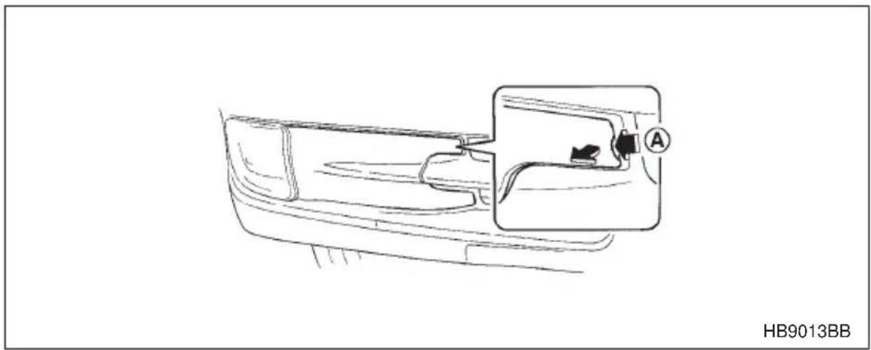
natural_image
Line drawing of a car interior with a close-up inset showing a device labeled 'A' (no text or symbols on the diagram itself)- Push at the notched portion A, and pull the towing hook cover toward you.
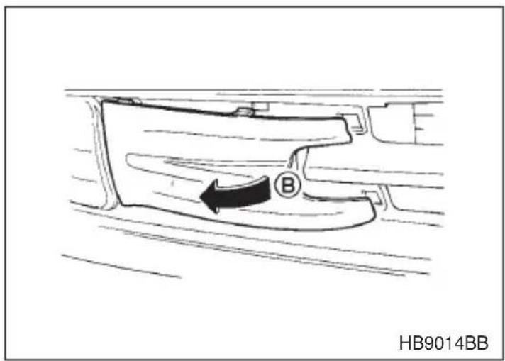
- Insert your fingers under the raised portion B. Then, pull it toward you so that the towing hook cover may swing open. Remove the cover.
For OUTBACK models:
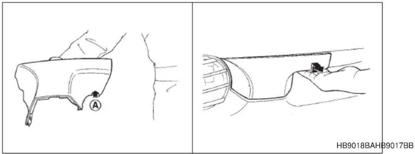
- Pull the towing hook cover toward you while pushing up the portion A. The portion B will be raised.
- Pull the portion B toward you with your left hand. Simultaneously pull the portion C toward you while pushing the portion C with your right hand.
natural_image
Line drawing of a garment sleeve with a small inset detail labeled D (no text or symbols)
natural_image
Line drawing of hands holding a tool over a circular object, no text or symbols present- Push the portion D. Pull out the towing hook cover to remove it.
- CONTINUED -
▽ Towing hook cover installation procedure For except OUTBACK models:
HB9016BAHB9015BA
- Insert the towing hook cover into the clearance between the fog light (or bumper trim cover) and the bumper body.
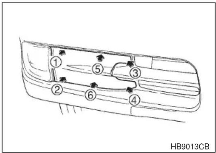
- Push the towing hook cover in accordance with the pushing order given in the illustration.
For OUTBACK models:
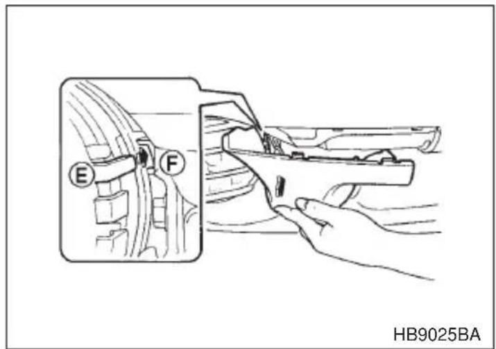
1. Insert the guide E into the hole F.
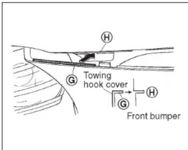
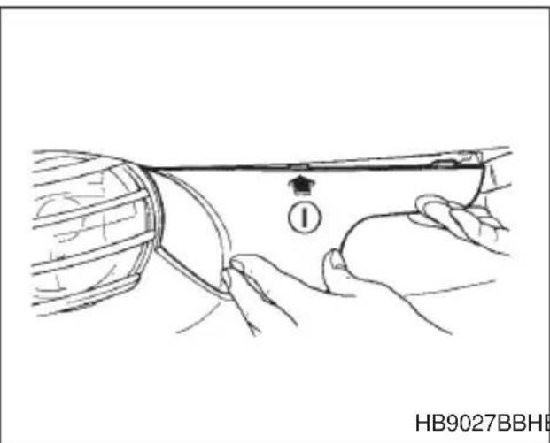
HB9027BBHB9026BB
- Fit the flange G in the slit H from the left end. While holding the towing hook cover at the portion G, push at the portion I.
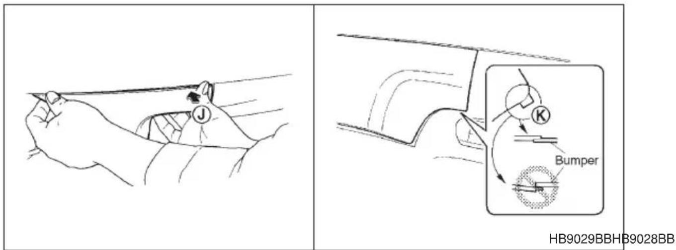
- Push at the portion J. Check that the tab of the portion K is fitted in the bumper as shown in the illustration.
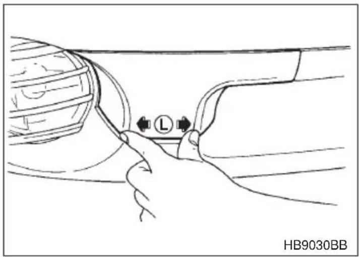
natural_image
Line drawing of a hand adjusting a car interior panel with a valve labeled 'L' (no text or symbols beyond label)- Push the portion L.
▼Using a flat-bed truck
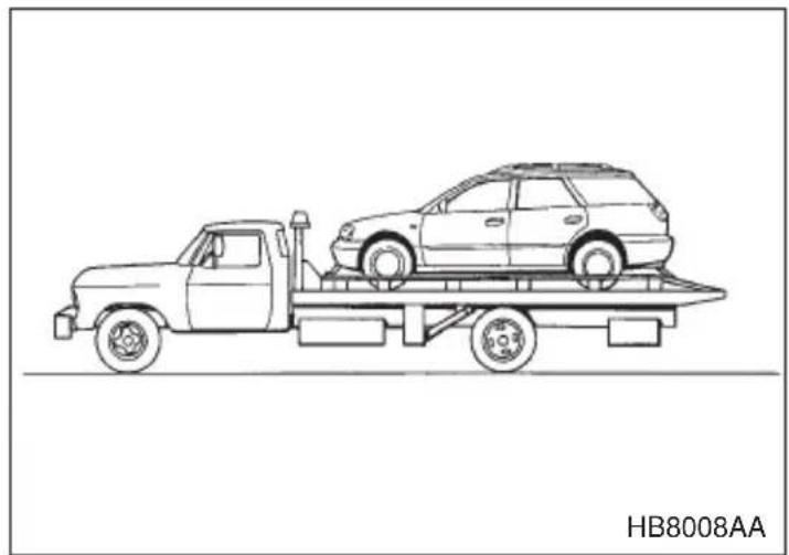
natural_image
Line drawing of a flatbed truck carrying a car on its trailer (no text or symbols on the diagram itself)This is the best way to transport your vehicle. Use the following procedures to ensure safe transportation.
- Shift the selector lever into the "P" position for automatic transmission vehicles or "1st" for manual transmission vehicles.
- Pull up the parking brake lever firmly.
- Secure the vehicle onto the carrier properly with safety chains. Each safety chain should be equally tightened and care must be taken not to pull the chains so tightly that the suspension bottoms out.
▼Towing with all wheels on the ground
WARNING
- Never turn the ignition switch to the “LOCK” position while the vehicle is being towed because the steering wheel and the direction of the wheels will be locked.
- Remember that the brake booster and power steering do not function when the engine is not running. Because the engine is turned off, it will take greater effort to operate the brake pedal and steering wheel.

CAUTION
- If transmission failure occurs, transport your vehicle on a flat-bed truck.
- Do not run the engine while being towed in this method. Transmission damage could result if the vehicle is towed with the engine running.
- For vehicles with automatic transmission, the traveling speed must be limited to less than 20 mph (30 km/h) and the traveling distance to less than 31 miles (50 km). For greater speeds and distances, transport your vehicle on a flat-bed truck.
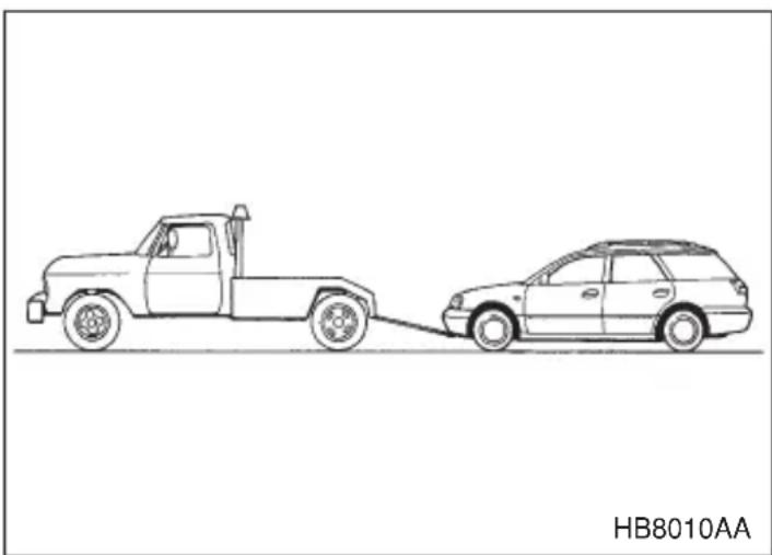
natural_image
Line drawing of a car being towed from a pickup truck, with no text or symbols on the diagram itself.- Check the transmission and differential oil levels and add oil to bring it to the upper level if necessary.
- Release the parking brake and put the transmission in neutral.
- The ignition switch should be in the "ACC" position while the vehicle is being towed.
- Take up slack in the towline slowly to prevent damage to the vehicle.
Moonroof — if the moonroof cannot be closed
If the moonroof cannot be closed with the moonroof switch, you can close the moonroof manually.
Sedan
- Take out the hex-headed wrench from the glove compartment and screwdriver from the tool bag.
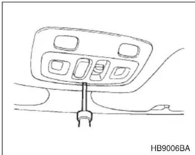
natural_image
Line drawing of a car air conditioner unit with control panel and connector (no text or symbols)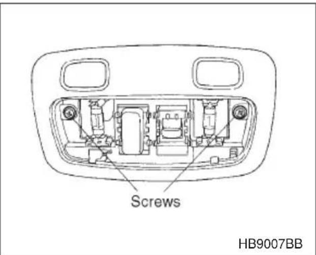
- Remove the spot light lens by prying the edge of the lens with a regular screwdriver, then remove the switch body retaining screws and take off the moonroof switch.
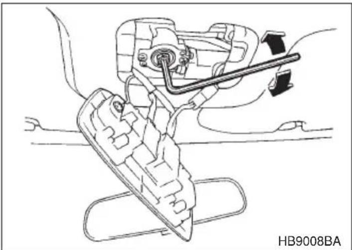
natural_image
Technical line drawing of a mechanical assembly with no visible text or symbols- Insert the wrench in the end of the motor shaft.
●To lower the moonroof, turn the wrench clockwise.
●To close the moonroof, turn the wrench counterclockwise.
Have your vehicle checked by an authorized SUBARU dealer.
- CONTINUED -
▼Station wagon
- Take out the hex-headed wrench from the glove compartment and screwdriver from the tool bag.
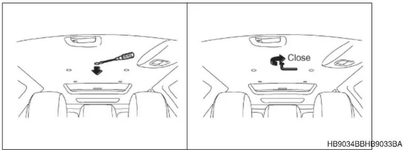
- Remove the plug on the roof trim by inserting the end of the regular screwdriver between the roof and plug and prying it off.
- Insert the wrench in the end of the motor shaft.
To close the moonroof, turn the wrench clockwise.
Have your vehicle checked or repaired by an authorized SUBARU dealer.
Maintenance tools
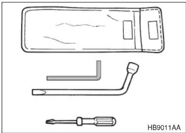
natural_image
Technical line drawing of a remote control panel with three different tool designs (no text or symbols)Your vehicle is equipped with the following maintenance tools:
Screwdriver
Wheel nut wrench
Hex-headed wrench (for vehicles with moonroof)
■Jack and jack handle
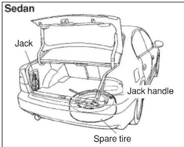
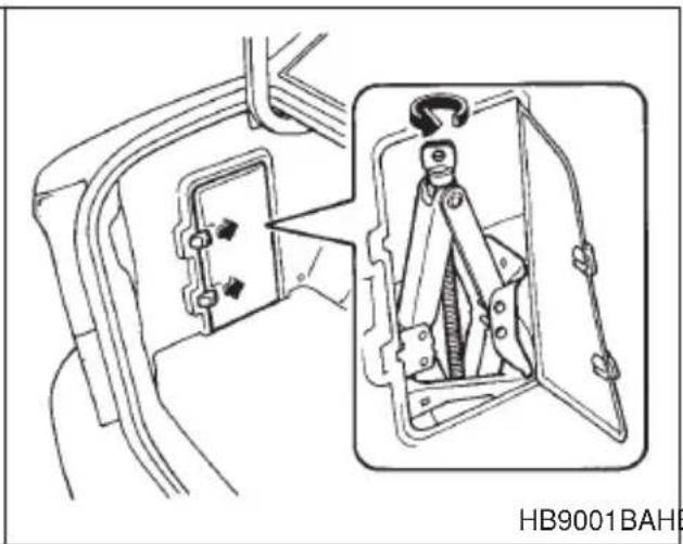
natural_image
Technical line drawing of an electrical switchgear assembly with a close-up view showing internal components (no text or symbols)HB9001BAHBF015CB
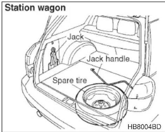
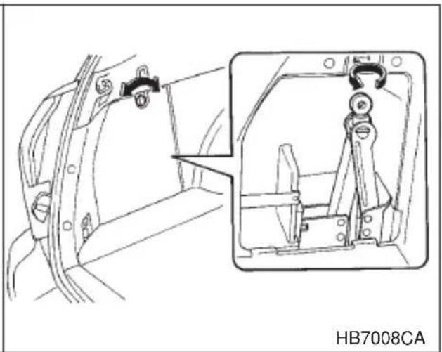
natural_image
Technical line drawing of a mechanical assembly with two views: one showing internal components and the other showing a bracket (no text or symbols)The jack is stored on the left side of the trunk or cargo area.
To take out the jack, turn the jackscrew counterclockwise to loosen it, then remove the jack.
The jack handle is stored under the spare tire cover.
For how to use the jack, refer to "Flat tires".
Appearance care
Exterior care 10-2
Washing 10-2
Waxing and polishing 10-3
Cleaning aluminum wheels 10-4
Cleaning fog light lens (for OUTBACK) 10-4
Corrosion protection 10-5
Cleaning the interior 10-6
Exterior care
Washing

CAUTION
- When washing the vehicle, the brakes may get wet. As a result, the brake stopping distance will be longer. To dry the brakes, drive the vehicle at a safe speed while lightly pressing the brake pedal to heat up the brakes.
- Do not wash the engine compartment and areas adjacent to it. If water enters the engine air intake, electrical parts or the power steering fluid reservoir, it will cause engine trouble or faulty power steering respectively.
The best way to preserve your vehicle's beauty is frequent washing. Wash the vehicle at least once a month to avoid contamination by road grime.
Wash dirt off with a wet sponge and plenty of lukewarm or cold water. Do not wash the vehicle with hot water and in direct sunlight.
Salt, chemicals, insects, tar, soot and bird droppings should be washed off by using a light detergent, as required. If you use a light detergent, make certain that it is a neutral detergent. Do not use strong soap or chemical detergents. All cleaning agents should be promptly flushed from the surface and not allowed to dry there. Rinse the vehicle thoroughly with plenty of lukewarm water. Wipe the remaining water off with a chamois or soft cloth.
NOTE
When having your vehicle washed in an automatic car wash, make sure beforehand that the car wash is of suitable type. If the vehicle is equipped with a rear/roof spoiler, it may be damaged by car wash brushes or other equipment.
▼Washing the underbody
Chemicals, salts and gravel used for deicing road surfaces are extremely corrosive, accelerating the corrosion of underbody components, such as the exhaust system, fuel and brake lines, brake cables, floor pan and fenders, and suspension.
Thoroughly flush the underbody and inside of the fenders with lukewarm or cold water at frequent intervals to reduce the harmful effects of such agents.
▼Using a warm water washer
- Keep a good distance of 12 in (30 cm) or more between the washer nozzle and the vehicle.
- Do not wash the same area continuously.
- If a stain will not come out easily, wash by hand. Some warm water washers are of the high temperature, high pressure type, and they can damage or deform the resin parts such as mouldings, or cause water to leak into the vehicle.
■Waxing and polishing
Always wash and dry the vehicle before waxing and polishing.
Use a good quality polish and wax and apply them according to the manufacturer's instructions. Wax or polish when the painted surface is cool.
Be sure to polish and wax the chrome trim, as well as the painted surfaces. Loss of wax on a painted surface leads to loss of the original luster and also quickens the deterioration of the surface. It is recommended that a coat of wax be applied at least once a month, or whenever the surface no longer repels water.
If the appearance of the paint has diminished to the point where the luster or tone cannot be restored, lightly polish the surface with a fine-grained compound. Never polish just the affected area, but include the surrounding area as well. Always polish in only one direction. A No. 2000 grain compound is recommended. Never use a coarse-grained compound. Coarser grained compounds have a smaller grain-size number and could damage the paint. After polishing with a compound, coat with
wax to restore the original luster. Frequent polishing with a compound or an incorrect polishing technique will result in removing the paint layer and exposing the undercoat. When in doubt, it is always best to contact your SUBARU dealer or an auto paint specialist.
■Cleaning aluminum wheels
- Promptly wipe the aluminum wheels clean of any kind of grime or agent. If dirt is left on too long, it may be difficult to clean off.
- Do not use soap containing grit to clean the wheels. Be sure to use a neutral cleaning agent, and later rinse thoroughly with water. Do not clean the wheels with a stiff brush or expose them to a high-speed washing device.
- Clean the vehicle (including the aluminum wheels) with water as soon as possible when it has been splashed with sea water, exposed to sea breezes, or driven on roads treated with salt or other agents.
■Cleaning fog light lens (for OUTBACK)
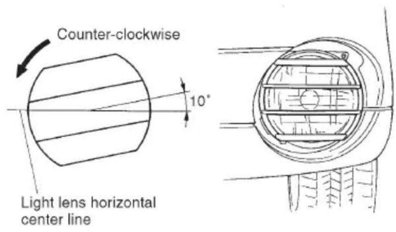
HBA017BB
- Stop the vehicle in a safe place.
- Stop the engine and turn off the fog lights.
- Check that the fog lights are not hot. Then, grasp the protector and turn it approximately 10^ counter-clockwise.
- Pull the protector off the fog light.
- Wash the lens with water.
- Apply the protector to the lens at an angle of approximately 10° from
the fog light's horizontal center line. Then, turn the protector clockwise until it stops. Finally, check that the protector's horizontal bars are parallel with the fog light's horizontal center line.
Corrosion protection
Your SUBARU has been designed and built to resist corrosion. Special materials and protective finishes have been used on most parts of the vehicle to help maintain fine appearance, strength, and reliable operation.
▼ Most common causes of corrosion
The most common causes of corrosion are:
- The accumulation of moisture retaining dirt and debris in body panel sections, cavities, and other areas.
- Damage to paint and other protective coatings caused by gravel and stone chips or minor accidents.
Corrosion is accelerated on the vehicle when:
- It is exposed to road salt or dust control chemicals, or used in coastal areas where there is more salt in the air, or in areas where there is considerable industrial pollution.
- It is driven in areas of high humidity, especially when temperatures range just above freezing.
- Dampness in certain parts of the vehicle remains for a long time, even though other parts of the vehicle may be dry.
- High temperatures will cause corrosion to parts of the vehicle which cannot dry quickly due to lack of proper ventilation.
▼To help prevent corrosion
Wash the vehicle frequently. If you drive on salted roads in the winter or if you live in a coastal area, you should flush the underbody with fresh water frequently.
After the winter has ended, it is recommended that the underbody be given a very thorough washing.
Before the beginning of winter, check the condition of underbody components, such as the exhaust system, fuel and brake lines, brake cables, suspension, steering system, floor pan, and fenders. If any of them are found to be rusted, they should be given an appropriate rust prevention treatment or should be replaced. Contact your SUBARU dealer to perform this kind of maintenance and treatment if you need assistance.
Repair chips and scratches in the paint as soon as you find them.
Check the interior of the vehicle for water and dirt accumulation under the floor mats because that could cause corrosion. Occasionally check under the mats to make sure the area is dry.
Keep your garage dry. Do not park your vehicle in a damp, poorly ventilated garage. In such a garage, corrosion can be caused by dampness. If you wash the vehicle in the garage or put the vehicle into the garage when wet or covered with snow, that can cause dampness.
If your vehicle is operated in cold weather and/or in areas where road salts and other corrosive materials are used, the door hinges and locks, trunk lid lock, and hood latch should be inspected and lubricated periodically.
Cleaning the interior
Use a vacuum cleaner to get rid of the dust and dirt. Wipe the vinyl areas with a clean, damp cloth.
Seat fabric
Remove loose dirt, dust or debris with a vacuum cleaner. If the dirt is caked on the fabric or hard to remove with a vacuum cleaner, use a soft blush then vacuum it.
Wipe the fabric surface with a tightly wrung cloth and dry the seat fabric thoroughly. If the fabric is still dirty, wipe using a solution of mild soap and lukewarm water then dry thoroughly.
If the stain does not come out, try a commercially-available fabric
cleaner. Use the cleaner on a hidden place and make sure it does not affect the fabric adversely. Use the cleaner according to its instructions.
▼ Leather seat materials
The leather used by SUBARU is a high quality natural product which will retain its distinctive appearance and feel for many years with proper care.
Allowing dust or road dirt to build up on the surface can cause the material to become brittle and to wear prematurely. Regular cleaning with a soft, moist, natural fiber cloth should be performed monthly, taking care not to soak the leather or allow water to penetrate the stitched seams.
A mild detergent suitable for cleaning woolen fabrics may be used to remove difficult dirt spots, rubbing with a soft, dry cloth afterwards to restore the luster. If your SUBARU is to be parked for a long time in bright sunlight, it is recommended that the seats and headrests be covered, or the windows shaded, to prevent fading or shrinkage.
Minor surface blemishes or bald patches may be treated with a commercial leather spray lacquer. You will discover that each leather seat section will develop soft folds or wrinkles, which is characteristic of genuine leather.
▼Synthetic leather upholstery
The synthetic leather material used on the SUBARU may be cleaned using mild soap or detergent and water, after first vacuuming or brushing away loose dirt. Allow the soap to soak in for a few minutes and wipe off with a clean, damp cloth. Commercial foam-type cleaners suitable for synthetic leather materials may be used when necessary.
NOTE
Strong cleaning agents such as solvents, paint thinners, window cleaner or gasoline must never be used on leather or synthetic interior materials.
Maintenance and service
Maintenance schedule 11-3
Maintenance precautions 11-3
Engine hood 11-5
Engine compartment overview 11-7
Engine oil 11-9
Cooling system 11-14
Engine coolant 11-15
Air cleaner element 11-18
Spark plugs 11-20
Drive belts 11-22
Manual transmission oil 11-23
Automatic transmission fluid 11-24
Front differential gear oil (AT vehicles) 11-26
Rear differential gear oil 11-27
Power steering fluid 11-29
Brake fluid 11-30
Clutch fluid (MT vehicles) 11-32
Brake booster 11-33
Brake pedal 11-34
Clutch pedal (Manual transmission vehicles) 11-35
Replacement of brake pad and lining 11-36
Parking brake stroke 11-37
Tires and wheels 11-38
Types of tires 11-38
Tire inspection 11-39
Tire pressures and wear 11-39
Wheel balance 11-42
Wear indicators 11-43
Tire rotation 11-44
Tire replacement 11-44
Wheel replacement 11-45
Wheel covers 11-46
Aluminum wheels (If equipped) 11-47
Windshield washer fluid 11-47
Replacement of windshield wiper blades 11-48
Battery 11-51
Fuses 11-52
Main fuse 11-54
Installation of accessories 11-54
Replacing bulbs 11-55
Headlight 11-57
Front fog light (if equipped) 11-59
Front turn signal light, parking light and marker light 11-59
Rear combination lights 11-61
License plate light 11-64
Spot light, dome light, luggage compartment light and door step light 11-65
Trunk light 11-66
High mount stop light 11-67
Maintenance schedule
The scheduled maintenance items required to be serviced at regular intervals are shown in the “Warranty and Maintenance Booklet”.
For details of your maintenance schedule, read the separate “Warranty and Maintenance Booklet”.
Maintenance precautions
When maintenance and service are required, it is recommended that all work be done by an authorized SUBARU dealer.
If you perform maintenance and service by yourself, you should familiarize yourself with the information provided in this section on general maintenance and service for your SUBARU.
Incorrect or incomplete service could cause improper or unsafe vehicle operation. Any problems caused by improper maintenance and service performed by you are not eligible for warranty coverage.

WARNING
- Testing of an All-Wheel Drive vehicle must NEVER be performed on a single two-wheel dynamometer or similar apparatus. Attempting to do so will result in transmission damage and in uncontrolled vehicle movement and may cause an accident or injuries to persons nearby.
●Always select a safe area when performing maintenance on your vehicle.
●Always be very careful to avoid injury when working on the vehicle. Remember that some of the materials in the vehicle may be hazardous if improperly used or handled, for example, battery acid. - Your vehicle should only be serviced by persons fully competent to do so. Serious personal injury may result to persons not experienced in servicing vehicles.
●Always use the proper tools and make certain that they are well maintained.
- Never get under the vehicle supported only by a jack. Always use a safety stands to support the vehicle.
- Never keep the engine running in a poorly ventilated area, such as a garage or other closed areas.
- Do not smoke or allow open flames around the fuel or battery. This will cause a fire.
- Because the fuel system is under pressure, replacement of the fuel filter should be performed only by your SUBARU dealer.
- Wear adequate eye protection to guard against getting oil or fluids in your eyes. If something does get in your eyes, thoroughly wash them out with clean water.
- Do not tamper with the wiring of the SRS airbag system or seatbelt pretensioner system, or attempt to take its connectors apart, as that may activate the system or it can render it inoperative. The wiring and connectors of these systems are yellow for easy identification. NEVER use a circuit tester for these wiring.
If your SRS airbag or seatbelt pretensioner needs service, consult your nearest SUBARU dealer.
■Before checking or servicing in the engine compartment
●Always stop the engine and set the parking brake firmly to prevent the vehicle from moving.
●Always let the engine cool down. Engine parts become very hot when the engine is running and remain hot for some time after the engine is stopped.
- Do not spill engine oil, engine coolant, brake fluid or any other fluid on hot engine components. This may cause a fire.
- Always remove the key from the ignition switch. When the ignition switch is in the “ON” position, the cooling fan may operate suddenly even when the engine is stopped.
■When you do checking or servicing in the engine compartment while the engine is running
A running engine can be dangerous. Keep your fingers, hands, clothing, hair and tools away from the cooling fan, belts and any other moving engine parts. Removing rings, watches and ties is advisable.
Engine hood

WARNING
Always check that the hood is properly locked before you start driving. If it is not, it might fly open while the vehicle is moving and block your view, which may cause an accident and serious bodily injury.
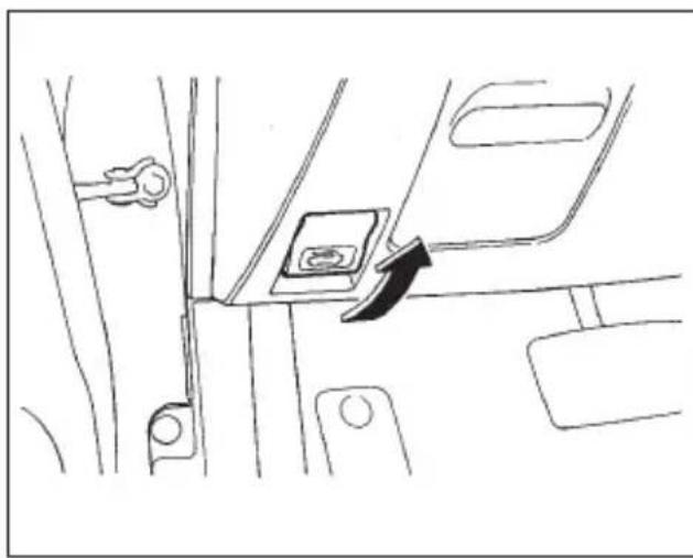
natural_image
Line drawing of a car seatbelt switch mechanism (no text or symbols)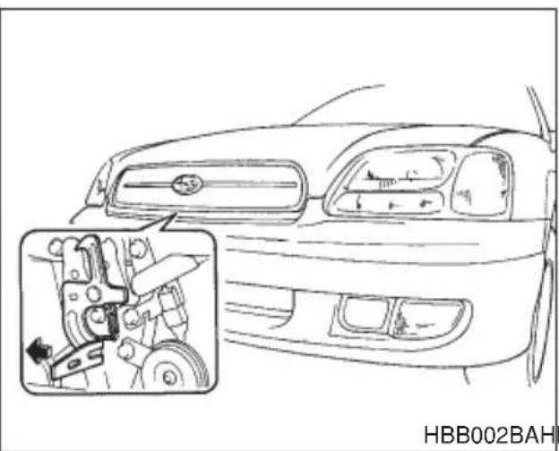
natural_image
Line drawing of a car front view with an inset showing internal mechanical components (no text or symbols)HBB002BAHBB001BA
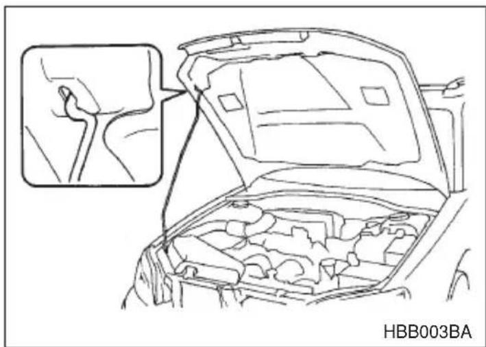
natural_image
Line drawing of a car engine compartment with an inset showing a close-up of the hood (no text or symbols)To open the hood:
- Pull the hood release knob under the instrument panel.
- Release the secondary hood release located under the front grille by moving the lever toward the left. Lift up the hood, release the hood prop from its retainer and put the end of the hood prop into the slot in the hood.
To close the hood:
- Lift the hood slightly and remove the hood prop from the slot in the hood and return the prop to its retainer.
- Lower the hood until it approaches about 6 in. (15 cm) from the closed position and let it drop.
- After closing the hood, be sure the hood is securely locked.
If this does not close the hood, release it from a slightly higher position. Do not push the hood forcibly to close it. It could deform the metal.
Engine compartment overview
▼2.5 liter models
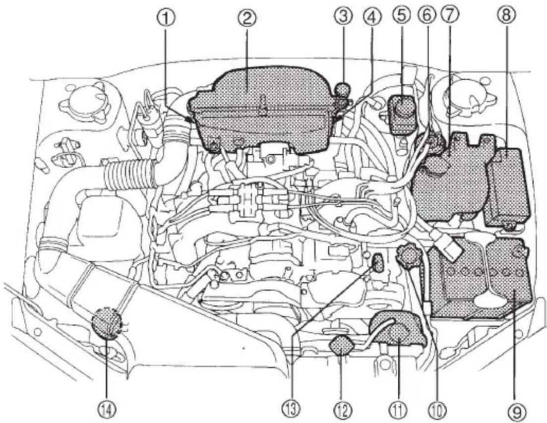
HBB036BB
① Manual transmission oil level gauge (MT) (page 11-23) or Differential gear oil level gauge (AT) (page 11-26)
② Air cleaner element (page 11-18)
③ Clutch fluid reservoir (page 11-32)
④ Automatic transmission fluid level gauge (page 11-24)
⑤ Brake fluid reservoir (page 11-30)
⑥ Fuel filter
⑦ Windshield washer tank (page 11-47)
⑧ Fuse box (page 11-52)
⑨ Battery (page 11-51)
⑩ Engine oil filler cap (page 11-9)
⑪ Engine coolant reservoir (page 11-15)
⑫ Radiator cap (page 11-15)
⑬ Engine oil level gauge (page 11-9)
⑭ Power steering fluid reservoir (page 11-29)
▼3.0 liter models
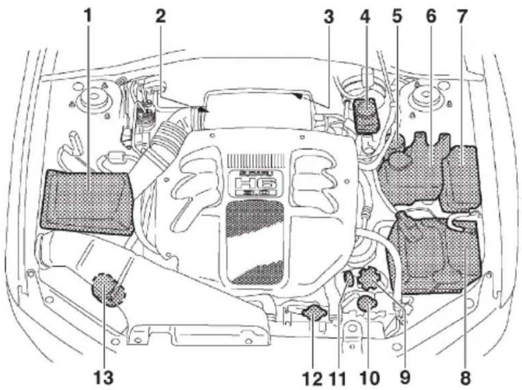
HBB058BB
① Air cleaner element (page 11-18)
② Differential gear oil level gauge (AT) (page 11-26)
③ Automatic transmission fluid level gauge (page 11-24)
④ Brake fluid reservoir (page 11-30)
⑤ Fuel filter
⑥ Windshield washer tank (page 11-47)
⑦ Fuse box (page 11-52)
⑧ Battery (page 11-51)
⑨ Engine oil filler cap (page 11-9)
⑩ Engine coolant reservoir (page 11-15)
⑪ Engine oil level gauge (page 11-9)
⑫ Radiator cap (page 11-15)
⑬ Power steering fluid reservoir (page 11-29)
Engine oil
▼Checking the oil level
Check the engine oil level at each fuel stop.
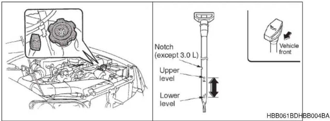
- Park the vehicle on a level surface and stop the engine.
- Pull out the dipstick, wipe it clean, and insert it again.
- Be sure the dipstick is correctly inserted until it stops with the graphic symbol 📄 on its top appearing as shown in the illustration.
- Pull out the dipstick again and check the oil level on it. If it is below the lower level, add oil to bring the level up to the upper level.

CAUTION
Use only engine oil with the recommended grade and viscosity.
If you check the oil level just after stopping the engine, wait a few minutes for the oil to drain back into the oil pan before checking the level. To prevent overfilling the engine oil, do not add any additional oil above the upper level when the engine is cold.
In 2.5-liter-engine models, the dipstick has a notch above the upper level.
Just after driving or while the engine is warm, the engine oil level reading may be in a range between the upper level and the notch mark. This is caused by thermal expansion of the engine oil.
- CONTINUED -
▼Changing the oil and oil filter
Change the oil and oil filter according to the maintenance schedule in the "Warranty and Maintenance Booklet".
The engine oil and oil filter must be changed more frequently than listed in the maintenance schedule when driving on dusty roads, when short trips are frequently made, or when driving in extremely cold whether.
- Warm up the engine by letting the engine idle for about 10 minutes to ease draining the engine oil.
- Park the vehicle on a level surface and stop the engine.
- Remove the oil filler cap.
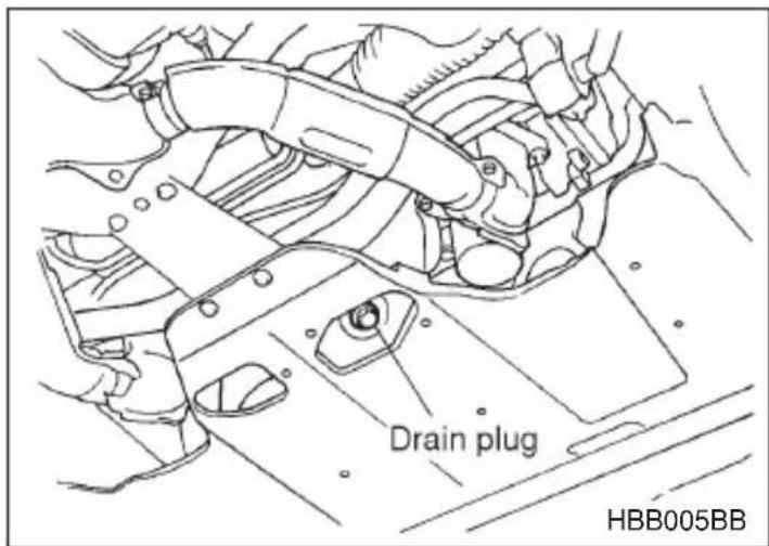
- Drain out the engine oil by removing the drain plug while the engine is still warm. The used oil should be drained into an appropriate container and disposed of properly.

WARNING
Be careful not to burn yourself with hot engine oil.
- Wipe the seating surface of the drain plug with a clean cloth and tighten it securely with a new sealing washer after the oil has completely drained out.
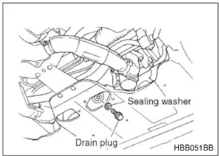
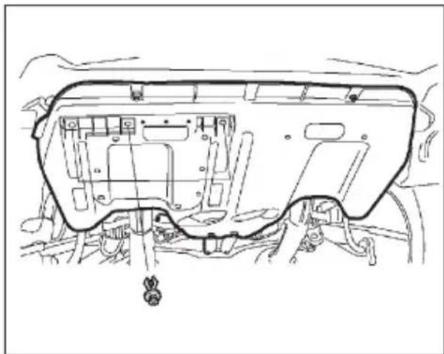
natural_image
Technical line drawing of a vehicle chassis frame with structural components (no text or symbols)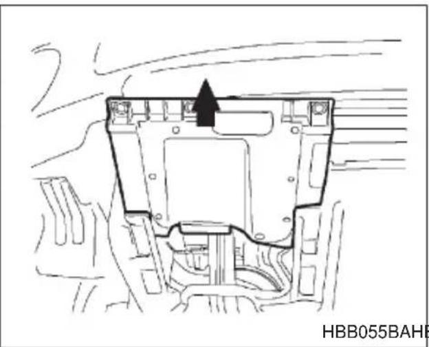
natural_image
Technical line drawing of a mechanical component with no visible text or symbolsHBB055BAHBB054BA
-
Remove three clips at the front of the cover under the oil filter.
-
Slide the cover toward the vehicle front to remove it.
-
Remove the oil filter with an oil filter wrench.
-
Before installing a new oil filter, apply a thin coat of engine oil to the seal.
-
Clean the rubber seal seating area of the lower crank case and install the oil filter by hand turning. Be careful not to twist or damage the seal.
-
Tighten it approximately two-thirds of a turn after the seal makes contact with the lower crank case.
CAUTION
Never over tighten the oil filter because that can result in an oil leak.
- Reinstall the cover under the oil filter.
- Pour the specified amount of engine oil through the filler neck.
Oil capacity:
2.5 liter models: 4.2 US qt (4.0 liters, 3.5 Imp qt)
3.0 liter models: 6.1 US qt (5.8 liters, 5.1 Imp qt)
- Start the engine and make sure that no oil leaks appear around the filter's rubber seal.
- Run the engine until it reaches the normal operating temperature. Then stop the engine and wait a few minutes to allow the oil drain back. Check the oil level again and if necessary, add more engine oil.
▼Recommended grade and viscosity

CAUTION
Use only engine oil with the recommended grade and viscosity.
Oil grade: API classification SL or SJ with the words “ENERGY CONSERVING II” (if you cannot obtain the oil with SL or SJ grade, you may use SH grade oil.) or the new API certification mark (Starburst mark) displayed on the container.
API Service label
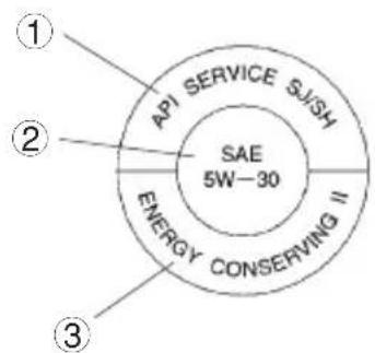
New API Certification Mark (Starburst Mark)

In choosing an oil, you want the proper quality and viscosity, as well as one that will add to fuel economy. The following table lists the recommended viscosities and applicable temperatures.
When adding oil, different brands may be used together as long as they are the same API classification and SAE viscosity as those recommended by SUBARU.
Engine oil viscosity (thickness) affects fuel economy. Oils of lower viscosity provide better fuel economy. However, in hot weather, oil of higher viscosity is required to properly lubricate the engine.
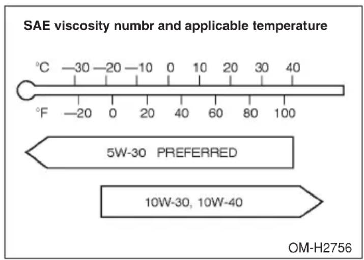
▼Recommended grade and viscosity under severe driving conditions
If the vehicle is used in desert areas, in areas with very high temperatures, or used for heavy-duty applications such as a towing a trailer, use of oil with the following grade and viscosities is recommended.
API classification SL or SJ: SAE viscosity No.: 30, 40, 10W-50, 20W-40, 20W-50
Cooling system

WARNING
Never attempt to remove the radiator cap until the engine has been shut off and has cooled down completely. Since the coolant is under pressure, you may suffer serious burns from a spray of boiling hot coolant when the cap is removed.

CAUTION
- The cooling system has been filled at the factory with a high quality, corrosion-inhibiting, year-around coolant which provides protection against freezing down to -33^ ( -36^ ). For adding, use genuine SUBARU coolant or an equivalent: a mixture of 50% soft water and 50% ethylene-glycol basis coolant. Use of improper coolants may result in corrosion in the cooling system. It is important to maintain protection against freezing and corrosion, even if freezing temperatures are not expected. Never mix different kinds of coolant.
- Do not splash the engine coolant over painted parts. The alcohol contained in the engine coolant may damage the paint surface.
▼ Hose and connections
Your vehicle employs an electric cooling fan which is thermostatically controlled to operate when the engine coolant reaches a specific temperature.
If the radiator cooling fan does not operate even when the engine coolant temperature gauge exceeds the normal operating range, the cooling fan circuit may be defective. Check the fuse and replace it if necessary. If the fuse is not blown, have the cooling system checked by your SUBARU dealer.
If frequent addition of coolant is necessary, there may be a leak in the engine cooling system. It is recommended that the cooling system and connections be checked for leaks, damage, or looseness.
■Engine coolant
▼Checking the coolant level
Check the coolant level at each fuel stop.
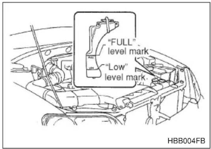
- Check the coolant level on the outside of the reservoir while the engine is cool.
- If the level is close to or lower than the "LOW" level mark, add coolant up to the "FULL" level mark. If the reserve tank is empty, remove the radiator cap and refill as required.
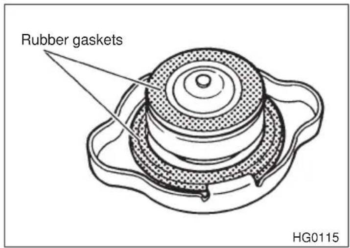
- After refilling the reserve tank and the radiator, reinstall the caps and check that the rubber gaskets inside the radiator cap are in the proper position.
▼Changing the coolant
WARNING
Never attempt to remove the radiator cap until the engine has been shut off and has cooled down completely. Since the coolant is under pressure, you may suffer serious burns from a spray of boiling hot coolant when the cap is removed.
Change the engine coolant using the following procedures according to the maintenance schedule in the "Warranty and Maintenance Booklet".
- Remove the under cover.
- Place a proper container under the drain plug and loosen the drain plug.
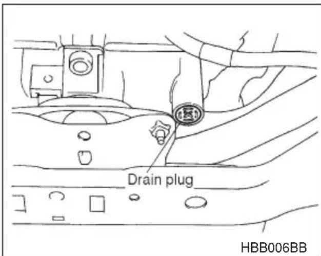
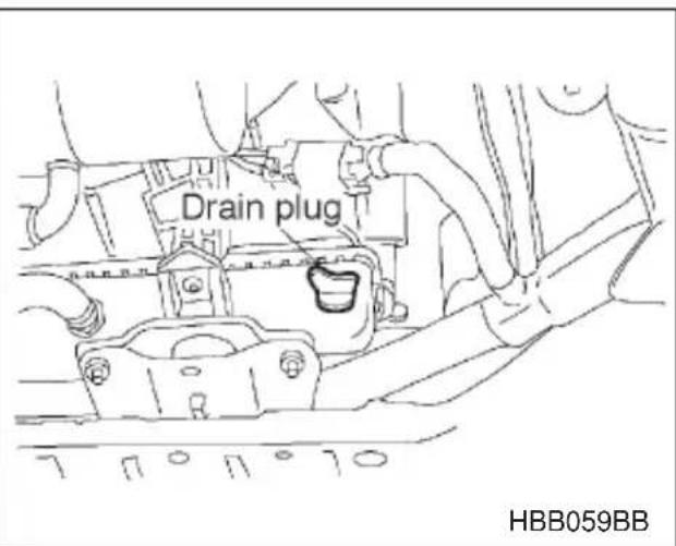
- Loosen the radiator cap to drain the coolant from the radiator. Then drain the coolant from the reserve tank. Tighten the drain plug securely.
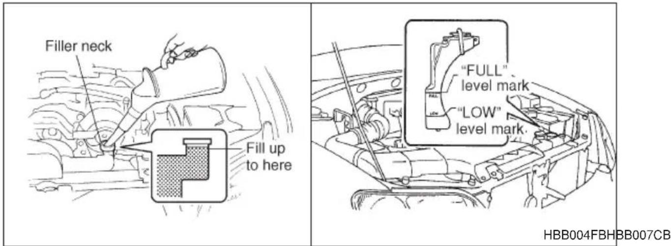
- Slowly pour the coolant and fill to the radiator filler neck and to the reserve tank's "FULL" level mark. Do not pour the coolant too quickly, as this may lead to insufficient air bleeding and trapped air in the system.
Coolant capacity:
2.5 liter models MT. 7.2 US qt (6.8 liters, 6.0 Imp qt)
AT. 7.1 US qt (6.7 liters, 5.9 Imp qt)
3.0 liter models 8.4 US qt (7.9 liters, 7.0 Imp qt)
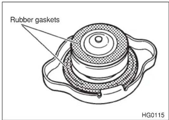
- Put the radiator cap back on and tighten firmly. At this time, make sure that the rubber gasket in the radiator cap is correctly in place.
- Start and run the engine for more than five minutes at 2,000 to 3,000 rpm.
- CONTINUED -
- Stop the engine and wait until the coolant cools down (122 to 140°F [50 to 60°C]). If there is any loss of coolant, add coolant to the radiator's filler neck and to the reserve tank's "FULL" level.
- Put the radiator cap and reservoir cap back on and tighten firmly.
Air cleaner element

WARNING
Do not operate the engine with the air cleaner element removed. The air cleaner element not only filters intake air but also stops flames if the engine backfires. If the air cleaner element is not installed when the engine backfires, you could be burned.
The air cleaner element functions as a filter screen. When the element is perforated or removed, engine wear will be excessive and engine life shortened.
The air cleaner element is a viscous type. It is unnecessary to clean or wash the element.
▼Replacing the air cleaner element
Replace the air cleaner element according to the maintenance schedule in the “Warranty and Maintenance Booklet”. Under extremely dusty conditions, replace it more frequently. It is recommended that you always use genuine SUBARU parts.
▽ 2.5 liter models
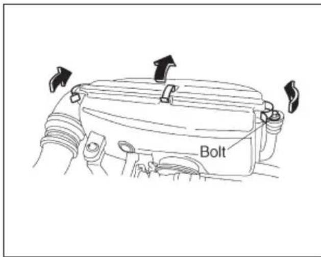
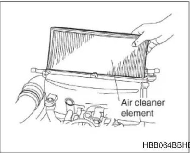
HBB064BBHBB063BB
- Remove the bolt securing the rear air cleaner element case.
- Unsnap the three clamps holding the rear air cleaner element case.
- Separate the rear air cleaner element case from the front air cleaner element case and remove the air cleaner element.
- Clean the inside of the front and rear air cleaner element cases with a damp cloth and install a new air cleaner element.
- Insert the four projections on the rear air cleaner element case into the slits on the front air cleaner element case and snap the three clamps on the rear air cleaner element case and then tighten the bolt.
▽ 3.0 liter models
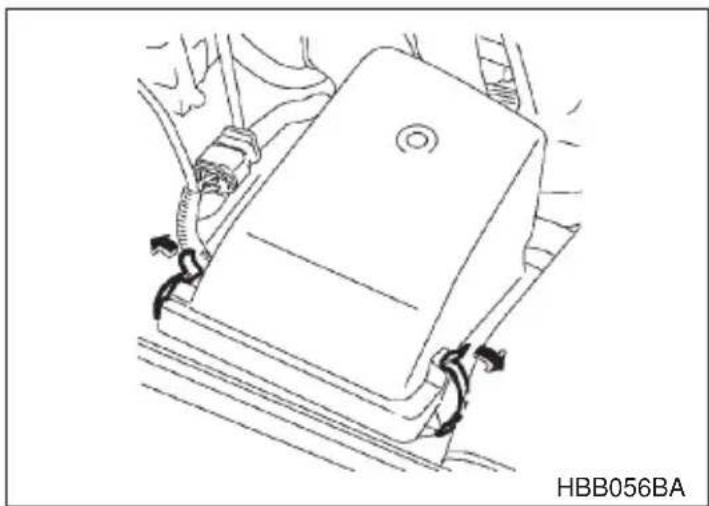
natural_image
Line drawing of a car seatbelt with attached hoses and a label HBB056BA (no text or symbols on the diagram itself)- Unsnap the two clamps holding the air cleaner case cover.
- CONTINUED -
-
Open the air cleaner case cover and remove the air cleaner element.
-
Clean the inside of the air cleaner cover and case with a damp cloth and install a new air cleaner element.
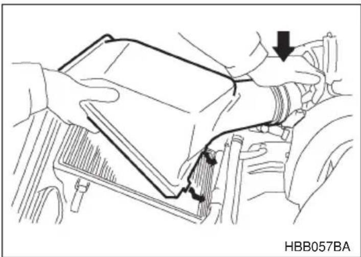
natural_image
Line drawing of a car interior showing hands holding a device, with a black arrow pointing to a component (no text or symbols on the diagram itself)To install the air cleaner case cover, insert the two projections on the air cleaner case cover into the slits on the air cleaner case and then snap the two clamps on the air cleaner case cover.
Spark plugs

CAUTION
- When disconnecting the spark plug cables, always grasp the spark plug cap, not the cables.
●Make sure the cables are replaced in the correct order.
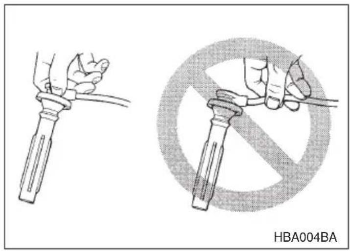
It may be difficult to replace the spark plugs. It is recommended that you have the spark plugs replaced by your SUBARU dealer.
The spark plugs should be replaced according to the maintenance schedule in the “Warranty and Maintenance Booklet”.
▼Recommended spark plugs
2.5 liter models:
RC10YC4 (Champion)
BKR6E-11 (NGK)
BKR5E-11 (NGK)
3.0 liter models: PLFR6A-11 (NGK)
Drive belts
The alternator, power steering pump, and air conditioner compressor depend on drive belts. Satisfactory performance requires that belt tension be correct.
▼2.5 liter models
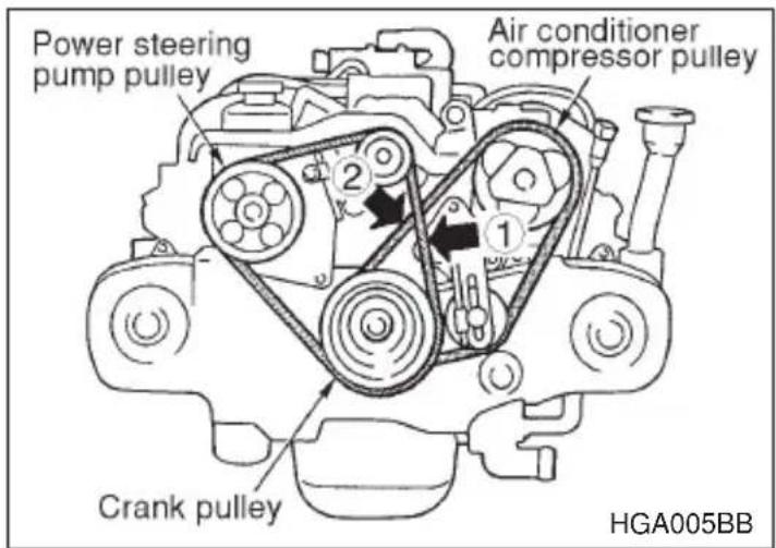
in (mm)
| Deflection | ||
| New belt Used belt | ||
| 1 | 0.28 — 0.35(7.0 — 9.0) | 0.35 — 0.43(9.0 — 11.0) |
| 2 | 0.30 — 0.33(7.5 — 8.5) | 0.35 — 0.40(9.0 — 10.0) |
To check belt tension, place a straightedge (ruler) across two adjacent pulleys and apply a force of 22 lb (98 N, 10 kg) midway between the pulleys by using a spring scale. Belt deflection should be the amount specified.
▼3.0 liter models
It is unnecessary to check belt tension periodically because your engine is equipped with an automatic belt tension adjuster. However, replacement of the belt should be done according to the maintenance
schedule in the "Warranty and Maintenance Booklet". Consult your SUBARU dealer for replacement.
If a belt is loose, cracked, or worn, contact your SUBARU dealer.
Manual transmission oil
▼Checking the oil level
Check the oil level monthly.
- Park the vehicle on a level surface and stop the engine.
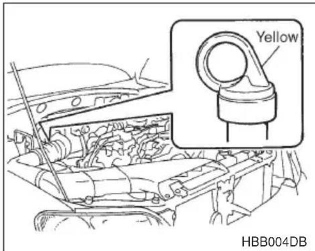
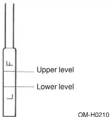
- Pull out the dipstick, wipe it clean, and insert it again.
- Pull out the dipstick again and check the oil level on it. If it is below the lower level, add oil through the dipstick hole to bring the level up to the upper level.
▼Recommended grade and viscosity
Each oil manufacturer has its own base oils and additives. Never use different brands together.
Oil grade: API classification GL-5
SAE viscosity No. and Applicable Temperature
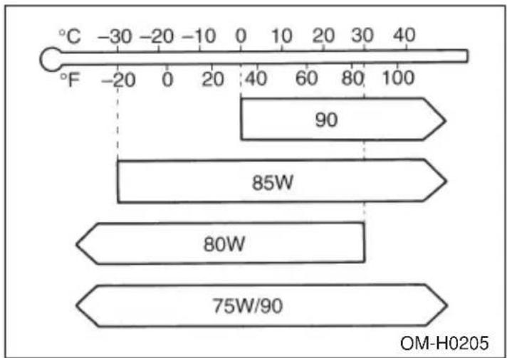
bar
| Temperature (°C) | Value | | ----------------- | ----- | | -30 | 90 | | -20 | | | -10 | | | 0 | | | 10 | | | 20 | | | 30 | | | 40 | | | 75W/90 | |Automatic transmission fluid
▼Checking the fluid level
The automatic transmission fluid expands largely as its temperature rises; the fluid level differs according to fluid temperature. Therefore, there are two different scales for checking the level of hot fluid and cold fluid on the dipstick.
Though the fluid level can be checked without warming up the fluid on the “COLD” range, we recommend checking the fluid level when the fluid is at operating temperature.
▼ Checking the fluid level when the fluid is hot
Check the fluid level monthly.
-
Drive the vehicle several miles to raise the temperature of the transmission fluid up to normal operating temperature; 140 to 176^ F (60 to 80^ C ) is normal.
-
Park the vehicle on a level surface and set the parking brake.
-
First shift the selector lever in each position. Then shift it in the "P" position, and run the engine at idling speed.
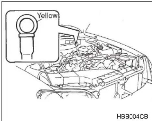
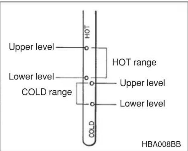
- Pull out the dipstick and check the fluid level on the gauge. If it is below the lower level on the "HOT" range, add the recommended automatic transmission fluid up to the upper level.
▼ Checking the fluid level when the fluid is cold
When the fluid level has to be checked without time to warm up the automatic transmission, check to see that the fluid level is between the lower level and upper level on the "COLD" range. If it is below that range, add fluid up to the upper level. Be careful not to overfill.
▼Recommended fluid
"Dexron III" Type Automatic Transmission Fluid
Front differential gear oil (AT vehicles)
▼Checking the oil level
Check the differential oil level monthly.
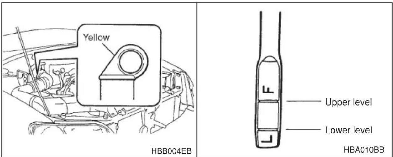
- Park the vehicle on a level surface and stop the engine.
- Pull out the dipstick, wipe it clean, and insert it again.
- Pull out the dipstick again and check the oil level on it. If it is below the lower level, add oil to bring the level up to the upper level.
▼Recommended grade and viscosity
Each oil manufacturer has its own base oils and additives. Never use different brands together.
Oil grade: API classification GL-5
SAE viscosity No. and Applicable Temperature
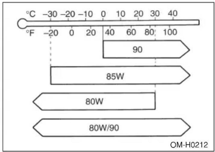
bar
| Temperature (°C) | Latitude (°F) | | ----------------- | ------------- | | -30 | -20 | | -20 | 0 | | -10 | 20 | | 0 | 40 | | 10 | 60 | | 20 | 80 | | 30 | 100 | | 40 | 100 | | 50 | 100 | | 60 | 100 | | 70 | 100 | | 80 | 100 | | 90 | 100 | | 100 | 100 | OM-H0212Rear differential gear oil
▼Checking the gear oil level
CAUTION
If the vehicle requires frequent refilling, there may be an oil leak. If you suspect a problem, have the vehicle checked at your SUBARU dealer.
Your vehicle may be equipped with a rear differential protector. The differential protector provides protection to the rear differential assembly during off-road use. Removal of the rear differential protector is not required when checking the oil level.
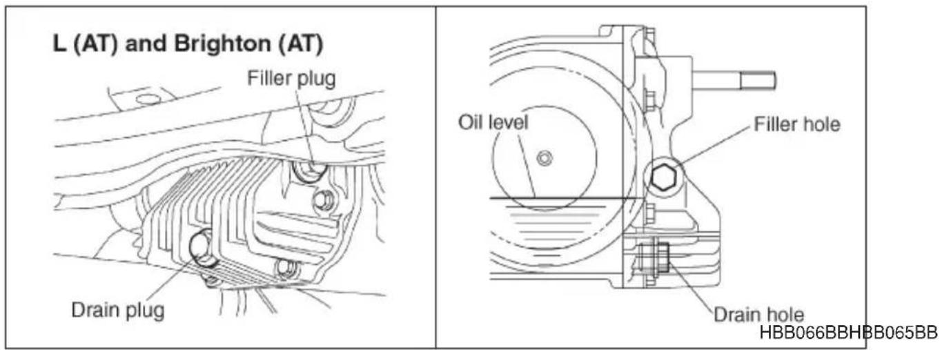
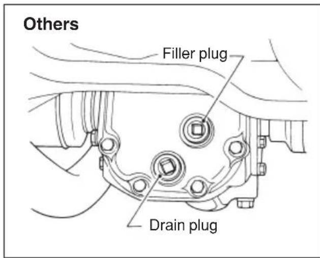
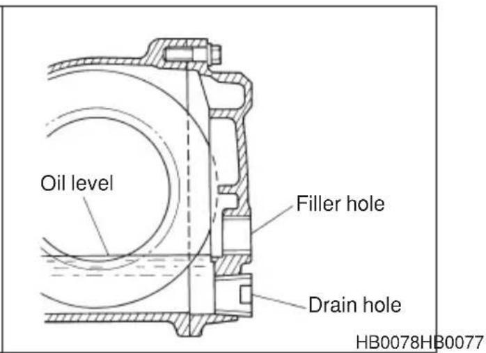
Remove the plug from the filler hole and check the oil level. The oil level should be kept even with the bottom of the filler hole. If the oil level is below the bottom edge of the hole, add oil through the filler hole to raise the level.
▼Recommended grade and viscosity
Each oil manufacturer has its own base oils and additives. Never use different brands together.
Oil grade: API classification GL-5
SAE viscosity No. and Applicable Temperature
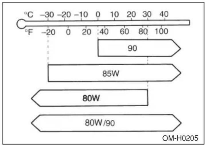
bar
| Value | Label | |-------|-----------| | 90 | | | 85W | | | 80W | | | 80W/90| |Power steering fluid
▼Checking the fluid level

WARNING
Be careful not to burn yourself because the fluid may be hot.

CAUTION
- When power steering fluid is being added, use only clean fluid, and be careful not to allow any dirt into the tank. And never use different brands together.
- Avoid spilling fluid when adding it in the tank.
The power steering fluid expands greatly as its temperature rises; the fluid level differs according to fluid temperature. Therefore, the reservoir tank has two different checking ranges for hot and cold fluids.
Check the power steering fluid level monthly.
- Park the vehicle on a level surface, and stop the engine.
- Check the fluid level of the reservoir tank.
When the fluid is hot after the vehicle has been run: Check that the oil level is between "HOT MIN" and "HOT MAX" on the surface of the reservoir tank.
- CONTINUED -
When the fluid is cool before the vehicle is run: Check that the oil level is between “COLD MIN” and “COLD MAX” on the surface of the reservoir tank.
- If the fluid level is lower than the applicable "MIN" line, add the recommended fluid as necessary to bring the level between the "MIN" and "MAX" line.
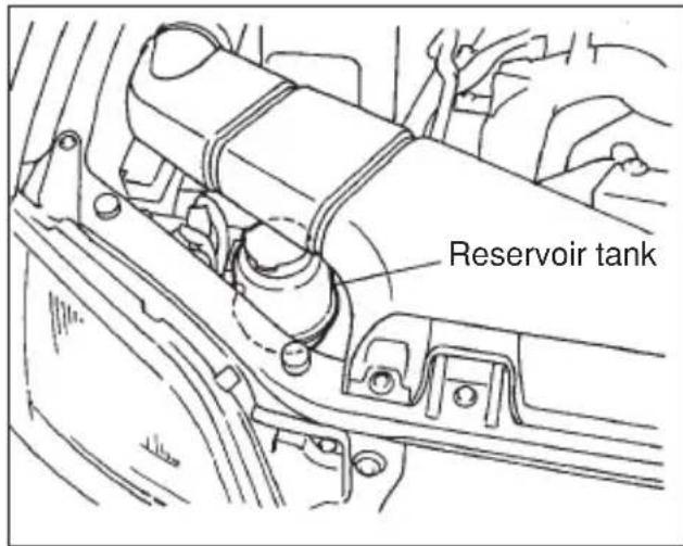
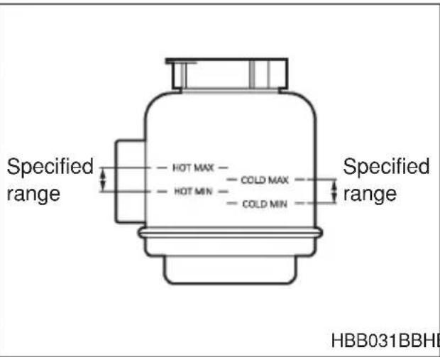
HBB031BBHBB030BB
If the fluid level is extreme low, it may indicate possible leakage. Consult your SUBARU dealer for inspection.
▼Recommended fluid
"Dexron III" Type Automatic Transmission Fluid
Brake fluid
▼Checking the fluid level

WARNING
●Never let brake fluid contact your eyes because brake fluid can be harmful to your eyes. If brake fluid gets in your eyes, immediately flush them thoroughly with clean water. For safety, when performing this work, wearing eye protection is advisable.
●Brake fluid absorbs moisture from the air. Any absorbed moisture can cause a dangerous loss of braking performance.
- If the vehicle requires frequent refilling, there may be a leak. If you suspect a problem, have the vehicle checked at your SUBARU dealer.

CAUTION
●Never use different brands of brake fluid together.
- When adding brake fluid, be careful not to allow any dirt into the reservoir.
●Never splash the brake fluid over painted surfaces or rubber parts. Alcohol contained in the brake fluid may damage them.
Check the fluid level monthly.
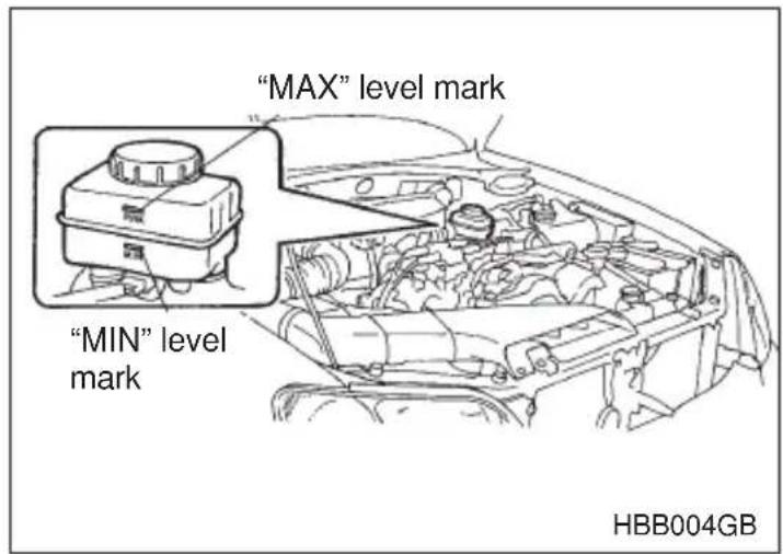
Check the fluid level on the outside of the reservoir. If the level is below "MIN", add the recommended brake fluid to "MAX". Use only brake fluid from a sealed container.

Recommended brake fluid
FMVSS No. 116, fresh DOT 3 or 4 brake fluid
Clutch fluid (MT vehicles)
▼Checking the fluid level

WARNING
Never let clutch fluid contact your eyes because clutch fluid can be harmful to your eyes. If clutch fluid gets in your eyes, immediately flush them thoroughly with clean water. For safety, when performing this work, wearing eye protection is advisable.

CAUTION
- Clutch fluid absorbs moisture from the air. Any absorbed moisture can cause improper clutch operation.
- If the vehicle requires frequent refilling, there may be a leak. If you suspect a problem, have the vehicle checked at your SUBARU dealer.
●Never use different brands of clutch fluid together. - When clutch fluid is added, be careful not to allow any dirt into the tank.
Check the fluid level on the outside of the reservoir. If the level is below "MIN" level mark, add the recommended clutch fluid to "MAX" level mark.
Use only clutch fluid from a sealed container.
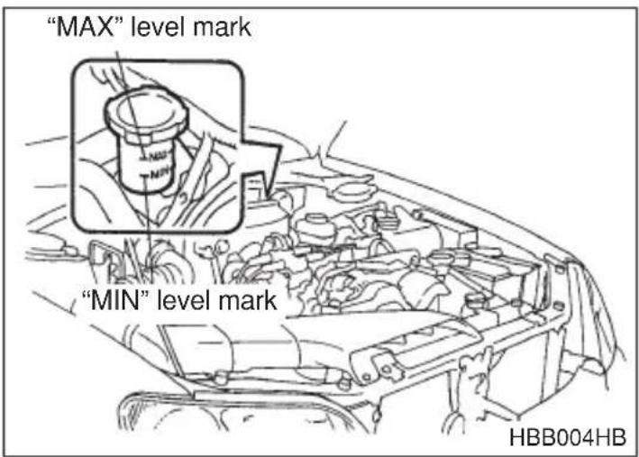
▼Recommended clutch fluid
FMVSS No. 116, fresh DOT 3 or 4 brake fluid
Brake booster
If the brake booster does not operate as described below, have it checked by your SUBARU dealer.
- With the engine off, depress the brake pedal several times, applying the same pedal force each time. The distance the pedal travels should not vary.
- With the brake pedal depressed, start the engine. The pedal should move slightly down to the floor.
- With the brake pedal depressed, stop the engine and keep the pedal depressed for 30 seconds. The pedal height should not change.
- Start the engine again and run for about one minute then turn it off. Depress the brake pedal several times to check the brake booster. Brake booster operates properly if the pedal stroke decreases with each depression.
Brake pedal
Check the brake pedal free play and reserve distance according to the maintenance schedule in the “Warranty and Maintenance Booklet”.
▼Checking the brake pedal free play
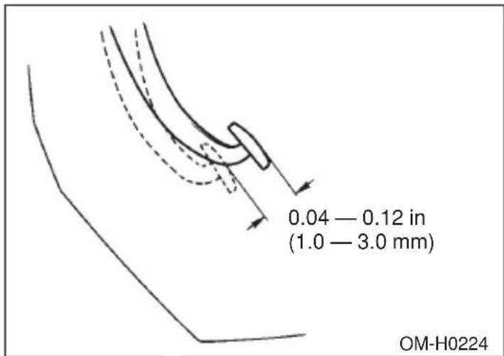
Stop the engine and firmly depress the brake pedal several times. Lightly press the brake pedal down with one finger to check the free play with a force of less than 2 lb (10 N, 1 kg).
If the free play is not within proper specification, contact your SUBARU dealer.
▼Checking the brake pedal reserve distance
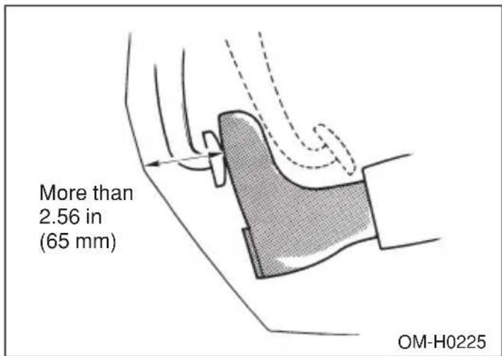
Depress the pedal with a force of approximately 66 lb (294 N, 30 kg)
and measure the distance between the upper surface of the pedal pad and the floor.
When the measurement is smaller than the specification, or when the pedal does not operate smoothly, contact with your SUBARU dealer.
Clutch pedal (Manual transmission vehicles)
Check the clutch pedal free play and reserve distance according to the maintenance schedule in the “Warranty and Maintenance Booklet”.
▼Checking the clutch function
Check the clutch engagement and disengagement.
- With the engine idling, check that there are no abnormal noises when the clutch pedal is depressed, and that shifting into 1st or reverse feels smooth.
- Start the vehicle by releasing the pedal slowly to check that the engine and transmission smoothly couple without any sign of slippage.
▼Checking the clutch pedal free play
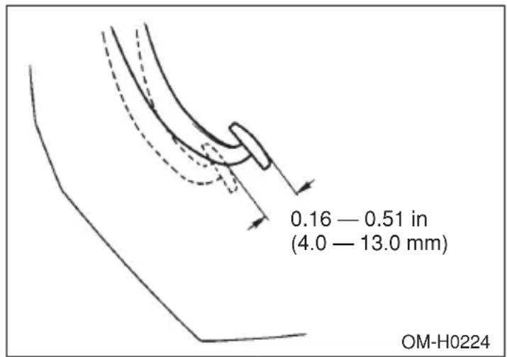
Lightly press the clutch pedal down with your finger until you feel resistance, and check the free play.
If the free play is not within proper specification, contact your SUBARU dealer.
Replacement of brake pad and lining

CAUTION
If you continue to drive despite the scraping noise from the audible brake pad wear indicator, it will result in the need for costly brake rotor repair or replacement.
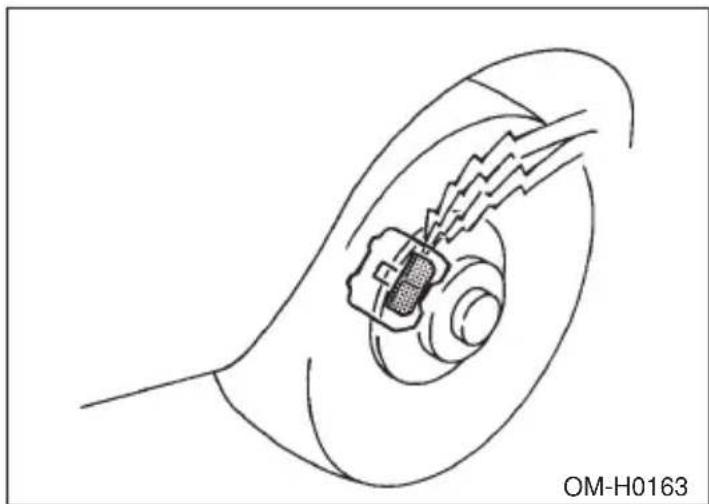
natural_image
Diagram of a mechanical component inside a circular housing, showing internal wiring and a central connector (no text or symbols)The front disc brakes and the right rear disc brake have an audible wear indicators on the brake pads. If the brake pads wear close to their service limit, the wear indicator makes a very audible scraping noise when the brake pedal is applied.
If you hear this scraping noise each time you apply the brake pedal, have the brake pads serviced by your SUBARU dealer as soon as possible.

Breaking-in of new brake pads and linings
When replacing the brake pad or lining, use only genuine SUBARU parts. After replacement, the new parts must be broken in as follows:

Brake pad and lining
While maintaining a speed of 30 to 40 mph (50 to 65 km/h), step on the brake pedal lightly. Repeat this five or more times.
▽ Parking brake lining
WARNING
A safe location and situation should be selected for break-in driving.
CAUTION
Pulling the parking brake lever too forcefully may cause the rear wheels to lock. To avoid this, be certain to pull the lever up slowly and gently.
- Drive the vehicle at a speed of about 22 mph (35 km/h).
- With the parking brake release button pushed in, pull the parking brake lever SLOWLY and GENTLY. (Pulling with a force of approximately 33 lb [147 N, 15 kg].)
- Drive the vehicle for about 220 yards (200 meters) in this condition.
- Wait 5 to 10 minutes for the parking brake to cool down. Repeat this procedure.
- Check the parking brake stroke. If the parking brake stroke is out of the specified range, adjust it by turning the adjusting nut located on the parking brake lever.
Parking brake stroke: 7 — 8 notches / 44 lb (196 N, 20 kg)
Parking brake stroke
Check the parking brake stroke according to the maintenance schedule in the “Warranty and Maintenance Booklet”. When the parking brake is properly adjusted, braking power is fully applied by pulling the lever up seven to eight notches gently but firmly (about 44 lb, 196 N, 20 kg). If the parking brake lever stroke is not within the specified range, have the brake system checked and adjusted at your SUBARU dealer.
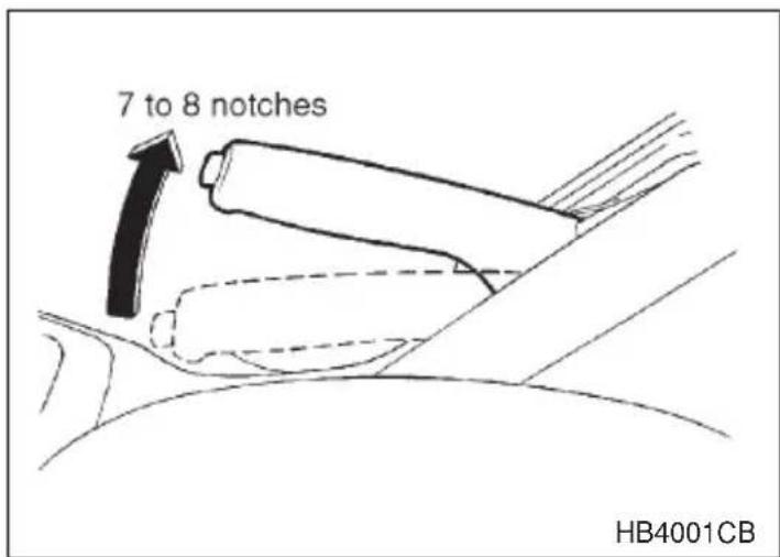
Tires and wheels
■Types of tires
You should be familiar with type of tires present on your vehicle.
All season tires
The factory-installed tires on your new vehicle are all season tires.
All season tires are designed to provide an adequate measure of traction, handling and braking performance in year-round driving including snowy and icy road conditions. However all season tires do not offer as much traction performance as winter (snow) tires in heavy or loose snow or on icy roads.
All season tires are identified by "ALL SEASON" and/or "M+S" (Mud & Snow) on the tire sidewall.
▼Summer tires
Summer tires are high-speed capability tires best suited for highway driving under dry conditions.
Summer tires are inadequate for driving on slippery roads such as on snow-covered or icy roads.
If you drive your vehicle on snow-covered or icy roads, we strongly recommend the use of winter (snow) tires.
When installing winter tires, be sure to replace all four tires.
▼Winter (snow) tires
Winter tires are best suited for driving on snow-covered and icy roads. However winter tires do not perform as well as summer tires and all season tires on roads other than snow-covered and icy roads.
■Tire inspection
Check on a daily basis that the tires are free from serious damage, nails, and stones. At the same time, check the tires for abnormal wear.
Contact your SUBARU dealer immediately if you find any problem.
NOTE
- When the wheels and tires strike curbs or are subjected to harsh treatment as when the vehicle is driven on a rough surface, they can suffer damage that cannot be seen with the naked eye. This type of damage does not become evident until time has passed. Try not to drive over curbs, potholes or on other rough surfaces. If doing so is unavoidable, keep the vehicle's speed down to a walking pace or less, and approach the curbs as squarely as possible. Also, make sure the tires are not pressed against the curb when you park the vehicle.
- If you feel unusual vibration while driving or find it difficult to steer the vehicle in a straight line, one of the tires and/or wheels may be damaged. Drive slowly to the nearest authorized SUBARU dealer and have the vehicle inspected.
■Tire pressures and wear
Maintaining the correct tire pressures helps to maximize the tires' service lives and is essential for good running performance. Check and, if necessary, adjust the pressure of each tire (including the spare) at least once a month (for example, during a fuel stop) and before any long journey.
Check the tire pressures when the tires are cold. Use a pressure gauge to adjust the tire pressures to the values shown on the tire placard. The tire placard is located on the door pillar on the driver's side.
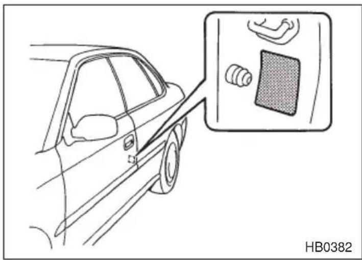
Driving even a short distance warms up the tires and increases the tire pressures. Also, the tire pressures are affected by the ambient temperature. It is best to check tire pressure outdoors before driving the vehicle.
When a tire becomes warm, the air inside it expands, causing the tire pressure to increase. Be careful not to mistakenly release air from a warm tire to reduce its pressure.
NOTE
●The air pressure in a tire increases by approximately 4.3 psi (30 kPa, 0.3 kg/cm ^2 ) when the tire becomes warm.
●The tires are considered cold when the vehicle has been parked for at least three hours or has been driven less than one mile (1.6 km).

WARNING
Do not let air out of warm tires to adjust pressure. Doing so will result in low tire pressure.
Incorrect tire pressures detract from controllability and ride comfort, and they cause the tires to wear abnormally.
- Correct tire pressure (tread worn evenly)
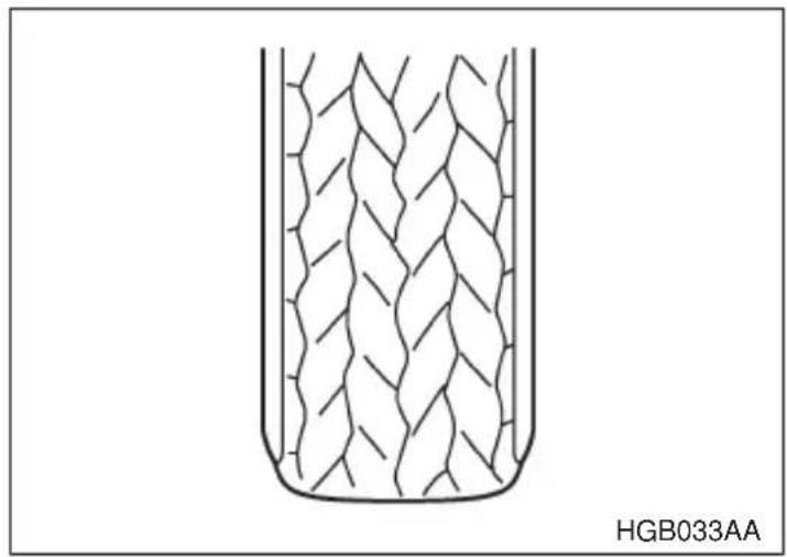
natural_image
Diagram of a container with internal mesh structure, labeled HGB033AA (no text or symbols on the diagram itself)Roadholding is good, and steering is responsive. Rolling resistance is low, so fuel consumption is also lower.
●Abnormally low tire pressure (tread worn at shoulders)
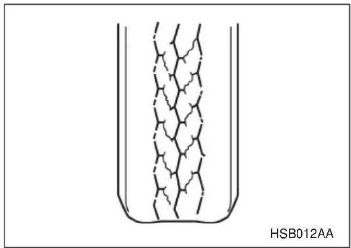
Rolling resistance is high, so fuel consumption is also higher.
●Abnormally high tire pressure (tread worn in center)
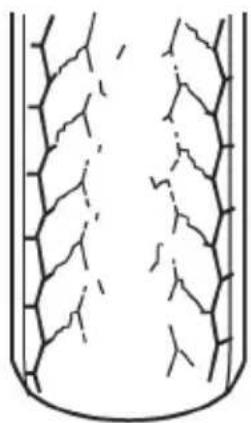
natural_image
Diagram of a cylindrical container with internal branching structures (no text or symbols)HSB013AA
Ride comfort is poor. Also, the tire magnifies the effects of road-surface bumps and dips, possibly resulting in vehicle damage.
If the tire placard shows tire pressures for the vehicle when fully loaded and for the vehicle when towing a trailer, adjust the tire pressures to the values that match current loading conditions.

WARNING
Driving at high speeds with excessively low tire pressures can cause the tires to deform severely and to rapidly become hot. A sharp increase in temperature could cause tread separation, and destruction of the tires. The resulting loss of vehicle control could lead to an accident.
■Wheel balance
Each wheel was correctly balanced when your vehicle was new, but the wheels will become unbalanced as the tires become worn during use. Wheel imbalance causes the steering wheel to vibrate slightly at certain vehicle speeds and detracts from the vehicle's straight-line stability. It can also cause steering and suspension system problems and abnormal tire wear. If you suspect that the wheels are not correctly balanced, have them checked and adjusted by your SUBARU dealer. Also have them adjusted after tire repairs and after tire rotation.
NOTE
Loss of correct wheel alignment* causes the tires to wear on one side and reduces the vehicle's running stability. Contact your SUBARU dealer if you notice abnormal tire wear.
* : The suspension system is designed to hold each wheel at a certain alignment (relative to the other wheels and to the road) for optimum straight-line stability and cornering performance.
■Wear indicators
Each tire incorporates a tread wear indicator, which becomes visible when the depth of the tread grooves decreases to 0.063 in. (1.6 mm). A tire must be replaced when the tread wear indicator appears as a solid band across the tread.
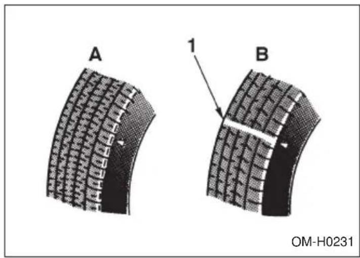
A) New tread
B) Worn tread
1) Tread wear indicator
! WARNING
When a tire's tread wear indicator becomes visible, the tire is worn beyond the acceptable limit and must be replaced immediately. With a tire in this condition, driving at high speeds in wet weather can cause the vehicle to hydroplane. The resulting loss of vehicle control can lead to an accident.
NOTE
For safety, inspect the tire tread regularly and replace the tires before their tread wear indicators become visible.
- CONTINUED -
■Tire rotation
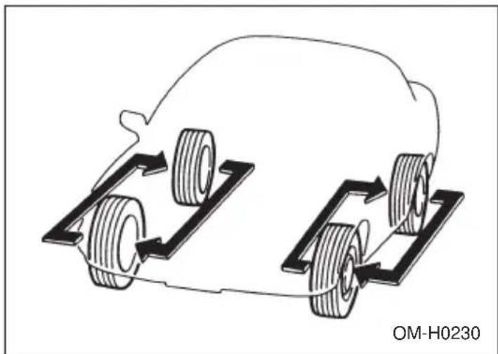
natural_image
Diagram of a car with wheels and directional arrows indicating motion or movement (no text or symbols)Tire wear varies from wheel to wheel. To maximize the life of each tire and ensure that the tires wear uniformly, it is best to rotate the tires every 7,500 miles (12,500 km). Rotating the tires involves switching the front and rear tires on the right-hand side of the vehicle and similarly switching the front and rear tires on the left-hand side of the vehicle. (Each tire must be kept on its original side of the vehicle.)
Replace any damaged or unevenly worn tire at the time of rotation. After tire rotation, adjust the tire pressures and make sure the wheel nuts are correctly tightened.
After driving approximately 600 miles (1,000 km), check the wheel nuts again and retighten any nut that has become loose.
■Tire replacement
The wheels and tires are important and integral parts of your vehicle's design; they cannot be changed arbitrarily. The tires fitted as standard equipment are optimally matched to the characteristics of the vehicle and were selected to give the best possible combination of running performance, ride comfort, and service life. It is essential for every tire to have a size and construction matching those shown on the tire placard and to have a speed symbol and load index matching those shown on the tire placard.
Using tires of a non-specified size detracts from controllability, ride comfort, braking performance, speedometer accuracy and odometer accu-
racy. It also creates incorrect body-to-tire clearances and inappropriately changes the vehicle's ground clearance.
All four tires must be the same in terms of manufacturer, brand (tread pattern), construction, and size. You are advised to replace the tires with new ones that are identical to those fitted as standard equipment.
For safe vehicle operation, SUBARU recommends replacing all four tires at the same time.

WARNING
- All four tires must be the same in terms of manufacturer, brand (tread pattern), construction, degree of wear, speed symbol, load index and size. Mixing tires of different types, sizes or degrees of wear can result in damage to the vehicle's power train. Use of different types or sizes of tires can also dangerously reduce controllability and braking performance and can lead to an accident.
- Use only radial tires. Do not use radial tires together with belted bias tires and/or bias-ply tires. Doing so can dangerously reduce controllability, resulting in an accident.
■Wheel replacement
When replacing wheels due, for example, to damage, make sure the replacement wheels match the specifications of the wheels that are fitted as standard equipment. Replacement wheels are available from SUBARU dealers.

WARNING
Use only those wheels that are specified for your vehicle. Wheels not meeting specifications could interfere with brake caliper operation and may cause the tires to rub against the wheel well housing during turns. The resulting loss of vehicle control could lead to an accident.
Wheel covers
▼Removing the wheel cover
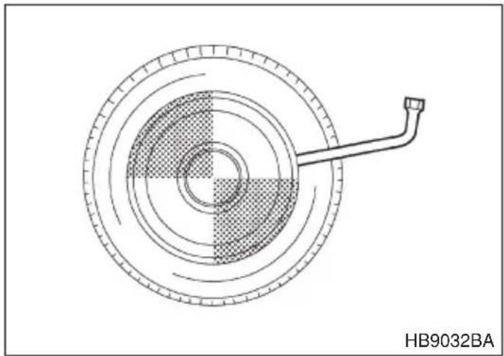
natural_image
Technical diagram of a circular mechanical component with concentric rings and a protruding rod, labeled HB9032BA (no text or symbols on the diagram itself)Insert the wheel nut wrench into the notch provided, and pry the wheel cover off.
▼Installing the wheel cover
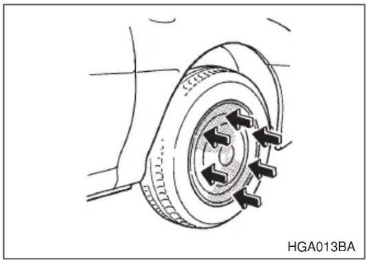
natural_image
Technical line drawing of a car tire assembly with mounting bracket (no text or symbols)Align the valve with the valve hole in the cover, then fit the cover on the wheel by tapping your hand evenly around the circumference of the cover.
NOTE
When any of the wheels is removed and replaced for tire rotation or to change a flat tire, always check the tightness of the wheel nuts after driving approximately 600 miles (1,000 km). If any nut is loose,
tighten it to the specified torque.
Aluminum wheels (If equipped)
Aluminum wheels can be scratched and damaged easily. Handle them carefully to maintain their appearance, performance, and safety.
- When any of the wheels is removed and replaced for tire rotation or to change a flat, always check the tightness of the wheel nuts after driving approximately 600 miles (1,000 km). If any nut is loose, tighten it to the specified torque.
- Never apply oil to the threaded parts, wheel nuts, or tapered surface of the wheel.
- Never let the wheel rub against sharp protrusions or curbs.
- Be sure to fit tire chains on uniformly and completely around the tire, otherwise the chains may scratch the wheel.
- When wheel nuts, balance weights, or the center cap is replaced, be sure to replace them with genuine SUBARU parts designed for aluminum wheels.
Windshield washer fluid

CAUTION
Never use engine coolant as washer fluid because it could cause paint damage.
Check the level of the washer fluid at each fuel stop. If the level is low, fill the fluid up to the neck of the reservoir.
Use windshield washer fluid. If windshield washer fluid is unavailable use clean water.
In areas where water freezes in winter, use an anti-freeze type windshield washer fluid. SUBARU Windshield Washer Fluid contains 58.5% methyl alcohol and 41.5% surfactant, by volume. Its freezing temperature varies according to how much it is diluted, as indicated below.
| Washer Fluid Concentration Freezing Temperature | |
| 30% | 10.4°F (-12°C) |
| 50% | -4 °F (-20°C) |
| 100% | -49°F (-45°C) |
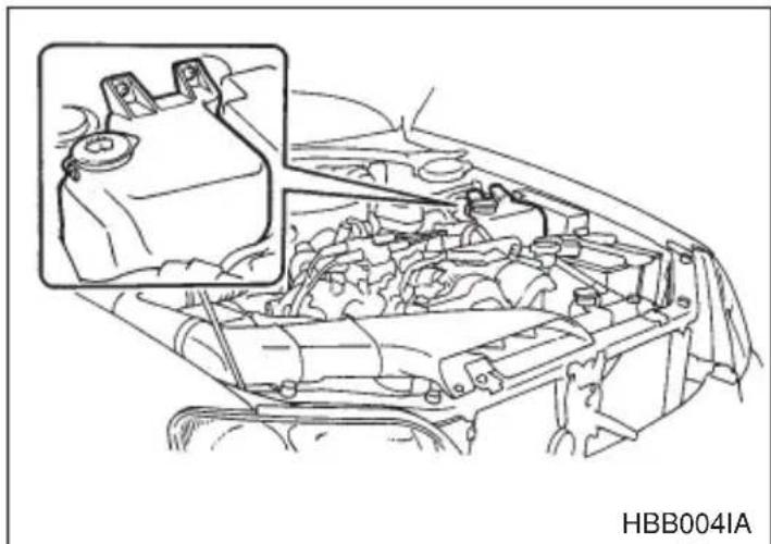
natural_image
Technical line drawing of a car engine bay with an inset showing internal components (no text or symbols)Replacement of windshield wiper blades
Grease, wax, insects, or other materials on the windshield or the wiper blade results in jerky wiper operation and streaking on the glass. If you cannot remove the streaks after operating the windshield washer or if the wiper operation is jerky, clean the outer surface of the windshield (or rear window) and the wiper blades using a sponge or soft cloth with a neutral detergent or mild-abrasive cleaner. After cleaning, rinse the windshield and wiper blades with clean water. The windshield is clean if beads do not form when you rinse the windshield with water.

CAUTION
Do not clean the wiper blades with gasoline or a solvent, such as paint thinner or benzene. This will cause deterioration of the wiper blades.
If you cannot eliminate the streaking even after following this method, replace the wiper blades using the following procedures:
- Raise the wiper arm off the windshield.
- Remove the wiper blade assembly by holding its pivot area and pushing it in the direction shown by the arrow while depressing the wiper blade stopper.
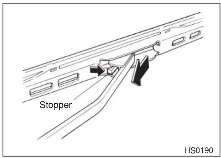
- Grasp the locked end of the blade rubber assembly and pull it firmly until the stoppers on the rubber are free of the metal support.
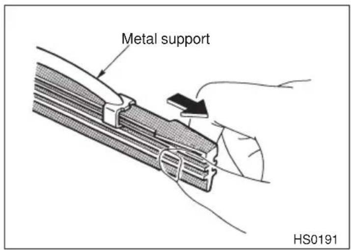
- If the new blade rubber is not provided with two metal spines, remove the metal spines from the old blade rubber and install them in the new blade rubber.
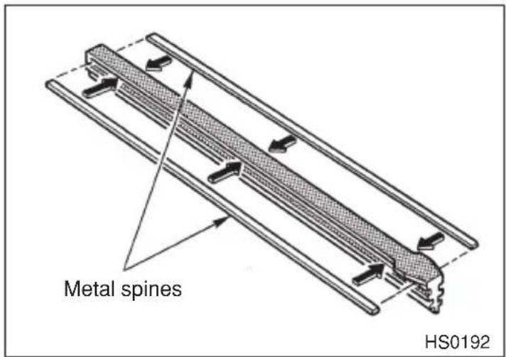
- Align the claws of the metal support with the grooves in the rubber and slide the blade rubber assembly into the metal support until it locks. Be sure to position the claws at the end of the metal support between the stoppers on the rubber as shown. If the rubber is not retained properly, the wiper blade may scratch the windshield.
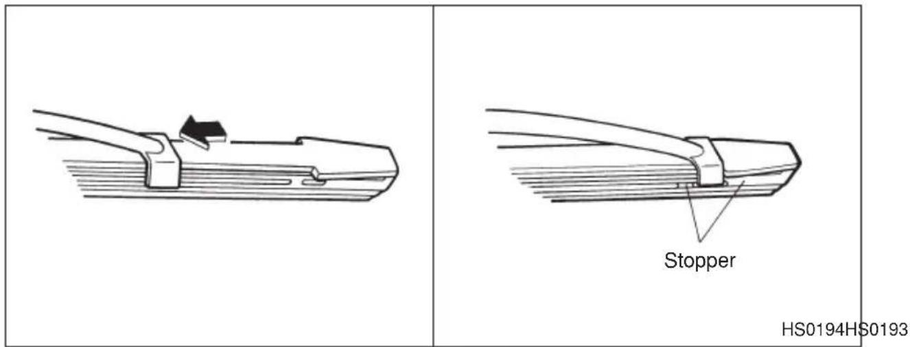
- Install the wiper blade assembly to the wiper arm. Make sure that it locks in place.
- Lower the wiper arm.
Battery
WARNING
- Before beginning work on or near any battery, be sure to extinguish all cigarettes, matches, and lighters. Never expose a battery to an open flame or electric sparks. Batteries give off a gas which is highly flammable and explosive.
- For safety, in case an explosion does occur, wear eye protection or shield your eyes when working near any battery. Never lean over a battery.
- Do not let battery fluid contact eyes, skin, fabrics, or paint because battery fluid is a corrosive acid. If battery fluid gets on your skin or in your eyes, immediately flush the area with water thoroughly. Seek medical help immediately if acid has entered the eyes.
If battery fluid is accidentally swallowed, immediately drink a large amount of milk or water, and seek medical attention immediately.
- To lessen the risk of sparks, remove rings, metal watchbands, and other metal jewelry. Never allow metal tools to contact the positive battery terminal and anything connected to it WHILE you are at the same time in contact with any other metallic portion of the vehicle because a short circuit will result.
- Keep everyone including children away from the battery.
- Charge the battery in a well-ventilated area.
●Battery posts terminals and related accessories contain lead and lead compounds, chemicals known to the State of California to case cancer and reproductive harm. Wash hands after handling.
CAUTION
Never use more than 10 amperes when charging the battery because it will shorten battery life.
It is unnecessary to periodically check the battery fluid level or periodically refill with distilled water.
Fuses

CAUTION
Never replace a fuse with one having a higher rating or with material other than a fuse because serious damage or a fire could result.
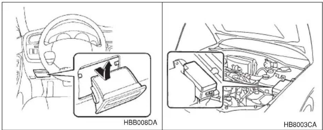
The fuses are designed to melt during an overload to prevent damage to the wiring harness and electrical equipment. The fuses are located in two fuse boxes. One is located under the instrument panel behind the coin tray on the driver's seat side. The other one is housed in the engine compartment. The fuse puller and spare fuses are stored in the main fuse box cover in the engine compartment.
If any lights, accessories or other electrical controls do not operate, inspect the corresponding fuse. If a fuse has blown, replace it.
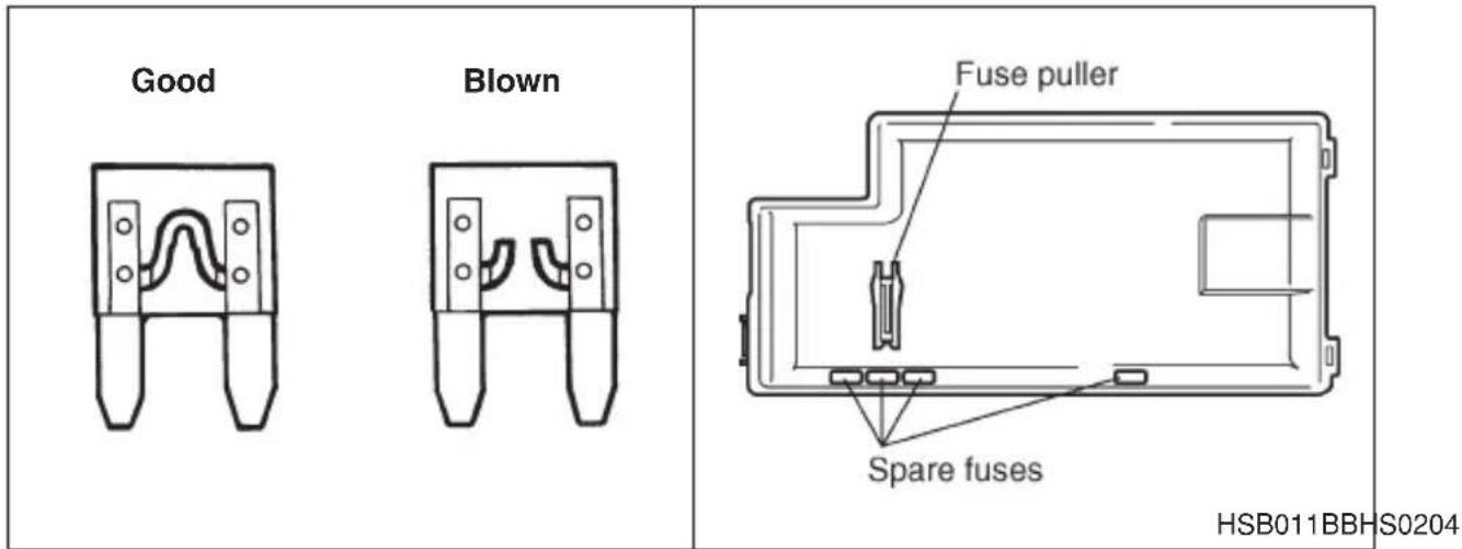
- Turn the ignition switch to the "LOCK" position and turn off all electrical accessories.
- Remove the cover.
(For behind the coin tray: open the coin tray and pull it horizontally to remove it.)
- Determine which fuse may be blown. The back side of each fuse box cover and the "Fuse and circuits" section in chapter 12 in this manual show the circuit for each fuse.
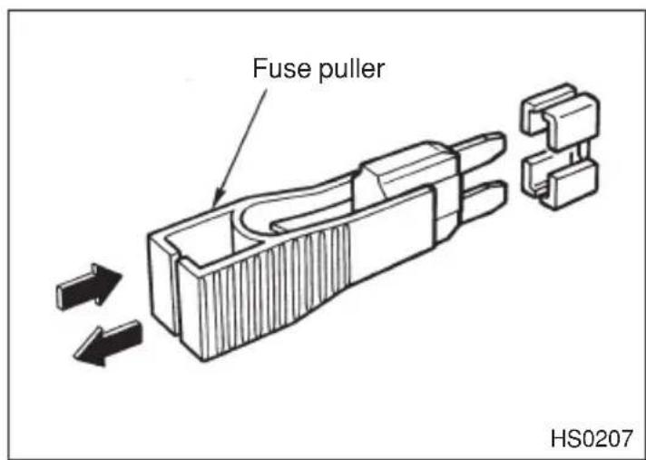
- Pull out the fuse with the fuse puller.
- Inspect the fuse. If it has blown, replace it with a spare fuse of the same rating.
- If the same fuse blows again, this indicates that its system has a problem. Contact your SUBARU dealer for repairs.
Main fuse
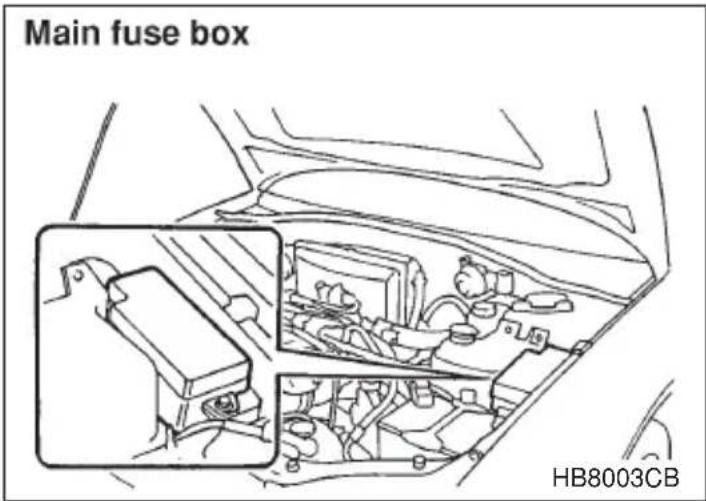
The main fuses are designed to melt during an overload to prevent damage to the wiring harness and electrical equipment. Check the main fuses if any electrical component fails to operate (except the starter motor) and other fuses are good. A melted main fuse must be replaced. Use only replacements with the same specified rating as the melted main fuse. If a main fuse blows after it is replaced, have the electrical system checked by your nearest SUBARU dealer.
Installation of accessories
Always consult your SUBARU dealer before installing fog lights or any other electrical equipment in your vehicle. Such accessories may cause the electronic system to malfunction if they are incorrectly installed or if they are not suited for the vehicle.
Replacing bulbs
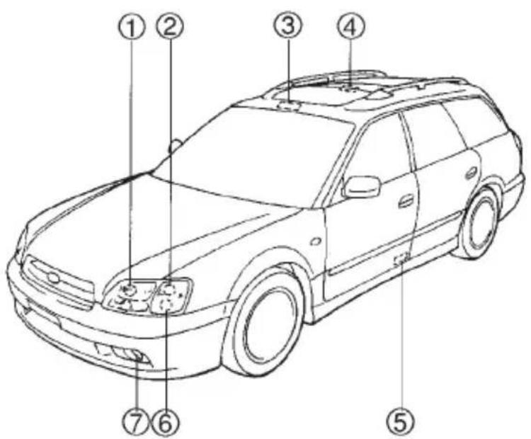
HB5019EB
Wattage Bulb No.
① Headlight
GT and OUTBACK models
Low beam 12V-55W H1
High beam 12V-60W 9005 (HB3)
Except GT and OUTBACK models 12V-65/55W 9007 (HB5)
② Front turn signal
12V-27W
1156NA (Amber)
③ Spot light 12V-8W —
④ Dome light 12V–8W —
⑤ Door step light 12V-3.4W —
⑥ Front turn signal light/parking and front side marker light 12V-27/8W 1157NA (Amber)
⑦ Front fog light
Except OUTBACK 12V-55W H3
OUTBACK
12V-51W 9006 (HB4)
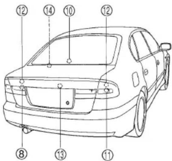
HBF013FC
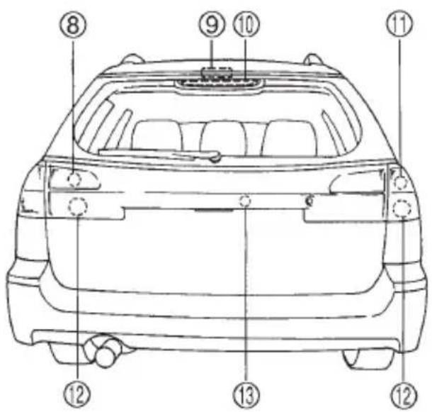
HBB033BC
Wattage Bulb No.
⑧ Backup light
Sedan 12V-27W 3156K
Station wagon 12V-27W 1156
⑨ Luggage area light 12V–13W 912
⑩ High mount stop light
Sedan 12V-16W 921
Station wagon 12V-13W 912
⑪ Rear turn signal light
Sedan 12V-21W —
Station wagon 12V-21W 7440
⑫ Brake/tail light
Sedan 12V-27/8W 3157K
Station wagon 12V-27/8W 1157
⑬ Licence plate light
Sedan 12V-5W 168
Station wagon 12V-3.8W or 5W 194 or 168
⑭ Trunk room light 12V-5W W5W
Headlight
CAUTION
Halogen headlight bulbs become very hot while in use. If you touch the bulb surface with bare hands or greasy gloves, finger prints or grease on the bulb surface develop into hot spots, causing the bulb to break. If there are finger prints or grease on the bulb surface, wipe them away with a soft cloth moistened with alcohol.
NOTE
If headlight aiming is required, consult your SUBARU dealer for proper adjustment of the headlight aim.
▼For GT and OUTBACK models
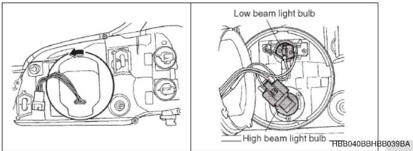
Remove the headlight bulb cover, by turning it counterclockwise.
▽ Low beam light bulbs
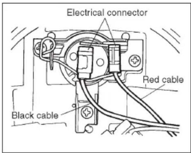
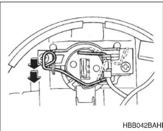
natural_image
Technical line drawing of a mechanical component with no visible text or symbolsHBB042BAHBB041BB
- Disconnect the electrical connector for the black cable.
- Remove the retainer spring.
- Replace the bulb, then set the retainer spring securely.
- Reconnect the electrical connector for black cable.
- Install the headlight bulb cover.
▽ High beam light bulbs
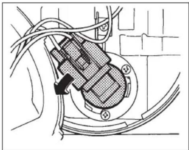
natural_image
Technical diagram of a mechanical assembly with wires and components (no visible text or symbols)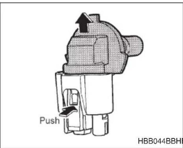
HBB044BBHBB043BA
- Disconnect the electrical connector from the bulb.
- Remove the bulb from the headlight assembly by turning it counterclockwise.
- Replace the bulb with new one.
-
Reconnect the electrical connector. At this time, use care not to touch the bulb surface.
-
To install the bulb to the headlight assembly, turn it clockwise until it clicks.
-
Install the headlight bulb cover.
▼Except GT and OUTBACK models
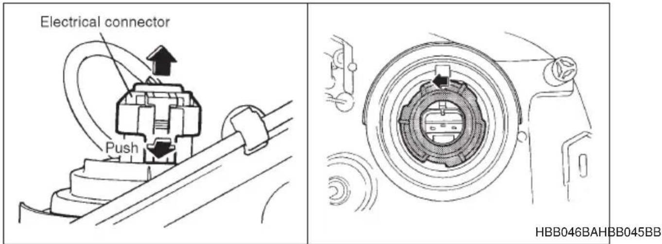
-
Disconnect the electrical connector while pressing the lock release tab.
-
Remove the bulb holder from the headlight assembly by turning it counterclockwise.
-
Remove the bulb from the headlight assembly.
-
Install the new bulb.
-
Install the bulb holder in the headlight assembly by turning it clockwise until it locks.
-
Remove the electrical connector.
■Front fog light (if equipped)
It may be difficult to replace the bulbs. Have your SUBARU dealer replace the bulbs if necessary.
■Front turn signal light, parking light and side marker light
The headlight assembly must be removed before the front turn signal light and parking light bulbs can be replaced. When the headlight assembly has been removed and then reinstalled, it may become necessary to make a headlight aiming adjustment. After a bulb has been replaced, it is recommended that the headlight aiming adjustment be
- CONTINUED -
made at a SUBARU dealer.
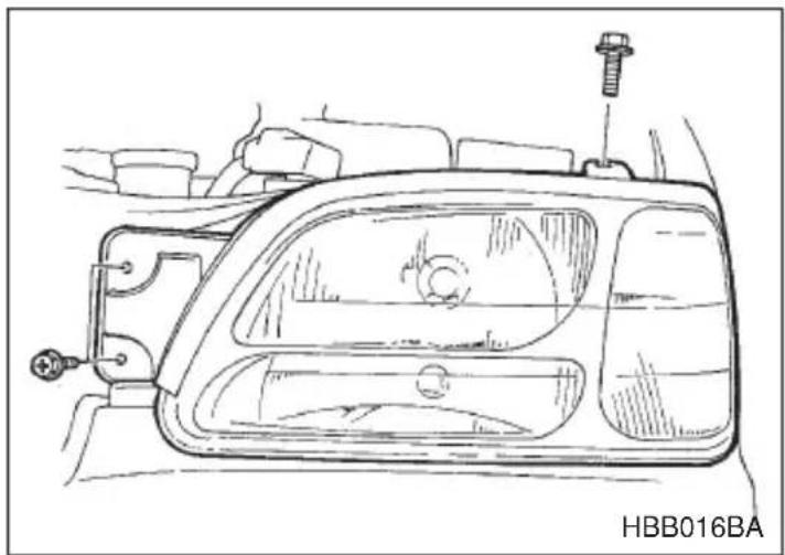
natural_image
Technical line drawing of a car head panel with mounting bracket and screw mount (no text or symbols)- Remove the headlight assembly mounting screws located at the top of and the front of the headlight assembly using a phillips screwdriver or an open-end wrench.
- Move the headlight assembly forward.
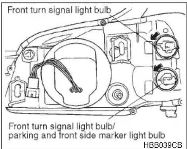
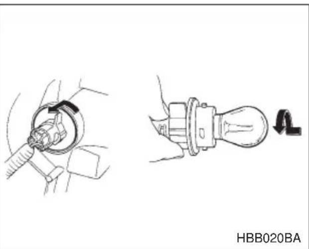
- Remove the bulb socket from the headlight assembly by turning it counterclockwise.
- Remove the bulb from the socket by pushing it and turning counterclockwise. Install a new bulb in the socket.
- Set the bulb socket into the headlight assembly and turn it clockwise until it locks.
- Set the headlight assembly into the vehicle body. Tighten the mounting screws.
■Rear combination lights
Sedan
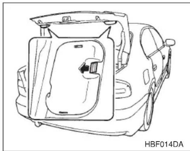
natural_image
Line drawing of a car interior frame with no text or symbols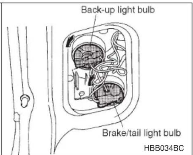
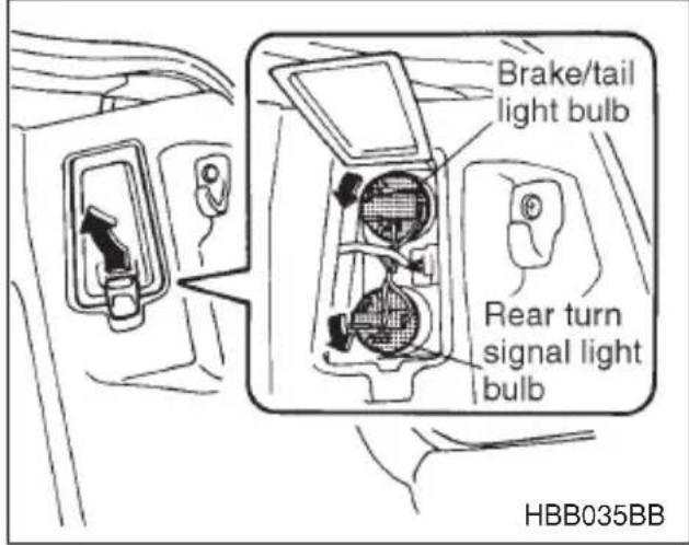
- Open the trunk lid.
- Open the rear combination light cover.
For covers on the trunk lid:
Unlatch the cover by pushing the knob and open the cover.
For covers on the trunk wall:
Unlatch the cover by moving the knob upward and open the cover.
- Remove the bulb socket from the light assembly by turning it counterclockwise.
- Remove the bulb from the socket.
Rear turn signal light: Remove the bulb from the socket by pushing it and turning it counterclockwise.
Others: Pull the bulb out of the socket.
- Install a new bulb in the socket.
- Set the bulb socket into the rear combination light assembly and turn it clockwise until it locks.
- Close the cover and latch the clock.
▼Station wagon
▼ Brake/tail and rear turn signal light bulbs
It may be difficult to replace the bulbs. It is recommended that you have the bulbs replaced by your SUBARU dealer.
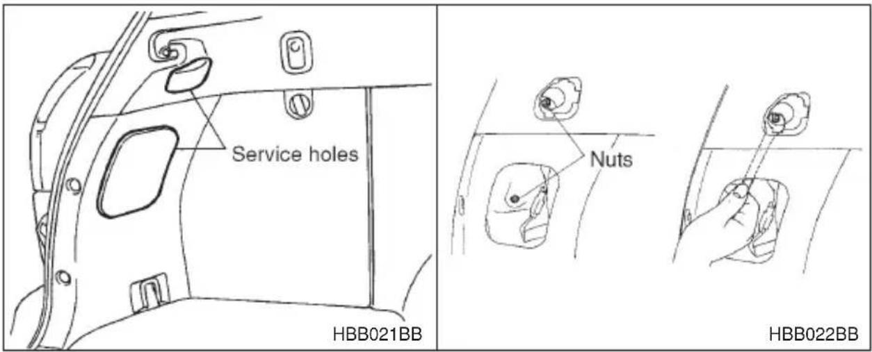
- Remove the light bulb replacement service hole covers at two places by prying the edge of the cover with a regular screwdriver.
- Remove the upper and lower nuts. Then, slide the rear combination lamp assembly to the rear and remove it from the vehicle.
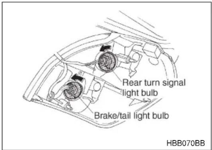
- Using a Phillips screwdriver, remove the upper and lower screws that secure the side cover of the rear combination light assembly.
- Remove the bulb socket from the rear combination light assembly by turning it counterclockwise.
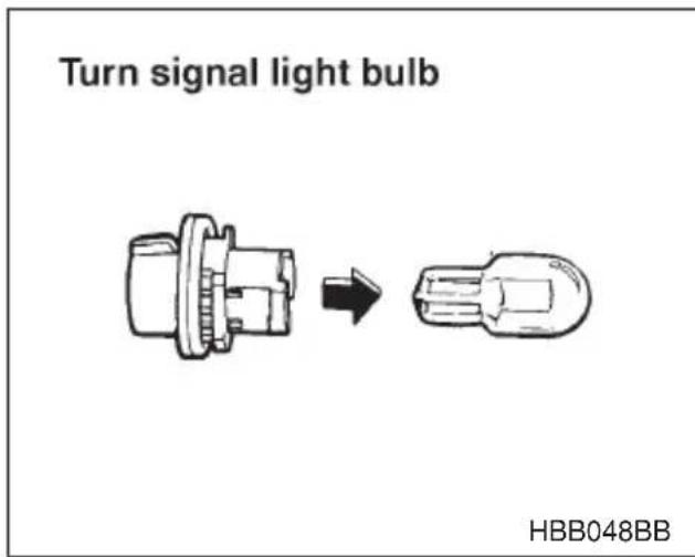
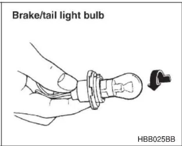
- Remove the bulb from the socket.
Turn signal light: Pull the bulb out of the socket.
Brake/tail light: Remove the bulb from the socket by pushing it and turning it counterclockwise.
- Install a new bulb in the socket.
- Set the bulb holder into the rear combination light assembly and turn it clockwise until it locks.
- Using a Phillips screwdriver, install the side cover to the rear combination light assembly.
- Fit the rear combination light assembly into the vehicle body and tighten the nuts from the interior of the vehicle.
- Reinstall the light bulb replacement service hole covers.
▽ Back-up and brake/tail light bulbs
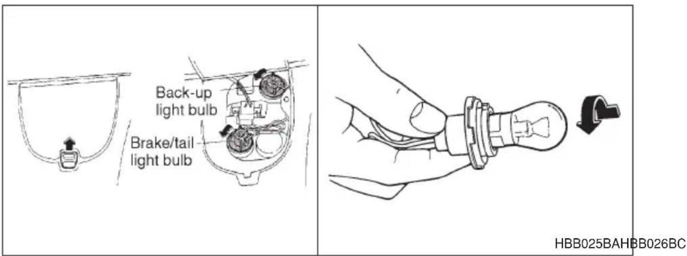
- Unlatch the rear finisher light cover by moving the knob upward. Open the cover up.
- Remove the bulb socket from the rear finisher light assembly by turning it counterclockwise.
- Remove the bulb from the socket by pushing it and turning counterclockwise. Install a new bulb in the socket.
- Set the bulb holder into the rear finisher light assembly and turn it clockwise until it locks.
- Close the cover and latch the lock.
■License plate light
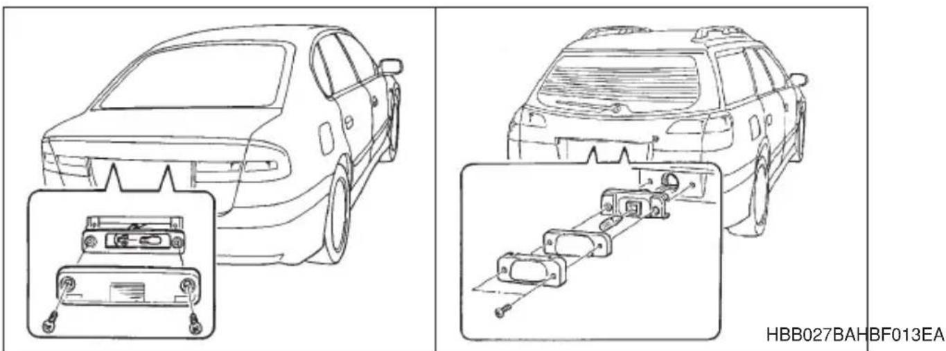
-
Remove the mounting screws using a phillips screwdriver.
-
Remove the cover and lens.
- Pull the bulb out of the socket. Install a new bulb.
- Reinstall the lens and cover.
- Tighten the mounting screws.
■Spot light, dome light, luggage compartment light and door step light
| Spot light (without moonroof model) | Spot light(with moonroof model) |
 |  |
 |  |
Dome light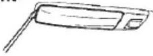 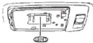 HSA005BB HSA005BB | Luggage compartment light 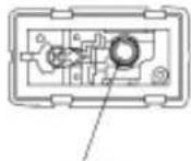 Bulb HBB067BB Bulb HBB067BB |
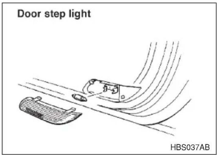
- Remove the lens by prying the edge of the lens with a regular screw-driver.
- Pull the bulb out of the socket. Install a new bulb.
- Reinstall the lens.
Trunk light
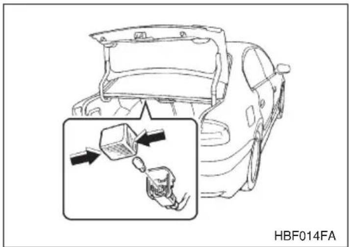
- Remove the cover by squeezing its sides and pulling it.
- Pull the bulb out of the socket. Install a new bulb.
- Reinstall the cover.
■High mount stop light
Sedan
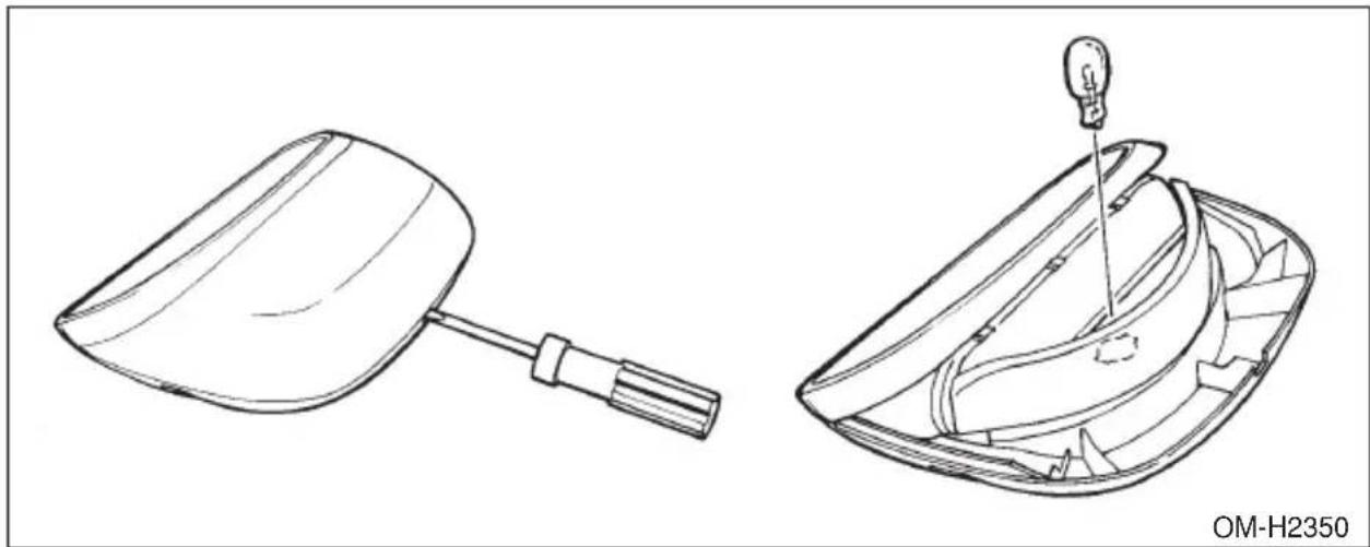
natural_image
Technical line drawings of two mechanical components, one with a handle and the other with a light bulb (no text or symbols)- Remove the high mount stop light cover by prying on the edge with a screwdriver.
- Pull the bulb out of the socket. Install a new bulb.
- Reinstall the cover.
▼Station wagon
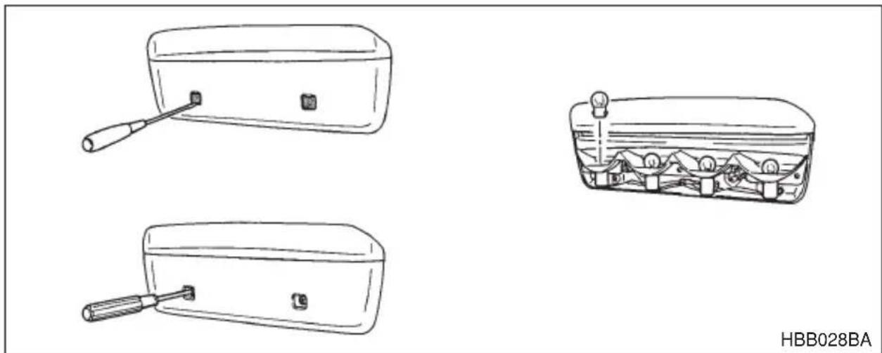
natural_image
Line drawings of three different household appliances: a rectangular box with a handle, a wooden box with a handle, and a small container filled with mountains (no text or symbols)- Remove the mounting screw covers by prying on the edge with a screwdriver.
- Remove the mounting screws using a phillips screwdriver and then remove the high mount stop light cover.
-
Pull the bulb out of the socket. Install a new bulb.
-
Reinstall the cover.
- Tighten the mounting screws then reinstall the covers.
NOTE
Other bulbs may be difficult to replace. Have your SUBARU dealer replace these bulbs if necessary.
Specifications
Specifications 12-2
Dimensions 12-2
Engine 12-3
Electrical system 12-3
Capacities 12-4
Tires 12-4
Wheel alignment 12-5
Fuses and circuits 12-6
Fuse panel located behind the coin tray 12-6
Fuse panel located in the engine compartment 12-10
Bulb chart 12-14
Vehicle identification 12-15
Specifications
These specifications are subject to change without notice.
Dimensions
Legacy sedan
Overall length 184.4 in (4,685 mm)
Overall width 68.7 in (1,745 mm)
Overall height 55.7 in (1,415 mm)
Ground clearance 6.1 in (155 mm)
Front tread 57.5 in (1,460 mm)
Rear tread 57.5 in (1,460 mm)
Wheelbase 104.3 in (2,650 mm)
Legacy station wagon
Overall length 187.4 in (4,760 mm)
Overall width 68.7 in (1,745 mm)
Overall height 56.6 in (1,435 mm)
59.6 in (1,525 mm) ^*
Ground clearance 6.3 in (160 mm)
Front tread 57.5 in (1,460 mm)
Rear tread 57.3 in (1,455 mm)
Wheelbase 104.3 in (2,650 mm)
*: With roof rail
OUTBACK sedan
Overall length 184.4 in (4,685 mm)
Overall width 68.7 in (1,745 mm)
Overall height 58.3 in (1,480 mm)
Ground clearance 7.3 in (185 mm)
Front tread 57.9 in (1,470 mm)
Rear tread 57.7 in (1,465 mm)
Wheelbase 104.3 in (2,650 mm)
OUTBACK station wagon
Overall length 187.4 in (4,760 mm)
Overall width 68.7 in (1,745 mm)
Overall height 62.2 in (1,580 mm)
Ground clearance
2.5 liter models 7.3 in (185 mm)
3.0 liter models 7.9 in (200 mm)
Front tread 57.9 in (1,470 mm)
Rear tread 57.7 in (1,465 mm)
Wheelbase 104.3 in (2,650 mm)
Engine
2.5 liter
Engine model EJ251
Engine type Horizontally opposed, liquid cooled
4 cylinder, 4 stroke gasoline engine
Engine displacement 2,457 cc (150 cu in.)
Bore 3.92 in (99.5 mm)
Stroke 3.11 in (79.0 mm)
Compression ratio 10.0 : 1
Firing order 1 - 3 - 2 - 4
3.0 liter
Engine model EZ30D
Engine type Horizontally opposed, liquid cooled
6 cylinder, 4 stroke gasoline engine
Engine displacement 3,000 cc (183.0 cu in.)
Bore 3.51 in (89.2 mm)
Stroke 3.15 in (80.0 mm)
Compression ratio 10.7 : 1
Firing order 1 - 6 - 3 - 2 - 5 - 4
Electrical system
2.5 liter
Battery type and capacity
MT: 55D23L
AT: 75D23L
Alternator 12V-90A
Spark plugs type RC10YC4 (Champion)
BKR6E-11 (NGK)
BKR5E-11 (NGK)
3.0 liter
Battery type and capacity 75D23L
Alternator 12V-100A
Spark plugs type PLFR6A-11 (NGK)
■Capacities
Fuel tank 16.9 US gal (64 liters, 14.1 Imp gal)
Engine oil 2.5 liter 4.2 US qt (4.0 liters, 3.5 Imp qt)
3.0 liter 6.0 US qt (5.7 liters, 5.0 Imp qt)
Transmission oil (MT) 3.7 US qt (3.5 liters, 3.1 Imp qt)
Transmission fluid (AT) 9.8 US qt (9.3 liters, 8.2 Imp qt)
AT differential gear oil 1.3 US qt (1.2 liters, 1.1 Imp qt)
Rear differential gear oil
Brighton, L (AT) 0.9 US qt (0.9 liter, 0.8 Imp qt)
Others 0.8 US qt (0.8 liter, 0.7 Imp qt)
Power steering gear fluid 0.7 US qt (0.7 liter, 0.6 Imp qt)
Engine coolant 2.5 liter MT 7.2 US qt (6.8 liters, 6.0 Imp qt)
AT 7.1 US qt (6.7 liters, 5.9 Imp qt)
3.0 liter 8.4 US qt (7.9 liters, 7.0 Imp qt)
Tires
Legacy
| Type | Steel belted radial, Tubeless | |
| Size | Brighton | P195/60R15 87H |
| L | P205/60R15 90H | |
| GT | P205/55R16 89H | |
| Temporary spare | T135/70D16 | |
Pressure
| Front | Brighton | 33 psi (230 kPa, 2.3 kg/cm2) |
| GT, L | 32 psi (220 kPa, 2.2 kg/cm2) | |
| Rear | Brighton | 32 psi (220 kPa, 2.2 kg/cm2) |
| GT, L | 30 psi (210 kPa, 2.1 kg/cm2) |
Temporary spare 60 psi (420 kPa, 4.2 kg/cm ^2 )
Wheel size 15 x 6JJ, 16 x 6 ^1/_2 JJ
OUTBACK
Type Steel belted radial, Tubeless
Size P225/60R16 97H
Temporary spare T145/80R16
Pressure
Front 30 psi (210 kPa, 2.1 kg/cm) ^2)
Trailer towing 30 psi (210 kPa, 2.1 kg/cm ^4 )
Rear 29 psi (200 kPa, 2.0 kg/cm ^4 )
Trailer towing 32 psi (220 kPa, 2.2 kg/cm ^4 )
Temporary spare 60 psi (420 kPa, 4.2 kg/cm ^2 )
Wheel size 16 x 6 12 JJ
■Wheel alignment
Legacy sedan
| Toe | Front | 0 ± 0.12 in (0 ± 3 mm) |
| Rear | 0 ± 0.12 in (0 ± 3 mm) | |
| Camber | Front | -0°05' ± 30' |
| Rear -0°30' ± 45' | ||
Legacy station wagon
| Toe | Front | 0 ± 0.12 in (0 ± 3 mm) |
| Rear | 0 ± 0.12 in (0 ± 3 mm) | |
| Camber | Front | -0°05' ± 30' |
| Rear -0°20' ± 45' | ||
OUTBACK sedan
| Toe | Front | 0 ± 0.12 in (0 ± 3 mm) |
| Rear | 0 ± 0.12 in (0 ± 3 mm) | |
| Camber | Front | 0°20' ± 30' |
| Rear | -0°10' ± 45' |
OUTBACK station wagon
| Toe | Front | 0 ± 0.12 in (0 ± 3 mm) |
| Rear | 0 ± 0.12 in (0 ± 3 mm) | |
| Camber | Front | 0°20' ± 30' |
| Rear | -0°10' ± 45' |
Fuses and circuits
■Fuse panel located behind the coin tray
▼2.5 liter models
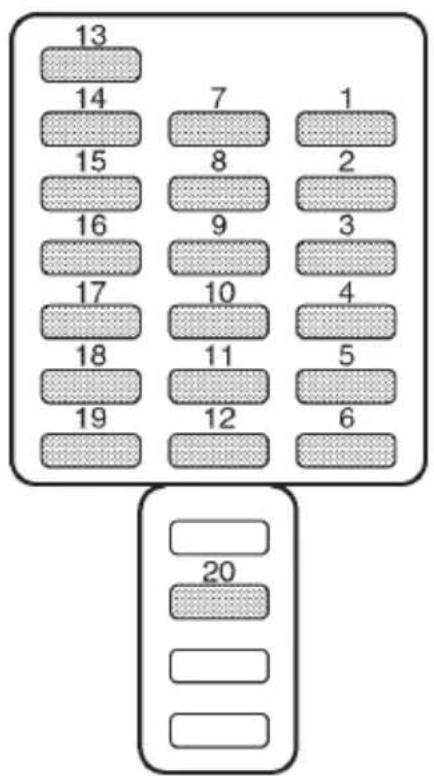
other
| Row | Column 1 | Column 2 | Column 3 | |---|---|---|---| | 1 | 13 | 14 | 15 | | 2 | 7 | 8 | 16 | | 3 | 1 | 2 | 9 | | 4 | 17 | 10 | 3 | | 5 | 18 | 11 | 5 | | 6 | 19 | 12 | 6 | | 7 | 20 | 20 | 20 | The top row contains the first column (13), the middle row contains the second (14), and the bottom row contains the third (20). The bottom row contains the fourth column (20).HBC001BB
Fuse panel Fuse rating Circuit
| 1 15A ●Heater fan |
| 2 15A ●Heater fan |
| 3 15A ●Power door lock●Keyless entry |
| 4 20A ●Cigarette lighter●Remote controlled rear view mirrors |
| 5 10A ●Tail light●Parking light |
| Fuse panel CircuitFuse rating |
| 6 15A ●SRS airbag |
| 7 15A ●Front fog light |
| 8 30A ●ABS solenoid |
| 9 15A ●Radio●Clock |
| 10 15A ●Trailer |
| 11 15A ●Engine ignition system●SRS airbag |
| 12 10A ●Illumination brightness control |
| 13 15A ●Fuel pump |
| 14 10A ●Rear window wiper and washer |
| 15 30A ●Windshield wiper and washer |
| 16 20A ●Brake light |
| 17 15A ●Air conditioner |
| 18 15A ●Backup light●Cruise control●ABS control |
| 19 20A ●Mirror heater●Wiper deicer |
| 20 20A ●Accessory power socket●Seat heater |
▼3.0 liter models
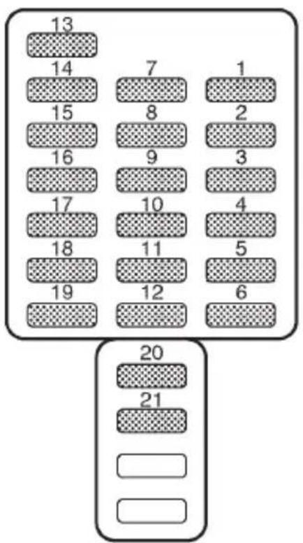
other
| Row | Column 1 | Column 2 | |---|---|---| | Top Row | 13 | | | Top Row | 14 | 7 | | Top Row | 15 | 8 | | Top Row | 16 | 9 | | Top Row | 17 | 10 | | Top Row | 18 | 11 | | Top Row | 19 | 12 | | Top Row | 20 | | | Top Row | 21 | | | Bottom Row | | 6 | | Bottom Row | | 5 | | Bottom Row | | 4 | | Bottom Row | | 3 | | Bottom Row | | 2 | | Bottom Row | | 1 | | Bottom Row | | 0 | The bottom row contains two rows of numbers: '20' and '21'. The top row contains all four cells (7), while the bottom row contains three rows (20, 21).HBC001CB
Fuse panel Fuse rating Circuit
| 1 15A ●Heater fan |
| 2 15A ●Heater fan |
| 3 15A ●Power door lock●Keyless entry |
| 4 20A ●Cigarette lighter●Remote controlled rear view mirrors |
| 5 10A ●Tail light●Parking light |
| 6 15A ●SRS airbag |
| 7 15A ●Front fog light |
| Fuse panel CircuitFuse rating |
| 8 30A ●ABS (VDC) solenoid |
| 9 15A ●Radio●Clock |
| 10 15A ●Trailer |
| 11 15A ●Engine ignition system●SRS airbag |
| 12 10A ●Illumination brightness control |
| 13 15A ●Fuel pump |
| 14 10A ●Rear window wiper and washer |
| 15 30A ●Windshield wiper and washer |
| 16 20A ●Brake light |
| 17 15A ●Air conditioner |
| 18 15A ●Backup light●Cruise control●ABS (VDC) control |
| 19 20A ●Mirror heater●Wiper deicer |
| 20 20A ●McIntosh audio amp (if equipped) |
| 21 20A ●Accessory power socket●Seat heater |
■Fuse panel located in the engine compartment
▼2.5 liter models
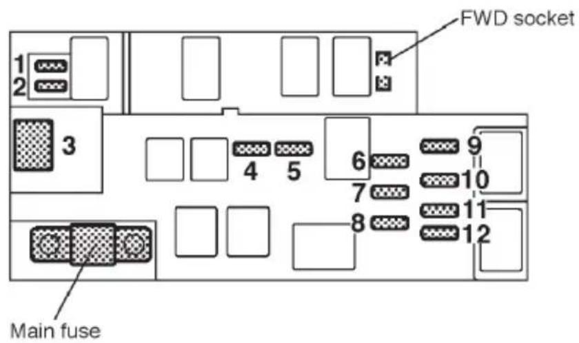
HBC003BB
Fuse panel Fuse rating Circuit
| 1 20A ●Radiator cooling fan (Main) |
| 2 20A ●Radiator cooling fan (Sub) |
| 3 50A ●ABS motor |
| 4 20A ●Rear window defogger |
| 5 15A ●Hazard warning flasher●Horn |
| 6 15A ●Meter●SRS airbag system warning light |
| 7 10A ●Automatic transmission control unit●ABS UNIT |
| 8 10A ●Alternator |
| 9 15A ●Headlight (right side) |
Fuse panel CircuitFuse rating
| 10 15A ●Headlight (left side) |
| 11 20A ●Lighting switch |
| 12 15A ●Clock●Interior light |
▼3.0 liter models
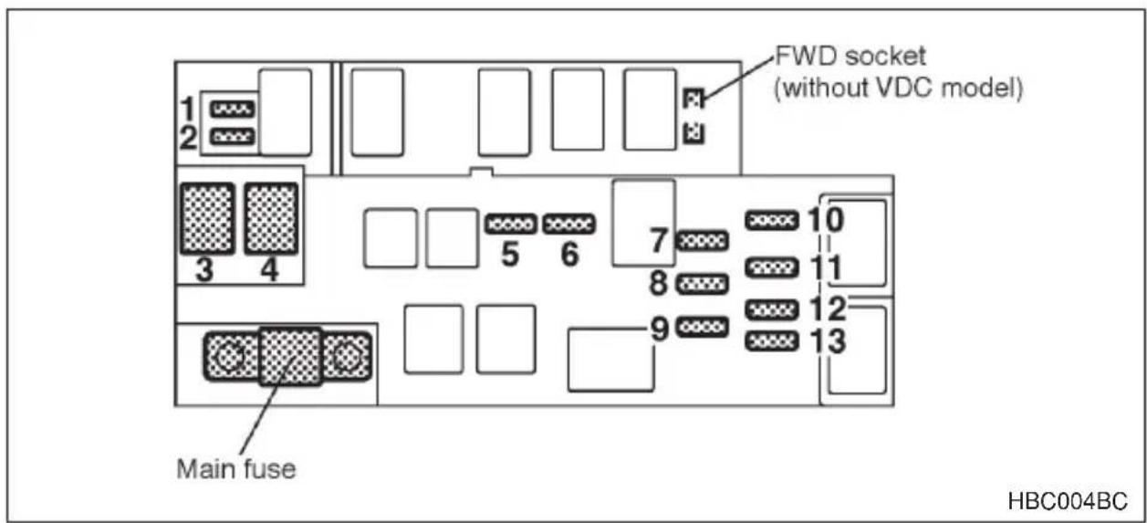
Fuse panel Fuse rating Circuit
| 1 30A ●Radiator cooling fan (Main) |
| 2 30A ●Radiator cooling fan (Sub) |
| 3 50A ●ABS (VDC) motor |
| 4 30A ●McIntosh audio amp (if equipped) |
| 5 20A ●Rear window defogger |
| 6 15A ●Hazard warning flasher●Horn |
| 7 15A ●Meter●SRS airbag system warning light |
| 8 10A ●Automatic transmission control unit●ABS UNIT |
| 9 10A ●Alternator |
| 10 15A ●Headlight (right side) |
Fuse panel CircuitFuse rating
| 11 15A ●Headlight (left side) |
| 12 20A ●Lighting switch |
| 13 15A ●Clock●Interior light |
Bulb chart
Wattage Bulb No.
Headlight
GT and OUTBACK
Low beam 12V-55W H1
High beam 12V-60W 9005 (HB3)
Except GT and OUTBACK 12V-60/55W 9007 (HB5)
Front turn signal 12V-27W 1156NA (Amber)
Spot light 12V–8W —
Dome light 12V–8W —
Door step light 12V-3.4W —
Parking and front side marker light 12V-27/8W 1157NA (Amber)
Front fog light
Except OUTBACK 12V-55W H3
OUTBACK 12V-51W 9006 (HB4)
Backup light
Sedan 12V-27W 3156K
Station wagon 12V-27W 1156
Luggage area light 12V–13W —
High mount stop light
Sedan 12V-18W 921
Station wagon 12V–13W 912
Rear turn signal light
Sedan 12V-21W —
Station wagon 12V-21W R2172 7440
Brake/tail light
Sedan 12V-27/8W 3157K
Station wagon 12V-27/8W 1157
Licence plate light
Sedan 12V-5W 168
Station wagon 12V-3.8W or 5W 194 or 168
Trunk room light 12V–5W W5W
Vehicle identification
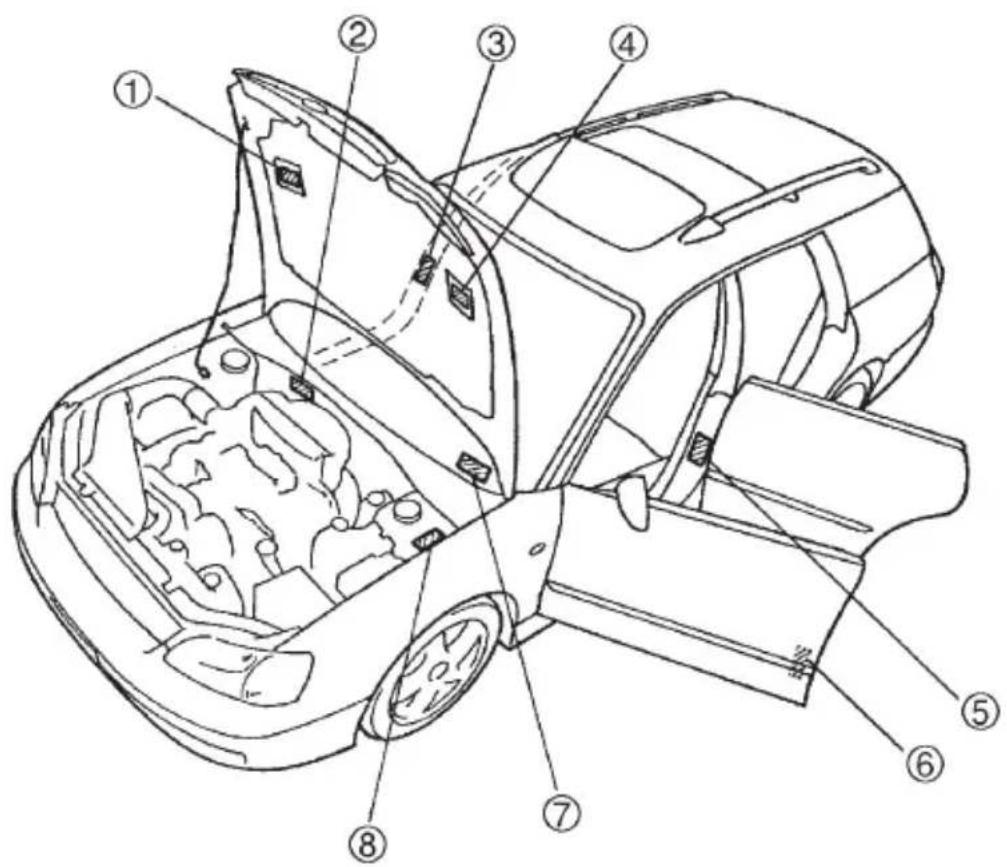
HBD002BB
① Emission control label
② Vehicle identification number
③ Radio noise label (Canada model)
④ Vacuum hose connections label
⑤ Tire inflation pressure label
⑥ Certification and bar cord label
⑦ Vehicle identification number plate
⑧ Model number plate
Consumer information and Reporting safety defects
Uniform tire quality grading standards 13-2
Treadwear 13-2
Traction AA, A, B, C 13-2
Temperature A, B, C 13-3
Reporting safety defects (USA) 13-4
For U.S.A.
The following information has been compiled according to Code of Federal Regulations “Title 49, Part 575”.
Uniform tire quality grading standards
This information indicates the relative performance of passenger car tires in the area of treadwear, traction, and temperature resistance. This is to aid the consumer in making an informed choice in the purchase of tires. Quality grades can be found where applicable on the tire sidewall between tread shoulder and maximum section width. For example:
Treadwear 200 Traction AA Temperature A
The quality grades apply to new pneumatic tires for use on passenger cars. However, they do not apply to deep tread, winter type snow tires, space-saver or temporary use spare tires, tires with nominal rim diameters of 12 inches or less, or to some limited production tires.
All passenger car tires must confirm to Federal Safety Requirements in addition to these grades.
Treadwear
The treadwear grade is a comparative rating based on the wear rate of the tire when tested under controlled conditions on a specified government test course.
For example, a tire graded 150 would wear one and one-half (1-1/2) times as well on the government course as a tire graded 100. The relative performance of tires depends upon the actual conditions of their use, however, and may depart significantly from the norm due to variations in driving habits, service practices and differences in road characteristics and climate.
■Traction AA, A, B, C
The traction grades, from highest to lowest, are AA, A, B and C. Those grades represent the tire's ability to stop on wet pavement as measured under controlled conditions on specified government test surfaces of as-
phalt and concrete. A tire marked C may have poor traction performance.

WARNING
The traction grade assigned to this tire is based on straight-ahead braking traction tests, and does not include acceleration, cornering, hydroplaning, or peak traction characteristics.
■Temperature A, B, C
The temperature grades are A (the highest), B, and C, representing the tire's resistance to the generation of heat and its ability to dissipate heat when tested under controlled conditions on a specified indoor laboratory test wheel. Sustained high temperature can cause the material of the tire to degenerate and reduce tire life, and excessive temperature can lead to sudden tire failure. The grade C corresponds to a level of performance which all passenger car tires must meet under the Federal Motor Vehicle Safety Standards No. 109. Grades B and A represent higher levels of performance on the laboratory test wheel than the minimum required by law.

WARNING
The temperature grade for this tire is established for a tire that is properly inflated and not overloaded. Excessive speed, under-inflation, or excessive loading, either separately or in combination, can cause heat buildup and possible tire failure.
Reporting safety defects (USA)
If you believe that your vehicle has a defect which could cause a crash or could cause injury or death, you should immediately inform the National Highway Traffic Safety Administration (NHTSA) in addition to notifying Subaru of America, Inc.
If NHTSA receives similar complaints, it may open an investigation, and if it finds that a safety defect exists in a group of vehicles, it may order a recall and remedy campaign. However, NHTSA cannot become involved in individual problems between you, your dealer, or Subaru of America, Inc. To contact NHTSA, you may either call the Auto Safety Hotline toll-free at 1-800-424-9393 (or 366-0123 in the Washington D.C. area) or write to: NHTSA, U.S. Department of Transportation, Washington, D.C. 20590. You can also obtain other information about motor vehicle safety from the Hotline.
A
ABS (Anti-lock Brake System) 7-23
ABS warning light 3-14
Accessory power socket 6-13
Air cleaner element 11-18
Air conditioner operation 4-10
Air filtration system (if equipped) 4-21
Aluminum wheels (If equipped) 11-47
Antenna system 5-2
Armrest (if equipped) 1-10
Ashtray 6-12
AT OIL TEMPerature warning light (for AT vehicles) 3-14
Audio set 5-3
Automatic climate control system (if equipped) 4-12
Automatic/Emergency Locking Retractor (A/ELR) 1-18
Automatic transmission 7-14
Automatic transmission fluid 11-24
B
Battery 11-51
Brake booster 11-33
Brake fluid 11-30
Brake pedal 11-34
Brake system 7-22
Brake system warning light 3-16
Braking 7-21
Braking tips 7-21
Bulb chart 12-14
C
Capacities 12-4
Cargo anchorage eyelets (if equipped) 6-18
Cargo area light (if equipped) 6-3
Catalytic converter 8-4
CD player 1 (if equipped) 5-60
CD player 2 (if equipped) 5-62
Center console 6-6
Charge warning light 3-13
CHECK ENGINE warning light/Malfunction indicator lamp 3-12......
Child restraint systems 1-33
Child safety locks 2-20
Cigarette lighter socket (if equipped) 6-9
Cleaning aluminum wheels 10-4
Cleaning fog light lens (for OUTBACK) 10-4
Cleaning the interior 10-6
Clock 3-19
Clutch fluid (MT vehicles) 11-32
Clutch pedal (Manual transmission vehicles) 11-35
Coin tray 6-7
Convenience hook 6-14
Cooling system 11-14
Corrosion protection 10-5
Cruise control (if equipped) 7-34
Cup holder 6-8
D
Daytime running light system 3-21
Dimensions 12-2
Disc brake pad wear warning indicators 7-23
Dome light 6-2
Door locks 2-3
Door open warning lights 3-17
Drive belts 11-22
Driving in foreign countries 8-5
Driving tips for AWD vehicles 8-6
Dual moonroofs (Station wagon) 2-32
E
Electrical system 12-3
Emergency Locking Retractor (ELR) 1-17
Engine 12-3
Engine compartment overview 11-7
Engine coolant 11-15
Engine exhaust gas (Carbon monoxide) 8-3
Engine hood 11-5
Engine oil 11-9
Engine overheating 9-14
Exterior care 10-2
F
Fastening the seatbelt 1-18
Flat tires 9-4
Floor mat (if equipped) 6-15
Fog light switch (if equipped) 3-24
Folding down the rear seat — Station wagon 1-12
Front differential gear oil (AT vehicles) 11-26
Front fog light (if equipped) 11-59
Front seatbelt pretensioners 1-29
Front seats 1-2
Front turn signal light, parking light and marker light 11-59
Front-wheel drive warning light (for AT vehicles) 3-17
Fuel 7-2
Fuel economy hints 8-3
Fuel filler lid and cap 7-4
Fuel gauge 3-9
Fuel requirements 7-2
Fuse panel located behind the coin tray 12-6
Fuse panel located in the engine compartment 12-10
Fuses 11-52
Fuses and circuits 12-6
G
Glove compartment 6-6
GVWR and GAWR (Gross Vehicle Weight Rating and Gross Axle Weight Rating) ... 8-19
H
Hazard warning flasher 3-7
Headlight 11-57
Headrest adjustment — Rear center seating position on Station wagon 1-12
Heater operation 4-7
High beam indicator light 3-19
High mount stop light 11-67
Horn 3-37
|
If you park your vehicle in an emergency 9-2
Ignition switch 3-3
Ignition switch light 3-5
Illumination brightness control 3-22
In-dash 6 CD auto changer (if equipped) 5-65
Inside mirror 3-31
Installation of accessories 5-3, 11-54
Interior light 6-2
Internal trunk lid release handle 2-26
J
Jack and jack handle 9-27
Jump starting 9-11
K
Key interlock release (AT vehicles only) 3-6
Keyless entry system (if equipped) 2-7
Key reminder chime 3-5
Keys 2-2
L
License plate light 11-64
Light control switch 3-19
Loading your vehicle 8-17
Low fuel warning light 3-17
Luggage cover (if equipped) 6-16
M
Main fuse 11-54
Maintenance precautions 11-3
Maintenance schedule 11-3
Maintenance tools 9-26
Manual heating and air conditioning system 4-4
Manual transmission.... 7-11
Manual transmission oil 11-23
McIntosh audio set (if equipped) 5-50
Meters and gauges 3-7
Mirrors 3-31
Moonroof (if equipped) 2-30
Moonroof — if the moonroof cannot be closed 9-25
N
New vehicle break-in driving – the first 1,000 miles (1,600 km) ..... 8-2
0
Odometer/Trip meter 3-7
Off road driving 8-7
Oil pressure warning light 3-13
Operating tips for heater and air conditioner 4-20
Outside mirrors 3-34
Outside temperature indicator (if equipped) 3-9
Overhead console (if equipped) 6-7
P
Parking brake stroke 11-37
Parking light switch 3-23
Parking your vehicle 7-32
Periodic inspections 8-5
Power door locking switches (if equipped) 2-6
Power steering 7-21
Power steering fluid 11-29
Power windows 2-21
Precautions against vehicle modification 1-64
Precautions to observe when handling a compact disc (CD) 5-68....
Preparing to drive 7-8
R
Rear combination lights 11-61
Rear differential gear oil 11-27
Rear gate (Station wagon) 2-29
Rear seats 1-10
Rear viscous limited slip differential (LSD) (if equipped) 7-20
Rear window defogger switch 3-29
Rear window wiper and washer switch (if equipped) 3-28
Replacement of brake pad and lining 11-36
Replacement of windshield wiper blades 11-48
Replacing bulbs 11-55
Reporting safety defects (USA) 13-4
Rocking the vehicle 8-16
Roof rail and crossbar (if equipped) 8-20
S
Seatbelt maintenance 1-28
Seatbelts 1-16
Seatbelt safety tips 1-16
Seatbelt warning light and chime 1-18, 3-11
Seat heater (if equipped) 1-9
Security system (if equipped) 2-13
Security system status indicator light (if equipped) 3-18
Selector lever for automatic transmission 7-15
Shift lock release 7-19
Shift position indicator (for AT vehicles) 3-18
Snow tires 8-14
Spark plugs 11-20
Specifications 12-2
Speedometer 3-7
Spot light, dome light, luggage compartment light and door step light 11-65
Spotlight (if equipped) 6-3
SRS airbag (Supplemental Restraint System airbag) 1-43
SRS airbag system monitors 1-62
SRS airbag system servicing 1-63
SRS airbag system warning light 3-11
SRS frontal airbag 1-48
SRS side airbag (if equipped) 1-55
Starting a flooded engine 7-10
Starting the engine 7-9
Starting the engine during cold weather below -4^ ( -20^ ) ..... 7-10
Starting the engine for a manual transmission vehicle 7-9
Starting the engine for an automatic transmission vehicle 7-9
State emission testing (U.S. only) 7-7
Stopping the engine 7-11
Storage compartment 6-5
Storage tray (if equipped) 6-18
Sun visors 6-4
T
Tachometer 3-9
Temperature A, B, C 13-3
Temperature gauge 3-10
Temporary spare tire 9-3
Tilt steering wheel 3-36
Tilting/sliding moonroof (Sedan) 2-30
Tire chains 8-16
Tire inspection 11-39
Tire pressures and wear 11-39
Tire replacement 11-44
Tire rotation 11-44
Tires 12-4
Tires and wheels 11-38
Top tether anchorages 1-40
Towing 9-15
Traction AA, A, B, C 13-2
Trailer hitch (if equipped) 8-24
Trailer towing (for OUTBACK) 8-28
Treadwear 13-2
Trunk lid (Sedan) 2-24
Trunk light 11-66
Turn signal indicator lights 3-18
Turn signal lever 3-21
Type A and B audio set (if equipped) 5-8
Type C audio set (if equipped) 5-20
Type D and E audio set (if equipped) 5-34
Type F audio set (if equipped) 5-44
Types of tires 11-38
U
Uniform tire quality grading standards 13-2
V
Vanity mirror (if equipped) 6-5
VDC OFF switch 7-31
VDC (Vehicle Dynamics Control) OFF indicator light (if equipped). 3-18
VDC (Vehicle Dynamics Control) operation indicator light (if equipped) 3-17
VDC (Vehicle Dynamics Control) system (if equipped) 7-26
VDC (Vehicle Dynamics Control) warning light (if equipped) 3-15
Vehicle capacity weight 8-18
Vehicle identification.... 12-15
Vehicle with driver's and front passenger's SRS airbags and lap/shoulder restraints 1-43
Ventilator 4-2
W
Warning and indicator lights 3-10
Washing 10-2
Waxing and polishing 10-3
Wear indicators 11-43
Wheel alignment 12-5
Wheel balance 11-42
Wheel covers 11-46
Wheel replacement 11-45
Windows 2-21
Windshield washer fluid 11-47
Windshield wiper and washer switches 3-26
Windshield wiper deicer (if equipped) 3-30
Winter driving 8-10
Wiper and washer 3-24


- OWNER'S MANUAL
- Foreword
- ▼Warranties for U.S.A.
- ▼Warranties for Canada
- NOTE
- ■Using your Owner's manual
- Chapter 1: Seat, seatbelt and SRS airbags
- Chapter 2: Keys and doors
- Chapter 3: Instruments and controls
- Chapter 4: Climate control
- Chapter 5: Audio
- Chapter 6: Interior equipment
- Chapter 7: Starting and operating
- Chapter 8: Driving tips
- Chapter 9: In case of emergency
- Chapter 10: Appearance care
- Chapter 11: Maintenance and service
- Chapter 12: Specifications
- Chapter 13: Consumer information and Reporting safety defects
- Chapter 14: Index
- ■Safety warnings
- WARNING
- CAUTION
- ■Safety symbol
- Safety precautions when driving
- SEATBELT AND SRS AIRBAG
- CHILD SAFETY
- CLOSE TO THE SRS AIRBAG.
- ENGINE EXHAUST GAS (CARBON MONOXIDE)
- DRINKING AND DRIVING
- DRIVING WHEN TIRED OR SLEEPY
- MODIFICATION OF YOUR VEHICLE
- DRIVING WITH PETS
- TIRE PRESSURES
- CALIFORNIA PROPOSITION 65 WARNING
- Table of contents
- Seat, seatbelt and SRS airbags
- ▼Fore and aft adjustment
- ▽ Manual type
- ▽ Power seat (if equipped)
- ▼Seat cushion angle and height adjustment (Power seat only)
- ▼Reclining the seatback
- ▼ Lumbar support (if equipped)
- Seat heater (if equipped)
- Rear seats
- Armrest (if equipped)
- ▼Loading long objects (Sedan)
- ■ Headrest adjustment — Rear center seating position on Station wagon
- ■ Folding down the rear seat — Station wagon
- ▼Folding down the seatback
- ▼Folding down the seat cushion and seatback
- ■Seatbelt safety tips
- ▼ Infants or small children
- Children
- ▼Expectant mothers
- Emergency Locking Retractor (ELR)
- ■Automatic/Emergency Locking Retractor (A/ELR)
- ■Seatbelt warning light and chime
- ■Fastening the seatbelt
- ▼Front seatbelts
- ∇ Unfastening the seatbelt
- ▼Rear seatbelts (except rear center seatbelt on wagon)
- ▼Rear center seatbelt on wagon model
- ■Seatbelt maintenance
- Front seatbelt pretensioners
- ▼System monitors
- ▼System servicing
- ▼Precautions against vehicle modification
- Child restraint systems
- ▼Installing child restraint systems with seatbelt
- ▼Installation of child restraint systems by use of lower and tether anchorages
- ■Top tether anchorages
- ▼Anchorage location
- ▼To hook the top tether
- ▽ Sedan
- \*SRS airbag (Supplemental Restraint System airbag)
- ■ Vehicle with driver's and front passenger's SRS airbags and lap/shoulder restraints
- Components
- ■SRS frontal airbag
- Operation
- Driver's side Passenger's side
- Examples of accident in which the SRS frontal airbag will most likely deploy.
- Examples of the types of accidents in which it is possible that the SRS frontal airbag will deploy.
- Examples of the types of accidents in which the SRS frontal airbag is unlikely to deploy.
- Examples of the types of accidents in which the SRS frontal airbag will basically not deploy.
- ■SRS side airbag (if equipped)
- Example of the type of accident in which the SRS side airbag will most likely deploy.
- Examples of the types of accidents in which the SRS side airbag is unlikely to deploy.
- Examples of the types of accidents in which the SRS side air-bag will basically not deploy.
- ■SRS airbag system monitors
- ■SRS airbag system servicing
- ■Precautions against vehicle modification
- Keys and doors
- Keys
- ▼Key number
- Door locks
- ▼Locking and unlocking from the outside
- For vehicles with power door locking switches
- ■Power door locking switches (if equipped)
- Keyless entry system (if equipped)
- ▼Locking the doors
- ▼Unlocking the doors
- ▼Illuminated entry
- ▼Sounding a panic alarm
- ▼Selecting audible signal operation
- ▼Replacing the battery
- ▼Replacing lost transmitters
- ▽ Programming the transmitters
- To enter the programming mode:
- To program the transmitters:
- To exit the programming mode:
- ∇ Deleting old transmitter codes
- Security system (if equipped)
- ▼ System operation
- Arming the system
- To arm the system using power door locking switches
- ▼Disarming the system
- Emergency disarming
- ▼Valet mode
- ▼Passive arming
- ∇ To enter the passive mode
- ▼Tripped sensor identification
- The battery must be reconnected before the indicator light will flash.
- Child safety locks
- Windows
- Power windows
- ▼Driver's side switches
- Operating the driver's window
- ▽ Operating the passengers' windows
- ∇ Locking the passengers' windows
- ▼Passengers' side switches
- Trunk lid (Sedan)
- ▼To open the trunk lid from inside
- ▼To cancel the trunk lid release
- ■Internal trunk lid release handle
- Inspection
- Rear gate (Station wagon)
- Moonroof (if equipped)
- ■Tilting/sliding moonroof (Sedan)
- ▼To raise or lower the moonroof
- ▼To open or close the moonroof
- Sun shade
- ■Dual moonroofs (Station wagon)
- To open the moonroof(s)
- To close the moonroof(s)
- Sun shades
- ▽ Front sun shade
- ▽ Rear sun shade
- Instruments and controls
- Ignition switch 3-3
- Hazard warning flasher 3-7
- Meters and gauges 3-7
- Warning and indicator lights 3-10
- Clock 3-19
- Light control switch 3-19
- Turn signal lever 3-21
- Illumination brightness control 3-22
- Parking light switch 3-23
- Ignition switch
- ▼LOCK
- ∇ Automatic transmission vehicles
- ▽ Manual transmission vehicles
- ▼ACC
- VON
- ▼START
- ■Key reminder chime
- ■Ignition switch light
- ■Key interlock release (AT vehicles only)
- Hazard warning flasher
- Meters and gauges
- ■Speedometer
- ■Odometer/Trip meter
- ▼Odometer
- ▼Double trip meter
- Tachometer
- ■Outside temperature indicator (if equipped)
- Fuel gauge
- ■Temperature gauge
- Warning and indicator lights
- ■SRS airbag system warning light AIRBAG
- ■CHECK ENGINE warning light/Malfunction indicator lamp
- ▼If the light comes on steadily:
- ▼ If the light is blinking:
- ■Charge warning light
- ■Oil pressure warning light
- ■AT OIL TEMperature warning light (for AT vehicles)
- ▼Automatic transmission control system warning
- ■ABS warning light
- ■VDC (Vehicle Dynamics Control) warning light (if equipped)
- ▼Parking brake warning
- ▼Brake fluid level warning
- ■ Door open warning lights
- ■Low fuel warning light
- ■Front-wheel drive warning light (for AT vehicles) FWD
- ■ VDC (Vehicle Dynamics Control) operation indicator light (if equipped)
- ■VDC (Vehicle Dynamics Control) OFF indicator light (if equipped)
- ■Security system status indicator light (if equipped)
- ■Shift position indicator (for AT vehicles)
- ■Turn signal indicator lights
- ■High beam indicator light
- Clock
- Light control switch
- ▼ Headlights
- EDGE first position
- ED second position
- ▼High/low beam change (dimmer)
- ▼Headlight flasher
- ■Daytime running light system
- Turn signal lever
- Illumination brightness control
- Parking light switch
- Fog light switch (if equipped)
- Wiper and washer
- ■ Windshield wiper and washer switches
- ▼Windshield wipers
- ▼Wiper intermittent time control (if equipped)
- ▼Mist (for a single wipe)
- Washer
- ■Rear window wiper and washer switch (if equipped)
- Rear wiper
- Rear window defogger switch
- For vehicles with manual heating and air conditioning systems
- For vehicles with automatic climate control
- Windshield wiper deicer (if equipped)
- Mirrors
- Inside mirror
- ▼Compass mirror (if equipped)
- ▼ Photosensors
- ▽ Compass calibration
- ▽ Compass zone adjustment
- ■Outside mirrors
- ▼Convex mirror (Passenger side)
- ▼Adjusting mirrors
- ▼Remote control mirror switch (if equipped)
- ▼Outside mirror defogger (if equipped)
- Tilt steering wheel
- Horn
- Climate control
- Ventilator
- ▼Center and side ventilators
- Adjustable side defroster grille (for driver's side only)
- Air flow selection
- Manual heating and air conditioning system
- ▼Control panel
- ▽ Temperature control dial
- ▽ Fan speed control dial
- ▽ Air flow control dial
- Air conditioner button
- ▽ Air inlet selection button
- ■Heater operation
- ▼Defrosting or defogging the windshield
- ▼Heating and defrosting
- Heating
- ▼Bi-level heating
- Ventilation
- ! WARNING
- ■Air conditioner operation
- ▼Cooling or dehumidifying
- ▼Defrosting or defogging
- Automatic climate control system (if equipped)
- ▼ AUTO switch
- AUTO mode operation:
- ECON (economy) mode:
- Manual mode operation:
- ▽ OFF switch
- ▼ OUT.TEMP switch
- ▽ — Defroster switch
- — fan speed control switch
- A/C — Air conditioner switch
- ▽ MODE — Air flow control switch
- ▽ Air inlet selection switch
- ▼Temperature sensors
- Operating tips for heater and air conditioner
- ▼Cleaning ventilator grille
- ▼Efficient cooling after parking in direct sunlight
- ▼Lubrication oil circulation in the refrigerant circuit
- ▼Checking air conditioning system before summer season
- ▼Cooling and dehumidifying in high humidity and low temperature weather condition
- ▼Air conditioner compressor shut-off when engine is heavily loaded
- ▼Refrigerant for your climate control system
- Air filtration system (if equipped)
- Audio
- Antenna system
- ▼Printed antenna
- ▼Pillar mounted antenna
- ▼FM reception
- Installation of accessories
- Audio set
- ▼Type A and type B audio set
- ▼Type C audio set
- ▼Type D and type E audio set
- ▼Type F audio set
- ▼McIntosh audio set
- In-dash 6 CD auto changer (Optional audio unit — if equipped)
- Type A and B audio set (if equipped)
- Radio operation
- ▼Power switch and volume/bass/treble/fader/balance control
- ▼ Power switch and volume control (PWR/VOL)
- ∇ Tone and balance control (AUDIO)
- B Waveband selection
- n FM/AM selection
- n FM/AM/Weather band selection
- B Stereo indicator
- B Tuning (TUNE)
- n Manual tuning (TUNE)
- n Manual tuning for weather band
- n Automatic tuning (SCAN)
- ▼Selecting preset stations
- ▼How to preset stations
- Cassette player operation
- ▼Cassette slot
- ▼TAPE button
- ▼Tape travel indicators
- ▼ Program button (PROG)
- ▼Fast-forward button (FF)
- ▼Rewind button (REW)
- ▼Eject button ( △ )
- ▼Tape program sensor button (TPS)
- Blank skip
- Blank search
- ▼Repeat (RPT)
- ▼Dolby B NR button ( □□ )
- CD player control (If optional CD player is connected)
- ▼To start playback
- When CD is not in the CD player
- When CD is in the CD player
- ▼To select a song from its beginning
- ▼Fast-forwarding and fast-reverse
- Repeat
- ▼Random playback
- ▼Scan (a convenient way to become familiar with a disc)
- ▼To stop playback
- CD changer control (If optional in dash CD changer is connected)
- ▼Selection of a desired disc
- ▽ Operation with the in-dash CD changer unit
- Type C audio set (if equipped)
- ▼Power switch and volume/bass/treble/fader/balance control (PWR/VOL)
- ∇ Tone control
- ∇ Fader and balance control
- ▽ Display illumination dimness cancellation (BRIGHT)
- ▼FM/AM selection button (FM/AM)
- ▼Stereo indicator
- ▼Weather band button (WB)
- ▼ Manual tuning (TUNE)
- ▽ Manual tuning for AM and FM waveband
- ▼ Manual tuning for weather band
- ▼ Automatic tuning (SCAN)
- OR
- ▼To play back a cassette tape
- When cassette tape is not in the player
- When cassette tape is in the player
- ▼ Program switching button (PROG)
- ▼ Fast-forward button (FF)
- ▼Eject button ( ▲ )
- ▼Repeat button (RPT)
- ▼Auto metal sensor
- Compact disc player operation
- ▼To play back a compact disc
- When CD is not in the player
- ▼Repeat playback
- Scan
- ▼To eject a disc from the player
- CD changer control (If optional in-dash CD changer is connected)
- ▼To select the desired disc
- ▽ Forward direction
- ▽ Backward direction
- ▼Fast forwarding and fast reverse
- ∇ Fast forwarding
- ∇ Fast reverse
- Type D and E audio set (if equipped)
- ▼Waveband selection
- ▽ FM/AM selection
- ▽ FM/AM/Weather band selection
- ▼Tuning (TUNE)
- ▽ Manual tuning (TUNE)
- ▼To playback a compact disc
- When CD is in the player
- ▼To stop playback of a CD
- Backward direction
- ∇ Fast forward
- Type F audio set (if equipped)
- ▼Tone and balance control
- ▼Manual tuning (TUNING)
- ▼Program switching buttons
- ▼Fast-forward button
- ▼Rewind button
- ▼Dolby BNR button (BNR)
- CD player operation (if optional CD player is connected)
- McIntosh audio set (if equipped)
- ▼ON-OFF switch
- Volume control
- ▼Tone control
- BASS control
- TREBLE control
- ▼Balance control
- ▼ FADER control
- ▼ BALANCE control
- ▼FM/AM selection button
- ▼Manual tuning
- ▼Seek tuning (SEEK)
- ▼Scan tuning (SCAN)
- ▼ Preset tuning
- ▼ Manual preset
- ▼Cassette tape stop and eject button
- ▼Program button (PROG)
- ▼Dolby B NR button (B NR)
- CD player 1 (if equipped)
- ▼To insert a disc
- ▽ Disc indicator
- ▼To remove disc left in slot
- ▽ Function control
- CD player 2 (if equipped)
- ▼Top
- In-dash 6 CD auto changer (if equipped)
- ▼To insert six discs at a time
- ▼To remove a disc
- ▼To remove all discs at one time
- ▼To replace a playing disc with another
- ▼Disc indicators
- ▼Function control
- Precautions to observe when handling a compact disc (CD)
- Interior equipment
- Interior light
- Dome light
- ■ Cargo area light (if equipped)
- Spotlight (if equipped)
- Sun visors
- ■Vanity mirror (if equipped)
- ▼Vanity mirror with light (if equipped)
- Storage compartment
- Glove compartment
- ■Center console
- Coin tray
- ■Overhead console (if equipped)
- Cup holder
- Front cup holder
- ▼ Rear passenger's cup holder (if equipped)
- Cigarette lighter socket (if equipped)
- ▼Use with a cigarette lighter
- ▼Using as an accessory power socket
- Ashtray
- Front ashtray
- ▼Rear ashtray (if equipped)
- Accessory power socket
- Convenience hook
- ▼Coat hook
- ▼Shopping bag hook
- For sedan models
- For station wagon models
- Floor mat (if equipped)
- Luggage cover (if equipped)
- ▼Using the cover
- ▼To remove the cover
- Cargo anchorage eyelets (if equipped)
- Storage tray (if equipped)
- Starting and operating
- Fuel
- ■Fuel requirements
- ▼2.5 Liter models
- ▼3.0 Liter models
- ▼Fuel octane rating
- ▼Unleaded gasoline
- ▼Gasoline for California-certified LEV
- ▼Gasoline for cleaner air
- ■Fuel filler lid and cap
- Refueling
- State emission testing (U.S. only)
- Preparing to drive
- Starting the engine
- ■ Starting the engine for a manual transmission vehicle
- ■Starting the engine for an automatic transmission vehicle
- ■Starting the engine during cold weather below -4°F ( -20°C )
- ■Starting a flooded engine
- Stopping the engine
- Manual transmission
- ▼Shifting speeds
- ▼ Recommended shifting speeds
- ▽ Maximum allowable speeds
- ▼Driving tips
- Automatic transmission
- ■Selector lever for automatic transmission
- ▼P (Park)
- ▼R (Reverse)
- ▼N (Neutral)
- ▼D (Drive)
- While climbing a grade
- While going down a hill
- ▼3 (Third)
- ▼2 (Second)
- ▼1 (First)
- ▼Maximum speeds
- Shift lock release
- Rear viscous limited slip differential (LSD) (if equipped)
- Power steering
- Braking
- Braking tips
- ▼When the brakes get wet
- ▼Use of engine braking
- ▼Braking when a tire is punctured
- Brake system
- ▼Two separate circuits
- ▼Brake booster
- ■Disc brake pad wear warning indicators
- ABS (Anti-lock Brake System)
- ▼ABS system self-check
- ▼ABS warning light
- VDC (Vehicle Dynamics Control) system (if equipped)
- ▼VDC system monitor
- ▽ VDC OFF indicator light
- warning light turns on, the VDC OFF indicator light will also turn on.
- ▽ VDC operation indicator light
- ▽ VDC warning light
- ■VDC OFF switch
- Parking your vehicle
- Cruise control (if equipped)
- ▼To set cruise control
- ▼To temporarily cancel the cruise control
- ▼To turn off the cruise control
- ▼To change the cruising speed
- ∇ To increase the speed (by control lever)
- ∇ To increase the speed (by accelerator pedal)
- ∇ To decrease the speed (by control lever)
- ∇ To decrease the speed (by brake pedal)
- Driving tips
- New vehicle break-in driving – the first 1,000 miles (1,600 km)
- ▼Break-in engine speed limit
- Fuel economy hints
- Catalytic converter
- Periodic inspections
- Driving in foreign countries
- Driving tips for AWD vehicles
- Off road driving
- ▼All AWD models except OUTBACK
- ▼OUTBACK
- Winter driving
- ▼Operation during cold weather
- ∇ Before driving your vehicle
- ∇ Parking in cold weather
- Refueling in cold weather
- ▼Driving on snowy and icy roads
- ▽ Wiper operation when snowing
- ▼Corrosion protection
- ■Snow tires
- ▼All models except Outback
- ▼Outback models only
- vehicle and may cause rubbing on sharp turns. Listed below is the winter tire size that we recommend.
- Tire chains
- ■Rocking the vehicle
- Loading your vehicle
- ■Vehicle capacity weight
- ■GVWR and GAWR (Gross Vehicle Weight Rating and Gross Axle Weight Rating)
- ■Roof rail and crossbar (if equipped)
- ▼Installing carrying attachments on the crossbars
- ∇ To remove the crossbar
- ▽ To install the crossbar
- Front crossbar:
- ▼Connecting a trailer
- ▼When you do not tow a trailer
- Trailer towing
- ▼Warranties and maintenance
- ▼Maximum load limits
- ▽ Total trailer weight
- ∇ Gross Vehicle Weight (GVW) and Gross Vehicle Weight Rating (GVWR)
- ▼Gross Axle Weight (GAW) and Gross Axle Weight Rating (GAWR)
- ∇ Tongue load
- ▼Trailer hitches
- ▼OUTBACK wagon
- ▼All vehicles except OUTBACK wagon
- ▼ Trailer safety chains
- ▽ Side mirrors
- Trailer lights
- Tires
- ▼Trailer towing tips
- ∇ Before starting out on a trip
- ∇ Driving with a trailer
- ∇ Driving on grades
- ▼ Parking on a grade
- In case of emergency
- If you park your vehicle in an emergency
- Temporary spare tire
- Flat tires
- Jump starting
- ▼How to jump start
- ▼If steam is coming from the engine compartment
- ▼If no steam is coming from the engine compartment
- Towing
- ▼Towing and tie-down hooks
- ▽ Towing hook cover removal procedure For except OUTBACK models:
- ▽ Towing hook cover installation procedure For except OUTBACK models:
- For OUTBACK models:
- Insert the guide E into the hole F.
- ▼Using a flat-bed truck
- ▼Towing with all wheels on the ground
- Moonroof — if the moonroof cannot be closed
- Sedan
- ▼Station wagon
- Maintenance tools
- ■Jack and jack handle
- Appearance care
- Exterior care 10-2
- Corrosion protection 10-5
- Cleaning the interior 10-6
- Exterior care
- Washing
- ▼Washing the underbody
- ▼Using a warm water washer
- ■Waxing and polishing
- ■Cleaning aluminum wheels
- ■Cleaning fog light lens (for OUTBACK)
- Corrosion protection
- ▼ Most common causes of corrosion
- ▼To help prevent corrosion
- Cleaning the interior
- Seat fabric
- ▼ Leather seat materials
- ▼Synthetic leather upholstery
- Maintenance and service
- Maintenance schedule
- Maintenance precautions
- ■Before checking or servicing in the engine compartment
- ■When you do checking or servicing in the engine compartment while the engine is running
- Engine hood
- Engine compartment overview
- Engine oil
- ▼Checking the oil level
- ▼Changing the oil and oil filter
- Be careful not to burn yourself with hot engine oil.
- Oil capacity:
- ▼Recommended grade and viscosity
- ▼Recommended grade and viscosity under severe driving conditions
- Cooling system
- ▼ Hose and connections
- ■Engine coolant
- ▼Checking the coolant level
- ▼Changing the coolant
- Air cleaner element
- ▼Replacing the air cleaner element
- ▽ 2.5 liter models
- ▽ 3.0 liter models
- Spark plugs
- ▼Recommended spark plugs
- Drive belts
- Manual transmission oil
- Oil grade: API classification GL-5
- SAE viscosity No. and Applicable Temperature
- Automatic transmission fluid
- ▼Checking the fluid level
- ▼ Checking the fluid level when the fluid is hot
- ▼ Checking the fluid level when the fluid is cold
- ▼Recommended fluid
- Front differential gear oil (AT vehicles)
- Rear differential gear oil
- Power steering fluid
- Brake fluid
- Recommended brake fluid
- Clutch fluid (MT vehicles)
- ▼Recommended clutch fluid
- FMVSS No. 116, fresh DOT 3 or 4 brake fluid
- Brake booster
- Brake pedal
- ▼Checking the brake pedal free play
- ▼Checking the brake pedal reserve distance
- Clutch pedal (Manual transmission vehicles)
- ▼Checking the clutch function
- ▼Checking the clutch pedal free play
- Replacement of brake pad and lining
- Breaking-in of new brake pads and linings
- Brake pad and lining
- ▽ Parking brake lining
- Parking brake stroke
- Tires and wheels
- ■Types of tires
- All season tires
- ▼Summer tires
- ▼Winter (snow) tires
- ■Tire inspection
- ■Tire pressures and wear
- ●Abnormally high tire pressure (tread worn in center)
- ■Wheel balance
- ■Wear indicators
- ■Tire rotation
- ■Tire replacement
- ■Wheel replacement
- Wheel covers
- ▼Removing the wheel cover
- ▼Installing the wheel cover
- Aluminum wheels (If equipped)
- Windshield washer fluid
- Replacement of windshield wiper blades
- Battery
- Fuses
- Main fuse
- Replacing bulbs
- Headlight
- ▽ Low beam light bulbs
- ▽ High beam light bulbs
- ▼Except GT and OUTBACK models
- ■Front fog light (if equipped)
- ■Front turn signal light, parking light and side marker light
- ■Rear combination lights
- For covers on the trunk lid:
- For covers on the trunk wall:
- ▼ Brake/tail and rear turn signal light bulbs
- ▽ Back-up and brake/tail light bulbs
- ■License plate light
- ■Spot light, dome light, luggage compartment light and door step light
- Trunk light
- ■High mount stop light
- Specifications
- Specifications 12-2
- Fuses and circuits 12-6
- Bulb chart 12-14
- Vehicle identification 12-15
- Dimensions
- Legacy sedan
- Legacy station wagon
- OUTBACK sedan
- OUTBACK station wagon
- Engine
- liter
- liter
- Electrical system
- ■Capacities
- OUTBACK
- ■Wheel alignment
- Fuses and circuits
- ■Fuse panel located behind the coin tray
- ■Fuse panel located in the engine compartment
- Bulb chart
- Vehicle identification
- Consumer information and Reporting safety defects
- For U.S.A.
- Uniform tire quality grading standards
- Treadwear 200 Traction AA Temperature A
- Treadwear
- ■Traction AA, A, B, C
- ■Temperature A, B, C
- Reporting safety defects (USA)
- A
- B
- C
- D
- E
- F
- G
- H
- |
- J
- K
- L
- M
- N
- 0
- P
- R
- S
- T
- U
- V
- W
Brand : SUBARU
Model : Legacy (2002)
Category : Automobile