AS1-GSM - Intercom Estom - Free user manual and instructions
Find the device manual for free AS1-GSM Estom in PDF.


User questions about AS1-GSM Estom
0 question about this device. Answer the ones you know or ask your own.
Ask a new question about this device
Download the instructions for your Intercom in PDF format for free! Find your manual AS1-GSM - Estom and take your electronic device back in hand. On this page are published all the documents necessary for the use of your device. AS1-GSM by Estom.
USER MANUAL AS1-GSM Estom
GSM based intercom and access control
Installation and user manual
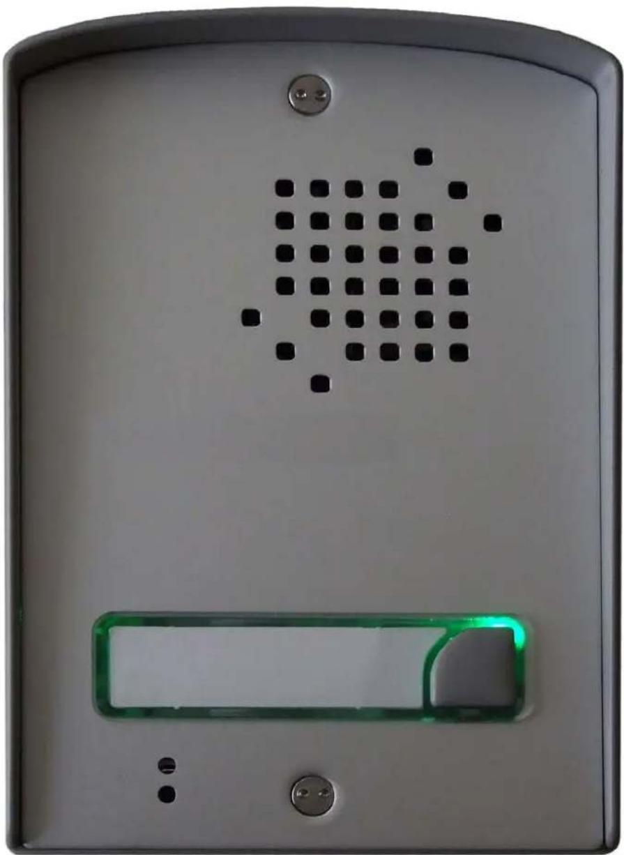
natural_image
Close-up of a white electronic device panel with a green LED display and black square patterned vent (no text or symbols visible)Table of contents
1 Functions....3
2 Features....3
3 Application area....3
4 Operation ....4
4.1 Visitor mode....4
4.2 Listen-in mode 4
4.3 Relay output control (gate opening)....4
4.4 Voltage output control (electric lock activation) 4
4.5 Forwarding incoming SMS messages....4
5 Settings .... 5
5.1 Response SMS explanation....5
6 LED indications ....6
7 Installation....6
7.1 Mounting....6
7.2 Putting into operation....6
8 Wiring diagram....7
9 Surface mounting....8
10 Technical specification ....8
C€
The AS1-GSM is an intercom unit which as a cell phone can call the owner's mobile or landline phone. By pressing the call button on the intercom, it makes the voice connection in a few seconds, just like when talking via a conventional intercom system. This way it makes possible for the owner to receive the visitor's calls and talk to them at anytime and anywhere, even when not at home.
The unit does not need internal handset, any special installation or complicated wiring, it needs power only and an active SIM card.
1 Functions
- Intercom
- Listen-in mode
• Electric door lock control via DTMF codes
• Electric gate control by free call - SMS forwarding
- Programming through SMS message
2 Features
• GSM communication in full duplex mode
- 2 configurable phone number for communication
- 4 configurable phone numbers for electric gate control
• 1 relay output with independent N.O. contact, supports 1A@24V max. load
- 12V/1A voltage output with short circuit and overcurrent protection for electric lock control
- Local control of the voltage output using a separate input
• Supports prepaid SIM cards by forwarding the received balance information in SMS
3 Application area
- Wireless intercom
- Gate/door opener
• Emergency call device
4 Operation
4.1 Visitor mode
When the visitor pushes the call button, the device initiates a voice call to the configured phone number. If the called party accepts the call, the communication establishes for the configured duration. During the call, the connection cannot be interrupted nor by making a call to the device, nor by pressing the button again. The call is ended automatically when the configured communication time expires, or the called party can hang up the call at anytime on his/her phone. The call is ended automatically if the called party does not answer or is not available. A new call is initiated only if the button is pressed again.
A call to the second telephone number can be initiated for 60 seconds after the first call is ended, by pressing the call button on the intercom again. The maximum duration of the call is the same as in case of the first call.
4.2 Listen-in mode
The intercom unit can be called from any phone number. In this case the unit accepts the call without ringing and the voice connection establishes. The call can be ended on the caller's phone or by pressing the call button on the unit.
If the call is initiated from a phone number which is configured in the unit as gate opener number, the device will consider the call as a gate opening call. In this case voice connection is not established, but the relay output is activated. To make a “listen-in” call from such phone number, use the #31# code in front of the number, this hides the caller’s phone number (e.g.: #31#0036301234567).
4.3 Relay output control (gate opening)
The unit can activate an independent, normally open relay output by free call, using caller (phone number) identification. Up to 10 user phone numbers can be configured for this function. To use this function, caller identification service should be activated at the GSM service provider on the SIM card inserted in the unit, as well as the caller should send the ID (phone number) when calling. When receiving a control call, the unit identifies the caller, rejects the call and activates the relay output.
4.4 Voltage output control (electric lock activation)
The voltage output can be activated for the configured duration during the phone conversation. This makes possible to control directly an electric lock. The activation of the output can be done by the called party by pressing any number or character key on the phone, thereby sending a DTMF code. The voltage output can also be activated locally, by closing the "INPUT" input on the unit. In this case the device will activate the output still for the configured duration. In case of a short circuit or overcurrent the output turns off, then it operates again after the termination of the fault.
4.5 Forwarding incoming SMS messages
The unit forwards the SMS messages received on its SIM card (e.g. balance information in case of a prepaid card) to the phone number set with the TEL command. After forwarding, the received message is deleted from the SIM card. If there is no phone number configured, the unit deletes the incoming messages without forwarding. A forwarded SMS message looks as follows: SMS forward from „the sender's phone number”: ...the forwarded message...
5 Settings
Configuration of the unit is possible by sending the appropriate commands in SMS to the module's phone number. It is possible to send more commands (settings) in the same SMS, but the length of the message must not exceed 140 characters! Each message must begin with the password using the PWD=password# command and each command must end with # character, else the module does not apply the modifications. The following table contains the configuring and query commands:
| Configuration commands | |
| PWD= 1234# | Password for programming, default setting:1234 |
| PWC=new password# | Changing the password. The password is a 4-digit number. |
| RESET# | Resetting the settings and the password to default. |
| TEL=phone number# | Setting the primary phone number to be called when pressing the button (in international format) |
| TEL2=phone number# | Secondary telephone number in case the first telephone number is unavailable. |
| TIME=duration# | Maximal duration of the conversation. (60-600 seconds)Default setting: 60 seconds |
| RTIME= duration# | Duration of the relay output activation.(1-100 seconds)Default setting: 3 seconds |
| VTIME= duration# | Duration of the voltage output (- OUT +) activation.(1-100 seconds).Default setting: 5 seconds |
| RTEL= phone number# | Setting the phone numbers for relay output activation.(max. 4 user) |
| STATUS?# | Query of the settings and the phone numbers set for relay output activation. |
Example: PWD=1234#TEL=00363012345678#TIME=120#RTEL=00363012345678#
5.1 Response SMS explanation
After sending the configuration SMS, the unit sends back two SMS messages containing the modified setting and the phone numbers set for relay output activation. It sends the same messages when querying the status with the STATUS?# command, as shown in the following example:
TEL: 00363012345678 the phone number called on button pressing: 00363012345678
CALL TIME: 120 conversation duration (limited to 120 seconds)
SIGNAL: GOOD GSM signal (BAD / GOOD / EXCELLENT).
If the indication is BAD, find a more suitable place for the unit or the GSM antenna, or a higher gain GSM antenna is necessary.
RTEL: 00363012345678 phone number(s) authorized to activate the relay output.
6 LED indications
| LED | Color | |
| GSM OK | green | Is lit if the unit is connected to the network and field strength is appropriate.Appropriate field strength: 2 (on the scale of 0-5) |
| GSM / SIM ERROR | red | Is lit continuously if the unit is not connected to the network.The following cases are possible:- the GSM antenna is not connected or is faulty- the SIM card is not inserted, or PIN code request is not deactivated, or the card is faulty. |
| CALL IN PROGRESS | green | Call or conversation is in progress. |
| VOLTAGE OUT | red | Voltage output activated (e.g. electric lock control) |
| RELAY CONTROL | red | Relay output activated (e.g. gate control) |
7 Installation
7.1 Mounting
- Measure the GSM signal with your mobile phone. It may happen that in the desired place of installation the signal strength is not satisfactory. In this case you can move the unit or the GSM antenna in a more suitable place before installation.
- Do not mount the unit where it could be affected by strong electromagnetic disturbances.
- Do not mount the unit in wet places or in places with a high degree of humidity.
- Connecting the antenna: the GSM antenna can be connected to the SMA connector. The antenna supplied with the unit provides good transmission under normal reception circumstances. In case of having signal strength problems or/and wave interference (fading), use other type of antenna or find a more suitable place for the unit.
- Inserting the SIM card: turn the SIM card with the metallic contact surface downwards towards the panel, and the cut corner should point towards the panel's center. Insert the card in this position in the socket and press until it clicks. To remove the SIM card, push it towards the socket then pull it out.
7.2 Putting into operation
- Disable PIN code request, voicemail and missed call notification service on the SIM card.
- Enable caller identification and caller ID sending service on the SIM card at the GSM service provider.
• Make sure the SIM card is inserted properly into its socket. - Make sure the antenna is fixed properly into the SMA connector.
- Make sure the wiring is done as shown in the wiring diagram.
- Power up the unit (12-24V AC/ DC). Make sure the power supply is sufficient for the operation of the unit. If operating from a 16V AC transformer, the necessary current is min. 300mA (5VA).
8 Wiring diagram
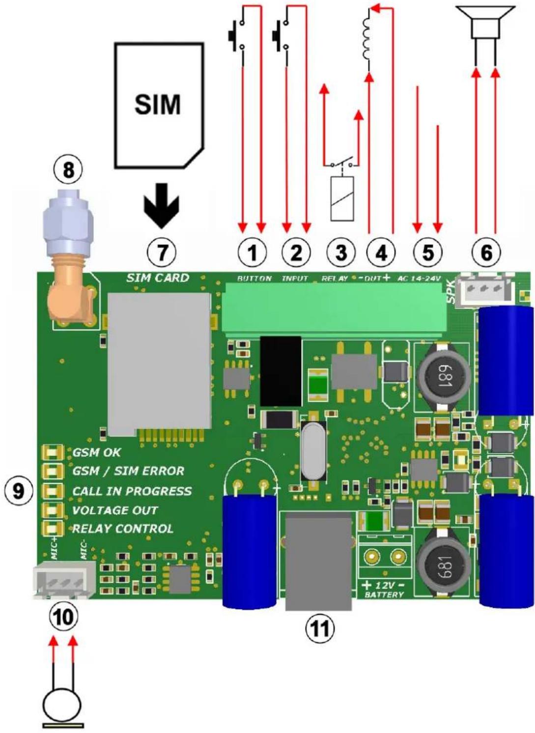
text_image
SIM 8 ↓ 7 ① ② ③ ④ ⑤ ⑥ SIM CARD BUTTON INPUT RELAY -OUT+ AC 14-24V SPK GSM OK GSM / SIM ERROR CALL IN PROGRESS VOLTAGE OUT RELAY CONTROL MIC- ⑨ ⑩ ⑪ + 12V - BATTERY 10 11- Call button input
- Local input for voltage output control
- Voltage output 12V DC/1A
- Supply voltage input 14-24V AC/DC
- Speaker output
- SIM card socket
- GSM antenna connector (SMA type)
- Status indicator LED's
- Microphone input
-
USB connector (only for maintenance)
-
Relay output - normally open contact (max. 24V DC/1A)
9 Surface mounting
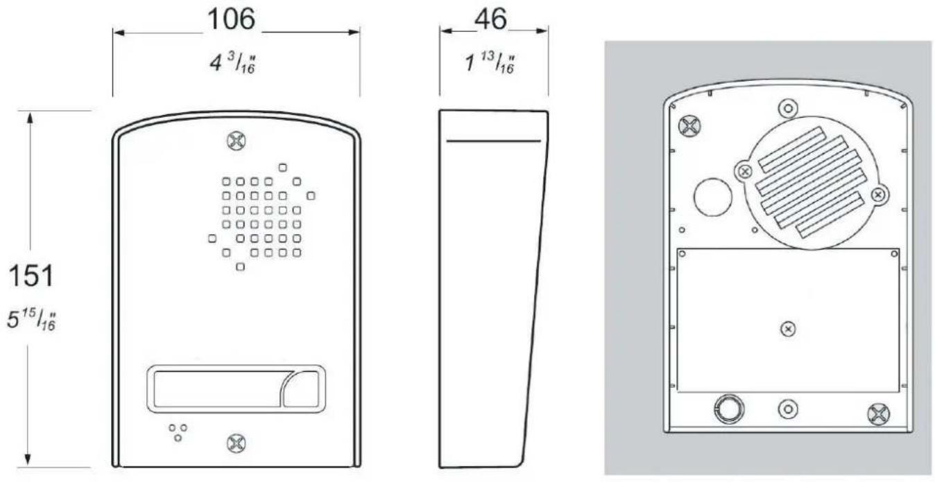
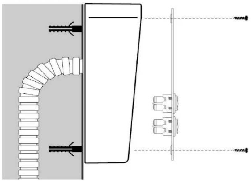
natural_image
Technical diagram showing a pipe connection and wall-mounted components with screw fasteners (no text or labels)10 Technical specification
• Supply voltage:
12-24V
AC/DC
• Nominal consumption: 100mA
• Maximum consumption: 400mA @ 12VDC, 200mA @ 24VDC
• Max. load of the relay output: max. 1A @ 24V DC
• Voltage output / max. load: 12V DC / max. 1A
- Operating temperature: -20^ - +70^
• Transmission frequency: GSM 900/1800 MHz (GSM 2G network)
- Contents of package: AS1-GSM unit, GSM antenna, security screws
• Warranty: 1 year