UVS-ABL1300 - Security Camera Geovision - Free user manual and instructions
Find the device manual for free UVS-ABL1300 Geovision in PDF.


User questions about UVS-ABL1300 Geovision
0 question about this device. Answer the ones you know or ask your own.
Ask a new question about this device
Download the instructions for your Security Camera in PDF format for free! Find your manual UVS-ABL1300 - Geovision and take your electronic device back in hand. On this page are published all the documents necessary for the use of your device. UVS-ABL1300 by Geovision.
USER MANUAL UVS-ABL1300 Geovision
natural_image
Exterior view of three USAVision security cameras with visible lens and camera modules (no text or symbols on the devices themselves)
USAVisionsys
© 2017 USAVision, sys. All rights reserved.
Under the copyright laws, this manual may not be copied, in whole or in part, without the written consent of USAVision.
Every effort has been made to ensure that the information in this manual is accurate. USAVision, sys. makes no expressed or implied warranty of any kind and assumes no responsibility for errors or omissions. No liability is assumed for incidental or consequential damages arising from the use of the information or products contained herein. Features and specifications are subject to change without notice.
Note: No memory card slot or local storage function for Argentina.
USA Vision Systems Inc.
9235 Research Drive,
Irvine, CA 92618, USA
Tel: +1-949-583-1519
Fax: +1-949-583-1522
http://www.usavisionsys.com
Trademarks used in this manual: USAVision, the USAVision logo and UVS series products are trademarks of USAVision, sys. Windows is the registered trademarks of Microsoft Corporation.
May 2017
Preface
This Manual is designed for the following models and firmware versions:
| Model Model Number Firmware Version | |
| Eyeball Dome ABD1300 | |
| Bullet IP Camera ABL1300 | |
| Mini Fixed Rugged IP Dome ADR1300 |
Contents
Naming Definition......iv
Note for Connecting to GV-VMS / DVR / NVR ......v
Note for Recording ......vi
Note for Installing Camera Outdoor ......vii
Chapter 1 Introduction ......1
1.1 Key Features....2
1.2 Packing List 4
1.3 Optional Accessories 5
Chapter 2 Accessing the Camera....6
2.1 Installing on a Network....6
2.1.1 Checking the Dynamic IP Address....7
2.1.2 Assigning an IP Address.... 9
2.2 Accessing Live View....11
2.2.1 The Live View Window 12
Chapter 3 Administrator Mode ......15
3.1 Common....17
3.1.1 Basic Info....17
3.1.2 Local Settings ....18
3.2 Network 20
3.2.1 Network 20
3.2.2 DNS....22
3.2.3 Port....23
3.2.4 FTP 25
3.2.5 E-mail 27
3.3 Video 28
3.3.1 Video 28
3.3.2 Snapshot 30
3.3.3 Media Stream 31
3.4 Image 33
Chapter 4 Recording and Playback ....52
4.1 Recording 52
4.2 Playback from the Memory Card....53
4.2.1 Recording Download 55
Chapter 5 Advanced Applications ....56
5.1 Upgrading System Firmware....56
5.1.1 Using the Web Interface ....57
5.1.2 Using the GV-IP Device Utility ....58
5.2 Restoring to Factory Default Settings....60
5.2.1 Using the Web Interface 60
5.2.2 Directly on the Camera 61
Chapter 6 DVR Configurations ......62
6.1 Setting Up IP Cameras on GV-System 63
6.1.1 Customizing the Basic Settings on GV-System....65
6.2 Setting Up IP Cameras on GV-VMS 66
Appendix 68
A. RTSP Protocol Support....68
B. Optional Installation for ABD1300 69
C. Optional Installation for ADR1300....78
D. Optional Installation for ABL1300....83
E. Waterproofing the Cable 88
Naming Definition
| GV-System | GeoVision Analog and Digital Video Recording Software. The GV-System also refers to Multicam System, GV-NVR System, GV-DVR System and GV-Hybrid DVR System at the same time |
| GV-VMS | GeoVision Video Management System for IP cameras. |
Note for Connecting to GV-VMS / DVR / NVR
The Eyeball Dome, Bullet IP Camera and Mini Fixed Rugged Dome are designed to work with and record on GV-VMS / DVR / NVR, a video management system. Once the cameras are connected to the GV-VMS / DVR / NVR, the resolution set on the GV-VMS / DVR / NVR will override the resolution set on the cameras' Web interface. You can only change the resolution settings through the Web interface when the connection to the GV-VMS / DVR / NVR is interrupted.
Note for Recording
Mind the following when using a memory card for recording:
- Recorded data on the memory card can be damaged or lost if the data are accessed while the camera is under physical shock, power interruption, memory card detachment or when the memory card reaches the end of its lifespan. No guarantee is provided for such causes.
- The stored data can be lost if the memory card is not accessed for a long period of time. Back up your data periodically if you seldom access the memory card.
- Memory cards are expendable and their durability varies according to the conditions of the installed site and how they are used. Back up your data regularly and replace the memory card annually.
- To avoid power outage, it is highly suggested to apply a battery backup (UPS).
- For better performance, it is highly suggested to use Micro SD card of MLC NAND flash, Class 10.
- Replace the memory card when its read/write speed is lower than 6 MB/s or when the memory card is frequently undetected by the camera.
Note for Installing Camera Outdoor
When installing the camera outdoor, be sure that:
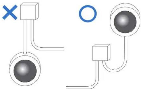
- The camera is set up above the junction box to prevent water from entering the camera along the cables.
natural_image
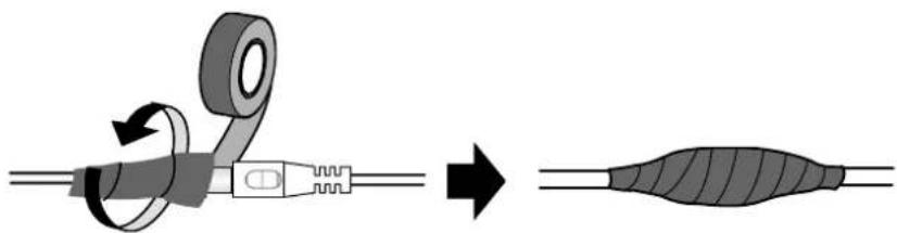
Diagram showing two connected components with a cross mark and a circle, no text or symbols present- Any power, audio and I/O cables are waterproofed using waterproof silicon rubber or the like.
natural_image
Diagram showing a cable being twisted with tape, resulting in a striped cable (no text or symbols present)- The screws are tightened and the cover is in place after opening the camera cover.
Chapter 1 Introduction
For ABD1300
The Eyeball Dome is an outdoor, network, camera equipped with an automatic IR-cut filter and an IR LED for day and night surveillance. The camera adheres to IP66 standards.
For ABL1300
The Bullet Camera is an outdoor, network camera equipped with an automatic IR-cut filter and 2 IR LEDs for day and night surveillance. The camera adheres to IP66 standards. The Bullet Camera offers an entry-level surveillance solution with all the essential features at excellent image quality.
For ADR1300
The Mini Fixed Rugged Dome is an outdoor, fixed, network camera equipped with an automatic IR-cut filter and 30 IR LEDs for day and night surveillance. The camera adheres to IP66 and IK10 standards.
1.1 Key Features
For ABD1300
• 1/3" progressive scan low lux CMOS sensor
- Min. illumination at 0.06 lux (B/W and color)
- Triple streams from H.264 and MJPEG
- Up to 30 fps at 1280 x 960
- Intelligent IR
• IR distance up to 30 m (98.4 ft)
• Day and night function (with removable IR-cut filter)
• 3-axis mechanism (pan / tilt / rotate)
- Ingress protection (IP66)
- Wide temperature tolerance (-35°C \~ 60°C / -31°F \~ 140°F)
• DC 12V / PoE (IEEE 802.3af)
- Wide Dynamic Range (WDR)
- Defog
- 3D noise reduction
- Motion detection
- Text overlay
- Privacy mask
• ONVIF (Profile S) conformant
For ABL1300
• 1/3" progressive scan low lux CMOS sensor
- Min. illumination at 0.06 lux (B/W and color)
- Triple streams from H.264 and MJPEG
- Up to 30 fps at 1280 x 960
- Intelligent IR
• IR distance up to 30 m (98.4 ft)
• Day and night function (with removable IR-cut filter)
• Ingress protection (IP66)
- Wide temperature tolerance (-35°C \~ 60°C / -31°F \~ 140°F)
• DC 12V / PoE (IEEE 802.3af) - Wide Dynamic Range (WDR)
- Defog
- 3D noise reduction
- Motion detection
- Text overlay
- Privacy mask
• ONVIF (Profile S) conformant
For ADR1300
• 1/3" progressive scan low lux CMOS sensor
- Min. illumination at 0.02 lux (B/W and color)
- Triple streams from H.264 and MJPEG
- Up to 30 fps at 1280 x 960
- Intelligent IR
• IR distance up to 30 m (98.4 ft)
• Day and night function (with removable IR-cut filter)
• 3-axis mechanism (pan / tilt / rotate)
- Ingress protection (IP66)
• Vandal resistance (IK10)
- Wide temperature tolerance (-35°C \~ 60°C / -31°F \~ 140°F)
• DC 12V / PoE (IEEE 802.3af)
- Wide Dynamic Range (WDR)
- Defog
- 3D noise reduction
- Motion detection
- Text overlay
- Privacy mask
• ONVIF (Profile S) conformant
• Built-in micro SD card slot (SD/SDHC/SDXC/UHS-I, Class 10) for local storage
1.2 Packing List
For ABD1300
- Eyeball Dome
• Waterproof Rubber Set - Screw x 2
- Screw Anchor x 2
- Drill Template Paster
- Software Download Guide
- Warranty Card
For ABL1300
- Bullet Camera
• Waterproof Rubber Set - Screw x 4
- Screw Anchor x 4
- Drill Template Paster
- Software Download Guide
- Warranty Card
For ADR1300
• Mini Fixed Rugged IP Dome
• Waterproof Rubber Set
- Screw x 3
- Screw Anchor x 3
- Drill Template Paster
- Torx Wench
- Software Download Guide
- Warranty Card
1.3 Optional Accessories
Optional accessories can expand the capabilities and versatility of your cameras. Contact your dealer for more information.
| Model Number Name | Details | |
| GV-Mount211 | Wall Box Mount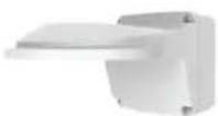 | Dimensions: 233 x 126 x 126 mm (9.2" x 5" x 5")Weight: 0.92 kg (2.0 lb)Only ABD1300 and ADR1300 support this accessory. |
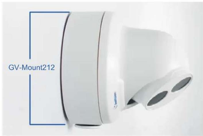
| GV-Mount212 | Wall Box Mount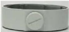 | Dimensions: Φ126 x 36mm (5.0"x1.4")Weight: 0.18 kg (0.4 lb) |
GV-Mount502 Wall Mount Bracket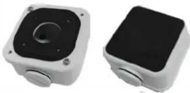 | Dimensions: 93 x 93 x 39 mm (3.66" x 3.66" x 1.53")Weight: 0.235kg (0.52 lb)Only ABL1300 supports this accessory. | |
| GV-PA191 | Power over Ethernet (PoE) Adapter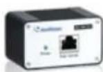 | The GV-PA191 is a Power over Ethernet (PoE) adapter designed to provide power to the IP device through a single Ethernet cable. |
| GV-POE Switch | The GV-POE Switch is designed to provide power along with network connection for IP devices. The GV-POE Switch is available in various models with different numbers and types of ports. | |
| Power Adapter | Contact your sales representative for the countries and areas supported. | |
Chapter 2 Accessing the Camera
Once installed, the camera is accessible on a network. Follow these steps to configure the network settings and access your surveillance images.
2.1 Installing on a Network
These instructions describe the basic connections to install the camera on the network.
- Using a standard network cable, connect the camera to your network.
-
Connect to power using one of the methods:
-
Using the optional power adapter to connect to power.
-
Using the Power over Ethernet (PoE) function. The power will be provided over the network cable.
-
You can now access the Web interface of the camera.
-
If the camera is installed in a LAN with the DHCP server, use GV-IP Device Utility to look up the camera's dynamic IP address. See 2.1.1 Checking the Dynamic IP Address.
- If the camera is installed in a LAN without the DHCP server, the default IP address 192.168.0.10 will be applied. To assign a different static IP address, see 2.1.2 Assigning an IP Address.
Note: You must set your browser to allow ActiveX Controls and perform a one-time installation of the ActiveX component onto your computer at your first login.
2.1.1 Checking the Dynamic IP Address
Follow the steps below to look up the IP address and access the Web interface.
- Download and install the GV-IP Device Utility program from http://www.geovision.com.tw/english/5_8.asp
Note: The PC installed with GV-IP Device Utility must be under the same LAN with the camera you wish to configure.
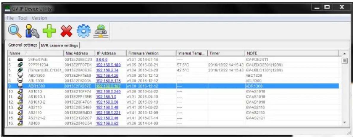
- On the GV-IP Utility window, click the button to search for the IP devices connected in the same LAN. Click the Name or Mac Address column to sort.
text_image
GV IP Device Utility File Tool Version General settings | NVR camera settings | Name / Mac Address IP Address Firmware Version Internal Temp... Timer NOTE 4 24Port PcE 0013E208C23 0.0.0 v1.01 2014-07-16 --- GYPOE2411 5 ?????1234 0013E2FF07D1 192.196.6.180 v1.05 2015-08-21 57.5°C 2016/12/22 14:15:43 GVJUBXC2301(128M) 6 [Taiwan]UBLC1301_0013E20A0B3E 192.196.2.34 v1.04 2016-03-28 42.5°C 2016/12/22 14:15:43 GVJUBLC1301(128M) 7 ABD1300 0013E2FA1E58 192.198.4.26 v1.00 2016-12-12 --- ABD1300 8 ABL1300 0013E2FA209A 192.196.6.175 v1.00 2016-12-12 --- ABL1300 9 ADR1300 0013E2FA207E 192.196.6.197 v1.09 2015-12-12 --- ADR1300 10 AS1010 0013E210FF74 192.198.6.240 v1.20 2015-04-22 --- GVAS1010 11 AS1013-1 0013E2FF135B 192.198.6.3 v1.31 2015-09-19 --- GVAS1010 12 AS1010-2 0013E2OF47C1 192.198.6.58 v1.31 2015-09-19 --- GVAS1010 13 AS2110 0013E2OF5468 192.198.6.48 v1.41 2015-08-22 --- GVAS2110 14 AS2110 0013E2OF54D3 192.198.6.5.221 v1.41 2015-12-09 --- GVAS2110 15 AS2121-2 0013E2I28ZC7 192.198.6.46 v1.41 2016-07-14 --- GVAS2121 16 AS400 0013E2O46D54 192.198.6.52 v1.06 2014-04-09Figure 2-1
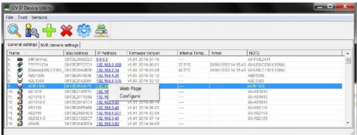
- Find the camera with its Mac Address, click on its IP address and select Web Page.
text_image
GV IP Device Utility File Tool Version General settings | NVR camera settings Name / Mac Address IP Address Firmware Version Internal Temp... Timer NOTE 4. 24Port PoE 0013E2098C23 0.0.0 v1.01 2014-07-16 — GVPOE2411 5. ????1234 0013E2FF07D1 192.168.6.120 v1.05 2016-08-21 57.5°C 2016/12/22 14:15:43 GVUBXC2301(128M) 6. [Taiwan]JUBLC1301_0013E20A0B3E 192.168.2.34 v1.04 2016-03-28 42.5°C 2016/12/22 14:15:43 GVJUBLC1301(128M) 7. AED1300 0013E2FA1E58 192.168.4.25 v1.00 2016-12-12 — AED1300 8. AGL1300 0013E2FA208A 192.169.5.175 v1.00 2016-12-12 — AGL1300 9. ACR1300 0013E2FA267E 192.16 Web Page — ACR1300 10. AS1010 0013E210FF74 192.16 Configure — GVAS1010 11. AS1010-1 0013E2FF135B 192.16 — — GVAS1010 12. AS1010-2 0013E20F47C1 192.168.0.66 v1.31 2016-09-19 — GVAS1010 13. AS2110 0013E20E5458 192.168.0.48 v1.41 2016-08-22 — GVAS2110 14. AS2110 0013E20E54D3 192.168.5.221 v1.41 2016-12-09 — GVAS2110 15. AS212-2 0013E2I29ZC7 192.169.0.45 v1.41 2016-07-14 — GVAS212I 16. AS400 0013E2O45D54 192.168.9.82 v1.05 2014-04-09 —Figure 2-2
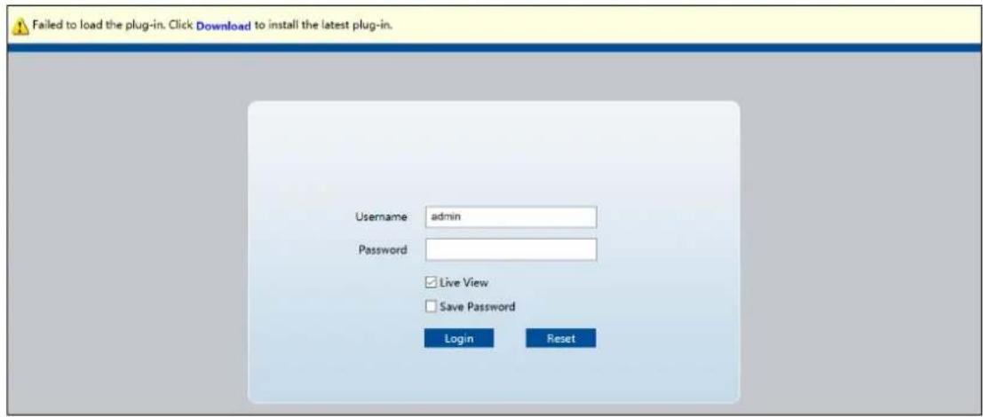
4. The login page appears.
text_image
Failed to load the plug-in. Click Download to install the latest plug-in. Username admin Password Live View Save Password Login ResetFigure 2-3
- For the first time accessing the Web interface, download and install the plug-in.
- Type the default ID and password admin and click Login to login.
2.1.2 Assigning an IP Address
To assign a new static IP address, log in the Web interface to access the network setting page.
Note: If your router does not support DHCP, the default IP address will be 192.168.0.10. In this case, it is strongly suggested that you modify the IP address to avoid the IP address conflict with other GV-IP devices on the same LAN.
- Open your web browser, and type the default IP address http://192.168.0.10. A dialog box appears.
- Type the default username and password admin. Click Login.
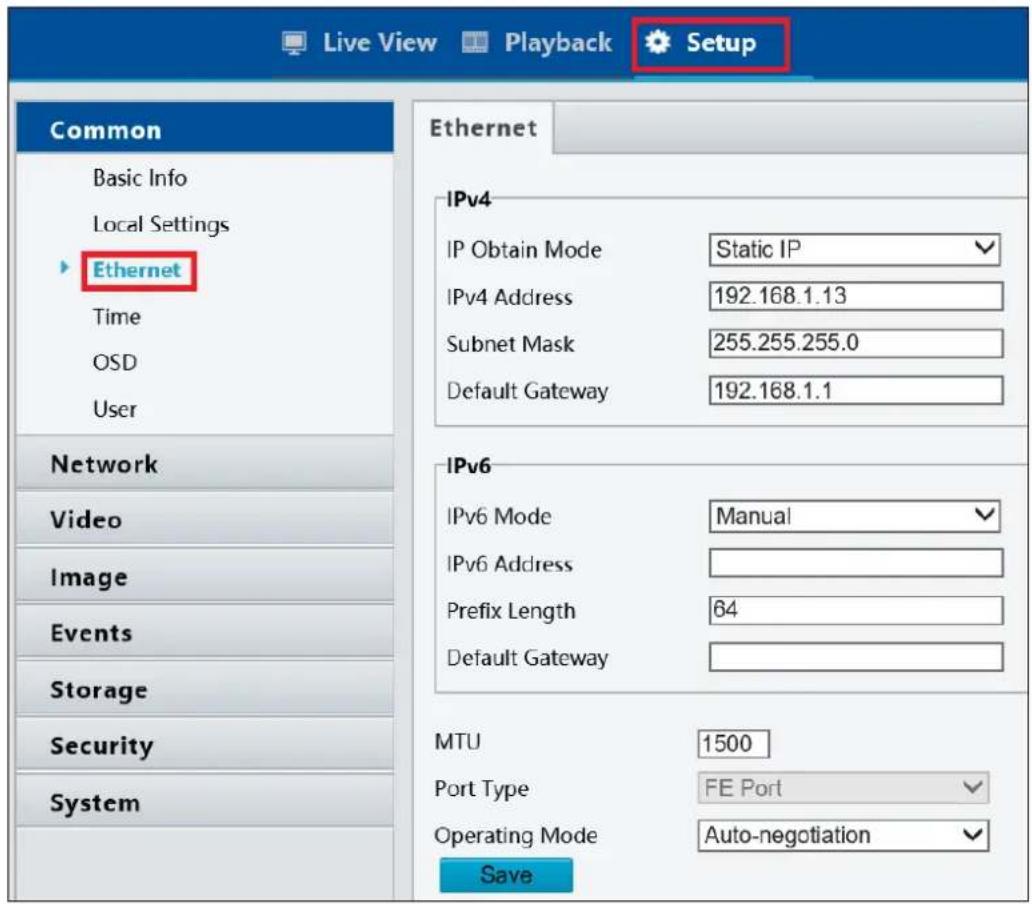
- Click Setup, select Common in the left menu and select Ethernet.
text_image
Live View Playback Setup Common Basic Info Local Settings Ethernet Time OSD User Network Video Image Events Storage Security System Ethernet IPv4 IP Obtain Mode Static IP IPv4 Address 192.168.1.13 Subnet Mask 255.255.255.0 Default Gateway 192.168.1.1 IPv6 IPv6 Mode Manual IPv6 Address Prefix Length 64 Default Gateway MTU 1500 Port Type FE Port Operating Mode Auto-negotiation SaveFigure 2-4
-
Select Static IP from the IP Obtain Mode drop-down list.
-
Enter the IP address, subnet mask, and default gateway address. Make sure that the IP address of the camera is unique in the network.
- Click Save.
Note: When you are changing the network segment through the Web interface or the GV-IP Device Utility (V8.7.0.0), it is required that you change the default gateway too to complete the IP address change successfully.
2.2 Accessing Live View
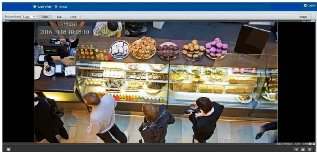
After logging in to your camera, you will see the Home page as shown below:
text_image
Live View Setup Proportional Scale Main Sub Third IPC 2016 10 05 10:05:10 Image Live Vid 2016 10 05 10:05:10Figure 2-5
2.2.1 The Live View Window
text_image
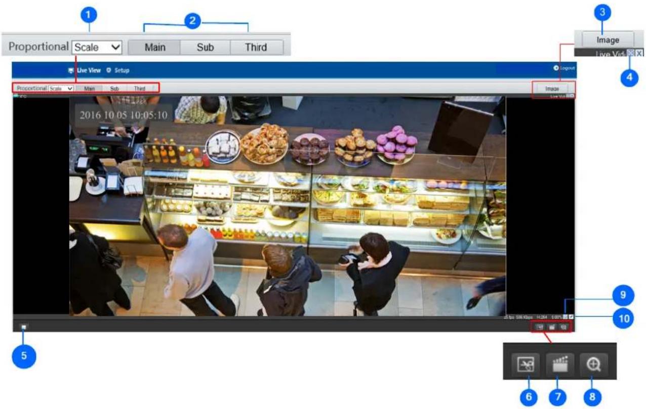
Proportional Scale Main Sub Third Live View Setup Proportional Scale Main Sub Third 2016 10 05 10:05:10 Image Live Vid Image Live Vid 5 9 10 6 7 8Figure 2-6
| No. | Name Function | |
| 1 | Proportional | Set the display ratio of the image.Scale: display images by 16:9.Stretch: display images by window size.Original: display images in its original size. |
| 2 | Live Stream | Select a live video stream: main stream, sub stream or third stream. |
| 3 | Image | Open the image setting page. – See 3.4.1 Image. |
| 4 | Full Screen Mode Display in full screen mode. | |
| 5 | Play/Stop Play or stop live video. | |
| 6 | Snapshot Take a snapshot of the current image displayed on the PC. | |
| 7 | Local Recording Start or stop local recording. | |
| 8 | Digital Zoom | Start or stop digital zoom. -- See 2.2.1.1 Digital Zoom. |
| 9 | Reset the packet loss rate to zero. |
| 10 | [4H50] Display packet loss rate and bit rate information in the bottom. |
| Note:1. The paths for saving snapshots and local recordings are set in System Configuration.2. The buttons (No. 9 and No. 10) will appear on the floating toolbar after you move the mouse cursor on a live view window.3. Click the button (No. 10) to display the bottom information. Click this button again, the bottom information is displayed if the mouse cursor is moved on a live view window or on the bottom information, and it hides automatically if the mouse cursor remains on a live view window for 3 seconds or leaves the window. | |
2.2.1.1 Digital Zoom
To use the digital zoom function, follow these steps:
- Click (No. 8, Figure 2-6) on the toolbar.
- Click and hold the mouse button, and then drag from the top down to specify an area.
- To restore the original image size, click in the enlarged area, or drag from the bottom up.
- To exit, click (No. 8, Figure 2-6) on the toolbar.
Chapter 3 Administrator Mode
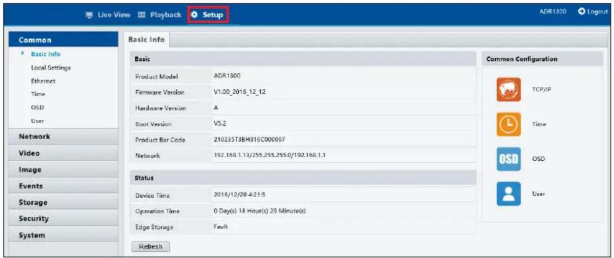
The Administrator can access and configure your camera through the network. Click Setup at the top of the Web interface to access the following seven configuration tabs: Common, Network, Video, Image, Events, Storage, Security and System.
text_image
Live View Playback Setup ADR1300 Logout Common Basic Info Basic Product Model ADR1300 Firmware Version V1.00_2016_12_12 Hardware Version A Boot Version V5.2 Product Bar Code 210235T3BH316C000007 Network 192.168.1.13/255.255.255.0/192.168.1.1 Status Device Time 2016/12/28 4:21:5 Operation Time 0 Day(s) 18 Hour(s) 29 Minute(s) Edge Storage Fault Refresh Common Configuration TCP/IP Time OSD UserFigure 3-1
List of Options
See the table below for the settings available on the Web interface. Find the topic of interest by referring to the section number prefixed to each option. The configuration tabs and settings may vary with available models.
| 3.1 Common | 3.1.1 Basic Info3.1.2 Local Settings |
| 3.2 Network | 3.2.1 Network3.2.2 DNS3.2.3 Port3.2.4 FTP3.2.5 E-mail |
| 3.3 Video | 3.3.1 Video3.3.2 Snapshot3.3.3 Media Stream |
| 3.4 Image | 3.4.1 Image3.4.2 OSD3.4.3 Privacy Mask |
| 3.5 Events 3.5.1 Motion Detection | |
| 3.6 Storage 3.6.1 Storage | |
| 3.7 Security | 3.7.1 User3.7.2 Network Security |
| 3.8 System | 3.8.1 Time3.8.2 Maintenance |
3.1 Common
Under the Common tab, the Administrator can find the general settings for the camera, as well as shortcuts to the following setting pages.
■ Ethernet: See 3.2.1 Network for details.
■ Time: See 3.8.1 Time for details.
■ OSD: See 3.4.2 OSD for details
■ User: See 3.7.1 User for details
3.1.1 Basic Info
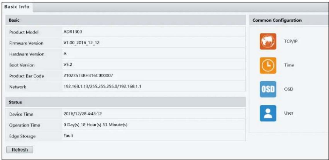
You can view the current status of your camera. Click Refresh for the latest status information. Under Common Configuration on the right, you can click on the icons to quickly access the configuration pages.
text_image
Basic Info Basic Product Model ADR1300 Firmware Version V1.00_2016_12_12 Hardware Version A Boot Version V5.2 Product Bar Code 21023ST3BH316C000007 Network 192.168.1.13/255.255.255.0/192.168.1.1 Status Device Time 2016/12/28 4:45:12 Operation Time 0 Day(s) 18 Hour(s) 53 Minute(s) Edge Storage Fault Refresh Common Configuration TCP/IP Time OSD OSD UserFigure 3-2
3.1.2 Local Settings
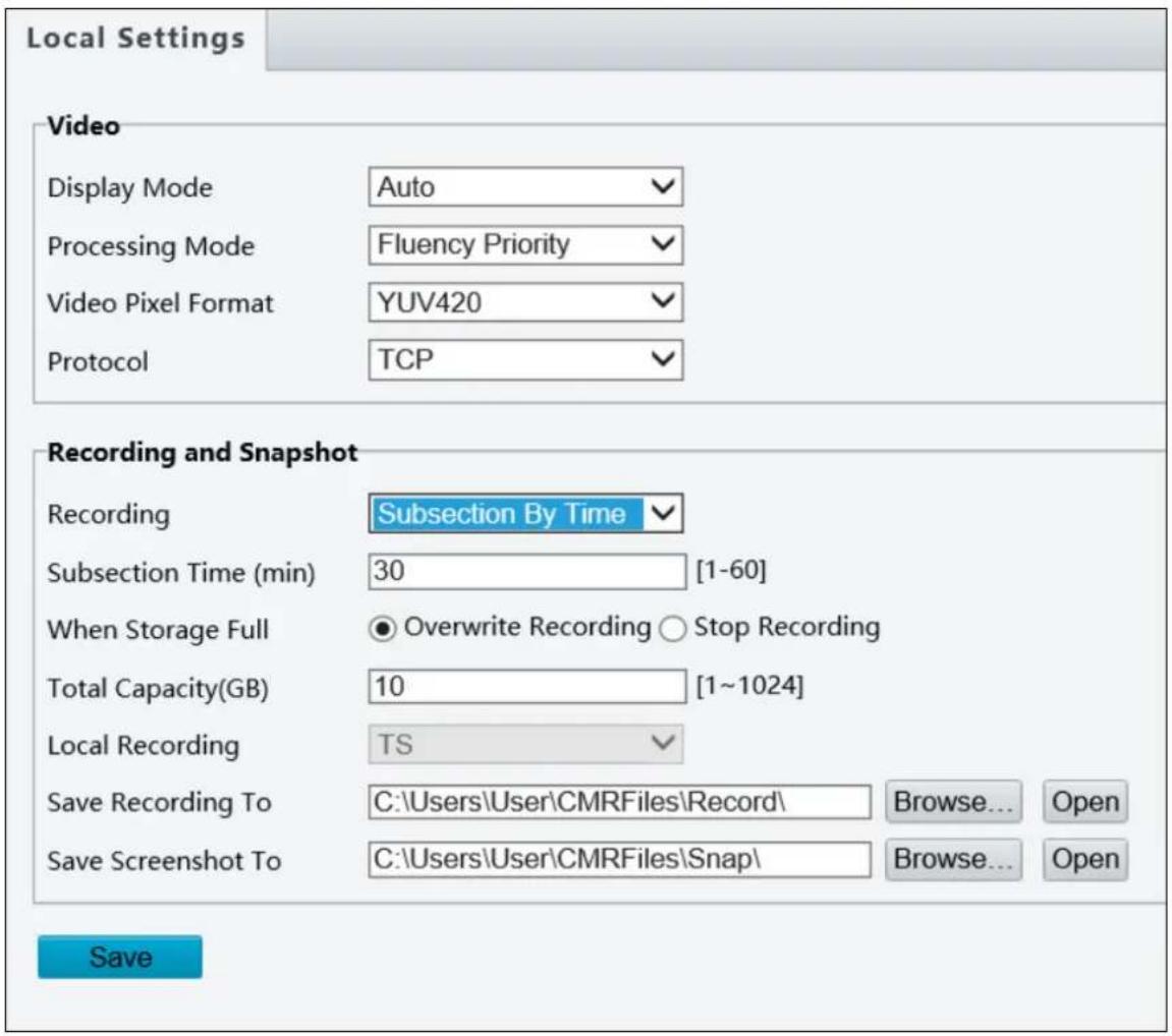
You can set local parameters for your PCs.
text_image
Local Settings Video Display Mode Auto Processing Mode Fluency Priority Video Pixel Format YUV420 Protocol TCP Recording and Snapshot Recording Subsection By Time Subsection Time (min) 30 [1-60] When Storage Full Overwrite Recording Stop Recording Total Capacity(GB) 10 [1~1024] Local Recording TS Save Recording To C:\Users\User\CMRFiles\Record\ Browse... Open Save Screenshot To C:\Users\User\CMRFiles\Snap\ Browse... Open SaveFigure 3-3
[Video Param]
■ Processing Mode
Real Time Prior: Select this if the network is in good condition.
- Fluent Prior: Select this if you want short time lag for live video.
- Ultra-Low Latency: Select this if you want the minimum time lag for live video.
■ Video Pixel Format: Select the video format for images at your local computer. It is recommended to choose YUV420 if the graphics card of your PC supports it.
■ Protocol: Select the protocol used to transmit media streams to be decoded by the PC.
[Recording and Snapshot]
■ Recording
Subsection By Time: Set a maximum time length of each recording file. If you select 5 minutes, a 30-minute event will be chopped into six 5-minute event files.
Subsection by Size: Set a maximum size limit of each recording file.
■ When Storage Full
- Overwrite Recording: When the assigned storage space on the computer is used up, the camera deletes the existing recording files to make room for the new recording file.
- Stop Recording: When the assigned storage space on the computer is full, recording stops automatically.
■ Total Capacity: Set a capacity limit to the assigned storage space on the computer.
■ Save Recording To: Click Browse to set a folder to store the recorded videos at your local computer.
■ Save Screenshot To: Click Browse to set a folder to store the captured snapshots at your local computer.
3.2 Network
The network section allows you to configure the network settings, modify ports, configure FTP server, and set up e-mail for notification.
3.2.1 Network
text_image
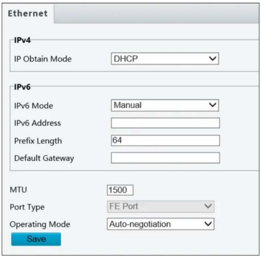
Ethernet IPv4 IP Obtain Mode DHCP IPv6 IPv6 Mode Manual IPv6 Address Prefix Length 64 Default Gateway MTU 1500 Port Type FE Port Operating Mode Auto-negotiation SaveFigure 3-4
■ IPv4: Select Static IP or DHCP according to your network environment.
Static IP address: Assign a static IP or fixed IP to the camera. Type the camera's IP address, Subnet Mask, Router/Gateway, Preferred DNS server and Alternate DNS server.
| Parameters Default | |
| IP address 192.168.0.10 | |
| Subnet Mask 255.255.255.0 | |
| Router/Gateway | 192.168.0.1 |
| Preferred DNS server 8.8.8.8 | |
| Alternate DNS server 8.8.4.4 | |
- DHCP: The network environment has a DHCP server which will automatically assign a dynamic IP address to the camera. You can look up the current IP address using GV-IP Device Utility.
- IPv6: Type the camera's IPv6 Address and Default Gateway. Optionally change the Prefix Length according to your network settings.
Note: To enable IPv6, make sure your network environment and hardware specifications support IPv6.
■ Operating Mode: Select a mode to control the bandwidth.
3.2.2 DNS
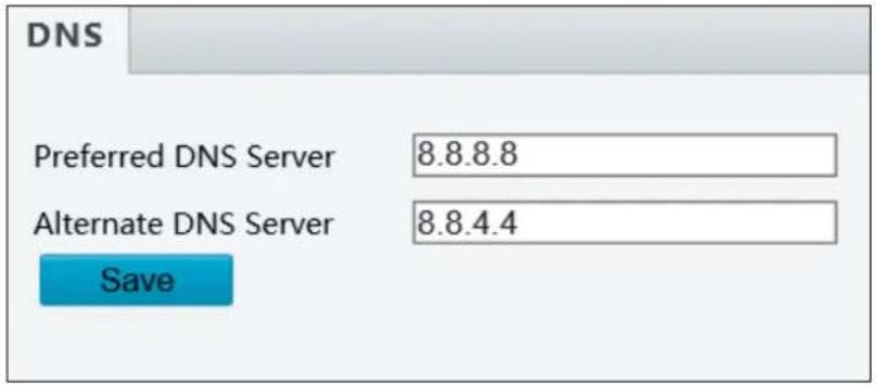
The configuration of DNS (Domain Name System) server is applicable when the device is accessed by domain name. For details, see IPv4, 3.2.1 Network.
text_image
DNS Preferred DNS Server 8.8.8.8 Alternate DNS Server 8.8.4.4 SaveFigure 3-5
3.2.3 Port
Port
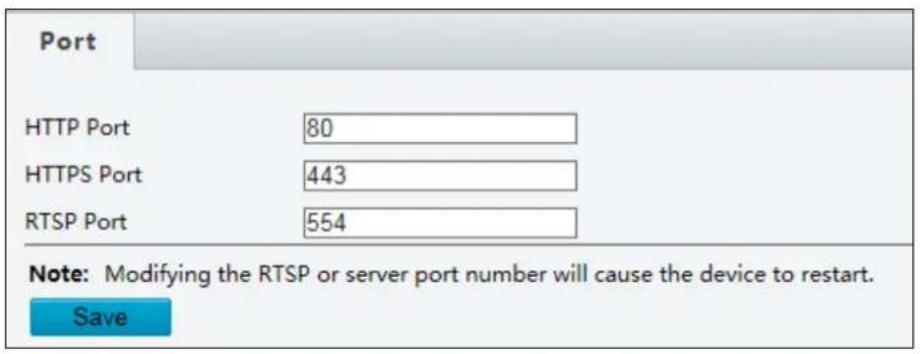
You can modify the default HTTP port, HTTPS port and RTSP port if necessary.
text_image
Port HTTP Port 80 HTTPS Port 443 RTSP Port 554 Note: Modifying the RTSP or server port number will cause the device to restart. SaveFigure 3-6
Port Mapping
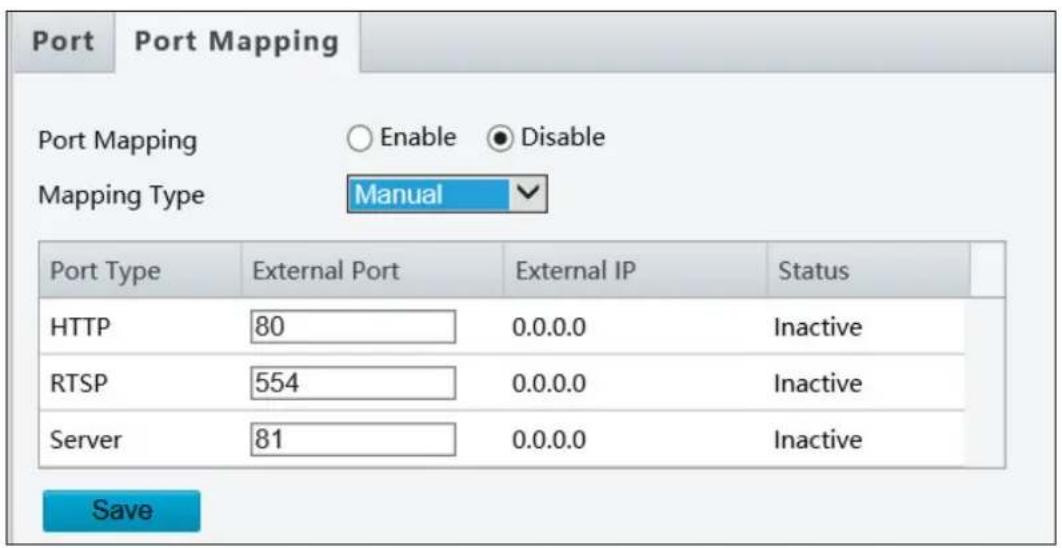
This function can automatically forward and open certain ports on your router, allowing connection to your camera from the Internet.
text_image
Port Port Mapping Port Mapping ○ Enable ● Disable Mapping Type Manual Port Type External Port External IP Status HTTP 80 0.0.0.0 Inactive RTSP 554 0.0.0.0 Inactive Server 81 0.0.0.0 Inactive SaveFigure 3-7
- Enable Port Mapping, and select Mapping Type.
-
If you select Automatic, external ports will be automatically configured by the router.
-
If you select Manual, configure external ports. External IP is applied to the camera automatically. If the configured port is occupied, the Status will show inactive.
- Click Save.
Note: For this function, your router needs to support port forwarding.
3.2.4 FTP
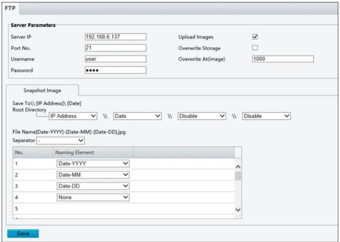
After the configuration of FTP, you will be able to upload snapshots from the camera to the specified FTP server.
text_image
FTP Server Parameters Server IP 192.168.6.137 Upload Images ✓ Port No. 21 Overwrite Storage □ Username user Overwrite At(image) 1000 Password ••••• Snapshot Image Save To\ [IP Address]\ [Date] Root Directory IP Address ✓ \ Date ✓ \ Disable ✓ \ Disable ✓ File Name[Date-YYYY]-[Date-MM]-[Date-DD].jpg Separator - ✓ No. Naming Element 1 Date-YYYY ✓ 2 Date-MM ✓ 3 Date-DD ✓ 4 None ✓ 5 ✓ SaveFigure 3-8
- Type the Server IP address.
- Change the Port No. of the FTP server if needed.
- Type the Username and Password of the upload account.
- Enable Upload Images.
- There are two separate snapshot storage paths.
A. Selecting Overwrite Storage
(1) Select Overwrite Storage to overwrite the oldest images when the storage is full. You can set the number of images in Overwrite At (Image). When the defined image threshold is reached, the oldest images will be overwritten.
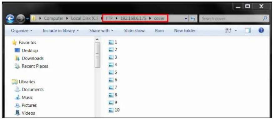
(2) The snapshots will be stored in the "cover" folder as shown below. If the number of images in Overwrite At (Image) is 10 for example, the file name of the snapshots will be listed from 1 to 10.
text_image
Computer > Local Disk (C:) FTP 192.168.6.175 cover Organize Include in library Share with Slide show Burn New folder Favorites Desktop Downloads Recent Places Libraries Documents Music Pictures Videos 1 2 3 4 5 6 7 8 9 10Figure 3-9
B. Unselecting Overwrite Storage
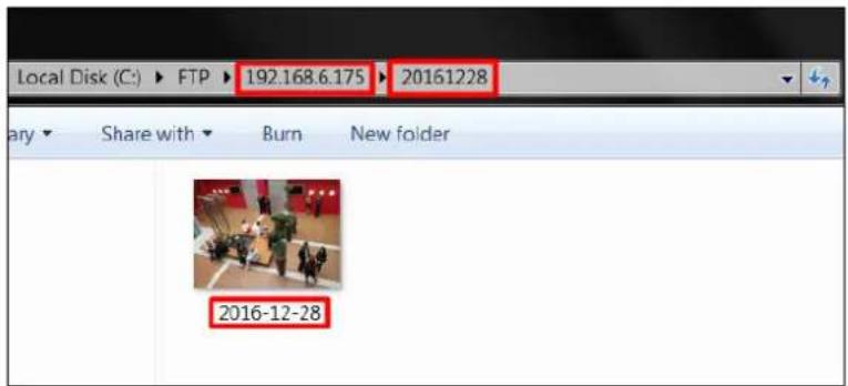
(1) Select items from the Save To Root Directory drop-down list to create the snapshot storage path; for example, IP Address \ Date.
(2) Select items from the Separator drop-down list and the Naming Element drop-down list to define the file name; for example, Date-YYYY-Date-MM-Date-DD.jpg.
(3) The snapshots will be stored in the folder you specified and with the file name you defined.
text_image
Local Disk (C:) ▶ FTP ▶ 192.168.6.175 ▶ 20161228 Share with ▶ Burn New folder 2016-12-28Figure 3-10
6. Click Save.
Note:
- To upload snapshots, make sure to enable Snapshot in Video. For more detailed instructions, refer to 3.3.2 Snapshot.
- If Overwrite Storage is not selected and the storage is full, snapshots can no longer be taken.
- The "Custom" option in Save To Root Directory, Separator, and Naming Element drop-down list is not functional.
3.2.5 E-mail
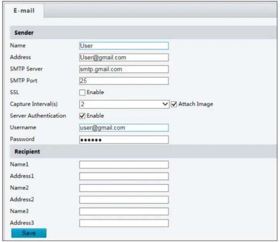
After the configuration of E-mail, you will be able to send messages to the specified E-mail address when alarms are triggered.
text_image
E-mail Sender Name User Address User@gmail.com SMTP Server smtp.gmail.com SMTP Port 25 SSL Enable Capture Interval(s) 2 Attach Image Server Authentication Enable Username user@gmail.com Password ••••••• Recipient Name1 Address1 Name2 Address2 Name3 Address3 SaveFigure 3-11
[Sender]
- Type the Name and Address of the sender.
- Type the SMTP Server.
- Type the SMTP Port number.
- To send the e-mail through SSL encryption, enable SSL.
- Enable Attach Image to include 3 instant snapshots as attachment in the e-mail according to the Capture Interval specified.
- If the SMTP Server needs authentication, enable Server Authentication and type a valid username and password to log in the SMTP server.
[Recipient] Type the name and e-mail address of the recipient.
3.3 Video
This section allows you to configure the three video streams.
3.3.1 Video
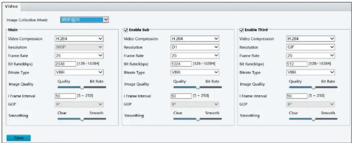
You can set video parameters that your camera supports. You may also enable the sub-stream and third stream as needed.
text_image
Video Image Collection Mode 060P@25 Main Video Compression H.264 Resolution 960P Frame Rate 25 Bit Rate(kbps) 2048 [128~16384] Bitrate Type VBR Image Quality Quality Bit Rate I Frame Interval 50 [5 ~ 250] GOP IP Smoothing Clear Smooth Enable Sub Video Compression H.264 Resolution D1 Frame Rate 25 Bit Rate(kbps) 1024 [128~16384] Bitrate Type VBR Image Quality Quality Bit Rate I Frame Interval 50 [5 ~ 250] GOP IP Smoothing Clear Smooth Enable Third Video Compression H.264 Resolution CIF Frame Rate 25 Bit Rate(kbps) 512 [128~16384] Bitrate Type VBR Image Quality Quality Bit Rate I Frame Interval 50 [5 ~ 250] GOP IP Smoothing Clear Smooth SaveFigure 3-12
■ Image Collection Mode: Sets the maximum resolution and frame rate.
The following options are available for the main, sub and third streams.
■ Video Compression: Set the codec type to H.264 or MJPEG.
■ Resolution: You may select the different resolutions for each stream.
■ Frame Rate: Select a frame rate for encoding images. The unit is frame per second.
Bit Rate:
- CBR: The camera transmits data at a constant data rate by varying the quality of the stream
- VBR: The quality of the video stream is kept as constant as possible at the cost of a varying bitrate.
■ Image Quality: When VBR is selected for the encoding mode, you can move the slider to adjust quality level for images. Moving the slider toward Bit Rate decreases the bit rate and may affect image quality. Moving the slider toward Quality increases the bit rate and improves image quality.
■ I F rame Interval: Set the number of frames between each I frame (key frame). This option is only available when H.264 is selected for codec.
■ Smoothing: Set the extent of smoothing. Choosing Clear means disabling Smoothing. Moving the slider toward Smooth increases the level of smoothing but will affect image quality.
3.3.2 Snapshot
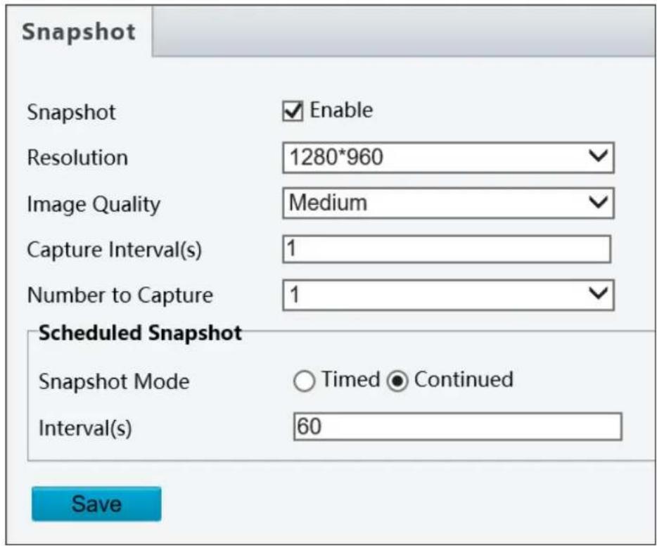
Using the Snapshot function, when an alarm is triggered, the camera will automatically upload the captured snapshots to the FTP server or send snapshots to the specified e-mail address.
text_image
Snapshot Snapshot Enable Resolution 1280*960 Image Quality Medium Capture Interval(s) 1 Number to Capture 1 Scheduled Snapshot Snapshot Mode Timed Continued Interval(s) 60 SaveFigure 3-13
- Enable Snapshot.
- Select Resolution.
- Choose the Image Quality.
- Choose the Number (of snapshot) to Capture upon alarm trigger.
- Select Timed Mode or Continued Mode to set up the Scheduled Snapshot.
- If you select Timed mode, click + to specify a time to take a snapshot.
- If you select Continued mode, type the interval in seconds to take a snapshot.
- Click Save.
Note: Capture Interval(s) is not functional.
3.3.3 Media Stream
Media Stream
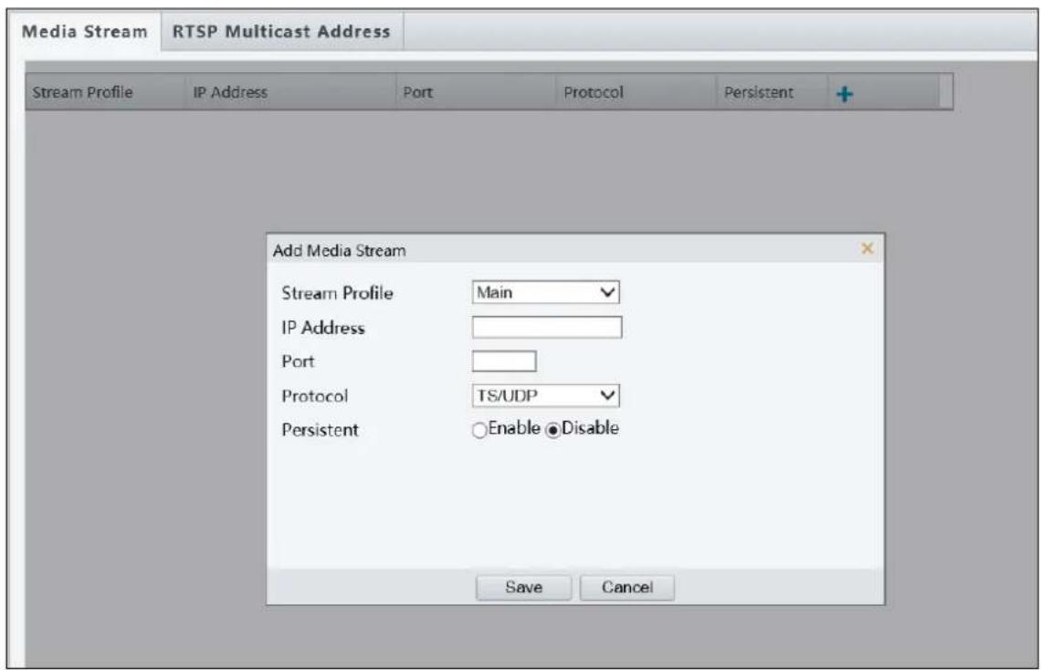
By configuring media stream, you can set the camera to transmit code streams by UDP or TCP protocol to a specified IP address and port number. The settings can be saved and take effects after the camera is restarted.
text_image
Media Stream RTSP Multicast Address Stream Profile IP Address Port Protocol Persistent Add Media Stream Stream Profile Main IP Address Port Protocol TS/UDP Persistent Enable ●Disable Save CancelFigure 3-14
- Click + and then select a type in the Stream Profile.
- Type the IP Address and Port number of the unicast or multicast group for the decoding device that receives video streams from the camera.
- If you want the device to establish the media stream that has been configured before automatically after the restart, select Enable for Persistent.
- To delete a stream, click 📄.
- Click Submit to complete the settings.
RTSP Multicast Address
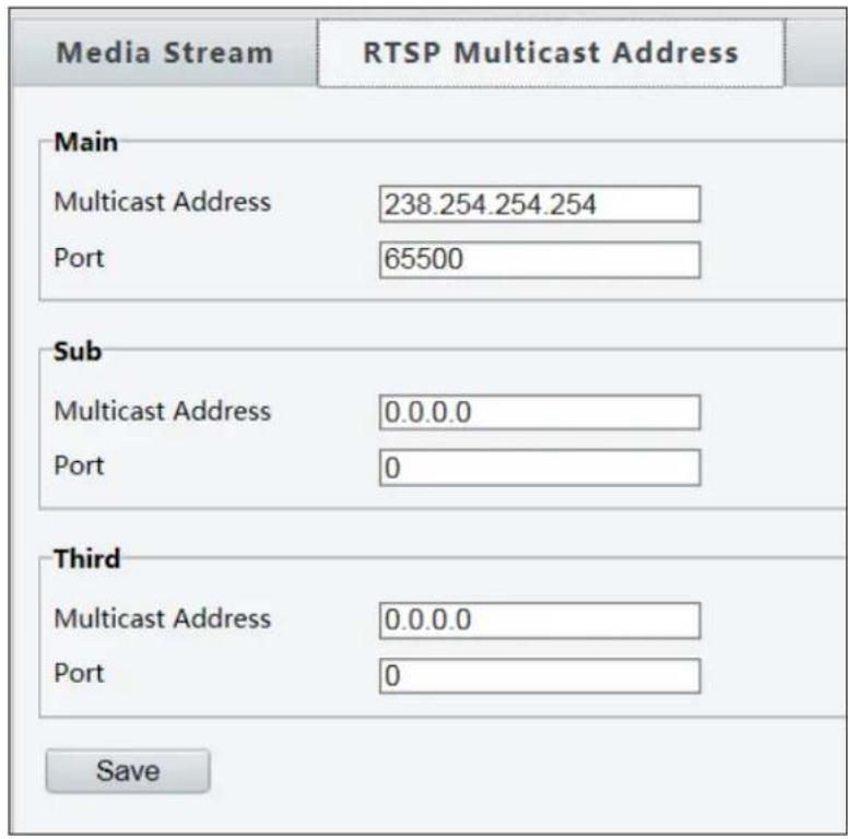
After an RTSP multicast address is configured, the third-party player can request the RTSP multicast media stream from the camera through the RTP protocol.
text_image
Media Stream RTSP Multicast Address Main Multicast Address 238.254.254.254 Port 65500 Sub Multicast Address 0.0.0.0 Port 0 Third Multicast Address 0.0.0.0 Port 0 SaveFigure 3-15
- Type the Multicast Address (224.0.0.0 to 239.255.255.255) and Port number (0 to 65535).
- Click Save.
3.4 Image
This section introduces the Image Settings, On-screen Display, and Privacy Mask.
3.4.1 Image
This page allows you to adjust image settings such as brightness, exposure, IR illumination and white balance.
text_image
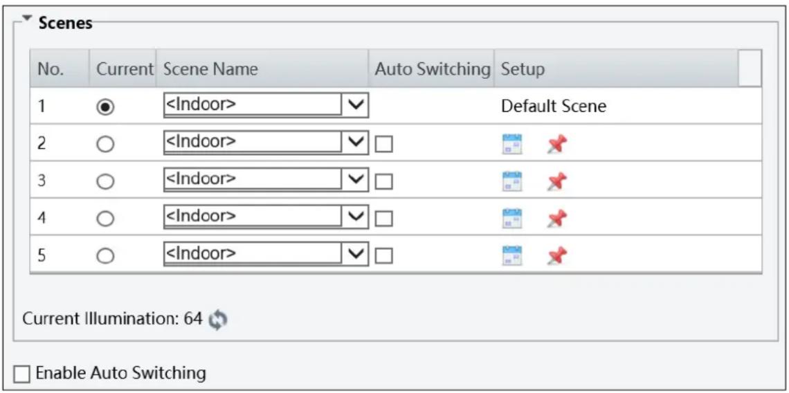
Scenes No. Current Scene Name Auto Switching Setup 1 ●Figure 3-16
[Scene]
■ Current: Indicates the scene that is being used.
■ Screen Name: When you select a scene, the corresponding image parameters are displayed. You can adjust image settings according to actual needs.
■ Auto Switching: Indicates whether to add a scene to the auto-switching list.
■ Setup:
- Click to set a schedule for illumination.
- Click ✪ to set a scene as the default scene.
■ Enable Auto Switching: Allow the camera to switch to the scene automatically when the condition for switching to a non-default scene is met.
![Geovision UVS-ABL1300 - [Scene] - 1](/content/2026/05/793858/images/b492378ee4636b3ce0a5a4de5d480598c1ba70411b22044fd27be74503699ea0.jpg)
bar
| Image Enhancement | Value | | ----------------------- | ----- | | Brightness | 128 | | Saturation | 128 | | Contrast | 50 | | Sharpness | 50 | | 2D Noise Reduction | 128 | | 3D Noise Reduction | 128 |Figure 3-17
[Image Enhancement]
■ Brightness: Adjust the degree of brightness of the image.
■ Saturation: Adjust the amount of a hue contained in a color.
■ Contrast: Set the degree of difference between the blackest pixel and the whitest pixel.
■ Sharpness: Adjust the sharpness of the image.
■ 2D / 3D Noise Reduction: Reduce the noise of the image.
■ Image Rotation: Change the rotation of the image.
![Geovision UVS-ABL1300 - [Image Enhancement] - 1](/content/2026/05/793858/images/1776976a22adb23a73da4b582ac47b467f1d7c59f883108475c3556672b8f153.jpg)
text_image
Exposure Exposure Mode Outdoor Shutter(s) 1/50 Gain 0 Slow Shutter ● Off ○ On Slowest Shutter 1/25 Compensation 0 Metering Control Center-Weighted Average Metering Day/Night Mode ● Automatic ○ Day ○ Night Day/Night Sensitivity Medium Day/Night Switching(s) 3 WDR Off WDR Level 5Figure 3-18
[Exposure]
■ Exposure Mode: Select the correct exposure mode to achieve the desired exposure effect. The default setting is Outdoor.
■ Shutter (s): The length of time that allows light to enter into the lens. You can set a shutter speed when Exposure Mode is set to Manual.
Note: If Slow Shutter is set to Off, the reciprocal of the shutter speed must be greater than the frame rate.
■ Gain: Control image signals so that the camera outputs standard video signals according to the light condition. You can set this parameter only when Exposure Mode is set to Manual.
■ Slow Shutter: Improve image brightness in low light conditions.
■ Slowest Shutter: Set the slowest shutter speed that the camera can use during exposure.
■ Compensat ion: Adjust the compensation value as required to achieve the desired effects. You can set this parameter only when Exposure Mode is not set to Manual.
■ Metering Control: Set the way the camera measures the intensity of light. You can only set this parameter when Exposure Mode is not set to Manual.
- Center-Weighted Average Metering: Measure light mainly in the central part of images.
- Evaluative Metering: Measure light in the customized area of images.
Day/Night Mode: Select Automatic for automatic switch between day mode and night mode depending on the amount of light detected. Select Night to produce high-quality black and white images using the existing light. Select Day to produce high-quality color images using the existing light.
■ Day/Night Sensitivity: Set the light threshold for switching between day mode and night mode. A higher sensitivity means that the camera is more sensitive to the change of light and becomes more easily to switch between day mode and night mode.
■ Day/Night Switching(s): Set the length of time before the camera switches between day mode and night mode after the conditions for switching are met.
■ WDR: Enable WDR to distinguish the bright and dark areas in the same image.
■ WDR Level: After enabling the WDR function, you can improve the image by adjusting the WDR level.
![Geovision UVS-ABL1300 - [Exposure] - 1](/content/2026/05/793858/images/88643b90920dd540a055698715fdace574090c9db141fec41b32e3fec7388636.jpg)
text_image
Smart Illumination Smart Illumination Enable Off Lighting Type Infrared Control Mode Overexposure Restrain Illumination Level 0Figure 3-19
[Smart Illumination]
■ Smart Illumination: Select Enable to adjust the IR illumination settings.
■ Control Mode:
- Global Mode: Adjust IR illumination and exposure to achieve balanced image effects. Some areas might be overexposed if you select this option. This option is recommended if monitored range and image brightness are your first priority.
- Overexposure Restrain: Adjust IR illumination and exposure to avoid regional overexposure. Some areas might be dark if you select this option. This option is recommended if clarity of the central part of the image and overexposure control are your first priority.
- Manual: Allow you to manually control the intensity of IR illumination.
■ Illumination Level: Set the intensity level of the IR light. The greater the value, the higher the intensity. 0 means that the IR light is turned off. When Control Mode is set to Manual, you can set the intensity level of the IR light.
![Geovision UVS-ABL1300 - [Smart Illumination] - 1](/content/2026/05/793858/images/49e69a7c478f3f6434d5ecb69b9a0cb62f488a2114d4931f4b76882244f04426.jpg)
text_image
White Balance White Balance Auto Red Offset 4 Blue Offset 14Figure 3-20
[White Balance]
■ White Balance: Adjust the red or blue offset of the image.
■ Auto: Adjust the red and blue offset automatically according to the light condition (the color tends to be blue).
■ Outdoor: It is recommended for the outdoor scenes with a wide range of the color temperature variation.
■ Fine tune: Allow you to adjust the red and blue offset manually.
■ Sodium Lamp: Adjust the red and blue offset automatically according to the light condition (the color tends to be red).
■ Locked: Lock the current color temperature settings without adjustment.
![Geovision UVS-ABL1300 - [White Balance] - 1](/content/2026/05/793858/images/e9952fd5cbc67e880190fc6f7a355dbe3348479c94f719f3a9a7ffeca47fdf51.jpg)
text_image
Advanced Defog Off Defog Intensity 1Figure 3-21
[Advanced]
■ Defog: Select ON to activate the slider for adjusting the defog intensity for images.
3.4.2 OSD
On Screen Display (OSD) is the text displayed on the screen with video images and may include time and other customized contents.
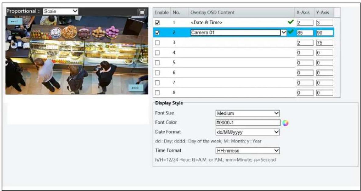
text_image
Proportional : Scale Enable No. Overlay OSD Content X-Axis Y-Axis ✓ 1Figure 3-22
- Enable a No. to select an area #, and then click Overlay OSD Content to select the content to display on screen.
- Adjust the position of the Area 1/2/3 boxes on the live view either by dragging directly or by specifying the coordinates under X-Axis / Y-Axis column.
- Under Display Style, customize the text style and date/time format.
After you have set the position and OSD content, the √ symbol appears in the Status column, which means that the OSD is set successfully.
3.4.3 Privacy Mask
On certain occasions, you may need to set a mask area to block out parts of the camera image to protect privacy, for example, the keyboard of an ATM machine. When PTZ changes its position or zooms, the Privacy Mask will be adjusted accordingly to protect the area all along.
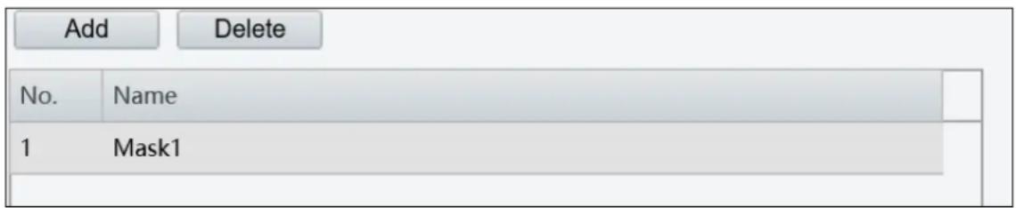
text_image
Add Delete No. Name 1 Mask1Figure 3-23
- Click Add to add a privacy mask.
- Click the box (with Mask displayed on it) to activate the mask.
- Drag the box to the intended position and adjust the size of the box. Alternatively, you can also use the mouse to draw a box on the area you want to mask.
- To delete a mask, click Delete
3.5 Events
You can set the camera to generate an alarm upon motion detection.
3.5.1 Motion Detection
Motion detection is used to generate an alarm whenever movement occurs in the specified area.
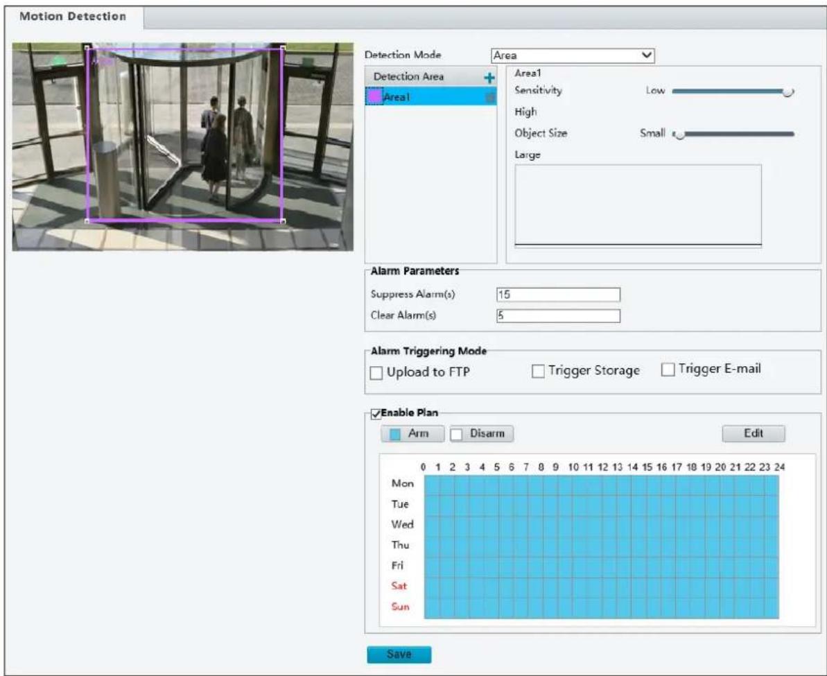
text_image
Motion Detection Detection Mode Area Detection Area + Area1 Area1 Sensitivity Low High Object Size Small Large Alarm Parameters Suppress Alarm(s) 15 Clear Alarm(s) 5 Alarm Triggering Mode Upload to FTP Trigger Storage Trigger E-mail Enable Plan Arm Disarm Edit Mon Tue Wed Thu Fri Sat Sun 0 1 2 3 4 5 6 7 8 9 10 11 12 13 14 15 16 17 18 19 20 21 22 23 24 SaveFigure 3-24
- In the Detection Area, click to add a new detection area.
-
Click and drag the detection area to a desired location.
-
You can use the following functions to reduce false alarm.
■ Sensitivity: Move the slider to the right to increase detection sensitivity.
■ Object Size: When the extent of motion within the detection area exceeds the set object size, motion detection alarm will be triggered.
[Alarm Parameters]
■ Suppress alarm: After an alarm is triggered, the same alarm will not be reported within the set time.
■ Clear alarm: After an alarm is triggered,
- If the same alarm is not triggered within the set time, the alarm will be cleared and the same alarm can be reported again.
- If the same alarm is triggered within the set time, the alarm will not be cleared until the suppress alarm time expires. Then the same alarm can be reported again.
[Alarm Triggering Mode]
■ Upload to FTP: Select to automatically upload snapshots to the specified FTP server upon motion detection.
■ Trigger e-mail: Select to automatically send snapshots to the specified E-mail address upon motion detection.
■ Trigger storage: (The function is only for ADR1300.) Select to automatically start recording to memory card upon motion detection.
Note:
- For the Upload to FTP function, make sure to configure the settings in 3.2.4 FTP and 3.3.2 Snapshot first.
- For the Trigger e-mail function, make sure to configure the settings in 3.2.5 E-mail and 3.3.2 Snapshot first.
- For the Trigger storage function, make sure to configure the settings in 3.6.1 Storage.
[Enable Plan]
Select this option to set the start and end times during which motion detection alarm is enabled. You can directly drag the mouse to draw a plan or click Edit to edit time periods in the table. You can set up to four periods for each day, and the time periods cannot overlap. The camera reports alarms during the specified period(s) only.
![Geovision UVS-ABL1300 - [Enable Plan] - 1](/content/2026/05/793858/images/2333d627b0a2657cce4645c357ab6ab9a0243f82bc88159cdac6ae5d7a0e9211.jpg)
text_image
Edit Mon Tue Wed Thu Fri Sat Sun No. Start Time End Time 1 00:00:00 23:59:59 2 3 4 Copy to Select All ✓ Mon Tue Wed Thu Fri Sat Sun Copy Submit CancelFigure 3-25
3.6 Storage
This section allows you to configure memory card settings.
3.6.1 Storage
Note this function is only for ADR1300.
After inserting a memory card to the camera, you need to format the memory card using the Format button on this page.
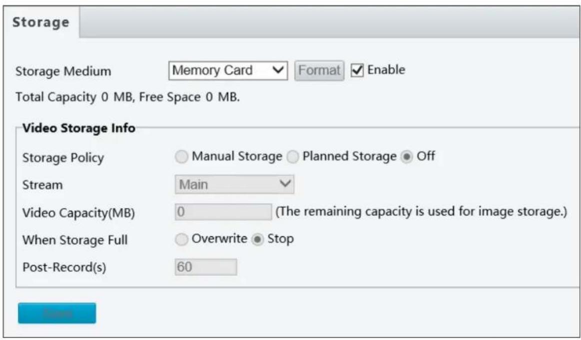
text_image
Storage Storage Medium Memory Card Format Enable Total Capacity 0 MB, Free Space 0 MB. Video Storage Info Storage Policy Manual Storage Planned Storage Off Stream Main Video Capacity(MB) 0 (The remaining capacity is used for image storage.) When Storage Full Overwrite Stop Post-Record(s) 60Figure 3-26
The following storage settings are available.
■ Storage Medium: Click the Format button to format the memory card before you start recording.
■ Storage Policy: Choose the Storage Policy from one of the three options.
- Manual Storage: Manually start recording.
- Planned Storage: Start recording by schedule. For detailed instructions, refer to Enable Plan section, 3.5.1 Motion Detection.
Off: Stop recording.
Stream: Select the stream you want to use for recording.
■ When St orage Full:
- Overwrite: If there is no free space in the memory card, new data will overwrite the existing data repeatedly.
- Stop: If there is no free space in the memory card, new data will not be saved to the memory card.
■ Post-Record (s): When an alarm is raised, the camera is triggered to record live video and continues recording for the specified time after the alarm is cleared.
3.7 Security
This section allows you to create user accounts and set the network security settings.
3.7.1 User
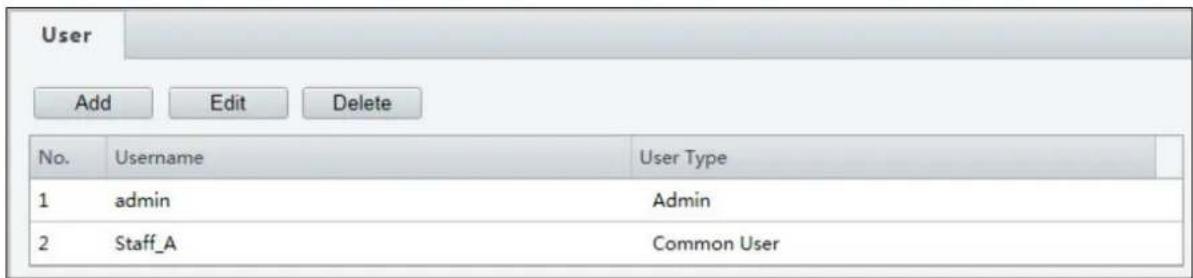
There are two types of accounts: Administrator and Common User.
■ Administrator: The default name of the administrator is admin, which cannot be modified. Admin has full permission and can manage all users and devices. Only one admin account is allowed in the system.
■ Common Users: The user only has permission to play live and recorded video. Up to 31 common users are allowed in the system.
The administrator can create new account for a common user. After the user is added successfully, the administrator can change the password by entering the new password or delete the user by clearing the username.
text_image
User Add Edit Delete No. Username User Type 1 admin Admin 2 Staff_A Common UserFigure 3-27
Note: Changing the username or password for a user when the user is still logged in will force the user to log out. The user must use a new username or password to log in.
3.7.2 Network Security
There are four types of network security settings: HTTPS, RTSP Authentication, ARP Binding and IP Address Filtering.
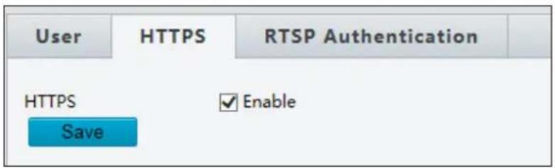
HTTPS
You can enable the Hypertext Transfer Protocol Secure (HTTPS) settings to access the camera through a secure protocol. Click Enable and click Save.
text_image
User HTTPS RTSP Authentication HTTPS Enable SaveFigure 3-28
RTSP Authentication
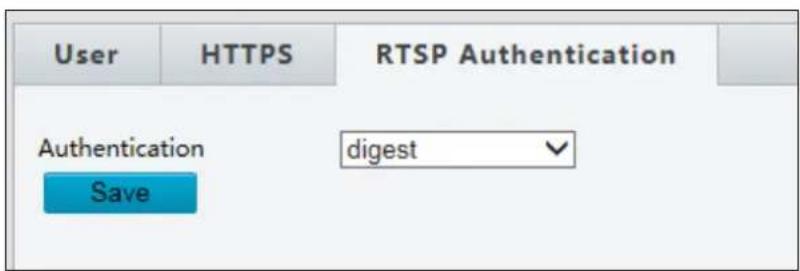
RTSP (Real Time Streaming Protocol) is an application layer protocol for transmitting video. Set the Authentication mode for RTSP streaming.
text_image
User HTTPS RTSP Authentication Authentication digest SaveFigure 3-29
ARP Binding
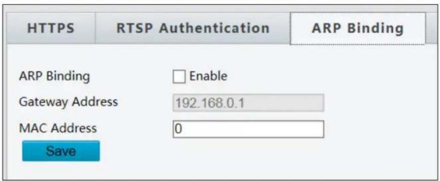
This function can protect the camera from ARP attacks. When the camera visits an IP of another network segment via a gateway, it can only communicate with the MAC address binding to the gateway address in the same segment.
text_image
HTTPS RTSP Authentication ARP Binding ARP Binding Enable Gateway Address 192.168.0.1 MAC Address 0 SaveFigure 3-30
- Enable ARP Binding.
- Type MAC Address.
- Click Save.
IP Address Filtering
You can allow or deny the access from the specified IP address to your camera.
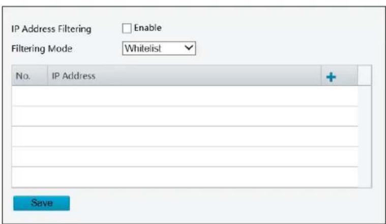
text_image
IP Address Filtering Enable Filtering Mode Whitelist No. IP Address + SaveFigure 3-31
- Enable IP Address Filtering.
- Choose a Filtering Mode: Allow Access or Deny Access.
- Click + to add an IP address.
- Click Save.
3.8 System
This section allows you to set the camera time, and update the firmware.
3.8.1 Time
You can use the following methods to adjust the system time of your camera.
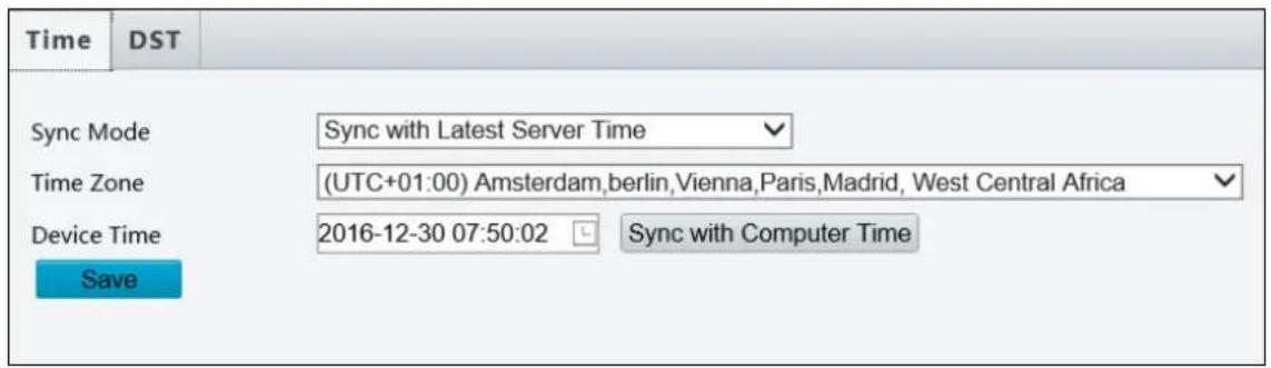
text_image
Time DST Sync Mode Sync with Latest Server Time Time Zone (UTC+01:00) Amsterdam,berlin,Vienna,Paris,Madrid, West Central Africa Device Time 2016-12-30 07:50:02 Sync with Computer Time SaveFigure 3-32
To manually set a time or synchronize with the computer time:
- Select Sync with Latest Server Time from the Sync Mode drop-down list.
- Select a Time Zone.
- Next to Device Time, manually set the camera's time or click Sync with Computer Time to synchronize with the time of your PC.
- Click Save.
To synchronize with a network time server:
- Select Sync with NTP Server from the Sync Mode drop-down list to configure the NTP Server settings.
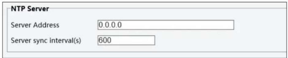
text_image
NTP Server Server Address 0.0.0.0 Server sync interval(s) 600Figure 3-33
- Type the IP address of the network time server next to Server Address.
- Change the number of Server sync Interval(s) if necessary.
- Click Save.
To adjust the camera's time for daylight saving time:
- Click the DST tab at the top.
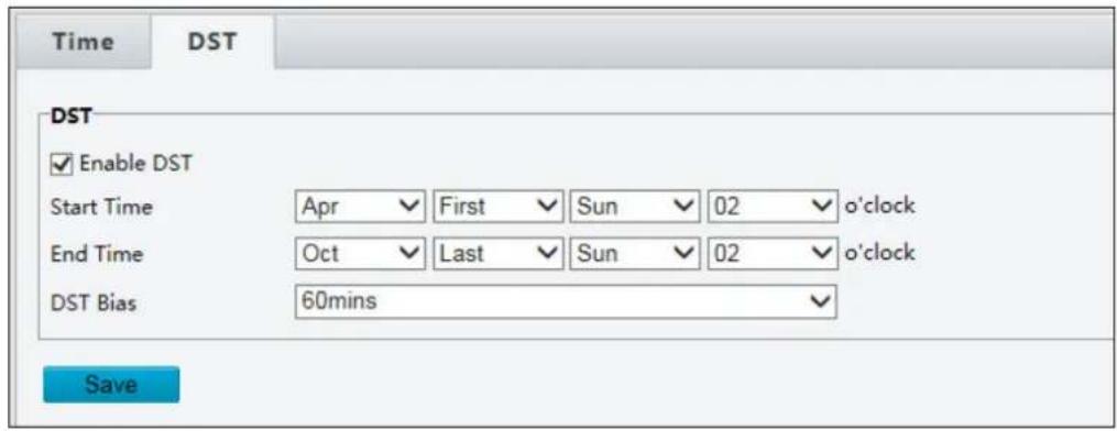
text_image
Time DST DST Enable DST Start Time Apr First Sun 02 o'clock End Time Oct Last Sun 02 o'clock DST Bias 60mins SaveFigure 3-34
- Select Enable DST.
- Set a Start Time and End Time for the daylight saving time.
- Select a time period for DST Bias.
- Click Save.
3.8.2 Maintenance
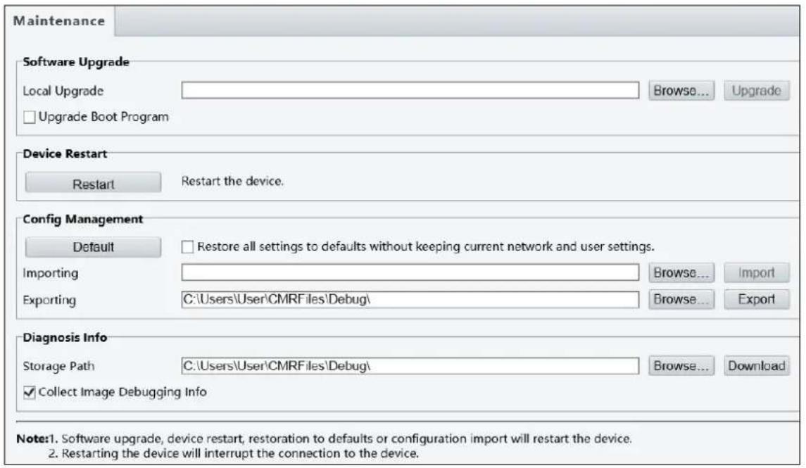
This section allows you to upgrade firmware, restart the camera, and backup/import camera configurations.
text_image
Maintenance Software Upgrade Local Upgrade Upgrade Boot Program Browse... Upgrade Device Restart Restart Restart the device. Config Management Default Restore all settings to defaults without keeping current network and user settings. Importing Browse... Import Exporting C:\Users\User\CMRFiles\Debug\ Browse... Export Diagnosis Info Storage Path C:\Users\User\CMRFiles\Debug\ Browse... Download Collect Image Debugging Info Note:1. Software upgrade, device restart, restoration to defaults or configuration import will restart the device. 2. Restarting the device will interrupt the connection to the device.Figure 3-35
[Software Upgrade]
For detailed instructions, refer to 5.1 Upgrading System Firmware and 5.1.1 Using the Web Interface.
[Device Restart] Click Restart to restart the device after you confirm the operation.
[Config Management] Export the current configurations of the camera and save them to the PC or an external storage medium. You can also quickly restore configurations by importing backup configurations stored on the PC or an external storage medium back to the camera.
[Diagnosis Info] Includes logs and system configurations. You can export diagnostic information to your PC. Click Browse to select the destination folder, and then click Download to save the diagnostic information to the specified folder.
Chapter 4 Recording and Playback
Note this function is only for ADR1300.
The camera can record video and audio directly to the memory card.
Note: See Note for Recording at the beginning of the manual.
4.1 Recording
To configure the recording function, refer to the following sections
- Insert the memory card to the camera -- See 1.3 Overview, ADR1300 Mini Fixed Rugged IP Dome Quick Guide.
- Format the memory card, create a recording schedule, set up post-recording or select the stream for recording -- See 3.6.1 Storage.
- Set up recording upon motion detection -- See 3.5.1 Motion Detection.
4.2 Playback from the Memory Card
You can play back the files recorded at the memory card of the camera from the Web interface.
1. Click Playback at the top. This page appears.
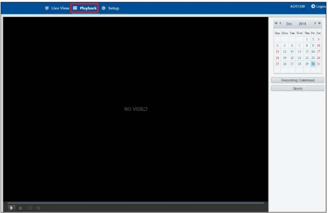
text_image
Live View Playback Setup ADR1300 Logou Dec 2016 Sun Mon Tue Wed Thu Fri Sat 4 3 6 7 8 9 10 11 12 13 14 15 16 17 18 19 20 21 22 23 24 25 26 27 28 29 30 31 Recording Download Query NO VIDEOFigure 4-1
2. On the right, select a date and click Query.
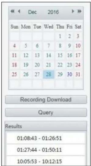
text_image
Dec 2016 Sun Mon Tue Wed Thu Fri Sat 4 5 6 7 8 9 10 11 12 13 14 15 16 17 18 19 20 21 22 23 24 25 26 27 28 29 30 31 Recording Download Query Results 01:08:43 - 01:26:51 01:27:44 - 01:50:11 10:05:53 - 10:12:15Figure 4-2
- Double-click a search result to play back the recorded file.
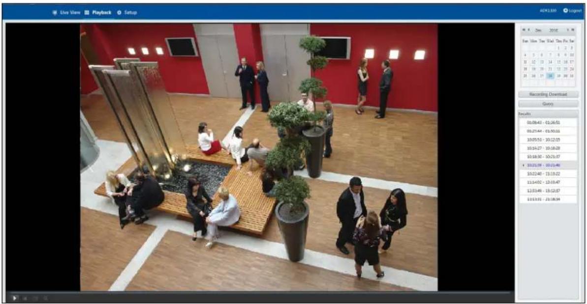
text_image
Live View Playback Setup ADK130 Logov Sun View Time 2016 Sun View Bar 1 2 3 4 5 6 7 8 9 10 11 12 13 14 15 16 17 18 19 20 21 22 23 24 25 26 27 28 29 30 Recording Download Query Results 10:08:43 - 01:36:51 01:27:44 - 03:30:33 10:05:53 - 10:12:15 10:16:27 - 10:18:28 10:18:30 - 10:21:37 10:23:39 - 10:23:46 10:22:45 - 13:13:22 11:14:07 - 12:33:47 12:33:48 - 15:12:37 13:13:35 - 23:18:34Figure 4-3
The following functions are available:
■ Snapshot ☐: Click to capture a snapshot of the recorded video.
■ Digital Zoom Ⓧ: Click the icon and draw a box on the camera view to digitally zoom in.
4.2.1 Recording Download
You can search and download the recorded videos stored in the memory card.
- Click Recording Download on the Playback page.
- Select a time period to search for video, and click Search. The search results are shown.
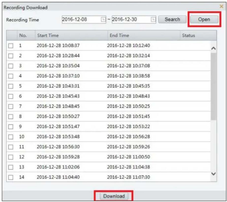
text_image
Recording Download Recording Time 2016-12-08 ~ 2016-12-30 Search Open No. Start Time End Time Status □ 1 2016-12-28 10:08:37 2016-12-28 10:12:40 □ 2 2016-12-28 10:28:44 2016-12-28 10:32:14 □ 3 2016-12-28 10:35:04 2016-12-28 10:37:08 □ 4 2016-12-28 10:37:10 2016-12-28 10:38:58 □ 5 2016-12-28 10:43:31 2016-12-28 10:45:35 □ 6 2016-12-28 10:45:43 2016-12-28 10:48:43 □ 7 2016-12-28 10:48:45 2016-12-28 10:50:25 □ 8 2016-12-28 10:50:27 2016-12-28 10:51:45 □ 9 2016-12-28 10:51:47 2016-12-28 10:53:22 □ 10 2016-12-28 10:53:48 2016-12-28 10:56:28 □ 11 2016-12-28 10:56:30 2016-12-28 10:59:26 □ 12 2016-12-28 10:59:28 2016-12-28 11:00:50 □ 13 2016-12-28 11:02:06 2016-12-28 11:04:38 □ 14 2016-12-28 11:04:40 2016-12-28 11:07:30 DownloadFigure 4-4
- To download the videos, select the files and click Download.
- To open the folder for storing recordings, click Open.
Chapter 5 Advanced Applications
This chapter introduces more advanced applications.
5.1 Upgrading System Firmware
We periodically release the updated firmware on the website. The new firmware can be simply loaded into the camera using the Web interface or the GV-IP Device Utility.
Important Notes before You Start
Before you start updating the firmware, please read these important notes:
- If you use the GV-IP Device Utility for firmware upgrade, the computer used to upgrade firmware must be under the same network of the camera.
- Stop monitoring of the camera.
- Stop the connection to GV-VMS / DVR / NVR and all remote connections.
- While the firmware is being updated, the power supply must not be interrupted.
WARNING: The interruption of power supply during updating causes not only update failures but also damages to your camera. In this case, please contact your sales representative and send your device back to us for repair.
- Do not turn the power off within 10 minutes after the firmware is updated.
- If firmware upgrade fails, you will need to restore the camera to the default settings. For details, see 5.2 Restoring to Factory Default Settings in the User's Manual.
5.1.1 Using the Web Interface
Log into the Web interface and follow the steps below to update the firmware.
- At the top, click Setup.
- In the left menu, select System and select Maintenance. This page appears.
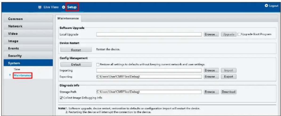
text_image
Live View Setup Common Network Video Image Events Security System Time Maintenance Maintenance Software Upgrade Local Upgrade Browse... Upgrade Upgrade Boot Program Device Restart Restart Restart the device. Config Management Default Restore all settings to defaults without keeping current network and user settings. Importing Browse... Import Exporting C:\Users\User\CMRFiles\Debug\ Browse... Export Diagnosis Info Storage Path C:\Users\User\CMRFiles\Debug\ Browse... Download Collect Image Debugging Info Note:1. Software upgrade, device restart, restoration to defaults or configuration import will restart the device. 2. Restarting the device will interrupt the connection to the device.Figure 5-1
- Click the Browse button to locate the firmware file (.zip) saved at your local computer.
- Optionally select Upgrade Boot Program to reboot the camera after a successful upgrade.
- Click the Upgrade button to process the upgrade.
5.1.2 Using the GV-IP Device Utility
You can upgrade the camera firmware using the GV-IP Device Utility. Note the computer used to upgrade firmware must be under the same network of the camera.
- Download GV-IP Device Utility from http://www.geovision.com.tw/english/5_8.asp Then follow the onscreen instructions to install the program.
- Double-click the GV IP Device Utility icon created on your desktop.
- Click the camera in the list and select Configure.
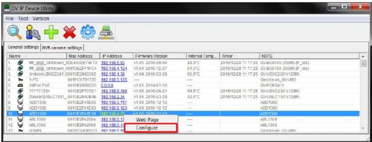
text_image
GV TP Device Utility File Tool Version General settings | NVR camera settings | Name / Mac Address IP Address Firmware Version Internal Temp... Timer NOTE 1. #_@_Unknown_0DE4A3D679F72 192.158.5.83 v1.05 2016-09-05 49.0°C 2016/12/28 11:17:25 GV-BX4700 (256M) (P_Ins) 2. #_@_Unknown_10013E2FF1FC4 192.158.4.124 v1.04 2016-12-27 51.5°C 2016/12/28 11:17:23 GV-BX5700 (256M) (P_Ins) 3. [Indocr]UBXC2301-20013E2000362 192.156.1.30 v1.04 2016-03-28 55.5°C 2016/12/28 11:17:25 GV-UBXC2301(128M) 4. 1-PC 001FC6791720 192.156.5.175 — — GeoVision_GV-VMS 5. 24Port PoE 0013E2088C23 0.0.0.0 v1.01 2014-07-18 —— GV-POE2411 6. ?????1234 0013E2FF07D1 192.158.5.180 v1.05 2016-08-21 59.5°C 2016/12/28 11:17:25 GV-UBXC2301(128M) 7. [Taiwan]UBLC1301_0013E20ADB3E 192.158.2.34 v1.04 2016-03-28 42.5°C 2016/12/28 11:17:25 GV-UBLC1301(128M) 8. ABD1300 0013E2FA1E56 192.158.0.117 v1.00 2016-12-12 —— ABD1300 9. ABD1300 0013E2FA1E60 192.158.5.123 v1.00 2016-12-12 —— ABD1300 10. ABD1300 0613E2FAI5B 192.158.4.25 v1.00 2016-12-12 —— ABD1300 11. ABL 1300 0013E2FA2C8A 192.158.6.17 Web Page —— ABL 1300 12. ABL 1300 0013E2FA2C89 192.158.0.14 —— ABL 1300 13. ADMIN 68DC44D8D73 192.158.5.58 Configure —— GeoVision_GV-VMSFigure 5-2
- Type the camera's user name and password to log in.
- Click the Firmware Upgrade tab. This dialog box appears.
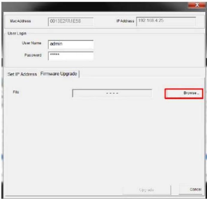
text_image
MacAddress 0013E2FA1E58 IP Address 192.168.4.25 User Login User Name admin Password ***** Set IP Address Firmware Upgrade File ---- Browse... Upgrade CancelFigure 5-3
5 Advanced Applications
- Click the Browse button to locate the firmware file (.zip) saved at your local computer.
- Click Upgrade to start upgrading the firmware.
5.2 Restoring to Factory Default Settings
You can restore the camera to factory default settings using the Web interface or directly on the camera.
Note: There is no default button on ABD1300 and ADR1300.
5.2.1 Using the Web Interface
- At the top, click Setup.
- In the left menu, select System and select Maintenance.
- Under the Config Management section, click the Default button.
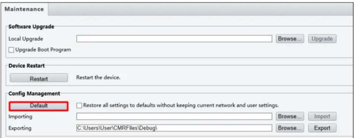
text_image
Maintenance Software Upgrade Local Upgrade Upgrade Boot Program Browse... Upgrade Device Restart Restart Restart the device. Config Management Default Restore all settings to defaults without keeping current network and user settings. Importing Browse... Import Exporting C:\Users\User\CMRFiles\Debug\ Browse... ExportFigure 5-4
5.2.2 Directly on the Camera
Note this function is only for ABL1300.
Press and hold the default button for at least 15 seconds to restore to factory default settings.

text_image
Default ButtonFigure 5-5
Chapter 6 DVR Configurations
The GV-VMS / DVR / NVR provide complete video management, such as video viewing, recording, playback, alert settings, and almost every feature of the system. The integration specifications are listed below:
- The compatible GV-VMS / DVR / NVR versions are listed below:
| Camera Model Compatible GV-System Compatible GV-VMS | ||
| ABD1300 | V8.7.1.0 with patch files or later | V15.11.3.0 with patch files or later |
| ABL1300 | ||
| ADR1300 | ||
- The maximum number of streams supported by one camera when connecting to other applications is 8.
- When a camera is connected to IE browser or any other applications, it takes up 1 stream; when it is connected to GV-VMS / DVR / NVR, it takes up 2 streams.
6.1 Setting Up IP Cameras on GV-System
To set up the camera on the GV-System, follow these steps:
- On the main screen, click the Configure button, select System Configure, select Camera Install and click IP Camera Install. This dialog box appears.
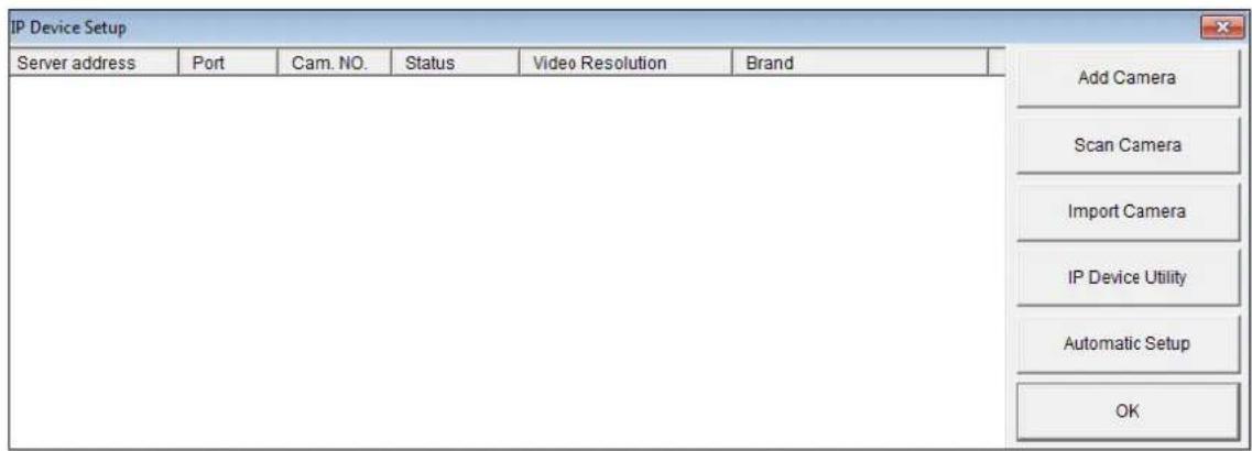
text_image
IP Device Setup Server address Port Cam. NO. Status Video Resolution Brand Add Camera Scan Camera Import Camera IP Device Utility Automatic Setup OKFigure 6-1
- To automatically set up the camera, click Scan Camera to detect any camera on the LAN.
- Double-click your camera and type the user name and password of the camera.

text_image
Scan Camera Network Adapter : IP[192.168.0.147] Realtek PCIe GBE Family Controller Port : 15000 Start Scan Search Progress : Name IP Address Port MACAddress Brand ADR1300 192.168.0.107 80 0013E2FA2079 ADR1300 ABD1300 192.168.0.13 80 0013E2FA1E55 ABD1300 ABL1300 192.168.0.10 80 0013E2FA2067 ABL1300 Please enter username and password User name : admin Password : •••••• OK Cancel CloseFigure 6-2
- Click OK. This dialog box appears.
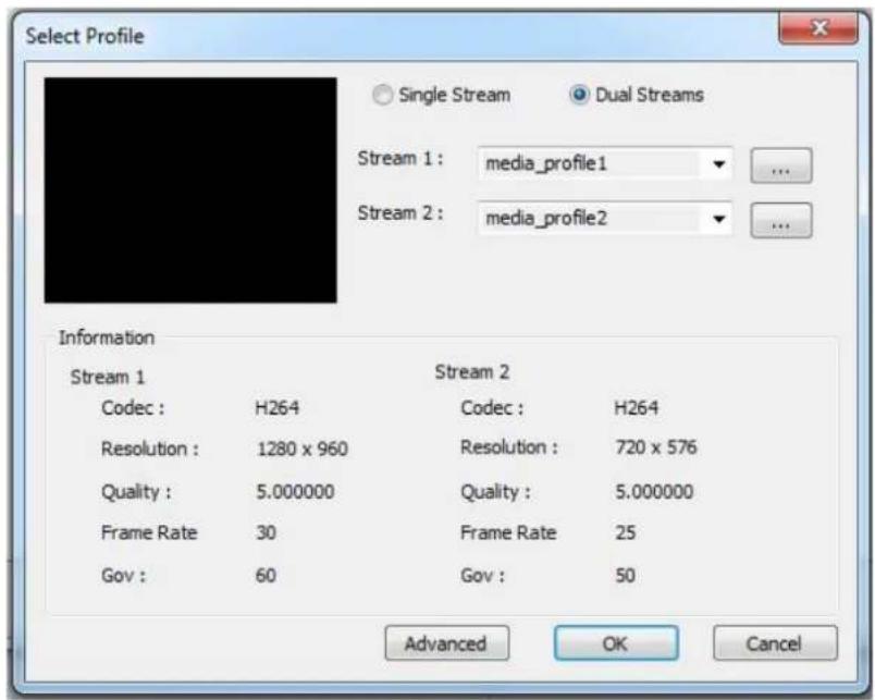
text_image
Select Profile Single Stream Dual Streams Stream 1: media_profile1 Stream 2: media_profile2 Information Stream 1 Stream 2 Codec : H264 Codec : H264 Resolution : 1280 x 960 Resolution : 720 x 576 Quality : 5.000000 Quality : 5.000000 Frame Rate 30 Frame Rate 25 Gov : 60 Gov : 50 Advanced OK CancelFigure 6-3
- Click OK. The IP camera is added to the connection list.
- Click the listed camera and select Display position to map the IP camera to a channel on the GV-System.
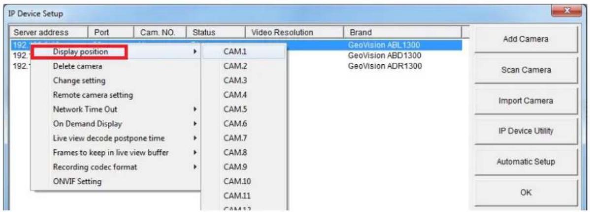
text_image
IP Device Setup Server address Port Cam. NO. Status Video Resolution Brand 192 192: Display position 192: Delete camera Change setting Remote camera setting Network Time Out On Demand Display Live view decode postpone time Frames to keep in live view buffer Recording codec format ONVIF Setting CAM.1 GeoVision ABL1300 CAM.2 GeoVision ABD1300 CAM.3 GeoVision ADR1300 CAM.4 CAM.5 CAM.6 CAM.7 CAM.8 CAM.9 CAM.10 CAM.11 CAM.12 Add Camera Scan Camera Import Camera IP Device Utility Automatic Setup OKFigure 6-4
- The Statue column should display "Connected". Click OK.
6.1.1 Customizing the Basic Settings on GV-System
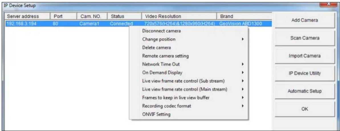
After the camera is connected and assigned with a display position, you can configure the camera's settings such as frame rate, codec type and resolution. Right-click the desired camera to see the following list of options:
text_image
IP Device Setup Server address Port Cam. NO. Status Video Resolution Brand 192.168.3.194 80 Camera1 Connected 720x576(H264)&1280x960(H264) GeoVision ABD1300 Disconnect camera Change position Delete camera Remote camera setting Network Time Out On Demand Display Live view frame rate control (Sub stream) Live view frame rate control (Main stream) Frames to keep in live view buffer Recording codec format ONVIF Setting Add Camera Scan Camera Import Camera IP Device Utility Automatic Setup OKFigure 6-5
■ Network Time Out: When network disconnection exceeds the specified time period, the camera status will be displayed as Connection Lost.
■ On-Demand Display: Enables automatic switching between main stream and substream based on the size of camera image on screen.
■ Live-view frame rate control (Sub / Main): Sets the frame rate of the stream to help reduce the CPU usage. If you have set the codec to be MJPEG, select the number of frames to allow in a second. If the codec selected is H.264, select one of the following options:
- Maximum Live-view Frame Rate: View the video at the maximum frame rate possible.
Live-view Key Frame only: You can choose to view the key frames of the videos only instead of all frames on the live view. This option is related to the GOP setting of the IP camera. For example, if the GOP value is set to 30, there is only one key frame among 30 frames.
■ Frames to keep in live view buffer: Specifies the number of frames to keep in the live view buffer.
■ Recording Codec Format: Select the codec to record in.
6.2 Setting Up IP Cameras on GV-VMS
Follow the steps below to manually connect your camera to GV-VMS.
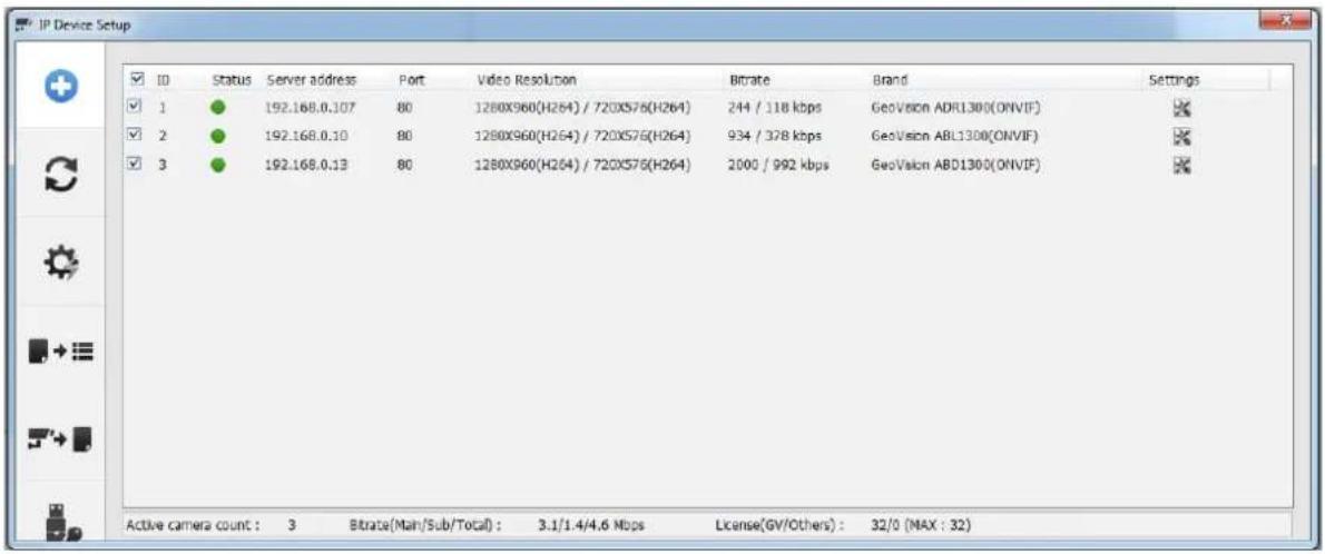
- To access the IP Device Setup page, click Home 🔒, select Toolbar ☐, click
Configure and select Camera Install.
text_image
IP Device Setup ID Status Server address Port Video Resolution Bitrate Brand Settings 1 ● 192.168.0.107 80 1280X960(H264) / 720X576(H264) 244 / 118 kbps GeoVision ADR1300(ONVIF) 2 ● 192.168.0.10 80 1280X960(H264) / 720X576(H264) 934 / 378 kbps GeoVision ABL1300(ONVIF) 3 ● 192.168.0.13 80 1280X960(H264) / 720X576(H264) 2000 / 992 kbps GeoVision ABD1300(ONVIF) Active camera count : 3 Bitrate(Main/Sub/Total) : 3.1/1.4/4.6 Mbps License(GV/Others) : 32/0 (MAX : 32)Figure 6-6
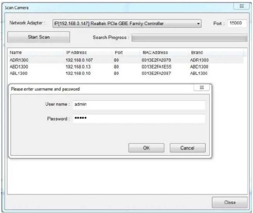
- Click Automatic Setup

- Double-click the camera and type the user name and password of the camera.
text_image
Scan Camera Network Adapter : [P[192.168.0.147] Realtek PCIe GBE Family Controller Port : 15000 Start Scan Search Progress : Name IP Address Port MAC Address Brand ADR1300 192.168.0.107 80 0013E2FA2079 ADR1300 ABD1300 192.168.0.13 80 0013E2FA1E55 ABD1300 ABL1300 192.168.0.10 80 0013E2FA2087 ABL1300 Please enter username and password User name : admin Password : ***** OK Cancel CloseFigure 6-7
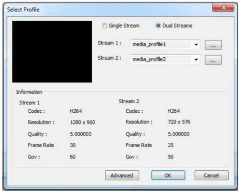
- Click OK. This dialog box appears.
text_image
Select Profile Single Stream Dual Streams Stream 1: media_profile1 ... Stream 2: media_profile2 Information Stream 1 Stream 2 Codec : H264 Codec : H264 Resolution : 1280 x 960 Resolution : 720 x 576 Quality : 5.000000 Quality : 5.000000 Frame Rate 30 Frame Rate 25 Gov : 60 Gov : 50 Advanced OK CancelFigure 6-8
- Click OK to add the camera to the list.
- To connect the added camera, click the box besides the ID column. Upon successful connection, the Status icon shows green, with the video resolution and bitrate being displayed in the correspondent columns.

text_image
ID Status Serve address Port Video Resolution Bitrate Brand Settings 1 192.166.0.107 80 1280X960(H264) / 720X576(H254) 243 / 120 kbps Geovision ADR1300(ONVJF)Figure 6-9
Appendix
A. RTSP Protocol Support
The camera can support RTSP protocol for both video and audio streaming.
If you are using Quick Time player, use the following RTSP command:
rtsp://
For example, rtsp://192.168.3.111:554/CH001.sdp
If you are using VLC player, use the following RTSP command:
If you use the VLC, and if authentication is not required, enter:
rtsp://@<IP of the camera:554/
For example, rtsp://@192.168.3.111:554/CH001.sdp
Note:
- See 3.6.2 Security for RTSP related settings on the Web interface.
- Only VLC and QuickTime players are supported for streaming video via RTSP protocol.
B. Optional Installation for ABD1300
You can optionally purchase GV-Mount211 or GV-Mount212 for Wall Box Mount. Follow the instructions below.
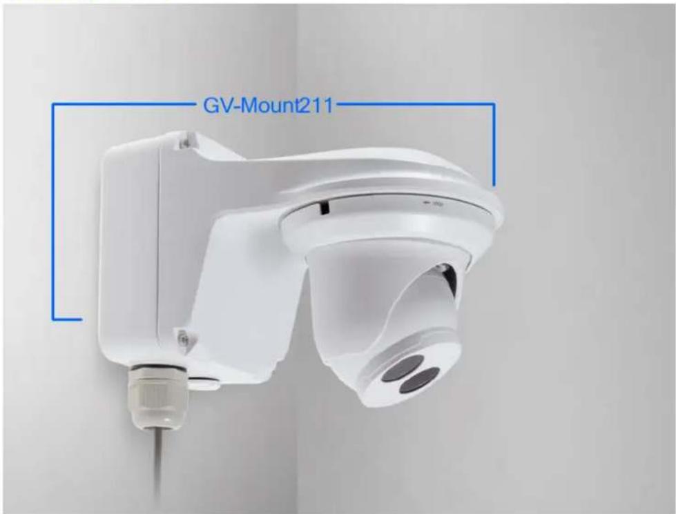
GV-Mount211
text_image
GV-Mount211Figure B-1
GV-Mount211 Packing List
GV-Mount211 Wall Mount Bracket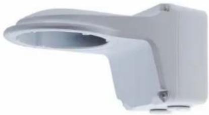 | Long Screw x 4 |
Short Screw x 3 | Screw Anchor x 5 |
Plastic PG21 Conduit Connector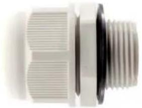 | Drill Template Paster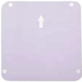 |
- Unscrew the bracket.
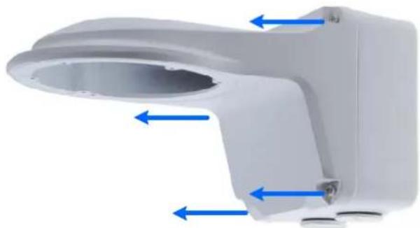
natural_image
White medical device component with blue directional arrows indicating flow or movement (no text or symbols)Figure B-2
- Loosen the indicated area by turning it anticlockwise.

text_image
Power Box T UPFigure B-3
- Stick the drill template paster to the wall with the arrow pointing up.
- Drill 4 holes according to the sticker and insert the 4 screw anchors to the 4 holes.
- Secure the camera housing to the wall with 4 long screws.
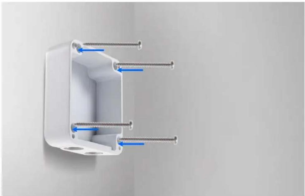
natural_image
White plastic electrical connector with four screws inserted, showing internal wiring (no text or symbols)Figure B-4
- Remove the bottom ring by turning it anticlockwise.
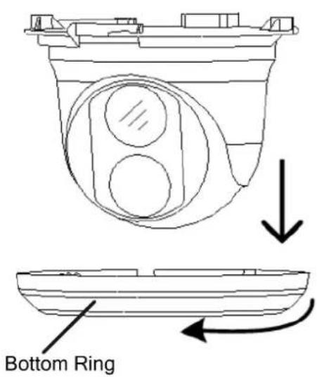
text_image
Bottom RingFigure B-5
- Thread the network and power wires through the camera housing.
- Secure the camera to the wall box mount with 3 short screws.
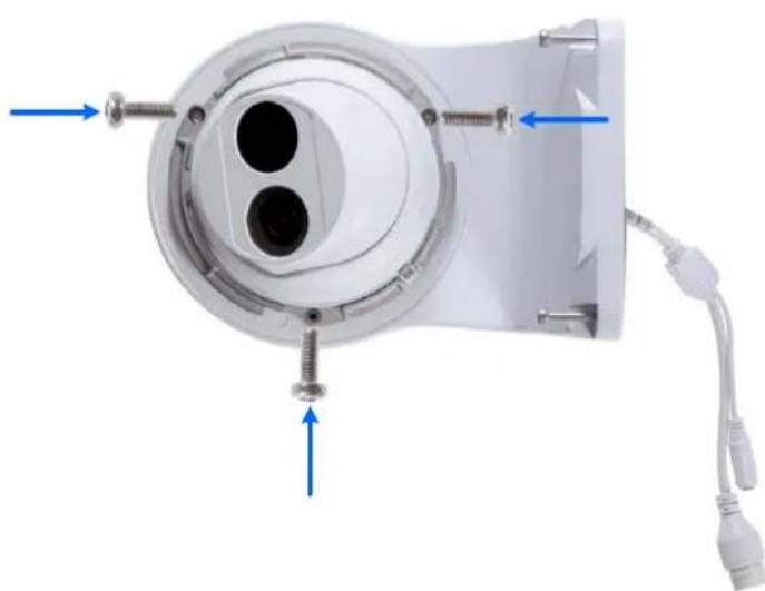
natural_image
Close-up of a medical device component with blue arrows indicating directional flow or movement, no visible text or symbols.Figure B-6
- Thread the Ethernet cable through the PG21 conduit connector and the camera housing as shown in No. 9, Figure B-7.
- Rotate the plastic ring to secure the conduit connector to the camera housing. Screw in the cap as shown in No. 10, Figure B-7.
- Plug the Ethernet cable to the RJ-45 connector of the camera as shown in No. 11, Figure B-7. To waterproof the Ethernet cable, see E.Waterproofing the Cable.
- Screw the wall box mount to the camera housing as shown in No. 12, Figure B-7.
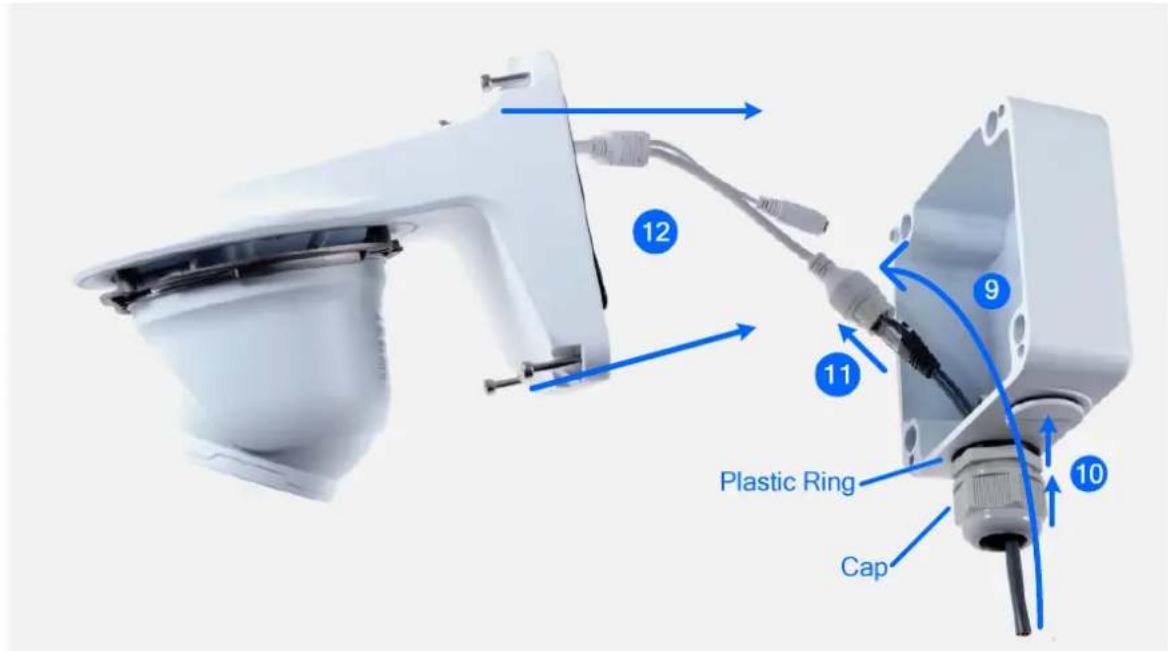
text_image
12 11 Plastic Ring Cap 9 10Figure B-7
- Mount the bottom ring.
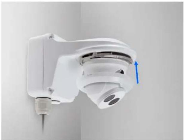
natural_image
Close-up of a white wall-mounted smart camera with a blue directional arrow indicating left-side motion (no text or symbols visible)Figure B-8
GV-Mount212
text_image
GV-Mount212Figure B-9
GV-Mount212 Packing List
GV-Mount212 Wall Box Mount | Long Screw x 3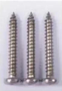 |
Short Screw x 3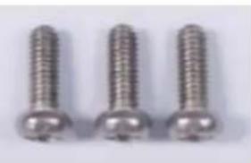 | Screw Anchor x 3 |
Standard Installation
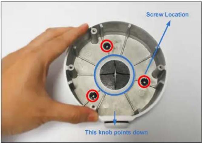
1 Attach the wall box to the wall and use a marker to mark the location for the center socket and the screws. Make sure the knob points down.
text_image
Screw Location This knob points downFigure B-10
2 Drill 3 holes according to the screw location. Then, drill a bigger hole at the center socket location for the Ethernet cable.
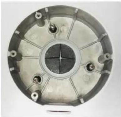
3 Insert 3 screw anchors to the screw location and secure the wall box to the wall with 3 long screws.
natural_image
Circular mechanical component with central hole and multiple mounting holes (no visible text or symbols)Figure B-11
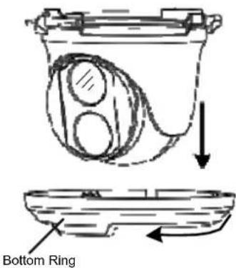
4 Remove the bottom ring by turning it anticlockwise.
text_image
Bottom RingFigure B-12
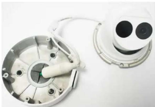
5 Thread the Ethernet cable through the center socket and waterproof the Ethernet cable. For details, see E.Waterproofing the Cable.
natural_image
Two white industrial sensor modules with circular components and wiring, one larger and one smaller, against a plain background (no text or symbols visible)Figure B-13
6 Fit the cable into the wall box.
7 Before securing the camera, make sure the indicated area fits to the designated location.
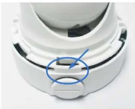
natural_image
Close-up of a white mechanical component with a blue arrow pointing to a small rectangular feature (no text or symbols visible)Figure B-14
8 Secure the camera by locking 2 short screws to the indicated position.
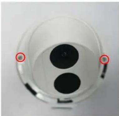
natural_image
Top-down view of a transparent cylindrical device with two black circular components and two red-circled points on the side (no text or symbols visible)Figure B-15
9 Mount the bottom ring.
Note: In addition to the Standard Installation, you can also choose to run the Ethernet cable through a corrugated tube. To do this, you will have to purchase your own conduit connector and corrugated tube. 3/4" NPS is the recommended type of connector. After you secure the wall box to the desired location, remove the knob at the bottom and connect the conduit connector with a self-prepared corrugated tube to the wall box. Then, thread the Ethernet cable through the corrugated tube and waterproof the Ethernet cable.
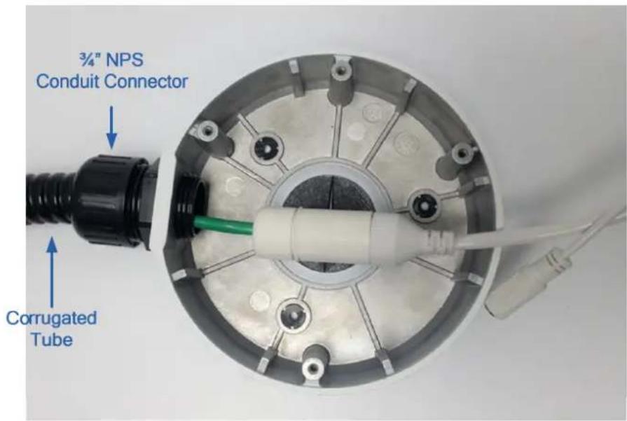
text_image
3/4" NPS Conduit Connector Corrugated TubeFigure B-16
C. Optional Installation for ADR1300
You can optionally purchase GV-Mount211 for Wall Bracket Mount. Follow the instructions below.
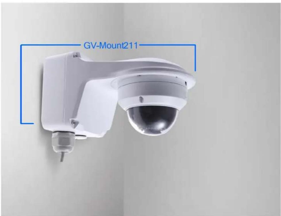
text_image
GV-Mount211Figure C-1
GV-Mount 211 Packing List
For details, see Appendix B. Optional Installation for ABD1300.
- Unscrew the bracket.
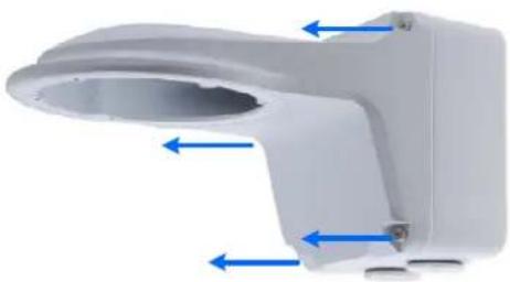
natural_image
White plastic toilet housing component with blue directional arrows indicating flow or movement (no text or symbols)Figure C-2
- Loosen the indicated area by turning it anticlockwise.

natural_image
White plastic electrical enclosure with two circular ports and a blue arrow indicating a rotation (no text or symbols on the box itself)Figure C-3
- Stick the drill template paster to the wall with the arrow pointing up.
- Drill 4 holes according to the sticker and insert the 4 screw anchors to the 4 holes.
- Secure the power box to the wall with four long screws.
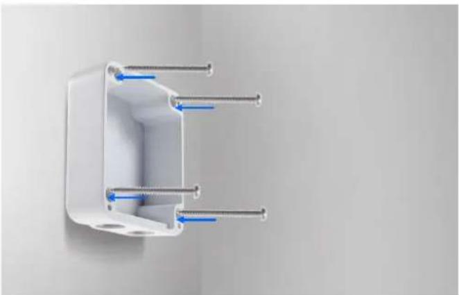
natural_image
3D rendering of a white plastic enclosure with metal screws and blue arrows indicating internal components (no text or symbols)Figure C-4
- Unscrew the transparent dome cover with the supplied torx wrench.
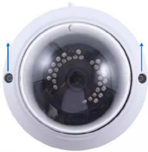
natural_image
Close-up of a circular security camera with visible lens and control buttons (no text or symbols)Figure C-5
- Optionally insert a micro SD card into the micro SD card slot to use the local storage function.
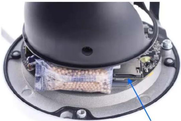
natural_image
Close-up of a device's internal components, including a black dome and electronic board with a blue arrow pointing to a wrapped package (no visible text or symbols)Figure C-6
-
Thread the network and power wires through the wall mount bracket.
-
Secure the camera to the wall mount bracket with 2 short screws.
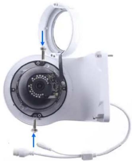
natural_image
Close-up of a white electronic device with internal components and wiring, showing no visible text or symbols.Figure C-7
- Secure the transparent dome cover with the supplied torx wrench.
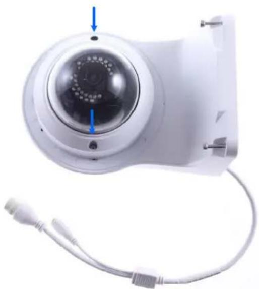
natural_image
White remote camera with circular lens and attached cable, no visible text or symbolsFigure C-8
- Thread the Ethernet cable through the PG21 conduit connector and the power box as shown in No. 9, Figure C-9.
- Rotate the plastic ring to secure the conduit connector to the power box. Screw in the cap as shown in No. 10, Figure C-9.
- Plug the Ethernet cable to the RJ-45 connector of the camera as shown in No. 11, Figure C-9.
- Screw the wall mount bracket to the power box as shown in No. 12, Figure C-9.
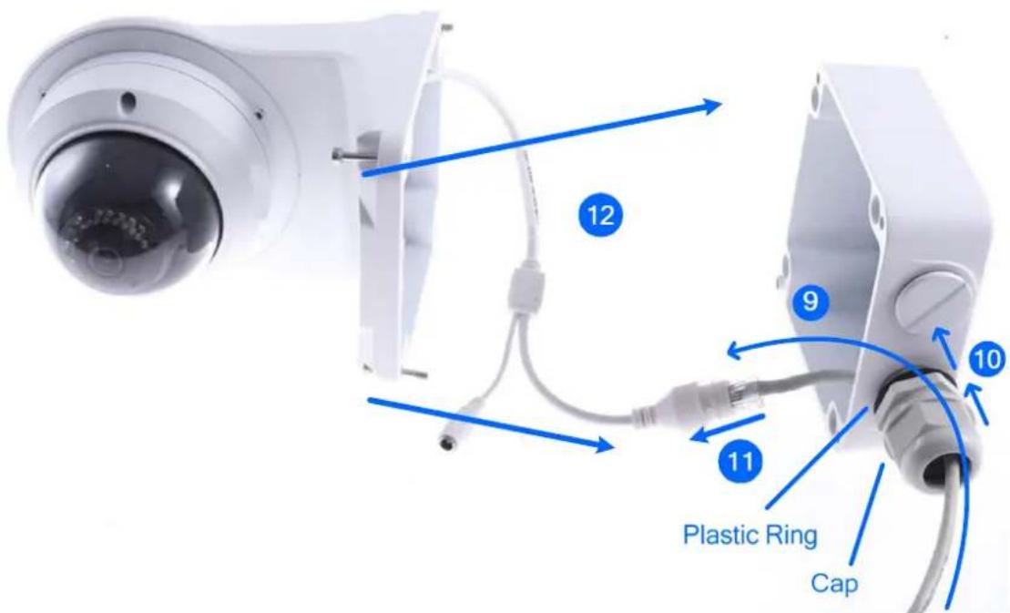
text_image
12 9 10 11 Plastic Ring CapFigure C-9
D. Optional Installation for ABL1300
You can optionally purchase GV-Mount502 for Wall Box Mount. Follow the instructions below.
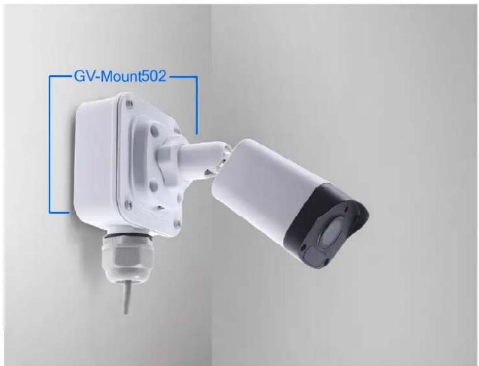
text_image
GV-Mount502Figure D-1
GV-Mount502 Packing List
GV-Mount502 Wall Mount Box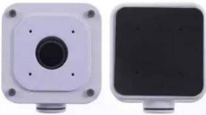 | M3 25 mm Screw x 4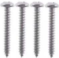 |
M3 12 mm Screw x 4 | Screw Anchor x 4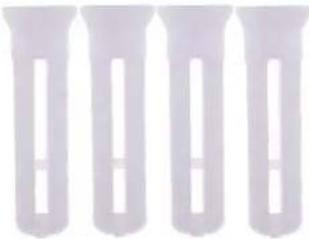 |
Plastic PG21 Conduit Connector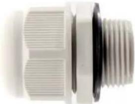 |
- Unscrew the box cover.
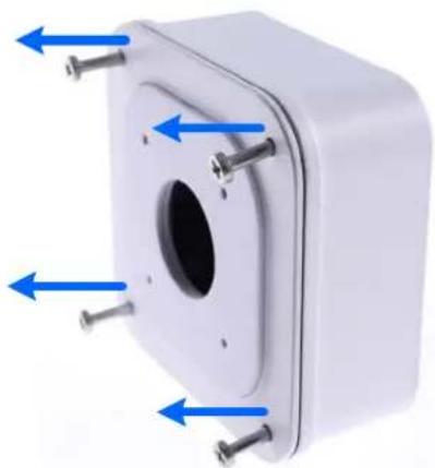
natural_image
White mechanical component with blue directional arrows indicating force or movement (no text or symbols)Figure D-2
- Loosen the indicated area by turning it anticlockwise.
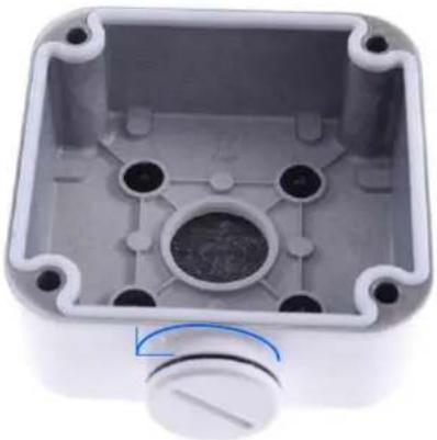
natural_image
Interior view of a white plastic enclosure with mounting holes and central circular cavity (no text or symbols visible)Figure D-3
- Attach the box to the wall with the arrow pointing up and use a marker to mark 4 dots.
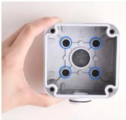
natural_image
Hand holding a transparent square mechanical housing with four circular components and mounting holes (no text or symbols visible)Figure D-4
-
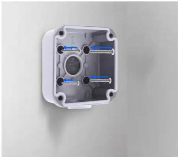
Drill 4 holes according to the marks and insert the 4 screw anchors to the 4 holes.
-
Secure the power box to the wall with four M3 25 mm screws.
natural_image
Interior view of a white plastic enclosure with four screws and blue arrows indicating internal components (no text or symbols)Figure D-5
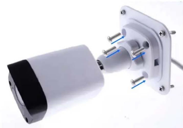
- Thread the network and power wires through the wall mount box cover.
- Secure the camera to the wall mount box cover with 4 M3 12 mm screws.
natural_image
Close-up of a white electrical outlet with blue arrows indicating internal components (no text or symbols visible)Figure D-6
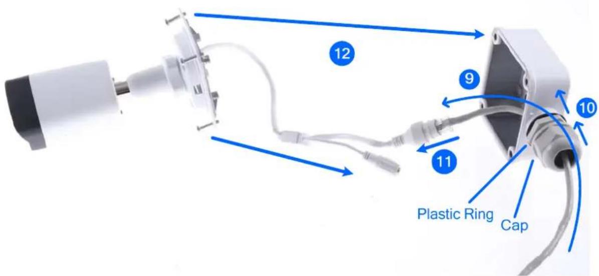
- Thread the Ethernet cable through the PG21 conduit connector and the wall mount box as shown in No. 9, Figure D-7.
- Rotate the plastic ring to secure the conduit connector to the wall mount box. Screw in the cap as shown in No. 10, Figure D-7.
- Plug the Ethernet cable to the RJ-45 connector of the camera as shown in No. 11, Figure D-7. To waterproof the Ethernet cable, see F.Waterproofing the Cable.
- Arrange the cables.
- Screw the wall mount box cover to the wall mount box as shown in No. 12, Figure D-7.
text_image
Plastic Ring Cap 10 11 9 12Figure D-7
E. Waterproofing the Cable
Waterproof the Ethernet cable by using the supplied waterproof rubber set.
- Attach the seal ring to the RJ-45 plug.

text_image
Seal ringFigure E-1
- Insert the waterproof components through the Ethernet cable as shown below.

text_image
Insert in orderFigure E-2
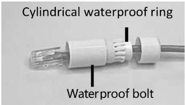
- Insert the cylindrical waterproof ring into waterproof bolt.
text_image
Cylindrical waterproof ring Waterproof boltFigure E-3
- Insert the cable into the RJ-45 plug and screw the waterproof bolt in.
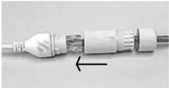
natural_image
Close-up of a white electrical plug with internal components and an arrow indicating a specific section (no text or symbols visible)Figure E-4
- Screw in the waterproof bolt lid.
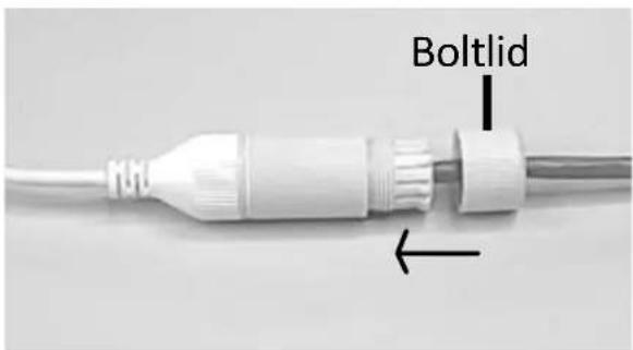
text_image
BoltlidFigure E-5
- Finish the waterproof Installation.
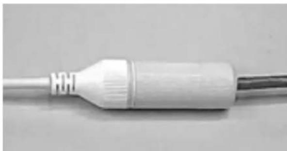
natural_image
Close-up of a white plastic electrical plug with a metallic end cap (no visible text or symbols)Figure E-6