
6104 - Door/window sensor OLYMPIA - Free user manual and instructions
Find the device manual for free 6104 OLYMPIA in PDF.


| Product Type | Door/Window Sensor |
| Model | 6104 |
| Brand | Olympia |
| Series | Protect Series |
| Intended Use | Monitoring door/window open/closed status |
| Transmitter Dimensions (W x H x D) | 15.7 x 106.8 x 22 mm |
| Magnet Unit Dimensions (W x H x D) | 11.5 x 48 x 34.5 mm |
| Weight | Approx. 38 g |
| Radio Frequency | 868.5 MHz |
| Maximum Transmission Power | 0.7 mW |
| Power Supply | 2 x AAA batteries (included) |
| Permissible Ambient Temperature | -10°C to +40°C |
| Permissible Humidity | 30% to 75% rel. humidity |
| Maximum Distance Transmitter to Magnet | 5 mm |
| Installation Method | Double-sided adhesive tape or screws |
| Registration | Via base unit 'Register' menu, trigger by opening door/window |
| Scope of Delivery | 1x Door/Window contact, 2x AAA batteries, screws, adhesive tape, operating manual |
| Indoor Use Only | Yes (except outdoor siren) |
| Compatible Systems | Olympia Protect Series alarm base units |
| Cleaning | Soft, lint-free cloth; no chemicals |
| Safety Warnings | Risk of explosion from improper battery handling; keep batteries away from children |
| Disposal | Separate from household waste; dispose of batteries at collection points |
| Guarantee | Return with receipt to point-of-sale |
| CE Conformity | Compliant with Directive 2014/53/EU |
Frequently Asked Questions - 6104 OLYMPIA
User questions about 6104 OLYMPIA
0 question about this device. Answer the ones you know or ask your own.
Ask a new question about this device
Download the instructions for your Door/window sensor in PDF format for free! Find your manual 6104 - OLYMPIA and take your electronic device back in hand. On this page are published all the documents necessary for the use of your device. 6104 by OLYMPIA.
USER MANUAL 6104 OLYMPIA
Sensors for the Protect Series
Operating Manual
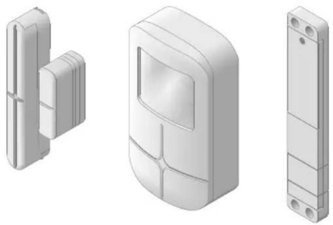

natural_image
Solid dark gray rectangular area with a white diagonal line on the right edge (no text or symbols)Hello,
We are delighted that you have decided to purchase these reliable devices from Olympia.
The descriptions on the following pages will explain how easy it is to make your home more safe and secure.

Contents
Before You Start 6 Mini Remote Control 19
Important Information on the Sensors . . . 6 Intended Use . . . . . . . . . . . . . . . . . . . . . . . . . . . . . . . . . . . . . . . . 19
Safety Instructions 7 Scope of Delivery 19
Door/Window contact 9 General View 19
Intended Use 9 Registering a Sensor 20
Scope of Delivery 9 Changing the Battery 20
General View 9 Monitoring Functions 21
Installation 10 SOS Key 21
Inserting the Batteries 10 Technical Data 21
Registering a Sensor 11 Convenient Remote Control 22
Technical Data 11 Intended Use 22
Concealed Window Contact 12 Scope of Delivery 22
Intended Use 12 General View 22
Scope of Delivery 12 Registering a Sensor 23
General View 12 Changing the Battery 23
Installation 13 Monitoring Functions 24
Inserting the Batteries 14 SOS Key 24
Registering a Sensor 14 Technical Data 24
Technical Data 14 SOS/Panic Button 25
Motion Detector 15 Intended Use 25
Intended Use 15 Scope of Delivery 25
Scope of Delivery 15 General View 25
General View 15 Registering a Sensor 26
Inserting the Batteries 16 Changing the Battery 26
Installation 16 Information on Use 26
Registering a Sensor 17 Technical Data 26
Technical Data 18

Vibration Sensor 27 Outdoor Siren 36
Intended Use 27 Intended Use 36
Scope of Delivery 27 Scope of Delivery 36
General View 27 General View 36
Setting the Sensitivity 28 Inserting the Batteries 37
Installation 28 Installation 37
Registering a Sensor 28 Registering the Outdoor Siren 38
Changing the Battery 29 Technical Data 38
Technical Data 29 TFS 200 Temperature Sensor 39
Water Detector 30 Intended Use 39
Intended Use 30 Scope of Delivery 39
Scope of Delivery 30 General View 39
General View 30 Full Instruction Manual 39
Installation 31 Technical Data 39
Inserting the Batteries 31 IR 500 Infrared light Barrier 40
Registering a Sensor 31 Intended Use 40
Technical Data 32 Scope of Delivery 40
Glass Breakage Detector 33 General View 40
Intended Use 33 Technical Data 40
Scope of Delivery 33 Appendix 41
General View 33 Troubleshooting 41
Installation 34 Information on Disposal 42
Inserting the Batteries 34 Guarantee 42
Registering a Sensor 35 Cleaning and Service 43
Technical Data 35 Information on Conformity 43

BEFORE YOU START
Before You Start
The sensors used in the alarm systems in the Protect series are passive security products and have been developed for use as deterrents. Additional measures are necessary to prevent and hinder burglary and theft. You can obtain all the necessary information on this from your local police station.

Read the operating manual thoroughly and observe all the information contained when using the alarm system. Keep the operating manual in a safe place for future reference.

Pay attention to this symbol. Texts which are highlighted by this symbol provide helpful information on handling the alarm system.
Important Information on the Sensors
- The sensors are intended for private use indoors (exception: outdoor siren).
- The sensors only work in combination with an alarm system from the Protect series!
- All the individual sensors must be installed within transmission range of the base unit of the Protect series alarm system.
- More detailed information on how to configure the alarm system (e.g. changing the name of a sensor) is available in the operating manual supplied with the base unit.
Safety Instructions
The following safety information applies to the entire document.
Read and observe all the safety information to protect yourself and the environment from any harm.
The following warnings indicate potentially dangerous situations which could lead to serious injuries or even fatal injuries if the information is ignored.

WARNING! Risk of fatal injury from electric shock! NEVER use the device if you suspect damage to the power cable or power plug or there are visible signs of damage to the power cable or power plug.

NEVER complete any repairs to the device yourself. Never open the device because it contains no components which you may service yourself. In the event of a fault, contact our Service Department.

WARNING! Risk of suffocation! Children can swallow small parts, packaging and protective foils. Keep the device and packaging out of reach of children.

WARNING! Risks to health through batteries! Keep batteries out of reach of children. Do not swallow batteries. If any type of battery or round cell is swallowed, seek medical attention immediately.

WARNING! Risk of explosion! Improper storage of batteries can put your health and the environment at risk. Batteries may contain toxic, ecologically hazardous heavy metals. Never open, damage or swallow batteries or allow them to pollute the environment.

WARNING! Risk of serious injuries through damaging cables or pipes! During installation, pay attention to the possibility of cables and pipes running in the walls. We are not deemed liable for installation errors. If in doubt, contact a specialist!

SAFETY INSTRUCTIONS
The following warnings indicate potentially dangerous situations which could lead to minor or slight injuries if the information is ignored.

CAUTION! This device can be used by children from the age of 8 and persons with restricted physical, sensory or mental capabilities or a lack of experience and knowledge as long as they are supervised or have been instructed with regard to safe use of the device and are aware of the potential risks involved with its use. Children must never play with the device. Cleaning and user maintenance may not be completed by children without any supervision.

CAUTION! Hearing damage through loud alarm signal! Due to legal requirements, the alarm signal continues for maximally 120 seconds. Use ear protectors when testing the device. Do not remain in the vicinity of the acoustic alarm for a longer period when it has been triggered.
The following warnings indicate potentially dangerous situations which could lead to property damage if the information is ignored.
IMPORTANT! Risk of property damage through the use of inappropriate batteries! The use of inappropriate batteries can cause a loss of function of the device. Only use the batteries supplied or those of the type described in Section "Technical Data".
IMPORTANT! Risk of property damage through environmental influences! Prevent environmental influences such as exposure to smoke, dust, vibration, chemicals, moisture, heat and direct sunlight.
IMPORTANT! Before starting to install, fix or position the sensors, take into account that walls, ceilings and sources of electrical disturbance can impair wireless communication.
Door/Window contact
Intended Use
The door/window contact consists of the transmitter unit and the magnet unit and serves for monitoring the condition of doors and windows (open/closed).
A condition for complying with the intended use is that the equipment is installed correctly and the information in the manual is observed and maintained. Any other use is considered unintended use.
Scope of Delivery
Please check the contents of the package carefully. If anything is missing or has been damaged during transport, DO NOT put the door/window contact into operation!
Door/Window contact 1
| Batteries 2 x AAA battery |
| Assembly material Screws, adhesive tape |
| Operating manual 1 |
General View
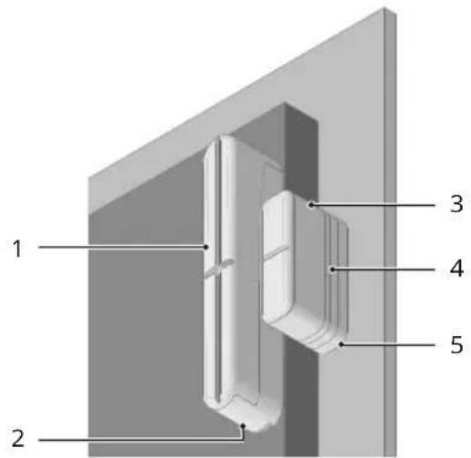
1 Transmitter (with battery compartment)
2 Mounting bracket
3 Magnet unit
4 Spacers (optional)
5 Mounting bracket

DOOR/WINDOW CONTACT
Installation
natural_image
Isometric diagram of a multi-stage appliance assembly with no visible text or symbols
Pay attention that the surfaces to be adhered to are free of dust and grease.
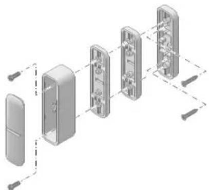
1 Fix the mounting bracket for the transmitter and mounting bracket for the magnet unit in place using double-sided adhesive tape.

Fix the door/window contact in place, positioned and aligned as illustrated above. Otherwise, there is no guarantee that the door/window contact will function properly.
2 Mount the battery compartment on the mounting bracket of the transmitter.
3 Mount the magnet unit on the mounting bracket of the magnet unit.

The transmitter and magnet unit must be on the same plane. Optionally, you can use the spacers which can be fitted on the mounting bracket of the magnet unit. Use the appropriate screws supplied.

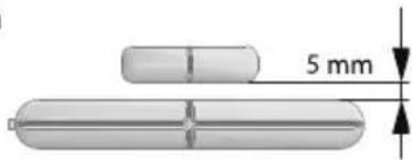
The distance between the transmitter and magnet unit when assembled may be maximally 5 mm.
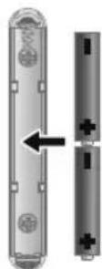
Inserting the Batteries
1 Open the transmitter by pressing the lock downwards.
2 Insert the batteries in the battery compartment. Pay attention that the batteries are inserted the right way around.
3 Fit the battery compartment on the mounting bracket. The lock engages audibly.
Registering a Sensor
1 Select the Register menu option on the base unit.
2 Trigger the sensor by opening the window or door being monitored.
3 The base unit display indicates that registration has been completed successfully on the alarm system.

If registering was not successful. Refer to Section Troubleshooting.
Technical Data
| Weight Approx. 38 g | |
| Dimensions (W x H x D) Transmitter | |
| 15.7 x 106.8 x 22 mm | |
| Magnet unit | |
| 11.5 x 48 x 34.5 mm | |
| Radio frequency 868.5 MHz | |
| Transmission power (max.) | 0.7 mW |
| Batteries 2 x AAA batteries | |
| Permissible ambient conditions | -10 °C to +40 °C at 30% to 75% rel. humidity |

CONCEALED WINDOW CONTACT
Concealed Window Contact
Intended Use
The window contact consists of the transmitter unit and the magnet unit and serves for monitoring the condition of windows (open/closed). As a result of its compact dimensions, it is perfectly suited for a concealed assembly between the window frame and window casement.
A condition for complying with the intended use is that the equipment is installed correctly and the information in the manual is observed and maintained. Any other use is considered unintended use.
Scope of Delivery
Please check the contents of the package carefully. If anything is missing or has been damaged during transport, DO NOT put the door/window contact into operation!
Window contact 1
| Battery 2 x round cell batteries,CR2354, 3 V |
| Assembly material Screws, adhesive tape |
Operating manual 1
General View
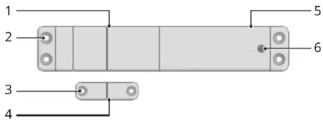
1 Transmitter
2 Hole for screw
3 Hole for screw
4 Magnet unit
5 Battery compartment cover
6 Screw for battery compartment cover
Installation
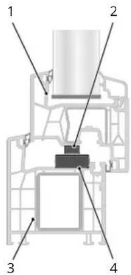
1 Window casement
2 Magnet unit
3 Window frame
4 Transmitter

Pay attention that the surfaces to be adhered to are free of dust and grease.
1 Fix the transmitter to the window frame as illustrated using double-sided adhesive tape.
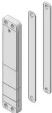
Any misalignment within the window frame can be compensated for using the spacers supplied. Fix the spacers to the underside of the transmitter using the screws supplied.
2 Fix the magnet unit on the window casement so that the magnet unit is positioned directly over the transmitter, as illustrated, when the window is closed.

Where necessary, you can also fix the transmitter and magnet unit to the window frame and window casement, respectively, using the screws supplied.
natural_image
Illustration of three metallic rectangular components with mounting holes, shown from different angles (no text or symbols)
CONCEALED WINDOW CONTACT
Registering a Sensor
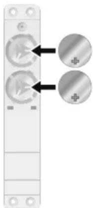
The window contact is supplied with batteries already inserted.
1 Select the Register menu option on the base unit.
2 Remove the plastic strip.
3 The base unit display indicates that registration has been completed successfully on the alarm system.

If registering was not successful. Refer to Section Troubleshooting.
Changing the Batteries
1 Loosen the screw in the battery compartment cover using an appropriate screwdriver.
2 Remove the battery compartment cover.
3 Remove the batteries.
4 Insert new batteries of the same type in the battery compartment. Pay attention that the batteries are inserted the right way around.
5 Replace the battery compartment cover.
6 Tighten the screw in the battery compartment cover using an appropriate screwdriver.
Technical Data
Weight Approx. 38 g
Dimensions (W x H x D) Window contact
25 x 140 x 9.5 mm
Magnet unit
11.5 × 34.5 × 9.5 mm
Radio frequency 868.5 MHz
Transmission power (max.) 6.1 mW
Batteries 2 x round cell batteries,
CR2354 3 V
Permissible -10 °C to +40 °C at
ambient conditions 30% to 75% rel. humidity
natural_image
Close-up of a vertical electronic device with two circular buttons and a plus/minus icon, no visible text or symbols.Motion Detector
Intended Use
The wireless motion detector reacts to movements within the detection range of the sensor.
A condition for complying with the intended use is that the equipment is installed correctly and the information in the manual is observed and maintained. Any other use is considered unintended use.
Scope of Delivery
Please check the contents of the package carefully. If anything is missing or has been damaged during transport, DO NOT put the motion detector into operation!
Motion detector 1
| Mounting bracket 1 |
| Batteries 3 x round cell batteries, type AA |
| Assembly material Screws, dowels |
| Operating manual 1 |
General View
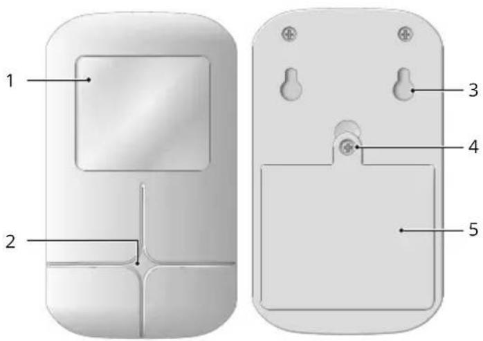
1 Motion sensor
| 2 LED |
| 3 Recesses for mounting bracket |
| 4 Screw for battery compartment cover |
| 5 Battery compartment cover |

MOTION DETECTOR
Inserting the Batteries
natural_image
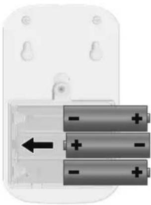
Close-up of a battery pack with three stacked batteries and an arrow indicating direction (no text or symbols)1 Loosen the screw in the battery compartment cover using an appropriate screwdriver.
2 Remove the battery compartment cover.
3 Insert the batteries in the battery compartment. Pay attention that the batteries are inserted the right way around.
4 Replace the battery compartment cover.
5 Tighten the screw in the battery compartment cover using an appropriate screwdriver.
Installation
Appropriate Installation Locations
Position the motion detector so that an intruder must move through part of the area being monitored.
An optimal installation location is directly in a corner, two meters from the floor at an angle of 14 degrees. The possible direction of movement of an intruder should be frontal towards the motion detector.
Inappropriate Installation Locations
The area to be monitored by the motion detector must not be obstructed by objects.
Avoid locations prone to quick temperature changes in the area monitored, near an air-con unit or heater, for example.
No pets should have access to the area to be monitored by the motion detector when the alarm system is armed.
natural_image
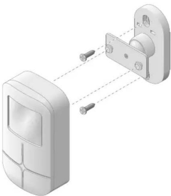
3D diagram of a door handle assembly with two screws and a bracket, showing alignment between components (no text or symbols)The wireless motion detector is provided with a wall bracket which can be mounted on a wall as well as on a ceiling.
MOTION DETECTOR


WARNING!
Risk of serious injuries through damaging cables or pipes! During installation, pay attention to the possibility of cables and pipes running in the walls. We are not deemed liable for installation errors. If in doubt, contact a specialist!
1 Drill two holes, about 45 mm apart, at the intended installation location.
2 Assemble the wall mounting bracket using screws supplied.
3 Hook the recesses on the rear side of the motion detector on the mounting bracket.
Registering a Sensor
1 Select the Register menu option on the base unit.
2 Move inside the area monitored by the motion detector.
3 The base unit display indicates that registration has been completed successfully on the alarm system.

If registering was not successful. Refer to Section Troubleshooting.

MOTION DETECTOR
Technical Data
| Weight Approx. 88 g | |
| Dimensions (W x H x D) 70 x 127 x 40 mm | |
| Radio frequency 868.5 MHz | |
| Transmission power (max.) | 1.6 mW |
| Monitoring radius 120° | |
| Monitoring range 8 m | |
| Battery 3 x round cell batteries, type AA | |
| Permissible ambient conditions | -10 °C to +40 °C at 30% to 75% rel. humidity |
Mini Remote Control
Intended Use
The mini remote control serves for the remote control of an alarm system from the Protect series.
A condition for complying with the intended use is that the equipment is installed correctly and the information in the manual is observed and maintained. Any other use is considered unintended use.
Scope of Delivery
Please check the contents of the package carefully. If anything is missing or has been damaged during transport, DO NOT put the mini remote control into operation!
| Mini remote control | 1 |
| Battery Round cell battery, | CR2032, 3 V |
| Operating manual | 1 |
General View
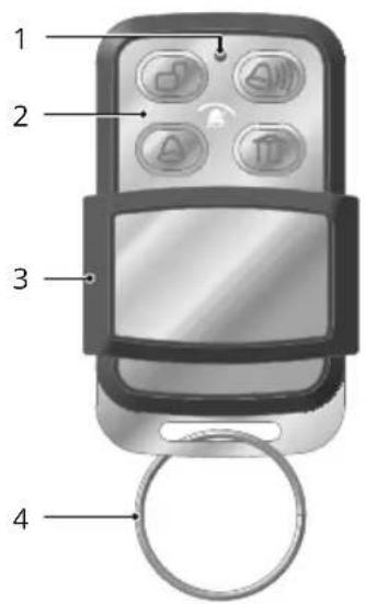
1 LED
2 Function keys
3 Cover
4 Key ring

MINI REMOTE CONTROL
Registering a Sensor
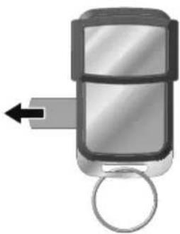
The remote control is supplied with a battery already inserted.
1 Select the Register menu option on the base unit.
2 Remove the plastic strip.
3 The base unit display indicates that registration has been completed successfully on the alarm system.
natural_image
Illustration of a car key with an arrow indicating left motion (no text or symbols)
If registering was not successful. Refer to Section Troubleshooting.
Changing the Battery
natural_image
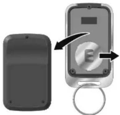
Diagram showing a device with a lock and a circular button, no text or symbols present1 Loosen the screws in the battery compartment cover using an appropriate screwdriver.
2 Remove the battery compartment cover.
3 Remove the battery contained.
4 Insert a new battery of the same type in the battery compartment. Pay attention that the battery is inserted the right way around.
5 Replace the battery compartment cover on the battery compartment.
6 Tighten the screws in the battery compartment cover using an appropriate screwdriver.
Monitoring Functions
natural_image
Illustration of a mobile phone with four app icons inside a circular frame, no text or symbols present.
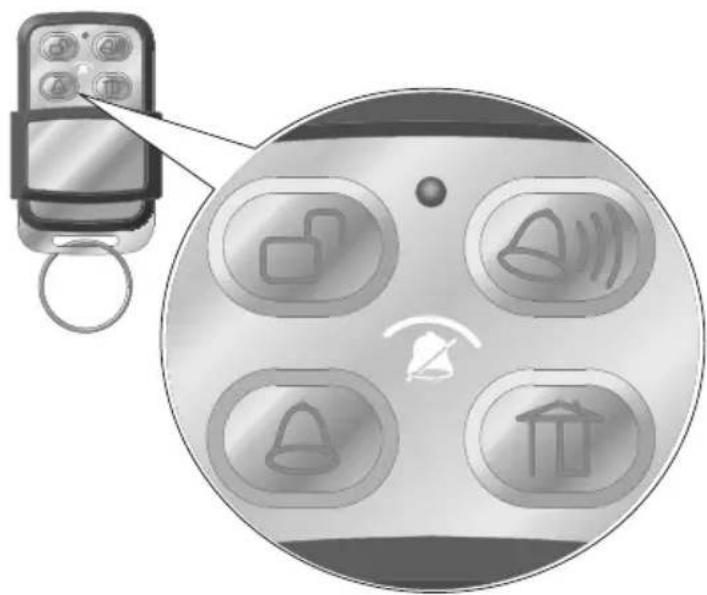
Disarmed mode

Alarm mode

At Home mode

SOS/Emergency call key

Silent mode
SOS Key
The 🔒 key on the mini remote control can be configured as an Emergency Call or Panic key via the base unit of the alarm system.

More detailed information is available in the operating manual supplied with the base unit.
Technical Data
Weight Approx. 24 g
Dimensions (W x H x D) 34 x 55 x 13 mm
Radio frequency 868.5 MHz
Transmission power (max.) 1.6 mW
Battery Round cell battery, CR2032, 3 V
Permissible ambient conditions -10 °C to +40 °C at 30% to 75% rel. humidity

CONVENIENT REMOTE CONTROL
Convenient Remote Control
Intended Use
The convenient remote control serves for the remote control of an alarm system from the Protect series.
A condition for complying with the intended use is that the equipment is installed correctly and the information in the manual is observed and maintained. Any other use is considered unintended use.
Scope of Delivery
Please check the contents of the package carefully. If anything is missing or has been damaged during transport, DO NOT put the convenient remote control into operation!
Convenient remote control 1
Battery Round cell battery, CR2032, 3 V
Operating manual 1
General View
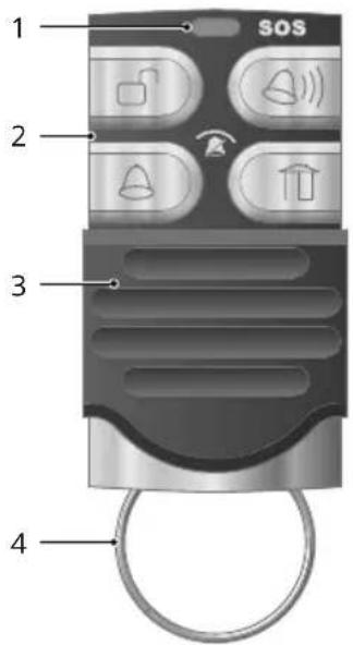
1 LED
2 Function keys
3 Cover
4 Key ring
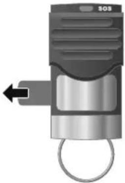
Registering a Sensor
The convenient remote control is supplied with a battery already inserted.
1 Select the Register menu option on the base unit.
2 Remove the plastic strip.
3 The base unit display indicates that registration has been completed successfully on the alarm system.
natural_image
Mechanical component with a circular ring and internal structure, no visible text or symbols
If registering was not successful. Refer to Section Troubleshooting.
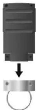
Changing the Battery
natural_image
Diagram showing a mechanical component being lifted by a ring (no text or symbols present)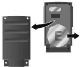
natural_image
Diagram showing a device with a fan blade and an arrow indicating rotation or change (no text or symbols present)1 Loosen the screws in the battery compartment cover using an appropriate screwdriver.
2 Remove the battery compartment cover.
3 Remove the battery contained.
4 Insert a new battery of the same type in the battery compartment.
5 Replace the battery compartment cover on the battery compartment.
6 Tighten the screws in the battery compartment cover using an appropriate screwdriver.

CONVENIENT REMOTE CONTROL
Monitoring Functions
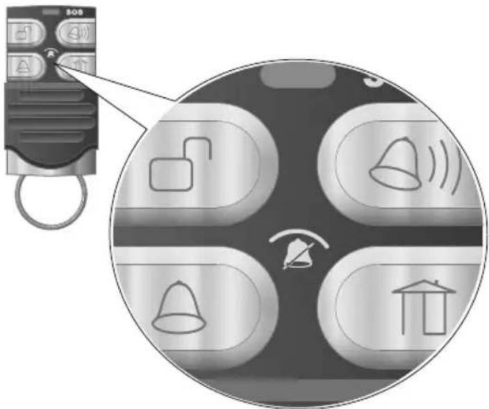

Disarmed mode

Alarm mode

At Home mode

SOS/Emergency call key

Silent mode
SOS Key
The 🔒 key on the convenient remote control can be configured as an Emergency Call or Panic key via the base unit of the alarm system.

More detailed information is available in the operating manual supplied with the base unit.
Technical Data
Weight Approx. 16 g
Dimensions (W x H x D) 30 x 58.5 x 13.7 mm
Radio frequency 868.5 MHz
Transmission power 0.04 mW (max.)
Battery Round cell battery, CR2032, 3 V
Permissible ambient conditions -10 °C to +40 °C at 30% to 75% rel. humidity
SOS/Panic Button
Intended Use
The SOS/Panic button issues a remote command to an alarm system from the Protect series.
A condition for complying with the intended use is that the equipment is installed correctly and the information in the manual is observed and maintained. Any other use is considered unintended use.
Scope of Delivery
Please check the contents of the package carefully. If anything is missing or has been damaged during transport, DO NOT put the SOS/Panic button into operation!
SOS/Panic button 1
Battery Round cell battery,
CR2430, 3 V
Operating manual 1
General View
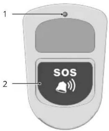
1 LED
2 SOS/Panic button

SOS/PANIC BUTTON
Registering a Sensor
The SOS/Panic button is supplied with a batteries already installed.
1 Select the Register menu option on the base unit.
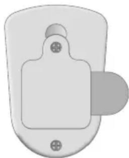
2 Remove the plastic strips.
3 The base unit display indicates that registration has been completed successfully on the alarm system.
natural_image
Simple 3D diagram of a mechanical component with mounting holes and a central rectangular block (no text or symbols)
If registering was not successful. Refer to Section Troubleshooting.
Changing the Battery
1 Loosen the screw in the battery compartment cover using an appropriate screwdriver.
2 Remove the battery compartment cover.
3 Remove the battery contained.
4 Insert a new battery of the same type in the battery compartment. Pay attention that the battery is inserted the right way around.
5 Replace the battery compartment cover on the battery compartment.
6 Tighten the screw in the battery compartment cover using an appropriate screwdriver.
Information on Use
The SOS/Panic button can be carried in a pocket or hung around the neck so it is permanently close by.
By simply pressing the button on the SOS/Panic button unit once, you can send an emergency call or trigger an alert signal on the base unit of the alarm system.
Technical Data
Weight Approx. 28 g
| Dimensions (W x H x D) 40 x 59 x 15 mm | |
| Radio frequency 868.5 MHz | |
| Transmission power (max.) | 0.05 mW |
| Battery Round cell battery, CR2430, 3 V | |
| Permissible ambient conditions | -10 °C to +40 °C at 30% to 75% rel. humidity |
Vibration Sensor
Intended Use
The vibration sensor is designed to detect vibrations and send a signal to the base unit of the alarm system.
A condition for complying with the intended use is that the equipment is installed correctly and the information in the manual is observed and maintained. Any other use is considered unintended use.
Scope of Delivery
Please check the contents of the package carefully. If anything is missing or has been damaged during transport, DO NOT put the vibration sensor into operation!
Vibration sensor 1
| Battery Round cell battery,CR2032, 3 V |
Operating manual 1
General View
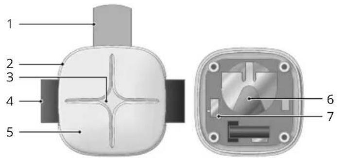
1 Plastic strips
2 Holder
3 LED
4 Felt strip (with hook-and-loop fastener)
5 Vibration Sensor
6 Battery
7 DIP switch (sensitivity setting)

VIBRATION SENSOR
Setting the Sensitivity
1 Loosen the screws in the battery compartment cover using an appropriate screwdriver.
2 Remove the battery compartment cover.
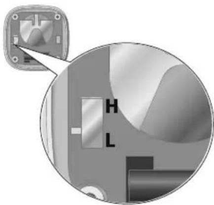
3 Set the sensitivity of the vibration sensor using the DIP switch (H = High, L = Low).
4 Replace the battery compartment cover on the battery compartment.
5 Tighten the screws in the battery compartment cover using an appropriate screwdriver.
natural_image
Close-up of a mechanical switch component with labeled parts (H, L), no readable text or symbols present.Installation
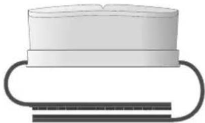
Position the vibration sensor in an appropriate location. When the vibration sensor detects any vibration (agitation), the LED lights up and the vibration sensor sends a signal to the base unit of the alarm system.
natural_image
Simple line drawing of a cylindrical object with a curved base and a flat top, no text or symbols present.Use the practical holder to fi x the vibration sensor fi rmly at any suitable location with the aid of the hook-and-loop fastener.
Registering a Sensor
1 Select the Register menu option on the base unit.
2 Remove the plastic strips.
3 Trigger the vibration sensor by shaking the vibration sensor.
4 The base unit display indicates that registration has been completed successfully on the alarm system.

If registering was not successful. Refer to Section Troubleshooting.
Changing the Battery
1 Loosen the screws in the battery compartment cover using an appropriate screwdriver.
2 Remove the battery compartment cover.
3 Remove the battery contained.
4 Insert a new battery of the same type in the battery compartment. Pay attention that the batteries are inserted the right way around.
5 Replace the battery compartment cover on the battery compartment.
6 Tighten the screws in the battery compartment cover using an appropriate screwdriver.
Technical Data
Weight Approx. 86 g
| Dimensions (W x H x D) Vibration sensor |
| 41 x 17 x 41 mm |
| Felt strip (length) |
| 280 mm |
Radio frequency 868.5 MHz
| Transmission power (max.) | 0.8 mW |
| Battery Round cell battery, CR2032, 3 V | |
| Permissible ambient conditions | -10 °C to +40 °C at 30% to 75% rel. humidity |

WATER DETECTOR
Water Detector
Intended Use
The water detector serves for the early detection of high water levels indicating potential flooding.
A condition for complying with the intended use is that the equipment is installed correctly and the information in the manual is observed and maintained. Any other use is considered unintended use.
Scope of Delivery
Please check the contents of the package carefully. If anything is missing or has been damaged during transport, DO NOT put the water leak detector into operation!
Water detector 1
Batteries 2 x AAA battery
Assembly material Adhesive tape
Operating manual 1
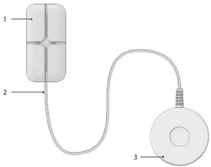
General View
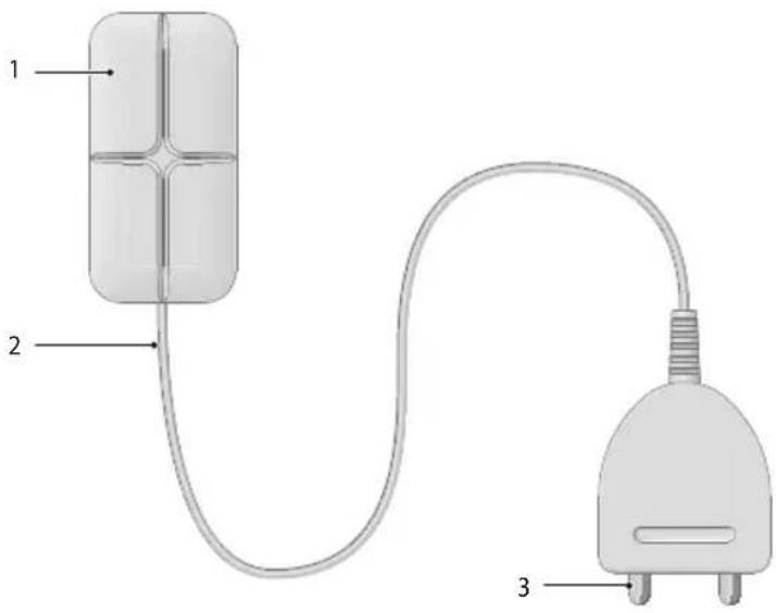
1 Battery compartment
2 Sensor cable
3 Sensor with contact surfaces
Installation

Pay attention that the surfaces to be adhered to are free of dust and grease.
The water detector is suitable for installation locations where there is a risk of flooding, e.g. through water-supplying equipment, intruding rain water or overflowing tanks.
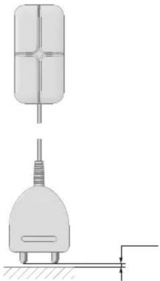
1 Position the sensors at the site to be monitored.
Observe:
- The distance between the maximum fi ll quantity and contact surfaces of the sensors must be approx 1 mm.
- The battery compartment is not waterproof. Use the double-sided adhesive tape included in the package contents to mount the battery compartment in a protected location.
natural_image
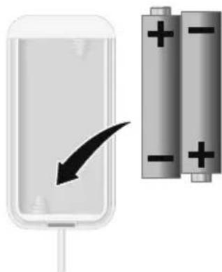
Technical diagram showing a cylindrical component and a plug with a base, connected by a ground line (no text or symbols)Inserting the Batteries
1 Open the battery compartment by pressing the locking latch down using an appropriate, pointed object.
2 Insert two batteries in the battery compartment. Pay attention that the batteries are inserted the right way around.
3 Close the battery compartment. The lock engages audibly.
natural_image
Illustration of a battery with an arrow pointing to its side, next to two cylindrical batteries (no text or symbols)Registering a Sensor
1 Select the Register menu option on the base unit.
2 Trigger the sensors by immersing the contact surfaces in water.
3 The base unit display indicates that registration has been completed successfully on the alarm system.

If registering was not successful. Refer to Section Troubleshooting.

WATER DETECTOR
Technical Data
Weight Approx. 86 g
| Dimensions (W x H x D) 15 x 105 x 22 mm | |
| Radio frequency 868.5 MHz | |
| Transmission power (max.) | 0.8 mW |
| Battery 2 x AAA battery | |
| Permissible ambient conditions | -10 °C to +40 °C at30% to 75% rel. humidity |
Glass Breakage Detector
Intended Use
The glass breakage detector reacts to vibration, which is a typical result of an attempted burglary (smashing, drilling, sawing, levering).
A condition for complying with the intended use is that the equipment is installed correctly and the information in the manual is observed and maintained. Any other use is considered unintended use.
Scope of Delivery
Please check the contents of the package carefully. If anything is missing or has been damaged during transport, DO NOT put the glass breakage detector into operation!
Glass breakage detector 1
| Batteries 2 x AAA battery |
| Assembly material Adhesive tape |
| Operating manual 1 |
General View
1 Battery compartment
2 Sensor cable
3 Sensor with contact surfaces

GLASS BREAKAGE DETECTOR
Installation
Appropriate Installation Locations
- On objects which are valuable or contain valuable items, e.g. pictures, safes, drawers etc.
- On objects which can be easily broken or forced open, e.g. glass panes, plasterboard walls, wooden doors, etc.
Inappropriate Installation Locations
- Near the floor.
- In the vicinity of metallic structures, electrical cables or gas pipelines, electrical or radio equipment.
- On objects which move of their own accord.

Pay attention that the surfaces to be adhered to are free of dust and grease.
1 Position the sensor with the contact surfaces at the site to be monitored. Use the double-sided adhesive tape supplied.
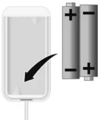
Inserting the Batteries
1 Open the battery compartment by pressing the locking latch down using an appropriate, pointed object.
2 Insert two batteries in the battery compartment. Pay attention that the batteries are inserted the right way around.
3 Close the battery compartment. The lock engages audibly.
natural_image
Illustration of a battery cell with an arrow indicating direction, alongside two cylindrical batteries with positive charges (no text or symbols)Registering a Sensor
1 Select the Register menu option on the base unit.
2 Remove a battery from the glass breakage detector and then replace it in the glass breakage detector.
3 The base unit display indicates that registration has been completed successfully on the alarm system.

If registering was not successful. Refer to Section Troubleshooting.
Technical Data
| Weight Approx. 86 g | |
| Dimensions (W x H x D) 15 x 105 x 22 mm | |
| Radio frequency 868.5 MHz | |
| Transmission power (max.) | 0.8 mW |
| Battery 2 x AAA battery | |
| Permissible ambient conditions | -10 °C to +40 °C at 30% to 75% rel. humidity |

OUTDOOR SIREN
Outdoor Siren
Intended Use
The outdoor siren issues a loud acoustic signal in addition to a visual alert in the event an alarm is triggered.
A condition for complying with the intended use is that the equipment is installed correctly and the information in the manual is observed and maintained. Any other use is considered unintended use.
Scope of Delivery
Please check the contents of the package carefully. If anything is missing or has been damaged during transport, DO NOT put the outdoor siren into operation!
Outdoor siren 1
| Battery 3 x round cell batteries,type AA |
| Assembly material Screws, dowels |
| Operating manual 1 |
General View
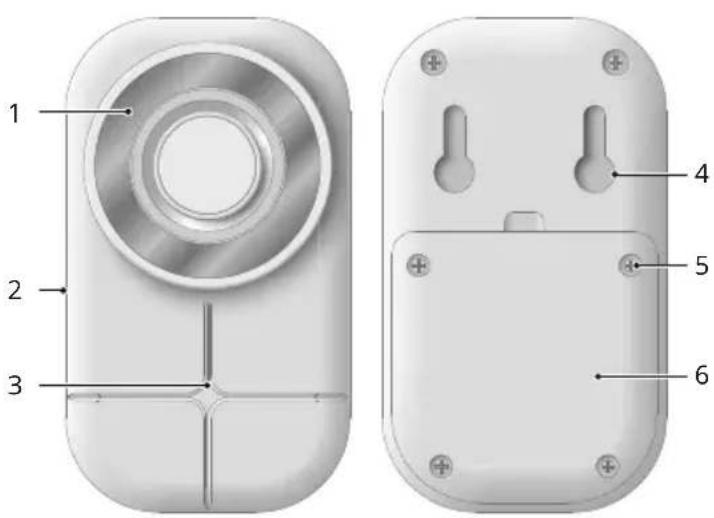
1 LED (lights up for an alarm)
2 Loudspeaker
3 Power adapter port (option)
4 Recesses for mounting bracket
5 Screw for battery compartment
6 Battery compartment
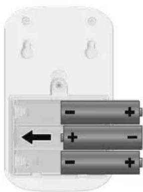
Inserting the Batteries
1 Loosen the screws in the battery compartment cover using an appropriate screw-driver.
2 Insert the batteries in the battery compartment. Pay attention that the batteries are inserted the right way around.
3 Replace the battery compartment cover on the outdoor siren.
4 Tighten the screw in the battery compartment cover using an appropriate screw-driver.
natural_image
Close-up of a battery pack with three stacked batteries and an arrow indicating direction (no text or symbols)Installation
WARNING! Risk of serious injuries through damaging cables or pipes! During installation, pay attention to the possibility of cables and pipes running in the walls. We are not deemed liable for installation errors. If in doubt, contact a specialist!
1 Drill two holes, about 37 mm apart, at the intended installation location.
2 Insert the screws supplied with the aid of dowels.
3 Hook the slots in the rear panel of the outdoor siren on the screws installed in the wall in Step 2.

OUTDOOR SIREN
Registering the Outdoor Siren
1 Select the Register menu option on the base unit.
2 Remove the batteries from the outdoor siren's battery compartment.
3 Replace the battery in the battery compartment.
4 The base unit display indicates that registration has been completed successfully on the alarm system.

If registering was not successful. Refer to Section Troubleshooting.

Alternatively, the outdoor siren can be operated by means of a power adapter. The power adapter is not included in the equipment supplied. Either contact our Service Department or visit our website at www.olympia-vertrieb.de
Technical Data
| Weight Approx. 198 g | |
| Dimensions (W x H x D) 92 x 138 x 49 mm | |
| Radio frequency 868.5 MHz | |
| Transmission power (max.) | 0.4 mW |
| Battery 3 x round cell batteries, type AA | |
| Permissible ambient conditions | -10 °C to +40 °C at 30% to 75% rel. humidity |
TFS 200 Temperature Sensor
Intended Use
The temperature sensor serves to display and monitor the temperature.
A condition for complying with the intended use is that the equipment is installed correctly and the information in the manual is observed and maintained. Any other use is considered unintended use.
Scope of Delivery
Please check the contents of the package carefully. If anything is missing or has been damaged during transport, DO NOT put the temperature sensor into operation!
Temperature sensor 1
Batteries 1 x AAA battery
Operating manual 1
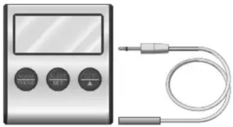
General View
natural_image
Illustration of a digital display and connected audio cable (no text or symbols visible)Full Instruction Manual
Read the full instruction manual for information on how the temperature sensor is started up, operated, registered on the base unit of the alarm system or how to change the batteries.
Technical Data
Weight Approx. 86 g
Dimensions (W x H x D) 65 x 71.5 x 21 mm
Radio frequency 868.5 MHz
Transmission power 0.6 mW (max.)
Battery 1 x AAA battery
Permissible ambient conditions -10 °C to +40 °C at 30% to 75% rel. humidity

IR 500 INFRARED LIGHT BARRIER
IR 500 Infrared light Barrier
Intended Use
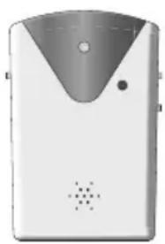
The infrared light barrier consists of a transmitter and a receiver. If the connection between the transmitter and receiver is interrupted by an object, the interruption is indicated by an acoustic alarm or doorbell chime.
A condition for complying with the intended use is that the equipment is installed correctly and the information in the manual is observed and maintained. Any other use is considered unintended use.
Scope of Delivery
Please check the contents of the package carefully. If anything is missing or has been damaged during transport, DO NOT put the infrared light barrier into operation!
Infrared light barrier 1
| Batteries 6 x round cell batteries,type AA |
Power adapter 2
| Assembly material Screws, dowels |
Operating manual 1
General View
natural_image
Exterior view of a modern office building (no signage)Full Instruction Manual
Read the full instruction manual for information on how the infrared light barrier is started up, operated, registered on the base unit of the alarm system or how to change the batteries.
Technical Data
Weight Approx. 198 g
| Dimensions (W x H x D) 80 x 120 x 40 mm | |
| Radio frequency 868.5 MHz | |
| Transmission power (max.) 8 mW | |
| Battery 3 x round cell batteries, type AA | |
| Permissible ambient conditions | -10 °C to +40 °C at 30% to 75% rel. humidity |
Appendix
Troubleshooting
I cannot register the sensors on the base unit of the alarm system.
The maximum number of sensors which can be registered on the base unit has been reached - deregister sensors from the base unit before attempting to register another sensor on the base unit.
Ensure that the Register option has been selected on the base unit before attempting to register a sensor.
More detailed information is available in the operating manual supplied with the base unit.
The sensor does not respond or does not work.
The batteries are weak or empty. Replace the empty batteries with new ones and try again.
The sensor reacts too sensitively or triggers too quickly.
If possible, adjust the sensitivity of the of the sensor (e.g. vibration sensor).
Check whether the sensor is mounted or positioned at a suitable location. Observe the corresponding sections in this operating manual.
If the proposed solutions prove unsuccessful.
Visit our website: www.olympia-vertrieb.de.
If you cannot find the information you need there either, please contact our Service Hotline.

APPENDIX
Information on Disposal
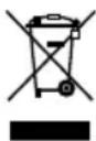
The adjacent symbol indicates that electrical and electronic apparatus and batteries no longer required must be disposed of separate from domestic waste in accordance with legal directives.
You are legally obliged to dispose of batteries and power packs at shops which sell batteries or collection points which provide the corresponding containers. Disposal is free of charge. The symbols indicate that the batteries must not be disposed of in normal domestic waste and that they must be brought to collection points provided by local public waste authorities.

Packaging materials must be disposed of according to local regulations.
Guarantee
Dear Customer,
we are pleased that you have chosen this equipment.
In the case of a defect, please return the device together with the receipt and original packing material to the point-of-sale.
Cleaning and Service
1 Disconnect the sensors from the power outlet before cleaning, if necessary!
2 Clean the surface of the housing with a soft, lint-free cloth. Never use any chemicals or scouring agents.
3 Check the functionality of each sensor registered once a month and after changing the batteries.
4 Change the batteries at least once a year or after receiving the relevant message from the alarm system.
Information on Conformity
CE Olympia Business Systems Vertriebs GmbH, Zum Kraftwerk 1, 45527 Hattingen hereby declares that these devices fulfil the basic requirements and other relevant provisions stipulated in the Directive 2014/53/EU. The CE Mark on the devices confirms conformity.
More detailed information on the Declaration of Conformity is contained on the supplementary sheet issued with the respective sensor.
OLYMPIA
v1.0, 06.2017
Door/Window Contact 6102
Concealed Window Contact 6104
Motion Detector 6108
Mini Remote Control 6101
Convenient Remote Control 6100
SOS/Panic Button 5912
Vibration Sensor 6107
Water Detector 6105
Glass Breakage Detector 6106
Outdoor Siren 6109
Temperature Sensor, TFS 200 5963
Infrared Light Barrier, IR 500 5964

- Contents
- Before You Start 6 Mini Remote Control 19
- Important Information on the Sensors . . . 6 Intended Use . . . . . . . . . . . . . . . . . . . . . . . . . . . . . . . . . . . . . . . . 19
- Safety Instructions 7 Scope of Delivery 19
- Door/Window contact 9 General View 19
- Registering a Sensor 11 Convenient Remote Control 22
- Concealed Window Contact 12 Scope of Delivery 22
- Technical Data 14 SOS/Panic Button 25
- Motion Detector 15 Intended Use 25
- Vibration Sensor 27 Outdoor Siren 36
- Water Detector 30 Intended Use 39
- Glass Breakage Detector 33 General View 40
- Scope of Delivery 33 Appendix 41
- BEFORE YOU START
- Important Information on the Sensors
- Safety Instructions
- Door/Window contact
- Intended Use
- Scope of Delivery
- Installation
- Inserting the Batteries
- Registering a Sensor
- Concealed Window Contact
- General View
- Changing the Batteries
- Technical Data
- Motion Detector
- Appropriate Installation Locations
- Inappropriate Installation Locations
- WARNING!
- Mini Remote Control
- Changing the Battery
- SOS Key
- Convenient Remote Control
- SOS/Panic Button
- Information on Use
- Vibration Sensor
- Setting the Sensitivity
- Water Detector
- Glass Breakage Detector
- Outdoor Siren
- Registering the Outdoor Siren
- TFS 200 Temperature Sensor
- Full Instruction Manual
- IR 500 Infrared light Barrier
- Appendix
- Troubleshooting
- Information on Disposal
- Guarantee
- Cleaning and Service
- Information on Conformity
- OLYMPIA
Brand : OLYMPIA
Model : 6104
Category : Door/window sensor