
CWM664 - Pregnant BOWERS & WILKINS - Free user manual and instructions
Find the device manual for free CWM664 BOWERS & WILKINS in PDF.


| Product Type | In-Ceiling Speaker |
| Brand | Bowers & Wilkins |
| Model | CWM664 |
| Driver Configuration | 1x 6.5" (165mm) woven glass fiber cone bass/midrange driver, 1x 1" (25mm) Nautilus™ aluminum dome tweeter |
| Frequency Response | 50Hz - 22kHz (±3dB) |
| Impedance | 8 ohms (nominal) |
| Sensitivity | 88 dB (2.83V, 1m) |
| Power Handling | 20W – 120W continuous (recommended amplifier power) |
| Dimensions (Cut-Out Diameter) | 200mm (7.9 in) |
| Dimensions (Overall) | Diameter: 240mm (9.4 in), Depth: 110mm (4.3 in) |
| Weight | 2.4 kg (5.3 lbs) |
| Finishes | White (paintable grille) |
| Installation Type | Ceiling mount (with dog-leg clamping system) |
| Safety Features | Spring-loaded terminals, back box optional |
| Cleaning & Maintenance | Wipe with dry cloth; do not use abrasive cleaners. Paint grille carefully to avoid clogging |
| Spare Parts & Repairability | Contact Bowers & Wilkins service for replacement drivers or grilles |
Frequently Asked Questions - CWM664 BOWERS & WILKINS
User questions about CWM664 BOWERS & WILKINS
0 question about this device. Answer the ones you know or ask your own.
Ask a new question about this device
Download the instructions for your Pregnant in PDF format for free! Find your manual CWM664 - BOWERS & WILKINS and take your electronic device back in hand. On this page are published all the documents necessary for the use of your device. CWM664 by BOWERS & WILKINS.
USER MANUAL CWM664 BOWERS & WILKINS
Welcome to Bowers & Wilkins and the CWM6 Series
Thank you for choosing Bowers & Wilkins. When John Bowers first established our company he did so in the belief that imaginative design, innovative engineering and advanced technology were keys that could unlock the enjoyment of audio in the home. His belief is one that we continue to share and it inspires every product we design.
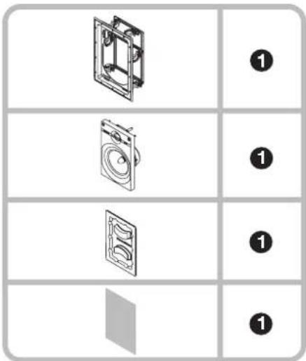
The CWM6 Series of wall mount speakers is designed to offer easy installation and high quality audio reproduction for discrete custom install applications. This manual describes the installation of CWM6 Series speakers within conventional stud and sheetrock (joist and plasterboard) walls. It begins by listing the contents of the CWM6 series carton.
text_image
Zeppelin and Zeppelin mini The best thing is happen to your kids? I can't know what if you're a healthy or super-high quality downloads for only $35.00 + My brand: Zeeppelin mini
text_image
Boll Brothers AG/300.com Boll Brothers AG/300.com Use the complete ABBN range Synonyms Boll Brothers AG/300.com Boll Brothers AG/300.com Boll Brothers AG/300.com Boll Brothers AG/300.com Boll Brothers AG/300.com Boll Brothers AG/300.com Boll Brothers AG/300.com Boll Brothers AG/300.com Boll Brothers AG/300.com Boll Brothers AG/300.com Boll Brothers AG/300.m Boll Brothers AG/300.m Boll Brothers AG/300.m Boll Brothers AG/300.m Boll Brothers AG/300.m Boll Brothers AG/300.m Boll Brothers AG/300.m Boll Brothers AG/300.m Boll Brothers AG/300.m Boll Brothers AG/300.m Boll Brothers AG/300.com Boll Brothers AG/300.com Boll Brothers AG/300.com Boll Brothers AG/300.com Boll Brothers AG/300.com Boll Brothers AG/300.com Boll Brothers AG/300.com Boll Brothers AG/300.com Boll Brothers AG/300.com Boll Brothers AG/300.12.2019 - 12 March 2019 Boll Brothers AG/300.com Boll Brothers AG/300.com Boll Brothers AG/300.com Boll Brothers AG/300.com Boll Brothers AG/300.com Boll Brothers AG/300.com Boll Brothers AG/300.com Boll Brothers AG/300.com Boll Brothers AG/300.com Boll Brothers AG/300.c12.2019 - 12 March 2019 Boll Brothers AG/300.com Boll Brothers AG/300.com Boll Brothers AG/300.com Boll Brothers AG/300.com Boll Brothers AG/300.com Boll Brothers AG/300.com Boll Brothers AG/300.comwww.bowers-wilkins.com
2. CWM6 Series Basics1. CWM6 Carton Contents
text_image
Diagram showing three views of a washing machine with numbered callouts for each view.CWM6 Series speaker assembly (baffle, frame, grille)• Cut-out template•
Paint mask•
Document pack containing Quick Start Guide and • Warranty information
Environmental Information
At Bowers & Wilkins products are designed to comply with international directives on the Restriction of Hazardous Substances (RoHS) in electrical and electronic equipment and the disposal of Waste Electrical and Electronic Equipment (WEEE). These symbols indicate compliance and that the products must be appropriately recycled or processed in accordance with these directives. Consult your local waste disposal authority for guidance.
CWM663, CWM664
text_image
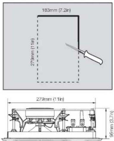
183mm (7.2in) 279mm (11in) 279mm (11in) 95mm (3.7in)CWM6 Series wall mount speakers comprise a baffle carrying the speaker drivers and crossover, an integrated frame and front flange, and a magnetically secured grille. The frame is connected via side mounted terminals to the speaker cables, with the baffle connecting automatically as it is inserted in the frame.
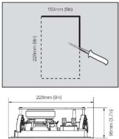
CWM6 Series speakers require wall aperture dimensions described in the following table:
Model Aperture Height Aperture Width
CWM652 228mm (9 in) 153mm (6 in) CWM663 279mm (11 in) 183mm (7.2 in) CWM664 279mm (11 in) 183mm (7.2 in)
CWM652
text_image
153mm (6in) 228mm (9in) 228mm (9in) 96mm (3.7in)All CWM6 Series speakers require clear depth behind the sheetrock (plasterboard) of 90mm (3.55 in). The diagrams above illustrate these dimensions.
Note: If CWM6 Series speakers are to be installed in "new build" projects, pre-mount kits and back boxes are available. Contact your local Bowers & Wilkins retailer for more information.
Before installing CWM6 Series speakers you should ensure that the wall locations chosen are free of obstructions such as pipe work, ducting or wiring that will interfere with the installation. In existing dry-wall construction, use a stud-finding tool to help you map the wall construction and a pipe detector to scan the proposed installation locations.
The appropriate position for CWM6 Series speakers within the listening environment will depend on their specific application:
General Background Audio Applications:
For applications where single CWM6 Series speakers are required to operate independently to provide background audio, they can be located substantially as installation convenience and architecture dictate. The only acoustic constraint to bear in mind is that corner locations will result in significantly emphasised low frequencies and should be avoided.
Stereo Audio Applications:
For applications where a pair of CWM6 Series speakers is to be used for conventional stereo reproduction, they should be located between 3m (10 ft) and 5m (16.5 ft) apart and a similar distance in front of the listening area. Try to avoid corner locations for the speakers and to ensure that acoustic environment around each speaker is similar.
Note: Different acoustic environments might be, for example, a bare wall and a heavily curtained window.
Multi-channel Audio Applications
For applications where multiple CWM6 Series speakers are to be used for multi-channel audio visual systems, the left and right front speakers should be located either side of the screen approximately 0.5m (20 in) away. The centre channel speaker should be located either directly above or below the screen or, in the case of an acoustically transparent screen, directly behind. Surround channel CWM6 Series speakers should be located just behind and either side of the listening position. Try to avoid corner locations for any of the speakers and to ensure that acoustic environment around each front and surround speaker is similar.
Note: Different acoustic environments might be, for example, a bare wall and a heavily curtained window.
Note: The nature of the installation of wall speakers means that it is sometimes impractical to locate them in the acoustically ideal positions. In these cases they should be located as close as is practical to the ideal positions. Your local Bowers & Wilkins retailer will be able to offer advice if required.
Note: CWM6 Series drive units create stray magnetic fields. We recommend that magnetically sensitive items such as CRT screens and magnetic cards for example, are kept at least 0.5m (20 in) from the speaker. LCD, OLED and plasma screens are not affected by magnetic fields.
To install a CWM6 Series speaker, proceed as described in the following paragraphs:
4.1 Using the supplied cut-out template, mark a cut line on the existing wall. Check the cut line defines the correct dimensions. Cut along the line with an appropriate tool to create a rectangular aperture in the wall.
Note: Ensure that there is enough free space internally adjacent to the aperture for the QuickDogs™.
Note: To reduce the possibility of the wall buzzing or rattling, adhesive mastic can be applied between the studs and sheetrock in the vicinity of the speaker aperture.
text_image
Diagram showing two labeled components (1 and 2) with arrows indicating flow or movement, likely illustrating a mechanical or electrical assembly.4.2 If speaker cable is already present in the wall space, pull the cable down through the aperture. If speaker cables are not already installed this should be done at this stage. It is likely that you will need to gain access through the floor above to route the cables down into the wall cavity.
Leave enough spare cable through the aperture to ease connection to the speaker frame, but not so much that it is likely to buzz or rattle when pushed back up into the wall space. Approximately 1.0m (3 ft) is appropriate.
Note: Always use high quality, low resistance speaker cable. Low resistance is especially important if the length of cable from amplifier to speaker exceeds 5m. Your local Bowers & Wilkins retailer will be able to offer advice on speaker cable selection if required.
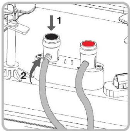
4.3 Now connect the speaker cable to the spring terminals on the side of the frame. Ensure that the speaker connection polarity is correct: the cable connected to the positive terminal on the amplifier should be connected to the red spring terminal on the frame. Similarly, the cable connected to the negative terminal on the amplifier should be connected to the black spring terminal on the frame. The diagram above illustrates cable connection.
Note: If an amplifier is already connected to the cable it should be switched off while connections are being made to the frame.
natural_image
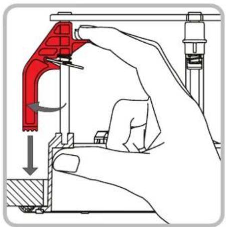
Illustration of a hand using a red mechanical clamp to adjust or install a component, with no visible text or symbols.4.4 With the frame connected it may be inserted into the wall aperture. Ensure that the QuickDogs™ (spring clamps) are rotated so that they will pass through the aperture then insert the frame up so that the flange is flush on the wall. Take care that the cable is not trapped. Now reach inside the aperture, rotate the QuickDogs™ outwards and, using two fingers and thumb, pull each spring clamp downwards so that the frame is fixed securely. There are four QuickDogs™ on the CWM652 and six on the CWM663 and CWM664. The diagram above illustrates insertion of the frame.
Note: To release a spring clamp push the metal tab, located just below the finger platform, upwards.
natural_image
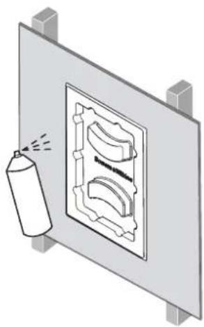
Illustration of a spray can spraying onto a wall-mounted device (no text or symbols visible)4.5 If the frame flange is to be painted it should be done at this stage. Any conventional, domestic paint may be applied by brushing, rolling or spraying. Use the supplied paint mask to avoid getting paint in the cavity. Painting without using the paint mask risks contamination of the internal connection terminals or the grille attachment magnets. The diagram above illustrates painting using the paint mask.
Note: If the grille is to be painted this should be done "off-line" before it is fitted.
text_image
= 1x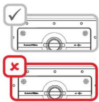
text_image
Schematic/Officer ###-01+ ##-02+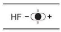
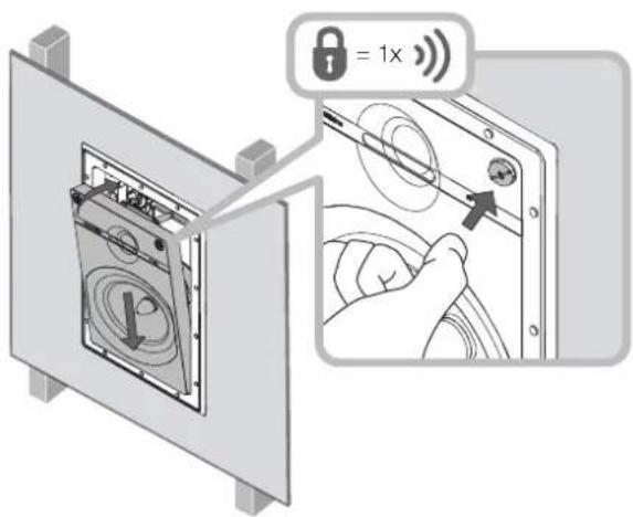
4.6 The baffle can now be fitted into the frame. Ensure that the connector on the baffle is oriented correctly with the connector in the frame. The baffle is hinged into place along its bottom edge and secured at the top by two push-lock fasteners. Push-lock fasteners are secured by pushing the head inwards - either with a thumb or a screwdriver. Please ensure that the largest groove on the fastener is orientated at a diagonal, pointing to the corner of the baffle, before pushing the fastener. As they secure, the fasteners will click. The baffle will then be secure in the frame. The diagram above illustrates inserting the baffle and securing the push-lock fasteners.
Note: Push-lock fasteners are released by turning anticlockwise with a screwdriver.
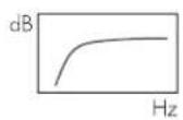
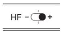
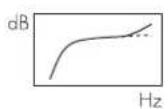
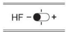
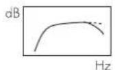
The HF+ boost position can be useful where the listening environment is acoustically absorbent, for instance where carpets, soft furnishings and curtains predominate, or where the speakers are covered by curtains or wall hangings. The HF- cut position may be preferred where the listening environment is acoustically reflective, for instance where hard floors and glass predominate. The diagram above illustrates the level switch and its effect.
4.7 A three position high frequency level switch is fitted to CWM600 series models, on the front face of the baffle. The centre position of the switch gives a nominally level frequency response.

natural_image
Isometric view of a rectangular panel with a mesh pattern and two side supports, featuring a small U-shaped magnet icon (no text or symbols)4.8 The grille can now be fitted to the baffle. It is held in place magnetically, so simply needs to be aligned with the groove in the frame flange, where it will click into place. The diagram above illustrates fitting the grille.
The CWM6 Series speaker is now installed and ready for use.
Bowers & Wilkins
B&W Group Ltd
Dale Road
Worthing West Sussex
BN11 2BH England
T +44 (0) 1903 221 800
F +44 (0) 1903 221 801
info@bwgroup.com
www.bowers-wilkins.com
B&W Group (UK Sales)
T +44 (0) 1903 221 500
E uksales@bwgroup.com
B&W Group North America
T+1 978 664 2870
E marketing@bwgroupusa.com
B&W Group Asia Ltd
T +852 3 472 9300
E info@bwgroup.hk
Copyright © B&W Group Ltd. E&OE