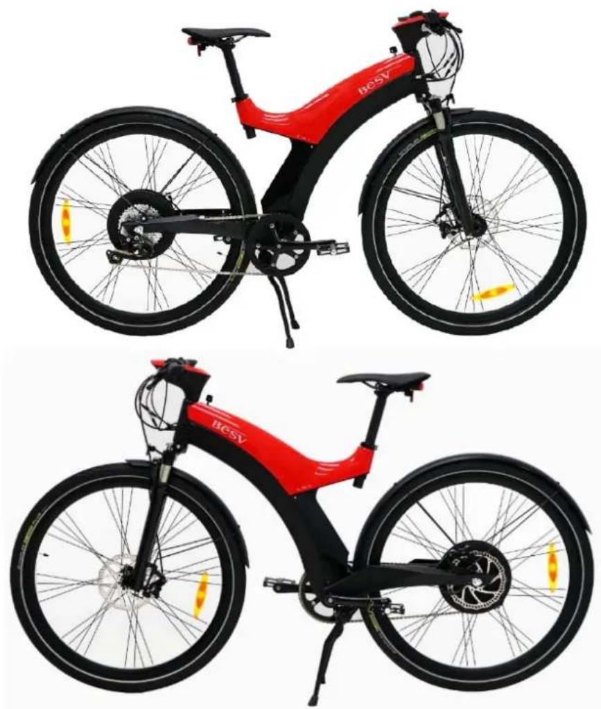
LX1 - Bike BESV - Free user manual and instructions
Find the device manual for free LX1 BESV in PDF.


User questions about LX1 BESV
0 question about this device. Answer the ones you know or ask your own.
Ask a new question about this device
Download the instructions for your Bike in PDF format for free! Find your manual LX1 - BESV and take your electronic device back in hand. On this page are published all the documents necessary for the use of your device. LX1 by BESV.
USER MANUAL LX1 BESV
Quick Assembly Guide BESV LX1
natural_image
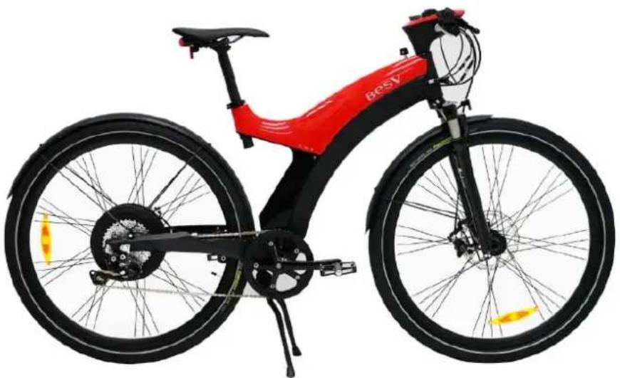
Red and black BYR-5 electric bicycle with visible branding, shown from front and side (no text or symbols on the bike body)Contents
1. What's in the Box....2
1.1 Main Box Contents 2
1.2 Accessory Box Contents 2
2. Assembly Procedures 3
2.1 Front Wheel 3
2.2 Front Fender and Reflector 5
2.3 Pedal 6
2.4 Battery....7
2.5 Saddle & Seat Post....8
2.6 Rear Light....9
3 Checklist....10
1. What's in the Box
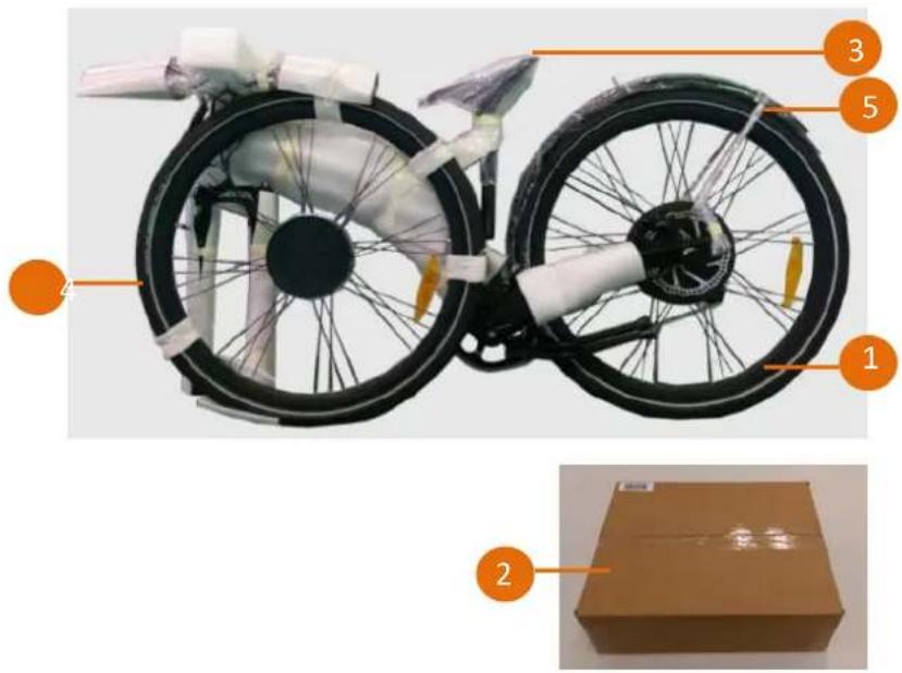
1.1 Main Box Contents
- Main Bike Assembly
- Accessory Box
- Saddle/Seat Post Set
- Front Wheel
- Front Fender
text_image
Diagram of a bicycle with labeled parts and a cardboard box, showing structural components and assembly.1.2 Accessory Box Contents
- Product Documentation
- Charger
- Pedals
- Rear Light & Reflector
- Quick Release (QR) for the Front Wheel
- Key
- Front reflector and screw sets

text_image
Diagram of a cardboard box assembly with numbered parts labeled 1 through 7, showing internal components like packing, cladding, and accessories.2. Assembly Procedures
2.1 Front Wheel
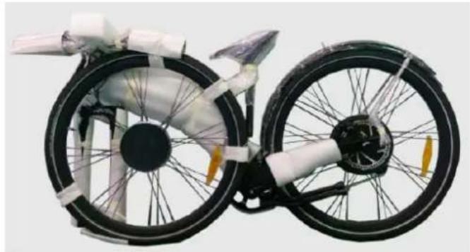
2.1.1 Unpack the front wheel and the main bike assembly.
natural_image
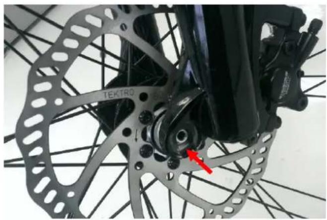
Exterior view of a bicycle with visible wheel rim, suspension rings, and black frame (no text or symbols)2.1.2 Insert the wheel into the fork end.
natural_image
Close-up of a bicycle wheel assembly with visible components and a red arrow pointing to a specific part (no text or symbols)Attention: The disk should be placed between the brake pads.

natural_image
Close-up of a bicycle wheel assembly with a red arrow pointing to a specific component (no visible text or symbols)2.1.3 Set the quick release (QR)
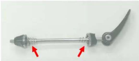
Unscrew the nut and spring from the QR and insert the QR stem from the left side of the bike.
Attention: The quick release handle should be on the left side of bike.
natural_image
Mechanical linkage component with two red arrows indicating movement or force direction (no text or symbols)2.1.4 Tighten the nut
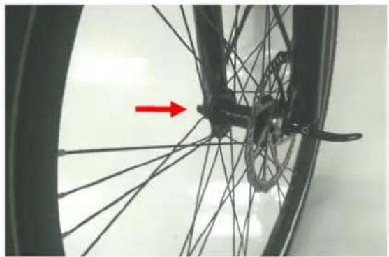
Place the spring back in the QR stem and tighten the nut until you encounter resistance.
Then loosen 1/4 turn.
Note: The tapered end of the spring should be facing inward.
natural_image
Close-up of a bicycle wheel with visible spokes and a red arrow pointing to the wheel (no text or symbols)2.1.5 Tighten the nut
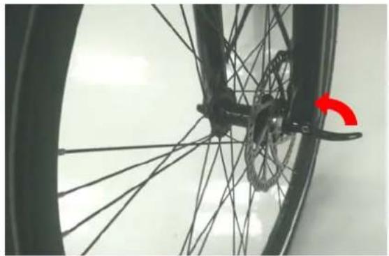
Lock the QR by pushing the handle upwards until parallel with fork. Turn the wheel and verify the rotation is smooth
natural_image
Close-up of a bicycle wheel with visible spokes and a red curved arrow indicating rotation (no text or symbols)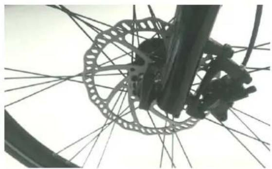
natural_image
Close-up of bicycle wheel and gear assembly with visible spokes (no text or symbols)2.2 Front Fender and Reflector
2.2.1 Fender parts introduction
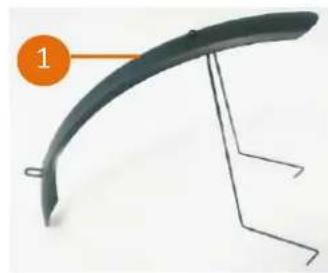
- Front Fender & Support
- Fix Plate*2
- M5 Screw*2
- Front Reflector
- Fender screw with washers
natural_image
Curved metal bracket with attached metal frame, no text or symbols visible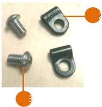
natural_image
Four metallic screw fasteners with orange connectors pointing to them (no text or symbols visible)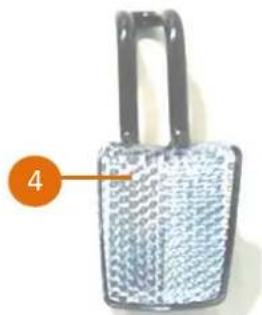
natural_image
Close-up of a metallic padlock with textured surface and handle, labeled with number 4 (no text or symbols on the object itself)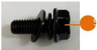
natural_image
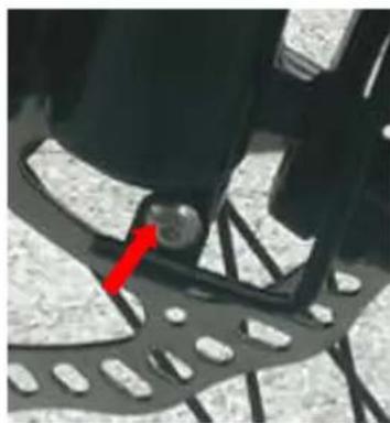
Close-up of a black threaded bolt with a flanged end, no visible text or symbols2.2.2 Place the fix plate at the bottom of the front fork and loosely secure with the M5 screw.
2.2.3 Place front fender and support with the end of the support going into the fix plate.
2.2.4 Place the front reflector at the top of the fork where the fender meets the fork, then loosely secure with the fender screw.
2.2.5 Adjust the fender position, and then tighten the screws at the reflector and at the fix plate.
natural_image
Close-up of a black foot and pedal mechanism with a red arrow pointing to a circular component (no text or symbols visible)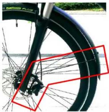
natural_image
Close-up of a bicycle wheel with visible spokes and a red bounding box highlighting the front wheel (no text or symbols)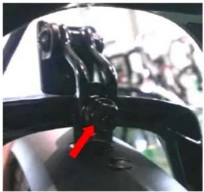
natural_image
Close-up of a car's front wheel assembly with a camera mounted on the intake (no visible text or symbols)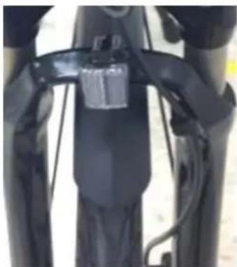
natural_image
Close-up of a black bicycle seatbelt with visible straps and wiring (no text or symbols)Note: When securing the reflector to the fork, make sure the placement order is fork, fender and then reflector.
2.3 Pedal
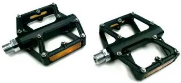
2.3.1 Take out the pedal.
natural_image
Two black mechanical brake pedal components with attached connectors and fittings (no text or symbols visible)2.3.2 Set up the right pedal
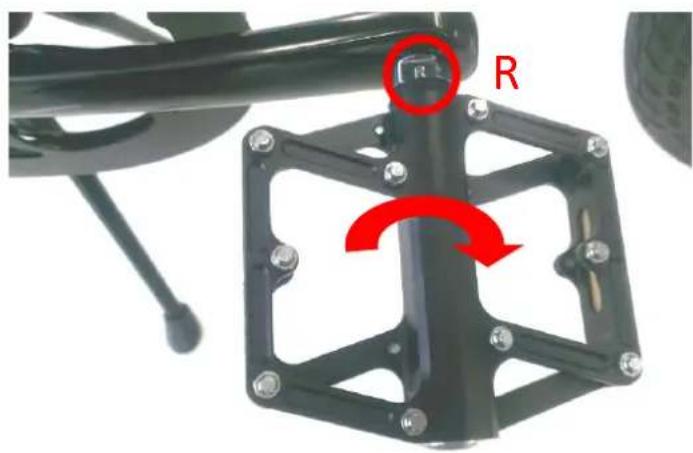
Note: There is a mark "R" on one of the pedal. Assemble it onto the right crank clockwise.
natural_image
Mechanical assembly with a black frame and red circular annotation indicating 'R' (no text or symbols on the diagram itself)2.3.3 Set up the left pedal
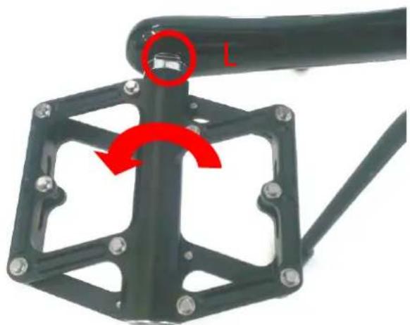
Take another pedal and assemble it to the left crank counterclockwise.
natural_image
Mechanical linkage component with red rotation arrow indicating rotational motion (no text or symbols)2.4 Battery
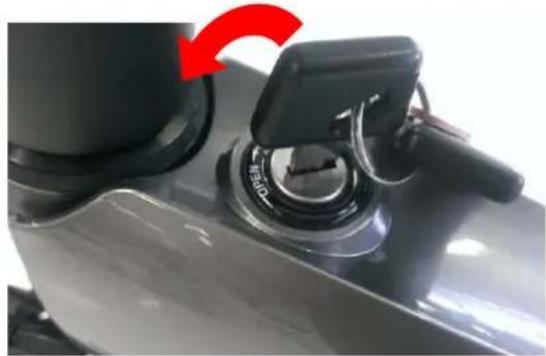
2.4.1 Insert the key and turn it to the "OPEN" position.
2.4.2 Pull the battery cover upward.
2.4.3 Slide the battery in and push it until it firmly connects to the socket.
2.4.4 Close the battery cover. Push the key in and turn it to "OFF" position to lock the battery cover in place.
natural_image
Close-up of a mechanical component with a red arrow indicating rotation, showing a knob and handle (no text or symbols visible)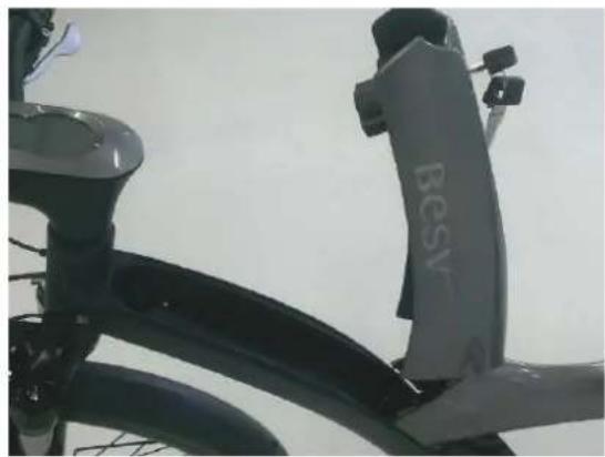
natural_image
Close-up of a BEV charging station bicycle (no visible text or symbols)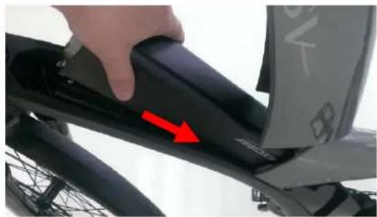
natural_image
Close-up of a bicycle seatbelt with a hand adjusting the seat area, showing a red arrow pointing to the side (no text or symbols visible)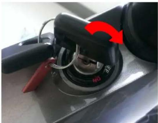
natural_image
Close-up of a black mechanical component with red arrows indicating rotation or adjustment, no visible text or symbols2.5 Saddle & Seat Post
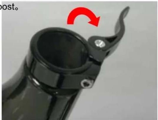
2.5.1 Open the seat post clamp and insert the seat post.
natural_image
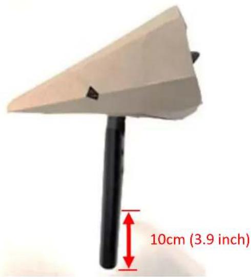
Close-up of a black plastic mechanical component with a red curved arrow indicating rotation (no text or symbols)Attention: the depth of the seat post. The seat post must be inserted at least 10cm (3.9inch).
text_image
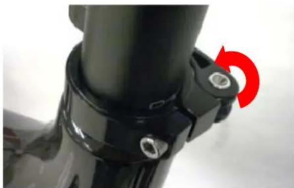
10cm (3.9 inch)2.5.2 Set the saddle face forward and adjust the height. Lock the seat post clamp.
natural_image
Close-up of a black mechanical component with a red circular arrow indicating rotation (no text or symbols)2.6 Rear Light
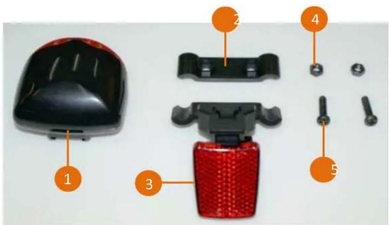
2.6.1 Introduction of the rear light parts.
- Rear light
- Bracket upper housing.
- Bracket lower housing & reflector
- M4 Nut*2
- M4*L15 Screw*2
text_image
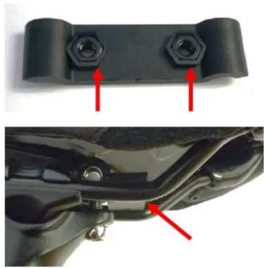
Exploded view diagram of a device showing labeled parts including a black hard case, red brake pad, and five bolted components.2.6.2 Bracket.
Put the M4 nut into bracket upper housing. Set under the saddle.
natural_image
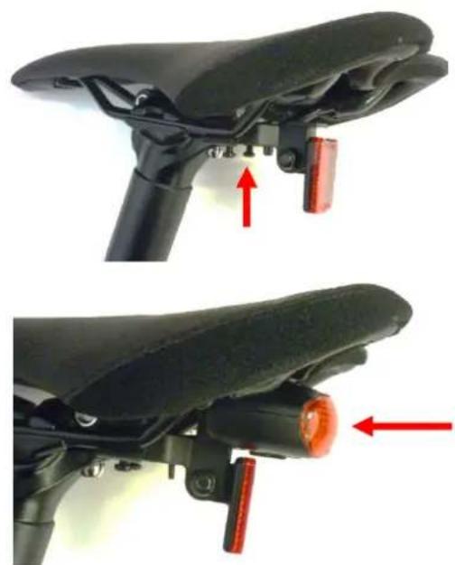
Close-up of a black mechanical component with two hexagonal nuts and red arrows pointing to features, shown from top and side (no text or symbols)2.6.3 Combine upper and lower housing by M4 nut.
natural_image
Close-up of a black bicycle seat with red LED lights and mechanical components, shown from top and side views (no text or symbols)2.6.4 Insert the rear light into the bracket rail.
3 Checklist
3.1 Check the tire pressure is normal.
3.2 Check the function of the brakes, derailleur, and chain.
3.3 Check the function of the electric module and the battery power. Please refer to LX1 user manual.