Frame - Bed Loof - Free user manual and instructions
Find the device manual for free Frame Loof in PDF.


User questions about Frame Loof
0 question about this device. Answer the ones you know or ask your own.
Ask a new question about this device
Download the instructions for your Bed in PDF format for free! Find your manual Frame - Loof and take your electronic device back in hand. On this page are published all the documents necessary for the use of your device. Frame by Loof.
USER MANUAL Frame Loof
natural_image
Simple line drawing of a two-legged bench with legs and a flat top (no text or symbols)Bed Frame
Assembly manual
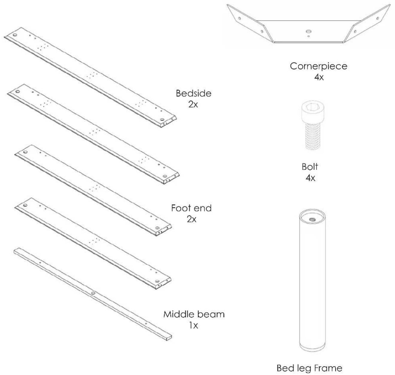
Content of the box
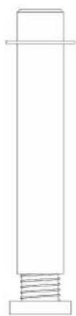
natural_image
Simple line drawing of a cylindrical object with a spring at the base (no text or symbols)Plastic leg 1x
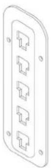
Support plate
8x
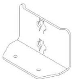
natural_image
Line drawing of a metal bracket with two small holes and mounting holes (no text or symbols)Bed hook 8x
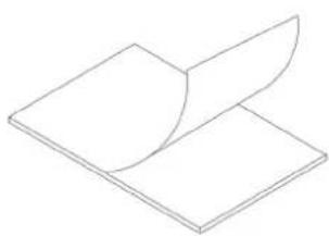
natural_image
Simple line drawing of two overlapping sheets or panels (no text or symbols)Rubber pad 6x

Optional headboard type 1 or 2
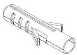
natural_image
Technical line drawing of a cylindrical mechanical component with mounting brackets (no text or symbols)Screw plug 10x
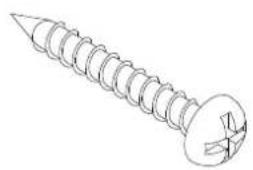
natural_image
Line drawing of a screw with threaded shaft and circular head (no text or symbols)Screw 4x30 10x
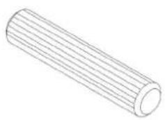
natural_image
Simple line drawing of a cylindrical object with vertical grooves (no text or symbols)Dowel 8x40 4x

natural_image
Line drawing of a screw with threaded head and base (no text or symbols)Screw 4x50 6x
natural_image
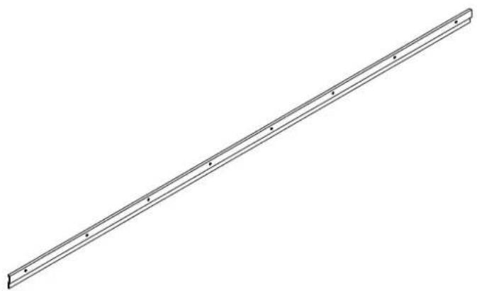
Pure diagonal line diagram without any text, numbers, or symbolsMetal strip 2x
natural_image
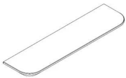
Simple line drawing of a rectangular object with rounded edges (no text or symbols)Shelf 2x
natural_image
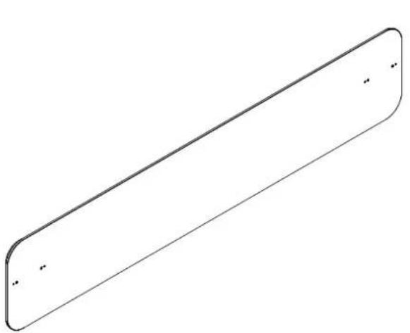
Simple 3D line drawing of a rectangular object with two small dots on its top face (no text or symbols)Headboard for Frame type 1 1x
text_image
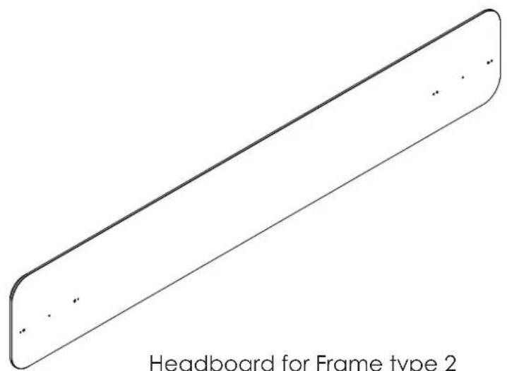
Headboard for Frame type 2Headboard for Frame type 2 1x
Needed for assembling
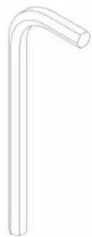
natural_image
Simple line drawing of a bent pipe or tube (no text or symbols)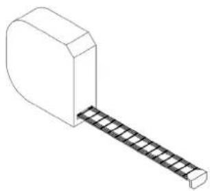
natural_image
Isometric line drawing of a mechanical component with a rectangular block and a diagonal bar (no text or symbols)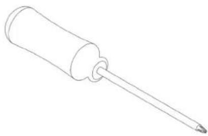
natural_image
Line drawing of a screwdriver with a pointed tip (no text or symbols)ScrewdriverMeasuring toolAllei
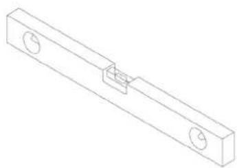
natural_image
Isometric line drawing of a mechanical bracket with two circular holes (no text or symbols)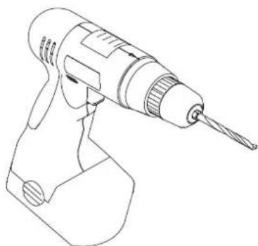
natural_image
Line drawing of a handheld electric drill (no text or symbols)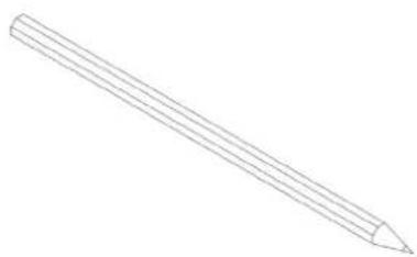
natural_image
Line drawing of a sharpened pencil (no text or symbols)PencilDrill 6mmLeveller
Assembly
text_image
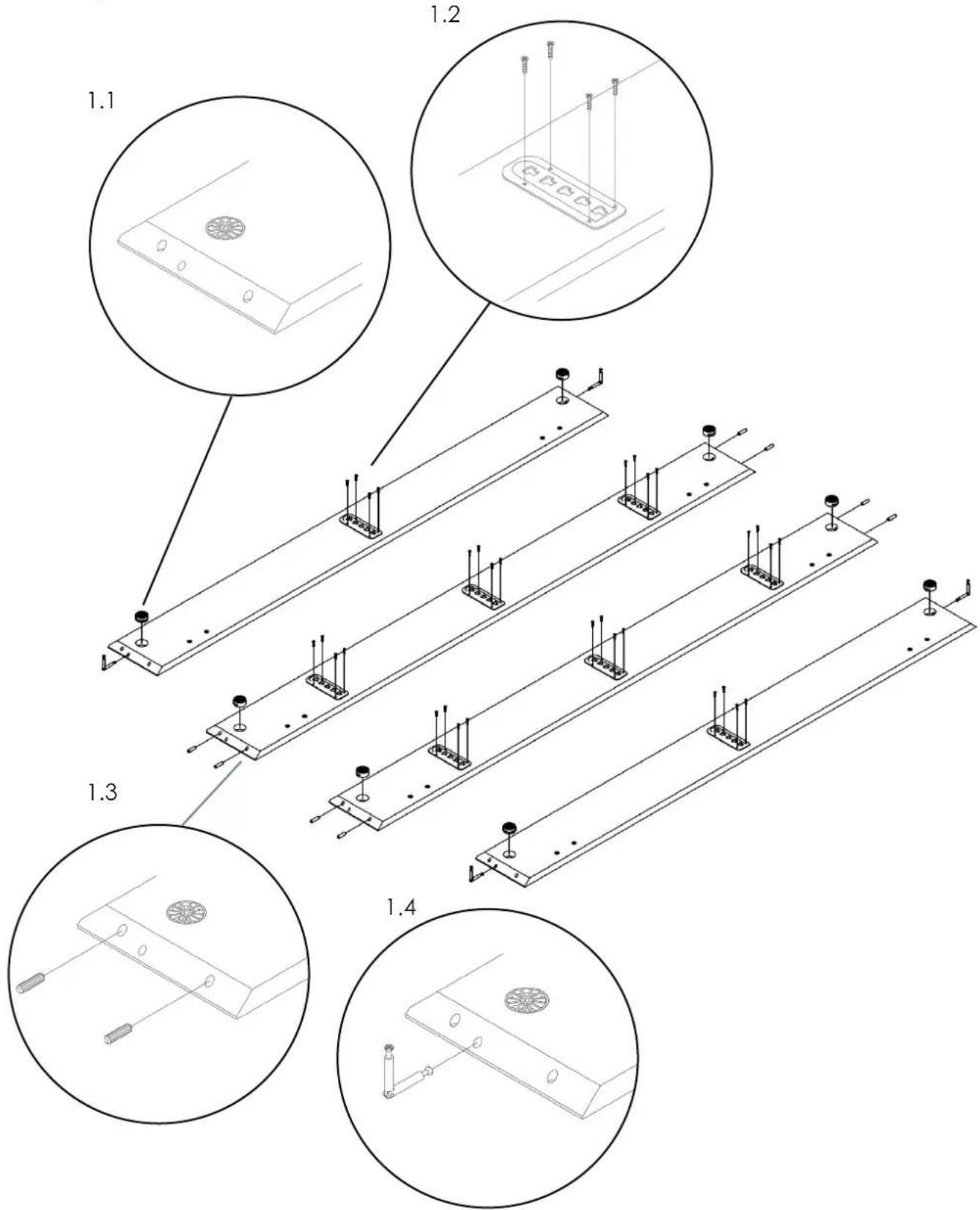
Technical diagram showing assembly steps of a metal frame structure with numbered components and mounting details.1.1 Insert the connector housing 8x into the round holes on top of the bedsides and foot end - make sure the arrow is pointing to the hole.
1.2 Attach the support plates 8x to the frame with the Euro-screws 32x.
1.3 Insert the dowels 30 mm 8x into the smaller holes at the ends of the bedsides.
1.4 Insert the joint connector 4x into the holes at the ends of the foot end.
natural_image
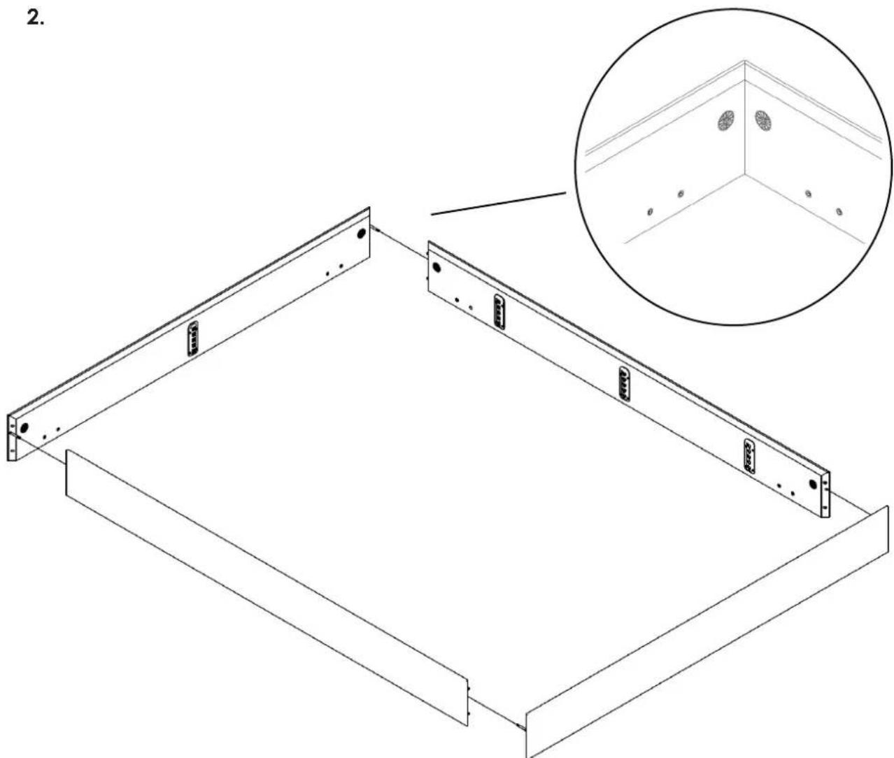
Technical line drawing of a structural frame assembly with mounting brackets and a magnified inset showing internal components (no text or symbols)2.1 Connect the four bedsides.
2.2 Tighten by turning the connector housing 8x to the right with the allen key - only 3/4 turn needed.
natural_image
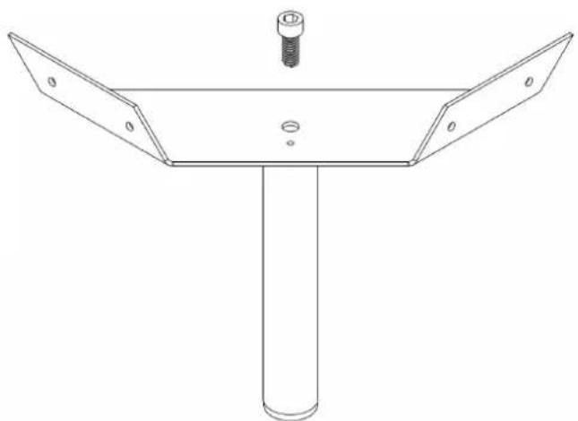
Technical line drawing of a mechanical support structure with a central column and mounting bracket (no text or symbols)Connect the legs to the cornerpiece by using the bolt M10.
4.
natural_image
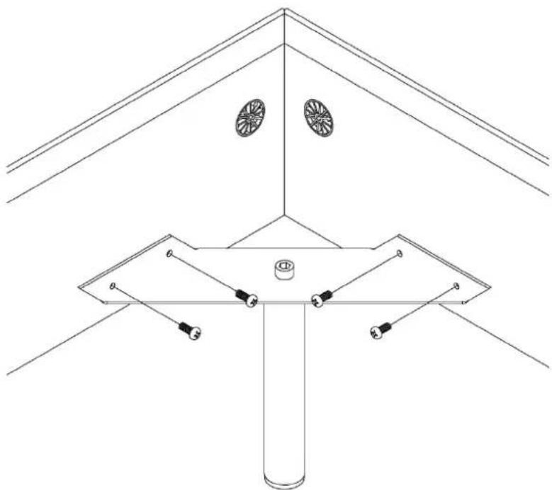
Technical line drawing of a structural support frame with three vertical supports and circular components (no text or symbols)Connect the cornerpiece to the bed Frame using the screw 16mm.
5.
natural_image
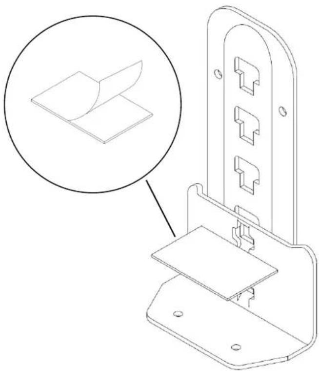
Technical line drawing of a mechanical bracket assembly with an inset showing a folded sheet component (no text or symbols)To avoid the bed base from sliding, stick the rubber pads 6x to the bed hooks 6x.
natural_image
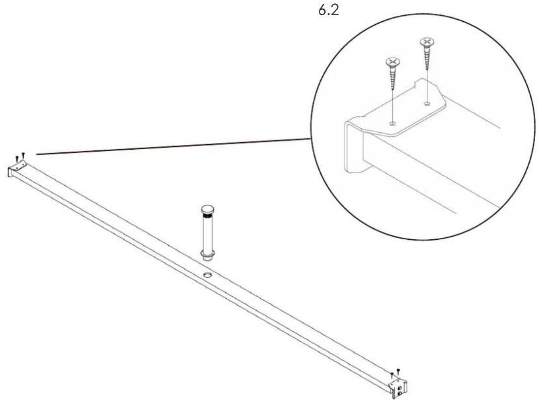
Technical line drawing of a metal bracket with two screws inserted, shown in an inset (no text or symbols)6.1 Insert the plastic leg 1x into the middle beam.
6.2 Attach the bed hooks 2x to the middle beam with the 20mm screws 4x.
natural_image
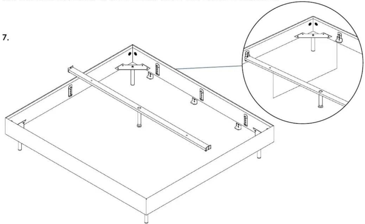
Technical line drawing of a structural frame assembly with mounting brackets and mounting holes, shown in two orthographic views (no text or symbols present)To achieve the desired height of your mattress, hook the bed hooks 6x into the support plates 6x on the level of your choice. Do the same with the middle beam but please note the beam has to be hooked one level below the other bed hooks.
8.
natural_image
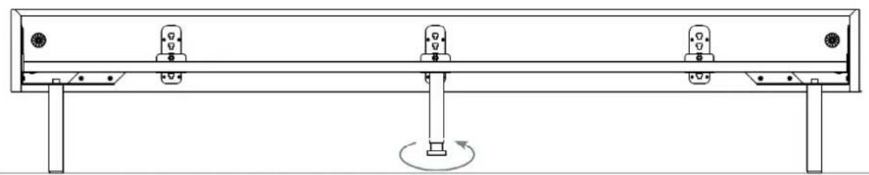
Technical line drawing of a mechanical assembly with four vertical supports and a central rotating component (no text or symbols)Turn the plastic leg 1x to the left to extend it and give it the desired length.
9.
natural_image
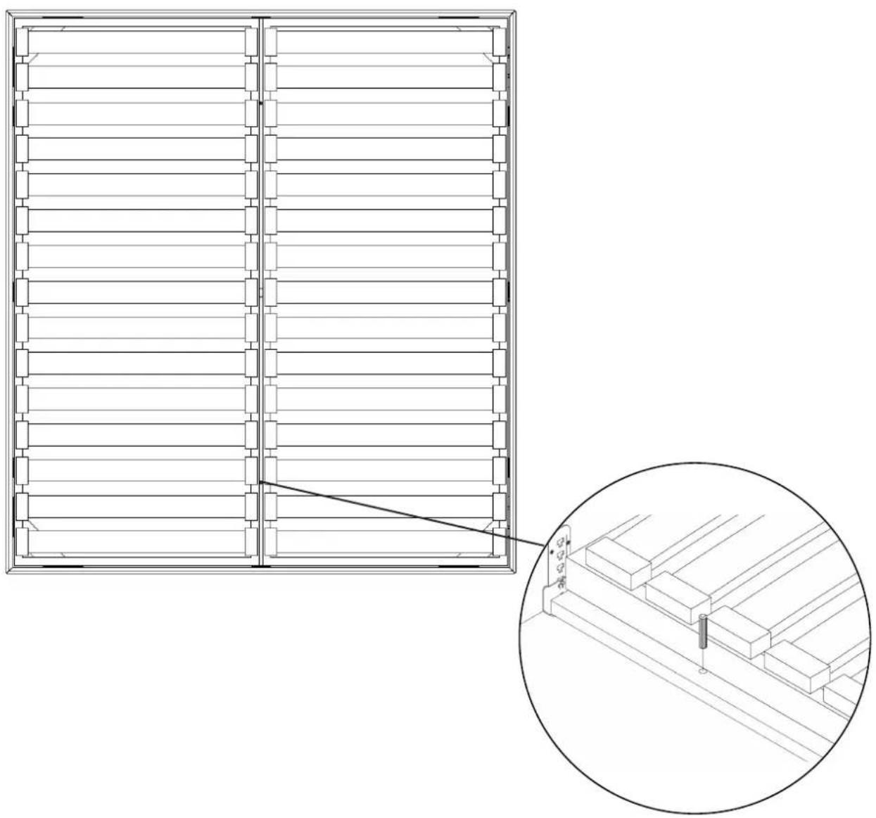
Architectural line drawing of a rectangular building facade with internal structural beams and a magnified inset showing a detailed detail (no text or symbols)Please note: when there's too much empty space between the bed bases and the bed-frame you can put the dowels 60 mm 2x into the holes in the middle beam. To enable a fixed position for the bed bases.
Assembly headboard type 1 or type 2 1.
natural_image
Technical line drawings of two electronic device components with pins and connectors (no text or symbols)Type 1 Type 2
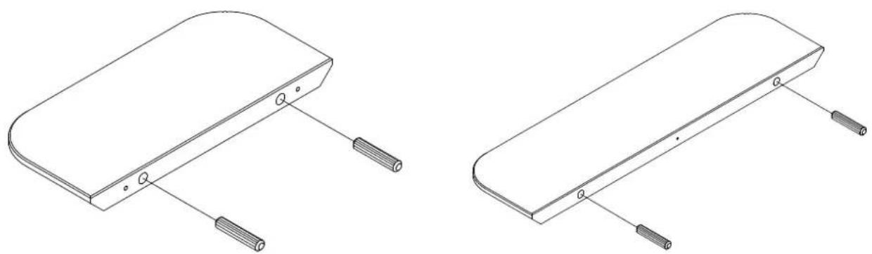
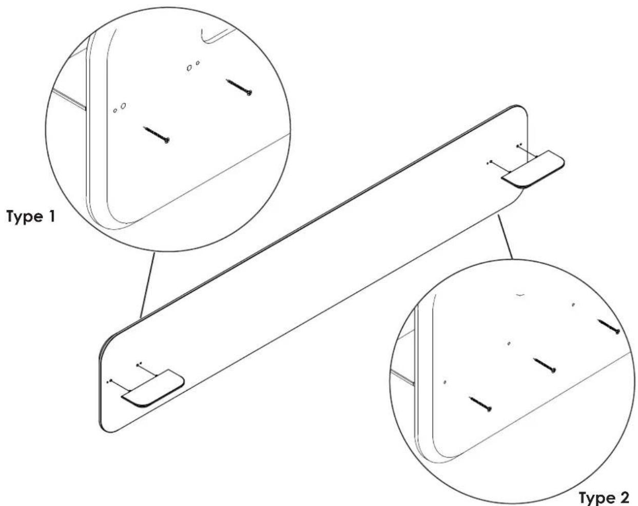
Insert the dowels 40 mm 4x into the big holes at the back of the two shelves type 1 2x or type 2 2x.
2.
text_image
Type 1 Type 2Attach the - shelf 2x type 1 or shelf 2x type 1 - on the - headboard type 1 or headboard type 2 - using the screw 4x50.
text_image
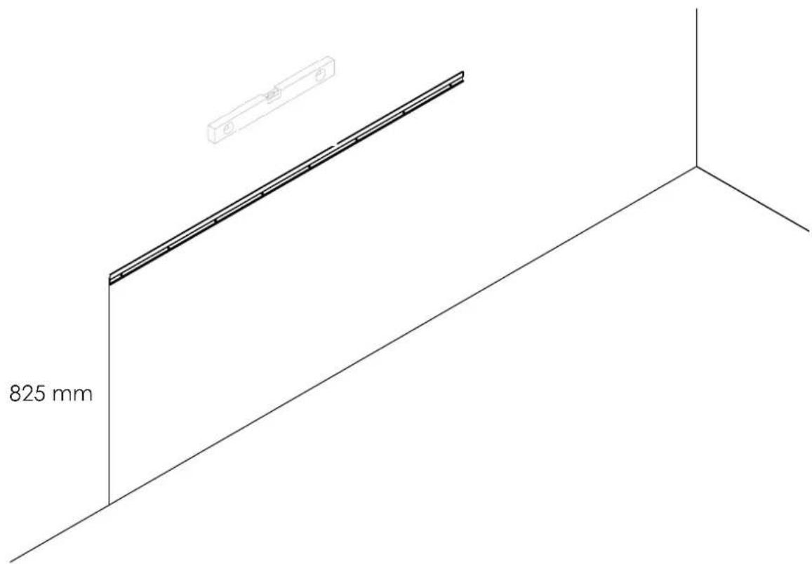
825 mmHold the metal strip against the wall to mark the drill holes. Make sure that the headboard is moanted level by using a leveller. We recommend a height of 825 mm measured from the floor. Use a pencil to mark the holes.
text_image
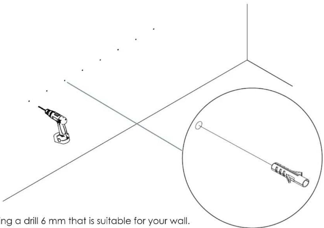
ng a drill 6 mm that is suitable for your wall.Drill the holes using a drill 6 mm that is suitable for your wall. Insert the plugs into the holes.
5.
natural_image
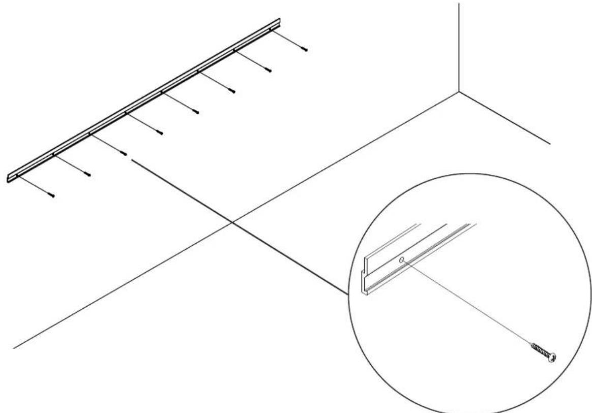
Technical line drawing of a structural beam with supports and a magnified inset showing a fixed support (no text or symbols)Mount the metal strip against the wall with the screw 4x30.
6.
natural_image
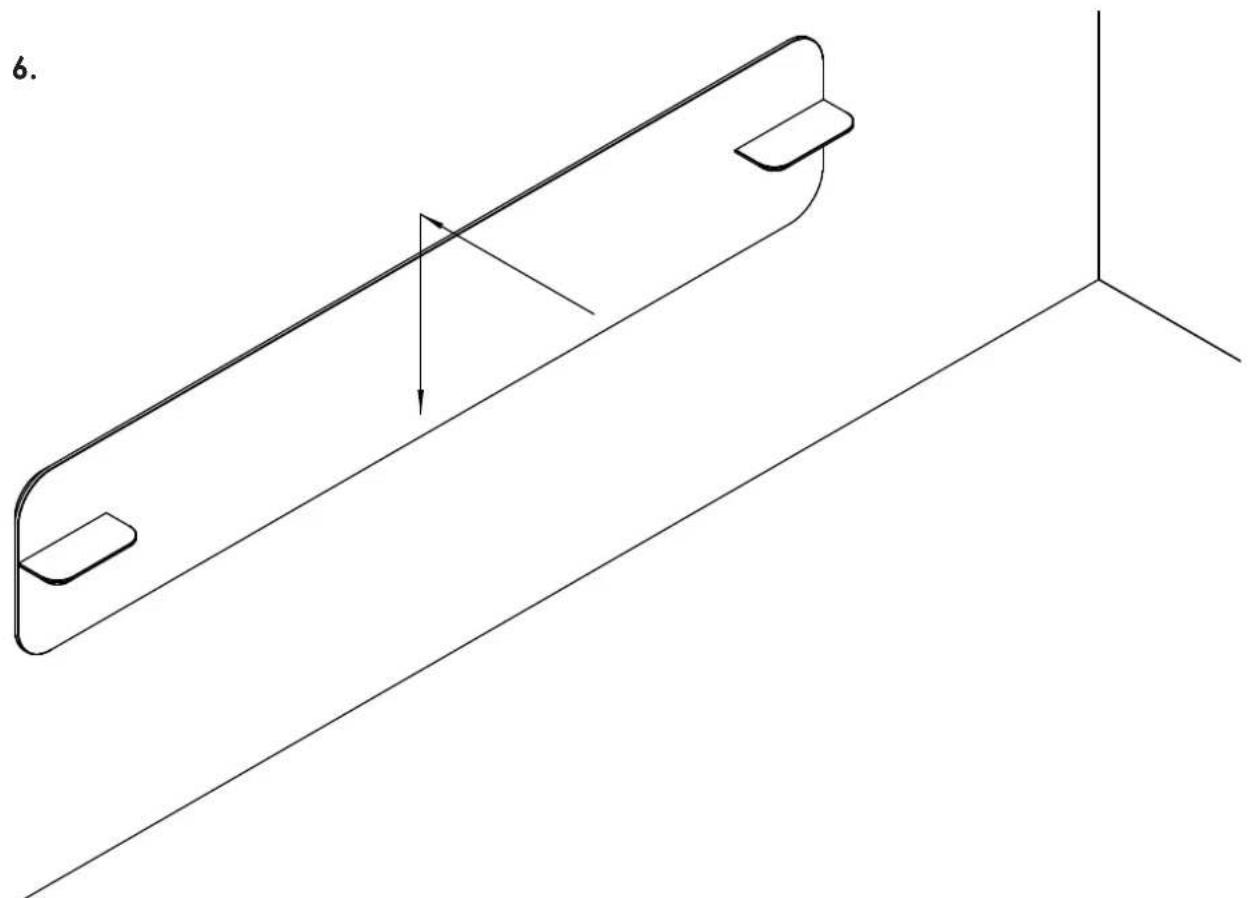
Pure technical line drawing of a mechanical part with an arrow indicating direction, no text or symbols presentYou are now ready to mount the headboard against the wall. Push the headboard softly towards the wall and slowly lower the headboard until it is fully supported by the metal frame.
NEED SOME HELP?
hello@loof.nl / +31 (0)75 7729216