
AJ-HPX2000P - Camcorder PANASONIC - Free user manual and instructions
Find the device manual for free AJ-HPX2000P PANASONIC in PDF.


| Product Type | Professional Camcorder |
| Model | AJ-HPX2000P |
| Brand | Panasonic |
| Dimensions (W x H x D) | 137 mm x 209 mm x 318 mm (5-3/16 in x 8-1/2 in x 12-1/2 in) excluding handle and wireless option cover |
| Weight | Approx. 4.5 kg (9.9 lb) main unit only, excluding VF mount |
| Power Supply | DC 12 V (11.0 V - 17.0 V) |
| Power Consumption | 36 W (main unit only, LCD monitor OFF); 43 W (with SDI-IN and AVC-Intra option, LCD monitor ON) |
| Operating Temperature | 0°C to +40°C (32°F to +104°F) |
| Storage Temperature | -20°C to +60°C (-4°F to +140°F) |
| Operating Humidity | 10% to 85% (relative humidity) |
| Pickup Devices | 2/3-inch CCD x 3 (RGB 3CCD) |
| Total Pixels | 1370 (H) x 744 (V) |
| Valid Pixels | 1280 (H) x 720 (V) |
| Quantization | 14-bit A/D conversion |
| Lens Mount | 2/3-inch bayonet type |
| Recording Media | P2 cards (up to 5 slots) |
| Video Recording Formats | DVCPRO HD, DVCPRO50, DVCPRO, DV; optional AVC-Intra |
| Audio Recording | 48 kHz/16-bit, 4-channel (2/4 ch selectable in DVCPRO/DV) |
| Gain Settings | -3 dB to +30 dB (programmable), Digital Super Gain up to +20 dB, Super Gain up to +48 dB |
| Shutter Speeds | 1/60 to 1/2000, synchro-scan (various ranges per format) |
| White Balance | Auto, preset (3200K), memory A/B, auto-tracking (ATW) |
| Viewfinder | Optional HD (AJ-HVF21G) or SD viewfinders |
| LCD Monitor | 3.5-inch color LCD for thumbnail display and settings |
| Input/Output | HD/SD SDI, composite, IEEE1394 (DV), USB 2.0, XLR audio, TC, remote |
| Safety Features | Warnings for electric shock, moisture, laser; FCC Class B compliance; battery recycling information |
| Maintenance | Regular inspections, black/white shading adjustment, lens file management, fan auto mode |
| Optional Accessories | AVC-Intra board (AJ-YBX200G), SDI input board (AJ-YA350AG), video encoder (AJ-YAX800G), GPS unit (AJ-GPS910G), remote control (AJ-RC10G) |
Frequently Asked Questions - AJ-HPX2000P PANASONIC
User questions about AJ-HPX2000P PANASONIC
0 question about this device. Answer the ones you know or ask your own.
Ask a new question about this device
Download the instructions for your Camcorder in PDF format for free! Find your manual AJ-HPX2000P - PANASONIC and take your electronic device back in hand. On this page are published all the documents necessary for the use of your device. AJ-HPX2000P by PANASONIC.
USER MANUAL AJ-HPX2000P PANASONIC
Model No. AJ-HPX2000P
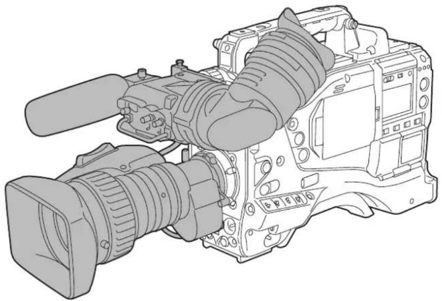
natural_image
Line drawing of a professional video camera with extended lens and external frame (no text or symbols)
AVC INTRA DVCPRO HD DVCPRO 50 DVCPRO DV
Before operating this product, please read the instructions carefully and save this manual for future use. To use AVC-Intra, the AVC-Intra codec board (AJ-YBX200G/optional) must be installed.
Read this first!

CAUTION
RISK OF ELECTRIC SHOCK
DO NOT OPEN

CAUTION: TO REDUCE THE RISK OF ELECTRIC SHOCK, DO NOT REMOVE COVER (OR BACK).
NO USER SERVICEABLE PARTS INSIDE.
REFER TO SERVICING TO QUALIFIED SERVICE PERSONNEL.

The lightning flash with arrowhead symbol, within an equilateral triangle, is intended to alert the user to the presence of uninsulated "dangerous voltage" within the product's enclosure that may be of sufficient magnitude to constitute a risk of electric shock to persons.

The exclamation point within an equilateral triangle is intended to alert the user to the presence of important operating and maintenance (service) instructions in the literature accompanying the appliance.
WARNING:
●TO REDUCE THE RISK OF FIRE OR SHOCK HAZARD, DO NOT EXPOSE THIS EQUIPMENT TO RAIN OR MOISTURE.
●TO REDUCE THE RISK OF FIRE OR SHOCK HAZARD, KEEP THIS EQUIPMENT AWAY FROM ALL LIQUIDS. USE AND STORE ONLY IN LOCATIONS WHICH ARE NOT EXPOSED TO THE RISK OF DRIPPING OR SPLASHING LIQUIDS, AND DO NOT PLACE ANY LIQUID CONTAINERS ON TOP OF THE EQUIPMENT.
CAUTIONS:
TO REDUCE THE RISK OF FIRE OR SHOCK HAZARD AND ANNOYING INTERFERENCE, USE THE RECOMMENDED ACCESSORIES ONLY.
CAUTIONS:
In order to maintain adequate ventilation, do not install or place this unit in a bookcase, built-in cabinet or any other confined space. To prevent risk of electric shock or fire hazard due to overheating, ensure that curtains and any other materials do not obstruct the ventilation.
CAUTION:
This equipment has been tested and found to comply with the limits for a Class B digital device, pursuant to Part 15 of the FCC Rules. These limits are designed to provide reasonable protection against harmful interference in a residential installation. This equipment generates, uses and can radiate radio frequency energy, and if not installed and used in accordance with the instructions, may cause harmful interference to radio communications. However, there is no guarantee that interference will not occur in a particular installation. If this equipment does cause harmful interference to radio or television reception, which can be determined by turning the equipment off and on, the user is encouraged to try to correct the interference by one of the following measures:
● Reorient or relocate the receiving antenna.
- Increase the separation between the equipment and receiver.
- Connect the equipment into an outlet on a circuit different from that to which the receiver is connected.
- Consult the dealer or an experienced radio/TV technician for help.
The user may find the booklet "Something About Interference" available from FCC local regional offices helpful.
FCC Warning: To assure continued FCC emission limit compliance, the user must use only shielded interface cables when connecting to host computer or peripheral devices. Also, any unauthorized changes or modifications to this equipment could void the user's authority to operate this device.
Declaration of Conformity
Model Number: AJ-HPX2000P/AJ-HPX2100E
Trade Name: PANASONIC
Responsible Party: Panasonic Corporation of North America One Panasonic Way, Secaucus, NJ 07094
Support contact: Panasonic Broadcast & Television Systems Company 1-800-524-1448
This device complies with Part 15 of FCC Rules. Operation is subject to the following two conditions:
(1) This device may not cause harmful interference, and (2) this device must accept any interference received, including interference that may cause undesired operation.
To assure continued compliance, follow the attached installation instructions and do not make any unauthorized modifications.
CAUTIONS:
TO REDUCE THE RISK OF FIRE OR SHOCK HAZARD, REFER MOUNTING OF OPTIONAL INTERFACE BOARDS TO QUALIFIED SERVICE PERSONNEL.
indicates safety information.
A rechargeable battery that is recyclable powers the product you have purchased.
This product contains a CR Coin Cell Lithium Battery which contains Perchlorate Material — special handling may apply.
See www.dtsc.ca/gov/hazardouswaste.perchlorate.
Caution regarding laser beams
The CCD may be damaged if it is subjected to light from a laser beam.
When using the camera-recorder in locations where laser irradiation equipment is used, be careful not to allow the laser beam to shine directly on the lens.
Attention/Attentie
ENGLISH
- Batteries are used for the main power source and memory back-up in the product. At the end of their useful life, you should not throw them away. Instead, hand them in as small chemical waste.

natural_image
Simple line drawing of a trash bin with a handle and circular base, no text or symbols present.NERDERLAND
Main Power Battery (Ni-Cd / Ni-MH / Li-ion Battery)
● To detach the battery, please proceed in the reverse order of the installation method described in this manual.
- If a battery made by any other manufacturer is to be used, check the Operating Instructions accompanying the battery.
Back-up Battery (Lithium Battery)
- For the removal of the battery for disposal at the end of its service life, please consult your dealer.
PLEASE NOTE:
- When preparing to record important images, always shoot some advance test footage, to verify that both pictures and sound are being recorded normally.
- Should video or audio recording fail due to a malfunction of this camera-recorder or the P2 cards used, we will not assume liability for such failure.
- If the unit is operated continuously with the fan stopped due to a failure, camera images may not be output, recorded, or played back properly.
What to remember when throwing memory cards away or transferring them to others
Formatting memory cards or deleting data using the functions of the unit or a computer will merely change the file management information: it will not completely erase the data on the cards. When throwing these cards away or transferring them to others, either physically destroy them or use a data deletion program for computers (commercially available) to completely erase the data. Users are responsible for managing the data on their memory cards.
Read this first! 2
General
Features of Camera unit....8
Features of Recorder/player unit 9
Features of the Input/Output unit 11
Other features....11
Dimensions drawing....12
System Configuration....13
Parts and their Functions
Power Supply and Accessory Mounting Section....14
Audio (input) Function Section 15
Audio (output) Function Section....16
Shooting and Recording/Playback Functions Section ....17
Menu Operation Section 22
Time Code Section....23
Warning and Status Display Functions ....24
Display Window Functions ......25
LCD Monitor 26
Viewfinder 27
Recording and Playback
P2 Cards....29
How to handle data recorded on P2 cards....31
Basic Procedures 32
Normal Recording....34
PRE-RECORDING function 35
Loop Recording....36
Interval Recording....36
Recording Review Function....39
Normal and Variable Speed Playback ....40
Text Memo Function ....40
Shot Mark Function....41
Recording Setting and Operation Mode....41
Adjustments and Settings for Recording
Multi Format....42
Adjusting the White balance and Black Balance ....45
Setting the Electronic Shutter 49
Assigning Functions to USER MAIN, USER1 and USER2 Buttons ..51
Selecting Audio Input Signals and Adjusting Recording Levels.....53
Preparation
Setting Time Data ....55
Viewfinder Screen Status Displays 69
Adjusting and setting the LCD monitor 80
Selection of video output signals 81
Handling data....83
Power Supply....97
Mounting the lens and Performing the Flange Back and
White Shading Adjustments ....101
Preparing for Audio Input ....104
Mounting the Camera on a Tripod 105
Attaching the Shoulder Strap....106
Attaching the Rain Cover 106
Connection of the remote control unit(AJ-RC10G)....107
Attaching the Front Audio Level Control Knob ....107
Connection of the external switch....108
Manipulating Clips with Thumbnails
Thumbnail Manipulations Overview ....109
Thumbnail Screen 110
Selecting Thumbnails....112
Playing back Clips....112
Switching the Thumbnail Display ....113
Shot Mark....115
Text Memo 115
Deleting Clips ....117
Restoring Clips....117
Reconnection of Incomplete Clips....118
Copying Clips 118
Setting of Clip Meta Data ....119
Setting of Proxy (optional)....122
Formatting a P2 Card....122
Formatting SD memory cards ....123
Setting the Thumbnail Display Mode ....124
Properties....125
Connection with external device
Connection through the DVCPRO/DV connector....129
Connection with external devices using the USB 2.0 port .....131
Connection using the SDI IN connector
(when AJ-YA350AG attached) 137
| Maintenance and Inspections | Inspections Before Shooting......138 |
| Maintenance......140 | |
| Warning System......145 | |
| Menu | Menu Configuration......151 |
| Menu Description Tables......155 |
Updating the firmware incorporated into the camera-recorder.... 189
Specifications....190
General
Attention
- Adjust the black-balance setting when using the unit for the first time. (Refer to page 48)
- Set VF TYPE on the
screen on the SYSTEM SETTING page depending on your viewfinder. The factory setting is set to the HD viewfinder. - Consult the dealer for installation of the AVC-Intra codec board (AJ-YBX200G).
AJ-HPX2000 integrates a camera unit equipped with three CCDs, incorporating a 2/3-inch on-chip lens featuring progressive drive technology (All-pixel reading), and a video recorder/player (VTR) that supports DVCPRO HD, DVCPRO50, DVCPRO and DV formats.
AJ-HPX2000 offers choices of 1080i/720P mode for HD and NTSC/PAL mode for SD. It also provides features such as storage-type gain enhancement for news reports and film-like gammas for production purposes, providing many applications ranging from news reports to production.
Utilising P2 cards, which require no mechanism, as media, your unit offers greater responsibility, operability, and portability. It is highly resistant to shock and vibration during recording, and therefore ensures stable operation for capturing quality video images under the most adverse conditions.
■ Supports the new AVC-Intra codec (optional)
Installation of the AVC-Intra codec board (AJ-YBX200G) provides support for the new AVC-Intra codec. By employing the Intra-Frame compression method based on H.264 standards, the latest motion picture compression technology, a high compression rate, high image quality, and high editing accuracy have been achieved.
The AVC-Intra codec supports the following two methods.
● High image quality supporting full sample HD AVC-Intra100
- Capable of operation at low rates and low cost: AVC-Intra50
24P, 30P, 25P Recording and Native Recording
The unit is capable of recording at frame rates of 24P (23.98P)/30P (29.97P) at 59.94 Hz and 25P at 50 Hz using the progressive drive of the CCD.
There are two methods: one method (Native recording) ^*2 records images at the unchanged frame rate of the camera, and the other method ^3 pulls the rate down to 59.94 or 50 frames.
*2 For the AVC-Intra100/50 at 1080i, AVC-Intra100/50 at 720P, and the DVCPRO HD formats, the rate is pulled down to 59.94 or 50 frames during playback.
*3 For the (HD) DVCPRO HD, (SD) DVCPRO50, DVCPRO, and DV formats
■ Supports the HD/SD multi format
- System frequency
59.94 Hz/50 Hz switchable
HD
DVCPRO HD/AVC-Intra100/AVC-Intra50 switchable *1
SD
DVCPRO50/DVCPRO/DV switchable
In the HD (1080i and 720P) mode, the new AVC-Intra codec (optional) can be selected as the recording format in addition to the ordinary DVCPRO HD.
In SD mode, you can select a recording format appropriate for your purpose. For example, choose DVCPRO50 to give higher priority to image quality or DVCPRO if cost efficiency is a high priority.
*1 When the AVC-Intra codec board (AJ-YBX200G) is installed
Multi-format
| Mode SYSTEM MODE Recording method | |||
| HD | 1080-59.94i | AVC-Intra 100^*1 | 59.94i29.97P (Native)23.98P (Native) |
| AVC-Intra 50^*1 | |||
| DVCPRO HD | 59.94i29.97P Over 59.94i23.98P Over 59.94i (2-3 Pull-down)23.98P Over 59.94i (2-3-3-2 Pull-down) | ||
| 720-59.94P | AVC-Intra 100^*1 | 59.94P29.97P (Native)23.98P (Native) | |
| AVC-Intra 50^*1 | |||
| DVCPRO HD | 59.94P29.97P (Native)29.97P Over 59.94P23.98P (Native)23.98P Over 59.94P (2-3 Pull-down) | ||
| 1080-50i | AVC-Intra 100^*1 | 50i25P (Native) | |
| AVC-Intra 50^*1 | |||
| DVCPRO HD | 50i25P over 50i | ||
| 720-50P | AVC-Intra 100^*1 | 50P25P (Native) | |
| AVC-Intra 50^*1 | |||
| DVCPRO HD | 50P25P (Native)25P Over 50P | ||
| SD | 480-59.94i | DVCPRO50 59.94 | 29.97P Over 59.94i23.98P Over 59.94i (2-3 Pull-down)23.98P Over 59.94i (2-3-3-2 Pull-down) |
| DVCPRO | |||
| DV | |||
| 576-50i | DVCPRO50 | 50i25P Over 50i | |
| DV | |||
| DV | |||
*1 When the AVC-Intra codec board (AJ-YBX200G) is installed
Features of Camera unit
■ 14-bit A/D conversion digital signal processing
Analog video signals are processed into digital data by a 14-bit A/D converter with sampling frequencies of 74 MHz. It is possible to reproduce images that are more finely detailed.
■ Storage type high-sensitivity function (DS. GAIN)
The unit uses the storage type gain increase function by driving the CCD progressively. With this function, it is possible to obtain brighter pictures without increasing noise under low light conditions.
This is a function that makes it possible to achieve higher sensitivity of up to 20 dB above the regular gain increase. Furthermore, this function can also be used as picture effects.
Digital Zoom
The camera unit features progressive digital zoom. This is particularly effective when you want to zoom-in closer on the subject.
■ Auto White Balance with Automatic Tracking capability
The white balance is automatically adjusted in real time, according to the subject. This is effective for urgent recording, where you can't spare the time to make an adjustment through the auto white balance feature.
■ DRS (Dynamic Range Stretcher) function
The dynamic range can be stretched by compressing the video signal level of a part with high brightness where white-color-skipping phenomena occur during ordinary shooting. (Refer to page 51)
Film-like Gamma function
The unit employs three types of film-like gamma to easily obtain film tones accumulated through Varicam (AJ-HDC27 series), so that a wide range of image impressions can be reproduced for production. (Refer to page 167)
Lens file function
The unit has 8 lens files.
By using an SD memory card, 64 lens files can be stored. (Refer to page 92)
■ Focus assist function
The unit will display a marker to help with focusing when shooting videos. This function provides a visual cue for focusing. (Refer to page 51)
■ Data management function
Within the unit, one user data file and four sets of scene file data can be saved.
By using an SD memory card as the setup card, up to eight sets of setup data can be stored. (Refer to page 83)
Color bar
The unit employs the SMPTE color bar, ARIB color bar, Split color bar for SNG (Satellite News Gathering) as well as the conventional color bar, which is useful for adjusting the color monitor. (Refer to page 175)
Features of Recorder/player unit
■ Multiple Slots
AJ-HPX2000 is equipped with five slots for P2 cards. Up to five cards may be inserted in these slots for continuous recording. They also provide new recording capabilities specific to memory cards.
● Hot-Swap recording
The Hot-Swap capability allows cards not in use to be replaced without interrupting recording. This facilitates continuous recording.
- Loop recording
AJ-HPX2000 can retain a certain amount of previously recorded material by continuously loop-recording data into a specified recording area.
- INTERVAL REC/ONE SHOT REC
The AJ-HPX2000 features interval recording at minimum one-frame intervals. This function is particularly suited to shooting science and nature programs. Frame-by-frame shooting is simple with the one-shot recording function.
- PRE-RECORDING function
In standby status, AJ-HPX2000 always stores video and sound input to the camera for up to 8 seconds (For 1080i/720P (HD)). This means that the PRE-RECORDING function, when turned on, records the video and sound for a preceding duration preset by the user. This feature recovers critical moments that you might have missed. For DVCPRO and DV, video and sound can be recorded for up to 15 seconds.
● Proxy recording (when AJ-YAX800G attached)
By installing the optional video encoder card (AJ-YAX800G), MPEG4 format video and real-time metadata such as time code data can be recorded simultaneously on the P2 card and the SD memory card, together with the video and sound recorded by the camera. This function is useful for confirmation of editing of clips. For more information about the approximate duration for proxy recording, see [Approximate Proxy Recording Time (optional) on SD memory cards (Except for 24P native mode)] (page 10). Please also see
● Data protection
Data on P2 cards will not be lost due to overwriting unless the files are deleted or the cards are initialised. Recordings are written only to free space.
■ 4-channel Digital Audio Recording (all formats)
In HD (1080i or 720P) mode, 4-channel digital audio recording is used.
All formats in SD mode, DVCPRO, DV, and DVCPRO50, also support 4-channel digital audio recording with high-quality sound (48 kHz/16 bits).
Clip Thumbnailing
● Automatic generation of thumbnails
AJ-HPX2000 automatically generates a thumbnail for each recording cut (clip). It is possible to make use of this on the camera-recorder as well as for non-linear editing purposes, and after uploading to a server.
● Thumbnail display on the LCD monitor
The 3.5-inch color LCD side of the your video camera recorder can provide a multi-screen view of 12 clip thumbnails. You can choose a desired clip to playback instantly.
- Seamless playback of selected clips
You can select more than one clip from the thumbnail view for continuous playback and output of seamless video.
Note
During continuous playback of clips in different recording formats, seamless playback is not available.
- Display of clip information
By selecting clips, information added to clips, such as the recording time, Text Memo, Shot Marks and metadata can be checked.
■ Text Memos & Shot Marks
Each clip can incorporate comments, in the form of text memo added to the thumbnail associated with the time code, together with shot marks which, for example, can help you distinguish OK cuts from reject cuts.
Both text memos and shot marks can be added to selected clips during and after a recording. This is helpful for editing recorded video.
In addition, you can use the copy function for each text memo block to take only the necessary portions out of a clip.
■ Front-mounted Sound Level Control Mechanism
AJ-HPX2000 features a front-mounted control for fine adjustment of the sound recording level. This control is particularly effective for adjusting the sound level when you are shooting without a sound recordist. The control can be disabled.
■ Support for Built-in Unislot Wireless Receive
AJ-HPX2000 is designed to support an optional slot-in wireless receiver.
■ Recording Review Capability
This capability automatically plays back the last 2 to 10 seconds of recorded video, allowing you to quickly check the recorded contents.
Built-in Time Code Generator/reader
A special-purpose Subcode track can be used to record and reproduce time code information.
■ Support for Metadata
AJ-HPX2000 is capable of recording positional information (latitudes, longitudes and altitudes), as UMID information (metadata), from the GPS unit AJ-GPS910G (optional accessory). Names/titles can also be recorded, e.g. the camera person, the reporter, or the program which was registered on the SD memory card in advance. This information is also useful in managing information on clips. Regarding SD memory cards, please also see
Recording Time
Operation of the following P2 cards with AJ-HPX2000 has been verified:
● AJ-P2C004HG (4 GB)
● AJ-P2C008HG (8 GB)
● AJ-P2C016RG (16 GB)
(The model numbers and capacities are accurate as of August 2007 but may change to expand capacity.)
The AJ-P2C002SG (2 GB) is disabled.
Recording Time on P2 Cards: When one 16 GB card is used; HD Mode
| Image system | Recording method and Recording time | ||
| DVCPRO HD | AVC-Intra100*1 | AVC-Intra5 0*1 | |
| 1080-59.94i/50i*2 | Approx.16 minutes | Approx.16 minutes | Approx.32 minutes |
| 1080-30PN/25PN (Native) | — | Approx.16 minutes | Approx.32 minutes |
| 1080-24PN(Native) | — | Approx.20 minutes | Approx.40 minutes |
| 720-59.94P/50P*2 | Approx.16 minutes | Approx.16 minutes | Approx.32 minutes |
| 720-30PN/25PN(Native) | Approx.32 minutes | Approx.32 minutes | Approx.64 minutes |
| 720-24PN(Native) | Approx.40 minutes | Approx.40 minutes | Approx.80 minutes |
*1 When the AVC-Intra codec board (AJ-YBX200G) is installed
*2 Including 30P, 24P, and 25P pull down of the DVCPRO HD
SD Mode
| Image system | Recording method and Recording time | ||
| DVCPRO 50 | DVCPRO^*3 | DV^*3 | |
| 480-59.94i/576-50i*4 | Approx. 32 minutes | Approx. 64 minutes | Approx. 64 minutes |
*3 For 2ch audio recording
*4 Including 30P, 24P, and 25P pull down
Notes
- The values for 8 GB P2 cards are 1/2 and the values for 4 GB P2 cards are 1/4 those of 16 GB P2 cards shown above.
- If the one-time continuous recording exceeds the duration which is given in the table below when a P2 card with a memory capacity of 8GB or more is used in AJ-HPX2000, the recording is automatically continued on a separate clip. When performing thumbnail operations (such as display, delete, repair or copy) for these kinds of clips using a P2 device, it is possible to perform the operations for the entire recording as a single clip. However, with nonlinear editing software or a personal computer, the recording may be displayed as separate clips.
| Recording method (except for native) | Continuous recording time |
| DVCPRO HD | Approx. 5 minutes |
| AVC-Intra100*1 | |
| AVC-Intra50*1 | Approx. 10 minutes |
| DVCPRO50 | |
| DVCPRO | Approx. 20 minutes |
| DV |
*1 When the AVC-Intra codec board (AJ-YBX200G) is installed
Approximate Proxy Recording Time (optional) on SD memory cards (Except for 24P native mode)
| Card No.(Card Capacity) | MPEG4 recording rate | ||
| 192 kbps 768 kbps 1500 kbps | |||
| RP-SDH256(256 MB) | Approx.2 hour17 minutes | Approx. 35minutes | Approx. 19minutes |
| RP-SDH512RP-SDK512(512 MB) | Approx.4 hour27 minutes | Approx. 69minutes | Approx. 38minutes |
| RP-SDQ01GRP-SDK01G(1 GB) | Approx.8 hour56 minutes | Approx.2 hour19 minutes | Approx. 77minutes |
| RP-SDQ02GRP-SDK02G(2 GB) | Approx.18 hour11 minutes | Approx.4 hour44 minutes | Approx.2 hour37 minutes |
| RP-SDV024G(SDHC 4 GB) | Approx.35 hour42 minutes | Approx.9 hour18 minutes | Approx.5 hour12 minutes |
(Reference values when cards are used for continuous recording with our products. Actual recording time depends on the kind of scenes and the number of clips. For SD or SDHC memory cards with Class indications, the recording time may be reduced significantly compared with the actual capacity when images of short recording time are recorded repeatedly)
The driver installed on the unit must be updated when using SD memory cards other than as listed above. To update the driver, refer to [Updating the firmware incorporated into the camera-recorder] (Page 189)
For the latest information on P2 cards and SD memory cards not available in the operating Instructions, visit the P2 Support Desk at the following Web sites.
Features of the Input/Output unit
■ Features USB2.0 port (HOST/DEVICE)
By connecting with a PC via USB2.0, a P2 card inserted in AJ-HPX2000 can be used as a bulk storage device. It is also possible to store data on a P2 card onto a USB 2.0-connected external hard disk equipped with USB host capability as well as view clips stored on hard disks and write them to P2 cards.
■ DVCPRO (IEEE1394) output and DV output provided as a standard configuration
Data can be input/output to an external device through the IEEE1394 digital interface. Use a 6-pin type connector. The unit does not support the bus power. While operating AVC-Intra, it is impossible to input/output data with IEEE 1394.
■ HD/SD SDI output featured as standard
Video can be output as HD SDI signals, down-converted SD SDI signals, or analog composite signals. SDI output includes embedded audio etc.. (Refer to page 43) Note that the SD mode does not output HD SDI signals.
■ Down converter output provided as a standard configuration
In HD mode, the MON OUT output connector and the VIDEO OUT connector (in setting VBS mode) output down converter (analog composite) signals.
It is optimum for confirming shot images on the SD monitor. (Refer to page 43)
■ HD/SD SDI input function (when the AJ-YA350AG is attached)
The camera-recorder with the AJ-YA350AG extension board attached can record SDI signals input through the SDI input connector only if the signals are in the same format as the camera-recorder.
■ Remote control connector
By connecting the remote control unit (AJ-RC10G), which is available as an optional accessory, the unit can be controlled remotely. (Refer to page 107)
■ Confirmation of return video signals
It is possible to confirm the return video signals (analog HD-Y signals in the HD mode/VBS or Y signals in the SD mode) supplied to the GENLOCK IN connector of AJ-HPX2000 in the viewfinder to confirm programs. (Only video signals from the same record format can be confirmed.) (Refer to page 175)
DC OUT connector
The DC OUT connector of the unit produces 1.5 A of electrical current.
By connecting an external switch to this connector, it is possible to control REC start/stop.
Since a tally lamp can be used by connecting the LED to this connector, it is useful for shooting video when fixing the camera on a crane. (Refer to page 108)
Other features
■ Viewfinder connection
From the viewfinder connector of the unit, 1080-59.94i, 1080-50i, 480-59.94i or 576-50i signals are output. Furthermore, signals are output for switching the frequencies of the connected viewfinder.
Confirm images in multi formats by connecting the viewfinder (AJ-HVF21G), which is available as an optional accessory. (Refer to page 27)
While the AJ-VF20WBP (59.94 Hz)/E (50 Hz) can also be connected, you cannot view video in formats with different frequencies.
User button
On the side panel of the unit, three user buttons (USER MAIN/USER1/USER2) are available.
Each button can be assigned the on/off function for any frequently used feature selected from among the many features of the unit, such as digital zooming and super gain (Refer to page 51).
Dimensions drawing
Unit: mm (inch)
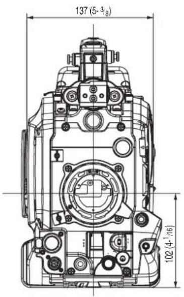
text_image
137 (5-3/8) 102 (4-1/6)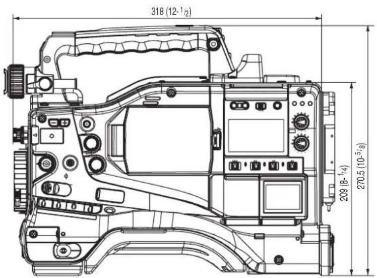
text_image
318 (12-1/2) 209 (8-1/4) 270.5 (10-5/8)System Configuration
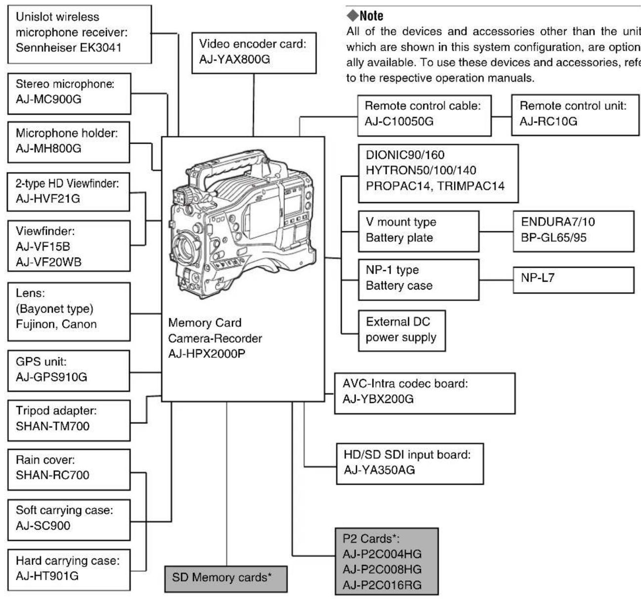
flowchart
graph TD
    A["Memory Card Camera-Recorder AJ-HPX2000P"] --> B["Unislot wireless microphone receiver: Sennheiser EK3041"]
    A --> C["Video encoder card: AJ-YAX800G"]
    A --> D["SD Memory cards*"]
    A --> E["Remote control cable: AJ-C10050G"]
    A --> F["DIONIC90/160 HYTRON50/100/140 PROPAC14, TRIMPAC14"]
    A --> G["V mount type Battery plate"]
    A --> H["NP-1 type Battery case"]
    A --> I["External DC power supply"]
    A --> J["AVC-Intra codec board: AJ-YBX200G"]
    A --> K["HD/SD SDI input board: AJ-YA350AG"]
    A --> L["P2 Cards*: AJ-P2C004HG AJ-P2C008HG AJ-P2C016RG"]
    A --> M["GPS unit: AJ-GPS910G"]
    A --> N["Tripod adapter: SHAN-TM700"]
    A --> O["Rain cover: SHAN-RC700"]
    A --> P["Soft carrying case: AJ-SC900"]
    A --> Q["Hard carrying case: AJ-HT901G"]
* For the latest information on P2 cards and SD memory cards not available in the operating Instructions, visit the P2 Support Desk at the following Web sites. https://eww.pavc.panasonic.co.jp/pro-av/
Parts and their Functions
Power Supply and Accessory Mounting Section
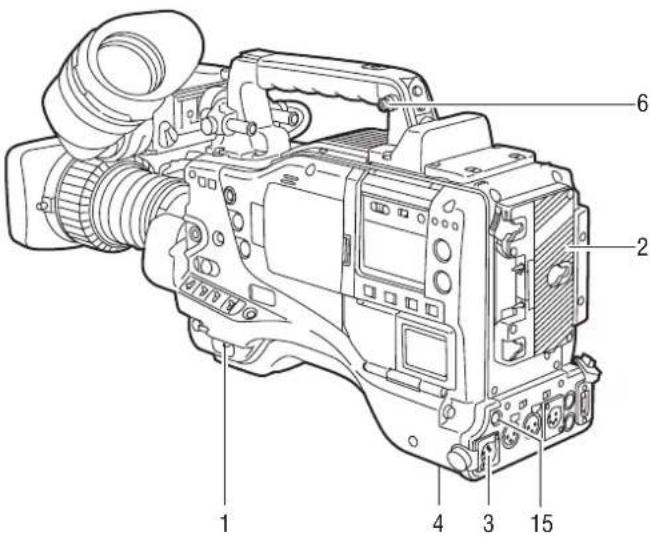
text_image
Technical diagram of a digital video camera with numbered parts labeled 1 through 61. POWER switch
Used to turn on/off the power.
2. Battery mount
A battery pack from Anton/Bauer is mounted here.
3.DC IN (external power input) socket (XLR, 4P)
camera-recorder is connected to an external DC power supply.
4.BREAKER switch
When an excessive amount of current is fed through the camera-recorder, due to any abnormal event, the breaker automatically turns off the power in order to protect the device.
After the interior of the camera-recorder has been checked and/or repaired, this button must be depressed. If there is no unusual reaction, the unit can be powered-up.
5. GPS connector
This connects the optional GPS unit AJ-GPS910G.
6. Shoulder strap fittings
The shoulder strap is attached here.
7. Light shoe
A video light or similar accessory can be attached here.
8. Lens mount (bayonet 2/3-type)
The lens is attached here.
9. Lens lever
Lower this lever to lock the lens to the lens mount.
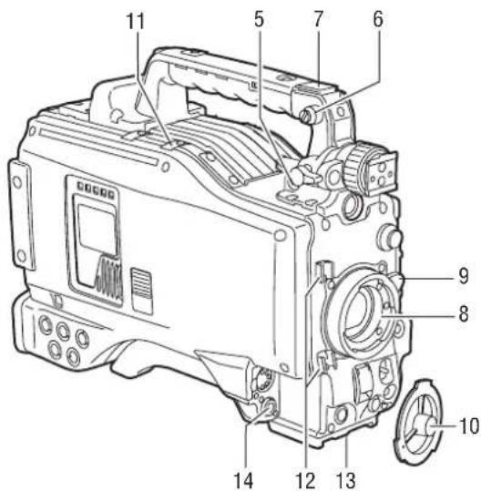
text_image
11 5 7 6 9 8 10 14 12 1310. Lens mount cap
To remove the cap, raise the 9. lens lever.
When the lens is not mounted, replace the cap.
11. Light cable clamp
Secures the light cable.
12. Lens cable/microphone cable clamp
This clamp secures the lens and microphone cables.
13. Tripod mount
When you want to mount camera-recorder on a tripod, the optional tripod adapter (SHAN-TM700) is attached here.
14.LENS jack (12-pin)
The lens connection cord is connected here. For a detailed description of your lens, see the relevant manufacturer's instruction manual.
15.DC OUT (DC power supply) output socket
This output socket is designed for 12-VDC. It provides a maximum current of 1.5 A.
Connect an external switch to this socket to control REC starts and stops or an LED for use as a tally lamp. For more information, see [Connection of the external switch] (page 108).
Audio (input) Function Section
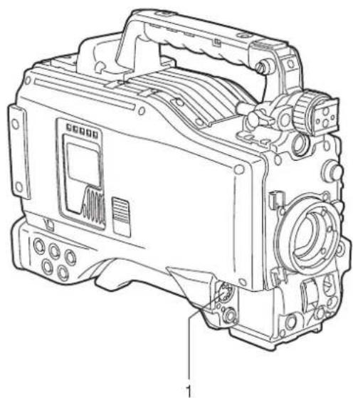
natural_image
Line drawing of a mechanical device with no visible text or symbols1. MIC IN (microphone input) jack (XLR, 5-pin)
A microphone (optional accessory) is connected here. Power for the microphone comes from this jack.
A remote microphone may be connected. When a microphone is used, set the power to ON through the menu option FRONT MIC POWER.
These options are found in the
2. AUDIO LEVEL CH1/CH2 (audio channel 1 & 2 recording level adjustment) controls
With the 3. AUDIO SELECT CH1/CH2 switch positioned to [MAN], these controls can be used to adjust the recording levels for Audio Channels 1/2.
Note that the controls are designed to be locked. For adjustment, each control must be depressed while turning.
3. AUDIO SELECT CH1/CH2 (audio channel 1 & 2 automatic/manual level adjustment selector) switch
Use this switch to select recording level control mode for Audio Channels 1 and 2.
AUTO: Recording level automatically controlled.
MAN: Recording level manually controlled.
4. AUDIO IN (audio input selector) switch
Use this switch to select the signals recorded through Audio Channels 1 - 4.
FRONT: Signal from the microphone connected to the 1. MIC IN jack is recorded.
W.L. (WIRELESS) :
Signal from the slot-in wireless receiver is recorded.
REAR: Signal from the audio device connected to the 5. AUDIO IN CH1/CH2 connector is recorded.
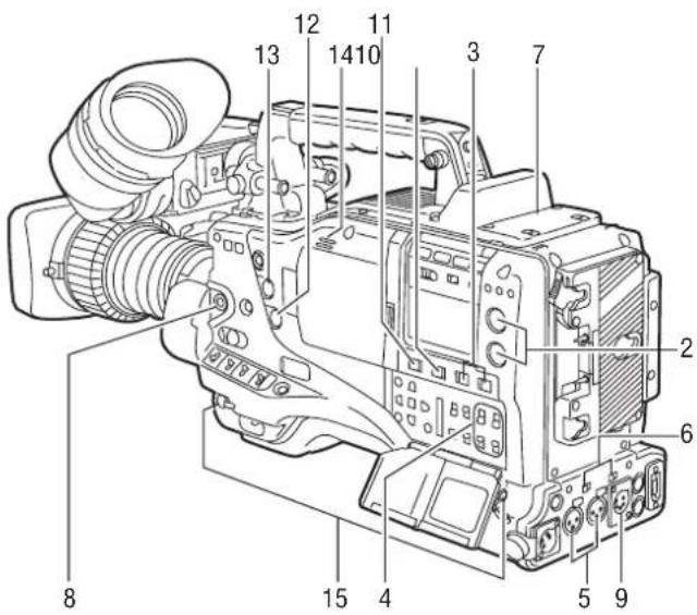
text_image
Labeled diagram of a DSLR camera with numbered parts for identificationNote
When you use stereo microphone (AJ-MC900G optional), set both CH1 and CH2 to [FRONT]. The signal from L CH is recorded to CH1 and that from R CH to CH2.
5. AUDIO IN CH1/CH2 (audio input channel 1 & 2) connectors (XLR, 3-pin)
Audio devices or a microphone may be connected here.
6. LINE/MIC/+48V (line input/mic input/mic input + 48V) selector switch
Used to select the audio signal input from the 5. AUDIO IN CH1/CH2 connectors.
LINE: Audio signal line-input from the audio device is input.
MIC: Audio signal from a self-powered (active) microphone is input. (The main unit does not supply power to the remote microphone).
+ 48V: Audio signal from a passive microphone is input. (The unit supplies power to the remote microphone).
7. Wireless slot
A Unislot wireless receiver (optional accessory) may be attached here.
8. FRONT AUDIO LEVEL (audio recording level adjustment) control
This control adjusts the recording levels for Audio Channels 1 and 2.
However, when the 3. AUDIO SELECT CH1/CH2 switch is set to "AUTO", the level will adjust automatically and the 2. AUDIO LEVEL CH1/CH2 knob and this knob will not be active.
The control can be enabled or disabled through the menu options FRONT VR CH1 or FRONT VR CH2. These options can be found in the
Audio (output) Function Section
9. AUDIO OUT connector (XLR, 5-pin)
This connector outputs audio signals recorded on Channels 1/2 or 3/4.
Output signals are selected with the MONITOR SELECT CH1/2 / CH3/4 selector switch.
10. MONITOR SELECT (audio channel) CH1/2 / CH3/4 selector switch
Use this switch to select the audio channel whose signals are output to the speakers, earphones or AUDIO OUT connector.
CH1/2: Signals on Audio Channels 1 and 2 are output.
CH3/4: Signals on Audio Channels 3 and 4 are output.
The channel indications on the display window and on the audio level meter in the viewfinder are synchronised with this selector switch.
11. MONITOR SELECT (audio selection) CH1/3 / ST / CH2/4 selector switch
The MONITOR SELECT switch is synchronised with the audio signal output to the speakers and earphones, and from the AUDIO OUT connector.
CH1/3: Signal on Audio Channel 1 or 3 is output.
ST: Stereo audio signals on Audio Channels 1 and 2 or Audio Channels 3 or 4 are output. The stereo signals can be changed to mixed signals using a menu option.
CH2/4: Signal on Audio Channel 2 or 4 is output.
| Monitor switch | MONITOR SELECT switch | |
| CH1/2 CH3/4 | ||
| CH1/3 Audio Channel 1 Audio Channel 3 | ||
| ST | Stereo signals from Audio Channels 1 and 2* | Stereo signals from Audio Channels 3 and 4* |
| CH2/4 Audio Channel 2 Audio Channel 4 | ||
* You can select between stereo and mixed signal types using the menu option MONITOR SELECT. This menu option can be found in the
12. MONITOR (volume) control
Used to control the volume of sound output from the monitor speakers and earphones.
13. ALARM (warning alarm volume adjustment)
Used to control the volume of the warning sound emitted from 14. speakers or earphones connected to the 15. PHONES jack.
If the control is minimised, no alarm is audible.
14.Speakers
The speakers output EE sound during recording, and reproduced sound during playback.
The speakers emit an alarm sound when the warning lamp blinks and/or the indicator activates.
When the 15. PHONES jack is connected with earphones, sound from the speaker is automatically muted.
15. PHONES (earphones) jack (mini jack)
This connector is designed for audio monitoring (stereo) earphones. When earphones are connected, sound from the speakers is automatically muted.
Both the front and rear connectors output the same sound.
Shooting and Recording/Playback Functions Section
text_image
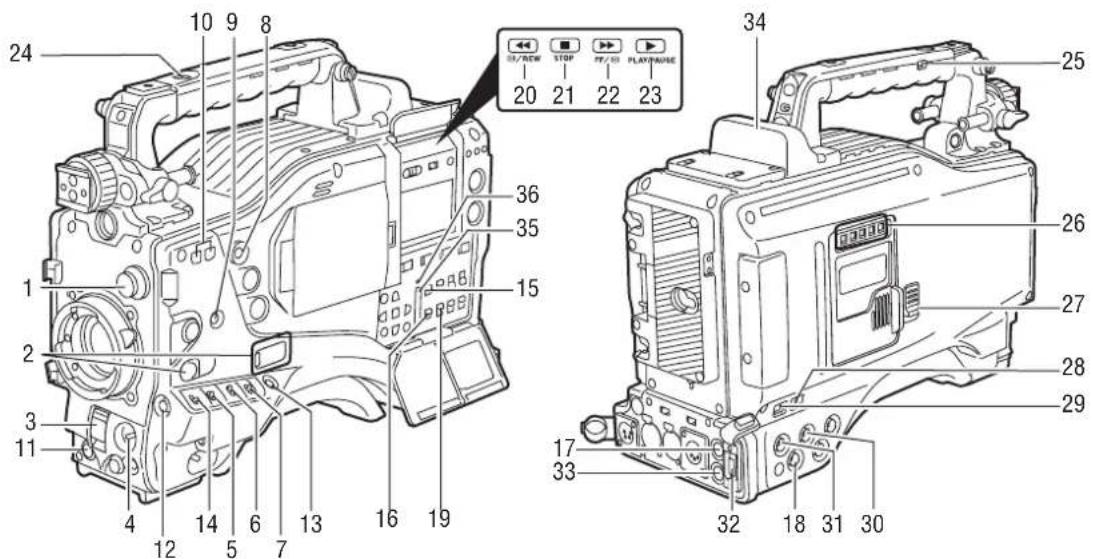
24 10 9 8 36 35 15 34 25 20 STOP FF/03 PLAYPAGE 27 26 28 29 17 33 32 18 31 30 11 4 12 5 6 7 13 16 191. CC/ND FILTER (filter selector) control
Used to select a filter appropriate for illumination and color temperature of the subject.
When the menu option DISP MODE is set to "3", switching this control displays the selected filter number in the viewfinder.
Examples of filter selection according to shooting conditions
| Setting of the CC/ND FILTER control | Description of filter | Shooting conditions |
| 1 3200K | Sunrise, sunset Studio | |
| 2 5600K + 1/8 | Clear outdoor environments | |
| 3 5600K | Cloudy/rainy outdoor environments | |
| 4 5600K + 1/64 | Clear, bright scenes such as snowscape, high mountains, beaches, etc. |
2. USER MAIN, USER 1 and USER 2 buttons
These buttons can be assigned user-selected functions, using a menu option. Each button, when pressed, performs the assigned function.
For more information, see [Assigning Functions to USER MAIN, USER1 and USER2 Buttons] (page 51).
3.SHUTTER switch
Used to enable or disable the electronic shutter.
OFF: Electronic shutter disabled.
ON: Electronic shutter enabled.
SEL: Used to change the speed of the electronic shutter.
This dial switch returns to its original position. Each turn of the switch alters the shutter speed.
For more information, see [Setting the Electronic Shutter] (page 49).
4. AUTO W/B (white/black) BAL switch
AWB: White balance is automatically adjusted.
When the WHITE BAL switch on the side is positioned at [A] or [B], the adjusted value is stored in the memory.
Note that when the switch is positioned at PRST this function does not work.
ABB: Back balance is automatically adjusted.
Note
To stop automatic adjustment of the white or black balance in progress, set the switch to either ([AWB] or [ABB]).
If automatic adjustment is cancelled, the value in effect before automatic adjustment will be used.
5. Gain selector switch
Use this switch to select video amplifier gain, according to lighting conditions under which you are shooting.
The values for L, M, and H can be preset using menu options.
These are factory-set to 0 dB for L, 6 dB for M, and 12 dB for H.
6. OUTPUT/AUTO KNEE selector switch
Used to select the video signals sent from the camera unit to the memory, viewfinder and video monitor.
CAM. AUTO KNEE ON:
Video being recorded through the camera is sent with the auto knee circuit activated.
It is also possible to assign the DRS (Dynamic Range Stretcher) function instead of the AUTO KNEE function.
CAM. AUTO KNEE OFF:
Video being recorded through the camera is sent in manual knee mode.
BARS:
Color bar signal is output. The auto knee circuit does not work.
You can select between four types of color bar signal.
For more information, see [SW MODE] (page 175).
Auto Knee function
Usually, when you adjust levels to shoot people or scenery against a strongly lit background, the background will be totally whited-out, with buildings and other objects blurred. In this case, the auto knee function reproduces the background clearly. This function is effective when:
- The subject is a person positioned in the shade under a clear sky.
•The subject is a person inside a car or building, and you also want to capture the background visible through a window.
•The subject is a high-contrast scene.
7. WHITE BAL (white balance memory selector) switch
Used to select the white balance adjustment method.
PRST: Use this when you have no time to adjust the white balance.
The value for the white balance is factory-set to 3200 K.
It can be changed to any color temperature using a menu option. For more information, see [Setting Color Temperature Manually] (page 47).
A or B: Pressing the 4. AUTO W/B BAL Switch toward [AWB] automatically adjusts the white balance, saving the adjusted value in Memory A or B. For more information, see [Adjusting the White Balance] (page 45).
Through a menu option, the auto-tracking white balance (ATW) can be assigned to B.
For more information, see [Adjusting the White Balance] (page 45).
8. MODE CHECK button
Each press of this button changes the screen type in the viewfinder in the following order: STATUS, !LED, FUNCTION, AUDIO.
This does not affect the signal output from the camera.
9. MARKER SELECT button
This button selects the marker information indicated on the viewfinder screen. It switches between two marker information indications, which can be selected using a menu option. Pressing this button once switches the indicated marker information from A (Marker A) to B (Marker B), and pressing again switches B to OFF (no marker). When the power is turned on, the last selected indication before power-down appears.
For more information, see [Marker Check Screen Displays (MARKER SELECT button function)] (page 79).
10.SYNCHRO SCAN ADJUSTMENT buttons
These buttons are enabled when the 3. shutter switch is positioned at [ON] and synchro scan is selected.
They are used to adjust the speed of the synchro scan.
The - button decreases shutter speed; the + button increases shutter speed.
If you shoot a PC monitor, for example, you should adjust shutter speed so that the horizontal bars in the viewfinder will produce less noise.
11. REC START/STOP button
Pressing this button starts recording, pressing again stops recording.
This button has the same function as the 24. REC button on the handle and the VTR button at the lens.
12. SHOT MARK/Menu cancel button
Pressing this button while recording adds a shot mark to the thumbnail of that clip. This button also adds a shot mark to any thumbnail selected on the LCD monitor.
For more information on shot marks, see [Shot Mark Function] (page 41).
This button cancels the revised set value when the menu is displayed.
13.Text memo button
Records a text memo if pressed during recording or playback or when playback is paused.
text_image
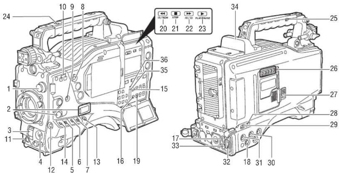
24 10 9 8 36 35 15 34 25 20 21 22 23 26 27 28 29 17 33 32 18 31 3014.SAVE ON/OFF switch
Used to select the power supply method for each output section.
ON: The output selected through the menu option SAVE SW is power-saved. This option can be found on the OPTION MODE screen on the SYSTEM SETTING page.
OFF: Power saving is canceled.
Note
The ON/OFF switch does not function during recording. The ON/OFF status changes after recording is completed.
15. VIDEO OUT (output signal selector) switch
Changes the mode of the signals output through the VIDEO OUT connector.
HD SDI: HD SDI signals are output. When the camera-recorder is in SD mode, SD SDI signals are output.
SD SDI : SD SDI signals are output. (Signals are down-converted in HD mode.)
VBS : Composite video signals are output. (Signals are down-converted in HD mode.)
16. VIDEO OUT CHARACTER switch
This switch controls the superimposition of characters onto the video output from the VIDEO OUT connector.
ON: Characters are superimposed.
OFF: Characters are not superimposed.
For types of characters, see [Settings of signals output from VIDEO OUT connector] (page 81).
17. VIDEO OUT (video signal output) connector
This connector outputs video signals. The video signals linked to the settings of 15. VIDEO OUT switch, 16. VIDEO OUT CHARACTER switch and 19. OUTPUT SEL switch are output from here.
18. MON OUT (monitor output) connector
Used to output down-converted (analog composite) signals for the monitor. The video signals linked to the setting of the OUTPUT SEL switch are output from here. Through an internal menu option, the characters can be superimposed independently of the VIDEO OUT connector. For more information, see [Settings of signals output from MON OUT connector] (page 82).
19. OUTPUT SEL (output signal selection) switch
Used to switch the signals output from the VIDEO OUT and MON OUT connectors.
MEM: Video from the camera is output during recording or when recording is paused or playback signals are output from the P2 card during playback.
CAM: Video from the camera is output constantly.
OFF: Video is not output, and the camera-recorder operates in power-saving mode.
Note that the audio output is synchronised with the video.
For types of video outputs, see [Settings of signals output from VIDEO OUT connector] (page 81) or [Settings of signals output from MON OUT connector] (page 82).
Notes
- During recording, this switch does not switch output signals before stopping the recording operation.
- When CAM is not selected through the REC SIGNAL menu option, the output signals are the same as for MEM even if the switch is set to CAM. The menu option REC SIGNAL is found in the SYSTEM MODE screen on the SYSTEM SETTING page.
20. REW (rewind) button and lamp
During pause, this button performs a fast-reverse playback with the lamp blinking.
During playback, it performs an approximately 4× fast-reverse playback with the PLAY and REW lamps blinking.
If this button is pressed when playback is paused, the start of the clip being played back is located in pause mode.
21.STOP button
This button stops playback.
22.FF (fast forward) button and lamp
During pause, this button is used to perform fast playback with the lamp blinking.
During playback, it performs an approximately 4× fast playback with the PLAY and FF lamps blinking.
If this button is pressed when playback is paused, the start of the next clip is located in pause mode.
23. PLAY/PAUSE button
This button is used to view playback using the viewfinder screen or a color video monitor. The lamp comes on when playback starts.
In playback mode, this button pauses (PLAY/PAUSE) playback with the lamp blinking.
24.REC button
Pressing this button starts recording, and pressing again stops recording.
This button has the same function as 11. the REC START/STOP button and the VTR button at the lens.
It may be disabled with 25. the recording protection button.
25. REC protection button
This button disables 24. the REC button on the handle.
ON: The REC button is enabled.
OFF: The REC button is disabled.
26.P2 CARD ACCESS LED
This LED indicates the recording and playback status of each card.
27.Slide lock button
Used to open the slide-out door for inserting P2 cards.
While depressing this button, slide the door to the left.
28. USB 2.0 connector (DEVICE)
29. USB 2.0 connector (HOST)
A USB 2.0 cable is connected here.
When the menu option PC MODE is set to "ON", data can be transferred via USB 2.0. During such data transfer, recording, playback or operations of clips is permitted.
The menu option PC MODE is found in the SYSTEM MODE screen on the SYSTEM SETTING page. For more information, see [Connection with external devices using the USB 2.0 port] (page 131).
30. GENLOCK IN connector
Used to input an HD Y signal when GENLOCKing the camera or externally locking the time code. Alternatively, a composite signal can be input as the reference signal. Note that the subcarriers for the down-converter (composite signal) output from the camera-recorder cannot be externally locked.
Notes
- When HD Y signal is input and RET is selected, you can check return video on the viewfinder screen. The menu option RET SW can be found in the SW MODE screen on the CAM OPERATION page.
- When the mode is set to SD, you can record original signals by specifying VIDEO for the menu option REC SIGNAL.
31.HD/SD SDI IN input connector
If installed, the optionally available HD/SD SDI input board (AJ-YA350AG) acts as an input connector for HD/SD SDI signals. You can record signals from this input connector by specifying SDI for the menu option REC SIGNAL. For details, refer to [Connection using the SDI IN connector (when AJ-YA350AG attached)] (page 137).
32. DVCPRO/DV connector
This is an in/output connector for video, voice, and data that comply with the IEEE1394 standard.
Notes
● Power is not supplied from the unit.
- Be absolutely sure to bear the following points in mind when connecting the IEEE1394 cable (DV cable).
- Ensure that the connections with other devices are made on a 1:1 basis.
- When a DV cable has been connected to the DV connector, do not apply any strong external force as this may damage the connector.
- When error code 1394 E-92 (1394 INITIAL ERROR) appears, disconnect the connecting cables and re-connect them or turn off the camera-recorder's power and turn it back on.
- Ensure that the unit and all of the connected devices are each grounded (or connected to a common ground) before use.
If it is not possible to ground the unit and devices, turn off the power of the unit and of all the connected devices before connecting or disconnecting the IEEE1394 cable.
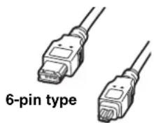
- When the unit is to be connected to a device equipped with a 4-pin type of connector, connect the unit's connector (6-pin type) first.
- When connecting the unit with a PC equipped with a 6-pin type of connector, connect the 1394 cable as dictated by the shapes of the 1394 connectors.
Bear in mind that
4-pin type
inserting a plug the wrong way round may damage the unit.
- When the unit is used in AVC-Intra format, image/voice signals cannot be output/input through the DVCPRO/DV connector.
33. REMOTE (remote control) connector
The remote control unit AJ-RC10G (optional accessory) is connected here.
34. OPTION SLOT
Attach the video encoder card (AJ-YAX800G, optional). For information about the installation and proxy recording, see the AJ-YAX800G instruction manual.
35. SD memory card insertion slot
An SD memory card (optional accessory) is inserted here. SD memory cards are used for recording and accessing the menu settings of cameras and the lens files, uploading metadata, and proxy recording (optional).
Use the unit by inserting an SD memory card that is compliant with the SD standard or the SDHC standard.
MultiMediaCards cannot be used. (Bear in mind that taking pictures may no longer be possible if you do use them.)
If you intend to use miniSD cards in camera-recorder, always install the adapter specially designed for miniSD cards. (The unit will not work properly if only the miniSD card adapter is installed. Make sure that the card has been installed in the adapter before using it.)
Use of Panasonic's SD memory cards and miniSD cards is recommended. Be sure to format cards using camera-recorder.
To format SD memory cards using a personal computer, download the dedicated software from the support site.
Any SD memory card with the following capacities (8 MB to 2 GB) and any 4 GB SDHC memory card can be used with the unit.
8 MB 16 MB 32 MB 64 MB 128 MB 256 MB 512 MB 1 GB 2 GB 4 GB (SDHC)
To record proxy (optional), use an SD memory card with a capacity of 256 MB, 512 MB, 1 GB, or 2 GB labeled "High Speed" or use a 4 GB SDHC memory card.
For the latest information not available in the operating Instructions, visit the P2 Support Desk at the following Web sites.
- The SDHC card conforms to a new standard for memory cards with a large capacity of more than 2 GB which was established by the SD Association in 2006.
● The SD card logo is a registered trademark. - MMC (MultiMediaCard) is a registered trademark of Infineon Technologies AG.
36.BUSY (operation mode display) lamp
This lamp indicates the active status of the SD memory card.
It stays illuminated when the card is active.
Note
While the lamp is on, do not insert or remove the card.
Menu Operation Section
text_image
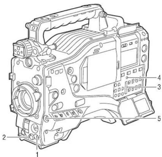
Technical diagram of a digital camera with numbered parts labeled 1 through 51. MENU button
Used to turn on/off the menu.
2. JOG dial button
With the menu open, this button is used to navigate through menu pages, select options and specify values.
For directions on manipulating the menu, see [Menu Configuration] (page 151).
3. SD memory card insertion slot
An SD memory card (optional accessory) is inserted here. It is used when writing or saving menu data or lens files on an SD memory card.
4. BUSY (operation mode display) lamp
This lamp indicates the active status of the SD memory card.
It stays illuminated when the card is active.
Note
While the lamp is on, do not insert or remove the card.
5. Shot Mark/Cancel Menu button
Undoes any changes to the menu option settings if pressed during the changes
Time Code Section
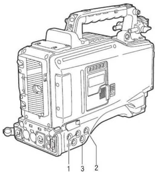
text_image
Technical diagram of a mechanical device with numbered parts labeled 1, 2, and 31. GENLOCK IN connector (BNC)
This connector is used to input a reference signal before the camera unit is gen-locked, or before the time code is externally locked.
2. TC IN connector (BNC)
This connector is used to input a reference time code when you externally lock the time code.
3. TC OUT connector (BNC)
When you inter-lock the time code of camera-recorder with that of an external device this must be connected with the time code input (TC IN) connector of the external device.
Note
The time code must be input in the same format as the system mode of the camera-recorder.
4. HOLD button
Pressing this button freezes the time data indication on the counter. Note that time code generation continues. Pressing the button again reactivates the counter.
This function is used to ascertain the time code or CTL count of a particular recorded scene.
5. RESET button
This button resets the time data (CTL) on the counter to "00:00:00:00".
If this button is pressed when with the 7.TCG switch positioned at [SET], time code and user bits data are reset to 0, and real-time data is reset to the initial value.

text_image
Technical diagram of a digital camera with numbered parts labeled 4 through 86.DISPLAY (counter display selector) switch
Indications of the time code, CTL and user bits on the counter of the display window depend on the positions of this switch and the 7.TCG switch.
Pressing the 4.HOLD button also displays Date/Time/Time Zone.
UB: User bits, TIME, DATE or Time zone indicated.
TC: Time code indicated.
CTL: CTL indicated.
7.TCG (time code selector) switch
This switch is used to specify the stepping mode for the built-in time code generator.
F-RUN: Select this position to continuously advance the time code independently of the P2 card recording status.
Use this mode to synchronise the time code with the time of day, or to externally lock the time code.
SET: Select this position to set the time code and/or user bits.
R-RUN: Select this position to advance the time code only during recording.
For spliced scenes recorded on P2 cards, the sequence of time codes is unbroken.
8. CURSOR and SET buttons
Use these buttons to set the time code and user bits. The four triangular buttons are the CURSOR buttons, and the center rectangular one is the SET button.
For guidance in setting the time code and user bits, see [Setting Time Data] (page 55).
Warning and Status Display Functions
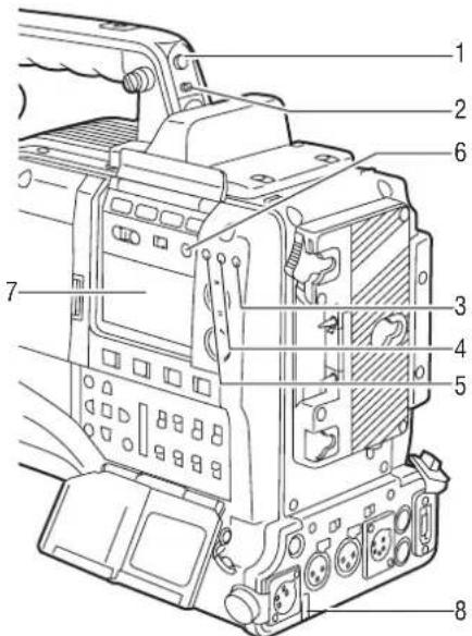
text_image
Technical diagram of an electronic device with numbered components for identification1. Back tally lamp
When the 2.BACK TALLY switch is set to [ON], the lamp behaves in the same way as the front tally lamp at the viewfinder.
2. BACK TALLY switch
This switch controls the action of the 1.back and 8.rear tally lamps.
ON: Back and rear tally lamps enabled. OFF: Back and rear tally lamps disabled
3.WARNING lamp
This lamp starts blinking or lights up if something unusual occurs in the memory.
4.USB lamp
Stays on when the camera-recorder is in USB mode.
5. Access lamp
Blinks when the camera-recorder is in recording or playback mode or when a P2 card is being accessed, or stays on when a recordable P2 card is inserted.
6. LIGHT button
Use this button to control illumination of the display window. Alternately pressing this button toggles illumination of the 7.display window on or off.
7. Display window
This window displays warnings, battery-remaining level, sound volume, time data, and other information.
Note
When the battery is installed, the camera-recorder indicates the data even if the power is turned off. To turn off the data indications to keep the battery from being discharged, specify OFF for the menu option P. OFF LCD DISPLAY found in the TC/UB screen on the MAIN OPERATION page.
8. Rear tally lamp
When the 2.BACK TALLY switch is set on [ON], the rear tally lamp behaves in the same way as the back tally lamp.
Display Window Functions
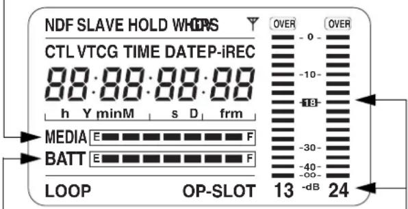
P2 card/battery-remaining level indications
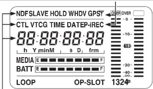
Media-remaining space indication bar
The bar indicates the remaining free space on each P2 card, using a seven-segment display.
Each segment can represent either three or five minutes of remaining free space, depending on the value set through the menu option CARD REMAIN/■. According to the set value, the segments disappear one-by-one. The menu option CARD
REMAIN /■ can be found in the
text_image
NDF SLAVE HOLD WHOPS CTL VTCG TIME DATEP-iREC 88:88:88:88 h Y minM s D frm MEDIA E F BATT E F LOOP OP-SLOT 13 24 OVER OVER -0 - -10 - -18 - -30 - -40 - -dBBattery-remaining level indication bar
For a battery with a digital indicator (percentage indication), if the remaining level of the battery is higher than 70%, all seven segments up to the "F" position are lit.
When the remaining level falls below 70%, the segments go out one-by-one for each drop of 10%. All seven segments can be set to light up when the battery-remaining balance is 100%. To do so select "100%" for the menu option BATT REMAIN FULL in the
Audio channel level meter
When the MONITOR SELECT CH1/2 / CH3/4 switch is set to [CH1/2], the meter indicates 1 and 2 as the audio channel numbers, together with their audio levels. When the switch is set to [CH3/4], the meter indicates 3 and 4 as the audio channel numbers, together with their audio levels.
Memory action status indication
Error Code Indication (for more information, see [Warning System] (page 145))
text_image
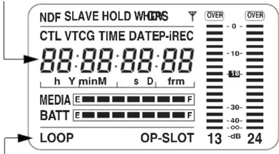
NDF SLAVE HOLD WHO CTL VTCG TIME DATEP-iREC 88:88:88:88 h Y minM s D frm MEDIA E F BATT E F LOOP OP-SLOT 13 24 OVER OVER -0 -10- -18- -30- -40- -∞- -dBInformation indication
LOOP: Stays illuminated in LOOP REC mode. For information about the LOOP REC mode, see [Loop Recording] (page 36).
OP-SLOT: Remains illuminated when a video encoder card is operated in the optional slot.
Mode indication
W: Stays illuminated when the camera-recorder operates in SD mode (480-59.94i, 576-50i) and is set to 16:9 mode.
HD: Stays illuminated when the camera-recorder is in HD mode (1080i, 720P).
DV: Stays illuminated when the recording/playback format is DV.
GPS: Stays illuminated when radio waves are not received during GPS operation.
GPSY: Stays illuminated when radio waves are received during GPS operation.
P-REC: Stays illuminated when the PRE REC MODE is set to ON, and blinks when recording is continued after the recording tally lamp has gone out.
iREC: Remains illuminated during INTERVAL REC mode recording, and blinks during a pause.
i: Blinks when INTERVAL REC mode is selected.
text_image
NDFSLAVE HOLD WHDV GPSY CTL VTCG TIME DATEP-iREC 88:88:88:88 h Y minM s D frm MEDIA E F BATT E F LOOP OP-SLOT 1324Time code indication
NDF: Stays illuminated when the time code is in non-drop frame mode.
DF: Stays illuminated when the time code is in drop frame mode.
SLAVE: Stays illuminated when the time code is externally locked.
HOLD: Stays illuminated when the time code generator/reader value is frozen.
CTL: Stays illuminated when the DISPLAY switch is positioned at [CTL] to display the CTL count.
TCG: Stays illuminated when the DISPLAY switch is positioned at [TC] (or [UB]) to display the TC (or UB) generator value.
TC: Stays illuminated when the DISPLAY switch is positioned at [TC] (or [UB]) to display the TC (or UB) reader value.
VTCG: Stays illuminated when the DISPLAY switch is positioned at [UB] to display the VIUB generator value.
VTC: Stays illuminated when the DISPLAY switch is positioned at [UB] to display the VIUB reader value.
TIME: Stays illuminated when the DISPLAY switch is positioned at [UB] to display the real-time hour, minute and second.
DATE: Stays illuminated when the DISPLAY switch is positioned at [UB] to display the real-time date.
No Indication:
The CTL, VTCG, TIME, and DATE stay off when the DISPLAY switch is positioned at [UB] to display real time, time zone, hour and minute.
Time count indication:
The time code, CTL, user bits and real time are shown.
Note
When the DISPLAY switch is positioned at UB, each press of the HOLD button changes the indication through VTCG (VTC) DATE TIME No Indication (Time Zone) TCG (TC), in that order.
Positions of time code-related switches and information provided
| Position of DISPLAY switch | Position of TCG switch | Information Item |
| CTL | SET Time code | |
| F-RUN or R-RUN CTL | ||
| TC | F-RUN/SET/R-RUN | Time code |
| UB | User bits or real-time, time zone | |
LCD Monitor
text_image
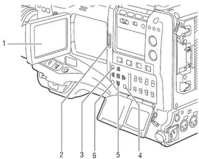
1 2 3 6 5 41. LCD monitor
The LCD monitor displays the video in the viewfinder. Alternatively, it can show clips on the P2 card in a thumbnail format.
In thumbnail display mode, clips can be edited or deleted, or P2 cards can be formatted using the 4.THUMBNAIL MENU button and 5.CURSOR and SET buttons.
2. OPEN button
Used to open the LCD monitor.
3.THUMBNAIL button
This button switches the content on the 1.LCD monitor from the video in the viewfinder to clip thumbnails. Another press switches them back to the video from the viewfinder.
Note that this switchover is not performed during a recording or playback.
4.THUMBNAIL MENU button
In thumbnail display mode, this button allows you to manipulate the thumbnail menu (e.g., to delete clips).
5. CURSOR and SET buttons
The four triangular buttons are the CURSOR buttons, and the center rectangular one is the SET button.
They are used to select a thumbnail and manipulate the thumbnail menu. For more information, see [Manipulating Clips with Thumbnails] (page 109).
6. EXIT button
Used to return the display to the previous state when the thumbnail menu or the property screen is displayed.
Viewfinder
You can use any of the following viewfinders (extra-cost options) on AJ-HPX2000:
HD Viewfinders: AJ-HVF21G (selectable between 59.94 and 50 Hz)
SD Viewfinders: AJ-VF20WBP (59.94 Hz), AJ-VF15BP (59.94 Hz), AJ-VF20WBE (50 Hz), and AJ-VF15BE (50 Hz)
Use the VF TYPE menu options on the SYSTEM MODE screen on the SYSTEM SETTING page to adjust the appropriate settings for the viewfinder that will be used. We recommend using a HD viewfinder when the camera-recorder is used in HD mode or an SD viewfinder when it is used in SD mode. Depending on the mode, some types of video are unavailable as shown below (●: the finder shows nothing on a black screen).
| Mode | Video seen through viewfinder | HD viewfinder SD viewfinder | |
| HD | Video from camera | ○ | ○1 |
| Playback ○ | ○ | * 1*2 | |
| Return video (HD-Y) ○ ● | |||
| 1394/HD-SDI input (HD) ○ | ○ | 1 * | |
| SD | Video from camera | ○ | ○ |
| Playback ● ○ | |||
| Return video (VBS) ● ○ | |||
| 1394/HD-SDI input (SD) ● | ○ | ||
Each viewfinder shows return signals and 1394 and SDI input signals in the recording formats assigned to the camera-recorder.
*1 : Down-converted signals
*2: When the OUTPUT SEL (output signal selection) switch (page 19) of the camera-recorder is set to CAM, a black screen is displayed.
text_image
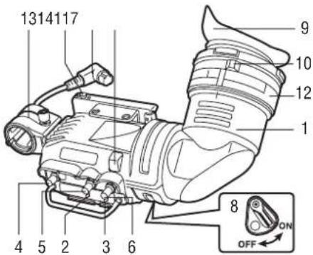
1314117 9 10 12 1 8 ON OFF 4 5 2 3 61.Viewfinder (optional accessory)
During recording or playback, the viewfinder displays the video image in monochrome. It also displays warnings, messages, zebra patterns, markers (safety zone and center markers), etc.
2.ZEBRA (zebra pattern) switch
This switch is used to display the zebra pattern in the viewfinder.
ON: Zebra pattern displayed.
OFF: No zebra pattern displayed.
3.TALLY switch
Used to control the 7.front tally lamp.
HIGH: Front tally lamp brightly illuminated.
OFF: Front tally lamp stays off.
LOW: Front tally lamp dimly illuminated.
4. PEAKING control
Used to adjust the outlines of the video image in the viewfinder for easier focusing. This does not affect the signal output from the camera.
5. CONTRAST control
Used to adjust the contrast of the video image in the viewfinder. This does not affect the signal output from the camera.
6. BRIGHT control
Used to adjust the brightness of the video image in the viewfinder. This does not affect the signal output from the camera.
7. Front tally lamp
This lamp is activated when the 3.TALLY switch is positioned at [HIGH] or [LOW], and stays on during recording. It also blinks in synchronisation with the REC lamp in the viewfinder, and provides alerts.
Use the TALLY switch to change the intensity of the lamp to ([HIGH] or [LOW]).
8. Back tally lamp
This lamp stays illuminated during shooting. It also blinks in synchronisation with the REC lamp in the viewfinder, and provides alerts.
When the lever is positioned at [OFF], the back tally lamp is hidden.
9. Eyepiece
Note
Do not leave the eyepiece aimed at the sun. Doing so may damage the internal components.
10. Diopter adjustment ring
Use this to make adjustments in line with your diopter, in order to obtain optimum clarity in the viewfinder image.
The adjustable range of the viewfinder view angle is shown in the following table.
| Product Number | Adjustable range |
| AJ-HVF21G | |
| AJ-VF20WBP | -0.9 D to -4.4 D |
| AJ-VF20WBE | |
| AJ-VF15BP | +1.1 D to -3.4 D |
| AJ-VF15BE |
For an eyepiece for presbyopia, consult the dealer.
11. Connecting plug
12. Locking ring
13. Microphone holder
14.Viewfinder stopper
Used to attach or remove the viewfinder.
text_image
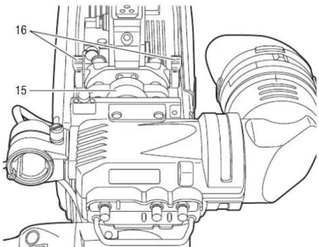
16 1515.Viewfinder left-right position anchoring ring
Used to adjust the side-to-side position of the viewfinder.
16.Viewfinder front-back position anchoring lever
Used to adjust the fore-and-aft position of the viewfinder.
Note
For more information, see the instruction manual for the viewfinder.
Recording and Playback
P2 Cards
Inserting P2 Cards
Note
When using the camera-recorder for the first time, be sure to set the time data beforehand. On how the time data is set, see [Setting Time Data] (page 55).
1 Turn on the POWER switch.
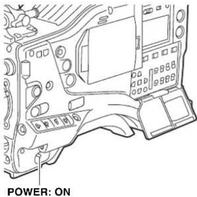
text_image
POWER: ON2 While pressing down the slide lock button, slide the slide-out door to the left. The door opens.
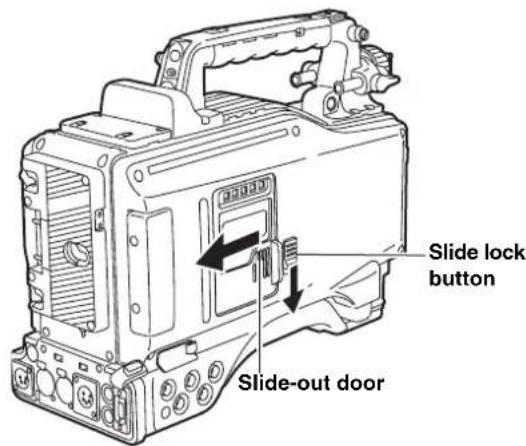
text_image
Slide lock button Slide-out door3 Insert a P2 card into the P2 card slot until the EJECT button pops up.
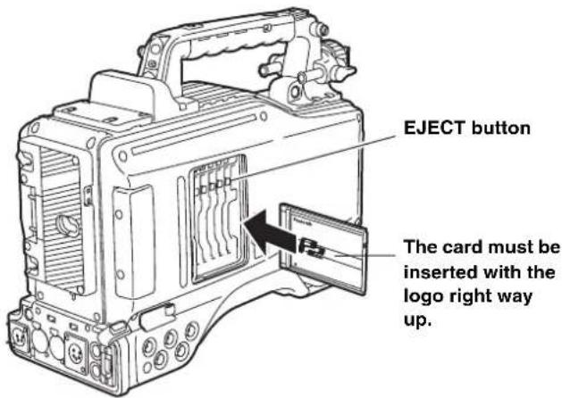
text_image
EJECT button The card must be inserted with the logo right way up.4 Tilt up the popped-up EJECT button, to lock-in the P2 card.
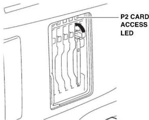
text_image
P2 CARD ACCESS LED5 Insert a P2 card into camera-recorder. The P2 CARD ACCESS LED for the appropriate slot indicates the status of the P2 card. For how the P2 card status is indicated, see [P2 CARD ACCESS LED and status of P2 cards] (page 30).
6 Close the slide-out door.
Note
Do not leave the slide-out door open when moving camera-recorder.
Removing P2 Cards
1 While pressing down the slide lock button, move the slide-out door to the left.
The door opens.
2 Tilt down the EJECT button.
3 Then, depress the EJECT button to release the P2 card so that you can remove it.
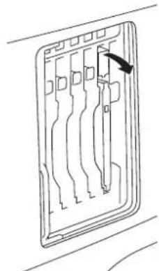
natural_image
Diagram of a device panel with multiple slots and a cursor arrow pointing to the top slot (no text or symbols)Tilt down the EJECT button.
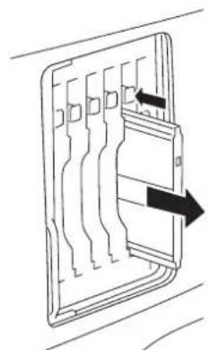
natural_image
Diagram of a mechanical component with internal channels and directional arrows indicating movement (no text or symbols)Depress the tilted-down EJECT button to release the P2 card.
Notes
- After insertion, do not remove the P2 card while it is being accessed or recognized (the P2 card access LED flashes orange), or the P2 card may fail. If your unit is not set to turn on the P2 CARD ACCESS LED, before removing the card ensure that pre-recording and/or voice memo recording have finished (the P-REC indication has stopped blinking and the V mark or VOICE REC indication on the viewfinder screen has turned off) after stopping recording or playback.
- If a P2 card being accessed is removed, the viewfinder displays "TURN POWER OFF" and camera-recorder gives a warning using an alarm and the WARNING LED. In addition, all P2 CARD ACCESS LEDs blink rapidly in green. If this is the case, turn the power off. For more information on warning indications, see [Warning System] (page 145).
- If a P2 card is removed while being accessed, clips on it may become irregular. Check the clips and restore them if required. For more information about how to restore clips, see [Restoring Clips] (page 117).
- If a P2 card being formatted is removed, it may be not be formatted properly. In this case, the viewfinder displays "TURN POWER OFF". If this message appears, turn off the power, then restart camera-recorder to reformat the card.
- If a P2 card is inserted while another P2 card is being played back, the inserted P2 card is not recognised and the P2 CARD ACCESS LED for that card does not come on. Card recognition starts when the playback ends.
- Even if a P2 card is inserted in a vacant slot while recording, the media may not be recognized during the following times:
- Immediately after pre-recording
- Immediately before or after switching from the first P2 card for recording to the second one, when data are recorded on multiple cards spanning from one to the other (hot-swap recording)
The P2 CARD ACCESS LEDs may be set to stay off using the menu option ACCESS LED. This option can be found on the
To Prevent Accidental Erasure of P2 Card Content
To prevent the content of a P2 card being accidentally erased, position the write-protect switch on the P2 card at [Protect].
Note
Write-protect switchover can be performed while the card is being accessed (during recording or playback), but does not take effect until access to the card ceases.
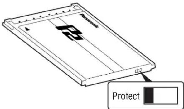
text_image
Panasonic 8.5 ProtectWrite-protect switch
P2 CARD ACCESS LED and status of P2 cards
| P2 CARD ACCESS LED | MODE CHECK indication* | Status of P2 Card |
| Stays on in green | ACTIVE Writing and reading enabled | |
| Stays on in orange | ACTIVE Writing and reading enabled. The card is recordable (loop recording also enabled). | |
| Blinks in orange | ACCESSING Writing or reading being performed. | |
| Blinks rapidly in orange | INFO READING Recognising the P2 card. | |
| Blinks slowly in green | FULL The P2 card has no free space. Only reading is enabled. | |
| PROTECTED The write-protect switch on the P2 card is positioned at [PROTECT]. Only reading is enabled. | ||
| Stays off NOT | SUPPORTED | The card is not supported by your unit. Replace the card. |
| FORMAT ERROR | The P2 card is not properly formatted. Reformat the card. | |
| NO CARD | No P2 card is inserted. | |
* The mode check indication is shown in the viewfinder. For more information, see [Viewfinder Status Indication Layout] (page 70).
The access LED located on the display window blinks when reading or writing data from or to any of the P2 cards inserted in Slots 1 - 5 or stays illuminated when any of the cards are recordable. It stays off when none of the P2 cards are recordable.
How to handle data recorded on P2 cards
The P2 card is a semiconductor memory card that is used as the recording medium in the professional video production and broadcasting devices that make up the DVCPRO P2 Series.
- Since data recorded in the DVCPRO P2 format or AVC-Intra (option) are in a file format, they have excellent compatibility with PCs. The file structure is a unique format, which in addition to video and audio data in MXF files contains various other important information items. The folder structure links the data as shown on the right.
Changing or deleting just one information component could make it impossible to recognize the data as P2 data or use the card in a P2 device
Device:\
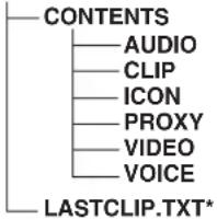
text_image
CONTENTS AUDIO CLIP ICON PROXY VIDEO VOICE LASTCLIP.TXT*All these folders are required.
* This is the file in which the information on the final clip that was recorded with the P2 device is written.
- When transferring data from a P2 card to a PC, or when rewriting data saved on a PC to a P2 card, to prevent data loss be sure to use the special P2 Viewer software. Download it from the following website. (Compatible with the Windows Vista, Windows XP and Windows 2000 operating systems.)
- When using regular IT tools such as Microsoft Windows Explorer or Apple Finder to transfer data to a PC, follow the instructions below. However, be sure to use the P2 Viewer when returning data to a P2 card.
- Transfer the corresponding CONTENTS folder and LASTCLIP.TXT file together as a set. Do not transfer individual files from the CONTENTS folder. When copying, copy the LASTCLIP.TXT file at the same time as the CONTENTS folder.
- When transferring multiple P2 cards to a PC, create a folder for each P2 card to prevent clips with the same name from being overwritten. - Do not delete data from the P2 card. - Before using a P2 card, be sure to format it with a P2 device.
● Microsoft and Windows are registered trademarks of the Microsoft Corporation in the USA and other countries.
- Apple and Macintosh are registered trademarks of Apple, Inc., in the USA and other countries.
Basic Procedures
This section describes the basic procedure for shooting and recording. Before you embark on a shoot, pre-inspect your system to ensure that it works properly.
* For directions on inspecting your memory card camera-recorder, see [Inspections Before Shooting] (page 138).
Battery Set-up to P2 card Insertion
1 Insert a charged battery pack.
2 Turn on the POWER switch and ensure that more than four segments of the battery-remaining amount indication bar are illuminated.
- If the number of illuminated segments is fewer than five, first check the battery placement. If placement is not the problem, replace the battery with a fully charged one.
3 Insert a P2 card and ensure that the P2 CARD ACCESS LED stays on in orange or green. Then, close the slide-out door.
When more than one P2 card slot contains a P2 card, the card in the slot with the lowest number is used first. However, regardless of slot number, a P2 card inserted later will not be accessed until the other cards have been used.
Example:
If all five slots contain P2 cards, the cards are used in order of slot numbers 1 2 3 4 5 . However, if the P2 card in Slot 1 is removed and then re-inserted, the cards will be used in the following order: 2 3 4 5 1 .
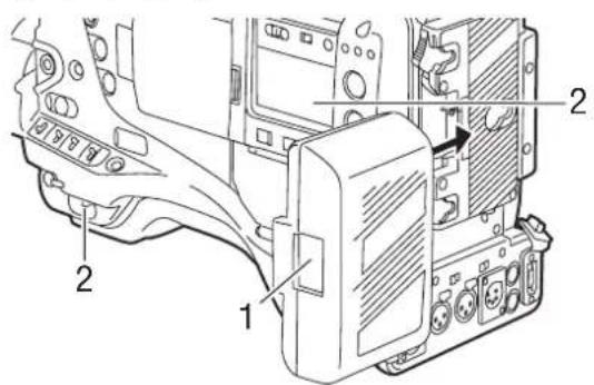
text_image
Technical diagram of a vehicle chassis with numbered components and directional arrow indicating assembly or movement.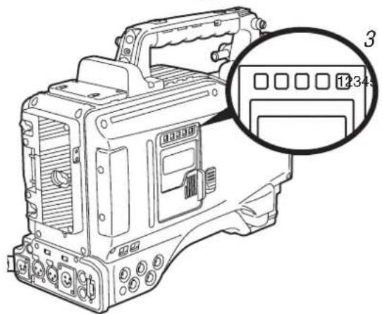
natural_image
Line drawing of a handheld electronic device with a magnified inset showing a labeled component (no text or symbols present)Note that the recording order is retained even if the power is turned off. When the power is next turned on, the last card written before powering-down will be the target card.
Note
When "SLOT1" is selected for the menu option P.ON REC SLOT SEL, recording starts from the P2 card inserted in the smallest slot number, after the power is turned on. This option is found in the REC FUNCTION screen on the SYSTEM SETTING page.
Switch Setting
When a battery and P2 cards are installed, set the switches as detailed below, before starting to use your unit.
Setting the switches before shooting and recording
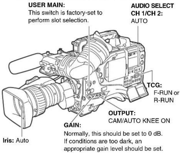
text_image
USER MAIN: This switch is factory-set to perform slot selection. AUDIO SELECT CH 1/CH 2: AUTO TCG: F-RUN or R-RUN OUTPUT: CAM/AUTO KNEE ON GAIN: Iris: Auto Normally, this should be set to 0 dB. If conditions are too dark, an appropriate gain level should be set.Notes
- The USER MAIN button is factory-set to perform the slot selection function, which selects the target card from among several P2 cards.
When a new target P2 card is selected, the appropriate slot number appears on the P2 card remaining amount indicator in the viewfinder.
For more information about the indications in the viewfinder, see [Viewfinder Status Indication Layout] (page 70).
- SLOT SEL function is enabled during recording. Until the P2 card on which images are recorded has been switched completely, [SLOT SEL] blinks on the viewfinder. If the [SLOT SEL] operation cannot be executed for any reason, for instance immediately after starting recording or switching the P2 card on which images are recorded, [SLOT SEL INVALID] is displayed.
Shooting
White/Black Balance Adjustment to Recording Completion
For shooting, follow the steps below.
1 Select a filter according to light conditions.
2A When the white balance is saved: Position the WHITE BAL switch to [A] or [B].
2B When the white or black balance is not saved and you have no time to adjust the white balance:
Position the WHITE BAL switch to [PRST]. This adjusts the white balance against the filter according to the position of the FILTER control.
2C If the white balance is adjusted on the spot: Position the WHITE BAL switch to [A] or [B] and shoot a white test subject so that it appears at the center of the screen. Then, follow the steps below to adjust the white balance.
- Press the AUTO W/B BAL switch toward [AWB] to adjust the white balance.
- Press the AUTO W/B BAL switch toward [ABB] to adjust the black balance.
- Press the AUTO W/B BAL switch toward [AWB] to adjust the white balance again.
For directions on making adjustments, see [Adjusting the White Balance] (page 45) and [Adjusting the Black Balance] (page 48).
3 Point the camera at your subject to adjust the focus, and zoom.
4 To use the electronic shutter, set the shutter speed and operation mode. For more information, see [Setting the Electronic Shutter] (page 49).
5 Press either the REC START/STOP button, REC button on the handle or VTR button at the lens to start recording. During recording, the REC lamp in the viewfinder stays illuminated.
6 To stop recording, press either the REC START/STOP button, REC button on the handle or VTR button at the lens. The REC lamp in the viewfinder goes out.
Operation Buttons During recording, all operation buttons (REW, FF, PLAY, PAUSE, STOP) are disabled.
White/Black balance adjustment to recording completion
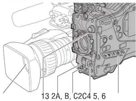
text_image
13 2A, B, C2C4 5, 6Normal Recording
REC START/STOP button, REC button on the handle or VTR button at the lens starts recording of video and sound on the P2 card. A cluster of data that consists of video and sound generated through a shooting action, together with such added information as meta data, is called a "clip".
Normal Recording and Native Recording
In the unit, the camera's recording method is selectable between the Native recording method with the frame rate unchanged and the normal recording method pulling the frame rate down to 59.94 or 50 frames.
Normal recording (Pull-down recording)
Images at 24P (23.98P: referred to as 24P) are pulled down in 2:3 mode. Images at 30P (29.97P: referred to as 30P) are pulled down in 2:2 mode and recorded as 59.94i or 59.94P (referred to as 60i and 60P). Images at 25P are recorded as 50i or 50P with 2:2 pulled down. 1080i and 480i support 24PA (2:3:3:2 Advanced Pull down) as well.
AVC-Intra (optional) does not support pull-down recording.
Example of 24P Over 60i
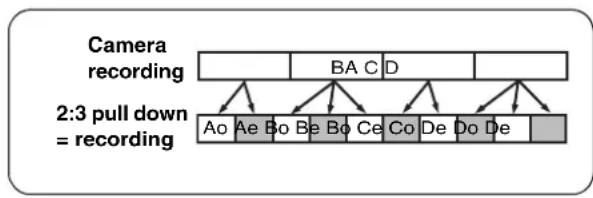
flowchart
graph TD
    A["Camera recording"] --> B["BA C D"]
    B --> C["Ao Ae Bo Be Bo Ce Co De Do De"]
    C --> D["2:3 pull down = recording"]
    D --> E["Output"]
Example of 720P 24P Over 60P
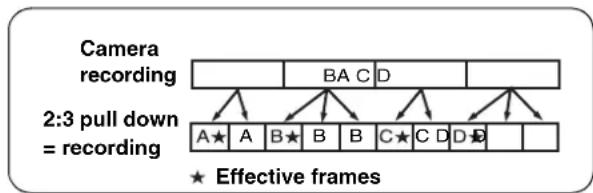
flowchart
graph TD
    A["Camera recording"] --> B["A★"]
    A --> C["A"]
    A --> D["B★"]
    A --> E["B"]
    A --> F["B"]
    A --> G["C★"]
    A --> H["C"]
    A --> I["D"]
    A --> J["D"]
    A --> K["D"]
    A --> L["D"]
    M["2:3 pull down = recording"] --> N["A★"]
    M --> O["A"]
    M --> P["B★"]
    M --> Q["B"]
    M --> R["B"]
    M --> S["C★"]
    M --> T["C"]
    M --> U["D"]
    M --> V["D"]
    M --> W["D"]
    M --> X["D"]
    M --> Y["D"]
    M --> Z["D"]
    style A fill:#f9f,stroke:#333
    style M fill:#ccf,stroke:#333
    style N fill:#cfc,stroke:#333
    style O fill:#cfc,stroke:#333
    style P fill:#cfc,stroke:#333
    style Q fill:#cfc,stroke:#333
    style R fill:#cfc,stroke:#333
    style S fill:#cfc,stroke:#333
    style T fill:#cfc,stroke:#333
    style U fill:#cfc,stroke:#333
    style V fill:#cfc,stroke:#333
    style W fill:#cfc,stroke:#333
    style X fill:#cfc,stroke:#333
    style Y fill:#cfc,stroke:#333
    style Z fill:#cfc,stroke:#333
Native recoding
This recording method extracts and records effective frames at the frame rates of the AVC-Intra recording (optional) in 1080i, and DVCPRO HD and AVC-Intra recording (optional) in 720P.
For 720P, it is possible to record images where the length is 2 to 2.5 times longer than the pull-down recording.
Even in Native recording, the rate for outputting camera images and playback images is 59.54 or 50 frames that are pulled down.
Example of 1080-24PN (Native)
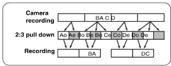
flowchart
graph TD
    A["Camera recording"] --> B["BA C D"]
    B --> C["Ao Ae Bo Be Bo Ce Co De Do De"]
    C --> D["Bo Ba"]
    C --> E["Bo Ba"]
    C --> F["Bo Ce"]
    C --> G["Bo De"]
    C --> H["Bo De"]
    C --> I["Bo De"]
    J["2:3 pull down"] --> K["Recording"]
    K --> L["BA"]
    K --> M["DC"]
Example of 720-24PN (Native)

flowchart
graph TD
    A["A"] --> B["B"]
    B --> C["C"]
    C --> D["D"]
    style A fill:#f9f,stroke:#333
    style B fill:#f9f,stroke:#333
    style C fill:#f9f,stroke:#333
    style D fill:#f9f,stroke:#333
    note1["2:3 pull down ★ Effective frame Recording"]
    note2["Camera recording"]
Notes
- The recording will start from the top frame of a five-frame cycle for 24P/24PA recording, a four-frame cycle for 24P native recording or a two-frame cycle for 30P and 25P of 720P, respectively. Therefore, the time code may be discontinued when recording clips continuously in different modes during the recording cycle.
- Even if a P2 card has just been inserted, or the power has been just turned on, you can start recording using the internal memory of camera-recorder. In this case, recording cannot be stopped until the P2 card is recognised. If the inserted card is not recognized as a recordable P2 card, the record in internal memory is instantly discarded, and the message "CANNOT REC" message is displayed on the viewfinder. Press the MODE CHECK button to check P2 card status (displayed in viewfinder).
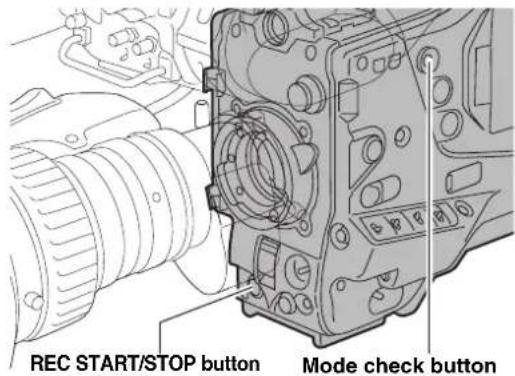
text_image
REC START/STOP button Mode check buttonPRE-RECORDING function
The internal memory of your unit is capable of storing several seconds of video and sound data coming from the camera. This capability can be used to record video and sound several seconds before either the REC START/STOP button, REC button on the handle or VTR button at the lens is pressed to start recording. To use this function, the menu option PRE REC MODE must be set to "ON". The storage duration of the internal memory can be set from the menu option PRE REC TIME. PRE REC MODE and PRE REC TIME menu options can be found in the REC FUNCTION screen on the SYSTEM SETTING page. The function of the menu option PRE REC MODE may be assigned to a desired user button by using any one of the menu options USER MAIN SW, USER1 SW, or USER2 SW. These options can be found in the USER SW screen, which is accessible from the CAM OPERATION page. These are the options for PRE REC TIME.
1-15 SEC (for DVCPRO 25M or DV)
1-8 SEC (for DVCPRO HD or 50M):
Specify the duration for which data may be recorded before either the REC START/STOP button, REC button on the handle or VTR button at the lens is pressed.
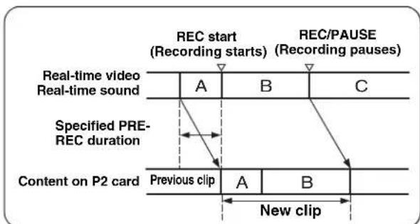
flowchart
graph TD
    A["Real-time video\nReal-time sound"] --> B["Specified PRE-REC duration"]
    B --> C["Content on P2 card"]
    C --> D["Previous clip"]
    D --> E["New clip"]
    E --> F["Rec start\n(Recording starts)"]
    F --> G["Rec/PAUSE\n(Recording pauses)"]
    G --> H["Rec/A"]
    H --> I["Rec/A"]
    I --> J["Rec/A"]
    J --> K["Rec/A"]
    K --> L["Rec/A"]
    L --> M["Rec/A"]
    M --> N["Rec/A"]
    N --> O["Rec/A"]
    O --> P["Rec/A"]
    P --> Q["Rec/A"]
    Q --> R["Rec/A"]
    R --> S["Rec/A"]
    S --> T["Rec/A"]
    T --> U["Rec/A"]
    U --> V["Rec/A"]
    V --> W["Rec/A"]
    W --> X["Rec/A"]
    X --> Y["Rec/A"]
    Y --> Z["Rec/A"]
Notes
- "P-REC" indication when the "PRE REC MODE" menu option is set to OFF
After recording is stopped, the "P-REC" indication remains displayed until all video and sound are recorded on the P2 card, even if the PRE REC MODE menu option is set to OFF. For details of the [P-REC] display, refer to [30.INTERVAL REC/PRE RECORDING indication/ SD memory card remaining free space (page 75)] in [Viewfinder Status Indication Layout].
- Immediately after the power is turned on, the menu option PRE REC TIME is selected and/or the storage duration is changed, the content in internal memory will be undefined. In these situations, the video or sound will not be recorded for the duration specified, even if either the REC START/STOP button, REC button on the handle or VTR button at the lens is pressed to start recording.
- A P2 card that has been just inserted takes some time to recognise. In this situation, video or sound may not be recorded for the duration specified, even if either the REC START/STOP button, REC button on the handle, or VTR button at the lens is pressed to start a recording.
- The internal memory does not store video or sound when a playback or recording review is being performed. For this reason, no video or sound can be recorded during such operation.
- When recording starts, the time code indication (TCG) may be shown as "HOLD" until the P2 card has been recognised.
● During recording of IEEE1394 input or INTERVAL REC operation, PRE RECORDING is not available.
Loop Recording
When two or more P2 card slots contain cards, this function allows the target P2 card to be switched in order. Even when the free space of a P2 card is used up, this function continues recording while erasing existing data. To use this function, the menu option LOOP REC MODE must be set to "ON" The option LOOP REC MODE can be found in the
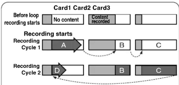
flowchart
graph TD
    A["Before loop recording starts"] --> B["No content"]
    B --> C["Content recorded"]
    D["Recording Cycle 1"] --> E["A"]
    E --> F["B"]
    F --> G["C"]
    H["Recording Cycle 2"] --> I["D"]
    I --> J["B"]
    J --> K["C"]
    style A fill:#f9f,stroke:#333
    style D fill:#f9f,stroke:#333
    style H fill:#f9f,stroke:#333
    style B fill:#ccf,stroke:#333
    style E fill:#cfc,stroke:#333
    style F fill:#cfc,stroke:#333
    style J fill:#cfc,stroke:#333
    style K fill:#cfc,stroke:#333
Data are recorded by connecting the unrecorded sections on the P2 card (in the sequence of A to B to C). When the remaining recording capacity is less than 30 seconds, A is deleted, and data are record on C up to FULL (remaining memory capacity is 0), and then new data are recorded (D).
Notes
- When the loop recording capability is used, each P2 card must have at least one minute of free space.
- During loop recording, the P2 CARD ACCESS LEDs for all target P2 cards illuminate in orange. Note that if any of the target P2 card is removed, loop recording stops.
- When the menu option LOOP REC MODE is set to ON, the viewfinder and display window both show "LOOP". However, when only one card is inserted, or when each card has less than one minute of free space, the loop recording capability does not work, even if the option LOOP REC MODE is set to ON. If this is the case, the indication "LOOP" flashes in the viewfinder and on the display window.
- When the menu option LOOP REC MODE is set to ON, the P2 card remaining free space indicates the minimum guaranteed recording time. The minimum guaranteed recording time means the guaranteed time or length of recorded data when LOOP REC stops immediately after deleting old data.
- During recording of IEEE1394 input or INTERVAL REC operation, LOOP REC is not available.
Terminating the Loop Recording Mode
You can terminate the loop recording mode by either:
● Turning off the POWER switch of camera-recorder; or
- Setting the menu option LOOP REC MODE to "OFF".
Interval Recording
It is possible to record in intervals of one frame as the shortest length by using the internal memory of the unit.
To use this option, open the REC FUNCTION screen from the SYSTEM SETTING page, and set the interval recording mode, REC TIME, PAUSE TIME and TAKE TOTAL TIME for the menu option INTERVAL REC MODE. When the settings are finalized, TOTAL REC TIME needed on the P2 card is automatically calculated and displayed.
The following are the options for INTERVAL REC MODE:
OFF:
No interval recording performed.
ON:
Interval recording performed.
ONE SHOT:
Performs “one-shot” recording for the duration specified under the REC TIME option by pressing either the REC START/STOP button, REC button on the handle, or VTR button at the lens.
Notes
- When executing interval recording, data cannot be output with IEEE1394. When the 1394 CONTROL is set to [BOTH], it is also impossible to control external devices.
- The shortest recording time, stand-by time, and the set value of the cut-off unit frame number ^*1 may vary with the recording method as follows.
| Recording method | Unit frame number | |
| 1080i | 60i, 50i30P, 25P (Pull down)30PN, 25PN (Native) | 1 frame |
| 24P, 24PA (Pull down) 5 frames | ||
| 24PN (Native) 4 frames | ||
| 720P | 60P, 50P30P, 25P (Pull down) | 1 frame |
| 30PN, 25PN (Native) 2 frames | ||
| 24P (Pull down) 5 frames | ||
| 24PN (Native) 4 frames | ||
| SD MODE | 60i, 50i30P, 25P (Pull down) | 1 frame |
| 24P, 24PA (Pull down) 5 frames | ||
*1 For instance, interval recording is at every 24 frames since frames are cut off every two frames even if the REC TIME is set to 1 second (= 25 frames) in the 25PN mode of 720P.
Shooting procedures when INTERVAL REC is ON
1 Following basic operations of shooting and recording according to "Basic Procedures", lock the camera securely.
2 Check that "i" is blinking in the display, and that the interval recording mode is selected.
3 Press either REC START/STOP button, REC button on the handle, or VTR button at the lens.
Interval recording starts. Recording automatically stops after the specified TAKE TOTAL TIME, and the entire recording is generated as one clip.
“i” starts blinking in the display when the internal recording mode is selected. “iREC” illuminates after recording starts. “iREC” blinks during a pause.
The display in the viewfinder is the same as that in the display window.
The tally lamp illuminates during recording. If PAUSE TIME is set at 2 minutes or longer, the tally lamp illuminates at 5-second intervals to indicate that it is paused. The tally lamp also blinks 3 seconds before recording starts.
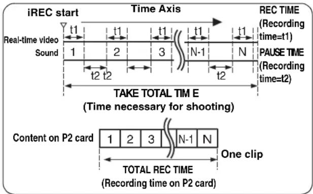
text_image
iREC start Time Axis Real-time video Sound t1 t1 t1 t1 t1 t2 t2 N-1 N TARE TOTAL TIME E (Time necessary for shooting) RECE Time (Recording time=t1) PAUSE TIME (Recording time=t2) Content on P2 card 1 2 3 N-1 N One clip TOTAL REC TIME (Recording time on P2 card)For continuous recording
Press either the REC START/STOP button, REC button on the handle, or VTR button at the lens, again. Interval recording resumes.
To stop recording
Press the STOP button. Recording stops. Then, the camera accesses the P2 card to record the video stored in memory before recording stops. The record from the beginning of the interval recording to the moment of pressing the STOP button is generated as one clip.
To stop the Interval recording mode
- Setting the menu option INTERVAL REC MODE to "OFF".
When INTERVAL REC HOLD is set to [OFF], the mode returns to ordinary recording mode if the POWER switch of the unit is turned OFF.
If INTERVAL REC HOLD is set to [ON], the interval recording mode will not change even if the POWER switch is turned OFF.
Shooting procedures for the ONE SHOT mode of INTERVAL REC
After setting the INTERVAL REC mode, follow these steps:
1 Following basic operations of shooting and recording according to "Basic Procedures", lock the camera securely.
2 Press either the REC START/STOP button, REC button on the handle, or VTR button at the lens. The AJ-HPX2000 automatically goes into ONE SHOT pause mode after the specified REC TIME.
3 Performs recording for the duration specified under the REC TIME option by pressing either the REC START/STOP button, REC button on the handle, or VTR button at the lens, and returns to ONE SHOT pause mode.
4 Press the STOP button.
The video and sound stored in memory are generated as one clip.
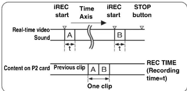
text_image
iREC start Time Axis iREC start STOP button Real-time video Sound A B t t Content on P2 card Previous clip A B One clip REC TIME (Recording time=t)To check the previous recording during a pause
Press the RET button at the lens to put the AJ-HPX2000 into REC REVIEW mode. ONE SHOT operation continues after the REC REVIEW.
To divide clips or to change the P2 card used for recording
Even during ONE SHOT mode, clips will not be generated on the P2 card until the STOP button is pressed. Press the STOP button, and stop ONE SHOT mode operation.
To stop the ONE SHOT mode of INTERVAL REC
- Set the menu option INTERVAL REC MODE to "OFF".
When INTERVAL REC HOLD is set to [OFF], the mode returns to ordinary recording mode if the POWER switch of the unit is turned OFF.
If INTERVAL REC HOLD is set to [ON], the interval recording mode will not change even if the POWER switch is turned OFF.
During INTERVAL REC mode general notes
- Sound
By selecting ON/OFF for the menu option AUDIO REC in the REC FUNCTION screen, it is possible to specify whether or not sound will be recorded during interval recording.
- Record/Playback Buttons
During interval recording, all operation buttons other than STOP (REW, FF, PLAY/PAUSE) are disabled. However, during a pause in ONE SHOT mode, REC REVIEW can be executed with the RET button on the lens.
- If the power is turned off during recording
If the AJ-HPX2000 is turned off during interval recording, the video stored in memory is recorded onto the P2 card, and then the camera automatically turns off.
● To start emergency recording during a pause
By setting the REC button to USER MAIN or USER1/USER2, emergency recording can be performed during a pause by pressing the button. Pause time measurement continues after such emergency recording.
Note
However, this function does not work when the recording signals are in 24P, 24PA or 24PN (Native) mode.
● Time code indication
When recording starts, the time code (TCG) display may not update until the unit recognizes the P2 card.
- Removing cards
During INTERVAL REC mode operation, the P2 card access LED for the inserted P2 card blinks in orange. Do not remove the P2 card during this status. If you should remove the card accidentally, restore clips. However, even if the clips are restored, the last 3 to 4 seconds up to a maximum of about 10 seconds of the recording may be lost if the P2 card is removed while recording onto multiple P2 cards. For more information on how to fix clips, see [Restoring Clips] (page 117).
- Operation mode
INTERVAL REC does not work when "1394" is selected for the menu option REC SIGNAL. The menu option REC SIGNAL is found in the SYSTEM MODE screen on the SYSTEM SETTING page. For more information, see [Recording Setting and Operation Mode] (page 41).
● Thumbnail operation and menu operation
Thumbnail operation does not work during the INTERVAL REC mode operation. Press the STOP button before operating thumbnails.
When standby time is set to 1 minute or more or when in ONE SHOT mode, the following restrictions apply even though the menu can be operated during stand-by mode.
- The respective settings or SYSTEM MODE, REC SIGNAL, CAMERA MODE, REC MODE, 25M REC CH SEL, and PC MODE cannot be changed.
- The respective settings for SD CARD READ/WRITE, LENS FILE CARD R/W, READ USER DATA, and READ FACTORY DATA cannot be executed.
Recording Review Function
When recording is paused, pressing the RET button automatically locates the last two seconds of video just recorded, and the viewfinder provides video playback.
After playback, the camera-recorder is again ready to start recording.
The picture location/playback duration can be increased to up to 10 seconds by continuously pressing the RET button. For short clips, however, when the start of a clip is located, continuously pressing the RET button does not play back any clips before that clip.
The function of the RET button may be assigned to a desired user button by using one of the menu options USER MAIN SW, USER1 SW or USER2 SW. These options can be found in the
When recording is paused, pressing the PLAY/PAUSE button plays back the last recorded clip, from the beginning. After completion of playback, the camera-recorder enters the stopped state.
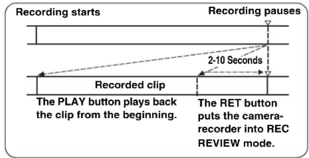
flowchart
graph TD
    A["Recording starts"] --> B["Recorded clip"]
    B --> C["The PLAY button plays back the clip from the beginning."]
    D["Recording pauses"] --> E["2-10 Seconds"]
    E --> F["The RET button puts the camera-recorder into REC REVIEW mode."]
Notes
- Set the menu option RET SW (found on the SW MODE page for CAM OPERATION) to R. REVIEW.
- When the OUTPUT SEL switch on the side panel is positioned at [MEM], the video for REC REVIEW is output from the video output connectors (VIDEO OUT and MON OUT connectors), and also to the viewfinder.
Note that when a backup device is connected to back up the video the pictures for REC REVIEW are backed up.
Normal and Variable Speed Playback
The PLAY/PAUSE button provides monochrome playback through the viewfinder and color playback on the LCD monitor. A color video monitor connected to the VIDEO OUT or MON OUT connector of camera-recorder also provides color playback.
The VIDEO OUT connector outputs an SDI playback (to view the playback, the OUTPUT SEL switch on the side panel must be positioned to [MEM]).
Variable speed playback
The FF and REW buttons provide 32× and 4× fast playbacks and fast reverse playbacks.
When playback is paused, the FF button locates the beginning of the next clip while maintaining the pause mode.
When playback is paused, the REW button locates the beginning of the current clip while maintaining the pause mode.
Notes
- The camera-recorder cannot play back clips where the system mode differs. If this is the case, set the system mode of camera-recorder to the format of the desired clip before playing it back.
- When a P2 card has been just removed or inserted, or when the power has been just turned on for playback, it may take some time for camera-recorder to read clip information. If this is the case, the viewfinder displays "UPDATING". If data is played back when the P2 card is being recognized, the message "CANNOT PLAY" will be displayed.
- If a P2 card is inserted while another P2 card is being played back, the clips on the inserted P2 card will not be played back. A P2 card inserted during playback will be recognised after playback ends.
- If you perform variable speed playback on a clip split across more than one P2 card, sound may disappear for a moment. This is not a fault.
Text Memo Function
Text memos are time-coded thumbnails added to any video point when a clip is being recorded or played back. The Text Memo button adds text memo information at the appropriate point. You can edit added text memos using the P2 viewer.
Through a thumbnail display, you can choose and play back the text memo point or copy any portion. For more information, see [Text Memo] (page 115).
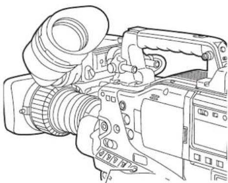
natural_image
Line drawing of a DSLR camera with lens and external frame (no text or symbols)Text MEMO button
Notes
● One clip can have up to 100 text memos.
- Text memos can also be recorded when the LCD monitor is in thumbnail mode. In this case, the text memo is added to the position on the clip where the cursor is set (normally at the beginning) only.
- Text memos cannot be recorded when the color bar is output or the unit is in LOOP REC mode and INTERVAL REC mode.
- For a clip with voice memos added through the AJ-SPX800 or any other camera-recorder, you can record up to 100 text and voice memos in combination. For information about voice memos, see the instruction manual for the AJ-SPX800.
Shot Mark Function
A shot mark is added to the thumbnail of a clip to distinguish that clip from others. With the LCD monitor, only clips that have shot marks can be viewed and/or played back.
Adding Shot Marks
To add a shot mark during recording, press the SHOT MARK button. The viewfinder displays "MARK ON" and adds a shot mark to the thumbnail of the appropriate clip. Another press of the button erases the shot mark.

text_image
SHOT MARK buttonShot marks may also be added or erased using clip thumbnails. For more information, see [Shot Mark] (page 115).
Notes
- When the color bar is output or the unit is in LOOP REC mode and INTERVAL REC mode, it is impossible to add/delete shot marks.
- It is impossible to add shot marks to incomplete clips (refer page 111).
- For clips recorded on plural P2 cards or clips split on a P2 card (refer to Notes on page 10), a shot mark is added to the top clip only.
Recording Setting and Operation Mode
AJ-HPX2000 recording mode works according to the priorities outlined in the following table, relative to the setting of the menus and switches.
| Functional operation mode | Menu switches related to system/recording Buttons | Proxy recording (optional) | ||||||
| PC MODE | REC SIGNAL | INTERVAL REC MODE | LOOP REC MODE | PRE REC MODE | Recording a Text Memo | Shot Mark | ||
| USB device | USB DEVICE | Disabled Disabled | Disabled Disabled | Disabled Disabled | Disabled Disabled | Disabled | ||
| USB host USB HOST | ST Disabled | Disabled Disabled | Disabled Enabled | Enabled | Disabled Disabled | |||
| 1394 Input record | OFF | 1394 Disabled | Disabled Disabled | Enabled | Enabled | Disabled | ||
| INTERVAL REC | CAMERA VIDEO SDI (optional) | ON or ONE SHOT | Disabled Disabled | Disabled Disabled | Disabled Disabled | |||
| LOOP REC | OFF | ON | Enabled 1s - 8s/15s | Disabled Disabled | ||||
| Normal Recording | OFF | Enabled 1s - 8s/15s | Enabled* | Enabled* | Enabled | |||
* Disabled for color bars
Adjustments and Settings for Recording
Multi Format
Video system and Recording format
The unit employs a progressive scan (full pixel reading) CCD system.
With combinations of the SYSTEM MODE and CAMERA MODE menu options on the SYSTEM MODE screen on the SYSTEM SETTING menu, you can select an image system from among 23 types ^4 including HD (1080i, 720P) and SD formats.
In any image system, the CCD operates in progressive (non-interlace) scan mode. In addition, through the REC SIGNAL menu option, you can record external input signals such as 1394 and SDI (optional).
*1 When the AVC-Intra codec board (AJ-YBX200G, optional) is installed
Selecting a recording signal and method
SYSTEM MODE menu option
Allows you to select a combination of system frequency (59.94 Hz or 50 Hz) and signaling system (1080i, 720P, 480i, or 576i). When a change has been made to the SYSTEM MODE option, the viewfinder indicates "TURN POWER OFF." Then, turn the POWER switch of the camera-recorder off and wait five seconds or longer before turning the camera-recorder on again.
REC SIGNAL menu option
CAM Signals from the camera are recorded. The CAMERA MODE option allows you to select a camera operation mode (frame mode).
1394 Signals from the DVCPRO/DV connector are recorded. For information about the 1394 connection, see [Connection through the DVCPRO/DV connector] (page 129).
VIDEO Signals from the GENLOCK IN connector are recorded when the camera-recorder is in SD mode (480-59.94i or 576-50i).
SDI Signals from the SDI IN connector are recorded (when the AJ-YA350AG, an SDI IN option, is installed).
Notes
- When VIDEO is selected, video may produce noise if the signals from GENLOCK IN are non-standard signals.
- When SDI is selected, the time code or UMID superimposed on SDI input signals are not recorded.
CAMERA MODE menu option
Used to select a camera operation mode when the option REC SIGNAL is set to CAM. For information about the behavior for each setting, see [Recording formats and output connector signal formats] (page 43).
Note
When the camera has been switched from 60i, 60P, or 30P to 24P or 24PA, video may produce noise for a moment because the pull-down five-frame cycle is adjusted. This is not an abnormal condition.
REC MODE menu option
Used to select the recording mode
For HD mode (1080i, 720P)
DVCPRO HD
The DVCPRO HD format is used to record video. The pull-down recording is for the 30P, 24P, 24PA and 25P modes.
DVC HD (N)
The native mode used to record video in DVCPRO HD format. (Only for 720P)
AVC-I 50 (when the AVC-Intra codec board is installed)
The AVC-Intra50 format is used to record video. The native recording is applied to the 30P, 24P and 25P modes.
AVC-I 100 (when AVC-Intra codec board is installed))
The AVC-Intra100 format is used to record video. The native recording format applies to the 30P, 24P and 25P modes.
Note
When AVC-Intra 50 or AVC-Intra 100 is selected, the 24PA mode cannot be selected.
For SD mode (480i, 576i)
DVCPRO50
The DVCPRO50 format (50 Mbps) is used to record video.
DVCPRO
The DVCPRO format (25 Mbps) is used to record video.
DV The DV format is used to record video.
ASPECT menu option
Used to select the aspect ratio for the SD mode (480i or 576i)
16 : 9 The 16:9 aspect ratio is used to record video.
4:3 The 4:3 aspect ratio is used to record video.
Recording formats and output connector signal formats
The table below shows the formats used to record signals from the CCD and externally input signals along with the formats for signals output from the output connectors.
For 59.94 Hz
| Menu setting | Recording Output | |||||||||||||
| SYSTEM MODE item | REC MODE item | REC SIGNAL item | CAMERA MODE item | Recording frame mode | P2 card recording*1 | Output frame mode | VIDEO OUT connector (HD SDI)*2 | VIDEO OUT connector (SD SDI)*3 | VIDEO OUT (VBS), MON OUT, and REMOTE connectors | When VF connector is set to HD VF | When VF connector is set to SD VF | |||
| Video | Sound Video | Sound | Video | Sound | Video | |||||||||
| 1080-59.94i | DVCPRO-HD | CAM | 60i 60i | Over 60 | 4ch | 60i | 1080i | 4ch | 525i | 4ch 525i | 1080i 525i | |||
| 30P | 30P Over 60i 30 | |||||||||||||
| 24P | 24P Over 60i | 24P Over 60i | ||||||||||||
| 24PA | 24PA Over 60i | 24PA Over 60i | ||||||||||||
| 1394 | — | 60i 60i | ||||||||||||
| SDI (optional) | — | 60i 60i | ||||||||||||
| AVC-I 100 AVC-I 50 (optional) | CAM | 60i 60i 60i | ||||||||||||
| 30P | 30PN (Native) | 1080P | 30P Over 60i | |||||||||||
| 24P | 24PN (Native) | 24P Over 60i | ||||||||||||
| SDI (optional) | — | 60i 1080i | 60i | |||||||||||
| 720-59.94P | DVCPRO-HD | CAM | 60P | 60P | 720P | 4ch | 60P | 720P | 4ch | 525i | 4ch 525i | 1080i | 525i | |
| 30P | 30P Over 60P | 30P Over 60P | ||||||||||||
| 24P | 24P Over 60P | 24P Over 60P | ||||||||||||
| 1394 | — | 60P | 60P | |||||||||||
| SDI (optional) | — | 60P | 60P | |||||||||||
| DVC HD (N) | CAM | 60P | 60P | 60P | ||||||||||
| 30P | 30PN (Native) | 30P Over 60P | ||||||||||||
| 24P | 24PN (Native) | 24P Over 60P | ||||||||||||
| SDI (optional) | — | 60P | 60P | |||||||||||
| AVC-I 100 AVC-I 50 (optional) | CAM | 60P | 60P | 60P | ||||||||||
| 30P | 30PN (Native) | 30P Over 60P | ||||||||||||
| 24P | 24PN (Native) | 24P Over 60P | ||||||||||||
| SDI(optional) | — | 60P | 60P | |||||||||||
| 480-59.94i | DVCPRO50 DVCPRO DV | CAM | 60i 60i | Over 60 | 4ch or 2ch *5 | 60i | — *4 | — *4*5 | 525i | 4ch or 2ch*5 | 525i | 1080i (Playback not output) | 525i | |
| 30P | 30P Over 60i 30 | |||||||||||||
| 24P | 24P Over 60i | 24P Over 60i | ||||||||||||
| 24PA | 24PA Over 60i | 24PA Over 60i | 2ch*5 | (Playback not output) | ||||||||||
| 1394 | — | 60i 60i | ||||||||||||
| VIDEO | ||||||||||||||
| SDI (optional) | ||||||||||||||
*1 The time code, user bits, and UMID are recorded.
*2 The time code, user bits, and UMID (selectable between ON and OFF) are output.
*3 The EDH (selectable between ON and OFF) and UMID (selectable between ON and OFF) are output. The time code or user bits are not output.
*4 The SD SDI output is maintained.
*5 4ch for DVCPRO50, 4ch/2ch selectable for DVCPRO and DV
Note
- UMID is not output for recording or playing back in DV format or for playing back DVCPRO HD Native recording clips.
● During playback, the formats for clips in the same system mode are switched automatically and played back.
For 50 Hz
| Menu setting | Recording Output | ||||||||||||||
| SYSTEM MODE item | REC MODE item | REC SIGNAL item | CAMERA MODE item | Recording frame mode | P2 card recording*1 | Output frame mode | VIDEO OUT connector (HD SDI)*2 | VIDEO OUT connector (SD SDI)*3 | VIDEO OUT (VBS), MON OUT, and REMOTE connectors | When VF connector is set to HD VF | When VF connector is set to SD VF | ||||
| Video | Sound Video | Sound | Video | Sound | Video | ||||||||||
| 1080-50i | DVCPRO-HD | CAM | 50i 50i | Over 50i 1080i | 4ch | 50i | 1080i | 4ch | 625i | 4ch 625i | 1080i 625i | ||||
| 25P | 25P Over 50i 25P | ||||||||||||||
| 1394 | — | 50i 50i | |||||||||||||
| SDI (optional) | — | 50i 50i | |||||||||||||
| AVC-I 100 AVC-I 50 (optional) | CAM | 50i | 50i | 50i | |||||||||||
| 25P | 25PN (Native) | 1080P | 25P Over 50i | ||||||||||||
| SDI (optional) | — | 50i 1080i 50i | |||||||||||||
| 720-50P | DVCPRO-HD | CAM | 50i 50P | 720P | 4ch | 50P | 720P | 4ch | 625i | 4ch 625i | 1080i 625i | ||||
| 25P | 25P Over 50P | 25P Over 50P | |||||||||||||
| 1394 | — | 50P | 50P | ||||||||||||
| SDI (optional) | — | 50P | 50P | ||||||||||||
| DVC HD (N) | CAM | 50P | 50P | 50P | |||||||||||
| 25P | 25PN (Native) | 25P Over 50P | |||||||||||||
| SDI (optional) | — | 50P | 50P | ||||||||||||
| AVC-I 100 AVC-I 50 (optional) | CAM | 50P | 50P | 50P | |||||||||||
| 25P | 25PN (Native) | 25P Over 50P | |||||||||||||
| SDI (optional) | — | 50P | 50P | ||||||||||||
| 576-50i | DVCPRO50 DVCPRO DV | CAM | 50i 50i | Over 50i 576i | 4ch or 2ch*5 | 50i | —*4 | —*4*5 | 625i | 4ch or 2ch*5 | 625i | 1080i (Playback not output) | 625i | ||
| 25P | 25P Over 50i 25P | ||||||||||||||
| 1394 | — | 50i 50i | (Playback not output) | ||||||||||||
| VIDEO | |||||||||||||||
| SDI (optional) | |||||||||||||||
*1 The time code, user bits, and UMID are recorded.
*2 The time code, user bits, and UMID (selectable between ON and OFF) are output.
*3 The EDH (selectable between ON and OFF) and UMID (selectable between ON and OFF) are output. The time code or user bits are not output.
*4 The SD SDI output is maintained.
*5 4ch for DVCPRO50, 4ch/2ch selectable for DVCPRO and DV
Note
- UMID is not output for recording or playing back in DV format or for playing back DVCPRO HD Native recording clips.
● During playback, the formats for clips in the same system mode are switched automatically and played back.
Adjusting the White balance and Black Balance
To record high-quality video with the unit, the black and white balances must be adjusted according to conditions. For higher quality, it is recommended that the adjustments should be made in this order AWB (white balance adjustment) → ABB (black balance adjustment) → AWB (white balance adjustment).
Adjusting the White Balance
Whenever light conditions change, the white balance must be re-adjusted.
To adjust the white balance, follow the steps below.
1 Set the switches as illustrated below.
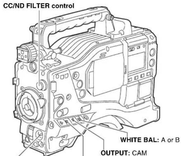
text_image
CC/ND FILTER control WHITE BAL: A or B OUTPUT: CAMAUTO W/B BAL switch: Used to perform AWB.
GAIN: Under normal conditions, set to 0 dB If it is too dark, an appropriate gain should be set.
2 Adjust the CC/ND FILTER control according to the light conditions.
Note
For examples of CC/ND FILTER adjustments, see [Shooting and Recording/Playback Functions Section] (page 17).
3 Place a white pattern at a point where the light conditions match those for the light source of the subject. Then zoom-in on the white pattern so that white color appears in the screen. A white object (cloth or wall) may be used instead of a white pattern. The illustration below shows the required size for the white space.
Notes
- Do not include a high-intensity spot in the screen.
- The white object must appear at the center of the screen.
1/4 or more of the screen in width
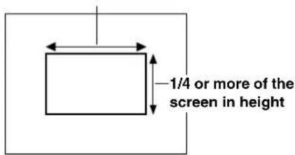
text_image
1/4 or more of the screen in height4 Adjust the lens iris.
5 Flip up the AUTO W/B BAL switch so that it is positioned at [AWB], then release it. The switch returns to the central position with the white balance automatically adjusted.
Note
To cancel automatic white balance adjustment in process (the viewfinder displays "AWB ACTIVE"), reposition the AUTO W/B BAL switch at [AWB]. If automatic adjustment is cancelled, the value in effect before automatic adjustment will be used.
6 During an adjustment, the viewfinder displays the following message:
AWB ACTIVE
7 The adjustment will take effect in a few seconds, and the following message will appear: The adjusted value is automatically stored in the memory specified in Step 1 ([A] or [B]).
AWB A OK 3.2K
8 For the 3200K CC/ND filter, if the subject's color temperature is lower than 2300K or higher than 9900K the following message appears: If the arrow points down (↓) the actual color temperature is lower than the temperature indicated. If the arrow points up (↑) the actual temperature is higher than the temperature indicated.
AWB A OK 2.3K ↓
Detection area for the white balance
The detection area for the white balance is selectable between 90%, 50% and 25%, using the menu option AWB AREA.
This option can be found in the
The detection area is factory-set to 25%.
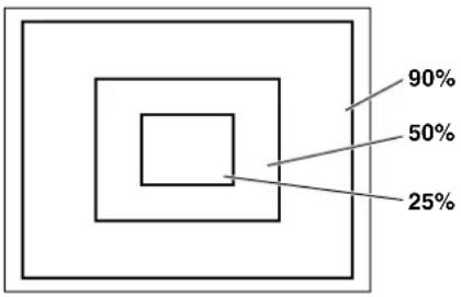
pie
| Category | Percentage (%) | |---|---| | Top Section | 90 | | Middle Section | 50 | | Bottom Section | 25 |When you have no time to adjust the white balance
Position the WHITE BAL switch at [PRST].
This adjusts the white balance for the filter according to the position of the CC/ND FILTER control.
When the white balance has not been automatically adjusted
When the white balance has not been successfully adjusted, the viewfinder displays an error message.
If one of the error messages listed below appears, take the appropriate steps, then adjust the white balance again.
If the error message appears after repeated readjustments, the interior of the unit must be inspected. For more information, contact your distributor.
| Error message | Description Remedies | |
| COLOR TEMP. HIGH | The color temperature is too high. | Select an appropriate filter. |
| COLOR TEMP. LOW | The color temperature is too low. | Select an appropriate filter. |
| LOW LIGHT There | is insufficient light. | Increase the light level or gain. |
| LEVEL OVER There | re is too much light. | Decrease the light level or gain. |
| CHECK FILTER T | the FILTER control is displaced. | Check the FILTER control. |
| TIME OVER AWB | was not completed within the time allowed. | Shooting conditions may be unstable. If flicker occurs, press the shutter and readjust the AWB under stable conditions. |
Retaining white balances
Each value in memory is retained even if the camera-recorder is turned off; it will not be lost until the white balance is re-adjusted. White balances are stored in either of two systems: A or B.
When the menu option FILTER INH is set to "ON" (default), each system stores only one value. If this is the case, the values are not synchronised with the filters.
This option can be found in the
When the menu option FILTER INH is set to "OFF", the adjusted value for each filter can be automatically stored in the memory that corresponds to the position of the WHITE BAL switch (A or B). Your unit has four built-in filters; it stores eight (4 × 2) adjusted values.
When the S. GAIN (super gain) function is activated, the AWB switch does not function and the value set for PRST is used.
Setting the auto-tracking white balance (ATW)
The unit has an auto-tracking white balance (ATW) feature that automatically tracks the white balance for pictures according to lighting conditions.
The ATW feature can be assigned to Position [B] of the WHITE BAL switch. To do so, the menu option AWB B must be set to "ATW". This option can be found in the
The ATW feature may be assigned to the USER MAIN, USER1, or USER2 button. For more information, see [Assigning Functions to USER MAIN, USER1 and USER2 Buttons] (page 51).
To cancel the auto-tracking white balance
Press the user button that has the ATW feature assigned, or change the position of the WHITE BAL switch. Note that, when the ATW feature is assigned to [B] of the WHITE BAL switch, the auto-tracking white balance cannot be cancelled with a user button.
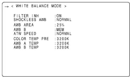
text_image
→ < WHITE BALANCE MODE > FILTER INH :ON SHOCKLESS AWB :NORMAL AWB AREA :25% AWB B :MEM ATW SPEED :NORMAL COLOR TEMP PRE :3200K AWB A TEMP :3200K AWB B TEMP :3200KNote
This function does not guarantee 100% accuracy of the white balance.
When using the unit, remember that there will be some allowance in the trackability of changes in lighting conditions and pull-in accuracy of white balances.
Setting Color Temperature Manually
The white balance can be manually adjusted by setting the color temperature. Manual color temperature settings can be performed for each of the WHITE BAL switch positions: PRST, A and B.
The color temperature is set using the menu options COLOR TEMP PRE, COLOR TEMP A, and COLOR TEMP B.
These options can be found in the
Note
Even if the color temperature has been manually set, automatic adjustment of the white balance (AWB) records the color temperature at the time of AWB at the position where the WHITE BAL switch was located. When the CC filter position is switched, the value for the color temperature changes.
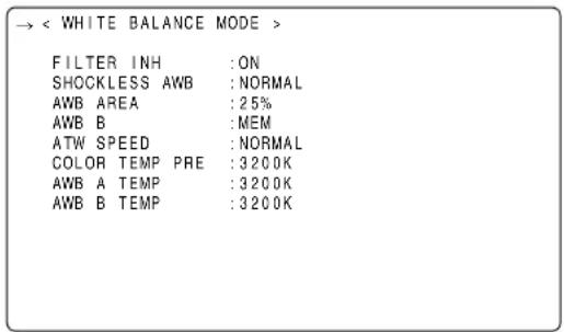
text_image
→ < WHITE BALANCE MODE > FILTER INH :ON SHOCKLESS AWB :NORMAL AWB AREA :25% AWB B :MEM ATW SPEED :NORMAL COLOR TEMP PRE :3200K AWB A TEMP :3200K AWB B TEMP :3200KViewfinder displays related to white balance
See [Viewfinder Screen Status Displays] (page 69).
Adjusting the Black Balance
The black balance must be adjusted when:
- You use your unit the first time;
- Your unit has not been used for some time;
● The ambient temperature has changed substantially;
● The gain switchover value has been changed; or - S.GAIN (super gain) has been set with the USER MAIN/USER1/USER2 button.
1 Set the switches as illustrated below.
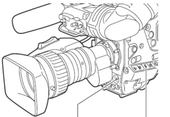
natural_image
Line drawing of a professional video camera with lens and external components (no text or symbols)AUTO W/B BAL switch:
Used to perform ABB.
OUTPUT: CAM
2 Tilt the AUTO W/B BAL switch so that it is positioned at [ABB], then release it.
The switch returns to the central position with the black balance automatically adjusted.
3 During adjustment, the viewfinder displays the following message:
ABB ACTIVE
Note
During adjustment, the lens iris automatically becomes CLOSE.
4 The adjustment will take effect in a few seconds and the following message will appear:
ABB OK
The adjusted value is automatically stored in the memory.
Notes
- Ensure that the lens connector is connected and the lens iris is CLOSE.
- During a black balance adjustment, light is automatically cut off.
- During a black balance adjustment, the gain switchover circuit is automatically switched.
The viewfinder screen may flicker and/or display noise; this is not a failure.
- If you find the black shading annoying after performing an auto black balance adjustment, adjust the black shading. To do so, go to the menu option DETECTION (DIG), move the cursor () , then press the JOG dial button. The menu option DETECTION (DIG) can be found in the
Note that pressing the ABB switch for longer than five seconds automatically performs an auto black balance adjustment, followed by an automatic black shading adjustment. (For more information, see the menu option SHD. ABB SW CTL in [SW MODE] (page 175).)
However, when the remote control unit (AJ-RC10G: optional accessory) is connected, automatic black shading cannot be executed even if the ABB switch is held down.
- To cancel the automatic black balance adjustment in process (the viewfinder displays "ABB ACTIVE"), flip the AUTO W/B BAL switch down to [ABB] again. If automatic adjustment is cancelled, the value in effect before automatic adjustment will be used.
Retaining black balances
Each value in memory is retained even if the camera-recorder is turned off.
Setting the Electronic Shutter
This section provides a description of the electronic shutter, together with setting and handling directions.
Shutter Modes
The table below lists the shutter modes in which the unit's electronic shutter can be used as well as the shutter speeds which can be selected.
To use the fixed shutter speed
● For eliminating flicker due to lighting
● For shooting fast moving subjects clearly
To use the shutter speed of SYNCHRO SCAN
- For shooting monitor screens in a way that minimizes the pattern of horizontal lines
- For shooting images when adding effects to the subjects' movement
To use the half shutter speed (HALF)
- For shooting images when adding effects as if taken with film
Notes
- No matter in which mode the electronic shutter is used, the higher the shutter speed, the lower the camera's sensitivity.
- When the aperture is in the automatic mode, it will increasingly open and the depth of focus will become shallower as the shutter speed is increased.
| Video system | CAMERA MODE | Shutter speed Half shutter speed | Variable range for SYNCHRO SCAN |
| 1080-59.94i 60i | 1/120 1/60.3 - 1/249.8 | ||
| 1080-29.97P 30P 1/60 | 1/30.2 - 1/249.8 | ||
| 1080-23.98P 24P 1/48 | 1/24.1 - 1/249.8 | ||
| 1080-23.98PA 24PA | 1/48 1/24.1 - 1/249.8 | ||
| 720-59.94P 60P 1/120 | 1/60.3 - 1/249.8, 1/120, 1/250, 1/500, 1/1000, 1/2000, 1/24.1 - 1/249.8 | ||
| 720-29.97P 30P 1/60 | 1/30.2 - 1/249.8 | ||
| 720-23.98P 24P 1/48 | 1/24.1 - 1/249.8 | ||
| 480-59.94i 60i 1/120 | 1/60.3 - 1/249.8 | ||
| 480-29.97P 30P 1/60 | 1/30.2 - 1/249.8 | ||
| 480-23.98P 24P 1/48 | 1/24.1 - 1/249.8 | ||
| 480-23.98PA | 24PA 1/48 | 1/24.1 - 1/249.8 | |
| 1080-50i | 50i | 1/100 1/50.2 - 1/209.5 | |
| 1080-25P | 25P 1/50 1/25.2 - 1/209.5 | ||
| 720-50P | 50P 1/100 1/50.2 - 1/209.5 | ||
| 720-25P | 25P 1/50 1/25.2 - 1/209.5 | ||
| 576-50i | 50i 1/100 1/50.2 - 1/209.5 | ||
| 576-25P | 25P 1/50 1/25.2 - 1/209.5 |
Setting the Shutter Mode and Speed
The shutter speed in any shutter mode is set using the SHUTTER switch.
In SYNCHRO SCAN mode, shutter speed can be switched easily, using the synchro-scan adjustment switches (+/-) on the side panel.
Note that the range of selectable shutter speeds may be pre-defined; whether or not to use the SYNCHRO SCAN mode may be determined through the
The selected shutter speed is retained even if the unit is turned off.
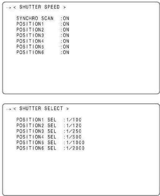
text_image
→ < SHUTTER SPEED > SYNCHRO SCAN :ON POSITION1 :ON POSITION2 :ON POSITION3 :ON POSITION4 :ON POSITION5 :ON POSITION6 :ON → < SHUTTER SELECT > POSITION1 SEL :1/100 POSITION2 SEL :1/120 POSITION3 SEL :1/250 POSITION4 SEL :1/500 POSITION5 SEL :1/1000 POSITION6 SEL :1/20001 Press the SHUTTER switch, positioned at [ON], towards [SEL].
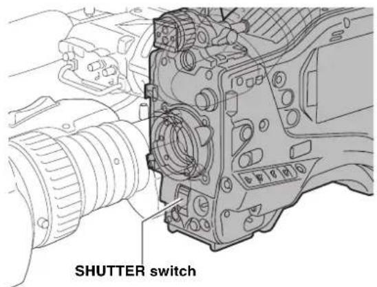
text_image
SHUTTER switch2 Once more, press the SHUTTER switch towards [SEL]. Repeat this switchover until the desired mode or speed appears in the viewfinder screen. If all modes and speeds are available, the display changes in the following order:
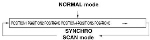
flowchart
graph TD
    A["NORMAL mode"] --> B["POSITION1 POSITION2 POSITION3 POSITION4 POSITION5 POSITION6"]
    B --> C["SYNCHRO SCAN mode"]
    C --> A
Viewfinder displays relating to the shutter
See [Viewfinder Screen Status Displays] (page 69).
Placing the Camera-recorder in SYNCHRO SCAN Mode
To place the camera-recorder in SYNCHRO SCAN mode, follow the steps below.
1 Press the SHUTTER switch positioned at [ON] towards [SEL], to place the camera-recorder in SYNCHRO SCAN mode.
2 In the SYNCHRO SCAN mode, it is possible to change the shutter speed continuously by operating the SYNCHRO SCAN (+ and -) buttons.
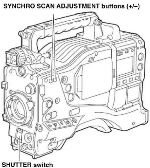
text_image
SYNCHRO SCAN ADJUSTMENT buttons (+/-) SHUTTER switchAssigning Functions to USER MAIN, USER1 and USER2 Buttons
The USER MAIN, USER1, and USER2 buttons can be assigned user-selected functions.
To select desired functions, use the menu options USER MAIN SW, USER1 SW and USER2 SW. These options can be found in the
| < USER SW > | |
| → USER MAIN SW | : SLOT SEL |
| USER1 SW | : S. GAIN |
| USER2 SW | : DS. GAIN |
Selectable Functions
INH: No function assigned.
S.GAIN: S.GAIN function assigned.
DS.GAIN: DS.GAIN function assigned.
LINE MIX GAIN:
LINE MIX GAIN function (+6 dB) assigned.
S.IRIS: Super Iris function assigned.
This is useful for backlight compensation.
I.OVR: Iris Override function assigned.
The target (reference) value in Auto Iris mode must be changed.
To change the target value, put the unit into this mode and press the JOG dial button. Turn the JOG dial button clockwise or anticlockwise to change the value. The iris indication section of the viewfinder screen displays “+”, “++”, “-”, or “- -”.
When the desired value is displayed, stop turning the JOG dial button. Then, press the dial button to accept that value.
Note that once the mode is cancelled or the power is turned off the original reference value will be used again.
+: Iris opens up by 0.5.
++: Iris opens up by 1.
-: Iris closes down by 0.5.
--: Iris closes down by 1.
No indication: The reference value is used.
S.BLK: Super Black function assigned.
This function lowers the black level to the pedestal level or below.
B.GAMMA: The BLACK gamma function is allocated.
This function highlights the black gradations. Regardless of the value set in the BLACK GAMMA item on the menu (
D.ZOOM: When the digital zoom function is active the view angle expands by double, triple or 4 times horizontally and vertically. When the digital zoom function is turned on, the DTL function is disabled.
ATW: Auto-tracking white balance function assigned.
Y GET: Function of indicating the brightness level of the center marker assigned.
DRS: The function of the dynamic range stretcher is allocated.
The function is allocated to compress the video level with high brightness and stretched the dynamic range.
Notes
- Since the DRS function compresses the video levels of sections with high brightness, there are slight differences in color development when the DRS function is turned on/off.
- When the DRS function is turned on, the Knee function and the BLACK GAMMA function are not available.
- The DRS function may be degraded when the LINE MIX gain and D. ZOOM functions are enabled at the same time.
ASSIST : The function to turn on or off the assigned focus assist indication.
Note
When the ASSIST button is turned on, a graph is displayed on the viewfinder and the bottom right of the LCD monitor. Adjust the focus ring on the lens so that the graph comes further right.
C. TEMP : The function to switch to the mode that allows the JOG dial button to change the assigned color temperature. It is useful for intentionally changing the color temperature after adjusting the white balance. To change the color temperature, press the user button with this assigned function, and then press the JOG dial button. The color temperature indicated on the viewfinder display is highlighted and starts blinking, indicating that the color temperature can be changed. While the indication is blinking, the JOG dial button can be turned to change the color temperature. At this time, the value set for the position (PRST, A, or B) to which the WHITE BAL switch is set is also changed.
AUDIO CH1: Function of switching the input signal source for Audio Channel 1 assigned. Pressing the button switches the input signal in the following order: FRONT → WL → REAR. Note that the AUDIO IN switch can also be used to change the input signal: later specification takes precedence.
AUDIO CH2: Function of switching the input signal source for Audio Channel 2 assigned. Pressing the button switches the input signal in the following order: FRONT → W.L. → REAR. Note that the AUDIO IN switch can also be used to change the input signal: later specification takes precedence.
REC SW: Function of the REC START/STOP button assigned.
RET SW: Function of the RET button at the lens assigned.
PRE REC: PRE RECORDING switch ON/switch OFF function assigned.
SLOT SEL: Function of switching the target P2 card among multiple cards assigned.
PC MODE: The function to turn on or off the assigned USB device or USB host mode. Switching between the USB device and USB host modes is set by selecting the PC MODE SELECT menu option in the SYSTEM MODE screen on the SYSTEM SETTING page.
Note
When the remote controller, AJ-RC10G (option), is connected and I.OVR or C.TEMP is assigned to the USER button on the side of the AJ-RC10G, operation of the jog dial button on the main unit is disabled.
Setting the Switchover of USER SW GAIN
AJ-HPX2000 allows three other modes to be used in addition to the L/M/H standard gain settings: the analog gain-up S.GAIN (super gain) mode to achieve a gain of 30 dB or more, the cumulative gain-up DS.GAIN (digital super gain) mode which uses progressive drive, and the LINE MIX GAIN mode where the gain of two lines is mixed.
To select these functions, perform menu operations to open the
For instance, if the S.GAIN, DS.GAIN and LINE MIX GAIN functions have been allocated to the USER MAIN button, USER1 button or USER2 button, the gain can be increased by using these buttons in combination with the USER buttons.
1) To increase the gain without increasing noise:
The DS.GAIN function and the LINE MIX GAIN function are used.
2) To increase the normal analog gain:
(noise is increased)
Use the S.GAIN feature alone.
Note
Note that the accuracy of AUTO IRIS, White Balance, and Black Balance may be influenced by an increase in noise.
3) To achieve ultra-high sensitivity:
Use the S.GAIN function and DS.GAIN or LINE MIX GAIN function in combination. However, exercise care during operation since image lag will become more conspicuous with moving subjects the more the gain is increased by using the DS.GAIN function.
When shooting moving subjects, keep the gain increase with the LINE MIX GAIN function or DS.GAIN function to under +12 dB.
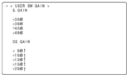
text_image
→ < USER SW GAIN > S. GAIN *30dB *36dB *42dB *48dB DS. GAIN * 6dB↑ *10dB↑ *12dB↑ *15dB↑ *20dB↑Settings Options and Usage
S.GAIN: An analog gain increase with an asterisk is one that is valid. One without an asterisk is invalid.
DS.GAIN: A cumulative gain increase with an asterisk is one that is valid. One without an asterisk is invalid.
Selecting Audio Input Signals and Adjusting Recording Levels
AJ-HPX2000 supports independent 4-channel sound recording in any recording format in HD (1080i or 720P) and SD (DVCPRO50, DVCPRO, or DV with 480i or 576i) modes.
When the AUDIO SELECT CH1/CH2 switch is positioned at [AUTO], the recording levels for Audio Channels 1 and 2 are automatically adjusted. To manually adjust the recording levels, position the switch at [MAN]. Note that the recording levels for Audio Channels 3 and 4 are selected through a menu option.
Notes
- Even in HD mode (1080i or 720P), 4-channel sound is recoded on P2 cards.
- When SDI input signals or signals input through the DVCPRO/DV connector are recorded, the settings above are overridden; audio signals from the SDI IN or DVCPRO/DV connector are always recorded.
Selecting Audio Input Signals
The input signals to be recorded on Audio Channels 1, 2, 3, and 4 are selected with the AUDIO IN switch. For more information, see [Audio (input) Function Section] (page 15).
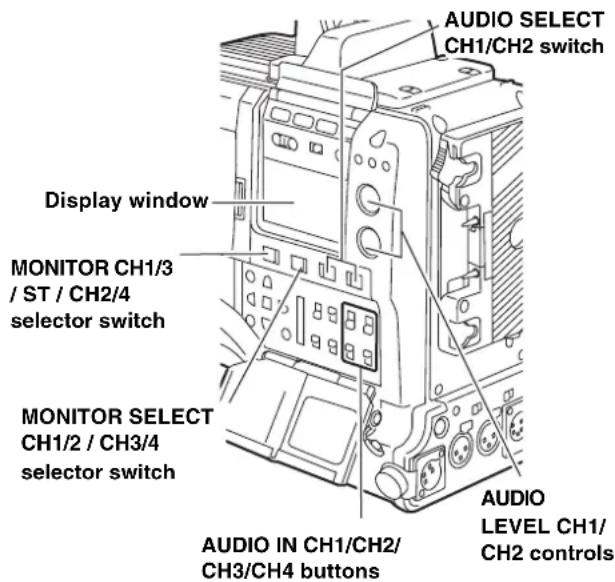
text_image
AUDIO SELECT CH1/CH2 switch Display window MONITOR CH1/3 / ST / CH2/4 selector switch MONITOR SELECT CH1/2 / CH3/4 selector switch AUDIO IN CH1/CH2/ CH3/CH4 buttons AUDIO LEVEL CH1/ CH2 controlsIn SD mode (DVCPRO50, DVCPRO, or DV with 480i or 576i), your unit is factory-set to perform no recording on Audio Channels 3 and 4 in the DVCPRO and DV formats. To enable four-channel recording, the menu option 25M REC CH SEL must be set to "4CH".
Specific audio settings are performed through the
For more information, see [MAIN OPERATION] (page 178).
| → < MIC/AUDIO1 > | |
| FRONT VR CH1 | :OFF |
| FRONT VR CH2 | :OFF |
| MIC LOWCUT CH1 | :OFF |
| MIC LOWCUT CH2 | :OFF |
| MIC LOWCUT CH3 | :OFF |
| MIC LOWCUT CH4 | :OFF |
| LIMITER CH1 | :OFF |
| LIMITER CH2 | :OFF |
| AUTO LEVEL CH3 | :ON |
| AUTO LEVEL CH4 | :ON |
| 25M REC CH SEL | :2CH |
| TEST TONE | :NORMAL |
| → < MIC/AUDIO2 > | |
| FRONT MIC POWER | :ON |
| REAR MIC POWER | :ON |
| MONITOR SELECT | :STEREO |
| FRONT MIC LEVEL | :-40dB |
| REAR MIC CH1 LEVEL | :-60dB |
| REAR MIC CH2 LEVEL | :-60dB |
| REAR LINE IN LVL | :+4dB |
| AUDIO OUT LVL | :+4dB |
| HEADROOM | :20dB |
| WIRELESS WARN | :OFF |
Notes
● Audio Channels 1 and 2 always receive the signals selected with the AUDIO IN CH1 and CH2 switches.
- Four-channel-recorded audio signals are SDI-output as they are.
Adjusting Recording Levels
To adjust the recording levels for Audio Channels 1 and 2, follow the steps below.
1 Position the MONITOR SELECT CH1/2 / CH3/4-selector switch at CH1/2 so that the audio level meter on the display window will provide CH1 and CH2 indications. Ensure that the channel indications displayed in the window are 1 and 2.
Whether to enable or disable the FRONT AUDIO LEVEL control must be preset through menu options FRONT VR CH1 and FRONT VR CH2. Note that this control is factory-disabled.
The menu options are found in the MIC/AUDIO1 screen, which is accessible from the MAIN OPERATION page.
2 Position the AUDIO SELECT CH1/CH2 switch at [MAN].
3 While checking the audio channel level meter in the display window or the audio level meter in the viewfinder, adjust the AUDIO LEVEL CH1/CH2 control.
Note that if the level exceeds the top bar (0 dB), the word OVER illuminates to show that the input level is excessive. The adjustment made in such a way that the maximum level will not reach the 0 dB bar.
Audio level meter on the display window
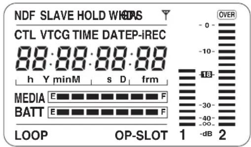
text_image
NDF SLAVE HOLD WICAS CTL VTCG TIME DATEP-iREC 88:88:88:88 h Y minM s D frm MEDIA E F BATT E F LOOP OP-SLOT 1 -dB 2 OVER -0 -10 -18 -30 -40 -∞ -∞ 1 -dB 2Audio level meter in the viewfinder

text_image
F : 1 - - - - R : 2 - - - - ■ - - +When operating the unit without a sound recordist, it is recommended that the FRONT AUDIO LEVEL control should be used to adjust the audio level.
In advance, check the level meter in the viewfinder screen and use the AUDIO LEVEL control to adjust the appropriate audio channel so that no excessive audio signals will be admitted.
Selecting Function for the FRONT AUDIO LEVEL Control
This function enables the recording level to be adjusted using the F.AUDIO LEVEL control.
To select this function, perform menu operations to open the
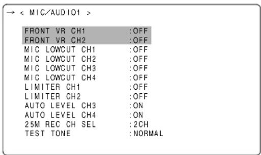
text_image
→ < MIC/AUDIO1 > FRONT VR CH1 :OFF FRONT VR CH2 :OFF MIC LOWCUT CH1 :OFF MIC LOWCUT CH2 :OFF MIC LOWCUT CH3 :OFF MIC LOWCUT CH4 :OFF LIMITER CH1 :OFF LIMITER CH2 :OFF AUTO LEVEL CH3 :ON AUTO LEVEL CH4 :ON 25M REC CH SEL :2CH TEST TONE :NORMALCH3 and CH4 Recording Levels
The following table shows the effects on the recording level for Audio Channels 3 and 4 that depend on the settings and input levels specified through the menu options AUTO LEVEL CH3 and AUTO LEVEL CH4. Note that the recording level cannot be adjusted manually.
These options are found in the
| AUTO LEVELCH3/CH4 | Input level | |
| LINE MIC | ||
| ON AGC ON AGC | ON | |
| OFF AGC/LIMITER | R OFF LIMITER ON | |
Setting Time Data
AJ-HPX2000 supports time codes, user bits, date, and time (real time) data, which are recorded as data for the sub-code area, VIDEO AUX area, and clip metadata files. It also includes a CTL counter and camera ID.
Description of time data
Time code
The TCG switch can be used to switch between Rec run and free run.
Free run: The time code always advances even when the power is turned off. It can be handled as time. It can be slaved to the time code input through the TC IN or DVCPRO/DV connector.
Rec run: The time code is recorded as sequential values regenerated as the time code for a clip recorded on a P2 card.
User bits
The camera-recorder separately includes two types of user bits: one (UB) is recorded in the sub-code area and the other (VITC UB) in the VIDEO AUX area. Each user bits can be recorded as any of the following: a user defined value, time, date, same value as the time code, frame rate information for camera shooting, externally input value (through the TC IN or DVCPRO/DV connector), and value regenerated as the user bits recorded in a clip on a P2 card.
The camera-recorder includes only one user defined value. If user defined values are selected for both the UB and VITC UB, then the same value is used.
Types of UB can be selected in UB MODE and types of VITCUB can be selected in VITC UB, respectively. However, in the following cases, these are fixed to the frame rate information of the editing machines (editing software for PCs).
- In 720P mode, both the UB and VITC UB are always frame rate information.
- For recoding 24P/24PA in 1080i or 480i mode, VITC UB is fixed to frame rate information.
- In Native mode, VITC UB is fixed to frame rate information.
Date and time (real time)
The built-in clock maintains the date and time. When the GPS unit AJ-GPS910G is installed, the built-in clock is corrected with accurate date and time information from the GPS. This clock is used to store the date and time while the power is turned off and as the time for the user bits and date data, as well as the reference for file generation times during clip recording, which determine the sorting order of thumbnails and the order of playback. It is also used to generate clip metadata and UMIDs (Unique Material Identifiers) in the VIDEO AUX area.
CTL counter
The CTL counter will measure total recording time after resetting in the recording operation. On the other hand, this value is the count time and sets the start point of a clip that can be played back. This can be used to find the current playback position.
Camera ID
The camera ID can be set with 10 characters ×3 lines, which can be superimposed on the color bar video. It can be also superimposed along with date and time data.
The number of frames for TC varies with the settings for the input signal, system mode, and camera mode as follows.
| REC SIGNAL | SYSTEM MODE | Recording frame MODE*10 | TC in sub-code area | TC in VIDEO AUX area (VITC) | No. of frames of TC during recording and presetting | No. of frames of the output TC | No. of frames of the displayed TC | UB in sub-code area | UB in VIDEO AUX area (VITC UB) |
| CAM | 1080-59.94i | 60i, 30P (Over 60i) | As per the TC MODE*4 | As per the TC MODE*4 | 30 | 30 | 30/24 switch-able | As per the UB MODE*6 | As per the VITC UB MODE |
| 24P (Over 60i) 24PA (Over 60i) | Always non-drop frame*5 | Always non-drop frame*5 | Always frame rate information*3 | ||||||
| 30PN (Native) | As per the TC MODE*4 | As per the TC MODE*4 | As per the UB MODE*6*9 | Always frame rate information*8 | |||||
| 24PN (Native) | Always non-drop frame*5 | Always non-drop frame*5 | 24 | Recording: 24 fixed Playback: 30/24 switchable | |||||
| 1080-50i | 50i, 25P (Over 50i) | - *4 | - *4 | 25 25 | 25 | As per the UB MODE*6 | As per the VITC UB MODE | ||
| 25PN (Native) | As per the UB MODE*6*9 | Always frame rate information*8 | |||||||
| 720-59.94P | 60P, 30P (Over 60P) | As per the TC MODE*4 | As per the TC MODE*4 | 30 | 30 | 30/24 switch-able | Always frame rate information*3 | Always frame rate information*3 | |
| 24P (Over 60P) | Always non-drop frame*5 | Always non-drop frame*5 | |||||||
| 30PN (Native) | As per the TC MODE*4 | As per the TC MODE*4 | Always frame rate information*3*9 | Always frame rate information*8 | |||||
| 24PN (Native) | Always non-drop frame*5 | Always non-drop frame*5 | 24 | Recording: 24 fixed Playback: 30/24 switchable | |||||
| 720-50P | 50P, 25P (Over 50P) | - *4 | - *4 | 25 25 | 25 | Always frame rate information*3 | Always frame rate information*3 | ||
| 25PN (Native) | Always frame rate information*3*9 | Always frame rate information*8 | |||||||
| 480-59.94i | 60i 30P (Over 60i) | As per the TC MODE*4 | As per the TC MODE*4 | 30 30 | 30/24 switch-able | As per the UB MODE*6 | As per the VITC UB MODE | ||
| 24P (Over 60i) 24PA (Over 60i) | Always non-drop frame*5 | Always non-drop frame*5 | Always frame rate information*3 | ||||||
| 576-50i | 50i, 50P (Over 50i) | - *4 | - *4 | 25 25 | 25 | As per the UB MODE*6 | As per the VITC UB MODE | ||
| SDI*1 or VIDEO | 1080-59.94i 480-59.94i | - | As per the TC MODE*4 | As per the TC MODE*4 | 30 30 | 30/24 switch-able | As per the UB MODE*6 | As per the VITC UB MODE | |
| 720-59.94P | Always frame rate information*3 | Always frame rate information*3 | |||||||
| 1080-50i 576-50i | - *4 | - *4 | 25 25 25 | As per the UB MODE*6 | As per the VITC UB MODE | ||||
| 720-50P | Always frame rate information*3 | Always frame rate information*3 | |||||||
| 1394 | 1080-59.94i 720-59.94P 480-59.94i | - (Natives of AVC-Intra and DVCPRO HD are not selectable.) | As per the TC MODE*4 | Regardless of the setting, TC in the VIDEO AUX area input through the DVCPRODV connector is recorded. | 30 30 | 30/24 switch-able | As per the UB MODE*7 | Regardless of the setting, TC in the UB area input through the DVCPRODV connector is recorded. | |
| 1080-50i 720-50P 576-50i | - *2 | 25 25 | 25 |
*1 It will not be slaved to a TC or UB value that is input in the SDI IN connector.
*2 Can be slaved to values input through the DVCPRO/DV connector but not to the TC for TC IN connector.
*3 If the option menu FRAME RATE UB is set to MENU, then recording is performed as per the UB or VITC UB mode. If this is the case, however, edit tools (e.g. PC edit software) cannot record the required information.
*4 For free run, the time code is slaved to the time code input through the TC IN connector.
*5 For free run, the time code is slaved to the time code input through the TC IN connector if it is a non-drop frame.
*6 When the option UB MODE is set to EXT, then the bits are slaved to the user bits input through the TC IN connector.
*7 If the option UB MODE is set to EXT, then the bits are slaved to the user bits input through the DVCPRO/DV connector.
*8 Regardless of the menu settings, frame rate information is always recorded. During playback, the information is output after being converted into pull-down frame rate information.
*9 When the UB MODE is set to [FRM.RATE], the pull-down frame rate information read out from the UB in the VAUX area is output during playback.
*10 For details on this item, refer to [Recording formats and output connector signal formats] (page 43)
Setting of the user bits
The user bits (UB) to be recorded in the sub-code area are selected through the menu option UB MODE. The user bits (VITC UB) to be recorded in the VIDEO AUX area are selected through the menu option VITC UB MODE.
USER (UB MODE only)
The included user value is recorded. A user value is input through the display window. For more information about how to input a user value, see[Inputting a user value] (page 57). The recorded user value is retained even if the power is turned off.
TIME
The time kept by the built-in clock is recorded.
DATE
The hour digits for date and time kept by the built-in clock are recorded.
EXT (UB MODE only)
The user bits value input through the TC IN connector is recorded. When the menu option REC SIGNAL is set to 1394, then the value is slaved to the user bits value from the DVCPRO/DV connector. The included user's value will also be this input value.
TCG
The time code value is recorded.
FRM.RATE
The frame rate information for camera shooting is recorded. For more information, see [Frame rate information recorded in user bits] (page 58).
REGEN
The user bits last recorded on the current target P2 card is read and recorded as is.
USER/EXT (VITC UB MODE only)
The included user's value is recorded as the user bits for the VIDEO AUX area. It is the same value as the user bits indicated when the option UB MODE is set to "USER" or "EXT".
Inputting a user value
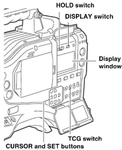
text_image
HOLD switch DISPLAY switch Display window TCG switch CURSOR and SET buttons1 Position the DISPLAY switch at [UB].
2 Position the TCG switch at [SET]. When the left digit starts blinking you can change the value.
3 Use CURSOR buttons to set the user bits.
▷ button:Shifts the target (blinking) digit to the right.
◀ button:Shifts the target (blinking) digit to the left.
△ button: Advances the blinking number by one digit.
▼ button:Winds back the blinking number by one digit.
4 Position the TCG at [F-RUN] or [R-RUN].
5 Go to the
Notes
- When the TCG switch is positioned at [SET], thumbnails cannot be manipulated.
- To confirm VICT UB, press the HOLD switch to display VTCG on the display window.
Retaining the user bits
The data set for the user bits are automatically saved and retained even if the camera-recorder is turned off.
Frame rate information recorded in user bits
If video information to be recorded based on the frame rate set through the menu option CAMERA MODE is recorded in the user bits, it can be edited with editing tools (e.g. PC editing software). In 1080i and SD mode, the frame rate information for the user bits recorded in the VIDEO AUX area are used. In 720P mode, the video information is also recorded in the sub-code area because the frame rate information for the user bits recorded in the sub-code area is also used.
Frame rate information
The frame rate and video pull-down menu are linked to the time code and user bits as follows:
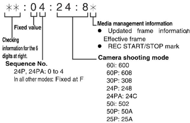
text_image
**: 0 4 : 2 4 : 8 * Fixed value Checking information for the 6 digits at right. Sequence No. 24P, 24PA: 0 to 4 In all other modes: Fixed at F Media management information • Updated frame information Effective frame • REC START/STOP mark Camera shooting mode 60i: 600 60P: 608 30P: 308 24P: 248 24PA: 24C 50i: 502 50P: 50A 25P: 25AFor 1080i or 480i/576i
Frame rate: 24P Over 60i (2:3)
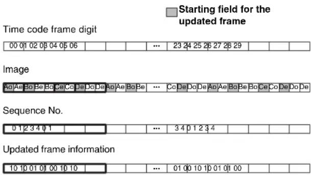
text_image
Starting field for the updated frame Time code frame digit 00 01 02 03 04 05 06 ... 23 24 25 26 27 28 29 Image Ao Ae Bo Be Bo Ce Co De Do De Ao Ae Bo Be ... Co De Do De Ap Ae Bo Be Bo Ce Co De Do De Sequence No. 0 1 2 3 4 0 1 ... 3 4 0 1 2 3 4 Updated frame information 10 10 01 01 00 10 10 ... 01 00 10 10 01 01 00Frame rate: 24PA Over 60i (2:3:3:2)
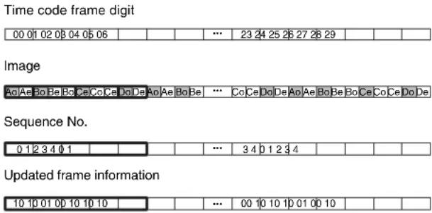
text_image
Time code frame digit 00 01 02 03 04 05 06 Image Ao Ae Bo Be Bo Ce Co Ce Do De Ao Ae Bo Be ... Co Ce Do De Ao Ae Bo Be Bo Ce Co Ce Do De Sequence No. 0 1 2 3 4 0 1 Updated frame information 10 10 01 00 10 10 10 ... 00 10 10 10 01 00 10Frame rate: 30P Over 60i (2:2)
25P Over 50i (2:2)
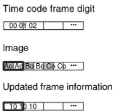
text_image
Time code frame digit 00 01 02 .... Image AoAe Bd Bd Cb Cp Cp ... Updated frame information 10 10 10 ....For 720P
Frame rate: 24P Over 60P (2:3)
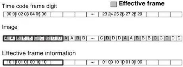
text_image
Time code frame digit 00 01 02 03 04 05 06 Image A A B B C C D D D A A B B ... C D D D A A B B B C C D D D Effective frame information 10 10 01 01 00 10 10 Effective frame 23 24 25 26 27 28 29 ... 01 00 10 10 01 01 00Frame rate: 30P Over 60P (2:2)
25P Over 50P (2:2)
Image

The frame rate information of user bits in Native recording is as follows.
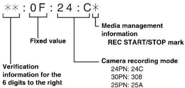
flowchart
graph TD
    A["**: 0 F : 24 : C*"] --> B["Fixed value"]
    B --> C["Verification information for the 6 digits to the right"]
    B --> D["Media management information REC START/STOP mark"]
    D --> E["Camera recording mode"]
    E --> F["24PN: 24C"]
    E --> G["30PN: 308"]
    E --> H["25PN: 25A"]
Note
During playback of clips recorded in Native recording frame rate information of user bits is converted according to the image pull down and then output.
Example: Recording
**: 0F : 24 : C*
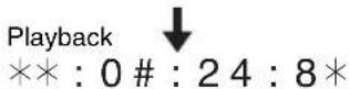
# indicates sequence Nos. 0 to 4.
Setting the Internal Clock's Date and Time
1 Position the DISPLAY switch at [UB].
2 Press the HOLD button to display a date in the display window.
3 Position the TCG switch at [SET].
4 Use the CURSOR and SET buttons to set the year, month and day (Y/M/D).
Note that any later than 2030 cannot be set.
▷ button: Shifts the target (blinking) digit to the right.
◀ button: Shifts the target (blinking) digit to the left.
△ button: Advances the blinking number by one digit.
∇ button: Winds back the blinking number by one digit.
5 Press the HOLD button to display a time in the display window.
6 Use the CURSOR buttons to set the hour, minute and second (h/min/s).
7 Position the TCG switch at [F-RUN] or [R-RUN]. The internal clock starts at the moment the switch position is changed.
8 Press the HOLD button to display a time zone (time difference between local time and Greenwich Mean Time) in the display window.
9 Position the TCG switch at [SET].
10 Use the and buttons to set the desired hours and minutes ahead of (no sign) or behind (- sign) the Greenwich Mean Time).
Example: If the local time is five hours behind Greenwich Mean Time, set the time zone to "5:00 –".
The time zone is always recorded, together with the date and time, as metadata. See the table at right to set the time zone according to your local time.
11 Position the TCG switch at [F-RUN] or [R-RUN] to accept the time zone.
Notes
- When using the camera-recorder for the first time, be sure to perform this setting beforehand. Do not change the setting during use of the camera-recorder.
- When the TCG switch is positioned at [SET], thumbnails cannot be manipulated.
| Time difference | Area | Time difference | Area |
| 00:00 | Greenwich – | 12:00 | Kwajalein |
| + 00:30 | -11:30 | ||
| + 01:00 | Central Europe – | 11:00 | Midway Island |
| + 01:30 | -10:30 | ||
| + 02:00 | Eastern Europe – | 10:00 | Hawaii |
| + 02:30 | -09:30 | Marquesas Islands | |
| + 03:00 | Moscow – | 09:00 | Alaska |
| + 03:30 | Tehran – | 08:30 | |
| + 04:00 | Abu Dhabi – | 08:00 | Los Angeles |
| + 04:30 | Kabul – | 07:30 | |
| + 05:00 | Islamabad – | 07:00 | Denver |
| + 05:30 | Bombay | -06:30 | |
| + 06:00 | Dacca | -06:00 | Chicago |
| + 06:30 | Rangoon | -05:30 | |
| + 07:00 | Bangkok | -05:00 | New York |
| + 07:30 | -04:30 | ||
| + 08:00 | Beijing | -04:00 | Halifax |
| + 08:30 | -03:30 | Newfoundland Island | |
| + 09:00 | Tokyo – | 03:00 | Buenos Aires |
| + 09:30 | Darwin | -02:30 | |
| + 10:00 | Guam | -02:00 | Mid-Atlantic |
| + 10:30 | Lord Howe Island | -01:30 | |
| + 11:00 | Solomon Islands | -01:00 | Azores Islands |
| + 11:30 | Norfolk Island | -00:30 | |
| + 12:00 | New Zealand | ||
| + 12:45 | Chatham Islands | ||
| + 13:00 |
Notes
- In Step 4, if the TCG switch is positioned at [F-RUN] or [R-RUN], this also activate the internal clock.
To cancel date, time and time zone settings in process, hold down the SET button and position the TCG switch at [F-RUN] or [R-RUN]. - Clock accuracy fluctuates between about ± 30 seconds per month when the power is turned off. If more accurate timekeeping is required, check the time when the power is turned on and, if necessary, reset the clock.
When the GPS unit AJ-GPS910G is installed, and if it successfully receives time information, the internal clock keeps accurate (local) time based on the received time (Greenwich Mean Time) and the time zone. If the date and time differ from the actual local time, the time zone may not be set correctly. Check again, to see if the time zone is set correctly. (The date and time need not be set again.)
- The built-in clock operates for several years on a lithium battery built into the camera-recorder. When the lithium battery is exhausted, the viewfinder indicates the message "BACKUP BATT EMPTY" when the power is turned on. For more information, see [Maintenance] (page 140).
Setting the Time Code
1 Position the DISPLAY switch at [TC].
2 Position the TCG switch at [SET].
3 Set the menu option TC MODE to "DF" or "NDF". "DF" steps the time code in drop frame mode, and "NDF" steps it in non-drop frame mode. However, the camera always operates in "NDF" for 24P, 24PA and 24PN (Native) modes.
The menu option TC MODE can be found in the
Note
Switching between DF and NDF is operative only when the system frequency of the camera-recorder is set to 59.94 Hz.
4 Use the CURSOR buttons to set the time code. The time code setting range extends from 00:00:00:00 to 23:59:59:29 (59.94 Hz), 23:59:59:23 (24PN) or to 23:59:59:24 (50 Hz).
▷ button:Shifts the target (blinking) digit to the right.
◀ button:Shifts the target (blinking) digit to the left.
△ button: Advances the blinking number by one digit.
▼ button:Winds back the blinking number by one digit.
5 Change the position of the TCG switch. [F-RUN] steps the time code in free run mode, and [R-RUN] set it in recording run mode.
Notes
- When the unit is in the 24P or 24PA mode, time code settings are adjusted to the five-frame unit. For 24PN (Native) mode, it is adjusted for counting by the four-frame unit. For 30PN UN (Native) of 720P, it is adjusted to even numbers. In the 25PN (Native) mode of 720P, [Sec + Frame] is adjusted to even numbers. The time code cannot be set when recording in the 24P, 24PA, and 24PN (Native) formats.
- When the TCG switch is positioned at [SET], thumbnails cannot be manipulated.
Regeneration of Time Code
When the TGC switch is positioned to R-RUN, the time code recorded on the last frame of the last recorded clip (with the latest recording date) on the P2 card is read, and this time code can be used again.
When the menu option FIRST REC TC is set to REGEN and a P2 card is removed or inserted or the target recording card is changed with the USER button for the SLOT SEL function, the same time code is added to the last recorded clip on the target P2 card. When there is no recorded clip, the time code is recorded on the new recording target P2 card, from the value generated by the TC generator built into the camera-recorder.
The menu option FIRST TC REC can be found in the
Regeneration function using REC REVIEW
If the menu option FIRST REC TC is set to PRESET, if the time code has been set or reset, or if the time code has been switched from free run to Rec run, it is possible to regenerate the time code as the last time code of a clip recorded on the P2 card.
This action requires you to preset the RET SW menu option on the SW MODE screen to R. REVIEW and the REC REVIEW REGEN menu option on the TC/UB screen to ON.
1 Make sure the P2 card to record the data. To regenerate the time code of the last recorded clip when more than one P2 card is inserted, press the Thumbnail button to open the thumbnail screen.
2 Be sure a P2 card is inserted for recording the clip displayed at the end of the screen, and then switch the slot with the USER button assigned the SLOT SEL function so that data will be recorded on the P2 card.
3 Press the RET button on the lens. The message "TC REGEN" is displayed in the viewfinder. During the next recording, the time code of the last recorded clip on the card will be regenerated.
Notes
- When a card with recorded data is changed, the time code of the last recorded clip on the changed P2 card will be regenerated.
- This function is disabled during recording or free-run.
Time code function during battery replacement
Even during battery replacement, the backup mechanism functions, allowing the camera-recorder to operate continuously.
If SYSTEM MODE is changed, a free-run time code may shift. After turning on the power again, confirm the time code and reset if necessary.
Note
When the POWER switch has been switched ON → OFF → ON, the backup accuracy of the time code in free run mode is about ±2 frames.
Externally Locking the Time Code
The unit's internal time code generator can be locked to an external generator. In addition, the external time code generator can be locked to the unit's internal generator.
Example of connections for external locking
As the figure shows, connect both the reference video signal and reference time code.
Example 1: When locking onto an external signal
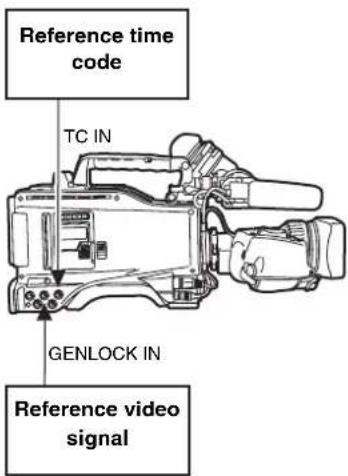
text_image
Reference time code TC IN GENLOCK IN Reference video signalNote
In place of the HD Y reference signal, composite video signals can be input as the reference video signal.
Example 2: When connecting a multiple number of units and using one of them as the reference unit
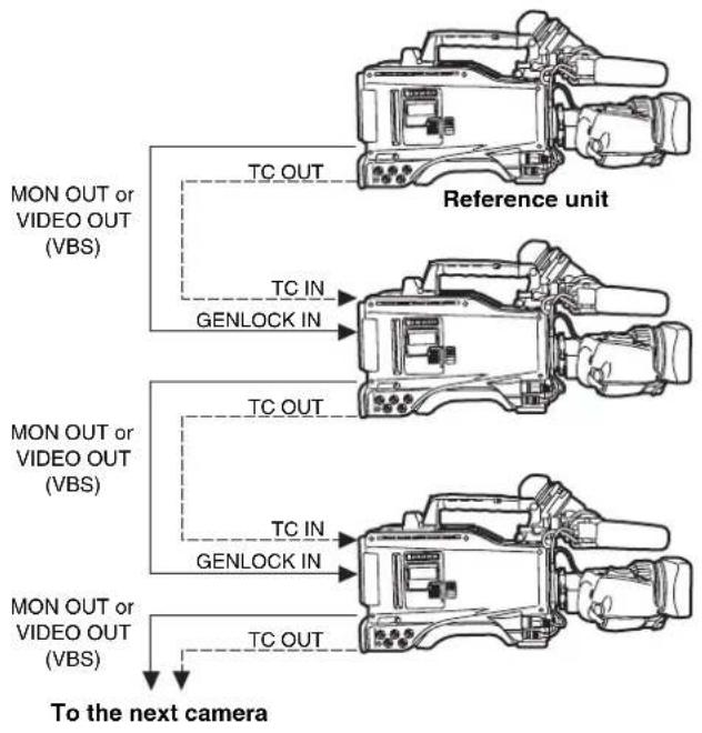
flowchart
graph TD
    A["Reference unit"] --> B["MON OUT or VIDEO OUT (VBS)"]
    A --> C["TC OUT"]
    A --> D["TC IN"]
    A --> E["GENLOCK IN"]
    F["MON OUT or VIDEO OUT (VBS)"] --> G["MON OUT or VIDEO OUT (VBS)"]
    F --> H["TC OUT"]
    F --> I["TC IN"]
    F --> J["GENLOCK IN"]
    K["MON OUT or VIDEO OUT (VBS)"] --> L["To the next camera"]
Note
The system can be configured with multiple units by opening the
The phase of the time code can correspond to either the HDY output signals of the MON OUT connector or VBS output signals of the VIDEO OUT and MON OUT connector.
However, the same value should commonly be set to the GL PHASE for all cameras. If different values coexist in the system, the shooting timing may not correspond to each other.
| Reference video signal Setting of GL PHASE | |
| MON OUT (VBS) orVIDEO OUT (VBS) | COMPOSIT |
Setting of GL PHASE
| Item | Variable range | Remarks |
| GL PHASE HD SDI____COMPOSIT | For selecting the output signals that lock phases to the signals that are input in the GENLOCK IN connector.HD SDI:For locking the HD SDI signals to the GENLOCK input.For the down converter output signals, the start position of the video delays by about 90 lines.COMPOSIT:For locking the down converter output signals to the GENLOCK input.For the HD SDI output signals, the start position of the video gains by about 90 lines. | |
In the unit, there is a video signal delay in the camera, which is required or the process of converting video images taken with the image-shooting element from the progressive signals to the interlace signals. Since time is required for making the 2:3 pull-down from the 24P frame, there is a video signal delay in the camera. When recording from a device that can record images without a delay and the unit is connected in parallel, it is necessary to synchronize the time code. To set this timing, open the
Set by referring to the connection example.
Setting of the TC VIDEO SYNCRO item
| Item | Variable range | Remarks |
| TC VIDEOSYNCRO | 0123 | For setting to correct the time code according to the delay of video signals.0: Do not correct.1: To delay the time code to be input according to the timing of the video images.2: To forward the time code to be output according to the timing of the video images.3: To delay the time code to be input and forward the time code to be output, respectively, according to the timing of the video images. |
Example 3:
When the unit and an external device are locked to the external time code generator, which is connected externally, and when simultaneous recording is made by using the TC OUT output signals.
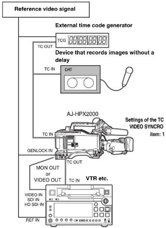
flowchart
graph TD
    A["Reference video signal"] --> B["External time code generator"]
    B --> C["Device that records images without a delay"]
    C --> D["TCG 881888888"]
    C --> E["TC IN DAT"]
    C --> F["AG-HPX2000"]
    F --> G["GENLOCK IN"]
    F --> H["MON OUT or VIDEO OUT"]
    F --> I["VIDEO IN SDI IN HD SDI IN"]
    F --> J["REF IN"]
    F --> K["VTR etc."]
    style A fill:#f9f,stroke:#333
    style B fill:#ccf,stroke:#333
    style C fill:#cfc,stroke:#333
    style D fill:#fcc,stroke:#333
    style E fill:#cff,stroke:#333
    style F fill:#ffc,stroke:#333
    style G fill:#fcf,stroke:#333
    style H fill:#cff,stroke:#333
    style I fill:#fcf,stroke:#333
    style J fill:#cff,stroke:#333
    style K fill:#ffc,stroke:#333
Example 4:
When the unit and an external device are locked to the external time code generator and when several units of the camera are connected in a cascade configuration.
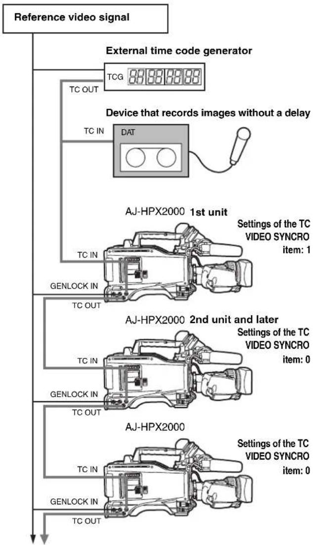
flowchart
graph TD
    A["Reference video signal"] --> B["External time code generator"]
    B --> C["Device that records images without a delay"]
    C --> D["AGJ-HPX2000 1st unit"]
    D --> E["Settings of the TC VIDEO SYNCRO item: 1"]
    D --> F["AGJ-HPX2000 2nd unit and later"]
    F --> G["Settings of the TC VIDEO SYNCRO item: 0"]
    F --> H["AGJ-HPX2000"]
    H --> I["Settings of the TC VIDEO SYNCRO item: 0"]
Example 5:
When an external device is locked to the time code generator of the unit.
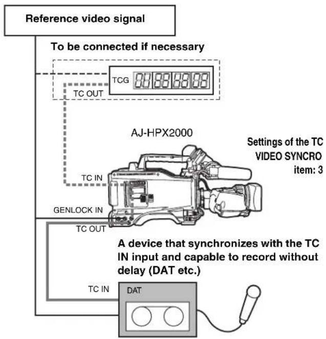
flowchart
graph TD
    A["Reference video signal"] --> B["To be connected if necessary"]
    B --> C["TCG 84888888"]
    C --> D["TC OUT"]
    D --> E["AJ-HPX2000"]
    E --> F["TC IN"]
    F --> G["GENLOCK IN"]
    G --> H["TC OUT"]
    H --> I["TC IN"]
    I --> J["DAT"]
    style A fill:#f9f,stroke:#333
    style J fill:#ccf,stroke:#333
    note right of E: Settings of the TC VIDEO SYNCRO item: 3
    note right of J: A device that synchronizes with the TC IN input and capable to record without delay (DAT etc.)
    note right of J: A device that synchronizes with the TC IN input and capable to record without delay (DAT etc.)
Example 6:
When an external device is locked to the time code generator of camera-recorder, which is connected in a cascade configuration.
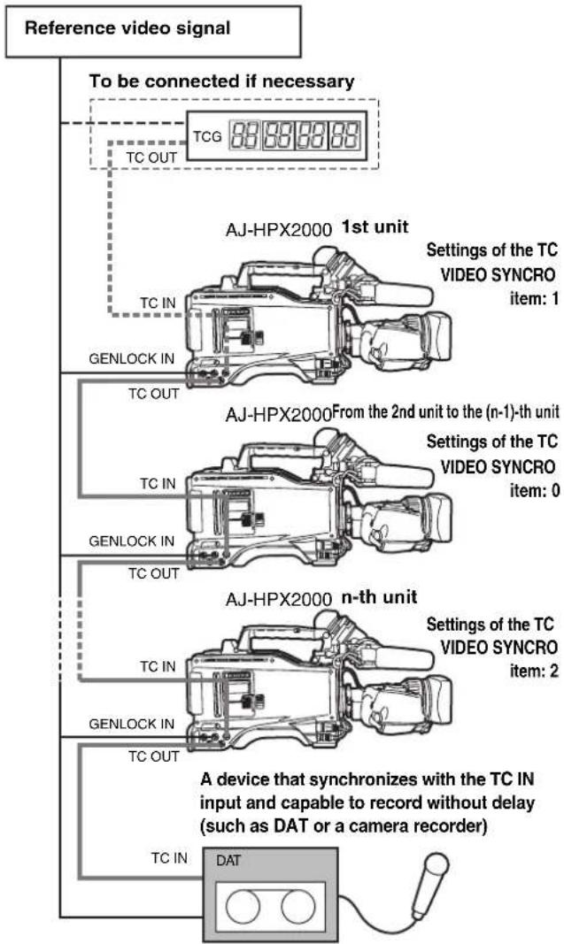
flowchart
graph TD
    A["Reference video signal"] --> B["To be connected if necessary"]
    B --> C["TCG 88.88.88.88"]
    C --> D["TC OUT"]
    D --> E["AJ-HPX2000 1st unit"]
    E --> F["Settings of the TC VIDEO SYNCRO item: 1"]
    E --> G["TC IN"]
    G --> H["GENLOCK IN"]
    H --> I["AJ-HPX2000 From the 2nd unit to the (n-1)-th unit"]
    I --> J["Settings of the TC VIDEO SYNCRO item: 0"]
    I --> K["TC IN"]
    K --> L["GENLOCK IN"]
    L --> M["AJ-HPX2000 n-th unit"]
    M --> N["Settings of the TC VIDEO SYNCRO item: 2"]
    M --> O["TC IN"]
    O --> P["GENLOCK IN"]
    P --> Q["A device that synchronizes with the TC IN input and capable to record without delay (such as DAT or a camera recorder)"]
    P --> R["TC IN"]
    R --> S["DAT"]
To externally lock the time code Setting the user bits when the time code is
Follow the steps below.
1 Turn on the POWER switch.
2 Position the TCG switch at [F-RUN].
3 Position the DISPLAY switch at [TC].
4 Set the menu option GENLOCK to "EXT".
This option can be found in the
5 Supply a phase-relationship reference time code (that conforms to the time code requirements) and reference video signals to the TC IN and GENLOCK IN connectors, respectively.
Now the built-in time code generator is locked with the reference time code.
From about 10 seconds after locking the time code generator stays locked even if the supply of external reference time code is discontinued.
Notes
- When the time code generator is externally locked, the time code instantly becomes locked with the external time code, and the counter displays the external time code value. Do not put the unit in recording mode before the sync generator stabilises.
- Be sure to enter the non-drop-frame time code to externally lock the time code in the 24P, 24PA or 24PN (Native) mode. Externally locking the drop-frame time code is not permitted.
Video quality may be degraded momentarily while externally locking to adjust the 5-frame cycle. This is not abnormal.
- While recording data in the 24P, 24PA, or Native modes, it is impossible to lock the time code externally. Lock it before recording.
When the unit PRE REC MODE is set to [ON] in these modes, corrupt images or stopped time codes may be recorded if the time code is switched from REC RUN to FREE RUN immediately before recording or when using slave lock.
- When "1394" is selected for the menu option REC SIGNAL, it is not possible to synchronize with the time code entered via TC IN connector.
The menu option REC SIGNAL is found in the SYSTEM MODE screen on the SYSTEM SETTING page.
When the TCG switch is positioned to F-RUN, only the time code is locked to an external time code. To lock the user bits to an externally input value, the UB MODE and VITC UB MODE menu options must be set to EXT and USER/EXIT, respectively.
The menu option UB MODE and VITC UB MODE can be found in the
To unlock the externally locked time code
Discontinue external time code supply, then position the TCG switch at [R-RUN].
Cautions in switching the power source from battery to external power supply
Connect the DC IN socket with the external power supply before removing the battery pack, in order to keep the time code generator energised. If the battery pack is removed first, there is no guarantee that the time code will stay externally locked.
External synchronisation of the camera when the time code is externally locked
When the time code is externally locked, the reference video signals input through the GENLOCK IN connector gen-lock the camera.
Notes
- To externally lock the unit, as the master device, with more than one unit, the mode must be the same as that of the camera. Note that in a system using both interlaced and progressive scanning, there may be breaks in the video and time code.
- When using the MON OUT or VIDEO OUT connector to output reference signals, position the OUTPUT SEL switch on the side panel at [CAM].
Superimpose of time codes
To display the time code in the viewfinder or the LCD monitor when recording or during playback, set TC in
To display the time code indication on the MONITOR OUT or VIDEO OUT outputs, set MONI OUT CHARA in
To display the time code while the color bar is displayed, set TC ON COLOR BAR in
Providing an ID to the Camera
The camera ID is specified through the
The ID can include up to 10 alphanumeric characters, symbols, and/or spaces.
Note
When the settings menu is displayed, outputting color bar signals does not indicate the camera ID.
1 Go to the
→ < CAMERA ID >
ID1 : ABCDEFGHIJ
ID2 : ABCDEFGHIJ
ID3 : ABCDEFGHIJ
2 Turn the JOG dial button to move the cursor to options [ID1:] - [ID3:].
3 Press the JOG dial button. The cursor moves to the ID entry area, allowing you to enter an ID.
4 Turn the JOG dial button until a desired character appears. The characters that appear are switched in the following order:
Space: □
↓
Alphabetical characters: A to Z
↓
Numerals: 0 to 9
↓
Symbols: ', >, <, /, -
5 Press the JOG dial button to accept a desired character.
6 Turn the JOG dial button to move cursor to the next digit (clockwise), and repeat Steps 4 - 5 to set characters.
To change an input character, turn the JOG dial button to move the arrow (cursor) to the appropriate character and carry out steps 4 and 5.
7 When all the characters are set, turn the JOG dial button to move the cursor to [:].
8 Pressing the JOG dial button brings the cursor back to the options [ID1:] - [ID3:].
9 To exit the menu, press the MENU button.
Notes
- When the menu option CAMERA ID is set to "BAR", the camera ID is recorded together with color bar signals.
This menu option is accessible from the
screen, which is accessible from the VF page. - The ID POSITION menu option can be used to select a position where the camera ID is superimposed on the color bar. The ID POSITION option can be accessed through the VF INDICATOR 1 screen on the VF page.
- When the TIME/DATE menu option is set to ON, the camera ID along with the data and time information are superimposed on the color bar. The TIME/DATE option can be accessed through the VF INDICATOR 1 screen on the VF page.
Setting UMID Information
The unit supports UMID metadata. You need to specify as UMID information the country where you live (using up to three characters), organisation or company (up to four characters) and user name (up to four characters). For the country name, you must use abbreviations prescribed in the ISO3166 Country Code ^*1 .
Here are some examples of the correct method for specifying a user name:
*1 Examples: China CHN
U.S.A. USA
Canada CAN
Japan JPN
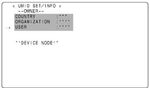
text_image
< UMID SET/INFO > --OWNER-- COUNTRY :*** ORGANIZATION :**** → USER :**** **DEVICE NODE**1 Go to the
2 Turn the JOG dial button to move the cursor to the option [USER].
3 Press the JOG dial button. The cursor moves to the user entry area, allowing you to enter a user name.
4 Turn the JOG dial button until a desired character appears. The characters appear in the following order:
Space:


Alphabetical characters: A to Z

Numerals: 0 to 9

Symbols: ', >, <, /, -
Note
The COUNTRY entry can only include alphabetical characters and spaces.
5 Press the JOG dial button to accept a desired character.
6 Turn the JOG dial button to move the cursor to the next digit (clockwise), and repeat Steps 4 to 5 to set characters.
To change an input character, go back to step3.
7 When the last character is set, press the JOG dial button to bring the cursor back to the option [USER].
8 To exit the menu, press the MENU button.
CTL Count Setting and Display
By setting the DISPLAY switch to "CTL", CTL count is displayed on the time count indication of the LCD display window.
The CTL count is displayed in ±12 hours with non-drop-frame.
The playback order of clips recorded on a P2 card is not linear as for VTRs. It is organized according to thumbnail operations or exchanging P2 cards, and the priority of recorded clips will be altered. Therefore, different CTL counts are displayed for recording mode and playback mode, respectively.
CTL count for recording mode (recording CTL)
Recording CTL count is displayed during recording mode (REC, REC/PAUSE, STOP and REC REVIEW), and the count continues from the end point of the previous recording. Recording CTL count is retained even if the power is turned off. When the power is next turned on, the count continues from the previous value.
Notes
- If the RESET button is pressed while the recording CTL count is being displayed, only the recording CTL count is reset. Note that reset is disabled during the REC REVIEW operation.
● 24 frames are counted in the 24PN (Native) mode.
CTL count for the playback mode ( playback CTL )
During playback mode (PLAY, FF, REW, PLAY/PAUSE), playback CTL count is displayed.
Whenever the playback order of clips is altered (clips are sorted by shooting dates), previous playback CTL count is disabled. The first frame of the first clip is used as a reference value for recalculation, and the new playback CTL count is displayed.
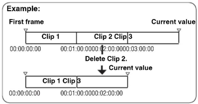
flowchart
graph TD
    A["Clip 1"] --> B["Clip 2 Clip 3"]
    B --> C["Delete Clip 2."]
    C --> D["Current value"]
    E["Clip 1 Clip 3"] --> F["00:00:00:00"]
    F --> G["00:01:00:00:00:02:00:00:03:00:00"]
    G --> H["00:00:00:00"]
    H --> I["00:01:00:00:00:02:00:00"]
The playback order of clips is altered when either of the following occurs:
- Clips are deleted, copied or restored, or the P2 card is formatted.
- The thumbnail display is switched (for more information, see [Switching the Thumbnail Display] (page 113)).
● A P2 card is inserted or removed.
The reference value (value of the first frame of the first clip) is changed when either of the following occurs:
● The power is turned on, the first frame becomes 0.
- When the playback CTL count is reset, the current playback position is set as 0, and the previous reference value becomes a negative value.
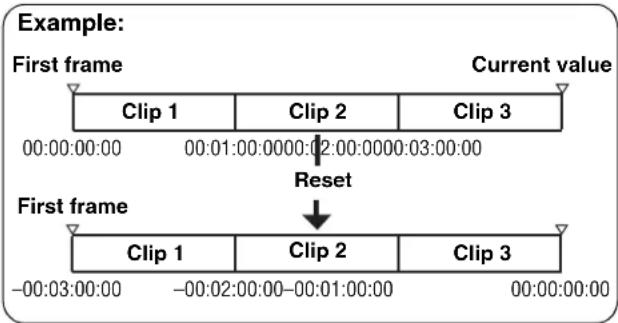
text_image
Example: First frame Current value Clip 1 Clip 2 Clip 3 00:00:00:00 00:01:00:00:00:02:00:00:00:03:00:00 Reset First frame Clip 1 Clip 2 Clip 3 -00:03:00:00 -00:02:00:00-00:01:00:00 00:00:00:00Notes
- If the RESET button is pressed while the playback CTL count is being displayed, only the playback CTL count is reset.
- For playback in 24PN (Native) mode, 30 frames are counted in accordance with the pull-down images.
Viewfinder Screen Status Displays
In addition to video images, the viewfinder displays lamps and text that indicate the settings and operating status of the unit, together with messages, a center marker, a safety zone marker and the camera ID.
Lamps in the Viewfinder Screen
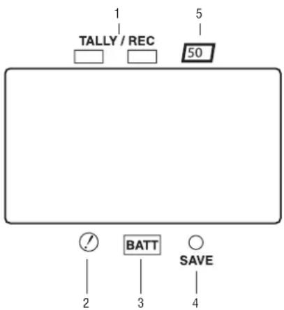
text_image
1 TALLY / REC 5 50 2 BATT SAVE 3 4The above viewfinder is the AJ-VF20WBP (for further information on your optional viewfinder model, see the relevant instruction manual).
1. TALLY/REC (recording) Lamp
This lamp stays illuminated during recording, and starts blinking if any abnormal action occurs.
For more information, see [Warning System] (page 145).
2. Abnormal Operating Status Warning Lamp
This lamp comes on when the unit is in any of the abnormal operating statuses specified through the menu sub-option !LED.
For statuses that activate the lamp, see the options in the <!LED> screen in [!LED] (page 172).
3. BATT (battery) Lamp
This lamp starts blinking a few minutes before the battery charge starts to run out, and stays illuminated after the battery is completely flat. The battery should be replaced before it is nearly flat, so that operation will not be interrupted.
For more information, see [Warning System] (page 145).
4.SAVE Lamp
In the normal setting:
The lamp stays on when the SAVE switch is positioned at [ON] and the output of video and audio is power-saved.
When the menu option SAVE LED is set to "P2 CARD":
The lamp starts blinking when the P2 card remaining free space is getting low.
The menu option SAVE LED can be found in the
5.50 (50-Mbps recording/playback) Lamp (In using the SD viewfinder)
This lamp stays illuminated when the unit is set to the DVCPRO50 (50 Mbps) format, and when playback is being performed in the DVCPRO50 format.
Note that the lamp is factory-disabled. For more information, see the relevant section of the menu option 50M INDICATOR in [VF DISPLAY] (page 169).
Mode Check Screen Displays (MODE CHECK button function)
The viewfinder can display a screen that allows you to check the settings and status of the unit.
Each press of the MODE CHECK button switches the screen as follows:
STATUS screen→!LED screen → FUNCTION screen → AUDIO screen → No indication
Each screen is displayed for about three seconds. A press of the MODE CHECK button switches the current screen.
Whether or not to display each screen is specified through the
→ < MODE CHECK IND >
| STATUS | :ON |
| ! LED | :ON |
| FUNCTION | :ON |
| AUDIO | :ON |
| P. ON IND | :ON |
Selecting Viewfinder Display Information
To select the information items you want to have displayed in the viewfinder screen, go to the
For directions on setting the options, see [Setting Menu Options] (page 153).
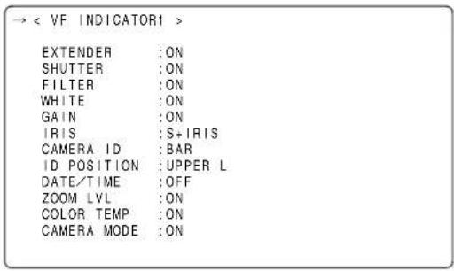
text_image
→ < VF INDICATOR1 > EXTENDER :ON SHUTTER :ON FILTER :ON WHITE :ON GAIN :ON IRIS :S+IRIS CAMERA ID :BAR ID POSITION :UPPER L DATE/TIME :OFF ZOOM LVL :ON COLOR TEMP :ON CAMERA MODE :ON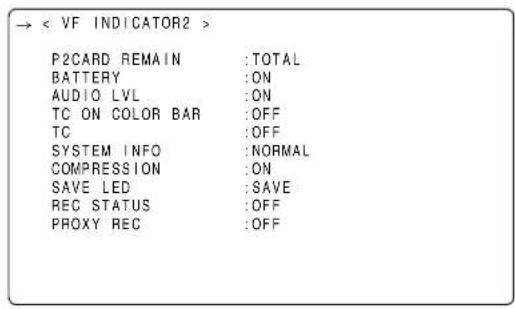
text_image
→ < VF INDICATOR2 > P2CARD REMAIN :TOTAL BATTERY :ON AUDIO LVL :ON TC ON COLOR BAR :OFF TC :OFF SYSTEM INFO :NORMAL COMPRESSION :ON SAVE LED :SAVE REC STATUS :OFF PROXY REC :OFFViewfinder Status Indication Layout
The indications are arranged as illustrated below.
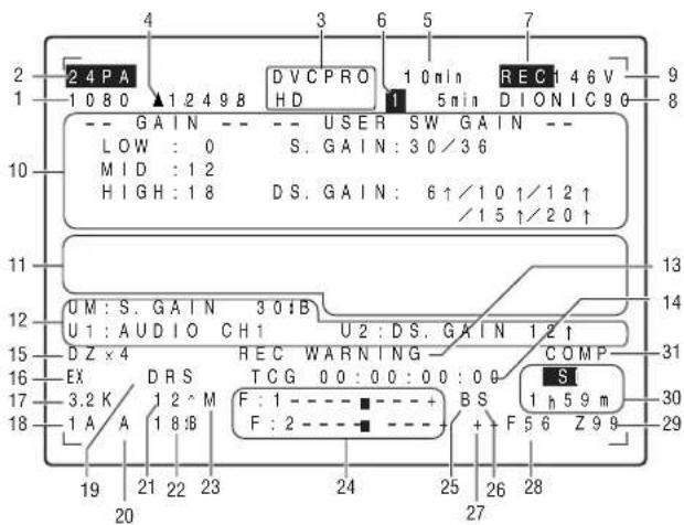
text_image
2 4 PA 1 0 8 0 1 2 4 9 8 DV C PRO HD 1 0 min 1 5 min REC 1 4 6 V D I O N I C 9 0 9 8 - GAIN - - USER SW GAIN - LOW : 0 S. GAIN : 30/3 6 MID : 1 2 HIGH : 1 8 DS. GAIN : 6↑/10↑/12↑ /15↑/20↑ 13 14 12 UM : S. GAIN 3 0 B U1 : AUDIO CH1 U2 : DS. GAIN 1 2 ↑ 15 D Z × 4 REC WARNING COMP 31 EX DRS TCG 00:00:00:00 SI 3.2 K 1 2 M F : 1 - - - + BS F : 2 - - - + F 5 6 Z 9 9 1 h 5 9 m 17 A A 1 8 B 29 19 21 22 23 24 25 26 28For more information, see the following pages:
| Information Item Indication Status | ||
| 1. System mode | 1080720480576 | This indicates the mode that the unit operates in.1080 interlace mode720 progressive mode480 interlace mode576 interlace mode |
| 2. Camera mode | 60i30P24P24PA50i25P60P50P | This indicates the video system when signals output from CCD are recorded on a P2 card or output as video signals.1080-59.94i or 480-59.94i1080-29.97P, 720-29.97P or 480-29.97P (2-2 Pull-down)1080-23.98P, 720-23.98P or 480-23.98P (2-3 Pull-down)1080-23.98P or 480-23.98P (2-3-3-2 Pull-down)1080-50i or 576-50i1080-25P, 720-25P or 576-25P (2-2 Pull-down)720-59.94P720-50P |
| 3. REC mode | DVCPRO HDAVC-I 100 (optional)AVC-I 50 (optional)DVCPRO50DVCPRODV | This indicates the recording mode.NoteDVCPRO HD is displayed in the Native recording. |
| 4. Shutter speed/mode | ▶1/××.*1/60 (1/100) - 1/2000, HALF | This indicates that the shutter speed is set to SYNCHRO SCAN.This indicates that a fixed shutter speed has been set. |
| 5. P2 card remaining free space | ××*minENDWPLOOPINFO P2×/* | The indication “×××min” stays illuminated under normal conditions or blinks when the remaining level is near zero.When the card space is used up, “END” blinks.The P2 card is write-protected.The camera-recorder is in LOOP REC mode. When loop recording cannot be performed, for example because the P2 card has no free space, the indication blinks.P2 card being recognised.Total free space/capacities of the P2 cards (when MODE CHECK is being performed).NoteWhen the menu option P2 CARD REMAIN is set to “ONE CARD”, the number of the P2 card slot that contains the target card is indicated, together with the remaining space.For more information, see [P2 Card Remaining Free Space/capacity Indication] (page 76). |
| 6. P2 card remaining free space(when MODE CHECK is being performed) | 1 * × × min The number of the | P2 card slot that contains the target card and the remaining free space (when MODE CHECK is being performed) are indicated. In LOOP REC mode, the minimum guaranteed recording time (Refer to [Loop Recording] (page 36)) is indicated. This indication also appears when the target P2 card has been switched with a user button. |
| 7. Camera-recorder REC indication | REC When an external device is controlled through the 1394 connection (when the 1394 option is set to BOTH),the recording status of the camera-recorder is displayed using characters. The indication stays illuminated during recording. This is displayed when the menu option REC TALLY of the OPTION MODE is set to “CHAR”.This can also be displayed during the recording using the unit alone. This is displayed when the menu option REC STATUS of the VF INDICATOR2 is set to “ON”. | |
| 8. Battery type(when MODE CHECK is being performed) | PRO14 - AC ADPT Battery type, selected through a menu option. “AC ADPT” indicates when an external DC power supply has been input. | |
| 9. Battery remaining level/voltage | ××.*V××*%EMPMAX | Battery remaining level in tenths of a voltThe remaining battery level is indicated in percentage.This indicates that the battery level is empty.This indicates the battery is fully charged. |
| 10. MODE CHECKIndication Area(STATUS:Master gain,USER SW GAIN) | LOW/MID/HIGH-3 to 30S.GAIN 30/36/42/48DS.GAIN 6 ↑/10 ↑/12 ↑/15 ↑/20 ↑ | Value set for the master gainExample: LOW: 0Gain value to which S.GAIN and DS.GAIN are assigned |
| (Cause of !LEDillumination: displayedfull-screen)● Indications selectedthrough the menu option!LED are marked with[!].● Indications which mayactivate the !LED aremarked with [][I] | GAIN (0 dB)GAIN (-3 dB)DS.GAINLINE MIXSHUTTERWHITE PRE.EXTENDERB.GAMMAMATRIXCOLOR COR.FILTERATW | Gain statusGain statusDS. GAIN valueLINE MIX status (ON or OFF)Shutter statusWhite balance statusExtender status (EX2 or OFF)BLACK GAMMA status (ON or OFF)MATRIX status (A, B, or OFF)Color correction status (ON or OFF)Filter statusATW status (ON or OFF) |
| (FUNCTION:VIDEO OUT) | OUTPUT: MEM/CAM/OFFTYPE: HD-SDI/SD-SDI/VBSCHAR: ON/OFF | Position of OUTPUT SEL switch.Setting for menu option VIDEO OUT switch.Position of VIDEO OUT CHARACTER switch. |
| (FUNCTION:MON OUT) | OUTPUT: MEM/CAM/OFFSELECT: VBS/VF/YCHAR: ON/OFF | Position of OUTPUT SEL switch.Signal mode set through the MONITOR OUT menu option.The setting for menu option MONITOR OUT CHAR.The options MONITOR OUT and MONITOR OUT CHAR can be found inthe OUTPUT SEL screen, which is accessible from the SYSTEM SETTINGpage. |
| (FUNCTION:P2CARD STATUS) | TOTALSLOT1/SLOT2/SLOT3/SLOT4/SLOT5OP-SLOT | Total remaining free space/capacities of the P2 cards loaded in P2 Card Slots 1 - 5.Remaining free space/capacity of each card. The numbers denote the P2 card slot numbers.The card status is indicated as:ACTIVE/ACCESSING/INFO READING/FULL/PROTECTED/NOT SUPPORTED/FORMAT ERROR/NO CARD/PROXYFor details of statuses, see [P2 CARD ACCESS LED and status of P2 cards] (page 30).Indicates optional slot status.The card status is indicated as:PROXY/NO CARD/NOT SUPPORTED |
| (AUDIO: Enabling ordisabling the FRONTAUDIO LEVELcontrol) | CH1: ON/OFFCH2: ON/OFF | If the FRONT AUDIO LEVEL control is in effect for Channel 1, then ON is indicated. If not, OFF is indicated.If the FRONT AUDIO LEVEL control is in effect for Channel 2, then ON is indicated. If not, OFF is indicated. |
| (AUDIO: Phantompower status for themicrophone) | FRONT: ON/OFFREAR: ON/OFF | Phantom power status of the front microphonePhantom power status of the rear microphoneFor more information, see [MIC/AUDIO2] (page 182). |
| (AUDIO: Input signaland level for eachchannel) | FRONT/W.L./REARCH1/2/3/4 | Input signal and level for each channel |
| 11. Camera Warning and Report Area (related to AWB, ABB and switch settings) | AWB A ACTIVEAWB B ACTIVEAWB A OK *.*KAWB B OK *.*KAWB BREAK *.*KAWB NGCOLOR TEMP LOWCOLOR TEMP HIGHLEVEL OVERLOW LIGHTTIME OVERATW MODEAWB PRESET *.*KCHECK FILTERABB ACTIVEABB OKABB BREAKABB NGB-SHD READYB-SHD ACTIVEB-SHD OKB-SHD BREAKB-SHD NG | AWB being performed on Ch A.AWB being performed on Ch B.AWB successful on Ch A.AWB successful on Ch B.AWB action aborted by user.AWB action failed. The second line indicates the status.Color temperature too low.Color temperature too high.Brightness too high.Brightness too low.Action timed-out.This is indicated when AWB cannot be executed since ATW is being operated.AWB cannot be performed because the AWB switch is position at PRE or the super gain is enabled.Make sure the FILTER control is positioned correctly.ABB being performed.ABB action successful.ABB action aborted by user.ABB action failed.Black shading accepted (by holding down the ABB switch during ABB adjustment).Black shading being adjusted.Black shading adjustment successful.Black shading adjustment aborted by user.Black shading adjustment failed. |
| (Switch changeover indication) | WHITE: # *.*KAUTO KNEE: ON/OFFGAIN: **dBSS: 1/*****SS: ▶ 1/*****FILTER: * *.×KEXTENDER: ON/OFFIRIS: ** F *.* | The WHITE BAL switch has been switched. # is replaced with A, B or PRST.When [A] and [B] are set to “VAR”, then it is indicated as VAR *.* K. When [B] is assigned ATW, then it is indicated as ATW MODE.AUTO KNEE switch has been switched to ON or OFF.Gain has been switched with the GAIN selector switch or a user button.When the shutter speed has been switched, the shutter speed is indicated.Shutter speed is in SYNCRO SCAN mode.Filter position and detail have been switched Lens extender has been turned on or off.Indicated when the iris override correction value is to be changed. |
| (Low light warning) LOW LIGHT Brightness too low. | ||
| (Y GET value) | ***.% | With the Y GET ON setting, the output brightness level near the center marker is displayed as “%.” |
| (MARKER indication) MKR: A/B/OFF Current marker type | ||
| 12. User button functionsUM: USER MAINbuttonU1: USER1 buttonU2: USER2 button | INHS.GAIN **dB/OFFDS.GAIN ** ↑/OFFLINE MIX ON/OFFS.IRIS ON/OFFI.OVR ON/OFFS.BLK -***/OFFB.GAMMA ON/OFFAUDIO CH1AUDIO CH2REC SWY GET ONRET SWATW ON/OFFD.ZOOM ×2/×3/×4/OFFSLOT SELPRE RECUSB HOST/DEVICE/OFFDRS ON/OFFASSIST ON/OFFC.TEMP | User buttons disabled.Selected S.GAINSelected DS.GAINWhether LINE MIX GAIN is ON or OFF.Whether S.IRIS is ON or OFF.Iris override can be set (the IRIS OVERRIDE setting is ON).Status of SUPER BLACK (ON or OFF). When it is ON, the set value is also indicated.Status of BLACK GAMMA (shade correction for the black level): ON or OFFInput signal to be recorded on Audio Channel 1 has been switched.Input signal to be recorded on Audio Channel 2 has been switched.USER button acts as REC switch.Y GET function ON.USER button acts as RET switch.ATW being performed.Magnification of digital zoomSwitch that changes the target card is set.Indicates that PRE RECORDING mode has been switched ON or OFF.USB action status has been switched.Indicates whether the dynamic range stretcher function is ON or OFF.Indicates whether the focus assist function is ON or OFF.Indicates the mode for changing the color temperature with the JOG dial button is ON or OFF. |
| 13. System information and warnings | SYSTEM ERROR- €¢ | Something abnormal is happening to the internal computer communications or reference signal. No further recording or playback can be performed. cc is replaced with an error code. For more information, see [Error Codes] (page 148).P2 card has been removed while being accessed (recorded, played back, or formatted), and subsequent operation is disabled.An error has occurred while recording data to or playing data from a P2 card. In the actual indication the € is replaced by the slot number of the P2 card that triggered the error.Something abnormal is happening to video and/or audio being recorded.Backup battery needs replacing.The fan is locked and halted.RF signal from the wireless receiver is degraded.P2 card has no free space.Playback position is at the start of all the clips.Playback position is at the end of all the clips.The P2 card is not recordable. Detailed information is provided on the FUNCTION screen of MODE CHECK. See the relevant section of the MODE CHECK indication area.Clip cannot be played back perhaps because no P2 card is loaded, or the P2 card contains no clips.Displayed when disconnection between microcomputers continues for a specified period or longer.Text memo has been added.Text memo has not been successfully added.Shot mark been added or deleted. For information on shot marks, see [ Shot Mark Function ] (page 41).This is displayed when shot marks cannot be added.Clip information is being updated. Playback operation disabled.AJ-HPX2000 is in USB DEVICE mode. When communication is disabled, the indication blinks.Indicates that the camera-recorder is set to the USB HOST mode. When the external hard disk is not successfully recognized, then the indication blinks.Thumni is being manipulated.Displayed when the connection of the DVCPRO/DV connector is abnormal (when AJ-YAD800G is attached).Displayed when proxy recording on either the P2 card or the SD memory card starts (when AJ-YAX800G is attached, the PROXY REC item on the VF INDICATOR2 screen is turned on).Displayed when proxy recording on the P2 card starts (when AJ-YAX800G is attached, the PROXY REC item on the VF INDICATOR2 screen is turned on).When the remaining free space on the SD Memory card drops below one minute during proxy recording, the message is displayed (when AJ-YAX800G is attached).Displayed when full capacity is reached during proxy recording on the SD memory card (when AJ-YAX800G is attached).Displayed when proxy recording stops because of failure on either the video encoder card or the stream.(when AJ-YAX800G is attached).Displayed when a failure occurs on the SD memory card during proxy recording, and only recording on the SD memory card stops.(when AJ-YAX800G is attached).No return video, playback, or externally input video can be output to the viewfinder.The RET button was pressed to regenerate the time code as the time code for the last clip recorded on a P2 card.This blinks while the recording slots of P2 cards are switched after pressing the USER switch where the SLOT SEL function is assigned.This is displayed if the recording slots of P2 cards cannot be switched when the USER switch where the SLOT SEL function is assigned is pressed.This is displayed when the recording starts or completes while a P2 card with an irregular directory arrangement is inserted or data are recorded after inserting an irregular P2 card.This is displayed when the recording starts or completes with an expired P2 card or when data are recorded after inserting an expired P2 card. |
| TURN POWER OFF | ||
| CARD ERR € | ||
| REC WARNING | ||
| BACKUP BATT EMPTY | ||
| FAN STOP | ||
| WIRELESS-RF | ||
| EOM | ||
| BOS | ||
| EOS | ||
| CANNOT REC | ||
| CANNOT PLAY | ||
| COMM ERROR | ||
| TEXT MEMO | ||
| TEXT MEMO INVALID | ||
| MARK ON/OFF | ||
| SHOT MARK INVALID | ||
| UPDATING | ||
| USB DEVICE | ||
| USB HOST | ||
| THUMBNAIL OPEN | ||
| 1394 INITIAL ERROR | ||
| PROXY REC P2&SD | ||
| PROXY REC P2 | ||
| NEAR END (SD) | ||
| EOM (SD) | ||
| PROXY CARD ERROR | ||
| SD CARD WRITE ERR | ||
| CANNOT DISP IN VF | ||
| TC REGEN | ||
| SLOT SEL | ||
| SLOT SEL INVALID | ||
| DIR NG CARD | ||
| SLOT1/2/3/4/5 | ||
| RUN DOWN CARD | ||
| SLOT1/2/3/4/5 | ||
| 14. Time code indication | TCG 12:59:59:20TCR 12:59:59:20(V)UBG AB CD EF 00(V)UBR 12 34 56 78CTL -1:59:59:20 | TCG (time code generator value)TCR (time code reader value)UBG VUBG (User bits generator value)UBR VUBR (User bits reader value)Displays CTL count. |
| 15. D.ZOOM | DZa2/a3/a4 | Magnification of the digital zoom when the unit is in digital zoom mode. |
| 16. Extender | EX Lens extender used. | |
| Information Item | Indication | Status |
| 17. Color temperature | ×.*K | Color temperature assigned to A, B, and PRST of the WHITE BAL switch (this is a value stored at AWB performance or a value set through the menu option). The indication is not provided in ATW mode. |
| 18. Filter position | 1 - 4- | Position of the CC/ND filter.This indicates that the filter has not been set to a proper position. |
| 19. Dynamic range stretcher mode | DRS This appears when the video level of a part with high brightness is compressed, and the function stretching the dynamic range is selected. | |
| 20. WHITE BAL switch position | A | WHITE BAL switch positioned at [A]. |
| B | WHITE BAL switch positioned at [B]. | |
| P | WHITE BAL switch positioned at [PRST]. | |
| T | ATW mode active. When brightness and color are outside operating limits, the indication blinks. | |
| 21. Stored gain indication | 6 ↑/10 ↑/12 ↑/15 ↑/20 ↑ | Storage gain (DS.GAIN) value (when active) |
| 22. Gain value | ×*dB Current gain value. | |
| 23. LINE MIX GAIN display | M This appears when LINE MIX GAIN (+6 dB) is active | |
| 24. Audio input channel and level meter | - - - - ■- - - - + | Selected channel together with its audio level. |
| F | AUDIO IN switch is positioned at FRONT. | |
| W | AUDIO IN switch is positioned at W.L.(WIRELESS) | |
| R | AUDIO IN switch is positioned at REAR. | |
| 25. Super black ON | B Super black ON. | |
| 26. Super iris ON | S Super iris ON. | |
| 27. Iris override indication | ++ | Correction phase of the iris override (when active) |
| + | ++: On the open side by 1+: On the open side by 0.5 | |
| (No indication) | --: On the closed side by 1-: On the closed side by 0.5 | |
| - | No indication: Standard status | |
| -- | ||
| 28. Iris, F value | NC | Lens cable is not connected. |
| OPEN | Lens iris is at maximum. | |
| F1.7 - F16 | Lens iris value | |
| CLOSE | Lens iris closed. | |
| ◆NoteThese indications are provided when the lens is capable of indicating the iris value. When the iris is being overridden, they blink. | ||
| 29. Zoom indication | Z00 - Z99 | Zoom degree is indicated. This indication is not provided for a lens that does not return the zoom position, even if the indication is set to ON. |
| 30. INTERVAL REC/PRE RECORDING indication/ SD memory card remaining free space | i | Displayed before and after operation during INTERVAL REC mode. |
| iREC (blink) | Displayed during INTERVAL REC operation. | |
| iREC (blink) **h**m/**s | Displays the pause time before the next recording during INTERVAL REC. | |
| P-REC (blink) | Indicated while pre-recorded video and audio are being recorded on the P2 card. If the USER switch is set to perform the PRE RECORDING function, either “P-REC OFF” or the specified duration “1s - 8/15s” is displayed when the PRE RECORDING mode is switched by pressing the USER switch. | |
| SD | If a video encoder card (AJ-YAX800G, optional accessory) is attached, the remaining free space on the SD Memory card will be displayed when the MODE CHECK button is pressed during proxy recording. | |
| ×*h ××m | [END] is displayed when there is no remaining free space. | |
| 31. Compression mode | COMP | This appears when setting the mode for suppressing distortion of compressed video images that may occur when dark parts are shot. (Only for the DVCPRO HD at 720P) |
P2 Card Remaining Free Space/capacity Indication
| Status of unit | Recording status | Menu option P2 CARD REMAIN*1 | 5.P2 card remaining free space indication*2 | 6.P2 card remaining free space indication (during MODE CHECK)*2 |
| Under normal conditions | Other than LOOP REC mode | TOTAL The total remaining free space of all P2 cards loaded in the P2 card slots is indicated in minutes. Example: 30min | Not provided | |
| ONE CARD The number of the P2 card slot holding the target P2 card, together with that card's remaining free space indicated in minutes. Example: 1 8min | Not provided | |||
| OFF Not provided Not provided | ||||
| LOOP REC mode | TOTAL/ONE CARD Indicated as [LOOP] Not provided | |||
| OFF Not provided Not provided | ||||
| During MODE CHECK | Other than LOOP REC mode | TOTAL/ONE CARD/OFF Indicated as [LOOP] The minimum guaranteed recording | The number of the P2 card slot holding the target P2 card, together with that card's remaining free space, indicated in minutes. Example: 1 8min | |
| LOOP REC mode | time is indicated in minutes. Example: 7min |
*1 The menu option P2CARD REMAIN can be found in the
*2 If the remaining free space or memory capacity is 999 min or more, [999min] is displayed.
Indications Available in the Viewfinder Screen
| Selectable between on and off through menu options | Provided when the appropriate status is encountered. | Provided during MODE CHECK*1 | Selectable | Provided during playback | |
| 1. System mode | ○ | - | ● | ○ | - |
| 2. Camera mode | ○ | - | ● | ○ | - |
| 3. REC mode | ○ | - | ● | ○ | - |
| 4. Shutter speed/mode | ○ | ○ | ● | ○ | - |
| 5. P2 card remaining free space | ○ | - | ● | ○ | - |
| 6. P2 card remaining free space (MODE CHECK) | - | - | ● | ○ | - |
| 7. Camera-recorder REC indication | ○ | ○ | - | ○ | - |
| 8. Battery type | - | - | ● | ○ | - |
| 9. Battery remaining level/voltage | ○ | - | ● | ○ | - |
| 10. MODE CHECK indication area | - | - | ○ | ○ | - |
| 11. Camera warning and report area | - | ○ | ○ | ○ | - |
| 12. User button functions | - | ○ | ○ | ○ | - |
| 13. System information and warnings | ○ | ○ | ● | ○ | ○ |
| 14. Time code indication | ○ | - | ● | ○ | ○ |
| 15. D.ZOOM | - | ○ | ● | ○ | - |
| 16. Extender | ○ | ○ | ● | ○ | - |
| 17. Color temperature | ○ | ○ | ● | ○ | - |
| 18. Filter position | ○ | - | ● | ○ | - |
| 19. Dynamic range stretcher mode | ○ | - | ● | ○ | - |
| 20. WHITE BAL switch position | ○ | - | ● | ○ | - |
| 21. Stored gain indication | ○ | - | ● | ○ | - |
| 22. Gain value | ○ | - | ● | ○ | - |
| 23. LINE MIX GAIN display | ○ | - | ● | ○ | - |
| 24. Audio input channel and level meter | ○ | - | All 4ch input information | ○ | - |
| 25. Super black ON | ○ | ○ | ● | ○ | - |
| 26. Super iris ON | ○ | ○ | ● | ○ | - |
| 27. Iris override indication | ○ | ○ | ● | ○ | - |
| 28. Iris, F value | ○ | - | ● | ○ | - |
| 29. Zoom indication | ○ | - | ● | ○ | - |
| 30. INTERVAL REC/PRE RECORDING indication/SD memory card remaining free space | - | ○ | ● | - | - |
| 31. Compression mode | ○ | ○ | ○ | ○ | - |
*1 ○: Not provided when the menu option STATUS is set to OFF, which can be found in the
●: Provided regardless of the menu option setting.
Display Modes and Setting Changes/adjustment Result Messages
The messages that appear on the viewfinder screen to indicate changes to settings and adjustment results may be limited, or set not to appear, through the menu option DISP MODE. This menu option can be found in the
| → < VF DISPLAY > | |
| DISP CONDITION | :NORMAL |
| DISP MODE | :3 |
| VF OUT | :Y |
| VF DTL | :3 |
| ZEBRA1 DETECT | :070% |
| ZEBRA2 DETECT | :085% |
| ZEBRA2 | :SPOT |
| LOW LIGHT LVL | :35% |
| ECU MENU DISP. | :OFF |
| 50M INDICATOR | :OFF |
| MARKER/CHAR LVL | :50% |
| Message appears when: Message | DISP MODE settings | |||
| 1 | 2 | 3 | ||
| CC/ND filter changed. FILTER: n (n=1, 2, 3, 4) | ○ | ○ | ● | |
| Gain changed. | GAIN: n dB(n=-3, 0, 3, 6, 9, 12, 15, 18, 21, 24, 27, 30) | ○ | ○ | ● |
| WHITE BAL switch re-positioned. | WHITE: n (n=A, B, PRE) | ○ | ○ | ● |
| OUTPUT/AUTO KNEE switch positioned at [AUTO KNEE] or [OFF]. | AUTO KNEE: ON (or OFF) | ○ | ● | ● |
| Shutter speed/mode changed. | SS: 1/100 (or 1/120, 1/250, 1/500, 1/1000, 1/2000, ▶1/∗∗.∗) | ○ | ● | ● |
| White balance adjusted (AWB performed). Example: AWB A OK 3.2 K | ○ | ● | ● | |
| Black balance adjusted (ABB performed). | Example: ABB OK | ○ | ● | ● |
| Extender selected. Example: EXTENDER ON ○ | ○ ● | |||
| USER button selected. Example: UM: S.GAIN 30 dB | ○ | ● | ● | |
| MARKER SELECT button selected. | Example: MKR: A | ○ | ○ | ● |
| Iris being overridden. | Example: ++ F 5.6 | ○ | ● | ● |
●: Message appears.
○: Message does not appear.
Setting the Marker Displays
The center, safety zone, safety zone area and frame markers may be set to ON or OFF, along with specifications of the marker types. To set and select markers, go to the VF MARKER screen from the VF page and select the appropriate options.
For directions on navigating the menu, see [Setting Menu Options] (page 153).
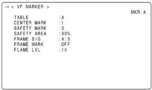
text_image
→ < VF MARKER > MKR : A TABLE : A CENTER MARK : 1 SAFETY MARK : 2 SAFETY AREA : 90% FRAME SIG : 4 : 3 FRAME MARK : OFF FLAME LVL : 15Note
The indication MKR:A at the upper right of the screen shows the current indication status. To view TABLE B, press the MARKER SELECT button. This changes the indication to MKR:B, allowing you to view the settings.
Marker Check Screen Displays (MARKER SELECT button function)
The viewfinder can display a screen that allows you to view the marker settings of the unit.
Pressing the MARKER SELECT button on the camera-recorder switches the marker indication as follows.
Marker A → Marker B → No marker
If the menu option FRAME SIG is set to 16:9 as the information of Marker A and 4:3 as the information of Marker B, then the 16:9 and 4:3 view angles can easily be checked with the button, as required.
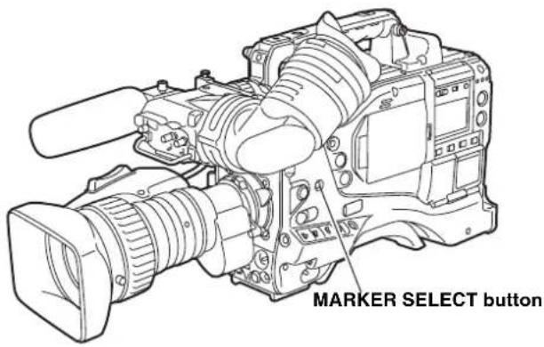
text_image
MARKER SELECT button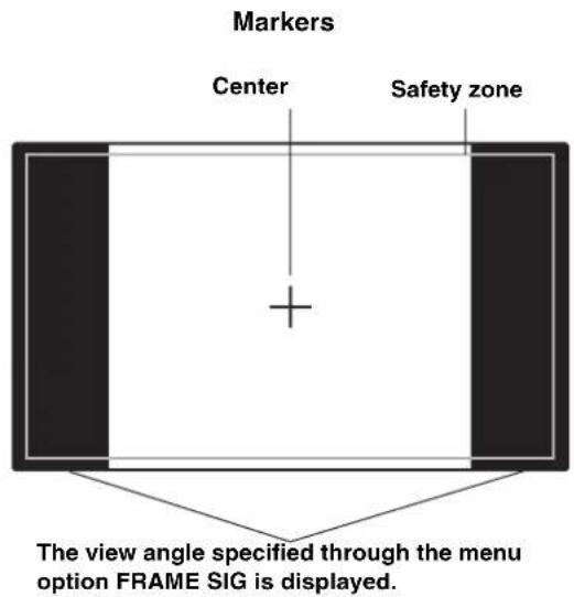
text_image
Markers Center Safety zone The view angle specified through the menu option FRAME SIG is displayed.Checking Return Video Signal in the Viewfinder
The viewfinder displays the return video signal input to the GENLOCK IN connector while the RET button at the lens is held down.
To enable this capability, select CAM RET for the menu option RET SW. This option can be found in the
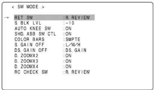
text_image
< SW MODE > → RET SW :R. REVIEW S. BLK LVL :-10 AUTO KNEE SW :ON SHD. ABB SW CTL :ON COLOR BARS :SMPTE S. GAIN OFF :L/M-H DS. GAIN OFF :DS. GAIN D. ZOOMX2 :ON D. ZOOMX3 :ON D. ZOOMX4 :ON RC CHECK SW :R. REVIEWAdjusting and setting the LCD monitor
Using the LCD Monitor
1 Turn on the POWER switch of the unit.
2 Slide the OPEN button in the arrow ① direction to open the LCD monitor in the arrow ② direction.
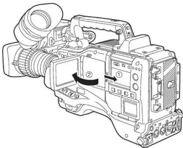
natural_image
Line drawing of a professional video camera with labeled parts (① and ②), showing internal components without any text or symbols.3 Adjust the angle of the LCD monitor for most convenient viewing.
The monitor can turn up to 180 degrees towards the lens and up to 90 degrees towards you.
Note
To prevent camera-recorder failure, do not allow undue force to be applied to the monitor (when it is open).
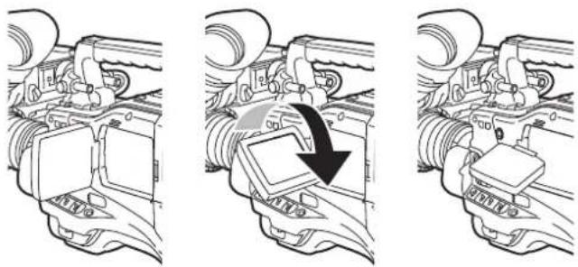
natural_image
Three-step diagram showing mechanical assembly steps: press, press valve, and hand press (no text or symbols)4 The options BRIGHTNESS, COLOR LEVEL, and CONTRAST show respectively the brightness, color level and contrast of the screen. These options can be found in the
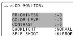
5 Through the menu option LCD MON CHAR, specify whether or not the LCD should display the same characters as the viewfinder. This menu option can be found in the
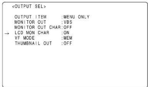
text_image
Notes
- When closing the LCD monitor make sure that it is shut tight.
- In an environment with sudden temperature changes, condensation may form on the liquid crystal surface of the monitor. If this happens, wipe off the moisture with a soft, dry cloth.
- When the camera-recorder is very cold, the video image in the LCD monitor will appear slightly darker immediately after the power is turned on. Once the interior of the camera-recorder warms up, the LCD monitor delivers normal brightness.
Self-portrait Shooting
When shooting with the LCD display angled 180 degrees towards the lens, you can set the menu option SELF SHOOT to "MIRROR", to horizontally flip the video image on the LCD display, and allow you to view a mirror image while shooting.
Note that only the video image on the LCD monitor is horizontally flipped, not the actual video being recorded.
The menu option SELF SHOOT can be found in the
Notes
- When the LCD monitor is angled 180 degrees towards you with the menu option SELF SHOOT to "MIRROR", the LCD monitor does not provide the same status indication as the viewfinder, regardless of the setting for the menu option LCD MON CHAR.
- Return signals from the GENLOCK IN connector cannot be output to the LCD monitor.
- When the OUTPUT SEL switch is positioned to CAM in the HD mode (1080i, 720P), playback cannot be output to the LCD monitor. The HD viewfinder must be used to view playback.
Selection of video output signals
The unit employs the VIDEO OUT connector and the MON OUT connector as connectors for outputting video signals.
Settings of signals output from VIDEO OUT connector
The signal modes for outputting signals from the VIDEO OUT connector are switched with the VIDEO OUT switch.
HD SDI:
To output the HD SDI signals. When the camera-recorder is set to the SD mode, SD-SDI signals are output.
SD SDI:
To output the SD SDI signals. (Signals are down-converted in HD mode.)
VBS:
To output the composite video signals. (Signals are down-converted in HD mode.)
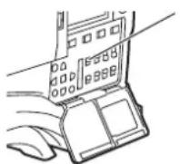
VIDEO OUT switch
The signals output from the MON OUT connector or VIDEO OUT connector are switched with the OUTPUT SEL switch.
However, the switching operation is not acknowledged during the recording operation.
MEM :
During EE, such as recording, video images taken by the camera are output. Meanwhile, signals on the P2 card are output during playback.
CAM :
The camera images are output at all times.
OFF :
No signal is output from the VIDEO OUT or MON OUT connector.
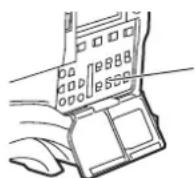
OUTPUT SEL switch
Set the characters to be superimposed on the signals output from the VIDEO OUT connector by using the VIDEO OUT CHARACTER switch and the OUTPUT ITEM item on the menu (
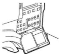
VIDEO OUT CHARACTER switch
| Item | Variable range | Remarks |
| OUTPUT ITEM MENU ONLY TC STATUS | Set the characters to be superimposed on the output signals from the VIDEO OUT connector. MENU ONLY:The menu screen is superimposed only when the menu is accessed.This normally displays nothing.TC:Time codes are superimposed (when the menu is accessed, the menu screen is superimposed.)STATUS:The characters that are the same as the characters superimposed in the viewfinder screen are superimposed.(When the menu is accessed, the menu screen is superimposed.) | |
Settings of signals output from MON OUT connector
The MON OUT connector outputs down-converted analog signals.
Set the video signals output from the MON OUT connector by using the MONITOR OUT item on the menu (
| Item | Variable range | Remarks |
| MONITOR OUT VBS_VFY | Set video signals output from the MON OUT connector.VBS: Analog composite signals are output.VF: Y signals to be output to the viewfinder is output. The status screen is also superimposed.Y: Analog HD-Y signals are output. |
Set to superimpose characters to the VBS signals output from the MON OUT connector in the MONITOR OUT CHARA item of the menu (
| Item | Variable range | Remarks |
| MONITOR OUT CHARA | ONOFF | Superimpose characters on the VBS output signals from the MON OUT connector.ON: To superimposeOFF:Not to superimpose◆NoteThis does not link with the VIDEO OUT CHARACTER switch. |
Handling data
Set data file configuration
The unit employs 5 sets for the file data area.
FACTORY data:
The area for storing factory settings
Data cannot be revised with menu operations.
USER data:
The area for storing the data set by menu operations The FACTORY data is stored as the factory setting.
CURRENT data:
The area for storing the operating status of the unit
The set value in this area is revised by menu operations.
SCENE file:
Four sets of scene files are provided.
LENS file:
Eight sets of lens files are provided.
For menu items that can be read from or stored in the respective areas, refer to [Menu] (page 151)
Notes
- For information about how to navigate through the menu for this section, see [Setting Menu Options] (page 153).
- Access the respective data settings files after switching the PC MODE to "OFF". If the respective data settings files are accessed when the unit is in USB DEVICE mode, an error may occur. The PC MODE can be operated from the
screen on the SYSTEM SETTING page.
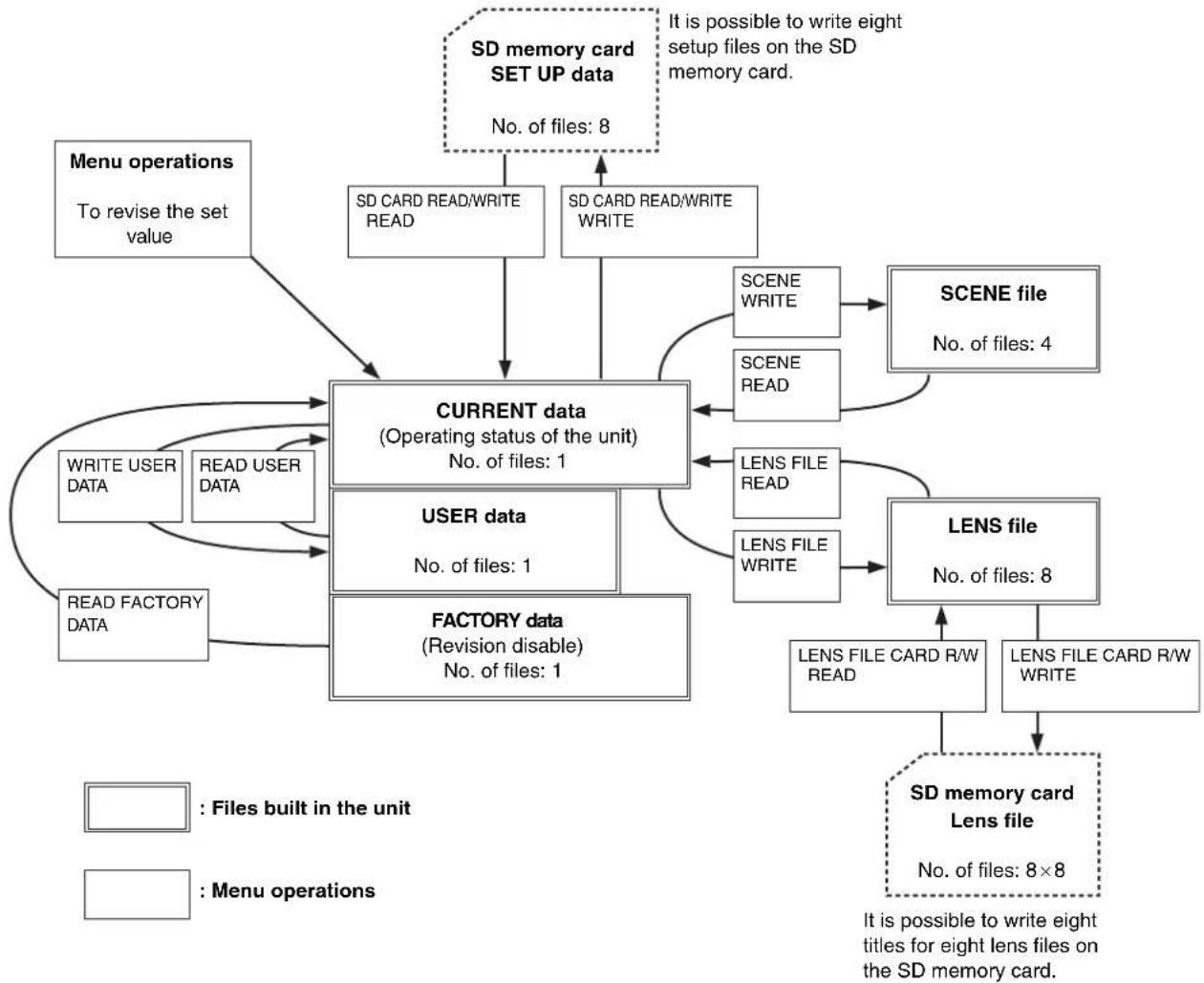
flowchart
graph TD
    A["Menu operations\nTo revise the set value"] --> B["CURRENT data\n(Operating status of the unit)\nNo. of files: 1"]
    C["SD memory card SET UP data\nNo. of files: 8"] --> B
    D["SD CARD READ/WRITE READ"] --> B
    E["SD CARD READ/WRITE WRITE"] --> B
    F["SCENE WRITE"] --> G["SCENE file\nNo. of files: 4"]
    H["SCENE READ"] --> G
    I["LENS FILE READ"] --> J["LENS file\nNo. of files: 8"]
    K["LENS FILE WRITE"] --> J
    L["READ FACTORY DATA"] --> B
    M["WRITE USER DATA"] --> B
    N["READ USER DATA"] --> B
    O["USER data\nNo. of files: 1"] --> B
    P["FACTORY data\n(Revision disable)\nNo. of files: 1"] --> B
    Q["LENS FILE CARD R/W READ"] --> R["SD memory card\nLens file\nNo. of files: 8×8"]
    S["LENS FILE CARD R/W WRITE"] --> R
    T["It is possible to write eight setup files on the SD memory card."] --> R
    style A fill:#f9f,stroke:#333
    style C fill:#f9f,stroke:#333
    style D fill:#f9f,stroke:#333
    style E fill:#f9f,stroke:#333
    style F fill:#f9f,stroke:#333
    style G fill:#f9f,stroke:#333
    style H fill:#f9f,stroke:#333
    style I fill:#f9f,stroke:#333
    style J fill:#f9f,stroke:#333
    style K fill:#f9f,stroke:#333
    style L fill:#f9f,stroke:#333
    style M fill:#f9f,stroke:#333
    style N fill:#f9f,stroke:#333
    style O fill:#f9f,stroke:#333
    style P fill:#f9f,stroke:#333
    style Q fill:#f9f,stroke:#333
Setting Data Using an SD memory card
An SD memory card (optional accessory) can be used as a setup card that stores up to eight files of settings menu specifications.
This data allows you to quickly reproduce an optimum state.
Regarding SD memory cards, please see
Handling SD memory cards
An SD memory card may be inserted or removed, either before or after the power is turned on.
To insert an SD memory card To remove the SD memory card
Open the lid of the switch cover, and insert an SD memory card (optional accessory) into the SD memory card slot with the notch upward. Close the lid.
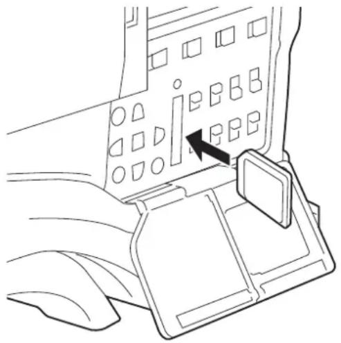
natural_image
Line drawing of an aircraft fuselage showing the control panel with a black arrow pointing to the mode (no text or symbols present)Note
An SD memory card must be inserted with the right side facing the slot. If the card is hard to insert, it may be reversed or upside down. Do not force it into the slot. Check the card before re-inserting it.
Open the lid of the switch cover, and ensure that the BUSY lamp is not illuminated. Then, further depress the SD memory card towards the main unit. This releases the SD memory card from the insertion slot. Take hold of the SD memory card and remove it. Close the lid.
SD memory cards must not be used or stored in an environment where they may be
● Exposed to high temperatures/humidities;
● Exposed to water droplets; or
- Electrically charged.
For storage, the SD memory card must be kept inserted into the unit with the lid closed.
Formatting, Writing and Reading an SD memory card
To format an SD memory card, write settings data or read data on an SD memory card, navigate the menu to the
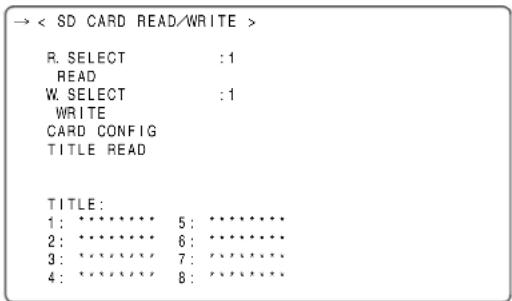
text_image
→ < SD CARD READ/WRITE > R. SELECT : 1 READ W. SELECT : 1 WRITE CARD CONFIG TITLE READ TITLE: 1: ********* 5: ********* 2: ********* 6: ********* 3: ********* 7: ********* 4: ********* 8: *********If an SD memory card that is formatted in a standard other than the SD standards and SDHC standards, [FORMAT ERROR] is displayed in the top right section of the window. In this case, reformat the card as follows. Note that the indication "FORMAT ERROR" does not disappear if the SD memory card is replaced with this menu page open. When the SD memory card is replaced, perform TITLE READ.
To format an SD memory card
Note
SD memory cards may be formatted via the thumbnail screen. For more information, see [Formatting SD memory cards] (page 123).
1 Navigate the menu to the
2 Turn the JOG dial button to move the cursor to the menu option CARD CONFIG.
3 Press the JOG dial button to display the following message:
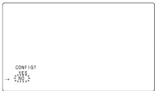
flowchart
graph TD
    A["NO"] --> B{CONFIG?}
    style A fill:#f9f,stroke:#333
    style B fill:#ccf,stroke:#333
4 To format the SD memory card, turn the JOG dial button to move the cursor to YES. Then, press the dial button. When the SD memory card has been formatted, the following message appears:
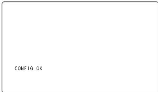
text_image
CONFIG OKThe card will not be formatted if the following message appears when the JOG dial button is pressed:
| Error message Remedy | |
| CONFIG NGNO CARD(No SD memory card inserted.) | Insert an SD memory card. |
| CONFIG NGERROR(SD memory card cannot be formatted.) | The card may be defective.Replace the card. |
| CONFIG NGWRITE PROTECT(SD memory card is write-protected.) | Remove the card and cancel the protect. |
| CONFIG NGCANNOT ACCCESS(SD memory card not accessible). | Example: The SD memory card is not accessible because it is being played back.After the operation in process, format the card. |
5 To exit the menu, press the MENU button. The settings menu disappears and the status of the unit is indicated at the top and bottom of the viewfinder screen.
Note
If an SD memory card is inserted or removed with the
To write set data on an SD memory card
1 Navigate the menu to the
To select a file number
2 Turn the JOG dial button to move the cursor to the option [W. SELECT]. Then, press the dial button.
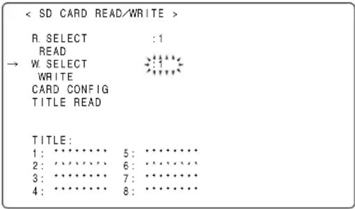
text_image
< SD CARD READ/WRITE > R. SELECT :1 READ → W. SELECT :1 WRITE CARD CONFIG TITLE READ TITLE: 1: ******** 5: ******** 2: ******** 6: ******** 3: ******** 7: ******** 4: ******** 8: ********3 Turn the JOG dial button to select a desired number (1 - 8). Then, press the dial button.
To give the selected file a title
4 Turn the JOG dial button to move the cursor to the option [TITLE:].
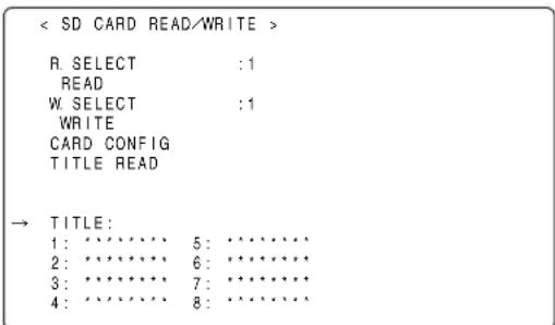
text_image
< SD CARD READ/WRITE > R. SELECT :1 READ W. SELECT :1 WRITE CARD CONFIG TITLE READ → TITLE: 1: ******** 5: ******** 2: ******** 6: ******** 3: ******** 7: ******** 4: ******** 8: ********5 Press the JOG dial button. This moves the cursor to the entry area, putting the unit in entry mode.
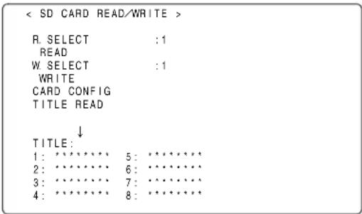
text_image
< SD CARD READ/WRITE > R. SELECT :1 READ W. SELECT :1 WRITE CARD CONFIG TITLE READ ↓ TITLE: 1: ********* 5: ********* 2: ********* 6: ********* 3: ********* 7: ********* 4: ********* 8: *********6 Turn the JOG dial button until a desired character appears. The characters that appear are switched in the following order:
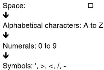
text_image
Space: ↓ Alphabetical characters: A to Z ↓ Numerals: 0 to 9 ↓ Symbols: ', >, <, /, -7 Press the JOG dial button to accept a desired character.
8 Turn the JOG dial button to move the cursor to the next digit (clockwise), and repeat Steps 6 - 7 to set characters (up to eight characters).
To write data on a selected file
9 When the title is set, turn the JOG dial button to move the cursor to [:].
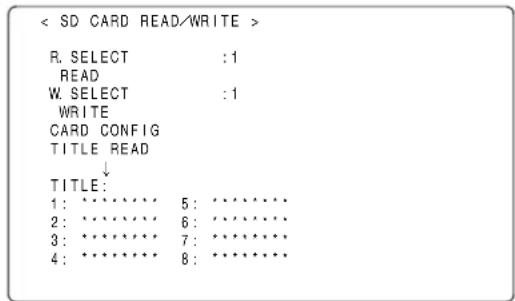
text_image
< SD CARD READ/WRITE > R. SELECT :1 READ W. SELECT :1 WRITE CARD CONFIG TITLE READ ↓ TITLE: 1: ******** 5: ******** 2: ******** 6: ******** 3: ******** 7: ******** 4: ******** 8: ********10 Press the JOG dial button to return the cursor to the option [TITLE:].
11 Turn the JOG dial button to move the cursor to the option [WRITE].
12 Press the JOG dial button to display the following message:
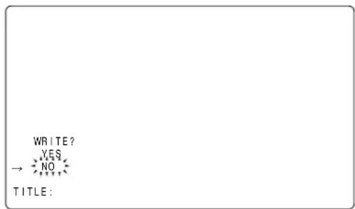
text_image
WRITE? YES NO TITLE:The data will not be written if any of the following messages appears when the JOG dial button is pressed:
| Error message Remedy | |
| WRITE NGNO CARD(No SD memory card inserted.) | Insert an SD memory card. |
| WRITE NGFORMAT ERROR(SD memory card not properly formatted.) | The card has not been formatted using the unit.Replace the card. |
| WRITE NGERROR(SD memory card not writable.) | The card may be defective.Replace the card. |
| WRITE NGWRITE PROTECT(SD memory card write-protected.) | Remove the card and disable the protect. |
| WRITE NGCANNOT ACCESS(SD memory card not accessible.) | Example: The SD memory card is not accessible because it is being played back.After the operation in process, format the card. |
| WRITENGCARD FULL(SD memory card has no free space.) | The card is not writable because it has no free space.Delete unwanted files or replace the card with a new one. |
13 Turn the JOG dial button to move the cursor to YES. Then, press the dial button.
When the data has been written, the following message appears:
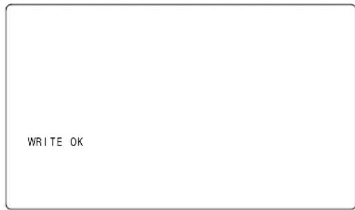
text_image
WRITE OK14 To exit the menu, press the MENU button. The settings menu disappears and the status of the unit is indicated at the top and bottom of the viewfinder screen.
Notes
- The SD CARD R/W SELECT screen can be used to select the type of the menu to be written on the SD memory card.
- It is possible to overwrite the setup file on the unit with a setup file from another device. Note that if the file is overwritten, the original setup file from the other device will be lost.
- We recommend managing the respective SD memory cards on the respective devices independently.
To read data on an SD memory card
1 Navigate the menu to the
To select a file number
2 Turn the JOG dial button to move the cursor to the menu option [R. SELECT]. Then, press the dial button.
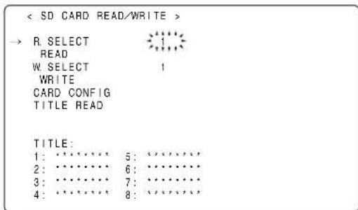
text_image
< SD CARD READ/WRITE > → R. SELECT READ W. SELECT 1 WRITE CARD CONFIG TITLE READ TITLE: 1: ········ 5: ········ 2: ········ 6: ········ 3: ········ 7: ········ 4: ········ 8: ········3 Turn the JOG dial button to select a desired number (1 - 8). Then, press the dial button.
To read data on a selected file
4 Turn the JOG dial button to move the cursor to the option [READ].
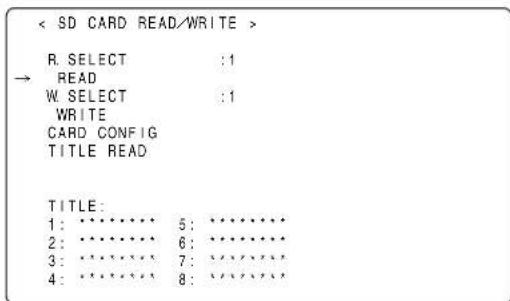
text_image
< SD CARD READ/WRITE > R. SELECT :1 → READ W. SELECT :1 WRITE CARD CONFIG TITLE READ TITLE: 1: ********* 5: ********* 2: ********* 6: ********* 3: ********* 7: ********* 4: ********* 8: *********5 Press the JOG dial button to display the following message:

text_image
READ? YES → NO6 Turn the JOG dial button to move the cursor to YES. Then, press the dial button.
When the data has been read, the following message appears:
text_image
READ OKThe data will not be read if any of the following messages appears when the JOG dial button is pressed:
| Error message Remedy | |
| READ NGNO CARD(No SD memory card inserted.) | Insert an SD memory card. |
| READ NGFORMAT ERROR(SD memory card not properly formatted.) | The card has not been formatted using the unit.Replace the card. |
| READ NGNO FILE(No file found.) | Write file data. |
| READ NGERROR(SD memory card not readable.) | Only data written with the unit is readable. |
| READ NGCANNOT ACCCESS(SD memory card not accessible.) | Example: The SD memory card is not accessible because it is being played back.After the operation in process, read data. |
7 To exit the menu, press the MENU button. The settings menu will be replaced by status indications for the unit.
How to Use the User Data
It is possible to transfer settings and other data to the user area of the internal memory of the unit. This data allows you to quickly reproduce an optimum setup state.
To write data, go to the
To write settings data in the user area
1 Navigate the menu to the
2 Turn the JOG dial button to move the cursor to the option WRITE USER DATA.
< INITIALIZE >
READ FACTORY DATA
→ WRITE USER DATA
3 Press the JOG dial button to display the following message:
text_image
WRITE? YES NO4 Turn the JOG dial button to move the cursor to YES. Then, press the dial button.
This writes the settings data into the user area of the internal memory of the unit.
5 To exit the menu, press the MENU button.
To read written user data
1 Navigate the menu to the
2 Turn the JOG dial button to move the cursor to the option READ USER DATA.
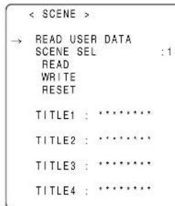
text_image
< SCENE > → READ USER DATA SCENE SEL : 1 READ WRITE RESET TITLE1 : ***** TITLE2 : ***** TITLE3 : ***** TITLE4 : *****3 Press the JOG dial button to display the following message:
text_image
READ? YES NO4 Turn the JOG dial button to move the cursor to YES. Then, press the dial button. The data written in the user area of the internal memory of the unit is read to complete the setting.
5 To exit the menu, press the MENU button.
The set user data may be also read without navigating the menu.
1 Turn off the POWER switch.
2 Position the WHITE BAL switch at [PRST].
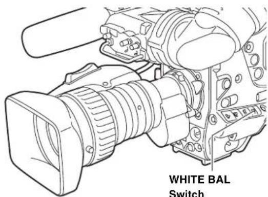
text_image
WHITE BAL Switch3 With the AUTO W/B BAL switch flipped up, turn on the POWER switch. This resets all settings for USER menu options to their defaults.
How to Use Scene File Data
It is possible to write the settings data into the scene file area of the internal memory of the unit, or to read data written in this area. Four types of scene files are available. This data allows you to quickly reproduce an optimum setup state.
To change the settings, go to the
To write settings data for scene files
1 Navigate the menu to the SCENE screen.
2 Turn the JOG dial button to move the cursor to the SCENE SEL option.
3 Press the JOG dial button to blink scene file numbers. Then, turn the dial button to select a desired scene file number.
< SCENE >
READ USER DATA
→ SCENE SEL : 1
READ
WRITE
RESET
TITLE1 : *****
TITLE2 : *****
TITLE3 : *****
TITLE4 : ****
4 Press the JOG dial button to accept the scene file.
5 Turn the JOG dial button to return the cursor to the option WRITE.
< SCENE >
READ USER DATA
SCENE SEL : 1
READ
WRITE
RESET
TITLE1 : *****
TITLE2 : *****
TITLE3 : *****
TITLE4 : *****
6 Press the JOG dial button to display the following message:
WRITE?
YES
→ NO
TITLE:
7 Turn the JOG dial button to move the cursor to YES. Then, press the dial button. This writes the setting data into the scene file area of the unit internal memory.
8 To exit the menu, press the MENU button.
7 Turn the JOG dial button to move the cursor to YES. Then, press the dial button.
This writes the setting data into the scene file area of the unit internal memory.
8 To exit the menu, press the MENU button.
7 Turn the JOG dial button to move the cursor to YES. Then, press the dial button.
8 To exit the menu, press the MENU button.
8 To exit the menu, press the MENU button.
8 To exit the menu, press the MENU button.
8 To exit the menu, press the MENU button.
8 To exit the menu, press the MENU button.
8 To exit the menu, press the MENU button.
8 To exit the menu, press the MENU button.
8 To exit the menu, press the MENU button.
8 To exit the menu, press the MENU button.
8 To exit the menu, press the MENU button.
8 To exit the menu, press the MENU button.
8 To exit the menu, press the MENU button.
8 To exit the menu, press the MENU button.
8 To exit the menu, press the MENU button.
8 To exit the menu, press the MENU button.
8 To exit the menu, press the MENU button.
8 To exit the menu, press the MENU button.
8 To exit the menu, press the MENU button.
8 To exit the menu, press the MENU button.
8 To exit the menu, press the MENU button.
8 To exit the menu, press the MENU button.
8 To exit the menu, press the MENU button.
8 To exit the menu, press the MENU button.
8 To exit the menu, press the MENU button.
8 To exit the menu, press the MENU button.
8 To exit the menu, press the MENU button.
8 To exit the menu, press the MENU button.
8 To exit the menu, press the MENU button.
8 To exit the menu, press the MENU button.
8 To exit the menu, press the MENU button.
8 To exit the menu, press the MENU button.
8 To exit the menu, press the MENU button.
8 To exit the menu, press the MENU button.
8 To exit the menu, press the MENU button.
8 To exit the menu, press the MENU button.
8 To exit the menu, press the MENU button.
8 To exit the menu, press the MENU button.
8 To exit the menu, press the MENU button.
8 To exit the menu, press the MENU button.
8 To exit the menu, press the MENU button.
To read settings data for scene files
1 Navigate the menu to the
2 Turn the JOG dial button to move the cursor to the option SCENE SEL.
3 Press the JOG dial button to blink scene file numbers. Then, turn the dial button to select a desired scene file number.
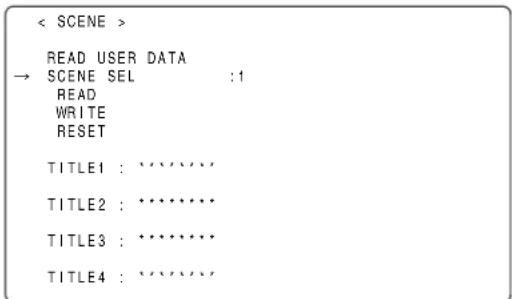
text_image
< SCENE > READ USER DATA → SCENE SEL :1 READ WRITE RESET TITLE1 : ***** TITLE2 : ***** TITLE3 : ***** TITLE4 : *****4 Press the JOG dial button to accept the scene file.
5 Turn the JOG dial button to move the cursor to the READ option.
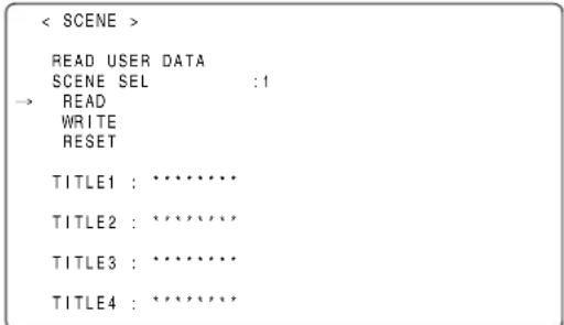
text_image
< SCENE > READ USER DATA SCENE SEL :1 → READ WRITE RESET TITLE1 : ********** TITLE2 : ********** TITLE3 : ********** TITLE4 : **********6 Press the JOG dial button to display the following message:
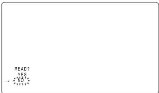
text_image
READ? YES → NO7 Turn the JOG dial button to move the cursor to YES. Then, press the dial button. The data stored in the scene file area of the internal memory of the unit is read to complete the setting.
8 To exit the menu, press the MENU button.
To return data for scene files to their defaults
1 Navigate the menu to the
2 Turn the JOG dial button to move the cursor to the option SCENE SEL.
3 Press the JOG dial button to blink scene file numbers. Then, turn the dial button to select the scene file that you want to reset.
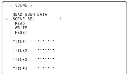
text_image
< SCENE > READ USER DATA → SCENE SEL :1 READ WRITE RESET TITLE1 : ········ TITLE2 : ········ TITLE3 : ········ TITLE4 : ········4 Press the JOG dial button to accept the scene file.
5 Turn the JOG dial button to move the cursor to the option [RESET].
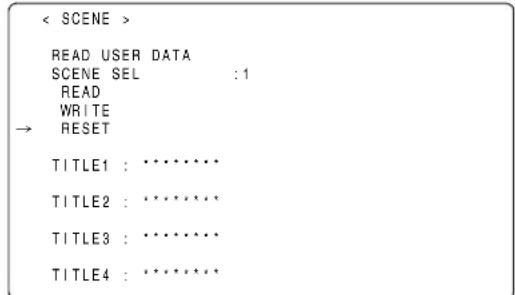
text_image
< SCENE > READ USER DATA SCENE SEL :1 READ WRITE → RESET TITLE1 : ********** TITLE2 : ********** TITLE3 : ********** TITLE4 : **********6 Press the JOG dial button to display the following message:
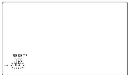
text_image
RESET? YES → NO7 Turn the JOG dial button to move the cursor to YES. Then, press the dial button.
The data stored in the scene file area of the internal memory of the unit is reset to the defaults.
8 To exit the menu, press the MENU button.
To title settings data for scene files
1 Navigate the menu to the
2 Turn the JOG dial button to move the cursor to the option [TITLE 1 - 4] for the appropriate scene file.
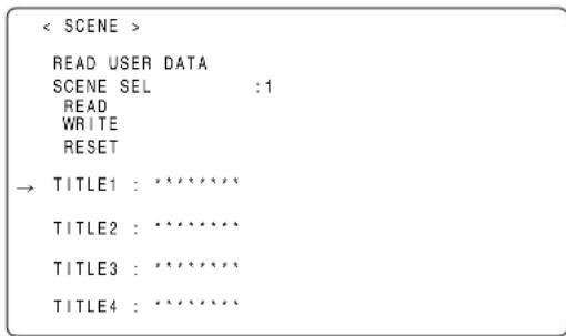
text_image
< SCENE > READ USER DATA SCENE SEL : 1 READ WRITE RESET → TITLE1 : ****** TITLE2 : ****** TITLE3 : ****** TITLE4 : ******3 Press the JOG dial button to move the cursor to the title entry area, putting the unit in entry mode.
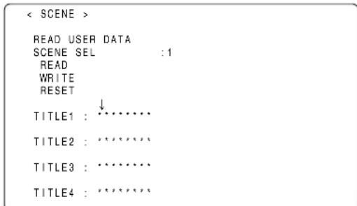
text_image
< SCENE > READ USER DATA SCENE SEL : 1 READ WRITE RESET ↓ TITLE1 : ········ TITLE2 : ········ TITLE3 : ········ TITLE4 : ········4 Turn the JOG dial button until a desired character appears.
The characters that appear are switched in the following order:
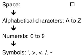
flowchart
graph TD
    A["Space:"] --> B["Alphabetical characters: A to Z"]
    B --> C["Numerals: 0 to 9"]
    C --> D["Symbols: ', >, <, /, -"]
5 Press the JOG dial button to accept a desired character.
6 Turn the JOG dial button to move the cursor to the next digit (clockwise), and repeat Steps 4 - 5 to set characters (up to eight characters).
7 When the title is set, turn the JOG dial button to move the cursor to [:].
8 Press the JOG dial button to return the cursor to the options TITLE 1 - 4.
9 Turn the JOG dial button to return the cursor to the option WRITE.
10 Press the JOG dial button to display the following message:
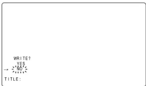
text_image
WRITE? YES → NO TITLE:11 Turn the JOG dial button to move the cursor to YES. Then, press the dial button.
This writes the title into the scene file area of the unit internal memory.
12 To exit the menu, press the MENU button.
Resetting Menu Option Settings to Defaults
The menu settings can be reset to their defaults.
To reset the settings to their defaults, select the menu option READ FACTORY DATA in the
All settings will be reset to their defaults.
Note
This operation does not delete the scene file, lens file, and the information stored as the user data.
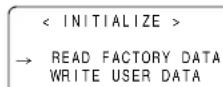
Lens file
The built-in memory of the unit stores eight sets of lens files.
On the SD memory card, eight titles for eight sets of lens files in a table (total 64 sets) can be written.
The following data are recorded on the lens file.
- Title name
● White shading correction value
● Flare compensation value - RB gain offset correction value
How to provide lens files
Adjustment of white shading
For the white shading adjustment, refer to [Adjusting the Lens White Shading] (page 102)
Adjustment of the flare
Using the menu operations, open the
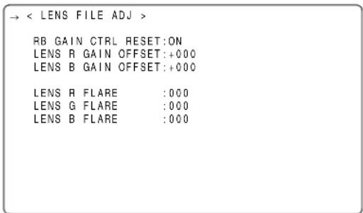
text_image
→ < LENS FILE ADJ > RB GAIN CTRL RESET:ON LENS R GAIN OFFSET:+000 LENS B GAIN OFFSET:+000 LENS R FLARE :000 LENS G FLARE :000 LENS B FLARE :000Example of the chart for flare adjustment
Adjustment of gain offset
For correcting changes in white balance that may occur when replacing the lens.
1 Mount the lens as standard on the unit.
2 Shoot the grayscale chart with appropriate lighting (2000 lx, 3200 K are preferable).
3 Set the WHITE BAL switch to the "A" position.
4 Adjust the lens aperture so that the white window at the center of the grayscale chart is about 80%.
5 Push the AUTO W/B BAL switch to "AWB" to adjust the white balance automatically.
6 Measure the signal level of RGB by using the waveform monitor (WFM).
7 Replace the lens to one where a lens file is provided.
8 Adjust the lens aperture so that the signal level of Gch is the same signal level as the one obtained in 6 above.
9 Using the menu operations, open the
10 Adjust the signal level of Rch to be the same as Gch in the LENS R OFFSET item.
11 In the same way, adjust the signal level of Bch to be the same as Gch in the LENS B OFFSET item.
Select the file No.
1 Using the menu operations, open the
2 Turn the JOG dial button to move the arrow (cursor) to the FILE SELECT item.
3 Press the JOG dial button and the file number will flash. Turn the JOG dial button to select the file (1 to 8) to be recorded.
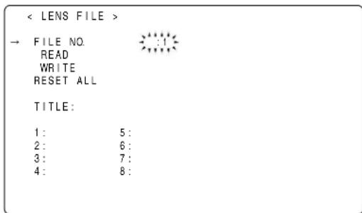
text_image
< LENS FILE > → FILE NO. READ WRITE RESET ALL TITLE: 1: 5: 2: 6: 3: 7: 4: 8:4 Press the JOG dial button to enter the file number.
Give a title to the selected file.
5 Turn the JOG dial button to move the arrow (cursor) to the "TITLE : " item.
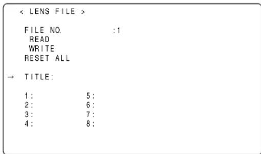
text_image
< LENS FILE > FILE NO: :1 READ WRITE RESET ALL → TITLE: 1: 5: 2: 6: 3: 7: 4: 8:6 When the JOG dial button is pressed, the arrow (cursor) moves to the title input area, and the input mode is established.
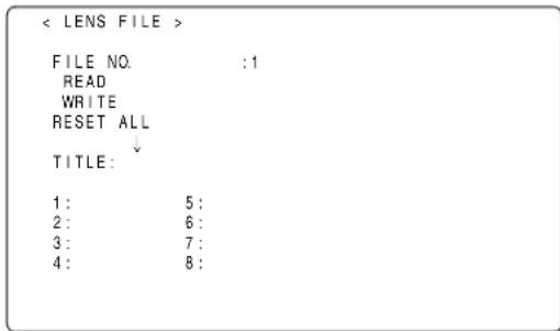
text_image
7 Press the JOG dial button again and turn it until the character to be set is displayed. When the button is turned, the character displayed is switched in the following sequence: Space: □ ↓ Alphabetical characters: A to Z ↓ Numerals: 0 to 9 ↓ Symbols: ', >, <, /, -, . , x
8 Press the JOG dial button to enter the character.
9 Turn the JOG dial button to move the arrow (cursor) to the next position (right), and repeat steps 7 and 8 to set the characters (maximum of 12).
10 When the title has been input, turn the JOG dial button to move the arrow (cursor) to the “:” position.
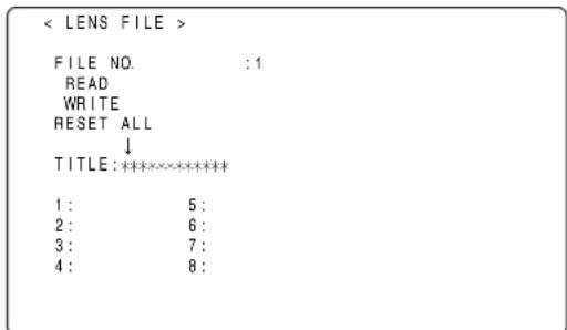
text_image
< LENS FILE > FILE NO. :1 READ WRITE RESET ALL ↓ TITLE:***** 1: 5: 2: 6: 3: 7: 4: 8:11 When the JOG dial button is pressed, the arrow (cursor) returns to the "TITLE : " item.

text_image
< LENS FILE > FILE NO. :1 READ WRITE RESET ALL → TITLE:***** 1: 5: 2: 6: 3: 7: 4: 8:12 Turn the JOG dial button to move the arrow (cursor) to the WRITE position.
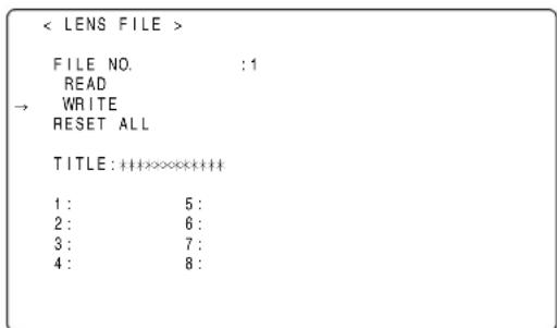
text_image
13 When the JOG dial button is pressed, the following message appears.
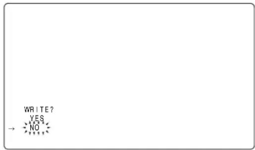
text_image
WRITE? YES NO14 Turn the JOG dial button to move the arrow (cursor) to YES, and press the JOG dial button. The current white shading correction value, the flare compensation value, and the RB gain offset correction value are stored in the built-in memory of the unit.
Note
The values will not be stored in the unit's internal memory if another menu screen is selected without executing WRITE or if the menu is exited.
15 Press the MENU button.
The setting menu is cleared, and the displays showing the unit's current statuses appear at the top and bottom of the viewfinder screen.
To read the lens file from the builtin memory
1 Using menu operations, open the
2 Turn the JOG dial button to move the arrow (cursor) to the FILE SELECT item.
3 Press the JOG dial button and the file number will flash. Turn the JOG dial button to select the file (1 to 8) to be read.
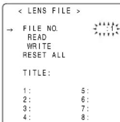
text_image
< LENS FILE > → FILE NO. READ WRITE RESET ALL TITLE: 1: 5: 2: 6: 3: 7: 4: 8:4 Press the JOG dial button to enter the file number.
5 Turn the JOG dial button to move the arrow (cursor) to the READ item.
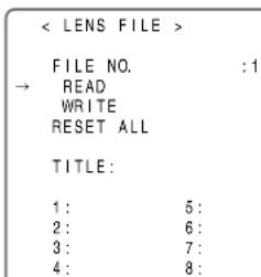
text_image
< LENS FILE > FILE NO. :1 → READ WRITE RESET ALL TITLE: 1: 5: 2: 6: 3: 7: 4: 8:6 When the JOG dial button is pressed, the following message appears.
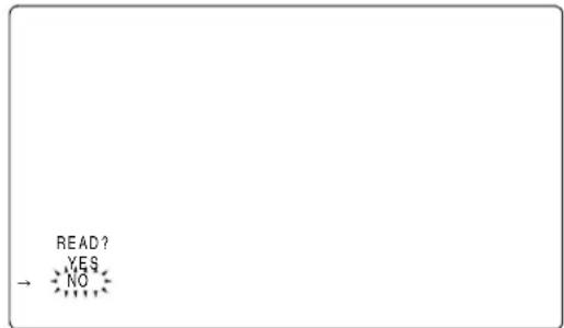
text_image
READ? YES NO7 Turn the JOG dial button to move the arrow (cursor) to YES, and press the JOG dial button.
The recorded correction values for the white shading, flare, and RB gain offset are read.
8 Press the MENU button.
The setting menu is cleared, and the displays showing the unit's current statuses appear at the top and bottom of the viewfinder screen.
To write in and read out the lens file to/from the SD memory card
The contents of the eight lens files stored in the unit's internal memory can be saved onto an SD memory card as card files under a single title. A total of eight titles can be saved on an SD memory card.
Furthermore, the eight lens files saved under one title on an SD memory card can be loaded into the unit's internal memory.
The correlation between the lens files stored in the internal memory and lens files saved on an SD memory card is shown below.
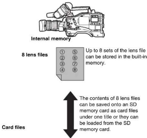
text_image
Internal memory 8 lens files Up to 8 sets of the lens file can be stored in the built-in memory. The contents of 8 lens files can be saved onto an SD memory card as card files under one title or they can be loaded from the SD memory card. Card filesTitle 1 Title 2 Title 3 Title 4
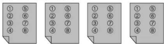
text_image
① ⑤ ② ⑥ ③ ⑦ ④ ⑧Title 5 Title 6 Title 7 Title 8
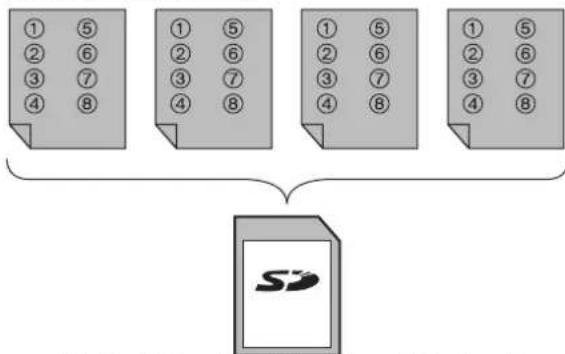
flowchart
graph TD
    A["1 5\n2 6\n3 7\n4 8"] --> D["Document Icon"]
    B["1 5\n2 6\n3 7\n4 8"] --> D
    C["1 5\n2 6\n3 7\n4 8"] --> D
    E["1 5\n2 6\n3 7\n4 8"] --> D
A total of 64 lens files (8 lens files × 8 titles) can be saved on an SD memory card.
Saving lens files on the SD memory card
Select the card file No.
1 Using menu operations, open the
2 Turn the JOG dial button to move the arrow (cursor) to the CARD FILE SELECT item.
3 Press the JOG dial button and the card file number will flash. Turn the JOG dial button to select the file (1 to 8) to be recorded.
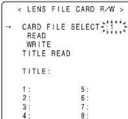
text_image
< LENS FILE CARD R/W >
→ CARD FILE SELECT
READ
WRITE
TITLE READ
TITLE:
1: 5:
2: 6:
3: 7:
4: 8:
4 Press the JOG dial button to enter the file number.
Give a title to the selected card file.
5 Turn the JOG dial button to move the arrow (cursor) to the "TITLE:" item.
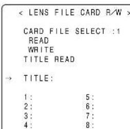
text_image
6 When the JOG dial button is pressed, the arrow (cursor) moves to the title input area, and the input mode is established.
Now perform step 7 on page 93 through step 15 on page 94.
Loading lens files from the SD memory card
1 Using menu operations, open the
2 Turn the JOG dial button to move the arrow (cursor) to the CARD FILE SELECT item.
3 Press the JOG dial button and the card file number will flash. Turn the JOG dial button to select the file (1 to 8) to be read.
< LENS FILE CARD R/W >
→ CARD FILE SELECT
READ
WRITE
TITLE READ
TITLE:
1: 5:
2: 6:
3: 7:
4: 8:
4 Press the JOG dial button to enter the file number.
Now perform steps 5 through 8 on page 94.
Note
The card file titles on the SD memory card are displayed on the
To display these titles, load the files, and check the titles on the
The lens files in the unit's internal memory will be rewritten as the loaded lens files at this time. For this reason, save the lens files in the internal memory onto the SD memory card first to back them up before loading them on the SD memory card.
Preparation
Power Supply
A battery pack or an external DC power supply can be used as AJ-HPX2000's power supply.
Using a Battery Pack
Battery packs from the following manufacturers can be used:
- Anton/Bauer
• IDX
• PAC O - Sony
The type of the battery can be checked or changed through the viewfinder or menu screen on the monitor.
- Pressing the MODE CHECK button on the side of the camera-recorder displays the current type of the battery in the upper right corner of the viewfinder display.
- Navigate the menu to open the BATTERY/P2CARD screen from the MAIN OPERATION page. Then, through the BATTERY SELECT menu option, you can check and change the battery type.
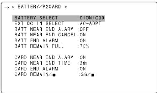
text_image
→ < BATTERY/P2CARD > BATTERY SELECT :DIONIC90 EXT DC IN SELECT :AC-ADPT BATT NEAR END ALARM :OFF BATT NEAR END CANCEL :ON BATT END ALARM :ON BATT REMAIN FULL :70% CARD NEAR END ALARM :ON CARD NEAR END TIME :2th CARD END ALARM :ON CARD REMAIN/■ :3mir/■Notes
- Other batteries may be used by changing the menu setting, but system compatibility is not guaranteed.
- Charge the battery pack with the battery charger before using it. (Please refer to the battery charger's instruction manual for information about charging.)
Mounting the Battery and Setting the Battery Type
Using an Anton/Bauer Battery Pack
1 Mount the Anton/Bauer battery pack.
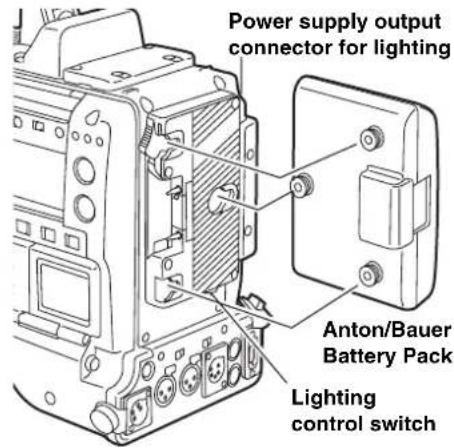
text_image
Power supply output connector for lighting Anton/Bauer Battery Pack Lighting control switchThe Anton/Bauer battery holder includes both a power supply output connector for lighting and a lighting control switch, which are convenient when attaching a light. Please contact Anton/Bauer for information about the lighting system.
2 Insert the battery and slide it in the direction of the arrow.
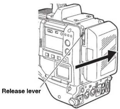
text_image
Release leverRemoving the battery pack
Completely push down and hold the release lever on the battery holder. Then, slide the battery pack in the opposite direction to the arrow while holding the lever down.
3 Setting the battery type.
Select the battery type listed under BATTERY SELECT. Select BATTERY SELECT from the
Please refer to [BATTERY SETTING1] (page 179) for more information.
The following Anton/Bauer batteries can be used:
- PROPAC14
- TRIMPAC14
- HYTRON50
- HYTRON100
- HYTRON140
• DIONIC90
• DIONIC160
Using an NP-1 type battery pack
CAUTION:
These servicing instructions are for use by qualified service personnel only. To reduce the risk of fire or electric shock do not perform any servicing other than that contained in the operating instructions unless you are qualified to do so.
1 Remove the battery holder.
2 Mount the NP-1 type battery case on the camera-recorder.
① Tighten the mounting screws.
② Tighten the power contact screws.
③ Insert the upper part of the removed cover in the direction of the arrow.
④ Align the holes in the bottom part (metal part) of the cover with the holes in the case, and secure the cover with the screw.
Note
When mounting the battery holder, take care not to pinch the connection cord.

text_image
Battery Case (for NP-1 type)When using a V-mount type battery pack
Mount the V-mount adapter plate.
Insert the plate and slide it in the direction of the arrow.
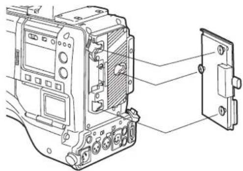
text_image
Technical diagram of an electrical switchgear assembly with labeled components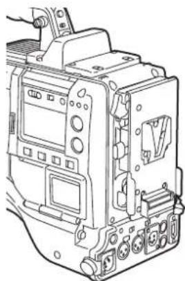
natural_image
Technical line drawing of an electrical enclosure or motor housing (no text or symbols visible)3 Setting the battery type.
Select the battery type listed under BATTERY SELECT. Select BATTERY SELECT from the
When using another battery which cannot be selected using the BATTERY SELECT item setting, select TYPE A or TYPE B, and set the items that correspond to the characteristics of the battery. Please refer to [BATTERY SETTING2] (page 180) for more information.
Note
For information about the V-mount adapter plate, please contact the store where you purchased the camera-recorder.
Use of the external DC power supply
1 Connect the external DC power supply to the DC IN socket on the unit.
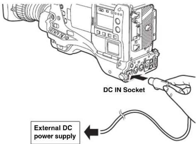
text_image
DC IN Socket External DC power supply2 Turn "ON" the power switch of the external DC power supply. (If the power switch is available on the external DC power supply)
3 Turn ON the POWER switch on the unit.
Inrush current is generated when the power of the unit is turned on. Insufficient power supply when turning on the power may cause a malfunction. We recommend using an external DC power supply with double the capacity of the total power consumption of the unit and any other connected device that is turned by interlocking with the power on of the unit (the viewfinder). Select the DC cord that is recommended for the external DC power supply.
Confirm the pin arrangements of the DC output connector of the external DC power supply and the DC IN socket on the unit, and connect the proper polarities to each other.
If the +12 V power supply is connected to the GND connector in error, it may cause a fire or failure of the unit.
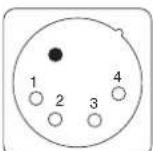
DC IN Socket
| Pin No. Signal | |
| 1 | GND |
| 2,3 | — |
| 4 | + |
1
2
Notes
- If both the battery pack and the external DC power supply are connected, the electric power is supplied from the external DC power supply. While the external DC power supply is used, the battery can be mounted and removed on/from the unit.
- When the external DC power supply is used, ensure that the power switch of the external DC power supply is turned on first and then the POWER switch on the unit is turned on. In the case of the reverse operation, a malfunction may occur on the unit since the output voltage of the external DC power supply is raised slowly.
Mounting the lens and Performing the Flange Back and White Shading Adjustments
Mounting the Lens
1 Raise the lens clamping lever and remove the mount cap.
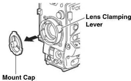
text_image
Lens Clamping Lever Mount Cap2 To mount the lens, align the indentation at the top center of the lens mount with the center mark of the lens.
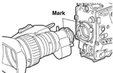
text_image
Mark3 Lower the lens clamping lever to clamp the lens.
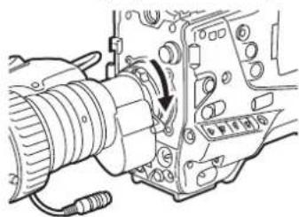
natural_image
Mechanical assembly diagram showing a pipe connection with a valve and housing (no text or labels)4 Secure the cable through the cable clamp, and plug it into the LENS connector.
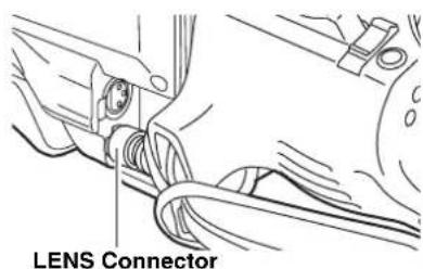
text_image
LENS Connector5 Adjust the lens flange back.
Notes
- Please refer to the lens instruction manual for guidance on lens handling.
- When the lens is removed, install the mount cap to protect the device.
Adjusting the Lens Flange Back
If images are not clearly focused at both telephoto and wide-angle positions during zoom operations, adjust the flange back (distance from the lens mounting surface to the image formation surface).
Once adjusted, the flange back does not need to be re-adjusted as long as the same lens is mounted on the camera.
Note
Please also refer to the lens instruction manual for directions on adjustment and locations of individual lens parts.
1 Mount the lens on the camera. Make sure you connect the lens cable.
2 Set the lens iris to manual, and fully open the iris.
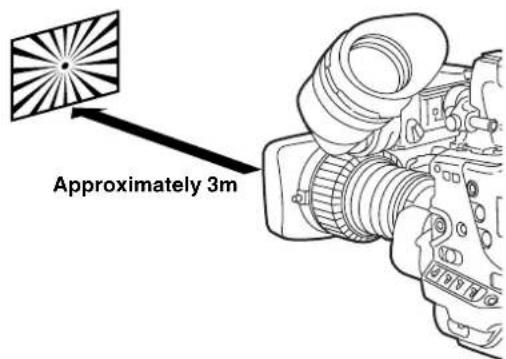
text_image
Approximately 3m3 Place the flange back adjustment chart about 3 m from the lens and adjust the lighting on the chart to obtain an appropriate video output level. If the video level is too high, use the filters or the shutter.
4 Loosen the F.f (Flange focus) ring clamping screw.
Note
F.b (Flange back) may be indicated on some lenses.
5 Set the zoom ring to the telephoto position, either manually or by electric drive.
6 Aim the lens at the flange back adjustment chart and turn the distance ring to bring the chart into focus.
7 Set the zoom ring to the wide-angle position and turn the F.f ring to bring the chart into focus. While focusing, take care not to move the distance ring.
8 Repeat Steps 5 to 7 until the lens is in focus at both the telephoto and wide-angle positions.
9 Firmly tighten the F.f ring clamping screw.
Adjusting the Lens White Shading
Method to correct the waveform to be more flat by combining the sawtooth-shaped waveform and the parabola waveform when watching the respective waveforms of R, G and B of the video signals.
White shading adjustment is disabled when the DS. GAIN is turned ON or the LINE MIX GAIN function operates. Adjust the white shading in the following manner after turning OFF the DS. GAIN and releasing the LINE MIX GAIN function.
Note
Coloring may occur in the vertical direction near where the lens aperture is open even when the white shading has been adjusted. This is something that is inherent to lenses and optical systems and is therefore not indicative of a failure or malfunctioning.
1 Attach the lens to the camera.
At this stage, do not forget to connect the lens cable.
2 Set the electronic shutter to OFF and the gain to "L (0 dB)."
3 If the extender is attached to the lens, release the extender function.
4 Perform a menu operation to open the VF DISPLAY screen from the VF page, check that the settings selected for the ZEBRA1 DETECT item, ZEBRA2 DETECT item and ZEBRA2 item match the settings shown in the figure below. If they differ, make the appropriate changes, and then close the menu screen.
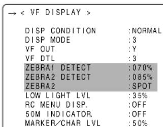
text_image
→ < VF DISPLAY > DISP CONDITION : NORMAL DISP MODE : 8 VF OUT : Y VF DTL : 3 ZEBRA1 DETECT : 070% ZEBRA2 DETECT : 085% ZEBRA2 : SPOT LOW LIGHT LVL : 35% RC MENU DISP. : OFF 50M INDICATOR. : OFF MARKER/CHAR LVL : 50%5 Set the ZEBRA switch on the viewfinder to ON.
6 Shoot a white sheet of paper with no unevenness of color.
Note
Since fluorescent lights, mercury lamps and other such kinds of lighting tend to flicker, use a light source which is free from flicker such as sunlight or a halogen lamp.
7 Set the lens aperture control to manual, and adjust it so that the zebra pattern covers the whole screen. Check that the lens aperture is between F4 and F10.
Notes
- The zebra pattern will not cover the whole screen if there is any unevenness in the lighting. In this case, make adjustments to the position of the lighting, etc.
- Make adjustments to the position of the lighting, etc. also when the lens aperture is not between F4 and F10.
- Be absolutely sure to leave the electronic shutter at OFF.
8 ① Set the WHITE BAL selector switch to "A" or "B," and use the AUTO W/B BAL switch to adjust the white balance automatically (AWB).
② Use the AUTO W/B BAL switch to adjust the black balance automatically (ABB).
③ Again, use the AUTO W/B BAL switch to adjust the white balance automatically (AWB).
9 Repeat step 7.
10 Using the menu operation, open the
| < WHITE SHADING > | |
| CORRECT | :ON |
| → R H SAW | : +00.0 |
| R H PARA | : +00.0 |
| R V SAW | : +00.0 |
| R V PARA | : +00.0 |
| G H SAW | : +00.0 |
| G H PARA | : +00.0 |
| G V SAW | : +00.0 |
| G V PARA | : +00.0 |
| B H SAW | : +00.0 |
| B H PARA | : +00.0 |
| B V SAW | : +00.0 |
| B V PARA | : +00.0 |
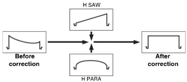
flowchart
graph TD
    A["Before correction"] --> B["H SAW"]
    C["H PARA"] --> B
    B --> D["After correction"]
11 When the lens has an extender or ratio converter, repeat steps 7 - 9 to enable the extender or ratio converter function. The camera-recorder stores, as one lens file data item, three different correction values for the following: a lens with an extender, a lens with a ratio converter, and a lens with neither of them.
When making the white shading correction, make the adjustment while observing the R, G, and B waveforms in the horizontal and vertical directions with the waveform monitor.
This now completes the white shading adjustments.
The adjustment values are now stored in the non-volatile memory so that even when the unit's power is turned off, there will be no further need to perform the white shading adjustment.
Preparing for Audio Input
Take the following steps to prepare the camera for connecting audio input devices.
When Using the Front Microphone
AJ-HPX2000 can be equipped with the AJ-MC900G stereo microphone kit (an extra-cost option).
1 Open the microphone holder.
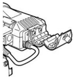
natural_image
Line drawing of a mechanical device with attached components (no text or symbols)2 Mount the microphone and tighten the clamping screw. The microphone must be attached with the UP mark on the microphone facing up.

text_image
Clamping Screw3 Connect the microphone cable to the MIC IN jack on the camera.
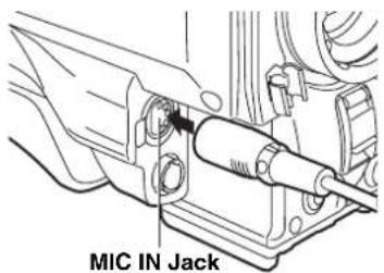
text_image
MIC IN Jack4 Set the AUDIO IN switch to [FRONT] depending on the audio channel to be recorded.
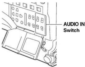
text_image
AUDIO IN SwitchWhen Using a Wireless Receiver
When Using the Unislot Wireless Receiver
1 Remove the cover to insert the wireless receiver and secure it with the screws.
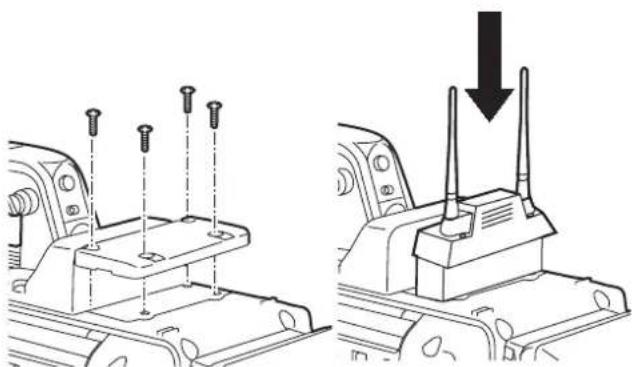
natural_image
Technical illustration of a vehicle chassis with screw fasteners and a warning symbol (no text or labels)2 Set the AUDIO IN switch to [W.L.] depending on the audio channel to be recorded.
When Using Audio Devices
1 Connect the audio device to the AUDIO IN jack with the XLR cable.
2 Set the AUDIO IN switch to [REAR] for the channel to which the XLR cable is connected.
3 Set the LINE/MIC/+48V selector switch on the rear panel to [LINE].
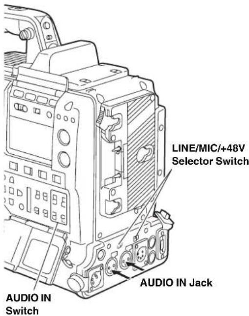
text_image
LINE/MIC/+48V Selector Switch AUDIO IN Switch AUDIO IN JackMounting the Camera on a Tripod
When mounting the camera on a tripod, use the tripod adapter supplied with the camera.
1 Mount the tripod adapter on the tripod.
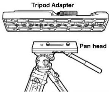
text_image
Tripod Adapter Pan headNote
Select an appropriate hole in the adapter, taking into account the center of gravity of the camera and tripod adapter combined.
Also, make sure that the diameter of the selected hole matches the diameter of the pan head screw.
2 Mount the camera on the tripod adapter.
Slide the camera forward along the grooves until you hear a "click".
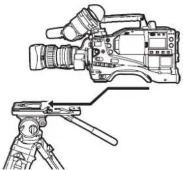
natural_image
Line drawing of a professional video camera with tripod-mounted stand and cable clip (no text or symbols)Removing the Camera from the Tripod Adapter
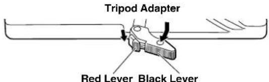
text_image
Tripod Adapter Red Lever Black LeverWhile holding the red lever down, move the black lever in the direction of the arrow, and slide the camera backward to remove it.
Note
If the tripod adapter pin does not return to its original position after the camera has been removed, hold the red lever down and move the black lever in the direction of the arrow again, in order to return the pin to its original position.
Please note that the camera cannot be mounted if the pin remains in the center.
Attaching the Shoulder Strap
To detach the shoulder strap, first open the hooks, then detach the strap.
Note
Make sure that the shoulder strap is securely attached.
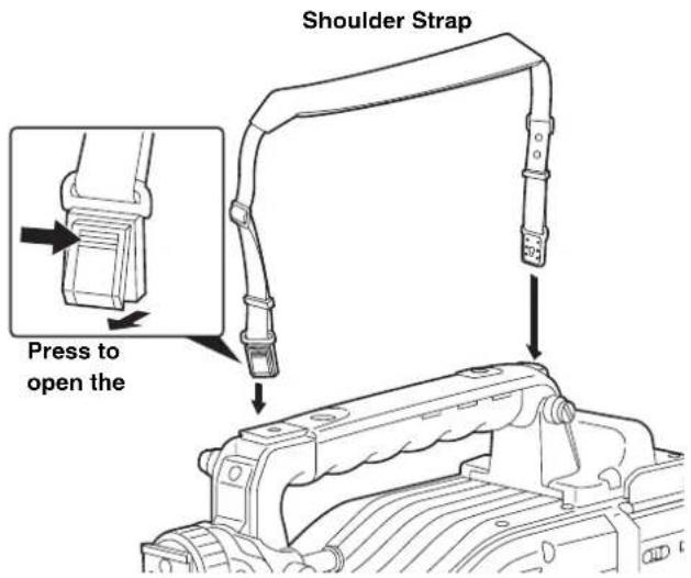
text_image
Shoulder Strap Press to open theAttaching the Rain Cover
When using the SHAN-RC700 Rain Cover
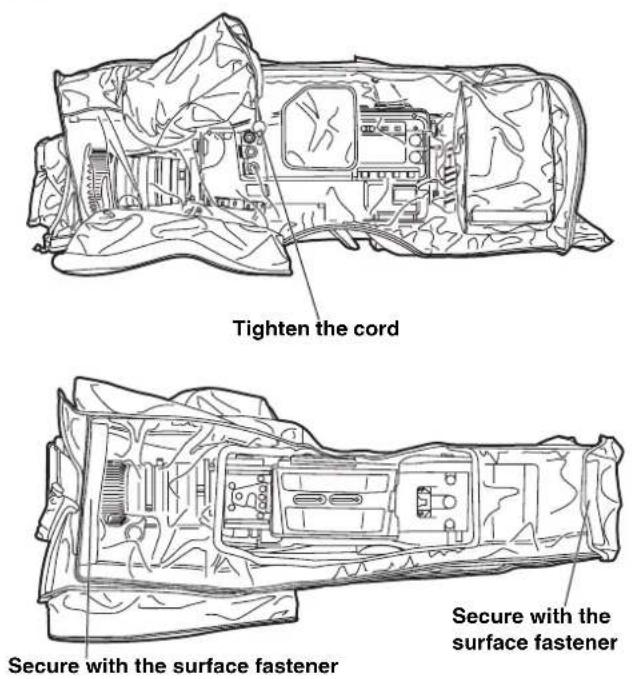
text_image
Tighten the cord Secure with the surface fastener Secure with the surface fastenerConnection of the remote control unit (AJ-RC10G)
It is possible to control some of the functions remotely by connecting the remote control unit AJ-RC10G (optional accessory).
When AJ-RC10G is connected to the REMOTE connector on the unit and the power switches of both of the unit and AJ-RC10G are turned on, the unit automatically enters the remote control mode.
The remote control mode is released when AJ-RC10G is removed or the power for the AJ-RC10G is turned OFF.
Switch functions in the remote control mode
In the remote control mode, the following switches and buttons on the unit are disabled.
- SHUTTER switch
- MENU button
- JOG dial button
- GAIN switch
• OUTPUT/AUTO KNEE switch - WHITE BAL switch
- USER MAIN button
- USER 1 button
- USER 2 button
Recording and playback Operations in the remote control mode
When the remote control is connected, recording and playback can be controlled through both the camera-recorder and the AJ-RC10G.
Notes
- The state that was adjusted by connecting AJ-RC10G is stored in the unit. Not to store the adjusted state in the unit, open the FUNCTION MENU of AJ-RC10G to set the RC DATA SAVE item to "OFF".
- When the dedicated cable is connected or removed, ensure that the POWER switches on both the main unit and AJ-RC10G are turned "OFF".
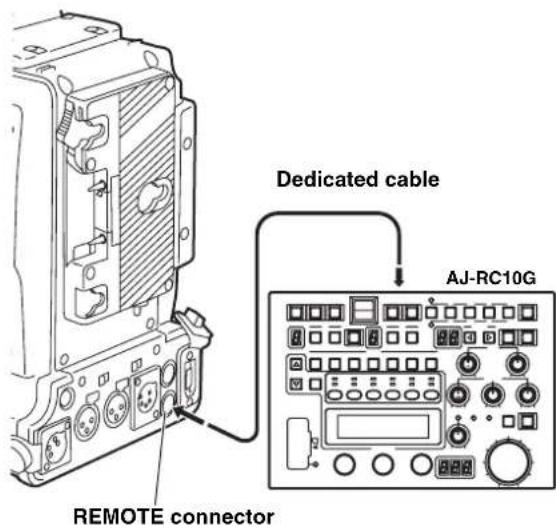
text_image
Dedicated cable AJ-RC10G REMOTE connectorAttaching the Front Audio Level Control Knob
If you use the Front Audio Level control frequently, attach the accessory knob so that it can be easily operated.
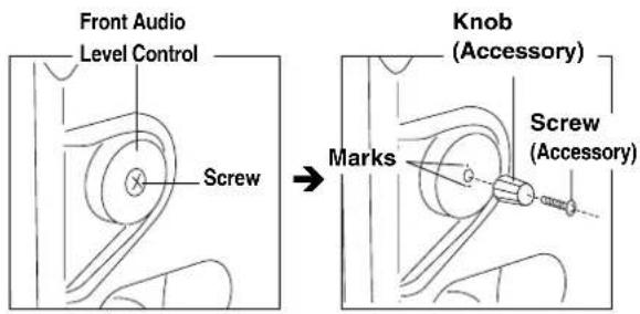
text_image
Front Audio Level Control Screw → Knob (Accessory) Marks Screw (Accessory)Remove the screw in the center of the Front Audio Level control, and attach the accessory knob using the screw (included). When attaching the knob, be sure to align the marks on the control with the marks on the knob.
Connection of the external switch
It is possible to draw 1.5 A current from the DC OUT connector of the unit.
REC start/stop can be controlled by connecting an external switch to this connector.
Since a tally lamp can be used by connecting an LED to this connector, it is useful for shooting video when fixing the camera on a crane.
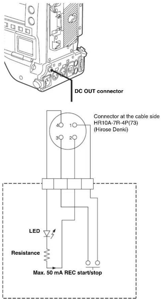
text_image
DC OUT connector Connector at the cable side HR10A-7R-4P(73) (Hirose Denki) LED Resistance Max. 50 mA REC start/stop1: GND
2: TALLY OUT
Open collector output on the unit side
TALLY ON: Low impedance
TALLY OFF: High impedance
3: REC start/stop switch
This is connected in parallel to the REC START button on the unit or the VTR button on the lens
4: +12 V
Manipulating Clips with Thumbnails
A clip is a data group that includes the images and voices created from one shooting session, together with additional information such as text memos and meta data. The following manipulations can be performed using the cursor and SET buttons, while checking the images displayed on the LCD monitor:
- Playback, delete, copy or restore the clip.
- Add or delete a shot mark and a text memo on the clip thumbnail.
● Copy part of a clip by using the test memo. - Change the thumbnail image.
- Format P2 cards and SD memory cards.
- Uploading and editing clip metadata from the SD memory card
Thumbnail Manipulations Overview
Thumbnail screens are configured as follows:
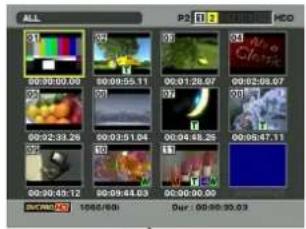
text_image
ALL 00:30:00.00 00:09:55.11 00:01:28.07 00:02:08.07 00:02:33.26 00:03:51.04 00:04:48.25 00:05:47.11 00:30:45.12 00:09:44.03 00:00:00.00 DUR: 1068/601 Dur : 00:30:30.03THUMBNAIL
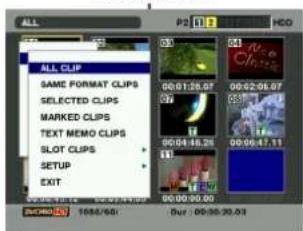
text_image
ALL CLIP SAME FORMAT CLIPS SELECTED CLIPS MARKED CLIPS TEXT MEMO CLIPS SLOT CLIPS SETUP EXIT P2 1 1 HCD 00:01:26.07 00:02:06.07 00:04:18.26 00:06:47.11 00:00:00.00 1688/601 Our : 00:30:30.03OPERATION PROPERTY
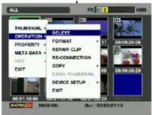
text_image
ALL PHUMINIAL OPERATION PROPERTY META DATA HDD EXIT DCLET FORMAT REPAIR CLIP RE-CONNECTION COPY EXCH. PHUMINIAL DEVICE SETUP EXIT 00:01:19:68 00:02:19:68 00:03:19:68 00:04:19:68 00:05:19:68 00:06:19:68 00:07:19:68 00:08:19:68 00:09:19:68 00:10:19:68 00:11:19:68 00:12:19:68 00:13:19:68 00:14:19:68 00:15:19:68 00:16:19:68 00:17:19:68 00:18:19:68 00:19:19:68 00:20:19:68 00:21:19:68 00:22:19:68 00:23:19:68 00:24:19:68 00:25:19:68 00:26:19:68 00:27:19:68 00:28:19:68 00:29:19:68 00:30:19:68 00:31:19:68 00:32:19:68 00:33:19:68 00:34:19:68 00:35:19:68 00:36:19:68 00:37:19:68 00:38:19:68 00:39:19:68 00:40:19:68 00:41:19:68 00:42:19:68 00:43:19:68 00:44:19:68 00:45:19:68 00:46:19:68 00:47:19:68 00:48:19:68 00:49:19:68 00:50:19:68 00:51:19:68 00:52:19:68 00:53:19:68 00:54:19:68 00:55:19:68 00:56:19:68 00:57:19:68 00:58:19:68 00:59:19:68 00:60:19:68 00:61/19/68 EXIT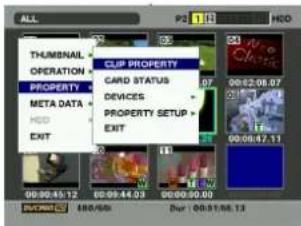
text_image
ALL PH 1.0 HCO THUMBNAIL OPERATION PROPERTY META DATA HDD EXIT CLIP PROPERTY CARD STATUS DEVICES PROPERTY SETUP EXIT 00:00:45.12 00:00:44.03 00:00:50.00 00:01:06.13ALL CLIP
SAME FORMAT CLIPS
SELECTED CLIPS
MARKED CLIPS
TEXT MEMO CLIPS
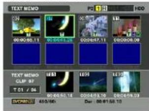
text_image
TEXT MEMO 00:00:00.11 00:04:00.28 00:05:07.11 00:06:08.09 TEXT MEMO CLIP 07 T 01 / 06 00:04:00.14 00:04:09.10 00:04:09.03 DUR/AN 45/66 Date : 00:01:58.10DELETE
FORMAT
REPAIR CLIP
RE-CONNECTION
COPY
EXCH. THUMBNAIL
DEVICE SETUP
EXIT
CLIP PROPERTY
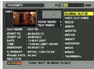
text_image
PROPERTY 0001 CUP NAME: 0001SK START TO: 00:00:05:12 START ID: 940F300T GATE: 18-MAY-2007 TOLERATION: 00:00:07:19 V_FORMAT: DV105.1080/19.541 FRAME RATE: 99.94% REG RATE: GLOBAL CLIP ID USER CLIP NAME VIDEO AUDIO ACCESS DEVICE SHOOT SCENARIO NEVAS MEMO THUMBINAL AVOCADO: PUSH "EXIT" IN MENU TO EXITCARD STATUS
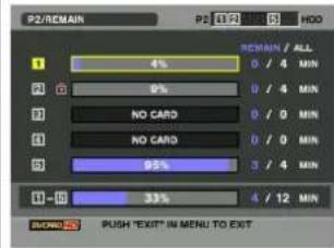
text_image
P2/REMAIN P2 100 5 HDD 1 4% 0 / 4 MIN 2 9% 0 / 4 MIN 3 NO CARD 0 / 0 MIN 4 NO CARD 0 / 0 MIN 5 95% 3 / 4 MIN 6 -5 33% 4 / 12 MIN MINDO PUSH 'EXIT' IN MENU TO EXIT.DEVICES
— PROPERTY SETUP
EXIT
SLOT CLIPS
SETUP
EXIT
ALL HIDE
MARKER IND.
TEXT MEMO IND.
WIDE IND.
PROXY IND.
DATA DISPLAY
DATE FORMAT
THUMBNAIL SIZE
THUMBNAIL INIT
EXIT
META DATA
LOAD
RECORD
- USER CLIP NAME
- INITIALIZE
- PROPERTY
EXIT
HDD
EXPORT
EXPLORE
FORMAT
SETUP
EXIT
Thumbnail Screen
Press the THUMBNAIL button to display the thumbnail screen on the LCD monitor. Pressing the THUMBNAIL button again returns the display to the regular display. When switching is done from the regular screen display to the thumbnail screen display, all the clips will be displayed on the thumbnail screen.
Pressing the MENU button allows you to navigate the thumbnail menu.
Note
With the TCG switch positioned at [SET], when the time code or user bits are set or when camera menus are being manipulated, thumbnails cannot be manipulated.
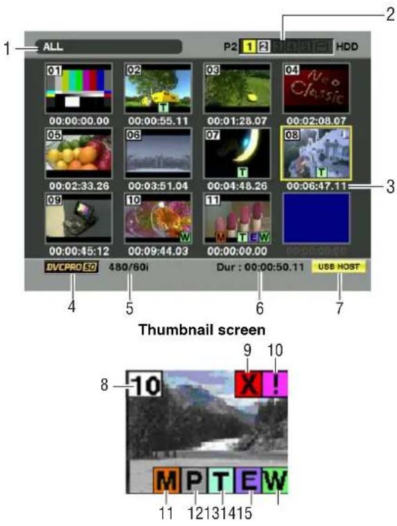
text_image
ALL P2 1 2 3 4 5 6 7 HDD 01 02 03 04 05 06 07 08 09 00:00:00.00 00:00:55.11 00:01:28.07 00:02:08.07 00:02:33.26 00:03:51.04 00:04:48.26 00:06:47.11 00:00:45.12 00:09:44.03 00:00:00.00 DVCPRO 5D 480/60i Dur : 00:00:50.11 USB HOST Thumbnail screen 8 -10 X! 11 121314151. Display Mode
The type of the thumbnail indicated on the display and the types of the other information screens are indicated.
ALL: Display all clips.
SAME FORMAT:
The clips in the same format as the system format are shown.
SELECT:The clips selected with the SET button are shown.
MARKER: Display clips with shot marks.
TEXT MEMO:
Display clips with text memo data.
SLOT n: Display clips in the specified P2 card. (n: 1 to 5, which indicates Slots 1-5.)
UPDATING..:
Indicated when the camera-recorder is updating the screen or reading data. When the screen is being updated, the rotating icon is indicated.
Please refer to [Switching the Thumbnail Display] (page 113) for more information.
2.Slot numbers and HDD status
This section indicates on which P2 card the pointed clip is recorded. The number of the slot that contains the appropriate P2 card is indicated in yellow. If the clip is recorded on more than one P2 card, then the numbers of all slots that contain the appropriate cards are indicated. The numbers of the other slots are shown in white if they contain P2 cards.
When the following P2 card is inserted, the slot number is displayed with a pink frame.
- RUN DOWN CARD
(A P2 card on which the number of rewrites exceeds the limit defined in the standards.)
- DIR ENTRY NG CARD
(A P2 card on which the directory structure does not comply with the standards.)
The USB HDD section is indicated as follows:
● Other than the USB HOST mode: gray
● Not connected in USB HOST mode: gray
- HDD recognized and usable in USB HOST mode: white
- HDD recognized and thumbnails shown in USB HOST mode: yellow
- HDD recognized and data unable to be copied in USB HOST: red
3.Time Display
You can set this to display the time code at the start of clip recording, the user bits at the start of clip recording, the shooting time, the shooting date, the shooting and date or USER CLIP NAME.
4. Recording mode
The recording mode for the clip on which the pointer is located is indicated.
5. System format
The format for the clip on which the pointer is located is indicated.
6. Duration
The duration of the clip on which the pointer is located is indicated.
7. USB HOST mode indicator
Indicated when the mode has been switched to USB HOST.
8. Clip Number
The numbers set by the camera for all the clips recognised correctly by the P2 card. These numbers are allocated in chronological order, by shooting dates and times.
If clips cannot be played because of different recording formats, they are displayed in red.
9. Defective Clip Indicator and
? Unknown Clip indicator
This marker is displayed for defective clips, which may result from a variety of causes, e.g., powering-down during recording.
Clip with yellow defective clip indicators can be restored in some cases. Please refer to [Restoring Clips] (page 117) for more information.
A clip displayed with a red corrupt marker cannot be restored and must be deleted. If the clip cannot be deleted, format the P2 card.
When clips have different formats, ? is displayed instead of
10. Incomplete Clip Indicator
Indicates that although a clip is recorded across multiple P2 cards, one of these cards is not inserted into a P2 card slot.
11. Shot Mark Indicator
This marker is displayed for a clip with a shot mark attached. Please refer to [Shot Mark] (page 115) for more information about shot marks.
12. Indicator for clips with proxy
This marker is displayed for clips with proxy attached.
13. Text Memo Indicator
This marker is displayed for a clip with a text memo attached.
14. Edit Copied Clip Indicator
This marker is displayed on a clip when the model supports edit copy, such as the AJ-HPM100. For more information about edit copying, see the instruction manual for a mode that supports edit copying.
15. Wide Clip Indicator
This marker is displayed for clips recorded with the 16:9 aspect ratio. However, it does not accompany clips in HD format.
Selecting Thumbnails
Multiple thumbnails can be randomly selected in the thumbnail screen.
1 Use the cursor buttons to move the pointer (yellow frame) to the desired clip and press the SET button. The frame around the selected thumbnail changes to a blue frame. Press the SET button again to deselect the clip.
2 Additional clips can be selected by repeating Step 1.
It is possible to display only the selected thumbnails in the thumbnail screen for playback. Please refer to [Switching the Thumbnail Display] (page 113) for more information.
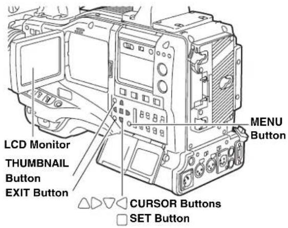
text_image
LCD Monitor THUMBNAIL Button EXIT Button △△▽▽ △ CURSOR Buttons □ SET Button MENU ButtonPlaying back Clips
1 Press the THUMBNAIL button.
The thumbnail screen appears on the LCD monitor.
2 Use the cursor buttons to move the pointer over the desired clip.
3 Press the PLAY/PAUSE button, and the clip under the pointer will be played back on the LCD monitor. After playback of the clip under the pointer, subsequent clips are played back in order, according to when they were shot. The thumbnail screen returns after the last clip has been played back.
Notes
- When playing back clips, it is not necessary to "select" the clips (blue frames around the thumbnails).
- Clips with clip numbers displayed in red cannot be played.
4 During playback, pressing the REW button starts 4× speed reverse playback, and the FF button starts 4× speed fast playback. Press the PLAY/PAUSE button to return to normal playback.
5 During clip playback, pressing the PLAY/PAUSE button will temporarily stop (pause) the process. During a pause, pressing the REW button moves the pause position to the beginning of the clip. Pressing the REW button again moves the pause position to the beginning of the previous clip. During a pause, pressing the FF button moves the pause position to the beginning of the next clip.
6 Pressing the STOP button during clip playback stops the playback and returns the display to the thumbnail screen.
Note
When playback is stopped, the position of the pointer remains on the clip that was being played back, regardless of where the playback started. However, when the THUMBNAIL button is pressed to close the thumbnail screen, the pointer will move to the starting clip (i.e., the clip with the earliest recording date and time), not the clip on which the pointer was last positioned.
Switching the Thumbnail Display
The display can be switched so that only those clips matching the specified conditions are displayed in the thumbnail screen.
1 Press the THUMBNAIL button. The thumbnail screen appears on the LCD monitor.
2 Press the THUMBNAIL MENU button. The thumbnail menu appears.
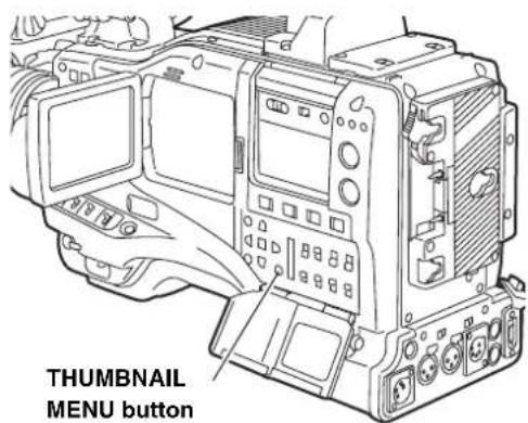
text_image
THUMBNAIL MENU button3 Select THUMBNAIL from the thumbnail menu. Switch the thumbnail display by selecting one of the following items:
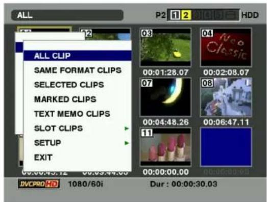
text_image
ALL P2 1 2 3 4 5 6 7 8 9 10 11 12 13 14 15 16 17 18 19 20 ALL CLIP SAME FORMAT CLIPS SELECTED CLIPS MARKED CLIPS TEXT MEMO CLIPS SLOT CLIPS SETUP EXIT DVCPRO HD 1080/60i Dur : 00:00:30.03ALL CLIP:
Display all clips.
SAME FORMAT CLIPS:
Displays clips in the same format as the system format. System format means the image system set in SYSTEM MODE and REC MODE. Press the MODE CHECK button to display the viewfinder. Refer to [1.System mode] (71 page) and [3.REC mode] (71 page) of [Viewfinder Status Indication Layout].
SELECTED CLIPS:
Display randomly selected clips.
MARKED CLIPS:
Display clips with shot marks attached.
TEXT MEMO CLIPS:
Display clips with text memo data attached.
SLOT CLIPS:
Display clips recorded in the P2 card inserted in the specified slot.
When this item is selected, SLOT1 to SLOT5 are displayed as a sub-menu. Select the desired slot to display the clips.
SETUP:
Please refer to [Setting the Thumbnail Display Mode] (page 124) for information about this item.
EXIT:
Close the sub-menu.
Changing thumbnails
It is possible to replace thumbnails with images that include previously attached text memos while images are recorded or played back.
1 Add text memos to images that you intend to change. Refer to [Text Memo Function] (page 40) for the method to add text memos.
2 Select THUMBNAIL → TEXT MEMO CLIPS to display thumbnails of the clips with text memos.
3 Place the pointer on the clip of the thumbnail that you intend to change, and then press SET. Move the pointer to the text memo display on the lower row.
4 Select the thumbnail that you intend to replace, place the pointer on it, and then select OPERATION → EXCH. THUMBNAIL on the thumbnail menu.
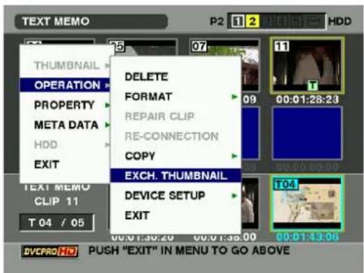
text_image
TEXT MEMO P2 1 2 RICHOT HDD THUMBNAIL OPERATION PROPERTY META DATA HDD EXIT DELETE FORMAT REPAIR CLIP RE-CONNECTION COPY EXCH. THUMBNAIL DEVICE SETUP EXIT 00:01:38.20 00:01:38.00 00:01:43.06 T 04 / 05 DVCPRO HD PUSH "EXIT" IN MENU TO GO ABOVE5 Press SET. When the YES/NO confirmation window is displayed, select YES by using the cursor button and the SET button. The menu closes and the thumbnail for the clip is replaced.
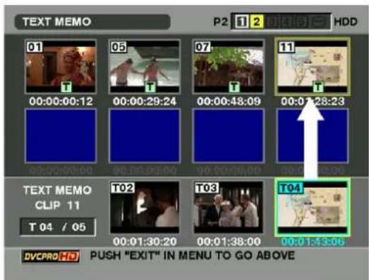
text_image
TEXT MEMO P2 1 2 3 4 5 HDD 01 00:00:00:12 05 00:00:29:24 07 00:00:48:09 11 00:01:28:23 02:00:00:00 00:00:00:00 00:20:00:00 02:25:26 TEXT MEMO CLIP 11 T 04 / 05 T02 00:01:30:20 T03 00:01:38:00 T04 00:01:43:06 DVCPRO HD PUSH "EXIT" IN MENU TO GO ABOVENote
Display clip properties by selecting PROPERTY → CLIP PROPERTY on the thumbnail menu to confirm the position of the thumbnail (the number of frames from the top of the clip). Since thumbnails come generally from the top of the clip, [0] is displayed.
Shot Mark
A shot mark can be added to a clip thumbnail to distinguish this clip from the others.
1 Press the THUMBNAIL button.
The thumbnail screen appears on the LCD monitor.
2 Use the cursor buttons to move the pointer over the clip to which you want to attach a shot mark.
3 Press the Shot Mark button.
4 A shot mark will be attached to the clip thumbnail under the pointer.
To delete a shot mark, reposition the pointer over the clip and press the Shot Mark button.
Notes
- A shot mark can be attached during recording. Please refer to [Shot Mark Function] (page 41) for more information.
- When adding a shot mark to (or deleting the shot mark from) a clip recorded across multiple P2 cards, do this with all these P2 cards inserted into P2 card slots.
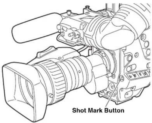
text_image
Shot Mark ButtonText Memo
During recording or playback, you can add text memos to clips. Text memos can be used to play back clips at some point or break clips into chunks and copy the necessary portions.
Adding a text memo
Text memos can be added in one of the following ways.
- Press the TEXT MEMO button during recording or playback of a clip. A text memo is added to the position where the button is pressed.
- Press the TEXT MEMO button when the thumbnail screen is displayed. A text memo is added to the beginning of the clip.
Note
One clip can have up to 100 text and voice memos in combination. Note that camera-recorder is not capable of adding or showing voice memos.
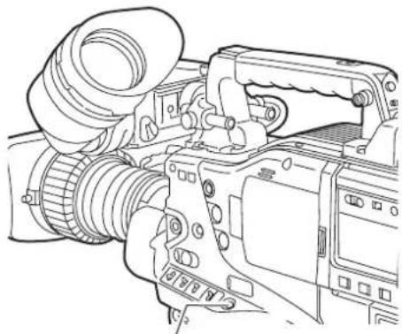
natural_image
Line drawing of a digital camera with lens and control panel (no text or symbols)Text Memo Button
Playing back a clip at the position where a text memo is recorded
1 Press the THUMBNAIL button.
The thumbnail screen appears on the LCD monitor.
2 Press the THUMBNAIL MENU button and select THUMBNAIL → TEXT MEMO CLIPS from the thumbnail menu.
The clip thumbnails with text memos attached are displayed in the upper section of the LCD monitor. The lower section of the LCD monitor shows information about the text memo on the clip selected by the pointer.
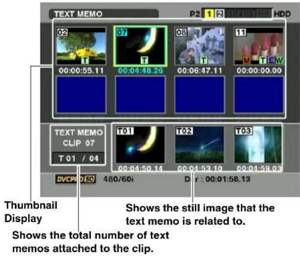
text_image
TEXT MEMO P2 1 2 HDD 02 07 08 11 00:00:55.11 00:04:48.26 00:06:47.11 00:00:00.00 TEXT MEMO CLIP 07 T 01 / 04 T01 T02 T03 DVCP D 50 480/60i D r : 00:01:58.13 Thumbnail Display Shows the still image that the text memo is related to. Shows the total number of text memos attached to the clip.3 Move the pointer over the clip that contains the desired text memo to playback and press the SET button. The pointer moves to the lower part of the LCD monitor.
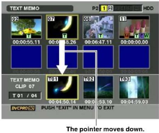
text_image
TEXT MEMO P2 1 2 HDD 02 07 08 11 00:00:55.11 00:00:58.26 00:06:47.11 00:00:00.00 TEXT MEMO CLIP 07 T 01 / 04 T01 T02 T03 DVCPRO CO PUSH "EXIT" IN MENU TO EXIT The pointer moves down.4 With the pointer located in the lower part, move the pointer to the desired text memo number using the cursor right and left buttons (<). Then, press the PLAY button.
5 Playback will start from the time code position of the text memo where the pointer is located. If the STOP button is pressed during playback or the playback has finished at the end of the clip, then the thumbnail screen appears again with the pointer replaced with the text memo where the playback started.
6 Press the THUMBNAIL MENU button to select EXIT or press the EXIT button to return the pointer to the upper part of the thumbnail screen.
Note
If the AVC-Intra codec board (AJ-YBX200G, optional) is not installed, the test memo thumbnails of the clips recorded in AVC-I 100 or AVC-I 50 may not display; the section is indicated in gray.
Deleting a text memo
1 Select the desired text memo by carrying out steps 1-3 for [Playing back a clip at the position where a text memo is recorded] (page 116).
2 Move the pointer to the desired text memo, and then press the SET button.
3 Press the THUMBNAIL MENU button to select OPERATION → DELETE from the thumbnail menu. YES and NO appear to confirm deletion. Use the cursor buttons and the SET button to select YES. The text memo is deleted.
Using a text memo to break a clip and copy the necessary portion
1 Select a desired text memo in a clip by carrying out steps 1-3 for [Playing back a clip at the position where a text memo is recorded] (page 116).
2 Move the pointer to the desired text memo, and then press the SET button. You can select more than one text memo.
3 Press the THUMBNAIL MENU button to select OPERATION → COPY.
4 User the cursor buttons and SET buttons to select the destination slot. Then, select YES to start copying the clip. The portion between the selected text memo and the next one is copied. If no text memo is found after the selected one, then all part after the selected text memo is copied. If multiple text memos are selected, the selected sections are copied.
5 When the clip is being copied, the camera-recorder indicates the progress of the copy process and cancellation status. To discontinue the copy process, press the SET button. Then, a YES/NO confirmation screen is displayed. Use the cursor buttons and SET button to select YES.
Deleting Clips
1 Press the THUMBNAIL button.
The thumbnail screen appears on the LCD monitor.
2 Use the cursor buttons to move the pointer over the clip you want to delete.
Press the SET button to select the clip.
3 Press the THUMBNAIL MENU button and select OPERATION → DELETE from the thumbnail menu.
4 The following screen appears. Use the cursor buttons and the SET button to select YES.
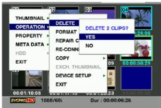
text_image
THUMBNAIL OPERATION PROPERTY META DATA HDD EXIT DELETE FORMAT REPAIR C RE-CONN COPY EXCH. THUMBNAIL DEVICE SETUP EXIT DELETE 2 CLIPS? YES NO 00:01:10:08 00:01:17:10 00:01:23:23 00:00:56:29 DVCPRO HD 1080/60i Dur : 00:00:06:285 The clip is deleted. All selected clips (in blue-green frames) are deleted by this operation.
Note
Pressing the SET button stops the deletion operation in the middle.
Restoring Clips
Restores clips that are defective as a result of sudden powering-down during recording, or removal of the P2 card being accessed.
Note
Only those clips with yellow corrupt clip markers can be restored. Delete the clips with red corrupt clip markers. If the clip cannot be deleted, format the P2 card.
During restoration of the clips, however, the defective-clip indicator may change from yellow to red, resulting in inability to restore the clips.
1 Press the THUMBNAIL button.
The thumbnail screen appears on the LCD monitor.
2 Use the cursor buttons to move the pointer over the clip you want to restore (defective clips are indicated by corrupt clip marks).
Press the SET button to select the clip.
3 Press the THUMBNAIL MENU button, and select OPERATION→ REPAIR CLIP from the thumbnail menu.
4 The confirmation window appears. Use the cursor buttons and the SET button to select YES.
Reconnection of Incomplete Clips
Incomplete clips may be generated when clips recorded on multiple P2 cards (connected clips) are separately copied to different cards. Reconnection function generates one clip (the original, connected clip) from incomplete clips.
1 Press the THUMBNAIL button. The thumbnail screen appears on the LCD monitor.
2 Use the cursor and SET button to select incomplete clips to reconnect.
Usually, thumbnails of incomplete clips (clips with marker) are displayed in line.
3 Press the THUMBNAIL MENU button and select OPERATION → RE-CONNECTION from the thumbnail menu.
4 The confirmation window appears. Use the cursor buttons and SET button to select YES.
Note
1 indication stays illuminated until all the incomplete clips that comprise the original clip are reconnected.
Copying Clips
Selected clips can be copied to the P2 card or SD memory card in the desired slot.
1 Press the THUMBNAIL button. The thumbnail screen appears on the LCD monitor.
2 Use the cursor buttons to move the pointer to the desired clip and press the SET button.
3 Press the THUMBNAIL MENU button and select OPERATION → COPY from the thumbnail menu. Select Slot 1-5 or SD memory card as the destination.
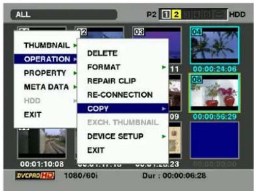
text_image
ALL P2 1 2 Siding HDD THUMBNAIL OPERATION PROPERTY META DATA HDD EXIT DELETE FORMAT REPAIR CLIP RE-CONNECTION COPY EXCH. THUMBNAIL DEVICE SETUP EXIT 00:01:10:08 00:01:11:16 00:01:23:23 DVCPRO HD 1080/60i Dur : 00:00:06:284 The confirmation window appears. Use the cursor buttons and SET button to select YES.
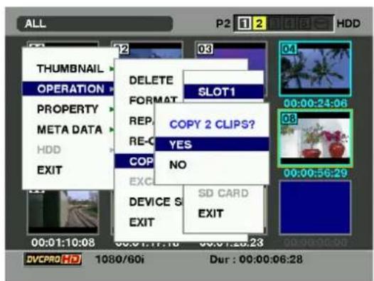
text_image
ALL P2 1 2 HDD THUMBNAIL OPERATION DELETE SLOT1 PROPERTY FORMAT REP. COPY 2 CLIPS? META DATA RE- YES COP NO HDD EXIT EXC DEVICE S SD CARD EXIT EXIT 00:01:10:08 00:01:17:10 00:01:26:23 DVCPRO HD 1080/60i Dur : 00:00:06:28Notes
- Do not turn off the power or remove a P2 card while data is being copied. Doing so may cause the P2 card to fail. If you should accidentally perform one of the above operations, defective clips will be generated. Delete them, and then copy them again.
- When clips are copied to P2 cards, all the information on the clips is copied. However, when they are copied to the SD memory card *1, video and sound information is not copied, only thumbnails, clip metadata, icons, Voice Memo, proxy, and real-time metadata.
- When there is insufficient recording capacity on the destination, the message "LACK OF REC CAPACITY" is displayed, and copying will not proceed. When clips to be copied include some with defects, the message "CANNOT ACCESS" is displayed, and copying will not proceed. If selected clips include any that are already recorded on the destination P2 card, copying will not proceed.
- To stop copying, press the SET button. Clips currently being copied to the destination will be deleted.
- When identical clips exist on the destination card, the "OVERWRITE?" is displayed. Select "YES" or "NO".
*1 Regarding SD memory cards to be used, see
Setting of Clip Meta Data
Information such as the name of person who shot the video, the name of the reporter, the shooting location, or a text memo can be read from the SD memory card, and can be recorded as Clip Meta Data.
Reading Clip Meta Data (metadata upload)
1 Insert the SD memory card that contains the Clip Meta Data (metadata upload file).
2 Press the THUMBNAIL button. The thumbnail screen appears on the LCD monitor.
Note
Press the thumbnail button while pressing MODE CHECK button when a thumbnail is displayed to move to Step 4.
3 Press the THUMBNAIL MENU button and Select META DATA → LOAD from the thumbnail menu, and press the SET button.
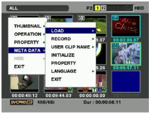
text_image
ALL THUMBNAIL OPERATION PROPERTY META DATA HDD EXIT LOAD RECORD USER CLIP NAME INITIALIZE PROPERTY LANGUAGE EXIT 00:00:45.12 00:09:44.03 00:00:00.00 DVCPRO 50 480/60i Dur : 00:00:50.11 P2 1 2 HDD 03 04 05 06 07 08 09 10 11 12 13 14 15 16 17 18 19 20 21 22 23 24 25 26 27 28 29 30 31 32 33 34 35 36 37 38 39 40 41 42 43 44 45 46 47 48 49 504 Names of metadata upload files stored on the SD memory card are displayed*. Select the desired files using the cursor buttons, and choose YES. Upload starts.
Uploaded metadata is retained even if the power is turned off. For [more information on] confirmation of uploaded data, see [Checking and modifying read metadata] (page 120).
* Press the cursor button (▶) to display the full name of the file, up to 100 characters, at the cursor position. Press the cursor button (◀) to return to the original state.
Clip Meta Data items
Clip Meta Data includes the following items: Underlined items can be set by reading the metadata upload file on the SD memory card. Other items are set automatically during shooting. Using the latest update version of P2 viewer, metadata upload files can be written to SD memory cards using a PC. Download the latest update version of P2 viewer from the following URL and install it to your PC:
The file which was edited by except P2 viewer is displayed as "UNKNOWN DATA", and may not be read.
GLOBAL CLIP ID:
Displays the global clip ID, which indicates the shooting status of the clip.
USER CLIP NAME:
Displays the clip name specified by the user.*
VIDEO: Displays [FRAME RATE] (frame rate of the clip), [PULL DOWN], and [ASPECT RATIO].
AUDIO: [SAMPLING RATE] (sampling frequency of recorded sound) and [BITS PER SAMPLE] (digitized bit[s] of recorded sound).
ACCESS: Displays [CREATOR] (person who recorded the clip), [CREATION DATE] (date when the clip was recorded), [LAST UPDATE DATE] (date of the latest update of the clip), and [LAST UPDATE PERSON] (person who made the latest update of the clip).
DEVICE: Displays [MANUFACTURER] (name of the device manufacturer), [SERIAL NO.] (serial number of the device) and [MODEL NAME] (model name of the device).
SHOOT: Displays [SHOOTER] (name of the person who shot the video), [START DATE] (start date of shooting), [END DATE] (end date of shooting), and [LOCATION] ALTITUDE/LONGITUDE/LATITUDE/SOURCE/PLACE_NAME (altitude, longitude, latitude, and source of the information and name of the location).
SCENARIO:
Displays [PROGRAM NAME], [SCENE NO.], and [TAKE NO].
NEWS: Displays [REPORTER] (name of the reporter), [PURPOSE] (purpose of shooting), and [OBJECT] (object of shooting).
MEMO*2: Displays [NO.] (the number of the text memo), [OFFSET] (location of the frame where the text memo is added), [PERSON] (person who recorded the text memo added to the clip), and [TEXT] (contents of the text memo).
THUMBNAIL:
Displays the location of the frame (frame offset) and the size (height and width) of the image selected as the thumbnail image.
*1 The USER CLIP NAME recording method is selectable. For details, refer to [Selecting the USER CLIP NAME recording method] (page 121).
*2 Be sure to enter TEXT when entering MEMO. It is not possible to record only PERSON or OFFSET.
Note
AJ-HPX2000 only displays printable ASCII characters.
Checking and modifying read metadata
The camera-recorder allows you to check the details of read metadata.
1 Press the THUMBNAIL button.
The thumbnail screen appears on the LCD monitor.
2 Press the THUMBNAIL MENU button to select METADATA→ PROPERTY from the thumbnail menu. Then, the screen like this is displayed:
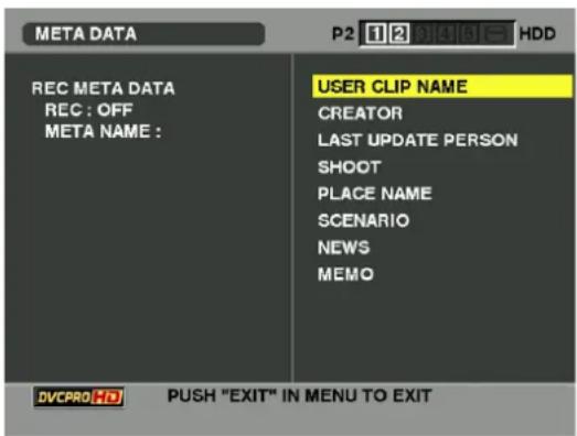
text_image
META DATA P2 12 BICLIGIT HDD REC META DATA REC : OFF META NAME : USER CLIP NAME CREATOR LAST UPDATE PERSON SHOOT PLACE NAME SCENARIO NEWS MEMO DVCPRO HD PUSH "EXIT" IN MENU TO EXIT3 Use the cursor buttons to move the pointer. Then, press the SET button. This allows you to view the settings of the read metadata.
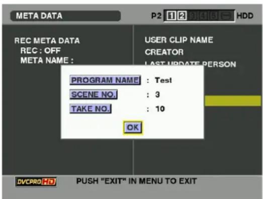
text_image
META DATA P2 12 81416 HDD REC META DATA REC : OFF META NAME : USER CLIP NAME CREATOR LAST UPDATE PERSON PROGRAM NAME : Test SCENE NO. : 3 TAKE NO. : 10 OK DVCPRO HD PUSH "EXIT" IN MENU TO EXIT4 While viewing the settings for the metadata, use the cursor buttons to move the pointer to the desired option. Then, press the SET button. A software keyboard screen is displayed, allowing you to modify the setting.
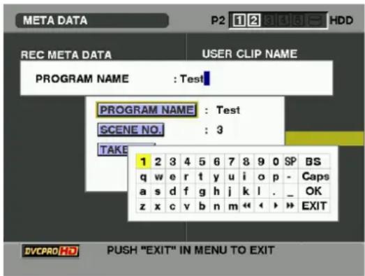
text_image
META DATA P2 1 2 3 4 5 6 7 8 9 0 SP BS REC META DATA USER CLIP NAME PROGRAM NAME : Test PROGRAM NAME : Test SCENE NO. : 3 TAKE 1 2 3 4 5 6 7 8 9 0 SP q w e r t y u i o p - Caps a s d f g h j k l . _ OK z x c v b n m « « » EXIT DVCPRO HD PUSH "EXIT" IN MENU TO EXITTo set whether or not the uploaded metadata is recorded
Set ON/OFF in ME TA→ BERTARD from the thumbnail menu. The factory setting is OFF.
Selecting the USER CLIP NAME recording method
Select M ETA DATA → USER CLIP NAME from thumbnail menu to select the recording method. Two options are available: TYPE1 and TYPE2.
- TYPE1 (Factory setting)
| USER CLIP NAME to be recorded | |
| If clip metadata has been read in | Uploaded data |
| If no clip metadata has been read in or if the setting for recording clip metadata has been turned off | Same as GLOBAL CLIP ID (UMID data) |
- TYPE2
| USER CLIP NAME to be recorded | |
| If clip metadata has been read in | Uploaded data + COUNT value* |
| If no clip metadata has been read in or if the setting for recording clip metadata has been turned off | Same as CLIP NAME |
* The COUNT value is indicated as a four-digit number.
The COUNT value is incremented each time a new clip is captured if clip metadata has been read in and TYPE2 has been selected as the recording method.
The COUNT value can be reset using the following procedure.
Select PROPERTY → DEVICE → META DATA from the thumbnail menu, then select USER CLIP NAME to display the menu shown below. Select "COUNT RESET" with the cursor and press the SET button to reset the COUNT value to 1.
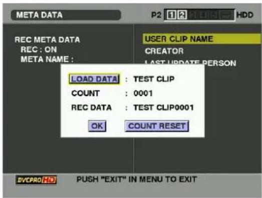
text_image
META DATA P2 1 2 HDD REC META DATA REC : ON META NAME : USER CLIP NAME CREATOR LAST UPDATE PERSON LOAD DATA : TEST CLIP COUNT : 0001 REC DATA : TEST CLIP0001 OK COUNT RESET DVCPRO HS PUSH "EXIT" IN MENU TO EXITNote
When a P2 card with a memory capacity of 8 GB or more is used in camera-recorder and a one-time continuous recording exceeds the prescribed duration (DVCPRO HD and the AVC-Intra 100 (optional): about 5 minutes; DVCPRO50 and the AVC-Intra 50 (optional): about 10 minutes; DVCPRO or for DV: about 20 minutes) or when a one-time recording extends over more than one P2 card, the recording concerned will automatically be undertaken as a separate clip. At this time, each clip will be provided with its own COUNT value.
Example of recording (DVCPRO HD) a clip on one P2 card:
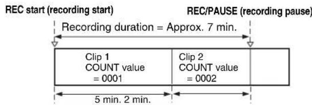
text_image
REC start (recording start) Recording duration = Approx. 7 min. REC/PAUSE (recording pause) Clip 1 COUNT value = 0001 Clip 2 COUNT value = 0002 5 min. 2 min.Example of recording a clip on two P2 cards:
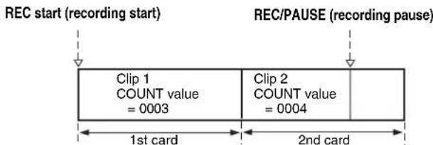
text_image
REC start (recording start) REC/PAUSE (recording pause) Clip 1 COUNT value = 0003 Clip 2 COUNT value = 0004 1st card 2nd cardIf the clip thumbnails are displayed as shown in the example above or their properties are indicated using a P2 device, the thumbnail and COUNT value of clip 1 will be displayed.
Clear the uploaded metadata
Select ME TA DATAINITIALIZE from the thumbnail menu, and press the SET button. Select "YES" when the confirmation screen is displayed.
Notes
- Japanese or Chinese characters indicated in English or other characters that cannot be indicated in English will not display properly; they will be indicated as *.
- The letters which can be input with AJ-HPX2000 are only the alphanumeric. AJ-HPX2000 cannot input Japanese and Chinese.
Setting of Proxy (optional)
By attaching the video encoder card (AJ-YAX800G, optional) either to the optional slot or Slot 5, it is possible to specify the proxy recording setting.
The video encoder card is not recognized when inserted if the power for the unit is turned ON. Insert the video encoder card after turning off the power for the unit.
Select OPERATION → DEVICE SETUP → PROXY from the thumbnail menu to specify the setting.
For the method of installation and the settings of the video encoder card, refer to the operation manual of the video encoder card.
Note
To use the proxy function in 24PN (Native) mode, the FPGA version of the video encoder card firmware must be updated to [B102] or higher. For the method to confirm the FPGA version of the video encoder card firmware, refer to [Video Encoder Card Status Display (optional)] (page 128). For instructions on updating, refer to the P2 support page on the following website.
Formatting a P2 Card
1 Press the THUMBNAIL button. The thumbnail screen appears on the LCD monitor.
2 Press the THUMBNAIL MENU button and select OPERATION → FORMAT from thethumbnail menu. The following screen appears. Select the slot number for the P2 card you want to format. Select EXIT if formatting is not required.
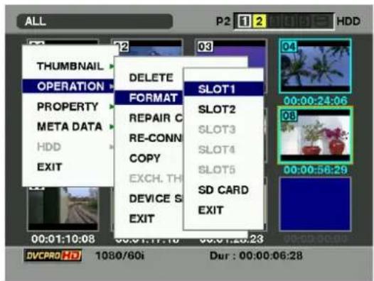
text_image
ALL THUMBNAIL OPERATION PROPERTY META DATA HDD EXIT 02 12 03 DELETE FORMAT REPAIR C RE-CONN COPY EXCH. TH DEVICE S EXIT SLOT1 SLOT2 SLOT3 SLOT4 SLOT5 SD CARD EXIT 00:00:24:06 03 00:00:56:29 DVCPRO HD 1080/60i Dur : 00:00:06:283 The following screen appears. Use the cursor buttons and the SET button to select YES.
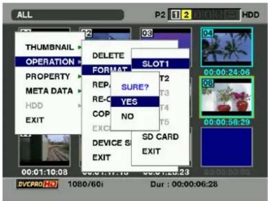
text_image
ALL P2 1 2 BIOTE HDD THUMBNAIL OPERATION DELETE SLOT1 PROPERTY FORMAT REF. T2 T3 RE-O T4 COP NO EXO T5 DEVICE S SD CARD EXIT EXIT 00:01:10:08 00:01:11:10 00:01:23:23 DVCPRO HD 1080/60i Dur : 00:00:06:284 The selected P2 card is formatted.
Formatting SD memory cards
SD memory cards can also be formatted from the thumbnail screen. With an SD memory card inserted into the camera-recorder, perform the following operation:
1 Press the THUMBNAIL button.
The thumbnail screen appears on the LCD monitor.
2 Press the THUMBNAIL MENU button and select OPERATION → FORMAT from the thumbnail menu. The following screen appears. Select "SD CARD". Select "EXIT" if formatting is not required.
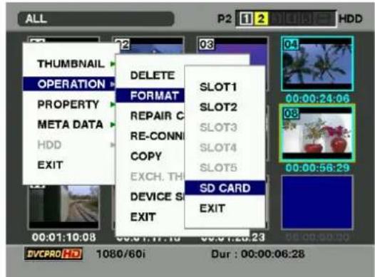
text_image
ALL THUMBNAIL OPERATION PROPERTY META DATA HDD EXIT 00:01:10:08 00:01:17:10 00:01:23:23 DVCPRO HD 1080/60i P2 1 2 MICHIGIT HDD DELETE FORMAT REPAIR C RE-CONN COPY EXCH. TH DEVICE S EXIT SLOT1 SLOT2 SLOT3 SLOT4 SLOT5 SD CARD EXIT 00:00:24:06 00:00:56:29 Dur : 00:00:06:283 The following screen appears. Use the cursor buttons and the SET button to select YES.
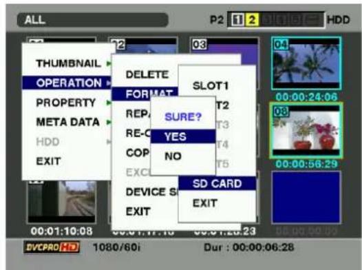
text_image
ALL THUMBNAIL OPERATION PROPERTY META DATA HDD EXIT 00:01:10:08 00:01:17:16 00:01:23:23 DVCPRO HD 1080/60i P2 1 2 HDD 03 SLOT1 04 00:00:24:06 08 00:00:56:29 03 00:00:00:03 NONE? YES NO SD CARD EXIT DELETE FORMAT RE- COP EXC DEVICE S EXIT4 The SD memory card is formatted.
Note
SD memory cards can also be formatted from the menu screen. For more information, see [Handling SD memory cards] (page 84).
Setting the Thumbnail Display Mode
The thumbnail display mode can be customised to suit your preferences.
1 Press the THUMBNAIL button.
The thumbnail screen appears on the LCD monitor.
2 Press the THUMBNAIL MENU button and select THUMBNAIL→SETUP from thethumbnail menu. The following screen appears.
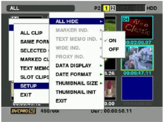
text_image
ALL P2 1 2 BIGLOT HDD ALL HIDE MARKER IND. TEXT MEMO IND. WIDE IND. PROXY IND. DATA DISPLAY DATE FORMAT THUMBNAIL SIZE THUMBNAIL INIT EXIT SETUP EXIT 00:00:40.12 DVCPRO 50 480/60i Dur : 00:00:50.11ALL HIDE :
ON : All indicators are not displayed.
OFF : Indication/No indication will be set depending on the following menu. The factory settings are as follows.
MARKER IND. :
Switches the shot mark marker between indication and no indication (ON/OFF). The factory setting is ON (indication).
TEXT MEMO IND. :
Switches the text memo marker between indication and no indication (ON/OFF). The factory setting is ON (indication).
WIDE IND. :
Switches the wide marker between indication and no indication (ON/OFF). The factory setting is ON (indication).
PROXY IND. :
Switches the proxy marker between indication and no indication (ON/OFF). The factory setting is ON (indication).
DATA DISPLAY:
The time display field of the clip offers a choice of Time Code (TC), User Bits (UB), Shooting Time (TIME), Shooting Date (DATE). Shooting Time and Date (Time DATE) or USER CLIP NAME. The factory setting is Time Code.
DATE FORMAT:
You can specify the display order for the shooting date as either Year/Month/Day (YMD), Month/Day/Year (MDY) or Day/Month/Year (DMY). The factory setting is Month/Day/Year. This setting is reflected in the recording date shown in the clip property and the shooting date shown when DATE is selected under the item DATA DISPLAY.
THUMBNAIL SIZE:
For the size of thumbnails displayed on one screen, either LARGE (3 × 2 thumbnails displayed) or NORMAL (4 × 3 thumbnails displayed) can be selected. The factory default value is NORMAL.
THUMBNAIL INIT:
Return the above thumbnail display settings to default. Move the cursor to this option, and press the SET button. Select "YES" when the confirmation screen is displayed.
EXIT:
Returns to the previous menu.
Properties
The clip's properties and the P2 card's status are displayed.
It is possible to edit and rewrite recorded clip metadata while clip properties are displayed.
Clip Property
From the thumbnail menu, select PROPERTY → CLIP PROPERTY. The following screen appears.
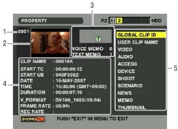
text_image
PROPERTY 1-0001 2 3 P2 1 2 INFOE HDD VOICE MEMO 0 TEXT MEMO 1 GLOBAL CLIP ID USER CLIP NAME VIDEO AUDIO ACCESS DEVICE SHOOT SCENARIO NEWS MEMO THUMBNAIL CLIP NAME : 00018K START TC : 00:00:00:12 START UB : 940F3082 DATE : 16-MAY-2007 TIME : 15:38:06 (GMT+09:00) DURATION : 00:00:07:10 V_FORMAT : DV100_1080/59.94i FRAME RATE : 59.94i REC RATE : DVCPRO HD PUSH "EXIT" IN MENU TO EXIT1. Clip Number
2. Thumbnail
3. Clip Information
Indicates the indicators added to the clip and the number of text and voice memos added to the clip.
The park appears if the clip is recorded on a write-protected P2 card.
Note
AJ-HPX2000 is not capable of recording or playing back voice memos.
4. Clip Information
Displays detailed information about the clip.
CLIP NAME:
Display clip names.
START TC:
The time code value at the start of the recording.
START UB:
The user bit value at the start of the recording.
DATE: The date of the recording.
TIME: The time at the start of the recording.
DURATION:
The time length of the clip.
V-FORMAT:
The recording format for the clip.
FRAME RATE:
The frame rate for the playback.
REC RATE:
The recording frame rate is displayed. (This is indicated on the clip that data is recorded in a special way using the camera recorder.)
5. Clip Meta Data
Displays more detailed data about the clip. Use the cursor buttons to move the pointer, and press the SET button to check the detailed content. The underlined items are automatically set during shooting. For more information on displayed metadata, see [Setting of Clip Meta Data] (page 119).
Modification of recorded clip metadata
1 Display the window for detailed clip metadata that you intend to modify in the clip properties window.
2 Place the cursor on the item to be modified using the cursor button. The metadata that can be modified are shown like [CREATOR] in the following figure.
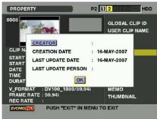
text_image
PROPERTY P2 1 2 HDD 0008 GLOBAL CLIP ID USER CLIP NAME CREATOR : CREATION DATE : 16-MAY-2007 LAST UPDATE DATE : 16-MAY-2007 LAST UPDATE PERSON : OK V_FORMAT : DV100_1080/59.94i MEMO FRAME RATE : 59.94i THUMBNAIL REC RATE : DVCPRO HD PUSH "EXIT" IN MENU TO EXIT3 Press the SET button.
The input window (soft keyboard) for modifying metadata is displayed. Use the keyboard to modify the metadata.
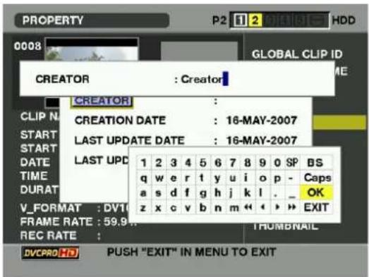
text_image
PROPERTY P2 1 2 Initiate HDD 0008 GLOBAL CLIP ID CREATOR : Creator CREATOR : CLIP N CREATION DATE : 16-MAY-2007 START LAST UPDATE DATE : 16-MAY-2007 START DATE LAST UPD q w e r t y u i o p - Caps a s d f g h j k l . _ OK z x c v b n m « « » EXIT V_FORMAT : DVTI FRAME RATE : 59.9 REC RATE : TRUMBNAIL DVCPRO HD PUSH "EXIT" IN MENU TO EXITThe keyboard operation is the same as [Checking and modifying read metadata] (page 120).
4 Press OK on the keyboard to write the modified metadata on the clip and return to the metadata window. The input window (soft keyboard) for modifying metadata is displayed. Use the keyboard to modify the metadata.
Note
- Deleting only the respective items of LOCATION (recording location data) in SHOOT is not possible. By setting ALTITUDE to empty, other LONGITUDE/LATITUDE items are collectively deleted.
- The metadata for a clip with the incomplete clip indicator cannot be modified. For the clips recorded on multiple P2 cards, modify the metadata while all P2 cards are inserted.
- Any MEMO with 100 characters or more cannot be modified.
P2 Card Status Display
P2 Card Status Display Settings
Select PROPERTY → CARD STATUS from the thumbnail menu to set the desired indication mode (remaining free space or used memory capacity) for the P2 card status display.
1 Press the THUMBNAIL button.
The thumbnail screen appears on the LCD monitor.
2 Press the MENU button and select PROPERTY→PROPERTY SETUP→P2 CARD CAP from the thumbnail menu.
The following screen appears. Select the P2 card status display settings from the P2 CARD CAP menu option.
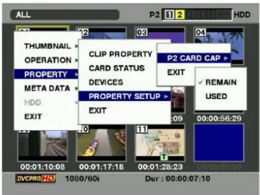
text_image
ALL P2 1 2 3 4 5 6 7 HDD THUMBNAIL OPERATION PROPERTY META DATA HDD EXIT CLIP PROPERTY CARD STATUS DEVICES PROPERTY SETUP EXIT P2 CARD CAP EXIT ✓ REMAIN USED 00:01:10:08 00:01:17:18 00:01:28:23 00:00:29:00 DVCPRO HD 1080/60i Dur : 00:00:07:10REMAIN:
Show remaining free space on the P2 card as the P2 card status display. (Factory setting)
USED:
Show used memory capacity on the P2 card as the P2 card status display.
Contents of P2 Card Status Display Settings
From the thumbnail menu, select PROPERTY → CARD STATUS. The following screen appears.
When "REMAIN" is selected:
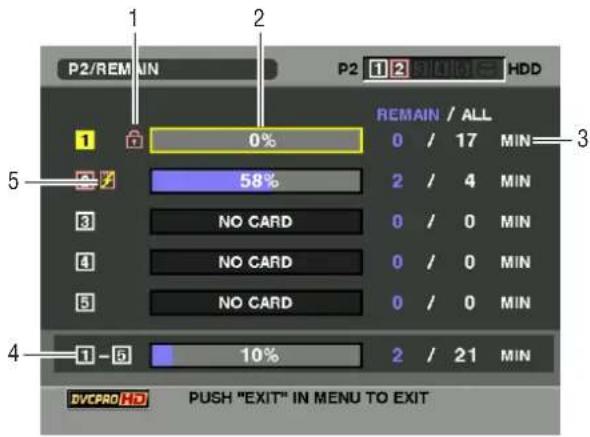
text_image
P2/REM UN 1 2 P2 1 2 FLOUATE HDD 1 0% 58% 0 / 17 MIN 2 / 4 MIN NO CARD 0 / 0 MIN NO CARD 0 / 0 MIN NO CARD 0 / 0 MIN 1 - 6 10% 2 / 21 MIN DVCPRO ✉ PUSH "EXIT" IN MENU TO EXIT1. Write-protect Mark
The mark appears if the P2 card is write-protected.
2.P2 Card Status (remaining free space)
The remaining memory capacity of the P2 card is indicated by a bar graph and percentage. The bar graph indicator moves to the left as the remaining free space decreases.
The following indications may appear, depending on the card status:
FORMAT ERROR:
An unformatted P2 card is inserted.
NOT SUPPORTED:
An unsupported card is inserted in the camera.
NO CARD:
P2 cards are not inserted.
Use the cursor button to place the cursor on the P2 card for data you want to access and press the SET button to display detailed information about the P2 card to check individual information such as the serial number and the user ID.
3.P2 Card Remaining Capacity/Total Capacity
Displays the P2 card remaining capacity and total capacity in minutes. The total of the remaining memory capacity for each P2 card that is displayed may not match the actual total remaining memory capacity for the P2 cards because only the figure in minute is displayed.
4. Total remaining free space for the slot
Displays the total remaining free space for all 5 slots. Please note that the remaining capacity of a write-protected P2 card is not included in the total remaining capacity.
5. Warning symbol
When the following P2 card is detected, the symbol is displayed.
RUN DOWN CARD:
The number of rewrites of the card exceeds the limit defined in the standards.
DIR ENTRY NG CARD:
The directory structure on the P2 card does not comply with the standards.
The warning can be confirmed on the P2 card detailed information indication in [2.P2 Card Status (remaining free space)].
When "USED" is selected:
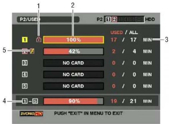
text_image
P2/USE 1 2 P2 1 2 HDD 100% USED / ALL 17 / 17 MIN 3 42% 2 / 4 MIN NO CARD 0 / 0 MIN NO CARD 0 / 0 MIN NO CARD 0 / 0 MIN 1 -5 90% 19 / 21 MIN DVCPRO HD PUSH "EXIT" IN MENU TO EXIT1. Write-protect Mark
The park appears if the P2 card is write-protected.
2.P2 Card Status (used memory capacity)
The used memory capacity of the P2 card is indicated by a bar graph and a percentage figure. The bar graph indicator moves to the right as the used memory capacity increases.
The following indications may appear, depending on the card status:
FORMAT ERROR:
An unformatted P2 card is inserted.
NOT SUPPORTED:
An unsupported card is inserted in the camera.
NO CARD:
P2 cards are not inserted.
Use the cursor button to place the cursor on the P2 card for data you want to access and press the SET button to display detailed information about the P2 card to check individual information such as the serial number and the user ID.
3.P2 Card memory capacity/Total Capacity
Displays the used memory capacity on a P2 card and the total capacity, in minutes. Because fractions are truncated, the figure shown for used memory capacity on a P2 card may differ from the figure for total capacity.
The used memory capacity of a write-protected P2 card is displayed as 100%.
4. Total used memory capacity for all slots
Displays the total used memory capacity for all 5 slots.
5. Warning symbol
When the following P2 card is detected, the symbol is displayed.
RUN DOWN CARD:
The number of rewrites on the card exceeds the limit defined in the standards.
DIR ENTRY NG CARD:
The directory structure of the P2 card does not comply with the standards.
The warning can be confirmed on the P2 card detailed information indication in [2.P2 Card Status (remaining free space)].
SD memory card Status Display
The status display enables a confirmation of the SD memory card formatted condition, available memory capacity etc.
From the thumbnail menu, select PROPERTY → DEVICES → SD CARD.
If the format is compatible with SD standards, the message "SD STANDARD: SUPPORTED" is displayed.
If the format is not compatible with SD standards, the message "SD STANDARD: NOT SUPPORTED" is displayed. If this is the case, writing or reading will not be successful. Format the card with the AJ-HPX2000. For more on formatting SD memory cards, see [Formatting SD memory cards] (page 123).
Note
The indicated remaining memory capacity on the SD memory card (PROXY REM) can be an index of remaining memory capacity for the Proxy but may differ from the actual remaining capacity. For SD or SDHC cards with Class indications, the recording time may be reduced significantly compared with the actual capacity when images of short recording time are recorded repeatedly. If the remaining memory capacity exceeds 999 min, "999 min" is displayed.
The remaining capacity is displayed only when set to record the Proxy record on the SD memory card. For the setting method, refer to the operation manual of the video encoder card (the optional AJ-YAX800G).
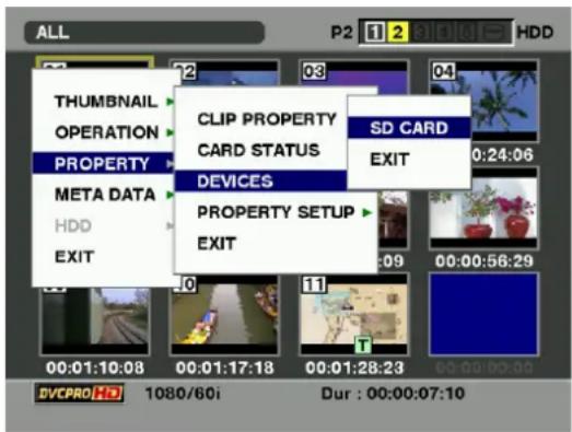
text_image
ALL P2 1 2 HDD THUMBNAIL OPERATION PROPERTY META DATA HDD EXIT CLIP PROPERTY CARD STATUS DEVICES PROPERTY SETUP EXIT SD CARD EXIT 0:24:06 00:00:56:29 DVCPRO HD 1080/60i Dur : 00:00:07:10Video Encoder Card Status Display (optional)
Attaching the video encoder card (AJ-YAX800G, optional), select PROPERTY → DEVICES → PROXY from the thumbnail menu.
The slot in which the video encoder card is inserted, and version information is displayed.
Connection with external device
Connection through the DVCPRO/DV connector
Records of signals input to the DVCPRO/DV connector
1 Refer to [32.DVCPRO/DV connector] (page 21) to connect the 1394 cable (DV cable). Ensure that the signal format of the target device agrees with that of the camera-recorder.
2 Open the <1394 SETTING> on the SYSTEM SETTING page and confirm that the settings in the 1394 IN CH item and the 1394 OUT CH item are set to "AUTO".
3 In case of input from the IEEE1394 interface, set REC SIGNAL to "1394".
The REC SIGNAL option must be selected from the
Notes
- When the AVC-Intra (optional) format is selected and data are recorded in DVCPRO HD Native mode, it is impossible to input/output data from the DVCPRO/DV connector.
- When INTERVAL REC is operated, it is impossible to input/output data from the DVCPRO/DV connector.
- When no device is connected to the DVCPRO/DV connector or no signal is being input to the connector, the display window indicates "1394E-90" in the counter section. Input the same signals to the IEEE1394 interface as the format set in SYSTEM MODE and REC MODE in the setting menu. If a different format is used, signals are not properly recorded on P2 cards. When playback signals other than regular×1 (normal speed) playback signals have been input, no guarantees are made for the video and sound recorded or for the video and sound of the EE system. For information about the error codes, see [1394 Error Codes] (page 148).
- The audio signal input will consist of an input signal from the IEEE1394 interface.
- When the audio signal input from the IEEE1394 interface is 32 kHz/4CH (12 bits), it is recorded as 48 kHz/4CH (16 bits) on the P2 card.
- It is not possible to use the GENLOCK IN connector to achieve synchronization with the external reference signal.
- In SD mode, the thumbnail button is prerssed, thumbnail screen are output to the viewfinder and the MON OUT and VIDEO OUT connectors.
- The signals which are output from the VIDEO OUT connector, MON OUT connector or AUDIO OUT connector differ from the actual input signals. Use them for monitoring purposes.
- The condition indicator character is not shown in the viewfinder screen and the output images.
- The following functions are not available. PRE-RECORDING function Loop recording function Interval recording function Proxy recording function
Time code and user bits
- When input from the IEEE1394 interface is being received, the time code and/or the user bits input from the TC IN connector cannot be recorded on the P2 card.
- When input from the IEEE1394 interface is being received, the time code output from TC OUT will not be synchronized with the images output from the MON OUT connector.
Timecode and user bits in the subcode (SBC) area
- When input from the IEEE1394 interface is being received, the timecode in the SBC area, which is input from the DVCPRO/DV connector, is recorded on the P2 card by turning the TCG switch to the "F-RUN" position and it will also be output from the TC OUT connector of camera-recorder.
- By turning the TCG switch into the "R-RUN" position, the timecode in the SBC area will be recorded on the P2 card in accordance with the timecode of the clip recorded on the P2 card.
- When recording the user bits input from the DVCPRO/DV connector on the P2 card, open the
screen on the MAIN OPEATION page from the menu and select the "EXT" at UB MODE.
Timecode and user bits in the VAUX area
- When the input from the IEEE1394 interface is being received, regardless of the menu setting and/or the switch position on camera-recorder, the timecode and the user bits in the VAUX area input from the DVCPRO/DV connector are always recorded on the P2 card.
Recording of UMID (Unique Material Identifier) information
- When the input from the IEEE1394 interface is being received, the UMID information input from the DVCPRO/DV connector will be recorded on the P2 card. If there is no UMID information, it will be generated in the unit and recorded.
UMID information is not added when the unit is operated in DV mode or when playing back DVCPRO HD clips recorded in Native mode.
External device control through DVCPRO/DV connection
The DVCPRPO/DV connector can be connected with an external device for recording backup copies to control the start and stop of recording.
1 When connecting the 1394 (DV) cable, see [32.DVCPRO/DV connector] (page 21). Set the 1394 CONTROL menu option on the 1394 SETTING screen on the SYSTEM SETTING page to BOTH.
2 Through the 1394 CMD SEL menu option, select the type of stop recording command to be received by the external device.
3 Through the REC TALLY menu option on the OPTION MODE screen, select how the recording status of the camera-recorder should be indicated. Note that the recording status of the external device is indicated with a red tally LED.
Notes
- When the Fire Store FS-100 is used as external storage, the VITC UB MODE menu option on the TC/UB screen on the MAIN OPERATION page can be set to FRM. RATE to allow the FS-100 to indicate the shooting frame rate of the camera-recorder on its display. It is also possible to add the same USER CLIP NAME of the unit to the record clip of the FS-100.
- Note that when recording a backup with an external device connected to the camera-recorder during REC RUN mode and there is insufficient storage space on the P2 card inserted into the camera-recorder, the time code output from the DVCPRO/DV connector will not advance from that point.
- When the AVC-Intra (optional) format, DVCPRO HD Native mode or INTERVAL REC mode is selected, it is impossible to control any external devices through the 1394 connection.
Directions for using the DVCPRO/DV connection
- When connecting the 1394 (DV) cable, see [32.DVCPRO/DV connector] (page 21).
- The AV signals may be disrupted by turning the power of the connected devices ON and OFF or by disconnecting and re-connecting the I/F cables.
- It may take several seconds for the system to operate stably when the input signals are switched or operation is transferred from one mode to another. Perform recording operation after the system operation has stabilized.
- For recording data using the IEEE1394 interface input selection, or for signals output from the IEEE1394 interface, the AUDIO Volume on the side panel is disabled.
- When camera-recorder is controlled through PC application software, etc., take note of the following.
- The scene-to-scene continuity recording from an arbitrary position on the clip is not possible. Recording will always continue immediately after the latest clip.
- Software must be used under the condition where the camera-recorder thumbnail screen is closed. The application software may not be able to apply control when the thumbnail screen is open.
- During special playback, video and audio signals which have not been processed as the output signals of the IEEE1394 interface will be output. When these video and audio signals are monitored on another device, they may be at variance from the video and audio signals which are played back by camera-recorder.
- In the case when the output format is either DV or DVCPRO (25M), the audio channel signal selected from the 1394 AUDIO OUT option of the setup menu will be output from the IEEE1394 interface.
Connection with external devices using the USB 2.0 port
Connection with a PC in the USB DEVICE mode
By connecting AJ-HPX2000 with an external PC using USB 2.0, the P2 card connected to AJ-HPX2000 can be used as a mass storage device.
Procedures for establishing a connection with a PC
1 Connect the USB cable to the USB 2.0 port.
Notes
- The USB 2.0 cable is not included with the camera-recorder. Please use a commercially available USB 2.0 cable (shield with a ferrite core).
- Although the unit supports USB cables up to 5 meters long, cables up to 3-meters long are recommended.
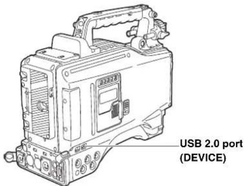
text_image
USB 2.0 port (DEVICE)2 Navigate the menu to open the SYSTEM MODE screen on the SYSTEM SETTING page. Then, set the PC MODE SELECT menu option to USB DEVICE and the PC MODE option to ON.
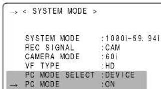
text_image
→ < SYSTEM MODE > SYSTEM MODE :10801-59.941 REC SIGNAL :CAM CAMERA MODE :601 VF TYPE :HD PC MODE SELECT :DEVICE PC MODE :ONNote
The function of the menu option USB may be assigned to a desired user button by using any one of the menu options USER MAIN SW, USER1 SW or USER2 SW.
These options can be found in the USER SW screen, which is accessible from the CAM OPERATION page.
When you establish the USB connection for the first time, install the accessory P2 software for AJ-HPX2000 on the PC. Refer to the Installation Manual for the details.
Notes
● A USB driver must be installed on the PC.
- AJ-HPX2000 is only applicable to USB 2.0. Use a personal computer that supports USB 2.0.
- Only one unit at a time must be connected to the PC via USB.
- The P2 card must not be removed when it is connected via USB.
- While a USB connection is established, the P2 card's access LED should not be lit except when access is being carried out.
- When a USB device is active, recording, playback, or navigation through clip thumbnails is disabled.
During a USB connection, the USB LED on the side panel stays illuminated. Also, "USB DEVICE" is displayed in the system information/warning area in the viewfinder.
When the connection is not correctly established, both of these indications blink.
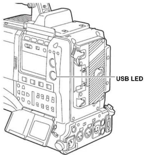
text_image
USB LED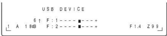
text_image
USB DEVICE 6 ↑ F : 1 - - - - ■ - - - + 1 A 1 8dB F : 2 - - - - ■ - - - + F 1.4 Z 9 93 There are two ways to terminate the USB mode, as follows:
- Turn the POWER switch of AJ-HPX2000 OFF.
- Set the PC MODE item to "OFF" from the menu operations.
USB HOST mode
AJ-HPX2000 can be connected to a hard disc drive that supports USB 2.0 to store data from cards on it, view thumbnails for stored clips, and write data back to P2 cards.
Switching to the USB HOST mode
1 By navigating the menu, set the PC MODE SELECT menu option on the SYSTEM MODE screen to USB HOST, then the PC MODE option to ON. This will place the camera-recorder in USB HOST mode.
- When the camera-recorder is in USB HOST mode, the viewfinder indicates "USB HOST" and the USB LED on the side panel stays illuminated. If the hard disc drive is not properly connected, then the LED blinks.
- When a user button is assigned the PC MODE on/off switching capability, you can press that user button to switch between the normal and USB HOST modes. For information about how to assign functions to the user buttons, see [Assigning Functions to USER MAIN, USER1 and USER2 Buttons] (page 51).
2 Press the THUMBNAIL button to go to the thumbnail screen. Check to see that the screen indicates "USB HOST" in the lower right corner. When a hard disc drive is connected, the HDD indication in the upper right corner stays illuminated. However, if this indicator illuminates red, it means that the hard disk drive cannot be copied. Confirm the hard disk drive type.
For information about the HDD indication, see [Thumbnail Screen] (page 110).
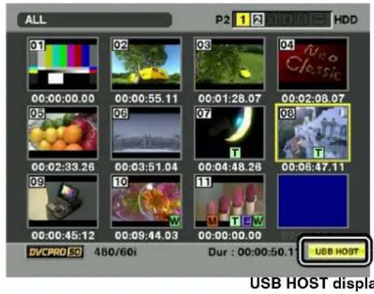
text_image
ALL P2 1 2 HDD 01 00:00:00.00 00:00:55.11 00:01:28.07 00:02:08.07 03 06 07 00:02:33.26 00:03:51.04 00:04:48.26 00:06:47.11 09 00:00:45.12 DVCPRO EQ 480/60i 10 00:09:44.03 11 M T E W 00:00:00.00 Dur : 00:00:50.11 USB HOST USB HOST displayNote
In USB HOST mode, clips on P2 cards can be displayed but video from the camera or an external device cannot be recorded. Clips written to a hard disc must be written back to a P2 card before it can be played back. For information about how to write clips back to P2 cards, see [Writing data back to P2 cards] (page 135).
Using the USB host mode
Usable hard disc drives
● Hard disc drives connectable via USB 2.0
● P2 STORE (AJ-PCS060G)
Notes
- While the USB HOST mode supports USB bus power (5V, 0.5A), some hard disc drives may not activate. If this is the case, power must be supplied in a different way.
- Do not connect multiple units through a hub, even for a hard disk drive where the power is turned off. Even with devices other than a hard disk drive, do not connect to the drive together with the hard disk drive through a hub.
- The unit does not support a hard disk drive of 2 TB or more.
Viewing hard disc drive information
You can view the information on the hard disc drive connected via USB 2.0 with the following steps.
1 Switch the mode to USB HOST. For more information, see [Switching to the USB HOST mode] (page 132).
2 Connect the hard disc drive to the camera-recorder via USB 2.0.
3 Press the thumbnail button to display the thumbnail screen.
4 Press the MENU button and select HDD → EXPLORE from the thumbnail menu. The screen provides the information about the hard disc drive.
For Type S or P2 STORE
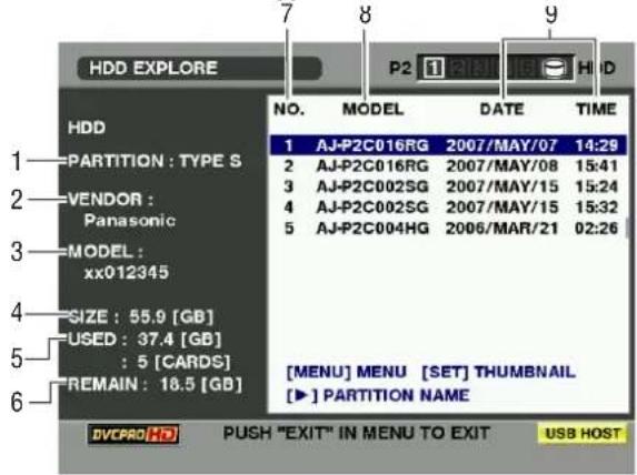
text_image
HDD EXPLORE P2 1310 HID NO. MODEL DATE TIME 1 AJ-P2C016RG 2007/MAY/07 14:29 2 AJ-P2C016RG 2007/MAY/08 15:41 3 AJ-P2C002SG 2007/MAY/15 15:24 4 AJ-P2C002SG 2007/MAY/15 15:32 5 AJ-P2C004HG 2006/MAR/21 02:26 [MENU] MENU [SET] THUMBNAIL [►] PARTITION NAME DVCPRO HD PUSH "EXIT" IN MENU TO EXIT USB HOST PARTITION : TYPE S VENDOR : Panasonic MODEL : xx012345 SIZE : 55.9 [GB] USED : 37.4 [GB] : 5 [CARDS] REMAIN : 18.5 [GB]EXIT button ↑
↓ Press the set button.
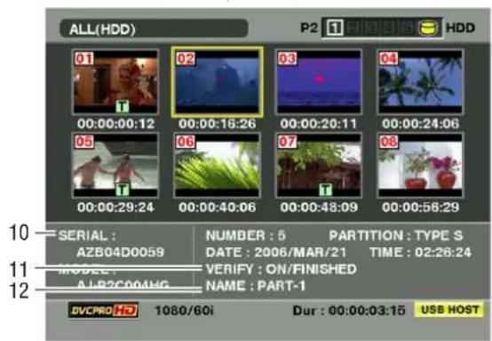
text_image
ALL(HDD) P2 1 A10016 HDD 01 02 03 04 05 06 07 08 00:00:29:24 00:00:40:06 00:00:48:09 00:00:58:29 SERIAL: AZB04D0059 MODEL: ALP2C004HG NUMBER : 5 PARTITION : TYPE S DATE : 2006/MAR/21 TIME : 02:26:24 VERIFY : ON/FINISHED NAME : PART-1 DVCPRO HD 1080/60i Dur : 00:00:03:15 USB HOSTFor the FAT
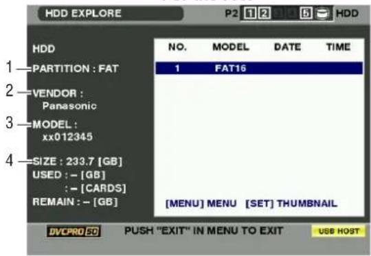
text_image
HDD EXPLORE P2 1 2 3 4 5 HDD HDD NO. MODEL DATE TIME 1 FAT16 —PARTITION : FAT —VENDOR : Panasonic —MODEL : xx012345 —SIZE : 233.7 [GB] USED : - [GB] : - [CARDS] REMAIN : - [GB] [MENU] MENU [SET] THUMBNAIL DVCPRO 50 PUSH "EXIT" IN MENU TO EXIT USB HOST1. PARTITION
This section indicates the type of the hard disc drive. The available functions depend on the type of hard disc drive.
| HDD type | Feature | Available functions |
| TYPE S | A special format that allows high-speed writing and writing back on a card-by-card basis. A drive formatted with the camera-recorder uses this format. | Thumbnail viewing, writing and writing back on a card basis, writing back on a clip basis, and formatting |
| P2 STORE | P2 STORE (AJ-PCS060G). No writing can be performed. | Thumbnail viewing, writing back on a card basis, and writing back on a clip basis |
| FAT | For a hard disc drive with the first primary partition formatted in FAT 16 or 32, as seen on personal computers, etc., which requires a CONTENTS directory at its root. | Thumbnail viewing, reading on a clip basis, and formatting *Once formatted, the hard disc drive can be treated as a TYPE-S HDD. |
| OTHER | Hard disc drives not described above.* They are hard disc drives that have no CONTENTS directory or use the NTFS and any other file system instead of FAT 16 or 32. | Formatting* Once formatted, they can be treated as a TYPE-S HDD. |
2. VENDOR
This section indicates the vendor for the hard disc drive.
3. MODEL
This section indicates the model of the hard disc drive.
4.SIZE
This section indicates the total storage on the hard disc drive.
5. USED
This section indicates the used space on the hard disc drive (in GB) and the number of P2 cards in use.
6.REMAIN
This section indicates the remaining free space on the hard disc drive in GB.
7. PARTITION #
This section indicates the partition number (one P2 card is used as a unit) on the hard disc drive.
Note
The screen indicates up to 10 partitions. When the number of partitions exceeds 10, scroll down the indication with the cursor button (▽) to view the hidden partitions.
8.MODEL
This section indicates the model of the P2 card that originally contained data on the partition.
Note
Press the cursor button (▷) to switch to the PARTITION NAME. Press the [◀] button to return to the original model name display.

text_image
HDD EXPLORE P2 1 2 3 4 5 HDD PARTITION : TYPE S VENDOR : Panasonic MODEL : xx012345 SIZE : 55.9 [GB] USED : 37.4 [GB] : 5 [CARDS] REMAIN : 18.5 [GB] NO. PARTITION NAME 1 2 P2-HD CONTENTS 3 TEST 4 PART-3 5 PART-1 [MENU] MENU [SET] THUMBNAIL [◀] PARTITION INFO. DVCPRO HD PUSH "EXIT" IN MENU TO EXIT USB HOSTEnter the PARTITION NAME from the software keyboard by selecting [CHANGE PARTITION NAME] in the OPERATION MENU while the thumbnail of the hard disk drive is displayed. (Max. 20 characters)
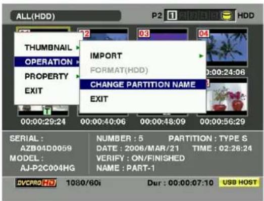
text_image
ALL(HDD) P2 1 HDD THUMBNAIL OPERATION PROPERTY EXIT IMPORT FORMAT(HDD) CHANGE PARTITION NAME EXIT 00:00:29:24 00:00:40:06 00:00:48:09 00:00:56:29 SERIAL : AZB04D0059 MODEL : AJ-P2C004HG NUMBER : 5 PARTITION : TYPE S DATE : 2006/MAR/21 TIME : 02:26:24 VERIFY : ON/FINISHED NAME : PART-1 DVCPRO HD 1080/60i Dur : 00:00:07:10 USB HOST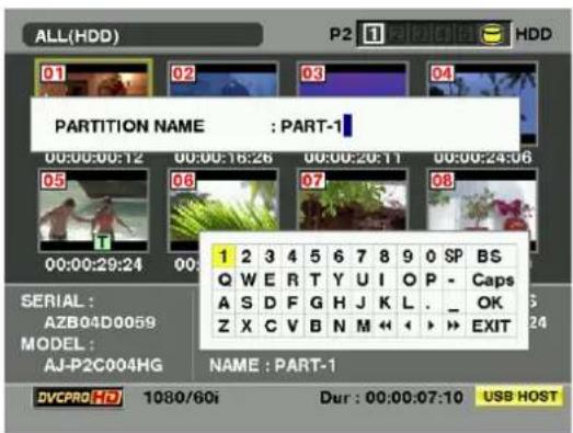
text_image
ALL(HDD) P2 1 HDD 01 02 03 04 PARTITION NAME : PART-1 00:00:00:12 00:00:16:26 00:00:20:11 00:00:24:06 05 06 07 08 00:00:29:24 00: 1 2 3 4 5 6 7 8 9 0 SP BS Q W E R T Y U I O P - Caps A S D F G H J K L . _ OK Z X C V B N M << ↓ >> EXIT SERIAL : AZB04D0059 MODEL : AJ-P2C004HG NAME : PART-1 DVCPRO HD 1080/60i Dur : 00:00:07:10 USB HOST9. DATE/TIME
This section indicates the date and time the data on the partition was recorded.
10.SERIAL
This section indicates the serial number of the P2 card that originally contained the data on the partition.
11. VERIFY
This section indicates the verification setting and results at the time the data on the partition was recorded.
ON:FINISHED :
Verification was performed and the results agreed.
ON:FAILED :
Verification was performed and the results did not agree.
OFF :
No verification was performed.
... :
No verification information is available.
Notes
- Even for a FAT-type hard disc drive, the 1001st or later clips are not shown.
- For a FAT-formatted hard disc drive, the information about only the first partition is shown.
- For a P2 STORE (AJ-PCS060G) that has an invalid partition, that partition information is shown in gray.
12. NAME
This section indicates the PARTITION NAME.
Formatting a hard disc drive
1 Switch the mode to USB HOST.
For more information, see [Switching to the USB HOST mode] (page 132).
2 Connect the hard disc drive via USB.
3 Press the thumbnail button to display the thumbnail screen.
4 Press the MENU button and select HDD → EXPLORE from the thumbnail menu. The display provides a screen that shows the information about the hard disc drive.
5 From the menu, select OPERATION → FORMAT (HDD) and select YES using the cursor buttons and SET button. Then, the confirmation message is displayed again. Select YES.
6 The camera-recorder starts formatting the hard disc drive. Once formatted, the hard disc drive can be treated as a TYPE-S HDD.
Note
Formatting a hard disc drive erases all contents of it. Note that you cannot erase the contents of certain partitions by specifying them.
Writing data on a hard disc drive Writing data back to P2 cards
1 Switch the mode to USB HOST. For more information, see [Switching to the USB HOST mode] (page 132).
2 Connect a hard disc drive via USB.
A hard disc drive that has not been formatted with the camera-recorder must be formatted as directed in [Formatting a hard disc drive] (page 134).
3 Insert a P2 card.
4 Press the thumbnail button to display the thumbnail screen.
5 Press the MENU button and select HDD → EXPLORE from the thumbnail menu. Then, specify the slot that contains the P2 card bearing the data to be written to the hard disc drive.
6 Select YES to start writing.
When the data is being written, a progress bar is displayed. To discontinue writing, press the SET button and select YES instead of cancellation confirmation.
Notes
- To disable verification at the time of writing, select HDD → SETUP from the thumbnail menu and set the option VERIFY to OFF. This speeds up writing without verifying data writing.
- Select [ALL SLOT] to write data collectively onto all P2 cards currently inserted in the unit to the hard disk drive.
7 When the writing is completed, the message "COPY COMPLETED!" is displayed.
Notes
- For a Type-S hard disc drive, data can be written on a card basis. The data on up to 23 P2 cards can be stored on the hard disc drive. The data set on each P2 card is recognized as a separate drive by the PC.
- If data on a P2 card that contains a defective clip must be written to a hard disc drive, then we recommend fixing that clip before copying the data.
- When the process is discontinued during verification, the data on the P2 card has been written to the hard disc drive.
You can select clips on the hard disc drive to be written back to P2 cards.
1 Switch the mode to USB HOST. For more information, see [Switching to the USB HOST mode] (page 132).
2 Connect a hard disc drive via USB.
3 Insert the target P2 card in a slot.
4 Press the MENU button and select HDD → EXPLORE from the thumbnail menu. Move to the appropriate partition and select it with the SET button.
5 From among the thumbnails, select the clips to be written to the P2 card.
6 Press the MENU button and select OPERATION → IMPORT → SELECTED CLIPS. Then, specify the slot that contains the target P2 card.
7 Select YES to start writing data back to the P2 card.
8 When the writing is completed, the message "COPY COMPLETED!" is displayed.
Note
When only selected files are written, no verification is performed.
For a Type-S or P2 STORE hard disc drive, you have the choice of writing data on a card basis. The target P2 cards must be preformatted.
1 Switch the mode to USB HOST. For more information, see [Switching to the USB HOST mode] (page 132).
2 Connect a hard disc drive via USB.
3 Insert the target P2 cards in slots.
4 Press the MENU button and select HDD → EXPLORE. Then, move to the appropriate partition and select it with the SET button.
5 From the thumbnail menu, select OPERATION → IMPORT → ALL. Then, specify the slots that contain the empty target P2 cards.
6 Select YES to start writing data to the cards.
To disable verification during writing, select HDD→SETUP from the thumbnail menu and set the option VERIFY to OFF. This speeds up writing without verifying data writing.
7 When the writing is completed, the message "COPY COMPLETED!" is displayed.
Note
If a clip is written back to a P2 card different from the original card that contained that clip, then the clip may be incomplete. If this is the case, reconnect the clip. For more information, see [Reconnection of Incomplete Clips] (page 118).
Direction for using a hard disc drive
- A hard disc drive must be used under the following conditions:
- It must meet the operating requirements (e.g. temperature).
- It must not be placed in an instable place or a place exposed to vibrations.
● Some hard disc drives do not operate properly. - Some hard disk drives with the SATA (Serial ATA) interface or the PATA (Parallel ATA) interface connected by a USB conversion cable may not be recognized.
- When copying data, a hard disc drive must have sufficient free space.
- Do not remove the cable or the target P2 card or turn off the camera-recorder or hard disc drive during formatting or copying. Doing so requires the camera-recorder and the hard disc drive to be reactivated.
- Since hard disc drives are high precision devices, there is a high possibility that they may become incapable of writing data depending on the conditions of use.
- Take note that we will not be liable for loss of data caused by failed hard disc drives or any other problem as well as direct or indirect damages resulting from the loss of data.
- We do not guarantee that hard disc drives will operate properly with the camera-recorder or that the data on them will be properly retained if data copied to them from the camera-recorder has been replaced with other data using a PC.
- By using the drive mount converter distributed on the following URL, the hard disk drive can be mounted in the designated folder when connected.
Connection using the SDI IN connector (when AJ-YA350AG attached)
1 Confirm that the HD/SD-SDI input board (AJ-YA350AG: optional accessory) is attached to the unit and that the wires are connected properly. For details, refer to the installation manual for the AJ-YA350AG.
2 Confirm that the connected device has the same signal format as camera-recorder.
3 When signals are input from the SDI IN connector, set the REC SIGNAL in the setting menu to "SDI". The REC SIGNAL item will be selected from
Notes
- If the HD/SD-SDI input board is not attached, REC SIGNAL cannot be set to "SDI".
- When nothing is connected to the SDI IN connector or there is no input signal, images to be recorded will be black and no sound will be recorded. Input the same signals as the format set in the SYSTEM MODE item in the setting menu through the SDI IN connector. If the formats are different, data will not be properly recorded on the P2 card.
-
Note the following points when the REC SIGNAL of the setting menu is set to "SDI".
-
Audio signals are input from the SDI IN connector.
- Audio signals must be input synchronized with video images. Data will be recorded as 48 kHz/4CH (16 bit) on a P2 card.
- When the REC SIGNAL item is set to "SDI", signals input from the GENLOCK IN connector are disabled even if nothing is connected to the SDI IN connector. Please note that there is a delay between video images and voice signals when the unit is used on a system synchronized with the reference.
- UMID information, time code and user bits cannot be recorded on a P2 card using the SDI IN connector.
Maintenance and Inspections
Inspections Before Shooting
Make sure you check that the system is operating normally before embarking on a shoot. We recommend using a color video monitor to check the image.
Preparing for Inspections
1 Mount a charged battery pack.
2 Turn the power switch ON and check that 5 or more BATT indication marks appear.
- If fewer than 5 BATT indication marks appear, replace the battery with a fully-charged battery.
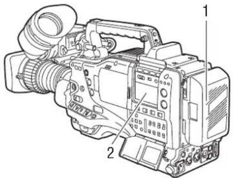
text_image
Technical diagram of a video camera with numbered parts labeled 1 and 23 Insert a P2 card into the card slot and close the slide cover.
Confirm that the P2 card access LED for the inserted card slot lights up in orange. If P2 cards are inserted into multiple card slots, only the P2 card access LED for the first-inserted P2 card lights up in orange. Then, the other P2 card access LEDs light up in green when P2 cards are inserted.
If the access LED for the P2 card slot in which a P2 card is inserted keeps blinking in green, or if there is no display, recording is not possible on that particular P2 card.
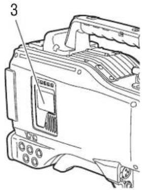
text_image
3Inspecting the Camera Unit
1 Set the zoom to electric zoom mode and check the zoom operation. Check that the image changes to telephoto and wide angle.
2 Set the zoom to manual zoom mode and check the zoom operation.
Turn the manual zoom lever to check that the image changes to telephoto and wide angle.
3 Set the iris to automatic adjustment mode and aim the lens at objects with different degrees of brightness, to check that the automatic iris adjustment operates normally.
4 Set the iris to manual adjustment mode and turn the iris ring, to check the manual iris adjustment.
5 While holding down the instant iris automatic adjustment button, aim the lens at objects with different degrees of brightness, to check that the instant iris automatic adjustment operates properly.
6 Return the iris to automatic adjustment mode and change the GAIN switch setting to L, M, and H, to check the following items:
● The iris is adjusted for objects with the same brightness according to the switch setting.
- The gain value displayed on the viewfinder screen changes according to the switch setting.
7 When a lens with an extender is mounted, set the extender to the operating position to check that the extender operates properly.
Inspecting the Memory Recording Functions
Make sure you successively carry out the inspections from [1. Inspecting the P2 Card Recording] to [4. Inspecting the Earphone and Speaker].
1. Inspecting the P2 Card Recording
1 Check on the display inside the viewfinder that the remaining P2 card recording capacity is sufficient. Please refer to [P2 Card Remaining Free Space/ capacity Indication] (page 76) for information about P2 card remaining recording capacity.
2 Set the TCG switch to [R-RUN].
3 Set the DISPLAY switch to [TC].
4 Press the camera's REC START/STOP button to check the following items:
● The P2 access LED blinks in orange.
● The REC lamp inside the viewfinder lights up.
- System warnings do not appear inside the viewfinder.
5 Press the camera's REC START/STOP button again. This step confirms that the P2 access LED is on and showing orange, and the REC lamp in the viewfinder is turned off.
6 Using the REC button on the handle, repeat Steps 4 to 5 to check the same operation. Check the VTR button on the lens in the same way.
7 Press the LIGHT button to check that the screen brightness in the display window increases.
8 Press the PLAY button to check that the clip that has just been shot is played back from the beginning. Check that recording and playback operate properly.
9 When multiple P2 cards are inserted into the P2 card slots, press the USER MAIN button to select the P2 card used for recording.
Repeat the operations in Steps 4 to 5 and 8 to check that recording and playback operate properly.
2. Inspecting the Audio Level Automatic Adjustment
1 Set the AUDIO SELECT CH1 and CH2 switches to [AUTO].
2 Set the AUDIO IN CH1 and CH2 switches to [FRONT].
3 Aim the microphone connected to the MIC IN jack at an appropriate sound source. Then, check that the level displays for both CH1 and CH2 change according to the sound level.
3. Inspecting the Audio Level Manual Adjustment
1 Set the AUDIO IN CH1 and CH2 switches to [FRONT].
2 Set the AUDIO SELECT CH1 and CH2 switches to [MAN].
3 Turn the AUDIO LEVEL CH1 and CH2 controls. Check that the level display increases when the controls are turned to the right.
4. Inspecting the Earphone and Speaker
1 Turn the MONITOR control to check that the speaker volume changes.
2 Connect an earphone to the PHONES jack.
Check that the speaker is turned off and the microphone sound can be heard from the earphone.
3 Turn the MONITOR control to check that the earphone volume changes.
5. Inspection for Using an External Microphone
1 Connect an external microphone to the AUDIO IN CH1 and CH2 connectors.
2 Set the AUDIO IN CH1 and CH2 switches to [REAR].
3 Set the LINE/MIC/+48V selector switches on the rear panel to [MIC] or [+48V], depending on the power supply type of the external microphone.
MIC: For a microphone with internal power supply. +48V: For a microphone with external power supply.
4 Aim the microphone at a sound source. Then check that the audio level meter in the display window and the audio level display inside the viewfinder change according to the sound level.
The channels can also be checked separately by connecting a single microphone to each channel.
6. Inspection of the clock, time code, and user bits
1 Set the user's bit as required.
Please refer to [Setting of the user bits] (page 57) for the setting procedures.
2 Set the time code.
Please refer to [Setting the Time Code] (page 61) for the setting procedures.
3 Set the TCG switch to [R-RUN].
4 Press the REC START/STOP button.
Check that the counter display number changes as recording progresses.
5 Press the REC START/STOP button again.
Check that recording stops and the counter display number stops changing.
6 Set the TCG switch to [F-RUN]. Check that the counter display number changes regardless of recording status.
7 Set the DISPLAY switch to [UB]. Each time the HOLD button is pressed, make sure that the displayed value changes in the following sequence: VTCG → DATE → TIME → No display (time zone) → TCG; and also verify that the displayed value is correct. If DATE, TIME, or time zone is not correct, refer to [Setting the Internal Clock's Date and Time] (page 60) for guidance on setting the correct values.
Note
Note that date and time data set for DATE, TIME, and time zone is recorded in clips, and affects the playback sequence, etc. at the time of thumbnail manipulations.
Maintenance
Cleaning Inside the Viewfinder
- Do not use thinner or other solvents to remove dirt.
● Wipe the lens with a commercially available lens cleaner.
- Do not wipe the mirror. If dirt or rubbish is sticking on the mirror, remove it with a commercially available air blower.
Phenomenon Inherent to CCD Cameras
Smears
Smears may appear when shooting an object with very high brightness.
This phenomenon becomes more obvious as the electronic shutter speed becomes faster.
Replacing the Backup Battery
The camera is shipped from the factory with a backup battery already mounted.
When the battery runs out, the [BACK UP BATT EMPTY] display appears on the viewfinder screen for 5 seconds after the power switch is turned ON.
The internal clock stops operating when the battery runs out. Also, the TCG time code value returns to [00:00:00:00], and the time code backup is disabled. The battery must be replaced.
Please consult your distributor for replacement with a new battery (CR2032).
The backup battery is visible when the panel on the LCD monitor side is removed (right side when viewed from the front).
Note
Please contact the store where you purchased the camera when replacing the battery.
Connector Signals
| DC IN | |
| 1 | GND |
| 2 | NC |
| 3 | NC |
| 4 + 1 | 2V |
Matsushita part number K1AA104H0038 Maker part number HA16RX-4P (SW1) (Hirose Denki)
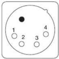
Note
Ensure that the polarities are used correctly for a power supply from an external source.
| DC OUT | |
| 1 | GND |
| 2 | R TALLY(Open collector) |
| 3 | REC START SW |
| 4 | +12V OUT(Max. 1.5 A) |
Matsushita part number K1AY104J0001 Maker part number HR10A-7R-4SC(73) (Hirose Denki)
Connector at the cable side Maker part number HR10A-7R-4P(73) (Hirose Denki)
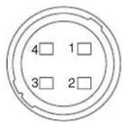
| FRONT MIC IN | |
| 1 | GND |
| 2 L | CH IN (H) |
| 3 L | CH IN (C) |
| 4 R | CH IN (H) |
| 5 R | CH IN (C) |
Matsushita part number K1AB105B0002 Maker part number NC5FBH (NEUTRIK)
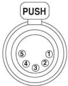
flowchart
graph TD
    A["PUSH"] --> B["1"]
    B --> C["2"]
    C --> D["3"]
    D --> E["4"]
    E --> F["5"]
    style A fill:#f9f,stroke:#333
    style B fill:#ccf,stroke:#333
    style C fill:#cfc,stroke:#333
    style D fill:#fcc,stroke:#333
    style E fill:#cff,stroke:#333
    style F fill:#ffc,stroke:#333
| AUDIO IN | |
| 1 | GND |
| 2 A | AUDIO IN(H) |
| 3 A | AUDIO IN(C) |
Matsushita part number K1AB103A0011 Maker part number HA16PRM-3SG (Hirose Denki)
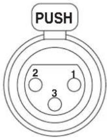
text_image
PUSH 2 1 3| AUDIO OUT | |
| 1 | GND |
| 2 | L C H O |
| 3 | L C H O |
| 4 R | CH OUT (H) |
| 5 R | CH OUT (C) |
Matsushita part number K1AA105H0016 Maker part number HA16RD-5P(76) (Hirose Denki)
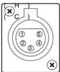
text_image
H C ① ⑤ ② ④ ③| REMOTE | |
| 1 CAM DATA (H) Data from the camera to the remote control (H) | |
| 2 CAM DATA (C) Data from the camera to the remote control (C) | |
| 3 CAM CONT (H) Control signals from the remote control to the camera (H) | |
| 4 CAM CONT (C) Control signals from the remote control to the camera (C) | |
| 5 RC-ON Identification signals of the remote controlLow: ON | |
| 6 RC VIDEO OUT Video signals output to the remote control | |
| 7 RC VIDEO GND GND of the video signals to the remote control | |
| 8 NC Not used | |
| 9 UNREG 12V DC +12 V power supply (AJ-RC10G: Max. 0.75 A) | |
| 10 GND GND | |
Matsushita part number K1AY110JA001
Maker part number HR10A-10R-10SC(71) (Hirose Denki)
Connector at the cable side
Maker part number HR10A-10P-10P(73) (Hirose Denki)
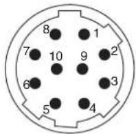
| VF | |
| 1 UNREG-12V DC +12 V power supply (AJ-HVF21G: About 0.35 A) | |
| 2 UNREG-12V DC +12 V power supply | |
| 3 A9.0V DC +9 V power supply (not used) | |
| 4 VF-PB-GND GND for the viewfinder P B signals | |
| 5 VF-PR-GND GND for the viewfinder P R signals | |
| 6 VF-Y Viewfinder Y signals output | |
| 7 VF-Y-GND GND for the viewfinder Y signals | |
| 8 VF-CLK Serial data clock pulse signals | |
| 9 VF-WR Pulse signals for reading serial-parallel conversion data | |
| 10 VF-DATA Serial data signals for serial-parallel conversion | |
| 11 UNREG-GND GND | |
| 12 ZEBRA-SW ON/OFF of the zebra signals | |
| 13 PEAKING Control of the peaking (not used) | |
| 14 SPARE Standby (not used) | |
| 15 VF-PR Viewfinder P R signal output | |
| 16 VF-PB Viewfinder P B signal output | |
| 17 MARKER-SW ON/OFF of the marker (not used) | |
| 18 FRONT-VR FRONT AUDIO LEVEL adjustment (not used) | |
| 19 VR-GND GND for the FRONT AUDIO LEVEL (not used) | |
| 20 UNREG-GND GND |
Matsushita part number K1AB120H0001
Maker part number HR12-14RA-20SC (Hirose Denki)
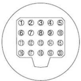
text_image
① ② ③ ④ ⑤ ⑥ ⑦ ⑧ ⑨ ⑩ ⑪ ⑫ ⑬ ⑭ ⑮ ⑯ ⑰ ⑱ ⑲ ⑳ ⑯ ⑰ ⑱ ⑲ ⑳◆ Caution Total amount of current from the respective connectors for DC OUT, REMOTE, VF, and LENS should not exceed 2.5 A.
| LENS | ||
| 1 RET-SW ON/OFF of the return videoRETURN ON: GNDRETURN OFF: OPEN | ||
| 2 REC-START/STOP Control for recording start/stop[IMAGE] | ||
| 3 G N D G N D | ||
| 4 IRIS-AUTO ON/OFF of the forced iris servoSERVO ON: +5V±0.5VSERVO OFF: OPEN | ||
| 5 IRIS-CONT Control output for the lens irisF2.8: -6.2 V, F16: +3.4 V, CLOSE: +2.5 V | ||
| 6 UNREG-12V +12V power supply for the lens (Max. 1.5 A) | ||
| 7 IRIS-POSI Iris position signals3.4 V (F16) to +6.2 V (F2.8) | ||
| 8 IRIS-G-MAX IRIS REMOTE/LOCAL (AUTO) signalsREMOTE: +5V±0.5VLOCAL (AUTO):GND | ||
| 9 EXT-POSI ON/OFF of the built-in extenderEXTENDER ON: GNDEXTENDER OFF: OPEN | ||
| 10 ZOOM-POSI Zoom position signals | ||
| 11 FOCUS-POSI Focus position signal | ||
| 12 SPARE Standby (not used) |
| GPS | ||
| 1 GPS TXA | Transmission data from the GPS unit to the camera | |
| 2 GPS RXA | Transmission data from the camera to the GPS unit | |
| 3 GPS VBAT | Backup power supply connector for the GPS unit (DC+3.3 V) | |
| 4 REC START SW | Control signals of REC start/stop | |
| 5 GPS VCC | Power supply connector for the GPS unit (DC+3.3 V) | |
| 6 G P S G ND | G ND | |
Matsushita part number K1AY112JA001
Maker part number HR10A-10R-12SC(71) (Hirose Denki)
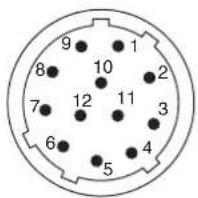
text_image
9 8 7 6 5 10 11 4 3 2 1Matsushita part number K1AY106J0001
Maker part number HR10A-7R-6SC(73) (Hirose Denki)
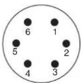
| Unislot Interface | ||
| 1 CH-1 SHIELD GND | ||
| 2 CH-1 HOT Audio input from the wireless receiver: HOT | ||
| 3 CH-1 COLD Audio input from the wireless receiver: COLD | ||
| 4 G N D G N D | ||
| 5 +12V UNREG Power supply to the wireless receiver | ||
| 6 RX ON Power supply remote output to the wireless receiver | ||
| 7 RF WARN RF warning input from the wireless receiver | ||
| 8 R M 5 N o t | u s e d | |
| 9 R M 4 N o t | u s e d | |
| 10 SPARE 1 Not used | ||
| 11 SPARE 2 Not used | ||
| 12 EXT CLK Not used | ||
| 13 CLK SHIELD Not used | ||
| 14 CH-2 SHIELD Not used | ||
| 15 CH-2 HOT Not used | ||
| 16 CH-2 COLD Not used | ||
| 17 +5.6V Power supply to the wireless receiver | ||
| 18 VIDEO OUT Not used | ||
| 19 VIDEO RET Not used | ||
| 20 VIDEO EN Not used | ||
| 21 RM 1 (RM CLK) Not used | ||
| 22 RM 2 (RM DATA) Not used | ||
| 23 RM 3 (RM WR) Not used | ||
| 24 RM +5V Not used | ||
| 25 RM GND Not used | ||
Matsushita part number K1GB25A00010
Maker part number HDBB-25S(05)
(Hirose Denki)

Warning System
Warning Description Tables
If a problem is detected immediately after the power is turned on, or during operation, this will be indicated by the WARNING lamp, lamps inside the viewfinder and a warning tone.
Note
The WARNING lamp has the highest priority, followed by the tally lamp, and then the warning tone. When multiple errors occur simultaneously a higher priority indication will be triggered. The [WIRELESS RF], however, may not be indicated, depending on the menu setting.
- System Errors
| Display window indication | The error code lights up. |
| WARNING lamp | Blinks 4 times per second. |
| Tally lamp Blinks 4 | times per second. |
| Viewfinder | The SYSTEM ERROR indication and the error code light up. |
| Warning tone Beeps continuously. | |
| Warning description | An error in the reference signal or the communication. |
| Recording/ playback operation | The operation stops. |
| Countermeasures | Please confirm [Error Codes] (page 148) and consult your distributor. |
- Card removal error
| Display window indication | Error code E-30 blinks. |
| WARNING lamp | Blinks 4 times per second. |
| Tally lamp Blinks 4 | times per second. |
| Viewfinder | The “TURN POWER OFF” indicator lights up. |
| Warning tone | Continues to beep. |
| Warning description | The P2 card being accessed has been removed, resulting in an error in the internal memory of the camera-recorder. |
| Recording/ playback operation | Cannot be performed. |
| Countermeasures | Turn off the power to the camera-recorder. If there is an error in a clip on the removed P2 card, repair the clip. |
- Battery Empty
| Display window indication | All 7 bar indicators for battery remaining capacity start blinking. |
| WARNING lamp | Lights up. |
| Tally lamp Blinks once per second. | |
| Viewfinder The BATT LED lights up. | |
| Warning tone Beeps continuously. | |
| Warning description | The battery has run out. |
| Recording/ playback operation | The operation stops. |
| Countermeasures | Replace the battery. |
- Write-protect
| Display window indication | All 7 bar indicators for remaining MEDIA capacity start blinking. |
| WARNING lamp | This lamp will illuminate continuously until an operation is made after recording. |
| Tally lamp | This lamp will flash 4 times every second until an operation is made after recording. |
| Viewfinder The WP indicator lights up. | |
| Warning tone | This tone will sound continuously until an operation is made after recording. |
| Warning description | The inserted P2 cards are write-protected. |
| Recording/ playback operation | Recording is disabled. |
| Countermeasures | Disable the write-protect or replace the P2 card. |
- P2 Card Fully Recorded
| Display window indication | All 7 bar indicators for remaining MEDIA capacity start blinking. |
| WARNING lamp | This lamp will illuminate continuously until an operation is made after recording. |
| Tally lamp | This lamp will flash 4 times every second until an operation is made after recording. |
| Viewfinder The END | D indicator blinks. |
| Warning tone | This tone will sound continuously until an operation is made after recording. |
| Warning description | The P2 cards are recorded to maximum capacity. |
| Recording/ playback operation | The recording stops. |
| Countermeasures | Delete the clips in the P2 card or insert a new P2 card. |
- Recording Error
| Display window indication | “00:00:00:11” appears in the time code display field. Even after recording is stopped, this display continues to blink until the next operation is performed. |
| WARNING lamp | Blinks 4 times per second while recording continues. |
| Tally lamp | Blinks 4 times per second while recording continues. |
| Viewfinder | The REC WARNING indicator lights up. |
| Warning tone | Beeps 4 times per second while recording continues. |
| Warning description | This indicates a failure either in the P2 card recording or the recording circuit. This is displayed when attempting to record clips where the total quantity exceeds the upper limit (1000 pieces) for a single P2 card. |
| Recording/ playback operation | The recording may stop or continue. |
| Countermeasures | Restart recording. Or, turn the power OFF and turn it ON again, before starting recording. |
- Image Sequence Error (24P, 30P, 25P)
| Display window indication | “E-40” appears in the time code display field. |
| WARNING lamp | Blinks 4 times per second. |
| Tally lamp | Blinks 4 times per second while recording continues. |
| Viewfinder | The REC WARNING indicator lights up. |
| Warning tone | Beeps 4 times per second while recording continues. |
| Warning description | There are abnormal conditions in the image sequence of the 24P, 30P, or 25P mode. |
| Recording/ playback operation | Images can be recorded and played back, but some frames may be dropped or the sequences of TC and UB may shift. |
| Countermeasures | Confirm the recording/playback operation after turning OFF the power supply once and then turning it on again. If the error is not corrected after executing this procedure, contact the dealer. |
- Low Wireless Signal Reception
| Display window indication | No display. |
| WARNING lamp | Blinks 4 times per second. (During pause and recording) |
| Tally lamp | Blinks 4 times per second while recording continues. |
| Viewfinder | The WIRELESS RF indicator lights up while recording continues. |
| Warning tone | Beeps 4 times per second while recording continues. |
| Warning description | This error indicates poor wireless audio reception conditions. |
| Recording/ playback operation | Continues to operate without receiving the wireless microphone signal. |
| Countermeasures | Check the microphone power supply and the reception status of the wireless receiver. |
9.1394 Error
| Display window indication | The 1394 E-** indicator in the display window blinks. For more information, see [1394 Error Codes] (page 148). |
| WARNING lamp | Blinks 4 times per second while the WARNING lamp recording is continuing. |
| Tally lamp | Blinks 4 times per second while the TALLY LAMP recording is continuing. |
| Viewfinder | In the case of Error Code 92, “1394 INITIAL ERROR” indicator lights up (during pause and recording)For Error Codes other than Error Code 92, or if REC SIGNAL is set to “1394”, no error is displayed in the viewfinder. |
| Warning tone | Beeps 4 times per second while ALARM recording is continuing. |
| Warning description | This indicates a failure of the DVCPRO/DV connector. |
| Recording/ playback operation | The operation continues, but input signals to the DVCPRO/DV connector are abnormal. For more information, see [1394 Error Codes] (page 148). |
| Countermeasures | Check the connection between the IEEE1394 cable and the DVCPRO/DV connector, settings of any external device and menus, and the turn on the power again. If the warning indication is still illuminated, confirm the “1394 Error Codes” (page 148), and consult your distributor. |
- Battery Nearly Empty
| Display window indication | One of the bars in the battery remaining indicator starts blinking. |
| WARNING lamp | Blinks once per second. |
| Tally lamp Blinks once per second. | |
| Viewfinder The BATT LED blinks. | |
| Warning tone | Beeps 4 times per second. |
| Warning description | The battery is about to run out. |
| Recording/ playback operation | Continues to operate. |
| Countermeasures | Replace the battery as required. |
- P2 Card Nearly Full
| Display window indication | One of the bars for remaining MEDIA capacity starts blinking. |
| WARNING lamp | Blinks once per second while recording continues. |
| Tally lamp | Blinks once per second while recording continues. |
| Viewfinder | The P2 card remaining capacity indicator blinks. |
| Warning tone | Beeps once per second while recording continues. |
| Warning description | The total remaining capacity of all the P2 cards is two minutes or less. |
| Recording/ playback operation | Continues to operate. |
| Countermeasures | Replace the cards. If there is an empty card slot, insert a new card. |
- P2 Card Error
| Display window indication | If the error occurs during recording, “00:0000:11” appears as the time code indication. The indication continues to flash after recording is stopped and until the next operation is performed. There is no indication if the error occurs during playback. |
| WARNING lamp | If the error occurs during recording, the lamp flashes four times per second for a period of about three seconds. The lamp does not light if the error occurs during playback. |
| Tally lamp | If the error occurs during recording, the lamp flashes four times per second for a period of about three seconds. The lamp does not light if the error occurs during playback. |
| Viewfinder | A flashing “CARD ERR *” appears. In the actual indication the * is replaced by the slot number of the P2 card that triggered the error. |
| Warning tone | If the error occurs during recording, the tone sounds four times per second for a period of about three seconds. The tone does not sound if the error occurs during playback. |
| Warning description | An error has occurred while recording data to or playing data from a P2 card. |
| Recording/ playback operation | Stop recording or playback. |
| Countermeasures | Replace the affected P2 card. |
- FAN STOP
| Display window indication | No display. |
| WARNING lamp | Blinks 4 times per second. |
| Tally lamp | No display. |
| Viewfinder | The FAN STOP indicator blinks while recording continues. |
| Warning tone | It does not sound. |
| Warning description | The fan is at rest because something is wrong with it. |
| Recording/ playback operation | If the camera-recorder operates with the fan stopped, then the temperature inside rises. While the camera-recorder continues to operate, clips may not be recorded or played back properly. |
| Countermeasures | Immediately stop using the camera-recorder and consult your distributor. |
Error Codes
The following error codes are displayed in the display window if an error occurs in the camera:
Confirm the type of warning and refer to the details in the [Warning Description Tables] (page 145) for countermeasures.
| Code No. | Description Type of warnings | |
| E-11 Video | initialisation error 1. System Errors | |
| E-27 Recording | control error 1. System Errors | |
| E-30 P2 card | removal error 2. | Card removal error |
| E-34 LCD | microcontroller error 1. System Errors | |
| E-38 P2 streaming | microcontroller error 1. System Errors | |
| E-39 | Abnormal initialization of the AVC-Intra codec board (optional AJ-YBX200G) | System Errors |
| E-3F Microprocessor | error in the camera control circuit. 1. System Errors | |
| E-40 Image sequence error (in case of 24P, 30P and 25P) | 6. | Image Sequence Error (24P, 30P, 25P) |
| E-63 Something is wrong with the system control microprocessor. 1. System Errors | ||
| E-6F Reference signal error. 1. System Errors | ||
| 00:00:00:11 | Recording error on a P2 card | Recording Error |
1394 Error Codes
| Code No. | Description | Recording | Indication in display window |
| 1394 E-80 | Signals being input to the DVCPRO/DV connector are not 1 × speed transfer signals in DV format. | Stops | The time code section of the display window indicates the appropriate error code that blinks every two seconds. |
| 1394 E-81 | Signals being input to the DVCPRO/DV connector are not 1 × speed transfer signals in DVCPRO (25 Mbps) format. | Stops | |
| 1394 E-82 | Signals being input to the DVCPRO/DV connector are not 1 × speed transfer signals in DVCPRO50 (50 Mbps) format. | Stops | |
| 1394 E-83 | Incorrect signals are being input to the DVCPRO/DV connector. | Stops | |
| 1394 E-84 | Signals being input to the DVCPRO/DV connector are not in DVCPRO or DV format. | Stops | |
| 1394 E-85 | Signals being input to the DVCPRO/DV connector are not 1x speed transfer signals in DVCPRO HD format. | Stops | |
| 1394 E-87 | Incorrect audio signals are being input to the DVCPRO/DV connector. | Continues with no sound. | |
| 1394 E-90 | No signal is supplied to the DVCPRO/DV connector. | While the recording mode continues, no data is recorded on cards unless the abnormal condition is corrected. If an error has occurred before recording, then, recording does not start. | |
| 1394 E-91 | With the menu option REC MODE set to DV, copy guard information signals for recording prohibited data are being input to the DVCPRO/DV connector. | Stops | |
| 1394 E-92 | The DVCPRO/DV connector is not properly connected. The viewfinder indicates the message "1394 INITIAL ERROR." | No recording in 1394 input mode can be performed. |
Card Warning Code
| Code No. | Description Recording | Indication in display window | |
| E-70 | The directory organization on the inserted P2 card does not comply with the standards. ([DIR NG CARD (Slot No.)] is indicated on the viewfinder.) | Although different kinds of recording operations will function, data may not be recorded properly. Use the unit to format the card immediately. | A warning code blinks once every 2 seconds on the time code display section of the display window. |
| E-71 | A P2 card was inserted where the number of rewrites exceeds the limit of the standards. ([RUN DOWN CARD (Slot No.)] is indicated on the viewfinder.) | Although different kinds of recording operations will function, data may not be recorded properly. It is recommended to replace it. |
Warning and Error Display for Thumbnail Operation and USB HOST MODE
| Item Message Description Measure | |||
| Thumbnails | CANNOT ACCESS! Data cannot be accessed because it is corrupted or for other reasons. | Restore media and clips to normal state before access. | |
| WRITE PROTECTED! | The P2 or SD card is write protected. Insert write-enabled media. | ||
| CARD FULL! The P2 or SD card is full. Insert media with sufficient capacity. | |||
| NO CARD! No P2 or SD card is inserted. Insert compatible media. | |||
| NO FILE! The designated file is not found. Check the file. | |||
| CANNOT COPY! | Images cannot be copied. | Check the conditions for copying. | |
| CANNOT DELETE ! | Contents version mismatch prevents deletion. | Match devices and contents version. | |
| UNKNOWN CONTENTS FORMAT! | Warning displayed to indicate contents version mismatch. | Match devices and contents version. | |
| CANNOT FORMAT! P2 card problem prevents formatting. Check P2 card. | |||
| CANNOT REPAIR! | Data cannot be repaired since content that cannot be repaired is selected. | Check selected content. | |
| CANNOT RE-CONNECT! | A clip that does not span multiple P2 cards cannot be reconnected. | Check selected content. | |
| INVALID VALUE! | Entered data was invalid. | Enter data in a valid range. | |
| UNKNOWN DATA! | The metadata character code is invalid. | Use UTF-8 for the metadata character code. Use the viewer to enter correct characters. | |
| CANNOT REPAIR IN SELECTION! | Some of the selected clip could not be repaired. | ||
| NO SD CARD! | No SD card is inserted. | Insert an SD card. | |
| NO COPY TO SAME CARD! | A clip cannot be copied to the card storing the original clip. | Copy the selected clip to a card that does not contain the original clip. | |
| SAME CLIP IS SELECTED! | The clip cannot be copied because a clip that has already been copied and the original clip have been selected. | Confirm the selected clip and release either the source clip or the destination clip and then execute the copy operation. | |
| USER CLIP NAME MODIFIED! | Characters in the clip name had to be deleted in adding the counter value. | The user clip name plus the counter value can only contain up to 100 bytes. Characters in the clip name are automatically deleted when the total exceeds 100 bytes. | |
| TOO MANY CLIPS! | Too many clips are selected. | Reduce the number of selected clips. | |
| LACK OF REC CAPACITY! | There is not enough recording capacity left on the card. | Insert a card with sufficient recording capacity. | |
| CANNOT CHANGE! | Any thumbnails that cannot be produced on the AVC-Intra 100 or AVC-Intra 50 and displayed in gray cannot be changed at the text memo position. | Install the AVC-Intra codec board (AJ-YBX200G, optional) and set SYSTEM MODE according to the clips. | |
| MISSING CLIP! | A shot mark will be added to the clips recorded on multiple P2 cards when all P2 cards are not inserted yet. | Insert all P2 cards with recorded clips, and confirm that the incomplete clip indicators disappear, and then add shot marks. | |
| Item | Message | Description | Measure |
| Soft keyboard | CANNOT CHANGE! | [PERSON] will be entered while the text memo is not available. | Enter [TEXT] before entering [PERSON]. |
| CANNOT SET! INVALID VALUE! | The entered value is incorrect. Change the value. | ||
| HDD (USB HOST MODE) | HDD CAPACITY FULL! | Not enough space left on the hard disk. There | is not enough space on the connected hard disk. Use a new hard disk or formatted hard disk. |
| TOO MANY PARTITIONS! | There are too many partitions. Hard disks can | handle up to 23 partitions. Use a new hard disk or formatted hard disk. | |
| HDD DISCONNECTED! | The unit is not connected to a hard disk. Reconnect the USB cable. If the hard disk does not operate normally, turn it off and turn it back on again. | ||
| CANNOT FORMAT! | The hard disk cannot be initialized. Connect another hard disk drive. | ||
| TOO MANY TARGETS! | Multiple devices are connected. Disconnect devices, turn off the unit and turn it back on again. | ||
| UNKNOWN DEVICE CONNECTED! | The connected DVD drive is not compatible. Disconnect devices, turn off the unit and turn it back on again. | ||
| CANNOT ACCESS TARGET! | An error occurred during hard disk access. | Check hard disk status and connection. | |
| CANNOT RECOGNIZE HDD! | The destination target cannot be properly recognized. | Reboot the hard disk or connect a different hard disk. | |
| CANNOT ACCESS CARD! | An error occurred during P2 card access. | Check P2 card. | |
| MISMATCH COMPONENT! | Copying cannot be made because the destination card is in the wrong format. | Use a P2 card with appropriate capacity. | |
| P2 CARD IS UNFORMATTED! | The P2 card is not formatted. | Use a formatted P2 card. | |
| CARD IS EMPTY! CANNOT COPY! | The P2 selected for copying is empty. | Copying is not performed since the card is empty. | |
| VERIFICATION FAILED! | The compare check after copying failed. | Copy the data again. | |
| PLEASE FORMAT P2 CARD! | This warning indicates that data could not be imported from a hard disk to a P2 card because the P2 card contained recorded data. | You cannot copy to a P2 card that contains data. Format the card on a P2 device and copy again. | |
Menu
Menu Configuration
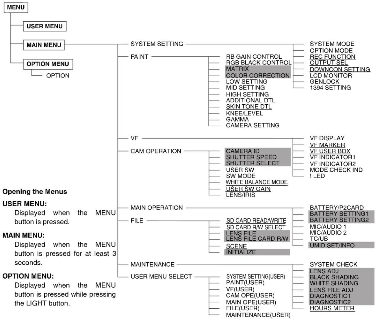
flowchart
graph TD
    A["MENU"] --> B["USER MENU"]
    A --> C["MAIN MENU"]
    A --> D["OPTION MENU"]
    C --> E["SYSTEM SETTING"]
    C --> F["CAM OPERATION"]
    C --> G["MAIN OPERATION"]
    C --> H["MAINTENANCE"]
    C --> I["OPTION MENU"]

    E --> J["PAINT"]
    E --> K["RB GAIN CONTROL"]
    E --> L["RGB BLACK CONTROL"]
    E --> M["MATRIX"]
    E --> N["COLOR CORRECTION"]
    E --> O["LOW SETTING"]
    E --> P["MID SETTING"]
    E --> Q["HIGH SETTING"]
    E --> R["ADDITIONAL DTL"]
    E --> S["SKIN TONE DTL"]
    E --> T["KNEE/LEVEL"]
    E --> U["GAMMA"]
    E --> V["CAMERA SETTING"]

    K --> W["CAM OPERATION"]
    K --> X["Camera ID"]
    K --> Y["SHUTTER SPEED"]
    K --> Z["SHUTTER SELECT"]
    K --> AA["USER SW"]
    K --> AB["SW MODE"]
    K --> AC["WHITE BALANCE MODE"]
    K --> AD["USER SW GAIN"]
    K --> AE["LENS/IRIS"]

    L --> AF["SYSTEM MODE"]
    L --> AG["OPTION MODE"]
    L --> AH["REC FUNCTION"]
    L --> AI["OUTPUT SEL"]
    L --> AJ["DOWNCON SETTING"]
    L --> AK["LCD MONITOR"]
    L --> AL["GENLOCK"]
    L --> AM["1394 SETTING"]

    M --> AN["VF DISPLAY"]
    M --> AO["VF MARKER"]
    M --> AP["VF USER BOX"]
    M --> AQ["VF INDICATOR1"]
    M --> AR["VF INDICATOR2"]
    M --> AS["MODE CHECK IND"]
    M --> AT["! LED"]

    N --> AU["MAIN OPERATION"]
    N --> AV["FILE"]
    N --> AW["MAINTENANCE"]

    AU --> AX["BATTERY/P2CARD"]
    AU --> AY["BATTERY SETTING1"]
    AU --> AZ["BATTERY SETTING2"]

    AV --> BA["SD CARD READ/WRITE"]
    AV --> BB["SD CARD R/W SELECT"]
    AV --> BC["LENS FILE"]
    AV --> BD["LENS FILE CARD R/W"]

    AW --> BE["SCENE"]
    AW --> BF["INITIALIZE"]

    AX --> BG["BATTERY/P2CARD"]
    AX --> BH["BATTERY SETTING1"]
    AX --> BI["BATTERY SETTING2"]

    BA --> BJ["MIC/AUDIO 1"]
    BA --> BK["MIC/AUDIO 2"]

    BB --> BL["UMID SET/INFO"]

    CA["OPTION MENU"] --> CB["Displayed when the MENU button is pressed."]

    AD["Opening the Menus"] --> AE
    AF["USER MENU"] --> AF
    AG["MAIN MENU"] --> AH
    AH --> AI["Displayed when the MENU button is pressed for at least 3 seconds."]

    AI --> AJ["Displayed when the MENU button is pressed while pressing the LIGHT button."]

    AK["SYSTEM CHECK"] --> AL["SYSTEM CHECK"]
    AK --> AM["LENS ADJ"]
    AK --> AN["BLACK SHADING"]
    AK --> AO["WHITE SHADING"]

    AL --> AP["DISP\nOCTIC1"]
    AL --> AQ["HOURS METER"]
Notes
- The items highlighted in grey cannot be selected by
- The underlined items can only be selected as one whole page (with all sub-items). Individual sub-items cannot be selected separately.
About Menu Description Tables
The following letters indicate whether the modified menu data is saved to or read out from the memory. The – indicates that the data cannot be saved or read.
S = Can be saved and read as scene data file.
C = Can be saved or read using CARD READ/WRITED.
U = Can be saved and read as user data.
Please refer to [SCENE] (page 185) and [INITIALIZE] (page 185).
F = Can be read using READ FACTORY DATA.
Please refer to [INITIALIZE] (page 185).
R = Can be saved using RC DATA SAVE.
Please refer to [Connection of the remote control unit (AJ-RC10G)] (page 107).
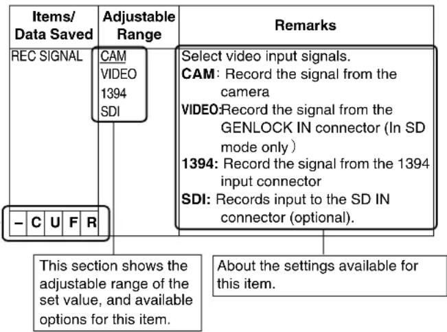
text_image
Items/ Data Saved Adjustable Range Remarks REC SIGNAL CAM VIDEO 1394 SDI Select video input signals. CAM: Record the signal from the camera VIDEO: Record the signal from the GENLOCK IN connector (In SD mode only ) 1394: Record the signal from the 1394 input connector SDI: Records input to the SD IN connector (optional). - C U F R This section shows the adjustable range of the set value, and available options for this item. About the settings available for this item.USER MENU: USER MENU is factory-set. The menu can be configured to suit your preferences by specifying each option according to your purposes and frequency of use, through the
MAIN MENU: Allows you to set all options on the settings menu. This menu has a category-by-category structure, layered according to purposes and frequency of use. To display MAIN MENU, press the MENU button for three seconds or longer.
SYSTEM SETTING:
This option is used to specify recording signal, recording system, etc.
PAINT: This option is used to fine-adjust images while monitoring the output waveform of the camera, using the waveform monitor. Normally, this adjustment requires assistance from a video engineer. This menu option may be set with an external remote controller, and is useful when using the unit without a sound recordist.
VF: Used to select the information items to be displayed in the viewfinder screen.
CAM OPERATION:
Used to change settings according to the conditions for the subject.
MAIN OPERATION:
Used to specify recording-related items, such as audio settings, time code, battery and P2 card remaining amounts.
FILE: Used to specify file-related items such as SD memory card reading/writing and lens file settings.
MAINTENANCE:
Used to specify maintenance-related items.
USER MENU SELECT:
Used to edit USER MENU.
OPTION MENU: Provides options which may be needed if functions are added in the future. To display OPTION MENU, hold down the LIGHT button and press the MENU button. For more information, contact your distributor.
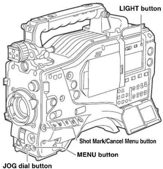
text_image
LIGHT button Shot Mark/Cancel Menu button MENU button JOG dial buttonSetting Menu Options
The menu options are set with the MENU and JOG dial buttons.
The menu comprises main menu, sub-menus and options menus.
The data specified through menu options are written and saved in the internal memory of the unit.
This section describes how to set options in MAIN MENU. The other menus can be configured in the same manner (the method of displaying the menu screen depends on the particular menu).

Note
When the unit is in thumbnail mode, the viewfinder displays "THUMBNAIL OPEN", disabling navigation through the menu.
1
Press the MENU button for three seconds or longer. The MAIN MENU screen appears, together with its options.
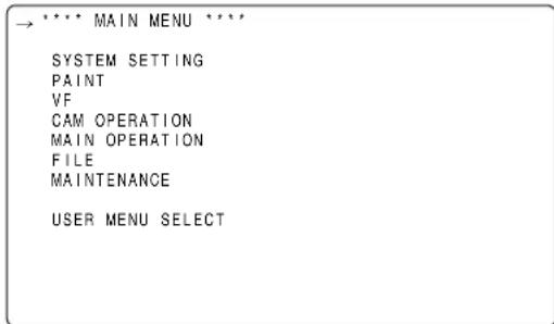
text_image
→ **** MAIN MENU **** SYSTEM SETTING PAINT VF CAM OPERATION MAIN OPERATION FILE MAINTENANCE USER MENU SELECT2
Turn the JOG dial button to move the mark ( ) to a desired menu option. Then, press the JOG dial button to display the sub-menu screen.
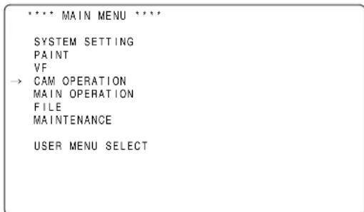
text_image
**** MAIN MENU **** SYSTEM SETTING PAINT VF → CAM OPERATION MAIN OPERATION FILE MAINTENANCE USER MENU SELECT3
Turn the JOG dial button to move the mark ( ) to a desired menu option. Then, press the JOG dial button to display the options screen.
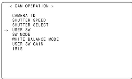
text_image
< CAM OPERATION > CAMERA ID SHUTTER SPEED SHUTTER SELECT → USER SW SW MODE WHITE BALANCE MODE USER SW GAIN IRIS4
Turn the JOG dial button to move the mark ( ) to a desired option. Then, press the JOG dial button. The value starts blinking.
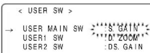
5
Turn the JOG dial button to change the value.
To increase the value:
Turn the JOG dial button clockwise, as seen from the front of the camera.
To decrease the value:
Turn the JOG dial button anti-clockwise, as seen from the front of the camera.
Each turn of the dial switches the value by one step. A quick turn changes the value rapidly; a slow turn makes a fine adjustment.
To turn an option on or off:
To select ON, turn the JOG dial button clockwise, as seen from the front of the camera.
To select OFF, turn the JOG dial button anti-clockwise, as seen from the front of the camera.
To return the changed set value to the previous one:
Press the shot mark/menu cancel button to display the message "PUSH CANCEL BACK TO PREV".
Press the shot mark/menu cancel button again to return the set value to the value before the change.
Note
The following menu items cannot be cancelled using the shot mark/menu cancel button.
- Pages on the USER MENU SELECT screen
- Pages on the FILE screen
- CAMERA ID
- USER SW GAIN
● Part of the WHITE BALANCE MODE pages
● BATTERY SETTING1, 2 - UMID SET/INFO
6
Press the JOG dial button.
The value stops blinking and is accepted.
7
To change the settings for other options on the same page, repeat Steps 4 - 6.
8
When the settings are finalised, press the MENU button.
This terminates the menu option setting mode and returns the unit to normal operation mode.
Go to the USER MENU SELECT page from MAIN MENU.
Then, open relevant options menu screens to select options to add to USER MENU.
Only the selected options are displayed as options in USER MENU.
For information about how to navigate this menu, see [Setting Menu Options] (page 153).
< USER MENU SELECT >
<h1 id="system-setting-2">SYSTEM SETTING</h1>
PAINT
VF
CAM OPERATION
MAIN OPERATION
FILE
MAINTENANCE
(SELECT MODE)
Note
Options with [*] are effective. The number of options that can be added to USER MENU is 14 × 3 = 42 (three pages of options) for camera-related options, and 14 (one page of options) for memory-related options.
Menu Description Tables
SYSTEM SETTING
SYSTEM MODE
| Items/Data Saved | Adjustable Range | Remarks | ||||
| SYSTEM MODE | 1080-59.94i1080-50i720-59.94P720-50P480-59.94i576-50i | For setting the system frequency and the recording format of the unit.When this item is switched, turn “OFF” the POWER switch on the unit and then turn it “ON” again.◆NotesWhen the remote control unit (AJ-RC10G) is connected, this item is not displayed.To switch this item, operate the main unit independently.When the time code is in free run mode and a change is made to the SYSTEM MODE menu option, the time may not be correctly recorded.After turning on the camera-recorder, check the time code and make a change to the setting if required.When USB DEVICE mode is selected, no change can be made to this option. | ||||
| - | C | U | F | - | ||
| REC SIGNAL | CAMVIDEO1394SDI | Select video input signals.CAM: Record the signal from thecameraVIDEO:Record the signal from the GENLOCK IN connector (In SD mode only)1394: Record the signal from the 1394 input connectorSDI: Records input to the SDI IN connector (optional).◆NotesIn Native mode for the AVC-Intra (optional) and DVCPRO HD, 1394 cannot be selected.After the power has been turned OFF this setting defaults to CAM when the power is turned ON again.In order to select VIDEO and synchronize video signals input to the GENLOCK IN connector (VBS) with the unit, set the GENLOCK item of [GENLOCK] (page 159) to "EXT". | ||||
| - | C | U | F | R | ||
| CAMERA MODE | (1080-59.94i/480-59.94i)60i30P24P24PA(1080-50i/576-50i)50i25P(720-59.94P)60P30P24P(720-50P)50P25P | For setting the video system for shooting.◆NoteIn AVC-Intra mode (optional), 24PA cannot be selected. | ||||
| - | C | U | F | R | ||
| Items/Data Saved | Adjustable Range | Remarks | ||||
| ASPECT | 16:94:3 | Select the aspect ratio for recording. (In SD mode only)16:9: Record in <16:9> aspect ratio.4:3: Record in <4:3> aspect ratio. | ||||
| - | C | U | F | R | ||
| VF TYPE HD | SD | Specify the type of viewfinder to be attached to the camera-recorder. | ||||
| - | C | U | F | R | ||
| REC MODE | HD MODE(1080i):DVCPRO HDAVC-I 100AVC-I 50HD MODE(720P):DVCPRO HDDVC HD (N)AVC-I 100AVC-I 50SD MODE:DVCPRO50DVCPRODV | Select the recording mode.DVCPRO HD:Record in DVCPRO HD formatDVC HD (N):Record in Native mode for DVCPROHDAVC-I 100:Record in AVC-I 100 formatAVC-I 50:Record in AVC-I 50 formatDVCPRO50:Record in DVCPRO50 format.DVCPRO:Record in DVCPRO format.DV: Record in DV format.◆ Notes● AVC-I 100 and AVC-I 50 cannot be selected when the AJ-YBX200G(optional) is not installed.● If [1394] is selected in REC SIGNAL,AVC-I 100, AVC-I 50 and DVC HD (N) cannot be selected. | ||||
| - | C | U | F | R | ||
| SETUP | 0%7.5%A | Switch the setup. (For 480-59.94i only)0%: Setup is switched to 0% for both the camera output and the recording.7.5%A: Setup is switched to 7.5% for the camera output and 0% for the recording. | ||||
| - | C | U | F | R | ||
| PC MODE SELECT | USB HOSTUSB DEV. | Specify the operation mode of the camera-recorder when an external device is connected via USB.USB HOST:Sets the camera-recorder to the mode that allows an external hard disk drive to be connected.USB DEV.:Sets the camera-recorder to the USB device mode, which allows a PC to be connected via USB 2.0 for use with P2 cards as mass storage.◆ NoteWhen the PC MODE menu option is set to ON, no change can be made to this option. | ||||
| - | - | - | F | - | ||
The ____ in the Adjustable Range column indicates the preset mode.
| Items/Data Saved | Adjustable Range | Remarks | |||
| PC MODE ON | OFF | Used to enable or disable the mode that allows the camera-recorder to be connected to a PC or an external hard disk drive via USB 2.0.ON: Sets the camera-recorder to the mode selected through the PC MODE SELECT menu option.OFF: Disables the PC MODE for normal operation.◆NoteOnce the power is turned off, the option is always set to OFF when the power is turned on next time. | |||
| - | - | - | F | - | |
OPTION MODE
| Items/ Data Saved | Adjustable Range | Remarks | |||
| REC TALLY | REDGREENCHAR | Select the method for displaying the recording status of camera-recorder when controlling an external VTR by setting 1394 CONTROL items to BOTH. Select the 1394 CONTROL item on the <1394 SETTING> screen in the SYSTEM SETTING page.RED: The red tally lamp lights up.GREEN:The green tally lamp lights up.CHAR: The VF displays [REC] in characters. | |||
| - | C | U | F | - | |
| ACCESS LED O | OFFSLOT SIDELCD SIDEBOTH | Specify whether or not to enable the P2 card access LEDs.OFF: Disables both LEDs above the slots and on the side panel.SLOT SIDE:Enables the LED above the slots and disables the LED on the side panel.LCD SIDE:Enables the LED on the side panel and disables the LED above the slots.BOTH: Enables both LEDs above the slots and on the side panel. | |||
| - | C | U | F | - | |
| P.OFF GPS DATA | HOLDCLEAR | Select whether or not to hold the UMID GPS position information while the power is turned off, thereby keeping this information as status data holding the previous value until the power is turned on again, which enables a new measurement to start.HOLD: Hold and save the data.CLEAR: Clear the data when the power is turned off, and save zero (No-Info) from the next power-on until a new measurement is completed. | |||
| - | C | U | F | - | |
| SDI METADATA | ONOFF | Used to specify whether or not to output metadata (UMID) to SDI when the VIDEO OUT menu option is set to HD SDI or SD HDI. | |||
| - | C | U | F | - | |
| SDI EDH | ONOFF | Select whether or not to add an error detection flag to the SD SDI output. | |||
| - | C | U | F | - | |
| Items/ Data Saved | Adjustable Range | Remarks | ||||
| SAVE SW (AUD OUT) | ONOFF | Select whether or not to forcibly disable the audio output when the SAVE ON/OFF switch is set to [ON].ON: Disable audio output.OFF: Enable audio output. | ||||
| - | C | U | F | - | ||
| SAVE SW (LCD) | ONOFF | Select whether or not to automatically turn off the LCD monitor when the SAVE ON/OFF switch is set to [ON].ON: Turn off LCD monitor.OFF: Do not turn off LCD monitor. | ||||
| - | C | U | F | - | ||
| COMPRESSION MODE | NORMAL DARK | Select a compression mode for the 720P mode (Only for recording DVCPRO HD for 720-59.94P and 720-50P).NORMAL:The normal shooting mode is selected.DARK:Compressed video distortion that occurs in dark areas is lowered, which may increase distortion in other areas. | ||||
| - | C | U | F | - | ||
| AUTO REC | OFFTYPE1TYPE2 | Select the method for detecting REC START/STOP marks from the frame rate information in the user bits added through HD SD IN in HD mode in order to automatically start or stop recording (for the AJ-YA350AG, an SDI-IN option).OFF: No automatic recording is performed.TYPE1: REC START/STOP marks are detected from LTC input through HD SDI for automatic recording.TYPE2: REC START/STOP marks are detected from VITC input through HD SDI for automatic recording.NoteSet the menu option REC SIGNAL to SDI to input HD SDI signals to the SDI IN connector. For information about user bits frame rate information, see [Setting of the user bits] (page 57).The AUTO REC function does not operate in INTERVAL REC and LOOP REC modes. | ||||
| - | C | U | F | - | ||
The ____ in the Adjustable Range column indicates the preset mode.
| Items/Data Saved | Adjustable Range | Remarks | |||
| INTERVALREC MODE | ONONE SHOTOFF | Sets INTERVAL REC function.ON:Uses internal memory to perform interval recording.ONE SHOT:Performs “one-shot” recording for the duration specified under REC TIME, and then stops.OFF:INTERVAL REC is not performed.◆NoteThis item cannot be changed when [ON] is selected in LOOP REC MODE.-C U | |||
| INTERVALREC HOLD | ONOFF | Selects whether INTERVAL REC MODE settings are retained or not when the power is turned off once.ON:RetainOFF:Do not retain. The INTERVAL REC MODE is OFF whenever the power is turned on again. | |||
| - | C | U | F | - | |
| REC TIME*1 | 00s01f:59s29f | Set REC TIME (1 cut).◆NoteHowever, the settings can be made frame by frame, and the numbers of the cut-off unit frames for the shortest time period and the set time on the actual operation may vary with the recording method. For details, refer to [Interval Recording] (page 36). | |||
| - | C | U | F | - | |
| PAUSE TIME*1 | 00h00m00s01f:00h04m59s29f:23h59m59s29f | Specify PAUSE time for recording.◆NoteHowever the settings can be made frame by frame, and the numbers of the cut-off unit frames for the shortest time period and the set time on the actual operation may vary with the recording method. For details, refer to [Interval Recording] (page 36). | |||
| - | C | U | F | - | |
| TAKE TOTALTIME | NONE:5day | Specify the time needed for shooting.Select from NONE (continue until operation is manually stopped) to 5 days. | |||
| - | C | U | F | - | |
| TOTAL REC TIME*1 | 00m00s01f:99m59s29fOVER100minNONE | Display total recorded time. The setting cannot be changed using this option.Displays the recording time (recording time needed for the P2 card) calculated using REC TIME, PAUSE TIME, and TAK E TOTAL TIME.◆NoteA value based on actual processing is displayed. | |||
| - | - | - | - | - | |
| AUDIO REC ON | OFF | Select whether or not sound will be recorded. | |||
| - | C | U | F | - | |
| START DELAY | 0SEC:10SEC | Set the delay after pressing REC START to start recording in INTERVAL REC. | |||
| - | C | U | F | - | |
| PRE RECMODE | ONOFF | Select whether or not to enable PRE RECORDING.ON:PRE RECORDING enabled.OFF:PRE RECORDING disabled.◆NoteSpecify the PRE RECORDING time by using the menu option PRE REC TIME. | |||
| - | C | U | F | - | |
*1 This variable range is the numerical values for 59.94 Hz. For 50 Hz, the frame rate is up to 24f. The frame rate is up to 23f in 24PN (Native) mode.
The ____ in the Adjustable Range column indicates the preset mode.
| Items/ Data Saved | Adjustable Range | Remarks | ||||
| PRE REC TIME | 1SEC : 8SEC : 15SEC | Set PRE RECORDING. 1-15SEC: Set the length of time that can be retrospectively recorded before the REC START button is pressed. ◆Note When the SYSTEM MODE menu option on the SYSTEM MODE screen is set to 1080-59.94i, 1080-50i, 720-59.94P, or 720-50P, or when it is set to 480-59.94i or 576-50P and the REC MODE menu option is set to DVCPRO50, the upper limit of the above recording time is 8 seconds. | ||||
| - | C | U | F | - | ||
| LOOP REC MODE | ON OFF | Select whether or not to enable LOOP REC. This setting can be used with PRE RECORDING features. ON: Enable LOOP REC. OFF: Disable LOOP REC. ◆Notes After the power is turned off, this item will default to OFF the next time the power is turned on. This item cannot be changed when [ON] or [ONE SHOT] is selected in INTERVAL REC MODE. | ||||
| - | - | - | F | - | ||
| REC START ALL NORMAL | Select operating modes that allow recording to start. ALL: Allow recording to start during stop, recording pause, and playback. NORMAL: Allow recording to start during stop and recording pause. ◆Note Even if this is set to [ALL], the operation is [NORMAL], when [ON] or [ONE SHOT] is selected in INTERVAL REC MODE. | |||||
| - | C | U | F | - | ||
| P.ON REC SLOT SEL | HOLD SLOT1 | Select the recording order of the slot when the power is turned on. HOLD: The recording order starts with the card previously selected when the power was turned off. SLOT1: The recording order starts with the card that is inserted in Slot 1 when the power is turned on. | ||||
| - | C | U | F | - | ||
Note
Displayed REC TIME, PAUSE TIME and TOTAL REC TIME are translated into either drop-frame or non-drop-frame according to the mode of operation. TAKE TOTAL TIME is actual time. Therefore, TOTAL REC TIME may incorporate fractions, depending on the settings.
Example of drop-frame
| REC TIME | 02s00f |
| PAUSE TIME | 02s00f |
| TAKE TOTAL TIME | 40min |
| TOTAL REC TIME | 19m59s06f |
| Items/ Data Saved | Adjustable Range | Remarks | |||
| OUTPUT ITEM | MENU ONLYTCSTATUS | Set the character contents superimposed onto the output signals for the VIDEO OUT connector (Analog or SDI) and MON OUT connector. MENU ONLY:Displays only when the menu characters are superimposed. No display appears when other characters are superimposed.TC:Display the time code. (Displays the menu when menu characters are superimposed.) ◆NoteThe TC display position moves up and down depending on the camera ID position. STATUS:Display the same characters superimposed on the VF signal. (Displays the menu when menu characters are superimposed.) | |||
| - | C | U | F | - | |
| MONITOR OUT | VBSVFY | Select the output signal on the MON OUT connector.VBS:Output a regular composite signal.VF: Output a VF Y signal. The status display is also superimposed.Y: Output a component Y signal. ◆NoteThe VBS signal is output in playback mode. | |||
| - | C | U | F | - | |
| MONITOR OUT CHAR | ONOFF | Select whether or not to superimpose characters on the MON OUT connector signal independently of the camera's VIDEO OUT CHARACTER switch. (The character content is the same as the video output signal.) ON: Enable superimpose.OFF: Disable superimpose. | |||
| - | C | U | F | - | |
| LCD MON CHAR | ONOFF | Select whether or not to superimpose characters on the LCD monitor. (The character content is the same as the video output signal.) ON: Enable superimpose.(Not interlocked with the VIDEO OUT CHARACTER switch.) OFF: Disable superimpose.(Not interlocked with the VIDEO OUT CHARACTER switch.) | |||
| - | C | U | F | - | |
| VF MODE | MEMCAM | When the REC SIGNAL menu option on the SYSTEM MODE screen is set to CAM, select the image to display in the viewfinder.MEM:Display the playback image in the playback mode.CAM:Always display the camera image. | |||
| - | C | U | F | - | |
| THUMBNAIL OUT | ONOFF | Select whether or not to output clip thumbnails displayed on the LCD monitor to the video output and monitor output signals.ON: Enable output.OFF: Disable output. ◆NoteHD SDI signals are being output from the VIDEO OUT connector, thumbnails are not output. | |||
| - | C | U | F | - | |
| Items/ Data Saved | Adjustable Range | Remarks | ||||
| DOWNCON MODE | SQUEEZ LTBOX S-CROP | For setting the mode of the down converter output signals. | ||||
| - | C | U | F | R | ||
| DETAIL | ON OFF | For setting the detail function for the down converter output signals ON/OFF.The down converter output signals contain detailed components that are set during HD signal processing. In this setting, these signals overlap the detailed components dedicated to the down converter outputs.Even if this setting is turned off, it is impossible to turn off the detailed components set during HD signal processing. | ||||
| - | C | U | F | R | ||
| H.DTL LEVEL 00 | 0831 | For setting the horizontal detail correction level for the down converter output signals. | ||||
| - | C | U | F | R | ||
| V.DTL LEVEL 00 | 0431 | For setting the vertical detail correction level for the down converter output signals. | ||||
| - | C | U | F | R | ||
| DTL CORING 00 | 0115 | For setting the noise elimination level of the details. | ||||
| - | C | U | F | R | ||
| H.DTL FREQ. 1 | 35 | For selecting the horizontal detail frequencies.1: 2.5 MHz 4: 4 MHz2: 3 MHz 5: 4.5 MHz3: 3.5 MHz | ||||
| - | C | U | F | R | ||
| 2D LPF | ON OFF | For setting the 2-D low path filter reducing cross colors.ON: Cross colors are reduced.OFF: Cross colors are not reduced. | ||||
| - | C | U | F | R | ||
| SETUP | 0%7.5% | For setting the setup level for the down converter output signals.(Only for 1080-59.94i or 720-59.94P)◆NoteWhen the system frequency is set to 50 Hz, the setup level will be 0%. | ||||
| - | C | U | F | R | ||
Note
The
The ____ in the Adjustable Range column indicates the preset mode.
| Items/Data Saved | Adjustable Range | Remarks | ||||
| BRIGHTNESS | -7 +0 +7 | Adjust the LCD monitor brightness. | ||||
| - | C | U | F | - | ||
| COLOR LEVEL | -7 +0 +7 | Adjust the LCD monitor chroma level. | ||||
| - | C | U | F | - | ||
| CONTRAST -7 | +0 +7 | Adjust the LCD monitor contrast. | ||||
| - | C | U | F | - | ||
| BACKLIGHT | NORMAL HIGH | Adjust the backlightNORMAL: Mode normally usedHIGH: This is brighter than NORMAL | ||||
| - | C | U | F | - | ||
| SELF SHOOT | NORMAL MIRROR | Select whether or not to change the LCD monitor to mirror image.NORMAL: Do not change to mirror image.MIRROR: Change to mirror image. | ||||
| - | C | U | F | - | ||
| ASPECT CONV. | SQUEEZE LTBOX | Select a screen ratio for images displayed on the LCD monitor (In SD mode only).SQUEEZE: Display images in the squeeze size.LTBOX: Display images in the letter box size.◆NoteThis item is enabled only when ASPECT described in SYSTEM MODE is set to “16:9”. | ||||
| - | C | U | F | - | ||
The ____ in the Adjustable Range column indicates the preset mode.
| Items/ Data Saved | Adjustable Range | Remarks | ||||
| GENLOCK | INTEXT | Switch the camera synchronising signal. INT: Synchronise with the internal reference signal regardless of the reference signal input to the GENLOCK IN connector. EXT: Synchronise with the reference signal input to the GENLOCK IN connector. | ||||
| - | C | U | F | R | ||
| GL PHASE | HD SDI COMPOSIT | For selecting the output signals that lock phases to the signals that are input in the GENLOCK IN connector. (Only for 1080-59.94i, 1080-50i, 720-59.94P, or 720-50P) HD SDI: For locking the HD SDI signals to the GENLOCK input. For the down converter output signals, the start position of the video delays by about 90 lines. COMPOSIT: For locking the down converter output signals to the GENLOCK input. For the HD SDI output signals, the start position of the video gains by about 90 lines. | ||||
| - | C | U | F | R | ||
| H PHASE COARSE | -100 : +000 : +100 | Perform coarse phase adjustment for horizontal hold when configuring a system. | ||||
| - | - | - | - | - | ||
| H PHASE FINE | -100 : +000 : +100 | Perform fine phase adjustment for horizontal hold when configuring a system. | ||||
| - | - | - | - | - | ||
| Items/ Data Saved | Adjustable Range | Remarks | |||
| 1394 AUDIO OUT | CH1/CH2CH3/CH4 | For selecting the channels for audio signals output from the DVCPRO/DV connector when the camera-recorder is operating in DVCPRO or DV mode (for 480-59.94i or 576-50i only)◆ NoteWhen CH3/CH4 is selected, no sound is heard in the following outputs:● EE output if the 25M REC CH SEL menu option on the MIC AUDIO screen on the MAIN OPERATION page is set to 2CH.● Output of playback data recorded as 2-channel audio signals. | |||
| - | C | U | F | - | |
| 1394 SPEED S100S200S400 | For setting the transfer rate of signals output from the DVCPRO/DV connector.S100:100MbpsS200:200MbpsS400:400Mbps | ||||
| - | C | U | F | - | |
| 1394 IN CH 0 | :63AUTO | For setting the input channel of signals input to the DVCPRO/DV connector.0 - 63: To fix to the designated valueAUTO: To follow the settings of the externally connected devices | |||
| - | C | U | F | - | |
| 1394 OUT CH 0 | :63AUTO | For setting the input channel of signals output from the DVCPRO/DV connector.0 - 63: To fix to the designated valueAUTO: To follow the settings of the externally connected devices | |||
| - | C | U | F | - | |
| 1394CONTROL | OFFBOTH | For setting the control for recording start/stop operations of external devices that are connected to the DVCPRO/DV connector.OFF: Do not control the externally connected devices.BOTH:To control both the unit and the externally connected devices | |||
| - | C | U | F | - | |
| 1394 CMD SEL | REC_PSTOP | For setting the control of recording stop operations of the external devices that are connected to the DVCPRO/DV connector.REC_P: Operation to pause recording STOP: Stopping operation | |||
| - | C | U | F | - | |
The ____ in the Adjustable Range column indicates the preset mode.
RB GAIN CONTROL
| Items/Data Saved | Adjustable Range | Remarks | |||
| R GAIN AWB PRE | -200+000+200 | For setting the Rch gain when the WHITE BAL switch is in the PRST position.If the remote control unit is connected, settings made from the menu are disabled. (The set value is displayed.) | |||
| S | C | U | F | ||
| B GAIN AWB PRE | -200+000+200 | For setting the Bch gain when the WHITE BAL switch is in the PRST position.If the remote control unit is connected, settings made from the menu are disabled. (The set value is displayed.) | |||
| S | C | U | F | ||
| R GAIN AWB A | -200+000+200 | For setting the Rch gain when the WHITE BAL switch is in the A position.If the remote control unit is connected, settings made from the menu are disabled. (The set value is displayed.) | |||
| S | C | U | F | ||
| B GAIN AWB A | -200+000+200 | For setting the Bch gain when the WHITE BAL switch is in the A position.If the remote control unit is connected, settings made from the menu are disabled. (The set value is displayed.) | |||
| S | C | U | F | ||
| R GAIN AWB B | -200+000+200 | For setting the Rch gain when the WHITE BAL switch is in the B position.If the remote control unit is connected, settings made from the menu are disabled. (The set value is displayed.) | |||
| S | C | U | F | ||
| B GAIN AWB B | -200+000+200 | For setting the Bch gain when the WHITE BAL switch is in the B position.If the remote control unit is connected, settings made from the menu are disabled. (The set value is displayed.) | |||
| S | C | U | F | ||
| AWB A GAIN OFFSET | ONOFF | For setting the values of the Rch gain and the Bch gain when the auto white balance is executed as the WHITE BAL switch is in the A position.ON: To retain the values set in the items of R GAIN AWB A and B GAIN AWB AOFF: The values of the Rch gain and the Bch gain is set to “0”. | |||
| S | C | U | F | ||
| AWB B GAIN OFFSET | ONOFF | For setting the values of the Rch gain and the Bch gain when the auto white balance is executed as the WHITE BAL switch is in the B position.ON: To retain the values set in the items of R GAIN AWB B and B GAIN AWB BOFF: The values of the Rch gain and the Bch gain is set to “0”. | |||
| S | C | U | F | ||
RGB BLACK CONTROL
| Items/Data Saved | Adjustable Range | Remarks | ||||
| MASTER PED -200+015+200 | For setting the level of the master pedestal.If the remote control unit is connected, settings made from the menu are disabled. (The set value is displayed.) | |||||
| S | C | U | F | R | ||
| R PEDESTAL | -100+000+100 | For setting the pedestal level of the Rch.If the remote control unit is connected, settings made from the menu are disabled. (The set value is displayed.) | ||||
| S | C | U | F | R | ||
| G PEDESTAL -100+000+100 | For setting the pedestal level of the Gch.If the remote control unit is connected, settings made from the menu are disabled. (The set value is displayed.) | |||||
| S | C | U | F | R | ||
| B PEDESTAL -100+000+100 | For setting the pedestal level of the Bch.If the remote control unit is connected, settings made from the menu are disabled. (The set value is displayed.) | |||||
| S | C | U | F | R | ||
| PEDESTAL OFFSET | ONOFF | For setting the pedestal levels of the Rch, the Gch and the Bch when the auto black balance is adjusted.ON: To retain the values set in the respective items of R PEDESTAL, G PEDESTAL, and B PEDESTAL OFF: The pedestal levels of the Rch, the Gch and the Bch are set to "0". | ||||
| S | C | U | F | - | ||
| R FLARE -100+000+100 | +000+100 | For adjusting the flare level of the Rch. Adjustment values in this item are added to the flare adjustment value that is adjusted onscreen.If the remote control unit is connected, settings made from the menu are disabled. (The set value is displayed.) | ||||
| S | C | U | F | R | ||
| G FLARE | -100+000+100 | For adjusting the flare level of the Gch. Adjustment values in this item are added to the flare adjustment value that is adjusted onscreen.If the remote control unit is connected, settings made from the menu are disabled. (The set value is displayed.) | ||||
| S | C | U | F | R | ||
| B FLARE | -100+000+100 | For adjusting the flare level of the Bch. Adjustment values in this item are added to the flare adjustment value that is adjusted onscreen.If the remote control unit is connected, settings made from the menu are disabled. (The set value is displayed.) | ||||
| S | C | U | F | R | ||
The ____ in the Adjustable Range column indicates the preset mode.
MATRIX
| Items/ Data Saved | Adjustable Range | Remarks | ||||
| ■MATRIX TABLE | A B | For selecting the color correction table for the linear matrix. | ||||
| S | C | U | F | R | ||
| MATRIX R-G -63 | +00 +63 | For performing the linear matrix adjustment. (red/green) | ||||
| S | C | U | F | R | ||
| MATRIX R-B -63 | +00 +63 | For performing the linear matrix adjustment. (red/blue) | ||||
| S | C | U | F | R | ||
| MATRIX G-R -63 | +00 +63 | For performing the linear matrix adjustment. (green/red) | ||||
| S | C | U | F | R | ||
| MATRIX G-B -63 | +00 +63 | For performing the linear matrix adjustment. (green/blue) | ||||
| S | C | U | F | R | ||
| MATRIX B-R -63 | +00 +63 | For performing the linear matrix adjustment. (blue/red) | ||||
| S | C | U | F | R | ||
| MATRIX B-G -63 | +00 +63 | For performing the linear matrix adjustment. (blue/green) | ||||
| S | C | U | F | R | ||
| ■L MATRIX TABLE | OFF A B | For selecting the color correction table when the GAIN switch is in the L position. | ||||
| S | C | U | F | R | ||
| ■M MATRIX TABLE | OFF A B | For selecting the color correction table when the GAIN switch is in the M position. | ||||
| S | C | U | F | - | ||
| ■H MATRIX TABLE | OFF A B | For selecting the color correction table when the GAIN switch is in the H position. | ||||
| S | C | U | F | - | ||
Note
The items indicated by ■ are the setting items for PAINT MENU SW(■) R/W in the
Please refer to [SD CARD R/W SELECT] (page 184) for more information.
COLOR CORRECTION
| Items/ Data Saved | Adjustable Range | Remarks | ||||
| R (SAT) | -63 +00 +63 | For performing the color saturation correction of red. | ||||
| S | C | U | F | R | ||
| R-Mg (SAT) | -63 +00 +63 | For performing the color saturationcorrection between red and magenta. | ||||
| S | C | U | F | R | ||
| Mg (SAT) | -63 +00 +63 | For performing the color saturationcorrection of magenta. | ||||
| S | C | U | F | R | ||
| Mg-B (SAT) | -63 +00 +63 | For performing the color saturation correction between magenta and blue. | ||||
| S | C | U | F | R | ||
| B (SAT) | -63 +00 +63 | For performing the color saturation correction of blue. | ||||
| S | C | U | F | R | ||
| B-Cy (SAT) | -63 +00 +63 | For performing the color saturation correction between blue and cyan. | ||||
| S | C | U | F | R | ||
| Cy (SAT) | -63 +00 +63 | For performing the color saturation correction of cyan. | ||||
| S | C | U | F | R | ||
| Cy-G (SAT) | -63 +00 +63 | For performing the color saturation correction between cyan and green. | ||||
| S | C | U | F | R | ||
| G (SAT) | -63 +00 +63 | For performing the color saturation correction of green. | ||||
| S | C | U | F | R | ||
| G-YI (SAT) | -63 +00 +63 | For performing the color saturation correction between green and yellow. | ||||
| S | C | U | F | R | ||
| YI (SAT) | -63 +00 +63 | For performing the color saturation correction of yellow. | ||||
| S | C | U | F | R | ||
| YI-R (SAT) | -63 +00 +63 | For performing the color saturation correction between yellow and red. | ||||
| S | C | U | F | R | ||
The ____ in the Adjustable Range column indicates the preset mode.
| Items/ Data Saved | Adjustable Range | Remarks | ||||
| R(PHASE) -63 | +00+63 | For performing the hue correction for red. | ||||
| S | C | U | F | R | ||
| R-Mg(PHASE) -63 | For performing the hue correction between red and magenta. | |||||
| S | C | U | F | R | ||
| Mg(PHASE) -63 | +00+63 | For performing the hue correction for magenta. | ||||
| S | C | U | F | R | ||
| Mg-B(PHASE) -63 | For performing the hue correction between magenta and blue. | |||||
| S | C | U | F | R | ||
| B(PHASE) | -63+00+63 | For performing the hue correction for blue. | ||||
| S | C | U | F | R | ||
| B-Cy(PHASE) -63 | For performing the hue correction between blue and cyan. | |||||
| S | C | U | F | R | ||
| Cy(PHASE) -63 | +00+63 | For performing the hue correction for cyan. | ||||
| S | C | U | F | R | ||
| Cy-G(PHASE) -63 | For performing the hue correction between cyan and green. | |||||
| S | C | U | F | R | ||
| G(PHASE) -63 | +00+63 | For performing the hue correction for green. | ||||
| S | C | U | F | R | ||
| G-YI(PHASE) -63 | For performing the hue correction between green and yellow. | |||||
| S | C | U | F | R | ||
| YI(PHASE) -63 | +00+63 | For performing the hue correction for yellow. | ||||
| S | C | U | F | R | ||
| YI-R(PHASE) | -63+00+63 | For performing the hue correction between yellow and red. | ||||
| S | C | U | F | R | ||
| ■ COLOR CORRECT | ON OFF | For switching ON/OFF of the 12-axis independent color correction of the position selected with the GAIN switch (L, M, H). | ||||
| S | C | U | F | R | ||
The ____ in the Adjustable Range column indicates the preset mode.
| Items/Data Saved | Adjustable Range | Remarks | |||
| ■MASTER GAIN | -3dB 0dB 30dB | Select the master gain from -3, 0, 3, 6, 9, 12, 15, 18, 21, 24, 27, or 30dB. | |||
| S | C | U | F | R | |
| H.DTL LEVEL | 00 10 63 | For performing the horizontal detail correction level setting. | |||
| S | C | U | F | R | |
| V.DTL LEVEL | 00 20 31 | For performing the vertical detail correction level setting. | |||
| S | C | U | F | R | |
| DTL CORING | 00 01 15 | For performing the noise elimination level setting for detail. | |||
| S | C | U | F | R | |
| H.DTL FREQ. | 00 18 31 | For performing the horizontal detail frequency selection. | |||
| S | C | U | F | R | |
| LEVEL DEPEND. | 0 15 | For setting the LEVEL DEPEND.When the Y-detail is emphasized, details of dark sections are compressed.If the numerical value is larger, details of bright sections are also compressed. | |||
| S | C | U | F | R | |
| MASTER GAMMA | 0.30 0.45 0.75 | For setting the master gamma. (0.01 step) | |||
| S | C | U | F | R | |
| BLACK GAMMA | -3 OFF +3 | For setting the gamma curve for the dark portion.-3 to -1:The dark portion is compressed.OFF:Standard state+1 to +3:The dark portion is extended. | |||
| S | C | U | F | R | |
| ■MATRIX TABLE | QFEAB | For selecting the color correction table for the linear matrix. | |||
| S | C | U | F | R | |
| ■COLOR CORRECT | ONQEF | For switching ON/OFF of the 12-axis independent color correction. | |||
| S | C | U | F | R | |
Notes
- The items indicated by ■ are the setting items for PAINT MENU SW(■) R/W in the
- If images are shot when the master gain is set to -3dB , some coloring phenomena may occur on images in very bright sections. In order to suppress the coloring phenomena, switch the OUTPUT AUTO KNEE switch to "CAM AUTO KNEE OFF", set the MANUAL item on the KNEE/LEVEL screen to "ON", and then set a smaller value for the KNEE SLOPE item on the KNEE/LEVEL screen. After executing these settings, confirm that there are no coloring phenomena and then start shooting.
MID SETTING
| Items/ Data Saved | Adjustable Range | Remarks | ||||
| ■MASTER GAIN | -3dB6dB30dB | Select the master gain from -3, 0, 3, 6, 9, 12, 15, 18, 21, 24, 27, or 30dB. | ||||
| S | C | U | F | - | ||
| H.DTL LEVEL 00 | 0863 | For performing the horizontal detail correction level setting. | ||||
| S | C | U | F | - | ||
| V.DTL LEVEL 00 | 1831 | For performing the vertical detail correction level setting. | ||||
| S | C | U | F | - | ||
| DTL CORING 00 | 0215 | For performing the noise elimination level setting for detail. | ||||
| S | C | U | F | - | ||
| H.DTL FREQ. | 001831 | For performing the horizontal detail frequency selection. | ||||
| S | C | U | F | - | ||
| LEVEL DEPEND. | 015 | For setting the LEVEL DEPEND.When the Y-detail is emphasized,details of dark sections are compressed.If the numerical value is larger, details of bright sections are also compressed. | ||||
| S | C | U | F | - | ||
| MASTER GAMMA | 0.300.450.75 | For setting the master gamma. (0.01 step) | ||||
| S | C | U | F | - | ||
| BLACK GAMMA | -3OFF+3 | For setting the gamma curve for the dark portion.-3 to -1:The dark portion is compressed.OFF:Standard state+1 to +3:The dark portion is extended. | ||||
| S | C | U | F | - | ||
| ■MATRIX TABLE | OFFAB | For selecting the color correction table for the linear matrix. | ||||
| S | C | U | F | - | ||
| ■COLOR CORRECT | ONOFF | For switching ON/OFF of the 12-axis independent color correction. | ||||
| S | C | U | F | - | ||
HIGH SETTING
| Items/ Data Saved | Adjustable Range | Remarks | ||||
| ■MASTER GAIN | -3dB12dB30dB | Select the master gain from -3, 0, 3, 6, 9, 12, 15, 18, 21, 24, 27, or 30dB. | ||||
| S | C | U | F | - | ||
| H.DTL LEVEL 00 | 06 | For performing the horizontal detail correction level setting. | ||||
| S | C | U | F | - | 63 | |
| V.DTL LEVEL 00 | 16 | For performing the vertical detail correction level setting. | ||||
| S | C | U | F | - | 31 | |
| DTL CORING 00 | 03 | For performing the noise elimination level setting for detail. | ||||
| S | C | U | F | - | 15 | |
| H.DTL FREQ. | 0018 | For performing the horizontal detail frequency selection. | ||||
| S | C | U | F | - | 31 | |
| LEVEL DEPEND. | 035 | For setting the LEVEL DEPEND.When the Y-detail is emphasized,details of dark sections are compressed.If the numerical value is larger, details of bright sections are also compressed. | ||||
| S | C | U | F | - | ||
| MASTER GAMMA | 0.300.55 | For setting the master gamma. (0.01 step) | ||||
| S | C | U | F | - | 0.75 | |
| BLACK GAMMA | -3OFF+3 | For setting the gamma curve for the dark portion.-3 to -1:The dark portion is compressed.OFF:Standard state+1 to +3:The dark portion is extended. | ||||
| S | C | U | F | - | ||
| ■MATRIX TABLE | OFFAB | For selecting the color correction table for the linear matrix. | ||||
| S | C | U | F | - | ||
| ■COLOR CORRECT | ONOFF | For switching ON/OFF of the 12-axis independent color correction. | ||||
| S | C | U | F | - | ||
Note
The items indicated by ■ are the setting items for PAINT MENU SW(■) R/W in the
Please refer to [SD CARD R/W SELECT] (page 184) for more information.
The ____ in the Adjustable Range column indicates the preset mode.
| Items/ Data Saved | Adjustable Range | Remarks | |||
| KNEE APE LVL | OFF125 | For changing the detail level of the high brightness portion. | |||
| S | C | U | F | R | |
| DTL GAIN(+) -31: +00: +31 | Adjust the detail level toward + (upwards). | ||||
| S | C | U | F | R | |
| DTL GAIN(-) -31: +00: +31 | Adjust the detail level toward the - (downwards). | ||||
| S | C | U | F | R | |
| DTL CLIP | 00: 63 | For setting the level for clipping the detail signals. | |||
| S | C | U | F | R | |
| DTL SOURCE | (R+G)/2(G+B)/22G+R+B/4(3G+R)/4RG | For setting the proportion of the RGB signal components that provide the detail. | |||
| S | C | U | F | R | |
| V DTL FREQ 360TV450TV540TV630TV720TV | For selecting the vertical detail frequency. (In HD mode only)● It is enabled when the recording format is set to 720P. | ||||
| S | C | U | F | R | |
| H.DTL LINE MIX | 0H1H2H | For setting the number of scanning lines to be added to the video signals in order to generate the horizontal detail signals. (In HD mode only) | |||
| S | C | U | F | R | |
| MASTER DTL -31: +00: +31 | For revising the master detail level. | ||||
| S | C | U | F | R | |
The ____ in the Adjustable Range column indicates the preset mode.
| Items/ Data Saved | Adjustable Range | Remarks | |||
| ■ SKIN TONE DTL | OFFA B AB | For selecting the skin color table for enabling the skin tone detail. The skin color table is provided in the SKIN TONE TABLE item. By enabling the skin tone detail, it is possible to shoot human skin more accurately. | |||
| S | C | U | F | ||
| ■ SKIN TONE ZEBRA VF | ON OFF | For the setting to display the zebra pattern in the skin tone area displayed in the viewfinder screen. The zebra pattern is displayed when this item is turned “ON” and thescreen is opened. The zebra pattern is displayed on area A or B, which is selected in the SKIN TONE TABLE item. It is impossible to display both area A and B at the same time. | |||
| S | C | U | F | ||
| SKIN TONE TABLE | A B | For selecting the skin color table for subjects to which the skin tone table applies. | |||
| S | C | U | F | ||
| SKIN TONE GET | For fetching the color information of A or B, which is selected in the SKIN TONE TABLE item, near the center marker. When this function is executed, data from I CENTER to Q PHASE are fetched automatically. The fetched data will be the table data of A or B, which is selected in the SKIN TONE TABLE item. It is impossible to obtain color information of both A and B at the same time. | ||||
| - | - | - | - | ||
| SKIN DTL CORING | 057 | For setting the effect level of the skin tone detail. | |||
| S | C | U | F | ||
| Y MAX 000 | 190255 | For setting the maximum value of brightness for enabling the skin tone. | |||
| S | C | U | F | ||
| Y MIN | 000010255 | For setting the minimum value of brightness for enabling the skin tone. | |||
| S | C | U | F | ||
| I CENTER 000 | 035255 | For setting the center position on the I axis (for setting an area that enables skin tone.) | |||
| S | C | U | F | ||
| I WIDTH 000 | 055255 | For setting the area width for enabling the skin tone on the I-axis of which the center is the I CENTER. | |||
| S | C | U | F | ||
| Q WIDTH 00 | 1090 | For setting the area width for enabling the skin tone on the Q-axis of which the center is the I CENTER. | |||
| S | C | U | F | ||
| Q PHASE -180 | +000+179 | For setting phases of the area for enabling skin tone as setting the standard to the Q-axis. | |||
| S | C | U | F | ||
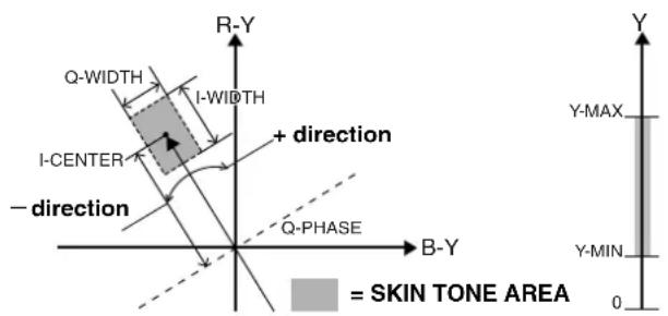
text_image
R-Y Q-WIDTH I-WIDTH + direction I-CENTER -direction Q-PHASE B-Y Y-MAX Y-MIN 0 = SKIN TONE AREANote
The items indicated by ■ are the setting items for PAINT MENU SW(■) R/W in the
Please refer to [SD CARD R/W SELECT] (page 184) for more information.
The ____ in the Adjustable Range column indicates the preset mode.
| Items/ Data Saved | Adjustable Range | Remarks | |||
| MASTER PED | -200+015+200 | Set the master pedestal. | |||
| S | C | U | F | R | |
| ■MANUAL KNEE | ON OFF | Set the mode when the AUTO KNEE switch is OFF. The KNEE POINT/ SLOPE set value is enabled when this setting is ON. | |||
| S | C | U | F | R | |
| KNEE POINT 7 | 0.0%93.0%107.0% | For setting the knee point position in increments of 1% steps. | |||
| S | C | U | F | R | |
| KNEE SLOPE | 08599 | For setting the inclination of the knee. | |||
| S | C | U | F | R | |
| ■WHITE CLIP | ON OFF | Set the WHITE CLIP feature to ON or OFF. The WHITE CLIP LVL set value is enabled when this setting is ON. | |||
| S | C | U | F | R | |
| WHITE CLIP LVL | 90%109% | Set WHITE CLIP LEVEL. | |||
| S | C | U | F | R | |
| A.KNEE POINT | 80%93%107% | Set the AUTO KNEE POINT position in 1% steps. This setting is enabled when the OUTPUT/AUTO KNEE selector switch is set to CAM.AUTO KNEE ON. | |||
| S | C | U | F | R | |
| A.KNEE LVL 10 | 107109 | Set the AUTO KNEE LEVEL. | |||
| S | C | U | F | R | |
| A.KNEE RESPONSE | 148 | Set the AUTO KNEE response speed. The smaller the setting value, the faster the response speed. | |||
| S | C | U | F | R | |
| CHROMA LEVEL | OFF-99%+00%+40% | For setting the chroma level of the PR signals and the Pb signals. If this is set to OFF, the color elements of video signals are eliminated. | |||
| S | C | U | F | R | |
| DRS EFFECT DEPTH | 123 | Set the compression level of the high-brightness component of DRS. If the numerical value is larger, the compression level of the high-brightness component increases. | |||
| S | C | U | F | R | |
Note
The items indicated by ■ are the setting items for PAINT MENU SW(■) R/W in the
Please refer to [SD CARD R/W SELECT] (page 184) for more information.
| Items/ Data Saved | Adjustable Range | Remarks | ||||
| MASTER GAMMA | 0.30 0.45 0.75 | Set the master gamma in 0.01% steps. | ||||
| S | C | U | F | R | ||
| R GAMMA -15 | +00 +15 | Set the Rch gamma. | ||||
| S | C | U | F | R | ||
| B GAMMA -15 | +00 +15 | Set the Bch gamma. | ||||
| S | C | U | F | R | ||
| GAMMA MODE SEL | DFLTHDSDFILMLIKE1FILMLIKE2FILMLIKE3 | For selecting the gamma mode.DFLT: This will operate as SD gamma in SD mode, or HD gamma in HD mode.HD:Video gamma characteristics for HD (High Definition)SD:The gain in the dark section is higher than the HD gamma.FILMLIKE1:The cinema gamma characteristics for video applications are selected.FILMLIKE2:The cinema gamma characteristics for video applications are selected.In this setting gradations in highlit areas can be expressed better than when FILM LIKE1 is selected.FILMLIKE3:The cinema gamma characteristics for video applications are selected.In this setting gradations in highlit areas can be expressed better than when FILM LIKE2 is selected. | ||||
| S | C | U | F | R | ||
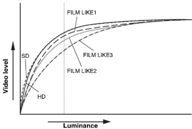
line
| Luminance | Video level (HD) | Video level (SD) | Video level (FILM LIKE2) | Video level (FILM LIKE3) | Video level (FILM LIKE1) | | --------- | ---------------- | ---------------- | ------------------------ | ------------------------ | ------------------------ | | 0 | 0 | 0 | 0 | 0 | 0 | | >0 | ~0.5 | ~1.0 | ~0.8 | ~1.2 | ~1.5 |- When the GAMMA MODE SEL item is used for FILM LIKE3, the following settings are recommended.
MANUAL KNEE : ON
KNEE POINT : 85.0%
KNEE SLOPE : 50
The ____ in the Adjustable Range column indicates the preset mode.
| Items/ Data Saved | Adjustable Range | Remarks | ||||
| DETAIL | ON | For switching ON/OFF of the detail signals. | ||||
| OFF | ||||||
| S | C | U | F | R | ||
| 2D LPF ON | OFF | For specifying whether or not to enable or disable the 2-dimension LPF, which reduce the cross color (for the SD mode only). ◆Note In PAL mode, the 2-dimension LPF is disable. | ||||
| S | C | U | F | R | ||
| HIGH COLOR | ON | ON/OFF switching for the HIGH COLOR mode, which enhances the color dynamic range. | ||||
| S | C | U | F | R | OFF | |
| GAMMA | ON | For switching ON/OFF of the gamma correction. | ||||
| S | C | U | F | R | OFF | |
| TEST SAW ON | OFF | Switch the test signal ON or OFF. | ||||
| S | C | U | F | R | ||
| FLARE | ON | Set the flare correction to ON or OFF. | ||||
| OFF | ||||||
| S | C | U | F | R | ||
| H-F COMPE. | ON | For switching ON/OFF of the aperture correction. | ||||
| S | C | U | F | R | OFF | |
Note
All items in CAMERA SETTING are setting targets of the item PAINT MENU SW(■) R/W in the
The ____ in the Adjustable Range column indicates the preset mode.
VF DISPLAY
| Items/ Data Saved | Adjustable Range | Remarks | |||
| DISP CONDITION | NORMAL HOLD | NORMAL: Display status constantly. HOLD: Display status only when the MODE CHECK switch is pressed. | |||
| - | C | U | F | R | |
| DISP MODE 1 | 23 | Set the DISP MODE. Switch the camera's Warning/Message indication. Please refer to [Display Modes and Setting Changes/adjustment Result Messages] (page 78) for more information. | |||
| - | C | U | F | R | |
| VF OUT | Y NAM R G B | For selecting the video signals to display in the viewfinder screen. Y: Brightness signal NAM:Output signal with the highest level among R, G, and B signals. R: Rch signal G: Gch signal B: Bch signal | |||
| - | C | U | F | R | |
| VF DTL | 05 | For setting the detail level of the viewfinder screen. The details of the signals for the viewfinder are further enhanced. If 0 is selected, then the detail is the same as that for the main line. | |||
| - | C | U | F | R | |
| ZEBRA1 DETECT | 0%70%109% | Set the ZEBRA1 detection level (IRE value). | |||
| - | C | U | F | R | |
| ZEBRA2 DETECT | 0%85%109% | Set the ZEBRA2 detection level (IRE value). | |||
| - | C | U | F | R | |
| ZEBRA2 ON | SPOT OFF | Set the ZEBRA2 to ON, OFF, or SPOT. | |||
| - | C | U | F | R | |
| LOW LIGHT LVL | OFF10%15%20%25%30%35% | Set the camera incoming light volume at which to display LOW LIGHT. | |||
| - | C | U | F | R | |
| RC MENU DISP. | ON OFF | For the setting to display the menu in the viewfinder screen when the remote control unit is connected to the unit. | |||
| - | C | U | F | R | |
| 50M INDICATOR | ON OFF | For specifying whether to enable or disable the 50M LED inside the SD viewfinder when the REC MODE menu option is set to DVCPRO50. (In SD mode only) | |||
| - | C | U | F | R | |
| MARKER/CHAR LVL | 50%60%70%80%90%100% | Adjust the brightness of markers and characters displayed on the VF. | |||
| - | C | U | F | R | |
ZEBRA Pattern Display
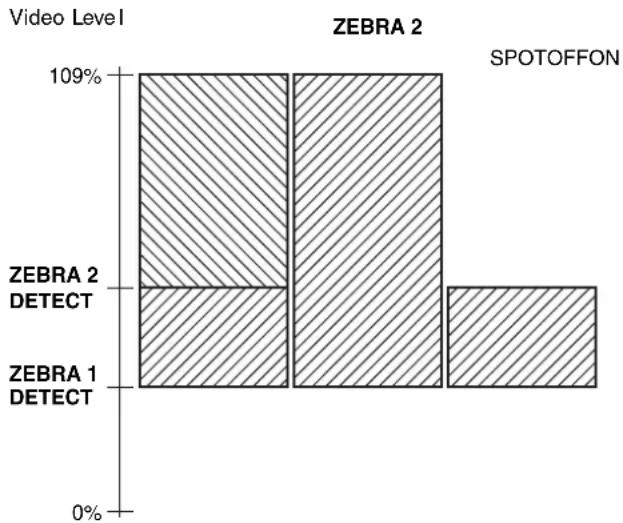
bar
Video Level | Video Level | ZEBRA 1 (%) | ZEBRA 2 (%) | | :--- | :--- | :--- | | 109% | 0 | 109% | ZEBRA 2 DETECT | 0 | 109% | ZEBRA 1 DETECT | 0 | 0 | SPOTOFFONThe ____ in the Adjustable Range column indicates the preset mode.
VF MARKER
| Items/Data Saved | Adjustable Range | Remarks | ||||
| TABLE | A | Select the VF MARKER setting table.First, select table A or B, then set the items below for each table. | ||||
| B | ||||||
| - | C | U | F | R | ||
| CENTERMARK | OFF1234 | Switch the center mark.OFF: Do not display center mark.1: + (large)2: Hollow (large)3: + (small)4: Hollow (small) | ||||
| - | C | U | F | R | ||
| SAFETYMARK | OFF12 | Select the frame type for the safety zone.OFF: Do not display frame.1: Box2: Corner frame | ||||
| - | C | U | F | R | ||
| SAFETYAREA | 80%90%100% | For setting the size of the safety marker.It is possible to set the size by units of 1% with a fixed ratio between of width and height. | ||||
| - | C | U | F | R | ||
| FRAME MARK | ONOFF | Set the frame marker to ON or OFF. | ||||
| - | C | U | F | R | ||
| FRAME SIG | 4:313:914:9VISTA | Set the frame marker.Only enabled when REC MODE is set to 16:9.The VISTA ratio is 16:8.65. | ||||
| - | C | U | F | R | ||
| FRAME LVL 0 | 15 | Set the level outside the frame marker.0: Equivalent to signal OFF. (Blanking status)15: Same brightness as center area. This setting, however, is disabled if the FRAME SIG is set to VISTA. | ||||
| - | C | U | F | R | ||
Note
When SYSTEM MODE is set to either "1080-59.94i", "1080-50i", "720-59.94P", or "720-50P" (in HD mode), the safety zone marker, the safety zone area, and the frame marker are displayed on the LCD monitor or the SD viewfinder if "LT-BOX" or "S-CROP" is selected in DOWNCON MODE.
VF USER BOX
| Items/ Data Saved | Adjustable Range | Remarks | ||||
| USER BOX ON | OFF | For setting whether the user box is displayed in the viewfinder or not. | ||||
| - | C | U | F | R | ||
| USER BOX WIDTH | 1:13:100 | For setting the horizontal width of the user box. | ||||
| - | C | U | F | R | ||
| USER BOX HEIGHT | 1:13:100 | For setting the horizontal position of the user box center. | ||||
| - | C | U | F | R | ||
| USER BOX H POS | -50:+00:+50 | For setting the horizontal position of the user box center. | ||||
| - | C | U | F | R | ||
| USER BOX V POS | -50:+00:+50 | For setting the vertical position of the user box center. | ||||
| - | C | U | F | R | ||
- The user box can be displayed in any position as a boxtype cursor.
Note
When SYSTEM MODE item is set to either "1080-59.94i", "1080-50i", "720-59.94P", or "720-50P" (in HD mode), the user box is not displayed on the LCD monitor or the SD viewfinder if "LT-BOX" or "S-CROP" is selected in DOWNCON MODE.
The ____ in the Adjustable Range column indicates the preset mode.
| Items/ Data Saved | Adjustable Range | Remarks | |||
| EXTENDER | ON OFF | For selecting ON or OFF for the extender display. | |||
| - | C | U | F | R | |
| SHUTTER | ON OFF | Set the shutter speed indication to ON or OFF. | |||
| - | C | U | F | R | |
| FILTER | ON OFF | Set the filter No. indication to ON or OFF. | |||
| - | C | U | F | R | |
| WHITE | ON OFF | Set the AWB PRE/A/B indication to ON or OFF. | |||
| - | C | U | F | R | |
| GAIN | ON OFF | For selecting ON/OFF of the gain currently selected, S.GAIN, DS. GAIN and LINE MIX GAIN displays. | |||
| - | C | U | F | R | |
| IRIS OFF | IRIS S+IRIS S | OFF: Disable indications of both the super iris ON status and the iris value.IRIS: Enable only the iris value indication.S+IRIS: Enables indications of the super iris ON status and the iris value.S: Enable indication of the super iris ON status.The display of the aperture value and the display of the iris override are interlinked. When the iris override is changed, it is forcibly displayed for 3 seconds. | |||
| - | C | U | F | R | |
| CAMERA ID | BAB OFF | For setting to record the camera ID.BAR:The camera ID is recorded when the color bar signals are recorded.OFF: Disable ID mix. | |||
| - | C | U | F | R | |
| ID POSITION U | UPPER R UPPER L LOWER R LOWER L | For setting the position to display the camera ID.UPPER R: Upper right.UPPER L: Upper left.Lower R: Lower right.Lower L: Lower left. | |||
| - | C | U | F | R | |
| DATE/TIME | ON OFF | For selecting an option to display year/month/day and hour/minute/second simultaneously when the camera ID is displayed. | |||
| - | C | U | F | R | |
| ZOOM LVL | ON OFF | Set the zoom position indication to ON or OFF. | |||
| - | C | U | F | R | |
| COLOR TEMP | ON OFF | Set the color temperature indication to ON or OFF. | |||
| - | C | U | F | R | |
| SYSTEM MODE | ON OFF | For selecting ON or OFF for the camera mode and REC mode display. | |||
| - | C | U | F | R | |
| CAMERA MODE | ON OFF | For selecting ON/OFF of the dynamic range stretcher mode display. | |||
| - | C | U | F | R | |
| Items/ Data Saved | Adjustable Range | Remarks | |||
| P2CARD REMAIN | OFFONE-CARD TOTAL | Select the indication mode for the P2 card's remaining capacity.OFF: Disable the remaining capacity indication.ONE-CARD:Display the remaining capacity of the P2 card currently used for recording.TOTAL:Display the total remaining capacity of all P2 cards in slots. | |||
| - | C | U | F | R | |
| BATTERY | ONOFF | Set the battery voltage indication to ON or OFF. | |||
| - | C | U | F | R | |
| AUDIO LVL | ONOFF | Set the audio lever meter indication to ON or OFF. | |||
| - | C | U | F | R | |
| TC ON COLOR BAR | ONOFF | Select whether the time code is to be displayed or not on the color bar. | |||
| - | C | U | F | R | |
| TC | OFFTCGTCRTCG/TCR | Select the time code to display.OFF: Disable the time code display.TCG: Display the time code generator value in recording mode.TCR: Display the time code reader value in playback mode.TCG/TCR:Display the time code generator value in recording mode, and the time code reader value in playback mode. | |||
| - | C | U | F | R | |
| SYSTEM INFO | OFF ALWAYS NORMAL | Select the method of displaying system information and warnings.OFF: Display no warnings other than “TURN POWER OFF” and “SYSTEM ERROR”.ALWAYS:Always display warnings.NORMAL:Display warnings for 3 seconds only when problems occur. | |||
| - | C | U | F | R | |
| COMPRESSION | ONOFF | Specify whether to enable or disable the compression indication when the camera-recorder is in compression mode. (Only for DVCPRO HD in 720P)ON: When the COMPRESSION MODE menu option on the OPTION MODE screen is set to DARK, COMP is indicated.OFF: No indication is given. | |||
| - | C | U | F | R | |
| SAVE LED | SAVE P2CARD | Set the SAVE lamp function.SAVE:The lamp lights up when the SAVE ON/OFF switch is set to ON and the output system assigned in [OPTION MODE] (page 156) is in the save mode.P2CARD:The lamp blinks in synch with the warning message when the P2 card's remaining recording capacity is getting low. | |||
| - | C | U | F | R | |
The ____ in the Adjustable Range column indicates the preset mode.
| Items/ Data Saved | Adjustable Range | Remarks | ||||
| REC STATUS | ONOFF | Select whether or not to enable “REC” indication in the viewfinder and on the LCD monitor during recording.ON: REC indication enabled.OFF: REC indication not enabled.◆NoteThis option is useful when camera-recorder is used independently. When the 1394 CONTROL menu option on the 1394 SETTING screen is set to BOTH, then the setting of the REC TALLY menu option for SYSTEM MODE is used. | ||||
| - | C | U | F | R | ||
| PROXY REC ON | ONOFF | When a video encoder card (AJ-YAX800G, optional) is attached, proxy recording information is displayed when recording starts.ON: Display indicating whether proxy recording is to be performed on the P2 card only, or on both the P2 card and the SD memory card.OFF: Proxy recording information is not displayed. | ||||
| - | C | U | F | R | ||
MODE CHECK IND
| Items/ Data Saved | Adjustable Range | Remarks | ||||
| STATUS | ON | For the setting to display the status screen when the MODE CHECK button is pressed. | ||||
| OFF | ||||||
| - | C | U | F | R | ||
| ILED | ON | For the setting to indicate causes for turning on thelamp on the viewfinder is displayed when the MODE CHECK button is pressed.The causes for turning on thelamp are displayed with! | ||||
| OFF | ||||||
| - | C | U | F | R | ||
| FUNCTION | ON | For the setting to display the FUNCTION screen when the MODE CHECK button is pressed. | ||||
| OFF | ||||||
| - | C | U | F | R | ||
| AUDIO ON | — | For the setting to display the AUDIO screen when the MODE CHECK button is pressed. | ||||
| OFF | ||||||
| - | C | U | F | R | ||
| P.ON IND | ON | For the setting to display the status screen immediately after turning on the power of the unit.NoteEven if it is set to “ON” in this item, the status screen is not displayed immediately after turning on the power of the unit when the STATUS item is set to OFF. | ||||
| OFF | ||||||
| - | C | U | F | R | ||
ILED
| Items/ Data Saved | Adjustable Range | Remarks | ||||
| GAIN(0dB) | ONOFF | For the setting to turn the clamp on the viewfinder on when the GAIN is set to a value other than 0 dB. | ||||
| - | C | U | F | R | ||
| GAIN (-3dB) ON | ONOFF | For the setting to turn the clamp on the viewfinder on when the GAIN is set to a value other than -3dB. | ||||
| - | C | U | F | R | ||
| DS.GAIN ON | OFF | For the setting to turn the clamp on the viewfinder on when the DS. GAIN (cumulative gain) is activated. | ||||
| - | C | U | F | R | ||
| LINE MIX ON | OFF | For the setting to turn the clamp on the viewfinder on when the LINE MIX GAIN is activated. | ||||
| - | C | U | F | R | ||
| SHUTTER | ONOFF | For the setting to turn the clamp on the viewfinder on when the electronic shutter is activated. | ||||
| - | C | U | F | R | ||
| WHITE PRESET | ONOFF | For the setting to turn the clamp on the viewfinder on when the WHITE BAL switch is set to the PRST position. | ||||
| - | C | U | F | R | ||
| EXTENDER | ONOFF | For the setting to turn the clamp on the viewfinder on when the lens extender is activated. | ||||
| - | C | U | F | R | ||
| B.GAMMA ON | OFF | For the setting to turn the clamp on the viewfinder on when the BLACK GAMMA is activated. | ||||
| - | C | U | F | R | ||
| MATRIX ON | OFF | For the setting to turn the clamp on the viewfinder on when the color correction table for the linear matrix is selected. | ||||
| - | C | U | F | R | ||
| COLOR CORRECTION | ONOFF | For the setting to turn the clamp on the viewfinder on when the 12-axis independent color correction is selected. | ||||
| - | C | U | F | R | ||
| FILTER ON | OFF | For the setting to turn the clamp on the viewfinder on when the filter combination is anyone other than 3200K and CLEAR. | ||||
| - | C | U | F | R | ||
| ATW | ONOFF | For specifying whether or not to illuminate the indication when auto-tracking white balance is activated. | ||||
| - | C | U | F | R | ||
The ____ in the Adjustable Range column indicates the preset mode.
CAMERA ID
| Items/ Data Saved | Adjustable Range | Remarks | ||||
| ID1 | ***** | Setting 1 for the CAMERA ID recorded on color bars. Up to 10 characters are allowed for this setting. | ||||
| - | C | U | F | - | ||
| ID2 | ***** | Setting 2 for the CAMERA ID recorded on color bars. Up to 10 characters are allowed for this setting. | ||||
| - | C | U | F | - | ||
| ID3 | ***** | Setting 3 for the CAMERA ID recorded on color bars. Up to 10 characters are allowed for this setting. | ||||
| - | C | U | F | - | ||

Note
This setting is canceled when READ FACTORY DATA is selected.
SHUTTER SPEED
| Items/Data Saved | Adjustable Range | Remarks | |||
| SYNCHRO SCAN | ONOFF | Allocate SYNCHRO SCAN as a shutter speed selectable by the shutter switch. | |||
| - | C | U | F | - | |
| POSITION1 | ONOFF | Allocate the shutter speed set by POSITION1 SELECT in thescreen as the shutter speed selectable by the shutter switch. | |||
| - | C | U | F | - | |
| POSITION2 | ONOFF | Allocate the shutter speed set by POSITION2 SELECT in thescreen as the shutter speed selectable by the shutter switch. | |||
| - | C | U | F | - | |
| POSITION3 | ONOFF | Allocate the shutter speed set by POSITION3 SELECT in thescreen as the shutter speed selectable by the shutter switch. | |||
| - | C | U | F | - | |
| POSITION4 | ONOFF | Allocate the shutter speed set by POSITION4 SELECT in thescreen as the shutter speed selectable by the shutter switch. | |||
| - | C | U | F | - | |
| POSITION5 | ONOFF | Allocate the shutter speed set by POSITION5 SELECT in thescreen as the shutter speed selectable by the shutter switch. | |||
| - | C | U | F | - | |
| POSITION6 | ONOFF | Allocate the shutter speed set by POSITION6 SELECT in thescreen as the shutter speed selectable by the shutter switch. | |||
| - | C | U | F | - | |
The ____ in the Adjustable Range column indicates the preset mode.
| Items/ Data Saved | Adjustable Range | Remarks | |||
| POSITION1 SEL For 59.94 Hz | For setting the shutter speed for POSITION 1. | ||||
| 1/100 | |||||
| 1/120 | |||||
| 1/250 | |||||
| 1/500 | |||||
| 1/1000 | |||||
| 1/2000 | |||||
| HALF | |||||
| For 50 Hz | 1/60 | ||||
| 1/120 | |||||
| 1/250 | |||||
| 1/500 | |||||
| 1/1000 | |||||
| 1/2000 | |||||
| HALF | |||||
| - | C | U | F | - | |
| POSITION2 SEL For 59.94 Hz | For setting the shutter speed for POSITION 2. | ||||
| 1/100 | |||||
| 1/120 | |||||
| 1/250 | |||||
| 1/500 | |||||
| 1/1000 | |||||
| 1/2000 | |||||
| HALF | |||||
| For 50 Hz. | 1/60 | For setting the shutter speed for POSITION 3. | |||
| 1/120 | |||||
| 1/250 | |||||
| 1/500 | |||||
| 1/1000 | |||||
| 1/2000 | |||||
| HALF | |||||
| For 50 Hz. | 1/60 | ||||
| 1/120 | |||||
| 1/250 | |||||
| 1/500 | |||||
| 1/1000 | |||||
| 1/2000 | |||||
| HALF | |||||
| - | C | U | F | - | |
| POSITION4 SEL For 59.94 Hz | For setting the shutter speed for POSITION 4. | ||||
| 1/100 | |||||
| 1/120 | |||||
| 1/250 | |||||
| 1/500 | |||||
| 1/1000 | |||||
| 1/2000 | |||||
| HALF | |||||
| For 50 Hz | 1/60 | ||||
| 1/120 | |||||
| 1/250 | |||||
| 1/500 | |||||
| 1/1000 | |||||
| 1/2000 | |||||
| HALF | |||||
| Items/ Data Saved | Adjustable Range | Remarks | ||||
| POSITION5 SEL For 59.94 Hz | For setting the shutter speed for POSITION 5. | |||||
| 1/100 | ||||||
| 1/120 | ||||||
| 1/250 | ||||||
| 1/500 | ||||||
| 1/1000 | ||||||
| 1/2000 | ||||||
| HALF | ||||||
| For 50 Hz | 1/60 | |||||
| 1/120 | ||||||
| 1/250 | ||||||
| 1/500 | ||||||
| 1/1000 | ||||||
| 1/2000 | ||||||
| - | C | U | F | - | HALF | |
| POSITION6 SEL For 59.94 Hz | For setting the shutter speed for POSITION 6. | |||||
| 1/100 | ||||||
| 1/120 | ||||||
| 1/250 | ||||||
| 1/500 | ||||||
| 1/1000 | ||||||
| 1/2000 | ||||||
| HALF | ||||||
| For 50 Hz | 1/60 | |||||
| 1/120 | ||||||
| 1/250 | ||||||
| 1/500 | ||||||
| 1/1000 | ||||||
| 1/2000 | ||||||
| - | C | U | F | – | HALF | |
The ____ in the Adjustable Range column indicates the preset mode.
| Items/ Data Saved | Adjustable Range | Remarks | |||
| USER MAIN SW | INH S.GAIN DS.GAIN LINE MIX S.IRIS I.OVR S.BLK B.GAMMA D.ZOOM ATW Y GET DRS ASSIST C.TEMP AUDIO CH1 AUDIO CH2 REC SW RET SW PRE REC SLOT SEL PC MODE | Allocate the USER MAIN button. For descriptions of the functions, see [Assigning Functions to USER MAIN, USER1 and USER2 Buttons] (page 51). | |||
| - | C | U | F | R | |
| USER1 SW INH | S.GAIN DS.GAIN LINE MIX S.IRIS I.OVR S.BLK B.GAMMA D.ZOOM ATW Y GET DRS ASSIST C.TEMP AUDIO CH1 AUDIO CH2 REC SW RET SW PRE REC SLOT SEL PC MODE | Allocate the USER1 button. For descriptions of the functions, see [Assigning Functions to USER MAIN, USER1 and USER2 Buttons] (page 51). | |||
| - | C | U | F | R | |
| USER2 SW INH | S.GAIN DS.GAIN LINE MIX S.IRIS I.OVR S.BLK B.GAMMA D.ZOOM ATW Y GET DRS ASSIST C.TEMP AUDIO CH1 AUDIO CH2 REC SW RET SW PRE REC SLOT SEL PC MODE | Allocate the USER2 button. For descriptions of the functions, see [Assigning Functions to USER MAIN, USER1 and USER2 Buttons] (page 51). | |||
| - | C | U | F | R | |
| Items/Data Saved | Adjustable Range | Remarks | |||
| RET SW R.REVIEWCAM RETD.ZOOM | For setting the function when the USER button on the unit, to which the RET button of the lens or the RET SW function is allocated, is pressed.R.REVIEW:REC view functionIt is possible to check a last few seconds of the records taken.CAM RET:Return video functionIt is possible to confirm the return video signals (HD: analog HD-Y signals, SD: VBS signals) supplied to the GENKLOCK IN connector on the unit by using the viewfinder.D.ZOOM:Digital zoom functionIt is possible to enable or disable the digital zoom function.◆Notes● When video signals in a format different from that for the video mode of the camera-recorder, return video is not properly displayed.● When the GENLOCK item (the GENLOCK screen on the SYSTEM SETTING page) is set to INT, the return video image may be displayed as slightly shaking horizontally. | ||||
| - C U F R | |||||
| S.BLK LVL OFF-10-20-30 | For setting the super black level. | ||||
| - C U F R | |||||
| AUTO KNEESW | ONOFFDRS | For selecting ON/OFF of the AUTO KNEE function and DRS function.When it is set to OFF, the AUTO KNEE may not function even if the AUTO KNEE switch is turned ON.When the DRS function is enabled and the AUTO KNEE switch is positioned to ON, the DRS function turns on. | |||
| S C U F R | |||||
| SHD.ABB SWCTL | ONOFF | For the setting to adjust the black shading automatically when the AUTO W/B BAL switch is held to the ABB side for 8 seconds or more. | |||
| - C U F R | |||||
| COLOR BARS | SMPTEFULL BARSSPLITARIB | For selecting the color bar to be used.SMPTE: Color bar complied with the SMPTE standardsFULL BARS: Full color barSPLIT: SPLIT color bar for SNG (Satellite News Gathering)ARIB: Color bar complied with the ARIB standards | |||
| - C U F R | |||||
| S.GAIN OFF | L/M/HS.GAIN | For selecting the method used to release the super gain mode.L/M/H: Disabled when the gain selector switch is operated.S.GAIN: Disabled only with the S.GAIN switch (USER button). | |||
| - C U F - | |||||
The ____ in the Adjustable Range column indicates the preset mode.
| Items/ Data Saved | Adjustable Range | Remarks | ||||
| DS.GAIN OFF | L/M/HD.S.GAIN | For selecting the method used to release the digital super gain mode (cumulative gain).L/M/H: The mode is released by making a change in the L/M/H switch position and the DS.GAIN switch (USER switch).DS.GAIN: The mode is released using only the DS.GAIN switch (USER switch). | ||||
| - | C | U | F | - | ||
| D.ZOOM x2 ON | OFF | For specifying whether to enable or disable 2× when a user button on the camera-recorder is assigned the digital zoom function. | ||||
| - | C | U | F | R | ||
| D.ZOOM x3 ON | OFF | For specifying whether to enable or disable 3× when a user button on the camera-recorder is assigned the digital zoom function. | ||||
| - | C | U | F | R | ||
| D.ZOOM x4 ON | OFF | For specifying whether to enable or disable 4× when a user button on the camera-recorder is assigned the digital zoom function. | ||||
| - | C | U | F | R | ||
| RC CHECK SW | R.REVIEWPLAY | For specifying what the camera-recorder does when the REC check button on the remote control unit is pressed.R.REVIEW: The camera-recorder performs rec review.PLAY: The camera-recorder performs playback. | ||||
| - | C | U | F | R | ||
WHITE BALANCE MODE
| Items/ Data Saved | Adjustable Range | Remarks | ||||
| FILTER INH | ONOFF | For selecting independently whether memory data for white balance (Ach, Bch) is retained or not for the respective CC filters.ON: Regardless of the CC filter, data for the memories (2 memories) for Ach and Bch is retained.OFF: The memory data (8 memories) for Ach and Bch is retained for the respective CC filters. | ||||
| - | C | U | F | R | ||
| SHOCKLESS AWB | OFFFASTNORMALSLOW1SLOW2SLOW3 | For setting the length of time for transiting to the switched position of white balance, when the position of the WHITE BAL switch is changed.OFF: To transit instantlyFAST: About 1 secondNORMAL: About 2 secondsSLOW1: About 3 secondsSLOW2: About 10 secondsSLOW3: About 20 seconds | ||||
| - | C | U | F | R | ||
| Items/ Data Saved | Adjustable Range | Remarks | ||||
| AWB AREA | 25%50%90% | For switching the detection area for executing the automatic adjustment of white balance.25%: An area near the screen center equivalent to 25% of the screen is detected.50%: An area near the screen center equivalent to 50% of the screen is detected.90%: An area equivalent to 90% of the screen is detected. | ||||
| - | C | U | F | R | ||
| AWB B | MEMATW | For selecting the function to be assigned to the B position of the WHITE BAL switch.MEM:The value set when the white balance is automatically adjusted is saved, which is used each time the WHITE BAL switch is set to B.ATW: The auto-tracking white balance function is assigned. | ||||
| - | C | U | F | R | ||
| ATW SPEED | NORMALSLOWFAST | Select the control speed for the auto-tracking white balance. | ||||
| - | C | U | F | R | ||
| COLOR TEMPPRE | 2300K↓3200K8000K | For setting the color temperature when the WHITE BAL switch is set to the PRST position.Since the range of color temperatures that can be set will vary with the CC filter position, a numerical value cannot be changed even if the color temperature is changed when a high color temperature is set. | ||||
| - | - | - | F | - | ||
| AWB A TEMP | 2300K↓3200K8000K | For setting the color temperature when the WHITE BAL switch is set to the A position.If the automatic adjustment of white balance is executed in the A position, the color temperature at that time is memorized in the position of the WHITE BAL switch A. If the white balance has been automatically adjusted or the CC filter has been switched, then up to 9000K may be indicated. | ||||
| - | - | - | F | - | ||
| AWB B TEMP | 2300K↓3200K8000K | For setting the color temperature when the WHITE BAL switch is set to the B position.If the automatic adjustment of white balance is executed in the B position, the color temperature at that time is memorized in the position of the WHITE BAL switch B. If the white balance has been automatically adjusted or the CC filter has been switched, then up to 9000K may be indicated. | ||||
| - | - | - | F | - | ||
The ____ in the Adjustable Range column indicates the preset mode.
| Items/ Data Saved | Adjustable Range | Remarks | ||||
| S.GAIN30 dB | × • | Select whether or not to enable 30dB for SUPER GAIN.*: Enable.•: Disable. | ||||
| - | C | U | F | R | ||
| 36 dB | × • | Select whether or not to enable 36dB for SUPER GAIN.*: Enable.•: Disable. | ||||
| - | C | U | F | R | ||
| 42 dB | × • | Select whether or not to enable 42dB for SUPER GAIN.*: Enable.•: Disable. | ||||
| - | C | U | F | R | ||
| 48 dB | × • | Select whether or not to enable 48dB for SUPER GAIN.*: Enable.•: Disable. | ||||
| - | C | U | F | R | ||
| DS.GAIN6 dB↑ | × • | Select whether or not to enable 6 dB ↑ for DS.GAIN.*: Enable.•: Disable. | ||||
| - | C | U | F | R | ||
| 10 dB↑ | × • | Select whether or not to enable 10 dB ↑ for DS.GAIN.*: Enable.•: Disable. | ||||
| - | C | U | F | R | ||
| 12 dB↑ | × • | Select whether or not to enable 12 dB ↑ for DS.GAIN.*: Enable.•: Disable. | ||||
| - | C | U | F | R | ||
| 15 dB↑ | × • | Select whether or not to enable 15 dB ↑ for DS.GAIN.*: Enable.•: Disable. | ||||
| - | C | U | F | R | ||
| 20 dB↑ | × • | Select whether or not to enable 20 dB ↑ for DS.GAIN.*: Enable.•: Disable. | ||||
| - | C | U | F | R | ||
Note
When the DS.GAIN function is active, the shutter mode is set to OFF.
| Items/ Data Saved | Adjustable Range | Remarks | ||||
| A.IRIS LEVEL | 000:045:100 | Set the target value for auto iris. | ||||
| - | C | U | F | R | ||
| A.IRIS PEAK/ AVE | 000:030:100 | Determine the peak-to-standard ratio for the auto iris.A larger value sets the auto iris to respond to the peak in the IRIS detection window, while a smaller value sets it to respond to the average value in the window. | ||||
| - | C | U | F | R | ||
| A.IRIS WINDOW | NORM1NORM2CENTR | Select the auto iris detection window.NORM1:The window closer to the center of the screen.NORM2:The window closer to bottom of the screen.CENTR:The spot window in the center of the screen. | ||||
| - | C | U | F | R | ||
| S.IRIS LEVEL | 000:080:100 | Set the target value for the super iris (Backlight correction function). | ||||
| - | C | U | F | R | ||
| IRIS GAIN CAM | LENS | Select which unit controls IRIS GAIN.◆NoteLenses with an extender, such as × 2 , × 0.8 sold before FUJINON DIGI POWER, perform IRIS compensation while enabling the extender. Therefore, if this setting is switched to CAM, the camera's iris control will not operate properly. | ||||
| - | C | U | F | R | ||
| IRIS GAIN VALUE | 01:10:20 | Set the adjustable value for IRIS GAIN.This setting is effective when CAM is selected for IRIS GAIN. | ||||
| - | C | U | F | R | ||
The ____ in the Adjustable Range column indicates the preset mode.
BATTERY/P2CARD
| Items/Data Saved | Adjustable Range | Remarks | |||
| BATTERY SELECT | PROPAC14TRIMPAC14HYTRON50HYTRON140DIONIC90DIONIC160NP-L7ENDURA7ENDURA10ENDURA-DPAG L 95BP-L65/95NICD14TYPE ATYPE B | Select the battery to use. Remaining capacity detection is also performed according to the selected battery.The variable range is changed by the item settings selected on the [BATTERY SETTING1] (page 179) and [BATTERY SETTING2] (page 180) menus.The initial value for TYPE A is set to DIONIC90 while the same for TYPE B is set to HYTRON140.When BP-GL65 or BP-GL95, a battery made of Sony, is used, set this to "BP-L65/95". | |||
| - | C | U | F | - | |
| EXT DC IN SELECT | AC ADPTPROPAC14TRIMPAC14HYTRON50HYTRON140DIONIC90DIONIC160NP-L7ENDURA7ENDURA10ENDURA-DPAG L 95BP-L65/95NICD14TYPE ATYPE B | Set the remaining capacity detection type when a battery is connected to the DC IN connector. Remaining capacity detection is also performed according to the selected battery type.The variable range is changed by the item settings selected on the [BATTERY SETTING1] (page 179) and [BATTERY SETTING2] (page 180) menus.Analog voltage is displayed on the viewfinder screen.When BP-GL65 or BP-GL95, a battery made of Sony, is used, set this to "BP-L65/95". | |||
| - | C | U | F | - | |
| BATT NEAREND ALARM | ONOFF | Select whether or not to set the alarm to beep for BATT NEAR END ALARM. | |||
| - | C | U | F | - | |
| BATT NEAREND CANCEL | ONOFF | If set to ON, the warning tone and indication can be canceled by pressing the MODE CHECK button when BATT NEAR END ALARM is triggered. | |||
| - | C | U | F | - | |
| BATT END ALARM | ONOFF | Select whether or not to set the alarm to beep for BATT END ALARM. | |||
| - | C | U | F | - | |
| BATT REMAINFULL | 70%100% | Set the display of the remaining battery level indicator bar in the display window when a battery with this function is used.70%: Indicate FULL at 70% capacity.100%: Indicate FULL at 100% capacity. | |||
| - | C | U | F | - | |
| Items/ Data Saved | Adjustable Range | Remarks | ||||
| CARD NEAR END ALARM | ONOFF | Select whether or not to set the alarm to beep for P2 CARD NEAR END ALARM. | ||||
| - | C | U | F | - | ||
| CARD NEAR END TIME | 2min3min | Set the remaining time to indicate the P2 CARD NEAR END TIME alarm. | ||||
| - | C | U | F | - | ||
| CARD END ALARM | ONOFF | Select whether or not to set the alarm to beep for P2 CARD END ALARM. | ||||
| - | C | U | F | - | ||
| CARD REMAIN/■ | 3min.■5min.■ | Set the length of time for one segment (■) of the P2 card's remaining capacity indicator bars.3min/■: One segment represents 3 minutes.5min/■: One segment represents 5 minutes. | ||||
| - | C | U | F | - | ||
The ____ in the Adjustable Range column indicates the preset mode.
| Items/ Data Saved | Adjustable Range | Remarks | |||
| PROPAC14 | × | Enable selection under BATTERY SELECT.*:Enable selection..: Disable selection. | |||
| AUTOMANUAL | Select auto or manual to set the NEAR END voltage.AUTO: Set voltage automatically.MANUAL:Set voltage manually. | ||||
| 11.0:13.8:15.0 | When MANUAL is selected in the above menu, set the NEAR END voltage in 0.1 V steps. | ||||
| - | C | U | F | ||
| TRIMPAC14 | × | Enable selection under BATTERY SELECT.*:Enable selection..: Disable selection. | |||
| AUTOMANUAL | Select auto or manual to set the NEAR END voltage.AUTO: Set voltage automatically.MANUAL:Set voltage manually. | ||||
| 11.0:13.6:15.0 | When MANUAL is selected in the menu above, set the NEAR END voltage in 0.1 V steps. | ||||
| - | C | U | F | ||
| HYTRON50 | × | Enable selection under BATTERY SELECT.*:Enable selection..: Disable selection. | |||
| AUTOMANUAL | Select auto or manual to set the NEAR END voltage.AUTO: Set voltage automatically.MANUAL:Set voltage manually. | ||||
| 11.0:13.5:15.0 | When MANUAL is selected in the menu above, set the NEAR END voltage in 0.1 V steps. | ||||
| - | C | U | F | ||
| HYTRON140 | × | Enable selection under BATTERY SELECT.*:Enable selection..: Disable selection. | |||
| AUTOMANUAL | Select auto or manual to set the NEAR END voltage.AUTO: Set voltage automatically.MANUAL:Set voltage manually. | ||||
| 11.0:13.5:15.0 | When MANUAL is selected in the menu above, set the NEAR END voltage in0.1 V steps. | ||||
| - | C | U | F | ||
| DIONIC90 | × | Enable selection under BATTERY SELECT.*:Enable selection..: Disable selection. | |||
| AUTOMANUAL | Select auto or manual to set the NEAR END voltage.AUTO: Set voltage automatically.MANUAL:Set voltage manually. | ||||
| 11.0:13.6:15.0 | When MANUAL is selected in the menu above, set the NEAR END voltage in 1.1 V steps. | ||||
| - | C | U | F | ||
| Items/Data Saved | Adjustable Range | Remarks | ||||
| DIONIC160 | *• | Enable selection under BATTERY SELECT.*:Enable selection.•: Disable selection. | ||||
| AUTOMANUAL | Select auto or manual to set the NEAR END voltage.AUTO: Set voltage automatically.MANUAL:Set voltage manually. | |||||
| 11.0:13.2:15.0 | When MANUAL is selected in the menu above, set the NEAR END voltage in 0.1 V steps. | |||||
| - | C | U | F | - | ||
| NP-L7 | *• | Enable selection under BATTERY SELECT.*:Enable selection.•: Disable selection. | ||||
| AUTOMANUAL | Select auto or manual to set the NEAR END voltage.AUTO: Set voltage automatically.MANUAL:Set voltage manually. | |||||
| 11.0:13.2:15.0 | When MANUAL is selected in the menu above, set the NEAR END voltage in 1.1 V steps. | |||||
| - | C | U | F | - | ||
| ENDURA7 | *• | Enable selection under BATTERY SELECT.*:Enable selection.•: Disable selection. | ||||
| AUTOMANUAL | Select auto or manual to set the NEAR END voltage.AUTO: Set voltage automatically.MANUAL:Set voltage manually. | |||||
| 11.0:13.2:15.0 | When MANUAL is selected in the menu above, set the NEAR END voltage in V steps. | |||||
| - | C | U | F | - | ||
| ENDURA10 | *• | Enable selection under BATTERY SELECT.*:Enable selection.•: Disable selection. | ||||
| AUTOMANUAL | Select auto or manual to set the NEAR END voltage.AUTO: Set voltage automatically.MANUAL:Set voltage manually. | |||||
| 11.0:13.2:15.0 | When MANUAL is selected in the menu above, set the NEAR END voltage in V 1.1 V steps. | |||||
| - | C | U | F | - | ||
| ENDURA-D | *• | Enable selection under BATTERY SELECT.*:Enable selection.•: Disable selection. | ||||
| AUTOMANUAL | Select auto or manual to set the NEAR END voltage.AUTO: Set voltage automatically.MANUAL:Set voltage manually. | |||||
| 11.0:13.2:15.0 | When MANUAL is selected in the menu above, set the NEAR END voltage in 2.1 V steps. | |||||
| - | C | U | F | - | ||
The ____ in the Adjustable Range column indicates the preset mode.
BATTERY SETTING2
| Items/ Data Saved | Adjustable Range | Remarks | ||||
| PAG L95 | *• | Enable selection under BATTERY SELECT.*:Enable selection.•: Disable selection. | ||||
| AUTOMANUAL | Select auto or manual to set the NEAR END voltage.AUTO: Set voltage automatically.MANUAL:Set voltage manually. | |||||
| 11.0:13.5:15.0 | When MANUAL is selected in the menu above, set the NEAR END voltage in 0.1 V steps. | |||||
| - | C | U | F | - | ||
| BP-GL65/95 | *• | Enable selection under BATTERY SELECT.*:Enable selection.•: Disable selection. | ||||
| AUTOMANUAL | Select auto or manual to set the NEAR END voltage.AUTO: Set voltage automatically.MANUAL:Set voltage manually. | |||||
| 11.0:13.5:15.0 | When MANUAL is selected in the menu above, set the NEAR END voltagein 0.1 V steps. | |||||
| - | C | U | F | - | ||
| Items/ Data Saved | Adjustable Range | Remarks | ||||
| NiCd14 | ו | Enable selection under BATTERY SELECT.*:Enable selection.•: Disable selection. | ||||
| NEAR END | 11.0:13.8:15.0 | Set the NEAR END voltage in 0.1 V steps. | ||||
| END 11.0 | :13.4:15.0 | Set the END voltage in 0.1 V steps. | ||||
| - | C | U | F | - | ||
| TYPE A | ו | Enable selection under BATTERY SELECT.*:Enable selection.•: Disable selection. | ||||
| FULL 12.0 | :15.1:17.0 | Set the voltage to display the FULL indication in 0.1 V steps. | ||||
| NEAR END | 11.0:13.6:15.0 | Set the NEAR END voltage in 0.1 V steps. | ||||
| END 11.0 | :12.9:15.0 | Set the END voltage in 0.1 V steps. | ||||
| - | C | U | F | - | ||
| TYPE B | ו | Enable selection under BATTERY SELECT.*:Enable selection.•: Disable selection. | ||||
| FULL 12.0 | :15.5:17.0 | Set the voltage to display the FULL indication in 0.1 V steps. | ||||
| NEAR END | 11.0:13.5:15.0 | Set the NEAR END voltage in 0.1 V steps. | ||||
| END 11.0 | :13.1:15.0 | Set the END voltage in 0.1 V steps. | ||||
| - | C | U | F | - | ||
- The remaining battery level is indicated in percentage when a battery with this function is installed on the unit.
The ____ in the Adjustable Range column indicates the preset mode.
| Items/ Data Saved | Adjustable Range | Remarks | |||
| FRONT VR CH1 | OFFFRONTW.L.REARALL | Select whether or not to enable the FRONT AUDIO LEVEL control for the signal selected as the input signal to AUDIO CH1.OFF: Disabled for any input selected.Recording level does not change by turning the volume control.FRONT: Only enabled when FRONT is selected.W.L.: Only enabled when WIRELESS is selected.REAR: Only enabled when REAR is selected.ALL: Enabled for any input selected. | |||
| - | C | U | F | - | |
| FRONT VR CH2 | OFFFRONTW.L.REARALL | Select whether or not to enable the FRONT AUDIO LEVEL control for the signal selected as an input signal to AUDIO CH2.OFF: Disabled for any input selected.Recording level does not change by turning the volume control.FRONT: Only enabled when FRONT is selected.W.L.: Only enabled when WIRELESS is selected.REAR: Only enabled when REAR is selected.ALL: Enabled for any input selected. | |||
| - | C | U | F | - | |
| MIC LOWCUT CH1 | OFFFRONTW.L.REAR | Select the microphone low cut filter for Input Channel 1.OFF: The microphone low cut filter is disabled for any input.FRONT: The microphone low cut filter is enabled when the front microphone is selected.W.L.: The microphone low cut filter is enabled only when the wireless microphone is selected.REAR: The microphone low cut filter is enabled only when the rear microphone is selected. | |||
| - | C | U | F | - | |
| MIC LOWCUT CH2 | OFFFRONTW.L.REAR | Select the microphone low cut filter for Input Channel 2.OFF: The microphone low cut filter is disabled for any input.FRONT: The microphone low cut filter is enabled when the front microphone is selected.W.L.: The microphone low cut filter is enabled only when the wireless microphone is selected.REAR: The microphone low cut filter is enabled only when the rear microphone is selected. | |||
| - | C | U | F | - | |
| MIC LOWCUT CH3 | OFFFRONTW.L.REAR | Select the microphone low cut filter for Input Channel 3.OFF: The microphone low cut filter is disabled for any input.FRONT: The microphone low cut filter is enabled when the front microphone is selected.W.L.: The microphone low cut filter is enabled only when the wireless microphone is selected.REAR: The microphone low cut filter is enabled only when the rear microphone is selected. | |||
| - | C | U | F | - | |
| Items/ Data Saved | Adjustable Range | Remarks | |||
| MIC LOWCUT CH4 | OFF FRONT W.L. REAR | Select the microphone low cut filter for Input Channel 4.OFF: The microphone low cut filter is disabled for any input.FRONT: The microphone low cut filter is enabled when the front microphone is selected.W.L.: The microphone low cut filter is enabled only when the wireless microphone is selected.REAR: The microphone low cut filter is enabled only when the rear microphone is selected. | |||
| - | C | U | F | - | |
| LIMITER CH1 ON OFF | Select the limiter.The limiter is enabled when AUDIO SELECT CH1 switch is set to MAN. | ||||
| - | C | U | F | - | |
| LIMITER CH2 ON OFF | Select the limiter.The limiter is enabled when AUDIO SELECT CH2 switch is set to MAN. | ||||
| - | C | U | F | - | |
| AUTO LEVEL CH3 | ON OFF | Select the level setting method.For more information, see [CH3 and CH4 Recording Levels] (page 54) | |||
| - | C | U | F | - | |
| AUTO LEVEL CH4 | ON OFF | Select the level setting method.For more information, see [CH3 and CH4 Recording Levels] (page 54) | |||
| - | C | U | F | - | |
| 25M REC CH SEL | 2CH 4CH | Select the audio channels to be recorded in the DVCPRO and DV formats.2CH: Only recorded in CH1 and CH2.4CH: Recorded in all channels from CH1 to CH4. | |||
| - | C | U | F | - | |
| TEST TONE OFF NORMAL ALWAYS CHSEL | Select the test signal.OFF: Disable test tone output.NORMAL: Test tone signals are output to all of Channels 1 - 4 when the OUTPUT/AUTO KNEE selector switch has been switched to BARS and CH1 of the AUDIO IN switch has been switched to FRONT.ALWAYS Test tone signals are always output to all of Channels 1 - 4 when the OUTPUT/AUTO KNEE selector switch has been switched to BARS.CHSEL: Output test tone to the channels where the AUDIO IN switch CH1 or CH2 is set to FRONT when OUTPUT/AUTO KNEE selector switch is set to BARS. The test tone is not output to CH3 and CH4. | ||||
| - | C | U | F | - | |
Note
The frequency characteristics when the micro cut filter is applied are 200 Hz to 10 kHz.
The ____ in the Adjustable Range column indicates the preset mode.
| Items/ Data Saved | Adjustable Range | Remarks | |||
| FRONT MIC POWER | ON OFF | Select the phantom power supply for the front microphone. | |||
| - | C | U | F | - | |
| REAR MIC POWER | ON OFF | Select the phantom power supply for the rear microphone.When OFF is selected, no phantom power is supplied even if the REARAUDIO CH1 or CH2 switch is set to +48. | |||
| - | C | U | F | - | |
| MONITOR SELECT | STEREO MIX | When the MONITOR switch is set to ST (stereo), select the signal format for the monitor output. | |||
| - | C | U | F | - | |
| FRONT MIC LEVEL | -40dB -50dB | Select the front microphone input level. | |||
| - | C | U | F | - | |
| REAR MIC CH1 LVL | -50dB -60dB | Select the rear microphone input level. | |||
| - | C | U | F | - | |
| REAR MIC CH2 LVL | -50dB -60dB | Select the rear microphone input level. | |||
| - | C | U | F | - | |
| REAR LINE IN LVL | 0dB +4dB -3dB | Select the rear line input level. | |||
| - | C | U | F | - | |
| AUDIO OUT LVL | 0dB +4dB -3dB | Select the audio output level. | |||
| - | C | U | F | - | |
| HEADROOM 1 | 8dB 20dB | Set the headroom (standard level). | |||
| - | C | U | F | - | |
| WIRELESS WARN | ON OFF | Select whether or not to enable the alarm to trigger for poor wireless receiver reception. | |||
| - | C | U | F | - | |
The ____ in the Adjustable Range column indicates the preset mode.
| Items/Data Saved | Adjustable Range | Remarks | |||
| TC MODE | DFNDF | Set the time code mode.DF: Drop frame.NDF:Non drop frame.◆NoteWhen the camera-recorder operates at 50 Hz or in 24P or 24PA mode, the non-drop frame is always used. | |||
| - | C | U | F | - | |
| UB MODE | USERTIMEDATEEXTTCGFRM RATEREGEN | Select the user bits mode.USER: Select UB value set in the LCD section.TIME: Select local time (hours, minutes, seconds).DATE: Select local date and time (2 last digits of year, month, date, time).EXT: When "CAM", "VIDEO", or "SDI" is selected in REC SIGNAL on the SYSTEM MODE screen, the user bits input to the TC IN connector are recorded.When "1394" is selected, the user bits of signals input to the DVCPRO/DV connector are recorded.If reading fails, USER value is retained.TCG: TCG value enters UB.FRM RATE:Select the shooting information (e.g. frame rate) for the camera. For more information, see [Frame rate information recorded in user bits](page 58).When clips recorded in Native mode are played back, the frame rate information recorded in users bits in the VAUX range is output.REGEN: Read out value stored in the card and record value continuously.◆NoteWhen the camera-recorder is in 720P mode, FRM RATE is always selected. | |||
| - | C | U | F | - | |
| VITC UB MODE | USER/EXTTIME DATETCGFRM RATE REGEN | Select the user bits mode for VAUX TC (VITC).USER/EXT:If UB MODE is set to EXT, the EXT value is recorded. If not, USER value set by UB is recorded.TIME: Select local time (hours, minutes, seconds).DATE: Select local date and time (2 last digits of year, month, date, time).TCG: TCG value enters UB.FRM RATE:Select camera shoting information (frame rate, etc.). For more information, see [Frame rate information recorded in user bits](page 58).REGEN: Read out value stored in card and record value continuously.NoteWhen the unit operates in 24P, 24PA, 720P, and Native mode, the FRM RATE is fixed. | |||
| - | C | U | F | - | |
| TCG SET HOLD | ONOFF | ON/OFF switching for the feature that always starts recording (when the power is turned ON again) the TCG value that was set before the power is turned OFF. | |||
| - | C | U | F | - | |
| FIRST REC TC | PRESET REGEN | For the first recording after the power is turned on, a P2 card is inserted and then switching from this P2 card to another recording-target P2 card is performed, select whether or not to regenerate the time code as the value on the new P2 card.PRESET:Use the camera-recorder's internal time code.REGEN:For clips recorded on the recording-target P2 card, regenerate the time code as the time code of the clip that has the most recent date and time.NotesSet the date and time accurately. For guidance on setting, see [Setting the Internal Clock's Date and Time] (page 60).During operation in either 24P o 24PA mode, regeneration of the value of the card recorded in drop-frame is not permitted. | |||
| - | C | U | F | - | |
| P.OFF LCD DISPLAY | ONOFF | Select whether or not to display the time code setting and counter indication on the LCD monitor when the power is turned OFF.ON: Display setting and indication while the power is turned OFF.OFF: Power-down LCD monitor while camera power is turned OFF.Setting and indication disabled. | |||
| - | C | U | F | - | |
| TC OUT | TCGTCG/TCR | Select the time code to be output to the time code output connector.TCG:Always output time code generator value.TCG/TCR:Display time code generator value in recording mode, and time code reader value in playback mode. | |||
| - | C | U | F | - | |
| Items/ Data Saved | Adjustable Range | Remarks | ||||
| TC DISP SEL | 30F24F | Select the display format for the time code frame digits. (For 1080-59.94i, 720-59.94P or 480-59.94i only) For details, refer to [Recording time code and user bits] (page 56).30F: Display time code frame digits in 30 frames.24F: Convert time code frame digits into 24 frames for display. | ||||
| - | C | U | F | - | ||
| TC VIDEO SYNCRO | 0123 | For setting to correct the time code according to the delay of video signals.0: Do not correct.1: To delay the time code to be input according to the timing of the video images.2: To forward the time code to be output according to the timing of the video images.3: To delay the time code to be input and forward the time code to be output, respectively, according to the timing of the video images.For details, refer to [Externally Locking the Time Code] (page 62). | ||||
| - | C | U | F | - | ||
| REC REVIEW REGEN | ONOFF | For selecting whether the time code is regenerated to the value on the P2 card or not, when subsequent recording starts after setting the RET SW item on the SW MODE screen to R.REVIEW and pressing the RET button on the lens or the USER button on the unit on which the RET SW function is assigned.ON: The time code is regenerated to the value on the tape.OFF: The time code is not regenerated. | ||||
| - | C | U | F | - | ||
UMID SET/INFO
| Items/ Data Saved | Adjustable Range | Remarks | ||||
| COUNTRY | NO-INFO | Input the user's country. NO-INFO is displayed until the input completes. | ||||
| - | C | U | F | - | ||
| ORGANIZATION | NO-INFO | Input the user's organisation or company name. NO-INFO is displayed until the input completes. | ||||
| - | C | U | F | - | ||
| USER | NO-INFO | Input the user name. NO-INFO is displayed until the input completes. | ||||
| - | C | U | F | - | ||
| DEVICE NODE | Indicate the product ID number. | |||||
| -- | -- | -- | -- | -- | ||
Note
Please refer to [Setting UMID Information] (page 67) for the UMID information setting.
The ____ in the Adjustable Range column indicates the preset mode.
SD CARD READ/WRITE
| Items/ Data Saved | Adjustable Range | Remarks | ||||
| R.SELECT | 1 : 8 | Select the file number to read out. | ||||
| - | - | - | F | - | ||
| READ | Read out the data from the SD memory card. | |||||
| - | - | - | - | - | ||
| W SELECT | 1 : 8 | Select the file number to write in. | ||||
| - | - | - | F | - | ||
| WRITE | Write the camera-recorder's menu data to the SD memory card. | |||||
| - | - | - | - | - | ||
| CARD CONFIG | Format the SD memory card. | |||||
| - | - | - | - | - | ||
| TITLE READ | Read out the title of the data recorded on the SD memory card. | |||||
| - | - | - | - | - | ||
| TITLE1 - 8 | ***** | Up to 8 letters can be set for the title name. | ||||
| - | - | - | - | - | ||
Note
For a USB DEVICE mode, errors occur even if the respective items for SD CARD READ/WRITE are executed, since it does not access an SD memory card. Set PC MODE to "OFF" and then execute the operation again.
SD CARD R/W SELECT
| Items/ Data Saved | Adjustable Range | Remarks | ||||
| SYSTEM MODE R/W | ON OFF | Specify whether or not to use the settings for the options on the SYSTEM MODE screen when data is read or written from or to SD memory cards. | ||||
| - | - | - | F | - | ||
| ID READ/WRITE | ON OFF | Select whether or not to include the CAMERA ID when reading out or writing to the SD memory card. | ||||
| - | - | - | F | - | ||
| USER MENU SELECT R/W | ON OFF | Select whether or not to include the FILE MENU SELECT settings when reading out or writing to the SD memory card. | ||||
| - | - | - | F | - | ||
| SYSTEM MENU R/W | ON OFF | Specify whether or not to use the settings on all screens except the SYSTEM MODE screen on the SYSTEM SETTING page and the settings on the OPTION MENU page when data is read or written from or to SD memory cards. | ||||
| - | - | - | F | - | ||
| PAINT MENU LEVEL R/W | ON OFF | Select whether or not to include the adjusted values on the PAINT page when reading out or writing to the SD memory card. | ||||
| - | - | - | F | - | ||
| PAINT MENU SW(■) R/W | ON OFF | Select whether or not to include the set values on the PAINT MENU page when reading out or writing to the SD memory card. | ||||
| - | - | - | F | - | ||
| VF MENU R/W | ON OFF | Select whether or not to include the set values on the VF page when reading out or writing to the SD memory card. | ||||
| - | - | - | F | - | ||
| CAM OPE MENU R/W | ON OFF | Select whether or not to include the set values on the CAM OPERATION page when reading out or writing to the SD memory card. | ||||
| - | - | - | F | - | ||
| MAIN OPE MENU R/W | ON OFF | Select whether or not to include the set values on the MAIN OPERATION page when reading out or writing to the SD memory card. | ||||
| - | - | - | F | - | ||
| MAINTE MENU R/W | ON OFF | Select whether or not to include the set values on the MAINTENANCE page when reading out or writing to the SD memory card. | ||||
| - | - | - | F | - | ||
The ____ in the Adjustable Range column indicates the preset mode.
LENS FILE
| Items/ Data Saved | Adjustable Range | Remarks | ||||
| FILE NO. | 1 : 8 | Select the lens file number. | ||||
| - | - | - | F | - | ||
| READ | Read the lens file data. | |||||
| - | - | - | - | - | ||
| WRITE | Write the lens file data. | |||||
| - | - | - | - | - | ||
| RESET ALL | For resetting the all data of the lens file. | |||||
| - | - | - | - | - | ||
| TITLE1 - 8 | ********** | Up to 12 letters can be set for the title name. | ||||
| - | - | - | - | - | ||
LENS FILE CARD R/W
| Items/ Data Saved | Adjustable Range | Remarks | ||||
| CARD FILE SELECT | 1 : 8 | For selecting the number of the lens file in the SD memory card. | ||||
| - | - | - | F | - | ||
| READ | For reading the lens file data from the SD memory card. | |||||
| - | - | - | - | - | ||
| WRITE | For writing the lens file data into the SD memory card. | |||||
| - | - | - | - | - | ||
| TITLE READ | For reading the title of the lens file in the SD memory card. | |||||
| - | - | - | - | - | ||
| TITLE1 - 8 | ***** | For setting a title consisting of not more than 12 characters. | ||||
| - | - | - | - | - | ||
Note
For a USB DEVICE mode, errors occur even if the respective items of LENS FILE CARD R/W are executed, since it does not access an SD memory card. Set PC MODE to "OFF" and then execute the operation again.
SCENE
| Items/ Data Saved | Adjustable Range | Remarks | ||||
| READ USER DATA | Read out the data from the user area in the memory. | |||||
| - | - | - | - | - | ||
| SCENE SEL | 1 : 4 | Select the scene file. | ||||
| - | - | - | F | - | ||
| READ | Read the scene file. | |||||
| - | - | - | - | - | ||
| WRITE | Write the scene file. | |||||
| - | - | - | - | - | ||
| RESET | Reset the scene file values to the initial values. | |||||
| - | - | - | - | - | ||
| TITLE 1-4 | Create the scene file title. | |||||
| - | - | - | - | - | ||
Note
For a USB DEVICE mode, errors occur even if the READ USER DATA item is executed, since it does not access an SD memory card. Set PC MODE to "OFF" and then execute the operation again.
INITIALIZE
| Items/ Data Saved | Adjustable Range | Remarks | ||||
| READ FACTORY DATA | The menu (MAIN MENU, OPTION MENU) values are all reset to factory settings. ◆ Note The settings for the following are not reset to the factory-set values. ● Scene file ● User data ● Lens file ● Black shading data | |||||
| - | - | - | - | - | ||
| WRITE USER DATA | Save the user preference menu data in the camera's internal memory. | |||||
| - | - | - | - | - | ||
Note
For a USB DEVICE mode, errors occur even if the READ FACTORY DATA item is executed, since it does not access an SD memory card. Set PC MODE to "OFF" and then execute the operation again.
The ____ in the Adjustable Range column indicates the preset mode.
SYSTEM CHECK
| Items/ Data Saved | Adjustable Range | Remarks | ||||
| COLOR CHECK | ON OFF | ON/OFF switching for checking proper operation of the camera-recorder. The RGB level in the area around the center of the screen is indicated in the viewfinder to show whether each signal is successfully communicated from the optical channel to the digital channel and processed. | ||||
| - | - | - | - | - | ||
LENS ADJ
| Items/ Data Saved | Adjustable Range | Remarks | ||||
| F2.8 ADJ ON | OFF | The iris is only set to F2.8 when this item set to ON. (Adjustment to F2.8 will be executed on the lens) | ||||
| - | - | - | - | - | ||
| F16 ADJ ON | OFF | The iris is only set to F16 when this item set to ON. (Adjustment to F16 will be executed on the lens) | ||||
| - | - | - | - | - | ||
BLACK SHADING
| Items/ Data Saved | Adjustable Range | Remarks | ||||
| CORRECT | ON OFF | ON/OFF switching for digital black shading compensation. | ||||
| - | C | U | F | R | ||
| DETECTION (DIG) | - | Execute digital black shading compensation. | ||||
| - | - | - | - | - | ||
WHITE SHADING
| Items/ Data Saved | Adjustable Range | Remarks | ||||
| CORRECT | ONOFF | ON/OFF switching for white shading compensation. | ||||
| - | C | U | F | R | ||
| R | H | SAW | -255+000+255 | For executing the white shading compensation manually.The sawteeth-shaped waveform and the parabola waveform of the respective RGB channels are adjusted in the horizontal direction and the vertical direction. | ||
| R | H | PARA | ||||
| R | V | SAW | ||||
| R | V | PARA | ||||
| G | H | SAW | ||||
| G | H | PARA | ||||
| G | V | SAW | ||||
| G | V | PARA | ||||
| B | H | SAW | ||||
| B | H | PARA | ||||
| B | V | SAW | ||||
| B | V | PARA | ||||
| - | - | - | F | - | ||
LENS FILE ADJ
| Items/ Data Saved | Adjustable Range | Remarks | ||||
| RB GAIN CTRL RESET | ON OFF | ON: The gains of Rch and Bch adjusted inscreen are reset. Furthermore, the flare levels of Rch, Gch and Bch that are adjusted onscreen are reset.OFF: The gains of Rch and Bch adjusted inscreen are enabled. Furthermore, the flare levels of Rch, Gch and Bch that are adjusted onscreen are enabled. | ||||
| - | - | - | F | - | ||
| LENS R GAIN OFFSET | -200 : +000 : +200 | For compensating Rch sensitivity of the lens used. | ||||
| - | - | - | F | - | ||
| LENS B GAIN OFFSET | -200 : +000 : +200 | For compensating Bch sensitivity of the lens used. | ||||
| - | - | - | F | - | ||
| LENS R FLARE | 000 : 100 | For adjusting the flare level of Rch. | ||||
| - | - | - | F | - | ||
| LENS G FLARE | 000 : 100 | For adjusting the flare level of Gch. | ||||
| - | - | - | F | - | ||
| LENS B FLARE | 000 : 100 | For adjusting the flare level of Bch. | ||||
| - | - | - | F | - | ||
● Data adjusted on the LENS FILE ADJ screen can be stored on an SD memory card as a lens file.
The ____ in the Adjustable Range column indicates the preset mode.
DIAGNOSTIC1
| Items/ Data Saved | Adjustable Range | Remarks | ||||
| CAMSOFT MAIN | Displays the version of the main software for the camera microprocessor. | |||||
| - | - | - | - | - | ||
| CAM TABLE | Display the table version. | |||||
| - | - | - | - | - | ||
| PULSE FPGA | Displays the version of the program for driving the CCD. | |||||
| - | - | - | - | - | ||
| UCIF FPGA | Displays the version of the program for the microprocessor interface FPGA. | |||||
| - | - | - | - | - | ||
| FM FPGA | Displays the version of the program for the frame memory control FPGA. | |||||
| - | - | - | - | - | ||
| CHAR FPGA | Displays the version of the program for the HD signal I/O control FPGA. | |||||
| - | - | - | - | - | ||
| DC FPGA | Displays the version of the program for the SD signal I/O control FPGA. | |||||
| - | - | - | - | - | ||
DIAGNOSTIC2
| Items/ Data Saved | Adjustable Range | Remarks | ||||
| SYSCON SOFT | Display the software version for the system control microprocessor. | |||||
| - | - | - | - | - | ||
| LCD SOFT | Display the software version for the LCD microprocessor. | |||||
| - | - | - | - | - | ||
| P2CS OS | Display the OS version for the streaming controller. | |||||
| - | - | - | - | - | ||
| P2CS AP | Display the application version for the streaming controller. | |||||
| - | - | - | - | - | ||
| SH4CTRL FPGA | Display the program version for the streaming control FPGA. | |||||
| - | - | - | - | - | ||
| PRCCTRL FPGA | Displays the version of the program for the prerecording control FPGA. | |||||
| - | - | - | - | - | ||
| SYSIF FPGA | Display the program version for the serial interface FPGA. | |||||
| - | - | - | - | - | ||
| SDI IN FPGA | Displays the version of the program for the SDI board FPGA (optional). | |||||
| - | - | - | - | - | ||
| AVC-I SOFT | Display the control software version of the AVC-I board (optional). | |||||
| - | - | - | - | - | ||
| AVC-I FPGA | Display the FPGA program version of the AVC-I board (optional). | |||||
| - | - | - | - | - | ||
HOURS METER
| Items/ Data Saved | Adjustable Range | Remarks | ||||
| OPERATION | Display total hours the camera power has been turned ON. | |||||
| - | - | - | - | - | ||
| P.ON TIMES | Display total number of times the power switch has been turned ON. | |||||
| - | - | - | - | - | ||
OPTION
| Items/ Data Saved | Adjustable Range | Remarks | ||||
| ENG SECURITY | ON OFF | Select whether or not to prohibit opening the menu screen.ON: Menu screen cannot be opened.Please consult your distributor to release the setting.OFF: Menu screen can be opened. | ||||
| - | - | - | - | - | ||
| FRAME RATE UB | FRM RATE MENU | For setting the user bits to record when the video system is set to 24P or 24PA, or when the recording format is set to 720P. For details, refer to [Recording time code and user bits] (page 56).FRM RATE:For recording the shooting information (frame rate etc.) of the camera.MENU: This follows the settings in the UB MODE item and the VITC UB MODE item ofscreen. However, the camera recording information is always recorded when recording in Native mode. | ||||
| - | C | - | - | - | ||
| 1394 CONFIG | DFLT(000)001:255 | This is the menu for expanding the DVCPRO/DV connector.Use with DFLT in normal operation. | ||||
| - | C | - | - | - | ||
| 1394 GAP COUNT | 0:40:63 | For setting the interval between packets. | ||||
| - | C | - | - | - | ||
| AUDIO OUT DELAY | DELAYED THROUGH | Select whether or not to delay audio, headphone and speaker outputs.DELAYED:Delay audio output in synchronisation with video output.THROUGH:Output audio input without delay. This setting prevents echo effect between the sound source and audio output when the sound source is near the camera-recorder. | ||||
| - | C | - | - | - | ||
| FAN MODE OFF AUTO | For setting the operation mode of the fan OFF: The fan always stops.AUTO:The fan will run automatically when the temperature in the unit increases.NoteOnce the power is turned off, this will always be set to "AUTO" whenever the power is turned on. If the unit is operated as the fan stops, the temperature in the unit will increase, and data may not record or play back properly. Use the unit after setting this item to "AUTO" for normal operation. | |||||
| - | - | - | - | - | ||
The ____ in the Adjustable Range column indicates the preset mode.
Updating the firmware incorporated into the camera-recorder
For the most up-to-date information on firmware, see the support page for P2 at the following Web site:
To update the firmware, confirm the version on AJ-HPX2000 by selecting MAINTENANCE→ DIAGNOSTIC 1 and DIAGNOSTIC 2 screens from the menu, and then access the above Web site to download the firmware if necessary. Then, load the downloaded file on AJ-HPX2000 through an SD memory card to complete the update. For more information on how to update the firmware, see the above site.
Note
SD cards used on AJ-HPX2000 must be compliant with the SD standards. In addition, they must be formatted with the camera-recorder. If they must be formatted with a PC, then download special software from the above Web site and use it to format the SD cards.
An SDHC memory card cannot be used for updating.
Specifications
General
Power supply:
DC 12 V (11.0 V - 17.0 V)
Power consumption:
36 W (Main unit only, with LCD monitor OFF)
43 W (With the SDI-IN and AVC-Intra option installed,
LCD monitor ON)
indicates safety information.
Operating temperature:
0^ to +40^ (32°F to +104^ )
Storage temperature:
-20^ to +60^ (-4^ to +140^)
Operating humidity:
10% to maximum 85% (relative humidity)
Maximum continuous operation:
Approximately 120 minutes (using an Anton/Bauer DIONIC90 battery)
Dimensions (W × H × D):
137 mm × 209 mm × 318 mm
(5-3/16 inches × 8-1/2 inches × 12-1/2 inches)
(excluding handle and wireless option cover)
Weight: Approx. 4.5 kg (9.9 lb)
(main unit only, excluding VF mount)
Camera Unit
Pickup devices: 2/3-inch CCD × 3
Image pickup scheme:
RGB 3CCD
Total pixels: 1370 (H) × 744 (V)
Valid pixels: 1280 (H) × 720 (V)
Filter: 1: 3200K
2: 5600K + 1/8ND
3: 5600K
4: 5600K + 1/64ND
Quantizing: 14-bit
Horizontal drive frequency:
74.1758 MHz (59.94 Hz)
74.25 MHz (50 Hz)
Sampling frequencies:
74.1758 MHz (59.94 Hz)
74.25 MHz (50 Hz)
Digital signal processing:
74.1758 MHz (59.94 Hz)
74.25 MHz (50 Hz)
Programmable gain:
-3 dB, 0 dB, +3 dB, +6 dB, +9, dB
+12 dB, +15 dB, +18 dB, +21 dB,
+24 dB, +27 dB or +30 dB
Digital Super Gain (DS.GAIN):
Selectable from +6 dB, +10 dB, +12 dB,
+15 dB or +20 dB
LINE MIX GAIN:
+6 dB (selectable between on and off)
Super Gain (S.GAIN):
Selectable from 30 dB, 36 dB, 42 dB or
48 dB
Shutter speeds: 1/60 (50 Hz), 1/100 (59.94 Hz), 1/120,
1/250, 1/500, 1/1000, 1/2000, HALF
Synchro-scan shutter:
1/60.3 to 1/249.8
(1080-59.94i/720-59.94P/480-59.94i)
1/30.2 to 1/249.8
(1080-29.97P/720-29.97P/480-29.97P)
1/24.1 to 1/249.8
(1080-23.98P(A)/720-23.98P/480-
23.98P(A))
1/50.2 to 1/209.5
(1080-50i/720-50P/576-50i)
1/25.2 to 1/209.5
(1080-25P/720-25P/576-25P)
Lens mount: 2/3-inch bayonet type
Color separation optical system:
Optical prism (F1.4)
Sensitivity: F10 (2000 lx, 89.9% reflection)
Minimum object illuminance:
0.007 lx
(For F1.4, +48 dB (S. GAIN), +20 dB
Video S/N: 54 dB (standard)
Registration error: 0.03% or less (all areas, excluding lens distortion)
Record media: P2 card
Video recording formats:
Selectable from DVCPRO HD, DVCPRO50, DVCPRO and DV
Audio recording formats:
48 kHz 16-bit 4ch (DVCPRO HD/DVCPRO50) 48 kHz 16-bit 2ch/4ch selectable (DVCPRO/DV)
Recording/playback time:
Approximately 8 minutes: For recording in DVCPRO HD (1080/60i) mode using one AJ-P2C008HG
Approximately 32 minutes:
For recording in DVCPRO (480/60i) mode using one AJ-P2C008HG
Note
This recording time represents one shot continuously recorded on a P2 card. The recording time may be shorter, depending on the number of shots recorded.
For the latest information on P2 cards not available in the operating Instructions, visit the P2 Support Desk at the following Web sites.
Frequency range: Y: 74.1758 MHz (59.94 Hz)
74.25 MHz (50 Hz) (DVCPRO HD)
PB/PR: 37.0879 MHz (59.94 Hz) 37.125 MHz (50 Hz) (DVCPRO HD)
Y: 13.5 MHz (DVCPRO50)
PB/PR: 6.75 MHz (DVCPRO50)
Quantization: 8 bits
Video compression ratio:
DVCPRO HD: 1/6.7 (not in 1080-50i/25P mode) 1/6.3 (in 1080-50i/25P mode)
DVCPRO50: 1/3.3
DVCPRO/DV: 1/5
Video recording bit rate:
DVCPRO HD: 100 Mbps
DVCPRO50: 50 Mbps
DVCPRO/DV: 25 Mbps
Digital Audio System
Sampling frequency:
48 kHz (synchronised with video)
Quantizing: 16 bits
Frequency response:
20 Hz - 20 kHz ± 1.0 dB
(at standard level)
Dynamic range: Minimum 85 dB (1 kHz, AWTD)
Distortion factor: 0.1% or less (1 kHz, standard level)
Headroom: 20 dB
Input/output Unit
GEN LOCK IN: BNC×1, 1.0 VP-P, 75 Ω (This is available as VIDEO IN or the return video input connector, which can be switched in the menu.)
MON OUT: BNC×1, 1.0 V P-P, 75 Ω
VIDEO OUT : BNC×1, 1.0 V P-P, 75 Ω
(It can be switched among HD-SDI/SD-SDI/Composite.)
HD-SDI: 0.8 V P-P, 75 Ω
(Compliant with the
SMPTE292M/296M/299M
standards)
SD-SDI: 0.8 V P-P, 75 Ω
(Compliant with the
SMPTE259M-C/272M-A/
ITU-R. BT656-4 standards)
Composite: 1.0 Vp-P, 75 Ω
TC IN: BNC×1, 0.5 V P-P to 8 VP-P, 10 kΩ
TC OUT: BNC×1, low impedance, 2.0 ± 0.5 V P-P
DVCPRO/DV : 6 pins (I/O)
Transmission rate:
400, 200, or 100 Mbps (selectable)
Transmission data:
compliant with IEEE1394 - 1995/
1394a - 2000, IEC 61883-1 and 2,
and SMPTE 396M
Control commands:
compliant with the AV/C Command
Set standards.
SDI-IN : BNC×1, 0.8 V P-P, 75 Ω
(HD/SD-SDI input board AJ-YA350AG is attached.)
HD: Compliant with the SMPTE292M/
296M/299M standards
SD: Compliant with the SMPTE259M-C/272M-A/ITU-R.BT656-4 standards
AUDIO IN CH1/CH2:
XLR × 2, 3 pins
LINE, MIC, and +48 V switch-selectable
LINE: +4 dBu
(-3 dBu/0 dBu/+4 dBu
selectable with menu)
MIC: -60 dBu (-60 dBu/-50 dBu selectable with menu)
MIC + 48V: Compatible with +48V phantom power supply -60 dBu (-60 dBu/-50 dBu selectable with menu)
MIC IN: XLR × 1, 5 pins
+48 V phantom: ON/OFF selectable
with menu
-40 dBu
(-50 dBu/-40 dBu selectable with menu)
WIRELESS IN: 25 pin D-SUB, -40 dBu
AUDIO OUT CH1/CH2:
XLR × 1, 5 pins, +4 dBu
(-3 dBu/0 dBu/+4 dBu selectable with menu)
Balanced low-impedance output
DC IN: XLR × 1, 4 pins, DC 12 V (DC 11 V - 17 V)
DC OUT: 4 pins, DC 12 V (DC 11 V - 17 V)
Maximum rated current: 1.5 A
LENS: 12 pins
EVF: 20 pins
REMOTE: 10 pins (connector for AJ-RC10G)
GPS: 6 pins (connector for AJ-GPS910G)
USB version 2.0 : HOST: 4-pin, Type-A connector
DEVICE: 4-pin, Type-B connector
Accessories
Shoulder Strap
Front Audio Level control knob
Control knob mounting screw×1
CD-ROM
Operating Instructions
Weight and dimentions when shown are approximately.
Specifications are subject to change without notice.
Software information for this product
- Customer advisory: This product includes software licensed under the GNU General Public License (GPL) and GNU Lesser General Public License (LGPL); customers have the right to download, modify, and redistribute source code for this software.
Descriptions of the GPL and LGPL are stored on the installation CD included with this camera-recorder. See the folder named \LDOC. (The description is the original (written in English)). To download the relevant source code, visit https://eww.pavc.panasonic.co.jp/pro-av/.
Please note that we cannot answer any questions you may have about the content, etc. of any source code you may obtain from the above Web site.
- This product includes software licensed under the MIT License. A description of the MIT is stored on the installation CD included with this camera-recorder. See the folder named \LDOC. (The description is the original (written in English)).
This product is licensed under the AVC patent portfolio license for the personal and non-commercial use of a consumer to (i) encode video in compliance with the AVC Standard ("AVC Video") and/or (ii) decode AVC Video that was encoded by a consumer engaged in a personal and non-commercial activity and/or was obtained from a video provider licensed to provide AVC Video. No license is granted or shall be implied for any other use. Additional information may be obtained from MPEG LA, LLC.
See http://www.mpegla.com.
● Unislot is a trademark of Ikegami Tsushinki Co., Ltd.
● Other names of companies and products are trademarks or registered trademarks of the respective companies.
Information on Disposal for Users of Waste Electrical & Electronic Equipment (private households)

This symbol on the products and/or accompanying documents means that used electrical and electronic products should not be mixed with general household waste.
For proper treatment, recovery and recycling, please take these products to designated collection points, where they will be accepted on a free of charge basis. Alternatively, in some countries you may be able to return your products to your local retailer upon the purchase of an equivalent new product.
Disposing of this product correctly will help to save valuable resources and prevent any potential negative effects on human health and the environment which could otherwise arise from inappropriate waste handling. Please contact your local authority for further details of your nearest designated collection point.
Penalties may be applicable for incorrect disposal of this waste, in accordance with national legislation.
For business users in the European Union
If you wish to discard electrical and electronic equipment, please contact your dealer or supplier for further information.
Information on Disposal in other Countries outside the European Union
This symbol is only valid in the European Union.
If you wish to discard this product, please contact your local authorities or dealer and ask for the correct method of disposal.
Panasonic®
Panasonic Broadcast & Television Systems Company Unit Company of Panasonic Corporation of North America
Executive Office:
One Panasonic Way 4E-7, Secaucus, NJ 07094 (201) 348-7000
EASTERN ZONE:
One Panasonic Way 4E-7, Secaucus, NJ 07094 (201) 348-7196
Southeast Region: (201) 348-7162
WESTERN ZONE:
3330 Cahuenga Blvd W., Los Angeles, CA 90068 (323) 436-3500
Government Marketing Department:
One Panasonic Way 2E-10, Secaucus, NJ 07094 (201) 348-7587
Broadcast PARTS INFORMATION & ORDERING:
9:00 a.m. - 5:00 p.m. (EST) (800) 334-4881/24 Hr. Fax (800) 334-4880
Emergency after hour parts orders (800) 334-4881
TECHNICAL SUPPORT:
Emergency 24 Hour Service (800) 222-0741
Panasonic Canada Inc.
5770 Ambler Drive, Mississauga, Ontario L4W 2T3 (905) 624-5010
Panasonic de Mexico S.A. de C.V.
Av angel Urraza Num. 1209 Col. de Valle 03100 Mexico, D.F. (52) 1 951 2127
Panasonic Puerto Rico Inc.
San Gabriel Industrial Park, 65th Infantry Ave., Km. 9.5, Carolina, Puerto Rico 00630 (787) 750-4300
Professional & Broadcast IT Systems Business Unit Europe Panasonic AVC Systems Europe a Division of Panasonic Marketing Europe GmbH
Hagenauer Str. 43, 65203 Wiesbaden-Biebrich Deutschland Tel: 49-611-235-481