
PT-JX200FBE - Vidéo-projecteur PANASONIC - Free user manual and instructions
Find the device manual for free PT-JX200FBE PANASONIC in PDF.


User questions about PT-JX200FBE PANASONIC
0 question about this device. Answer the ones you know or ask your own.
Ask a new question about this device
Download the instructions for your Vidéo-projecteur in PDF format for free! Find your manual PT-JX200FBE - PANASONIC and take your electronic device back in hand. On this page are published all the documents necessary for the use of your device. PT-JX200FBE by PANASONIC.
USER MANUAL PT-JX200FBE PANASONIC
Operating Instructions Functional Manual
DLP™ Projector
Commercial Use
Model No. PT-JX200FBU PT-JX200FWU
natural_image
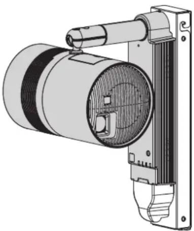
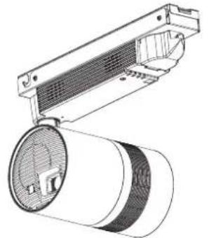
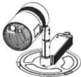
Technical illustration of a mechanical device with cylindrical body and attached housing (no text or symbols)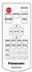
* Above illustration is shown in combination of this product and optional Mount Bracket.
Thank you for purchasing this Panasonic product.
■ This product is used in combination with optional Mount Bracket (Model No.: ET-JPC200BU / ET-JPC200WU) or Floor Stand Kit (Model No.: ET-JPF200BU / ET-JPF200WU). This product cannot be used by itself.
■ Before operating this product, please read the instructions carefully and save this manual for future use.
■ Before using this product, be sure to read "Read this first!" (→ pages 4 to 12).
■ Refer to “Operating Instructions – Content Manager Manual” for signage playback.
Contents
Read this first!
Chapter 1 Preparation
Precautions for use
Cautions when installing....
Cautions when transporting
Security
Notes regarding the wireless LAN
Art-Net
Cautions on use
Storage
Disposal
Accessories
Optional accessories....
About your projector
Remote control..... Projector body....26
Preparing the remote control 28
Inserting and removing the batteries 28
When using multiple projectors 28
Chapter 2 Getting Started
Before the installation 30
Installation method 30
Installation form 30
Projection direction
Projection dimensions 32
Setting up 35
Installing the projector 35
Adjusting the projection position 35
Connecting 37
Before connecting 37
Connecting example: External devices 37
Attaching the caps to the connecting terminals.....38
Chapter 3 Basic Operations
Turning on/off the projector 40
Power indicator 40
Turning on the projector 41
When the initial setting screen is displayed....41
Making adjustments and selections 43
Turning off the projector 44
Projecting 4 45
Selecting the input 45
Adjusting the projection 46
Using SD cards 47
Notes on use 17 47
Data protection
Cards that can be used with the projector ....47
Inserting an SD card 20 48
Ejecting the SD card 48
Operating with the remote control 49
Switch on/off spotlight display 49
Adjusting the volume ..... 22.....
Using the AV mute function22....50
Setting the remote control ID numbers 50
24
Chapter 4 Settings
Menu navigation 25 52
Navigating through the menu 52
Main menu 53
Sub-menu 54
[PICTURE] menu 56
[PICTURE MODE] 56
[CONTRAST] 56
[BRIGHTNESS] 56
[COLOR] 56
[TINT] 57
[COLOR TEMPERATURE] 57
[DIMMER] 58
[COLOR MATCHING] 58
[LIGHTING] menu 60
[LIGHTING] 60
[PATTERN] 60
[MEMORY VIEWER] menu 62
[VIEW] 62
[SORT] 62
[AUTOPLAY] 62
[INTERVAL] 62
[EFFECT] 63
[GUIDE] 63
[SETUP] menu
[PROJECTOR ID]
[PROJECTION METHOD]
[VERTICAL FLIP]....
[SHIFT]
[ASPECT]
[KEYSTONE]
[SIGNAGE]
[DIRECT PLAY SETTING]....
[ECO MANAGEMENT]....
[INITIAL STARTUP]
[STARTUP INPUT SELECT]....
[AUDIO SETTING]
[DC OUT]
[STATUS]
[SCHEDULE]
[DATE AND TIME] 73
[SAVE ALL USER DATA] 74
[LOAD ALL USER DATA] 74
[INITIALIZE] 74
[SERVICE PASSWORD] 75
[NETWORK] menu 76
[PROJECTOR NAME] 76
[WIRED LAN] 76
[WIRELESS LAN]
[NETWORK CONTROL] 80
[Panasonic APPLICATION] 81
[NETWORK STATUS] 82
[Art-Net] 83
[Art-Net STATUS] 86
[MIRRORING] 86
[DISPLAY OPTION] menu 88
[HDMI IN]....
[ON-SCREEN DISPLAY] 88
[AV MUTE] 89
[DISPLAY LANGUAGE] menu 90
Changing the display language 90
[SECURITY] menu 91
[SECURITY PASSWORD] 91
[SECURITY PASSWORD CHANGE] 91
[TEST PATTERN] menu 92
[TEST PATTERN] 92
Chapter 5 Operations
64
Memory Viewer function 94
Files that can be played back with the Memory
Viewer function 94
Displaying the Memory Viewer screen 95
Operating the Memory Viewer screen 95
Playing back still images 97
Playing back movies 98
Direct playback 100
Memory Viewer screen descriptions 101
Network connection 102
When connecting via wired LAN 102
When connecting via wireless LAN 103
Web control function 71 106
Computer that can be used for setting 106
Accessing from the web browser 106
MIRRORING function 125
Chapter 6 Maintenance
Light source/temperature indicators 128
When an indicator lights up 128
Inspection and maintenance 129
Before maintaining the projector 129
Maintenance 77 129
Inspection
Troubleshooting 130
FAQ 131
Chapter 7 Appendix
Technical information 133
Using the PJLink protocol 133
Using Art-Net function 133
Control commands via LAN 135
Glossary of network terms 138
Specifications 140
Dimensions 142
List of compatible signals 143
Index 144
Read this first!
WARNING:
- Disconnect the power from the projector by turning off the circuit breaker or disconnecting the power plug from the outlet when this projector is not in use for a prolonged period of time.
- To prevent electric shock, do not remove cover. No user serviceable parts inside. Refer servicing to qualified service personnel.
- Do not remove the earthing pin on the mains plug. This apparatus is equipped with a three prong earthing-type mains plug. This plug will only fit an earthing-type mains socket. This is a safety feature. If you are unable to insert the plug into the mains socket, contact an electrician. Do not defeat the purpose of the earthing plug.
WARNING: TO REDUCE THE RISK OF FIRE OR ELECTRIC SHOCK, DO NOT EXPOSE THIS PRODUCT TO RAIN OR MOISTURE.
WARNING: RISK OF ELECTRIC SHOCK. DON'T OPEN.
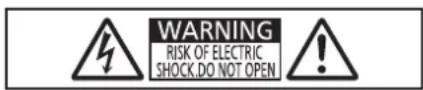
Indicated on the projector

The lightning flash with arrowhead symbol, within an equilateral triangle, is intended to alert the user to the presence of uninsulated “dangerous voltage” within the product’s enclosure that may be of sufficient magnitude to constitute a risk of electric shock to persons.

The exclamation point within an equilateral triangle is intended to alert the user to the presence of important operating and maintenance (servicing) instructions in the literature accompanying the product.
WARNING: Do not look at the light emitted from the lens while the projector is being used.

RG2
Indicated on the projector
CAUTION: Use of controls or adjustments or performance of procedures other than those specified herein may result in hazardous radiation exposure.
Notice on laser
This projector is the Class 3R laser product that complies with IEC 60825-1:2007.
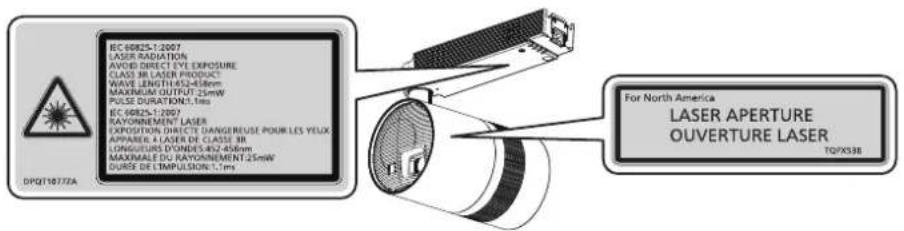
text_image
BC-60825-T-2007 LASER RADIATION AVOID DIRECT EYE EXPOSURE CLASS 3B LASER PRODUCT WAVE LENGTH:45±4.56mm MAXIMUM OUTPUT:25mW PULSE DURATION:1,ms BC-60825-T-2007 RAYONNEMENT® LASER EXPOSITORS DIRECTE DANGEREUSE POUR LES YELIX APPAREL A LASER DE CLASSE 3B LONGUIRES D'ONDES:45±456mm MAXIMALE DU RAYONNEMENT:25mW DURSE DE L'EMPULSION:1,ms For North America LASER APERTURE OUVERTURE LASER TQTX538 DPQT1077ZA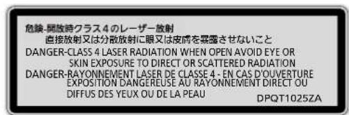
text_image
危険-開放時クラス4のレーザー放射 直接放射又は分散放射に眼又は皮膚を霊露させないこと DANGER-CLASS 4 LASER RADIATION WHEN OPEN AVOID EYE OR SKIN EXPOSURE TO DIRECT OR SCATTERED RADIATION DANGER-RAYONNEMENT LASER DE CLASSE 4 - EN CAS D'OUVERTURE EXPOSITION DANGEREUSE AU RAYONNEMENT DIRECT OU DIFFUS DES YEUX OU DE LA PEAU DPQT1025ZA(Inside of product)
WARNING (USA and Canada)
- Not for use in a computer room as defined in the Standard for the Protection of Electronic Computer/Data Processing Equipment, ANSI/NFPA 75.
- For permanently connected equipment, a readily accessible disconnect device shall be incorporated in the building installation wiring.
NOTIFICATION (Canada)
This class B digital apparatus complies with Canadian ICES-003.
Product Identification Marking is located on the bottom of the Wireless LAN Adaptor.
For USA-California Only
This product contains a CR Coin Cell Lithium Battery which contains Perchlorate Material – special handling may apply.
See www.dtsc.ca.gov/hazardouswaste/perchlorate
FCC NOTICE (USA)
Declaration of Conformity
Model Number: PT-JX200FBU / PT-JX200FWU
Trade Name: Panasonic
Responsible Party: Panasonic Corporation of North America
Address: Two Riverfront Plaza, Newark, NJ 07102-5490
General Contact: http://www.panasonic.com/support
Projector Contact: http://panasonic.net/avc/projector/
This device complies with Part 15 of the FCC Rules.
Operation is subject to the following two conditions:
(1) This device may not cause harmful interference, and (2) this device must accept any interference received, including interference that may cause undesired operation.
To assure continued compliance, follow the attached installation instructions and do not make any unauthorized modifications.
CAUTION:
This equipment has been tested and found to comply with the limits for a Class B digital device, pursuant to Part 15 of the FCC Rules. These limits are designed to provide reasonable protection against harmful interference in a residential installation. This equipment generates, uses and can radiate radio frequency energy and, if not installed and used in accordance with the instructions, may cause harmful interference to radio communications. However, there is no guarantee that interference will not occur in a particular installation. If this equipment does cause harmful interference to radio or television reception, which can be determined by turning the equipment off and on, the user is encouraged to try to correct the interference by one of the following measures:
- Reorient or relocate the receiving antenna.
- Increase the separation between the equipment and receiver.
- Connect the equipment into an outlet on a circuit different from that to which the receiver is connected.
- Consult the dealer or an experienced radio/BD technician for help.
Any changes or modifications not expressly approved by Panasonic Corp. of North America could void the user's authority to operate this device.
This device is restricted to indoor use when operated in the 5.15 to 5.25 GHz frequency range.
The user may find the booklet “Something About Interference” available from FCC local regional offices helpful.
FCC Warning:
To assure continued FCC emission limit compliance, follow the attached installation instructions. This includes using shielded interface cables when connecting to computer or peripheral devices. Also, any unauthorized changes or modifications to this equipment could void the user's authority to operate this device.
FCC NOTICE (USA and Canada)
This device complies with Part 15 of FCC Rules and RSS-Gen of IC Rules.
Operation is subject to the following two conditions:
(1) This device may not cause harmful interference, and (2) this device must accept any interference received, including interference that may cause undesired operation of this device.
This transmitter must not be co-located or operated in conjunction with any other antenna or transmitter.
This product is restricted to indoor use due to its operation in the 5.15 to 5.25 GHz frequency range.
FCC and IC require this product to be used indoors for the frequency range 5.15 to 5.25 GHz to reduce the potential for harmful interference to co-channel Mobile Satellite systems. High power radars are allocated as primary users of the 5.25 to 5.35 GHz and 5.65 to 5.85 GHz bands. These radar stations can cause interference with and/or damage this product.
The available scientific evidence does not show that any health problems are associated with using low power wireless devices.
There is no proof, however, that these low power wireless devices are absolutely safe. Low power Wireless devices emit low levels of radio frequency energy (RF) in the microwave range while being used.
Whereas high levels of RF can produce health effects (by heating tissue), exposure to low-level RF that does not produce heating effects causes no known adverse health effects.
Many studies of low-level RF exposures have not found any biological effects. Some studies have suggested that some biological effects might occur, but such findings have not been confirmed by additional research.
Wireless LAN adaptor has been tested and found to comply with FCC/IC radiation exposure limits set forth for an uncontrolled equipment and meets the FCC radio frequency (RF) Exposure Guidelines in KDB 447498 D01 and RSS-102 of the IC radio frequency (RF) Exposure rules.
Federal Communication Commission (FCC) / IC Radiation Exposure Statement
This EUT is compliance with SAR for general population/uncontrolled exposure limits in ANSI/IEEE C95.1-1999/IC RSS-102 and had been tested in accordance with the measurement methods and procedures specified in KDB 447498 D01. This equipment should be installed and operated with minimum distance 20 cm between the radiator & your body.
CAUTION:
Be aware of the following limits before using the Wireless LAN Module.
• To use the Wireless LAN Module, an access point needs to be obtained.
- Do not use the Wireless LAN Module to connect to any wireless network (SSID*) for which you do not have usage rights. Such networks may be listed as a result of searches. However, using them may be regarded as illegal access.
*SSID is a name for identifying a particular wireless network for transmission.
- Do not subject the Wireless LAN Module to high temperatures, direct sunlight or moisture.
- Do not bend, or subject the Wireless LAN Module to strong impacts.
- Do not disassemble or alter the Wireless LAN Module in any way.
- Do not attempt to install the Wireless LAN Module in any incompatible device.
- Do not remove the Wireless LAN Module from the host product during operations.
• Data transmitted and received over radio waves may be intercepted and monitored.
- To avoid malfunctions caused by radio wave interface, keep the host product away from the devices such as other wireless LAN devices, microwaves and the devices that use 2.4 GHz and 5 GHz signals when using the Wireless LAN Module.
- When noises occur due to the static electricity, etc., the host product might stop operating for the protection of the devices. In this case, turn the host product Off with Mains power On / Off switch, then turn it On again.
- Depending on the area, this Wireless LAN Module may not be available.
WARNING:
POWER
The wall outlet or circuit breaker (with rated current of 20 A or less) shall be installed near the equipment and shall be easily accessible when problems occur. If the following problems occur, cut off the power supply immediately.
Continued use of the projector in these conditions will result in fire, electric shock, or will cause visual impairment.
- If foreign objects or water get inside the projector, cut off the power supply.
- If you notice smoke, strange smells or noise coming from the projector, cut off the power supply.
Please contact your dealer for repairs, and do not attempt to repair the projector yourself.
During a thunderstorm, do not touch the projector or the cable.
Electric shocks can result.
Do not do anything that might damage the power cord or the power plug.
If the power cord is used while damaged, electric shocks, short-circuits or fire will result.
- Do not damage the power cord, make any modifications to it, place it near any hot objects, bend it excessively, twist it, pull it, place heavy objects on top of it or wrap it into a bundle.
Ask your dealer to carry out any repairs to the power cord that might be necessary.
Do not use a power cord other than the one supplied with the optional accessories.
Using the power cord other than the one supplied with the optional Mount Bracket and Floor Stand Kit may cause shorting or overheating, result in electric shocks or fire. Also, using the power cord supplied with the optional accessories without grounding at the outlet side may cause electric shocks.
Completely insert the power plug into the wall outlet and the power connector into the projector terminal.
If the plug is not inserted correctly, electric shocks or overheating will result.
- Do not use plugs which are damaged or wall outlets which are coming loose from the wall.
Do not handle the power plug and power connector with wet hands.
Failure to observe this will result in electric shocks.
Do not overload the wall outlet.
If the power supply is overloaded (ex., by using too many adapters), overheating may occur and fire will result.
Clean the power plug regularly to prevent it from becoming covered in dust.
Failure to observe this will cause a fire.
- If dust builds up on the power plug, the resulting humidity can damage the insulation.
- If not using the projector for an extended period of time, pull the power plug out from the wall outlet.
Pull the power plug out from the wall outlet and wipe it with a dry cloth regularly.
■ ON USE/INSTALLATION
Ask your dealer or a building electrician for installing the projector to a wall or ceiling.
Inadequate installation may result in a fire, an electric shock, or a falling accident.
- Work of electrical wiring must be performed by qualified personnel only.
Use the installation kit (Mount Bracket) specified by Panasonic when the projector is used by installing on a wall or ceiling.
Inadequate kit may result in a falling accident, a fire, or an electric shock.
Use the installation kit (Floor Stand Kit) specified by Panasonic when the projector is used standing on the floor.
Inadequate stand may result in a tipping accident, a fire, or an electric shock.
Secure the safety of a foothold when directly accessing the main unit of the projector if the projector is installed on a wall or ceiling.
You may tip over or fall down when adjusting the image position or inserting/removing the SD card, resulting in an injury.
Make sure that the mounting work is carried out by two or more persons if the projector is installed on a wall or ceiling.
Failure to observe this may result in damage or deformation of the projector, serious accidents or injury caused by falling.
Do not install the projector on a wall or ceiling that cannot bear the weight.
Doing so may result in a fire or an electric shock due to falling of the projector.
WARNING:
Do not install the projector in a location that cannot bear the weight, location that is not stable, or location that is tilted when the projector is used standing on the floor.
Doing so may result in the projector falling off or tipping, causing damage or deformation, or a serious accident or injury.
Do not install the projector in a passageway.
Bumping into the projector or tripping on the power cord may cause a fire, electric shock, or injury.
- When installing the projector in a passageway, take measures to prevent physical contact with the projector by setting up a fence or similar things.
Do not set up the projector in humid or dusty places or in places where the projector may come into contact with oily smoke or steam.
Using the projector under such conditions will result in fire, electric shocks or deterioration of components.
Deterioration of components may cause the projector to fall down.
Do not place the projector on soft materials such as carpets or sponge mats.
Doing so will cause the projector to overheat, which can cause burns, fire or damage to the projector.
Do not use the projector whose outer case is damaged due to falling or other reasons.
Continued use of the projector in such a condition will result in fire, electric shock, or exposure to dangerous laser radiation.
Please contact your dealer for repairs, and do not attempt to repair the projector yourself.
Do not cover the air intake/exhaust ports.
Doing so will cause the projector to overheat, which can cause fire or damage to the projector.
- Do not place the projector in narrow, badly ventilated places.
- Do not bring a cloth or papers close to the projector, as these materials could be drawn into the air intake port.
- Keep the air intake/exhaust ports on the power supply unit away from walls or objects by 300 mm (11-13/16") or more.
Do not look at the light emitted from the lens while the projector is being used.
Do not enter the projection luminous flux using an optical device (such as magnifier or mirror).
Doing so can cause loss of sight.
- Strong light is emitted from the projector's lens. Do not look at this light.
- Be especially careful not to let young children look into the lens. In addition, turn off the power and cut off the power supply when you are away from the projector.
Never attempt to remodel or disassemble the projector.
High voltages can cause fire or electric shocks.
- For any inspection, adjustment and repair work, please contact your dealer.
Doing so may cause exposure to dangerous laser radiation.
- The laser module is built in this projector. Follow procedures specified in the Operating Instructions to make operations and adjustments.
Do not allow metal objects, flammable objects, or liquids to enter inside of the projector. Do not allow the projector to get wet.
Doing so may cause short circuits or overheating, and result in fire, electric shock, or malfunction of the projector.
- If liquid enters inside of the projector, cut off the power supply and consult your dealer.
ACCESSORIES
Do not use or handle the batteries improperly, and refer to the following.
Failure to observe this will cause burns, batteries to leak, overheat, explode or catch fire.
- Do not use unspecified batteries.
- Do not use chargeable batteries.
- Do not disassemble dry cell batteries.
- Do not heat the batteries or place them into water or fire.
- Do not allow the + and – terminals of the batteries to come into contact with metallic objects such as necklaces or hairpins.
- Do not store or carry batteries together with metallic objects.
- Store the batteries in a plastic bag and keep them away from metallic objects.
- Make sure the polarities (+ and −) are correct when inserting the batteries.
- Do not use a new battery together with an old battery or mix different types of batteries.
- Do not use batteries with the outer cover peeling away or removed.
WARNING:
If the battery fluid leaks, do not touch it with bare hands, and take the following measures if necessary.
- Battery fluid on your skin or clothing could result in skin inflammation or injury.
Rinse with clean water and seek medical advice immediately. - Battery fluid coming in contact with your eyes could result in loss of sight.
In this case, do not rub your eyes. Rinse with clean water and seek medical advice immediately.
Remove the depleted batteries from the remote control promptly.
• Leaving them in the remote control may result in fluid leakage, overheating, or explosion of the batteries.
Do not allow children to reach the batteries and covers.
Accidentally swallowing them can cause physical harm.
- If swallowed, seek medical advice immediately.
CAUTION:
POWER
When disconnecting the power cord, be sure to hold the power plug and power connector.
If the power cord itself is pulled, the lead will become damaged, and fire, short-circuits or serious electric shocks will result.
When not using the projector for an extended period of time, disconnect the power plug from the wall outlet.
Failure to do so may result in fire or electric shock.
Disconnect the power plug from the wall outlet before carrying out any cleaning.
Failure to do so may result in electric shock.
■ ON USE/INSTALLATION
Do not place the projector in extremely hot locations.
Doing so will cause the outer casing or internal components to deteriorate, or result in fire.
- Take particular care in locations exposed to direct sunlight or near heaters.
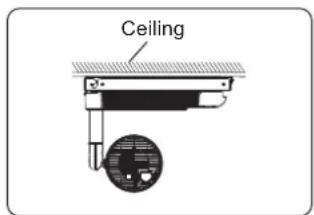
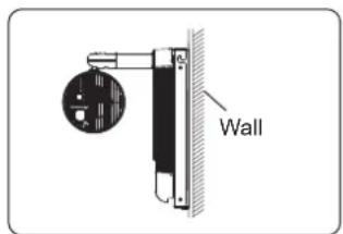
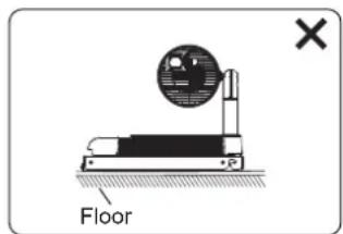
When using the optional Mount Bracket, install the projector on a wall or ceiling in the specified direction.
Installing on a floor, or installing in a wrong direction may result in a falling accident.
Do not use the projector together with dimmers such as a light controller.
Doing so will result in the damage to the components inside the projector and will cause fire.
Do not put excessive force on the projector by hanging on the projector or dangling any object.
Doing so will result in falling of the projector.
Do not place heavy objects on top of the projector.
Failure to observe this will cause the projector to become unbalanced and fall, which could result in damage or injury. The projector will be damaged or deformed.
Do not put your weight on this projector.
You could fall or the projector could break, and injury will result.
- Be especially careful not to let young children stand or sit on the projector.
Do not place your hands or other objects close to the air exhaust port.
Doing so will cause burns or damage your hands or other objects.
- Heated air comes out of the air exhaust port. Do not place your hands or face, or objects which cannot withstand heat close to this port.
Do not stand in front of the lens while the projector is being used.
Doing so can cause damage and burns to clothing.
- Extremely strong light is emitted from the projector's lens.
Do not place objects in front of the lens while the projector is being used.
Doing so can cause fire, damage to an object, or malfunction of the projector.
- Extremely strong light is emitted from the projector's lens.
Do not install the projector in a location where salt pollution or corrosive gas may occur.
Doing so may result in falling due to corrosion or cause the projector to rust. Also, it may result in malfunctions.
CAUTION:
Never plug headphones and earphones into
Excessive sound pressure from headphones and earphones can cause hearing loss.
Do not allow unattended children to use the projector.
Incorrect handling will cause them to be exposed to dangerous laser radiation.
- Use the projector under the supervision and control of adults.
Always disconnect all cables before moving the projector.
Moving the projector with cables still attached can damage the cables, which will cause fire or electric shocks.
■ ACCESSORIES
When not using the projector for an extended period of time, remove the batteries from the remote control.
Failure to observe this will cause the batteries to leak, overheat, catch fire or explode, which may result in fire or contamination of surrounding area.
■ MAINTENANCE
Ask your dealer about inspection by a qualified technician once every three years.
Using the projector for long time without inspection may result in fire, electric shocks, or falling of the projector.
- For inspection fee, ask your dealer.
Panasonic disclaims all liability for any accidents or any damage caused by setting up the projector in an inappropriate environment or mounting the projector using methods that are not described in the Operating Instructions.
Brazil Only Brasil Apenas
natural_image
Line drawing of a remote control box with two buttons and directional arrows indicating rotation (no text or symbols)•SOLID SHINE is a trademark of Panasonic Corporation.
- DLP and the DLP logo are registered trademarks or trademarks of Texas Instruments.
- HDMI, the HDMI Logo, and High-Definition Multimedia Interface are trademarks or registered trademarks of HDMI Licensing LLC in the United States and other countries.
- PJLin ^M is a registered trademark or pending trademark in Japan, the United States, and other countries and regions.
• RoomView and Crestron RoomView are registered trademarks of Crestron Electronics, Inc.
Crestron Connected™ and Fusion RV are trademarks of Crestron Electronics, Inc.
- Art-Net™ Designed by and Copyright Artistic Licence Holdings Ltd
- Wi-Fi, Wi-Fi Direct™ and Miracast™ are registered trademarks or trademarks of Wi-Fi Alliance.
•SDHC Logo is a trademark of SD-3C, LLC.
- Windows, Internet Explorer and Microsoft Edge are registered trademarks or trademarks of Microsoft Corporation in the United States and other countries.
- Mac, Mac OS, OS X, iPad, iPhone, iPod touch, and Safari are trademarks of Apple Inc., registered in the United States and other countries.
- IOS is a trademark or registered trademark of Cisco in the U.S. and other countries and is used under license.
- Google, Google Chrome and Android are trademarks or registered trademarks of Google Inc.
- Adobe, Adobe Flash Player, and Adobe Reader are trademarks or registered trademarks of Adobe Systems Inc. in the United States and/or other countries.
- Intel is a trademark of Intel Corporation registered in the United States and/or other countries.
- Some of the fonts used in the on-screen menu are Ricoh bitmap fonts, which are manufactured and sold by Ricoh Company, Ltd.
- The software included in this product is prohibited to transfer, copy, reverse assembling, reverse compiling, reverse engineering, and/or exporting against the exporting laws and regulations.
- The copyright protection laws will apply to the contents displayed using this product.
The manufacturer or the distributor of this product assumes no responsibility of any kind for the problem such as the infringement of copyright, caused by using this product. Take caution not to infringe the right of the copyright owner and any other right holder when editing and using the contents to display.
- This product is licensed under AVC Patent Portfolio License, VC-1 Patent Portfolio License, and MPEG-4 Visual Patent Portfolio License, and following actions except for the personal or non-profit use are not licensed.
- Recording the image information in compliance with the AVC standard, the VC-1 standard, and the MPEG-4 Visual standard (AVC/VC-1/MPEG-4 video hereafter)
- Playing back the AVC/VC-1/MPEG-4 video recorded by consumer practicing in a private activity, or AVC/VC-1/MPEG-4 video acquired from the licensed provider
For details, refer to the website of MPEG LA, LLC (http://www.mpegla.com).
The trademarks and product trademarks for various companies are fully respected even if they are not mentioned.
Please note that the ^ and ^TM symbols are not specified in this manual.
Software information regarding this product
This product incorporates the following software.
(1) the software developed independently by or for Panasonic Corporation
(2) the software licensed under the GNU GENERAL PUBLIC LICENSE Version2.0 (GPL V2.0)
(3) the software licensed under the GNU LESSER GENERAL PUBLIC LICENSE Version2.1 (LGPL V2.1)
The software that is categorized as (2) and (3) is distributed in the hope that it will be useful, but WITHOUT ANY WARRANTY, without even the implied warranty of MERCHANTABILITY or FITNESS FOR A PARTICULAR PURPOSE. For details, refer to the license conditions included in the supplied CD-ROM.
For customers who contacted the following contact center, Panasonic provides complete and machine-readable source code based on GPL V2.0, LGPL V2.1 or software licensed under other terms imposing source code disclosure obligations in actual expenses, together with information about each copyright owner, for a period of at least 3 years from the purchase of this product.
Contact Center (Email): sav.pj.gpl.pavc@ml.jp.panasonic.com
■Illustrations in this manual
- Unless otherwise specified, the illustration of installation status of the projector in this document is using the optional Mount Bracket.
- Illustrations of the projector, combination status with the optional accessories, and screen may vary from the actual product.
■Reference pages
- Reference pages in this manual are indicated as (→ page 00).
Terms
- In this manual, the "Wireless remote control unit" accessory is referred to as "Remote control".
- In this manual, the SD memory card and the SDHC memory card are referred to as "SD card".
Features of the Projector
Quick Steps
For details, refer to the corresponding pages.
Variety of projection function
▶ Various playback method can be selected, such as projecting the still image/movie in the SD card just with the projector, projecting the image in the computer by transmitting it wirelessly, projecting the contents of the Blu-ray disc via HDMI.
The signage function is installed allowing playback of the still image/movie/music files in the SD card and turning off/on the projector according to the schedule created by yourself.
Easy setup
▶ Three installation methods of wall mount, ceiling mount and floor standing are supported ^4 .
The display can be freely layout by projecting the image vertically or horizontally.
The projector is equipped with an electric 2.2x zoom, electric focus lens.
A design fitting in to the space
▶ A spotlight type design is adopted to easily conform to a space requiring conformity to the design, such as a store.
1. Install the projector in combination with the optional accessory.
(→ page 35)
- Be sure to ask your dealer or a building electrician for installing the projector to a wall or ceiling with the optional Mount Bracket.
- When using the optional Mount Bracket, refer to the Installation Instructions of the Mount Bracket.
- To use the projector standing on the floor, refer to the Operating Instructions of the Floor Stand Kit.

2. Connect with external devices.
(→ page 37)

3. Switch on the projector.
(→ page 41)

4. Make initial settings.
(→ page 41)
•Take this step when you switch on the power for the first time after purchasing the projector.

5. Select the input to project.
(→ page 45)

6. Adjust the projection.
(→ page 46)
Chapter 1 Preparation
This chapter describes things you need to know or check before using the projector.
Precautions for use
Cautions when installing
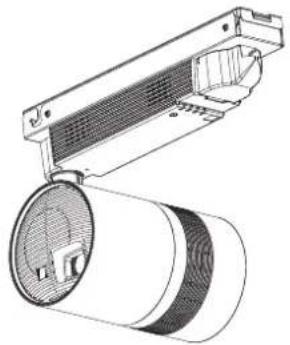
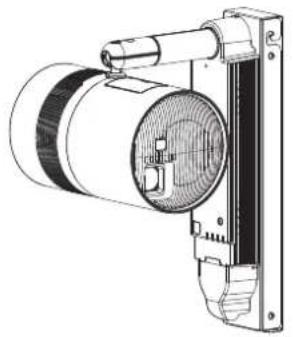
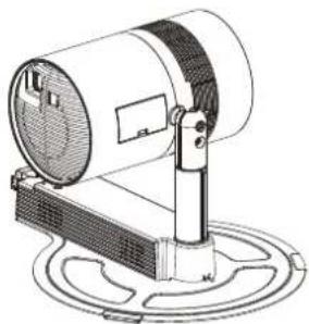
■ Use the projector in combination with the optional Mount Bracket or Floor Stand Kit.
To use the projector, the optional Mount Bracket (Model No.: ET-JPC200BU/ET-JPC200WU) or Floor Stand Kit (Model No.: ET-JPF200BU/ET-JPF200WU) is required.
natural_image
Technical line drawing of a mounted industrial fan or fixture with a cylindrical roller and ventilation slots (no text or symbols)Installation example when installing on the ceiling
natural_image
Technical line drawing of a mechanical device with no visible text or symbolsInstallation example when installing on the wall
natural_image
Technical line drawing of a cylindrical device mounted on a base with a circular base and mounting bracket (no text or symbols)Installation example when installing on the floor
■Do not set up the projector outdoors.
The projector is designed for indoor use only.
■Do not set up the projector in the following locations.
- Places where vibration and impacts occur such as in a car or vehicle: Doing so may cause damage to internal components or malfunction.
- Locations near the sea or areas affected by corrosive gas: Corrosion may cause the projector to fall off, shorten the life of the parts or cause the projector to malfunction.
- Near the exhaust of an air conditioner: Depending on the conditions of use, the screen may fluctuate in rare cases due to the heated air from the air exhaust port or the hot or cooled air. Make sure that the exhaust from the projector or other equipment, or the air from the air conditioner does not blow toward the front of the main unit of the projector.
- Places with sharp temperature fluctuations near lights (such as studio lamps): Doing so may result in deformation of the projector due to heat, which may cause malfunctions.
The operating environment temperature of the projector should be between 0 °C (32 °F) and 40 °C (104 °F) when using it at elevations lower than 1 000 m (3 281') above sea level, and between 0 °C (32 °F) and 35 °C (95 °F) when using it at elevations between 1 000 m (3 281') and 2 700 m (8 858') above sea level. - Near high-voltage power lines or near motors: Doing so may interfere with the operation of the projector.
- Places where there is high-power laser equipment: Directing a laser beam onto the lens surface causes damage to the DLP chip.
■ Do not install the projector at elevations of 2 700 m (8 858') or higher above sea level.
Doing so may shorten the life of the components and result in malfunctions.
■ Be sure to ask your dealer or a building electrician for installing the projector to a wall or ceiling with the optional Mount Bracket.
•The optional Mount Bracket is required.
• Work of electrical wiring must be performed by qualified personnel only.
- Panasonic takes no responsibility for any damage to the projector caused by mounting the product to a wall or ceiling in any method not specified by Panasonic or caused by inappropriate installation environment, even if the warranty period of the projector has not expired.
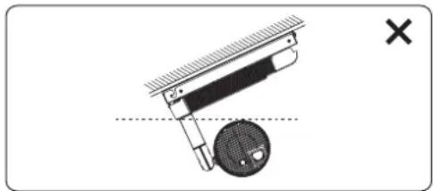
■ Do not install the projector on a ceiling with the power supply unit tilted right or left.
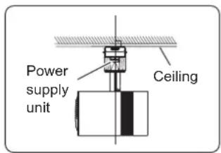
text_image
Power supply unit CeilingCan be installed Cannot be installed
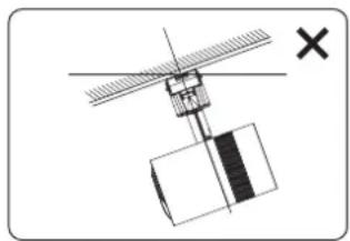
natural_image
Pure mechanical diagram showing a lever and shaft assembly without any text, numbers, or symbols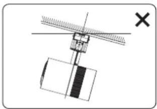
natural_image
Simple line drawing of a mechanical or electrical component with no visible text, numbers, or symbols.Cannot be installed
■ When installing the projector on a sloped ceiling, install in a direction that the pole side of the power supply unit will be higher than the power <∅/|> button side.
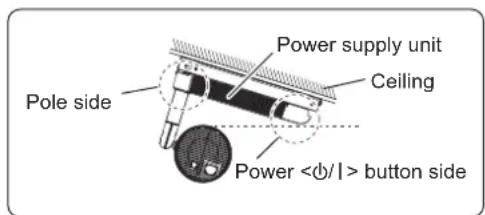
text_image
Power supply unit Ceiling Pole side Power <φ/l> button sideCan be installed Cannot be installed
natural_image
Diagram of a mechanical device with a circular component and a cross mark, no text or symbols present■ When using the optional Mount Bracket, do not install the projector on a floor.
text_image
CeilingCan be installed
text_image
WallCan be installed Cannot be installed
text_image
Floor■ When installing the projector to a wall using the optional Mount Bracket, set the pole side higher than the power <∅/|> button side and the power supply unit vertically.
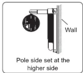
text_image
Wall Pole side set at the higher side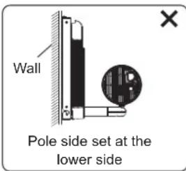
text_image
Wall Pole side set at the lower side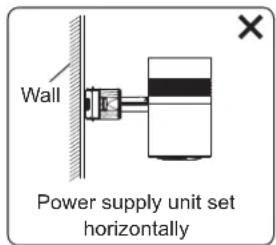
text_image
Wall Power supply unit set horizontally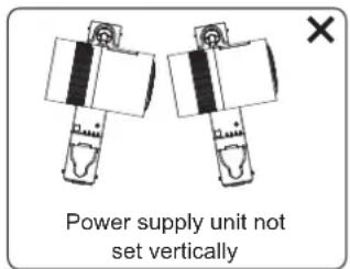
text_image
Power supply unit not set verticallyCan be installed Cannot be installed Cannot be installed Cannot be installed
■ When using the projector in combination with the optional Floor Stand Kit, install on a horizontal surface.
■ When using the projector in combination with the optional Mount Bracket or Floor Stand Kit, use the power cord supplied with the optional accessories, and ground at the outlet side.
■ Focus adjustment
The projection lens is thermally affected by the light from the light source, making the focus unstable in the period just after switching on the power. It is recommended that images be projected continuously for at least 30 minutes before the focus is adjusted.
■Cautions when setting up the projector
- Do not block the ventilation ports (intake and exhaust) of the projector.
- Prevent hot and cool air from the air conditioning system to blow directly to the ventilation ports (intake and exhaust) of the projector.
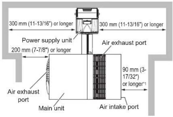
text_image
300 mm (11-13/16") or longer 300 mm (11-13/16") or longer Power supply unit 200 mm (7-7/8") or longer Air exhaust port 90 mm (3- 17/32") or longer" Air exhaust port Main unit Air intake port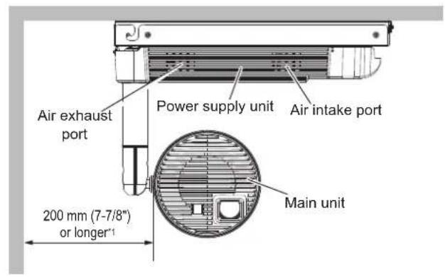
text_image
Air exhaust port Power supply unit Air intake port 200 mm (7-7/8") or longer¹ Main unit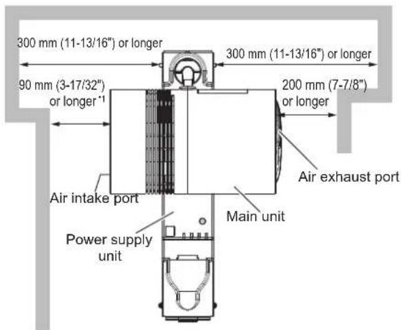
text_image
300 mm (11-13/16") or longer 90 mm (3-17/32") or longer '1' 300 mm (11-13/16") or longer 200 mm (7-7/8") or longer Air intake port Power supply unit Main unit Air exhaust port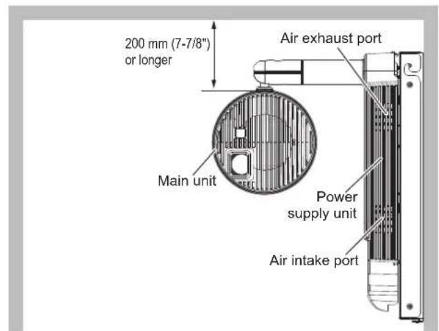
text_image
200 mm (7-7/8") or longer Air exhaust port Main unit Power supply unit Air intake port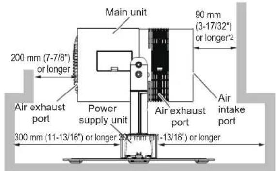
text_image
Main unit 90 mm (3-17/32") or longer*2 200 mm (7-7/8") or longer Air exhaust port Power supply unit Air exhaust port Air intake port 300 mm (11-13/16") or longer 300 mm (11-13/16") or longer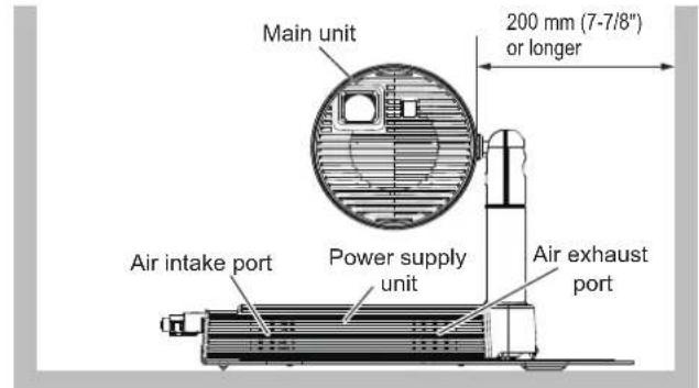
text_image
Main unit 200 mm (7-7/8") or longer Air intake port Power supply unit Air exhaust port*1 Distance from the wall or ceiling surface which will block the whole air intake port
*2 Distance from the wall or floor surface which will block the whole air intake port
- Do not install the projector in a confined space.
When installing the projector in a confined space, provide air conditioning or ventilation separately. Exhaust heat may accumulate when the ventilation is not enough, triggering the protection circuit of the projector.
Cautions when transporting
- Before transporting, tighten the ball joint fixing screw and the ball joint stopper using the supplied Allen wrench (opposite side size 3/16"). Transporting while they are loose may cause the fingers to be caught in between or malfunction.
- When the optional Floor Stand Kit is used, hold the bottom of the floor stand attached to the projector, and handle so that excessive vibration or shock is not applied when transporting. Failure to do so may damage the internal components and result in malfunctions.
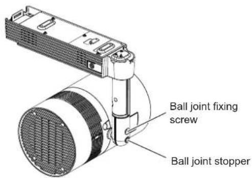
text_image
Ball joint fixing screw Ball joint stopper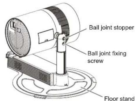
text_image
Ball joint stopper Ball joint fixing screw Floor standSecurity
When using this product, take safety measures against the following incidents.
- Personal information being leaked via this product
- Unauthorized operation of this product by a malicious third party
- Interfering or stopping of this product by a malicious third party
Take sufficient security measures. (→ pages 91, 120)
- Make your password difficult to guess as much as possible.
- Change your password periodically. Set the password from the [SECURITY] menu → [SECURITY PASSWORD CHANGE].
- Panasonic Corporation or its affiliate companies will never ask for your password directly. Do not divulge your password in case you receive such inquiries.
- The connecting network must be secured by a firewall, etc.
- Set a password for the web control and restrict the users who can log in. Set the password for the web control from the [Change password] page of the web control screen.
■Security when using the wireless LAN product
The advantage of a wireless LAN is that information can be exchanged between a PC or other such equipment and a wireless access point using radio waves, instead of using a LAN cable, as long as you are within range for radio transmissions.
On the other hand, because the radio waves can travel through obstacles (such as walls) and are available everywhere within a given range, problems of the type listed below may occur if security settings are insufficient.
• Transmitted data may be intercepted
A malicious third-part may intentionally intercept radio waves and monitor the following transmitted data.
-Personal information such as your ID, password, credit card number
-Content of an Email
- Illegally accessed
A malicious third party may access your personal or corporate network without authorization and engage in the following types of behavior.
- Retrieve personal and/or secret information (information leak)
- Spread false information by impersonating a particular person (spoofing)
- Overwrite intercepted communications and issue false data (tampering)
- Spread harmful software such as a computer virus and crash your data and/or system (system crash)
Since most wireless LAN adapters or access points are equipped with security features to take care of these problems, you can reduce the possibility of these problems occurring when using this product by making the appropriate security settings for the wireless LAN device.
Some wireless LAN devices may not be set for security immediately after purchase. To decrease the possibility of occurrence of security problems, be sure to make all security related settings according to the operation instructions supplied with each wireless LAN device before using a wireless LAN device.
Depending on the specifications of the wireless LAN, a malicious third party may be able to break security settings by special means.
Panasonic asks customers to thoroughly understand the risk of using this product without making security settings, and recommends that the customers make security settings at their own discretion and responsibility.
Notes regarding the wireless LAN
Radio wave in the 2.4 GHz/5 GHz band is used when the wireless LAN connection function of the projector is used. The license of wireless station is not required, but understand the following when using.
■Do not use close to other wireless devices.
Following devices may be using radio wave in the same bandwidth as the projector. Using the projector close to these devices may cause the communication to be disabled or the communication speed to slow down due to interference of radio wave.
- Microwave oven, etc.
- Industrial, scientific, or medical devices, etc.
- In-plant wireless station for identifying moving vehicles used in the manufacturing lines at a plant
- Specified low power wireless station
■ Do not use cell phone, television, or radio as much as possible close to the projector.
Cell phone, television, or radio is using radio wave with different bandwidth from the projector, so there is no effect on the wireless LAN communication or the send/receive on these devices. However, noise may occur in the audio or video due to the radio wave from the projector.
■ Radio wave for wireless LAN communication does not go through the reinforcing bars, metal, or concrete.
The projector can communicate through wall or floor made of wood or glass (excluding the glass with metal mesh embedded), but it cannot communicate through wall or floor made of reinforcing bars, metal, or concrete.
■ Do not use the projector as much as possible in a location where static electricity is generated.
The communication via wireless LAN or wired LAN may be prone to disruption when the projector is used in a location where static electricity or noise is generated.
There is a rare case that the LAN connection may not be established due to static electricity or noise. In such case, turn off the power with the power button on the remote control or the power supply unit of the projector, remove the source of problematic static electricity or noise, and turn the power of the projector back on.
■Using the projector outside the country
The wireless LAN function is forbidden when you use the projector outside the country or region where you purchased it. Note that depending on countries or regions, there are restrictions on the channels and frequencies at which you can use the wireless LAN.
■Available wireless LAN channels
The channels (frequency range) that can be used differ according to the country or region. Please use the wireless LAN feature in compliance with the laws of each country.
For MIRRORING mode ( page 125)
(When the connecting method is [MIRRORING])
| Standard Channels used Frequency band (Center frequency) | |
| IEEE802.11b/g/n 1 - 1 | 2.412 GHz - 2.462 GHz |
| IEEE802.11a/n | 36 / 40 / 44 / 48 5.180 GHz - 5.240 GHz |
| 149 / 153 / 157 / 161 5.745 GHz - 5.805 GHz | |
For M-DIRECT mode ( page 78)
(When the connecting method is [M-DIRECT] of [Panasonic APPLICATION])
| Standard Channels used Frequency band (Center frequency) | ||
| IEEE802.11b/g/n 1 - 11 | 2.412 GHz - 2.462 GHz | |
| IEEE802.11a/n | 36 / 40 / 44 / 48 | 5.180 GHz - 5.240 GHz |
| 149 / 153 / 157 / 161 / 165 | 5.745 GHz - 5.825 GHz | |
For USER mode ( page 78)
(When the connecting method is [USER] of [Panasonic APPLICATION])
| Standard | Channels used | Frequency band (Center frequency) | Scanning type |
| IEEE802.11b/g/n 1 - | 11 2.412 GHz - 2.462 GHz Active scanning | ||
| IEEE802.11a/n | 36 / 40 / 44 / 48 5.180 GHz - 5.240 GHz Active scanning | ||
| 52 / 56 / 60 / 64 5.260 GHz - 5.320 GHz Passive scanning | |||
| 100 / 104 / 108 / 112 / 116 / 132 / 136 / 140 | 5.500 GHz - 5.700 GHz(except 5.600GHz - 5.650GHz) | Passive scanning | |
| 149 / 153 / 157 / 161 / 165 5.745 GHz - 5.825 GHz Active scanning |
* The passive scanning is performed by changing radio to the channel being scanned in each country.
■ This device is restricted to indoor use when operated in the 5.15 to 5.25 GHz frequency range (Channels 36 to 48).
Art-Net
"Art-Net" is an Ethernet communication protocol based on the TCP/IP protocol.
By using the DMX controller and the application software, illumination and stage system can be controlled. Art-Net is made based on DMX512 communication protocol.
Cautions on use
■To get a good picture quality
- In order to view a beautiful image in higher contrast, prepare an appropriate environment. Draw curtains or blinds over windows and turn off any lights near the projection surface to prevent outside light or light from indoor lamps from shining onto the projection surface.
- The projection lens of the projector is thermally affected by the light from the light source, making the focus unstable in the period just after switching on the power. The focus will stabilize after projection for more than 30 minutes has elapsed.
■ Do not touch the surface of the projection lens with your bare hands.
The finger print or dirt on the projection lens surface may be projected enlarged to the projection surface.
■DLP chips
- The DLP chips are precision-made. Note that in rare cases, pixels of high precision could be missing or always lit. Note that such phenomenon does not indicate malfunction.
- Directing a high-power laser beam onto the projection lens surface can damage the DLP chip.
Light source
Laser is used as the light source of the projector, and it has the following characteristics.
- The luminance of the light source will decrease by duration of usage.
When the light source is used for approximately 20 000 hours, its luminance is reduced to half its initial luminance. 20 000 hours is the estimated duration, and it varies depending on individual differences and usage conditions.
If the light source goes off or the brightness reduces noticeably, ask your dealer about replacement of the light source unit.
■Computer and external device connections
When connecting a computer or an external device, read related section of this document including the use of power cords and shielded cables.
Storage
If you store the projector, please keep it in a dry room.
Disposal
To dispose of the product, ask your local authorities or dealer for correct methods of disposal. Also, dispose of the product without disassembling.
22 - ENGLISH
Accessories
Make sure that the following accessories are provided with your projector. Numbers enclosed in < > show the number of accessories.
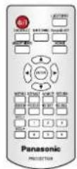
Wireless remote control unit <1> (N2QAYA000134)
Card slot cap <1> (DPHG1011ZA)
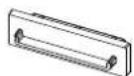
(Attached to the projector at the time of purchase)
HDMI terminal cap <1>
(TKKL5575)

(Attached to the projector at the time of purchase)
LAN terminal cap <1> (TKKL5576)

(Attached to the projector at the time of purchase)
AAA/R03 or AAA/LR03 battery <2>
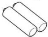
(For remote control unit)
CD-ROM <1>
(1JK1JX200FU)

Allen wrench <1> (DPPB1006ZA)
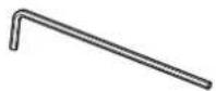
(Opposite side size 3/16")
Connector secure lock <1> (TTRA0185)
Attention
• After unpacking the projector, discard the packaging material properly.
- For missing accessories, consult your dealer.
- Store small parts in an appropriate manner, and keep them away from small children.
Note
- The supplied connector secure lock is used together with the Mount Bracket or the Floor Stand Kit. Take care not to lose it.
- The model numbers of accessories are subject to change without prior notice.
Contents of the supplied CD-ROM
The contents of the supplied CD-ROM are as follows.
| Instruction/list (PDF) Operating Instructions – Functional Manual | ||
| Software Multi Monitoring & Control Software (Windows) | This software allows you to monitor and control multiple displays (projector or flat panel display) connected to the LAN. | |
Note
- The "List of Compatible Device Models" for the flat panel display compatible with the "Multi Monitoring & Control Software" can be downloaded from the Panasonic website (http://panasonic.net/prodisplays/).
Optional accessories
| Optional accessories (product name) | Model No. Outer color Usage | ||
| Mount Bracket | ET-JPC200BU Black | *1 | Dedicated fixture necessary to use the projector mounted directly to a wall or ceiling. |
| ET-JPC200WU White | *2 | ||
| Floor Stand Kit | ET-JPF200BU Black | *1 | Dedicated fixture necessary to use the projector set on a floor or flat surface. |
| ET-JPF200WU White | *2 | ||
*1 Used in combination with PT-JX200FBU.
*2 Used in combination with PT-JX200FWU.
Attention
- Use the projector in combination with the optional Mount Bracket or Floor Stand Kit.
Note
- The model numbers of optional accessories are subject to change without prior notice.
About your projector
Remote control
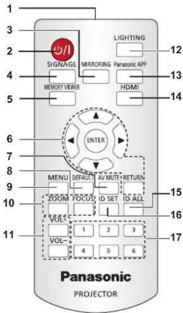
text_image
1 2 3 4 5 6 7 8 9 10 11 PANasonic PROJECTOR SIGNAGE MIRRORING PARASONIC APP MEMORY VIEWER HDMI LIGHTING 12 13 14 ENTER MENU DEFAULT AV MUTE RETURN ZOOM FOCUS ID SET ID ALL VOL 1 2 3 VOL 4 5 6 15 16 171 Remote control signal transmitter
2 Power <∅/|> button (⊕ standby / | power on)
Turns on/off the power of the projector. (→ page 40)
3
4
5
6 ▲▼◀▶ buttons/
7
8
9
10
11
12
13
14
15
16
17 Number (<1> - <6>) buttons
Used in a multiple projector environment.
Used to enter ID number or password.
Attention
- Do not drop the remote control.
- Avoid contact with liquids or moisture.
- Do not attempt to modify or disassemble the remote control.
- Observe the following instructions that are indicated on the caution label at the back of the remote control:
-Do not use a new battery together with an old battery.
-Do not use unspecified batteries.
-Make sure the polarities (+ and-) are correct when inserting the batteries.
For other instructions, read the instructions related to batteries that are described in "Read this first!".
CAUTION
1.Do not use old battery with new one.
2 Do not use batteries other than
the type specified.
3.Be sure the batteries are inserted properly.

Caution label at the back of the remote control
Note
- When operating the remote control by directly pointing to the remote control signal receiver at the power supply unit of the projector, operate the remote control within a distance approximately 7 m (22'11") or shorter from the remote control signal receiver. The remote control can control at angles of up to ±30° vertically and horizontally, but the effective control range may be reduced.
- If there are any obstacles between the remote control and the remote control signal receiver, the remote control may not operate properly.
- The signal from the remote control can be reflected off the projection surface to operate the projector. However, the operating range may be limited from light reflection loss or the shape of the projection surface.
- The remote control may not operate properly if the remote control signal receiver on the power supply unit of the projector is directly receiving strong light, such as fluorescent light. Install the projector in a place distant from the light source.
Projector body
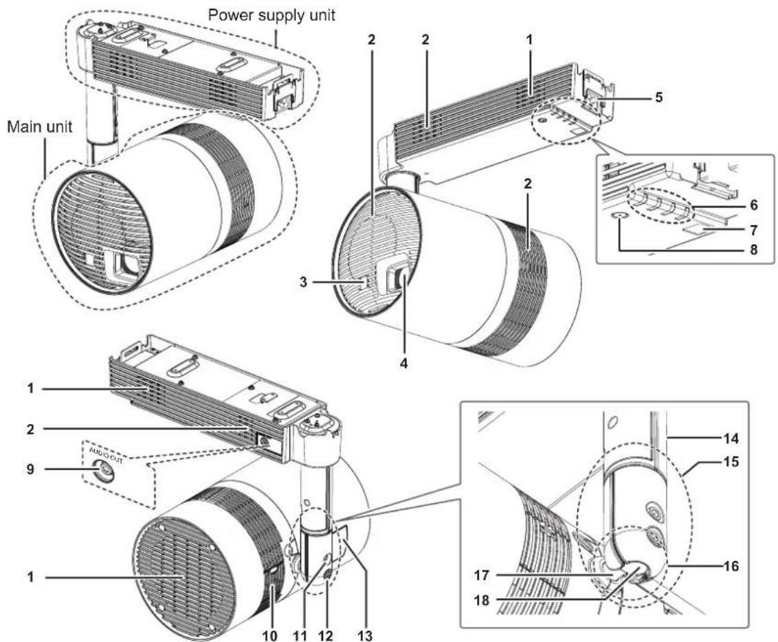
text_image
Power supply unit Main unit 1 2 2 1 5 3 4 2 6 7 8 1 2 9 AUDIO CUT 10 11 12 13 14 15 16 17 181 Air intake port
2 Air exhaust port
3 Remote control signal receiver (Main unit)
4 Projection lens
5
Connects the power cord supplied with the optional Mount Bracket or Floor Stand Kit.
6 Indicators ( pages 27, 128)
7 Remote control signal receiver (Power supply unit)
8 Power <∅/|> button (∅ standby / | power on)
Turns on/off the power of the projector. (→ page 40)
9
This is the terminal to output audio signal when a audio signal is input to the
10
11 Ball joint fixing screw
Fixes the angle between the shaft holder and the main unit after adjusting the orientation of the main unit. To rotate the shaft holder, loosen the ball joint fixing screw. (→ page 35)
12 Ball joint stopper
To free the ball joint movable part, remove the stopper.
(→ page 35)
13 Connecting terminals cover (→ page 27)
The connecting terminals are inside.
14 Pole
15 Shaft holder
16 Ball joint movable part
17 Shaft
18 Ball joint
■Indicators
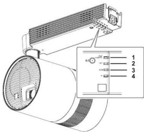
text_image
Technical diagram of an air conditioner unit with labeled components and a close-up inset showing internal wiring or wiring layout.1 Power indicator
2 Light source indicator
3 Temperature indicator
4 SD card indicator
■Connecting terminals and terminal
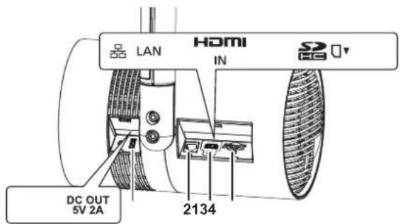
text_image
LAN HDMI IN 22000 DC OUT 5V 2A 21341
2
3
4 SD card slot
Supports SD memory card and SDHC memory card.
(→ page 47)
Attention
- The LAN cable connecting to the projector directly should be wired indoors only.
- Store small parts such as SD card in an appropriate manner, and keep them away from small children.
Preparing the remote control
Inserting and removing the batteries
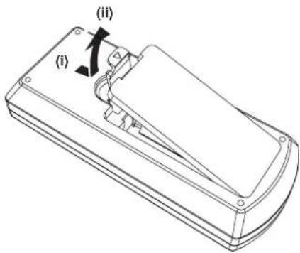
text_image
(i) (ii)Fig. 1
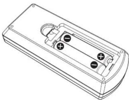
natural_image
Line drawing of a remote control box with four buttons and mounting holes (no text or symbols)Fig. 2
1) Open the cover. (Fig. 1)
2) Insert the batteries and close the cover (insert the ● side first). (Fig. 2)
- When removing the batteries, perform the steps in reverse order.
When using multiple projectors
When you use multiple projectors together, you can control all the projectors simultaneously or each projector individually using single remote control, if a unique ID number is assigned to each projector.
When using the projectors by setting the ID numbers, set the ID number ([1] - [6]) of the projector body after initial settings have been completed. Then, set the ID number of the remote control.
For initial settings, refer to "When the initial setting screen is displayed" (→ page 41).
The factory default ID number of the projector (projector body and remote control) is set to [ALL], so you can use it as it is. Set the ID numbers of the projector body and remote control as necessary.
For details on setting the ID number of the remote control, refer to "Setting the remote control ID numbers" (→ page 50).
Note
- Set the ID number of the projector body from the [SETUP] menu → [PROJECTOR ID].
Chapter 2 Getting Started
This chapter describes things you need to do before using the projector such as the setup and connections.
Before the installation
This section describes the display method using the projector.
Installation method
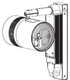
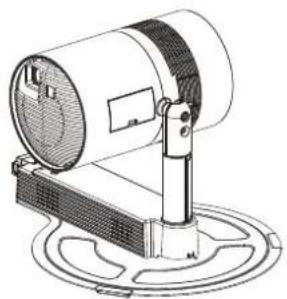
The projector can be installed in three methods of wall or ceiling mount and floor standing depending on the combination of the optional accessories. Purchase the optional accessories depending on the installation method. The Mount Bracket (Model No.: ET-JPC200BU, ET-JPC200WU) is required for wall or ceiling mounting installation, and the Floor Stand Kit (Model No.: ET-JPF200BU, ET-JPF200WU) is required for floor standing installation.
natural_image
Technical line drawing of a mounted industrial fan or fixture with a cylindrical component (no text or symbols visible)Installation example when installing on the ceiling
natural_image
Technical line drawing of a mechanical device with cylindrical components and mounting bracket (no text or symbols)Installation example when installing on the wall
natural_image
Technical line drawing of a mechanical device with a cylindrical component mounted on a base (no text or symbols visible)Installation example when installing on the floor
Installation form
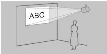
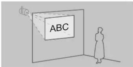
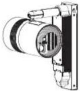
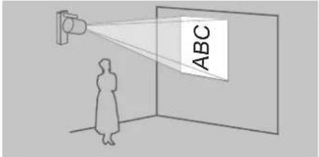
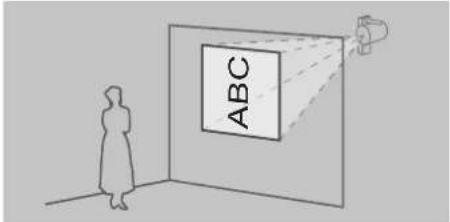
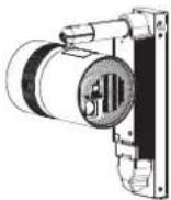
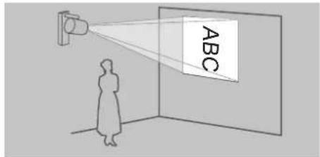
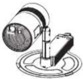
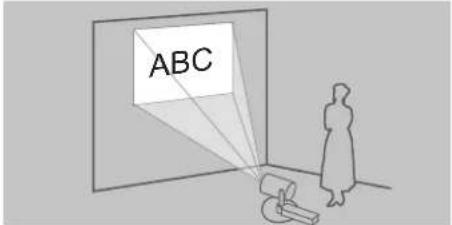
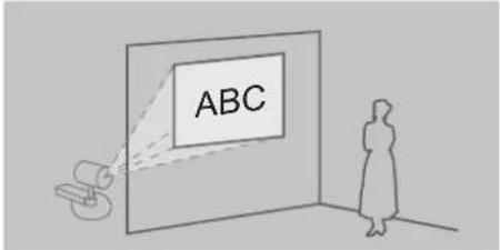
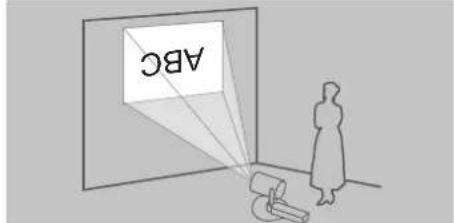
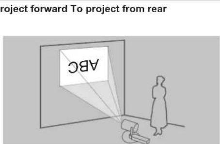
There are a total of four installation forms: two for the projection method and two for the display direction, for each of the three installation methods. Set the [SETUP] menu → [PROJECTION METHOD] (→ page 64) and [VERTICAL FLIP] (→ page 64) depending on the installation form in combination with the optional accessories. The following illustration is an example when the orientation of the main unit is adjusted to the position as indicated on the left of the table.
■Installation form when installing on the ceiling
Orientation of main unit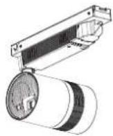 | To project forward To project from rear | (Using the translucent screen) | ||
 |  | |||
| Menu item Method | Menu item Method | |||
| [PROJECTION METHOD] | [FRONT] | [PROJECTION METHOD] | [REAR] | |
| [VERTICAL FLIP] | [OFF] | [VERTICAL FLIP] | [OFF] | |
Orientation of main unit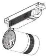 | To project forward To project from rear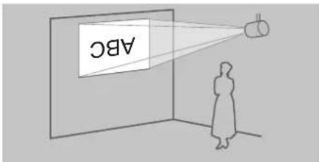 | (Using the translucent screen)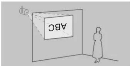 | ||
| Menu item Method | Menu item Method | |||
| [PROJECTION METHOD] | [FRONT] | [PROJECTION METHOD] | [REAR] | |
| [VERTICAL FLIP] | [ON] | [VERTICAL FLIP] | [ON] | |
■Installation form when installing on the wall
| Orientation of main unit | To project forward To project from rear | (Using the translucent screen) | ||
 |  |  | ||
| Menu item Method | Menu item Method | |||
| [PROJECTION METHOD] | [FRONT] | [PROJECTION METHOD] | [REAR] | |
| [VERTICAL FLIP] | [OFF] | [VERTICAL FLIP] | [OFF] | |
text_image
ABC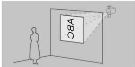
text_image
ABC■Installation form when installing on the floor
| Orientation of main unit | To project forward To project from rear | (Using the translucent screen) | ||
 |  |  | ||
| Menu item Method | Menu item Method | |||
| [PROJECTION METHOD] | [FRONT] | [PROJECTION METHOD] | [REAR] | |
| [VERTICAL FLIP] | [ON] | [VERTICAL FLIP] | [ON] | |
text_image
ABC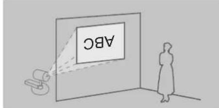
text_image
ABC| Orientation of main unit |
text_image
project forward To project from rear ABCNote
- Above illustrations for installation form are examples for explanation, and it may not be the actual condition of usage. Set the [SETUP] menu → [PROJECTION METHOD] (→ page 64) and the [VERTICAL FLIP] (→ page 64) according to the environment of the usage and the direction of the main unit.
Projection direction
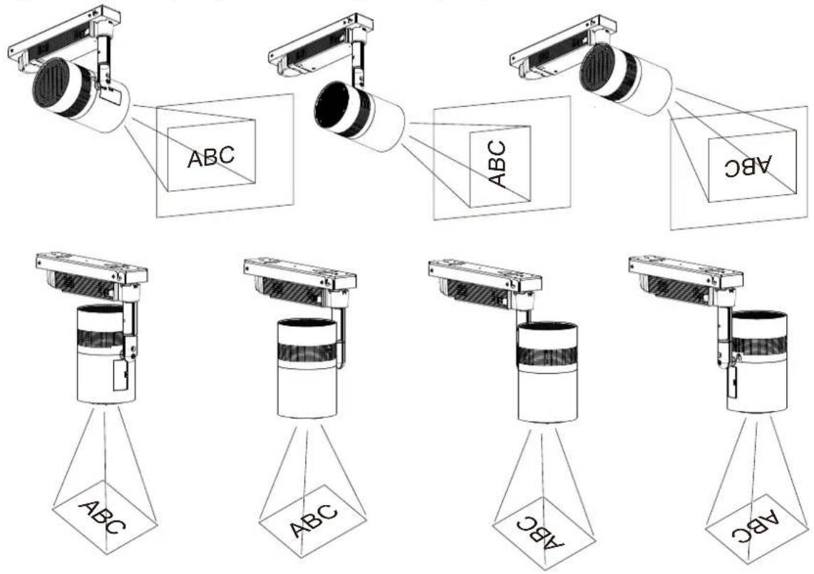
Various expressions are possible by combination of adjustment of the direction of the main unit as described in "Adjusting the projection position" (→ page 35) and the settings of the [SETUP] menu → [PROJECTION METHOD] (→ page 64) and the [VERTICAL FLIP] (→ page 64).
The following illustration is an example when the projector is installed on the ceiling and [PROJECTION METHOD] is set to [FRONT] and [VERTICAL FLIP] is set to [OFF].
text_image
ABC ABC ABC ABC ABC ABC ABCAttention
- When setting up the projector, please pay attention to the cable between the main body and the pole.
Projection dimensions
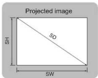
Determine the installation position of wall mount or the setting position of floor standing referencing following illustrations and projection distance dimensions. The size and position of the projected image can be adjusted according to the area and position of the projection surface.
■When installing on the ceiling or wall
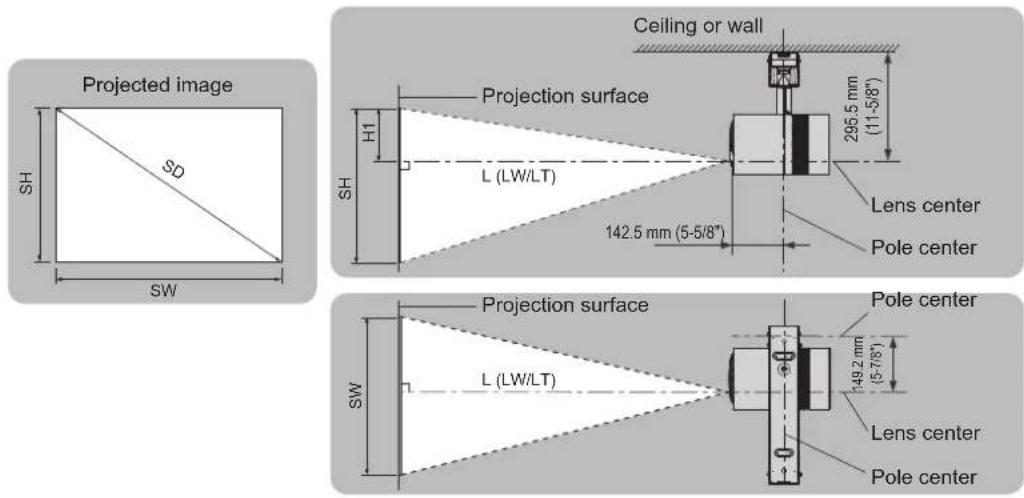
■When standing on the floor
text_image
Projected image SH SD SW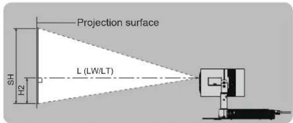
text_image
Projection surface SH H2 L (LW/LT)
text_image
Projection surface MW L (LW/LT)| L (LW/LT)1 | Projection distance (distance from the projection lens surface to the projection surface) (m) | |
| SH Image height (m) | ||
| SW Image width (m) | ||
| SD Image diagonal size (m) | ||
| H | H1 | When installing on the ceiling or wall: Distance from the lens center to the image end (the ceiling/wall surface) (m) |
| H2 When standing on the floor: Distance from the lens center to the image lower end (m) | ||
*1 LW: Minimum projection distance
LT: Maximum projection distance
Attention
- Before setting up, read "Precautions for use" (→ page 16).
- Do not use the projector and the high-power laser equipment in the same room.
The DLP chip can be damaged if a laser beam hits the lens surface.
Projection distance
The dimension in the following table contains a slight error.
Also, it is corrected to become smaller than the specified image size when [KEYSTONE] is used.
■When the image aspect ratio is 4:3
(Unit: m)
| Projected image size Projection distance (L) | Distance from the lens center to the image end (H) | ||||
| Diagonal (SD) Height (SH) Width (SW) Min. (LW) Max. (LT) | |||||
| 0.76 (30") 0.457 | 0.610 0.79 1.75 0.152 | ||||
| 1.02 (40") 0.610 | 0.813 1.06 2.35 0.203 | ||||
| 1.27 (50") 0.762 | 1.016 1.34 2.94 0.254 | ||||
| 1.52 (60") 0.914 | 1.219 1.62 3.54 0.305 | ||||
| 1.78 (70") 1.067 | 1.422 1.89 4.14 0.356 | ||||
| 2.03 (80") 1.219 | 1.626 2.17 4.73 0.406 | ||||
| 2.29 (90") 1.372 | 1.829 2.45 5.33 0.457 | ||||
| 2.54 (100") 1.524 | 2.032 2.72 5.92 0.508 | ||||
| 3.05 (120") 1.829 | 2.438 3.28 7.12 0.610 | ||||
| 3.81 (150") 2.286 | 3.048 4.10 8.90 0.762 | ||||
| 5.08 (200") 3.048 | 4.064 5.48 11.88 1.016 | ||||
Projection distance formula
To use an image size not listed in this manual, check the projected image size SD (m) and use the respective formula to calculate projection distance (L).
The unit of the formula is all “m”. (Value obtained by the following calculation formula contains a slight error.) When calculating a projection distance using image size designation (value in inches), multiply the value in inches by 0.0254 and substitute it into SD in the formula for calculating the projection distance.
■When the image aspect ratio is 4:3
| Minimum projection distance (LW) L = 1.09 | 07 × SD - 0.0507 |
| Maximum projection distance (LT) L = 2.34 | 68 × SD - 0.0379 |
Setting up
Installing the projector
This projector is used in combination with the optional Mount Bracket or Floor Stand Kit.
■When installing on a wall or ceiling
The optional Mount Bracket (Model No.: ET-JPC200BU, ET-JPC200WU) is required to use the projector directly installed on a wall or ceiling.
- Be sure to use the Mount Bracket specified for this projector.
- For installation of the projector to a wall or ceiling, refer to the Installation Instructions of the Mount Bracket.
Attention
- To ensure projector performance and security, be sure to ask your dealer or a building electrician for installing the projector to a wall or ceiling.
■When standing on the floor
The optional Floor Stand Kit (Model No.: ET-JPF200BU, ET-JPF200WU) is required to use the projector set on the floor.
- Be sure to use the Floor Stand Kit specified for this projector.
- For installation of the Floor Stand Kit to the projector, refer to the Operating Instructions of the Floor Stand Kit.
- After installing the Floor Stand Kit, install the projector referencing "Projection dimensions" (→ page 32).
Adjusting the projection position
Adjust the orientation of the main unit to determine the projection position after installing the projector.
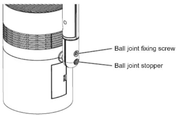
1) Loosen the ball joint fixing screw.
- Loosen the ball joint fixing screw using the supplied Allen wrench (opposite side size 3/16").
text_image
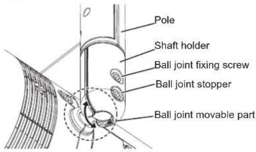
Ball joint fixing screw Ball joint stopper2) Adjust the orientation of the main unit.
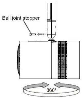
- Rotate the shaft holder and adjust the ball joint movable part to the direction to tilt the main unit, and adjust the orientation of the main unit.
text_image
Pole Shaft holder Ball joint fixing screw Ball joint stopper Ball joint movable part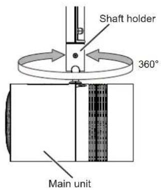
text_image
Shaft holder 360° Main unitThe shaft holder will rotate 360° when the ball joint fixing screw is loosened. Rotate the shaft holder and move the ball joint movable part to the direction to tilt the main unit.
text_image
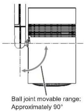
Ball joint stopper 360°The ball joint will become free when the ball joint stopper is removed. The main unit can be rotated 360^ or the main unit can be tilted 90^ at the ball joint movable part.
text_image
Ball joint movable range: Approximately 90°3) Tighten the ball joint fixing screw.
- While supporting the main unit, securely tighten the ball joint fixing screw using the supplied Allen wrench (opposite side size 3/16").
Attention
- The main unit and the power supply unit are connected with cables, etc. Do not rotate or tilt the main unit more than necessary.
- When adjusting the orientation of the main unit while connected to an external device via connection cable, please be careful not to damage the connection cable.
- Please store the ball joint stopper in an appropriate manner for future use.
- Note that your hand may get caught in between the pole and the main unit when the pole joint fixing screw is loosened while holding the pole section.
Note
• After adjusted roughly, fine adjust the projection position while projecting.
Connecting
Before connecting
- Before connecting, carefully read the operating instructions for the external device to be connected.
- Turn off the power of all devices before connecting cables.
- Take note of the following points before connecting the cables. Failure to do so may result in malfunctions.
- When connecting a cable to a device connected to the projector or the projector itself, touch any nearby metallic objects to eliminate static electricity from your body before performing work.
- Do not use unnecessarily long cables to connect a device to the projector or to the projector body. The longer the cable, the more susceptible to noise it becomes. Since using a cable while it is wound makes it act like an antenna, it is more susceptible to noise.
- When connecting cables, connect the earthing end first, then insert the connecting terminal of the connecting device in a straight manner.
- Acquire any connection cable necessary to connect the external device to the system that is neither supplied with the device nor available as an option.
- Some computer models or graphics cards are not compatible with the projector.
- Use a cable compensator when you connect devices to the projector using long cables. Otherwise the image may not display properly.
- Only HDMI signals can be input to the projector. Refer to “List of compatible signals” ( page 143) for the types of video signals that can be used with the projector.
Connecting example: External devices
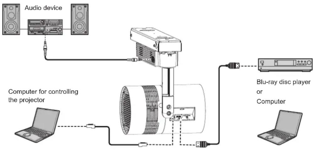
flowchart
graph TD
    A["Audio device"] --> B["Projector"]
    C["Computer for controlling the projector"] --> B
    D["Blu-ray disc player or Computer"] --> B
    B --> E["Computer"]
Attention
- When connecting the projector to a computer or an external device, use the power cord supplied with each device and commercially available shielded cables.
- When adjusting the orientation of the main unit while connected to an external device via connection cable, please be careful not to damage the connection cable.
Note
- For an HDMI cable, use an HDMI High Speed cable that conforms to HDMI standards. If a cable that does not conform to HDMI standards is used, images may be interrupted or may not be displayed.
- The
terminal of the projector can be connected to an external device with a DVI terminal by using an HDMI/DVI conversion cable, but the projector may not project the image properly or function properly with some devices.
•The projector does not support VIERA Link (HDMI). - If you operate the projector using the computer with the resume feature (last memory), you may have to reset the resume feature to operate the projector.
Attaching the caps to the connecting terminals
It is recommended to attach the supplied terminal caps to the
Before attaching the caps, check the shapes of the caps and the places to attach.
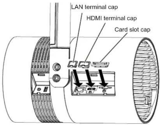
text_image
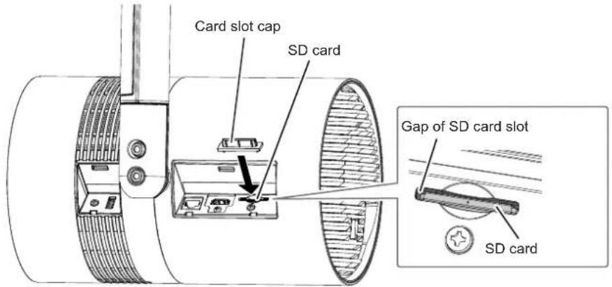
LAN terminal cap HDMI terminal cap Card slot capNote
- Attach the card slot cap with the opening of the "J" shaped rib facing the projector body. However, the card slot cap can also be attached from the opposite side of the rib opening, but it may be difficult to take it out with the finger.
- The card slot cap can be attached even when an SD card is inserted.
The direction of attaching the card slot cap will differ as shown below depending on the presence of the SD card. Check the condition of the SD card slot and the direction of the card slot cap before attaching.
text_image
Card slot cap SD card Gap of SD card slot SD card- Do not insert with excessive force when attaching the cap. Doing so may damage the terminal or the cap.
Also, when attaching the card slot cap with the SD card inserted, the SD card will be in ejected state if it is pressed in too much.
Chapter 3 Basic Operations
This chapter describes basic operations to start with.
Turning on/off the projector
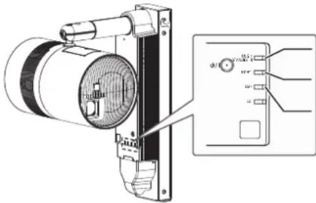
Power indicator
Indicates the status of the power. Check the status of the power indicator
When the light source indicator
text_image
Technical diagram of a mechanical device with labeled components and an inset showing wiring connectionsPower indicator
Light source indicator
Temperature indicator
| Indicator status Projector status | ||
| Off | The power is not supplied to the projector. (The circuit breaker is turned off or the power cord is not connected to the outlet.) | |
| Red | Lighting | The power is switched off. (standby mode)[STANDBY MODE] in the [SETUP] menu → [ECO MANAGEMENT] is set to [ECO].Projection will start when the power <∅/|> button is pressed.The projector may not operate when the temperature indicatoris blinking.(⇨ page 128) |
| Blinking*1 | The power is switched off (in standby mode).[STANDBY MODE] in the [SETUP] menu → [ECO MANAGEMENT] is set to [NETWORK].Projection will start when the power <∅/|> button is pressed.The projector may not operate when the temperature indicatoris blinking.(⇨ page 128) | |
| Blinking*2 | The power is switched off (in standby mode).[STANDBY MODE] in the [SETUP] menu → [ECO MANAGEMENT] is set to [NORMAL].Projection will start when the power <∅/|> button is pressed.The projector may not operate when the temperature indicatoris blinking.(⇨ page 128) | |
| Green Lighting Projecting. | ||
*1 The indicator will blink in frequency of lighting 2.75 seconds → off 0.25 seconds → lighting 0.75 seconds → off 0.25 seconds.
*2 The indicator will blink in frequency of lighting 2.75 seconds → off 0.25 seconds.
Note
- The projector consumes power even in standby mode (when the power indicator
is lighting or blinking in red). Refer to "Power consumption" ( page 140) for the power consumption. - The power indicator
blinks in green if a remote control signal is received. - The power indicator
blinks in green in frequency of lighting 0.8 seconds → off 0.8 seconds while AV mute is in use. - When the computer (including iPad/iPhone/iPod touch, Android devices) performs a connection check on the projector using the Panasonic image transfer application software, the power indicator
blinks in orange.
Turning on the projector
text_image
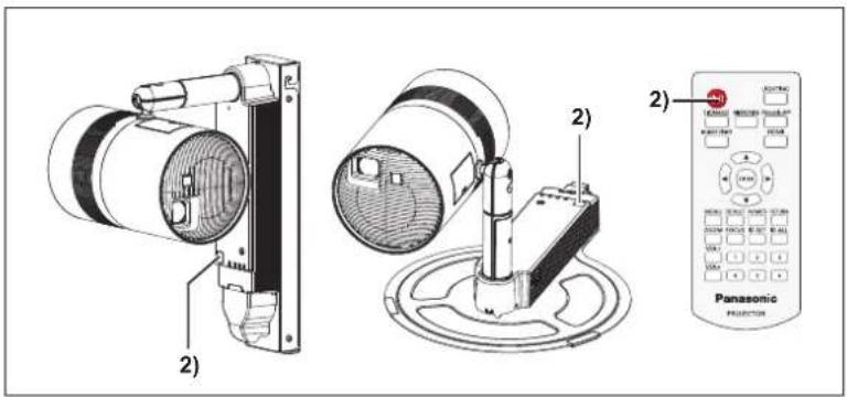
2) 2) Panasonic PROJECTION1) Connect the power cord connected to the projector to an outlet.
- The power indicator
2) Press the power <|>|> button.
- The power indicator
Attention
- When turning on the projector, take notice of the people around the projector and ensure the light from the light source will not flash into their eyes.
- The signage playback function of this projector can play still image/movie/audio files in the SD card or switch on/off the projector according to the schedule registered beforehand.
When using the signage playback function to automatically turn on the projector at the start time set in the schedule, turn on the circuit breaker or connect the power plug to the outlet at least three minutes before the start time.
Refer to "Operating Instructions – Content Manager Manual" for the signage playback.
Note
- The initial setting screen is displayed when the projector is turned on for the first time after purchase or when [ALL USER DATA] in the [SETUP] menu → [INITIALIZE] is executed. Refer to "When the initial setting screen is displayed" (→ page 41).
- If you press the power <∅/|> button on the remote control to turn on the projector, the signal from the remote control can be reflected off the projection surface to operate, but the operating range may be limited due to light reflection loss or the shape of the projection surface. In such cases, operate with the remote control aimed toward the remote control signal receiver on the projector power supply unit.
- It may take longer for the projection to start when the [SETUP] menu → [ECO MANAGEMENT] → [STANDBY MODE] is set to [ECO] or [NETWORK] when compared set to [NORMAL].
- When the power is turned on or an input signal is switched, you may hear a high-frequency driving sound. This is not a malfunction.
- When turning on the project in a low-temperature place, it may take some time before the projection starts and the color of the displayed image becomes stable. This is not a malfunction.
- When the [SETUP] menu → [INITIAL STARTUP] is set to [LAST MEMORY], the power indicator
lights in green and the projection is soon started when the projector was turned off by directly by turning off the circuit breaker or disconnected the power plug from the outlet during the previous use, and the power supply is turned on or the power plug is connected to the outlet again.
When the initial setting screen is displayed
The initial setting screen is displayed when the projector is turned on for the first time after purchase or when [ALL USER DATA] in the [SETUP] menu → [INITIALIZE] is executed. Set the following according to the circumstances. In other occasions, you can change the settings by menu operations.
If you press the
Focus adjustment
Adjust the focus to display the menu screen clearly.
You may also need to adjust the zoom.
Refer to "Adjusting the projection" ( page 46) for details.
1) Press ▲▼◀▶ on the remote control to adjust the focus.
2) Press the
- The projector will continue to consume power when the power is supplied to the projector even if the power is turned off by pressing the power <∅/|> button.
The power consumption during standby can be conserved when the [SETUP] menu → [ECO MANAGEMENT] → [STANDBY MODE] is set to [ECO]. - The projector can be turned off by turning off the circuit breaker or disconnecting the plug of the power cord from the outlet during the projection, but the settings and adjustments performed right before turning off the power may not be reflected.
- Do not turn off the circuit breaker, disconnect the plug of the power cord from the outlet, or eject the SD card while the SD card indicator
is blinking. The projector may not operate properly or the contents of the SD card may get damaged. - When the [SETUP] menu → [ECO MANAGEMENT] → [STANDBY MODE] is set to [NORMAL], the internal cooling fan may operate even during standby.
Projecting
The projection will start after confirming the connection with the external device ( page 37) and then turning on the projector ( page 41). Select the input to project, and adjust the state of the projected image.
Selecting the input
text_image
SIGNAGE MIRRORING Panasonic APP MEMORY VIEWER HDMISwitch the input to project.
The input for projection can be switched directly by pressing the input selection button on the remote control.
1) Press the , , , , or button on the remote control to select the input.
• Image of the selected input is projected.
| Remote control button Input Usage | ||
| HDMI | Switches the input to HDMI.Displays the image input to theterminal from the external device. | |
| Memory Viewer | Switches the input to Memory Viewer.Displays the still image or movie recorded in the SD card using the Memory Viewer function. (→ page 94) | |
| MIRRORING | Switches the input to MIRRORING.Displays the image transmitted wirelessly from the Intel® WiDi / Intel® Pro WiDi / Miracast compatible terminal. | |
| Panasonic APPLICATION | Switches the input to Panasonic APPLICATION.Displays the image transferred from the computer (including iPad, iPhone, iPod touch, or Android devices) using the Panasonic image transfer application software. | |
| Signage | Switches the input to Signage.Plays back and displays the contents such as still image or movie files in the SD card according to the schedule or slideshow setting registered with the Content Manager.For the use of the signage playback function, please refer to the "Operating Instructions – Content Manager Manual".It is also possible to use the signage playback function by setting schedule in the Content Management Software. | |
Note
- When an audio signal is included in each input, it is output from the
- To switch the input to anything other than the HDMI input, it may take seconds to complete the switching. [Please wait...] is displayed on the projection screen when the switching takes time.
- When the
, , , or button is pressed during signage playback, the signage playback is stopped and switches to respective input. - Pressing the
button while the signage playback is in standby or stopped will switch the input to signage, and the signage playback will start or resume. - Refer to "Operating Instructions – Content Manager Manual" for the signage playback.
- The image transfer application software "Wireless Manager ME6.3" compatible with Windows computers or Mac is contained in the supplied CD-ROM. For the image transfer application software compatible with iPad/iPhone/iPod touch, and Android devices, refer to the following URL http://panasonic.net/avc/projector/
- The "Content Management Software" compatible with Windows computers can set schedule used for signage playback. For details, refer to the following URL http://panasonic.net/avc/projector/
Adjusting the projection
Adjust focus and zoom.
1) Press the
button: Adjusts focus. button: Adjusts zoom.
2) Select each item and press ▲▼◀▶ to adjust it.
Note
- When a projection position is required to be adjusted, adjust according to the steps described in "Adjusting the projection position" (→ page 35).
- The operation can be sped up by pressing ▲▼◀▶ for at least one second.
- Only [FOCUS] is shown in yellow so that the displayed menu item can be recognized by color, even when the projector is not focused and displayed characters are unreadable.
- The projection lens is thermally affected by the light from the light source, making the focus unstable in the period just after switching on the power. It is recommended that images be projected continuously for at least 30 minutes before the focus is adjusted.
Using SD cards
The SD card slot of the projector supports the SD memory card and the SDHC memory card.
Notes on use
Observe following.
- Do not disassemble or modify.
- Do not apply strong shock, bend, drop, get wet, etc.
- Do not touch the metal contacts with your hands or metal.
- Do not peel off the affixed label or affix new label or seal.
- Do not leave in a place that will become hot (inside a car, under direct sunlight, etc.).
- Do not leave in a place with high humidity or dust.
- Do not leave in a place with extreme temperature difference. Condensation may occur.
- Do not leave in a place where static electricity or electromagnetic radiation is generated.
- Store SD card in an appropriate manner, and keep it away from small children.
Data protection
- To prevent losing important data, set the write protect switch on the SD card to "LOCK" position. Turn off the write protect switch when saving or editing a file.
Write protect switch
- Use a felt-tip pen (oil-based) when writing a character in the memo space of the label. Do not use pencil or ballpoint pen. The card may get damaged or the data may be destroyed.
- Manage the contents in the SD card under your responsibility. It is recommended to take a backup of important data on other disc, etc.
- Panasonic assumes no responsibility for loss of data recorded by yourself, or any other direct or indirect damage.
- It is recommended to physically destroy the card with a hammer, etc., when discarding.
Cards that can be used with the projector
SD memory card (2 GB)
(Including the miniSD memory card and the microSD memory card)
SDHC memory card (4 GB, 8 GB, 16 GB, 32 GB)
(Including the miniSDHC memory card and the microSDHC memory card)
Note
•Commercially available SD card is supported.
- Use the SD card with high data transfer speed. If the data transfer speed is slow, movie or music recorded in the SD card may not be played back properly or it may take time to display a still image. (Speed class: Class 10 recommended)
- Only the cards formatted in FAT16 or FAT32 can be used.
Inserting an SD card
1) Insert the card securely into the SD card slot with the front of the card facing outward, from the side with cut corner.
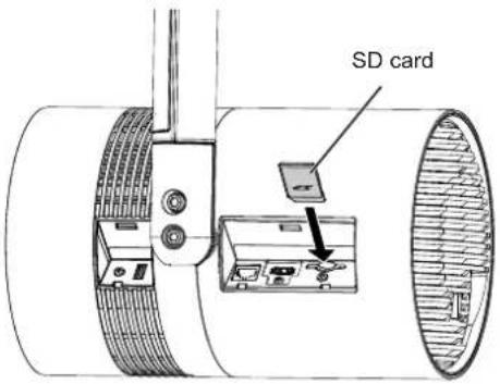
text_image
SD cardAttention
- When using the miniSD memory card or the microSD memory card, always use the dedicated miniSD memory card adapter or the microSD memory card adapter, and insert/eject together with the adapter.
•Take care not to leave the adapter in the SD card slot. - Do not insert anything other than the SD card, such as metal or foreign object, into the SD card slot.
- Please refrain from frequent insertion and ejection of the SD card in short period of time. Wait for at least five seconds after inserting until ejecting the SD card, and wait for at least five seconds until inserting it again after ejecting. The projector requires approximately five seconds to recognize the insertion or ejection of the SD card.
Ejecting the SD card
1) Confirm that the SD card indicator
2) Lightly press center of the SD card.
3) Hold onto the slightly ejected SD card and pull it out.
- Note that pulling out the card forcibly while it is inserted will cause a malfunction.
Attention
- Do not perform the following when the projector is accessing the SD card (while the SD card indicator < SD> is blinking).
-Ejecting the SD card
-Turning off the circuit breaker
-Disconnecting the plug of the power cord from the outlet - Applying vibration or shock
- Do not perform the insertion and ejection of the SD card in short period of time. Wait for at least five seconds after inserting until ejecting the SD card, and wait for at least five seconds until inserting it again after ejecting. The projector requires approximately five seconds to recognize the insertion and ejection of the SD card.
Operating with the remote control
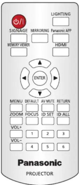
text_image
LIGHTING SIGNAGE MIRRORING Panasonic APP MEMORY VIEWER HDMI ENTER MENU DEFAULT AV MUTE RETURN ZOOM FOCUS ID SET ID ALL VOL+ 1 2 3 VOL- 4 5 6 Panasonic PROJECTORSwitch on/off spotlight display
Enable/disable the setting items in [PATTERN] menu.
LIGHTING
button
1) Press the button.
- The spotlight based on the items set for the user ([USER1] - [USER5]) selected in the [PATTERN] individual adjustment screen is displayed.
2) Press the button again.
- The spotlight and the frame gradation disappear and the projection returns to the input image.
Note
- When you press the
button, the setting of the user ([USER1] - [USER5]) in the [PATTERN] detailed setting screen is displayed. Refer to "[LIGHTING] menu" (→ page 60) for details about the pattern setting. - If the spotlight and the frame gradation are set to [OFF] in the [PATTERN] detailed setting screen, the spotlight and the frame gradation cannot be displayed when you press the
button.
Adjusting the volume
The audio output volume can be adjusted.
1) Press the
| Increases the volume. | |
| Decreases the volume. |
Using the AV mute function
The projection and the audio output can be paused temporarily when the projector is not used for specific time such as during break or preparation.
AV MUTE

button
1) Press the
•The projection and the audio are stopped.
2) Press the
•The projection and the audio are resumed.
Note
- The power indicator
blinks in green in frequency of lighting 0.8 seconds → off 0.8 seconds while AV mute is in use. - The projector has no built-in speakers. Audio is output from the external sound system connected to the
Setting the remote control ID numbers
When you use the system with multiple projectors, you can operate all the projectors simultaneously or each projector individually using single remote control, if a unique ID number is assigned to each projector.
After setting the ID number ([1] - [6]) of the projector, set same ID number on the remote control.
The factory default ID number of the projector is set to [ALL]. When using a single projector, press the
ID SET
ID ALL


button
1) Press the
2) Within five seconds, press the number (<1> - <6>) buttons to set the one-digit ID number preset on the projector.
- If you press the
Attention
- Since the ID number of the remote control can be set without the projector, do not press the
button on the remote control carelessly. If the button is pressed and no number (<1> - <6>) button is pressed within five seconds, the ID number returns to its original value before the button was pressed. - The ID number set on the remote control will be stored unless it is set again. However, it will be erased if the remote control is left with dead batteries. Set the same ID number again when the batteries are replaced.
Note
- Set the ID number of the projector from the [SETUP] menu [PROJECTOR ID].
Chapter 4 Settings
This chapter describes the settings and adjustments you can make using the on-screen menu.
Menu navigation
The on-screen menu (Menu) is used to perform various settings and adjustments of the projector.
Navigating through the menu
Operating procedure
MENU
button
1) Press the
- Pressing the
or - Some items may not be allowed to adjust or use depending on the selected signal input to the projector. The menu items that cannot be adjusted or used are shown in gray characters, and they cannot be selected.
- Some items can be adjusted even if signals are not input.
- Individual adjustment screen is cleared automatically if no operation is performed for approximately five seconds.
- For menu items, refer to "Main menu" (→ page 53) and "Sub-menu" (→ page 54).
Resetting the adjusted value to the factory default
If the

button
1) Press the button on the remote control.

Note
- You cannot reset all the settings to the factory default at a time.
- To reset all the adjusted sub-menu items to the factory defaults at a time, perform the [SETUP] menu → [INITIALIZE] (→ page 74).
- Some items cannot be reset to the factory default settings even when the
button on the remote control is pressed. Adjust those items individually. - The square mark under the bar scale in the individual adjustment screen indicates the factory default value. The position of the square mark varies by the input signal.
Current adjustment value

Factory default setting
Setting the on-screen display to show/hide
If you hold down the
- The factory default setting for [COLOR TEMPERATURE] is [MIDDLE].
- The [USER] setting is shared with [User] under [Color] in the Content Manager. Changes to the [USER] setting are also reflected in [User] under [Color] in the Content Manager. For details, please refer to "Operation method of the schedule" → "Color" in the "Operating Instructions – Content Manager Manual".
Adjusting white balance as desired
1) Press ▲▼ to select [COLOR TEMPERATURE].
2) Press ◀▶ or the button.
- The [COLOR TEMPERATURE] individual adjustment screen is displayed.
3) Press ◀▶ to select [USER].
- The [COLOR TEMPERATURE] screen is displayed.
5) Press ▲▼ to select [RED], [GREEN], or [BLUE].
6) Press ◀▶ to adjust the level.
| Item Operation Adjustment Range of adjustment | |||
| [RED] | Press ▶. | Deepens red. | 0 - +255(Factory default is +255) |
| Press ◀. | Weakens red. | ||
| [GREEN] | Press ▶. | Deepens green. | |
| Press ◀. | Weakens green. | ||
| [BLUE] | Press ▶. | Deepens blue. | |
| Press ◀. | Weakens blue. | ||
Note
- Adjust [COLOR TEMPERATURE] correctly. All colors will not be displayed properly unless adequate adjustment is made. If the adjustment does not look suitable, you can press the
button on the remote control to return the setting for the selected item only to the factory default setting. - The setting of [COLOR TEMPERATURE] is not reflected in internal test patterns ( page 92). Make sure to set [COLOR TEMPERATURE] while the input signal is projected.
[ DIMMER ]
Adjust the brightness.
1) Press ▲▼ to select [DIMMER].
2) Press ◀▶ or the
- The [DIMMER] individual adjustment screen is displayed.
3) Press ◀▶ to adjust the level.
| Operation Adjustment Range of adjustment | ||
| Press ▶. | Makes brighter. | 0 - +100(Factory default is +100) |
| Press ◀. | Makes darker. | |
Note
- Video images may appear reddish depending on the set value.
[COLOR MATCHING]
Correct the color difference between projectors when using multiple projectors simultaneously.
Adjusting color matching as desired
1) Press ▲▼ to select [COLOR MATCHING].
2) Press ◀▶ to switch the item.
- The items will switch each time you press the button.
| [OFF] | Color matching adjustment is not carried out. |
| [3COLORS] | Adjusts the three colors [RED], [GREEN], or [BLUE]. |
| [7COLORS] | Adjusts the seven colors [RED], [GREEN], [BLUE], [CYAN], [MAGENTA], [YELLOW], or [WHITE]. |
| [MEASURED] | Refer to “Adjusting color matching using a colorimeter” (⇨ page 59) for details about this mode. |
3) Select [3COLORS] or [7COLORS], and press the
- The [3COLORS] or [7COLORS] screen is displayed.
4) Press ▲▼ to select [RED], [GREEN], [BLUE], or [WHITE] ([RED], [GREEN], [BLUE], [CYAN], [MAGENTA], [YELLOW], or [WHITE] when [7COLORS] is selected).
5) Press the
- The [3COLORS:RED], [3COLORS:GREEN], [3COLORS:BLUE], or [3COLORS:WHITE] screen is displayed. When [7COLORS] is selected, the [7COLORS:RED], [7COLORS:GREEN], [7COLORS:BLUE], [7COLORS:CYAN], [7COLORS:MAGENTA], [7COLORS:YELLOW], or [7COLORS:WHITE] screen is displayed.
- By setting [AUTO TESTPATTERN] to [ON], the test pattern for the selected color is displayed.
6) Press ▲▼ to select [RED], [GREEN], or [BLUE].
- Only [GAIN] can be adjusted when [WHITE] is selected for [3COLORS].
7) Press ◀▶ to adjust.
- The adjustment value will change between 0 and 2048^*1 .
*1 The limit values vary depending on the color to be adjusted.
Note
•Operation when correcting the adjustment color
When the correction color same as the adjustment color is changed: The luminance of the adjustment color changes.
When correction color red is changed: Red is added to or subtracted from the adjustment color.
When correction color green is changed: Green is added to or subtracted from the adjustment color.
When correction color blue is changed: Blue is added to or subtracted from the adjustment color.
- Since advanced skills are necessary for the adjustment, this adjustment should be carried out by a person who is familiar with the projector or by a service person.
- Pressing the
button on the remote control will restore the factory default settings for all items.
Adjusting color matching using a colorimeter
Use a colorimeter that can measure chromaticity coordinates and luminance to change the colors of [RED], [GREEN], [BLUE], [CYAN], [MAGENTA], [YELLOW], or [WHITE] to desired colors.
1) Press ▲▼ to select [COLOR MATCHING].
2) Press ◀▶ to select [MEASURED].
3) Press the
- The [MEASURED MODE] screen is displayed.
4) Press ▲▼ to select [MEASURED DATA].
5) Press the
- The [MEASURED DATA] screen is displayed.
6) Measure the current luminance (Y) and the chromaticity coordinates (x, y) using the colorimeter.
7) Press ▲▼ to select a color, and press ◀▶ to adjust the setting.
- Set [AUTO TESTPATTERN] to [ON] to display a test pattern of selected colors.
8) Once all the input is completed, press the