button to clear.
Note
•[FREEZE] is displayed on the screen when video is paused. button on the remote control. (→ page 73)
[DIGITAL ZOOM]
(When RGB signal for still images, HDMI signal for still images, or DIGITAL LINK signal for still images is input. Or, when MEMORY VIEWER, Panasonic APPLICATION, or MIRRORING is input.)
1) Press ▲▼ to select [DIGITAL ZOOM].
- The [DIGITAL ZOOM] individual adjustment screen is displayed.
3) Press ◀▶ to adjust the magnification factor.
- The magnification factor can be adjusted from 1.0 times to 3.0 times in 0.1 intervals.
•The move screen is displayed.
5) Moving the enlargement area
- For details, refer to "Using the digital zoom function" (→ page 75).
Note
The digital zoom is canceled when the button on the remote control or the button on the control panel is pressed while performing the digital zoom.
The adjustment value of the digital zoom is canceled when the type of input signal is changed while performing the digital zoom.
The freeze function is disabled while performing the digital zoom.
The digital zoom will not operate in some of the still image signals.
On the menu screen, select [PROJECTOR SETUP] from the main menu, and select an item from the submenu.
Refer to "Navigating through the menu" ( page 80) for the operation of the menu screen.
[PROJECTOR ID]
The projector has an ID number setting function that can be used when multiple projectors are used side by side to enable simultaneous control or individual control via a single remote control.
1) Press ▲▼ to select [PROJECTOR ID].
2) Press ◀▶ to switch the item.
- The items will switch each time you press the button.
[ALL] Select this item when controlling projectors without specifying an ID number.
[1] - [64] Select this item when specifying an ID number to control individual projector.
Note
To specify an ID number for individual control, the ID number of a remote control must match the ID number of the projector.
When the ID number is set to [ALL], the projector will operate regardless of the ID number specified during remote control or computer control.
Refer to "Setting ID number of the remote control" (→ page 77) for how to set the ID number on the remote control.
[PROJECTION METHOD]
Set the projection method in accordance with the installation status of the projector.
Change the [FRONT/REAR] setting when the screen display is inverted.
Change the [FLOOR/CEILING] setting when the screen display is upside down.
Setting [FRONT/REAR]
1) Press ▲▼ to select [FRONT/REAR] of [PROJECTION METHOD].
2) Press ◀▶ to switch the item.
- The items will switch each time you press the button.
[FRONT] Select this item when installing the projector in front of the screen.
[REAR] Select this item when installing behind the screen (using translucent screen).
Setting [FLOOR/CEILING]
1) Press ▲▼ to select [FLOOR/CEILING] of [PROJECTION METHOD].
2) Press ◀▶ to switch the item.
- The items will switch each time you press the button.
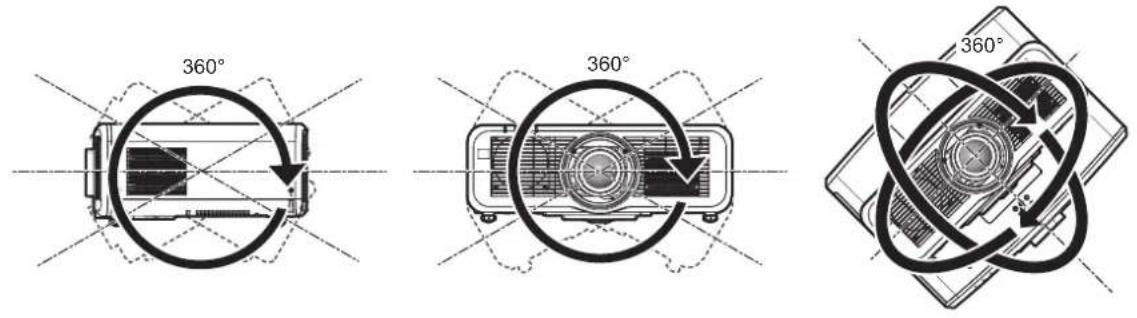
[AUTO] Automatically detects the attitude of the projector by the built-in angle sensor. Set [AUTO] normally. [FLOOR] Select this item when installing the projector on a desk, etc. [CEILING] Select this item when installing the projector using the Ceiling Mount Bracket (optional). Projected image is inverted upside down.
Note
- For the range of installation attitude detected by the built-in angle sensor, refer to "Angle sensor" (→ page 37).
[ECO MANAGEMENT]
Set [ECO MANAGEMENT] to reduce the power consumption and enhance the life of the light source.
Setting [LIGHT POWER]
1) Press ▲▼ to select [ECO MANAGEMENT]. button.
•The [ECO MANAGEMENT] screen is displayed.
3) Press ▲▼ to select [LIGHT POWER].
- The items will switch each time you press the button.
[NORMAL] Set this item when high luminance is required. The light power is 100 % and the estimated runtime is approximately 20 000 hours*1. [ECO] The luminance will decrease compared to [NORMAL], but set this item to suppress the reduction in luminance against the runtime of the light source. The light power is 70 % and the estimated runtime is approximately 24 000 hours*1. [QUIET] Select this item to prioritize the operation with low noise. The light power is 70 % and the estimated runtime is approximately 20 000 hours*1.
*1 The runtime is an estimation when the [PICTURE] menu → [DYNAMIC CONTRAST] is set to [2].
Note
Under influences of characteristics of each light source, conditions of use, installation environment, etc., the runtime may be shorter than the estimation.
Runtime is a time until the luminance of the light source to become about half when using the projector continuously. The runtime is just an estimate, and is not the warranty period.
If the runtime exceeds 10 000 hours, replacement of the components inside the projector may be required. Consult your dealer for details.
When anything other than [NORMAL] is set, the setting in the [PROJECTOR SETUP] menu → [LightID] is disabled, and this item is fixed to [OFF].
Setting [AMBIENT LIGHT DETECTION]
Sets if the [AMBIENT LIGHT DETECTION] function to adjust the light power depending on the brightness of the installed location is enabled or not.
1) Press ▲▼ to select [ECO MANAGEMENT]. button.
•The [ECO MANAGEMENT] screen is displayed.
3) Press ▲▼ to select [AMBIENT LIGHT DETECTION].
- The items will switch each time you press the button.
[OFF] Disables the ambient light detection function.
[ON] Enables the ambient light detection function.
Note
The luminance may not be detected correctly when an object is placed on top of the projector, blocking the luminance sensor. In such a case, it may not operate properly even if [AMBIENT LIGHT DETECTION] is set to [ON].
When the [PROJECTOR SETUP] menu → [LightID] is set to [EXTERNAL CONTROL] or [INTERNAL ID], [AMBIENT LIGHT DETECTION] is set to [OFF].
Setting [SIGNAL DETECTION]
Set if the [SIGNAL DETECTION] function to reduce the power of the light source during no signal is enabled or not.
1) Press ▲▼ to select [ECO MANAGEMENT].
•The [ECO MANAGEMENT] screen is displayed.
3) Press ▲▼ to select [SIGNAL DETECTION].
4) Press ◀▶ to switch the item.
- The items will switch each time you press the button.
[OFF] Disables the [SIGNAL DETECTION] function. [ON] Enables the [$IGNAL DETECTION] function.
Note
When the [PROJECTOR SETUP] menu [LightID] is set to [EXTERNAL CONTROL] or [INTERNAL ID], [SIGNAL DETECTION] is set to [OFF].
The [SIGNAL DETECTION] function will also operate during MEMORY VIEWER, MIRRORING, or Panasonic APPLICATION input. In the following cases, the projector will determine that there is no input signal.
MEMORY VIEWER input: USB memory is not inserted in the terminal
MIRRORING input, Panasonic APPLICATION input: There is no connection from the computer, etc.
Setting [POWER MANAGEMENT]
This is a function to set the power of the projector to standby state or ready state automatically when there is no input signal for specific time. Selection of standby state or the ready state, and the time for the power management function to operate can be set.
1) Press ▲▼ to select [ECO MANAGEMENT]. button.
•The [ECO MANAGEMENT] screen is displayed.
3) Press ▲▼ to select [POWER MANAGEMENT].
- The items will switch each time you press the button.
[SHUT DOWN] The countdown timer is displayed when the signal input is not present for 30 seconds, and the light source is turned off, and goes into standby after cooling when the time set in [TIMER] has elapsed. [OFF] Disables the power management function. [READY] The countdown timer is displayed when the signal input is not present for 30 seconds, and the light source is turned off, and goes into ready state after cooling when the time set in [TIMER] has elapsed.The light source will turn on and starts projection when a signal is input or the button is operated while in ready state.
- Proceed to Step 5) when anything other than [OFF] is selected.
5) Press the button.
- The [POWER MANAGEMENT] screen is displayed.
6) Press ◀▶ to set the time for [TIMER].
- The setting time will switch each time you press the button.
- The time for the power management function to operate can be set from 5 minutes to 120 minutes in five-minute interval.
Note
The power management function will also operate in MEMORY VIEWER, MIRRORING, and Panasonic APPLICATION inputs. The condition to determine that there is no input signal is as follows.
MEMORY VIEWER input: USB memory is not attached to the terminal
MIRRORING input, Panasonic APPLICATION input: There is no connection from the computer, etc.
Setting [STANDBY MODE]
Set the power consumption during standby and whether to enable the [QUICK STARTUP] function.
1) Press ▲▼ to select [ECO MANAGEMENT].
f The [ECO MANAGEMENT] screen is displayed.
3) Press as to select [STANDBY MODE].
4) Press qw to switch the item.
f The items will switch each time you press the button.
[NORMAL] Select this item when using the network function during standby. [ECO] Select this item to reduce power consumption during standby.
f Proceed to Step 5) when [NORMAL] is selected.
5) Press as to select [QUICK STARTUP].
6) Press qw to switch the item.
f The items will switch each time you press the button.
[OFF] Disables the QUICK STARTUP] function. [ON] Enables the [QUICK STARTUP] function until the specified time set in [VALID PERIOD] elapses after the projector enters the standby mode. The time until the projection starts after the power is turned on will be reduced during the period when the [QUICK STARTUP] function is valid.
f Proceed to Step 7) when [ON] is selected.
f The [QUICK STARTUP] screen is displayed.
8) Press qw to switch [VALID PERIOD].
f The items will switch each time you press the button.
[30MIN.] Sets the time until the [QUICK STARTUP] function is disabled after the projector enters the standby mode. Select a desired valid period. [60MIN.] [90MIN.]
Note
f When [STANDBY MODE] is set to [NORMAL], the network function can be used during standby. blinks in red while in the standby mode during the period when the [QUICK STARTUP] function is valid. When [IN STANDBY MODE] in [AUDIO SETTING] is set to [OFF], the power indicator will change to a red light when the specified time set in [VALID PERIOD] elapses after the projector enters the standby mode.
[LightID]
Set the function to transmit the Light ID signal.
1) Press as to select [LightID].
2) Press qw to switch the item.
f The items will switch each time you press the button.
[OFF] Disables the Light ID function. The Light ID signal is not transmitted.
[EXTERNAL CONTROL] Transmits the Light ID signal set by the user.Select this item when the Light ID signal transmitted by the projector is switched using the contents list distribution function or the Light ID control function of the “Multi Monitoring & Control Software”.To set the Light ID, it is necessary to purchase the Light ID. To purchase the Light ID, visit the Panasonic website (https://panasonic.net/cns/LinkRay/).The Light ID which the user has set is erased in following cases.•When theswitched is set to [INTERNAL ID] Transmits the internal Light ID signal.The Light ID signal is linked to the Panasonic website (https://panasonic.net/cns/projector/) in the factory default setting or after the [PROJECTOR SETUP] menu → [INITIALIZE] is executed.When the Light ID is set while [LightID] is set to [INTERNAL ID], the Light ID signal set by the user is transmitted.
Note
When the [PROJECTOR SETUP] menu → [ECO MANAGEMENT] → [LIGHT POWER] is set to anything other than [NORMAL], the [LightID] setting is disabled and fixed to [OFF].
The light output is decreased when [LightID] is set to anything other than [OFF]. When clogging of the filter is detected and the brightness of the light source is restricted, [LightID] will be fixed to [OFF].
Following setting will be disabled and it will be fixed to [OFF] when [LightID] is set to anything other than [OFF]. -The [PICTURE] menu [DYNAMIC CONTRAST]
The [PROJECTOR SETUP] menu → [ECO MANAGEMENT] → [AMBIENT LIGHT DETECTION] and [SIGNAL DETECTION]
To set the Light ID signal, use "Multi Monitoring & Control Software". The software can be downloaded from the Panasonic website (https://panasonic.net/cns/projector/).
The internal Light ID signal can be rewritten by executing the control command using the "Multi Monitoring & Control Software". For details of executing the control command, refer to the Operating Instructions of "Multi Monitoring & Control Software".
When the [PROJECTOR SETUP] menu → [INITIALIZE] → [ALL USER DATA] is executed, the [LightID] setting is reset to the factory default.
For details of the contents list distribution function and Light ID control function of “Multi Monitoring & Control Software”, refer to the Operating Instructions of “Multi Monitoring & Control Software”.
The projected image may flicker when the Light ID signal is transmitted, but this is caused luminance change during the transmission of the Light ID, and it is not a malfunction.
When clogging of the filter is detected and the brightness of the light source is restricted, the filter indicator lights up and [LightID] is set to [OFF], and the Light ID signal will not be transmitted. Set it again after cleaning the clogged filter.
For details on how to solve the filter clogging, refer to "When an indicator lights up" (▶ page 197).
[INITIAL STARTUP]
Set the startup method when the switch is set to .
1) Press ▲▼ to select [INITIAL STARTUP].
- The items will switch each time you press the button.
[LAST MEMORY] Starts up the projector in the condition before theswitch is set to. [STANDBY] Starts up the projector in standby. [ON] Starts projecting immediately.
Set the input when the projector is switched on to start projection.
1) Press ▲▼ to select [STARTUP INPUT SELECT]. button.
- The [STARTUP INPUT SELECT] screen is displayed.
3) Press ▲▼◀▶ to select the input, and press the button.
[LAST USED] Keeps the input selected last. [RGB1] Sets the input to RGB1. [RGB2] Sets the input to RGB2. [VIDEO] Sets the input to VIDEO. [HDMI1] Sets the input to HDMI1. [HDMI2] Sets the input to HDMI2. [DIGITAL LINK] Sets the input to DIGITAL LINK. [MEMORY VIEWER] Sets the input to MEMORY VIEWER. [Panasonic APPLICATION] Sets the input to Panasonic APPLICATION. [MIRRORING]*1 Sets the input to MIRRORING. [INPUT1] - [INPUT10]*2 Sets the input to DIGITAL LINK, and switches the input of the Panasonic twisted-pair-cable transmitter to the specified input.
*1 [MIRRORING] is displayed when the optional Wireless Module (Model No.: ET-WM300) is attached.
[DATE AND TIME]
Set the time zone, date, and time of the built-in clock of the projector.
Setting the time zone
1) Press ▲▼ to select [DATE AND TIME]. button.
- The [DATE AND TIME] screen is displayed.
3) Press ▲▼ to select [TIME ZONE].
Setting the date and time manually
1) Press ▲▼ to select [DATE AND TIME]. button.
- The [DATE AND TIME] screen is displayed.
3) Press ▲▼ to select [ADJUST CLOCK]. button.
•The [ADJUST CLOCK] screen is displayed.
5) Press ▲▼ to select an item, and press ◀▶ to set the local date and time. button.
- The setting of the date and time will be completed.
Setting the date and time automatically
1) Press ▲▼ to select [DATE AND TIME]. button.
- The [DATE AND TIME] screen is displayed.
3) Press ▲▼ to select [ADJUST CLOCK]. button.
•The [ADJUST CLOCK] screen is displayed.
5) Press ▲▼ to select [NTP SYNCHRONIZATION], and press ◀▶ to change the setting to [ON]. button.
- The setting of the date and time will be completed.
Note
To set the date and time automatically, the projector must be connected to the network.
If synchronization with the NTP server fails just after [NTP SYNCHRONIZATION] is set to [ON], [NTP SYNCHRONIZATION] will return to [OFF]. If [NTP SYNCHRONIZATION] is set to [ON] while the NTP server is not set, [NTP SYNCHRONIZATION] will return to [OFF].
Access the projector via a web browser to set the NTP server. Refer to “[Adjust clock] page” (→ page 170) for details.
The [TIME ZONE] setting is reset to the factory default when the [PROJECTOR SETUP] menu → [INITIALIZE] → [ALL USER DATA] is executed. However, the date and time based on the local date and time setting (Coordinated Universal Time, UTC, Universal Time, Coordinated) will be maintained without being initialized.
[SCHEDULE]
Set the command execution schedule for each day of the week.
Enabling/disabling the schedule function
1) Press ▲▼ to select [SCHEDULE].
- The items will switch each time you press the button.
[OFF] Disables the schedule function. [ON] Enables the schedule function. Refer to “How to assign a program” (⇨ page 119) or “How to set a program” (⇨ page 119) for how to set the schedule.
Note
- The [STANDBY MODE] setting will be forced to [NORMAL] when the [PROJECTOR SETUP] menu → [ECO MANAGEMENT] → [STANDBY MODE] is set to [ECO], and [SCHEDULE] is set to [ON]. Changing the setting to [ECO] is not available. The [STANDBY MODE] setting will not change back even when [SCHEDULE] is set to [OFF] in this condition.
How to assign a program
1) Press ▲▼ to select [SCHEDULE]. button.
•The [SCHEDULE] screen is displayed.
3) Select and assign a program to each day of week.
Press ▲▼ to select the day of week, and press ◀▶ to select a program number.
You can set the program from No.1 to No.7. “--” indicates that the program number has not been set.
How to set a program
Set up to 16 commands to each program.
1) Press ▲▼ to select [SCHEDULE]. button.
•The [SCHEDULE] screen is displayed.
3) Press ▲▼ to select [PROGRAM EDIT]. button. button.
- You can change the page using ◀.
6) Press ▲▼◀▶ to select [TIME], and press the button. button. button.
- The [COMMAND] detailed screen is displayed.
10) Press ▲▼ to select a [COMMAND].
For [COMMAND] which requires detailed settings, the items of the detailed settings will switch each time you press ◀.
When [INPUT] is selected, press the button, and then press ▲▼◀▶ to select the input to be set.
Chapter 4 Settings — [PROJECTOR SETUP] menu
[COMMAND] Detailed settings of [COMMAND] Description [POWER ON] — Switches on the projector. [STANDBY] — Enters standby. [QUICK STARTUP] [ON] Enables the function of the [PROJECTOR SETUP] menu → [ECO MANAGEMENT] → [QUICK STARTUP]. [OFF] Disables the function of the [PROJECTOR SETUP] menu → [ECO MANAGEMENT] → [QUICK STARTUP]. [SHUTTER] [OPEN] Disables the shutter function (shutter: open). [CLOSE] Enables the shutter function (shutter: closed). [INPUT] [RGB1] Switches the input to RGB1. [RGB2] Switches the input to RGB2. [VIDEO] Switches the input to VIDEO. [HDMI1] Switches the input to HDMI1. [HDMI2] Switches the input to HDMI2. [DIGITAL LINK] Switches the input to DIGITAL LINK. [MEMORY VIEWER] Switches the input to MEMORY VIEWER. [Panasonic APPLICATION] Switches the input to Panasonic APPLICATION. [MIRRORING]*1 Switches the input to MIRRORING. [INPUT1] - [INPUT10]*2 Switches the input to DIGITAL LINK, and switches the input of the Panasonic twisted-pair-cable transmitter to the specified input. [LIGHT POWER] [NORMAL] Prioritizes luminance. [ECO] Controls the power to increase the life of the light source although the luminance is lower than that of [NORMAL]. [QUIET] Prioritizes the operation with less noise although the luminance is lower than that of [NORMAL]. [IN STANDBY MODE(AUDIO)] [OFF] Stops the audio output during standby. [ON] Outputs the audio during standby. [VOLUME] [0] - [63] Sets the volume.
*1 [MIRRORING] is displayed when the optional Wireless Module (Model No.: ET-WM300) is attached.
The command is fixed and is displayed at the left of the selected command.
After the command is fixed, press the button to close the detailed setting screen.
Note
To delete a command that has been already set, press the button on the remote control while the screen in Step 5) is displayed, or select [DELETE] at the screen in Step 6) and press the button.
If multiple commands have been set for the same time, they are executed in chronological order starting from the smallest command number.
The operating time will be the local time. (→ page 118)
If an operation is executed with the remote control or control panel of the projector or with a control command before the command set in [SCHEDULE] is executed, the command set with the schedule function may not be executed.
[RS-232C]
Set the communication condition of the terminal. Refer to " terminal" (→ page 214).
1) Press ▲▼ to select [RS-232C]. button.
• The [RS-232C] screen is displayed.
3) Press ▲▼ to select [INPUT SELECT].
[PROJECTOR] Performs the RS-232C communication with theterminal of the projector. [DIGITAL LINK] Performs the RS-232C communication via the optional DIGITAL LINK output supported device (Model No.: ET-YFB100G, ET-YFB200G) and theterminal.
5) Press ▲▼ to select [BAUDRATE].
- The items will switch each time you press the button.
[9600] Select the proper speed.[19200] [38400]
7) Press ▲▼ to select [PARITY].
- The items will switch each time you press the button.
[NONE] Select the parity condition.[EVEN] [ODD]
Note
When [INPUT SELECT] is set to [DIGITAL LINK], communication using that serial terminal is available only when the corresponding device (such as the optional DIGITAL LINK output supported device (Model No.: ET-YFB100G, ET-YFB200G)) is connected to the terminal.
When transferring logos via the optional DIGITAL LINK output supported device (Model No.: ET-YFB100G, ET-YFB200G), setting for "NO SIGNAL SLEEP" of the DIGITAL LINK output supported device should be set to "OFF" to avoid interruption of communication.
When [INPUT SELECT] is set to [DIGITAL LINK], communication speed for input is fixed to 9 600 bps and the parity is fixed to "NONE".
Using the control command for the existing projector
Set this function when using the control command for previously purchased Panasonic projector to control this projector with a computer using the terminal on the projector. The existing Panasonic projector control software, etc., can continually be used.
1) Press ▲▼ to select [RS-232C]. button.
•The [RS-232C] screen is displayed.
3) Press ▲▼ to select [EMULATE]. button.
- The [EMULATE] screen is displayed.
5) Press ▲▼ to select an item.
[OFF] Does not use existing control command for the projector. [D3500] D3500 series [D4000] D4000 series [D/W5k SERIES] D5700 series, DW5100 series, D5600 series, DW5000 series, D5500 series [D/W/Z6k SERIES] DZ870 series, DW830 series, DX100 series, DZ780 series, DW750 series, DX820 series, DZ770 series, DW740 series, DX810 series, DZ680 series, DW640 series, DX610 series, DW730 series, DX800 series, DZ6710 series, DZ6700 series, DW6300 series, D6000 series, D5000 series, DZ570 series, DW530 series, DX500 series, RZ970 series, RW930 series, RX110 series, RZ770 series, RZ660 series, RW730 series, RW620 series, RZ670 series, RW630 series, RZ575 series, RZ570 series [L730 SERIES] L730 series, L720 series, L520 series [L780 SERIES] L780 series, L750 series [L735 SERIES] L735 series [L785 SERIES] L785 series [F/W SERIES] FW430 series, FX400 series, FW300 series, F300 series, F200 series, FW100 series, F100 series [LZ370] LZ370 series [LB/W SERIES] LB3 series, LB2 series, LB1 series, ST10 series, LB90 series, LW80NT series, LB80 series, LB78 series, LB75 series [VX500 SERIES] VW435N series, VW440 series, VW430 series, VX505N series, VX510 series, VX500 series, VW330 series, VX400NT series, VX400 series, VX41 series [EZ570 SERIES] EZ570 series, EW630 series, EW530 series, EX600 series, EX500 series
[VW431D] VW431D series
6) Press the button.
- The confirmation screen is displayed.
7) Press ◀▶ to select [OK], and press the button.
[REMOTE1 MODE]
Set the terminal.
1) Press ▲▼ to select [REMOTE1 MODE].
2) Press ◀▶ to switch the item.
- The items will switch each time you press the button.
[DEFAULT] Uses pin assignment of theterminal in standard setting. [USER] Use this item when changing the setting of theterminal. (→ page 217) [F/W SERIES] Uses theterminal setting compatible with the F/W series.
- Proceed to Step 3) when [USER] is selected.
3) Press the button.
4) Press ▲▼ to select one from [PIN2] to [PIN8], and press ◀▶ to switch the setting.
Set the function of the button on the remote control.
1) Press ▲▼ to select [FUNCTION BUTTON].
2) Press the button.
- The [FUNCTION BUTTON] screen is displayed.
3) Press ▲▼ to select a function.
[DISABLE] Disables thebutton. [SUB MEMORY] Displays the sub memory list. (⇨ page 135) [SYSTEM SELECTOR] Switches the [SYSTEM SELECTOR] setting. (⇨ page 89) [DAYLIGHT VIEW] Switches the [DAYLIGHT VIEW] setting. (⇨ page 88)
4) Press the button.
[LENS CALIBRATION]
Detect the lens shift limit value of the projector, and automatically set the home position.
1) Press ▲▼ to select [LENS CALIBRATION].
2) Press the button.
•The confirmation screen is displayed.
3) Press ◀▶ to select [OK], and press the button.
•To cancel, select [CANCEL].
- The lens moves up, down, left, and right to detect the lens shift limit value, and automatically set the home position.
- The lens stops to complete the lens calibration.
Note
[PROGRESS] is displayed in the menu during lens calibration. The operation cannot be canceled during calibration.
[INCOMPLETE] is displayed when the lens calibration was not executed correctly.
Pressing the button on the remote control for three seconds or longer will also display the confirmation screen for lens calibration execution.
[AUDIO SETTING]
Set audio functions in detail.
Adjusting the volume
1) Press ▲▼ to select [AUDIO SETTING]. button.
3) Press ▲▼ to select [VOLUME].
4) Press ◀▶ to adjust the level.
Operation Adjustment Range of adjustment Press ▶. Increases the volume. 0 - 63 Press ◀. Decreases the volume.
Adjusting the left to right audio balance
1) Press ▲▼ to select [AUDIO SETTING]. button.
3) Press ▲▼ to select [BALANCE].
4) Press ◀▶ to adjust the level.
Operation Adjustment Range of adjustment Press ▶. Increases the volume on the right. L16 - R16 Press ◀. Increases the volume on the left.
Setting the audio output of the built-in speaker
1) Press ▲▼ to select [AUDIO SETTING]. button.
3) Press ▲▼ to select [BUILT-IN SP].
4) Press ◀▶ to switch the item.
- The items will switch each time you press the button.
[ON] Outputs the audio from the built-in speaker. [OFF] Does not output the audio from the built-in speaker.
Note
- When [BUILT-IN SP] is set to [ON], audio is output from the built-in speaker even when a cable is connected to the terminal. To not output audio from the built-in speaker and output the audio from the external audio device connected to the terminal, set [BUILT-IN SP] to [OFF].
Setting audio output in the standby mode
1) Press ▲▼ to select [AUDIO SETTING]. button.
4) Press ◀▶ to switch the item.
- The items will switch each time you press the button.
[OFF] Audio is not output during standby.
[ON] Audio is output during standby.
Note
- Audio is not output in the standby mode when the [PROJECTOR SETUP] menu → [ECO MANAGEMENT] → [STANDBY MODE] is set to [ECO].
Setting audio output while using the shutter function
1) Press ▲▼ to select [AUDIO SETTING]. button.
•The [AUDIO SETTING] screen is displayed.
3) Press ▲▼ to select [IN SHUTTER].
- The items will switch each time you press the button.
[OFF] Audio is not output while using the shutter function (shutter: closed).
[ON] Audio is output while using the shutter function (shutter: closed).
Setting mute mode
1) Press ▲▼ to select [AUDIO SETTING]. button.
•The [AUDIO SETTING] screen is displayed.
3) Press ▲▼ to select [MUTE].
- The items will switch each time you press the button.
[OFF] Audio is output.
[ON] Audio is not output.
1) Press ▲▼ to select [AUDIO SETTING]. button.
•The [AUDIO SETTING] screen is displayed.
3) Press ▲▼ to select item to set in [AUDIO IN SELECT].
[RGB1] Sets the audio to output when RGB1 is input. [RGB2] Sets the audio to output when RGB2 is input. [VIDEO] Sets the audio to output when VIDEO is input. [HDMI1] Sets the audio to output when HDMI1 is input. [HDMI2] Sets the audio to output when HDMI2 is input. [DIGITAL LINK] Sets the audio to output when DIGITAL LINK is input. [NETWORK/USB] Sets the audio to output when MEMORY VIEWER, MIRRORING, or Panasonic APPLICATION is input.
4) Press ◀▶ to switch the item.
- The items will switch each time you press the button.
[AUDIO IN 1] Audio connected to theterminal is output during projection of image from the set input terminal. [AUDIO IN 2] Audio connected to theterminal is output during projection of image from the set input terminal. [AUDIO IN 3] Audio connected to theterminal is output during projection of image from the set input terminal. [HDMI1 AUDIO IN]*1 Audio input to HDMI1 is output. [HDMI2 AUDIO IN]*2 Audio input to HDMI2 is output. [DIGITAL LINK AUDIO IN]*3 Audio input to DIGITAL LINK is output. [NETWORK/USB AUDIO IN]*4 Outputs the audio of MEMORY VIEWER, MIRRORING, or Panasonic APPLICATION.
*1 Only when the input signal is HDMI1
*2 Only when the input signal is HDMI2
*3 Only when the input signal is DIGITAL LINK
*4 Only when the input signal is MEMORY VIEWER, MIRRORING, or Panasonic APPLICATION
[FILTER COUNTER]
Check the runtime of the filter and set the cleaning/replacement cycle of the filter. Also, the runtime of the filter can be reset.
1) Press ▲▼ to select [FILTER COUNTER]. button.
- The [FILTER COUNTER] screen is displayed.
[FILTER COUNTER] Displays the runtime of the filter. [TIMER] Sets the cleaning/replacement cycle of the filter. [FILTER COUNTER RESET] Resets the runtime of the filter.
Setting [TIMER]
If the filter is to be cleaned/replaced periodically, set the cycle in hours. Once the runtime of the filter reaches the set time, a message prompting to clean/replace the filter [FILTER COUNTER has reached the set time.] is displayed on the projected image.
1) Press ▲▼ to select [FILTER COUNTER]. button.
- The [FILTER COUNTER] screen is displayed.
3) Press ▲▼ to select [TIMER].
- The items will switch each time you press the button.
[OFF] Select this item when a message is not to be displayed. [1000 H] - [20000 H] Select this item when a message is to be displayed. The cleaning/replacement cycle of the filter can be set in 1 000 hour intervals.
Resetting [FILTER COUNTER]
Reset the runtime of the filter.
1) Press ▲▼ to select [FILTER COUNTER]. button.
- The [FILTER COUNTER] screen is displayed.
3) Press ▲▼ to select [FILTER COUNTER RESET]. button. button.
- Display of [FILTER COUNTER] will change to [0 H].
[DC OUT]
Set the power supply function of the terminal.
1) Press ▲▼ to select [DC OUT].
2) Press ◀▶ to select an item.
[ON] Enables the power supply function. Power is supplied to the external device connected to theterminal. [OFF] Disables the power supply function. The power is not supplied even if an external device is connected to theterminal.
Note
- When [DC OUT] is set to [ON], the power is supplied even in the standby state or ready state in the following cases.
- When the [PROJECTOR SETUP] menu → [ECO MANAGEMENT] → [STANDBY MODE] is set to [NORMAL], and [QUICK STARTUP] is set to [ON], and then the projector goes into the standby state by pressing the power <∅/|> button
- When the [PROJECTOR SETUP] menu → [ECO MANAGEMENT] → [POWER MANAGEMENT] is set to [READY], and no signal is detected and the projector goes into the ready state
- When an external device exceeding the rating (DC 5 V, maximum 2 A) is connected to the terminal while this function is set to [ON], an error is detected and the power supply will be stopped. At this time, [ERROR] is displayed in [DC OUT]. Disconnect the external drive and turn on the projector again when [ERROR] is displayed.
[STATUS]
Display the status of the projector.
1) Press ▲▼ to select [STATUS].
2) Press the button.
- The [STATUS] screen is displayed.
3) Press ◀▶ to switch the pages.
- The page will change each time you press the button.
[PROJECTOR TYPE] Displays the projector type and serial number of the projector. [SERIAL NUMBER] Displays the serial number of the projector. [PROJECTOR RUNTIME] Displays the runtime of the projector. [LIGHT RUNTIME] Displays the runtime of the light source. [CONTINUOUS LIGHTING TIME] Displays the elapsed time from when the light source is illuminated.The elapsed time after the illumination of the light source can be confirmed when adjusting the focus.The elapsed time is reset when the light source is temporarily turned off such as using the shutter function. [MAIN/SUB VERSION] Displays the main and sub versions of the firmware of the projector. [NETWORK VERSION] Displays the network version of the firmware of the projector. [INTAKE AIR TEMP.] ^1 Displays the status of the intake air temperature of the projector. [EXHAUST AIR TEMP.] ^1 Displays the status of the exhaust air temperature of the projector. [LIGHT TEMP. 1] ^1 Displays the temperature status for the front block of the light source (on the lens side). [LIGHT TEMP. 2] ^1 Displays the temperature status for the rear block of the light source (on the air exhaust port side). [SELF TEST] Displays the status of the projector. [INPUT] Displays the input terminal currently selected. [SIGNAL NAME] Displays the input signal name. [MEMORY NO.] Displays the memory number of the input signal. [ON COUNT] [POWER ON TIMES] Displays the number of times the power is turned on. [NUMBER OF REGISTERED SIGNAL] Displays the number of registered signals. [COOLING CONDITION] Displays the set cooling conditions. [ATMOSPHERIC PRESSURE] Displays the atmospheric pressure. [REMOTE1 STATUS] Displays the control status of the REMOTE1. [EMULATE] Displays the setting in the [PROJECTOR SETUP] menu → [RS-232C] → [EMULATE]. [SIGNAL INFORMATION] [INPUT] Displays the input terminal used for the projected image. [SIGNAL FORMAT] Displays the format of the input signal. [SIGNAL FREQUENCY] Displays the frequency of the input signal. [SYNC.STATE] Displays the sync polarity of the input signal. [V.SYNC WIDTH] Displays the vertical sync signal pulse width of the input signal. [SCAN TYPE] Displays the scan type of the input signal. [TOTAL DOTS] Displays the total dot count of the input signal. [DISPLAY DOTS] Displays the number of input signal display dots. [TOTAL LINES] Displays the total line count of the input signal. [DISPLAY LINES] Displays the number of input signal display lines. [SAMPLING] Displays the sampling information of the input signal. [SIGNAL LEVEL] Displays the signal level of the input signal.
*1 The temperature status is indicated with text color (green/yellow/red) and bar scale. Use the projector within the range that the indication is green.
Note
E-mail containing the status can be sent to the E-mail address (up to two addresses) set in “[E-mail set up] page” (→ page 171) by pressing the button while the [STATUS] screen is displayed.
There may be items that are displayed and items that are not displayed in [SIGNAL INFORMATION] depending on the setting or the input signal.
If any abnormality has occurred on the projector, press the button while the [STATUS] screen is displayed to display the detail screen of the error information.
For details on the contents displayed in [SELF TEST], refer to “[SELF TEST] display” (→ page 207).
[DATA CLONING]
The menu setting and adjustment values of one projector can be copied to multiple projectors via LAN or using the USB memory.
■ Data that cannot be copied
Following menu settings and adjustment values are not copied. Set these in each projector.
Menu lock password
Security password
The [PROJECTOR SETUP] menu → [PROJECTOR ID]
The [PROJECTOR SETUP] menu → [DATE AND TIME] → [ADJUST CLOCK]
The [PROJECTOR SETUP] menu → [DATA CLONING] → [LAN] → [WRITE PROTECT]
Password set in “[Change password] page” (→ page 175) of the web control screen
“[E-mail set up] page” (→ page 171) in the web control screen
“[Authentication set up] page” (→ page 172) in the web control screen
“[Crestron Connected(TM)] page” (→ page 176) in the web control screen
■ Supported device
Commercially available USB memory is supported.
Only the cards formatted in FAT16 or FAT32 can be used.
Only the single partition structure is supported.
Note
The cloning function will not operate when the models of the projectors are different. Use between the same model.
Set the input to anything other than MEMORY VIEWER, and then execute [DATA CLONING].
When the data cloning function is used, the light source indicator , the temperature indicator , and the filter indicator will blink while copying the data. Wait until the blinking of the indicator is stopped.
Copying the data to other projector via LAN
Set the projector to copy the data as follows in advance.
- The [PROJECTOR SETUP] menu → [DATA CLONING] → [LAN] → [WRITE PROTECT] → [OFF]
1) Connect all projectors to the hub using LAN cables. (→ page 155) button.
- The [SECURITY PASSWORD] screen is displayed.
5) Enter a security password and press the button.
- The [DATA CLONING] screen is displayed.
6) Press ▲▼ to select [LAN]. button.
- The [LAN DATA CLONING] screen is displayed.
8) Press ▲▼ to select [SELECT PROJECTOR]. button.
- The projector with the same subnet is displayed as a list.
10) Press ▲▼ to select the projector to be the copy destination. button.
- To select multiple projectors, repeat Steps 10) to 11).
12) Press the button on the remote control.
•The confirmation screen is displayed.
13) Press ◀▶ to select [OK], and press the button.
- Copy of the data to the projector is started.
Once the copy is completed, result is displayed in the [LAN DATA CLONING] screen.
Meanings of the marks displayed in the list are as follows.
-Green: Data copy has succeeded.
Red: Data copy has failed. Confirm the connection of the LAN cable and power status of the copy destination projector.
The copy destination projector will display the data cloning request message, transfer to standby mode automatically, and perform the copy of the data.
14) Turn off the copy destination projector.
- The copied content is reflected in the copy destination projector.
Note
- The security password is the password set in the [SECURITY] menu → [SECURITY PASSWORD CHANGE]. Initial password as the factory default: ▲▶▼◀▲▶▼◀
Setting [WRITE PROTECT].
Set if the copy of data via LAN is permitted or not.
1) Press ▲▼ to select [DATA CLONING]. button.
- The [SECURITY PASSWORD] screen is displayed.
3) Enter a security password and press the button. button.
- The [LAN DATA CLONING] screen is displayed.
6) Press ▲▼ to select [WRITE PROTECT].
7) Press ◀▶ to switch the item.
- The items will switch each time you press the button.
[OFF] Operation of [DATA CLONING] from other projector via LAN is enabled. [ON] Operation of [DATA CLONING] from other projector via LAN is disabled.• Copy will not be possible when set to [ON]. When it is not necessary to copy, set to [ON] so the data is not changed by mistake.
Note
- The security password is the password set in the [SECURITY] menu → [SECURITY PASSWORD CHANGE]. Initial password as the factory default: ▲▶▼◀▲▶▼◀
Copying the data to other projector using USB
Copying projector data to USB memory
1) Insert the USB memory into the terminal. button.
- The [SECURITY PASSWORD] screen is displayed.
4) Enter a security password and press the button. button.
- The [SELECT COPY TYPE] screen is displayed.
7) Press ▲▼ to select [PROJECTOR -> USB MEMORY]. button.
- The confirmation screen is displayed.
9) Press ◀▶ to select [OK], and press the button.
- Copying of data to the USB memory is started.
Once the copying of data is completed, [Data copy finished.] is displayed.
10) Once the copying of the data is completed, disconnect the USB memory from the terminal.
Note
The security password is the password set in the [SECURITY] menu → [SECURITY PASSWORD CHANGE]. Initial password as the factory default: ▲▶▼◀▲▶▼◀
Depending on the type of the USB memory, it may not be able to connect by contacting the surrounding parts. In such case, copy the data via LAN. For details of copying the data via LAN, refer to "Copying the data to other projector via LAN" ( page 127).
An error message is displayed when saving or reading to/from the USB memory has failed.
Copying data in the USB memory to the projector
1) Insert the USB memory into the terminal. button.
- The [SECURITY PASSWORD] screen is displayed.
4) Enter a security password and press the button.
- The [DATA CLONING] screen is displayed.
5) Press ▲▼ to select [USB MEMORY].
6) Press the button.
- The [SELECT COPY TYPE] screen is displayed.
7) Press ▲▼ to select [USB MEMORY -> PROJECTOR].
8) Press the button.
- The confirmation screen is displayed.
9) Press ◀▶ to select [OK], and press the button.
- Copying of the data from the USB memory is started, and the projector will go into standby mode.
10) Once the copying of the data is completed, disconnect the USB memory from the terminal.
11) Turn off the power of the projector.
- The copied content is reflected to the projector.
Note
- The security password is the password set in the [SECURITY] menu → [SECURITY PASSWORD CHANGE]. Initial password as the factory default: ▲▶▼◀▲▶▼◀
[SAVE ALL USER DATA]
Save the various setting values as a backup in the built-in memory of the projector.
1) Press ▲▼ to select [SAVE ALL USER DATA].
2) Press the button.
- The [SECURITY PASSWORD] screen is displayed.
3) Enter a security password and press the button.
4) When the confirmation screen is displayed, press ◀▶ to select [OK], and press the button.
•[PROGRESS] is displayed while saving data.
Note
- The security password is the password set in the [SECURITY] menu → [SECURITY PASSWORD CHANGE]. Initial password as the factory default: ▲▶▼◀▲▶▼◀
- Data set from the computer application is not included in [ALL USER DATA].
[LOAD ALL USER DATA]
Load the various setting values saved as a backup in the built-in memory of the projector.
1) Press ▲▼ to select [LOAD ALL USER DATA].
2) Press the button.
- The [SECURITY PASSWORD] screen is displayed.
3) Enter a security password and press the button.
4) When the confirmation screen is displayed, press ◀▶ to select [OK], and press the button.
Note
- The security password is the password set in the [SECURITY] menu [SECURITY PASSWORD CHANGE]. Initial password as the factory default: ▲▶▼◀▲▶▼◀
- The projector enters the standby mode to reflect the setting values when [LOAD ALL USER DATA] is executed.
- Data registered from a computer is not included in [ALL USER DATA].
[INITIALIZE]
Return various setting values to their factory default settings.
1) Press ▲▼ to select [INITIALIZE].
2) Press the button.
- The [SECURITY PASSWORD] screen is displayed.
3) Enter a security password and press the button.
•The [INITIALIZE] screen is displayed.
4) Press ▲▼ to select an item to initialize.
[ALL USER DATA] Returns all setting values including [REGISTERED SIGNAL], [NETWORK/E-MAIL], and [LOGO IMAGE] to the factory default settings.The projector enters the standby mode to reflect the setting values. [REGISTERED SIGNAL] Deletes all the setting values saved for each input signal.To delete only a part of a registered signal, perform the procedure described in “Deleting the registered signal” (→ page 133). [NETWORK/E-MAIL] Returns the various setting values in the [NETWORK/USB] menu to the factory default values. [LOGO IMAGE] Deletes the image registered in [USER LOGO].
5) Press the button.
6) When the confirmation screen is displayed, press ◀▶ to select [OK], and press the button.
Note
The security password is the password set in the [SECURITY] menu → [SECURITY PASSWORD CHANGE]. Initial password as the factory default: ▲▶▼◀▲▶▼◀
The following settings are not initialized even if [ALL USER DATA] is executed.
The [PROJECTOR SETUP] menu → [ECO MANAGEMENT] → [STANDBY MODE]
[SERVICE PASSWORD]
This function is used by a service person.
On the menu screen, select [TEST PATTERN] from the main menu.
Refer to "Navigating through the menu" (→ page 80) for the operation of the menu screen.
[TEST PATTERN]
Display the test pattern built-in to the projector.
Settings of position, size, and other factors will not be reflected in test patterns. Make sure to display the input signal before performing various adjustments.
1) Press ◀▶ to switch the [TEST PATTERN] item.
- The items will switch each time you press the button.
Menu screen + Color bar(vertical) Displays a test pattern with the menu screen. Select a desired test pattern. Menu screen + Color bar(horizontal) Menu screen + 16 tones(vertical 1) Menu screen + 16 tones(vertical 2) Menu screen + 16 tones(horizontal 1) Menu screen + 16 tones(horizontal 2) Menu screen + Focus Menu screen + 16:9/4:3aspect frame Menu screen + All white Menu screen + All black Menu screen + Input screen Displays the menu screen and input signal.Internal test patterns are not displayed.
Note
- Press the button on the remote control while the test pattern is displayed to hide the menu screen.
On the menu screen, select [SIGNAL LIST] from the main menu.
Refer to "Navigating through the menu" ( page 80) for the operation of the menu screen.
■Registered signal details
text_image
Memory number: A1 (1-2)
↑
Sub memory number
When the address number (A1, A2, ... L7, L8) signal is registered
- A name can be set for each sub memory (→ page 135).
Registering new signals
After a new signal is input and the
button on the remote control or the control panel is pressed, the registration is completed and the [MAIN MENU] screen is displayed.
Note
Up to 96 signals, including sub memories, can be registered to the projector.
There are 12 pages (eight memories of A through L, with eight memories possible on each page) for memory numbers, and the signal is registered to the lowest number that is available. If there is no available memory number it will be overwritten from the oldest signal.
The name to be registered is automatically determined by the input signal.
If a menu is being displayed, the new signals will be registered at the instant they are input.
Renaming the registered signal
Registered signals can be renamed.
1) Press ▲▼◀▶ to select the signal of which name is to be changed. button.
The [REGISTERED SIGNAL STATUS] screen is displayed.
The memory number, input terminal, input signal name, frequency, synch polarity, etc., are displayed.
Press the button to return to the [REGISTERED SIGNAL LIST] screen.
3) Press the button. button.
- The [SIGNAL NAME CHANGE] screen is displayed.
6) Press ▲▼◀▶ to select the text, and press the button to enter the text. button.
- The registration is completed and the [REGISTERED SIGNAL SETUP] screen returns.
- When pressing ▲▼◀▶ to select [CANCEL] and pressing the button, the changed signal name will not be registered and an automatically registered signal name will be used.
Deleting the registered signal
Registered signals can be deleted.
1) Press ▲▼◀▶ to select the signal to delete. button on the remote control.
The [REGISTERED SIGNAL DELETE] screen is displayed.
To cancel the deletion, press the button to return to the [REGISTERED SIGNAL LIST] screen.
3) Press the button.
•The selected signal will be deleted.
Note
- A registered signal can also be deleted from [REGISTERED SIGNAL DELETE] on the [REGISTERED SIGNAL SETUP] screen.
Protecting the registered signal
1) Press ▲▼◀▶ to select the signal to protect. button.
- The [REGISTERED SIGNAL STATUS] screen is displayed.
3) Press the button.
- The [REGISTERED SIGNAL SETUP] screen is displayed.
4) Press ▲▼ to select [LOCK].
- The items will switch each time you press the button.
[OFF] The signal is not protected.
[ON] The signal is protected.
- A lock icon is displayed at the right of the [REGISTERED SIGNAL LIST] screen when [LOCK] is set to [ON].
Note
When [LOCK] is set to [ON], signal deletion, image adjustment, and automatic setup are not available. To perform these operations, set [LOCK] to [OFF].
A signal can be registered to the sub memory even if it is protected.
Even a protected signal will be deleted if [INITIALIZE] is executed.
Expanding signal lock-in range
1) Press ▲▼◀▶ to select the signal to set. button.
- The [REGISTERED SIGNAL STATUS] screen is displayed.
3) Press the button.
4) Press ▲▼ to select [LOCK-IN RANGE].
5) Press ◀▶ to switch the item.
- The items will switch each time you press the button.
[NARROW] Select this item usually.
[WIDE] Widens the lock-in range.
- An expansion icon is displayed at the right of the [REGISTERED SIGNAL LIST] screen when [LOCK-IN RANGE] is set to [WIDE].
Note
Switch the range where the signal to be input is determined to be the same signal as the already registered signal.
To prioritize the determination that a signal is the same as the already registered signal, set this function to [WIDE].
Use in cases such as when the synchronizing frequency of a signal to be input has changed slightly, or multiple signal lists are registered.
This function can be used only when a signal is input from the terminal, the terminal, terminal, the terminal, or the terminal.
When [WIDE] is set, the image may be distorted because a signal is recognized as the same even if its synchronizing frequency varies slightly.
When a signal to be input corresponds to multiple signals set in [WIDE], a registered signal with a high memory number receives priority. Example: a signal to be input that corresponds to memory numbers A2, A4 and B1 will be determined to be B1.
When a registration signal is deleted, the settings are also deleted.
In an environment where multiple types of signals are input to the same terminal, signals are sometimes not determined correctly when the setting is set to [WIDE].
Sub memory
The projector has a sub memory function that can register the multiple image adjustment data, even if it is recognized as the same signal by the frequency or format of the synchronization signal source.
Use this function when you need to switch the aspect or adjust the picture quality such as the white balance while using the same signal source. The sub memory includes all the data that can be adjusted for each signal, such as the image aspect ratio and data adjusted in the [PICTURE] menu (items such as [CONTRAST] and [BRIGHTNESS]).
Registering to the sub memory
1) While in the normal screen (where no menu is displayed), press ▲▼.
The sub memory registration screen is displayed if the sub memory is not registered. Proceed to Step 3).
A list of sub memories registered to the signal currently input is displayed.
The button on the remote control can be used instead of ▲▼ when [SUB MEMORY] is selected from the [PROJECTOR SETUP] menu → [FUNCTION BUTTON].
2) Press ▲▼◀▶ to select the sub memory number to register in [SUB MEMORY LIST].
3) Press the button.
- The [SIGNAL NAME CHANGE] screen is displayed.
4) Press ▲▼◀▶ to select [OK], and press the button.
- To rename the registered signal, follow the procedure in Steps 6) and 7) in “Renaming the registered signal” (→ page 133).
Switching to the sub memory
1) While in the normal screen (where no menu is displayed), press ▲▼.
- A list of sub memories registered to the signal currently input is displayed.
2) Press ▲▼◀▶ to select the signal to switch in [SUB MEMORY LIST].
3) Press the button.
- This switches to the signal selected in Step 2).
Deleting the sub memory
1) While in the normal screen (where no menu is displayed), press ▲▼.
- The [SUB MEMORY LIST] screen is displayed.
2) Press ▲▼◀▶ to select the sub memory to be deleted, and press the button on the remote control.
- The [REGISTERED SIGNAL DELETE] screen is displayed.
- To cancel the deletion, press the
button to return to the [SUB MEMORY LIST] screen.
3) Press the button.
- The selected sub memory will be deleted.
On the menu screen, select [SECURITY] from the main menu, and select an item from the sub-menu. Refer to “Navigating through the menu” (→ page 80) for the operation of the menu screen.
- When the projector is used for the first time
Initial password: Press ▲▶▼◀▲▶▼◀ in order, and press the button.
Attention
When you select the [SECURITY] menu and press the button, entering a password is prompted. Enter the preset password and then continue operations of the [SECURITY] menu.
When the password has been changed previously, enter the changed password, and press the button.
Note
The entered password is displayed with * marks on the screen.
An error message is displayed on the screen when the entered password is incorrect. Re-enter the correct password.
[SECURITY PASSWORD]
Display the [SECURITY PASSWORD] screen when the power is turned on with the switch set to the side. When the entered password is incorrect, the operation will be restricted to the power <∅/|> button.
1) Press ▲▼ to select [SECURITY PASSWORD].
- The items will switch each time you press the button.
[OFF] Disables the security password entry.
[ON] Enables the security password entry.
Note
This item is set to [OFF] in the factory default setting or when the [PROJECTOR SETUP] menu → [INITIALIZE] → [ALL USER DATA] is executed. Set it to [ON] as necessary.
Change the password periodically that is hard to guess.
The security password is enabled after setting the item to [ON] and setting the switch to .
[SECURITY PASSWORD CHANGE]
Change the security password.
1) Press ▲▼ to select [SECURITY PASSWORD CHANGE]. button.
- The [SECURITY PASSWORD CHANGE] screen is displayed.
3) Press ▲▼◀▶ and the number (<0> - <9>) buttons to set the password.
- Up to eight button operations can be set.
4) Press the button. button.
Note
The entered password is displayed with * marks on the screen.
When numerical values are used for the security password, the security password is required to be initialized if the remote control is lost. Consult your dealer for the method of initialization.
[DISPLAY SETTING]
Overlap the security message (text or image) over the projecting image.
1) Press ▲▼ to select [DISPLAY SETTING].
2) Press ◀▶ to switch the item.
- The items will switch each time you press the button.
[OFF] Hides the security message. [TEXT] Displays the text set in the [SECURITY] menu → [TEXT CHANGE]. [USER LOGO] Displays the image registered by the user.
Note
- To create and register the [USER LOGO] image, use "Logo Transfer Software". The software can be downloaded from the Panasonic website (https://panasonic.net/cns/projector/).
[TEXT CHANGE]
Edit the text to be displayed when [TEXT] is selected in [DISPLAY SETTING].
1) Press ▲▼ to select [TEXT CHANGE]. button.
•The [TEXT CHANGE] screen is displayed.
3) Press ▲▼◀▶ to select the text, and press the button to enter the text. button.
- The text is changed.
Press the
button to display the menu, and set if menu operation is enabled or not.
1) Press ▲▼ to select [MENU LOCK].
- The items will switch each time you press the button.
[OFF] Enables the menu operation.
[ON] Disables the menu operation.
Note
This function is set to [OFF] as the factory default setting or after the [PROJECTOR SETUP] menu [INITIALIZE] is executed. Set it to [ON] as necessary.
When [MENU LOCK] is set to [ON], the [MENU LOCK PASSWORD] screen is displayed by pressing the button. Menu operation is enabled by entering the set menu lock password. In this case, enabling of the menu operation is maintained until the projector goes into the standby mode.
Change the menu lock password.
1) Press ▲▼ to select [MENU LOCK PASSWORD]. button.
- The [MENU LOCK PASSWORD] screen is displayed.
3) Press ▲▼◀▶ to select the character, and press the button to enter the character.
- Up to 16 characters can be entered.
4) Press ▲▼◀▶ to select [OK], and press the button.
•To cancel, select [CANCEL].
Attention
- The initial password is AAAA as the factory default or after the [PROJECTOR SETUP] menu [INITIALIZE] is executed.
- Change the password periodically and make it hard to guess.
[CONTROL DEVICE SETUP]
Enable/disable the button operations on the control panel and the remote control.
1) Press ▲▼ to select [CONTROL DEVICE SETUP]. button.
- The [CONTROL DEVICE SETUP] screen is displayed.
3) Press ▲▼ to select [CONTROL PANEL] or [REMOTE CONTROL].
[CONTROL PANEL] Sets the limitation on the control from the control panel. [REMOTE CONTROL] Sets the limitation on the control from the remote control.
4) Press the button.
- The [CONTROL PANEL] screen or the [REMOTE CONTROL] screen is displayed.
5) Press ▲▼ to select [CONTROL PANEL] or [REMOTE CONTROL].
6) Press ◀▶ to switch the item.
- You can set the operation restriction from the control panel or the remote control.
[ENABLE] Enables all button operations. [DISABLE] Disables all button operations. [USER] Operation of all buttons can be enabled/disabled separately.Refer to “Enabling/disabling any button” (⇨ page 138) for details.
7) Press ▲▼ to select [APPLY], and press the button.
•The confirmation screen is displayed.
8) Press ◀▶ to select [OK], and press the button.
1) Press ▲▼ to select [CONTROL DEVICE SETUP]. button.
- The [CONTROL DEVICE SETUP] screen is displayed.
3) Press ▲▼ to select [CONTROL PANEL] or [REMOTE CONTROL]. button.
- The [CONTROL PANEL] screen or the [REMOTE CONTROL] screen is displayed.
5) Press ▲▼ to select [CONTROL PANEL] or [REMOTE CONTROL].
7) Press ▲▼ to select the button item to set.
- When [INPUT SELECT BUTTON] is selected in [REMOTE CONTROL], press the button, and then press ▲▼ to select the button to set.
Buttons that can be set [CONTROL PANEL] [REMOTE CONTROL] [POWER BUTTON] Powerbutton [INPUT SELECT BUTTON]buttonbutton,button,button,button button,button,button,button,button [MENU BUTTON]button [LENS BUTTON]button Lens buttons (,,) [AUTO SETUP BUTTON]— button [SHUTTER BUTTON]button [ON SCREEN BUTTON]— button [OTHER BUTTON]▲▼▶,button button
8) Press ◀▶ to switch the item.
[ENABLE] Enables button operations.
[DISABLE] Disables button operations.
- The following items can be selected only when [RGB1/2 BUTTON] is selected in [INPUT SELECT BUTTON].
[TOGGLE] Switches between [RGB1] and [RGB2] when the button is operated.
[RGB1] Fixes to [RGB1].
[RGB2] Fixes to [RGB2].
[DISABLE] Disables button operations.
- The following items can be selected only when [NETWORK/USB BUTTON] is selected in [INPUT SELECT BUTTON].
[TOGGLE] Switches the items in following order when the button is operated.[MEMORY VIEWER] → [Panasonic APPLICATION] → [MIRRORING] [MEMORY VIEWER] Fixes to [MEMORY VIEWER]. [Panasonic APPLICATION] Fixes to [Panasonic APPLICATION]. [MIRRORING] Fixes to [MIRRORING]. [DISABLE] Disables button operations.
- When [INPUT SELECT BUTTON] is selected in Step 7), pressing the
button returns to the [CONTROL PANEL] screen or the [REMOTE CONTROL] screen once the item is switched.
- The confirmation screen is displayed.
Note
When a button operation is performed on the control panel or remote control where [DISABLE] is set, the [CONTROL DEVICE PASSWORD] screen is displayed.
The [CONTROL DEVICE PASSWORD] screen will disappear when there is no operation for approx. 10 seconds.
When the setting has completed, the menu screen will disappear. To operate continuously, press the button to display the main menu.
Even when you set button operations on the remote control disabled, operations of the and buttons on the remote control are kept enabled.
[CONTROL DEVICE PASSWORD CHANGE]
The control device password can be changed.
1) Press ▲▼ to select [CONTROL DEVICE PASSWORD CHANGE]. button.
- The [CONTROL DEVICE PASSWORD CHANGE] screen is displayed.
3) Press ▲▼◀▶ to select the text, and press the button to enter the text. button.
•To cancel, select [CANCEL].
Attention
The initial password is "AAAA" as the factory default or when the [PROJECTOR SETUP] menu → [INITIALIZE] → [ALL USER DATA] is executed.
Change the password periodically that is hard to guess.
On the menu screen, select [NETWORK/USB] from the main menu, and select an item from the sub-menu. Refer to "Navigating through the menu" ( page 80) for the operation of the menu screen.
To use the wireless LAN function with the projector, it is necessary to attach the optional Wireless Module (Model No.: ET-WM300).
[DIGITAL LINK MODE]
Switch the communication method of the terminal of the projector.
1) Press ▲▼ to select [DIGITAL LINK MODE].
- The items will switch each time you press the button.
[AUTO] Switches the communication method automatically to DIGITAL LINK, long reach, or Ethernet. [DIGITAL LINK] Fixes the communication method to DIGITAL LINK. [LONG REACH] Fixes the communication method to long reach. [ETHERNET] Fixes the communication method to Ethernet.
Possible communication modes
√: Communication possible
Setting Communication possible Video transfer (100 m (328'1")) Video transfer (150 m (492'2")) Ethernet RS-232C [AUTO] For DIGITAL LINK √ — √ √ For long reach — √√√ For Ethernet — — √*1 — [DIGITAL LINK] √ — √ √ [LONG REACH] — √√√ [ETHERNET] — — √*1 —
*1 Communication via a twisted-pair-cable transmitter is not available. Connect the projector to the network directly.
Note
The maximum transmission distance when connected with the long-reach communication method is 150 m (492'2"). In this case, the signal that the projector can receive is only up to 1080/60p (1 920 x 1 080 dots, dot clock frequency 148.5 MHz).
When the communication method of the twisted-pair-cable transmitter is set to long reach, the projector will connect with long-reach communication method when [DIGITAL LINK MODE] is set to [AUTO]. To connect with the optional DIGITAL LINK Switcher (Model No.: ET-YFB200G) with the long-reach communication method, set [DIGITAL LINK MODE] to [LONG REACH].
Connection will not be made correctly if the twisted-pair-cable transmitter is not supporting the long-reach communication method even if [DIGITAL LINK MODE] is set to [LONG REACH].
[DIGITAL LINK STATUS]
Display the DIGITAL LINK connection environment.
1) Press ▲▼ to select [DIGITAL LINK STATUS]. button.
- The [DIGITAL LINK STATUS] screen is displayed.
[LINK STATUS] One of [NO LINK], [DIGITAL LINK], [LONG REACH], or [ETHERNET] is displayed. [HDCP STATUS] One of [NO SIGNAL], [OFF], or [ON] is displayed. [SIGNAL QUALITY] [SIGNAL QUALITY] is a numerical value of the amount of error, and the display color changes to green, yellow, or red depending on that value.Check the signal quality level while receiving a signal from the twisted-pair-cable transmitter.[MAX]/[MIN]: Maximum/minimum value of the amount of error•Green (-12 dB or lower) → normal signal quality level.•Yellow (+11 to -8 dB) → caution level that noise may appear on the screen.•Red (-7 dB or more) → abnormal level that synchronization is disrupted or not possible to receive.
When the optional DIGITAL LINK output supported device (Model No.: ET-YFB100G, ET-YFB200G) is connected to the terminal, the main menu of the connected DIGITAL LINK output supported device is displayed. Refer to the Operating Instructions of the DIGITAL LINK output supported device for details.
Note
- When the [NETWORK/USB] menu [NETWORK CONTROL] [EXTRON XTP] is set to [ON], [DIGITAL LINK MENU] cannot be selected.
[WIRED LAN]
Perform the connection setting to use the wired LAN.
1) Press ▲▼ to select [WIRED LAN]. button.
- The [WIRED DETAILED SETUP] screen is displayed.
3) Press ▲▼◀▶ to select an item, and change the setting according to the operation instruction of the menu.
[DHCP] [ON] Select this item when there is a DHCP server in the network the projector is to be connected, and to acquire the IP address automatically. [OFF] Select this item when there is no DHCP server in the network the projector is to be connected, and to specify the IP address. [IP ADDRESS] Enter the IP address when [DHCP] is set to [OFF]. [SUBNET MASK] Enter the subnet mask when [DHCP] is set to [OFF]. [DEFAULT GATEWAY] Enter the default gateway address when [DHCP] is set to [OFF]. [DNS1] Enter the address of the preferred DNS server when [DHCP] is set to [OFF]. [DNS2] Enter the address of the alternate DNS server when [DHCP] is set to [OFF]. [EAP] Select the EAP set for the RADIUS server. If the EAP is not set, set to [NONE].The types of EAP that can be selected are as follows.[PEAP(MS-CHAPv2)], [PEAP(GTC)], [EAP-TTLS(MD5)], [EAP-TTLS(MS-CHAPv2)], [EAP-FAST(MS-CHAPv2)], [EAP-FAST(GTC)], [EAP-TLS] [USER NAME] Enter the user name to be used for authentication in single-byte alphanumeric characters (excluding the space). (Maximum of 64 characters)This can be set when [EAP] is set to anything other than [NONE]. [PASSWORD] Enter the password to be used for authentication in single-byte alphanumeric characters. (Maximum of 64 characters)This can be set when [EAP] is set to anything other than [NONE].
4) Once the setting change is completed, press ▲▼ to select [STORE], and press the button.
•The confirmation screen is displayed.
5) Press ◀▶ to select [OK], and press the button.
Note
For setting content of each item, consult the network administrator.
When using EAP, the projector is required to be set according to the RADIUS server setting. For the RADIUS server setting, confirm with the network administrator.
- Wired LAN and wireless LAN cannot be used in the same segment.
- When using the projector by setting [DHCP] to [ON], confirm that the DHCP server is operating.
■Factory default setting
- Following is preset as the factory default setting.
[DHCP] [OFF] [IP ADDRESS] 192.168 10.100 [SUBNET MASK] 255.255 5.255.0 [DEFAULT GATEWAY] 192 168.10.1 [DNS1]/[DNS2] (Blank) [EAP] [NONE]
[WIRELESS LAN]
Set the connection method of wireless LAN and its details.
- To use the wireless LAN function with the projector, it is necessary to attach the optional Wireless Module (Model No.: ET-WM300).
For details on how to attach the optional Wireless Module (Model No.: ET-WM300), refer to "Attaching the Wireless Module" (→ page 51).
1) Press ▲▼ to select [WIRELESS LAN].
2) Press ◀▶ to select an item.
- The items will switch each time you press the button.
[SIMPLE] Various devices (computer, tablet, smartphone, etc.) equipped with various OS such as Windows, Mac OS, iOS, or Android can be directly connected to the projector.Also, it is possible to connect with the projector using Panasonic image transfer application software “Wireless Manager ME6.4”, “Plug and Share”, or “Wireless Projector”.For details on setting procedure, refer to “Setting [SIMPLE]” (⇨ page 142). [M-DIRECT] This is the mode to use the projector as a simple access point, and allows the device such as computer to directly connect to the projector in the infrastructure mode even if there is no separate access point. Use the Panasonic image transfer application software “Wireless Manager ME6.4”, “Plug and Share”, or “Wireless Projector” to connect. It can connect in easier manner when using the iPad/iPhone/iPod touch and Android devices.Also, detailed network setting can be performed in accordance with the network environment in use. For details on setting procedure, refer to “Setting [M-DIRECT]” (⇨ page 143). [USER] Detailed network settings can be configured according to the network environment in use. For details on setting procedure, refer to “Setting [USER]” (⇨ page 144). [DISABLE] Select this item when the wireless LAN is not to be used.
Attention
This device is restricted to indoor use when operated in the 2.412 to 2.472 GHz band, in the 5.18 to 5.825 GHz frequency range (Channels 36 to 165).
Note
When [SIMPLE] or [M-DIRECT] is set, maximum number of devices that can be connected to the projector via the wireless LAN simultaneously is 10 devices.
Even if [SIMPLE] or [M-DIRECT] is set, the setting is disabled while MIRRORING input is selected.
For how to use the image transfer application software "Wireless Manager ME6.4" compatible to the Windows computer or Mac, refer to the Operating Instructions of "Wireless Manager ME6.4". The software can be downloaded from the Panasonic website (https://panasonic.net/cns/projector/).
For how to use the image transfer application software "Plug and Share" allowing to easily connect via the wireless LAN by pairing the commercially available USB memory with the projector, refer to following URL.
https://panasonic.net/cns/projector/
For details of the image transfer application software "Wireless Projector" compatible with the iPad/iPhone/iPod touch or Android device, refer to the following URL.
https://panasonic.net/cns/projector/
Setting [SIMPLE]
1) Press ▲▼ to select [WIRELESS LAN].
3) Press the button.
- The [WIRELESS DETAILED SETUP] screen is displayed.
4) Press ▲▼◀▶ to select [KEY].
5) Press the button.
•The [KEY] screen is displayed.
6) Press ▲▼◀▶ to select the character, and press the button to enter the character.
- The character string that can be registered as the key is as follows.
-8 to 15 alphanumeric characters
7) Once the entry of key is completed, press ▲▼◀▶ to select [OK], and press the button.
8) Press ▲▼ to select [STORE], and press the button.
•The confirmation screen is displayed.
9) Press ◀▶ to select [OK], and press the button.
Note
- The factory default setting for [KEY] is set to the same character string as the network ID "Projxxxx" (xxxx is 4-digit number). The network ID is a fixed value assigned to each product. The network ID can be confirmed in the standby screen projected when switched to Panasonic APPLICATION input.
Setting [M-DIRECT]
1) Press ▲▼ to select [WIRELESS LAN]. button.
- The [WIRELESS DETAILED SETUP] screen is displayed.
4) Press ▲▼◀▶ to select an item, and change the setting according to the operation instruction of the menu.
[IP ADDRESS] Enter the IP address. [SUBNET MASK] Enter the subnet mask. [SSID] Set SSID to be used. [CHANNEL] Select the channel to be used. [KEY] Set the key to be used.Enter 8 to 63 characters of ASCII character, or 64-digit hexadecimal number.
5) Once the setting change is completed, press ▲▼ to select [STORE], and press the button.
•The confirmation screen is displayed.
6) Press ◀▶ to select [OK], and press the button.
Note
By leaving the [KEY] setting as the factory default value, it is possible for the malicious third party to intercept the radio wave, and content of the communication may be eavesdropped. Be sure to change it from the factory default value.
For setting content of each item, consult the network administrator.
Do not use in ANY connection with SSID set to "any" or "ANY" character string. ANY connection is a method to connect to a wireless LAN device with best reception that was detected in the range where the radio wave reaches the wireless LAN compatible device.
Depending on the device, key may be represented as "password for SSID".
The authentication method is fixed to WPA2-PSK and the encryption method is fixed to AES.
When [M-DIRECT] is set, the projector will function as a DHCP server. Set the device to connect to the projector via LAN to automatically acquire the IP address.
■Factory default setting
- Following is preset as the factory default setting.
[IP ADDRESS] 192.168 12.100 [SUBNET MASK] 255.255 5.255.0 [SSID] M-DIRECTxxxx(xxxx is the last four digits of the network ID. The network ID is a fixed value assigned to each product. The network ID can be confirmed in the standby screen projected when switched to Panasonic APPLICATION input.) [CHANNEL] 1 [KEY] M-DIRECTxxxx (the same character string as [SSID])
Setting [USER]
1) Press ▲▼ to select [WIRELESS LAN]. button.
The [WIRELESS LAN] screen is displayed and the search result of SSID is displayed. Maximum number of SSID that can be detected at once is 50 (maximum of 5 pages).
Currently selected SSID is always displayed at the top, and ● mark is displayed at the left.
- A key icon is displayed for the encrypted SSID.
The antenna level of each SSID is indicated with the number of ■. More the number indicates higher the antenna level.
To search the SSID again, press the button.
4) Press ▲▼ to select the SSID to connect from the search result, and press the button.
To set the SSID without selecting from the search result, select [OTHER].
The [WIRELESS DETAILED SETUP] screen (1/2) is displayed.
5) Press ▲▼◀▶ to select an item, and change the setting according to the operation instruction of the menu.
[SSID] Enter the same string as the SSID registered to the access point.This item can be set when the SSID with the ● mark at the top was selected in Step 4), or when [OTHER] was selected. [AUTHENTICATION] Select the user authentication method used in the network to which the projector is connected. [OPEN] Select this item when the authentication method for the access point is Open System. [SHARED] Select this item when the authentication method for the access point is Shared Key. [WPA-PSK] Select this item when the authentication method for the access point is WPA-PSK. [WPA2-PSK] Select this item when the authentication method for the access point is WPA2-PSK. [WPA-EAP/WPA2-EAP] Select this item when the authentication method of the access point is WPA-EAP/WPA2-EAP. [WPA-EAP] Select this item when the authentication method for the access point is WPA-EAP. [WPA2-EAP] Select this item when the authentication method for the access point is WPA2-EAP. [ENCRYPTION] Select the encryption method used for the communication between the projector and the network. [NONE] Select this item not to use encryption.This item can be selected only when [AUTHENTICATION] is set to [OPEN] or [SHARED]. [WEPI] Select this item when the encryption method is WEP.This item can be selected when [AUTHENTICATION] is set to [OPEN] or [SHARED]. [TKIP] Select this item when the encryption method is TKIP.This item can be selected when [AUTHENTICATION] is set to [WPA-PSK], [WPA2-PSK], [WPA-EAP], or [WPA2-EAP]. [AES] Select this item when AES is used as the encryption method.This item can be selected when [AUTHENTICATION] is set to [WPA-PSK], [WPA2-PSK], [WPA-EAP], or [WPA2-EAP]. [DEFAULT KEY] Set one of numbers from [1] to [4] as the default key.This item can be set when [AUTHENTICATION] is set to [OPEN] or [SHARED], and [ENCRYPTION] is set to [WEP]. [KEY1] - [KEY4] Set WEP key to the key number selected in [DEFAULT KEY].This item can be selected only when [AUTHENTICATION] is set to [OPEN] or [SHARED], and the encryption method is [WEP].Only the 64 bits or 128 bits WEP key can be set. For 64 bits, enter five characters in alphanumeric (10 digits in case of hexadecimal), and for 128 bits, enter 13 characters in alphanumeric (26 digits in case of hexadecimal). [KEY] Set the key.This item can be set when [AUTHENTICATION] is set to [WPA-PSK] or [WPA2-PSK].Enter 8 to 63 characters of ASCII character, or 64-digit hexadecimal number. [EAP] Select the EAP set for the RADIUS server.This item can be set when [AUTHENTICATION] is set to [WPA-EAP/WPA2-EAP], [WPA-EAP], or [WPA2-EAP].The types of EAP that can be selected are as follows.[PEAP(MS-CHAPv2)], [PEAP(GTC)], [EAP-TTLS(MD5)], [EAP-TTLS(MS-CHAPv2)], [EAP-FAST(MS-CHAPv2)], [EAP-FAST(GTC)], [EAP-TLS] [USER NAME] Enter the user name to be used for authentication in single-byte alphanumeric characters (excluding the space). (Maximum of 64 characters)This item can be set when [AUTHENTICATION] is set to [WPA-EAP/WPA2-EAP], [WPA-EAP], or [WPA2-EAP]. [PASSWORD] Enter the password to be used for authentication in single-byte alphanumeric characters. (Maximum of 64 characters)This item can be set when [AUTHENTICATION] is set to [WPA-EAP/WPA2-EAP], [WPA-EAP], or [WPA2-EAP].
6) Press ▲▼ to move to next page.
- The [WIRELESS DETAILED SETUP] screen (2/2) is displayed.
7) Press ▲▼◀▶ to select an item, and change the setting according to the operation instruction of the menu.
[DHCP] [OFF] Select this item when there is no DHCP server in the network to which the projector is to be connected, and to specify the IP address. [ON] Select this item when there is a DHCP server in the network to which the projector is to be connected, and to acquire the IP address automatically. [IP ADDRESS] Enter the IP address when [DHCP] is set to [OFF]. [SUBNET MASK] Enter the subnet mask when [DHCP] is set to [OFF]. [DEFAULT GATEWAY] Enter the default gateway address when [DHCP] is set to [OFF]. [DNS1] Enter the address of the preferred DNS server when [DHCP] is set to [OFF]. [DNS2] Enter the address of the alternate DNS server when [DHCP] is set to [OFF].
8) Once the setting is completed, press ▲▼ to select [STORE], and press the button.
•The confirmation screen is displayed.
- When [INVALID ENTRY. PLEASE RE-ENTER.] is displayed, change the setting to correct content.
9) Press ◀▶ to select [OK], and press the button.
Note
For setting content of each item, consult the network administrator.
When using EAP, the projector is required to be set according to the RADIUS server setting. For setting the server, consult the network administrator.
When using the EAP combined with an access point with the SSID broadcast disabled, select [WPA-EAP] or [WPA2-EAP] as the authentication method even if the authentication of the access point is WPA-EAP/WPA2-EAP.
Wired LAN and wireless LAN cannot be used in the same segment.
When using the projector by setting [DHCP] to [ON], confirm that the DHCP server is operating.
If the LAN connection is not established via access point even when “Setting of the projector” (▶ page 157) is executed, consult the manufacturer of the used access point (radio wave repeater).
■Factory default setting
- Following is preset as the factory default setting.
[AUTHENTICATION] [OPEN] [ENCRYPTION] [NONE] [DHCP] [OFF] [IP ADDRESS] 192.168 11.100
[SUBNET MASK] 255.255.255.0 [DEFAULT GATEWAY] 192.168.11.1 [DNS1]/[DNS2] (Blank)
[PROJECTOR NAME]
Name of the projector can be changed. Enter if a host name is required when using the DHCP server, etc.
1) Press ▲▼ to select [PROJECTOR NAME]. button.
- The [PROJECTOR NAME CHANGE] screen is displayed.
3) Press ▲▼◀▶ to select the character, and press the button to enter the character.
- Up to 16 characters can be entered.
4) Once the entry of the projector name is completed, press ▲▼◀▶ to select [OK], and press the button.
•To cancel, select [CANCEL].
Note
- The factory default of the projector name is "Namexxxx". xxxx is the last four digits of the network ID. The network ID is a fixed value assigned to each product. The network ID can be confirmed in the standby screen projected when switched to Panasonic APPLICATION input.
[NETWORK CONTROL]
Set up the control method of the network.
1) Press ▲▼ to select [NETWORK CONTROL]. button.
•The [NETWORK CONTROL] screen is displayed.
3) Press ▲▼ to select an item, and press ◀▶ to change the setting.
[WEB CONTROL] Set to [ON] to control with the web browser. [PJLink CONTROL] Set to [ON] to control with the PJLink protocol. [PJLink NOTIFICATION] Set to [ON] to use the PJLink notification function.• The [PJLink NOTIFICATION] screen is displayed when set to [ON] and thebutton is pressed. Set the IP address of the computer to notify the status of the projector in [NOTIFIED IP ADDRESS 1], [NOTIFIED IP ADDRESS 2]. [COMMAND CONTROL] Set to [ON] to control with the control command format (→ page 216) for theterminal.Refer to “Control commands via LAN” (→ page 211). [COMMAND PORT] Set the port number used for command control. [Crestron Connected(TM)] Set to [ON] to control with Crestron ConnectedTM of Crestron Electronics, Inc. [AMX D.D.] Set to [ON] to control with the controller of AMX Corporation.Setting this function to [ON] enables detection through “AMX Device Discovery”. For details, visit the website of AMX Corporation.URL http://www.amx.com/ [EXTRON XTP] Set to [ON] when connecting the “XTP transmitter” of Extron Electronics to theterminal.The [EXTRON XTP] setting must be set to [OFF] when connecting the optional DIGITAL LINK output supported device (Model No.: ET-YFB100G, ET-YFB200G).For details of the “XTP transmitter”, visit the website of Extron Electronics.URL http://www.extron.com/
4) Press ▲▼ to select [STORE], and press the button.
•The confirmation screen is displayed.
5) Press ◀▶ to select [OK], and press the button.
[MEMORY VIEWER]
Set the operation of the Memory Viewer.
1) Press ▲▼ to select [MEMORY VIEWER].
- The [MEMORY VIEWER] screen is displayed.
3) Press ▲▼ to select an item, and press ◀▶ to change the setting.
- The items will switch each time you press the button.
[VIEW] Sets the display view of the Memory Viewer screen. [THUMBNAIL] Displays the files in thumbnail view. [LIST] Displays the files in list view. [SORT] Sets the display order of files in the Memory Viewer screen. [NAME] Displays the files in the ascending order by the file name. [TYPE] Displays the files by the types of files. [TIME] Displays the files in order from the file whose update time is the oldest. [AUTOPLAY] Enables/disables automatic playback. [OFF] Select this item to disable automatic playback. [ON] Select this item to enable automatic playback. [SCENARIO] Select this item to perform automatic playback following the scenario file registered from "Multi Monitoring & Control Software". [INTERVAL] Sets display duration of the still image that is being automatically played back. [5S] - [120S] Sets the display duration of still image.Select an item from [5S], [10S], [15S], [30S], [60S], and [120S]. [EFFECT] Sets special effects used when changing the playback screen of still image content. [OFF] Does not apply special effects. [RANDOM] Applies special effects randomly. [WIPE LEFT] Displays the image gradually from the left like wiping. [WIPE RIGHT] Displays the image gradually from the right like wiping. [WIPE DOWN] Displays the image gradually from the top like wiping. [SPLIT] Displays the image gradually from the center toward the left and right like wiping. [ZOOM OUT] Displays the image gradually from the center towards the entire image. [FADE] Displays the entire image gradually. [BLIND] Displays the image gradually like opening vertical blind. [CHECKER WIPE] Displays the image gradually from the left to right in checkerboard patterns. [SLIDE IN] Displays the next screen as if it slides in from the right to left. [SLIDE OUT] Displays the next screen by removing the current screen as if it slides out from the right to left. [GUIDE] Shows/hides the operation guide on the playback screen and the time bar that visually represents the playback progress of a movie. [ON] Select this item to display the operation guide and the time bar (only for movie playback) while playing back the still image/movie. [OFF] Select this item not to display the operation guide and the time bar while playing back the still image/movie.
Note
For how to use the Memory Viewer, refer to "Projecting with MEMORY VIEWER input" (→ page 186).
When [AUTOPLAY] is set to [OFF] or [SCENARIO], [INTERVAL] cannot be set.
Even if the setting for [INTERVAL] or [EFFECT] is changed while a still image or movie is being played back in the Memory Viewer, it is not reflected to the projected image being played back. Return to the Memory Viewer screen in the thumbnail view or list view and restart playback.
Even if [GUIDE] is set to [ON], the operation guide and the time bar will automatically erased approximately three seconds after playback is started.
Even if [GUIDE] is set to [OFF], the operation guide and the time bar is displayed during the fast-forward or rewind.
Even if the operation guide is not displayed, operation of the Memory Viewer by ▲▼◀▶, the button, or the button during the playback is enabled.
The contents list that can be selected in [SCENARIO] of [AUTOPLAY] uses the "Delivering contents list" function of the "Multi Monitoring & Control Software".
When [AUTOPLAY] is set to [SCENARIO], the playback order and the playback time follow the scenario file registered using the “Multi Monitoring & Control Software”.
When [AUTOPLAY] is set to [SCENARIO], the Light ID set with the "Multi Monitoring & Control Software" is transmitted.
[Panasonic APPLICATION]
Set the operation when a device such as computer is to be connected via LAN using the Panasonic application software.
Setting [MODERATOR MODE]
Set if [MODERATOR MODE] is enabled or not, which allows the moderator can specify the presenter when multiple devices are connected to the projector using the Panasonic image transfer application software.
1) Press ▲▼ to select [Panasonic APPLICATION]. button.
- The [Panasonic APPLICATION] screen is displayed.
3) Press ▲▼ to select [MODERATOR MODE].
- The items will switch each time you press the button.
[OFF] Disables [MODERATOR MODE].Select this item when the user of each device is to operate to display full screen or not. [ON] Enables [MODERATOR MODE].Select this item when the moderator is to operate the projector and specifies the image to display in full screen from the images of multiple devices displayed in thumbnail.
Note
When [ON] is set, cut-in of image by other user is not possible.
For how to operate the moderator mode in the Panasonic APPLICATION input, refer to “Projecting with Panasonic APPLICATION input” ( page 179).
The image transfer application software used for Panasonic APPLICATION input are as follows.
-Wireless Manager ME6.4
- For how to use the image transfer application software "Plug and Share" allowing to easily connect via the wireless LAN by pairing the commercially available USB memory with the projector, refer to following URL.
https://panasonic.net/cns/projector/
For the method of pairing the projector and the USB memory, refer to "Using the pairing function" (▶ page 194). By pairing, the connection information between the image transfer application software "Plug and Share", and the projector and the USB memory is written into the USB memory.
- For details regarding "Wireless Projector", refer to the following URL. https://panasonic.net/cns/projector/
Setting [CUT IN]
Set if the cut-in of image by other user or cut-in of image by the simultaneous image distribution function of "Multi Monitoring & Control Software" is allowed or not while projecting an image of the device screen using the Panasonic image transfer application software.
1) Press ▲▼ to select [Panasonic APPLICATION]. button.
- The [Panasonic APPLICATION] screen is displayed.
3) Press ▲▼ to select [CUT IN].
- The items will switch each time you press the button.
[ON] Select this item when allowing the cut-in of an image.
[OFF] Select this item when prohibiting the cut-in of an image.
Note
When [MODERATOR MODE] is set to [ON], [CUT IN] cannot be set.
When both “Multi Monitoring & Control Software” and “Wireless Manager ME6.4” are running on a single computer, the simultaneous image distribution function of “Multi Monitoring & Control Software” may not operate properly. If it is necessary to run these two applications simultaneously, prepare a computer for each of the application.
Setting [PASSWORD]
It is possible to ask the input of password against the device when trying to connect to the projector using the Panasonic image transfer application software. By requiring the input of password, it is possible to prevent image cut-in caused by erroneous external connection.
1) Press ▲▼ to select [Panasonic APPLICATION]. button.
- The [Panasonic APPLICATION] screen is displayed.
3) Press ▲▼ to select [PASSWORD].
- The items will switch each time you press the button.
[OFF] Select this item when not requiring input of password at the time of connection.
[ON] Select this item when requiring input of password at the time of connection.
Note
This function is set to [OFF] as the factory default setting or after the [NETWORK/USB] menu → [INITIALIZE] is executed. When connecting to the projector using the image transfer application software, it is recommended to register a password in the [NETWORK/USB] menu → [Panasonic APPLICATION] → [PASSWORD CHANGE], and set [PASSWORD] to [ON].
When [ON] is set, receiving of distributed image by the simultaneous image distribution function or erasing of image by the distributed image erasing function of the “Multi Monitoring & Control Software” is not possible. To use these functions, set [OFF].
Setting [PASSWORD CHANGE]
Register or change the password to enter when connecting to the projector using the Panasonic image transfer application software.
1) Press ▲▼ to select [Panasonic APPLICATION]. button.
- The [Panasonic APPLICATION] screen is displayed.
3) Press ▲▼ to select [PASSWORD CHANGE]. button.
- The [PASSWORD CHANGE] screen is displayed.
5) Press ▲▼◀▶ to select the character, and press the button to enter the character.
•Maximum of 8 ASCII characters can be entered.
6) Press ▲▼◀▶ to select [OK], and press the button.
Entered password is registered.
Note
As the factory default or after the [NETWORK/USB] menu → [INITIALIZE] is executed, the password is blank. Even if [PASSWORD] is set to [ON], it will be possible to connect without entering the character if the password is not registered. Make sure to register a password when setting [PASSWORD] to [ON].
Change the password periodically and make it hard to guess.
Setting [PAIRING GUIDE]
Set if the pairing function to display the guide for writing the pairing data on the standby screen when USB memory is connected to the terminal while the Panasonic APPLICATION input is selected is enabled or not. The pairing data is a connection information between the image transfer application software "Plug and Share", and the projector and the USB memory.
1) Press ▲▼ to select [Panasonic APPLICATION]. button.
- The [Panasonic APPLICATION] screen is displayed.
3) Press ▲▼ to select [PAIRING GUIDE].
4) Press ◀▶ to select an item.
- The items will switch each time you press the button.
[ON] Enables the pairing function.Detects the USB memory connected to theterminal, and displays the guide to execute the pairing in the standby screen. [OFF] Disables the pairing function.Does not detect even if USB memory is connected to theterminal.
Note
The [PAIRING GUIDE] setting is enabled when the Panasonic APPLICATION input is selected.
For the method of pairing the projector and the USB memory, refer to "Using the pairing function" (→ page 194).
For the handling of the USB memory, refer to "Using the USB memory" (→ page 70).
For how to use the image transfer application software "Plug and Share" allowing to easily connect via the wireless LAN by pairing the commercially available USB memory with the projector, refer to following URL.
[MIRRORING]
Set the operation when connecting a device to the projector using the mirroring function.
To use the mirroring function, it is necessary to attach the optional Wireless Module (Model No.: ET-WM300).
Setting the connection
Set the connection by the mirroring function.
1) Press ▲▼ to select [MIRRORING]. button.
•The [MIRRORING] screen is displayed.
3) Press ▲▼ to select an item, and press ◀▶ to change the setting.
[CONNECTION TYPE] Select the connection method when performing the connection with the mirroring function to the projector for the first time. [AUTO] Select this item when connecting automatically. [PIN] Select this item to display a PIN (eight-digit number) in the MIRRORING input standby screen, and connect by entering that PIN in the device side. [CHANNEL] Select the channel to be used. [MOBILE CONNECTION] Select this item when the connectivity is bad. Set [OFF] normally. [OFF] Disables the function. [ON] Enables the function.
Note
When [CONNECTION TYPE] is set to [AUTO] and the projector cannot be connected depending on the device in use, use the projector by setting to [PIN].
When connecting with a device that has previously connected to the projector with the mirroring function, it will connect automatically regardless of the [CONNECTION TYPE] setting.
Setting [MODERATOR MODE]
Set if [MODERATOR MODE], which allows the moderator to specify the presenter when multiple devices are in the condition to connect with the projector with mirroring, is enabled or not.
1) Press ▲▼ to select [MIRRORING]. button.
•The [MIRRORING] screen is displayed.
3) Press ▲▼ to select [MODERATOR MODE].
4) Press ◀▶ to select an item.
- The items will switch each time you press the button.
[OFF] Disables the moderator mode.Number of device that can connect to the projector and display the image is restricted to one. [ON] Enables the moderator mode.Select this item when the moderator is to operate the projector and specify the device to display the screen image from the multiple devices displayed in the standby screen.
Note
When [ON] is set, cut-in of connection by other user is not possible.
For how to operate the moderator mode in the MIRRORING input, refer to "Projecting with MIRRORING input" (→ page 182).
Setting [CUT IN]
Sets if the cut-in of connection by other user when the projector is displaying the screen of the device for specific user is allowed or not.
1) Press ▲▼ to select [MIRRORING]. button.
•The [MIRRORING] screen is displayed.
3) Press ▲▼ to select [CUT IN].
- The items will switch each time you press the button.
[ON] Select this item when allowing the cut-in.Clears the connection with the current device, switches the connection to the device with new connection request, and displays that image. [OFF] Select this item when prohibiting the cut-in.Maintains the connection with the current device.
Note
- When [MODERATOR MODE] is set to [ON], [CUT IN] cannot be set.
[NETWORK STATUS]
Display the status of the projector network.
1) Press ▲▼ to select [NETWORK STATUS]. button.
- The [NETWORK STATUS] screen is displayed.
3) Press ◀▶ to switch the display screen.
- The page will change each time you press the button.
[WIRED LAN] (page 1/3), [WIRELESS LAN] (page 2/3), [WIRELESS LAN] (page 3/3)
[WIRED LAN] Displays the network information of the wired LAN set on the projector. [DHCP] Displays the status of use of DHCP server. [IP ADDRESS] Displays the [IP ADDRESS]. [SUBNET MASK] Displays the [SUBNET MASK]. [DEFAULT GATEWAY] Displays the [DEFAULT GATEWAY]. [DNS1] Displays the address of the preferred DNS server. [DNS2] Displays the address of the alternate DNS server. [MAC ADDRESS] Displays the [MAC ADDRESS] of wired LAN. [EAP] Displays the type of EAP. [WIRELESS LAN] Displays the network information of the wireless LAN set on the projector. [ANTENNA LEVEL] Displays the signal status of wireless LAN. [NETWORK] Displays the connection method of wireless LAN. [SSID] Displays the string of SSID. [AUTHENTICATION] Displays the user authentication method. [EAP] Displays the type of EAP. [ENCRYPTION] Displays the encryption method. [DEFAULT KEY] Displays the [DEFAULT KEY] setting. [DHCP] Displays the status of use of DHCP server. [IP ADDRESS] Displays the [IP ADDRESS]. [SUBNET MASK] Displays the [SUBNET MASK]. [DEFAULT GATEWAY] Displays the [DEFAULT GATEWAY]. [DNS1] Displays the address of the preferred DNS server. [DNS2] Displays the address of the alternate DNS server. [MAC ADDRESS] Displays the [MAC ADDRESS] of wireless LAN.
Note
- When [WIRELESS LAN] is set to [DISABLE], the [WIRELESS LAN] page in the [NETWORK STATUS] screen is not displayed.
Chapter 5 Operations
This chapter describes how to use each function.
Network connection
The projector is equipped with the network function, and following is possible by connecting to a computer.
- Web control
Setting, adjustment, and displaying status of the projector are possible by accessing the projector from a computer.
Refer to "Web control function" ( page 159) for details.
•Smart Projector Control
This application software sets and adjusts the projector connected via LAN using a smartphone or a tablet.
For details or downloading application software, visit the Panasonic website (https://panasonic.net/cms/projector/).
•Multi Monitoring & Control Software
"Multi Monitoring & Control Software", a software application to monitor and control multiple display devices (projector or flat panel display) connected to intranet, can be used.
Plug-in software “Early Warning Software”, which monitors the status of the display devices and their peripherals within an intranet, and notifies of abnormality of such equipment and detects the signs of possible abnormality, can also be used.
For details, visit the Panasonic website (https://panasonic.net/cns/projector/).
•Image transfer application software
Using the Panasonic image transfer application software, the image sent from a device can be displayed as a projected image.
For details, refer to "Projecting with Panasonic APPLICATION input" ( page 179).
For how to use the image transfer application software "Wireless Manager ME6.4" compatible to the Windows computer or Mac, refer to the Operating Instructions of "Wireless Manager ME6.4".
For how to use the image transfer application software “Plug and Share” allowing to easily connect via the wireless LAN by pairing the commercially available USB memory with the projector, refer to the Operating Instruction of “Plug and Share”. For the method of pairing the projector and the USB memory, refer to “Using the pairing function” ( page 194). By pairing, the connection information between the image transfer application software “Plug and Share”, and the projector and the USB memory is written into the USB memory.
The application software and Operating Instructions for “Wireless Manager ME6.4” and “Plug and Share” can be used by downloading from the Panasonic website (https://panasonic.net/cns/projector/).
For details of the image transfer application software "Wireless Projector" compatible with the iPad/iPhone/iPod touch or Android device, refer to the Panasonic website (https://panasonic.net/cns/projector/).
- Mirroring
By using the mirroring function, the screen of the device connected via wireless LAN can be displayed as a projected image.
For details, refer to "Projecting with MIRRORING input" ( page 182).
•PJLink
Operation or status query of the projector can be performed from a computer using the PJLink protocol.
Refer to "PJLink protocol" ( page 210) for details.
- Command control
Operation or status query of the projector can be performed from a computer using the control command.
Refer to "Control commands via LAN" ( page 211) for details.
Connecting via wired LAN
This projector can receive the Ethernet signal from the twisted-pair-cable transmitter together with the video, audio, and serial control signal via a LAN cable.
Example of a normal network connection
flowchart
graph TD
    A["Computer"] -->|LAN cable (straight)| B["Hub"]
    C["Projector"] -->|LAN cable (straight)| B["Hub"]
Attention
- When a LAN cable is directly connected to the projector, the network connection must be made indoors.
Note
A LAN cable is required to use the network function via wired LAN.
Connect a LAN cable to send and receive the Ethernet signal to the terminal or the terminal of the projector.
Use a straight or crossover LAN cable that is compatible with CAT5 or higher. Either the straight or the crossover cable, or both cables can be used depending on the system configuration. Consult your network administrator. The projector will determine the type of the cable (straight or crossover) automatically.
Use a LAN cable of 100 m (328'1") or shorter.
Example of network connections via a twisted-pair-cable transmitter
flowchart
graph TD
    A["Computer"] -->|LAN cable (straight)| B["Hub"]
    B -->|LAN cable (straight) | C["Projector"]
    C -->|TWisted-pair-cable transmitter| D["Hub"]
    style A fill:#f9f,stroke:#333
    style C fill:#ccf,stroke:#333
Attention
- When a LAN cable is directly connected to the projector, the network connection must be made indoors.
Note
For the LAN cable between the twisted-pair-cable transmitter and the projector, use a cable that meets the following criteria:
The maximum transmission distance between the twisted-pair-cable transmitter and the projector is 100 m (328'1"). It is possible to transmit up to 150 m (492'2") if the twisted-pair-cable transmitter supports the long-reach communication method. However, the signal that the projector can receive is only up to 1080/60p (1 920 x 1 080 dots, dot clock frequency 148.5 MHz) for the long-reach communication method. If this distance is exceeded, image may be disrupted or a malfunction may occur in LAN communication.
When laying cables between the twisted-pair-cable transmitter and the projector, confirm that cable characteristics are compatible with CAT5e or higher using tools such as a cable tester or cable analyzer.
Do not use a hub between the twisted-pair-cable transmitter and the projector.
Do not pull cables forcefully. Also, do not bend or fold cables unnecessarily.
To reduce the effects of noise as much as possible, stretch out the cables between the twisted-pair-cable transmitter and the projector without any loops.
Lay the cables between the twisted-pair-cable transmitter and the projector away from other cables, particularly power cables.
When laying multiple cables, run them side by side along the shortest distance possible without bundling them together.
After laying the cable, confirm that the value of [SIGNAL QUALITY] in the [NETWORK/USB] menu → [DIGITAL LINK STATUS] is displayed in green, which indicates a normal quality.
For twisted-pair-cable transmitters of other manufacturers that the operation has been verified with this projector, visit the Panasonic website (https://panasonic.net/cns/projector/). Note that the verification for devices of other manufacturers has been made for the items set by Panasonic Corporation, and not all the operations have been verified. For operation or performance problems caused by the devices of other manufacturers, contact the respective manufacturers.
Setting the projector
1) Connect the projector to a computer using a LAN cable.
2) Turn on the power of the projector.
3) From the main menu, select the [NETWORK/USB] menu → [WIRED LAN], and press the button.
4) Perform the [WIRED LAN] setting.
- For details, refer to [WIRED LAN] (→ page 141).
Note
- To connect to an existing network, perform after consulting your network administrator.
■Factory default setting
- Following is preset as the factory default setting.
[DHCP] [OFF] [IP ADDRESS] 192.168 10.100 [SUBNET MASK] 255.255 255.0 [DEFAULT GATEWAY] 192 168.10.1 [DNS1]/[DNS2] (Blank) [EAP] [NONE]
Operating the computer
1) Turn on the power of the computer.
2) Perform the network setting following the instruction of your network administrator.
- Operation from the computer is possible by configuring the network setting of the computer as follows if the projector is in the factory default setting.
[IP ADDRESS] 192.168.10.101 [SUBNET MASK] 255.255.255.0 [DEFAULT GATEWAY] 192.168.10.1
Connecting with the wireless LAN
To use the wireless LAN function with the projector, it is necessary to attach the optional Wireless Module (Model No.: ET-WM300).
For details on how to attach the optional Wireless Module (Model No.: ET-WM300), refer to "Attaching the Wireless Module" (→ page 51).
Connecting example
text_image
IEEE802.11a/b/g/n
Connecting example for image transfer
MIRRORING Image transfer application software Illustration of connection (Example) Displaying the contents (Example) Displaying on multiple screens Projector Projector Miracast compatible device Device such as computer that has installed the Panasonic image transfer application software Input MIRRORING Panasonic APPLICATION Communication method IEEE802.11n IEEE802.11a/b/g/n Connection method — Panasonic exclusive method + connection by user Image transmission method H.264 Panasonic exclusive method
Setting of the projector
1) Turn on the projector.
3) Press the button.
- The [WIRELESS DETAILED SETUP] screen is displayed.
4) Setting the connection
- For details, refer to [WIRELESS LAN] (→ page 142).
Note
- Wireless LAN and wired LAN cannot be used in the same segment.
If multiple devices are to be connected, set IP addresses that do not overlap.
Do not use in ANY connection with SSID set to "any" or "ANY" character string.
The connection setting in the [WIRELESS DETAILED SETUP] screen is not necessary when the Miracast compatible device and the projector are connected with the mirroring connection. For details regarding the connection using the mirroring function, refer to "Projecting with MIRRORING input" ( page 182).
■Factory default setting
- Following is preset as the factory default setting.
[SIMPLE] [KEY] Projxxxx(Same character string as the network ID is set. xxxx is a four-digit number.) [M-DIRECT] [IP ADDRESS] 192.168 12.100 [SUBNET MASK] 255.255 5.255.0 [SSID] M-DIRECTxxxx(xxxx is the last four digits of the network ID.) [CHANNEL] 1 [KEY] The same character string as SSID [USER] [SSID] Panasonic Projector [AUTHENTICATION] [OPEN] [ENCRYPTION] [NONE] [DHCP] [OFF] [IP ADDRESS] 192.168 11.100 [SUBNET MASK] 255.255 5.255.0 [DEFAULT GATEWAY] 192.168.11.1 [DNS1]/[DNS2] (Blank)
Operating the computer
1) Turn on the computer.
When the [NETWORK/USB] menu [WIRELESS LAN] is set to [M-DIRECT], set the network setting in the computer to "acquire IP address automatically".
When the [NETWORK/USB] menu [WIRELESS LAN] is set to [USER], set the network items of the computer and the projector in accordance with the instruction of the network administrator.
3) Connect the computer to the network set for the projector.
In case of the Windows computer, click in the task tray (bottom right of the computer screen), and select following SSID as the connection destination.
When the [NETWORK/USB] menu → [WIRELESS LAN] is set to [M-DIRECT]: The SSID that is set to the projector
When the [NETWORK/USB] menu → [WIRELESS LAN] is set to [USER]: The SSID of the access point in use
Note
- If you use wireless LAN connection utility that is standard for your OS, follow the operation procedure of the utility you use to connect to the network.
Web control function
Following operation is possible from a computer using the web control function.
Setting and adjustment of the projector
Sending E-mail messages when there is a problem with the projector
The projector supports "Crestron Connected™", and the following application software of Crestron Electronics, Inc. can be used.
•RoomView Express
Note
Communication with an E-mail server is required to use the E-mail function. Confirm that the E-mail can be used beforehand.
"Crestron Connected™" is a system of Crestron Electronics, Inc. that collectively manages and controls devices on multiple systems connected to a network using a computer.
For details of the "Crestron Connected™", visit the website of Crestron Electronics, Inc. (English only.) URL http://www.crestron.com
Computer that can be used for setting
To use the web control function, a web browser is required. Confirm that the web browser can be used in advance.
OS Compatible browser Windows Internet Explorer 11.0 Mac OS Safari 6.0/7.0/8.0/9.0/10.0 iOS Safari (equipped with version iOS 9 and iOS 10) Android Google Chrome (equipped with version Android 4.4/5.0/5.1/6.0/7.0)
Accessing from the web browser
1) Start up the web browser on the computer.
- The factory default settings are User name: dispuser (user rights)/disadmin (administer rights); Password: @Panasonic.
- Change of password is prompted when using the web control function for the first time. Proceed to Step 4). If the web control function was used previously, proceed to Step 7).
text_image
Windows Security
iexplore
The server 192.168.10.100 is asking for your user name and password. The server reports that it is from WEB Zone.
User name
Password
Remember my credentials
OK Cancel
4) Click OK.
•The [Change password] page is displayed.
For user rights For administrator rights
text_image
Projector Control Window
Change payment
Please input your password.
New Payment:
Range:
Phone
• Including payment of our accountants
• Using the payment of their current accountants
• A payment setting of a basic plan with width dimension and size of character of a business of the following type is recommended.
• Options: Import
• Access to Web
• Page
• Download: 1-20% (A) / 100% (F)
text_image
Projector Control Window
Status: Current
Phase: Initial
Current
Password:
Change password
Change password
New
Access - Administration
Your name:
Named:
Reserved/Named
Change
• Opening passwords to new password
• Using the password to set password.
• In permission setting that has left a password and receiving password at the location of the following the type in username.txt.
• Common User
• Unknown Info
• Style
• Standard (100% white code) (100% white code)
• The code contains permission set by the Title Control Function and Verizonization Code 1.0 (including Password Application IDs).
Changing the control settings page to change the connection. For details, it is the start of the projector control.
5) Enter the new user name and password, and click [Change].
- The screen in Step 3) is displayed again.
6) Enter the new user name and password.
- Enter the new user name and password set in Step 5).
7) Click OK.
Attention
- The entry screen for the user name and password may be hidden by other window that is already opened. In such case, minimize the window in front to display the entry screen.
Note
• To control with the web browser, set the [NETWORK/USB] menu → [NETWORK CONTROL] → [WEB CONTROL] to [ON].
Rights for each account
The administrator rights allow use of all functions. There is a limitation in the rights that can be used with the user rights. Select the rights depending on the purpose.
The function that has √ in the administrator rights/user rights column indicates that it can be operated with that rights.
Item Function Administrator rights User rights Page [Projector status] [Projector status] √ √ 162 Error information page √ √ 163 [Network status] √ √ 163 [Access error log] √ — 164 [Mail error log] √ — 164 [Projector control] [Basic control] √ √ 164 [Detail control] √ — 165 [Detailed set up] [Network config] √ — 166 [Adjust clock] √ — 170 [Ping test] √ — 170 [E-mail set up] √ — 171 [Authentication set up] √ — 172 [ECO management set up] √ — 172
Chapter 5 Operations — Web control function
Item Function Administrator rights User rights Page [Change password] User name of [Administrator] √ — 175 User name of [User] √ — 176 User name of [Moderator] √ — 176 Password of [Administrator] √ — 175 Password of [User] √ √ 176, 176 Password of [Moderator] √ — 176 [Crestron Connected(TM)] Operation page √ — 177 [Tools] √ — 177 [Info] √ — 178 [Help] √ — 178
Descriptions of items
text_image
Projector Control Window
Status
Projector status
Network status
Access error log
Multi-error log
Projector
PROJECTION TYPE
PT-MSRCB
SERIAL NUMBER
031380241
PROJECTION NAME
FlueroGRA
MAIN VERSION
SIZE
NETWORK VERSION
0.05
Installed
set. up
POWER
ON STANLEY
LIGHT POWER
NORMAL
SHOTTER
ON OFF VOLUME
0
Change
postcount
PROJETURE MODE
STANDARD REMOTE1 STATUS
ENABLE DISABLE
INPUT
DIGITAL LINK
(0.000%/1.000/1)
INTAKE AIR TEMPERATURE
25°C / 80°F
EXHAUST AIR TEMPERATURE
25°C / 90°F
LIGHT TEMPERATURE1
40°C / 100°F
LIGHT TEMPERATURE2
35°C / 90°F
LIGHT ON OFF RUNTIME
30 H
PROJECTION RUNTIME
30 H
SELF TEST
No errors
1 Page tab
Switches pages by clicking this item.
2 [Status]
The status of the projector is displayed by clicking this item.
3 [Projector control]
The [Projector control] page is displayed by clicking this item.
4 [Detailed set up]
The [Detailed set up] page is displayed by clicking this item.
5 [Change password]
The [Change password] page is displayed by clicking this item.
6 [Crestron Connected(TM)]
The operation page of Crestron Connected ^™ is displayed by clicking this item.
[Projector status] page
Click [Status] → [Projector status].
Display the status of the projector for the following items.
text_image
Control Window
Project name:
Project type: PT-DRIVE
Project name: Normalize
Main Temperature: 0.5V
Power: 20V, 1000V
Switch: Off
Pulsifier: Breaker
Digital CLK — 30 MHz (0.0001)
DC/DC/DC/DC
DC/DC/DC/DC
DC/DC/DC/DC
DC/DC/DC/DC
DC/DC/DC/DC
DC/DC/DC/DC
DC/DC/DC/DC
DC/DC/DC/DC
DC/DC/DC/DC
DC/DC/DC/DC
DC/DC/DC/DC
DC/DC/DC/DC
DC/DC/DC/DC
DC/DC 18
DC/DC 19
7
8
9
10
11
12
13
14
15
16
17
18
19
1 [PROJECTOR TYPE]
Displays the type of the projector.
2 [PROJECTOR NAME]
Displays the projector name set for the projector.
3 [MAIN VERSION]
Displays the main version of the firmware of the projector.
4 [POWER]
Displays the status of the power.
5 [SHUTTER]
Displays the status of the shutter function ([ON]: Enabled (closed), [OFF]: Disabled (open)).
6 [PICTURE MODE]
Displays the setting status of [PICTURE MODE].
7 [SERIAL NUMBER]
Displays the serial number of the projector.
8 [NETWORK VERSION]
Displays the network version of the firmware of the projector.
9 [LIGHT POWER]
Displays the setting status of [LIGHT POWER].
10 [VOLUME]
Display the volume status.
11 [REMOTE1 STATUS]
Displays the control status of the terminal.
12 [INPUT]
Displays the status of the selected input.
13 [INTAKE AIR TEMPERATURE]
Displays the status of the intake air temperature of the projector.
14 [EXHAUST AIR TEMPERATURE]
Displays the status of the exhaust air temperature of the projector.
15 [LIGHT TEMPERATURE1]
Displays the temperature status of light source 1.
16 [LIGHT TEMPERATURE2]
Displays the temperature status of light source 2.
17 [LIGHT]
Displays the lighting status and runtime of the light source.
18 [SELF TEST]
Displays the self-diagnosis information.
19 [PROJECTOR RUNTIME]
Displays the runtime of the projector.
Error information page
When [Error (Detail)] or [Warning (Detail)] is displayed in the [SELF TEST] display field of the [Projector status] screen, click it to display the content of the error/warning.
- The projector may go into the standby status to protect the projector depending on the contents of the error.
text_image
Projector Control Window
Status
Projector type
PT-0033
GLOBAL MEMSOS
SOTMESH
Projector NAME
NanMX14
MAIN VERSION
B22
NETWORK VERSION
0.0
Detailed set up
POWER
ON STATION
LIGHT POWER
NORMAL
SHUTTER
ON OFF VOLUME
0
Change generated
PROVEE MODE
STANDARD REMOTEN STATUS
ORANGE
INLET
DIGITAL LINK — (0.00%)
Couches:
OUTLET ON
BEANS
EXhaust ANT TEMPERATURE
25°C / 60°F
-
LIGHT TEMPERATURE
45°C / 80°F
-
LIGHT ON POT ROUTE
WH
PROJECTOR ROUTE
20 H
SELF TEST
Take (OK)
Displays the alphanumeric symbols and content of errors/warnings that occur.
For the details of the display content, refer to "[SELF TEST] display" (→ page 207).
text_image
Projector Control Window
Status
Projector status
Current status
Current status
Accessibility
Projector
Current status
Current status
1
2
2 Error code
[Network status] page
Click [Status] → [Network status].
The current network setting status is displayed.
text_image
Projector Control Window
Status
Projector name
Projector type
Accounting
Welcome
Projector contact
Detailed set up
Change password
Creation scheduled time
Options
NAME: LAD
PRICE
PRICE
TITLE ADDRESS
TITLE MASK
250 250 250
DETAIL GATEWAY
192 368 141
MAC ADDRESS
CHD 06 09 09 09 09
DATA Tools Help
Profile
1 [WIRED LAN]
Displays the settings of wired LAN.
text_image
Projector Control Window
Projector control
Connected
Installed
Out. up
Change
powered
Condition
Control ID
Parameters
WHEELS AIR
OPTIONAL INPUT
NETWORK
SUPPORT CHANNEL
SUB PROJECTOR
AUTHORIZATION
POST-100
IMPORT
OFF IF ADDRESS
192.348.31.06
SECRET MASK
205.20.25.04 DEFAULT GATEWAY
MAC ADDRESS
2400.00.00.07 REN'S PAPER ID
2016
TITLE AIR
BUMP
OFF IF ADDRESS
192.348.31.06
SECRET MASK
205.20.25.04 DEFAULT GATEWAY
MAC ADDRESS
2400.00.00.07 REN'S PAPER ID
2016
2 [WIRELESS LAN]
Displays the settings of wireless LAN when the optional Wireless Module (Model No.: ET-WM300) is attached.
[Access error log] page
Click [Status] → [Access error log].
The error log on the web server is displayed such as access to the pages that do not exist or access with unauthorized user names or passwords.
text_image
Projector Control Window
Action
Projector status
Status status
Support project log
Multi-project log
Projector control
Detailed
set up
Change
postpart
Creation
control set up
Projector
Web asset log
This log is 01.04.08 (2017) - Status: 50166.148.3.30 (File name set up, output)"http:
[Mail error log] page
Click [Status] → [Mail error log].
E-mail error log is displayed if periodic E-mail sending has failed.
text_image
Projector Control Window
File Name:
Projector control
Details
Details key
Change password
Correlation
Consolidation Time
Progression
[File No. 07-10-15, 2017] [mec] [mec] [mec] [MUS] [MUS] [MUS] [MUS] [MUS] [MUS]
[ ] Projector projector import (MUS)
Note
[Access error log] and [Mail error log] display the recent few thousand accesses/requests. All information may not be displayed when many accesses/requests are made at once.
Logs in [Access error log] and [Mail error log] are deleted from the oldest when exceeding a certain amount.
Check [Access error log] and [Mail error log] periodically.
[Basic control] page
Click [Projector control] → [Basic control].
text_image
Projector Control Window
1
2
3
4
5
6
Projector Control Window
Projector Control Window
POSTS
STARTS
ADD
POSTM
SELECTOR
POSTS
POSTM
POSTM
POSTM
POSTM
POSTM
POSTM
POSTM
POSTM
POSTM
POSTM
POSTM
POSTM
POSTM
POSTM
POSTM
POSTM
POSTM
POSTM
POSTM
POSTM
POSTM
POSTM
POSTM
POSTM
POSTM
POSTM
POSTM
POSTM
POSTM
POSTM
POSTM
POSTM
POSTM
POSTM
1 [POWER]
Turns off/on the power.
2 [SHUTTER]
Switches whether to use the shutter function (enabled (shutter: closed)/disabled (shutter: open)).
3 [OSD]
Switches on (display)/off (hide) the on-screen display function.
4 [SYSTEM]
Switches the system method.
5 On-screen display of the projector
Displays the same items as shown on the on-screen display of the projector. You can check or change the settings of the menus. It is displayed even if the on-screen display function is set to off (hide).
Switches the input signal.
[Detail control] page
Click [Projector control] → [Detail control].
text_image
Projector Control Window
Status
Parameters
Parameters
Power
Sensitivity
GPS
COSM
System
Power
Sensitivity
GPS
Sensitivity
Detailed set up
RUN
RMS
VDD
Change
Pensetted
Digital Line
Digital Digital Work
No. (B) Normal
1
2
3
4
5
6
7
8
9
1 Control of the projector
The projector is controlled by clicking the buttons in the same way as the buttons on the remote control. After control, the on-screen display of the projector at the right of the control page is updated.
2 [SUB MEMORY]
Switches the sub memory.
3 [DAYLIGHT VIEW]
Switches the day light view setting.
4 [FREEZE]
Temporarily pauses the image.
5 [MUTE]
Switches whether to use the mute function.
6 [STATUS]
The [STATUS] screen is displayed on the projected image.
7 [LENS]
Displays the [LENS] page.
8 [TEST PATTERN]
Displays the test pattern.
9 [GET OSD]
Updates the on-screen display of the projector at the right of the control page.
[LENS] page
Click [Projector control] → [Detail control] → [LENS].
text_image
Projector Control Window
Status
New control
Control
Projector
switched
Installed
set-up
Change
password
Current set free
Subgate
Sub
Main Position
ONLY
NICKS
ROOM
1 [HOME POSITION]
Moves the projection lens to the home position.
2 [SHIFT]
Click ▲▼◀▶ to adjust the lens shift (vertical position and horizontal position).
The adjustment can be performed faster by holding down the button for approximately three seconds or longer.
3 [FOCUS]
Click ◀▶ to adjust the focus.
The adjustment can be performed faster by holding down the button for approximately three seconds or longer.
4 [ZOOM]
Click ◀▶ to adjust the zoom.
The adjustment can be performed faster by clicking and holding the button for approximately three seconds or longer.
5 [Back]
Returns to the [Detail control] page.
[Network config] page
Click [Detailed set up] → [Network config].
- To use the wireless LAN function with the projector, it is necessary to attach the optional Wireless Module (Model No.: ET-WM300).
For details on how to attach the optional Wireless Module (Model No.: ET-WM300), refer to “Attaching the Wireless Module” ( page 51).
1) Click [Network config].
- Click [Network config] to display the [CAUTION!] screen.
text_image
Projector Control Window
Status
F-mail up
Automotive setup
NO.1 assignment up
Projector control
Detailed set up
Network only
About dark
Play int
CAUTION
Encoding to Network Settings score.
1) Using key to change your computer's settings list with name settings.
2) Investment settings will find to identify to convert to the projects.
Change password
NETWORK
WORKLELLAN
UNITS
UNITS
UNITS
Create from network based time
Projector
2) Place a check mark in the item to change the setting.
- The [WIRELESS LAN] setting can be selected only when the optional Wireless Module (Model No.: ET-WM300) is attached.
3) Click the [Next] button.
- The current settings are displayed.
4) Click the [Change] button.
- The setting change screen is displayed. Set following the instruction on the screen.
When [WIRED LAN] is selected
text_image
Projector Control Window
Status
External status
Internal status
SOU response setup
Demodays
Add back
Play Up
Projector
metals
Detailed
PPT. UP
Network
VREF.LAS
● TAP-T10
● TAP-LAS
CP-ANSSUE 100.000.000 Temporary 100.000.000
CP-T10S-MADE 100.000.00 Temporary 250.000.00
DEFAULT SWITCH 100.000.01 Temporary 100.000.00
DOOL Temporary 100.000.00
FAS Temporary 100.000.00
● NOOR
● PAP-T10S-MADE ● PAP-T10S
● TAP-T10S-MADE ● TAP-T10S-MADE
● TAP-HAUNES CHAPD ● TAP-HAUNES
● TAP-T14
Back Back
1
2
3
4
5
6
7
8
1 [DHCP ON], [DHCP OFF]
To enable the DHCP client function, set to [DHCP ON].
2 [IP ADDRESS]
Enter the IP address when not using a DHCP server.
3 [SUBNET MASK]
Enter the subnet mask when not using a DHCP server.
4 [DEFAULT GATEWAY]
Enter the default gateway address when not using a DHCP server.
5 [DNS1]
Enter the DNS1 server address.
Permissible characters for the entry of DNS1 server address (primary):
Numbers (0 - 9), period (.)
(Example: 192.168.0.253)
6 [DNS2]
Enter the DNS2 server address.
Available characters for the entry of DNS2 server address (secondary):
Numbers (0 - 9), period (.)
(Example: 192.168.0.254)
7 [EAP]
Select the EAP set in the RADIUS server.
text_image
TITLE (20)
NAME
PASSWORD
Data
New
TITLE (20)
NAME
PASSWORD
INTERNAL CERTIFICATE
START TO
START BY
START PUBLIC
START BY
START BY
START PUBLIC
CA CERTIFICATE
Back
Next
9
10
11
12
13
11
8 [Back], [Next]
Click the [Back] button to return to the previous screen. When [EAP] is set to anything other than [NONE], clicking the [Next] button will advance to next page. When [EAP] is set to [NONE], clicking the [Next] button will display the screen to confirm the setting. Click the [Submit] button to update the setting.
9 [USER NAME]
Enter the user name to be used for authentication in single-byte alphanumeric characters (excluding the space). (Maximum of 64 characters)
10 [PASSWORD]
Enter the password to be used for authentication in single-byte alphanumeric characters. (Maximum of 64 characters)
11 [Back], [Next]
Click the [Back] button to return to the original screen. Click the [Next] button to display the setting confirmation screen. Click the [Submit] button to update the setting.
12 [DIGITAL CERTIFICATE]
Registers the electronic certificate to be used for authentication (file extension: PFX).
13 [CA CERTIFICATE]
Registers the CA certificate to be used for authentication (file extension: CER).
Note
When you use the "Forward" and "Back" functions of your browser, a warning message "Page has Expired" may appear. In that case, click [Network config] again since the following operation will not be guaranteed.
The connection may be disconnected when the LAN setting is changed while connected with LAN.
When [SIMPLE] (wireless LAN) is selected
text_image
Projector Control Window
Status
Products
Information step
NO Management step
System info
Admin Unit
Play me
Parameters
Analysis
Detailed
set-up
KEY (F:3)
NETWORK
SAMPLE
OK
Add
Change
processes
Implementation
Connected Path
Preview
1
2
1 [KEY]
Set the key to be used with simple.
Enter 8 to 15 characters of single-byte alphanumeric.
2 [Back], [Next]
Click the [Back] button to return to the previous screen. Click the [Next] button to display the screen to confirm the setting.
Click the [Submit] button to update the setting.
When [M-DIRECT] (wireless LAN) is selected
text_image
Projector Control Window
Allocation
P: 100.00
Description: projector control
Projector
Parameters
Reported
Not up
Change
performance
Create
Connected to the
Projector
RECEIVED
NETWORK
N: DIRECT
IP
IP: ADDRESS: 402 MHz 100 MHz Channel: 375 MHz 1000 MHz
IP: INPUT NAME: 262-282-2828 Channel: 252-255-255-01
USB
N: DIRECT/TRANS
CHANNEL:
KEY:
Data
Next
1
2
3
4
5
6
1 [IP ADDRESS]
Enter the IP address.
2 [SUBNET MASK]
Enter the subnet mask.
3 [SSID]
Set SSID to be used with M-DIRECT with single-byte alphanumeric.
4 [CHANNEL]
Select the channel to be used with M-DIRECT.
5 [KEY]
Set the key to be used with M-DIRECT.
Enter 8 to 63 characters of ASCII character, or 64-digit hexadecimal number.
6 [Back], [Next]
Click the [Back] button to return to the previous screen. Click the [Next] button to display the screen to confirm the setting. Click the [Submit] button to update the setting.
Note
- Do not use in ANY connection with SSID set to "any" or "ANY" character string.
When [USER] (wireless LAN) is selected
text_image
Projector Control Window
Status
Forward set
Information set up
Write management set up
Network mask
Add disk
Play the
SETUP (20)
NETWEEK
100.0
Select UP pin
BNDU 100
GNDU 200
T1000 100
T1000 200
T1000 300
T1000 400
T1000 500
T1000 600
T1000 700
T1000 800
T1000 900
T1000 1000
GPIO
GPIO
GPIO
GPIO
GPIO
GPIO
GPIO
GPIO
GPIO
GPIO
GPIO
GPIO
GPIO
GPIO
GPIO
GPIO
GPIO
GPIO
GPIO
GPIO
GPIO
GPIO
GPIO
GPIO
GPIO
GPIO
GPIO
GPIO
GPIO
GPIO
GPIO
GPIO
GPIO
GPIO
GPIO
GPIO
GPIO
GPIO
GPIO
GPIO
GPIO
GPIO
GPIO
GPIO
GPIO
GPIO
GPIO
GPIO
GPIO
GPIO
GNDU
Proposed UP pin(s)
OK Next
text_image
TITLE
CUSTOMER
TITLE
TITLE
TITLE
TITLE
TITLE
TITLE
TITLE
TITLE
TITLE
TITLE
TITLE
TITLE
TITLE
TITLE
TITLE
TITLE
TITLE
TITLE
TITLE
TITLE
TITLE
TITLE
TITLE
TITLE
TITLE
TITLE
TITLE
TITLE
TITLE
TITLE
TITLE
TITLE
TITLE
TITLE
TITLE
TITLE
TITLE
TITLE
TITLE
TITLE
TITLE
TITLE
TITLE
TITLE
TITLE
TITLE
TITLE
TITLE
TITLE
TITLE
ITEMS
ITEMs
ITEMs
ITEMs
ITEMs
ITEMs
ITEMs
ITEMs
ITEMs
ITEMs
ITEMs
ITEMs
ITEMs
ITEMs
ITEMs
ITEMs
ITEMs
ITEMs
ITEMs
ITEMs
ITEMs
ITEMs
ITEMs
ITEMs
ITEMs
ITEMs
ITEMs
ITEMs
ITEMs
ITEMs
ITEMs
ITEMs
ITEMs
ITEMs
ITEMs
1 [DHCP ON], [DHCP OFF]
To enable the DHCP client function, set [DHCP ON].
2 [IP ADDRESS]
Enter the IP address if the DHCP server is not used.
3 [SUBNET MASK]
Enter the subnet mask if the DHCP server is not used.
4 [DEFAULT GATEWAY]
Enter the default gateway address if the DHCP server is not used.
5 [DNS1]
Enter the DNS1 server address.
Permissible characters for the entry of DNS1 server address (primary):
Numbers (0 - 9), period (.)
6 [DNS2]
Enter the DNS2 server address.
Available characters for the entry of DNS2 server address (secondary):
Numbers (0 - 9), period (.)
7 [SSID]
Enter the same string as the SSID registered to the access point.
8 [Back], [Next]
Click the [Back] button to return to the previous screen. Click the [Next] button to proceed to the next screen.
9 [AUTHENTICATION]
Select the user authentication method used in the network to which the projector is connected.
text_image
HELP/201
ENSCRIPTION
DATA
KEY
Add
New
HELP/202
USB NAME
PASSWORD
Add
New
HELP/203
ENSCRIPTION
DATA
KEY NAME
PASSWORD
Add
New
HELP/204
USB NAME
PASSWORD
Add
New
HELP/205
ENSCRIPTION
DATA
KEY NAME
PASSWORD
Add
New
HELP/206
USER NAME
PASSWORD
Digital Certificate
RIGHT TO:
RIGHT TO:
VALID BY:
VALID BY:
CALCERTIFICATE
RIGHT TO:
RIGHT TO:
VALID BY:
VALID BY:
CALCERTIFICATE
HELP/207
ENSCRIPTION
DATA
KEY NAME
Password
Add
New
HELP/208
ENSCRIPTION
DATA
KEY NAME
Password
Digital Certificate
RIGHT TO:
RIGHT TO:
VALID BY:
VALID BY:
CALCERTIFICATE
RIGHT TO:
RIGHT TO:
VALID BY:
VALID BY:
10 [EAP]
Select the EAP set for the RADIUS server.
11 [ENCRYPTION]
Select the encryption method used for the communication between the projector and the network.
12 [Back], [Next]
Click the [Back] button to return to the previous screen. Click the [Next] button to display the screen to confirm the setting. Click the [Submit] button to update the setting.
13 [KEY]
Set the key to be used with USER.
Enter 8 to 63 characters of ASCII character, or 64-digit hexadecimal number.
14 [USER NAME]
Enter the user name to be used for authentication in single-byte alphanumeric characters (excluding the space). (Maximum of 64 characters)
15 [PASSWORD]
Enter the password to be used for authentication in single-byte alphanumeric characters. (Maximum of 64 characters)
16 [DIGITAL CERTIFICATE]
Registers the electronic certificate to be used for authentication (file extension: PFX).
17 [CA CERTIFICATE]
Registers the CA certificate to be used for authentication (file extension: CER).
Note
[Adjust clock] page
Click [Detailed set up] → [Adjust clock].
text_image
Projector Control Window
Status
Red date
Additional date
BVI management at up
Demographic data
Add data
Focus
Components
Detailed
with up
Time Point: 00:00:00:00
Selected Local team start
Contact Site: V173826745.00
Set the zone
Change
postpartic
Duration
contacted time
Projector
Current site is set as 00:00:00:00:00.00
FST SPC TSP/SP/SP/SP/SP/SP/SP/SP/SP/SP/SP/SP/SP/SP/SP/SP/SP/SP/SP/SP/SP/SP/SP/SP/SP/SP/SP/SP/SP/SP/SP/SP/SP/SP/SP/SP/SP/SP/SP/SP/SP/SP/SP/SP/SP/SP/SP/SP/SP/SP/SP/
FST Subframe Job Date
Date: 2017-02-27
User: 2017-02-27
State type: VYYY-VNYY-VNYY-VNYY-VNYY-VNYY-VNYY-VNYY-VNYY-VNYY-VNYY-VNYY-VNYY-VNYY-VNYY-VNYY-VNYY-VNYY-VNYY-VNYY-VNYY-VNYY-VNYY-VNYY-VNYY-VNYY-VNYY-VNYY-VNYY-VNYY-VNYY-VNYY-VNYY-VNYY-VNYY-
Set the zone at time
1 [Time Zone]
Select the time zone.
2 [Set time zone]
Updates the time zone setting.
3 [NTP SYNCHRONIZATION]
Set to [ON] when setting the date and time automatically.
4 [NTP SERVER NAME]
Enter the IP address or server name of the NTP server when you set to adjust the date and time manually.
(To enter the server name, the DNS server needs to be set up.)
5 [Date]
Enter the date to be changed.
6 [Time]
Enter the time to be changed.
7 [Set date and time]
Updates the date and time settings.
Note
- The replacement of the battery inside the projector is required when the time goes out of alignment right after correcting the time. Consult your dealer.
[Ping test] page
Check whether the network is connected to the E-mail server, POP server, DNS server, etc.
Click [Detailed set up] → [Ping test].
text_image
Projector Control Window
Status
Projector
Subtask status
MID management status
Projector
Network info.
Next link
Project ID
Projector
Installed
Initiation
Change
Passions
Progression
Construction Building
Projector
Sign Up action
Sign Down
1 [Input IP address]
Enter the IP address of the server to be tested.
2 [Submit]
Executes the connection test.
text_image
FING 192.168.0.50 (192.168.0.50) 56(84) bytes of data.
6% bytes from 192.168.0.50; icmp_seq=1 ttl=128 time=0.349 ms
4% bytes from 192.168.0.50; icmp_seq=2 ttl=128 time=0.330 ms
4% bytes from 192.168.0.50; icmp_seq=3 ttl=128 time=0.340 ms
6% bytes from 192.168.0.50; icmp_seq=4 ttl=128 time=0.345 ms
--- 102.168.0.50 ping statistics ---
4 packets transmitted, 4 received, 0% packet loss, time 200ms
rtt min/avg/max/msw = 0.330/0.341/0.349/0.007 ms
FING 192.168.0.51 (192.168.0.51) 56(84) bytes of data.
from 192.168.0.100 icmp_seq=1 Destination Host Unreachable
From 192.168.0.100 icmp_seq=2 Destination Host Unreachable
From 192.168.0.100 icmp_seq=3 Destination Host Unreachable
From 192.168.0.100 icmp_seq=4 Destination Host Unreachable
--- 102.168.0.51 ping statistics ---
4 packets transmitted, 0 received, +4 errors, 100% packet loss, time 300ms
pipe 3
3 Example of display when the connection has succeeded
4 Example of display when the connection has failed
[E-mail set up] page
When there is a problem or the runtime of the light source reaches the preset value, an E-mail can be sent to previously set E-mail addresses (up to two addresses).
Click [Detailed set up] → [E-mail set up].
text_image
Projector Control Window
Start
New Start
Adjust Back
Preview
Start Run
Add Back Run
End View
Projector Control Window
Set to
Change
Update
Change
Change
Change
Change
Change
Change
Change
Change
Change
Change
Change
Change
Change
Change
Change
Change
Change
Change
Change
Change
Change
Change
Change
Change
Change
Change
Change
Change
Change
Change
Change
Change
Change
Change
Change
Change
Change
Change
Change
Change
Change
Change
Change
Change
Change
Change
Change
Change
Change
Change
1
2
3
4
5
6
Start Run:
Start Run:
Start Run:
Start Run:
Start Run:
Start Run:
Start Run:
Start Run:
Start Run:
Start Run:
Start Run:
Start Run:
Start Run:
Start Run:
Start Run:
Start Run:
Start Run:
Start Run:
Start Run:
Start Run:
Start Run:
Start Run:
Start Run:
Start Run:
Start Run:
Start Run:
Start Run:
Start Run:
Start Run:
Start Run:
Start Run:
Start Run:
Start Run:
Start Run:
End Run:
End Run:
End Run:
End Run:
End Run:
End Run:
End Run:
End Run:
End Run:
End Run:
End Run:
End Run:
End Run:
End Run:
End Run:
End Run:
End Run:
End Run:
End Run:
End Run:
End Run:
End Run:
End Run:
End Run:
End Run:
End Run:
End Run:
End Run:
End Run:
End Run:
End Run:
End Run:
End Run:
EndRun:
1 [ENABLE]
Select [Enable] to use the E-mail function.
2 [SMTP SERVER NAME]
Enter the IP address or the server name of the E-mail server (SMTP). To enter the server name, the DNS server needs to be set up.
3 [MAIL FROM]
Enter the E-mail address of the projector. (Up to 63 characters in single byte)
4 [MEMO]
Enter information such as the location of the projector that notifies the sender of the E-mail. (Up to 63 characters in single byte)
text_image
Projector Control Window
A10000
Network analysis
Add user list
Target set
Loading
Add to account up
BUT component up
Projector control
Installed
set up
Projector control
Projector control
Projector control
Projector control
Projector control
Projector control
Projector control
Projector control
Projector control
Projector control
Projector control
Projector control
Projector control
Projector control
Projector control
Projector control
Projector control
Projector control
Projector control
Projector control
Projector control
Projector control
Projector control
Projector control
Projector control
ProjectorControl
ProjectorControl
ProjectorControl
ProjectorControl
ProjectorControl
ProjectorControl
ProjectorControl
ProjectorControl
ProjectorControl
ProjectorControl
ProjectorControl
ProjectorControl
ProjectorControl
ProjectorControl
ProjectorControl
ProjectorControl
ProjectorControl
ProjectorControl
ProjectorControl
ProjectorControl
ProjectorControl
ProjectorControl
ProjectorControl
ProjectorControl
ProjectorControl
Projectorcontrol
Projectorcontrol
Projectorcontrol
Projectorcontrol
Projectorcontrol
Projectorcontrol
Projectorcontrol
Projectorcontrol
Projectorcontrol
Projectorcontrol
Projectorcontrol
Projectorcontrol
Projectorcontrol
Projectorcontrol
Projectorcontrol
Projectorcontrol
Projectorcontrol
Projectorcontrol
Projectorcontrol
Projectorcontrol
Projectorcontrol
Projectorcontrol
Projectorcontrol
Projectorcontrol
Projectorcontrol
ProjectorControl
ProjectorControl
ProjectorControl
ProjectorControl
ProjectorControl
ProjectorControl
ProjectorControl
ProjectorControl
ProjectorControl
ProjectorControl
ProjectorControl
ProjectorControl
ProjectorControl
ProjectorControl
ProjectorControl
ProjectorControl
ProjectorControl
ProjectorControl
ProjectorControl
ProjectorControl
ProjectorControl
ProjectorControl
ProjectorControl
ProjectorControl
ProjectorTotal1234567897878888888888888888888888888888888888888888888888888888888888888888888888888888888888888888888888888888
7 [E-MAIL ADDRESS 1], [E-MAIL ADDRESS 2]
Enter the E-mail address to be sent. Leave [E-MAIL ADDRESS 2] blank when two E-mail addresses are not to be used.
5 [MINIMUM TIME]
Change the minimum interval for the temperature warning E-mail. The default value is 60 minutes. In this case, another E-mail will not be sent for 60 minutes after sending the temperature warning E-mail even if it reaches the warning temperature.
6 [INTAKE AIR TEMPERATURE]
Change the temperature setting for the temperature warning mail. A temperature warning E-mail is sent when the temperature exceeds this value.
text_image
Projector Control Window
Status:
New project
Add project
Project
Standard
Add project
EVI management at up
Parameters
Parameters
Details list
Test-up
Periodic Report
Sunday
Monday
Tuesday
Wednesday
Thursday
Friday
Saturday
Sunday
Sunday
Sunday
Sunday
Sunday
Sunday
Sunday
Sunday
Sunday
Sunday
Sunday
Sunday
Sunday
Sunday
Sunday
Sunday
Sunday
Sunday
Sunday
Sunday
Sunday
Sunday
Sunday
Sunday
Sunday
Sunday
Sunday
Sunday
Sunday
Sunday
Sunday
Sunday
Sunday
Sunday
Sunday
Sunday
Sunday
Sunday
Sunday
Sunday
Sunday
Sunday
Sunday
Sunday
Sunday
Sunday
Sunday
Sunday
Sunday
Sunday
SOMAT ATTRIBUS 3
Show to:
Show to:
Show to:
Show to:
Show to:
Show to:
Show to:
Show to:
Show to:
Show to:
Show to:
Show to:
Show to:
Show to:
Show to:
Show to:
Show to:
Show to:
Show to:
Show to:
Show to:
Show to:
Show to:
Show to:
Show to:
Show to:
Show to:
Show to:
Show to:
Show to:
Show to:
Show to:
Show to:
Show to:
SOMAT CURRENTS 3
SOMAT CURRENTS 3
SOMAT CURRENTS 3
SOMAT CURRENTS 3
SOMAT CURRENTS 3
SOMAT CURRENTS 3
SOMAT CURRENTS 3
SOMAT CURRENTS 3
SOMAT CURRENTS 3
SOMAT CURRENTS 3
SOMAT CURRENTS 3
SOMAT CURRENTS 3
SOMAT CURRENTS 3
SOMAT TRANSITION 3
SOMAT TRANSITION 3
SOMAT TRANSITION 3
SOMAT TRANSITION 3
SOMAT TRANSITION 3
SOMAT TRANSITION 3
SOMAT TRANSITION 3
SOMAT TRANSITION 3
SOMAT TRANSITION 3
SOMAT TRANSITION 3
SOMAT TRANSITION 3
SOMAT TRANSITION 3
SOMAT TRANSITION 3
T-MAI ATTERIOR 3
T-MAI ATTERIOR 3
8 Settings of the conditions to send E-mail
Select the conditions to send E-mail.
[MAIL CONTENTS]:
Select either [NORMAL] or [SIMPLE].
[ERROR]:
Send an E-mail when an error occurred in the self-diagnosis.
[INTAKE AIR TEMPERATURE]:
Send an E-mail when the intake air temperature has reached the value set at the above field.
[PERIODIC REPORT]:
Place a check mark on this to send an E-mail periodically.
It will be sent on the days and time with the check mark.
9 [Submit]
Update the settings.
[Authentication set up] page
Set the authentication items when POP authentication or SMTP authentication is necessary to send an E-mail. Click [Detailed set up] → [Authentication set up].
text_image
Projector Control Window
Status:
Current status:
Adjust status:
Process:
Current status:
A: 100%
B: 100%
C: 100%
D: 100%
E: 100%
F: 100%
G: 100%
H: 100%
I: 100%
J: 100%
K: 100%
L: 100%
M: 100%
N: 100%
O: 100%
P: 100%
Q: 100%
R: 100%
S: 100%
T: 100%
U: 100%
V: 100%
W: 100%
X: 100%
Y: 100%
Z: 100%
W: 100%
X: 100%
Y: 100%
Z: 100%
W: 100%
X: 100%
Y: 100%
Z: 100%
W: 100%
X: 100%
Y: 100%
Z: 100%
W: 100%
X: -1.5
Y: -2.5
Z: -3.5
W: -4.5
X: -5.5
Y: -6.5
Z: -7.5
W: -8.5
X: -9.5
Y: -1.5
Z: -2.5
W: -3.5
X: -4.5
Y: -5.5
Z: -6.5
W: -7.5
X: -8.5
Y: -9.5
Z: -1.5
W: -3.5
X: -4.5
Y: -5.5
Z: -6.5
W: -7.5
X: -8.5
Y: -9.5
Z: -1.5
W: -3.5
X: -4.5
Y: -5.5
Z: -6.5
W: -7.5
X: -8.6
Y: -9.6
Z: -1.6
W: -3.6
X: -4.6
Y: -5.6
Z: -6.6
W: -7.6
X: -8.6
Y: -9.6
Z: -1.6
W: -3.6
X: -4.6
Y: -5.6
Z: -6.6
W: -7.6
X: -8.6
Y: -9.6
Z: -1.6
W: -3.6
X: -4.6
Y: -5.6
X: -6.6
Z: -7.6
W: -3.6
X: -4.6
Y: -5.6
Z: -6.6
W: -7.6
X: -8.6
Y: -9.6
Z: -1.6
W: -3.6
X: -4.6
Y: -5.6
Z: -6.6
W: -7.6
X: -8.
1 [Auth]
Select the authentication method specified by your Internet service provider.
2 [SMTP Auth]
Set when the SMTP authentication is selected.
3 [POP server name]
Enter the POP server name.
Allowed characters:
Alphanumerics (A - Z, a - z, 0 - 9)
Minus sign (-) and period (.)
4 [User name]
Enter the user name for the POP server or the SMTP server.
5 [Password]
Enter the password for the POP server or the SMTP server.
6 [SMTP server port]
Enter the port number of the SMTP server.
(Normally 25)
7 [POP server port]
Enter the port number of the POP server.
(Normally 110)
8 [Submit]
Update the settings.
[ECO management set up] page
Settings related to the ECO management function of the projector can be made. Click [Detailed set up] → [ECO management set up].
text_image
Projector Control Window
Name: 2014
Action button: Active button
Control button: Active button
Projector control
Light Power
• MANUAL
• OFF
• OFF
• ON
• ON
• ON
• ON
• ON
• ON
• ON
• ON
• ON
• ON
• ON
• ON
• ON
• ON
• ON
• ON
• ON
• ON
• ON
• ON
• ON
• ON
• ON
• ON
• ON
• ON
• ON
• ON
• ON
• ON
• ON
• ON
• ON
• ON
1 [LIGHT POWER]
Displays the [LIGHT POWER] setting.
2 [AMBIENT LIGHT DETECTION]
Enables ([ON])/disables ([OFF]) the ambient light detection function.
3 [SIGNAL DETECTION]
Enables ([ON])/disables ([OFF]) the signal detection function.
4 [POWER MANAGEMENT]
Displays the [POWER MANAGEMENT] setting.
5 [TIMER]
Select the time until the light source is turned off after the power management function is operated.
6 [QUIK STARTUP]
Displays the [QUICK STARTUP] setting.
7 [VALID PERIOD]
Select the valid period until the [QUICK STARTUP] function is disabled after going into the standby mode.
8 [Submit]
Updates the setting.
Note
- For details of each setting item, refer to the [PROJECTOR SETUP] menu of the projector → [ECO MANAGEMENT].
Contents of E-mail sent
Example of the E-mail sent when E-mail is set
The following E-mail is sent when the E-mail settings have been established.
=== Panasonic projector report (CO NFI G URE) ===
Project or Type : PT -MZ 670
Serial No : 123456789

---- E-mail setup data ----
TEMPERATURE WARNING SETUP
MI NIMUM TIME    at [ 60] minut os int erval
INT AKE AIR T EMPERAT URE O ver [ 32 degC / 89 degF ]

ERROR [ ON ]
INTAKE AIR TEMPERATURE [ ON ]
PERI O DIC REPO RT
Sunday [ OFF ] Monday [ OFF ] Tuesday [ OFF ] Wednesday [ OFF ]
T hursday [ OFF ] Friday [ OFF ] Sat urday [ OFF ]

00:00 [ OFF ] 01:00 [ OFF ] 02:00 [ OFF ] 03:00 [ OFF ]
04:00 [ OFF ] 05:00 [ OFF ] 06:00 [ OFF ] 07:00 [ OFF ]
08:00 [ OFF ] 09:00 [ OFF ] 10:00 [ OFF ] 11:00 [ OFF ]
12:00 [ OFF ] 13:00 [ OFF ] 14:00 [ OFF ] 15:00 [ OFF ]
16:00 [ OFF ] 17:00 [ OFF ] 18:00 [ OFF ] 19:00 [ OFF ]
20:00 [ OFF ] 21:00 [ OFF ] 22:00 [ OFF ] 23:00 [ OFF ]

---- Error information ----
Error code :
00 00 00 00 00 00 00 00 00 00 00 00 00 00 00
Int ake air t emperat ure : 30 degC / 86 degF
Exhaust air t emperat ure : 50 degC / 122 degF
Light temperature1 : 31 degC / 87 degF
Light temperature2 : 31 degC / 87 degF
PROJECTOR RUNTIME   10 H
PO WER ON    5 times
LIG HT RUNTIME    25 H
LIG HT ON    6 times

---- Current status ----
MAIN VERSION    1.00
NETWORK VERSION    1.00
SUB VERSION    1.00
LIGHT STATUS    LIGHT=OFF
INPUT    DIGITAL LINK
REMOTE1 STATUS    ENABLE

---- Wired net work config igurat ion ——
DHCP Client    OFF
IP address    192.168. 0. 100
MAC address    7E: D6: 57:86: D9: OF

---- Wireless net work config igurat ion ——
DHCP Client    OFF
IP address    192.168. 13. 166
MAC address    7C:B7: 33:1C: 9B:98

Mon Jan 01 12: 34:56 20XX

---- Memo ----
Note
• Information of the wireless LAN is displayed when the optional Wireless Module (Model No.: ET-WM300) is attached.
Example of the E-mail sent for an error
The following E-mail is sent when an error has occurred.
=== Panasonic projector report (ERRO R) ===
Project or Type : PT -MZ 670
Serial No : 123456789 ----- E-mail setup data ----
TEMPERATURE WARNING SETUP
MI NIMUM T IME at [ 60] minutes int erval
INT AKE AI R T EMPERAT URE O ver [ 32 degC / 89 degF ] ERRO R [O N ]
INTAKE AIR TEMPERATURE [ON ]
PERI O DIC REPO RT
Sunday [O FF ] Monday [O FF ] Tuesday [O FF ] Wednesday [O FF ]
T hursday [O FF ] Friday [O FF ] Sal urday [O FF ] 00:00 [O FF ] 01:00 [O FF ] 02:00 [O FF ] 03:00 [O FF ] 04:00 [O FF ] 05:00 [O FF ] 06:00 [O FF ] 07:00 [O FF ] 08:00 [O FF ] 09:00 [O FF ] 10:00 [O FF ] 11:00 [O FF ] 12:00 [O FF ] 13:00 [O FF ] 14:00 [O FF ] 15:00 [O FF ] 16:00 [O FF ] 17:00 [O FF ] 18:00 [O FF ] 19:00 [O FF ] 20:00 [O FF ] 21:00 [O FF ] 22:00 [O FF ] 23:00 [O FF ] ----- Error information ----
U21 Int ake air temp. error Error code :
00 00 00 00 00 00 00 00 00 00 00 00 00 10 Int ake air t emperat ure : 30 degC / 86 degF
Exhaust air t emperat ure : 50 degC / 122 degF
Light temperature1 : 31 degC / 87 degF
Light temperature2 : 31 degC / 87 degF
PRO JECTO R RUNTIME 10 H
PO WER O N 5 times
LIG HT RUNTIME 25 H
LIG HT ON 6 times ----- Current status ----
MAIN VERSION 1.00
NETWORK VERSION 1.00
SUB VERSION 1.00
LIGHT STATUS LIGHT=OFF
INPUT DIGITAL LINK
REMOTE1 STATUS ENABLE ----- Wired net work config igurat ion ----
DHCP Client OFF
IP address 192.168. 0. 100
MAC address 7E: D6: 57:86: D9: OF ----- Wireless net work config igurat ion ----
DHCP Client OFF
IP address 192.168. 13. 166
MAC address 7C:B7: 33:1C: 9B:98 Mon Jan 01 12:34:56 20XX
----- Memo ----
Note
• Information of the wireless LAN is displayed when the optional Wireless Module (Model No.: ET-WM300) is attached.
[Change password] page
Click [Change password].
text_image
Projector Control Window
Status
Charge current
Projector
minutes
Detailed
out-up
Change
minutes
Cowskorn
connected run
Aggrace
Select Active
Active Center
Drive
Abstator
Add
1
2
3
4
1 [Administrator]
Used to change the setting of the [Administrator].
2 [User]
Used to change the setting of the [User].
3 [Moderator]
Select this item to change the [Moderator] setting.
4 [Next]
Used to change the setting of the password.
Note
- The [Moderator] account is used when operating in the moderator mode when the MIRRORING input or the Panasonic APPLICATION input is selected.
[Administrator] account
text_image
Projector Control Window
Startups
Parameters
Parameters
Detailed set up
Change password
Duration
Duration/Time Time
Parameters
1
2
3
4
Current
User name:
Password:
New
User name:
Password:
Password(If you)
Cancel
• Reading passwords in more recommended.
• Facing the password blocks in recommended.
• Applicable scanning of a key right bit with channel and continuing channels of a key down of the following the type is recommended.
• Exposure terms
• Accession terms
• Signs
• Updates (-100% CI: 5.0) (1-5.0)
• Transfer lines and packets used by the Web-Cancel functions and to communicate with LAX (including Panasonic applications software)
Changing for custom settings up to improve the connection, Pin details, order to the open format.
1 [Account]
Displays the account to change.
2 [Current]
[User name]:
Enter the user name before the change.
[Password]:
Enter the current password.
3 [New]
[User name]:
Enter the desired new user name. (Up to 16 characters in single byte)
[Password]:
Enter the desired new password. (Up to 16 characters in single byte)
[Password(Retype)]:
Enter the desired new password again.
4 [Change]
Determines the change of password.
Note
- When the projector is already registered in application software (such as "Multi Monitoring & Control Software" or "Smart Projector Control") which uses the communication control via LAN, communication with the projector will become impossible if a user name or password for [Administrator] is changed. If a user name or password for [Administrator] is changed, update the registration information of the application software in use.
[User] and [Moderator]
text_image
Projector Control Window
Location
Properties
Installed
New
Change
Parameters
Create on
Internet and PDF
Parameters
Change
1
2
3
Close point
Close point
Close point
Close point
Close point
Close point
Close point
Close point
Close point
Close point
Close point
Close point
Close point
Close point
Close point
Close point
Close point
Close point
Close point
Close point
Close point
Close point
Close point
Close point
Close point
Close point
Close point
Close point
Close point
Close point
Close point
Close point
Close point
Close point
1 [Account]
Displays the account to change.
3 [Change]
Determines the change of password.
2 [New]
[User name]:
Enter the desired new user name. (Up to 16 characters in single byte)
[Password]:
Enter the desired new password. (Up to 16 characters in single byte)
[Password(Retype)]:
Enter the desired new password again.
[Change password] (For user rights)
Only the change of password is enabled under the user rights.
text_image
Projector Control Window
File Edit View Insert
Properties
Remove projector
Change
Postscript
Change
1
2
3
4
UQI (Channel)
New Channel
Recipe
Change
• New projector is not converted
• Lending the projector block in the projector.
• A projector starting at an eight-hour table with room and routing function of a level time of the following projector is not converted:
• Upstream hours
• Lower stream hours
• Top
• Update time: 0.000000000000000000000000000000000000000000000000000000000000000000000000000000000000000000
• Update hours
• Lower stream hours
• Top
• Update time: 1.564879999999999999999999999999999999999999999999999999999999999999999999999999999999999999999999999999999
1 [Old Password]
Enter the current password.
3 [Retype]
Enter the desired new password again.
2 [New Password]
Enter the desired new password. (Up to 16 characters in single byte)
4 [Change]
Determines the change of password.
Note
- To change the account of the [Administrator], entry of [User name] and [Password] in [Current] is required.
[Crestron Connected(TM)] page
The projector can be monitored/controlled with Crestron Connected™.
It is necessary to access with the administrator rights to start the operation screen of Crestron Connected™ from the web control screen. (The [Crestron Connected(TM)] button is not displayed in the Web control screen with the user rights.)
The operation page of Crestron Connected ^TM is displayed by clicking [Crestron Connected(TM)].
It is not displayed if Adobe Flash Player is not installed on your computer, or the browser you use does not support Flash. In such a case, click [Back] in the operation page to go back to the previous page.
Operation page
text_image
1
2
3
4
5
6
7
8
POWER
POWER BASE
WERTER
VOLT
Input Select
RGB1
HOLD
WHOLE
FOLD
FUSE CENTER BRIGHT COLOR
OK
1 [Tools], [Info], [Help]
Tabs for selecting the setting, information, or help page of the projector.
2 [POWER]
Turns off/on the power.
3 [VOL DOWN], [VOL UP]
Adjusts the volume.
4 [SHUTTER]
Switches whether to use the shutter function (enabled (shutter: closed)/disabled (shutter: open)).
5 [Input Select]
Controls input selection.
Not available when the power of the projector is turned off.
6 Menu screen control buttons
Navigates the menu screen.
7 Freeze/image quality adjustment
Controls items related to freeze/image quality.
8 [Back]
Returns to the previous page.
[Tools] page
Click [Tools] in the operation page.
text_image
Control System
P address
108.1
Page: UTRM
New
User Password
User Password
Admin Password
Admin Password
User Password
Admin Password
User Password
User Password
User Password
User Password
User Password
User Password
User Password
User Password
User Password
User Password
User Password
User Password
User Password
User Password
User Password
User Password
User Password
User Password
User Password
User Password
User Password
User Password
User Password
User Password
User Password
User Password
User Password
User Password
User Password
User Password
User Password
User Password
User Password
UserPassword
1 [Control System]
Set the information required for communicating with the controller to be connected with the projector.
2 [User Password]
Set the user rights password for the operation page of Crestron Connected™.
3 [Admin Password]
Set the administrator rights password for the operation page of Crestron Connected™.
4 Network status
Displays the settings of wired LAN.
[DHCP]
Displays the current setting.
[Ip Address]
Displays the current setting.
[Subnet Mask]
Displays the current setting.
[Default Gateway]
Displays the current setting.
[DNS Server]
Displays the current setting.
5 [Exit]
Returns to the operation page.
[Info] page
Click [Info] in the operation page.
text_image
Projector Information
Projector Status
Power State: 100000000
State: 20000
Load State: 100000
Load State: 200000000
Load State: 200000000
Load State: 200000000
Load State: 200000000
Load State: 200000000
Load State: 200000000
Load State: 200000000
Load State: 20000
Load State: 2000
Load State: 200
Load State: 200
Load State: 200
Load State: 200
Load State: 200
Load State: 200
Load State: 200
Load State: 200
Load State: 200
Load State: 200
Load State: 200
Load State: 200
Load State: 200
Lot
1 [Projector Name]
Displays the projector name.
2 [Mac Address]
Displays the MAC address.
3 [Lamp Hours]
Displays the runtime of the light source.
4 [Power Status]
Displays the status of the power.
5 [Source]
Displays the selected input.
6 [Lamp Mode]
Displays the [LIGHT POWER] setting.
7 [Error Status]
Displays the error status.
8 [Exit]
Returns to the operation page.
[Help] page
Click [Help] in the operation page.
The [Help Desk] window is displayed.
text_image
Control System
User Password
Password
Main Password
Custom
DADP - Address
password: 100.00.00.00
Connection: 100.00.00.00
Data/Session: 100.00.00.00
DNS/Name: 100.00.00.00
Admin Password
Password
Main Password
Custom
Edit
C:\Users\Control\System\SapiR\Control\System\SapiR\Control\System\SapiR\Control\System\SapiR\Control\System\SapiR\Control\System\SapiR\Control\System\SapiR\Control\System\SapiR\Control\System\SapiR\Control\System\SapiR\Control\System\SapiR\Control\System\SapiR\Control\System\SapiR\Control\SapiR\Control\SapiR\Control\SapiR\Control\SapiR\Control\SapiR\Control\SapiR\Control\SapiR\Control\SapiR\Control\SapiR\Control\SapiR\Control\SapiR\Control\SapiR\Control\SapiR\Control\SapiR\Control\SapiR\Control\SapiR\Control\Sapi
1 [Help Desk]
A message can be sent/received with the administrator using the Crestron Connected™.
Using the Panasonic application, the image sent from a device connected via LAN can be displayed as a projected image.
Application that can be used
The image transfer application software used for Panasonic APPLICATION input are as follows.
•Wireless Manager ME6.4
Note
For details of the installation method of the application software, connection method to the projector, and operation method, refer to the Panasonic website (https://panasonic.net/cns/projector/).
"Plug and Share" allows to write the connection information between the image transfer application software "Plug and Share", and the projector and the USB memory by attaching the USB memory to the terminal of the projector. By connecting this paired USB memory to the USB terminal of the Windows computer or Mac, "Plug and Share" will automatically start up and perform the connection operation to the projector. For details on the pairing method, refer to "Using the pairing function" ( page 194).
Connecting the device
1) Press the button to switch the input to Panasonic APPLICATION.
Every time the button is pressed, the input will switch in the order of MEMORY VIEWER, Panasonic APPLICATION, and MIRRORING. Press the button until the input switches to Panasonic APPLICATION.
The standby screen is displayed once the input is switched to Panasonic APPLICATION.
The standby screen differs depending on the setting in the [NETWORK/USB] menu → [WIRELESS LAN]. For details on the standby screen, refer to “Description of the standby screen” (→ page 180).
2) Connect the device with the image transfer application software started to the projector.
- The image sent to the projector by the operation on the device is displayed as the projected image.
Note
For details of the connection method to the projector using the application software, refer to the Operation Instruction of each application software.
When the button on the remote control or the button on the control panel is pressed while displaying the image from the device, the information such as the network ID, the projector name, or the QR code is displayed on the screen. For details of these information, refer to "Description of the standby screen" ( page 180).
Ending the connection with the device
1) Perform disconnection process in the device side.
- Once the connection is disconnected, the standby screen is displayed.
Note
- It may take some time for the standby screen to display when the connection is ended forcefully by turning off the device, etc., without performing an appropriate disconnection process.
Description of the standby screen
The standby screen differs depending on the setting in the [NETWORK/USB] menu → [WIRELESS LAN].
■When [WIRELESS LAN] is set to [SIMPLE]
text_image
Panasonic APPLICATION
1 —— Proj3313 / Name9692
2
Please read the QR code through Wireless Projector for iOS / Android App to connect to the projector.
3 —— SIMPLE SSID [Proj3313_SX3eGNeODARolyowsKdlmK] —— 4
KEY [**********] —— 5
To display KEY, press the CANCEL button.
1 Network ID/projector name
Displays the network ID of the projector and the projector name set for this projector.
2 QR code
The connection information to connect to the projector using the "Wireless Projector".
3 Connection method
Displays the setting in the [NETWORK/USB] menu → [WIRELESS LAN]. In this case, it is displayed as [SIMPLE].
4 [SSID]
Displays the SSID to be used.
5 [KEY]
Displays the key to be used.
It is normally displayed as *. Press the button on the remote control or the button on the control panel to display the character string.
Note
- The QR code is used when connecting to the projector using the "Wireless Projector".
■When [WIRELESS LAN] is set to [SIMPLE]
text_image
Panasonic APPLICATION
1—Proj1234 / Name1234
2—M-DIRECT
1 Network ID/projector name
Displays the network ID of the projector and the projector name set for this projector.
2 Connection method
Displays the setting in the [NETWORK/USB] menu → [WIRELESS LAN]. In this case, it is displayed as [M-DIRECT] or [USER].
When using the projector in the moderator mode, the moderator can specify the image to allow to display by operating the projector when multiple devices are connected to the projector.
1) Set the [NETWORK/USB] menu → [Panasonic APPLICATION] → [MODERATOR MODE] to [ON]. button to switch the input to Panasonic APPLICATION.
Every time the button is pressed, the input will switch in the order of MEMORY VIEWER, Panasonic APPLICATION, and MIRRORING. Press the button until the input switches to Panasonic APPLICATION.
The screen to display in thumbnail view is displayed once the input is switched to Panasonic APPLICATION.
3) Connect the device with the image transfer application software started to the projector.
The image sent to the projector by the operation on the device is displayed in thumbnail view.
Images from maximum of 16 devices can be displayed in the screen in thumbnail view.
text_image
Windows
Mac
4) Press ▲▼◀▶ to select the device to display the image in full screen, and press the button.
- Select the image to display in full screen from the images displayed in thumbnail.
- After a while, the selected image is displayed in full screen.
Note
For details of the connection method to the projector and operation method using the application software, refer to the Operating Instruction of each application software.
For details on moderator mode setting, refer to the [NETWORK/USB] menu → [Panasonic APPLICATION] (→ page 148).
Press the button while displaying the image in full screen to return to the screen in thumbnail view. Select different image by pressing ▲▼◀▶ to switch the image to display.
When the button on the remote control or the button on the control panel is pressed while displaying the image from the device, the information such as the network ID, the projector name, or the QR code is displayed on the screen. For details of these information, refer to "Description of the standby screen" ( page 180).
When "Wireless Manager ME6.4" or "Wireless Projector" is used, selection of the image to display in full screen can be operated from the web browser. For details, refer to the Operation Instructions of each application software.
When the [NETWORK/USB] menu → [WIRELESS LAN] is set to [SIMPLE] or [M-DIRECT], the number of devices that can connect to the projector via wireless LAN is restricted to 10 devices.
By using the mirroring function, the screen of the Miracast compatible device can be displayed as a projected image.
- To use the mirroring function, it is necessary to attach the optional Wireless Module (Model No.: ET-WM300). For details on how to attach the optional Wireless Module (Model No.: ET-WM300), refer to “Attaching the Wireless Module” ( page 51).
Connecting the device
1) Press the button to switch the input to MIRRORING.
Every time the button is pressed, the input will switch in the order of MEMORY VIEWER, Panasonic APPLICATION, and MIRRORING. Press the button until the input switches to MIRRORING.
The standby screen is displayed once the input is switched to MIRRORING.
text_image
MIRRORING
Name: Name9692_Proj2668
Receiving device name
2) Search the display device that can be connected on the Miracast compatible device, and select this projector and connect it.
Confirm the receiving device name displayed in the standby screen, and select the device name corresponding to this projector from the search result displayed in the device screen.
When the [NETWORK/USB] menu → [MIRRORING] → [CONNECTION TYPE] is set to [PIN], entry of PIN may be requested at the time of connection. In such case, enter the eight-digit PIN code displayed at the top of the standby screen.
After a while, the screen of the device is displayed as a projected image.
text_image
PIN:28831952
Name: Name9692_Proj2668
PIN code
Note
The operation method may differ depending on the device or the application software in use.
For details of connection by the mirroring function, refer to the [NETWORK/USB] menu → [MIRRORING] (→ page 150).
The mirroring function cannot be used when the [NETWORK/USB] menu [WIRELESS LAN] is set to [DISABLE].
The receiving device name displayed in the standby screen is constructed by the projector name set to the projector and the network ID unique to the projector.
- Press the button while displaying the device screen to display the receiving device name at the top left of the screen.
Ending the connection with the device
- Once the connection is disconnected, the standby screen is displayed.
Note
- It may take some time for the standby screen to display when the connection is ended forcefully by turning off the device, etc., without performing an appropriate disconnection process.
When using the projector in the moderator mode, the moderator can specify the device allowed to display by operating the projector when multiple devices are connected to the projector for mirroring.
Every time the button is pressed, the input will switch in the order of MEMORY VIEWER, Panasonic APPLICATION, and MIRRORING. Press the button until the input switches to MIRRORING.
The standby screen is displayed once the input is switched to MIRRORING.
3) Search the display that can be connected on the Miracast compatible device, and select this projector.
Confirm the receiving device name displayed in the standby screen, and select the device name corresponding to this projector from the search result displayed in the device screen.
When the [NETWORK/USB] menu → [MIRRORING] → [CONNECTION TYPE] is set to [PIN], entry of PIN may be requested at the time of connection. In such case, enter the eight-digit PIN code displayed at the top of the standby screen.
Select the device to display its screen from the device names displayed in the standby screen.
After a while, the screen of the selected device is displayed as a projected image.
text_image
MIRRORING
Name: Name9692_Proj2668
Moderator mode application URL:
http://192.168.12.1/m
Ready to Present
USER1
USER2
USER3
Note
The operation method may differ depending on the device or the application software in use.
For details on moderator mode setting, refer to the [NETWORK/USB] menu → [MIRRORING] (→ page 150).
The device name displayed in the standby screen differs depending on the device and the application software that is used. In case of the Miracast compatible Windows computer, the computer name is displayed.
Press either ▲▼ or the button while displaying the screen of the device to display the standby screen.
Selection of the device to display can also be performed on the web browser. For details, refer to "Operating with the web browser" (→ page 184).
Press the button while displaying the device screen to display the receiving device name at the top left of the screen.
Operating with the web browser
When using the projector in the moderator mode, the device to be allow connection can be specified with the web browser in addition to operation in the standby screen.
1) Set the [NETWORK/USB] menu → [MIRRORING] → [MODERATOR MODE] to [ON]. button to switch the input to MIRRORING.
Every time the button is pressed, the input will switch in the order of MEMORY VIEWER, Panasonic APPLICATION, and MIRRORING. Press the button until the input switches to MIRRORING.
The standby screen is displayed once the input is switched to MIRRORING.
3) Search the display that can be connected to the Miracast compatible device, and select this projector.
Confirm the receiving device name displayed in the standby screen, and select the device name corresponding to this projector from the search result displayed in the device screen.
When the [NETWORK/USB] menu → [MIRRORING] → [CONNECTION TYPE] is set to [PIN], entry of PIN may be requested at the time of connection. In such case, enter the eight-digit PIN code displayed at the top of the standby screen.
4) Press the button.
- The receiving device name and the URL to access the projector is displayed at the top left of the screen.
5) Start the web browser in the moderator device.
Perform the operation in Step 3) in advance on the moderator device.
For the browser that can be used, refer to "Computer that can be used for setting" (→ page 159).
6) Enter the address displayed in Step 4) into the URL entry field of the web browser.
7) Enter the user name and password with moderator rights.
- The factory default setting of the user name is moderator, and the password is @Panasonic.
8) Click OK.
- The [MODERATOR MODE] page is displayed.
text_image
MIRRORING - Moderator Mode
Connected to Name4002_Proj268
Project
Select the terminal to project from.
USER1
USER2
9) Click the device to allow connection.
Select the device to display the screen with the projector from the names of devices displayed in the [MODERATOR MODE] page.
After a while, the screen of the selected device is displayed as a projected image.
Note
Click another device in the [MODERATOR MODE] page while projecting the screen of the device and switch the display to the screen of that device. Clicking the device being projected will end the projection of the device, and display the standby screen.
The [MODERATOR MODE] page can be operated with the user name and password with the administrator rights for the web control screen.
Description of the [MODERATOR MODE] page
text_image
MIRRORING - Moderator Mode
Connected for NameNow_Projektus
Select the terminal to project from.
USER1
USER2
1
2
3
1 Connection destination
Displays the receiving device name that is connected.
2 Language switching button
Switches the display language (Japanese/English).
3 Device list
Click the device name to display the screen of that device as a projected image.
Note
- The user name and password with moderator rights can be changed in the “[Change password] page” (→ page 175) of the web control screen.
Display the still image or movie recorded in the USB memory as a projected image using the Memory Viewer function.
Images that can be played back with the Memory Viewer function
The following still image/movie files can be played back on the projector.
Still image Extension Format Restriction jpg/jpeg JPEG Number of pixels: Maximum 8 000 x 8 000(For progressive format, maximum 4 096 x 4 096)YUV format: Only YUV444, YUV422, and YUV411 supportedColor mode: Only RGB supported bmp Windows Bitmap Number of pixels: Maximum 2 000 x 2 000(1 bit, 4 bits, 8 bits, 16 bits, 24 bits, 32 bits supported)Following formats are not supported.Run-length encoding, Bit fields, Top to bottom, Transparent data
Movie Extension Codec Restriction *1 Video Audio Video Audio mov H.264/MPEG-4 AVC Motion JPEG AAC Linear PCM Resolution: Maximum 1 920 x 1 080 Minimum 240 x 180 Frame rate: Maximum 30 fps Bit rate: Maximum 40 Mbps Sample rate: Maximum 48 kHz (For Linear PCM, maximum 16 kHz) Channel: Maximum 2 ch Bit rate: Maximum 384 kbps avi H.264/MPEG-4 AVC Motion JPEG MPEG-4 MPEG-1/2 Audio Layer-3 (MP3) AAC Linear PCM mp4 H.264/MPEG-4 AVC MPEG-4 AAC MPEG-4 AAC-LC mpg/mpeg MPEG-2 MPEG-1/2 Audio Layer-2 wmv WMV9 WMA
*1 Following movie files are not supported.
Note
- Some information for still image/movie files can be viewed with a computer where relevant files are accessible.
Operation example
- For Windows computer
Right-click a file, and click [Properties].
Click the [Details] tab.
- For Mac
Click a file while holding down the "Control" key, and click [Get Info].
Click [More Info].
File size that can be played back is 2 GB at the maximum.
Files protected by DRM (Digital Rights Management) cannot be played back.
The total number of folders/files that can be recognized on the projector is 1 000 at the maximum. If there are 1 001 or more folders/files, an error message is displayed.
Some files cannot be played back even if the formats are supported.
For USB memory that can be used with the projector, refer to "USB memory that can be used with the projector" (→ page 70).
Displaying the Memory Viewer screen
When the [NETWORK/USB] menu → [MEMORY VIEWER] → [AUTOPLAY] is set to [ON] or [OFF], the still image or movie file can be selected and played back in the Memory Viewer screen.
When [AUTOPLAY] is set to [SCENARIO], the Memory Viewer screen is not displayed, and projection of still image or movie and transmission of the Light ID signal are performed automatically following the setting of the scenario file.
For operation of [SCENARIO], refer to "Playing back using the contents list" (→ page 193).
1) Connect the USB memory with still image or movie file recorded to the terminal.
- For the handling of the USB memory, refer to "Using the USB memory" (→ page 70).
2) Press the button to switch the input to MEMORY VIEWER.
- Every time the button is pressed, the input will switch in the order of MEMORY VIEWER, Panasonic APPLICATION, and MIRRORING. Press the button until the input switches to MEMORY VIEWER.
- The Memory Viewer screen (thumbnail or list view) is displayed.
- The cursor is at the thumbnail display area or the list display area at the right of the screen. (Cursor background color: yellow)
text_image
MEMORY VIEWER
FOLDER LIST
Folder
Folder01
Folder02
INFORMATION
NAME: video2012091...
SIZE: 11.1 MB
TYPE: MOVE
TIME: 2012/09/19
10:00:00
PLAY TIME: 00:14:24
ENTER PLAY MENU MENU FOLDER LIST
text_image
MEMORY VIEWER
FOLDER LIST
Folder2
Folder01
Folder02
00:00:21 / 00:00:40
NAME SIZE TYPE TIME
Folder01 FOLDER
Folder02 FOLDER
video20120919a.mpg 11.1 MB MOVE 2012/09/19 10:00:00
photo20120919b.jpg 100 KB MAGE 2012/09/19 10:00:00
video20120919c.mpg 100 MB MOVE 2012/09/19 10:00:00
photo20120919d.jpg 1.11 MB MAGE 2012/09/19 10:00:00
photo20120919e.jpg 10.0 MB MAGE 2012/09/19 10:00:00
video20120919f.mpg 1.111 GB MOVE 2012/09/19 10:00:00
SELECT ENTER PLAY MEND MENU CANCEL FOLDER LIST
Example of displaying in thumbnail view Example of displaying in list view
Note
- Display method (displaying in thumbnail view or list view) in the Memory Viewer screen can be set in the [NETWORK/USB] menu → [MEMORY VIEWER] → [VIEW] (→ page 147).
Operating the Memory Viewer screen
This section describes an example of screen operations after the Memory Viewer screen is displayed.
For thumbnail view
text_image
MEMORY VIEWER
FOLDER LIST
Folder
Folder01
Folder02
INFORMATION
NAME :video2012091...
SIZE :11.1 MB
TYPE :MOVIE
TIME :2012/09/19
10:00:00
PLAY TIME:00:14:24
Folder01
Folder02
video2012091
photo2012091
video2012091
photo2012091
video2012091
video2012091
video2012091
video2012091
SELECT
ENTER
PLAY
MENU
MENU
CANCEL
FOLDER LIST
1) Press ▲▼◀▶ to select a file.
- Select a folder in the thumbnail display area and press the button to display the files inside that folder.
Press the button to move the cursor from the thumbnail display area at the right of the screen to the folder list at the left of the screen. Press ▲▼ to select a folder and press the button to display the files inside that folder in the thumbnail display area, and move the cursor to the thumbnail display area.
The information of the selected still image or movie file is displayed in the information area at the bottom left of the screen.
-Playback starts in the full-screen display.
- For details on playback procedure, refer to “Playing back still images” (→ page 189) or “Playing back movies” (→ page 190).
Full-screen display ends and the Memory Viewer screen (thumbnail view) is displayed.
To subsequently play back another file, perform Steps 1) to 2).
Note
Every time the button is pressed while displaying the Memory Viewer screen, the cursor will move between the folder list and the thumbnail display areas.
The display order of the thumbnail follows the setting in the [NETWORK/USB] menu → [MEMORY VIEWER] → [SORT] (→ page 147).
For list view
text_image
MEMORY VIEWER
FOLDER LIST
Folder2
Folder01
Folder02
00:00:21 / 00:00:40
NAME SIZE TYPE TIME
Folder01 FOLDER
Folder02 FOLDER
video20120919a.mpg 11.1 MB MOVID 2012/09/19 10:00:00
photo20120919b.jpg 100 KB IMAGE 2012/09/19 10:00:00
video20120919c.mpg 100 MB MOVID 2012/09/19 10:00:00
photo20120919d.jpg 1.11 MB IMAGE 2012/09/19 10:00:00
photo20120919e.jpg 10.0 MB IMAGE 2012/09/19 10:00:00
video20120919f.mpg 1.111 GB MOVID 2012/09/19 10:00:00
SELECT ENTER PLAY MENU MENU CANCEL FOLDER LIST
1) Press ▲▼ to select a file.
Select a folder in the list display area and press the button to display the files inside that folder.
Press the button to move the cursor from the list display area at the right of the screen to the folder list at the left of the screen. Press ▲▼ to select a folder and press the button to display the files inside that folder in the list display area, and move the cursor to the list display area.
The thumbnail of the selected still image or movie file is displayed in the area on the lower left of the screen.
- Playback starts in the full-screen display.
- For details on playback procedure, refer to “Playing back still images” (→ page 189) or “Playing back movies” (→ page 190).
Full-screen display ends and the Memory Viewer screen (list view) is displayed.
To subsequently play back another file, perform Steps 1) to 2).
Note
Every time the button is pressed while displaying the Memory Viewer screen, the cursor will move between the folder list and the list display areas.
The display order of the list follows the setting in the [NETWORK/USB] menu → [MEMORY VIEWER] → [SORT] (→ page 147).
Playing back still images
This section describes the procedure using an operation example on the Memory Viewer screen in thumbnail view.
Playback on the Memory Viewer screen in list view can be performed with the same procedure except for the file selection.
natural_image
Scenic view of a calm lake surrounded by green mountains and forested slopes, with no visible text or symbols.
Example of display during automatic playback (still image)
When automatic playback is enabled
This section describes the operation method when the [NETWORK/USB] menu → [MEMORY VIEWER] → [AUTOPLAY] (→ page 147) is set to [ON].
In this case, all the still image files inside a single folder is automatically played back following the setting in the [NETWORK/USB] menu → [MEMORY VIEWER] (→ page 146) → [INTERVAL] and [EFFECT].
1) Press ▲▼◀▶ to select the file to project first from the thumbnail, and press the button.
-Playback starts in the full-screen display. button during playback to pause automatic playback. Press it again to resume playback.
2) Press the button.
• Automatic playback ends and the Memory Viewer screen (thumbnail view) returns.
When automatic playback is disabled
This section describes the operation method when the [NETWORK/USB] menu → [MEMORY VIEWER] → [AUTOPLAY] (→ page 147) is set to [OFF]. In this case, files to be projected are selected and played back one by one.
1) Press ▲▼◀▶ to select a file from the thumbnail, and press the button.
The selected still image is played back in the full-screen display.
Press ▶ to playback the next file.
Press ◀ to playback the previous file.
- Press ▲ to rotate the image 90° clockwise while retaining the aspect ratio.
- Press ▼ to rotate the image 90° counterclockwise while retaining the aspect ratio.
2) Press the button.
• Full-screen display ends and the Memory Viewer screen in thumbnail view returns.
Note
When the recorded number of pixels is smaller than the maximum number of display dot ^1 , it will be displayed enlarged maintaining the aspect ratio.
When the recorded number of pixels is larger than the maximum number of display dot ^1 , it will be displayed reduced maintaining the aspect ratio.
Order of the playback follows the display order set in the [NETWORK/USB] menu → [MEMORY VIEWER] → [SORT] (→ page 147). Also in the cases where still image and movie files both exist in the same folder, they are played back according to the [SORT] setting.
The operating guide at the bottom of the playback screen can be erased by setting the [NETWORK/USB] menu → [MEMORY VIEWER] → [GUIDE] (→ page 147) to [OFF].
Playback ends and the Memory Viewer screen returns when the contents list is distributed using the "Multi Monitoring & Control Software" during playback. To resume the playback of still images, perform the playback operation after the distribution of contents list is completed.
Playing back movies
This section describes the procedure using an operation example on the Memory Viewer screen in thumbnail view.
Playback on the Memory Viewer screen in list view can be performed with the same procedure except for the file selection.
text_image
Status display
Time bar
RE FE PLAY FROM BEGINNING OUTTEST PLAY BEND MENU
CANCE RETURN
} Operation guide
Example of display during fast-forward playback (x10 speed)
When automatic playback is enabled
This section describes the operation method when the [NETWORK/USB] menu → [MEMORY VIEWER] → [AUTOPLAY] (→ page 147) is set to [ON].
In this case, all movie files in the same folder are played back automatically.
1) Press ▲▼◀▶ to select the file to project first from the thumbnail, and press the button.
-Playback starts in the full-screen display.
Press the button during playback to pause playback. Press it again to resume playback from the position where the playback has been stopped.
- Press ▶ during playback to perform the fast-forward playback. The speed is increased every time ▶ is pressed. (3 levels)
- Press ◀ during playback to perform the rewind playback. The speed is increased every time ◀ is pressed. (3 levels)
- Press ▲ during playback to play back the file being played back from the start. (cue)
- Press ▶ while paused to play back the next file skipping the file being played back.
- Press ◀ while paused to go back and play back the previous file.
2) Press the button.
• Automatic playback ends and the Memory Viewer screen (thumbnail view) returns.
When automatic playback is disabled
This section describes the operation method when the [NETWORK/USB] menu → [MEMORY VIEWER] → [AUTOPLAY] (→ page 147) is set to [OFF].
In this case, files to be projected are selected and played back one by one.
- Playback starts in the full-screen display.
Press the button during playback to pause playback. Press it again to resume playback from the position where the playback has been stopped.
After playback ends, playback goes into pause state at the beginning of the file.
Press ▶ during playback to perform the fast-forward playback. The speed is increased every time ▶ is pressed. (3 levels)
Press ◀ during playback to perform the rewind playback. The speed is increased every time ◀ is pressed. (3 levels)
Press ▲ during playback to play back the file being played back from the start. (cue)
Press ▶ while paused to play back the next file skipping the file being played back.
Press ◀ while paused to go back and play back the previous file.
- Full-screen display ends and the Memory Viewer screen in thumbnail view returns.
Note
When the recorded number of pixels is smaller than the maximum number of display dot ^1 , it will be displayed enlarged maintaining the aspect ratio.
When the recorded number of pixels is larger than the maximum number of display dot ^1 , it will be displayed reduced maintaining the aspect ratio.
Order of the playback follows the display order set in the [NETWORK/USB] menu → [MEMORY VIEWER] → [SORT] (→ page 147). Also in the cases where still image and movie files both exist in the same folder, they are played back according to the [SORT] setting.
The time bar in the operating guide at the bottom of the playback screen can be erased by setting the [NETWORK/USB] menu → [MEMORY VIEWER] → [GUIDE] (→ page 147) to [OFF].
Playback ends and the Memory Viewer screen returns when the contents list is distributed using the "Multi Monitoring & Control Software" during playback. To resume the playback of movies, perform the playback operation after the distribution of contents list is completed.
Resume playback
When the automatic playback is disabled (the [NETWORK/USB] menu → [MEMORY VIEWER] → [AUTOPLAY] (→ page 147) is set to [OFF]), resume playback can be performed.
Resume playback is a function that stops movie playback in the middle and restarts playback from the position where the movie has been stopped the last time when the same file is to be played back next time.
The following operations resume playback from the position where the last playback has been stopped.
- Stopping movie playback in the middle, going back to the Memory Viewer screen, and then selecting the same movie file again and playing it back
- After playing back other movie or still image files, selecting the previous movie file and playing it back
Note
Resume information (information on the position when movie playback is stopped in the middle) is automatically saved at the time when playback is paused by pressing the button during playback or when full-screen display is ended by pressing the button during playback.
Resume information (information on the position when movie playback is stopped in the middle) of 50 movie files can be saved. After the 51st movie file is played back, resume information will be deleted in order from the oldest.
When resume playback is performed, some files may not be played back from the correct position where the last playback has been stopped.
All resume information is discarded when following operation is performed.
Description of the Memory Viewer screen
The icons on the Memory Viewer screen indicate the following.
An icon to indicate moving to upper hierarchy. Select it to move to the upper hierarchy. An icon to display folders in lower hierarchy. Select it to move to the lower hierarchy. An icon to indicate that the file is still image. An icon to indicate that the file is movie. An icon to indicate that the extension of the file is supported but it cannot be opened. Rotates the still image 90° counterclockwise. Rotates the still image 90° clockwise. Indicates that fast-forward playback is being performed in approximately x2 speed. Indicates that fast-forward playback is being performed in approximately x5 speed. Indicates that fast-forward playback is being performed in approximately x10 speed. Indicates that playback is being paused. Indicates that fast-rewind playback is being performed in approximately x2 speed. Indicates that fast-rewind playback is being performed in approximately x5 speed. Indicates that fast-rewind playback is being performed in approximately x10 speed.
Playing back using the contents list
When the [NETWORK/USB] menu → [MEMORY VIEWER] → [AUTOPLAY] is set to [SCENARIO], playback of still image or movie and transmission of the Light ID signal are performed automatically following the setting of the contents list saved in the USB memory. To transmit the Light ID signal, it is necessary to set the [PROJECTOR SETUP] menu → [LightID] to [EXTERNAL CONTROL].
The contents list is generated with the “Multi Monitoring & Control Software”, and it can be saved in the USB memory, etc. For details, refer to the Operating Instructions of “Multi Monitoring & Control Software”.
1) Insert the USB memory with the contents list saved into the terminal.
- For the handling of the USB memory, refer to "Using the USB memory" (→ page 70).
2) Press the button to switch the input to MEMORY VIEWER.
Every time the button is pressed, the input will switch in the order of MEMORY VIEWER, Panasonic APPLICATION, and MIRRORING. Press the button until the input switches to MEMORY VIEWER.
Once the input is switched to MEMORY VIEWER, playback is repeated automatically following the setting of the contents list.
3) Press the button to switch the input to anything other than MEMORY VIEWER to end.
- Once the input is switched to anything other than MEMORY VIEWER, playback using the contents list ends.
Note
- The contents list is the following 4 types of file. Generate it in advance using the “Multi Monitoring & Control Software”.
-Scenario file specifying the playback order and time (scenario.dat)
Nothing is played back, when the [NETWORK/USB] menu → [MEMORY VIEWER] → [AUTOPLAY] is set to [SCENARIO] and there is no contents list in the USB memory, or there is defect in it.
Playback can also be stopped by setting the [NETWORK/USB] menu → [MEMORY VIEWER] → [AUTOPLAY] to anything other than [SCENARIO].
Playback is suspended and the contents list is updated when the contents list is distributed using the "Multi Monitoring & Control Software" during playback using the contents list. Once the update of contents list is completed, playback using the overwritten contents list resumes.
Using the pairing function
When the following two conditions are met, the guide for wring the pairing data is displayed in the standby screen when the USB memory is connected to the terminal.
- The [NETWORK/USB] menu → [Panasonic APPLICATION] → [PAIRING GUIDE] is set to [ON]
- Input is Panasonic APPLICATION
By wring the pairing data to the USB memory following the instruction, the pairing of the projector and that USB memory is completed.
Connection to the projector is automatically performed by attaching the USB memory paired with the projector to the USB terminal of the Windows computer or Mac, and starting the image transfer application software “Plug and Share” in the USB memory.
The pairing data is a connection information between the image transfer application software "Plug and Share", and the projector and the USB memory.
Attention
Do not use a USB extension cable or a USB hub, and directly insert the USB memory into the terminal of the projector.
Do not insert the USB memory into the terminal. The USB memory cannot be used on the terminal.
Note
If the USB memory cannot be directly connected to the terminal of the projector, such as the projector is installed on the ceiling, it is possible to download the image transfer application software "Plug and Share" to a USB memory from the Panasonic website, and use it. Refer to the following URL.
Pairing the USB memory
1) Set the [NETWORK/USB] menu → [Panasonic APPLICATION] → [PAIRING GUIDE] to [ON]. button to switch the input to Panasonic APPLICATION.
- Every time the button is pressed, the input will switch in the order of MEMORY VIEWER, Panasonic APPLICATION, and MIRRORING. Press the button until the input switches to Panasonic APPLICATION.
- The standby screen is displayed once the input is switched to Panasonic APPLICATION.
3) Connect the USB memory for pairing to the terminal.
For the USB memory that can be used for pairing, refer to “USB memory that can be used with the projector” (→ page 70).
For the handling of the USB memory, refer to "Using the USB memory" (→ page 70).
4) When the confirmation message is displayed on the standby screen, press ◀▶ to select [OK], and press the button.
- The pairing data is written to the USB memory.
text_image
Do you read the pairing data to the USB memory drive?
YES NO
5) Once the completion message is displayed in the standby screen, remove the USB memory.
text_image
Pairing data read successfully.
Remove the USB memory drive.
Note
Use the commercially available USB memory formatted in FAT16 or FAT32 as the USB memory to be used for pairing. Approximately 30 MB of available space is required.
Displaying of the image using the image transfer application software is not possible during pairing. Also, the pairing function cannot be used while displaying the image using the image transfer application software.
For how to use the image transfer application software "Plug and Share", refer to the Operating Instructions of "Plug and Share". Operating Instructions of "Plug and Share" can be downloaded from the Panasonic website (https://panasonic.net/cns/projector/).
Chapter 6 Maintenance
This chapter describes methods of inspection when there are problems, maintenance, and replacement of the units.
Light source/temperature/filter indicators
When an indicator lights up
If a problem occurs inside the projector, the slight source indicator /temperature indicator /filter indicator will inform you by illuminating or blinking. Check the status of the indicators and take following measures.
Attention
- When switching off the projector to deal with problems, make sure to follow the procedure in "Switching off the projector" (→ page 66).
text_image
Light source indicator
Temperature indicator
Filter indicator
Light source indicator
Indicator status Lighting in red Blinking in red(2 times) Blinking in red(3 times) Status Some of the elements of the light source are defective and the light output has decreased. The light source does not light up, or the light source turns off while the projector is in use. Solution • Turn theswitch to(→ page 66), and turn on the power again.
Note
If the light source indicator continues to light or blink even after the measure is taken, set the switch to , and ask your dealer for repair.
When the projector is in projecting state and there is no notification by illuminating or blinking in red, the light source indicator is turned off.
Temperature indicator
Indicator status Lighting in red Blinking in red(2 times) Blinking in red(3 times) Status Internal temperature is high (warning). Internal temperature is high (standby status). The cooling fan has stopped. Cause •Is the air intake/exhaust port blocked?•Is the room temperature high? — Solution •Remove any objects that are blocking the air intake/exhaust port.• Install the projector in a location with the operating environment temperature between 0 °C (32 °F) and 45 °C (113 °F).• Do not use the projector at high altitudes of 2 700 m (8 858') or higher above sea level. •Turn theswitch to(→ page 66), and consult your dealer.
Note
- If the temperature indicator is still lit or blinking after taking the measures, ask your dealer for repair.
Filter indicator
Indicator status Lighting in red Blinking in red Status The filter is clogged.The ambient or internal temperature is abnormally high. Air filter unit is not attached. Cause •Is the air filter unit dirty? •Is the air intake/exhaust port blocked? •Is the air filter unit attached? Solution •Clean or replace the air filter unit.(→ page 199) •Remove any objects that are blocking the air intake/exhaust port. •Attach the air filter unit.
Note
- If the filter indicator is still lit or blinking after taking the measures, ask your dealer for repair.
- If the air filter unit is not attached when the projector is turned on, the filter indicator will blink in red
- When clogging of the filter is detected and the brightness of the light source is restricted, the [PROJECTOR SETUP] menu → [LightID]
(→ page 116) will be set [OFF], and the Light ID signal will not be transmitted. Set it again after clearing the clogging.
Maintenance/replacement
Before performing maintenance/replacement
Make sure to turn off the projector and disconnect the power plug from the outlet before maintaining or replacing the unit. (→ pages 58, 66)
When switching off the projector, make sure to follow the procedures in "Switching off the projector" (→ page 66).
Maintenance
Outer case
Wipe off dirt and dust with a soft, dry cloth.
If the dirt is persistent, soak the cloth with water and wring it thoroughly before wiping. Dry off the projector with a dry cloth.
Do not use benzene, thinner, or rubbing alcohol, other solvents, or household cleaners. Doing so may deteriorate the outer case.
When using chemically treated dust cloths, follow the instructions written on its packaging.
Lens front surface
Wipe off dirt and dust from the front surface of the lens with a soft clean cloth.
- Do not use a cloth that is fluffy, dusty, or soaked with oil/water.
- Since the lens is fragile, do not use excessive force when wiping the lens.
Attention
- The lens is made of glass. Impacts or excessive force when wiping may scratch its surface. Handle with care.
Air filter unit
Perform maintenance of the air filter unit in the following case.
- The air filter is clogged with dust, causing the filter replacement message to appear on the screen and the filter indicator to light in red.
Attention
- Make sure to secure the stability of the projector, and perform the maintenance in a safe location even if the air filter cover or the air filter unit falls accidentally.
- When the air filter unit is replaced, reset the filter counter.
If the filter counter is not reset after replacing the air filter unit, [FILTER COUNTER has reached the set time.] is displayed. For details of resetting the filter counter, refer to "Resetting the filter counter" (→ page 201).
Removing the air filter unit
1) Turn off the power of the projector.
- Always follow the procedure of "Switching off the projector" (→ page 66) when turning off the power.
2) Remove the air filter cover. (Fig. 1)
Turn the air filter cover fixing screw (x 1) counterclockwise with a Phillips screwdriver until it turns freely, and remove the air filter cover by placing a finger in the depressed section and pull it out slowly in the direction of the arrow.
When pulling out the air filter cover, make sure to place a hand on the air filter cover. Pulling it out too rapidly may cause the air filter cover to fall.
3) Pull out the air filter unit. (Fig. 2)
Slightly push the grip of the air filter unit inward in the direction of the arrow, remove from the tabs on the projector body, and pull out the air filter unit.
After pulling out the air filter unit, remove any foreign object and dust from the air filter unit compartment and the projector's air intake port.
Performing maintenance of the air filter unit
Remove the air filter unit in advance with the procedure for "Removing the air filter unit" (→ page 199) described previously.
natural_image
Two technical illustrations: a circular container with internal structure and a 3D block on a surface, both without any text or symbols.
Fig. 1 Fig. 2
1) Wash the air filter unit. (Fig. 1)
i) Soak the air filter unit in cold or warm water and then lightly rinse it.
- Do not use cleaning tools such as brushes.
- When rinsing, hold the frame of the air filter unit without putting strong pressure on the filter unit.
ii) Rinse the air filter unit two to three times using fresh water each time.
• Insufficient rinsing may result in odors.
2) Dry the air filter unit. (Fig. 2)
Let the air filter unit naturally dry off in a well-ventilated place where there is little dust and is not exposed to direct sunlight.
Do not dry using drying devices such as dryers.
Once the air filter is dried, proceed to "Attaching the air filter unit" (→ page 200) next.
Attaching the air filter unit
1) Attach the air filter unit to the projector.
Attach the air filter unit in the reverse procedure of Step 3) in "Removing the air filter unit" (→ page 199).
Push in the air filter unit all the way in until it clicks.
2) Attach the air filter cover.
Close the air filter cover in the reverse procedure of Step 2) in "Removing the air filter unit" (→ page 199), and press it in all the way until it clicks.
Securely tighten the air filter cover fixing screw (x 1) using a Phillips screwdriver.
Resetting the filter counter
1) Turn on the power of the projector.
button on the remote control or control panel.
•The [MAIN MENU] screen is displayed.
3) Press ▲▼ to select [PROJECTOR SETUP]. button.
- The [PROJECTOR SETUP] screen is displayed.
5) Press ▲▼ to select [FILTER COUNTER]. button.
- The [FILTER COUNTER] screen is displayed.
7) Press ▲▼ to select [FILTER COUNTER RESET], and press the button. button.
- Display of [FILTER COUNTER] will change to [0 H].
Attention
After washing the air filter unit, dry it thoroughly before attaching it back to the projector. Attaching a wet unit will cause an electric shock or malfunction.
Do not disassemble the air filter unit.
Make sure that the air filter unit is properly attached before using the projector. If it is not attached, the projector will suck in dirt and dust causing a malfunction.
Do not insert object from the hole of the air intake port. Doing so may cause damage.
Note
When the projector is used without resetting the filter counter, the actual filter runtime (counter numeric value) will not be able to be confirmed.
When the projector is used without attaching the air filter unit, the filter indicator will blink in red, and a message is displayed on the projected image for approximately 30 seconds.
When the air filter unit is damaged or dirt does not come off even if it is washed, replace with the new optional Replacement Filter Unit (Model No.: ET-RFM100).
Replacement to a new air filter unit is recommended after washing it twice.
The dust-proof properties may be reduced after each cleaning.
The replacement cycle of the air filter unit varies greatly depending on the usage environment.
Replacing the unit
Air filter unit
Air filter unit should be replaced if the dirt does not come off after cleaning.
The Replacement Filter Unit (Model No.: ET-RFM100) is an optional accessory. To purchase the product, consult your dealer.
Air filter unit replacement procedure
Attention
Make sure to turn off the projector before replacing the filter.
When attaching the air filter unit, make sure to secure the stability of the projector, and execute in a safe location even if the air filter unit falls accidentally.
1) Remove the air filter unit.
- Refer to "Removing the air filter unit" (→ page 199).
2) Attach the optional Replacement Filter Unit (Model No.: ET-RFM100) to the projector.
The air filter unit has no difference between top and bottom, but is two-sided. Match the protrusion position of the air filter unit with the grooves on the projector body.
Refer to "Attaching the air filter unit" (→ page 200).
Attention
When switching on the projector, make sure that the air filter unit is attached. If it is not attached, the projector will suck in dirt and dust causing a malfunction.
When the projector is used without attaching the air filter unit, the filter indicator will blink in red, and a message is displayed on the projected image for approximately 30 seconds.
Note
- The replacement cycle of the air filter unit varies greatly depending on the usage environment.
Troubleshooting
Review the following points. For details, see the corresponding pages.
Problems Points to be checked Page Power does not turn on. ●Is the power plug firmly inserted into the outlet? —●Is theswitch set to? 66●Is the wall outlet supplying electricity? —●Have the circuit breakers tripped? —●Is the light source indicatorblinking? 197●Is the temperature indicatorlit or blinking? 198 No image appears. ●Are connections to external devices correctly performed? 52●Is the input selection setting correct? 67●Is the [BRIGHTNESS] adjustment setting at a minimum? 85●Is the external device that is connected to the projector working properly?●Is the shutter function in use? 72, 109●If the power indicatoris blinking in red, consult your dealer. — Image is fuzzy. ●Is the lens focus set correctly?●Is the projection distance appropriate?●Is the lens dirty?●Is the projector installed perpendicular to the screen? 683826— Color is pale or grayish. ●Are [COLOR] and [TINT] adjusted correctly?●Is the external device connected to the projector adjusted correctly?●Is the computer cable damaged? 8652— Audio is not output. ●Is the external device connected correctly to the audio input terminal?●Is the volume set to minimum?●Is the mute function used?●Is [AUDIO IN SELECT] in [AUDIO SETTING] correctly set?●Is there a cable connected to theterminal? Audio is not output from the built-in speaker when a cable is connected. 3373, 12372, 12412453, 124 Remote control does not respond. ●Are the batteries depleted?●Is the polarity of the batteries set correctly?●Are there any obstructions between the remote control and the remote control signal receiver of the projector?●Is the remote control being used beyond its effective operation range?●Are other forms of light, such as fluorescent light, affecting the projection?●Is the [REMOTE CONTROL] setting in [CONTROL DEVICE SETUP] set to [DISABLE]?●Is the ID number setting operation correct? —3430303013877 Menu screen does not appear. ●Is the on-screen display function turned off (hidden)? 73 Buttons on the control panel do not operate. ●Is the [CONTROL PANEL] setting in [CONTROL DEVICE SETUP] set to [DISABLE]? 138 Image does not display correctly. ●Is [SYSTEM SELECTOR] set properly?●Is there a problem with the video tape or other image sources?●Is a signal which is not compatible with the projector being input? 89—218 Image from a computer does not appear. ●Is the cable too long? (For D-Sub cables, the cable length should be 10 m (32'10") or shorter.)●Is the external video output on the laptop computer set correctly? (Ex.: The external output settings may be switched by pressing the "Fn" + "F3" keys or the "Fn" + "F10" keys simultaneously. This will differ depending on the model of the computer. Refer to the user manual provided with your computer.) — Video from HDMI compatible device does not appear or it appears jumbled. ●Is the HDMI cable connected securely?●Turn the power of the projector and the external device off and on.●Is a signal which is not compatible with the projector being input? 52—218 No audio is coming from the HDMI compatible device. ●Set the audio for connected device to linear PCM. —
Chapter 6 Maintenance — Troubleshooting
Problems Points to be checked Page The DIGITAL LINK input image is not displayed. Is the cable compatible to the condition of the projector used? 55Are the connections between the twisted-pair-cable transmitter and an external device, and between the twisted-pair-cable transmitter and projector correctly done?Is [DIGITAL LINK MODE] set to [AUTO] or [DIGITAL LINK]? Is it set to [ETHERNET]?Is a signal which is not compatible with a twisted-pair-cable transmitter being input? —140— Light ID cannot be received. When [LIGHT POWER] in [ECO MANAGEMENT] is set to anything other than [NORMAL], the [LightID] setting is disabled, and it will be fixed to [OFF].Depending on the surrounding environment such as distance or brightness, receiving of the Light ID signal may become difficult. 11424 Operation noise became loud. If the temperature inside the projector becomes high, the speed of the internal cooling fan increases automatically and the operation noise becomes loud. If the internal temperature reaches the abnormal value, the indicators will light up or blink.Is the ambient temperature high? 21Is the air filter unit dirty? 199Is the air intake/exhaust port blocked? 22 197
Attention
- If problems persist even after checking the preceding points, consult your dealer.
FAQ
Refer to this section when there is a problem with the wireless LAN connection or connection with the mirroring function (noted as “mirroring connection” hereafter).
Wireless LAN connection
■Wireless LAN connection cannot be established.
To use the wireless LAN function with the projector, it is necessary to attach the optional Wireless Module (Model No.: ET-WM300).
Is the [NETWORK/USB] menu [WIRELESS LAN] set to [DISABLE]?
Confirm the settings of the device.
Is there an obstacle between the device and the projector? Or, is the device too far away from the projector?
Set the [NETWORK/USB] menu → [WIRELESS LAN] to [DISABLE] once, and then perform the wireless LAN connection operation again. Restoration process of the built-in Wireless Module is performed, which may enable the connection.
- Under certain reception conditions, the image may be disrupted. In such a case, try the following.
Move the device to perform wireless LAN connection closer to the projector.
Install the projector away from other device that emits electromagnetic radiation, such as microwave oven, gaming device, etc. If it does not improve, refrain from using other devices that emit electromagnetic radiation.
The bandwidth of the wireless may not be sufficient when multiple wireless LAN devices are connected to a single router. Turn off the devices which are not used or refrain from using other devices.
Where possible, try not use the projector in a location where excessive static electricity or noise is generated.
Mirroring connection
■Mirroring connection is not established.
•Is the input set to MIRRORING?
Is the [NETWORK/USB] menu [WIRELESS LAN] set to [DISABLE]?
Confirm the settings of the device.
Is there an obstacle between the device and the projector? Or, is the device too far away from the projector?
Connection may not be established correctly right after the device has restored from the sleep status, or right after switching the logon user. Turn the wireless LAN of the device off once and then on again, or restart the device.
■The connection is disconnected and the image is not updating.
Try the following when the mirroring connection is disconnected.
With the [PROJECTOR SETUP] menu → [ECO MANAGEMENT] → [STANDBY MODE] set to [ECO], turn the power of the projector off once and then back on.
After turning off the projector, reconnect the plug of the power cord to the outlet.
-Restart the device.
- Under certain reception conditions, the image may be disrupted. In such a case, try the following.
Move the device to perform wireless LAN connection closer to the projector.
Install the projector away from other device that emits electromagnetic radiation, such as microwave oven, gaming device, etc. If it does not improve, refrain from using other devices that emit electromagnetic radiation.
The bandwidth of the wireless may not be sufficient when multiple wireless LAN devices are connected to a single router. Turn off the devices which are not used or refrain from using other devices.
Where possible, try not use the projector in a location where excessive static electricity or noise is generated.
When the [NETWORK/USB] menu → [WIRELESS LAN] is set to [USER], it may improve when setting is changed to [SIMPLE] or [M-DIRECT]. End the mirroring connection once, and re-connect.
- It may improve by ending the mirroring connection once, and then change to a different channel in the [NETWORK/USB] menu → [MIRRORING] → [CHANNEL]. End the mirroring connection once, and reconnect.
- Confirm that there is no problem with the used contents.
- It may be caused by the processing performance or the wireless transfer performance of the device in use. Confirm the specification of the device.
■ The connection was disconnected when not doing anything after performing the mirroring connection.
- Depending on the device in use, it may be set to disconnect the connection after specific time has elapsed. Confirm the energy saving setting, etc., of the device.
- It may improve by updating the firmware of the device in use or the driver of the wireless LAN. Consult with the customer support for the device.
■Other
Depending on the device in use, confirmation screen for reconnection with the connection name of "from UNKNOWN" may display, but reconnection cannot be performed from that screen.
Depending on the device in use, it may be requested to “delete the device” at the time of connection. In such case, delete the device following the instruction of the device.
[SELF TEST] display
[SELF TEST] can be checked in the [PROJECTOR SETUP] menu → [STATUS] → [SELF TEST].
The following list shows the alphanumeric symbol that is displayed when an error or a warning has occurred and its details. Confirm “Action number”, and follow the measure in “Measure for error and warning” ( page 208).
Error/warning display Details Action number U04 Filter clogging warning 6 U11 Intake temperature warning 1 U13 Exhaust air temperature warning 1 U16 Light source temperature 1 warning 1 U18 Light source temperature 2 warning 1 U21 Intake temperature error 1 U23 Exhaust air temperature error 1 U25 Light source temperature 1 error 1 U27 Light source temperature 2 error 1 U76 Filter not attached warning 6 U78 Filter clogging error 6 U84terminal power supply error 4 H01 Battery replacement for the internal clock 3 H11 Intake air temperature sensor error 4 4 H13 Exhaust air temperature sensor error 4 H14 Light source temperature sensor 1 error 4 H16 Light source temperature sensor 2 error 4 H18 Clog temperature sensor error 4 F16 Angle sensor error 4 F18 Air pressure sensor error 4 F50 Power source intake fan warning 4 F51 Power source exhaust fan warning 4 F52 LCD panel red fan warning 4 F53 LCD panel green fan warning 4 F54 LCD panel blue fan warning 4 F55 PBS fan warning 4 F56 Phosphor wheel fan warning 4 F57 Light source fan warning 4 F58 Backup fan warning 4 F61 Light source driver communication error 4 F90 FPGA configuration error 4 F96 Lens mounter operation error 4 FE1 Power supply intake fan error 4 FE2 Power supply exhaust fan error 4 FE3 LCD panel red fan error 4 FE4 LCD panel green fan error 4 FE5 LCD panel blue fan error 4 FE6 PBS fan error 4 FE7 Phosphor wheel fan error 4 FE8 Light source fan error 4 FE9 Backup fan error 4 FH0 PW ERROR (FM/SUB) 4 FH1 Phosphor wheel error 4 FL1 Light source unit error 5 FL5 Light source bank 1 warning 4 FL6 Light source bank 2 warning 4 FL7 Light source bank 3 warning 4 FL8 Light source bank 4 warning 4
Note
The self-diagnosis display and the details of the malfunction may be different.
For errors and warnings that are not described in the table, consult your dealer.
■Measure for error and warning
Action number Measure 1 The operating environment temperature is too high. Use the projector in an appropriate operating environment temperature^*1 . 2 The operating environment temperature is too low. Use the projector in an appropriate operating environment temperature^*1 . 3 Battery replacement is required. Consult your dealer. 4 If the display does not clear after switching the main power off and on, consult your dealer. 5 The light source has failed to turn on. If the light source does not light up after turning the power off and on, consult your dealer. 6 Perform maintenance or replacement of the filter. (→ page 199)
*1 For the operating environment temperature of the projector, refer to "Operating environment temperature" (→ page 221).
Chapter 7 Appendix
This chapter describes specifications and after-sales service for the projector.
PJLink protocol
The network function of this projector supports the PJLink class 1 and class 2, and setting of the projector or querying of the projector status can be performed from the computer using the PJLink protocol.
Control commands
The following table lists the PJLink protocol commands that can be used to control the projector.
•x characters in tables are non-specific characters.
Class Command Control details Parameter/response string Remark 1 POW Power supply control 0 Standby1 Power on 1 POW Power supply status query 0 Standby1 Power on2 Preparing for switching off the projector 1, 2 INPT Input selection 11 RGB112 RGB221 VIDEO31 HDMI132 HDMI233 DIGITAL LINK41 MEMORY VIEWER51 Panasonic APPLICATION52 MIRRORING INPT? Input selection query 1 AVMT Shutter control/audio output control 10 Shutter function disabled (shutter: open), mute function disabled11 Shutter function enabled (shutter: closed), mute function disabled20 Shutter function disabled (shutter: open), mute function disabled21Shutter function disabled (shutter: open), mute function enabled (muted)30 Shutter function disabled (shutter: open), mute function disabled31Shutter function enabled (shutter: closed), mute function enabled (muted) AVMT? Shutter status query/ audio output status query 1 ERST? Error status query xxxxxx 1st byte Indicates fan errors, and returns 0 or 2. 0 = No error is detected1 = Warning2 = Error 2nd byte Indicates light source errors, and returns 0 or 2. 3rd byte Indicates temperature errors, and returns 0 - 2. 4th byte Returns 0. 5th byte Returns 0. 6th byte Indicates other errors, and returns 0 - 2. 1 LAMP? Light source status query AAAA X AAAA: Light source runtimeX: 0 = Light source off, 1 = Light source on 1, 2 INST? Input selection list query 11 12 21 31 32 33 4151 52 — 1 NAME? Projector name query xxxxx Returns the name set tin the [NETWORK/USB] menu → [PROJECTOR NAME]. 1 INF1? Manufacturer name query Panasonic Returns manufacturer name. 1 INF2? Model name query PT-MZ670PT-MW630PT-MZ570PT-MW530 Returns model name. 1 INFO? Other information queries xxxxx Returns information such as version number. 1 CLSS? Class information query 2 Returns class for PJLink. 2 SNUM ? Serial number query xxxxxxxxx Returns serial number. 2 SVER ? Software version query xxxxxxxxx Returns version number.
Chapter 7 Appendix — Technical information
Class Command Control details Parameter/response string Remark 2 INNM ? Input terminal name query 11 / RGB112 / RGB221 / VIDEO31 / HDMI132 / HDMI233 / DIGITAL LINK41 / MEMORY VIEWER51 / PANASONICAPPLICATION52 / MIRRORING Returns input terminal name. 2 IRES ? Input signal resolution query AAAAxBBBB AAAA: Horizontal resolutionBBBB: Vertical resolution 2 RRES ? Recommended resolution query 1920x1200 Only for PT-MZ670, PT-MZ570 1280 x 800 Only for PT-MW630, PT-MW530 2 FILT ? Filter runtime inquiry xxxx Returns the runtime of the filter. 2 RFIL ? Filter replacement model number inquiry ET-RFM100 Returns the filter replacement model number. 2 SVOL Speaker volume 0 Increases the volume.1 Decreases the volume. 2 FREZ Freeze control 0 Freeze function cancel FREZ ? Freeze status query 1 Freeze function (stop) 2 LKUP Link up notifi cation xx:xx:xx:xx:xx:xx Notifies the MAC address when the PJLink communication becomes possible. 2 SRCH Projector se arch ACKN=xx:xx:xx:xx:xx:xx The projector connected to the same network that can communicate with PJLink will respond with its MAC address.
PJLink security authentication
The password used for PJLink is the same as that of the password set for web control.
When using the projector without security authentication, do not set a password for web control.
- For specifications related to PJLink, visit the website of Japan Business Machine and Information System Industries Association.
URL http://pjlink.jbmia.or.jp/english/
Control commands via LAN
When web control administrator rights password is set (Protect mode)
Connecting
1) Obtain the IP address and port number (Initial set value = 1024) of the projector and request a connection to the projector.
- You can obtain both the IP address and the port number from the menu screen of the projector.
IP address Obtain from the [NETWORK/USB] menu → [NETWORK STATUS]. Port number Obtain from the [NETWORK/USB] menu → [NETWORK CONTROL] → [COMMAND PORT].
2) Check the response from the projector.
Data section Blank Mode Blank Random number section Termination symbol Command example “NTCONTROL” (ASCII string) ‘’ 0x20 ‘1’ 0x31 ‘’ 0x20 “zzzzzzzz” (ASCII code hex number) (CR) 0x0d Data length 9 bytes 1 byte 1 byte 1 byte 8 bytes 1 byte
- Mode: 1 = Protect mode
- Example: Response during protect mode (random number section is undefined value) "NTCONTROL 1 23181e1e" (CR)
3) Generate a 32-byte hash value from the following data using MD5 algorithm.
- "xxxxxx:yyyy:zzzzzzzzz"
xxxxxx Administrator rights user name for the web control (default user name is “dispadmin”) yyyy Password of above administrator rights user (default password is "@Panasonic") zzzzzzzzz 8-byte random number obtained in Step 2)
Command transmission method
Transmit using the following command formats.
■Transmitted data
Header Data section Termination symbol Command example Hash value“Connecting” (→ page 211) ‘0’0x30 ‘0’0x30 Control command(ASCII string) (CR)0x0d Data length 3 2 bytes 1 byte 1 byte Undefined length 1 byte
Example: Transmission of power supply status acquisition command (hash value is calculated from default user name, password, and acquired random number)
■Received data
Header Data section Termination symbol Command example ‘0’0x30 ‘0’0x30 Control command(ASCII string) (CR)0x0d Data length 1 byte 1 byte Undefined length 1 byte
Example: The projector is powered on "00001" (CR)
■Error response
String Details Termination symbol Message “ERR1” Undefined control command (CR)0x0d “ERR2” Out of parameter range “ERR3” Busy state or no-acceptable period “ERR4” Timeout or no-acceptable period “ERR5” Wrong data length “ERRA” Password mismatch Data length 4 bytes — 1 byte
When web control administrator rights password is not set (Non-protect mode)
Connecting
1) Obtain the IP address and port number (Initial set value = 1024) of the projector and request a connection to the projector.
- You can obtain both the IP address and the port number from the menu screen of the projector.
IP address Obtain from the [NETWORK/USB] menu → [NETWORK STATUS]. Port number Obtain from the [NETWORK/USB] menu → [NETWORK CONTROL] → [COMMAND PORT].
2) Check the response from the projector.
Chapter 7 Appendix — Technical information
Data section Blank Mode Termination symbol Command example “NTCONTROL” (ASCII string) ‘’ 0x20 ‘0’ 0x30 (CR) 0x0d Data length 9 bytes 1 byte 1 byte 1 byte
Mode: 0 = Non-protect mode
Example: Response during non-protect mode
Command transmission method
Transmit using the following command formats.
■Transmitted data
Header Data section Termination symbol Command example ‘0’0x30 ‘0’0x30 Control command(ASCII string) (CR)0x0d Data length 1 byte 1 byte Undefined length 1 byte
- Example: Transmission of power supply status acquisition command "00QPW" (CR)
■Received data
Header Data section Termination symbol Command example ‘0’0x30 ‘0’0x30 Control command (ASCII string) (CR)0x0d Data length 1 byte 1 byte Undefined length 1 byte
- Example: The power of the projector is in standby status "00000" (CR)
■Error response
String Details Termination symbol Message “ERR1” Undefined control command (CR)0x0d “ERR2” Out of parameter range “ERR3” Busy state or no-acceptable period “ERR4” Timeout or no-acceptable period “ERR5” Wrong data length “ERRA” Password mismatch Data length 4 bytes — 1 byte
terminal The terminal of the projector conforms with RS-232C so that the projector can be connected to and controlled from a computer.
Connection
When connecting directly
text_image
Projector connecting terminals
D-Sub 9p (female)
D-Sub 9p (male)
Computer
Communication cable (straight)
When connecting using DIGITAL LINK compatible device
flowchart
graph LR
    A["Projector connecting terminals"] --> B["DIGITAL LINK DIGITAL LINK"]
    B --> C["LAN cable (straight)"]
    B --> D["D-Sub 9p (female)"]
    D --> E["D-Sub 9p (male)"]
    E --> F["Computer"]
    E --> G["Communication cable (straight)"]
Note
The destination of [RS-232C] (→ page 120) must be set according to the connection method.
When connecting using a DIGITAL LINK compatible device, set the [PROJECTOR SETUP] menu → [ECO MANAGEMENT] → [STANDBY MODE] to [NORMAL] to control the projector in the standby mode.
Pin assignments and signal names
D-Sub 9-pin (female) Outside view Pin No. Signal name Details (1) — NC (2) TXD Transmitted data (3) RXD Received data (4) — NC (5) GND Earth (6) — NC (7) CTS Connected internally (8) RTS (9) — NC
Communication conditions (Factory default)
Signal level RS-232C-compliant Sync. method Asynchronous Baud rate 9 600 bps Parity None Character length 8 bits Stop bit 1 bit X parameter None S parameter None
Transmission from the computer starts with STX, then the ID, command, parameter, and ETX are sent in this order. Add parameters according to the details of control.
text_image
ID designate
ZZ, 01 to 64
STX A D I1 I2 ; C1 C2 C3 : P1 P2 ~ Pn ETX
(2 bytes) (2 bytes)
Semi-colon (1 byte) 3 command characters (3 bytes)
2 ID characters (2 bytes)
Start (1 byte) Parameter (undefined length) End (1 byte)
flowchart
graph TD
    A["STX"] --> B["Sub command (5 bytes)"]
    C["ETX"] --> D["Sub command (5 bytes)"]
    E["Operation (1 byte)"] --> F["Sub command (5 bytes)"]
    G["Parameter (6 bytes)'"] --> H["Symbol “+” or “-” (1 byte) and setting or adjustment value (5 bytes)"]
    I["“=” (Set the value specified using parameter)"]
*1 When transmitting a command which does not need a parameter, an operation (E) and parameter are not necessary.
Attention
If a command is sent after the light source starts lighting, there may be a delay in response or the command may not be executed. Try sending or receiving any command after 60 seconds.
When transmitting multiple commands, be sure to wait until 0.5 seconds has elapsed after receiving the response from the projector before sending the next command. When transmitting a command which does not need a parameter, a colon (:) is not necessary.
Note
If a command cannot be executed, the "ER401" response is sent from the projector to the computer.
If an invalid parameter is sent, the "ER402" response is sent from the projector to the computer.
ID transmission in RS-232C supports ZZ (ALL) and 01 to 64.
If a command is sent with an ID designated, a response will be sent to the computer only in the following cases.
When the [PROJECTOR SETUP] menu → [PROJECTOR ID] is set to [ALL] on the projector
STX and ETX are character codes. STX shown in hexadecimal is 02, and ETX shown in hexadecimal is 03.
Cable specification
When connected to a computer
text_image
Projector
( terminal)
1 NC NC 1
2
3
4 NC NC 4
5
6 NC NC 6
7
8
9 NC NC 9
Computer
(DTE specifications)
Control command
The following table lists the commands that can be used to control the projector using a computer.
■Projector control command
Command Details Parameter/response string Remark (parameter) PON Power on — To check if the power is on, use the “Power query” command. POF Power standby QPW Power query 000001 STANDBYPower on IIS Switching the input signal VID VIDEORG1 RGB1RG2 RGB2HD1 HDMI1HD2 HDMI2DL1 DIGITAL LINKPA1MC1MV1 MEMORY VIEWER Panasonic APPLICATIONMIRRORING OSH Shutter control 0 OPENCLOSE QSH Shutter status query 1 VSE Aspect ratio switch 01256910 NORMAL/VID AUTO4:3WIDENATIVENFULLH FITV FIT QSE Aspect ratio settings query OCS Sub memory switch 01 - 96 Sub memory number QSB Sub memory status query
terminal The projector can be remotely controlled (contact control) by the control board that is located far away from the projector where the signal from the remote control does not reach.
Use the terminal on the connecting terminals of the projector to connect to the control board.
flowchart
graph TD
    A["Remote control Contact control"] --> B["Standby Lit"]
    B --> C["Light source"]
    C --> D["RGB1 HDMI1"]
    C --> E["RGB2 HDMI2"]
    C --> F["VIDEO"]
Installation locations in meeting rooms, etc. Remote control board in another location
Pin assignments and signal names
D-Sub 9-pinOutside view Pin No. Signal name Open (H) Short (L) (1) GND — GND (2) POWER OFF ON (3) RGB1 Other RGB1 (4) RGB2 Other RGB2 (5) VIDEO Other VIDEO (6) HDMI1 Other HDMI1 (7) HDMI2 Other HDMI2 (8) SHUTTER OFF ON (9) RST/SET Controlled by remote control Controlled by external contact
Attention
- When controlling, make sure to short-circuit pins (1) and (9).
- When pins (1) and (9) are short-circuited, the following buttons on the control panel and the remote control are disabled. Commands for RS-232C and network functions corresponding to these functions are also disabled.
- Power <@/|> button, button
- When pins (1) and (9) are short-circuited, and then any pins from (3) to (7) and the pin (1) are short-circuited, the following buttons on the control panel and the remote control are disabled. Commands for RS-232C and network functions corresponding to these functions are also disabled.
- Power <∅/|> button, button, button, button, button, button, button, button
Note
- Setting of the pin (2) to pin (8) can be changed when the [PROJECTOR SETUP] menu → [REMOTE1 MODE] is set to [USER]. (→ page 122)
To initialize your password, consult your distributor.
List of compatible signals
The following table specifies the video signals compatible with the projector.
This signal with √ in the supported signal column is supported.
- Symbols that indicate formats are as follows.
-V: VIDEO
DIGITAL LINK input compatible signal is the same as HDMI input compatible signal.
Input corresponding to each item in the plug and play column is as follows.
Compatible signal Resolution(Dots) Scanning freq. Dot clock freq.(MHz) Format Plug and play*1 Horizontal(kHz) Vertical(Hz) RGB HDMI DL NTSC/NTSC4.43/PAL-M/PAL60 720 x 480i 15.7 59.9 — V — — PAL/PAL-N/SECAM 7 20 x 576i 15.6 50.0 — V — — 480/60i 720 x 4 80i 15.7 59.9 13.5 R/Y — — 576/50i 720 x 5 76i 15.6 50.0 13.5 R/Y — — 480/60i 720(1 440) x 480i2 15.7 59.9 27.0 H — — 576/50i 720(1 440) x 576i2 15.6 50.0 27.0 H — — 480/60p 720 x 480 31.5 59.9 27.0 R/Y/H — √ 576/50p 720 x 576 31.3 50.0 27.0 R/Y/H — √ 720/60p 1 280 x 720 45.0 60.0 74.3 R/Y/H — √ 720/50p 1 280 x 720 37.5 50.0 74.3 R/Y/H — √ 1080/60i 1 920 x 1 080i 33.8 60.0 74.3 R/Y/H — √ 1080/50i 1 920 x 1 080i 28.1 50.0 74.3 R/Y/H — √ 1080/24p 1 920 x 1 080 27.0 24.0 74.3 R/Y/H — √ 1080/24sF 1 920 x 1 080i 27.0 48.0 74.3 R/Y/H — — 1080/25p 1 920 x 1 080 28.1 25.0 74.3 R/Y/H — — 1080/30p 1 920 x 1 080 33.8 30.0 74.3 R/Y/H — — 1080/60p 1 920 x 1 080 67.5 60.0 148.5 R/Y/H — √ 1080/50p 1 920 x 1 080 56.3 50.0 148.5 R/Y/H — √ 640 x 400/70 640 x 400 31.5 70.1 25.2 R/H — — 640 x 400/85 640 x 400 37.9 85.1 31.5 R/H — — 640 x 480/60 640 x 480 31.5 59.9 25.2 R/H √ √ 640 x 480/67 640 x 480 35.0 66.7 30.2 R/H — — 640 x 480/73 640 x 480 37.9 72.8 31.5 R/H √ √ 640 x 480/75 640 x 480 37.5 75.0 31.5 R/H √ √ 640 x 480/85 640 x 480 43.3 85.0 36.0 R/H — — 800 x 600/56 800 x 600 35.2 56.3 36.0 R/H √ √ 800 x 600/60 800 x 600 37.9 60.3 40.0 R/H √ √ 800 x 600/72 800 x 600 48.1 72.2 50.0 R/H √ √ 800 x 600/75 800 x 600 46.9 75.0 49.5 R/H √ √ 800 x 600/85 800 x 600 53.7 85.1 56.3 R/H — — 832 x 624/75 832 x 624 49.7 74.6 57.3 R/H √ √ 1024 x 768/50 1 024 x 768 39.6 50.0 51.9 R/H — — 1024 x 768/60 1 024 x 768 48.4 60.0 65.0 R/H √ √ 1024 x 768/70 1 024 x 768 56.5 70.1 75.0 R/H √ √ 1024 x 768/75 1 024 x 768 60.0 75.0 78.8 R/H √ √ 1024 x 768/82 1 024 x 768 65.5 81.6 86.0 R/H — — 1024 x 768/85 1 024 x 768 68.7 85.0 94.5 R/H — — 1024 x 768/100 1 024 x 768 81.4 100.0 113.3 R/H — — 1152 x 864/60 1 152 x 864 53.7 60.0 81.6 R/H — —
Chapter 7 Appendix — Technical information
Compatible signal Resolution(Dots) Scanning freq. Dot clock freq.(MHz) Format Plug and play*1 Horizontal(kHz) Vertical(Hz) RGB HDMI/DL 1152 x 864/75 1 15 2 x 864 67.5 75.0 108.0 R/H — — 1152 x 864/85 1 15 2 x 864 77.1 85.0 119.7 R/H — — 1152 x 870/75 1 15 2 x 870 68.7 75.1 100.0 R/H √ √ 1280 x 720/50 1 28 0 x 720 37.1 49.8 60.5 R/H — — 1280 x 720/60 1 28 0 x 720 44.8 59.9 74.5 R/H — — 1280 x 768/50 1 28 0 x 768 39.6 49.9 65.3 R/H — — 1280 x 768/60 1 280 x 768 47.7 60.0 80.1 R/H — — 1 280 x 768 47.8 59.9 79.5 R/H — — 1280 x 768/75 1 28 0 x 768 60.3 74.9 102.3 R/H — — 1280 x 768/85 1 28 0 x 768 68.6 84.8 117.5 R/H — — 1280 x 800/50 1 28 0 x 800 41.3 50.0 68.0 R/H — — 1280 x 800/60 1 28 0 x 800 49.7 59.8 83.5 R/H √*3 √*3 1280 x 800/75 1 28 0 x 800 62.8 74.9 106.5 R/H — — 1280 x 800/85 1 28 0 x 800 71.6 84.9 122.5 R/H — — 1280 x 960/60 1 28 0 x 960 60.0 60.0 108.0 R/H — — 1280 x 1024/50 1 280 x 1 024 52.4 50 88.0 R/H — — 1280 x 1024/60 1 280 x 1 024 64.0 60.0 108.0 R/H — — 1280 x 1024/75 1 280 x 1 024 80.0 75.0 135.0 R/H √ √ 1280 x 1024/85 1 280 x 1 024 91.1 85.0 157.5 R/H — — 1366 x 768/50 1 36 6 x 768 39.6 49.9 69.0 R/H — — 1366 x 768/60 1 36 6 x 768 47.7 59.8 85.5 R/H — — 1400 x 1050/50 1 400 x 1 050 54.1 50 99.9 R/H — — 1400 x 1050/60 1 400 x 1 050 65.2 60.0 122.6 R/H — — 1 400 x 1 050 65.3 60.0 121.8 R/H — — 1400 x 1050/75 1 400 x 1 050 82.2 75.0 155.9 R/H — — 1440 x 900/50 1 44 0 x 900 46.3 50.0 87.4 R/H — — 1440 x 900/60 1 44 0 x 900 55.9 59.9 106.5 R/H — — 1600 x 900/50 1 60 0 x 900 46.4 49.9 96.5 R/H — — 1600 x 900/60 1 60 0 x 900 55.9 60.0 119.0 R/H — — 1600 x 1200/50 1 600 x 1 200 61.8 49.9 131.5 R/H — — 1600 x 1200/60 1 600 x 1 200 75.0 60.0 162.0 R/H √ √ 1680 x 1050/50 1 680 x 1 050 54.1 50.0 119.5 R/H — — 1680 x 1050/60 1 680 x 1 050 65.3 60.0 146.3 R/H — — 1920 x 1080/50 1 920 x 1 080 55.6 49.9 141.5 R/H — — 1920 x 1080/60 1 920 x 1 080*4 66.6 59.9 138.5 R/H — — 1 920 x 1 080*5 67.2 60.0 173.0 R — — 1920 x 1200/50 1 920 x 1 200 61.8 49.9 158.3 R/H — — 1920 x 1200/60 1 920 x 1 200*4 74.0 60.0 154.0 R/H √*6 √*6 1 920 x 1 200*5 74.6 59.9 193.3 R — —
*1 Signal with √ in the plug and play column is a signal described in the EDID (extended display identification data) of the projector. The signal that does not have √ in the plug and play column can also be input if it is described in the format column. The resolution may not be selected in the computer even if the projector is compatible for the signal that does not have √ in the plug and play column.
*2 Pixel-Repetition signal (dot clock frequency 27.0 MHz) only
*3 Only for PT-MW630/PT-MW530
*4 VESA CVT-RB (Reduced Blanking)-compliant
*5 Samples the pixels in the image processing circuit and projects the image.
*6 Only for PT-MZ670/PT-MZ570
Note
- A signal with a different resolution is converted to the number of display dots. The number of display dots is as follows.
- PT-MZ670, PT-MZ570: 1 920 x 1 200
- PT-MW630, PT-MW530: 1 280 x 800
- The "i" at the end of the resolution indicates an interlaced signal.
- When interlaced signals are connected, flickering may occur on the projected image.
- Even if it is the signal listed in the list of compatible signals, it may not be displayed by the projector if the video signal is recorded in a special format.
Specifications
The specifications of the projector are as follows.
Power supply 100 V - 240 V ~ (100 V - 240 V alternating current), 50 Hz/60 Hz Power consumption PT-MZ670 525 W (6.0 A - 2.5 A) PT-MW630 505 W (5.9 A - 2.4 A) PT-MZ570 450 W (5.3 A - 2.2 A) PT-MW530 415 W (4.9 A - 2.0 A) Power consumption (during standby) Approx. 0.5 W When [STANDBY MODE] is set to [ECO] Approx. 22 W When [STANDBY MODE] is set to [NORMAL] Approx. 47 W When [IN STANDBY MODE] in [AUDIO SETTING] is set to [ON], maximum audio is output, and USB memory is inserted in theterminal Approx. 115 W When [QUICK STARTUP] is set to [ON], [IN STANDBY MODE] in [AUDIO SETTING] is set to [ON], maximum audio is output, and the power is supplied from theterminal LCD panel Size 19.3 mm (0.76") (aspect ratio 16:10) Display system Translucent screen LCD panel 3 panels, 3 primary colors system Drive system Active matrix Number of pixels PT-MZ670, PT-MZ570 2 304 000 pixels (1 920 x 1 200 dots) PT-MW630, PT-MW530 1 024 000 pixels (1 280 x 800 dots) Lens*1 Electric zoom 1.6 to 2.8:1 Electric focus F = 1.7 to 2.3f = 26.8 mm to 45.5 mm Light source Laser Light output*2*3 PT-MZ670, PT-MW630 6 500 lm (when [LIGHT POWER] in [ECO MANAGEMENT] is set to [NORMAL]) PT-MZ570, PT-MW530 5 500 lm (when [LIGHT POWER] in [ECO MANAGEMENT] is set to [NORMAL]) Contrast ratio*2 3 000 000:1 (when [DYNAMIC CONTRAST] is set to [1] or [2]) Color system 7 standards (NTSC/NTSC4.43/PAL/PAL-N/PAL-M/SECAM/PAL60) Projected image size 1.02 m (40") to 10.16 m (400") *4 Image aspect ratio 16:10 Projection method [FRONT/REAR]/[FLOOR/CEILING] Speaker 4.0 cm, round x 1 Audio maximum useful output power 10 W (monaural) Power cord length 3.0 m (118-1/8") Outer case Molded plastic Outer color Black model Black (PT-MZ670LB only) White model White (except for PT-MZ670LB) Dimensions Width 560 mm (22-1/16") Height 205 mm (8-1/16") (with the feet at shortest position) Depth PT-MZ670, PT-MZ670D, PT-MZ670A, PT-MW630, PT-MW630D, PT-MW630A, PT-MZ570, PT-MZ570D, PT-MZ570A, PT-MW530, PT-MW530D, PT-MW530A 443 mm (17-7/16") (including standard zoom lens) PT-MZ670L, PT-MZ670LA, PT-MZ670LB, PT-MW630L, PT-MW630LA, PT-MZ570L, PT-MZ570LA, PT-MW530L, PT-MW530LA 428 mm (16-27/32") (excluding the optional lens)
Chapter 7 Appendix — Specifications
Weight PT-MZ670, PT-MZ670D, PT-MZ670A, PT-MW630, PT-MW630D, PT-MW630A, PT-MZ570, PT-MZ570D, PT-MZ570A, PT-MW530, PT-MW530D, PT-MW530A Approx. 16.9 kg (37.3 lbs.)*5 (including standard zoom lens) PT-MZ670L, PT-MZ670LA, PT-MZ670LB, PT-MW630L, PT-MW630LA, PT-MZ570L, PT-MZ570LA, PT-MW530L, PT-MW530LA Approx. 16.1 kg (35.5 lbs.)*5 (excluding the optional lens) Noise level*2 32 dB When [LIGHT POWER] in [E] CO MANAGEMENT] is set to [NORMAL] 26 dB When [LIGHT POWER] in [E] CO MANAGEMENT] is set to [QUIET] Operating environment Operating environment temperature 0 °C (32 °F) to 45 °C (113 °F)*6 Operating environment humidity 20 % to 80 % (no condensation) Remote control Power supply DC 3 V (AAA/R03/LR03 battery x 2) Operating range Within approx. 30 m (98'5") (when operated directly in front of signal receiver) Weight 102 g (3.6 ozs.) (including batteries) Dimensions Width: 48 mm (1-7/8"), Height: 145 mm (5-23/32"), Depth: 27 mm (1-1/16")
*1 The lens for PT-MZ670L, PT-MZ670LB, PT-MW630L, PT-MZ570L, and PT-MW530L is sold separately.
*2 Measurement, measuring conditions, and method of notation all comply with ISO/IEC 21118:2012 international standards.
*3 Value is for the supplied standard zoom lens. The value varies depending on the lens.
*4 When the Zoom Lens (Model No.: ET-ELW22) is used, the projected image size is 1.524 m (60") to 10.160 m (400").
*5 Average value. Weight varies for each product.
*6 The projector cannot be used at an altitude of 2700 m (8858') or higher above sea level.
The light output may decrease to protect the projector when the operating environment temperature exceeds 36 °C (96.8 °F).
Note
- The model numbers of accessories and optional accessories are subject to change without prior notice.
■Connecting terminal
1 set, BNC x 5 (RGB/YP _B P _R /YC _B C _R ) x 1RGB signal 0.7 V [p-p] 75 Ω (SYNC ON GREEN: 1.0 V [p-p] 75 Ω)SYNC/HD TTL high impedance, automatic positive/negative polarity compatibleVD TTL high impedance, automatic positive/negative polarity compatibleYP _B P _R signal Y: 1.0 V [p-p] including synchronization signal, P _B P _R : 0.7 V [p-p] 75 Ω 1 set, high-density D-Sub 15 p (female)RGB signal 0.7 V [p-p] 75 Ω (SYNC ON GREEN: 1.0 V [p-p] 75 Ω)SYNC/HD TTL high impedance, automatic positive/negative polarity compatibleVD TTL high impedance, automatic positive/negative polarity compatibleYP _B P _R signal Y: 1.0 V [p-p] including synchronization signal, P _B P _R : 0,7 V [p-p] 75 Ω 1 set, high-density D-Sub 15 p (female)RGB signal 0.7 V [p-p] 75 Ω (SYNC ON GREEN: 1.0 V [p-p] 75 Ω)SYNC/HD TTL high impedance, positive/negative polarityVD TTL high impedance, positive/negative polarityYP _B P _R signal Y: 1.0 V [p-p] including synchronization signal, P _B P _R : 0.7 V [p-p] 75 Ω Total 2 sets, HDMI 19 p, HDCP compatible, Deep Color compatibleAudio signal Linear PCM (sampling frequency: 48 kHz/44.1 kHz/32 kHz) 1 set, pin jack, 1.0 V [p-p] 75 Ω Total 2 sets, M3 stereo mini jack, 0.5 V [rms], input impedance 22 kΩ or more 1 set, pin jack x 2 (L-R), 0.5 V [rms], input impedance 22 kΩ or more 1 set, M3 stereo mini jack (monitor output, stereo compatible), 0 V [rms] to 2.0 V [rms] (variable), output impedance 2.2 kΩ or lower D-Sub 9 p, 1 set, RS-232C compliant, for computer control 1 set, D-Sub 9 p, for contact control
Chapter 7 Appendix — Specifications
terminal 1 set, M3 stereo mini jack, for remote control (wired) terminal 1 set, RJ-45, for network and DIGITAL LINK connections (HDBase ^TM compliant), PJLink compatible, 100Base-TX, HDCP compatible, Deep Color compatible terminal 1 set, RJ-45, for network connection, PJLink compatible, 10Base-T/100Base-TX terminal 1 set, USB connector (type A), for Memory Viewer function/pairing function terminal USB connector (type A) x 1, for power supply (DC 5 V, maximum 2 A)
■Wireless LAN
To use the wireless LAN function with the projector, it is necessary to attach the optional Wireless Module (Model No.: ET-WM300).
Compliance standards IEEE802.11a/b/g/n Transmission method DSSS, OFDM Modulation method DBPSK, DQ PSK, CCK, BPSK, QPSK, 16QAM, 64QAM, MIMO Transmission speed IEEE802.11b Maximum 11 MbpsIEEE802.11g/a Maximum 54 MbpsIEEE802.11n Maximum 300 Mbps Communication distance Approx. 30 m (98'5") (depending on the operating environment) Frequency band (center frequency) When MIRRORING input is selected PT-MZ670, PT-MZ670L,PT-MZ670LB, PT-MW630,PT-MW630L, PT-MZ570,PT-MZ570L, PT-MW530,PT-MW530L IEEE802.11b/g/n 2.412 GHz - 2.462 GHz IEEE802.11a/n 5.180 GHz - 5.240 GHz (W52) PT-MZ670A, PT-MZ670LA,PT-MW630A, PT-MW630LA,PT-MZ570A, PT-MZ570LA,PT-MW530A, PT-MW530LA IEEE802.11b/g/n 2.412 GHz - 2.462 GHz IEEE802.11a/n 5.745 GHz - 5.805 GHz (W58: excluding ch 165) PT-MZ670D, PT-MW630D,PT-MZ570D, PT-MW530D IEEE802.11b/g/n 2.412 GHz - 2.462 GHz IEEE802.11a/n 5.180 GHz - 5.240 GHz (W52)5.745 GHz - 5.805 GHz (W58: excluding ch 165) When [WIRELESS LAN] is set to [SIMPLE] All models IEEE802.11b/g/n 2.412 GHz - 2.462 GHz When [WIRELESS LAN] is set to [M-DIRECT] PT-MZ670, PT-MZ670L,PT-MZ670LB, PT-MW630,PT-MW630L, PT-MZ570,PT-MZ570L, PT-MW530,PT-MW530L IEEE802.11b/g/n 2.412 GHz - 2.462 GHz IEEE802.11a/n 5.180 GHz - 5.240 GHz (W52) PT-MZ670A, PT-MZ670LA,PT-MW630A, PT-MW630LA,PT-MZ570A, PT-MZ570LA,PT-MW530A, PT-MW530LA, PT-MZ570D, PT-MW630D,PT-MZ570D, PT-MW530D IEEE802.11b/g/n 2.412 GHz - 2.462 GHz IEEE802.11a/n 5.745 GHz - 5.805 GHz (W58: excluding ch 165) PT-MZ670D, PT-MW630D,PT-MZ570D, PT-MW520D, PT-MZ670L, PT-MW630L, PT-MZ570L, PT-MW530L, PT-MW530L, PT-MW530L, PT-MZ570L, PT-MW530L, PT-MZ570L, PT-MW530L, PT-MZ570L, PT-MW530L, PT-MZ570L, PT-MW530L, PT-MZ570L, PT-MW530L, PT-MZ570L, PT-MW530L, PT-MZ570L,PT-MZ570L, PT-MZ570L, PT-MZ570L, PT-MZ570L, PT-MZ570L, PT-MZ570L, PT-MZ570L, PT-MZ570L, PT-MZ570L, PT-MZ570L, PT-MZ570L, PT-MZ570L, PT-MZ570L, PT-MZ56000, PT-MZ670L, PT-MZ670L,PT-MZ670LB, PT-MW630,PT-MW630L, PT-MZ570,PT-MZ570L, PT-MW530,PT-MW530L, PT-MZ570L, PT-MW530L, PT-MZ570L, PT-MZ570L, PT-MZ570L, PT-MZ570L, PT-MZ570L, PT-MZ570L, PT-MZ570L, PT-MZ570L, PT-MZ570L, PT-MZ570L, PT-MZ570L, PT-MZ570L,PT-MZ570L, PT-MZ570L, PT-MZ570L, PT-MZ570L, PT-MZ570L, PT-MZ570L, PT-MZ570L, PT-MZ570L, PT-MZ570L, PT-MZ570L, PT-MZ570L,PT-MZ570L, PT-MZ56000, PT-MZ670L, PT-MZ670L,PT-MZ670LB, PT-MW630,PT-MW630L, PT-MZ570,PT-MZ570L, PT-MW530,PT-MW530L, PT-MZ570L, PT-MW530,PT-MZ570L, PT-MZ570L,PT-MZ570L, PT-MZ570L, PT-MZ570L, PT-MZ570L, PT-MZ570L, PT-MZ570L, PT-MZ570L, PT-MZ570L, PT-MZ570L, PT-MZ570L, PT-MZ56000, PT-MZ670L, PT-MZ570L,PT-MW630A, PT-MW630LA,PT-MZ570A, PT-MZ570LA,PT-MW530A, PT-MW530LA IEEE802.11b/g/n 2.412 GHz - 2.462 GHz IEEE802.11a/n 5.180 GHz - 5.240 GHz (W52)5.260 GHz - 5.320 GHz (W53)5.660 GHz - 5.700 GHz PT-MZ670A, PT-MZ670LA,PT-MW630A, PT-MW630LA,PT-MZ570A, PT-MZ570LA,PT-MW530A, PT-MW530LA IEEE802.11b/g/n 2.412 GHz - 2.462 GHz IEEE 802.11a/n 5.745 - 5.805 GHz (W58: excluding ch 165)• for Taiwan5.280 GHz - 5.320 GHz (W53: excludingch 52)5.745 GHz - 5.805 GHz (W58: excludingch 165) PT-MZ670D, PT-MW630D,PT-MZ570D, PT-MW530D IEEE802.11b/g/n 2.412 GHz - 2.472 GHz IEEE802.11a/n 5.180 GHz - 5.240 GHz (W52)5.260 GHz - 5.320 GHz (W53)5.745 GHz - 5.825 GHz (W58)
Chapter 7 Appendix — Specifications
Channels used When MIRRORING input is selected PT-MZ670, PT-MZ670L,PT-MZ670LB, PT-MW630,PT-MW630L, PT-MZ570,PT-MZ570L, PT-MW530,PT-MW530L IEEE802.11b/g/n Channels 1 to 11 IEEE802.11a/n Channels 36/40/44/48 (W52) PT-MZ670A, PT-MZ670LA,PT-MW630A, PT-MW630LA,PT-MZ570A, PT-MZ570LA,PT-MW530A, PT-MW530LA IEEE802.11b/g/n Channels 1 to 11 IEEE802.11a/n Channels 149/153/157/161 (W58: excludingch 165) PT-MZ670D, PT-MW630D,PT-MZ570D, PT-MW530D IEEE802.11b/g/n Channels 1 to 11 IEEE802.11a/n Channels 36/40/44/48 (W52) IEEE802.11a/n Channels 149/153/157/161 (W58: excludingch 165) When [WIRELESS LAN] is set to [SIMPLE] All models IEEE802.11b/g/n Channels 1/6/11 When [WIRELESS LAN] is set to [M-DIRECT] PT-MZ670, PT-MZ670L,PT-MZ670LB, PT-MW630,PT-MW630L, PT-MZ570,PT-MZ570L, PT-MW530,PT-MW530L IEEE802.11b/g/n Channels 1 to 11 IEEE802,11a/n Channels 36/40/44/48 (W52) PT-MZ670A, PT-MZ670LA,PT-MW630A, PT-MW630LA,PT-MZ570A, PT-MZ570LA,PT-MW530A, PT-MW530LA IEEE802.11b/g/m Channels 1 to 11 IEEE802.11a/n Channels 149/153/157/161 (W58: excludingch 165) PT-MZ670D, PT-MW630D,PT-MZ570D, PT-MW530D IEEE802.11b/g/m Channels 1 to 13 IEEE802.11a/n Channels 36/40/44/48 (W52) IEEE802.11a/n Channels 149/153/157/161/165 (W58) When [WIRELESS LAN] is set to [USER] PT-MZ670, PT-MZ670L,PT-MZ670LB, PT-MW630,PT-MW630L, PT-MZ570,PT-MZ570L, PT-MW530,PT-MW530L IEEE802.11b/g/m Channels 1 to 11 IEEE802.11a/n Channels 36/40/44/48 (W52) IEEE802.11a/n Channels 52/56/60/64 (W53) Channels 132/136/140 (part of W56) PT-MZ670A, PT-MZ670LA,PT-MW630A, PT-MW630LA,PT-MZ570A, PT-MZ570LA,PT-MW530A, PT-MW530LA IEEE802.11b/g/m Channels 1 to 11 IEEE802.11a/a/n Channels 149/153/157/161 (W58: excludingch 165)●for Taiwan Channels 56/60/64 (W53: excluding ch 52) Channels 149/153/157/161 (W58: excludingch 165) PT-MZ670D, PT-MW630D,PT-MZ570D, PT-MW530D IEEE802.11b/g/m Channels 1 to 13 IEEE802.11a/n Channels 36 / 40 / 44 / 48 (W52) IEEE802.11a/n Channels 52/56/60/64 (W53) Channels 149/153/157/161/165 (W58) Security When connected in infrastructure mode128 bits/64 bits WEP, WPA-PSK,WPA2-PSK,WPA-EAP/WPA2-EAP(MS-CHAPv2)/PEAP (GTC)/EAP-TTLS (MD5) /EAP-TTLS (MS-CHAPv2)/EAP-FAST (MS-CHAPv2)/EAP-FAST (GTC)>
■Compatible signal
For details of the types of video signals that can be used with the projector, refer to "List of compatible signals" (→ page 218).
Video input Horizontal: 15.73 kHz, Vertical: 59.94 Hz; Horizontal: 15.63 kHz, Vertical: 50 Hz RGB input •Resolution: 640 x 400 to 1 920 x 1 200•Dot clock frequency: 162 MHz or less•PIAS (Panasonic Intelligent Auto Scanning) system YC_B C_R / YP_B P_R input •Resolution: 480i/576i to 1 920 x 1 080•Dot clock frequency: 148.5 MHz or less•The SYNC/HD and VD terminals do not support 3 value SYNC. HDMI input •Moving image signal resolution: 480i^/576i^*† to 1 920 x 1 080Still image signal resolution: 640 x 400 to 1 920 x 1 200 (non-interlace)•Dot clock frequency: 25 MHz to 162 MHz
*1 Pixel-Repetition signal (dot clock frequency 27.0 MHz) only
Note
- DIGITAL LINK input compatible signal is the same as HDMI input compatible signal.
Dimensions
Unit: mm
text_image
428 (16-27/32")
15 (19/32")
280 (11-1/32")
107 (4-7/32")
87 (3-7/16")
20 (25/32")
235 (9-1/4")
470 (18-1/2")
560 (22-1/16")
326 (12-27/32")
185 (7-9/32")
205 (8-1/16)
* The above dimensions are obtained when the standard zoom lens is attached.
* Actual dimensions may differ depending on the product.
Precautions for attaching the Ceiling Mount Bracket
- When installing the projector to a ceiling, use the Ceiling Mount Bracket (Model No.: ET-PKD120H (for High Ceilings), ET-PKD120S (for Low Ceilings)) together with Ceiling Mount Bracket (Model No.: ET-PKE301B (Projector Mount Bracket)).
Model No.: ET-PKD120H (for High Ceilings), ET-PKD120S (for Low Ceilings), ET-PKE301B (Projector Mount Bracket)
Attach the drop-prevention set that comes with the Ceiling Mount Bracket to the projector. If you need the drop-prevention set (Service Model No.: DPPW1004ZA/X1) is necessary, consult your dealer.
When the projector is mounted to the existing Ceiling Mount Bracket (in combination with the Model No.: ET-PKD120H (for High Ceilings) or ET-PKD120S (for Low Ceilings), and the Model No.: ET-PKE300B (Projector Mount Bracket)), it is necessary to replace the drop-prevention wire rope with the one corresponding to this projector. Consult your dealer.
Drop-prevention set (service model no.: DPPW1004ZA/X1)
Ask a qualified technician to do the installation work such as mounting the projector on the ceiling.
Panasonic takes no responsibility for any damage to the projector resulting from use of the Ceiling Mount Bracket not manufactured by Panasonic or the inappropriate choice of location for installing the Ceiling Mount Bracket, even if the warranty period of the projector has not expired.
- Unused products must be removed promptly by a qualified technician.
Use a torque screwdriver or Allen torque wrench to tighten bolts to their specified tightening torques. Do not use electric screwdrivers or impact screwdrivers.
Read the Installation Instructions of the Ceiling Mount Bracket for details.
The model numbers of accessories and optional accessories are subject to change without prior notice.
■ Specification for the screw holes to fix the projector (projector bottom view)
Unit: mm
text_image
M6
12 (15/32")
Screw tightening torque: (M6) 4 ± 0.5 N·m
Index
A
Accessories terminal 31, 58 Adjusting adjustable feet [ADVANCED MENU] 82, 96 Air filter unit 199 Application software 25 [ASPECT] 90 button Remote control 29, 76 Aspect function 76 [AUDIO SETTING] 123 Automatic setup function 74 [AUTO SETUP] 101 button Remote control 29, 74 [AUTO SIGNAL] 101
B
[BACK COLOR] [BLANKING] 96 [BRIGHTNESS] 85
C
Cautions on use Cautions when installing 20 Cautions when transporting 20 Ceiling Mount Bracket 226 [CLAMP POSITION] 97 [CLOCK PHASE] 92 [CLOSED CAPTION SETTING] 108 [COLOR] 86 [COLOR ADJUSTMENT] 100 [COLOR CORRECTION] 100 [COLOR TEMPERATURE] 86 Connecting the power cord 58 Connecting the remote control to the projector with a cable 34 Connecting with the wireless LAN 157 Connection 52 [CONTRAST] 85 [CONTROL DEVICE PASSWORD CHANGE] 139 [CONTROL DEVICE SETUP] 138 [Crestron Connected(TM)] 176
D
[DATA CLONING] [DATE AND TIME] 118 [DAYLIGHT VIEW] 88 [DC OUT] 126 button Remote control 29, 81 Deleting the registered signal 133 [DIGITAL CINEMA REALITY] 96 DIGITAL LINK 25 button Remote control 29, 67 [DIGITAL LINK IN] 104 [DIGITAL LINK MENU] 141 [DIGITAL LINK MODE] 140 [DIGITAL LINK STATUS] 140 [DIGITAL ZOOM] 111 Dimensions 225 Display language 83, 99 [DISPLAY OPTION] 83, 100 [DISPLAY SETTING] 136 Disposal 25 [DYNAMIC CONTRAST] 89 button Remote control 29, 75 button Remote control 29, 75
E
button Remote control 29, 77 [ECO MANAGEMENT] 114 button Projector body 32 Remote control 29, 80 Expanding signal lock-in range 134
F
FAQ [FILTER COUNTER] 125 Filter indicator 197 button Remote control 29, 68 [FREEZE] 111
button Remote control 27 29, 73 Freeze function 73 Function button 76 button Remote control 29, 76 [FUNCTION BUTTON] 122
G
H
<HDMI 1> buttonRemote control....29, 67 <HDMI 2> buttonRemote control....29, 67[HDMI IN]....103
1
button 109Remote control 29, 77 buttonRemote control 29, 77 [INITIALIZE] 130 Initial setting 26 61 [INITIAL STARTUP] 117 [INPUT RESOLUTION] 97 buttonProjector body 32, 68 Installation mode 36
L
[LENS CALIBRATION] button Projector body 32, 68 [LightID] 116 Light source indicator 197 List of compatible signals 218 [LOAD ALL USER DATA] 130
M
Main menu Main power switch 31, 60 Maintenance 199 [MEMORY VIEWER] 146 MEMORY VIEWER input 186 button 127 Projector body 32, 80 Remote control 29, 80 Menu item 82 [MENU LOCK] 137 [MENU LOCK PASSWORD] 137 [MIRRORING] 150 MIRRORING input 182 button Remote control 29, 72
N
Navigating through the menu Network connection 154 [NETWORK CONTROL] 146 [NETWORK STATUS] 151 [NETWORK/USB] 84, 140 button Remote control 29, 67 [NOISE REDUCTION] 88
0
<ON SCREEN> button Remote control 29, 73 [ON-SCREEN DISPLAY] 105 On-screen menu 80 Optional accessories 28
P
Pairing function [Panasonic APPLICATION] 148 Panasonic APPLICATION input 179 [PICTURE] 82, 85 [PICTURE MODE] 85 [POSITION] 82, 90 Power button Projector body 32 Remote control 29 Power cord 58 Power indicator 59 Precautions for attaching the Ceiling Mount Bracket 226 Precautions for use 20
Projecting [PROJECTION METHOD] 113 Projector body 31 [PROJECTOR ID] 113 [PROJECTOR NAME] 146 [PROJECTOR SETUP] 83, 113 Protecting the registered signal 134 [P-TIMER] 110 button Remote control 87 29, 76
R
[RASTER POSITION] 98 Read this first! 5 [REALTIME KEYSTONE] 92 Registering new signals 133 terminal 217 [REMOTE1 MODE] 122 terminal 34 Remote control 29 Remote control operations 72 Removing/attaching the projection lens 49 Renaming the registered signal 133 Replacing the air filter unit 201 Replacing the unit 201 Resetting to the factory default 81 button Remote control 29 button Remote control 29, 67 [RGB IN] 102 [RS-232C] 122
S
[SAVE ALL USER DATA] 130 [SCHEDULE] 119 Remote control 29, 74 [SCREEN ADJUSTMENT] 93 [SCREEN SETTING] 101 Security 23 [SECURITY] 81, 84, 136 [SECURITY PASSWORD] 136 [SECURITY PASSWORD CHANGE] 136 Selecting the input signal 67 [SELF TEST] display 207 [TERMIAL IN> terminal 214 [SERVICE PASSWORD] 131 Setting ID number of the remote control 77 Setting up 36 [SHARPNESS] 88 [SHIFT] 90 button Remote control 29, 68 button Projector body Remote control 29, 72 [SHUTTER SETTING] 109 [SIGNAL EST] 84, 133 [SIGNAL SEARCH] 108 Specifications 220 [STARTUP INPUT SELECT] 117 [STARTUP LOGO] 109 [STATUS] 126 button Remote control 29, 77 Sub memory 135 Switching off the projector 66 Switching on the projector 60 [SYSTEM SELECTOR] 89
T
Temperature indicator 197 [TEST PATTERN] 84, 132 button Remote control 194 29, 76 [TEXT CHANGE] 137 [TINT] 86 Troubleshooting
V
button Remote control 29, 67 Volume adjustment 73 button Projector body 29, 73 Remote control 29, 73
Index
W
Web control 159
[WIRED LAN] 141
[WIRELESS LAN] 142
Wireless Module 51
Z
[ZOOM] 91
button
Remote control 29, 68
Disposal of Old Equipment and Batteries
Only for European Union and countries with recycling systems
These symbols on the products, packaging, and/or accompanying documents mean that used electrical and electronic products and batteries must not be mixed with general household waste.
For proper treatment, recovery and recycling of old products and used batteries, please take them to applicable collection points in accordance with your national legislation.
By disposing of them correctly, you will help to save valuable resources and prevent any potential negative effects on human health and the environment.
For more information about collection and recycling, please contact your local municipality.
Penalties may be applicable for incorrect disposal of this waste, in accordance with national legislation.
Note for the battery symbol (bottom symbol)
This symbol might be used in combination with a chemical symbol. In this case it complies with the requirement set by the Directive for the chemical involved.
These symbols are only valid in the European Union.
If you wish to discard these items, please contact your local authorities or dealer and ask for the correct method of disposal.
AEEE Yönetmeliğine Uygundur.
Eski Ekipman ve Bataryaların İşlenmesi.
Sadece geri dönüşüm sistemleri olan Avrupa Birliği ve ülkeleri için geçerlidir.
Ürünler, ambalaj ve/veya ekli belgeler üzerindeki bu semboller kullanılmış elektrik ve elektronik ürünlerin ve pillerin genel ev atığı ile karıştırılmaması gerektiğini ifade eder.
Eski ürünlerin ve pillerin toplanması ve geri kazanılması için bu atıkları lütfen yasayla belirlenmiş olan uygun toplama merkezlerine teslim ediniz.
Bu atıkların doğru işlenmesiyle, değerli kaynakların korunmasına ve insan sağlığı ve çevreye olası negatif etkilerinin engellenmesine yardımcı olabilirsiniz.
Atıkların toplanması ve geri dönüşümü için detaylı bilgi için lütfen bağlı olduğunu yerel yönetimlerle iletişime geçiniz.
Atıkların atılmasıyla ilgili yanlış uygulamalar yasayla belirlenmiş olan cezalara sebebiyet verebilir.
Panasonic Corporation
Web Site : https://panasonic.net/cns/projector/
© Panasonic Corporation 2017
Panasonic System Solutions Company of North America
Two Riverfront Plaza, Newark, NJ 07102
TEL: (877) 803 - 8492
Panasonic Canada Inc.
5770 Ambler Drive, Mississauga, Ontario L4W 2T3
TEL: (905) 624 - 5010