THERM EL 30 - Chauffe-eau instantané et cumulus Thermona - Free user manual and instructions
Find the device manual for free THERM EL 30 Thermona in PDF.


User questions about THERM EL 30 Thermona
0 question about this device. Answer the ones you know or ask your own.
Ask a new question about this device
Download the instructions for your Chauffe-eau instantané et cumulus in PDF format for free! Find your manual THERM EL 30 - Thermona and take your electronic device back in hand. On this page are published all the documents necessary for the use of your device. THERM EL 30 by Thermona.
USER MANUAL THERM EL 30 Thermona
Operation and maintenance manual for electric boilers
(user manual)
THERM EL 5
THERM EL 9
THERM EL 14
THERM EL 8
THERM EL 15
THERM EL 23
THERM EL 30
THERM EL 38
THERM EL 45
Firmware V 06.7

text_image
buiom 19e1. CONTENTS
- CONTENTS 2
- GENERAL USE....3
- GENERAL CHARACTERISTICS OF THERM - EL ELECTRIC BOILERS....3
- TECHNICAL DATA....7
- BASIC INSTRUCTIONS FOR BOILER INSTALLATION ....8
- BOILER OPERATION – LED DISPLAY WITH BUTTONS....13
- BOILER CONTROL AND DISPLAY OF BASIC OPERATIONAL INFORMATION......17
- USER MENU – LED DISPLAY WITH BUTTONS ....19
- BOILER OPERATION – GRAPHIC TOUCH DISPLAY....22
- USER MENU - TOUCH DISPLAY ....30
- SPECIAL BOILER FUNCTIONS....33
- HIDDEN BUTTONS ON THE TOUCH DISPLAY....34
- PUTTING THE BOILER INTO OPERATION....35
- DIAGRAM FOR SERVICEABLE CONNECTING CHARGE PRESSURES OF HEATING WATER .....37
- THERM EL BOILERS CONNECTION TO THE POWER SUPPLY 38
- WARRANTY AND RESPONSIBILITY FOR DEFECTS......46
- CONNECTION WITH SOLAR SYSTEM ....47
- DOMESTIC HOT WATER STORAGE TANK HEATING MODE....47
- THERM EL 8, 15, 23 (KW) BOILER ASSEMBLY....49
- THERM EL 5, 9, 14 (KW) BOILER ASSEMBLY....50
- THERM EL 30, 38, 45 BOILER ASSEMBLY (KW)....51
- WALL-MOUNTING OF THE BOILER ....52
- BOILER DIMENSIONS AND CONNECTION....53
- PRODUCT INFORMATION SHEET AS REQUIRED BY THE EU COMMISSION REGULATION NO. 811/2013 AND 813/2013....54
- RECORD OF REPAIRS AND ANNUAL INSPECTIONS ....55
2. GENERAL USE
The construction of THERM-EL electric boilers is designed for hot-water heating systems with induced water circulation. They can be installed in central or individual-storey heating with induced circulation sealed or open systems and they are characterized by an environmentally friendly operation without requirements for venting of the combustion product. Service-free operation enables the installation of an external regulator, other external regulating or controlling components (not included in the boiler delivery package!), simple equitherm regulator or room thermostat integrated directly in the automatic controlling system which maintains the pre-set room temperature. The electric boiler can be used as a universal source of heat for heating flats, small family houses, resort houses and also as an alternative source to another main heat source of heating and hot water preparation (also for transitional periods) – for heat pumps, accumulation systems or in previously installed central or single-storey heating systems etc. To attain higher output levels, boilers can be connected into a cascade format.
3. GENERAL CHARACTERISTICS OF THERM - EL ELECTRIC BOILERS
Therm-EL electric boilers are wall-mounted appliances designed for water heating in a heating system and potentially for domestic hot water heating (hereinafter referred to as “DHW”) in an indirect heating storage tank.
THERM EL boilers are produced in three series. The first, lower output series, has three types: 8, 15 and 23 kW, in the second higher output series there are a further 3 types: 30, 38 and 45 kW. In terms of the construction and manner they are controlled and regulated in the same manner as with the output lower series. The latest series are with touch display boilers in variants 5, 9 and 14 kW.
The electric boiler is formed by a steel vessel with inbuilt heating bars, heating temperature probe and safety thermostat (these components are all located under one cover in the upper part of the vessel). The vessel is made from a varnished steel sheet and it is fitted with thermal insulation. Heating water inlet, on which a circular pump is mounted, is welded at the bottom part of the boiler. A lug located in the upper part of the vessel is adjusted to the cup for the boiler temperature sensor and emergency thermostat. Heating water outlet and threaded sleeve pieces are also located in the upper part of the vessel. Heating bars (up to 6) are screwed in the sleeve pieces. In variants 5, 9 and 14 kW there are 3 bars with the output 1.5 kW (each bar has three independent 0.5 kW heating bodies), 3 kW (each bar has three independent 1 kW heating bodies) and 4.5 kW (each bar has three independent 1.5 kW heating bodies), the remaining series of boilers have bars, each with the total output of 7.5 kW (in each heating bar there are three independent heating bodies, each 2.5 kW). An automatic vent valve is placed at the highest point of the water heating circuit. The boiler control box enables connection of an external room thermostat, addition of interface for the boiler cascade connection type, programmable (time) switch and MRC (mass remote control) tariff switch. Switching and electric line protection of the boiler and output inlets for the heating bars are not located in the boiler but they always form part of the electric distributor of the flat or house. Terminals of the main wiring are concentrated in the right part of the boiler. A sufficiently rated output line contactor or switch (correctly marked!) which are used for disconnecting the electric boiler from the power network must be connected right next to the boiler during its installation.
♦ Boiler operation characteristics:
Operational stage of the boiler is launched when heating system temperature drops below the temperature set on the boiler control panel or on the room thermostat. Control circuit of the heating bars becomes activated and heating water inside the boiler body becomes heated gradually. After the required temperature has been reached in the room (if a room thermostat is applied), the control microprocessor unit starts switching off the heating bodies one by one and the heating of the water stops. At this moment the function of an adjustable limited pump deceleration (in terms of time or temperature) becomes activated.
As standard, Therm-EL boilers are also fitted with emergency thermostat which delivers maximum safety. It is connected to the control circuit of the integrated output contactor. The disconnection of the emergency thermostat (disjunction of the controlling circuit relay and heating bars) and thus the boiler shut-down occur when the temperature reaches 105^ C. Shall the emergency thermostat become disconnected, the boiler can be only put back into operation by an authorized service engineer. Another protection of the boiler is assured by a pressure switch
which disengages the control circuit when the heating system water pressure decreases (when there is not enough water in the heating system). When the system becomes replenished with water, the boiler automatically relaunches operation. Proper deaeration of the heating system must be assured prior to launching and also during boiler operation. The heating system bleeding is partially ensured by the automatic vent valve which is placed at the outlet of heating water from the boiler body.
♦ Selected important characteristics and merits of THERM- EL electric boilers:
- top microprocessor control
- digital 3-character LED display (displays selected temperatures, pressure, output, error and other messages) or touch LCD display (displays alpha-numeric selected temperatures, pressure, output, error and other messages)
- very quiet operation (switch power relay of the heating bodies)
• state-of-the-art design
• ergonomic, interactive control - fluent regulation by 0.5kW (EL 5), 1kW (EL 9), 1.5kW (EL 14) and 2.5kW for lower output series EL 8, 15, 23 (5 kW for upper output series - EL 30, 38 and 45)
• service-adjustable pump deceleration
• protection of the pump against particulate build-up - PID regulation
- anti-freeze protection
- DHW heating option (terminals for an external three-way valve, NTC temperature sensor or a storage tank thermostat)
- optional connection of an external NTC sensor (integrated equitherm regulation)
- connection of an NTC temperature room sensor (automatic controlling system as a room regulator)
- integrated safety switch contactor for all output phases
- possibility of an intelligent cascade boiler connection format (up to 32 boilers – with smooth output modulation)
- optional external control by means of GSM (external modem necessary)
- optional connection of an external regulator with OpenTherm communication
• balanced loading of the heating bars and bodies - power relays do not form part of the processor board printed circuits (easy servicing and replacement). Special relays with integrated fastons were used, i.e. high currents do not flow through printed circuits.
- boiler start system functioning on the basis of a mass remote control (MRC)
• external control of energy input (relief relay) - soft start
• integrated Grundfos UPS 15/60 pump - integrated 7 l expansion vessel (with the lower performance series)
- integrated safety valve
• automatic bleeding
• digital heating water pressure sensor (fitted with all types) - auto-diagnostics, unequivocal service notification of defects
- optional boiler parameter adjustment (rich service menu)
- three-digit display (displays selected temperatures, pressure, output, error messages etc.)
- further 7 LEDs for unequivocal signalling of the operational conditions
- option of a default setting (immediate change of operation into the factory settings mode)
◆ Brief characteristics of the main merits of THERM-EL electric boilers:
Simple and intuitive operation
The control is designed in a simple, understandable and unambiguous way. Simple operation is also enabled by way of a three-digit LED 7-seg display complemented by an unambiguous signalling system of a series of LEDs. Boilers EL 5, 9 and 14 are equipped in standard manner with a touch display with easy-to-orientate control and signalling in various world languages.
Pump protection against clogging
Regular spinning of the pump (once every 24 hours) prevents potential clogging of the pump during an extended boiler down time.
It is possible to additionally connect an external indirect DHW heating storage tank to the THERM-EL boiler. Heating of the storage tank water is ensured by means of changing the position of the three-way valve. The boiler electronics can communicate with the temperature sensor (continuous DHW temperature regulation) as well as with the traditional storage tank thermostat (can be set in the service menu).
External regulatory elements
Boiler control by way of room thermostat or equitherm sensor is commonplace. Connection of the boiler to the room thermostat or equitherm probe leads to further savings for electricity. The THERM-EL boiler is moreover able to cooperate with regulators communicating via the OpenTherm communication protocol. Additional communication interface is not necessary. If the NTC temperature sensor is connected only in a room of reference according to which the whole heated space is regulated, automatic control system can be used as a simple room regulator! (This can be set in the user menu.)
Safety switch contactor
Safety three-phase contactor is inserted in the power branch circuit at the boiler inlet which can cut the power from the heating bars in case of emergencies and detected incorrect conditions (for further details see auto-diagnostics of the automatic control system) and prevent a potentially dangerous situation from occurring.
Boiler cascade connection format option
The boiler electronics enable connection of up to 32 boilers into a single intelligent cascade which modulates the performance ranging from minimum output of the first boiler to the total of maximum outputs of all boilers combined. The interconnection of the master and slave boilers is possible only through a system of intelligent modules – i.e. the same interface must be used for master as well as slave boilers.
GSM operated boiler
The boiler can be switched on and off by means of a mobile phone (it is however necessary that an external modem is used; the modem is not an item of the boiler delivery package!). The boiler operation can be remotely launched by calling on a GSM modem connected to the boiler, for example prior to returning from holiday, so that the house has a pleasant temperature at the time of arrival. The module is not included in the delivery. The module cooperates with the automatic system of the REK electric boiler with software 6.0 and later. For later SW the function may slightly differ from this description. It is not possible to combine with cascade connection of boilers!
Balanced service load of heating bars
Principle of a balanced service load on the heat bars extends their life-time. The heating bar which was connected first will be also disconnected first within the framework of the regulation cycle which leads to an increase in overall reliability and prolonged durability of the appliance. The processor assess the operational time of individual heating bars and actuates them in a manner which ensures a thermally balanced loading of the boiler (the boiler body) and even service load of the bars.
MRC system for launching the boiler operation
THERM-EL boilers signal and respond to commands from the MRC receiver of the external distributor. The output signal of this receiver must be connected to the reset conductor which is attached to the MRC/R terminal. This method of remote control
enables the boiler to operate in a low tariff rate and thus significantly reduce energy costs. Maximum boiler output can be limited in the service menu if the operation must proceed also outside the so-called “low tariff”.
!!! Shall other ways of installing the MRC receiver be applied the output of which is one of the phases (MRC/L1 - L3), it is necessary to assure transmission to the R level (reset conductor) by means of e.g. installing an auxiliary relay in the external distributor.
Soft start
The soft start function rests in a gradual heat-up of the heating system which is therefore protected against abrupt upward temperature gradient. When the boiler is switched on or a new regulation period is initiated and the resulting quick change in temperature caused by induction of heat into the system could also bring about noise due to the dilatation of pipes, the boiler is actuated in the so-called “soft start” and limits the output after it is launched.
Auto-diagnostics, unambiguous signalling and service messages
THERM-EL electric boilers are equipped with a very useful system of auto-diagnostics chiefly with respect to service. This function facilitates speedy and efficient removal of a potential boiler defect. Apart from the commonly displayed user values – heating water temperature (the TOP circuit), DHW temperature, outdoor or room temperature sensor, TOP circuit pressure – the display can show other service information if the service menu is set up correspondingly: E.g. disconnection or short circuit of all sensors, boiler output, MRC condition and other error messages.
Wide choice of parameter settings
Service and user menus of THERM-EL boilers provide a wide range of boiler settings according to specific conditions of operation or based on customer requirements:
- The option of setting various outputs for the heating water and heating of DHW undoubtedly offers positive financial effects. - The possibility of setting different outputs with the MRC signal switched on or off provides the user with a pleasant heat comfort.
External energy input control
If there are several concurrently operating electrical apparatuses and the household has increased requirements for power take-off, the THERM-EL boiler user will certainly appreciate the external energy input control function. A relief relay can be connected to the distributor with a pre-set value of the electric current. If the current reaches e.g. 30 A, the boiler disconnects a specified number of heating bars and relieves the whole system.
SLEEP standby mode
Another function the advantage of which will be namely appreciated by those users who stay outside home for longer periods of time is the SLEEP mode. This mode is used in situations when the house will not be inhabited for an extended period and the user wants to have the heating system reliably safeguarded against solidification or freeze-up. Boiler in the SLEEP mode consumes minimum amount of power but the protective boiler functions – spinning, unblocking and anti-freeze protections – are also active. If the boiler is connected to an equitherm sensor, the drop in outside temperature activates an anti-freeze protection which can protect not only the actual boiler but the entire heating system.
If during the boiler's operation none of the control panel buttons becomes activated, the display automatically switches over to the saving mode (only the LED is turned on).
4. TECHNICAL DATA
Lower performance series:
| THERM EL 5 | THERM EL 9 | THERM EL 14 | THERM EL 8 | THERM EL 15 | THERM EL 23 | ||
| Nominal thermal output | kW | 4,5 | 9 | 13,5 | 7,5 | 15 | 22,5 |
| Minimum regulating output level | W | 500 | 1000 | 1500 | 2500 | 2500 | 2500 |
| Number of output regulation | - | 9 | 9 | 9 | 3 | 6 | 9 |
| Rated current | A | 7(21) | 13(39) | 20(60) | 11(33) | 22(66) | 33 |
| Level of electrical coverage | IP | 40 | |||||
| Electricity voltage / frequency | V/Hz | 3 x 400/230 + N + PE/50 | 3 x 400 + N + PE/50 | ||||
| Max. rated current | A | 3 x 8 (1x24) | 3 x 14 (1x42) | 3 x 21 (1x63) | 3x 12 (1x36) | 3 x 24 (1x72) | 3 x 36 |
| Main electricity circuit breaker | A | 10(25A) | 16 (50) | 25 (80) | 16 (40) | 25 (80) | 40 |
| Nominal current for the control | A | 1,25 | |||||
| Electrical service life of relay | - | 1.10^5 cyklü (16 A, 250V/50 Hz) | |||||
| Mechanical service life of relay | - | 10.10^6 cyklü | |||||
| Input - output of heating water | - | G 3/4" vnější | |||||
| Minimum working over-pressure | bar | 0,8 | |||||
| Maximum working overpressure | bar | 2,5 | |||||
| Maximum temperature of the | °C | 80 | |||||
| Water volume of the boiler | 1 | 6,0 | 14,5 | ||||
| Efficiency at nominal output | % | 99 | |||||
| Volume of expansion tank | 1 | 7 | |||||
| Maximum number of boilers in | ks | 32 | |||||
| Dimensions (height/ width /depth) | mm | 625/475/235 | 805/475/235 | ||||
| Weight of the boiler without water | kg | 27 (30) | 27 (30) | 27 (30) | 37 (40) | 38 (41) | 39 (42) |
Higher performance series:
| THERM EL 30 | THERM EL 38 | THERM EL 45 | ||
| Nominal heat output | kW | 30 | 37.5 | 45 |
| Rated current | A | 44 | 55 | 66 |
| El. components degree of shielding | IP | 40 | ||
| Power voltage / frequency | V/Hz | 3 x 230 + N + PE/50 | ||
| Max. rated current | A | 3 x 48 | 3 x 60 | 3 x 72 |
| Wiring main circuit breaker | A | 50 A | 63 A | 80 A |
| Rated current of the control system fuse | A | 1.25 | ||
| Electric durability of the relay | - | 1.10^5 cycles (16 A. 250V/50 Hz) | ||
| Mechanical durability of the relay | - | 10.10^6 cycles | ||
| Heating water inlet/outlet | - | male G 1" | ||
| Min. service overpressure of the heating assembly | bar | 0.8 | ||
| Max. service overpressure of the heating assembly | bar | 2.5 | ||
| Max. heating water temperature | °C | 80 | ||
| Boiler water capacity | 1 | 28.0 | ||
| Effectiveness for nominal output | % | 99 | ||
| Expansion vessel capacity | 1 | to order (placed outside the boiler!) | ||
| Max. number of boilers in the cascade | pcs | 32 | ||
| Dimensions (height/ width /depth) | mm | 805/475/235 | ||
| Boiler weight without water | kg | 56.5 | 59.5 | 62.2 |
♦ Manufacturing control
All boiler parts are checked and correctly set by the manufacturer prior to final assembly. Each boiler is tested on water circuit tightness and the function of the regulating and safety components is set and tested as well.
The boiler was manufactured in line with:
Standards: CSN EN 60 335-1, CSN EN 60 335-2-30, CSN 06 1008, CSN 07 7401, CSN 06 0810, CSN 07 0240, CSN 06 0310, CSN EN 60 730, CSN 06 0830, CSN EN 60 730-1, CSN 06 1010; Government Regulations: No. 163/2002 Coll., 17/2003 Coll. and 18/2003 Coll.
5. BASIC INSTRUCTIONS FOR BOILER INSTALLATION
Electric boilers are designed for permanent connection to a fixed mains supply voltage. A disconnecting device – main circuit breaker and a corresponding electric line protection – must be installed in the permanent electric boiler mains.
Installation of electric boilers can be carried out only by a qualified expert company or authorized worker with the required qualification level in the field of electrical equipment maintenance. In the process of installation, all pieces of advice as well as warnings included in this Manual must be observed. It must be performed in compliance with the valid standards and provisions! The connection of an electric heating is subject to authorization issued by the local power distribution plant. An applicant must ask for a provisional approval with the connection of a higher energy input and for a relevant direct heating dwelling unit tariff. In the case of construction of a new or repair of an old central heating system, we suggest that the design is elaborated by an expert. Performance of an expert installation by an authorized service organization is always the precondition for warranty provision by the manufacturer! Connection to the electric network and the wiring can be carried out only by an expert worker qualified in line with the Czech Decree No. 50/1978 Coll.
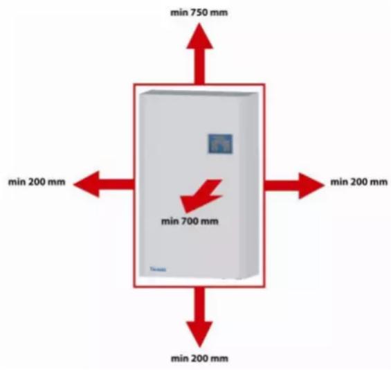
Installation location must be chosen for the electric boiler which will enable necessary access for the operator or for the purposes of a service inspection. Minimum distances between the boiler and a solid obstacle are shown in the Figure in the Chapter “Wall-mounting of a boiler”. Ask an expert worker of the company which performs the installation for a demonstration of the system function and training for operation. Once the boiler has been put into operation, a letter of guarantee must be certified by the authorized expert service worker.
In the location of the electric boiler installation pressure water for filling the heating system and water discharge point must be available. It is further necessary that the room has a sufficiently even wall (electric boiler is wall-mounted).
♦ Boiler location
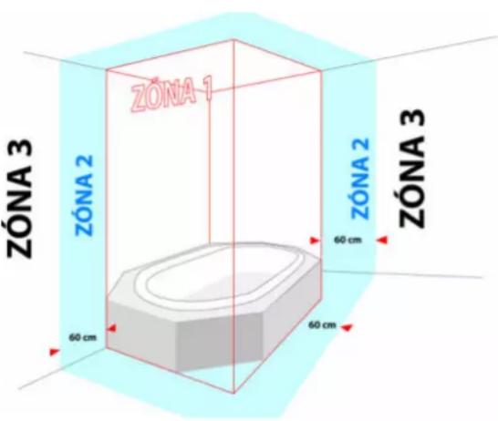
Electric boilers can be installed in the basic environment AA5/AB5 according to the standards CSN 2000-3 and CSN 33-2000-5:51 (range of temperatures between +5 and 40°C, humidity depending on the temperature of maximum 85%, no harmful chemical influences). It can be installed in residential as well as non-residential spaces with the exception of rooms with a bathtub or shower, in bathrooms and wash rooms in general in zones 1 and 2 according to CSN 33 2000-7-701. It cannot be however installed in zone 3 in locations where a water jet designed for cleaning can form. If the boiler is installed in the permitted zones, relevant electric current accident protection must be concurrently performed in accordance with the same standard, too.
text_image
ZÓNA 1 ZÓNA 2 ZÓNA 2 ZÓNA 3 60 cm 60 cm 60 cm ZÓNA 3The installation location must be chosen which will allow sufficient access for the operator as well as service inspector.
Degree of shielding of the boiler electric components is IP 40.
♦ Wall-mounting of the boiler
text_image
min 750 mm min 200 mm min 200 mm min 700 mm min 200 mmElectric boiler is mounted on the wall by means of a fixing strip (1) supplied with the boiler according to the Figure in the Chapter “Wall-mounting of the boiler”. If the boiler is mounted on a wall with a lower carrying capacity, it is recommended to consult the installation with a civil engineering technician. Free space of at least 200 mm below and 750 mm above the lower and upper edges of the jacketing shall be left for the purposes of inspecting the boiler or replacing the heating bodies (see Figure depicting the boiler wall-mounting and installation).
- Connecting the boiler to the hot-water heating system
Electric boiler must be connected to the distribution network in a manner preventing its aeration. Connection to the heating system must be tackled in a project design calculating hydraulic ratios of the whole system because the installation involves a hot-water flow-through boiler fitted with an integrated pump. It needs be noted that minimum flow through the boiler must be constantly assured for the designated boiler output at maximum thermal gradient of the heating system amounting to 20^ C. Any reduction of this flow (due to integrated high hydraulic friction elements) results in insufficient circulation and drop in life-time of some boiler parts. To utilize the maximum output of the heat exchangers, ensure correct functioning and high durability, the minimum heating system overpressure must amount to 0.8 bar.
Proper rinsing of the heating system resulting in the removal of all impurities must be performed prior to testing and launching the operation of the whole system in line with CSN 06 0310 within the framework of the installation. A suitable filter must be unconditionally fitted in the recuperative water inlet from the heating system into the boiler to prevent impurities from entering the boiler system.
The heating system must be installed in accordance with CSN 06 0830 -- Safety equipment for central heating and domestic hot water heating and CSN 06 0310 - Central heating - designing and assembly.
Shall the boiler be connected to a sealed heating system, such system must have a pressure expansion vessel of sufficient capacity (higher performance series boilers are not equipped with their own expansion vessel).
!!! We recommend:
- fill the system with soft water in line with CSN 07 7401;
■ fit the boiler outlet with a bleeding device; - mount a filter or a sludge device into the pump suction section;
■ overflow valve should be installed in heating systems with thermostatic valves - mount a heating system charge and discharge cock and a sludge cock at the lowest point of the system in the very proximity of the electric boiler
- separate all electric boiler types on inlet and outlet by stop valves, too (see standards CSN 06 8030), not to be forced to discharge the whole system in case of inspection or repair of the boiler or during filter replacement
■ remove control levers from stop valves and secure them against manipulation.
♦ Boiler connection to electric network
Wiring can be installed only by an authorized person in the sense of the Decree No. 50/1978 Coll. on professional qualification in electrical engineering. Certification of the boiler installation and putting into operation
must be noted in a proper manner on the letter of guarantee. Any interference with internal boiler wiring (with the exception of wiring specified in this Manual, e.g. the external regulator connection instead of jumper wire) are inadmissible!
The boiler control box must be connected according to the relevant CSN standard by means of a separately protected line which enables its disconnection and which is located in the very proximity of the electric boiler!
Current protective switch must be used if the electric boiler is installed in a bathroom.
The power wiring is connected by a 5-conductor system to the U, V, W, N and PE terminals. In the case of a 4-conductor system the N and PE terminals shall be connected together and the power wiring matched with the U, V, W and PE terminals.
If MRC is connected to the boiler control box, the MRC receiver outlet is matched with the terminal marked HDO/N. ^1
WARNING! When using the MRC receiver signal on the HDO/N terminal, it must be made sure that all contactor coils of other appliances (e.g. of the boiler if it is connected to the common MRC signal) are energized with the same phase!
When operation must be delivered also outside the so-called “low tariff”, the maximum boiler output limit can be switched off in the service menu also without the MRC signal (P4.4)!
Recommended cable cross sections under the plaster:
| Boiler output [kW] | 5 | 9 | 8 | 14 | 15 | 23 | 30 | 38 | 45 |
| Power take-off [A] | 7 | 13 | 12 | 20 | 24 | 36 | 48 | 60 | 72 |
| PVC insulated cable with copper conductors 5 [sq.mm] | 2,5 | 2,5 | 2,5 | 4 | 4 | 6 | 10 | 16 | 25 |
◆ Connection of electric boilers to one phase
Therm EL 5, EL 9, EL 14, EL 8 and EL 15 electric boilers can only be connected in certain cases to a single-phase distribution line.
Connection of Therm EL 5, EL 8, EL 9 and EL 14 electric boilers to a single phase distribution system.
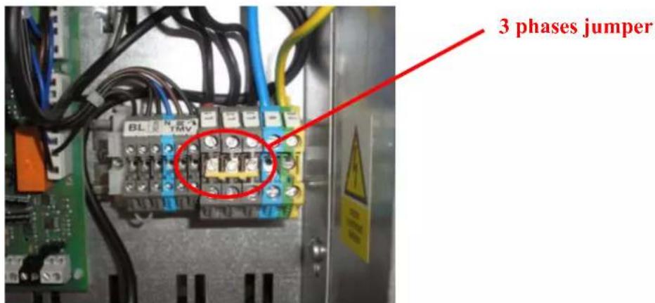
For the connection of EL 5, 8, 9 and 14 boilers, a connection unit is delivered which connects all three terminals. The supply cable with cross-section max. 10 ~mm^2 (for EL 14 max. 16 ~mm^2 ) can be connected to any of the three terminals marked L1, L2 or L3. We recommend to protect using a single-phase circuit breaker according to the table!
The connecting strip with bolts is attached to the boiler. Before the connection it is necessary to remove the plastic separating partition pieces between the individual phase terminals.
text_image
3 phases jumper BL TRV 3 phases jumperConnection of the Therm EL 15 electric boiler to a single-phase distribution line.
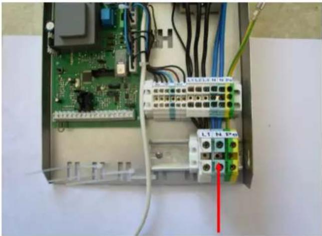
For the connection of boiler EL 15 to a single-phase set of terminals a DIN bar is delivered which is screwed into the prepared holes in the metal sheet under the existing terminals and for the prepared conductors it is connected to the original terminals. This ensures the connection of all three-phase distribution lines inside the boiler and the possibility to connect the supply cable with the conductor with a cross section of a max. 16mm^2 . We recommend protecting using a single-phase 80A circuit breaker! The connecting set has the storage number 43473 – “Set for connection to 1 phase for EL 15”.
natural_image
Electrical circuit board with green PCB, wiring, and terminal blocks (no readable text or symbols)♦ Charging the heating system
For the duration of the heating system charging, the boiler must be unplugged from the electric network by disconnecting it by the main circuit breaker. It is useful to maintain the level of filling pressure in a cold system in the range between 1 and 1.5 bar. Filling must proceed slowly in order to let the air bubbles escape through the respective valves. According to CSN 07 7401 the water used for the first filling as well as for refilling must be clear, colourless, without any suspended substances, oil or chemically aggressive admixtures, with a minimum carbonate hardness (max. 3.5 mval/l) and it cannot be acidic (pH cannot be below 7). Only approved agents can be used for water hardness adjustments.
Non-observance of the aforementioned requirements results in cancellation of the undertaking for the damaged components!
♦ Choice of the regulating and controlling components
The boiler is fitted with basic regulatory and safety elements as the following electric diagrams show. Therm-EL boilers can regulate their outputs. They are equipped with their own PID regulation which does not allow heating over the set temperature. Even if the TOP temperature is set to 80^ C, electric boilers frequently overheat up to the temperature of 96^ C, while THERM-EL boiler heats up to the maximum temperature of 84^ C.
It is always suitable and economical to let the electric boiler be controlled by a superior regulatory element (room thermostat or an OpenTherm communication regulator). These regulators are not included in the boiler delivery package!
Connection of a room thermostat and servicing of the boiler electric section may be carried out only by authorized service organizations!
Regulation based on temperature in a referential room (room regulator) or an equitherm regulation of the heating water, or potentially both, can be used as further extensions to the regulatory option. A whole series of regulatory or switch thermostats can be used to control the room temperature: E.g. PT 10, PT 21, PT 30, BPT 30, PT 30 GSM, REV 23, CM 707, CM 907 or OpenTherm communication regulators such as CR 04, PT59, Therm RC 03 or Siemens QAA 73.110.
Regulators (room regulator, water temperature thermostat, trip relay of the current value monitor or an OpenTherm regulator) can be connected to the boiler's input terminals (24V= circuits).
Current value monitor HJ 103TRX is a device used for disconnecting or reducing the output of the electric boiler when other high power input electrical appliances (e.g. flow-through water heater, washing machine, dishwasher, stove etc.) are connected to the network. Such a device is rules out the necessity of purchasing a high-capacity main circuit-breaker which also means the payment of a high lump fee.
If a part of the electric boiler needs to be disconnected, the tripping device becomes connected to the terminals for a trip relay (see the wiring scheme). The output size which becomes disconnected by individual trip relays is set by changing the parameters (P0^-, P1^-, P2^-, P3^-) in the control panel (from zero to maximum) in the service menu.
If the contact of the external tripping device should disconnect the whole boiler, it shall be either connected serially in combination with the room thermostat (24V=) or to the terminals of the blocking element (230V/50Hz).
Equitherm (outside temperature) regulation
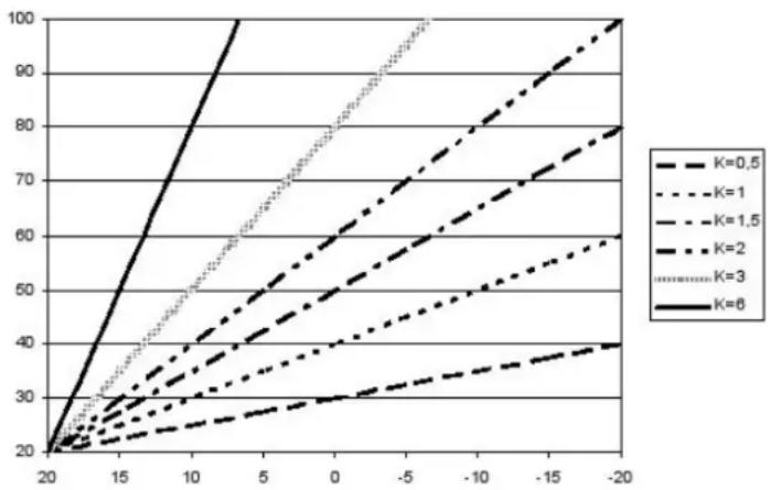
Heating water temperature in the equitherm regulation system is controlled on the basis of outdoor temperature. The regulation takes place according to equitherm curves which specify the dependence between outdoor temperature and the temperature of heating water required to reach the desired room temperature. An equitherm curve must be drawn on the basis of designed, calculated or measured heat losses of the building. This type of regulation does not have any feedback which would take into account higher cooling on one side of the house by wind or heating by sun and, as a result, it cannot safeguard accurate temperature regulation in all parts of the house. Boiler connection to room thermostat and Therm Q01 outdoor sensor enables utilizing the equitherm regulation which leads to additional energetic cost-cutting. THERM EL boiler is moreover capable of cooperating with OpenTherm communication interface regulators without any further communication interface installation. The inclination and shifting of equitherm curves can be modified in the automatic control user menu.
Heating water temperature [°C]
line
| x | K=0.5 | K=1 | K=1.5 | K=2 | K=3 | K=6 | |----|-------|-------|-------|-------|-------|-------| | 20 | 20 | 20 | 20 | 20 | 20 | 20 | | 15 | 25 | 27 | 30 | 32 | 35 | 40 | | 10 | 30 | 35 | 40 | 45 | 55 | 65 | | 5 | 35 | 45 | 50 | 60 | 75 | 90 | | 0 | 40 | 55 | 60 | 75 | 90 | 100 | | -5 | 45 | 65 | 70 | 85 | 100 | 100 | | -10| 50 | 75 | 80 | 95 | 100 | 100 | | -15| 55 | 85 | 90 | 100 | 100 | 100 | | -20| 60 | 95 | 100 | 100 | 100 | 100 |Outdoor temperature [°C]
Regulation according to room of reference
Used in family houses. Only temperature of a selected room is monitored on the basis of which the entire flat environment is regulated. Other rooms with diverse heat losses will be heated to different temperature unless further thermoregulating knobs are not installed on the radiators. This method has the advantage of a more flexible regulation. If an NTC temperature sensor located in the room of reference is connected to the boiler automatic control system – without any other external regulator – the automatic control system can be used as a simple room regulator (adjustable in the user menu – a Prt heating mode).
Cascade connection of boilers
The cascade connection format means connecting the boilers by means of technical elements into one set the task of which is common heating of large spaces in a manner which complies with requirements for a desired
heat comfort. Boilers can be arranged in a cascade (see wiring diagrams) by way of a simple interface which divides the actual electronics from the surrounding environment. Boiler electronics enable connecting up to 32 boilers in one single intelligent cascade which will modulate the output ranging from the minimum performance of the first boiler to the sum of maximum outputs of all boilers.
REKAS 1 interface (not included in the delivery package!) needs to be installed in both master and slave boilers.
The master boiler is in addition fitted with a master regulator (selection of the master and slave boiler is done in the service menu).
♦ MRC – mass remote control
Mass remote control (MRC) enables transmission of electricity as well as various commands to the users regarding tariff switching on the electrometer and operation of some appliances via standard distribution network. Mass remote control is a set of technical means (e.g. emitters, receivers, central automatics, transmission routes etc.) serving the emission of commands or signals for switching on or off electrical appliances. The MRC system has replaced the switch clock used in the past. Each customer who makes use of tariff switching must be equipped with a respective device which ensures this activity. This device is placed on the electrometer panel and cooperates with the electric boiler. The MRC receiver is an apparatus which performs the required switching operation (it for example blocks or unblocks an electrical appliance) as a result of a processed MRC signal.
Depending on the service setting, the boiler can be operated either only if the cheaper tariff signal is activated (the "HDO" LED is turned on) or if the user requires so (Ph^- parameter, P4.4).
6. BOILER OPERATION – LED DISPLAY WITH BUTTONS
Description of the control panel:
Control panel is simple and intuitive and displays the boiler functions.
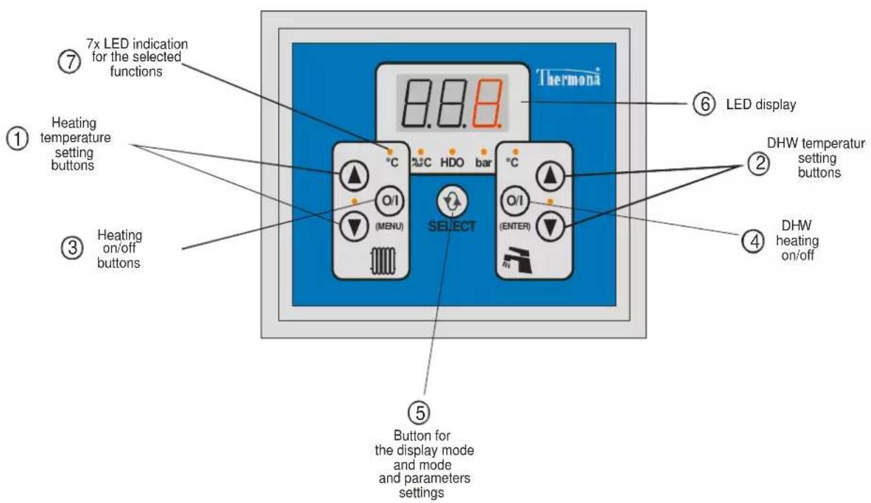
The panel uses colour-coding and graphical division of the heating and DHW preparation sections. LEDs positioned between the buttons for setting the temperature higher/lower (up/down arrows) are turned on if the particular mode is selected (i.e. either the DHW ^2 preparation mode or the heating water mode marked TOP).
If the display shows any other variable, pressing one of the ▲, ▼ buttons (1) displays the heating water temperature (the LED “°C” TOP is turned on).
If the display shows any other variable, pressing one of the ▲, ▼ buttons (2) displays the DHW temperature (the LED “°C” DHW is turned on).
Changing the value of the desired variable: When the heating water temperature is displayed (the LED “°C” TOP is on), the first pressing of one of the heating temperature setting buttons displays the setting for the required value of this temperature. This is indicated by the flashing of LED “°C” TOP. Required value can be changed within the ranges defined in the service menu. The set value becomes automatically registered in the memory after 15 seconds of inactivity (measured after the last button was pressed).
The required DHW temperature is set in a similar fashion (by the DHW temperature setting buttons).
The five LEDs below the main display show the variables which are currently set or indicated on the 3-digit display:
- if the LED “°C” (TOP or DHW) is on, the display shows the temperature of water in the heating or DHW circuits
- if the LED “IN/OUT °C” is on, the display shows the temperature of the outdoor or room temperature sensors
- if the LED "HDO" is on, the MRC signal is activated and the boiler produces heat in the low tariff
- if the LED "bar" is on, the display shows the pressure in the TOP system in bars
Automatic control elements (user access):
- Buttons for displaying heating temperature settings ▲, ▼ (1) – higher/lower, additionally, if selected, browsing through the service MENU
- Buttons for displaying DHW temperature settings ▲, ▼ (2) - higher/lower, the flashing value of the selected variable can be also changed in the menu)
- Heating on/off button O/I (MENU) (3) (press shortly), open the MENU (press for more than 2 seconds), exit the MENU (press shortly)
-
DHW heating on/off button O/I (ENTER) (4) (press shortly), ENTER (press shortly only in the MENU)
-
SELECT - main display selection button (SELECT) (5):
• temperature (according to the menu and selected option)
• water pressure (bar)
• output (kW)
- error messages (last error)
- heating mode
-
3-digit 7-segment LED display
-
7 LED indicators for the selected functions
text_image
7x LED indication for the selected functions ⑦ Heating temperature setting buttons ① ③ Heating on/off buttons Select ⑥ LED display HDO bar (O/I) (MENU) (O/I) (ENTER) ② DHW temperatur setting buttons ④ DHW heating on/off ⑤ Button for the display mode and mode and parameters settingsERROR MESSAGES:
| Error code | Type of defect |
| E.00 | NO DEFECT |
| E.02 | LOW PRESSURE (detected by the analogue pressure sensor) |
| E.03 | BLOCKING FUNCTION |
| E.04 | HEATING WATER (TOP) NTC TEMPERATURE SENSOR DEFECT |
| E.05 | DHW (TUV) NTC TEMPERATURE SENSOR DEFECT |
| E.06 | SAFETY THERMOSTAT (manual reset directly on the thermostat!) |
| E.07 | OUTDOOR/ROOM TEMPERATURE SENSOR DEFECT |
| E.08 | reserve |
| E.09 | PRESSURE SENSOR DEFECT – analogous pressure sensor |
| E.10 | COMMUNICATION PROBLEM between boilers in the cascade – master boiler |
| E.11 | COMMUNICATION PROBLEM between boilers in the cascade – slave boiler |
| - | past defects register (1–20) |
Apart from the E.06 defect (emergency thermostat temperature becomes exceeded), all other defects shut down the boiler and bring it to the defect state (heating bars become disconnected) which is automatically revoked only after the defect has been removed. The boiler's operation is then automatically re-initiated.
Defect detected by the emergency thermostat is irreversible (the thermostat is equipped with manual reset function which can be used only by an authorized service worker after the defect has been properly detected and addressed).
◆ Menu parameters
It can be always selected (in the user menu by the diS / P3.2 parameter) whether the item is displayed in the numerical format (more suitable in foreign language versions of the automatic control system) or in the mnemotechnical format (closer to the Czech language).
| MENU PARAMETERS: | |||
| Mnemo format | Numerical format | USER MENU | Initial settings |
| Et1 | P1.1 | CURVE SLOPE AT BININ N.UTL = 0 (night moderation – disconnected) | 1.6 |
| Et2 | P1.2 | CURVE SHIFT 1 | 0 |
| Et3 | P1.3 | CURVE SLOPE 2 AT BININ N.UTL = 1 (night moderation – connected) | 1.6 |
| Et4 | P1.4 | CURVE SHIFT 2 | -5 |
| ti1 | P2.1 | ROOM TEMPERATURE 1 AT BININ N.UTL = 0 (night moderation – disconnected) for rto=Prt | 21 |
| ti2 | P2.2 | ROOM TEMPERATURE 2 AT BININ N.UTL = 1 (night moderation – connected for rto=Prt | 19 |
| tdr | P2.3 | DIFFERENCE – REGULATORY RANGE (PROPORTIONAL) | 3 |
| tdf | P2.4 | DIFFERENCE – HYSTERESIS OFF/ON | 0.5 |
| GSE | P6.6 | ALLOW GSM MODEM AUTOMAT. SENDING ERROR SMS | 0 (NE) |
| diS | P3.2 | DISPLAY TYPE FOR THE MENU | AbC |
| Mnemo format | Numerical format | SERVICE MENU(opening this MENU is permitted only to the service engineer with the authorization of the manufacturer!) |
| rto | P3.1 | HEATING OPERATION MODE (tEr,EtE,Prt,otP,ot-) |
| rtU | P3.3 | DHW (TUV) HEATING OPERATION MODE (temperature probe/thermostat) |
| to_ | P3.4 | LOWER LIMIT FOR THE HEATING WATER TEMPERATURE SETTING |
| to- | P3.5 | UPPER LIMIT FOR THE HEATING WATER TEMPERATURE SETTING |
| tU_ | P3.6 | LOWER LIMIT FOR THE DHW TEMPERATURE SETTING |
| tU- | P3.7 | UPPER LIMIT FOR DHW TEMPERATURE SETTING |
| FtL | P3.8 | BINARY INPUT FUNCTION |
| PSt | P4.1 | START OUTPUT |
| Pt- | P4.2 | MAX. OUTPUT DURING HEATING |
| PU- | P4.3 | MAX. OUTPUT DURING DHW HEATING |
| Ph- | P4.4 | MAX. OUTPUT WITHOUT MRC SIGNAL |
| P0- | P4.5 | MAX. OUTPUT AT DISCONNECTED CONTACTS OF RELIEF RELAY 1 AND 2 |
| P1- | P4.6 | MAX. OUTPUT AT CONNECTED CONTACT OF RELIEF RELAY 1 |
| P2- | P4.7 | MAX. OUTPUT AT CONNECTED CONTACT OF RELIEF RELAY 2 |
| P3- | P4.8 | MAX. OUTPUT AT CONNECTED CONTACTS OF RELIEF RELAY 1 AND 2 |
| tSt | P5.1 | LIMIT OF THE REQUIRED VALUE OF TOP HOT-WATER OUTLET (to start heating) |
| ttU | P5.2 | REQUIRED OUTLET TEMPERATURE DURING BOILER HEATING |
| bdF | P5.3 | DIFFERENCE BETWEEN DHW HEATING ON/OFF |
| C_T | P5.4 | TIME LIMIT FOR THE OUTPUT/TEMPERATURE AFTER HEATING START |
| dCt | P5.5 | PUMP DECELERATION TIME AFTER HEATING IS FINISHED |
| dCU | P5.6 | PUMP DECELERATION TIME AFTER DHW HEATING IS FINISHED |
| AF_ | P5.7 | SYSTEM ANTI-FREEZE PROTECTION |
| UP0 | P5.8 | PRESSURE SENSOR VOLTAGE AT P=0 |
| UP4 | P5.9 | PRESSURE SENSOR VOLTAGE AT P=4 |
| h.01-h.21 | ERROR HISTORY DISPLAY | |
| i.01-i.12 | SERVICE AND DIAGNOSTIC INFORMATION | |
| tYP | P6.1 | BOILER TYPE SETTING |
| Adr | P6.2 | MULTIPLE BOILER FORMAT (CASCADE) CONTROL PARAMETER |
| GSo | P6.3 | ENABLE COMMUNICATION WITH GSM MODULE |
| Pn1 | P6.4 | FIRST GROUP OF TWO DIGITS PIN FOR GSM MODULE |
| Pn2 | P6.5 | SECOND GROUP OF TWO DIGITS PIN FOR GSM MODULE |
| PARAMETERS SET FOR THE MASTER CASCADE BOILER | ||
| PCC | P7.1 | NUMBER OF BOILERS IN THE CASCADE |
| dCC | P7.2 | SYSTEM CASCADE PUMP DECELERATION |
| dC1 | P7.3 | BOILER PUMP DECELERATION, IN THE CASCADE, AFTER ITS HEATING OPERATION IS FINISHED |
| AFC | P7.4 | CASCADE SYSTEM ANTI-FREEZE PROTECTION FREEZE |
| PhC | P7.5 | MAXIMUM CASCADE OUTPUT WITHOUT MRC SIGNAL |
| P0C | P7.6 | MAXIMUM CASCADE OUTPUT AT DISCONNECTED CONTACTS OF RELAY 1 AND 2 |
| P1C | P7.7 | MAXIMUM CASCADE OUTPUT AT CONNECTED CONTACT OF RELAY 1 |
| P2C | P7.8 | MAXIMUM CASCADE OUTPUT AT CONNECTED CONTACT OF RELAY 2 |
| P3C | P7.9 | MAXIMUM CASCADE OUTPUT AT CONNECTED CONTACTS OF RELAY 1 AND 2 |
7. BOILER CONTROL AND DISPLAY OF BASIC OPERATIONAL INFORMATION
(more detailed user instructions)
♦ Heating water temperature display
After its connection to the power network, the display shows heating water temperature in °C which is indicated by the pilot light °C above the O/I (MENU) button (3). If any other variable is displayed at the moment (DHW temperature, output, error message etc.), pressing any of the buttons ▲, ▼ (1) opens the heating water temperature dialogue.
In the case of sensor defect, the numerical data become replaced with dashes: ____ during disconnection or interruption of the sensor or wiring, ____ after short circuit on the sensor or wiring.
◆ Displaying and changing (setting) the desired temperature of heating water
If you press any of the ▲, ▼ buttons (1) with the display showing the heating water temperature dialogue, you can display its desired value. Slow flashing of the °C pilot light above the O/I (MENU) button (3) shows the desired value. The currently valid desired temperature value according to the operational mode is displayed (e.g. calculated by means of the integrated equitherm regulator or integrated room thermostat by way of a communication line from the external regulator).
If you press any of the ▲, ▼ buttons (1) with the display showing the desired heating water temperature, you can set the desired value. Faster flashing of the °C pilot light above button 3 indicates the setting process. The desired temperature value can be set by means of ▲, ▼ buttons (1) within the range defined by TO_ a TO⁻ (P3.4 a P3.5) items in the service menu. The set value does not need to be confirmed. The mode of setting the desired value terminates 15 seconds after any of the ▲, ▼ buttons were last pressed (1).
The set desired value is valid in the following situations:
- rto heating mode is set to tEr (P3.1 = 1) (control performed by contact of the external room thermostat),
- rto heating mode is set to EtE (P3.1 = 2) (equitherm regulation) but the outdoor temperature sensor defect has been reported,
- rto heating mode is set to Prt (P3.1 = 3) (integrated room thermostat) but the room temperature sensor defect has been reported,
- rto heating mode is set to otP or ot- (P3.1 = 4 or 5) (external OpenTherm protocol regulation) but communication has failed.
If any other variable is displayed at the moment (heating water temperature, output, error message etc.), pressing any of the buttons 2 opens the DHW temperature dialogue. This display is indicated by the °C pilot light above button 4.
In the case of sensor defect or absence, the numerical data become replaced with dashes: ____ during disconnection or interruption of the sensor or wiring, ____ after a short circuit on the sensor or wiring.
◆ Displaying and change (setting) of the desired DHW temperature value
If you press any of the ▲, ▼ buttons (2) with the display showing the DHW temperature dialogue, you can set its desired value. The setting process is indicated by flashing of the °C pilot control above the O/I (ENTER) button (4). You can set the desired temperature value by pressing the ▲, ▼ button (2) within the range defined by the TU_ a TU⁻ (P3.5 a P3.6) items of the service menu. The set value does not need to be confirmed. The setting mode for the required values terminates 15 seconds after any of the ▲, ▼ (2) buttons has been last pressed.
The desired DHW temperature value can be set only if the rtU DHW heating mode is set to b_c (P3.2 = 2) (storage tank with the temperature sensor).
♦ Switching the heating on or off
The heating mode can be switched on or off by pressing the O/I (MENU) button (3). The on-mode is signalled by the pilot light between ▲, ▼ buttons (1); the pilot light in the off-mode is turned off.
Heating can be switched on only if its operation is pre-set in the user menu; the rto item must be set to tEr, EtE, Prt, otP or ot- (P3.1 = 1 - 5).
♦ Switching the DHW heating on or off
The DHW heating mode can be switched on or off by pressing the O/I (ENTER) button (4). The on-mode is signalled by the pilot light between ▲, ▼ buttons (2); the pilot light is off if the DHW is in the off-mode.
The DHW heating can be switched on only if its operation has been pre-set in the service menu; the rtU item must be set to b_n or b_c (P3.3 = 1 or 2).
◆ Displaying the outdoor/room temperatures
To display any other operational variables (except for the heating water and DHW temperatures), use the (SELECT) button (5) . If you press (or double press) it, the outdoor/room temperature display dialogue opens. This dialogue is indicated by the IN/OUT °C pilot light.
In the case of sensor defect or absence, the numerical data become replaced with dashes: ____ during disconnection or interruption of the sensor or wiring, --- during short circuit of the sensor or wiring
The difference between displaying the room or outdoor temperature rests only in the location of the sensor. Shall the boiler operation be controlled on the basis of its data, the respective mode must be selected in the user menu:
- for rto = EtE (P3.1 = 2) (integrated equitherm regulation) outdoor sensor must be used,
- for rto = Prt (P3.1 = 3) (integrated room thermostat) sensor in the room of reference must be used.
If the sensor is connected but the boiler operation is not controlled on the basis of its data, these data are used at least for protecting the system against freezing.
◆ Displaying the heating system pressure
If you press (or double press) the (SELECT) button (5), the system pressure dialogue opens. This display dialogue is indicated by the bar pilot light.
Minimum operation pressure of the system is 0.5 bar.
♦ Signal indication of the mass remote control (MRC)
The presence of the MRC signal is indicated by the HDO (MRC) pilot light. If it is turned on, it means that the full boiler input is allowed.
Reduction of the boiler input by way of MRC signal can be set in the service menu by means of the Ph ^- (P4.4) item.
◆ Displaying the error messages
If you press (or double press) the (SELECT) button (5), the error message dialogue opens. This display dialogue is indicated by the letter E in the first position of the digital display. If an error message is generated, it is displayed automatically. To display any other variable, press buttons 1, 2 and 5.
If several simultaneous error messages occur, all of them are displayed (each for one roughly second): e.g.
$$ \mathbf {E . 0 2} - \mathbf {E . 0 4} - \mathbf {E . 0 5} - \mathbf {E . 0 2} - \mathbf {E . 0 4} - \mathbf {E . 0 5} - \dots $$
E.00 no defect
E.01 reserve
E.02 is low TOP water pressure in the heating system. Boiler operation is not possible in any mode.
Water pressure measured by analogous pressure sensor is below 0.5 bar.
E.03 is a disconnection of the blocking element 2. Boiler operation is not possible in any mode.
E.04 is a defect on NTC sensor for the TOP heating water temperature. Boiler operation is not possible in any mode.
When the respective value is displayed, the lower dashes (____) are displayed in the case of disconnection or interruption of the sensor or its wiring, the upper dashes (____) if there is a short circuit on the sensor or its wiring.
E.05 is a defect of NTC sensor for DHW temperature. The boiler operation in the heating mode is possible, DHW heating is not possible in the b_c (storage tank with sensor) mode and it is possible in the b_n (storage tank with thermostat) mode. For further details see the rtU parameter for the operation of the DHW heating in the service menu.
If the respective temperature setting is selected, lower dashes (____) are displayed if the sensor or wiring have been disconnected or interrupted, upper dashes (____) are displayed for short circuit on the sensor or wiring.
E.06 defect – emergency thermostat of TOP heating water temperature. Boiler operation is not possible (only after a manual reset!).
E.07 is a defect of the NTC sensor for outdoor/room temperature. Boiler operation in the heating mode is possible. If, however, the EtE heating mode (equitherm regulation) or Prt (integrated room thermostat) are selected, the boiler automatically switches to the boiler thermostat mode (outlet water temperature control according to a value set by buttons 1). DHW heating is possible in any of the modes.
If a respective display is selected, the lower dashes ( _ _ ) are displayed if the sensor or wiring have become disconnected or interrupted, upper dashes ( -- ) stand for short circuit on the sensor or wiring.
E.08 reserve
E.09 is a defect of the TOP heating water pressure sensor - analogous sensor. Boiler operation is not possible in any of the modes.
E.10 is a defect of the communication between boilers connected in a cascade which has been detected by the master boiler. To display the details about this defect, press button 5. Addresses of all boilers are alternately displayed (each for the time of approximately 1 second) which do not communicate with the master boiler:
$$ E. 1 0 - c. 0 4 - c. 0 5 - E. 1 0 - c. 0 4 - c. 0 5 - \dots $$
E.11 is a defect of communication between boilers connected in a cascade which has been detected by one of the slave boilers.
◆ Displaying the instantaneous boiler output
If you press (or double press) the (SELECT) button (5), the display dialogue of the instantaneous boiler output opens. This dialogue is indicated by the letter P in the first position of the display. The output is shown in kW (P.2.5 = 2.5 kW, P.18 = 18 kW etc.).
8. USER MENU - LED DISPLAY WITH BUTTONS
◆ Accessing the user menu
To access the user menu, press the O/I (MENU) button (3) for more than 2 seconds. To move between the menu items, press the ▲, ▼ buttons (1). If you want to change the input values, press the ▲, ▼ buttons (2). The entered value in the menu must be confirmed by pressing the O/I (ENTER) button (4). Exit the menu and data input by pressing the O/I (MENU) button (3).
The menu item (the set variable) and its value display alternately (e.g. Et1 - 1.6 - Et1 - 1.6...). The menu item is displayed either by means of mnemotechnical texts (Et1) or numerical parameters (P1.1). The display mode is set in the menu by way of the diS (P3.2) item.
Group 1: Integrated equitherm regulation parameters
Equitherm regulation defines the desired value of heating water temperature depending on the outdoor temperature. The selection of parameters for the calculation depends on the specification of the binary NU (night moderation).
If NU is disconnected, the following is true:
the desired heating water temperature value = (20 - outdoor temperature) * Et1 + 20 + ET2
If NU is connected, the following is true:
the desired value of heating water temperature = (20 - outdoor temperature) * Et3 + 20 + ET4
The desired outlet heating water temperature value is limited in the range between to_ (P3.3) and to ^- (P3.4).
Equitherm regulation always requires the connection of an outdoor temperature sensor and the heating mode setting of rto = EtE (P3.1=2).
Et1 P1.1 Equitherm regulation parameter, curve slope. True for a disconnected NU.
The setting range falls between 0.1 .. 6.0, step of 0.1, leading value is 1.6.
Et2 P1.2 Equitherm regulation parameter, curve shift. True for a disconnected NU.
The setting range is -20^ .. +40°C, step of 1°C, leading value is 0.
Et3 P1.3 Equitherm regulation parameter, curve slope. True for a disconnected NU.
The setting range falls between 0.1 .. 6.0, step of 0.1, leading value is 1.6.
Et4 P1.4 Equitherm regulation parameter, curve shift. True for a connected NU.
The setting range falls between -20^ .. +40°C, step of 1^ , leading value is -5.
Group 2: Integrated room thermostat parameters
An integrated room thermostat can control heating operation according to the data from internal temperature sensor. It uses proportional control to set the outlet water temperature within the range defined by the tdr (P2.3) parameter:
- if TM < ti1 - tdr (TM < P2.1 - P2.3), heating is controlled to reach the maximum heating water temperature to (P3.4),
- if TM > ti1 (TM > P2.1), heating is controlled to have the minimum heating water temperature to_ (P3.3),
- if ti1 - tdr < TM < ti1 (P2.1 - P2.3 < TM < P2.1), the desired heating water temperature is calculated by the interpolation between to_ and to ^- (P3.3 a P3.4),
- if TM > til + tdF, the heating is switched off completely.
The aforementioned is true if the NU binary input specification is “disconnected”. If the NU binary input specification is “connected”, a value of ti2 (P2.2) is used instead of ti1 (P2.1).
ti1 P2.1 Desired value of the room temperature. True if NM is “disconnected”.
The setting range falls between 10 and 30°C, step of 1°C, leading value is 21°C.
ti2 P2.2 Desired value of the room temperature. True if NM is “connected”.
The setting range falls between 10 and 30°C, step of 1°C, leading value is 19°C.
tdr P2.3 Temperature range of room in which the proportional control of the desired outlet water temperature value takes place.
The setting range falls between 2 and 10°C, step of 1°C, leading value is 3°C.
tdF P2.4 Difference (hysteresis) between the shut-down and repeated initiation of heating when the desired room temperature has been exceeded.
The setting range falls between 0.25 and 2.50°C, step of 0.25°C, leading value is 0.5°C.
Complete heating shut-down occurs if the room temperature exceeds the set value by more than tdF (P2.4). Heating is again switched on only when the room temperature drops below the set value.
Group 6: GSM communication
GSE P6.6 Enable automatic sending of fault SMS when a fault occurs
Settings: nO, Yes (0, 1), leading value is nO (0).
Parametr is shown in menu only if Adr = c.0 a GSO = Yes (Ano).
Group 3: Heating setting and display mode
rto P3.1 Heating mode (TOP) (inside service menu)
The boiler operation is conditioned by the connection of the external room thermostat PT terminals at all possible settings. If the thermostat is not used at all, it is necessary to create a permanent connection between the PT terminals.
Settings options:
--- 0 Heating switched off. It is not possible to switch it on even by means of button 3. Anti-freeze protection is active.
tEr 1 Heating is controlled by the external room thermostat contact and the outlet water temperature is set by buttons 1.
EtE 2 Heating is controlled by integrated equitherm regulator. Outdoor temperature sensor must be connected.
In the case of a defective sensor or if it is not connected, the boiler is controlled in the tEr (like at P3.1 = 1) mode.
Prt 3 Heating is controlled by integrated room thermostat. The room temperature sensor must be connected.
In the case of a defective sensor or if it is not connected, the boiler is controlled in the tEr (like at P3.1 = 1) mode.
otP 4 Heating is controlled by external regulator which is connected by way of the OpenTherm Plus interface.
In the case of defective communication or regulator, the boiler is controlled in the tEr (like at P3.1 = 1) mode.
ot- 5 Heating is controlled by external regulator which is connected by way of the OpenTherm Lite interface.
In the case of defective communication or regulator, the boiler is controlled in the tEr (like at P3.1 = 1) mode.
diS P3.2 Menu display type (mnemotechnical texts/numerical parameters)
Settings options:
diS = 012, AbC (P3.2 = 0, 1), leading value AbC (1).
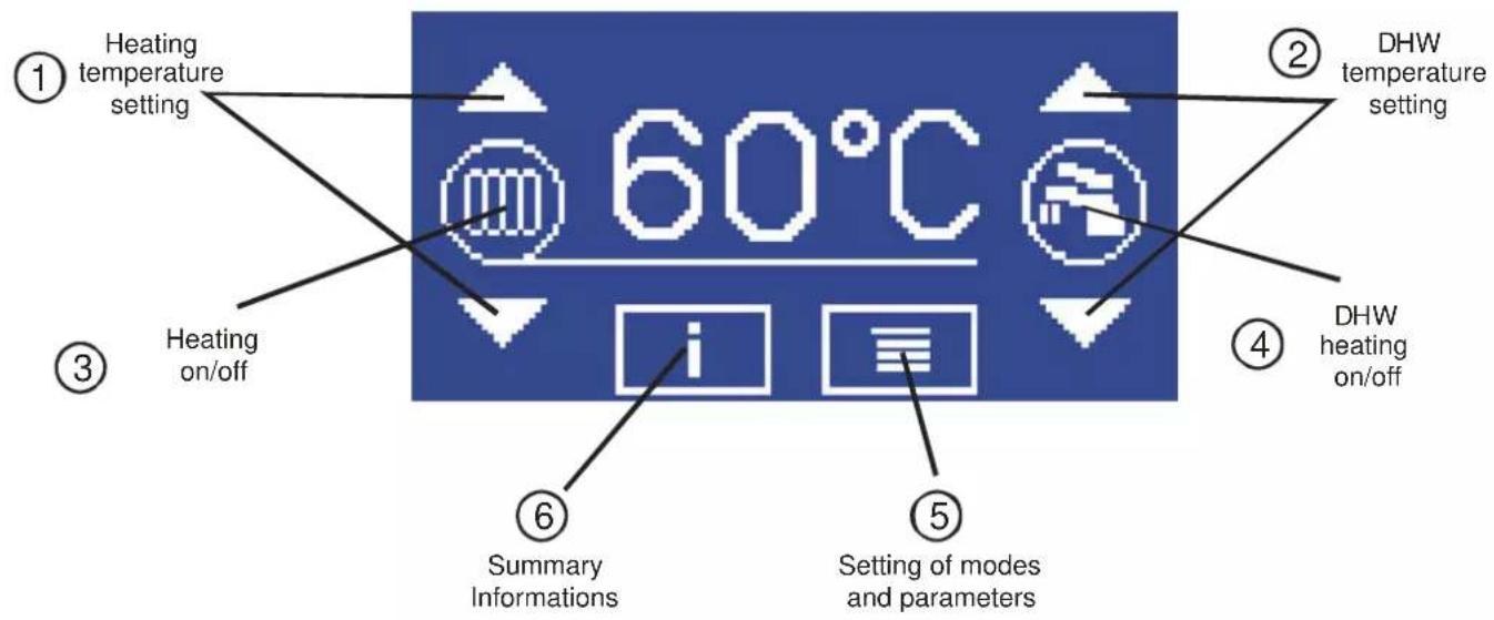
◆ Description of control
The control panel enables the simple intuitive control and display of the function of the boiler. The control of the control system is performed by finger touch on the indicated parts of the display.
text_image
① Heating temperature setting ② DHW temperature setting ③ Heating on/off ④ DHW heating on/off ⑤ Setting of modes and parameters ⑥ Summary Informations◆ Change of the style of the display
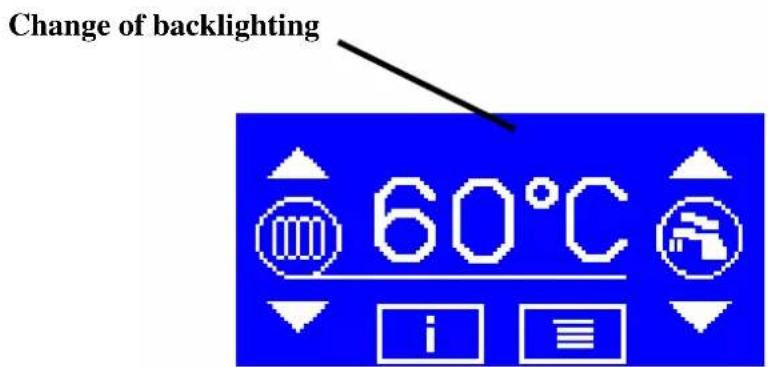
By pressing the touch display in the centre of the upper part (see Fig.) it is possible to change the style of the display. There are four variants of display in total. If is possible to ON or OFF the backlit. At the same time, it is possible to select between traditional or inverse display of the display.
text_image
Change of backlighting 60°C♦ Basic display
After activation of the boiler the logo of the producer is briefly displayed. Then the basic screen is displayed. Its content differs depending on which heating of service water is used (DHW):
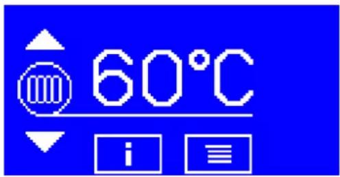
text_image
60°C iBASIC SCREEN (WITHOUT HEATING OF DHW)
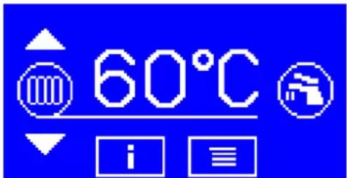
text_image
60°C iSTORAGE TANK WITH DHW WITH THERMOSTAT
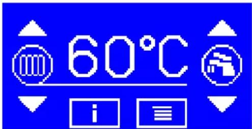
text_image
60°C iSTORAGE TANK FOR DHW WITH TEMPERATURE SENSOR
In the centre of the display is the temperature of the heating water in ^ C, which is indicated by the linkage of the underlying value of the temperature with the heating symbol on the left side.
Elements on the right side of the display – symbol of the tap (DHW), or arrow for setting the DHW temperature are displayed depending on the adjusted regime of DHW heating in the service menu.
In the case of the failure of the thermal sensor of the heating water, question marks are displayed instead of a numeric value. -?? during the disconnection or interruption of the sensor or supply, ?? in the case of a short circuit of the sensor or the inlets.
♦ Activation and deactivation of heating
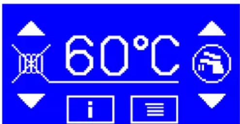
In the left part of the display are three control elements: the symbol for heating (radiator) and the arrows for setting the requested value of the temperature of the heating water.
The heating regime can be activated and deactivated by pressing the heating symbol. The activated status is signalled by the symbol of a radiator in a wheel; in the disconnected status the radiator is crossed.
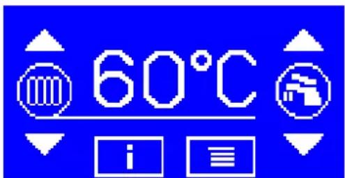
text_image
60°C iHEATING ACTIVATED
text_image
60°C iHEATING DEACTIVATED
The heating can only be activated in the case that in the pre-set operation in the user menu, the HEATING REGIME item is set for some of values: THERMOSTAT, EKVITHERM, ROOM THERMOSTAT, OT/+, OT/-.
◆ Change (the setting) of the required value of the temperature of the heating water
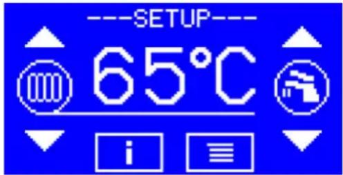
Press some arrows on the left side of the display at the time when on the display the temperature of the heating water is displayed and set the required values. The regime for setting the required value is signalled by the text – SETTING – in the upper part of the display.
text_image
----SETUP---- 65°C i ≡SETTING THE REQUIRED VALUE OF THE TEMPERATURE OF THE HEATING WATER
The value of the temperature can be changed using the buttons with arrows within the range stated by the items LOWER LIMIT FOR SETTING THE HEATING WATER and UPPER LIMIT FOR SETTING THE HEATING WATER in the service menu. It is not necessary to confirm the adjusted value. The regime for setting the required value is terminated within 15 seconds after the last pressing of a button.
Such adjusted required temperatures are valid in the following cases:
- the heating regime (item HEATING MODE in the user menu) is set for THERMOSTAT (boiler thermostat) and external regulator OT/+ is not connected,
- the heating regime is set for EKVITERM (equitherm regulation), and any error in the ambient temperature sensor is reported (E.07) and the external regulator is not connected OT/+,
- the heating regime is set for ROOM THERM. (built-in room thermostat), although the error in the room temperature sensor is reported (E.07) and the external regulator is not connected OT/+,
- the regime is set for OT/+ or OT/-(external regulator with OpenTherm protocol), although the external regulator is not connected OT/+, OT/-.
◆ Activation/deactivation of heating the service water
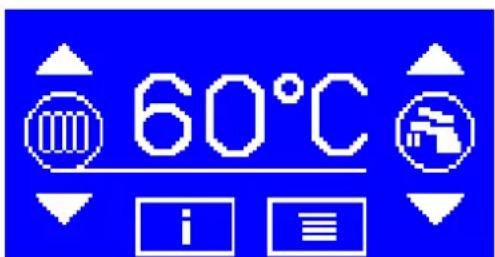
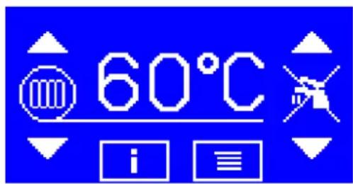
The regime for the heating of DHW can be activated and deactivated by pressing the symbol with the water tap. The activated status is signalled by the symbol of the tap in the wheel, in the disconnected status the tap is crossed.
text_image
60°C iHEATING OF DHW ON
text_image
60°C iHEATING OF DHW OFF
The heating of DHW can be activated in the case where the operation is pre-set in the service menu, the item HEATING MODE OF DHW is set for THERMOSTAT or SENSOR.
♦ Switching of the display of the heating water temperature and the hot service water temperature
If the heating water temperature is displayed, it is possible to switch to the display of the temperature of DHW by pressing any arrow on the right side of the display or by touching the displayed temperature. The display of the temperature of DHW is indicated by the linkage of the underlined temperature data and the symbol of the tap on the right.
On the contrary, if the temperature of DHW is displayed, it is possible to switch to the display of the heating water
temperature by pressing any arrow on the left side of the display or by touching the displayed temperature. The display of the heating water temperature is indicated by the linkage of the underlined temperature data and the heating symbol on the left side.
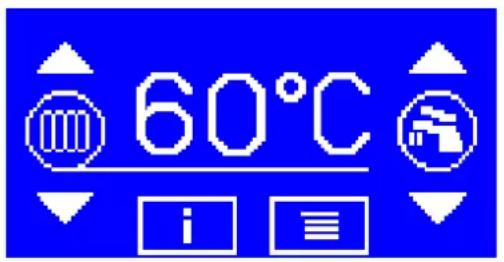
text_image
60°C iDISPLAY OF HEATING WATER TEMPERATURE
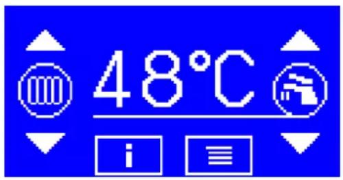
text_image
48°C iIn the case of failure or absence of a thermal sensor, question marks are displayed instead of a numeric value. -?? during the disconnection or interruption of the sensor or the supply, ?? in the case of a short circuit of the sensor or inlets. This is valid only in the case of the DHW SENSOR heating regime. In other cases, during the failure of the sensor of the DHW temperature, it is not possible to switch the display to display this.
◆ Change (setting) of the required value of the hot service water temperature
Press any arrow on the right side of the display in the time when on the display the DHW temperature is displayed to display and set the required values. The regime for setting is signalled by the text - SETUP - in the upper part of the display.
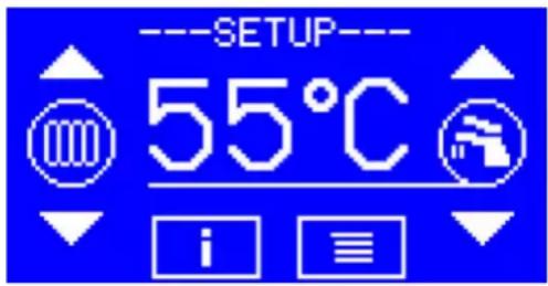
text_image
----SETUP---- 55°C i ≡SETTING THE REQUIRED VALUE OF THE DHW TEMPERATURE
It is possible to change the value of the required temperature by the buttons with arrows within the range stated by the items DHW TEMP. SETTING – LOWER LIMIT and DHW TEMP. SETTING – UPPER LIMIT in the service menu. It is not necessary to confirm the adjusted value. The regime for setting the required value is terminated within 15 seconds after the last pressing of any arrow.
The required temperature of DHW can be set only in the case that the regime for the operation of heating of DHW (item DHW HEATING MODE in the service menu) is set for SENSOR (storage tank with temperature sensor).
◆ 1. info screen - Display of the operating status of the boiler and failures

text_image
60°C iBUTTON FOR SWITCH TO 1. INFO SCREEN
The information screen has four buttons in its lower part:
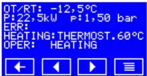
text_image
OT/RT: -12,5°C P:22,5kW P:1,50 bar ERR: HEATING:THERMOST.60°C OPER: HEATINGRETURN - PREVIOUS - NEXT - MENU
BUTTONS IN THE 1. INFO SCREEN
RETURN – return to home screen,
PREVIOUS – move to the previous screen,
NEXT – move to the next info screen,
MENU - enter user menu.
Data on the first info screen:
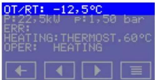
text_image
OT/RT: -12,5°C P:22,5kW P:1,50 bar ERR: HEATING:THERMOST.60°C OPER: HEATINGOT/RT: OUTDOOR TEMPERATURE / ROOM TEMPERATURE
In the case of failure or absence of the sensor, question marks will appear instead of a numeric value :-??? in the case of the disconnection or interruption of the sensor or inlets, ??? in the case of short circuit of the sensor or inlets.
This only depends on the location of the sensor and whether it concerns the display of room temperature or ambient temperature. If on the basis of data the operation of the boiler is to be controlled, the respective regime must be set in the user menu:
- for heating regime OTC (built-in equitherm regulation) an external sensor must be used,
- for heating regime = ROOM THERMOSTAT (room spatial thermostat) a sensor in the characteristic room must be used.
If the sensor is connected but the operation of the boiler is not controlled on the basis of its data, this data is used as a minimum for the anti-freeze protection of the system.
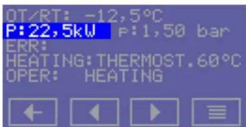
text_image
OT/RT: -12,5°C P:22,5kW P:1,50 bar ERR: HEATING:THERMOST.60°C OPER: HEATINGIf the failure status exists, it is signalled by flashing text as follows:
1 RELAY CONTACT failure of the power relay contact – not used
2 LOW PRESSURE low water pressure in the heating system.
Water pressure measured by the analogue pressure sensor is lower than 0.5 bar.
3 BLOCKADE 2 the contact for blockage 2 is disconnected
4 THERMAL SENSOR TOP failure of the thermal sensor for the heating water. The operation of the boiler is not possible in any regime.
During selection of the respective display of temperature, question marks are displayed on the display (-??) in the case of disconnection or interruption of the sensor or inlets, (??) in the case of a short circuit of the sensor or inlets.
5 THERMAL SENSOR DHW failure of the sensor of the DHW temperature. The operation of the boiler in the heating regime is possible, the heating of DHW is not possible in the SENSOR regime (storage tank with the sensor), only the THERMOSTAT regime is possible (storage tank with thermostat).
During selection of the respective temperature display, question marks are displayed on the display (??) in the case of disconnection or interruption of the sensor or inlets, (-??) in the case of the short circuit of the sensor or inlets.
6 EMERGENCY THERMOSTAT contact for the emergency thermostat is disconnected (the intervention of a service technician is necessary).
7 THERMAL SENSOR TV/TM failure of the ambient temperature / room temperature sensor. The operation of the boiler in the heating regime is possible. If the OTC heating regime is selected (equitherm regulation) or ROOM THERMOSTAT (built-in room thermostat), the boiler will automatically switch into the boiler thermostat regime (control of the temperature of the output water according to the value adjusted for the boiler thermostat). Heating of DHW is possible in any regime.
During selection of the respective display of temperature, question marks are displayed on the display (???) in the case of disconnection or interruption of the sensor or inlets, (-??? ) in the case of a short circuit of the sensor or inlets.
9 PRESSURE SENSOR failure of the analogue pressure sensor. The operation of the boiler is not possible.
10 COM. CASCADE failure of communication between boilers in the cascade which was recognized by the control boiler in the cascade. By touching the display on the text of the error message, it is possible to switch to the display of the details about this failure. During this display all addresses are gradually displayed for one second of all boilers which do not communicate with the control boiler.
10 KOM. CASCADES - c.04 - c.05 - 10 KOM. CASCADES - c.04 - c.05 - ...
11 COM. CASCADE failure of communication between boilers in the cascade which was recognized by the control boiler of the cascade. If there are several failure statuses, they are all gradually displayed after about one second. During the origination of the failure status, switching from the home page to the display is done automatically.
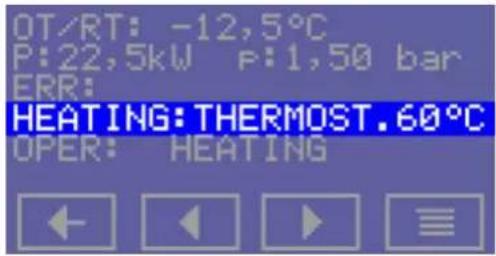
text_image
OT/RT: -12,5°C P:22,5kW P:1,50 bar ERR: HEATING:THERMOST.60°C OPER: HEATINGThe displayed regime is the actual one. It takes into consideration the advantage of external regulator OT/+ and any failure of the TV/TM sensor.
Some of the following texts are displayed:
OFF
THERMOSTAT
OTC
ROOM TH.
OT/+
OT/-
CAS. SLAVE
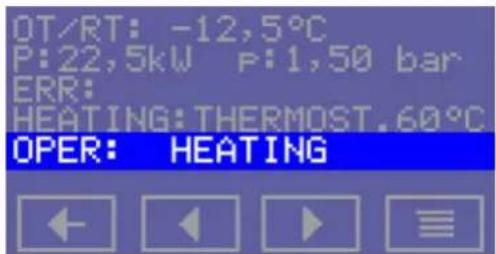
text_image
OT/RT: -12,5°C P:22,5kW P:1,50 bar ERR: HEATING:THERMOST.60°C OPER: HEATING◆ 2. info screen – Display of the status of the binary inputs and GSM module
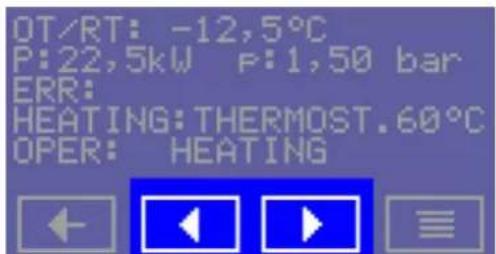
text_image
OT/RT: -12,5°C P:22,5kW P:1,50 bar ERR: HEATING:THERMOST.60°C OPER: HEATINGBUTTONS FOR MOVING BETWEEN INFO SCREENS
The second screen contains information about the status of the binary inputs.
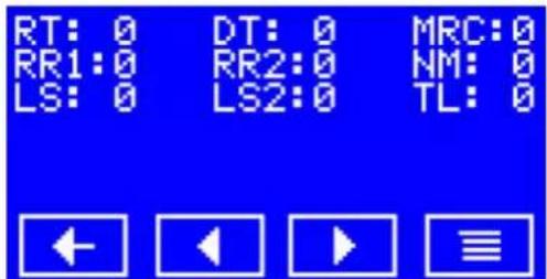
text_image
RT: 0 DT: 0 MRC:0 RR1:0 RR2:0 NM: 0 LS: 0 LS2:0 TL: 0- INFO SCREEN
The 0 behind the respective abbreviation means input without voltage (disconnected contact); number 1 means input under voltage (connected contact).
Abbreviations
RT (PT in Czech) room thermostat
DT (BT) boiler thermostat (external storage tank for DHW)
MRC (HDO) mass remote control (lower rate for two-rate electric meter)
RR1 (OR1) input for releasing relay 1
RR2 (OR2) input for releasing relay 2
NM (NU) night damping
LS (HT) emergency thermostat
LS2 (BL2) blockage 2
TL (TL) binary input
If the boiler is fitted with a GSM module and communication with this module is enabled in this menu, on the 2.info screen there is line with the status of the module.
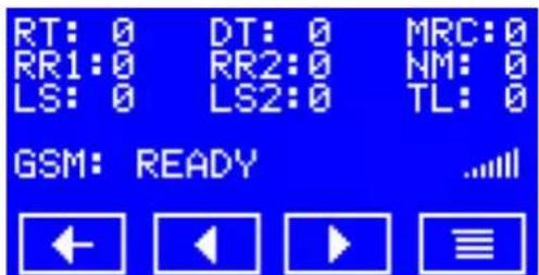
text_image
RT: 0 DT: 0 MRC:0 RR1:0 RR2:0 NM: 0 LS: 0 LS2:0 TL: 0 GSM: READY ...... ← ← → ≡2. INFO SCREEN WITH GSM MODULE INFORMATION
Possible GSM module statuses are:
MODULE SEARCH after activation the board attempts to automatically establish connection with the GSM module
INITIALIZATION configuration of found module, login into the operator network
BLOCKED login into the network of the operator failed – SIM card is not inserted or incorrectly typed PIN
READY the module is logged into the operator network, monitors incoming calls (ringing out), regularly transfers to checking incoming SMS
SENDS SMS sending of SMS either for ringing out to a known telephone number or after receipt of an SMS with request for reply
CHECKING SMS regular checking of incoming SMS
At the end of the status line (if the module is correctly logged into the operator network) there is the icon indicating the level of the signal. Only in the case of permitted communication with the GSM module is it possible to transfer using the arrow to the right to 3. info screen, where it is possible to find information on the last received SMS regarding the last ringing out.
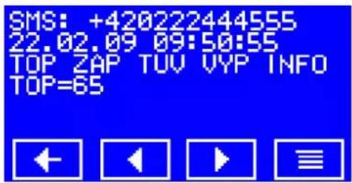
text_image
SMS: +420222444555 22.02.09 09:50:55 TOP ZAP TUV VYP INFO TOP=653. INFO SCREEN FOR LAST DELIVERED SMS
If a delivered message is longer than the screen, the rest of the message can be displayed on the next screen. It is possible to switch to the basic screen by pressing the return button.
text_image
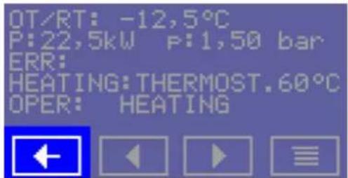
OT/RT: -12,5°C P:22,5kW P:1,50 bar ERR: HEATING:THERMOST.60°C OPER: HEATINGBUTTON TO RETURN TO THE HOME SCREEN
After four minutes without pressing any buttons there is automatic switching to the home page.
10. USER MENU - TOUCH DISPLAY
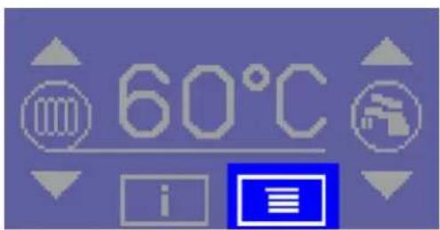
BUTTON FOR OPENING THE USER MENU
text_image
60°C iFROM HOME SCREEN
text_image
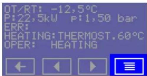
OT/RT: -12,5°C P:22,5kW P:1,50 bar ERR: HEATING:THERMOST.60°C OPER: HEATINGFROM INFO SCREEN
text_image
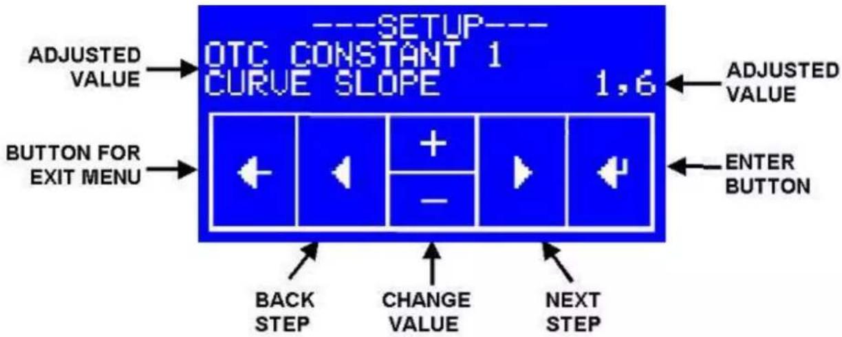
---SETUP--- OTC CONSTANT 1 CURVE SLOPE 1,6 ADJUSTED VALUE BUTTON FOR EXIT MENU BACK STEP CHANGE VALUE NEXT STEP ADJUSTED VALUE ENTER BUTTONUSER MENU SCREEN
It is possible to move between the menu items using the PREVIOUS and NEXT buttons. Use + and – to change the typed value. It is necessary to confirm the typed value in the menu with the CONFIRM button. Press the button for LEAVING MENU to leave the menu and terminate typing.
The adjusted value flashes on the display.
Some items of user menu are displayed conditionally – depending on setting of other items.
◆ User menu items
Group 1 Parameters of equithermal regulation
Equithermal regulation states the required value of the temperature of the heating water depending on the ambient temperature. The selection of parameters for the calculation depends on the status of binary input NU.
For NM (NU) disconnected, it is valid:
Engaged value of the temperature of heating water = (20 - Outdoor temperature) * EQUITHERM CONSTANT 1 + 20 + EQUITHERM CONSTANT 2
For NM (NU) connected, it is valid:
Engaged value of the temperature of heating water = (20 - Outdoor temperature) * EQUITHERM CONSTANT 3 + 20 + EQUITHERM CONSTANT 4
The required value of the temperature of the output water is restricted concerning the range stated by the items HEATING WATER SETTING – LOWER LIMIT and HEATING WATER LIMIT – UPPER LIMIT of service menu.
The equitherm regulation requires the connection of an external sensor for the temperature of the service water; the heating must be set for OTC.
The equitherm regulation parameters are displayed in the user menu only in the case where the heating regime is set for OTC.
OTC CONSTANT 1 CURVE SLOPE
Parameter of equitherm regulation, declination of the curve. Valid for NM (NU) disconnected.
The range of setting 0.1 .. 6.0, step 0,1, initial value 1.6.
OTC CONSTANT 2 CURVE SHIFT [°C]
Parameter of equitherm regulation, shift of the curve. Valid for NM (NU) disconnected.
The range of setting is -20^.. + 40^ , step 1^ , initial value 0.
OTC CONSTANT 3 CURVE SLOPE
Parameter of equitherm regulation, declination of the curve. Valid for NM (NU) connected.
The range of setting is 0.1 .. 6.0, step 0,1, initial value 1.6.
OTC CONSTANT 4 CURVE SHIFT [°C]
Parameter of equitherm regulation, shift of the curve. Valid for NM (NU) connected.
The range of setting is -20^ .. +40°C, step 1°C, initial value -5.
Group 2 Parameters of the built-in room thermostat
The built-in room thermostat can regulate heating according to the internal temperature sensor. Within the scope of temperatures stated by the parameter ROOM THERMOSTAT REGUL. RANGE proportional control is used for setting the temperature of the output water:
- for RT (TM) < ROOM TEMPERATURE 1 - ROOM THERMOSTAT REGUL. RANGE the heating is for the maximum temperature of heating water HEATING WATER LIMIT - UPPER LIMIT,
- for RT (TM) > ROOM TEMPERATURE 1 the heating is for the maximum temperature of heating water HEATING WATER LIMIT – LOWER LIMIT),
- for ROOM TEMPERATURE 1 – ROOM THERMOSTAT REGUL. RANGE < RT (TM) < ROOM TEMPERATURE 1 the required value of heating water is calculated by interpolation between the values of the HEATING WATER LIMIT – LOWER LIMIT and HEATING WATER LIMIT – UPPER LIMIT,
- for RT (TM) > ROOM TEMPERATURE 1 + ROOM THERMOSTAT HYSTERESIS the heating is disconnected fully.
The above mentioned statement is valid for the status of binary input NM (NU) disconnected. For the status NM (NU) connect, the ROOM TEMPERATURE 2 is used instead of the ROOM TEMPERATURE 1.
The built in room thermostat requires the connection of the internal temperature sensor RT (TM), the heating regime must be set for ROOM TH.
The parameters of the room thermostat are displayed in the user menu only in the case where the heating regime is set for ROOM TH.
ROOM TEMPERATURE 1
NM OFF [°C]
Required value of temperature of the room Valid for NU disconnected.
The range of setting is 10 to 30°C, step 0.25°C, initial value 21°C.
ROOM TEMPERATURE 2
NM OFF [°C]
Required value of temperature of the room Valid for NU connected.
The range of setting is 10 to 30°C, step 0.25°C, initial value 19°C.
ROOM THERMOSTAT
REGUL. RANGE [°C]
Range of temperatures of the room in which the proportional control of the required value of the temperature of output water is carried out.
The range of setting is 2 to 10°C, step 1°C, initial value 3°C.
ROOM THERMOSTAT
HYSTERESIS [°C]
The difference (hysteresis) between the disconnection of heating and re-connection exceeding the temperature of the room.
The range of setting is 0.25 to 2.50°C, step 0.25°C, initial value 0.5°C.
The full disconnection of heating in the case where the temperature of the room exceeds the adjusted value by more than the set value. The re-connection of the heating is in the case where the temperature of the room decreases below the set value ROOM TEMPERATURE 1 (2).
Group 3 Regime of the operation of heating and the language on the display (inside service menu)
HEATING MODE
Heating mode
For all possible settings the operation of the boiler is conditioned by the connection of terminals PT for the external room thermostat. If it is not used at all, it is necessary to permanently link terminals PT.
Options for setting the heating regime:
| OFF | Heating disconnected, it is not possible to activate it even by using the button with the symbol of heating on the main screen. The anti-freeze protection is active. |
| THERMOST. | The heating is controlled by the contact for the external room thermostat, the temperature of the output water is set by means of buttons on the main screen (boiler thermostat). |
| OTC | The heating is controlled by the built-in equitherm regulator. The ambient temperature sensor must be connected.In the case of failure or if it is not connected, the boiler is controlled in the THERMOSTAT regime. |
| ROOM TH. | The heating is controlled by the built-in room thermostat. The temperature sensor in the room must be connected.In the case of failure or if it is not connected, the boiler is controlled in the THERMOSTAT regime. |
| OT/+ | The heating is controlled by an external regulator which is connected by means of the OpenTherm Plus interface.In the case of failure of communication or the regulator, the boiler is controlled in the THERMOSTAT regime. |
| OT/- | The heating is controlled by a regulator which is connected by means of the OpenTherm Lite interface.In the case of failure of communication or the regulator the boiler is controlled in the THERMOSTAT regime. |
LANGUAGE
Language of the menu on the display The following languages are available: Czech, Slovak, English, Russian and German. Moreover, the “language of abbreviations” is used which is well known for technicians from versions with the LED display (EL 8–45).
♦ Indications of failures and parameters of the menu
Possible failures are displayed directly on the display. Codes for failures and menu parameters remain identical to boilers with LED displays (see the description of the service of boilers with an LED display).
11. SPECIAL BOILER FUNCTIONS
♦ Protection against overheating of the boiler
If the temperature of the output water measured by the heating water sensor is higher than 80^ C at the time when the boiler is out of operation, the circulation pump of the boiler is activated. The pump is disconnected in the case of a decrease of temperature below 76^ C.
If the temperature of the output water measured by the heating water sensor is higher than 85^ C, all heating bars are disconnected.
If the temperature of the output water measured by the heating water sensor is higher than 87^ C, the contactor of the boiler is disconnected.
♦ Protection against freezing of the boiler
If the temperature of the heating water decreases below 8^ C, the circulation pump for heating is activated and the boiler heats up. The heating is disconnected when the temperature of the heating water exceeds 20^ C. If the output restricted to 0 is enabled, the boiler does not respect this restriction and heats with one heating body.
◆ Automatic setting of restriction of output without signal
For the simplification of the commissioning of the boiler (without the necessity to take care of the use of signal HDO) the following algorithm is programmed in the automated system:
- the initial value of restriction without the signal HDO (P4.4) = maximum output of the boiler (factory setting),
- after first activation of the automatic system and always after returning to the factory setting, the circuit breaker is activated which enables to make one automatic change to parameter P4.4,
- this circuit breaker is deactivated:
1) either by the change/confirmation of parameter P4.4 by the setting in the menu (after confirm. by button 4),
2) or by automatically changing parameter P4.4 according to the following point.
- after the first supply of active signal HDO for a period of at least ten seconds (non-stop) parameter P4.4 is rewritten to the zero value. Parameter P4.4 is rewritten only in the case that the circuit breaker is activated; after rewriting the circuit breaker is deactivated.
◆ Priority control of the boiler of regulator OT/+
If regulator OT/+ is connected to the automation system, its commands take priority against the adjusted regime of heating. The exception is if the adjusted regime is disconnected. The adjusted heating regime is applied during the failure of the regulator or in the case that the regulator is not connected. In the following table is the summary of the heating regimes in individual situations.
| regime | heating regime, if OT/+ is not connected or has an error | heating regime, if OT/+ is connected | transfer of TV/TM through OT/+ | report of failure of the TV/TM sensor on the display and through OT/+ |
| --- | OFF | OFF | Yes | No |
| tEr | boiler mechanism | OT/+ | Yes | No |
| EtE | built-in equitherm | OT/+ | Yes | Yes |
| Prt | built-in room thermostat | OT/+ | No | display yes, OT/+ no |
| Ot+ | boiler mechanism | OT/+ | Yes | Yes |
| Ot- | boiler mechanism | boiler mechanism | No | No |
12. HIDDEN BUTTONS ON THE TOUCH DISPLAY
1) Home screen and display saver – the whole area of the display. Transfer to basic display.
2) Basic display - on the up in the middle of the display. Change of manner of display - high/damped backlit, option blue on white or white on blue.
3) Info screen - on the up in the middle of the display. Transfer to the display of service information (firmware, lower sensor of temperature in the storage tank of DHW, optical inputs, etc.)
4) Info screen - on the up in the middle of the display. If failure 10 is signalled - error in communication in the cascade, there is switching to the detailed description of the error - list of slave boilers which do not communicate.
5) Screen with service information – the whole area of the display. Return to info display
6) Screen with menu - slightly above the centre (height) on the right edge of the display, approximately on the typed value.
Further options:
- during the display of menu item LANGUAGE prolongation of the basic menu to service menu,
- during the display of menu item ERROR HISTORY, value 20 – DELETE deletion of error history,
- during the display of menu item TYPE OF BOILER returning to the factory setting for the service menu items,
Service engineer with authorization from the manufacturer is obliged to make a verifiable demonstration for the user of the boiler operation, its individual parts, safety components and control methods prior to putting the boiler into operation and fill in the letter of guarantee and hand over this Operation and Maintenance Manual to the user.
User is bound to observe the correct use of the boiler in accordance with this Manual; this is a basic precondition for acknowledgement of the warranty. It is further strictly forbidden to interfere with any of the sealed parts inside the boiler!
Warning:
The settings of the boiler output range and other parameters must be in compliance with the technical data. Any excess loads or incorrect use of the boiler can cause damage to its components. Warranty does not apply to the components which suffer this kind of damage!
♦ General instructions:
The following must be checked before the electric boiler is set into operation:
■ connection to the heating system
- opening of the fittings separating the electric boiler from the system and securing them against manipulation
- charging (may be followed by pressurizing) the system by soft water and subsequent bleeding
- electric connection and protection in line with the CSN standards. For further details refer to the Chapter “Wall-mounting of the boiler”.
The procedure for setting the boiler into operation is as follows:
- switch on the main circuit breaker (switch) in the power intake, switch on the boiler by pressing the O/I button for heating actuation
■ set the desired outlet boiler temperature to maximum - check the correct functioning of all safety thermostats and control components
- check the settings of the boiler output range, potentially adjust the settings on the basis of the heated building.
Electric boiler operation is very simple and fast and does not require any special qualification. The boiler can be nevertheless controlled only by adults who have been demonstrably explained the boiler function and operation. This demonstration must be performed by the worker who carried out the installation and set the boiler into operation.
■ If the display is turned on, the control supply voltage is fed to the boiler.
- Set the room thermostat (or other control element) to the required temperature.
- Display the current heating water temperature by pressing the Arrow Up button. To switch on the boiler press the O/I button in the heating temperature setting section. Concurrently, the circular pump is switched on which runs for the period defined by the set parameters. The heating function is indicated by the LED pilot light in the left section of the control panel = “HEATING”.
- After the set temperature has been reached, the automatic controlling system gradually switches off the heating bodies in order to maintain the heating water temperature within the range specified by the parameters.
- First heating: maintain the highest possible service temperature of the heating medium in the system for the first four hours. The system must be carefully deaerated while in operation to rid it reliably off the remaining air after the previous bleeding in the cold state. When the system cools down, refill it with water.
If a power outage (or MRC signal interruption) occurs, the boiler is shut down. When the power supply is renewed, the electric boiler restarts its operation.
- No objects can be placed on the jacketing or inside the electric boiler. Cleaning of the electric boiler external surface is recommended only by a damp cloth.
- It is recommended to bleed the heating system regularly and remove the deposited impurities by discharging small amounts of the liquid through the discharge cock assuring that also sediments at the bottom of the boiler vessel are washed out.
- Switch off the boiler after the end of the heating season by the circuit breaker. It is recommended to start the boiler for roughly 30 seconds every month to spin the pump outside the heating season.
- Minimum water pressure at the circular pump inlet must be 5 kPa (the water temperature must not exceed 75°C).
- Check whether the air charge pressure specified on the expansion vessel label is sufficient for the heating system (system static height of 5 m corresponds to the air charge pressure of 50 kPa, 10 m = 100 kPa, 15 m = 150 kPa) prior to the boiler connection to the heating system.
Setting the pressure in the expansion vessel
When the system is filled with the heat carrier and properly vented, write down the displayed system water pressure value. Correct the air charge pressure in the expansion vessel to the same value by bleeding. Adjust the system pressure value to at least 10 kPa by filling more water into the system. If the air charge pressure in the expansion vessel is not correctly adjusted, similar defects – big changes in pressure during operation – occur as in the case of an insufficiently rated expansion vessel.
♦ Maintenance
Regular maintenance is very important for a reliable operation and high durability of the boiler and its components. The user is recommended to contact the manufacturer via a local authorized service organization and ensure regular inspections after every year of operation (which is one of the conditions for warranty acknowledgement). Service engineer will also carry out an inspection of the control and safety elements of the boiler. To safeguard faultless heating system service, it is necessary to regularly check the initial water pressure in the cold state. Shall any drop in pressure occur, the heating system must be replenished with water.
The outer jacketing can be cleaned by a dishcloth dipped in soap-suds and subsequently dried.
♦ Boiler shut-down
You can switch off the boiler for a shorter period by pressing the 0/1button or potentially by the room thermostat switch. If you want to shut the boiler down for an extended period of time outside the heating season (i.e. during summer holiday), it is suitable to switch off the boiler by the external main circuit-breaker (switch) unless there is a potential risk of system freezing or pump clogging (these functions are naturally not available during the complete boiler shut-down).
14. DIAGRAM FOR SERVICEABLE CONNECTING CHARGE PRESSURES OF HEATING WATER
Warning: The curves of serviceable charge pressures of heating water are calculated for Grundfos 15/60 pumps to the highest regulation grade.
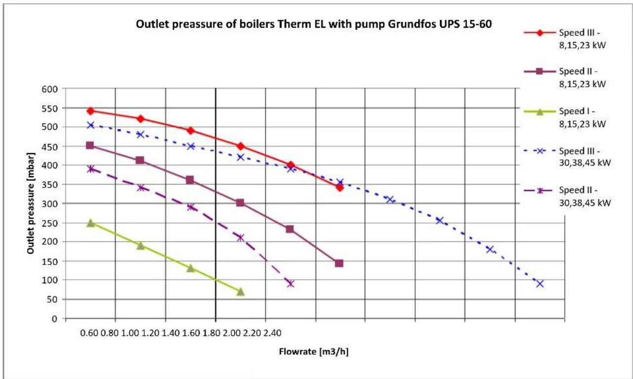
Outlet pressure EL 5, EL 9, EL 14 with WILO pump
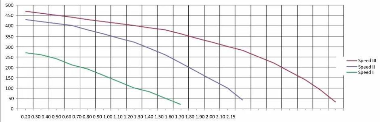
line
| x | Speed I | Speed II | Speed III | |-------|---------|----------|-----------| | 0.20 | 270 | 430 | 470 | | 0.30 | 260 | 420 | 460 | | 0.40 | 250 | 410 | 450 | | 0.50 | 240 | 400 | 440 | | 0.60 | 230 | 390 | 430 | | 0.70 | 220 | 380 | 420 | | 0.80 | 210 | 370 | 410 | | 0.90 | 200 | 360 | 400 | | 1.00 | 190 | 350 | 390 | | 1.10 | 180 | 340 | 380 | | 1.20 | 170 | 330 | 370 | | 1.30 | 160 | 320 | 360 | | 1.40 | 150 | 310 | 350 | | 1.50 | 140 | 300 | 340 | | 1.60 | 130 | 290 | 330 | | 1.70 | 120 | 280 | 320 | | 1.80 | 110 | 270 | 310 | | 1.90 | 100 | 260 | 300 | | 2.00 | 90 | 250 | 290 | | 2.10 | 80 | 240 | 280 | | 2.15 | 70 | 230 | 270 | | >2.15 | <50 | <50 | <50 |Min. flow at thermal gradient 20°C
| Therm 5 EI | 0.25 | m^3/hour |
| Therm 8 EL | 0.35 | m^3/hour |
| Therm 9 EL | 0.45 | m^3/hour |
| Therm 14 EL | 0.65 | m^3/hour |
| Therm 15 EL | 0.70 | m^3/hour |
| Therm 23 EL | 1.05 | m^3/hour |
| Therm 30 EL | 1.35 | m^3/hour |
| Therm 38 EL | 1.70 | m^3/hour |
| Therm 45 EL | 2.00 | m^3/hour |
15. THERM EL BOILERS CONNECTION TO THE POWER SUPPLY
♦ Therm EL 8 boiler connection to the power supply
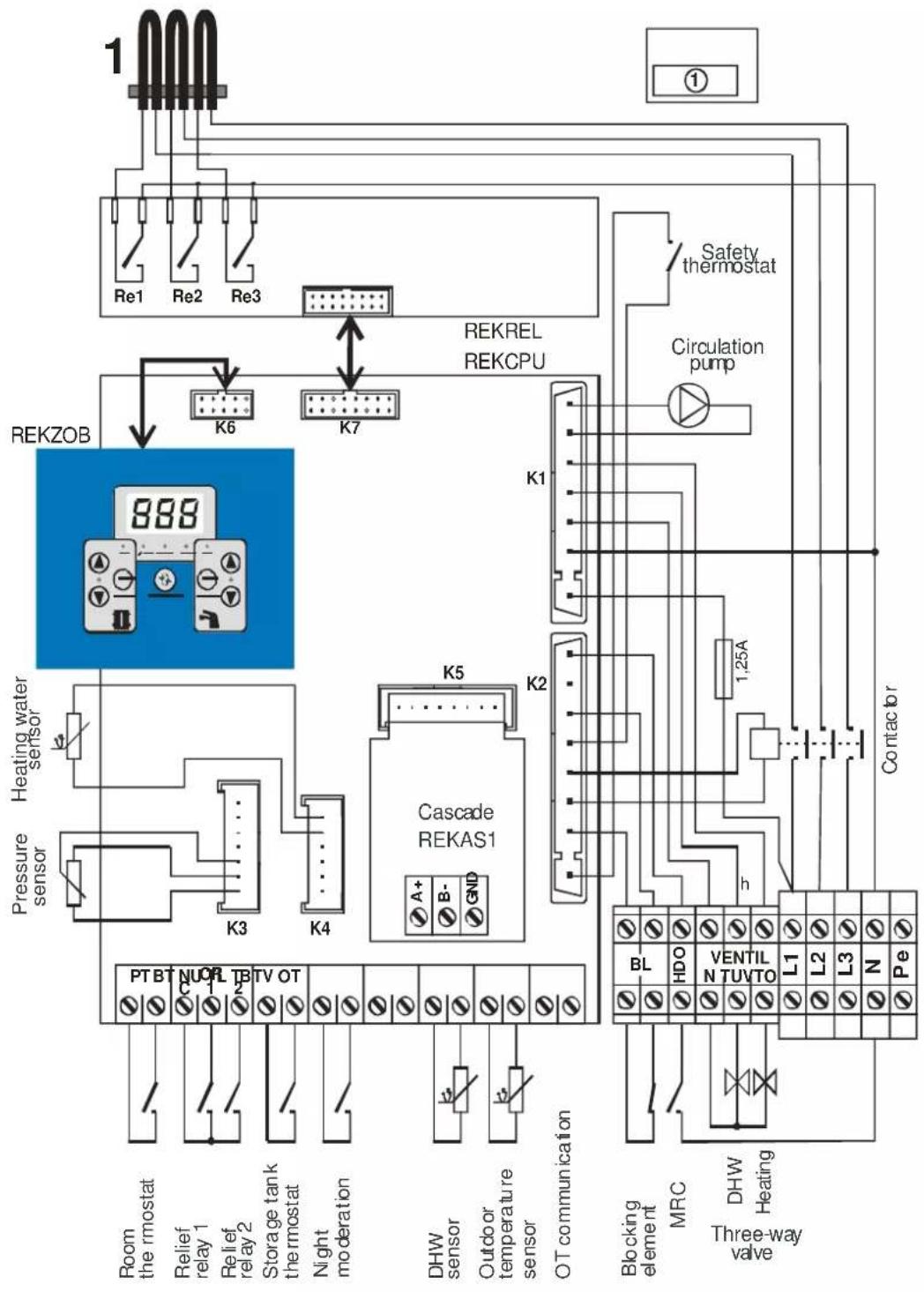
flowchart
graph TD
    A["Re1 Re2 Re3"] --> B["REKZOB"]
    C["K6"] --> D["K7"]
    E["K5"] --> F["Cascade REKAS1"]
    G["Pressure sensor"] --> H["K3"]
    I["Room the rmostat"] --> J["PT BT N U O R T B T V OT"]
    K["Relief relay 1 Relief relay 2 Storage tank thermostat Night moderation"] --> L["PT BT N U O R T B T V OT"]
    M["DHW sensor"] --> N["OT communication"]
    O["Outdoor temperature sensor"] --> P["OT communication"]
    Q["Balance element MRC Three-way valve"] --> R["Blocking element BL HDO VENTIL L1 L2 L3 N Pe"]
    S["Safety thermostat"] --> T["Circulation pump"]
    U["Contactor"] --> V["1.25A"]
    W["REKREL REKCPU"] --> X["K6"]
    Y["Pressure sensor"] --> Z["K3"]
    AA["OK"] --> AB["K4"]
    AC["AC"] --> AD["K5"]
Contact functions:
1/ contacts of the Room thermostat must be permanently connected during the boiler operation
2/ contacts of the "blocking element" must be permanently connected during the boiler operation
3/ contacts of the Emergency thermostat must be constantly connected during the boiler operation
4/ if the storage tank Thermostat is connected, the boiler heats the DHW in the storage tank
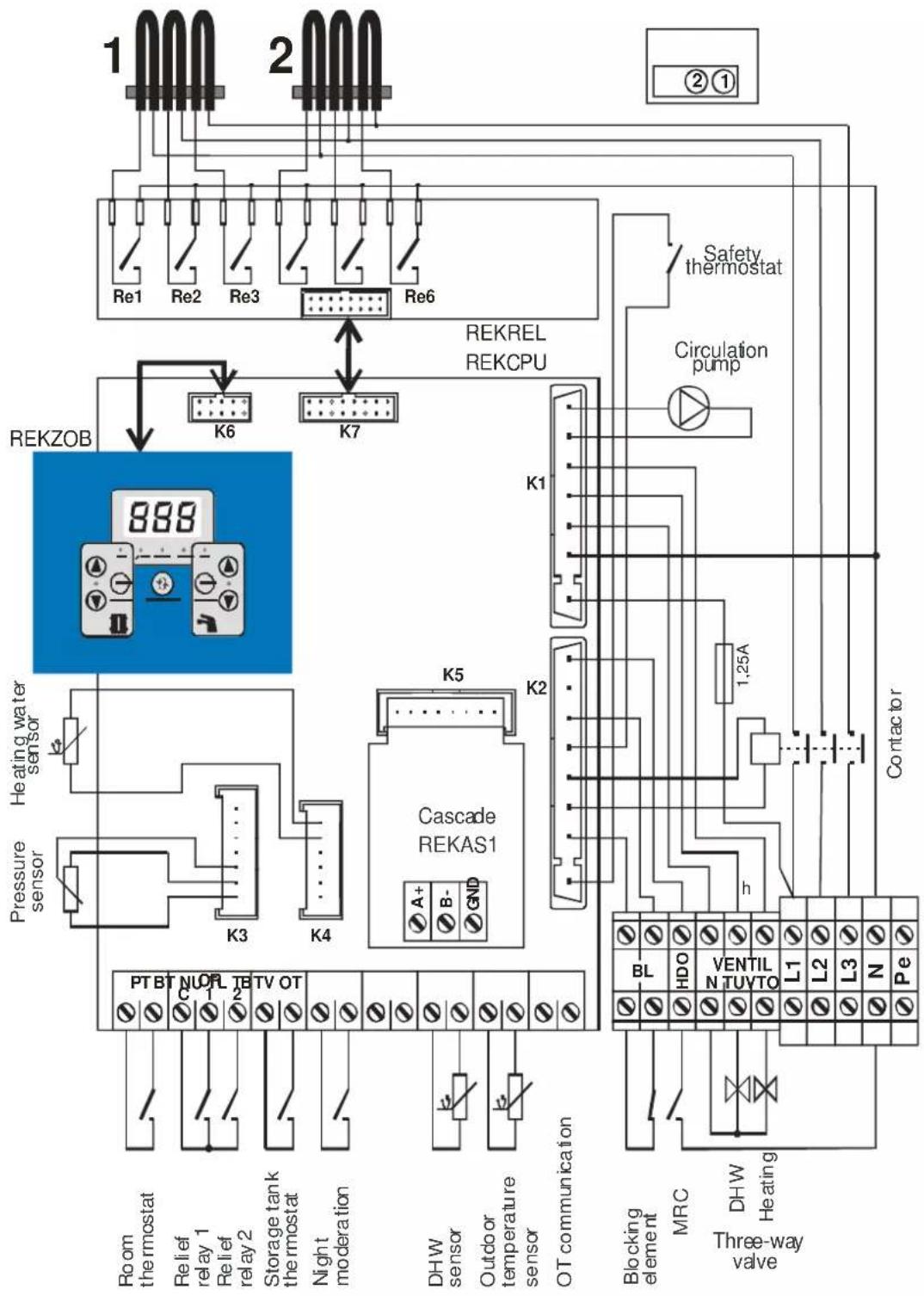
flowchart
graph TD
    A["Room the thermostat"] --> B["PTBT NOR TETV OT"]
    C["Relief relay 1"] --> D["K3"]
    E["Relief relay 2"] --> F["K4"]
    G["Storage tank thermostat"] --> H["..."]
    I["Night moderation"] --> J["..."]
    K["DHW sensor"] --> L["A+"]
    M["Outdoor temperature sensor"] --> N["B-"]
    O["OT communication"] --> P["GND"]
    Q["Blocking element"] --> R["HDO"]
    S["MRC"] --> T["VENTIL"]
    U["Three-way valve"] --> V["L1"]
    W["DHW Heating"] --> X["L2"]
    Y["Pressure sensor"] --> Z["Heating water sensor"]
    AA["ReKZOB"] --> AB["REKAS1 Cascade"]
    AC["ReKREL REKCPU"] --> AD["K1"]
    AE["Safety thermostat"] --> AF["Conactor"]
    AG["Circulation pump"] --> AH["1,25A"]
    AI["Re1 Re2 Re3 Re6"] --> AJ["Re6"]
    AK["RE7"] --> AL["REKCPU"]
♦ Therm EL 23 boiler connection to the power supply
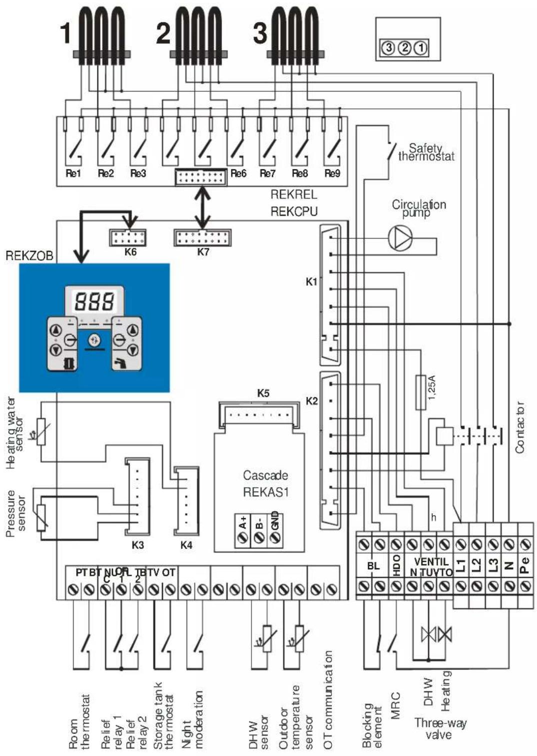
flowchart
graph TD
    A["Room the rmostat"] --> B["PTBT NOR TBT OT"]
    C["Relief relay 1"] --> D["K3"]
    E["Relief relay 2"] --> F["K4"]
    G["Storage tank thermostat"] --> H["..."]
    I["Night moderation"] --> J["..."]
    K["DHW sensor"] --> L["A+"]
    K --> M["B-"]
    K --> N["GND"]
    O["Outdoor temperature sensor"] --> P["..."]
    Q["OT communication"] --> R["..."]
    S["Blocking element"] --> T["BL"]
    U["MRC"] --> V["HDO"]
    W["Three-way valve"] --> X["DHW Heating"]
    Y["Pressure sensor"] --> Z["Heating water sensor"]
    AA["Re Kazakhstan"] --> AB["REKAS1 Cascade"]
    AC["REKREL REKCPU"] --> AD["K1"]
    AE["Circulation pump"] --> AF["1,25A"]
    AG["Safety thermostat"] --> AH["..."]
    AI["Contactor"] --> AJ["L1"]
    AK["Contactor"] --> AL["L2"]
    AM["Contactor"] --> AN["L3"]
    AO["Contactor"] --> AP["N"]
    AQ["Contactor"] --> AR["Pe"]
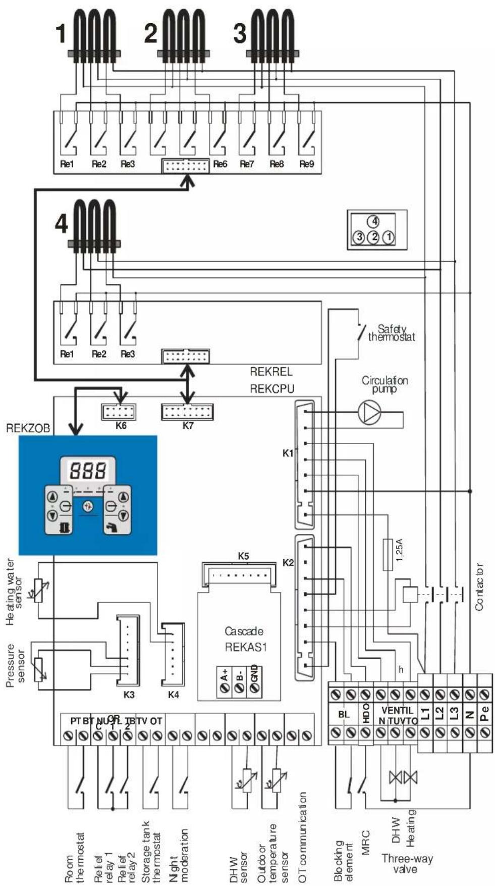
flowchart
graph TD
    A["Room thermostat"] --> B["Pressure sensor"]
    C["Relief relay 1"] --> D["Heating water sensor"]
    E["Relief relay 2"] --> D
    F["Storage tank thermostat"] --> G["Rekezob"]
    H["Night moderation"] --> I["Cascade REKAS1"]
    J["DHW sensor"] --> K["OUTDO or temperature sensor"]
    L["OT communication"] --> M["OT communication"]
    N["Blocking element"] --> O["MRC"]
    P["Three-way valve"] --> Q["DHW Heating"]
    R["Contactor"] --> S["Coilander"]
    T["RekEL REKCPU"] --> U["Circulation pump"]
    V["Safety thermostat"] --> W["Circulation pump"]
    X["RE1 Re2 Re3"] --> Y["4"]
    Z["RE6 Re7 Re8 Re9"] --> AA["1"]
    AB["100000"] --> AC["200000"]
    AD["30000"] --> AE["30000"]
♦ Therm EL 38 boiler connection to the power supply
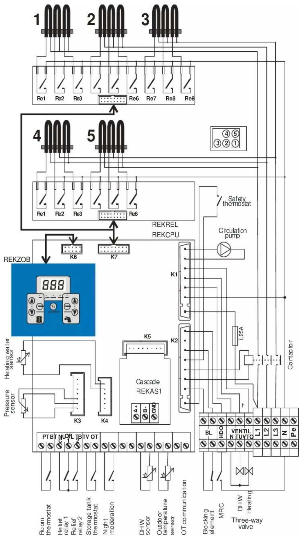
flowchart
graph TD
    A["Room the thermostat"] --> B["Pressure sensor"]
    C["Relief relay 1"] --> D["Heating water sensor"]
    E["Relief relay 2"] --> F["Heating water sensor"]
    G["Storage tank the thermostat"] --> H["Rekezob"]
    I["Night moderation"] --> J["Rekezob"]
    K["DHW sensor"] --> L["Cascade REKAS1"]
    M["Outdoor or temperature sensor"] --> N["REKREL REKCPU"]
    O["OT communication"] --> P["REKREL REKCPU"]
    Q["Blocking element"] --> R["HDO"]
    S["MRC"] --> T["VENTIL"]
    U["Three-way wave"] --> V["L1"]
    W["DHW Heating"] --> X["L2"]
    Y["L3"] --> Z["L3"]
    AA["Pe"] --> AB["Pe"]
    AC["Contactor"] --> AD["Co#tactor"]
    AE["Re1 Re2 Re3"] --> AF["Re6 Re7 Re8 Re9"]
    AG["Re6 Re7 Re8 Re9"] --> AH["Re6 Re7 Re8 Re9"]
    AI["Re1 Re2 Re3"] --> AJ["Re6 Re7 Re8 Re9"]
    AK["Re6 Re7 Re8 Re9"] --> AL["Re6 Re7 Re8 Re9"]
♦ Therm EL 45 boiler connection to the power supply
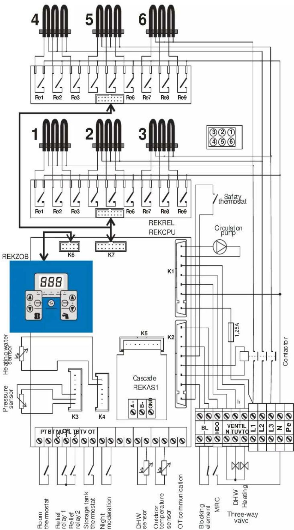
flowchart
graph TD
    A["Room the thermostat"] --> B["Pressure sensor"]
    C["Relief relay 1"] --> D["Heating water sensor"]
    E["Relief relay 2"] --> D
    F["Storage tank thermostat"] --> G["Rekezob"]
    H["Night moderation"] --> I["Rekezob"]
    J["DHW sensor"] --> K["A+"]
    L["Outdoor temperature sensor"] --> M["B-"]
    N["OT communication"] --> O["GND"]
    P["Blocking element"] --> Q["BL"]
    R["MRC"] --> S["HDO"]
    T["DHW heating"] --> U["VENTIL"]
    V["Three-way valve"] --> W["L1"]
    V --> X["L2"]
    V --> Y["L3"]
    V --> Z["N"]
    V --> AA["Pe"]
    AB["Cascade"] --> AC["K5"]
    AD["Circulation pump"] --> AE["K1"]
    AF["Safety thermostat"] --> AG["K6"]
    AH["REKREL REKCPU"] --> AI["REKCEL"]
    AJ["Contactor"] --> AK["Coactor"]
◆ Connection of Therm boilers EL 5, EL 9 and EL 14
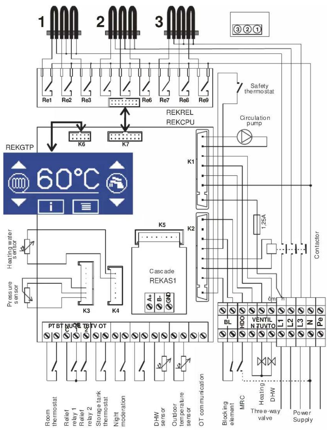
flowchart
graph TD
    A["Room thermostat"] --> B["PTBT"]
    C["Relief relay 1"] --> D["TV OT"]
    E["Relief relay 2"] --> F["TV OT"]
    G["Storage tank thermostat"] --> H["TV OT"]
    I["Night moderation"] --> J["TV OT"]
    K["DHW sensor"] --> L["HV"]
    M["Outdoor temperature sensor"] --> N["HV"]
    O["OT communication"] --> P["HV"]

    Q["Pressure sensor"] --> R["Heating water sensor"]
    S["Cascade REKAS1"] --> T["REKGTP"]
    U["A+"] --> V["K5"]
    W["B-"] --> X["K2"]
    Y["GND"] --> Z["K1"]

    AA["Blocking element"] --> AB["BL"]
    AC["MRC"] --> AD["HDO"]
    AE["Three-way valve"] --> AF["VENTIL"]
    AG["DHW"] --> AH["L1"]
    AI["Power Supply"] --> AJ["L2"]
    AK["Pe"] --> AL["L3"]

    AM["Circulation pump"] --> AN["1,25A"]
    AO["Safety thermostat"] --> AP["REKREL REKCPU"]

    AQ["Re1 Re2 Re3"] --> AR["REKREL REKCPU"]
    AS["Re6 Re7 Re8 Re9"] --> AT["REKREL REKCPU"]

    AU["1000"] --> AV["2000"]
    AW["2000"] --> AX["3000"]
    AY["3000"] --> AZ["3000"]
♦ 2 Therm EL cascade system
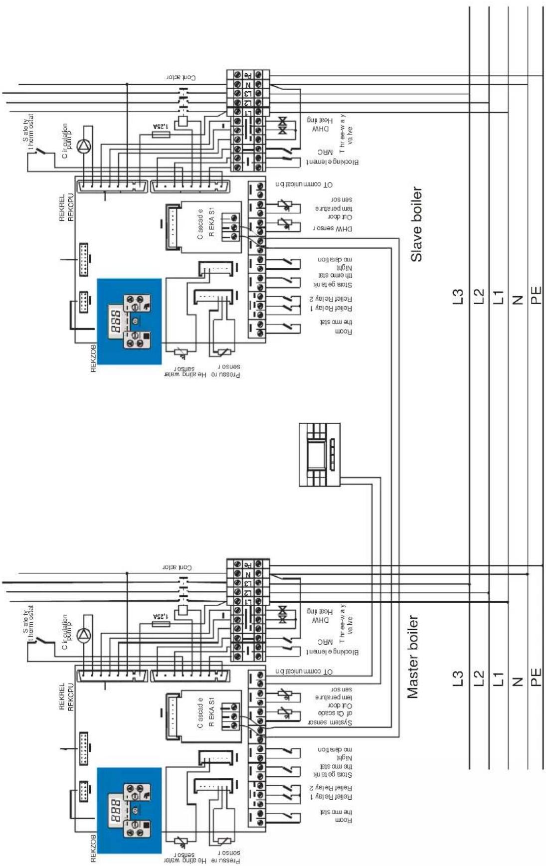
text_image
Master boiler Slave boiler PE N L1 L2 L3 L4 S safe ty therm ostat RekZOB REKREL REKCPU Circulation polmp Pressure He eling water sensor Sensor r Room the rmo stat Relief Relay 1 Relief Relay 2 Stora ge tank the rmo stat Night mo deration C cascade R EKA S1 System sensor of Ca scade Cut door lem perature sen sor OT communica bn Blocking element1 MRC DHW Heat ring Thr ee-w ay y val lve REKZOB 888 888 S safe ty therm ostat REKREL REKCPU Circulation polmp Pressure He eling water sensor r Room the rmo stat Relief Relay 1 Relief Relay 2 Stora ge tank th emo stat Night mo deration C cascade R EKA S1 DHW sensor r Cut door tem porature sensor OT communica bn S safe ty therm ostat Circulation polmp r Room the rmo stat Relief Relay 1 Relief Relay 2 Stora ge tank th emo stat Night mo deration DHW Heat ring Thr ee-w ay y val lve Slave boiler◆ Connection of the current maximum value monitor to the boiler relief relay terminals
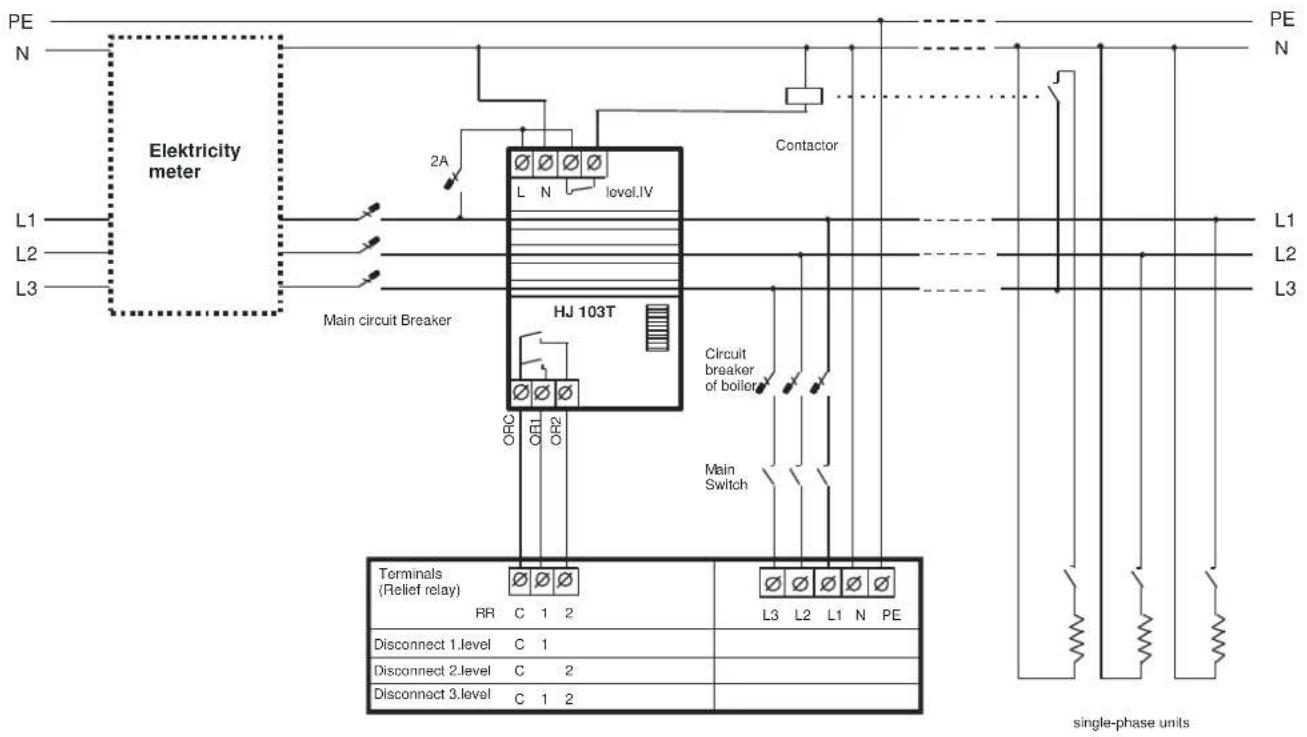
text_image
PE N Elektricity meter L1 L2 L3 Main circuit Breaker HJ 103T 2A level.IV Contactor Circuit breaker of boiler ORC OR1 OR2 Main Switch Terminals (Relief relay) RR C 1 2 L3 L2 L1 N PE Disconnect 1.level C 1 Disconnect 2.level C 2 Disconnect 3.level C 1 2 PE N L1 L2 L3 single-phase units16. WARRANTY AND RESPONSIBILITY FOR DEFECTS
The manufacturer is not liable for any mechanical damage to individual components by harsh treatment, neither for any damage caused by unprofessional interference with the electronics during setting or connecting of accessory regulations or by using other than original components used by the manufacturer.
The guarantee does further not apply to defects brought about by nonobservance of the binding conditions specified in the individual sections of this Manual regarding operation and maintenance of the boilers.
The guarantee equally does not apply to non-standardized ratios in the distribution networks (fluctuation of the supply voltage – chiefly during overvoltage peaks etc.), defects outside the boiler which affect its operation, damage incurred due to external factors, mechanical damage, storage, transport and defects originating during natural disasters etc.
In such situations the service organization can ask the user to reimburse the repair.
THERMONA spol. s r. o. provide a warranty in accordance with the terms contained in the warranty certificate.
Conditions which must be observed for the guarantee acknowledgement:
- Boiler inspection must be performed regularly once per year. The inspections can be effected only by an authorized organization, i.e. by a contractual service body (these inspections are not included in the boiler price!).
- It is necessary to document all records with respect to the performed guarantee repairs and annual boiler inspections in the appendix to this Manual.
17. CONNECTION WITH SOLAR SYSTEM
Therm EL electric boilers can also be used as an alternative (additional) heat source to the solar system. The primary source for heating of DHW is the solar system. When the sunlight and energy delivered to the storage unit is low, the electric Therm EL boiler is activated and automatically hears the storage unit. It can happen that, e.g. for several days when the sun is behind a cloud or in the case of prompt increased energy, the user will not have enough hot water. Use advantageous solar sets with a Thermona electric boiler (more at www.thermona.cz).
Principle of the connection of heating using a Therm electric boiler
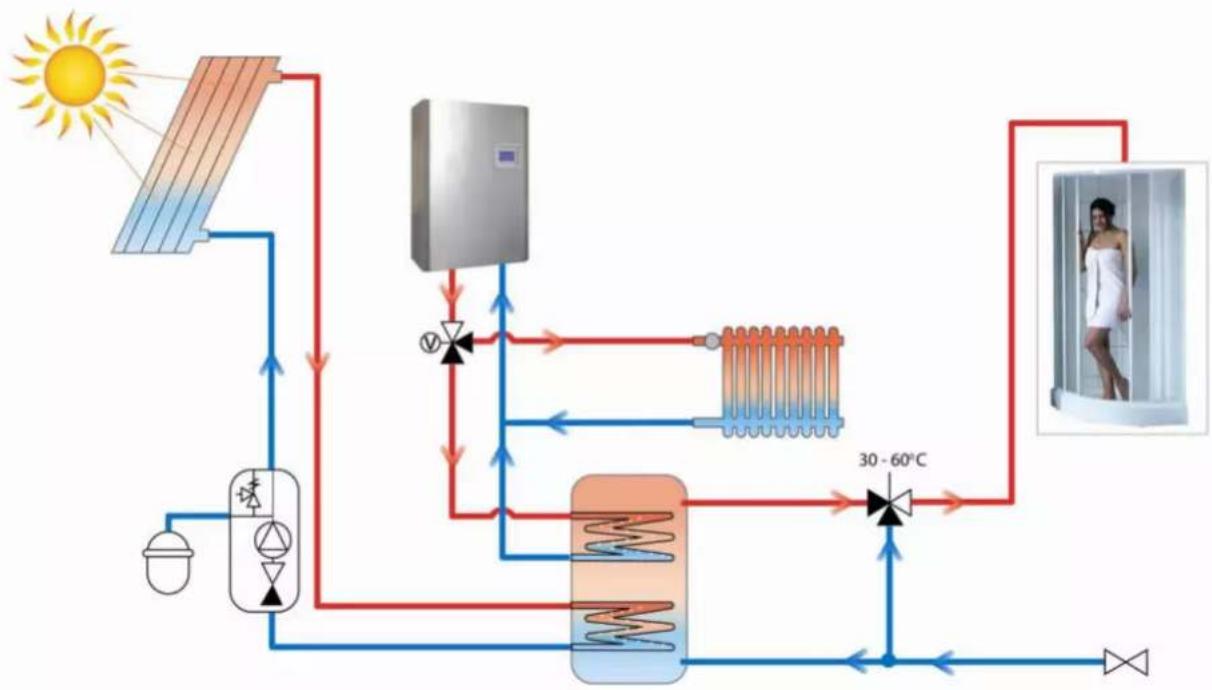
flowchart
graph TD
    A["Sun"] --> B["Heat Exchanger"]
    B --> C["Condensate Heat Exchanger"]
    C --> D["30-60°C Range"]
    D --> E["Refrigerator"]
    E --> F["Refrigeration System"]
    F --> G["Refrigeration System"]
    G --> H["Refrigeration System"]
    H --> I["Refrigeration System"]
    I --> J["Refrigeration System"]
    J --> K["Refrigeration System"]
    K --> L["Refrigeration System"]
    L --> M["Refrigeration System"]
    M --> N["Refrigeration System"]
    N --> O["Refrigeration System"]
    O --> P["Refrigeration System"]
    P --> Q["Refrigeration System"]
    Q --> R["Refrigeration System"]
    R --> S["Refrigeration System"]
    S --> T["Refrigeration System"]
    T --> U["Refrigeration System"]
    U --> V["Refrigeration System"]
    V --> W["Refrigeration System"]
    W --> X["Refrigeration System"]
    X --> Y["Refrigeration System"]
    Y --> Z["Refrigeration System"]
18. DOMESTIC HOT WATER STORAGE TANK HEATING MODE
External indirect DHW heating storage tank can be connected to the THERM EL boiler. Storage tank heating is ensured by changing the position of the three-way valve. The boiler electronics can communicate with the temperature sensor (continuous DHW temperature regulation) as well as with the traditional storage tank thermostat (to be set in the service menu). Service with a connected DHW storage tank is always of superior position with regards to heating and the maintenance of the set temperature always proceeds without time limits (with the exception of the MRC signal). Shall the temperature in the storage tank fall below the set value, the boiler system three-way valve position is set preferentially and the boiler water heats up the external indirect heating DHW storage tank. The DHW preparation can be deactivated by setting the boiler in the SLEEP mode. If the operation mode is set after the termination of the MRC signal, the DHW preparation becomes interrupted. Connections of the storage tank and the three-way valve are shown in the electric diagram.
◆ Connection diagram of an electric boiler with indirect heating storage tank for informational purposes
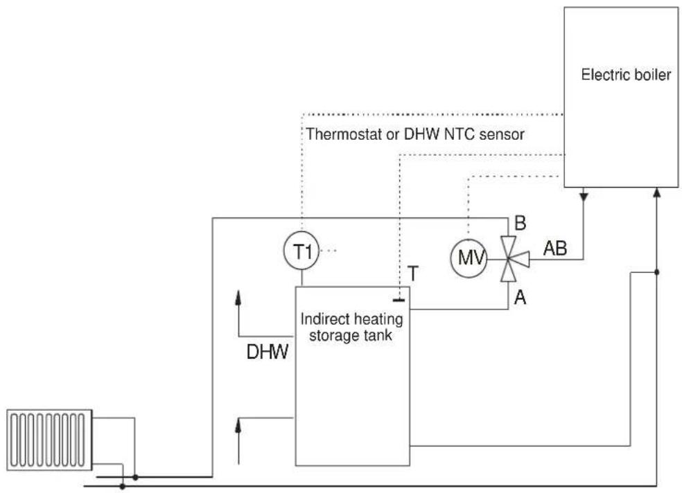
flowchart
graph TD
    A["Indirect heating storage tank"] --> B["T1"]
    B --> C["MV"]
    C --> D["AB"]
    D --> E["Electric boiler"]
    F["DHW"] --> A
    G["Thermostat or DHW NTC sensor"] --> C
    H["Top panel: Heat source"]
    I["Bottom panel: Air vent"]
MV - valve servomotor
AB - heating water inlet from the boiler
A – heating water outlet to the storage tank
B – heating water outlet to the heating circuit
T1 - storage tank thermostat
T-NTC sensor of the storage tank
DHW - DHW outlet
19. THERM EL 8, 15, 23 (KW) BOILER ASSEMBLY
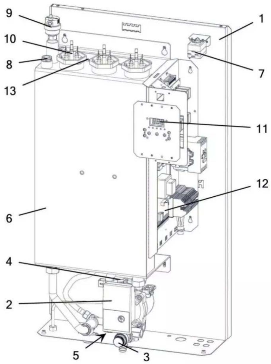
text_image
Technical diagram of an electronic device with numbered components for identification1 - Boiler frame
2 - Pump
3 - Safety valve
4 – Pressure sensor
5 - Discharge valve (1/2")
6 - Boiler heat exchanger
7 - Emergency thermostat (the sensor is placed in the cup together with the temperature sensor)
8 - Temperature sensor
9 - Air relief valve
10 - Heating bar
11 - Control display
12 - Boiler automatic system
13 - Expansion vessel (7 l)
20. THERM EL 5, 9, 14 (KW) BOILER ASSEMBLY
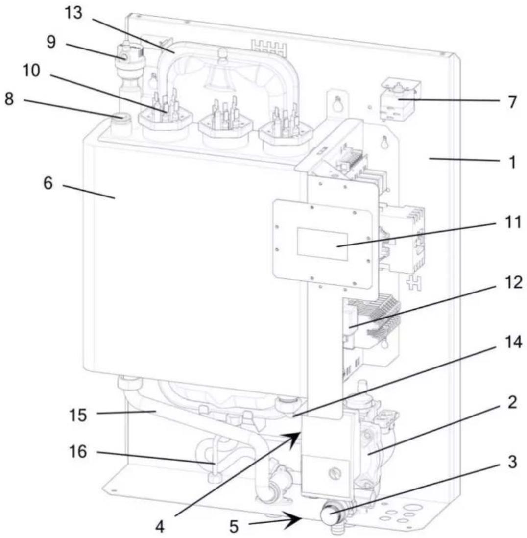
text_image
Technical diagram of an electrical enclosure with numbered components for identification1 - Boiler frame
2 - Pump
3 - Safety valve
4 - Pressure sensor
5 - Discharge valve (1/2")
6 - Boiler exchanger
7 - Emergency thermostat (the sensor is located in the pit together with the thermal sensor)
8 - Thermal sensor
9 - Air relief valve
10 - Heating bar
11 - Control display
12 - Boiler automatic system
13 - Expansion tank 7 l
14 - Return pipe
15 – Heating pipe
16 – Pipe for additional charging
- THERM EL 30, 38, 45 BOILER ASSEMBLY (KW)
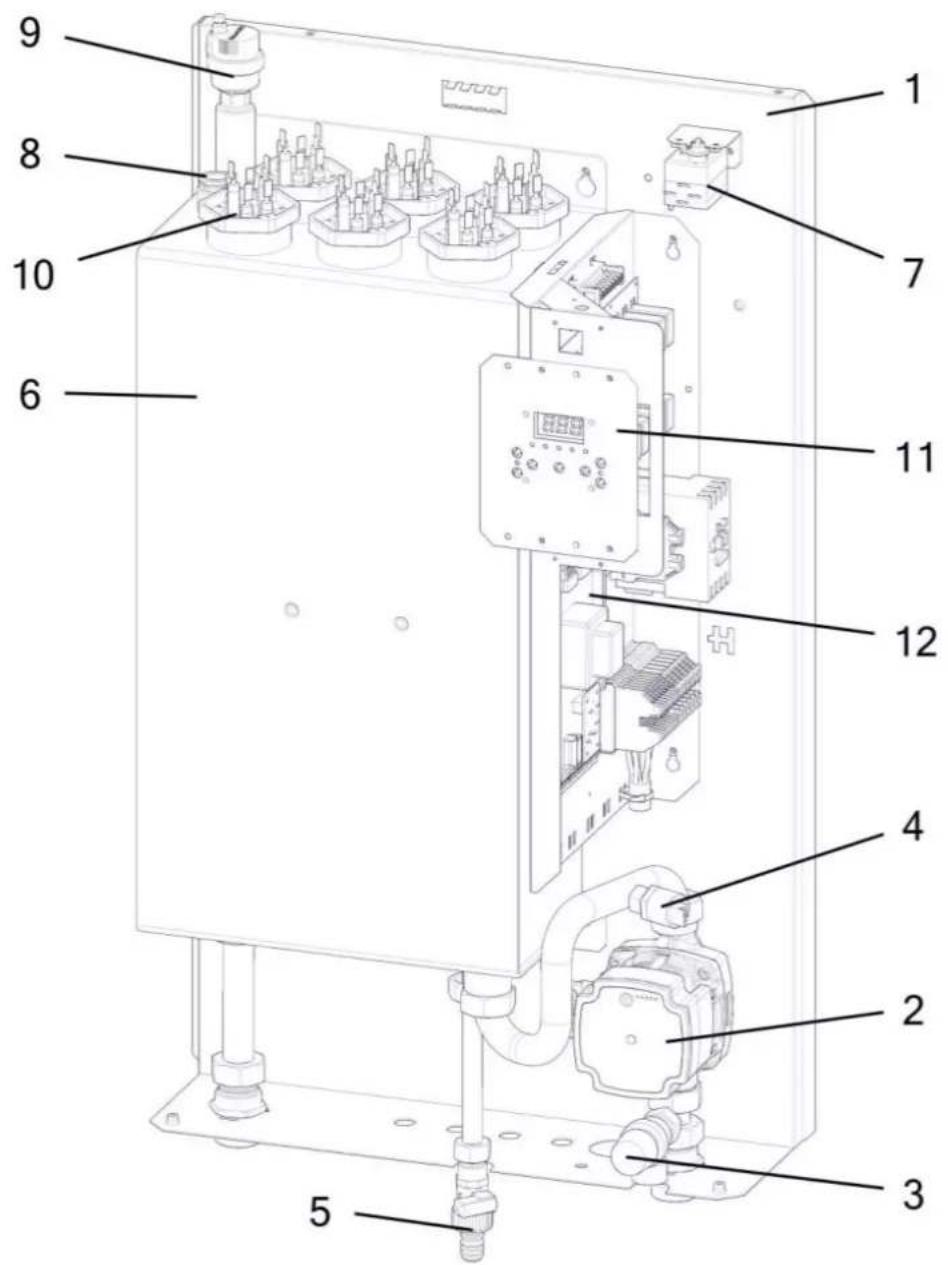
text_image
Technical diagram of an electrical control unit with numbered components for identification1 - Boiler frame
2 - Grundfos pump
3 - Safety valve
4 - Pressure sensor
5 - Discharge valve (1/2")
6 - Boiler heat exchanger
7 - Emergency thermostat (the sensor is placed in the cup together with the temperature sensor)
8 - Temperature sensor
9 - Vent valve
10 - Heating bar
11 - Control display
12 - Boiler automatics
22. WALL-MOUNTING OF THE BOILER
♦ Therm EL 8, EL 15, EL 23, EL 30, EL 38, EL 45
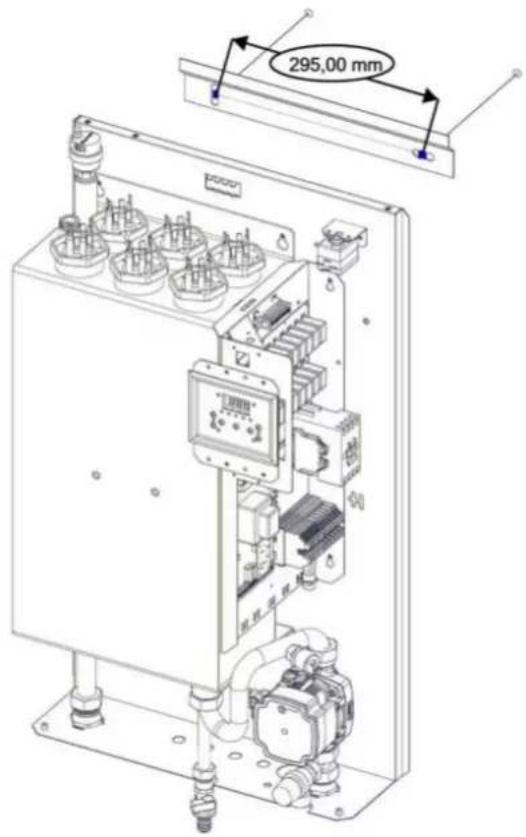
text_image
295,00 mm♦ Therm EL 5, EL 9, EL 14
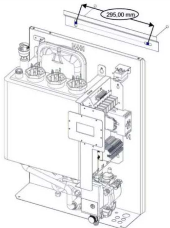
text_image
295,00 mm23. BOILER DIMENSIONS AND CONNECTION
♦ Therm EL 8, EL 15, EL 23
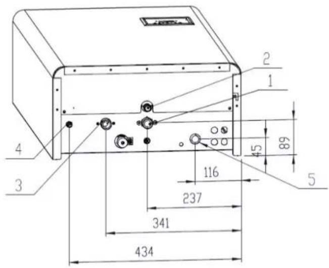
text_image
2 1 4 3 45 89 116 237 341 434 51 - Return water inlet 34''
2 - Safety valve outlet (hose connection)
3 - Heating water outlet 34''
4 - Refilling water inlet 1/2
5 - Main power inlet
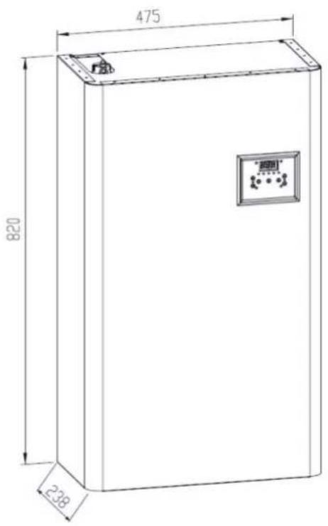
text_image
475 820 238♦ Therm EL 30, EL 38, EL 45
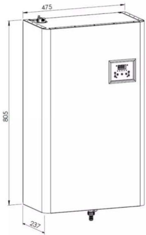
text_image
475 805 237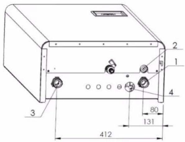
text_image
2 1 4 3 80 131 4121 - Return water inlet 1"
2 - Safety valve outlet (hose connection)
3 - Heating water outlet 1
4 - Main power inlet
♦ Therm EL 5, EL 9, EL 14
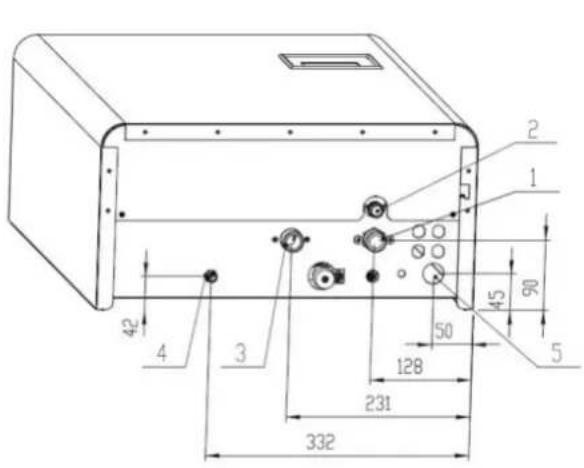
text_image
2 1 45 90 50 128 231 332 42 4 31 - Return water inlet 34
2 - Safety valve outlet (hose connection)
3 - Heating water outlet 34 "
4 - Refilling water inlet 12
5 - Main power inlet
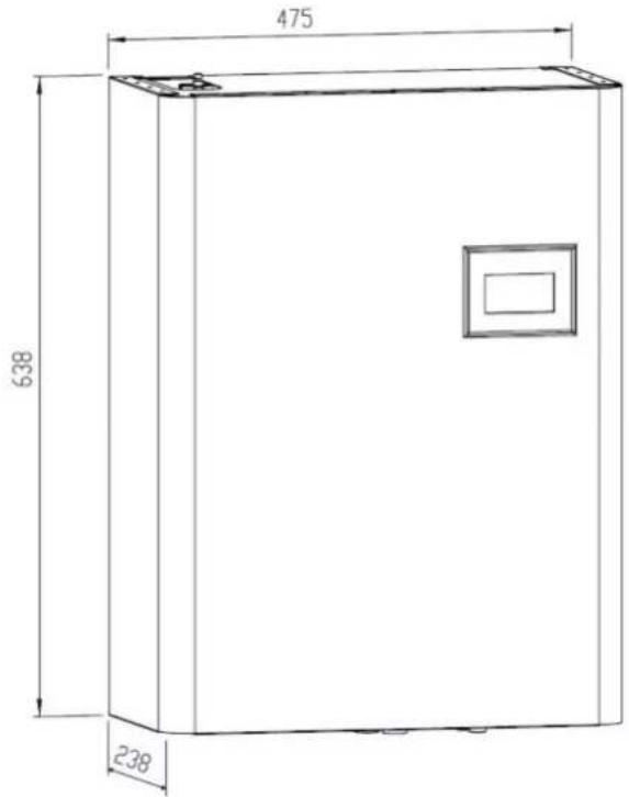
text_image
475 638 238- Product information sheet as required by the EU Commission Regulation No. 811/2013 and 813/2013
| Producer | Model | Seasonal space heating energy efficiency class | Rated heat output | Seasonal space heating energy efficiency | Annual electricity consumption | Annual fuel consumption | Sound power level |
| kW | % | kWh | GJ | dB(A) | |||
| Thermona | Therm EL 5 | D | 5 | 36 | 10 053 | 36 | 41 |
| THERM EL 8 | D | 8 | 36 | 16 638 | 60 | 41 | |
| THERM EL 9 | D | 9 | 36 | 19 888 | 72 | 41 | |
| THERM EL 14 | D | 14 | 36 | 29 712 | 107 | 41 | |
| THERM EL 15 | D | 15 | 36 | 33 031 | 119 | 41 | |
| THERM EL 23 | D | 23 | 36 | 49 413 | 178 | 41 | |
| THERM EL 30 | D | 30 | 36 | 65 890 | 237 | 41 | |
| THERM EL 38 | D | 38 | 36 | 82 284 | 296 | 41 | |
| THERM EL 45 | D | 45 | 36 | 98 679 | 355 | 41 |
- Record of repairs and annual inspections
| Performed operation | Contractual org. | Customer signature | Date of record |
Warning regarding the disposal of the packaging and the product after the end of its service life-time
All applied materials comply with the requirements specified in Section 10 of the Act No. 185/2001 Coll. and Section 6 of the Act No. 477/2001 Coll.
The product packaging is commonly disposed of in scrap paper collection centres. The packaging foil can be disposed of in collection containers for plastics.
Boiler parts made from steel, copper and copper alloys are to be delivered to sorted metal waste scrapyards.
Heat insulation of the combustion chamber is in accordance with the health safety and shall be liquidated in common home waste.
Standard storage conditions must be assured (non-aggressive and dust-free environment, temperature range of 5 to 50°C, atmospheric humidity of maximum 75%, prevention of biological influences, shocks and vibrations)
CERTIFICATE OF QUALITY AND COMPLETENESS OF THE PRODUCT
Electric direct heating THERM EL boiler
Type designation:
Product number:
The appliance complies with the requirements of the European Directives No. 89//336/EHS, 73/23/EHS and other related technical regulations, standards and recommendations. Its operation under the service conditions in line with manufacturer recommendations is safe. Measures were adopted which assure the conformity of this appliance now introduced to the market with technical documentation and basic technical, safety and hygienic requirements.
Technical incpection:
date: ....
stamp and signature: ....
THERMONA, spol. s r. o.
Stará osada 258, Zastávka u Brna, 664 84
Czech Republic
Phone: +420 544 500 511 fax: +420 544 500 506
thermona@thermona.cz
www.thermona.cz