Compact - Uncategorized ICU - Free user manual and instructions
Find the device manual for free Compact ICU in PDF.


User questions about Compact ICU
0 question about this device. Answer the ones you know or ask your own.
Ask a new question about this device
Download the instructions for your Uncategorized in PDF format for free! Find your manual Compact - ICU and take your electronic device back in hand. On this page are published all the documents necessary for the use of your device. Compact by ICU.
USER MANUAL Compact ICU
text_image
Available Waiting Charging Error START STOP 1 ✓ 2 ✗ 3 ✗ 1 ✓ 2 ✗ 3 ✗Package Contents / Inhoud Verpakking / Inhalt Verpackung / Contenu de l'emballage / Contenuto della confezione
ICU Compact

text_image
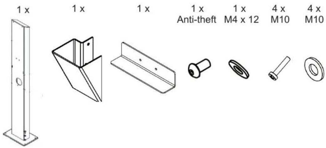
1 x 1 x or 1 x 1 x 1 x 1 x 1 xPole / Paal / Säule / Pôle / Polo
text_image
1 x 1 x 1 x 1 x Anti-theft 1 x M4 x 12 4 x M10 4 x M10Types / Varianten / Varianten / Variantes / Varianti
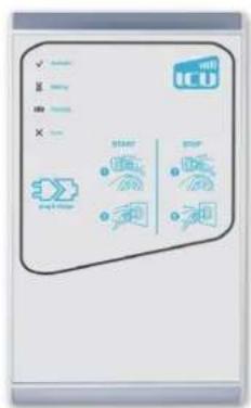
text_image
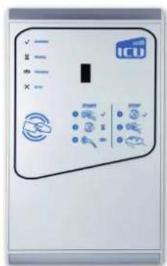
✓ ✓ ✓ X ICU Start Stop ✓ ✓ ✓Fixed Cable Plug & Charge
text_image
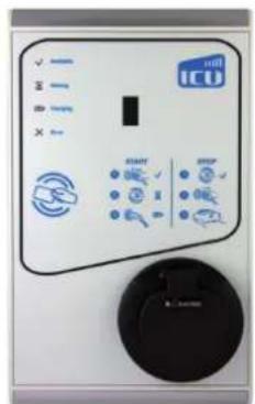
Control panel with labeled buttons and icons, including 'ICU' logo and various function keysFixed Cable RFID
text_image
ICU X Y Z S T M X Y P N Y S T M X Y P N Y S T M X Y P N Y S T M X Y P N Y S T M X Y P N Y S T M X Y P N Y S T M X Y P N Y S X Y P N Y S T M X Y P N Y S T M X Y P N Y S T M X Y P N Y S T M X Y P N Y S T M X Y PRFID
Outside / Buiten / Außen / Extérieur / Esterno
text_image
Available Waiting Charging Error START STOP 1 2 3 4 5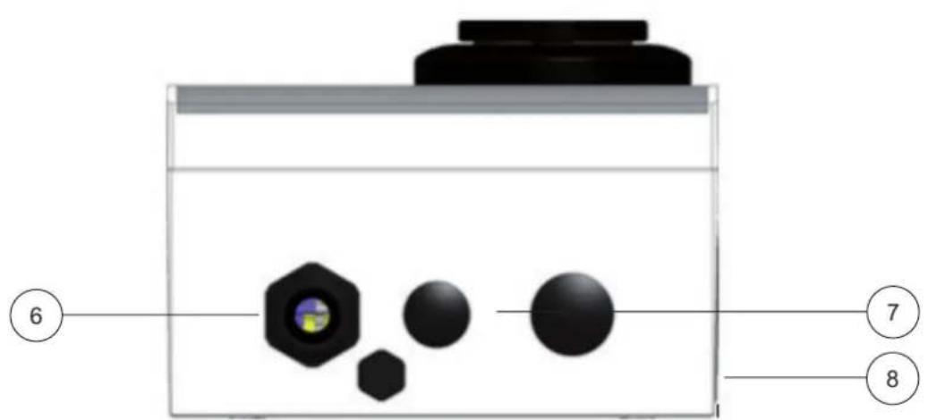
text_image
6 7 8H x W x D: 330 x 200 x 120 mm
Inside / Binnenzijde / Innen / Intérieur / Interno
text_image
Exploded view diagram of a device showing internal components with numbered labelsInstallation / Installatie / Installation / Installation / Installazione
natural_image
Technical line drawing of an electrical enclosure assembly with exploded and assembled views (no text or symbols)Operating / Operating / Betrieb / Opération / Operazione
Plug & Charge – Authorisation without charging card
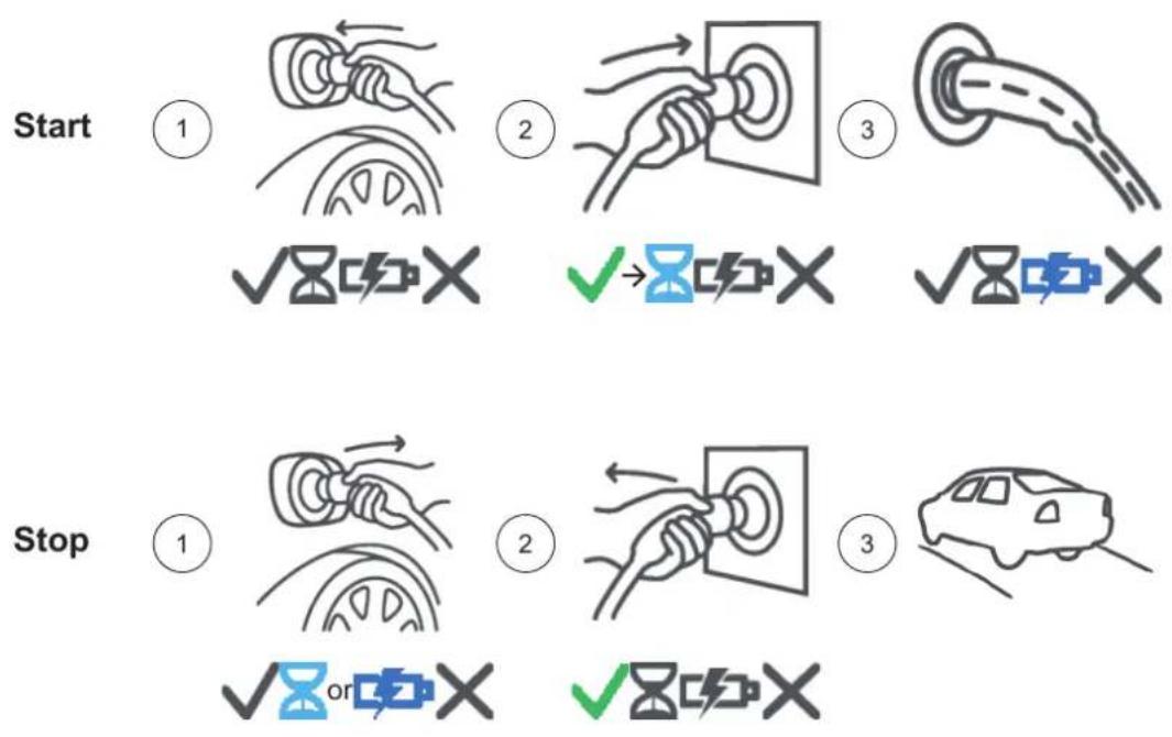
flowchart
graph TD
    A["Start"] --> B{Checkmark}
    B -->|✓| C["Checkmark X"]
    B -->|✓| D["Checkmark X"]
    B -->|✓| E["Checkmark X"]
    F["Stop"] --> G{Checkmark}
    G -->|✓| H["Checkmark X"]
    G -->|✓| I["Checkmark X"]
    G -->|✓| J["Checkmark X"]
Charging station with RFID card
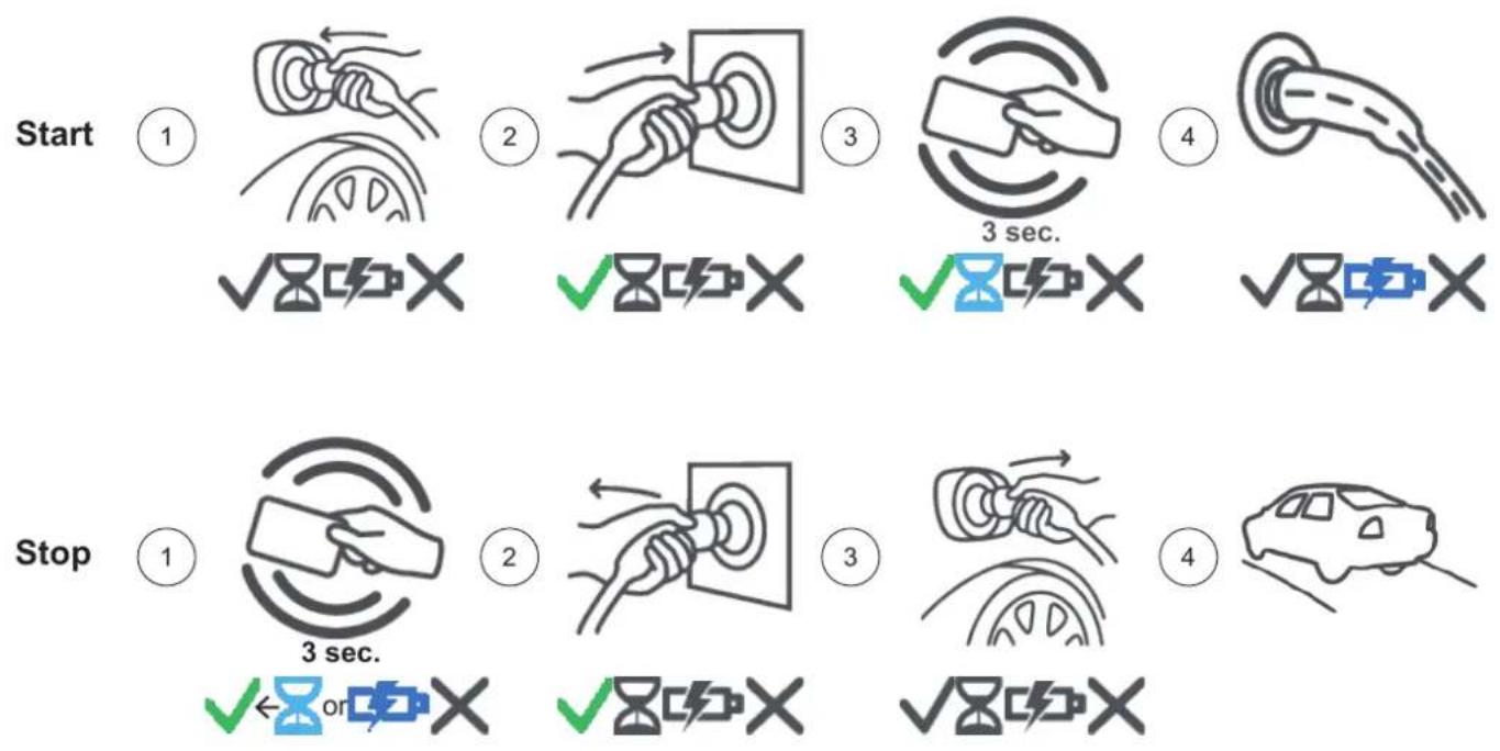
flowchart
graph TD
    A["Start"] --> B["1: ✓☒☐☒"]
    B --> C["2: ✓☒☐☒"]
    C --> D["3: ✓☒☐☒"]
    D --> E["4: ✓☒☐☒"]
    F["Stop"] --> G["1: ✓☒ or ☑X"]
    G --> H["2: ✓☒☐☒"]
    H --> I["3: ✓☒☐☒"]
    I --> J["4: ✓☒☐☒"]
Contact / Contact / Kontakt / Contact / Contatto
Alfen ICU B.V.
Splijtbakweg 15
1333 HC Almere
The Netherlands
Postbus 1042
1300 BA Almere
Tel: +31 36 54 93 400
E-mail: info@icu-charging-stations.com
Website: www.icu-charging-stations.com
Status LED / Status LED / Status-LED / LED d'état / LED di stato









natural_image
Uniform gray gradient background with no visible text, symbols, or objectsSubject to modifications and amendments.
Alfen ICU B.V. | Splijtbakweg 15 Almere NL | Tel: +31 36 - 549 34 00
E-mail: info@icu-charging-stations.com | www.icu-charging-stations.com

Table of content
1. Safety and operation instructions 2
1.1 Aim of the manual and target group 2
1.2 General safety 2
2. Product 3
2.1 The charging station 3
2.2 LED-status display 3
2.3 Technical specifications 4
3. Mounting and connecting 6
3.1 Installation and connection 6
3.2 Requirements for assembly and installation 6
3.3 Mechanical installation 7
3.4 Electrical installation 8
4. Commissioning the charging station 9
4.1 Safety instructions before operating 9
4.2 Putting into operation 9
5. Connectivity 10
5.1 Back Office Services 10
5.2 UTP (Ethernet) connection 10
5.3 Registering your ICU EZ account 10
Declaration of Conformity
Name of manufacturer:
Alfen ICU B.V.
Splijtbakweg 15
1333 HC Almere
The Netherlands
Declares the conformity of the product:
Charging stations of Type ICU Compact
Following the European Directives:
Low Voltage Directive 2014/35/EU
EMC directive 2014/30/EU
Applied (harmonized) standards:
NEN-EN-IEC 61851-1
NEN-EN-IEC 61851-22
NF-EN-IEC 61851-1
NF-EN-IEC 61851-22
DIN EN 61851-1
DIN EN 61851-22
BS EN 61851-1
BS EN 61851-22
All mentioned products are marked with the CE mark.
Almere, April 20 ^th , 2016.

natural_image
Abstract line drawing with intersecting curves and a small mark (no text or symbols)1. Safety and operation instructions
1.1 Aim of the manual and target group
The ICU Compact charging station is intended exclusively for charging of electric vehicles without the need for a separate grid connection (house connection box). Follow the instructions to ensure proper operation of the charging station.
The installation, commissioning and maintenance may only be performed by a qualified electrician (Alfen ICU certified partner).
The following requirements must be met by the qualified electrician:
• Knowledge of the general and specific safety and accident prevention regulations
• Knowledge of the relevant electrical regulations
- Ability to identify risks and avoid potential hazards
• Knowledge of the Installation and Operating Instructions
1.2 General safety

DANGER!
The safety notes are intended to ensure proper operation in practice. An infringement or non-compliance with safety regulations and instructions in this manual and on the device can result in electric shock, fire and/or serious injury.
In the following cases the use of the product is prohibited:
- When explosive or highly flammable substances are close
• If the product is in the water - At ambient temperatures of less than -25 °C or over 40 °C
- When the product or individual components are damaged
• For children or persons who can not assess the risk in handling the product
In the following cases Alfen ICU B.V. accepts no liability for damages. The warranty on products and accessories expires in the following cases:
- Failure to follow these Installation and Operation Instructions
- Improper use
- Improper handling
• Use of non-qualified personnel
• Additions or modifications to the product
• Use of replacement parts that are not manufactured or approved by Alfen ICU
Additional safety information is available in the relevant sections in this document.
2. Product
2.1 The charging station
In the cover of this manual you will find the corresponding pictures of the charging station. You will also find more information about the package contents and charging.
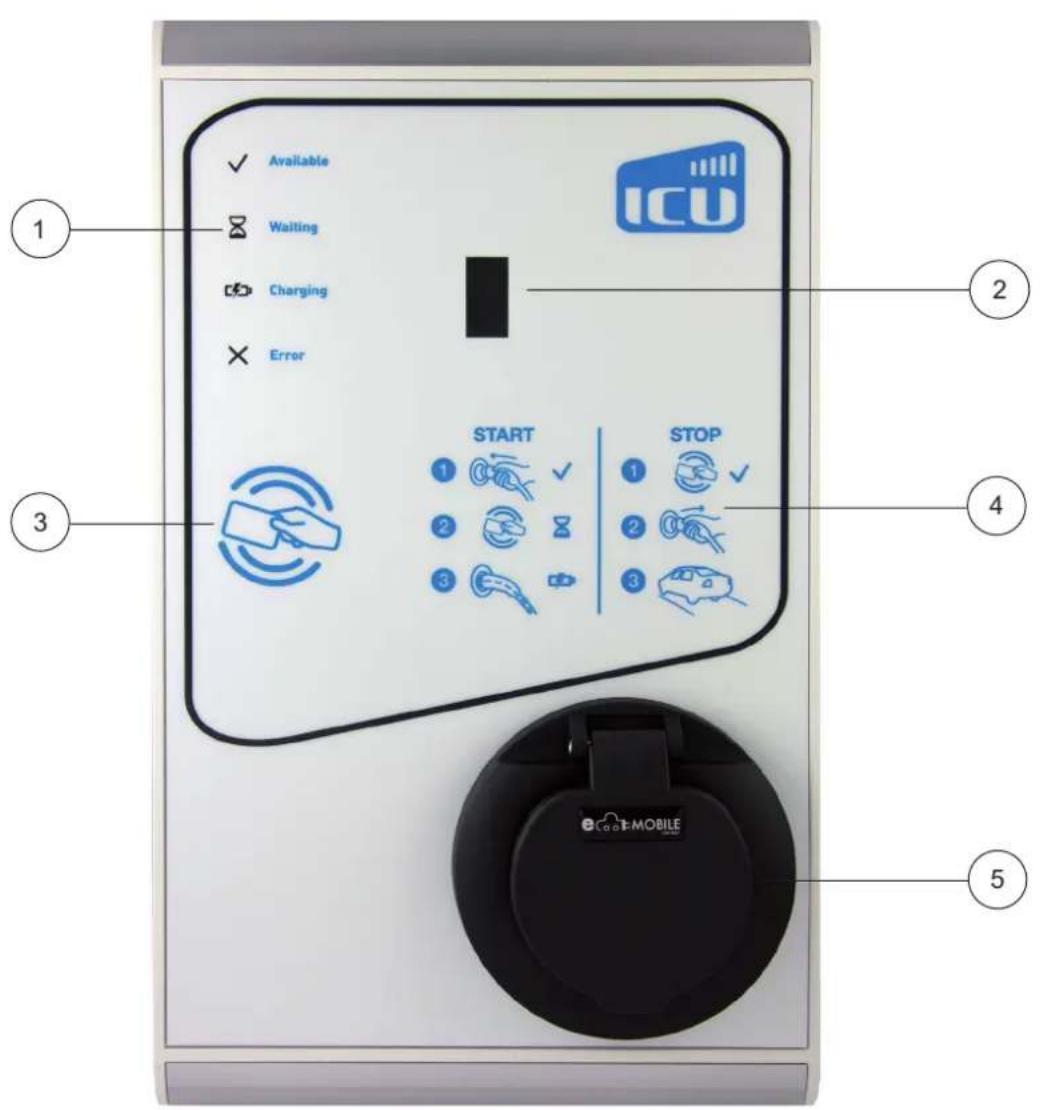
The charging station (outside)
1 LED Identifications
② kWh-meter (optional)
③ RFID-card reader
4 Operating manual
⑤ Type 2-charging socket (optional)
6 Cable screw connection for tethered charging cable (car)
⑦ Cable screw connection for power cable
⑧ Identification label
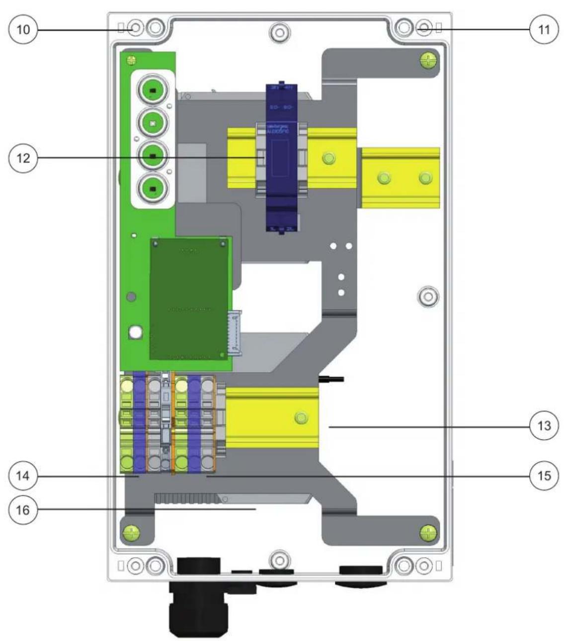
The charging station (indside)
| 10 | Screws front cover |
| 11 | Screws wall mounting |
| 12 | Connection kWh-meter |
| 13 | SIM Card Slot |
| 14 | Terminal block for tethered cable |
| 15 | Terminal block for power cable |
| 16 | UTP (Ethernet) Connection |
Identification Label
| The identification label (8) specifies, for example,the model, production date and serial number. It canbe found on the side of the charging station. |
| Always make reference to the serial number whencontacting to Alfen ICU so that you receive the fastest support. |
2.2 LED-status display
The ICU Compact comes with four LEDs which indicate the status of the socket. Please find below an overview of the different states:
| Status LED | Meaning |
| 17 | • Available |
| 18 | • Cable is connected in the charging station and waiting• Identification with RFID is done and now waiting for cable to be connected |
| 19 | • The charging station and vehicle are communicating• Electric vehicle is full or charging is on hold |
| 20 | • Vehicle is charging |
| 21 | • External error• The cable has been left too long in the charging station without starting a charging process |
| 22 | • The charging station has an internal error |
| 23 | • The card reader is active |
2.3 Technical specifications
| Input/power supply | |
| Power supply | Min. 5 x 4 mm2 (16 A) / 5 x 6 mm2 (32 A) |
| Rated voltage | 230 V / 400 V |
| Mains connection | 25 A 1-phase 230 V 50 Hz (3.7 kW version); 25 A 3-phase 400 V 50 Hz (11 kW version); 40 A 3-phase 400 V 50 Hz (22 kW version) |
| Rated frequency | 50 Hz |
| Back-up fuse | 20 A - 80 A (required on site) |
| Connecting terminals | M20 terminal block, for cable sizes from 12.5 mm - 20.5 mm, Cable-clamps max. 6 mm2 (main switch) |
| Grounding | TN-system: PE-wire |
| Output/vehicle connection | |
| Connection system | 1 x type 1 or type 2 connector in accordance with IEC62196-2 |
| Output Voltage | 230 V or 400 V |
| Max. charging current | 16 A, 1-phase or 16 A, 3-phase or 32 A, 3-phase |
| Max. output | 3,7 kW or 11 kW or 22 kW |
| Shut down (Standby) | all contacts |
| Dynamic load balancing | - |
| Protection/integrated components | |
| RCCB | Residual-current circuit breaker (RCCB) - external (required on site) |
| Energy meter | kWh-meter, integrated, MID certified, Modbus |
| Installation contactor | 4-pole (charging procedure activation) at 400 V |
| Standards/Directives | |
| IEC 61851-1 (2010), IEC 61851-22 (2010), Renault Z.E. Ready Guidelines | |
| Charge control/status indicators | |
| Charge controller | 1 x IB503 and 1 x communication module |
| Communication with vehicle | Mode 3, Renault Z.E. Ready |
| Operating status indicator | 4 x RBG LED |
| Card reader | RFID (NFC) Mifare 13.56 Mhz, DESFire, integrated (optional) |
| Internet / Network ability | GPRS (900/1800Mhz), SIM lock free or TCP/IP (at least CAT5 Ethernet) |
| Communication protocol | OCPP 1.5 (JSON) |
| Backend-connection | ICU Connect (optional) or other backend (on request) |
| Communication with Smart Meter | - |
| Operating conditions | |
| Operating temperature | -25°C to 40°C |
| Relative humidity | 5% to 95% |
| Class of protection | I |
| Degree of protection (housing) | IP54 |
| IK Protection | IK10 |
| Stand-By consumption | C. 20 W |
| Housing | |
| Type | Wall-mounted housing |
| Fixing type | Plug and screw mounting or screwed to a pole (optional) |
| Material | Aluminium |
| Colour | RAL 9010 (Traffic white), Powder coated, semi-gloss |
| Locking | - |
| Weight | C. 6.3 kg |
3. Mounting and connecting
3.1 Installation and connection
Read these instructions before installing the charging station carefully. Alfen ICU B.V. are not liable for any consequential damages that occur due to the use of this manual.
NOTICE
The installation must be performed by qualified personnel that have read this manual and operate in accordance with the guidelines IEC 60364. Otherwise it may result in injury or dangerous situations when dealing with electricity.
NOTICE
Work may not be performed when it is raining or the air humidity is higher than 95%.
NOTICE
A charging station should always be installed on a dedicated circuit.

DANGER!
Danger to life through improper installation! Non-observance of the following installation and environmental requirements can lead to dangerous situations when dealing with electricity.

DANGER!
The electrical system must be dead (disconnected from the power supply) during all installation and maintenance work.
3.2 Requirements for assembly and installation
NOTICE
Cables should be laid based on maximum charging rate of the charging station under continuous load (no diversity). The cable diameters in this manual are indicative. The technician is responsible for determining the correct cable diameter and compliance with applicable standards.
Make sure that the following requirements for the installation of the ICU Compact are fulfilled:
- The cable route from the main distribution to the ICU Compact must be secured with a miniature circuit breaker (MCB) with characteristic B or a screw or blade fuse gG against overvoltage and short circuit
- The cable route must be secured against accidental contact 30 mA by a type A or B-residual-current circuit breaker
- The cable route and the charging station are part of a TN-S system; the device is grounded via the main distributor
- The cable route must be laid in accordance with applicable standards
- The cable tray is made of copper cable with a maximum conductor temperature of at least 90 °C
NOTICE
Installation requirements may be dependent on the location.
The table below shows the safety options and the necessary cable diameters:
| Type | Protection Option 1 | Protection Option 2 | Min. core cross section |
| 1 x type 2 charging socket, 1-phase, 16 A | 1 x 20 A gG-fuses + 20 A - 30 mA residual-current circuit breaker | 20 B - 30 mA 1p + N residual-current fuse | 3 x 4 mm ^2 |
| 1 x type 2 charging socket, 3-phase, 16 A | 3 x 20 A gG-fuses + 20 A - 30 mA residual-current circuit breaker | 20 B - 30 mA 4p residual-current fuse | 5 x 4 mm ^2 |
| 1 x type 2 charging socket, 3-phase, 32 A | 3 x 35 A gG-fuses + 40 A - 30 mA residual-current circuit breaker | 40 B - 30 mA 4p residual-current fuse | 5 x 6 mm ^2 |
When selecting the installation site the following conditions must be assessed:
• Installation not in potentially explosive atmospheres
• Installation not in flood-prone areas
• Compliance with local technical connection requirements and safety rules
• The mounting surface should have a flat and sufficiently firm ground
• Humidity maximum 95% (non-condensing)
• Ambient temperature of -25 °C to 40 °C
• Average temperature within 24 hours < 35 °C
- As a installation height: a distance of 50 to 150 cm is recommended from the ground to the lower housing edge
- The charging socket on the vehicle should be easily reachable with the tethered charging cable or the charging cable intended for use. The charging cable must not be under tension when it is connected to the vehicle
• It should not be possible to drive over the cable
3.3 Mechanical installation
The following tools and materials to install the ICU Compact:
- Spirit level
- Impact Drill
- Screwdriver for an M5 cross recess hole
- Screwdriver for a terminal block
• Pencil and provided drilling template - Torx M5 (T25)
- Wire Stripper
- Allen key
• 4 x screws M5 x 30 mm
• 4 x plugs M5 x 30 mm - 4 x rings M5
• 4 x screws M8 x 20 mm - 4 x rings M8
• 4 x screws M4 x 20 mm - 4 x rings M4
Wall mounting: Drilling using the drilling template
NOTICE
Please check the indicated dimensions with a tape measure.
The distance between holes is 144 mm (horizontal) and 312 mm (vertical).
- Cut the drilling template from the cardboard packaging
- Place the template on the desired location
- Check with a spirit level whether the template is applied straight
- Draw the drill holes using the template
- Drill holes at the marked points
- Check the drilled holes
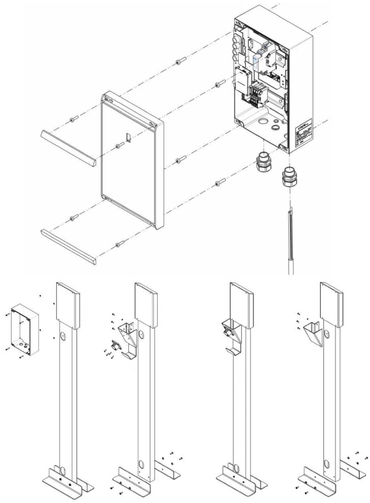
Pole Mounting: Mounting the pole with the concrete base (optional):
- Dig a hole about 50 x 50 cm with a depth of 50 cm
- Attach the brackets at the bottom of the pole with four M8 x 20 mm screws and four M8 ring (see fig. on the cover)
- Now place the pole in the hole
- Run the ground cable through the pedestal to the charging station
- Attach the cover plate to the pole using three M5 x 13 mm screws and three M5 x 13 rings
- Attach the holding of the charging cable on the cover plate using four M4 x 12 mm screws
- Fill the hole and pave the area
- Cover the area afterwards with a clean trim (e.g. tiles)
Preparation of the charging station
The front cover of the charging station must be opened before installing. Proceed as follows:
The front cover is firmly attached to the charging unit and is secured with two screws at the top and bottom.
- Place the device on its back
- Remove the metal cover strips on the top and bottom
- Loosen the four screws with an Allen key
- Keep the screws in a safe place; they will be required later
- Lift the left side of the cover and open it to the right
Mounting the charging station

natural_image
Isometric line drawing of a computer case with internal components and wiring (no text or labels)Fig. 1: Attachment to the wall
- Insert appropriate wall plugs into the four holes
- Attach the ICU Compact on the wall with four M5 x 30 mm screws
3.4 Electrical Installation

CAUTION!
Read and follow all safety instructions in this manual!

DANGER!
The electrical system must be disconnected from the power supply during assembly and maintenance work!
- Loosen the gland and remove it together with the rubber ring from the screw connection
- Slide the gland over the power supply and/or fixed cables
- Slide the rubber ring over the power supply and/or fixed cable
- Insert the power supply and/or fixed cable through the opening in the screw connection of the charging station
NOTICE
Ensure that 30 mm of cable is available in the housing.
- Slide the rubber ring and the gland on to the screw connection
- Tighten the power supply and/or fixed cable in the screw connection until it no longer shows any movement
- Remove the sleeve of the power supply and/or fixed cable using a wire stripper so that the cores are sufficiently exposed to be able to be installed in the connecting terminals
NOTICE
Always install the earthing first.
- Fix the cores at the correct location in the connecting terminals (14 and 15 on the right of the cover)
- Screw the cover on the housing
- Install the metal cover strips at the correct location on the cover
4. Commissioning the charging station
4.1 Safety instructions before operating
Follow the below safety instructions before putting your charger into operation:
- Make sure that the charging station is securely connected to the house supply line as specified in this manual
- Make sure that the supply line in the house distribution is separately protected by an appropriate circuit breaker (B-characteristic)
- Make sure that the built-in charger or external upstream RCD is switched on
- Make sure that the charging station has been installed in accordance with this guidance
- Make sure that the housing is always locked in normal operation
- Make sure that the charging cable is not twisted and make sure that cable, charging plug and housing are free of damage
4.2 Putting into operation
- Turn on the power at the power supply cable
The charger now performs a self test. The following actions are performed by the charging station:
- The door lock is activated
- The red LED lights up for one second continuously
- All LEDs light up for one second continuously
- The red LED flashes five times, so that the electronics are started
- All LEDs go out
- The ICU Compact is now ready for charging
5. Connectivity
5.1 Back End Systems
You are in possession of an intelligent ICU charging station that can communicate with a back end system through an internet connection. Back end systems allow you for example to view the energy consumption of individual users, remotely control charging or monitor the charging station for service purposes.
If you signed a contract with a back end supplier or with Alfen ICU B.V. (for provision of ICU EZ back end services), your charging station is configured to connect to the respective back end ex-factory. The internet connection may be facilitated via GPRS (SIM card) or via UTP (Ethernet) cable connection.
In case you opted for a GPRS (SIM card) connection, your charging station is already equipped with the correct SIM card. The charging station will establish a connection to the internet as soon as it is turned on. In case there is no SIM card in the SIM Card Slot (⑬ on the left of the cover), please contact your back end provider or Alfen ICU.
The following paragraphs describe how to connect your charging station via UTP (Ethernet) cable to the internet.
5.2 UTP (Ethernet) connection
Which cable is required?
A UTP cable of minimally CAT5 is needed to connect the charging station to the Internet. This cable is suitable for speeds up to 100Mbps.
Installation
- Connect the UTP cable to your router
- Turn off the power of the charging station by putting the main switch to the 0 position
-
Connect the UTP cable to the Communication Unit of the charging station (16) on the left of the cover)
-
Turn on the power of the charging station by putting the main switch to the 1 position
- In order for your charging station to communicate with ICU EZ through a wired UTP ethernet connection, your network setting should be adjusted if these are additionally secured. Below you will find the necessary information to allow access through your network:
• IP address ICU EZ: 93.191.128.6 - Port: 9090
- Inbound – Outbound
It may be possible that a MAC address is required. This is stated on the FAT report of the charging station. This report can be provided by Alfen ICU.
NOTICE
Please also make sure that your network settings allow the charging station to undiagnostics and updates via a secure FTP connection to ICU servers.
5.3 Registering your ICU EZ account
If you would like to sign a contract with ICU for provision of ICU EZ back end services, go to www.icu-charging-stations.com/ez-english
NOTICE
Please always activate your ICU EZ account first. Only connect the charger via UTP cable to the Internet after ICU confirmed that your account has been activated.
- Fill out the digital form. Please add the imprinted card numbers of all of your ICU charging cards supplied with your ICU charging station in the "Comment" field
- Click on "Send"
- ICU will process the form and activate your account. Your login details will be sent to you as soon as possible
- You can login to the website www.icu-ez.com with your received account information
- After logging on to ICU EZ you can see if your charging station is online. This will be shown with the status "Available". If your charging station is not yet connected, it will show the status "Planned"