
Audiosystem8.8 - Blender APART - Free user manual and instructions
Find the device manual for free Audiosystem8.8 APART in PDF.


User questions about Audiosystem8.8 APART
0 question about this device. Answer the ones you know or ask your own.
Ask a new question about this device
Download the instructions for your Blender in PDF format for free! Find your manual Audiosystem8.8 - APART and take your electronic device back in hand. On this page are published all the documents necessary for the use of your device. Audiosystem8.8 by APART.
USER MANUAL Audiosystem8.8 APART
natural_image
Pure grayscale gradient with diagonal light streak, no text or symbols
text_image
POWER
text_image
2A 2B 3AAUDIOSYSTEM8.8
Instruction manual

bar
| Category | Value | |---|---| | Category 1 | 100 | | Category 2 | 100 | | Category 3 | 100 | | Category 4 | 100 | | Category 5 | 100 | | Category 6 | 100 | | Category 7 | 100 | | Category 8 | 100 | | Category 9 | 100 | | Category 10 | 100 | | Category 11 | 100 | | Category 12 | 100 | | Category 13 | 100 | | Category 14 | 100 | | Category 15 | 100 | | Category 16 | 100 | | Category 17 | 100 | | Category 18 | 100 | | Category 19 | 100 | | Category 20 | 100 | | Category 21 | 100 | | Category 22 | 100 | | Category 23 | 100 | | Category 24 | 100 | | Category 25 | 100 | | Category 26 | 100 | | Category 27 | 100 | | Category 28 | 100 | | Category 29 | 100 | | Category 30 | 100 | | Category 31 | 100 | | Category 32 | 100 | | Category 33 | 100 | | Category 34 | 100 | | Category 35 | 100 | | Category 36 | 100 | | Category 37 | 100 | | Category 38 | 100 | | Category 39 | 100 | | Category 40 | 100 | | Category 41 | 100 | | Category 42 | 100 | | Category 43 | 100 | | Category 44 | 100 | | Category 45 | 100 | | Category 46 | 100 | | Category 47 | 100 | | Category 48 | 100 | | Category 49 | 100 | | Category 50 | 100 | | Category 51 | 100 | | Category 52 | 100 | | Category 53 | 100 | | Category 54 | 100 | | Category 55 | 100 | | Category 56 | 100 | | Category 57 | 100 | | Category 58 | 100 | | Category 59 | 100 | | Category 60 | 100 | | Category 61 | 100 | | Category 62 | 100 | | Category 63 | 100 | | Category 64 | 100 | | Category 65 | 100 | | Category 66 | 100 | | Category 67 | 100 | | Category 68 | 100 | | Category 69 | 100 | | Category 70 | 100 | | Category 71 | 100 | | Category 72 | 100 | | Category 73 | 100 | | Category 74 | 100 | | Category 75 | 100 | | Category 76 | 100 | | Category 77 | 100 | | Category 78 | 100 | | Category 79 | 100 | | Category 80 | 100 | | Category 81 | 100 | | Category 82 | 100 | | Category 83 | 100 | | Category 84 | 100 | | Category 85 | 100 | | Category 86 | 100 | | Category 87 | 100 | | Category 88 | 100 | | Category 89 | 100 | | Category 90 | 100 | | Category 91 | 100 | | Category 92 | 100 | | Category 93 | 100 | | Category 94 | 100 | | Category 95 | 100 | | Category 96 | 100 | | Category 97 | 100 | | Category 98 | 100 | | Category 99 | 100 | | Total (Total) = [sum of bars] / [bar chart] / [line chart] / [line graph] / [line chart] / [line graph] / [line graph] / [line graph] / [line graph] / [line graph] / [line graph] / [line graph] / [line graph] / [line graph] / [line graph] / [line graph] / [line graph] / [line graph] / [line graph] / [line graph] / [line graph] / [line graph] / [line graph] / [line graph] / [line graph] / [line chart]AUDIOSYSTEM8.8

text_image
u2park AUDIO SYSTEM 1.0 □ MAX PULSD & AMPLIERS □ TCP-PHARMS/ANALAWAY □ MAXIMAX PR-AM PLANS OUTPUTS POWERSafety information
- Please check the carton box for any kind of damage on reception of the goods. In case of a damaged carton, please contact your dealer before opening the carton.
- !!!!! Danger !!!!! Exposure to high sound levels may cause a permanent hearing loss. Individuals vary considerably to sound pressure level induced hearing loss but nearly everyone will lose some hearing if exposed to high sound pressure levels for a sufficient amount of time. Therefore it is recommended that all persons exposed to equipment capable of producing high sound pressure levels, such as this device, be protected by hearing protection while installing or operating this unit.
- Read all documentation before operating your equipment.
- Keep all documentation for future reference.
- Save the carton and packing material even if the equipment has arrived in good condition.
- Should you ever need to ship the unit, use only the original factory packing.
- Do not spill water or other liquids into or on the unit.
- Make sure power outlets are conform to the power requirements listed on the back of the unit.
- Do not use the unit if the electrical power cord is frayed or broken.
- Always operate the unit with the AC ground wire connected to the electrical system ground.
- Do not connect the inputs / outputs of amplifiers or consoles to any other voltage source, such as a battery, mains source, or
power supply, regardless of whether the amplifier or console is turned on or off.
- Power down & disconnect units from mains voltage before making connections.
- Do not use the unit near stoves, heat registers, radiators, or other heat producing devices.
- Do not operate equipment on a surface or in an environment which may distort the normal flow of air around the unit. If the unit is used in an extremely dusty or smoky environment, the unit should be periodically “blown free” of dust.
- Do not remove the cover. Removing the cover will expose you to potentially dangerous voltages.
- Do not drive the inputs with a signal level higher than that required to drive equipment to full output.
- Do not run the output of any amplifier back into another input.
- In case of mal-function this device should be serviced by qualified service personnel only.
- The apparatus may not be exposed to dripping or splashing and no objects filled with liquids may be placed on the apparatus.
- The appliance coupler has to be readily operable to disconnect the device.
Caution

natural_image
Black triangular warning symbol with a lightning bolt inside, indicating electrical hazard (no text)CAUTION
TO REDUCE THE RISK OF ELECTRIC SHOCK DO NOT REMOVE COVER OR BACK NO USER-SERVICEABLE PARTS INSIDE SERVICING ONLY FOR QUALIFIED PERSONNEL
text_image
Warning symbol image with exclamation mark inside black triangleCAUTION: a clipped or distorted audio signal at the input (overload) will come out as a clipped or distorted signal at the output, regardless of the output level and DSP processing power applied to the signal. Clipping occurs when the signal and/or the applied gain is too high, due to incompatibility of the signal level, a faulty source, an impedance mismatch or a human error. Therefore, monitor incoming signals and do not overload the inputs. Adjust the output level(s) and gain settings of your source(s) if necessary. Due to the internal gain structure of the AUDIOSYSTEM, the output signals may clip even when the input signals are relatively low. Do not over amplify audio signals. Boosting certain frequency bands or over compressing incoming audio signals may cause signal clipping, distortion and excessive noise at the output. If you have to add lots of gain, your incoming signal may be too weak.
NOTE: This is the out-of-the-box manual of your AUDIOSYSTEM8.8. A full manual and GUI guide can be found on our website. If you want customized configurations, adjustments and a total solution for your specific application, please seek the online manual.
The apart-team hopes you enjoy our product. We enjoyed developing this product and guarantee it will serve as a solution for every kind of implementation.
General Description
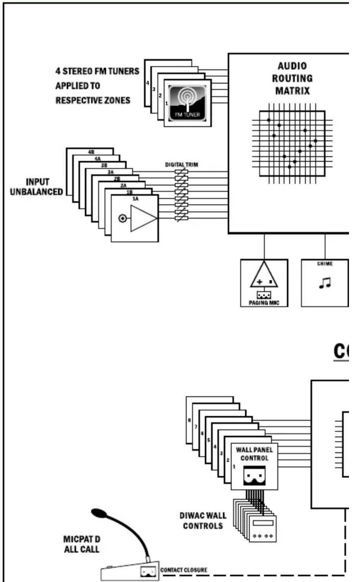
AUDIOSYSTEM8.8 is an audio matrix with 4 stereo line inputs, 4 stereo D-class amplified outputs and 2 stereo line outputs (copies of amplified outputs). The AUDIOSYSTEM8.8 also has 4 stereo FM RDS tuners built-in. Together with this the AUDIOSYSTEM8.8 has a paging input and an emergency mute.
The unit may be controlled through our DIWAC wall panels and has a built-in webserver for TCP/IP connection for system integration and/or control through any mobile device or computer that has a web browser installed.
Features
- Internal webserver GUI for configuration and use
- TCP/IP
- Fixed architecture
- Stand alone operation
• Online upgradeable firmware - Configurable mono/stereo zones
- 4 stereo unbalanced line inputs using RCA connectors
- 2 stereo unbalanced line outputs using RCA connectors
- 8 x 30 watts class-D amplifier outputs (6 - 8 ohms)
- Up to 8 DIWAC wall controls (maximum 2 controls per output zone)
• LED display for zone status overview - Import / export function
- 8 integrated chimes
- Universal integrated switching power supply: 85-264 Vac / 47-63 Hz
- Removable 19" rack ears
Out of box behavior
Standard factory configuration:
Input Configuration:
- 4 stereo inputs: AUX1 (1A & 1B), AUX2 (2A & 2B), AUX3 (3A & 3B) and AUX4 (4A & 4B).
Output Configuration:
• 4 stereo outputs: output 1 (1A & 1B), output 2 (2A & 2B), output 3 (3A & 3B) and output 4 (4A & 4B).
Wall panel(DIWAC) configuration:
- Pushbuttons ∨ for source selection (AUX 1 - 4) and +- for volume control (0 - 50).
- DIWAC 1A - 1B for output 1, 2A - 2B for output 2, 3A - 3B for output 3 and 4A - 4B for output 4
- Out of the box there are no FM presets configured but they may be accessed and configured through the control menu. The control menu in accessed by pressing + . In the control menu it is possible to set EQ settings, set default settings and do an FM scan.
flowchart
graph TD
    A["4 STEREO FM TUNERS APPLIED TO RESPECTIVE ZONES"] --> B["FM TUNER"]
    C["INPUT UNBALANCED"] --> D["4B 4A 3B 2A 1B 1A"]
    D --> E["DIGITAL TRIM"]
    F["AUDIO ROUTING MATRIX"] --> G["PAGING MIC"]
    F --> H["CHIME"]
    I["MICPAT D ALL CALL"] --> J["CONTACT CLOSURE"]
    K["DIWAC WALL CONTROLS"] --> L["WALL PANEL CONTROL"]
    M["C"] --> N["Output"]
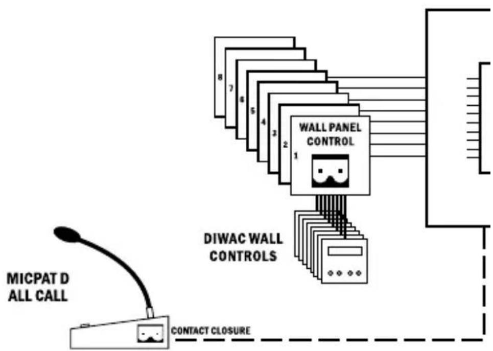
flowchart
graph TD
    A["MICPAT D ALL CALL"] --> B["DIWAC WALL CONTROLS"]
    B --> C["CONTACT CLOSURE"]
    C --> D["Wall Panel CONTROL 1"]
    D --> E["Output Line"]
    style A fill:#f9f,stroke:#333
    style B fill:#ccf,stroke:#333
    style C fill:#cfc,stroke:#333
    style D fill:#fcc,stroke:#333
    style E fill:#ffc,stroke:#333
AUDIO
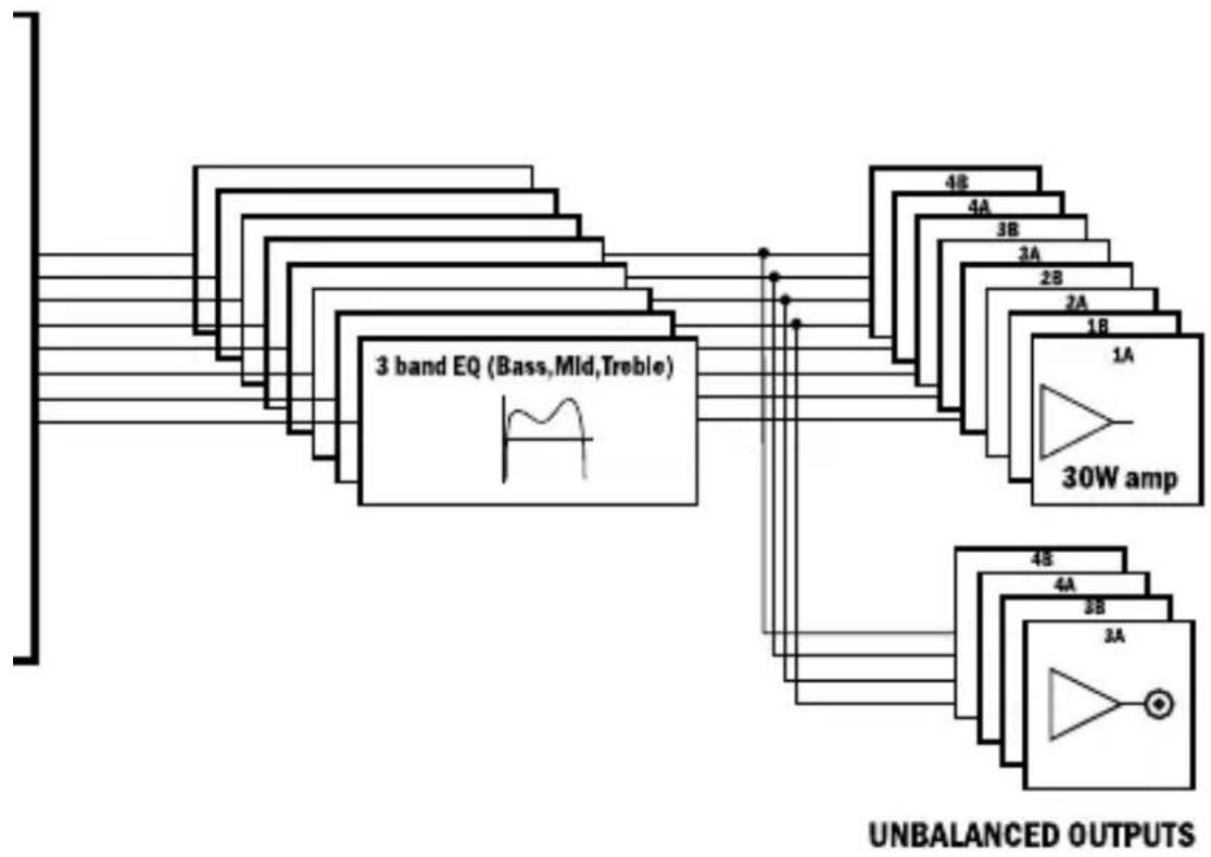
flowchart
graph TD
    A["3 band EQ (Bass,Mld,Treble)"] --> B["4A"]
    A --> C["3B"]
    A --> D["2A"]
    A --> E["2B"]
    A --> F["1B"]
    A --> G["1A"]
    A --> H["30W amp"]
    H --> I["4A"]
    H --> J["3B"]
    H --> K["2A"]
    style A fill:#f9f,stroke:#333
    style H fill:#ccf,stroke:#333
    note bottom of H UNBALANCED OUTPUTS
ONTROL
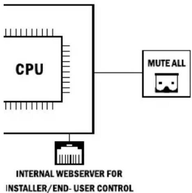
flowchart
graph TD
    A["CPU"] --> B["MUTE ALL"]
    B --> C["INTERNAL WEBSERVER FOR INSTALLER/END-USER CONTROL"]
Connecting the paging microphone
As paging microphone for the AUDIOSYSTEM8.8 you can use any microphone and contact input. Apart provides the MICPAT D as a solution. To make the paging microphone compatible with the AUDIOSYSTEM8.8, cut the wires from the Micpat-D Din-5 connector and connect them to a 5-way Euroblock connector. The picture below shows how to connect the wires of the Micpat-D to the respective Euroblock connector.
MICPAT-D
DIN5-180° front-view
AUDIOSYSTEM
MICROPHONE
PAGING
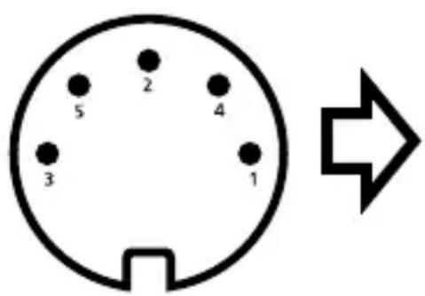
text_image
2 4 5 3 1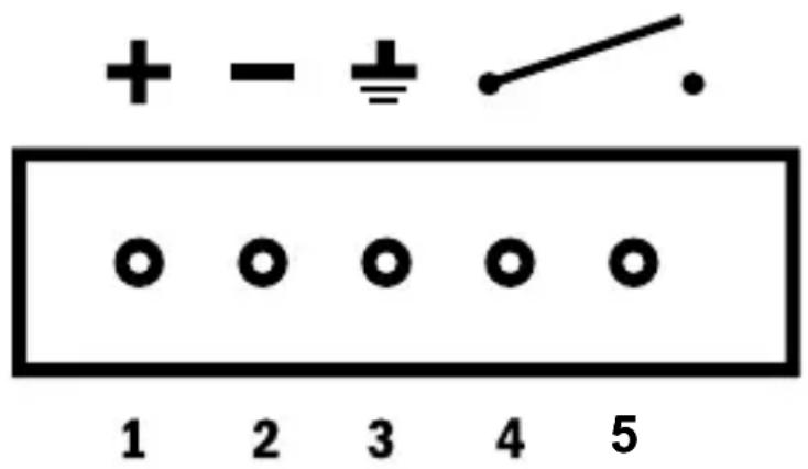
- Output status: These leds indicate the status of the output zones. When a zone is active the corresponding led will be lit. The leds also indicate the status of the amplifiers, when an amplifier is short circuited, the output led will start to blink.
- Power led: lights up when mains power is present and the unit has been switched on.
- Removable rack ears left and right.
Rear panel
text_image
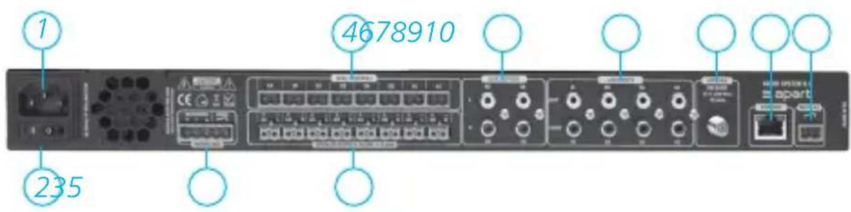
1 235 4678910- Power inlet: Connect the power cord here.
- Powerswitch: Power the unit on and off.
- Paging mic: Connection to MICPAT-D. A microphone balanced input is provided with a contact closure.
- The wall controls (DIWAC): Only one control per connection is allowed, resulting in a maximum of 8 wall controls per AUDIOSYSTEM8.8. The DIWAC may not be daisy chained.
- Amplifiers: There are 8 class D amplifiers in the AUDIOSYSTEM8.8. Speakers are connected with the female euroblocks. Each output is protected against short circuit, thermal overload and DC error.
- Lineoutputs: These are copies of amplifier outputs 3A, 3B, 4A and 4B. Used for additional power amplifiers or 100V amplifiers.
-
Lineinputs: The AUDIOSYSTEM8.8 has 8 audio line inputs, which can be configured as 4 stereo inputs or 8 mono inputs.
-
FMantenna: Connect the FM antenna wire here. When you want to connect the input to an antenna or cable distribution network, you need to connect through a galvanic separation transformer designed for FM signals. We advise you to always use a separation transformer to connect to a cable distribution network because otherwise it may lead to unpredictable behavior and even system damage.
- Network cable connector: connect to a network, AUDIOSYSTEM8.8 supports DHCP and DNS. A connection with the device can be established through any web browser.
- Emergency / Mute all: Contact closure for emergency mute on all zones.
Network
Connect a standard RJ45 cable from your network router to the unit. Make sure that the DHCP function of your AUDIOSYSTEM8.8 is enabled. Make sure you're pc is connected to the same network.
Connect to device:
- Open your web browser and open the link "http://system88/config.html". This link will open the configuration GUI of the AUDIOSYSTEM8.8.
- The graphical user interface may be accessed by http://system88.
- When the device is powered on, the wall control will show the device's IP address.
Specifications
| Unbalanced inputs 1 - 8 | |
| Input impedance: 10 kohm | |
| Sensitivity: 940 mVrms | |
| Max input voltage: 3.5 Vrms | |
| Input range -33 dB / +12 dB | |
| Amp Outputs 1- 8 | |
| Minimum load 6 ohm | |
| Max output level +26 dBV | |
| SNR 98 dB @ 1 % THD, 1 kHz | |
| THD-N full power -6 dB @ 1 kHz 0.061% | |
| Noise floor -74 dBV | |
| Noise floor muted: -119 dBV | |
| Line outputs 5 - 8 | |
| Output impedance 330 ohm | |
| Max output level 10 dBV | |
| SNR 90 dB @ 1 % THD, 1 kHz | |
| Noise floor -83 dBV | |
| THD-N 0.0031% @ max input -6 dB, 1 kHz | |
| Channel separation | |
| Line input to amplifier output ch 1A - ch1B | 84 dB @ 1kHz, 65 dB @ 20 kHz @ Full power with 8 ohm load |
| Line input to line output ch 3A - ch 3B | 83 dB @1 kHz, 77 dB @ 20 kHz @ Full power |
| EQ | |
| Bass range: 100 Hz / min -12 dB & max: +12 dB | |
| Mid range: 1 kHz / min -12 dB & max: +12 dB | |
| Treble range: 10 kHz / min -12 dB & max: +12 dB | |
| Paging mic | |
| Sensitivity 32.33 mVrms | |
| SNR 87.6 dB @ 1% THD (to amplifier) | |
| Noise floor -63.2 dBV | |
| THD-N | 0.1% @ full power -6 dB,1 kHz, 8 ohm |
| FM | |
| Frequency spacing 100 kHz | |
| Frequency range 87.5 MHz – 108.0 MHz | |
| Power supply | |
| Power supply SMPS | |
| Input voltage range 85 – 264 VAC | |
| Max power 150 W | |
| Wall controls | |
| Voltage output 24 V | |
| Power consumption 110 mA, automatic fused | |
| Communication 2 wire interface | |
| Dimensions and weight | |
| W x D x H 484 x 316 x 44 mm | |
| Net Weight 4 kg | |
| Amp Topology | |
| Type Class-D | |
developed by
Audioprof nv
Industriepark Brechtsebaan 8 bus 1
2900 Schoten - Belgium
Company names, product names and trademarks are property of their respective owners.
Apart-Audio specifications are subject to change without notice.