
VS2000 - Digital decoder Black Box - Free user manual and instructions
Find the device manual for free VS2000 Black Box in PDF.


| Product Type | Digital Decoder (H.264/MPEG-4 AVC) |
| Dimensions (H x W x D) | 3.0 x 12.2 x 7.1 in (7.6 x 31 x 18 cm) |
| Weight | 3.86 lb (1.75 kg) |
| Power Supply | 12 VDC, 1 A (power adapter included) or PoE (IEEE 802.3af) |
| Power Consumption | 6 W (DC adapter), 10 W (PoE minimum) |
| Video Input | 1 x LAN (Ethernet) – streaming media |
| Video Output | 1 x HDMI (up to 1920x1080@60Hz or 1920x1200@60Hz) |
| Audio Input | Embedded audio via LAN |
| Audio Output | 1 x 3.5mm 3-pin Phoenix connector (unbalanced stereo) |
| Control Methods | Web GUI (browser) and Telnet API |
| Network Protocols | Static IP, DHCP, Unicast, Multicast, RTP, RTSP |
| Supported Input Resolutions | 480p @60Hz to 1920x1200 @60Hz |
| Video Codec | H.264/MPEG-4 AVC |
| Audio Codec | AAC |
| ESD Protection | ±8 kV air discharge, ±4 kV contact discharge |
| Surge Protection | ±1 kV |
| Operating Temperature | 32 to 113°F (0 to 45°C) |
| Operating Humidity | 10 to 90% (non-condensing) |
| Storage Temperature | -4 to 140°F (-20 to 70°C) |
| Regulatory Approvals | CE, FCC Class A, RoHS |
| Included Accessories | Power adapter, 2 Phoenix connectors, 2 mounting ears |
| Maintenance | Keep dry, clean with soft cloth; avoid dust and liquids |
| Serviceability | No user-serviceable parts; contact technical support for repairs |
Frequently Asked Questions - VS2000 Black Box
User questions about VS2000 Black Box
0 question about this device. Answer the ones you know or ask your own.
Ask a new question about this device
Download the instructions for your Digital decoder in PDF format for free! Find your manual VS2000 - Black Box and take your electronic device back in hand. On this page are published all the documents necessary for the use of your device. VS2000 by Black Box.
USER MANUAL VS2000 Black Box
natural_image
Exterior view of a black rectangular electronic device with ports and indicator lights (no readable text or symbols)FEDERAL COMMUNICATIONS COMMISSION AND INDUSTRY CANADA RADIO FREQUENCY INTERFERENCE STATEMENTS
This equipment generates, uses, and can radiate radio-frequency energy, and if not installed and used properly, that is, in strict accordance with the manufacturer's instructions, may cause interference to radio communication. It has been tested and found to comply with the limits for a Class A computing device in accordance with the specifications in Subpart B of Part 15 of FCC rules, which are designed to provide reasonable protection against such interference when the equipment is operated in a commercial environment. Operation of this equipment in a residential area is likely to cause interference, in which case the user at his own expense will be required to take whatever measures may be necessary to correct the interference.
Changes or modifications not expressly approved by the party responsible for compliance could void the user's authority to operate the equipment.
This digital apparatus does not exceed the Class A limits for radio noise emission from digital apparatus set out in the Radio Interference Regulation of Industry Canada.
Trademarks Used in this Manual
Black Box and the Double Diamond logo are registered trademarks of BB Technologies, Inc.
Any other trademarks mentioned in this manual are acknowledged to be the property of the trademark owners.
Table of Contents
- Specifications....7
- Overview 9
2.1 Introduction....9
2.2 Features....9
2.3 What's Included....10
2.4 Hardware Description....11
- Hardware Installation .... 13
- Operation 14
4.1 Logging In to the Web-based Configuration Page 14
4.2 Introduction to Functions Page 15
4.2.1 Stream Page....15
4.3 Introduction to System Page 16
4.3.1 Device Name Page....16
4.3.2 Network Page 17
4.3.3 Password Page 18
4.3.4 Idle Pattern Picture Page 19
4.3.5 Upgrade Page....20
4.3.6 Version Info Page 21
4.3.7 Commands Page 22
Appendix. API Commands 23
A.1 Introduction 23
A.2 Preparation 23
A.2.1 Setting IP Address on Your Computer....23
A.2.2 Enabling Telnet Client....23
A.2.3 Logging In to the Encoder via Command Line Interface ....24
A.3 Commands Overview....26
A.3.1 gbconfig command....26
A.3.2 gbcontrol command 27
A.4 gbconfig Command Sets 27
A.4.1 gbconfig -name....27
A.4.2 gbconfig --ip-mode 28
A.4.3 gbconfig --ip4-addr 29
A.4.4 gbconfig --net-mask....29
A.4.5 gbconfig --gateway-ip 30
A.4.6 gbconfig —network-url....30
A.4.7 gbconfig -s 31
A.4.8 gbconfig -h 32
A.5 gbcontrol Command Sets 33
A.5.1 gbcontrol --blink-led 33
- Specifications
| Approvals CE, FCC, RoHS | compliant |
| Connectors Video: | Input: (1) LAN,Output: (1) HDMIAudio:Input: (1) LAN,Output: (1) Phoenix connector;Audio Format:Input: Audio embedded in streaming media:Output: Unbalanced stereo audio |
| Video Type Input: H.264/MPEG-4 AVCOutput: HDMI 1.4 | |
| Video Impedence 100 ohms | |
| Resolutions (Input) Input Video: 480p @ 60Hz –1920 x 1200 @ 60 Hz | |
| Resolutions (Output) Output Video: HDMI Input: 640 x 480 ^8 ,800 x 600 ^8 , 1024 x 768 ^8 , 1280 x 768 ^8 ,1280 x 800 ^8 , 1280 x 1024 ^8 , 1360 x 768 ^8 ,1366 x 768 ^8 , 1440 x 900 ^8 , 1400 x 1050 ^8 ,1600 x 1200 ^8 , 1680 x 1050 ^8 , 1920 x 1200 ^8 ,720 x 480 ^8 (480P), 720 x 576 ^6 (576P),1280 x 720 ^5 (720P@30Hz), 1280 x 720 ^6 (720P@50Hz), 1280 x 720 ^8 (720P@60Hz),1920 x 1080 ^2 (1080P@24Hz), 1920 x 1080(1080P@25Hz), 1920 x 1080 (1080P@30Hz),1920 x 1080 ^6 (1080P@50Hz), 1920 x 1080(1080P@60Hz) | |
| Control: | |
| Control Method LAN (Web | GUI and Telnet) |
| Web Browser Supported | Internet Explorer, Microsoft Edge, Firefox,Chrome (Recommended) |
| General | |
| Operating Temperature/Humidity | 32 to 113°F (0 to 45°C),10 to 90%, non-condensing |
| Storage Temperature/Humidity | -4 to 140°F (-20 to 70°C),10 to 90%, non-condensing |
| Power 12 VDC, 1 A | |
| Device PowerConsumption | DC Adapter: 6 W (Max.)PoE: 10 W (Min.) for safe operation |
| ESD Protection Human body model:±8kV (air-gap discharge)±4kV (contact discharge) | |
| Surge Protection Voltage: ±1 kV | |
| Dimensions Product: 3.0"H x 12.2"W x 7.1"D (7.6 x 31 x 18 cm) | |
| Weight 3.86 lb. (1.75 kg) | |
2. Overview
2.1 Introduction
The VS-2000-DEC Decoder works with a VS-2000-ENC Encoder to deliver an A/V signal over a LAN or WAN.
The VS-2000-DEC employs standards-based H.264 video compression technology that decodes video content with visual lossless quality at a link using limited bandwidth. The Decoder supports AAC audio encoding technology so the audio signal can be delivered with low bandwidth but high quality.
Compatible with diversified network: The decoder can receive media data by multiple approaches so to work in many different network environments. Multicast mode saves bandwidth and unicast mode works with unmanaged switches. Even in a network protected by a firewall, the decoder can activate RTP over RTSP mode to receive media data without requiring a new UDP port.
Optimized controlling methods: To achieve pairing, the user just needs to configure the IP address of the encoder. The decoder will negotiate with the encoder and try to obtain the media stream by the most suitable approach. Manage the decoder via web UI or Telnet API. Use the web UI to control it through a common web browser. Use Telnet API control the decoder via a 3rd-party system.
2.2 Features
- Uses with H.264 and AAC codec technology, providing high video/audio quality while using low bandwidth.
- Supports HDMI input signals up to 1920 x 1200@60Hz, including Full HD1080P@60Hz — VS-2000-ENC supports a wide range of input resolutions, from standard definition up to the high resolutions.
- Receive TS data with unicast or multicast method, UDP and RTP payload are both supported, and RTP over RTSP is supported.
- Uses RTSP protocol to negotiate with the encoder to get the address of the media data;
- Supports resolutions up to 1920 x 1080 @ 60Hz and 1920 x 1200 @ 60 Hz.
- Uses static IP and DHCP.
- Works with Bonjour protocol; can be discovered by a Bonjour browser.
• Control the display through RS-232 or CEC. -
"Where am I" feature supported: once the decoder receives a "locate device" command, the status indicator will blink with a special mode to indicate its physical position.
-
Has one Ethernet input, one HDMI output, one analog audio output, one RS-232 input, and 12-VDC power.
• Control via Telnet API and web UI.
• Supports two power modes: 12 VDC and PoE.
2.3 What's Included
• (1) VS-2000-DEC
• (2) Phoenix connectors
• (1) 12-VDC, 1-A power adapter
• (2) mounting ears
2.4 Hardware Description
Figures 2-1 and 2-2 show the front and back panels of the decoder. Table 2-1 describes its components.
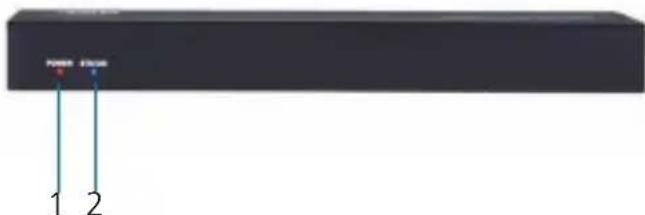
Figure 2-1. VS-2000-DEC front panel.
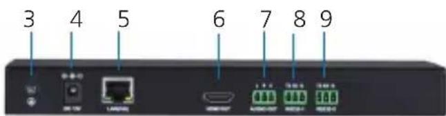
Figure 2-2. VS-2000-DEC back panel.
Table 2-1. VS-2000-DEC components.
| Number | Component | Status | Description |
| 1 Power Indicator(red) | ON VS-2000-DEC is powered on. | ||
| OFF VS-2000-DEC is powered off. | |||
| 2 Status Indicator(blue) | ON VS-2000-DEC works properly | ||
| OFF VS-2000-DEC is idle | |||
| Blinks every two seconds. | VS-2000-DEC can't connect to the corresponding decoder. | ||
| Blinks for ten seconds | VS-2000-DEC is executing a “locate device” command | ||
| 3 Grounding screw Connected to | ground | Prevents electric shock and device damage | |
| 4 Power input connector | Connected Connects to the supplied 12-VDC, 1-A power adapter. | ||
| Not connected Unit powered via PoE. | |||
| NOTE: We recommend powering the VS-2000-DEC using either a power adapter or a PoE switch instead of using both at the same time.For example, if you use a power adapter, make sure that the PoE function of the connected switch's LAN port is disabled or use a non-PoE switch. | |||
Table 2-1. VS-2000-DEC components.
| Number Component Status | Description | ||
| 5 (1) LAN (PoE) connector | Video Input | Links to an Ethernet switch for streaming media input.NOTE: If you use a PoE Ethernet switch, decoder can be powered by this switch, eliminating the need for a nearby power outlet. | |
| 6 (1) HDMI OUT connector | Video Output | Attaches to an A/V device such as an HDMI display device. | |
| 7 (1) 3.5-mm 3-pin Phoenix connector | Audio Output | Connects to an audio output device such as an amplifier and a speaker. | |
| 8 (1) RS-232-1 Debug | Port | Connects to an RS-232 device such as a computer for debugging VS-2000-DEC. | |
| 9 (1) RS-232-2, 3.5-mm 3-pin Phoenix connector | Not used | This port is reserved for future use.. | |
NOTE: If you use a PoE Ethernet switch, the VS-2000-DEC can be powered by this switch, eliminating the need for a nearby power outlet.
If the PoE switch is unable to provide enough power, connect the VS-2000-DEC to the supplied power adapter and disable the PoE function of the connected LAN port in the switch.
3. Hardware Installation
WARNING:
Before the installation, disconnect the power supplies from all the devices.
During the installation, do not connect the VS-2000-DEC via PoE to a power source equipment and its power adapter at the same time.
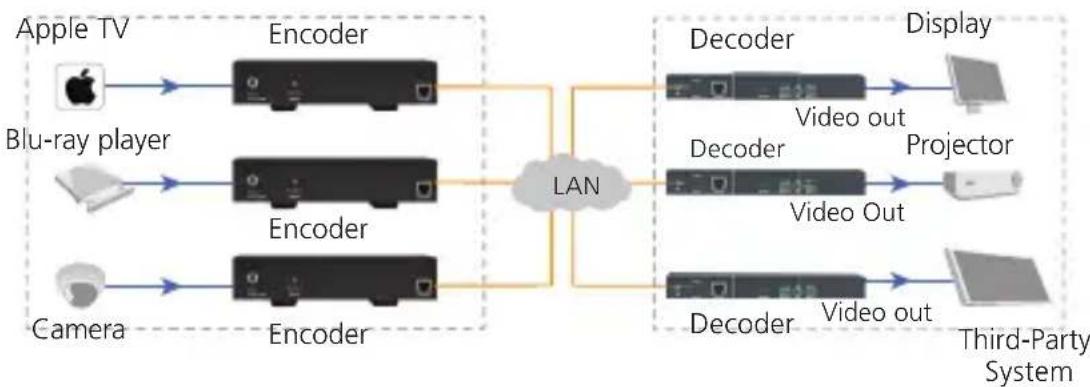
The following illustration describes a common application. Your application may vary. After connection is complete, use a third-party enoder to view the intended application.
flowchart
graph LR
    A["Apple TV"] --> B["Encoder"]
    C["Blu-ray player"] --> D["Encoder"]
    E["Camera"] --> F["Encoder"]
    B --> G["LAN"]
    D --> G
    F --> G
    G --> H["Decoder"]
    H --> I["Display"]
    G --> J["Decoder"]
    J --> K["Projector"]
    G --> L["Decoder"]
    L --> M["Third-Party System"]
Figure 3-1. Typical installation.
4. Operation
4.1 Logging In to the Web-based Configuration Page
- Make sure that your encoder, computer, and VS-2000-DEC are on the same subnet.
- Start a browser.
- In the address bar, enter the default IP address 192.168.10.254.
- In the displayed login dialog box, enter the default password "admin".
- Click Login.
NOTE: If you want your browser to remember your login password, select the check box next to "Remember Password" before login.
If you forgot the login IP address and password, restore the VS-2000-DEC to its factory defaults, and then use the default settings. For more information, see Section 4.3.2, Network Page, and Section 4.3.3, Password Page.
4.2 Introduction to Functions Page
4.2.1 Stream Page
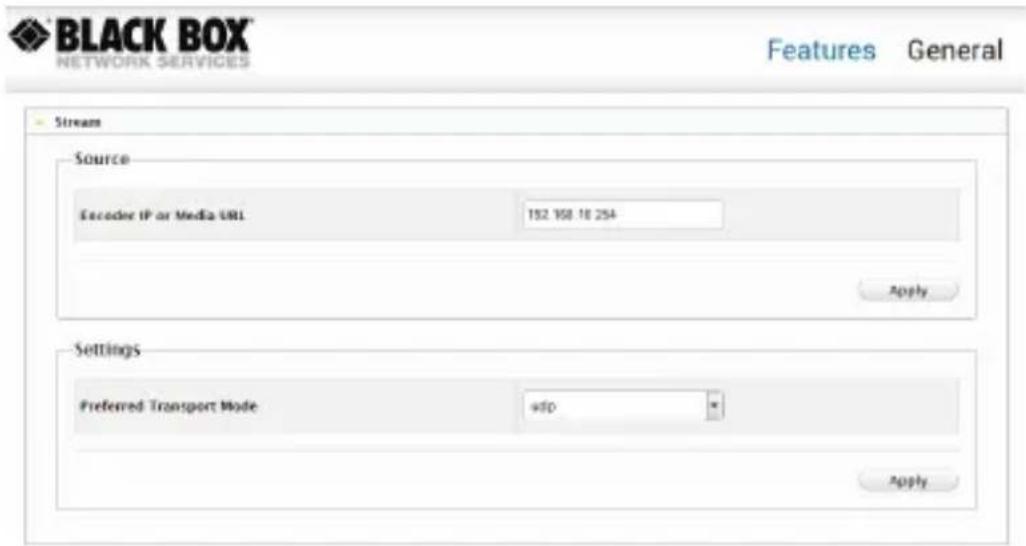
Figure 4-1. Stream page.
Table 4-1. Stream page elements.
| GUI Element Description | |
| Encoder IP Indicates the encoder IP address | |
| Apply Saves the current settings and applies them to the VS-2000-DEC. |
4.3 Introduction to System Page
4.3.1 Device Name Page
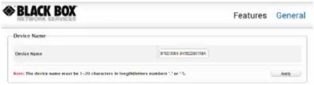
Figure 4-2. Device Name page.
Table 4-2. Device Name page elements.
| GUI Element Description | |
| Device Name Indicates the Device Name page, where you can change the device name. | |
| Device Name Inputs a new device name. This name can be: Displayed on the browser tab. Displayed and used after bonjour automatic discovery of the VS-2000-DEC. NOTE: The name must contain 1–20 letters, numbers, hyphen (-) or underscore (_), or their combinations. | |
| Apply Saves the current settings and applies them to the VS-2000-DEC. |
4.3.2 Network Page
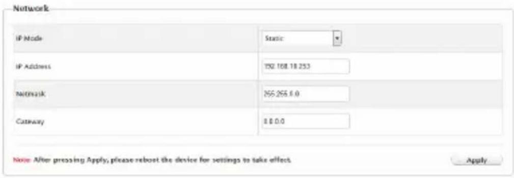
Figure 4-3. Network page.
Table 4-3. Network page elements.
| GUI Element Description | |
| Network Indicates the Network page where you can set the network parameters IP mode (Static or DHCP), IP address, subnet mask and gateway. The default protocol is shown below.IP mode: StaticIP address: 192.168.10.253Subnet mask: 255.255.0.0Gateway: 0.0.0.0 | |
| Apply Saves the current settings and applies them to the VS-2000-DEC. |
NOTE: If the network parameters are changed, reboot the VS-2000-DEC for the changes to take effect.
4.3.3 Password Page

Figure 4-4. Password page.
Table 4-4. Password page elements.
| GUI Element Description | |
| Password Indicates the Password page where you can set a new password. | |
| New Password | Inputs a new password. The default is admin.NOTE: The password must contain 4–16 letters, numbers, or their combinations. |
| Apply Saves the | current settings and applies them to the VS-2000-DEC. |
4.3.4 Idle Pattern Picture Page
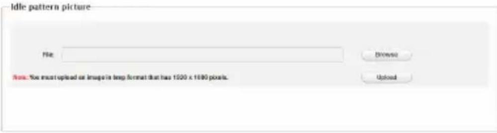
Figure 4-5. Idle Pattern Picture page.
Table 4-5. Idle Pattern Picture page elements.e
| GUI Element Description | |
| Idle pattern picture | Indicates the Idle Pattern Picture page where you can set the VS-2000-DEC and output to the display when no active source is available. |
| File Shows the uploaded image location on your local computer. | |
| Browse Browses for an image on your local computer.NOTE: You must upload an image in bmp format that has 1920 x 1080 pixels. | |
| Upload Uploads the local image to the VS-2000-DEC. | |
4.3.5 Upgrade Page
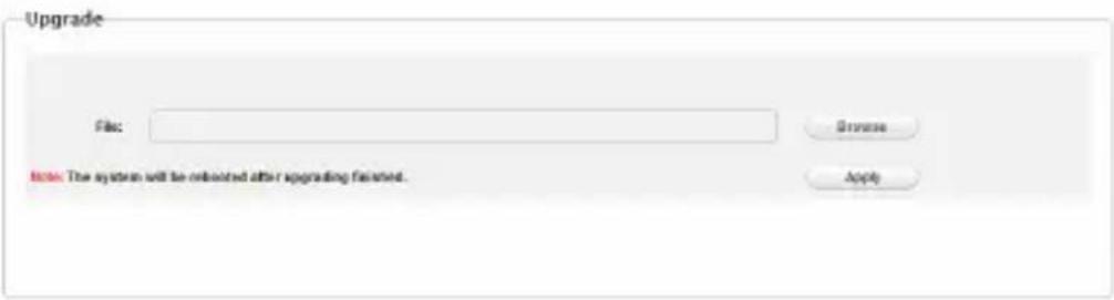
Figure 4-6. Upgrade page.
Table 4-6. Upgrade page elements.
| GUI Element Description | |
| Upgrade Indicates the Upgrade page where you can upgrade VS-2000-DEC to another version. | |
| File Shows the upgrade file location on your local computer. | |
| Browse Browses for an upgrade file on your local computer. | |
| Apply Saves the current settings and applies them to the VS-2000-DEC.NOTE: VS-2000-ENC reboots automatically to make the settings take effect after upgrade process has completed. |
4.3.6 Version Info Page

Figure 4-7. Version Info page.
Table 4-7. Version Info page elements.
| GUI Element Description | |
| Version info Indicates the Version Info page where you can view the device information | |
| Model Indicates the device model. | |
| Version Indicates the device version. | |
| Build Time Indicates the time and date when the device software was built. |
4.3.7 Commands Page

Figure 4-8. Commands page.
Table 4-8. Commands page elements.
| GUI Element Description | |
| Commands Indicates the Commands page where you can reboot and restore VS-2000-DEC to its factory defaults. | |
| Locate Device Locates the device. | |
| Reboot Reboots VS-2000-DEC. | |
| Reset to Factory Default. | Restores VS-2000-DEC to its factory defaults. |
A.1 Introduction
The decoder offers one Ethernet port LAN, which allows you to control and manage this device via API commands.
A.2 Preparation
A third-party device is required to be connected to the VS-2000-DEC network and to log in to the decoder before implementing API commands to control and manage it. In this section, a command line interface (CLI) on Windows 7 is used as an example. You may also use other third-party devices. For more information, see below.
A.2.1 Setting the IP Address on Your Computer
First ensure that your computer with CLI and VS-2000-DEC are on the same subnet. By default, network settings in VS-2000-DEC's LAN (PoE) port are 192.168.10.253/255.255.0.0. You can set your computer's IP address in the 192.168.10.x range with a subnet mask of 255.255.0.0.
A.2.2 Enabling Telnet Client
After setting your computer with CLI and VS-2000-DEC to be on the same subnet, make sure that Telnet Client is enabled on your computer. By default, a Telnet Client is disabled on Windows 7. To turn on a Telnet Client, do as follows:
- Choose Start > Control Panel > Programs.
- In Programs and Features area box, click Turn Windows features on or off.
- In Windows Features dialog box, select Telnet Client check box.
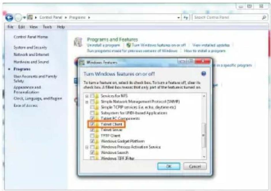
Figure A-1. Windows features dialog box
A.2.3 Logging In to the Decoder via a Command-Line Interface
Now you can log in to the CLI by performing the procedures in the order presented.
- Choose Start > Run.
- In the Run dialog box, enter cmd then click OK.
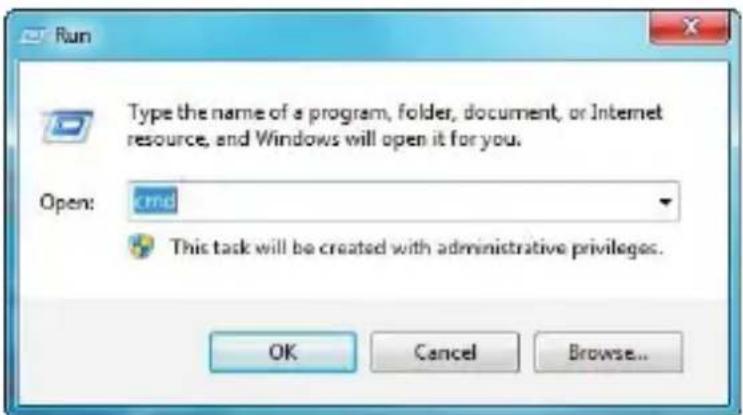
Figure A-2. Run dialog box
- Enter telnet 192.168.10.253 24, and then press Enter.
NOTE: 192.168.10.253 is the VS-2000-DEC's defaultIP address and may vary depending on the actual settings. 24 is the default port number.
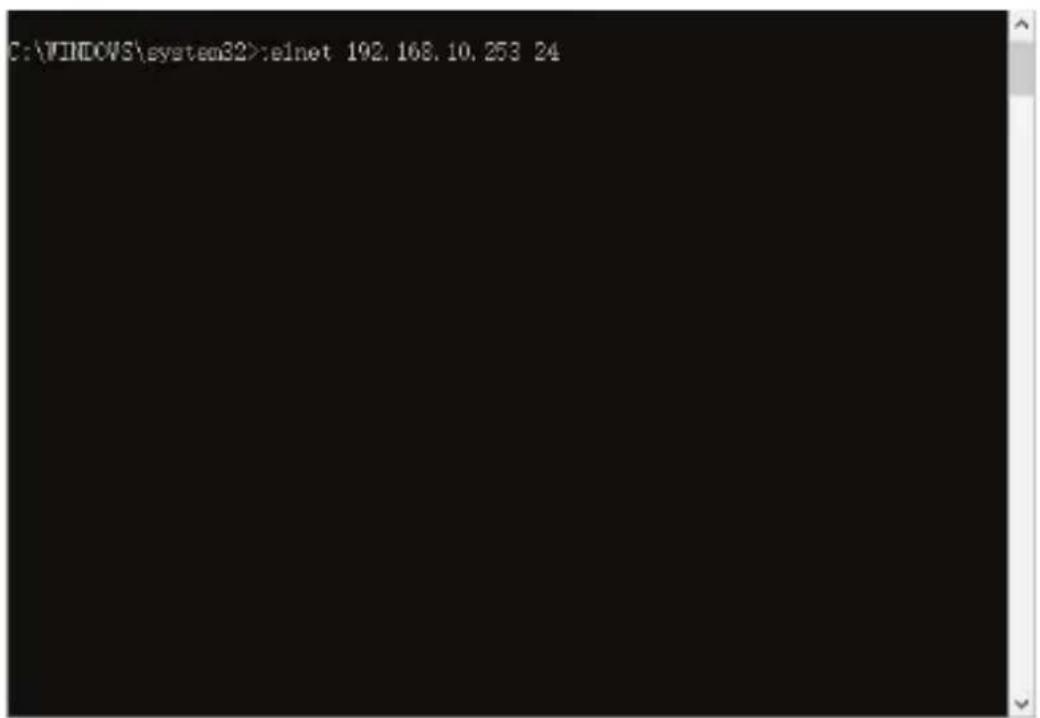
Figure A-3. Telnet screen
- Enter root, and then press Enter.
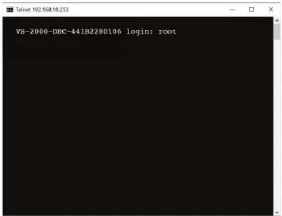
Figure A-4. login screen
- Use the command line interface below to perform API commands.
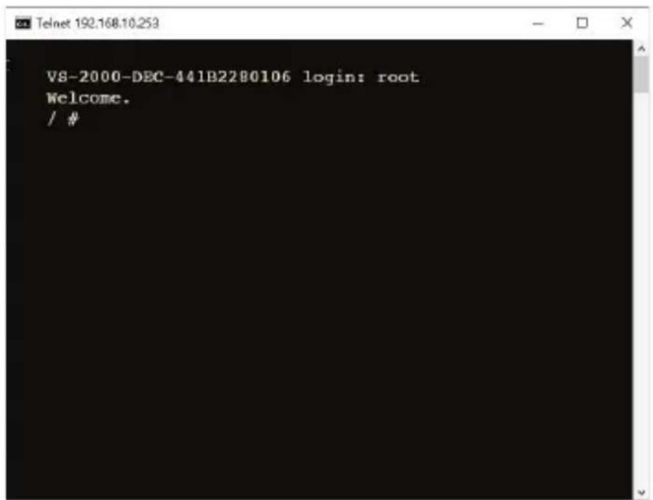
Figure A-5. Command-Line Interface screen
A.3 Commands Overview
A.3.1 gbconfig command
A script file named "gbconfig" is responsible for most of the API commands and is invoked as a console command. By assigning different arguments to this script file via API commands, a third party device can query and alter the decoder's configurations.
The following table lists all the gbconfig commands in this guide.
Table A-1. gbconfig commands summary
| Command Description | |
| gbconfig --name Configures the decoder name. | |
| gbconfig --ip-mode Configures the IP mode by which the decoder acquires an IP address | |
| gbconfig --ip4-addr Configures an IP address with static IP mode | |
| gbconfig --net-mask Configures the subnet mask with static IP mode | |
| gbconfig --gateway-ip Configures the gateway with static IP mode | |
| gbconfig —network-url Configures the URL the decoder plays, or the IP address of the encoder from which the decoder receives a media stream | |
| gbconfig -s, --show Queries the response of a implemented API command or the current state of configuration | |
| gbconfig -h, --help Shows a brief introduction to the gbconfig command sets | |
| gbcontrol --blink-led Control the decoder to twinkle the status indicator | |
A.3.2 gbcontrol command
A script file named "gbcontrol" is responsible for some API commands and is invoked as a console command. By assigning different arguments to this script file via API commands, a third-party device can control the decoder.
The following section lists all the gbcontrol commands in this guide.
A.4 gbconfig Command Set
NOTE: In this guide, " " represents a carriage return and a line feed input manually.
A.4.1 gbconfig -name
| Request gbconfig | --name namestring |
| Response Returns | nothing |
| Description Configures the decoder name, which is displayed and used after bonjour automatic discovery of the decoder. Reboot decoder for this operation to take effect. The default device name is "VS-2000-DECXXXXXXXXXXXX" in which "XXXXXXXXXXX" is the decoder MAC address. | |
NOTE: "namestring" can only include letters, digits, "-" (hyphen) and "_" (underscore).
Example:
To change the device name to "MyVS-2000-DEC-000", do as follows.
Request: gbconfig --name MyVS-2000-DEC-000
Response: [Returns nothing]
A.4.2 gbconfig --ip-mode
| Request gbconfig | --ip-mode {static/dhcp} |
| Response Returns | nothing |
| Description Configures the IP mode by which the decoder acquires an IP address. The decoder supports static IP and DHCP modes and is set to static IP by default. Reboot the decoder for this operation to take effect. | |
NOTES:
- "static" sets the decoder to static IP. "dhcp" sets the decoder to DHCP.
- To ensure that the decoder works properly using static IP, correctly set its IP address and subnet mask.
- To ensure that the decoder works properly using DHCP, an available DHCP server is required on the network to assign an IP address to the decoder.
Example:
To set the decoder to DHCP, do as follows.
Request: gbconfig --ip-mode dhcp
Response: [Returns nothing]
A.4.3 gbconfig --ip4-addr
| Request gbconfig | --ip4-addr ip4addr |
| Response Returns | nothing |
| Description | Configure an IP address with static IP mode. This configuration is used in static IP mode and takes effect after the decoder is rebooted. |
NOTE: "ip4addr" is the decoder's IP address. The default is 192.168.10.253.
Example:
To assign IP address 192.168.2.11 to the decoder, do as follows.
Request: gbconfig --ip4-addr 192.168.2.11
Response: [Returns nothing]
A.4.4 gbconfig --net-mask
| Request gbconfig | --net-mask netmask |
| Response Returns | nothing |
| Description Configures the subnet mask with a static IP mode. This configuration is used in static IP mode and takes effect after the decoder is rebooted. | |
NOTE: "netmask" is the decoder's subnet mask. The default is 255.255.0.0.
Example: To assign subnet mask 255.255.255.0 to the decoder, do as follows.
Request: gbconfig --net-mask 255.255.255.0
Response: [Returns nothing]
A.4.5 gbconfig --gateway-ip
| Request gbconfig | --gateway-ip gateway |
| Response Returns | nothing |
| Description | Configures the gateway with static IP mode. This configuration is used in static IP mode and takes effect after the decoder is rebooted. |
NOTE: "gateway" is the decoder's gateway. The default is blank.
Example: To assign gateway 192.168.1.1 to the decoder, do as follows.
Request: gbconfig – gateway- ip 192.16 8 .1.1
Response: [Returns nothing]
A.4.6 gbconfig --network-url
| Request gbconfig | --encoder-ip {encoderip4addr|mediaURL} |
| Response Returns | nothing |
| Description Configures the URL the decoder plays, or the IP address of the encoder from which the decoder receives a media stream. | |
NOTE: "encoderip4addr" is the IP address of the encoder from which the decoder receives media stream. "mediaURL" is the multicast address of the media stream. The decoder will decide how to use this configuration according to the class of the designated IP address.
The default is 192.168.10.254, namely, the default IP address of VS-2000-ENC.
Example: To receive a media stream from the encoder whose IP address is 192.168.1.33, do as follows.
Request: gbconfig --network-url 192.168.1.33
Response: [Returns nothing]
A.4.7 gbconfig -s
| Request gbconfig | {-s/--show} param |
| Response Returns | a response based on the actual configuration |
| Description Queries | the response of a implemented API command or the current state of configuration. |
NOTES:
- Either "-s" or "--show" is available for use. "-s" is short for "--show" for easy operation.
- "param" is the name of a configuration item such as "--name" in "gbconfig --name".
Example: To query the decoder's name, do as follows.
Request: gbconfig -s ----name
Response: MyVS-2000-DEC
A.4.8 gbconfig -h
| Request gbconfig | {-h/--help} |
| Response A brief | introduction to the gbconfig command sets.NOTE: Either "-h" or "--help" is available for use. "-h" is short for "--help" for easy operation. |
| Description Shows | a brief introduction to the gbconfig command sets |
Example: To show a brief introduction to the gbconfig command sets, do as follows.
Request: gbconfig -h
Response:
Usage: gbconfig [options]
Options:
--name=[VALUE] localname for bonjour
--ip-mode[=VALUE] [dhcp/static]
--ip4-addr[=VALUE] ip4 addr
--net-mask[=VALUE] ip4 netmask
--gateway-ip [=VALUE] gateway ip
--encoder-ip [=VALUE] encoder ip addr
-s, --show show the value for the specified items
-h, --help show this message Example:
gbconfig --name MyEncoder
gbconfig --ip-mode=static --ip4-addr=192.168.1.11 --net-mask=255.255.0.0
gbconfig -s --name
gbconfig --show --ip4-addr --net-mask
A.5 gbcontrol Command Set
A.5.1 gbcontrol --blink-led
| Request gbcontrol | --blink-led |
| Response Returns | nothing |
| Description Control | the decoder to flash the status indicator. Once it receives this command, the decoder will flash its status indicator with the frequency of 5 Hz during the following 10 seconds. This feature is designed for the user to find the physical position of a certain decoder. |
Example: To make the decoder flash the LED, do as follows.
Request: gbcontrol --blink-led
Response: [Returns nothing]
Black Box Tech Support: FREE! Live. 24/7.
Tech support the way it should be.

natural_image
Close-up portrait of a smiling man with hand near ear (no text or symbols visible)Great tech support is just 60 seconds away at 877-877-2269 or blackbox.com.

BLACK BOX®
About Black Box
Black Box provides an extensive range of networking and infrastructure products. You'll find everything from cabinets and racks and power and surge protection products to media converters and Ethernet switches all supported by free, live 24/7 Tech support available in 60 seconds or less.
© Copyright 2017. Black Box Corporation. All rights reserved. Black Box ^® and the Double Diamond logo are registered trademarks of BB Technologies, Inc. Any third-party trademarks appearing in this white paper are acknowledged to be the property of their respective owners.
vs-2000-dec_user_rev2_a6
- FEDERAL COMMUNICATIONS COMMISSION AND INDUSTRY CANADA RADIO FREQUENCY INTERFERENCE STATEMENTS
- Trademarks Used in this Manual
- Table of Contents
- Overview
- Introduction
- Features
- What's Included
- Hardware Description
- Hardware Installation
- Operation
- Logging In to the Web-based Configuration Page
- Introduction to Functions Page
- Stream Page
- Introduction to System Page
- Device Name Page
- Network Page
- Password Page
- Idle Pattern Picture Page
- Upgrade Page
- Version Info Page
- Commands Page
- A.1 Introduction
- A.2 Preparation
- A.2.1 Setting the IP Address on Your Computer
- A.2.2 Enabling Telnet Client
- A.2.3 Logging In to the Decoder via a Command-Line Interface
- A.3 Commands Overview
- A.3.1 gbconfig command
- A.3.2 gbcontrol command
- A.4 gbconfig Command Set
- A.4.1 gbconfig -name
- Example:
- A.4.2 gbconfig --ip-mode
- NOTES:
- A.4.7 gbconfig -s
- Black Box Tech Support: FREE! Live. 24/7.
- BLACK BOX®
- About Black Box
Brand : Black Box
Model : VS2000
Category : Digital decoder