
CDX10 - Thin Client ASUS - Free user manual and instructions
Find the device manual for free CDX10 ASUS in PDF.

| Product Type | Thin Client |
| Brand | ASUS |
| Model | CDX10 |
| Max Resolution | 1920 x 1200 @ 60Hz |
| Power Consumption (ON) | < 22 W |
| Power Consumption (Off) | < 0.5 W |
| Power Consumption (Wake on LAN) | < 1.2 W |
| Voltage Rating | AC 100-240V (External) |
| Physical Dimensions (WxHxD) | 135 x 204.8 x 84 mm |
| Net Weight (Est.) | 0.6 kg |
| Mounting Interface | 100mm x 100mm & 75mm x 75mm |
| Supported Protocols | Citrix HDX, Microsoft RemoteFX, VMware PCoIP |
| Connectivity | DVI-D, COM, RJ-45, USB (front & rear), Earphone-out, Mic-in |
| Audio | Earphone-out and microphone input |
| Kensington Lock | Yes (rear) |
| Power Button | Yes (front) |
| Wall Mountable | Yes (100x100mm or 75x75mm) |
| Included Accessories | Box set, wall mount, base & screw, quick start guide, warranty card, adapter, DVI cable |
| Cleaning | Use lint-free non-abrasive cloth; avoid alcohol/acetone; do not spray cleaner directly |
| Safety | Use only specified AC/DC adapter; do not open cabinet; unplug during lightning storms |
| Power Adapter Model | AD891M21010ALF & AD891M21210ALF |
Frequently Asked Questions - CDX10 ASUS
User questions about CDX10 ASUS
0 question about this device. Answer the ones you know or ask your own.
Ask a new question about this device
Download the instructions for your Thin Client in PDF format for free! Find your manual CDX10 - ASUS and take your electronic device back in hand. On this page are published all the documents necessary for the use of your device. CDX10 by ASUS.
USER MANUAL CDX10 ASUS
natural_image
Line drawing of a wireless router device with visible ports and branding (no text or symbols beyond branding)Table of contents
Notices...... iv
Safety information ...... v
Care and cleaning...... vi
1.1 Welcome 1-1
1.2 Package contents.... 1-1
1.3 Assembling the zero client box 1-2
1.4 Zero client introduction.... 1-4
1.4.1 Front of the box....1-4
1.4.2 Rear of the box 1-5
1.4.3 Get start with client system.... 1-6
1.4.4 Client Indicator Behavior....1-6
2.1 CLIENT BOX SYSTEM....2-1
2.1.1. Login Widget....2-1
2.1.2. Desktop Mode....2-7
2.1.3. Client Network IP Setting 2-16
3.1 Specifications.... 3-1
3.2 Trouble shooting (FAQ) 3-2
3.3 Supported Timing List.... 3-3
Copyright © 2014 ASUSTeK COMPUTER INC. All Rights Reserved.
No part of this manual, including the products and software described in it, may be reproduced, transmitted, transcribed, stored in a retrieval system, or translated into any language in any form or by any means, except documentation kept by the purchaser for backup purposes, without the express written permission of ASUSTeK COMPUTER INC. ("ASUS").
Product warranty or service will not be extended if: (1) the product is repaired, modified or altered, unless such repair, modification of alteration is authorized in writing by ASUS; or (2) the serial number of the product is defaced or missing.
ASUS PROVIDES THIS MANUAL "AS IS" WITHOUT WARRANTY OF ANY KIND, EITHER EXPRESS OR IMPLIED, INCLUDING BUT NOT LIMITED TO THE IMPLIED WARRANTIES OR CONDITIONS OF MERCHANTABILITY OR FITNESS FOR A PARTICULAR PURPOSE. IN NO EVENT SHALL ASUS, ITS DIRECTORS, OFFICERS, EMPLOYEES OR AGENTS BE LIABLE FOR ANY INDIRECT, SPECIAL, INCIDENTAL, OR CONSEQUENTIAL DAMAGES (INCLUDING DAMAGES FOR LOSS OF PROFITS, LOSS OF BUSINESS, LOSS OF USE OR DATA, INTERRUPTION OF BUSINESS AND THE LIKE),
EVEN IF ASUS HAS BEEN ADVISED OF THE POSSIBILITY OF SUCH DAMAGES ARISING FROM ANY DEFECT OR ERROR IN THIS MANUAL OR PRODUCT.
SPECIFICATIONS AND INFORMATION CONTAINED IN THIS MANUAL ARE FURNISHED FOR INFORMATIONAL USE ONLY, AND ARE SUBJECT TO CHANGE AT ANY TIME WITHOUT NOTICE, AND SHOULD NOT BE CONSTRUED AS A COMMITMENT BY ASUS. ASUS ASSUMES NO
RESPONSIBILITY OR LIABILITY FOR ANY ERRORS OR INACCURACIES THAT MAY APPEAR IN THIS MANUAL, INCLUDING THE PRODUCTS AND SOFTWARE DESCRIBED IN IT.
Products and corporate names appearing in this manual may or may not be registered trademarks or copyrights of their respective companies, and are used only for identification or explanation and to the owners' benefit, without intent to infringe.
Notices
Federal Communications Commission Statement
This device complies with Part 15 of the FCC Rules. Operation is subject to the following two conditions:
• This device may not cause harmful interference, and
- This device must accept any interference received including interference that may cause undesired operation.
This equipment has been tested and found to comply with the limits for a Class B digital device, pursuant to Part 15 of the FCC Rules. These limits are designed to provide reasonable protection against harmful interference in a residential installation. This equipment generates, uses and can radiate radio frequency energy and, if not installed and used in accordance with manufacturer's instructions, may cause harmful interference to radio communications. However, there is no guarantee that interference will not occur in a particular installation. If this equipment does cause harmful interference to radio or television reception, which can be determined by turning the equipment off and on, the user is encouraged to try to correct the interference by one or more of the following measures:
• Reorient or relocate the receiving antenna.
- Increase the separation between the equipment and receiver.
- Connect the equipment to an outlet on a circuit different from that to which the receiver is connected.
- Consult the dealer or an experienced radio/TV technician for help.
Canadian Department of Communications Statement
This digital apparatus does not exceed the Class B limits for radio noise emissions from digital apparatus set out in the Radio Interference Regulations of the Canadian Department of Communications.
This class B digital apparatus complies with Canadian ICES-003.
Warning: This zero client complies with the EMC directive only when you use a shielded Ethernet cable.
Safety information
Use only the AC/DC adapter model: AD891M21010ALF&AD891M21210ALF
- Before setting up the box, carefully read all the documentation that came with the package.
- To prevent fire or shock hazard, never expose the zero client to rain or moisture.
- Never try to open the zero client cabinet. The dangerous high voltages inside the zero client may result in serious physical injury.
- If the power supply is broken, do not try to fix it by yourself. Contact a qualified service technician or your retailer.
- Before using the product, make sure all cables are correctly connected and the power cables are not damaged. If you detect any damage, contact your dealer immediately.
- Slots and openings on the back or top of the cabinet are provided for ventilation. Do not block these slots. Never place this product near or over a radiator or heat source unless proper ventilation is provided.
- The zero client should be operated only from the type of power source indicated on the label. If you are not sure of the type of power supply to your home, consult your dealer or local power company.
- Use the appropriate power plug which complies with your local power standard.
- Do not overload power strips and extension cords. Overloading can result in fire or electric shock.
- Avoid dust, humidity, and temperature extremes. Do not place the zero client in any area where it may become wet. Place the zero client on a stable surface.
- Unplug the unit during a lightning storm or if it will not be used for a long period of time. This will protect the zero client from damage due to power surges.
- Never push objects or spill liquid of any kind into the slots on the zero client cabinet.
- The socket-outlet shall be installed near the equipment and shall be easily accessible.
- If you encounter technical problems with the zero client, contact a qualified service technician or your retailer.
Care and cleaning
- Before you lift or reposition your zero client, it is better to disconnect the cables and power cord. Follow the correct lifting techniques when positioning the zero client. When lifting or carrying the zero client, grasp the edges of the zero client. Do not lift the zero client by the stand or the cord.
- Cleaning. Turn your zero client off and unplug the power cord. Clean the zero client surface with a lint-free, non-abrasive cloth. Stubborn stains may be removed with a cloth dampened with mild cleaner.
- Avoid using a cleaner containing alcohol or acetone. Use a cleaner intended for use with the screen. Never spray cleaner directly on the screen, as it may drip inside the zero client and cause an electric shock.
The following symptoms are normal with the zero client :
- The screen may flicker during the initial use due to the nature of the fluorescent light. Turn off the power switch and turn it on again to make sure that the flicker disappears.
- You may find slightly uneven brightness on the screen depending on the desktop pattern you use.
- When the same image is displayed for hours, an afterimage of the previous screen may remain after switching the image. The screen will recover slowly or you can turn off the power switch for hours.
- When the screen becomes black or flashes, or cannot work anymore, contact your dealer or service center to fix it. Do not try to repair the zero client by yourself!
Conventions used in this guide

WARNING: Information to prevent injury to yourself when trying to complete a task.

CAUTION: Information to prevent damage to the components when trying to complete a task.

IMPORTANT: Information that you MUST follow to complete a task.

NOTE: Tips and additional information to aid in completing a task.
Where to find more information
Refer to the following sources for additional information and for product and software updates.
1. ASUS websites
The ASUS websites worldwide provide updated information on ASUS hardware and software products. Refer to http://www.asus.com
2. Optional documentation
Your product package may include optional documentation that may have been added by your dealer. These documents are not part of the standard package.
1.1 Welcome
Thank you for purchasing the ASUS® zero client box.
The latest zero client box from ASUS delivers you a seamless desktop and viewing experiences.
Please enjoy the convenient and delightful experience that the zero client brings to you!
1.2 Package contents
Check your package for the following items:
√ Box set
√ Wall mount
√ Base and screw
√ Quick start guide
√ Warranty card
√ Adapter
√ DVI Cable

- If any of the above items is damaged or missing, contact your retailer immediately.
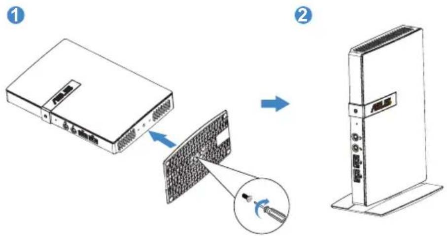
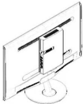
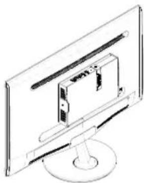
1.3 Assembling the zero client box
1. Use Base Assembly
- Attach the base to the box and fix with the screw to join them tightly. You can easily tighten the screw by screw driver.
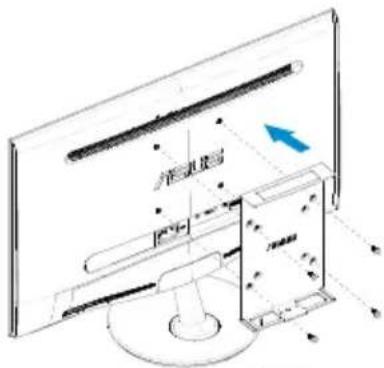
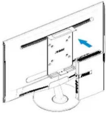
2. Use Wall mount Assembly
- Attach the wall mount to the back of display and fix with the screw to join them the tightly.
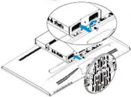
- Snap the box into the wall mount (You can use 100x100mm or 75x75mm two modes to lock it).
1
2
natural_image
Line drawing of a computer monitor with an open screen and a blue arrow indicating the left side (no text or symbols present)3
natural_image
Isometric diagram of a computer monitor with an inset showing a close-up of the screen (no text or symbols present)4
natural_image
Line drawing of a flat-screen monitor with a central screen and stand (no text or symbols)or
natural_image
Line drawing of a computer monitor with an internal device, no text or symbols present1.4 Zero client introduction
1.4.1 Front of the box
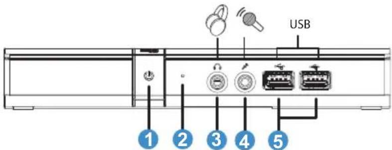
- Power Indicator:
• The color of power indicator is as below.
- Client Link LED Indicator:
- The color of client link LED Indicator is as below.
| Status description | ||
| LED1 White Client power on | ||
| LED1 Dark Power off | ||
| LED2 Green | blinking | RJ-45 jack is connected |
- Earphone-out
- Microphone input
- USB connector
1.4.2 Rear of the box
- Kensington lock
- Power-in jack
- USB connector
- RJ45
- DVI-D
- COM (*1)
*1. COM port pin define
| Pin No Description Pin No Description | ||
| 1 N/A 6 N/A | ||
| 2 TxD(Transmit Data) signal | 7 N/A | |
| 3 RxD(Receive Data) signal | 8 N/A | |
| 4 N/A 9 N/A | ||
| 5 Ground | ||
1.4.3 Get start with client system
| Key Description | |
| Power Press this button to turn on/off the zero client box | |
1.4.4 Client Indicator Behavior
| Status POWER LINK | ||
| Power On White Off | ||
| Power Off Off Off | ||
| Power On and RJ-45jack is connected | White Green blinking |
2.1 CLIENT BOX SYSTEM
Box Power Control
- Shortly press Power key to turn it on.
- Click "Power Off" button in client system interface to turn off the client by SW.
- Hold Power key for 4 seconds to force turn it off.
- When AC power plugs in, box power LED will be lighted up for 1 second and then be turned off. This action sets WOL function ready and powers down the box.
- USB ports do not provide 5V standby power at box DC Off mode.
2.1.1. Login Widget
Simply login to virtual desktop with default connection setting.
2.1.1.1. VDI Login Screen
| Label Description | |
| Protocol Select the connection protocol type. “Citrix HDX”, “Microsoft RemoteFX”, “VMware PCoIP” are provided in this option. | |
| Server IP Input remote server IP address the user connects to.(maximum input length: 100 characters) | |
| Username Input the user account name.(maximum input length: 30 characters) | |
| Password Input the user account password.(maximum input length: 30 characters) | |
| Domain Input the remote server domain name.(maximum input length: 30 characters) | |
| * Indicate this column is required in current protocol type. | |
 | Click on this button will save current account information and protocol type as default values. |
| Login Press | this button will pass the connection information to remote server and login VDI by different protocol way:Citrix HDX: show the Citrix VDI/App list.VMware PCoIP: switch to VMware automatic login screen.Microsoft RemoteFX: video output will be changed to 1280x1024 mode. If the NLA certification request of server IP is already accepted, it will continue verify the account information and then login VDI. Or it will show the certificate warning message. |
* Note about display setting with VDI connection:
Changing screen resolution setting should be done at local Client. Dynamically modify display setting in VDI will not be applied. Users can logout from VDI first and change display settings at local side. While user login VDI at next time, connection agent will adapt VDI display configuration to local side settings.
* Note about connection to citrix:
Connection to citrix server when the network is disconnect. Client system will pop up a dialog box to notify the status. You must response to the "Quit" button to disconnect from server. The dialog box will hide when you click the desktop window. You could disconnect from citrix server by clicking "Esc", "Enter" or "Spacebar" key.

2.1.1.2. Status Row

Wed Mar 26 17:09 2014
| Icon / Text Description | |
| The displayed icon will only express network cable connection status. “Cross” showing when the cable is loose / plugged out. | |
| Wed Mar 26 17:09 2014 | This column shows local client system date and time. User can update this date / time in Time setting window. |
2.1.1.3. Menu Items

natural_image
Row of five software icons: power button, speaker, gear, wrench, and info (no text or symbols)| Menu Item Description | |
 | Open “Power” menu. It includes “Reboot”, “Power Off”, “Close” and “Quit” option. User can switch to Desktop mode by “Quit” option. |
 | Open “Volume Control Tool” to set system audio output volume. The icon will be changed if volume is set to zero. |
 | Open “Client Setup” window. It provides “Desktop”, “Display”, “Keyboard”, “Mouse”, “Network”, “Login Widget”, “Time” setting functions. |
 | Open “Network Test Tool” to test if network connection is working. |
 | Open “System Information” window. It will display network, hardware and software information of client system. |
- Power menu
| Label Description | |
| Reboot Restart the local client system. | |
| Power Off Shutdown the local client system. | |
| Close Close “Power” menu. | |
| Quit Switch to Desktop mode. | |
• Volume Control tool
| Label Description | |
| (Volume bar) The level value is from 0 to 100. | |
- Client Setup window
• Network Test tool
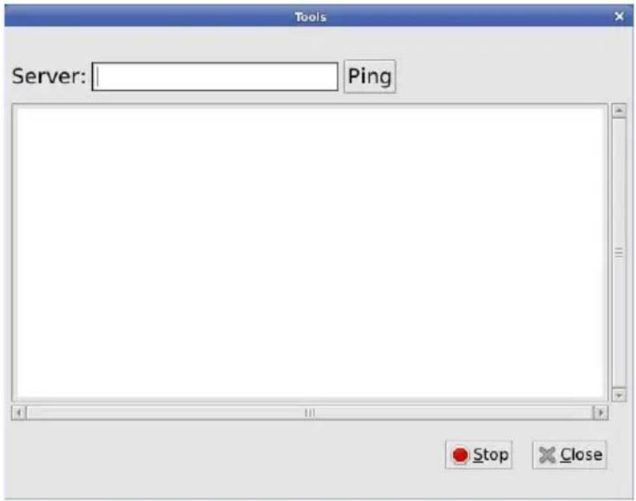
| Label Description | |
| Server Input | ut the server IP to test if network connection is working.(maximum input length: 20 characters) |
| Ping Start | “ping” action. The ping result will be printed in below text area. |
| Stop Stop | “ping” action. |
| Close Close | e network test tool. |
2.1.2. Desktop Mode
In the Desktop mode, user can create shortcuts on desktop by connection manager and simply double click the shortcut to log in virtual desktop / remote applications. Advance options can be adjusted in each shortcut for different user scenarios. In client setup, several functions are provided to administrator for advance control.
![START Menu Login Widget Information Settings Reboot Power Off START / [medR - Aome/use...] (Display) [user@Client: AusrIs...] [user@Client: ~R] [user@Client: ~] Status Row 11.37](/content/2026/05/790358/images/999fb27490483050b62bb8e3efe69bcb74415ec71d000d2fcc0aa1ca1f74d2ca.jpg)
2.1.2.1. START Menu
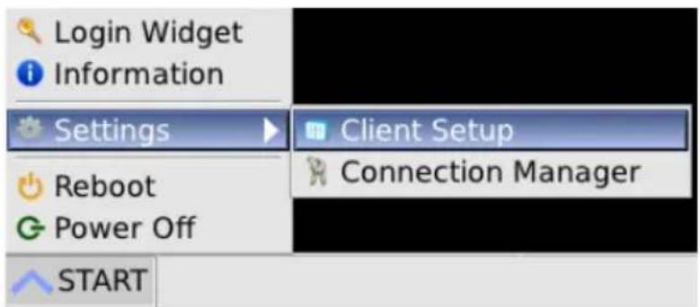
| Menu Item Description | |
| Login Widget | Switch to Login Widget mode. |
| Information Display software information of client system. | |
| Settings Expand submenu items: “Connection Manager” and “Client Setup”. Please refer descriptions for each item below. | |
| Reboot Reboot the client system. | |
| Power Off Shutdown the client system. | |
| START Open | “START menu”. |
2.1.2.2. Status Row

| Icon / Text Description | |
 | The displayed icon will express network cable connection status. “Cross” showing when the cable is loose / plugged out. |
 | Open volume bar to set system audio output volume. The icon will be changed if volume is set to zero. |
| 16:16 | This column shows local client system date and time. User can update this date / time in Time setting window. |
2.1.2.3. Connection Manager
In the “Applications” page, add/edit/delete connection shortcuts of Microsoft RemoteFX, Citrix HDX and VMware PCoIP, and setup advance options of each corresponding protocol. In the “Devices” page, global settings for VDI/App connections are listed here. Currently sound recording settings are available.
- Applications
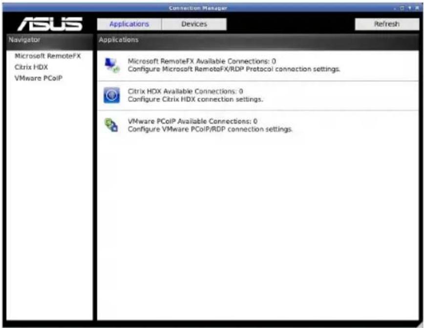
| Label Description | |
| Applications Display | “Applications” page. |
| Devices Display “Devices” page. | |
| Refresh Reload connection status which may be modified by “Device Manager”. | |
| “Navigator” list Add/Delete connection lists on different protocol. | |
| “Applications” list Display statistics of 3 protocol connections.Click on each protocol row will also switch to the connection list of corresponding protocol. | |
*1. Characters cannot be used in connection name: \~ `! @ # \$ % ^ & * ( )
+ = {} [ ] | \ : ; “ < , > . ? /
*2. The space character and the following characters cannot be used in server address: \~ `! @ # \$ % ^ & * ( ) + = {} [ ] | \; “‘ < , > ? /
• Devices
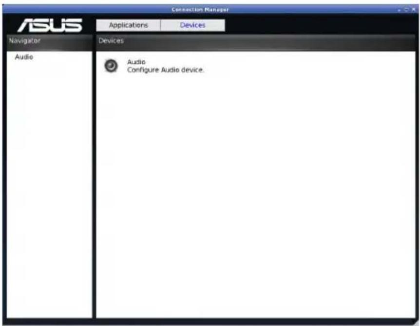
| Label Description | |
| Applications Display “Applications” page. | |
| Devices Display “Devices” page. | |
| “Navigator” list | Click on each item will switch to the corresponding setting page. |
| “Devices” list | Display global setting items. Every setting in “Devices” page will affect VDI/App of all protocols.Click on each setting row will also switch to the setting page. |
2.1.2.4. Client Setup
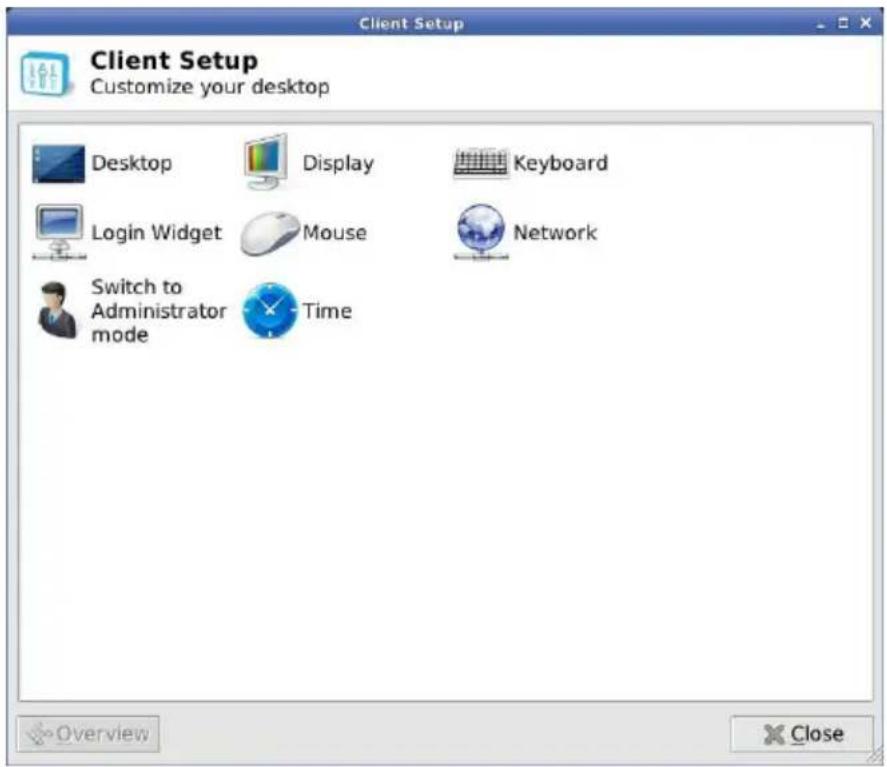
| Item Description | |
| Desktop (*1) | Switch to “Desktop” setting window to change wallpaper, client name and client system language. |
| Display (*1) | Switch to “Display” setting window to set screen resolution or dual display mode. |
| Keyboard (*1) | Switch to “Keyboard” setting window to set keyboard setting and layout. |
| Mouse (*1) S | Switch to “Mouse” setting window to set mouse setting. |
| Network Switch | to “Network” setting window to set LAN network connection. |
| Login Widget | Switch to “Login Widget” setting window to enable/disable auto-start Login Widget interface. |
| Time Switch | to “Time” setting window to set system date/time and time zone. |
| Switch to Administrator mode | Switch to administrator mode menu for advance functions. Need input administrator password to pass through authentication. (*2) |
| Overview Go | back to “Client Setup” menu. It is locked here. |
| Close Close | “Client Setup” window. |
*1. Some settings need time to write setting value to configuration files (normally about 5 seconds). If user shuts down the client just after changes these settings, such as AC off, the modified setting values may be lost.
*2. The default administrator password is "1234".
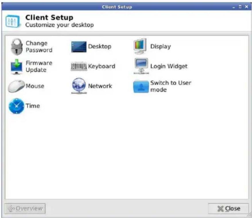
| Item Description | Please refer user mode descriptions. |
| Desktop (*1) | |
| Display (*1) | |
| Keyboard (*1) | |
| Mouse (*1) | |
| Network | |
| Login Widget | |
| Time | |
| Change Password (*3) | Switch to “Change Password” setting window to change administrator password. |
| Firmware Update (*3) | Switch to “Firmware Update” window to update client firmware/software. |
| Switch to User mode (*3) | Switch back to user mode menu. |
*3. This function is only available in administrator mode.
- Display setting window
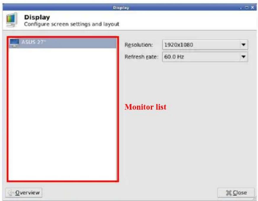
*1. DVI-D output does not have hotplug EDID detection function. System only enables DVI-D output if user plugs in DVI-D cables before client boot up.
*2. Change resolution of refresh rate will pop up confirmation window. If user does not click "confirm" button in 10 seconds, the display setting will be restored.
- Firmware Update window
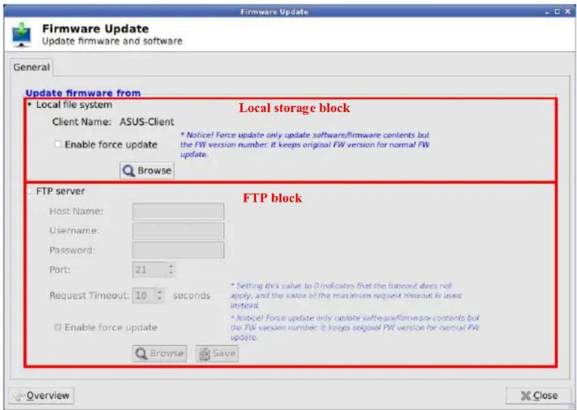
| Label | Description |
| [Local storage block] | |
| Local file system | Select this item to enable “update from local storage” block. |
| Enable force update | Check this option to enable force update mode. Force up-date does not check firmware version and update only the content files but the firmware version number. |
| Browse Click | this button will call the file selection window to let administrator select update files. After update files are chosen, firmware update process will start validating chosen files and updating firmware/software. |
| [FTP block] | |
| FTP server S | Select this item to enable “update from FTP” block. |
| Host Name Input | FTP server IP. |
| Username Input | put user name of FTP account. |
| Password Input | put password of FTP account. |
| Port Select FTP | port number. |
| Request Timeout | Adjust request timeout value. When administrator click “Browse” button, it will request FTP server to establish a connection. If the response time is larger than timeout value, the FTP connecting action will be aborted. |
| Enable force update | Please refer above description in “local storage block”. |
| Browse Click | this button will connect to FTP server and call the file selection window to let administrator select update files on FTP. After update files are chosen, firmware update process will download chosen files and start file validating step and updating firmware/software. |
| Save Click this | is button will store the setting values in FTP block as default values. |
2.1.3. Client Network IP Setting
• LAN setup
- DHCP setting
By default setting, client will request DHCP as local IP when client system boots up. User can check IP status in System Information window (in Login Widget mode) or in Network setting window (in Desktop mode). If the client IP is not correctly set, user can request DHCP again or set static IP.
• DHCP auto reconnect function
If network cable is dropped accidentally at DHCP connective status, local IP can be automatically requested again from DHCP server in 10 seconds when user plug in network cable.
- StaticIP
If static IP is preferred, user can manually set IP / Subnet Mask value to local client. Optionally user can also specify Default gateway and DNS IP.
Firewall limited
When use the client system make sure the firewall is not blocking access. If the functions list below can't work normally then check the firewall.
- Login to server
- FTP Firmware Update
- NTP Time Synchronize
- RM Device Manager (ACDM)
Notice:
Under the same operating system environment, using Apache to install another application that will cause ACDM work abnormal.
3.1 Specifications
| Model CDX10 | |
| Max. Resolution 1920 x 1200/60 | |
| Power ON Consumption ON Mode: | <22 W |
| Mic phone Yes | |
| Earphone Yes | |
| Power off < 0.5 W | |
| Power off and wake on LAN < 1.2 W | |
| Mounting Interface 100mm x 100mm & 75mm x 75mm | |
| Phys. Dimension (WxHxD) 135 x 204.8 x 84 mm | |
| Box Dimension (WxHxD) 195.6 x 31.2 x 130.5 mm | |
| Net Weight (Esti.) 0.6 kg | |
| Gross Weight (Esti.) 1.2 kg | |
| Voltage Rating AC 100~240V(External) |
3.2 Trouble shooting (FAQ)
| Problem Possible Solution | |
| Power LED is not ON | Press the button to check if the box is in the ON mode.Check if the power cord is properly connected to the box and the power outlet. |
3.3 Supported Timing List
| Resolution Refresh Rate | |
| 1920 x 1200 60Hz | |
| 1920 x 1080 60Hz | |
| 1680 x 1050 60Hz | |
| 1600 x 900 60Hz | |
| 1440 x 900 60Hz | |
| 1366 x 768 60Hz | |
| 1360 x 768 60Hz | |
| 1280 x 1024 60Hz | |
| 1280 x 960 60Hz | |
| 1280 x 800 60Hz | |
| 1280 x 768 60Hz | |
| 1280 x 720 60Hz | |
| 1024 x 768 60Hz | |
- Table of contents
- Notices
- Federal Communications Commission Statement
- Canadian Department of Communications Statement
- Safety information
- Use only the AC/DC adapter model: AD891M21010ALF&AD891M21210ALF
- Care and cleaning
- The following symptoms are normal with the zero client :
- Conventions used in this guide
- Where to find more information
- ASUS websites
- Optional documentation
- Welcome
- Package contents
- Assembling the zero client box
- Use Base Assembly
- Use Wall mount Assembly
- Zero client introduction
- Front of the box
- Rear of the box
- Get start with client system
- Client Indicator Behavior
- CLIENT BOX SYSTEM
- Box Power Control
- Login Widget
- VDI Login Screen
- Status Row
- Wed Mar 26 17:09 2014
- Menu Items
- - Power menu
- • Volume Control tool
- - Client Setup window
- • Network Test tool
- Desktop Mode
- START Menu
- Status Row
- Connection Manager
- - Applications
- • Devices
- Client Setup
- - Display setting window
- - Firmware Update window
- Client Network IP Setting
- Firewall limited
- Notice:
- Specifications
- Trouble shooting (FAQ)
- Supported Timing List
Brand : ASUS
Model : CDX10
Category : Thin Client