
DS-2DE7320IW-AE - Security Camera Hikvision - Free user manual and instructions
Find the device manual for free DS-2DE7320IW-AE Hikvision in PDF.


| Product Type | PTZ Speed Dome Security Camera |
| Brand | Hikvision |
| Model | DS-2DE7320IW-AE |
| Series | E Series Network Speed Dome |
| Video Resolution | 1280 x 720 (720p) |
| Video Compression | H.264 |
| Day/Night Function | Auto switch with IR cut filter |
| IR Illumination | Yes, configurable |
| PTZ Control | Pan, tilt, zoom, presets, patrol, pattern |
| Auto Flip | Yes, 180° horizontal flip when target passes under dome |
| Privacy Mask | Up to 8 programmable mask areas |
| Wide Dynamic Range (WDR) | Supported |
| Backlight Compensation (BLC) | Supported |
| 3D Positioning | Yes, via client software |
| Network Protocols | TCP/IP, DHCP, PPPoE, DDNS, SNMP, 802.1X, QoS, FTP, UPnP, HTTPS |
| Power Supply | SELV compliant adapter (typical 12V DC or PoE) |
| Power Consumption | Not less than required value (not specified) |
| Cleaning Instructions | Use soft dry cloth; avoid alkaline detergents |
| Operating Temperature | Refer to specification manual (not specified) |
| Security Features | User management, IP filter, HTTPS, 802.1X authentication, password strength enforcement |
| Maximum Users | 32 user accounts |
| Firmware Upgrade | Via web browser or client software |
Frequently Asked Questions - DS-2DE7320IW-AE Hikvision
User questions about DS-2DE7320IW-AE Hikvision
0 question about this device. Answer the ones you know or ask your own.
Ask a new question about this device
Download the instructions for your Security Camera in PDF format for free! Find your manual DS-2DE7320IW-AE - Hikvision and take your electronic device back in hand. On this page are published all the documents necessary for the use of your device. DS-2DE7320IW-AE by Hikvision.
USER MANUAL DS-2DE7320IW-AE Hikvision
text_image
HIKVISIONE Series Network Speed Dome
User Manual
UD.6L0201D1823A01
User Manual
COPYRIGHT © 2015 Hangzhou Hikvision Digital Technology Co., Ltd.
ALL RIGHTS RESERVED.
Any and all informaon, including, among others, wordings, pictures, graphs are the properes of Hangzhou Hikvision Digital Technology Co., Ltd. or its subsidiaries (hereinaer referred to be "Hikvision"). This user manual (hereinaer referred to be "the Manual") cannot be reproduced, changed, translated, or distributed, parally or wholly, by any means, without the prior written permission of Hikvision. Unless otherwise spulated, Hikvision does not make any warranes, guarantees or representaons, express or implied, regarding to the Manual.
About this Manual
This Manual is applicable to E Series Network Speed Dome.
The Manual includes instrucons for using and managing the product. Pictures, charts, images and all other informaon hereinaer are for descripon and explanaon only. The informaon contained in the Manual is subject to change, without noce, due to rmware updates or other reasons. Please end the latest version in the company website (hp://overseas.hikvision.com/en/).
Please use this user manual under the guidance of professionals.
Trademarks Acknowledgement
HIKVISION and other Hikvision's trademarks and logos are the properes of Hikvision in various jurisdicons. Other trademarks and logos menoned below are the properes of their respective owners.
Legal Disclaimer
TO THE MAXIMUM EXTENT PERMITTED BY APPLICABLE LAW, THE PRODUCT DESCRIBED, WITH ITS HARDWARE, SOFTWARE AND FIRMWARE, IS PROVIDED "AS IS", WITH ALL FAULTS AND ERRORS, AND HIKVISION MAKES NO WARRANTIES, EXPRESS OR IMPLIED, INCLUDING WITHOUT LIMITATION, MERCHANTABILITY, SATISFACTORY QUALITY, FITNESS FOR A PARTICULAR PURPOSE, AND NON-INFRINGEMENT OF THIRD PARTY. IN NO EVENT WILL HIKVISION, ITS DIRECTORS, OFFICERS, EMPLOYEES, OR AGENTS BE LIABLE TO YOU FOR ANY SPECIAL, CONSEQUENTIAL, INCIDENTAL, OR INDIRECT DAMAGES, INCLUDING, AMONG OTHERS, DAMAGES FOR LOSS OF BUSINESS PROFITS, BUSINESS INTERRUPTION, OR LOSS OF DATA OR DOCUMENTATION, IN CONNECTION WITH THE USE OF THIS PRODUCT, EVEN IF HIKVISION HAS BEEN ADVISED OF THE POSSIBILITY OF SUCH DAMAGES. REGARDING TO THE PRODUCT WITH INTERNET ACCESS, THE USE OF PRODUCT SHALL BE WHOLLY AT YOUR OWN RISKS. HIKVISION SHALL NOT TAKE ANY RESPONSIBILITES FOR ABNORMAL OPERATION, PRIVACY LEAKAGE OR OTHER DAMAGES RESULTING FROM CYBER ATTACK, HACKER ATTACK, VIRUS INSPECTION, OR OTHER INTERNET SECURITY RISKS; HOWEVER, HIKVISION WILL PROVIDE TIMELY TECHNICAL SUPPORT IF REQUIRED.
SURVEILLANCE LAWS VARY BY JURISDICTION. PLEASE CHECK ALL RELEVANT LAWS IN YOUR JURISDICTION BEFORE USING THIS PRODUCT IN ORDER TO ENSURE THAT YOUR USE CONFORMS THE APPLICABLE LAW. HIKVISION SHALL NOT BE LIABLE IN THE EVENT THAT THIS PRODUCT IS USED WITH ILLEGITIMATE PURPOSES.
IN THE EVENT OF ANY CONFLICTS BETWEEN THIS MANUAL AND THE APPLICABLE LAW, THE LATER PREVAILS.
0503001050325
Regulatory Informaon
FCC Informaon
FCC compliance: This equipment has been tested and found to comply with the limits for a digital device, pursuant to part 15 of the FCC Rules. These limits are designed to provide reasonable protecon against harmful interference when the equipment is operated in a commercial environment. This equipment generates, uses, and can radiate radio frequency energy and, if not installed and used in accordance with the instrucon manual, may cause harmful interference to radio communicaons. Operaon of this equipment in a residential area is likely to cause harmful interference in which case the user will be required to correct the interference at his own expense.
FCC Conditions
This device complies with part 15 of the FCC Rules. Operaon is subject to the following two conditions:
- This device may not cause harmful interference.
- This device must accept any interference received, including interference that may cause undesired operaon.
EU Conformity Statement

This product and - if applicable - the supplied accessories too are marked with "CE" and comply therefore with the applicable harmonized European standards listed under the EMC Direcve 2004/108/EC, the RoHS Direcve 2011/65/EU.

2012/19/EU (WEEE direcve): Products marked with this symbol cannot be disposed of as unsorted municipal waste in the European Union. For proper recycling, return this product to your local supplier upon the purchase of equivalent new equipment, or dispose of it at designated collecon points. For
more informaon see: www.recyclethis.info.

2006/66/EC (baery direcve): This product contains a baery that cannot be disposed of as unsorted municipal waste in the European Union. See the product documentaon for speci baery informaon. The baery is marked with this symbol, which may include leering to indicate cadmium (Cd), lead (Pb), or
mercury (Hg). For proper recycling, return the baery to your supplier or to a designated collecon point. For more informaon see: www.recyclethis.info.
Industry Canada ICES-003 Compliance
This device meets the CAN ICES-3 (A)/NMB-3(A) standards requirements.
Safety Instrucon
These instrucons are intended to ensure that the user can use the product correctly to avoid danger or property loss.
The precauon measure is divided into 'Warnings' and 'Cauons':
Warnings: Serious injury or death may be caused if any of these warnings are neglected.
Cauons: Injury or equipment damage may be caused if any of these cauons are neglected.
 |  |
| Warnings Follow these safeguards to prevent serious injury or death. | Cauons Follow these precautions to prevent potential injury or material damage. |

Warnings:
- Please adopt the power adapter which can meet the safety extra low voltage (SELV) standard. The power consumption cannot be less than the required value.
- Do not connect several devices to one power adapter as an adapter overload may cause over-heang and can be a re hazard.
- When the product is installed on a wall or ceiling, the device should be rmly xed.
- To reduce the risk of re or electrical shock, do not expose the indoor used product to rain or moisture.
- This installaon should be made by a qualified service person and should conform to all the local codes.
- Please install blackouts equipment into the power supply circuit for convenient supply interrupon.
- If the product does not work properly, please contact your dealer or the nearest service center. Never aempt to disassemble the product yourself. (We shall not assume any responsibility for problems caused by unauthorized repair or maintenance.)

Cauons:
● Make sure the power supply voltage is correct before using the product.
- Do not drop the product or subject it to physical shock. Do not install the product on vibratory surface or places.
- Do not expose it to high electromagnec radiang environment.
- Do not aim the lens at the strong light such as sun or incandescent lamp. The strong light can cause fatal damage to the product.
- The sensor may be burned out by a laser beam, so when any laser equipment is being used, make sure that the surface of the sensor not be exposed to the laser beam.
- For working temperature, please refer to the specicaon manual for details.
● To avoid heat accumulaon, good ventilaon is required for a proper operang environment.
● While shipping, the product should be packed in its original packing.
- Please use the provided glove when open up the product cover. Do not touch the product cover with ngers directly, because the acidic sweat of the ngers may erode the surface coang of the product cover.
- Please use a so and dry cloth when clean inside and outside surfaces of the product cover. Do not use alkaline detergents.
- Improper use or replacement of the battery may result in hazard of explosion. Please use the manufacturer recommended baery type.
Table of Contents
Chapter 1 Overview....1
1.1 System Requirement....1
1.2 Funcons....1
Chapter 2 Network Connecon ....4
2.1 Seng the Network Speed Dome over the LAN....4
2.1.1 Wiring over the LAN 4
2.1.2 Acvang the Speed Dome ....5
2.2 Seng the Network Speed Dome over the WAN....10
2.2.1 Stac IP Connecon....10
2.2.2 Dynamic IP Connecon....11
Chapter 3 Access to the Network Speed Dome....14
3.1 Accessing by Web Browsers....14
3.2 Accessing by Client Soware .... 15
Chapter 4 Live View ......17
4.1 Live View Page....17
4.2 Starng Live View 18
4.3 Recording and Capturing Pictures Manually....19
4.4 Operang PTZ Control....20
4.4.1 PTZ Control Panel....20
4.4.2 Seng / Calling a Preset....20
4.4.3 Seng / Calling a Patrol....22
4.4.4 Seng / Calling a Paern 24
4.5 Conguring Live View Parameters....25
Chapter 5 PTZ Conguraon....26
5.1 Conguring Inial Posion....26
5.2 Conguring Basic PTZ Parameters....26
5.3 Conguring PTZ Limits 28
5.4 Conguring Scheduled Tasks....29
5.5 Conguring Park Acons....30
5.6 Conguring Privacy Mask....31
5.7 Clearing PTZ Conguraons 32
Chapter 6 Speed Dome Conguraon ....33
6.1 Conguring Local Parameters....33
6.2 Conguring Time Sengs....34
6.3 Conguring Network Sengs....37
6.3.1 Conguring TCP/IP Sengs 37
6.3.2 Conguring Port Sengs....38
6.3.3 Conguring PPPoE Sengs....38
6.3.4 Conguring DDNS Sengs....39
6.3.5 Conguring SNMP Sengs 41
6.3.6 Conguring 802.1X Sengs....42
6.3.7 Conguring QoS Sengs 44
6.3.8 Conguring FTP Sengs....44
6.3.9 Conguring UPnP™ Sengs 46
6.3.10 Conguring NAT (Network Address Translaon) Sengs....46
6.3.11 Conguring Email Sengs....47
6.3.12 Conguring Plaorm Access Sengs 48
6.3.13 Conguring HTTPS Sengs 49
6.4 Conguring Video and Audio Sengs 51
6.4.1 Conguring Video Sengs 51
6.4.2 Conguring Audio Sengs 52
6.4.3 Conguring ROI Sengs....53
6.5 Conguring Image Sengs 54
6.5.1 Conguring Display Sengs 54
6.5.2 Conguring OSD Sengs....60
6.5.3 Conguring Text Overlay Setngs 61
6.6 Conguring and Handling Alarms 62
6.6.1 Conguring Moon Detecon....62
6.6.2 Conguring Video Tampering Alarm 66
6.6.3 Conguring External Alarm Input 67
6.6.4 Conguring Alarm Output 68
6.6.5 Handling Excepon....69
6.6.6 Detecng Audio Excepon 70
6.6.7 Conguring Dual-VCA 71
6.6.8 Conguring Intrusion Detecon 71
6.6.9 Conguring Line Crossing Detecon....72
Chapter 7 Record Setngs ....75
7.1 Conguring NAS Sengs 75
7.2 Conguring Recording Schedule 77
7.3 Conguring Snapshot Sengs 80
Chapter 8 Playback....83
Chapter 9 Log Searching....87
Chapter 10 Others....88
10.1 Managing User Accounts 88
10.2 Conguring Authencaon Security....90
10.3 Conguring Anonymous Visit 90
10.4 Conguring IP Address Filter....91
10.5 Security Service....91
10.6 Viewing Device Informaon 91
10.7 Maintenance....92
10.7.1 Reboong the Speed Dome....92
10.7.2 Restoring Default Sengs 92
10.7.3 Imporng/Exporng Conguraon File 93
10.7.4 Upgrading the System....93
10.8 Conguring RS-485 94
10.9 Conguring IR Light....95
10.10 Conguring Remote Connecon....95
Appendix 96
Appendix 1 SADP Soware Introducon....96
Appendix 2 Port Mapping....98
Chapter 1 Overview
1.1 System Requirement
System requirement of web browser accessing is as follows:
Operang System: Microso Windows XP SP1 and above version / Vista / Win7 / Server 2003 / Server 2008 32bits
CPU: Intel Penum IV 3.0 GHz or higher
RAM: 1G or higher
Display: 1024×768 resoluon or higher
Web Browser: Internet Explorer 8.0 and above version, Apple Safari 5.02 and above version, Mozilla Firefox 5 and above version and Google Chrome 18 and above versions.
1.2 Funcons

The funcons vary depending on the models of speed dome.
- PTZ Limits
The dome can be programmed to move within the PTZ limits (le/right, up/down).
- Scan Modes
The dome provides 5 scan modes: auto scan, It scan, frame scan, random scan and panorama scan.
- Presets
A preset is a predened image posion. When the preset is called, the dome will automatically move to the dened posion. The presets can be added, modified, deleted and called.
- Label Display
The on-screen label of the preset tle, azimuth/elevaon, zoom, me and dome name can be displayed on the monitor. The displays of me and speed dome name can be programmed.
- Auto Flips
In manual tracking mode, when a target object goes directly beneath the dome, the video will automatically ips 180 degrees in horizontal direcon to maintain connuity of tracking. This funcon can also be realized by auto mirror image depending on dierent camera models.
- Privacy Mask
This funcon allows you to block or mask certain area of a scene, for preventing the personal privacy from recording or live viewing. A masked area will move with pan and It funcons and automacally adjust in size as the lens zooms telephoto and wide.
● 3D Posioning
In the client soware, use the le key of mouse to click on the desired posion in the video image and drag a rectangle area in the lower right direcon, then the dome system will move the posion to the center and allow the rectangle area to zoom in. Use the le key of mouse to drag
a rectangle area in the upper le direcon to move the posion to the center and allow the rectangle area to zoom out.
● Proporonal Pan/Tilt
Proporonal pan/It automacally reduces or increases the pan and It speeds according to the amount of zoom. At telephoto zoom sengs, the pan and It speeds will be slower than at wide zoom sengs. This keeps the image from moving too fast on the live view image when there is a large amount of zoom.
- Auto Focus
The auto focus enables the camera to focus automacally to maintain clear video images.
● Day/Night Auto Switch
The speed domes deliver color images during the day. And as light diminishes at night, the speed domes switch to night mode and deliver black and white images with high quality.
- Slow Shuer
In slow shuer mode, the shuer speed will automatically slow down in low illuminaon conditions to maintain clear video images by extending the exposure time. The feature can be enabled or disabled.
● Backlight Compensaon (BLC)
If you focus on an object against strong backlight, the object will be too dark to be seen clearly. The BLC (Backlight Compensaon) funcon can compensate light to the object in the front to make it clear, but this causes the over-exposure of the background where the light is strong.
● Wide Dynamic Range (WDR)
The wide dynamic range (WDR) funcon helps the camera provide clear images even under back light circumstances. When there are both very bright and very dark areas simultaneously in the eld of view, WDR balances the brightness level of the whole image and provide clear images with details.

This feature varies depending on speed dome models.
● White Balance (WB)
White balance can remove the unrealisc color casts. White balance is the white rendition funcon of the camera to adjust the color temperature according to the environment automacally.
- Patrol
A patrol is a memorized series of pre-dened preset funcon. The scanning speed between two presets and the dwell me at the preset are programmable.
● Paern
A paern is a memorized series of pan, lt, zoom, and preset funcons. By default the focus and iris are in auto status during the paern is being memorized.
● Power O Memory
The dome supports the power o memory capability with the predened resume me. It allows the dome to resume its previous posion aer power is restored.
- Scheduled Task
A me task is a precongured acon that can be performed automatically at a specific date and me. The programmable acons include: auto scan, random scan, patrol 1-8, paern 1-4, preset 1-8, frame scan, panorama scan, lt scan, day, night, reboot, PT adjust, Aux Output, etc.
Park Acon
This feature allows the dome to start a predened acon automatically aer a period of inacvity.
- User Management
The dome allows you to edit users with dierent levels of permission, in the admin login status.
Mulple users are allowed to access and control the same network speed dome via network simultaneously.
● 3D Digital Noise Reducon
Comparing with the general 2D digital noise reducon, the 3D digital noise reducon funcon processes the noise between two frames besides processing the noise in one frame. The noise will be much less and the video will be clearer.
Chapter 2 Network Connecon
Before you start:
- If you want to set the network speed dome via a LAN (Local Area Network), please refer to Secon 2.1.
- If you want to set the network speed dome via a WAN (Wide Area Network), please refer to Secon 2.2.
2.1 Seng the Network Speed Dome over the LAN

- You shall acknowledge that the use of the product with Internet access might be under network security risks. For avoidance of any network aacks and informaon leakage, please strengthen your own protecon. If the product does not work properly, please contact with your dealer or the nearest service center.
- To ensure the network security of the speed dome, we recommend you to have the speed dome assessed and maintained termly. You can contact us if you need such service.
Purpose:
To view and congregate the speed dome via a LAN, you need to connect the network speed dome in the same subnet with your computer, and install the SADP or client soware to search and change the IP of the network speed dome.

For the detailed introducon of SADP, please refer to Appendix 1.
2.1.1 Wiring over the LAN
The following gures show the two ways of cable conneccon of a network speed dome and a computer:
Purpose:
- To test the network speed dome, you can directly connect the network speed dome to the computer with a network cable as shown in Figure 2-1.
● Refer to the Figure 2-2 to set the network speed dome over the LAN via a switch or a router.
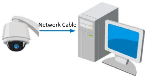
text_image
Network CableFigure 2-1 Connecng Directly
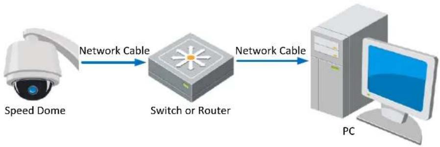
flowchart
graph LR
    A["Speed Dome"] -->|Network Cable| B["Switch or Router"]
    B -->|Network Cable| C["PC"]
Figure 2-2 Connecng via a Switch or a Router
2.1.2 Acvang the Speed Dome
Purpose:
You are required to acvate the speed dome rst before you can use the speed dome.
Acvaon via Web Browser, Acvaon via SADP, and Acvaon via client soware are supported.
In the following seconds, acvaon via web browser and SADP will be taken as examples. You
may refer to the user manual of the speed dome for the details of acvaon via client soware.
-
Power on the speed dome, and connect the speed dome to the network.
-
Input the IP address into the address bar of the web browser, and click Enter to enter the acvaon interface.

The default IP address of the speed dome is 192.168.1.64.
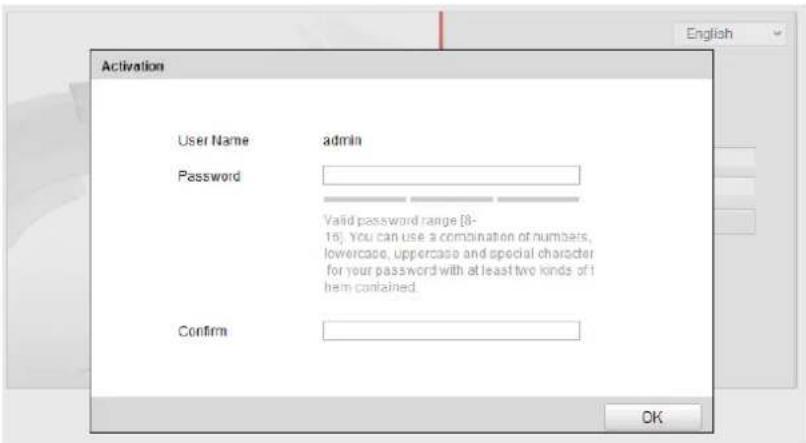
text_image
Activation User Name admin Password Valid password range [8- 16]. You can use a combination of numbers, lowercase, uppercase and special character for your password with at least two kinds of it them contained. Confirm OKFigure 2-3 Acvaon Interface(Web)
- Create a password and input the password into the password eld.

STRONG PASSWORD RECOMMENDED— We highly recommend you create a strong password of your own choosing (using a minimum of 8 characters, including upper case leers, lower case leers, numbers, and special characters) in order to increase the security of your product. And we recommend you reset your password regularly, especially in the high security system, reseng the password monthly or weekly can beer protect your product.
- Conrm the password.
- Click OK to acvate the speed dome and enter the live view interface.
◆ Acvaon via SADP Soware
SADP soware is used for detecting the online device, acvang the device, and reseng the password.
Get the SADP soware from the supplied disk or the ofcial website, and install the SADP according to the prompts. Follow the steps to acvate the speed dome.
Steps:
- Run the SADP soware to search the online devices.
- Check the device status from the device list, and select an inactive device.
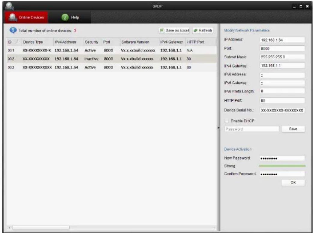
text_image
SADP Online Devices Help Total number of online devices: 3 Save as Excel Refresh ID Device Type IPv4 Address Security Port Software Version IPv4 Gateway HTTP Port 001 XX-XXXXXXXXX-192.168.1.64 Active 8000 Vx.x.xbuild xxxxxx 192.168.1.1 N/A 002 XX-XXXXXXXXX-192.168.1.64 Inactive 8000 Vx.x.xbuild xxxxxx 192.168.1.1 80 003 XX-XXXXXXXXX-192.168.1.64 Active 8000 Vx.x.xbuild xxxxxx 192.168.1.1 80 Modify Network Parameters IP Address: 192.168.1.64 Port: 8000 Subnet Mask: 255.255.255.0 IPv4 Gateway: 192.168.1.1 IPv6 Address: : IPv6 Gateway: : IPv6 Prefix Length: 0 HTTP Port: 80 Device Serial No.: XX-XXXXXXXX-XXXXXXXX Enable DHCP Password Save Device Activation New Password: ********** Strong Confirm Password: ********** OKFigure 2-4 SADP Interface
- Create a password and input the password in the password eld, and conrm the password.

STRONG PASSWORD RECOMMENDED- We highly recommend you create a strong password of your own choosing (using a minimum of 8 characters, including upper case leers, lower case leers, numbers, and special characters) in order to increase the security of your product. And we recommend you reset your password regularly, especially in the high security system, reseng the password monthly or weekly can beer protect your product.
- Click OK to save the password.
You can check whether the acvaon is completed on the popup window. If acvaon failed, please make sure that the password meets the requirement and then try again.
- Change the device IP address to the same subnet with your computer by either modifying the IP address manually or checking the checkbox of Enable DHCP.
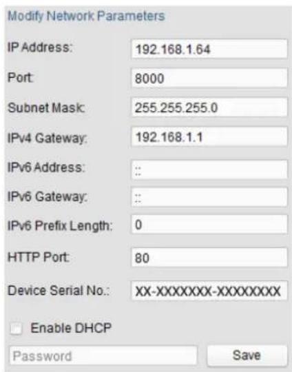
text_image
Modify Network Parameters IP Address: 192.168.1.64 Port: 8000 Subnet Mask: 255.255.255.0 IPv4 Gateway: 192.168.1.1 IPv6 Address: : : IPv6 Gateway: : : IPv6 Prefix Length: 0 HTTP Port: 80 Device Serial No.: XX-XXXXXXXX-XXXXXXXXX Enable DHCP Password SaveFigure 2-5 Modify the IP Address
- Input the password and click the Save button to acvate your IP address modicaon.
◆ Acvaon via Client Soware
The client soware is versale video management soware for mulple kinds of devices. Get the client soware from the supplied disk or the ocial website, and install the soware according to the prompts. Follow the steps to acvate the camera.
Steps:
- Run the client soware and the control panel of the soware pops up, as shown in the gure below.
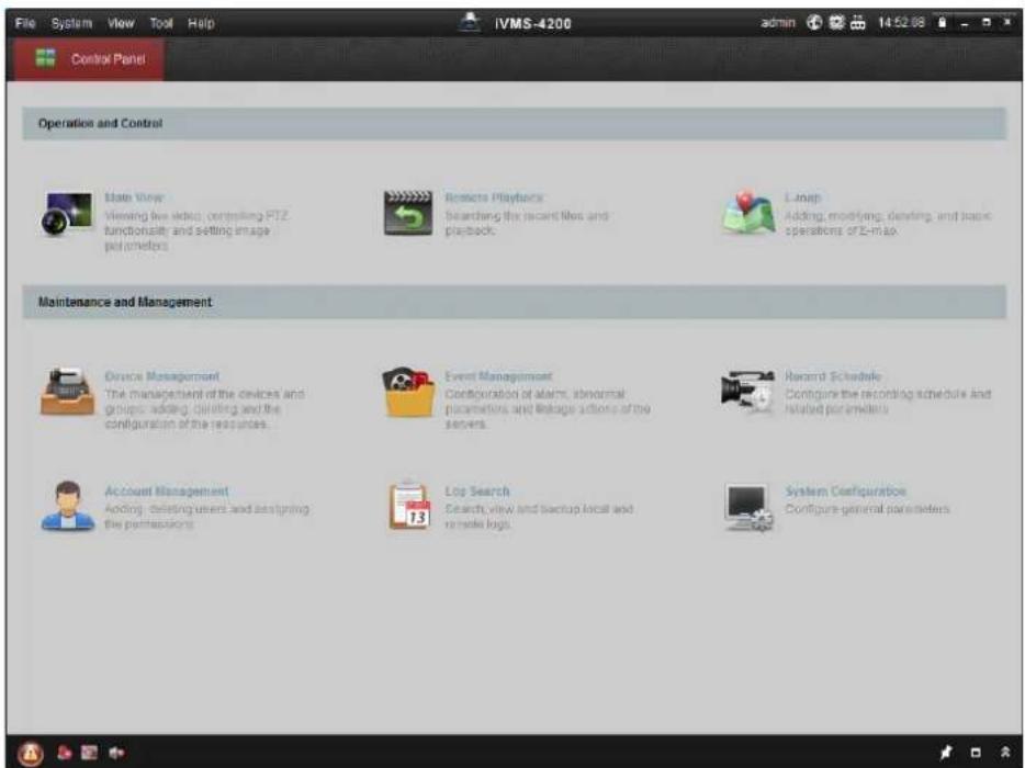
text_image
File System View Tool Help IVMS-4200 admin 14:52:08 Control Panel Operation and Control Main View Viewing live video, controlling PTZ functionality and setting image parameters Reagents Playbacks Searching the recent files and playback E-mail Adding, modifying, deleting, and basic operations or E-mail Maintenance and Management Device Management The management of the devices and groups, adding, deleting and the configuration of the resources. Event Management Configuration of alarms, abnormal paramulations and linkages actions of the servers. Record Schedule Configure the recording schedule and related parameters Account Management Adding, deleting users and assigning the performances. Log Search Search, view and backup local and to make logs. System Configuration Configure general parametersFigure 2-6 Control Panel
- Click the Device Management icon to enter the Device Management interface, as shown in the gure below.
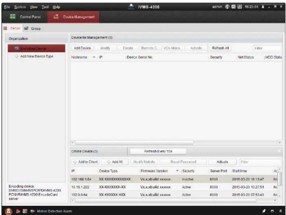
text_image
Device for Management (0) Add Device Modify Delete Remote C VCA Apache Activate Refresh All Filter Nickname IP Device Serial No. Security Net Status HDD Statu Online Device (3) Refresh Every 15s Add to Client Add All Modify NetInfo Reset Password Activate Filter IP Device Type Firmware Version Security Server Port Start time Ac 182.166.1.64 XX-XXXXXXXXXX Vx.x.xbuild xxxxxx Inactive 8000 2015-03-20 16:13:47 No 10.10.1.222 XX-XXXXXXXXXX Vx.x.xbuild xxxxxx Active 8000 2015-03-20 10:27:51 No 192.0.0.64 XX-XXXXXXXXXX Vx.x.xbuild xxxxxx Active 8000 2015-03-20 07:53:43 No Encoding devices: DVREVISN/RIPCPDVMIS-4200 PCNVRIVMS-4200 EncodersCard server Motion Detection AlarmFigure 2-7 Device Management Interface
- Check the device status from the device list, and select an inactive device.
- Click the Acvate buon to pop up the Acvaon interface.
- Create a password and input the password in the password eld, and conrm the password.

STRONG PASSWORD RECOMMENDED- We highly recommend you create a strong password of your own choosing (using a minimum of 8 characters, including upper case leers, lower case leers, numbers, and special characters) in order to increase the security of your product. And we recommend you reset your password regularly, especially in the high security system, reseng the password monthly or weekly can beer protect your product.
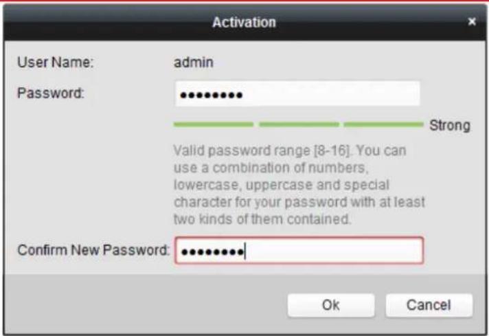
text_image
Activation User Name: admin Password: ••••••••• Strong Valid password range [8-16]. You can use a combination of numbers, lowercase, uppercase and special character for your password with at least two kinds of them contained. Confirm New Password: ••••••••••• Ok CancelFigure 2-8 Acvaon Interface
- Click OK buon to start acvaon.
- Click the Modify Nenfo button to pop up the Network Parameter Modication interface, as shown in the gure below.
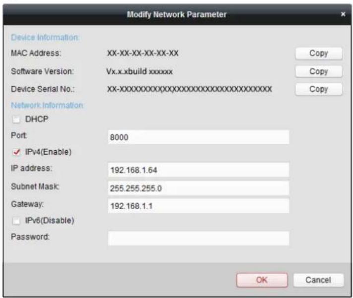
text_image
Modify Network Parameter Device Information: MAC Address: XX-XX-XX-XX-XX Software Version: Vx.x.xbuild xxxxxx Device Serial No.: XX-XXXXXXXXXXXXXXXXXXXXXXXXXXXXX Network Information: DHCP Port: 8000 IPv4(Enable) IP address: 192.168.1.64 Subnet Mask: 255.255.255.0 Gateway: 192.168.1.1 IPv6(Disable) Password: OK CancelFigure 2-9 Modifying the Network Parameters
- Change the device IP address to the same subnet with your computer by either modifying the IP address manually or checking the checkbox of Enable DHCP.
- Input the password to acvate your IP address modicaon.
2.2 Seng the Network Speed Dome over the WAN
Purpose:
This secon explains how to connect the network speed dome to the WAN with a stac IP or a dynamic IP.
2.2.1 Stac IP Connecon
Before you start:
Please apply a stac IP from an ISP (Internet Service Provider). With the stac IP address, you can connect the network speed dome via a router or connect it to the WAN directly.
- Connecng the network speed dome via a router
Steps:
- Connect the network speed dome to the router.
- Assign a LAN IP address, the subnet mask and the gateway. Refer to Secon 2.1.2 for detailed IP address conguraon of the speed dome.
- Save the stac IP in the router.
- Set port mapping, E.g., 80, 8000 and 554 ports. The steps for port mapping vary depending on dierent routers. Please call the router manufacturer for assistance with port mapping.

Refer to Appendix 2 for detailed informaon about port mapping.
- Visit the network speed dome through a web browser or the client soware over the internet.
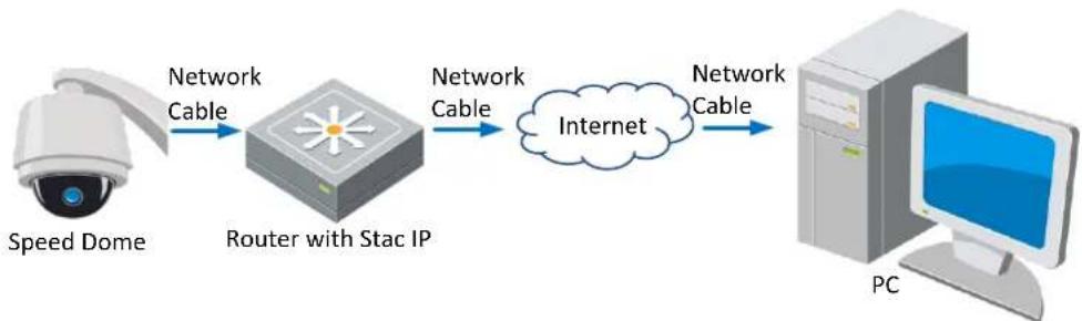
flowchart
graph LR
    A["Speed Dome"] -->|Network Cable| B["Router with Stac IP"]
    B -->|Network Cable| C["Internet"]
    C -->|Network Cable| D["PC"]
Figure 2-10 Accessing the Speed Dome through Router with Stac IP

- Connecng the network speed dome with stac IP directly
You can also save the stac IP in the speed dome and directly connect it to the internet without using a router. Refer to Secon 2.1.2 for detailed IP address conguraon of the speed dome.
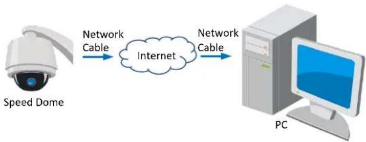
flowchart
graph LR
    A["Speed Dome"] -->|Network Cable| B(Internet)
    B -->|Network Cable| C["PC"]
Figure 2-11 Accessing the Speed Dome with Stac IP Directly
2.2.2 Dynamic IP Connecon
Before you start:
Please apply a dynamic IP from an ISP. With the dynamic IP address, you can connect the network speed dome to a modem or a router.
- Connecng the network speed dome via a router
Steps:
-
Connect the network speed dome to the router.
-
In the speed dome, assign a LAN IP address, the subnet mask and the gateway. Refer to Secon 2.1.2 for detailed LAN conguraon.
-
In the router, set the PPPoE user name, password and conrm the password.

-
For your privacy and to better protect your system against security risks, we strongly recommend the use of strong passwords for all functions and network devices. The password should be something of your own choosing (using a minimum of 8 characters, including upper case letters, lower case letters, numbers and special characters) in order to increase the security of your product.
● Proper configuration of all passwords and other security settings is the responsibility of the installer and/or end-user. -
Set port mapping. E.g. 80, 8000 and 554 ports. The steps for port mapping vary depending on dierent routers. Please call the router manufacturer for assistance with port mapping.

Refer to Appendix 2 for detailed informaon about port mapping.
- Apply a domain name from a domain name provider.
- Congure the DDNS sengs in the setng interface of the router.
- Visit the speed dome via the applied domain name.

- Connecng the network speed dome via a modem
Purpose:
This speed dome supports the PPPoE auto dial-up funcon. The speed dome gets a public IP address by ADSL dial-up aer the speed dome is connected to a modem. You need to congregate the PPPoE parameters of the network speed dome. Refer to Secon 6.3.3 Conguring PPPoE Sengs for detailed conguraon.

flowchart
graph LR
    A["Speed Dome"] -->|Network Cable| B["Modem"]
    B -->|Network Cable| C["Internet"]
    C -->|Network Cable| D["Computer"]
Figure 2-12 Accessing the Speed Dome with Dynamic IP

The obtained IP address is dynamically assigned via PPPoE, so the IP address always changes aer reboong the speed dome. To solve the inconvenience of the dynamic IP, you need to get a domain name from the DDNS provider (E.g. DynDns.com). Please follow below steps for normal domain name resoluon and private domain name resoluon to solve the problem.
♦ Normal Domain Name Resoluon
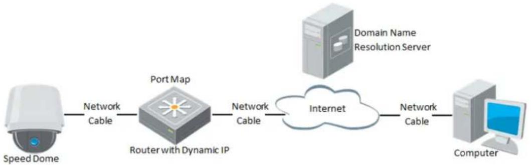
flowchart
graph LR
    A["Speed Dome"] -->|Network Cable| B["Router with Dynamic IP"]
    B -->|Network Cable| C["Internet"]
    D["Domain Name Resolution Server"] -->|Network Cable| C
    C -->|Network Cable| E["Computer"]
Figure 2-13 Normal Domain Name Resoluon
Steps:
- Apply a domain name from a domain name provider.
- Congure the DDNS setngs in the DDNS Setngs interface of the network speed dome. Refer to Secon 6.3.4 Conguring DDNS Sengs for detailed conguraon.
- Visit the speed dome via the applied domain name.

◆ Private Domain Name Resoluon
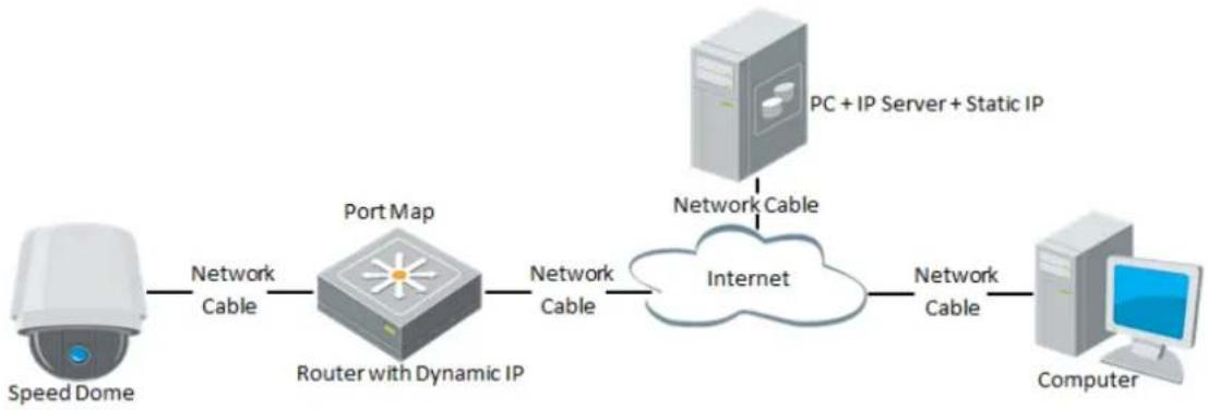
flowchart
graph LR
    A["Speed Dome"] -->|Network Cable| B["Router with Dynamic IP"]
    B -->|Network Cable| C["Internet"]
    D["PC + IP Server + Static IP"] -->|Network Cable| C
    C -->|Network Cable| E["Computer"]
Figure 2-14 Private Domain Name Resoluon
Steps:
- Install and run the IP Server soware in a computer with a static IP.
- Access the network speed dome through the LAN with a web browser or the client soware.
- Enable DDNS and select IP Server as the protocol type. Refer to Secon 6.3.4 Conguring DDNS Sengs for detailed conguraon.

Chapter 3 Access to the Network Speed Dome
3.1 Accessing by Web Browsers
Steps:
- Open the web browser.
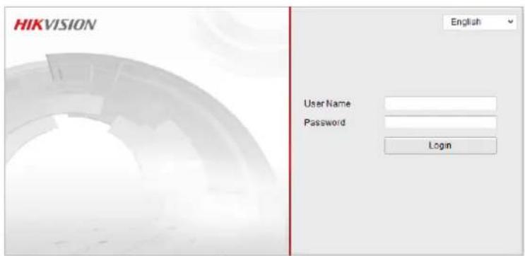
- In the address eld, input the IP address of the network speed dome, e.g., 192.168.1.64 and press the Enter key to enter the login interface.
- Acvate the speed dome for the rst me using, refer to the secon 2.1.2 Acvang the Speed Dome.
-
Select English as the interface language on the top-right of login interface.
-
Input the user name and password and click Login
The admin user should congregate the device accounts and user/operator permissions properly. Delete the unnecessary accounts and user/operator permissions.

The device IP address gets locked if the admin user performs 7 failed password aempts (5 aempts for the user/operator).
text_image
HIKVISION English User Name Password LoginFigure 3-1 Login Interface
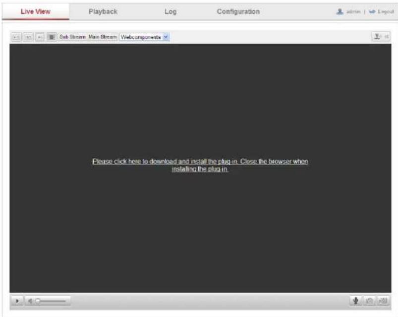
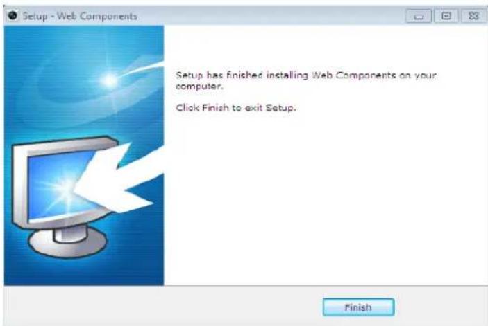
- Install the plug-in before viewing the live video and operating the speed dome. Please follow the installaon prompts to install the plug-in.
text_image
Live View Playback Log Configuration admin Layout Sub Stream Main Stream Web components Please click here to download and install the plug-in. Close the browser when installing the plug-in.Figure 3-2 Download and Install Plug-in
text_image
Setup - Web Components Setup has finished installing Web Components on your computer. Click Finish to exit Setup. FinishFigure 3-3 Install Plug-in


You may have to close the web browser to install the plug-in. Please reopen the web or and log in again aer installing the plug-in.
3.2 Accessing by Client Soware
The product CD contains the client soware. You can view the live video and manage the speed dome with the client soware.
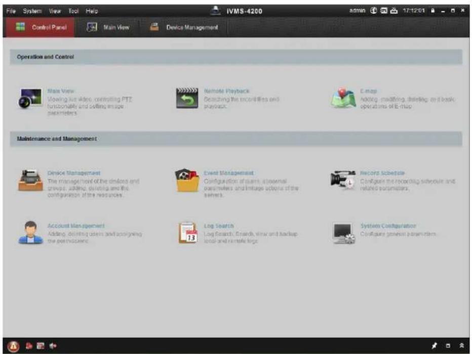
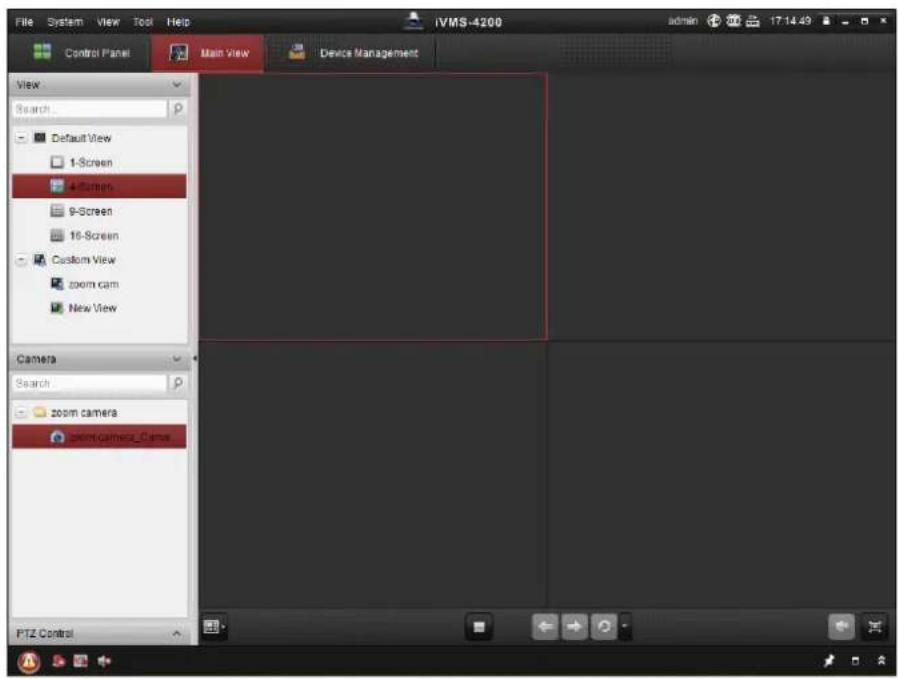
Follow the installaon prompts to install the client soware and WinPcap. The conguraon interface and live view interface of client soware are shown below.
text_image
File System View Tool Help IVMS-4200 Control Panel Main View Device Management Operation and Control Main View Viewing live video, controlling PTZ functionally and setting image parameters Remote Playback Searching the recordings and playback E-map Adding, modifying, deleting, or break operations of E-map Maintenance and Management Device Management The management of the devices and groups, adding, deleting and the configuration of the resources. Event Management Configuration of users, a normal parameters and trigger actions of the system. Record Schedule Configure the recording schedule and related parameters. Account Management Adding, deleting users and assigning the processors. Log Search Log Search, Expls, view and backup local and remote logo System Configuration Configure general parametersFigure 3-4 iVMS-4200 Control Panel
text_image
File System View Tool Help Control Panel Main View Device Management View Search Default View 1-Screen 4-Screen 9-Screen 16-Screen Custom View zoom cam New View Camera Search zoom camera zoom camera_Came PTZ ControlFigure 3-5 iVMS-4200 Live View Interface

- If you use third party VMS soware, please contact technical support of our branch for camera rmware.
- For detailed information about client soware of our company, please refer to the user manual of the soware. This manual mainly introduces accessing to the network speed dome by web browser.
Chapter 4 Live View
4.1 Live View Page
Purpose:
The live video page allows you to view live video, capture images, realize PTZ control, set/call presets and congure video parameters.
Log in the network speed dome to enter the live view page, or you can click on the
menu bar of the main page to enter the live view page.
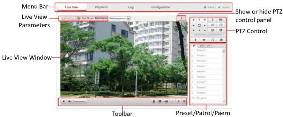
Descripons of the live view page:
text_image
Menu Bar Live View Playback Leg Configuration Live View Parameters Live View Window Show or hide PTZ control panel PTZ Control Toolbar Preset/Patrol/PaernFigure 4-1 Live View Page
Menu Bar:
Click each tab to enter Live View, Playback, Log and Conguraon page respectively.
Live View Window:
Display the live video.
Toolbar:
Operaons on the live view page, e.g., live view, capture, record, audio on/o, two-way audio, etc.
PTZ Control:
Panning, Ing, focusing and zooming acons of the speed dome. The lighter, wiper, one-touch focus and lens inializaon control.
Preset/patrol/paern:
Set and call the preset/patrol/paern for the speed dome.
Live View Parameters:
Congure the image size and stream type of the live video.
4.2 Starng Live View
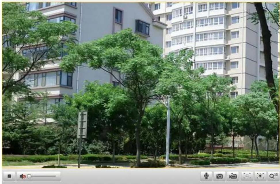
In the live view window as shown in Figure 4-2, click ▶ on the toolbar to start the live view of the speed dome.
natural_image
Exterior view of a modern residential building with green trees and a paved walkway in the foreground (no signage or text visible)Figure 4-2 Start Live View
Table 4-1 Descripons of the Toolbar
| Icon | Descripon | Icon | Descripon |
 | Start/Stop Live view |  | Manually capture the pictures |
 | Manual recording o/on |   | Mute / Audio on and adjust volume |
 | Two-way audio o/on/ |  | 3D posioning |
 | Enable / Disable Regional Exposure | [S46Z] | Enable / Disable Regional Focus |

Before using the two-way audio or recording with audio funcons, please set the
Stream Type to Video & Audio referring to Secon 6.4.1 Conguring Video Sengs.
Full-screen Mode:
You can double-click on the live video to switch the current live view into full-screen or return to normal mode from the full-screen.
Regional Focus:
Steps:
- Click the 📋 on the toolbar to enter the regional focus operaon mode.
- Click-and-drag the mouse to draw a rectangle on the image as the desired focus region.
- Click the to exit the regional focus operaon mode.
Regional Exposure:
Steps:
- Click the 📄 on the toolbar to enter the regional exposure operaon mode.
- Click-and-drag the mouse to draw a rectangle on the image as the desired exposure region.
- Click the to exit the regional exposure operaon mode.
3D Posioning:
Steps:
- Click on the tool bar of live view interface.
-
Operate the 3D posioning funcon:
-
Le click a posion of the live video. The corresponding posion will be moved to the center of the live video.
- Hold down the le mouse buon and drag the mouse to the lower right on the live video. The corresponding posion will be moved to the center of the live video and zoomed in.
- Hold down the le mouse button and drag the mouse to the upper le on the live video. The corresponding posion will be moved to the center of the live video and zoomed out.

Please refer to the following seconds for more informaon:
● Conguring remote recording in Section 7.2 Conguring Recording Schedule.
- Seng the image quality of the live video in Secon 6.1 Conguring Local Parameters and Secon 6.4.1 Configuring Video Setngs.
● Seng the OSD text on live video in Secon 6.5.2 Conguring OSD Sengs.
4.3 Recording and Capturing Pictures Manually
In the live view interface, click 📷 on the toolbar to capture the live pictures or click 📷 to record the live video. The local saving paths of the captured pictures and clips can be set in the Conguraon > Local Conguraon interface.
To congure remote automat recording, please refer to Secon 7.2 Conguring Recording Schedule.


You can congregate the format of the picture to save in your computer as JPEG or BMP,
refer to the secon 6.1 Conguring Local Parameters.
4.4 Operang PTZ Control
Purpose:
In the live view interface, you can use the PTZ control buons to control panning, lting and zooming.
4.4.1 PTZ Control Panel
On the live view page, click to show the PTZ control panel or click to hide it.
Click the direcon buons to control the pan/lt movements.
Click the zoom/iris/focus buons to realize lens control.

text_image
Screenshot of a software toolbar with icons for navigation, editing, and display functionsFigure 4-3 PTZ Control Panel
Table 4-2 Descripons of PTZ Control Panel
| Buon | Descripon |
| Zoom in/out | |
| Focus near/far | |
| Iris Open/Close | |
| Adjust speed of pan/lt movements |
4.4.2 Seng / Calling a Preset
Purpose:
A preset is a predened image posion. For the dened preset, you can click the calling buon to quickly view the desired image posion.
- Seng a Preset:
Steps:
- In the PTZ control panel, select a preset number from the preset list.
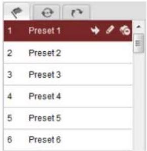
text_image
1 Preset 1 2 Preset 2 3 Preset 3 4 Preset 4 5 Preset 5 6 Preset 6Figure 4-4 Seng a Preset
-
Use the PTZ control buons to move the lens to the desired posion.
-
Pan the speed dome to the right or le.
- Tilt the speed dome up or down.
- Zoom in or out.
-
Refocus the lens.
-
Click to nish the seng of the current preset.
-
You can click to delete the preset.

You can congure up to 256 presets.

- Calling a Preset:
In the PTZ control panel, select a dened preset from the list and click to call the preset.
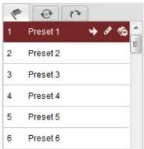
text_image
1 Preset 1 2 Preset 2 3 Preset 3 4 Preset 4 5 Preset 5 6 Preset 6Figure 4-5 Calling a Preset
For convenient preset selecon, refer to the following steps to navigate to the preset you want.
Steps:
- Select any preset from the list.
- Click the preset number you need on the keyboard.


NOTE The following presets are predened with special commands. You can only call them but not congure them. For instance, preset 99 is the "Start auto scan". If you call the preset 99, the
speed dome starts auto scan funcon.
Table 4-3 Special Presets
| Preset No. | Funcon | Preset No. | Funcon |
| 33 | Auto ip | 93 | Set limit stops manually |
| 34 | Back to initial posion | 94 | Remote reboot |
| 35 | Call patrol 1 | 96 | Stop a scan |
| 36 | Call patrol 2 | 97 | Start random scan |
| 37 | Call patrol 3 | 98 | Start frame scan |
| 38 | Call patrol 4 | 99 | Start auto scan |
| 39 | IR cut Iter in | 100 | Start It scan |
| 40 | IR cut Iter out | 101 | Start panorama scan |
| 41 | Call paern 1 | 102 | Call patrol 5 |
| 42 | Call paern 2 | 103 | Call patrol 6 |
| 43 | Call paern 3 | 104 | Call patrol 7 |
| 44 | Call paern 4 | 105 | Call patrol 8 |
| 45 | One-touch patrol | 106 | Fan On |
| 92 | Start to set limit stops | 107 | Fan O |
| 108 | Fan On By Temperature Control |
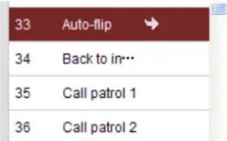
text_image
33 Auto-flip 34 Back to in… 35 Call patrol 1 36 Call patrol 2Figure 4-6 Special Preset

When you calling preset 45 (one-touch patrol), the speed dome patrols from the preset 1 to 32. Before you enable this funcon, please set the preset 1 to 32 rst.
4.4.3 Seng / Calling a Patrol
Purpose:
A patrol is a memorized series of preset funcon. It can be congured and called on the patrol sengs interface. There are up to 8 patrols for customizing. A patrol can be congured with 32 presets.
Before you start:
Please make sure that the presets you want to add into a patrol have been denied.
- Seng a Patrol:
Steps:
- In the PTZ control panel, click 📄 to enter the patrol settings interface.
-
Select a patrol number from . Path 01
-
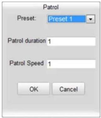
Click to enter the adding interface of preset as shown in Figure 4-7.
text_image
Patrol Preset: Preset 1 Patrol duration 1 Patrol Speed 1 OK CancelFigure 4-7 Adding Presets
- Congure the preset number, patrol me and patrol speed.
| Name | Descripon |
| Patrol Time | It is the duraon staying on one patrol point. The speed dome moves to another patrol point aer the patrol me. |
| Patrol Speed | It is the speed of moving from one preset to another. |
- Click to save a preset into the patrol.
- Repeat the steps from 3 to 5 to add more presets.
- Click to save all the patrol sengs.

- Calling a Patrol:
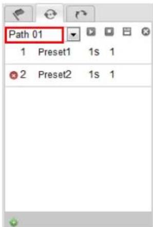
In the PTZ control panel, select a dened patrol from and click to call the patrol as shown in Figure 4-8.

text_image
Path 01 1 Preset1 1s 1 2 Preset2 1s 1Figure 4-8 Calling a Preset
● Buons on the Patrols interface:
| Buons | Descripon |
| Save a patrol |

| [VC3H] | Call a patrol |
| [YD4W] | Stop a patrol |
| [725W] | Enter the adding interface of preset |
 | Modify a preset |
| [07C3] | Delete a preset |
| [67BH] | Delete all the presets in one patrol |
4.4.4 Seng / Calling a Paern
Purpose:
A paern is a memorized series of pan, lt, zoom, and preset funcons. It can be called on the paern sengs interface. There are up to 4 paerns for customizing.
- Seng a Paern:
Steps:
- In the PTZ control panel, click 📄 to enter the paern setngs interface.
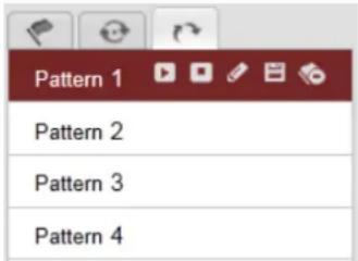
- Select a paern number from the list as shown in Figure 4-9.
text_image
Pattern 1 Pattern 2 Pattern 3 Pattern 4Figure 4-9 Paerns Sengs Interface
- Click to enable recording the panning, lng and zooming acons.
-
Use the PTZ control buons to move the lens to the desired position aer the information of PROGRAM PATTERN REMAINNING MEMORY(%) is displayed on the screen.
-
Pan the speed dome to the right or le.
- Tilt the speed dome up or down.
- Zoom in or out.
-
Refocus the lens.
-
Click to save all the paern sengs.

● Buons on the Paerns interface:
| Buons | Descripon |
| Start to record a paern. | |
| Stop recording a paern. | |
| Call the current paern. | |
| Stop the current paern. | |
| Delete the current paern. |






● These 4 patterns can be operated separately and with no priority level.
- When conguring and calling the pattern, proporcional pan is valid; the limit stops and auto ip will be invalid; and the 3D poisoning operaon is not supported.
4.5 Conguring Live View Parameters
● Main stream/Sub-stream:
You can select or as the stream type of live viewing. The main stream is with a relatively high resolution and needs much bandwidth. The sub-stream is with a low resolution and needs less bandwidth. The default seng of stream type is . Main Stream

Please refer to Secon 6.4.1 Conguring Video Sengs for more detailed parameter sengs of the main stream and sub-stream respectively.
- Image Size:
You can scale up/down the live view image by clicking . the image size can be 4:3,
16:9, original or auto.
Chapter 5 PTZ Conguraon
5.1 Conguring Inial Posion
Purpose:
The initial posion is the origin of PTZ coordinates. It can be the factory default initial posion. You can also customize the initial posion according to your own demand.
- Customize an Inial Posion:
Steps:
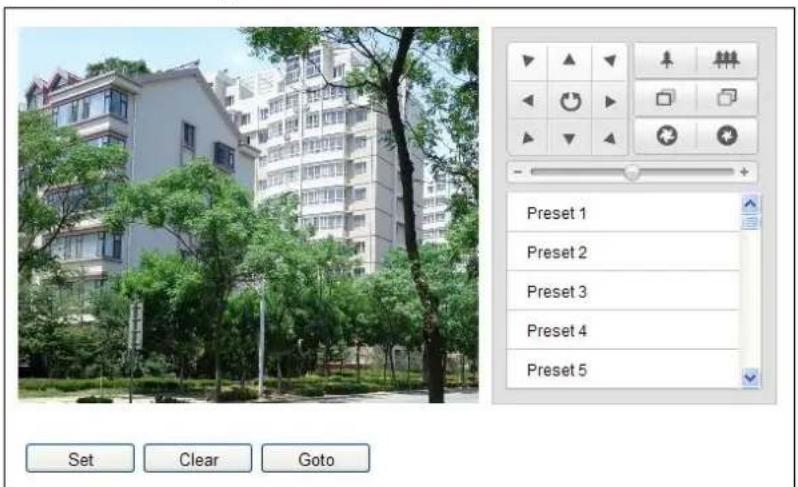
- Enter the Inial Posion Conguraon interface:
Conguraon > Advanced Conguraon > PTZ > Inial Posion
text_image
Preset 1 Preset 2 Preset 3 Preset 4 Preset 5 Set Clear GotoFigure 5-1 PTZ Conguraon
- Click the PTZ control buons to nd a posion as the initial posion of the dome; you can also call a dened preset and set it as the initial posion of the dome.
- Click Set to save the posion.

- Call/delete an Inial Posion:
You can click Goto to call the initial posion. You can click Clear to delete the initial posion and restore the factory default initial posion.
5.2 Conguring Basic PTZ Parameters
Purpose:
You can congregate the basic PTZ parameters, including proporcional pan, preset freezing, preset speed, etc.

1. Enter the Basic PTZ Parameter Conguraon interface:
Conguraon > Advanced Conguraon > PTZ > Basic
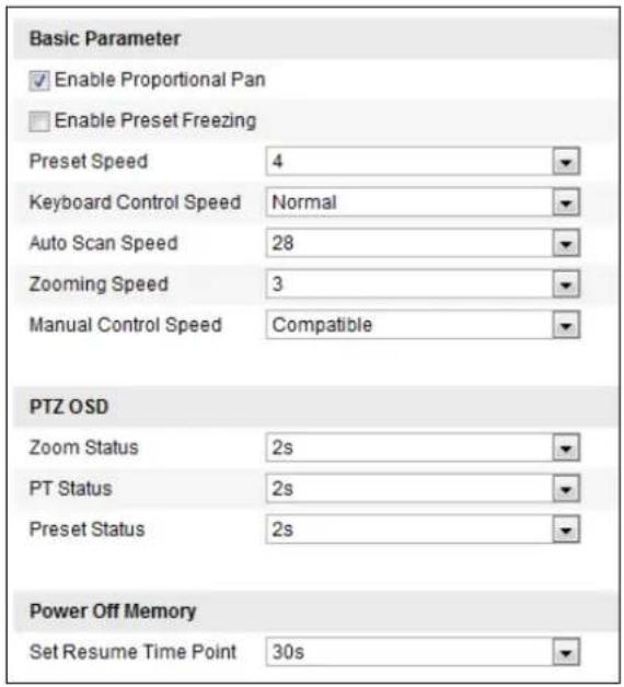
text_image
Basic Parameter ✓ Enable Proportional Pan □ Enable Preset Freezing Preset Speed 4 Keyboard Control Speed Normal Auto Scan Speed 28 Zooming Speed 3 Manual Control Speed Compatible PTZ OSD Zoom Status 2s PT Status 2s Preset Status 2s Power Off Memory Set Resume Time Point 30sFigure 5-2 Basic PTZ Conguraon Interface
2. Congure the following sengs:
- Basic Parameters: Enable/disable proportional pan and preset freezing, set the preset speed, keyboard control speed, and auto scan speed.
◆ Proporonal Pan: If you enable this funcon, the pan/lt speeds change according to the amount of zoom. When there is a large amount of zoom, the pan/lt speed will be slower for keeping the image from moving too fast on the live view image.
◆ Preset Speed: You can set the speed of a dened preset from 1 to 8.
◆ Keyboard Control Speed: Dene the speed of PTZ control by a keyboard as Low, Normal or High.
◆ Auto Scan Speed: The dome provides 5 scan modes: auto scan, lt scan, frame scan, random scan and panorama scan. The scan speed can be set from level 1 to 40.
◆ Zooming Speed: The speed of zooming is adjustable.
◆ Manual Control Speed: The manual control speed can be set as Compatible, Pedestrian, Non-motor Vehicle, Motor Vehicle or Self-adapve.
➢ Comparable: The control speed is same as the Keyboard Control Speed.
Pedestrian: Choose the Pedestrian when you monitor the pedestrians.
➢ Non-motor Vehicle: Choose the Non-motor Vehicle when you monitor the non-motor vehicles.
➢ Motor Vehicle: Choose the Motor Vehicle when you monitor the motor vehicles.
➢ Self-adapve: You are recommended to set the Self-adaptive when the applicaon scene of the speed dome is complicated.
- PTZ OSD: Set the on-screen display duraon of the PTZ status.
◆ Zoom Status: Set the OSD duration of zooming status as 2 seconds, 5 seconds, 10 seconds, Always Close or Always Open.
◆ PT Status: Set the azimuth angle display duraon while panning and Ing as 2 seconds,
5 seconds, 10 seconds, Always Close or Always Open.
◆ Preset Status: Set the preset name display duraon while calling the preset as 2 seconds, 5 seconds, 10 seconds, Always Close or Always Open.
- Power-o Memory: The dome can resume its previous PTZ status or acons aer it restarted from a power-o. You can set the me point of which the dome resumes its PTZ status. You can set it to resume the status of 30 seconds, 60 seconds, 300 seconds or 600 seconds before power-o.
- Click to save the sengs.

5.3 Conguring PTZ Limits
Purpose:
The dome can be programmed to move within the congorable PTZ limits (le/right, up/down).
Steps:
- Enter the Limit Conguraon interface:
Conguraon > Advanced Conguraon > PTZ > Limit
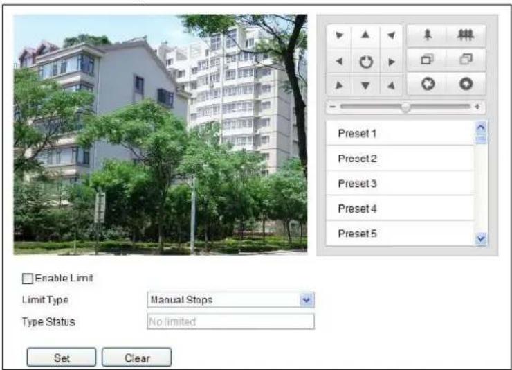
text_image
Enable Limit Limit Type Manual Stops Type Status No limited Set ClearFigure 5-3 Congure the PTZ Limit
- Click the checkbox of Enable Limit and choose the limit type as manual stops or scan stops.
- Manual Stops:
When manual limit stops are set, you can operate the PTZ control panel manually only in the limited surveillance area.
- Scan Stops:
When scan limit stops are set, the random scan, frame scan, auto scan, lt scan, panorama scan is performed only in the limited surveillance area.

Manual Stops of Limit Type is prior to Scan Stops. When you set these two limit types at the same me, Manual Stops is valid and Scan Stops is invalid.
- Click the PTZ control buons to nd the le/right/up/down limit stops; you can also call the dened presets and set them as the limits of the dome.
- Click Set to save the limits or click Clear to clear the limits.

5.4 Conguring Scheduled Tasks
Purpose:
You can congregate the network dome to perform a certain acon automacally in a user-dened me period.
Steps:
- Enter the Scheduled Task Sengs interface:
Conguraon> Advanced Conguraon> PTZ > Scheduled Tasks
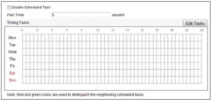
text_image
Enable Scheduled Task Park Time 5 second Timing Tasks Edit Tasks Mon Tue Wed Thu Fri Sat Sun Note: Red and green colors are used to distinguish the neighboring scheduled tasks.Figure 5-4 Congure Scheduled Tasks
- Check the checkbox of Enable Scheduled Task.
- Set the Park Time. You can set the park me (a period of inactivity) before the dome starts the scheduled tasks.
- Set the schedule and task details.
(1) Click to edit the task schedule.
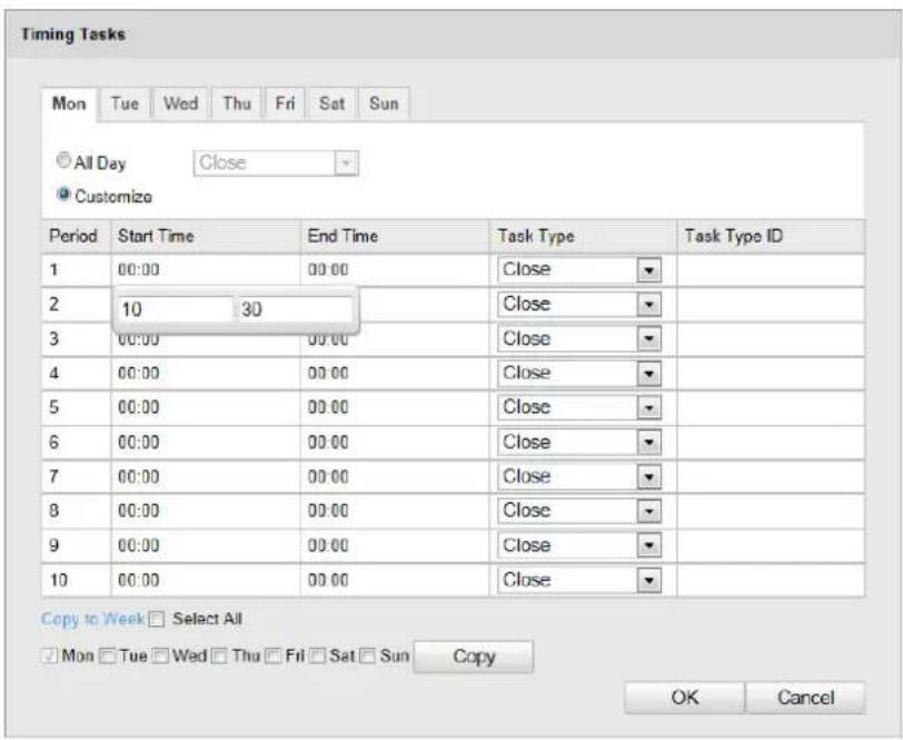
text_image
Timing Tasks Mon Tue Wed Thu Fri Sat Sun © All Day Close Customize Period Start Time End Time Task Type Task Type ID 1 00:00 00:00 Close 2 10 30 Close 3 00:00 00:00 Close 4 00:00 00:00 Close 5 00:00 00:00 Close 6 00:00 00:00 Close 7 00:00 00:00 Close 8 00:00 00:00 Close 9 00:00 00:00 Close 10 00:00 00:00 Close Copy to Week Select All Mon Tue Wed Thu Fri Sat Sun Copy OK CancelFigure 5-5 Edit the Schedule and Task Type
(2) Choose the day you want to set the task schedule.
(3) Click All Day to set the schedule as all day; or click Customize and input the Start Time and End Time for each task, and click Enter on your keyboard to enter the me.
(4) Choose the task type from the drop-down list. You can choose scan, preset, pattern, etc.
(5) (Oponal) Aer you set the scheduled task, you can copy the task to other days.
(6) Click to save the sengs.

The me of each task can't be overlapped. Up to 10 tasks can be congured for each
- Click to save the sengs.

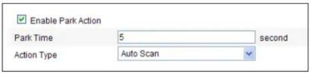
5.5 Conguring Park Acons
Purpose:
This feature allows the dome to start a predened park acon (scan, preset, pattern and etc.) automacally aer a period of inacvity (park me).

Scheduled Tasks funcon is prior to Park Acon funcon. When these two funcons
are set at the same me, only the Scheduled Tasks funcon takes eect.
Steps:
- Enter the Park Action Seings interface:
Conguraon > Advanced Conguraon> PTZ > Park Acon

© Hikvision
text_image
Enable Park Action Park Time 5 second Action Type Auto ScanFigure 5-6 Set the Park Acon
- Check the checkbox of Enable Park Acon.
- Set the Park Time as the inactivity me of the dome before it starts the park acons.
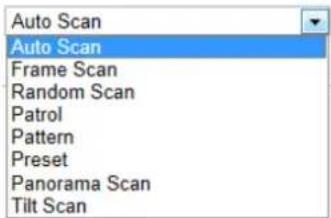
- Choose Acon Type the from the drop-down list.
text_image
Auto Scan Auto Scan Frame Scan Random Scan Patrol Pattern Preset Panorama Scan Tilt ScanFigure 5-7 Acon Types
- Click to save the sengs.

5.6 Conguring Privacy Mask
Purpose:
Privacy mask enables you to cover certain areas on the live video to prevent certain spots in the surveillance area from being live viewed and recorded.
Steps:
- Enter the Privacy Mask Sengs interface:
Conguraon > Advanced Conguraon> PTZ > Privacy Mask

text_image
Enable Privacy Masks Stop Drawing Clear All Privacy Mask List Add Delete No. Name Type Enable Active Zoom Ratio 1 Privacy Mask 1 blue Yes 1Figure 5-8 Draw the Privacy Mask
- Click the PTZ control buttons to nd the area you want to set the privacy mask.
- Click Draw Area ; click and drag the mouse in the live video window to draw the area.
- You can drag the corners of the red rectangle area to draw a polygon mask.
- Click Stop Drawing to nish drawing or click Clear All to clear all of the areas you set without saving them.
- Click Add to save the privacy mask, and it will be listed in the Privacy Mask List area; you can select a mask and click to delete it from the list.
| No. | Name | Type | Enable | Active Zoom Ratio |
| 1 | Privacy Mask 1 | blue | Yes | 1 |
| 2 | Privacy Mask 2 | blue | Yes | 1 |
Figure 5-9 Privacy Mask List
- Check the checkbox of Enable Privacy Mask to enable this funcon.

You are allowed to draw up to 8 areas for the speed dome.

5.7 Clearing PTZ Conguraons
Purpose:
You can clear PTZ conguraons in this interface, including all presets, patrols, paerns, privacy masks, PTZ limits, scheduled tasks and park acons.
Steps:
- Enter the Clearing Conguraon interface:
Conguraon > Advanced Conguraon> PTZ > Clear Cong
- Check the checkbox of the items you want to clear.
- Click to clear the sengs.

Chapter 6 Speed Dome Conguraon
6.1 Conguring Local Parameters

The local conguraon refers to the parameters of the live view and other operaons the web browser.
Steps:
- Enter the Local Conguraon interface:
Conguraon > Local Conguraon
text_image
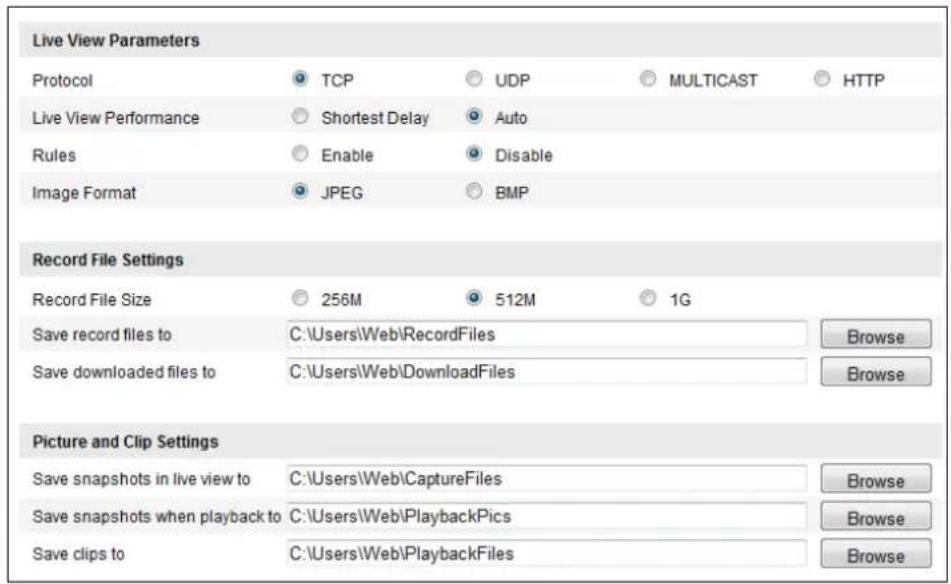
Live View Parameters Protocol TCP UDP MULTICAST HTTP Live View Performance Shortest Delay Auto Rules Enable Disable Image Format JPEG BMP Record File Settings Record File Size 256M 512M 1G Save record files to C:\Users\Web\RecordFiles Save downloaded files to C:\Users\Web\DownloadFiles Browse Browse Picture and Clip Settings Save snapshots in live view to C:\Users\Web\CaptureFiles Save snapshots when playback to C:\Users\Web\PlaybackPics Save clips to C:\Users\Web\PlaybackFiles Browse Browse BrowseFigure 6-1 Local Conguraon Interface
- Congure the following sengs:
● Live View Parameters: Set the protocol type, stream type, image size and live view performance.
◆ Protocol Type: TCP, UDP, MULTICAST and HTTP are selectable. TCP: Ensures complete delivery of streaming data and better video quality, yet the real-me transmission will be aected.
UDP: Provides real-me audio and video streams.
HTTP: Allows the same quality as of TCP without setng specic ports for streaming under some network environments.
MULTICAST: It's recommended to select the protocol type to MULTICAST when using the Mulcast funcon. For other informaon about Mulcast, refer to Secon 6.3.1
Conguring TCP/IP Sengs.
Live View Performance: Set the live view performance to Shortest Delay, or Auto.
Rules: You can enable or disable the rules of dynamic analysis for moon here.
◆ Image Format: The captured pictures can be saved as dierent format. JPEG and BMP are
available.
- Record File Setngs: Set the saving path of the video les.
Record File Size: Select the packed size of manually recorded and downloaded video les. The size can be set to 256M, 512M or 1G.
◆ Save record les to: Set the saving path for the manually recorded video les.
◆ Save downloaded les to: Set the saving path for the downloaded video les in
Playback
interface.
● Picture and Clip Setngs: Set the saving paths of the captured pictures and clipped videos.
◆ Save snapshots in live view to: Set the saving path of the manually captured pictures in
Live View
interface.
◆ Save snapshots when playback to: Set the saving path of the captured pictures in
Playback
interface.
Save clips to: Set the saving path of the clipped video les in Playback interface.
Playback

You can click to change the directory for saving video les, clips and s.
- Click to save the sengs.

6.2 Conguring Time Sengs
Purpose:
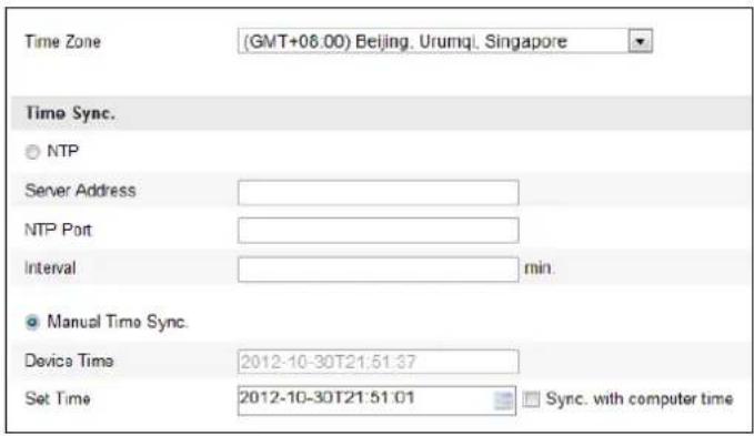
You can follow the instrucons in this secon to conjure the me which can be displayed on the video. There are Time Zone, Time Synchronizaon, Daylight Saving Time (DST) funcons for seeing the me. Time Synchronizaon consists of auto mode by Network Time Protocol (NTP) server and manual mode.
To enter the Time Sengs interface:
Conguraon > Basic Conguraon > System > Time Sengs
Or Conguraon > Advanced Conguraon > System > Time Seings
text_image
Time Zone (GMT+08.00) Beijing. Urumql. Singapore Time Sync. ○ NTP Server Address NTP Port Interval min. ● Manual Time Sync. Device Time 2012-10-30T21:51:37 Set Time 2012-10-30T21:51:01 Sync. with computer timeFigure 6-2 Time Sengs
● Conguring Time Synchronizaon by NTP Server
Steps:
(1) Check the radio buon to enable the NTP funcon.
(2) Congure the following sengs:
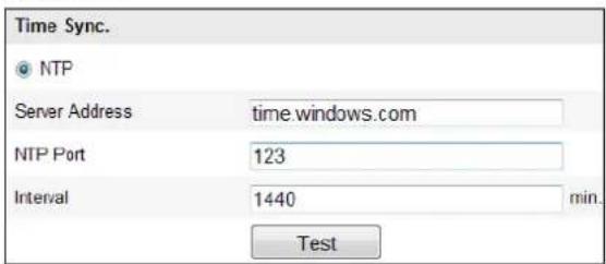
Server Address: IP address of NTP server.
NTP Port: Port of NTP server.
Interval: The me interval between the two synchronizing acons by NTP server. It can be set from 1 to 10080 minutes.
text_image
Time Sync. NTP Server Address time.windows.com NTP Port 123 Interval 1440 min.. TestFigure 6-3 Time Sync by NTP Server
You can click Test to make sure that the NTP server is connected.

If the speed dome is connected to a public network, you should use a NTP server that has a me synchronizaon funcon, such as the server at the Naonal Time Center (IP Address: 210.72.145.44). If the speed dome is set in a customized network, NTP soware can be used to establish a NTP server for me synchronizaon.

● Conguring Time Synchronizaon Manually
Steps:
(1) Check the Manual Time Sync radio button.
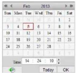
(2) Click to set the system me from the pop-up calendar.
(3) Click to save the sengs.

You can also check the Sync with local me checkbox to synchronize the me of the dome with the me of your computer.
text_image
Feb 2013 Sun Mon Tue Wed Thu Fri Sat 3 4 5 6 7 8 9 10 11 12 13 14 15 16 17 18 19 20 21 22 23 24 25 26 27 28 Time: 14 : 24 : 10 Today OK
text_image
Manual Time Sync. Device Time 2012-06-25T21:15:13 Set Time 2012-06-25T21:14:03 Sync. with computer timeFigure 6-4 Time Sync Manually

- Select the Time Zone
Purpose:
When the speed dome is taken to another me zone, you can use the Time Zone funcon to adjust the me. The me will be adjusted according to the original me and the time dience between the two me zones.
From the Time Zone drop-down menu as shown in Figure 6-5, select the Time Zone in which the speed dome locates.

text_image
Time Zone (GMT+08:00) Beijing, Urumqi, SingaporeFigure 6-5 Time Zone Sengs
● Conguring Daylight Saving Time (summer me)
Purpose:
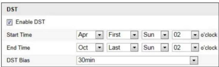
If there is the habit of adjusting clocks forward in your country in certain me period of a year, you can turn this function on. The me will be adjusted automatically when the Daylight Saving Time(DST) comes.
Steps:
(1) Enter the DST interface by Conguraon > Advanced Conguraon > System > DST
(2) Check to enable the DST funcon.
(3) Set the date of the DST period.
(4) Click to save the sengs.
text_image
DST Enable DST Start Time Apr First Sun 02{o'clock End Time Oct Last Sun 02{o'clock DST Bias 30minFigure 6-6 DST Sengs


6.3 Conguring Network Sengs
6.3.1 Conguring TCP/IP Sengs
Purpose:
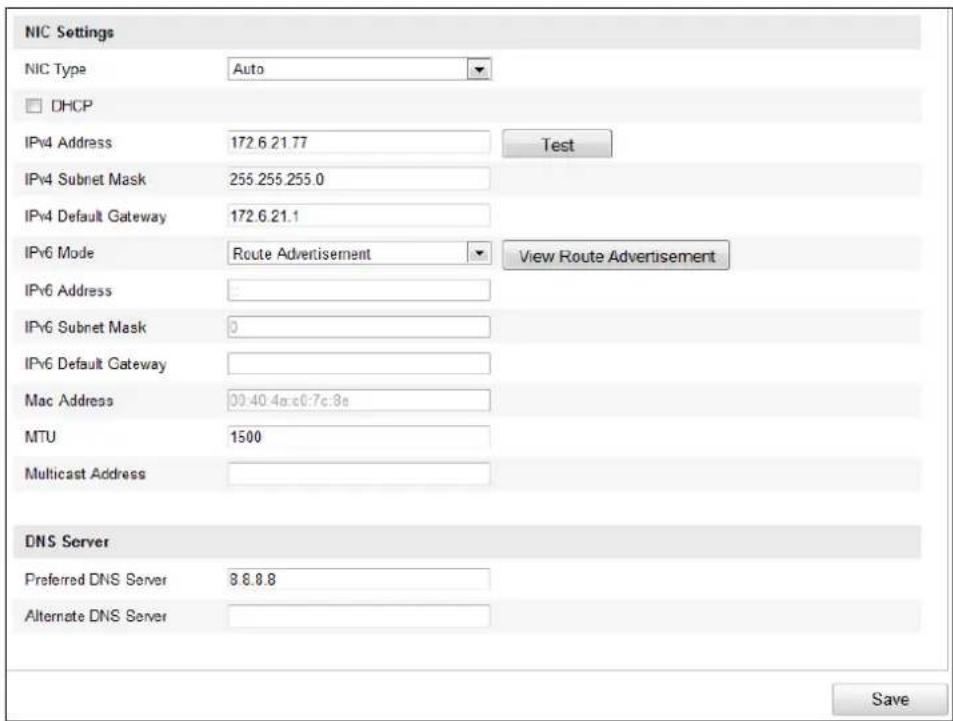
TCP/IP sengs must be properly congured before you operate the speed dome over network. IPv4 and IPv6 are both supported.
Steps:
1. Enter TCP/IP Setngs interface:
Conguraon > Basic Conguraon > Network > TCP/IP
Or Conguraon > Advanced Conguraon > Network > TCP/IP
text_image
NIC Settings NIC Type Auto DHCP IPv4 Address 172.6.21.77 Test IPv4 Subnet Mask 255.255.255.0 IPv4 Default Gateway 172.6.21.1 IPv6 Mode Route Advertisement View Route Advertisement IPv6 Address IPv6 Subnet Mask 0 IPv6 Default Gateway Mac Address 00:40.4a:e0:7c:8a MTU 1500 Multicast Address DNS Server Preferred DNS Server 8.8.8.8 Alternate DNS Server SaveFigure 6-7 TCP/IP Sengs
2. Congure the NIC sengs, including the IPv4(IPv6) Address, IPv4(IPv6) Subnet Mask and IPv4(IPv6) Default Gateway.
3. Click Save to save the above settings.
You can click Test to make sure that the IP address is valid.

- If the DHCP server is available, you can check ☐ DHCP to automatically obtain an IP address and other network sengs from that server.
- The valid value range of Maximum Transmission Unit (MTU) is 500 \~ 1500. The default value is 1500.
- The Mulcast sends a stream to the mulcast group address and allows mulple clients to acquire the stream at the same me by requesng a copy from the mulcast group address.
Before utilizing this function, you have to enable the Multicast function of your router and congure the gateway of the network speed dome.
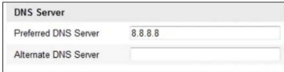
- If the DNS server sengs are required for some applicaons (e.g., sending email), you should properly conjure the Preferred DNS Server and Alternate DNS server.
text_image
DNS Server Preferred DNS Server 8.8.8.8 Alternate DNS ServerFigure 6-8 DNS Server Sengs

The router must support the route adversement funcon if you select Route Adversement as the IPv6 mode.

6.3.2 Conguring Port Sengs
Purpose:
If there is a router and you want to access the speed dome through Wide Area Network (WAN), you need to forward the 3 ports for the speed dome.
Steps:
- Enter the Port Setngs interface:
Conguraon > Basic Conguraon > Network > Port
Or Conguraon > Advanced Conguraon > Network > Port
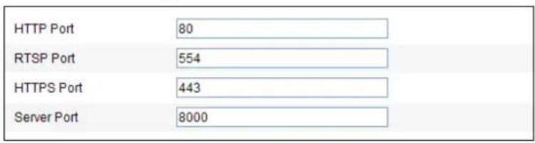
text_image
HTTP Port 80 RTSP Port 554 HTTPS Port 443 Server Port 8000Figure 6-9 Port Sengs
- Set the HTTP port, RTSP port and port of the speed dome.
HTTP Port: The default port number is 80.
RTSP Port: The default port number is 554.
HTTPS Port: The default port number is 443.
Server Port: The default port number is 8000.
- Click to save the sengs.

6.3.3 Conguring PPPoE Sengs
Purpose:

If you have no router but only a modem, you can use Point-to-Point Protocol over Ethernet (PPPoE) funcon.
Steps:
1. Enter the PPPoE Seings interface:
Conguraon >Advanced Conguraon > Network > PPPoE
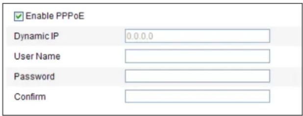
text_image
Enable PPPoE Dynamic IP 0.0.0.0 User Name Password ConfirmFigure 6-10 PPPoE Sengs
- Check the Enable PPPoE checkbox to enable this feature.
- Enter User Name, Password, and Conrm password for PPPoE access.

The User Name and Password should be assigned by your ISP.

- For your privacy and to better protect your system against security risks, we strongly recommend the use of strong passwords for all functions and network devices. The password should be something of your own choosing (using a minimum of 8 characters, including upper case letters, lower case letters, numbers and special characters) in order to increase the security of your product.
-
Proper configuration of all passwords and other security settings is the responsibility of the installer and/or end-user.
-
Click to save and exit the interface.

6.3.4 Conguring DDNS Sengs
Purpose:
If your speed dome is set to use PPPoE as its default network conncon, you can use the Dynamic DNS (DDNS) for network access.
Before you start:
Registraon on the DDNS server is required before conguring the DDNS sengs of the speed dome.

- For your privacy and to better protect your system against security risks, we strongly recommend the use of strong passwords for all functions and network devices. The password should be something of your own choosing (using a minimum of 8 characters, including
upper case letters, lower case letters, numbers and special characters) in order to increase the security of your product.
- Proper configuration of all passwords and other security settings is the responsibility of the installer and/or end-user.
Steps:
- Enter the DDNS Sengs interface:
Conguraon > Advanced Conguraon > Network > DDNS

text_image
Enable DDNS DDNS Type DynDNS Server Address Domain Port 0 User Name Password ConfirmFigure 6-11 DDNS Sengs
- Check the Enable DDNS checkbox to enable this feature.
- Select DDNS Type. Three DDNS types are selectable: IPServer, HiDDNS, NO-IP and DynDNS.
• DynDNS:
Steps:
(1) Enter Server Address of DynDNS (e.g. members.dyndns.org).
(2) In the Domain text eld, enter the domain name obtained from the DynDNS website.
(3) Enter the Port of DynDNS server.
(4) Enter the User Name and Password registered on the DynDNS website.
(5) Click to save the sengs.
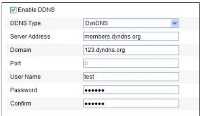
text_image
Enable DDNS DDNS Type DynDNS Server Address members.dyndns.org Domain 123.dyndns.org Port 0 User Name test Password •••••••• Confirm •••••••••Figure 6-12 DynDNS Sengs
- IP Server:
Steps:
(1) Enter the Server Address of the IP Server.
(2) Click to save the sengs.

The Server Address should be entered with the stac IP address of the computer that runs the IP Server soware. For the IP Server, you have to apply a stac IP, subnet mask, gateway and preferred DNS from the ISP.
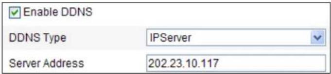
text_image
Enable DDNS DDNS Type IPServer Server Address 202.23.10.117Figure 6-13 IPServer Sengs
- HiDDNS:
Steps:
(1) Enter the Server Address: www.hik-online.com.
(2) Enter the Domain name of the camera. The domain is the same with the device alias in the HiDDNS server.
(3) Click to save the sengs.
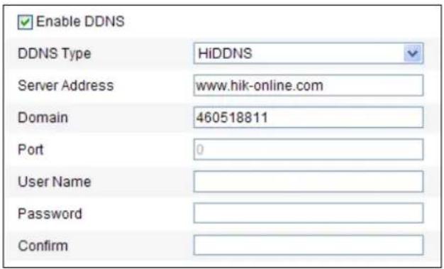
text_image
Enable DDNS DDNS Type HiDDNS Server Address www.hik-online.com Domain 460518811 Port 0 User Name Password ConfirmFigure 6-14 HiDDNS Sengs
- NO-IP:
Steps:
(1) Enter Server Address of NO-IP.
(2) In the Domain text eld, enter the domain name obtained from the NO-IP website.
(3) Enter the Port of NO-IP server.
(4) Enter the User Name and Password registered on the NO-IP website.
(5) Click to save the sengs.

6.3.5 Conguring SNMP Sengs
Purpose:
You can use SNMP to get speed dome status and parameters related informaon.
Before you start:
Before seng the SNMP, please use the SNMP soware and manage to receive the speed dome informaon via SNMP port. By seng the Trap Address, the speed dome can send the alarm event and excepon messages to the surveillance center.

The SNMP version you select should be the same as that of the SNMP soware.
Steps:

1. Enter the SNMP Seings interface:
Conguraon > Advanced Conguraon > Network > SNMP
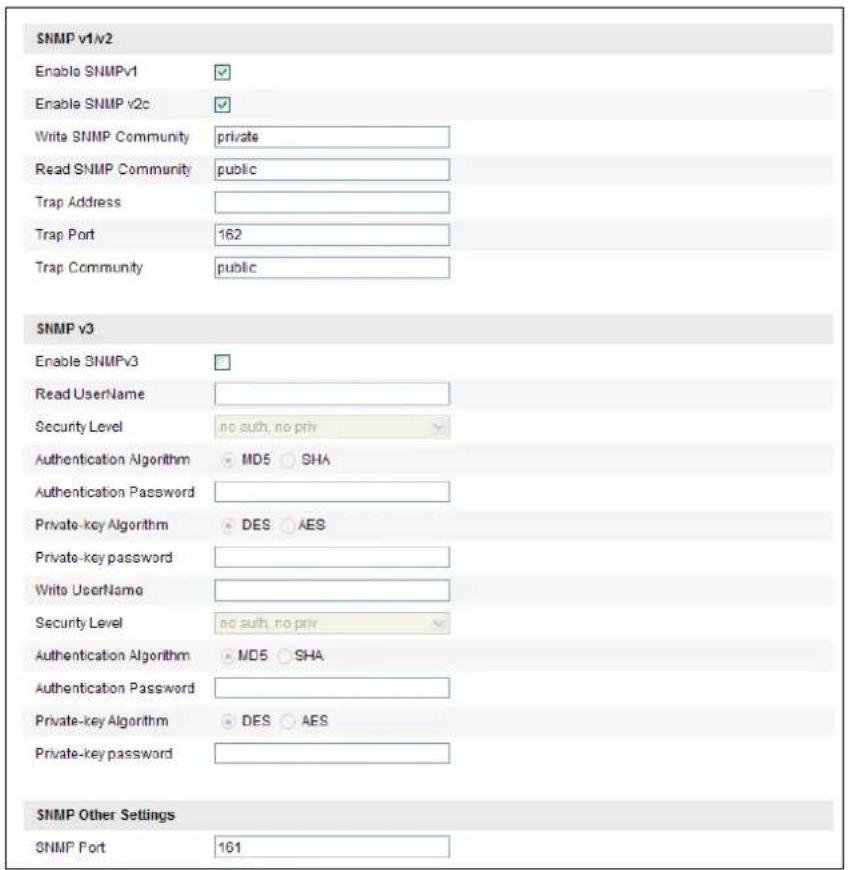
text_image
SNMP v1/v2 Enable SNMPv1 ✓ Enable SNMP v2c ✓ Write SNMP Community private Read SNMP Community public Trap Address Trap Port 162 Trap Community public SNMP v3 Enable SNMPv3 □ Read UserName Security Level no auth, no priv Authentication Algorithm MD5 SHA Authentication Password Private-key Algorithm DES AES Private-key password Write UserName Security Level no auth, no priv Authentication Algorithm MD5 SHA Authentication Password Private-key Algorithm DES AES Private-key password SNMP Other Settings SNMP Port 161Figure 6-15 SNMP Sengs
- Check the corresponding version checkbox (Enable SNMP SNMPv1 Enable SNMP v2c Enable SNMPv3) to enable the feature.
- Congure the SNMP sengs.

The conguraon of the SNMP soware should be the same as the sengs you e here.
- Click to save and nish the sengs.

6.3.6 Conguring 802.1X Sengs
Purpose:
The speed dome supports IEEE 802.1X standard.
IEEE 802.1X is a port-based network access control. It enhances the security level of the LAN. When devices connect to this network with IEEE 802.1X standard, the authencaon is needed. If the authencaon fails, the devices don't connect to the network.
The protected LAN with 802.1X standard is shown as follows:
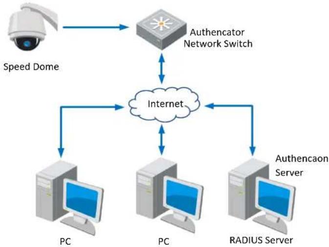
flowchart
graph TD
    A["Speed Dome"] --> B["Authenticator Network Switch"]
    B --> C["Internet"]
    C --> D["PC"]
    C --> E["PC"]
    C --> F["RADIUS Server"]
    D --> G["Authencaon Server"]
    E --> G
    F --> G
Figure 6-16 Protected LAN
- Before connecting the Network Camera to the protected LAN, please apply a digital cercate from a Cercate Authority.
- The network camera requests access to the protected LAN via the authenticator (a switch).
- The switch forwards the identity and password to the authencaon server (RADIUS server).
● The switch forwards the cercate of authencaon server to the network camera. - If all the informaon is validated, the switch allows the network access to the protected network.

- For your privacy and to better protect your system against security risks, we strongly recommend the use of strong passwords for all functions and network devices. The password should be something of your own choosing (using a minimum of 8 characters, including upper case letters, lower case letters, numbers and special characters) in order to increase the security of your product.
- Proper configuration of all passwords and other security settings is the responsibility of the installer and/or end-user.
Steps:
- Connect the network camera to your PC directly with a network cable.
- Enter the 802.1X Sengs interface:
Conguraon > Advanced Conguraon > Network > 802.1X
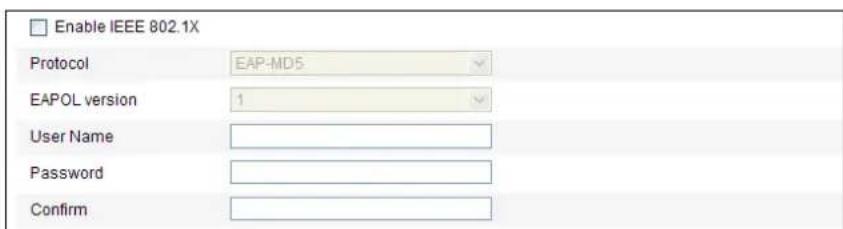
text_image
Enable IEEE 802.1X Protocol EAP-MDS EAPOL version 1 User Name Password ConfirmFigure 6-17 802.1X Sengs
- Check the Enable IEEE 802.1X checkbox to enable it.
- Congure the 802.1X setngs, including user name and password.

The EAP-MD5 version must be identical with that of the router or the switch.
- Click to nish the sengs.

The camera reboots when you save the sengs.
- Aer the conguraon, connect the camera to the protected network.

6.3.7 Conguring QoS Sengs
Purpose:
QoS (Quality of Service) can help solve the network delay and network congeson by conguring the priority of data sending.
Steps:
- Enter the QoS Sengs interface:
Conguraon >Advanced Conguraon > Network > QoS
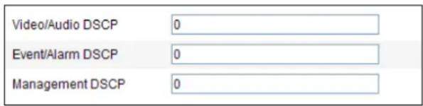
text_image
Video/Audio DSCP 0 Event/Alarm DSCP 0 Management DSCP 0Figure 6-18 QoS Sengs
- Congure the QoS sengs, including video / audio DSCP, event / alarm DSCP and Management DSCP.
The valid DSCP value ranges from 0 to 63. The DSCP value is bigger, the priority is higher.
- Click to save the sengs.

● Make sure that you enable the QoS function of your network device (such as a router).
- It will ask for a reboot for the sengs to take eect.

6.3.8 Conguring FTP Sengs
Purpose:
You can set a FTP server and conjure the following parameters for uploading captured pictures.
Steps:
- Enter the FTP Seings interface:

© Hikvision
Conguraon >Advanced Conguraon > Network > FTP
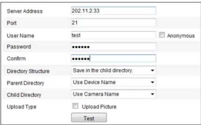
text_image
Server Address 202.11.2.33 Port 21 User Name test Anonymous Password ••••••• Confirm •••••••• Directory Structure Save in the child directory. Parent Directory Use Device Name Child Directory Use Camera Name Upload Type □ Upload Picture TestFigure 6-19 FTP Sengs
- Congure the FTP settings, including server address, port, user name, password, directory and upload type.

The server address supports both the domain name and IP address formats.

- For your privacy and to better protect your system against security risks, we strongly recommend the use of strong passwords for all functions and network devices. The password should be something of your own choosing (using a minimum of 8 characters, including upper case letters, lower case letters, numbers and special characters) in order to increase the security of your product.
- Proper configuration of all passwords and other security settings is the responsibility of the installer and/or end-user.
- Setng the directory in FTP server for saving les:
In the Directory Structure eld, you can select the root directory, parent directory and child directory.
◆ Root directory: The les will be saved in the root of FTP server.
◆ Parent directory: The les will be saved in a folder in FTP server. The name of folder can be dened as shown in following Figure 6-20.
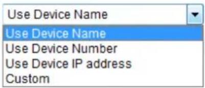
text_image
Use Device Name Use Device Name Use Device Number Use Device IP address CustomFigure 6-20 Parent Directory
◆ Child directory: It is a sub-folder which can be created in the parent directory. The les will be saved in a sub-folder in FTP server. The name of folder can be dened as shown in following Figure 6-21.
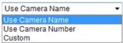
text_image
Use Camera Name Use Camera Name Use Camera Number CustomFigure 6-21 Child Directory
- Upload type: To enable uploading the captured picture to the FTP server.
-
Click to save the sengs.
-
You can click Test to conrm the conguraon.

NOTE If you want to upload the captured pictures to FTP server, you also have to enable the connuous snapshot or event-triggered snapshot in Snapshot interface. For detailed information, please refer to the Secon 7.3 Conguring Snapshot Sengs.

6.3.9 Conguring UPnP™ Sengs
Universal Plug and Play (UPnP™) is a networking architecture that provides compatibility among networking equipment, soware and other hardware devices. The UPnP protocol allows devices to connect seamlessly and to simplify the implementation of networks in the house and corporate environments.
With the funcon enabled, you don't need to conjure the port mapping for each port, and the camera is connected to the Wide Area Network via the router.
Steps:
- Enter the UPnP ^TM settings interface.
Conguraon >Advanced Conguraon > Network > UPnP
- Check the checkbox to enable the UPnP™ funcon.
You can edit the Friendly Name of the speed dome. This name can be detected by corresponding device, such as a router.

text_image
Enable UPnP™ Friendly Name CameraFigure 6-22 Congure UPnP Sengs

6.3.10 Conguring NAT (Network Address Translaon) Sengs
Steps:
- Set the port mapping mode:
To port mapping with the default port numbers:
Choose
Port Mapping Mode
Auto
To port mapping with the customized port numbers:
Choose
Port Mapping Mode
Manual
▼

© Hikvision
And you can customize the value of the port number by yourself.
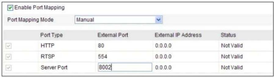
text_image
Enable Port Mapping Port Mapping Mode Manual Port Type External Port External IP Address Status HTTP 80 0.0.0.0 Not Valid RTSP 554 0.0.0.0 Not Valid Server Port 8002 0.0.0.0 Not Valid- Click to save the sengs.

6.3.11 Conguring Email Sengs
Purpose:
The system can be congured to send an Email nocao on to all designated receivers if an alarm event is detected, e.g., moon detecon event, video loss, tamper-proof, etc.
Before you start:
Please congure the DNS Server sengs under Basic Conguraon > Network > TCP/IP or Advanced Conguraon > Network > TCP/IP before using the Email funcon.
Steps:
- Enter the Email Sengs interface:
Conguraon > Advanced Conguraon > Network > Email
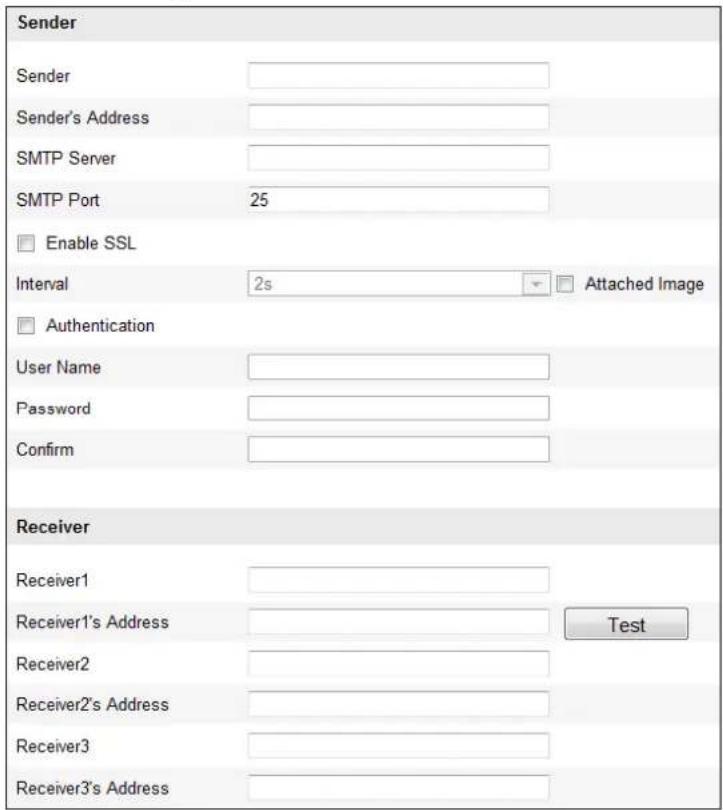
text_image
Sender Sender Sender's Address SMTP Server SMTP Port 25 Enable SSL Interval 2s Attached Image Authentication User Name Password Confirm Receiver Receiver1 Receiver1's Address Test Receiver2 Receiver2's Address Receiver3 Receiver3's AddressFigure 6-23 Email Sengs
- Congure the following sengs:
Sender: The name of the email sender.
Sender's Address: The email address of the sender.
SMTP Server: The SMTP Server IP address or host name (e.g., smtp.263xmail.com).
SMTP Port: The SMTP port. The default TCP/IP port for SMTP is 25.
Enable SSL: Check the checkbox to enable SSL if it is required by the SMTP server.
Aached Image: Check the checkbox of Aached Image if you want to send emails with aached alarm images.
Interval: The interval refers to the me between two acons of sending aached pictures.
Authenticaon (oponal): If your email server requires authencaon, check this checkbox to use authencaon to log in to this server and enter the login user name and password.

- For your privacy and to better protect your system against security risks, we strongly recommend the use of strong passwords for all functions and network devices. The password should be something of your own choosing (using a minimum of 8 characters, including upper case letters, lower case letters, numbers and special characters) in order to increase the security of your product.
- Proper configuration of all passwords and other security settings is the responsibility of the installer and/or end-user.
Receiver: Select the receiver to which the email is sent. Up to 2 receivers can be congured.
Receiver: The name of the user to be noed.
Receiver's Address: The email address of user to be need. (Oponal: click Test to make sure that the email server can send email out.)
- Click to save the sengs.

6.3.12 Conguring Plaorm Access Sengs
● Conguring EZVIZ Cloud P2P
Purpose:
EZVIZ Cloud P2P provides the mobile phone applicaon and as well the service plaorm page to access and manage your connected NVR, which enables you to get a convenient remote access to the surveillance system.
Steps:
- Enter the Plaorm Access conguraon interface.
Conguraon > Advanced Conguraon > Network > Plaorm Access - Check the checkbox of the Enable.
- Select the Plaorm Type as the EZVIZ Cloud P2P in the dropdown list.
- Click the Save button to acvate the sengs.
You can view the register status of the device in the corresponding text.

Among the EZVIZ Cloud P2P and DDNS, you can only select one of them to enable.
6.3.13 Conguring HTTPS Sengs
Purpose:
HTTPS is consisted by SSL&HTTP. It is used for encrypon transmission, identy authencaon network protocol which enhances the security of WEB accessing.

- For your privacy and to better protect your system against security risks, we strongly recommend the use of strong passwords for all functions and network devices. The password should be something of your own choosing (using a minimum of 8 characters, including upper case letters, lower case letters, numbers and special characters) in order to increase the security of your product.
- Proper configuration of all passwords and other security settings is the responsibility of the installer and/or end-user.
● To Create Self-signed Cercate:
Steps:
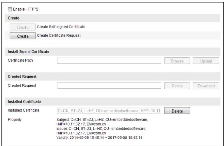
text_image
Enable HTTPS Create Create Self-signed Certificate Create Certificate Request Install Signed Certificate Certificate Path Browse Upload Created Request Created Request Delete Download Installed Certificate Installed Certificate C=CN, ST=ZJ, L=HZ, OU=embeddedsoftware, H/IP=10.11 Property Subject: C=CN, ST=ZJ, L=HZ, OU=embeddedsoftware, H/IP=10.11.32.17, EM=com.cn Issuer: C=CN, ST=ZJ, L=HZ, OU=embeddedsoftware, H/IP=10.11.32.17, EM=com.cn Validity: 2014-05-09 15:45.14 ~ 2017-05-08 15:45.14 DeleteFigure 6-24 HTTPS Sengs
- Click Create on the le of Create Self-signed Certificate.
- In the pop-up interface, input the Country, Hostname/IP, Validity, Password, etc.. Click OK. The Self-signed Cercate informaon is displayed under Installed Cercate. If you need to disable this cercate, click Delete on the right of Installed Cercate.
- Check the checkbox of Enable HTTPS and click the Save button.
● To Install Authoritave Cercate:
For more secure HTTPS access, you can purchase an authoritave cercate from a CA

© Hikvision
(Cercate Authority). Install this cercate to the device.
Steps:
- Click Create on the le of Create Cercate Request.
- In the pop-up interface, input the Country, Hostname/IP, Validity, Password, etc.. Click OK.
- Check the checkbox of Enable HTTPS and click the Save button.
● To access the speed dome via HTTPS:
Steps:
- Open the web browser.
- Input the IP address of the network speed dome and press the Enter key to enter the login interface.

● The default port number of HTTPS is 443. The port value ranges from 1 to 65535.
- When the port number is the default number 443, the format of the URL is hps://IP address, eg., hps://192.168.1.64.
- When the port number is not the default number 443, the format of the URL is hps://IP address:port number, eg., hps://192.168.1.64:81.
6.4 Conguring Video and Audio Sengs
6.4.1 Conguring Video Sengs
Steps:
- Enter the Video Sengs interface:
Conguraon >Basic Conguraon >Video / Audio >Video
Or Conguraon > Advanced Conguraon > Video / Audio > Video
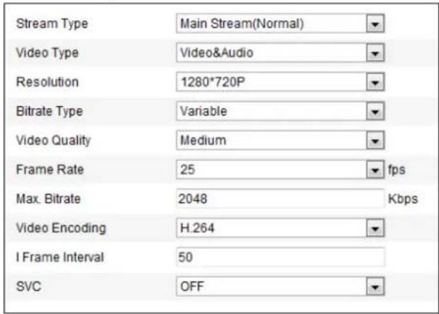
text_image
Stream Type Main Stream(Normal) Video Type Video&Audio Resolution 1280*720P Bitrate Type Variable Video Quality Medium Frame Rate 25 fps Max. Bitrate 2048 Kbps Video Encoding H.264 I Frame Interval 50 SVC OFFFigure 6-25 Congure Video Sengs
- Select the Stream Type of the speed dome to main stream (normal) or sub-stream.
The main stream is usually for recording and live viewing with good bandwidth, and the sub-stream can be used for live viewing when the bandwidth is limited. Refer to the Secon
6.1 Conguring Local Parameters for switching the main stream and sub-stream for live viewing.
- You can customize the following parameters for the selected main stream or sub-stream:
Video Type:
Select the stream type to video stream, or video & audio composite stream. The audio signal will be recorded only when the Video Type is Video & Audio.
Resoluon:
Select the resolution of the video output.
Bitrate Type:
Select the bitrate type to constant or variable.
Video Quality:
When bitrate type is selected as Variable, 6 levels of video quality are selectable.
Frame Rate:
The frame rate is to describe the frequency at which the video stream is updated and it is measured by frames per second (fps). A higher frame rate is advantageous when there is movement in the video stream, as it maintains image quality throughout.
Max. Bitrate:
Set the max. bitrate to 32\~12288Kbps. The higher value corresponds to the higher video
quality, but the higher bandwidth is required.
Video Encoding:
The Video Encoding standard can be set to H.264.
I Frame Interval:
Set the I-Frame interval from 2 to 250.
SVC:
SVC(Scalable video coding technology) is for storing videos when the bandwidth is limited. To use this function, a specied H.264 encoding storage device is necessary.
- Click to save the sengs.

6.4.2 Conguring Audio Sengs
Steps:
- Enter the Audio Sengs interface
Conguraon > Basic Conguraon > Video / Audio > Audio
Or Conguraon > Advanced Conguraon > Video / Audio > Audio
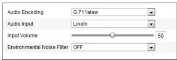
text_image
Audio Encoding G.711alaw Audio Input LineIn Input Volume 50 Environmental Noise Filter OFFFigure 6-26 Audio Sengs
- Congure the following sengs.
Audio Encoding: G.722.1, G.711ulaw, G.711alaw, MP2L2 and G.726 selectable.
Audio Input: When an intercom is connected to the speed dome, you need to set this opon to LineIn. When a microphone is connected to the speed dome, you need to set this opon to MicIn.
Audio Stream Bitrate: When the Audio Encoding is selected as MP2L2, you can conjure the Audio Stream Bitrate in the dropdown list. The greater the value is, the beer the audio quality will be.
Sampling Rate: When the Audio Encoding is selected as MP2L2, you can congregate the Sampling Rate in the dropdown list. The greater the value is, the beer the audio quality will be.
Input Volume: Slid the bar to turn up/down the volume. The value ranges from 0 to 100.
Environmental Noise Filter: Select ON or OFF in the dropdown list to enable or disable the funcon. It's recommended to enable the funcon when the sampling rate is lower than 32kHz.
- Click to save the sengs.


6.4.3 Conguring ROI Sengs
Before you start:
ROI (Region of Interest) encoding is used to enhance the quality of images which are specified in advance.
Stream Type:
You can set the ROI funcon for main stream or sub stream. Select a stream type and then congure the ROI sengs.
- Fixed Region: The xed region encoding is the ROI encoding for the manually congured area. And you can choose the Image Quality Enhancing level for ROI encoding, and you can also name the ROI area.
Steps:
- Select a Region No..
- Check the checkbox of Enable under Fixed Region.
- Click Draw Area and draw a red frame in the live view image.
- Adjust the ROI level from 1 to 6. The higher the value, the better image quality in the red frame.
- Enter a Region Name and click Save to save the settings.
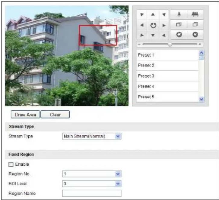
text_image
Draw Area Clear Stream Type Stream Type Main Stream(Normal) Fixed Region Enable Region No. 1 ROI Level 3 Region NameFigure 6-27 Region of Interest

6.5 Conguring Image Sengs
6.5.1 Conguring Display Sengs
Purpose:
You can set the image quality of the speed dome, including brightness, contrast, saturaon, sharpness, etc.

- The parameters in Display Setngs interface vary depending on the models of speed dome.
- You can double click the live view to enter full screen mode and double click it again to exit.
Steps:
- Enter the Display Sengs interface:
Conguraon > Basic Conguraon> Image> Display Sengs
Or Conguraon > Advanced Conguraon> Image> Display Sengs
- You can select the Mounng Scenario in the dropdown list with dierent predened image parameters.
- Set the image parameters of the speed dome.

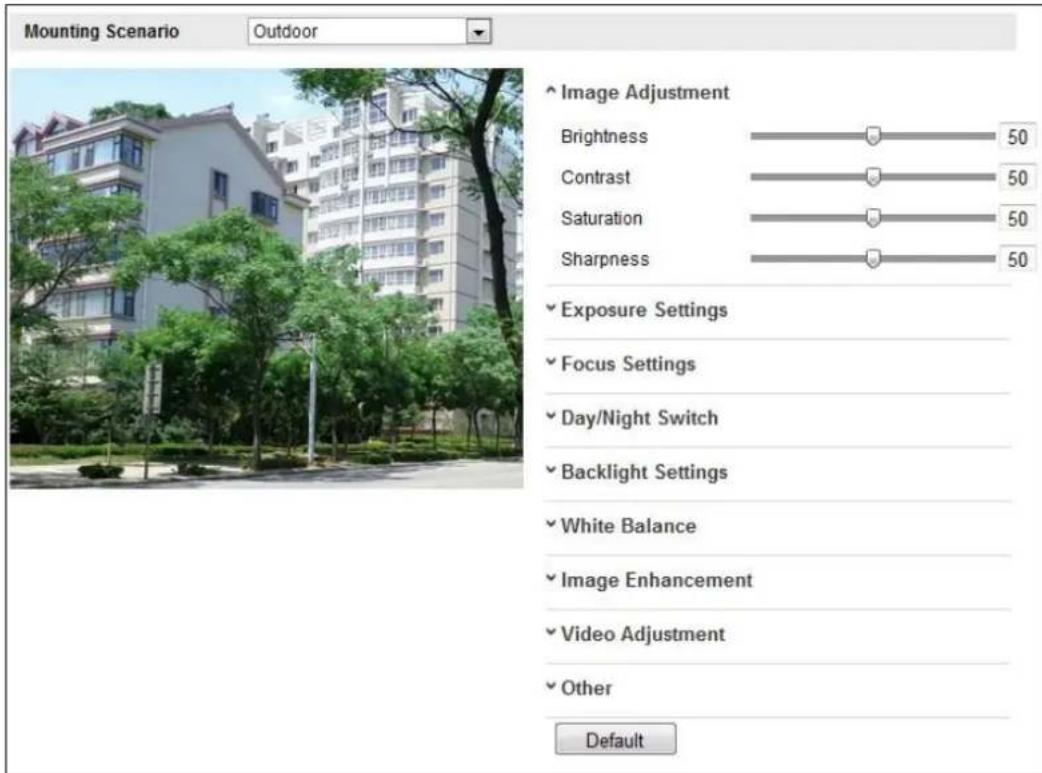
text_image
Mounting Scenario Outdoor Image Adjustment Brightness 50 Contrast 50 Saturation 50 Sharpness 50 ✓ Exposure Settings ✓ Focus Settings ✓ Day/Night Switch ✓ Backlight Settings ✓ White Balance ✓ Image Enhancement ✓ Video Adjustment ✓ Other DefaultFigure 6-28 Display Sengs
Image Adjustment
- Brightness
This feature is used to adjust brightness of the image. The value ranges from 0 to 100.
- Contrast
This feature enhances the dience in color and light between parts of an image. The value ranges from 0 to 100.
- Saturaon
This feature is used to adjust color saturation of the image. The value ranges from 0 to 100.
- Sharpness
Sharpness funcon enhances the detail of the image by sharpening the edges in the image. The value ranges from 0 to 100.

This funcon varies depending on the models of speed dome.
Exposure Sengs
- Exposure Mode
The Exposure Mode can be set to Auto, Iris Priority, Shuer Priority, Manual.
Auto:
The iris, shuer and gain values will be adjusted automatically according to the brightness of the environment. You can set the iris range and shuer ranges by seng the Max. Iris Limit, Min. Iris Limit, Max. Shuer Limit, and Min. Shuer Limit respectively.
◆ Iris Priority:
The value of iris needs to be adjusted manually. The shuer and gain values will be adjusted automatically according to the brightness of the environment.

text_image
Exposure Mode Iris Priority Iris f2.4Figure 6-29 Manual Iris
◆ Shuer Priority:
The value of shuer needs to be adjusted manually. The iris and gain values will be adjusted automatically according to the brightness of the environment.
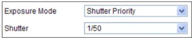
text_image
Exposure Mode Shutter Priority Shutter 1/50Figure 6-30 Manual Shuer
◆ Gain Priority:
The value of gain needs to be adjusted manually. The shuer and iris values will be adjusted automatically according to the brightness of the environment.

text_image
Gain 49Figure 6-31 Manual Gain
◆ Manual:
In Manual mode, you can adjust the values of Gain, Shutter, Iris manually.

This funcon varies depending on the models of speed dome.
- Limit Gain
This feature is used to adjust gain of the image. The value ranges from 0 to 100.
- Slow Shuer
This funcon can be used in underexposure condition. The slow shuer value can be set to Slow Shuer*2, *4, *6, *12, *16, *24 and *32.
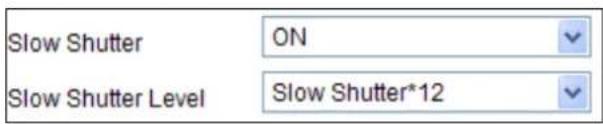
text_image
Slow Shutter ON Slow Shutter Level Slow Shutter*12Figure 6-32 Slow Shuer
Focus Sengs
- Focus Mode
The Focus Mode can be set to Auto, Manual, Semi-auto.
Auto:
The speed dome focuses automacally at any me according to objects in the scene.
◆ Semi-auto:
The speed dome focuses automacally only once aer panning, Ing and zooming.
◆ Manual:
In Manual mode, you need to use on the control panel to focus manually.
● Min. Focus Distance
This funcon is used to limit the minimum focus distance. The value can be set to 1.5m, 3m, 6m, 10cm and 50cm.

The minimum focus value varies depending on the models of speed dome.
Day/Night Switch
● Day/Night Switch
The Day/Night Switch mode can be set to Auto, Day and Night.
Auto:
In Auto mode, the day mode and night mode can switch automacally according to the light condition of environment. The switching sensitivity can be set to Low, Normal, High.

text_image
Day/Night Switch Auto Sensitivity NormalFigure 6-33 Auto Mode Sensitivity
Day:
In Day mode, the speed dome displays color image. It is used for normal lightng condions.
◆ Night:
In Night mode, the image is black and white. Night mode can increase the sensitivity in low light conditions.
◆ Schedule:
In Schedule mode, you can set the me schedule for day mode as shown in Figure 6-34. The rest me out of the schedule is for night mode.

This funcon varies depending on the models of speed dome.
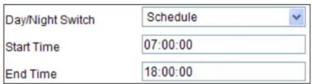
text_image
Day/Night Switch Schedule Start Time 07:00:00 End Time 18:00:00Figure 6-34 Day Night Schedule
- IR Light Mode
IR light mode can be set to Auto and Manual.
◆ Auto: The brightness of the infrared light will be adjusted automacally. IR Light Sensitivity value ranges from 0 to 100. Trigger Mode can be set to Camera or Photosensitive.
◆ Manual: you need to adjust the brightness value of infrared light manually. IR Light Bright value ranges from 0 to 100.

Only the IR speed domes support IR Light Mode.

- When the IR Light Mode is auto, the day/night mode is adjusted automatically according to the IR Light Mode. Manually seng the day/night mode is invalid.
- When the IR Light Mode is manual and the IR Light Bright is 0, you can set the day/night mode manually.
- When the IR Light Mode is manual and the IR Light Bright is not 0, the night mode is set as the default mode. Manually seng the day/night mode is invalid.
Backlight Sengs
BLC
If there's a bright backlight, the subject in front of the backlight appears silhoueed or dark. Enabling BLC(back light compensaon) funcon can correct the exposure of the subject. But the
backlight environment is washed out to white.
● WDR (Wide Dynamic Range)
The wide dynamic range (WDR) funcon helps the camera provide clear images even under back light circumstances. When there are both very bright and very dark areas simultaneously in the eld of view, WDR balances the brightness level of the whole image and provide clear images with details.
You can enable or disable the WDR funcon as shown in Figure 6-35. The wide dynamic level ranges from 0 to 100.

text_image
WDR Enable Wide Dynamic Level 1 34Figure 6-35 WDR

This funcon varies depending on the models of speed dome.
HLC
HLC (High Light Compensaon) makes the camera identify and suppress the strong light sources that usually are across a scene. This makes it possible to see the detail of the image that would normally be hidden.
White Balance
The White Balance mode can be set to Auto, MWB, Outdoor, Indoor, Fluorescent Lamp, Sodium Lamp and Auto-Track.
Auto:
In Auto mode, the camera retains color balance automacally according to the current color temperature.
◆ Manual White Balance:
In MWB mode, you can adjust the color temperature manually to meet your own demand as shown in Figure 6-36.

text_image
WB Gain Circuit R WB Gain Circuit BFigure 6-36 Manual White Balance
Outdoor
You can select this mode when the speed dome is installed in outdoor environment.
Indoor
You can select this mode when the speed dome is installed in indoor environment.
Fluorescent Lamp
You can select this mode when there are uorescent lamps installed near the speed dome.
♦ Sodium Lamp
You can select this mode when there are sodium lamps installed near the speed dome.
Auto-Track
In Auto-Track mode, white balance is connuously being adjusted in real-me according to the color temperature of the scene illuminaon.

This funcon varies depending on the models of speed dome.
Image Enhancement
● 3D Digital Noise Reducon
You can enable or disable the 3D Digital Noise Reducon function as shown in Figure 6-37. The level ranges from 0 to 100.

text_image
Digital Noise Reduction Normal Mode Noise Reduction Level 50Figure 6-37 3D Digital Noise Reducon

This funcon varies depending on the models of speed dome.
Video Adjustment
- Mirror
If you turn the MIRROR funcon on, the image will be ipped. It is like the image in the mirror. The ip direcon can be set to OFF or CENTER.

This funcon varies depending on the models of speed dome.
- Video Standard
You can set the Video Standard to 50hz(PAL) or 60hz(NTSC) according to the video system in your country.

This funcon varies depending on the models of speed dome.
- Capture Mode
You can disable this funcon or set the value as 1280*720@30fps or 1280*960@30fps.

This funcon varies depending on the models of speed dome.
Other
- Lens Inializaon
The lens operates the movements for initializaon when you check the check box of Lens Inializaon.
- Zoom Limit
You can set Zoom Limit value to limit the maximum value of zooming. The value can be set to 20, 40, 80, 160 and 320.

This funcon varies depending on the models of speed dome.
6.5.2 Conguring OSD Sengs
Purpose:
The speed dome supports following on screen displays:
Time: Supports for me display.
Camera Name: Idenes the name of speed dome.
You can customize the on screen display of me.
Steps:
- Enter the OSD Setngs interface:
Conguraon > Advanced Conguraon > Image > OSD Setngs
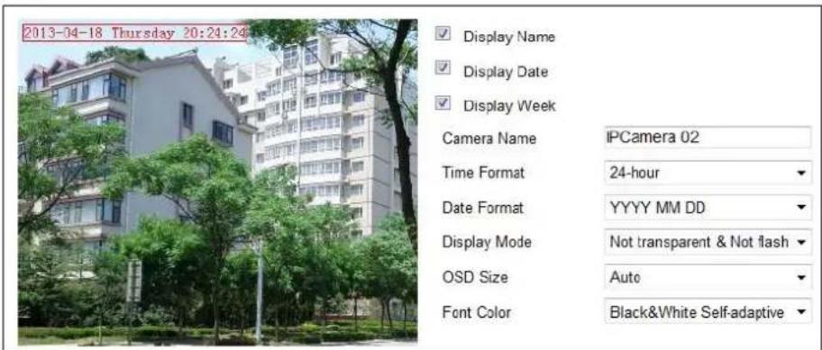
text_image
2013-04-18 Thursday 20:24:24 Display Name Display Date Display Week Camera Name IPCamera 02 Time Format 24-hour Date Format YYYY MM DD Display Mode Not transparent & Not flash OSD Size Auto Font Color Black&White Self-adaptiveFigure 6-38 OSD Sengs
- Check the corresponding checkbox to select the display of speed dome name, date or week if required.
- Edit the speed dome name in the text eld of Camera Name.
- Select from the drop-down list to set the me format, date format, display mode, OSD size and Font color.
- You can use the mouse to click and drag the text frame IPDome2 in the live view window to adjust the OSD posion.
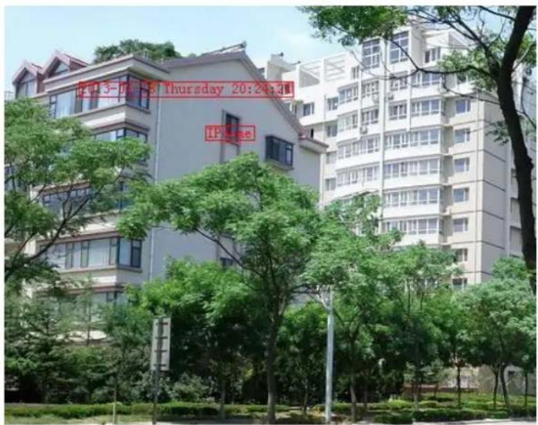
text_image
13-04-58 Thursday 20:24:11 IF DateFigure 6-39 Adjust OSD Locaon
- Click to acvate above sengs.

6.5.3 Conguring Text Overlay Sengs
Purpose:
You can customize the text overlay.
Steps:
- Enter the Text Overlay Sengs interface:
Conguraon > Advanced Conguraon > Image > Text Overlay - Check the checkbox in front of textbox to enable the on-screen display.
- Input the characters in the textbox.
-
Use the mouse to click and drag the red text frame Text in the live view window to adjust the text overlay posion.
-
Click . Save

NOTE There are up to 4 text overlays congorable. When the video resoluon is 1080p, only one text overlay is supported. When PTZ direcon, preset OSDs are displayed, the text overlay is disabled.
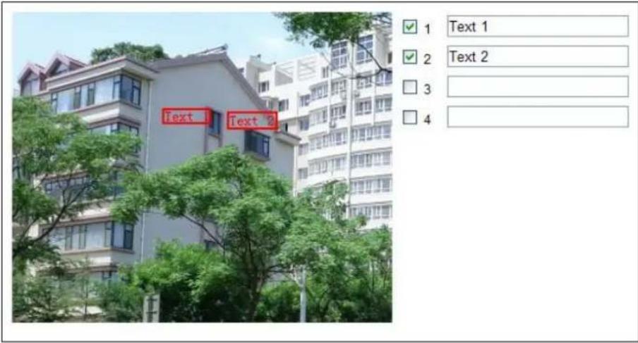
text_image
Text 1 Text 2 3 4Figure 6-40 Text Overlay Sengs

6.6 Conguring and Handling Alarms
Purpose:
This secon explains how to conjure the network speed dome to respond to alarm events, including moon detecon, video tampering and excepon. These events can trigger the alarm acons, such as Nofy Surveillance Center, Send Email, Trigger, etc.
For example, when moon detecon is triggered, the network speed dome sends a nocaon to an e-mail address.
6.6.1 Conguring Moon Detecon
Purpose:
Moon detecon is a feature which can trigger alarm acons and actions of recording videos when the moon occurred in the surveillance scene.
Steps:
- Enter the moon detecon seng interface:
Conguraon > Advanced Conguraon> Basic Event > Moon Detecon
- Check the checkbox of the Enable Moon Detecon to enable this funcon.
You can check the Enable Dynamic Analysis for Moon checkbox if you want the detected object get marked with rectangle in the live view.
- Select the conguraon mode as Normal or Expert and set the corresponding moon detecon parameters.
- Normal
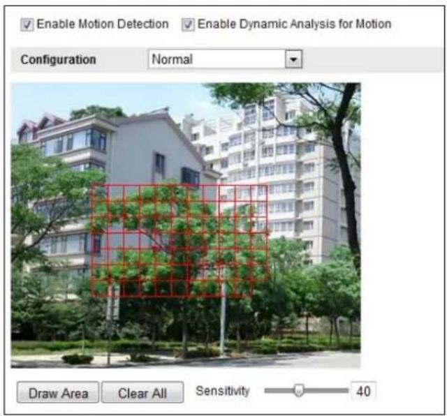
text_image
Enable Motion Detection Enable Dynamic Analysis for Motion Configuration Normal Draw Area Clear All Sensitivity 40Figure 6-41 Moon Detecon Sengs-Normal
Steps:
(1) Draw Area. Click and drag the mouse on the live video image to draw a moon detecon area.
(2) Click to nish drawing.

- You can draw up to 8 moon detecon areas on the same image.
- You can click to clear all of the areas.
(3) Move the slider to set the sensitivity of the detecon.
- Expert
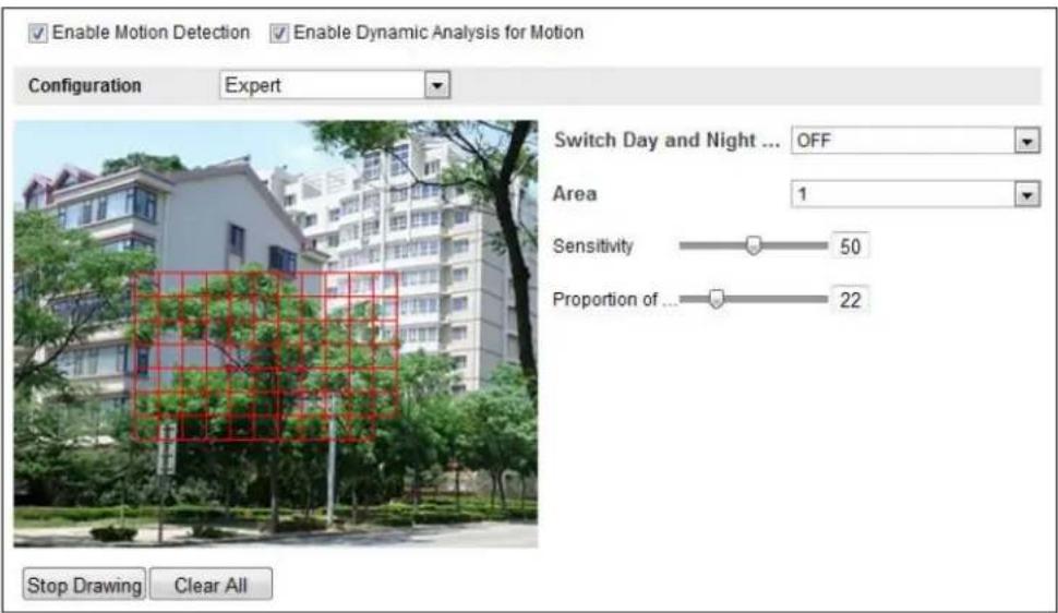
text_image
Enable Motion Detection Enable Dynamic Analysis for Motion Configuration Expert Switch Day and Night ... OFF Area 1 Sensitivity 50 Proportion of ... 22 Stop Drawing Clear AllFigure 6-42 Moon Detecon Sengs-Expert
Steps:
(1) Set the Day&Night switch mode, there are OFF, Auto-Switch and Scheduled-Switch selectable. If the Day&Night switch mode is enabled, you can congregate the detector rule for the day and night separately.
OFF: Disable the day and night switch.
Auto-Switch: Switch the day and night mode according to the illuminaon automacally.
Scheduled-Switch: Switch to the day mode at 6:00 a.m., and switch to the night mode at 18:00 p.m..
(2) Select Area No. to congure in the dropdown list.
(3) Set the values of sensitivity and proportion of object on area.
Sensitivity: The greater the value is, the easier the alarm will be triggered.
Proporon of Object on Area: When the size proporon of the moving object exceeds the predened value, the alarm will be triggered. The less the value is, the easier the alarm will be triggered.
- Set the Arming Schedule for Moon Detecon.
(1) Click to pop

bar
Arming Schedule | Day | Arming Schedule | |---|---| | Mon | 1 | | Tue | 1 | | Wed | 1 | | Thu | 1 | | Fri | 1 | | Sat | 1 | | Sun | 1 | EditFigure 6-43 Arming Schedule
(2) Choose the day you want to set the arming schedule.
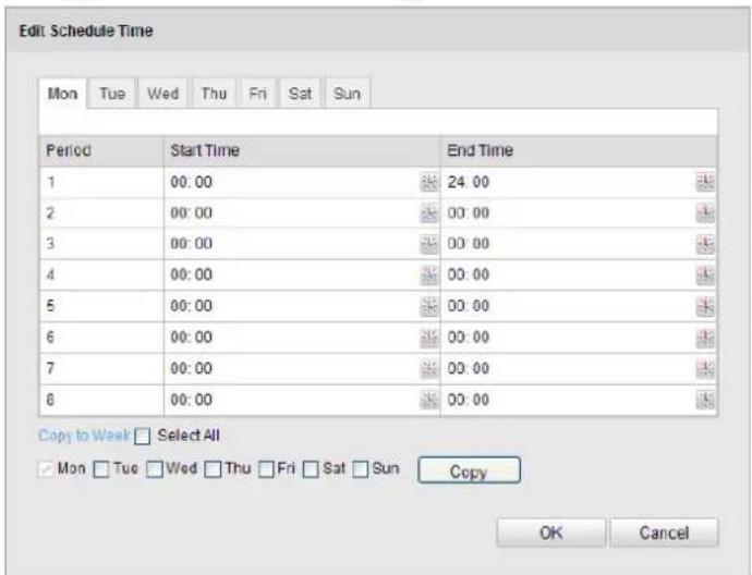
text_image
Edit Schedule Time Mon Tue Wed Thu Fri Sat Sun Period Start Time End Time 1 00:00 24:00 2 00:00 00:00 3 00:00 00:00 4 00:00 00:00 5 00:00 00:00 6 00:00 00:00 7 00:00 00:00 8 00:00 00:00 Copy to Week □ Select All □ Mon □ Tue □ Wed □ Thu □ Fri □ Sat □ Sun Copy OK CancelFigure 6-44 Arming Time Schedule
(3) Click to set the me period for the arming schedule.
(4) (Oponal) Aer you set the arming schedule, you can click to copy the schedule to other days.
(5) Click to save the sengs.

The me of each period cannot be overlapped. Up to 8 periods can be congured for say.
5. Set the Alarm Acons for Moon Detecon.
You can specify the linkage method when an event occurs. The following contents are about how to conjure the dierent types of linkage method.
| Linkage Method | |
| Normal Linkage | Other Linkage |
| □ Notify Surveillance Center □ Send Email □ Upload to FTP □ Trigger Channel | Trigger Alarm Output □ Select All □ A->1 □ A->2 |
Figure 6-45 Linkage Method
Check the checkbox to select the linkage method. Nofy surveillance center, send email, upload to FTP, trigger channel and trigger alarm output are selectable.
● Nofy Surveillance Center
Send an excepon or alarm signal to remote management soware when an event occurs.
- Send Email
Send an email with alarm informaon to a user or users when an event occurs.

To send the Email when an event occurs, you need to refer to Secon 6.3.11 Conguring Email Sengs to set the Email parameters.
- Upload to FTP
Capture the image when an alarm is triggered and upload the picture to a FTP server.

You need a FTP server and set FTP parameters rst. Refer to Secon 6.3.8 Conguring FTP Sengs for seng FTP parameters.
- Trigger Channel
Record a video when an event occurs.

You have to set the recording schedule to realize this funcon. Please refer to Secon 7.2 Conguring Recording Schedule for sengs the recording schedule.
- Trigger Alarm Output
Trigger one or more external alarm outputs when an event occurs.

To trigger an alarm output when an event occurs, please refer to Secon 6.6.4 Conguring Alarm Output to set the alarm output parameters.

6.6.2 Conguring Video Tampering Alarm
Purpose:
You can congregate the speed dome to trigger the alarm acons when the lens is covered.
Steps:
- Enter the Video Tampering Setngs interface :
Conguraon > Advanced Conguraon > Basic Event > Video Tampering

text_image
Enable Video Tampering Area Settings Draw Area Clear All SensitivityFigure 6-46 Tampering Alarm
- Check Enable Video Tampering checkbox to enable the tampering detecon.
- Set the tampering area. Refer to Step 1 Set the Moon Detecon Area in Secon 6.6.1 Conguring Moon Detecon.
- Click Edit to edit the arming schedule for tampering. The arming schedule conguraon is the same as the seng of the arming schedule for moon detecon. Refer to Step 2 Set the Arming Schedule for Moon Detecon in Secon 6.6.1 Conguring Moon Detecon.
- Check the checkbox to select the linkage method taken for the tampering. Nofy surveillance center, send email and trigger alarm output are selectable. Please refer to Step 3 Set the Alarm Acons for Moon Detecon in Section 6.6.1 Conguring Moon Detecon.
- Click to save the sengs.


6.6.3 Conguring External Alarm Input
Steps:
- Enter the Alarm Input Sengs interface:
Conguraon > Advanced Conguraon> Basic Event > Alarm Input:
-
Choose the alarm input No. and the Alarm Type. The alarm type can be NO (Normally Open) and NC (Normally Closed).
-
Edit the name in Alarm Name to set a name for the alarm input (oponal).
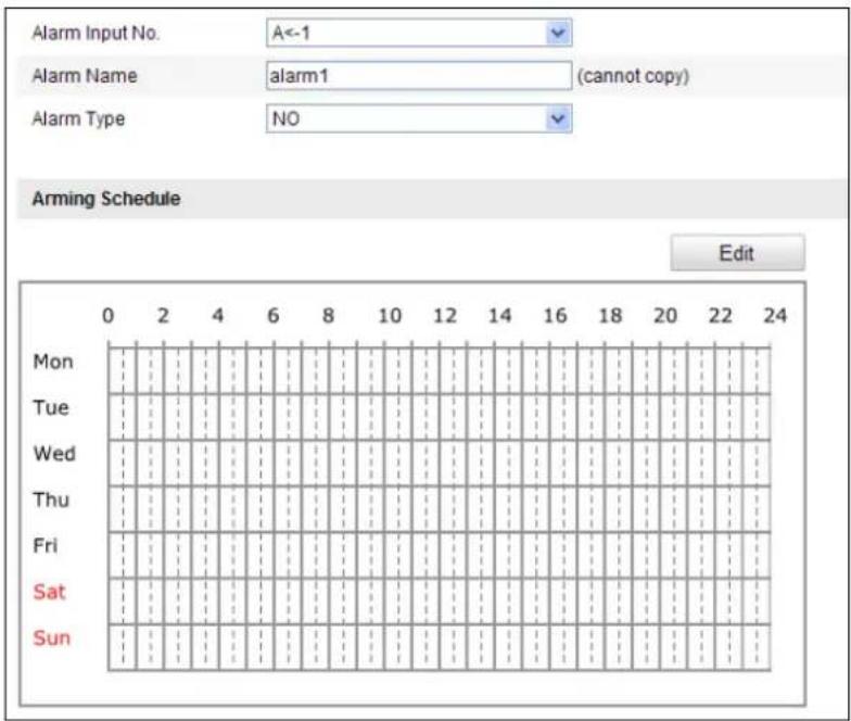
text_image
Alarm Input No. A<-1 Alarm Name alarm1 (cannot copy) Alarm Type NO Arming Schedule Edit Mon Tue Wed Thu Fri Sat Sun 0 2 4 6 8 10 12 14 16 18 20 22 24Figure 6-47 Alarm Input Sengs
- Click Edit to set the arming schedule for the alarm input. Refer to Step 2 Set the Arming Schedule for Moon Detecon in Secon 6.6.1 Conguring Moon Detecon.
- Check the checkbox to select the linkage method taken for the alarm input. Refer to Step 3 Set the Alarm Acons for Moon Detecon in Secon 6.6.1 Conguring Moon Detecon.
- You can also choose the PTZ linking for the alarm input. Check the relave checkbox and select the No. to enable Preset Calling, Patrol Calling or Paern Calling.
- You can copy your seings to other alarm inputs.
- Click to save the sengs.
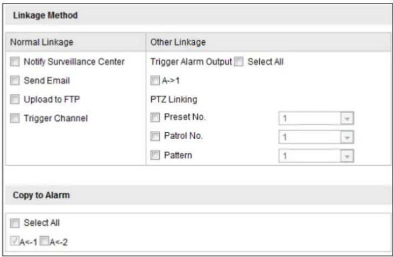
text_image
Linkage Method Normal Linkage Other Linkage □ Notify Surveillance Center □ Send Email □ Upload to FTP □ Trigger Channel Trigger Alarm Output □ Select All □ A->1 PTZ Linking □ Preset No. 1 □ Patrol No. 1 □ Pattern 1 Copy to Alarm □ Select All ✓A<-1 □A<-2Figure 6-48 Linkage Method

6.6.4 Conguring Alarm Output
Steps:
- Enter the Alarm Output Sengs interface:
Conguraon>Advanced Conguraon> Basic Event > Alarm Output - Select one alarm output channel in the Alarm Output drop-down list.
- Set a name in for the alarm output (oponal).
- The Delay me can be set to 5sec, 10sec, 30sec, 1min, 2min, 5min, 10min or Manual. The delay me refers to the me duraon that the alarm output remains in eect aer alarm occurs.
- Click Edit to enter the Edit Schedule Time interface. The time schedule conguraon is the same as the sengs of the arming schedule for moon detection. Refer to Step 2 Set the Arming Schedule for Moon Detecon in Secon 6.6.1 Configuring Moon Detecon.
- You can copy the sengs to other alarm outputs.
- Click to save the sengs.
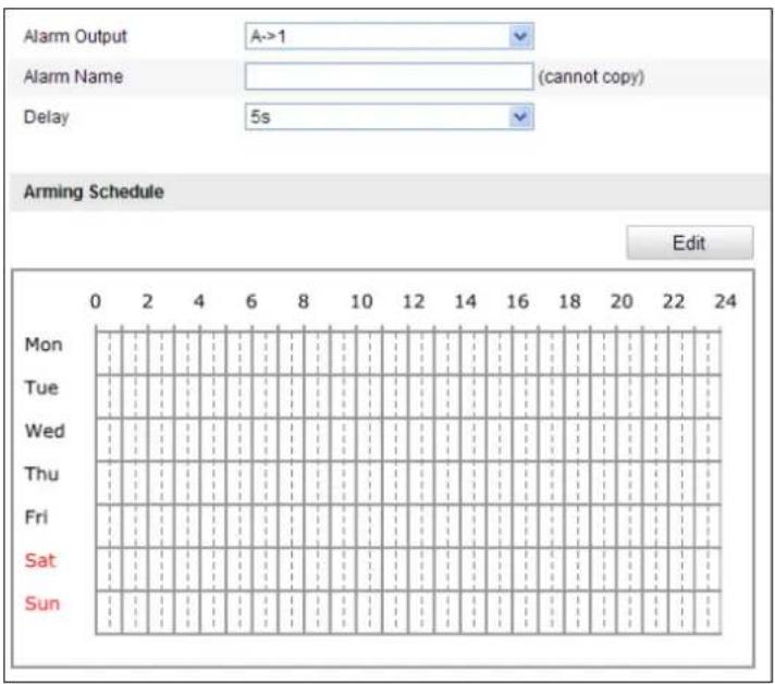
text_image
Alarm Output A->1 Alarm Name (cannot copy) Delay 5s Arming Schedule Edit Mon Tue Wed Thu Fri Sat Sun 0 2 4 6 8 10 12 14 16 18 20 22 24Figure 6-49 Alarm Output Sengs

6.6.5 Handling Excepon
The exception type can be HDD full, HDD error, network disconnected, IP address conicted and illegal login to the speed domes.
Steps:
- Enter the Excepon Sengs interface:
Conguraon > Advanced Conguraon> Basic Event > Excepon
- Check the checkbox to set the acons taken for the Excepon alarm. Refer to Step 3 Set the Alarm Acons Taken for Moon Detecon in Secon 6.6.1 Configuring Moon Detection.
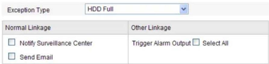
text_image
Exception Type HDD Full Normal Linkage Other Linkage Notify Surveillance Center Trigger Alarm Output Select All Send EmailFigure 6-50 Excepon Sengs
- Click to save the sengs.


6.6.6 Detecng Audio Excepon
Purpose:
When you enable this funcon and audio excepon occurs, the alarm acons will be triggered.
Steps:
- Enter the video audio excepon detecon interface:
Conguraon > Advanced Conguraon > Smart Event > Audio Excepon Detecon

text_image
Exception Detection Audio Loss Detection Sudden Increase of Sound Intensity Detection Sensitivity 50 Sound Intensity Threshold 50 Sudden Decrease of Sound Intensity Detection Sensitivity 50 Real-time VolumeFigure 6-51 Audio Excepon Detecon
- Check the checkbox of Audio Loss Detecon to enable the audio input excepon detecon.
-
Check the checkbox of Sudden Increase of Sound Intensity Detecon checkbox to enable the sudden rise detecon.
-
Sensitivity: Range [1-100], the smaller the value the more severe the sound change will trigger the detecon.
● Sound Intensity Threshold: Range [1-100], it can iter the sound in the environment, the louder the environment sound, the higher the value should be. You can adjust it according to the actual environment. -
Check the checkbox of Sudden Decrease of Sound Intensity Detecon checkbox to enable the sudden drop detecon.
Sensitivity: Range [1-100], the smaller the value the more severe the sound change will trigger the detecon.
- Click Edit to edit the arming schedule. The arming schedule conguraon is the same as the seng of the arming schedule for moon detecon. Refer to Step 2 in Secon 6.6.1.
- Check the checkbox to select the linkage method taken for audio excepon. Nofy surveillance center, send email, trigger alarm output, etc. are selectable. Please refer to Step 3 in Secon 6.6.1.
- Click to save the sengs.

6.6.7 Conguring Dual-VCA
Purpose:
Enable the VCA funcon and then the informaon of the objects (e.g. human, vehicle, etc.) will be marked in the video stream and you can set rules on the connected back-end device to detect the events including line crossing, intrusion, etc..
Steps:
- Enter the Dual-VCA funcon conguraon interface.
Conguraon> Advanced Conguraon> Video/Audio> Display Info. on Stream
- Check the Enable Dual-VCA checkbox.
- Click to save the sengs.
6.6.8 Conguring Intrusion Detecon
Intrusion detecon can set an area in the surveillance scene and once the area is entered, a set of alarm acon is triggered.
Steps:
- Enter the intrusion detecon interface:
Conguraon > Advanced Conguraon > Events > Intrusion Detecon
- Check the Enable Intrusion Detecon checkbox.
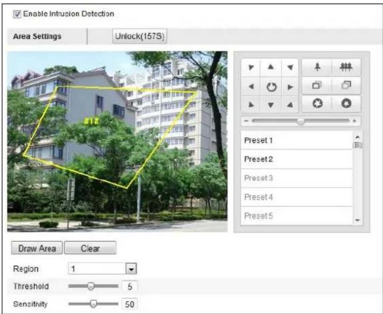
text_image
Enable Intrusion Detection Area Settings Unlock(157S) Preset 1 Preset 2 Preset 3 Preset 4 Preset 5 Draw Area Clear Region 1 Threshold 5 Sensitivity 50Figure 6-52 Conguring Intrusion Area
- The event triggered and park acon related PTZ movement will be locked for 180 seconds
aer you enter the intrusion detecon interface. Oponally, you can click the
Unlock(170S)
buon to manually acvate the movement, or lock the movement when the buon turns to
Lock
by clicking it.
- Draw area.
1) Select the Region No.in dropdown list.
2) Click Draw Area to draw a rectangle on the image as a defense region.
3) Click on the image to specify a corner of the rectangle, and right-click the mouse aer four corners are congured.

Up to four areas are supported.
You can click to clear the areas you drawn.
-
Congure the parameters for each defense region separately.
-
Threshold: Range [0-10s], the threshold for the me of the object loitering in the region. If you set the value as 0, alarm is triggered immediately aer the object entering the region.
-
Sensitivity: Range [1-100]. The value of the sensitivity denotes the size of the object which can trigger the alarm, when the sensitivity is high, a very small object can trigger the alarm.
-
Click Edit to edit the arming schedule for tampering. The arming schedule conguraon is the same as the seng of the arming schedule for moon detecon. Refer to Step 2 in Secon 6.6.1 Conguring Moon Detecon
-
Check the checkbox to select the linkage method taken for the intrusion detecon. Notify surveillance center, send email, trigger channel, smart tracking and trigger alarm output are selectable. Please refer to Step 3 in Secon 6.6.1 Conguring Moon Detection.
-
Click to save the sengs.

6.6.9 Conguring Line Crossing Detecon
The virtual plane detecon can be adopted for the intrusion detecon. Once the virtual plane is detected being traversed according to the congured direcon, a set of alarm acon is triggered.
Steps:
- Enter the Line Crossing Detecon interface:
Conguraon > Advanced Conguraon > Events > Line Crossing Detecon - Check the Line Crossing Detecon checkbox.
- Select the Line in dropdown list to congure.
- The event triggered and park acon related PTZ movement will be locked for 180 seconds
© Hikvision
aer you enter the line crossing detecon interface. Oponally, you can click the
Unlock(170S)
buon to manually acvate the movement, or lock the movement when the buon turns to

by clicking it.

text_image
Enable Line Crossing Detection Line 1 Unlock(115s) Preset 1 Preset 2 Preset 3 Preset 4 Preset 5 Draw Area Clear Direction A<->B Sensitivity 50Figure 6-53 Conguring Line
- Draw area.
1) Click to draw a line on the image.
2) Click the line to switch to the eding mode.
Click and drag an end to the desired place to adjust the length and angle of the line. And click and drag the line to adjust the locaon.

Up to four lines are supported.
-
Congure the parameters for each defense region separately.
-
Direcon: Select the detecon direcon in the dropdown list, there are A<->B, A->B and B->A selectable.
-
Sensitivity: Range [1-100]. The value of the sensitivity denotes the size of the object which can trigger the alarm, when the sensitivity is high, a very small object can trigger the alarm.
-
Click Edit to edit the arming schedule for line crossing detection. The arming schedule conguraon is the same as the seng of the arming schedule for moon detecon. Refer to
Step 2 in Secon 6.6.1 Conguring Moon Detecon.
- Check the checkbox to select the linkage method taken for the line crossing detection. Nofy surveillance center, send email, upload to FTP, trigger channel, smart tracking and trigger alarm output are selectable. Please refer to Step 3 in Secon 6.6.1 Conguring Moon
Detecon.
- Click to save the sengs.

Chapter 7 Record Sengs
Before you start:
To congure record settings, please make sure that you have the network storage device within the network or the Micro SD card inserted in your speed dome.
7.1 Conguring NAS Sengs
Before you start:
The network disk should be available within the network and properly congured to store the recorded les, log les, etc.
Steps:
1. Add the network disk
(1) Enter the NAS (Network-Aached Storage) Sengs interface:
Conguraon > Advanced Conguraon > Storage > NAS
(2) Select the NAS type as NFS or SMB/CIFS. If you select SMB/CIFS, you need to enter the User Name and Password.

- For your privacy and to better protect your system against security risks, we strongly recommend the use of strong passwords for all functions and network devices. The password should be something of your own choosing (using a minimum of 8 characters, including upper case letters, lower case letters, numbers and special characters) in order to increase the security of your product.
- Proper configuration of all passwords and other security settings is the responsibility of the installer and/or end-user.

text_image
HDD No. Type Server Address File Path 1 NAS Mounting Type NFS User Name Password NFS 2 NA SMB/CIFSFigure 7-1 Select NAS Type
(3) Enter the IP address of the network disk. The default NFS storage format of le path is /dvr/test as shown in Figure 7-2. And the default SMB/CIFS storage format of le path is /test.
(4) Click Test to make sure that the NAS is connected successfully.(Oponal)
| HDD No. | Type | Server Address | File Path |
| 1 | NAS | 10.99.105.249 | /dvr/test |
| 2 | NAS | ||
| 3 | NAS | ||
| 4 | NAS |
Figure 7-2 Add Network Disk

The network disk le path name share is user-dened while creang the DVR k storage. Please refer to the User Manual of NAS for creang the le path.
(5) Click to add the network disk.

Aer having saved successfully, you need to reboot the speed dome to acvate the
- Initialize the added network disk.
(1) Enter the HDD Sengs interface (Advanced Configuraon > Storage > Storage Management), in which you can view the capacity, free space, status, type and property of the disk.
(2) If the status of the disk is Uninialized as shown in Figure 7-3, check the corresponding checkbox to select the disk and click format to start inializing the disk.

text_image
HDD Device List Format ✓ HDD No. Capacity Free space Status Type Property Progress ✓ g 0.96GB 0.00GB Uninitialized NAS R/WFigure 7-3 Inialize Disk

text_image
HDD Device List Format ✓ HDD No. Capacity Free space Status Type Property Progress ✓ 9 39.06GB 0.00GB Uninitialized NAS R/W 7%Figure 7-4 Inializing
When the initializaon completed, the status of disk will become Normal as shown in Figure 7-5.

text_image
HDD Device List Format □ HDD No. Capacity Free space Status Type Property Progress □ 9 39.06GB 38.75GB Normal NAS R/WFigure 7-5 View Disk Status
Quota:
In Storage Management interface, you can predene the storage space for storing the pictures and videos by conguring the Percentage of Picture and Percentage of Record manually.

● Up to 8 NAS disks can be connected to the speed dome.
- To inialize and use the SD card aer insert it to the speed dome, please refer to the steps of NAS disk inializaon.

7.2 Conguring Recording Schedule
Purpose:
There are two kinds of recording for the speed domes: manual recording and scheduled recording. For the manual recording, refer to Secon 4.4 Recording and Capturing Pictures Manually. In this secon, you can follow the instrucons to conjure the scheduled recording. By default, the record les of scheduled recording are stored in the SD card (if supported) or in the network disk.
Steps:
- Enter the Record Schedule Sengs interface:
Conguraon > Advanced Conguraon> Storage > Record Schedule
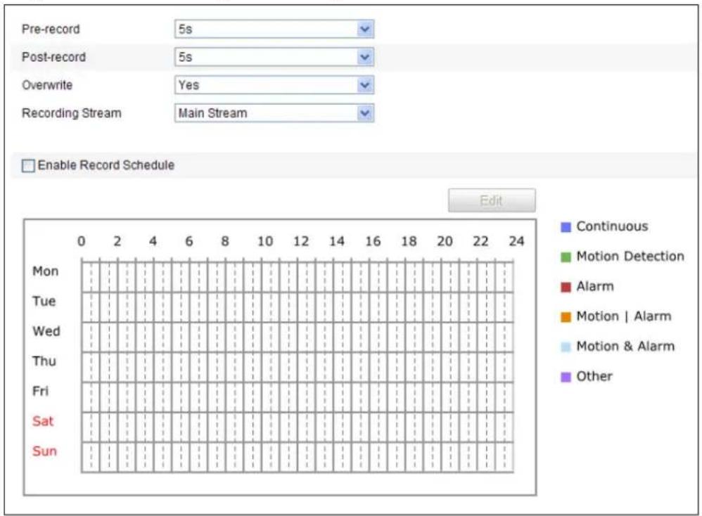
text_image
Pre-record 5s Post-record 5s Overwrite Yes Recording Stream Main Stream Enable Record Schedule Edit Mon Tue Wed Thu Fri Sat Sun Continuous Motion Detection Alarm Motion | Alarm Motion & Alarm OtherFigure 7-6 Recording Schedule Interface
- Check the checkbox of Enable Record Schedule to enable scheduled recording.
- Set the record parameters of the speed dome.
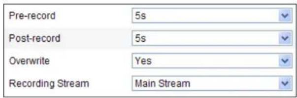
text_image
Pre-record 5s Post-record 5s Overwrite Yes Recording Stream Main StreamFigure 7-7 Record Parameters
● Pre-record: The me you set to start recording before the scheduled me or the event. For example, if an alarm triggers recording at 10:00, and the pre-record me is set as 5 seconds, the speed dome starts to record at 9:59:55.
The Pre-record me can be congured as No Pre-record, 5 s, 10 s, 15 s, 20 s, 25 s, 30 s or not limited.

The pre-record me changes according to the video bitrate.
- Post-record: The me you set to stop recording aer the scheduled me or the event. For example, if an alarm triggered recording ends at 11:00, and the post-record me is set as 5 seconds, the speed dome records until 11:00:05. The Post-record me can be congured as 5 s, 10 s, 30 s, 1 min, 2 min, 5 min or 10 min.
- Overwrite: If you enable his funcon and the HDD is full, the new record les overwrite the oldest record les automacally.
- Recording Stream: You can select the stream type for recording; Main stream and Sub Stream are selectable. If you select the sub stream, you can record for a longer me with the same storage capacity.

The Pre-record and Post-record parameters vary depending on the speed dome
- Click to edit the record schedule.
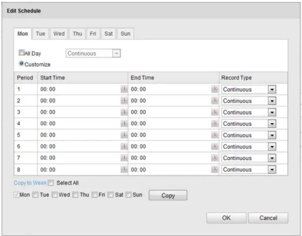
text_image
Edit Schedule Mon Tue Wed Thu Fri Sat Sun All Day Continuous Customize Period Start Time End Time Record Type 1 00:00 00:00 Continuous 2 00:00 00:00 Continuous 3 00:00 00:00 Continuous 4 00:00 00:00 Continuous 5 00:00 00:00 Continuous 6 00:00 00:00 Continuous 7 00:00 00:00 Continuous 8 00:00 00:00 Continuous Copy to Week Select All Mon Tue Wed Thu Fri Sat Sun Copy OK CancelFigure 7-8 Record Schedule
- Choose the day to set the record schedule.
(1) Set all-day record or segment record:
If you want to congregate the all-day recording, please check the All Day checkbox. If you want to record in different time seconds, check the Customize checkbox. Set the Start Time and End Time.

The me of each segment can't be overlapped. Up to 8 segments can be
congured.
(2) Select a Record Type. The record type can be Normal, Moon Detecon, Alarm, Motion | Alarm, Moon & Alarm.
Normal
If you select Normal, the video will be recorded automatically according to the me of the schedule.
◆ Record Triggered by Moon Detecon
If you select Moon Detecon, the video will be recorded when the moon is detected.
Besides conguring the recording schedule, you have to set the moon detecon area and check the checkbox of Trigger Channel in the Linkage Method of Motion Detection Seings interface. For detailed information, please refer to the Step 1 Set the Moon Detecon Area in the Secon 6.6.1 Conguring Moon Detecon.
◆ Record Triggered by Alarm
If you select Alarm, the video will be recorded when the alarm is triggered via the external alarm input channels.
Besides conguring the recording schedule, you have to set the Alarm Type and check the checkbox of Trigger Channel in the Linkage Method of Alarm Input Sengs interface. For detailed informaon, please refer to Secon 6.6.4 Conguring External Alarm Input.
◆ Record Triggered by Moon & Alarm
If you select Moon & Alarm, the video will be recorded when the moon and alarm are triggered at the same me.
Besides conguring the recording schedule, you have to congure the sengs on the Moon Detecon and Alarm Input Sengs interfaces. Please refer to Secon 6.6.1 and Secon 6.6.4 for detailed informaon.
◆ Record Triggered by Moon | Alarm
If you select Moon | Alarm, the video will be recorded when the external alarm is triggered or the moon is detected.
Besides conguring the recording schedule, you have to congure the sengs on the Moon Detecon and Alarm Input Sengs interfaces. Please refer to Secon 6.6.1 and Secon 6.6.4 for detailed informaon.
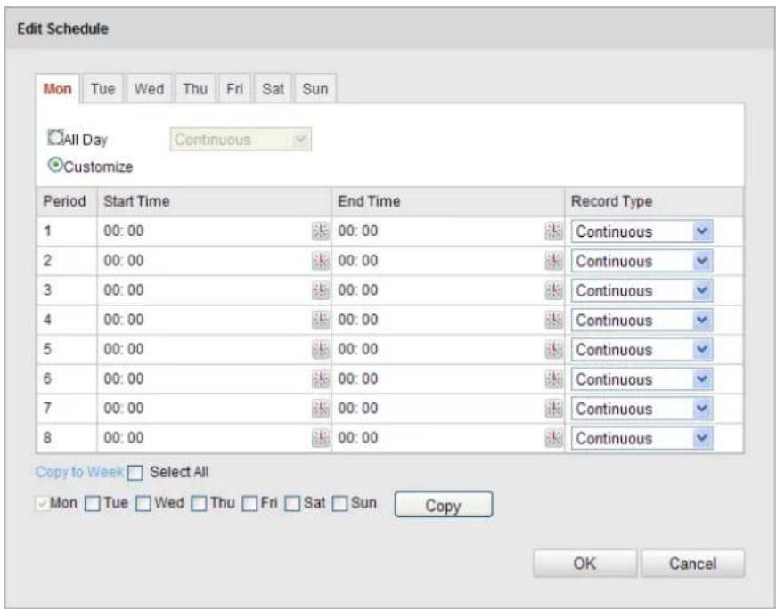
text_image
Edit Schedule Mon Tue Wed Thu Fri Sat Sun All Day Continuous Customize Period Start Time End Time Record Type 1 00:00 00:00 Continuous 2 00:00 00:00 Continuous 3 00:00 00:00 Continuous 4 00:00 00:00 Continuous 5 00:00 00:00 Continuous 6 00:00 00:00 Continuous 7 00:00 00:00 Continuous 8 00:00 00:00 Continuous Copy to Week Select All ✓ Mon □ Tue □ Wed □ Thu □ Fri □ Sat □ Sun Copy OK CancelFigure 7-9 Edit Record Schedule
(3) Check the checkbox ☐ Select All and click Copy to copy sengs of this day to the whole week. You can also check any of the checkboxes before the date and click Copy.
(4) Click OK to save the sengs and exit the Edit Record Schedule interface.
- Click to save the sengs.

7.3 Conguring Snapshot Sengs
Purpose:
You can congregate the scheduled snapshot and event-triggered snapshot. You can upload the captured pictures to a FTP server.
Basic Sengs
Steps:
- Enter the Snapshot Sengs interface:
Conguraon > Advanced Conguraon > Storage > Snapshot - Check the Enable Timing Snapshot checkbox to enable connuous snapshot. Check the Enable Event-triggered Snapshot checkbox to check event-triggered snapshot.
- Select the quality of the snapshot.
- Set the me interval between two snapshots.
- Click to save the sengs.


Uploading to FTP

Please make sure that the FTP server is online.
You can follow below conguraon instrucons to upload the snapshots to FTP.
- Upload connuous snapshots to FTP
Steps:
1) Congure the FTP settings and check ☑ Upload Picture checkbox in FTP Sengs interface. Please refer to Secon 6.3.8 Conguring FTP Sengs for more details to congure FTP parameters.
2) Check the Enable Timing Snapshot checkbox.
3) Click Edit to set the snapshot schedule. Refer to Step 2 Set the Arming Schedule for Moon Detecon in Secon 6.6.1 Conguring Motion Detection.

- Upload event-triggered snapshots to FTP
Steps:
1) Congure the FTP seings and check ✅ Upload Picture checkbox in FTP Sengs interface. Please refer to Secon 6.3.8 Conguring FTP Sengs for more details to congure FTP parameters.
2) Check ☑ Upload to FTP checkbox in Moon Detecon Sengs or Alarm Input interface. Please refer to Step 3 Set the Alarm Acons Taken for Moon Detecon in Secon 6.6.1 Conguring Moon Detecon, or Step 4 Conguring External Alarm Input in Secon 6.6.1 Conguring Moon Detecon.
3) Check the Enable Event-triggered Snapshot checkbox.
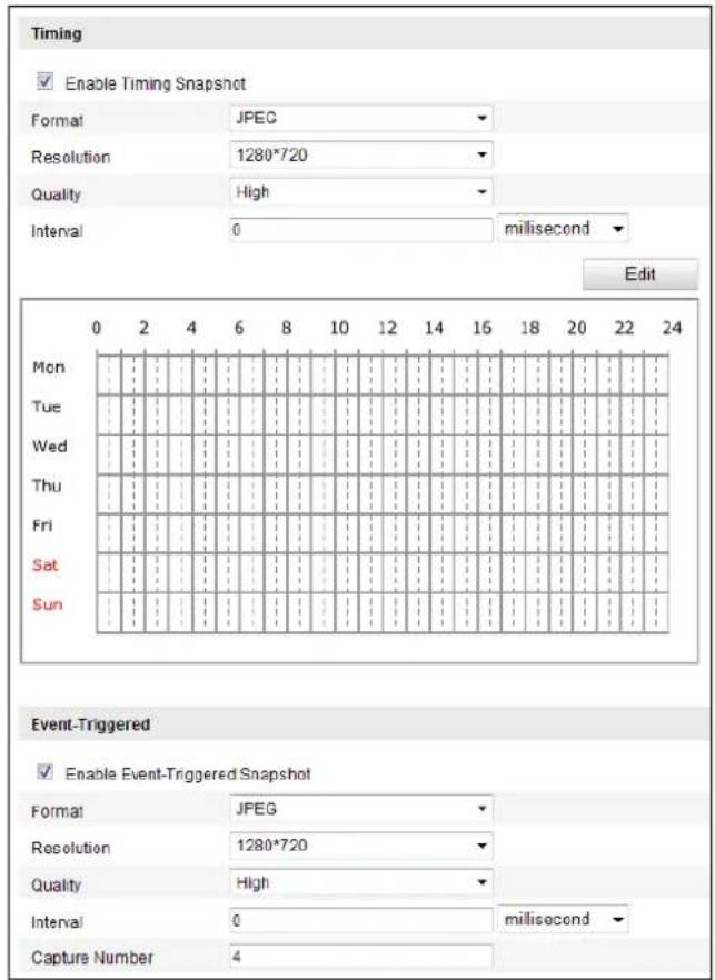
text_image
Timing Enable Timing Snapshot Format JPEG Resolution 1280*720 Quality High Interval 0 millisecond Edit Mon Tue Wed Thu Fri Sat Sun Event-Triggered Enable Event-Triggered Snapshot Format JPEG Resolution 1280*720 Quality High Interval 0 millisecond Capture Number 4Figure 7-10 Snapshot Sengs

Chapter 8 Playback
Purpose:
This secon explains how to view the remotely recorded video les stored in the network disks or SD cards.
Task 1: To play back the video les
Steps:
- Click Playback on the menu bar to enter playback interface.
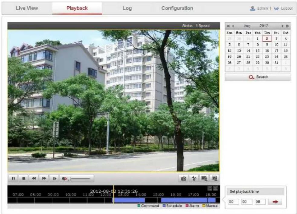
text_image
Live View Playback Log Configuration admin | Logout Status 1 Speed Sun Mon Fri Wed Fri Sat 29 00 14 1 2 3 4 5 8 7 8 9 10 11 12 13 14 15 16 17 18 19 20 21 22 23 24 25 26 27 28 29 30 31 2 3 4 5 5 7 8 Search 2012-08-02 12:31:26 07:00 08:00 09:00 10:00 11:00 12:00 13:00 14:00 15:00 16:00 17:00 18:00 Command Schedule Alarm Manual Set playback time 00 00 00Figure 8-1 Playback Interface
- Select the date and click .

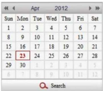
text_image
Sun Mon Tue Wed Thu Fri Sat 1 2 3 4 5 6 7 8 9 10 11 12 13 14 15 16 17 18 19 20 21 22 23 24 25 26 27 28 29 30 4 2 3 4 5 6 7 8 9 10 11 12 SearchFigure 8-2 Search Video
- Click to play the video les found on this date.


The toolbar on the boom of Playback interface can be used to control playing process.

text_image
Screenshot of a media player control bar with playback, audio, and video iconsFigure 8-3 Playback Toolbar
Table 8-1 Descripon of the buons
| Buon | Operaon | Buon | Operaon |
 | Play |  | Capture a picture |
 | Pause |  | Start/Stop clipping video les |
 | Stop |  | Audio on and adjust volume/Mute |
 | Speed down |  | Download video les |
 | Speed up |  | Download captured pictures |
 | Display playback status |  | Playback by frame |

NOTE You can choose the le paths locally for downloaded playback video les and pictures in Local Conguraon interface. Please refer to Secon 6.1 Conguring Local Parameters for details.
Drag the progress bar with the mouse to locate the exact playback point. You can also input the
me and click

to locate the playback point in the Set playback me eld. You can also
click to zoom out/in the progress bar.
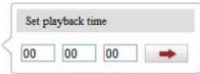
Figure 8-4 Set Playback Time

text_image
2012-04-23 09:57:54 Command Schedule Alarm ManualFigure 8-5 Progress Bar
The different colors of the video on the progress bar stand for the dierent video types as shown in Figure 8-6.

Figure 8-6 Video Types
Task 2: To download the video les
Steps:
- Click on the playback interface. The pop-up menu is shown in Figure 8-7.
- Set the start me and end me. Click Search. The corresponding video les are listed on the le.
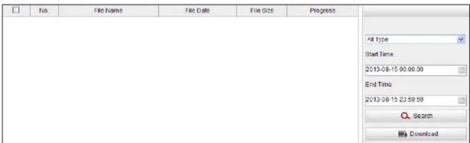
text_image
No. File Name File Date File Size Progress All Type Start Time 2013-08-15 00:00:00 End Time 2013-08-15 23:59:59 Search My DownloadFigure 8-7 Video Downloading interface
- Check the checkbox in front of the video les that you need to download.
- Click to download the video les.


● The progress rao 6% displays the downloading rao of the video le.
- You can click to stop the downloading.
● The total number displays the amount of the video les.
● The video les are not all listed on one page. You can click First Page Prev Page 1/2 Next Page Last Page to turn pages.
Task 3: To download the captured pictures
Steps:
- Click on the playback interface. The pop-up menu is shown in Figure 8-8.
- Set the linkage type of capturing the pictures as ming, alarm, motion, etc..
- Set the start me and end me. Click Search. The corresponding picture les are listed on the le.
- Check the checkbox in front of the les that you need to download.
- Click to download the les.
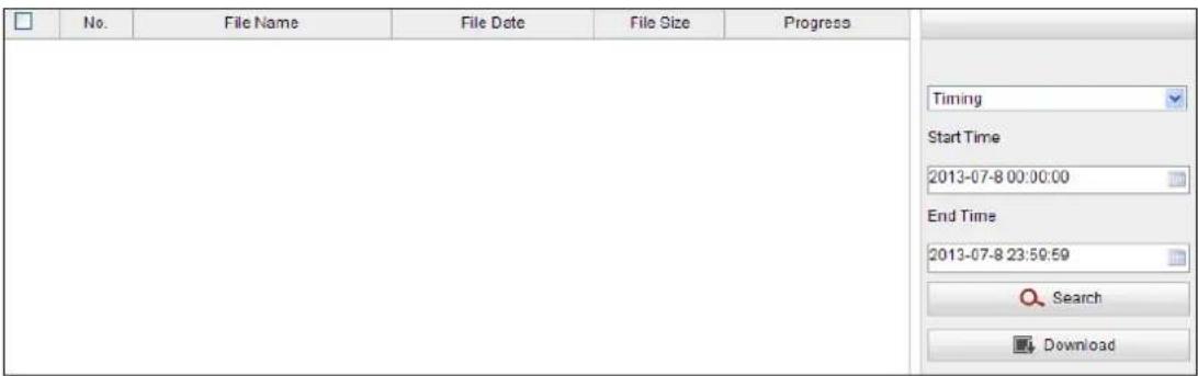
text_image
No. File Name File Date File Size Progress Timing Start Time 2013-07-8 00:00:00 End Time 2013-07-8 23:59:59 Search DownloadFigure 8-8 Picture Downloading interface

Chapter 9 Log Searching
Purpose:
The operation, alarm, exception and informaon of the speed dome can be stored in log les. You can also export the log les on your demand.
Before you start:
Please congure network storage for the speed dome or insert a SD card in the speed dome.
Steps:
- Click on the menu bar to enter log searching interface.
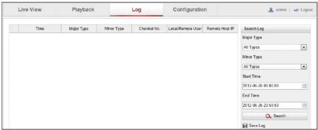
text_image
Live View Playback Log Configuration adults | Logout Time Major Type Miner Type Channel No. Local/Remote User Remote Host IP Search Log Major Type All Types Minor Type All Types Start Time 2012-06-26 00:00:00 End Time 2012-06-26 23:59:59 Search Save LogFigure 9-1 Log Searching Interface
- Set the log search conditions to specify the search, including the Major Type, Minor Type, Start Time and End Time as shown in Figure 9-2.
- Click Search to search log les. The matched log les will be displayed on the Log interface.
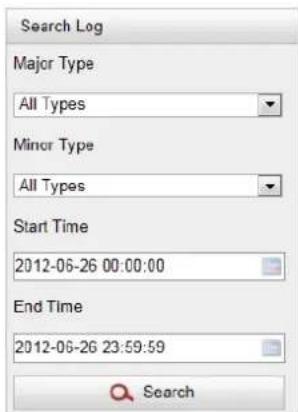
text_image
Search Log Major Type All Types Minor Type All Types Start Time 2012-06-26 00:00:00 End Time 2012-06-26 23:59:59 SearchFigure 9-2 Log Searching
- To export the log les, click Save Log to save the log les in your computer.


Chapter 10 Others
10.1 Managing User Accounts
Enter the User Management interface:
Conguraon >Basic Conguraon> Security >User
Or Conguraon > Advanced Conguraon> Security > User
The admin user has access to create, modify or delete other accounts. Up to 32 user accounts can be created.

text_image
No. User Name Level 1 admin Administrator Add Modify DeleteFigure 10-1 User Informaon
- Add a User
Steps:
-
Click to add a user.
-
Input the new User Name, select Level and input Password.

The level indicates the permissions you give to the user. You can denote the user as
Operator or User.
-
In the Basic Permission eld and Camera Conguraon eld, you can check or uncheck the permissions for the new user.
-
Click OK to nish the user addition.
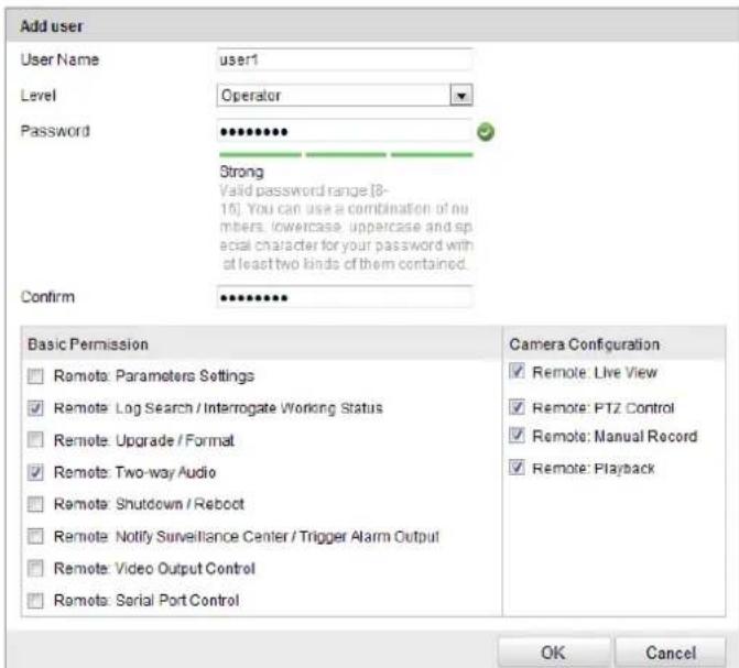
text_image
Add user User Name user1 Level Operator Password •••••••• Strong Valid password range[8-16]. You can use a combination of numbers, lowercase, uppercase and special character for your password with at least two kinds of them contained. Confirm •••••••• Basic Permission □ Remote: Parameters Settings ☑ Remote: Log Search / Interrogate Working Status □ Remote: Upgrade / Format ☑ Remote: Two-way Audio □ Remote: Shutdown / Reboot □ Remote: Notify Surveillance Center / Trigger Alarm Output □ Remote: Video Output Control □ Remote: Serial Port Control Camera Configuration ✓ Remote: Live View ✓ Remote: PTZ Control ✓ Remote: Manual Record ✓ Remote: Playback OK CancelFigure 10-2 Add a User
END
- Modify a User
Steps:
- Le-click to select the user from the list and click .
Modify - Modify the User Name, Level or Password.
- In the Basic Permission eld and Camera Conguraon eld, you can check or uncheck the permissions.
- Click to nish the user modicaon.
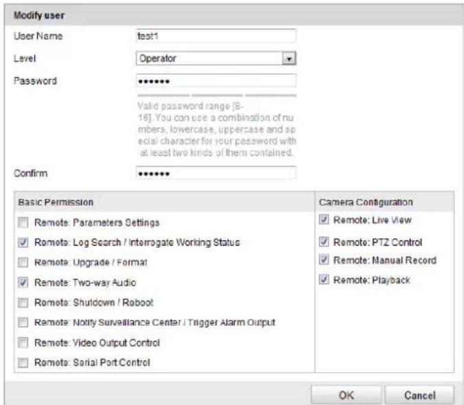
text_image
Modify user User Name test1 Level Operator Password ***** Valid password range [8-16]. You can use a combination of numbers, lowercase, uppercase and special character for your password with at least two kinds of them contained. Confirm ***** Basic Permission Camera Configuration Remote: Parameters Settings Remote: Live View Remote: Log Search / Interrogate Working Status Remote: PTZ Control Remote: Upgrade / Format Remote: Manual Record Remote: Two-way Audio Remote: Playback Remote: Shutdown / Roboot Remote: Notify Surveillance Center / Trigger Alarm Output Remote: Video Output Control Remote: Serial Port Control OK CancelFigure 10-3 Modify a User
END
- Delete a User
Steps:
- Le-click the user name you want to delete and click .
Delete
- Click OK on the pop-up dialogue box to delete the user.
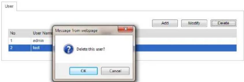
text_image
User No User Name 1 admin 2 lost Message from webpage ? Delete this user? OK Cancel Add Modify DeleteFigure 10-4 Delete a User
END

10.2 Conguring Authencaon Security
Purpose:
You can specifically secure the stream data of live view.
Steps:
- Enter the Authencaon interface:
Conguraon> Advanced Conguraon> Security > Authencaon - Set the authentication mode for each authenticaon type.
RTSP Authentication: Select the authencaon mode as basic or disable in the dropdown list to enable or disable the RTSP authencaon. - Click to save the sengs.

10.3 Conguring Anonymous Visit
Enabling this funcon allows visit for whom doesn't have the user name and password of the device.

Only live view is available for the anonymous user.
Steps:
- Enter the Anonymous Visit interface:
Conguraon> Advanced Conguraon> Security > Anonymous Visit

text_image
Anonymous Visit EnableFigure 10-5 Anonymous Visit
-
Set the Anonymous Visit permission Enable or Disable in the drop-down list to enable or disable the anonymous visit.
-
Click Save to save the settings.
There will be a checkbox of Anonymous by the next me you logging in.
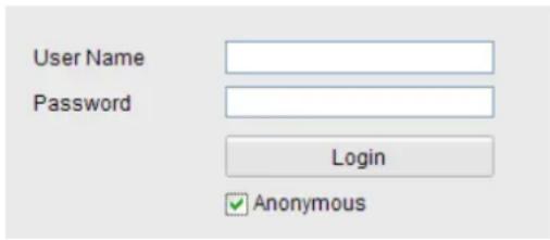
text_image
User Name Password Login AnonymousFigure 10-6 Login Interface with an Anonymous Checkbox
- Check the checkbox of Anonymous and click Login.
By perming the Anonymous "Live View" funcon, you may enable others to access your speed dome and view live images without providing login credentials. It therefore is critical when
perming the Anonymous "Live View" funcon to ensure that your camera's eld of view does not impact the privacy of individuals whose images might be captured without authorizaon.
Given its inherent intrusiveness, video surveillance is inappropriate in areas where people have a higher expectaon of privacy.
10.4 Conguring IP Address Filter
With this funcon on, the camera allows certain IP addresses whether to log in or not.
| Filter Type | Descripon |
| Forbidden | Forbid the IP addresses added in the IP Address Filter interface to log in. |
| Allowed | Allow only the IP addresses added in the IP Address Filter interface to log in. |
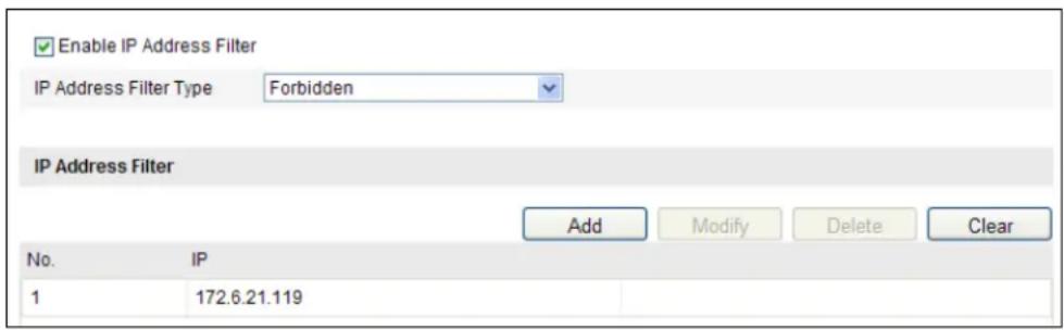
text_image
Enable IP Address Filter IP Address Filter Type Forbidden IP Address Filter Add Modify Delete Clear No. IP 1 172.6.21.119Figure 10-7 IP Address Filter
10.5 Security Service
Steps:
- Enter the Security Service interface:
Conguraon> Advanced Conguraon> Security > Security Service
- Check the checkbox to enable the SSH funcon.
Enable SSH: Enabling SSH (Secure Shell) funcon is to encrypt and compress the data and to reduce the transmission me.
10.6 Viewing Device Informaon
Enter the Device Informaon interface:
Conguraon > Basic Configuraon> System > Device Informaon
Or Conguraon > Advanced Conguraon> System > Device Informaon
In the Device Informaon interface, you can edit the Device Name.
Other informaon of the network speed dome, such as Model, Serial No., Firmware Version,
Encoding Version, Number of Channels, Number of HDDs, Number of Alarm Input and Number of Alarm Output are displayed. The informaon cannot be changed in this menu. It is the reference for maintenance or modicaon in future.
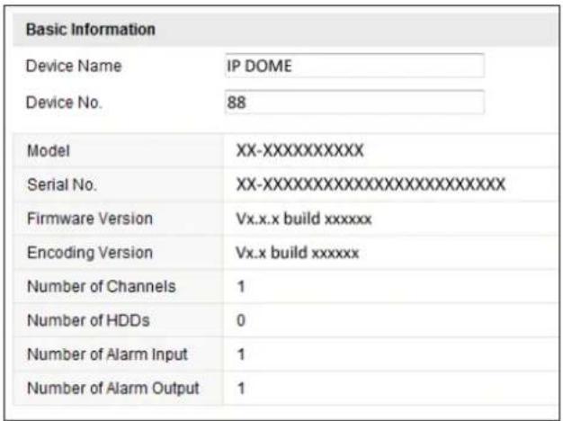
text_image
Basic Information Device Name IP DOME Device No. 88 Model XX-XXXXXXXXXXXX Serial No. XX-XXXXXXXXXXXXXXXXXXXXXXX Firmware Version Vx.x.x build xxxxxx Encoding Version Vx.x build xxxxxx Number of Channels 1 Number of HDDs 0 Number of Alarm Input 1 Number of Alarm Output 1Figure 10-8 Device Informaon
10.7 Maintenance
10.7.1 Reboong the Speed Dome
Steps:
- Enter the Maintenance interface:
Conguraon > Basic Conguraon > System > Maintenance
Or Conguraon > Advanced Conguraon> System > Maintenance:
- Click Reboot to reboot the network speed dome.
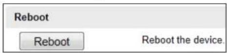
text_image
Reboot Reboot the device.Figure 10-9 Reboot the Device

10.7.2 Restoring Default Sengs
Steps:
- Enter the Maintenance interface:
Conguraon > Basic Conguraon > System > Maintenance
Or Conguraon > Advanced Conguraon> System > Maintenance
- Click or to restore the default sengs.


Clicking restores all the parameters to default sengs including the IP s and user informaon. Please use this buon with cauon.

text_image
Default Restore Reset all the parameters, except the IP parameters and user information, to the default settings. Default Restore all parameters to default settings.Figure 10-10 Restore Default Sengs

10.7.3 Imporng/Exporng Conguraon File
Steps:
- Enter the Maintenance interface:
Conguraon > Basic Conguraon > System > Maintenance
Or Conguraon > Advanced Conguraon> System > Maintenance
- Click Browse to select the local conguraon le and then click Import to start imporng conguraon le.

You need to reboot the speed dome aer imporng conguraon le.
- Click Export and set the saving path to save the conguraon le in local storage.
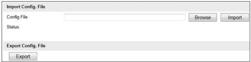
text_image
Import Config. File Config File Status Export Config. File Export Browse ImportFigure 10-11 Import/Export Conguraon File

10.7.4 Upgrading the System
Steps:
- Enter the Maintenance interface:
Conguraon > Basic Conguraon> System > Maintenance
Or Conguraon > Advanced Conguraon> System > Maintenance
-
Select Firmware or Firmware Directory.
-
Firmware: when you select Firmware, you need to nd the rmware in your computer to upgrade the device.
● Firmware Directory: You need to nd the directory where the rmware locates. The
device can nd the rmware in the directory automacally.
- Click Browse to select the local upgrade le and then click Upgrade to start remote upgrade.

The upgrading process will take 1 to 10 minutes. Please don't disconnect power of speed dome during the process. The speed dome reboots automatically aer upgrading.
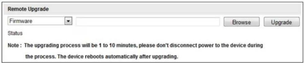
text_image
Remote Upgrade Firmware Browse Upgrade Status Note : The upgrading process will be 1 to 10 minutes, please don't disconnect power to the device during the process. The device reboots automatically after upgrading.Figure 10-12 Remote Upgrade

10.8 Conguring RS-485
Purpose:
The RS-485 serial port is used to control the PTZ of the camera. The conguring of the PTZ parameters should be done before you control the PTZ unit.
Steps:
- Enter RS-485 Port Seng interface:
Conguraon> Advanced Conguraon> System > RS485
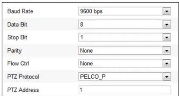
text_image
Baud Rate 9600 bps Data Bit 8 Stop Bit 1 Parity None Flow Ctrl None PTZ Protocol PELCO_P PTZ Address 1Figure 10-13 RS-485 Sengs
- Set the RS-485 parameters and click to save the sengs.

The Baudrate, PTZ Protocol and PTZ Address parameters of the speed dome should be exactly the same as those of the control device.

10.9 Conguring IR Light
Steps:
- Enter the interface of conging the remote conncon:
Conguraon> Advanced Conguraon> System > Service - Check the checkbox to enable the IR light funcon, and then the light will be turned on automatically when the illuminaon is not enough for the video monitoring.
- Click the buon to acvate the sengs.

10.10 Conguring Remote Connecon
Steps:
- Enter the interface of conging the remote conncon:
Conguraon> Advanced Conguraon> System > Service
- Input a number in text eld as the upper limit of the remote connection number. E.g. when you specify the remote conncon number as 10, then the 11th remote conncon cannot be established.

text_image
Software Live View Connection 10Figure 10-14 Live View Connecon Sengs
- Click the buon to acvate the sengs.
Appendix
Appendix 1 SADP Soware Introducon
- Descripon of SADP
SADP (Search Acve Devices Protocol) is a kind of user-friendly and installaon-free online device search tool. It searches the acve online devices within your subnet and displays the informaon of the devices. You can also modify the basic network informaon of the devices using this soware.
- Search acve devices online
◆ Search online devices automacally
Aer launch the SADP soware, it automacally searches the online devices every 15 seconds from the subnet where your computer locates. It displays the total number and informaon of the searched devices in the Online Devices interface. Device informaon including the device type, IP address and port number, etc. will be displayed.
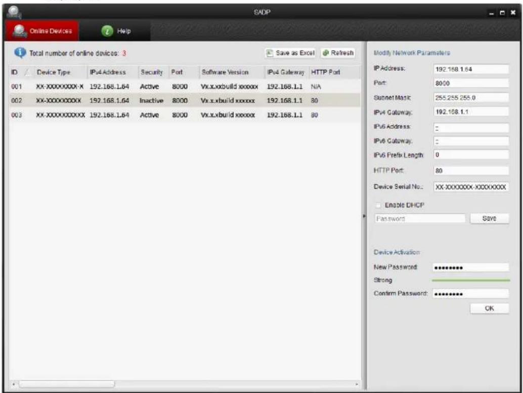
text_image
SADP Online Devices Help Total number of online devices: 3 ID Device Type IPv4 Address Security Port Software Version IPv4 Gateway HTTP Port 001 XX-XXXXXXX-X 192.168.1.64 Active 8000 Vx.x.xbuild xxxxxx 192.168.1.1 N/A 002 XX-XXXXXXXX 192.168.1.64 Inactive 8000 Vx.x.xbuild xxxxx 192.168.1.1 80 003 XX-XXXXXXXX 192.168.1.64 Active 8000 Vx.x.xbuild xxxxx 192.168.1.1 80 Modify Network Parameters IP Address: 192.168.1.64 Port: 8000 Subnet Mask: 255.255.255.0 IPv4 Gateway: 192.168.1.1 IPv6 Address: IPv6 Gateway: IPv6 Prefix Length: 0 HTTP Port: 80 Device Serial No.: XX-XXXXXXX-XXXXXXX Enable DHCP Password Save Device Activation New Password: ********** Strong Confirm Password: ********** OKFigure A.1.1 Searching Online Devices

Device can be searched and displayed in the list in 15 seconds aer it went online; it will be removed from the list in 45 seconds aer it went oine.
◆ Search online devices manually
You can also click Refresh to refresh the online device list manually. The newly

© Hikvision
searched devices will be added to the list.

text_image
NOTE You can click △ or ▽ on each column heading to order the informaon; you can click ▶ to expand the device table and hide the network parameter panel on the right side, or click ▶ to show the network parameter panel.- Modify network parameters
Steps:
- Select the device to be modified in the device list and the network parameters of the device will be displayed in the Modify Network Parameters panel on the right side.
- Edit the modiable network parameters, e.g. IP address and port number.
- Enter the password of the admin account of the device in the Password eld and click to save the changes.

- For your privacy and to better protect your system against security risks, we strongly recommend the use of strong passwords for all functions and network devices. The password should be something of your own choosing (using a minimum of 8 characters, including upper case letters, lower case letters, numbers and special characters) in order to increase the security of your product.
● Proper configuration of all passwords and other security settings is the responsibility of the installer and/or end-user.
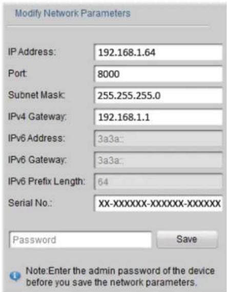
text_image
Modify Network Parameters IP Address: 192.168.1.64 Port: 8000 Subnet Mask: 255.255.255.0 IPv4 Gateway: 192.168.1.1 IPv6 Address: 3a3a: IPv6 Gateway: 3a3a: IPv6 Prefix Length: 64 Serial No.: XX-XXXXXX-XXXXXX-XXXXXX Password Save Note:Enter the admin password of the device before you save the network parameters.Figure A.1.2 Modify Network Parameters
Appendix 2 Port Mapping
The following setngs are for TP-LINK router (TL-R410). The setngs vary depending on dierent models of routers.
Steps:
- Select the WAN Connecon Type, as shown below:
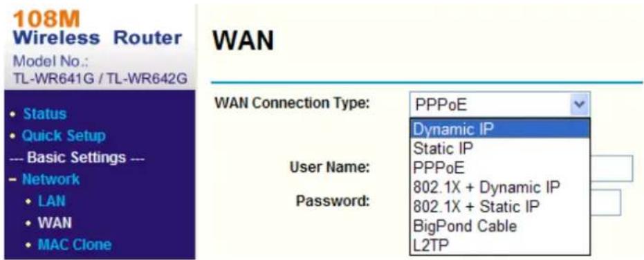
text_image
108M Wireless Router Model No.: TL-WR641G / TL-WR642G WAN Status Quick Setup --- Basic Settings --- Network LAN WAN MAC Clone WAN Connection Type: PPPoE Dynamic IP Static IP User Name: PPPoE Password: 802.1X + Dynamic IP 802.1X + Static IP BigPond Cable L2TPFigure A.2.1 Select the WAN Connecon Type
- Set the LAN parameters of the router as in the following gure, including IP address and subnet mask sengs.
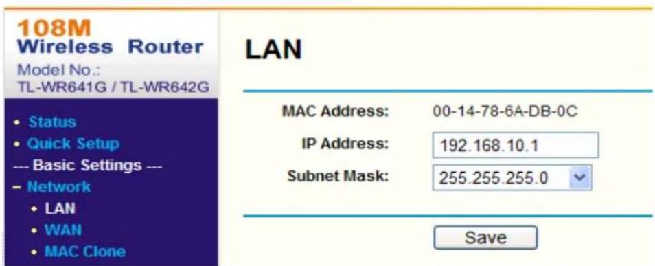
text_image
108M Wireless Router Model No.: TL-WR641G / TL-WR642G • Status • Quick Setup --- Basic Settings --- - Network • LAN • WAN • MAC Clone LAN MAC Address: 00-14-78-6A-DB-0C IP Address: 192.168.10.1 Subnet Mask: 255.255.255.0 SaveFigure A.2.2 Set the LAN parameters
- Set the port mapping in the virtual severs of Forwarding. You need to forward ports 80, 8000, 8200\~8210 and 554 for a speed dome.


- You can change 80, 8000 and 554 ports value in the speed dome with web browser or client soware.
- In the speed dome, the 8200\~8210 ports change with the 8000 port with a constant value
of 200. E.g. if the 8000 port is changed to 8005, then the 8200\~8210 ports should be changed to 8205\~8215.
Example:
When the speed domes are connected to the same router, you can forward the ports of a speed dome as 80, 8000, 8200\~8210 and 554 with IP address 192.168.1.23, and the ports of another speed dome as 81, 8001, 8201\~8211 and 555 with IP 192.168.1.24. Refer to the steps as below:
Steps:
- As the sengs mentioned above, forward the port 80, 8000, 8200\~8210 and 554 for the network speed dome at 192.168.1.23
- Forward the port 81, 8001, 8201\~8211 and 555 for the network speed dome at 192.168.1.24.
- Enable ALL or TCP protocols.
- Check the Enable checkbox and click Save
108M
Wireless Router
Model No.
--- Basic Settings ---
+ Network
+ Wireless
--- Advanced Settings ---
+ DHCP
- Forwarding
• Virtual Servers
- Port Triggering
• DMZ
• UPnP
+ Security
- Static Routing
• Dynamic DNS
Maintenance ---
+ System Tools
Virtual Servers
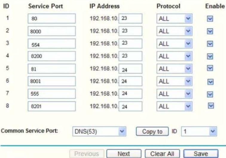
text_image
ID Service Port IP Address Protocol Enable 1 80 192.168.10. 23 ALL ✓ ✓ 2 8000 192.168.10. 23 ALL ✓ ✓ 3 554 192.168.10. 23 ALL ✓ ✓ 4 8200 192.168.10. 23 ALL ✓ ✓ 5 81 192.168.10. 24 ALL ✓ ✓ 6 8001 192.168.10. 24 ALL ✓ ✓ 7 555 192.168.10. 24 ALL ✓ ✓ 8 8201 192.168.10. 24 ALL ✓ ✓ Common Service Port: DNS(53) Copy to ID 1 ✓ Previous Next Clear All SaveFigure A.2.3 Port Mapping


The port of the network speed dome cannot conict with other ports. For example,
some web management port of the router is 80. Change the speed dome port if it is the same as the management port.

text_image
FirstFirst Choice for Security Professionals