
CIVS-IPC-7530PD - Security Camera CISCO - Free user manual and instructions
Find the device manual for free CIVS-IPC-7530PD CISCO in PDF.


User questions about CIVS-IPC-7530PD CISCO
0 question about this device. Answer the ones you know or ask your own.
Ask a new question about this device
Download the instructions for your Security Camera in PDF format for free! Find your manual CIVS-IPC-7530PD - CISCO and take your electronic device back in hand. On this page are published all the documents necessary for the use of your device. CIVS-IPC-7530PD by CISCO.
USER MANUAL CIVS-IPC-7530PD CISCO
natural_image
Rooftop with solar panels in front of a modern city skyline under a bright sky (no text or symbols visible)Cisco Video Surveillance 7530PD IP Camera Installation Guide
September 18, 2014
Americas Headquarters
Cisco Systems, Inc.
170 West Tasman Drive
San Jose, CA 95134-1706
USA
http://www.cisco.com
Tel: 408 526-4000
800 553-NETS (6387)
Fax: 408 527-0883
THE SPECIFICATIONS AND INFORMATION REGARDING THE PRODUCTS IN THIS MANUAL ARE SUBJECT TO CHANGE WITHOUT NOTICE. ALL STATEMENTS, INFORMATION, AND RECOMMENDATIONS IN THIS MANUAL ARE BELIEVED TO BE ACCURATE BUT ARE PRESENTED WITHOUT WARRANTY OF ANY KIND, EXPRESS OR IMPLIED. USERS MUST TAKE FULL RESPONSIBILITY FOR THEIR APPLICATION OF ANY PRODUCTS.
THE SOFTWARE LICENSE AND LIMITED WARRANTY FOR THE ACCOMPANYING PRODUCT ARE SET FORTH IN THE INFORMATION PACKET THAT SHIPPED WITH THE PRODUCT AND ARE INCORPORATED HEREIN BY THIS REFERENCE. IF YOU ARE UNABLE TO LOCATE THE SOFTWARE LICENSE OR LIMITED WARRANTY, CONTACT YOUR CISCO REPRESENTATIVE FOR A COPY.
The following information is for FCC compliance of Class A devices: This equipment has been tested and found to comply with the limits for a Class A digital device, pursuant to part 15 of the FCC rules. These limits are designed to provide reasonable protection against harmful interference when the equipment is operated in a commercial environment. This equipment generates, uses, and can radiate radio-frequency energy and, if not installed and used in accordance with the instruction manual, may cause harmful interference to radio communications. Operation of this equipment in a residential area is likely to cause harmful interference, in which case users will be required to correct the interference at their own expense.
The following information is for FCC compliance of Class B devices: This equipment has been tested and found to comply with the limits for a Class B digital device, pursuant to part 15 of the FCC rules. These limits are designed to provide reasonable protection against harmful interference in a residential installation. This equipment generates, uses and can radiate radio frequency energy and, if not installed and used in accordance with the instructions, may cause harmful interference to radio communications. However, there is no guarantee that interference will not occur in a particular installation. If the equipment causes interference to radio or television reception, which can be determined by turning the equipment off and on, users are encouraged to try to correct the interference by using one or more of the following measures:
- Rcorient or relocate the receiving antenna.
- Increase the separation between the equipment and receiver.
- Connect the equipment into an outlet on a circuit different from that to which the receiver is connected.
- Consult the dealer or an experienced radio/TV technician for help.
Modifications to this product not authorized by Cisco could void the FCC approval and negate your authority to operate the product.
The Cisco implementation of TCP header compression is an adaptation of a program developed by the University of California, Berkeley (UCB) as part of UCB's public domain version of the UNIX operating system. All rights reserved. Copyright © 1981, Regents of the University of California.
NOTWITHSTANDING ANY OTHER WARRANTY HEREIN, ALL DOCUMENT FILES AND SOFTWARE OF THESE SUPPLIERS ARE PROVIDED "AS IS" WITH ALL FAULTS. CISCO AND THE ABOVE-NAMED SUPPLIERS DISCLAIM ALL WARRANTIES, EXPRESSED OR IMPLIED, INCLUDING, WITHOUT LIMITATION, THOSE OF MERCHANTABILITY, FITNESS FOR A PARTICULAR PURPOSE AND NONINFRINGEMENT OR ARISING FROM A COURSE OF DEALING, USAGE, OR TRADE PRACTICE.
IN NO EVENT SHALL CISCO OR ITS SUPPLIERS BE LIABLE FOR ANY INDIRECT, SPECIAL, CONSEQUENTIAL, OR INCIDENTAL DAMAGES. INCLUDING, WITHOUT LIMITATION, LOST PROFITS OR LOSS OR DAMAGE TO DATA ARISING OUT OF THE USE OR INABILITY TO USE THIS MANUAL, EVEN IF CISCO OR ITS SUPPLIERS HAVE BEEN ADVISED OF THE POSSIBILITY OF SUCH DAMAGES.
Cisco and the Cisco logo are trademarks or registered trademarks of Cisco and/or its affiliates in the U.S. and other countries. To view a list of Cisco trademarks, go to this URL: www.cisco.com/go/trademarks. Third-party trademarks mentioned are the property of their respective owners. The use of the word partner does not imply a partnership relationship between Cisco and any other company. (1110R)
Any Internet Protocol (IP) addresses and phone numbers used in this document are not intended to be actual addresses and phone numbers. Any examples, command display output, network topology diagrams, and other figures included in the document are shown for illustrative purposes only. Any use of actual IP addresses or phone numbers in illustrative content is unintentional and coincidental.
Cisco Video Surveillance 7530PD IP Camera Installation Guide © 2014 Cisco Systems, Inc. All rights reserved.

text_image
CONTENTSPreface v
Overview v
Organization v
Obtaining Documentation, Obtaining Support, and Security Guidelines v
CHAPTER 1 Overview 1-1
Introduction 1-1
Package Contents 1-1
IP Camera Physical Details 1-3
General Purpose I/O Terminal Block 1-5
CHAPTER 2 Camera Installation 2-1
Installation Guidelines 2-1
Warnings Before Installation 2-1
Installing the IP Camera with a Vandal Resistant Enclosure 2-4
CHAPTER 3
Performing the Initial Setup of the IP Camera 3-1
CHAPTER 4 Camera Management 4-1
Understanding the IP Camera User Interface 4-1
IP Camera Window Links 4-1
IP Camera Windows 4-2
Adjusting the IP Camera Focus and Zoom 4-3
Powering the IP Camera On or Off 4-4
Resetting the IP Camera 4-4
Viewing Live Video 4-5
INDEX
Contents
natural_image
Panoramic cityscape with modern skyscrapers and a rooftop solar panel, no visible text or signagePreface
Overview
This document, Cisco Video Surveillance 7530PD IP Camera Installation Guide, provides information about installing and deploying the Cisco Video Surveillance 7530PD IP Camera.
Organization
This manual is organized as follows:
| Chapter 1, “Overview” | Provides an overview of the IP camera and its features. |
| Chapter 2, “Camera Installation” | Provides instructions for physically installing the IP camera. |
| Chapter 3, “Performing the Initial Setup of the IP Camera” | Provides instructions for performing the initial network setup of the IP camera. |
| Chapter 4, “Camera Management” | Provides instructions for accessing and understanding the IP camera user interface, adjusting its focus and, powering the IP camera on and off, and resetting the IP camera. |
Obtaining Documentation, Obtaining Support, and Security Guidelines
For information about obtaining documentation, submitting a service request, and gathering additional information, see the monthly What's New in Cisco Product Documentation, which also lists all new and revised Cisco technical documentation, at:
http://www.cisco.com/en/US/docs/general/whatsnew/whatsnew.html
Subscribe to the What's New in Cisco Product Documentation as a Really Simple Syndication (RSS) feed and set content to be delivered directly to your desktop using a reader application. The RSS feeds are a free service and Cisco currently supports RSS version 2.0.
text_image
CHAPTER 1Overview
This chapter describes the Cisco Video Surveillance 7530PD IP Camera, and includes the following topics:
• Introduction, page 1-1
• Package Contents, page 1-1
• IP Camera Physical Details, page 1-3
Introduction
The Cisco Video Surveillance 7530PD IP Camera is an outdoor, multi-megapixel, full-functioned smart video endpoint with industry-leading image quality and processing power. The camera is capable of a 2560 x 1920 resolution while optimizing network utilization with either H.264 or MJPEG compression. An integrated RS485 interface enables easy integration and aggregation of a wide variety of sensor nodes and alarms.
An onboard DSP co-processor allows for a wide range of processor intensive application to be run directly on the camera, providing true intelligence as the edge.
The 7530PD IP camera comes with an advanced P-Iris lens, which controls the iris opening with extreme precision at an optimal level at all times via the built-in stepper motor, resulting in superior sharpness and depth of field as well as image quality.
Package Contents
The Cisco Video Surveillance IP Camera package includes the following items:
• Cisco Video Surveillance 7530PD IP Camera (1)
• Installation template/alignment sticker (1)
- Mounting plate (1)
- Lens hood (1)
- Bushing (1)
• Waterproof connector (1)
• L type hex key (allen wrench) (1)
- Screws (5)
- Wall anchors (4)
- Hex nut (1)
• Double sided tape (1)
• Silica gel packet (1)
• Extra set of labels (3)
• Cisco documentation pointer card (1)
• Cisco RoHS document (1)
IP Camera Physical Details
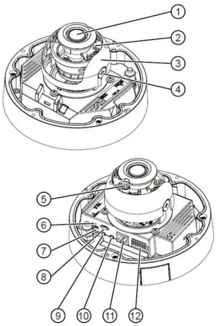
Figure 1-1 and the table that follows describe the physical features of the 7530PD IP camera.
Figure 1-1 IP Camera Physical Features
text_image
Technical diagram of a mechanical device with numbered parts for identification| 1 | Varifocal lens | IP camera lens that changes focus as the focal length changes. |
| 2 IR | LEDs Infrared illuminator LEDs | that enhance the video image (effective up to 60 ft. [20 m]) when the IP camera is running in night mode. |
| 3 Black cover A dark cover with a cutout for the camera lens that makes it difficult to see where the IP camera is pointed.Note You must temporarily remove the black cover when adjusting the camera field of view. | ||
| 4 Tilt adjustment screw Used when tilting the camera to set the field of view. | ||
| 5 Light sensor Senses the level of ambient light to determine when to switch day/night mode. | ||
| 6 | Recessed reset button | Recessed button that reboots the IP camera or resets it to a default state. You can use a pin or paper clip to depress it. It can be used any time that the IP camera is on and can have various effects, as described in the “Resetting the IP Camera” section on page 2-11. |
| 7 External microphone and video output switches | External microphoneOff (up)—disables an external microphone connected to the IP camera.On (down)—enables an external microphone connected to the IP camera.Note There is no internal microphone. You must connect an external microphone if you require audio inputs.Video outputNTSC 60Hz (up)—switches camera operation to the National Television System Committee (NTSC) standard.PAL 50Hz (down)—switches camera operation to the Phase Alternating Line (PAL) standard. | |
| 8 | Micro SD/SDHC card slot | Support for the SD/SDHC card slot will be available in future releases. |
| 9 | Audio/Video out (green) | Allows the connection of an optional Y cable or mini cable with BNC connector. You can connect a video monitor to the mini cable with BNC connector. Both cables are included in the optional audio/video cables accessory kit can be purchased from Cisco (Cisco part number CIVS-AVCABLE).Note Support for audio will be in future releases. |
| 10 Microphone In (pink) Connection for an external microphone. | ||
| 11 | Ethernet 10/100 RJ45 socket | Accepts a standard LAN cable to connect the IP camera to a 10/100BaseT router or switch. |
| 12 | GPIO Block | General purpose input/output (GPIO) terminal block that is used to connect external input and output devices. For more information, see Figure 1-2. |
General Purpose I/O Terminal Block
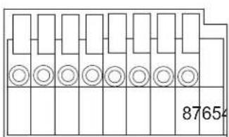
Figure 1-2 shows the GPIO terminal block pin locations and descriptions.
Figure 1-2 GPIO Terminal Block Pin Locations and Descriptions
text_image
87654| Pin Description | |
| 1 24 VAC | |
| 2 24 VAC | |
| 3 RS485- | |
| 4 RS485+ | |
| 5 | DI- |
| 6 | DI+ |
| 7 DO- | |
| 8 DO+ | |

Note The maximum output load from pins 7 and 8 is 50mA.
General Purpose I/O Terminal Block
Camera Installation
This chapter provides information and instructions for installing the Cisco Video Surveillance 7530PD IP Camera, and includes the following topics:
• Installation Guidelines, page 2-1
- Warnings Before Installation, page 2-1
• Installing the IP Camera with a Vandal Resistant Enclosure, page 2-4
Installation Guidelines
This section describes how to install the IP camera. Before installing, review these guidelines:
- The IP camera requires a network cable and a connection to a standard 10/100BaseT router or switch. To power the IP camera with Power over Ethernet (PoE), a switch must be 802.3af compliant.
- If you are using the IP camera on a network connection that does not provide PoE, you must use a third-party 24 VAC power adapter.
- If you are using an external speaker, microphone, input device, output device, or pan/tilt control device, you must configure additional settings after installing and performing the initial set up of the IP camera before the external device can fully operate. For detailed information about these settings, see the Cisco Video Surveillance 6000 Series IP Camera Configuration Guide.
- If you do not connect an external device (speaker, microphone, input, output, or pan/tilt control) when you perform the following installation procedure, you can install any of these devices later.
Warnings Before Installation
• Power off the IP Camera as soon as smoke or unusual odors are detected.
Contact your distributor in the event of this happening.
- Keep the IP Camera away from water. If the IP Camera becomes wet, power off immediately.
Contact your distributor in the event of this happening.
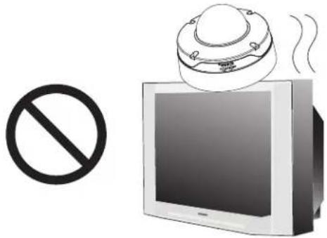
- Do not place the IP Camera around heat sources, such as a television or oven.
text_image
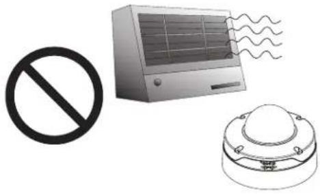
Image showing a prohibition symbol, a monitor with a speaker emitting sound waves, and a circle symbol.- Refer to your user's manual for the operating temperature.
natural_image
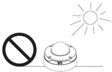
Illustration of three symbols: a prohibition sign, an air conditioner with cooling effect, and a dome-shaped device (no text or labels)- Keep the IP Camera away from direct sunlight.
natural_image
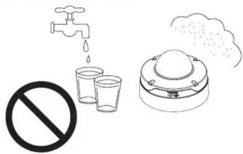
Simple line drawing of a sun and a prohibition symbol on a device (no text or labels)- Do not place the IP Camera in high humidity environments.
text_image
Safety warning illustration showing a faucet, two cups with water droplets, and an air purifier emitting smoke.- Do not place the IP Camera on unsteady surfaces.

natural_image
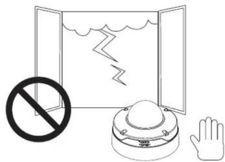
Simple line drawing of a prohibition symbol, no text or labels present- Do not touch the IP Camera during a lightning storm.
text_image
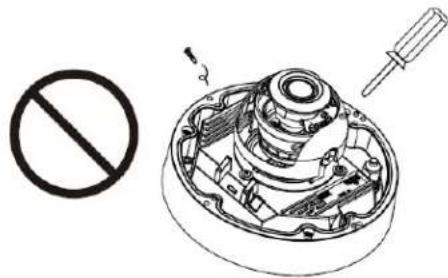
Safety warning illustration showing a prohibition symbol, water drop, and hand gesture with a device.• Do not disassemble the IP Camera.
natural_image
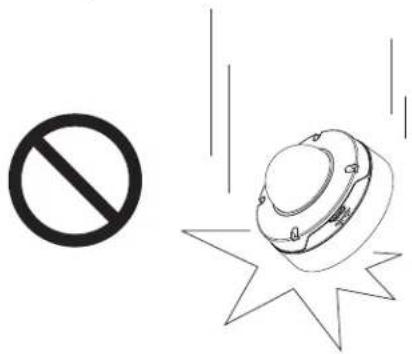
Technical diagram showing a disassembled mechanical component with no visible text or symbols• Do not drop the IP Camera.
text_image
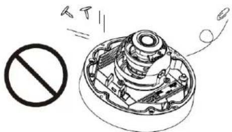
Safety warning symbol with prohibition sign and helmet icon, including a star symbol below- Do not insert sharp or tiny objects into the IP Camera.
natural_image
Diagram of a mechanical device with a prohibition symbol and motion lines, no text or labels present.Warning
Installation of the equipment must comply with local and national electrical codes. Statement 1074
Warning
The power supply must be placed indoors. Statement 331

Note
If you use the IP camera outdoors, place the camera and the power supply in a suitable NEMA enclosure.
Warning
This product must be connected to a power-over-ethernet (PoE) IEEE 802.3af compliant power source or an IEC60950 compliant limited power source. Statement 353
Caution
Inline power circuits provide current through the communication cable. Use the Cisco provided cable or a minimum 24AWG communication cable.
Note
The power adapter that you use with the IP camera must provide power that is within +/-10% of the required power.

Note The equipment is to be connected to a Listed class 2, limited power source.
Installing the IP Camera with a Vandal Resistant Enclosure
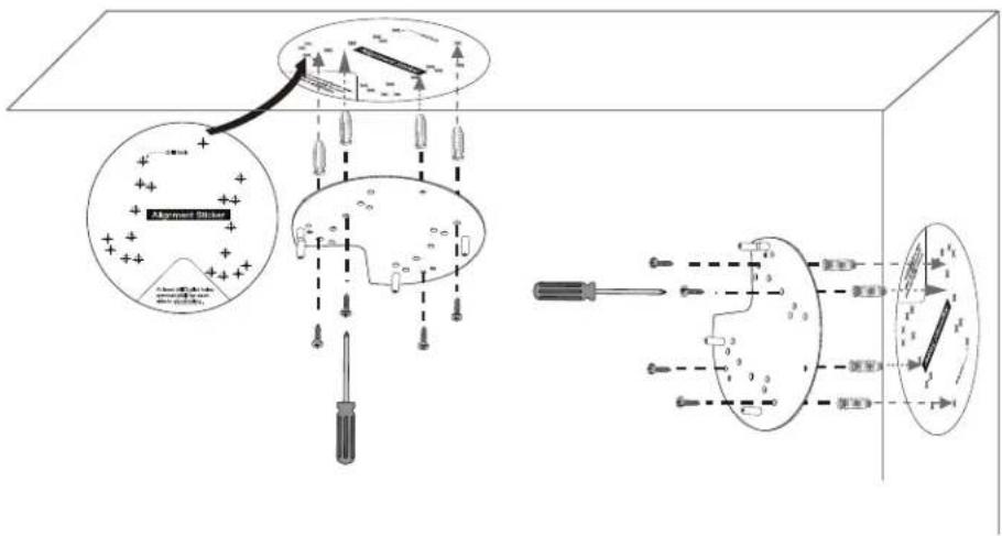
To install the IP camera to a ceiling or wall using a vandal resistant (VR) enclosure, perform the following steps.
Procedure
Step 1 Attach the included alignment sticker to the ceiling or wall.
Step 2 Using the circle marks on the sticker, drill at least two pilot holes symmetrically on each side (four holes total) into the ceiling or wall. Then hammer the included wall anchors into the holes.
Step 3 Secure the mounting plate to the ceiling or wall with the four included screws.
text_image
Technical diagram illustrating a mechanical assembly with labeled components and directional arrows, including alignment checkers and screwdriver.Step 4 Do one of the following to feed the cables to the IP camera:
- Cut out a section of the ceiling or wall that corresponds to the triangular cutout on the alignment sticker, and feed cables through a ceiling or wall.
- Use a screwdriver to remove the cutout on the side of the conduit base, connect a cable conduit, and feed the cables through the side of the conduit base.
Step 5 Perform the following steps to install and connect an RJ45 Ethernet cable.

Note We recommended using 24AWG (0.51 mm) gauge cable.
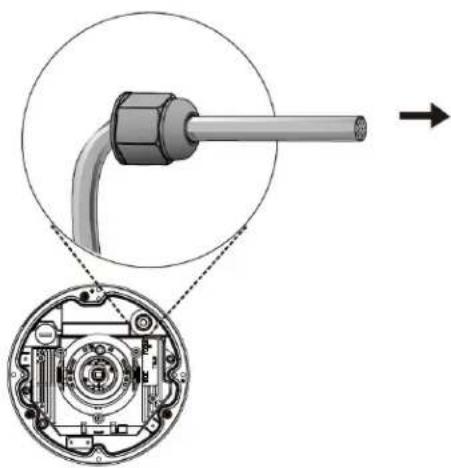
a. Drill a hole on the rubber seal plug and insert an Ethernet cable (without a connector) through the opening.
natural_image
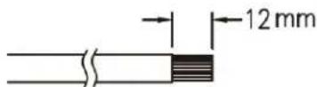
Technical diagram showing a mechanical component with cross-sectional view and directional arrow (no text or symbols)a. Strip about 1/2 inch (12 mm) of the sheath from the Ethernet cable.
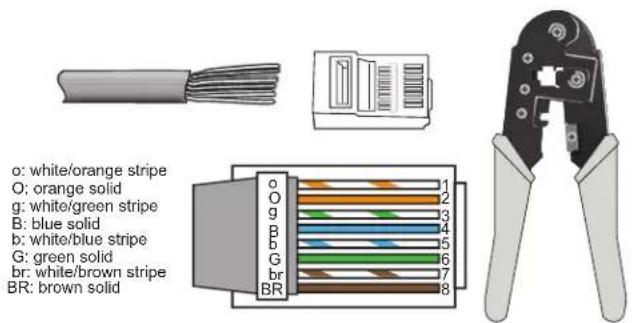
b. Use an RJ45 crimping tool to attach the Ethernet wires to a connector. When done, connect the cable to the camera's Ethernet RJ45 socket.
text_image
o: white/orange stripe O: orange solid g: white/green stripe B: blue solid b: white/blue stripe G: green solid br: white/brown stripe BR: brown solidc. Press the Ethernet cable into the routing path at the bottom of the camera so that the cable will not get in the way when the metal mounting plate is attached.
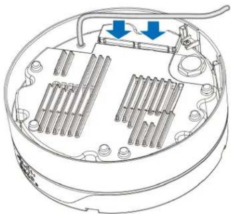
natural_image
Technical line drawing of a mechanical device with internal components and two blue arrows indicating directional flow (no text or symbols)Step 6 (Optional) Perform the following steps to install and connect an external power cable and I/O cables for external devices:
a. Disassemble the components of the waterproof connector into parts (A) \~ (F).
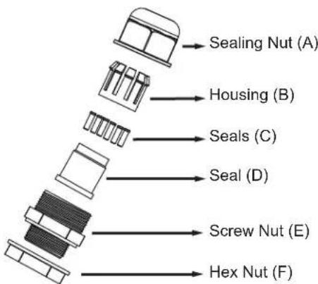
text_image
Sealing Nut (A) Housing (B) Seals (C) Seal (D) Screw Nut (E) Hex Nut (F)b. Place the screw nut (E) on the power and I/O cable opening.
c. Feed the power cable through the waterproof connector (F --> E --> D --> B --> A). Be sure to feed enough power cable length through the waterproof connector to connect the power cable to the GPIO block.
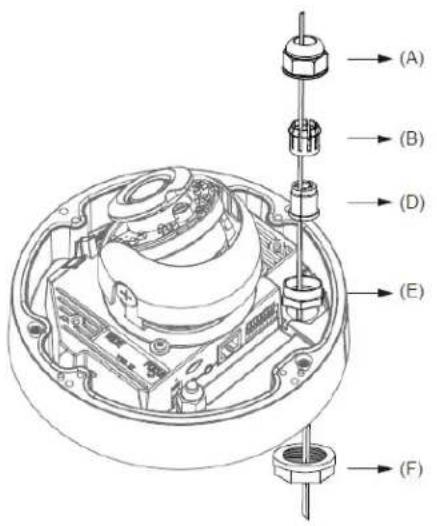
text_image
(A) (B) (D) (E) (F)
Note
There are 8 holes on the seal (D), and the widest holes with a crack on the side are specific for power cables.
d. Feed the I/O cables through the waterproof connector (F --> E --> D --> B --> A). Be sure to feed enough I/O cable length through the waterproof connector to connect the I/O cable to the GPIO block.
The recommended cable gauge is 2.0 through 2.8 mm.
e. Push the seal (D) into the housing (B).
f. Insert the seals (C) into unused holes on the seal (D) to avoid moisture.
g. Secure the sealing nut (A) tightly and hex nut (F) from the bottom of the camera.
h. Connect the power and I/O cables to the GPIO terminal block.
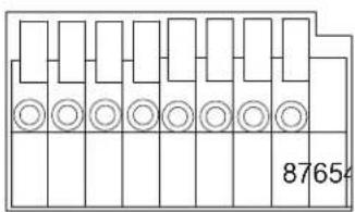
text_image
87654Pin Description
| 1 24 VAC | |
| 2 24 VAC | |
| 3 RS485- | |
| 4 RS485+ | |
| 5 | DI- |
| 6 | DI+ |
| 7 DO- | |
| 8 DO+ | |
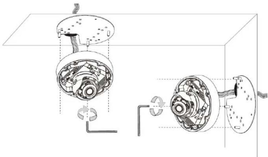
Step 7 Use the included L-type wrench to secure the conduit base to the mounting plate with the three included screws.
natural_image
Technical diagram of a mechanical assembly showing internal components and fluid flow paths (no text or labels)Step 8 (Optional) Use mini cable with BNC connector to temporarily attach an NTSC or PAL compliant analog video display device to the analog video out port on the rear of the IP camera.

Note
The mini cable with BNC adapter is included in the audio/video cables accessory kit, which you can purchase from Cisco (Cisco part number CIVS-AVCABLE).
Analog video is enabled by default to allow you to adjust the camera field of view during installation. However, it is not supported as a normal camera feed and is automatically disabled when any of the following camera settings are made:
- The primary video stream frame rate must be set higher than 15 fps.
- The secondary video stream must is enabled.

Note
We recommend that you disable analog video after installation. To disable analog video, see the Cisco Video Surveillance 6000 Series IP Camera Configuration Guide.
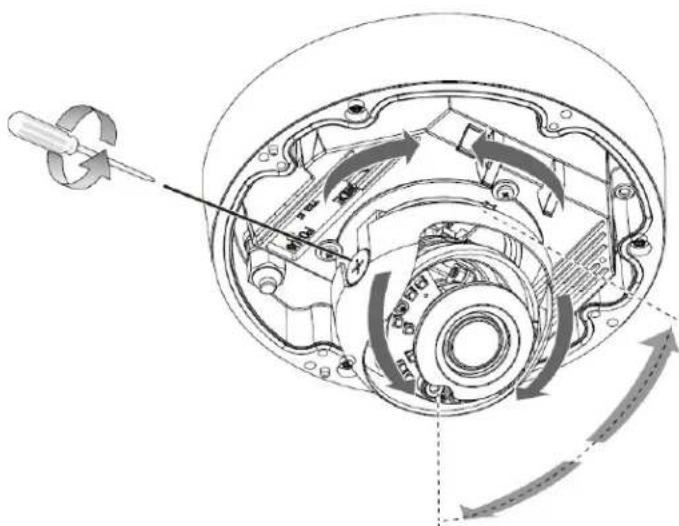
Step 9 While viewing video from the IP camera, perform the following steps to adjust the 3-axis field of view:
a. Grip the two tilt adjustment screws and pan the IP camera left or right.
b. Loosen the two tilt adjustment screws, tilt the IP camera, then tighten the screws.
c. Rotate the IP camera to adjust the horizontal orientation until you achieve a level image.
natural_image
Technical diagram of a mechanical assembly with directional arrows indicating motion or flow (no text or symbols present)Step 10 Remove the wrapper from the included silica gel pack and place the pack with the camera inside the VR housing. Secure the pack with the provided double-sided tape. Ensure that the silica gel pack does not obstruct the IP camera field of view.
The silica gel pack help protect the IP camera from damage that can be caused by moisture.
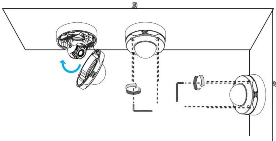
Step 11 Attach the dome cover to the camera by aligning it with the mounting holes.
Step 12 Use the included wrench and tighten the four dome cover screws to secure the dome cover to the camera. Make sure all parts of the camera are securely installed.
text_image
Technical diagram showing mechanical assembly with labeled components and motion indicatorsWhat to do next
Complete the following procedures:
- After you install the IP camera, follow the instructions in Chapter 3, “Performing the Initial Setup of the IP Camera” to access the IP camera through your network.
- After completing the initial setup, use the IP camera user interface to adjust the focal length and zoom factor. For more information, see the “Adjusting the IP Camera Focus and Zoom” section on page 4-3.
Performing the Initial Setup of the IP Camera
After you install IP camera as described in the Chapter 2, “Camera Installation,” or after you perform a factory reset procedure, you must access the IP camera and make initial configuration settings. These settings include administrator and root passwords, and whether the IP camera can be accessed through an HTTP connection in addition to the default HTTPS (HTTP secure) connection.
To make these configuration settings, you connect to the IP camera from any PC that is on the same network as the IP camera. The PC must meet these requirements:
- Operating system—Microsoft Windows 7 (32-bit and 64-bit)
- Browser—Internet Explorer 8.0 (32-bit only)
In addition, you must know the IP address and default login credentials of the IP camera. By default, when the IP camera powers on, it attempts to obtain an IP address from a DHCP server in your network. If the camera cannot obtain an IP address through DCHP within 90 seconds, it uses a default IP address of 192.168.0.100. The default login credentials (Username/Password) are admin/admin.
To connect to the IP camera for the first time and make initial configuration settings, perform the following steps. You can change these configuration settings in the future as described in the Cisco Video Surveillance 6000 Series IP Camera Configuration Guide.
Before you Begin
The Microsoft .NET Framework version 2.0 or later must be installed on the PC that you use to connect to the IP camera. You can download the .NET Framework from the Microsoft website.
Procedure
Step 1 Start Internet Explorer, enter HTTPS://ip_address in the address field, and press Enter.
Replace ip_address with the IP address that the IP camera obtained through DHCP or, if the camera was unable to obtain this IP address, enter 192.168.0.100.
The Login window appears.
Step 2 Enter the default login credentials:
Username: admin
Password: admin
The Initialization window appears.
Step 3 In the Password and Confirm Password fields of the admin row, enter a password for the IP camera administrator.
You must enter the same password in both fields. The password is case sensitive and must contain at least eight characters, which can be letters, numbers, and special characters, but no spaces. Special characters are: ! " # \$ % & ' ( ) * + , - . : ; <= > ? @ [ \ ] ^ _ ` { | } \~.
Step 4 In the Password and Confirm Password fields of the Root row, enter a password that is used when accessing the IP camera through a Secure Shell (SSH) connection.
You must enter the same password in both fields. The password is case sensitive and must contain at least eight characters, which can be letters, numbers, and special characters, but no spaces. Special characters are: ! " # \$ % & ' ( ) * + , - . : ; <= > ? @ [ \ ] ^ _ ` { | } \~.
You use the root password if you need to troubleshoot the IP camera through a SSH connection with the assistance of the Cisco Technical Assistance Center.
Step 5 In the Access Protocols area, check the Enable HTTP check box if you want to allow both HTTP and HTTPS connections to the IP camera.
By default, only the Enable HTTPS check box is checked, which allows only HTTPS (secure) connections to the IP camera.
Step 6 Click Apply.
The IP camera reboots and the Login window appears.
Step 7 After the IP camera reboots, start Internet Explorer and, in the Address field, enter the following:
protocol://ip_address
where:
- protocol is HTTPS or HTTP. (You can use HTTP only if you enabled it in Step 5.)
- ip_address is the IP address that you used in Step 1.
Step 8 If you are prompted to install ActiveX controls, which are required to view video from the IP camera, follow the on-screen prompts to do so.
The Home window appears.
Camera Management
This chapter provides information and instructions for managing the IP Camera, and includes the following topics:
• Understanding the IP Camera User Interface, page 4-1
- Adjusting the IP Camera Focus and Zoom, page 4-3
• Powering the IP Camera On or Off, page 4-4
- Resetting the IP Camera, page 4-4
• Viewing Live Video, page 4-5
Understanding the IP Camera User Interface
After you log in to the IP camera, you can access the IP camera windows and perform a variety of administrative and user procedures.
The links and activities that you can see and access in the IP camera windows depend on your IP camera privilege level.
- Administrator—Can access all IP camera windows, features, and functions.
- Viewer—Can access the Camera Video & Control window with limited controls, and can access the Refresh, Logout, About, and Help links from that window.
IP Camera Window Links
The IP Camera user interface includes links that you use to access various windows and perform other activities. Table 4-1 describes each link and lists the IP camera privilege level that you must have to access the link.
Table 4-1 Links in the IP Camera Windows
| Link Description | Privilege Level | |
| Refresh | Updates the information in the window that is currently displayed. | AdministratorUser |
| Home Displays | the Home window. Administrator | |
| Link | Description | Privilege Level |
| View Video Displays the Camera Video & Control window.You may be prompted to install ActiveX controls when trying to access this window for the first time. ActiveX controls are required to view video from the IP camera. Follow the on-screen prompts to install ActiveX controls. | AdministratorUser | |
| Setup | Provides access to the configuration menus for the IP camera. | Administrator |
| Logout Logs you out from the IP camera. Administrator | User | |
| About Displays a pop-up window with model, version, and copyright information for the IP camera. | AdministratorUser | |
| Help | Displays reference information for the window that is currently displayed. | AdministratorUser |
IP Camera Windows
The IP camera user interface includes these main windows:
• Home window—Displays the system information that is described in Table 4-2.
- Setup window—Provides access to the IP camera configuration windows.
- Camera Video & Control window—Displays live video from the camera and lets you control a variety of camera and display functions.
Table 4-2 Home Window Information
| Field | Description |
| General Information | |
| ID | Identifier of the IP camera. |
| Name | Name of the IP camera. |
| Current Time | Current date and time of the IP camera. |
| S/N | Serial number of the IP camera. |
| Firmware | Version of the firmware that is installed on the IP camera. |
| Codec | Version of the codec that is running on the IP camera. |
| Part Number | Cisco manufacturing part number of the IP camera. |
| Top Assembly Revision | Cisco assembly revision number. |
| Network Status | |
| MAC Address | MAC address of the IP camera. |
| Configuration Type | Method by which the IP camera obtains its IP address. |
| LAN IP | IP address of the LAN to which the IP camera is connected. |
| Subnet Mask | Subnet mask of the LAN to which the IP camera is connected. |
| Gateway Address IP address of the gateway through which the IP camera is connected. | |
| Primary DNS IP address of the primary DNS server, if configured for the IP camera. | |
| Secondary DNS IP address of the secondary DNS server, if configured for the IP camera. | |
| IO Port Status | |
| Input Port 1 Current state of input port 1 on the IP camera. | |
| Output Port 1 Current state of output port 1 on the IP camera. | |
| Stream 1 and Stream 2 | |
| User IP camera user name of each user who is accessing the primary video stream(Stream 1) or the secondary video stream (Stream 2) through a client PC or a third-party device.Be default, users appear in order of start time. To displays users in ascending order of any information in any corresponding column, click the column heading. Click a column heading again to reverse the display order. | |
| IP Address IP address of the client device. | |
| Start Time | Time and date that the client accessed the video stream for this session. |
| Elapsed Time Length of time that the client has been accessing the video stream. | |
| Codec Video codec being used for the stream. | |
Adjusting the IP Camera Focus and Zoom
To adjust the IP camera focus and zoom, perform the following steps while viewing video from the camera. For information about viewing video, see “Viewing Live Video” section on page 4-5.
Procedure
Step 1 Login to the IP camera.
The Home window appears.
Step 2 Click the View Video link.
The Camera Video & Control window appears.
Step 3 Verify that the field of view is correctly set.
Step 4 Click the Focus/Zoom toggle button located below the video pane.
Step 5 The focus and zoom controls appear.
Step 6 While watching the video pane, perform the following steps:
a. Move the Zoom slider until you achieve the desired zoom level.
b. Move the Focus slider until the video image is at its sharpest.
Step 7 (Optional) Click Auto Focus to have the IP camera automatically adjust its focus. To automatically adjust the focus to a particular region in the field of view, check the Specify Region check box and draw or select a region before clicking Auto Focus.
Powering the IP Camera On or Off
The IP camera does not include an on/off switch. You power it on or off by connecting it to or disconnecting it from a power source. When you power off the IP camera, configuration settings are retained.
To power on the IP camera, take either of these actions:
- Use an STP (shielded twisted pair) Category 5 or higher network cable to connect the IP camera to a network switch that provides 802.3af compliant PoE.
- Use an optional 12 VDC or 24VAC power adapter to connect the IP camera to a wall outlet
To power off the IP camera, take either of these actions:
- If the IP camera is receiving PoE, disconnect the network cable
- If the IP camera is receiving power through the power adapter, unplug the adapter from the wall or disconnect it from the camera
Resetting the IP Camera
You reset the IP camera by pressing the Reset button on the IP Camera (see Figure 1-1 on page 1-3). There are various reset types, as described in Table 4-3.
You also can also perform these reset operations from the Maintenance Settings window as described in the Cisco Video Surveillance 6000 Series IP Camera Configuration Guide.
Table 4-3 Resetting the IP Camera
| Reset Type Procedure Remarks | ||
| Reboot. Press and immediately release the Reset button. | This action is equivalent to powering the IP camera down and then powering it up. Settings that are configured for the IP camera are retained. | |
| Factory reset. Press and hold the button for at least 15 seconds. | Sets all IP camera options to their default values. After you perform this procedure, follow the steps in Chapter 3, “Performing the Initial Setup of the IP Camera.” | |
Viewing Live Video
After you install and set up the Cisco Video Surveillance IP Camera, you can connect to the IP camera through Internet Explorer and access the Camera Video & Control window to view live video.
The Camera Video & Control window also provides for controlling the video display, configuring preset positions, and controlling certain IP camera functions. Available controls depend on the privilege level of the user.

View Video
To view live video, log in to the IP camera, then click View Video in the IP camera Main window menu bar. The Camera Video & Control window appears. This window displays live video from the camera and lets you control a variety of camera and display functions.
The controls that you see in the Camera Video & Control window depend on your IP camera privilege level and the configurations settings for the IP camera. Users with the Administrator privilege can access all controls. Users with the Viewer privilege do not have access to the following controls:
• Video image controls
- Motion detection controls
Table 4-4 describes the controls in the Camera Video & Control window.
Table 4-4 Camera Video & Control Window Controls
| Control Description | |
| Video Control | |
| Video Codec drop-down listPri. H.264▼ | Choose the codec for video transmission (H.264 or MJPEG). |
| Video Resolution display1280x960▼ | Displays the resolution for video transmission. The resolutions in this depends on the video standard that you selected. |
| Viewer | |
| Video viewer drop-down listActiveX▼ | Choose the viewer to use for video. Options are:ActiveX—Available only if you are using accessing the IP camera through Microsoft Internet Explorer. Allows you to configure several IP camera options, such as motion detection and privacy zone.QuickTime—Allows viewing of H.264 streams only. Does not allow you to configure several IP camera options, such as motion detection and privacy zone.VLC—Allows viewing of H.264 and MJPEG streams. Does not allow you to configure several IP camera options, such as motion detection and privacy zone.The default video viewer value is ActiveX. |
| Image tools | |
Hotspot Zoom button | Click this latch button to enables the digital zoom feature, which provides five-step digital zooming in for the normal (not full screen) video display.Click this button again to disable the digital zoom feature.To perform a digital zoom, engage the Hotspot Zoom button and click the video display. The first five clicks zoom the display. The sixth click returns to unzoomed display. |
Hotspot Pan+Tilt button | Not supported. |
Save Snapshot button | Captures and saves a the current video image as a .gif file or a .jpg file in the location of your choice and with the file name of your choice.When you click this button, the Snapshot window appears. Click Save and follow the on-screen prompts to save the image with the name and in the location that you want. |
Flip button Rotates the | video image by 180 degrees. |
Mirror button Reverses | the video image. |
Restore button | Displays the default video image, which is not rotated and not reversed. |
| Full Screen button DisFull Screen | plays the video image in full screen mode.To return to normal display mode, click the full screen image. |
| Audio Control | |
| Enable/Disable Speaker toggle button | Click the Disable Speaker button to mute audio that is sent from the IP camera to the PC that you are using. The button changes to the Enable Speaker button.Click the Enable Speaker button to unmute audio. The button changes to the Disable button. |
| Mute/Un-Mute Microphone toggle button | Click the Mute Microphone button  to mute the audio stream that is captured and sent to the IP camera from the internal or external microphone of the PC that you are using. When you click this button, the speaker that is attached to the IP camera does not play audio that is transmitted from your PC.Note If you are simultaneously accessing other IP cameras in different browser sessions on the same PC, clicking this button in one browser session does not mute the audio that the PC sends to the other IP cameras.When you click the Mute Microphone button, it changes to the Un-Mute Microphone button to mute the audio stream that is captured and sent to the IP camera from the internal or external microphone of the PC that you are using. When you click this button, the speaker that is attached to the IP camera does not play audio that is transmitted from your PC.Note If you are simultaneously accessing other IP cameras in different browser sessions on the same PC, clicking this button in one browser session does not mute the audio that the PC sends to the other IP cameras.When you click the Mute Microphone button, it changes to the Un-Mute Microphone button  Click the Un-Mute Microphone button to unmute audio that is sent to the IP camera. The button changes to the Mute Microphone button. Click the Un-Mute Microphone button to unmute audio that is sent to the IP camera. The button changes to the Mute Microphone button. |
Restore button Resets  | audio controls to their default values. |
Speaker Volume slider  | When the speaker is unmuted, drag this slider to adjust the volume at which your PC speakers play the audio from the IP camera, or enter a value from 0 through 100 in the field and press the Enter key.The default value is 50. |
Microphone Sensitivity slider 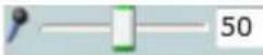 | Drag this slider to adjust the gain of the PC microphone (that is, how sensitive it is to the audio that it picks up and that is sent to the IP camera), or enter a value from 0 through 100 in the field and press the Enter key.The default value is 50. |
| Camera Settings controlsNote To display these controls click the Expand icon next to Camera Settings under the video image. The icon changes to the Collapse icon . Click the Collapse icon to hide these controls.If you make changes to any of the Camera Settings options, click the Save button to save the changes. | |
| Picture Adjustments | |
| Brightness slider To control | control the brightness of the video image, drag the slider to select a value from 1 through 10. A higher value increases the brightness and a lower value decreases the brightness. For example, if the IP camera is facing a bright light and the video appears too dark, you can increase the brightness.The default value is 5. |
| Contrast slider To control | control contrast of the video image, drag the slider to select a value from 1 through 10. A higher value increases the contrast and a lower value decreases the contrast.The default value is 5. |
| Sharpness slider | To control the sharpness of the video from the IP camera, drag the slider to select a value from 1 through 100. A higher value increases the sharpness and a lower value decreases the sharpness.The default value is 50. |
| Saturation slider To control | control the saturation of the video from the IP camera, drag the slider to select a value from 1 through 10. A higher value increases the saturation and a lower value decreases the saturation.High saturation provides a vivid, intense color for a video image. With less saturation, the video image appears more muted and gray.The default value is 50. |
| Restore button | Resets brightness, contrast, sharpness, and saturation to their default values. |
| White Balance Mode drop-down menu | Choose one the following white balance modes:Auto—White balance automatically set by camera and suitable for most conditions.Manual—Choose this option if you want to set the white balance by setting RGain (Red Gain) and BGain (Blue Gain) manually.The default setting is Auto. |
| Exposure Control | |
| Exposure level drop-down menu | Choose a value to increase or decrease the exposure level of the video image.The default value is 0.0. |
| Exposure mode drop-down menu | Choose one of these options:Manual—Choose this option if you want to set Exposure time and Gain control manually.Auto—Suitable for most conditions.The default setting is Auto. |
| Flickerless check box | Appears when you chooseManualfrom the Exposure mode drop-down menu.Flickering can occur when a combination of indoor and outdoor light get to the IP camera, due to a difference in capture frequency and actual indoor lighting frequency. Check this check box to limit the range of exposure time, which prevents flickering. |
| Exposure time slider | Appears when you chooseManualfrom the Exposure mode drop-down menu.To control the minimum length of time in seconds that the IP camera keeps its iris open for each frame, drag the left slider box. To control the maximum length of time in seconds that the IP camera keeps its iris open for each frame, drag the right slider box.When capturing video, the IP camera automatically selects the optimum value between the minimum and maximum values that you configure.If the Flickerless check box is not checked, the minimum exposure value is 1/32000 and the maximum value is 1/5. If the Flickerless check box is checked, the minimum exposure value is 1/120 and the maximum value is 1/5. |
| Gain control slider | Appears when you chooseManualfrom the Exposure mode drop-down menu.To control the minimum gain of the IP camera, drag the left slider box. To control the maximum gain, drag the right slider box. A value of 0 does not boost the gain, so the image may appear darker in a darker environment. A higher value increases the exposure of the image, which can cause the image to look brighter, but can also cause the image to appear more noisy.When capturing video, the IP camera automatically selects the optimum value between the minimum and maximum values that you configure. |
| Iris mode drop down menu | Appears only when you chooseAutofrom the Exposure mode drop-down menu. Choose one of these options for the IP camera iris:Indoor—Suitable for indoor conditionsOutdoor—Suitable for outdoor conditions |
| Measurement Window | Choose one of the following options to control how the IP camera calculates exposure:Full View—The entire IP camera image is considered for the exposure calculation.Custom—Lets you draw up to 4 Inclusion regions and up to 4 Exclusion regions for the exposure calculation.To designate regions, right-click the video image, chooseDraw Region, then hold down the left mouse button and draw the region, which is indicated by a green rectangle.A region is an Inclusion region by default.To move a region, left-click it and drag its window to the desired area.To resize a region, left-click it and drag a box in the edge or corner of the region.To remove a region, left-click it, then right-click it and chooseDelete Region.BLC—Back Light Compensation causes only the middle part of the IP camera image, indicated by a white dashed rectangle, to be considered for the exposure calculation. |
| Region Properties Appears when you click a custom region that you created.To expand region properties information, click the + icon next to Region Properties. The icon changes to a - icon, which you click to collapse region properties information.Location-X and Y coordinates, respectively, of the top left corner of the selected custom region. To expand location information, lick the + icon next to Location. The icon changes to a - icon, which you click to collapse region location information.Region Type-Type of the region (Inclusion or Exclusion). To change the region type, left-click that region, click Region Type, then choose one of the following values from the drop-down menu that appears on the Region Type line. Alternatively, you can double-click Inclusion or Exclusion to toggle between these values.- Inclusion-The region is used to calculate the exposure value- Exclusion-The region is ignored in the exposure value calculation | |
| Advanced Settings | |
| Enable Low Light Compensation check box | In a low-light environment, check this check box to reduce noise in the video image. |
| Enable DRX check box | In situations in which there is significant contrast between light and dark parts of an image, check this check box to cause the IP camera to continually adjust the image for optimal appearance. |
| Sensitivity drop-down menu | Appears when you check the Enable DRX check box.Choose Low or High to specify how quickly the IP camera adjusts the image for optimal appearance. |
| Strength drop-down menu | Appears when you check the Enable DRX check box.Choose Low, Medium, or High to specify the relative adjustment that the IP camera makes between the light and dark parts of an image. |
| Gamma Curve | Select a gamma curve value to adjust the monitor gray-scale for video from the IP camera. |
| Motion DetectionNote To display these controls click the Expand icon ▲ next to Motion Detection under the video image. The icon changes to the Collapse icon ▼. Click the Collapse icon to hide these controls.If you make changes to any of the Motion Detection options, click the Save button to save the changes. | |
| Enable MotionDetection check box | Enables the motion detection feature.When motion detection is enabled, the IP camera monitors activity in the video field areas that you specify. If activity at a defined level occurs in any of these areas, the IP camera generates an alert and takes the configured actions.To designate regions, right-click the video image, choose Draw Region, then hold down the left mouse button and draw the region, which is indicated by a green rectangle (for an inclusion region) or a red rectangle (for an exclusion region).You can draw up to 4 Inclusion regions and up to 4 Exclusion regions for a total of up to 8 regions.To move a region, left-click it and drag its window to the desired area.To resize a region, left-click it and drag a box in the edge or corner of the region.To remove a region, left-click it, then right-click it and choose Delete Region. |
| Region Properties | To expand region properties information, click the + icon next to Region Properties. The icon changes to a - icon, which you click to collapse region properties information.IsActive-To indicate whether the IP camera monitors a region for motion detection, left-click that region, clickIsActive, then choose True (consider region) of False (do not consider region) from the drop-down menu that appears on theIsActive line. Alternatively, you can double-click True or False to toggle between these values.Location-X and Y coordinates, respectively, of the top left corner of the selected custom region. To expand location information, lick the + icon next to Location. The icon changes to a - icon, which you click to collapse region location information.Name-Name of the region. By default, the system assigns the name RegionX, where X is a number 1 through 8. To rename a region, click its name (which appears in bold type on this line) and type a unique name of up to 32 characters.Region Type-Type of the region. To change the region type, left-click that region, click Region Type, then choose one of the following values f from the drop-down menu that appears on the Region Type line. Alternatively, you can double-click Inclusion or Exclusion to toggle between these values.- Inclusion-The IP camera examines this region for motion- Exclusion-The IP camera ignores motion in this area |
| Control | Description |
| Sensitivity slider Becomes available when you left-click a motion detection region. Designates the relative amount of activity that the IP camera must detect in the area before it generates an alert. A lower value means that more, or faster, activity is required to trigger an alert. A higher value means that less, or slower, activity is required. The default value is 80. | |
| Threshold slider Becomes available when you left-click a motion detection region. Designates the percentage of pixels that the IP camera must identify as changed in the area before it generates an alert. The camera monitors for pixel changes at the defined sensitivity level. The default threshold value is Low. | |
| Focus/ZoomNote To display these controls click the Expand icon ▲ next to Focus/Zoom under the video image. The icon changes to the Collapse icon ▼ Click the Collapse icon to hide these controls. | |
| Zoom slider | Drag to the right to increase the zoom level of the video image (tele) and drag to the left to decrease the zoom level (wide). You also can use these buttons to adjust the zoom level:•-10—Decreases the zoom level by 10 steps•-1—Decreases the zoom level by 1 step•+1—Increases the zoom level by 1 step•+10 —Increases the zoom level by 10 steps |
| Focus slider Drag to the right sharpen the focus on objects at are farther away from the camera and drag to the left to sharpen the focus on objects that are nearer. You also can use these buttons to adjust the focus:•-10—Decreases the focus by 10 steps•-1—Decreases the focus by 1 step•+1—Increases the focus by 1 step•+10 —Increases the focus by 10 step | |
| Auto Focus button | Click to have the IP camera automatically adjust its focus. This adjustment uses larger steps that the full auto focus feature (see the “Full Auto Focus button” row in this table), but takes less time to complete than a full auto focus. The auto focus process can take a few minutes to complete, and the Focus/Zoom controls are dimmed during this process. When the process completes, click OK in the dialog box that displays the message “Set Auto Focus successfully.” |
| Reset button Click to set | the zoom and focus controls to their default values. When the process completes, click OK in the dialog box that displays the message “Settings reset successfully.” |
| Control Description | |
| Specify Region check box | To automatically adjust the focus with priority given to a particular region in the field of view:1. Check the Specify Region check box.2. Right-click the video image and choose Draw Region.3. Hold down the left mouse button and draw the region, which is indicated by a green rectangle.To move a region, left-click it and drag its window to the desired area.To resize a region, left-click it and drag a box in the edge or corner of the region.To remove a region, uncheck the Specify Region check box. |
| Full Auto Focus button | Click to have the IP camera automatically adjust its focus. This adjustment uses smaller steps that the auto focus feature (see the “Auto Focus button” row in this table), but can result in a sharper focus and takes more time to complete than an auto focus.The full auto focus process can take some time, and the Focus/Zoom controls are dimmed during this process. If you see a dialog with the message “Operation still in progress,” click OK. When the process completes, click OK in the dialog box that displays the message “Set Full Auto Focus successfully.” |
Privacy Zone
Note To display these controls click the Expand icon ▲ next to Privacy Zone under the video image. The icon changes to the Collapse icon . Click the Collapse icon to hide these controls.
If you make changes to any of the Privacy Zone options, click the Save button to save the changes.
| Enable Privacy Region check box | Enables the Privacy Zone feature.You can create up to four user-defined masking zones that can used to provide regions of privacy in the camera field of view. When the Privacy Zone feature is enabled, video within privacy each region is not recorded in the camera, nor sent in the video stream. Instead of the actual video, privacy regions display as solid rectangles that you choose from the Region Color drop-down list.To designate regions, right-click the video image, chooseDraw Region, then hold down the left mouse button and draw the region, which is indicated by a green rectangle.To move a region, left-click it and drag its window to the desired area.To resize a region, left-click it and drag a box in the edge or corner of the region.To remove a region, left-click it, then right-click it and chooseDelete Region. |
| Region Color drop-down menu | Choose the color in which the system displays the zones that are defined by privacy regions. You can chooseRed, Green, Black, or Blue. |
| Control Description | |
| Privacy Zone properties | To expand region properties information, click the + icon next to Privacy Zone Properties. The icon changes to a - icon, which you click to collapse region properties information.• Name—Name of the region. By default, the system assigns the name RegionX, where X is a number 1 through 4. To rename a region, click its name (which appears in bold type on this line) and type a unique name of up to 32 characters .•IsActive—To indicate whether the IP camera displays a region as a privacy mask, left-click that region, clickIsActive, then choose True (mask the region) of False (do not mask the region) from the drop-down menu that appears on theIsActive line. Alternatively, you can double-click True or False to toggle between these values. |
text_image
INDEXA
About link 4-2
ActiveX controls 4-2
B
brightness 4-7
C
camera
See IP camera
camera settings, controls in Camera Video/Control window 4-7
Camera Video/Control window
accessing 4-5
description 4-2
displaying 4-2
connecting, to the IP camera
for the first time 3-1
PC requirements for 3-1
contrast 4-7
D
DHCP, obtaining IP address through 3-1
F
factory reset 4-4
focus and zoom, controls 4-12
G
GPIO terminal block 2-7
H
help, for IP camera windows 4-2
Home window
description 4-2
displaying 4-1
HTTP, allowing access through 3-2
I
installing
GPIO terminal block 2-7
IP camera 2-1
mounting to ceiling or wall 2-4
warnings 2-1
waterproof connector 2-6
IP address
default for IP camera 3-1
obtaining from DCHP server 3-1
IP camera
accessing through a web browser 3-1
connecting to for the first time 3-1
installation 2-1
GPIO terminal block 2-7
mounting to ceiling or wall 2-4
warnings 2-1
waterproof connector 2-6
logging out of 4-2
powering off 4-4
Cisco Video Surveillance 7530PD IP Camera Installation Guide
REVIEW DRAFT-CISCO CONFIDENTIAL
powering on 4-4
windows 4-2
reboot 4-4
L
live video
See also video
live video, viewing
through home window 4-5
through third-party device or software 4-5
log out, of IP camera 4-2
M
motion detection
controls 4-11, 4-13
enabling 4-11
sensitivity 4-12
mounting to ceiling or wall 2-4
P
password
, requirements for 3-2
password, requirements for 3-2
power
adapter 2-1
powering off the IP camera 4-4
powering on the IP camera 4-4
Power over Ethernet (PoE) 2-1
Power over Ethernet (PoE) 2-1
R
rebooting, IP camera 4-4
Refresh link 4-1
reset
factory default values 4-4
Cisco Video Surveillance 7530PD IP Camera Installation Guide
s
saturation 4-8
Setup window
description 4-2
displaying 4-2
sharpness 4-8
T
terminal block 2-7
v
video
codec, controls in Camera Video/Control
window 4-5
resolution, controls in Camera Video/Control
window 4-5
viewing live
through Home window 4-5
through third-party device or software 4-5
See also live video
View Video link 4-2
W
warnings before installation 2-1
waterproof connector 2-6