
RemotePro - Solar installation Tycon Systems - Free user manual and instructions
Find the device manual for free RemotePro Tycon Systems in PDF.


| Product Name | RemotePro® Remote Power System (RPST) |
| Brand | Tycon Systems |
| Models | RPST12 (12V), RPST24 (24V) |
| Category | Off-Grid Solar Power System |
| Enclosure Material | Powder Coat Steel |
| Operating Temperature | -30°C to +60°C |
| Battery Type | Valve Regulated Sealed Lead Acid AGM |
| Battery Life | Up to 5 years in normal use |
| Battery Capacity Options | 50Ah, 100Ah, or 200Ah |
| Controller Type | Dual Input Solar/POE, PWM, 12V/24V 10A (TP-SCPOE) or 20A PWM (TP-SC24-20) |
| Overcharge Protection | 14.4V (12V system), 28.6V (24V system) |
| Over-discharge Protection | 11V (12V system), 22V (24V system) |
| Continuous Power Output | 25W to 50W (depending on configuration, with 6 hours peak sun) |
| Reserve Power | >24 hours at rated load |
| PoE Output | 24V 1.2A or 48V 0.62A (TP-SCPOE models) |
| Ventilation | PowerVent™ with thermostatic fan (activates >45°C) |
| Mounting Options | Pole mount with hose clamps or wall mount |
| Solar Panel Tilt | Adjustable; optimize for winter sun using latitude-based calculation |
| Warranty | 36 months limited (covers material and workmanship defects) |
| Safety Requirements | Install at least 20 ft from power lines; use grounding wire |
| Controller Self Consumption | <0.5W |
| Fuse Ratings | 12A in controller, 30A in battery cable |
| Included Accessories | Pole mount kit, hose clamps, PowerVent, battery platform, DIN rail, octopus cable |
| Compatible Loads | Wireless base stations, surveillance cameras, remote sensors, lighting, off-grid electronics |
| Controller LED Indicators | POE, SOL, CHA, LOA, REV |
Frequently Asked Questions - RemotePro Tycon Systems
User questions about RemotePro Tycon Systems
0 question about this device. Answer the ones you know or ask your own.
Ask a new question about this device
Download the instructions for your Solar installation in PDF format for free! Find your manual RemotePro - Tycon Systems and take your electronic device back in hand. On this page are published all the documents necessary for the use of your device. RemotePro by Tycon Systems.
USER MANUAL RemotePro Tycon Systems
RPST
RemotePro®
Remote Power System
- Wireless Base Stations and Client Devices
- Surveillance Cameras
- Remote Sensors
- Remote Lighting
- Off Grid Electronics
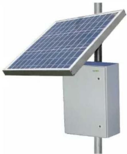
Congratulations! on your purchase of the RemotePro™ off-grid remote power system. Please take a moment to review this Qwik Install Guide before assembly or battery installation.

DANGER! Avoid Powerlines! You Can Be Killed!
When following the instructions in this guide take extreme care to avoid contact with overhead power lines, lights and power circuits. Contact with power lines, lights or power circuits may be fatal. We recommend to install no closer than 20 feet to any power lines.
Safety: For your own protection, follow these safety rules.
☐ Perform as many functions as possible on the ground
Do not attempt to install on a rainy, windy or snowy day or if there is ice or snow accumulation at the install site or if the site is wet.
- Make sure there are no people, pets, etc. below when you are working on a roof or ladder.

Recommended Tools: Phillips Screwdriver, 13mm and 10mm Wrench, 5/16" nut driver, Flat Blade Screwdriver
Please help preserve the environment and return used batteries to an authorized depot
Qwik Install
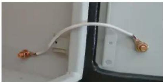
STEP 1: Add Grounding Wire Between Door and Enclosure: Remove
plastic covers on copper studs on inside of door and inside of enclosure. Add jumper wire between 2 copper studs and use copper washers and nuts to secure.
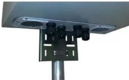
STEP 2: Remove the bottom cover and replace it with the PowerVent™ included with the package. Add wire feedthrus and any necessary connectors into the bottom PowerVent™ plate.
STEP 3: Install hole plug in drain hole in bottom right corner of the enclosure.
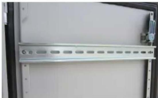
STEP 4: Mount the DIN rail to the door using screws provided. Mount any extra equipment to the orange backplate and secure the backplate in the enclosure. Note: The DIN rail can also be mounted to the orange backplate or sides of enclosure if desired.
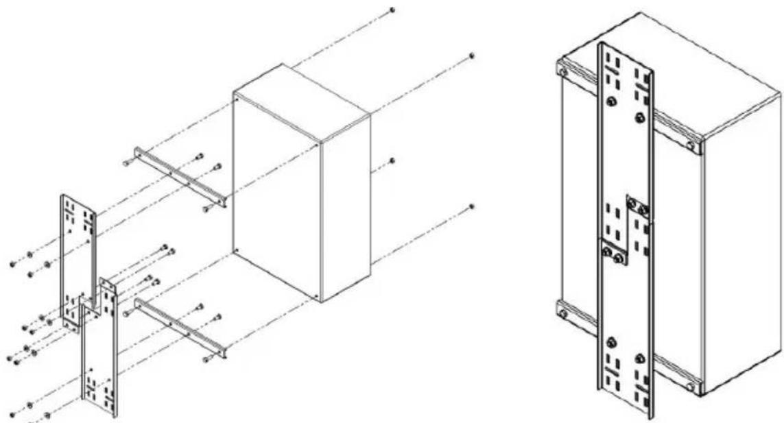
STEP 5: If pole mounting the enclosure, assemble the pole mount kit to the back of the enclosure and mount the enclosure to a pole using the 6 hose clamps provided. The enclosure can also be wall mounted using the 4 holes in the back of the enclosure.
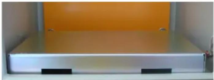
STEP 6: Insert the battery platform in the bottom of the enclosure. The battery platform has cutouts so wires can be routed under the battery as needed.
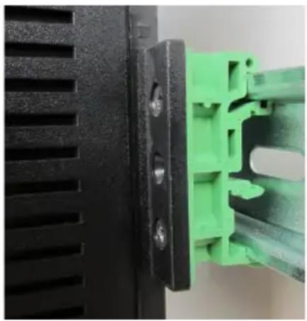
STEP 7: Attach the green DIN Rail adapters to the charge controller
using the screws provided. Clip the controller to the DIN rail. NOTE: For the TP-SC24-20 charge controller with LCD display, the green clip attaches using 1 screw only.
STEP 8: Assemble the solar panel mount and set the correct tilt angle based on your Latitude. There is a useful tool to calculate optimum angle at http://tyconsystems.com If you will be using a fixed angle all year we recommend using the optimum angle for winter sun. You can also calculate winter tilt using: Your_Latitude*0.9+30. Mount the solar panel mount to the pole using hose clamps provided. Be sure to mount high enough so the door of the enclosure clears the solar panel mount when opened. You can also mount the panel to a wall using lag bolts.
NOTE: If the Solar Controller is model TP-SCPOE12xx you must wire batteries and solar for 12V configuration. If Solar controller is model TP
-SCPOE-24xx you must wire solar panels and batteries for 24V configuration. Basically Batteries / Solar / Controller must be same voltage. The TP-SC24-20 controller is auto ranging and will detect 12V or 24V.
STEP 9: Attach the solar panel to the solar panel mount so that the wire junction box is towards the top or side.
If the solar panel is already connectorized, connect the solar panel MC-4 connectors to the included solar cable.
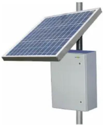
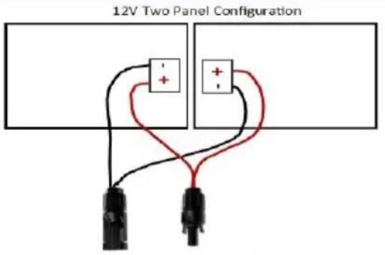
If the solar panel is not connectorized, remove the cover from the solar panel junction box by unscrewing or releasing the 6 snaps. Connect the included octopus cable wires to the + and - screws inside the junction box. Replace the cover making sure it is fully snapped.
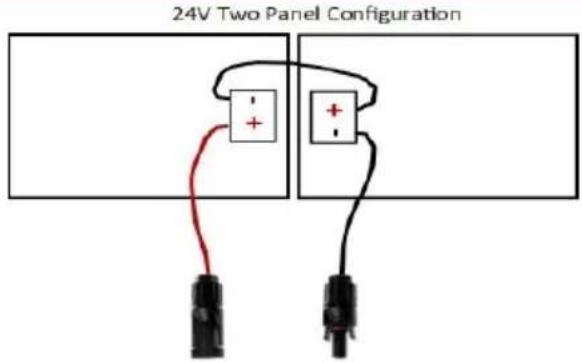
NOTE: When wiring 2 panels in a 24V configuration you will have two unused wires on the octopus cable assembly. Wrap the ends with electrical tape to avoid any shorting of the panels. Mount so octopus cable is under the solar panel to protect it from direct weather.
Panels without pre-installed MC-4 Connectors Configurations
![graph TD subgraph_Panel_1["Panel 1"] A1["Black Node"] --> B1["Red Node +"] A2["Black Node"] --> B2["Red Node -"] A3["Black Node"] --> B3["Red Node +"] A4["Black Node"] --> B4["Red Node -"] A5["Black Node"] --> B5["Red Node +"] end subgraph_Panel_2["Panel 2"] C1["Black Node"] --> D1["Red Node +"] C2[…](/content/2026/05/790199/images/ac84a35255bd6982388a06ee30763f43921d948454a5bf6fc75e12e79209010b.jpg)
MC-4 Connectorized Panels 12V Wiring Configurations using PWM Solar Controller
![graph TD A["12V Solar Panel"] --> B["15VDC"] C["12V Solar Panel"] --> D["15VDC"] B --> E["To Controller PV-"] D --> F["To Controller PV+"] style A fill:#f9f,stroke:#333 style C fill:#f9f,stroke:#333 style B fill:#ccf,stroke:#333 style D fill:#ccf,stroke:#333 style E fill:#dfd,stroke:#333 style F fil…](/content/2026/05/790199/images/3846456e12f27f6d15afc5c815f227c29cdbc5177c8d59c4e6fefd87c2dbcb9e.jpg)
![graph TD subgraph_Panel_Configuration["12V Four Panel Configuration"] A["12V Solar Panel"] --> B["+"] C["12V Solar Panel"] --> D["+"] E["12V Solar Panel"] --> F["+"] G["12V Solar Panel"] --> H["+"] I["12V Solar Panel"] --> J["+"] K["12V Solar Panel"] --> L["+"] end subgraph Panel_Configuration M["RP…](/content/2026/05/790199/images/3245c0c849f3fca59a0afa165cda7fd7f3e6ee5522055974cbacde4f4f268c46.jpg)
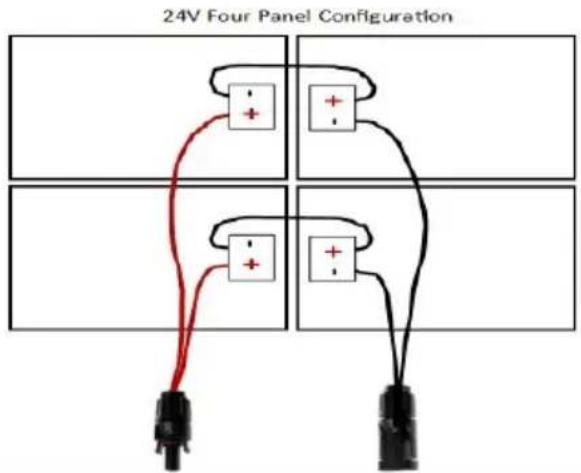
MC-4 Connectorized Panels 24V Wiring Configurations using PWM Solar Controller
24V Two Panel Configuration
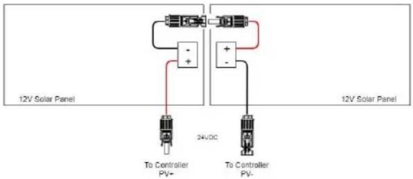
24V Four Panel Config
![graph TD A["12V Solar Panel"] --> B["Resistor"] B --> C["+"] B --> D["-"] E["12V Solar Panel"] --> F["Resistor"] F --> G["+"] F --> H["-"] I["12V Solar Panel"] --> J["Resistor"] J --> K["+"] J --> L["-"] M["12V Solar Panel"] --> N["Resistor"] N --> O["+"] N --> P["-"] Q["RPST-CABLE-2 PANEL-CONN"] --…](/content/2026/05/790199/images/ad296d1fa3416dc4a3032bd61e366dcf3e394701595d7551c86f602256316505.jpg)
STEP 10: Install the batteries in the enclosure. If using multiple batteries, connect in parallel for 12V output or connect in series for 24V output.
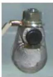
If batteries are installed on their side make sure to apply an insulator (included) to the top of the battery terminal to prevent the battery terminals from shorting to the metal enclosure in case the battery
shifts inside the enclosure during an earthquake.
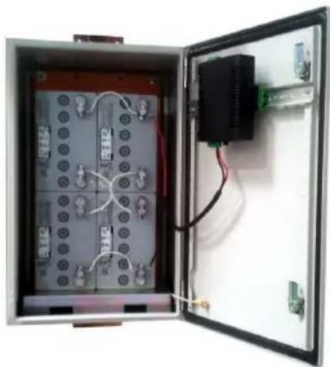
![graph TD A["12V Battery"] --> B["Controller"] B --> C["PowerVent"] C --> D["12V PV Solar Panel Array"] D --> E["12V Battery Config for 4 battery"] E --> F["12V Battery"] F --> G["12V PV Solar Panel Array"] G --> H["12V Battery"] H --> I["12V Battery"] I --> J["12V Battery"] J --> K["12V Battery"] K…](/content/2026/05/790199/images/37f0fa4f67b4cc96bb3f5c49217784419d85f235de3cb2b204ca4e7d6aa74b00.jpg)
RPST 12V Wiring Diagram
![graph TD A["Controller"] -->|Load - Load + Batt - Batt + PV - PV +| B["12V Battery"] B --> C["+"] B --> D["-"] E["PowerVent"] --> F["12V Battery"] E --> G["-"] E --> H["12V Battery"] I["Duplicate wiring for 4 batteries"] --> J["12V Battery"] I --> K["-"] I --> L["12V Battery"] M["24V PV Solar Panel…](/content/2026/05/790199/images/90585359e292ee2c9817726447829bfab22477742820b8079ad8fe06010ad015.jpg)
RPST 24V Wiring Diagram
STEP 11: Disconnect the green connector from the front of the controller. Connect the solar and battery wires to the green connector. Note: For the TP-SC24-20 controller connect wires directly to the integrated wire terminals.
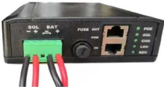
Connect the Battery cables to the Battery. Be sure to observe polarity. Black wire connects to battery negative terminal and BAT(-) terminal on the controller. Connect the green connector to the controller. When a fully charged battery is connected, the Green LOA LED should light on controller.
NOTE: The green connector on the controller may become unplugged due to vibration and the weight of the cables. Be sure to add a zip tie or other method to hold the cables and relieve the cable weight from the connector.
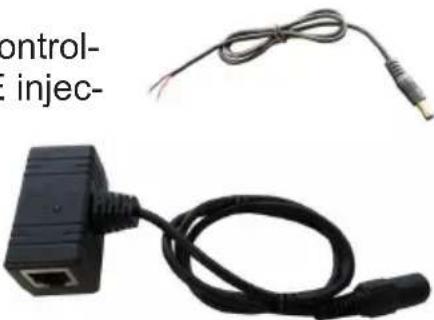
NOTE: On kits using the TP-SCPOE-24xx controllers, we have included a Gigabit passive PoE injector and adapter cable to be able to connect to the Aux port on the controller and provide passive PoE equal to the battery voltage. 24V Output is regulated.
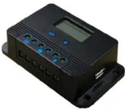
NOTE: An alternate high capacity (20A) controller is shipped with the RPST12 and RPST24 systems. The controller has wire terminal solar, battery and unregulated load outputs.
NOTE: If there is no room for multiple cables on the controller input use wire nuts to combine two cables to one and connect the one cable to the controller.
NOTE: Be sure to connect the battery to the controller first and disconnect it last. Connecting solar panels to the controller without the battery connected could damage the controller.
STEP 12: Route the solar panel cables out thru the feedthrus and install to the solar panel. Be sure to connect in the proper polarity, red wire to + and black wire to -.
STEP 13: Tighten all wire feedthrus. If they don't tighten on a small diameter wire, you can wrap some electrical tape around the wire in the seal area to increase its diameter and make a better seal.
STEP 14: Make sure lid gasket is clean and free from any particles, then carefully close the cover, making sure that wires are clear of the
| RPST12xx | RPST12 | RPST24xx | RPST24 | |
| Battery Capacity | 100Ah or 200Ah | 50Ah or 100Ah | ||
| Reserve Power @ Rated Load | >24 hours | >24 hours | ||
| Wire Terminal Output Voltage (DC) | 12V 1.5A | 12V 20A | 24V 1.5A | 24V 20A |
| POE Output Voltage (DC) | 24V1.2A or 48V .62A | N/A | 24V1.2A or 48V .62A | N/A |
| Maximum POE Input Voltage (DC) | 57V | N/A | 57V | N/A |
| Battery Voltage (DC) | 12V | 24V | ||
| Battery Type | Valve Regulated Sealed Lead Acid AGM | |||
| Battery Life | 5 Years | |||
| Controller Type | Dual Input Solar/POE, PWM, 12V/24V 10A | 20A PWM | Dual Input Solar/POE, PWM, 12V/24V 10A | 20A PWM |
| Overcharge Protection | 14.4V | 28.6V | ||
| Over-discharge protection | 11V | 22V | ||
| Over-discharge recovery voltage | 12.5V | 24.5V | ||
| Controller Self Consumption | <0.5W | |||
| Enclosure Type | Powder Coat Steel | |||
| Operating Temperature | -30°C to +60°C | |||
seam and hinge area. Use the special key to close the two cover locks.
TP-SCPOE Controller Wire Terminal Output Wiring
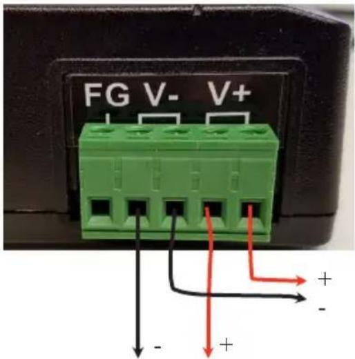
Device 1
FG = Frame Ground. Connect to Earth Ground
V- (There are two V- connections)
V+ (There are two V+ connections)
Device 2
TECH CORNER
Additional Information you may find useful
- CONTROLLER: The 12V controller turns off power to the load at 11V and reconnects when the battery reaches 12.5V. The 24V controller turns off power at 22V and reconnects at 24.5V. This protects battery from overdischarge and increases battery life and performance.
2.TP-SCPOE Controller LEDS:
POE = ON POE input detects current from POE source. If POE led is flashing it means the power source is too weak for the POE input. Find a power source with more capacity. The input requires at least 2.5A SOL = ON Solar input detects current from solar panel.
CHA = ON Batteries are being charged from solar input. If CHA is flashing it means batteries are fully charged.
LOA = ON Battery voltage is sufficient and load outputs (POE OUT and auxiliary wire terminal output) are turned on.
REV = ON Battery wires reversed.
Note: The TP-SC24-20 controller has an LCD display which shows battery voltage, current, solar voltage and load control. Press the button to turn the load on and off.
1.Fuse:
There is a fuse in the TP-SCPOE controller (12A) and a fuse in the battery cable (30A). The fuse is in-line with battery power. If fuse is blown there was some sort of short in the battery connection and the controller will appear dead. Replace with same size fuse.
- CAPACITY: The RemotePro ® RPST is rated at either 25W to 50W continuous power output with 6 hours of peak sun per day, depending on the configuration.
- VENTING: The enclosure is vented thru the PowerVent™. The fan is thermostatically controlled and will turn on when the temperature inside the enclosure exceeds 45°C.
- BATTERY MAINTENANCE: The batteries used in the RemotePro® systems don't require any maintenance. They should last up to 5 years in normal use.
NOTE: Never store batteries for a long time in a discharged state or it will kill the battery, especially during cold weather
- SOLAR PANEL TILT: There is a solar panel tilt calculator at the Tycon Systems® website http://tyconsystems.com. We recommend using a fixed tilt and setting to optimize for winter sun. The panel should face South if you are in the Northern Hemisphere or face North if you are in the Southern Hemisphere. Some typical winter tilt angles are as follows:
Place Optimum Winter Tilt
Houston / Cairo 56 deg
Albuquerque / Tokyo 60.5 deg
Denver / Madrid 65 deg
Minneapolis / Milano 69.5 deg
Winnipeg / Prague 74 deg
- BATTERY OVERDISCHARGE: We highly recommend hooking all equipment loads to the controller voltage output. This output will disconnect the load if the battery voltage drops below 11V (12V battery) or 22V (24V battery) and this will protect the battery from over-discharge. If batteries get completely discharged (<10V) because the equipment was connected directly to the battery, you will reduce the battery life and you will most likely need to recondition them with a good quality 10A min automotive battery charger. Avoid charging for longer than 24hrs to avoid battery damage. Once they are back to a normal operating range, the integrated charge controller will maintain the charge.
3. TROUBLESHOOTING:
A. I only get the SOL light on my charger controller?—The battery voltage and solar panel voltage must match the controller. If controller is TP-SCPOE-12xx it needs 12V solar and battery voltage. If the model is TP-SCPOE-24xx it needs 24V battery and solar voltage.
B. There is no LOA light and no voltage output?—If battery voltage is too low the charge controller will turn off the load outputs. On a 12V battery system the load will turn off if battery is <11V. On a 24V battery system the load will turn off at <22V.
C. Why is my solar panel voltage so high? - Open circuit voltage on a 12V panel is around 23V, and about 40V on a 24V panel. Once you connect to the charge controller the panel voltage will be reduced to a little higher than the battery voltage.
D. My system turns off at night and comes back on in the morning?- This is a sure sign that the solar panels and/or battery capacity can't support the load. You should measure your actual load and recalculate to make sure you have adequate capacity.
E. Can I charge my batteries from AC power? The TP-SCPOE controller gives the capability to charge the batteries through the POE IN Port. For 12V Battery use a 24-57V 2.6A(min) or greater power supply. For a 24V battery use a 36-57V 2.6A(min) power supply. Tycon® offers 90W power supplies and PoE inserters for this purpose.
Replacement Parts
Solar Controller: TP-SC24-20 (20A Output) or TP-SCPOE-xxxx (With PoE output)
Batteries: TPBAT12-52
Solar Mount: TPSM-80X4-UNI (2-4panels) or TPSM30-80-SP (single panel)
Solar Panel: TPS-12-85W
RemotePro® Typical Application—24V
![graph TD A["TP-SSW5-NC Uni-volt POE Switch"] -->|24VDC 1.5A| B["CAT5/6"] A -->|CAT5/6 24V POE| C["24V Solar Panel"] A -->|CAT5/6 24V Battery| D["24V Battery"] B --> E["24V BAT"] E --> F["Wireless Backhaul 24V 1A"] style A fill:#f9f,stroke:#333 style B fill:#ccf,stroke:#333 style C fill:#cfc,stroke:#…](/content/2026/05/790199/images/7c93dfe2cb78b95147299142e2d39afab42dce4b0c4ba42fe6946e00c2a73acf.jpg)
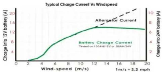
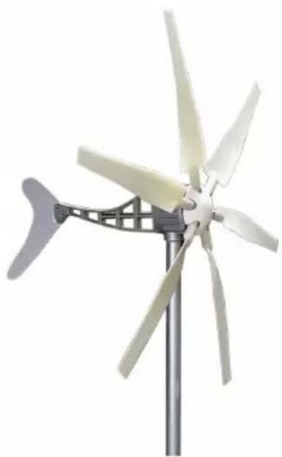
Wind Turbine
- Includes Integrated Controller with Dump Load
• Good low wind performance
• Self braking in high wind
• 110MPH survivability
• Sealed and maintenance free
Limited Warranty
The RemotePro ® products are supplied with a limited 36 month warranty which covers material and workmanship defects. This warranty does not cover the following:
- Parts requiring replacement due to improper installation, misuse, poor site conditions, faulty power, etc.
Lightning or weather damage.
▪ Physical damage to the external & internal parts. - Products that have been opened, altered, or defaced.
- Water damage for units that were not mounted according to user manual.
- Usage other than in accordance with instructions and the normal intended use.
Tycon Systems
14641 S 800 W
Bluffdale, UT 84065
support@tyconsystems.com
PH: 801-432-0003
- RPST
- REMOTEPRO®
- REMOTE POWER SYSTEM
- DANGER! AVOID POWERLINES! YOU CAN BE KILLED
- QWIK INSTALL
- MC-4 CONNECTORIZED PANELS 24V WIRING CONFIGURATIONS USING PWM SOLAR CONTROLLER
- TP-SCPOE CONTROLLER WIRE TERMINAL OUTPUT WIRING
- TECH CORNER
- ADDITIONAL INFORMATION YOU MAY FIND USEFUL
- 2.TP-SCPOE CONTROLLER LEDS
- 1.FUSE
- NOTE: NEVER STORE BATTERIES FOR A LONG TIME IN A DISCHARGED STATE OR IT WILL KILL THE BATTERY, ESPECIALLY DURING COLD WEATHER
- PLACE OPTIMUM WINTER TILT
- TROUBLESHOOTING
- REPLACEMENT PARTS
- WIND TURBINE
- LIMITED WARRANTY
Brand : Tycon Systems
Model : RemotePro
Category : Solar installation