2012 - Uncategorized Deutz - Free user manual and instructions
Find the device manual for free 2012 Deutz in PDF.


User questions about 2012 Deutz
0 question about this device. Answer the ones you know or ask your own.
Ask a new question about this device
Download the instructions for your Uncategorized in PDF format for free! Find your manual 2012 - Deutz and take your electronic device back in hand. On this page are published all the documents necessary for the use of your device. 2012 by Deutz.
USER MANUAL 2012 Deutz
natural_image
Illustration of two mechanical vehicles with visible gears and springs, set against a mountainous background (no text or symbols)Operation Manual
2012

text_image
DEUTZ®
text_image
Warning symbol with exclamation mark inside a triangle, commonly used to indicate caution or hazard.- Please read and observe the information given in this Operation Manual. This will enable you to avoid accidents, preserve the manufacturer's warranty and maintain the engine in peak operating condition.
● This engine has been built exclusively for the application specified in the scope of supply, as described by the equipment manufacturer and is to be used only for the intended purpose. Any use exceeding that scope is considered to be contrary to the intended purpose. The manufacturer will not assume responsibility for any damage resulting therefrom. The risks involved are to be borne solely by the user. - Use in accordance with the intended purpose also implies compliance with the conditions laid down by the manufacturer for operation, maintenance and servicing. The engine should only be operated by personnel trained in its use and the hazards involved.
● The relevant accident prevention guidelines and other generally accepted safety and industrial hygiene regulations must be observed.
● When the engine is running, there is a risk of injury through: - turning/hot components
- engines with positive ignition
- ignition systems (high electrical voltage)
You must avoid contact at all times!
● Unauthorized engine modifications will invalidate any liability claims against the manufacturer for resultant damage.
Manipulations of the injection and regulating system may also influence the performance of the engine, and its emissions. Adherence to legislation on pollution cannot be guaranteed under such conditions.
- Do not change, convert or adjust the cooling air intake area to the blower.
The manufacturer shall not be held responsible for any damage which results from such work.
- When carrying out maintenance/repair operations on the engine, the use of DEUTZ original parts is prescribed. These are specially designed for your engine and guarantee perfect operation.
Non-compliance results in the expiry of the warranty!
● Maintenance and cleaning of the engine should only be carried out when the engine is switched off and has cooled down.
You must ensure that the electrical systems have been switched off and the ignition key has been removed.
Accident prevention guidelines concerning electrical systems (e.g. VDE-0100/-0101/-0104/-0105 Electrical protective measures against dangerous touch voltage) are to be observed.
When cleaning with fluids, all electrical components are to be covered impermeably.
Operation Manual 2012
0297 9912 en
Engine Serial Number:
Please enter the engine serial number here. This number should be quoted when inquiring about Customer Service, Repairs or Spare Parts (see Section 2.1).
Technical modifications required to improve our engines are reserved with regard to specification data and other technical information contained in this Operation Manual. No parts of this Manual may be reproduced in any form or by any means without our written approval.

text_image
DEUTZ®Foreword
Dear Customer,
Liquid-cooled DEUTZ engines are designed for a large number of applications. Consequently, a wide range of variants are offered to meet the requirements of specific cases.
Your engine is appropriately equipped for the installation concerned, which means that not all of the components described in this Operation Manual are necessarily mounted to your engine.
We have endeavored to highlight any differences so that you will be able to locate the operating and maintenance instructions relevant to your engine quickly and easily.
Please read this Manual before starting your engine, and always observe the operating and maintenance instructions.
We are available to help with any additional inquiries
Sincerely,
DEUTZ AG
natural_image
Technical line drawing of an internal combustion engine assembly (no text or labels)© 31 493 0
Index
1. General
2. Engine Description
2.1 Model
2.1.1 Rating Plate
2.1.2 Position of the Rating Plate
2.1.3 Engine Serial Number
2.1.4 Cylinder Enumeration
2.2 Engine Illustrations
2.2.1 Operating Side 2012 Ribbed V-belt Drive
2.2.2 Starter Side 2012 Ribbed V-belt Drive
2.2.3 Operating Side 2012
2.2.4 Starter Side 2012
2.3 Lube Oil Circuit Schematic
2.3.1 Lube Oil Plan
2.4 Fuel System
2.4.1 Fuel System Plan
2.5 Coolant System
2.5.1 Coolant Plan 2012
3. Engine Operation
3.1 Commissioning
3.1.1 Pour in Engine Oil
3.1.2 Filling Oil Bath Air Filter with Engine Oil
3.1.3 Pour in Fuel
3.1.4 Fill / Bleed Cooling System
3.1.5 Other Preparations
3.2 Starting
3.2.1 Electric Starting
3.3 Monitoring Operation
3.3.1 Engine Oil Pressure
3.3.2 Coolant Temperature
3.4 Shutting off
3.4.1 Mech. Stopping
3.4.2 Electr. Stopping
3.5 Operating Conditions
3.5.1 Winter Operation
3.5.2 High Ambient Temperature, High Altitude
4. Operating Media
4.1 Lube Oil
4.1.1 Quality
4.1.2 Viscosity
4.2 Fuel
4.2.1 Quality
4.2.2 Winter Fuel
4.3 Coolant
4.3.1 Water Quality for Coolant
4.3.2 Coolant Treatment
4.3.3 Cooling System Protectants
5. Routine Maintenance
5.1 Maintenance Plan
5.2 Maintenance Diagram
5.3 Maintenance Work Completed
6. Service and Maintenance
6.1 Lubrication System
6.1.1 Oil Change Intervals
6.1.2 Check Oil Level, Change Engine Oil
6.1.3 Replace Oil Filter
6.1.4 Clean/Replace Oil Filter (Cup)
6.2 Fuel System
6.2.1 Replace Fuel Filter
6.2.2 Clean / Replace Fuel Oil Filter (Cup)
6.2.3 Clean / purge or change fuel Fuel pre-filter
6.2.4 Bleed Fuel System with Fuel Pre-filter
6.2.5 Bleed Fuel System without Fuel Pre-filter
6.2.6 Clean/Replace Fuel Pre-Filter, Filter Element
6.2.7 Clean/Replace/VentFuel Pre-Filter, Filter Element
6.3 Cooling System
6.3.1 Cleaning Intervals
6.3.2 Clean Cooling System
6.3.3 Drain Cooling System
6.3.4 Fill / Bleed Cooling System
6.4 Combustion Air Filter
6.4.1 Cleaning Intervals
6.4.2 Emptying Cyclone Type Precleaner
6.4.3 Clean Oil Bath Air Filter
6.4.4 Dry Type Air Cleaner
6.5 Belt Drives
6.5.1 Check V-belts
- 2012 Standard
- 2012 with Ribbed V-belt
Index
6.5.2 Tension V-belts
Coolant / Fuel Pump
6.5.3 Replace V-belts
Coolant / Fuel Pump
6.5.4 Replace V-belts
Ribbed V-belts
6.5.5 Tension Alternator V-belts
6.5.6 Replace Alternator V-belts
6.5.7 Wedge rib V-belts wear limit examine
6.6 Adjustments
6.6.1 Check Valve Clearance (Adjust if Necessary)
6.6.1.1 Valve Clearance Adjustment Plan
6.7 Accessories
6.7.1 Battery
6.7.2 Rotary Current Alternator
6.7.3 Transportation Shackles
- Faults, Causes and Remedies
7.1 Fault Table
- Engine Preservation
8.1 Preservation
- Technical Specification
9.1 Engine Specifications and Settings
9.2 Screw Tightening Torques
9.3 Tools
- Service
General
DEUTZ Diesel Engines
are the product of many years of research and development. The resulting know-how, coupled with stringent quality standards, guarantee their long service life, high reliability and low fuel consumption.
It goes without saying that DEUTZ Diesel Engines meet the highest standards for environmental protection.
Care and Maintenance
Sound care and maintenance practices will ensure that the engine continues to meet the requirements placed on it. Recommended service intervals must be observed and service and maintenance work carried out conscientiously.
Special care should be taken under abnormally demanding operating conditions.
Service
Please contact one of our authorized service representatives in the event of breakdowns or for spare parts inquiries. Our trained specialists will carry out repairs quickly and professionally, using only genuine spare parts.
Original parts from DEUTZ AG are always produced in accordance with state-of-the-art technology.
Please turn to the end of this manual for further service information.
Beware of Running Engine
Shut the engine down before carrying out maintenance or repair work. Ensure that the engine cannot be accidentally started. Risk of accidents. When the work is complete, be sure to refit any panels and guards that may have been removed. Never fill the fuel tank while the engine is running. Observe industrial safety regulations when running the engine in an enclosed space or underground.
Safety

This symbol is used for all safety warnings. Please follow them carefully. The attention of operating personnel should be drawn to these safety instructions. General safety and accident prevention
regulations laid down by law must also be observed.
Asbestos

DEUTZ original parts are asbestosfree.
Engine Description
2.1 Model
2.2 Engine Illustrations
2.3 Lube Oil Circuit Schematic
2.4 Fuel System
2.5 Coolant System
Engine Description
2.1 Model
2
2.1.1 Rating Plate
text_image
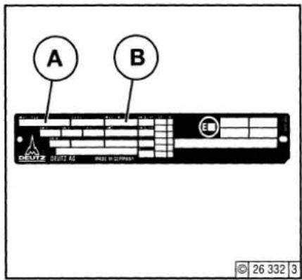
A B DEUTZ DEUTZ 45 FREE IN 22 PNEEAT © 26 332 3The model A, the engine serial number B and the performance data are stamped on the rating plate. The model and engine serial number must be given when ordering parts.
2.1.2 Position of the Rating Plate
text_image
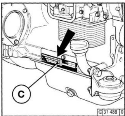
Technical diagram of a mechanical assembly with labeled component 'C' and directional arrow indicating motion or force.The rating plate C is attached to the crankcase.
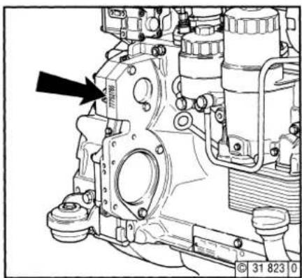
2.1.3 Engine Serial Number
natural_image
Technical line drawing of an internal combustion engine component with no visible text or symbolsThe engine serial number is stamped on the crankcase (arrow) as well as the rating plate.
2.1 Model
Engine Description
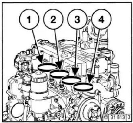
2.1.4 Cylinder Enumeration
text_image
1 2 3 4 31 813 0Cylinders are numbered consecutively, beginning at the flywheel.
Engine Description
2.2 Engine Illustration
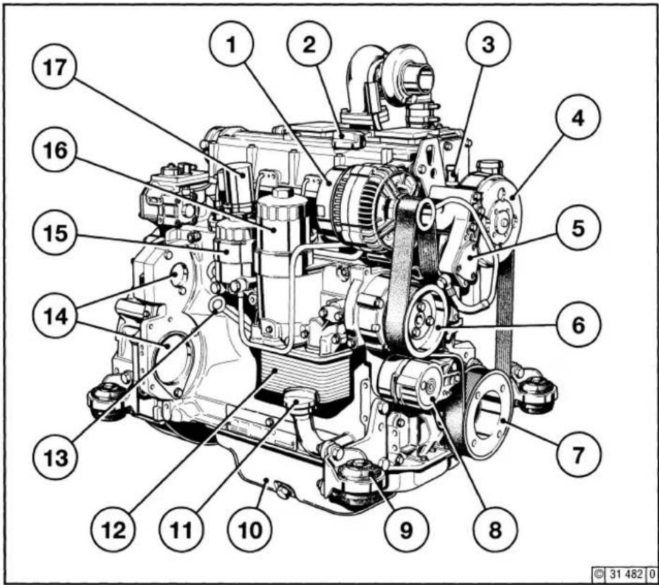
2.2.1 Operating Side 2012
Ribbed V-belt drive
text_image
Technical diagram of a mechanical assembly with numbered parts for identification1 Alternator
2 Oil filler
3 Coolant connection compensation line
4 Fan pulley
5 Fuel pump
6 Coolant pump
7 Ribbed V-belt pulley on crankshaft
8 Tension roller
9 Feet
10 Oil pan
11 Oil filler neck
12 Oil filter housing with engine oil cooler
13 Oil dipstick
14 Optional attachment of:
Compressor or hydraulic pump
15 Fuel filter cartridge
16 Oil filter cartridge
17 Tractive electromagnet
2.2 Engine Illustration
Engine Description
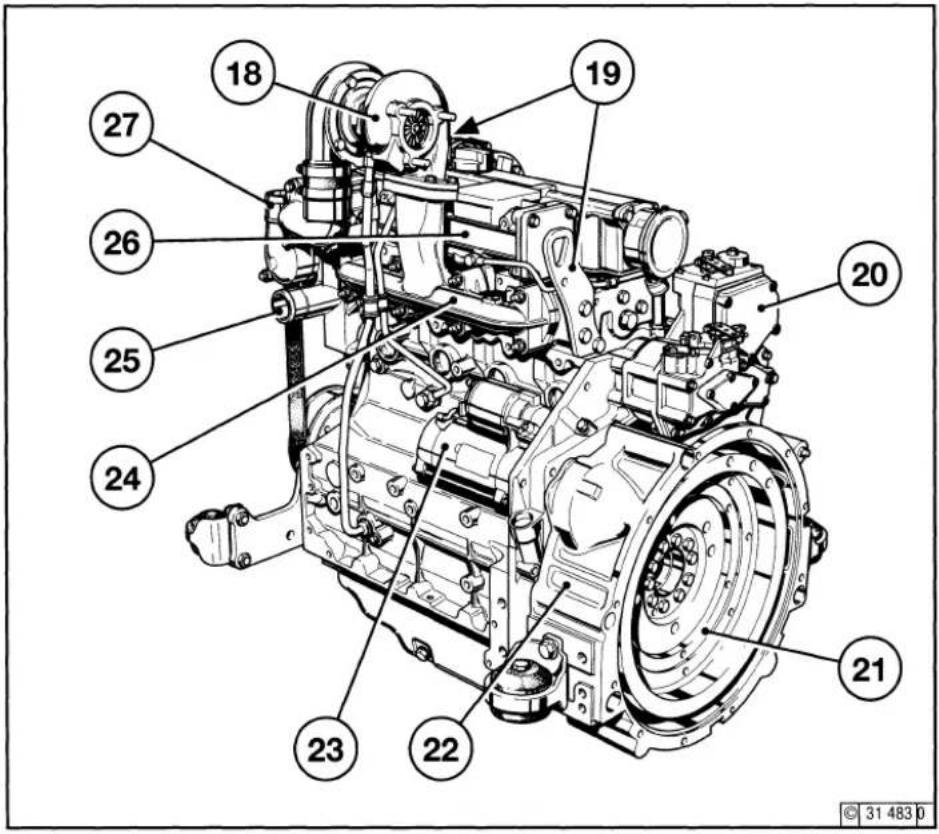
2.2.2 Starter Side 2012 Ribbed V-belt drive
text_image
Technical diagram of a mechanical transmission system with numbered components for identification18 Turbocharger
19 Engine suspension
20 Speed regulator
21 Flywheel
22 SAE housing
23 Starter
24 Exhaust manifold
25 Coolant inlet
26 Heater flange not shown
27 Thermostat housing coolant outlet
Engine Description
2.2 Engine Illustration
2
2.2.3 Operating Side 2012
© 2003
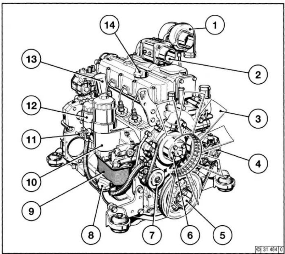
text_image
Technical diagram of an internal combustion engine with numbered components for identification1 Turbocharger
2 Heater flange
3 Fan
4 Alternator
5 V-belt pulley on crankshaft
6 Coolant pump
7 Fuel pump
8 Oil filler
9 Oil filter housing with engine oil cooler
10 Oil filter housing with oil filter cartridge
11 Oil dipstick
12 Fuel filter
13 Tractive electromagnet
14 Oil filler neck
2.2 Engine Illustration
Engine Description
2.2.4 Starter Side 2012
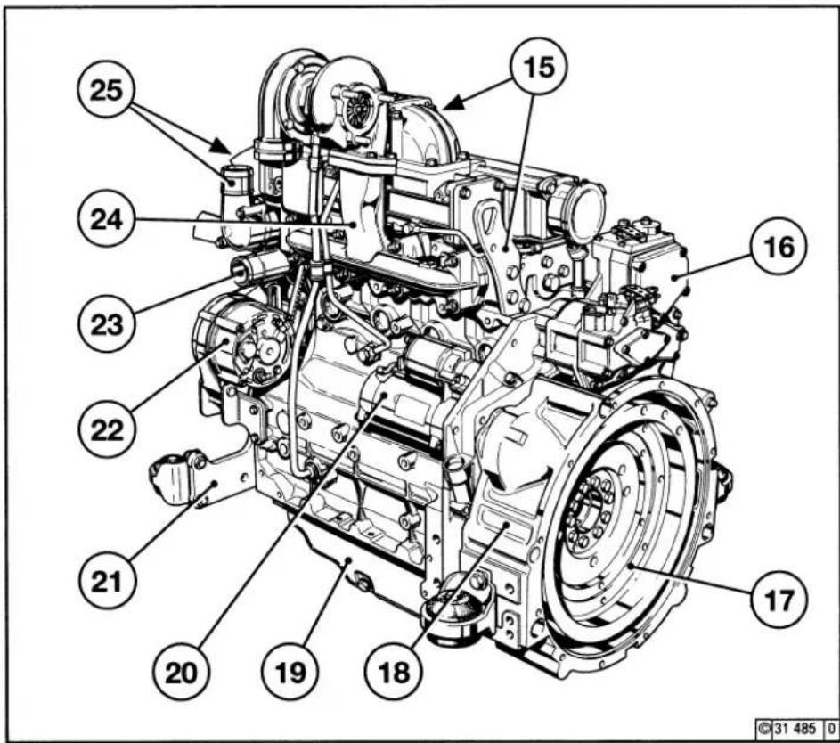
text_image
Technical diagram of a mechanical transmission system with numbered components for identification15 Engine suspension
16 Speed regulator
17 Flywheel
18 SÄE housing
19 Oil pan
20 Starter
21 Feet
22 Alternator
23 Coolant inlet
24 Exhaust manifold
25 Coolant outlet
Engine Description
2.3 Lube Oil Circuit Schematic
2.3.1 Lube Oil Plan
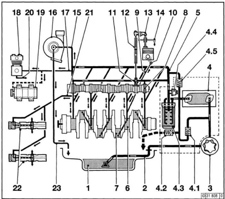
text_image
18 20 19 16 17 15 21 11 12 9 13 14 10 8 5 4.4 4.5 4 4.4 4.5 22 23 1 7 6 2 4.2 4.3 4.1 3 ©31 B08 01 Oil pan
2 Intake line
3 Lube oil pump
4 Lube oil cooler
4.1 Heat exchanger bypass valve
4.2 Shut-off valve
4.3 Lube oil replacement filter
4.4 Oil pressure sensor
5 Main oil pipe
6 Crankshaft bearing
7 Con-rod bearing
8 Camshaft bearing
9 Line to spray nozzle
10 Spray nozzle for piston cooling
11 Valve lifter with rocker arm impulse lubrication
12 Stop rod, oil supply for rocker arm lubrication
13 Rocker arm
14 Return line to oil pan
15 Oil line to turbocharger
16 Turbocharger
17 Oil line to compressor or hydraulic pump
18 Compressor
19 Hydraulic pump
20 Return line from compressor or hydraulic pump
21 Line to the differential (2x)
22 Balancer shafts
23 Turbocharger return to crankcase
2.4 Fuel System
Engine Description
2.4.1 Fuel System Plan
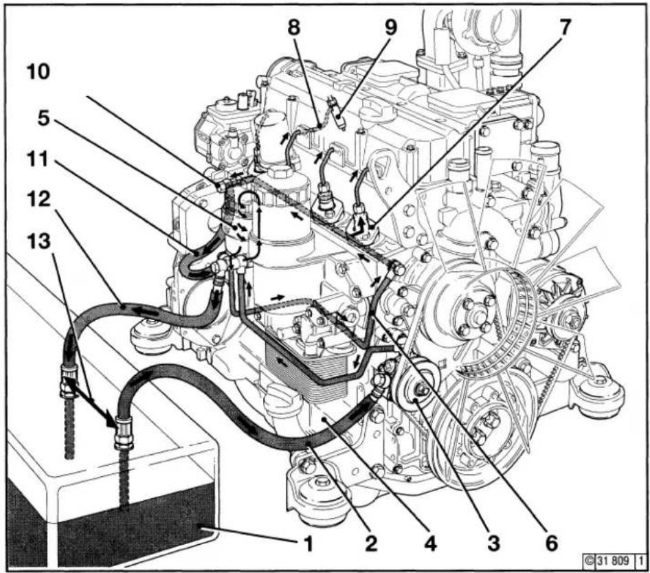
text_image
Technical diagram of an internal combustion engine with numbered components and labeled parts1 Fuel tank
2 Line to fuel pump
3 Fuel pump
4 Line to fuel filter
5 Fuel filter
6 Line to the injection pumps
7 Injection pump
8 Line to injection valve
9 Injection valve
10 Banjo bolt with pressure maintenance valve
11 Return line to fuel filter housing from pressure maintenance valve (with cup filter installation only)
12 Return line to fuel tank
13 Maintain maximum possible distance
Engine Description
2.5 Coolant System
2
2.5.1 Coolant block diagram 2012
Example: With cup filter
© 2003
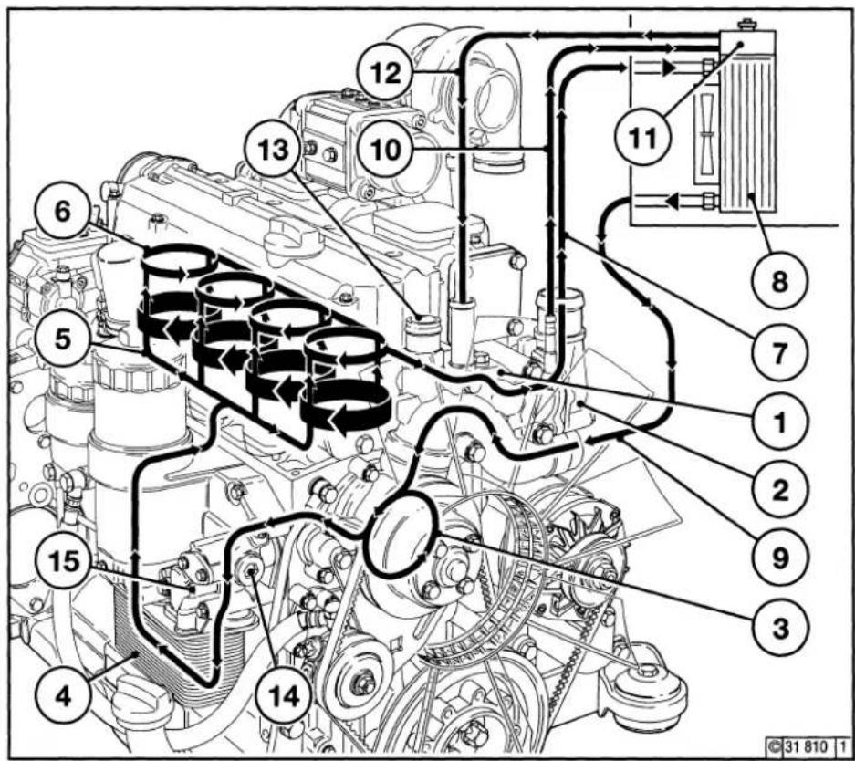
text_image
Technical diagram of an engine cylinder with numbered components and flow paths, likely for vehicle or industrial control.- Thermostat housing
- Outlet neck cover
- Coolant pump
- Lube oil cooler
- Cylinder cooling
- Cylinder head cooling
- Line from engine to heat exchanger
- Heat exchanger
- Line from heat exchanger to thermostat
- Ventilation line to the compensation tank
- Compensation tank
- Coolant compensation line
- Coolant return from heater
- Coolant supply to heating at V-belts
- Coolant supply to heating at ribbed V-belts
Engine Operation
3.1 Commissioning
3.2 Starting
3.3 Monitoring Operation
3.4 Shutting off
3.5 Operating Conditions
Engine Operation
3.1 Commissioning
3
3.1.1 Pour in Engine Oil
3.1.2 Oil Bath Air Filter with Engine Oil
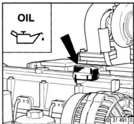
text_image
OIL © 31 491 0As a rule, engines are delivered without oil. Pour lube oil into the oil filler neck (arrow). Oil capacity, see 9.1. For oil grade and viscosity, see 4.1.
text_image
FUEL © 26 398 0Fill oil cup 1 of the oil bath air cleaner (if installed) with oil up to the arrow. For oil grade and viscosity, see 4.1.

Never fill the fuel tank while the engine is running. Ensure cleanliness! Do not spill fuel!
3.1 Commissioning
Engine Operation
3.1.3 Fill / Bleed Cooling System
● 2012: In accordance with the radiator supplier's specifications
- Unit engine: In accordance with the radiator supplier's specifications
3.1.4 Other Preparations
- Check battery and cable connections, see 6.7.1.
● Trial run
-After the engine has been prepared, carry out a brief trial run for approx. 10 minutes, without load if possible.
During and after the trial run
- Check the engine for leaks.
After the engine has been turned off
- Check oil level and top up if necessary, see 6.1.2.
- Retension V-belts, see 6.5.
● Breaking in
During the break-in phase - about 200 operating hours - check the oil level twice a day. After the engine is broken in, checking once a day will be sufficient.
● In the event of commissioning engines which have been preserved
Carry out removal of preservation in accordance with Chapter 8.1.
3.2.1 Electric Starting

Before starting, make sure that nobody is standing in the immediate vicinity of the engine or driven machine. After repair work:
Check that all guards have been replaced and that all tools have been removed from the engine.
When starting with glow plugs, do not use any other starter substance (e.g. injection with start pilot). Risk of accident!
Caution: If the speed regulator has been removed, the engine must not be started under any circumstances.
Disconnect the battery!
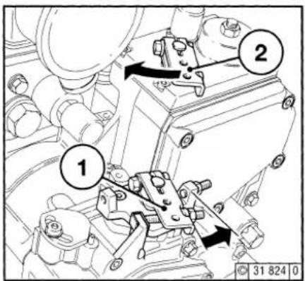
text_image
Technical diagram of a mechanical assembly with numbered components and directional arrows indicating movement or force.without cold start assistance
text_image
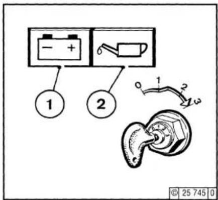
1 2 0 1 2 © 25 745 0Do not actuate the starter for more than 20 seconds. If the engine does not catch, wait for one minute then try again.
If the engine does not catch after two attempts, refer to the Fault Table (see 7.1).
● Disengage the clutch to separate the engine from any driven parts.
● Bring speed adjustment lever 1 into at least the middle speed position in the direction of the arrow.
- Move cut-out handle 2 into operating position counter to the direction of the arrow.
- Insert key
- Position 0 = no operating voltage.
- Turn key clockwise
- Position 1 = operating voltage
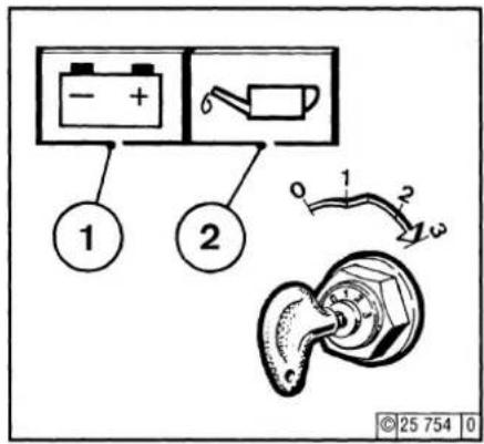
- Pilot lights 1 and 2 illuminate.
● Push key in and turn further clockwise against spring pressure. - Position 2 = no function
- Position 3 = start
● Release key as soon as engine fires - The pilot lights will go out.
3.2 Starting
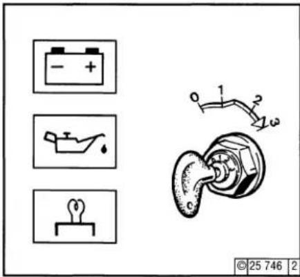
with cold start assistance Heater flange
text_image
Diagram showing three battery symbols and a valve mechanism with labeled parts, including a 25-746 scale indicator.- Insert key
- Position 0 = no operating voltage.
- Turn key clockwise
- Position 1 = operating voltage.
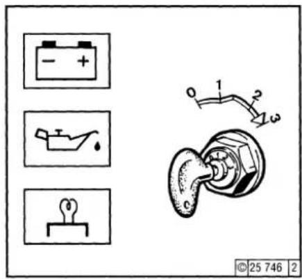
- Pilot lights illuminate, pre-glowing until glow indicator is extinguished.
- Push key in and turn further clockwise against spring pressure.
- Position 2 = no function
- Position 3 = start
- Release key as soon as engine fires.
- The pilot lights will go out.
Engine Operation
3.3 Monitoring Operation
3
3.3.1 Engine Oil Pressure
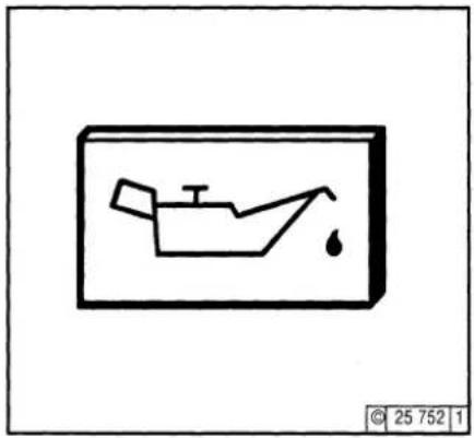
Oil pressure lamp
natural_image
Simple line drawing of a boat with a water droplet inside, enclosed in a rectangular frame (no text or symbols)● The oil pressure pilot light comes on with operating voltage on and engine off.
● The oil pressure pilot light must be extinguished when the engine is running.
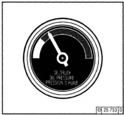
Oil Pressure Indicator
text_image
DEL DRUCK OIL PRESSURE PRESSION D' HUNE © 25 753 0● The pointer must remain in the green sector over the entire operating range.
Oil Pressure Gauge
text_image
Diagram showing battery and plug connections with numbered components and a close-up of the plug's internal structure.● The pointer of the oil pressure gauge must display the minimum oil pressure (see 9.1)
3.3 Monitoring Operation
Engine Operation
3.3.2 Coolant temperature
natural_image
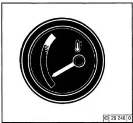
Circular gauge or dial indicator with needle and handle, no visible text or symbols● The engine temperature gauge pointer should always remain in the green sector. It should rarely enter the yellow-green sector. If the pointer enters the orange sector, the engine is overheating. Turn off and establish the cause from the Fault Table (see 7.1).
Engine Operation
3.4 Shutting Off
3.4.1 Mechanical Stopping
3.4.2 Electrical Stopping
text_image
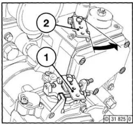
Technical diagram showing mechanical assembly with numbered components and directional arrow indicating motion or flow- Move speed adjustment lever 1 to low idle.
- Move shut-off lever 2 until the engine comes to a stop. The charge pilot light and the oil pressure pilot light illuminate when the engine stops.
● Turn key counterclockwise (to position 0) and remove. The pilot lights will go out.
text_image
Diagram showing battery, car oil drop, and light bulb with corresponding electrical circuit symbols and a mechanical component diagram.● Turn key counterclockwise (to position 0) and remove. The pilot lights will go out.
If possible, do not switch off the engine when under full load. Subsequently allow the engine to idle for approx. 2 mins.
3.5 Operating Conditions
Engine Operation
3.5.1 Winter Operation
● Lube Oil Viscosity
- Select the oil viscosity (SAE grade) according to the ambient temperature before starting the engine, see 4.1.2.
- Increase oil change frequency when operating below -10 °C, see 6.1.1.
● Diesel Fuel
- Use winter-grade diesel fuel for operation below 0 °C, see 4.2.2.
● Coolant
- Mixture ratio of anti-freeze / water for minimum temperature (max. -35 °C), see 4.3.1.
● Additional Maintenance Work
- Drain the sludge from the fuel tank once a week (undo the sludge drain screw).
- If necessary, adjust oilbath filter oil level, like the engine oil, to the ambient temperture.
- Below -20 °C, after removing the starter if necessary, smear the ring gear on the flywheel via the pinion bore from time to time with cold-resistant grease. (e.g. Bosch grease FT 1 V 31).
● Cold Start Assistance
- The heater flange is automatically initialised at temperatures < -25 °C.
● Battery
- Efficient cold starting necessitates that the battery is well-charged, see 6.7.1.
-The starting limit temperatures can be lowered by 4-5 °C by heating the battery up to about 20 °C. (To do so, remove the battery and store in a warm place).
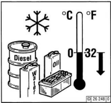
text_image
Diesel Water Oil °C 0 °F 32 © 26 248 0
Engine Operation
3.5 Operating Conditions

3.5.2 High Ambient Temperature High Altitude
● Air density decreases as altitude or ambient temperature increase.
As a result of this, the engine's maximum output, the quality of the exhaust gas, the temperature level and, in extreme cases, starting behaviour, are impeded.
In the event of non-stationary operation, use up to altitudes of 1000 m and temperatures of 30 °C is permissible.
If the engine is to operate under unfavourable conditions (at higher altitudes or temperatures), it will be necessary to reduce the injected fuel quantity and thus, engine power.
- If you have any doubts about engine operation under these or similar conditions, ask your engine or equipment supplier whether the engine has been derated in the interests of reliability, service life and exhaust gas quality (smoke!). Otherwise contact your service representative.
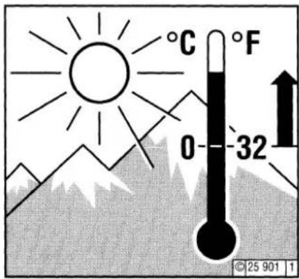
text_image
°C 0 -32 F © 25 901 1Operating Media
4.1 Lube Oil
4.2 Fuel
4.3 Coolant

Operating Media
4.1 Lube Oil

4.1.1 Quality Grade
Lube oils are differentiated by Deutz according to their performance and quality class. Oils of other, comparable specifications can be used.
The precise assignment of the admissible oil qualities to the engines is indicated in chapter 6.1.1. If in doubt, contact your service representative.
4.1.2 Viscosity
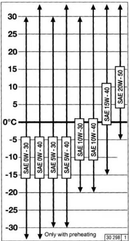
Generally, multi-grade oils shall be used. In closed heated rooms at temperatures >5^ C, also single-grade oils can be used.
As the viscosity of lube oil is dependent on temperature, the choice of SAE grade should be governed by the ambient temperature prevailing at the engine operating site.
Optimum operating behaviour will be attained if you take the accompanying oil viscosity diagram as a guide.
Should the temperature fall temporarily below the limits of the SAE grade selected, cold starting may be affected but the engine will not be damaged.
In order to keep wear to a minimum, do not exceed application limits for extended periods of time.
Synthetic lube oils feature an improved temperature and oxidation stability.
bar
| Category | Value | |---|---| | SAE 0W - 30 | -18 | | SAE 0W - 40 | -17 | | SAE 5W - 30 | -16 | | SAE 5W - 40 | -15 | | SAE 10W - 30 | -12 | | SAE 10W - 40 | -11 | | SAE 15W - 40 | 12 | | SAE 20W - 50 | 15 | Only with preheating 30 298 14.1 Lube Oil
Operating Media
4.1.2.1 Specific lube oil definitions
Turbocharged engines with uprated power and engines with high loading
The oils listed in enclosure 1 are to be used for the following engines and applications: COM/EPA II version and increased output BF4M 2012/C > 95 kW
BF6M 2012/C > 143 kW (bore 101 + 98-MVS) BF6M 2012/C > 135 kW (bore 98 mech. FIE)
● all engines in CHP plants
● all engines in gensets operating in parallel with the mains/with each other
● engines in combines with:
These are high-grade oils according to ACEA or API. In addition most of these oils are partly synthetic, some even fully synthetic (5W-40) and thus achieve the thermal stability required for the relevant application and are distinguished by a low tendency to cause deposits in the turbocharger and in the charge air pipes with closed-circuit crankcase breather
| Lube oils for engines with uprated power and engines with high loading | |||
| Producer | Type of lube oil | SAE class | Availability |
| DEUTZ | TXL-10W40 FE | 10W-40 | |
| AGIP | Agip Sigma Ultra TFE | 10W-40 | worldwide |
| AGIP | Autol Valve Ultra FE | 10W-40 | Germany |
| ARAL GmbH | Aral MegaTurboral | 10W-40 | worldwide |
| ARAL GmbH | Aral SuperTurboral | 5W-30 | worldwide |
| BAYWA | BayWa Super Truck 1040 MC | 10W-40 | South Germany |
| BAYWA | BayWa Turbo 4000 | 10W-40 | South Germany |
| Castrol GmbH | Castrol SYNTRUCK | 5W-40 | Europe, North America, BrazilArgentina, Australia, South Africa |
| Castrol GmbH | Castrol DYNAMAX | 7,5W-40 | Europe, North America, BrazilArgentina, Australia, South Africa |
| CHEVRON | Chevron Delo 400 Synthetic | 5W-40 | North America |
| ESSO | Essolube XTS 501 | 10W-40 | Europe |
| FINA | FINA KAPPA FIRST | 5W-30 | Europe |
| FINA | FINA KAPPA ULTRA | 10W-40 | Europe |
| FUCHS DEA | DEA Cronos Synth | 5W-40 | Germany, Europe |
| FUCHS DEA | DEA Cronos Premium LD | 10W-40 | Germany, Europe |
| FUCHS DEA | Fuchs Titan Cargo MC | 10W-40 | worldwide |
| FUCHS DEA | Deutz Oel TLL 10W-40 MB | 10W-40 | Germany |
| FUCHS DEA | DEA Cronos Premium FX | 10W-40 | Europe |
| FUCHS DEA | Fuchs Titan Unic Plus MC | 10W-40 | worldwide |
| MOBIL OIL | Mobil Delvac 1 SHC | 5W-40 | Europe, SE Asia, Africa |
| MOBIL OIL | Mobil Delvac 1 | 5W-40 | worldwide |
| MOBIL OIL | Mobil Delvac XHP Extra | 10W-40 | Europe, SE Asia |
| BP OIL International | BP Vanellus HT Extra | 10W-40 | Europe |
| Shell International | Shell Myrina TX / | 5W-30 | Europe, different |
| Shell Rimula Ultra | description in some countries | ||
| Shell International | Shell Myrina TX / | 10W-40 | Europe, different |
| Shell Rimula Ultra | description in some countries | ||
| TOTAL | TOTAL RUBIA TIR 86000 | 10W-40 | worldwide |
| SchmierölraffinerieSalzbergen GmbH | Wintershall TFG | 10W-40 | Europe |
The table will be extended as and when required.
4.2.1 Quality
Use commercially available diesel fuel with less than 0.5% sulphur content. If the sulphur content is higher, oil change intervals should be reduced (see 6.1.1).
The following fuel specifications / standards are approved:
● DIN EN 590
● BS 2869: A1 and A2 (with A2, take note of the sulphur content!)
● ASTM D 975-88; 1-D and 2-D
● NATO Code F-54 and F-75
Exhaust emission values which may be determined in the case of type approval tests always refer to the reference fuel prescribed by the authorities for the type approval test.
4.2.2 Winter Fuel
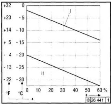
Waxing may occur at low temperatures, clogging the fuel system and reducing engine efficiency. Use winter-grade diesel fuel (up to -20 °C) for operation below 0 °C. This is made available within good time by filling stations prior to the start of the winter season.
- Kerosene must be added at temperatures below -20 °C. The relevant percentages are given in the adjacent diagram.
● Special diesel fuels may be used in arctic climatic zones up to -44 °C.
If summer-grade diesel fuel must be used at temperatures below 0 °C, up to 60% kerosene can be added (see diagram).
In most cases, adequate resistance to cold can be obtained by adding a flow improver (additive). Please ask your DEUTZ partner.
line
| X (%) | Y Value (I) | Y Value (II) | |---|---|---| | 0 | 0 | -20 | | 10 | -5 | -25 | | 20 | -10 | -30 | | 30 | -14 | -35 | | 40 | -18 | -40 | | 50 | -22 | -45 | | 60 | -26 | -50 || Legend: | |
| I | Summer-grade diesel fuel |
| II | Winter-grade diesel fuel |
| A | Ambient temperature |
| B | Percentage of kerosen added |

Diesel fuels must never be mixed with gasoline (Normal and Super grades)!

Mix in tank only! Fill with the appropriate amount of kerosene first, then add the diesel fuel.
4.3 Coolant
Operating Media
4.3.1 Quality of Water for Coolant
The values listed below must not be exceeded. In order to examine the quality of your water, a test case can be ordered from DEUTZ under Order No. 12130382.
| Water quality | min. | max. |
| pH value at 20 °C | 6.5 | 8.5 |
| Chloride ion content [mg / dm3] | - | 100 |
| Sulphate ion content [mg / dm3] | - | 100 |
| Total hardness [°dGH] | 3 | 20 |
4.3.2 Coolant Treatment
In the case of liquid-cooled engines, special attention must be paid to the treatment and control of the coolant, as the engine may otherwise become damaged as a result of corrosion, cavitation and freezing.
The treatment of the coolant is carried out by adding a cooling system protectant to the cooling water.
The cooling system must be continuously monitored, see 5.1. In addition to checking the coolant level, this also involves checking the concentration of the cooling system protectant.
The cooling system protectant concentration can be checked with commercially available testers (example: gefo glycomat®).
4.3.3 Cooling System Protectants
DEUTZ cooling system protectant must be purchased in drums under Order No. 01011490 (5 litres) or 1221 1500 (210 litres). These are nitrite, amine and phosphate-free, and provide effective protection against corrosion, cavitation and freezing.
If the above mentioned cooling system protectant is unavailable, the following products may be used in exceptional cases.
| Manufacturer | Product designation |
| AVIA | AVIA Antifreeze Extra |
| ARAL | Antifreeze Extra |
| BASF | Glysantin G 48 |
| DEA | DEA Radiator Antifreeze |
| SHELL | SHELLGlycoShell |
The cooling system protectant in the coolant should not fall below or exceed the following concentration:
| Cooling system protectant | Water |
| max. 45 Vol.% | 55% |
| min. 35 Vol.% | 65% |
Filling volume, see chart over page in combination with specifications in Chapter 9.1.
The use of other cooling system protectants, e.g. chemical anti-corrosion agents, is possible in exceptional cases. Consult DEUTZ Service.

If nitrite-based cooling system protectants are mixed with amine-based agents, dangerous nitrosamines are formed.

Cooling system protectants must be disposed of in an environmentally-friendly manner.
| Cooling system protection | |||||||||
| Cooling system protection in | Frost protection in [°C] | content of coolant system*) [Litres] | |||||||
| 18 | 20 | 22 | 25 | 27 | 30 | 32 | 35 | ||
| Cooling system protectant | |||||||||
| 35 | -22 | 6,3 | 7,0 | 7,7 | 8,75 | 9,5 | 10,5 | 11,2 | 12,3 |
| 40 | -28 | 7,2 | 8,0 | 8,8 | 10 | 10,8 | 12 | 12,8 | 14 |
| 45 | -35 | 8,1 | 9,0 | 9,9 | 11,3 | 12,2 | 13,5 | 14,4 | 15,8 |
| 50 | -45 | 9,0 | 10 | 11 | 12,5 | 13,5 | 15 | 16 | 17,5 |
| *) For coolant content of your engine, see Operation Manual Chapter 9.1. Note: Grey sector only after consulting head office | |||||||||
Routine Maintenance
5.1 Maintenance Schedule
5.2 Maintenance Chart
5.3 Maintenance Work Completed
Routine Maintenance
5.1 Maintenance Schedule
| check= ● adjust= ○ clean= ▲ replace= ■ | Industrial enginesThe specified engine maintenance values are permissible recommended maximums. Depending on usage, reduced maintenance intervals may be necessary, comply with the unit manufacturer's operating instructions.# Maintenance must only be carried out by authorised service personnel | Section | |||||||||
| ↓ prior to or during 1st trial run, check 2x daily during the breaking in phase or when commissioning new and overhauled engines | |||||||||||
| ↓ every 10 hours of operation or daily | |||||||||||
| Operating hours (OP) every | Years | Operation | |||||||||
| 250 | 500 | 1000 | 1500 | 12000 | 1 | 2 | |||||
| ● | ● | Top lube oil up if necessary | 6.1.2/3.3.4 | ||||||||
| ■ | Lube oil (oil change intervals depending on engine use), see TR 0199-99-3002 | 6.1.1/ 6.1.2 | |||||||||
| ■ | Oil filter cartridge (at each lube oil change) | 6.1.3 | |||||||||
| ■ | Fuel filter cartridge | 6.2.1 | |||||||||
| ● | ■ | Flexible fuel leak oil lines (replace completely) | |||||||||
| ■ | Injection valve | # | |||||||||
| ● | ▲ | ■ | Fuel pre-cleaner/ filter element (cleaning or replace if necessary) | 4.2/ 5.2 | |||||||
| ● | ● | ■ | Coolant (additive concentration) | 4.3.1/ 2/ 3 | |||||||
| ■ | Coolant pump | # | |||||||||
| ● | ● | Coolant level | - | ||||||||
| ● | ● | ■ | Intake air cleaner (If available, maintain according to maintenance indicator) | 6.4.3 /6.4.4 | |||||||
| ● | ● | ▲ | Intercooler (drain lube oil/condensation) | ||||||||
| ● | Battery and cable connectors | 6.7.1 | |||||||||
| ● | ● | Engine monitoring system, warning system | 3.3 # | ||||||||
| ○ | Valve clearance | 6.6.1# | |||||||||
| ● | ● | ■ | V-belts (retension or replace if necessary) | 6.5.1 | |||||||
* When the warning system responds (lamp/horn), the fuel pre-filter must be emptied immediately
5.1 Maintenance Schedule
Routine Maintenance
| check= ● adjust= ○ clean= ▲ replace= ■ | Industrial enginesThe specified engine maintenance values are permissible recommended maximums. Depending on usage, reduced maintenance intervals may be necessary, comply with the unit manufacturer's operating instructions.# Maintenance must only be carried out by authorised service personnel | Section | |||||||||
| prior to or during 1st trial run, check 2x daily during the breaking in phase or when commissioning new and overhauled engines | |||||||||||
| every 10 hours of operation or daily | |||||||||||
| In hours of operation (HO) every Years | Operation | ||||||||||
| 250 | 500 | 1000 | 1500 | 12000 | 1 | 2 | |||||
| ● | ● | Check engine for leaks (visual inspection) | - | ||||||||
| ● | ● | Engine suspension (replace if damaged) | 9.2 | ||||||||
| ● | ● | Fastenings, hose connections / clamps | - | ||||||||
| ■ | Basic overhaul | # | |||||||||
Page 2 of 2
| check= ● adjust= ○ clean= ▲ replace= ■ | Additions and modificationsfor engines with EPA approvalThe specified engine maintenance values arepermissiblerecommended maximums. Depending on usage, reducedmaintenance intervals may be necessary, comply with theunit manufacturer's operating instructions.# Maintenance must only be carried out by authorisedservice personnel | ||||||||||
| Max. permissible reference times in operating hours (HO) every | |||||||||||
| prior to or during 1st trial run, check 2x daily during the breaking inphase or when commissioning new and overhauled engines | |||||||||||
| every 10 hours of operation or daily | |||||||||||
| In hours of operation (HO) every Years | Operation | ||||||||||
| 250 | 500 | 1000 | 3000 | 6000 | 12000 | 1 | 2 | ||||
| ■ | Injection valve | # | |||||||||
Routine Maintenance
5.2 Maintenance Chart
5
The maintenance chart shown on this page is supplied as a self-adhesive label with each engine. It should be affixed where it can be seen clearly on the engine or driven equipment.
Check that this is the case.
If necessary, ask your engine or equipment supplier for a fresh supply of labels.
Routine work should be carried out according to the schedule in 5.1.
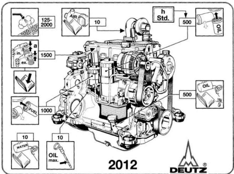
text_image
125-2000 Air 10 h Std. 500 in. ex. a 1500 FUEL 1000 10 10 OIL max. 500 OIL 2012 DEUTZ®0297 9901 1

Stop the engine before carrying out any maintenance work.
5.2 Maintenance Chart
Routine Maintenance
The maintenance chart shown on this page is supplied as a self-adhesive label with each engine. It should be affixed where it can be seen clearly on the engine or driven equipment.
Check that this is the case.
If necessary, ask your engine or equipment supplier for a fresh supply of labels.
Routine work should be carried out according to the schedule in 5.1.
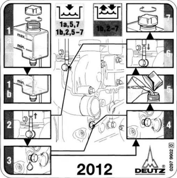
text_image
1 max. min. 1a,5,7 1b,2,5-7 1b,2-7 1 min. b 2 3 4 2012 DEUTZ® 0297 9902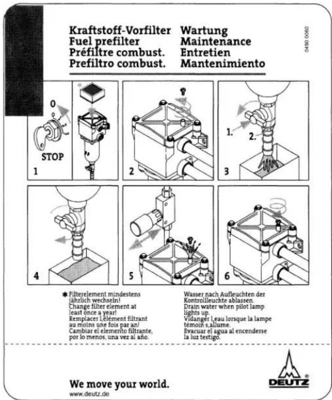
text_image
Kraftstoff-Vorfilter Fuel prefilter Prefiltre combust. Prefiltro combust. Wartung Maintenance Entretien Mantenimiento 0 STOP 1 2 1. 2. 3 4 5 6 * Filterelement mindestens jährlich wechseln! Change filter element at least once a year! Remplacer l'èlement filtrant au moins une fois par an! Cambiar el elemento filtrante, por lo menos, una vez al año. Wasser nach Aufleuchten der Kontrollleuchte ablassen. Drain water when pilot lamp lights up. Vidanger l'eau lorsque la lampe temoin s'allume. Evacuar el agua al encenderse la luz testigo. We move your world. www.deutz.de DEUTZRoutine Maintenance
5.3 Maintenance Work Completed
| Op. hours | Date | Signature/stamp | Op. hours | Date | Signature/stamp |
| 50-150* | - | ||||
| 125 | 250 | ||||
| 375 | 500 | ||||
| 625 | 750 | ||||
| 875 | 1000 | ||||
| 1125 | 1250 | ||||
| 1375 | 1500 | ||||
| 1625 | 1750 | ||||
| 1875 | 2000 | ||||
| 2115 | 2250 | ||||
| 2375 | 2500 | ||||
| 2625 | 2750 | ||||
| * following commissioning of new and overhauled engines.Duly completed maintenance jobs can be recorded and signed off in the above chart. | |||||
5.3 Maintenance Work Completed
Routine Maintenance
| Op. hours | Date | Signature/stamp | Op. hours | Date | Signature/stamp |
| 2875 | 3000 | ||||
| 3125 | 3250 | ||||
| 3375 | 3500 | ||||
| 3625 | 3750 | ||||
| 3875 | 4000 | ||||
| 4125 | 4250 | ||||
| 4375 | 4500 | ||||
| 4625 | 4750 | ||||
| 4875 | 5000 | ||||
| 5125 | 5250 | ||||
| 5375 | 5500 | ||||
| 5625 | 5750 | ||||
| Duly completed maintenance jobs can be recorded and signed off in the above chart. | |||||
Routine Maintenance
5.3 Maintenance Work Completed
| Op. hours | Date | Signature/stamp | Op. hours | Date | Signature/stamp |
| 5875 | 6000 | ||||
| 6125 | 6250 | ||||
| 6375 | 6500 | ||||
| 6625 | 6750 | ||||
| 6875 | 7000 | ||||
| 7125 | 7250 | ||||
| 7375 | 7500 | ||||
| 7625 | 7750 | ||||
| 7825 | 8000 | ||||
| 8125 | 8250 | ||||
| 8375 | 8500 | ||||
| 8625 | 8750 | ||||
| Duly completed maintenance jobs can be recorded and signed off in the above chart. | |||||
5.3 Maintenance Work Completed
Routine Maintenance
| Op. hours | Date | Signature/stamp | Op. hours | Date | Signature/stamp |
| 8875 | 9000 | ||||
| 9125 | 9250 | ||||
| 9375 | 9500 | ||||
| 9625 | 9750 | ||||
| 9875 | 10000 | ||||
| 10125 | 10250 | ||||
| 10375 | 10500 | ||||
| 10625 | 10750 | ||||
| 10825 | 11000 | ||||
| 11125 | 11250 | ||||
| 11375 | 11500 | ||||
| 11625 | 11750 | ||||
| Duly completed maintenance jobs can be recorded and signed off in the above chart. | |||||
Routine Maintenance
5.3 Maintenance Work Completed
| Op. hours | Date | Signature/stamp | Op. hours | Date | Signature/stamp |
Service and Maintenance
6.1 Lubrication System
6.2 Fuel System
6.3 Cooling System
6.4 Combustion Air Filter
6.5 Belt Drives
6.6 Adjustments
6.7 Accessories
Service and Maintenance
6.1 Lubrication System
6.1.1 Oil Change Intervals
● The lube oil is changed for the first time 50-150 hours of operation following commissioning or recommissioning or following repairs
● The lube oil change intervals are dependent on:
- Lube oil quality
- Fuel sulphur content
-
The engine application
-
If the oil change times are not achieved within a year, the oil must be changed at least once a year.
● The table refers to the following conditions: -
For diesel fuel: Sulphur content max. 0.5% by weight.
- Continuous ambient temperature down to -10 °C (+14 °F).
● In the case of fuels
- with > 0.5 to 1 % sulphur content
or
- Continuous ambient temperatures down to -10 °C (+14 °F)
or
– with biological diesel fuels to DIN 51606-FAME, the oil change intervals must be halved.
- In the case of fuels with a sulphur content higher than 1%, ask the relevant
Service representative.
Change the oil with the engine off but still warm (lube oil temperature approx. 80 °C).
6.1 Lubrication System
Service and Maintenance
6.1.1.1 Lube oil change intervals for industrial and marine engines
| Lube oil grade | ||||
| Deutz lube oil quality class | DQC I | DQC II | DQC III | |
| ACEA-specification | E2-96 | E3-96/E5-02 | E4-99 | |
| API-specification | CF/CF-4 | CG-4/CH-4 | - | |
| Worldwide specification | - | DHD-1 | - | |
| special DEUTZ release list | - | - | Enclosure 1 | |
| Standard lube oil code for building equipment and nonraod vehicles | EO...EO...A, EO...B | EO...C | - | |
| Engine series | Engine version | Lube oil change intervals in op. hours | ||
| Oil use normal high | Oil use normal high | Oil use normal high | ||
| 2012 | All engines except for: | 250 | 500 | 500 |
| BF4M2012C P > 95 kW | - | - | 500 | |
| BF6M2012C P > 143 kW, from nonroad stage II at cylinder bore 101 mm or 98 mm with MV system | - | - | 500 | |
| BF6M2012C P > 135 kW, from nonroad stage II at cylinder bore 98 mm with mech. injection system | - | - | 500 | |
| Other engines from nonroad stage II | - | 500 | 500 | |
| eng. in harv. machines, block-typethermal power stat., gensets* | - | - | 500 | |
* Gensets as referred to here are units operating in parallel with the mains / with each other. Emergency power units are dealt with in TR 0199-99-1126.
Service and Maintenance
6.1 Lubrication System
6.1.1.2 Oil change intervals for vehicle engines
| Schmieröl-Qualität | ||||||
| Deutz lube oil quality class | DQC I | DQC II | DQC III | |||
| ACEA specification | E2-96 | E3-96/E5-02 | E4-99 | |||
| API specification | CF/CF-4 | CG-4/CH-4 | - | |||
| worldwide specification | - | DHD-1 | - | |||
| special DEUTZ release | - | - | Enclosure 1 | |||
| Application | Engine version | Lube oil change intervals in km | ||||
| Site vehicles/busses | 25 Average speed in km/h approx. | 2012 | Euro I | 10 000 | 15 000 | 20 000 |
| Euro II and Euro III, except for: | - | 15 000 | 20 000 | |||
| BF4M2012C | >95 kW from Euro II | - | - | 20 000 | ||
| BF6M2012C | >143 kW from Euro II at cylinder bore 101 mm with or 98 mm with MV system | - | - | 20 000 | ||
| >135 kW from Euro II at cylinder bore 98 mm with mechanical injection system | - | - | 20 000 | |||
| Local traffic | 40 | 2012 | Euro I | 15 000 | 20 000 | 30 000 |
| Euro II and Euro III,except for: | - | 20 000 | 30 000 | |||
| BF4M2012C | >95 kW from Euro II | - | - | 30 000 | ||
| BF6M2012C | >143 kW from Euro II at cylinder bore 101 mm with or 98 mm with MV system | - | - | 30 000 | ||
| >135 kW from Euro II at cylinder bore 98 mm with mechanical injection system | - | - | 30 000 | |||
| Long distance traffic | 60 | 2012 | Euro I | 20 000 | 30 000 | 40 000 |
| Euro II and Euro III, except for: | - | 30 000 | 40 000 | |||
| BF6M2012C | >143 kW from Euro II at cylinder bore 101 mm with or 98 mm with MV system | - | - | 40 000 | ||
| >135 kW from Euro II at cylinder bore 98 mm with mechanical injection system | - | - | 40 000 | |||
If, for vehicle engines, lube oil change intervals are determined by operating hours, the lube oil change intervals indicated in table 4.1. for "Oil use under normal duty" will apply.
6.1 Lubrication System
Service and Maintenance
6.1.2 Check Oil Level / Change Engine Oil
6.1.2.1 Check Oil Level
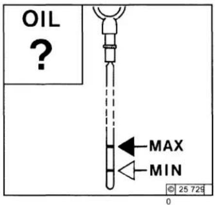
text_image
OIL ? MAX MIN © 25 729 0- Ensure that the engine or vehicle is in a level position.
● Engine warm: Shut engine off, wait for 5 minutes and check oil level. - Engine cold:
Check oil level. - Remove the oil dipstick.
● Wipe the dipstick with a non-fibrous, clean cloth. - Insert it to the stop and remove again.
- Check the oil level, and if necessary, top up to the "MAX" mark.
- If the oil level is only just above the "MIN" mark, more oil must be added.
The level must not fall below the "MIN" mark.
6.1.2.2 Engine Oil Change
text_image
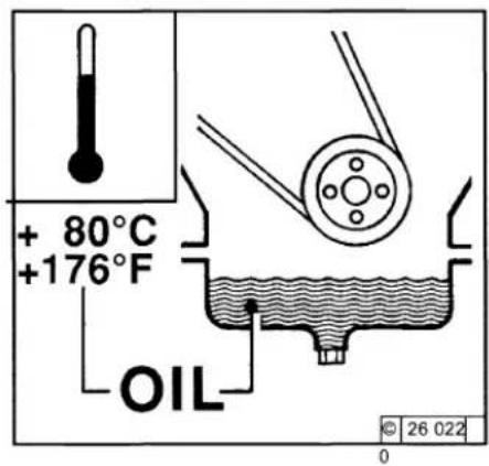
+ 80°C +176°F OIL © 26 022 0● Run engine until warm.
- Ensure that the engine or vehicle is in a level position.
- Lube oil temperature approx. 80 °C.
- Switch off the engine.
text_image
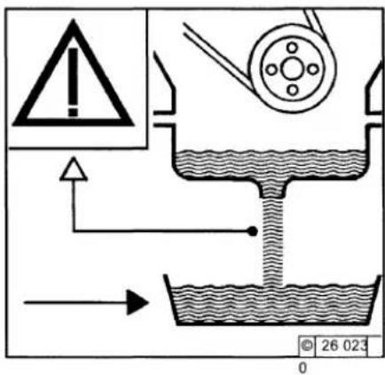
! → © 26 023 0● Place oil tray under the engine.
● Unscrew oil drain screw.
- Drain oil.
- Screw oil drain screw in with new seal ring and tighten. (Tightening torque see 9.2).
- Pour in lube oil.
- For grade / viscosity, see 4.1
- For quantity, see 9.1.
- Check oil level, see 6.1.2.1.

Caution when draining hot oil: Risk of scalding!
Do not let used oil run into the soil but collect it in a container!
Dispose of this in accordance with environmental regulations!
Service and Maintenance
6.1 Lubrication System
6.1.3 Replace Oil Filter
natural_image
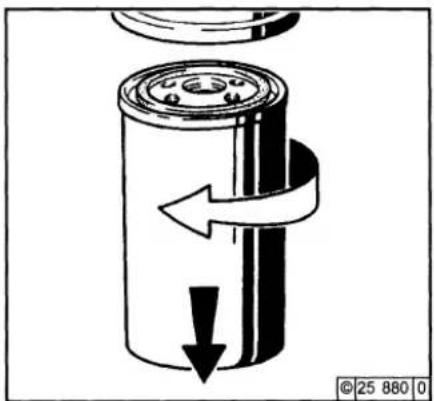
Diagram of a cylindrical mechanical component with directional arrows indicating motion or flow (no text or symbols)- With attached locking piston: Undo tensioning screws and remove tensioning clamps downwards.
- Undo the lube oil filter cartridge using a commercial tool and spin off.
● Catch any escaping oil.
text_image
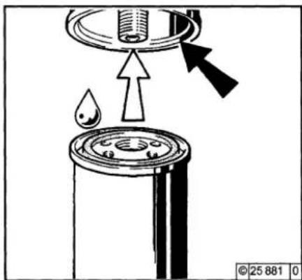
Diagram illustrating a mechanical press or valve assembly with labeled components and directional arrows indicating flow or movement.- Clean any dirt from the filter carrier sealing surface.
● Lightly oil the rubber gasket of the new lube oil filter cartridge. - Manually screw in the new cartridge until the gasket is flush.
natural_image
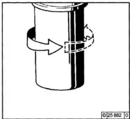
Diagram of a cylindrical object with a dashed arrow indicating rotation or movement, no text or symbols present● Tighten the lube oil filter cartridge with another half-turn.
- If locking piston is available: Position tensioning clamps and tighten with tensioning screws.
- Check oil level, see 6.1.2.
- Check oil pressure, see 3.3.1.
- Check lube oil filter cartridge seal for leaks.

Caution is required in the case of hot oil: Risk of scalding!
6.1 Lubrication System
Service and Maintenance
6.1.4 Clean / Replace Oil Filter (Cup)
text_image
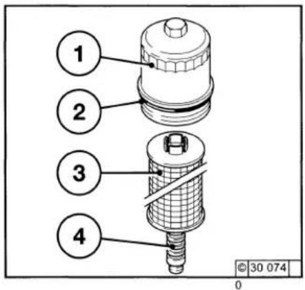
1 2 3 4 © 30 074 0- Switch off the engine.
- Loosen lube oil filter cover 1 and unscrew in an anticlockwise direction, emties itself the system automatically (drain valve).
● Carefully loosen paper filter cartridge 3 upwards from the guide 4.
● Catch any escaping oil. - Replace paper filter cartridge 3.
-
Clean any dirt from the sealing surface of the filter carrier and lube oil filter cover 1 and fromb the guide 4.
-
Replace and lightly oil the rubber gasket 2.
- Carefully insert new paper filter cartridge 3 into guide 4.
● Tighten lube oil filter cover 1 in a clockwise direction (25 Nm). - Start engine.
- Check oil level, see 6.1.2.
- Check oil pressure, see 3.3.1
- Check lube oil filter attachment for leaks.

Caution is required in the case of hot oil: Risk of scalding!
6.2.1 Replace Fuel Filter
natural_image
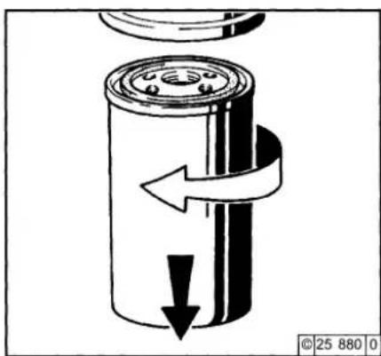
Diagram of a cylindrical mechanical component with directional arrows indicating motion or flow (no text or symbols)- Close the fuel shut-off valve.
- Undo fuel filter cartridge with commercial tool and spin off.
● Catch any escaping fuel. - Clean any dirt from the filter carrier sealing surface.
text_image
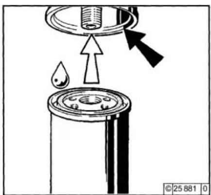
Diagram illustrating a mechanical or fluid system with labeled components and directional arrows, including a droplet and cylinder.- Apply light film of oil or diesel fuel to the rubber gasket of the new fuel filter cartridge.
● Manually screw in the new cartridge until the gasket is flush.
● Tighten the fuel filter cartridge with a final half-turn.
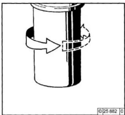
natural_image
Diagram of a cylindrical object with a dashed arrow indicating rotation or movement, no text or symbols present.- Open fuel shutoff valve.
- Check for leaks.

The fuel system does not need to be bled.
Keep naked flames away when working on the fuel system. Do not smoke!
6.2 Fuel System
Service and Maintenance
6.2.2 Clean / Replace Fuel Oil Filter (Cup)
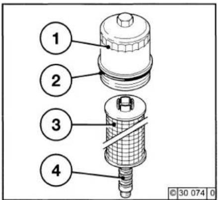
text_image
1 2 3 4 © 30 074 0- Switch off the engine.
- Loosen fuel oil filter cover 1 and unscrew in an anticlockwise direction, entries itself the system automatically (drain valve).
● Carefully loosen paper filter cartridge 3 upwards from the guide 4. - Catch any escaping oil.
- Replace paper filter cartridge 3.
- Clean any dirt from the sealing surface of the filter carrier and fuel oil filter cover 1 and fromb the guide 4.

Keep naked flames away when working on the fuel system. Do not smoke!
- Replace and lightly oil the rubber gasket 2.
- Carefully insert new paper filter cartridge 3 into guide 4.
● Tighten fuel oil filter cover 1 in a clockwise direction (25 Nm). - Start engine.
- Check fuel oil filter attachment for leaks.
Service and Maintenance
6.2 Fuel System
6.2.3 Clean / purge or change fuel pre-filter
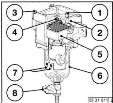
text_image
1 2 3 4 5 6 7 8 © 31 811 2Clean (purge) - remove water:
● Turn off engine or, in the case of a change-over filter, switch over to the other filter.
● Close the fuel stopcock or supply. (if available)
● Open the bleed screw 1 on the cover 2
● Place the fuel collector underneath the fuel pre-filter.
● Empty water and dirt from the bowl 6 by opening (press in and turn slightly without using force) the drain cock 8 and close the drain cock 8 again
● Close the bleed screw 1 on the cover 2 again
● Bleed the fuel pipe according to instructions, see 6.2.5 opposite
Changing the filter element 5:
Change at least once a year or as required (drop
in performance also after purging)
● Turn off the engine or switch to other filter in case of changeover filter
- Close the fuel stopcock or supply (if available)
● Loosen the cover screws 3 diagonally
- Remove the cover 2
- Remove the spring cassette 4
- Remove the filter element 5 from the bracket
- Insert new filter element 5
● Place spring cassette 4 on the element
- Check that the cover seal is fit properly in the cover 2 and check for damage (change if necessary)
● Tighten the cover 2 with the screws 3 diagonally (torque 6 Nm)
● Check the cover 2 for proper fit and leaks
● Bleed the fuel system, see 6.2.4.

The connection of a warning system (lamp/horn) via contacts 7 is specified.
Immediate maintenance is necessary when the warning system is triggered.

Naked flames are prohibited when working on the fuel system! Do not smoke!
Dispose of old fuel in an environmentally friendly way!
6.2.4 Bleed Fuel System with Fuel Pre-filter
- Place fuel collection container beneath the fuel pre-filter.
Bleed:
- In the event of re-commissioning, following maintenance work or if the tank has been run empty, the fuel system must be bled.
● Bring engine regulator into stop position. - Position fuel collection container beneath filter housing 8 / pressure maintenance valve 9.
- Open fuel shut-off valve, pressure maintenance valve 9, bleeder screw 1.
- Turn engine over with starter (max. 20 sec.) until bubble-free fuel escapes from bleeder screw 1 and pressure maintenance valve 9.
● Firmly tighten bleeder screw 1 and pressure maintenance valve 9, see 6.2.5..
● Bring engine regulator into start position and start. - Check for leaks after starting the engine.

Keep naked flames away when working on the fuel system. Do not smoke!
Dispose of used fuel in an environmentally-friendly manner!
6.2 Fuel System
Service and Maintenance
6.2.5 Bleed Fuel System without Fuel Pre-filter
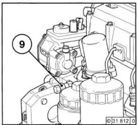
text_image
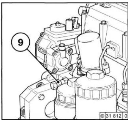
9 © 31 812 0● Bring engine regulator into stop position.
● Open fuel shut-off valve.
- Loosen pressure maintenance valve 9. Collect any escaping fuel and dispose of this in an environmentally-friendly manner.
● Turn engine over with starter (max. 20 sec.) until bubble-free fuel escapes from pressure maintenance valve 9.
● Tighten pressure maintenance valve 9.
● Bring engine regulator into start position and start.
- Check for leaks after starting the engine.

Keep naked flames away when working on the fuel system. Do not smoke! Dispose of used fuel in an environmentally-friendly manner!
6.2.6 Clean/Replace Fuel Pre-Filter, Filter Element
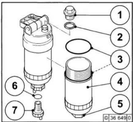
text_image
Technical diagram of a mechanical device with numbered components and a bolted joint detailClean/Replace:
- Close the fuel shut-off valve.
- Place fuel collection container beneath the fuel pre-filter.
● Loosen the drain screw 7+9 and drain fuel. - Turn the filter element housing 4 with gasket 3 and filter element 3 anti-clockwise and remove.
- Clean any dirt from the sealing face of the filter carrier and filter element housing 4 and sludge chamber 5 and filter element (replace if necessary).
- Insert new round sealing rings 2+3+6.
- Screw in filter element housing 4 and filter element (max. torque 25^-5Nm ).
● Tighten the drain screw 7+9
text_image
9 © 31 812 0- Open fuel shut-off valve.
- Bleed system
- Check for leaks after starting the engine.
6.2.7 Clean/Replace/Vent Fuel Pre-Filter, Filter Element
text_image
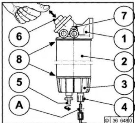
6 8 5 A 7 1 2 3 4 © 36 648 0Clean:
- Close the fuel shut-off valve.
● Place fuel collection container beneath the fuel pre-filter. - Loosen the drain screw 5 and drain fuel/water.
● Turn filter cartridge 2 and dirt trap 3 anticlockwise and remove. - Turn dirt trap 3 anticlockwise and remove. Empty emulsion into the fuel collection container and clean the dirt trap 3.
- Screw the filter cartridge 2 and dirt trap 3 together. Wet the filter cartridge with fuel, wet the sealing surfaces 8 slightly with oil.
-
Mount clockwise.
-
Open the fuel shut-off valve and bleed the system.
- Check for leaks after starting the engine.
Replace:
- Replace defective filter cartridge 2.
- Clean any dirt from the filter carrier 1 sealing surface 8.
● Wet the filter cartridge 2 with fuel, wet the sealing surfaces 8 slightly with oil.
● Mount the filter cartridge 2 and dirt trap 3 clockwise. - Open fuel shut-off valve.
- Check for leaks and vent the system after starting the engine.

Work may only be performed on the fuel system with the engine switched off.
No naked flames! Do not smoke! Dispose of waste fuel in an environmentally-friendly manner.
Service and Maintenance
6.3 Cooling System
6.3.1 Cleaning Intervals
● The amount of contamination in the cooling system depends on the engine application.
● Oil and fuel residues on the engine increase the risk of contamination. Therefore pay special attention to leaks if the engine is used in dusty environments.
● Serious contamination occurs, for example: - on construction sites where there is a high level of air-borne dust.
- in harvesting applications where there are high concentrations of chaff and chopped straw in the vicinity of the machine.
● Because applications vary, cleaning intervals have to be determined from case to case. The cleaning intervals given in the table below can be used as a guide.
| Checking or cleaning intervals | |
| Guideline values OH | Engine application |
| 2000 | Ships, electrical modules in enclosed areas, pumps. |
| 1000 | Vehicles on paved roads |
| 500 | Tractors, fork-lift trucks, drivable electric units. |
| 250 | Vehicles on construction sites and unpaved roads, construction machines, compressors, underground mining units. |
| 125 | Agricultural machines, tractors in harvesting applications. |
6.3.2 Clean Cooling System
● External cooling system: Clean according to cooling system manufacturer's specifications.
6.3 Cooling System
Service and Maintenance
6.3.3 Drain Cooling System

natural_image
Mechanical assembly diagram showing a motor and gear assembly with no visible text or symbols● Position a collecting pan beneath screw plug 1.
- Remove screw plug 1 at crankcase.
- Drain coolant.
● Tighten screw plug 1 again.
- If screw plug 1 is not accessible, drainage can be carried out at the engine radiator (coolant channel).
Fill / bleed cooling system see Chapter 6.3.4

Caution when draining hot coolant: Risk of scalding! Collect coolant on draining.
Dispose of this in accordance with environmental regulations!
6.3.4 Fill / Bleed Cooling System 2012
Standard Engine

text_image
1 1a,5,7 1b,2,5-7 1b,2-7 1 b 2 3 4 2012 DEUTZ® 0307 9602● Open radiator cap item 1.
● Loosen vent hose item 2.
- Fill coolant item 1b in up to the "MAX" mark or filling limit (if fitted, system heater valve must be open).
- Connect vent hose, item 6, + tighten screw plug item 4.
- Close radiator cap item 7.
● Start engine and warm up until thermostat opens.
● Switch off the engine.
- Check coolant level when engine is cold, and top up if necessary.
- Close radiator cap item 1.
Bleed
- External cooling system: According to cooling system manufacturer's specifications.
Service and Maintenance
6.4 Combustion Air Filter
6.4.1 Cleaning Intervals
- The amount of dirt in the combustion air filter depends on the amount of dust in the air and the size of the air filter used. If a high level of dust is anticipated, a cyclone-type pre-cleaner can be fitted in front of the combustion air filter.
● Cleaning intervals must therefore be determined from case to case. -
If dry type air filters are used, cleaning should only be carried out according to the service indicator or service switch.
● Filter servicing is needed when: -
Service indicator the red signal 1 is fully visible when the engine is off.
- Service switch
the yellow pilot light comes on when the engine is running.
● After carrying out service work, press the reset button on the service indicator. The service indicator is now ready for operation again.
text_image
Technical diagram of a mechanical device with labeled component and directional arrow indicating motion or force6.4 Combustion Air Filter
Service and Maintenance
6.4.2 Emtying Cyclone Type Precleaner
6.4.3 Clean Oil Bath Air Filter
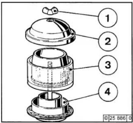
text_image
1 2 3 4 © 25 886 0● Undo wing nut 1 and remove cover 2.
- Remove collector bowl 3 from lower section 4 and empty. Clean leaves, straw and other foreign matter from lower section of precleaner.
● Reposition collector bowl 3 onto lower section 4, fasten cover 2 in place by tightening wing nut 1.
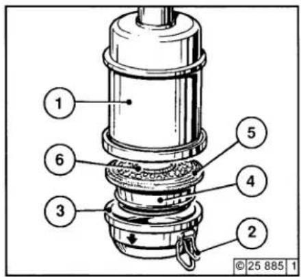
text_image
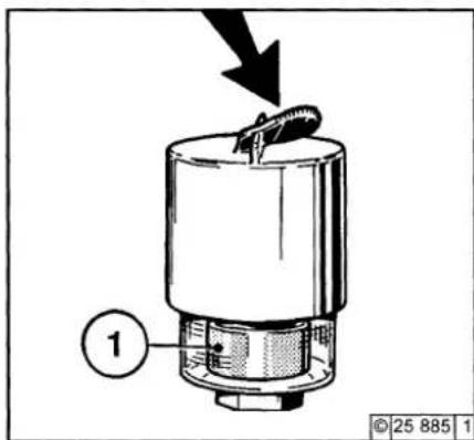
1 6 3 2 4 5 © 25 885 1● Turn engine off and wait about 10 minutes for the oil to drain from filter housing 1.
- Loosen snap clips 2 and remove oil cup 3 with filter element 4; if necessary, loosen filter element with the aid of a screwdriver at the separating point. Do not damage rubber gasket 5!
- Remove dirty oil and sludge. Clean oil cup.
● Clean filter element 4 in diesel fuel and allow to drip-dry thoroughly.
● Clean filter housing 1 if very dirty.
- Inspect and replace rubber gasket 5 and 6 if necessary.
● Fill oil cup with engine oil up to the mark (arrow) (for viscosity, see 4.1.2).
● Refit oil cup and element to filter housing and secure with snap clips.
Never fill collector bowl with oil. Replace collector bowl if damaged.

Never clean filter with gasoline. Dispose of old oil in accordance with environmental regulations!
Service and Maintenance
6.4 Combustion Air Filter
6.4.4 Dry Type Air Filter Dust Discharge Valve
Filter Cartridge
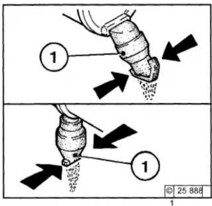
text_image
Diagram illustrating a mechanical or fluidic process with labeled components and directional arrows, showing two stages of fluid flow.● Empty dust discharge valve 1 by pressing apart lips of discharge slot as indicated by arrows.
● Clean discharge slot from time to time.
- Remove any caked dirt by pressing together the upper section of the valve.
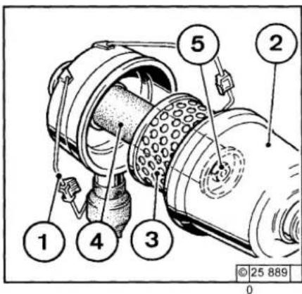
text_image
1 2 3 4 5 © 25 889 0● Undo clip fasteners 1.
● Take off hood 2 and remove cartridge 3.
● Clean cartridge (replace at least once a year)
● Clean cartridge 3.
- Using dry compressed air (max. 5 bar), blow out from inside outwards,
or
- Tap out (in emergencies only). Do not damage the cartridge, or
- Wash out according to manufacturer's specifications.
- Check paper filter (light showing through) and gaskets for damage. Replace if necessary.
● After five filter services or after two years at the latest, replace safety cartridge 4 (never clean!).
To do so:
- Undo hex nut 5 and remove cartridge 4.
- Insert new cartridge, re-install hex nut and tighten.
● Install cartridge 3, replace hood 2 and do up clip fasteners 1.

Never clean filter cartridge with gasoline or hot fluids!
6.5 Belt Drives
Service and Maintenance
6.5.1 Check V-belts 2012 Standard

text_image
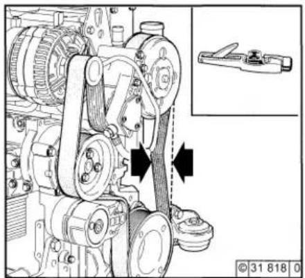
Technical diagram of a mechanical assembly with labeled components and an inset showing a tool and bracket.● Visually inspect entire V-belt for damage.
- Replace damaged V-belts.
● After installing new belts, run engine for 15 minutes, then check belt tension.
● To check the tension of the V-belt, use a tension gauge (see 9.3).
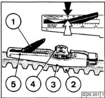
- Place indicator arm 1 into gauge.
- Position guide 3 on V-belt 2, midway between the pulleys, with flange 3 on bottom of gauge against the edge of belt.
- Push slowly on the black pad 4 at right angles to V-belt 2 until the spring is heard or felt to trigger.
2012 with Ribbed V-belt
natural_image
Technical line drawing of a mechanical assembly with no visible text or symbols-Carefully raise the gauge without changing the position of indicator arm 1.
- Read off the value where the indicator arm 1 intersects scale 5 (arrow) and read indicator arm 1 off. For settings, see 9.1.
- If necessary, retention belt and measure again.
text_image
1 2 3 4 5 AUTOMOTIVE KGI. TBD/BELT 100 100 100 100 © 26 261 1
Check, tension and change V-belts only with the engine off. If necessary, reinstall V-belt
Service and Maintenance
6.5 Belt Drives
6.5.2 Tension V-belts Coolant / Fuel Pump
6.5.3 Replace V-belts Coolant / Fuel Pump
6.5.4 Replace V-belts
text_image
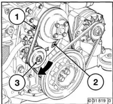
Technical diagram of a mechanical assembly with numbered components and directional arrows indicating motion or force directions.● Loosen screws 1 and 2.
● Press fuel pump 3 in direction of arrow until the correct V-belt tension has been achieved.
● Tighten screws 1 and 2 again.
text_image
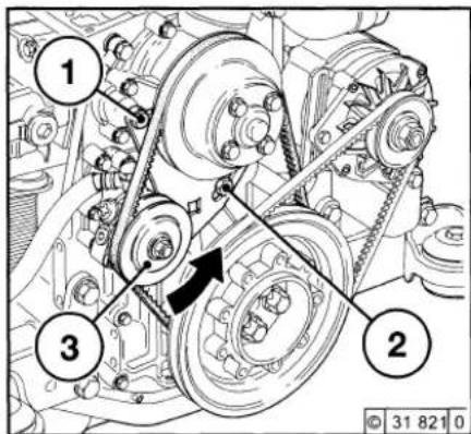
Technical diagram of a mechanical belt drive system with numbered components and directional arrows indicating motion paths.● Loosen screws 1 and 2.
● Press fuel pump 3 in direction of arrow.
- Remove V-belt and position new belt.
- Press fuel pump counter to direction of arrow until the correct V-belt tension has been achieved.
● Tighten screws 1 and 2 again.
text_image
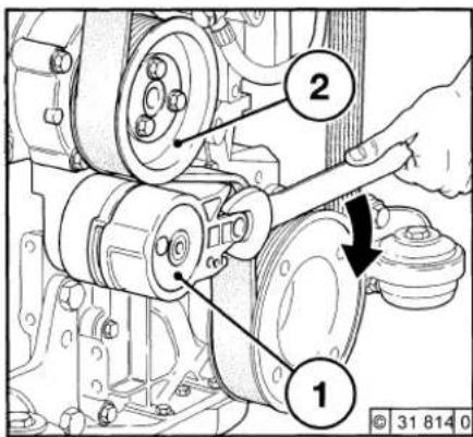
Technical diagram of a mechanical assembly with labeled parts 1 and 2, showing a hand operating a tool.- Press tension roller in direction of arrow until the ribbed V-belt is free.
● First remove ribbed V-belt from the smallest roller.
● Position new ribbed V-belt. - Press tension roller counter to direction of arrow until the ribbed V-belt is tensioned.

Check, tension and change V-belts only with the engine off. If necessary, reinstall V-belt guard.

Check whether ribbed V-belt is positioned correctly in its guide.
6.5 Belt Drives
Service and Maintenance
6.5.5 Tension V-belts Alternator
6.5.6 Replace V-belts Alternator
text_image
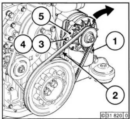
1 2 3 4 5- Loosen screws 1, 2 and 4.
- Adjust alternator 5 in direction of arrow by turning screw 3 until correct V-belt tension is achieved.
● Retighten screws 1, 2 and 4.
text_image
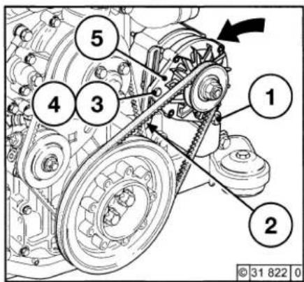
1 2 3 4 5● Loosen fuel pump V-belt, see 6.5.3
● Loosen screws 1, 2 and 4.
- Adjust screw 3 until V-belt can be removed.
- Position new belt.
- Adjust screw 3 until the correct V-belt tension has been achieved.
● Retighten screws 1, 2 and 4.
● Tension fuel pump V-belt, see 6.5.4.

Check, tension and change V-belts only with the engine off. If necessary, reinstall V-belt guard.
Service and Maintenance
6.5 Belt Drives
6.5.7 Wedge rib V-belts wear limit examine.
text_image
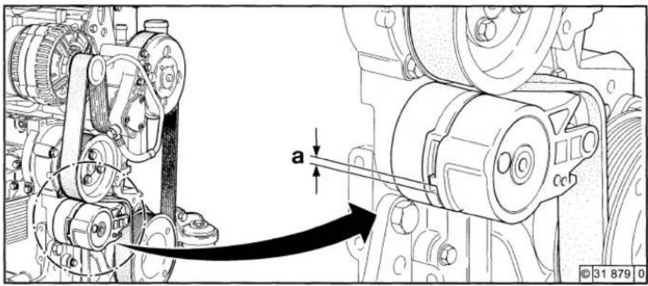
a © 31 879 0● Wear limit of the wedge ribV-belt as follows examine:
- Distance between the nose of the flexibiliti clamping arm and the notice of the firm tension adjuster housing examine.
- If „a“ is smaller than 3 mm, then the wedge rib V- belt is to be exchanged
6.6 Adjustments
Service and Maintenance

6.6.1 Check Valve Clearance, Adjust if Necessary
text_image
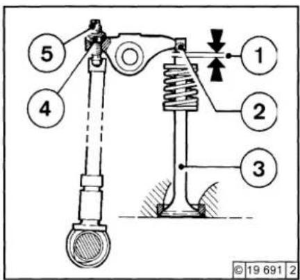
5 4 1 2 3 © 19 691 2- Loosen ventilation valve and swing to the side.
- Remove the cylinder head cover.
- Position crankshaft as per schematic, see 6.6.1.1.
- Before adjusting valve clearance, allow engine to cool down for at least 30 minutes. The oil temperature should be below 80 °C.
- Check valve clearance 1 between rocker arm / tappet contact face 2 and valve 3 with feeler gauge 6 (there should be only slight resistance when feeler blade is inserted). For permissible valve clearance, see 9.1.
text_image
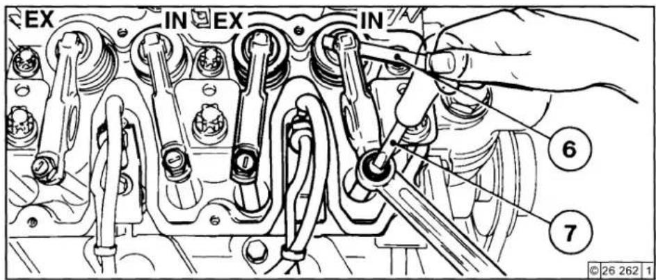
EX IN EX IN ⑥ ⑦ © 26 262 1- Adjust valve clearance if necessary: - Release locknut 4.
- Use screwdriver 7 to turn setscrew 5 so that the correct valve clearance 1 is attained after locknut 4 has been tightened.
- Check and adjust valve clearance on all cylinders.
● Reinstall cylinder head cover (with new gasket if necessary).
● Swing ventilation valve into position and fasten.
6.6.1.1 Valve Clearance Adjustment Schematic

©26 263 2
● Crankshaft Position 1:
Turn crankshaft until both valves in cylinder 1 overlap (exhaust valve about to close, inlet valve about to open). Adjust valve clearance according to schematic (marked in black). Mark respective rocker arm with chalk to show that adjustment has been carried out.
● Crankshaft Position 2:
Turn crankshaft one full revolution (360°). Adjust valve clearance according to schematic (marked in black).
6.7.1 Battery
6.7.1.1 Check Battery and Cable Connections
text_image
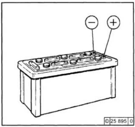
Diagram of a battery with labeled terminals and polarity indicators- Keep battery clean and dry.
- Undo dirty clamps.
- Clean terminal posts (+ and -) and clamps of the battery, and grease with acid-free and acid-resistant grease.
- When reassembling, ensure that clamps make good contact. Tighten clamp bolts hand-tight.
6.7.1.2 Check Electrolyte Level
text_image
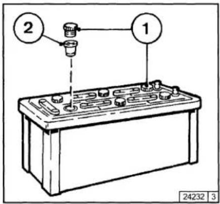
② ① 24232 3- Remove sealing caps 1.
- If testers 2 are present: Electrolyte level should reach the base of these.
● Without testers: The electrolyte level should be 10-15 mm above the top of the plates. - If necessary, top up with distilled water.
- Screw sealing caps back in.
6.7.1.3 Check Electrolyte Density
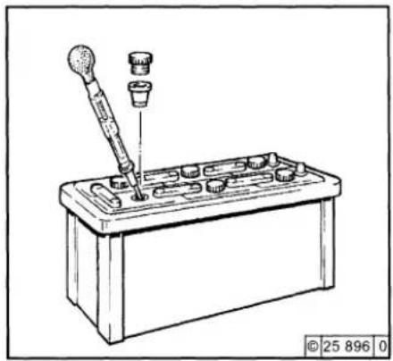
natural_image
Line drawing of a mechanical device with a pipette inserted into a housing (no text or symbols)- Measure the electrolyte density of individual cells with a commercial hydrometer. The hydrometer reading (see table on following page) indicates the battery's state of charge. During measurement, the temperature of the electrolyte should preferably be 20 °C.
6.7 Accessories
Service and Maintenance
| Electrolyte density | ||||
| in [kg/ l] | in [°Bé (Baumé scale)*] | Charge status | ||
| Normal | Tropical | Normal | Tropical | |
| 1.28 | 1.23 | 32 | 27 | well charged |
| 1.20 | 1.12 | 24 | 16 | semi-charged, re-charge |
| 1.12 | 1.08 | 16 | 11 | discharged, immediately charge |
* Measurement of electrolyte density in ° Bé (Baumé scale) is out of date and rarely used today.

The gases emitted by the battery are explosive! Keep sparks and naked flames away from the battery!
Do not allow battery acid to come
into contact with skin or clothing!
Wear protective goggles!
Do not rest tools on the battery!
Service and Maintenance
6.7 Accessories
6.7.2 Rotary Current Alternator
6.7.3 Transportation Shackles
Notes on the three-phase system:
- Never disconnect the cables between battery, alternator and regulator while the engine is running.
- If, however, it is necessary to start and operate the engine without the battery, disconnect the regulator from the alternator before starting.
- Be sure not to confuse the battery terminals.
- Replace defective charge pilot lamp bulb immediately.
- When cleaning the engine: Do not spray the alternator with a direct jet of water/steam!
Allow the engine to run warm so that the remaining water evaporates.
● The habit of touching a lead against the frame to check whether it is live must under no circumstances be used with three-phase electrical systems.
- In case of electric welding, connect the ground terminal on the welder directly to the piece being welded.
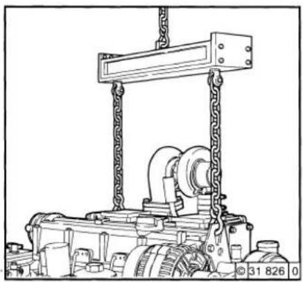
natural_image
Technical line drawing of a mechanical lifting device with chains and gears (no text or symbols)● Only use proper lifting gear when transporting the engine.
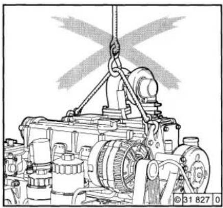
natural_image
Technical line drawing of a mechanical assembly with a propeller above (no text or symbols)
Use only the correct lifting gear!
Faults, Causes and Remedies
7.1 Fault Table

Faults, Causes and Remedies

● Faults can frequently be attributed to the fact that the engine has been incorrectly operated or not serviced.
● Each time a fault occurs, check whether all operating and servicing regulations have been complied with.
● A corresponding fault table can be found on the opposite page.
- If the cause of a fault cannot be determined, or you are unable to remedy a fault yourself, then please contact your DEUTZ Service representative.
Before starting, make sure that nobody is standing in the immediate vicinity of the engine or driven machine.
In the event of repair work:

Caution: If the speed regulator has been removed, the engine must not be started under any circumstances. Disconnect the battery!
7.1 Fault Table
Faults, Causes and Remedies
| FaultsEngine does not start or is difficult to start (Starting speed is not achieved on starting) | MeasuresCheck PAdjust EReplace WClean RTop up A Bleed L | |||||||||
| Engine starts, but runs irregularly or fails | ||||||||||
| Engine becomes excessively hot. Temperature warning system responds | ||||||||||
| Engine output is deficient | ||||||||||
| Engine does not run on all cylinders | ||||||||||
| Engine oil pressure is non-existent or excessively low | ||||||||||
| Engine oil consumption excessive | ||||||||||
| Engine smokes - blue | ||||||||||
| - white | ||||||||||
| - black | ||||||||||
| Cause | Section | |||||||||
| ● | Not declutched (where possible) | Engine Operation | P | |||||||
| ● | ● | Below starting limit temperature | P | |||||||
| ● | ● | Engine shut-off lever still in stop position (shutoff magnet defective) | P | |||||||
| ● | ● | Oil level too low | A | |||||||
| ● | ● | ● | ● | Oil level too high | S | |||||
| ● | ● | ● | Excessive inclination of engine | P/E | ||||||
| ● | Adjust throttle to half actuation travel | P/E | ||||||||
| ● | ● | ● Air cleaner clogged / turbocharger defective | Combustion air | P/W | ||||||
| ● | ● | ● Air cleaner service switch / indicator defective | P | |||||||
| ● | ● CPD* defective (connection line leaks) | P | ||||||||
| ● | ● | ● Charge air line leaking | P/W | |||||||
| ● | Coolant pump defective | Cooling system | P/R | |||||||
| ● | ● Intercooler soiled | P/R | ||||||||
| ● | Coolant heat exchanger soiled | P/R | ||||||||
| ● | ● | ● | ● | ● | Cooling fan defective, torn or loose V-belt (fuel pump in belt drive) | P/W | ||||
| ● | ● | Cooling air temperature rise / heating short circuits | P | |||||||
| ● | Battery defective or discharged | Electrics | P | |||||||
*CPD = Charge pressure-dependent full-load stop
Table 1 of 2
Faults, Causes and Remedies
7.1 Fault Table
| FaultsEngine does not start or is difficult to start (Starting speed is not achieved on starting) | MeasuresCheck PAdjust EReplace WClean RTop up AReduce S | |||||||||
| ● | ||||||||||
| ● | ||||||||||
Table 2 of 2
Engine Preservation
8.1 Preservation


8.1 Preservation
If the engine is to remain idle for an extended period of time, it is necessary to take protective measures to prevent the formation of corrosion. The preservative measures described here will protect the engine for up to approx. 6 months. The procedure will have to be reversed before the engine is recommissioned.
● Anti-corrosion oils to specification:
- MIL-L 21260B
- TL 9150-037/2
- Nato Code C 640 / 642
- Recommended cleaning agent to remove pre servatives:
- Petroleum benzine (hazardous materials class A3)
Preserve engine:
● Clean engine (poss. with cold cleaner). Radiator cleaning, see 6.3.2.
● Run engine until warm, then turn off.
- Drain engine oil, see 6.1.2, and fill with anti-corrosion oil.
- Drain coolant, see 6.3.3
● Top up anti-corrosion agent, see specifications.
● Clean oil bath air filter if necessary, see 6.4.3, and top up anti-corrosion oil.
- Drain fuel tank.
● Make up a mixture of 90 % diesel fuel and 10 % anti-corrosion oil, and refill fuel tank.
- Allow the engine to run for approx. 10 mins.
- Switch off the engine.
- Manually turn the engine over several times. When turning over with starter, set shutoff lever to stop position.
- Remove V-belts and store in wrapped condition.
● Spray grooves on V-belt pulleys 2 with anti-corrosion spray.
● Drain anti-corrosion agent, see 6.3.3.
● Lightly preserve coolant filler neck and seal with cap.
- Seal intake ports and exhaust ports.
Remove engine preservation:
- Remove anti-corrosion agent from grooves in V-belt pulleys 2.
● Install V-belts. Retension after brief operation if necessary, see 6.5. - Remove covers from intake port 3 and exhaust port 4.
- Disconnect coolant inlet and outlet neck covers, remove protection and connect to cooling system.
● Top up coolant, see 6.3.4. System must be bled. - Commission engine
Technical Specification

9.1 Engine Specifications and Settings
9.2 Torque Wrench Settings
9.3 Tools
Technical Specification
9.1 Engine Specifications and Settings
| Model | BF4M 2012 | BF4M 2012 C | BF6M 2012 C | |
| Number of cylinders | 4 | 4 | 6 | |
| Cylinder arrangement | vertical in line | |||
| Bore | [mm] | ø 101 | ||
| Stroke | [mm] | 126 | ||
| Total displacement | [cm3] | 4.04 | 4.04 | 6.06 |
| Compression ratio | [ε]. | 19 | ||
| Working cycle | Four-stroke diesel | |||
| Combustion system | with turbocharging and direct fuel injection | |||
| Charge air cooling | without with | with | ||
| Direction of rotation | counter-clockwise | |||
| Weight 2012/ C including cooling system to DIN 70020-A [approx.kg] | Refer to head-office | |||
| Engine output | [kW] | 75 | 103 | 155 |
| Max. speed | [1/rpm] | 2500 | ||
| Valve clearance with cold engine (PTs) | [mm] | Inlet 0.3 * 0.1 / exhaust 0.5 * 0.1. | ||
| Valve clearance with cold engine standard | [mm] | Adjustment with special tool, see 6.6.1 | ||
| Injector opening pressure | [bar] | 250 | ||
| Start of feed | [°CS BTOC] | 1). | ||
| Firing order of the engine | 1-3-4-2 | 1-3-4-2 | 1-5-3-6-2-4 | |
| V-belt tension: | Pre-tension / re-tension 2) | |||
| Alternator / fan | [N] | 450 / 300 =50. | ||
| Fuel pump - coolant pump | [N] | 450 / 300 =50. | ||
| Compressor | [N] | 550 / 450 =50. | ||
| Ribbed V-belt tension spring-loaded tension roller | [N] | 900 / 600 =50. | ||
9.1 Engine Specifications and Settings
Technical Specification
| Model | BF4M 2012 | BF4M 2012 C | BF6M 2012 C | |
| ling | Liquid-cooled / cooling system protection | |||
| Coolant volume | ||||
| 2012/ C | [ca.ltr.] | 5,6 | 5,6 | 7,3 |
| Perm. constant coolant temperature | ||||
| Engine exhaust, output group I | [°C] | max.1106) | ||
| Engine exhaust, output group II-IV | [°C] | max. 1056) | ||
| Thermostat opening commencement at | [°C] | 7) | ||
| Thermostat fully open from | [°C] | 838) | ||
| Coolant pre-heating | (4) | |||
| Coolant pump | ||||
| Feed pressure in | [bar] | 9) | ||
| Feed quantity in | [m3/h] | 9) | ||
| Power consumption in | [kW] | 9) | ||
| Lubrication | Pressure lubrication | |||
| Oil temperature in oil pan | [°C] | 125 | ||
| Min. oil pressure when warm | ||||
| (120 °C and SAE oil 15 W 40 ) and low idle | [bar] | 0,8 | ||
| Oil plate filling quantity without filter [approx.ltr.] | 8.53) | 8.53) | 12.53) | |
| Oil plate filling quantity with filter [approx.ltr.] | 103) | 103) | 14.03) | |
3) Approx. values may vary depending on version. The upper oil dipstick mark is always authoritative.
4) Only necessary in winter operation, see 3.5.1.
5) Engine content without radiator only. Content of external cooling system depending on cooling system version.
6) Other output groups have different values, consultation with head office is required.
7) In the case of external cooling systems with outlet regulation, the thermostat begins to open at 87 °C
8) In the case of external cooling systems with outlet regulation, the thermostat is fully open at 102 °C
9) Consultation with head office is required (differ depending on engine version)
Technical Specification
9.2 Screw Tightening Torques
| Installation location | Pre-tension [Nm] | Re-tension [Nm] | Total[Nm] | Comments | |||||
| 1. Stage | 2. Stage | 3. Stage | 1. Stage | 2. Stage | 3. Stage | 4. Stage | |||
| Cylinder head screw | 8.5 | ||||||||
| Rocker arm adjustment screw | 21 | ||||||||
| Foot on flywheel side | 187 | M16x40 8.8 A 4 C | |||||||
| Foot on fan side | 30 | 45 | 187 | M16x40 8.8 A 4 C | |||||
| Intake manifold | 8.5 | ||||||||
| Exhaust manifold | 21 | ||||||||
| Oil drain screw | 50 | ||||||||
| Injection valve attachment | 16 | Torx | |||||||
| Injection line attachment | 30 | M14x1.5 | |||||||
| Oil pan (cast) | 29 | ||||||||
| Oil pan (sheet metal) | 21 | ||||||||
9.3 Tools
Technical Specification
TORX
V-belt tension gauge
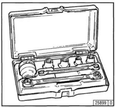
natural_image
Line drawing of a mechanical tool kit with multiple cylindrical components and a central shaft (no text or symbols)A TORX wrench set is used with engines in the 2012 series.
This system was chosen because of the many advantages it offers:
● Outstanding accessibility to bolts.
● High load transfer when loosening and tightening.
- Almost impossible for socket to slide off or break, thereby practically ruling out the risk of injury.
TORX tools can be ordered from:
WILBÄR
Postfach 14 05 80
D-42826 Remscheid
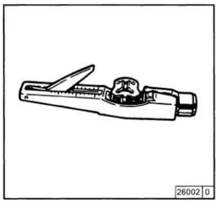
natural_image
Line drawing of a mechanical device with a handle and central component (no text or symbols)The V-belt tension gauge can be obtained under order number 8115 + 8120 from:
WILBÄR
Postfach 14 05 80
D-42826 Remscheid
Knowing it's DEUTZ
DEUTZ has always stood for excellence in motor construction, pioneering many developments in the industry. As an independent motor manufacturer, we offer — worldwide — a comprehensive range of diesel and gas motors spanning from 4kW to 7,400kW. Our products are perfectly tailored to meet our customers' individual requirements.
Over 1.4 million DEUTZ motors do their job reliably all over the world. We are determined to preserve the high standard of performance and dependability of our motors, thus keeping our customers satisfied at all times. Therefore we are represented worldwide through a network of highly competent service partners who will meet the needs of our customers, wherever they are.
This is why DEUTZ is not only the name for motors which pack a lot of inventive genius. DEUTZ also means reliable service and comprehensive support to enhance your motor's performance.
This index Sales & Service offers you an overview of the DEUTZ partners in your vicinity, including the products for which they are responsible and the range of services provided. But even when no direct product responsibility is mentioned, your DEUTZ partner will be happy to help you with expert advice.
The Index is constantly updated. Please ask your DEUTZ service partner for the latest edition.
DEUTZ AG — at your service.

text_image
Register Vertrieb & Service Register Sales & Service Réseau Distribution & Service Registro Red de Distribución & Servicio Registro Vendita & Service SERWORLD BRENTZ BRENTZ BRENTZ Order-No.: 0312 0806 Order-No.: 0312 0807 (CD-ROM)Obtainable from the local service Partner responsible for you or from:
DEUTZ AG
Deutz-Mülheimer Str. 147-149
D-51063 Köln
Telefon: 0049-221-822-0
Telefax: 0049-221-822-5358