PHD2000 - Uncategorized Harvard - Free user manual and instructions
Find the device manual for free PHD2000 Harvard in PDF.


User questions about PHD2000 Harvard
0 question about this device. Answer the ones you know or ask your own.
Ask a new question about this device
Download the instructions for your Uncategorized in PDF format for free! Find your manual PHD2000 - Harvard and take your electronic device back in hand. On this page are published all the documents necessary for the use of your device. PHD2000 by Harvard.
USER MANUAL PHD2000 Harvard
PHD 2000 Infusion/Withdraw 70-2001
PHD 2000 Programmable 70-2002
PHD 2000 VHP 70-2023
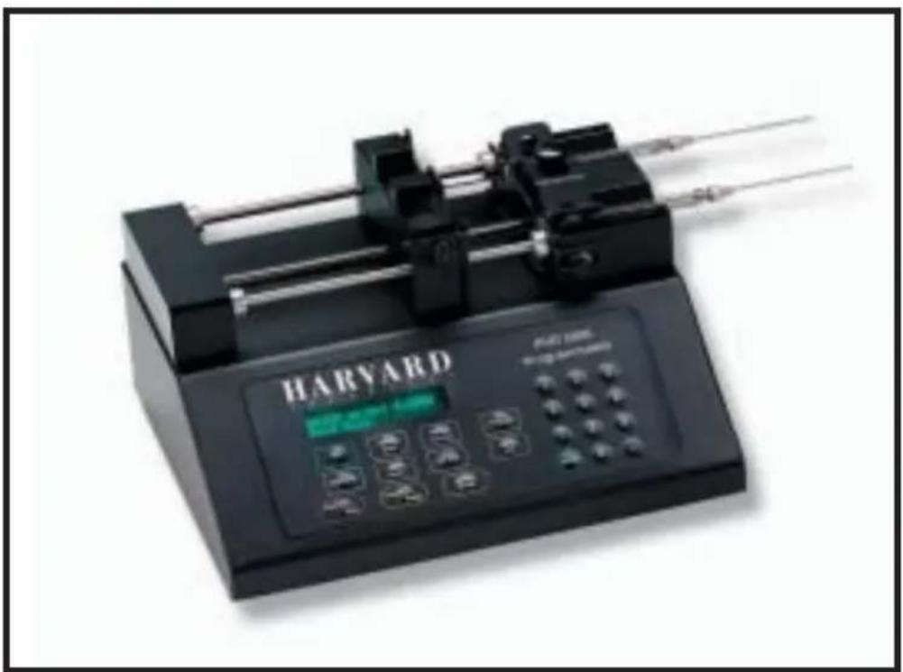
natural_image
Black Harvard industrial testing device with control panel and three tubes (no visible text or symbols on main body)HARVARD
APPARATUS
SUBJECT PAGE
1. Warranty and Repair Information ....4
Manual Description ....4
Warranty 4
Repair Facilities and Parts ....4
Serial Numbers ....4
Calibrations 4
General Safety Summary ....5
2. Specifications and Ordering Information....6-7
3. Theory of Operation ....8
4. Features ......9
Pressure and Speed 9
Built-in Syringe Table and Custom Syringes.....9
Infusion and Refill Rates....9
Target Volume 9
Auto Fill (Programmable Mode Only) .....9
Modes of Operation....9
External Connections ....10
Nonvolatile Memory ....10
Stall Detection....10
Visual / Audible Alarm ....10
Power-Up Options (Pump Mode Only) .....10
Program Storage (Programmable Mode Only) 10
5. User Interface....11
Description of Keys ....12
Entering Data 13
Special Features Access Table....13
SUBJECT PAGE
6. Initial Setup ....14
7. Operation....15-20
Syringe Loading 15
Running the Pump ....18
Diameter 18
Infuse Rate ....18
Refill Rate 19
Target Volume 19
Auto Fill 19
Selecting the Run Mode ....20
Pump Mode....20
Volume Mode ....20
8. Program Mode ......21-24
Program Description ....21
Entering a Program....21
Sequence Operation 21
Program Printout....24
Program Run Time Error Messages ......24
9. External Control and Interfaces ......25-26
RS-232 Devices 25
Configuring Pump for RS-232 Devices.....25
Pump Chain 25
Scale 26
Printer 26
TTL Devices 26
Foot Switch or Relay....26
Timer 26
Pumping Direction....26
Valve Control....26
SUBJECT PAGE
10.Programming Tutorial ......27
Multiple Infusion Example ......27
Ramping Up Infusion Rate Example....28
Multiple Dispensing Example ....29
Periodic Dispense Loop Example....30
Comb. of Infusion and Withdraw Profiles Ex. ..31
Use of Events 32
11.Pump Chain Commands ....34-45
Model 22 Protocol ....35
Model 44 Protocol ....37
A Table of Syringe Diameters .....46
APPENDICES
PAGE
B Stainless Steel Syringes ....47
C Nominal Min./Max. Flow Rates .....48
D PHD 2000 to PC Connection....49
E TTL Connector Specifications ....49
F RS-232 Specifications ....50
G Maintenance and Troubleshooting......51
H Accessories and Spare Parts ....52
I Kits and Upgrades ....53
J Custom Applications ....54
K Symphony ....54

CAUTION: Verify operating voltage selection before plugging in the PHD2000 Pump. Refer to Section 6, Initial Setup.
Manual Description
This manual is designed to provide all operational and program information required to operate and maintain all three models of the PHD 2000 series pumps. The three models are: Infusion, Infuse/Withdraw and Programmable. The functions and features of these models are described in the Technical Specifications section.
Warranty
Harvard Apparatus warranties this instrument for a period of one year from date of purchase. At its option, Harvard Apparatus will repair or replace the unit if it is found to be defective as to workmanship or material. This warranty does not extend to damage resulting from misuse, neglect or abuse, normal wear and tear, or accident. This warranty extends only to the original customer purchaser.
IN NO EVENT SHALL HARVARD APPARATUS BE LIABLE FOR INCIDENTAL OR CONSEQUENTIAL DAMAGES. Some states do not allow exclusion or limitation of incidental or consequential damages so the above limitation or exclusion may not apply to you. THERE ARE NO IMPLIED WARRANTIES OF MERCHANTABILITY, OR FITNESS FOR A PARTICULAR USE, OR OF ANY OTHER NATURE. Some states do not allow this limitation on an implied warranty, so the above limitation may not apply to you.
If a defect arises within the one-year warranty period, promptly contact Harvard Apparatus, Inc. 84 October Hill Road, Building 7, Holliston, Massachusetts 01746 using our toll free number 1-800-272-2775. Goods will not be accepted for return unless an RMA (returned materials authorization) number has been issued by our customer service department. The customer is responsible for shipping charges. Please allow a reasonable period of time for completion of repairs, replacement and return. If the unit is replaced, the replacement unit is covered only for the remainder of the original warranty period dating from the purchase of the original device.
This warranty gives you specific rights, and you may also have other rights which vary from state to state.
Repair Facilities and Parts
Harvard Apparatus stocks replacement and repair parts. When ordering, please describe parts as completely as possible, preferably using our part numbers. If practical, enclose a sample or drawing. We offer a complete reconditioning service.
Serial Numbers
All inquires concerning our product should refer to the serial number of the unit. Serial numbers are located on the rear of the chassis.
Calibrations
All electrical apparatus is calibrated at rated voltage and frequency.

CAUTION: Not for clinical use on human patients.
GENERAL SAFETY SUMMARY
Please read the following safety precautions to ensure proper use of your syringe pump. To avoid potential hazards and product damage, use this product only as instructed in this manual.
To Prevent Hazard or Injury:
Use Proper Line Cord
Use only the specified line cord for this product and make sure line cord is certified for country of use.
Ground the Product
This product is grounded through the grounding conductor of the power cord. To avoid electric shock, the grounding conductor must be connected to earth ground. Before making any connections to the input or output terminals of the product, ensure that the product is properly grounded.
Make Proper Connections
Make sure all connections are made properly and securely.
Observe all Terminal Ratings
Review the operating manual to learn the ratings on all connections.
Use Proper Fuse
Use only specified fuses with product.
Avoid Exposed Circuitry
Do not touch any electronic circuitry inside of the product.
Do Not Operate with Suspected Failures
If damage is suspected on or to the product do not operate the product. Contact qualified service personnel to perform inspection.
Place Product in Proper Environment
Review the operating manual for guidelines for proper operating environments.
Observe all Warning Labels on Product
Read all labels on product to ensure proper usage.

CAUTION
Refer to Manual

Protective
Ground
Terminal
Specifications
PHD 2000 SYRINGE PHD 2000 VHP REMOTE PUMP SERIES SYRINGE PUMP SERIES
Accuracy ± 1 % ± 1 %
Reproducibility ± 0.1% ± 0.1%
Syringes (Min./Max.) .5 l / 140 ml Holds 20 to 200 ml
stainless steel syringes
Flow Rate:
| Minimum .0001 μl/hr 1.5 μl/hr(with 0.5 μl Syringe) |
| Maximum 220.82 ml/min 112 ml/min(with 140 ml Syringe) |
| Calibration | Automatic | Automatic |
| Display | 2 line, 40 char. fluorescent | 2 line, 40 char. fluorescent |
| Non-Volatile Memory | Stores all settings | Stores all settings |
| RS-232 Interface | Multiplexed dual bidirectional ports | Multiplexed dual bidirectional ports |
| RS-232 Connectors | RJ11-4 cond. phone plug | RJ11-4 cond. phone plug |
| TTL Connectors | 9 pin D-Sub. connector | 9 pin D-Sub. connector |
Linear Force (Max)
| Standard | 23 kg (50 lbs) | 196 kg (433 lbs) |
| High Force | 30 kg (66 lbs) | N/A |
Drive Motor 1.8° Stepper Motor 1.8° Stepper Motor geared
Motor Drive Control Microprocessor Microprocessor from 1/2 to 1/32 microstepping from 1/2 to 1/32 microstepping
Motor Step per one Rev. of Lead Screw From 800 to 12,800 From 8,000 to 128,000
Step Rate:
| Minimum 27.3 sec/step 27.3 sec/step | |
| Maximum 416.7 μsec/step | 416.7 μsec/step |
Pusher Travel Rate
| Minimum 0.18 μm/min | 0.09 μm/min |
| Maximum 190.676 mm/min | 71.210 mm/min |
| Power | 115/230 VAC: | 115/230 VAC: |
| 50-60 Hz | 50-60 Hz | |
| External voltage selection | External voltage selection | |
| 65 W, 0.5 A fuse | 65 W, 0.5 A fuse |
| Voltage Range | 95-130 VAC, 220-260 VAC | 95-130 VAC, 220-260 VAC |
| Dimensions, HxWxD | 15.9 × 22.8 × 27.9 cm (6.3 × 9 × 11 in) | 9.5 × 27.9 × 22.9 cm (3.75 × 11 × 9 in) |
Syringe Holder, HxWxD N/A 22.9 x 43.2 x 30.5 cm (9 x 17 x 12 in)
Remote Cable Length N/A 152 cm (60 in) approx. Weight 4.5 kg (10 lb)
Harvard PHD 2000 Syringe Pump Series
| Pump Versions Regular Remote | Standard (29 lbs Force) High Power (58 lbs Force) Regular Remote |
PHD 2000 Infusion Only 70-2000 70-2100 71-2000 71-2100
PHD 2000 Infuse/Withdraw 70-2001 70-2101 71-2001 71-2101
PHD 2000 Programmable 70-2002 70-2102 71-2002 71-2102 Infuse/Withdraw
PHD 2000 Infusion Only 70-2003 70-2103 71-2003 71-2103 with 6/10 Multirack
PHD 2000 Infusion Only 70-2004 70-2104 71-2004 71-2104 with 4 x 140 Multirack
PHD 2000 Infusion Only 70-2005 70-2105 71-2005 71-2105 with Microliter Rack
PHD 2000 Infuse/Withdraw 70-2006 70-2106 71-2006 71-2106 with 6/10 Multirack
PHD 2000 Infuse/Withdraw 70-2007 70-2107 71-2007 71-2107 w/ 4 x 140 Multirack
PHD 2000 Infuse/Withdraw 70-2008 70-2108 71-2008 71-2108 with Microliter Rack
PHD 2000 Programmable 70-2009 70-2109 71-2009 71-2109 with 6/10 Multirack
PHD 2000 Programmable 70-2010 70-2110 71-2010 71-2110 with 4 x 140 Multirack
PHD 2000 Programmable 70-2011 70-2111 71-2011 71-2111 with Microliter Rack
Harvard PHD 2000 Push/Pull Syringe Pump Series
| Pump Versions Regular | Standard (29 lbs Force) |
PHD 2000 Infusion/Withdraw 70-2020
PHD 2000 Programmable Infuse/Withdraw 70-2019
Harvard PHD 2000 HVP (High Volume and Pressure)
| Pump Versions Regular | Standard (over 400 lbs Force) |
PHD 2000 HVP (High Volume and Pressure) | 70-2023
All three models in the PHD 2000 series employ a microcontroller which controls a small step angle stepping motor that drives a lead screw and Pusher Block. Micro-stepping techniques are employed to further reduce the step angle, eliminating flow pulsation. A keypad is used for entry of operating data to the pump. Data can also be entered via an RS-232 connector located on the rear panel. The microcontroller, using the internal Syringe Look Up Table, calculates the cross-sectional area of the syringe selected and calibrates the flow rate and volume accumulation. The numerous features of the PHD 2000 series result from the use of microprocessor technology.
The PHD 2000 Infuse/Withdraw model is equipped with all the functions of the PHD 2000 Infusion model along with additional features to provide the Withdraw (Refill) function. The PHD 2000 Infuse/Withdraw model's additional features include two additional function keys on the keypad, REFILL RATE key and the INFUSE/REFILL key and the addition of syringe Retaining Brackets and Adjustable Stops for refill. Use of the REFILL RATE key, the INFUSE/REFILL key, Retaining Brackets and Adjustable Stops are all described in detail in section 7 of this manual.
The PHD 2000 Programmable model is equipped with all the functions of the PHD 2000 Infuse/Withdraw model along with additional features to provide Programmable functions. The PHD 2000 Programmable models additional features include two additional function keys on the keypad, the PROGRAM key and the AUTO FILL key. Use of the PROGRAM key and the AUTO FILL key are described in detail in section 7 of this manual.
Pressure and Speed
PHD 2000 can deliver up to 220.82 ml/minute with a single 140 ml syringe. Maximum pressure is dependent on syringe size. For example a Becton-Dickinson 'Plasticpak' 50/60cc syringe run at 5ml/minute delivers an average maximum pressure of 1.8kg per cm ^2 (25psi).
Built-In Syringe Table and Custom Syringes
If a non-standard syringe is to be used, enter the inside diameter of the syringe in millimeters. If a standard syringe is to be used, use the pump's built-in syringe table. Syringes are arranged according to manufacturer and material, and then according to size. The pump will look up and use the diameter for the syringe you select. (See Appendix A for a listing of the standard syringes).
Infusion and Refill Rates
Specify independent rates for infusing and refilling. This allows a slow infusion rate then a fast refill. If Refill Rate is not set, the software defaults to the set Infuse Rate value.
Target Volume
Specify the volume that is to be infused or refilled. The pump will run at the rate specified until this volume has been delivered when in the Volume mode.
Auto Fill (Programmable Model Only)
Auto Fill automatically activates an externally attached solenoid (Refer to Appendix H for part number) and refills the syringe when it is empty. This permits infusions to be virtually independent of syringe capacity.
Modes of Operation
Pump
Runs continuously, in the infuse or refill directions, until stopped. Refill not applicable to the Infusion model.
Volume
Runs until a specified volume has been pumped or refilled. Refill not applicable to the Infusion model.
Program
Pump operates according to a specified sequence of instructions. Programmable model only. (Note: All modes interact with Auto Fill feature, but it is only available on the Programmable model)
External Connections
TTL
Allows pump operations to be synchronized with external devices or by a person at a distance from the pump. Direction of pump travel can be set via a TTL pin. Also, a TTL pin is used to control an external valve for refilling. Additional TTL pins are available for general use. (See Section 9 and Appendix E).
RS-232
Multiple pumps can be 'daisy chained' together and remotely controlled from a computer or any device communicating via RS-232. A scale can be connected, enabling the pump to infuse by weight instead of by volume. (Section 9). A printer can be connected to record final volumes or weights whenever the pump stops. In addition the program entered for the program mode can be listed on a connected printer. Both a scale and a printer may be connected simultaneously. (See Section 9).
Nonvolatile Memory
All operational data entered into the pump from the keypad or from a computer will be stored, including the program. On power up, the display will blink until the pump receives its first command and all settings from when it was powered down will be recalled.
Stall Detection
An optical detector is used to verify expected movement of the motor. If the motor is prevented from turning due to jamming or excessive back pressure, the pump will stop and the display will read:PUMP STALLED.
Visual/Audible Alarm
After a power interruption the alarm can be selected to be a silent flashing display or an audible signal in addition to flashing display.
Power-Up Options (Pump Mode only)
Enables the user to select between a standby mode (waiting for a command to begin running) after power is interrupted or a restart mode that begins running the pump at the settings that were in process when the power was interrupted.
Program Storage (Programmable model only)
Programmable model can store up to 4 sets of 9 program sequences for later selection.
text_image
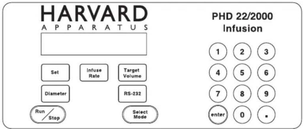
HARVARD APPARATUS PHD 22/2000 Infusion 1 2 3 4 5 6 7 8 9 enter 0 -Figure 1. Infusion Model Keypad.
text_image
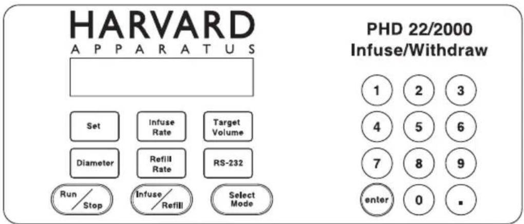
HARVARD APPARATUS PHD 22/2000 Infuse/Withdraw 1 2 3 4 5 6 7 8 9 enter 0 -Figure 2. Infuse/Withdraw Model Keypad.
text_image
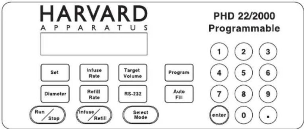
HARVARD APPARATUS PHD 22/2000 Programmable 1 2 3 4 5 6 7 8 9 enter 0 -Figure 3. Programmable Model Keypad.
The user interface consists of a keypad with a display area. The display consists of a 2 line,40 character alphanumeric vacuum fluorescent display. The display will show one of three types of messages:Default display,setting display,or an informational message. The top line of the display is divided into three sections.The first consists of the delivered volume,or time interval remaining in an operation, expressed with 5 digits plus a decimal point. Next is the units of the previous number expressed as 'ml' for milliliters,'g' for grams, if a scale is attached,or 'time' for a time interval.Third is the pumping direction,either 'INFUSE'or 'REFILL',or the current operating state of the pump.A diamond symbol ◇ in the last character of the display indicates pump chain communication has been received.
Setting displays are used to facilitate entering control information and data into the pump. Data entry will be discussed in detail later in this section. Informational messages occur at various times to indicate such items as a data setting out of range, or a detected problem, such as the pump stalling. Pressing any key clears the message from the display. The second line of the display is also divided into 3 sections. The first is the Running Mode (Pump, Vol, Prog). The second section is the AutoFill indication (no message if Auto Fill is Off, If On, AutoFill ON is displayed) The third section is a pair of directional arrow heads (< or >) indicating that the pump is running and in what direction. AutoFill is not applicable to the Infusion and Infuse/Withdraw Models.
DESCRIPTION OF KEYS
The keypad consists of 19 keys on the Infusion model, 21 keys on the Infuse/Withdraw model and 23 keys on the Programmable model. The keys are used for entering control information and data into the pump. These keys are grouped into 3 sections (see Figures 1,2 & 3): Set keys, Toggle keys, and Data Entry keys.
Set Keys

SET – Allows modification of a data item in this group of keys. To modify a data item, press the relevant key after pressing the SET key. Pressing Set with an appropriate data entry key will also allow the selection of special features. Refer to Entering Data on page 7.
INFUSE RATE – Displays/sets current infuse rate. Scrolls through rate units with each press of the key when setting. Displays current programmed rate while running in program mode.
TARGET VOLUME – Displays/sets current volume mode target volume.
PROGRAM – Displays current program number, program sequence and sequence number. Held down, with a printer attached and the pump stopped, prints a program listing. Not applicable to the Infusion or Infuse/Withdraw models.
DIAMETER – Displays/sets current syringe diameter. When held down during setting, accesses built-in syringe table.
REFILL RATE – Displays/sets current refill rate. Scrolls through rate units with each press of the key when setting. Not applicable to the Infusion model.
RS-232 - Displays/sets current RS-232 device(s) attached.
AUTO FILL – Turns Auto Fill feature setting on/off. Also, displays/sets syringe refill volume.
Toggle Keys
Keys in this group, when permitted, successive states of the keys' function are selected when the key is pressed.
RUN/STOP – Starts/stops—interrupts running of pump.
INFUSE/REFILL – Changes direction of pusher block travel during operation in Pump and Volume modes. Pump must be stopped or in Pump Mode to reverse direction of pump. Not applicable to the Infusion model.
SELECT MODE – Toggles in an incremental loop through PUMP, VOLUME or PROGRAM run modes with each press of the key. The current mode is displayed on the 2nd line of the display. (Program mode is only available on the Programmable Model).
Data Entry Keys

1, 2, 3, 4, 5, 6, 7, 8, 9, 0, – Used to enter numeric data values or access special features.
ENTER – Saves and stores displayed data value in memory when setting a data item.
ENTERING DATA
Set Keys
Keys with rectangular outlines in this group are used to modify or review settings of the pumps control data. To review the current setting of a control data item, simply hold down the relevant key and the data setting will appear in the top line of the display. In the case of the PROGRAM key (Programmable model only), if it is held down the data will be sent to the printer if one is attached.
To modify a data setting, first press then release the green outlined SET key. The display should then read 'SET WHAT?'. Press the key in the SET key group whose data is to be modified. The display will display the current setting. Data is entered into the pump by either entering a numerical value or by scrolling through a menu of choices. Always press the green outlined ENTER key to terminate and store each data request by the pump.
If you are to enter a numerical value, the far left of the display will show 'ENTER' followed by the units of the number to be entered. Using the numerical keys on the right side of the keypad (see Figures 1,2 & 3) enter the new data value. Up to five digit numbers are accepted, including up to four decimal places. Entering more than five digits will clear the previous five digits entered in the display. Press the green outlined ENTER key when the desired data value is displayed. If the far left of the display does not show 'ENTER', then a menu of choices is being displayed. Pressing the relevant key, according to the choices being displayed, selects successive menu entries. When the desired selection is displayed, press the green outlined ENTER key.
If the data value entered is outside the pump's operating parameters, the display will read 'OUT OF RANGE'. Pressing any key will restore the display with the original data value. Enter another data value within the pump's parameters or just press the green outlined ENTER key to reuse the original data value.
The data value entered can be reviewed as described above. Note: Certain data items have multiple settings. For these, after the ENTER key is pressed, the display will prompt you for the additional information. Various rules apply to when, what and how data can be set at various times. See the relevant section for further details.
SPECIAL FEATURES ACCESS TABLE
Pressing the green outlined SET key and then the appropriate numerical key will allow the setting of several special features. Pressing the appropriate numerical key again will scroll between the options provided. Refer to the table below. When the desired option is displayed, press the green outlined ENTER key.
RS232 Protocol SET 1
Alarm Mode SET 2
Power Up Mode SET 3
text_image
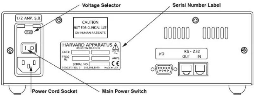
Voltage Selector 1/2 AMP. S.B. CAUTION NOT FOR CLINICAL USE ON HUMAN PATIENTS Serial Number Label HARVARD APPARATUS HOLUSTON, MA 01748 CAT# FREQ Hz SERIAL NO. 2006-313 REV. 0 506-093-8599 MADE IN USA Power Cord Socket Main Power Switch I/O RS - 232 OUT INFigure 4. Rear Panel: Voltage Selector and Serial Number Label
- Read the entire manual to become familiar with all features and functions of the PHD 2000.
- If the operating voltage is other than 115VAC, 60Hz, locate the voltage selector on the rear panel (See Figure 4) of the pump and set it to the voltage being used. Also, if other than 115 V, 60 Hz is being used, the plug must be cut off and an appropriate plug installed, observing the polarity of the international line cord used:
Brown – live Blue – neutral Green – ground
-
Take this opportunity to fill out and mail the Warranty Card. The Catalog and Serial numbers are located on the Serial Number label on the rear panel. Refer to Figure 4.
-
Turn on main power switch (See Figure 4) located directly above the power cord receptacle on the rear panel. The two-line display will illuminate indicating that the power connections are correct. The flashing display indicates that power has just been applied. Pressing any key will reset the blinking display to constant illumination.
-
See Section 7 for operating Instructions on next page.
-
To change the Voltage setting from 115V to 230V, turn off the Main Power switch (0) and remove the power cord. Pry open the access door using a small screwdriver. Refer to (A) in Figure 4.
-
Remove the red fuse holder assembly by prying it out of the switch assembly using a small screw driver.
-
Rotate the red fuse holder 180^ and install it back into the switch assembly. Close the small access door firmly until fully closed.230V should be showing through the small opening in the switch assembly.Install the power cord.
-
Fuse Replacement.Turn off power, remove power cord from power module. Use straight blade screw driver, pry open access door. Remove fuse holder, remove fuse(s) from holder. Replace fuse(s) and fuse holder. (Replace holder with correct voltage marking is showing through access door window) For continued fire protection,replace fuse only with 250V fuse of the specified type and rating.(3AG 1/2 AMP SLO-BLO)

WARNING: Use in manner not specified by the manufacturer may impair the protection provided by the equipment.
Because of the wide range of functions that the PHD 2000 is capable of performing, certain information about your application must be entered into the pump. At minimum, the pump needs to know the Diameter of your syringe, the Infusion Rate and Direction of travel. (Direction of travel Infuse/Refill, is not applicable to the Infusion model) This is the only information needed to run the pump in the Pump Mode. If not specified, the Refill Rate (Refill Rate is not applicable to the Infusion model) will default to the Infuse Rate. The pump will need additional information to utilize its more advanced features. See Section 5, User Interface, for general information on data entry.
SYRINGE LOADING
Standard with a 2 Syringe Holder
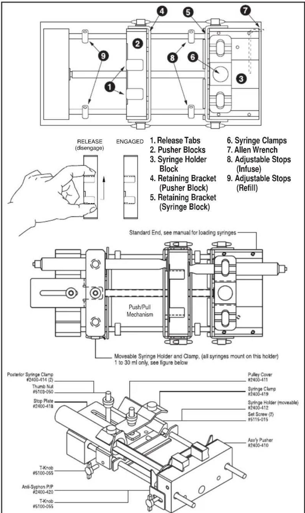
The Pusher Block (2) and Syringe Holder Block (3) are fitted with movable retaining brackets (4 and 5) (Available as an option for the PHD 2000 Infusion model as an Anti-siphon kit - Catalog # 70-2015) which hold the syringe barrel and plunger firmly when refilling. When loading the syringe into the pump it is necessary to adjust these retaining brackets and the Adjustable Stops (8 & 9). The Pusher Block (2) is fitted with Release Tabs (1) to release the drive nut from the leadscrew so that the Pusher Block (2) can be moved freely on the leadscrew to facilitate loading the syringe. Refer to Figure 5.
- Squeeze the Release Tabs (1) towards each other and move the Pusher Block (2) to the left allowing enough space for the syringe being used to fit between the Pusher Block (2) and the Syringe Holder Block (3).
- Loosen the four screws to free the retaining brackets (4 and 5) on the Pusher Block (2) and Syringe Holder Block (3). This step is not required for the PHD 2000 Infusion model which is not equipped with retaining brackets (4 & 5) or Adjustable Stops (9).
- Locate Syringe Clamp (6) and determine if clamp is in the correct position to firmly hold the desired syringe. Rule of thumb is that if the syringe is 20ml or larger, the tips of the clamp should be pointing down. If it is required to change the orientation of the clamp, unscrew the plastic knob located in the center of the clamp by turning it counter-clockwise (to the left). Remove the knob, lift the clamp off the shaft, flip the clamp over and place back on the shaft, then tighten the knob by turning it clockwise (to the right). Refer to Figure 6.
- Lift up on the spring loaded Syringe Clamp (6) and rotate it 90° to allow clearance for the syringe. Place the barrel of the syringe on to the Syringe Holder Block (3) and rotate the clamp over the syringe. Ensure that the syringe barrel flange and plunger flange are located within the retaining brackets on both the Pusher Block (2) and the Syringe Holder Block (3). This step is not required for the PHD 2000 Infusion model which is not equipped with retaining brackets or Adjustable Stops (9). Lower the Syringe Clamp (6) down onto the syringe. CAUTION: Do not let the Syringe Clamp snap down on the syringe. Doing so may crack or break a glass syringe.
- Ensure that both retaining brackets (4 and 5) are tight against the syringe barrel flange and plunger flange, then tighten the screws on the retaining brackets on the Pusher Block (2) and the Syringe Holder Block (3). This step is not required for the PHD 2000 Infusion model which is not equipped with retaining brackets or Adjustable Stops.
- Squeeze the Release Tabs (1) and move the Pusher Block (2) to the right until the syringe plunger is located as far into the syringe as it will travel. Then squeeze the Release Tabs (1) and move the Pusher Block (2) to the left just enough so that the end of the syringe plunger is not touching the inside end of the syringe barrel and release the Release Tabs (1). This step is not required for the PHD 2000 Infusion model which is not equipped with retaining brackets or Adjustable Stops.
Harvard Apparatus PHD 2000 Syringe Pump Series User's Manual
- Release Tabs
- Pusher Blocks
- Syringe Holder Block
- Retaining Bracket (Pusher Block)
-
Retaining Bracket (Syringe Block)
-
Syringe Clamps
- Allen Wrench
- Adjustable Stops (Infuse)
- Adjustable Stops (Refill)
Figure 5. Syringe Loading: Infuse/Withdraw or Programmable model shown
- Locate Allen Wrench (7) in its holder on the back of the Syringe Holder Block and remove. Loosen front and rear Infusion Adjustable Stops (8) (right side) and slide them both to the left until they contact the retaining bracket (4). Using the Allen Wrench, tighten both Infusion Adjustable Stops (8).
- Squeeze the Release Tabs (1) and move the Pusher Block (2) to the left until the syringe plunger is located as far out of the syringe as intended to travel. Then squeeze the Release Tabs (1) and move the Pusher Block (2) to the right just enough so that the end of the syringe plunger is just short of the maximum travel allowable and release the Release Tabs (1). This step is not required for the PHD 2000 Infusion model which is not equipped with retaining brackets or Adjustable Stops.
- Loosen the front and rear Refill Adjustable Stops (9) (on the left side) and slide them both to the right until they contact the Pusher Block (2). Then using the Allen Wrench tighten both Refill Adjustable Stops (9) and return the Allen Wrench to its holder.
With Multiple Syringe Holder
Catalog Numbers - 70-2003, 70-2006, 70-2009
These Versions of the PHD 2000 have a saw tooth syringe holder capable of holding up to ten syringes, emptying them simultaneously at identical rates. This multiple syringe pump will accommodate up to:
- Ten syringes of any size up to 10 ml
- Six syringes of 20ml-100 ml
Catalog Numbers - 70-2004, 70-2007, 70-2010
These Versions of the PHD 2000 have a multiple syringe holder which accommodates:
- Up to four syringes of 30ml to 140 ml
To load syringes rotate the spring loaded retainer arm out of the way and lay syringes in 'V' shaped slots with the syringe flange touching the holder. Rotate the retainer arm to hold syringes in place. If less than the maximum number of syringes are used, try to place them symmetrically about the lead screw to present a balanced load.
Maximum Force:The PHD 2000 will generate 29 lbs of force. With a 50 ml syringe it will deliver 25 psi.
Note: The back pressure for each syringe will be divided by the number of syringes used. Thus for four 50 ml syringes the maximum pressure developed in each syringe will be 6.3 psi.
Syringe Loading: Push/Pull Mechanism
- Loading syringes on the standard end, see manual.
- Loading syringes on push/pull end:1 ml through 30 ml only. Remove (2) thumb nuts and syringe clamp. Place syringes on moveable syringe holder. Adjust syringe retainer using (2) set screws. Position moveable holder for correct stroke. Clamp on to guide rod with the T-knob. Lock stop plate in place with thumb nut. Place syringe clamp over syringes and lock in place with thumb nut.
Running the Pump
Pressing the RUN/STOP key starts the pump. The pump will operate according to the relevant data entered as interpreted by the selected run mode. Pressing the RUN/STOP key while the pump is running stops the pump and the right side of the top line of the display will indicate 'INTERRUPT' plus '>' for infusing or '<' for refilling. (Refilling is not applicable to the Infusion model) This indicates that the pumping operation has been suspended and can be continued. Pressing the RUN/STOP key again will continue the pumping operation at the point that it was interrupted. Changing any of the settings, including the pumping direction and the run mode, cancels the interrupted operation and resets the display. The pump can also be started and stopped from a remote source.
Diameter
If the inside diameter of the syringe being used is known, enter the value in millimeters. Otherwise, access the built-in Syringe Table and select the syringe being used. After a new diameter is entered, directly or via the built-in Syringe Table, the Infuse Rate and Refill Rate are set to 0 and the Auto Fill feature is turned off (Refill Rate is not applicable to the Infusion model), (Auto Fill is applicable to the Programmable model only). This is done for reasons of safety. The maximum diameter that can be entered is 50 mm.
To access the built-in Syringe Table, after pressing the SET key then the DIAMETER key, hold down the DIAMETER key for about one second. Once the Syringe Table has been accessed, each press of the key will scroll through the manufacturers. Find the manufacturer and material, if applicable, of your syringe. Press the ENTER key to enter your selection. Now, using the DIAMETER key again, scroll by pressing the DIAMETER key until the size of your syringe is displayed, in cc or L, as indicated on the display. Pressing the ENTER key will select the size of the syringe and look up and store the diameter. The diameter will be displayed until the ENTER key is released. Thereafter, pressing the DIAMETER key will display the selected diameter. In addition, the syringe size selected becomes the default Refill Volume when the Auto Fill feature is turned on. (Auto Fill is applicable to the Programmable model only) See Appendix A for a listing of the built-in Syringe Table and their respective diameters.
Infuse Rate
The Infuse Rate is the rate of pumping while infusing in the Pump or Volume modes. Also, the Infuse Rate is used as a starting rate for the program model if one is not specified in the program, regardless of pumping direction. (Programmable model only.) When entering the Infuse Rate, the INFUSE RATE key is used to scroll through the allowable units of rate. The allowable units are: ml/mn, ml/hr, l/mn, l/hr. While running in the Pump or Volume modes, the Infuse Rate can be changed. If the new rate is valid, it will take effect when the ENTER key is pressed. The minimum and maximum rates permitted vary depending on the diameter of the syringe. If an 'OUT OF RANGE' message is displayed when entering a rate, try using a different syringe for your application.
Refill Rate
The Refill Rate is the rate of pumping while refilling in the Pump or Volume Modes or during Auto Fill. If the Refill Rate hasn't been set (rate is 0), the Refill Rate will default to the Infuse Rate. (Refill Rate is not applicable to the Infusion model), (Auto Fill is applicable to the Programmable model only)
When entering the Refill Rate, the REFILL RATE key is used to scroll through the allowable units of rate. The allowable units are: ml/mn, ml/hr, l/mn, l/hr. (Refill Rate is not applicable to the Infusion model), While running in the Pump or Volume modes, the Refill Rate can be changed. If the new rate is valid, it will take effect when the ENTER key is pressed. (Refill Rate is not applicable to the Infusion model), The minimum and maximum rates permitted vary depending on the diameter of the syringe. If an 'OUT OF RANGE' message is displayed when entering a rate, try using a different syringe for your application.
Target Volume
The Tagret Volume is the volume that you desire to deliver at the set Infuse or Refill Rate. The pump must be set for this Volume mode for this feature to work. When entering the Target Volume, enter the volume desired in mls (milliliters) and press the ENTER key.
Auto Fill (only applicable to programmable model)
Use AUTO FILL key to toggle between Auto Fill 'ON' and 'OFF'. If Auto Fill is set to 'ON', the pump will next request the volume of the syringe in milliliters. The volume of the syringe is used as the refill volume of the syringe. This volume can be set to a volume smaller than the syringe if desired.
When set to 'ON', the syringe is assumed to be empty. Auto Fill continuously monitors the volume of the syringe according to the volume pumped. When the pump determines that the syringe is empty, the operation in progress is suspended and Auto Fill is activated. The pumping direction is then reversed and the pump runs at the refill rate. During the Auto Fill operation, the display will indicate the volume of liquid in the syringe.
When the volume in the syringe reaches the set refill volume, Auto Fill will stop, and the previous operation of the pump will resume. Auto Fill continues to monitor the volume of the syringe. TTL direction output is toggled 'ON' during refill. Refill Rate defaults to Infuse Rate if not set.
Note: Auto Fill will only activate while infusing, (i.e., if the pump direction is set to Refill, the pump will not stop when the syringe is full.) Also, if the syringe plunger is manually moved, the pump will lose track of the true syringe volume.
Selecting the Run Mode
After entering any necessary operating data into the pump, select the pumping mode that will be used when the pump is operated. Pressing the SELECT MODE key advances the second line of the display to indicate the next run mode. Advance the run mode to the desired mode, either Pump Mode, Volume Mode or Program Mode until it is displayed. (Program Mode is applicable to the Programmable model only)
Pump Mode
The pump will continuously pump, infusing or refilling, until stopped. While running, the Infuse and Refill Rates can be changed. The new rate, for the relevant pumping direction, takes effect when the ENTER key is pressed. Also, the pumping direction can be changed by pressing the INFUSE/REFILL key. (Refill, Refill Rate and Infuse/Refill are not applicable to the Infusion model),
Volume Mode
The pump will run, infusing or refilling, until a specified target volume is pumped or refilled. The TARGET VOLUME key is used to enter the Volume Mode target volume. Used in conjunction with Auto Fill, the target volume can be greater than the volume of the syringe. While running, the Target Volume, Infuse and Refill Rates can be changed. The new rate, for the relevant pumping direction, takes effect when the ENTER key is pressed. Target Volume can be used to enter a Target weight in grams if a scale is attached via RS-232.(Refill is not applicable to the Infusion model),(Auto Fill is applicable to the Programmable model only)
(only applicable to programmable model)
In the Program Mode the pump can make complex dispenses including changes in rate and target volume. These complex dispenses are easily programmed from the keypad and are detailed in the Program Mode and the Programming Tutorial sections.
Program Description
A program is made up of a set of sequences. Each sequence being a set of operating instructions for the pump to follow. When the pump is started in the PROGRAM run mode, the pump will start at sequence 1 and execute the operating instructions in that sequence. When the pump has completed the instructions for a sequence, it will go to the next, or specified, sequence and execute the instructions in that sequence. The pump continues this process until it either has reached a 'STOP' operation, the pump is manually or remotely stopped, or the last sequence has been completed. 4 programs with up to 9 sequences each may be entered.
A sequence consists of a sequence number, indicating the order of the sequence; a mode, indicating what operation the sequence will be performing; and the actual data for the operation, such as rates and volumes. The necessary data specified for each sequence will depend on the strategy used. One of two strategies may be chosen for a sequence's target. Strategy 1 (Target Volume) pumps until a target volume is reached, while Strategy 2 (Time Interval) pumps until a target time interval has lapsed. When Strategy 1 is used, enter a time interval of 0:00:00, then you will be prompted for the target volume. See the Programming Tutorial for example programs.
Entering a Program
It is advisable to plan out your program prior to entering the program into the pump. Press the SET key then the PROGRAM key to begin entering a program.
The following is a list of possible data that can be requested when entering a program and instructions on entering the data.
Sequence Operation
Use the PROGRAM key to select the sequence's operation. Operations that can be selected are: Profile, Increment (Incr), Decrement (Decr), Dispense, Event, Go To, Pause, Pump, TTL Out, Restart, Stop. When the required operation is displayed press the ENTER key. Additional information may be requested.
Rate
Enter the rate, using the INFUSE RATE key to change units. Note: If the rate entered is invalid, an error message will not be given at the immediate time of entry. An 'OUT OF RANGE' error message will be given during the running of the program.
Delta Rate
Enter the rate of Increment or Decrement desired. The units of the rate cannot be specified. Units will be the same as the units of the current pumping rate at the time the sequence is executed.
Target Volume
Enter the required delivered target volume of the sequence. For increment and decrement sequences, the target volume is an incremental target. An incremental target is added to the delivered volume at the start of the sequence.
Time Interval
Enter the time duration of the sequence in the form: 'hours : minutes : seconds'. If sequence Strategy 1 (Target Volume) is used, enter 0:00:00 for the time target. The maximum time interval is 9:99:99.
Number of Repetitions
Enter the number of times the sequence is to be repeated. The repetition number can be from 1 to 99,999.
Pumping Direction
Each sequence that specifies a pumping operation, also specifies a pumping direction. Use the INFUSE/REFILL key to change the pumping direction (< or >). (Direction of travel Infuse/Refill, is not applicable to the Infusion model)
Pin Level
Select either HI or LOW for the logic level of the programmable output pin 4. Use the PROGRAM key to change the setting.
Go to Sequence Number
Enter the destination sequence to continue operation of the program. Valid sequence numbers are 1 to 10.
Profile
Runs at specified flow rate until target volume is pumped or a time interval has elapsed.
Travel direction is as specified.
Data Specified:
Strategy 1: Flow rate
(Volume) Time Interval = 00:00:00
Target volume
Pumping direction
Strategy 2: Flow rate
(Time) Time interval
Pumping direction
Incr
Increments current rate by specified value and pumps until the target volume is pumped or a time interval has elapsed. Units of rate will be that of the current rate of the pump or the infusion rate's units, if first sequence.
Sequence is repeated the specified number of times. Travel direction is as specified.
Data Specified:
Strategy 1: Delta flow rate
(Volume) Time Interval = 00:00:00
Volume increment
Number of repetitions
Pumping direction
Strategy 2: Delta flow rate
(Time) Time interval
Number of repetitions
Pumping direction
Decr
Same as INCR except rate is decremented.
Dispense
Repeatedly dispense specified volume. Runs at specified flow rate until a volume is pumped or a time interval has elapsed, then pump will stop. If no time interval was specified (Strategy 1), the display will show 'TRIGGER' and the next dispense will begin after an external or keyboard run command. Otherwise, the sequence will pause for specified time interval. Sequence is repeated the specified number of times. Travel direction is as specified.
Data Specified:
Strategy 1: Flow rate
(Volume) Time Interval 00:00:00
Target volume
Number of repetitions
Pumping direction
Strategy 2: Flow rate
(Time) Target volume
Time interval
Number of repetitions
Pumping direction
Event
Program Events – A program event is an external event defined as a high to low transition on TTL pin-9. Within a program, a one time event trigger can be set which watches for and acts upon the external event. The triggered event causes an immediate continuation of the program at the specified sequence and the operation of the pump will be according to this sequence.
Data Specified:
Go To sequence number
Go To
Causes the program to immediately continue operation at the sequence specified.
Data Specified:
Go To sequence number
Pause
Pump stops for specified time then continues with next programmed sequence. Current program rate set to 0, with no change in units.
Data Specified:
Time interval
Pump
Runs the pump continuously at the specified flow rate without any pumping target. This mode can provide a background flow rate while waiting for an external event to trigger a new sequence specified by the EVENT operation.
Data Specified:
Flow rate
Pumping direction
TTL Out
Programmable TTL Pin:TTL output Pin 4 can be set to a HIGH or LOW level from within a program.
Data Specified:
TTL pin level
Restart
Immediately restart program from the first sequence.
Data Specified:
None
Stop
Stops pump and the program terminates.
Data Specified:
None
Program Printout
If a printer is attached and the pump is stopped, a program listing can be obtained by pressing the PROGRAM key for about one second. 'PRINTING PROGRAM' will be displayed while data is being sent.
Program Run Time Error Messages
If while running a program an operation is requested that cannot be performed, the pump will stop and an error message will be displayed. Error messages will be displayed with the following format:
Program N SEQ n: message
Where 'N' is the Program number and 'n' is the sequence number when an error was detected, and 'message' is the indicated error as follows:
INFINITE LOOP
A GO TO sequence cannot specify the current sequence.
INVALID GO TO
The target of the GO TO specified an invalid sequence number.
RATE UNDERFLOW
A decrement sequence decremented a rate to less than or equal to 0.
RATE OVERFLOW
An increment sequence caused an arithmetic overflow.
OUT OF RANGE
Specified or calculated rate is beyond the pumps capabilities with the specified syringe.
VOL TGT ERROR
A sequence with a volume target cannot follow a sequence with a time target, unless the volume delivered is zero or the pump is stopped at the start of the sequence entering it, select Program Mode using the SELECT MODE key and press the RUN/STOP key.
text_image
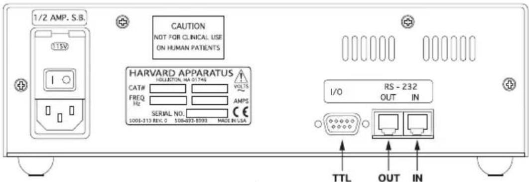
1/2 AMP. S.B. 115V CAUTION NOT FOR CLINICAL USE ON HUMAN PATIENTS HARVARD APPARATUS HOLLIETON, MA 0174S CAT# FREQ Hz SERIAL NO. 1008-313 REV. 0 508-093-8093 MADE IN USA I/O RS - 232 OUT IN TTL OUT INFigure 7. Rear Panel External Connections.
External devices that can be attached to the PHD 2000 are categorized into either RS-232 devices or TTL devices. Pump Chains, Scales and Printers are RS-232 devices, all other devices are TTL devices. See the Appendix F for specification details on attaching RS-232 devices and Appendix E for TTL.
RS-232 Devices
There are two telephone jack type connectors on the back of the unit (See Figure 7). These are the RS-232 ports. Looking at the back of the pump, the connector on the right is IN and the left is OUT. Attach the RS-232 connectors in the appropriate port according to the following chart:
Device Port
Pump Chain computer side IN
Pump Chain pump side OUT
Scale IN
Printer OUT
Configuring the Pump for RS-232 Devices
Press the SET key and then press 1 to select either Model 22 or Model 44 Protocol (Refer to Section 11, Pump Chain Commands). Press the SET key, then use the RS-232 key to scroll through the menu of allowable RS-232 configurations. Possible configurations are:
Pump Chain
Scale
Printer
Scale & Printer
After entering the RS-232 configuration, additional information may be requested:
Pump Chain
Enter the 2-digit address assigned to the pump. Note: Each pump in the chain needs a unique address. After entering the address (up to 99), the baud rate will be requested. Use the RS-232 key to toggle between the supported baud rates: 1200, 2400, 9600 and 19200. Note: Each pump in the chain must have same baud rate. See the Section 11, Pump Chain Commands for pump chain control information.
Scale
Use the RS-232 key to toggle between the supported manufacturers:Mettler,Sartorius and Ohaus.When a scale is attached,the weight will be read from the scale and used as the delivered volume whenever the pumping direction of the pump is set to infuse. When refilling, the syringe diameter is used for volume calculations.When the scale weight is displayed,the units will be grams.
Printer
No additional information requested when entering. With a printer (capable of serial port communication) attached, the pump will print the delivered volume whenever the pump stops or the direction of pumping changes, except before and after Auto Fill of the syringe. If the pump stops due to the pump stalling, an asterisk (*) will be appended to the volume printed. In addition, the entered pump program can be listed on the printer by pressing the PROGRAM key for about one second, with the pump stopped.
TTL Devices
The pump does not need to be configured to attach a TTL device. Simply plug the device into the 9-pin connector on the rear of the pump. See Appendix E for wiring specifications.
Foot Switch or Relay
Used to start and stop the pump. Pressing the foot switch performs the same function as pressing the RUN/STOP key on the keyboard. The foot switch connector allows remote or automated operation of the pump.
Timer
Opening the timer input starts the pump. Closing the timer input stops the pump. The timer input allows for an externally controlled pumping interval.
Pumping Direction (Not applicable for Infusion model)
Sets the direction of pumping. Opening the directional input sets the pump to infuse. Closing the directional input sets the pump to refill. The pumping direction input is recognized only in the situations that the INFUSE/REFILL key would be recognized, i.e., when the pump is stopped or running in the Pump Mode.
Valve Control (Not applicable for Infusion model)
The valve control output is an indicator of the direction of pump travel. When the output is high, the pump is set to Refill. A output low indicates Infuse.
In the following examples, the diameter is 26.7 mm and the infuse rate is 50 ml/mn. Torun a program after entering it, select Program mode using the SELECT MODE key and press the RUN/STOP key. The examples on the following pages include: Multiple Infusions, Ramping Up Infusion Rate, Multiple Dispensing, Periodic Dispense Loop, Combination Infuse and Withdraw Profile, Use of Events and Use of Signal.
Multiple Infusion Example
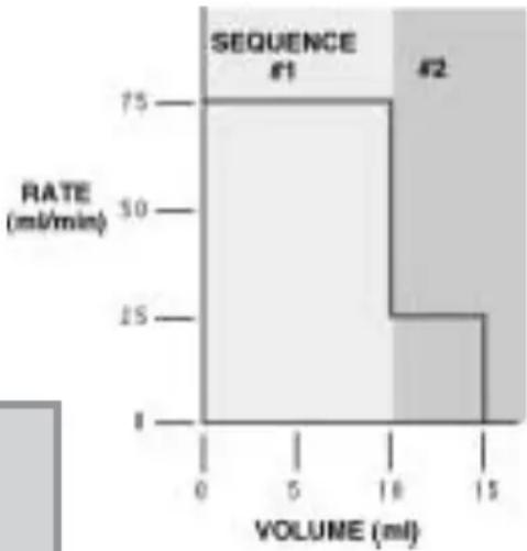
The following program will instruct the pump to infuse according to the above graph. The program instructs the pump to infuse 10 ml at 75.000 ml/mn then infuse another 5 ml at 25 ml/mn then stop, for a total of three sequences. Since this graph is Rate vs. Volume, Strategy 1 will be used when entering the program.
bar
| VOLUME (ml) | RATE (ml/min) | |---|---| | 0 | 75 | | 5 | 30 | | 10 | 25 | | 15 | 1 |Figure 6. Multiple Infusions.
SEQUENCE 1:
Key Presses Explanation
SET Allows selection of Programming mode
PROGRAM Press until PROFILE selected
ENTER Enters selection
75 Enter rate of 75.000 ml/mn
INFUSE RATE Press until units are ml/mn
ENTER Enters rate
0 ENTER Enter 0 for time, this indicates Strategy 1
10 ENTER 10 ml is the first target volume
INFUSE/REFILL Toggles direction to infuse
ENTER Enters sequence's pumping direction
SEQUENCE 2:
Key Presses Explanation
PROGRAM Press until PROFILE selected
ENTER Enters selection
25 Enter rate of 25.000 ml/mn
INFUSE RATE Press until units are ml/mn
ENTER Enters rate
0 ENTER Enter 0 for time, this indicates Strategy 1
5 ENTER 5 ml is the second target volume
INFUSE/REFILL Toggles direction to infuse
ENTER Enter sequence's pumping direction
SEQUENCE 3:
Key Presses Explanation
PROGRAM Press until STOP selected
ENTER Enters selection and ends program entry
PROGRAM PRINTOUT
PROG1 SEQ 1: PROFILE
75.000 ml/mn
10.000 ml
INFUSE
PROG1 SEQ 2: PROFILE
25.000 ml/mn
5.0000 ml
INFUSE
PROG1 SEQ 3: STOP
Ramping Up Infusion Rate Example
line
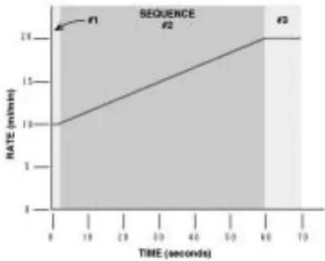
| TIME (seconds) | RATE (m/min) | | -------------- | ------------ | | 0 | 10 | | 60 | 26 | | 70 | 26 |Figure 7. Ramping Up Infusion Rate
PROGRAM PRINTOUT
PROG1 SEQ 1: PRO- FILE
10.000 ml/mn
0:00:01 INTERVAL
INFUSE
PROG1 SEQ 2: INCR
0.1695 INCR
0:00:01 INTERVAL
INFUSE
59 REPEAT
PROG1 SEQ 3: PROFILE
20.000 ml/mn
0:00:10 INTERVAL
INFUSE
PROG1 SEQ 4: STOP
In this example, the pump will ramp up from 10 ml/mm to 20 ml/mn over 60 seconds, then continue to run at 20 ml/min for another 10 seconds. This is a Strategy 2 Program requiring four sequences:
-
Specify the initial rate as a profile of 10 ml/mn for one second.
-
Specify the ramp up to 20 ml/mn. Since the minimum resolution of an increment is one second, it will take 59 steps to reach the target rate. Sequence 2 starts at time 1 second and ends at time 60 seconds, giving it a duration of 59 seconds.
At one second a step, 59 seconds divided by one second per step equals 59 steps. The increase per step will by 20 ml/mn minus 10 ml/mn, divided by 59 steps or 0.1695 rounded to four decimal places.
- Continue running at 20 ml/mn for 10 seconds with a profile operation.
- Stop the pump.
Multiple Dispensing Example
bar
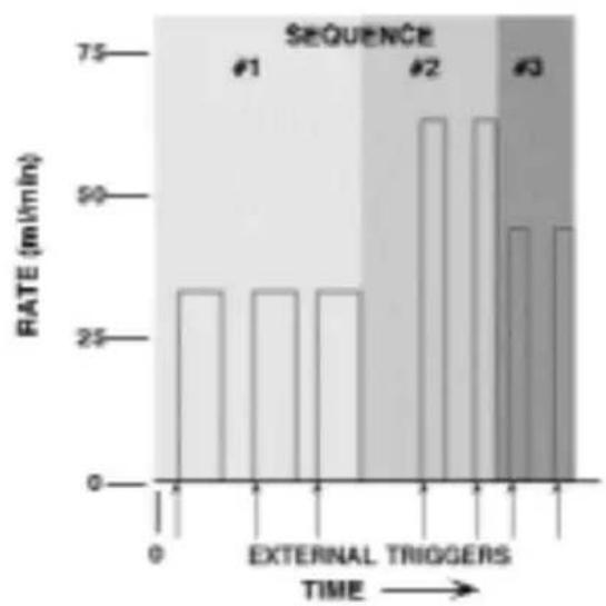
| SEQUENCE | RATE (m/min) | | -------- | ------------ | | #1 | 30 | | #2 | 65 | | #3 | 45 |Figure 8. Multiple Dispensing
PROGRAM PRINTOUT
PROG1 SEQ 1: DISPENSE
35.000 ml/mn
15.000 ml
- REPEAT
INFUSE
PROG1 SEQ 2: DISPENSE
65.000 ml/mn
25.000 ml
- REPEAT
INFUSE
PROG1 SEQ 3: DISPENSE
45.000 ml/mn
17.000 ml
- REPEAT
INFUSE
PROG1 SEQ 4: STOP
Here, a series of dispenses are programmed. Each dispense is started by a trigger, such as pressing the RUN/STOP key or pressing an attached foot switch. Seven dispenses are programmed: three of 15 ml at 35 ml/mn, two of 25 ml at 65 ml/mn, and two of 17 ml at 45 ml/mn. The pump's display will show 'TRIGGER' when it is waiting for a run trigger and < or > will not be displayed.
This is a Strategy 1 dispense. A time interval of 0 is specified when entering a Strategy 1 dispense. Since the total volume to be dispensed is 129 ml and the syringe volume is 50 ml, the Auto Fill feature would be very useful with this program.
Periodic Dispense Loop Example
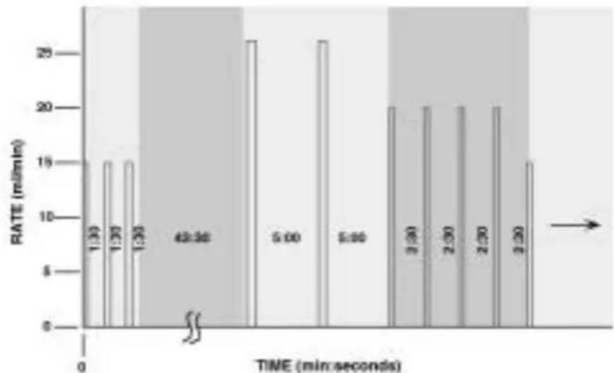
bar
| TIME (min:seconds) | RATE (mL/min) | |---|---| | 1:30 | 15 | | 1:30 | 15 | | 1:30 | 15 | | 42:38 | 0 | | 5:00 | 35 | | 5:00 | 35 | | 9:00 | 20 | | 9:00 | 20 | | 2:30 | 20 | | 2:30 | 20 | | 2:30 | 15 |Figure 9. Periodic Dispense Loop
This is an example of a series of periodic dispenses of varying volumes and intervals. For this application, Strategy 2 dispenses are used. Note that between the third and fourth dispenses is a 45 minute interval. Each dispense in the first sequence is separated by a pause interval of 1:30. Since after the third dispense there already will be a 1:30 pause, an additional pause of 43:30 is used to extend the pause to the desired 45:00. Sequence 5 is a RESTART command, causing the series of dispenses to be continuously repeated until the pump is stopped.
PROGRAM PRINTOUT
PROG1 SEQ 1: DISPENSE
15.000 ml/mn
3.5000 ml
0:01:30 INTERVAL
- REPEAT
INFUSE
PROG1 SEQ 2: PAUSE
0:43:30 INTERVAL
PROG1 SEQ 3: DISPENSE
25.700 ml/mn
6.7500 ml
0:05:00 INTERVAL
- REPEAT
INFUSE
PROG1 SEQ 4: DIS-
PENSE
20.000 ml/mn
4.3000 ml
0:02:30 INTERVAL
- REPEAT
INFUSE
PROG1 SEQ 5: RESTART
Combination of Infusion and Withdraw Profiles
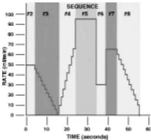
bar
| TIME (seconds) | RATE (m/min) | | -------------- | ------------ | | 0 | 50 | | 10 | 40 | | 20 | 30 | | 30 | 95 | | 40 | 65 | | 50 | 50 | | 60 | 0 |Figure 10. Combination Infusion and Withdraw Profiles
Example
Here is an example of a more complex profile program. Each 'run' of the infusion has been determined to pump 43.155 ml. The first sequence refills the syringe with the volume to be infused then the infusion profile is started, after which the syringe is refilled and the infusion is repeated until the pump is stopped.
PROGRAM PRINTOUT
| PROG1 SEQ 1: PROFILE PROG1 SEQ 5: PROFILE75.000 ml/mn 95.000 ml/mn43.155 ml 0:00:10 INTERVALREFILL INFUSEPROG1 SEQ 2: PROFILE PROG1 SEQ 6: PROFILE50.000 ml/mn 30.000 ml/mn0:00:04 INTERVAL 0:00:05 INTERVALINFUSE INFUSEPROG1 SEQ 3: DECR PROG1 SEQ 7: PROFILE4.0000 DECR 65.000 ml/mn0:00:01 INTERVAL 0:00:05 INTERVAL12. REPEAT INFUSEINFUSE PROG1 SEQ 8: DECRPROG1 SEQ 4: INCR 5.0000 DECR5.0000 DECR 0:00:01 INTERVAL8.0000 INCR 11. REPEAT0:00:01 INTERVAL INFUSE8. REPEAT PROG1 SEQ 9: RESTARTINFUSE |
Use of Events
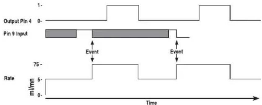
Figure 11. Use of Events
This is an example of the PHD 2000 working interactively with other laboratory equipment. The pump will continuously pump at 300 ml/hr until an external event, a high to low transition at pin 9, possibly produced by another PHD 2000, causes the pump to deliver a 15 ml bolus at 75 ml/mn. After delivering 5 ml of the bolus, output pin 4 is set to a logic high for the duration of the bolus after which it is dropped. This output pin can be attached to the timer input of another pump, such as a Harvard Pump 22 or 44, to create a precise mixture during the bolus. After the bolus is completed, the Pump 22 would be stopped and the PHD 2000 would return to delivering its background rate of 300 ml/hr, waiting for another external event.
PROGRAM PRINTOUT
| PROG1 SEQ 1: TTL OUT 5.0000 mlOFF INFUSEPROG1 SEQ 2: EVENT PROG1 GO TO 4 ONPROG1 SEQ 3: PUMP PROG1 300.00 ml/hr 75.000 ml/mnINFUSE 10.0000 mlPROG1 SEQ 4: PROFILE 75.000 ml/mn | SEQ 5: TTL OUTSEQ 6: PROFILEINFUSEPROG1 SEQ 7: RESTART |
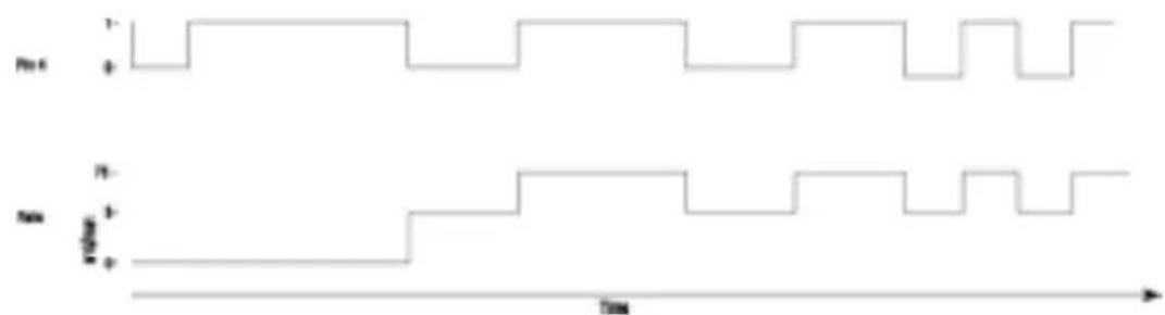
line
| Time | Pst | Tst | |------|-----|-----| | 0 | + | + | | 1 | + | + | | 2 | + | + | | 3 | + | + | | 4 | + | + | | 5 | + | + | | 6 | + | + | | 7 | + | + | | 8 | + | + | | 9 | + | + | | 10 | + | + | | 11 | + | + | | 12 | + | + | | 13 | + | + | | 14 | + | + | | 15 | + | + | | 16 | + | + | | 17 | + | + | | 18 | + | + | | 19 | + | + | | 20 | + | + | | 21 | + | + | | 22 | + | + | | 23 | + | + | | 24 | + | + | | 25 | + | + | | 26 | + | + | | 27 | + | + | | 28 | + | + | | 29 | + | + | | 30 | + | + | | 31 | + | + | | 32 | + | + | | 33 | + | + | | 34 | + | + | | 35 | + | + | | 36 | + | + | | 37 | + | + | | 38 | + | + | | 39 | + | + | | 40 | + | + | | 41 | + | + | | 42 | + | + | | 43 | + | + | | 44 | + | + | | 45 | + | + | | 46 | + | + | | 47 | + | + | | 48 | + | + | | 49 | + | + | | 50 | + | + | | 51 | + | + | | 52 | + | + | | 53 | + | + | | 54 | + | + | | 55 | + | + | | 56 | + | + | | 57 | + | + | | 58 | + | + | | 59 | + | + | | 60+ | - | - |Figure 12. Use of TTL Signal
Before the pumping flow begins, the pump sends a TTL signal to another piece of equipment for 5 seconds, but first verifies that the TTL line is low by turning it off for 1 second, then turns it on. The pumping process consists of an alternation of pumping 3 ml's at 53 ml/mn and 5 ml's at 75 ml/mn. It uses the TTL output to signal to another device whose sequence it is executing by lowering the TTL line before sequence 5 and raising it before sequence 8.
PROGRAM PRINTOUT
| PROG1 SEQ 1: TTL OUT OFFPROG1 SEQ 2: PAUSE0:00:01 INTERVALPROG1SEQ 3: TTL OUT ONPROG1 SEQ 4: PAUSE0:00:01 INTERVALPROG1 SEQ 5: TTL OUT OFFPROG1SEQ 6: PROFILE | 53.000 ml/mn3.0000 mlINFUSEPROG1 SEQ 7: TTL OUT ONPROG1 SEQ 8: PROFILE75.000 ml/mn5.0000 mlINFUSEPROG1SEQ 9: GO TO 5 |
This is an example of the PHD 2000 being operated from a remote location. When the pump is powered on, the position of the pusher block is unknown and must be homed to a known position.
At the syringe full position, a limit switch is placed such that it is tripped by the pusher block when the syringe is full. The limit switch is connected to pins 4 and 9, programmable output and the event input, on the TTL connector. When the pump receives a start signal, it first refills the syringe and stops when the limit switch is sensed. The pump then waits for a start trigger and performs a dispense then refills the syringe and waits again for the next start trigger.
PROGRAM PRINTOUT
| PROG1 SEQ 1: EVENTGO TO 7PROG1 SEQ 2: TTL OUTONPROG1 SEQ 3: PAUSE0:00:01 INTERVALPROG1 SEQ 4: TTL OUTOFFPROG1 SEQ 5: PAUSE00:00:01 INTERVALPROG1 SEQ 6: PUMP | 75.000 ml/mnPROG1 SEQ 7: DISPENSE10.000 ml/mn0.0001 ml1. REPEATREFILLPROG1 SEQ 8: PUMP75.000 ml/mn10.000 mlINFUSEPROG1 SEQ 9: RESTART |
The Pump Chain RS-232 interface is used to enhance the control applications of the PHD 2000. This interface allows all control information, including a program, to be entered into the pump from an external source such as a computer. In addition, this interface allows up to 100 pumps and, in certain cases, other RS-232 devices to be controlled from a single RS-232 communication port on a computer.
Assign each pump in the pump chain a unique address from 0 to 99. This address is used to identify which pump is to receive a command and which pump is responding. Configure each pump with its assigned address and the baud rate being used (See Section 9, External Control & Interfaces).
When the control device communicates with the pump, a diamond appears on the far right of the display indicating that it is receiving RS-232 commands. The diamond remains on the display until the pump is turned off or SET RS-232 is entered on the keyboard, indicating a change in the RS-232 configuration.
A pump will not respond to pump chain communication while it is in a setting mode (entered when user presses the SET key). The pump can still be controlled from the keyboard while it is in a pump chain. Control data that is changed via RS-232 will be stored in the pump's non-volatile memory.
After each command is received and executed, the pump terminates its responses with a prompt. A prompt is a string of ASCII characters sent by a pump.
The PHD 2000 is capable of using two sets of pump interface commands. This will allow users of Harvard Apparatus Model 22 and Model 44 pumps to use existing programs to control the PHD 2000 pumps. The two sets of commands are contained on the following pages.
Each command sent to the pump chain is a string of ASCII characters, with leading zero's on numbers and all spaces optional.Numbers are a maximum of five digits.The following symbols are used in describing the commands:
Pump Chain Commands - Model '22' Protocol (Model 44 Protocol on page 37)
After each transmission to the Pump terminating with a CR character (ASCII 13), the pump enters remote mode and responds with the three character sequence:
CR LF prompt
The prompt character indicates the status of the pump as follows:
: When stopped (ASCII 58 decimal)
When running forward (ASCII 62 decimal)
< When running reverse (ASCII 60 decimal)
* When stalled (ASCII 42 decimal)
Note: With a pump chain, if no address precedes the command transmitted, the pump at address 0 will respond to the command.
Commands - Response: CR LF prompt
RUN Infuse (forward direction)
REV Start (reverse direction) Not accessible on Infusion model
STP Stop
CLV Clear volume accumulator to zero
CLT Clear target volume to zero
MLM number Set rate, units are milliliters per minute
ULM number Set rate, units are microliters per minute
MLH number Set rate, units are milliliters per hour
ULH number Set rate, units are microliters per hour
MMD number Set diameter, units are mm. Rate is set to 0
MLT number Set target infusion volume, units are ml.
Numbers between 0 and 1999 will be accepted by the pump. Leading zeros and trailing decimal point are optional. Any number of digits to the right of the decimal point may be transmitted. The number received will be rounded to four significant digits if the leading digit is 1, or three significant digits if the leading digit is 2 to 9.
Queries - Response: CR LF Value CR LF Prompt
Queries with Numeric Response
DIA Send diameter value, units in mm
RAT Send rate value in current range units
VOL Send current accumulated infused volume, units are ml.
TAR Send target volume, units are ml.
VER Send model and version number
Value format:nnnn.nnn
The transmitted value is an 8 character string with leading zeros converted to SP characters. (ASCII 32) The fifth character is a decimal point (ASCII 46).
Query - Response: CR LF Range CR LF Prompt
Queries with String Response
RNG Send range message
Range is a character string, one of: ML/H ML/M UL/H or UL/M
Error Responses
CR LF ? CR LF prompt Unrecognized command
CR LF O O R CR LF prompt Out of range
Pump Chain Commands - Model '44' Protocol
Symbol Meaning
[...] optional
{...} select one
| either/or
f digits 0 - 9 or a decimal point
d digits 0 - 9
<cr> carriage return (ASCII 13)
<lf> line feed (ASCII 10)
<float> f f f f f
<integer> ddddd
<time> d:dd:dd
<text> any string of ASCII characters
Command Formats and Meanings:
Command Format Meaning
<cr> Stops all pumps.
All pumps on the pump chain interpret this as a stop command.
pump address,<cr> Request for prompt
The pump with the indicated address responds with its prompt
optional pump address,
command,<cr> Send a command to a pump.
The pump with the indicated address executes the command then responds with its prompt.
The optional pump address,if not specified,will default to pump address 0.
After each command is received and executed, the pump acknowledges the command with a prompt. Preceding the prompt may be some additional text responses. The additional text will be one or more lines of ASCII text, each preceded by a line feed and terminated by a carriage return:
<lf>, <text>, <cr>
A prompt is a string of ASCII characters sent by a pump indicating the pumps address and its present state:
Prompt Characters Meaning
:
> Pump stopped
> Pump infusing
< Pump refilling
/
Pause interval (pump stopped)
* Pumping interrupted (pump stopped)
^ Dispense trigger wait (pump stopped)
Pump Commands and Responses
RUN Starts pumping according to the present setting of the pump. If pump is already pumping, a 'Not Applicable' response will be given.
STP Stops pump if it was running. If pump was already stopped, a 'Not Applicable' response will be given.
DEL Request for volume delivered, in ml. Response is of the following format: space, space, f f f f f
CLD Request to zero volume delivered. If the pump was interrupted, it will cancel the interrupted condition. If the pump is running, request will not be accepted and a 'Not Applicable' response will be given. Otherwise, no response is given.
RAT [
Request to set or query infusion rate setting.
Set infusion rate: RAT rate
Set infusion rate and units: RAT rate units
Rate is of format: f f f f f
Units are one of:
Definition
UM l/mn UH l/hr MM ml/mn MH ml/hr
If rate is accepted and valid, rate will become the new infusion rate. If the rate is invalid, an 'Out Of Range' response will be given. Command will not be accepted if the pump is running in the Program Mode and a 'Not Applicable' response will be given.
Query infusion rate:RAT
Response is of the following format: space, space, f f f f f units
Where units is one of the following:
ml/mn ul/mn ml/hr ul/hr
RFR [
Request to set or query refill rate setting.
Set refill rate:
RFR rate
Set refill rate and units:
RFR rate units
Rate is of format: f f f f f
Units are one of:
Definition
UM μl/mn
UH μl/hr
MM ml/mn
MH ml/hr
If rate is accepted and valid, rate will become the new refill rate.
If the rate is invalid, an 'Out Of Range' response will be given.
Command will not be accepted if the pump is running in the
Program Mode and
a 'Not Applicable' response will be given.
Query refill rate: RFR
Response is of the following format:
space, space, f f f f f units
Where units is one of the following:
ml/mn
ul/mn
ml/hr
ul/hr
PGR Request for the rate of pumping set during the running of a program.
Response is of the following format:
space,space, f f f f f units
Where units is one of the following:
ml/mn
ul/mn
ml/hr
ul/hr
DIA []
Request to set or query syringe diameter setting.
Set diameter:
DIA diameter Diameter is of format: f f f f f Units are MM.
INFUSE and REFILL rates will be set to zero and AUTO FILL will be set to off.
If diameter is accepted and valid, diameter becomes new diameter.
Diameter will not be accepted if the pump is running and a 'Not Applicable' response will be given.
If the diameter is invalid, an 'Out Of Range' response will be given.
Query diameter:DIA
Response is of the following format: space, space, f f f f f Units are MM.
TGT []
Request to set or query target volume setting.
Set target volume:
TGT volume Volume is of format: f f f f f Units are ML. If volume is accepted and valid, volume becomes new target volume. Volume will not be accepted if the pump is running and a 'Not Applicable' response will be given. If the volume is invalid, an 'Out Of Range' response will be given.
Query volume:TGT
Response is of the following format: space, space, f f f f f Units are ML.
MOD [{PMP | VOL | PGM}]
Request to set or query pumping mode Set: MOD PMP (Puts pump in Pump Mode) MOD VOL (Puts pump in Volume Mode) MOD PGM (Puts pump in Program Mode)
Command will not be accepted if the pump is running and a 'Not Applicable' response will be given.
Query:MOD If mode is PUMP, response will be: PUMP If mode is VOLUME, response will be: VOLUME If mode is PROGRAM response will be: PRGRAM
DIR [ | REF | REV\ ]
Request to set or query pumping direction Set: DIR INF (sets pumping direction to infusion) DIR REF (sets pumping direction to refill) DIR REV (reverses current pumping direction)
Command will not be accepted if the pump is running in volume or program modes and a 'Not Applicable' response will be given.
Query:DIR If pump direction is infusion, response will be: INFUSE If pump direction is refill, response will be: REFILL
AF [{ON|OFF}]
Request to set or query auto fill setting Set: AF ON (turns Auto Fill feature on) Note:The syringe volume is also needed for auto fill to operate. (See SYR command) AF OFF (turns Auto Fill function off) Command will not be accepted if the pump is running and a 'Not Applicable' response will be given.
Query:AF If Auto Fill function is ON, response will be:ON If Auto Fill function if OFF, response will be:OFF
SYR [
Request to set or query syringe volume setting for auto fill. Used in conjunction with Auto Fill feature.(See AF command).
Set syringe volume:SYR volume
Volume is of format: f f f f f
Units are ML.
If volume is accepted and valid, volume will become the new syringe Auto Fill volume.
Volume will not be accepted if the pump is running and a 'Not Applicable' response will be given.
If the volume is invalid,an 'Out Of Range' response will be given.
Query syringe volume:SYR
Response is of the following format:
space, space, f f f f f
IN d
Request to read the TTL logic level of the specified pin on the external 9 pin D-SUB connector. Valid pin numbers for input are:
6,7, 8 and 9
If the pin specified is valid and if the pin level is high, response will be:
ON
If the pin level is low, response will be:
OFF
If the pin specified is invalid:
An 'Out Of Range' response will be given
OUT d =
Request to set the TTL logic level at the specified pin on the external 9 pin D-SUB connector.
Valid pin number for output is:4
If the pin specified is invalid:
An 'Out Of Range' response will be given
Example:
Set pin 4 high:
OUT 4 = ON
Set pin 4 low:
OUT 4 = OFF
SEQ [] []
Request to set or query programming sequences.
Default is Sequence 1. Command only applicable while pump is stopped. Valid
sequence numbers, 'n', are 1 to 10. 'n' defaults to 1 wherever it is optional.
See program
examples.
Query entire program: SEQ
Example response:
SEQ 1: DISPENSE
75.000 ml/mn
43.155 ml
0:00:01 INTERVAL
3 REPEAT
INFUSE
SEQ 2: PROFILE
100.00 ml/mn
150.00 ml
REFILL
SEQ 3: RESTART
Query program sequence [n]: SEQ n
Example response to the command 'SEQ 2' with the previous example's program:
SEQ 2: PROFILE
100.00 ml/mn
150.00 ml
REFILL
Query program sequence n's mode: SEQ [n] MOD
Response will be according to the following table:
Response Description Response Description
| STP stop RST restart | |||
| PRO profile | GOT | go to | |
| INC increment | EVN event | ||
| DEC decrement | PMP pump | ||
| DIS | dispense | OUT | |
| PAS | pause | ||
Query data item of program sequence n:
Command Description
SEQ [n] RAT Query rate
Response:
f f f f f units
Where units is one of the following:
ml/mn
ul/mn
ml/hr
ul/hr
SEQ [n] GOT Query go to sequence number
Response:
SEQ [n] TGT Query target volume
Response:
SEQ [n] INT Query time interval
Response:
SEQ [n] RPT Query repetition count
Response:
SEQ [n] OUT Query output pin level setting
Response:
SEQ [n] DIR Query pumping direction
Possible responses: INFUSE
REFILL
Set mode of program sequence n:
SEQ [n] MOD mode
Where mode is as follows:
Mode Description Mode Description
STP stop RST restart
PRO profile EVN event
INC increment GOT go to
DEC decrement
OUT
set output pin
DIS
dispense
PMP pump
PAS
pause
Set data item of program sequence n:
Set sequence's rate:
SEQ [
Rate is of format: f f f f f
Units are one of : Description
UM
μl/mn
UH
μl/hr
MM
ml/mn
MH
ml/hr
Set sequence's go to sequence number
SEC [
Set sequence's target volume:
SEQ [
Set sequence's time or target:
SEQ [
Set sequence's repetition number:
SEQ [
Set sequence's pumping direction:
SEQ [
Set sequence's output pin level
SEQ [
VER Request for version of pumps embedded software.
Pump Chain Error Messages
Error messages are in the format:
Where
? Syntax error in a received command
NA Command not applicable at this time
OOR Control data is out of the operating range of the pump
Note: If assistance is needed in programming pump control via RS-232, call Harvard Apparatus Customer Service Support at 1-800-272-2775.
Harvard Apparatus PHD 2000 Syringe Pump Series User's Manual
| Stainless SteelSize Diameter8 cc 9.525 mm20 19.13050 28.600100 34.900200 44.755Becton Dickinson Plastic 'Plasti-pak'Size Diameter1 cc 4.78 mm3 8.665 12.0610 14.5020 19.1330 21.7050/60 26.70Air-Tite 'All Plastic'Size Diameter2.5 cc 9.60 mm5 12.4510 15.9020 20.0530 22.5050 29.00Unimetrics Series 4000 & 5000Size Diameter10 μl 0.460 mm25 0.72950 1.031100 1.460250 2.30500 3.261000 4.610 | TerumoSize Diameter3 cc 8.95 mm5 13.0010 15.8020 20.1530 23.1060 29.10Sherwood-Monoject PlasticSize Diameter1 cc 4.65 mm3 8.946 12.7012 15.9020 20.4035 23.8060 26.60140 38.40Popper & Sons, Inc. 'Perfektum' GlassSize Diameter0.25 cc 3.45 mm0.5 3.451 4.502 8.923 8.995 1 1.7010 14.7020 19.5830 22.7050 29.00100 35.70RenfacSize Diameter2 cc 9.12 mm5 12.3410 14.5520 19.8630 23.2050 27.60 | SGE Scientific Glass EngineeringSize Diameter25 μl 0.73 mm50 1.03100 1.46250 2.30500 3.261.0 ml 4.61 mm2.5 7.285 10.3010 14.57Hamilton-Microliter Series GastightSize Diameter0.5 μl 0.103 mm1 0.14572 0.2065 0.325710 0.46025 0.72950 1.031100 1.46250 2.3500 3.261.0 ml 4.61 mm2.5 7.285 10.310 14.5725 23.050 32.6Becton Dickinson Glass-All TypesSize Diameter0.5 μl 4.64 mm1 4.642.5 8.665 11.8610 14.3420 19.1330 22.7050 28.60100 34.90 |
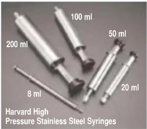
text_image
100 ml 200 ml 50 ml 8 ml 20 ml Harvard High Pressure Stainless Steel SyringesHarvard High Pressure Stainless Steel Syringes
Harvard now offers a completely new line of Stainless Steel Syringes intended for high pressure applications with good resistance to most aggressive liquids. Wetted parts are #316 stainless steel or Viton. Syringes are available in 20, 50, 100 and 200 ml sizes with removable replaceable tips. Genuine SWAGELOK® syringe to tube fittings are available in 1/16, 1/8 and 1/4 inch sizes. A luer lock end fitting is also available. All tips are interchangeable with all syringes (20 to 200 ml) in the series.
Both syringe barrel end plungers are #316 stainless steel. A Viton O-ring seal between top and end of the barrel insures against leakage. Syringes are guaranteed to be leak free for pressures up to 700 psi.
All syringes are supplied with inside diameter dimensions for use with Harvard microprocessor controlled pumps and rate charts for use with older 'classic' pumps. Replacement Viton O-Rings are available, as are the more chemically resistant Chemraz® O-Rings.
Harvard High Pressure 8 ml Stainless Steel Syringe
This syringe has been designed to utilize the high forces available in our syringe pumps to produce pressures up to 1500 psi. The syringe is constructed entirely of #316 stainless steel with two Chemraz® O-Ring seals, two Teflon O-Ring seals and 1.6 mm (1/16 in) SWAGELOK® end. When used in the 70-2200 or 70-2201 Harvard PHD 4400, pressures in excess of 1500 psi are achieved for chromatography and process control applications.
Specifications
Volume 8 ml
Dimensions:
Length of Barrel 16.5 cm (6-1/2 in)
Plunger Excursion 11.4 cm (4-1/2 in)
OD 1.6 cm (5/8 in)
ID 0.95 cm (3/8 in)
Max Test Pressure 4000 p.s.i
Working Pressure 1500 p.s.i
Cat. No. Product
55-3369 Harvard High Pressure 8 ml Stainless Steel Syringe
Replacement Parts
5013-089 Chemraz ^ O-Ring 20 ml
5013-090 Chemraz ^ O-Ring 50 ml
5013-091 Chemraz ^ O-Ring 100 ml
5013-092 Chemraz ^ O-Ring 200 ml
5013-087 Chemraz ^® Tip Seal O-Ring, all sizes
72-2472 Replacement Viton O-Ring 20 ml, 10
72-2473 Replacement Viton O-Ring 50 ml, 10
72-2474 Replacement Viton O-Ring 100 ml, 10
72-2475 Replacement Viton O-Ring 200 ml, 10
72-2476 Replacement Viton Tip Seal O-Ring, 10
72-2477 Stainless Steel Plunger Button to Adapt
Syringe for Use with PHD 2000 HVP with Triple S Clamp
Harvard High Pressure Stainless Steel Syringes
| Syringe Size | With SWAGELOK®Diameter | With Luer Lock | ||
| 1/16 inch | 1/8 inch | 1/4 inch | ||
| 20 ml | 55-4199 | 55-4205 | 55-4209 | 55-4214 |
| 50 ml | 55-4200 | 55-4206 | 55-4210 | 55-4215 |
| 100 ml | 55-4201 | 55-4207 | 55-4211 | 55-4216 |
| 200 ml | 55-4202 | 55-4208 | 55-4213 | 55-4217 |
| Replacement Tips, Furnished with Sealing O-Ring | ||||
| 55-4220 | 55-4221 | 55-4222 | 55-4223 | |
Minimum flow rates are taken from the smallest inside diameters and maximum flow rates are taken from the largest inside diameters of the syringes supplied by the eleven most widely used syringe manufacturers.
| Nominal Minimum/Maximum Flow Rates for Various Syringes(Actual Limits will vary depending on manufacturer) | |||||||
| Syringe μl/hr μl/min ml/hr ml min | |||||||
| Size Min. | Max. Min | Max. Min | Max. Min | Max. | |||
| 0.5 μl 0.0001 95.330 | |||||||
| 1 μl 0.0002 190.70 | |||||||
| 2 μl 0.0004 381.30 | |||||||
| 5 μl 0.0010 953.17 | |||||||
| 10 μl 0.0019 | 1.9013 | ||||||
| 25 μl 0.0046 | 4.7752 | ||||||
| 50 μl 0.0092 | 9.5511 | ||||||
| 100 μl | 0.0183 | 19.153 | |||||
| 250 μl | 0.0454 | 47.532 | |||||
| 500 μl | 0.0911 | 95.492 | |||||
| 1000 μl | 0.0031 | 190.95 | |||||
| 1 ml | 0.0033 | 205.30 | |||||
| 2 ml | 0.0119 | 747.35 | |||||
| 2.5 ml | 0.0076 | 476.21 | |||||
| 3 ml | 0.010 | 11.231 | |||||
| 5 ml | 0.0208 | 21.781 | |||||
| 10 ml | 0.0301 | 31.486 | |||||
| 20 ml | 0.0523 | 54.804 | |||||
| 30 ml | 0.0673 | 70.518 | |||||
| 50 ml | 0.1019 | 106.76 | |||||
| 100 ml | 0.1740 | 182.40 | |||||
| 140 ml | 0.2106 | 220.82 | |||||
Stainless Steel Syringes
Only Harvard's stainless steel syringes can be used with this pump. They can withstand high pressure applications and provide years of service.
| Flow Rates for PHD 2000 HVP (High Volume and Pressure)Rates listed are for single syringe | ||
| Syringe Size | Minimum | Maximum |
| 20 ml | 1.5 μl/hr 20 ml/min | |
| 50 ml | 3.4 μl/hr 46 ml/min | |
| 100 ml | 5.0 μl/hr 68 ml/min | |
| 200 ml | 8.2 μl/hr 112 ml/min | |
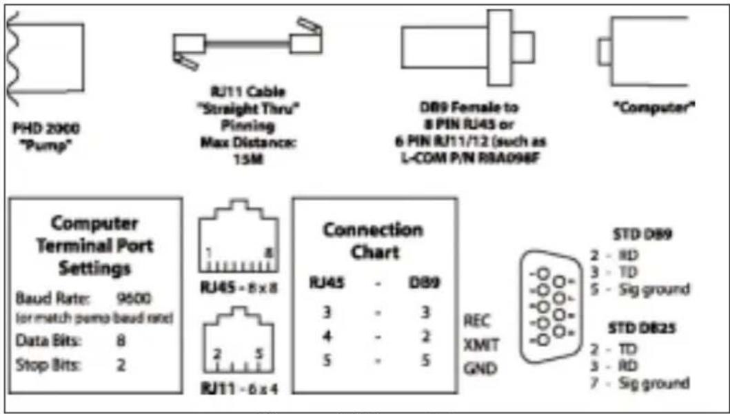
text_image
PHD 2000 "Pump" RJ11 Cable "Straight Thru" Pinning Max Distance: 15M DB9 Female to 8 PIN RJ45 or 6 PIN RJ11/12 (such as L-COM P/N RBA098F "Computer" Computer Terminal Port Settings Baud Rate: 9600 for match pump baud red Data Bits: 8 Stop Bits: 2 RJ45 - 8 x 8 RJ11 - 6 x 4 Connection Chart RJ45 - DB9 3 - 3 4 - 2 5 - 5 REC XMIT GND STD DB9 2 - RD 3 - TD 5 - Sig ground STD DB25 2 - TD 3 - RD 7 - Sig groundFigure 13. PHD 2000 to PC Connection
Appendix E: TTL Connector Specs
TTL Connections are via a 9 pin D-sub type connector. All inputs are internally pulled up to a logic high.
Pin Assignments
- Vss (Ground Reference, logic low)
Falling edge starts/stops pump - Valve Control Output:
Low - Infusing
High - Refilling - Running Output Indicator
High - Pump running
Low - Pumped stopped
-
Programmable Output
-
Logic High Reference (5V, 400 μA)
-
Foot Switch Input
-
Timer Input
Rising edge starts pump
Falling edge stops pump
- Directional Control Input
Rising edge sets pump to infuse
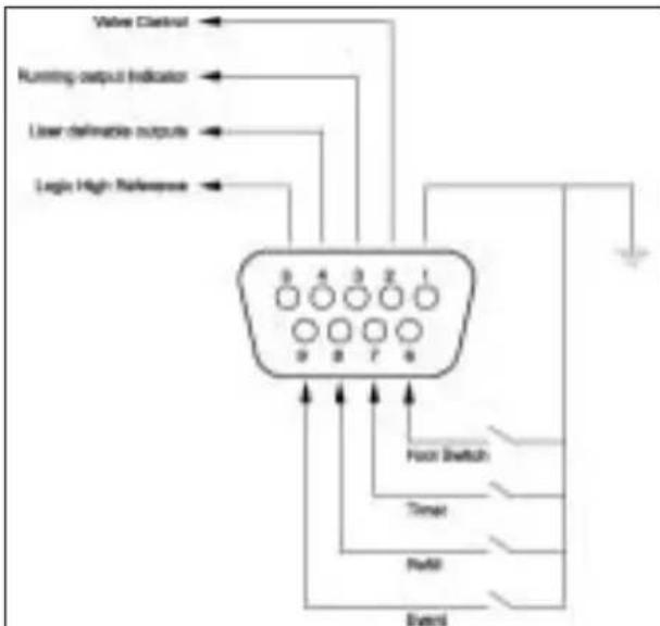
flowchart
graph TD
    A["Value Channel"] --> B["Running output Indicator"]
    B --> C["Lower delineable outputs"]
    C --> D["Logic High Reference"]
    D --> E["Output"]
    E --> F["Found Switch"]
    E --> G["Timer"]
    E --> H["Reset"]
    E --> I["External"]
Figure 15.TTL Connector Specifications
Falling edge sets pump to refill
- Event Input
Falling edge triggers program event
Logic Low: 0 V - 0.5 V
Max.2 mA current sink
Logic High: 2 V - 5 V
Max.400 μA current source
Pump Chain
Pump Port 1 – Computer control side Pump Port 2 – Connection for remainder of pump chain Baud Rate – 1200,2400,9600 or 19,200 Word Size – 8 Parity – none Stop Bits – 2
Scale
Connect scale to Pump Port 1
Supported scales:
Mettler
Baud Rate - 2400
Word Size - 7
Parity – even
Stop Bits - 1
Pause - 0
Sartorius
Baud Rate - 2400
Word Size - 7
Parity – even
Stop Bits - 1
Code Settings:
311 - Weigh only (models with PLUS performance package)
211 - External print command without stability
225 - 2400 baud
234 – Even Parity
432 – Beeper off
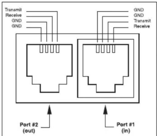
text_image
Transmit Receive GND GND GND GND GND Transmit Receive Port #2 (out) Port #1 (in)Figure 14. RS-232 Specifications
Ohaus
Baud Rate - 2400
Word Size - 8
Parity – even
Stop Bits - 1
Auto print feature – off
Stable data only – off
Serial data frame selection - Fr.7
Printer
Serial printer with print buffer:
Baud Rate - 2400
Word Size - 8
Parity – none
Stop Bits - 2
Maintenance
PHD 2000 series pumps require no special maintenance other than keeping them clean by avoiding accidental spills of pumped material.
The two guide rods and the lead screw should be sparingly lubricated periodically. The guide rods and the lead screw should be lubricated with Magnalube-G R grease (Catalog #0606-086) provided with the pump.
Solvents of any type should never be used to clean the pump. A mild detergent solution may be used to clean the keypad.
Troubleshooting
Infusion Accuracy
To ensure infusion accuracy always use new syringe(s) and measure syringe bore diameter and enter actual dimensions in millimeters (mm). Additionally make sure that the guide rods and lead screw are properly lubricated.
RS-232 Difficulties
Verify that the baud rates and data framing parameters on all devices are the same. With the pump chain, a “Communication timeout” error on a computer is usually caused by the computer errantly handshaking on the RTS, CTS and DSR lines. Verify pins 4, 5 and 6, on the 25 pin connector, are jumped on the computer side of the cable.
PHD 2000 Display Messages
Pump Stalled
This indicates that the pusher block travel has been impeded. This may be caused by the syringe plunger hitting bottom, a kink in the tubing, syringe plunger binding or any situation requiring more force to the head of the syringe than the pump is capable of delivering. To restart the pump, remove the cause of stalling and press RUN. The pump will continue the interrupted procedure where it stopped. Also note, a large increase in the pumping rate could also stall the motor.
Out of Range
A value was entered or encountered in a pump program that was beyond the pump's limits. Also, verify that the Infuse Rate is not 0. Note that rates must be less than 42949. Express larger rates using different units.
EEPROM Data Lost
The values stored in the non-volatile memory have been lost. This should never occur under normal operation.
Replace NOVRAM
The non-volatile memory has failed. This should never occur under normal operation.
Auto Fill Accessory
To operate the Auto Fill feature, either the low pressure or high pressure valve assembly is required. Each assembly contains the solenoid valve, connector cable, power cable, and tubing and fittings to connect to the syringe. Operates at 115/230 VAC, 50/60 Hz via a selector switch.
Catalog No. Description
Accessories
55-7760 Daisy-Chain Cable
70-2022 Daisy-Chain Connector, 9 PIN
55-4145 Daisy-Chain Connector, 25 PIN
55-4144 Foot Switch
55-1146 'Auto Fill' Valve Box-Regular Pressure – to 25 psi
55-1145 'Auto Fill' Valve Box-High Pressure - 200 psi
59-7357 Manual Liquid Switch
59-7358 Automatic Liquid Switch-115 VAC, 60 Hz
59-7359 Automatic Liquid Switch-230 VAC, 50 Hz
59-7356 Replacement Tubing Connection Kit
59-7355 Replacement Reducing Adapters
61-0270 Continuous Flow Tube Segment**
72-0199 Remote Extension Cable, 1.5 m (5 ft)*
72-1405 Remote Ext. Cable, 9.1 m (30 ft) ^*
70-2022 PHD 2000 RS-232 Adapter, 9-pin to standard phone jack*
55-4202 SS Syringe, 200 ml, with 1/16 inch Swagelok ®*
55-4208 SS Syringe, 200 ml, with 1/8 inch SWAGELOK ®*
55-4213 SS Syringe, 200 ml, with 1/4 inch SWAGELOK ®*
55-4217 SS Syringe, 200 ml, with Luer Lock*
* For PHD 2000 HVP Remote Syringe Pump
** For PHD 2000 Push/Pull Syringe Pump
Spare Parts
0606-086 Magnalube Lead Screw Lubricant
2400-243 Syringe Clamp
5012-005 3/32 Hex Key
5091-030 Syringe Retainer Knob
5100-055 T Knob - Withdraw and Anti-Siphon Bracket
5153-209 Power Cord
5400-001 PHD2000 Operators Manual
Catalog No. Description
Kits
70-2012 PHD 2000 6/10 Multirack Upgrade Kit
70-2013 PHD 2000 4 x 140ml Multirack Upgrade Kit
70-2014 PHD 2000 Microliter Rack Upgrade Kit
70-2015 PHD 2000 Anti-Siphon Kit (for Infusion Pump)
Upgrades
70-2016 PHD 2000 Infusion to Infuse/Withdraw*
70-2017 PHD 2000 Infuse/Withdraw to Programmable*
70-2018 PHD 2000 Infusion to Programmable*
*Factory Installed Only
Appendix J: Custom Applications
The Harvard PHD 2000 Syringe Pumps lend themselves to a multitude of OEM industrial applications. For all types of custom pumping or pilot plant applications, the pump's programming capabilities can be enhanced. Please contact the Harvard Development Group if we can be of help.
Appendix K: Symphony
Symphony, the Windows ^® Pump Manager software, allows you to control your PHD 2000 pump from your remote computer. With Symphony, you can orchestrate all pump functions from a virtual control panel via the serial communications link built into every PHD 2000 pump.
Catalog Number Product
70-3000 Symphony — The Windows™ Pump Manager
Harvard Apparatus pumps are distributed on a non-exclusive basis by:
INSTECH
Instech Laboratories, Inc.
Headquarters:
5209 Militia Hill Road
Plymouth Meeting, PA 19462
TL (800) 443-4227
TL (610) 941-0132
FX (610) 941-0134
European sales office:
P.O. Box 2
9950 AA Winsum
The Netherlands
TL 0031-(0)594-696123
www.instechlabs.com/Pumps/syringe/