UW8200SV - Uncategorized Shimadzu - Free user manual and instructions
Find the device manual for free UW8200SV Shimadzu in PDF.


User questions about UW8200SV Shimadzu
0 question about this device. Answer the ones you know or ask your own.
Ask a new question about this device
Download the instructions for your Uncategorized in PDF format for free! Find your manual UW8200SV - Shimadzu and take your electronic device back in hand. On this page are published all the documents necessary for the use of your device. UW8200SV by Shimadzu.
USER MANUAL UW8200SV Shimadzu
Electronic Balance Instruction Manual
UW series UX series
natural_image
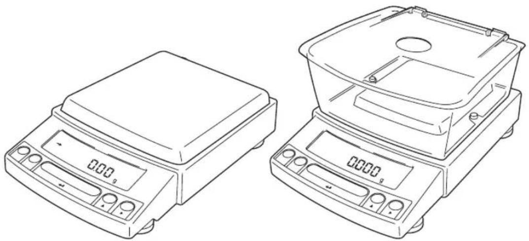
Line drawings of two laboratory balance gauges with digital displays (no text or symbols)Read the instruction manual thoroughly before you use the product. Keep this instruction manual for future reference.

- Provide this manual to the next user in the event that the instrument is transferred.
- To ensure safe operation, contact your Shimadzu Balance representative for installation, adjustment, or reinstallation after moving the instrument to a different site.
Notices
- The content of this manual is subject, without notice, to modifications for the sake of improvement.
- Every effort has been made to ensure that the content of this manual was correct at the time of creation. However, in the event that any mistakes or omissions are discovered, it may not be possible to correct them immediately.
- The copyright of this manual is owned by Shimadzu Corporation. Reproduction and duplication of whole or part of the content without permission of the company are strictly prohibited.
- "Microsoft", "Windows", "Windows Vista" and "Excel" are registered trademarks of Microsoft Corporation of the U.S.A. in the United States and other countries. All other company names and product names that appear in this manual are trademarks or registered trademarks of the companies concerned. Note that ™ and® indications are not used.
- The company names, organization names and product names in this manual are trademarks or registered trademarks of the companies and organizations concerned.
- Shimadzu does not guarantee that the WindowsDirect communication function will operate without problems on all PCs. Shimadzu will accept no responsibility for any trouble that arises as a result of using this function. You are recommended to back up all important data and programs in advance.
© 2002-2008 Shimadzu Corporation. All rights reserved.
Notation Conventions

Note
This instruction manual uses the following notation conventions to indicate Safety Precautions and additional information.

Caution
Indicates a potentially hazardous situation that may result in injury to personnel or equipment damage.

Note
Provides additional information needed to properly use the balance.
Other conventions used in this manual include:
| Item Description | |
| 1, 2, 3 .... | Indicates the step number in a procedure or a sequence of changes in the balance display. |
| [ ] key | Indicates the operation key on the balance. See 2.2. |
| mass display | Indicates that the balance is in the weighing mode and mass is displayed in one of the weighing units. |
 | These sections include information to make using the balance more convenient. |
 | Indicates the menu item to be selected.The number in the □ is the number of the menu item on the Menu Map.See 7.2 “Menu Map”. |
Notes on the use of verified balances as legal measuring instruments
Important notes about the use of verified balances as legal measuring instruments in the EU are highlighted with the shadow.
Examples:
Using a verified balance as a legal measuring instrument in the EU:
Not applicable to a verified balance as a legal measuring instrument in the EU:
There are special requirements on using a verified balance as a legal measuring instrument in the EU. With the verified balances, some of the functions are either unavailable or restricted.
“EU” includes the signatories of the European Economic Area agreement.
Safety Precautions
To be strictly observed
To ensure that you use the balance safely and correctly, read the following precautions carefully and observe them.
The levels of danger and damage that will arise if the balance is used incorrectly are classified and indicated as shown below.
WARNING
Indicates a potentially hazardous situation which, if not avoided, could result in serious injury or possibly death.
CAUTION
Indicates a potentially hazardous situation which, if not avoided, may result in minor to moderate injury or equipment damage.
Precautions are classified and explained by using one of the symbols below, depending on the nature of the precaution.

Instructions Prohibitions
Indicates an action that must be performed.

Indicates an action that must NOT be performed.
WARNING

Prohibitions
Never disassemble, modify or attempt to repair this product or any accessory.
You could sustain an electric shock or the product could operate abnormally. If you believe that the balance has failed, contact your Shimadzu representative.

Instructions
Use the balance with the specified power supply and voltage.
Using the balance with an incorrect power supply or voltage will lead to fire or trouble with the balance. Note also that if the power supply or voltage is unstable or if the power supply capacity is insufficient, it will not be possible to obtain satisfactory performance from the balance.

Instructions
Use the correct weighing units.
Using incorrect weighing units can lead to accidents as a result of weighing errors. Check that the weighing units are correct before starting weighing.

Prohibitions
Do not use the balance outdoors or anywhere where it will be exposed to water.
You could sustain an electric shock or the product could operate abnormally.
| CAUTION | |
 Prohibitions Prohibitions | Avoid locations where the balance will be exposed to any of the following.This could cause accidents or poor performance.Air flow from an air conditioner, ventilator, door or windowExtreme temperature changesVibrationDirect sunlightCorrosive or flammable gasesDust, electromagnetic waves or a magnetic field 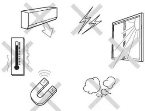 |
 Instructions Instructions | Install the balance on a strong and stable flat table or floor.Placing the balance in an unstable site could lead to injury or trouble with the balance.When selecting the installation site, take into account the combined weight of the balance and the item to be weighed. |
 Instructions Instructions | After a power outage, turn the power back ON.When a power outage occurs, the power is shut off automatically. Therefore, begin operation from 4.4 “Turning ON the Power” (^ page 18) again. |
 Instructions Instructions | Treat the balance with care and respect.The balance is a precision instrument. Subjecting it to impacts could cause it to fail.When moving the balance, remove pan and pan supporter. Grasp it firmly with both hands to carry it.If the balance has to be stored for a long time, store it in the packaging box in which it was delivered. |
 Prohibitions Prohibitions | Do not connect anything other than peripheral devices specified by Shimadzu to the balance's connector.If you do, the balance may stop working normally.In order to avoid trouble, always connect peripheral devices in accordance with the directions in this manual. |
 Instructions Instructions | If you detect anything abnormal (e.g. a burning smell) disconnect the AC adapter immediately.Continuing to use the balance with an abnormality could lead to fire or an electric shock. |
Declaration of Conformity
Manufacturer's Name: SHIMADZU CORPORATION
Analytical & Measuring Instruments Division
Address : 1, Nishinokyo-Kuwabara-cho, Nakagyo-ku,
Kyoto 604-8511, Japan
declares in sole responsibility that the following product
Product Name Electronic Balance
Model Name UW and UX series
P/N Depend on configuration. See Appendix 1.
referred to in this declaration conforms with following directives and standards
EMC Directive 2004/108/EC
EN 61326-1:2006
Low Voltage Directive 2006/95/EC
EN 60950-1:2006/A11:2009
The last two digits of the year in which CE marking was affixed for Low Voltage
Directive 2006/95/EC are 03.
Note 1) This declaration becomes invalid if technical or operational modifications are introduced without manufacturer's consent.
Note 2) This declaration is valid if this product is used alone or in combination with the accessories of this product which are mentioned in attached Appendix 1 or other instruments which fulfill with the requirement of mentioned directive.
Note3) Importer/Distributor and Authorised Representative in EU is as follows:
SHIMADZU EUROPA GmbH
Address : Albert-Hahn-Strasse 6-10, 47269 Duisburg, F.R. Germany
Kyoto, JAPAN 27, October, 2010
Place and date of issue
Koji Okada
Signature
Koji Okada
Name
General Manager of Quality Assurance Department
Analytical & Measuring Instruments Division
Title

SHIMADZU
Issued by NMi Certin B.V.
In accordance with The Council Directive 90/384/EEC on non-automatic weighing instruments.
Applicant Shimadzu Corporation
1, Nishinokyo-Kuwabara-cho, Nakagyo-ku,
Kyoto 604-8511,
JAPAN
In respect of A class ①, class ⑪, class ⑪ or class ① and class ⑪, electronic,
single-interval single range or multi-range, non-automatic weighing instrument.
Manufacturer : Shimadzu Corporation
Type : UW-series and UX-series
Characteristics
| Type | UW620HV | UW6200HV | UW820SV | UW8200SV | ||||
| Class | I | II | I | II | II | III | II | III |
| Max | 620 g | 3100 ct | 6200 g | 31000 ct | 820 g | 4100 ct | 8200 g | 41000 ct |
| e = | 0.01 g | 0.1 ct | 0.1 g | 1 ct | 0.1 g | 1 ct | 1 g | 10 ct |
| d = | 0.001 g | 0.01 ct | 0.01 g | 0.1 ct | 0.01 g | 0.1 ct | 0.1 g | 1 ct |
| n = | 62000 | 31000 | 62000 | 31000 | 8200 | 4100 | 8200 | 4100 |
| Min | 0.1 g | 0.2 ct | 1 g | 5 ct | 0.5 g | 2 ct | 5 g | 20 ct |
| T = - | 100% of Max | |||||||
| Temperature range | 10^ / 30^ | |||||||
(Chamber of Commerce no.27.228.701)
Subsidiary companies:
NMI Van Swinden Laboratorium B.V. (27228703)
NMi Certin B.V. (27.233.418)
Verispect B.V. (27.228.700)
This document is issued under the provision that
NMI. B.V. nor its subsidiary companies accept any liability.
Reproduction of the complete document is
allowed. Parts of the document may only be
reproduced after written permission.
| Type | UW220HV | UW420HV | UW2200HV | UW4200HV | ||||
| Class | II | |||||||
| Max | 220 g | 1100 ct | 420 g | 2100 ct | 2200 g | 11000 ct | 4200 g | 21000 ct |
| e = | 0.01 g | 0.1 ct | 0.01 g | 0.1 ct | 0.1 g | 1 ct | 0.1 g | 1 ct |
| d = | 0.001 g | 0.01 ct | 0.001 g | 0.01 ct | 0.01 g | 0.1 ct | 0.01 g | 0.1 ct |
| n = | 22000 | 11000 | 42000 | 21000 | 22000 | 11000 | 42000 | 21000 |
| Min | 0.02 g | 0.2 ct | 0.02 g | 0.2 ct | 0.5 g | 0.2 ct | 0.5 g | 0.2 ct |
| T = - | 100% of Max | |||||||
| Temperature range | 10^ / 30^ | |||||||
| Type | UW....HV / UX....HV | UW....SV / UX....SV | |
| Class | I | II | II |
| Max | 620 g ~ 6200 g | 220 g ~ 4200 g | 420 g ~ 8200 g |
| e = | 0.01 g ~ 0.1 g | 0.01 g ~ 0.1 g | 0.01 g ~ 1 g |
| d = | 0.001 g ~ 0.01 g | 0.001 g ~ 0.01 g | 0.01 g ~ 0.1 g |
| n | ≤ 62000 | ≤ 42000 | ≤ 42000 |
| Min | 0.1 g ~ 1 g | 0.02 g ~ 0.5 g | 0.2 g ~ 5 g |
| T = - | 100% of Max | ||
| Temperature range | 10° / 30°C | ||
In the description number T6315 revision 3 further characteristics are described.
Valid until 11 August 2013
Description and The instrument is described in the description number T6315 revision 3 and documentation documented in the documentation folder T6315-1, appertaining to this EC type-approval certificate.
Remarks This revision EC type-approval certificate replaces the earlier versions, except for its documentation folder.

text_image
documentatio Dordrecht, 9 October 2006 NMi Certin B.V. Ing. C. Oosterman Manager Product CertificationShimadzu Balances and 21 CFR Part 11
21 CFR Part 11
21 CFR Part 11, Electronic Records, Electronic Signatures, Final Rule (often referred to as Part 11) is the United States Food and Drug Administration (FDA) regulation affecting computer resources and electronic records that are used for any document that is required to be kept and maintained by FDA regulations.
Requirements concerning computer resources security are key elements in Part 11.
The controls implemented as a result of security related requirements are intended to result in trusted records.
Shimadzu CLASS-Balance Agent
Shimadzu provides a means for compliance with 21 CFR Part 11 with Shimadzu CLASS-Balance Agent software, part of a comprehensive laboratory data management system, Shimadzu CLASS Agent.
Ask your Shimadzu representative about it.
Shimadzu WindowsDirect
When Shimadzu balances are integrated with laboratory software by means of our WindowsDirect function, no communication software is required or used.
The Shimadzu balance functions as a primary device in the system, just as a keyboard, mouse or other data entry hardware does.
For this reason, system validation and compliance may be greatly simplified with the use of Shimadzu balances.
Two-way Communication
Shimadzu balances have always been computer friendly and they can be set up for bi-directional communication as part of a fully automated production system or LIMS.
This manual includes the command codes and information needed by programmers to integrate Shimadzu balances with their software.
Action for Environment (WEEE)
To all user of Shimadzu equipment in the European Union:
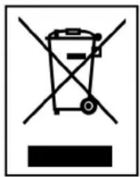
Equipment marked with this symbol indicates that it was sold on or after 13th August 2005, which means it should not be disposed of with general household waste. Note that our equipment is for industrial/professional use only.
Contact Shimadzu service representative when the equipment has reached the end of its life.
They will advise you regarding the equipment take-back.
With your co-operation we are aiming to reduce contamination from waste electronic and electrical equipment and preserve natural resource through re-use and recycling.
Do not hesitate to ask Shimadzu service representative, if you require further information.
text_image
Symbol of a trash bin with crossed and unbroken lines indicating restriction or dischargeWEEE Mark
Contents
- Introduction ...... 1
- Name and Function of Components 2
2.1 Components 2
2.2 Key Panel and Operation 4
2.3 Balance Display and Function 5
- Specifications 6
- Installation 8
4.1 Choosing the Installation Site 8
4.2 Unpacking and Delivery Inspection 10
4.3 Installation 13
4.4 Turning ON the Power 18
4.5 Span Calibration 19
- Basic Operation 22
5.1 Weighing 22
5.2 Changing the Unit Display 23
- WindowsDirect Function 24
6.1 Introduction: Experience it! 24
6.2 Set Up WindowsDirect 24
6.2.1 Setting Up the Balance 24
6.2.2 Cable Connection 25
6.2.3 Setting Up the Computer 25
6.2.4 Start and Checking Operation 27
6.3 Troubleshooting the WindowsDirect Communication Function 28
- Menu Item Selection 30
7.1 What is the Menu? 30
7.2 Menu Map 30
7.3 Menu Item Selection Procedure 31
7.4 Setting Numeric Values 33
7.5 Related Useful Functions 34
7.5.1 Last Menu Recall 34
7.5.2 Returning to the Default Settings (menu reset) 34
7.5.3 Menu Lock 35
8. Built-in Clock Set-up 36
8.1 Date 36
8.2 Date Output Style 36
8.3 Time 37
8.4 Setting Display During Stand-by 37
9. Display Selection 38
9.1 Bar graph display 38
9.2 Changing the Minimum Display Digit (10d:1d)* 38
10. Calibration 39
10.1 What is calibration? 39
10.2 Calibration Execution 40
10.2.1 Span Calibration Using the Built-in Weight (UW Series Only) 40
10.2.2 Calibration Check Using the Built-in Weight (UW Series Only) 41
10.2.3 Span Calibration Using External Weights* 42
10.2.4 Calibration Check Using External Weights* 43
10.3 Calibration Setting 44
10.3.1 Selecting the Calibration Type 44
10.3.2 PSC Fully-automatic Calibration (UW series only) 44
10.3.3 Clock-CAL Fully-automatic Calibration (UW series only) 45
10.3.4 PCAL: Calibration of the Built-in Weight (UW series only)* 46
10.3.5 PCAL Password Setting (UW series only)* 47
10.4 For GLP/GMP/ISO Conformance 48
10.4.1 Calibration Report Setting 48
10.4.2 Balance ID Setting 48
11. Environment 49
11.1 Overview 49
11.2 Stability and Response (Averaging) 49
11.3 Stability Detection and Settings 50
11.3.1 Stability Detection Band 51
11.3.2 Timing of Stability Mark Illumination and Data Output 52
11.4 Tracking 52
12. Units 53
12.1 Unit Display Set-up 53
12.2 Percentage (%) Conversion 54
13. Enhancing Productivity 55
13.1 Checkweighing and Target Display 55
13.1.1 Checkweighing (Comparator) Display Type 1 56
13.1.2 Checkweighing (Comparator) Display Type 2 56
13.1.3 Target Mode 57
13.2 Piece Counting (PCS) 58
13.3 Auto Print 59
13.4 Auto Zero ^* 61
13.5 Zero Range 62
13.6 Taring/Printing at Stability* 63
13.7 Pretaring Value* 64
14. Application Functions 65
14.1 Solid Specific Gravity Measurement 65
14.2 Liquid Density Measurement 67
14.3 Peak Hold* 69
14.4 Interval Timer ^* 71
14.5 Add-on Mode 72
14.6 Animal Weighing* 74
14.7 Formulation Mode 77
15. Connecting Peripheral Instruments 79
15.1 Electronic Printer 79
15.2 Personal Computer - RS-232C - 80
15.2.1 Connecting the Cable 80
15.2.2 Data Format 81
15.2.3 Using Command Codes 83
15.2.4 Multi-Connection Mode 88
15.3 Communication Setting 91
15.3.1 Overview 91
15.3.2 Handshaking 91
15.3.3 Format 92
15.3.4 Communication Speed 92
15.3.5 Parity / Bit Length 92
15.3.6 Stop Bit 92
15.3.7 Delimiter 93
15.4 Decimal Point Symbol in Output Data 93
16. Maintenance and Transportation 94
16.1 Maintenance 94
16.2 Moving the Balance 94
17. Troubleshooting 95
17.1 General Display 95
17.2 Error Display 96
17.3 Troubleshooting 97
17.4 LCD (Liquid Crystal Display) Check 97
Appendices 98
A-1. Menu Map 98
A-2. Standard Accessories and Maintenance Parts List 103
A-3. Optional Accessories List 104
A-4. Specifications of Connectors 105
A-5. Table of Unit Conversion Constants 106
A-6. Performance Checks 107
A-7. Below-Weigh Hook Dimensions 108
A-8. Index 109
1. Introduction
Shimadzu UW/UX series of toploading balances are a product of our 80 year history of developing and manufacturing weighing instruments.
Shimadzu UW/UX series of toploading balances utilize the patented Shimadzu UniBloc sensor, introduced in 1989, to achieve high performance, fast response, and durability. Available features include multiple units of measure, piece counting, checkweighing functions, auto print, and GLP/GMP/ISO output including date and time data from a built-in clock.
The new series also features Shimadzu's WindowsDirect communication, requiring no software installation to quickly integrate balances with lab or business software. This function eliminates data input errors and offers extensive flexibility for application development without compromising compliance or data security.
The UW series balance incorporates a motor-driven built-in calibration weight that can automatically calibrate sensitivity without the use of external weights.
Read this manual carefully before using this instrument and keep it with the balance for future reference.
This manual refers to the different types of UW and UX series (UW/UX series) balances as follows:
H type: UW/UX H
S type: UW/UX \$
Where: represents the figure indicating the capacity, H indicates high resolution and S indicates standard resolution.
Suffix "V" is added for models with EC Type Approval.
The type of balance is classified as “large pan” or “small pan” depending on the capacity. The small pan models with minimum display of 0.001g come with a standard windbreak. Accordingly, the models are classified into the following three groups in “4. Installation”.
a. Large pan models: Capacity 2200g or higher
b. Small pan models: Capacity 820g or lower (minimum display 0.01g)
c. Small pan models: Capacity 1020g or lower (minimum display 0.001g, windbreak standard)
For information on the following points, please contact your Shimadzu Balance representative.
- Product warranty
- After service
2. Name and Function of Components
2.1 Components
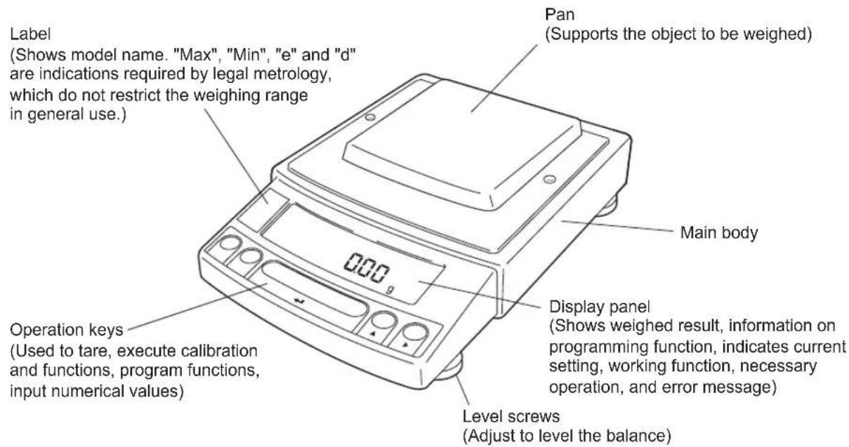
a. Large pan model
text_image
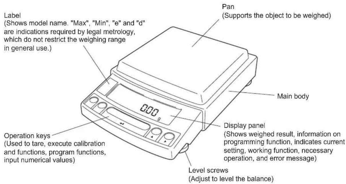
Label (Shows model name. "Max", "Min", "e" and "d" are indications required by legal metrology, which do not restrict the weighing range in general use.) Pan (Supports the object to be weighed) Main body Operation keys (Used to tare, execute calibration and functions, program functions, input numerical values) Display panel (Shows weighed result, information on programming function, indicates current setting, working function, necessary operation, and error message) Level screws (Adjust to level the balance)b. Small pan model (minimum display 0.01g)
text_image
Label (Shows model name. "Max", "Min", "e" and "d" are indications required by legal metrology, which do not restrict the weighing range in general use.) Pan (Supports the object to be weighed) Main body Operation keys (Used to tare, execute calibration and functions, program functions, input numerical values) Display panel (Shows weighed result, information on programming function, indicates current setting, working function, necessary operation, and error message) Level screws (Adjust to level the balance)c. Small pan model (minimum display 0.001g, windbreak standard)
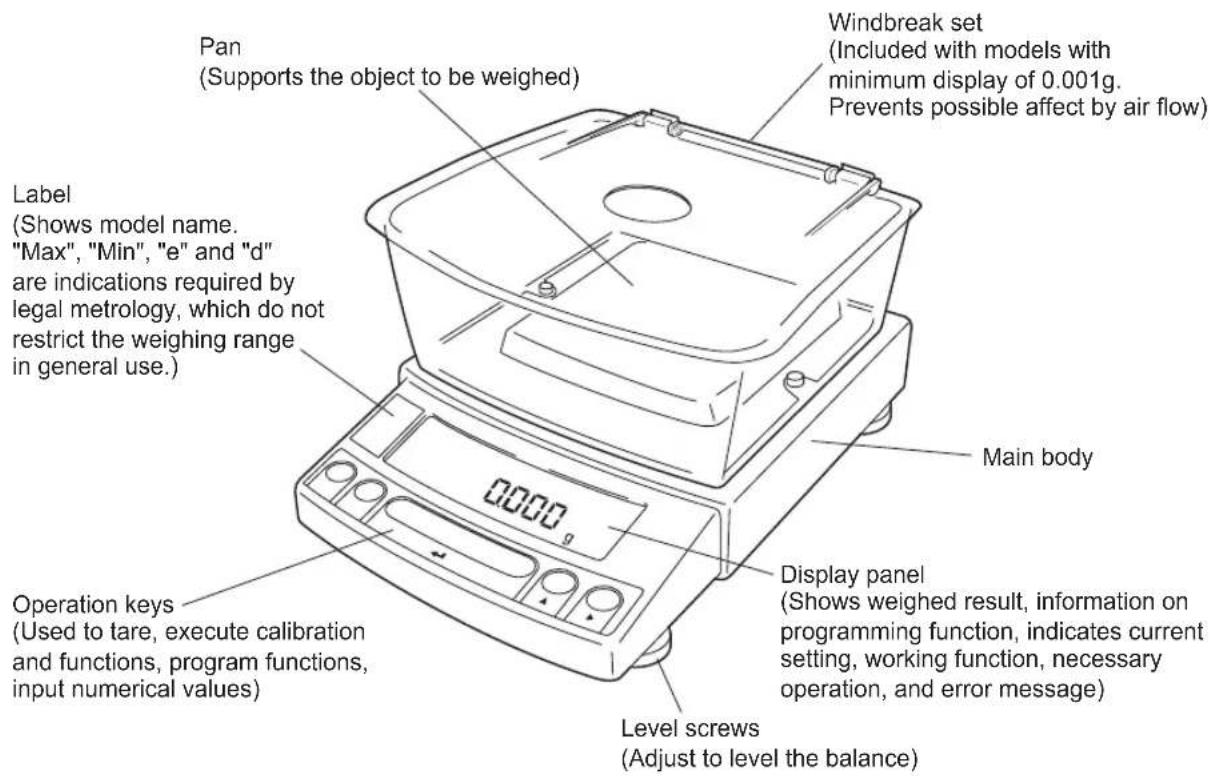
text_image
Pan (Supports the object to be weighed) Label (Shows model name. "Max", "Min", "e" and "d" are indications required by legal metrology, which do not restrict the weighing range in general use.) 0000 g Main body Display panel (Shows weighed result, information on programming function, indicates current setting, working function, necessary operation, and error message) Level screws (Adjust to level the balance)a, b, c. common
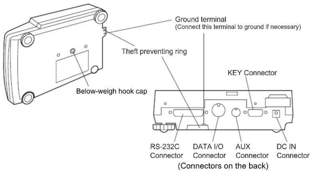
text_image
Ground terminal (Connect this terminal to ground if necessary) Theft preventing ring Below-weigh hook cap KEY Connector RS-232C Connector DATA I/O Connector AUX Connector DC IN Connector (Connectors on the back)2.2 Key Panel and Operation
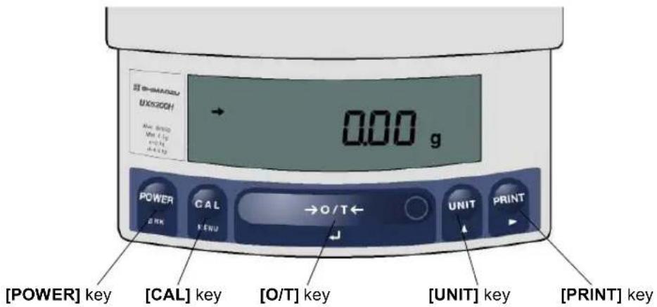
text_image
0.00 g POWER CAL →O/T ← UNIT PRINT [POWER] key [CAL] key [O/T] key [UNIT] key [PRINT] keyFunctions of the keys
| Key | During Weighing | |
| Press Once and Release Press and Hold for About 3 Seconds | ||
| [POWER] | Switches between the operation and standby modes. | Exits the application function and returns to the mass display. |
| [CAL] | Enters span calibration or menu item selection. (*1) | Displays the last menu item that was set. (Last menu recall) |
| [O/T] | Tares the balance. (Displays zero.) (*2) (*5) (*6) | Displays the Pretare value.(*7) |
| [UNIT] | Changes the weighing unit or selects specific gravity measurement. (*3) | Switches between the 1d and 10d display. (*4) (*7) |
| [PRINT] Sends the displayed value to a peripheral device. | Sends the date and time to a peripheral device. | |
*1 This key is used to set values when percent (%), number (PCS), solid specific gravity (▼d), or liquid specific gravity (d) are displayed.
*2 When a Pretare value is set, zero is not displayed and [-Pretare value] is displayed. (*7)
*3 Units other than "g" must be set up before they can be used for measurement. Only gram (g), percent (%), and piece counting (PCS) are set-up before shipment. To set up other units or specific gravity measurement, refer to section 12., or 14.1, 14.2.
*4 When the unit is set to 10d, the resolution of the minimum display is decreased by one decimal place.
*5 In Pouring mode (See 11.2), the right-most part of [O/T] key marked with a circle functions as the switch for environmental condition setting. Otherwise this part functions the same way as the other parts of [O/T] key.
*6 Either "Taring" (at a weight exceeding 2.0% of the capacity) or "Zeroing" (at a weight within 2.0% of the capacity) takes place with a verified balance as a legal measuring instrument in the EU.
*7 Not applicable to a verified balance as a legal measuring instrument in the EU.
| Key | During Menu Item Selection | |
| Press Once and Release Press and Hold for About 3 Seconds | ||
| [POWER] Returns to the previous menu level Returns to the mass display. | ||
| [CAL] Moves to the next menu item. | Displays the last menu item that was set. (Last Menu Recall) | |
| [O/T] | Selects or sets the currently displayed menu item, or enter into the displayed menu. | No operation. |
| [UNIT] Increases the numeric value of the blinking digit by 1. No operation. | ||
| [PRINT] Moves to the next digit during numeric value entry. No operation. | ||
2.3 Balance Display and Function
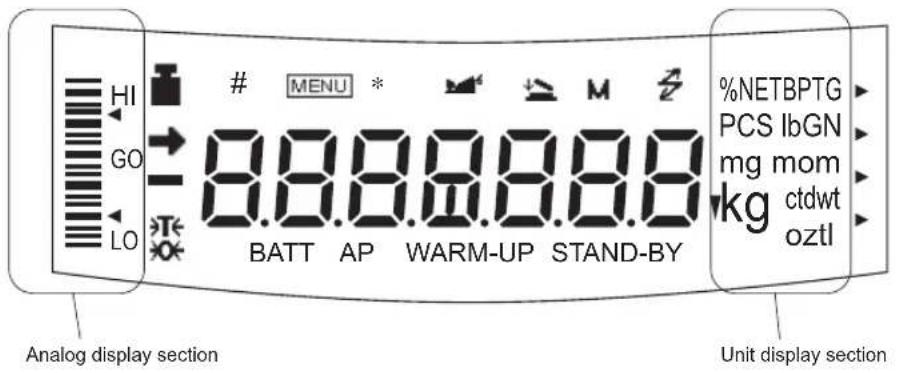
text_image
HI GO LO # MENU * 8.8.8.8.8.8 BATT AP WARM-UP STAND-BY %NETBPTG PCS IbGN mg mom kg ctdwt oztl Analog display section Unit display section| Display Name Description | ||
| → | Stability mark | Indicates that the weighed value is stable. (*1) In menu item selection, indicates currently selected item. |
| →T← | Tare symbol Ind | icates that a Pretare value has been set.(*2) |
| Weight symbol | Illuminates during span calibration. In menu selection, indicates setting related to calibration. Blinks before automatic span calibration starts.Note: Using a verified balance as a legal measuring instrument in the EU: When PSC fully-automatic span calibration is not activated, operator must carry out span calibration with the built-in weight upon blinking of this symbol. | |
| [ ] Bracket | Note: Using a verified balance as a legal measuring instrument in the EU: The figure bordered by the bracket is the auxiliary indicating device. | |
| # | Number symbol Ind | indicates numeric value entry. |
| MENU | Menu symbol Ind | icates that the menu lock is on. Illuminates during menu item selection. |
| * Asterisk Indicates that the displayed numeric value is not a mass value. | ||
| Communication symbol | Illuminates during communication to external equipment through the RS-232C or DATA I/O connector. In menu selection, indicates setting related to communication. | |
| BATT | Battery symbol | When the balance is operated with the optional battery pack, this symbol illuminates to indicate that the battery voltage has dropped. |
| Inverse triangle symbol | Indicates the set-up of solid specific gravity measurement. Used as a substitute for the decimal point. | |
| Zero symbol Ind | icates the set-up of Auto Zero function.(*2)Note: Using a verified balance as a legal measuring instrument in the EU: Indicates that the balance is set exactly to "Zero" with the zero-setting function(+/-0.20e: e = verification scale interval). | |
| Animal symbol Ind | indicates the set-up of Animal Weighing function.(*2) | |
| Add-on symbol | Indicates the set-up of Add-on mode or Formulation mode. | |
| Memory symbol Ind | indicates the set-up of Formulation mode. | |
| AP | Auto Print symbol | Indicates the set-up of Auto Print function. |
| STAND-BY | Stand-by symbol | Illuminates when the balance power is in the standby mode.Also illuminates when the application function has entered the standby mode. |
*1 Stability mark
The displayed value may change while the stability symbol remains illuminated if the load is changing slowly or if the stability detection band has been set to a large value.
*2 Not applicable to a verified balance as a legal measuring instrument in the EU
3. Specifications
3. Specifications
| UW Series Model | UW220H U | W420H UW | 620H UW820 | H UW1020 | H UW2200H | UW4200H | JW6200H U | W420S UW6 | 20S UW420 | 0S UW8200S | ||
| Capacity 220g 420g 6 | 20g 820g | 1020g 220 | 0g 4200g | 6200g 42 | 0g 820g 4 | 200g 820 | 0g | |||||
| Minimum display 0.00 | 1g 0.001g | 0.001g 0. | 001g 0.00 | 1g 0.01g | 0.01g 0.01 | g 0.01g 0 | 01g 0.1g | 0.1g | ||||
| Calibration range with external weights | 100 - 220g | 100 - 420g | 100 - 620g 40 | - 820g | 500 - 1020g | 1000 - 2200g | 1000 - 4200g | 1000 - 6200g | 100 - 420g | 100 - 820g | 1000 - 4200g | 1000 - 8200g |
| Repeatability (σ) | ≤0.001g | ≤0.01g | ≤0.008g | ≤0.08g | ||||||||
| Linearity | ±0.002g | ±0.003g | ±0.02g | ±0.01g | ±0.1g | |||||||
| Response time (s) | 1.5 - 2.5 | 0.7 - 1.2 | ||||||||||
| Ambient temperature and humidity | 5 - 40 °C 30 - 85% (No condensation) | |||||||||||
| Temperature coefficient of sensi-livity (ppm/°C) (10 - 30°C) | ±3 | ±5 | ||||||||||
| Pan size (mm) approx. | 108 X 105 | 170 X 180 | 108 X 105 | 170 X 180 | ||||||||
| Main body dimensions (mm) approx. | 190W X 317D X 78H | |||||||||||
| Weight (kg) approx. | 3.4 | 4.6 | 3.4 | 4.6 | ||||||||
| Display | LCD with backlight | |||||||||||
| Power requirements | DC, 10 to 15.5V, 500mA (plug polarity: center negative) | |||||||||||
| Data I/O | RS-232C | |||||||||||
| Features | WindowsDirect | |||||||||||
| PSC | ||||||||||||
| Clock-CAL | ||||||||||||
| GLP/GMP/ISO conformance | ||||||||||||
| Analog display, % display, PCS, User unit, Animal weighing, Specific gravity measurement S/W, Checkweighing | ||||||||||||
| UX Series Model | UX220H | UX420H | UX620H | UX820H | UX1020H | UX2200H | UX4200H | UX6200H | UX420S | UX820S | UX4200S | UX8200S |
| Capacity 220g 420g 6 | 20g 820g | 1020g 220g | 0g 4200g | 6200g 420g | 0g 820g | 4200g 8200g | ||||||
| Minimum display 0.00 | 1g 0.001g | 0.001g 0.001g | 0.001g 0.001g | 1g 0.01g | 0.01g 0.01g | 0.01g 0.01g | 0.01g 0.1g | 0.1g | ||||
| Calibration range with external weights | 100 - 220g | 100 - 420g | 100 - 620g | 400 - 820g | 500 - 1020g | 1000 - 2200g | 1000 - 4200g | 1000 - 6200g | 100 - 420g | 100 - 820g | 1000 - 4200g | 1000 - 8200g |
| Repeatability (σ) | ≤0.001g | ≤0.01g | ≤0.008g | ≤0.08g | ||||||||
| Linearity | ±0.002g | ±0.003g | ±0.02g | ±0.01g | ±0.1g | |||||||
| Response time (s) | 1.5 - 2.5 | 0.7 - 1.2 | ||||||||||
| Ambient temperature and humidity | 5 - 40 °C 30 - 85% (No condensation) | |||||||||||
| Temperature coefficient of sensi-tivity (ppm/°C) (10 - 30°C) | ±3 | ±5 | ||||||||||
| Pan size (mm) approx. | 108 X 105 | 170 X 180 | 108 X 105 | 170 X 180 | ||||||||
| Main body dimensions (mm) approx. | 190W X 317D X 78H | |||||||||||
| Weight (kg) approx. | 2.7 | 2.9 | 2.7 | 2.9 | ||||||||
| Display | LCD with backlight | |||||||||||
| Power requirements | DC, 10 to 15.5V, 500mA (plug polarity: center negative) | |||||||||||
| Data I/O | RS-232C | |||||||||||
| Features | WindowsDirect | |||||||||||
| GLP/GMP/ISO conformance | ||||||||||||
| Analog display, % display, PCS, User unit, Animal weighing, Specific gravity measurement S/W, Checkweighing | ||||||||||||
| UW Series (ECTA) Model | UW820SV | UW220HV | UW420HV | UW620HV | UW8200SV | UW2200HV | UW420HV | UW6200HV | |
| UX Series (ECTA) Model | UX820SV | UX220HV | UX420HV | UX620HV | UX8200SV | UX2200HV | UX420HV | UX6200HV | |
| g Accuracy class I T | I | I | I | ||||||
| Capacity 820g 220g 420g 620g 8200g | 2200g 4200g | 6200g | |||||||
| Verification scale interval (e) | 0.1g | 0.01g | 0.01g | 0.01g | 1g | 0.1g | 0.1g | ||
| Number of verification scale interval | 8200 | 22000 | 42000 | 62000 | 8200 | 22000 | 42000 | ||
| Scale interval (d) | 0.01g | 0.001g | 0.001g | 0.001g | 0.1g 0.01g | 0.01g 0.01g | 0.01g | ||
| Range of use | 0.5g - 820g | 0.02g - 220g | 0.02g - 420g | 0.1g - 620g | 5g - 8200g | 0.5g - 2200g | 0.5g - 4200g | ||
| Tare range (by subtraction) | -820g | -220g | -420g | -620g | -8200g | -2200g | -4200g | ||
| ct Accuracy class | II | ||||||||
| Capacity | N/A | 1100ct | 2100ct | 3100ct | N/A | 11000ct | 21000ct | ||
| Verification scale interval (e) | N/A | 0.1ct | 0.1ct | 0.1ct | N/A | 1ct | 1ct | ||
| Number of verification scale interval | N/A | 11000 | 21000 | 31000 | N/A | 11000 | 21000 | ||
| Scale interval (d) | N/A | 0.01ct | 0.01ct | 0.01ct | N/A | 0.1ct | 0.1ct | ||
| Range of use | N/A | 0.2ct - 1100ct | 0.2ct - 2100ct | 0.2ct - 3100ct | N/A | 5ct - 11000ct | 5ct - 21000ct | ||
| Tare range (by subtraction) | N/A | -1100ct | -2100ct | -3100ct | N/A | -11000ct | -21000ct -31000ct | ||
| Ambient operating temperature and humidity | 10 - 30 °C 30 - 85% (No condensation) | ||||||||
| Pan size (mm) approx. | 108 X 105 | 170 X 180 | |||||||
| Main body dimensions (mm) approx. | 190W X 317D X 78H | ||||||||
| Weight (kg) approx. | 3.4 | 4.6 | |||||||
| Display | LCD with backlight | ||||||||
| Power requirements | DC, 10 to 15.5V, 500mA (plug polarity: center negative) | ||||||||
| Data I/O | RS-232C | ||||||||
| Features | WindowsDirect | ||||||||
| PSC (UW***V only) | |||||||||
| Clock-CAL (UW***V only) | |||||||||
| GLP/GMP/ISO conformance | |||||||||
| Analog display, % display, PCS, Specific gravity measurement S/W, Checkweighing | |||||||||
4. Installation
4.1 Choosing the Installation Site
(1) Power supply
- Select an installation site that is near a power source to ensure that the attached AC adapter is used properly. If this is not possible, an optional battery pack is available as a special accessory.
- Verify that the supply power voltage conforms to that indicated on the AC adapter.
(2) Installation site

Caution
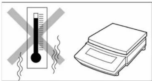
Avoid sites where the balance will be exposed to the following:
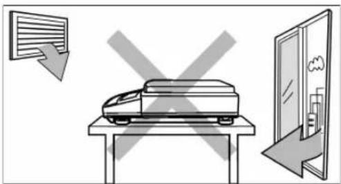
text_image
Diagram illustrating a document processing workflow with a printer, a crosshair symbol, and directional arrows indicating process flow.• Air flow from air-conditioner, open window, or ventilator
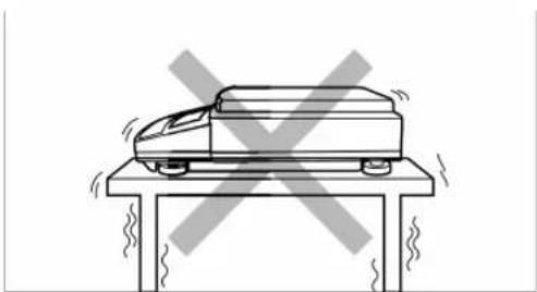
natural_image
Simple line drawing of a car on a platform with a cross symbol crossed out (no text or labels)- Vibration
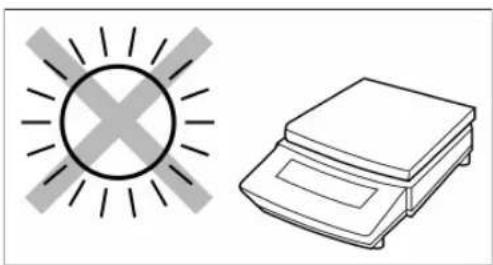
natural_image
Simple line drawing of a sun with cross symbol and a balance scale (no text or labels)- Direct sunlight
(Continued)
natural_image
Illustration showing a thermometer and a balance scale with warning symbols (no text or labels)- Extreme temperature, temperature changes or humidity
• Corrosive or flammable gasses
- Dust, wind, electromagnetic waves, or magnetic fields
Large capacity balances should be installed on a sturdy floor and table that can support the total load of the balance AND object to be weighed.

Note
Using a verified balance as a legal measuring instrument in the EU:
The balance must be used within the temperature range indicated on the verification label.
4.2 Unpacking and Delivery Inspection
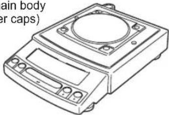
Unpack and remove all the items from the delivery box. Check if all the listed items are present and nothing has been damaged. Contact your local distributor in case of damaged or missing items.
Standard packed item and quantity
| Type a. Large pan | model | b. Small pan model(Minimum display 0.01g) | c. Small pan model(Minimum display 0.001g) | |
| Model(UW/UX is “UW or UX”. Additional suffix may appear after H or S on your balance.) | UW/UX2200H,UW/UX4200H,UW/UX6200H,UW/UX4200S,UW/UX8200S | UW/UX420S,UW/UX820S | UW/UX220H,UW/UX420H,UW/UX620H,UW/UX820H,UW/UX1020H | |
| Balance main body 1 | 1 | 1 | ||
| Pan supporter cap 4 | 4 | 4 | ||
| Pan 1 1 | 1 | |||
| AC adapter 1 | 1 | 1 | ||
| In-use protective cover 1 | 1 | 1 | ||
| Windbreak set | Main 0 | 0 | 1 | |
| Lid 0 | 0 | 1 | ||
| Fixing knob 0 | 0 | 2 | ||
| Rubber cap 0 | 2 (installed on balance main body) | 2 (installed on balance main body) | ||
| Stainless screw 0 | 2 | 2 | ||
| Instruction manual (incl. explanatory operation sheet) | 1 | 1 | 1 | |
a. Large pan model
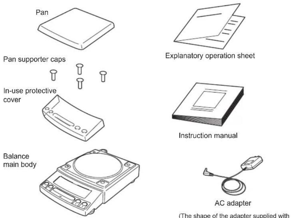
(The shape of the adapter supplied with the balance may differ from this figure.)
b. Small pan model (minimum display 0.01g)
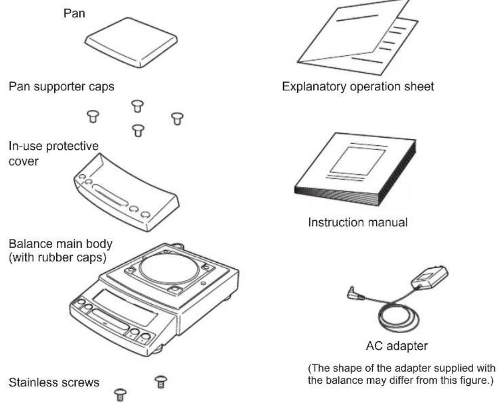
4. Installation
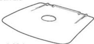
c. Small pan model (minimum display 0.001g)
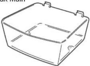
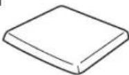
Windbreak Lid
natural_image
Simple line drawing of a rectangular basin with a circular hole and horizontal bars (no text or symbols)Windbreak Main
natural_image
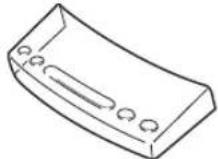
Line drawing of a rectangular plastic container with side supports (no text or symbols)Pan
Pan supporter caps
In-use protective
cover
Balance main body (with rubber caps)
natural_image
Line drawing of a mechanical balance scale with no text or symbols on the device itselfStainless screws
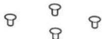
Fixing knobs for windbreak



natural_image
Simple line drawing of a folded paper or document with no text or symbolsExplanatory operation sheet
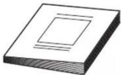
Instruction manual
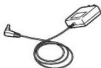
AC adapter
(The shape of the adapter supplied with the balance may differ from this figure.)
4.3 Installation
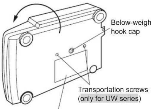
(Start at step 3 when installing a UX series balance. Prepare a plus (+) screw driver for a UW series balance.)
text_image
Below-weigh hook cap Transportation screws (only for UW series)Explanation label (only for UW series)
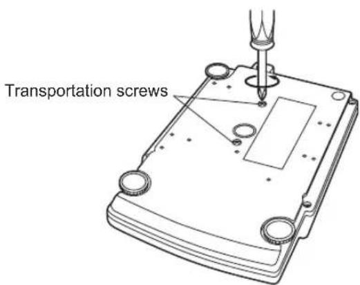
1 Place the balance main body upside down. (UW only)

Caution
Do not operate step 2 with the balance placed on its side.
Place the balance on a smooth surface.
text_image
Transportation screws2 Referring to the explanation label on the bottom of the balance, turn the two transportation screws counterclockwise until they tighten again. (UW only)

Caution
When moving the balance again, turn the two transportation screws clockwise until they tighen. (UW only)
4. Installation
text_image
Level indicator ① Level screw (At the shortest point when starting adjustment) ② Level front ③ Level screw[Large pan model]
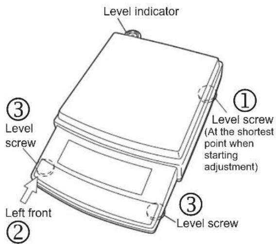
3 This balance has three level screws (adjustable feet) at the right front, left front and right rear corners.
Turning a level screw clock-wise stretches the leg to raise the balance body there. Turning anticlockwise withdraws the leg and lowers the balance body.
The level indicator locates at left rear. The bubble of it is off center when the balance is not placed level.
(1) Adjustment is made with the two front level screws only. Accordingly, first turn the right rear level screw ① anti-clockwise to withdraw its leg completely.
(2) While adjusting level screws and observing the bubble, gently press the left front corner of the balance ② so that both front level screw feet ③ are touching the table surface.
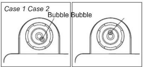
(3) Bubble moves to the highest position. Therefore, adjust level screws ③ so that the balance main body is lowered in the direction of the bubble.
Case 1: Right front of the balance is too high. Turn right front level screw anti-clockwise so that the bubble moves towards center.
Case 2: Front of the balance is too low. Turn both front level screws clockwise so that the bubble moves towards center.
(4) When the bubble has come to the center of the red circle, turn the right rear level screw clockwise until its foot softly touches the table surface. Verify the balance sits stable with four feet.
text_image
Case 1 Case 2 Bubble Bubble Bubble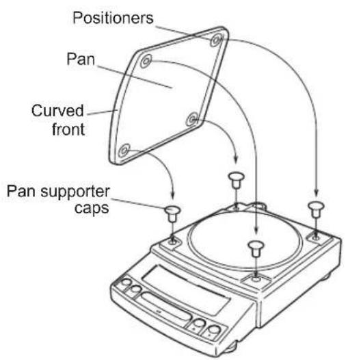
text_image
Positioners Pan Curved front Pan supporter caps4 Install the pan. With small pan model with minimum display of 0.001g, the standard windbreak is also installed here.
a. Large pan model
Insert the four pan supporter caps into the holes in the top of the balance. Place the pan gently on pan supporter caps. Positioners of the pan must fit pan supporter.
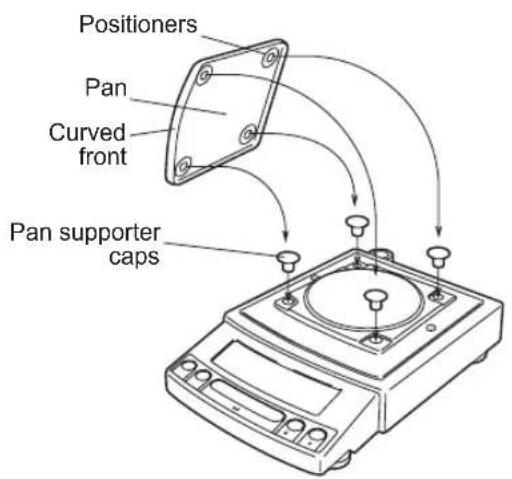
text_image
Positioners Pan Curved front Pan supporter capsb. Small pan model
(minimum display 0.01g)
Insert the four pan supporter caps into the holes in the top of the balance. Place the pan gently on pan supporter caps. Positioners of the pan must fit pan supporter.
The rubber caps on top of the main body may be replaced with the stainless screws so that it will be more secure when exposed to organic solvent.
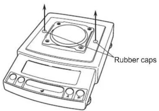
text_image
Rubber capsc. Small pan model
(minimum display 0.001g, windbreak standard)
(1) Pull out the two rubber caps from the main body top.
4. Installation
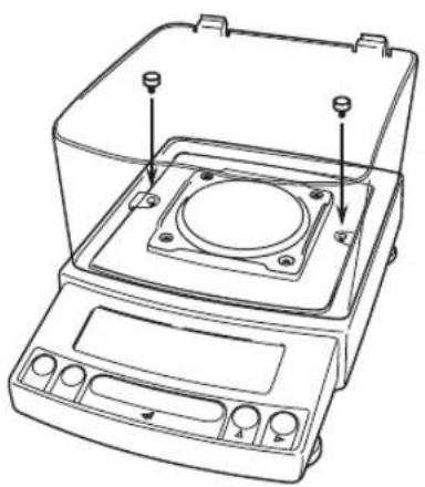
natural_image
Line drawing of a digital balance scale with two buttons and a central square base (no text or symbols)(2) Fit windbreak main on top of the balance main body, and fasten it with two fixing knobs.
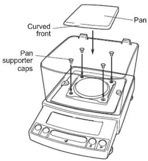
text_image
Pan Curved front Pan supporter caps(3) Insert the four pan supporter caps into the holes in the top of the balance. Place the pan on them. Positioners on the pan must fit pan supporter caps.
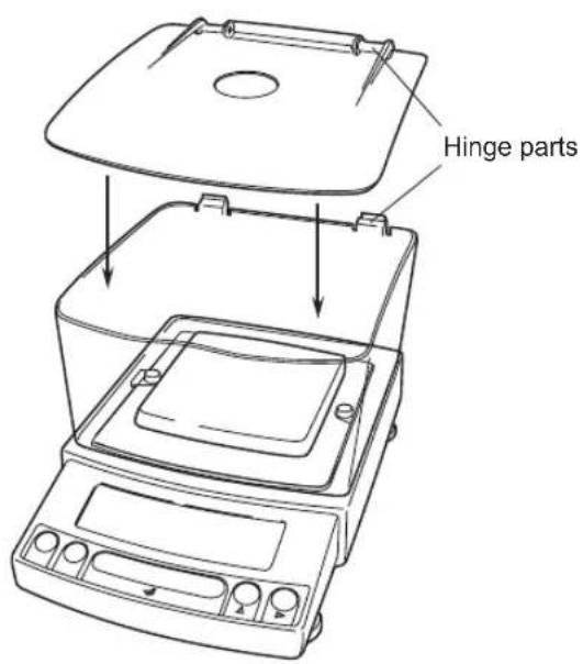
text_image
Hinge parts(4) Place windbreak lid on top of windbreak main fitting the hinge parts.
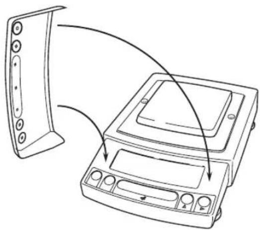
natural_image
Line drawing of a digital balance scale with control panel and display (no text or symbols)5 If you use in-use protective cover, peel off the paper to expose the adhesive on it, then fit it on the display and key part. Press the adhesive parts gently.

Note
Using a verified balance as a legal measuring instrument in the EU:
Legal regulations require a verified balance be sealed. This control seal is a self-destructive adhesive label. This seal is irreparably damaged invalidating the verification, if you attempt to remove it. The balance must then be re-verified before it is used for legal measurements.
4.4 Turning ON the Power
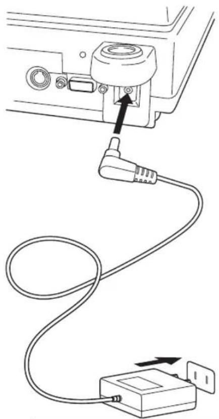
natural_image
Diagram showing cable connection to a device with an attached plug and power outlet (no text or symbols)1 Insert the plug of the AC adapter into the DC IN connector on the rear of the balance.
2 Insert the AC adapter into the power source. The balance self-check is activated and the following messages are displayed in the order indicated. First, the software version number is displayed.
[1.30:00], [CHE 5], [CHE 4], [CHE 3], [CHE2],
[CHE1], [CHE0], whole lighting, [oFF] ([CHE 5] and [CHE 4] are not displayed for the UX series).

Note
A power cable may be necessary to connect the AC adapter to the power source, depending on the type of the AC adapter.

text_image
AC Adapter Balance Power Source → Power cable3 Press [POWER] key. The whole display illuminates and then the display changes to indicate the gram-display. The backlight is illuminated.

Note
When using the optional battery pack (special accessory), connect the fully charged battery pack to the DC IN connector of the balance using the cable attached to the battery pack.
4.5 Span Calibration

Note
Using a verified balance as a legal measuring instrument in the EU:
Span calibration must be performed once the balance is installed and before using the balance as a legal measuring instrument in the EU. Span calibration must be performed with the internal calibration weight to maintain the verification valid. The balance must be connected to power and warmed up for at least 2 hours prior to span calibration and use as a legal measuring instrument.
It is necessary to calibrate the balance after it is moved.
Verify that the balance is stable before performing the span calibration. To achieve a very stable state, ensure that the balance has been turned on with the gram-display for at least one hour, that the temperature is constant, that there are no breezes or vibrations and that the balance is in an area isolated from the normal traffic flow.
UW series [Span Calibration Using the Built-in Weight]
![Shimadzu UW8200SV - UW series [Span Calibration Using the Built-in Weight] - 1](/content/2026/05/790010/images/4f03652275224c4c5075095f3a380885c4f5385228e00642e5824bc146a20a57.jpg)
text_image
-CAL - CAL 3 - CAL 2 - CAL 1 SET CAL End → 0.000g1 Verify that the balance is in gram-display and that the pan is empty.
2 Press the [CAL] key once. "i-CAL" is displayed.
3 Press the [O/T] key. After "i-CAL3"... "i-CAL1", "Set", "CALEnd" are displayed indicating the completion of span calibration, the gram-display will appear.
This is the standard calibration type. Refer to 10.3.1 for use of external weights.
![Shimadzu UW8200SV - UW series [Span Calibration Using the Built-in Weight] - 2](/content/2026/05/790010/images/626e539465025b1e5f2f504b122163aaa3473475979af40a57dbaaaf6804cc44.jpg)
Note
Span calibration should be performed again : when the location of the balance is changed, when the room temperature changes considerably, periodically, according to the quality control plan of the user.
UX series [Span Calibration Using External Weights]
1 Verify that the balance is in gram-display and unload the sample from the pan.
2 Press the [CAL] key once. "E-CAL" is displayed.
3 Press the [O/T] key. The value of the correct calibration weight to be loaded is displayed and blinks.
4 Load the indicated calibration weight and press the [O/T] key.
![Shimadzu UW8200SV - UX series [Span Calibration Using External Weights] - 1](/content/2026/05/790010/images/d49dcc73928184b5d87460668524d212e84844b1fa577496319190204fb0ca6a.jpg)
text_image
E-CAL (Example) 800.00 g![Shimadzu UW8200SV - UX series [Span Calibration Using External Weights] - 2](/content/2026/05/790010/images/799713353d988e052f0f325b3dfcbf2ec2967f6a4cf589cb8772dddcf8c2da0d.jpg)
natural_image
Line drawing of a digital laboratory balance scale with two weights on top (no text or symbols)![Shimadzu UW8200SV - UX series [Span Calibration Using External Weights] - 3](/content/2026/05/790010/images/c316f38fe83356513b1a30c4cc3789dac34d454a4ac344ee43231b60d62ea042.jpg)
text_image
0.00 g SET CAL End 0.000 g5 When the zero display blinks, unload the weight from the pan and press the [O/T] key. "Set" is displayed briefly to indicate completion of span calibration. Then the gram-display will return.
![Shimadzu UW8200SV - UX series [Span Calibration Using External Weights] - 4](/content/2026/05/790010/images/0aa503814fe2b66a22573a8081598e24862692c012520bf37e98145303b97987.jpg)
Note
Span calibration should be performed again : when the location of the balance is changed, when the room temperature changes considerably, periodically, according to the quality control plan of the user.
5. Basic Operation
5.1 Weighing
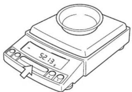
natural_image
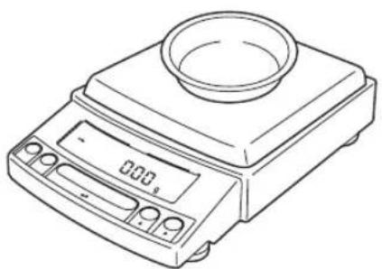
Line drawing of a digital laboratory balance scale with a round top and display (no text or symbols)1 If a weighing vessel (tare) is used, place it on the pan and wait for the stability mark to illuminate.
natural_image
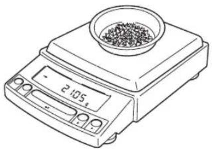
Line drawing of a digital laboratory balance scale with a round top and control buttons (no text or symbols)2 Press the [O/T] key to zero the display. (This operation is called "taring".)
natural_image
Line drawing of a digital laboratory balance scale with a beaker on top (no text or symbols)3 Place the object to be weighed on the pan.
4 Read the displayed value after the stability mark is displayed.

Note
Using a verified balance as a legal measuring instrument in the EU:
Indicates that the balance is set exactly to "Zero" with the zero-setting function (+/-0.20e: e = verification scale interval).

Note
Using a verified balance as a legal measuring instrument in the EU:
The balance must be used within the temperature range indicated on the verification label.
When PSC (refer to 10.3.2), fully-automatic span calibration, is not activated, operator must carry out span calibration with the built-in weight (refer to 4.5) upon blinking of the Weight Symbol.
Error Displays During Weighing
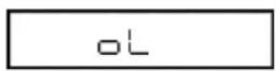 | Overload: Weighing capacity has been exceeded. |
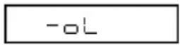 | Negative Overload: The load on the balance is too light.The pan is not adjusted properly.For D-type balances, [-oL] will appear if the load is below the low capacity range. |
5.2 Changing the Unit Display
Every time the [UNIT] key is pressed, the unit display changes sequentially among those set-up in 12.1 Unit Display Set-up. Gram, %, and PCS have been set-up before delivery.

Notes
- Before a unit can be displayed it must be registered in 12.1 Unit Display Set-up.
- The registered units are displayed sequentially according to the order of the 12.1 Unit Display Set-up.
6. WindowsDirect Function
6.1 Introduction: Experience it!
The UW/UX series balance can transfer data directly to a computer running MS-Excel, mass input window of analytical instrument software or other applications on Windows®* OS, as if the displayed value were typed from the keyboard to the cursor position. This function is called WindowsDirect. As this function directly accesses the Windows® OS, communication software-installation troubles are eliminated. A cable and a few simple settings are all that is needed to enable data transmission from the balance. For bi-directional communication between the balance and the computer, software is required. WindowsDirect does not send commands from the computer.
- Only numerical values can be transferred through WindowsDirect.
6.2 Set Up WindowsDirect
Simple settings are made for the balance and the computer. Connection is by RS-232C cable (15.2.1) specified by Shimadzu.
If bi-directional communication software is used: WindowsDirect function should be turned off. Set up the optimal communication parameters for the software according to "15.3 Communication setting".
6.2.1 Setting Up the Balance
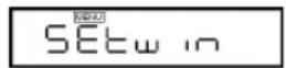
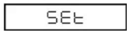
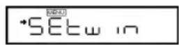
1 Press the [MENU] key twice from the gram-display. "Setwin" appears.
2 Press the [O/T] key. Verify the stability mark is illuminated with "Setwin" display. All the communication settings for WindowsDirect have been made.
3 Go to "STAND-BY" by pressing the [POWER] key several times and unplug the AC adapter from the balance. Unpluging the balance once is necessary after the above setting.

Notes
- Individual communication parameters can be changed at any time using the communications settings menu. If WindowsDirect communication settings have been previously made, the (stability mark) may appear with the "SEtwin" display even after communication settings are changed and become invalid for WindowsDirect. To restore WindowsDirect optimal settings, first go to the "SEtwin" display and remove the stability mark by pressing the [O/T] key. This restores the default communication settings. Then, reset "SEtwin" following the procedure described in 6.2.1.
- Refer to 15.3 for details of communication settings.
6.2.2 Cable Connection
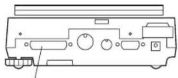
natural_image
Technical line drawing of a device casing with internal components and a labeled component (no text or symbols)RS-232C Connector
1 Verify the balance display is "STAND-BY".
2 Turn off the computer and remove power from the balance.
3 Connect the RS-232C cable to the balance.
4 Connect the RS-232C cable to the computer.
When using WindowsDirect, use a Null modem cable of one of the below wirings.
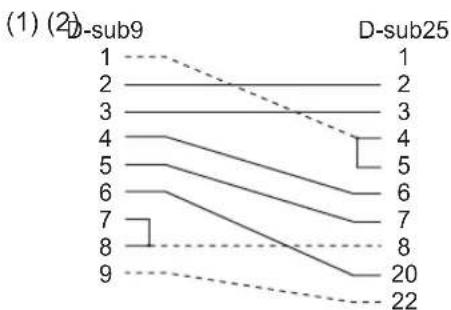
line
(1) (2) D-sub9 D-sub25 | Level | Value | |---|---| | 1 | 1 | | 2 | 2 | | 3 | 3 | | 4 | 4 | | 5 | 5 | | 6 | 6 | | 7 | 7 | | 8 | 8 | | 9 | 20 | | 22 | |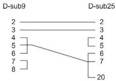
flowchart
graph TD
    A["2"] --> B["3"]
    C["4"] --> D["5"]
    E["6"] --> F["7"]
    G["8"] --> H["20"]
    I["2"] --> J["3"]
    K["4"] --> L["5"]
    M["6"] --> N["7"]
    O["20"] --> P["7"]
--- is not necessarily required.
A cable of the (1) wiring (including --- wiring) is available as an optional accessory.
RS-232C Cable 25P-9P (1.5m) P/N 321-60754-01
6.2.3 Setting Up the Computer
(leave the balance unplugged)
text_image
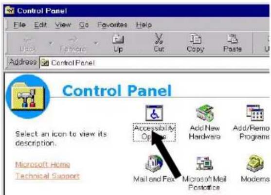
Control Panel File Edit View Go Favorites Help User Favorites Up Cut Copy Paste Address Control Panel Control Panel Select an icon to view its description. Microsoft Home Technical Support Accessibility Options Add New Hardware Add/Remo Programs Mail and Fax Microsoft Mail Postoffice Modems1 Turn ON the power to the computer and start Windows®*.
2 Click "Start", choose "Settings", and "Control Panel".
3 Select "Accessibility Options."
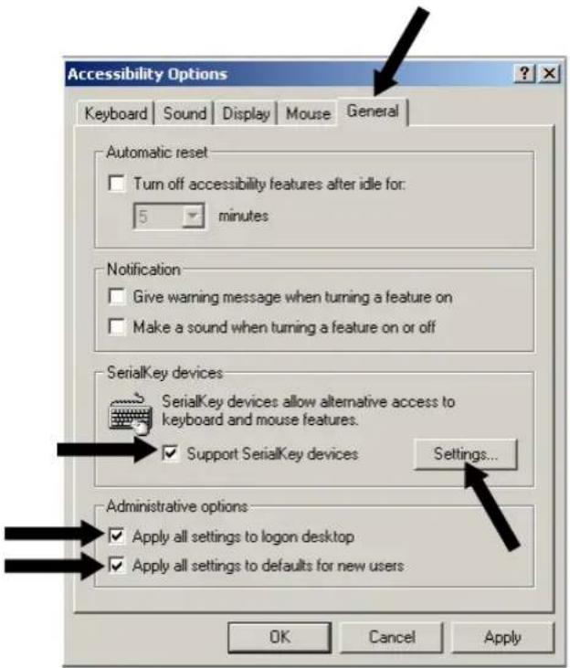
4 Verify that there are no check marks for any items on all five tabs including "General."
6. WindowsDirect Function
text_image
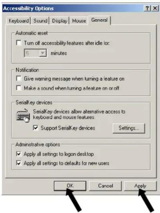
Accessibility Options Keyboard Sound Display Mouse General Automatic reset Turn off accessibility features after idle for: 5 minutes Notification Give warning message when turning a feature on Make a sound when turning a feature on or off SerialKey devices SerialKey devices allow alternative access to keyboard and mouse features. Support SerialKey devices Settings... Administrative options Apply all settings to logon desktop Apply all settings to defaults for new users OK Cancel Apply5 Put a check mark at "Support Serialkey device" in the "General" tab. This should be the only check mark on all the tabs of Accessibility Options unless "Administrative options" appears in the "General" tab. Put check marks at both the items of "Administrative options" to maintain the settings even after restarting Windows®.
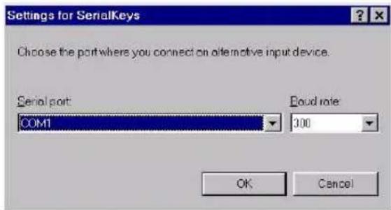
6 Open "Settings".
text_image
Settings for SerialKeys Choose the port where you connect on alternative input device. Serial port: COM1 Boud rate: 300 OK Cancel7 Select the serial port corresponding to the RS-232C port of your personal computer. (Serial port: any one of COM1 to 4. Usually, COM1)
8 Select a "Baud rate" of 300.
9 Click "OK".
10 Click "Apply" and wait.
11 Click "OK".
text_image
Accessibility Options Keyboard Sound Display Mouse General Automatic reset Turn off accessibility features after idle lor: 5 minutes Notification Give warning message when turning a feature on Make a sound when turning a feature on or off SerialKey devices SerialKey devices allow alternative access to keyboard and mouse features. Support SerialKey devices Settings... Administrative options Apply all settings to logon desktop Apply all settings to defaults for new users OK Cancel Apply6.2.4 Start and Checking Operation
1 Confirm Windows ^® is free from any application.
2 After Windows ^® has completely started, connect power cord from the AC adapter to the balance, when “oFF” is displayed, press the [POWER] key. The mass display appears.

Note
Turning ON the balance before Windows ^®* is completely activated may cause incorrect operation.
3 Open the "Note pad" accessory in Windows ®* (or start the application you wish to use).
4 Press the [PRINT] key of the balance.
Verify that the numeric value displayed on the balance appears at the cursor position on the screen of computer. The effect is the same as typing the value from the computer keyboard and pressing the ENTER key. Characteristics indicating the unit of measure are not sent to the computer.

Note
To output date and time from the balance, press and hold the [PRINT] key for about 3 seconds.
5 Test combination with Auto Print function, if you wish to use it. (Refer to 13.3)
6 End the operation using the standard close or exit procedure.
6.3 Troubleshooting the WindowsDirect Communication Function
If the WindowsDirect communication function doesn't run properly, check the following points.
If this doesn't resolve the problem, contact your Shimadzu representative.
Q1 WindowsDirect communication has been set but it is not operating at all.
A1
- Check the type of communications cable used for the connection (Shimadzu authorized part or another part available on the general market) and the soundness of the connection.
- If a USB serial converter is used, depending on the circumstances at the setup there is a possibility that it has been automatically set to a COM port number higher than 4, and in this case you should reassign it to a COM port number that can be used by serial key devices (COM1 to COM4).
- It is possible that the driver used as an accessory with the USB serial converter has not been set up properly. Try uninstalling the driver and installing it again.
- Some notebook PCs feature a setting for disabling RS-232C ports as a power-saving measure. Before trying to use the WindowsDirect communication function, make the setting that enables the use of RS-232C ports.
- Communications with other applications and PCs via a LAN may interfere with the serial key device settings. Try using WindowsDirect communication without using the LAN.
Q2 The WindowsDirect communication function won't work after I restart the PC.
A2
- Some PCs don't recognize that a serial key device has been set when they start up. For details on how to deal with this, contact your Shimadzu representative.
Q3 I want to use the WindowsDirect communication function with Windows Vista or Windows 7.
A3
- Windows Vista doesn't have the serial device setting screen that is required to set the WindowsDirect communication function. For details on the setting, contact your Shimadzu representative.
Q4 Data is input to the PC as garbled characters.
A4
- Either the balance or the PC is not set for the WindowsDirect connection function. Make the settings again.
Q5 When data is input into Excel, the cursor doesn't move to another cell.
A5
- If a function for conversion to 2-byte characters is available in Windows, turn the setting for this function off.
- Click the [Edit] tab under [Options] in Excel and check [Move selection after Enter] (if cells move in response to keyboard input there is no problem).
- Check the input data in another application (e.g. Notepad).
Q6 The operation is sometimes abnormal.
A6
- Depending on the processing capability of the PC, malfunctions may occur if the communications speed is high. Set 300 bps for the communication speed. Malfunctions may also occur if the interval for data transmission from the balance is too short. Ensure that one batch of data is displayed on the screen before the next batch of data is sent. And if there is limited processing capability, don't use the continuous output function.
- When data is sent from the balance, don't touch the PC's keyboard or mouse.
7. Menu Item Selection
7.1 What is the Menu?
The UW/UX series balance has many functions that can be selected to meet the requirements of the user. Menu Item selection is used to program these functions.
7.2 Menu Map
The menu of the UW/UX balance consists of seven groups and four levels. The Menu Map shows the structure clearly with menu item numbers to help access the desired function. Refer to the Menu Map on the operation explanatory sheet or in appendix when programming the functions in Chapter 8 through 15.
7.3 Menu Item Selection Procedure
This instruction manual identifies each menu item by a number. For example, the menu items of "Stability Detection Band" of "11. Environment" are 27 through .
Find the function to be programmed in the Menu Map, referring to the item number in square. No. To reach the item, operate the keys on the balance.
(1) Press the [CAL] key to cycle through the items within a menu level. (In the Menu Map)
(2) Press the [O/T] key to choose the current item or move to the next menu level. (In the Menu Map)
(3) Press the [POWER] key to move back one menu level.
(4) Press and hold the [POWER] key to return to the gram-display.

Note
The symbol is displayed during Menu Item selection.
Example: Select "Stability Detection Band" "4 counts".
The menu item number is 29n the Menu Map.
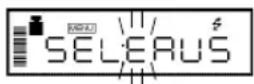
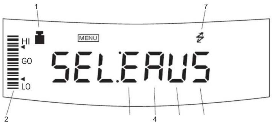
1 Press the [CAL] key repeatedly from the gram-display until "SEL:EAUS" and some symbols are displayed and "E" blinks.

Note
Before entering the menu, set the balance to the gram-display using the [UNIT] key. It is also possible to enter the menu from other weighing units involving no further setting with the [UNIT] key.
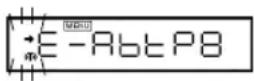
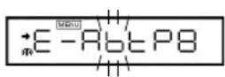
2 Press the [O/T] key. "E" is selected and display changes to "→E-AbtP8" and "→" blinks.
3 Press the [CAL] key twice to make "b" blink.
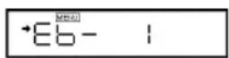
4 Press the [O/T] key. "b" is selected and "Eb-1" is displayed. Stability mark is lit if Eb-1 is currently set.
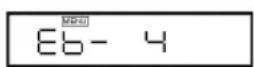
5 Press the [CAL] key twice. "Eb-4" is displayed.
7. Menu Item Selection
Important Note on Menu Item Selection
Even the desired menu item is reached and displayed, it is not yet set unless Stability mark (→) is illuminated with it. Do not fail to press [O/T] key to put Stability mark before returning to the mass display.
text_image
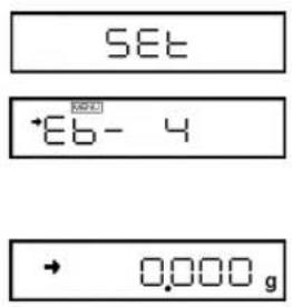
SET *EB- 4 → 0.000 g6 Press the [O/T] key to select this item. "SEt" is displayed and the stability mark now appears with "Eb-4". 7 Return to the desired menu by pressing the [POWER] key. If pressed and held, it returns to the gram-display.
Once the menu items have been set based on the installation environment and weighing purpose, it is not necessary to select the menu items each time the balance is used. Once the contents of the menu are set, they are stored even if the balance is turned OFF or if the power is disconnected.
Major Menu Description
| Menu Group | Symbol that blinks at beginning of menu | Menu Items Included |
| 1 Calibration | ||
| 2 (Graphic display) | Analog display, checkweighing, and target weighing | |
| 3 E Installation environment and taring | ||
| 4 A Application measurements and automatic output | ||
| 5 U Unit conversion and specific gravity measurement | ||
| 6 S Clock set-up and calibration record | ||
| 7 Communication with computer and external devices. |
text_image
1 HI GO LO 2 MENU SELECTAUS 7 2 43
5
7.4 Setting Numeric Values
Some of UW/UX series balance menu items require numeric value setting.
For example, external calibration weight input, thresholds for checkweighing, and reference density in specific gravity measurements (see 10.2, 10.3, 13.1, 13.5, 14.1, 14.2, 14.4 for detail of each item.)
The values can be set using the balance keys.
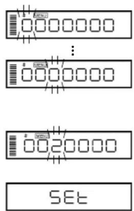
In a menu used to set numeric values, and are both illuminated and the digit to be input blinks.
text_image
SET1 Press the [UNIT] key to increase the value of the blinking digit by one. (0.....9, 0)
2 Press the [PRINT] key to move the blinking digit one place to the right.
3 Press the [O/T] key to store the displayed value in the balance memory.
“SEt” is displayed when the value has been successfully saved.
“Err” is displayed when the balance failed to save the value.
4 Press the [POWER] key to stop numeric entry.
“Abort” is displayed briefly and the display returns to the menu, one level up.

Notes: Setting a Decimal Point
A decimal point is only used when setting units for solid density weighing, liquid density weighing or when setting the multiplier for the user-defined unit. Set the decimal point while setting numerical values as follows.
- Press the [PRINT] key repeatedly until the last digit is blinking. Press the [PRINT] key once more to initiate decimal point setting mode. The ▼ symbol or current decimal point blinks.
- Press the [UNIT] key to move the blinking decimal point one digit at a time to the desired position.
- Press the [O/T] key to set the decimal point position. "SEt" is displayed briefly to indicate that the setting is completed.
Use the optional AKB-301 Application Keyboard to easily set numerical values and decimals.
7.5 Related Useful Functions
7.5.1 Last Menu Recall
This function is convenient when an application requires frequent changes to a specific menu item. During mass display or menu selection, press and hold the [CAL] key for approximately three seconds. The last menu item that was changed or set is displayed.
7.5.2 Returning to the Default Settings (menu reset)
The procedure below describes how to reset the menu and return to the default settings.
Default settings are indicated with the * symbol in the Menu Map.
Select menu item 72 to reset the menu.
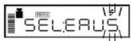
1 In the gram-display, press the [CAL] key repeatedly until the "S" of "SEL:EAUS" blinks.
2 Press the [O/T] key. The Menu Group 6 is selected.
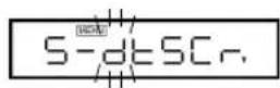
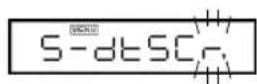
3 Press the [CAL] key repeatedly until the "r" in "S-dtSCr," is blinking.
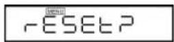
4 Press the [O/T] key to display "rESEt?" ("?" without the dot).
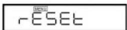
5 Press the [O/T] key again. "rESEt" is displayed to indicate menu reset completion.
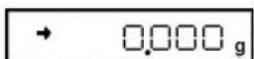
6 Press the [POWER] key several times (or hold it for approximately 3 seconds) to return to the gram-display.

Notes
- The settings made in "15.4 Decimal Point Symbol in Output Data" and "8.2 Date Output Style" are not be cleared with Menu reset.
- Environmental setting of Pouring mode (11.2) is not cleared with Menu reset.
- Operational condition setting of Animal Weighing mode (14.6) returns to the default (Cond 1).
7.5.3 Menu Lock
The “Menu Lock” function locks the menu item selection to protect the current settings from undesired alterations.
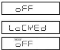
Menu Lock can be activated or released only at the "oFF" display immediately after the balance is connected to the power.
(How to lock the menu)
text_image
oFF LOCYED oFF1 Disconnect power from the balance once. Then, reconnect power to the balance.
2 Press and hold down the [CAL] key for about three seconds during "oFF" display. "LoCKEd" is briefly displayed to indicate that the menu is locked.

Notes
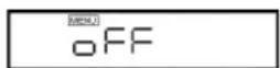
- is illuminated during "oFF" display or STAND-BY while Menu Lock is activated.
- "LoCKEd" is displayed upon an attempt of access to the menu including releasing the currently set function, while Menu Lock is activated.
- All the menu item selections including WindowsDirect setting (6.2.1) are locked. The operational condition setting for Animal Weighing (14.6) and the environmental setting for Pouring mode (11.2) are also locked under Menu Lock.
- Change of minimum display (See 9.2, 14.1, 14.2) is not locked by Menu Lock.
- Change of unit display (See 5.2) is not locked by Menu Lock.
(How to remove Menu Lock)
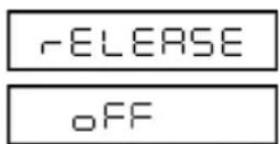
1 Disconnect power from the balance once. Then, reconnect power to the balance.
2 When "oFF" is displayed, press and hold down the [CAL] key for about three seconds.
3 "rRELEASE" is briefly displayed to indicate that the menu lock has been turned off.
8. Built-in Clock Set-up
The built-in clock has to be set up in advance if a calibration record is to be produced or Clock-CAL function is to be used.
8.1 Date
(Example)
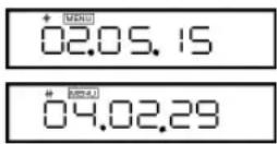
1 Select menu item 68d set the last two figures of the year, month and day, using the [UNIT] and [PRINT] keys.
Example: May 15 ^th , 2002, set as “02.05.15”
Example: February 29 ^th , 2004, set as “04.02.29”
2 Then press the [O/T] key.

Notes
- The built-in clock corrects for the leap year automatically.
- The moment the [O/T] key is pressed to finish setting, seconds are set to zero. If the is set after setting the time, the second value will be incorrect. It is important to set the first and then the time, or to correct the seconds value using the ± second correcting function described in section 8.3.
8.2 Date Output Style
The order of the year, the month and the date in the external output can be selected from three styles. The setting made here is not reflected on the display of the balance.
To output in the YYYY-MM-DD order, select menu item635.m.d]
To output in the DD-MM-YYYY order, select menu item63[p.m.y]
To output in the MM-DD-YYYY order, select menu item63[m.d.y]

Notes
The setting made here on "Date Output Style" will not be cleared with Menu reset (See 7.5.2).
8.3 Time
Select menu item 64 and set the time in the 24 hour system using the [UNIT] and [PRINT] keys, then press the [O/T] key.
(Example)
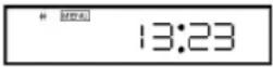
Example: 1:23 in the afternoon, is set as "13:23".

Note
The moment the [O/T] key is pressed seconds are set to 00.
8.4 Setting Display During Stand-by
Determine what is to be displayed during stand-by.
To display the time during stand-by, select menu item . 65
To display the date during stand-by, select menu item . 66
To display neither during stand-by, select menu item . 67

Notes
- Seconds display function:
Press the [UNIT] key to switch on/off of the display of seconds.
9. Display Selection
9.1 Bar graph display
The relative amount of the load on the pan is displayed in the bar graph. This feature helps to prevent errors due to OL (overload) status. This is called Full Scale mode. This display can not be used with the Checkweighing or Target mode.
Select the menu item 11b set up Full Scale mode.
(Examples) (1) (2)
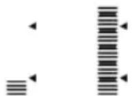
A bar displayed in the lower areas of the scale indicates that the load on the pan is small. (1)
A bar displayed up to the upper areas of the scale indicates that the load on the pan is close to the weighing capacity. (2)
To display no bar graph, select menu item 21
9.2 Changing the Minimum Display Digit (10d:1d)
Not applicable to a verified balance as a legal measuring instrument in the EU
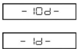
It is possible to decrease the resolution of the minimum balance display by one decimal place if necessary.
text_image
- 10d- - 1d-1 Press and hold the [UNIT] key for approximately three seconds. “- 10d -” is displayed and the display is decreased by one decimal place.
2 Press and hold the [UNIT] key for approximately three seconds. “- 1d -” is displayed and the display returns to the original number of decimal places.

Note
The location of the decimal point in the display does not shift. In the “10d” display, the last digit is empty.
10. Calibration
10.1 What is calibration?
Calibration is required to accurately weigh items with an electronic balance. Calibration should be performed:
- When the location of the balance is changed, even within the same room.
- When the room temperature changes considerably.
- Periodically, according to the quality control plan of the user.
Terms used in this manual:
Span Calibration: Adjustment of the balance to specifications using two weight values; zero and an appropriate value for the balance capacity.
Calibration Check: Comparing the current calibration weight reading to the calibration weight reading after the last span calibration.
Calibration: Pertains to both span calibration and calibration check.

Caution
Never plug off the balance when the following messages are displayed. "i-CAL x", "i-tESt x", "wAit", "Abort", "CAL E x"("x" represents a number).
With UW series, displaced built-in weight may cause damage to the mechanism.
10.2 Calibration Execution

Notes
- Setting before shipment is as the following:
UW series: Span calibration using the built-in weight
UX series: Span calibration using external weights
The type of calibration can be changed (See 10.3). - Calibration will not be performed when the weight on the pan is not near zero, or the balance is not stable.
10.2.1 Span Calibration Using the Built-in Weight (UW Series Only)
The balance is adjusted using the built-in calibration weight.
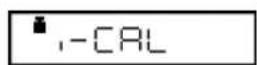
1 Verify that the balance is in mass display and that the pan is empty.
2 Press the [CAL] key once. "i-CAL" is displayed. (If "i-CAL" is not displayed, return to mass display and select menu item.)
3 Press the [O/T] key.
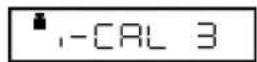
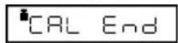
After "i-CAL3", "i-CAL2", "i-CAL1", "Set", "CALEnd" the mass display will appear indicating the completion of span calibration.
:
10.2.2 Calibration Check Using the Built-in Weight (UW Series Only)
The shift from the last calibration is displayed using the built-in calibration weight, however, the balance is not adjusted.
1 Verify that the balance is in mass display and that the pan is empty.
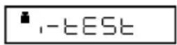
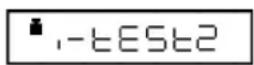
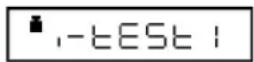
2 Press the [CAL] key once to display "i-tESt". (If "i-tESt" is not displayed, return to mass display and select menu item 2)
3 Press the [O/T] key.
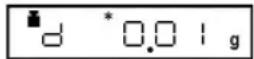
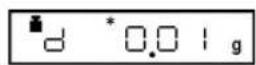
The display changes sequentially from “i-tESt 2” to the “d xxx” display. (xxx indicates a numeric value) This “d” value indicates the difference between the current calibration weight reading and the calibration weight reading at the last span calibration.
4 To perform span calibration, change the "d" value to zero, by pressing the [CAL] key.
--Otherwise, Press the [O/T] key to avoid changing the "d" value to zero. (Pressing the [POWER] key interrupts calibration and does not change this value to zero.)
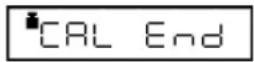
"CALEnd" is displayed, indicating the completion of the calibration check.

Note
Changing the "d" value to zero is equivalent to performing span calibration.

Notes
• Examples for interpreting the results of a Calibration Check:
“d” Value Actual Mass Displayed Mass
-0.3 3000g 2999.7(3200g/0.1g balance)
+0.21 400g 400.21(420g/0.01g balance)
- Error codes that may be displayed:
"d ouEr" (d OVER) indicates that the "d" value is 1000 counts or more.
"d UndEr" indicates that the "d" value is -1000 counts or less.
10.2.3 Span Calibration Using External Weights
Not applicable to a verified balance as a legal measuring instrument in the EU
The balance is adjusted using your external standard calibration weight(s).
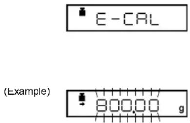
text_image
E-CAL (Example) 800.00 g1 Verify that the balance is in mass display and that the pan is empty.
2 Press the [CAL] key once. "E-CAL" is displayed.
(If "E-CAL" is not displayed, return to mass display and select menu item 3)
3 Press the [O/T] key.
The value of the correct calibration weight to be loaded is displayed and blinks.

Changing the Calibration Weight to be Used
Pressing the [CAL] key allows changes to the weight value. Modify the value using the [UNIT] key and [PRINT] key, then press the [O/T] key. Refer to 7.4 for how to make numerical input. To interrupt modification, press the [POWER] key. Calibration range with external weights is designated to each model. Refer to “3. Specifications” for calibration range. Attempt of inputting an invalid calibration weight value causes an error message.
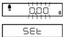
text_image
SET4 Load the indicated calibration weight and press the [O/T] key.
5 Shortly, zero display blinks. Unload the weight from the pan and press the [O/T] key.
“SEt” is displayed briefly to indicate completion of span calibration.

Note
OIML Class E2 or F1 calibration weight is recommended for calibration, depending on your accuracy demand.
10.2.4 Calibration Check Using External Weights
Not applicable to a verified balance as a legal measuring instrument in the EU
The shift from the last calibration is displayed using your external standard calibration weight(s), however, the balance is not adjusted.
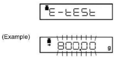
text_image
E-TEST (Example) 800.00 g1 Verify that the balance is in mass display and that the pan is empty.
2 Press the [CAL] key once to display "E-tEST". (If "E-tEST" is not displayed, select menu item 4)
3 Press the [O/T] key. The value of the correct calibration weight to be loaded is displayed and blinks.

Changing the Calibration Weight to be Used
Pressing the [CAL] key allows changes to the weight value. Modify the value using the [UNIT] key and [PRINT] key, then press the [O/T] key. Refer to 7.4 for how to make numerical input. To interrupt modification, press the [POWER] key. Calibration range with external weights is designated to each model. Refer to "3. Specifications" for calibration range. Attempt of inputting an invalid calibration weight value causes an error message.
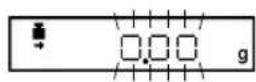
4 Load the indicated calibration weight and press the [O/T] key. The zero display blinks.
5 Unload the weight from the pan and press the [O/T] key. The display changes to the "d xxx" display. (xxx indicates a numeric value)
6 To perform span calibration, change the "d" value to zero by pressing the [CAL] key.
Otherwise, press the [O/T] key to avoid changing the "d" value to zero. (Pressing the [POWER] key interrupts calibration and does not change this value to zero.)
"CALEnd" is displayed, indicating the completion of the calibration check.

Note
Changing the "d" value to zero is equivalent to performing span calibration. Refer to 10.2.2. for interpreting the results of a Calibration Check.
10.3 Calibration Setting
10.3.1 Selecting the Calibration Type
Set the calibration type that will be used in Calibration Execution.
| To set up "Span calibration using the built-in weight", (UW only) Select menu item . | 1 |
| To set up "Calibration check using the built-in weight", (UW only) Select menu item . | 2 |
| To set up "Span calibration using external weights", Select menu item .* | 3 |
| To set up "Calibration check using external weights", Select menu item .* | 4 |
*Not applicable to a verified balance as a legal measuring instrument in the EU
10.3.2 PSC Fully-automatic Calibration (UW series only)
With the PSC function, span calibration is performed automatically using the built-in calibration weight when the balance detects a temperature change that would affect weighing accuracy.
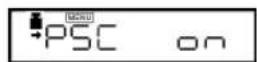
1 To turn ON the PSC function, Select menu item 5.
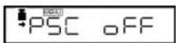
2 To turn OFF the PSC function, Select menu item 6.

Notes
- Blinking calibration symbol indicates an automatic calibration is about to start.
- If PSC starts while the balance is in use, press the [POWER] key to abort that cycle.

Note
Using a verified balance as a legal measuring instrument in the EU: When PSC, fully-automatic span calibration, is not activated, operator must carry out span calibration with the built-in weight (refer to 10.2.1) upon blinking of the Weight Symbol.
10.3.3 Clock-CAL Fully-automatic Calibration (UW series only)
Span calibration is performed automatically using the built-in calibration weight at up to 3 specific, pre-set times during each day. The user selects the times. This function is named Clock-CAL.
It is possible to set up to three specific times for Clock-CAL ("tCALt1", "tCALt2", and "tCALt3"). Use the 24 hour system to set menu items 7 Band. Setting to "00:00" releases the function.

Notes
To execute Clock-CAL, all of the following conditions must be satisfied at the set time. If these conditions are not satisfied within one minute, the automatic span calibration is not executed and that cycle is skipped.
- The balance must be in mass display or the standby mode.
• The balance must be stable.
(The stability symbol must be illuminated during mass display.) - Load on the pan should be near zero.
- The balance should not already be in the process of span calibration.
Example: Setting "tCAL t1" to twelve noon.
(Example)
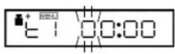
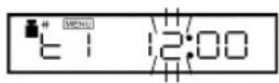
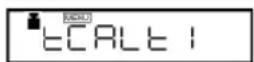
1 Select menu item .7
2 Set the desired time.(Refer to 7.4 for numerical input.)
3 Press the [O/T] key. The set time will be stored.
4 Proceed to next time setting by the [MENU] key, or return by the [POWER] key.
Skipping Clock-CAL
If Clock-CAL starts while the balance is in use, press the [POWER] key to abort that cycle.
Turning Off Clock-CAL Function
When all three Clock-CAL times are set to "00:00", the function is off.
10.3.4 PCAL: Calibration of the Built-in Weight (UW series only)
Not applicable to a verified balance as a legal measuring instrument in the EU
PCAL is used to calibrate the built-in weight to a standard calibration weight that is correctly adjusted, traceable and/or certified. The PCAL procedure is password protected. The administrator should set this password (refer to 10.3.5).

Caution
Use a correctly controlled, precise calibration weight for this procedure. If it is performed without a correct calibration weight, span calibration and calibration checks using the built-in mass may not be correct in subsequent operations.
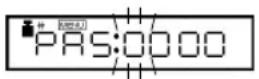
(Example)
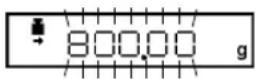
1 Unload the sample from the pan and verify a zero mass display.
2 Select the menu item .10 "PAS: 0000" is displayed.
3 Enter the PCAL password using the [UNIT] and [PRINT] keys, then press the [O/T] key.
The default password is 9999, set at shipment or upon menu reset.
After "PCAL 3" is displayed, the value of the standard weight to be loaded blinks.

Changing the Calibration Weight to be Used
Pressing the [CAL] key allows changes to the weight value. Modify the value using the [UNIT] key and [PRINT] key, then press the [O/T] key. Refer to 7.4 for how to make numerical input. To interrupt modification, press the [POWER] key. Calibration range with external weights is designated to each model. Refer to “3. Specifications” for calibration range. Attempt of inputting an invalid calibration weight value causes an error message.
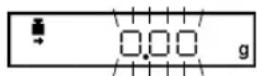
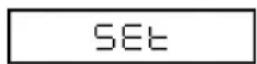
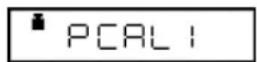
4 Load the standard weight displayed, and press the [O/T] key.
Soon, zero is displayed and blinks.
5 Unload the weight and press the [O/T] key. The display proceeds to "PCAL 0". When the mass display appears, calibration is complete.

Notes
- “SEt” is displayed during the process. Leave the balance in a stable state until the mass display appears as in step 5.
- In PCAL, the value of the "weight to be loaded" cannot be changed.
- Set the PCAL password using menu item .71
10.3.5 PCAL Password Setting (UW series only)
Not applicable to a verified balance as a legal measuring instrument in the EU
This password is necessary to access the PCAL function.
It is recommended that the balance administrator set this password to prevent an unauthorized person from incorrectly calibrating the built-in calibration weight.
Select menu item 7.1 The numerical setting display appears.
Enter a 4-digit number from "0000" to "9999".
Refer to 7.4 for numerical input.

Note
When the menu is reset, the PCAL password is reset to "9999".
10.4 For GLP/GMP/ISO Conformance
These settings should be made by the administrator.
10.4.1 Calibration Report Setting
Turns the calibration report function ON/OFF. Use this to generate and output a calibration report as for GLP, GMP, or ISO9000. An electronic printer (optional accessory) is required to print the report.
To create calibration report, Select menu item . 68
To turn off calibration report function, Select menu item .69

Note
Date output, ID number etc. of electronic printer EP-50 or EP-90 should be turned off when calibration report is produced.
10.4.2 Balance ID Setting
Individual balances can be identified by the serial number on the main body of the balance. The user can add a four-digit ID number to the calibration report.
Select menu item 76et a 4-digit number from "0000" to "9999".
11. Environment
11.1 Overview
Settings on the balance can be changed to compensate for the installation environment such as the degree of vibration or air movement or for the purpose of weighing a solid, liquid or powder.
11.2 Stability and Response (Averaging)
It is possible to match the stability of the display and the degree of response with the requirements of specific applications or the installation environment. One of the five modes can be selected. Note that adjustments for stability and response conflict with each other, although the UW/UX series is designed to meet both.
Auto mode: Select menu item . 22
The balance automatically performs optimum averaging dynamically while observing the load data. This is the recommended setting and should be used unless special circumstances exist.
Pouring mode: Select menu item . 23
(Filling, dosing) This mode is particularly suitable for dosing or filling purposes.
Note that this mode is very sensitive to wind and vibration.
(Environmental setting in Pouring mode)
Pouring mode allows further adjustments to the surrounding environmental conditions. Choose the optimal setting for your installation site observing the response and stability.
Every time the circle in the right part of the [O/T] key is pressed during weighing in Pouring mode, the environmental setting will be changed and cycles in the following order. Upon changing the setting, the new setting is briefly displayed as shown in “”.
normal environment (“norm E”) → unstable environment, (“UnStb E”) → very stable environment, (“StAbL E”) → normal environment, (“norm E”).
During use, the current environmental setting of Pouring mode can be confirmed by observing the position of the ◀ symbol in the display.
| (Display) | ◀ When “UnStb E” is selected◀ When “norm E” is selected◀ When “StAbL E” is selected |
11. Environment

Note
While “Pouring” is selected as the Stability and Response setting, taring the container or zeroing the display cannot be made by pressing the rightmost part of [O/T] key. Press the center or the left part of [O/T] key for tar-ing or zeroing.
Standard mode:
Select men24 item
This mode is suitable for weighing in a normal environment. Averaging is fixed and does not change dynamically as in the Auto mode.
Anti-vibration mode:
Select menu i25m
Use this mode when the balance is used in a location where there are large vibrations and the display fluctuates in the Auto mode.
Response is deteriorated at small mass amount changes.
Anti-wind mode:
Select men26 item
Use this mode when the balance is used in a location where it is exposed to airflow that causes the display to fluctuate in the Auto mode.
Response deteriorates further than the Anti-vibration mode, but weighing is comparatively stabilized.

Note
If weighing cannot be performed efficiently even with the Anti-wind mode, change the installation site of the balance or use the optional windbreak (large).
11.3 Stability Detection and Settings
Stability detection is an auxiliary function used for the following purposes.
(1) When stability is detected during measurement, Stability mark is illuminated as an auxiliary indication of measurement stability.
(2) Operations such as data output and auto zeroing of the below listed functions are triggered by stability detection. Some data output functions operated with communication commands (15.2.3) are also linked to stability detection.
(Functions that employ stability detection)
Auto Print (See 13.3), Auto Zero (See 13.4), Taring/Printing at Stability (See 13.6), Peak Hold (See 14.3), Auto-Memory and Zeroing (See 14.5), Animal Weighing (See 14.6), Formulation Mode (See 14.7).
It is possible to adjust the operation with the following stability detection settings.
(a) Stability Detection Band (11.3.1)
(b) Timing of Stability Mark Illumination and Automatic Output (11.3.2)
It is not usually required to change these settings as they are optimized at default. However, it is allowed to change according to 11.3.1 and 11.3.2 when: wishing to ease the criteria of stability detection under very unstable environmental or sample conditions, or wishing to accelerate automatic data output when using a function that employs stability detection.

Note
Stability mark is an auxiliary device to inform measurement stability. The displayed value may change while the stability symbol remains illuminated if the load is changing slowly, or depending on the stability detection settings.
11.3.1 Stability Detection Band
The default setting is "1 count" and the measurement is regarded to be stable when the display has remained within one display count for a fixed length of time. If stability detection band is set at "2 counts", it will be regarded to be stable when the display has remained within two display counts. Selecting a larger stability detection band generally eases the criteria and makes stability mark illuminate more readily. However, it will be more likely for the display to further fluctuate after illumination of stability mark.
Try a larger stability detection band when data outputs triggered by stability detection is slow due to very unstable environmental and/or sample conditions.
| Stability detection band | 1 count (default setting) | 2 counts 4 | counts 8 counts | 16 counts* 3 | 2 counts* 64 | counts* | |
| Menu item number | 27 28 29 | 30 31 32 33 | |||||
*Not applicable to a verified balance as a legal measuring instrument in the EU.

Note
Use “16 counts” to “64 counts” for Auto Print, Animal Weighing or other data-outputting function under very unstable conditions only.
11. Environment
11.3.2 Timing of Stability Mark Illumination and Data Output
The illumination of stability mark and automatic data output of the functions employing stability detection take place at the same timing. The timing after detection of stability is optimized at the default and it is not necessary to change the setting usually.
However, adjustment of the timing is allowed to three levels according to specific measurement requirements. When wishing to accelerate automatic data output with functions such as animal weighing, select menu item 21a when wishing to delay the illumination of stability mark, select menu item 21c 23b elect menu item to return it to the standard setting.
11.4 Tracking
Tracking is the function that will maintain the current displayed value as long as possible.
To turn ON this function, Select menu item . 34
To turn OFF this function, Select menu item . 35

Zero Tracking Function
When the display is zero, tracking functions as "zero tracking" to keep the zero display as long as possible. "Zero tracking" automatically cancels small zero drift.
It is recommended to set tracking off when measuring slight mass change such as in the process of drop addition or liquid evaporation.

Note
Using a verified balance as a legal measuring instrument in the EU: Even when Tracking is ON, the range where it works is restricted to the vicinity of the zero, and it is subjected to conditions, according to the regulations.
12. Units
12.1 Unit Display Set-up

Note
Using a verified balance as a legal measuring instrument in the EU:
Only g (gramme=gram), ct (carat) weighing units, percentage conversion and piece counting are available for use. Carat is not available for UW820SV and UW8200SV models.
The UW/UX series balance can display weighed results in various weighing units (Refer to 5.2).
(Example)
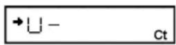
When menu item 58 (carat) has been selected.
1 It is possible to display units other than "g". Press the [UNIT] key in mass display to sequentially change the selected units.
2 Before weighing, set the display units to be used. Gram, %, and PCS (piece counting) are set up before shipment. Set up the desired units by selecting menu from 5462
For details of PCS and specific gravity measurement, refer to 13.3 and 14.1 to 14.2.

Notes
For the unit names, refer to the menu map.
- In the unit setting menu, the stability symbol is illuminated to indicate the currently set units.
- Set or release the unit by pressing the [O/T] key when the unit is displayed. Gram cannot be released.
User unit (menu item 62A numeric value (multiplier) is multiplied by the gram (g) weight of the unit.
Error Display
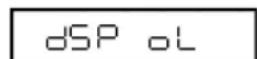
Display Overload: This display appears if the mass display exceeds 7 digits due to the choice of unit.
12.2 Percentage (%) Conversion
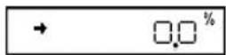
1 Set the % unit with menu item 56 is not set up. The % unit is set before shipment.
2 Press the [UNIT] key several times in the mass display until the \% unit is displayed.
Setting the 100% reference
1 Press the [O/T] key to tare the balance.
2 Load the reference sample that corresponds to the 100% value. This value must be equivalent to 100 counts or more in the "g" unit.
3 When the stability mark illuminates, press the [CAL] key.
"SEt" is displayed briefly and the reference sample weight is displayed as 100%.
The weights of subsequent samples are displayed as a percentage of the reference sample weight.
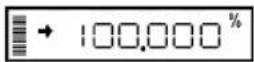

Note
The numbers of digits displayed in the \% unit and rounding off of the minimum digit vary depending on the mass value of the reference sample and the balance model. It is not possible to obtain resolution greater than that in the "g" unit.
13. Enhancing Productivity
Functions that are useful mainly in production sites are described in this chapter.
Only one of the functions in the menu group 4 (Refer to 7.3) (4158□) can be used at a time. When one of the functions in menu group 4 is to be used with a weighing unit other than gram, select the function from the gram-display first. Then, change to the other unit with the [UNIT] key. To release this function, use the [POWER] key. For returning to the previous function, Last Menu Recall function is convenient. There are some other combinations of functions that can be used together. Some functions employ the value set in Zero Range setting (refer to 13.5).
13.1 Checkweighing and Target Display
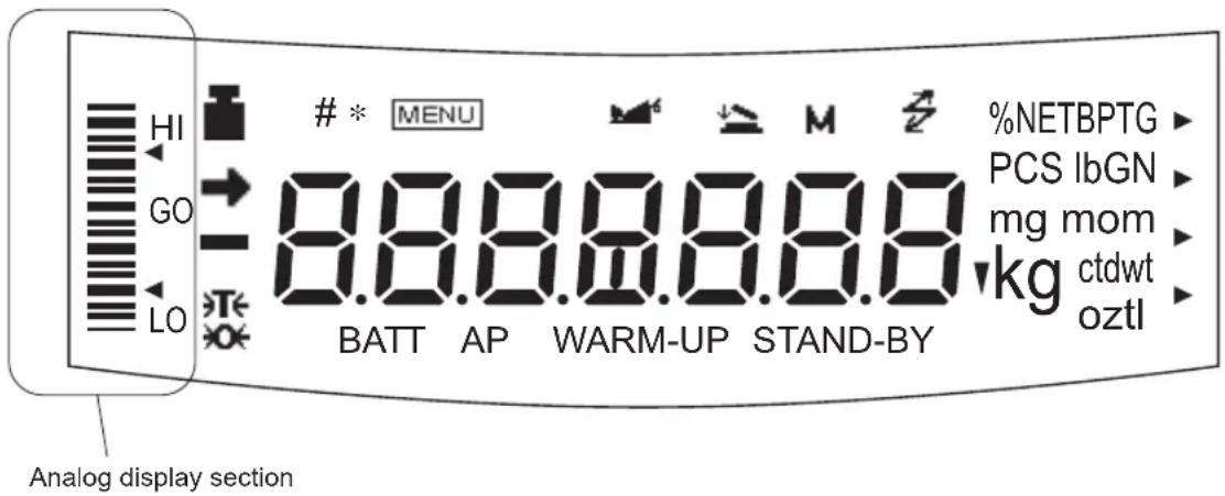
text_image
HI GO LO* MENU
8.8.8.8.8.8.8 BATT AP WARM-UP STAND-BY %NETBPTG PCS IbGN mg mom kg ctdwt oztl Analog display sectionThe UW/UX series balance has an analog bar graph located on the left side of the display. This graph can be conveniently used for checkweighing or cumulative weighing.
The graphic display functions include the two display modes of checkweighing, the target mode, and full scale mode. Only one of them can be used at a time. Refer to 9.1 for the full scale mode and the no bar graph display.
Upon selection of either the checkweighing mode or the target mode, the numerical value for threshold or target is requested. Numeric values are memorized independently for each graphic display mode.
When one of the checkweighing modes is selected, a signal corresponding to HI, GO, or LO in the-graphic display can be transmitted via the RS-232C/AUX connector.
Target, limit, upper, and lower values are set as numeric values only. Set the correct numerical value for the unit that will be used for weighing.
- In weighing mode, changing the displayed unit does NOT change the target, limit, upper, or lower numeric values. For example, when the upper limit has been set at 10g, switching the unit from “g” to “kg” does not change the limit to 10kg. It will be 0.01kg.
The decimal point is invisible in the value setting display. Determine its position based on the resolution of the balance. For example, if the balance's minimum display is 0.01g, 150g must be set by inputting "15000" in the display.
13.1.1 Checkweighing (Comparator) Display Type 1
This is the best mode to determine pass or failure judgment based on the sample weight.
Displays in use

text_image
GO LO HI1 Select menu map item . 15
2 Set the upper threshold value, which corresponds to the upper triangle mark, with menu item 16
3 Set the lower threshold value, which corresponds to the lower triangle mark, with menu item 17

Note
The decimal point is invisible in each value setting display. Setting the value cannot be made in gram unit. Determine the number based on the minimum display of the balance. For example, if the balance's minimum display is 0.01g, 150g (150.00g in this balance) must be set by inputting "15000" in the display, not "150" or "150.00".

Note
Determination as follows:
Upper threshold < Sample weight HI
Lower threshold ≤ Sample weight ≤ Upper threshold GO
Sample weight < Lower threshold LO
13.1.2 Checkweighing (Comparator) Display Type 2
Use this mode for classification based on the sample weight. The display looks like a bar graph, but also includes a checkweighing function.
Displays in use
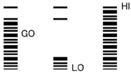
text_image
GO LO HI1 Select menu map item . 18
2 Set the upper threshold value, which corresponds to the upper triangle mark, with menu item 19
3 Set the lower threshold value, which corresponds to the lower triangle mark, with menu item 20
Upper threshold < Sample weight HI
Lower threshold ≤ Sample weight ≤ Upper threshold GO
Sample weight < Lower threshold LO

Note
The decimal point is invisible in each value setting display. Setting the value cannot be made in gram unit. Determine the number based on the minimum display of the balance. For example, if the balance's minimum display is 0.01g, 150g (150.00g in this balance) must be set by inputting "15000" in the display, not "150" or "150.00".
13.1.3 Target Mode
This mode is useful for constant amount weighing of liquid or judgment of excess and shortage.
The target value is the numeric value that is the desired amount in the unit that is used for weighing. The limit value is the numeric amount above or below the target value that is acceptable. The target will be indicated as the center line in the analog display. The limits will be indicated as triangle marks. A moving bar represents the current weight on the pan.
Display examples in use
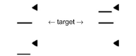
text_image
← target → _Without load With a load within the limit range
1 Select the Target mode with menu item 12
2 Set the "target" value, which corresponds to the center line of the graphic display, with menu item 13.
3 Set the "limit" value, which corresponds to the distance between the center line and upper or lower triangle marks, with menu item 14

Note
The decimal point is invisible in each value setting display. Setting the value cannot be made in gram unit. Determine the number based on the minimum display of the balance. For example, if the balance's minimum display is 0.01g, 150g (150.00g in this balance) must be set by inputting "15000" in the display, not "150" or "150.00".
13.2 Piece Counting (PCS)
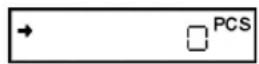
(Example)
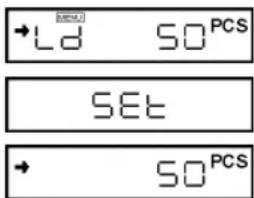
text_image
→Ld SO PCS SET → SO PCS1 Set up the PCS with menu item 57 it is not set.
(The PCS unit is set before shipment.)
2 Press the [UNIT] key several times in the mass display until the PCS is displayed.
3 Load the container and press the [O/T] key to tare the balance.
4 Count exactly five pieces (or 10, 20, 50, 100, or 200 pieces) of sample to be measured and load them on the pan.
5 Press the [CAL] key.
6 Every time the [CAL] key is pressed, the display sequentially changes as "Ld 5pcs" .... "Ld 200pcs", "Ld 5pcs"... The default setting is "Ld 10pcs". Press the [O/T] key when the display is equivalent to the number of loaded pieces.
Example: If 50 pieces are loaded, press the [O/T]
key when "Ld 50pcs" is displayed. This determines the unit weight or average weight per piece.
As sample is added or removed, the piece count (number of pieces) is displayed.

Note
Repeat steps 3 through 6 above when the sample or manufacturing lot is changed.

Piece Count Menu Display at Next Setting
In this example, when the [CAL] key is pressed in the next PCS menu, display starts from "Ld 50pcs".
13.3 Auto Print
Auto Print function allows output of the data automatically without pressing the [PRINT] key for each sample. The “Auto-Print symbol is illuminated when the Auto Print function is activated.
Six types of Auto Print are selectable.
Print on loading: Select menu item 42
Load the sample when the value displayed is within the Zero Range. When stability is detected and the positive displayed value is more than 5 times the Zero Range, data is automatically output.
The next data output is not performed unless the display has returned to a value within the Zero Range by unloading the sample or pressing the [O/T] key.
Print on loading and unloading: Select menu item 43
Load or unload the sample when the displayed value is within the Zero Range. When stability is detected and the displayed positive or negative value is more than 5 times the Zero Range, data is automatically output.
The next data output is not performed unless the display has returned to a value within the Zero Range by unloading the sample or pressing the [O/T] key.
Print on loading and on zero: Select menu item 44
Load the sample when the value displayed is within the Zero Range. When stability is detected and the positive displayed value is more than 5 times the Zero Range, data is automatically output.
Unload the sample or press the [O/T] key. When the displayed value is within the Zero Range and stability is detected, data is output again.
Print on loading, unloading, and on zero: Select menu item 45
Load the sample when the value displayed is within the Zero Range. When stability is detected and the displayed positive or negative value is more than 5 times the Zero Range, data is automatically output.
Unload the sample or press the [O/T] key. When the displayed value is within the Zero Range and stability is detected, data is output again.
Print continuously: Select menu item 46
Not applicable to a verified balance as a legal measuring instrument in the EU
By pressing the [PRINT] key while the Auto-Print symbol and Stand-by symbol are lit, the Stand-by symbol goes out, the Communication symbol lights and the displayed data is continuously output.
Continuous output stops temporarily when the [PRINT] key is pressed.
13. Enhancing Productivity

Note
During continuous output, the Communication symbol may appear to remain lit. If the transfer speed of the data output is slow, the display may become unstable. Increase the transfer speed as much as possible and set the handshake off (menu item 73)
Print on "GO" judge of checkweighing: Select menu item 47
When the checkweighing function (See 13.1) is used and stability is detected in the "GO" range, the data is output once.
The next data output is executed after the displayed value is within the Zero Range.

Notes
• See 13.5 for details of Zero Range.
• See 11.3 for details of stability detection.
- Pretaring Value (13.7) function cannot be used with Auto Print functions.
- Auto Print mode setting can be cleared without menu operation, by pressing the [POWER] key for about three seconds.
- Not more than one of these seven functions can be set at a time. Setting the second one with the menu will automatically clear the previously set function; Auto Print(13.3), Auto Zero(13.4), Peak Hold(14.3), Interval Timer(14.4), Add-on mode(14.5), Animal Weighing mode(14.6), Formulation mode(14.7).
- For automatic outputs at preset intervals, see "14.4 Interval Timer".
- When minimum display has been switched to 10d (See 9.2), the optimized Zero Range for 1d display may cause failure in the operation (e.g. Data is not automatically output as sample is loaded). Select optimal Zero Range value again when minimum display has been changed (See 13.5 for details).
13.4 Auto Zero
Not applicable to a verified balance as a legal measuring instrument in the EU
When the displayed value is within the Zero Range and stability is detected, zeroing occurs automatically. The Zero symbol appears in the display when the Auto Zero function is active. Other keys function as expected with the Auto Zero function activated.
Select menu item 4tb activate it.

Notes
• See 13.5 for details of Zero Range.
• See 11.3 for details of stability detection.
- Pretaring Value (13.7) function cannot be used with Auto Zero function.
- Auto Zero setting can be cleared without menu operation, by pressing the [POWER] key for about three seconds.
- Not more than one of these seven functions can be set at a time. Setting the second one with the menu will automatically clear the previously set function; Auto Print(13.3), Auto Zero(13.4), Peak Hold(14.3), Interval Timer(14.4), Add-on mode(14.5), Animal Weighing mode(14.6), Formulation mode(14.7).
- When minimum display has been switched to 10d (See 9.2), the optimized Zero Range for 1d display may cause failure in the operation. Select optimal Zero Range value again when minimum display has been changed (See 13.5 for details).
13.5 Zero Range
The “Zero Range” value is used in the following functions as a reference for judging whether the sample is loaded: Auto Print (13.3), Auto Zero(13.4), Peak Hold(14.3), Add-on Mode(14.5), Animal Weighing Mode(14.6), and Formulation Mode(14.7).
If the display is within the Zero Range, the balance determines that the balance is not loaded. If the display reaches five times the Zero Range or more, it determines that a sample is loaded. Functions which involves judgment of whether a sample is loaded or not work in accordance with the Zero Range setting.
Example: Samples are weighed one after another with UX2200H (minimum display 0.01g) and each measurement result is automatically output with the Auto Print “on Ld” function (13.3).
Suppose Zero Range is set to 10. As 1 count for UX2200H is 0.01g, Zero Range is 0.10g in this case. When a sample of 0.50g or more is placed, it is judged to be loaded and the data will be output. When this sample is removed and the display returns below 0.10g, it is judged that the balance is unloaded, then it is ready for the next sample. If it does not return below 0.10g, the previous sample is not judged to be unloaded. Therefore, even when the displayed value reaches 0.50g again by next loading, the data will not be automatically output.
Select Zero Range value according to the influences of environment (causing difficulty in zero-return), the weight of the samples, etc. so that Auto Print functions properly.
Set the "Zero Range" value with menu item 48 using the number of counts displayed in gram-display. The setting range is 01 to 99 with 10 being the default value. Even when weighing will be done in another unit, Zero Range setting is made by only gram value.

Notes
- Zero Range value is a common setting for all the Zero Range-linked functions.
- The application of Zero Range value is different depending on each function. Refer to the section of each function using Zero Range.
- When a Pretare value is set, the thresholds to determine that there is “no load” becomes “– Pretare ± Zero Range”.
- When minimum display is changed to 10d (See 9.2), number of counts used for load/unload judgment is counted based on the 10d minimum display. Therefore, the Zero Range value optimized for 1d display can be too large for 10d display. This may cause failure of linked operation, e.g. automatic output upon loading. Optimize Zero Range value again when switching minimum display 1d/10d.
13.6 Taring/Printing at Stability
Not applicable to a verified balance as a legal measuring instrument in the EU
Determine if the balance should wait for stability before printing when the [PRINT] key is pressed or zeroing when the [O/T] key is pressed.
To print or tare without waiting for stability: (Immediately operating mode)
Select menu item 39
To have printing or taring take place after stability is detected: (Waiting for stability detection)
Select menu item 40

Notes
- While the balance is waiting for stabilization, ---- is displayed.
- When the [O/T] key has been pressed,
“---” is displayed. At this occasion, press the [POWER] key if you desire to disable this function and abort taring.
- When the [PRINT] key has been pressed,
Once the communication symbol and the Stand-by symbol are lit, then stability detection is waited. The data will be output after stability is detected. If the [POWER] key is pressed during the waiting, the balance is brought to stand-by. The data will be printed upon stability in the next weighing.
• See 13.5 for details of Zero Range.
• See 11.3 for details of stability detection.
13.7 Pretaring Value
Not applicable to a verified balance as a legal measuring instrument in the EU

Notes
- If the weight of the tare (container) varies, accurate measurement with Pretaring Value function cannot made.
- Pretaring Value function cannot be used with Peak Hold (14.3), Add-on Mode(14.5), Animal Weighing Mode(14.6), Formulation Mode (14.7) or Auto Print function (13.3).
This function is used to weigh the mass of a sample packed in a container such as a bottle or bag without opening the container. Pretare function should be used only if the mass of each container does not vary from sample to sample. Instead of zero, the pretare value is displayed (as a negative value) when the [O/T] key is pressed. The pretare value is then subtracted from the total load on the balance pan to display the weight of the sample.
1 Select menu item .36
2 Set the Pretare value. Refer to 7.4 for numerical value input.

Pretare Value
Cancel the Pretare value by setting the value to zero.
When a Pretare value other than zero has been set, the Tare symbol illuminates.
The Pretare value is set using the “g” unit. The maximum value is the weighing capacity of the balance.
Check the Pretare value by pressing and holding the [O/T] key for approximately 3 seconds during weighing.
Use the AKB-301 external keypad if you have to change the Pretare value frequently.
14. Application Functions
Application measurement functions are described in this chapter.
Only one of the functions in the menu group 4 (Refer to 7.3) (4158□) can be used at a time. When one of the functions in menu group 4 is to be used with a weighing unit other than gram, select the function from the gram-display first. Then, change to the other unit with the [UNIT] key. To release this function, use the [POWER] key. For returning to the previous function, Last Menu Recall function is convenient. There are some other combinations of functions that can be used together. Some functions employ the value set in Zero Range setting (refer to 13.5).
14.1 Solid Specific Gravity Measurement
Solid specific gravity measurement refers to the measurement of the sample (solid) weight in the air and in a liquid of known specific gravity (or density) and the calculation of the sample specific gravity (or density).
The ▼d symbol is used to represent the solid specific gravity in this balance. The data output unit is DS.

Note
Use of the optional SMK-101, or SMK-102 Specific Gravity Measurement Kit (refer to A-3.) is recommended for efficient measurements. When using the SMK-101 or SMK-102, refer to the instruction manual of the kit. Follow the instruction below when a hanging pan and a tank are prepared by the user.
1 Select menu item 60 advance.

Note
Enter the value of the specific gravity (or density (g/cm^3) ) of the liquid (water, alcohol etc.) in which the sample is immersed. Refer to 7.4 for numerical value input. To cancel the set-up, set the value to zero.
2 Remove the below-weigh hook cap from the bottom of the balance to expose the below-weigh hook.
14. Application Functions
3 Hook the hanging pan, and then immerse the hanging pan in the tank filled with the liquid of known specific gravity (or density).
4 From mass display, press the [UNIT] key several times until d (inverse triangle and "d") is displayed.
5 Press the [O/T] key.
6 Load the sample on the balance pan (or in the hanging pan in air).
7 After the stability mark illuminates, press the [CAL] key.
"dSP oL" may be displayed but this does not indicate a malfunction.
8 Load the sample on the hanging pan immersed in the liquid. The specific gravity (or density) of the sample is displayed.
9 Repeat steps 5 through 8 for each additional sample.

Notes
- Up to four decimal places are displayed for density or specific gravity. Depending on the measurement conditions, not all digits are stable even the balance is working normally.
When it is not possible to stabilize the display in all 4 decimal places, you may change the minimum display by using the [UNIT] key.
How to change the minimum display in density (specific gravity) display When the result is displayed, press and keep holding down the [UNIT] key for about three seconds.
This changes the minimum display to 10d (d: original minimum display). Every time the same key operation is made, the minimum display changes and cycles in the order of “1d → 10d → 100d → 1000d → 1d →”.
- When loading the sample on the pan in the liquid, ensure that the entire sample is immersed in the liquid.
- The balance does not re-zero when the [O/T] key is pressed in this function.
- The dimensions of the below-weigh hook are shown in A-7.
14.2 Liquid Density Measurement
Liquid density measurement refers to the measurement of the weight of a reference solid of a known volume in air and in the sample liquid. Density of the liquid is calculated from these two values.
The display unit for liquid density is "d". The data output unit is DL.

Note
Use of the optional SMK-101, or SMK-102 Specific Gravity Measurement Kit (refer to A-3.) is recommended for efficient measurements. When using the SMK-101 or SMK-102, refer to the instruction manual of the kit. Follow the instruction below when a hanging pan and a tank are prepared by the user.
1 Select menu item 61 advance.

Note
Enter the value for the volume ( cm^3 ) of the reference weight. Refer to 7.4 for numerical value input. To cancel the set-up, set the value to zero.
2 Remove the below-weigh hook cap from the bottom of the balance to expose the below-weigh hook.
3 Hook the hanging pan, and then immerse the hanging pan in a tank containing the sample liquid.
4 From mass display, press the [UNIT] key several times until "d" is displayed.
5 Press the [O/T] key.
6 Load the reference weight on the pan of the balance.
14. Application Functions
7 After the stability mark illuminates, press the [CAL] key.
"dSP oL" may be displayed but this does not indicate a malfunction.
8 Load the reference weight on the hanging pan and immerse it in the sample liquid. The density of the sample liquid is displayed.
9 Repeat steps 5 through 8 for each additional sample.

Notes
- Up to four decimal places are displayed for density or specific gravity. Depending on the measurement conditions, not all digits are stable even the balance is working normally.
When it is not possible to stabilize the display in all 4 decimal places, you may change the minimum display by using the [UNIT] key.
How to change the minimum display in density (specific gravity) display When the result is displayed, press and keep holding down the [UNIT] key for about three seconds.
This changes the minimum display to 10d (d: original minimum display). Every time the same key operation is made, the minimum display changes and cycles in the order of “1d → 10d → 100d → 1000d → 1d →”.
- When loading the reference weight on the pan in the liquid, ensure that the entire weight is immersed in the liquid.
- The dimensions of the below-weigh hook are shown in A-7.
14.3 Peak Hold
Not applicable to a verified balance as a legal measuring instrument in the EU
Detects the peak value of a fluctuating weight. "Peak value" is the highest or lowest value displayed in the duration after it has changed beyond five times the Zero Range until the first stability detection after that. The "P" symbol ("P" of Auto-Print symbol) is illuminated when the Peak Hold function is activated. Select menu item 49 advance.
1 In the peak detection standby state with the "P" symbol and the Stand-by symbols illuminated, press the [O/T] key to tare the display.
2 Press the [PRINT] key. The Stand-by symbol disappears and peak value detection starts.
3 Upon stability is detected, the operation of peak value detection is ceased.
The detected peak value is displayed with the "P" symbol and Asterisk simultaneously illuminated. The peak value is output to external devices if connected. After the detection of the peak value, the same display remains regardless of the load change on the pan.
4 Press the [POWER] key for the next operation. The balance returns to the peak detection standby state described in the above step 1.

Notes
- Press the [POWER] key in the peak detection standby state to initiate the power standby state.
- Press the [POWER] key during detection of the peak to return to the peak detection standby state.
- Peak Hold setting can be cleared without menu operation, by pressing the [POWER] key for about three seconds.
- Polarity of the peak value displayed is “polarity of the displayed value of the first change (by five times or more of Zero Range) from the display within Zero Range.”
• Usually the peak value is easily measured by selecting menu item 23 (Pouring mode). Depending on the weighting conditions and the sample type, this setting may not always be suitable.
- Pretaring Value (13.7) function cannot be used with Peak Hold function.
• See 13.5 for details of Zero Range.
• See 11.3 for details of stability detection.
- Not more than one of these seven functions can be set at a time. Setting the second one with the menu will automatically clear the previously set function; Auto Print(13.3), Auto Zero(13.4), Peak Hold(14.3), Interval Timer(14.4), Add-on mode(14.5), Animal Weighing mode(14.6), Formulation mode(14.7).
- When minimum display has been switched to 10d (See 9.2), the optimized Zero Range for 1d display may cause failure in the operation. Select optimal Zero Range value again when minimum display has been changed (See 13.5 for details).
14.4 Interval Timer
Not applicable to a verified balance as a legal measuring instrument in the EU
Automatically outputs the displayed value at preset intervals. The "T" symbol ("T" of the Tare symbol) is illuminated when the Interval Timer is activated.
The optional AKB-301 Application Keyboard is convenient when the interval is changed frequently.
1 Select menu item 50d set the output interval (00:01 = 1 sec to 99:59 = 99 minutes 59 seconds).
2 In the interval timer standby state when the "T" and the Stand-by symbols are both illuminated, press the [PRINT] key.
The first data is output. Data will be automatically output at the set time intervals thereafter.
3 To stop output, press the [POWER] key.
The balance returns to the interval timer standby state in step 1).

Notes
- Use the [O/T] key to erase the tare or zero the balance at any time.
- Pressing the [POWER] key in the interval timer standby state brings the power supply standby state.
- Interval Timer setting can be cleared without menu operation, by pressing the [POWER] key for about three seconds. This does not clear the set time interval value.
- Using the interval timer function to record data over a long period may cause data error due to balance drift.
- Some instruments receiving the data may not operate normally if the set time interval is short. To correct this, set the time interval to a longer period. When the set time interval is short and the instrument connected to DATA I/O is unknown, it is recommended to set the handshake to a setting other than "H-tm" 76
- Not more than one of these seven functions can be set at a time. Setting the second one with the menu will automatically clear the previously set function; Auto Print(13.3), Auto Zero(13.4), Peak Hold(14.3), Interval Timer(14.4), Add-on mode(14.5), Animal Weighing mode(14.6), Formulation mode(14.7).
14. Application Functions
14.5 Add-on Mode
This function is convenient for weighing a large number of sample components as they are added on the balance. Every time a component is added and stability is detected, the mass of it is displayed and output through RS-232C or DATA I/O interface. The display will then be automatically zeroed for the next component. When all the components have been weighed, the total mass is calculated by pressing [POWER] key.
Select menu item 52
1 Load the weighing vessel and press the [O/T] key in the Add-on standby state (The "Add-on" and the Standby symbols are lit).
Zeroing occurs.
2 Press the [PRINT] key.
The Stand-by symbol disappears, and Add-on measurement starts.
3 Load the first sample.
When stability is detected with a displayed value five times the Zero Range or more, the displayed value is automatically output and zeroing occurs. Even if the displayed value is less than five times the Zero Range, pressing [PRINT] key at stability causes the same effect.
4 Repeat the above step 3 until all the components have been weighed.
5 Press the [POWER] key.
The total sample mass on the pan is displayed and the balance returns to the Add-on standby state.
Press the [PRINT] key to output the total mass.
Start the next set of measurements from the above step 1.

Notes
- In Add-on Mode, when stability is detected and the displayed value is within Zero Range, zeroing occurs automatically to maintain the zero display.
- When the [POWER] key is pressed in the Add-on standby state, the power standby state is initiated.
- Add-on Mode setting can be cleared without menu operation, by pressing the [POWER] key for about three seconds.
- Pretaring Value (13.7) function cannot be used with Add-on Mode.
• See 13.5 for details of Zero Range.
• See 11.3 for details of stability detection. - Weighing unit (12.1) and minimum display (9.2) cannot be changed when Add-on Mode is on.
- When Add-on Mode is ON, fully-automatic span calibration by PSC (10.3.2) or Clock-CAL (10.3.3) is not performed. Weight symbol keeps blinking when span calibration is necessary. Span calibration with the built-in calibration weight or external weights can be performed between sets of measurements (Add-on standby).
- Not more than one of these seven functions can be set at a time. Setting the second one with the menu will automatically clear the previously set function; Auto Print(13.3), Auto Zero(13.4), Peak Hold(14.3), Interval Timer(14.4), Add-on mode(14.5), Animal Weighing mode(14.6), Formulation mode(14.7).
14. Application Functions
14.6 Animal Weighing
Not applicable to a verified balance as a legal measuring instrument in the EU
Designed for weighing live animals. Select menu item 53o activate Animal Weighing mode. Also, optimize the operational condition (See the following), “Stability Detection Band (11.3.1)” and “Timing of Stability Mark Illumination and Data Output (11.3.2)” depending on the size and movement of the weighed animal.
If you weigh rats or mice, refer to the below table showing the typical settings to obtain optimal accuracy and efficiency.
Recommended Settings for Rat and Mouse
| Animal Operational condition(See below) | Stability detection band(See 11.3.1 for details) | Timing of Stability Mark Illumination and Data Output (See 11.3.2 for details) |
| Rat Cond3 4 counts (menu item ) “ES-FAst” (menu item )29 | 29 | 21a |
| Mouse Cond1 or 2 1 count (menu item = default setting) | 27 | “ES-FAst” (menu item 21a |
Operational condition selection according to the level of animal's movement.
Depending on the level of animal's movement, operational condition (response and stability) can be optimized within Animal Weighing mode. At zero display in Animal Weighing mode, operational conditions can be switched using only the [UNIT] key. Select the optimal operational condition by observing the response and stability of measurement.
(Operational Conditions)
| Operational condition Level of animal's movement Remarks | ||
| Cond 1 | Calm | |
| Cond 2 | Moderate | Not suitable for weighing animal lighter than 50g. |
| Cond 3 | Active | Not suitable for weighing animal lighter than 100g. |
Cond 2 and Cond 3 are not suitable for weighing animals lighter than the respectively specified in the above. When lighter animals are weighed with these settings, the zero return after removing the animal may be very slow
(Switching operational conditions)
Every time the [UNIT] key is pressed at the zero display in Animal Weighing mode, the operational condition will be changed in the following order: [Cond 1][Cond 2][Cond 3][Cond 1] .
Upon [UNIT] key is pressed, the new operational condition is briefly displayed. Thereafter, the confirmation of the operational condition setting can be made observing the position of the ◀ symbol in the right end of the display.
(Operational condition setting check display)
| (Display) | When Cond 3 is selected |
| When Cond 2 is selected | |
| When Cond 1 is selected |
(Operation)
The Animal symbol is illuminated when this mode is active. Also a triangular symbol to indicate the currently set operational condition is illuminated in the right end of the display (See the above).
1 Load the weighing vessel and press the [O/T] key to zero the display.
2 Load the sample (animal) with a mass more than 50 times the Zero Range.
3 When the measurement reaches stability criteria of Animal Weighing, the weighed value is automatically output.
4 Unload the animal or press the [O/T] key.
5 When the mass display becomes less than 10 times the Zero Range and stability is detected, automatic zeroing occurs.
The mass of any residue remaining on the balance (excrement or fur) is canceled and returns to zero display.
Start weighing from the above step 2 for the next animal.

Notes
- On the premise of weighing animated objects, the stability detection band is automatically extended in the Animal Weighing mode. Reproducibility of the measurement data is slightly less than with other modes. If a larger stability detection band is selected with the menu (See 11.3.1), stability detection is more readily made and the output of measurement result usually becomes faster. However, the accuracy may become poorer. When changing stability detection band, select according to the specific measurement's requirements on accuracy, observing the reproducibility on the test run.
- If the balance is slow to automatically return to the zero display, set a larger Zero Range value.
- Weighing unit cannot be changed when Animal Weighing is on.
• See 13.5 for details of Zero Range.
• See 11.3 for details of stability detection.
- When Menu Lock (7.5.3) is activated, operational condition of Animal Weighing is also locked.
- When Menu reset (7.5.2) is performed, operational condition setting of Animal Weighing is also returned to the default (Cond 1).
- Pretaring Value (13.7) function cannot be used with Animal Weighing mode.
- Small animal bucket set (option, see A-3.) is recommended for weighing small animals such as mice
- When the [POWER] key is pressed in the Animal Weighing standby state, the power standby state is initiated.
- Animal Weighing mode setting can be cleared without menu operation, by pressing the [POWER] key for about three seconds.
- Not more than one of these seven functions can be set at a time. Setting the second one with the menu will automatically clear the previously set function; Auto Print(13.3), Auto Zero(13.4), Peak Hold(14.3), Interval Timer(14.4), Add-on mode(14.5), Animal Weighing mode(14.6), Formulation mode(14.7).
- When minimum display has been switched to 10d (See 9.2), the optimized Zero Range for 1d display may cause failure in the operation (e.g. Data is not automatically output as animal is placed). Select optimal Zero Range value again when minimum display has been changed (See 13.5 for details).
14.7 Formulation Mode
This function is convenient for weighing in the components of a formulation. The mass of each component is displayed and stored Every time a component is added and [PRINT] key is pressed, the mass of that component is output through RS-232C or DATA I/O interface and the display will be automatically zeroed. When all the components have been weighed, the masses are summed up and the total mass is displayed and output by pressing [POWER] key.
Select menu item 51
(Operation)
1 When Formulation Mode is ON, the display stands at Formulation stand-by status upon entering the mass display. Add-on symbol, Memory symbol and Stand-by symbol are illuminated in the display.
Place a container (if used) and press [O/T] key to tare the display.
Note that taring with [O/T] key is not accepted after [PRINT] key is pressed in the following step 2 until [POWER] key is pressed in the step 5.
2 Press [PRINT] key. When external device is connected, “---- FORMULATION MODE ----” will be output.
3 Load the first component and press [PRINT] key. Upon stability is detected at a value higher than five times Zero Range, the mass value will be output with a numbering "CMP001 =". The display will be automatically zeroed after that.
4 Repeat step 3 until all the components have been weighed.
5 Press [POWER] key.
The total mass will be displayed and output to external devices with a remark "TOTAL =".
6 Clear the pan.
Start the next set of measurements from the step 1.
Output example: 1st component is 0.5361g, 2nd is 0.5422g, 3rd is 0.4488g.
$$ \begin{array}{l} \text {---Formulation Mode---} \ \text {CMP001 =} \ \text {CMP002 =} \ \text {CMP003 =} \ \text {TOTAL =} \ \text {1.5271g} \end{array} $$

Notes
- Set the Stability and Response to Pouring mode (menu item 23 See 11.2) if faster response is required.
- When the [POWER] key is pressed in the Formulation standby state, the power standby state is initiated.
- Formulation Mode setting can be cleared without menu operation, by pressing the [POWER] key for about three seconds.
• See 11.3 for details of stability detection.
• See 13.5 for details of Zero Range. - Cannot be used together with Pretaring (13.7).
- Weighing unit (12.1) and minimum display (9.2) cannot be changed when Formulation Mode is on.
- When Formulation mode is ON, fully-automatic span calibration by PSC (10.3.2) or Clock-CAL (10.3.3) is not performed. Weight symbol keeps blinking when span calibration is necessary. Span calibration with the built-in calibration weight or external weights can be performed between sets of measurements (Formulation stand-by).
- Not more than one of these seven functions can be set at a time. Setting the second one with the menu will automatically clear the previously set function; Auto Print(13.3), Auto Zero(13.4), Peak Hold(14.3), Interval Timer(14.4), Add-on mode(14.5), Animal Weighing mode(14.6), Formulation mode(14.7).
15. Connecting Peripheral Instruments
(For WindowsDirect, refer to "6. WindowsDirect Function")
A variety of peripheral instruments are available for use with the UW/UX series balance, such as an electronic printer, keyboard or personal computer.
This chapter describes how to connect and communicate with peripheral instruments.
The details of the balance's communication settings are described in 15.3.
15.1 Electronic Printer
Shimadzu Electronic Printer EP-80, EP-60A can be connected.
1 For the balance, select the default communication settings..
| Menu item number | 76 77 83 | 89 92 94 | ||||
| Setting | Handshaking, Timer | Format, EB type | Baud Rate, 1200 bps | Parity, None S | Stop bit, 1 bit Delimiter, CR | |
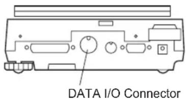
text_image
DATA I/O Connector2 Disconnect the power to the balance and the electronic printer.
3 Connect the DATA I/O connector of the balance to the electronic printer using the attached cable of the printer.
4 First turn ON the power to the balance, then turn ON the power to the electronic printer.

Notes
- Read the instruction manual of the electronic printer.
- When using EP-80 simultaneously with WindowsDirect function, communication settings are different. Follow 6.2.1 for setting the balance.
- Date and time output: Press and hold the balance's [PRINT] key for about 3 seconds
15.2 Personal Computer - RS-232C -
15.2.1 Connecting the Cable

Notes
- The cable must have the correct connections as shown in the diagram below.
- Cables with the connections shown below and the special accessory RS-232 cable are not guaranteed to operate properly for all types of computers and devices.
For DOS/V computers (D-sub9 pin) (Null-modem)
Computer side Balance side
RXD 2 ---- 2 TXD
TXD 3 ---- 3 RXD
DTR 4 ---- 6 DSR
SG 5 ---- 7 SG
DSR 6 ---- 20 DTR
RTS 7 5 CTS
CTS 84 RTS


15.2.2 Data Format
The detailed information on the standard format for Shimadzu electronic balances (Menu item 7.7 EB type". Refer to 15.3.3) is given here.
(1) Basic format
An example of data format of a negative value (-186.65g) with delimiter of C/R is shown.
The data length varies depending on attached information, unit expression and delimiter as explained in (2).
| Data length of this example: 12 bytes | ||||||||||||
| Position | 1 | 2 | 3 | 4 | 5 | 6 | 7 | 8 | 9 | 1 | 0 | 1 |
| ASCII code | 2DH | 20H 20 | H 31H | 38H 36 | H 2E | H 36 | H 35H | 67H 20 | 0H 0DH | |||
| Data | - | 1 | 8 | 6 | . | 6 | 5 | g | C/R | |||
Remarks
Position 1: For a positive value, " " (space) (20H), and for a negative value, "-" (2DH) is in this position.
Positions 2 to 9: The absolute value. When the numerical value does not use all the 8 positions, the code for space is entered to each excessive position as shown in this example.
Positions 10,11: One or two letters indicating the weighing unit. As shown in this example, the code for space is entered at position No.11 if only one letter is used for the unit.
Position 12: Code for delimiter.
(2) Information of additional bytes
(i) Output with stability information
When outputting data with stability information (Refer to 15.2.3 (4)-(i)), either of the following characters is added in front of Character No.1 in the example. Consequently, the data becomes 1 byte longer.
When stable: S
When unstable: U
(ii) Verified balance as a legal measuring instrument
The brackets “[ ]” bordering auxiliary indicating device of legal measuring instrument can also be outputted. In this case, “[” and “]” are inserted according to their positions in the weighed data. They come to the positions before and after Position No.9 in the example. Consequently, the data becomes 2 bytes longer.
(iii) Unit expressed with three letters
Some weighing units are expressed with three letters. Therefore one more byte is inserted after Position No.11 in the above example. Consequently, the data becomes 1 byte longer.
15. Connecting Peripheral Instruments
(iv) When the delimiter “C/R+L/F” is selected (Menu item No.96. Refer to 15.3.7.)
The delimiter information requires one more character. Therefore one more byte is added after Position No.12 in the above example. Consequently, the data becomes 1 byte longer.
(3) Data format in case of "oL" or "-oL" (Overload)
The below is the data format for "oL".
| Data length of this example: 12 bytes | ||||||||||||
| Position | 1 | 2 | 3 | 4 | 5 | 6 | 7 | 8 | 9 | 1 | 0 | 1 |
| ASCII code | 20H | 20H 20H | 20H 20H | 20H 4FH | 4CH | 20H 20H | 20H 20H | 20H 0DH | ||||
| Data | O | L | C | / | R | |||||||
1 1 2
For "-oL" (negative overload), Position 1 is replaced with "-" (minus, ASCII code: 2DH).
The following parts appearing in “(2) Information of additional bytes” also apply to (3).
(i) Output with stability information
(iv) When the delimiter "C/R+L/F" is selected
15.2.3 Using Command Codes

Note
If communication conditions are incorrectly set, a communication error message "ComErr" is displayed.
(1) Commands that end with a number, character, or symbol other than [=]: Transmit to the balance with a delimiter for each command code.
Example 1: PRINT
(2) Commands that end with a [=]: Transmit the number to the balance with a delimiter.
Example 2: TIME=1234
Example 3: P.TARE=1.23
Example 4: P.TARE=0.00

Note
Number of digits, decimal point, position of decimal point of the numeral transmitted succeeding to ‘=’ are the same as the case of setting the numeric value using the AKB-301 Application Keyboard.
Use the same number of decimal places as in the gram-display.
This restriction does not apply to USER=, SOLID=, and LIQUID=.
Example 5: MENU=4630
This is the same in the following operation.
.. from mass display, press the [CAL] key five times, then press the [O/T] key once and the press the [CAL] key six times. This returns to the same display as if the [CAL] key was never pressed.
Press the [O/T] key once, then [CAL] key three times, and the [O/T] key once more.
This example indicates that menu item 25 (Anti-vibration mode) is selected.
15. Connecting Peripheral Instruments

Notes
- If there is 0 in the four-digit number, the setting is complete at that point and menu selection is ended.
- The result of this command varies depending on the type of the balance.
Example 6: # = 2.56 < CR>
Example 7: #=12.345.67
A personal computer can instruct the weighing and display a specific number on the balance.
With the commands in Example 6 &7, [#2.56] and [#12.345.67] are displayed on the balance. When the operator presses the [PRINT] key, the character string '2-56
(3) Echo back command
The balance again transmits the character strings of N pieces included between an echo back command ‘{’ or ’’ and the delimiter.
An unprocessed echo back command is not left in the receiving buffer of the balance, N ≤ 30 .
Example 8: ABCDEFG12345
... After receiving this command, the balance outputs ABCDEFG12345

Note
Only capital alphabets and a part of symbols (decimal point, symbol etc.) can be used when printing with an electronic printer. A maximum of 15 characters per line.
(4) Command codes for Format EB type (menu item 7778Format Old EB type (menu item ) □
(i) Commands related to output
D01 Continuous output*
D03 Continuous output with stability information*
D05 Single output
D06 Auto Print setting (type of Auto Print is set separately)
D07 Single output with stability information*
D09 Release of continuous output and Auto Print
(The balance continuously outputs every about 80ms**)
*Not applicable to a verified balance as a legal measuring instrument in the EU
**Handshake is "OFF" or "Hardware"
(ii) Commands related to operation keys
POWER Equivalent to the [POWER] key.
Q Equivalent to the [POWER] key.
MENU Equivalent to the [CAL] key.
TARE Equivalent to the [O/T] key.
T Equivalent to the [O/T] key.
UNIT Equivalent to the [UNIT] key.
PRINT Equivalent to the [PRINT] key.
POWER+ Equivalent to holding the [POWER] key for approximately 3 seconds.
MENU+ Equivalent to holding the [CAL] key for approximately 3 seconds.
UNIT+ Equivalent to holding the [UNIT] key for approximately 3 seconds.
PRINT+ Equivalent to holding the [PRINT] key for approximately 3 seconds.
RECALC Equivalent to the [RECALC] key of the AKB-301Application Keyboard.
C Equivalent to the [C] key of the AKB-301 Application Keyboard.
(iii) Commands related to application measurement
PEAK Sets the Peak Hold mode.*
AZERO Sets the Auto Zero mode ON.*
INTERVAL Sets the Interval Timer mode.*
MEMORY Sets the Formulation mode.
M Immediately operates after setting the Formulation mode.
ADDON Sets the Add-on mode.
+ Immediately operates after setting the Add-on mode.
A Sets the Animal Weighing mode.*
ANIMAL Sets the Animal Weighing mode.*
R Releases the Application weighing mode.
(iv) Commands related to unit conversion
g Switches to "g" unit.
kg Registration of "kg" unit and switching.
mg Registration of "mg" unit and switching.*
PERCENT Registration of “%” unit and switching.
% Sets 100% when display is in “%” unit.
G g ← → % switching.
PCS Registration of "PCS" unit and switching.
CT Registration of "carat" unit and switching.
MOM Registration of "momme" unit and switching.*
SDENSE Registration of "solid density" unit and switching.
LDENSE Registration of "liquid density" unit and switching.
CU Switches to "user" unit (Set the conversion coefficient beforehand.).
RSTUNIT Returns the default units.
*Not applicable to a verified balance as a legal measuring instrument in the EU
15. Connecting Peripheral Instruments
(v) Readout commands of set value
TARGET Readout of target set value.
LIMIT Readout of limit set value.
G.LO Readout of lower limit set value in Checkweighing Display 1.
G.LO Readout of upper limit set value in Checkweighing Display 1.
L.LO Readout of lower limit set value in Checkweighing Display 2.
L.UP Readout of upper limit set value in Checkweighing Display 2.
UW Readout of unit weight set value.
G/PCS Equivalent to g/PCS key.
CALWT Readout of external weights set value for span calibration.*
ACALT1 Readout of Clock-CAL time 1.
ACALT2 Readout of Clock-CAL time 2.
ACALT3 Readout of Clock-CAL time 3.
P.TARE Readout of Pretare set value.*
ZRNG Readout of Zero Range set value.
USER Readout of user unit conversion coefficient.*
VOL Readout of reference weight set value.
DENSE Readout of surrounding liquid density set value.
I.TIME Readout of Interval Timer set value.*
(vi) Commands for numeric value setting
CALWT= Sets external weights value for span calibration.*
ACALT1= Sets Clock-CAL time 1.
ACALT2= Sets Clock-CAL time 2.
ACALT3= Sets Clock-CAL time 3.
P.TARE= Sets Pretare value.*
ZRNG= Sets Zero Range value.
UW= Sets unit weight.
USER= Sets user unit conversion coefficient.*
VOL= Sets volume of reference weight.
SDENSE= Sets surrounding liquid density.
I.TIME= Sets interval timer value.*
DATE= Sets the date.
TIME= Sets the time.
TARGET= Sets the target value.
LIMIT= Sets the limit value.
G.LO= Sets the lower limit value of Checkweighing Display 1.
G.UP= Sets the upper limit value of Checkweighing Display 1.
L.LO= Sets the lower limit value of Checkweighing Display 2.
L.UP= Sets the upper limit value of Checkweighing Display 2.
PCS= Sets the arbitrary loading piece.
= Corresponds to numeral keys of AKB-301 Application Keyboard.
ID= Sets ID.
PASSSET= Sets PCAL password.*
PASS= Inputs PCAL password.*
*Not applicable to a verified balance as a legal measuring instrument in the EU
(vii) Commands of special functions
CAL Enters Span Calibration mode.
C18 Enters Span Calibration mode.
LOCK Sets menu lock.
RELEASE Releases menu lock.
TIME Readout of date and time.
ADJCLK Adjusts ± 30 seconds.
RSTMN Menu reset.
MENU= Sets arbitrary menu.
{ Echo back.
} Echo back.
[α] Sets to Multi-Connection mode. (α represents a lower-case alphabet character.)

Note
For Multi-Connection mode, refer to Section "15.2.4 Multi-Connection Mode".
(5) Compatible commands with Mettler Toledo ^® PR and SR series Electronic Balances
S One time output at a stable state
SI Immediate one time output*
SIR Continuous output*
SR Continuous output at a stable state
T Taring after stabilized
TI Immediate taring*
Z Zero setting (same as immediate taring)*
(6) Compatible commands with Sartorius ^ IS series Electronic Balances

Note
*Not applicable to a verified balance as a legal measuring instrument in the EU
15. Connecting Peripheral Instruments
15.2.4 Multi-Connection Mode
A maximum of 26 UW/UX series balances can be connected to one personal computer at the same time. This is called “Multi-Connection mode.” To use the balance in this mode, prepare RS-232C cables in the number of balances connected, and the optional IFB-102A RS-232C Interface.
Connecting Method
Example for connecting 10 units of UW/UX series balances to one personal computer is shown in the diagram below.

flowchart
graph TD
    A["Personal computer IFB-IFB"] --> B["UW or UX [j"] UW_or_UX["i"] UW_or_UX["a"]]
    B --> C["..."]
    C --> D["Output"]
Assignment of Identification Name
In this example (10 balances connected to one computer), assign the identification name in lower-case alphabets.
Since 10th character of alphabet is “j,” assign “j” to the balance closest to the personal computer, “i” to next closest balance, and so on, back to “a.”
Setting to Multi-Connection Mode
1 Adjust the communication menu settings of all the balances to the specification of the personal computer, and then, turn off the power to all balances.
2 Start supplying the power to the whole system. Wait until all balances display OFF.
3 Send “[α]
is the name of the balance next to the personal computer. In the example above, lower-case “j.”
This command is valid only one time after turning the power ON.
Respective balances automatically enter the Multi-Connection mode and the mass is displayed.
On this process, the name smaller than the sent command by one, i.e. "[i]
4 This procedure completes the setting to the Multi-Connection mode.
BALANCE (No) Command (PC) RETURN DATA (PC)
a [a] PRINT [a] PRINT
0.0g
b [b] PRINT [b] PRINT
0.0g
c [c] PRINT [c] PRINT
0.0g
d [d] PRINT 0.0g
(nearest to PC) (No Data)
Command Codes in the Multi-Connection Mode
Only the commands shown below are valid in the Multi-Connection mode.
(α is the name of the balances.)
[α]TARE Same as the operation of pressing the [O/T] key of the balance “α”.
[α]T Same as the operation of pressing the [O/T] key of the balance “α”.
[α]POWER Same as the operation of pressing the [POWER] key of the balance “α”.
[α]Q Same as the operation of pressing the [POWER] key of the balance “α”.
[α] PRINT Same as the operation of pressing the [PRINT] key of the balance “α”.
[α]D05 Same as the operation of pressing the [PRINT] key of the balance “α”.
[α]D07 Same as sending the D07 command to the balance “α”.
[α]UNIT Same as the operation of pressing the [UNIT] key of the balance “α”.
[α]CAL Same operation as sending the CAL command to the balance “α”.
[α]UNIT+ Same as the state of holding down the [UNIT] key of the balance “α”.
Format of Output Data from the Balance
The output data from the balance “ ” is performed with the following format.
"[α]" data
Format of the load data is the same as the normal output form (Format EB type).
Operation is not guaranteed for the data containing characters, such as printing of date, time, and calibration document etc.
15. Connecting Peripheral Instruments
Restricted Items in the Multi-Connection Mode
- Multi-Connection mode is not designed for each balance to independently send the data.
This mode is for sampling the data by control of multiple balances with one PC. This is not the function to support multiple balances for sending the data separately.
When multiple number of data and commands exist on the system at the same time, the balance may not operate normally. For example, multiple data may exist simultaneously on the system when using multiple balances in the Application Measurement mode such as Auto Print or Continuous Output, or pressing the [PRINT] key. Normal operation cannot be guaranteed.
- Peripheral instruments connected to the DATA I/O or IFB-102A connector, such as an EP-50 Electronic Printer, cannot be used.
- The communication formats can only be used with "Format EB type". Delimiters cannot be used with menu items 97-98 (setting for WindowsDirect).
- It will take an average 0.05×N seconds for the data from the personal computer to reach balance unit N, even at setting of 38400 bps. Also, it will take almost the same time for the data from the balance in the Nth position to reach the personal computer.
Cancellation of Multi-Connection mode
Multi-Connection mode cannot be canceled unless the power for all balances is turned OFF.
15.3 Communication Setting
15.3.1 Overview
This menu is used to set the specifications for communication between the balance and a personal computer or electronic printer.

Notes
- This menu affects both the RS-232C and DATA I/O at the same time. For the instrument to be connected to the DATA I/O connector such as an electronic printer, select the communication setting of the balance to the default settings, which are menu items 76 77,83 89 92 94 □ However, select WindowsDirect setting (6.2.1) and follow the manual of the electronic printer when using EP-80 or EP-50WIN Electronic Printer simultaneously with WindowsDirect.
- When WindowsDirect function is set by the procedure described in 6.2.1, the communication settings are the same as selecting menu items 74,77,81,89,92,97, □.
15.3.2 Handshaking
Handshaking determines whether the peripheral equipment can receive communication data from the balance. This function does not relay the status of the balance to the peripheral equipment.
The balance is able to receive as long as there is space in the receiving buffer of the balance. This function operates once “oFF” is displayed, operation in other states is not guaranteed.
When the balance output is retained by handshaking, the display of the balance is locked. Determine the specifications for handshaking.
To have software handshaking not performed, select menu item 73
To have software handshaking performed as the following, select menu item 74 After the balance receives X-OFF (13H), the balance output is retained. After the balance receives X-ON (11H), the balance output is initiated.
To have hardware handshaking performed as the following, select menu item 75 When DTR is OFF, the output from the balance is retained. When DTR is ON, the output from the balance is initiated.
To have timed hardware handshaking performed, select menu item 7.6
15.3.3 Format
Set the balance output data format.
The standard format for the Shimadzu electronic balance: Select menu item .77 The old output format for the Shimadzu electronic balance: Select menu item 78 The old output format is employed in the following models. EB-500, 5000, 280, 2800, AEL-1600, EB-50K (except -15)

Note
In this format, the number of the lowest place of menu item 70s assigned to identify the balance.
Compatible format for the PR and SR series of Mettler-Toledo electronic balances. Available commands, functions and responses are limited: Select menu item . 79
Compatible format for the IS series of Sartorius electronic balances. Available commands, functions and responses are limited: Select menu item . 80
15.3.4 Communication Speed
Select the communication speed (300, 600, 1200, 2400, 4800, 9600, 19200, or 38400 bps). Number of "b-xxx" shows bps (bits/second). Baud rate and bps are the same value. Select one of the menu items 86 88
15.3.5 Parity / Bit Length
Select the parity and bit length.
No parity, 8-bit length: Select menu item . 89 Odd number parity, 7-bit length: Select menu item . 90 Even number parity, 7-bit length: Select menu item . 91
15.3.6 Stop Bit
Select the number of stop bits.
Stop bit 1: Select menu item. 92
Stop bit 2: Select menu item. 93
15.3.7 Delimiter
The “delimiter” is used to separate individual pieces of data or commands. Set the delimiter as follows:
| Set to CR(0DH): Select menu item . | 94 |
| Set to LF(0AH): Select menu item . | 95 |
| Set to CR+LF(0D0AH): Select menu item . | 96 |
WindowsDirect setting (down) :
equivalent to pressing the Enter key of the computer after typing the value:
Select menu item 97
WindowsDirect setting (right):
equivalent to pressing the right arrow key of the computer after typing the value:
Select menu item . 98

Note
Settings for "WindowsDirect" (menu items 9798)
When these menu items are selected, it is not possible to send commands to the balance from the peripheral instruments.
15.4 Decimal Point Symbol in Output Data
The decimal point symbols in the outputted data to external devices can be selected from “.” (period) or “,” (comma) depending on your preference. Note that the decimal point expression on the balance display is always with “.” (period).
To select “.” as outputted decimal point, select menu item number 72a ECP-Pr
To select “,” as outputted decimal point, select menu item number72toECP-Cn”

Note
The setting made here in “Decimal Point Symbol in Output Data” will not be cleared with Menu reset (See 7.5.2).
16. Maintenance and Transportation
16.1 Maintenance
Use a soft damp cloth containing a neutral detergent to clean the balance.
Avoid using organic solvents, chemicals, or dusting sprays as they may damage the coatings of the balance or the display panel.
Attach the protective in-use cover (standard accessory) when the balance is used in an environment where it is susceptible to being soiled.
The pan can be removed and washed with water. Verify that the pan is completely dry before replacing it on the balance.
16.2 Moving the Balance
To carry the balance, hold the balance firmly with both hands.
To transport the balance, use the shipping carton used to deliver the balance.
For UW balances:
Before placing the balance into the shipping carton, remove the pan and pan supporter caps and verify that the transportation screws in the bottom of the balance have been tightened clockwise until they stop. Refer to 4.3.
For UX balances:
Remove the pan and pan supporter caps and place the balance in the packing case as it was shipped.

Caution
Failing to tighten the transportation screws, placing the balance on its side when turning the transportation screws, or failing to remove pan supporter caps before placing the balance upside down may cause serious damage to the mechanism.

Note
Using a verified balance as a legal measuring instrument in the EU:
Span calibration must be newly performed with the built-in calibration weight after the balance has been moved and re-installed, before using the balance as a legal measuring instrument in the EU.
17. Troubleshooting
17.1 General Display
Display Description of message
| --- | Wait for next display. |
| -10d- | Minimum display resolution is decreased by one decimal place.* |
| -1d- | Minimum display digit is returned to original state.* |
| -t, mE- | Date and time are being output. |
| Abort | Operation was aborted. |
| APL End | Application Measurement was released. |
| d ouEr | Calibration check detects too large error. (Contact your Shimadzu representative.) |
| d UndEr | Calibration check detects too large error. (Contact your Shimadzu representative.) |
| LoCHED | Menu lock is applied. |
| RELEASE | Menu lock is released. |
| RESET | Menu was reset. |
| SET | Contents of new setting and coefficient were stored. |
| oFF | Reset by power failure. |
| wR it | Built-in weight is moving. Wait. |
All numerals blinking Place the displayed calibration weight.
*Not applicable to a verified balance as a legal measuring instrument in the EU
17. Troubleshooting
17.2 Error Display
Error display Description Countermeasure
| CAL EO | Trouble in weight loading mechanism Check transportation screws. | |
| CAL E1 | The load on the pan is unstable at calibration. | Avoid wind and vibration. |
| CAL E2 | The drift of zero point is large at calibration. | Install the pan properly.Unload the pan. |
| CAL E3 | The drift is large at the time of PCAL. Use correct weight. | |
| CAL E4 | The drift is large at span calibration. Use correct weight. | |
| CAL ES | Calibration weight is wrong. Use correct weight. | |
| CHE x | Failure in the balance(Stops when this is displayed) | * |
| ComErr | Received command code is not correct. | Check delimiter etc. |
| DSP oL | Integer of the displayed unit exceeded 7 digits. | Decrease the load. |
| Err 0x | Failure in the balance. | * |
| Err 10 | PCAL password error. Check the password. | |
| Err 20 | Attempted to set improper numeric value. | Review the numeric value and decimal places. |
| LoCryEd | Menu item selection was attempted when menu is locked. | Release menu lock. (Refer to 7.5.3) |
| Err 24 | Supply voltage is abnormal. Check the supply voltage. | |
* Contact your Shimadzu representative.
17.3 Troubleshooting
| Symptom Probable cause(s) Countermeasure | ||
| Nothing is displayed. • The | AC adapter is disconnected.• The breaker of the room is off.• The voltage is wrong. | Check the power and connect AC adapter correctly. (See 4.1) |
| “OL” or “-OL” is displayed. | Transportation screws haven’t been loosened.(UW only) | Turn them anti-clockwise until they stop. (See 4.3) |
| The pan is displaced. Place the pan properly. | ||
| Pan supporter caps are not installed. | Install pan supporter caps. (See 4.3) | |
| The load on the pan is too large. Use balance within its capacity. | ||
| Display does not change when pan is loaded. | Pan is displaced. Place the pan properly. | |
| Display fluctuates. | Affected by vibration or air flow. | Install the balance at a proper site. (See 4.1)Try changing environment settings. ( See 11.) |
| Protective in-use cover touches the pan. | Adhere the cover firm to the balance body. (See 4.3) | |
| The weighed result is not accurate. | Span calibration has not been done. | Calibrate it properly. (See 10.) |
| Taring has not been done. | Tare before weighing. (See 5.1) | |
| Does not display the unit desired to use. | The unit has not been set up | Set it up in advance. (See 12.) |
| Menu item selection is rejected. | Menu Lock is ON. | Release Menu Lock. (See 7.5.3) |
| WindowsDirect does not work. | See “6. WindowsDirect Function” | |
| An error code is shown. | See “17.2 Error Display” | |
17.4 LCD (Liquid Crystal Display) Check
By selecting the whole lighting mode, the LCD can be easily inspected upon power is connected.
To have the display stop and hold at whole lighting after power is connected, select the menu item 37
When the display holds, press the [O/T] key to proceed to the mass display.
To have the display stop and proceeds to the mass display automatically, select the menu item 38.
(Refer to chapter 7 for menu item selection.)
If the display is not the same as the figure in 2.3, contact your Shimadzu representative.
Appendices
A-1. Menu Map
- Pressing [CAL] key moves to the next menu in the same hierarchy. ( ↓ in menu map)
- Pressing [O/T] key moves to the menu of one hierarchy down. (→ in menu map)
When no menu exists in the menu of one hierarchy down, it is fixed. - Pressing [POWER] key returns to the menu of one hierarchy up. (← direction in menu map)
Refer to 7.3 for menu item selection.
Important Note on Menu Item Selection
Even the desired menu item is reached and displayed, it is not yet set unless Stability mark (→) is illuminated with it. Do not fail to press [O/T] key to put Stability mark before returning to the mass display.
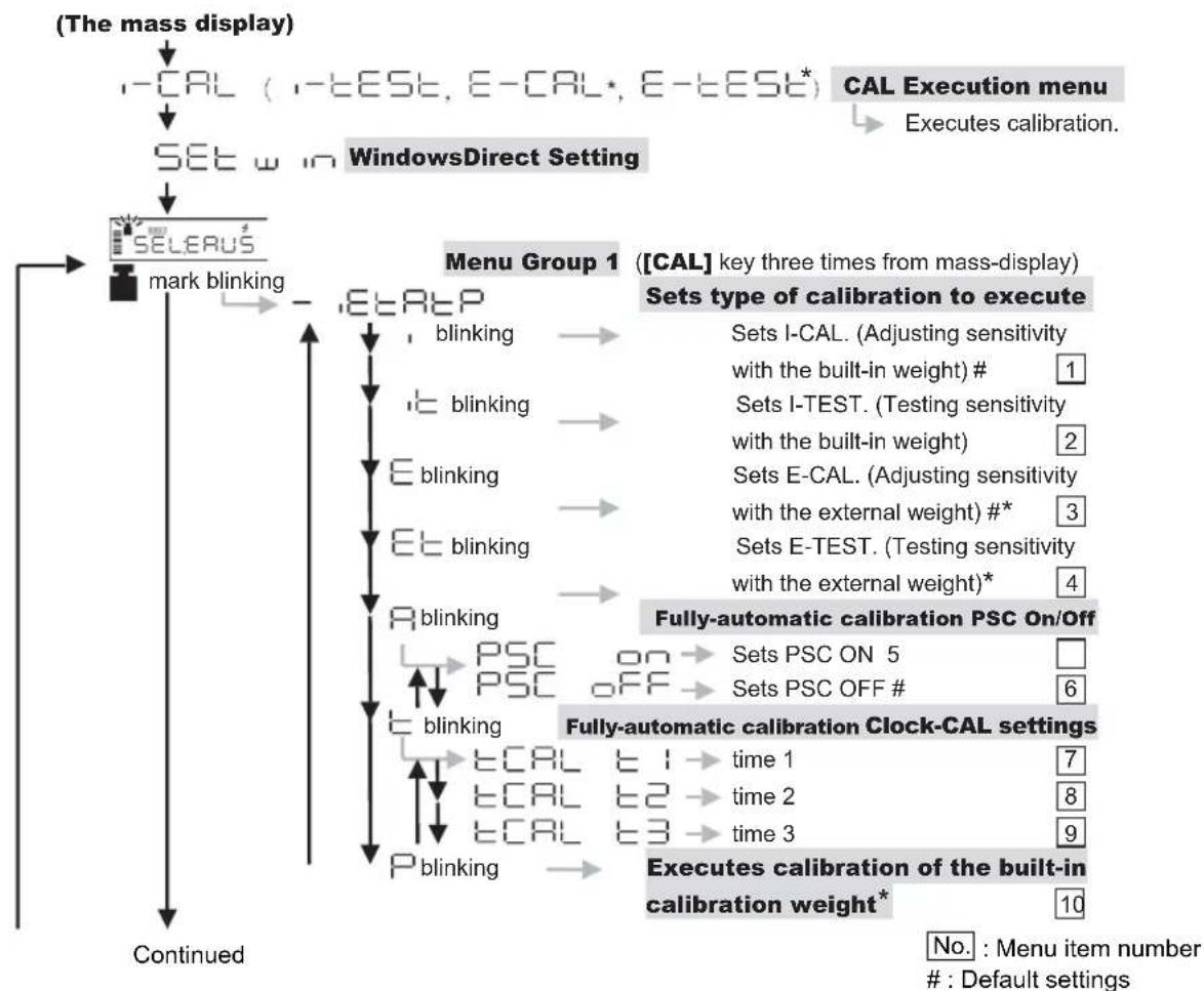
flowchart
graph TD
    A["(The mass display)"] --> B["CAL (I-TEST, E-CAL, E-TEST*)"]
    B --> C["SET w in WindowsDirect Setting"]
    C --> D["SELERUS"]
    D --> E["Mark blinking"]
    E --> F["Menu Group 1"]
    F --> G["ETRtP"]
    G --> H["blinking"]
    H --> I["E blinking"]
    I --> J["ET blinking"]
    J --> K["A blinking"]
    K --> L["PSC ON"]
    L --> M["PSC OFF"]
    M --> N["Blinking"]
    N --> O["ECAL t1 → time 1"]
    N --> P["ECAL t2 → time 2"]
    N --> Q["ECAL t3 → time 3"]
    O --> R["P blinking"]
    R --> S["Excludes calibration of the built-in calibration weight*"]
    S --> T["Fully-automatic calibration Clock-CAL settings"]
    T --> U["Sets PSC ON 5"]
    T --> V["Sets PSC OFF # 6"]
    U --> W["[CAL"] key three times from mass-display]
    V --> W
    W --> X["Sets I-CAL. (Adjusting sensitivity with the built-in weight) # 1"]
    W --> Y["Sets I-TEST. (Testing sensitivity with the built-in weight) 2"]
    W --> Z["Sets E-CAL. (Adjusting sensitivity with the external weight) #* 3"]
    W --> AA["Sets E-TEST. (Testing sensitivity with the external weight)* 4"]
    W --> AB["Fully-automatic calibration PSC On/Off"]
*Not applicable to a verified balance as a legal measuring instrument in the EU
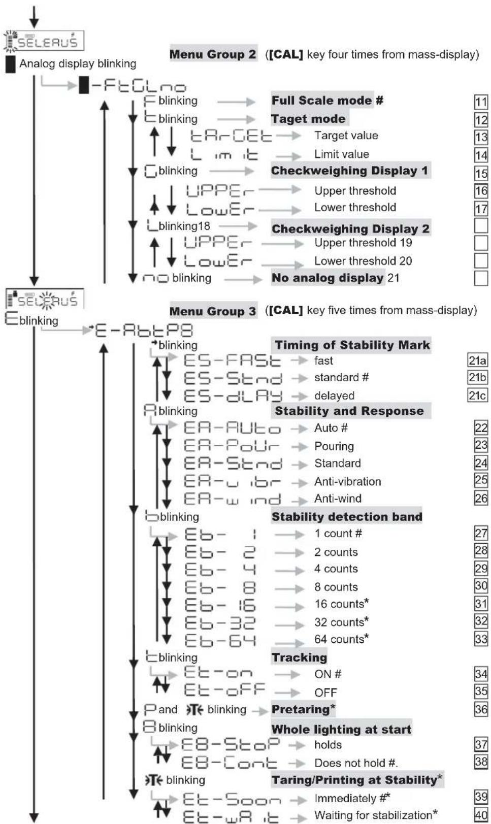
flowchart
graph TD
    A["SELEAUS"] --> B["Analog display blinking"]
    B --> C["Menu Group 2 (CAL key four times from mass-display)"]
    C --> D["Full Scale mode #"]
    D --> E["Target mode"]
    E --> F["Checkweighing Display 1"]
    F --> G["Checkweighing Display 2"]
    G --> H["Menu Group 3 (CAL key five times from mass-display)"]
    H --> I["Timing of Stability Mark"]
    I --> J["Stability and Response"]
    J --> K["Stability detection band"]
    K --> L["Tracking"]
    L --> M["Pretaring*"]
    M --> N["Whole lighting at start"]
    N --> O["Taring/Printing at Stability*"]

    subgraph Menu Group 2
        C1["Blinking"] --> C2["Target value"]
        C2 --> C3["Limit value"]
        C3 --> C4["Upper threshold"]
        C3 --> C5["Lower threshold"]
        C5 --> C6["Upper threshold 19"]
        C5 --> C7["Lower threshold 20"]
        C7 --> C8["No analog display 21"]
    end

    subgraph Menu Group 3
        H1["E-bLPS"] --> H2["E-ABLPS"]
        H2 --> H3["Timing of Stability Mark"]
        H3 --> H4["Stability and Response"]
        H4 --> H5["Stability detection band"]
        H5 --> H6["Tracking"]
        H6 --> H7["Whole lighting at start"]
        H7 --> H8["Taring/Printing at Stability*"]
    end
No.: Menu item number
: Default settings
*Not applicable to a verified balance as a legal measuring instrument in the EU
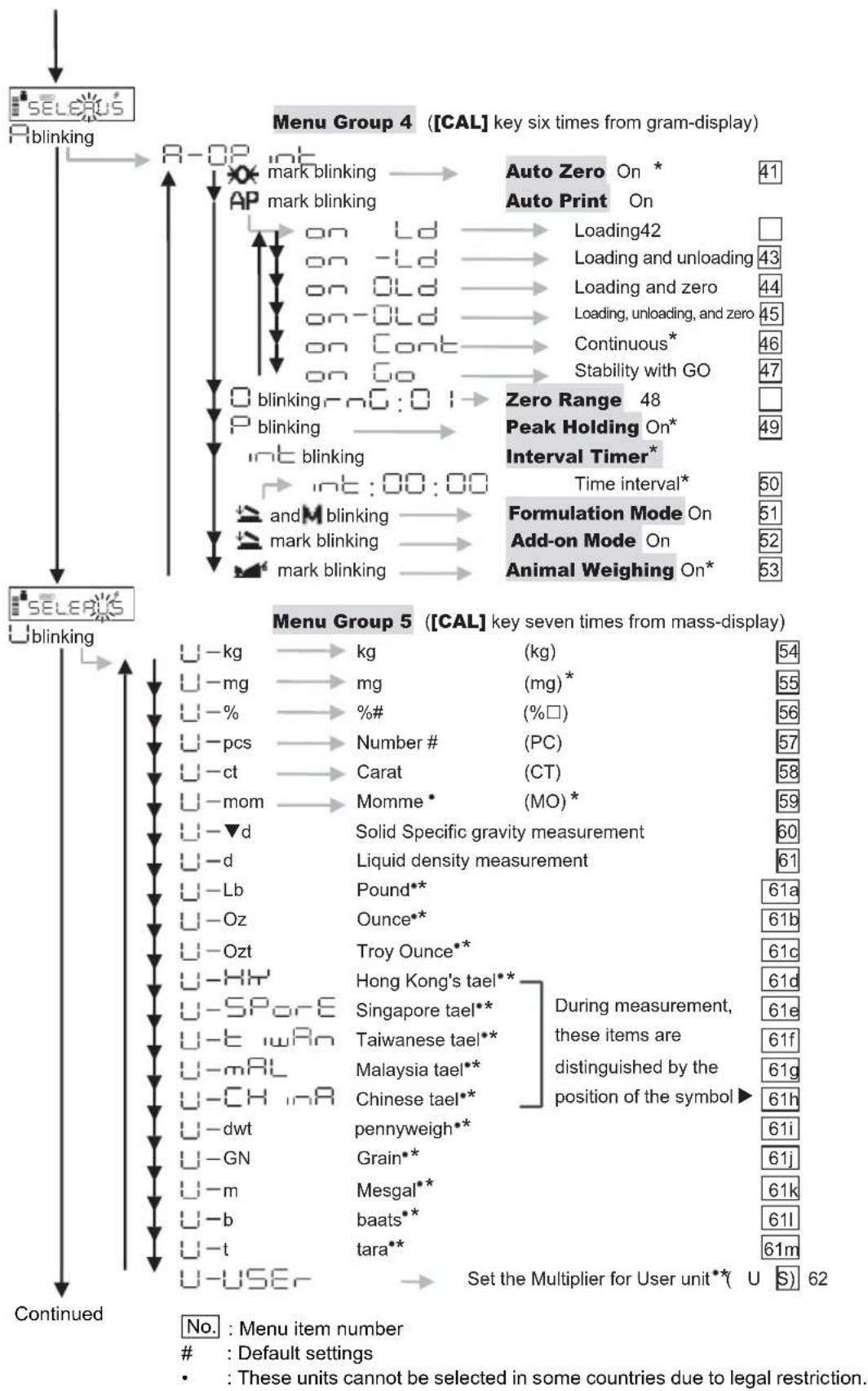
flowchart
graph TD
    A["Menu Group 4 (CAL"] key six times from gram-display] --> B["Menu Group 5 (CAL"] key seven times from mass-display]
    B --> C["Continued"]

    subgraph Menu Group 4
        D["Mark blinking"] --> E["Auto Zero On* 41"]
        F["AP mark blinking"] --> G["Auto Print On"]
        H["on Ld"] --> I["Loading42"]
        J["on -Ld"] --> K["Loading and unloading 43"]
        L["on Old"] --> M["Loading and zero 44"]
        N["on-Old"] --> O["Loading, unloading, and zero 45"]
        P["on Cont"] --> Q["Continuous* 46"]
        R["on Go"] --> S["Stability with GO 47"]
        T["O blinking-rnG:01"] --> U["Zero Range 48"]
        V["P blinking"] --> W["Peak Holding On* 49"]
        X["int blinking"] --> Y["Interval Timer*"]
        Z["int:00:00"] --> AA["Time interval* 50"]
        AB["andM blinking"] --> AC["Formulation Mode On 51"]
        AD marking blinking] --> AE["Add-on Mode On 52"]
        AF marking blinking] --> AG["Animal Weighing On* 53"]
    end

    subgraph Menu Group 5
        AH["U−kg"] --> AI["kg (kg) 54"]
        AJ["U−mg"] --> AK["mg (mg)* 55"]
        AL["U−%"] --> AM["%# (%□) 56"]
        AN["U−pcs"] --> AO["Number # (PC) 57"]
        AP["U−ct"] --> AQ["Carat (CT) 58"]
        AR["U−mom"] --> AS["Momme * (MO)* 59"]
        AT["U−▼d"] --> AU["Solid Specific gravity measurement 60"]
        AV["U−d"] --> AW["Liquid density measurement 61"]
        AX["U−Lb"] --> AY["Pound** 61a"]
        AZ["U−Oz"] --> BA["Ounce** 61b"]
        BB["U−Ozt"] --> BC["Troy Ounce** 61c"]
        DA["U−HY"] --> AE["Hong Kong's tael** 61d"]
        AFU["U−SPorE"] --> AV
        AWU["U−t iwRn"] --> AX
        AYU["U−mRL"] --> AZ
        AYV["U−CH inA"] --> BA
        AYW["U−dwt"] --> AZ
        AYX["U−GN"] --> AZ
        AYY["U−m"] --> AZ
        AYZ["U−b"] --> AZ
        AYWt["U−t"] --> AZ
        AYU["U−USER"] --> AZ
    end

    Note: The chart displays the menu item number as a default setting for the menu group. Note: These units cannot be selected in some countries due to legal restriction.
    Note: Set the Multiplier for User unit **(U S) 62.
*Not applicable to a verified balance as a legal measuring instrument in the EU
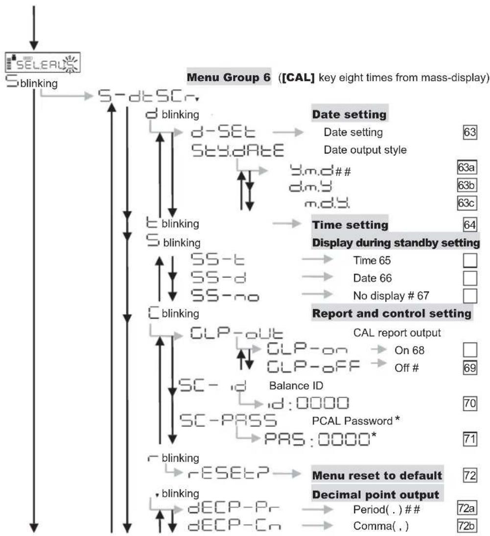
flowchart
graph TD
    A["SELEALS S blinking"] --> B["S-dtSCr"]
    B --> C["d blinking"]
    C --> D["d-SET"]
    D --> E["Sty.date"]
    E --> F["y.m.d##"]
    F --> G["d.m.y"]
    G --> H["m.d.y"]
    H --> I["T blinking"]
    I --> J["S blinking"]
    J --> K["SS-t"]
    K --> L["SS-d"]
    L --> M["SS-ro"]
    M --> N["C blinking"]
    N --> O["GLP-out"]
    O --> P["GLP-on"]
    P --> Q["GLP-off"]
    Q --> R["Balance ID"]
    R --> S["ID:0000"]
    S --> T["SC-PASS"]
    T --> U["PCAL Password*"]
    U --> V["PAS:0000*"]
    V --> W["r blinking"]
    W --> X["RESETP"]
    X --> Y["blinking"]
    Y --> Z["dECP-Pr"]
    Z --> AA["dECP-Cn"]
    AA --> AB["Menu Group 6 (CAL"] key eight times from mass-display]
    AB --> AC["Date setting"]
    AC --> AD["Date setting 63"]
    AC --> AE["Date output style 63a"]
    AC --> AF["63b 63c"]
    AB --> AG["Time setting 64"]
    AG --> AH["Time 65 □"]
    AG --> AI["Date 66 □"]
    AG --> AJ["No display # 67 □"]
    AB --> AK["Display during standby setting"]
    AK --> AL["Report and control setting"]
    AL --> AM["CAL report output On 68 □ Off # 69"]
    AL --> AN["70"]
    AL --> AO["71"]
    AL --> AP["Menu reset to default 72"]
    AL --> AQ["Decimal point output Period( . ) ## Comma( , ) 72a 72b"]
No.: Menu item number
: Default settings.
Settings are initialized to default by "Menu reset".
#: Default settings.
Settings are not initialized to default by "Menu reset".
*Not applicable to a verified balance as a legal measuring instrument in the EU
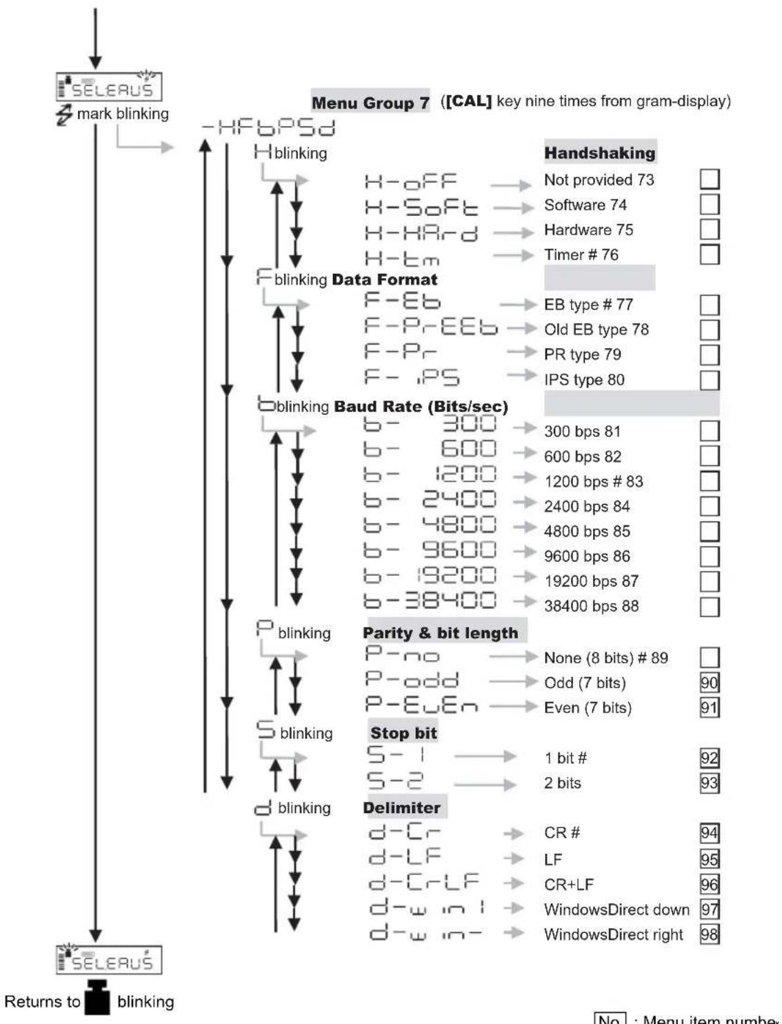
flowchart
graph TD
    A["Mark blinking"] --> B["Data Format"]
    B --> C["Baud Rate (Bits/sec)"]
    C --> D["Parity & bit length"]
    D --> E["Stop bit"]
    E --> F["Delimiter"]
    A --> G["Returns to blinking"]

    subgraph Menu Group 7 ([CAL] key nine times from gram-display)
        H["H-blinking"] --> I["H-off"] --> J["Software 74"] --> K["Hardware 75"] --> L["Timer # 76"]
        M["F-blinking"] --> N["F-EB"] --> O["Old EB type 78"] --> P["PR type 79"] --> Q["IPS type 80"]
        R["b-blinking"] --> S["b-300"] --> T["300 bps 81"] --> U["600 bps 82"] --> V["1200 bps # 83"] --> W["2400 bps 84"] --> X["4800 bps 85"] --> Y["9600 bps 86"] --> Z["19200 bps 87"] --> AA["38400 bps 88"]
        AB["b-blinking"] --> AC["P-blinking"] --> AD["S-blinking"] --> AE["d-blinking"]
    end

    H --> J
    I --> K
    J --> L
    K --> M
    L --> N
    M --> O
    N --> P
    O --> Q
    P --> Q
    Q --> R
    R --> S
    S --> T
    T --> U
    U --> V
    V --> W
    W --> X
    X --> Y
    Y --> Z
    Z --> AA
    AA --> AA
    AA --> AA
    AA --> AA
    AA --> AA
No. : Menu item number
: Default settings
A-2. Standard Accessories and Maintenance Parts List
| Item Part number Description | ||
| Pan (large pan) 321-51555 | ||
| Pan (small pan) 321-51556 | ||
| Pan supporter cap (for large pan) 321-51552-02 | ||
| Pan supporter cap (for small pan) 321-51552-01 | ||
| In-use protective cover 321-62395 For display and key part | ||
| In-use protective cover (5 pieces) 321-62395-10 For display and key part | ||
| Level screws 321-53530-30 | ||
| Windbreak main 321-62799-01 Standard for models with minimum display of 0.001g only | ||
| Windbreak lid 321-62798-01 | ||
| Windbreak fixing knob (1 piece) | 321-62787 | |
| Windbreak Set | 321-62797 | Set of 321-62799-01, 321-62798-01 and 2 pieces of 321-62787 |
| Rubber cap (1 piece) | 321-62794 For small pan model | |
| AC adapter | Contact your distributor | |
| Below-weigh hook cap | 321-51572-04 | |
A-3. Optional Accessories List
| Item Part number Description | ||
| EP-80 Electronic Printer 321-62675-01 | (w/o AC adapter) | Impact dot print, can be used with WindowsDirect |
| RS-232C Cable 25P-9P (1.5m) 321-60117-01 | For PC/AT, DOS/V serial port | |
| IFB-102A RS-232C Interface 321-41167-10 | Necessary for multi-connection | |
| IFB-102A-UNC RS-232C Interface 321-41167-20 Inch-size screws type, Necessary for multi-connection | ||
| AKB-301 Application Keyboard 321-53382-01 | ||
| Remote Display RDB-201 321-53600-01 With operation keys | ||
| Remote Display RDB-202 321-53600-02 Without operation keys | ||
| Windbreak Set 321-62797 For small pan model only (Standard for models with minimum display of 0.001g) | ||
| WBC-102 Glass Windbreak | 321-62795 | For small pan model only (with three sliding doors) |
| WBC-502 Large Size Windbreak | 321-53537 | For all models (opens upward with hinges) |
| FSB-102PK Foot Switch | 321-60110-11 | The same effect as [PRINT] key |
| FSB-102TK Foot Switch 321-60110-12 The same effect as [O/T] key | ||
| Animal Bucket Set | 321-62150 | For animal weighing, for large pan model only |
| Specific Gravity Measurement Kit SMK-101 | 321-60576-01 For large pan model only | |
| Specific Gravity Measurement Kit SMK-102 | 321-60576-02 | For small pan model only (except for UW/UX220H) |
| In-use protective cover (for large-pan model) | 321-53529-01 Covering whole main body | |
| In-use protective cover (for small-pan model) | 321-53529-02 Covering whole main body | |

Note
Part number and specification are subject to change without notice. It is not guaranteed that RS-232C cable will conform to all computers.
A-4. Specifications of Connectors
RS-232C Connector
| Pin No. | Name Function |
| 1 FG Frame ground | |
| 2 TXD Data output | |
| 3 RXD Data input | |
| 4 RTS Internal connection with CTS | |
| 5 CTS Internal connection with RTS | |
| 6 DSR Handshake (receiving) | |
| 7 SG Signal grounding | |
| 8 NC Blank | |
| 9 NC Blank | |
| 10 NC Blank | |
| 11 NC Blank | |
| 12 NC Blank | |
| 13 NC Blank | |
| 14 NC Blank | |
| 15 NC Blank | |
| 16 NC Blank | |
| 17 NC Blank | |
| 18 NC Blank | |
| 19 NC Blank | |
| 20 DTR Handshake (transmission) | |
| 21 NC Blank | |
| 22 NC Blank | |
| 23 NC Blank | |
| 24 NC Blank | |
| 25 NC Blank | |
KEY Connector
(When used for checkweighing output)
| Pin No. | Name Function | Remarks |
| 1 | GND | Ground of checkweighing |
| 2 | OPERATION | Output during weighing |
| 3 | STABILITY | Output while balance display is stable. |
| 10 | LO | LO signal output |
| 11 | GO | GO signal output |
| 12 HIGH | HI signal output | |
| 13 | ZERO | Output while balance display is zero |
| 9 | Pin 9 and Pin 15 must be short-circuited by the external device in order to use KEY Connector for checkweighing signal output. | |
| 15 | ||
Concept of Open Collector Circuit
(n=2,3,10,11,12,13)
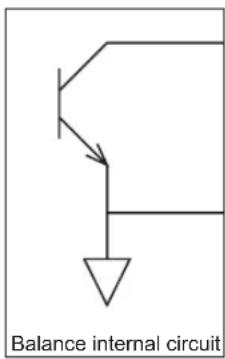
text_image
Balance internal circuit"Pin n" O.C. (+)
"Pin 1" (GND)
A-5. Table of Unit Conversion Constants
| Menu item number | Display | Unit | Conversion coefficient (1g=) | Minimum display in the unit (models with minimum display of 0.01g, as examples) | ||
| Center section (segmented character display) | Unit display section | Illuminated triangular symbols in the right end raw of the display; numbered from 1 to 4 from the top. | ||||
| 54 U- kg none kg 0.001 | 0.00001 | |||||
| 55 U- mg none mg* 100 | 0 10 | |||||
| 56 | U- | % | none | percentage | ____ | ____ |
| 57 | U- | pcs | none | piece counting | ____ | 1 |
| 58 | U- | ct | none | carat | 5 | 0.1 |
| 59 | U- | mom | none | momme* | 0.266667 | 0.005 |
| 60 | U- | ▼ d | none | solid specific gravity | ____ | ____ |
| 61 | U- | d | none | liquid density | ____ | ____ |
| 61a | U- | lb | none | Lb (pound)* | 0.00220462 | 0.00005 |
| 61b | U- | oz | none | Oz (ounce)* | 0.035274 | 0.0005 |
| 61c | U- | ozt | none | Ozt (troy ounce)* | 0.0321507 | 0.0005 |
| 61d | U-HK | tl | 1 | Hong Kong tael* | 0.0267165 | 0.001 |
| 61e | U-HK | tl | 2,3,4 | Hong Kong tael (jewel) * | 0.0267173 | 0.001 |
| 61f | U-SPorE | tl | 2 | Singapore tael* | 0.0264554 | 0.001 |
| 61g | U-twn | tl | 3 | Taiwan tael* | 0.0266667 | 0.001 |
| 61h | U-twn | tl | 1,2,4 | Taiwan tael* | 0.0266667 | 0.0002 |
| 61i | U- mAL | tl | 4 | Malaysia tael* | 0.0264600 | 0.0005 |
| 61j | U-CHinA | tl | none | China tael* | 0.0266071 | 0.0005 |
| 61k | U-CHinA | tl | 1,2,3,4 | China tael* | 0.0266071 | 0.001 |
| 61l | U- | dwt | none | dwt (pennyweight)* | 0.643015 | 0.01 |
| 61m | U- | GN | none | GN (Grain)* | 15.4324 | 0.2 |
| 61n | U- | t | none | tola* | 0.0857339 | 0.001 |
| 62 | U-USEr | 4 | User unit* | ____ | ____ | |
*Not applicable to a verified balance as a legal measuring instrument in the EU
A-6. Performance Checks
Not applicable to a verified balance as a legal measuring instrument in the EU

Notes
- Performance checks should be conducted in a room where there are no sudden temperature changes. Refer to the installation guidelines for the environmental factors that assure optimal performance.
- The following is a standard method used to determine whether the balance is working properly.
- The specific criterion should be set according to each user's quality goal.
Repeatability
1 Allow the balance to warm up sufficiently by turning ON the power and leaving it at the gram-display at least two hours before starting the performance checks.
2 Choose a weight that is near half the capacity of the balance. Load and unload the weight five successive times and record the following items: Xi: Displayed value when the weight is loaded. Yi: Displayed value when the weight is unloaded.
3 Use the formulas shown below to calculate the values Rx and Ry.
4 Balance repeatability is considered normal when both Rx and Ry are within five counts.
* One count corresponds to one minimum display unit of the balance model.
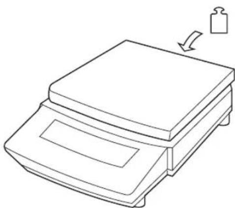
natural_image
Line drawing of a mechanical device with a weight attached, showing a base and top portion (no text or symbols)Load and unload a weight which is near the capacity of the balance five successive times.
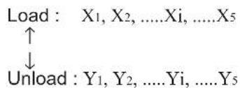
text_image
Load : X₁, X₂, ....Xᵢ, ....X₅ ↑ ↓ Unload : Y₁, Y₂, ....Yᵢ, ....Y₅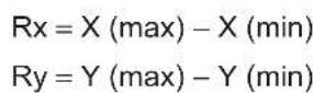
Cornerload Performance
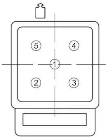
text_image
⑤ ④ ① ② ③1 Allow the balance to warm up sufficiently by turning ON the power and leaving it at the gram-display at least two hours before starting the performance checks.
2 Use a weight that is approximately 1/4 of the balance capacity and place it sequentially at five different positions on the pan in the order shown. Record the readings in each of the five positions.
3 If the difference between the readings at the center position and each of the off-center positions (eccentric error) is within five counts, the balance cornerload performance is considered normal.
* One count corresponds to one minimum display unit of the balance model.
A-7. Below-Weigh Hook Dimensions
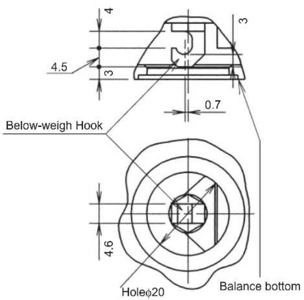
text_image
4.5 3 0.7 Below-weigh Hook 4.6 Holeφ20 Balance bottom(Unit: mm)
A-8. Index
A
AC adapter 8, 18, 103
Administrator 46, 47, 48
Air flow 8
Ambient temperature 6
Analog display 6, 32
Animal weighing 74, 85
Application keyboard ..... 33, 71, 85, 86, 104
Auto print 27,59
Auto zero 61,85
Automatic span calibration 45
Averaging 49, 50
B
Bar graph display 38
Basic operation 22
Battery pack 18
Baud rate 92
Below-weigh hook 3, 65, 67, 108
Bps 92
Built-in calibration weight 44, 45, 47
Built-in clock 36
C
Cable 25, 80, 88, 104
Calibration check 39, 43, 44
Calibration mass ( See Calibration weight)
Calibration report 48
Calibration weight ..... 20, 39, 42, 43, 44, 45, 46, 47
Checkweighing 55, 56, 60
Clock 36,45
Clock-CAL Fully-automatic Calibration ..... 45
Command code 83, 84, 89
Communication speed 92
Comparator 56
Computer 25,88
Connector 3,105
Continuous output 59
D
Data format 92
Date 36, 37, 86
Decimal point 33, 93
Default setting 34
Delimiter 93
Delivery 10
Density 65, 67
Display 5, 37, 38, 95, 96, 97
Dosing 49
E
Echo back 84, 87
Electronic printer 48, 79
Environment 49
Error code 97
Error display 23, 53, 96
External weight 20, 42, 43, 86
F
Filling 49
Foot Switch 104
Format 81, 92
Formulation 77
G
GLP 48
GMP 48
Graphic display 32
H
H type 1
Handshake 71
/
ID 48, 86
Impact dot 104
Appendices
Installation 8
Interval timer 71, 85, 86
In-use protective cover ....103
ISO9000 48
K
Key 4
L
Large pan model ....1
Last menu recall 34, 55, 65
LCD 6,97
Limit 55, 57, 86
M
Maintenance 94, 103
Menu 30
Menu group 32
Menu item selection ....30, 31
Menu lock 35,87
Menu map 30, 31, 98
Menu reset 34, 87
Minimum display 6, 38
Multi-connection 88
N
Numerical value ......33
0
Optional accessories 104
Output 48, 59, 60, 63, 84, 89, 92
P
Parity 92
Password ....46, 47, 86
PCS 58, 85, 86
Peak hold 69, 85
Percentage 54
Performance check 107
Peripherals ( See Optional accessories)
Personal computer 88
Piece counting 53, 58
Pouring mode 49
Power source 8,18
Pretare 64,86
Printing (→Also See "Output") 63
R
Readability (→See Minimum display)
Remote display 104
Response 49
s
S type 1
Sensitivity adjustment ( See Span calibration)
Small pan model 1
Span calibration ..... 19, 20, 39, 40, 42, 44, 45, 86, 87
Specific gravity 65, 104
Specification 6
Stability 49, 63
Stability detection band 50
Stability mark 5, 22, 52
standard accessories 103
Stand-by 5,37
Stop bit 92
T
Target 55, 57, 86
Taring 22,63
Time 37,45,86,87
Tracking 52
Transportation 13, 94
Troubleshooting 28, 95, 97
U
Unit 4,23,53,85,86
Unit conversion 32, 85, 106
Unit weight 58, 86
Unpacking 10
User unit 53, 86
V
Vibration 8, 49, 50
W
Weighing 22, 23
WindowsDirect 24,93
Z
Zero range 62
Zero tracking 52

SHIMADZU
[Explanatory Operation Sheet]
Key Switch Basic Function
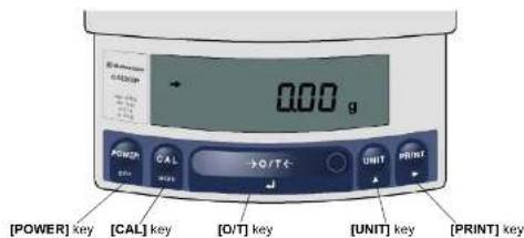
text_image
0.00 g POWER | CAL | O/T | UNIT | PRINT | [POWER] key | [CAL] key | [O/T] key | [UNIT] key | [PRINT] keyKey function during basic weighing (Refer main manual 2.2 for details)
| [POWER] Switches between operation and stand-by (On/Off). | |
| [CAL] Enlers span calibration or menu item selection. | |
| [O/T] Tares the balance (Displays zero with a container on the pan) | |
| [UNIT] Switches weighing units | |
| [PRINT] | Output the displayed data to an electronic printer or a computer.To output date and time > Press and hold for about 3 seconds |
Stabilizing Display / Faster Response for Filling
- If it is unavoidable to install the balance at a location subject to air flow or vibration, try changing the environmental settings to stabilize the reading.
(From mass display) Press [CAL] repeatedly till "E" is blinking in "SEL:EAUS" display → Press [O/T] ("→E- AbtP8" is displayed with "→" blinking) → Press [CAL] once ("A" blinks) → Press [CAL] repeatedly until "EA-vibr" is displayed → Press [O/T] (Stability mark → is added to "EA-vibr") → Press [POWER] repeatedly to return to mass display.
This setting will bring more stability, however response will be slower. If further stability is desired, select "EA-wind" instead of "EA-vibr" in the above procedure.
- If faster response is required for filling or dosing purpose, select "PoUr" instead of "EA-vibr" in the above procedure. Pouring mode is set and the response will be very fast, but display unstable. Refer to 11.2 for details of Pouring mode.
Hints on Fully-automatic Span Calibration(UW series only)
Fully-automatic span calibration PSC
Default setting of PSC is ON. Upon detection of temperature change, span calibration is automatically performed to maintain accuracy. The Weight symbol links prior to fully-automatic calibration.
How to skip a PSC calibration
Press [POWER] key while Weight symbol blinking.
UW/UX Series
321-56829-217
Nov. 2010

How to switch off PSC
(From mass display) Press [CAL] repeatedly till Weight symbol is blinking → Press [O/T] (“-I/EATP” is displayed with “i” blinking) > Press [CAL] repeatedly until “A” blinks > Press [O/T] (“PSC on” is displayed) → Press [CAL] (“PSC off” is displayed) → Press [O/T] (Stability mark) → is added) > Press [POWER] repeatedly to return to the mass display.
When PSC is off, perform span calibration according to Span Calibration Procedure when it is necessary. Using a verified balance as a legal measuring instrument in the EU:
When PSC, fully-automatic span calibration, is not activated, operator must carry out span calibration with the built-in weight (refer to the following) upon blinking of the Weight Symbol.
Clock-CAL is a practical alternative that performs regular automatic span calibration according to time setting (UW series only, up to 3 times a day, refer to main manual 10.3.3).
Span Calibration Procedure
Calibration is required to accurately weigh items with an electronic balance.
Calibration should be performed:
- When the location of the balance is changed, even within the same room.
- When the room temperature changes considerably.
- Periodically, according to the quality control plan of the user.
Before span calibration, verify that the balance is in the mass-display and that the pan is empty.
UW series [Span Calibration Using the Built-In Weight]
(1) Press the [CAL] key once. "I-CAL" is displayed.
(2) Press the [O/T] key. After "i-CAL3" ... "i-CAL1", and "SEI", "CAL End" are displayed indicating the completion of span calibration, the mass-display will return.
![Shimadzu UW8200SV - UW series [Span Calibration Using the Built-In Weight] - 1](/content/2026/05/790010/images/ca6aad989f2743a9665e77cf48b2f1a5fe2a86c2209e3fe055adb4ff40116b29.jpg)
text_image
POWER OK CAI NEW → O / T ← UNIT PRINT (1) (2)• This is the calibration of default setting. Refer to 10.3.1 for the use of external weights (Not applicable to a verified balance as a legal measuring instrument in the EU).
UX series [Span Calibration Using External Weights]
Not applicable to a verified balance as a legal measuring instrument in the EU
![Shimadzu UW8200SV - UX series [Span Calibration Using External Weights] - 1](/content/2026/05/790010/images/addfe5349416173e104b3a866e05be4eca27be329895de7608db4bf906608e4d.jpg)
text_image
(1) (2) (3) (4) (3) (4)(1) Press the [CAL] key once. "E-CAL" is displayed.
(2) Press the [O/T] key.
The value of the correct calibration weight to be loaded is displayed and blinks.
(3) Load the indicated calibration weight and press the [O/T] key.
(4) When the zero display blinks, unload the weight from the pan and press the [O/T] key. "SEt" is displayed briefly to indicate completion of span calibration. Then the mass-display will return.
Menu Map
321-56829-21F
Nov. 2010
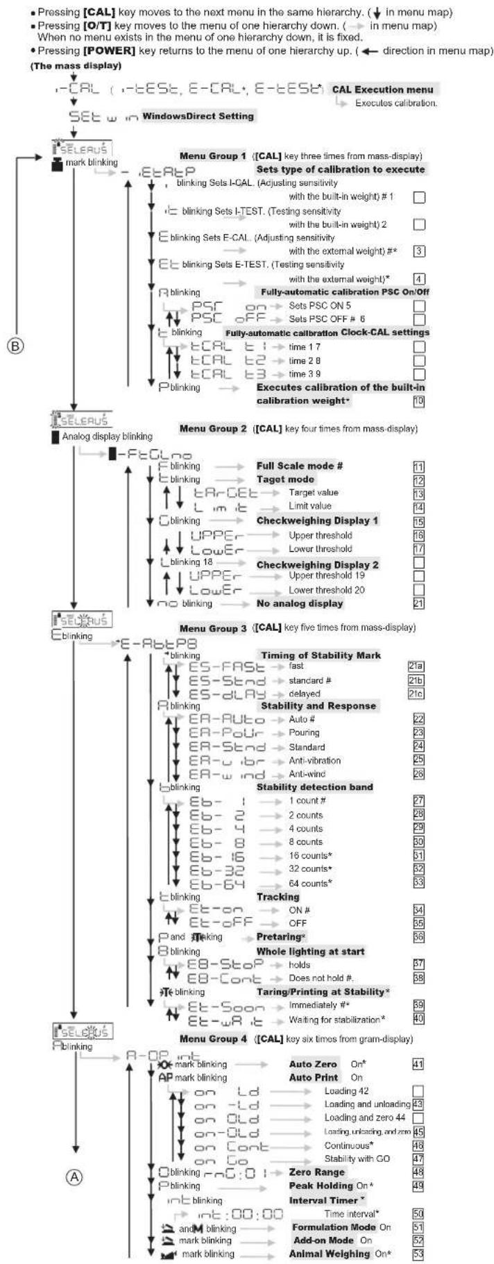
flowchart
CAL-based menu control flowchart with four groups, showing key states (user, menu, display) and their functions like blinking, target mode, and stability metrics.Cannot enter the menu?
"LoCKEd" is displayed and returns to mass display when menu access is attempted? → Menu is locked. How to remove Menu Lock
Press [POWER] (It goes STAND-BY) → Disconnect power cable → Connect power cable again (Displays proceed and it stands at "oFF") → Press [CAL] (Displays proceed: "RELEASE" then "oFF") → Press [POWER] (It returns to the mass display) (Refer to 7.5.3 for detail.)
Refer to main manual 7.3 for menu item selection.
Important Note on Menu Item Selection!
Even the desired menu item is reached and displayed, it is not yet set unless Stability mark ( ) is illuminated with it. Do not fail to press [O/T] key to put Stability mark before returning to the mass display.
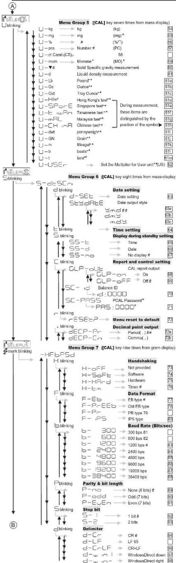
flowchart
graph TD
    A["Menu Group 5 [CAL"] key seven times from mass-display] --> B["Menu Group 6 [CAL"] key eight times from mass-display]
    B --> C["Menu Group 7 [CAL"] key nine times from gram-display]

    subgraph Menu Group 5
        D1["SBlinking"] --> E1["SBlinking"]
        D2["SBlinking"] --> E2["SBlinking"]
        D3["SBlinking"] --> E3["SBlinking"]
        D4["SBlinking"] --> E4["SBlinking"]
        D5["SBlinking"] --> E5["SBlinking"]
        D6["SBlinking"] --> E6["SBlinking"]
        D7["SBlinking"] --> E7["SBlinking"]
        D8["SBlinking"] --> E8["SBlinking"]
        D9["SBlinking"] --> E9["SBlinking"]
        D10["SBlinking"] --> E10["SBlinking"]
        D11["SBlinking"] --> E11["SBlinking"]
        D12["SBlinking"] --> E12["SBlinking"]
        D13["SBlinking"] --> E13["SBlinking"]
        D14["SBlinking"] --> E14["SBlinking"]
        D15["SBlinking"] --> E15["SBlinking"]
        D16["SBlinking"] --> E16["SBlinking"]
        D17["SBlinking"] --> E17["SBlinking"]
        D18["SBlinking"] --> E18["SBlinking"]
        D19["SBlinking"] --> E19["SBlinking"]
        D20["SBlinking"] --> E20["SBlinking"]
        D21["SBlinking"] --> E21["SBlinking"]
        D22["SBlinking"] --> E22["SBlinking"]
        D23["SBlinking"] --> E23["SBlinking"]
        D24["SBlinking"] --> E24["SBlinking"]
        D25["SBlinking"] --> E25["SBlinking"]
        D26["SBlinking"] --> E26["SBlinking"]
        D27["SBlinking"] --> E27["SBlinking"]
        D28["SBlinking"] --> E28["SBlinking"]
        D29["SBlinking"] --> E29["SBlinking"]
        D30["SBlinking"] --> E30["SBlinking"]
        D31["SBlinking"] --> E31["SBlinking"]
        D32["SBlinking"] --> E32["SBlinking"]
        D33["SBlinking"] --> E33["SBlinking"]
        D34["SBlinking"] --> E34["SBlinking"]
        D35["SBlinking"] --> E35["SBlinking"]
        D36["SBlinking"] --> E36["SBlinking"]
        D37["SBlinking"] --> E37["SBlinking"]
        D38["SBlinking"] --> E38["SBlinking"]
        D39["SBlinking"] --> E39["SBlinking"]
        D40["SBlinking"] --> E40["SBlinking"]
        D41["SBlinking"] --> E41["SBlinking"]
        D42["SBlinking"] --> E42["SBlinking"]
        D43["SBlinking"] --> E43["SBlinking"]
        D44["SBlinking"] --> E44["SBlinking"]
        D45["SBlinking"] --> E45["SBlinking"]
        D46["SBlinking"] --> E46["SBlinking"]
        D47["SBlinking"] --> E47["SBlinking"]
        D48["SBlinking"] --> E48["SBlinking"]
        D49["SBlinking"] --> E49["SBlinking"]
        D50["SBlinking"] --> E50["SBlinking"]
        D51["SBlinking"] --> E51["SBlinking"]
        D52["SBlinking"] --> E52["SBlinking"]
    end

    subgraph Menu Group 5
        G1["u -kg"] --> H1["kg (kg)"]
        G2["u -mg"] --> H2["mg (mg)*"]
        G3["u -%"] --> H3["# (%,f)"]
        G4["u -pcs"] --> H4["# (%,f)"]
        G5["u -ct Carat (CT)"] --> H5["# (%,f)"]
        G6["u -mom"] --> H6["Momme* (MO)*"]
        G7["u -▼d"] --> H7["Solid Specific gravity measurement"]
        G8["u -d"] --> H8["Liquid density measurement"]
        G9["u -Lb"] --> H9["Pound*"]
        G10["u -Oz"] --> H10o["Counce*"]
        G11["u -Ozt"] --> H11["Troy Ounce*"]
        G12["u -HH"] --> H12["Hong Kong's tael*"]
        G13["u -SPore"] --> H13["Singapore tael*"]
        G14["u -t wan"] --> H14["Taiwanese tael*"]
        G15["u -mRL"] --> H15["Malaysia tael*"]
        G16["u -CH inA"] --> H16["Chiense tael*"]
        G17["u -dwt"] --> H17["pennyweigh*"]
        G18["u -GN"] --> H18["Grain*^*"]
        G19["u -m"] --> H19["Mesgal*^*"]
        G20["u -b"] --> H20["baats*^*"]
        G21["u -l"] --> H21["tara*^*"]
    end

    subgraph Menu Group 6
        I["S-dtSCn"] --> J["Sdltscn"]
    end

    subgraph Menu Group 6
        K["d blinking"] --> L["d-set SdydRte"]
    end

    subgraph Menu Group 6
        M["d blinking"] --> N["d-set SSdltc"]
    end

    subgraph Menu Group 6
        O["d blinking"] --> P["d-set GLP-out SC-d SC-PRSS"]
    end

    subgraph Menu Group 6
        Q["d blinking"] --> R["d-set RFP-Pr DECP-Cn"]
    end

    subgraph Menu Group 6
        S["dotted text: Date setting, Date output style, Time, Report and control setting, Decimal point output, Handshaking, Data Format, Baud Rate, Parity & bit length, Stop bit, Delimiter, etc."]
    end

    subgraph Menu Group 7
        T["slice BLPSd H blinking"] --> U[slice BLPSd H-bFF H-SoFt H-HAr d H-tm F-EB F-Pr-EEF F-Pr F-PS b-300 b-600 b-1200 b-2400 b-4800 b-9600 b-19200 b-38400 b-38400 b-38400 b-38400 b-38400 b-38400 b-38400 b-38400 b-38400 b-38400 b-38400 b-38400 b-38400 b-38400 b-3840
    end

    subgraph Menu Group 7
        V[slice BLPSd H-bFF H-SoFt H-HAr d H-tm F-EB F-Pr-EEF F-Pr F-PS b-300 b-600 b-1200 b-2400 b-4800 b-9600 b-9600 b-19200 b-38400 b-38400 b-38400 b-38400 b-38400 b-384
    end

    subgraph Menu Group 7
        W[slice BLPSd H-bFF H-SoFt H-HAr d H-tm F-EB F-Pr-EEF F-Pr F-PS b-300 b-600 b-1200 b-2400 b-4800 b-9600 b-9600 b-9600 b-9600 b-960
    end

    subgraph Menu Group 7
        X[slice BLPSd H-bFF H-SoFt H-HAr d H-tm F-EB F-Pr-EEF F-Pr F-PS b-300 b-600 b-1200 b-2400 b-4800 b-9600 b-9600 b-960
    end

    subgraph Menu Group 7
        Y[slice BLPSd H-bFF H-SoFt H-HAr d H-tm F-EB F-Pr-EEF F-Pr F-PS b-38400 b-38400 b-38400
    end

    subgraph Menu Group 7
        Z[slice BLPSd H-bFF H-bFF H-bFF hllngk hllngk hllngk hllngk hllngk hllngk hllngk hllngk hllngk hllngk hllngk hllngk hllngk hllngk hllngk hllngk hllngk hllngk hllngk hllngk hllngk hllngk hllngk hllngk hllngk hllng
    end

    subgraph Menu Group 7
        AA[slice BLPSd H-bFF sobe BLPSd H-bFF BLPSd BLPSd BLPSd BLPSd BLPSd BLPSd BLPSd BLPSd BLPSd BLPSd BLPSd BLPSd BLPSd BLPSd BLPSd BLPSd BLPSd BLPSd BLPSd BLPSd BLPSd BLPSd BLPSd BLPSd BLPSd BLPSd BLPSd BLPSd BLPSd BLPSd BLPSd BLPSd BLPSd BLPSd MLBSBLMSBLMSBLMSBLMSBLMSBLMSBLMSBLMSBLMSBLMSBLMSBLMSBLMSBLMSBLMSBLMSBLMSBLMSBLMSBLMSBLMSBLMSBLMSBLMSBLMSBLMSBLMSBLMSBLMSBLMSBLMSBLMSBLMSBLMSBLMSBLMSBLMSBLMSBLMSBLMSBLMSBLMSBLMSBLMSBLMSBLMSBLMSBLMSBLMSBLMSBLMLSMLBSMLMSBLMSBLMSBLMSBLMSBLMSBLMSBLMSBLMSBLMSBLMSBLMSBLMSBLMSBLMSBLMSBLMSBLMSBLMSBLMSBLMSBLMSBLMSBLMSBLMSBLMSBLMSBLMSBLMSBLMSBLMSBLMSBLMSBLMSBLMSBLMSBLMSBLMSBLMSBLMSBLMSBLMSBLMSBLMSBLMSBLMLSMLBSMLMSBlmsMLBSMLMSBlmsMLBSMLMSBlmsMLBSMLMSBlmsMLBSMLMSBlmsMLBSMLMSBlmsMLBSMLMSBlmsMLBSMLMSBlmsMLBSMLMSBlmsMLBSMLMSBlmsMLBSMLMSBlmsMLBSMLMSBlmsMLBSMLMSBlmsMLBSMLMSBlmsMLBSMLMSBlmsMLBSMLMSBlmsMLBSMLMBLMTsBLSsBLSsBLSsBLSsBLSsBLSsBLSsBLSsBLSsBLSsBLSsBLSsBLSsBLSsBLSsBLSsBLSsBLSsBLSsBLSsBLSsBLSsBLSsBLSsBLSsBLSsBLSsBLSsBLSsBLSsBLSsBLSsBLSsBLSlsBLSlsBLSlsBLSlsBLSlsBLSlsBLSlsBLSlsBLSlsBLSlsBLSlsBLSlsBLSlsBLSlsBLSlsBLSlsBLSlsBLSlsBLSlsBLSlsBLSlsBLSlsBLSlsBLSlsBLSlsBLSlsBLSlsBLSlsBLSlsCDSsBCsBCsBCsBCsBCsBCsBCsBCsBCsBCsBCsBCsBCsBCsBCsBCsBCsBCsBCsBCsBCsBCsBCsBCsBCsBCsBCsBCsBCsBCsBCsBCsBCsBCsBCsBCsBCsBCsBCsBCsBCsBCsBCsBCsBCsBCsBCsBCsBCsBCsFCDSbDSbDSbDSbDSbDSbDSbDSbDSbDSbDSbDSbDSbDSbDSbDSbDSbDSbDSbDSbDSbDSbDSbDSbDSbDSbDSbDSbDSbDSbDSbDSbDSbDSbDSbDSbDSbDSbDSbDSbDSbDSbDSbDSbDSbDSbDSbDSbDSbDSbDScDSDcDSDcDSDcDSDcDSDcDSDcDSDcDSDcDSDcDSDcDSDcDSDcDSDcDSDcDSDcDSDcDSDcDSDcDSDcDSDcDSDcDSDcDSDcDSDcDSDcDSDcDSDcDSDcDSDcDSDcDSDcDSDcDSDcDSDeHLDTLCFLDLDLDLDLDLDLDLDLDLDLDLDLDLDLDLDLDLDLDLDLDLDLDLDLDLDLDLDLDLDLDLDLDLDLDLDLDLDLDLDLDLDLDLDLDLDLDLDLDLDLDLDLDLDLDLDLDLDLDLDLDLDLDLDLDLDLDLDLDLDLDLDLDLDLDLDLDLDLDLDLDLDLDLDLDLDLDLDLDLDLDLDLDLDLDLDLDLDLDLDL DL DL DL DL DL DL DL DL DL DL DL DL DL DL DL DL DL DL DL DL DL DL DL DL DL DL DL DL DL DL DL DL DL DL DL DL DL DL DL DL DL DL DL DL DL DL DL DL DL DL DL DL DL DL DL DL DL DL DL DL DL DL DL DL DL DL DL DL DL DL DL DL DL DL DL DL DL DL DL DL DL DL DL DL DL DL DL DL DL DL DL DL DL DL DL DL DL DL DL DL DI<nl>
No. : Menu item number
: Default settings. Settings are initialized to default by "Menu reset".
# : Default settings. Settings are not initialized to default by "Menu reset".
• : These units cannot be selected in some countries due to legal restriction.