Revo - Uncategorized Lewmar - Free user manual and instructions
Find the device manual for free Revo Lewmar in PDF.


User questions about Revo Lewmar
0 question about this device. Answer the ones you know or ask your own.
Ask a new question about this device
Download the instructions for your Uncategorized in PDF format for free! Find your manual Revo - Lewmar and take your electronic device back in hand. On this page are published all the documents necessary for the use of your device. Revo by Lewmar.
USER MANUAL Revo Lewmar
natural_image
Line drawing of a mechanical component with no visible text or symbolsInstallation, Operation & Servicing Manual
1- Introduction
Dear Customer,
Thank you for choosing Lewmar. Lewmar products are world renowned for their quality, technical innovation and proven performance. With a Lewmar product you will be provided with many years of outstanding service.
Product support
Lewmar products are supported by a worldwide network of distributors and Authorised Service Representatives. If you encounter any difficulties with this product, please contact your national distributor, or your local Lewmar dealer. Details are available at: www.lewmar.com
CE Approvals
For CE approval certificates contact Lewmar.
Important information about this manual
Throughout this manual, you will see safety and product damage warnings. You must follow these warnings carefully to avoid possible injury or damage.
2- Safety Notice
⚠ WARNING!
IMPORTANT: Read these notes before continuing.
Please ensure that you thoroughly understand the operation and safety requirements of the winch before commencing the installation. Only persons who are completely familiar with the controls and those who have been fully made aware of the correct use of the winch should be allowed to use it. If there is any doubt of how to install or operate this unit please seek advice from a suitably qualified engineer.
- Winches used incorrectly could cause harm to equipment or crew.
Winches are designed to generate very high loads and this is stored as energy you cannot see. Always be aware when handling rope that the load may be very high.
The winches must be installed on a suitably re-inforced deck area. If in doubt, consult your boat manufacturer or a suitably qualified expert.
A minimum of 2 turns of rope on the drum should be used to ensure easy and safe handling of the winch. For very high loading, add extra turns as required.
REVO winches may be operated from controls located remotely from the winch site. Before and during any winch operation, ensure the winches and ropes are free of any obstructions
When operating a REVO winch in reverse, it is vital that the rope tail is free to run. Attention must be paid at all times and operation ceased immediately if an obstruction might occur.
Electric winches should not be used for man hoisting. Any such operation should be performed manually with a winch handle and with the power isolated. Furthermore, the rope should be hand-tailed and not engaged in the self-tailing mechanism.
- Lewmar winches are designed and supplied for line control in marine applications and are to be used in conjunction with appropriate clutches, cleats and other manual controls and stoppers
- Every winch should be installed with adequate means of manually cleating or stopping the loaded ropes.
- This equipment must be installed and operated in accordance with the instructions contained in this manual. Failure to do so could result in poor product performance, personal injury and/or damage to your boat.
Make sure you have switched off the power before you start installing this product.
This product requires installation by a suitably qualified electrical engineer.
-
Sailing, like many other sports can be hazardous. Even the correct selection, maintenance and use of proper equipment cannot eliminate the potential for danger, serious injury or death.
-
It is the unavoidable responsibility of the owner or master or other responsible party to assess the risk of any operation on the vessel.
3- Important Usage Notes
These notes must be read before attempting installation.
3.1 Set up and function
▶ ROPE :
Correct rope specification is critical. See section 5.1 to ensure suitable line is used.
NON-CORRECT LINE WILL RESULT IN FAILURE OF THE REVO SYSTEM TO FUNCTION. THE LINE MAY FALL FROM THE SELF-TAILING MECHANISM AND BACK- WIND LOAD REQUIREMENT AS DESCRIBED TO THE RIGHT WILL BE VERY HIGH.

text_image
Warning sign with red triangle and black exclamation mark symbol- The Revo winch will power backwards (backwind) only if there is load on the sheet. This is to prevent over-runs and riding turns.
If no, or low, load on the sheet, the winch will not power backwards.
text_image
Post-FC Paraxial fin kg3.2 Using the winch
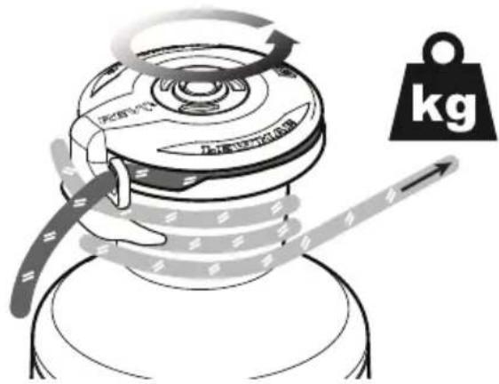
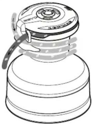
- Loading up the rope- see illustrations and photos below.
The number of turns of rope on the drum should be kept to a minimum at all times; add a wrap only when the line begins to slip when winding - this greatly improves the back-wind performance
- The maximum number of wraps is defined by the bottom of the suppressor plate on the feeder arm. Once the rope reaches this point, no more wraps should be attempted.
natural_image
Line drawing of a mechanical component with a handle and base plate (no text or symbols)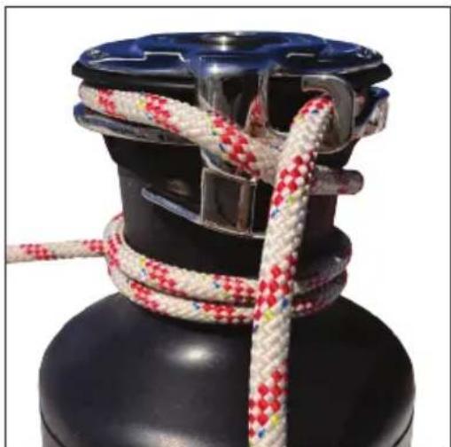
natural_image
Close-up of a black gas cylinder with red and white striped rope tied around it (no text or symbols visible)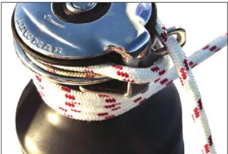
natural_image
Close-up of a blue LECUAR anchor with red and white rope tied, mounted on a black base (no text or symbols visible)3- Installation
3.1 Above deck preparation
IMPORTANT: Always keep in mind the space available below deck for the motor/gearbox.
text_image
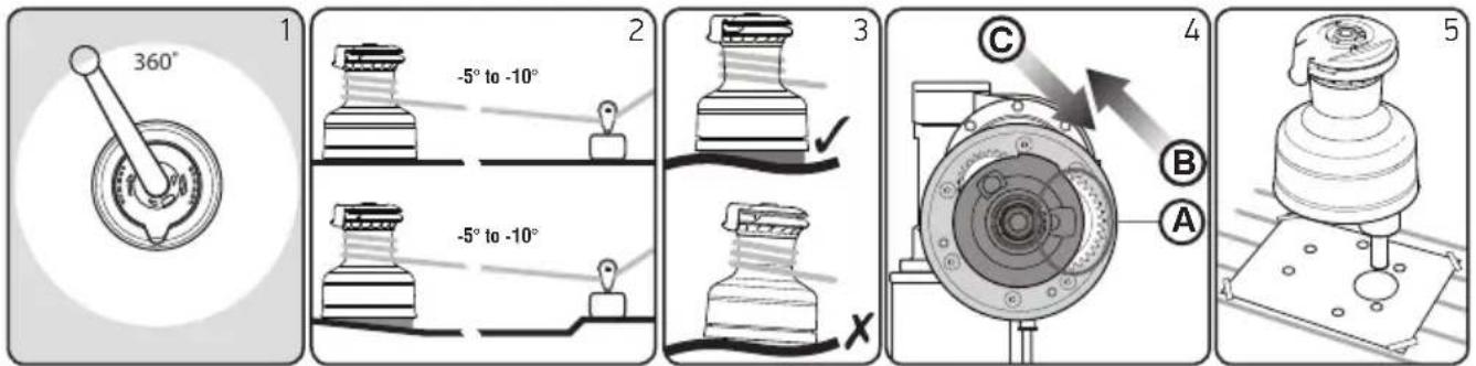
360° -5° to -10° -5° to -10° C B A XPlan location carefully before drilling any holes and allow for the following:
- 360 degree rotation of manual operating handle.
- Lewmar recommend that the rope enters onto the drum at an angle of -5^ to -10^ to the base axis of the winch. To achieve this angle it may be necessary to use a base wedge when installing the winch.
- It is essential that the winch is fixed to an even surface for maximum performance.
- If practical, for best performance, the winch should be installed so that the output gear (A) is situated in the optimum position in relation to the load (B) and sheet line entry (C).
- Once position of winch is established, mark position of driveshaft and drill ∅64mm hole. Strip winch (section 3.3) place base plate on deck then mark through mounting bolt holes, remove and drill to size of bolts.
3.2 Below deck preparation
IMPORTANT: The positioning of the motor/gearbox must be checked prior to cutting for deck/hull and bulkhead clearance.
natural_image
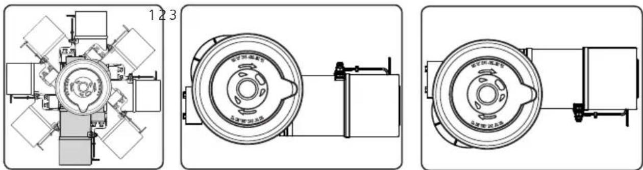
Technical line drawings of mechanical components, showing front, top, and side views (no text or symbols)- The motor/gearbox can be rotated in 45 degree steps.
- The motor rotation is factory set for fitting to drive shaft as shown.
- If the motor/gearbox is fitted the opposite way round, this will reverse the function of the buttons. If you have to position the motor/gearbox in this way you can swap round D1 and D2 connections on the motor gearbox.
Check clearance below deck and accessibility then position the deck switches near and in view of the winch. Use template as a guide to cut/drill hole, fit switch and seal.
Once you have selected the ideal position for winch, motor/gearbox and controls, double check everything and only then drill holes in the deck.
3.3 Fitting the REVO™Winch
⚠ WARNING! Isolate the winch using breaker/isolator.
natural_image
Technical illustration of a mechanical component with a rotating top and base, showing internal parts (no text or symbols)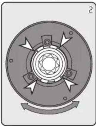
natural_image
Circular mechanical component with radial arrows indicating rotation or force direction (no text or symbols)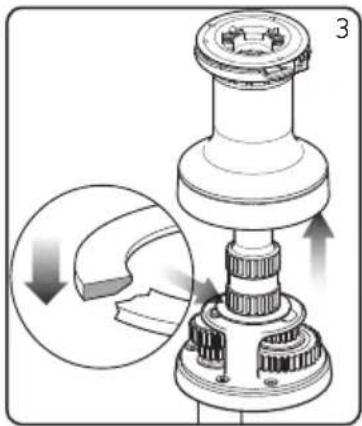
natural_image
Mechanical assembly diagram showing a gear-like component with a close-up inset illustrating the process (no text or symbols present)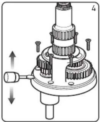
natural_image
Mechanical gear assembly diagram showing shaft, gears, and housing (no text or labels)Place the winch in position to ensure correct fit once the holes have been drilled/cut.
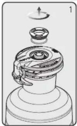
- Unscrew the top cap anti-clockwise and remove. Remove the feeder arm
- Rotate the drum until the cutout in the upper crown is opposite the collets (size 40 only).
-
Lift off drum. Remember to take care in re-fitting the drum washer with bevel on underside.
-
Remove all screws holding centre stem to base. Using a flat bladed screwdriver in the drainage slots, lever off centre stem assembly clear of the two dowel pins.
natural_image
Mechanical assembly diagram showing hands operating a gear with a close-up inset of a component (no text or symbols)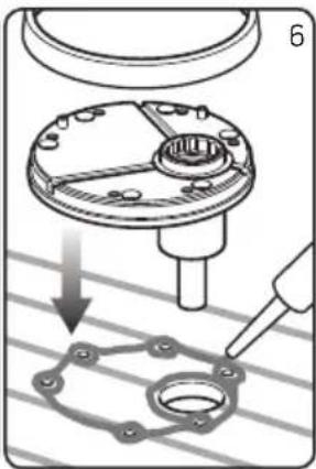
natural_image
Mechanical assembly diagram showing a mechanical component being inserted into a flange, with no visible text or symbols.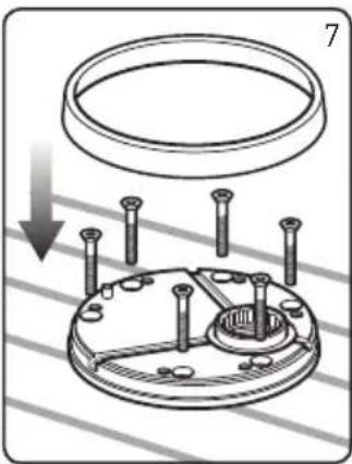
natural_image
Technical diagram of a mechanical assembly with a circular component and bolt holes, no text or symbols present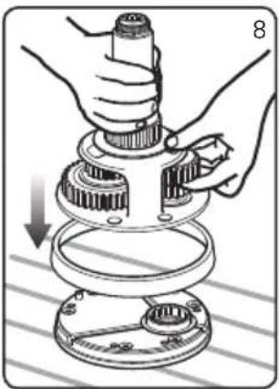
natural_image
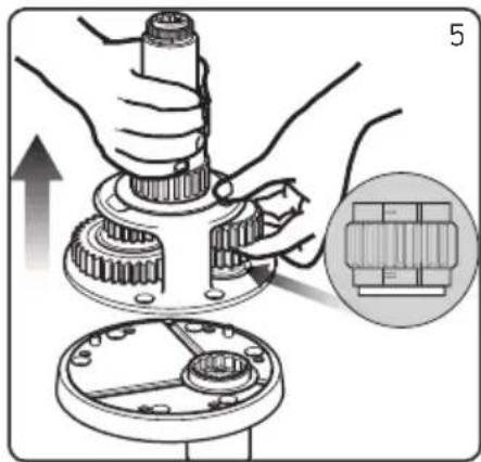
Mechanical assembly diagram showing hands assembling a gear and shaft components (no text or symbols)- Take care to hold the gear stack in position as shown. Keep pawls and pawl springs in place while rebuilding/placing the centre stem onto the base.
NOTE: If pawl gear falls out, ensure shoulder face is down on re-assembly.
- Remove the base plate cover. Lift the base and bed down with a light coating of sealing compound to prevent leaks.
Avoid using excessive sealant.
DO NOT use a permanent adhesive/sealant eg. 5200
- Consult the fastening guide for bolt type and length. Bolt the base plate to the deck ensuring that all fastening heads are countersunk then replace base plate cover.
NOTE: If using silicone or other rubbery type sealant, it is advisable to allow curing of the sealant before final tightening of the mounting nuts. - Refit the centre stem assembly, taking care to hold the gear stack in position as before. Rotating the gears will facilitate re-engagement of the pawls and ratchet tracks.
Replace the drum, collets and feeder arm in correct position and screw on the top cap.
3.4 Fastenings
Deck fastenings are not supplied.
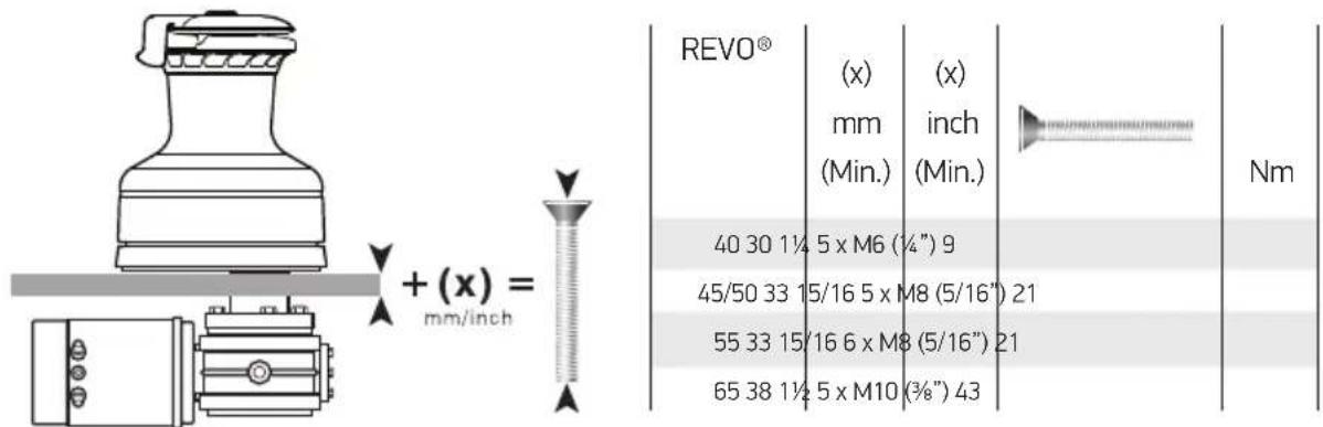
Fix the winch to the deck using CSK Head, stainless steel washers and locknuts.
Use the table to calculate the correct bolt length for your deck thickness.
text_image
+ (x) = mm/inch REVO® (x) mm (Min.) ( x ) (inch (Min.) 40 30 1¼ 5 x M6 (¼") 9 45/50 33 15/16 5 x M8 (5/16") 21 55 33 15/16 6 x M8 (5/16") 21 65 38 1½ 5 x M10 (¾") 43 Nm3.5 Electric motor/gearbox coupling
text_image
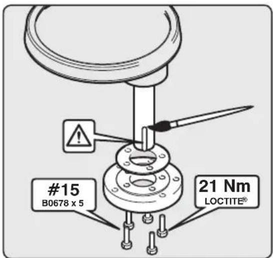
#15 B0678 x 5 21 Nm LOCTITE®These winches require the base motor coupling and shim to be fitted. Apply Loctite ^® threadlock to coupling bolts (# 15), insert isolation shim and secure to winch base plate. Assemble coupling bolts and washers, apply Loctite ^® threadlock and secure to 21 Nm.
Lightly coat the drive shaft with grease. Ensure the drive key is in place. Select the most suitable position and slide motor/gearbox into position, assemble bolts and washers, apply Loctite ^® threadlock and secure to 43Nm.
4- Electrical Wiring
4.1 Wiring
Plan the installation to suit the controls and give the operator a full view of the winch. The wiring system should be of the fully insulated type, which avoids possible electrolytic corrosion problems. We recommend the use of type III stranded, tinned copper wire with copper crimp terminals.
Most modern installations are negative return (negative ground) but polarity should be checked.
Overload protection, in the form of the circuit breaker/fuse (not supplied), must be built into the winch wiring circuit.
The circuit breaker should be positioned close to the battery in a dry, readily accessible place.
The breaker must be manually reset should an overload occur that causes it to trip to the off position.
▶ Lewmar recommends to source and install cable that meets the requirements of the standards and regulations relevant to the installation and codes of practice.
The cable sizes are calculated in order to maintain a maximum overall voltage drop of 10% supply over whole cable installation at max load current as per ISO10133.
▶ If you are not sure you understand these guidelines, seek professional help. Ensure that the installation complies with USCG, ABYC, NMMA or other local regulations.
4.2 Control switch installation
For the latest information and list of electric deck switches visit: www.lewmar.com
Follow the mounting instructions supplied with the switch.
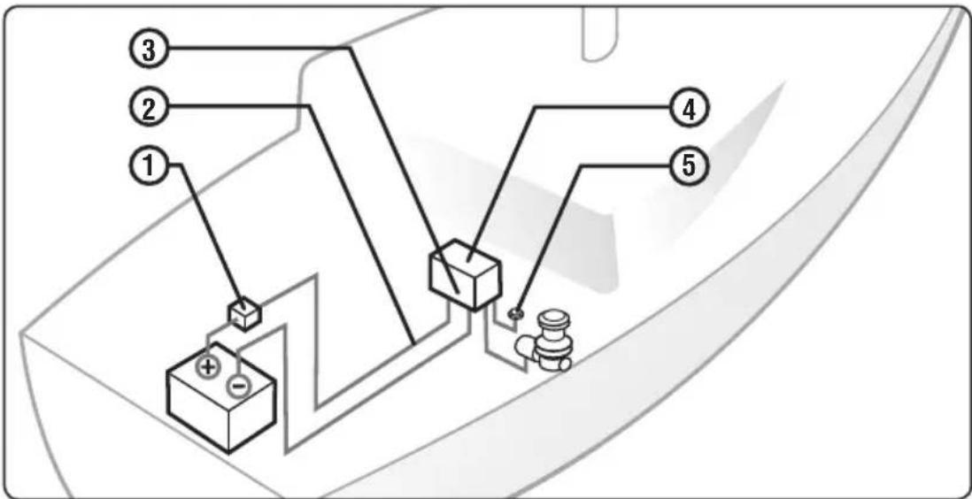
4.3 Typical electrical layout
⚠ WARNING! All electrical work must be carried out with the power OFF. Isolate the REVO™ winch using circuit breaker / isolator.
flowchart
graph TD
    1["①"] --> A["+"]
    2["②"] --> A
    3["③"] --> A
    4["④"] --> B["+"]
    5["⑤"] --> B
    A --> C["负极符号"]
    B --> D["负极符号"]
    C --> E["电池符号"]
    D --> F["电池符号"]
NOTE: This is not a wiring diagram.
- Position the circuit breaker close to the battery.
- Route 2 cables from battery to the control box.
- Attach motor cables to control box using recommended cable sizes.
- Position the controller near the winch (± 1 metre) in a dry area for watertight security and accessible for maintenance.
- Position deck switches in view of the winch. Route wire and attach to control box.
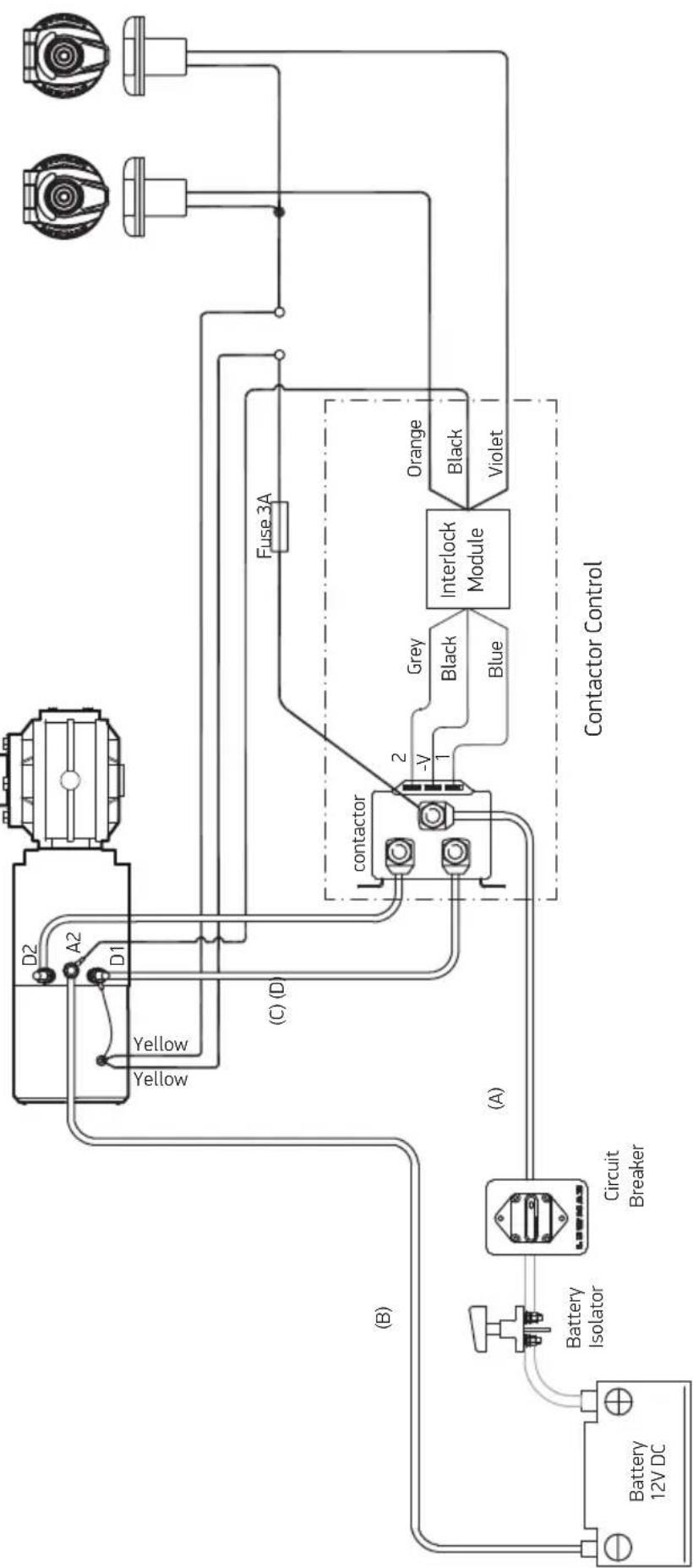
4.4 Wiring diagram
- An interlock module is provided to prevent faulty motor operation if both deck switches are operated at the same time.
- When both switches are operated together the contactor will open and the winch will halt until only one switch is operated.
- Refer to table for high current cable size guide - Low current wiring 18awg minimum
- Observe all safe practices for safe electrical installation - Consult with Lewmar if Lewmar circuit breaker NOT used
Electric Deck
switches
Forward Reverse
flowchart
graph TD
    A["Battery 12V DC"] --> B["Battery Isolator"]
    B --> C["Circuit Breaker"]
    C --> D["Contactor Control"]
    D --> E["Interlock Module"]
    E --> F["Fuse 3A"]
    F --> G["Orange"]
    F --> H["Black"]
    F --> I["Violet"]
    D --> J["contactor"]
    J --> K["-V"]
    J --> L["1"]
    J --> M["2"]
    J --> N["Yellow"]
    J --> O["D1"]
    J --> P["A2"]
    J --> Q["D2"]
    style A fill:#f9f,stroke:#333
    style B fill:#ccf,stroke:#333
    style C fill:#cfc,stroke:#333
    style D fill:#fcc,stroke:#333
    style E fill:#cff,stroke:#333
    style F fill:#ffc,stroke:#333
    style G fill:#f9f,stroke:#333
    style H fill:#f9f,stroke:#333
    style I fill:#f9f,stroke:#333
    style J fill:#cff,stroke:#333
    style K fill:#cfc,stroke:#333
    style L fill:#cfc,stroke:#333
    style M fill:#cfc,stroke:#333
    style N fill:#cfc,stroke:#333
    style O fill:#cfc,stroke:#333
    style P fill:#cfc,stroke:#333
    style Q fill:#cfc,stroke:#333
5- Operation
⚠ WARNING! Always remove handle when not in use
⚠ WARNING! Isolate the winch using circuit breaker/isolator when not in use
5.1 Rope Specifications
Choosing the correct sheet rope specification is vital to ensure your REVO product will work correctly. The following ropes must be used to ensure correct function :
GOTTIFREDI MAFFIOLI Globaltech 75 / Silvertech CORDERIE HENRI LANCELIN Minos / Helios LIROS GmbH Dynamic Plus / Regatta 2000 MARLOW ROPES D2 / Marlowbraid NEW ENGLAND ROPES T-900 / Endura SAMSON ROPES MLX / XLS Extra
In addition, the following rope diameters should be used :
REVO™ 40 10mm diameter REVO™ 55 10mm diameter REVOTM 45 10mm diameter REVOTM 65 10mm diameter REVOTM 50 10mm diameter

text_image
Diagram showing two hand positions with a red X and green checkmark indicating correct or incorrect states.A 10mm line as suggested above will have a breaking load of approximately 4500kg, which is suitably strong when compared to the REVO 65 WLL of 1700kg. For a full list of winch Working Load Limits, see section 7.2
If the above ropes cannot be found, then it is advised that you choose the best possible quality rope for your sheets. A rope with a firm and rigid construction will perform better. The cover must be tightly plaited onto the core, with the cover being very difficult to pinch between thumb and forefinger (see illustration 1).
Tests have shown that Dyneema™ cored ropes perform better due to their tighter construction.
5.2 Feeder arm adjustment
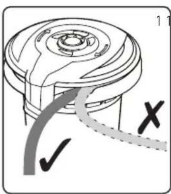
Thought must be given to the most suitable feeder arm position
text_image
Technical diagram of a mechanical component with checkmark and cross annotations indicating selection or validation points.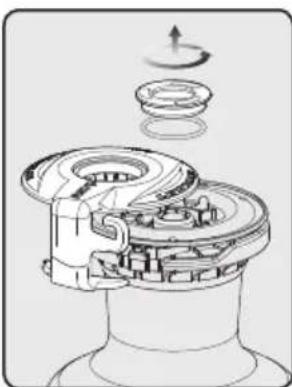
natural_image
Mechanical assembly diagram showing gear and housing components with motion indicators (no text or labels)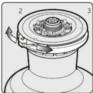
text_image
Technical diagram of a mechanical component with labeled parts 2 and 3, showing internal structure and directional arrows.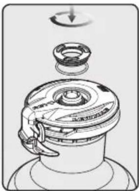
natural_image
Diagram of a mechanical device with a rotating knob and a base plate (no text or symbols)- The feed should be aligned so that when back-winding the rope enters the self-tailing mechanism at a tangent. - To adjust the position of the feeder arm, remove top cap and feeder arm.
-
Unscrew the top cap anti-clockwise and remove feeder arm. Ensure O ring remains in top cap groove.
-
Rotate stripper ring to required position
-
Replace feeder arm and top cap.
5.3 Operating the REVO™ winch
⚠ WARNING! Never hold the incoming rope to the winch while the winch is operated. Only control the rope leaving the winch.
⚠ WARNING! Always remove handle when not in use
text_image
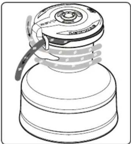
热泵 热泵 热泵The rope should be wound around the drum in a clockwise rotation, then fed up over the feeder arm, into the self tailing jaws and then pulled through the hook so that the rope engages in the keeper ring
- It is recommended to use as few turns of rope on the drum as possible for the sailing conditions, adding wraps only when the line begins to slip when winding in. (see Paragraph 3.2).
▶ Release the rope from the jaw set with care as load will be present, ease the line away with care, then remove from the drum.
▶ Only use rope as recommended in section 5.1
⚠ WARNING!
The rope should be located fully into the crown, keeper ring and retaining hook for best performance and to reduce the risk of the rope releasing itself.
Electrical Hauling
Lewmar uses a one-speed system, which offers high speed and full load pulling power.
▶ Check that nothing is obstructing the winch
- Hold the appropriate button to wind the winch until the desired line tension is achieved.
Manual Hauling
NOTE: A locking winch handle is required for REVO winches
Simply put the winch-handle into the top of the winch, ensuring the locking mechanism engages properly against the spring.
▶ Manual mode is now active.
- Wind the winch handle anti-clockwise for 1st gear (highest gear = fastest speed) and clockwise for 2nd gear (lowest gear = slowest speed)
\*Note that there is no manual back-wind facility\*
Electric Back-Wind
▶ Ensure that any winch handle has been removed and ensure that the plunger has sprung back up. If this is not the case, a short press on the "in" button will release it
▶ Ensure that the rope tail is free to run
- Holding the "out" button activates backwind until the load is reduced to a level such that a ratcheting will be heard.
*Note: The winch only backwinds with load on the winch. If the rope does not backwind, but a clicking/ratcheting noise can be heard, then the load on the winch is too low.
6- Servicing
Monthly
▶ Hose down winch with fresh water. Remove drum, then lightly oil the pawls and grease the gears and bearings taking care not to get any grease in the pawls as they will stick in operation.
Two or three times during active sailing season
- Strip, clean, check and lubricate.
End of season or beginning of new season.
- Strip, clean and thoroughly check for damage, lubricate and reassemble as detailed in B2304 Manual.
▶ Check condition of motor/gearbox. In the event of corrosion, clean and repaint motor with marine grade oil based enamel paint.
6.1 Spares
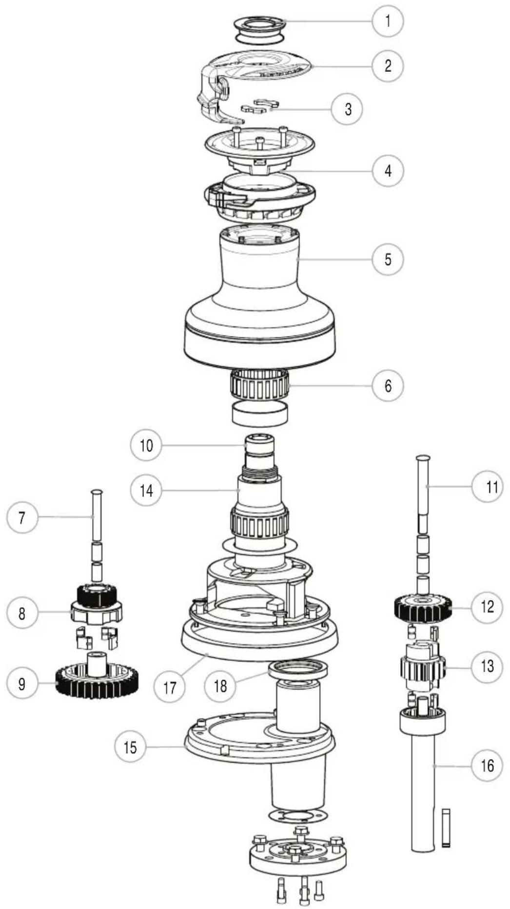
NOTE: see exploded views section 6.2 and 6.3
| ITEM | DESCRIPTION REVOTM | 40PART NO | REVOTM 45PART NO | REVOTM 50PART NO |
| 1 Top cap ® O-ring kit 48300080 48300080 48300080 | ||||
| 2 Feeder arm | 45300100 45300101 45300102 | |||
| 3 Collet kit 48000446 48000446 48000446 | ||||
| 4 Jaw kit 48300081 48300082 48300083 | ||||
| 5 | Drum - Black alloy | 45300032 | 45300035 | 45300009 |
| Drum - Grey Alloy | 45300033 | 45300036 | 45300018 | |
| Drum - Chrome | 45300034 | 45300037 | 45300019 | |
| 6 Drum Bearing kit 48000456 48000457 48000458 | ||||
| 7 Gear spindle kit | 48300027 45000323 45000423 | |||
| 8 Pawl gear 1 kit 11T 48300028 48300035 48300042 | ||||
| 9 Ratchet gear Kit 48300029 48300036 48300043 | ||||
| Spares kit (16-66ST) 19700200 19700200 19700200 | ||||
| Std small pawls ® springs | 19700501 19700501 19700501 | |||
| 10 Main spindle 48300005 48300006 48300004 | ||||
| 11 Gear spindle kit | 48300027 45000344 45000444 | |||
| 12 Ratchet gear | 45000222 45000333 45000422 | |||
| 13 Pawl gear 2 kit 17T | 48300030 48300037 48300044 | |||
| 14 Centre stem kit | 48300031 48300038 48300045 | |||
| 15 Base kit | 48300032 48300039 48300046 | |||
| 16 Drive shaft kit | 48300033 48300040 48300047 | |||
| 17 Base plate cover 45500212 45500312 45500412 | ||||
| 18 Seal | B6234 | B6234 | B6234 | |
| ITEM | DESCRIPTION REVOTM | 55 | REVOTM 65 |
| PART NO | PART NO | ||
| 1 Top cap & O-ring kit 48300080 48300080 | |||
| 2 | Feeder arm | 45300103 45300104 | |
| 3 Collet kit 48000446 48000446 | |||
| 4 Jaw kit 48300084 48300085 | |||
| 5 | Drum - Black alloy | 45300038 | 45300041 |
| Drum - Grey Alloy | 45300039 | 45300042 | |
| Drum - Chrome | 45300040 | 45300043 | |
| 6 Drum Bearing kit 48000460 48000462 | |||
| 7 | Gear spindle kit | 45000523 45000624 | |
| 8 Pawl gear 1 kit | 48300049 48300055 | ||
| 9 Roller Bearing kit (3) | 1300/SA2 15000017 | ||
| 10 Ratchet gear Kit 45000520 45000851 | |||
| 11 Washer | 15000981 15000646 | ||
| Spares kit (16-66ST) 19700200 19700200 | |||
| Std large pawls & springs | 19700401 19700401 | ||
| 12 Main spindle 48300007 48300008 | |||
| 13 | Gear spindle kit | 45000744 45000744 | |
| 14 Ratchet gear | 45000522 45005183 | ||
| 15 Roller Bearing kit (3) 15000017 15000017 | |||
| 16 Pawl gear 2 kit | 48300050 48300056 | ||
| 17 Centre stem kit | 48300051 48300057 | ||
| 18 Base kit | 48300052 48300058 | ||
| 19 Drive shaft kit | 48300053 48300059 | ||
| 20 Base plate cover 45500412 45500612 | |||
| 21 Seal | B6234 | B6235 | |
| 22 Roller bearing kit | 15000019 15000019 | ||
| 23 Circlip | B2092 | B2092 | |
| 24 Washer | - | 45000533 | |
6.2 Exploded views REVO™ 40 / 45 / 50
text_image
Exploded view diagram of a mechanical assembly with numbered parts for identification6.3 Exploded views REVO™ 55 /65
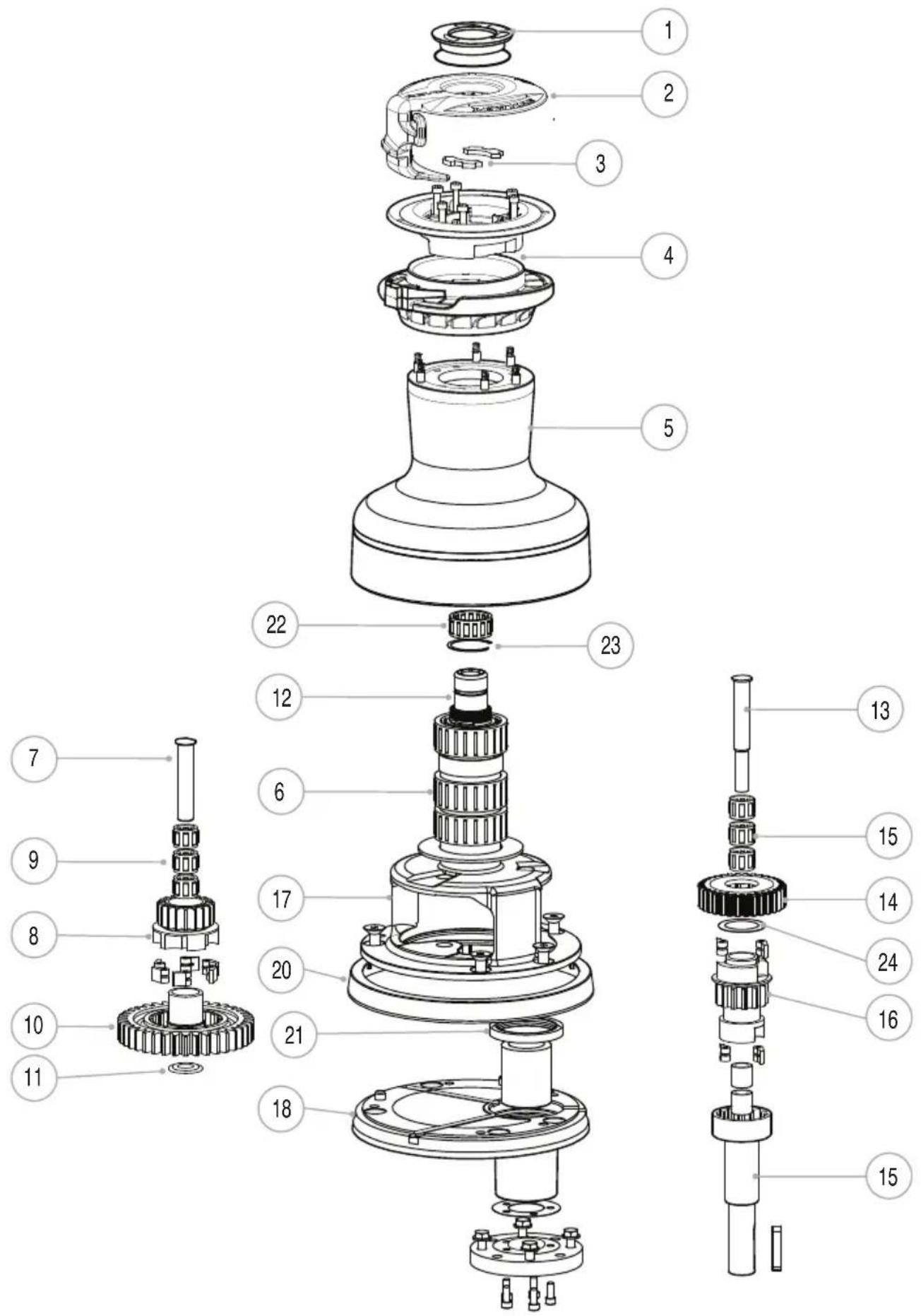
text_image
Exploded view diagram of a mechanical assembly with numbered parts for identification7- Specifications
7.1 Above/below deck dimensions
L = Line entry.
B
| REVO | Base Dia mm in mm in mm in | Height | Line Entry | H | ||||||
| L | ||||||||||
| T | ||||||||||
| U | ||||||||||
| 40 154 | 6^1/_16 | 176 | 6^15/_16 | 98 | 3^7/_8 | |||||
| 45 174 | 6^27/_32 | 193 | 7^19/_32 | 103 | 4^1/_16 | |||||
| 50 186 | 7^11/_32 | 215 | 8^15/_32 | 109 | 4^9/_32 | |||||
| 55 209 | 8^1/_4 | 253 | 9^31/_32 | 140 | 5^1/_2 | |||||
| 65 234 | 9^7/_32 | 268 | 10^9/_16 | 144 | 5^11/_16 | |||||
REVO
mm in mm in mm in mm in mm in mm in
| 40 306 | 12116 | 50 | 1^31/_32 | 35 | 1^3/_8 | 127 5 | 73 | 2^7/_8 | 111 | 4^3/_8 | |
| 45 306 | 12116 | 50 | 1^31/_32 | 65 | 2^9/_16 | 127 5 | 73 | 2^7/_8 | 115 | 4^17/_32 | |
| 50 306 | 12116 | 50 | 1^31/_32 | 65 | 2^9/_16 | 127 5 | 73 | 2^7/_8 | 117 | 4^5/_8 | |
| 55 325 | 12^13/_16 | 63 | 2^15/_32 | 61 | 2^13/_32 | 139 | 5^15/_32 | 84 | 3^5/_16 | 133 | 5^1/_4 |
| 65 325 | 12^13/_16 | 63 | 2^15/_32 | 61 | 2^13/_32 | 139 | 5^15/_32 | 84 | 3^5/_16 | 137 | 5^13/_32 |
7.2 REVO winch specifications
| REVO | ALLOY BLACK | ALLOY GREY | CHROME WLL WEIGHT | WEIGHT(CHROME) MTR/GBOX MOTOR | |||||||
| (ALLOY) | |||||||||||
| Kg lb | Kg lb | Kg lb | watts | ||||||||
| 40 | 48340210 | 48340200 | 48340201 | 795 | 1749 | 18.8 | 41.4 | 20.5 | 45.1 | 48300014 | 700 |
| 45 | 48345210 | 48345200 | 48345201 | 1200 | 2640 | 23.1 | 50.8 | 25.6 | 56.3 | 48300014 | 700 |
| 50 | 48350210 | 48350200 | 48350201 | 1250 | 2750 | 25.7 | 56.5 | 29.1 | 64.0 | 48300014 | 700 |
| 55 | 48355210 | 48355200 | 48355201 | 1480 | 3256 | 30 | 66.0 | 35.8 | 78.8 | 48300016 | 1600 |
| 65 | 48365210 | 48365200 | 48365201 | 1700 | 3740 | 34.6 | 76.1 | 41.8 | 92.0 | 48300016 | 1600 |
NOTE: WLL=Working Load Limit or maximum safe working load
WLL are recommended to be not more than those detailed above. This provides an acceptable safety margin for dynamic load surges in extreme sea conditions.
8- Troubleshooting
Winch will not operate manually
▶ Check for correct assembly.
▶ Pawls stuck-over use of grease
▶ Strip and clean as necessary
Winch will not haul electrically
- Is winch handle in? Remove handle
- Ensure that the metal plunger has popped up, if not press the "in" button momentarily.
- Power at the battery. Check terminal connections, battery voltage - adequate reserve battery capacity.
- Isolator switch/circuit breaker on. Switch on
- Check fuse in control box. Change fuse (3 Amp), check wiring
- Power at winch. Check circuit diagram, connections, clean and check cables
- Check switch connection in control box. Reconnect
Motor will not back-wind electrically
- Can a clicking noise be heard?
Check that the tail of the rope is free to pay out The load on the winch may be too low Reduce line diameter or wraps on drum to increase performance - Power at the battery. Check terminal connections, battery voltage - adequate reserve battery capacity.
- Isolator switch/circuit breaker on. Switch on
- Check fuse in control box. Change fuse (3 Amp), check wiring
- Power at winch. Check circuit diagram, connections, clean and check cables
- Check switch connection in control box. Reconnect
Notes
Notes
Notes
9- Warranty
Limited Warranty and Key Terms of Supply by Lewmar
Lewmar warrants that in normal private pleasure boat usage and with proper maintenance its products will conform with their specification for a period of three years from the date of purchase by the end user, subject to the conditions, limitations and exceptions listed below. Any product, which proves to be defective in normal usage during that three-year period, will be repaired or, at Lewmar's option, replaced by Lewmar.
A- CONDITIONS AND LIMITATIONS
i Lewmar's liability shall be limited to the repair or replacement of any parts of the product which are defective in materials or workmanship.
ii Responsibility for the selection of products appropriate for the use intended by the Buyer shall rest solely with the Buyer and Lewmar accepts no responsibility for any such selection.
iii Lewmar shall not be liable in any way for Product failure, or any resulting loss or damage that arises from:
a. use of a product in an application for which it was not designed or intended;
b. corrosion, ultra violet degradation or wear and tear;
c. a failure to service or maintain the product in accordance with Lewmar's recommendations;
d. faulty or deficient installation of the product (unless conducted by Lewmar);
e. any modification or alteration of the product;
f. conditions that exceed the product's performance specifications or safe working loads.
g. Abuse
iv Product subject to a warranty claim must be re-turned to the Lewmar outlet that supplied the product for examination unless otherwise approved by Lewmar in writing.
v This warranty does not cover any incidental costs incurred for the investigation, removal, carriage, transport or installation of product.
vi Service by anyone other than authorized Lewmar representatives shall void this warranty unless it accords with Lewmar guidelines and standards of workmanship.
vii Lewmar's products are intended for use only in the marine environment. Buyers intending to use them for any other purpose should seek independent professional advice as to their suitability. Lewmar accepts no liability arising from such other use.
B- EXCEPTIONS
Cover under this Warranty is limited to a period of one year from the date of purchase by the end user in the case of any of the following products or parts of products:
▶ Electric motors and associated electrical equipment
▶ Electronic controls
▶ Hydraulic pumps, valves and actuators
▶ Hatch & Portlight weather seals
- Products used in "Grand Prix" racing applications
- Products used in commercial or charter applications
▶ Anchor rodes
C-LIABILITY
i Lewmar's liability under this warranty shall be to the exclusion of all other warranties or liabilities (to the extent permitted by law). In particular (but without limitation):
a. Lewmar shall not be liable for:
- Any loss of anticipated turnover or profit or indirect, consequential or economic loss;
- Damages, costs or expenses payable to any third party;
▶ Any damage to yachts or equipment; - Death or personal Injury (unless caused by Lewmar's negligence).
Some states and countries do not allow the exclusion or limitation of incidental or consequential damages, so the above limitation or exclusion may not apply to you
b. Lewmar grants no other warranties regarding the fitness for purpose, use, nature or satisfactory quality of the products.
ii Where applicable law does not permit a statutory or implied warranty to be excluded, then such warranty, if permitted by that state or country's law, shall be limited to a period of one year from the date of purchase by the end user. Some states and countries do not allow limitations on how long an implied warranty lasts, so this limitation may not apply to you.
D- PROCEDURE
Notice of a claim for service under this warranty shall be made promptly and in writing by the end user to the Lewmar outlet that supplied the product or to Lewmar Limited at Southmoor Lane, Havant, Hampshire P09 1JJ, England.
E- SEVERANCE CLAUSE
If any clause of this warranty is held by any court or other competent authority to be invalid or unenforceable in whole or in part, the validity of the remaining clauses of this warranty and the remainder of the clause in question shall not be affected.
F- OTHER RIGHTS
This warranty gives you specific legal rights, and you may also have other legal rights, which vary from state to state and country to country.
In the case of European States a Consumer customer (as defined nationally) has legal rights under the applicable national law governing the sale of Consumer Goods; this Warranty does not affect those rights.
G- LAW
This warranty shall be governed by and read in accordance with the laws of England or the state or country in which the first end user is domiciled at the time of purchase of the product.
H- DISPUTES
Any dispute arising under this warranty may, at the option of the end-user, be referred to alternative dispute resolution under the rules of the British Marine Federation or to the Courts of the State whose law shall govern the warranty or to the Courts of England and Wales.
The British Marine Federation may be contacted at Marine House, Thorpe Lea Road, Egham, England, TW20 8BF
UK & International Distribution
Lewmar / Navtec
Southmoor Lane
Havant
Hampshire
P09 1JJ
England
Tel: +44 (0)23 9247 1841
Fax: +44 (0)23 9248 5720
Email: info@lewmar.com
USA
Lewmar / Navtec
351 New Whitfield Street
Guilford, CT
06437
USA
Tel: +1 203 458 6200