Tribunus_12_130 - Remote control toy Scorpion - Free user manual and instructions
Find the device manual for free Tribunus_12_130 Scorpion in PDF.


User questions about Tribunus_12_130 Scorpion
0 question about this device. Answer the ones you know or ask your own.
Ask a new question about this device
Download the instructions for your Remote control toy in PDF format for free! Find your manual Tribunus_12_130 - Scorpion and take your electronic device back in hand. On this page are published all the documents necessary for the use of your device. Tribunus_12_130 by Scorpion.
USER MANUAL Tribunus_12_130 Scorpion
text_image
PRECISION SCORPIOM® PERFORMANCEScorpion Power System
www.scorpionsystem.com
Scorpion User Guide for
Scorpion Tribunus 12-130A ESC
(SBEC)

v1.3
Scorpion User guide for Tribunus 12-130A ESC (SBEC)
SAFETY
Scorpion and their re-sellers are not responsible for your use of this product, or any damage or injuries you may cause or sustain as a result of it's usage.
Understand that an electric motor that is connected to a battery and speed control may start unexpectedly and cause serious injuries. Always treat them with necessary respect. Keep the propeller away from your body and others at all times.
We suggest that you remove the propeller when you are working on the plane with the battery connected.
We suggest that you remove the pinion when working on a Helicopter with the battery connected.
⚠️ Please observe all local laws regarding the flying of remote control aircraft.
Never fly over others or near crowds.
Included in the Box
• 1x Scorpion Tribunus 12-130A ESC (SBEC)
• 1x Master and Slave cable
• 1x Diode adaptor cable for V-Link II Cable(optional):
• 1x Thank You Card
Tribunus 12-130A ESC
The Scorpion Tribunus 12-130A is available in SBEC version.
12S-130A SBEC
Features of Tribunus 12-130A ESC SBEC
- Wide input voltage range 12\~52V (3S-12S LIPo/HVLI).
- ESC included phase sensor (RPM sensor) (Slave cable) connect to external governor/V-bar.
- High current, up to 130A continued current, with current protection.
- Airplane, Helicopter mode. Stored and unstored Governor, external governor.
- The first ESC that utilizes Morse code communication.
- ESC setup can be set by Mikado VBar control Radio.
- Data Logging, Data export for external data logging device, such as Mikado V control / Vbar combinations.
- Additional Scorpion V Link II cable for upgrading ESC firmware (sold separately).
- Downloadable PC program and Android apps
- PC connectivity, Android connectivity (OTG cable needed), Vlink II Cable(optional) plus Diode adaptor cable (included) needed.

- Aluminum heat sinks
- Build-in temperature sensor with adjustable temperature protection
- True DC-DC 5.1V-8.3V BEC for servo and receiver with 10A continues and 20A peak.
- Multiple protection features include: over current, over voltage, temperature protection
- Auto Detect mode
- Upgradeable Firmware
1.0 Connecting your ESC
* Please refer to the diagram on Page 3 to properly connect your ESC.
1.1 Add your battery connector
You must attach a quality battery connector of your choice to the red (positive) and black (negative) power wires. Solder the battery connector to the wires. ENSURE THAT THE POLARITY IS CORRECT (red wire (positive) to battery red wire (positive), black wire (negative) to battery black wire (negative)). Follow the instructions provided with the battery connector.
1.2 Connect Motor to ESC
We recommend using bullet connectors to connect your ESC to your motor as most of the Scorpion motors come with pre-installed bullet connectors that include a female set for your ESC. Solder the corresponding connectors for your motor to the wires coming from the ESC, or solder the motor wires directly to the motor leads. You may find it convenient to temporarily connect the motor leads to the ESC and test for proper rotation before you permanently solder them. Once connected DO NOT allow any exposed wire or connectors to contact each other! Ensure that a proper insulation material (such as heat shrink) is around each of the three wires. Failure to do so will cause the ESC to malfunction and void your warranty.
1.3 Connect to your receiver / External Governor / External BEC
Connect the receiver load (Master: the three colored small wires: black, red, white) with a black plastic connector on the end) to the throttle channel on your receiver and connect the other lead (Slave: the three colored small wires: brown, red, yellow) to an external governor or external BEC, unplug the yellow (signal) wire if if you do not use the RPM signal for telemetry or external governor (e.g. VBar governor).
1.4 Mounting the ESC
Mount the ESC with the Heatsink side of the controller facing outward. We recommend using a "Scorpion Fastening Strap" to attach the ESC to the airframe for easy removal. Double sided tape is acceptable for mounting as well. If zip ties are used, do not place them over any of the components on the ESC. Instead, zip tic around the metal heat sink, leaving some slack to allow some movement.
1.5 Tribunus ESC BEC
For safety reasons we recommend using a Scorpion backup guard or a backup battery. The Backup guard can be used on any BTC voltage from 5.1 to 8.3V. If the BTC voltage is set to 7.3V or 8.3V use a 25 LiPo. Connect the BEC backup parallel to the receiver or Flybarless system. Make sure that the Backup guard is charged or the 25 LiPo battery voltage matches to the set BEC Voltage before every flight. Also make sure all used RC components are designed to run at the set BEC voltage.
2.0 Using your Scorpion Tribunus ESC
2.1 Ensure that the initial setup has been performed before using your ESC.
2.2 Ensure that the ESC is connected to the proper channel on your receiver.
2.3 Turn your transmitter ON and set the throttle stick to zero throttle.
Connect the main power battery to the ESC.2.4
2.5 The ESC will beep the motor with Morse code when power up;Power On Sound(POS).
Power On Sound - Voltage in Morse code.
To arm the LSC ready for use, you must disconnect the battery, then move the throttle stick to zero position and recommend to power-up.
Always power your radio transmitter before powering up the receiver and/or the ESC. Some receivers with tail safe fixtures or Spectrum receiver units that are not found on receiver power up are entirely capable of causing the arming sequence to occur and comment the ESC to draw the motor. Always keep the installed restored and clear of body parts when the ESC is powered.
If your LSC cannot sense any radio signal it will beep the motor and flash green on the LED with Morse code.
3.0 Scorpion Tribunus ESC Programming Feature
All Scorpion Tribunus Series ESC programming features are available though the use of the PC programming.
Scorpion ESC's come with default factory settings which are recommended for most applications. Programming options can be changed at the discretion of the user.
| Safe Power up | To avoid the controller, the throttle must be held in the “Zone” postural state window. If this is not at zero at startup, the ESC will not provide any power to the motor regardless of where the throttle stick is posted when first powered up. |
| Loss of Signal (fail safe) | The Scorpion FSC will stop the motor as a safety feature when the throttle signal is lost or complete for 13 seconds. |
| LED* | The LED is used for indicate the status of your Scorpion Tribunus ESC, it shows with More code that can yet know the status of the ESC |
| Low Voltage Cutoff | You can choose for your EIC to stop or reduce power when the input battery voltage drops in pre-wel-organized low voltage. |
| Current Limiting | Amp output limit, the output is rated at 10% over the relief Amp. At approximately 15% over the roll Amps it will automatically limit the output to first motor, as long as the motor first ratio of 10% over the EIC spectrum limits, this safety mechanism will prevent a over lead to the LSC, but if you install a motor for example rated at 10% comps on a FSC that are rated for only 8% Amps, this mechanism will not work properly due to the instant surge of power demand from the motor, it may shutdown currently or simply fly the EIC, the only solution to this is to never use a Motor that has a rising bigger than the LSC, don't even think your can use if you run the motor at a power split or read it will not work and find your warranty. |
| Thermal Protection | At set value, the LSC will slowdown the power output to the motor to the set value of protection (the or below) if EIC will fail. More cards I (temperature alarm), after the LSC has one down to under set value you can then throttle up again. |
| Brake | slope rotation of the motor when the throttle signal is moved to the lowest position. |
| Throttle | Airplane and Hall maders come pre-programmion and can be selected by the motor. |
| Electronic Timing | Electronic Timing and drive frequency are Automatically and dynamically set that may improve the efficiency of the drive system! |
4.0 Initial Setup
You MUST perform throttle range calibration before the first use of the ESC, except if you are using external governor mode, remove propeller/pinion from motor or back off pinion from main gear while performing initial throttle range calibration.
5.0 Throttle Calibration
5.1 Turn on transmitter and receiver, then set throttle to maximum position be sure that your throttle curve is set at 0% minimum throttle and 100% at maximum.
5.2 Connect the battery to the ESC. After few seconds you will hear one beep. Now move your throttle to the lowest position, then you will hear two beeps, and POS Morse code come from the motor, this mean your calibration is done. You only need to do this once as throttle range will be stored in the memory of the speed controller. You can reset the throttle range by performing steps 5.1 to 5.2 again.
6.0 Simple Morse digits
| Simple Morse code Alphabet | 0 = T = -1 = A = --2 = U = --3 = W = --4 = V = ....-5 = S = ...6 = B = ....7 = G = --.8 = D = ...9 = N = --Z = ----I = ..P = ---- |
7.0 ERROR code Morse digits
| POS | Power on Sound, voltage in Kms code3.14V - 3TA = Kms code (beep)--- --- ,--- |
| Error | N < No Throttle signalZ = Throttle not in Zero positionV = Voltage ErrorI = Current ErrorP = Power ErrorI = Temperature Error |
| 1: Power up,No Throttle | Delay - POS - ERROR N --- |
| 2: Power up,Throttle not Zero | Delay - POS - ERROR Z --- |
| 3: Power up,Throttle Zero Position | Delay - POS - No Sound |
| 4: Power up,Voltage Error | Delay - POS - ERROR V --- |
| 4: Power up,Throttle CalibrationFull Throttle | Delay - 1 Beep - Lowest throttle2 beeps (confirmed) POS - ready to fly. |
8.0 Connecting the Scorpion ESC to Computer / Android Device
Scorpion provides the most advance PC/Android program for setup. Download Scorpion Tribunus ESC program Installer
with CH340 driver from http://www.scorpionssystem.com/files/download/ScorpionTribunusProgram.zip, it is available for Windows XP, Windows 7, Windows 8 and Windows 10.
Unzip it and double click the .ex file to start installation
Double click the 'setup.exe' under "CH340 Driver" folder to install the USB driver. If you have any problem installing the
USB driver, please send email to support@splhk.com and ask for assistance.
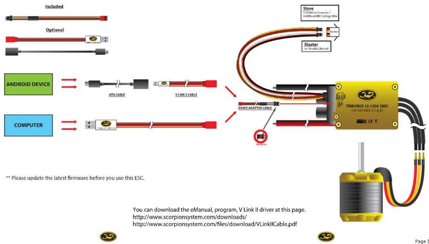
Scorpion Tribunus 12-130A ESC is programmed using the 1) Adaptor Diode Cable (included in the box).
2) Scorpion "VLink Cable II" (sold separately)
3) OTG (on the gp) Cable (Excluded)
** Scorpion do not provide OTG (on the go) Cable for Android Device. OTG cable can be found in local electronic store.
9.0 Tribunus 12-130A ESC Specification
| Model Type | Tribunus 12-130A ESC |
| CPU battery | 3x - 12x (12V ~52V) |
| Current rating | 130A |
| EPC Voltage Input | 6.1V ~8.3V |
| EPC rating | 20K |
| Weight | 7.0Hz / 16K (without cash) |
| Size | 74 x 44 x 29mm height and, superior |
| Low Voltage output | Low Voltage sub: 12V to 52V |
| Program output type | from 0% to 100% |
| Use of delay | 1000ms ~6000ms |
| Drag break | Avapable on Airplane any |
| Protection | Temperature, Voltage, Current, Density |
| Replace mode | Avapable |
| Lamp Angle | 100°~1000°s |
| Active Free Wheeling (PWM mode) | Always on for Helicopter mode, last be changed for Airplane mode |
| Hall Mode | Avapable |
| Self Start | Only available on Hall Mode, Fast, Medium, Slow, Custom |
| Ramp Angle | Fast, Medium, Slow, Custom |
| Last coil mode | Only available on Hall Mode, Fast, Medium, Slow, Custom |
| Crossover | Only Available on Hall-mode, Soft, Default, Hard, Custom |
| HCG | 8.4Hz~12 Hz Dynamic Frequency |
| Rotation | w/s |
| Timing | Auto Timing |
| P Gear | 0.3~1.8 |
| Star | 1.5~2.5 |
| Data Leaping | RPM, Throttle %, Voltage, Current, Temperature |
10.0 How to connect Scorpion V Link II Cable
- Follow the below diagram to connect the ESC to computer, using the Scorpion V-link II USB Cable (Optional)
Scorpion Tribunus 12-130A SBEC
text_image
Included Optional Android Device COMPUTER OTG CABLE V LINK II CABLE Master to throttle channel Slave To External Gownturn / Additional REC Voltage Wire DIODE ADAPTER CABLE ** Please update the latest firmware before you use this ESC. TRIBUNUS 12-130A SBEC UV-52V SBEC S-1-R.3V You can download the eManual, program, V Link II driver at this page. http://www.scorpionsystem.com/downloads/ http://www.scorpionsystem.com/files/download/VLinkII Cable.pdf Page 3
11.0 How to connect Scorpion ESC to Android device via OTG and V Link II Cable
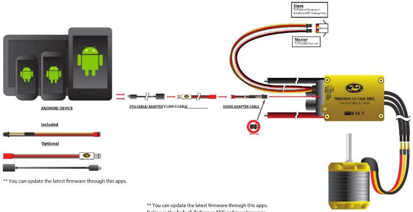
Follow the below diagram to connect the ESC to Android device, using the Scorpion V-link II USB Cable & OTG cable (Optional)
Scorpion Tribunus 12-130A SBEC
flowchart
graph TD
    A["Android Device"] --> B["OTG CABLE/ ADAPTER V LINK II CABLE"]
    B --> C["DIODE ADAPTER CABLE"]
    C --> D["Tribunus 12-130A SBEC 12V-52V SBEC 5.1-8.3V"]
    D --> E["Master to Throttle Channel"]
    E --> F["Slave to Federal Government / Additional REC Voltage Wire"]
    G["Included"] --> H["Optional"]
    I["** You can update the latest firmware through this apps."] --> J["** You can update the latest firmware through this apps. Below is the link of Tribunus ESC cofigurator apps."]

** You can update the latest firmware through this apps.
Below is the link of Tribunus ESC configurator apps.
https://play.google.com/store/apps/details?id=en.scorpion.tribunusapp

MAIN PAGE

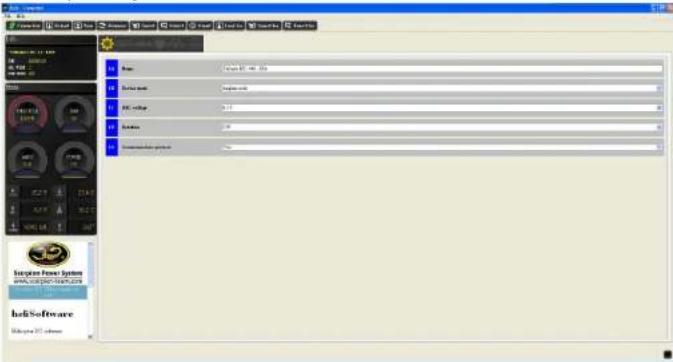
This is the main page of the program. Click Connection and Search to find the device you connected. IMPORTANT: After making a change on each page, ensure you click the SAVE button at the top to save your settings before navigating through the various pages of the setup process.
12.0 PC Software
IMPORTANT! When opening the Scorpion Heli ESC program, make sure to Right Click and click "Run As Administrator". Failing to do so may not allow the ESC to properly communicate with the PC Program.
MENU
Connection: Click to connect the ESC to the PC Program
Reload: Refreshes the ESC and reloads the settings
Save: Saves current settings to the ESC
Firmware: Click to update the ESC firmware. WARNING! All ESC settings are erased upon Firmware update. Please be sure to save settings before upgrading Firmware.
Import: Imports ESC settings from a JSON file
Export: Exports current ESC settings to a JSON file
About: Provides information about the current program settings
Load Log: Loads the log file from the ESC
Import Log: Imports a log from the JSON file
NOTE: When the user changes a value in any dialogue box, the BLUE box will turn RED. Once the user clicks "SAVE", the RED box will turn BLUE once again to signal that the value has been stored to the ESC.
NAME: Here you can change the name of the ESC
text_image
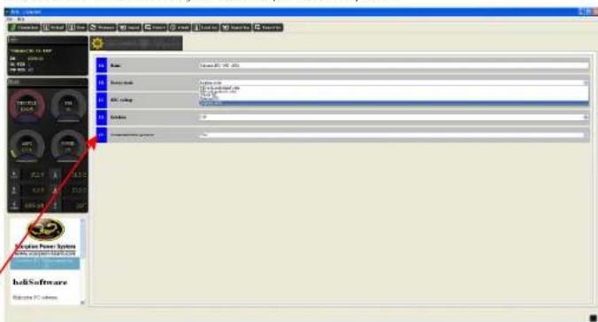
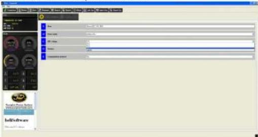
Add Add User Add Tools Add Settings Add Data Add Security Add Security System Add Security System Add Security System Add Security System Add Security System Add Security System Add Security System Add Security System Add Security System Add Security System Add Security System Add Security System Add Security System Add Security System Add Security System Add Security System Add Security System Add Security System Add Security System Add Security System Add Security System Add Security System Add Security System Add Security System Add Security System Add Security Systems Add Security Systems Add Security Systems Add Security Systems Add Security Systems Add Security Systems Add Security Systems Add Security Systems Add Security Systems Add Security Systems Add Security Systems Add Security Systems Add Security Systems Add Security Systems Add Security Systems Add Security Systems Add Security Systems Add Security Systems Add Security Systems Add Security Systems Add Security Systems Add Security Systems Add Security Systems Add Security Systems Add Security Systems Add Security SPT software Add Security SPT softwareDEVICE MODE: If you would like to utilize the internal governor in the Tribunus 200A ESC, select "Recalculated Value" for the first few flights with internal governor. Select the "Pre-stored value" after your first few flights. Select "VBAR PID" for VBAR governor, Select "External PID" for another external governor. Select "Airplane mode" for airplane use.
text_image
IekiSoftware Ieki Software Ieki Software Ieki Software Ieki Software Ieki Software Ieki Software Ieki Software Ieki Software Ieki Software Ieki Software Ieki Software Ieki Software Ieki Software Ieki Software Ieki Software Ieki Software Ieki Software Ieki Software Ieki Software Ieki Software Ieki Software Ieki Software Ieki Software Ieki Software Ieki Software IekiSoftware
BEC VOLTAGE: The BEC can be adjusted from 5.1V to 8.3V.
text_image
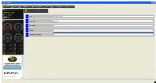
HelloSoftware Hello SoftwareRotation: Adjusts the motor rotation direction.
text_image
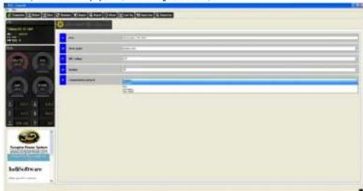
Screenshot of a software interface with menu bar, toolbar, and tool panels showing user profile and settingsCommunication Protocol: Select "Standard" if using Scorpion Internal Governor or Airplane Mode. Select VBar if using the Mikado VBar Control, Select "Jeti Exbus" if using a Jeti Exbus System or select Unsc Telem if using an Unspecified Telemetry System (Such as Jlog or Brain FBL).
text_image
Data File Edit View Insert Tools Help Tools Help Tools Help Tools Help Tools Help Tools Help Tools Help Tools Help Tools Help Tools Help Tools Help Tools Help Tools Help Tools Help Tools Help Tools Help Tools Help Tools Help Tools Help Tools Help Tools Help Tools Help Tools Help Tools Help Tools Help Tools Help Tools Help Tools Help Tools Help Tools Help Tools Help Tools Help Tools Help Tools Help Tools Help Tools Help Tools Help Tools Help Tools Help Tools Help Tools Help Tools Help Tools Help Tools Help Tools Help Tools Help Tools Help Tools Help Tools Help Tools Help Tools help 1.00 2.00 3.00 4.00 5.00 6.00 7.00 8.00 9.00 10.00 11.00 12.00 13.00 14.00 15.00 16.00 17.00 18.00 19.00 20.00 21.00 22.00 23.00 24.00 25.00 26.00 27.00 28.00 29.00 30.00 31.00 32.00 33.00 34.00 35.00 36.00 37.00 38.00 39.00 40.00 41.00 42.00 43.00 44.00 45.00 46.00 47.00 48.00 49.00 50.00 51.00 52.00 53.00 54.00 55.00 56.00 57.00 58.00 59.00 60.00 61.00 62.00 63.00 64.00 65.00 66.00 67.00 68.00 69.00 70.00 71.00 72.00 73.00 74.00 75.00 76.00 77.00 78.00 79.00 80.00 81.00 82.00 83.00 84.00 85.00 86.00 87.00 88.00 89.00 90.00 91.00 92.00 93.00 94.00 95.00 96.00 97.00 98.00 99.00 100.00
HELICOPTER

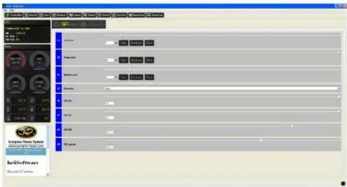
This is the page where you set up your Helicopter internal Governor settings.
*Only adjusts Heli Governor settings when the Internal Governor is activated in the previous menu-Device Mode*
12.1 Helicopter mode
HELICOPTER MENU
SOFT START: Adjusts how quickly the main rotor will ramp up (in Seconds). A lower number will cause the main rotors to spool up faster. A larger number will cause the main rotors to spool up slower.
ACCELERATION: Adjusts the acceleration between 1 Headspeed to another. A lower number will cause the main rotors to spool up faster from one desired headspeed to another. A larger number will cause the headspeed to change slower.
BAILOUT ACCELERATION: Adjusts how quickly the main rotor will ramp up (in Seconds) from Autorotation Bailout Mode. Autorotation Bailout mode allows the user to quickly spool up his blades when desired (for example, if an autorotation does not go as planned and the user immediately wants his rotor to spool up quickly). A lower number will cause the main rotors to spool up faster. A larger number will cause the main rotors to spool up slower.
GOVERNOR: Allows the user to adjust the Governor Gain Settings. It is recommended to begin with Default first, then change Gain settings to achieve the desired performance. "Soft" gains are pre-set lower than Default and "Hard" gains are pre-set higher than Default.
GAINS: Adjusts the P, I, and D Gain of the Governor.
Smooth: Adjusts the overall smoothing of the Governor. A lower number will make the governor act more aggressively. A larger number will make the governor respond slower and smoother.
text_image
File Edit View Insert Tools Help Tools Help Tools Help Tools Help Tools Help Tools Help Tools Help Tools Help Tools Help Tools Help Tools Help Tools Help Tools Help Tools Help Tools Help Tools Help Tools Help Tools Help Tools Help Tools Help Tools Help Tools Help Tools Help Tools Help Tools Help Tools Help Tools Help Tools Help Tools Help Tools Help Tools Help Tools Help Tools Help Tools Help Tools Help Tools Help Tools Help Tools Help Tools Help Tools Help Tools Help Tools Help Tools Help Tools Help Tools Help Tools Help Tools Help Tools Help Tools Help Tools Help Tools help 1.0000000000000000000000000000000000000000000000000000000000000000000000000000000000000000000000000000 1.56789999999999999999999999999999999999999999999999999999999999999999999999999999999999999999999999999999 1.5678999999999999999999999999999999999999999999999999999999999999 1.56788888888888888888888888888888888888888888888888888888888888888888 1.567877777777777777777777777777777777777777777777777777777777777777777 1.56786666666666666666666666666666666666666666666666666666666666666666666 1.567855555555555555555555555555555555555555555555555 1.567844444444444444444444444444444444444444444444444444444444444 1.56783333333333333333333333333333333333333333333333333333333 1.5678222222222222222222222222222222222222222222222222 1.567811111111111111111111111111111111111111111 1.56780SETTING UP AUTOROTATION BAILOUT
***IMPORTANT! Before setting up Autorotation Bailout please remove your pinion, or remove both your main rotor and tail rotor blades!!!***
In your transmitter, assign a switch to Throttle Hold. Once assigned to a switch, adjust the Throttle Hold value so that the Throttle % on the radio correlates to 20% (19% - 29% is OK) on the Scorpion Heli ESC value in the software. Congratulations, you have now activated Autorotation Bailout mode on your Tribunus ESC.
To confirm that you have indeed setup Autorotation Bailout Mode correctly, spool up your machine to Idle Up 1 or Idle Up 2, then click Throttle Hold. Wait 1 or 2 seconds, then click back out of Throttle Hold. The throttle should quickly come back up to your Idle Up 1/2 Headspeed.
NOTE: If you have flipped your Throttle Hold switch and activated Autorotation Bailout and wish to have your Headspeed come up back up slowly (as it should when first spooling up), you must first go to 0% throttle first, then spool up normally.


AIRPLANE

This is the page where you set up your Airplane Settings.
*Only adjusts Airplane settings when the Airplane Mode is activated in the previous menu- Device Mode*
12.2 Airplane mode
AIRPLANE MENU
DRAG BRAKE Adjusts the amount of brake enabled. If 0% is selected, the propeller will free-wheel in forward flight with the throttle at the 0% position. If 100% is selected, the propeller will not move in forward flight with the throttle at the 0% position.
RUMP ACCELERATION: Adjusts the overall time that it takes for the motor to spool up from 0% to 100%. For example, a larger aircraft such as a 50CC plane will require a value of about 1,000ms. A smaller aircraft with a 1 to 1.5 meter wingspan will require a smaller value of about 350ms or similar.
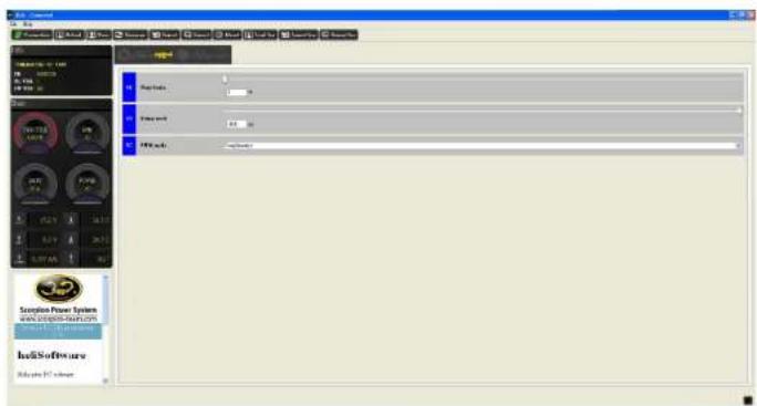
PWM MODE: Adjusts the way in which the ESC drives the motor. Regular: Operates as a standard ESC would without regenerative braking Complimentary: Actively slows down the motor when throttle is reduced (best for Multirotors or aircraft that require regenerative braking)
text_image
Software File Edit View Tools Help Tools Help Tools Help Tools Help Tools Help Tools Help Tools Help Tools Help Tools Help Tools Help Tools Help Tools Help Tools Help Tools Help Tools Help Tools Help Tools Help Tools Help Tools Help Tools Help Tools Help Tools Help Tools Help Tools Help Tools Help Tools Help Tools Help Tools Help Tools Help Tools Help Tools Help Tools Help Tools Help Tools Help Tools Help Tools Help Tools Help Tools Help Tools Help Tools Help Tools Help Tools Help Tools Help Tools Help Tools Help Tools Help Tools Help Tools Help Tools Help Tools Help Tools help tools help tools help tools help tools help tools help tools help tools help tools help tools help tools help tools help tools help tools help tools help tools help tools help tools help tools help tools help tools help tools help tools help tools help tools help tools help tools help tools help tools help tools help tools help tools help tools help tools help tools help tools help tools help tools help tools help tools help tools help tools help tools help tools help tools help tools help tools help tools help tools help tools help tools help teams help teams help teams help teams help teams help teams help teams help teams help teams help teams help teams help teams help teams help teams help teams help teams help teams help teams help teams help teams help teams help teams help teams help teams help teams help teams help teams help teams help teams help teams help teams help teams help teams help teams help teams help teams help teams help teams help teams help teams help teams help teams help teams help teams help teams help teams help teams help teams help teams help teams help groups help groups help groups help groups help groups help groups help groups help groups help groups help groups help groups help groups help groups help groups help groups help groups help groups help groups help groups help groups help groups help groups help groups help groups help groups help groups help groups help groups help groups help groups help groups help groups help groups help groups help groups help groups help groups help groups help groups help groups help groups help groups help groups help groups help groups help groups help groups help groups help groups help groups help teams help teams help teams help teams help teams help teams help teams help teams help teams help teams help teams help teams help teams help teams help teams help teams help teams help teams help teams help teams help teams help teams help teams help teams help teams help teams helps to support the team's best performance. Note: The chart is currently empty.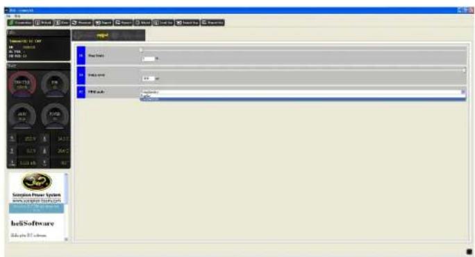
text_image
Bell Software Send to: 100% Send to: 100% Send to: 100% Send to: 100%

12.3 Protection settings
PROTECTION MENU
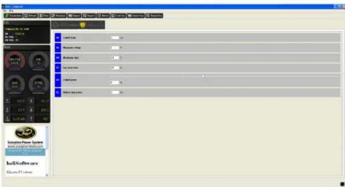
CUTOFF DELAY: Adjusts the amount of time that it takes for protection to engage if a lost signal is detected. Recommended value is 15,000ms.
MINIMUM VOLTAGE: Adjusts the minimum Voltage of the ESC. If the ESC detects the minimum voltage that is chosen, the ESC will reduce the overall RPM to the Cutoff Power % set below.
MAXIMUM TEMPERATURE: Adjusts the maximum temperature of the ESC during flight. If the ESC detects a temperature that it higher than the Maximum Temperature, the ESC will reduce the overall RPM to the Cutoff Power % set below.
MAXIMUM AMPERAGE: Adjusts the maximum Amperage of the ESC during flight. If the ESC detects a amperage that it higher than the Maximum Amperage, the ESC will reduce the overall RPM to the Cutoff Power % set below.
CUTOFF POWER: Adjusts the overall amount of RPM drop for when any of the following conditions are met: MIN VOLTAGE, MAX TEMPERATURE, MAX AMPERAGE, BATTERY MAX CAPACITY. (See below for clarity)
BATTERY MAX CAPACITY: Allows the user to enter a desired amount of battery capacity- which when met will trigger the BATTERY MAX CAPACITY protection, and then drop the RPM down by the CUTOFF POWER %. It is very useful to set this instead of a timer to know when your battery has been drained to a pre-set level. (See below for clarity)
For example, let's say a user enters 3.7Ah into BATTERY MAX POWER. When the ESC has detected that 3.7Ah (or 3,700 milliamp hours) of the battery has been consumed, the ESC will cut the main power down to the percentage that is entered in CUTOFF POWER. This means, if a pilot is flying with a headspeed of 2,000 RPM and enters 85% into CUTOFF POWER with 3.7Ah entered in BATTERY MAX CAPACITY, after 3.7Ah has been consumed, the headspeed will immediately drop down to 1700 RPM and stay at that headspeed until the pilot lands and shuts down the ESC.
** If "0" is entered into CUTOFF POWER, BATTERY MAX CAPACITY, MIN VOLTAGE, MAX TEMPERATURE or MAX AMPERAGE, this feature will not be active**
text_image
Shell Shell Style Shannon's Style Shannon's Style Shell Style Shell Style Shannon's Style Shell Software Shell Software Shell SoftwareSTATE TRACKING LOGGING

12.4 State tracking and Logging
STATE TRACKING
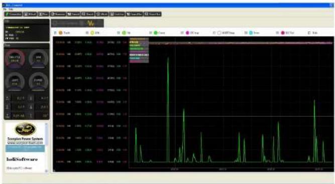
STATE TRACKING shows a live view of your ESC. With the flight battery plugged in and the ESC connected, the user is able to see Throttle, RPM of the Motor, Voltage, Current, CPU Temperature, MOSFET Temperature, Power, and BEC Voltage of the ESC at any time. This can be helpful especially when troubleshooting a particular problem.
LOGGING
LOGGING allows the user to save and read a log from a particular flight. Users are able to save/read Throttle Percentage, Current, Voltage, Amp/Hours, Temperature, Power, BEC Voltage, and RPM during the flight. For your data to show properly, make sure you have setup your Motor Pair Poles value and Gear ratio in Help -> Preferences.
text_image
Screenshot of a software interface displaying a financial chart with green line plots and data tables, alongside control panels and system status.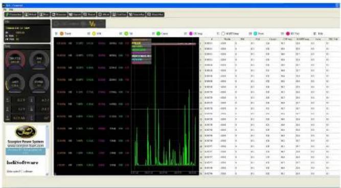


TRIBUNUS ESC AND MIKADO VBAR CONTROL/ VBAR NEO INTEGRATION
13 Tribunus ESC and VBar Control
13.1 Tribunus ESC telemetry/ setup cable for VBar
How to DIY your own Telemetry/setup cable for the Tribunus ESCs – Vbar NEO: http://www.scorpionsystem.com/blog/?p=6663 Cables are also available as a VBar Control Accessoire at Mikados onlineshop (no.: 05088 350mm and no.: 05089 500mm)
13.2 Tribunus ESC and VBar Control telemetry preparation before setup
After connecting the telemetry cable from Tribunus ESC PC port to your telemetry port of the VBar NEO do the following steps:
-Connect your VBar Control to VBar Control manager and download the "Scorpion ESC Support" App
-After that make sure the app is enabled with a “(X)” in your “application enable” menu of your radio.
-Install the latest firmware on your ESC (V52 or higher).
-On V52 or higher "VBar" is the standard communication protocol of your Tribunus ESC, communication to VBar Control is enabled
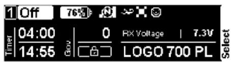
Once the previous steps are done there will be a Scorpion icon on VBar Control display, then setup of Tribunus ESC can start using VBar Control radio.
text_image
1 Off 76% Timer | 04:00 | 0 RX Voltage | 7.3V 14:55 LOGO 700 PL Select

TRIBUNUS ESC AND MIKADO VBAR CONTROL/ VBAR NEO INTEGRATION
13.3 Tribunus ESC and VBar Control ESC setup using VBar Govenor mode
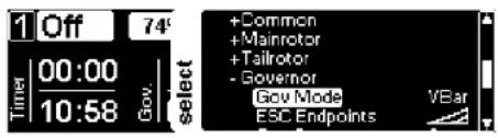
-select "Edit Heli wizard" and click through the setup to govenor page when using NEO Express
-select "Setup / Governor Mode" panel when using NEO PRO/ PRO Rescue.
You will be directly in Scorpion automatic setup panel.
text_image
1 Off 74' Timer 00:00 10:58 Gov. select +Common +Mainrotor +Tailrotor - Governor Gov Mode VBar ESC Endpoints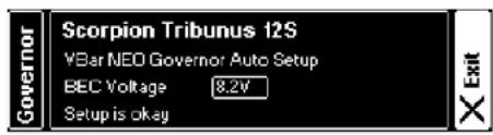
text_image
Scorpion Tribunus 12S YBar NEO Governor Auto Setup BEC Voltage 8.2V Setup is okay-by entering the Governor Mode panel, the automatic setup will start directly
-after automatic setup is done, choose your BEC voltage and exit this menu
-depending on changes the ESC may restart when leaving the panel
-afterwards check gear ratio, motor pole and headspeed settings in ESC Setup panel
-for battery management using the "Battery Logbook App" is suggested as well as installing a Battery ID reader and the required App
-after these automatic setup, check all parameters of step 13.5 e.g. motor direction and protection settings to match your usage


TRIBUNUS ESC AND MIKADO VBAR CONTROL/ VBAR NEO INTEGRATION
13.4 Switching from VBar Govenor Mode to Tribunus govenor with Mikado VBar Control
If you want to use the internal Tribunus ESCs govenor and you was using VBar govenor before please follow these steps (please remove the blades first for safety reasons):
1) choose "Gov. with recalc values" in Tribunus ESC settings
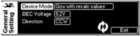
text_image
Device Mode Gov with recalc values BEC Voltage 8.2V Direction CCW General Setting Exit2) restart the ESC (store), ESC will restart
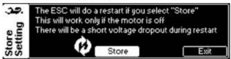
text_image
The ESC will do a restart if you select "Store" This will work only if the motor is off There will be a short voltage dropout during restart Store Exit3.1) disable Scorpion App in your VBar Control "application enable" menu
3.2) open model setup/ govenor/ govenor mode and choose "external Gov."
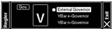
text_image
Regler Gov. V External Governor VBar e-Governor VBar n-Governor Exit5) enable Scorpion App for telemetry features
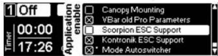
text_image
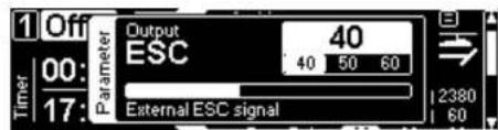
1 Off Timer 00:00 17:26 Application enable Canopy Mounting VBar old Pro Parameters Scorpion ESC Support Kontronik ESC Support Mode AutoswitcherAfter these steps a fixed trottle value can be set up in your govenor menu/ ESC output for each flight bank while using Tribunus ESC internal govenor.
text_image
1 Off Timer 00: 17: Parameter Output ESC 40 50 60 External ESC signal 2380 60Connect Tribunus Slave cable to "RPM" port of VBar NEO, set up your motor poles and gear ratio correctly to show your current headspeed on VBar control display in flight (step 13.5 gear settings). Do not forget to install "RPM Telemetry Setup" app.
4) calibrate throttle endpoints of the ESC:
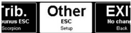
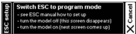
-open model setup/ setup tools/ ESC setup wizard and choose "other ESC, then go to full negativecollective stick position turn off the ESC
-go to full collective stick position on VBar Control
-power up the ESC again, wait few seconds for one beep of the ESC and go to full negative collective stick position
- wait for two beeps and POS Morse code come from the motor, this mean calibration is done and throttle endpoint has been set up correctly, exit the panel
text_image
Trib. Punus ESC Scorpion Other ESC Setup EXIT No change Back
text_image
Switch ESC to program mode - see ESC manual how to set up - turn the model off (this screen disappears) - turn the model on (next screen comes up)
TRIBUNUS ESC AND MIKADO VBAR CONTROL/ VBAR NEO INTEGRATION
13.5 Scorpion Support App functions and features
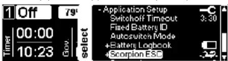
ESC setup panel at Application setup/ Scorpion ESC
text_image
1 Off 79° Timer 00:00 10:23 Gov. select - Application Setup Switchoff Timeout 3:30 Fixed Battery ID Autoswitch Mode +Battery Logbook +Scorpion ESGStatus menu of Tribunus ESC
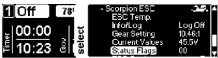
text_image
1 Off 78 Timer 00:00 10:23 Gov select - Scorpion ESC ESC Temp. Info/Log Log Off Gear Setting 10.46:1 Current Values 45.5V Status Flags 00Temperature warning setup:
Set up a temperature and warning type, by exceeding this temperature VBar Control will inform about in flight. This value should be lower than cutoff temperature in "protection limit" setup.
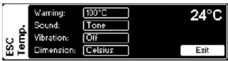
text_image
Vaming: 100°C Sound: Tone Vibration: Off Dimension: Celsius ESC Temp. 24°C ExitESC Info: Serial number and firmware version -choose write logfile of ESC data on VBC or not
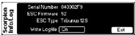
text_image
Scorpion Info/Log Serial Number 040002F9 ESC Firmware 52 ESC Type Tribunus 12S Write Logfile On Exit
Gear settings:
Motor Poles and gear ratio only need to set when using other govenor modes than VBar Govenor. This value will be set automatic during VBar govenor configuration.
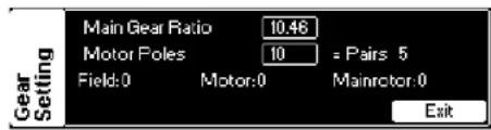
text_image
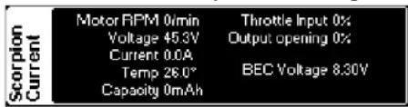
Gear Setting Main Gear Ratio 10.46 Motor Poles 10 = Pairs 5 Field:0 Motor:0 Mainrotor:0 ExitScorpion Current:
Real time ESC Values, surely also shown in flight
text_image
Scorpion Current Motor RPM 0min Voltage 45.3V Current 0.0A Temp 26.0° Capacity 0mAh Throttle Input 0% Output opening 0% BEC Voltage 8.30VScorpion Status:
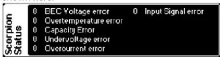
If there is an error from the ESC the cause will be shown here.
text_image
Scorpion Status 0 BEC Voltage error 0 Input Signal error 0 Overtemperature error 0 Capacity Error 0 Undervoltage error 0 Overcurrent error
TRIBUNUS ESC AND MIKADO VBAR CONTROL/ VBAR NEO INTEGRATION
13.5 Scorpion Support App functions and features
ESC Settings:
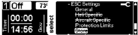
If there is a panel crossed out, it means that the settings are not used for the currently chosen ESC mode set up in "General" panel. In this case "VBar Govenor Mode" is activated, so there is no access to Aircraft specific and Tribunus internal Govenor settings. By changing the ESC mode, the needed panels will be available accordingly. All parameters of the PC software explained above are available in this menus depending on the chosen ESC mode.
text_image
1 Off 73' Timer 00:00 14:56 Gov. select - ESC Settings General Helt-Specific Aircraft-Specific Protection Limits StoreGeneral Settings:
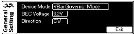
Set up ESC mode, BEC Voltage and motor direction in this panel.
text_image
General Setting Device Mode VBar Governor Mode BEC Voltage 8.2V Direction CW ExitIf "store" panel is not crossed out, it means that a parameter changed after last power up of the ESC.
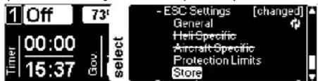
text_image
1 Off 73' Timer 00:00 15:37 Gov select - ESC Settings [changed] General Heir-Specific Aircraft-Specific Protection Limits Store
Protection Limits: set up all protection limits to match your usage (step 12.3)
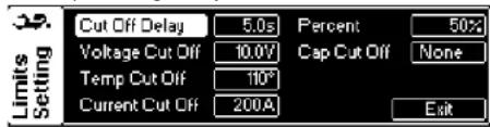
text_image
Cut Off Delay 5.0s Percent 50% Voltage Cut Off 10.0V Cap Cut Off None Temp Cut Off 110° Current Cut Off 200A ExitAdditionally a round symbol next to the exit button comes up after changing a parameter.
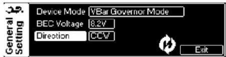
text_image
General Setting Device Mode VBar Governor Mode BEC Voltage 8.2V Direction CCV ExitAfter ESC setup or a change of a parameter, it is necessary to write the settings to the ESC.
By selecting the "Store" panel and pressing "Store" the ESC will restart and save all changed parameters accordingly.
Take note, that the ESC (as well as the BEC) will shut down for a short time. Sometimes you will notice a "Warmstart" of the VBar (LED flashing green/purple, entry into the Eventlog).
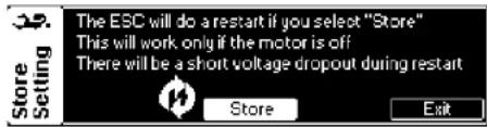
text_image
Store Setting The ESC will do a restart if you select "Store" This will work only if the motor is off There will be a short voltage dropout during restart Store Exit-that's all! - Tribunus ESC are now ready to fly!

ANTI SPARK DIY KIT
14.0 Anti Spark DIY Kit manual

Scorpion Power System
www.scorpionsystem.com
Scorpion Anti Spark DIY kit
www.scorpionsystem.com/files/download/AntiSparkDIYkit.pdf

direct QR to online manual
This Anti Spark DIY can be used on 65-165 Lipo battery systems
Including parts:
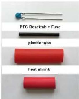
- PCT resettable fuse
- plastic tube
- heat shrink
text_image
PTC Resettable Fuse plastic tube heat shrinkHow to install it:
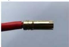
1) remove the old heat shrink
natural_image
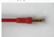
Close-up of a red electrical plug with metallic connectors (no text or symbols visible)2) wind one leg of the PTC Resettable fuse around the positive (+) wire from your ESC as shown below
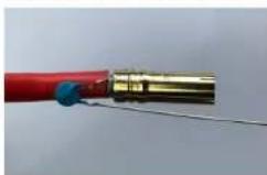
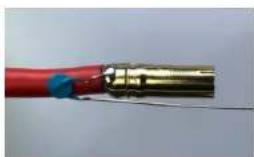
3) solder the of the PTC Resettable fuse to the positive wire
natural_image
Close-up of a red and gold electrical plug with blue connectors (no text or symbols visible)4) apply a heat shrink over the connector to isolate the other leg from the connector
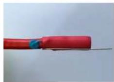
natural_image
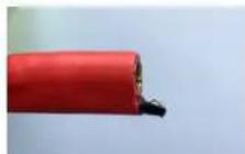
Close-up of a red electrical cable with blue insulation, lying on a plain surface (no text or symbols visible)5) modify the plastic tube (shorten it correctly and also cut it as shown in the picture)
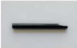
natural_image
Simple black rectangular object on a plain background (no text or symbols)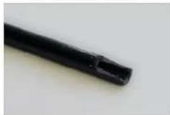
6) slide the plastic tube over the leg of the PTC Resettable fuse and use CA to keep it in position
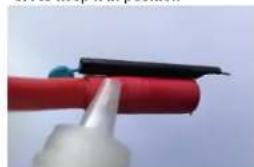
natural_image
Close-up of a red tool tip holding a black plastic object (no text or symbols visible)8) bend the leg of the PTC Resettable fuse as shown in the picture like a "V", cut the leg if it's too long
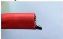
7) apply a heat shrink over it
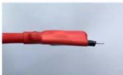
9) Anti Spark DIY ready to use!
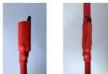
Now connect the negative (-) wire first. Then connect the positive (+) battery wire to the PTC Resettable fuse for a second and move straight into the positive connector. There will be no spark during connecting your battery to the ESC. Hope this DIY kit can help you on any spark issue during connecting a battery to an ESC.


ANTI SPARK DIY FOR HOUSING CONNECTORS
14.1 Anti Spark DIY for housing connectors


Scorpion Power System
www.scorpionsystem.com
Scorpion Anti Spark DIY kit
www.scorpionsystem.com/files/download/housingConnectorAntiSparkDIY.pdf

direct QR to online manual
This Anti Spark DIY can be used on 6S-16S Lipo battery systems
Required parts:
- PTC Resettable Fuse
- plastic tube
- heat shrink
- male and female connector that fit to your cable size and current

PTC Resettable Fuse

plastic tube

heat shrink

How to install it:
1) -cut the positive (+) wire that goes from housing connector to the ESC -solder the female connector as shown on the housing connector side
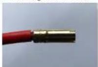
2) wind one leg of the PTC Resettable Fuse around the positive (+) wire as shown below
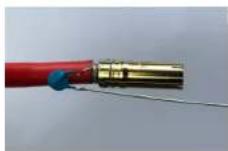
3) solder the leg of the PTC Resettable Fuse to the positive wire
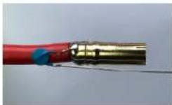
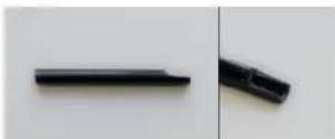
5) modify the plastic tube (shorten it correctly and also cut it as shown in the picture)
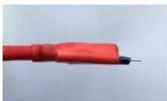
7) apply a heat shrink over it
9) solder the male connector to the ESC side and apply a heat shrink
4) apply a heat shrink over the connector to isolate the other leg from the connector
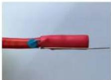
6) slide the plastic tube over the leg of the PTC Resettable Fuse and use CA to keep it in position

8) bend the leg of the PTC Resettable Fuse as shown in the picture like a "V", cut the leg if it's too long
10) Anti Spark DIY ready to use!
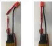
Now disconnect the Anti Spark wire first. After that connect the battery to the housing connector. Then connect the positive (+) cable coming from the ESC side to the PTC Resettable Fuse for a second and move straight into the positive female connector. There will be no spark during connecting your battery to the ESC. Hope this DIY kit can help you on any spark issue during connecting a battery to an ESC.


15.0 Warranty and Service
Scorpion Tribunus Speed Controller is guaranteed to be free from defected materials a dated, itemized sales receipt). During the warranty period Scorpion will repair speed controller that are found to be defective, providing that it has no signs of damage or abuse. The user will be responsible for shipping charges back to an authorized Scorpion Repair Facility, and Scorpion will pay the return shipping charges. If the damage is the result of a crash or mis-use, the returned item will be repaired, but the cost of repairs will be billed to the user. Repairs will never exceed 50% of the cost of a new speed controller, and if the speed controller is badly damaged or non-repairable, a brand new ESC will be offered at 50% discount of the current retail price for the ESC, plus a nominal shipping charge.
If the speed controller returned is no longer in production, Scorpion reserves the right to substitute any other speed controller of equal or better quality. In any event, Scorpion shall not be responsible for the damage that may result from the overuse of products, for consequential or special damages, or for any amount that exceeds the product value. If the motor product is purchased in clearance section, crash and dent section from www.scorpionsystem.com and www.scorpion-team.com, then the items are sold "AS IS". No refund or warranty policy will be covered with these products. It is because we do not have parts anymore to repair or replace. or replacement. Please obtain an RMA number by submitting a request by email to our RMA Department support@spihk.com or our distributors for the RMA number before sending. The RMA process normally takes around 3 - 4 weeks.
RMA form can be found and download from http://www.scorpion-team.com/downloads/ http://www.scorpionsystem.com/

