
250 XC-F (2007) - Motorcycle KTM - Free user manual and instructions
Find the device manual for free 250 XC-F (2007) KTM in PDF.


User questions about 250 XC-F (2007) KTM
0 question about this device. Answer the ones you know or ask your own.
Ask a new question about this device
Download the instructions for your Motorcycle in PDF format for free! Find your manual 250 XC-F (2007) - KTM and take your electronic device back in hand. On this page are published all the documents necessary for the use of your device. 250 XC-F (2007) by KTM.
USER MANUAL 250 XC-F (2007) KTM
250 XC-F, XCF-W, EXC-F
400 XC-W, EXC RACING
450 XC, XC-W, EXC RACING
525 XC, XC-W, EXC RACING
525 XC DESERT RACING
ART. NR. 3.211.145 EN
text_image
525 XC, XC-W, 525 XC DE ARWe would like to congratulate you on your purchase of a KTM motorcycle.
You are now the owner of a state-of-the-art sport motorcycle that guarantees to bring you lots of fun and enjoyment, provided that you clean and maintain it appropriately.
Please insert the serial numbers of your motorcycle in the boxes below
Frame number
Engine number
Key number
Stamp of dealer
All information contained is without obligation. KTM-Sportmotorcycle AG particularly reserves the right to modify any equipment, technical specifications, prices, colors, shapes, materials, services, service work, constructions, equipment and the like so as to adapt them to local conditions or to cancel any of the above items, all without previous announcement and without giving reasons. KTM may stop manufacturing certain models without previous notice. KTM shall not be held liable for any deviations of availability and/or ability to deliver, illustrations, descriptions, printing and/or other errors. The illustrated models partly contain extra equipment, which is not applied to standard models.
© 2006 by KTM-SPORTMOTORCYCLE AG, Mattighofen AUSTRIA; All rights reserved; Reprint, also in extracts, with written allowance of KTM-SPORTMOTORCYCLE AG, Mattighofen only.
COMSUMER INFORMATION FOR AUSTRALIA ONLY
Tampering with noise control system prohibited
Owners are warned that the law may prohibit:
(a) The removal or rendering inoperative by any person other than for purposes of maintenance, repair or replacement, of any device or element of design incorporated into any new vehicle for the purpose of noise control prior to its sale or delivery to the ultimate purchaser or while it is in use; and
(b) the use of the vehicle after such device or element of design has been removed or rendered inoperative by any person.

In accordance with the international quality management ISO 9001 standard, KTM uses quality assurance processes that lead to the highest possible product quality.
INTENDED PURPOSE
KTM sports motorcycles are designed and constructed to resist the usual wear and tear of normal use in competitions.
The motorcycles comply with the regulations and categories currently in effect with the leading international motorcycle associations.
The XC and other „competition only“ labeled models are prohibited on public roads.
„On the road“ approved models are only allowed on public roads in the original homologated (throttled) version. Without this performance restriction (i.e. de-throttled), these models are only allowed to be driven off-road and not on public roads.
The EXC models are designed for off-road sports endurance competitions(enduro) and not suitable for predominant motocross use.
NOTE: The above is a general statement. Specific limited warranty and limited guarantee information may vary depending upon distribution. Please check with your local KTM dealer for limited warranty and limited guarantee information specific to your KTM model and region.
OWNER'S MANUAL
Please read this manual carefully and completely before going on your first ride. It contains a great deal of information and advice which will help you use and handle your bike properly. Only by doing so will you learn how to tune your motorcycle to your specific needs and how to protect yourself against injury. Besides, this manual contains important information on motorcycle maintenance.
In your own interest, please pay particular attention to notices that are marked as follows:
WARNING
- Ignoring these instructions can be dangerous to life and limb!
! CAUTION
- Ignoring these instructions may damage parts of the motorcycle or impair the motorcycle's traffic safety!
At the time this manual was typeset, it was up-to-date with the latest state of this production series. It cannot be completely ruled out, however, that minor discrepancies may exist resulting from further design upgrades of these motorcycles. This manual is an important part of your motorcycle and should be passed on to any subsequent owner in case you decide to sell it.
SERVICE
Observance of the service, maintenance and tuning instructions for the engine and chassis specified in the Owner's Manual is a prerequisite for faultless operation and the avoidance of premature wear. An improperly tuned chassis can lead to damage and breakage of the chassis components (see chapter on checking the basic chassis setting).
The use of the motorcycle under extreme conditions, e.g. on extremely muddy and wet terrain, can lead to higher than average wear on components such as the drive train or the brakes. In this case it may become necessary to service or replace wear parts before the service limit specified in the maintenance schedule has been reached.
We expressly point out that work marked with an asterisk in the chapter „Maintenance work on the chassis and engine“ must be performed. If maintenance work should become necessary during a competition it should be performed by a trained mechanic. KTM strongly recommends that all service work to your KTM should be performed by a qualified KTM dealer.
Take special care to follow the recommended run in, inspection, and maintenance intervals. Heeding these guidelines will significantly increase the life of your motorcycle.
WARRANTY
The service work specified in the „Lubrication and Maintenance Schedule“ must be performed and service records must be kept for warranty documentation. Lack of proper service and maintenance records or documentation could void warranty.
No claims can be filed under the warranty for damage or consequential damage caused by manipulations or conversions to the motorcycle.
AUTOMOTIVE FLUIDS
The fuels and lubricants specified in the Owner's Manual or fluids with equivalent specifications must be used in accordance with the maintenance schedule.
SPARE PARTS, ACCESSORIES
For your own safety, use KTM-approved parts and accessories only. KTM is not liable for damage that arises in connection with the use of other products.
TRANPORT
When transporting your KTM, ensure that it is held upright with restraining straps or other mechanical fastening devices and that the fuel tap is in the OFF position - if the motorcycle should fall over, no fuel can leak from the carburetor or fuel tank
ENVIRONMENT
Off-road motorcycle driving is a wonderful sport and we hope that you will be able to enjoy it to the full. It may, however, involve potential problems for the environment or lead to conflicts with others. These problems or conflicts can be avoided if the motorcycle is used responsibly. To safeguard the future of motorcycle sports, make sure that you use the motorcycle in accordance with the law, show that you are environmentally conscious and respect the rights of others.
We wish you a lot of fun when driving!
KTM-SPORTMOTORCYCLE AG
5230 MATTIGHOFEN, AUSTRIA
Attachments: 1 spare parts manual chassis & engine
Page Page
INTRODUCTION....1
IMPORTANT INFORMATION 2
SERIAL NUMBER LOCATIONS 5
Engine number, engine type ....5
Chassis number 5
Short circuit button (XC) 6
Combination switch (EXC) 6
Headlamp switch (XC-W) 7
Flasher switch 7
Starter button 7
Emergency OFF switch (EXC Australia) .....7
Indicator lamps 7
Electronic speedometer....8
Activating and deactivating display modes .....9
Overview of the electronic speedometer functions .....12
Setting the clock 12
Filler cap (bayonet cap)....13
Filler cap (screw cap) 13
Fuel tap 13
Choke 13
Shift lever 14
Kickstarter 14
Foot brake pedal 14
Side stand 14
Steering lock 14
Compression damping of fork 15
Rebound damping of fork 15
Compression damping of shock absorber (XC, EXC SIXDAYS)....15
Compression damping of shock absorber (XC-W, EXC) ...16
Rebound damping of shock absorber .....16
GENERAL TIPS AND WARNINGS FOR STARTING
THE MOTORCYCLE 17
Instructions for initial operation .....17
Running in the XC/EXC models .....17
DRIVING INSTRUCTIONS 18
Check the following before each start .....18
Starting when the engine is cold .....18
Starting when the engine is warm .....19
What to do when the engine is „flooded“ .....19
Starting off 19
Shifting/Riding 19
Braking 20
Stopping and parking 20
Fuel 20
PERIODIC MAINTENANCE 21
MAINTENANCE WORK ON CHASSIS AND ENGINE .....27
Changing the spring preloading of the shock absorber . . .27
Pivot bearing 27
Basic suspension setup for the weight of the driver .....28
Checking the shock absorber and spring .....28
Determining the static sag of the shock absorber .....28
Determining the riding sag of the shock absorber .....28
Checking the basic setup of the telescopic fork .....29
Changing the spring preload on the telescopic fork (XC, EXC SIXDAYS)....29
Changing the spring preload on the telescopic fork (XC-W/EXC) 29
Replacing fork springs .....29
Breather plug front fork ....30
Cleaning the dust sleeves of the telescopic fork .....30
Checking and adjusting the steering head bearing .....30
Changing the fork offset (caster) (XC, EXC SIXDAYS) . . . .31
How to change the handlebar position .....32
Check chain tension 33
Correct chain tension 33
Chain maintenance ....34
Chain wear 34
General information about KTM disc brakes .....35
Adjusting the free travel at the hand brake lever .....36
Checking the brake fluid level - front brake .....36
Refilling the front brake fluid reservoir .....36
Checking the front brake pads 36
Replacing the front brake pads . . . . . . . . . . . . . . . . . . . . . . . . . . . . . . . . . . . . . . . . . . . . . 37
Changing the basic position of the foot brake pedal .....37
Checking the rear brake fluid level . . . . . . . . . . . . . . . . . . . . . . . . . . . . . . 37
Refilling the rear brake fluid reservoir .....37
Checking the rear brake pads . . . . . . . . . . . . . . . . . . . . . . . . . . . . . . . . . . . . . . . 38
Replacing the rear brake pads . . . . . . . . . . . . . . . . . . . . . . . . . . . . . . . . . . . . . . . . . 38
Dismounting and mounting the front wheel .....38
Dismounting and mounting the rear wheel .....39
Checking spoke tension....39
Tires, air pressure 40
Check/set distance of the magnetic sensor .....40
Replacing the battery of the digital speedometer .....40
Battery 41
Charging the battery 41
Fuse 42
Replacing headlight lamp/parking light lamp .....42
Cooling system . . . . . . . . . . . . . . . . . . . . . . . . . . . . . . . . . . . . . . . . . . . . . . . . . . . 43
Checking the coolant level .....43
Bleeding the cooling system (400/450/525) .....43
Bleeding the cooling system (250-F) .....44
Replacing the glassfiber yarn packing of the silencer . . . .44
Cleaning the spark arrester (XC-W USA) .....44
Cleaning the air filter .....45
Adjusting the throttle cables .....45
Changing the original position of the clutch lever .....46
Checking the oil level of the hydraulic clutch (400/450/525) 46
Checking the oil level of the hydraulic clutch (250-F) . . .46
Bleeding of the hydraulic clutch .....46
Carburetor - Adjust idling (Keihin-FCRMX 37/39/41) . . . .47
Basic information on carburetor wear .....47
Adjusting the mixture control screw ....47
Checking the float level (float height) .....47
Draining the float chamber of the carburetor .....48
Oil circuit (400/450/525) 48
Oil circuit (250-F) 48
Checking the engine oil level 48
Engine oil 49
Changing the engine oil 49
Changing the oil filters 50
TROUBLESHOOTING 51
CLEANING 53
CONSERVATION FOR WINTER OPERATION .....53
STORAGE 53
USE AFTER A PERIOD OF STORAGE .....53
TECHNICAL DATA – ENGINE .....54
TECHNICAL DATA - CHASSIS .....59
HEAD WORD INDEX 61
WIRING DIAGRAM ....appendix
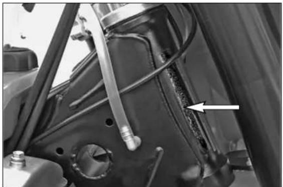
Chassis number
The chassis number is stamped on the right side of the steering head tube. Enter this number in the field on page no 1.
natural_image
Close-up of a mechanical assembly with hoses and components, no visible text or symbols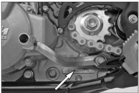
natural_image
Mechanical gear assembly with visible gears and shafts, no text or symbols presentEngine number, engine type
The engine number and the engine type are stamped into the left side of the engine below the engine sprocket. Enter this number on page 1.
text_image
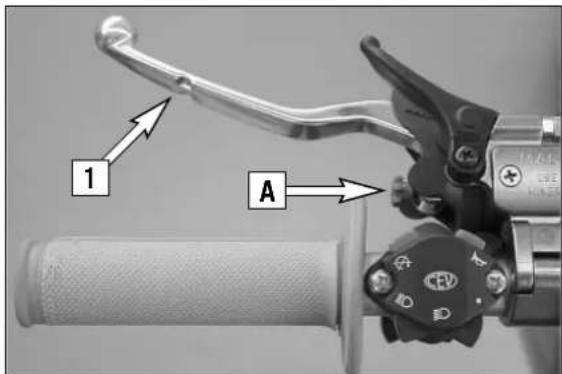
1 AClutch lever
The clutch lever [1] is located on the left side of the handlebar. The adjusting screw [A] is used to change the original position of the clutch lever (see maintenance work on chassis and engine).
The clutch is hydraulically actuated and adjusts itself automatically.
text_image
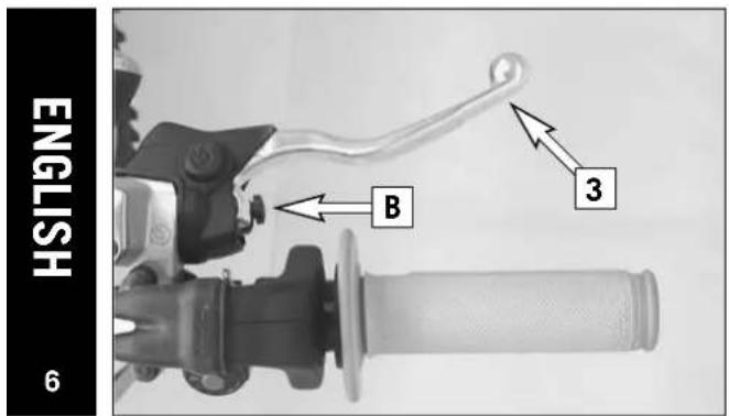
ENGLISH 6 B 3Hand brake lever
The hand brake lever [3] is mounted on the handlebars on the right and actuates the front wheel brake. The adjusting screw [B] can be used to change the basic position of the hand brake lever (see "Maintenance").
natural_image
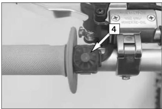
Close-up of a mechanical device with a knob and adjustment knob, labeled with number 4 (no readable text or symbols beyond labels)Short circuit button (XC)
The short circuit button [4] turns off the engine. When pressing this button, the ignition circuit is short-circuited.
text_image
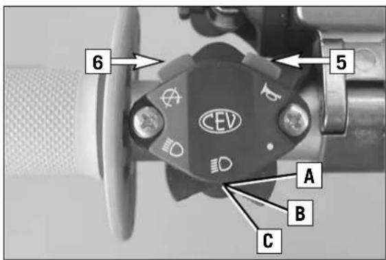
6 5 CEV A B CCombination switch (EXC)
The light switch has 2, respectively 3 switch positions.
[A] = Light off (this function is not available in all models)
[B] = Low beam on
[C] = High beam on
You may use button [5] to actuate the horn.
The red short circuit button [6] serves to switch off the engine. Leave the switch pressed until the engine stops.
natural_image
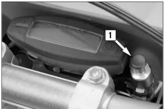
Close-up of a mechanical component with a digital display and cylindrical base (no visible text or symbols)Headlamp switch (XC-W)
In this model the headlamp is switched on with the pull switch [1].
natural_image
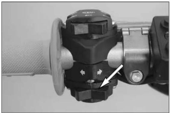
Close-up of a mechanical valve component with a white arrow pointing to a specific part (no visible text or symbols)Flasher switch
The flasher switch is a separate unit and is mounted on the left portion of the handlebar.
The wire harness is designed in a way that whenever you want to use your bike off-road, you can dismount the entire turn indicator system without affecting the function of the remaining electrical system.

Flasher left

Flasher right
natural_image
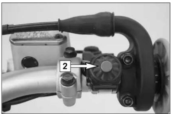
Close-up of a mechanical device with a numbered component labeled '2' pointing to a knob (no readable text or symbols beyond the label)Starter button

Pushing the black starter button [2] will actuate the E-starter.
text_image
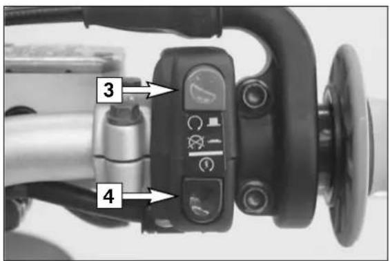
3 4Emergency OFF switch (EXC Australia)
The red emergency-OFF switch [3] is arranged adjacent to the throttle grip.


In this position, the E-starter is operational and the engine can be started.


In this position, the E-starter and ignition circuits are interrupted. The E-starter cannot be actuated, and the engine will not start, not even if you attempt to start it with the kickstarter.

Pushing the black starter button [4] will actuate the E-starter.
text_image
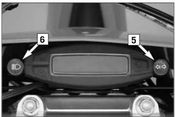
6 5Indicator lamps

The green control lamp [5] flashes in the same rhythm as the flashing indicator when the indicator is working.

The blue control lamp [6] lights up when the high beam is on.
text_image
SPEED 0 00:06.3 Km/h H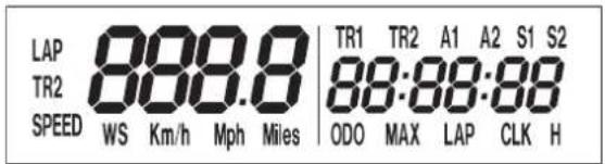
text_image
LAP 888.8 | TR1 TR2 A1 A2 S1 S2 TR2 88:88:88 SPEED WS Km/h Mph Miles ODO MAX LAP CLK HElectronic speedometer
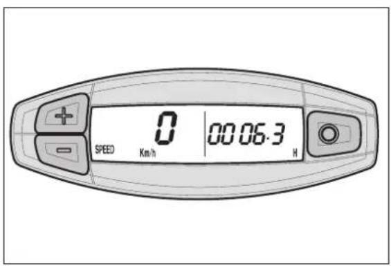
The display in the electronic speedometer is activated as soon as you press a button on the speedometer or an impulse is received from the wheel sensor. The display lights up when the engine is running.
The display is cleared if no button is pressed for 1 minute or no impulse is received from the wheel sensor.
The ○ button is used to change between display modes.
The + and - buttons are used to control various functions.
TEST
All of the display segments briefly light up for the display function test.
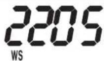
WS (wheel size)
The display changes and the circumference of the front wheel is briefly displayed in millimeters (2205 mm corresponds to a front wheel circumference of 21" with production tires).
Afterwards the display will return to the previous display mode.
text_image
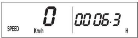
SPEED 0 | 00:06.3 H Km/hSPEED display mode / H (service hours)
Only the SPEED / H and SPEED / ODO display modes are activated in the condition at delivery. SPEED/H is displayed whenever the display is activated and the front wheel is not turning. It automatically changes to the SPEED/ODO display mode as soon as the front wheel starts turning.
SPEED displays the speed.
H displays the engine's service hours. The service hour counter starts to count as soon as you start the engine. The displayed figure cannot be changed. Service intervals are indicated in service hours for some KTM offroad motorcycles, making the service hour counter a very practical function.
text_image
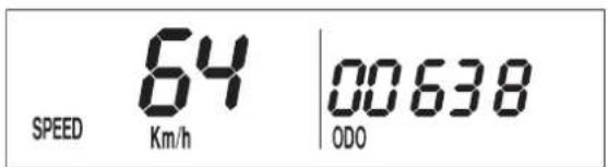
SPEED 64 Km/h 00638 ODOSPEED / ODO display mode (odometer)
The SPEED/ODO mode displays the speed and the total distance traveled. The display automatically changes to the SPEED/H display mode when the front wheel stops turning.
+ button no function
- button no function
briefly press ○ button changes to the next display mode hold ○ button 3 secs. changes to the next display mode
The electronic speedometer has a number of display modes (functions) that you can also activate (reveal) (see: Activating and deactivating display modes).
| TR1 | TR2 | A1 | A2 | S1 | S2 | |||
| Km/h | Mph | ODO ≥slant | MAX ≤slant | LAP | CLK | H |
Activating and deactivating display modes
In the display mode SPEED/H, press and hold the ○ button for 3 seconds to access the SETUP menu. The active functions will be displayed. The blinking function can be activated by pressing the + button and deactivated by pressing the - button.
Press and hold the ○ button 3 seconds to store the settings.
If no button is pressed for 20 seconds, the setting will be stored automatically and the display will return to the SPEED/H mode.
+ button activates the blinking display
- button deactivates the blinking display
briefly press ○ button changes to the next display without changing any settings
hold ○ button 3 secs. starts the SETUP
stores the settings and changes to the SPEED/H mode
The following display modes can be activated:
TR1 tripmaster 1
TR2 tripmaster 2
A1 average speed 1
A2 average speed 2
S1 stop watch 1
S2 stop watch 2
CLK clock
LAP lap time
MAX maximum speed
KMH/MPH display in kilometers or miles (see: Kilometers or miles)
If you have activated all of the display modes, they will be displayed in the following order:
SPEED/H, SPEED/CLK, SPEED/LAP, LAP/LAP, SPEED/MAX, SPEED/ODO, SPEED/TR1, SPEED/TR2, SPEED/A1, SPEED/A2, SPEED/S1, SPEED/S2
| SPEED | 68Km/h | 12:08:54CLK |
SPEED / CLK (time) display mode
CLK displays the time in hours, minutes and seconds.
+ button no function
- button no function
briefly press ○ button changes to the next display mode
hold ○ button 3 secs. set the clock menu
To set the clock, see „Setting the clock“.
| SPEED | 27Km/h | 00:08:39LAP |
SPEED / LAP (lap time) display mode
You can use the manual stop watch to stop and store up to 10 lap times, which you can view in the LAP/LAP display mode (see below).
LAP displays the lap times in hours, minutes and seconds.
+ button Starts and stops the stop watch, lap time is not reset to 0
- button Stops the stop watch, stores the lap time and restarts the stop watch again. The time is reset to 0. A total of 10 lap times can be stored. If the lap time continues to run after you press the - button, all 10 memory locations are occupied. To clear all of the stored lap times, hold the ○ button for 3 seconds in the SPEED/LAP mode. Up to 10 lap times can be stored in this way.
briefly press ○ button Changes to the next display mode. If no lap time is stored or the motorcycle is driving, the LAP/LAP mode will be skipped.
hold ○ button 3 secs. Clears all LAP figures
LAP

00:08:39
LAP
LAP / LAP display mode (to view lap times)
The LAP/LAP display mode will only be shown if lap times have been stored and the front wheel has stopped. It will display the lap number and the stopped lap time in hours, minutes and seconds. Press the + button to access the next lap time.
To clear all of the stored lap times, hold the ○ button for 3 seconds in the SPEED/LAP mode.
+ button changes to the next lap time
- button no function
briefly press ○ button changes to the next display mode hold ○ button 3 secs. changes to the next display mode
text_image
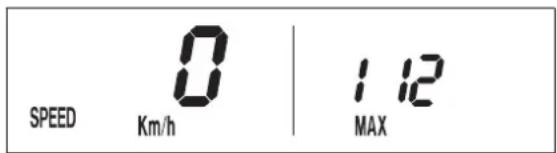
SPEED 0 | 1.12 Km/h MAXSPEED / MAX display mode (maximum speed)
MAX displays the maximum speed traveled and is always active.
+ button no function
- button no function
briefly press ○ button changes to the next display mode hold ○ button 3 secs. clears the MAX figure
text_image
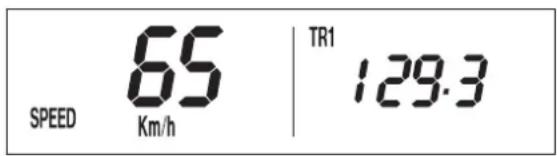
SPEED 65 Km/h TR1 129.3SPEED / TR1 display mode (tripmaster 1)
The TR1 tripmaster is always active and counts to 999.9. It is used to measure the length of a trip or the distance between 2 refueling stops.
TR1 is linked to A1 (average speed 1). The calculation of these figures is activated by the first impulse received from the wheel sensor (when the front wheel starts to turn) and stops 3 seconds after the last impulse is received (when the front wheel has stopped).
The TR1, A1 and S1 figures are automatically cleared after passing 999.9.

text_image
SPEED 62 Km/h | TR2 38.4+ button no function
- button no function
briefly press ○ button changes to the next display mode hold ○ button 3 secs. clears the TR1, S1, A1 figures
SPEED / TR2 display mode (tripmaster 2)
The tripmaster 2 is always active and counts to 999.9. Contrary to TR1, the displayed figure can be changed using the + and - buttons. This is a very useful function for trips taken according to a roadbook.
+ button increases the TR2 figure
- button decreases the TR2 figure
briefly press ○ button changes to the next display mode hold ○ button 3 secs. clears the TR2 figure
text_image
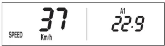
SPEED 37 Km/h | A1 22.9SPEED / A1 display mode (average speed 1)
A1 shows the average speed based on the TR1 (tripmaster 1) and S1 (stop watch 1) figures. The calculation of this figure is activated by the first impulse received from the wheel sensor and stops 3 seconds after the last impulse is received.
+ button no function
- button no function
briefly press ○ button changes to the next display mode
hold ○ button 3 secs. clears the TR1, S1, A1 figures
text_image
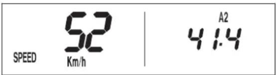
SPEED 52 Km/h | 4.14 A2SPEED / A2 display mode (average speed 2)
A2 shows the average speed based on the TR2 (tripmaster 2) and S2 (stop watch 2) figures.
The displayed figure can deviate from the actual average speed if the TR2 figure was changed manually or if S2 was not stopped after the trip.
+ button no function
- button no function
briefly press ○ button changes to the next display mode
hold ○ button 3 secs. changes to the next display mode
text_image
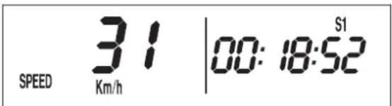
SPEED 31 | 00:18:52 S1 Km/hSPEED / S1 display mode (stop watch 1)
S1 shows the traveling time based on TR1 and continues to run whenever it receives impulses from the wheel sensor. The calculation of this figure is activated by the first impulse received from the wheel sensor and stops 3 seconds after the last impulse is received.
+ button no function
- button no function
briefly press ○ button changes to the next display mode
hold ○ button 3 secs. clears the TR1, S1, A1 figures
text_image
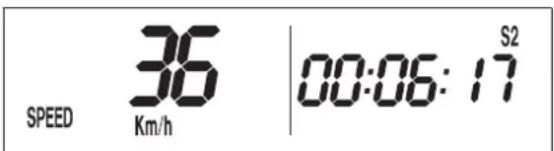
SPEED 36 Km/h | 00:06:17 S2SPEED / S2 display mode (stop watch 2)
S2 is a manual stop watch. Start the stop watch by pressing the + button, press again to hold. Press again to continue timing.
Press the ○ button to change to the next mode. The S2 display will blink in the other modes if S2 continues to run in the background. To stop S2, return to the SPEED/S2 mode and press the + button.
+ button starts and stops the stop watch
- button no function
briefly press ○ button changes to the next display mode
hold ○ button 3 secs. clears the S2 figure
text_image
TR1 TR2 A1 A2 S1 S2 ≥Km/h Mph≤ ODO MAX LAP CLK HKilometers or miles
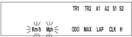
The unit (kilometers or miles) can also be changed. The ODO figure will be retained and converted accordingly. The TR1, A1, S1, TR2 and A2 figures will be cleared.
To select the unit, select the SPEED/H mode and hold the ○ button for 3 seconds to access the SETUP menu. Press the ○ button until the KMH/MPH function blinks. Press the + button briefly to move to the options. Press the + button for KMH or the - button for MPH.
To set, briefly press the ○ button 1 x and hold for 3 seconds until the display returns to the SPEED/H mode.
If no button is pressed for 20 seconds, the setting will be stored automatically and the display will return to the SPEED/H mode.
+ button to access the menu
to activate the KMH display
- button to activate the MPH display
briefly press ○ button changes to the next mode
changes from the menu to the SETUP menu
hold ○ button 3 secs. stores and closes the SETUP menu
text_image
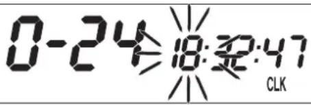
0-24 18:32:47 CLKSetting the clock
To set the clock, switch the ignition off and select the SPEED/CLK mode. Press and hold the ○ button for 3 seconds. The blinking digits can be changed using the + and - buttons. Press the ○ button to move to the next digit. 0-12 will show the time in the 12-hour mode, 0-24 in the 24-hour mode.
Press and hold the ○ button for 3 seconds to store the settings.
If no button is pressed for 20 seconds, the settings will be stored automatically and the display will return to the SPEED/CLK mode.
+ button time +
- button time -
briefly press ○ button changes to the next digit
hold ○ button 3 secs. starts the SETUP menu
stores the time and changes to the SPEED/CLK display mode
| Motorcycle is standing | Motorcycle is driving | OVERVIEW OF THE ELECTRONIC SPEEDOMETER FUNCTIONS | ||||
| display | briefly press + button | briefly press - button | briefly press ○ button | hold ○ button 3 secs. | ||
| X | SPEED / H | no function no function next display mode | displays the SETUP menu | |||
| X | X | SPEED / CLK | no function no function next display mode Setting the clock menu | |||
| X | X | SPEED / LAP | starts/stops LAP without clearing LAP figure | stops LAP, stores LAP figure, resets LAP to 0 | next display mode clears all LAP figures | |
| X | LAP / LAP | next figure no function next display mode next display mode | ||||
| X | X | SPEED / MAX | no function no function next display mode | clears MAX | ||
| X | SPEED / ODO | no function no function next display mode next display mode | ||||
| X | X | SPEED / TR1 | no function no function next display mode | clears TR1, S1, A1 | ||
| X | X | SPEED / TR2 | increases the TR2 figure | reduces the TR2 figure | next display mode | clears TR2 |
| X | X | SPEED / A1 | no function no function next display mode | clears TR1, S1, A1 | ||
| X | X | SPEED / A2 | no function no function next display mode next display mode | |||
| X | X | SPEED / S1 | no function no function next display mode | clears TR1, S1, A1 | ||
| X | X | SPEED / S2 | starts - stops S2 | no function | next display mode | clears S2 |
If the CLK, LAP, MAX, TR1, TR2 A1, A2, S1 and S2 figures are suddenly cleared, the battery in the electronic speedometer is empty and must be replaced (see: Replacing the battery in the electronic speedometer).
A tripmaster switch is available as an accessory that lets you control the electronic speedometer functions from the handlebar.
natural_image
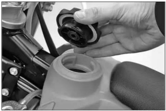
Close-up of a hand adjusting a black plastic component on a motorcycle wheel (no visible text or symbols)Filler cap (bayonet cap)
To open the filler cap: Turn the filler cap 45° counter-clockwise.
To close the filler cap: Put the filler cap on and turn it 45 ° clockwise.
natural_image
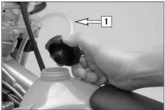
Close-up of a hand holding a black plastic component with a numbered arrow pointing to it, next to a vehicle engine (no text or symbols visible)Filler cap (screw cap)
To open the filler cap: Turn the filler cap counter-clockwise.
To close the filler cap: Put the filler cap on and tighten it by turning it clockwise.
Install the tank breather hose [1] without kinks.
natural_image
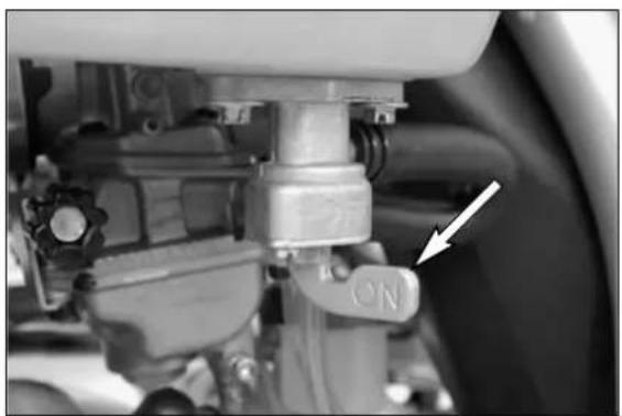
Close-up of a mechanical assembly with a white arrow pointing to a component labeled 'ON' (no readable text or symbols beyond the label)Fuel tap
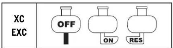
OFF In this position the fuel tap is closed. No fuel can flow to the carburetor.
ON During operation the twist grip must be turned to ON. This means that the fuel can flow to the carburetor. With the twist grip in this position the tank will be emptied until only the reserve is left.
RES The reserve tank cannot be tapped until the rotating handle is turned to the RES position. Fill the tank as soon as possible and remember to turn the rotating handle back to the ON position so that you will have backup fuel next time, too.
Reserve XC, XC-W, EXC ....1.0 I (0.3 US gallons)
Reserve XC Desert Racing ..2.01 (0.6 US gallons)
text_image
XC EXC OFF ON RES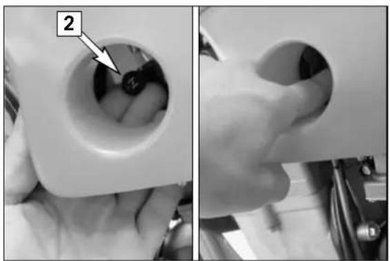
natural_image
Close-up of hands performing a mechanical tool with a labeled component (no text or symbols visible)Choke
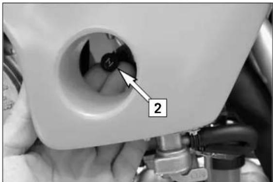
If you pull the choke button [2] out as far as possible, a bore in the carburetor will be opened through which the engine may take in additional fuel. The result is a „fat“ fuel-air mixture of the type needed for cold starts.
To deactivate the choke, push the choke button back into its basic position.
text_image
2,3,4 (5,6) N 1Shift lever
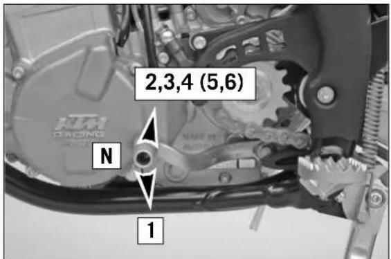
The shift lever is mounted on the left side of the engine. The position of the gears is shown in the illustration. Neutral, or the idle speed, is located between first and second gear.

natural_image
Close-up of a mechanical assembly with visible brackets and a white arrow pointing to a component (no text or symbols)Kickstarter
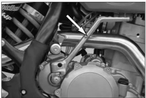
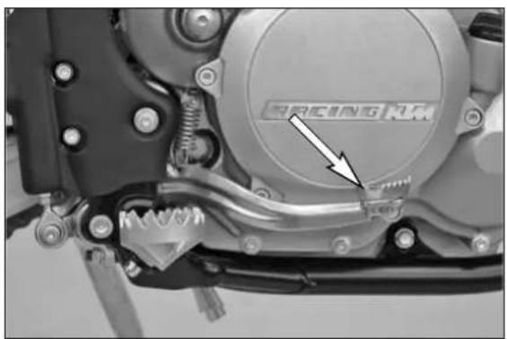
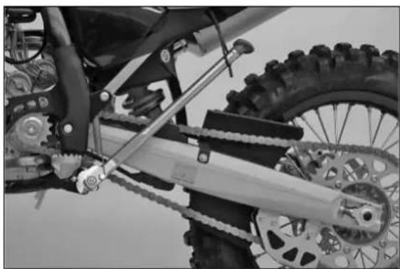
The kickstarter is mounted on the right side of the engine. Its upper part can be swivelled.
text_image
三轮电动机Foot brake pedal
The foot brake pedal is located in front of the right footrest. Its basic position can be adjusted to your seat position (see maintenance work).
natural_image
Mechanical assembly diagram showing a chain drive system with labeled component 1 (no text or symbols beyond label)Side stand
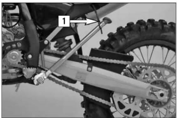
Push the side stand to the ground with your foot and load it with the motorcycle. Make sure that you put your bike on solid ground and in a secure position. For off-road riding, you can use the rubber band [1] to additionally secure the center stand in its folded-up position
natural_image
Close-up of mechanical components with a white arrow pointing to a component (no visible text or symbols)Steering lock
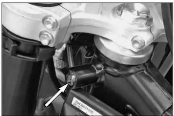
The handlebar can be locked by means of the lock located on the steering head. To lock it, turn handlebar all the way to the right, insert key, turn it to left, press it in, turn it to right, and remove it.
! CAUTION
Never leave the key inserted in the steering lock. If you turn the handlebar to the left the key could get damaged.
natural_image
Close-up mechanical component with labeled part '2' and arrow indicator (no readable text or symbols beyond label)
text_image
Technical diagram of a mechanical assembly with numbered components and directional arrows indicating motion or flow.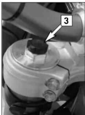
natural_image
Close-up of a mechanical component with a numbered annotation (3) pointing to a small cylindrical feature, no readable text or symbols present.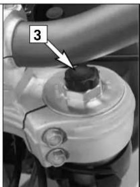
natural_image
Close-up of a mechanical component with a black knob and labeled part '3' (no text or symbols beyond label)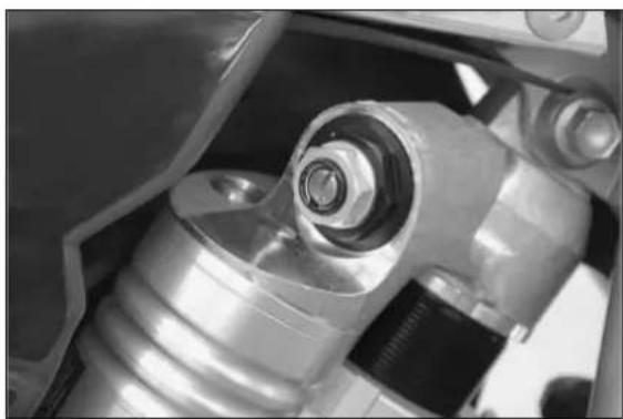
natural_image
Close-up of mechanical components including a metallic bearing and spring assembly (no visible text or symbols)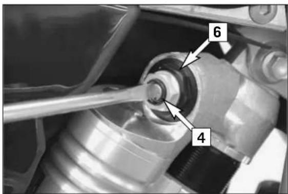
text_image
6 4
natural_image
Close-up of a mechanical assembly with a wrench and numbered component (no readable text or symbols)Compression damping of fork
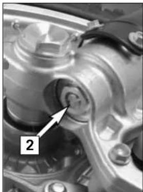
Hydraulic compression damping determines the reaction when the fork is compressed. The degree of compression can be adjusted with adjusting screws at the bottom of the fork legs. Remove the protecting cap [1]. Turn the adjusting screws [2] clockwise to increase damping, turn it counterclockwise to reduce damping during compression.
STANDARD ADJUSTMENT
- turn adjusting screw clockwise as far as it will go - turn it back by as many clicks as are specified for the relevant type of fork WP 14187C04 .... 20 clicks WP 14187C28 .... 18 clicks WP 14187C06 .... 20 clicks WP 14187C29 .... 18 clicks
Rebound damping of fork
Hydraulic rebound damping determines the reaction when the fork is rebound. By turning the adjusting screw [3] (REB), the degree of damping of the rebound can be adjusted. Turn the knob clockwise to increase damping, turn it counterclockwise to reduce damping during rebounding.
STANDARD ADJUSTMENT
- turn adjusting screw clockwise as far as it will go - turn it back by as many clicks as are specified for the relevant type of fork WP 14187C04 ....20 clicks WP 14187C28 ....20 clicks WP 14187C06 ....15 clicks WP 14187C29 ....20 clicks
Changing the spring preload on the telescopic fork (see page 29)
Compression damping of shock absorber (XC, EXC SIXDAYS)
The shock absorber on these models can synchronize the compression damping in the low and high-speed range separately (Dual Compression Control). Low and high speed refers to the movement of the shock absorber during compression and not to the speed of the motorcycle. The low and high-speed technology overlaps. The low-speed setting is primarily for slow to normal shock absorber compression rates. The high-speed setting is effective at fast compression rates. Turning in a clockwise direction will increase the damping, turning counterclockwise will decrease the damping.
STANDARD LOW-SPEED SETTING:
- turn the adjusting screw [4] to the limit in a clockwise direction using a screwdriver.
- unscrew the respective number of clicks for the specific type of shock absorber in a counterclockwise direction.
WP 12187C28 ..... 15 clicks
WP 12187C29 ..... 15 clicks
STANDARD HIGH-SPEED SETTING:
- turn the adjusting screw [5] to the limit in a clockwise direction using a box wrench.
- unscrew the respective number of turns for the specific type of shock absorber in a counterclockwise direction.
WP 12187C28 .....1 turn
WP 12187C29 .....1 turn
WARNING
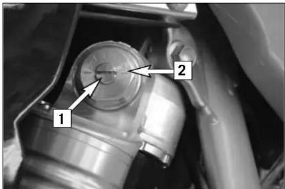
The damping unit of the shock absorber is filled with high-compression nitrogen. Never try to take the shock absorber apart or to do any maintenance work yourself. Severe injuries could be the result. Never unscrew the black screw connection [6] (24mm).
text_image
Close-up of a mechanical component with numbered annotations pointing to featuresCompression damping of shock absorber (XC-W, EXC)
The compression damping (during compression) can be adjusted for these shock absorbers (Mono Compression Control).
The degree of damping can be adjusted by turning adjusting screw [1] with a screwdriver. Turning in a clockwise direction will increase the damping, turning in a counterclockwise direction will decrease the damping.
STANDARD ADJUSTMENT:
- turn the adjusting screw clockwise to the stop.
- then turn the adjusting screw counterclockwise, counting the number of clicks that corresponds to the respective type of shock absorber.
WP 12187C04 ..... 15 clicks
WP 12187C06 ..... 15 clicks
WARNING
The damping unit of the shock absorber is filled with high-compression nitrogen. Never try to take the shock absorber apart or to do any maintenance work yourself. Severe injuries could be the result.
Never unscrew the black screw connection [2] (24mm).
text_image
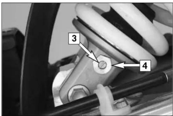
3 4Rebound damping of shock absorber
By using the adjusting screw [3], the degree of damping of the rebound can be adjusted. Turn the knob clockwise to increase damping, turn it counterclockwise to reduce damping during rebounding.
STANDARD ADJUSTMENT:
- turn the adjusting screw clockwise to the stop.
- then turn the adjusting screw counterclockwise, counting the number of clicks that corresponds to the respective type of shock absorber.
WP 12187C04 ..... 25 clicks WP 12187C28 ..... 24 clicks
WP 12187C06 ..... 25 clicks WP 12187C29 ..... 24 clicks
WARNING
The damping unit of the shock absorber is filled with high-compression nitrogen. Never try to take the shock absorber apart or to do any maintenance work yourself. Severe injuries could be the result.
Never unscrew the black screw connection [4] (15mm).
Instructions for initial operation
- Make sure the work for the „pre-delivery inspection“ was performed by your authorized KTM workshop. The DELIVERY CERTIFICATE and SERVICE MANUAL will be handed over when you pick up your vehicle.
- Read these operating instructions carefully before your first ride.
– Familiarize yourself with the operating elements. - Set the clutch lever, the handbrake lever, and the footbrake pedal to the positions that are most convenient for you.
- Get used to handling the motorcycle on an empty parking lot or open space, before starting on a longer drive. Also try to drive as slowly as possible and in a standing position, to improve your feeling for the vehicle.
- Do not drive along off-road tracks which go beyond your abitily and experience.
- Hold the handlebars with both hands and leave your feet on the foot rests while driving.
- Remove your foot from the foot brake lever when you are not braking. If the foot brake lever is not released the brake pads rub continuously and the braking system is overheated.
- Do not make any alterations to the motorcycle and always use ORIGINAL KTM SPARE PARTS. Spare parts from other manufacturers can impair the safety of the motorcycle.
- Motorcycles are sensitive to alterations in the distribution of weight. If you are taking luggage with you, this should be secured as close as possible to the middle of the vehicle; distribute the weight evenly between the front and rear wheel. Never exceed the maximum permissible laden weight and the axle weights. The maximum permissible laden weight is comprised of the following components:
– Motorcycle ready for operation and tank full
- Luggage
– Driver with protective clothing and helmet.
– Pay attention to the running-in procedure.
Running in the XC/EXC models
Even very precisely machined sections of engine components have rougher surfaces than components which have been sliding across one another for quite some time. Therefore, every engine needs to be broken in.
For this reason, do not load the engine more than 50% of its capacity during the first 3 operating hours. Besides, the engine speed must not exceed 7000 rpm. Avoid going full-throttle! In the following 12 operating hours, you may load the engine up to 75% of its capacity. Use the motorcycle on various types of terrain (road, easy off-road trails).
! CAUTION
The XC/EXC models were uncompromisingly designed for off-road competition purposes only. "On the road" approved models are only allowed on public roads in the original homologated (throttled) version. Avoid extended on-road rides at full throttle.
WARNING
- Wear suitable clothing when driving a motorcycle. Clever KTM drivers always wear a helmet, boots, gloves and a jacket, regardless of whether driving all day or just for a short trip. The protective clothing should be brightly colored so that other vehicles can see you as early as possible.
- Always turn on the light to make sure that other drivers become aware of you as early as possible.
- Do not drive after having consumed alcohol.
- Only use accessories recommended by KTM. For example, front panelling can impair the driving properties of the motorcycle. Cases, extra tanks, etc. can alter the weight distribution and thus also impair the vehicles driving properties.
- The front and rear wheel may only be fitted with tires that have the same profile type.
- The XC/EXC models are designed and dimensioned for 1 person only. Never take another rider along.
- Observe the traffic regulations, drive defensively and try to look ahead as far as possible so that any hazards can be recognized as early as possible.
- Adjust your driving speed according to the conditions and your driving skills.
- Drive carefully on unknown roads or on unfamiliar trials.
- When driving off-road, always have a friend on a second motorcycle to keep you company, so that you can help each other should difficulties arise.
- Replace the helmet visor or goggle lens when scratched or damaged. if bright light shines through a scratched visor or lens, the operator will be blinded.
- Never leave your motorcycle without supervision if the engine is running.
– The XC models are not approved for use on public roads and freeways. - When riding your motorcycle, please bear in mind that other people may feel molested by excessive noise.
natural_image
Mechanical assembly diagram showing a spring-loaded component with labeled parts A and B (no text or symbols beyond labels)
text_image
8-10mm / 0.3-0.4m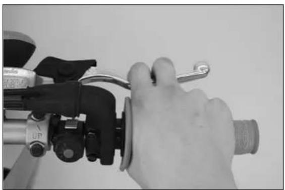
natural_image
Close-up of a hand using a bicycle brake chime to adjust the wheel (no text or symbols visible)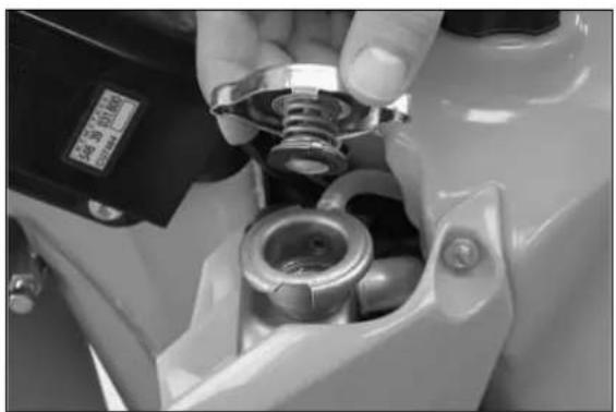
natural_image
Close-up of a hand adjusting a mechanical component with a metallic bolt and housing (no visible text or symbols)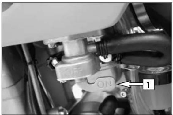
natural_image
Close-up of a mechanical assembly with pipes and a valve, no visible text or symbolsCheck the following before each start
When you start off, the motorcycle must be in perfect technical condition. For safety reasons, you should make a habit of performing an overall check of your motorcycle before each start.
The following checks should be performed:
1 CHECK THE OIL LEVEL
Insufficient oil results in premature wear and consequently to engine damage.
2 FUEL
Check that there is sufficient fuel in the tank; when closing the filler cap, check that the tank venting hose is free of kinks.
3 CHAIN
A loose chain can fall from the chain wheels; an extremely worn chain can tear, and insufficient lubrication can result in unnecessary wear to the chain and chain wheels. Excessive tensioning of the chain will put additional load on the components of the secondary drivetrain (chain, bearings of transmission and rear wheel). Aside from resulting in premature wear, if worst comes to worst the chain may rupture or the countershaft of the transmission may break.
4 TIRES
Check for damaged tires. Tires showing cuts or dents must be replaced. The tread depth must comply with the legal regulations. Also check the air pressure. Insufficient tread and incorrect air pressure deteriorate the driving performance.
5 BRAKES
Check correct functioning of the braking system. Check for sufficient brake fluid in the reservoir. The reservoirs have been designed in such a way that brake fluid does not need to be refilled even when the brake pads are worn. If the level of brake fluid falls below the minimum value, this indicates a leak in the braking system or completely worn out brake pads. Arrange for the braking system to be checked by a KTM specialist, as complete failure of the braking system can be avoided.
Also check the state of the brake hose and the thickness of the brake linings.
Check free travel at the hand brake lever and foot brake lever.
6 CABLES
Check correct setting and easy running of all control cables.
7 COOLING FLUID
Check the level of the cooling fluid when the engine is cold.
8 ELECTRICAL SYSTEM
Check correct functioning of headlamps, tail-lights, brake lights, indicators, control lamps and horn while the engine is running.
9 LUGGAGE
If you are taking luggage with you, check that this is securely fastened.
Starting when the engine is cold
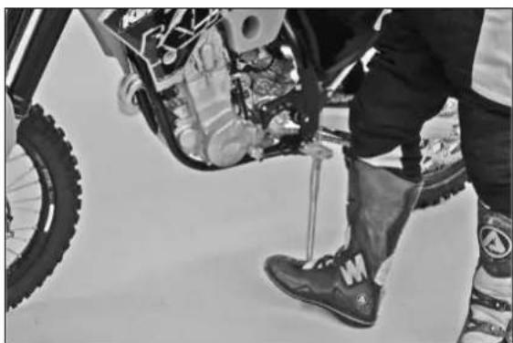
1 Open the fuel tap [1].
2 Swing up the side stand or center stand.
3 Put the gear in neutral.
4 Operate the choke [2].
5 Leave throttle closed and kick the kickstarter briskly ALL THE WAY or actuate the E-starter.
WARNING
- If you want to start the engine, make sure that you always put on sturdy motorcycle boots in order to avoid injuries. You might slip off the kick-starter, or the engine may kick back and propel your foot upward with great force.
natural_image
Close-up of a hand holding a white plastic container with a black circular opening, labeled with number 2 (no text or symbols on the object itself)WARNING
- Always kick the kickstarter briskly all the way without opening the throttle. If you do not Kick hard enough, with an open throttle grip, the kickback hazard will be higher.
- Do not start the engine and allow it to idle in a closed area. Exhaust fumes are poisonous and can cause loss of consciousness and death. Always provide adequate ventilation while the engine is running.
- Always verify that the transmission has been set to idle (neutral) before actuating the starter button. If you start the motorcycle with a gear engaged, the motorcycle will move forward.
! CAUTION
- Maximal period for continuous starting: 5 seconds. Wait at least 5 seconds before trying again.
- Don't ride your motorcycle with full load and don't rev up the engine when cold because the piston is warming up faster than the water cooled cylinder and can cause engine damage.
NOTE: If you have trouble starting the motorcycle, this could be due to old fuel in the float chamber. The easily inflammable components of the new fuels evaporate during longer periods of standstill. When the motorcycle has been out of operation for more than a week, it is therefore recommended to drain the old fuel from the float chamber. The engine will immediately start off when the float chamber is filled with new fuel.
natural_image
Close-up of a person's lower legs and foot wearing a motorcycle, with visible mechanical components and a tire (no text or symbols)Starting when the engine is warm
1 Open the fuel tap [1].
2 Swing up the side stand.
3 Put the gear in neutral.
4 Leave throttle closed and kick the kickstarter briskly ALL THE WAY or actuate the E-starter.
What to do when the engine is „flooded“
Unscrew the spark plug and dry it.
NOTE:
The carburetor has an accelerator pump. Every time you open the throttle, fuel will be injected into the intake passage. When starting, be sure that you open the throttle completely only once.
natural_image
Close-up of a bicycle's front wheel and suspension system, showing tracks, gears, and tire components (no text or symbols visible)Starting off
Pull the clutch lever. Put the engine into first gear, slowly release the clutch lever and open the throttle at the same time.
WARNING
Before you start off, check that the side stand has been swung up fully. If the stand drags on the ground, the motorcycle can go out of control.
natural_image
Close-up of a person riding a dirt bike with visible tracks and wheelbars (no text or symbols)Shifting/Riding
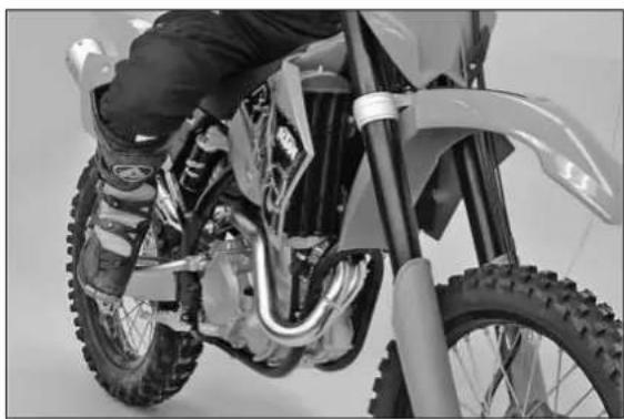
You are now in first gear, referred to as the drive or uphill gear. Depending on the conditions (traffic, hill size, etc.), you can shift to a higher gear. Close throttle, at the same time pull clutch lever in and shift to the next higher gear. Let clutch lever go again and accelerate. If you turned on the choke, make sure you turn it off again as soon as engine is warm.
When you reach full speed through opening the throttle all the way, turn throttle back to 3/4; the speed hardly decreases although the engine will use less gas. Only give as much gas as the engine can handle. Through quick and high revving of the throttle, the fuel usage increases.
By shifting down, use the brakes if necessary and close the throttle at the same time. Pull the clutch lever and shift down to the next gear. Let clutch lever go slowly and open the throttle or shift down again.
NOTE:
Dedicated to nothing but offroad racing, XC/EXC models make no compromises in their design. As such, they do not include any radiator fan, and the size of the radiator is dimensioned for optimum ergonomics.
In normal racing, the cooling system is sufficient.
If you use your motorbike in other conditions, please note that: the E-starter allows you to start XC/EXC models again at any time. Therefore, turn off the engine if you intend to run your motorcycle in idle or at a standstill for longer periods of time (more than 2 minutes).
Avoid letting the clutch slip frequently and for extended periods. This would cause the engine oil to heat up, thereby heating up the cooling system. You should drive at low speeds (4-stroke style - letting the engine pull you) and not at high speeds not by letting the clutch slip (2-stroke style).
WARNING
- After falling with the motorcycle, check all functions thoroughly before starting up operations again.
- A twisted handlebar must always be replaced. Do not adjust the handlebar, it will lose stability.
! CAUTION
– High rpm rates when the engine is cold have an adverse effect on the life of your engine. We recommend you run the engine in a moderate rpm range for a few miles giving it a chance to warm up. After that no further precautions in this respect need to be taken. The engine has reached its operating temperature as soon as the radiators become warm.
- Never have the throttle wide open when changing down to a lower gear. The engine will over-rev, damaging the valves. In addition, the rear wheel locks so that the motorcycle can easily get out of control.
- If any abnormal vibrations occur while driving, check that the engine fastening bolts are tight.
- In the event that, while riding on your motorcycle, you notice any unusual operation-related noise, stop immediately, turn the engine off, and contact an authorized KTM dealer.
Braking
Close throttle and apply the hand and foot brakes at the same time. When driving on sandy, wet or slippery ground use mainly the rear wheel brake. Always brake with feeling, blocking wheels can cause you to skid or fall. Always finish braking before you enter a curve. Also change down to lower gears depending on your speed. When driving down hill, use the braking effect of the engine. Change down one or two gears but do not overspeed the engine. In this way, you will not need to brake so much and the brakes will not overheat.
WARNING
- In case of rain, after washing the motorcycle, after rides through water and in case of rides on wet off-road tracks, humid or dirty brake discs can delay the braking effect. The brakes must be pulled until they are dry or clean.
- Rides on salt-strewed or dirty roads can also delay the braking effect. The brakes must be pulled until they are clean.
– Dirty brake discs cause increased tear of brake pads and brake discs. - When you brake, the brake discs, brake pads, brake caliper and brake fluid heat up. The hotter these parts get, the weaker the breaking effect. In extreme cases, the entire braking system can fail.
- If the resistance in the hand brake lever or foot brake pedal feels "spongy" (too much play), this is an indication that something is wrong with the brake system. Don't ride your motorcycle anymore without first having the brake system looked over by a KTM dealer.
Stopping and parking
Apply the brakes fully and put the engine into neutral. To turn off the engine, push the short-circuit button or the emergency-OFF button with the engine at idling speed until the engine stops. Turn the fuel tap to the OFF position, park on an area where the ground is firm, and lock the motorcycle.
WARNING
Motorcycle engines produce a great amount of heat while running. The engine, exhaust pipe, muffler, brake rotors, and shock absorbers can become very hot. Do not touch any of these parts after operating the motorcycle, and take care to park it where pedestrians are not likely to touch it and get burned.
! CAUTION
- Never use the hand decompression lever to turn off the engine. Use the short-circuit button or the emergency-off button instead.
- Close the fuel tap when leaving your vehicle. Otherwise the carburettor can flood and fuel will enter the engine.
- Never park your motorcycle in places where there are fire hazards due to dry grass or other easily flammable materials.
natural_image
Close-up of a person's legs and feet wearing a motorcycle foot and boots, with a tire in the background (no visible text or symbols)NOTE REGARDING THE SIDE STAND:
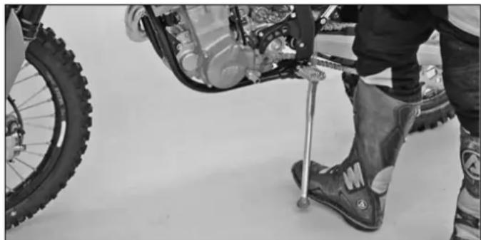
Use your foot to kick side stand forward up to the stop and lean the motorcycle sideways. Make sure that the ground is solid and that your motorcycle is standing securely. Just in case, you can shift into first gear.
! CAUTION
The side stand is designed to bear only the load of the motorcycle. The side stand and/or the frame can be damaged and the motorcycle can fall over if you mount the motor-cycle, thus putting an additional load on the side stand.
Fuel
The engine needs unleaded fuel with at least RON 95 (USA = Premium PON 91).
! CAUTION
Use leaded or unleaded premium grade gasoline (95 octanes). Never use gasoline having less than 95 octanes because it may damage the engine.
WARNING
Gasoline is highly flammable and poisonous. Extreme caution should be used when handling gasoline. Do not refuel the motorcycle near open flames or burning cigarettes. Always switch off the engine before refuelling. Be careful not to spill gasoline on the engine or exhaust pipe while the engine is hot. Wipe up spills promptly. If gasoline is swallowed or splashed in the eyes, seek a doctor's advice immediately.
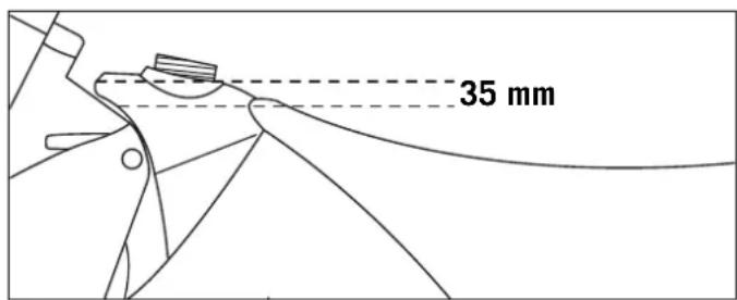
Fuel expands when its temperature rises. Therefore do not fill the tank to the top (see fig.).
text_image
35 mm| 250-F 2007A CLEAN MOTORCYCLE CAN BE CHECKED MORE QUICKLY WHICH SAVES MONEY! | 1st service after 3 hours or 20 l fuel | every 20 hours or 140 l fuel or 1 race | |
| ENGINE | Change engine oil, oil filter | ● | ● |
| Clean oil screen and drain plug magnet | ● | ● | |
| Replace spark plug (after 30 hours) | |||
| Check and adjust valve clearance | ● | ● | |
| Check engine mounting bolts for tightness | ● | ● | |
| Clean the spark-plug connector and check for a tight fit | ● | ● | |
| Check the screws on the kick starter and shift lever for a tight fit | ● | ● | |
| CARBURETOR | Check carburetor connection boot for cracks and leaks | ● | |
| Check idle speed setting | ● | ● | |
| Check vent hoses for damage or bends | ● | ● | |
| ADD-ON PARTS | Check cooling system for leaks, check quantity of antifreeze | ● | ● |
| Check exhaust system for leaks and fitment | ● | ||
| Check cables for damage, smooth operation and bends, adjust and lubricate | ● | ● | |
| Check fluid level of the clutch master cylinder | ● | ● | |
| Clean air filter and filter box | ● | ||
| Check electric wires for damage and bends | ● | ||
| Check headlamp setting | ● | ||
| Check function of electric systems (low high beam, brake light, indicator lamps, speedometer illumination, horn, emergency OFF switch or button | ● | ● | |
| BRAKES | Check brake fluid level, lining thickness, brake discs | ● | ● |
| Check brake lines for damage and leaks | ● | ● | |
| Check/function smooth operation and adjust free travel of handbrake/foot brake lever | ● | ● | |
| Check the screws and guide bolts on the brake system for a tight fit | ● | ● | |
| CHASSIS | Check shock absorber and fork for leaks and function | ● | ● |
| Clean fork dust bellows | ● | ||
| Bleed fork legs | ● | ||
| Check swing arm bearings | ● | ||
| Check/adjust steering head bearings | ● | ● | |
| Check tightness of chassis screws (triple clamps, fork leg axle passage, swingarm, shock aborber) | ● | ● | |
| WHEELS | Check/adjust steering head bearings | ● | ● |
| Check tires and air pressure | ● | ● | |
| Check chain, chain joint, rear sprockets and chain guides for wear, fit and tension | ● | ● | |
| Lubricate chain, clean and grease the adjusting screws on the chain tensioner | ● | ● | |
| Check clearance of wheel bearings | ● | ● | |
| 250-F 2007ADDITIONAL SERVICE WORK THAT MUST BE PERFORMED UNDER A SEPARATE ORDER | ||
| at least once a year | every 2 years | |
| Complete maintenance of fork | ● | |
| Complete maintenance of shock absorber | ● | |
| Clean and grease steering head bearings and gasket elements | ● | |
| Clean and adjust carburetor | ● | |
| Treat battery connections with contact grease | ● | |
| Treat electric contacts and switches with contact spray | ● | |
| Change hydraulic clutch fluid | ● | |
| Change brake fluid | ● | |
| Clean Sparkarrestor (XC-W USA) | ● | |
| 250-F 2007IMPORTANT CHECKS AND MAINTENANCE TO BE CARRIED OUT BY THE RIDER | ||||
| Before each start | After every cleaning | For cross-country use | at least once a year | |
| Check oil level | ● | |||
| Check brake fluid level | ● | |||
| Check brake pads for wear | ● | |||
| Check lights for function | ● | |||
| Check horn for function | ● | |||
| Lubricate and adjust cables and nipples | ● | |||
| Bleed fork legs regularly | ● | |||
| Remove and clean fork dust bellows regularly | ● | |||
| Clean and lubricate chain, check tension and adjust if necessary | ● | ● | ||
| Clean air filter and filter box | ● | |||
| Check tires for pressure and wear | ● | |||
| Check cooling fluid level | ● | |||
| Check fuel lines for leaks | ● | |||
| Drain and clean float chamber | ● | ● | ||
| Check all control elements for smooth operation | ● | |||
| Check brake performance | ● | ● | ||
| Treat blank metal parts (with the exception of brake and exhaust system) with wax-based anti corrosion agent | ● | |||
| Treat ignition and steering locks and light switches with contact spray | ● | |||
| Check tightness of screws, nuts and hose clamps regularly | ● | |||
| 250-F 2007IMPORTANT INSPECTIONS OR MAINTENANCE WORK THAT MUST BE PERFORMED BY THE SPECIALIZED KTM WORKSHOP FOR COMPETITIVERACING / FOR HOBBY-USE (SEPARATE ORDER FOR SPECIALIZED KTM WORKSHOP) | |||||
| A 100 liter fuel consumption RACINGis equivalent to approx. 15 operating hours | COMPETITIVE | every 10 hours70 liter | every 20 hours140 liter | every 40 hours270 liter | every 80 hours540 liter |
| HOBBY-USE | every 20 hours140 liter | every 40 hours270 liter | — | every 80 hours540 liter | |
| Check the clutch disks for wear | ● ● | ● | |||
| Check the length of the clutch springs | ● ● | ● | |||
| Check the clutch drive for indentations | ● | ● | |||
| Check the outer clutch hub for indentations | ● | ● | |||
| Check the cylinder and piston for wear | ● | ● | |||
| Check the groove on the piston pin retainer for wear (visual check) | ● | ● | |||
| Check the camshaft for wear (visual check) | ● | ● | |||
| Check the spring cap for wear | ● | ● | |||
| Check the eccentricity of the valve disk | ● | ● | |||
| Check the valve guides for wear | ● | ● | |||
| Replace the valves | ● | ||||
| Replace the valve springs | ● | ● | |||
| Check the function of the timing chain tensioner | ● | ● | |||
| Check the eccentricity of the crankshaft journal | ● | ● | |||
| Replace the conrod bearings | ● | ● | |||
| Check piston pin bearing | ● | ● | |||
| Replace the crankshaft main bearings | ● | ||||
| Check the entire transmission including the roller and bearings for wear | ● | ● | |||
| Check the length of the bypass valve spring | ● | ● | |||
| Replace the glass-fiber yarn filling in the silencer | ● ● | ● ● | |||
| Replace the sealing cup for the foot brake cylinder | ● ● | ● | |||
| Replace the throttle slide, jet needle and main jet holder (every 200 hours) | |||||
NOTE:
If the inspection establishes that permissible tolerances are exceeded, the respective components must be replaced.
| 400/450/525 2007A CLEAN MOTORCYCLE CAN BE CHECKED MORE QUICKLY WHICH SAVES MONEY! | 1st service after 3 hours or 20 l fuel | every 15 hours or 100 l fuel or 1 race | |
| ENGINE | Change engine oil, short and long oil filters | ● | ● |
| Clean oil screen and drain plug magnet | ● | ● | |
| Check oil lines for damage or bends | ● | ● | |
| Replace spark plug (after 30 hours) | |||
| Check and adjust valve clearance | ● | ● | |
| Check engine mounting bolts for tightness | ● | ● | |
| Clean the spark-plug connector and check for a tight fit | ● | ● | |
| Check the screws on the kick starter and shift lever for a tight fit | ● | ● | |
| CARBURETOR | Check carburetor connection boot for cracks and leaks | ● | |
| Check idle speed setting | ● | ● | |
| Check vent hoses for damage or bends | ● | ● | |
| ADD-ON PARTS | Check cooling system for leaks, check quantity of antifreeze | ● | ● |
| Check exhaust system for leaks and fitment | ● | ||
| Check cables for damage, smooth operation and bends adjust and lubricate | ● | ● | |
| Check fluid level of the clutch master cylinder | ● | ● | |
| Clean air filter and filter box | ● | ||
| Check electric wires for damage and bends | ● | ||
| Check headlamp setting | ● | ||
| Check function of electric systems (low high beam, brake light, indicator lamps, speedometer illumination, horn, emergency OFF switch or button | ● | ● | |
| BRAKES | Check brake fluid level, lining thickness, brake discs | ● | ● |
| Check brake lines for damage and leaks | ● | ● | |
| Check/function smooth operation and adjust free travel of handbrake/foot brake lever | ● | ● | |
| Check the screws and guide bolts on the brake system for a tight fit | ● | ● | |
| CHASSIS | Check shock absorber and fork for leaks and function | ● | ● |
| Clean fork dust bellows | ● | ||
| Bleed fork legs | ● | ||
| Check swing arm bearings | ● | ||
| Check/adjust steering head bearings | ● | ● | |
| Check tightness of chassis screws (triple clamps, fork leg axle passage, swingarm, shock aborber) | ● | ● | |
| WHEELS | Check spoke tension and rim joint | ● | ● |
| Check tires and air pressure | ● | ● | |
| Check chain, chain joint, rear sprockets and chain guides for wear, fit and tension | ● | ● | |
| Lubricate chain, clean and grease the adjusting screws on the chain tensioner | ● | ● | |
| Check clearance of wheel bearings | ● | ● | |
| 400/450/525 2007ADDITIONAL SERVICE WORK THAT MUST BE PERFORMED UNDER A SEPARATE ORDER | ||
| at least once a year | every 2 years | |
| Complete maintenance of fork | ● | |
| Complete maintenance of shock absorber | ● | |
| Clean and grease steering head bearings and gasket elements | ● | |
| Clean and adjust carburetor | ● | |
| Treat electric contacts and switches with contact spray | ● | |
| Treat battery connections with contact grease | ● | |
| Change hydraulic clutch fluid | ● | |
| Change hydraulic clutch fluid | ● | |
| Clean Sparkarrestor (XC-W USA) | ● | |
| 400/450/525 2007IMPORTANT CHECKS AND MAINTENANCE TO BE CARRIED OUT BY THE RIDER | ||||
| Before each start | After every cleaning | For cross-country use | At least once a year | |
| Check oil level | ● | |||
| Check brake fluid level | ● | |||
| Check brake pads for wear | ● | |||
| Check lights for function | ● | |||
| Check horn for function | ● | |||
| Lubricate and adjust cables and nipples | ● | |||
| Bleed fork legs regularly | ● | |||
| Remove and clean fork dust bellows regularly | ● | |||
| Clean and lubricate chain, check tension and adjust if necessary | ● | ● | ||
| Clean air filter and filter box | ● | |||
| Check tires for pressure and wear | ● | |||
| Check cooling fluid level | ● | |||
| Check fuel lines for leaks | ● | |||
| Drain and clean float chamber | ● | ● | ||
| Check all control elements for smooth operation | ● | |||
| Check brake performance | ● | ● | ||
| Treat blank metal parts (with the exception of brake and exhaust system) with wax-based anti corrosion agent | ● | |||
| Treat ignition and steering locks and light switches with contact spray | ● | |||
| Check tightness of screws, nuts and hose clamps regularly | ● | |||
| 400/450/525 2007IMPORTANT INSPECTIONS OR MAINTENANCE WORK THAT MUST BE PERFORMED BY THE SPECIALIZED KTM WORKSHOP FOR COMPETITIVERACING / FOR HOBBY-USE (SEPARATE ORDER FOR SPECIALIZED KTM WORKSHOP) | |||
| A 100 liter fuel consumption is equivalent to approx. 15 operating hoursHOBBY-USECOMPETITIVERACING | every 15 hours100 literevery 30 hours200 liter | every 30 hours200 literevery 60 hours400 liter | every 45 hours300 literevery 90 hours600 liter |
| Check the clutch disks for wear | ● ● | ● | |
| Check the length of the clutch springs | ● | ● | |
| Check the cylinder and piston for wear | ● | ||
| Check the groove on the piston pin retainer for wear (visual check) | ● | ||
| Check the camshaft for wear (visual check) | ● | ||
| Replace the camshaft bearings | ● | ||
| Check the length of the valve springs | ● | ||
| Check the spring cap for wear | ● | ||
| Check the eccentricity of the valve disk | ● | ||
| Check the valve guides for wear | ● | ||
| Check the radial clearance of the rocker arm rollers | ● | ||
| Check the elongation of the timing chain | ● | ||
| Check the chain tensioner tooting for damage (visual check) | ● | ● | |
| Check the eccentricity of the crankshaft journal | ● | ||
| Replace the conrod bearings | ● | ||
| Check piston pin bearing | ● | ||
| Replace the balancer shaft bearings | ● | ||
| Replace the crankshaft main bearings | ● | ||
| Check the entire transmission including the roller and bearings for wear | ● | ||
| Check the length of the bypass valve spring | ● | ||
| Replace the glass-fiber yarn filling in the silencer | ● | ||
| Replace the sealing cup for the foot brake cylinder | ● | ||
| Replace the throttle slide, jet needle and main jet holder (every 210 hours) | |||
NOTE:
If the inspection establishes that permissible tolerances are exceeded, the respective components must be replaced.
WARNING
Maintenance and adjusting work marked with an asterisk (*) requires expert skills and technical know-how. For your own safety, always have such work performed by a specialized KTM dealer where your motorcycle will be optimally serviced by appropriately qualified, skilled staff.
! CAUTION
- If using a power washer, do not point the water jet at the electric components, plugs, cables, bearings, carburetor, etc. The high pressure will cause water to penetrate into the components and can cause them to malfunction or lead to premature wear.
- When transporting your KTM, ensure that it is held upright with restraining straps or other mechanical fastening devices and that the fuel tap is in the OFF position - if the motorcycle should fall over, no fuel can leak from the carburetor or fuel tank
- Only use special screws with an appropriate thread length supplied by KTM to fix the spoilers on the tank. Using other screws or longer screws can cause leaks in the tank through which fuel can flow out.
- Do not use toothed washers or spring rings with the engine fastening screws, as these work into the frame parts and keep working loose. Instead, use self-locking nuts.
- Let your motorcycle cool down before beginning any maintenance work in order to avoid getting burned.
- Dispose oils, fatty matters, filters, fuels, washing detergents etc. properly.
- Under no circumstances may used oil be disposed of in the sewage system or in the open countryside. 1 liter of used oil contaminates 1,000,000 liters of water.
text_image
ods 1 2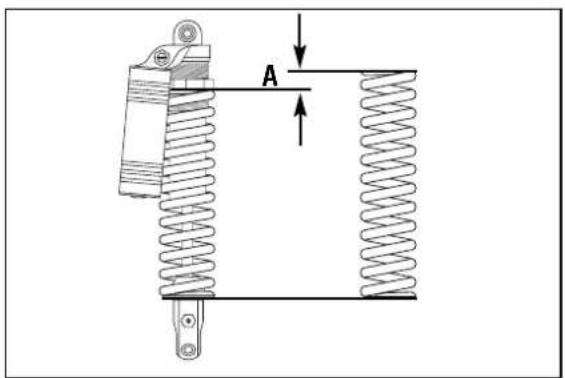
text_image
Technical diagram of a mechanical spring assembly with labeled component A and directional arrows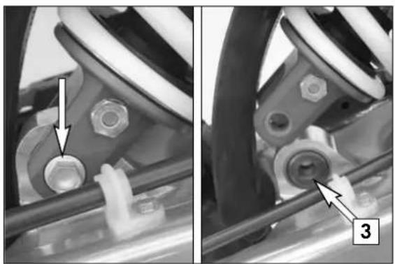
natural_image
Mechanical assembly diagram showing two views of a mechanical component with bolts and a pin (no text or symbols)Changing the spring preloading of the shock absorber
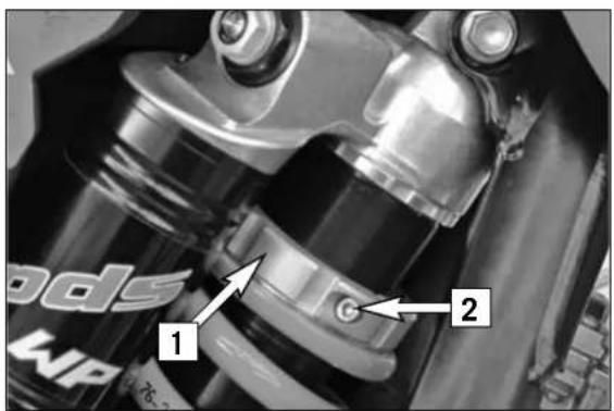
The spring preload can be changed by turning the adjusting ring [1]. For this purpose, you should dismount the shock absorber and clean it thoroughly.
NOTE:
- Before changing the spring preload note down the basic setting, e.g. how many threads are visible above the adjusting ring.
- One rotation of the adjusting ring [1] changes the spring pretension by approximately 1 mm (0.04 in).
Loosen the clamping screw [2] and use the hook wrench contained in the vehicle tool set to turn the adjusting ring as desired. Turning it counterclockwise will reduce the preload, turning it clockwise will increase the preload.
After readjusting the clamping screw [2], tighten it to 8 Nm.
ADJUSTMENT VALUES
Spring preload A.....5 mm (0,2 in)
Pivot bearing
The pivot bearing [3] for PDS suspension struts at the swinging fork is Teflon-coated and must not be lubricated with either grease or other lubricants. Grease and other lubricants cause the Teflon coat to dissolve, whereby the bearing's lifecycle will be reduced dramatically.
When cleaning your bike with a high-pressure cleaner, do not aim the high-pressure spray directly at the pivot bearing.
text_image
Technical diagram of a bicycle wheel assembly with labeled components and motion arrows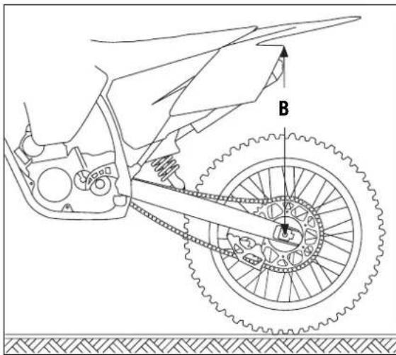
text_image
B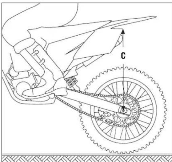
text_image
C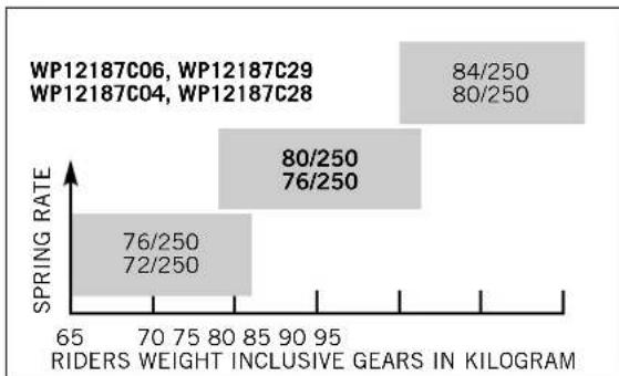
bar
| Riders Weight | Spring Rate (%) | | :--- | :--- | | 65 | 76/250 | | 70 | 72/250 | | 75 | 80/250 | | 80 | 76/250 | | 85 | 84/250 | | 90 | 80/250 | | 95 | 84/250 (with label 'WP12187C06, WP12187C29')Basic suspension setup for the weight of the driver
To achieve maximum handling performance and to prevent the fork, shock absorber, swing arm and frame from being damaged, the basic setup of the suspension components must be suitable for your weight. At delivery, KTM's offroad motorcycles are set to accommodate a driver weighing 75 - 85 kg (wearing full protective clothing). If your weight exceeds or falls short of this range, you will need to adjust the basic setup for the suspension components accordingly. Minor deviations in weight can be compensated by adjusting the spring preload. Different springs must be installed for larger deviations.
Checking the shock absorber and spring
You can establish whether or not the shock absorber spring is suitable for your weight by checking the riding sag. The static slag must be correctly adjusted before the riding sag can be determined.
Determining the static sag of the shock absorber
The static sag should be as close as possible to 35 mm. Deviations of more than 2 mm can strongly influence the motorcycle's performance.
Procedure:
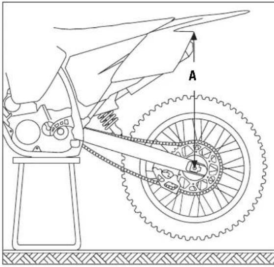
– Jack up the motorcycle until the rear wheel no longer touches the ground.
- Measure the vertical distance between the rear wheel axle and a fixed point (e.g. a mark on the side cover) and write it down as dimension A.
- Place the motorcycle on the ground again.
- Ask a helper to hold the motorcycle in vertical position.
- Measure the distance between the rear axle and the fixed point again to establish dimension B.
- The static sag is the difference between dimensions A and B.
EXAMPLE:
Motorcycle jacked up (dimension A) .....600 mm
Motorcycle on ground, unloaded (dimension B) .....- 565 mm
Static sag 35 mm
If the static sag is lower, the spring preload of the shock absorber must be reduced, if the static sag is higher, the spring preload must be increased. See chapter "Changing the spring preload of the shock absorber."
Determining the riding sag of the shock absorber
- Have a helper hold the motorcycle while you sit on the bike in a normal seating position (feet on the footrests) wearing full protective clothing and bounce up and down a few times to allow the rear wheel suspension to become level.
- Stay on the bike and have another person measure the distance between the same two points and write it down as dimension C.
- The riding sag is the difference between dimensions A and C.
EXAMPLE:
Motorcycle jacked up (dimension A) .....600 mm
Motorcycle on ground, loaded (dimension C) .... 500 mm
Riding sag....100 mm
The riding sag should lie between 95 and 105 mm.
If the riding sag is less than 95 mm, the spring is too hard (the spring rate is too high). If the riding sag is more than 105 mm, the spring is too soft (the spring rate is too low).
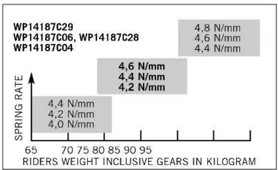
The spring rate is written on the outside of the spring (e.g. 80/250). The type number of the shock absorber is embossed on the bottom of the tank. The illustrations show which spring should be installed. The standard spring is shown in bold print.
After installing a different spring, readjust the static sag to 35 mm (± 2 mm).
According to our experience, the damping rate of the compression stage can remain unchanged. The damping rate of the rebound stage can be reduced by a few clicks for a softer spring or increased by a few clicks for a harder spring.
natural_image
Line drawing of a bicycle wheel with a knife inserted, showing mechanical components and gear (no text or symbols)Checking the basic setup of the telescopic fork
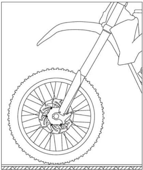
The precise riding sag of the telescopic fork cannot be determined for various reasons. Similar to the shock absorber, smaller deviations in your weight can be compensated by adjusting the spring preload. However, if your telescopic fork bumps frequently (hard end stop during compression), you should install harder fork springs to avoid damaging the telescopic fork and frame.
natural_image
Close-up of a mechanical assembly with metallic components and a lever (no visible text or symbols)Changing the spring preload on the telescopic fork (XC, EXC SIXDAYS)
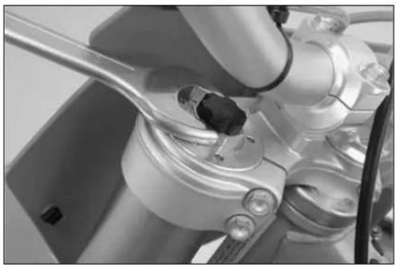
The telescopic forks of these models come with a preload adjuster for easy adjustment of the spring preload. You can adjust the spring preload ± 9 mm by turning the adjusting screws (basic position = middle position).
Turning in a clockwise direction will increase the prestress, turning in a counterclockwise direction will decrease the prestress.
Changing the spring preload will not affect the rebound damping adjustment. Generally, if the spring preload is higher, the rebound damping should also be set higher.
NOTE:
Always turn the adjusting screws the same distance on both fork legs. Different spring preloads on the fork legs will reduce the telescopic fork's response.
Changing the spring preload on the telescopic fork (XC-W/EXC)
The telescopic forks for these models must be partly disassembled to adjust the spring preload (see WP manual). Pretension spacers are available in heights of 1.5, 2.5, 5 and 10 mm (see spare parts catalog). The fork springs may not be pretensioned by more than 20 mm.
The preload adjuster used in the XC models can easily be retrofitted for the telescopic forks of the XC-W/EXC models.
NOTE:
WP precisely adjusts the spring pressure by inserting pretension spacers. Fluctuations in production are compensated with pretension spacers in various heights. This can cause the fork springs in the fork legs to have different degrees of pretension. Fork springs and pretension spacers should always stay together.
bar
| Riders Weight Inclusive Gear | Spring Rate (N/mm) | | :--- | :--- | | WP14187C29 | 4,8 | | WP14187C06, WP14187C28 | 4,6 | | WP14187C04 | 4,4 | | WP14187C06, WP14187C28 | 4,6 | | WP14187C04 | 4,4 | | WP14187C06, WP14187C28 | 4,2 | | WP14187C04 | 4,2 | | WP14187C06, WP14187C28 | 4,2 | | WP14187C04 | 4,0 | | WP14187C06, WP14187C28 | 4,0 | | WP14187C04 | 4,0 | | WP14187C06, WP14187C28 | 4,0 | | WP14187C04 | 4,0 | | WP14187C06, WP14187C28 | 4,0 | | WP14187C04 | 4,2 | | WP14187C06, WP14187C28 | 4,2 | | WP14187C04 | 4,2 | | WP14187C06, WP14187C28 | 4,2 | | WP14187C04 | 4,2 | | WP14187C06, WP14187C28 | 4,2 | | WP14187C04 | 4,0 | | WP14187C06, WP14355 | 4,2 | | WP14187C06, WP14355 | 4,2 | | WP14187C06, WP14355 | 4,2 | | WP14187C06, WP14355 | 4,2 | | WP14187C06, WP14355 | 4,2 | | WP1418TCE | 4,2 | | WP1418TCE | 4,2 | | WP1418TCE | 4,2 | | WP1418TCE | 4,2 | | WP1418TCE | 4,2 | | WP1418TCE | 4,2 | | WP1418TCE | 4,2 | | WP1418TCE | <6 N/mm | | WP1418TCE | <6 N/mm | | WP1418TCE | <6 N/mm | | WP1418TCE | <6 N/mm | | WP1418TCE | <6 N/mm | | WP1418TCE | <6 N/mm | | WP1418TCE | <6 N/mm | | WP1418TCE | <6 N/mm | | | WP1418TCE | <6 N/mm | | WP1418TCE | <6 N/mm | | WP1418TCE | <6 N/mm | | WP1418TCE | <6 N/mm | | WP1418TCE | <6 N/mm | | WP1418TCE | <6 N/mm | | WP1418TCE | <6 N/mm | | WPIA-CP0 | 4,2 | | WPIA-CP0 | 4,2 | | WPIA-CP0 | 4,2 | | WPIA-CP0 | 4,2 | | WPIA-CP0 | 4,2 | | WPIA-CP0 | 4,2 | | WPIA-CP0 | 4,2 | | WPIA-CP0 | 4,2 | | WPIA-CP0 (WPIA-CP0) | 4,2 | | WPIA-CP0 (WPIA-CP0) | 4,2 | | WPIA-CP0 (WPIA-CP0) | 4,2 | | WPIA-CP0 (WPIA-CP0) | 4,2 | | WPIA-CP0 (WPIA-CP0) | 4,2 | | WPIA-CP0 (WPT) | 4,2 | | WPIA-CP0 (WPT) | 4,2 | | WPIA-CP0 (WPT) | 4,2 | | WPIA-CP0 (WPT) | 4,2 | | WPIA-CP0 (WPT) | 4,2 | | WPIA-CP0 (WPT) | 4,2 | | WPIA-CP0(WE) | 4,2 | | WPIA-CP0(WE) | 4,2 | | WPIA-CP0(WE) | 4,2 | | WPIA-CP0(WE) | 4,2 | | WPIA-CP0(WE) | 4,2 | | WPIA-CP0(WE) | 4,2 | | WPIA-CP0(WE) | 6 N/mm | | WPIA-CP0(WE) | 6 N/mm | | WPIA-CP0(WE) | 6 N/mm | | WPIA-CP0(WE) | 6 N/mm | | WPIA-CP0(WE) | 6 N/mm | | WPIA-CP0(WE) | 6 N/mm | | WPIA-CP0(WE) | 6 N/mm | | WAPIA-CP0(WE) | 6 N/mm | | WAPIA-CP0(WE) | 6 N/mm | | WAPIA-CP0(WE) | 6 N/mm | | WAPIA-CP0(WE) | 6 N/mm | | WAPIA-CP0(WE) | 6 N/mm | | WAPIA-CP0(WE) | 6 N/mm | | WAPIA-CP3(WE) | 6 N/mm | | WAPIA-CP3(WE) | 6 N/mm | | WAPIA-CP3(WE) | 6 N/mm | | WAPIA-CP3(WE) | 6 N/mm | | WAPIA-CP3(WE) | 6 N/mm | | WAPIA-CP3(WE) | 6 N/mm | | WAPIA-CP3(WE) = WPLA(WE) - WPLA(WE) + WPLA(WE) = WPLA(WE) + WPLA(WE) = WPLA(WE) + WPLA(WE) = WPLA(WE) + WPLA(WE) = WPLA(WE) + WPLA(WE) = WPLA(WE) + WPLA(WE) = WPLA(WE) + WPLA(WE) = WPLA(WE) + WPLA(WE) = WPLA(WE) + WPLA(WE) = WPLA(WI) + WPLA(WE) + WPLA(WE) = WPLA(WE) + WPLA(WE) = WPLA(WE) + WPLA(WE) = WPLA(WE) + WPLA(WE) = WPLA(WE) + WPLA(WE) = WPLA(WE) + WPLA(WE) = WPLA(WE) + WPLA(WE) = WPLA(WE) + WPLA(WE) = WPLA(WA)(WA)(WA)(WA)(WA)(WA)(WA)(WA)(WA)(WA)(WA)(WA)(WA)(WA)(WA)(WA)(WA)(WA)(WA)(WA)(WA)(WA)(WA)(WA)(WA)(WA)(WA)(WA)(WA)(WA)(WA)(WA)(WA)(WA)(WA)(WA)(WA)(WA)(WA)(WA)(WA)(WA)(WA)(WA)(WA)(WA)(WA)(WA)(WA)(WA)(WA) WPLA(WA)(WA)(WA)(WA)(WA)(WA)(WA)(WA)(WA)(WA)(WA)(WA)(WA)(WA)(WA)(WA)(WA)(WA)(WA)(WA)(WA)(WA)(WA)(WA)(WA)(WA)(WA)(WA)(WA)(WA)(WA)(WA)(WA)(WA)(WA)(WA)(WA)(WA)(WA)(WA)(WA)(WA)(WA)(WA)(WA)(WA)(WA)(WA)(WA) WPLP(AW)(PAW)(PAW)(PAW)(PAW)(PAW)(PAW)(PAW)(PAW)(PAW)(PAW)(PAW)(PAW)(PAW)(PAW)(PAW)(PAW)(PAW)(PAW)(PAW)(PAW)(PAW)(PAW)(PAW)(PAW)(PAW)(PAW)(PAW)(PAW)(PAW)(PAW)(PAW)(PAW)(PAW)(PAU(AW)(PAU(AW)) / PAU(AW(AW(AW(AW(AW(AW(AW(AW(AW(AW(AW(AW(AW(AW(AW(AW(AW(AW(AW(AW(AW(AW(AW(AW(AW(AW(AW(AW(AW(AW(AW(AW(AW(AW(AW(AW(AW(AW(AW(AW(AW(AW(AW(AW(AW(AW(AW(AW(AW(AW(Aw(Aw(Aw(Aw(Aw(Aw(Aw(Aw(Aw(Aw(Aw(Aw(Aw(Aw(Aw(Aw(Aw(Aw(Aw(Aw(Aw(Aw(Aw(Aw(Aw(Aw(Aw(Aw(Aw(Aw(Aw(Aw(Aw(Aw(Aw(Aw(Aw(Aw(Aw(Aw(Aw(Aw(Aw(Aw(Aw(Aw(Aw(Aw(Aw(Aw(Av(OH))})(WPLA(OH))(WPLA(OH))(WPLA(OH))(WPLA(OH))(WPLA(OH))(WPLA(OH))(WPLA(OH))(WPLA(OH))(WPLA(OH))(WPLA(OH))(WPLA(OH))(WPLA(OH))(WPLA(OH))(WPLA(OH))(WPLA(OH))(WPLA(OH))(WPLA(OH))(WPLA(OH))(WPLA(OH))(WPLA(OH))(WPLA(OH):(WP LAO): 65 WPLA(OH): 65 WPLA(PB): 65 WPLA(MB): 65 WPLA(WP): 65 WPLA(MB): 65 WPLA(WP): 65 WPLA(MB): 65 WPLA(WP): 65 WPLA(MB): 65 WPLA(WP): 65 WPLA(MB): 65 WPLA(WP): 65 WPLA(MB): 65 WPLA(WP): 65 WPLA(MB: 65 WPLA(MB: 65 WPLA(WP): 65 WPLA(PB: 65 WPLA(PB: 65 WPLA(PB: 65 WPLA(PB: 65 WPLA(PB: 65 WPLA(PB: 65 WPLA(PB: 65 WPLA(PB: 65 WPLA(PB: 65 WPLA(PB: 65 WPLA(PB: 65 WPLA(PB: >6 N/mm WPLA(PB: >6 N/mm WPLA(PB: >6 N/mm WPLA(PB: >6 N/mm WPLA(PB: >6 N/mm WPLA(PB: >6 N/mm WPLA(PB: >6 N/mm WPLA(PB: >6 N/mm WPLA(PB: >6 N/mm WPLA(PB: >6 N/mm WPLA(PB: >6 N/mM WPLA(PB: >6 N/mM WPLA(PB: >6 N/mM WPLA(PB: >6 N/mM WPLA(PB: >6 N/mM WPLA(PB: >6 N/mM WPLA(PB: >6 N/mM WPLA(PB: >6 N/mM WPLA(PB: >6 N/mM WPLA(PB: >6 N/mMReplacing fork springs
If you weigh less than 75 kg or more than 85 kg, you should install the respective fork springs. The correct spring rate is shown in the illustrations. The standard spring is shown in bold print. The type number of the telescopic fork is embossed on the caps on the top of the telescopic fork.
If you are uncertain which spring to use, contact your KTM workshop.
According to our experience, the damping rate of the compression stage can remain unchanged. The damping rate of the rebound stage can be reduced by a few clicks for a softer spring or increased by a few clicks for a harder spring.
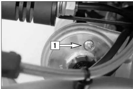
natural_image
Close-up of a mechanical component with a labeled arrow pointing to a circular feature (no text or symbols beyond the number '1')Breather plug front fork
After every 5 hours of use for competitive racing, slacken the breather plugs [1] a few turns in order to relieve excess pressure from the inside of the fork. To do this, place the motorcycle on a stand with the front wheel lifted off the ground. When riding the motorcycle mainly on the road, it will suffice to have this job performed in the course of the periodical maintenance service.
! CAUTION
Excessive pressure in the interior of the fork can cause leaks in the fork. If your fork is leaking, it is recommended to open the breather plugs before having the seals replaced.
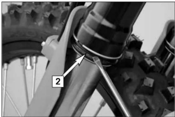
natural_image
Close-up of a bicycle wheel assembly with labeled component '2' (no text or symbols beyond label)Cleaning the dust sleeves of the telescopic fork
The dust-protection bellows [2] are to remove dust and coarse dirt particles from the fork tube. However, after some time, dirt may also get in behind the dust-protection bellows. If this dirt is not removed, the oil sealing rings located behind it may start to leak.
Use a screwdriver to lift the dust-protection bellows out of the outer tubes and slide them downward.
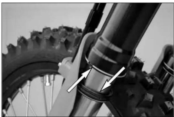
natural_image
Close-up of a bicycle wheel and bucket assembly with directional arrows indicating components (no text or symbols)Clean the dust-protection bellows, outer tubes, and fork tubes thoroughly, and oil them thoroughly with Universal oil spray (Motorex Joker 440) or engine oil. Then, push the dust-protection bellows into the outer tubes by hand.
WARNING
No oil may reach the front tire or the brake disks since this would considerably reduce the tire's road grip and the braking effect of the front brake.
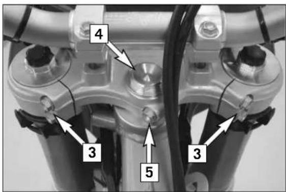
text_image
4 3 5 3Checking and adjusting the steering head bearing \*
Check steering head bearing for play periodically. To check, put the motorcycle on a stand so that the front wheel is off the ground. Now try to move the fork forward and backward. For readjusting, loosen the five pinch bolts [3] and [5] of the top triple clamp and turn steering stem bolt clockwise [4] until there is no more play. Don't tighten the steering stem bolt all the way, otherwise the bearings will be damaged. With a plastic hammer, lightly tap on the triple clamp to release tension. Retighten the five pinch bolts.
XC, EXC SIXDAYS .....17 Nm (pinch bolts 3) XC, EXC SIXDAYS .....Loctite 243 + 17 Nm (pinch bolt 5) XC-W, EXC .....20 Nm (pinch bolts 3 + 5)
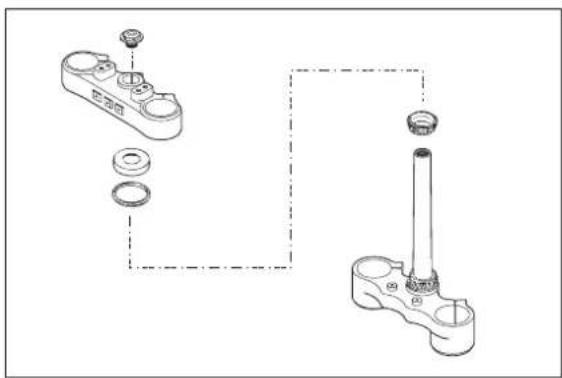
natural_image
Technical line drawing of a mechanical assembly with two components and a shaft (no text or symbols)WARNING
- If the steering head bearing is not adjusted to be free of play, the motor-cycle will exhibit unsteady driving characteristics and can get out of control.
- XC, EXC SIXDAYS: Be sure to lock the thread on the pinch bolt [5] with Loctite 243.
! CAUTION
If you drive with play in the steering head bearing for longer periods, the bearings and subsequently the bearing seats in the frame will be destroyed.
The steering head bearings should be regreased at least once a year (e.g. Motorex Long Term 2000).
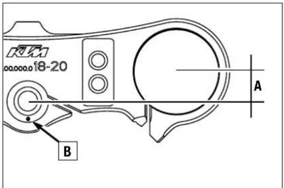
text_image
RKM 18-20 A BChanging the fork offset (caster) (XC, EXC SIXDAYS) \*
The fork offset [A] in these models (center fork legs - center steering head angle) can be set to either 18 or 20 mm. This allows you to optimize the handling to match the race course.
Remove the blind screw [1] to see which offset is set. If the mark [B] is in front, the offset is 18 mm. This setting will deliver more directional stability on fast race courses.
If the mark [B] is in the rear as illustrated, the offset is 20 mm. This setting will deliver better handling in curves.
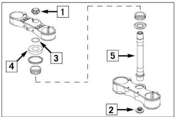
text_image
1 2 3 4 5The offset is set to 20 mm in the condition at delivery.
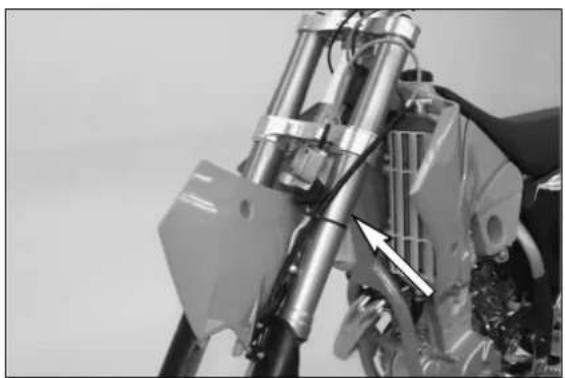
natural_image
Close-up of a mechanical assembly with metallic components and a white arrow pointing to a component (no visible text or symbols)To adjust the offset, dismount the front wheel and remove the front wheel fender.
Remove the screw on the starting number plate. Remove the clamp screws on the hand brake cylinder and fasten the hand brake cylinder to the left fork leg with a cable tie to keep the brake line from kinking (see illustration).
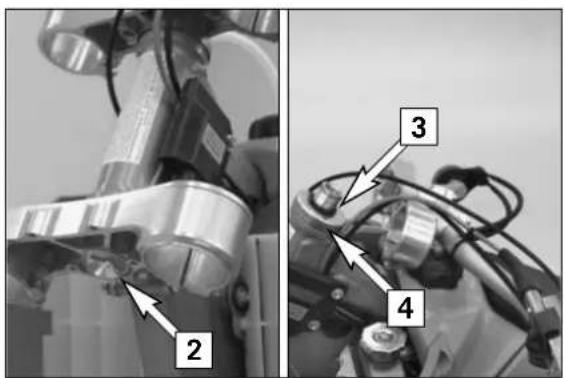
text_image
Technical diagram showing mechanical components with numbered labels 2, 3, and 4 indicating specific parts of a robotic arm or device.Loosen the clamp screws and take the fork legs out of the triple clamps. Loosen the collar screw [2] on the lower triple clamp 2 turns.
Remove the blind screw [1] from the upper triple clamp, loosen the clamp screw and upper triple clamp on the seat. Remove the O-ring [3] and the protection ring [4].
Tap gently on the lower triple clamp with a rubber hammer to loosen the steering stem [5] out of the bearing seat. Take the lower triple clamp with the steering stem out of the steering head.
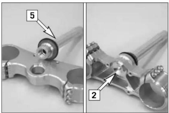
text_image
5 2Remove the collar screw from the lower triple clamp and pull out the steering stem. Thoroughly clean all parts. Turn the steering stem 180° and insert it in the triple clamp. Apply Loctite 243 to the thread of the collar screw [2] and turn all the way in.
WARNING
- Be sure to lock the thread on the collar screw [2] with Loctite 243.
- Do not confuse the collar screw with the blind screw [1].
Grease the steering head bearing and sealing elements.
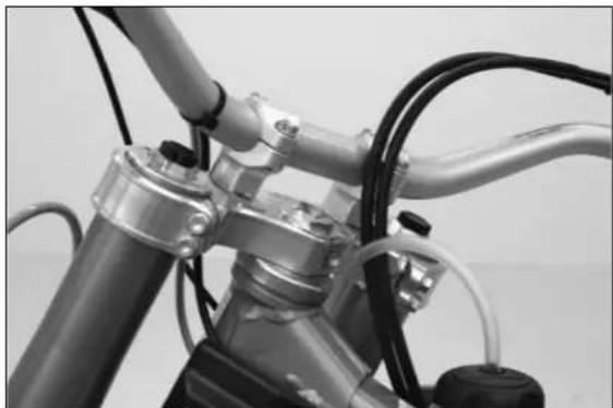
natural_image
Close-up of a bicycle's front wheel and suspension components (no visible text or symbols)Mount the lower triple clamp, upper steering head bearing, protection ring, O-ring, upper triple clamp and the blind screw.
Tighten the collar screw on the lower triple clamp to 60 Nm.
Mount the fork legs and tighten the clamp screws on the lower triple clamp to 12 Nm in 3 stages.
Adjust the steering head bearing without clearance (see: Checking and adjusting the steering head support). Apply Loctite 243 to the thread of the middle clamp screw. Tighten the clamp screws on the upper triple clamp to 17 Nm in 3 stages.
WARNING
The middle clamp screw must be secured with loctite 243.
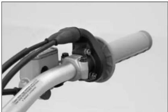
natural_image
Close-up of a bicycle wheel handle and lever mechanism (no visible text or symbols)Mount the front wheel fender and tighten the screws to 10 Nm.
Mount the hand brake cylinder and tighten the screws to 10 Nm.
Mount the staring number plate.
Mount the front wheel (see: Dismounting and mounting the front wheel).
WARNING
Tighten all screws and nuts to the specified torques using a torque wrench. Screws or nuts that are not tightened enough can become loose and cause the motorcycle to go out of control while driving. Screws or nuts tightened too firmly can damage the thread and components.
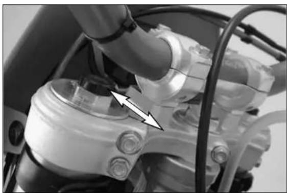
natural_image
Close-up of mechanical components with no visible text or symbolsHow to change the handlebar position
The handlebar position can be readjusted by 22 mm. Thus, you can put the handlebar in the position that is the most convenient for you. The upper triple clamp [1] includes 2 bores arranged at a distance of 15 mm (0.6 in) from one another. The bores at the handlebar support [2] are offset from the center by 3.5 mm (0.13 in). Accordingly, you can mount the handlebar in 4 different positions.
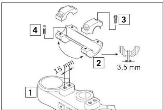
text_image
1 2 3 4 15 mm 3,5 mmFor this purpose, remove screws [3] of the handlebar clamps and screws [4] of the handlebar support. Position the handlebar support, and tighten screws [4] to 40 Nm (30 ft.lbs). Mount the handlebar and handlebar clamps, and tighten screws [3] to 20 Nm (15 ft.lbs). The gap between the handlebar support and the handlebar clamps should be the same size in the front and in the rear.
WARNING
The screws [4] must be secured with loctite 243.

text_image
A 8-10 mm / 0.3-0.4 inCheck chain tension
Jack the motorcycle up on its frame so that the rear wheel no longer touches the ground.
Press the chain upward at the end of the chain sliding component. The distance between the chain and the swing arm should be approx. 8 - 10 mm (0.31 - 0.39 in). In the course of this procedure, the upper chain portion [A] must be taut (see drawing). If necessary, correct the chain tension.
WARNING
- Excessive tensioning of the chain will put additional load on the components of the secondary drivetrain (chain, bearings of transmission and rear wheel). Aside from resulting premature wear, if worst comes to worst the chain may rupture or the countershaft of the transmission may break.
- Too much slack in the chain, on the other hand, can result in the chain jumping off the chain wheels. If this happens, the chain could also block the rear wheel or damage the engine.
- In either case the operator is likely to lose control of the motorcycle.
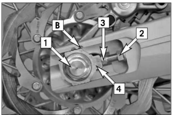
text_image
B 1 3 2 4Correct chain tension
Loosen collar nut [1], loosen lock nuts [2], and turn right and left adjusting screws [3] equally far. Tighten lock nuts.
To ensure the correct alignment of the rear wheel, the marks at the left and right chain adjusters must be positioned identically in relation to the reference marks [B]. Tighten the counter nut of the adjusting screws.
Clean and grease the adjusting screws regularly (Motorex Long Term Grease 2000). Before tightening the collar nut, verify that the chain adjusters [4] are sitting close to the adjusting screws and that the rear wheel has been aligned with the front wheel.
Tighten collar nut [1] to 80 Nm.
WARNING
- If you don't happen to have a torque wrench at hand, make sure you have the tightening torque corrected by a KTM dealer as soon as possible. A loose axle may lead to an unstable driving behavior of your motorcycle.
- Tighten the collar nut with the required torque. A loose wheel spindle may lead to an unstable behavior of your motorcycle.
NOTE:
The large adjusting range of the chain adjusters (32mm) allows you to use different secondary ratios in combination with the same chain length. The chain adjusters [4] can be rotated by 180°.
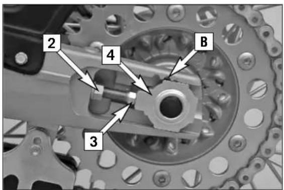
text_image
2 4 B 3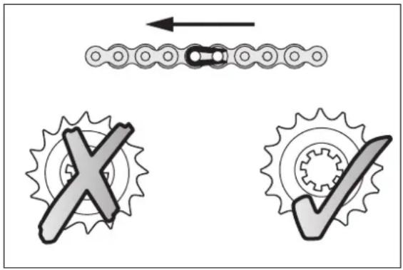
text_image
Diagram illustrating mechanical gear and chain link mechanism with X and check symbolsChain maintenance
For a long chain life, good maintenance is very important. Chains without X-rings should be cleaned in fireproof solvent regularly and afterwards treated with hot grease or chain spray (e.g. Motorex Chainlube 622).
X-ring chains on the other hand are very simple to clean. The best way is to use lots of water, but never use brushes or cleaning liquids. After letting the chain dry, you can use a special X-ring chain spray (e.g. Motorex Chainlube 622).
WARNING
No lubrication is allowed to reach the rear tire or the brake disks, otherwise the road adherence and the rear wheel braking effects would be strongly reduced and the motorcycle could easily lose control.
! CAUTION
When mounting the chain masterlink clip, the closed side of the masterlink clip must point in running direction.
Also check sprockets and chain guides for wear and replace if necessary.
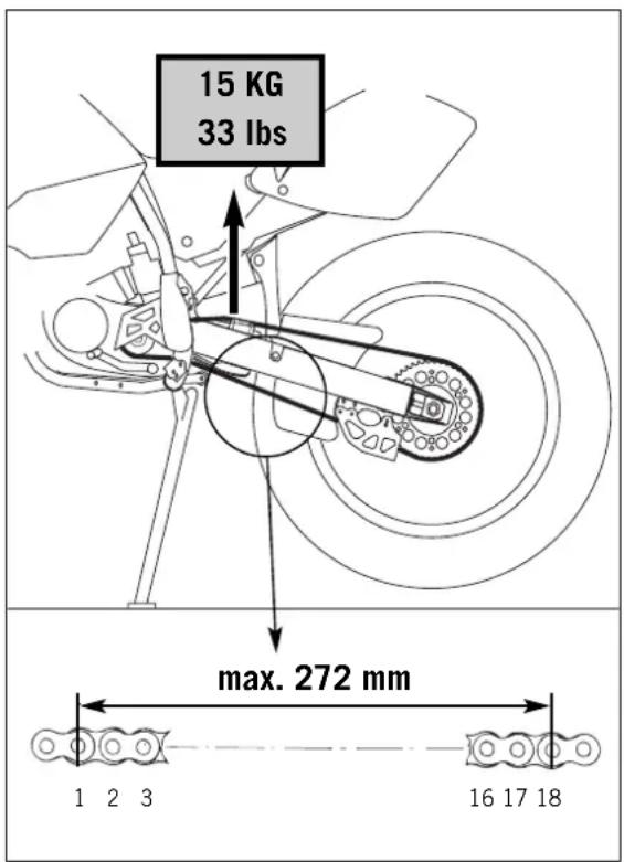
text_image
15 KG 33 lbs max. 272 mm 1 2 3 16 17 18Chain wear
To check the chain wear, observe the following indications:
Shift the gear into idling and pull the upper chain strand with approx. 10-15 Kilograms (33 lb) upwards (see figure). Now one can measure a space of 18 chain reels at the lower chain strand. The chain should be replaced at the latest when a space of 272 mm (10.70 in) is measured. Chains do not always wear off evenly, therefore repeat the measurement at different places on the chain.
NOTE:
If you mount a new chain, the sprockets should also be replaced. New chains wear faster if used on old used sprockets.
! CAUTION
Secure the screws of the chain wheel by applying Loctite and fasten them in a crosswise order.
Tightening torque for nuts: 35 Nm.
Tightening torque for screws: 50 Nm.
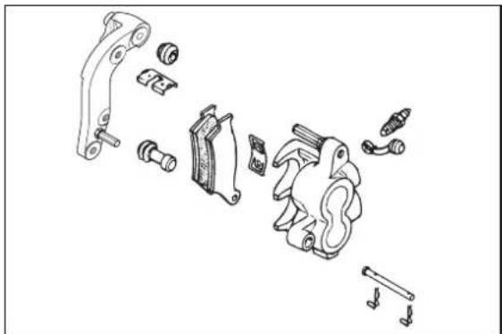
natural_image
Exploded view diagram of automotive mechanical components (no text or labels)General information about KTM disc brakes
BRAKE CALIPERS:
The brake calipers of this series use a „floating“ mount. This means that the brake calipers are not solidly attached to the caliper support, which enables them to „float“ for maximum braking contact. Secure the screws of the caliper support with Loctite 243 and tighten to 25 Nm.
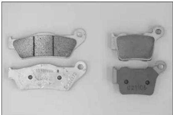
natural_image
Four brake brake components shown from different angles (no text or symbols visible)BRAKE PADS:
The brake pads are fitted with TOSHIBA TT 2701 HHB sintered lining at the front and TOYO B 143 FF sintered lining at the back. These linings provide an optimal combination of dosing, brake performance and life cycle. The lining type is stated on the back of the brake pad and also recorded in the homologation papers.
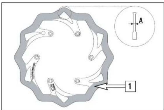
text_image
A 1BRAKE DISCS:
Due to wear, the thickness of the brake disc in the area of the contact face [1] of the brake pads decreases. The brake disk must be at least 2.50 mm (front) / 3.50 mm (rear) thick at the thinnest point [A]. Check the thickness of the brake disk at several points.

WARNING
- A brake disk worn down to less than 2.50 mm (front) / 3.50 mm (rear) is a safety risk. Have the brake disk replaced as soon as it reaches the service limit.
- Have any repairs on the brake system be performed by a KTM dealer.
BRAKE FLUID RESERVOIRS:
The brake fluid reservoirs on the front and rear wheel brakes have been designed in such a way that even if the brake pads are worn it is not necessary to top up the brake fluid. If the brake fluid level drops below the minimum level either the brake system has a leak or the brake pads are completely worn. In this case, consult an authorized KTM dealer immediately.
BRAKE FLUID:
KTM fills the brake systems with Motorex Brake Fluid DOT 5.1 brake fluid, one of the best brake currently available. We recommend that you continue to use it. DOT 5.1 brake fluid is based on glycol ether and of an amber color. If you do not have any DOT 5.1 for refilling, you may use DOT 4 brake fluid. However, you should replace it as soon as possible with DOT 5.1. Never use brake fluid DOT 5. The color of this silicon oil-based product is purple red. The gaskets and brake hoses of KTM motorcycles are not designed for DOT 5 brake fluid.

WARNING
Have the brake fluid changed at least once annually. If you wash your motorcycle often, the brake fluid should be changed even more frequently. Brake fluid tends to absorb water. Therefore, vapor pockets may form in "old" brake fluids even at low temperatures, causing the brake system to fail.
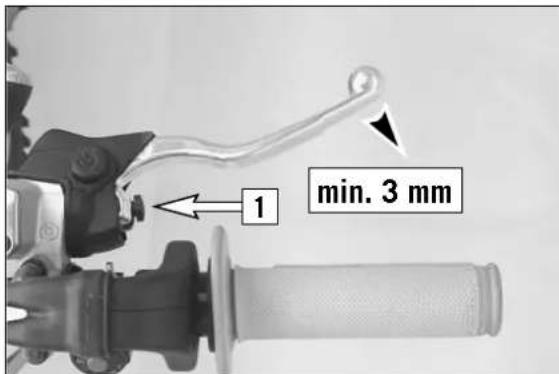
text_image
1 min. 3 mmAdjusting the free travel at the hand brake lever
Free travel at the hand brake lever may be readjusted by using adjustment screw [1]. In this way, the position of the point of pressure (i.e. the resistance you feel on the hand brake lever when the brake pads are pressed against the brake disc) can be adjusted for any hand size.
When you press the hand brake lever forwards, you should have at least 3 mm free travel. Turn the adjusting screw [1] if necessary.
! CAUTION
At the hand brake lever, free travel must at least be 3 mm (0.1 in). Only then may the piston in the hand brake cylinder be moved (to be recognized by the greater resistance of the hand brake lever). If this free travel is not provided, pressure will build up in the braking system, and the front-wheel brake may fail due to overheating.
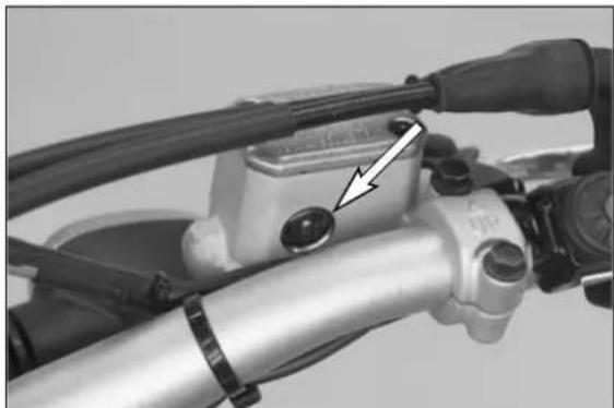
natural_image
Close-up of a motorcycle handle and lever mechanism with a black arrow pointing to a key pivot point (no text or symbols visible)Checking the brake fluid level - front brake
The brake fluid reservoir is linked with the hand brake cylinder at the handlebar and the reservoir is provided with an inspection glass. With the reservoir in a horizontal position, the brake fluid level should not drop below the middle of the glass.
WARNING
If the brake fluid level drops below the minimum either the brake system has a leak or the brake pads are completely worn. In this case, consult an authorized KTM dealer immediately.
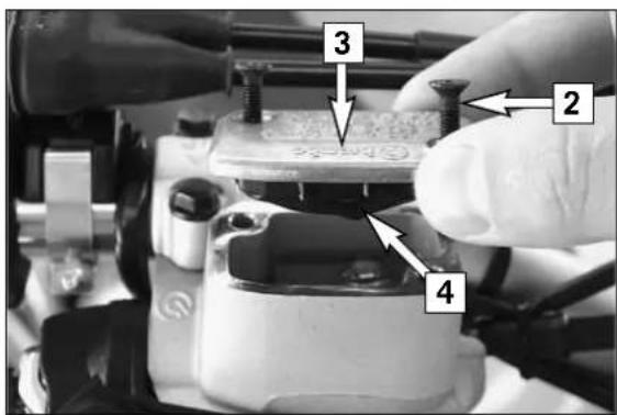
text_image
Close-up of a mechanical component with numbered parts labeled 2, 3, and 4 pointing to a component.Refilling the front brake fluid reservoir \*
Loosen screws [2] and remove lid [3] and membrane [4].
Place hand brake cylinder in a horizontal position and fill the brake fluid reservoir to 5 mm (0.2 in) below the rim with clean brake fluid DOT 5.1 (e.g. Motorex Brake Fluid DOT 5.1). Replace membrane and lid, tighten screws. Rinse off spilled or overflowing brake fluid with water.
WARNING
- Never use DOT5 brake fluid! It is based on silicone oil and of a purple color. Seals and brake hoses must be especially adapted to it.
- Store brake fluid out of reach of children.
- Brake fluid can cause skin irritation. Avoid contact with skin and eyes. If you get brake fluid in your eyes, rinse with plenty of water and consult a doctor
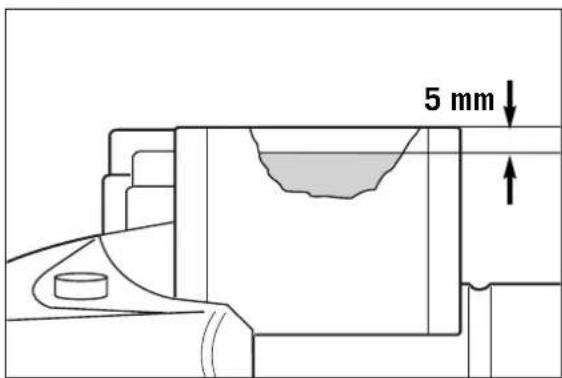
text_image
5 mm! CAUTION
- Don't let brake fluid get in contact with paint, it is an effective paint remover.
- Use only clean brake fluid taken from a tightly sealed container.
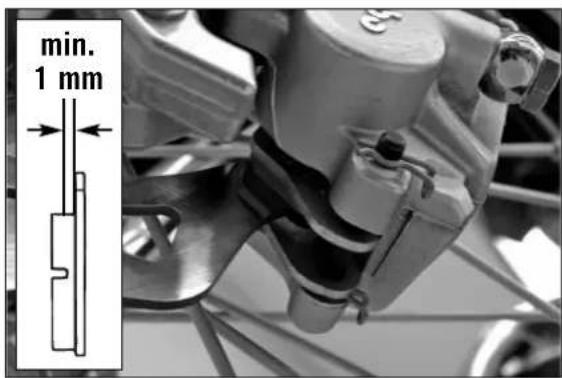
text_image
min. 1 mmChecking the front brake pads
The brake pads can be inspected from below. The linings must be at least 1 mm (0.04 in) thick.
WARNING
At their most worn point brake pad linings should not be thinner than 1 mm, otherwise they could lead to brake failure. For your own safety don't put off having your brake pads changed.
! CAUTION
If the brake pads are replaced too late so that the lining is partly or entirely worn, the steel components of the brake pad will rub against the brake disc, thereby impairing the braking effect and destroying the brake disc.
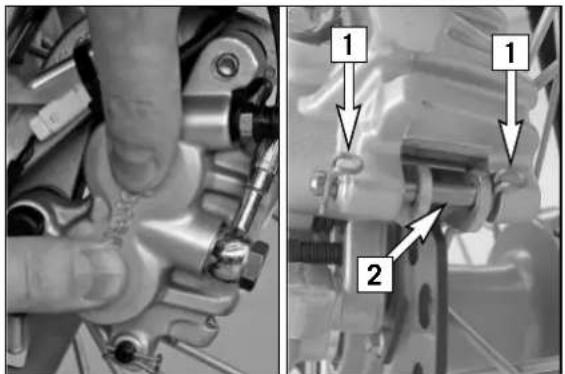
text_image
Technical diagram showing mechanical assembly with labeled parts 1 and 2, likely for assembly or maintenance instructions.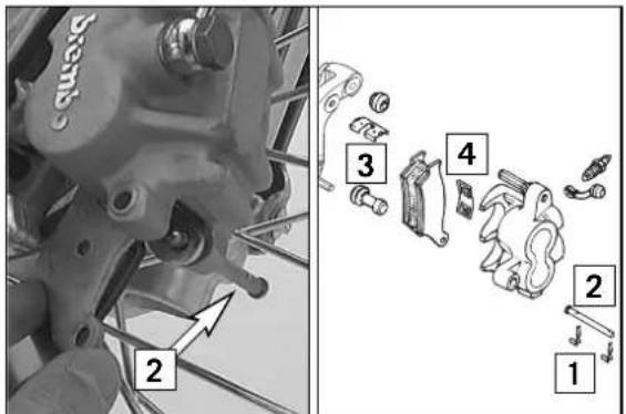
text_image
Technical diagram showing mechanical assembly with numbered parts and directional arrows indicating movement or assembly.Replacing the front brake pads \*
Press the brake caliper toward the brake disk, to put the brake piston in its basic position. Remove clips [1] and pull out bolt [2]. Remove brake pads from the brake caliper. Clean the brake caliper and the brake caliper support with compressed air. Check the sleeves of the guide bolts for damage, and grease guide bolts if necessary.
Mount the right brake pad and fix it with the bolt. Mount the left brake pad and insert the bolt until it stops. Mount the clips.
When mounting the brake pads, be sure to check for correct fit of the sliding metal-sheet [3] in the caliper support and of the leaf spring [4].
WARNING
- It is very important to keep the brake disk free from oil and fatty matters. Otherwise, the braking effect would be strongly reduced.
- After assembly, check if circlips have been fitted correctly.
- After working on the braking system, always actuate the hand brake lever or foot brake lever, respectively to ensure that the brake pads will lie against the brake disk and the pressure point is established.
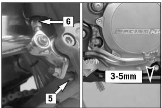
text_image
6 5 3-5mmChanging the basic position of the foot brake pedal \*
The basic position of the foot brake pedal can be altered by turning the stop screw [5]. The free play at the foot brake pedal must then be adjusted by means of the piston rod [6].
Measured on the outside, the foot brake pedal must have 3-5 mm (0.12–0.20 in) of free play before the piston rod can move the piston in the brake cylinder (to be recognised from the resistance on the foot brake pedal).
WARNING
If this free play is not present, then pressure can build up in the brake system when driving, causing the rear wheel to brake. The braking system overheats and may even fail completely in extreme cases.
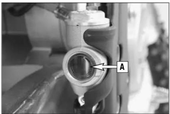
natural_image
Close-up of a mechanical component with a labeled section 'A' pointing to a cylindrical feature (no text or symbols beyond label)Checking the rear brake fluid level
The reservoir for the rear brake disk is located on the right side of the motorcycle on the rear brake cylinder.
No air bubble should be visible in inspection glass [A] when the vehicle is parked in a vertical position.
WARNING
If the brake fluid level drops below the minimum either the brake system has a leak or the brake pads are completely worn. In this case, consult an authorized KTM dealer immediately.
Refilling the rear brake fluid reservoir \*
Add brake fluid as soon as a bubble is visible in inspection glass [A]. To top up, remove screw [7]. Fill DOT5.1 brake fluid (e.g. Motorex Brake Fluid DOT 5.1) up to the mark [B] on the inside of the reservoir and remount the screw. Spilled brake fluid must be rinsed off with water.
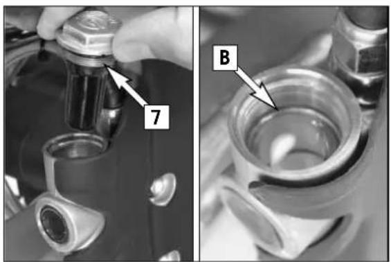
natural_image
Close-up of mechanical components with labeled parts (7 and B), no readable text or symbols present.WARNING
- Never use DOT5 brake fluid! It is based on silicone oil and of a purple color. Seals and brake hoses must be especially adapted to it.
- Store brake fluid out of reach of children.
- Brake fluid can cause skin irritation. Avoid contact with skin and eyes. If you get brake fluid in your eyes, rinse with plenty of water and consult a doctor.
! CAUTION
- Don't let brake fluid get in contact with paint, it is an effective paint remover.
- Use only clean brake fluid taken from a tightly sealed container.
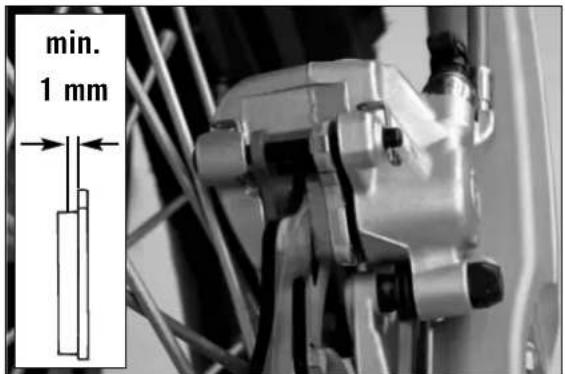
text_image
min. 1 mmChecking the rear brake pads
The brake pads can be inspected from the rear. The thickness of the linings may not be less than 1 mm (0.04 in).
WARNING
At their most worn point brake pad linings should not be thinner than 1 mm, otherwise they could lead to brake failure. For your own safety don't put off having your brake pads changed.
! CAUTION
If the brake pads are replaced too late so that the lining is partly or entirely worn, the steel components of the brake pad will rub against the brake disc, thereby impairing the braking effect and destroying the brake disc.
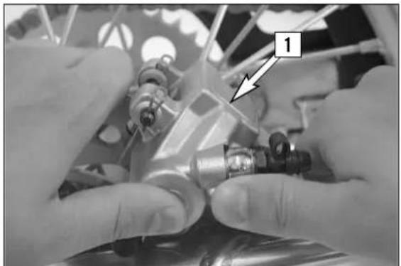
natural_image
Close-up of hands assembling mechanical components with a numbered label (1) and an arrow pointing to a detail (no readable text or symbols)Replacing the rear brake pads \*
Push the brake caliper [1] toward the chain wheel in order to move the brake piston into its basic position. Remove the clips [2], pull out the bolt [3], and remove the brake pads. Thoroughly clean the brake caliper with compressed air and check the sleeves of the guide bolts for damage.
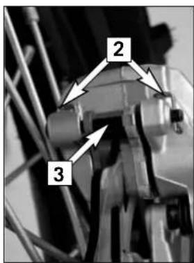
text_image
2 3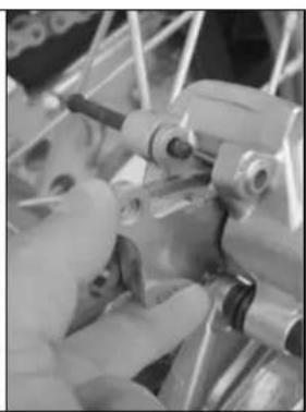
natural_image
Close-up of hands operating a mechanical clamp or fixture with metal brackets (no visible text or symbols)Insert the left brake pad into the brake caliper and secure it with the bolt. Insert the right brake pad and push the bolt [3] into the brake caliper up to the stop. Reattach clips [2].
WARNING
- It is very important to keep the brake disk free from oil and fatty matters. Otherwise, the braking effect would be strongly reduced.
- After assembly, check if clips have been fitted correctly.
- After working on the braking system, always actuate the hand brake lever or foot brake lever, respectively to ensure that the brake pads will lie against the brake disk and the pressure point is established.
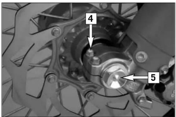
text_image
4 5Dismounting and mounting the front wheel
To remove the front wheel, jack the motorcycle up on its frame so that the front wheel no longer touches the ground.
Loosen the 2 clamping screws [4] on the left side of the fork fists. Loosen and remove the collar nut [5], loosen the clamping screews [6] on the right side of the fork fist.
Hold the front wheel, pull out the wheel spindle [7].
NOTE: The wheel spindle can be easily removed if you slightly revolve it with a ring spanner (SW 27 mm).
Carefully remove the front wheel from the fork.
! CAUTION
- Do not operate the hand brake when the front wheel has been dismounted.
- Make sure the brake disc is always on top when you lay down the wheel, otherwise the brake disc can be damaged.
Before remounting the front wheel, clean and grease the shaft seal rings [A] and the bearing surface [B] of the distance bushings and mount the distance bushing.

natural_image
Close-up of a mechanical assembly with a numbered component (6) and an arrow pointing to a specific part (no readable text or symbols)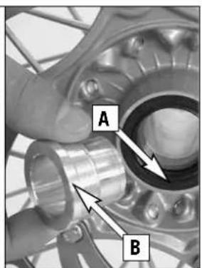
text_image
A BTo install the front wheel, lift it into the fork, position and mount the axle shaft. Mount the collar nut [5], tighten the clamping screws [6] on the right fork leg axle passage to prevent the axle shaft from turning and tighten the collar nut to 40 Nm (30ft.lb).
Loosen the clamp screws on the right fork leg. Take the motorcycle down from its stand. Press the front wheel brakes and push down on the fork a few times vigorously so that the fork legs come into alignment.
Only after this has been accomplished, tighten the clamp screws on both fork legs with 15 Nm
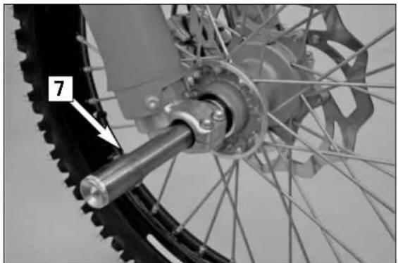
natural_image
Close-up of a bicycle wheel assembly with visible gears and shaft (no text or symbols)WARNING
- If you don't happen to have a torque wrench at hand, make sure you have the tightening torque corrected by a KTM dealer as soon as possible. A loose axle may lead to an unstable driving behavior of your motorcycle.
- After mounting the front wheel, keep operating the hand brake until the pressure point returns.
- It is very important to keep the brake disk free from oil and fatty matters, otherwise the braking effect would be strongly reduced.
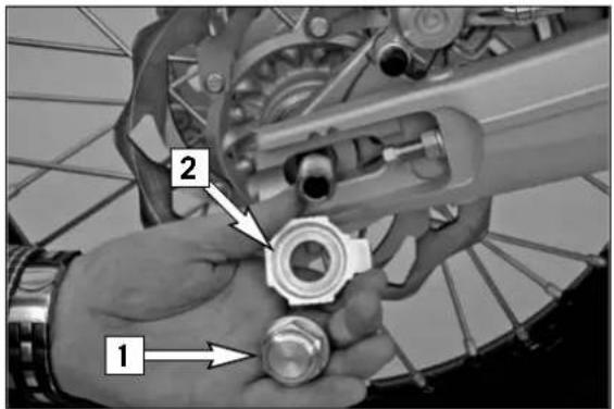
text_image
Mechanical assembly diagram showing hands assembling a bicycle component with numbered parts labeled 1 and 2Dismounting and mounting the rear wheel
Jack the motorcycle up on its frame so that the rear wheel no longer touches the ground.
Remove the collar nut [1], remove the chain tensioner [2] and pull out the wheel spindle [3] until you can push the rear wheel forwards.
Take the chain off the rear sprocket, pull out the wheel spindle and carefully remove the rear wheel from the swing arm.
! CAUTION
- Do not operate the rear brake when the rear wheel has been dismounted.
- Make sure the brake disc is always on top when you lay down the wheel, otherwise the brake disc can be damaged.
- If the axle is dismounted, clean the thread of the wheel spindle and collar nut thoroughly and apply a new coat of grease to prevent the thread from jamming.
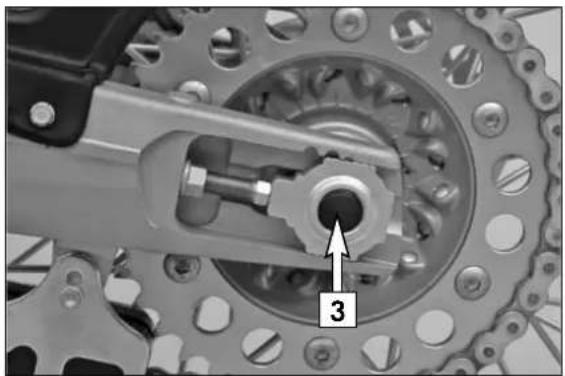
natural_image
Mechanical assembly diagram showing gear and shaft components (no text or symbols)The rear wheel is remounted in the reverse order. Before tightening the collar nut to 80 Nm, push the rear wheel forwards so that the chain tensioners lie on the tension screws.
WARNING
- If you don't happen to have a torque wrench at hand, make sure you have the tightening torque corrected by a KTM dealer as soon as possible. A loose axle may lead to an unstable driving behavior of your motorcycle.
- After mounting the rear wheel, keep operating the rear brake until the pressure point returns.
- It is very important to keep the brake disk free from oil and fatty matters, eitherwise the braking effects would be strongly reduced.
- Tighten the collar nut with the required torque. A loose wheel spindle may lead to an unstable behavior of your motorcycle.
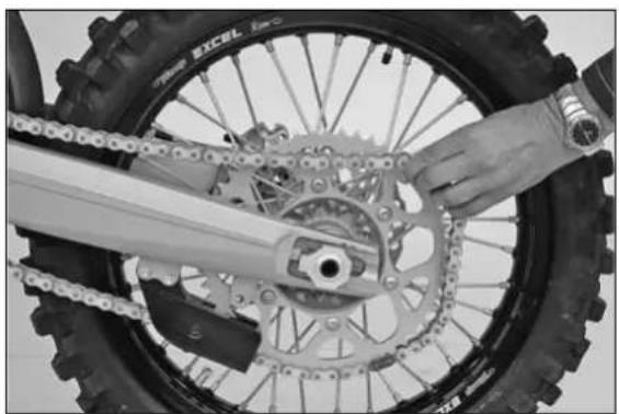
natural_image
Close-up of a hand adjusting a bicycle wheel rim and gear mechanism (no visible text or symbols)Checking spoke tension
The correct spoke tension is very important for the stability of the wheels and thus for riding safety. A loose spoke causes the wheel to become unbalanced and before long other spokes will have come loose. Check spoke tension, especially on a new motorcycle, at regular intervals. For checking, tap on each spoke with the blade of a screwdriver (see photo). A clear tone must be the result. Dull tones are indicators of loose spokes. If necessary, have the spokes retightened and the wheel centered by a KTM dealer.
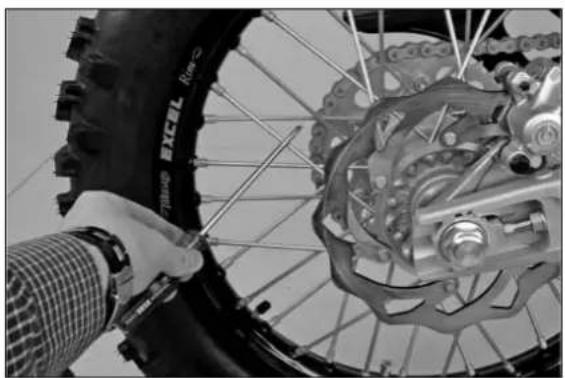
natural_image
Close-up of a bicycle tire being adjusted for repair, showing mechanical components and a hand adjusting the wheel (no visible text or symbols)WARNING
- Spokes can tear if you continue to ride with them loose. This may lead to an unstable handling of your motorcycle.
- Excessively tensioned spokes may rupture due to local overloading. The spokes must be tensioned to 5 Nm.
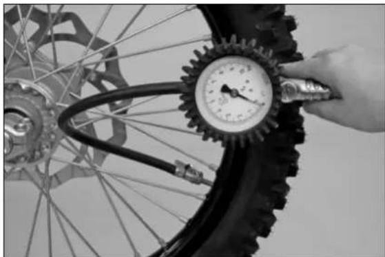
natural_image
Close-up of a hand adjusting a bicycle tire pressure gauge with hoses (no visible text or symbols)| TIRES-AIR PRESSURE | ||
| front rear | ||
| Off road 1,0 bar | 1,0 bar | |
| Road driver only | 1,5 bar 2,0 bar | |
Tires, air pressure
Tire type, tire condition, and air pressure level affect the way your motor-cycle rides and must therefore be checked whenever you are getting ready to go anywhere on your motorcycle.
– Tire size can be found in the technical specifications and in the homologation certificate
- Tire condition has to be checked every time you want to ride your motorcycle. Before leaving, check tires for punctures and nails or other sharp objects that might have become embedded in them.
Refer to the specific regulations in your country for minimum tire tread requirements. We recommend you replace the tires at the latest when the tread is down to 2 mm (0.08 in).
- Tire pressure should be checked regularly on a "cold" tire. Proper pressure ensures optimum driving comfort and extends the life of your tires.
WARNING
- Do not mount tires which have not been approved by KTM. Other tires could have adverse effects on the way your motorcycle behaves.
- front and rear wheels may only be fitted with tires having the same tread layout. Use homologated tires.
- For your own safety replace damaged tires immediately.
- Worn tires can have a negative effect on how your motorcycle performs, especially on wet surfaces.
- If air pressure is too low, abnormal wear and overheating of the tire can result.
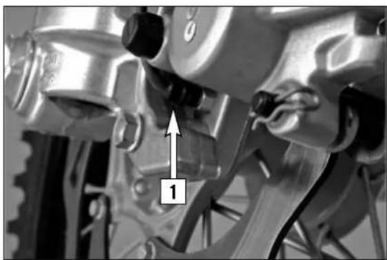
natural_image
Close-up of a mechanical brake caliper assembly with no visible text or symbols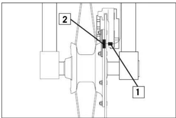
text_image
2 1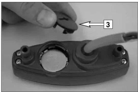
natural_image
Close-up of a hand holding a small electronic component with a cable inserted, no visible text or symbolsCheck/set distance of the magnetic sensor
The distance between magnet [2] and sensor [1] must be 2-4 mm (0,08-0,16 in), otherwise malfunctions on the speedometer might occur.
This distance can be corrected by screwing in or off the sensor [1].
Replacing the battery of the digital speedometer
Remove the headlight mask and disassemble the electronic speedometer. Remove the screw connection [3], insert the battery (type CR 2430) with the writing facing up and reinstall the screw connection.
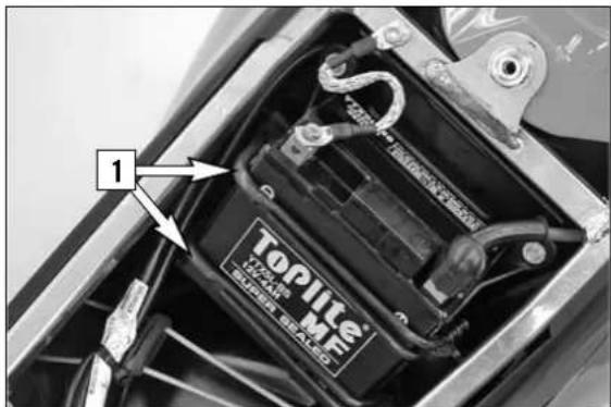
text_image
1 TOPiile TOPiile MotorBattery
The battery is located under the seat and is maintenance-free.
Maintenance-free means you will not need to check the acid level. Clean the battery terminals regularly and grease with acid-free grease if necessary. The charge condition and type of charge are very important for the battery's service life.
TO REMOVE THE BATTERY:
First disconnect the negative pole, then the positive pole from the battery. Remove the filter box cover and detach both rubber bands [1].
Remove the battery.
Install the battery as described for the specific type of battery (see illustration). Connect the minus pole to the battery last.
WARNING
- If electrolyte (sulphuric acid) leaks from the battery, proceed with great care. The electrolyte can cause severe burns.
- In the case of skin contact rinse thoroughly with water.
- In the case of contact with the eyes, thoroughly rinse eyes with water for at least 15 minutes. Immediately consult a doctor.
- The battery is a closed model but can nevertheless emit explosive gases. Avoid sparks and open fire near the battery.
- Defective batteries must be stored out of the reach of children. Ensure proper disposal of discarded batteries.
! CAUTION
Never remove the closure [2] since it will be damaged
STORAGE:
If the motorcycle is being immobilized for longer periods of time, remove and charge the battery. Storage temperature 0 - 35°C, avoid direct sunlight.
Charge the battery every 3 months.
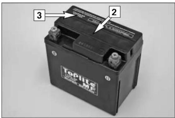
text_image
3 2 Toplite TOPLIFE TOPLIFE TOPLIFECharging the battery
The battery discharges every day, even if it is not used.
Always disconnect the battery when charging. Charge the battery as described in the instructions [3] on the battery housing. Do not exceed the amperage and charging time. Quick charging at a high amperage has an adverse effect on the service life.
Always use special charging devices to charge maintenance-free batteries, e.g. the KTM charging device (item no. 58429074000). You can also use this charging device to test the off-load voltage and startability of the battery and generator. It is impossible to overcharge the battery with this device.
Charge the battery immediately if it is empty when you start the motorcycle. If left to stand in an uncharged condition for a longer period of time, the battery will run down and sulfatize, destroying the battery.
Recharge the battery every 3 months if it is being stored for a longer period of time.
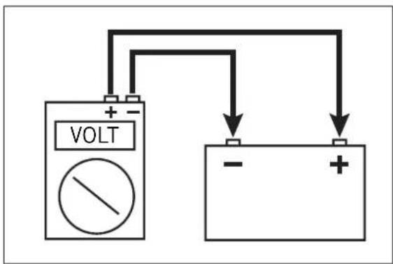
text_image
VOLT -! CAUTION
- Never remove the closure [2] since it will be damaged.
- To avoid damage to the on-board electronic system, always disconnect the minus pole before you charge the battery.
- To charge, connect the battery to the battery charger before you switch on the battery charger. When the battery is charged, switch off the battery charger before you disconnect the battery.
- Provide adequate ventilation when charging the battery in a closed room; the battery emits explosive gases when charging.
- Electrolytes will escape through the safety valves if the battery is charged too long or at an excessive voltage or amperage. This will reduce battery capacity.
– Try to avoid quick charges.
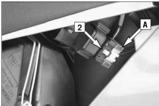
text_image
2 AFuse
The fuse [1] is located in the starter relay of the E-starter [2] underneath the left side paneling. Having removed the left side paneling, the air box cover and the protection cover [A], you will be able to see the fuse.
The following loads are connected to it:
- E-starter system
- horn
- flasher lights
- electronic speedometer
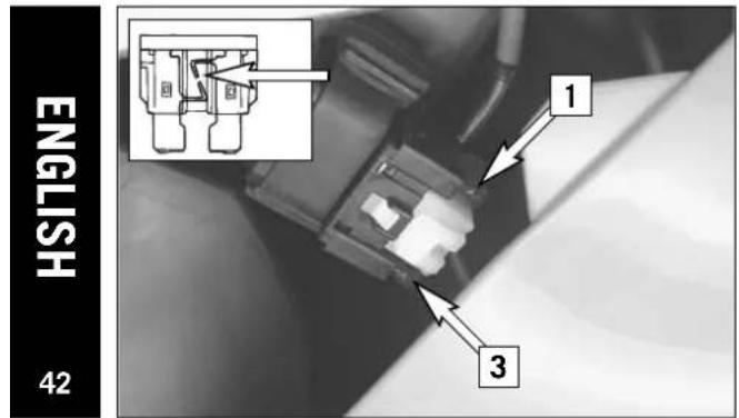
text_image
ENGLISH 42 1 3The starter relay also contains a (10 amp) spare fuse [3].
Replace a blown fuse only with an equivalent one. If a new fuse that has just been installed gets blown again, you are strongly advised to have it inspected by a KTM dealer. The fuse capacity is 10 Ampere.
! CAUTION
Under no circumstances is a stronger fuse allowed to be installed or a fuse allowed to be "repaired". An improper treatment could damage the whole electrical installation.
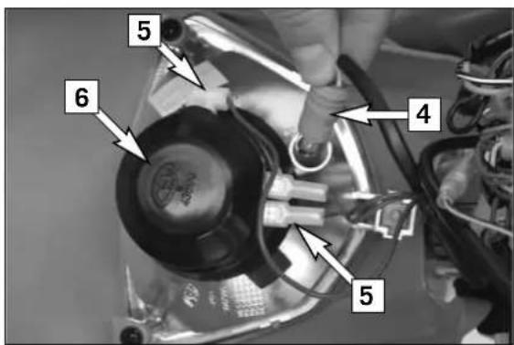
text_image
5 6 4 5Replacing headlight lamp/parking light lamp
Loosen both rubber bands and tilt headlight mask to the front. Pull the parking light lamp with holder [4] carefully out of the reflector. Pull connector [5] off the headlamp and remove rubber cap [6]. Disengage retaining clip and take bulb out of reflector. When changing the parking-light lamp, simply pull it out of the holder.
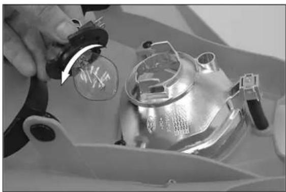
natural_image
Close-up of a mechanical component with a hand adjusting a circular component, no visible text or symbolsSlightly depress the bulb, turn it approx. 30° counterclockwise and pull it out of the socket.
To mount the lamp reverse the worksteps indicated above.
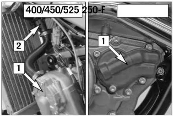
text_image
400/450/525 250-F 1 2 1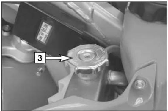
text_image
3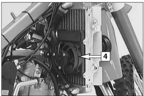
natural_image
Close-up of a vehicle's internal engine components, showing fan, chassis, and motors (no text or symbols visible)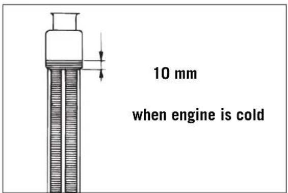
text_image
10 mm when engine is cold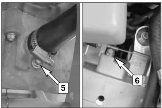
text_image
5 6Cooling system
Coolant is circulated by a water pump [1] located in the engine. When the engine is cold the coolant only circulates through the cylinder and the cylinder head. After the engine has reached its operating temperature (about 70°C, 158°F), the thermostat [2] opens and the coolant is also pumped through both aluminum radiators.
Air blowing in through the radiators cools the coolant. The slower the speed of the motorcycle, the less the coolant is cooled down. Dirty radiators also reduce the cooling efficiency.
Pressure induced by heating of the coolant in the system is controlled by a valve in the radiator cap [3]; a water temperature rising up to 120°C (248°F) is admissible, without fear of problems.
WARNING
- If possible, always check level of cooling liquid when the engine is cold. If you have to open the radiator cap [3] when the engine is hot, use a rag to cover the cap and open slowly to release pressure. Caution - scalding hazard!
- Do not detach any radiator hoses while the engine is hot. The escaping hot coolant and the steam may cause serious burns.
- In case you get burnt, hold the affected part of your body under running cold water right away.
- Coolant is toxic. Keep the coolant out of the reach of children.
- In case coolant is ingested, consult a doctor immediately.
- If coolant gets into your eyes, rinse them out with water immediately and consult doctor.
A mixture of 50% antifreeze liquid and 50% distilled water is used as coolant. However, the antifreeze protection must be at least -25^ C ( -13^ F). This mixture offers antifreeze protection but also good corrosion protection and should therefore not be replaced by pure water.
! CAUTION
- The cooling system must be bled after draining the cooling liquid or after adding more than 0.25 l (0.06 US gallons) cooling liquid.(see below).
- For the cooling system, use only high-grade antifreeze (e.g. Motorex Anti Freeze). Using lower-grade antifreeze agents can cause corrosion and coolant foaming.
- Extreme climate conditions or stop and go traffic may cause overheating problems. To avoid this, an electric blower [4] is offered (ask your KTM Dealer).
Checking the coolant level
The coolant should be 10 mm (0.4 in) above the radiator fins when the engine is cold (see diagram). In the event of the coolant being drained, always fill and bleed the system.
! CAUTION
If possible, always check the level of cooling liquid when the engine is cold. If you have to open the radiator cap [3] when the engine is hot, use a rag to cover the cap and open slowly to release pressure. Caution - scalding hazard!
Bleeding the cooling system (400/450/525)
By removing the screw [5] at the front end of the cylinder you can drain the coolant.
To bleed the cooling system, fill in approx. 0.8 liters (0.2 US gallons) of coolant and remove the bleeder screw [6]. Do not reinstall the bleeder screw until coolant escapes at the bore without any bubbles.
Then, fill in the coolant until it reaches a level about 10 mm above the radiator fins.
After a short ride, check the coolant level once more.
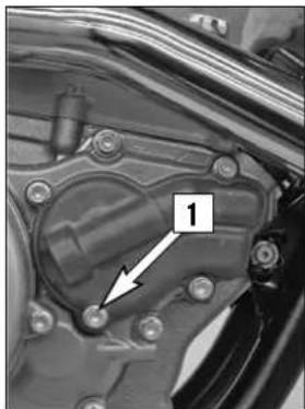
natural_image
Close-up of a mechanical component with a numbered annotation (1) pointing to a specific part, no readable text or symbols present.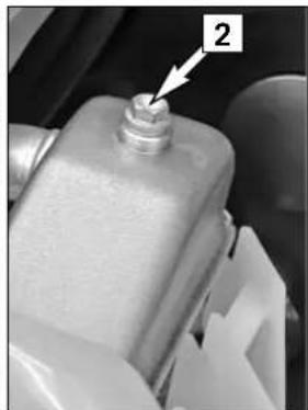
natural_image
Close-up of a mechanical component with a labeled arrow pointing to a bolt (no text or symbols visible)Bleeding the cooling system (250-F)
By removing the screw [1] at the water pump cover you can drain the coolant. To bleed the cooling system, fill in approx. 1.0 liter (0.25 US gallons) of coolant and remove the bleeder screw [2]. Do not reinstall the bleeder screw until coolant escapes at the bore without any bubbles.
Then, fill in the coolant until it reaches a level about 10 mm above the radiator fins.
After a short ride, check the coolant level once more.

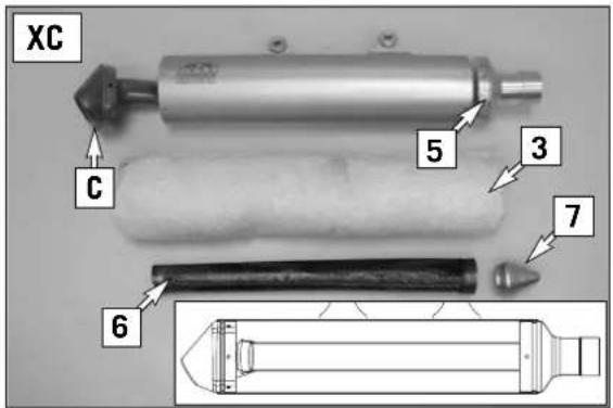
text_image
XC C 5 3 7 6Replacing the glassfiber yarn packing of the silencer \*
Aluminum silencers are filled with glassfiber yarn to muffle noise. Have the filling checked regularly by an authorized KTM workshop (see Lubrication and Service Chart). The insulating material fibers escape through the holes in the perforated pipe with time, causing the silencer to „burn out“. In addition to causing a higher noise-level, it will also affect the power characteristic. The insulating material suitable for your exhaust is available from your authorized KTM workshop.
By experience, the front glassfiber yarn packing [3] needs to be replaced more often than the rear silencing mat [4].
For this purpose, remove the silencer from the vehicle and dismount the front cap [5]. Pull the front glassfiber yarn packing together with the inner exhaust pipe [6] out of the silencer. Clean the front inner exhaust pipe.
To facilitate the mounting procedure, you can make a mounting tool [7] out of wood, plastic, or metal. Insert the mounting tool into the inner pipe and mount the glassfiber packing. Push the inner pipe containing the packing into the silencer such that the slot engages the web [A]. Use a blunt ended object to stuff the glassfiber yarn packing all the way into the silencer, and mount the front cap.
To change the rear silencing mat, start by removing the front packing and the inner exhaust pipe. Then, drill open the rivets and remove the end cap [C].
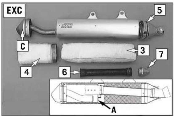
text_image
EXC 5 C 3 7 4 6 ANOTE:
In every exhaust repair procedure, the O-rings must be replaced by new ones. Glass fiber yarn packings are available from your licensed KTM mechanic.
Make sure the caps are screwed on tightly. Mount the muffler stress-free before tightening the fixing screws.
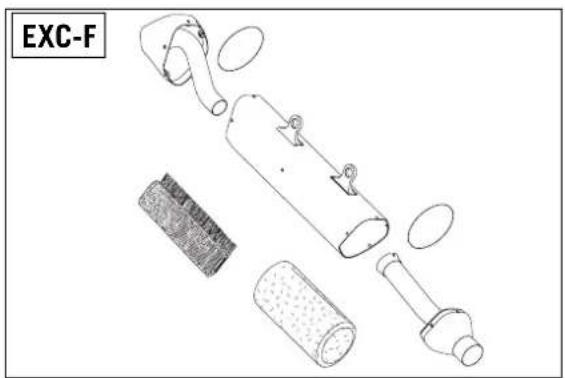
natural_image
Exploded view diagram of a device with internal components and labeled EXC-F (no text or symbols on the diagram itself)
WARNING
The exhaust system becomes very hot while the motorcycle is running, to avoid burns do not start work on the exhaust system until it has properly cooled down.
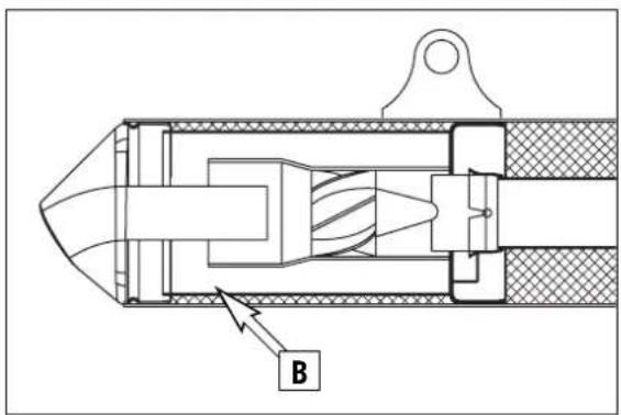
text_image
BCleaning the spark arrester (XC-W USA) \*
The spark arrester should be cleaned every time the glassfiber yarn filling is changed or at least once annually.
For this purpose, dismount the silencer cap and remove any deposits that might exist in region [B]. Renew the O-ring and mount the silencer cap.
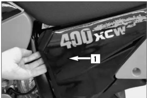
text_image
400XCW ← 1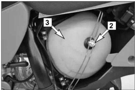
text_image
Technical diagram of a mechanical assembly with numbered components labeled 2 and 3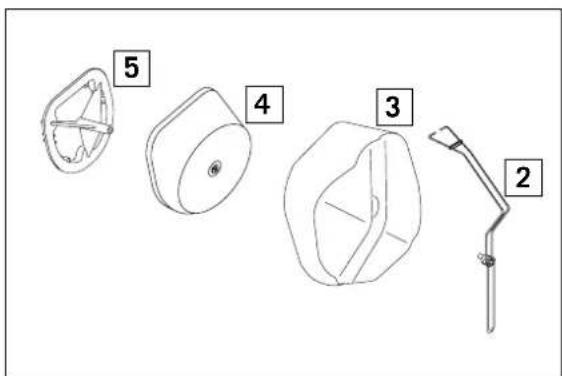
text_image
Diagram showing five labeled mechanical components or parts, numbered 2 to 5, with no visible text or symbols beyond labels.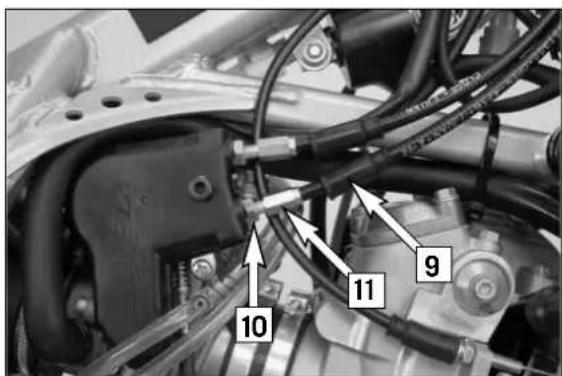
text_image
10 11 9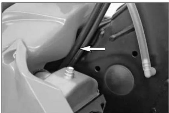
natural_image
Close-up of a mechanical component with a pipe fitting and a white arrow pointing to a feature (no visible text or symbols)Cleaning the air filter \*
The air filter must be cleaned prior to each race or whenever dust has accumulated. To clean, lift the filter box cover [1]
(see illustration) and pull off towards the front.
Detach the bottom of the filter retaining bracket [2], tilt aside and remove the throttle cap [3] and the air filter [4] and filter support [5] from the filter box. The XC models do not have a throttle cap.
! CAUTION
- Do not clean foam filter with fuel or petroleum since these damage the foam. KTM recommends the products of the company Motorex for air filter maintenance (Bio Dirt Remover and Liquid Bio Power).
- Never start your motorcycle without any air filters. Otherwise, dust and dirt may penetrate and cause damage and increased wear.
- Dust and dirt can accumulate and damage the engine if the air filter is not mounted correctly.
Thoroughly wash the air filter in special cleaning fluid and allow it to dry well. Only press out the filter, do not wring it out under any circumstances. Oil the dry air filter with a high-grade filter oil. Also clean the air filter box. Check the carburetor collar for damage and that it is filled correctly.
Mount the air filter on the filter support. Insert the air filter and filter support in the throttle cap and mount them in the filter box, aligning in a central position, and fix with the filter retaining bracket.
Adjusting the throttle cables \*
The throttle grip should always provide for a backlash of 3-5mm. Besides, with the engine running, the idling speed must not change if you turn the handlebar all the way to the left or right.
To adjust the throttle cables, dismount the seat and the tank together with spoilers. Slide back the protection cover [9]. Loosen the counternut [10] and turn the adjusting screw [11] accordingly. Turning the adjusting screw counterclockwise will reduce the backlash, turning the adjusting screw clockwise will increase the backlash.
Tighten the counternut and check whether the throttle grip can be actuated smoothly. Mount tank and seat.
! CAUTION
Be sure not to pinch the throttle cables when mounting the tank. Afterwards, check the throttle cables for easy action.
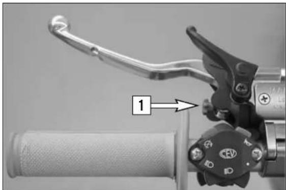
natural_image
Close-up of a bicycle brake lever handle and grip mechanism (no text or symbols visible)Changing the original position of the clutch lever
The adjusting screw [1] can be used for individual adjustment of the original position of the clutch lever, thus allowing adjustment to an optimal position for every hand size.
Turning the adjusting screw counterclockwise reduces the distance between the clutch lever and the handlebar. Turning the adjusting screw clockwise increases the distance between the clutch lever and the handlebar.
! CAUTION
Adjustment of the clutch lever position is only possible within certain limits. Only turn the adjusting screw manually and never apply excessive force.
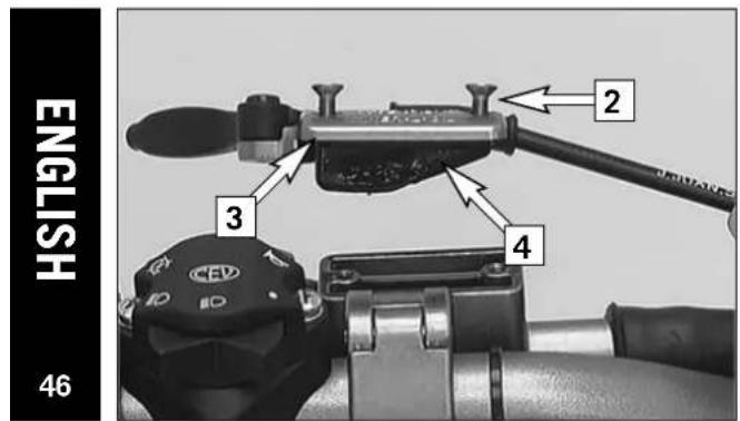
text_image
ENGLISH 46 2 3 4Checking the oil level of the hydraulic clutch (400/450/525)
To check the oil level in the master cylinder of the clutch remove the cover. For this purpose, remove screws [2] and cover [3] together with the rubber boot [4]. The oil level in the horizontal-standing master cylinder should be 4 mm below the upper edge.
If necessary, fill up with biodegradable hydraulic oil SAE 10 (e.g. Motorex Kupplungs-Fluid 75). Biodegradable hydraulic oil is available from your KTM dealer (50ml).
! CAUTION
KTM uses biodegradable, hydraulic mineral oil to actuate the hydraulic clutch. Do not mix this oil with any other hydraulic oil. Always use original KTM hydraulic oil (available from your authorized KTM workshop) to make sure your clutch operates smoothly. Never refill with brake fluid.
Checking the oil level of the hydraulic clutch (250-F)
To check the oil level in the master cylinder of the clutch remove the cover. For this purpose, remove screws [2] and cover [3] together with the rubber boot [4]. The oil level in the horizontal-standing master cylinder should be 4 mm below the upper edge.
If necessary, add DOT 5.1 brake fluid (Motorex Brake Fluid 5.1).
! CAUTION
Brembo clutch fittings are installed in the 250-F models and filled with DOT 5.1 brake fluid. To make sure the clutch operates smoothly, never add hydraulic oil to these systems.
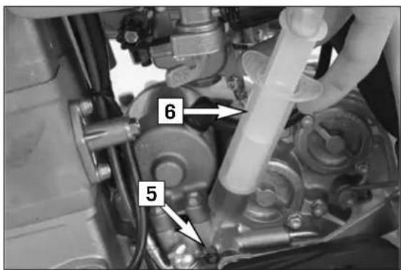
text_image
6 5Bleeding of the hydraulic clutch \*
If the clutch lever starts to feel unresponsive, the clutch control system needs to be bled. You will need to use a bleeding syringe (special tool). Please note that Motorex 75 clutch fluid must be used for the 400/450/525 models and Motorex DOT. 5.1 brake fluid for the 250-F models.
Turn the handlebar until the master cylinder is in a horizontal position, remove the screws [2], the cover [3] and the rubber boot [4].
Fill the bleeder syringe [6] with a suitable fluid (see Technical Specifications - Engine). Remove the bleeder screw [5] from the slave cylinder and mount the bleeder syringe.
Press oil into the system until the oil runs out of the hole [7] in the master cylinder without bubbles. Occasionally extract the oil from the master cylinder reservoir to keep it from overflowing.
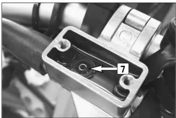
natural_image
Close-up of a mechanical component with a numbered arrow pointing to a specific part (no visible text or symbols)After you finish bleeding, remove the bleeder syringe, mount the bleeder screw, correct the oil level in the reservoir and mount the cover (see above).
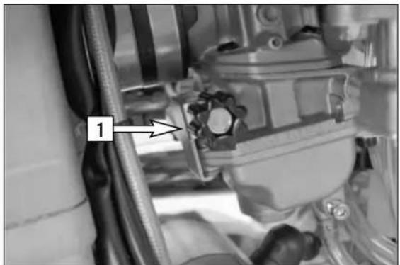
natural_image
Close-up of mechanical components with a numbered label '1' pointing to a specific part (no readable text or symbols beyond the label)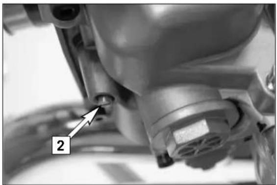
natural_image
Close-up of a mechanical component with a numbered annotation (2) pointing to a small cylindrical feature, no readable text or symbols present.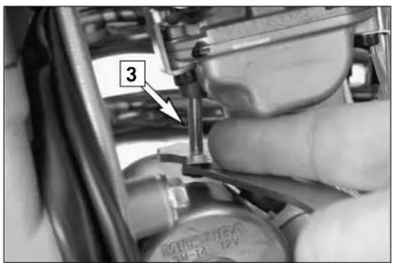
text_image
3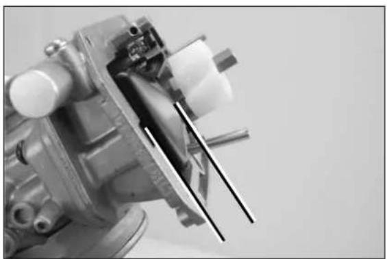
natural_image
Close-up of a mechanical assembly with visible gears and shafts (no text or symbols)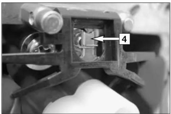
natural_image
Close-up of a mechanical component with a numbered annotation '4' pointing to a specific part (no readable text or symbols beyond the label)Carburetor - Adjust idling (Keihin-FCRMX 37/39/41) \*
Idling adjustment of the carburetor strongly affects the engine's starting behavior. That is, an engine whose idling speed is adjusted correctly will be easier to start than one whose idling speed has not been adjusted correctly.
The idle speed is controlled by means of the adjusting wheel [1] and the mixture control screw [2]. The adjusting wheel is used to adjust the basic setting of the slide. The mixture control screw is used to control the idle mixture which arrives at the engine by way of the idle system. Clockwise turning reduces the fuel quantity (lean mixture), counterclockwise turning increases the fuel quantity (rich mixture).
TO ADJUST IDLING CORRECTLY, PROCEED AS FOLLOWS:
1 Turn in mixture control screw [2] up to the stop, and turn it back out to the basic position (see technical date-engine)
2 Warm up the engine
3 Use the adjusting wheel [1] to set the normal idle speed (1400 - 1500 rpm).
4 Turn mixture control screw [2] slowly clockwise until idling speed starts to decrease. Memorize this position, and turn mixture control screw slowly counterclockwise until the idling speed decreases again. Adjust the point of the highest idling speed between these two positions. If, in the course of this procedure, the speed undergoes a relatively high increase, reduce the idle speed to a normal level and repeat the procedure specified in 4. Serious competitive racers will choose a setting approx. 1/4 turn (clockwise) leaner than this ideal value because their engine will heat up more when used in competitions.
NOTE: If you fail to obtain a satisfying result by following the procedure described above, an incorrectly dimensioned idling nozzle may be the cause. If:
a) the mixture control screw has been screwed in up to the stop without causing any change in rotational speed, a smaller idling jet has to be installed;
b) the engine dies when the mixture control screw is still open by 2 turns, a larger idling jet needs to be selected.
Naturally, in cases of jet changes, you have to start your adjusting work from the beginning.
5 Then, use the adjusting wheel to set the desired idle speed.
6 In cases of greater changes in the outside temperature and extremely different altitudes, the idling speed should be readjusted.
Basic information on carburetor wear
As a result of engine vibrations, the throttle valve, jet needle, and needle jet are subjected to increased wear. This wear may cause the carburetor to malfunction (e.g., overly rich mixture). Therefore, these parts should be replaced after approx. 200 hours.
Adjusting the mixture control screw \*
Especially on the EXC models, accessing the mixture control screw is difficult. For this reasons, we have created an appropriate special tool.
Introduce the special tool on the mixture control screw [2] at the carburetor bottom. Press the tool slightly upward and turn the adjusting wheel [3] until the tool engages the slot of the mixture control screw.
Now, you can go about adjusting the screw. Marks were provided on the adjusting wheel, making it easier to keep track of the turns.
Checking the float level (float height) \*
For this purpose, dismount the carburetor and remove the float chamber. Hold the carburetor in a slanted position such that the float will abut the float needle valve but not compress it.
In this position, the edge of the float should be parallel with the float chamber sealing surface (see illustration).
If the float height does not correspond to the desired value, check the float needle valve and, if necessary, replace it.
If the float needle valve is o.k., you can adjust the float height by bending the float lever [4].
Mount the float chamber, install the carburetor, and adjust the idle speed.
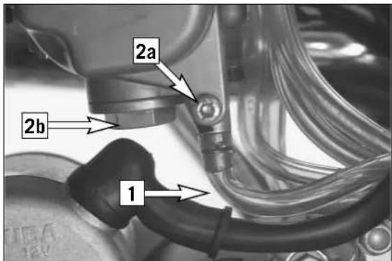
text_image
2a 2b 1Draining the float chamber of the carburetor
Following every wet cleaning procedure, the float chamber of the carburetor should be drained in order to remove any water that may have penetrated into it. Water in the float chamber causes malfunctioning. Perform this task on a cold engine.
400/450/525: Close the fuel tap and put one end of the hose [1] into a collecting vessel. Open the drain plug [2a] (turning it counterclockwise) by serval turns, and drain the fuel from the float chamber. Then, retighten the drain plug and open the fuel tap.
250-F: Close the fuel tap, and place a cloth under the carburetor, which is capable of absorbing the leaking fuel. Unscrew the plug [2b] and clean it with compressed air. Then, mount the plug together with the gasket, open the fuel tap, and check the float chamber for leaks.
WARNING
- Fuel is easily flammable and toxic. When handling fuel, be sure to exercise the utmost caution. Never perform any work on the fuel system near open flames or burning cigarettes.
- Always allow the engine to cool off first. Immediately clean up any fuel which may have been spilled. Materials saturated with fuel are also easily flammable. In case you ingested fuel or fuel splashed into your eyes, consult a doctor immediately.
- Dispose of the fuel properly.
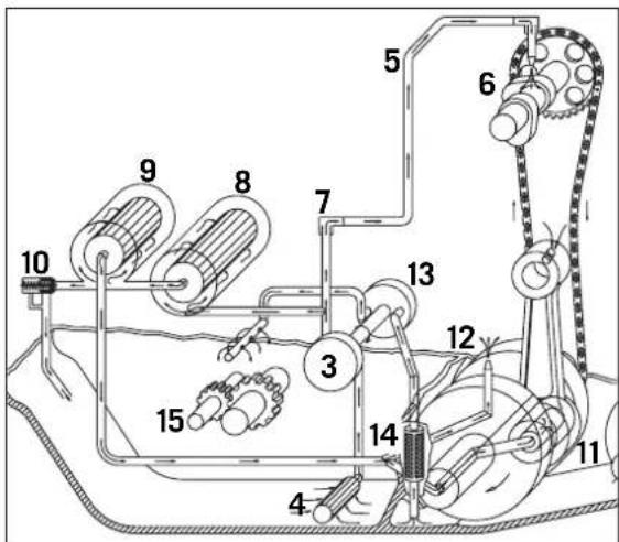
text_image
Technical diagram of a mechanical device with numbered components for identification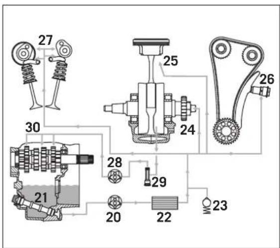
text_image
27 30 21 28 29 20 22 25 24 26 23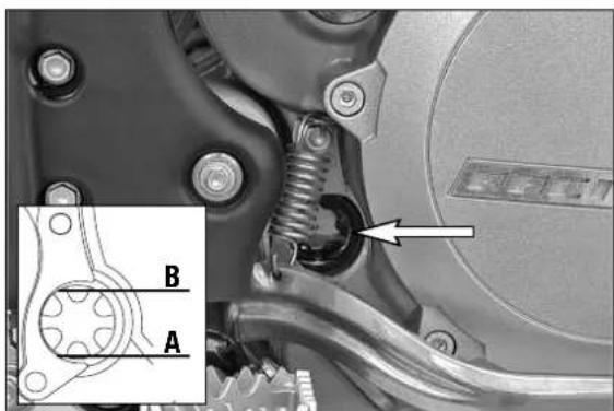
text_image
Mechanical assembly diagram with labeled parts A and B, showing mechanical components and a highlighted section with an arrow.Oil circuit (400/450/525)
Via the long oil screen [4], the oil pump [3] draws engine oil from the oil sump of the transmission. This engine oil flows through an oil line [5] into the cylinder head for camshaft lubrication [6]; the oil quantity is controlled by the jet screw [7]. An oil duct branches off to the long oil filter [8] where the coarser particles contained in the engine oil are filtered away. Then, the engine oil arrives at the short oil filter [9] which also filters the fine particles. Now, the purified engine oil is pumped past the bypass valve [10] to the conrod bearing [11] and sprayed from below onto the piston through a nozzle [12].
The second oil pump [13] draws the engine oil via the short oil screen [14] out of the crankcase, thereby lubricating the transmission gears [15].
Oil circuit (250-F)
The oil pump [20] sucks engine oil from the transmission oil sump through the long oil screen [21] and conveys it to the oil filter [22] where any contamination is filtered out. The cleaned engine oil is pumped past the bypass valve [23] to the conrod bearing [24] and sprayed onto the pistons from below through a jet [25].
Two other oil ducts lead into the cylinder head. One duct supplies the hydraulic chain tensioner [26], the other duct leads to the camshaft bearing support [27], where the camshaft bearings and the cam lever are supplied with oil (via spraying nozzles).
The second oil pump [28] sucks the engine oil out of the crankcase through the short oil screen [29] and uses it to grease the transmission gears [30].
Checking the engine oil level
The engine oil level can be checked with the engine either warm or cold. Place the motorcycle in an upright position and on a horizontal surface (not on the side stand).
If the engine is cold, the engine oil must be visible at the lower edge of the inspection glass [A].
If the engine is warm, the engine oil must be visible up to the upper edge of the inspection glass [B].
Replenish the engine oil, if necessary.
! CAUTION
Insufficient amounts of or low-grade engine oil lead to premature wear in the engine.
JASO T903 MA
250-F: 400/450/525:
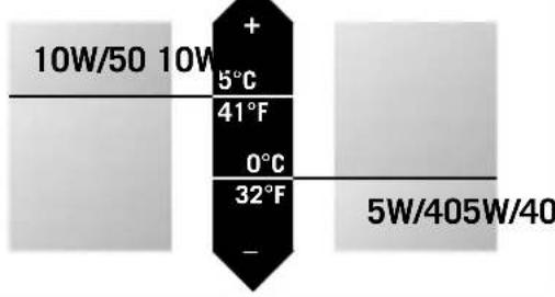
text_image
10W/50 10W + 5°C 41°F 0°C 32°F - 5W/405W/40Engine oil
Automobile engine oil used to be used for four-stroke motorcycles before there were separate motorcycle specifications. Different technical developments made it necessary to have a separate specification for four-stroke motorcycles - the JASO T903 MA standard. Whereas car engines require long changing intervals, motorcycle engines require a higher power output at higher speeds. Most motorcycle engines also use the same oil to lubricate the transmission and the clutch. The JASO MA standard responds to these special requirements. Only use fully synthetic engine oils that meet the JASO MA quality requirements (see information on the can).
KTM recommends Motorex Power Synt 4T in the 10W/50 viscosity or 5W/40 viscosity (see table).
! CAUTION
Insufficient oil or poor quality oil results in premature wear of the engine.
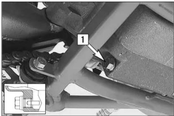
natural_image
Mechanical assembly diagram showing a bracket with labeled component '1' and inset detail (no readable text or symbols)Changing the engine oil \*
Note: When changing the engine oil, it is necessary to clean the short and long oil screens and to replace both oil filters (250-F: only one oil filter). Engine oil has been changed with the engine at an operating temperature.
! CAUTION
An engine at operating temperature and the engine oil it contains are very hot – do not burn or scald yourself.
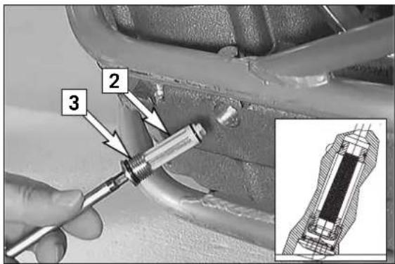
text_image
Technical diagram showing a hand using a screwdriver to adjust components, with numbered parts labeled 2 and 3.Place the motorcycle on a horizontal surface, remove the plug [1] and allow the oil to drain into a receptacle.
Clean plug (with magnet) thoroughly.
Once the entire oil has been drained, clean the sealing surface, mount the plug together with the sealing ring and tighten it to 20 Nm.
CLEANING THE SHORT OIL SCREEN
The short oil screen [2] is accommodated in the hex-socket plug [3] at the engine bottom. Insert a pin-type key into the plug and tap on the key a few times with a hammer in order to relieve the stress acting on the plug. Dismount the oil screen, clean the components thoroughly and blow compressed air through them. Check the O-rings for damage and, if necessary, replace them. Mount the oil screen together with the plug (oiled) again and tighten the plug to 10 Nm.
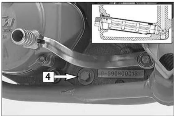
text_image
4 Φ-590K00018CLEANING THE LONG OIL SCREEN
The long oil screen is accommodated in the hexagon plug [4] adjacent to the engine number. Dismount the plug together with the oil screen, clean the components thoroughly and blow compressed air through them. Check the O-rings for damage and, if necessary, replace them.
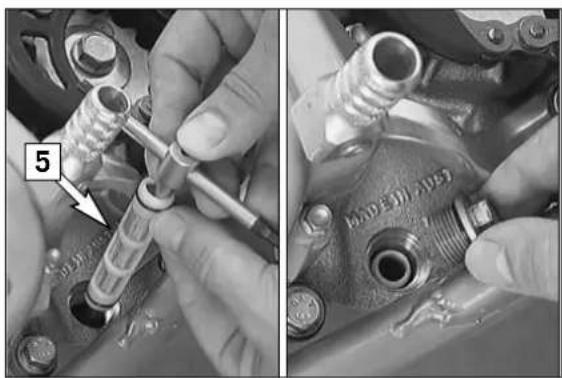
natural_image
Close-up of hands adjusting a mechanical component with a tool, showing part details (no visible text or symbols)To mount the long oil screen [5], place it on an approx. 300 mm (12 in) long pin-type key or a similar tool. Insert the pin-type key through the opening into the bore of the opposite engine casing wall. Then, push the oil screen into the engine casing as far as possible. Remove the pin-type key, mount the plug and tighten it to 15 Nm.
! CAUTION
The oil screen is mounted slightly downwards, incorrectly fitted, the screen looses its function and this can cause increased engine wear.
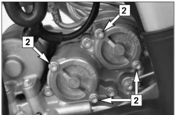
text_image
Technical diagram of a mechanical component with numbered callouts indicating parts of the valve or pump.Changing the oil filters
Place a receptacle underneath the engine to collect the drained oil. Remove the 4 screws [2] and dismount the two oil filter covers.
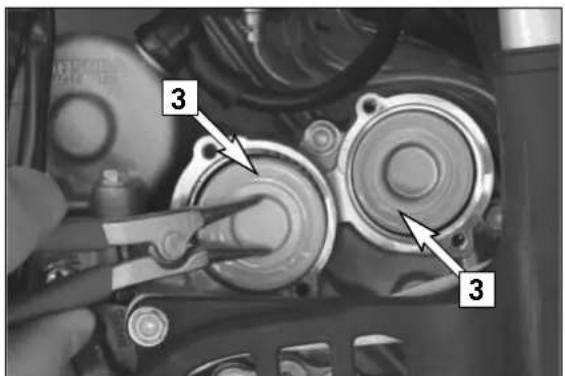
text_image
Close-up photo of mechanical components with numbered annotations pointing to specific partsUsing circlip pliers, pull the oil-filter inserts [3] out of the housing. Clean the oil filter cover, the sealing surfaces of the O-rings and the engine casing. Check the O-rings of the oil filter covers for damage and, if necessary, replace them.
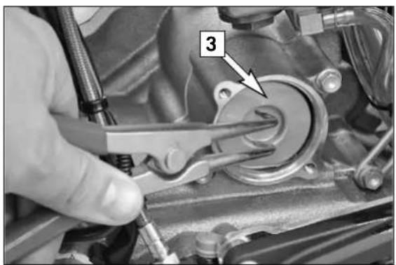
natural_image
Close-up of a mechanical component being adjusted with a tool, showing a numbered callout (3) and no visible text or symbols.NOTE:
The 250-F engine only has one oil filter insert [3].
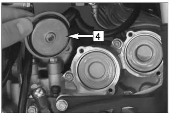
natural_image
Close-up of mechanical components with a hand adjusting a circular component (no visible text or symbols)Put the motorcycle on its side and fill the oil filter housings about halfway with engine oil. Fill oil filter with oil, place the long oil filter in the front and the short filter in the back of the filter box. Grease the O-rings [4] of the oil filter covers and mount the covers. Mount the screws and tighten them to 6 Nm.
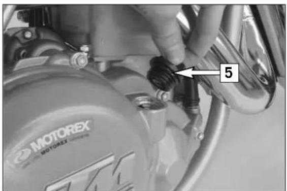
text_image
MOTOREX MOTOREX 5Return the motorcycle to an upright position.
Remove the oil dipstick [5] at the clutch cover and fill in 1.2 liters (250-F: 1.1 liters) of fully synthetic engine oil (Motorex Power Synt 4T 10W/50).
Start the engine and check all screwed connections and the oil filter cover for leaks.
Finally, check the engine oil level and, if necessary, correct it.
If you had the specified maintenance work on your motorcycle carried out, disturbances can hardly be expected. Should an error occur nevertheless, we advise you to use the troubleshooting chart in order to find the cause of error.
We would like to point out that many operations cannot be performed by yourself. In case of uncertainty, please contact a KTM-dealer.
| TROUBLE CAUSE REMEDY | ||
| Engine doesn't crank (E-starter). | Operating error | Turn on the emergency-OFF switch (Australia only) |
| Blown fuse | Dismount the left paneling and the filter box cover and replace the fuse in the starter relay. | |
| Discharged battery. | Recharge the battery and investigate the causes for discharging; contact a KTM dealer. | |
| Low outside temperature | Start the engine with the kickstarter | |
| Engine cranks but doesn't start (E-starter). | Operating error | Open fuel tap, tank fuel, actuate choke. Pay attention to starting information (see driving instructions). |
| Engine will not start (Kickstarter). | The motorcycle has been out of operation for a longer period of time. Therefore old fuel has accumulated in the float chamber | The easily inflammable components of the new fuels evaporate during longer periods of standing still.When the motorcycle has been out of operation for more than a week, it is therefore recommended to drain the old fuel from the float chamber. The engine will immediately start when the float chamber is filled with new fuel. |
| Fuel supply interrupted | Close fuel tap, loosen fuel hose at carburetor, lead into a basin and open fuel tap- if fuel leaks out, the carburetor may need cleaning- if no fuel leaks out, check tank ventilation, i.e. clean fuel tap | |
| Flooded engine | In order to "pump the engine free", pull the hand decompression lever, fully rev up the engine, actuate the kickstarter 5 to 10 times or actuate the E-starter 2 times for 5 seconds each. Then, start the engine as described above.If the engine fails to start, unscrew the spark plug and dry it. | |
| Sooty or wet spark plug | Clean and dry the spark plug or exchange it, respectively | |
| Electrode gap too large | Adjust spark plug electrode gap to 0.6 mm | |
| Spark plug connector or spark plug faulty | Dismount spark plug, connect ignition cable, hold to ground (blank place on engine) and actuate starter, a strong spark must be produced at the spark plug- If no spark is created replace the spark plug.- If the new spark plug doesn't produce a spark either, disconnect the spark plug connector from the ignition cable, hold it a distance of approx. 5 mm from ground and start.- If a spark now occurs, replace spark plug cap- If no spark is produced, control ignition system | |
| Short circuit cable scored in wiring harness, emergency OFF switch or short circuit button faulty | Dismount the fuel tank, disconnect the black/yellow cable from the cable of the emergency-OFF switch and the short-circuit button, respectively, and check the ignition spark. If a spark is generated, look for the problem in the short-circuit circuit. | |
| The plug connection of the CDI-unit, the pulse generator or the ignition coil has oxydized | Remove the seat and the fuel tank. Clean the plug con- nection and treat it with contact spray | |
| Water in carburetor or jets blocked | Dismount and clean the carburetor | |
| Engine fails to idle Glogged idling | Jet | Disassemble the carburetor and clean the jets |
| Incorrect adjustment of adjusting screws on carburetor | Have the carburetor adjusted | |
| Defective spark plug | Replace the spark plug | |
| Defective ignition system | Have the ignition system checked | |
| Engine does not rev high Carburetor fuel level too high because float needle valve is dirty or worn outLoose carburetor jetsElectronic ignition timing faulty | Dismount carburetor and check if worn outTighten jetsHave ignition system checked | |
| Engine will not reach full power Fuel supply partially interrupted or carburetor dirtyFloat leaksAir filter very dirtyExhaust system is not tight, deformed, or the silencer does not contain enough glass-fiber yarnValve gap too smallLoss of compression because hand decompressor has no playElectronic ignition timing faulty | Clean and check fuel system as well as carburetorReplace the floatClean or replace air filterCheck if exhaust is damaged, replace glasfiber yarn in exhaust silencerAdjust valve gapCheck setting of the hand decompression cableHave ignition system checked | |
| Engine stops or splutters in carburetor | Insufficient fuelEngine takes air out of control | Clean and check fuel system and carburettorCheck rubber sleeve and carburetor for tight fit |
| Engine gets too hot Insufficient cooling liquidNot enough air streamCooling system has not been bledRadiators very dirtyFoam formation in cooling systemBent cooling hoseThermostat defectiveBlown fan fuse (XC Desert)Defect thermoswitch (XC Desert)Fan defective (XC Desert) | Refill cooling liquid (see maintenance work), check cooling system for leaksDrive on briskly (electric fan can be retrofitted)Bleed cooling systemClean radiators with water jetReplace cooling liquid, use antifreeze liquid with brand nameShorten or replace cooling hoseDismount and check thermostat (opening temperature 70°C, (158°F) or replace itReplace fuse and check if fan operates properly (see below)Contact a KTM dealerCheck if fan operates properly. To do this, start the engine, then bypass the connections to the thermoswitch (bottom right radiator), contact a KTM dealer | |
| High oil consumption Hose of engine ventilation is bentEngine oil level too highMotor oil too thin (viscosity) | Dislocate i.e. replace non-buckling vetilation hoseCheck engine oil level and, if necessary, correct itUse thicker engine oil; see chapter “Engine oil” | |
| All switched on lamps blown out | Capacitor or voltage regulator faulty Dismount seat and fuel tank and check connections, have capacitor and voltage regulator checked | |
| Horn, flasher lights and E-starter do not work | Blown fuse in the starter relay Dismount left side paneling and filter box cover, replace fuse | |
| The battery is discharged The battery isn't charged by the generator because | Remove seat and fuel tank and check voltage regulator connections; voltage regulator and generator should be checked by a KTM dealer. | |
Clean your motorcycle regularly in order to maintain the beauty of its plastic surfaces.
The best manner would be to use warm water that has been mixed with a normal brand-name washing detergent and a sponge. The hard dirt can be removed before washing with the help of a soft water jet.
! CAUTION
If using a power washer, do not point the water jet at the electric components, plugs, cables, bearings, carburetor, etc. The high pressure will cause water to penetrate into the components and can cause them to malfunction or lead to premature wear.
- You should use normal brand-name detergents to clean the motorcycle. Especially dirty parts should also be cleaned with the help of a paint brush.
– Before cleaning with water, plug the exhaust pipe to prevent water ingress - After the motorcycle has been rinsed with a soft water jet, it should be dried by air pressure and a cloth. Drain the float chamber of the carburetor. Then take a short drive until the engine has reached the working temperature and also use the brakes. By warming these components, the residual water can evaporate from inaccessible parts of the engine and the brakes.
- Slide back the protective covers on the handlebar-mounted instruments so that any water that may have seeped into this part of the motorcycle is allowed to evaporate.
- Once the motorcycle has cooled down, oil or grease all sliding and bearing points. Treat the chain with a chain spray. Also oil the fuel tap.
- To avoid any failures in of the electric system, you should treat the emergency-OFF switch, short-circuit button, light switch and socket connectors with a contact spray.
CONSERVATION FOR WINTER OPERATION »
In the event that the motorcycle is also used in winter and on roads where one has to expect salt spraying, you will have to take precautions against the aggressive road salt.
– clean the motorcycle thoroughly and let it dry after each ride
- treat the engine, carburetor, swing arm, and all other bare or galvanized parts (except for brake discs) with a wax-based anti-corrosion agent.
WARNING
Keep the anti-corrosion agent from getting into contact with the brake discs, otherwise this will significantly reduce the braking power.
! CAUTION
After rides on salted roads, clean motorcycle thoroughly with cold water and let it dry well.
STORAGE >>
Should you wish to make a pause over a longer space of time, please observe the following instructions:
– Clean motorcycle thoroughly (see chapter: CLEANING)
- Change engine oil, short and long oil filters (old engine oil contains aggressive contaminants).
- Check antifreeze and amount of cooling liquid.
- Warm up the engine once again, close the fuel cock and wait until the engine dies. Then open the drain plug of the float chamber to remove the remaining fuel.
- Remove spark plug and fill in approx. 5 ccm of engine oil into the cylinder through the opening. Actuate kick-starter 10 times in order to distribute the oil onto the cylinder walls and mount the spark plug.
- Set piston to compression so that the valves will be closed (slowly operate the kickstarter until you can hear the automatic decompressor click (release))
- Let fuel flow out of tank into an appropriate container.
– Correct tire pressure.
– Lubricate pivot points of the control levers, foot rests, etc. as well as the chain.
– Service the shock absorber linkage
- Disassemble and charge battery (see chapter: BATTERY).
- The storage place should be dry and not subjected to excessive temperature fluctuations.
- Cover the motorcycle with an air permeated tarpaulin or blanket. Do not use airtight materials as a possible humidity might not be able to escape and could cause corrosion.
! CAUTION
It would be very bad to let the engine run for a short time during the storage period. The engine would not get warmed up enough and the thus developed steam would condense during the combustion process and cause the valves and exhaust to rust.
USE AFTER A PERIOD OF STORAGE
- Mount the charged battery (regard polarity).
- Set the time in the speedometer.
- Fill up tank with fresh fuel.
- Check motorcycle as before each start (see driving instructions).
- Take a short, careful test ride first.
NOTE: Before you put your motorcycle away for the winter, you should check all parts for their function and wear. Should any service jobs, repairs, or any refitting be necessary, you should have them carried out during the off-season (lower workload at mechanics' shops). This way, you can avoid the long waiting times at your mechanic at the beginning of the next biking season.
| ENGINE 250 XC-F 250 XCF-W, | EXC-F | |
| Design Liquid-cooled single cylinder 4-stroke engine | ||
| Displacement 249.51 ccm | ||
| Bore/Stroke 76 / 55 mm | ||
| Ratio 12.8 : 1 | ||
| Fuel unleaded fuel with at least RON 95 (USA = Premium PON 91) | ||
| Valve timing 4 valves controlled by finger levers and 2 camshafts, driven by a pair of spur gears and a tooth-type chain | ||
| Camshaft Intake: 770.36.009.100 / Exhaust: 770.36.110.100 | ||
| Valve diameter Intake 30.9 mm | ||
| Valve diameter Exhaust 26.5 mm | ||
| Valve clearance cold Intake 0.10 - 0.20 mm (0.004 - 0.008 in) | ||
| Valve clearance cold Exhaust | 0.12 - 0.22 mm (0.005 - 0.009 in) | |
| Crank shaft bearing 2 cylinder roller bearings | ||
| Connecting rod bearing needle bearing | ||
| Top end bearing bronze bushing | ||
| Piston | alluminium alloy forged | |
| Piston rings | 1 compression ring, 1 oil scraper ring | |
| Engine lubrication | pressure circulation lubrication with 2 rotor pumps | |
| Engine oil | full synthetic oil (Motorex Power Synt 4T 10W/50) | |
| Quantity of engine oil 1.1 liters | ||
| Primary drive | 22:68 | |
| Clutch | multiple disc clutch in oil bath, hydraulically operated (brake fluid DOT 5.1) | |
| Transmission claw shifted | 6-speed | 6-speed |
| 1st gear | 13:32 | 13:33 |
| 2nd gear | 15:30 | 17:33 |
| 3rd gear | 17:28 | 19:29 |
| 4th gear | 19:26 | 23:28 |
| 5th gear | 21:25 | 23:23 |
| 6th gear | 22:24 | 26:22 |
| Ignition system | contactless DC-CDI ignition with digital advanced system by KOKUSAN | |
| Generator | 12 V 150 W | |
| Spark plug | NGK CR 9 EBK | |
| Cooling system | liquid cooled, permanent rotation of cooling liquid through mechanically driven water pump | |
| Cooling liquid | 1.2 liters, 50% antifreeze, 50% destilled water, at least -25° (-13° F) | |
| Starting equipment | kick - electric starter | |
JASO T903 MA
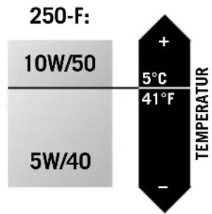
heatmap
| Temperature (F) | Value | |---|---| | 250-F: | + | | 5°C | 5°C | | 41°F | 41°F | | 5W/40 | - | | 10W/50 | 10W/50 |Engine oil
Only use fully synthetic engine oils that meet the JASO MA quality requirements (see information on the can).
KTM recommends Motorex Power Synt 4T in the 10W/50 viscosity (for temperatures over 5°C, 41°F) or 5W/40 (for temperatures under 5°C, 41°F).
! CAUTION
Poor oil quality or minor quantity cause early engine-wear.
| TIGHTENING TORQUES - ENGINE 250-F | ||
| Hexagon collar screw, engine case, clutch cover, ignition cover, water pump cover | M6 | 10 Nm |
| Oil drain plug | M12x1.5 | 20 Nm |
| Allen head plug, oil screen short | M16x1.5 | Oil + 10 Nm |
| Hexagon plug, oil screen long | M20x1.5 | 15 Nm |
| Collar screw for oil filter cover | M5 | 6 Nm |
| Plug pressure valve | M12x1.5 | 20 Nm |
| Screws, oil pump cover | M5 | Loctite 222 + 6 Nm |
| Hexagon collar screw, cylinder / cylinder head | M6 | 10 Nm |
| Cylinder head screw | M10 | Oil + 40/50 Nm |
| Hexagon collar screw, exhaust flange | M6 | Loctite 243 + 10 Nm |
| Valve cover screws | M6 | 10 Nm |
| Camshaft screw | M12x1 Loctite 243 + 80 Nm | |
| Collar screw/nut camshaft bearing support | M7 | Oil + 18 Nm |
| Hexagon nut, primary gear | M18x1.5 left | Loctite 243 + 150 Nm |
| Nut for inner clutch hub | M18x1.5 | Loctite 243 + 120 Nm |
| Hexagon collar screw, clutch spring | M6 | 10 Nm |
| Allan head screw, shift roller locking piece | M6 | Loctite 243 + 10 Nm |
| Hexagon collar screw, locking lever | M5 | Loctite 243 + 6 Nm |
| Locking screw for shift roller bearing | M6 | Loctite 243 + 6 Nm |
| Locking screw for main shaft bearing | M6 | Loctite 243 + 6 Nm |
| HH collar screw clip/tensioning rail | M6 | Loctite 243 + 10 Nm |
| Plug for chain tensioner | M24x1.5 | 25 Nm |
| Hexagon collar screw, stator XC, EXC | M6 | Loctite 243 + 8 Nm |
| Hexagon collar screw, E-starter | M6 | 10 Nm |
| Hexagon collar screw, pulser coil | M5 | Loctite 243 + 6 Nm |
| Hexagon collar nut, flywheel | M12x1 60 Nm | |
| Hexagon collar screw, bump part kickstarter | M6 | Loctite 243 + 10 Nm |
| Cable retaining bracket (ignition) | M6 | Loctite 243 + 6 Nm |
| Allan head screw, kickstarter | M8 | Loctite 243 + 25 Nm |
| Hexagon collar screw, shift lever | M6 | Loctite 243 + 10 Nm |
| Hexagon screw, engine sprocket | M10 | Loctite 243 + 60 Nm |
| Spark plug | M10 | 10-12 Nm |
| BASIC CARBURATOR SETTING | ||||
| 250 XC-F USA 250 XCF-W | USA 250 EXC-F 250 EXC-F SIXDAYS | |||
| Type | Keihin FCR-MX 3900G Keihin FCR-MX 3900G Keihin FCR-MX 3900G Keihin FCR-MX 3900G | |||
| Main jet 168 168 168 172 | ||||
| Jet needle OBETP OBEKT OBEKT | OBETP | |||
| Idling jet 40 40 40 40 | ||||
| Main air jet 200 200 200 200 | ||||
| Idling air jet 100 100 100 100 | ||||
| Needle position 5th from top 2nd | from top 2nd from top 5th from top | |||
| Starting jet | 85 85 85 85 | |||
| Mixture control screw open | 1.25 | 0.75 | 0.75 | 1.25 |
| Slide | 15 15 15 15 | |||
| Performance restrictor | - | - | Slide stop | - |
| Stop pump membrane | 858 / 2,15 mm | 858 / 2,15 mm | 858 / 2,15 mm | 858 / 2,15 mm |
| ENGINE 400 XC-W, EXC 450 XC 450 XC-W, EXC 525 XC 525 XC-W, EXC | |||||
| Design Liquid-cooled single cylinder 4-stroke engine with balancer shaft | |||||
| Displacement 398 cc 449 cc 448 cc 510 cc | |||||
| Bore/Stroke 89 / 64 mm | 95 / 63,4 mm | 89 / 72 mm 95 / 72 mm | |||
| Ratio 11 : 1 12 : 1 11 : 1 11 : 1 | |||||
| Fuel unleaded fuel with at least RON 95 (USA = Premium PON 91) | |||||
| Valve timing 4 valves over rocker arm and 1 overhead camshaft, camshaft drive through single chain | |||||
| Camshaft 595/0121 590/5521 590/5521 590/5521 | |||||
| Valve diameter Intake 35 mm | |||||
| Valve diameter Exhaust | 30 mm | ||||
| Valve clearence cold Intake | 0.10 - 0.15 mm (0,004 - 0,006 in) | ||||
| Valve clearence cold Exhaust | 0.10 - 0.15 mm (0,004 - 0,006 in) | ||||
| Crank shaft bearing | 2 cylinder roller bearing | ||||
| Connecting rod bearing | needle bearing | ||||
| Top end bearing | bronze bushing | ||||
| Piston alluminium alloy | cast | forged | cast | forged | |
| Piston rings | 1 compression ring, 1 oil scraper ring | ||||
| Engine lubrication | pressure circulation lubrication with two rotor pumps | ||||
| Engine oil | full synthetic oil (Motorex Power Synt 4T 10W/50) | ||||
| Quantity of engine oil | 1.25 liters | ||||
| Primary ratio | Primary ratio | ||||
| Clutch | multiple disc clutch in oil bath, hydraulically operated (Motorex Kupplungsfluid 75) | ||||
| Transmission claw shifted | 6-speed | 6-speed | 6-speed | 6-speed | 6-speed |
| Gear ratio1st Gear | 14:34 14:34 14:34 16:32 14:34 | ||||
| 2nd Gear 17:31 17:31 17:31 18:30 17:31 | |||||
| 3rd Gear | 19:28 20:28 19:28 20:28 19:28 | ||||
| 4th Gear | 22:26 22:26 22:26 22:26 22:26 | ||||
| 5th Gear | 24:23 24:24 24:23 24:24 24:23 | ||||
| 6th Gear | 26:21 21:18 26:21 21:18 26:21 | ||||
| Ignition system | contactless DC-CDI ignition with digital advanced system by KOKUSAN | ||||
| Generator | 12V 150W | ||||
| Spark plug | NGK DCPR 8 E | ||||
| Spark plug gap | 0.6 mm (0.02367 in) | ||||
| Cooling system | liquid cooled, permanent rotation of cooling liquid through mechanically driven water pump | ||||
| Cooling liquid | 1 liter, 50% antifreeze, 50% destilled water, at least -25° (-13° F) | ||||
| Starting equipment | kick - electric starter | ||||
JASO T903 MA
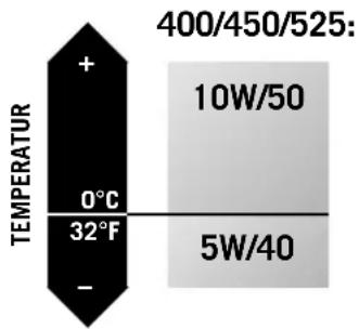
other
| TEMPERATURE | Value | |---|---| | + | 400/450/525: 10W/50 | | 0°C / 32°F | 5W/40 |Engine oil
Only use fully synthetic engine oils that meet the JASO MA quality requirements (see information on the can).
KTM recommends Motorex Power Synt 4T in the 10W/50 viscosity (for temperatures over 0°C, 32°F) or 5W/40 (for temperatures under 0°C, 32°F).
! CAUTION
Poor oil quality or minor quantity cause early engine-wear.
| BASIC CARBURATOR SETTING | ||
| 400 XC-W USA | 400 EXC RACING EU | |
| Type | Keihin FCR-MX 3900D | Keihin FCR-MX 3900E |
| Main jet 178 178 | ||
| Jet needle OBDVR OBDVR | ||
| Idling jet 42 42 | ||
| Main air jet 200 200 | ||
| Idling air jet 100 100 | ||
| Needle position 1st from top 1st from top | ||
| Starting jet 85 85 | ||
| Mixture control screw open 1.25 1.25 | ||
| Slide 15 15 | ||
| Performance restrictor | - | Slide stop |
| Stop pump membrane | 858 / 2.15 mm | 858 / 2.15 mm |
| BASIC CARBURATOR SETTING | |||
| 450 XC, XC-W USA | 450 EXC RACING EU / AUS | 450 EXC RACING SIXDAYS EU | |
| Type | Keihin FCR-MX 3900E | Keihin FCR-MX 3900E | Keihin FCR-MX 3900E |
| Main jet 178 178 182 | |||
| Jet needle OBDVR OBDVR OBDTR | |||
| Idling jet 42 42 42 | |||
| Main air jet 200 200 200 | |||
| Idling air jet 100 100 100 | |||
| Needle position | 3rd from top | 3rd from top | 4th from top |
| Starting jet 85 85 85 | |||
| Mixture control screw open 1.25 1.25 | 5 2.0 | ||
| Slide 15 15 15 | |||
| Performance restrictor | - | Slide stop | - |
| Stop pump membrane | 858 / 2.15 mm | 858 / 2.15 mm | 858 / 2.15 mm |
| BASIC CARBURATOR SETTING | |||
| 525 XC, XC-W USA | 525 EXC RACING EU 525 EXC RACING AUS 525 XC DESERT RACING EU | 525 EXC RACING SIXDAYS EU | |
| Type | Keihin FCR-MX 3900F | Keihin FCR-MX 3900F | Keihin FCR-MX 3900F |
| Main jet 178 178 182 | |||
| Jet needle OBDVT | OBDVT | OBDTR | |
| Idling jet 42 42 42 | |||
| Main air jet 200 200 200 | |||
| Idling air jet 100 100 100 | |||
| Needle position | 3rd from top | 3rd from top | 5th from top |
| Starting jet 85 85 85 | |||
| Mixture control screw open 1.25 1.25 | 5 2.0 | ||
| Slide 15 15 15 | |||
| Performance restrictor | - | Slide stop | - |
| Stop pump membrane | 858 / 2.15 mm | 858 / 2.15 mm | 858 / 2.15 mm |
| TIGHTENING TORQUES - ENGINE 400/450/525 | ||
| Hexagon collar screw, engine case, clutch cover, ignition cover | M6 | 10 Nm |
| Oil drain plug M12x1.5 20 Nm | ||
| Allan head plug, oil screen short M16x1.5 Oil + 10 Nm | ||
| Hexagon plug, oil screen long M20x1.5 15 Nm | ||
| Collar screw for oil filter cover M5 6 Nm | ||
| Plug pressure valve M12x1.5 20 Nm | ||
| Jet screw and hollow screw, oil line M8 10 Nm | ||
| Screws, oil pump cover M5 Loctite 222 + 6 Nm | ||
| Hexagon collar screw, cylinder head top section M6 10 Nm | ||
| Hex-collar screw, cylinder head top section, water pump cover M6 10 Nm | ||
| Hexagon collar screw, exhaust flange M6 Loctite 243 + 10 Nm | ||
| Cylinder head screw M10 Oil + 40/50 Nm | ||
| Allan head screw, camshaft gear | M8 Loctite 243 + 28 Nm | |
| Allan head screw, cap rocker arm | M5 6 Nm | |
| Counter nuts, valve adjustment screw | M6x0.75 11 Nm | |
| Allan head screw, primary gear, free wheel | M6 Loctite 648 + 16 Nm | |
| Hexagon nut, primary gear | M20x1.5 left | Loctite 243 + 150 Nm |
| Allan head screw, balancer shaft gear | M6 Loctite 243 + 10 Nm | |
| Nut for inner clutch hub | M18x1.5 Loctite 243 + 120 | Nm |
| Hexagon collar screw, clutch spring | M6 Loctite 243 + 8 Nm | |
| Allan head screw, shift roller locking piece | M6 Loctite 243 + 10 Nm | |
| Hexagon collar screw, locking lever | M5 Loctite 243 + 6 Nm | |
| Hexagon collar screw, shift roller | M5 Loctite 243 + 6 Nm | |
| Hexagon collar screw securing guide, chain guide, chain tensioner | M6 | Loctite 243 + 6 Nm |
| Hexagon collar screw, clip | M5 Loctite 243 + 6 Nm | |
| Hexagon collar screw, chain adjuster | M6 | 10 Nm |
| Hexagon collar screw, stator XC/EXC | M6 Loctite 243 + 10 Nm | |
| Hexagon collar screw, pulser coil | M5 Loctite 243 + 6 Nm | |
| Hexagon collar nut, flywheel | M12x1 | 60 Nm |
| Hexagon collar screw, bump part kickstarter | M6 Loctite 243 + 10 Nm | |
| Hexagon collar screw, spring hanger kickstarter | M6 | Loctite 243 + 10 Nm |
| Hexagon collar screw E-starter | M6 10 Nm | |
| Hexagon collar screw, hanger vent hose | M6 Loctite 243 + 10 Nm | |
| Allan head screw, kickstarter | M8 Loctite 243 + 25 Nm | |
| Hexagon collar screw, shift lever | M6 Loctite 243 + 10 Nm | |
| Hexagon screw, engine sprocket | M10 Loctite 243 + 60 Nm | |
| Spark plug | M10 10-12 Nm | |
| Spark plug | M12x1.25 | 20 Nm |
| CHASSIS 250/400/450/525 | |||||
| Frame Central tube chrome-moly-steel frame | |||||
| Fork WP Suspension - 4860 MXMA / MXMA + PA | |||||
| Wheel travel front/rear 300/335 mm | |||||
| Rear suspension WP Suspension - 5018 PDS MCC / DCC, aluminium swing arm | |||||
| Front brake Disk brake with carbon-steel brake disc ∅ 260 mm (10.2 in), brake caliper floated | |||||
| Rear brake Disk brake with carbon-steel brake disc ∅ 220 mm (8.7 in), brake caliper floated | |||||
| Brake disc Wear limit max. 2,5 mm front and 3,5 mm rear | |||||
| Front tires | XC, XC-F, XC-W, XCF-W EXC, EXC-F80/100-21" 90/90-21" | ||||
| Air pressure offroad | 1,0 bar | ||||
| Air pressure road | 1,5 bar | ||||
| Rear tires | 250 XC-F, XCF-W 250 EXC-F 400/450/525 XC, XC-W 400/450/525 EXC100/100-18" 120/90-18" 110/100-18" 140/80-18" | ||||
| Air pressure offroad | 1,0 bar | ||||
| Air pressure road | 2,0 bar | ||||
| Fuel tank capacity | 250 XC-F, XCF-W 250 EXC-F EU 400/450/525 450/525 XC, XC-W 525 XC250 EXC-F AUS EXC EU 450/525 EXC AUS DESERT RACING8,5 liters (2.2 US gal) 7 liters (2 US gal) 8 liters (2.1 US gal) 9.5 liters (2.5US gal) 13 liters (3.5 US gal) | ||||
| Final drive ratio | 250 XC-F 250 XCF-W 250 EXC-F 400/450/525 400/450/525 EXC13:48 13:52 14:38 XC, XC-W 525 XC DES. RAC.14:50 15:45 | ||||
| Chain | 5/8 x 1/4" | ||||
| Available final sprockets | 38, 40, 42, 45, 48, 49, 50, 51, 52 | ||||
| Bulbs (EXC) | headlight 12V 35/35W (socket BA20D)parking light 12V 5W (socket W2, 1x9,5d)brake - rear light 12V 21/5W (socket BaY15d)flasher light 12V 10W (socket Ba15s) | ||||
| Battery | maintenance-free battery 12V 4Ah | ||||
| Steering head angle | 63.5° | ||||
| Wheel base 250: 1475 ± | 10 mm (58 ± 0.4 in) 400/450/525: 1481 ± 10 mm (58.3 ± 0.4 in) | ||||
| Seat height, unloaded | 925 mm (36.5 in) | ||||
| Ground clearance, unloaded | 380 mm (15.1 in) | ||||
| Weight (without fuel) | 250: approx. 107 kg (235.4 lbs) 400/450/525: approx. 113 kg (248.6 lbs) | ||||
| STANDARD ADJUSTMENT - FORK | ||||
| 250 XCF-W250 EXC-F | 400/450/525 XC-W400/450/525 EXC525 XC DESERT RACING | 250 XC-F250 EXC-F SIXDAYS | 450/525 XC450/525 EXC SIXDAYS | |
| WP 4860 MXMA14187C04 | WP 4860 MXMA14187C06 | WP 4860 MXMA + PA14187C28 | WP 4860 MXMA + PA14187C29 | |
| Compression adjuster 20 20 18 | 18 | |||
| Rebound adjuster 20 15 20 20 | ||||
| Spring 4.2 N/mm 4.4 N/mm 4.4 | N/mm 4.6 N/mm | |||
| Spring preload -- 2 turns 2 turns | ||||
| Air chamber length 110 mm 110 | mm 110 mm 110 mm | |||
| Fork oil SAE 5 SAE 5 SAE 5 SAE | 5 | |||
| STANDARD ADJUSTMENT - SHOCK ABSORBER | ||||
| 250 XCF-W250 EXC-F | 400/450/525 XC-W400/450/525 EXC525 XC DESERT RACING | 250 XC-F250 EXC-F SIXDAYS | 450/525 XC450/525 EXC SIXDAYS | |
| WP 5018 PDS MCC12187C04 | WP 5018 PDS MCC12187C06 | WP 5018 PDS DCC12187C28 | WP 5018 PDS DCC12187C29 | |
| Compression adjuster 15 15 15 | LS (low speed) | 1.0 HS (high speed) | 15 LS (low speed)1.0 HS (high speed) | |
| Rebound adjuster 25 25 24 24 | ||||
| Spring 76/250 80/250 76/250 | 80/250 | |||
| Spring preload 5 mm 5 mm 5 mm | 5 mm | |||
| TIGHTENING TORQUES - CHASSIS | ||
| Collar screw, front wheel spindle M24x1,5 40 Nm | ||
| Brake caliper, front | M8 | Loctite 243 + 25 Nm |
| Brake caliper, FTE radial front | M10x1,25 | Loctite 243 + 40 Nm |
| Brake disks | M6 | 14 Nm |
| Clamping screws, upper fork bridge XC-W, EXC | M8 | 20 Nm |
| Clamping screws, lower fork bridge XC-W, EXC | M8 | 15 Nm |
| Clamping screws, upper fork bridge XC, EXC SIXDAYS | M8 | 17 Nm |
| Clamping screw, steering stem XC, EXC SIXDAYS | M8 | Loctite 243 + 17 Nm |
| Clamping screws, lower fork bridge XC, EXC SIXDAYS | M8 | 12 Nm |
| Clamping screws, fork stubs | M8 | 15 Nm |
| Hexagon nut, swing arm bolt | M16x1,5 100 Nm | |
| Hexagon collar screw, handlebar clamp | M8 | 20 Nm |
| Allan head screw, handlebar support | M10 | Loctite 243 + 40 Nm |
| Shock absorber, top | M12 | Loctite 243 + 70 Nm |
| Shock absorber, bottom | M12 | Loctite 243 + 70 Nm |
| Collar nut, swing arm bolt | M20x1,5 80 Nm | |
| Sprocket Screws | M8 | Loctite 243 + 35 Nm |
| Ball joint for push rod | M6 | 10 Nm |
| Engine mounting bolt | M10 | 60 Nm |
| Engine brace | M8 | 33 Nm |
| Spoke nipple | M4,5 / M5 | 5 Nm |
| Screw adjusting ring spring preload shock abs. | M6 | 8 Nm |
| Other screws on chassis | M6 | 10 Nm |
| M8 | 25 Nm | |
| M10 | 45 Nm | |
| Other collar nuts on chassis | M6 | 15 Nm |
| M8 | 30 Nm | |
| M10 | 50 Nm | |
Page
Activating and deactivating display modes .....9
Adjusting the free travel at the hand brake lever .....36
Adjusting the mixture control screw ....47
Adjusting the throttle cables 45
Basic information on carburetor wear ....47
Basic suspension setup for the weight of the driver .....28
Battery 41
Bleeding of the hydraulic clutch .....46
Bleeding the cooling system (250-F) .....44
Bleeding the cooling system (400/450/525) .....43
Braking 20
Breather plug front fork ....30
Carburetor - Adjust idling (Keihin-FCRMX 37/39/41) .....47
Chain maintenance....34
Chain wear 34
Changing the basic position of the foot brake pedal .....37
Changing the engine oil 49
Changing the fork offset (caster) (XC, EXC SIXDAYS) .....31
Changing the oil filters ....50
Changing the original position of the clutch lever .....46
Changing the spring preload on the telescopic fork
(XC, EXC SIXDAYS)....29
Changing the spring preload on the telescopic fork
(XC-W/EXC) 29
Changing the spring preloading of the shock absorber .....27
Chassis number 5
Check chain tension 33
Check the following before each start .....18
Check/set distance of the magnetic sensor .....40
Checking and adjusting the steering head bearing .....30
Checking spoke tension ....39
Checking the basic setup of the telescopic fork .....29
Checking the brake fluid level - front brake .....36
Checking the coolant level ....43
Checking the engine oil level .....48
Checking the float level (float height) .....47
Checking the front brake pads . . . . . . . . . . . . . . . . . . . . . . . . . . . . . . . . . . . . . . . . . . . . . . . . . 36
Checking the oil level of the hydraulic clutch (250-F) .....46
Checking the oil level of the hydraulic clutch (400/450/525) . .46
Checking the rear brake fluid level .....37
Checking the rear brake pads ....38
Checking the shock absorber and spring .....28
Choke 13
Cleaning 53
Cleaning the air filter 45
Cleaning the dust sleeves of the telescopic fork .....30
Cleaning the spark arrester (XC-W USA) .....44
Clutch lever 6
Combination switch (EXC) 6
Compression damping of fork .....15
Compression damping of shock absorber
(XC, EXC SIXDAYS)....15
Compression damping of shock absorber (XC-W, EXC) .....16
Conservation for winter operation ....53
Cooling system 43
Correct chain tension ....33
Determining the riding sag of the shock absorber .....28
Determining the static sag of the shock absorber .....28
Dismounting and mounting the front wheel .....38
Dismounting and mounting the rear wheel .....39
Draining the float chamber of the carburetor .....48
Driving instructions....18
Electronic speedometer 8
Emergency OFF switch (EXC Australia) .....7
Page
Engine number, engine type ....5
Engine oil 49
Filler cap (bayonet cap)....13
Filler cap (screw cap) 13
Flasher switch 7
Foot brake pedal 14
Fuel 20
Fuel tap....13
Fuse 42
General information about KTM disc brakes .....35
General tips and warnings for starting the motorcycle .....17
Hand brake lever 6
Headlamp switch (XC-W) 7
How to change the handlebar position .....32
Important information 2
Indicator lamps 7
Instructions for initial operation .....17
Introduction 1
Kickstarter 14
Kilometers or miles 11
Maintenance work on chassis and engine .....27
Oil circuit (250-F) 48
Oil circuit (400/450/525) 48
Operation instruments 6
Overview of the electronic speedometer functions .....12
Periodic maintenance 21
Pivot bearing 27
Rebound damping of fork 15
Rebound damping of shock absorber .....16
Refilling the front brake fluid reservoir . . . . . . . . . . . . . . . . . . . . . . . 36
Refilling the rear brake fluid reservoir . . . . . . . . . . . . . . . . . . . . . . . . . . . . . 37
Replacing fork springs .....29
Replacing headlight lamp/parking light lamp .....42
Replacing the battery of the digital speedometer .....40
Replacing the front brake pads ....37
Replacing the glassfiber yarn packing of the silencer .....44
Replacing the rear brake pads . . . . . . . . . . . . . . . . . . . . . . . . . . . . . . . . . . . . . . . . . . . . . 38
Running in the XC/EXC models .....17
Serial number locations 5
Setting the clock 12
Shift lever 14
Shifting/Riding 19
Short circuit button (XC) 6
Side stand 14
Starter button 7
Starting off 19
Starting when the engine is cold .....18
Starting when the engine is warm .....19
Steering lock 14
Stopping and parking 20
Storage 53
Table of contents 4
Technical Data – Chassis .....59
Technical Data – Engine ....54
Tires, air pressure 40
Troubleshooting ....51
Use after a period of storage .....53
What to do when the engine is „flooded“ .....19
Wiring diagram ......appendix
WS (wheel size) 8
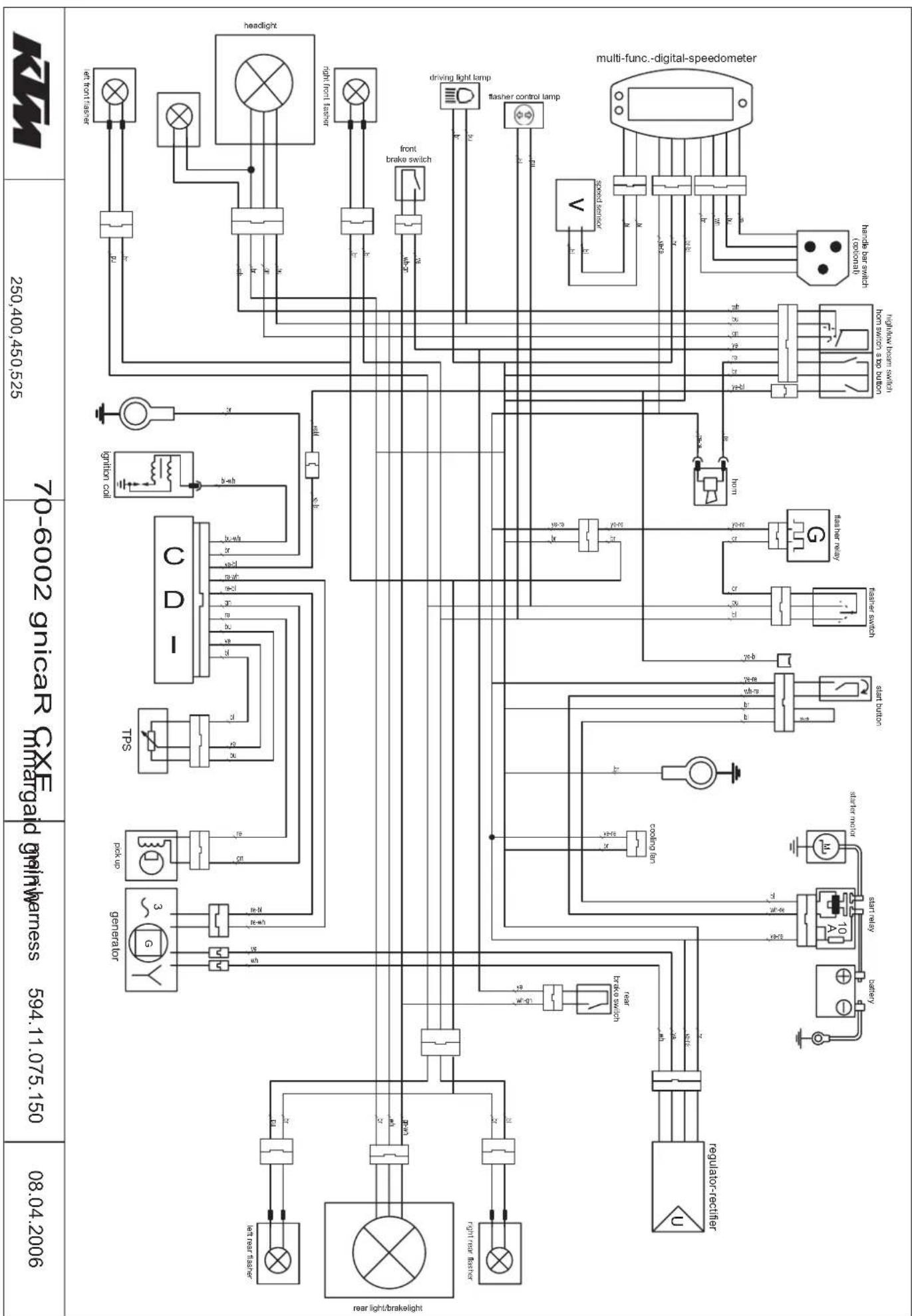
flowchart
graph TD
    A["70-6002 gincar CXF"] --> B["Generator"]
    A --> C["TPS"]
    A --> D["PTP"]
    A --> E["PTP"]
    A --> F["PTP"]
    A --> G["PTP"]
    A --> H["PTP"]
    A --> I["PTP"]
    A --> J["PTP"]
    A --> K["PTP"]
    A --> L["PTP"]
    A --> M["PTP"]
    A --> N["PTP"]
    A --> O["PTP"]
    A --> P["PTP"]
    A --> Q["PTP"]
    A --> R["PTP"]
    A --> S["PTP"]
    A --> T["PTP"]
    A --> U["PTP"]
    A --> V["PTP"]
    A --> W["PTP"]
    A --> X["PTP"]
    A --> Y["PTP"]
    A --> Z["PTP"]
    A --> AA["PTP"]
    A --> AB["PTP"]
    A --> AC["PTP"]
    A --> AD["PTP"]
    A --> AE["PTP"]
    A --> AF["PTP"]
    A --> AG["PTP"]
    A --> AH["PTP"]
    A --> AI["PTP"]
    A --> AJ["PTP"]
    A --> AK["PTP"]
    A --> AL["PTP"]
    A --> AM["PTP"]
    A --> AN["PTP"]
    A --> AO["PTP"]
    A --> AP["PTP"]
    A --> AQ["PTP"]
    A --> AR["PTP"]
    A --> AS["PTP"]
    A --> AT["PTP"]
    A --> AU["PTP"]
    A --> AV["PTP"]
    A --> AW["PTP"]
    A --> AX["PTP"]
    A --> AY["PTP"]
    A --> AZ["PTP"]
    A --> BA["PTP"]
    A --> BB["PTP"]
    A --> BC["PTP"]
    A --> BD["PTP"]
    A --> BE["PTP"]
    A --> BF["PTP"]
    A --> BG["PTP"]
    A --> BH["PTP"]
    A --> BI["PTP"]
    A --> BJ["PTP"]
    A --> BK["PTP"]
    A --> BL["PTP"]
    A --> BM["PTP"]
    A --> BN["PTP"]
    A --> BO["PTP"]
    A --> BP["PTP"]
    A --> BQ["PTP"]
    A --> BR["PTP"]
    A --> BS["PTP"]
    A --> BT["PTP"]
    A --> BU["PTP"]
    A --> BV["PTP"]
    A --> BW["PTP"]
    A --> BX["PTP"]
    A --> BY["PTP"]
    A --> BZ["PTP"]
    A --> CA["PTP"]
    A --> CB["PTP"]
    A --> CC["PTP"]
    A --> CD["PTP"]
    A --> CE["PTP"]
    A --> CF["PTP"]
    A --> CG["PTP"]
    A --> CH["PTP"]
    A --> CI["PTP"]
    A --> CJ["PTP"]
    A --> CK["PTP"]
    A --> CL["PTP"]
    A --> CD
    A --> CD
    style 70-6002 gincar CXF fill:#f9f,stroke:#333
    style 250,400,450,525 fill:#ccf,stroke:#333
    style 08,04,2006 fill:#cfc,stroke:#333
    style 70-6002 gincar CXF fill:#ffc,stroke:#333
    style 250,400,450,525 fill:#fcc,stroke:#333
    style 08,04,2006 fill:#fcc,stroke:#333
    style 70-6002 gincar CXF fill:#fff,stroke:#333
    style 250,400,450,525 fill:#fff,stroke:#333
    style 08,04,2006 fill:#fff,stroke:#333
    style 70-6002 gincar CXF fill:#fff,stroke:#333
    style 250,400,450,525 fill:#fff,stroke:#333
    style 08,04,2006 fill:#fff,stroke:#333
    style 70-6002 gincar CXF fill:none,stroke:none
    style 250,400,450,525 fill:none,stroke:none
    style 08,04,2006 fill:none,stroke:none
    style 70-6002 gincar CXF fill:none,stroke:none
    style 250,400,450,525 fill:none,stroke:none
    style 08,04,2006 fill:none,stroke:none
    style 70-6002 gincar CXF fill:none,stroke:none
    style 250,400,451,525 fill:none,stroke:none
    style 08,04,2006 fill:none,stroke:none
    style 70-6002 gincar CXF fill:none,stroke:none
    style 250,400,451,525 fill:none,stroke:none
    style 08,04,2006 fill:none,stroke:none
    style 70-5999 gincar CXF fill:none,stroke:none
    style 25999gincar CXF fill:none,stroke:none
    style 71999gincar CXF fill:none,stroke:none
    style 19999gincar CXF fill:none,stroke:none
    style 19999gincar CXF fill:none,stroke:none
    style 19999gincar CXF fill:none,stroke:none
    style 19999gincar CXF fill:none,stroke:none
    style 19999gincar CXF fill:none,stroke:none
    style 19999gncar CXF fill:none,stroke:none
    style 19999gncar CXF fill:none,stroke:none
    style 19999gncar CXF fill:none,stroke:none
    style 19999gncar CXF fill:none,stroke:none
    style 19999gncar CXF fill:none,stroke:none
    style 19999gncar CXF fill : note: The image contains a diagram of multiple functional blocks (e.g., 'regulator-rectifier', 'solder-noise', 'current-limit', etc.) with labels for the components. The diagram is labeled 'multi-func - digital-speedometer'.
→ ANHANG – APPENDICE APPENDIX – APÉNDICE
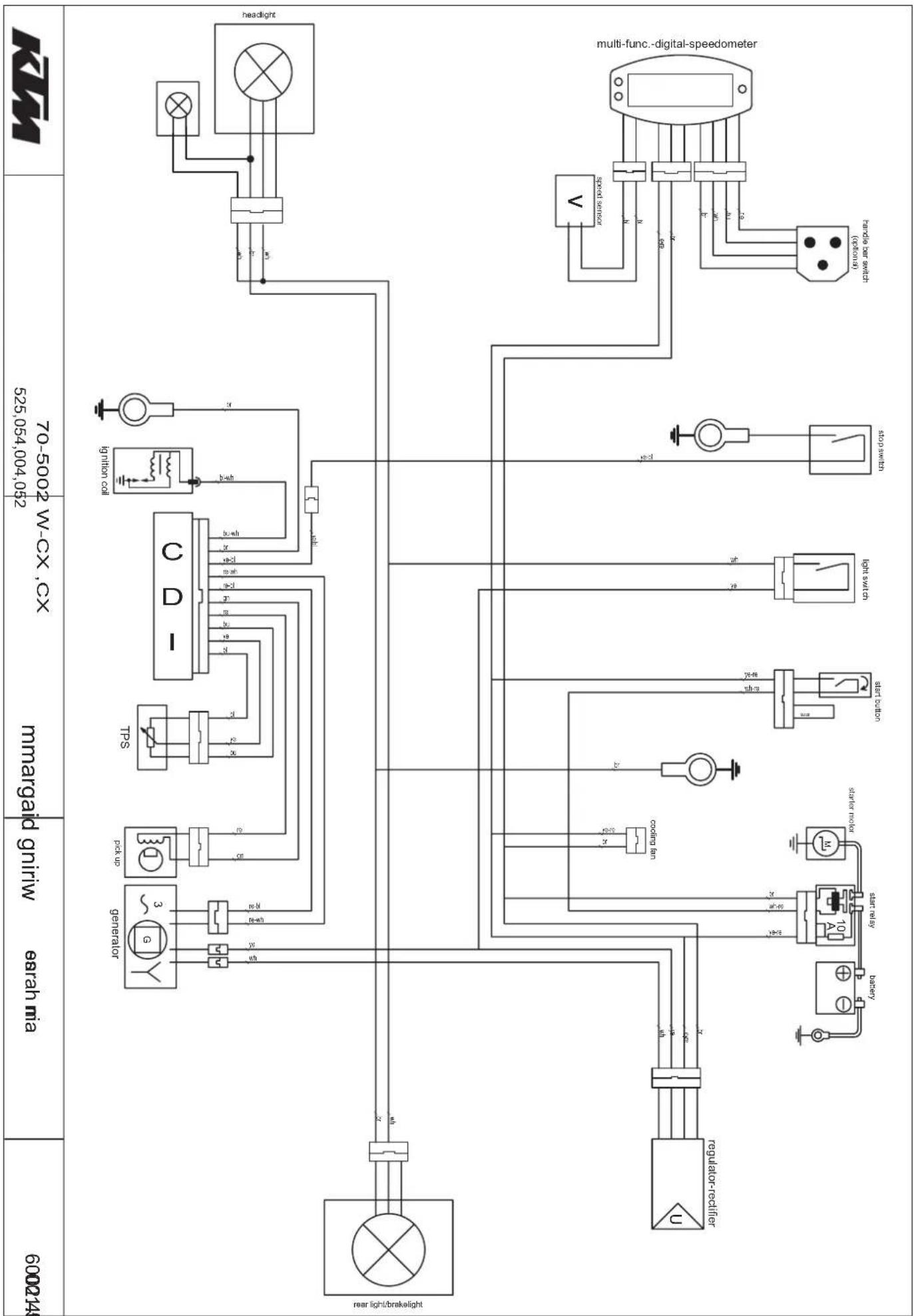
flowchart
graph TD
    A["70-5002 W-CX, CX 525,054,004,052"] --> B["Generator"]
    C["marginal giriwi"] --> D["TPS"]
    D --> E["ngition coil"]
    E --> F["stop switch"]
    F --> G["kift switch"]
    G --> H["stator coil"]
    H --> I["ster relay"]
    I --> J["cooling fan"]
    J --> K["regulator-settiffer"]
    K --> L["control"]
    L --> M["control"]
    M --> N["multi-func-digital-speedometer"]
    O["600243"] --> P["control panel"]
    Q["70-5002 W-CX, CX"] --> R["Generator"]
    S["marginal giriwi"] --> T["TPS"]
    U["multi-func-digital-speedometer"] --> V["stop switch"]
    V --> W["kift switch"]
    W --> X["cooling fan"]
    X --> Y["regulator-settiffer"]
    Z["control panel"] --> AA["control panel"]
    AB["marginal giriwi"] --> AC["control panel"]