85 XC (2008) - Motorcycle KTM - Free user manual and instructions
Find the device manual for free 85 XC (2008) KTM in PDF.


User questions about 85 XC (2008) KTM
0 question about this device. Answer the ones you know or ask your own.
Ask a new question about this device
Download the instructions for your Motorcycle in PDF format for free! Find your manual 85 XC (2008) - KTM and take your electronic device back in hand. On this page are published all the documents necessary for the use of your device. 85 XC (2008) by KTM.
USER MANUAL 85 XC (2008) KTM
natural_image
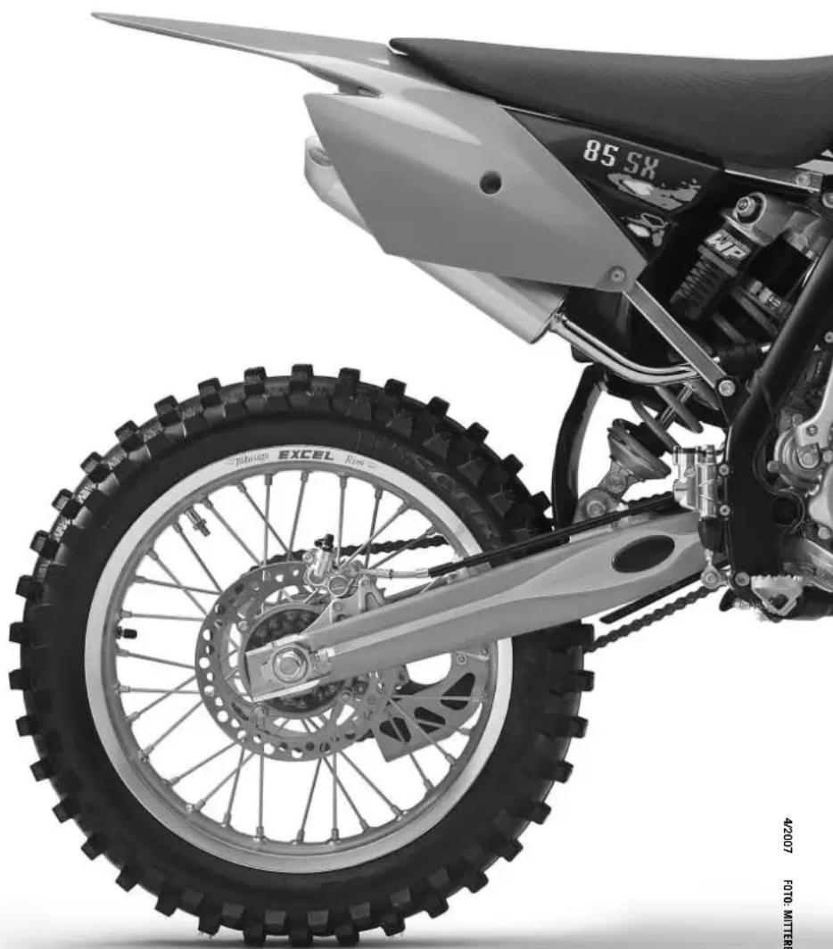
Side profile of a Kom Om-KAM motorcycle with visible tread, front wheel, and side gear (no text or symbols)Now you own a modern motorcycle that you and your youngster will certainly enjoy, provided that you service and maintain it properly.
Please insert the serial numbers of the motorcycle below
Chassis number
Engine number
Stamp of dealer
All information contained is without obligation. KTM-Sportmotorcycle AG particularly reserves the right to modify any equipment, technical specifications, prices, colors, shapes, materials, services, service work, constructions, equipment and the like so as to adapt them to local conditions or to cancel any of the above items, all without previous announcement and without giving reasons. KTM may stop manufacturing certain models without previous notice. KTM shall not be held liable for any deviations of availability and/or ability to deliver, illustrations, descriptions, printing and/or other errors. The illustrated models partly contain extra equipment, which is not applied to standard models.
© 2007 by KTM-SPORTMOTORCYCLE AG, Mattighofen AUSTRIA; All rights reserved; Reprint, also in extracts, with written allowance of KTM-SPORTMOTORCYCLE AG, Mattighofen only.

In accordance with the international quality management ISO 9001 standard, KTM uses quality assurance processes that lead to the highest possible product quality.
INTENDED PURPOSE
KTM mini-sports motorcycles are designed and constructed to resist the usual wear and tear of normal use in competitions.
The motorcycles comply with the regulations and categories currently in effect with the leading international motorcycle associations.
OWNER'S MANUAL
Please read this manual thoroughly before letting your youngster ride the motorcycle for the first time. This manual contains important information and recommendations that will help you and your youngster to operate and handle the motorcycle properly. In the interest of everybody involved, we urge you to pay particular attention to instructions and information marked as follows:
WARNING
- Ignoring these instructions can be dangerous to life and limb!
! CAUTION
- Ignoring these instructions may damage parts of the motorcycle or impair the motorcycle's traffic safety!
This manual contains important information on the operation and maintenance of your new KTM motorcycle. It went to press describing your model's latest state of development. Nevertheless, the descriptions may deviate slightly from the current design as our motorcycles are permanently improved. The Owner's Manual is an integral part of the motorcycle and must be handed over to the new owner when the motorcycle is sold.
SERVICE
Observance of the service, maintenance and tuning instructions for the engine and chassis specified in the Owner's Manual is a prerequisite for faultless operation and the avoidance of premature wear. An improperly tuned chassis can lead to damage and breakage of the chassis components (see chapter on checking the basic chassis setting).
The use of the motorcycle under extreme conditions, e.g. on extremely muddy and wet terrain, can lead to higher than average wear on components such as the drive train or the brakes. In this case it may become necessary to service or replace wear parts before the service limit specified in the maintenance schedule has been reached.
We expressly point out that work marked with an asterisk (*) in the chapter "Maintenance work on the chassis and engine" must be performed by a KTM workshop. If maintenance work should become necessary during a competition, it must be performed by a trained mechanic.
Please strictly observe the prescribed running-in periods and inspection and maintenance intervals.
Compliance with these instructions will significantly prolong the life of your motorcycle.
WARRANTY
The service work specified in the "Lubrication and Maintenance Schedule" must be performed by a KTM workshop and recorded in the service manual otherwise claims under the warranty shall become void. No claims can be filed under the warranty for damage or consequential damage caused by manipulations or conversions to the motorcycle.
AUTOMOTIVE FLUIDS
The fuels and lubricants specified in the Owner's Manual or automotive fluids with equivalent specifications must be used in accordance with the maintenance schedule.
SPARE PARTS, ACCESSORIES
For the safety of your child, only use spare parts and accessories approved by KTM. KTM shall not assume any liability for other products or consequential damage resulting from the use of such products. When special needs arise, please contact a KTM dealer, who will seek the assistance of the KTM importer if necessary.
SAFETY
Parents should keep in mind that the safety of their youngsters always depends on the efforts made by the parents to ensure that the motorcycle is kept in good working order and only used on safe terrains. Nevertheless, driving the motorcycle, like driving any other vehicle, involves a potential risk. Therefore, please make sure that all fundamental precautions are taken. Please also read the „INFORMATION ON SAFE DRIVING FOR PARENTS“ on page 4.
TRANSPORT
When transporting your motorcycle, secure it with elastic straps or other mechanical devices in an upright position. Be sure that the fuel tap is closed. If the motorcycle topples over, fuel can flow out of the carburetor or fuel tank.
ENVIRONMENT
Riding an off-highway motorcycle is a wonderful form of outdoor recreation and we certainly hope that you and your youngsters will enjoy it to the full. However, this enjoyable outdoor activity can cause environmental problems or lead to conflicts with other people. Responsible use of the motorcycle will prevent such problems and conflicts. You can contribute to securing the future of motorcycling by making sure that you and your youngsters only use the motorcycle within the limits established by the applicable laws, making environmental protection one of your top priorities and never violating other people's rights.
In this spirit, we hope that you and your youngsters will always safely enjoy your motorcycle!
KTM-SPORTMOTORCYCLE AG
5230 MATTIGHOFEN, AUSTRIA
Attachments: 1 spare parts manual chassis & engine
natural_image
Cartoon illustration of a motorcyclist riding a dirt bike, giving a thumbs-up (no text or symbols)The 85/105 SX/XC mini motorcycles are off-road motorcycles designed for one person only. They are not allowed on public roads.
The vehicle dimensions and components are designed for children from 10 to 15 years of age with a maximum weight of 75 kg (33,98 lb).
- Have your youngster wear proper protective gear whenever he or she rides the motorcycle: helmet, eye protection, chest, back, arm and leg protectors, gloves and boots. To set a good example, be sure to wear protective gear yourself whenever riding a motorcycle!
- Before your youngster takes his or her first ride, explain how each of the controls works and check if your youngster has understood what you explained. We recommend to review the entire owner's manual with your youngster item by item, paying particular attention to the specially marked warnings and pointing out the danger of injury.
- Instruct your youngster about riding and falling techniques, explain how the motorcycle will respond to shifting of the rider's weight, etc.
- Before starting the motorcycle for the first time check whether the basic fork and shock absorber settings are suitable for your child's weight (see chapter on checking the basic chassis setting)
- Before using the motorcycle you should always check all components for proper operation (see maintenance schedule). Have your youngster perform these technical checks himself / herself as well.
- Whenever you go for a ride with your youngster, keep in mind that the speed should be adjusted to your youngster and not the other way around.
- Your youngster must understand that all instructions he or she receives from you or any other supervising adult must be followed.
- Your child must be physically ready to ride a motorcycle. This means that he or she must at least be able to ride a bicycle. Being good at sports that require fast reactions is an additional advantage. Your youngster should be strong enough to pick up the motorcycle after a fall.
- Never demand too much of your youngster. Give him or her time to get used to the motorcycle and to improve his / her riding skills. Do not even consider letting your youngster participate in a race before his / her physical condition, riding skills and motivation have sufficiently developed.
- Explain to your youngster that he / she should always adjust his / her riding speed to the local conditions as well as to his / her own riding skills and that excessive speed can cause falls and severe injuries. Always keep in mind that youngsters tend to underestimate dangers or fail to recognize them altogether. The riding speed must be reduced, in particular, on unknown terrain.
- Never let your youngster ride the motorcycle without supervision. An adult should always be present.
- The motorcycle is designed for one rider only. Your youngster is not allowed to transport a passenger.
- When you go for a ride, somebody at home should always know where you are going and when you will be back. This makes it easier to send you help, should problems occur.
Page
IMPORTANT INFORMATION FOR PARENTS ABOUT SAFE DRIVING 4
SERIAL NUMBER LOCATIONS ....6
Chassis number 6
Engine number 6
Compression damping of fork 8
Rebound damping of fork 8
Damping action during compression of shock absorber .9
Rebound damping function of the shock absorber ....9
GENERAL TIPS AND WARNINGS FOR STARTING THE
MOTORCYCLE 10
Instructions for the first ride .....10
Running in 10
DRIVING INSTRUCTIONS .....11
What you should check before each start .....11
Starting when the engine is cold .....12
Starting when the engine is warm .....12
What to do when the engine is "flooded" .....12
Starting off 12
Shifting/Riding 12
Refueling, fuel 13
Braking 13
Stopping 13
PERIODIC MAINTENANCE SCHEDULE .....14
MAINTENANCE WORK ON CHASSIS AND ENGINE ....16
Checking and adjusting the steering head bearing . . .16
Breather plug front fork 16
Cleaning the dust sleeves of the telescopic fork .....17
How to change the handlebar position .....17
Changing the spring preloading of the shock absorber .17
Basic suspension setup for the weight of the driver . . .18
Checking the shock absorber and spring .....18
Page
Determining the static sag of the shock absorber ....18
Determining the riding sag of the shock absorber ....18
Overview of the shock absorber springs .....19
Checking the basic setup of the telescopic fork .....19
Overview of the telescopic fork springs .....19
Checking chain tension 20
Correct chain tension .....20
Chain maintenance 20
General information about KTM disc brakes .....21
Adjusting free travel of the hand brake lever .....21
Checking the brake fluid level/ refilling .....22
Checking front brake pads 22
Replacing the front brake pads 22
Changing basic position of the brake pedal .....23
Checking the rear brake fluid level .....23
Refilling the rear brake fluid reservoir .....23
Checking rear brake pads . . . . . . . . . . . . . . . . . . . . . . . . . . . . . . . . . . . . . . . . . . . . . 23
Dismounting and mounting the front wheel .....24
Dismounting and mounting the rear wheel .....25
Tires, air pressure .....25
Checking spoke tension 25
Cleaning the air filter .....26
Exhaust system 26
Changing the original position of the clutch lever . . . .27
Checking the oil level of the hydraulic clutch .....27
Bleeding of the hydraulic clutch .....27
Adjusting the throttle cable .....27
Cooling system 28
Checking coolant level 28
Refilling/Bleeding the cooling system .....28
Carburetor adjustment .....29
Draining the float chamber of the carburetor .....30
Checking gear oil level 30
Changing gear oil 30
TROUBLE SHOOTING ....31
CLEANING 33
STORAGE 33
Use after period of storage .....33
TECHNICAL SPECIFICATIONS - CHASSIS .....34
TECHNICAL SPECIFICATIONS - ENGINE .....35
CARBURETOR SETTING ....37
HEAD WORD INDEX ....38
natural_image
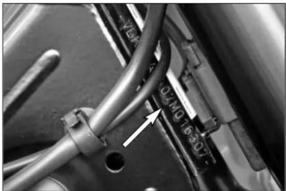
Close-up of mechanical components with visible wiring and a white arrow pointing to a component (no readable text or symbols)Chassis number
The chassis number is stamped on the right side of the steering head tube. Enter this number in the field on page no 1.

natural_image
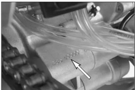
Close-up of mechanical components with a white arrow pointing to a dotted pattern on a surface (no visible text or symbols)Engine number
The engine number is stamped into the engine housing underneath the carburetor. Enter this number in the field on page no 1.
OPERATION INSTRUMENTS »
text_image
1 AClutch lever
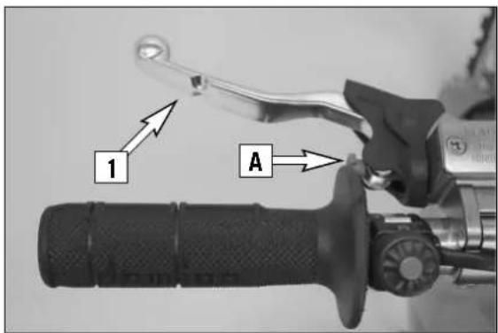
The clutch lever [1] is located on the left side of the handlebar. The adjusting screw [A] is used to change the original position of the clutch lever (see maintenance work on chassis and engine).
The clutch is hydraulically actuated and adjusts itself automatically.
text_image
B 2Hand brake lever
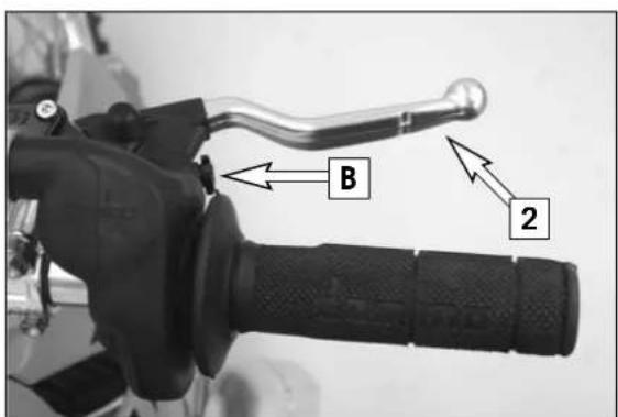
The hand brake lever [2] is mounted on the handle bars on the right and actuates the front wheel brake. The adjusting screw [B] is used to change the original position of the hand brake lever (see maintenance work on chassis and engine).
natural_image
Close-up of a mechanical lever handle and grip assembly (no visible text or symbols)Short circuit button
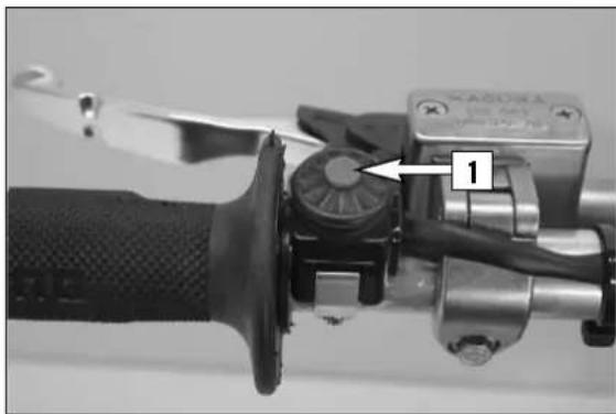
The short circuit button [1] turns off the engine. When pressing this button, the ignition circuit is short-circuited.
natural_image
Close-up of a motorcycle's front wheel assembly with a labeled component (no text or symbols visible)Filler cap
To open it: turn filler cap counter-clockwise.
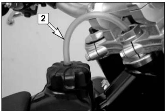
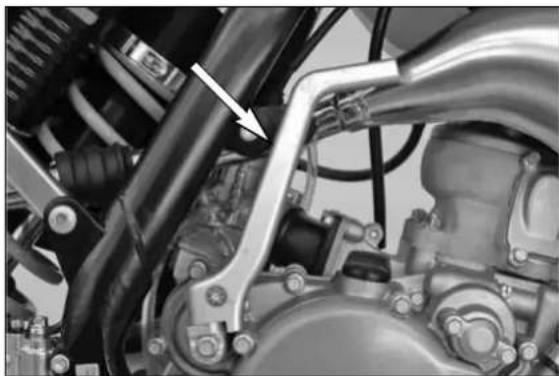
To close it: put filler cap back on and tighten it by turning it clockwise. Install tank breather hose [2] without kinks.
text_image
OFF ON 5X5 5X5Fuel tap
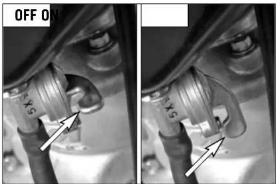
OFF In this position the fuel tap is closed. No fuel can flow to the carburetor. ON When the motorcycle is running the grip is must be in the ON position to enable fuel to flow to the carburetor. The tank will drain completely in this position.
natural_image
Close-up of mechanical components with no visible text or symbolsChoke
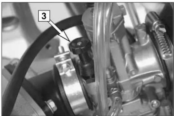
The choke button [3] is located on the left side of the carburetor. Pulling the choke button [3] all the way out opens a bore in the carburetor through which the engine can take in additional fuel, thus achieving the "rich" fuel air mixture needed for cold starting.
Pushing the choke button back in closes the bore in the carburetor.
text_image
2,3,4,5,6 N 1Shift lever
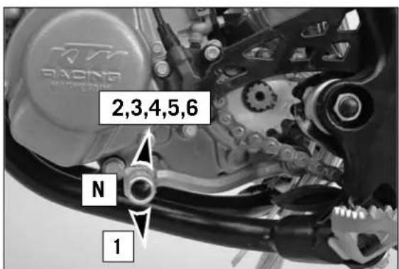
The shift lever is mounted on the left side of the engine. The position of the gears is shown in the illustration. Neutral, or the idle speed, is located between first and second gear.
natural_image
Close-up mechanical assembly showing internal components and a white arrow pointing to a specific part (no visible text or symbols)
natural_image
Close-up of a motorcycle's front wheel and drivetrain component, showing no visible text or symbols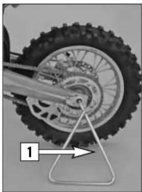
natural_image
Close-up of a motorcycle wheel with visible tire tracks and a metal stand, no text or symbols present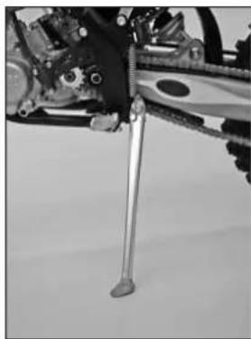
natural_image
Close-up of a mechanical assembly with a metallic rod inserted, no visible text or symbols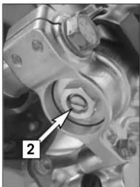
natural_image
Close-up mechanical component with a numbered annotation pointing to a circular feature (no readable text or symbols)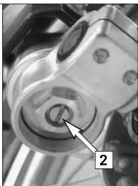
natural_image
Close-up of a mechanical component with a labeled arrow pointing to a circular feature (no readable text or symbols)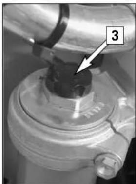
natural_image
Close-up of a mechanical component with a labeled arrow pointing to a dark cylindrical feature (no text or symbols visible)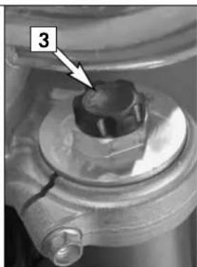
natural_image
Close-up of a mechanical component with a numbered annotation '3' pointing to a small circular feature (no readable text or symbols beyond the label)Kickstarter
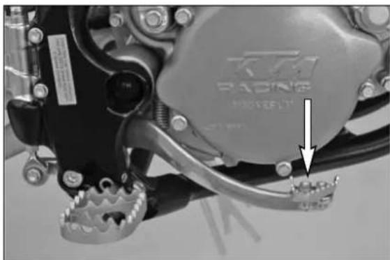
The kickstarter is mounted on the right side of the engine. Its upper part can be swivelled.
Foot brake pedal
The foot brake pedal is located in front of the right foot rest. Its basic position can be adjusted to your seat position (see maintenance work).
Plugin- Stand (SX)
The plug-in stand [1] included in the scope of supply can be plugged into the left side of the bike at the end of the swinging fork.
Side Stand (XC):
Use your foot to swing the side stand forwards to the stop. Make sure it rests securely on solid ground.
Compression damping of fork
Hydraulic compression damping determines the reaction when the fork is compressed. The degree of compression can be adjusted with adjusting screws at the bottom of the fork legs. Remove the protecting cap. Turn the knob [2] clockwise to increase damping, turn it counterclockwise to reduce damping during compression.
STANDARD ADJUSTMENT
- turn adjusting screw clockwise as far as it will go
- turn it back by as many clicks as are specified for the relevant type of fork
Type WP Suspension 05187D05 15 clicks
Type WP Suspension 05187D06 20 clicks
Rebound damping of fork
Hydraulic rebound damping determines the reaction when the fork is rebound. By turning the adjusting screw [3] (REB), the degree of damping of the rebound can be adjusted. Turn the knob clockwise to increase damping, turn it counterclockwise to reduce damping during rebounding.
STANDARD ADJUSTMENT
- turn adjusting screw clockwise as far as it will go
- turn it back by as many clicks as are specified for the relevant type of fork
Type WP Suspension 05187D05 20 clicks
Type WP Suspension 05187D06 20 clicks
natural_image
Close-up of a mechanical assembly with visible springs and components (no readable text or symbols)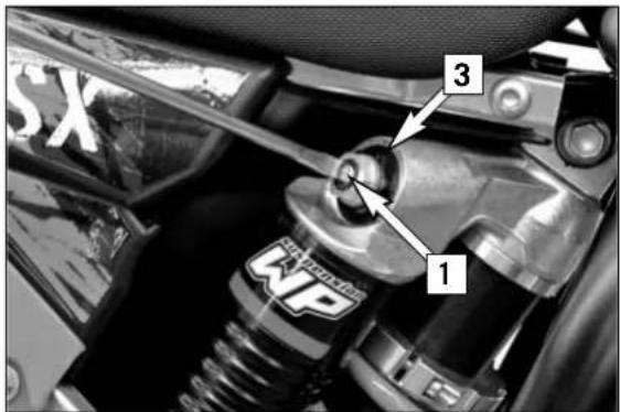
text_image
1 2 3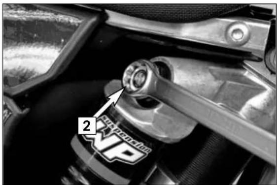
text_image
2 NVP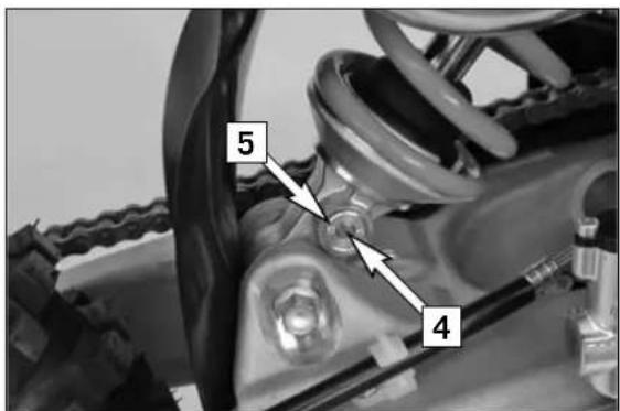
text_image
5 4Damping action during compression of shock absorber
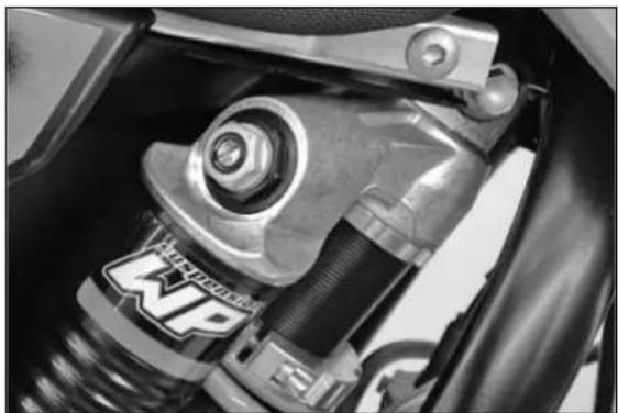
The shock absorber on the models can synchronize the compression damping in the low and high-speed range separately (Dual Compression Control).
Low and high speed refers to the movement of the shock absorber during compression and not to the speed of the motorcycle.
The low and high-speed technology overlaps.
The low-speed setting is primarily for slow to normal shock absorber compression rates. The high-speed setting is effective at fast compression rates. Turning in a clockwise direction will increase the damping, turning counterclockwise will decrease the damping.
Standard low-speed setting:
- Turn the adjusting screw [1] to the limit in a clockwise direction using a screwdriver.
- Unscrew the respective number of clicks for the specific type of shock absorber in a counterclockwise direction.
Type WP Suspension 15187D02 15 clicks
Type WP Suspension 15187D04 15 clicks
Standard high-speed setting:
- Turn the adjusting screw [2] to the limit in a clockwise direction using a box wrench.
– Unscrew the respective number of turns for the specific type of shock absorber in a counterclockwise direction.
Type WP Suspension 1518DC02 2 turns
Type WP Suspension 15187D04 2 turns
WARNING
The damping unit of the shock absorber is filled with high-compression nitrogen. Never try to take the shock absorber apart or to do any maintenance work yourself. Severe injuries could be the result.
Never unscrew the black screw 3 connection (24mm).
Rebound damping function of the shock absorber
By using the adjusting screw [4], the degree of damping of the rebound can be adjusted. Turn the knob clockwise to increase damping, turn it counterclockwise to reduce damping during rebounding.
STANDARD ADJUSTMENT:
- turn the adjusting screw clockwise to the stop.
- then turn the adjusting screw counterclockwise, counting the number of clicks that corresponds to the respective type of shock absorber.
Type WP Suspension 15187D02 22 clicks
Type WP Suspension 15187D04 22 clicks
WARNING
The damping unit of the shock absorber is filled with high-compression nitrogen. Never try to take the shock absorber apart or to do any maintenance work yourself. Severe injuries could be the result.
Never unscrew the black screw connection 5 (15mm).

natural_image
Sequence of identical line-drawn figures riding a dirt bike in motion, no text or symbols presentInstructions for the first ride
- Make sure the work for the "pre-delivery inspection" was performed by your authorized KTM workshop. The DELIVERY CERTIFICATE and SERVICE MANUAL will be handed over when you pick up your vehicle.
Before your youngster takes his or her first ride, explain how each of the controls works and check if your youngster has understood what you explained. We recommend to review the entire owner's manual with your youngster item by item, paying particular attention to the specially marked warnings and pointing out the danger of injury. - Adjust the clutch lever, hand lever and foot brake pedal so your child can operate them easily!
- To prevent injury, teach your youngster the basic riding skills on soft ground, e.g. on a meadow or in the garden. Be sure that there is room enough to maneuver, and that no other rid ers are close.
- To ensure that your youngster gets the feel of the hand brake, have your youngster operate the hand brake while you push the motorcycle. Do not start the engine before your youngster has learned to apply hand brake with appropriate pressure.
- To familiarize your youngster with the operation of the hand brake let him or her practice to operate the hand brake while you are pushing the motorcycle. Do not start the engine before he or she is thoroughly familiar with the use of the hand brake.
- Initially, your youngster should ride back and forth between two persons who help the young rider to stop the motorcycle. However, you should also teach your youngster how to stop the motorcycle himself/herself.
- To improve his/her riding skills, your youngster should practise riding the motorcycle standing on the footpegs or to rid ing at the slowest possible speed. Additionally, you can arrange a series of obstacles and have your youngster drive around them, etc.
– Pay attention to the running-in procedure.
Running in
- Even very precisely machined sections of engine components have rougher surfaces than components which have been sliding across one another for quite some time. Therefore, every engine needs to be broken in. For this reason, during its first 30 minutes the engine must not be revved up to its performance limits.
- Apply low but changing loads for running-in.
- DO NOT DRIVE AT FULL LOAD FOR THE FIRST 30 MINUTES!
WARNING
- Have your youngster wear proper protective gear whenever he or she rides the motorcycle: helmet, eye protection, chest, back, arm and leg protectors, gloves and boots. To set a good example, be sure to wear protective gear yourself whenever riding a motorcycle!
- Only use accessory parts recommended by KTM.
- The front and rear wheel are only allowed to be tired with tires that have the same profile type.
- Your youngster's driving speed should always be adjusted to his/her driving skills as well as to the terrain.
- Your youngster should never be allowed to ride the motorcycle without supervision.
- Replace the helmet visor or goggle glasses early enough. When light shines directly on a scratched visor or goggles, you will be practically blind.
- Never leave your motorcycle without supervision as long as the engine is running.
- SX and XC models are designed for one person only. Passengers are not allowed.
– These models do not comply with the regulations and safety standards established by the law. Therefore, they are not permitted on public roads. - Always keep in mind that other people feel molested by excessive noise.

natural_image
Sequence of identical line-drawn figures riding a dirt bike on waves (no text or symbols)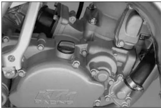
natural_image
Close-up of a mechanical assembly with visible gears and components (no text or symbols)
natural_image
Close-up of hands assembling a bicycle track with chains and a tire (no visible text or symbols)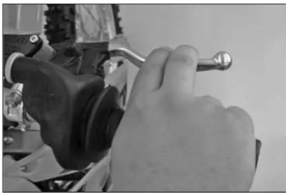
natural_image
Close-up of a hand using a wrench to adjust mechanical components (no visible text or symbols)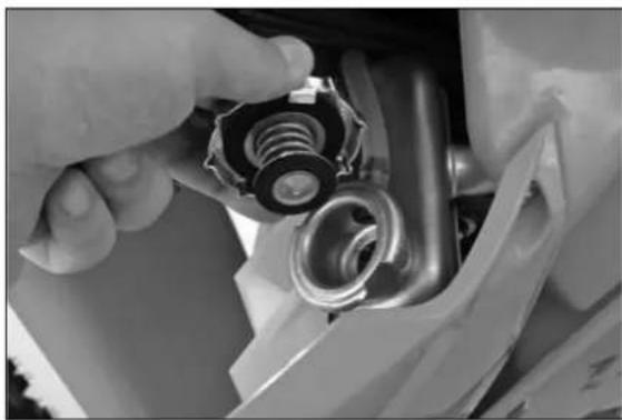
natural_image
Close-up of hands adjusting a mechanical component with a coiled spring and threaded shaft (no visible text or symbols)What you should check before each start
When you start off, the motorcycle must be in a perfect technical condition. For safety reasons, you should make it a habit to perform an overall check of your motorcycle before each start. The following checks should be performed:
1 CHECKING THE ENGINE
Check the engine for any oil leakage. Too little gear oil will lead to premature wear and consequently destroy the transmission.
2 FUEL
Check that there is sufficient fuel in the tank; when closing the filler cap, check that the tank venting hose is free of kinks.
3 CHAIN
A loose chain was fall off the chain wheels; an extremely worn chain may tear, and insufficient lubrication may result in unnecessary wear of the chain and chain wheels.
4 TIRES
Check for damaged tires. Tires showing cuts or dents must be replaced. Also check the air pressure. Insufficient tread and incorrect air pressure deteriorate the driving performance.
5 BRAKES
Check the correct functioning of the braking system. Verify that there is sufficient brake fluid in the reservoir. The reservoirs have been designed in such a way that brake fluid does not need to be refilled even when the brake pads are worn. If the level of brake fluid falls below the minimum value, this indicates a leak in the braking system or completely worn out brake pads. Always have the brake system checked by a KTM workshop to avoid brake failure.
Also check the state of the brake hose and the thickness of the brake linings. Check free travel at the hand brake lever and foot brake lever.
WARNING
If the resistance in the hand brake lever feels "spongy" (too much play), this is an indication that something is wrong with the brake system. Don't let your child ride the motorcycle anymore without first having the brake system looked over by a KTM dealer.
6 CABLES
Check correct setting and easy running of all control cables.
7 COOLING FLUID
Check the level of cooling fluid when the engine is cold.

natural_image
Sequence of identical line-drawn figures riding a dirt bike on waves (no text or symbols)
natural_image
Close-up of a mechanical component with labeled parts (no readable text or symbols)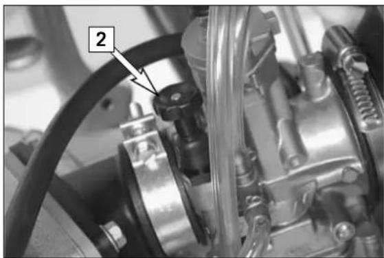
natural_image
Close-up mechanical assembly showing a component with labeled parts (no readable text or symbols)Starting when the engine is cold
1 Open fuel tap [1].
2 Put the gear in neutral
3 Activate the cold-starting aid (choke) [2].
4 Leave throttle closed and kick down the kickstarter vigorously all the way.
WARNING
- To avoid injury when starting the engine, always wear strong bikers boots! You may slip off the kickstarter, or the engine may kick back if you do not kick hart enough.
- Check for power transmission at temperatures below 0°C (32°F) before you actuate the kickstarter. If you depress the kickstarter without feeling any resistance, power is not being transmitted. This could cause injuries.
- Do not start the engine and allow it to idle in a closed area. Exhaust fumes are poisonous and can cause loss of consciousness and death. Always provide adequate ventilation while the engine is running.
! CAUTION
Do not ride your motorcycle at full load and do not rev up the engine when cold. since the piston warms up and expands faster than the water cooled cylinder, this might cause engine damage. always let engine idle until warm or drive it warm at low r.p.m. speeds.
NOTE:
The highly inflammable components in modern fuels volatilize if left standing for longer periods of time. If the motorcycle has not been used for over 1 week, the fuel should be drained from the float chamber. The engine will start up immediately if the float chamber is filled with fresh, ignitable fuel
Starting when the engine is warm
1 Open fuel tap
2 Put the gear in neutral
3 Leave throttle closed and kick down kickstarter vigorously all the way.
What to do when the engine is "flooded"
1 Close fuel tap
2 Start engine with full throttle. If necessary, unscrew spark plug and dry it.
3 Once the engine is running, open fuel tap again.
Starting off
Pull the clutch lever. Put the engine into first gear, slowly release the clutch lever and accelerate at the same time.
WARNING
Always make sure the side stand is kicked all the way up or the plug-in stand removed before you let your child drive off. The motorcycle could run out of control if the stand touches the ground.
Shifting/Riding
You are now in first gear, referred to as the drive or uphill gear. Depending on the conditions (traffic, hill size, etc.), you can shift to a higher gear. Turn down the throttle, at the same time pull clutch lever in and shift to the next higher gear. Let clutch lever go again and open the throttle. If you turned on the choke, make sure you turn it off again as soon as engine is warm.

natural_image
Sequence of identical line-drawn figures riding a dirt bike in motion, no text or symbols presentWhen shifting down, use the brakes if necessary and turn down at the same time. Pull clutch lever and shift down to the next lower gear. Let the clutch lever go slowly and open throttle or shift down again.
WARNING
- After falling with the motorcycle, check all its functions thoroughly before using it again.
- A twisted handlebar must always be replaced. Do not adjust the handlebar, it will lose stability.
! CAUTION
- Driving a cold engine at high speed will reduce the life of the engine. We recommend to warm the engine up at a medium engine speed for several minutes before switching to full load.
- Never have the throttle wide open when changing down to a lower gear. The engine will overrev, damaging the valves. In addition, the rear wheel blocks so that the motorcycle can easily get out of control.
- If the engine runs without throttle during longer downhill travel, the engine should be accelerated occasionally to ensure that it is supplied with sufficient lubricant which is mixed in the fuel.
- In the event that, while your child is riding on the motorcycle, you notice any unusual operation-related noise, your child should stop immediately, turn the engine off, and contact an authorized KTM dealer.
Braking
Turn off the gas and apply the hand and foot brakes at the same time. When driving on sandy, wet or slippery ground use mainly the rear wheel brake. Always brake with feeling, blocking wheels can cause you to skid or fall. Also change down to lower gears depending on your speed.
WARNING
- In case of rain, after washing the motorcycle, after rides through water and in case of rides on wet off-road tracks, humid or dirty brake discs can delay the braking effect. The brakes must be pulled until they are dry or clean.
– Dirty brake discs cause increased tear of brake pads and brake discs. - When you brake, the brake discs, brake pads, brake caliper and brake fluid heat up. The hotter these parts get, the weaker the breaking effect. In extreme cases, the entire braking system can fail.
Stopping
Brake motorcycle and shift gears to idling. To switch off the engine, depress short circuit switch until the engine stops. Close fuel tap.
WARNING
Motorcycle engines produce a great amount of heat while running. The engine, exhaust pipe, muffler, brake rotors, and shock absorbers can become very hot.
Do not touch any of these parts after starting the motorcycle, and take care to park it where pedestrians are not likely to touch it and get burned.
! CAUTION
- Close the fuel tap when leaving your vehicle. Otherwise the carburetor may get flooded and fuel will enter the engine.
- The plug-in stand is designed to hold the weight of the motorcycle only. By sitting on the motorcycle, your child will put additional weight on the plug-in stand, possibly causing the plug-in stand or swinging fork to be damaged or the motorcycle to fall down.
Refueling, fuel
Oil (high-grade two-stroke engine oil; i.e. Motorex Cross Power 2T) must be mixed with the fuel (ROZ 95) at a mixing ratio of 1:40.
WARNING
Gasoline is highly flammable and poisonous. Extreme caution should be used when handling gasoline. Never refuel the motorcycle near open flames or burning cigarettes. Always switch off the engine before refueling. Be careful not to spill gasoline on the engine or exhaust pipe while the engine is hot. Wipe up spills promptly. If gasoline is swallowed or splashed in the eyes, seek a doctor's advice immediately.
! CAUTION
- Only use premium-grade gasoline ROZ 95 mixed with high-grade two-stroke engine oil. Other types of gasoline can cause engine failure.
- Only use known brands of high-grade 2-stroke engine oil (Motorex Cross Power 2T).
- Not enough oil or low-grade oil can cause erosion of the piston. when Using too much oil, the engine may start smoking and foul the spark plug.
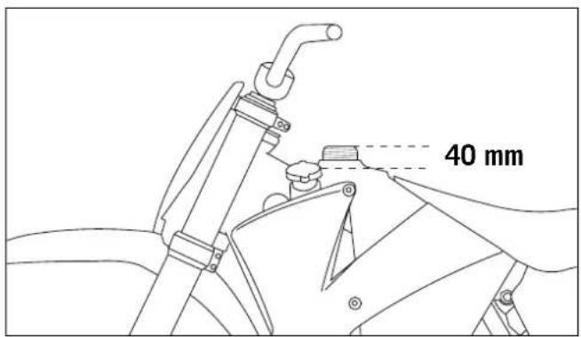
- Fuel expands when its temperature rises. Therefore do not fill the tank to the top. (see fig.)
- Do not use premixed two-stroke oils, oils for outboard engines or normal engine oil to prepare the mixture.
- Do not use gasoline and oil mixtures that are older than one week. The lubrication properties of some two-stroke oils can deteriorate very rapidly.
text_image
40 mm| 85/105 SX/XC 2008A CLEAN MOTORCYCLE CAN BE CHECKED MORE QUICKLY WHICH SAVES MONEY | before each race | 1st service after 10 hours | every 20 hours | every 40 hours | at least once a year | |
| ENGINE | Check gear box oil level | ● | ||||
| Change gear box oil | ● | ● ● | ● | |||
| Check spark plugs, adjust distance between electrodes | ● | ● | ||||
| Renew spark plugs | ● | ● | ||||
| Clean the spark-plug connector and check for a tight fit | ● | ● ● | ||||
| Check the screws on the kick starter and shift lever for a tight fit | ● | ● ● | ||||
| CARBURETOR | Check the carburetor connection boot and intake flange for cracks or leaks | ● | ● ● | |||
| Check idle speed setting | ● | ● ● | ● | |||
| Check that vent hoses are not damaged or bent | ● | ● ● | ● | |||
| ADD-ON-PARTS | Check cooling system for leaks, check quantity of antifreeze | ● | ● ● | ● | ||
| Check exhaust system for leaks and fitment | ● | ● ● | ||||
| Check cables for damage, smooth operation, bends; adjust and lubricate | ● | ● ● | ||||
| Check the fluid level in the master cylinder of the hydraulic clutch | ● | ● ● | ● | |||
| Clean air filter and filter box | ● | ● ● | ● | ● | ||
| Check electric wires for damage and bends | ● | ● | ||||
| Check function of electric systems (emergency OFF switch) | ● | ● ● | ||||
| BRAKES | Check brake fluid level, lining thickness, brake lining | ● | ● ● | |||
| Check brake lines for damage and leaks | ● | ● ● | ||||
| Check/adjust smooth operation and free travel of handbrake/foot brake lever | ● | ● ● | ||||
| Check the screws and guide bolts on the brake system for a tight fit | ● | ● ● | ||||
| CHASSIS | Check shock absorber and fork for leaks and function | ● | ● ● | ● | ||
| Clean dust bellows | ● | ● ● | ||||
| Bleed fork legs | ● | ● ● | ||||
| Check swing arm bearings | ● | ● | ||||
| Check/adjust steering head bearings | ● | ● ● | ||||
| Check tightness of all chassis screws (triple clamps, fork leg axle passage axle nuts and screws, swing arm bearings, shock absorber) | ● | ● ● | ||||
| WHEELS | Check spoke tension and rim joint | ● | ● ● | ● | ||
| Check tires and air pressure | ● | ● ● | ● | |||
| Check chain, rear sprockets and chain guides for wear, fitment and tension | ● | ● ● | ● | |||
| Lubricate chain, Clean and grease the adjusting screws on the chain tensioner | ● | ● ● | ● | |||
| Check clearance of wheel bearings | ● | ● ● | ||||
The kilometer reading for inspection intervals should not exceed 3 hours.
Maintenance work performed by your authorized KTM workshop is not a substitute for care and maintenance by the driver!
| 85/105 SX/XC 2008IMPORTANT SERVICE WORK THAT MUST BE PERFORMED BY AN AUTHORIZED KTM WORKSHOPUNDER A SEPARATE ORDER | Every 20 hours | Every 40 hours | At least once a year | Every 2 years |
| Clean and adjust carburetor | ● | |||
| Check the reed-type intake valve for wear | ● | ● | ||
| Check the wear on the clutch disks and length of the clutch springs | ● | ● | ||
| Check the cylinder and piston for wear | ● | ● | ||
| Check function of exhaust control | ● | ● | ||
| Check piston pin bearing | ● | |||
| Replace the crankshaft main bearings | ● | |||
| Replace the conrod bearings | ● | |||
| Check the entire transmission, the shift mechanism and bearings | ● | |||
| Complete maintenance of fork | ● | ● | ||
| Complete maintenance of shock absorber | ● | |||
| Clean and grease steering head bearings and gasket elements | ● | |||
| Replace the sealing cup for the foot brake cylinder | ● | ● | ||
| Replace the glass-fiber yarn filling in the silencer | ● | ● | ||
| Treat electric contacts and switches with contact grease | ● | |||
| Change break fluid | ● | ● ● | ||
| Change hydraulic clutch fluid | ● | |||
| Change the hydraulic clutch oil |
Note: If the inspection establishes that permissible tolerances are exceeded, the respective components must be replaced.
| 85/105 SX/XC 2008IMPORTANT CHECKS AND MAINTENANCE TO BE CARRIED OUT BY THE RIDER OR THE MECHANIC | before each start | after every cleaning | for cross country use | once a year |
| Check gear box oil level | ● | |||
| Check brake fluid level | ● | |||
| Check brake pads for wear | ● | |||
| Lubricate and adjust cables and nipples | ● | |||
| Bleed fork legs regulary | ● | |||
| Remove and clean dust bellows regularly | ● | |||
| Clean and lubricate chain, check tension and adjust if necessary | ● | ● | ||
| Clean air filter and filter box | ● | ● | ||
| Check tires for pressure and wear | ● | |||
| Check cooling liquid level | ● | |||
| Check fuel lines for leaks | ● | |||
| Empty and clean float chamber | ● | ● | ||
| Remove, clean and oil the throttle slide | ● | |||
| Check all control elements for smooth operation | ● | |||
| Check brake performance | ● | ● | ||
| Treat blank metal parts (with the exception of brake and exhaust systems) with wax-based anti corrosion agent | ● | |||
| Check tightness of screws, nuts and hose clamps regularly | ● |
WARNING
All maintenance and adjustment operations that are marked with an asterisk * require specialist knowledge. For your own security, let these tasks be carried out by a ktm-dealer where your motorcycle will be optimally serviced by appropriately qualified, skilled staff.
! CAUTION
- When cleaning the motorcycle, do not use a high pressure cleaning unit if possible, otherwise water will penetrate the bearings, carburetor, electric connectors, etc.
- When transporting your KTM, ensure that it is held upright with restraining straps or other mechanical fastening devices and that the fuel tap is in the OFF position - if the motorcycle should fall over, no fuel can leak from the carburetor or fuel tank
- Only use special screws with an appropriate thread length supplied by KTM to fix the spoilers on the tank. Using other screws or longer screws can cause leaks in the tank through which fuel can flow out.
- Do not use toothed washers or spring rings with the engine fastening screws, as these work into the frame parts and keep working loose. Instead, use self-locking nuts.
- Let your motorcycle cool down before beginning any maintenance work in order to avoid getting burned.
- Dispose of Oils, fatty matters, filters, fuels, washing detergents, etc. properly.
- Under no circumstances may used oil be disposed of in the sewage system or in the open countryside. 1 liter of used oil contaminates 1,000,000 liters of water.
text_image
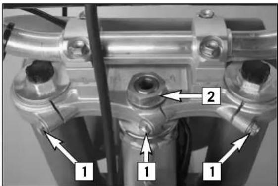
1 1 1 2Checking and adjusting the steering head bearing \*
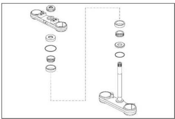
Check steering head bearing for play periodically. To check, put motorcycle on the stand so that the front wheel is off the ground. Now try to move the fork forward and backward. For readjusting, loosen the three clamp screws [1] of the top triple clamp and turn steering stem bolt [2] clockwise until there is no more play. Don't tighten the steering stem bolt all the way, otherwise the bearings will be damaged. With a plastic hammer, lightly rap on the triple clamp to release tension. Retighten the three clamp screws to 20 Nm.
WARNING
If the steering head bearing is not adjusted to be free of play, the motorcycle will exhibit unsteady driving characteristics and can get out of control.
! CAUTION
If you drive with play in the steering head bearing for longer periods, the bearings and subsequently the bearing seats in the frame will be destroyed.
The steering head bearings should be regreased at least once a year (i.e. Motorex Long Term 2000).
natural_image
Technical line drawing of a mechanical assembly with multiple components and a cylindrical component (no text or symbols)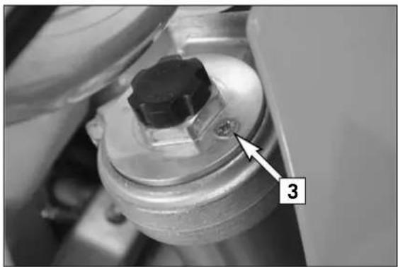
natural_image
Close-up of a mechanical component with a numbered annotation (3) pointing to a bolted joint (no readable text or symbols beyond the label)Breather plug front fork
After every 5 hours of use for competitive racing, slacken the breather plugs [3] a few turns in order to relieve excess pressure from the inside of the fork. To do this, place the motorcycle on a stand with the front wheel lifted off the ground.
! CAUTION
Excessive pressure in the interior of the fork can cause leaks in the fork. If your fork is leaking, it is recommended to open the breather plugs before having the seals replaced.
natural_image
Close-up of industrial machinery components with a labeled component '1' (no readable text or symbols beyond label)Cleaning the dust sleeves of the telescopic fork
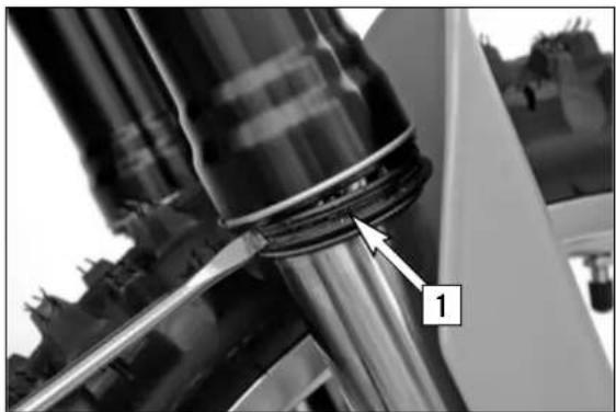
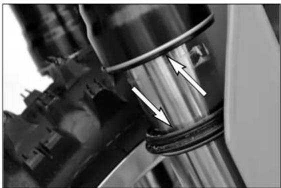
The dust-protection bellows [1] are to remove dust and coarse dirt particles from the fork tube. However, after some time, dirt may also get in behind the dust-protection bellows. If this dirt is not removed, the oil sealing rings located behind it may start to leak.
Use a screwdriver to lift the dust-protection bellows out of the outer tubes and slide them downward.
natural_image
Close-up of mechanical components with arrows indicating movement or force, no visible text or symbolsClean dust-protection bellows, outer tubes, and fork tubes thoroughly, and oil them thoroughly with oil-spray (Motorex Joker 440) or engine oil. Then, push dust-protection bellows into the outer tubes by hand.

WARNING
No oil may reach the front tire or the brake disks since this would considerably reduce the tire's road grip and the braking effect of the front brake.
natural_image
Close-up of mechanical components with visible wiring and arrows indicating motion (no text or symbols)How to change the handlebar position
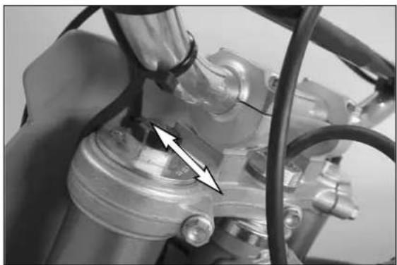
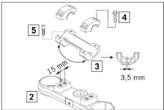
The handlebar position can be readjusted by 22 mm. Thus, you can put the handlebar in the position that is the most convenient for you. The upper triple clamp [2] includes 2 bores arranged at a distance of 15 mm (0.6 in) from one another. The bores at the handlebar support [3] are offset from the center by 3.5 mm (0.13 in). Accordingly, you can mount the handlebar in 4 different positions.
text_image
15 mm 3,5 mmFor this purpose, remove screws [4] of the handlebar clamps and screws [5] of the handlebar support. Position handlebar support, and tighten screws [5] to 40 Nm. Mount handlebar and handlebar clamps, and tighten screws [4] to 20 Nm. The gap between the handlebar support and handlebar clamps should be the same size in the front and in the rear.

WARNING
The screws [5] must be secured with loctite 243.
text_image
NP 7 6Changing the spring preloading of the shock absorber
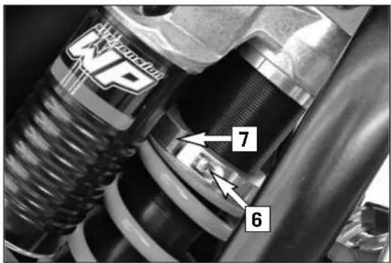
The spring preload can be changed by turning the adjusting ring [7]. For this purpose, you should dismount the shock absorber and clean it thoroughly. NOTE:
- Before changing the spring preload note down the basic setting, e.g. how many threads are visible above the adjusting ring.
- One rotation of the adjusting ring [6] changes the spring pretension by approximately 1.75 mm (0.07 in).
Loosen the clamping screw [7] and use the hook wrench contained in the vehicle tool set to turn the adjusting ring as desired. Turning it counterclockwise will reduce the preload, turning it clockwise will increase the preload. After readjusting the clamping screw [6], tighten it to 5 Nm (6 ft.lb).
text_image
Technical diagram of a bicycle's wheel and gear assembly with labeled component A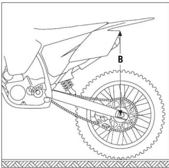
text_image
Technical diagram of a bicycle's front wheel and suspension mechanism with labeled component B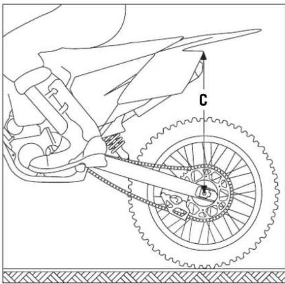
text_image
Technical diagram of a bicycle's wheel and chain assembly with labeled component 'C'Basic suspension setup for the weight of the driver
To achieve maximum handling performance and to prevent the fork, shock absorber, swing arm and frame from being damaged, the basic setup of the suspension components must be suitable for your child's weight. At delivery, the fork and shock absorber are set to accommodate a driver weighing between 45 and 55 kg (wearing full protective clothing). If your child's weight exceeds or falls short of this range, you will need to adjust the spring components accordingly.
Minor deviations in weight can be compensated by adjusting the spring preload on the shock absorber. Other springs must be mounted on the fork and shock absorber for larger deviations.
Checking the shock absorber and spring
You can establish whether or not the shock absorber spring is suitable for your child's weight by checking the riding sag. The static sag must be correctly adjusted before the riding sag can be determined.
Determining the static sag of the shock absorber
The static sag should be between 30 and 35 mm. Larger deviations can strongly influence the motorcycle's performance.
Procedure:
- Jack up the motorcycle until the rear wheel no longer touches the ground.
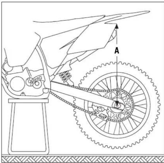
- Measure the vertical distance between the rear wheel axle and a fixed point (e.g. a mark on the side cover) and write it down as dimension A.
- Place the motorcycle on the ground again.
- Ask a helper to hold the motorcycle in vertical position.
- Measure the distance between the rear axle and the fixed point again to establish dimension B.
- The static sag is the difference between dimensions A and B.
EXAMPLE:
Motorcycle jacked up (dimension A) 600 mm
Motorcycle on ground, unloaded (dimension B) ....- 565 mm
Static sag 35 mm
If the static sag is lower, the spring preload of the shock absorber must be increased, if the static sag is reduced, the spring preload must be higher. See chapter "Changing the spring preload of the shock absorber."
Determining the riding sag of the shock absorber
- Have a helper hold the motorcycle. Your child should sit on the bike in a normal seating position (feet on the footrests) and bounce up and down a few times to allow the rear wheel suspension to become level.
- With your child on the bike, measure the distance between the same two points and write it down as dimension C.
- The riding sag is the difference between dimensions A and C.
EXAMPLE:
Motorcycle jacked up (dimension A) 600 mm
Motorcycle on ground, loaded (dimension C) ....- 500 mm
Riding sag 100 mm
The riding sag should lie between 95 and 105 mm.
If the riding sag is less than 95 mm, the spring is too hard (the spring rate is too high). If the riding sag is more than 105 mm, the spring is too soft (the spring rate is too low).
Shock absorber 85/105 SX/XC
bar
| Rider weight inclusive gears in kilogram | SPRING RATE | |---|---| | 30-215 | 30 | | 35-215 | 35 | | 40-215 | 40 |Overview of the shock absorber springs
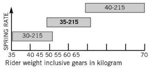
The spring rate is written on the outside of the spring (e.g. 35-215). The type number of the shock absorber is embossed on the top.
The illustration on the left shows which spring should be installed. The standard spring is shown in bold print.
After installing a different spring, readjust the static sag to 30-35 mm.
According to our experience, the damping rate of the compression stage can remain unchanged. The damping rate of the rebound stage can be reduced by a few clicks for a softer spring or increased by a few clicks for a harder spring.
natural_image
Line drawing of a bicycle wheel assembly with a hand operating the wheel (no text or symbols)Checking the basic setup of the telescopic fork
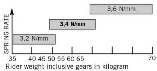
The precise riding sag of the telescopic fork cannot be determined for various reasons. If your telescopic fork bumps frequently (hard end stop during compression), you should install harder fork springs to avoid damaging the telescopic fork and frame.
Front fork 85/105 SX/XC
bar
| Rider weight inclusive gears in kilogram | SPRING RATE | |---|---| | 3.2 N/mm | 3.2 | | 3.4 N/mm | 3.4 | | 3.6 N/mm | 3.6 |Overview of the telescopic fork springs
If your child weights less than 45 kg or more than 55 kg, have your KTM workshop mount suitable fork springs. The illustration on the left shows the correct spring rate. The standard spring is shown in bold print.
The type number of the telescopic fork is embossed on the inside of the fork leg.
According to our experience, the damping rate of the compression stage can remain unchanged. The damping rate of the rebound stage can be reduced by a few clicks for a softer spring or increased by a few clicks for a harder spring.
text_image
5 - 6 cm
text_image
A 1 2 3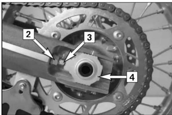
text_image
2 3 4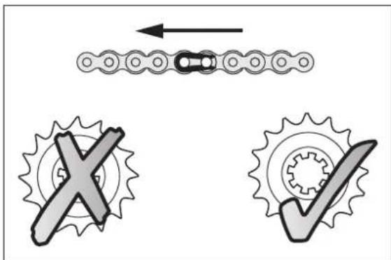
text_image
Diagram illustrating gear meshing and checkmark operations with labeled symbols for X and ✓Checking chain tension
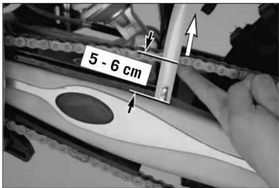
Support the motorcycle on the center stand or side stand, respectively. Switch transmission to neutral. Push the chain upwards from the end of the chain sliding component until the upper part of the chain is tensioned. The distance between the chain and the swing arm should be 5 - 6 cm. The lower part of the chain should be tightened. Correct chain tension, if necessary!
WARNING
- If the chain is too tight the secondary transmission components (chain, sprockets, bearings of the transmission and of the rear wheel) will be put under additional strain that can, in addition to premature wear, also cause chain breakage.
- If the chain is not tight enough it can slip off the sprockets and block the rear wheel or damage the engine.
- In both cases the rider is very likely to lose control of the motorcycle.
Correct chain tension
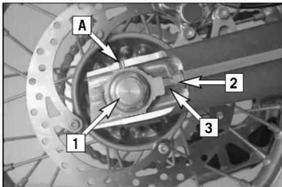
Loosen collar nut [1], loosen lock nuts [2], and turn right and left adjusting screws [3] equally far. Tighten lock nuts.
Before tightening the collar nut, verify that the chain adjusters [4] are sitting close to the adjusting screws and that the rear wheel has been aligned with the front wheel.
Tighten collar nut [1] to 80 Nm (60 ft.Ib).
WARNING
- If you don't happen to have a torque wrench at hand, make sure you have the tightening torque corrected by a KTM dealer as soon as possible. A loose axle may lead to an unstable driving behavior of your motorcycle.
- Tighten the collar nut with the required torque.
NOTE:
The large adjusting range of the chain adjusters (32mm) allows you to use different secondary ratios in combination with the same chain length. The chain adjusters [4] can be rotated by 180°.
! CAUTION
Always mount the chain tensioner equally aligned.
Chain maintenance (SX)
For long chain life, good maintenance is very important. The chain should be cleaned in fireproof solvent regularly and afterwards treated with hot grease or chain spray (Motorex Chainlube 622).
Chain maintenance (XC)
Maintenance of the O-ring chain is reduced to a minimum. Rinse off any heavy dirt with plenty of water. Residual used grease must be removed prior to lubrication (Motorex Chain Clean 611). After drying, use a chain spray specially designed for O-ring chains (Motorex Chainlube 622).
WARNING
No lubrication is allowed to reach the rear tire or the brake disks, otherwise the road adherence and the rear wheel braking effects would be strongly reduced and the motorcycle could easily lose control.
! CAUTION
When mounting the chain masterlink clip, the closed side of the masterlink clip must point in running direction.
Also check sprockets and chain guides for wear, and replace if necessary.
natural_image
Close-up of a bicycle wheel with visible mechanical components and suspension rings (no text or symbols)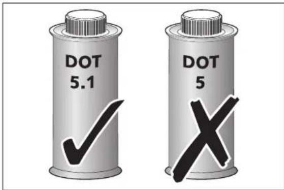
text_image
DOT 5.1 DOT 5 X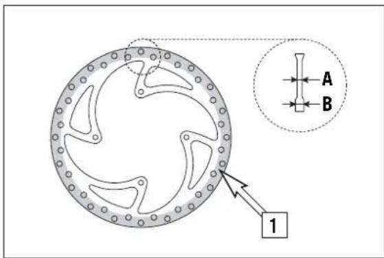
text_image
A B 1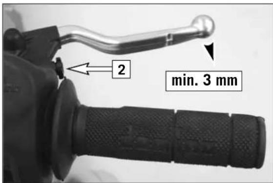
text_image
2 min. 3 mmGeneral information about KTM disc brakes
BRAKE CALIPERS:
If the front brake caliper is removed, the screws must be secured with Loctite 243 when mounted and tightened to 25 Nm.
BRAKE FLUID RESERVOIRS:
The brake fluid reservoirs on front and rear wheel brakes have been designed in such a way that even if the brake pads are worn it is not necessary to top up the brake fluid. If the brake fluid level drops below the minimum level either the brake system has a leak or the brake pads are completely worn. In this case, consult an authorized KTM dealer immediately.
BRAKE FLUID:
We recommend that you use Motorex DOT 5.1 brake fluid when you refill or change the brake fluid. DOT 5.1 brake fluid has a wet boiling point of 180^ C / 356^ F ( 25^ C / 45^ F higher than DOT 4) and is safer for high performance applications. Brake fluid DOT 5.1 is a polyethylene glycol based fluid, amber-colored and can be mixed with DOT 4 brake fluid. Do not, in any event, use DOT 5 brake fluid. It is based on silicone oil and is dyed purple. KTM motorcycle gaskets and brake hoses are not designed for DOT 5 brake fluid.
WARNING
Have the brake fluid changed at least once annually. If you wash your motor-cycle often, the brake fluid should be changed even more frequently. Brake fluid tends to absorb water. Therefore, vapor pockets may form in "old" brake fluids even at low temperatures, causing the brake system to fail.
BRAKE DISCS:
Due to wear, the thickness of the brake disc in the area of the contact face [1] of the brake pads decreases. At their thinnest point A, the brake discs must not be more than 0.40 mm (0.016 in) thinner than the pad's nominal thickness. Measure the nominal thickness in a location B outside the contact face. Check wear in several locations.
WARNING
- Brake discs suffering from wear greater than 0.40 mm (0.016 in) constitute a safety risk. Have the brake discs replaced immediately as soon as they reach the wear limit.
- Have any repairs on the brake system be performed by a KTM dealer.
Adjusting free travel of the hand brake lever
Free travel of the hand brake lever may be readjusted by using the adjustment screw [2]. In this way, the position of the point of pressure (i.e. the resistance you feel on the hand brake lever when the brake pads are pressed against the brake disc) can be adjusted for any hand size.
! CAUTION
At the hand brake lever, free travel must at least be 3 mm (0.1 in). Only then may the piston in the hand brake cylinder be moved (to be recognized by the greater resistance of the hand brake lever). If this free travel is not provided, pressure will build up in the braking system, and the front-wheel brake may fail due to overheating.
text_image
1 2 3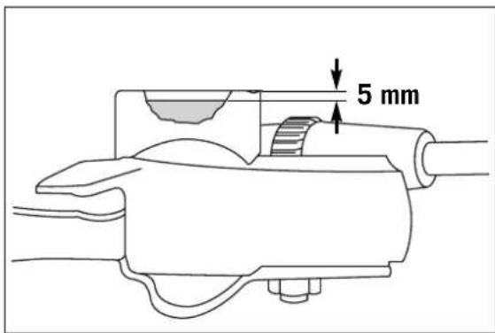
text_image
5 mm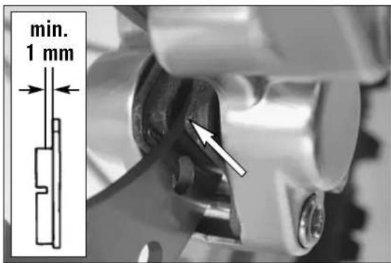
text_image
min. 1 mm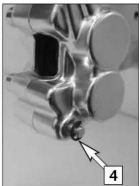
natural_image
Close-up of a metallic mechanical component with a small protrusion and an arrow pointing to a detail (no text or symbols visible)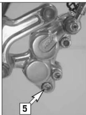
natural_image
Close-up of a mechanical component with no visible text or symbols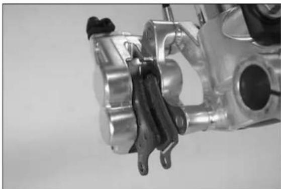
natural_image
Close-up of a mechanical component with metallic parts and a black clamped part (no visible text or symbols)Checking the brake fluid level/ refilling \*
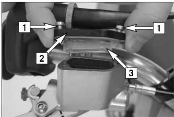
The brake fluid reservoir is combined with the hand brake cylinder on the handlebar. To check the brake fluid level, press the brake pistons back into the basic position. Move the hand brake cylinder in a horizontal position, remove the screws [1] and the cover [2] with the diaphragm [3]. The brake fluid level should be 5 mm below the upper edge of the reservoir (see drawing), otherwise add DOT 5.1 brake fluid (e.g. Motorex Brake Fluid DOT 5.1) up to 5 mm below the upper edge of the reservoir.
Mount the diaphragm, the cover and the screws and actuate the hand brake lever until you feel the point of pressure again. Wipe off any overflowing or spilled brake fluid with water.
WARNING
- Actuate the hand brake lever until you feel the point of pressure again.
- Never use DOT 5 brake fluid! It is based on silicone oil and of a purple color. Seals and brake hoses must be especially adapted to it.
- Store brake fluid out of reach of children.
- Brake fluid can cause skin irritation. Avoid contact with skin and eyes. If you get brake fluid in your eyes, rinse with plenty of water and consult a doctor.
! CAUTION
- Don't let brake fluid get in contact with paint, it is an effective paint remover.
- Use only clean brake fluid taken from a tightly sealed container.
Checking front brake pads
Inspect the brake pads from in front of the vehicle. The linings must be at least 1 mm (0.04 in) thick.
WARNING
At their most worn point brake pad linings should not be thinner than 1 mm (0.04 in), otherwise they could lead to brake failure. For your own safety don't put off having your brake pads changed.
! CAUTION
If the brake pads are replaced too late so that the lining is partly or entirely worn, the steel components of the brake pad will rub against the brake disc, thereby impairing the braking effect and destroying the brake disc.
Replacing the front brake pads \*
Remove the front wheel (see front wheel chapter).
Press brake shoes apart with a suitable screwdriver to put the brake pistons in their basic position.
Remove the lock washer [4] from the screw as well as fixing screw [5] and take the brake shoes out of the brake caliper. Clean brake caliper thoroughly with compressed air.
Mount the right brake shoe and fix with screw. Mount the left brake shoe and tighten the screw to 4 Nm. Mount the lock washer. Align brake shoes, mount front wheel (see chapter: Mounting the front wheel).
WARNING
- It is very important to keep the brake disk free from oil and fatty matters. Otherwise, the braking effect would be strongly reduced.
- After assembly, check if circlips have been fitted correctly.
- Do not unscrew any other screws on the brake caliper or you will have to bleed the brake system.
- After working on the brake system always operate the hand brake lever to apply the brake pads to the brake disk and create a point of pressure.

text_image
Technical diagram of a mechanical assembly with labeled parts 1 and 2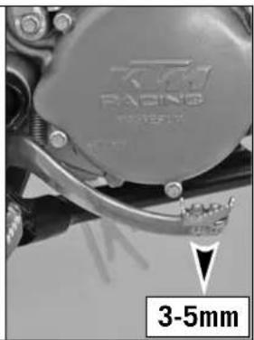
text_image
3-5mmChanging basic position of the brake pedal \*
The basic setting of the foot brake pedal can be changed by turning the end stop roller [1]. Using the push rod [2], the free play on the foot brake pedal must be set.
Measured on the outside, the foot brake pedal must have 3-5 mm of free play before the push rod can move the piston in the brake cylinder (to be recognised from the resistance on the foot brake pedal).
WARNING
If this clearance is missing, pressure accumulates in the braking system and the brake pads begin to rub. The braking system overheats and can fail completely in extreme cases.
natural_image
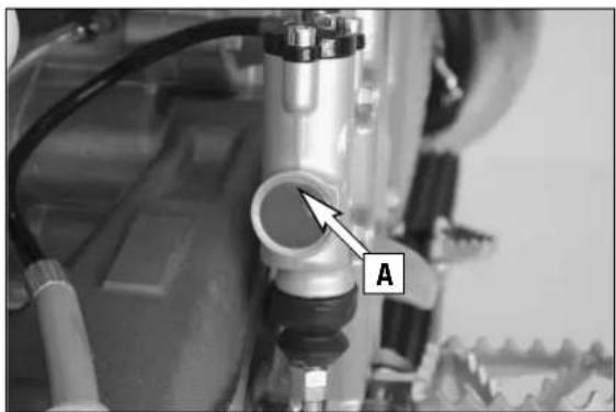
Close-up of a mechanical assembly with labeled component A (no readable text or symbols beyond label)Checking the rear brake fluid level
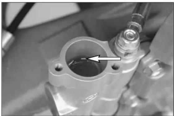
The reservoir for the rear disk brake is on the right side of the motorcycle on the rear brake cylinder.
The brake fluid level may not drop below the upper edge A of the inspection glass when the bike is in a horizontal position.
WARNING
If the brake fluid level drops below the upper edge of the inspection glass, this indicates that the brake system is either leaking or the brake shoes completely worn.
text_image
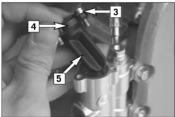
3 4 5Refilling the rear brake fluid reservoir \*
Remove the screws [3] and take off the cover [4] and diaphragm [5]. The brake pistons must be pushed back to their basic position. Fill DOT 5.1 brake fluid (e.g. Motorex Brake Fluid DOT 5.1) up to 10 mm (0.4 in) under the upper edge of the reservoir.
Remount the diaphragm, cover and screws and actuate the foot brake lever until you feel the point of pressure again. Wipe any overflowing or spilled brake fluid off with water.
WARNING
- Actuate the foot brake lever until you feel the point of pressure again.
- Never use DOT5 brake fluid! It is based on silicone oil and of a purple color. Seals and brake hoses must be especially adapted to it.
- Store brake fluid out of reach of children.
- Brake fluid can cause skin irritation. Avoid contact with skin and eyes. If you get brake fluid in your eyes, rinse with plenty of water and consult a doctor.
! CAUTION
- Don't let brake fluid get in contact with paint, it is an effective paint remover.
- Use only clean brake fluid taken from a tightly sealed container.
natural_image
Close-up of a mechanical component with a highlighted cylindrical opening and an arrow indicating a feature (no visible text or symbols)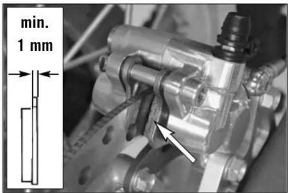
text_image
min. 1 mmChecking rear brake pads
The brake pads can be inspected from the rear. The thickness of the linings may not be less than 1 mm (0.04 in).
WARNING
At their most worn point brake pad linings should not be thinner than 1 mm, otherwise they could lead to brake failure. For your own safety don't put off having your brake pads changed.
! CAUTION
If the brake pads are replaced too late so that the lining is partly or entirely worn, the steel components of the brake pad will rub against the brake disc, thereby impairing the braking effect and destroying the brake disc.
text_image
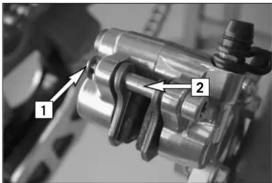
1 2Remove the safety device [1], knock out the guide pin [2] from the brake caliper with a drift towards the chain wheel and remove the brake pads. Carefully clean the brake caliper with compressed air and check the sleeves of the guide pins for damage.

natural_image
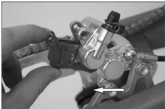
Close-up of hands assembling a mechanical component with a tool, no visible text or symbolsPress both brake shoes into the brake caliper and fix with bolt [2]. Mount the locks [1]. Tighten bolt [2] to 5 Nm (3,7 ft.lb).
WARNING
- It is very important to keep the brake disk free from oil and fatty matters. Otherwise, the braking effect would be strongly reduced.
- After assembly, check if circlips have been fitted correctly.
- After working on the braking system, one must always actuate the hand brake lever or foot brake lever, respectively so as to ensure that the brake pads will lie against the brake disk and the pressure point is established.
text_image
Mechanical assembly diagram with numbered components and directional arrows indicating motion or assembly stepsDismounting and mounting the front wheel
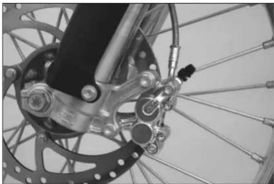
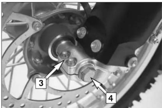
To remove the front wheel, jack the motorcycle up on its frame so that the front wheel no longer touches the ground.
Loosen the 2 clamping screws [3] on the left side of the fork fists.
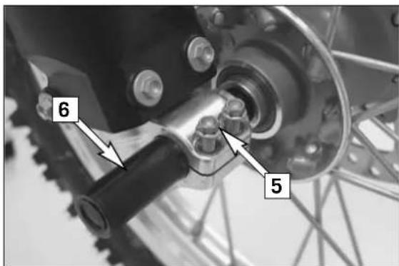
Loosen and remove the collar nut [4], loosen the clamping screews [5] on the right side of the fork fist.
Hold the front wheel, pull out the wheel spindle [6].
Carefully remove the front wheel from the fork.
! CAUTION
- Do not operate the hand brake when the front wheel has been dismounted.
- Make sure the brake disc is always on top when you lay down the wheel, otherwise the brake disc can be damaged.
text_image
6 5To install the front wheel, lift it into the fork, position and mount the axle shaft. Mount the collar nut [4], tighten the clamping screws [5] on the right fork leg axle passage to prevent the axle shaft from turning and tighten the collar nut to 40 Nm (29,52ft.lb).
Loosen the clamp screws on the right fork leg. Take the motorcycle down from its stand. Press the front wheel brakes and push down on the fork a few times vigorously so that the fork legs come into alignment.
Only after this has been accomplished, tighten the clamp screws on both fork legs with 10Nm (7ft.lbs)
WARNING
- If you don't happen to have a torque wrench at hand, make sure you have the tightening torque corrected by a KTM dealer as soon as possible. A loose axle may lead to an unstable driving behavior of your motorcycle.
- Tighten the hexagon nut with the required torque. A loose wheel spindle may lead to an unstable behavior of your motorcycle.
- After mounting the front wheel, keep operating the hand brake until the pressure point returns.
- It is very important to keep the brake disk free from oil and fatty matters, otherwise the braking effects would be strongly reduced.
text_image
Mechanical assembly photo with numbered annotations pointing to components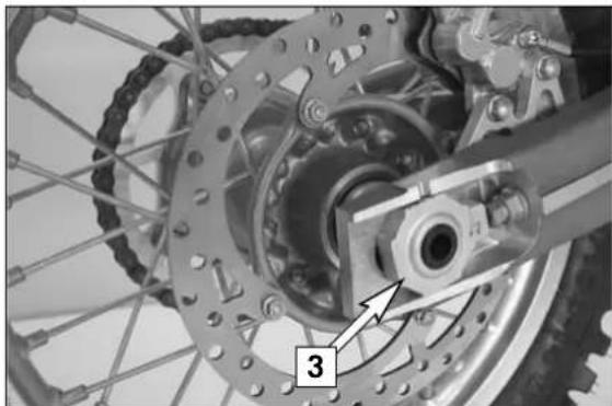
natural_image
Close-up of a bicycle wheel assembly with gear and hub (no visible text or symbols)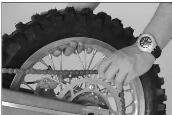
natural_image
Close-up of hands adjusting a tire track with chains and chains (no visible text or symbols)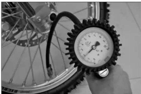
natural_image
Close-up of a hand adjusting a bicycle tire pressure gauge (no visible text or symbols)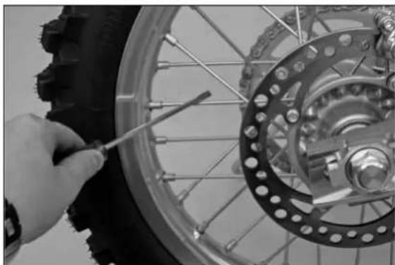
natural_image
Close-up of a hand using a screwdriver to adjust the wheel rim and disc brake system (no text or symbols visible)Dismounting and mounting the rear wheel
Jack the motorcycle up on its frame so that the rear wheel no longer touches the ground.
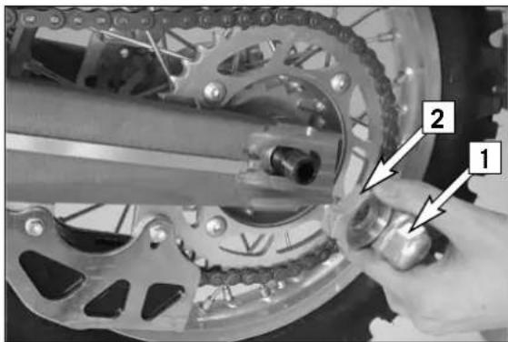
Loosen the collar nut [1], remove chain tensioner [2], hold the rear wheel and pull out the wheel spindle [3] until the rear wheel is free but the brake caliper support is still held.
Push the rear wheel as far forward as possible, take the chain from the chain wheel and carefully take the rear wheel out of the swingarm.
! CAUTION
- Do not operate the rear brake when the rear wheel has been dismounted.
- Make sure the brake disc is always on top when you lay down the wheel, otherwise the brake disc can be damaged.
- If the axle is dismounted, clean the thread of the wheel spindle and collar nut thoroughly and apply a new coat of grease to prevent the thread from jamming.
The rear wheel is remounted in the reverse order. Before tightening the collar nut to 80 Nm (60 ft.lb), push the rear wheel forwards so that the chain tensioners lie on the tension screws.
WARNING
- If you don't happen to have a torque wrench at hand, make sure you have the tightening torque corrected by a KTM dealer as soon as possible. A loose axle may lead to an unstable driving behavior of your motorcycle.
- After mounting the rear wheel, keep operating the rear brake until the pressure point returns.
- It is very important to keep the brake disk free from oil and fatty matters, otherwise the braking effects would be strongly reduced.
- Tighten the collar nut with the required torque. A loose wheel spindle may lead to an unstable behavior of your motorcycle.
Tires, air pressure
Tire type, tire condition, and air pressure level affect the way your motorcycle rides, and they must therefore be checked whenever you are getting ready to go anywhere on your motorcycle. Tire size can be found in the technical specifications. Tire condition has to be checked every time you want to ride your motorcycle. Before leaving, check tires for punctures and nails or other sharp objects that might have become embedded in them.
Tire pressure should be checked regularly on a "cold" tire. Proper pressure (1.0 bar) ensures optimum driving comfort and extends the life of your tires.
WARNING
– Damaged tires must be replaced immediately to protect your youngster.
- Worn tires can have a negative effect on how the motorcycle performs, especially on wet surfaces
– Tire pressure below the normal level will lead to premature tire wear.
Checking spoke tension
The correct spoke tension is very important for the stability of the wheels and thus for riding safety. A loose spoke causes the wheel to become unbalanced and before long other spokes will have come loose. Check spoke tension, especially on a new motorcycle, at regular intervals. For checking, tap on each spoke with the blade of a screwdriver (see photo). A clear tone must be the result. Dull tones are indicators of loose spokes. If necessary, have the spokes retightened and the wheel centered by a KTM dealer.
WARNING
- Spokes can tear if you continue to ride with them loose. This may lead to an unstable handling of your motorcycle.
- Excessively tensioned spokes may rupture due to local overloading. The spokes must be tensioned to 5 Nm.
natural_image
Close-up of hands installing or adjusting a black plastic component on a vehicle (no visible text or symbols)
text_image
2 TwinAir 1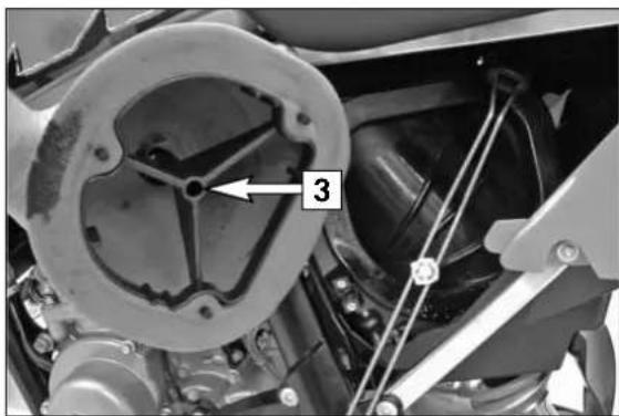
natural_image
Close-up mechanical assembly showing a circular component with internal structure and labeled part '3' (no readable text or symbols beyond label)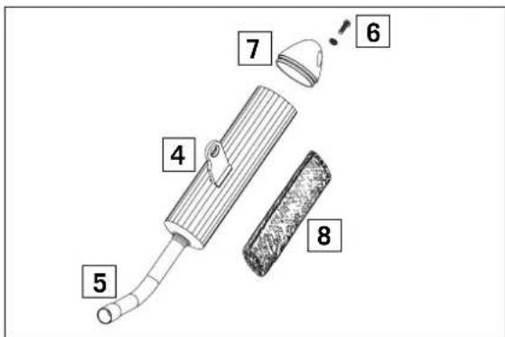
text_image
4 5 6 7 8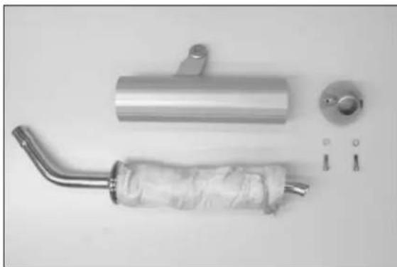
natural_image
Exterior view of a car exhaust pipe assembly with attached gauze and mounting bracket (no text or symbols visible)Cleaning the air filter \*
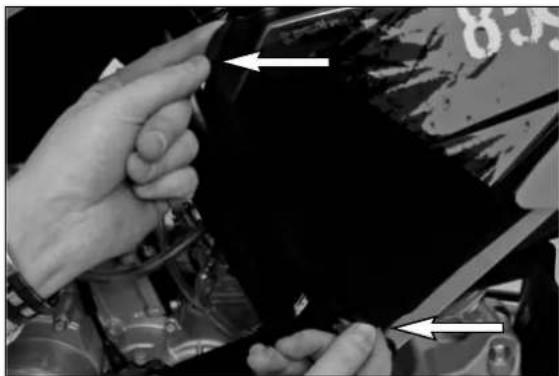
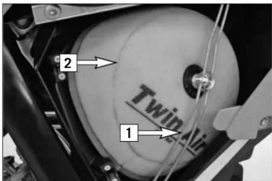
The air filter must be cleaned prior to each race or whenever dust has accumulated. To clean, lift the filter box cover (see illustration) and pull off towards the front. Detach the filter retainer [1] at the bottom, tilt to the side and remove the air filter [2] and the filter support [3] from the filter box.
WARNING
Do not clean the air filter with fuel or petroleum since these will damage the foam. KTM recommends the products made by Motorex (Bio Dirt Remover and Liquid Bio Power) for air filter maintenance. for cleaning purposes and to oil the air filter.
Thoroughly wash the air filter in special cleaning fluid and allow it to dry well. Only press out the filter, do not wring it out under any circumstances. Oil the dry air filter with a high-grade filter oil. Also clean the air filter box. Check the carburetor collar for damage and that it is filled correctly.
Mount the air filter on the filter support. Mount the filter together with the filter support in the filter box, making sure to center them, and fix them properly with the filter holding bracket.
Exhaust system
The silencer is filled with glass-fiber yarn for damping. When in use, the glass-fiber yarn becomes loose or coked with oil carbon. This can lead to a power loss and a reduction of the silencer damping. The glass-fiber yarn packing can be replaced in a few easy steps.
To replace, remove the silencer from the vehicle and mark the position of the outer tube [4] to the inner tube [5]. Remove screws [6] and the end cap [7]. Pull of the outer tube and remove the old glass-fiber yarn packing [8] from the inner tube. Thoroughly clean all parts.
To assemble, mount a new glass-fiber yarn packing onto the inner tube (see illustration) and slide into the outer tube. Mount end cap and fix with screws [6]. Before tightening the screws, turn the outer tube until they match the positions you marked. Mount the silencer and check the exhaust system for tightness.
Note: Glass fiber yarn packages are offered by your licensed KTM dealer.
WARNING
The exhaust system becomes very hot while the motorcycle is running. To avoid burns do not start work on the exhaust system until it has properly cooled down.
natural_image
Close-up of a hand gripping a brake lever and grip (no text or symbols visible)Changing the original position of the clutch lever
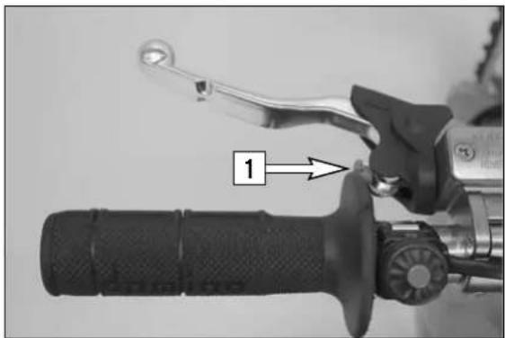
The adjusting screw [1] can be used for individual adjustment of the original position of the clutch lever, thus allowing adjustment to an optimal position for every hand size.
Turning the adjusting screw counterclockwise reduces the distance between the clutch lever and the handlebar. Turning the adjusting screw clockwise increases the distance between the clutch lever and the handlebar.
! CAUTION
Adjustment of the clutch lever position is only possible within certain limits. Only turn the adjusting screw manually and never apply excessive force.
text_image
Close-up of a mechanical component with numbered parts labeled 2, 3, and 4 indicating parts of the assembly.Checking the oil level of the hydraulic clutch
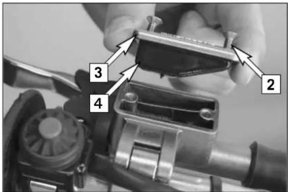
To check the oil level in the master cylinder of the clutch remove the cover. For this purpose, remove screws [2] and cover [3] together with the rubber boot [4]. The oil level in the horizontal-standing master cylinder should be 4 mm below the upper edge.
If necessary, add SAE 10 biodegradable hydraulic oil (Motorex clutch fluid 75), available from your authorized KTM workshop.
! CAUTION
KTM uses biodegradable hydraulic oil for the hydraulic clutch control. Never mix biodegradable hydraulic oils with mineral oils. Never refill with mineral hydraulic oil or brake fluid.
text_image
6 5Bleeding of the hydraulic clutch
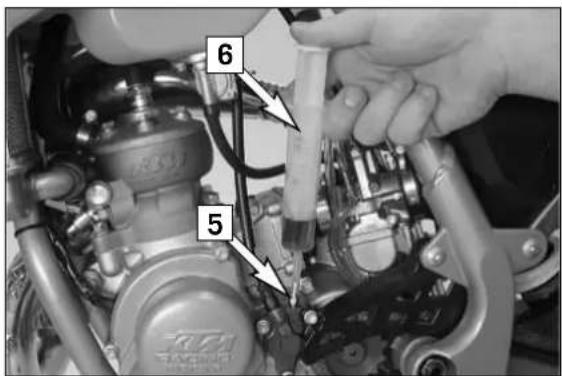
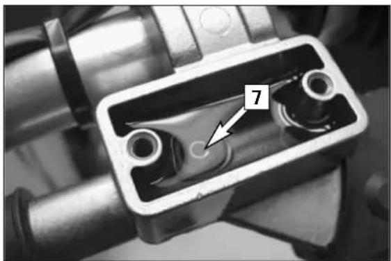
To bleed, the cover of the master cylinder of the clutch needs to be removed. For this purpose, remove screws [2] and take off the cover [3] together with the rubber bellows [4]. At the slave cylinder of the clutch, remove the bleeder nipple [5]. In its place, mount the bleeder syringe [6] which is filled with SAE 10 hydraulic oil. Refill oil, until oil is discharged from the bore [7] of the master cylinder in a bubble-free state. Make sure that the oil does not overflow. The bleeder syringe can be purchased from your KTM dealer. Having completed the bleeding procedure, you have to verify that the oil level in the master cylinder is correct. If necessary, fill up with biodegradable hydraulic oil SAE 10 (e.g. Motorex Clutchfluid 75). Biodegradable hydraulic oil is available from your KTM dealer (50ml).
! CAUTION
KTM uses biodegradable hydraulic oil for the hydraulic clutch control. Never mix biodegradable hydraulic oils with mineral oils.
Always use biodegradable hydraulic oil SAE 10 (e.g. Motorex Clutchfluid 75) to fill up the master cylinder. Never refill with mineral hydraulic oil or brake fluid.
natural_image
Close-up of a mechanical component with internal channels and a numbered annotation (7), no readable text or symbols present.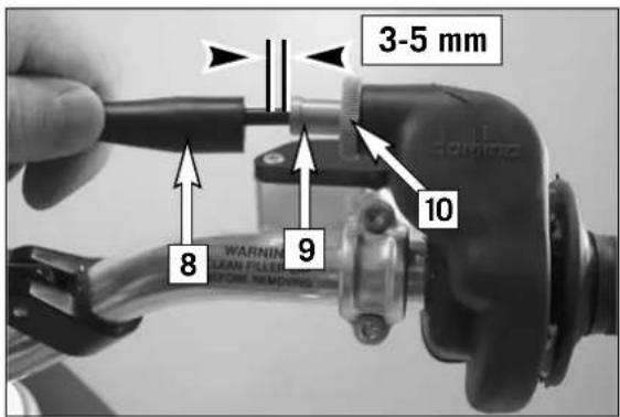
text_image
3-5 mm 8 9 10 WARNING LEAN FILLER FORM REMOKINGAdjusting the throttle cable\*
There must always be a 3-5 mm (0.1-0.2 in) play in the throttle cable. To check this, move back the protective cover [8] on the throttle grip. You must be able to lift the outer covering of the cable 3-5 mm from the adjusting screw [9] until resistance is felt.
To adjust, loosen the counternut [10] and turn the adjusting screw accordingly. Finally tighten the counternut and slide the protective cover back on.
To check the correctness of this setting, start the engine, turn the handlebar left and right, in both cases as far as it will go. This must not cause any changes in idling speed. Otherwise, you will have to increase the backlash of the throttle cable.
text_image
Technical diagram of a mechanical assembly with numbered components and directional arrows indicating parts of motion or assembly.
text_image
TUGH POWER SLOVATION 3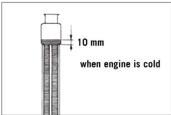
text_image
10 mm when engine is cold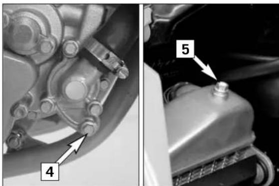
natural_image
Mechanical assembly diagram showing components labeled 4 and 5, with no readable text or symbols beyond labelsCooling system
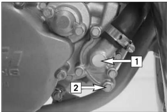
The water pump [1] in the engine keeps the cooling liquid in circulation. The cooling liquid is cooled by the air stream. Therefore, the cooling effect is reduced when the traveling speed is reduced. Dirty radiators additionally reduce the cooling effect.
The cooling liquid can be drained by removing the screw [2] on the water-pump cover.
WARNING
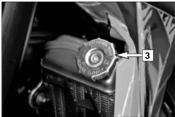
- If possible, always check level of cooling liquid when the engine is cold. If you have to open the radiator cap [3] when the engine is hot, use a rag to cover the cap and open slowly to release pressure. Caution - scalding hazard.
- Do not detach any radiator hoses while the engine is hot. The escaping hot coolant and the steam may cause serious burns.
- In case you get burnt, hold the affected part of your body under running cold water right away.
- Coolant is toxic. Keep the coolant out of the reach of children.
- In case coolant is ingested, consult a doctor immediately.
- If coolant gets into your eyes, rinse them out with water immediately and consult doctor.
A mixture of 50% antifreeze liquid and 50% water is used as coolant. However, the antifreeze protection must be at least -25^ C ( -13^ F). This mixture offers antifreeze protection but also good corrosion protection and should therefore not be replaced by pure water.
! CAUTION
For the cooling system, use only with high-grade antifreeze (Motorex Anti-Freeze). Using lower-grade antifreeze agents can cause corrosion and coolant foaming.
Pressure induced by heating of the coolant in the system is controlled by a valve in the radiator cap [3]; a water temperature rising up to 120°C (248°F) is admissible, without fear of problems.
Checking coolant level
The coolant should be 10 mm (0.4 in) above the radiator fins when the engine is cold (see illustr.). In the event of the coolant being drained, always fill and bleed the system.
WARNING
If possible, always check the level of cooling liquid when the engine is cold. If you have to open the radiator cap when the engine is hot, use a rag to cover the cap and open slowly to release pressure.
! CAUTION
The cooling system must be bled after draining the cooling liquid or after adding more than 0.25 l (0.06 US gallons) cooling liquid.
Refilling/Bleeding the cooling system
The cooling system must be bled as described below after draining the cooling liquid or after adding more than 0.25 l (0.06 US gallons) cooling liquid.
Make sure that the drain screw [4] is fastened.
Pour approx. 0.5 litres (0.13 US gallons) coolant into the system.
Remove the screw [5] on the right radiator.
Now add cooling liquid until it emerges free of bubbles at the right radiator. Then immediately mount the screw so that no more air can enter the right radiator.
Top up the left radiator until the coolant can be seen approx. 10 mm (0.4 in) above the radiator fins.
Check the coolant level again after a short ride.
Carburetor adjustment \*
Basic information on the original carburetor setting
The original carburetor setting was adapted for an altitude of approx. 500 meters (1600 ft.) above sea level, and the ambient temperature of approx. 20°C (68°F), mainly for off-road use and central European premium-grade fuel (ROZ 95).
Mixing ratio 2-stroke motor oil : super fuel 1:40 - 1:60 .
Basic information of changing the carburetor setting
Always start out from the original carburetor setting. Essential requirements are a clean air filter system, air-tight exhaust system and an intact carburetor. Experience has shown that adjusting the main jet, the idling jet and the jet needle is sufficient and that changes to other parts of the carburetor will not greatly affect engine performance.
RULE OF THUMB: high altitude or high temperatures → choose leaner carburetor adjustment low altitude or low temperatures → choose richer carburetor adjustment
WARNING
- Only use unleaded fuel with at least RON 95 (USA = Premium RON 91), mixed with high grade two-stroke oil. Other types of gasoline can cause engine failure, and their use will void your warranty.
- Only use high-grade 2-stroke engine oil of known brands (e. g. Motorex Cross Power 2T).
- Do not use premixed two-stroke oils, oils for outboard engines or normal engine oil to prepare the mixture.
- Not enough oil or low-grade oil can cause erosion of the piston. If you use too much oil, the engine can start smoking and foul the spark plug.
- In the case of a leaner adjustment of the carburetor proceed cautiously. Always reduce the jet size in steps of one number to avoid overheating and piston seizure.
NOTE: If the engine does not run properly, despite a changed adjustment look for mechanical faults and check the ignition system.
Basic information on carburetor wear:
Engine vibrations subject the throttle slide, jet needle, float needle valve and the main nozzle holder to extreme wear. Wear leads to malfunctioning of the carburetor (e.g. over-enrichment). These parts should be inspected and/or replaced after 100 operating hours.
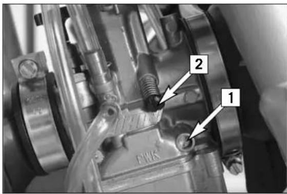
text_image
Close-up mechanical assembly photo with numbered annotations pointing to components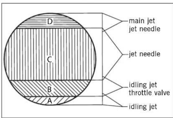
text_image
D C B A main jet jet needle jet needle idling jet throttle valve idling jetIdling range A
Operation with closed throttle valve. This range is influenced by the position of the air control screw [1] and the air control screw [2]. Only make adjustments when the engine is hot.
To this end, slightly increase the idling speed of the engine by means of the air control screw. Turning it clockwise produces a higher idling speed and turning the screw counterclockwise produces a lower idling speed. Create a round and stable engine speed using the air control screw (basic position of the air control screw = open by 1.5 turns). Then adjust to the normal idling speed by means of the air control screw.
Opening up - B
Engine behavior when the throttle opens. The idle jet and the shape of the throttle valve influences this range. If, despite good idling-speed and part-throttle setting, the engine sputters and smokes when the throttle is fully opened and develops its full power not smoothly but suddenly at high engine speeds, the mixture to the carburetor will be too rich, the fuel level too high or the float needle is leaking.
Part-throttle range - C
Operation with partly open throttle valve. This range is only influenced by the jet needle (shape and position). The optimum part-throttle setting is controlled by the idling setting in the lower range and by the main jet in the upper range. If the engine runs on a four-stroke cycle or with reduced power when it is accelerated with the throttle partly open, the jet needle must be lowered by one notch. If the engine pings, especially when accelerating under full power at maximum engine revs, the jet needle should be raised.
If these faults should occur at the lower end of the part throttle range at a four-stroke running, make the idling range leaner; if the engine pings, adjust the idling range richer.
Full throttle range - D
Operation with the throttle fully open (flat out). This range is influenced by the main jet and the jet needle. If the porcelain of the new spark plug is found to have a very bright or white coating or if the engine rings, after a short distance of riding flat out, a larger main jet is required. If the porcelain is dark brown or black with soot the main jet must be replaced by a smaller one.
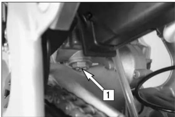
natural_image
Close-up of a mechanical component with a numbered arrow pointing to a component (no visible text or symbols)Draining the float chamber of the carburetor
Following every wet-cleaning procedure, the float chamber of the carburetor should be drained in order to remove any water that may have penetrated into it. Water in the float chamber leads to engine malfunction. Make sure you do this while the engine is cold. Close the fuel tap and place a cloth under the carburetor which is capable of absorbing the leaking fuel. Unscrew the plug [1] and clean it with compressed air. Then, mount the plug together with the gasket and tighten to 4 Nm, open fuel tap, and check the float chamber for leaks.
WARNING
Fuel is easily flammable and toxic. When handling fuel, be sure to exercise the utmost caution. Never perform any work on the fuel system near of open flames or burning cigarettes. Always allow the engine to cool off first. Immediately clean up any fuel which may have been spilled. Materials saturated with fuel are also easily flammable. In case you ingested fuel or fuel splashed into your eyes, consult a doctor immediately.
Dispose of the fuel properly!
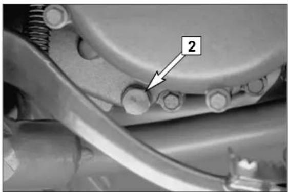
natural_image
Close-up of mechanical components with a numbered annotation pointing to a bolt (no readable text or symbols)Checking gear oil level
To check the gear oil, warm up the engine to operating temperature with a low load and place the motorcycle on an even surface. Remove the oil drain plug [2] and allow the gear oil to drain into a vessel. Clean the sealing area, mount the oil drain plug and gasket and tighten to 15 Nm.
Remove the oil filler screw [4] and add 0.5 liters of gear oil (e.g. Motorex Topspeed 4T 15W50). Mount the oil filler screw and check the engine for leaks.
If the gear oil is still clean you can continue to use it up to your next service.
! CAUTION
- too little oil or a poor oil quality will cause the transmission to wear prematurely. Only use brand-name oils.
- due to a change in the fluid capacities the inspection screw [3] can no longer be used.
WARNING
Engines and engine oil are extremely hot at operating temperatures - be careful not to burn yourself.
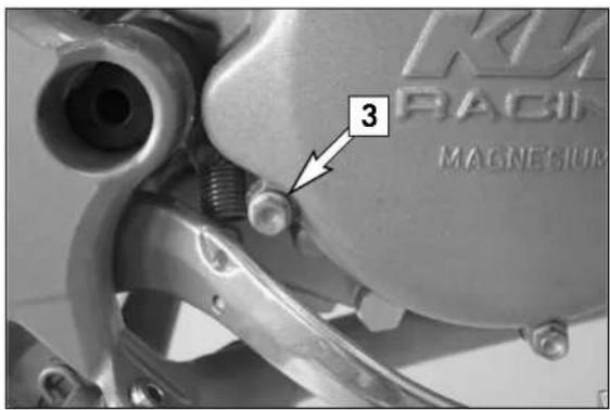
text_image
KAV RACI MAGNESIUM 3Changing gear oil \*
Before changing the gear oil warm up the engine and park the motorcycle on a horizontal surface. Remove the oil drain plug [2] and drain the used oil into an appropriate container. Clean the sealing surface. Mount the oil drain plug together with its gasket and tighten to 15 Nm.
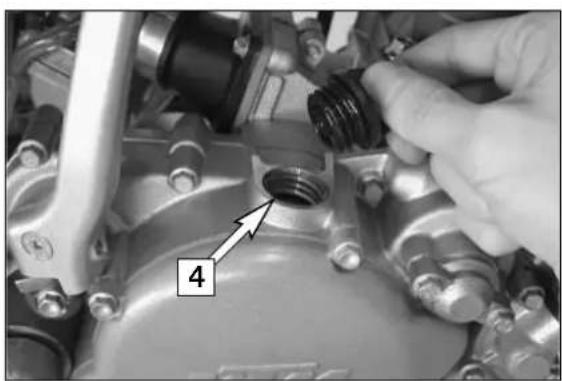
natural_image
Close-up of a mechanical component with a hand adjusting a threaded bolt, labeled with number 4 (no text or symbols beyond labeling)Remove the filler plug [4] and add 0.5 l gear oil (e.g. Motorex Topspeed 4T 15W50). Mount the filler plug and check the engine for leaks.
! CAUTION
- too little oil or a poor oil quality will cause the transmission to wear prematurely. Only use brand-name oils.
- due to a change in the fluid capacities the inspection screw [3] can no longer be used.
WARNING
Engines and engine oil are extremely hot at operating temperatures - be careful not to burn yourself.
If you let the specified maintenance work on your motorcycle be carried out, disturbances can hardly be expected. Should an error occur nevertheless, we advise you to use the trouble shooting chart in order to find the cause of error.
We would like to point out that many operations cannot be performed by oneself. In case of uncertainty, please contact a KTM-dealer.
| TROUBLE CAUSE REMEDY | ||
| Engine fails to start Operating error | Open fuel tap, replenish fuel, do not use choke | |
| The highly inflammable components in modern fuels volatilize if left standing for longer periods of time. If the motorcycle has not been used for over 1 week, the fuel should be drained from the float chamber. The engine will start up immediately if the float chamber is filled with fresh, ignitable fuel | ||
| Close fuel tap, loosen fuel hose at carburettor, lead into a basin and open fuel tap, - if fuel leaks out, clean carburettor - if no fuel leaks out, check tank ventilation, i.e. clean fuel tap | ||
| Reduce electrode distance (0.60 mm) | ||
| Clean spark plug or renew | ||
| Dismount spark plug, connect ignition cable, hold to ground (blank place on engine) and actuate kickstarter, a strong spark must be produced at the spark plug - If no spark is produced, loosen spark plug cap from ignition cable, hold about 5 mm from ground and actuate kickstarter - If a spark now occurs, replace spark plug cap - If no spark is produced, control ignition system | ||
| Disconnect black coloured cable from short circuit button at ignition coil and check ignition spark. If the spark is O.K. repair defective part of cable or ignition switch | ||
| Inspect cable connectors | ||
| Examine ignition system | ||
| Dismantle and clean carburetor | ||
| Engine without idle running Idle adjustment | Readjust idle running or replace idle adjusting screw | |
| Examine ignition system | ||
| Overhaul engine | ||
| Engine has not enough power Charred glass fiber yarn in silencer | Renew filling | |
| Clean or renew airfilter | ||
| Blow through fuel pipe and clean carburetor | ||
| Tighten spark plug | ||
| Check exhaust system for damage | ||
| Check and adjust ignition | ||
| Engine has not enough power Re | eed paddles tensionless or damaged, surface of reed valve housing damaged | Replace reed paddles or reed valve housing |
| Wear | Overhaul engine | |
| Engine revs not up and running in four stroke cycle | Carburetor overflows if level adjust too high, float needle seating is dirty or enlarged | Clean carburetor, if necessary replace float needle and adjust level |
| Loose carburetor jets | Tighten jets | |
| High rpm misfiring Incorrect heat range spark plug or low quality spark plug | Refer to technical data section | |
| Check and seal with silicon | ||
| Engine spluters into the carburetor | Lack of fuel | Clean fuel pipes, examine tank aeration and clean |
| Spark plug with incorrect heat value (Ignition by incandescence) | Fit correct spark plug | |
| Engine takes air out of control | Check intake flange and carburettor if firmly setted | |
| Engine overheating Insufficient liquid in cooling system | Top up coolant and bleed cooling system check cooling system for leaks | |
| Clean radiatar fins with water jet | ||
| Renew coolant using branded anti-freeze/anti-corrosive (Motorex Anti-Freeze) | ||
| Replace with correct routed hoses | ||
| Readjust to correct ignition timing specifications, secure screws with Loctite 243 | ||
| Measure and adjust compression ratio | ||
| Emission of white smoke (steam) | Cylinder head or O-ring of cylinder head gasket leaks | Check cylinder head, replace O-ring |
| Excessive oil escapes from transmission breather tube | Excessive oil quantity in transmission | Correct transmission oil level |
| Water in transmission oil Shaft seal ring of the water pump defect | Replace shaft seal ring of the water pump. | |
Clean your motorcycle regularly in order to keep its painted finish looking shiny and new.
The best manner would be to use warm water that has been mixed with a commercially available washing detergent and a sponge. The hard dirt can be removed before with the help of a soft water jet.
! CAUTION
Never clean your motorcycle with a high-pressured cleaner or a high-pressured water jet. otherwise the water might run into the electrical components, connectors, sheathed cables, bearings, carburetor etc. and cause mailfunctions, i.e., lead to the premature destruction of these parts.
- You should use commercially available detergents to clean the motorcycle. Heavily soiled parts should also be cleaned with the help of a paint brush.
- Before cleaning with water, plug the exhaust pipe to prevent water ingress.
- After the motorcycle has been rinsed with a soft water jet, it should be dried by air pressure and a cloth. Then take a short drive until the engine has reached its operating temperature, and also operate the brakes. The heat also causes the water at the inaccessible parts of the engine and the brakes to evaporate.
- Slide back the protective covers on the handlebar-mounted instruments so that any water that may have seeped into this part of the motorcycle is allowed to evaporate.
- After the motorcycle has cooled down, oil and grease all the gliding bearing parts. Also treat the chain with a chain spray.
- To prevent failures in the electric system, you should treat the short circuit button with a contact spray.
STORAGE >>
If you want to put your motorcycle away for longer periods of time, please observe the following instructions:
– Clean motorcycle thoroughly (see chapter: CLEANING)
– Change engine oil (old engine oil contains aggressive contaminations).
– Check antifreeze and amount of cooling liquid.
- Let the engine warm up again, close fuel tap and wait until the engine dies off by itself. In this way, the carburetor jets are prevented from becoming resin-clogged by the old fuel.
- Remove spark plug and fill in approx. 5 ccm of engine oil into the cylinder through the opening. Actuate kickstarter 10 times in order to distribute the oil onto the cylinder walls and mount the spark plug.
- Let fuel flow out of tank into an appropriate basin.
– Correct tire pressure.
– Lubricate bearing points of the control levers, footrests, etc. as well as the chain.
- The storage place should be dry and not be subjected to overly great temperature fluctuations.
- Cover the motorcycle with an air permeable tarpaulin or blanket. Do not use airtight materials, as possible humidity might not be able to escape and thereby cause corrosion.
WARNING
It would be very bad to let the engine run for a short time during the storage period. The engine would not get warmed up enough and the thus developed steam would condense during the combustion process and cause the exhaust to rust.
Use after period of storage
- Fill up tank with fresh fuel.
- Check motorcycle as before each start (see driving instructions).
- Take a short, careful test ride first.
NOTE: Before you put your motorcycle away for the winter, you should check all parts for their function and wear. Should any service jobs, repairs, or any refitting be necessary, you should have them carried out during the off-season (lower workload at mechanics' shops). This way, you can avoid the long waiting times at your shop at the beginning of the next biking season.
| CHASSIS 85 SX/XC (17"/14") 85 SX 105 SX/XC (19"/16") | ||
| Frame Central chrome-moly-steel frame | ||
| Fork telescopic fork WP Suspension 4357 | MXMA | |
| Wheel travel front/rear 275 mm / 300 mm | (10.82/11.81 in) | |
| Rear suspension WP PDS 4618 (Progressive Damping System) shock absorber | ||
| Front brake Disc brake ∅ 220 mm (8.66 in), 4 piston | ||
| Rear brake Disc brake ∅ 200 mm (7.87 in), 4 piston | ||
| Tires front 70/100-17" Pirelli NHS 40 M | 70/100-19" Pirelli NHS 42M | |
| Tires rear 90/100-14" Pirelli NHS 49 90/100-16" Pirelli NHS 51 | ||
| Air pressure 1.0 bar | ||
| Fuel tank capacity 5.1 liter | ||
| Final drive ratio 14 : 46 t 14 : 49 t | ||
| Chain | 1/2 x 5/16" 122 rolls (SX) | 1/2 x 5/16" O-Ring 122 rolls (XC) |
| Steering angle | 66° | |
| Wheel base 1290 mm | ||
| Seat height, unloaded | 865 mm | 900 mm |
| Ground clearance | 385 mm | 415 mm |
| Dead weight without fuel | 66 kg | 68 kg |
| Rider's body weight | max. 75 kg | |
| Recommended age of rider | 10 to 15 years | |
| Engine | CR-85/CR-105 | |
| STANDARD ADJUSTMENT – FORK (SX) | |
| WP 4357 MXMA05187D05 | |
| Compression adjuster | 15 |
| Rebound adjuster | 20 |
| Spring | 3,4 N/mm |
| Air chamber length | 110 mm |
| Fork oil | SAE 5 |
| STANDARD ADJUSTMENT – FORK (XC) | |
| WP 4357 MXMA05187D06 | |
| Compression adjuster | 20 |
| Rebound adjuster | 20 |
| Spring | 3,4 N/mm |
| Air chamber length | 110 mm |
| Fork oil | SAE 5 |
| STANDARD ADJUSTMENT – SHOCK ABSORBER (SX) | |
| WP 4618 PDS-DCCWP 15187D02 | |
| Compression adjuster | 15 LS (LOW SPEED)2 HS (HIGH SPEED) |
| Rebound adjuster | 22 |
| Spring | 35-215 |
| Spring preload | 7 mm |
| STANDARD ADJUSTMENT – SHOCK ABSORBER (XC) | |
| WP 4618 PDS-DCCWP 15187D04 | |
| Compression adjuster | 15 LS (LOW SPEED)2 HS (HIGH SPEED) |
| Rebound adjuster | 22 |
| Spring | 35-215 |
| Spring preload | 7 MM |
| TIGHTENING TORQUES - CHASSIS | ||
| Hexagon bolt - brake caliper front M 8 Loctite 243 + 25 Nm | ||
| Allan head screw - brake pads rear M6 5 Nm | ||
| Flat head bolt - brake discs M6 14 Nm | ||
| Hexagon nut - front wheel spindle M10x1.5 40 Nm | ||
| Hexagon nut - rear wheel spindle M20x1.5 80 Nm | ||
| Hexagon nut - swingarm bolt M14/M 16x1.5 75 Nm | ||
| Clamping bolts - top triple clamp M8 25 Nm | ||
| Clamping bolts - bottom triple clamp M8 15 Nm | ||
| Bolt - handlebar clamp M8 20 Nm | ||
| Spoke nipple M4,5 5 Nm | ||
| Other chassis bolts | M6 | 10 Nm |
| M8 | 25 Nm | |
| M10 | 45 Nm | |
| ENGINE 85 SX/XC | 105 SX/XC | |
| Design | Liquid cooled single cylinder two-stroke engine with reed valve intake | |
| Displacement | 84.93 ccm | 103.96 ccm |
| Bore/stroke | 47 / 48.95 mm | 52 / 48.95 mm |
| Fuel | unleaded fuel with at least RON 95 (USA = Premium RON 91), mixed with high grade two-stroke oil | |
| Oil/gasoline ratio | 1 : 40 - 1 : 60 when using high grade two-stroke oil (e.g. Motorex 2T Crosspower),when in doubt, please contact your importer | |
| Lubrication | mixture lubrication | |
| Crankshaft bearing | deep-groove ball bearing, cylinder roller bearing | |
| Connecting rod bearing | needle bearing | |
| Piston pin bearing | needle bearing | |
| Piston rings | 1 compression ring | |
| Primary drive | straight cut spur gears, 19 : 66 t | |
| Clutch | multiple disc clutch in oil bath, hydraulic operated (Motorex Kupplungs-Fluid 75) | |
| Transmission | 6 speed, claw actuated | |
| Gear ratio | 1^st gear 11 : 29 2^nd gear 14 : 28 3^rd gear 16 : 26 4^th gear 19 : 26 5^th gear 21 : 25 6^th gear 20 : 21 | |
| Transmission oil | 0.5 liter engine oil Motorex Topspeed 4T 15W50 | |
| Ignition system | Moric Digital 2M1 | |
| Spark plug | NGK BR 9 ECMVX | |
| Electrode gap | 0.60 mm | |
| Carburetor | flat-slide carburetor, carburetor see table | |
| Coolant | 1 liter, mixture 50% antifreeze, 50% distilled water, at least -25^ (-13°F) | |
| Air filter | wet foam type air filter insert | |
BASIC CARBURETOR SETTING
| Carburetor | Keihin PWK 28 |
| Main jet | 118 |
| Needle jet | 2.6 |
| Idling jet | 45 |
| Jet needle | N5HG |
| Needle position from top | III |
| Throttle valve | 3.5 |
| Starting jet | 62 |
| Air adjustment screw open | 1,5 |
TIGHTENING TORQUES - ENGINE
| Flange bolts - cylinder-head M 6 10 Nm | ||||||
| Nuts-cylinder base M 8 30 Nm | ||||||
| Flywheel collar nut M 12X1 60 Nm | ||||||
| Primary gear bolt M 10X1,25 Loctite 243 + 80 Nm | ||||||
| Nut for inner clutch hub M 14X1,25 Loctite 243 + 60 Nm | ||||||
| Crankcase and cover bolts M 6 8 Nm | ||||||
| Spark plug M 14X1,25 20 Nm | ||||||
| Reed valve housing M 14X1,5 75 Nm | ||||||
| Kickstarter M 6 6 Nm | ||||||
| Shift lever M 6 Loctite 243 + 12 Nm | ||||||
| Swingarm pivot M 6 Loctite 243 + 12 Nm | ||||||
| Other bolts | M 5M 6 | 6 Nm10 Nm | ||||
| VERGASERREGULIERUNG CARBURETOR SETTING KEIHIN PWK 28 | 85/105 SX/XC 2008 | KTM | ||||
| MEERESHÖHE ALTITUDE↓ | TEMPERATUR TEMPERATURE→ | -20°C bis -7°C -2°F to 20°F | -6°C bis 5°C 19°F to 41°F | 6°C bis 15°C 42°F to 60°F | 16°C bis 24°C 61°F to 78°F | 25°C bis 38°C 79°F to 98°F |
| 3000 m10000 ft↑2301 m7501 ft | LSO ASOLD IJNADEL NEEDLEPOS POSHD MJ | 1,545N5HG2118 | 1,7542N5HH3115 | 240N5HH2115 | 2,2538N5HH1115 | 2,538N5HH1115 |
| 2300 m7500 ft↑1501 m5001 ft | LSO ASOLD IJNADEL NEEDLEPOS POSHD MJ | 1,2548N5HG3120 | 1,545N5HG2118 | 1,7542N5HH3115 | 240N5HH2115 | 2,2538N5HH1115 |
| 1500 m5000 ft↑751 m2501 ft | LSO ASOLD IJNADEL NEEDLEPOS POSHD MJ | 150N5HF3122 | 1,2548N5HG3120 | 1,545N5HG2118 | 1,7542N5HH2115 | 240N5HH2115 |
| 750 m2500 ft↑301 m1001 ft | LSO ASOLD IJNADEL NEEDLEPOS POSHD MJ | 0,7550N5HF4125 | 150N5HF3122 | 1,2548N5HG3120 | 1,545N5HG3118 | 1,7542N5HH2115 |
| 300 m1000 ft↑MeeresniveauSea level | LSO ASOLD IJNADEL NEEDLEPOS POSHD MJ | 0,550N5HF5125 | 0,7550N5HF4125 | 150N5HG3122 | 1,2548N5HG3120 | 1,545N5HG2118 |
ASO = Air screw open from fully-seated
IJ = Idling jet
POS = Needle clip position from top
MJ = Main jet
NOT FOR HIGHWAY USE
Fuel: unleaded fuel with at least RON 95
USA = Premium PON 91
Page
Adjusting free travel of the hand brake lever .....21
Adjusting the throttle cable .....27
Basic suspension setup for the weight of the driver . . .18
Bleeding of the hydraulic clutch .....27
Braking 13
Breather plug front fork 16
Carburetor adjustment 29
Carburetor setting 37
Chain maintenance 20
Changing basic position of the brake pedal .....23
Changing gear oil 30
Changing the original position of the clutch lever . . . .27
Changing the spring preloading of the shock absorber .17
Chassis number 6
Checking and adjusting the steering head bearing . . .16
Checking chain tension .....20
Checking coolant level 28
Checking front brake pads 22
Checking gear oil level 30
Checking rear brake pads 23
Checking spoke tension .....25
Checking the basic setup of the telescopic fork .....19
Checking the brake fluid level/ refilling .....22
Checking the oil level of the hydraulic clutch .....27
Checking the rear brake fluid level .....23
Checking the shock absorber and spring .....18
Choke 7
Cleaning 33
Cleaning the air filter .....26
Cleaning the dust sleeves of the telescopic fork .....17
Clutch lever 6
Compression damping of fork 8
Cooling system 28
Correct chain tension .....20
Damping action during compression of shock absorber .9
Determining the riding sag of the shock absorber ....18
Determining the static sag of the shock absorber ....18
Dismounting and mounting the front wheel .....24
Dismounting and mounting the rear wheel .....25
Draining the float chamber of the carburetor .....30
Driving instructions .....11
Engine number 6
Exhaust system 26
Page
Filler cap 7
Foot brake pedal 8
Fuel tap 7
General information about KTM disc brakes .....21
General tips and warnings for starting the motorcycle .10
Hand brake lever....6
How to change the handlebar position .....17
Important information for parents about safe driving . . .4
Instructions for the first ride .....10
Kickstarter 8
Maintenance work on chassis and engine .....16
Operation instruments 6
Overview of the shock absorber springs .....19
Overview of the telescopic fork springs .....19
Periodic maintenance schedule .....14
Plugin- Stand 8
Rebound damping function of the shock absorber . . . .9
Rebound damping of fork 8
Refilling the rear brake fluid reservoir .....23
Refilling/Bleeding the cooling system .....28
Refueling, fuel 13
Replacing the front brake pads . . . . . . . . . . . . . . . . . . . . . . . . . . . . . 22
Running in 10
Serial number locations 6
Shift lever 7
Shifting/Riding 12
Short circuit button 7
Side stand 8
Standard high-speed setting: 9
Standard low-speed setting: 9
Starting off 12
Starting when the engine is cold .....12
Starting when the engine is warm .....12
Stopping 13
Storage 33
Technical Specifications – Chassis .....34
Technical specifications - engine .....36
Tires, air pressure .....25
Trouble shooting .....31
Use after period of storage ....33
What to do when the engine is "flooded" .....12
What you should check before each start .....11

text_image
Barcode image containing machine-readable data, no human-readable text visible3211224en