950 Super Enduro R (2009) - Motorcycle KTM - Free user manual and instructions
Find the device manual for free 950 Super Enduro R (2009) KTM in PDF.


User questions about 950 Super Enduro R (2009) KTM
0 question about this device. Answer the ones you know or ask your own.
Ask a new question about this device
Download the instructions for your Motorcycle in PDF format for free! Find your manual 950 Super Enduro R (2009) - KTM and take your electronic device back in hand. On this page are published all the documents necessary for the use of your device. 950 Super Enduro R (2009) by KTM.
USER MANUAL 950 Super Enduro R (2009) KTM
natural_image
Side profile of a 950 Super E motorcycle with visible dynamics and suspension components (no text or symbols on the bike body)KTM
We would like to congratulate you on your purchase of a KTM motorcycle. You are now the owner of a state-of-the-art sport motorcycle that guarantees to bring you lots of fun and enjoyment, provided that you clean and maintain it appropriately. Please insert the serial numbers of your motorcycle in the boxes below:
Frame number
Engine number
Key number
Stamp of dealer
All information contained is without obligation. KTM-Sportmotorcycle AG particularly reserves the right to modify any equipment, technical specifications, prices, colors, shapes, materials, services, service work, constructions, equipment and the like so as to adapt them to local conditions or to cancel any of the above items, all without previous announcement and without giving reasons. KTM may stop manufacturing certain models without previous notice. KTM shall not be held liable for any deviations of availability and/or ability to deliver, illustrations, descriptions, printing and/or other errors. The illustrated models partly contain extra equipment, which is not applied to standard models.
© 2008 by KTM-SPORTMOTORCYCLE AG, Mattighofen AUSTRIA; All rights reserved; Reprint, also in extracts, with written allowance of KTM-SPORTMOTORCYCLE AG, Mattighofen only.
COMSUMER INFORMATION FOR AUSTRALIA ONLY Tampering with noise control system prohibited Owners are warned that the law may prohibit:
(a) The removal or rendering inoperative by any person other than for purposes of maintenance, repair or replacement, of any device or element of design incorporated into any new vehicle for the purpose of noise control prior to its sale or delivery to the ultimate purchaser or while it is in use; and
(b) the use of the vehicle after such device or element of design has been removed or rendered inoperative by any person.

In accordance with the international quality management ISO 9001 standard, KTM uses quality assurance processes that lead to the highest possible product quality.
INTENDED PURPOSE
The KTM 950 Super Enduro R is designed to resist the usual wear and tear of onor off-road service, providing maximum performance in competitive racing or private use.
OWNER'S MANUAL
Carefully read the entire Owner's Manual before you start riding your motorcycle, even if this will take a little time. It contains useful tips and information on the best way to handle the motorcycle and how to protect yourself from injuries. The Manual also contains important information on service and maintenance. In your own interest, pay particular attention to the information marked as follows:

WARNING
- Ignoring these instructions, can endanger your body and your life.

CAUTION
- Ignoring these instructions could cause damage to parts of your motorcycle or that the motor-cycle is not road-safe anymore.
The Owner's Manual corresponded to the latest information available for this model series at the time it was printed. Minor deviations resulting from enhancements to the motorcycle design cannot be entirely precluded. The Owner's Manual is an integral part of the motorcycle and must be handed over to the new owner when the motorcycle is sold.
SERVICE
Observance of the service, maintenance and operating instructions for the engine and chassis specified in the Owner's Manual is a prerequisite for faultless operation and the avoidance of premature wear. Please observe the prescribed breaking-in periods, inspection intervals and service intervals. Strict observance will significantly prolong the service life of your motorcycle.
Use of the motorcycle under extreme conditions, e.g. on extremely muddy and wet terrain, can lead to higher than average wear on components such as the drive train or the brakes. In this case it may become necessary to service or replace wear parts before the service limit specified in the maintenance schedule has been reached.
IMPORTANT INFORMATION »
WARRANTY
The service work specified in the „Lubrication and Maintenance Schedule“ must be performed by an authorized KTM workshop. This is the only place that has the qualified technicians and the special tools required for the 950 Super Enduro R. Be sure to have the workshop verify all service work carried out in the service manual to avoid losing your right to claim under the warranty. The warranty or guarantee shall become void for damage and consequential damage caused by manipulations or conversions to the motorcycle.
AUTOMOTIVE FLUIDS
The fuels, lubricants and liquids specified in the Owner's Manual or automotive fluids with equivalent specifications must be used in accordance with the maintenance schedule.
SPARE PARTS, ACCESSORIES
For your own safety, only use spare parts and accessories approved by KTM. KTM shall not assume any liability for other products or consequential damage resulting from the use of such products.
ENVIRONMENT
Motorcycle driving is a wonderful sport and we hope that you will be able to enjoy it to the full. It may, however, involve potential problems for the environment or lead to conflicts with others. These problems or conflicts can be avoided if the motorcycle is used responsibly. To safeguard the future of motorcycle sports, make sure that you use the motorcycle in accordance with the law, show that you are environmentally conscious and respect the rights of others.
Enjoy driving your motorcycle!
KTM SPORTMOTORCYCLE AG
5230 MATTIGHOFEN, AUSTRIA
INDEX >>
INTRODUCTION 1
IMPORTANT INFORMATION 2
SERIAL NUMBER LOCATIONS 6
Chassis number, Type label .....6
Engine number, engine type 6
Multi-functional digital speedometer ....8
Display 8
Setting options in the display .....10
Cooling liquid temperature display 12
Indicator lamps 12
Ignition lock 13
Combination switch 13
Flasher switch....13
Starter tip switch 14
Filler cap 14
Fuel taps 14
Grips 15
Removal of seat 15
Tool set 16
Shift lever....16
Side stand 16
Foot brake pedal 17
Compression damping of fork 18
Rebound damping of fork 18
Spring preload of the fork ....18
Damping action during compression of shock absorber ....19
Rebound damping of shock absorber .....19
GENERAL TIPS AND WARNINGS FOR STARTING
THE MOTORCYCLE 20
Instructions for initial operation .....20
Running in the LC8 engine . . . . . . . . . . . . . . . . . . . . . . . . . . . . . . . . . . . . . . . . . . . . 20
Accessories and payload .....21
DRIVING INSTRUCTIONS .....22
Check the following before each start .....22
Starting when the engine is cold .....24
Starting when the engine is warm or hot . . . . . . . . . . . . . . . . . . . . . . . . . . . . 25
Starting off 25
Shifting/Riding 25
Braking 26
Stopping and parking 27
Fuel, refueling .....28
PERIODIC MAINTENANCE SCHEDULE 29
MAINTENANCE WORK ON CHASSIS AND ENGINE .....33
Adjusting the fork and shock absorber .....34
Adjusting compression damping of fork . . . . . . . . . . . . . . . . . . . . 34
Adjusting rebound damping of fork . . . . . . . . . . . . . . . . . . . . . . . . . . . . . . . . . . . . . . . 35
Adjusting the spring preload on the fork . . . . . . . . . . . . . . . . . . . . . . . . . . . . . . . . . . . . . . . 35
Compression damping of shock absorber . . . . . . . . . . . . . . . . . . 36
Rebound damping of shock absorber . . . . . . . . . . . . . . . . . . . . . . . . . . . . . 37
Breathing the fork legs 37
Checking the chain tension 38
Correcting the chain tension 38
Chain maintenance 39
Checking the chain for wear . . . . . . . . . . . . . . . . . . . . . . . . . . . . . . . . . . . . . . . . . . 39
General informations about KTM disc brakes .....40
INDEX >>
Adjusting of free travel at the hand brake lever .....42
Checking of brake fluid level - front brake .....42
Checking the front brake pads 42
Checking rear brake fluid level . . . . . . . . . . . . . . . . . . . . . . . . . . . . . . . . . . . . . . . 43
Checking the rear brake pads 43
Dismounting and mounting the front wheel .....44
Dismounting and mounting the rear wheel .....46
Tires, air pressure 48
Checking spoke tension 49
Battery 50
Charging the battery 51
Jump start ....51
Main fuse 52
Fuses for individual power consumers .....53
Replacing the headlight lamp .....54
Adjusting the headlight range .....55
Replacing the flasher bulbs .....55
Replacing the brake light and taillight bulbs .....56
Activating the ignition curve for low-octane fuel .....57
Cooling system 58
Checking the cooling liquid level in the compensating tank . .59
Checking the cooling liquid level in the radiator .....60
Bleeding the cooling system .....61
Changing the original position of the clutch lever .....62
Checking the oil level of the hydraulic clutch . . . . . . . . . . . . . . . . . . . . . . . . . . . . . . . . . . . . . . . . . . . . . . . . . . . . . . . . . 62
Checking and adjusting the throttle cable play .....63
Checking and adjusting the choke cable play .....63
Adjusting the engine idle speed .....63
Engine oil 64
Checking the engine oil level 64
Refilling engine oil 64
Changing the engine oil and the oil filter,
cleaning the oil screen 65
TROUBLESHOOTING....68
CLEANING 72
CONSERVATION FOR WINTER OPERATION .....73
STORAGE 74
RE-INITIATION AFTER TIME OF STORAGE .....74
TECHNICAL SPECIFICATIONS - CHASSIS .....75
TECHNICAL SPECIFICATIONS - ENGINE .....79
Engine oil 80
HEAD WORD INDEX 81
SERIAL NUMBER LOCATIONS »
natural_image
Interior view of a vehicle gear shift lever with a white arrow pointing to the component (no visible text or symbols)Chassis number, Type label
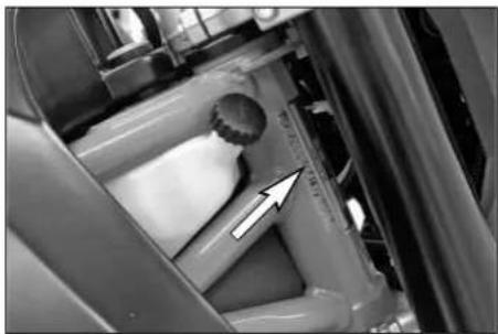
The chassis number is stamped on the right side of the steering head tube. Enter this number in the field on page no 1.
The type label is located next to the chassis number.
natural_image
Close-up of mechanical components with a white arrow pointing to a specific part (no visible text or symbols)Engine number, engine type
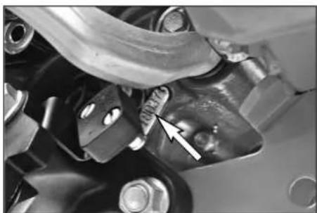
The engine number and the engine type are stamped into the left side of the engine below the engine sprocket. Enter this number on page 1.
OPERATION INSTRUMENTS »
text_image
1 AClutch lever
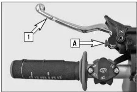
The clutch lever [1] is fitted on the left hand side of the handle bar. The adjusting screw [A] is used to change the original position of the clutch lever (see maintenance work on chassis and engine).
The clutch is hydraulically actuated and adjusts itself automatically.
text_image
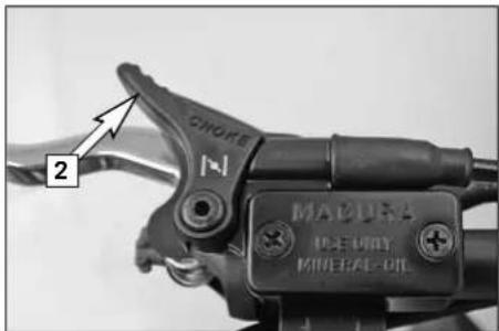
CNOKE 2 MALURA 100 LIMY MINERAL-OILChoke lever
If the choke lever [2] is pulled backwards, a bore in the carburetors will be opened in the carburetor through which the engine may draw in additional fuel. This produces a „rich“ fuel/air mixture necessary for cold start. The fuel quantity and thus the engine speed are determined by the choke lever position.
At temperatures over 5^ C ( 41^ F) it will suffice to pull the choke lever half way out. At temperatures below 5^ C ( 41^ F) the choke lever should be pulled all the way out. The hole is closed again by pushing the choke lever all the way back in.
text_image
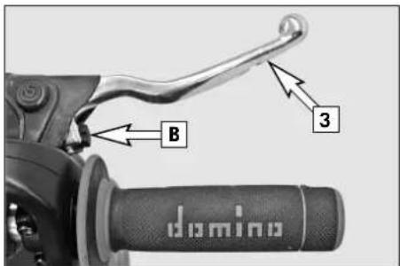
B 3 dominoHand brake lever
The hand brake lever [3] is mounted on the right side of the handlebar. The adjusting screw [B] can be used to change the basic position of the hand brake lever (see Maintenance).
OPERATION INSTRUMENTS »
text_image
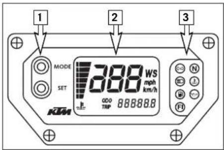
MODE SET 388 WS mph km/h QDO TRP 88888.0 1 2 3Multi-functional digital speedometer
The universal instrument is divided into 3 parts.
Use the MODE and SET [1] button to change the display and the basic settings in the display.
Display [2] shows all of the information that may be of interest to you. 5 display modes can be selected with the MODE button.
The indicator lamps [3] provide additional information on the motorcycle's running condition.
flowchart
graph TD
    A["TEST"] --> B["7388/8888880000"]
    B --> C["WS"]
    C --> D["17 WS"]
Display
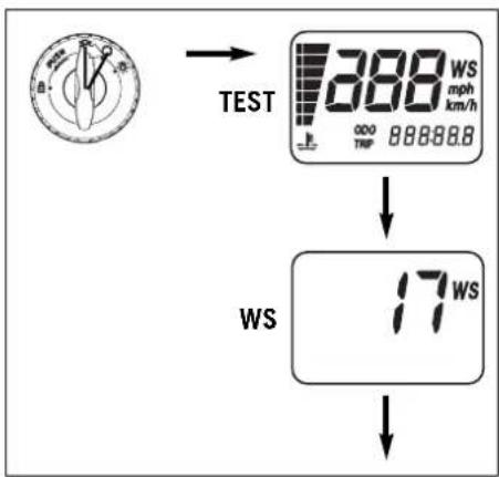
TEST
When you switch on the ignition, all of the display elements will light up for 1 second for the function test.
WS (wheel size)
The display will change and show the diameter of the front wheel in inches for 1 second (WS = wheel size).
Then the CLOCK mode will be displayed, or the mode that was active when the ignition was switched off.
OPERATION INSTRUMENTS »
flowchart
graph TD
    A["CLOCK"] --> B["MODE SET"]
    B --> C["ODO"]
    C --> D["MODE SET"]
    D --> E["TRIP 1"]
    E --> F["MODE SET"]
    F --> G["TRIP 2"]
    G --> H["MODE SET"]
    H --> I["TRIP F"]
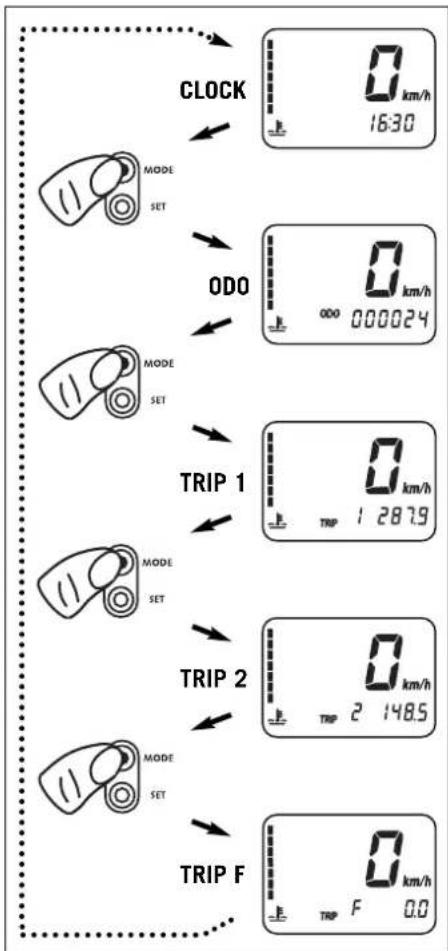
CLOCK
You will recognize the CLOCK display by the blinking dots between the hours and minutes. It displays the speed, temperature of the cooling liquid and the clock.
To switch to the next display mode, press the MODE button.
ODO
The speed, temperature of the cooling liquid and the total kilometers or miles traveled are shown in the ODO mode.
To switch to the next display mode, press the MODE button.
TRIP 1
The TRIP 1 mode shows the speed, the temperature of the cooling liquid and the trip odometer 1.
To switch to the next display mode, press the MODE button.
TRIP 2
The TRIP 2 mode shows the speed, the temperature of the cooling liquid and the trip odometer 2.
To switch to the next display mode, press the MODE button.
TRIP F
The TRIP F mode (fuel) displays the speed, the temperature of the cooling liquid and the distance traveled since reaching the low-fuel mark (the low-fuel indicator lamp lights up).
To return to the CLOCK mode, press the MODE button.
OPERATION INSTRUMENTS »
text_image
1 10 sec MODE SET KTM 0 mph km/h 9:32Setting options in the display
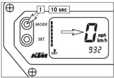
KILOMETERS OR MILES.
You can have the speed and distance shown in kilometers or miles in the display. The display can be adapted to the respective country on long-distance trips.
To switch from kilometers to miles, switch on the ignition and press the MODE [1] button for approx. 10 seconds. The km/h display will switch to mph. The speed and the stored distances will be converted and displayed in miles.
To return to kilometers, proceed as described above.
text_image
1 2 MODE SET 0 km/h 16:30 KTMSET CLOCK
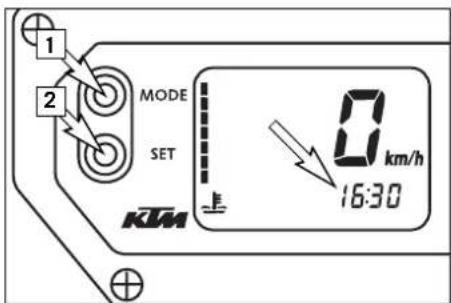
Switch on the ignition and change to the CLOCK mode.
Simultaneously press MODE [1] and SET [2]. The numbers on the clock will start to blink.
Use the MODE button to set the hours and the SET button to set the minutes.
The press the MODE and SET buttons simultaneously.
NOTE:
0:00 will be displayed if the clock is not supplied with electricity. This can be caused by a defective fuse or a fault in the board electric system (see Troubleshooting).
text_image
MODE SET 0 km/h TRIP 1 287.9 KMTRIP 1
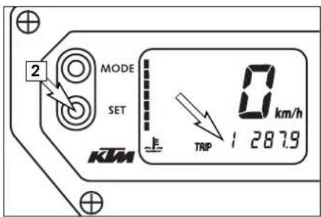
The trip meter 1 runs continuously and counts up to 999.9. It can be used to measure the length of a certain route on a trip or the distance between two refueling stops.
To return the trip meter 1 to zero, switch on the ignition, change to the TRIP 1 mode and press the SET button [2].
OPERATION INSTRUMENTS »
text_image
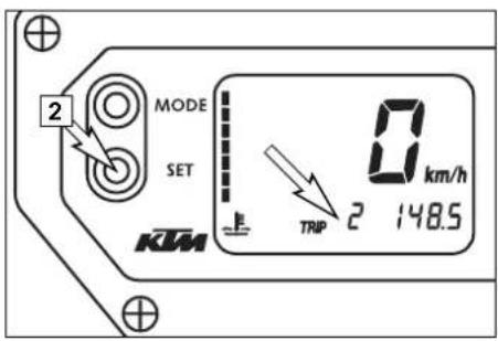
MODE SET 2 0 km/h TRIP 2 148.5 KTMRESETTING TRIP 2
The trip meter 2 runs continuously and counts up to 999.9. It can be used similarly to TRIP 1 or together with a switch available as an accessory (see below) for trips according to a roadbook.
To return the trip meter 2 to zero, switch on the ignition, change to the TRIP 2 mode and press the SET button [2].
text_image
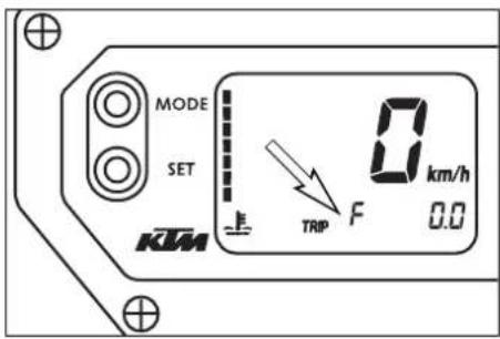
MODE SET KTM TRIP F 0 km/h 0.0TRIP F
When the fuel level reaches the reserve mark, the display will automatically switch to TRIP F and begin to count (no matter which display mode was active before). At the same time, the fuel warning lamp will light up. You will still have enough reserve fuel for at least 30 kilometers.
After refueling, it will take approx. 8 minutes for the fuel warning lamp to switch off and for TRIP F to automatically reset to 0 and return to the previous display mode.
NOTE:
Press the SET key for 2 seconds to immediately turn off the fuel warning lamp.
OPERATION INSTRUMENTS »
text_image
MODE 1 SET 120°C (248°F) 110°C (230°F) 100°C (212°F) 70°C (158°F) 60°C (140°F) 50°C (122°F) 40°C (104°F) TRIP KTM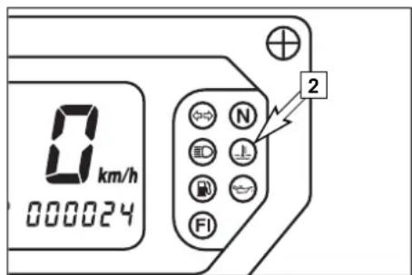
text_image
0 km/h 000024 N 2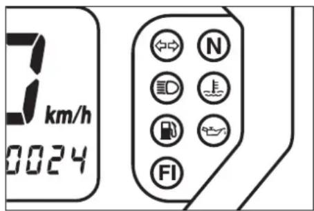
text_image
7 km/h 0024 N FICooling liquid temperature display
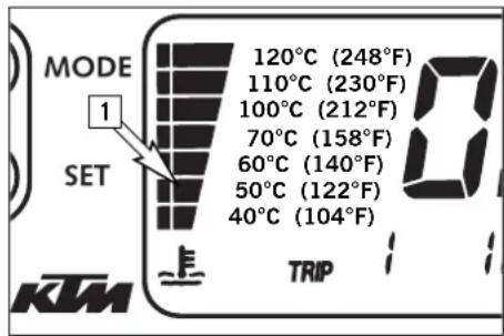
The temperature display [1] is shown in 7 bars. The more bars that light up, the hotter the cooling liquid. When the lowest bar lights up, the cooling liquid has reached a temperature of approx. 40^ C ( 104^ F). When the upper bar lights up 120^ C ( 248^ F), all of the bars will start to blink and the red warning lamp [2] will light up.
! CAUTION
Possible causes for an increase in temperature, causing the red warning light for the cooling liquid temperature to light up:
- Driving too slowly and driving with a heavy load at high air temperatures
- Not enough cooling liquid in the system
- The ventilator on the left radiator is not running
- Improper use of the clutch when driving slowly
Indicator lamps

The green indicator lamp will blink in the blinker rhythm when the blinker is switched on. NOTE:
The indicator lamp will blink faster when a blinker is broken.

The green indicator lamp will light up when the gearbox is in an idling position.

The blue indicator lamp will light up when the high beams are switched on.

The red warning light will light up when the cooling liquid has reached a temperature of approx. 120^ C ( 248^ F).

The orange warning light will light up when the fuel level reaches the reserve mark. At the same time the display will automatically change to TRIP F (see TRIP F).

The red warning lamp lights up when the ignition is switched on but the engine is not running. When the engine is started, the warning lamp will go out as soon as the oil pressure is high enough.

This indicator lamp has no function.
OPERATION INSTRUMENTS »
text_image
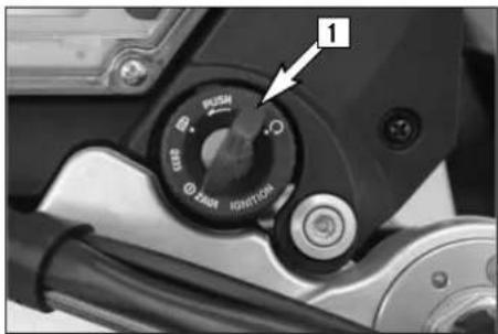
1 RUSH S 2NDI MINTONCAIgnition lock
The ignition lock [1] has 3 switching positions.

Ignition off, (engine can't be started)

Ignition on, light on, (engine can be started)

Ignition off, handlebar blocked
To switch the ignition to position turn the ignition key to position and firmly press it into the lock. Turn the handlebar to the left, then turn the ignition key to the left.
The ignition key can be withdrawn in position and .
text_image
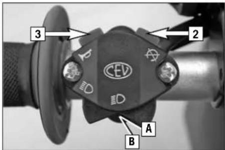
3 2 CEV A BCombination switch
The light switch has 2 switch positions.
[A] = Low beam light
[B] = High beam light
The red short circuit button [2] serves to switch off the engine. Leave the switch pressed, until the engine stops. With the button [3] the horn will sound.
natural_image
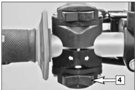
Close-up of a mechanical component with a knob and adjustment arrow (no visible text or symbols)Flasher switch
The flasher switch [4] is mounted on the left side of the handlebar.

Flasher left

Flasher right
OPERATION INSTRUMENTS »
natural_image
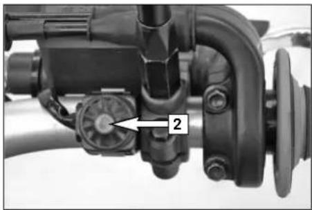
Close-up of a mechanical assembly with labeled component '2' (no readable text or symbols beyond label)Starter tip switch
Use the starter tip switch [2] to operate the electric starter.
natural_image
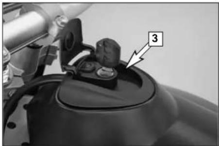
Close-up of a motorcycle's front bumper with a numbered component (3) pointing to the seat area, no visible text or symbols beyond the number.Filler cap
The filler cap [3] can be locked and is provided with a fuel evaporation control system. To open the cap insert the ignition key, turn it 90° counterclockwise, then lift off the filler cap. To close the tank insert the filler cap, turn the ignition key 90° clockwise and take out the key.
natural_image
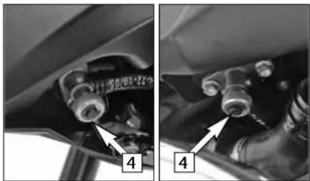
Close-up of mechanical components with numbered callouts (4), no visible text or symbolsFuel taps
2 fuel taps [4] are mounted on the fuel tank that must be open when the motorcycle is running. The level in the fuel tanks is equalized by means of a connecting hose. The fuel pump stops running when the engine is switched off and fuel cannot flow to the carburetors so the fuel taps do not need to be closed when the motorcycle is switched off.
Opening the fuel tap: Turn the knob all the way to the left. Closing the fuel tap: Turn the knob all the way to the right.
OPERATION INSTRUMENTS »
text_image
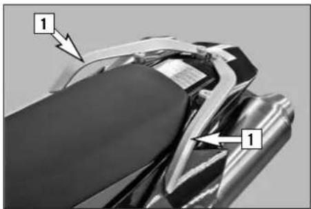
Technical diagram of a motorcycle seat with labeled parts and arrows indicating featuresGrips
The grips [1] are used to maneuver the motorcycle. If carrying a passenger, the passenger can hold on to the grip during the ride.
text_image
Technical diagram showing mechanical components with numbered annotations, likely from an automotive assembly or maintenance procedure.Removal of seat
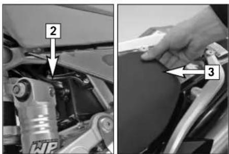
Actuate the lever [2] while lifting the back of the seat [3].
text_image
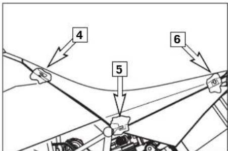
4 5 6To mount the seat, attach the seat to the oval head screw [4], lower the seat in the back while sliding it towards the front. Both noses [5] should fit into the frame. Insert the catch bolts [6] in the lock housing and push the seat down in the back until you hear the catch bolts snap into place.
Check whether the seat is correctly mounted.
WARNING
If not correctly mounted, the seat can slip while you are driving and cause you to lose control of your motorcycle.
OPERATION INSTRUMENTS »
natural_image
Close-up of a car's front engine compartment showing battery, switch, and wiring (no text or symbols visible)Tool set
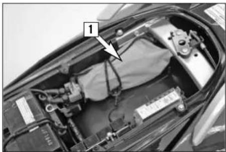
The tool set [1] is located in the storage compartment under the seat.
text_image
2,3,4,5,6 N 1Shift lever
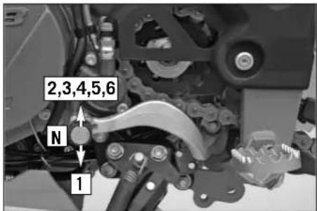
The shift lever is mounted on the left side of the engine. The position of the gears is shown in the illustration. Neutral, or the idle speed, is located between first and second gear.
text_image
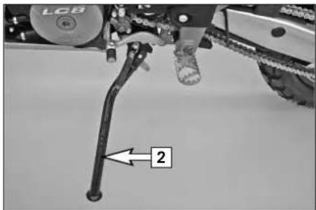
LCB 2Side stand
Fold the side stand [2] forward to the stop with your foot and put the weight of the motorcycle on the stand. Make sure it is standing securely on a firm surface. The side stand is linked to the safety start system; follow the driving instructions.
OPERATION INSTRUMENTS »
natural_image
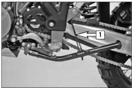
Mechanical assembly diagram showing a chain and linkage mechanism (no text or symbols visible)For off-road riding, you can use the rubber band [1] to additionally secure the center stand in its folded-up position

natural_image
Mechanical assembly diagram showing a motor and brake system with labeled component '2' (no text or symbols beyond label)NOTE:
A center stand is available from your authorized KTM workshop as an accessory.
Foot brake pedal
The foot brake pedal [2] is located in front of the right footrest. Its basic position can be adjusted to your seat position.
natural_image
Technical line drawing of mechanical components and assemblies (no text or symbols)NOTE:
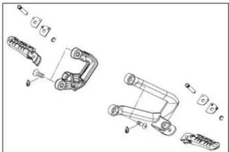
A passenger footrest system is available from your authorized KTM workshop as an accessory. The motorcycle is already approved for two seats.
OPERATION INSTRUMENTS »
natural_image
Mechanical component close-up showing internal cavity and internal ring (no text or symbols)Compression damping of fork
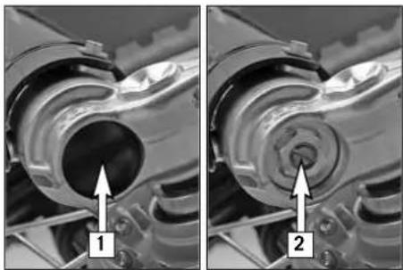
The fork's damping action during compression travel (compression damping) can be adjusted. This allows you adjust the damping behavior to match your driving style and the payload. The adjusting screws [2] are located under the cap [1] on the lower end of the fork legs. More information is provided in the chapter "Adjusting the fork and shock absorber."
natural_image
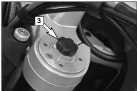
Close-up of a mechanical component with a numbered annotation '3' pointing to a small black component (no readable text or symbols beyond the label)Rebound damping of fork
The fork's damping action during rebound travel (rebound damping) can also be adjusted. This allows you adjust the damping behavior to match your driving style and the payload. The adjusting screws [3] are located on the upper end of the fork legs. More information is provided in the chapter "Adjusting the fork and shock absorber."
natural_image
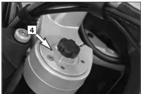
Close-up of a mechanical component with a knob and adjustment knob, no visible text or symbolsSpring preload of the fork
The fork's preload can be adjusted by means of the adjusting screws [4]. More information is provided in the chapter "Adjusting the fork and shock absorber."
OPERATION INSTRUMENTS »
natural_image
Close-up of a car suspension system with an arrow pointing to a bolt (no visible text or symbols)Damping action during compression of shock absorber
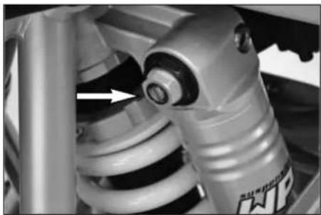
The shock absorber's damping action during compression travel (compression damping) can be adjusted. This allows you adjust the shock absorber's damping behavior to match your driving style and the payload.
The damping rate can be adjusted in the low and high-speed range (Dual Compression Control). The designation low and high-speed refers to the movement of the shock absorber and not to the motorcycle's driving speed.
natural_image
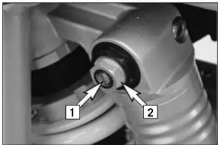
Close-up of a mechanical assembly with labeled parts (1 and 2), showing no readable text or symbols beyond labels.The adjusting screw [1] for the low-speed range can be adjusted with a screwdriver.
The adjusting screw [2] for the high-speed range can be adjusted with a 17 mm socket wrench.
More information is provided in the chapter "Adjusting the fork and shock absorber."
natural_image
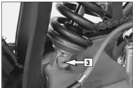
Close-up of a car suspension system with labeled component '3' (no text or symbols beyond label)Rebound damping of shock absorber
The shock absorber's damping action during rebound travel (rebound damping) can also be adjusted. This allows you adjust the damping behavior to match your driving style and the payload.
The adjusting screw [3] is located on the bottom of the shock absorber.
More information is provided in the chapter "Adjusting the fork and shock absorber."
GENERAL TIPS AND WARNINGS FOR STARTING THE MOTORCYCLE »
Instructions for initial operation
- Make sure the work for the „pre-delivery inspection“ was performed by your authorized KTM workshop. The DELIVERY CERTIFICATE and SERVICE MANUAL will be handed over when you pick up your vehicle.
- Read these operating instructions carefully before your first ride.
- Enter the chassis, engine and key numbers on page 1.
- Familiarize yourself with the operating elements.
- Adjust the hand brake lever and foot brake lever to your most comfortable position.
- This motorcycle is equipped with 2 catalytic converters. Leaded fuel will destroy the catalytic converters. Please use unleaded fuel only.
- Get used to handling the motorcycle on an empty parking lot, before starting on a longer drive. Also try to drive as slowly as possible and in standing position, to improve your feeling for the vehicle.
- Do not drive along off-road tracks which go beyond your abitily and experience.
– Hold the handlebars with both hands and leave your feet on the foot rests while driving. - Remove your foot from the foot brake lever when you are not braking. If the foot brake lever is not released the brake pads rub continuously and the braking system is overheated.
- Do not make any alterations to the motor-cycle and always use ORIGINAL KTM
SPARE PARTS. Spare parts from other manufacturers can impair the safety of the motorcycle.
- New wheels have a smooth surface, which means that they must be run in to achieve full grip. For this purpose, ride the motorcycle carefully at moderate speed during the first 200 kilometers (125 miles) with new tires, tilting the vehicle at different angles so that all sections are properly roughened. Tires will not display their full grip characteristics until they are properly run in.
- Motorcycles are sensitive to changes in the weight distribution. Read the section on "Accessories and payload" when carrying luggage.
– Pay attention to running-in procedure.
Running in the LC8 engine
Even finely machined surfaces of engine parts have rougher surfaces than parts that slide on each other for a long time. Therefore, every engine must be run in. For this reason, do not demand maximum performance from the engine for the first 1000 kilometers (620 miles). The vehicle must be run in at low, changing performance level for the first 1000 km (620 miles). Do not exceed the maximum speeds listed in the table during this time.
| GEAR MAXIMUM SPEED |
| 1st 50 km/h (30 mph) |
| 2nd 70 km/h (40 mph) |
| 3rd 95 km/h (60 mph) |
| 4th 115 km/h (70 mph) |
| 5th 135 km/h (85 mph) |
| 6th 160 km/h (100 mph) |
WARNING
- Wear suitable clothing when driving a motorcycle. Clever KTM drivers always wear a helmet, boots, gloves and a jacket, regardless of whether driving all day or just for a short trip. The protective clothing should be brightly colored so that other vehicle can see you as early as possible. Your passenger will also need suitable protective clothing.
- Do not drive after having consumed alcohol.
- Drive at a moderate speed for the first few kilometers of each trip to allow the tires to reach the necessary operating temperature. Maximum road grip is assured when the tires are warm.
- The front and rear wheel are allowed to be fitted only with tires that have the same profile type.
GENERAL TIPS AND WARNINGS FOR STARTING THE MOTORCYCLE »
WARNING
- New tires have a smooth surface, which means that they must be run in to achieve full grip. For this purpose, ride the motorcycle carefully at moderate speed during the first 200 kilometers with new tires, tilting the vehicle at different angles so that all sections are properly roughened. Tires will not display their full grip characteristics until they are properly run in.
- The factory mounted tires are approved for a maximum speed of 160 kph (100 mph). Under no circumstances should this speed be exceeded.
- Wheels with a different rim diameter or other rim width may not be mounted otherwise the vehicle handling will no longer be safe.
- Observe the traffic regulations, drive defensively and trying to look ahead as far as possible so that any hazards can be recognized as early as possible.
- The faster you drive, the more sensitive your motorcycle will be to crosswind and changing road conditions. Your motorcycle can easily go out of control at high speeds.
- Choose your driving speed according to the conditions and your driving skills.
- Drive carefully on unknown roads or on unfamiliar trials.
- Renew the vizor on your helmet on time so as to ensure optimum vision in any situation. When light shines directly on
scratched visor, the operator will be blinded.
- A passenger may only ride on the motorcycle if passenger footrests are mounted. A passenger footrest system is available from your authorized KTM workshop as an accessory. The motorcycle is already approved for two seats.
– Never leave your motorcycle without supervision if the engine is running.
Accessories and payload
Accessory parts and baggage can significantly decrease a motorcycle's driving stability. Please observe the following warnings.
WARNING
- Never drive faster than 130 kph (80 mph) if you have mounted accessory parts on your motorcycle. Accessory parts can significantly impair the motorcycle's handling, especially in the maximum speed range.
- Fasten the baggage close to the center of the motorcycle and distribute the weight evenly on the front and rear wheels and on the left and right.
- Baggage must be securely and adequately fastenend; loose baggage will significantly impair driving safety.
- A high payload will change the motorcycle's handling and considerably increase
the braking distance; adapt your driving speed accordingly.
- Never exceed the maximum permissible laden weight and the axle weights. The maximum permissible laden weight is made up of the following components:
- Motorcycle ready for operation and tank full
- Luggage
– Driver and passenger with protective clothing and helmet
DRIVING INSTRUCTIONS »
natural_image
Close-up of a hand adjusting a bicycle's chain gear mechanism (no text or symbols visible)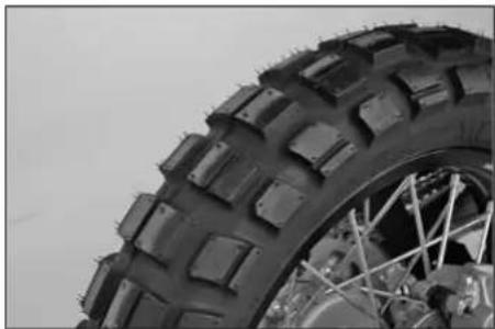
natural_image
Close-up of a rugged off-road tire with visible tread pattern and metal frame (no text or symbols)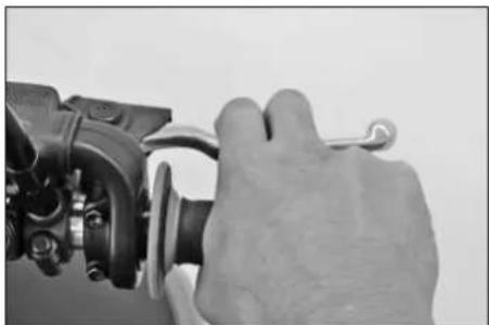
natural_image
Close-up of a hand adjusting a mechanical component with a wrench (no visible text or symbols)Check the following before each start
When you start, the motorcycle must be in perfect mechanical condition. For safety reasons, you should make a habit of performing an overall check of your motorcycle before each start.
The following checks should be performed:
1 FUEL
Check the fuel quantity in the tanks.
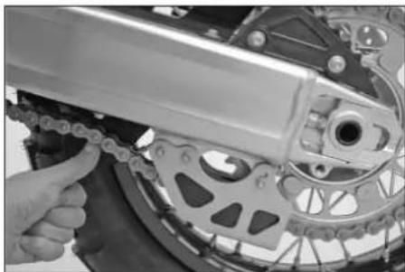
2 CHAIN
Check the tension and condition of the chain.
A loose chain can fall off the sprockets and a worn-out chain can tear. In both cases this can damage other motorcycle components and cause the motorcycle to go out of control. A chain that is too tight or not greased will cause unnecessary wear to the chain and sprockets.
3 TIRES
Check for damaged tires. Tires showing cuts or dents must be replaced. The tread depth must comply with the legal regulations. Also check the air pressure. Insufficient tread and incorrect air pressure deteriorate the driving performance.
4 BRAKES
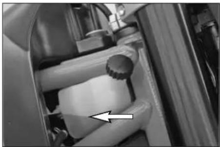
Check correct functioning of the braking system. Check for sufficient brake fluid in the reservoir. The reservoirs have been designed in such a way that brake fluid does not need to be refilled even when the brake pads are worn. If the level of brake fluid falls below the minimum value, this indicates a leak in the braking system or completely worn out brake pads. Arrange for the braking system to be checked by a KTM specialist, as complete failure of the braking system can be avoided.
Also check the state of the brake hose and the thickness of the brake linings. Check free travel at hand brake lever and foot brake lever.
DRIVING INSTRUCTIONS »
natural_image
Close-up of a mechanical device with cylindrical components and a white arrow pointing to a component (no visible text or symbols)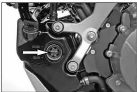
natural_image
Close-up mechanical component with no visible text or symbols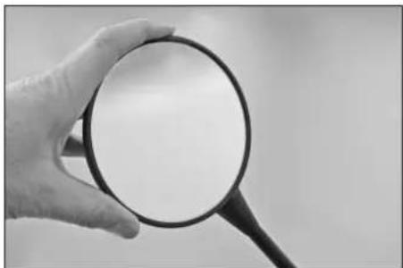
natural_image
Hand holding a magnifying glass (no text or symbols visible)5 CABLES Check the throttle cable for correct adjustment and smooth operation.
6 COOLING FLUID Check the level of cooling fluid when the engine is cold.
7 ELECTRICAL SYSTEM Start the engine and check the headlight, tail lamp, brake light, turn signals, indicator lamps, horn and emergency-off switch for proper functioning.
8 CHECK OIL LEVEL Insufficient oil results in premature wear and consequently to engine damage.
9 BAGGAGE, PAYLOAD Never exceed the maximum total weight (400 kg, 883 lbs) and the motorcycle's wheel loads. The maximum total weight is comprised of: - the motorcycle in a running condition and refueled (200 kg, 442 lbs) - the baggage and accessories - the driver and passenger with protective gear and helmet Adjust the tire inflation pressure as well as the preload and damping properties of the fork and shock absorber to the total weight. Make sure your luggage is correctly fastened before you drive off.
10 REAR MIRROR Sit on the motorcycle and check the adjustment of the rear mirror.
DRIVING INSTRUCTIONS »
natural_image
Close-up of mechanical components with no visible text or symbols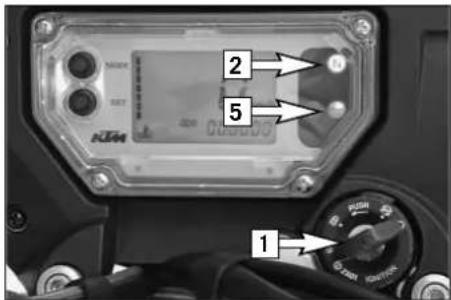
text_image
2 5 1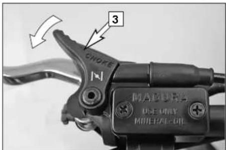
text_image
3 CHOKE MAJURS DO-ONLY MINERAL-OILStarting when the engine is cold
1 Switch on ignition (turn ignition key [1] into position ).
NOTE:
Usually the operating noise of the fuel pump can briefly be heard after the ignition is switched on.
2 Switch transmission to idle (green indicator lamp N [2] lights up).
3 Operate cold starting device (choke) [3].
Only pull the choke lever half way out at outer temperatures over 5°C (41°F). Pull the choke lever all the way out at outer temperatures below 5°C.
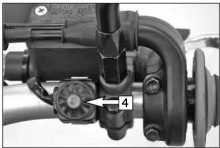
4 Do not accelerate; operate starter button [4].
5 The oil pressure warning lamp [5] should go out as soon as the engine is running.
6 Take the motorcycle off of the side stand.
7 Push the choke lever back in after a short time (max. 1 km, 0,6 mile).
WARNING
- Do not start the engine and allow it to idle in a closed room. Exhaust fumes are poisonous and can cause loss of consciousness and death. Always provide adequate ventilation while the engine is running.
- Never operate the motorcycle with a run-down battery or without the battery. This can damage the electronic components or safety equipment in either case and the motorcycle will no longer be roadworthy.
! CAUTION
- If the oil pressure warning lamp does not go out as soon as the engine is running, immediately switch off the engine. If the engine is not switched off, engine damage will occur within a short period of time. Check the engine oil level or contact a ktm workshop.
- Maximum period for continuous starting: 5 seconds. Wait at least 5 seconds before trying again.
- Don't ride your motorcycle with full load and don't rev engine when cold. Because the piston is warming up faster than the water cooled cylinder, it can cause engine damage. Always let the engine warm up before and refrain from driving with full load until the engine is warm.
- Release the choke lever after a maximum of 1 kilometer (0,6 mile) otherwise the catalytic converters will be destroyed.
DRIVING INSTRUCTIONS »
IF THE ENGINE IS DOES NOT CRANK WHEN YOU ACTUATE THE STARTER TIP SWITCH:
- If the transmission is switched to idle
– Check if the ignition is on - The headlight is on
- If this is not the case, the battery is discharged
- If the lights are on, proceed as described in the „Trouble-shooting“ section or contact a KTM dealer.
IF THE ENGINE CRANKS BUT DOES NOT START, WHEN YOU ACTUATE THE STARTER TIP SWITCH:
Check if the fuel taps are open
- Check if the choke lever has been operated
- Check if sufficient fuel is in the tank
- If this is not the case, refill the tank
- If sufficient fuel is in the tank, proceed as described in the „Trouble-shooting“ section or contact a KTM dealer.
NOTE:
This motorcycle is equipped with a safety starting system. The engine can only be started if the transmission is in neutral or the clutch lever is pulled. If the side stand is folded down, the engine can only be started if the transmission is in neutral or the clutch lever is pulled. The engine will stall if a gear is engaged and the clutch lever is released with the side stand folded down.
Starting when the engine is warm
or hot
1 Switch on ignition (turn ignition key into position ○).
2 Switch transmission to idle (green indicator lamp N lights up).
3 Do not accelerate; operate starter button.
4 The oil pressure warning lamp should go out as soon as the engine is running.
5 Take the motorcycle off of the side stand.
Starting off
Pull the clutch lever and engage 1st gear. Slowly release the clutch lever while you open the throttle.
Shifting/Riding
You are now in first gear, referred to as the drive or uphill gear. Depending on the conditions (traffic, road gradient, etc.), you can shift to a higher gear. Close the throttle while pulling the clutch lever, engage the next gear, release the clutch lever and carefully open the throttle. If you turned on the choke, make sure you turn it off again as soon as engine is warm.
Only accelerate to the extent that road and weather conditions allow. Be especially careful when you accelerate in curves. Abrupt opening of the throttle can cause the motorcycle to go out of control and also increases fuel consumption.
By shifting down, use the brakes if necessary and close throttle at the same time. Pull clutch lever and shift down to the next gear. Let clutch lever go slowly and open throttle or shift down again.
If the engine is killed f.ex. at a crossing, simply pull the clutch lever and start. It is not necessary to switch the gear to NEUTRAL.
WARNING
- Avoid abrupt load changes while riding around bends and on wet or slippery ground. Otherwise you might easily lose control over your motorcycle.
- While riding your motorcycle, never switch the ignition lock to positions And
- Do not try to change the settings of the multi-functional digital speedometer while driving. Your attention will be distracted from the traffic and may cause you to lose control of your motorcycle.
- When driving off-road, always have a friend on a second motorcycle to keep you company, so that you can help each other should difficulties arise.
WARNING
- The passenger must hold on to the driver or the grab handle during the ride and keep his feet on the passenger footrests.
- Regularly make sure that the baggage and cases are tightly fastened.
- After falling with the motorcycle, check all functions thoroughly before starting up operations again.
– A bent handlebar must always be replaced. Never try to straighten the handlebar because this will cause it to lose its stability.
! CAUTION
- High rpm rates when the engine is cold have an adverse effect on the life of your engine. We recommend you run the engine in a moderate rpm range for a few miles giving it a chance to warm up. After that no further precautions in this respect need be taken. The engine has reached operating temperature as soon as the 4th bar on the temperature indicator lights up.
- If the red oil pressure warning lamp lights up while driving, the oil pressure is too low to adequately lubricate the engine. Stop immediately and switch off the engine. if you continue to drive, engine damage will occur within a short period of time. Check the engine oil level or contact an authorized KTM workshop.
- Never have the throttle wide open when changing down to a lower gear. The engine will overspeed, damaging the valves. In
addition, the rear wheel blocks so that the motorcycle can easily get out of control.
- Never use your motorcycle without an air filter. Otherwise dust and dirt may enter the engine and cause increased wear.
- Stop immediately if a perceptible power loss occurs while driving due to a defective ignition caused by a cylinder misfiring or breaking down. If the unburned fuel/air mixture reaches the catalytic converter, it will ignite and the resulting heat will destroy the catalytic converter and the adjoining components.
- The red coolant warning lamp lights up when the coolant temperature has reached 120^ (248°F).
Possible causes for the increase in temperature:
- low driving velocity and high load situation in high air temperatures
– level of coolant in the system is insufficient
– fan at radiator is not running - improper use of the clutch while driving at low velocities
Let the engine cool down. Meanwhile, check whether any cooling liquid is leaking out of the motorcycle. Check the cooling liquid level in the radiator (not only in the compensating tank). CAUTION SCALDING HAZARD! Do not drive on, until there is sufficient liquid in the cooling system.
- In the event that, while riding on your motorcycle, you notice any unusual operation-related noise, stop immediately,
turn the engine off, and contact an authorized KTM dealer.
Braking
Close throttle and apply the hand and foot brakes at the same time. Carefully apply the brakes on sandy, wet or slippery surfaces. Always brake with feeling, blocking wheels can cause you to skid or fall. Also change down to lower gears depending on your speed. Always finish braking before you enter a curve.
When driving downhill, use the braking effect of the engine. Change down one or two gears but do not overspeed the engine. In this way, you will not need to brake so much and the brakes will not overheat.
WARNING
- In the rain, or after the motorcycle has been washed, braking action may be delayed due to wet brake discs. First, the brakes must be braked dry.
- On salt-sprayed or dirty roads brake action may be delayed as well. First, the brakes must be braked clean.
– Remember that the stopping distance will be longer if you are carrying a passenger or baggage. - When you brake, the brake discs, brake pads, brake caliper and brake fluid heat up. The hotter these parts get, the weaker the braking effect. In extreme cases, the entire braking system can fail.
- If the resistance in the hand brake lever or foot brake pedal feels "spongy" (too much play), this is an indication that something is wrong with the brake system. Don't ride your motorcycle anymore without first having the brake system looked over by a KTM dealer.
natural_image
Close-up of a bicycle's front wheel and suspension mechanism (no visible text or symbols)Stopping and parking
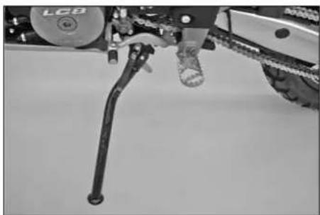
Apply the brakes fully and put the engine into neutral. To stop the engine, switch off the ignition. Fold the side stand forward to the stop with your foot, put the weight of the motorcycle on the stand and park the bike on a firm surface. Lock the motorcycle.
WARNING
- Always park your motorbike on a solid and horizontal surface.
- Never leave your motorcycle without supervision as long as the engine is running.
- Motorcycle engines produce a great amount of heat while running. The engine radiators, exhaust, exhaust system, brake discs, and shock absorbers can become very hot. Do not touch any of these parts after operating the motorcycle, and take care to park it where pedestrians are not likely to touch it and get burned
- Never park your motorcycle in places where there exist fire hazards due to dry grass or other easily flammable materials.
! CAUTION
- Always take out the ignition key when parking your motorcycle so that it cannot be used by unauthorized persons.
- The side stand is dimensioned for the weight of the motorcycle only. Sitting on the motorcycle will increase the weight on the side stand. The side stand or engine case can be damaged and the motorcycle can tip over.
text_image
50 mm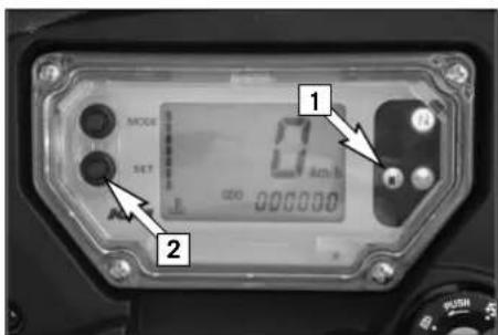
text_image
1 2 MODE SET 0.45V 0.000000Fuel, refueling
The LC8 engine requires unleaded fuel with at least RON 95 (USA = Premium PON 91, see technical specifications engine).
If using lower octane fuel, it is easy to change over to the pre-programmed ignition curve for 80 - 94 octane (RON) (see activating the ignition curve for low-octane fuel).
After refueling, it will take approx. 8 minutes for the fuel warning lamp to switch off and for TRIP F to automatically reset to 0 and return to the previous display mode.
! CAUTION
- Use unleaded fuel with at least RON 95 (USA = Premium RON 91). If using lower octane fuel, the ignition curve must be changed, otherwise engine damage will occur.
- This motorcycle is equipped with a catalytic converter that will be destroyed if you use leaded fuel. Always use unleaded fuel.
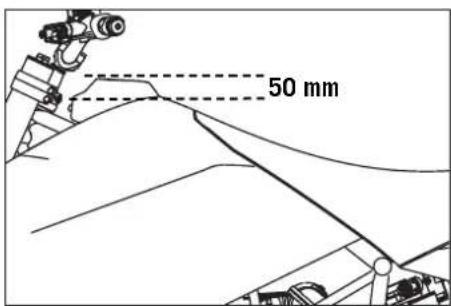
Fuel expands when its temperature rises. Therefore do not fill the tank to the top (see fig.). When you close the filler cap, make sure it is correctly positioned.
NOTE:
After refueling, it will take approx. 8 minutes for the fuel warning lamp [1] to switch off and for TRIP F to automatically reset to 0 and return to the previous display mode. Press the SET key [2] for 2 seconds to immediately turn off the fuel warning lamp.
WARNING
Gasoline is highly flammable and poisonous. Extreme caution should be used when handling gasoline. Do not refuel the motorcycle near open flames or burning cigarettes. Always switch off the engine before refuelling. Be careful not to spill gasoline on the engine or exhaust pipe while the engine is hot. Wipe up spills promptly. If gasoline is swallowed or splashed in the eyes, seek a doctor's advice immediately.
PERIODIC MAINTENANCE SCHEDULE »
| 950 SUPER ENDURO R 2008A CLEAN MOTORCYCLE CAN BE CHECKED MORE QUICKLY WHICH SAVES MONEY!IF MOTORCYCLE IS USED FOR COMPETITION 7500 KM SERVICE SHOULD BE CARRIED OUT AFTER EVERY RACE!Service intervals should never be exceeded by more than 500 km (300 miles).Maintenance work performed by an authorized KTM workshop is not a substitute for care and maintenance by the driver! | 1st Service after 1000 km | Service every 7500 km or once a year | Service every 15000 km or every 2 years | |
| ENGINE | Change engine oil and oil filter | ● ● | ● | |
| Clean oil screens of engine and oil tank | ● ● | ● | ||
| Clean magnetic drain plugs of engine and oil tank | ● ● | ● | ||
| Check oil lines for damage and kink-less arrangement | ● ● | ● | ||
| Renew spark plugs | ● | |||
| Check and adjust valve clearance | ● | ● | ||
| Check engine fastening bolts for tight fit | ● ● | ● | ||
| Check all engine bolts accessible from the outside for tight fit | ● ● | ● | ||
| Check clutch linings | ● | |||
| Check clutch pressure booster system | ● | |||
| Clean the oil jet for the clutch lubrication | ● | ● | ||
| CARBURETOR | Check carburetor connection boots for cracks and leaks | ● | ● | |
| Check synchronisation of carburators using special tool, if necessary adjust | ● | ● | ||
| Check idle setting (1400 rpm) | ● | ● | ||
| Check breeder hoses and fuel lines for damage and kink-free arrangement | ● | ● | ||
| ADD ON PARTS | Check cooling system for leaks and antifreeze protection | ● ● | ● | |
| Check radiator fan for proper operation | ● ● | ● | ||
| Check the exhaust system for leaks and correct suspension and the clamps for a tight fit | ● ● | ● | ||
| Check actuating cables for damage, smooth operation, and kink-less arrangement,adjust and lubricate | ● ● | ● | ||
PERIODIC MAINTENANCE SCHEDULE »
| 950 SUPER ENDURO R 2008A CLEAN MOTORCYCLE CAN BE CHECKED MORE QUICKLY WHICH SAVES MONEY!IF MOTORCYCLE IS USED FOR COMPETITION 7500 KM SERVICE SHOULD BE CARRIED OUT AFTER EVERY RACE!Service intervals should never be exceeded by more than 500 km (300 miles).Maintenance work performed by an authorized KTM workshop is not a substitute for care and maintenance by the driver! | 1st Service after 1000 km | Service every 7500 km or once a year | Service every 15000 km or every 2 years | |
| ADD ON PARTS | Check the oil level in the hydraulic clutch reservoir | ● | ● | |
| Check air filter, renew if necessary, clean air filter box | ● | ● | ||
| Check cables for damage and kink-less arrangement | ● ● | ● | ||
| Check headlamp adjustment | ● ● | ● | ||
| Check electrical system for function (low/high beams, stop light, turn indicators,headlamp, flasher, tell-tale lamps, speedometer illumination, horn, side-stand switch, clutch switch, emergency-off switch) | ● ● | ● | ||
| Make sure all bolts and nuts are tight | ● ● | ● | ||
| BRAKES | Check brake fluid level, lining thickness, and brake discs | ● ● | ● | |
| Change brake fluid | ● | |||
| Check brake lines for damage and leaks | ● ● | ● | ||
| Check/adjust smooth operation, free travel of handbrake/footbrake levers | ● ● | ● | ||
| Check bolts of brake system for tight fit | ● ● | ● | ||
| CHASSIS | Check shock absorber and fork for leaks and proper operation | ● ● | ● | |
| Clean fork dust sleeves | ● | ● | ||
| Bleed fork legs | ● ● | ● | ||
| Check swinging-fork pivot | ● ● | ● | ||
| Check/adjust steering-head bearing | ● ● | ● | ||
| Check all chassis bolts for tight fit (fork plates, fork leg, axle nuts/bolts, swinging-fork pivot, reversing lever, shock absorber) | ● ● | ● | ||
PERIODIC MAINTENANCE SCHEDULE »
| 950 SUPER ENDURO R 2008A CLEAN MOTORCYCLE CAN BE CHECKED MORE QUICKLY WHICH SAVES MONEY!IF MOTORCYCLE IS USED FOR COMPETITION 7500 KM SERVICE SHOULD BE CARRIED OUT AFTER EVERY RACE!Service intervals should never be exceeded by more than 500 km (300 miles).Maintenance work performed by an authorized KTM workshop is not a substitute for care and maintenance by the driver! | 1st Service after 1000 km | Service every 7500 km or once a year | Service every 15000 km or every 2 years | |
| WHEELS | Check spoke tension and rim joint | ● ● | ● | |
| Check tire condition and inflation pressure | ● ● | ● | ||
| Check chain, sprockets and chain guides for wear, force fit and tension | ● ● | ● | ||
| Check bolts on pinion and chain sprocket for locking devices and a tight fit | ● ● | ● | ||
| Lubricate chain | ● ● | ● | ||
| Check wheel bearings and jerk damper for play | ● ● | ● | ||
| 950 SUPER ENDURO R 2008ADDITIONAL SERVICE WORK THAT MUST BE PERFORMED UNDER A SEPARATE ORDER | at least once a year | Service every 15000 km or every 2 years |
| Perform complete fork maintenance | ● | |
| Perform complete shock absorber maintenance | ● | |
| Clean and lubricate steering-head bearing and sealing elements | ● | |
| Clean and adjust the carburetors | ● | |
| Treat the electrical contacts and switches with contact spray | ● | |
| Treat battery connections with contact grease | ● | |
| Change coolant fluid | ● |
PERIODIC MAINTENANCE SCHEDULE »
| 950 SUPER ENDURO R 2008VITAL CHECKS AND CARE PROCEDURES TO CONDUCTED BY THE OWNER OR THE MECHANIC | before each start | after every cleaning | every 1000 km | after off road use |
| Check oil level | ● | |||
| Check brake fluid level | ● | |||
| Check brake pads for wear | ● | |||
| Check lighting system for proper operation | ● | |||
| Check horn for proper operation | ● | |||
| Lubricate and adjust actuating cables and nipples | ● | |||
| Bleed fork legs in regular intervals | ● | ● | ||
| Clean chain | ● | ● | ||
| Lubricate chain | ● ● | ● | ||
| Check the chain tension; grease the chain if necessary | ● | |||
| Check tire pressure and wear | ● | |||
| Check coolant level | ● | |||
| Check fuel lines for leaks | ● | |||
| Check all control elements for smooth running | ● | |||
| Check brake performance | ● | ● | ||
| Treat exposed metal components (except for the braking and exhaust systems) with wax-based anti-corrosion agents | ● | |||
| Treat ignition/steering lock and light switch with contact spray | ● | |||
| Check spoke tension (sound test) | ● | |||
| Check the rims for damage and deformation | ● | |||
| Check exhaust system for leaks and correct fit | ● | |||
| Check air filter, renew if necessary, clean air filter box | ● | |||
| Check shock absorber and fork for leaks and proper operation | ● | |||
| Clean fork dust sleeves | ● |
MAINTENANCE WORK ON CHASSIS AND ENGINE »
! CAUTION
- If using a power washer, do not point the water jet at the electric components, plugs, cables, bearings, carburetor, etc. The high pressure will cause water to penetrate into the components and can cause them to malfunction or lead to premature wear.
- Use special KTM screws with the correct thread length to fasten the spoiler to the tank. Mounting other screws or longer screws could puncture the tank and cause fuel to leak out.
- If you disconnect socket connectors with self-locking nuts, replace them before remounting. If no new self-locking nuts are available, apply Loctite 243 to the thread of the old nuts. If the thread is damaged, replace the screws and nuts.
- Do not use toothed disks or split washers for the engine fastening bolts since they will work their way into the frame components and become loose. Always use self-locking nuts.
- Let the motorcycle cool down before servicing to avoid being burned.
– Properly dispose of oils grease, filters, fuel, cleansers, etc. Observe the regulations effective in your country. - Never pour used oil in the sewer or dispose of it outdoors. 1 liter of used oil will pollute 1,000,000 liters of water.
MAINTENANCE WORK ON CHASSIS AND ENGINE »
| 950 SUPER ENDURO R 2008 | FORK SHOCK | ||||||
| SETTING | Compression | Rebound | Spring preload (turns) | Compression Low Speed | Compression High Speed | Rebound | Spring preload (mm) |
| Comfort 25 25 | 1 25 | 2 22 8 | |||||
| Basic Setting | 20 20 | 5 20 | 1.5 | 18 8 | |||
| Sport (MX) | 15 15 | 8 15 | 1 15 8 | ||||
| Max. payload 20 | 20 5 | 5 1 15 | 8 | ||||
Adjusting the fork and shock absorber
There are a number of ways to adjust the fork and shock absorber to match the chassis to your driving style and the payload.
We have provided a table with pragmatical values to help you tune up your motorcycle. These tune-up specifications are reference values only and should serve as a basis for your personal chassis and suspension tuning. Do not make arbitrary changes to the settings (maximum ±40%) since this may impair the handling characteristics (particularly in the high-speed range).
Make sure both fork legs are equally adjusted.
natural_image
Close-up of a mechanical component with a circular opening and a numbered arrow indicator (no readable text or symbols)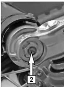
natural_image
Close-up of a mechanical component with a numbered arrow pointing to a circular feature (no visible text or symbols)Adjusting compression damping of fork
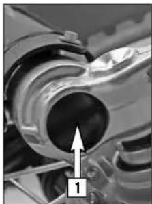
Hydraulic compression damping determines the reaction when the fork is compressed. The degree of compression can be adjusted with adjusting screws at the bottom of the fork legs. Carefully pry out the protection cover [1] with a screwdriver and remove.
Turn the adjusting screws [2] clockwise to increase damping, turn it counterclockwise to reduce damping during compression. Make the same damping rate adjustments to both fork legs.
STANDARD ADJUSTMENT
- Turn adjusting screw clockwise as far as it will go.
- Turn 20 clicks in a counterclockwise direction.
MAINTENANCE WORK ON CHASSIS AND ENGINE »
natural_image
Close-up of mechanical components with numbered arrows pointing to specific parts (no visible text or symbols)Adjusting rebound damping of fork
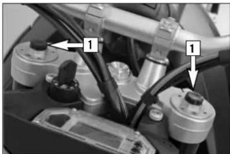
Hydraulic rebound damping determines the reaction when the fork is rebound. By turning the adjusting screw [1] (REB), the degree of damping of the rebound can be adjusted. Turn the knob clockwise to increase damping, turn it counterclockwise to reduce damping during rebounding. Make the same damping rate adjustment to both fork legs.
STANDARD ADJUSTMENT
- Turn adjusting screw clockwise as far as it will go.
- Turn 20 clicks in a counterclockwise direction.

natural_image
Close-up of a mechanical component with a labeled part (2) and an arrow pointing to a small component, no visible text or symbols.Adjusting the spring preload on the fork
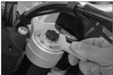
The fork spring preload can be adjusted by turning the adjusting screws [2] (wrench size 24 mm) ± 5 mm (0,2 in).
Turning in a clockwise direction will increase the preload, turning in a counterclockwise direction will decrease the preload. 1 turn will change the preload by 1 mm.
Changing the preload will not affect the rebound damping adjustment, although adjusting screw [1] will turn at the same time. Make the same spring preload adjustments to both fork legs.
Generally, if the preload is higher, the rebound damping should also be set higher.
natural_image
Close-up of a hand adjusting a mechanical component with wires and a small component (no visible text or symbols)STANDARD ADJUSTMENT:
- Turn adjusting screw counterclockwise as far as it will go.
- Turn 5 turns in a clockwise direction.
MAINTENANCE WORK ON CHASSIS AND ENGINE »
text_image
1 2Compression damping of shock absorber
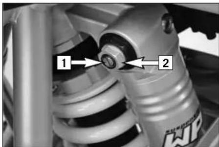
The shock absorber can synchronize the compression damping in the low and high-speed range separately (Dual Compression Control).
Low and high speed refers to the movement of the shock absorber during compression and not to the speed of the motorcycle.
The low and high-speed technology overlaps.
The low-speed setting is primarily for slow to normal shock absorber compression rates.
The high-speed setting is effective at fast compression rates.
Turning in a clockwise direction will increase the damping, turning counterclockwise will decrease the damping.
natural_image
Close-up of a mechanical assembly with a metal rod inserted into a bolted component (no visible text or symbols)STANDARD ADJUSTMENT LOW-SPEED:
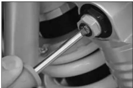
- Turn adjusting screw [1] clockwise as far as it will go.
- Turn 20 clicks in a counterclockwise direction.
natural_image
Close-up of a hand using a tool to adjust or install a mechanical component (no visible text or symbols)STANDARD ADJUSTMENT HIGH-SPEED:
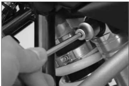
- Turn adjusting screw [2] (wrench size 17 mm) clockwise as far as it will go.
- Turn 1.5 turns in a counterclockwise direction.
WARNING
The damping unit of the shock absorber is filled with high-compression nitrogen. Never try to take the shock absorber apart or to do anymaintenance work yourself. Severe injuries could be the result.
Never unscrew the black screw connection (24mm).
MAINTENANCE WORK ON CHASSIS AND ENGINE »
natural_image
Close-up of a car suspension system with a tool inserted, showing no visible text or symbolsRebound damping of shock absorber
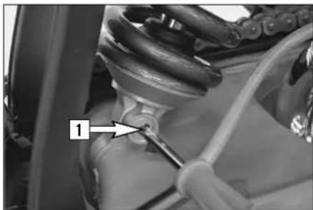
By using the adjusting screw [1], the degree of damping of the rebound can be adjusted. Turn the knob in a clockwise direction to increase damping, turn it in a counterclockwise direction to reduce damping during rebounding.
STANDARD ADJUSTMENT:
- Turn adjusting screw clockwise as far as it will go.
- Turn 18 clicks in a counterclockwise direction.
WARNING
The damping unit of the shock absorber is filled with high-compression nitrogen. Never try to take the shock absorber apart or to do any maintenance work yourself. Severe injuries could be the result.
natural_image
Close-up of a mechanical component with a labeled bolt and adjustment knob (no readable text or symbols)Breathing the fork legs
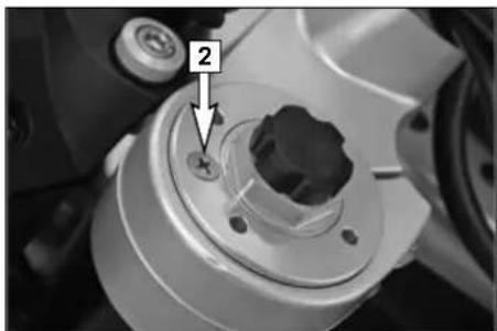
Breath the fork legs regularly (see Maintenance Schedule). To breath, place the motorcycle on the side stand and briefly remove the bleeder screws [2] to allow any overpressure to escape from the fork.
! CAUTION
Excessive pressure in the interior of the fork can cause leaks in the fork. If your fork is leaking, it is recommended to open the breather plugs before having the seals replaced.
MAINTENANCE WORK ON CHASSIS AND ENGINE »
text_image
A 15 - 17 mm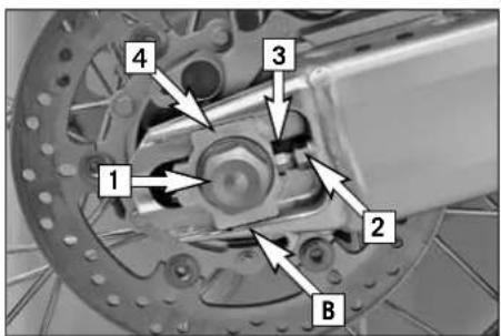
text_image
1 2 3 4 B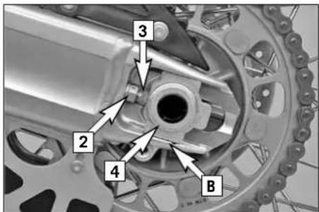
text_image
Technical diagram of a mechanical gear assembly with numbered components labeled 2, 3, 4, and B.Checking the chain tension
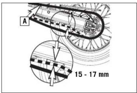
Place the motorcycle on the side stand. Switch the transmission to neutral and push the chain up. The distance between the chain and the swing arm should be 15 - 17 mm (0.6 - 0.7 in) when the upper part of the chain [A] is tensioned (see drawing). Correct the chain tension if necessary.
WARNING
- If chain tension is too great, parts within the secondary power transmission (chain, chain sprockets, transmission and rear wheel bearings) will be subjected to unnecessary stress, resulting in premature wear and even chain breakage.
- Too much slack in the chain, on the other hand, can result in the chain jumping off the chain wheels. If this happens, the chain could also block the rear wheel or damage the engine.
- In either case the operator is likely to lose control of the motorcycle.
Correcting the chain tension
Loosen the collar nut [1], loosen the counternuts [2] and turn the left and right adjustment screws [3] the same distance. Tighten the counternuts [2].
To make sure the rear wheel is aligned, the marks on the chain tensioners must be in the same position on the left and right in relation to the reference marks [B]. Before tightening the wheel spindle make sure the chain tensioner [4] rests against the adjustment screws and the rear wheel is aligned with the front wheel.
Tighten the collar nut [1] to 90 Nm.
WARNING
If you don't happen to have a torque wrench at hand, make sure you have the tightening torque corrected by a KTM dealer as soon as possible. A loose wheel spindle can cause the motorcycle's handling performance to become instable and cause it to crash.
MAINTENANCE WORK ON CHASSIS AND ENGINE »
text_image
Two icons: a gear with 'X' and a checkmark, both in gray with gear patterns.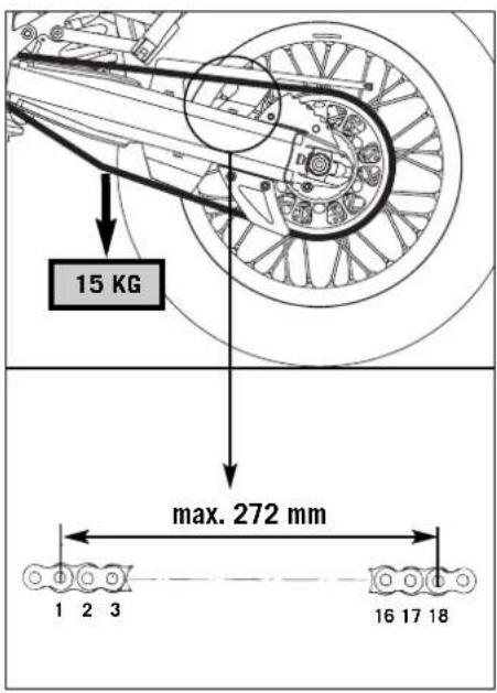
text_image
15 KG max. 272 mm 1 2 3 16 17 18Chain maintenance
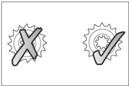
Maintenance of the X-ring chain is reduced to a minimum. Rinse off any heavy dirt with plenty of water. Residual used grease must be removed prior to lubrication (Motorex Chain Clean 611). After drying, use a chain spray specially designed for X-ring chains (Motorex Chainlube 622).
WARNING
- No lubrication is allowed to reach the rear tire or the brake disk, eitherwise the road adherence and the rear wheel braking effects would be strongly reduced and the motorcycle could easily get out of control.
- The chain does not have a chain joint for safety reasons. Always have the chain replaced in an authorized KTM workshop where the service technicians have the required riveting tool.
- Never mount a normal chain joint.
Also check sprockets and chain guides for wear, and replace if necessary.
Checking the chain for wear
To check the chain for wear proceed as follows:
Switch the transmission to idle and put a load of approx. 15 kilograms (33 lbs) on the lower part of the chain (see illustration). Now measure the distance between 18 chain rollers on the upper part of the chain. The chain needs to be replaced when the distance is 272 mm (10.70 in). Since chains do not always wear evenly, repeat the measurement at different parts of the chain.
Replace the chain if any X-rings are missing.
NOTE:
If you mount a new chain, the sprockets should also be replaced. New chains wear faster if used on old used sprockets.
MAINTENANCE WORK ON CHASSIS AND ENGINE »
natural_image
Exploded view diagram of automotive brake components (no text or labels)General informations about KTM disc brakes
BRAKE CALIPERS:
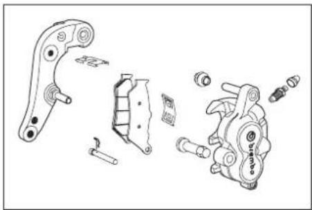
The brake calipers of this series "float". This means that the brake calipers are not solidly attached to the caliper support. Thus, the brake pads are always in optimum contact with the brake disc. Secure the screws of the caliper support with Loctite 243 and tighten to 25 Nm.
WARNING
For safety reasons, always have maintenance work and repairs to the brake system performed by an authorized KTM workshop.
natural_image
Two brake shield components shown side by side, no text or symbols visibleBRAKE PADS:
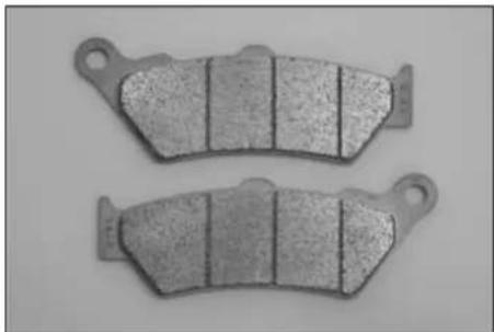
Your motorcycle is equipped with sintered brake pads in the front and rear and homologated accordingly. They guarantee maximum braking performance.
Front brake pads: Toshiba TT 2172 HH
Rear brake pads: Ferit I/D 450 FF
WARNING
Brake pads available in the accessory trade are often not authorized for operation of your KTM motorcycle in road traffic. The brake pads design and friction factor and therefore the braking power can deviate significantly from original KTM brake pads. If you use different brake pads than those provided with the original equipment, it cannot be warranted that they are authorized for use in road traffic. Your motorcycle will not longer comply with the regulations authorizing the use of vehicles for road traffic and the warranty will be void.
MAINTENANCE WORK ON CHASSIS AND ENGINE »
natural_image
Close-up of mechanical components with no visible text or symbolsBRAKE FLUID RESERVOIRS:
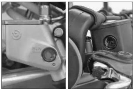
The brake fluid reservoirs on the front and rear wheel brakes have been designed in such a way that even if the brake pads are worn it is not necessary to top up the brake fluid. There is no reason to remove the reservoir cap under normal conditions. If the brake fluid level drops below the minimum either the brake system has a leak or the brake pads are completely worn down. In this case, consult an authorized KTM dealer immediately.

text_image
DOT 5.1 DOT 5 XBRAKE FLUID:
We recommend that you use Motorex DOT 5.1 brake fluid when you refill or change the brake fluid. DOT 5.1 brake fluid has a wet boiling point of 180^ C/ 356^ F ( 25^ C/ 45^ F higher than DOT 4) and is safer for high performance applications. Brake fluid DOT 5.1 is a polyethylene glycol based fluid, amber-colored and can be mixed with DOT 4 brake fluid. Do not, in any event, use DOT 5 brake fluid. It is based on silicone oil and is dyed purple. KTM motorcycle gaskets and brake hoses are not designed for DOT 5 brake fluid.
WARNING
Have the brake fluid for the front and rear brake changed at an authorized KTM workshop every 2 years.
text_image
Technical diagram of a mechanical component with labeled parts A and 4, showing cross-sectional view and dimension lines.BRAKE DISCS:
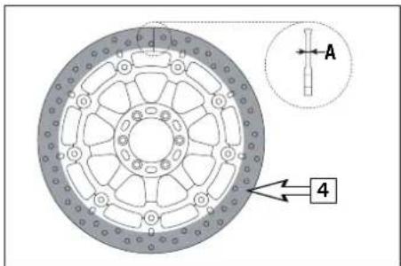
Wear reduces the thickness of the brake disc in the area of contact [4] with the brake pads. The brake disk should not be thinner than 4.5 mm (0.18 in) at the weakest point [A]. Check the wear at several points.
WARNING
Brake disks that are less than 4.5 mm (0.18 in) thick are a safety hazard. Have worn brake disks replaced immediately.
MAINTENANCE WORK ON CHASSIS AND ENGINE »
text_image
min. 3 mm 1 dominoAdjusting of free travel at the hand brake lever
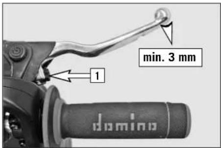
Free travel at the hand brake lever may be readjusted by using adjusting screw [1]. In this way, the position of the point of pressure (i.e., the resistance you feel on the hand brake lever when the brake pads are pressed against the brake disc) can be adjusted for any hand size.
! CAUTION
At the hand brake lever, free travel must at least be 3 mm (0.12 in). Only then may the piston in the hand brake cylinder be moved (to be recognized by the greater resistance of the hand brake lever). If this free travel is not provided, pressure will build up in the braking system, and the front wheel brake may fail due to overheating.
natural_image
Close-up of a mechanical component with a circular button and a metallic ring, no visible text or symbolsChecking of brake fluid level - front brake
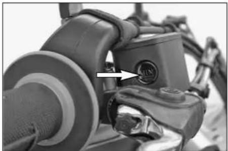
The brake fluid reservoir is linked with the hand brake cylinder at the handlebar and the reservoir is provided with an inspection glass. With the reservoir in a horizontal position, the brake fluid level should not go below middle of the glass.
WARNING
- If the brake fluid level drops below the minimum either the brake system has a leak or the brake pads are completely worn down. In this case, consult an authorized KTM dealer immediately.
- Have the brake fluid changed at an authorized KTM workshop every 2 years.
Checking the front brake pads
The brake pads can be inspected from below. The linings must be at least 1 mm (0.04 in) thick.
WARNING
At their most worn point brake pad linings should not be thinner than 1 mm, otherwise they could lead to brake failure. For your own safety don't put off having your brake pads changed.
! CAUTION
If the brake pads are replaced too late when the lining is partly or completely worn off, the steel parts on the brake pads will grind against the brake disks. This significantly decreases the braking effect and destroys the brake disks.
MAINTENANCE WORK ON CHASSIS AND ENGINE »
natural_image
Close-up of a mechanical component with a circular dial indicator and an arrow pointing to it (no visible text or symbols)Checking rear brake fluid level
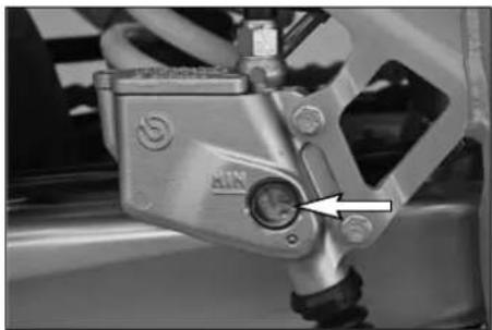
The brake fluid reservoir for the rear disk brake is combined with the foot brake cylinder and has an inspection window. The brake fluid level should not drop below the "MIN" mark when the motorcycle is in a vertical position.
WARNING
- If the brake fluid level drops below the minimum either the brake system has a leak or the brake pads are completely worn down. In this case, consult an authorized KTM dealer immediately.
- Have the brake fluid changed at an authorized KTM workshop every 2 years.
text_image
min. 1 mmChecking the rear brake pads
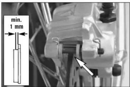
The brake pads can be inspected from the rear. The thickness of the linings may not be less than 1 mm (0.04 in).
WARNING
At their most worn point brake pad linings should not be thinner than 1 mm, otherwise they could lead to brake failure. For your own safety don't put off having your brake pads changed.
! CAUTION
If the brake pads are replaced too late so that the lining is partly or entirely worn away, the steel components of the brake pad will rub against the brake disc, impairing the braking effect and destroying the brake disc.
MAINTENANCE WORK ON CHASSIS AND ENGINE »
text_image
Mechanical assembly diagram showing two labeled components (1 and 2) with arrows indicating motion or assembly direction.Dismounting and mounting the front wheel
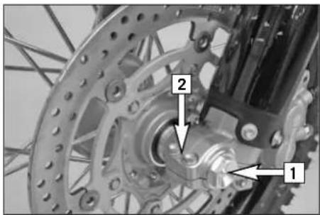
Jack the motorcycle up at the underride protection until the front wheel no longer touches the ground.
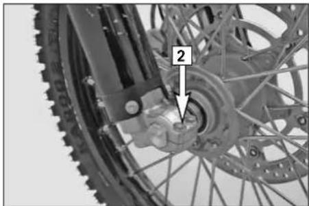
Loosen the 2 clamping screws [2] on the left side of the fork fists.
Loosen and remove the collar nut [1]., loosen the clamping screews [2] on the right side of the fork fist.
Hold the front wheel, pull out the wheel spindle [3].
Carefully remove the front wheel from the fork.
! CAUTION
- Do not operate the hand brake when the front wheel has been dismounted.
- Make sure the brake disc is always on top when you lay down the wheel, otherwise the brake disc can be damaged.
natural_image
Close-up of a bicycle wheel assembly with a numbered component (2) pointing to a central hub, no visible text or symbols beyond the number.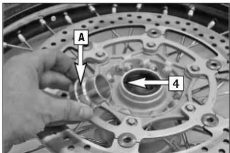
text_image
A 4Before remounting the front wheel, clean and grease the shaft seal rings [4] and the bearing surface [A] of the distance bushings and mount the distance bushings. Slightly push back the brake pads with a screwdriver. Set up the front wheel facing in the running direction.
MAINTENANCE WORK ON CHASSIS AND ENGINE »
text_image
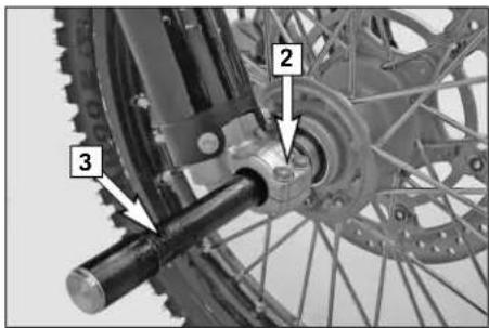
Technical diagram of bicycle wheel assembly with numbered components labeled 1, 2, and 3To install the front wheel, lift it into the fork, position and mount the axle shaft [3]. Mount the collar nut [1], tighten the clamping screws [2] on the right fork leg axle passage to prevent the axle shaft from turning and tighten the collar nut to 40 Nm (30ft.lb). Loosen the clamp screws on the right fork leg. Take the motorcycle down from its stand. Press the front wheel brakes and push down on the fork a few times vigorously so that the fork legs come into alignment.
Only after this has been accomplished, tighten the clamp screws on both fork legs with 15 Nm.
WARNING
- If you do not have a torque wrench to mount the wheel, have the torques corrected by an authorized KTM workshop as soon as possible. A loose wheel spindle can cause the motorcycle's handling performance to become instable and cause it to crash.
- After mounting the front wheel, keep operating the hand brake until the pressure point returns.
- Always keep the brake disks free from oil and grease, otherwise the braking effect will be significantly reduced.
MAINTENANCE WORK ON CHASSIS AND ENGINE »
text_image
Mechanical assembly diagram showing labeled components of a bicycle wheel and dashboard assembly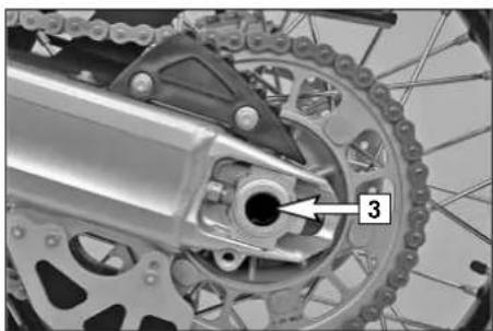
natural_image
Mechanical gear assembly with labeled component '3' (no text or symbols beyond label)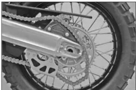
natural_image
Close-up of a bicycle's wheel and chain gear assembly (no text or symbols visible)Dismounting and mounting the rear wheel
Jack the motorcycle up at the underride protection until the rear wheel no longer touches the ground.
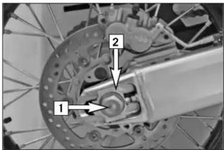
Unscrew the collar nut [1], remove the chain tensioner [2], hold on to the rear wheel while you pull out the axle passage [3]. Push the rear wheel as far to the front as possible, take the chain off of the rear sprocket and lay it on the rear sprocket guard. Carefully lift the rear wheel out of the swing arm.
! CAUTION
- Do not operate the rear brake when the rear wheel has been dismounted.
- Always place the wheel on the ground with the brake disc pointing upwards. Otherwise the brake disc may be damaged.
- If the axle is dismounted, clean the thread of the wheel spindle and collar nut thoroughly and apply a new coat of grease (Motorex Long Term 2000) to prevent the thread from jamming.
MAINTENANCE WORK ON CHASSIS AND ENGINE »
text_image
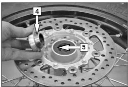
4 5Before remounting the rear wheel, clean and grease the bearing surface of the bushings [4] and the shaft seal ring [5].
The rear wheel is remounted in reverse order. Pay attention to the same mounting position of the axle passage and the chain tensioner.
Before tightening the collar nut to 90 Nm, push the rear wheel forwards so that the chain tensioners lie on the tension screws.
WARNING
- If you don't happen to have a torque wrench at hand, make sure you have the tightening torque corrected by a KTM dealer as soon as possible. A loose wheel spindle can cause the motorcycle's handling performance to become instable and cause it to crash.
- After mounting the rear wheel, keep operating the footbrake until the pressure point returns.
- It is very important to keep the brake disk free from oil and grease, otherwise the braking effect would be strongly reduced.
MAINTENANCE WORK ON CHASSIS AND ENGINE »
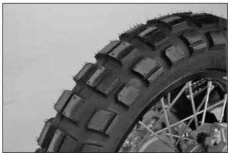
natural_image
Close-up of a rugged off-road tire with visible tread pattern and wheel rim (no text or symbols)| TIRES - AIR PRESSURE | ||
| 950 SUPER ENDURO R front rear | ||
| Offroad* | 1.7 bar24 psi | 1.5 bar21 psi |
| Road, rider only | 2.4 bar34 psi | 2.5 bar35 psi |
| Road, with passenger | 2.4 bar34 psi | 2.7 bar38 psi |
| Maximum payload | 2.4 bar34 psi | 2.7 bar38 psi |
* Immediately increase the tire inflation pressure when driving on the road again.
Tires, air pressure
Tire type, tire condition, and how much air pressure the tires have in them affect the way your motorcycle rides, and they must therefore be checked whenever you're getting ready to go anywhere on your motorcycle.
WARNING
The factory mounted tires are approved for a maximum speed of 160 kph (100 mph). Under no circumstances should this speed be exceeded. Other tires can have a negative effect on the motorcycle's handling (e.g. can cause it to "wobble" at higher speeds).
- Tire type and size can be found in the technical specifications and in the homologation certificate
- Tire condition has to be checked every time you want to ride your motorcycle. Before leaving check for punctures and nails or other sharp objects that might have become embedded in the tire.
- Refer to the specific regulations in your country for minimum tire tread requirements. We recommend replacing tires at the latest when the tread is down to 2mm (0.08 in).
- Tire pressure should be checked regularly on a „cold“ tire. Adapt the air pressure to the motorcycle's total weight. Proper pressure ensures optimum driving comfort and extends the life of your tires.
WARNING
- Do not mount tires which have not been approved by KTM. Other tires could have adverse effects on the way your motorcycle rides. Tire releases are available on the Internet at www.ktm.com
- Use tires of the same brand and type for the front and rear wheels.
- For your own safety replace damaged tires immediately.
- Worn tires can have a negative effect on how your motorcycle performs, especially on wet surfaces.
- If air pressure is too low, abnormal wear and overheating of the tire can result
- New wheels have a smooth surface, which means that they must be run in to achieve full grip. For this purpose, ride the motorcycle carefully at moderate speed during the first 200 kilometers (125 miles) with new tires, tilting the vehicle at different angles so that all sections are properly roughened. Tires will not display their full grip characteristics until they are properly run in.
- For reasons of safety, it is recommended to exchange the valve insert whenever a new tire is mounted.
MAINTENANCE WORK ON CHASSIS AND ENGINE »
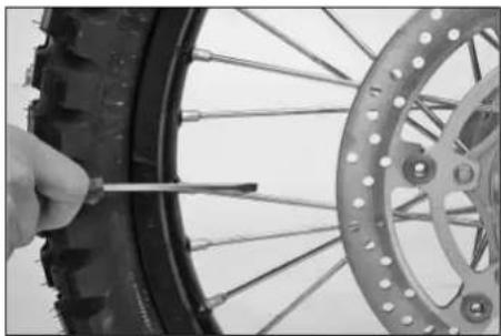
natural_image
Close-up of a hand using a screwdriver to adjust the tire wheel rim (no text or symbols visible)Checking spoke tension
The correct spoke tension is very important for the stability of the wheels and thus for riding safety. A loose spoke causes the wheel to become unbalanced and before long other spokes will have come loose. Check spoke tension, especially on a new motorcycle, in regular intervals. For checking, tap on each spoke with the blade of a screw driver (see illustration). A clear tone must be the result. Dull tones indicate loose spokes. If necessary, have the spokes retightened and the wheel centered by a KTM dealer.
WARNING
- If you continue to drive with loose spokes, the spokes can tear and lead to an instable handling performance. Torn spokes can damage the air hose. The loss of air can easily cause the motorcycle to go out of control.
- Excessively tensioned spokes may rupture due to local overloading. The spokes must be tensioned to 5Nm± 1Nm .
MAINTENANCE WORK ON CHASSIS AND ENGINE »
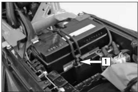
natural_image
Close-up of a car battery pack with wiring and a numbered component (no visible text or symbols)Battery
The battery is located under the seat and is maintenance-free.
Maintenance-free means you will not need to check the acid level. Clean the battery terminals regularly and grease with acid-free grease if necessary. The charge condition and type of charge are very important for the battery's service life.
WARNING
Never operate the motorcycle with a run-down battery or without the battery. This can damage the electronic components or safety equipment in either case and the motorcycle will no longer be roadworthy.
DISMOUNTING AND MOUNTING THE BATTERY:
Detach the rubber band [1]. First disconnect the negative pole, then the positive pole from the battery. Install the battery with the terminals facing the front (see illustration). Connect the minus pole to the battery last.
WARNING
- If electrolyte (sulphuric acid) leaks from the battery, proceed with great care. The electrolyte can cause severe burns.
- In the case of skin contact rinse thoroughly with water.
- In the case of contact with the eyes, thoroughly rinse eyes with water for at least 15 minutes. Immediately consult a doctor.
- The battery is a closed model but can nevertheless emit explosive gases. Avoid sparks and open fire near the battery.
- Defective batteries must be stored out of the reach of children. Ensure proper disposal of discarded batteries.
! CAUTION
Never remove the closing cover [2] otherwise the battery will be damaged.
STORAGE:
If the motorcycle is being immobilized for longer periods of time, remove and charge the battery. Storage temperature 0 - 35°C (32 - 95°F), avoid direct sunlight.
Charge the battery every 3 months.
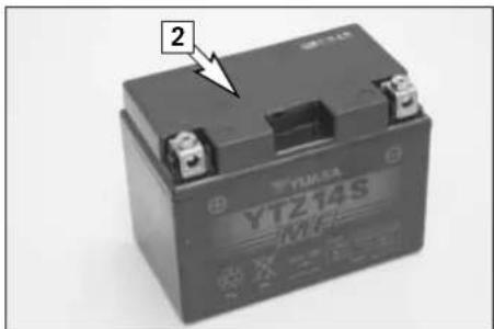
text_image
YTZ14S MFS 2MAINTENANCE WORK ON CHASSIS AND ENGINE »
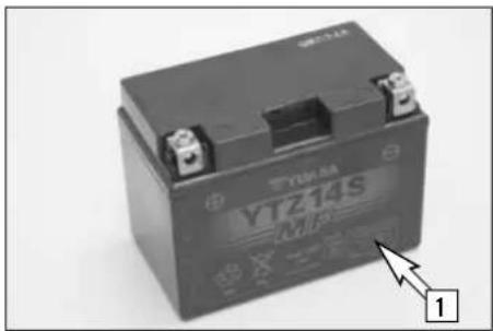
natural_image
Black YIZ14S MP3 battery with mounting holes and a numbered label pointing to its side (no readable text beyond branding)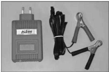
natural_image
Product photo of a KLM power supply unit with coiled black cables and clampers (no visible text or symbols)Charging the battery
The battery discharges every day, even if it is not used.
Always disconnect the battery when charging. Charge the battery as described in the instructions [1] on the battery housing. Do not exceed the amperage and charging time. Quick charging at a high amperage has an adverse effect on the service life.
Always use special charging devices to charge maintenance-free batteries, e.g. the KTM charging device (item no. 58429074000). You can also use this charging device to test the off-load voltage and startability of the battery and generator. It is impossible to overcharge the battery with this device.
Charge the battery immediately if it is empty when you start the motorcycle. If left to stand in an uncharged condition for a longer period of time, the battery will run down and sulfate, destroying the battery.
Recharge the battery every 3 months if it is being stored for a longer period of time.
! CAUTION
- Never remove the closure since it will be damaged.
- To avoid damage to the on-board electronic system, always disconnect the minus pole before you charge the battery.
- To charge, connect the battery to the battery charger before you switch on the battery charger. When the battery is charged, switch off the battery charger before you disconnect the battery.
- Provide adequate ventilation when charging the battery in a closed room; the battery emits explosive gases when charging.
- Electrolytes will escape through the safety valves if the battery is charged too long or at an excessive voltage or amperage. This will reduce battery capacity.
– Try to avoid quick charges.
Jump start
Jump starts are not recommended since they can damage the motorcycle's electronic system.
MAINTENANCE WORK ON CHASSIS AND ENGINE »
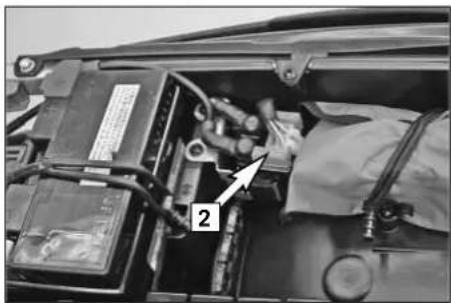
natural_image
Close-up of a car battery panel with wiring and labeled component (no readable text or symbols)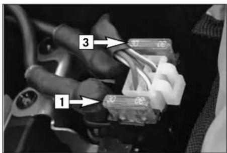
text_image
1 2 3Main fuse
The main fuse [1] protects all power-consuming units on the motorcycle. It is located below the seat at the starter relay.
For access to the fuse, remove the cover [2]. The capacity of the fuse is 30 A. A spare fuse [3] can be found under the other cover. When using the spare fuse, remember to replace it as soon as possible so that a spare fuse is always at hand. Replace a blown fuse only with an equivalent one. If a new fuse that has just been set in gets blown again, you are strongly advised to have it inspected by a KTM dealer. The fuse capacity is 30 Ampere.
! CAUTION
- Under no circumstances is a stronger fuse allowed to be set in or a fuse allowed to be "repaired". An inexpert treatment could damage the whole electrical installation!
- Contact a specialized KTM dealer, should defects of the electric system occur more frequently.
MAINTENANCE WORK ON CHASSIS AND ENGINE »
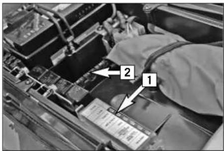
text_image
Close-up photo of a car battery terminal with labeled components and arrows indicating parts 1 and 2Fuses for individual power consumers
A fuse box is mounted under the seat containing additional fuses that protect the individual electric power consumers.
The power consumers and the corresponding capacities are listed on the cover of the fuse box [1]. The ACC 2 fuse protects the carburetor heaters from short circuits. Spare fuses 10 and 15 ampere [2] are located in the storage compartment.
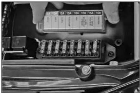
natural_image
Close-up of a car's electrical panel with visible fuse and terminal block (no text or symbols)Replace a blown fuse only with an equivalent one. If a new fuse that has just been set in gets blown again, you are strongly advised to have it inspected by a KTM dealer.
! CAUTION
Under no circumstances is a stronger fuse allowed to be set in or a fuse allowed to be "repaired". An inexpert treatment could damage the whole electrical installation!
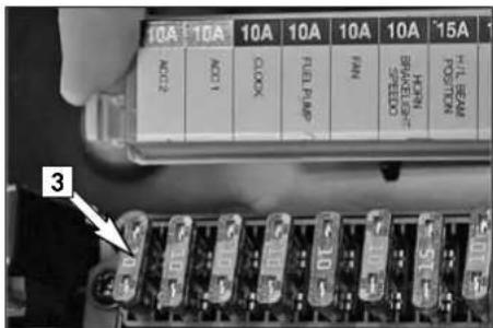
text_image
10A 10A 10A 10A 10A 10A 15A ACC2 ACC1 CLOCK FUEL PUMP FIN SPEED CONTROL DOWN 3 10 10 51Fuses ACC 1 and ACC 2 [3] are designed for accessories with a maximum power consumption of 10 amperes each. Fuse ACC 2 also protects the carburetor heaters from short circuits.
Sockets to connect the accessories are located under the headlight mask. For more information, contact an authorized KTM workshop.
MAINTENANCE WORK ON CHASSIS AND ENGINE »
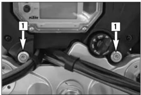
natural_image
Close-up of a motorcycle's front wheel assembly with two labeled buttons (1) and a digital display on the hood (no readable text or symbols)Replacing the headlight lamp
Remove the screws [1], tilt the headlight mask up towards the front and detach at the bottom.
! CAUTION
Never touch the glass of the bulb with your fingers. The glass of the bulb must remain absolutely free from grease. Heat will otherwise cause the grease to evaporate and settle down on the reflector.
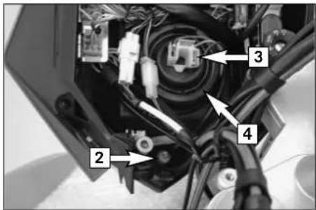
text_image
Labeled mechanical assembly diagram showing components 2, 3, and 4 with arrows pointing to specific partsPARKING LIGHT BULB:
Pull the bulb socket [2] out of the reflector and pull the bulb out of the bulb socket.
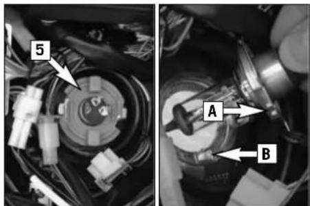
text_image
5 A BHEADLIGHT BULB:
Unplug the connector [3] and remove the rubber cap [4]. Turn the bulb socket [5] approx. 30^ in a counterclockwise direction and remove.
Insert a new bulb, making sure the tabs [A] on the lamp engage in the recess [B] in the headlight. Mount the bulb socket, rubber cap and connector.
Attach the headlight mask at the bottom, mount the screw and tighten to 10 Nm.
MAINTENANCE WORK ON CHASSIS AND ENGINE »
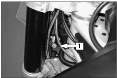
natural_image
Close-up of a mechanical assembly with visible components and wiring (no text or symbols)Adjusting the headlight range
The payload can make it necessary to correct the headlight range.
The headlight range can be adjusted with the adjusting screw [1]. Turning in a clockwise direction will reduce the headlight range, turning in a counterclockwise direction will increase the headlight range.
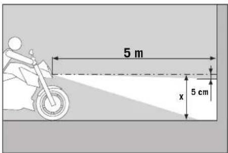
text_image
5 m x 5 cmTO CHECK:
Determine the distance from the ground to the center of the headlight when your motorcycle is loaded and ready for the trip (baggage, driver, passenger). Make a mark on a light wall behind a level surface at a height corresponding to the center of the headlight. Position your motorcycle loaded ready for the trip 5 meters (16,4 ft) away from the wall and switch on the low beam. The light/dark cut-off line should be 5 cm (2 in) under the mark (see drawing).
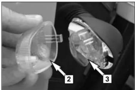
natural_image
Close-up of a hand holding a transparent plastic container with three numbered arrows pointing to internal components (no text or symbols visible)Replacing the flasher bulbs
Remove the screw on the back of the turn signal, carefully fold the lens [2] towards the motorcycle and remove. Turn the cap [3] approx. 15° in a counterclockwise direction and remove.
Slightly depress the bulb, turn it approx. 30° counterclockwise and pull it out of the socket.
To mount the lamp reverse the worksteps indicated above. When you mount the screw, first turn it in a counterclockwise direction until it engages in the thread and then tighten slightly.
MAINTENANCE WORK ON CHASSIS AND ENGINE »
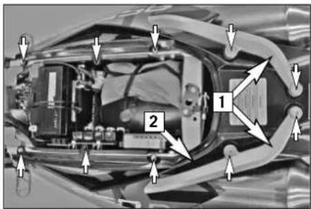
text_image
Technical diagram of a vehicle's internal components with numbered parts and directional arrows indicating flow or assembly.Replacing the brake light and taillight bulbs
Remove the seat. Remove the screws on the grips [1] and the upper rear [2] and take off the parts.
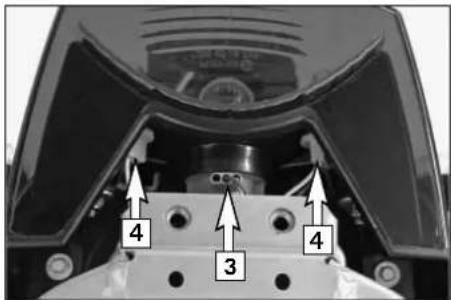
text_image
4 3 4Turn the bulb socket [3] approx. 30^ in a counterclockwise direction and pull it out of the taillight housing. Slightly press in the bulb, turn approx. 30^ in a counterclockwise direction and remove it from the socket.
Proceed in the reverse order to mount a new bulb.
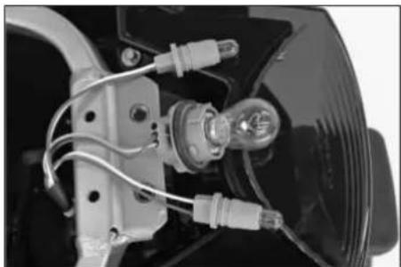
natural_image
Close-up of a car headgear with attached electrical components and wiring (no visible text or symbols)Remove the bulb socket [4] from the housing and pull the bulb out of the socket. Insert a new bulb and press the bulb socket all the way into the taillight housing.
Mount the upper rear and insert the screws. Mount the grips and tighten the screws to 25 Nm. Tighten the screws on the upper rear to 5 Nm. Mount the seat.
MAINTENANCE WORK ON CHASSIS AND ENGINE »
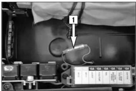
Activating the ignition curve for low-octane fuel
If you are traveling to a country where fuel having at least 95 octane (RON) is not available, you can easily activate the corresponding ignition curve.
A socket connector [1] is located on a brown-black cable under the fuse box.
If the two connectors are connected to each other, the ignition curve for fuel having at least 95 octane (RON) is activated.
If you disconnect the plug and socket connection, the ignition curve for fuel having 80 - 94 octane (RON) is activated. Although this causes the engine to lose some of its power output, it prevents poor glow ignitions and engine damage.
! CAUTION
If fuel having at least RON 95 (USA = Premium PON 91) is not available, the ignition curve for 80 - 94 octane (RON) must be activated to prevent engine damage.
MAINTENANCE WORK ON CHASSIS AND ENGINE »
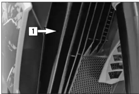
natural_image
Close-up of a mechanical component with a numbered arrow pointing to a feature (no visible text or symbols)
text_image
2 WS mph km/h 18.8 TRIP 3Cooling system
The water pump in the engine ensures a forced circulation of the cooling liquid. When the engine is cold, the cooling liquid only circulates in the cylinders and cylinder heads. The thermostat will open when the engine reaches approx. 75^ C ( 167^ F) and the cooling liquid will also be pumped through the aluminum radiator [1].
Cooling is by means of the air stream. The lower the speed, the lower the cooling effect. Soiled cooling fins also impair the cooling effect.
If, for example, slow urban traffic or waiting at a traffic light cause little or no air to stream through the radiator, the temperature of the cooling liquid will rise. The radiator fan switches on when the cooling liquid reaches a temperature of 102^ C ( 216^ F). Additional air is blown through the radiator to prevent the cooling system from overheating.
! CAUTION
The temperature indicator [2] will begin to blink and the red cooling liquid temperature warning lamp [3] will light up when the cooling liquid reaches approx. 120°C (248°F), having exceeded the normal operating temperature. Possible causes:
- Slow riding with large loads at a higher air temperature: If possible increase your running speed, so that more air can blow through the radiators. Should the warning light still be on off after 1500 meters (1 mile), stop immediately, switch off the engine and look for other possible causes.
- The cooling fan on the radiator is not working: The cooling fan must be running, when the cooling liquid temperature is 120^ (248°F) and the ignition is on. If the fan is not working, and there appears to be sufficient cooling liquid, the only thing you can do is to drive on to your nearest authorized KTM workshop at the least possible engine load.
- Too little cooling liquid in the system:
Check whether any cooling liquid is leaking out (also on the bottom of the motorcycle). Let the engine cool down and check the cooling liquid level in the radiator (see chapter Checking the cooling liquid level in the radiator). Only continue to drive if there is enough cooling liquid in the system. Contact an authorized KTM workshop to have the error eliminated. You will damage the engine if you continue to drive when the cooling liquid temperature warning lamp is on.
– Excessive use of the clutch at slow speed
MAINTENANCE WORK ON CHASSIS AND ENGINE »
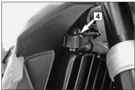
natural_image
Close-up of a mechanical component with a numbered annotation (4) pointing to a small component, no visible text or symbols beyond the number.A mixture of 50% antifreeze and 50% distilled water is used as the cooling liquid. However, the anti-freeze protection must be at least -25^ C ( -13^ F). Aside from antifreezing protection, this mixture also provides great corrosion protection which is why it must not be replaced by pure water.
! CAUTION
- For the cooling system, use only high-grade antifreeze (Motorex Anti-Freeze). Using lower-grade antifreeze agents, can cause corrosion and coolant foaming.
- More antifreeze must be added if you plan to travel to a region where temperatures are expected to drop below -25^ (-13°F).
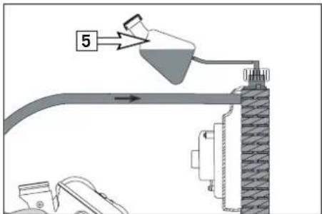
text_image
5Pressure induced by heating of the cooling liquid in the cooling system is controlled by a valve in the radiator cap [4]; a water temperature rising up to 125°C (257°F) is admissible, without fear of problems.
Any excess cooling liquid caused by thermal expansion is conducted to the compensating tank [5]. It will be sucked back in as soon as the temperature in the cooling system drops.
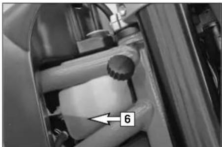
natural_image
Close-up of a mechanical device with a numbered component '6' pointing to a white cylindrical part (no visible text or symbols beyond the number)Checking the cooling liquid level in the compensating tank
Check the level of the cooling liquid when the engine is cold. It should fall between the MIN and MAX marks on the compensating tank [5].
Add cooling liquid (see above for mixture ratio) if the cooling liquid level drops below the MIN mark.
If you need to add cooling liquid quite often, the cooling system may leak. If the compensating tank is empty, also check the cooling liquid level in the radiator. Have the cooling system checked by an authorized KTM workshop.
MAINTENANCE WORK ON CHASSIS AND ENGINE »
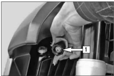
natural_image
Close-up of a hand adjusting a mechanical component with a numbered arrow pointing to the component (no visible text or symbols)Checking the cooling liquid level in the radiator
Hold the radiator cap [1] with a cloth, carefully turn in a counterclockwise direction and remove. The radiator should be completely filled with cooling liquid; no air should be in the radiator.
If any cooling liquid is missing, the cooling system is probably leaking. Have the cooling system checked at an authorized KTM workshop.
WARNING
If possible, check the cooling liquid level when the engine is cold. If you need to remove the radiator cap when the engine is hot, hold the cap with a cloth and open slowly, allowing any excess pressure to escape (danger of scalding).
! CAUTION
- If more than 1 liter of cooling liquid needs to be added, you will need to bleed the cooling system.
- Only continue to drive if there is enough cooling liquid in the system. Contact an authorized KTM workshop to have the error eliminated. You will damage the engine if you continue to drive when the cooling liquid temperature warning lamp is on.
MAINTENANCE WORK ON CHASSIS AND ENGINE »
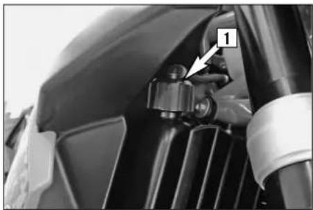
natural_image
Close-up of a mechanical component with a labeled component (1) and directional arrow, no readable text or symbols present.Bleeding the cooling system
To completely bleed the cooling system, the motorcycle must be raised approx. 50 cm (20 in) in the front.
Remove the radiator cap [1] and bleeder screw [2].
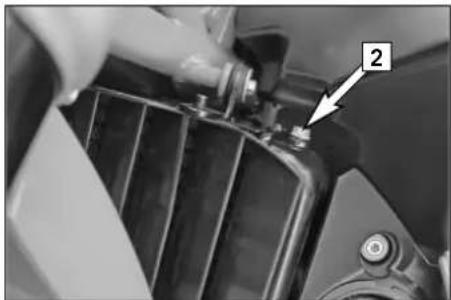
natural_image
Close-up of a hand adjusting a mechanical component with a numbered annotation (2), no visible text or symbols beyond the number.Add cooling liquid until it runs out of the vent holes without bubbles and immediately mount the screw to prevent air from entering the radiator.
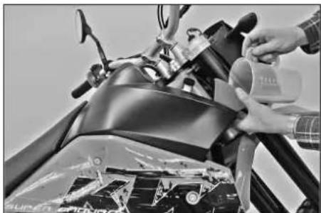
natural_image
Close-up of a person applying a spray bottle to a black motorcycle head (no visible text or symbols)Completely fill the radiator with cooling liquid. Mount the radiator cap and move the motor-cycle into a horizontal position again. Fill the compensating tank with cooling liquid until it reaches a level between the MIN and MAX mark. Close the compensating tank.
MAINTENANCE WORK ON CHASSIS AND ENGINE »

natural_image
Close-up of a bicycle brake lever with hand and belt (no text or symbols visible)Changing the original position of the clutch lever
The adjusting screw [1] can be used for individual adjustment of the original position of the clutch lever, thus allowing adjustment to an optimal position for every hand size.
Turning the adjusting screw in a clockwise direction will move the clutch lever away from the handlebar. Turning the adjusting screw in a counterclockwise direction will move the clutch lever closer to the handlebar.
! CAUTION
Adjustment of the clutch lever position is only possible within certain limits. Only turn the adjusting screw manually and never apply excessive force.

text_image
Close-up of hands using a tool to adjust or install a component, with numbered annotations pointing to parts 2, 3, and 4.Checking the oil level of the hydraulic clutch
To check the oil level in the master cylinder of the clutch remove the cover. For this purpose, remove screws and cover [2] together with the rubber boot [3]. The oil level in the horizontal-standing master cylinder should be 4 mm below the upper edge.
If necessary, add SAE 10 biodegradable hydraulic oil (Motorex clutch fluid 75), available from your authorized KTM workshop.
! CAUTION
KTM uses biodegradable, hydraulic mineral oil to actuate the hydraulic clutch. Do not mix this oil with any other hydraulic oil. Always use original KTM hydraulic oil (available from your authorized KTM workshop) to make sure your clutch operates smoothly. Never refill with brake fluid.
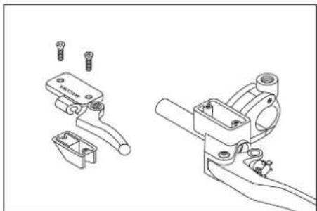
natural_image
Technical line drawings of mechanical components with screws and brackets (no text or symbols)MAINTENANCE WORK ON CHASSIS AND ENGINE »
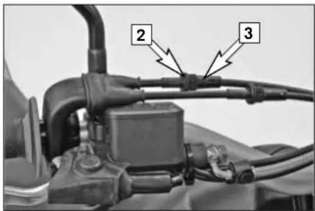
text_image
2 3Checking and adjusting the throttle cable play
You should feel 3-5 mm free travel on the throttle grip when you start to turn it.
To adjust, loosen the counternut [2], turn the adjusting screw [3] as required and tighten the counternut again.
Make sure that the throttle grip will return to the idle position automatically once you let go of it.
To check the correctness of this setting, start the engine, turn the handlebar left and right, in both cases as far as it will go. This must not cause any changes in idling speed. Otherwise, you have to increase the backlash of the throttle cable.
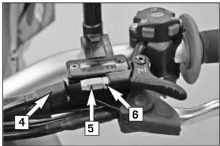
text_image
4 5 6Checking and adjusting the choke cable play
The choke cable must have a play of approx. 3 mm (0.12 in) at all times. To check the play, push back the protection cover [4]. It should be possible to lift the cable approx. 3 mm away from the adjusting screw [5].
If necessary, loosen the counter nut [6], turn the adjusting screw as needed, tighten the counter nut again and slide on the protection cover.
! CAUTION
If there is no play in the choke cable, the bore of the cold starter system cannot be completely closed. This will result in high fuel consumption, irregular engine operation, extreme wear on the pistons and cylinders and will destroy the catalytic converters.
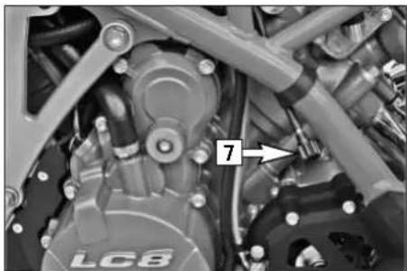
natural_image
Close-up mechanical assembly showing components like a LC8 valve and a numbered arrow (7), no readable text or symbols present.Adjusting the engine idle speed
The idle speed should be 1400 rpm when the engine is warm. The idle speed can be adjusted with the adjusting knurl [7] near the left frame tube. Turning in a clockwise direction will increase the idle speed, turning in a counterclockwise direction will reduce the idle speed.
MAINTENANCE WORK ON CHASSIS AND ENGINE »
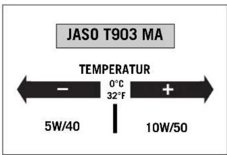
text_image
JASO T903 MA TEMPERATUR - 0°C + 5W/40 32°F 10W/50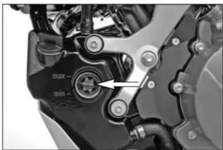
natural_image
Close-up of a mechanical component with labeled parts (max/min) and an arrow pointing to a central component (no readable text or symbols beyond basic labels)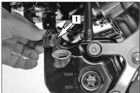
text_image
1 max- min-Engine oil
Automobile engine oil used to be used for four-stroke motorcycles before there were separate motorcycle specifications. Different technical developments made it necessary to have a separate specification for four-stroke motorcycles - the JASO T903 MA standard. Whereas car engines require long changing intervals, motorcycle engines require a higher power output at higher speeds. Most motorcycle engines also use the same oil to lubricate the transmission and the clutch. The JASO MA standard responds to these special requirements. Only use fully synthetic engine oils that meet the JASO MA quality requirements (see information on the can).
KTM recommends Motorex Power Synt 4T in the 10W/50 viscosity (for temperatures over 0°C, 32°F) or 5W/40 (for temperatures under 0°C, 32°F).
Checking the engine oil level
Check the engine oil level when the engine is warm (at least 4 bars on the temperature indicator light up). Allow the warm engine to run idle for approx. 1 minute and place the motorcycle on a level surface (not on the side stand).
The oil level should be between the MIN and MAX marks, add engine oil if necessary.
! CAUTION
Always check the oil level when the engine is warm. A cold engine can distort the measuring results. Engine oil expands when heated, increasing the oil level.
Refilling engine oil
Unscrew the plug [1] and refill engine oil. The quantity of oil between the MIN and MAX marks is 0.6 liter. Mount the plug and check the engine for leaks.
! CAUTION
- Insufficient amounts of or low-grade engine oil lead to premature wear in the engine.
- Do not overfill the engine case.
- Do not underfill the engine case.
MAINTENANCE WORK ON CHASSIS AND ENGINE »
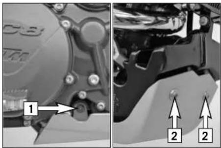
natural_image
Mechanical assembly diagram showing two views of a brake caliper with labeled parts (no text or symbols present)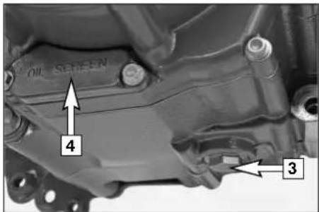
text_image
OIL SCREEN 4 3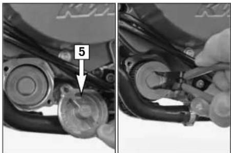
natural_image
Close-up of mechanical components with a hand adjusting parts, no visible text or symbolsChanging the engine oil and the oil filter, cleaning the oil screen
! CAUTION
You may only change the engine oil yourself after the warranty period has expired. The warranty will become void if you change the oil yourself during the warranty period.
NOTE: The LC8 engine has a dry-sump lubrication system. The engine oil is pumped from the oil sump in the engine case to the oil tank. The engine oil must also be drained from the oil tank during an oil change. Since many parts must be demounted for an oil change, we recommend having the engine oil changed by an authorized KTM workshop.
During the guaranty period, the oil change must be performed by an authorized KTM mechanic. Otherwise, the guarantee will become void.
The engine oil change is to be carried out when the engine is still warm.
WARNING
An engine having been run warm, and the engine oil in it is very hot – do not burn yourself.
Remove the screws on the right side of the underride protection [1] and on the left and front [2] and remove the underride protection.
Park the motorcycle on an even surface in an upright position. Place a vessel under the engine to catch the used oil and remove the oil drain plug [3]. Take off the cover [4] and pull the oil sieve out of the engine case with a pair of pliers.
Remove the oil filter cover [5] and pull the oil filter out of the engine case with circlip pliers (upside-down).
MAINTENANCE WORK ON CHASSIS AND ENGINE »
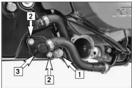
text_image
1 2 3 2Remove the drain plug [1] from the oil tank and allow the oil to drain into a vessel. Remove the screws [2] and tilt the connector [3] to the side.
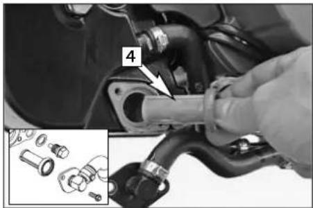
natural_image
Close-up of a hand adjusting a mechanical component with parts being adjusted (no visible text or symbols)Carefully pull the oil screen [4] out of the oil tank.
Thoroughly clean the drain plugs, the cover and both oil screens. Clean all rubber seal rings and check for damage. Replace if necessary.
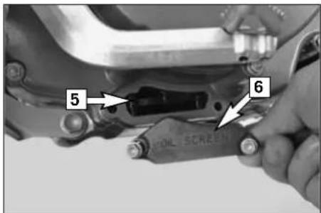
text_image
5 6 COIL SCREENMount the oil drain plug on the engine with a new seal ring and tighten to 20 Nm.
Slide the oil screen [5] into the guides in the oil pump housing with the TOP mark facing up. Make sure the form ring is in place and mount the cap [6]. Tighten the screws to 10 Nm.
MAINTENANCE WORK ON CHASSIS AND ENGINE »
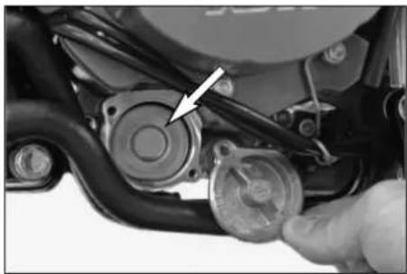
natural_image
Close-up of a mechanical component with a hand adjusting parts, no visible text or symbolsInsert a new oil filter in the engine case, grease the O-ring and mount the oil filter cover together with the O-ring. Tighten the screws to 6 Nm.
! CAUTION
Only use original ktm oil filters. The engine can be damaged if other filters are used.
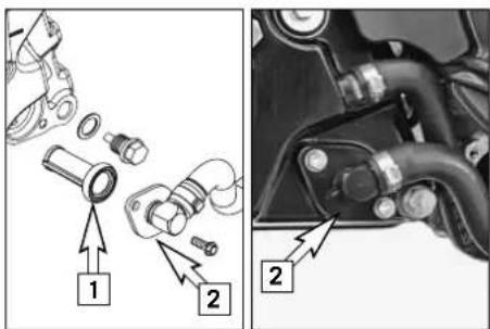
text_image
Technical diagram showing mechanical assembly steps with numbered components and directional arrows indicating assembly direction.Mount the oil drain plug on the oil tank with a new seal ring and tighten to 20 Nm.
Grease the seal ring [1] and carefully slide the oil screen in the oil tank. Position the connector [2], mount the screws and tighten to 10 Nm.
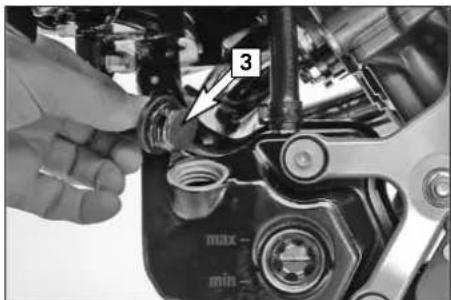
text_image
3 max- min-Unscrew the plug [3]. Add 2.5 liters (0.7 USgal) of fully synthetic engine oil according to the JASO MA Norm (e.g. Motorex Power Synt 4T) and remount the plug. Start the engine and allow to run warm in neutral until 4 bars on the temperature indicator light up. Switch off the engine and check the engine oil level (see Checking the engine oil level).
Check the engine and the oil tank for oil leakage.
Mount the underride protection and tighten the screws to 25 Nm.
TROUBLESHOOTING >>
If you let the specified maintenance work on your motorcycle be carried out, disturbances can hardly be expected. Should an error occur nevertheless, we advise you to use the trouble shooting chart in order to find the cause of error. We would like to point out that many operations cannot be performed by oneself. In case of uncertainty, please contact a KTM-dealer.
| TROUBLE CAUSE REMEDY | ||
| Engine does not start when the starter button is actuated | Operating errorDischarged battery.Blown fuse IGNITION.Blown main fuse.Defect ignition lockDefect safe-starting system. | Turn on the ignition, switch the gear to neutralRecharge the battery and investigate the causes for discharging; contact an authorized KTM workshop.Replace fuse IGNITIONRemove the seat and replace the main fuse in the starter relayCheck ignition lock, contact an authorized KTM workshop.Contact an authorized KTM workshop. |
| The engine cranks only with pulled clutch lever | A gear is engagedA gear is engaged and the side stand is still folded downDefect safe-starting system. | Shift the transmission to neutral.Shift the transmission to neutral.Contact an authorized KTM workshop. |
| Engine cranks with gear engaged. Defect safe-starting system. Contact an authorized KTM workshop. | ||
TROUBLESHOOTING >>
| TROUBLE CAUSE REMEDY | ||
| Engine cranks but doesn't start. Operating errorBlown fuse for the fuel pumpThe plug and socket connector on the wiring harness is oxidized | Open fuel taps, tank fuel, you did not use choke. Pay attention to starting off information (see driving instructions).Replace THE FUEL pump fuseRemove the panel and fuel tank, clean the plug and socket connector and spray with contact spray | |
| Engine will not reach full power Fuel supply partly interruptedCarburetors leakingAir filter very dirtyThe ignition curve for 80 octane is activated | Check the fuel taps, run the fuel lines without kinksCheck vacuum hoses and venting hoses of carburetors for correct position (no kinks)Have the air filter replaced at an authorized KTM workshop.Activate the ignition curve for 95 octane, if fuel with at least RON 95 (USA = Premium PON 91) is being used | |
| Engine overheats Insufficient cooling liquidRadiator fins are extremely dirtyFoam forms in cooling systemRadiator hose is kinked or damagedThermostat defectiveBlown fan fuse | Refill cooling liquid (see maintenance work), check cooling system for leaksClean radiator with water jetReplace cooling liquid, use antifreezer with brand nameRun the radiator hose correctly or replaceHave the thermostat checked (opening temperature 75°C, 167°F) or replaced; contact an authorized KTM workshopReplace fuse FAN | |
TROUBLESHOOTING >>
| TROUBLE CAUSE REMEDY | ||
| Engine overheats Defect fan or thermoswitch for fan Contact an authorized KTM workshop. | ||
| Engine stalls while driving No fuel | Operating errorFuse for fuel pump has blownFuse for the carburetor heater has blown, causing the carburetor to ice | RefuelOpen fuel tapsReplace fuse FUEL PUMPReplace fuse ACC2 |
| High oil consumption Engine oil level too highEngine oil too thin (viscosity) | Check engine oil level when the engine is warm; correct if necessaryUse thicker engine oil; see chapter „Engine oil“ | |
| Headlight and position light fail Blown fuse Replace fuse H/L BEAM POSITION. | ||
| Flasher lights, brake light, horn and multi-functional digital speedometer fail | Blown fuse Replace fuse HORN BRAKELIGHT SPEEDO. | |
| Time is not displayed or not correctly displayed | Blown fuse, thus no continuous power supply | Replace fuse CLOCK and set the clock. |
TROUBLESHOOTING >>
| TROUBLE CAUSE REMEDY | ||
| The battery is discharged The ignition | (power consumer) hasn't been switched offThe battery isn't charged by the generator because | Recharge the battery according to the relevant instructions.Voltage regulator and generator should be checked by an authorized KTM workshop. |
| No values are visible in the multi-functional digital speedometer display. | Blown fuse Replace fuse HORN BRAKELIGHT SPEEDO. | |
| No speed display. Defective sensor | cable or oxidized socket connector. | Check the pickup cable for damage, remove the headlight mask and check the cable connectors.Contact an authorized KTM workshop. |
Clean your motorcycle regularly in order to maintain the beauty of its plastic surfaces.
The best manner would be to use warm water that has been mixed with a normal brand-name washing detergent and a sponge. The hard dirt can be removed before washing with the help of a soft water jet.
! CAUTION
If using a power washer, do not point the water jet at the electric components, plugs, cables, bearings, carburetor, etc. The high pressure will cause water to penetrate into the components and can cause them to malfunction or lead to premature wear.
– Before you wash your motorcycle, close the muffler openings.
- Use warm water with a commercial detergent and sponge. Coarse dirt can be removed with a soft water jet. Areas that are heavily soiled can be sprayed with a motorcycle cleaner (e.g. Motorex 900) and cleaned with a brush.
- After the motorcycle has been rinsed with a soft water jet, it should be dried by air pressure and a cloth. Then take a short drive until the engine has reached the working temperature and also use the brakes. Due to the heat, the water also evaporates at the unapproachable parts of the engine and the brakes.
- Slide back the protective covers on the handlebar-mounted instruments so that any water that may have seeped into this part of the motorcycle is allowed to evaporate.
- After the motorcycle has cooled down, oil or lubricate all of the friction bearings and bearing positions and treat the chain with chain spray. Treat all bare areas (except brake disks) with a corrosion inhibitor (e.g. Motorex Protect & Shine).
- The exhaust pipes and mufflers are made of stainless steel and should be treated with a suitable care product.
- To prevent the electric system from malfunctioning, treat the ignition lock, emergency off switch, combination switch and connectors with contact spray.
CONSERVATION FOR WINTER OPERATION »
In the event that the motorcycle is also used in winter and on roads where one has to expect salt spraying, you will have to take precautions against the aggressive road salt.
– clean motorcycle thoroughly and let it dry
- treat engine, carburetor, swing arm, and all other bare parts (except for brake discs) with a wax-based anti-corrosion agent.
WARNING
Keep anti-corrosion agent from getting into contact with the brake discs, for otherwise this will significantly reduce the braking power.
! CAUTION
After rides on salted roads, clean motorcycle thoroughly with cold water and let it dry well!
STORAGE >>
Should you desire to make a pause over a longer space of time, please observe the following instructions:
- Drive the tank empty to be able to fill up with fresh fuel when starting the motorcycle up again.
– Clean motorcycle thoroughly (see chapter: CLEANING)
– Change engine oil and oil filter (old engine oil contains aggressive contaminations). - Check antifreezer and amount of cooling liquid.
- Allow the engine to warm up again, close the fuel taps and wait until the engine stalls. This drains the carburetor float chambers.
– Correct tire pressure. - Disassemble and charge battery (see chapter: BATTERY).
– Jack up the motorcycle if possible so the wheels do not touch the ground.
– The storage place should be dry and not subject to excessive temperature fluctuations. - Cover the motorcycle with an air permeated tarpaulin or blanket. Do not use non air permeable materials as a possible humidity might not be able to escape and could cause corrosion.
! CAUTION
It would be very bad to let the engine run for a short time during the storage period. The engine would not get warmed up enough and the thus developed steam would condense during the combustion process and cause the valves and exhaust to rust.
RE-INITIATION AFTER TIME OF STORAGE
- Mount the charged battery (pay attention to polarity) and set the clock.
- Fill up tank with fresh fuel.
- Check motorcycle as before each start (see driving instructions).
- Take a short, careful test ride first.
NOTE: Before you put your motorcycle away for the winter, you have to check all parts for their function and wear. Should any service jobs, repairs, or any refitting be necessary, you should have them carried out during the off-season (lower workload a mechanics' shops). This way, you can avoid the long waiting times at your mechanic at the beginning of the next biking season.
TECHNICAL SPECIFICATIONS – CHASSIS »
| CHASSIS 950 SUPER ENDURO R | |
| Frame tubular chrome-molybdenum | m-steel space frame |
| Fork | WP Suspension -Up Side Down 4860 MXMA PA |
| Wheel travel front | 250 mm (9.8 in) |
| Rear suspension | WP Suspension -Progressive Damping System shock absorber 4618 BAVP |
| Wheel travel rear | 255 mm (10 in) |
| Front brake Disk brake, perforated | brake disk ∅ 300 mm (11.8 in), floating brake caliper and brake disk |
| Rear brake Disk brake, perforated | brake disk ∅ 240 mm (9.5 in), floating brake caliper and brake disk |
| Authorized front tires * METZELER | MCE KAROO (T) FRONT 90/90-21 M/C 54Q M+S (up to a max. of 160 kph/ 100 mph) |
| Air pressure front | Offroad . . . . . . . . . . . . . . . . . . . . . . . . . . . . . . . . . . . . . . . . . . . . . . . . . . . . . . . . . . . . . . . . . . . . . . . . . . . . . . . . . . . . . . . . . . . . . . . . . . . . Road/driver only . . . . . . . . . . . . . . . . . . . . . . . . . . . . . . . . . . . . . . . . . . . . . . . . . . . . . . . . . . . . . . . . . . . . . . . . . . . . . . . . . . . . . . . . . . . . . . . . . . . 2.4 bar (34 psi)Road/with passenger . . . . . . . . . . . . . . . . . . . . . . . . . . . . . . . . . . . . . . . . . . . . . . . . . . . . . . . . . . . . . . . . . . . . . . . . . . . . . . . . . . . . . . . . . . . . . . . . . . . |
| Authorized rear tires * METZELER | MCE KAROO (T) 140/80-18 M/C 70Q M+S (up to a max. of 160 kph/ 100 mph) |
| Air pressure rear | Offroad . . . . . . . . . . . . . . . . . . . . . . . . . . . . . . . . . . . . . . . . . . . . . . . . . . . . . . . . . . . . . . . . . . . . . . . . . . . . . . . . . . . . . . . . . . . . . . . . Road/driveronly . . . . . . . . . . . . . . . . . . . . . . . . . . . . . . . . . . . . . . . . . . . . . . . . . . . . . . . . . . . . . . . . . . . . . . . . . . . . . . . . . . . . . . . . . . . . . . . . . . .Road/with passenger . . . . . . . . . . . . . . . . . . . . . . . . . . . . . . . . . . . . . . . . . . . . . . . . . . . . . . . . . . . . . . |
| Fuel tank capacity 14 liters (3.7 USgal), 4 liters (1 USgal) reserve | |
| Gear ratio - rear wheel 17:45 | |
| Chain | 5/8 x 5/16" X-ring |
| Lighting | headlight ....H4 12V 60/55W (socket P43t)position light front ....12V 5W (socket W2.1x9.5d)indicator lamps....LEDposition light rear....12V 5W (socket W2.1x9.5d)stoplight ....12V 21W (socket BA15s)licens plate illumination ....12V 5W (socket W2.1x9.5d)flasher ....12V 10W (socket BA15s) |
* further tire releases are available on the Internet at www.ktm.com
TECHNICAL SPECIFICATIONS – CHASSIS »
| CHASSIS 950 SUPER ENDURO R | |
| Battery 12V 11.2 Ah maintenance-free | |
| Steering head angle 64.4° | |
| Wheel base 1577 ± 10 mm (62 in) | |
| Seat height, unloaded 965 mm (38 in) | |
| Ground clearance, unloaded 330 mm (13 in) | |
| Dry weight 190 kg (419.4 lbs) | |
| Max. axle load, front 190 kg (419.4 lbs) | |
| Max. axle load, rear 250 kg (552 lbs) | |
| Max. total weight 400 kg (883 lbs) | |
| 950 SUPER ENDURO R 2008 | FORK | SHOCK | |||||
| SETTING | Compression | Rebound | Spring preload (turns) | Compression Low Speed | Compression High Speed | Rebound | Spring preload (mm) |
| Comfort | 25 | 25 | 1 | 25 | 2 | 22 | 8 |
| Basic Setting | 20 | 20 | 5 | 20 | 1.5 | 18 | 8 |
| Sport (MX) | 15 | 15 | 8 | 15 | 1 | 15 | 8 |
| Max. payload | 20 | 20 | 5 | 15 | 1 | 15 | 8 |
| FORK 950 SUPER ENDURO R | |
| Type 14187D32 WP Suspension | |
| Spring 5.9-450 | |
| Spring preload (turns) 5 | |
| Air chamber lenght 100 mm (4 in) | |
| Fork oil | SAE 5 (WP 4860.0401) |
| SHOCK ABSORBER | 950 SUPER ENDURO R |
| Type 15187D06 WP Suspension | |
| Spring 140-215 | |
| Spring preload (mm) | 8 mm (0.31 in) |
TECHNICAL SPECIFICATIONS – CHASSIS »
| TIGHTENING TORQUES - CHASSIS 950 SUPER ENDURO R 2008 | ||
| Collar bolt on front wheel spindle M24x1.5 60 Nm | ||
| Collar nut wheel spindle rear M25x1.5 90 Nm | ||
| AH bolt shock absorber top/bottom M14x1.5 80 Nm | ||
| Collar nut for swing arm bolt M19x1.5 130 Nm | ||
| AH bolts on subframe M10x1.25 Loctite 243 + 45 Nm | ||
| AH bolts on back of footrest support M8 Loctite 243 + 25 Nm | ||
| Engine carrier bolts M10 45 Nm | ||
| HH clamp bolts on top triple clamp M8 20 Nm | ||
| HH clamp bolts on bottom triple clamp M8 15 Nm | ||
| HH screw for steering head M20x1.5 12 Nm | ||
| HH clamp bolts on fork leg axle passages M8 15 Nm | ||
| Collar bolts for handlebar clamps M8 20 Nm | ||
| AH bolt for handlebar mount M10 20 Nm | ||
| HH clamp bolts for steering stem M8 20 Nm | ||
| Collar bolt front/rear brake disk | M6 Loctite 243 + 14 | Nm |
| HH bolts on front brake caliper | M8 Loctite 243 + 25 | Nm |
| HH bolts on handbrake cylinder | M6 10 Nm | |
| HH bolts on footbrake cylinder | M6 Loctite 243 + 10 | Nm |
| AH bearing bolt for foot brake pedal | M8 Loctite 243 + 25 | Nm |
| HH bolts on foot brake pedal surface | M5 | Loctite 243 + 6 Nm |
| AH bolts for side stand bracket - engine | M10 | Loctite 243 + 40 Nm |
| HH bolts for side stand fixture - side stand bracket | M10 | Loctite 243 + 25 Nm |
| HH bolts for side stand mounting | M10 | Loctite 243 + 35 Nm |
| HH bolt for spring rest on side stand | M8 Loctite 243 + 25 | Nm |
TECHNICAL SPECIFICATIONS – CHASSIS »
| TIGHTENING TORQUES - CHASSIS 950 SUPER ENDURO R 2008 | ||
| Bolt for side stand switch M4 2 Nm | ||
| Drain plug on oil tank M12x1,5 25 Nm | ||
| Exhaust nuts on manifold M8 evenly, do not bend sheet metal | ||
| Exhaust clamp M8 12 Nm | ||
| Senkschraube Hitzeschutzblech M6 8 Nm | ||
| HH bolt on fuel level indicator M5 3 Nm | ||
| HH bolts fuel taps M6 6 Nm | ||
| Collar screw for underride protection M8 25 Nm | ||
| Spoke nipple M5 5 Nm ± 1 Nm | ||
| Jerk damper bolt rear wheel M10x1,25 | Loctite 243 + 50 Nm | |
| Chainguard | M5 5 Nm | |
| Chain sliding guard | M5 6 Nm | |
| Taillight | M6 8 Nm | |
| Other bolts on chassis | M6 | 10 Nm |
| M8 | 25 Nm | |
| M10 | 45 Nm | |
| Other collar nuts on chassis M6 | M8 | 15 Nm |
| M10 | 30 Nm | |
| 50 Nm | ||
TECHNICAL SPECIFICATIONS – ENGINE »
| ENGINE 950 LC8 | |
| Design | liquid-cooled, 2-cylinder 4-stroke engine with 75° V arrangement with balancer shaft and electric starter |
| Displacement 942 cc | |
| Bore / Stroke 100/60 mm | |
| Compression ratio 11.5:1 | |
| Fuel unleaded fuel with at least RON 95 (USA: Premium PON 91*) | |
| Valve timing 4 valves controlled over bucket tappet and 2 camshafts, camshaft drive with gears/chain | |
| Valve diameter intake: 38 mm exhaust: 33 mm | |
| Valve clearance, cold intake: 0.10 - 0.15 mm exhaust: 0.25 - 0.30 mm | |
| Crankcase bearing friction bearings (2 main bearings / 1 supporting bearing) | |
| Conrod bearing friction bearing | |
| Piston pin bearing dual-fuel bearing | |
| Piston light alloy – forged | |
| Piston rings 1 compression ring, 1 taper face ring, 1 single-piece oil scraper ring with spiral-type expander | |
| Engine lubrication dry sump with 2 trochoidal pumps (pressure pump and suction pump) | |
| Engine oil SAE 5W/40, 10W/50 (Motorex Power Synt 4T) # | |
| Quantity of engine oil approx. 3.0 liters (0.8 USgal) during oil/filter change | |
| Primary drive straight-toothed spur wheels 35 : 67 | |
| Clutch | multi-disc clutch in oil bath, hydraulically operated |
| Transmission | 6-speed claw shifted |
| Gear ratio | 1st gear 12:352nd gear 15:323rd gear 18:304th gear 20:275th gear 24:276th gear 27:26 |
TECHNICAL SPECIFICATIONS – ENGINE »
| ENGINE 950 LC8 | |
| Ignition system breakerless transistorized electronic ignition system with digital ignition advance | |
| Ignition timing 5° BTDC at 1200 rpm | |
| Generator 12V 450W at 6000 rpm | |
| Spark plug NGK CR 8 EK | |
| Electrode distance 0.7 mm | |
| Cooling system liquid cooled, permanent circulation of cooling liquid through water pump | |
| Cooling liquid 2.1 liters (0.55 USgal), 50% antifreeze, 50% distilled water, at least -25°C | |
| Starting aid 0.9 kW electric starter | |
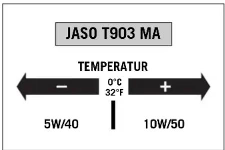
text_image
JASO T903 MA TEMPERATUR - 0°C + 32°F 5W/40 10W/50Engine oil
Only use fully synthetic engine oils that meet the JASO MA quality requirements (see information on the can).
KTM recommends Motorex Power Synt 4T in the 10W/50 viscosity (for temperatures over 0^ C, 32^ F) or 5W/40 (for temperatures under 0^ C, 32^ F).
| BASIC CARBURETOR SETTING | |
| Type of carburetor | CVRD 43 |
| Main jet | 155 (front) / 160 (rear) |
| Main air jet | 40 |
| Idling jet | 42 |
| Idle air jet 50 | |
| Idle air cutoff jet | 80 |
| Jet needle | NDFB |
| Needle position | 2nd from top |
| Mixture control screw open | 2 1/4 turns |
| Starting jet | 68 |
*
| PON / CLC RON / ROZ MON | ||
| 87 91 83 | ||
| 91 Premium | 95 87 | |
PON = Pump Octane Number CLC = Cost of Living Council RON = Research Octane Number ROZ = Research Oktan Zahl MON = Motor Octane Number
HEAD WORD INDEX >>
Accessories and payload .....21
Activating the ignition curve for low-octane fuel .....57
Adjusting compression damping of fork . . . . . . . . . . . . . . . . . . . . . . . . . . . . . 34
Adjusting of free travel at the hand brake lever .....42
Adjusting rebound damping of fork 35
Adjusting the engine idle speed .....63
Adjusting the fork and shock absorber .....34
Adjusting the headlight range 55
Adjusting the spring preload on the fork . . . . . . . . . . . . . . . . . . . . . . . . . . . . . . . . 35
Battery 50
Bleeding the cooling system ....61
Braking....26
Breathing the fork legs 37
Chain maintenance 39
Changing the engine oil and the oil filter, cleaning the oil screen .65
Changing the original position of the clutch lever . . . . . . . . . . . . . . . . . . . . . . . . . . . . . . . . . . . . . . . . . . . . . . . . . . . . . . . 62
Charging the battery 51
Chassis number, Type label 6
Check the following before each start .....22
Checking and adjusting the choke cable play . . . . . . . . . . . . . . . . . . . . . . . . . . . . . . . . . . . . . . . . . . . . . . . . . . . . . . . . . 63
Checking and adjusting the throttle cable play . . . . . . . . . . . . . . . . . . . . . . . . . . . . . . . . . . . . . . . . . . . . . . . . . . . . . . . . 63
Checking of brake fluid level - front brake .....42
Checking rear brake fluid level 43
Checking spoke tension 49
Checking the chain for wear . . . . . . . . . . . . . . . . . . . . . . . . . . . . . . . . . . . . . . . . . . . . . 39
Checking the chain tension . . . . . . . . . . . . . . . . . . . . . . . . . . . . . . . . . . . . . . . . . . . . . . 38
Checking the cooling liquid level in the compensating tank . . .59
Checking the cooling liquid level in the radiator . . . . . . . . . . . . . . . . . . . . . . . . . . . . . . . . . . . . . . . . . . . . . . . . . . . . . . . . . 60
Checking the engine oil level 64
Checking the front brake pads 42
Checking the oil level of the hydraulic clutch .....62
Checking the rear brake pads 43
Choke lever 7
Cleaning 72
Clutch lever 7
Combination switch 13
Compression damping of fork 18
Compression damping of shock absorber .....36
Conservation for winter operation .....73
Cooling liquid temperature display 12
Cooling system 58
Correcting the chain tension 38
Damping action during compression of shock absorber .....19
Dismounting and mounting the front wheel .....44
Dismounting and mounting the rear wheel .....46
Display 8
Driving instructions .....22
Engine number, engine type ....6
Engine oil 80
Engine oil 64
Filler cap 14
Flasher switch 13
Foot brake pedal 17
Fuel, refueling....28
Fuel taps 14
Fuses for individual power consumers .....53
General informations about KTM disc brakes . . . . . . . . . . . . . . . . 40
General tips and warnings for starting the motorcycle .....20
Grips 15
HEAD WORD INDEX >>
Hand brake lever 7
Ignition lock 13
Important information ....2
Index 4
Indicator lamps 12
Instructions for initial operation .....20
Introduction 1
Jump start ....51
Main fuse 52
Maintenance work on chassis and engine 33
Multi-functional digital speedometer 8
Operation instruments 7
Periodic maintenance schedule .....29
Rebound damping of fork 18
Rebound damping of shock absorber .....37
Rebound damping of shock absorber .....19
Refilling engine oil 64
Re-initiation after time of storage 74
Removal of seat 15
Replacing the brake light and taillight bulbs .....56
Replacing the flasher bulbs .....55
Replacing the headlight lamp 54
Running in the LC8 engine .....20
Serial number locations 6
Setting options in the display 10
Shift lever....16
Shifting/Riding 25
Side stand 16
Spring preload of the fork 18
Starter tip switch 14
Starting off 25
Starting when the engine is cold .....24
Starting when the engine is warm or hot . . . . . . . . . . . . . . . . . . . . . . . . . . . . 25
Stopping and parking 27
Storage 74
Technical specifications – chassis .....75
Technical specifications – engine .....79
Tires, air pressure .....48
Tool set 16
Troubleshooting 68
USE THIS SPACE FOR NOTES »
USE THIS SPACE FOR NOTES »

text_image
Barcode image containing encoded digital information3211240en

WP

09/2007 FOTO: MITTERBAUER

KTM Sportmotorcycle AG
A-5230 Mattighofen
www.ktm.at