
300 MXC (2002) - Motorcycle KTM - Free user manual and instructions
Find the device manual for free 300 MXC (2002) KTM in PDF.


| Product Type | Motorcycle |
| Brand | KTM |
| Model | 300 MXC (2002) |
| Category | Off-road enduro |
| Engine Displacement | 293 cc (nominal 300 cc) |
| Engine Type | 2-stroke, single cylinder, liquid-cooled |
| Starting System | Electric and kick start |
| Transmission | 6-speed |
| Fuel System | Carburetor (Keihin) |
| Front Suspension | WP upside-down fork |
| Rear Suspension | WP PDS shock |
| Brakes | Disc brakes front and rear |
| Front Tire | 90/90-21 |
| Rear Tire | 140/80-18 |
| Dry Weight | Approx. 100 kg (220 lbs) |
| Fuel Capacity | 9.5 L (2.5 gal) |
| Seat Height | 925 mm (36.4 in) |
| Ground Clearance | 370 mm (14.6 in) |
| Wheelbase | 1475 mm (58.1 in) |
| Manual Pages | 153 |
| Manual Language | English |
| Maintenance | Regular oil changes, air filter cleaning, chain lubrication |
| Cleaning | Use mild detergent, avoid high pressure on bearings |
| Safety | Always wear helmet, goggles, boots, and protective gear |
| Spare Parts & Repairability | Available from KTM dealers; many parts interchangeable |
Frequently Asked Questions - 300 MXC (2002) KTM
User questions about 300 MXC (2002) KTM
0 question about this device. Answer the ones you know or ask your own.
Ask a new question about this device
Download the instructions for your Motorcycle in PDF format for free! Find your manual 300 MXC (2002) - KTM and take your electronic device back in hand. On this page are published all the documents necessary for the use of your device. 300 MXC (2002) by KTM.
USER MANUAL 300 MXC (2002) KTM
natural_image
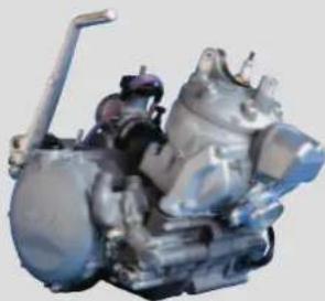
Close-up of a metallic automotive engine component with visible springs and hoses (no text or symbols)250 - 380 SX,MXC,EXC
REPAIR MANUAL ENGINE
KTM SPORTMOTORCYCLES
natural_image
3D rendered mechanical component with metallic and transparent surfaces (no visible text or symbols)1 SERVICE-INFORMATIONS
2 GENERAL INFORMATION
3 REMOVING AND REFITTING ENGINE
4 DISASSEMBLING THE ENGINE
5 SERVICING ON INDIVIDUAL COMPONENTS
6 ASSEMBLING THE ENGINE
7 ELECTRICAL
8 TROUBLE SHOOTING
9 TECHNICAL SPECIFICATIONS
10 PERIODIC MAINTENANCE SCHEDULE
11 WIRING DIAGRAMS
12
13
14
15
16
IMPORTANT INFORMATION/UPDATING INSTRUCTIONS
To be able to continue using the existing loose-leaf repair instructions, simply print the following pages and insert them in the existing repair instructions:
14-20, 26, 28-36, 37, 41, 42, 50, 51, 67, 72-77, 83, 121-126, 127, 134-136, 137, 151-153
| Remove page (s) Replace by page (s) Insert page (s) | after page | ||
| 2-1 to 2-4 2-1C to 2-6C | |||
| 3-4 3-4C | |||
| 4-1 to 4-9 4-1C to 4-8C | |||
| 5-1 5-1C | |||
| 5-4 5-4C / 5-5C | |||
| 5-13 to 5-14 5-13C to 5-14C | |||
| 7-1 7-1C 7-5C to 7-10C | |||
| 9-1 9-1C 9-37C to 9-42C | |||
| 10-1 10-1C 10-6C to 10-8C | |||
| 11-1 11-1C 11-14C to 11-16C | |||
KTM REPAIR MANUAL IN LOOSE-LEAF FORM
STORING THE REPAIR MANUAL IN THE BINDER
- Put the index into the binder.
- Put the front page of the repair manual (210x297 mm) into the transparent pocket provided for this purpose on the outside of the binder.
- Put the spine label (170x45 mm) into the transparent pocket provided for this purpose on the spine of the binder.
- Put the summary list of contents (150x297 mm) into the transparent pocket provided for this purpose on the inside of the binder or insert this page on the beginning of the manual.
- Then insert the individual chapters of the manual between the sheets of the index according to the page number printed in the right bottom corner of each page.
Example: page no. 3-5 3 = chapter 3 5 = page 5
All pages with a page number that begins with the digit 3, for example, must be put under the index heading „Chapter 3“.
– Index sheets that have not been marked with a certain chapter are for your personal convenience. The respective headings can be entered in the list of contents.
EXPLANATION - UPDATING
3.205.63-E Repair Manual 250 / 300 / 380 SX, MXC, EXC
Basicversion Modelyear 1999
(Engine number with first digit "9")
11/1998
3.205.87-E Updating of Rep.Manual 3.205.63-E
Modelyear 2000
(Engine number with first digit "0")
2/2000
3.210.02-E Updating of Rep.Manual 3.205.63-E
Modelyear 2001/2002
(Engine number with first digit "1")
(Engine number with first digit "2")
3/2001
3.206.004-E Updating of Rep.Manual 3.205.63-E
Modelyear 2003
(Engine number with first digit "3")
11/2002
Modification / Updating:
Technical Specification,
Periodic Maintenance Schedule, Wiring Diagrams
INTRODUCTION
This repair manual offers extensive repair-instructions and is an up-to-date version that describes the latest models of the series. However, the right to modifications in the interest of technical improvement is reserved without updating the current issue of this manual.
A description of general working modes common in work shops has not been included. Safety rules common in the work shop have also not been listed. We take it for granted that the repairs are made by qualified professionally trained mechanics.
Read through the repair manual before beginning with the repair work.
| WARNING | ||
| STRICT COMPLIANCE WITH THESE INSTRUCTIONS IS ESSENTIAL TO AVOID DANGER TO LIFE AND LIMB. | ||
| ! | CAUTION | ! |
| NON-COMPLIANCE WITH THESE INSTRUCTIONS CAN LEAD TO DAMAGE OF MOTORCYCLE COMPONENTS OR RENDER MOTORCYCLES UNFIT FOR TRAFFIC ! | ||
„NOTE" POINTS OUT USEFUL TIPS.
Use only ORIGINAL KTM SPARE PARTS when replacing parts.
The KTM high performance engine is only able to meet user expectations if the maintenance work is performed regularly and professionally.

text_image
G TÜV MANAGEMENT SERVICE ISO 9001REG.NO. 12 100 6061
KTM Austria's certificate of achievement for its quality system ISO 9001 is the beginning of an on going total reengineered quality plan for a brighter tomorrow.
KTM Sportmotorcycle AG 5230 Mattighofen, Austria
All design and assembly modification rights reserved.
© by KTM SPORTMOTORCYCLE AG, AUSTRIA All rights reserved
REPLY FAX FOR REPAIR MANUALS
We have made every effort to make our repair manuals as accurate as possible but it is always possible for a mistake or two to creep in.
To keep improving the quality of our repair manuals, we request mechanics and shop foremen to assist us as follows:
If you find any errors or inaccuracies in one of our repair manual – whether these are technical errors, incorrect or unclear repair procedures, tool problems, missing technical data or torques, inaccurate or incorrect translations or wording, etc. – please enter the error(s) in the table below and fax the completed form to us at 0043/7742/6000/5349.
NOTE to table:
- Enter the complete item no. for the repair manual in column 1 (e.g.: 3.210.66-E).
You will find the number on the cover page or in the left margin on each right page of the manual.
- Enter the corresponding page number in the repair manual (e.g.: 5-7c) in column 2.
- Enter the current text (inaccurate or incomplete) in column 3 by quoting or describing the respective passage of the text. If your text deviates from the text contained in the repair manual, please write your text in German or English if possible.
- Enter the correct text in column 4.
Your corrections will be reviewed and incorporated in the next issue of our repair manual.
| Item no. of repair manual Page Current text Correct text | |||
Additional suggestions, requests or comments on our Repair Manuals (in German or English):
GENERAL INFORMATION
2
INDEX
OPERATING RANGES OF THE CARBURETOR .....2-2
CARBURETOR ADJUSTMENT .....2-3
CHECKING OF THE SETTING OF THE TVC SYSTEM .....2-4
BLEEDING OF THE HYDRAULIC CLUTCH .....2-4
SPECIAL TOOLS - ENGINE 2-5
CLEANING 2-6
STORAGE 2-6
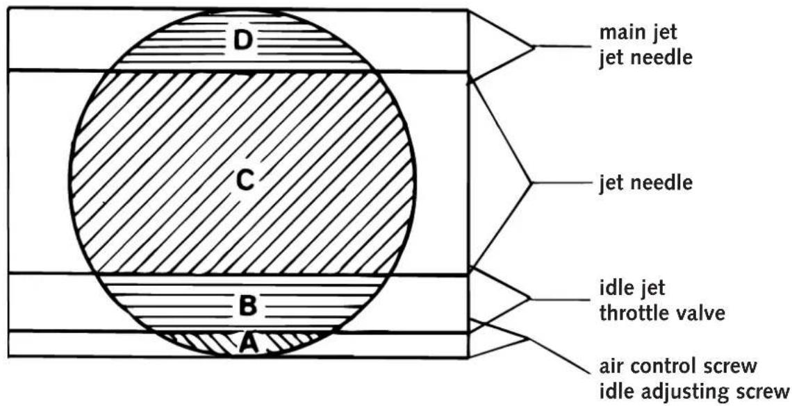
OPERATING RANGES OF THE CARBURETOR
text_image
D C B A main jet jet needle jet needle idle jet throttle valve air control screw idle adjusting screwmixture too lean:
not enough fuel in proportion to air
mixture too rich:
too much fuel in proportion to air
text_image
Technical diagram of a mechanical assembly with numbered components, likely for automotive or automotive maintenance.Idling range A
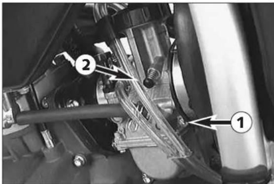
Operation with closed throttle valve. This range is influenced by the position of the air control screw ① and the idle adjusting screw ②. Only make adjustments when the engine is hot.
To this end, slightly increase the idling speed of the engine by means of the idle adjusting screw. Turning it clockwise produces a higher idling speed and turning the screw counterclockwise produces a lower idling speed. Create a round and stable engine speed using the air control screw (basic position of the air control screw = open by 1.5 turns). Then adjust to the normal idling speed by means of the idle adjusting screw.
Opening up B
Engine behavior when the throttle opens. The idle jet and the shape of the throttle valve influences this range. If, despite good idling-speed and part-throttle setting, the engine sputters and smokes when the throttle is fully opened and develops its full power not smoothly but suddenly at high engine speeds, the mixture to the carburetor will be too rich, the fuel level too high or the float needle is leaking.
Part-throttle range C
Operation with partly open throttle valve. This range is only influenced by the jet needle (shape and position). The optimum part-throttle setting is controlled by the idling setting in the lower range and by the main jet in the upper range. If the engine runs on a four-stroke cycle or with reduced power when it is accelerated with the throttle partly open, the jet needle must be lowered by one notch. If then the engine pings, especially when accelerating under full power at maximum engine revs, the jet needle should be raised.
If these faults should occur at the lower end of the part throttle range at a four-stroke running, make the idling range leaner; if the engine pings, adjust the idling range richer.
Full throttle range D
Operation with the throttle fully open (flat out). This range is influenced by the main jet and the jet needle. If the porcelain of the new spark plug is found to have a very bright or white coating or if the engine rings, after a short distance of riding flat out, a larger main jet is required. If the porcelain is dark brown or black with soot the main jet must be replaced by a smaller one.
Carburetor adjustment
Basic information on the original carburetor setting
The original carburetor setting was adapted for an altitude of approx. 500 meters (1600 ft.) above sea level, and the ambient temperature of approx. 20°C (68°F), mainly for off-road use and central European premium-grade fuel (ROZ 95 MOZ). Mixing ratio 2-stroke motor oil : super fuel 1:40 – 1:60.
Basic information on a change of the carburetor setting
Always start out from the original carburetor setting. Essential requirements are a clean air filter system, air-tight exhaust system and an intact carburetor. Experience has shown that adjusting the main jet, the idling jet and the jet needle is sufficient and that changes of other parts of the carburetor will not greatly affect engine performance.
RULE OF THUMB:
high altitude or high temperatures low altitude or low temperatures
→ choose leaner carburetor adjustment → choose richer carburetor adjustment
| WARNING | △ | |
| - ONLY USE PREMIUM -GRADE GASOLINE ROZ 95 MIXED WITH HIGH-GRADE TWO-STROKE ENGINE OIL. OTHER TYPES OF GASOLINE CAN CAUSE ENGINE FAILURE, AND USE OF SAME WILL VOID YOUR WARRANTY. | ||
| - ONLY USE HIGH-GRADE 2-STROKE ENGINE OIL OF KNOWN BRANDS. | ||
| - NOT ENOUGH OIL OR LOW -GRADE OIL CAN CAUSE EROSION OF THE PISTON. USING TOO MUCH OIL, THE ENGINE CAN START SMOKING AND FOUL THE SPARK PLUG. | ||
| - IN THE CASE OF A LEANER ADJUSTMENT OF THE CARBURETOR PROCEED CAUTIOUSLY . ALWAYS REDUCE THE JET SIZE IN STEPS OF ONE NUMBER TO AVOID OVERHEATING AND PISTON SEIZURE . | ||
NOTE: If despite a changed adjustment the engine does not run properly, look for mechanical faults and check the ignition system.
Basic information on carburetor wear
As a result of engine vibrations, throttle valve, jet needle, and needle jet are subjected to increased wear. This wear may cause carburetor malfunction (e.g., overly rich mixture). Therefore, these parts should be replaced after 10000 kilometers (6000 miles).
| jet needle th | throttle valve open effect | |
| N 85 A | ||
| N 85 B 0 | -^1/_4 | - |
| N 85 C | 0^-1/_4 | |
| N 85 D | 0^-1/_4 | |
| N 85 E | 0^-1/_4 | |
| NOZ C | ||
| NOZ D | 0^-1/_4 | - |
| NOZ E | 0^-1/_4 | |
| NOZ F | 0^-1/_4 | |
| NOZ G | 0^-1/_4 | |
| NOZ H | 0^-1/_4 | |
| NOZ I | 0^-1/_4 | |
| NOZ J | 0^-1/_4 | |
| N3CG | ||
| N3CH | 0^-1/_4 | - |
| N3CW | 0^-1/_4 |
Explanation - Example
Compared to the needle N 85 A, the jet needle N 85 C is two steps leaner in the range from the closed position of the throttle to 1/4 throttle. Otherwise, there are not differences.
| N 85 C | 0^-1/_4 |
| ! | CAUTION | ! |
WHEN CHANGING THE JET NEEDLE, MAKE SURE THAT YOU USE THE CORRECT NEEDLE TYPE (N 85 ,NOZ OR N3). THE TECHNICAL DATASHEET TELLS YOU WHICH JET NEEDLE CAN BE USED FOR WHICH MODEL .
natural_image
Close-up of a mechanical component with bolts and a screwdriver inserted (no visible text or symbols)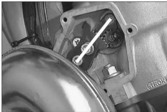
natural_image
Close-up of a mechanical component with visible gears and shafts, no text or symbols present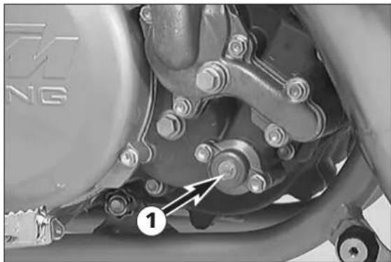
natural_image
Close-up of a mechanical assembly with labeled components (no readable text or symbols)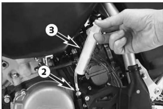
text_image
Close-up of a mechanical assembly with numbered components and directional arrows indicating parts of the component.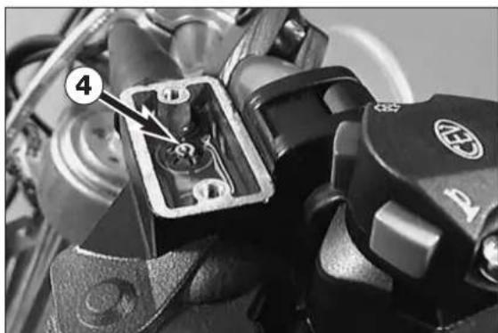
natural_image
Close-up of an automotive electrical connector with a labeled component (no readable text or symbols)Checking the setting of the TVC system
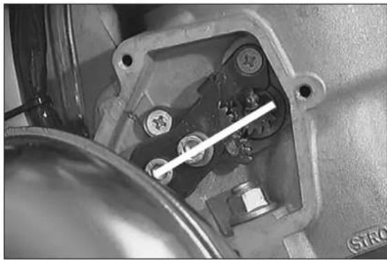
The function of the TVC system is checked with the engine running. This test checks the start of advance and the end of advance.
- For this, remove the left control cover.
- Connect a rev counter (either to the ignition cable or to the blue/white cable in the electronics box, depending on the rev counter design).
- Start engine, accelerate gently and observe when the TVC system starts to advance (tooth segment creeps upwards).
| start of advance | end of advance | |
| 250 Model 1999 5400 U/min | 7550 U/min | |
| 250 from Modell 2000 on | 5000 U/min 70 | 00 U/min |
| 300 up to Modell 2000 | 5300 U/min 77 | 50 U/min |
| 300 from Modell 2001 on | 5900 U/min 77 | 50 U/min |
| 380 | 5200 U/min 72 | 00 U/min |
- If necessary, turn the adjusting screw ①.
NOTE: Twisting the adjusting screw in delays the commencement of adjustment by the TVC system, twisting the adjusting screw out means that the TVC system will perform the adjustment earlier.
Bleeding of the hydraulic clutch
- T ake off cover together with rubber bellows.
- At the slave cylinder of the clutch, remove the bleeder nipple ②. It its place, mount the bleeder syringe ③ which is filled with SAE 10 hydraulic oil.
- Refill oil, until oil is discharged from the bore ④ of the master cylinder in a bubble-free state. Make sure that the oil does not overflow.
| ! | CAUTION | ! | |
| - | HAVING COMPLETED THE BLEEDING PROCEDURE, YOU HAVE TO VERIFY THAT THE OIL LEVEL IN THE MASTER CYLINDER IS CORRECT . | ||
| - | KTM USES BIODEGRADABLE HYDRAULIC OIL FOR THE HYDRAULIC CLUTCH CONTROL. NEVER MIX BIODEGRADABLE HYDRAULIC OILS WITH MINERAL OILS. | ||
| - | ALWAYS USE BIODEGRADABLE HYDRAULIC OIL SAE 10 TO FILL UP THE MASTER CYLINDER. NEVER REFILL WITH MINERAL HYDRAULIC OIL OR BRAKE FLUID. | ||
SPECIAL TOOLS - ENGINE 250 / 300 / 380
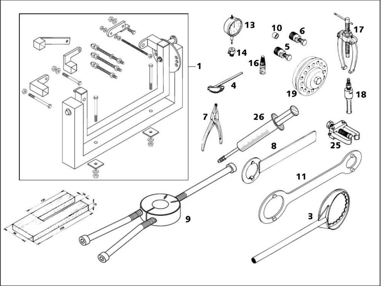
text_image
Technical diagram of mechanical assembly with numbered parts and dimension annotations| Fig. Part no. Description | |
| 1 560.12.001.000 Universal engine work stand | |
| 3 546.29.003.000 Clutch holder | |
| 4 560.12.004.000 Gear wheel segment | |
| 5 546.29.009.044 Magneto extractor M 27x1 Kokusan | |
| 6 6 276 807 Magneto extractor M 26x1,5 SEM | |
| 7 510.12.011.000 Circlip plier | |
| 8 544.12.012.000 Holding spanner for flywheel SEM | |
| 9 584.29.037.040 Mounting tool inner ring NJ 207 | |
| 9 584.29.037.043 Mounting tool inner ring NJ 207 | |
| 10 510.12.016.000 Protection cap | |
| 11 546.29.012.100 Holding spanner for flywheel Kokusan | |
| 13 501.12.013.000 Dial gauge 0-10 mm | |
| 14 501.12.030.000 Dial gauge support | |
| 16 6 899 785 Loctite 243 blue 6 ccm | |
| 17 151.12.017.000 Bearing puller | |
| 18 151.12.018.100 Internal bearing puller 18-23 mm | |
| 18 151.12.018.000 Internal bearing puller 12-16 mm | |
| 18 151.12.018.200 Internal bearing puller 5-7 mm | |
| 19 546.29.027.000 Clutch rivetting tool | |
| 25 0276 179 000 Extractor primary gear | |
| 26 503.29.050.000 Vent springe for hydraulic clutch | |
CLEANING
Clean your motorcycle regularly in order to maintain the beauty of its plastic surfaces.
The best manner would be to use warm water that has been mixed with a normal brand-name washing detergent and a sponge. The hard dirt can be removed before washing with the help of a soft water jet.
!
CAUTION
!
NEVER CLEAN YOUR MOTORCYCLE WITH A HIGH-PRESSURED CLEANER OR A HIGH-PRESSURED WATER JET. THE WATER COULD OTHERWISE RUN INTO THE ELECTRICAL COMPONENTS, CONNECTORS, SHEATHED CABLES, BEARINGS, CARBURETOR, ETC. AND CAUSE DISTURBANCES OR LEAD TO A PREMATURE DESTRUCTION OF THESE PARTS.
- Before cleaning with water, plug the exhaust pipe to prevent water ingress.
- You should use normal brand-name detergents to clean the motorcycle. Especially dirty parts should also be cleaned with the help of a paint brush.
- After the motorcycle has been rinsed with a soft water jet, it should be dried by air pressure and a cloth. Then take a short drive until the engine has reached the working temperature and also use the brakes. By warming these components, the residual water can evaporate from inaccessible parts of the engine and the brakes.
- Slide back the protective covers on the handlebar-mounted instruments so that any water that may have seeped into this part of the motorcycle is allowed to evaporate.
- After the motorcycle has cooled down, oil and grease all the gliding bearing parts. Treat the chain with a chain spray.
- To prevent failures in the electric system, you should treat the ignition lock, the emergency OFF switch, the short circuit button, the light switch and the socket connectors with contact spray.
CONSERVATION FOR WINTER OPERATION
In the event that the motorcycle is also used in winter and on roads where one has to expect salt spraying, you will have to take precautions against the aggressive road salt.
– clean the motorcycle thoroughly and let it dry after each ride
- treat the engine, carburetor, swing arm, and all other bare or galvanized parts (except for brake discs) with a wax-based anti-corrosion agent.
| ⚠ WARNING | ⚠ |
KEEP THE ANTI-CORROSION AGENT FROM GETTING INTO CONTACT WITH THE BRAKE DISCS , OTHERWISE THIS WILL SIGNIFICANTLY REDUCE THE BRAKING POWER .
!
CAUTION
!
AFTER RIDES ON SALTED ROADS, CLEAN MOTORCYCLE THOROUGHLY WITH COLD WATER AND LET IT DRY WELL.
STORAGE
Should you wish to make a pause over a longer space of time, please observe the following instructions:
– Clean motorcycle thoroughly (see chapter: CLEANING)
- Change engine oil (old engine oil contains aggressive contaminants).
– Check antifreeze and amount of cooling liquid.
- Let the engine warm up again, close fuel cock and wait until the engine dies off by itself. In this way the carburetor jets are prevented from becoming resin- clogged by the old fuel.
- Remove spark plug and fill in approx. 5 ccm of engine oil into the cylinder through the opening. Actuate kick-starter 10 times in order to distribute the oil onto the cylinder walls and mount the spark plug.
- Let fuel flow out of tank into an appropriate container.
- Correct tire pressure.
– Lubricate bearing points of the control levers, footrests, etc. as well as the chain.
- The storage place should be dry and not be subjected to too big temperature fluctuations.
- Cover the motorcycle with an air permeated tarp or blanket. Do not use non airtight materials as a possible humidity might not be able to escape and thereby cause corrosion.
!
CAUTION
!
IT WOULD BE VERY BAD TO LET THE ENGINE RUN FOR A SHORT TIME DURING THE STORAGE PERIOD. THE ENGINE WOULD NOT GET WARMED UP ENOUGH AND THE THUS DEVELOPED STEAM WOULD CONDENSE DURING THE COMBUSTION PROCESS AND CAUSE THE VALVES AND EXHAUST TO RUST .
USE AFTER A PERIOD OF STORAGE
- Fill up the tank with fresh fuel.
- Check the motorcycle as before each start (see driving instructions)
- Take a short, careful test ride first.
NOTE: Before you put your motorcycle away for the winter, you should check all parts for their function and wear. Should any service jobs, repairs, or any refitting be necessary, you should have them carried out during the off-season (lower workload at mechanics' shops). This way, you can avoid the long waiting times at your shop at the beginning of the next biking season.
REMOVING AND REFITTING ENGINE 3
INDEX
REMOVING THE ENGINE ....3-2
REFITTING THE ENGINE ....3-4
natural_image
Mechanical assembly diagram of a motorcycle showing internal components like gears, springs, and motors (no text or labels)Dismounting the engine
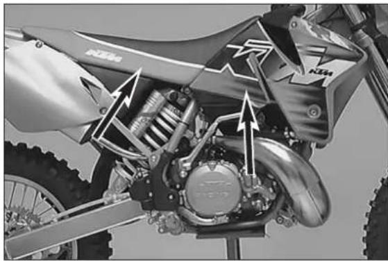
– Clean motorcycle thoroughly.
- P r op up motorcycle on an appropriate stand.
- Remove seat, right side paneling, and tank with spoilers.
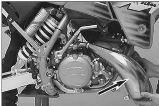
natural_image
Close-up of a motorcycle's internal mechanical assembly with visible springs and levers, no text or symbols present.- Dismount exhaust system.
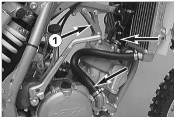
natural_image
Mechanical assembly diagram showing internal components with no visible text or symbols- Drain coolant, and disconnect radiator hoses from engine.
- Dismount engine strut ①.
- Disconnect plug-and-socket connector of ignition system and spark-plug connector.
natural_image
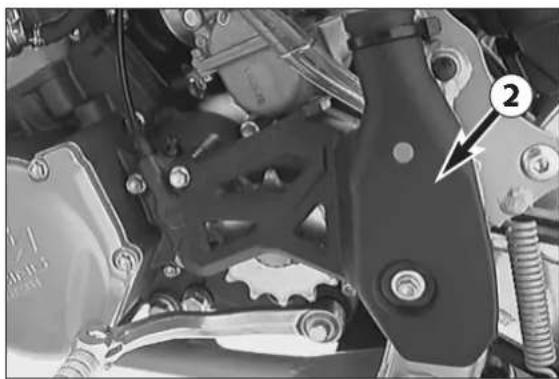
Close-up mechanical assembly showing gears and springs (no visible text or symbols)- Remove sprocket cover ② and chain.
natural_image
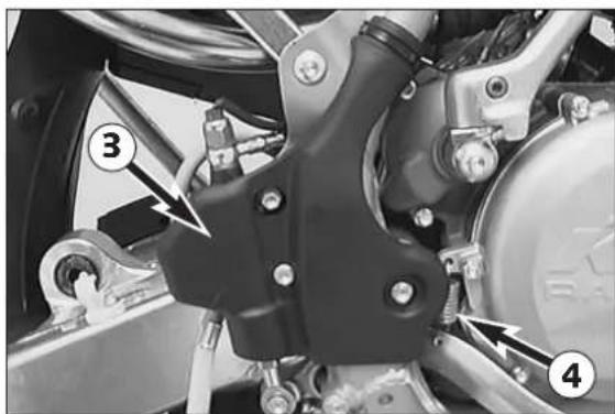
Mechanical assembly diagram showing components labeled 3 and 4, with no readable text or symbols beyond labels- Remove footbrake cylinder cover ③.
- Disengage and remove spring ④.
text_image
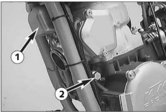
Technical diagram of a mechanical assembly with numbered components and directional arrows indicating parts of motion or flow.- Loosen the 3 screws, and remove intermediate flange chamber ① of KTC system together with O-ring.
- Remove engine fastening screw ②.
- Remove cable ties and loose the cable of ignition from frame.
natural_image
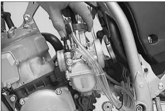
Close-up of a mechanical assembly with hoses and components, no visible text or symbols- Loosen both hose clamps, and pull caburetor out of carburetor connection boot and intake flange.
text_image
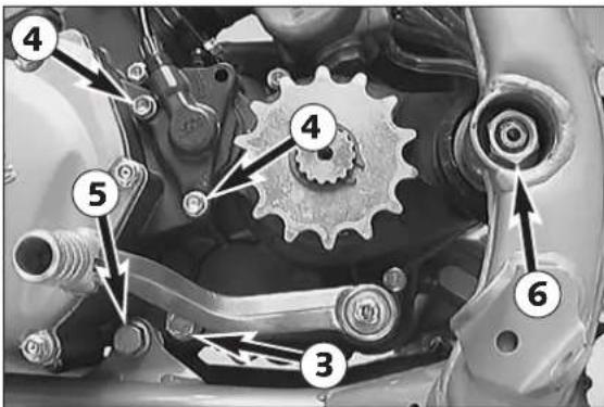
Technical diagram of a mechanical assembly with numbered components for identification- Remove transmission-oil drain plug ③ together with sealing ring, and drain the transmission oil.
- Remove the 2 screws ④, and dismount clutch slave cylinder.
!
CAUTION
!
DO NOT ACTUATE THE CLUTCH LEVER WITH THE CLUTCH SLAVE CYLINDER DISMOUNTED.
- Remove engine fastening screw ⑤.
- Remove hexagon nut of swingarm pivot ⑥.
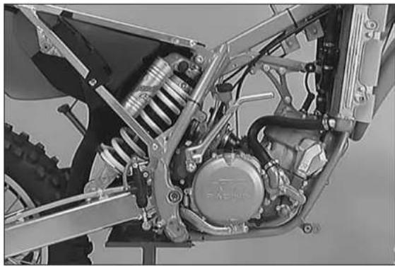
- Remove swingarm pivot, and pull swing arm backward out of the frame so as to make lifting the engine out of the frame easier.
- Lift engine out of frame.
NOTE: Cylinder head and cylinder can be dismounted even if the engine remains mounted. Likewise, work on clutch, primary drive, gearshift mechanism, and ignition system can be carried out.
natural_image
Mechanical assembly diagram showing motor, suspension, and gear components (no text or labels)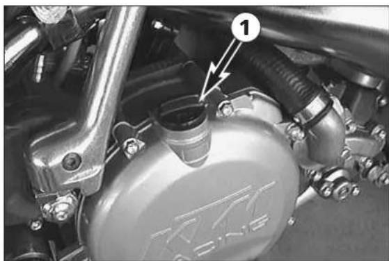
natural_image
Close-up of a mechanical component with labeled parts (no readable text or symbols)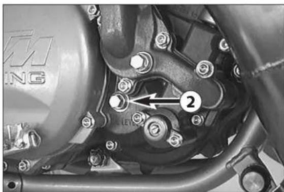
natural_image
Close-up of a motorcycle's internal mechanical components with no visible text or symbols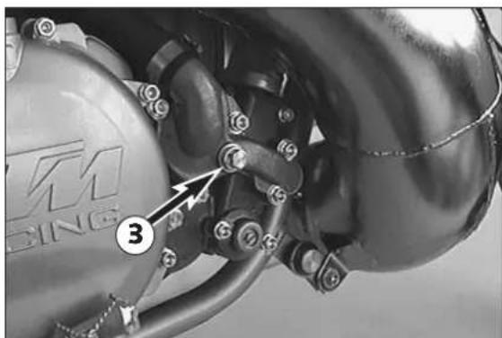
natural_image
Close-up of a mechanical component with bolts and a numbered label (3), no readable text or symbols present.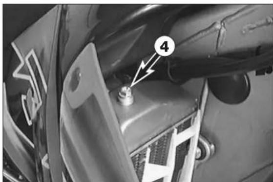
natural_image
Close-up of a car's front bumper with a numbered component (4) and arrow indicator, no readable text or symbols beyond the number.Refitting the engine
- T o install the engine, reverse the steps for removing the engine.
Filling in of transmission oil:
- Remove the plug ① and top up with engine oil 15W-50 (i. e. MOTOREX TOP SPEED 4T).
- In order to check the transmission oil level the control screw ② on the clutch cover is to be removed. Oil should just barely escape from the inspection opening when the motorcycle is in an upright position.
! CAUTION !
TRANSMISSION AND CLUTCH WILL BE SUBJECT TO AXCESSIVE WEAR AND TEAR, IF YOU USE TOO LITTLE OR LOW GRADE OIL . USE ONLY HIGH-GRADE OIL (I.E. MOTOREX TOP SPEED 4T).
Filling in of cooling liquid:
- Make sure that the drain screw ③ is fastened.
- Pour approx. 0.50 litres (0.13 US gallons) coolant into the system.
40% coolant : 60% water
- Remove the screw ④ on the right radiator and tilt the motorcycle to the right approx. 30 degree angle.
- Now add cooling liquid until it emerges free of bubbles at the right radiator. Then immediately mount the screw so that no more air can enter the right radiator.
- Return the motorcycle to its original position and top up the left radiator until the coolant can be seen approx. 10 mm (0.4 in) above the radiator fins.
DISASSEMBLING THE ENGINE
4
INDEX
DRAINING GEAR OIL 4-2
DISMOUNTING OF SPROCKET AND SHIFT LEVER .....4-2
DISMOUNTING OF CYLINDER HEAD, CYLINDER AND PISTON .....4-2
DISMOUNTING OF CLUTCH COVER 4-3
DISMOUNTING OF PRESSURE CAP AND CLUTCH DISCS .....4-4
DISMOUNTING OF THE PRIMARY DRIVE .....4-4
DISMOUNTING OF KICKSTARTER .....4-5
DISMOUNTING OF THE SHIFT LOCK ....4-5
DISMOUNTING OF IGNITION COVER ....4-5
DISMOUNTING OF THE IGNITION (KOKUSAN) .....4-6
DISMOUNTING OF THE IGNITION (SEM) .....4-6
DISMOUNTING OF INTAKE FLANGE AND REED VALVE HOUSING . . .4-7
PARTING OF ENGINE HOUSING HALVES 4-7
DISMOUNTING OF GEARSHIFT MECHANISM AND TRANSMISSION . .4-7
DISMOUNTING OF THE CRANKSHAFT .....4-8
natural_image
Close-up of a mechanical assembly with a central circular component and metal frame (no visible text or symbols)- Cleaning the engine thoroughly.
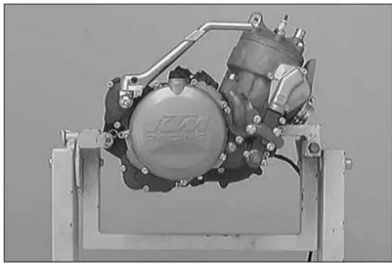
- Clamp the engine into the workstand.
- Remove the kickstarter together with the distance bushing behind.
natural_image
Close-up of a mechanical component with bolts and a numbered annotation (1), no readable text or symbols present.Draining gear oil
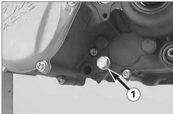
NOTE: The transmission oil should already be drained when the engine is dismounted. Otherwise, the transmission oil will leak out of the drive shaft following the removal of the slave cylinder of the clutch.
- Unscrew plug ①, allowing oil to drain.
text_image
Mechanical assembly diagram with numbered components and directional arrows indicating assembly stepsDismounting of sprocket and shift lever
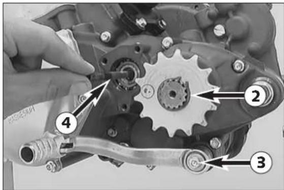
- Remove circlip ② from countershaft using circlip pliers. Slide off engine sprocket, distance bushing and O-ring.
- Undo the screw ③ and remove the shift lever.
- Pull out the clutch push rod ④ from drive shaft.
natural_image
Close-up of a mechanical component with bolts and nuts, no visible text or symbolsDismounting of cylinder head, cylinder and piston
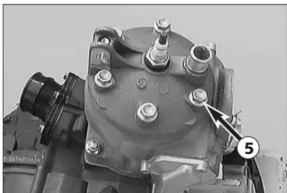
- Unscrew the 6 collar screws ⑤ and remove cylinder head and the two O-rings.
natural_image
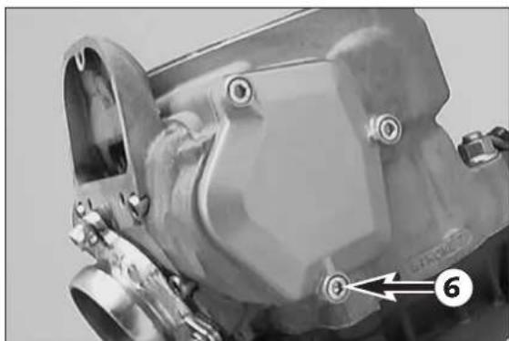
Close-up of a mechanical component with bolted features and a numbered arrow pointing to a specific part (no readable text or symbols)- Undo the screws ⑥ and remove the left control cover together with the gasket.
natural_image
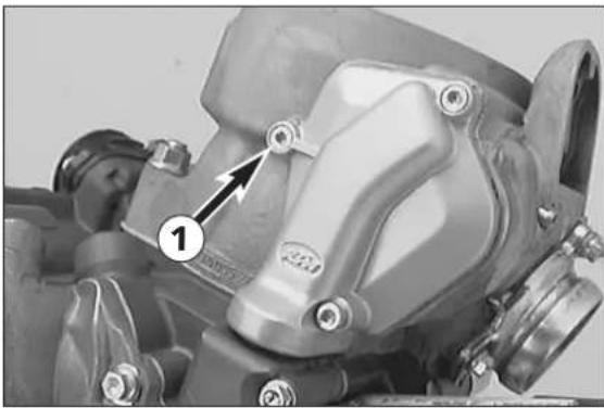
Close-up of a mechanical component with numbered annotation (1) and arrow indicating a detail point, no readable text or symbols present.- Undo the screws ① and remove the right control cover.

natural_image
Close-up of mechanical components with numbered annotations (2, 3), no readable text or symbols present.- Remove the securing clip of the ball socket ② and unhook the ball socket ③ from the adjusting lever.
- Remove gasket of the control cover.
natural_image
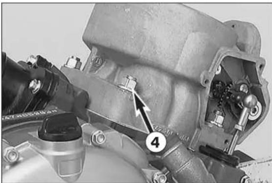
Close-up mechanical assembly showing a component with numbered annotation (4), no readable text or symbols present.- Remove the 4 collar nuts ④ on cylinder base and remove cylinder.
natural_image
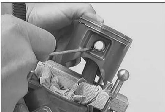
Close-up of a hand using a tool to adjust or install a mechanical component (no visible text or symbols)- Cover the crankcase.
- Place piston on wooden jig and remove both piston pin locking pins.
- Expel piston pin from piston without exerting undue force. Use a suitable mandrel if necessary.
- Remove piston and piston pin needle-bearing from conrod eye.
- Remove the cylinder base gaskets.
!
CAUTION
!
THE PISTON PIN MUST NEVER BE FORCED OUT WITH A PUNCH. THIS WOULD DAMAGE THE CONROD BEARING.
text_image
ICOM RACING 1 2 3 4 5 6 7Dismounting of clutch cover
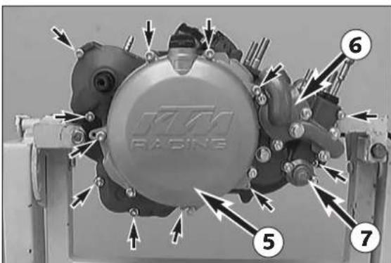
- Remove collar screws and clutch cover including gasket.
NOTE: The water pump cover ⑥, the outer cover ⑤ and the cover lid ⑦ do not need to be removed. The water pump and the centrifugal timer remain in the clutch cover.
natural_image
Close-up of a mechanical assembly with gears and a numbered component (no visible text or symbols)Dismounting of pressure cap and clutch discs
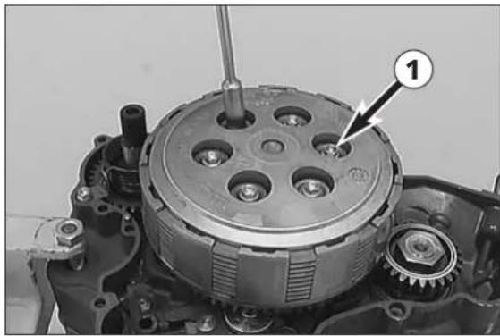
- Loosen collar screws ① in diagonally opposite sequence to prevent wedging of discs as springs expand.
- Remove collar screws, springs and spring retainers.
natural_image
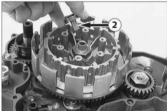
Close-up of a mechanical assembly showing a disassembled gear and rotor components (no visible text or symbols)- T ake pressure cap and disc package out of outer clutch hub.
- T ake thrust bearing ② off the drive shaft.
natural_image
Close-up of mechanical assembly with gears and a wrench, no visible text or symbolsDismounting of the primary drive
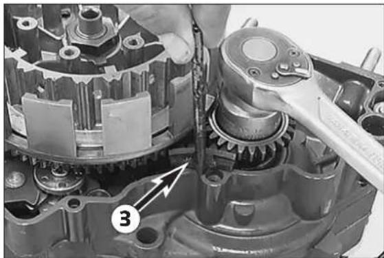
- Block the primary gear with the gear wheel segment ③ (see illustration).
- Undo the hexagon nut (LH thread) and remove it together with the detent edged ring.
natural_image
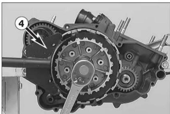
Mechanical gear assembly with labeled component (4), no visible text or symbols beyond label- Release the lock washer of the inner clutch hub.
- Connect clutch holder ④ to inner clutch hub and loosen hexagon nut (see illustration).
- Remove clutch holder.
- Remove inner clutch hub and outer clutch hub together with bearing from main shaft.
natural_image
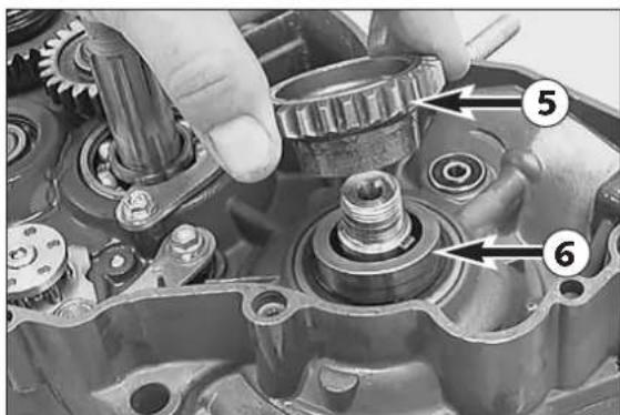
Close-up of mechanical gear assembly with numbered callouts (no readable text or symbols)- Pulling the primary gear ⑤ and the distance bushing ⑥ off the crankshaft.
NOTE: The primary gear and the outer clutch hub belong together. Always replace both together!
natural_image
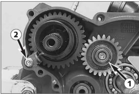
Mechanical gear assembly with numbered components (1 and 2), no visible text or symbols beyond labelsDismounting of kickstarter
- Remove circlip ① and kickstarter intermediate gear.
- Carefully release collar screw ② kickstarter spring is tensioned, release tension on kickstarter spring and unhook spring hanger.
| ! | CAUTION | ! |
CAREFULLY RELEASE THE KICKSTARTER SPRING! DANGER OF INJURY!
- T ake the complete kickstarter shaft out of the housing.
- T take care of the stop disc, which could stay in the housing.
natural_image
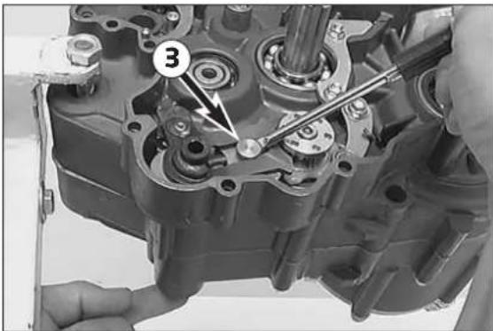
Close-up of a mechanical assembly with gears and shafts, no visible text or symbolsDismounting of the shift lock
- Press the sliding plate ③ back with a screw driver so it no longer engages with the driver for the shaft roller, at the same time remove shift shaft from the housing.
NOTE: Watch the stop disc which remains in the housing.
text_image
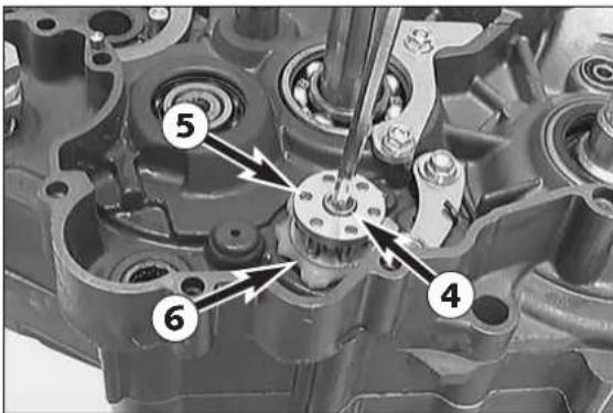
Technical diagram of an engine cylinder with numbered components labeled 4, 5, and 6- Remove allan head screw ④ and take driver for roller ⑤ and locking piece ⑥ from the shift roller.
NOTE: From model 2002 driver for roller ⑤ and locking piece ⑥ are made of aluminium.
natural_image
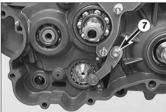
Close-up mechanical assembly showing bearing housing and gear mechanism (no visible text or symbols)NOTE: Disassemble locating lever only if the engine case must be replaced.
- Remove screw ⑦ and locking lever with spring and bush.
natural_image
Close-up of a mechanical component with engraved markings, no readable text or symbols present.Dismounting of ignition cover
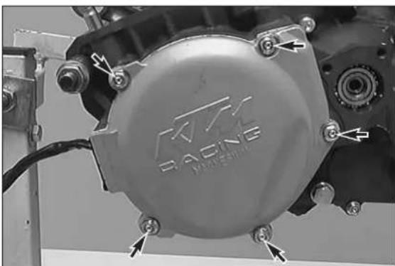
- Undo the 5 screws and remove the ignition cover together with the gasket.
natural_image
Mechanical assembly diagram showing a rotating component with a labeled part (1) and a tool inserted, no readable text or symbols present.Dismounting of the ignition (Kokusan)
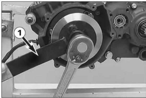
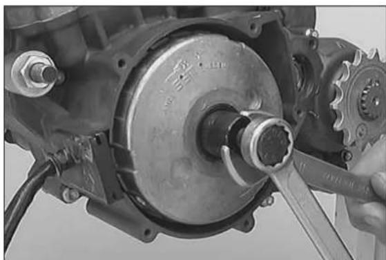
- Hold the flywheel with the holding spanner ① and undo the collar nut.
natural_image
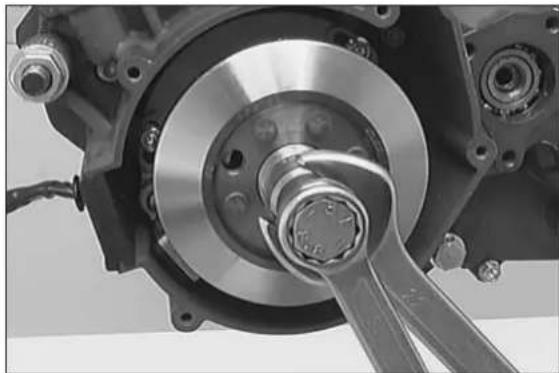
Close-up of a mechanical assembly with a central bearing and a wrench inserted (no visible text or symbols)- Put the protection cover on the crankshaft thread, twist in the flywheel extractor and remove the flywheel.
natural_image
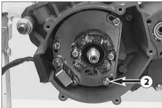
Close-up of a mechanical assembly with visible gears and bolts, no text or symbols present- Undo the 3 screws ② and remove the stator together with the base plate.
natural_image
Close-up of a mechanical assembly with a hand using a tool to adjust a component (no visible text or symbols)Dismounting of the ignition (SEM)
- Hold the flywheel with the special tool and undo the collar nut.
- Place protective cap on crankshaft thread.
- T wist in the flywheel extractor and remove the flywheel.
natural_image
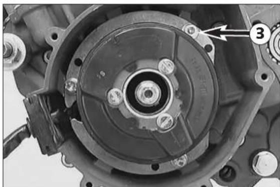
Close-up of a mechanical component with no visible text or symbols- Loosen the 3 collar screws ③, and take base plate with stator out of the casing.
natural_image
Close-up of a mechanical component with bolts and a numbered annotation (1), no visible text or symbols.Dismounting of intake flange and reed valve housing
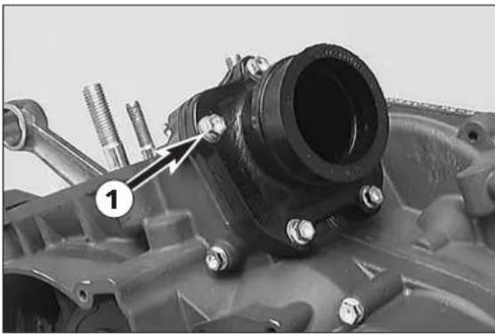
- Remove the 5 collar screws ①.
- Remove intake flange and reed valve housing.
natural_image
Mechanical assembly diagram showing internal gears and shafts with directional arrows indicating motion (no text or labels)Parting of engine housing halves
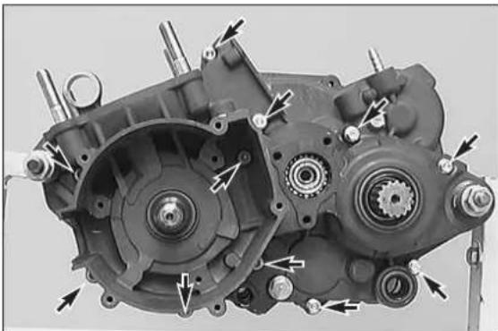
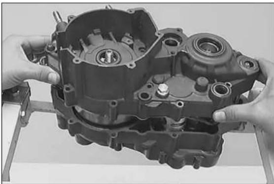
- T op ignition-gear upwards and remove all 11 housing screws.
- Loosen the 2 engine fixtures on the engine work stand.
natural_image
Close-up of hands assembling a mechanical engine block (no visible text or symbols)- Lift left-hand housing half with suitable tools by on the bosses provided, or part with a few light plastic mallet blows against the countershaft from the right-hand housing half.
! CAUTION !
LEVERING APART WITH A SCREW DRIVER OR SIMILAR TOOL MUST BE AVOIDED, SINCE THE SEAL FACES ARE EASILY DAMAGED.
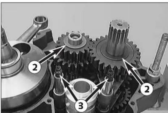
NOTE: Watch gear shaft stop discs ② to prevent them sticking to inside of housing.
natural_image
Mechanical gear assembly diagram showing three numbered components (no text or symbols present)Dismounting of gearshift mechanism and transmission
- Take the two stop discs ② off the transmission shafts.
- Pull the 2 pressure springs ③ out of the shift rails.
natural_image
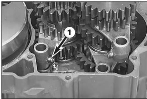
Close-up of a mechanical gear assembly with no visible text or symbols– Pull out the shift rails and swing the shift forks aside.
– Pull the shift roller out of the bearing seat.
- Remove the shift forks.
NOTE: During disassembly, watch out for the shift rollers ① on the driving pins of the shift forks. They may remain in the shift roller. Although the counter shaft shift forks are identical they should be refitted in the same position as before if reused. Therefore mark accordingly upon removal.
natural_image
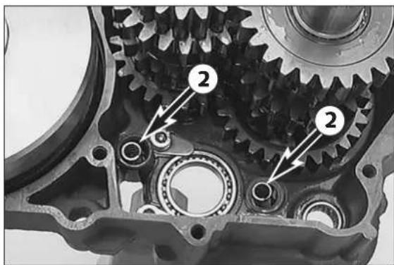
Close-up of a mechanical gear assembly with two numbered components (2), no visible text or symbols.- Remove the 2 pressure springs ② from the engine case.
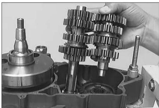
natural_image
Close-up of a mechanical gear assembly with a hand adjusting it (no visible text or symbols)– Pull the drive shaft together with the countershaft out of the bearing seats.
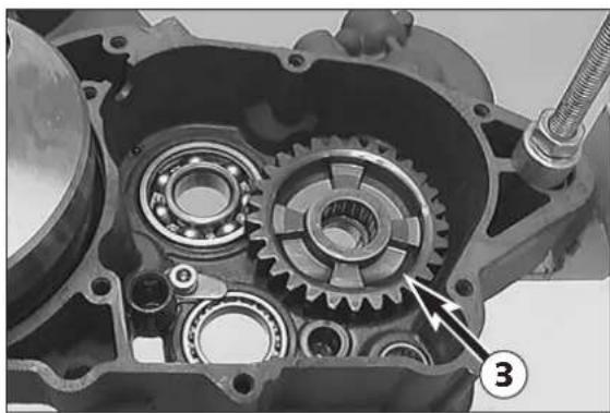
natural_image
Mechanical gear assembly inside a mechanical housing, showing gears and shafts (no text or symbols visible)- Remove 1^st -gear idler gear ③ with needle cage and the two stop discs from the engine case.
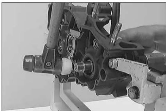
natural_image
Close-up of a mechanical assembly with a hand adjusting a component (no visible text or symbols)Dismounting the crankshaft
– Pull crankshaft from the bearing seat (if necessary, use a plastic hammer and tap carefully on the crankshaft journal).
- Remove O-ring from crankshaft.
– Clean all parts and check for wear, replace if necessary.
NOTE: When an engine is completely overhauled it is recommended that all gaskets, shaft seal rings and O-rings are renewed.
SERVICING ON INDIVIDUAL COMPONENTS 5
INDEX
WORKING ON THE RIGHT-HAND HOUSING HALF .....5-2
WORKING ON THE LEFT-HAND HOUSING HALF ....5-3
CRANKSHAFT 5-4
CRANKSHAFT WEBS - MEASURE OUTER DIMENSION .....5-4
PISTON 5-4
PISTON RING END GAP 5-4
CHECKING CYLINDER FOR WEAR 5-5
RECOATED CYLINDER 5-5
NIKASIL COATING OF CYLINDER .....5-5
CYLINDER EXHAUST CONTROL SYSTEM ....5-6
CYLINDER PREASSEMBLY 5-6
EXHAUST CONTROL, CLUTCH COVER .....5-8
PREASSEMBLY OF CLUTCH COVER .....5-8
REED VALVE HOUSING, INTAKE FLANGE .....5-9
CLUTCH 5-10
REPLACE OUTER CLUTCH HUB 5-11
SHIFT MECHANISM .....5-12
PREASSEMBLY OF SHIFT SHAFT .....5-12
IGNITION (KOKUSAN) .....5-13
SPARK PLUG 5-13
CHECK STATOR AND PULSE GENERATOR (KOKUSAN) .....5-13
IGNITION (SEM) .....5-14
CHECK STATOR (SEM) .....5-14
TRANSMISSION ....5-15
ASSEMBLY MAINSHAFT 5-15
ASSEMBLY COUNTERSHAFT ....5-16
KICKSTARTER ....5-17
ASSEMBLE OF KICKSTARTER SHAFT 5-17
Engine housing
NOTE: Read through the following section before commencing work. Then determine the assembly sequence so that the engine housing halves only need to be heated up once before replacing the bearings.
Having first removed the dowels, in order to expel the bearings or remove them with light mallet blows, the housing halves must be placed on a suitably large plane surface, supporting the whole of the sealing surface without damaging it. A wooden panel is best used as a base.
Bearings or shaft seal rings should not be hammered into their seats. If no suitable press is available, use a suitable mandrel and hammer them in with great care. Cold bearings will practically drop into their seats at an engine housing temperature of approx. 150^ C.
After cooling, should the bearings fail to lock in the bore, they are bound to rotate after warming. In that event the housing must be replaced.
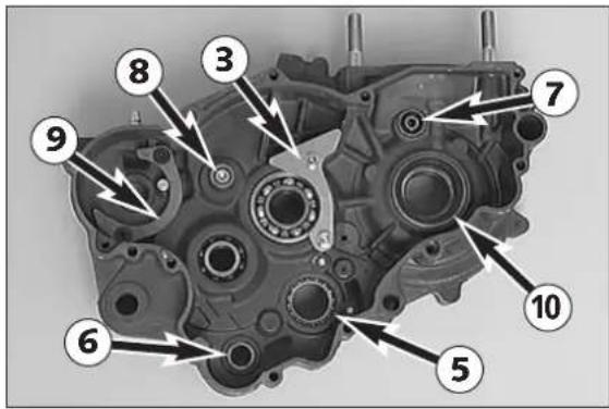
text_image
Technical diagram of an internal combustion engine cylinder with numbered components for identification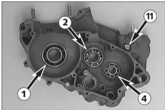
text_image
Technical diagram of an automotive gear assembly with numbered components labeled 1, 2, 4, and 11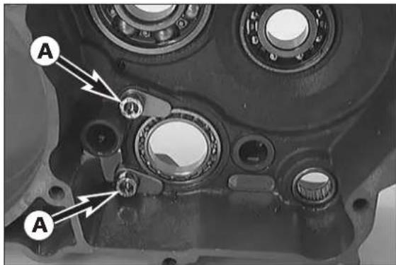
text_image
A A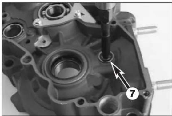
natural_image
Close-up of a mechanical component with a bolt and numbered annotation (7), no readable text or symbols present.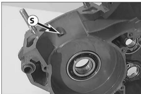
natural_image
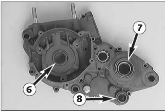
Close-up of a mechanical component with a threaded bolt and bearing housing (no visible text or symbols)Working on the right-hand housing half
- Remove all shaft seal rings and use an oven to heat the casing half to approx. 150°C.
Grooved ball bearing of crankshaft ①
Press old grooved ball-bearing inwards. Press in new ball bearing to the stop. The open side of the ball cage must be towards the bottom (outside) of the case.
Grooved ball bearing of main shaft ②
Press in new ball bearing from inside up to the stop.
! CAUTION !
DO NOT USE FORCE WHEN PRESSING THE GROOVED BALL BEARING AGAINST THE RETAINING BRACKET ③ TO AVOID A BENDING OF THE BRACKET, WHICH WOULD RESULT IN EXCESSIVE AXIAL PLAY OF THE MAINSHAFT.
Grooved ball bearing of countershaft 4
Press in new grooved ball bearing from downward to the stop. The open side of the ball cage must be face inwards.
Grooved ball bearing of the shift roller ⑤
Remove retaining screws Ⓐ and press bearing inwards. Press in new ball bearing from inside to the stop and secure retaining screws with Loctite 243.
Needle bushing of the shift shaft ⑥
Press old needle bushing inwards, press in new needle bushing flush from the outside.
Grooved ball bearing of centrifugal timer ⑦
The bearings usually fall out of their seat of their own accord by knocking the housing half on a plane piece of wood when the housing has a temperature of 150^ C. If necessary use a 6 mm internal bearing extractor and guide hammer (see illustration). Press in new grooved ball bearing to the stop.
Bearing bolt kickstarter intermediate gear ⑧
Experience has shown that it is never necessary to replace the bearing bolt. It is not recommended to mount a used bearing bolt in a new housing half, as it is practically impossible to remove it without causing damage.
Kickstarter release plate ⑨
When replacing the release plate, secure the flat-head screws with Loctite 243.
Crankshaft seal ring 10
Press in new shaft seal ring from the outside, with sealing lip facing inward, until flush.
Stop screw kickstarter ⑪
When mounting the stop screw, it must be secured with Loctite 243. Do not forget new copper seal ring.
Retaining bracket ③
When replacing the retaining bracket, the two collar screws are to be secured with Loctite 243.
- Finally check clear passage of the crankshaft ball bearing lubrication bore Ⓢ.
text_image
Technical diagram of an automotive clutch with numbered parts labeled 6, 7, and 8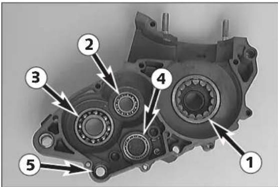
text_image
Technical diagram of an automotive gear assembly with numbered components labeled 1 through 5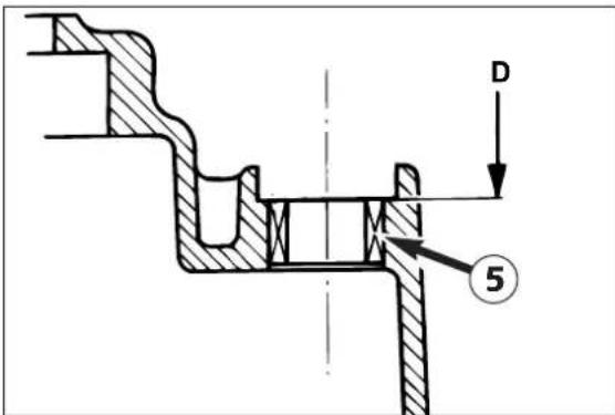
text_image
D ⑤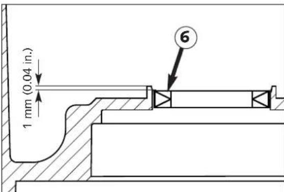
text_image
1 mm (0.04 in.) 6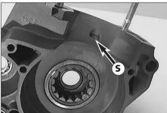
natural_image
Close-up of a mechanical component with a labeled arrow pointing to a feature marked 'S' (no text or symbols beyond the label)Working on the left-hand housing half
- Remove all shaft seal rings and use an oven to heat the casing half to approx. 150°C.
Crankshaft roller bearing ①
Press old roller bearing inwards, press in new ball bearing to the stop with the open side of ball cage downwards (outside). The inner ring on the crankshaft must also be renewed (see paragraph about crankshaft).
Needle bearing of drive shaft ②
Press old grooved ball bearing inward, press new grooved ball bearing from the inside up to the stop.
Grooved ball bearing of countershaft ③
Press old ball bearing inwards, press in new ball bearing to the stop from inside.
Grooved ball bearing of shift roller 4
Ball bearing falls out of its seat of its own accord when housing half has been heated to approx. 150°C.
If necessary, knock housing half on a plane piece of wood. Press in new grooved ball bearing to the stop.
Needle bushing of shift shaft ⑤
Remove shaft seal ring and press old needle bushing inwards. Press in new needle bushing from the outside to the collar ①.
Crankshaft seal ring ⑥
Press in new crankshaft seal ring from the outside, with sealing lip facing inwards. The seal ring is 1 mm (0.04 in) lower than the upper edge of the collar (see sketch).
Counter shaft seal ring ⑦
Press in the new shaft seal ring, until it is flush with machined surface.
Shift shaft seal ring ⑧
Press in the new shaft seal ring, until it is flush with machined surface.
When housing half has cooled off, check to see that the bearings are tight.
- Finally check clear passage of the crankshaft roller bearing lubrication bore Ⓢ.
natural_image
Metal mechanical component with flanged shaft and threaded end (no visible text or symbols)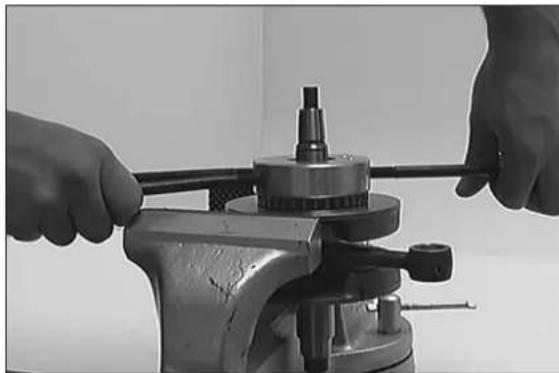
natural_image
Close-up of hands operating a mechanical press or fixture with a cylindrical component (no visible text or symbols)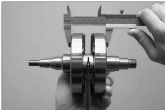
natural_image
Close-up of hands using a vernier caliper to measure a mechanical component (no visible text or symbols)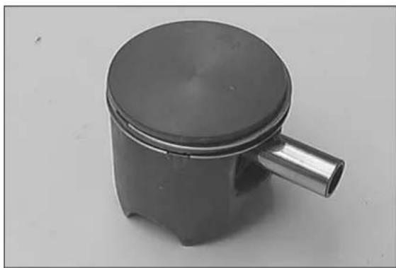
natural_image
Close-up of a cylindrical mechanical piston component with a flanged handle (no text or symbols visible)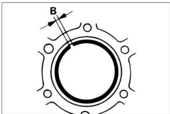
text_image
BCrankshaft
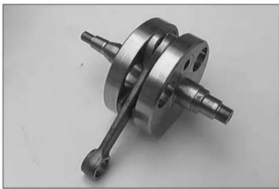
- When replacing the roller bearing, the inner crankshaft ring must also be renewed.
- Heat special tool 584.29.037.040 on a heating pad up to approx. 150^ and slip it on the inner ring immediately. Press the special tool together tightly so as to obtain a good heat transfer and pull the inner ring off the crankshaft.
- T o mount the new inner ring, heat the special tool again to approx. 150°C, engage the inner ring and slip it on the crankshaft journal immediately.
| ! | CAUTION | ! |
NEVER CLAMP THE CRANKSHAFT WITH A STUD OR WEB IN THE VICE, AND NEVER TRY TO KNOCK THE BEARING INNER RING FREE. THE CRANKSHAFT WEBS MAY BE COMPRESSED AND THE CONROD PLUG AND BEARING MAY BE DAMAGES, THEREBY MAKING THE CRANKSHAFT UNUSABLE.
NOTE: Distance adjustment of the main bearings is not requested.
Crankshaft webs – measure outer dimension
Crankshaft webs - measure outer dimension with a sliding caliper as illustrated.
Crankshaft webs - outer dimension = 60 mm ± 0.05 mm
Piston
If a used piston is to remain in service then the following should be checked:
- Piston running surface: Check for pressure marks (seizing marks) minor friction marks can be removed with a fine abrasive stick.
- Piston ring grooves: The piston rings must not get jammed in the grooves. For cleaning the grooves, use an old piston ring or abrasive paper (grain size 400).
- The piston ring locating pins must be firmly seated in the piston and must not be worn out.
- Check piston rings for wear and check end gap.
Piston ring end gap
- Insert piston ring into the cylinder and adjust. Piston ring must be approx. 10 mm (1/2 inch) from top of cylinder.
- The end gap Ⓑ can now be checked with a feeler gauge.
Piston ring end gap: max. 0.40 mm (0.015 in)
NOTE: If the end gap is greater check piston and cylinder for wear. If piston and cylinder wear are within the permitted tolerance limits, replace the piston ring.
text_image
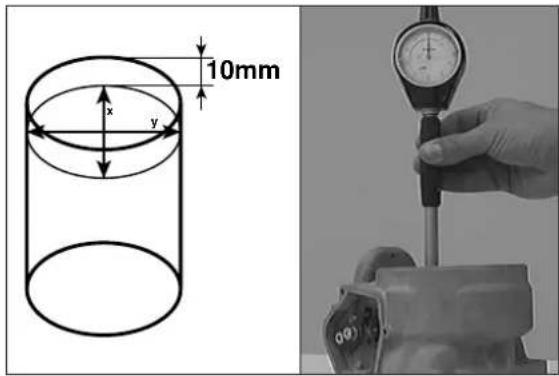
10mm x yChecking cylinder for wear
Measure diameter of cylinder approx. 10 mm (0.4 in.) below top of cylinder edge. Check diameter in several corresponding places to see if cylinder in worn oval.
| Engine Cylinder ∅ Piston size | ||
| 250 | 67,500 - 67,512 167,513 - 67,525 2 | |
| 300 | 72,000 - 72,012 172,013 - 72,025 2 | |
| 380 | 78,000 - 78,012 178,013 - 78,025 2 | |
| 250 66,340 - 66,350 1starting with the 2000 mod | 66,351 - 66,360 2 | |
| 300 71,940 - 71,950 1starting with the 2000 mod | 71,951 - 71,960 2 | |
natural_image
Close-up of a mechanical component with a numbered label (1) and an arrow pointing to a feature, no readable text or symbols present.Recoated cylinder
NOTE: If the cylinder diameter is larger than e.g. 66.360 mm the cylinder must be regenerated or replaced.
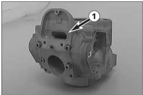
For reconditioning of the old cylinder all exhaust control components must be removed. The intermediate flange ① remains with the cylinder. The piston size is stamped into the bottom of the piston.
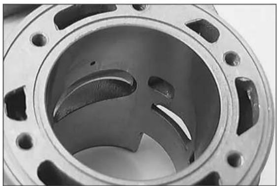
natural_image
Close-up of a mechanical component with three curved slots and flanges (no text or symbols visible)Nikasil coating of cylinder
Nikasil is the brand name for a cylinder coating process, developed by the piston manufacturer Mahle. The name is derived from the two materials used in this process - a nickel layer into which the particularly hard silicon carbide is inbedded.
The main advantages of the Nikasil coating are:
● excellent heat dissipation and thus better power output
- low wear
- low weight of the cylinder.
NOTE: The worn coating can be regenerated at low cost provided that the cylinders running surface is flawless.
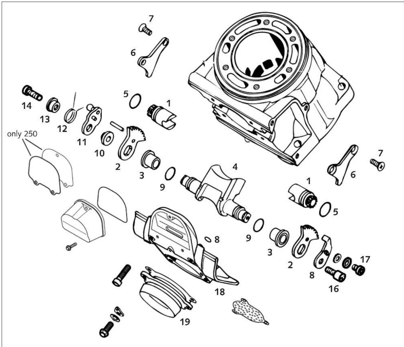
text_image
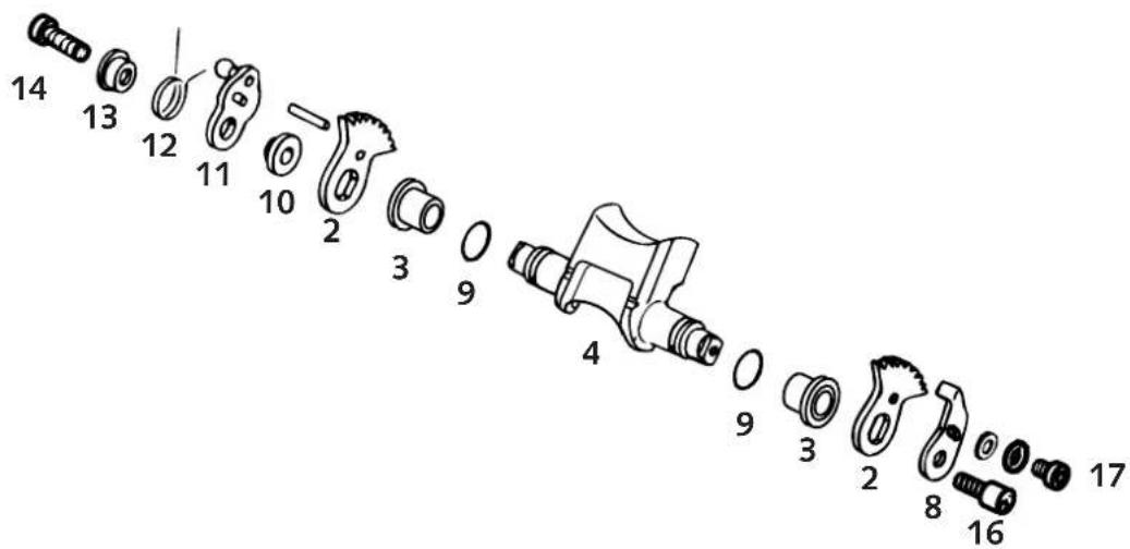
only 250 14 13 12 11 10 2 3 9 4 1 6 7 1 5 8 9 3 2 8 16 17 19 1Cylinder exhaust control system
Dismantle and clean all exhaust control components, check for signs of wear and damage.
Control rollers ① – Check clearance of bearings. Remove oil-derived deposits.
Check toothing of control rollers for signs of wear.
Gear segments ② – Check toothing of gear segments and control rollers for signs of wear.
Bearing sleeves ③ – Check bearing sleeves of the control flap for play and easy operation.
Control flap ④ – Clean the control flap. The control flap must not graze inside the exhaust port.
Silicon O-rings ⑤, ⑧ + ⑨ - Check silicon O-rings of control flap and control rollers for signs of wear. Renew if necessary.
text_image
Technical diagram of a mechanical assembly with numbered components and directional arrows indicating motion or force directions.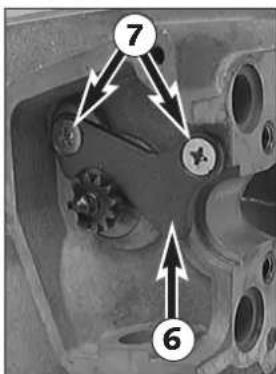
text_image
Technical diagram of a mechanical component with numbered callouts highlighting features like '7' and '6'Cylinder preassembly
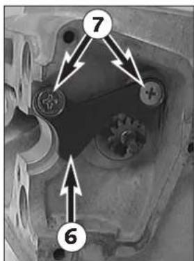
- Mount silicon O-rings (16x2 mm) ⑤ on control rollers and grease.
- Place control rollers ① in cylinder and mount retaining brackets ⑥; secure flat-head screws ⑦ with Loctite 243.
text_image
Exploded view diagram of a mechanical component with numbered parts for identification- Mount and grease silicon O-rings (15x1,50 mm) ⑨ on control flap and grease.
- Slightly grease the bearing sleeves ③ and plug them on the control flap.
- Mount toothed segments ② (the toothed segment with the cylindrical pin has to be mounted on the right side).
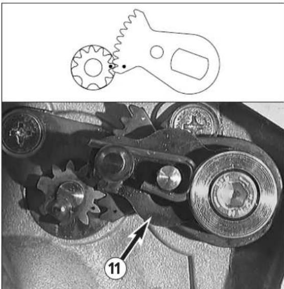
- On the right-hand side, mount bearing bushing ⑩ with collar outside, adjusting lever ⑪ with ball head on outside, overload spring ⑫ with short leg on outside and spring sleeve ⑬ to control flap.
- Coat allan head screw 14 with Loctite 243 and screw up about 5 revolutions, hook the short leg of the overload spring on to the cylinder pin (see illustration) and tighten the allan head screw.
- On the left side, mount the stop plate ⑧. Apply Loctite 243 to the threads of the two screws ⑯ + ⑰, and mount them.
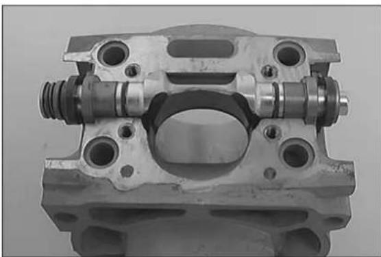
- T urn control roller① in cylinder in such a way that ports are completely open and no edges protrude.
natural_image
Close-up of a mechanical component with bolted and threaded features (no visible text or symbols)- Place preassembled control flap in cylinder, engage gear segments in control rollers in such a manner that, when the control flap is ,open (pivoted right to the top), the markings of the gear segments and the gear rollers coincide. Please check that the two control rollers do not block the cross-section of the port when the control flap is open.
- Coat sealing surface thinly with silicon and mount intermediate flange 18 with 4 O-rings (11,3x2,4 mm).
- Mount exhaust flange 19 and spring hangers. If you are dealing with a throttled version, do not forget the exhaust throttle.
– Finally check smooth running of exhaust control system.
NOTE: It must be possible to push adjusting lever ⑪ further upwards against the spring force.
natural_image
Mechanical gear assembly diagram showing gear meshing and mechanical components (no text or symbols)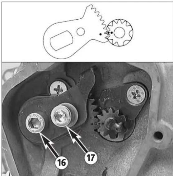
text_image
Technical diagram showing a mechanical component with labeled parts 16 and 17, including a gear mechanism and a top-view schematic.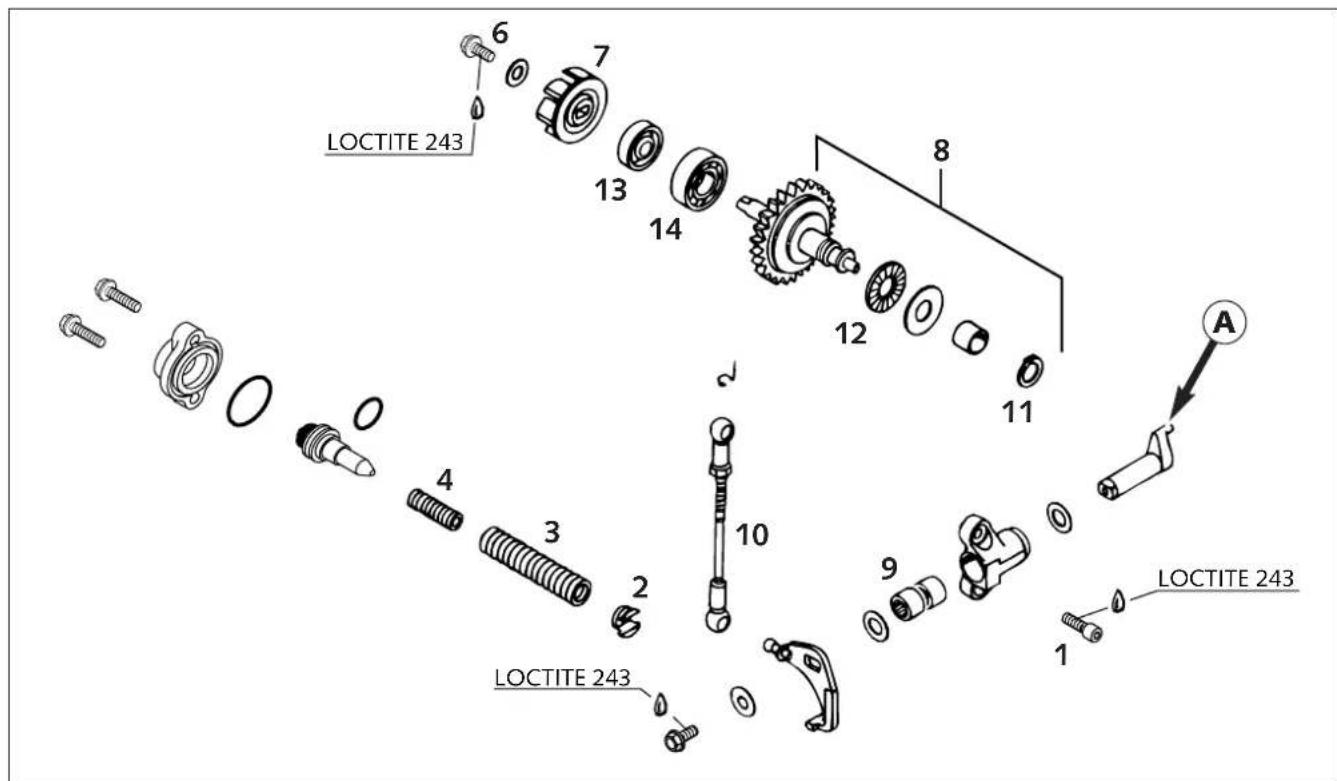
text_image
LOCTITE 243 6 7 13 14 8 12 11 A LOCTITE 243 0 4 3 2 10 9 1 LOCTITE 243 LOCTITE 243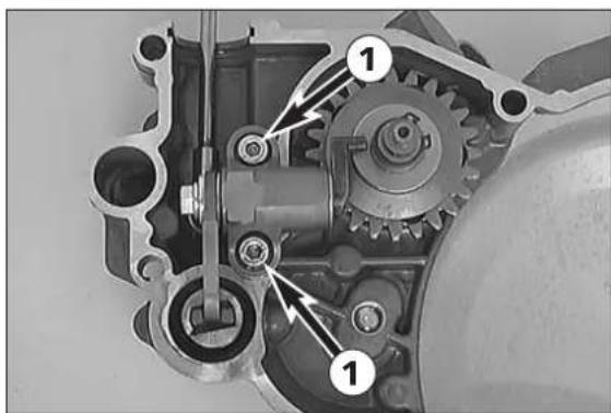
natural_image
Mechanical gear assembly diagram showing internal components and alignment arrows (no text or labels)Exhaust control, clutch cover
- Remove screws ① and take off the bearing support.
- T ake cup tappe ^2 , adjusting spring ③ and auxiliary spring ④ out of clutch cover.
- Take off water pump cover, remove allen head screw and take off water pump wheel 7.
- The centrifugal timer ⑧ can be pulled out of the bearing.
– Clean all parts and check for signs of wear.
Check play and easy operatability of the adjusting lever in the bearing ⑨.
Check pin Ⓐ of adjusting lever for wear.
Check linkage ball heads 10 for clearance.
Remove circlip ⑪ and check axial bearings ⑫ and washers for signs of wear.
If the water pump shaft seal ring ^13 is replaced, it should be coated with Loctite 243 on the outside.
Check grooved ball bearing ^14 for clearance.
natural_image
Close-up of a mechanical component with bolts and a curved handle (no visible text or symbols)Preassembly of clutch cover
- Grease water pump shaft seal ring ⑬ and mount centrifugal timer ⑧.
- Fit adjusting spring ③, auxiliary spring ④ and cup tappet ② in the clutch cover.
- Fit bearing support with control lever and linkage. Secure both screws ① with Loctite 243.
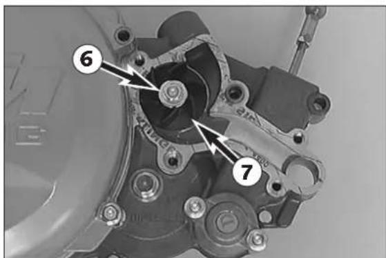
- Mount water pump wheel ⑦, coat screw ⑥ with Loctite 243 and mount with washer.
- Mount dowels of the water pump cover.
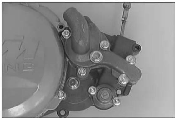
- Position gasket and fix water pump cover with 5 collar screws. The two screws mounted at the dowels must each be provided with one copper gasket.
text_image
Technical diagram of a mechanical assembly with numbered components, likely a valve or pump component.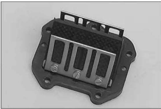
natural_image
Close-up of a black plastic electronic component with three slots and mounting holes (no visible text or symbols)Reed valve housing, intake flange
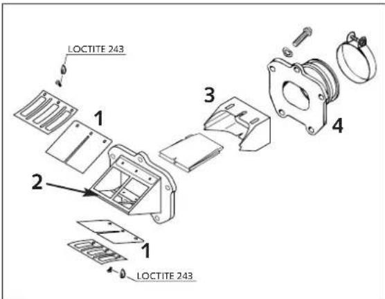
NOTE: Reed paddles ① gradually lose tension through operation, resulting in power loss. Damaged or worn reed paddles must be replaced. If the reed sealing surfaces ② of the reed valve housing are also damaged, replace the complete reed valve housing.
!
CAUTION
!
SECURE ALL SCREWS OF THE REED VALVE HOUSING WITH LOCTITE 243.
text_image
LOCTITE 243 1 2 3 4 1 LOCTITE 243Velocity insert ③
Check for firm mounting and for signs of damage.
Intake flange ④
Check for cracks and other signs of damage.
text_image
LOCTITE 242 13,5 mm A B 6 7 3 4 5 11 13 14 12 10 9 1 2 1Clutch
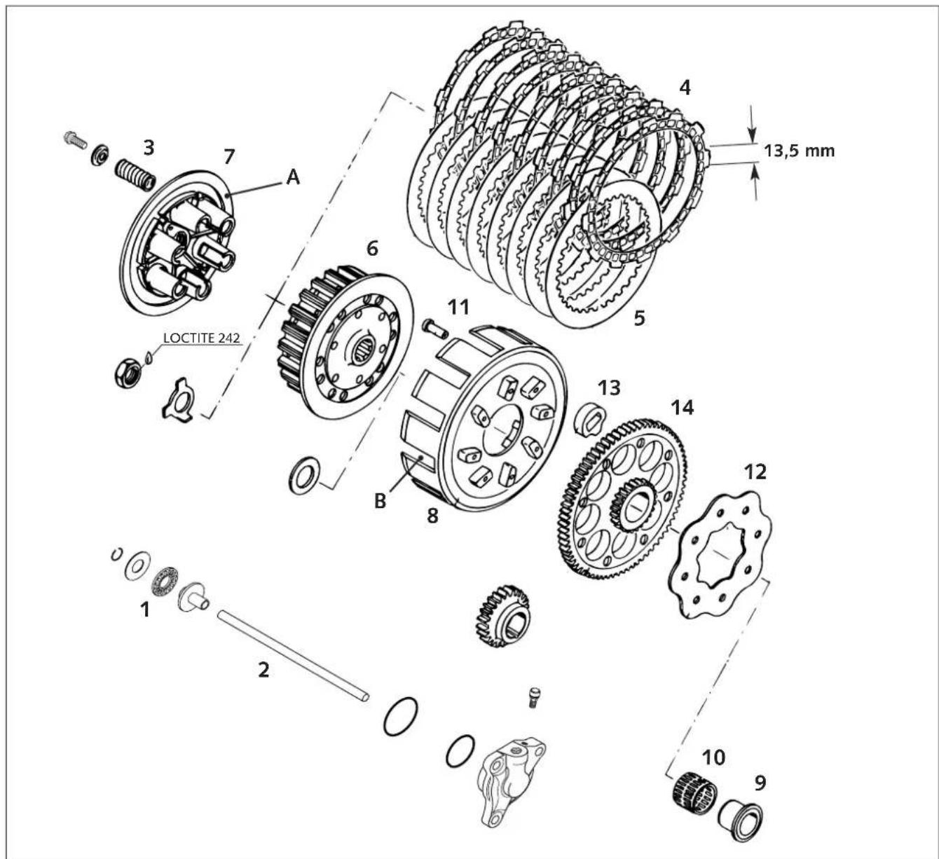
Thrust bearing ① check for wear
Push rod ② Check for wear. Minimum length: 199 mm (new: 199.80 mm)
Clutch springs ③
New spring length 42,5 mm / 1.7 in (new 43 mm / 1.73 in). Replace all 6 springs if applicable.
9 Lining discs ④
Minimum thickness 2.60 mm (0.102 in) / new disc 2.70 mm (0.106 in). Discs must be plane; there must be minimum spacing of 13.50 mm (0.531 in) between starting surfaces.
8 Steel discs ⑤
Must be plane, check for mechanical damage.
Inner clutch hub 6
Check contact surfaces of steel discs on the inner clutch hub, maximum 0.50 mm (0.02 in) indentations.
Pressure cap ⑦
Check contact surfaces Ⓐ between lining disc and pressure cap for signs of mechanical damage and score marks.
Outer clutch hub 8
Check start surfaces of clutch discs on for wear. If indentations exceed 0.50 mm (0.02 in), replace outer clutch hub (see below).
Check inner ring ⑨ and needle cage ⑩ for wear.
natural_image
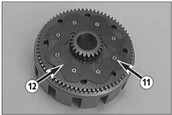
Mechanical gear assembly with numbered annotations (11 and 12) pointing to specific components, no readable text or symbols beyond labels.Replace outer clutch hub
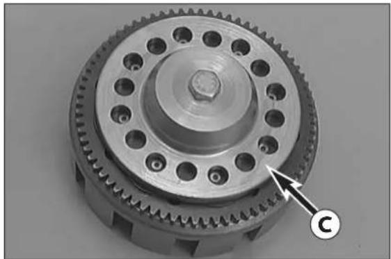
- Drill open the clutch rivets ⑪ in area of retaining bracket ⑫ and remove parts.
- Check 8 absorbing elements ⑬ for signs of mechanical damage, replace all 8 where applicable.
!
CAUTION
!
THE ABSORBING ELEMENTS ARE WIDER THAN THE PRIMARY GEAR CROWN. TO ENSURE THAT THE OUTER CLUTCH HUB ⑧ AND RETAINING BRACKET ARE POSITIONED DIRECTLY ON THE PRIMARY GEAR CROWN ⑭, THE PARTS MUST BE HELD IN POSITION UNDER TENSION WITH THE CLUTCH RIVETTING TOOL ⑥ WHILE RIVETING.
natural_image
Close-up of a mechanical gear assembly with a central hub and multiple teeth (no visible text or symbols)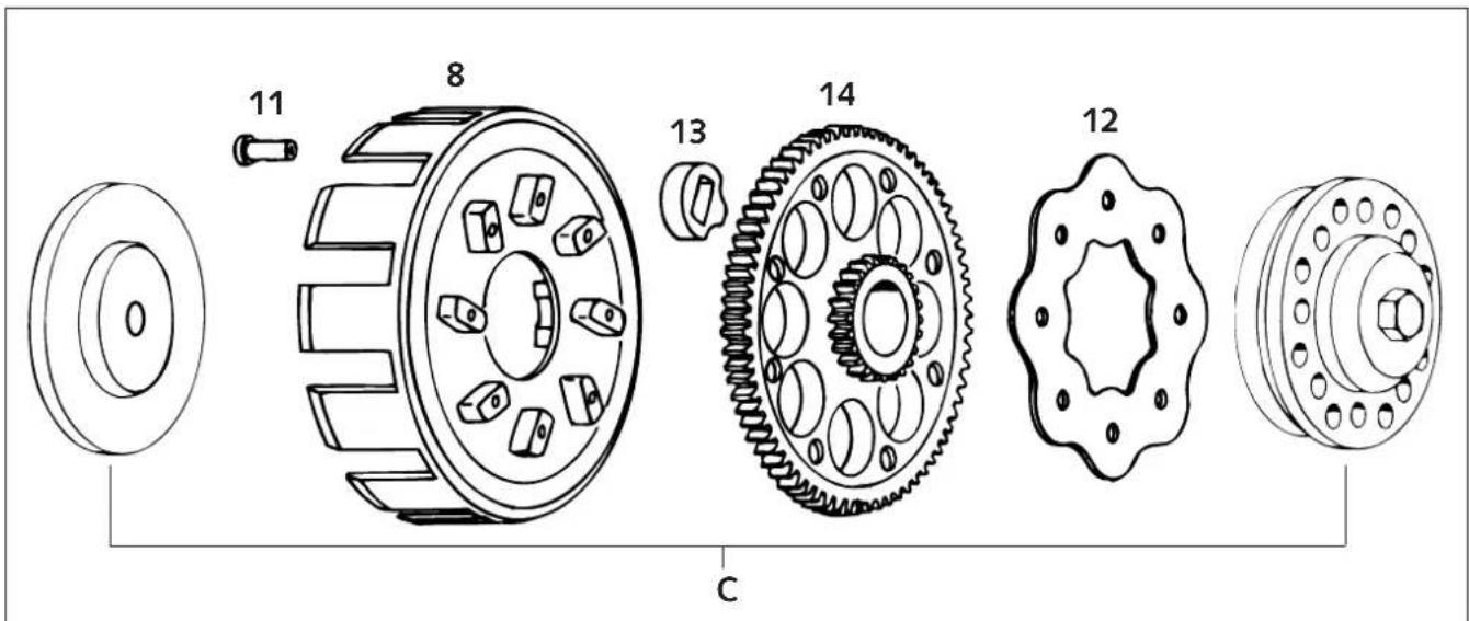
text_image
11 8 13 14 12 C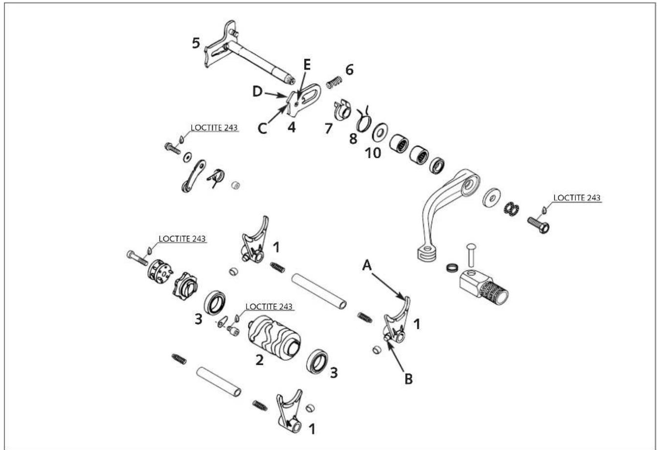
text_image
LOCTITE 243 LOCTITE 243 1 2 3 A B C D E 6 7 8 10 1 2 3 1 LOCTITE 243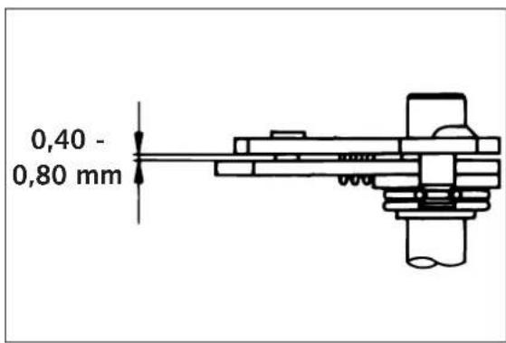
text_image
0,40 - 0,80 mm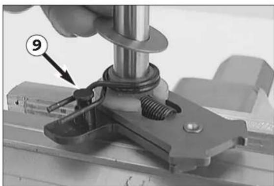
natural_image
Close-up of a mechanical assembly with a hand adjusting a bolt and spring, labeled with number 9 (no text or symbols on the main subject)Shift mechanism
Shift forks 1
Check shift fork blades Ⓐ and shift roller driving pin Ⓑ for signs of wear.
Shift roller ②
Check shift grooves for wear.
Check position of shift roller in grooved ball bearings ③.
Slide plate 4
Check slide plate at meshing points Ⓐ for wear.
Check return surface Ⓓ for wear (renew, if strongly notched).
Check that guide pin Ⓔ is securely fixed and check for wear.
Sliding guides
Check sliding guides (excess between guide pin and shift quadrant not to be more than 0.7 mm / 0.03 in).
Grooved ball bearings ③
Check grooved ball bearings for easy movement.
Shift mechanism
Assemble shift mechanism (see below) and check free play between slide plate ④ and shift quadrant ⑤. Free play should be 0.40 - 0.80 mm (0.016 - 0.032 in).
Preassembly of shift shaft
- Fix shift shaft in vice at shorter end (use covered clamps).
- Mount slide plate ④ with guide pins downwards, hook guide pins into shift quadrant ⑤.
- Mount pressure spring ⑥.
- Slide on spring guide ⑦, slide on return spring ⑧ with offset end upwards over the spring guide and lift offset end over bolt ⑨ (see illustration).
- M ount the stop dis⑩ (14x30x1 mm).
text_image
2K-1 2K-2 2K-3 2K-4Ignition (Kokusan)
General information
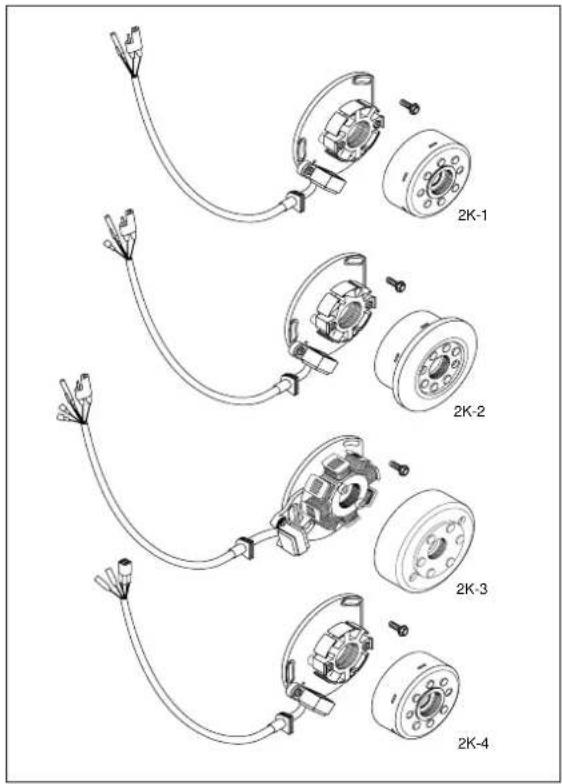
The measurements described below will only reveal severe problems. Coil short circuits leading to weak ignition sparks or low generator output, respectively, can only be detected with the help of an ignition test bench. In the case of malfunction always check the cables and the plug and socket connections of the ignition system first.
Make sure to select the correct measuring range when performing measurements.
Spark plug
- Set the electrode distance.
Electrode distance: 0.60 mm (0.024 in)
Insulator
Check for cracks and fissures.
| ! | CAUTION | ! |
ALWAYS USE A SPARK PLUG WITH RESISTOR. OTHERWISE PROBLEMS CAN OCCUR IN THE CDI UNIT.
natural_image
Two mechanical components: a circular component with bolt holes and a mechanical housing with a central hub (no text or symbols visible on the parts themselves)Check stator and pulse generator (Kokusan)
Use an ohmmeter to perform the following measurements:
natural_image
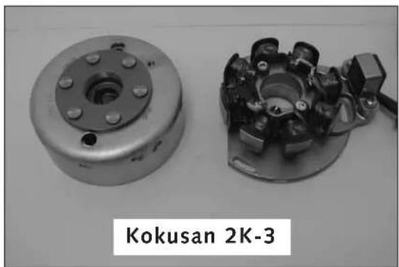
Two mechanical components: a circular flange and a mechanical housing with bolts, labeled 'Kokusan 2K-2' (no other text or symbols visible)| Ignition | Measure Cable colours Resistance | ||
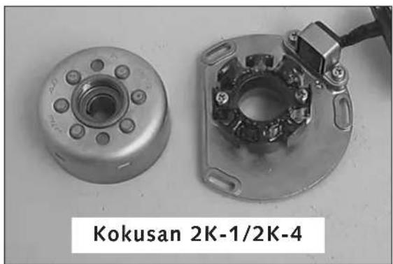
| 2K-1 | Pulser coilExciter | red – greenblack/red – red/white | 100 ± 15% 24 ± 15% |
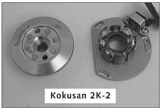
| 2K-2 | Pulser coilExciterCharge coil | red – greenblack/red – red/whiteground – yellow | 100 ± 15% 24 ± 15% 0,74 ± 15% |
| 2K-3 | Pulser coilExciterCharge coil | red – greenblack/red – red/whiteground – yellowwhite – yellow 0.16 | 100 ± 15% 12.7 ± 15% 0.65 ± 15% ± 15% |
| 2K-4 | Pulser coilExciterCharge coil | red – greenblack/red – red/whiteyellow – yellow | 100 ± 15% 24 ± 15% 0.65 ± 15% |
NOTE: The measuring must be performed at a temperature of 20^ C. Otherwise significant deviations must be expected.
Replace the stator if the measured values deviate significantly from the setpoint values.
natural_image
Two mechanical components, one circular and one complexed with visible springs and bolts, labeled 'Kokusan 2K-3' below (no other text or symbols)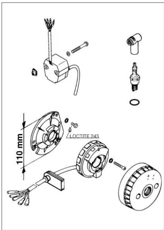
text_image
110 mm LOCTITE 243Ignition (SEM)
General information
The measurements described below will only reveal severe problems. Coil short circuits leading to weak ignition sparks or low generator output, respectively, can only be detected with the help of an ignition test bench. In the case of malfunction always check the cables and the plug and socket connections of the ignition system first.
Make sure to select the correct measuring range when performing measurements.
Spark plug
- Set the electrode distance.
Electrode distance: 0.60 mm (0.024 in)
Insulator
Check for cracks and fissures.
! CAUTION !
ALWAYS USE A SPARK PLUG WITH RESISTOR. OTHERWISE PROBLEMS CAN OCCUR IN THE CDI UNIT.
natural_image
Digital multimeter displaying 16.942 with connected cables and a mechanical component (no visible text or symbols)Check stator (SEM)
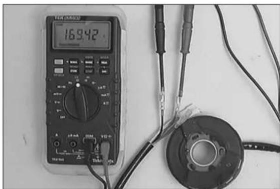
Perform the following measurements with an ohmmeter.
| + Pole – Pole Resistance | ||
| black red 1,7 kΩ | ||
| black | green | 165 |
| green red 1,7 kΩ | ||
| yellow | yellow | 1,0 Ω |
natural_image
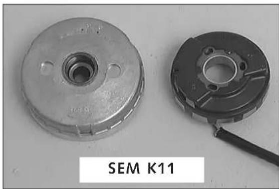
Two mechanical components, one circular and one metallic, displayed against a plain background (no text or symbols on the parts themselves)NOTE: The measuring must be performed at a temperature of 20^ C. Otherwise significant deviations must be expected.
Replace the stator if the measured values deviate significantly from the setpoint values.

text_image
Exploded view diagram of a mechanical gear assembly with numbered parts for identificationTransmission
Secure mainshaft or countershaft in the vice (using soft jaw-covers). Remove gears and check the following for wear:
- Needle bearing
- Mainshaft and countershaft pivot points including idler gears
- Shift dogs and gear wheels
- T ooth faces of all gears
- T ooth profile of mainshaft and countershaft and corresponding gears
– Easy operation of gear-change
Carefully clean components and replace damaged components.
NOTE: Always place circlips with sharp edge facing the components secured, ensuring that they are not overexpanded (use special pliers). Check that after any repair of the transmission, circlips should axially not move more than 0.20 mm (0.006 in) and must not seize between stop discs.
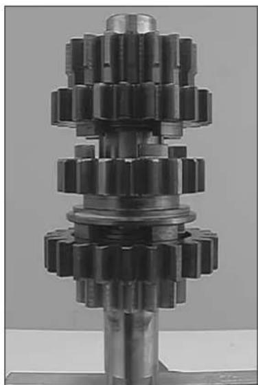
Assembly mainshaft
- Fix mainshaft in vice with toothed end upwards (use covered clamps). - Oil all parts before assembly.
- Mount the split needle cage ① on mainshaft, push 5th idler gear ② over it with collar downwards.
- Place internally toothed stop disc ③ (22.4x25.7x32.0x1.5 mm) in position and mount circlip ④ (25x1.64 mm) with sharp edge upwards.
- Place 3 rd sliding gear ⑤ in position with shift groove downwards, mount circlip ⑥ (25x1.64 mm) with sharp edge downwards and internally toothed stop disc ⑦ (22.4x25.7x32.0x1.5 mm)
- Mount the split needle cage ⑧, 4th idler gear ⑨ with shift dogs downwards 2nd gear ⑩ with collar downwards and stop disc ⑪ (20.2x33x1.5 mm).
- Finally check all gears for easy running.
natural_image
Close-up of a mechanical gear assembly with multiple teeth and central shaft (no visible text or symbols)
text_image
Exploded view diagram of a mechanical gear assembly with numbered parts for identificationTransmission
Secure mainshaft or countershaft in the vice (using soft jaw-covers). Remove gears and check the following for wear:
- Needle bearing
- Mainshaft and countershaft pivot points including idler gears
- Shift dogs and gear wheels
- T ooth faces of all gears
- T ooth profile of mainshaft and countershaft and corresponding gears
– Easy operation of gear-change
Carefully clean components and replace damaged components.
NOTE: Always place circlips with sharp edge facing the components secured, ensuring that they are not overexpanded (use special pliers). Check that after any repair of the transmission, circlips should axially not move more than 0.20 mm (0.006 in) and must not seize between stop discs.
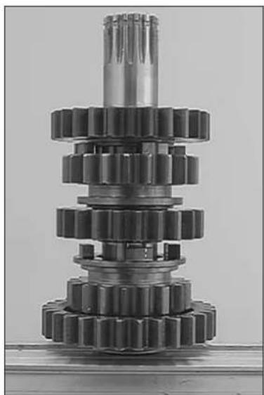
Assembly countershaft
- Fix countershaft in vice with toothed end (use covered clamps). - Oil all parts before assembly.
- Push stop disc ① (26x40x1,5 mm) onto countershaft.
- M o u rditler gear ② with shift dog recesses upwards and circlip ③ (25x2 mm) with sharp edge upwards.
- M o thin sliding gear ④ with shift groove downwards, stop disc ⑤ (22,2x33x1,5 mm), needle cage ⑥, 1st free gear ⑦ with shift dog recesses downwards and stop disc ⑧ (17,2x34x1,5 mm) with collar upwards on the countershaft.
- Remove countershaft from vice and fix again with toothed end upwards.
- Mo u ttsAiding gear ⑨ with shift dog upwards, stop disc ⑩ (28,2x40x1,5 mm), needle cage ⑪, 2nd idler gear ⑫ with shift dog recesses downwards and stop disc ⑬ (25,7x40x1,5 mm).
- Finally check all gears for easy running.
natural_image
Close-up of a mechanical gear assembly with multiple teeth and central shaft (no text or symbols visible)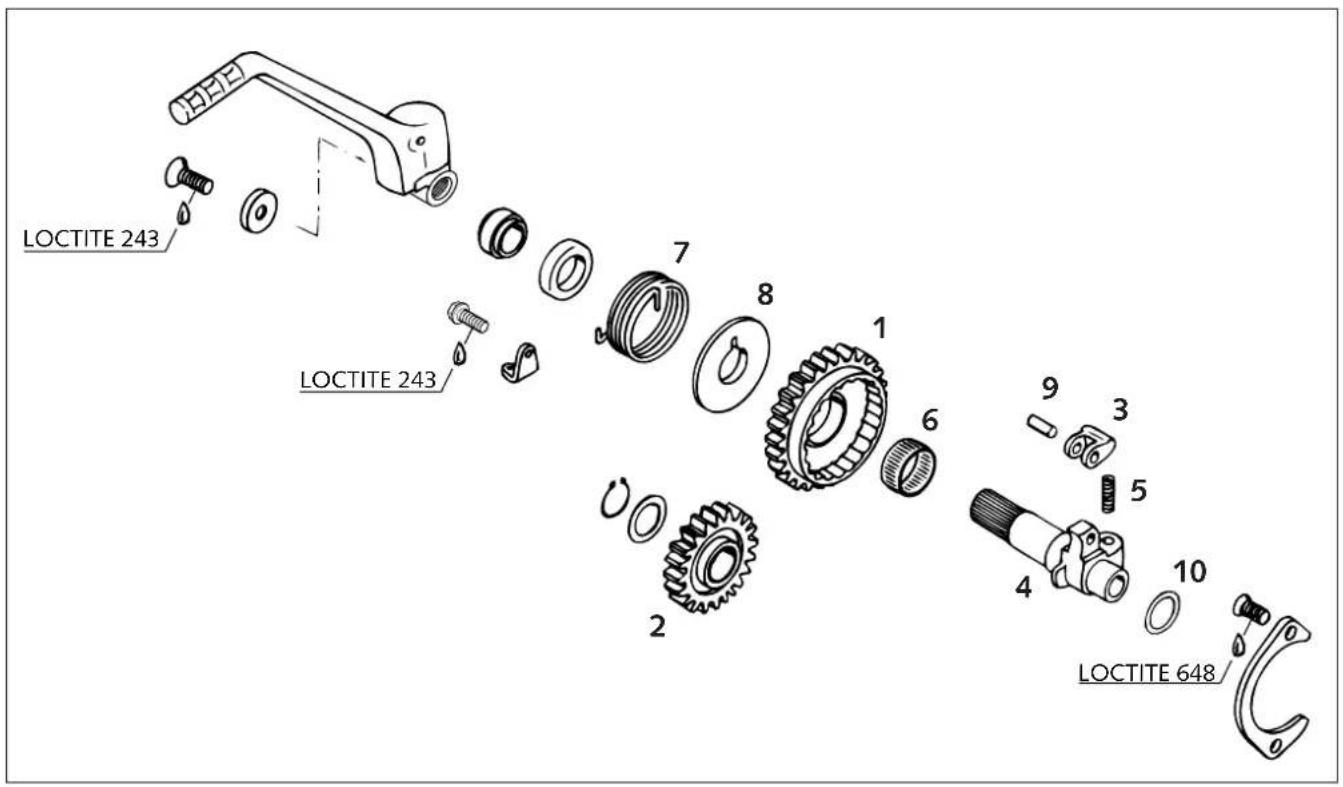
text_image
LOCTITE 243 LOCTITE 243 1 2 3 4 5 6 7 8 9 10 LOCTITE 648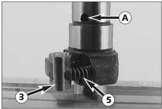
text_image
A 3 5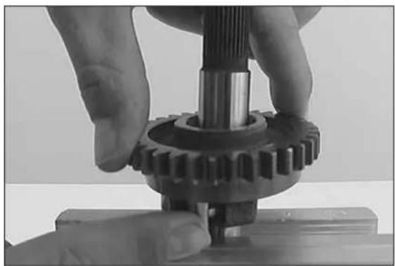
natural_image
Close-up of hands assembling a mechanical gear assembly (no visible text or symbols)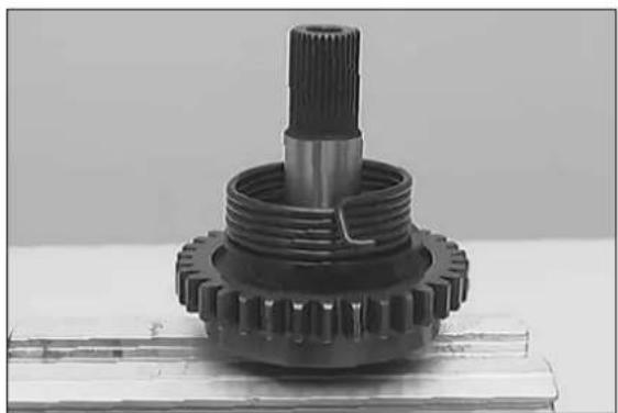
natural_image
Close-up of a mechanical gear component with threaded shaft and meshing (no visible text or symbols)Kickstarter
Starter gear ①
Check clearance of starter gear.
Starter intermediate gear ②
Check clearance of starter intermediate gear.
Locking pawl ③
Check for signs of wear and damage.
Kickstarter shaft 4
Check for signs of wear and damage.
For changing the locking pawl, press bearing needle ⑨ out of the kickstarter shaft.
Assemble of kickstarter shaft
- Fix the kickstarter shaft ④ in a vice with the toothed end upwards (use covered vice clamps).
- Mount ratchet spring ⑤ on kickstarter shaft as shown in the illustration.
- Place needle cage ⑥ in position, push starter gear ① over it, pressing locking pawl ③ inwards so that starter gear passes smoothly over it.
- Hook legs of the starter spring ⑦ into driving hub ⑧, push both together on the starter shaft, hook starter spring leg into kickstarter shaft bore ⑨.
- Release kickstarter shaft, and fix stop disc ⑩ with a small amount of grease on the kickstarter shaft.
ASSEMBLING THE ENGINE
6
INDEX
CRANKSHAFT 6-2
TRANSMISSION 6-2
ASSEMBLING THE ENGINE HOUSING 6-3
MOUNTING SHIFT MECHANISM 6-4
MOUNTING KICKSTARTER 6-4
MOUNT PRIMARY DRIVE AND CLUTCH....6-5
MOUNTING CLUTCH DISCS AND PRESSURE CAP .....6-6
MOUNTING CLUTCH COVER....6-6
MOUNTING PISTON AND CYLINDER 6-7
ADJUSTING DIMENSION „X“ 6-7
ADJUSTING CONTROL FLAP (DIMENSION „Z“) .....6-8
MOUNTING STEERING COVERS 6-9
MOUNTING CYLINDER HEAD 6-9
MOUNTING REED VALVE HOUSING AND INTAKE FLANGE .....6-9
MOUNTING ENGINE SPROCKET 6-10
MOUNTING THE IGNITION (KOKUSAN) 6-10
MOUNTING THE IGNITION (SEM) 6-11
ADJUSTING IGNITION POINT (SEM) 6-11
MOUNTING IGNITION COVER....6-11
MOUNTING STARTING LEVER AND SHIFT LEVER .....6-11
natural_image
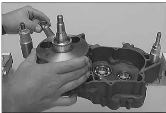
Close-up of hands assembling a mechanical component with cylindrical parts and bearings (no visible text or symbols)- Secure the right-hand housing half in the engine work stand.
Crankshaft
- Insert crankshaft from above through grooved ball bearing and push carefully as far as stop.
| ! | CAUTION | ! |
WHEN PUSHING IN CRANKSHAFT, MAKE SURE CONROD IS FACING CYLINDER.
natural_image
Two metallic mechanical components with a circular arrow labeled '1' pointing to one (no text or symbols on the parts themselves)Transmission
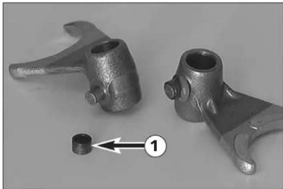
- Grease the driving pins of the shift forks and mount the shift rollers ①.
- Fix the lower stop disc on the countershaft with a small amount of grease.
- Mount drive shaft together with countershaft, and insert them into the bearings as far as they will go.
text_image
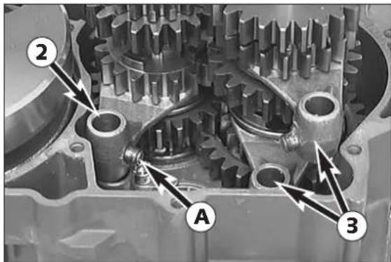
Technical diagram of a mechanical gear assembly with labeled components A and 2, showing internal gears and connections.- Shift fork ② with driving pin A in the middle belongs to the mainshaft.
- M ount the two other shift fork ^3 at the countershaft, using the marks applied before disassembly for better orientation.
| ! | CAUTION | ! |
USED SHIFT FORKS SHOULD BE MOUNTED IN THE SAME SLIDING GEAR AS BEFORE. WATCH AT THE MARKINGS FROM DISMANTLING.
natural_image
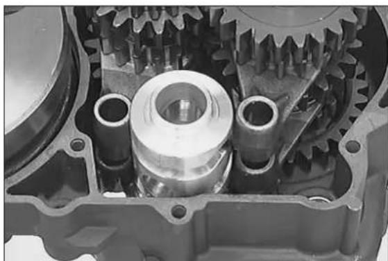
Close-up of a mechanical gear assembly with internal components (no visible text or symbols)- Attach the shift forks to the sliding gears, and insert shift roller into the grooved ball bearing.
- A ttach the shift forks to the shift roller.
| ! | CAUTION | ! |
WHEN ATTACHING THE SHIFT FORKS, MAKE SURE THAT THE SHIFT DRUMS DO NOT SLIDE OFF THE SHIFT FORKS.
natural_image
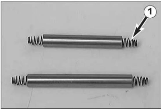
Two metallic cylindrical rods with coiled springs, one with a numbered arrow pointing to the spring (no text or symbols)- Fix the 4 pressure springs Ⓞ with ample amounts of grease in the gearshift rails.
natural_image
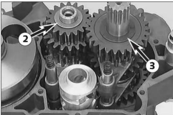
Mechanical gear assembly diagram showing three labeled components (no text or symbols present)- Oil gearshift rails and insert them into the gearshift forks (short gearshift rail toward drive shaft). Insert gearshift rails into the casing bores as far as they will go.
NOTE: It must now be possible to gently turn gear shafts.
- Slide stop disc ② (20.2x 33x1.5 mm) on the drive shaft, and stop disc ③ (25.7x40 x1.5 mm) on the countershaft.
natural_image
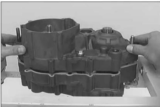
Close-up of hands assembling a mechanical component (no visible text or symbols)Assembling the engine housing
- Remove engine fastener from engine work stand.
- Check that both dowels are in proper place in right-hand housing and that transmission shaft stop discs have been mounted.
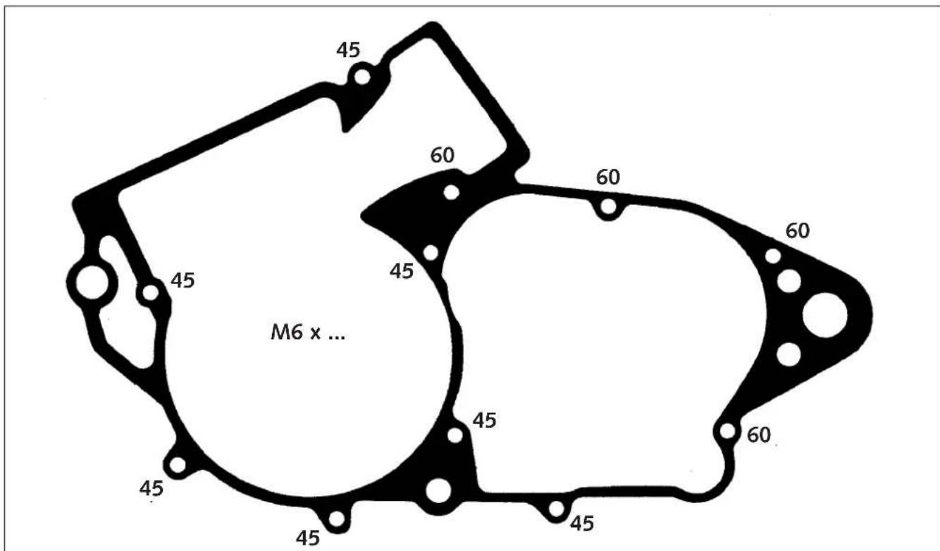
- Apply light coat of grease to sealing surfaces of the housing and position new gasket.
- G r ease shaft seal rings in left-hand half and place left-hand half in position.
- Position screws and tighten with 8 Nm (6 ft.lb).
- Gently knock crankshaft with plastic hammer and check easy running of shafts.
- Fix engine in work stand.
text_image
45 60 60 45 45 45 45 45 45 45 M6 x ...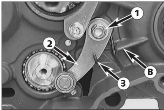
text_image
Mechanical assembly diagram with numbered components and directional arrows indicating motion or assembly steps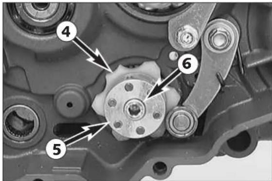
text_image
Mechanical component diagram with numbered parts labeled 4, 5, and 6
natural_image
Mechanical assembly diagram showing a gear mechanism with no visible text or symbols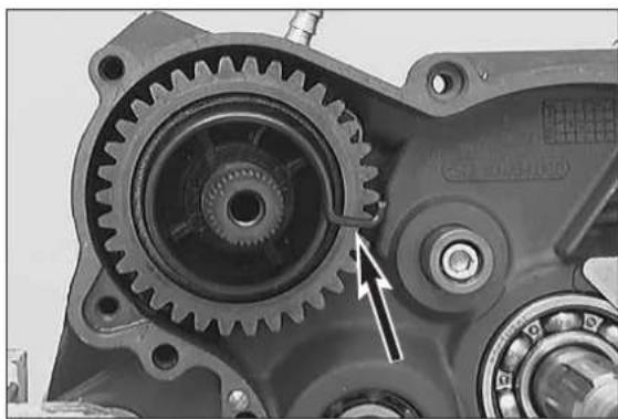
natural_image
Close-up mechanical gear assembly with visible teeth and bearing housing (no text or symbols)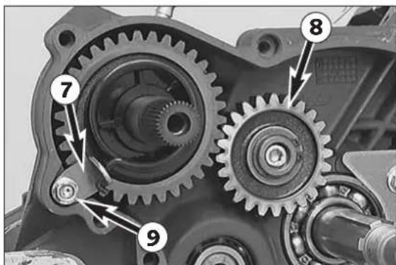
text_image
Mechanical gear assembly diagram with numbered components for identificationMounting shift mechanism
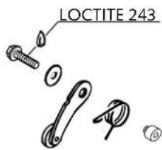
- Place locating spring with bent leg upwards into engine housing.
- Insert collar sleeve into spring with collar upwards.
- Coat collar screw ① with Loctite 243.
- Insert locating lever ② with roll upwards and fix all parts with collar screw.
- Hook locking spring ③ to lever. The other end of the retaining spring must abut the casing nose ⑧.
text_image
LOCTITE 243- Mount roller locking device ④ (plastic part) to shift roller. Ensure that the flat parts are not in the middle. Pull locking lever from shift roller.
- Mount driver for shift roller ⑤
- Coat allan head screw ⑥ with Loctite 243 and mount.
NOTE: From model 2002 on driver for roller ⑤ and locking piece ④ are made of aluminium.
- G r ease assembled shift shaft and push into bearings together with stop disc until slide plate contacts driver for shaft roller.
- Now squeeze, and push shift shaft in to the stop.
- Check that legs of return spring surround both left and right side of housing nose Ⓐ.
- Mount the foot shift lever and shift through all gears. When shifting through the gears, turn the countershaft. Then remove the foot shift lever.
Mounting kickstarter
- Place spacing washer on the stop face an place preassembled kickstarter shaft in bearing bore in such a way that the locking pawl is outside the release plate.
NOTE: If the kickstarter shaft is mounted correctly, the visible end of the starter spring must point forward (see photo).
- Hook spring hanger ⑦ to starter spring, coat screw ⑨ with Loctite 243, tighten starter spring approx. 90° clock-wise and fix spring pawl with allan head screw.
- Adjust starter spring so that the distance to the kickstarter shaft is the same all around.
- Place starter intermediate gear ⑧ with the high collar (see sketch) showing towards the engine casing on to the bearing.
- Slip on stop disc (17.2x25x1 mm) and mount circlip with the sharp edge showing upwards.
natural_image
Mechanical gear assembly diagram showing two numbered components (1 and 2) with no visible text or symbolsMount primary drive and clutch
- G r ease crankshaft seal ring.
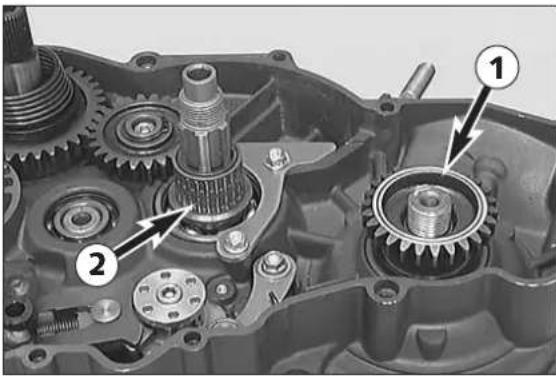
- Put the oiled O-ring (25x1.50 mm) onto the crankshaft and mount the distance bushing with the chamfer facing the crank web.
- Insert woodruff key into crankshaft.
- Place primary gear ① onto crankshaft with collar downwards.
- Put the inner ring onto the main shaft with the collar facing downwards, then mount the oiled needle cage ②.
natural_image
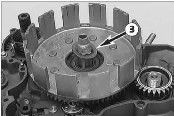
Mechanical assembly showing a gear and shaft assembly with no visible text or symbols- Mount outer clutch hub and stop disc ③.
natural_image
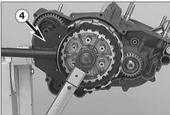
Mechanical gear assembly with labeled component (4), no visible text or symbols beyond label- Apply Loctite 243 to the thread of the main shaft.
- Mount inner clutch hub, new lock washer and hexagon nut to main shaft.
- Position clutch holder ④ and tighten hexagon nut with 100 Nm (74 ft.lb.).
- Remove the clutch holder and secure the hexagon nut by bending both brackets of the lock washer upwards.
natural_image
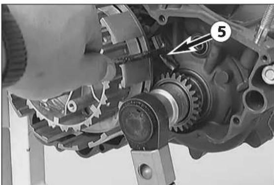
Close-up of a mechanical assembly showing gear and shaft components (no visible text or symbols)- Apply Loctite 243 to thread of the crankshaft.
- Fit locking washer and hexagon nut (left hand thread) by hand.
- Block primary drive with gear segment ⑤ and tighten primary gear hexagon nut with 150 Nm (110 ft.lb.).
- Remove gear segment and check easy running of primary drive by turning crankshaft.
natural_image
Close-up of a mechanical gear assembly with visible teeth and internal components (no text or symbols)Mounting clutch discs and pressure cap
- Oil the thrust bearing ①, and slide it over the drive shaft.
natural_image
Close-up of a mechanical clutch housing with multiple bolt holes and gears (no visible text or symbols)– Oil lining discs before mounting.
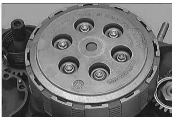
- Beginning with one lining disc, mount alternately 9 lining discs ( 2.70 mm / 0.10 in) and 8 intermediate discs ( 1.20 mm / 0.047 in), with a lining disc forming the final layer upwards.
- Place pressure cap into position; fit clutch springs, spring retainer and collar screws.
- T ighten the collar screws crosswise. Do not apply more than 6 Nm (4.5 ft.lb.) to prevent damaging of the threads in the inner clutch hub.
natural_image
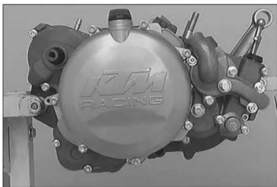
Close-up of a mechanical assembly with visible components and no readable text or symbolsMounting clutch cover
- Check whether both dowels are mounted in clutch cover or engine housing.
- G r ease kickstarter shaft seal ring and position clutch cover gasket. Secure gasket with a little grease.
- Carefully position preassembled clutch cover and press into place, turning crankshaft so that centrifugal timer can engage in the primary gear.
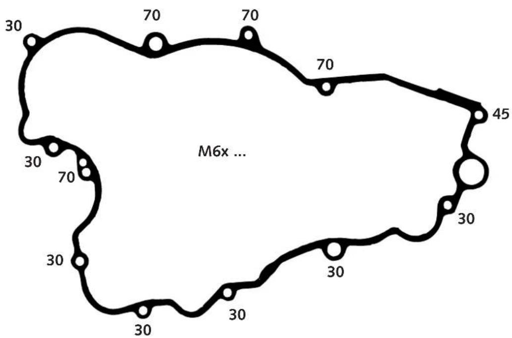
- Fit collar screws (see sketch for screw lengths) and tighten with 8 Nm (6 ft.lb.).
- Then check easy running of all shafts.
NOTE: If the clutch cover cannot be mounted, verify whether or not the kickstarter spring has been positioned correctly.
text_image
30 70 70 70 30 70 45 M6x ... 30 30 30 30 30 30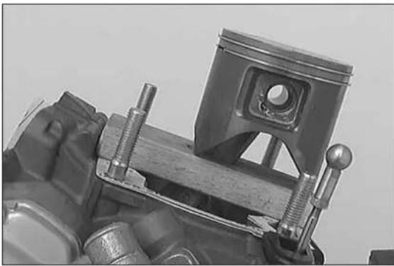
natural_image
Close-up of a mechanical piston assembly with attached frame and cylindrical components (no visible text or symbols)Mounting piston and cylinder
- Before assembly, oil all parts thoroughly at the sliding points.
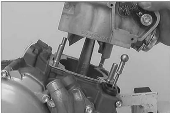
- Insert needle bearing in conrod eye, mount piston (arrow on piston head shows direction for exhaust duct).
- Mount piston pin and wire circlips with open side showing downwards (see sketch).
- Mount cylinder base gaskets.
- Place piston on selfmade wooden stand and position piston ring.
natural_image
Close-up of a mechanical assembly with a hand adjusting a component (no visible text or symbols)- Place on preassembled cylinder, remove wooden stand and tighten cylinder down crosswise, using two nuts.
text_image
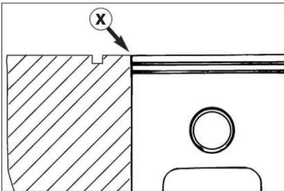
Technical diagram showing a cross-section with hatched area and labeled point 'X' pointing to a featureAdjusting dimension „X“
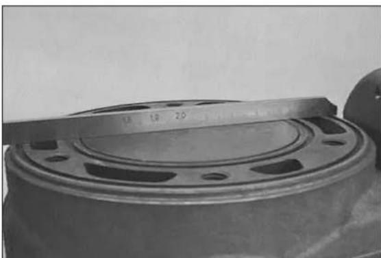
Dimension „X“ is the dimension from upper edge of piston to upper edge of cylinder with cylinder under low tension and piston in TDC position. The dimension „X“ should be adjusted extremely carefully by inserting cylinder base gaskets of suitable thicknesses.
! CAUTION !
IF THE DIMENSION „X“ IS TOO LARGE, THE COMPRESSION RATIO WILL BE REDUCED AND THE ENGINE LOOSES POWER. ON THE OTHER HAND, IF THE DIMENSION „X“ IS TOO SMALL, THE ENGINE WILL PING AND OVERHEAT.
natural_image
Close-up of a cylindrical mechanical component with a ruler for scale (no visible text or symbols)- Set the piston to TDC, and apply a sliding gage or straight-edge to the cylinder. Now, check the distance between the piston's upper edge and the sliding gage. This distance should be from 0 mm to 0.10 mm at the most. It can be corrected, if necessary, by adding or removing of cylinder-base gaskets.
! CAUTION !
THE PISTON MUST NOT PROTRUDE BEYOND THE CYLINDER'S UPPER EDGE.
Dimension „X“ = 0 mm + 0.1 mm
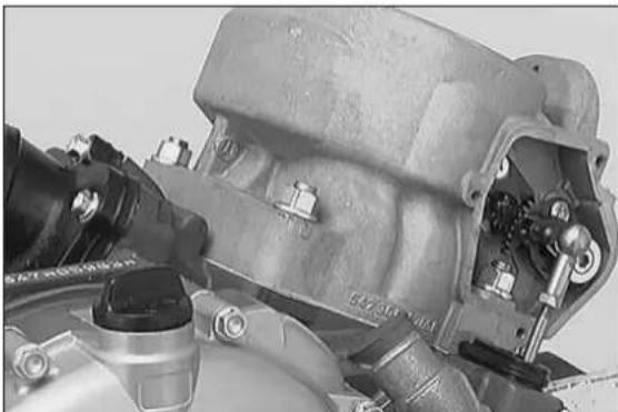
natural_image
Close-up of an internal combustion engine component (no visible text or symbols)- Mount the 2 remaining collar nuts at the cylinder base, and tighten each of the 4 collar nuts to 35Nm (27 ft.lb.).
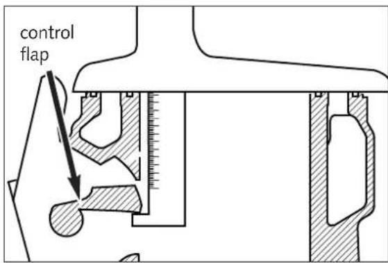
text_image
control flapAdjusting control flap (dimension "Z")
Note: Dimension "Z" is the distance from the lower edge of the control flap to the upper edge of the cylinder, as measured in the centre of the exhaust port.
250 Model 1999: 48.0 mm + 0.2 / - 0.6 mm
natural_image
Close-up of a mechanical component with no visible text or symbols- Undo the screws of the stop plate (left side of the cylinder) ① and ② and apply Loctite 243 to the threads. Then mount both screws but do not tighten them yet.
- Set preselected value on depth gauge and fix.
- S wifel control flap upwards and hold depth gauge into cylinder as shown in the illustration.
- Control flap must rest against depth gauge.
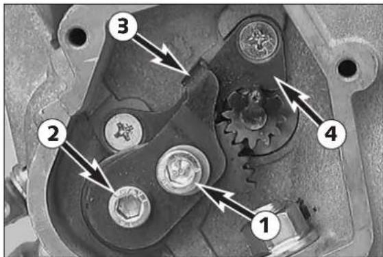
text_image
Technical diagram of a mechanical assembly with numbered components and directional arrows indicating motion or force directions.- Allow bump plate ③ to rest against retaining bracket ④.
- Secure bump plate fastening screws ① and ②.
- Remove depth gauge.
- Having tightened the screws ① + ②, you have to check the dimension "Z" again and correct it, if necessary.
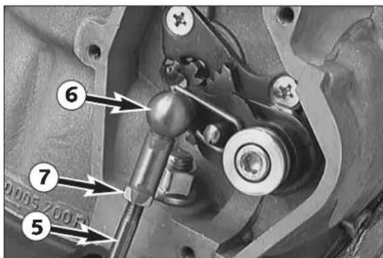
text_image
Technical diagram of a mechanical assembly with numbered components and directional arrows indicating motion or force directions.- Press linkage of control flap ⑤ down-wards as far as stop and press ball socket ⑥ onto ball of adjusting lever.
When pressing ball socket do not:
- pull the linkage too far up (max. 1 mm / 0.04 in).
● swivel control flap upwards.
- Adjust linkage length if necessary.
- T o do so, loosen counter nu7 and turn ball socket accordingly.
- Retighten counter nut.
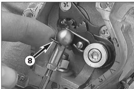
natural_image
Close-up of a mechanical component with a finger inserted, showing a bolt and nut assembly (no visible text or symbols)- Once adjustments are completed, remove ball socket once again and fit gasket for control cover.
- Refit ball socket and fit safety device ⑧.
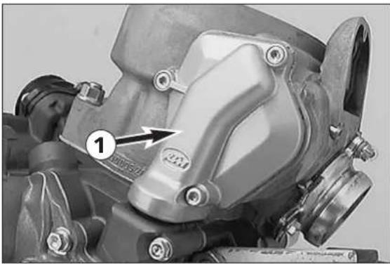
natural_image
Close-up of a mechanical component with no visible text or symbolsMounting steering covers
- Mount the right-hand control cover ①, and fix it with 3 screws.
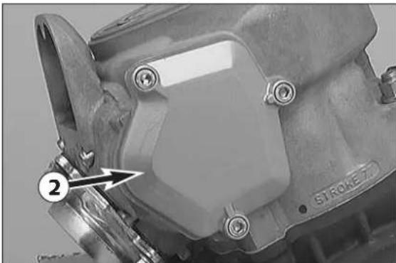
natural_image
Close-up of a mechanical component with bolts and a labeled arrow (no readable text or symbols)- Place gasket in position and fix left-hand steering cover ② on cylinder.
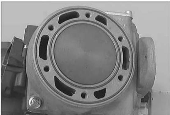
natural_image
Close-up of a mechanical component with circular and rectangular features, no visible text or symbolsMounting cylinder head
- Clean cylinder and cylinder head sealing surface, place O-rings in grooves.
- Mount cylinder head with water nozzle on the exhaust side.
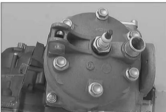
natural_image
Close-up of a mechanical component with bolts and nuts (no visible text or symbols)- Oil the collar nuts at threads and contact faces.
- M ount the collar screws with new copper gaskets and tighten them crosswise, taking three turns to achieve the total tightening torque of 35 Nm (25 ft.lb.).
- In first stage, only tighten until slight resistance is felt.
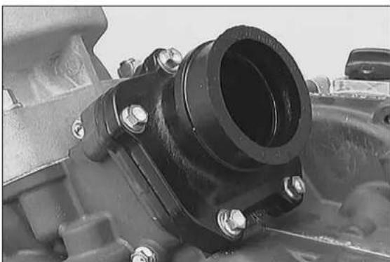
natural_image
Close-up of a mechanical component with a black cylindrical housing and bolted connectors (no visible text or symbols)Mounting reed valve housing and intake flange
- Place reed valve housing with velocity insert in inlet duct and fix intake flange with the 5 collar screws.
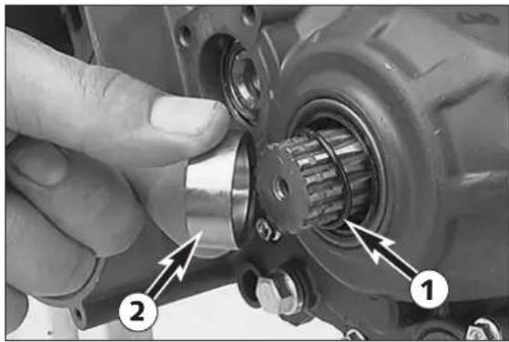
natural_image
Close-up of a hand adjusting a mechanical component with numbered callouts (1 and 2), no visible text or symbols.Mounting engine sprocket
- Lubricate O-ring ① with oil and slide over counter shaft.
- Slide distance bushing ② in position so that O-ring is in correct position.
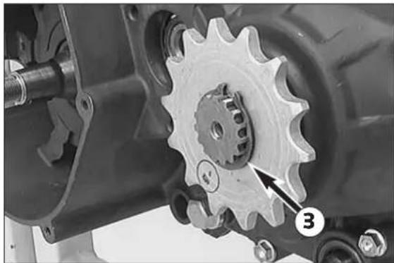
natural_image
Close-up of a mechanical gear assembly with a numbered component (3) and an arrow pointing to a specific gear tooth (no text or symbols visible)- Slide sprocket onto the countershaft with the collar facing inward, and fix it with the circlip ③ (sharp edge facing outward).
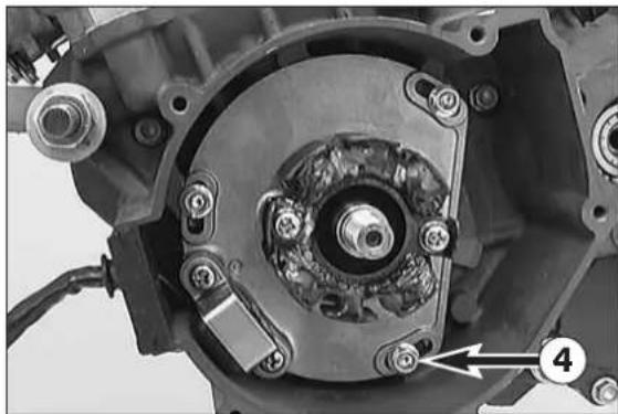
natural_image
Close-up of a mechanical assembly showing internal components and a numbered label (4), no readable text or symbols present.Mounting the ignition (Kokusan)
- Insert the woodruff key into the crankshaft.
- Apply Loctite 243 to 3 screws ④ and fix the stator (do not yet tighten the 3 screws all the way).
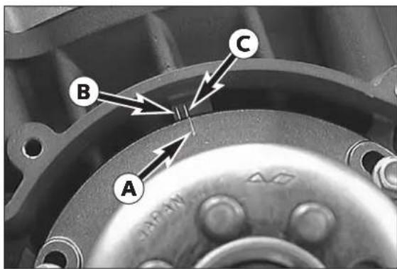
text_image
A B C- T urn stator such that the mark on the stator coincides with the mark in the casing, and tighten the 3 screws of the stator.
- At engines with ignition type 2K-4 the marking Ⓐ must coincide with the marking on the stator.
- At engines with all other ignitions (not SEM) the marking Ⓐ must coincide with the marking on the stator.
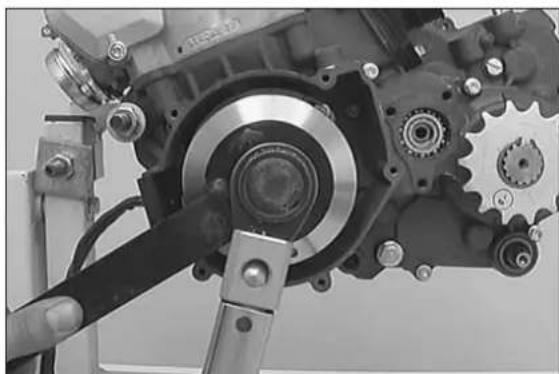
natural_image
Close-up of a mechanical assembly with gears and levers (no visible text or symbols)- Mount the rotor.
- Mount the detent edged ring and the nut.
- Hold the rotor with the holding spanner and tighten the nut with 60 Nm (45 ft.lb.).
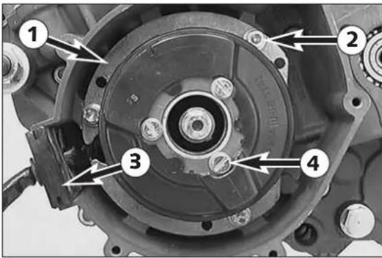
text_image
Technical diagram of a mechanical assembly with numbered components labeled 1 to 4Mounting the ignition (SEM)
- Insert woodruff key into crankshaft.
- Apply Loctite 243 to the threads of the 3 screws ②.
- Mount base plate ① together with stator, and tighten the 3 screws.
- Mount the cable guide ③ into the cutaway portion of the casing.
- Mount the rotor.
- Mount the detent edged ring and the nut.
- Hold the rotor with the holding spanner and tighten the nut with 60 Nm (45 ft.lb.).
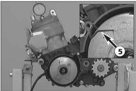
natural_image
Mechanical assembly with gears and a pressure gauge, showing mechanical components and a magnified inset (no readable text or symbols)Adjusting ignition point (SEM)
- Make sure that the stator can be turned on the intermediate plate. Otherwise, loosen the 3 screws ④.
- Mount flywheel.
- Screw dial gauge into spark plug thread.
- Place adjusting pin ⑤ in flywheel bore ("91") 2 mm (0.08 in) and turn flywheel until pin slots into recess ⑥ in stator.
- T urn flywheel and stator jointly to TDC.
- T urn dial gauge scale to 0 and turn flywheel with stator clockwise accordingly to preignition.
Ignition point:
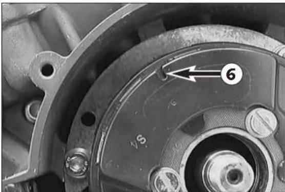
natural_image
Close-up of a mechanical component with numbered annotation (6) and no visible text or symbols- Carefully remove flywheel to prevent further turning of stator.
- T ighten the three stator cylinder screws.
- Mount flywheel and tighten collar nut with 60 Nm (45 ft.lb).
- Check ignition point once more.
- Remove dial gauge and fit spark plug with OR.
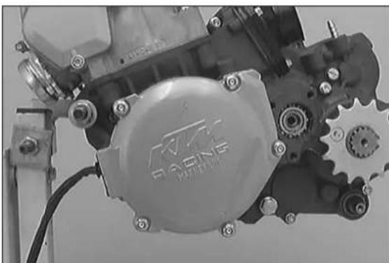
natural_image
Close-up of a mechanical assembly with visible gears and mounting brackets (no readable text or symbols)Mounting ignition cover
- Put on a new gasket, and fix the ignition cover by means of the 5 screws.
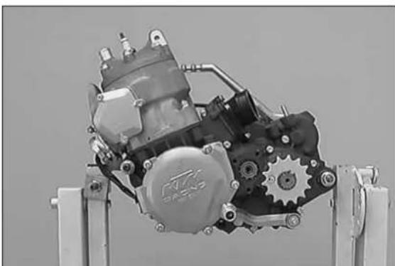
natural_image
Mechanical assembly with gears and mounting bracket (no visible text or symbols)Mounting starting lever and shift lever
- Push distance bushing onto kickstarter shaft and mount kickstarter.
- Mount shift lever.
- Operate the kickstarter a few times and check if the engine turns freely.
- Oil the push rod, and insert it into the drive shaft.
NOTE: The transmission oil should be filled in only after the engine has been mounted. Otherwise, a part of the transmission oil would leak out through the drive shaft.
ELECTRICAL
7
INDEX
CHECKING THE VOLTAGE REGULATOR-RECTIFIER (SHINDENGEN) . . .7-2
CHECKING THE VOLTAGE REGULATOR (KOKUSAN) .....7-2
CHECKING THE VOLTAGE REGULATOR (TYMPANIUM) .....7-2
CHECKING THE CAPACITOR 7-3
IGNITION COIL (SEM) 7-3
IGNITION COIL (KOKUSAN) 7-3
CDI UNIT 7-3
CHECKING THE VOLTAGE REGULATOR (MOD. 2000) .....7-4
CHECKING THE CAPACITOR (MOD. 2000) .....7-4
STATIC IGNITION VALUES 250 - 380 SX, EXC .....7-5
STATIC GENERATOR VALUES 250 - 380 EXC .....7-7
STATIC IGNITION AND GENERATOR VALUES 250 MXC, EXC (USA) . .7-9
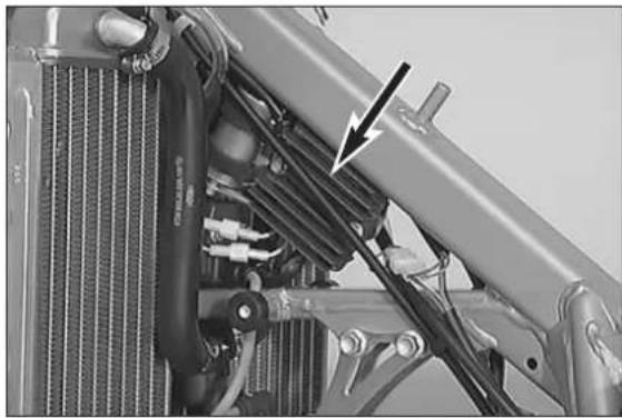
natural_image
Close-up of automotive engine components with visible hoses and springs (no text or symbols)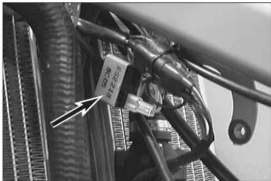
natural_image
Close-up of a mechanical component with visible wiring and a labeled part (no readable text or symbols)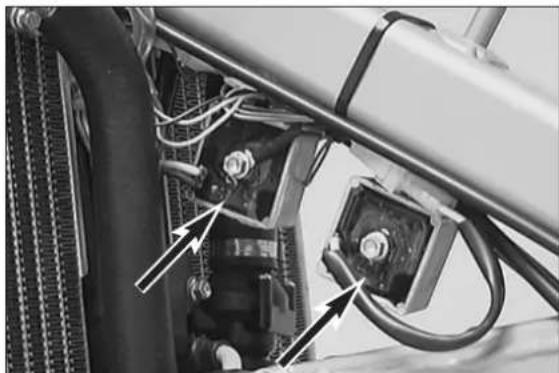
natural_image
Close-up of mechanical components with wiring and connectors, no visible text or symbolsChecking the voltage regulator-rectifier (Shindengen)
- Start the engine and switch on the low beam.
- Connect a voltmeter to the two terminals of the capacitor (red/white cable = positive, brown cable = negative).
- Accelerate the engine to a speed of 5000 r.p.m. and read off the voltage.
Nominal value: 14.0 - 15.0 V
In the case of a significant deviation from the nominal value:
- Check the capacitor
- Check the connector between the stator and the voltage regulator-rectifier and the connector between the voltage regulator-rectifier and the cable tree.
- Check the stator.
- Replace the voltage regulator-rectifier.
Checking the voltage regulator (Kokusan)
A defect voltage regulator can cause different kinds of trouble:
- No voltage in the circuit
In this case, the voltage regulator must be disconnected at idle speed. The voltage regulator is defect if the power consumers now work properly.
If the power consumers are still not supplied with power, the switch, the wiring harness or the ignition system must be checked for defects.
● Excessive voltage in the circuit
The bulbs burn out. In this case the voltage regulator must be replaced.
Checking the voltage regulator (Tympanium)
NOTE: The voltage regulators are connected downstream of the switches. One of the voltage regulators regulates only the brake light circuit, the other regulates the circuit for the head light, the tail light, the speedometer illumination and the horn.
A defect voltage regulator can cause different kinds of trouble:
- No voltage in the circuit
In this case, the voltage regulator must be disconnected at idle speed. The voltage regulator is defect if the power consumers now work properly.
If the power consumers are still not supplied with power, the switch, the wiring harness or the ignition system must be checked for defects.
- Excessive voltage in the circuit
The bulbs burn out.
Connect a voltmeter (yellow cable = positive, brown cable = negative) to check the voltage. Start the engine and switch on the power consumers.
At an engine speed of 3000 r.p.m, the voltage regulator must supply a voltage of 12.0 - 14.0 V A.C. At higher engine speeds, the limit of 14.0 V should not be exceeded either.
If the reading significantly deviates from the nominal value, replace the voltage regulator.
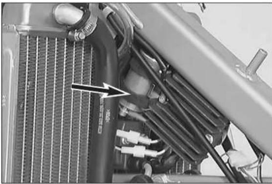
natural_image
Close-up of a car radiator panel with visible wiring and mechanical components (no text or symbols)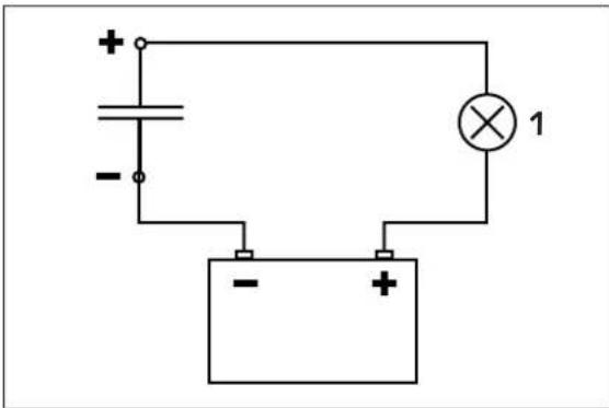
natural_image
Simple electrical circuit diagram with battery, switch, and lamp (no text or symbols)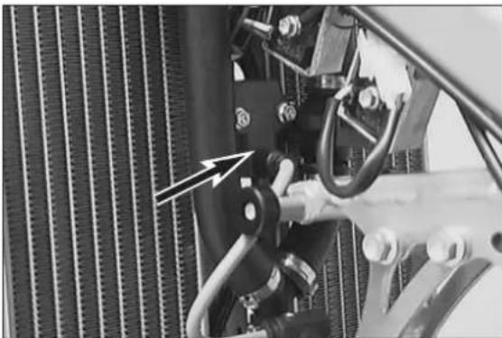
natural_image
Close-up of a mechanical assembly with hoses and a hand adjusting components (no visible text or symbols)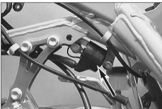
natural_image
Close-up of mechanical components with wires and connectors (no visible text or symbols)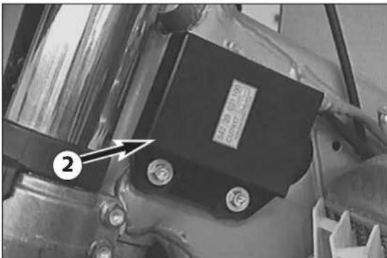
text_image
Close-up of a mechanical component with labeled parts and an arrow pointing to part number 2Checking the capacitor
- Discharge the capacitor by bridging the two terminals with a screwdriver and remove.
- Connect the negative pole of a 12V battery with the negative terminal of the capacitor. The connection between the positive pole of the battery and the positive terminal of the capacitor (marked +) is made with a test lamp ①.
- When the power circuit is closed, the test lamp must begin to light up. As capacitor charging increases, the brightness of the test lamp must decrease.
- The test lamp must go out after 0,5-2 seconds (depending on the lamp capacity).
- If the test lamp does not go out or does not light up at all, the capacitor is faulty.
| ! | CAUTION | ! |
DISCHARGE THE CAPACITOR BEFORE AND AFTER EACH TEST.
WHEN INSTALLING THE CAPACITOR, MAKE SURE THAT THE TERMINALS ARE CONNECTED IN ACCORDANCE WITH THEIR MARKINGS (CONNECT RED/WHITE CABLE TO + TERMINAL).
Ignition coil (SEM)
As this ignition coil uses electronic components, you are advised not to use conventional measuring instruments. An accurate function test can only be carried out on an ignition test bench.
Ignition coil (Kokusan)
- Disconnect all cables and remove the spark plug connector.
- Use an ohmmeter to measure the following values.
NOTE: The indicated setpoint values correspond to a temperature of 20^ C.
Replace the ignition coil if the measured values deviate significantly from the setpoint values.
| Measurement Cable colours Resistance | |
| Primary coil blue/white – ground 0,425 - 0,575 Ω | |
| Secondary coil blue/white – ignition wire 10,8 - 16,2 kΩ | |
CDI unit
Check the cables and plug and socket connections of the CDI unit ②.
The CDI unit function can only be checked on an ignition test bench.
| ! | CAUTION | ! |
NEVER USE A COMMERCIAL MEASURING DEVICE TO CHECK THE CDI UNIT. COMMERCIAL MEASURING DEVICES CAN DESTROY HIGHLY SENSITIVE ELECTRONIC COMPONENTS.
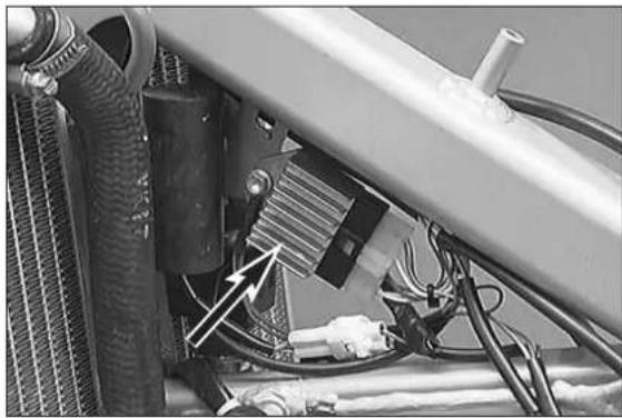
natural_image
Close-up of mechanical components with hoses and wiring, no visible text or symbols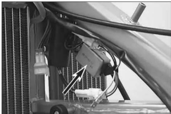
natural_image
Close-up of a car's engine compartment showing hoses, sensors, and a mounted device (no visible text or symbols)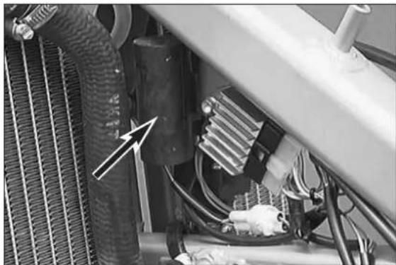
natural_image
Close-up of a car engine bay with visible hoses, springs, and wiring (no text or symbols)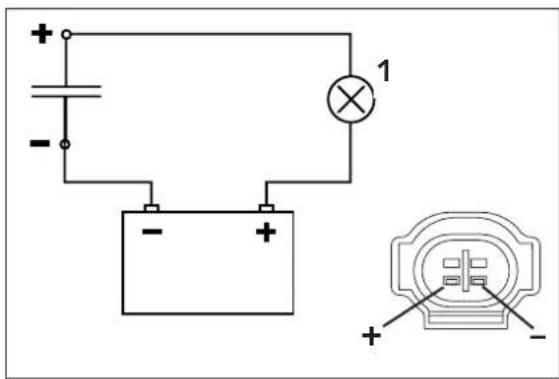
text_image
Electrical circuit diagram with battery, switch, and lamp labeled 1, plus/minus signs for polarityChecking the voltage regulator
- Start the engine and switch on the low beam.
- Connect a voltmeter to the two terminals of the capacitor.
- Accelerate the engine to a speed of 5000 r.p.m. and read off the voltage.
Nominal value: 14.0 - 15.0 V
In the case of a significant deviation from the nominal value:
- Check the capacitor
- Check the connector between the stator and the voltage regulator-rectifier and between the voltage regulator and the cable tree.
- Check the stator.
- Replace the voltage regulator-rectifier.
Checking the voltage regulator
- Start the engine.
- Connect a voltmeter to the two terminals of the capacitor.
- Accelerate the engine to a speed of 5000 r.p.m. and read off the voltage.
Nominal value: 14.0 - 15.0 V
In the case of a significant deviation from the nominal value:
- Check the capacitor
- Check the connector between the stator and the voltage regulator-rectifier and between the voltage regulator and the cable tree.
- Check the stator.
- Replace the voltage regulator-rectifier.
Checking the capacitor
- Discharge the capacitor by bridging the two connections with a cable bridge and dismount it.
- Connect the negative pole of a 12V battery with the negative terminal of the capacitor. The connection between the positive pole of the battery and the positive terminal of the capacitor is made with a test lamp ①.
- When the power circuit is closed, the test lamp must light up briefly and return to its dark state after 1 second at the latest.
- If the test lamp does not go out or does not light up at all, the capacitor is faulty.
STATIC IGNITION VALUES 250-380 SX, EXC (KOKUSAN 2K-1, 2K-3, 2K-4)
Measuring conditions:
- cold engine
- seat and tank removed
– all connectors and the ground connection in a non-corroding condition, connectors tightly connected - spark plug screwed out and spark plug connector attached to ground
– light switch turned off - the gap between the rotor and pulse generator must be set to 0.75 mm
- kick the kick starter forcefully at least 5 times for each measurement
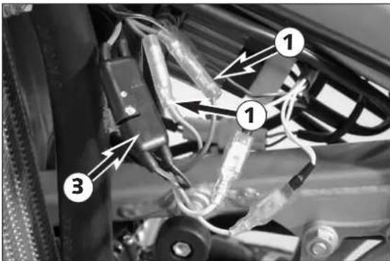
text_image
Labeled mechanical assembly diagram showing three numbered components with wiring and connectorsStatic ignition values 250-380 SX, EXC (except 250 USA)
Check the pulse generator for an output signal – two-pin connector ① with green and red cable colors (also see circuit diagram on opposite page):
- Apply the red measuring lead of the peak voltage adapter to the green cable and the black measuring lead to the red cable, disconnect both connectors ① to disconnect the CDI unit ②
Multimeter display: 6 volts +/- 1 volt
(250 SX model 2000/2001: 5 volts +/- 1 volt)
– Same measurement with CDI unit connected
Multimeter display: 3 volts +/- 1 volt
(250 SX model 2000/2001: 9 volts +/- 1 volt)
Check the generator charging coil for ignition capacitor charge for output voltage – two-pin connector ③ with black/red and red/white cable colors (also see circuit diagram on opposite page):
- Apply the red measuring lead of the peak voltage adapter to the black/red cable and the black measuring lead to the red/white cable, disconnect connector ③ to disconnect the CDI unit ②
Multimeter display: 35 volts +/- 5 volts
– Same measurement with connectors CDI unit connected
Multimeter display: 200 volts +/- 10 volts
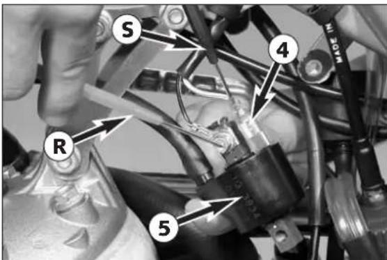
text_image
S R 4 5Check the primary voltage output ④ for ignition coil control (also see circuit diagram on opposite page) for output voltage (blue/white cable color):
- Apply the red measuring lead ① of the peak voltage adapter to the black/white cable (ground) and the black measuring lead ③ to the blue/white cable, CDI unit ② and ignition coil ⑤ connected
Multimeter display: 200 volts +/- 10 volts
NOTE: the ignition coil does not need to be removed to measure.
Repair manual KTM 250 / 300 / 380 Art No 3206004 -E
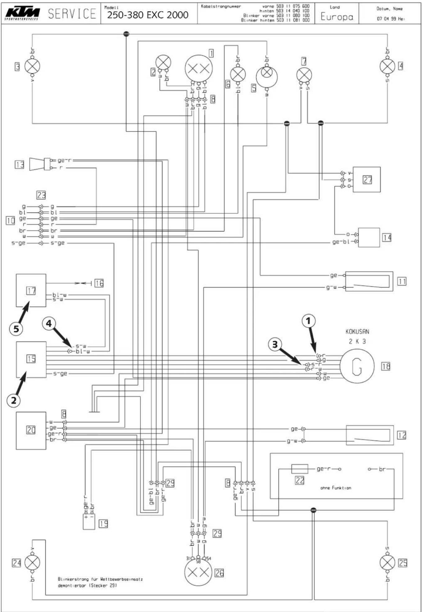
text_image
KTM SPORTHOTROCICIES SERVICE Modeli 250-380 EXC 2000 Kabelstrangnummer vorne 503 11 075 600 hinten 503 14 040 100 Blinker vorne 503 11 080 100 Blinker hinten 503 11 081 000 Land Europa Datum, Name 07.04.99 Hei 1 2 3 4 5 6 7 8 9 10 11 12 13 14 15 16 17 18 19 20 21 22 23 24 25 26 27 28 29 30 31 32 33 34 35 36 37 38 39 40 41 42 43 44 45 46 47 48 49 50 51 52 53 54 55 56 57 58 59 60 61 62 63 64 65 66 67 68 69 70 71 72 73 74 75 76 77 78 79 80 81 82 83 84 85 86 87 88 89 90 91 92 93 94 95 96 97 98 99STATIC GENERATOR VALUES 250-380 EXC (KOKUSAN 2K-3)
Measuring conditions:
- cold engine
- seat and tank removed
– all connectors and the ground connection in a non-corroding condition, connectors tightly connected
– light switch turned off - kick the kick starter forcefully at least 5 times for each measurement
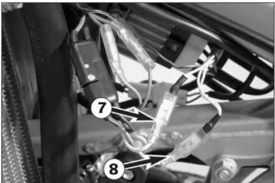
natural_image
Close-up of automotive electrical wiring and components (no visible text or symbols)Static generator values 250-380 EXC (except 250 USA)
Check the generator output ⑥ (also see circuit diagram on opposite page) for voltage between the following cable colors:
- between yellow and brown (ground), connector ⑦ disconnected
Multimeter display (250): 19 volts +/- 2 volts
- between white and brown (ground), connector ⑧ disconnected
Multimeter display (250): 24 volts +/- 2 volts
- Repeat both measurements with connector ⑦ and ⑧ connected. The measured values should be the same.
NOTE: the black measuring lead of the peak voltage adapter must be applied to the ground.
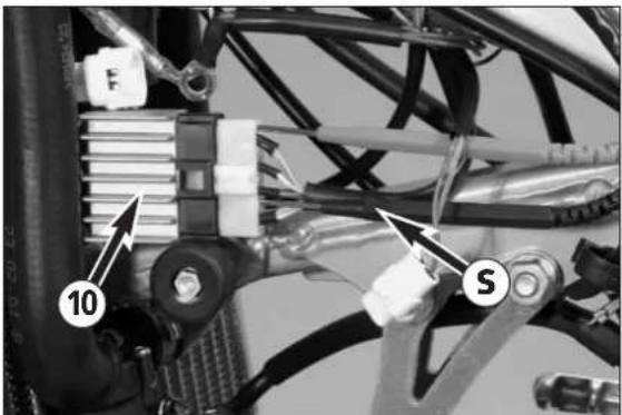
text_image
10 SCheck regulator rectifier output voltage ⑨ (also see circuit diagram on opposite page) cable colors yellow/red, regulator rectifier ⑩ connected, capacitor ⑪ disconnected:
- between yellow/red and brown (ground)
Multimeter display: 14 volts +/- 1 volt
NOTE:
- the black measuring lead Ⓠ of the peak voltage adapter must be applied to the ground.
- 300/380 USA corresponds to 300/380 EXC Europe but with less accessories (blinkers, horn, no capacitor installed). Features no rectification, only an over-voltage regulation.
Repair manual KTM 250 / 300 / 380 Art No 3206004 -E
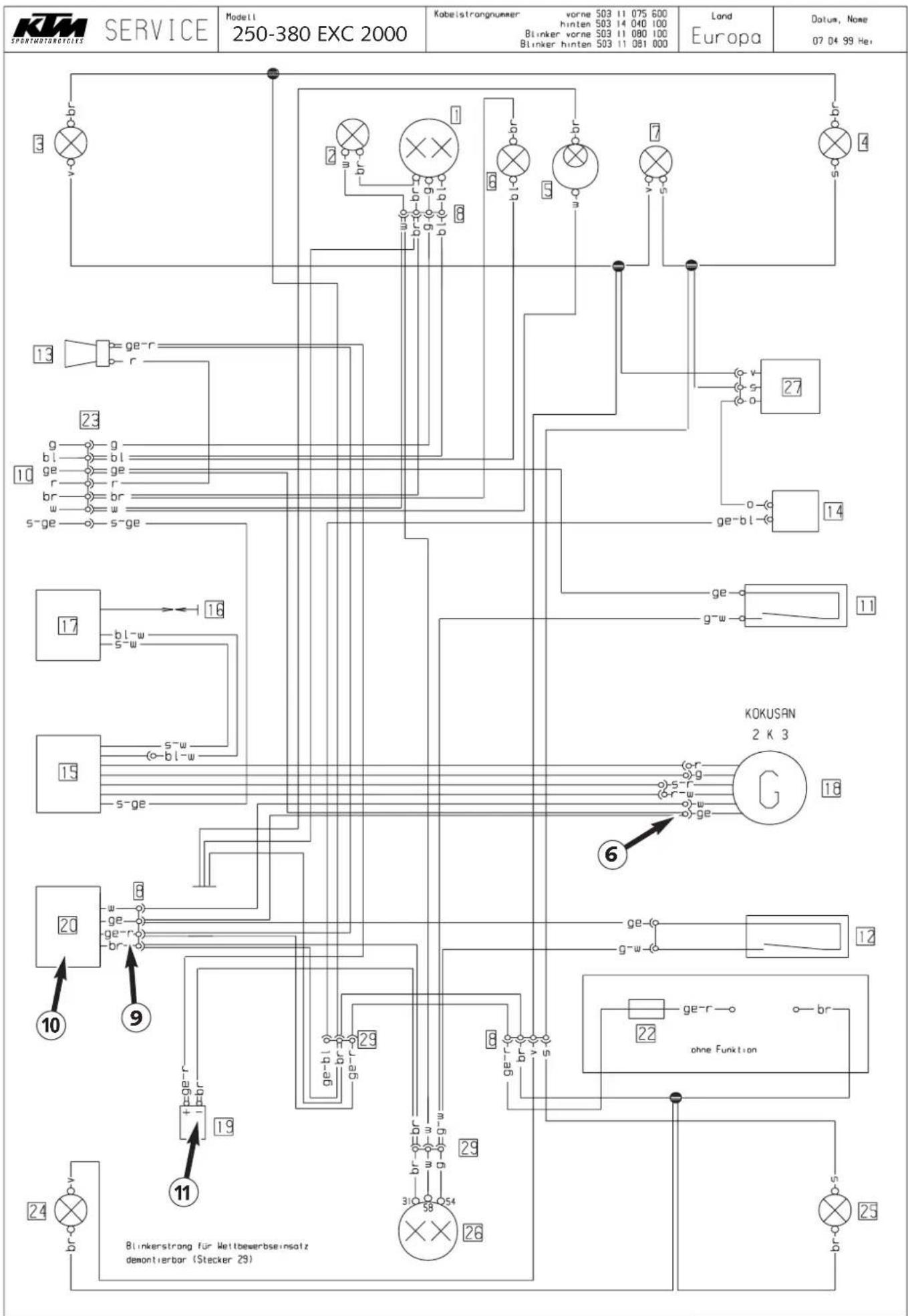
text_image
KTM SPORTMOTORcycles SERVICE Modeli 250-380 EXC 2000 Kabelstrongnummer vorne 503 11 075 600 hinten 503 14 040 100 Blinker vorne 503 11 080 100 Blinker hinten 503 11 081 000 Land Europa Datum, Nome 07 04 99 Hz 13 ge-r r 23 g-g bl-bl ge-ge r-r br-br s-ge-s-ge 17 bl-w s-w 15 s-w o-bl-w s-ge 20 w- ge-r ge-r br- ge-r ge-bi gr ge-r ohne Funktion 19 11 24 v-v br Blinkerstrang für Wettbewerbsensatz demontierbar (Stecker 29) 26 31C 58 29 29 22 ge-r br- G 18 12 6 11 14 27 4STATIC IGNITION AND GENERATOR VALUES 250 MXC, EXC USA(KOKUSAN 2K-2)
Measuring conditions:
- cold engine
- seat and tank removed
– all connectors and the ground connection in a non-corroding condition, connectors tightly connected - spark plug screwed out and spark plug connector attached to ground
– light switch turned off - the gap between the rotor and pulse generator must be set to 0.75 mm
- kick the kick starter forcefully at least 5 times for each measurement
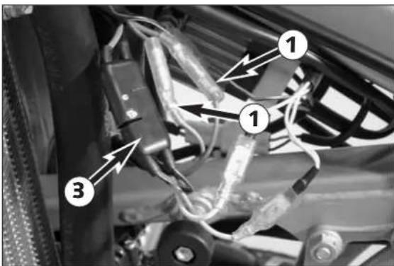
text_image
Labeled mechanical assembly diagram showing three numbered components with wiring and connectorsStatic ignition values 250 MXC, EXC USA
Check the pulse generator for an output signal – two one-pin connectors with green and red cable colors (also see circuit diagram on opposite page):
- Apply the red measuring lead of the peak voltage adapter to the green cable and the black measuring lead to the red cable, disconnect both connectors ① to disconnect the CDI unit ②
Multimeter display: 3.5 volts +/- 1 volt
- Same measurement with CDI unit connected
Multimeter display: 2 volts +/- 0.5 volt
Check the generator charging coil for ignition capacitor charge for output voltage – two-pin connector ③ with black/red and red/white cable colors (also see circuit diagram on opposite page)
- apply the red measuring lead of the peak voltage adapter to the black/red cable and the black measuring lead to the red/white cable, disconnect connector ③ to disconnect the CDI unit ②
Multimeter display: 45 volts +/- 5 volts
– Same measurement with connectors CDI unit connected
Multimeter display: 220 volts +/- 10 volts
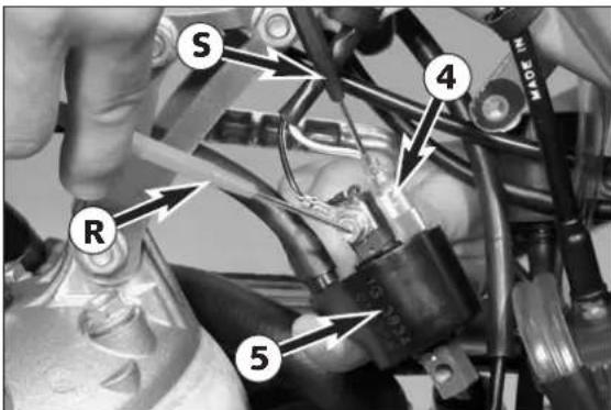
text_image
S R 4 5Check the primary voltage output ④ for ignition coil control (also see circuit diagram on opposite page) for output voltage (blue/white cable color):
- apply the red measuring lead ⑧ of the peak voltage adapter to the black/white cable (ground) and the black measuring lead ⑨ to the blue/white cable, CDI unit ② and ignition coil ⑤ connected
Multimeter display: 210 volts +/- 10 volts
NOTE: the ignition coil does not need to be removed to measure.
Static generator values 250 MXC, EXC USA
Check the generator output ⑥ for the lighting system (also see circuit diagram on opposite page) for voltage:
- between yellow and brown (ground), connector disconnected
Multimeter display: 10.5 volts +/- 1 volt
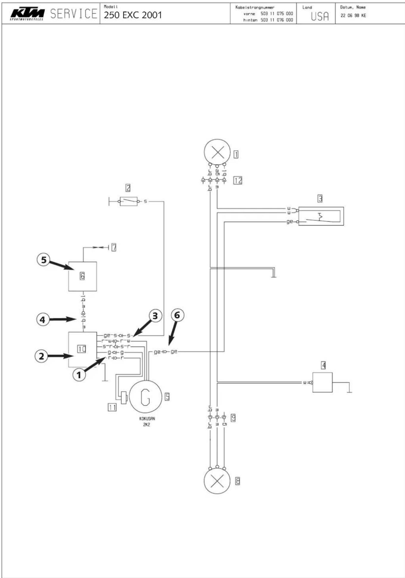
other
| Component | Value | |-----------|-------| | KOMUSRN 2k2 | 1 | | GE-4o-GE | 3 | | GE-4o-GE | 6 | | GE-4o-GE | 11 | | GE-4o-GE | 12 | | GE-4o-GE | 13 | | GE-4o-GE | 14 | | GE-4o-GE | 15 | | GE-4o-GE | 16 | | GE-4o-GE | 17 | | GE-4o-GE | 18 | | GE-4o-GE | 19 | | GE-4o-GE | 20 | | GE-4o-GE | 21 | | GE-4o-GE | 22 | | GE-4o-GE | 23 | | GE-4o-GE | 24 | | GE-4o-GE | 25 | | GE-4o-GE | 26 | | GE-4o-GE | 27 | | GE-4o-GE | 28 | | GE-4o-GE | 29 | | GE-4o-GE | 30 | | GE-4o-GE | 31 | | GE-4o-GE | 32 | | GE-4o-GE | 33 | | GE-4o-GE | 34 | | GE-4o-GE | 35 | | GE-4o-GE | 36 | | GE-4o-GE | 37 | | GE-4o-GE | 38 | | GE-4o-GE | 39 | | GE-4o-GE | 40 | | GE-4o-GE | 41 | | GE-4o-GE | 42 | | GE-4o-GE | 43 | | GE-4o-GE | 44 | | GE-4o-GE | 45 | | GE-4o-GE | 46 | | GE-4o-GE | 47 | | GE-4o-GE | 48 | | GE-4o-GE | 49 | | GE-4o-GE | 50 | | GE-4o-GE | 51 | | GE-4o-GE | 52 | | GE-4o-GE | 53 | | GE-4o-GE | 54 | | GE-4o-GE | 55 | | GE-4o-GE | 56 | | GE-4o-GE | 57 | | GE-4o-GE | 58 | | GE-4o-GE | 59 | | GE-4o-GE | 60 | | GE-4o-GE | 61 | | GE-4o-GE | 62 | | GE-4o-GE | 63 | | GE-4o-GE | 64 | | GE-4o-GE | 65 | | GE-4o-GE | 66 | | GE-4o-GE | 67 | | GE-4o-GE | 68 | | GE-4o-GE | 69 | | GE-4o-GE | 70 | | GE-4o-GE | 71 | | GE-4o-GE | 72 | | GE-4o-GE | 73 | | GE-4o-GE | 74 | | GE-4o-GE | 75 | | GE-4o-GE | 76 | | GE-4o-GE | 77 | | GE-4o-GE | 78 | | GE-4o-GE | 79 | | GE-4o-GE | 80 | | GE-4o-GE | 81 | | GE-4o-GE | 82 | | GE-4o-GE | 83 | | GE-4o-GE | 84 | | GE-4o-GE | 85 | | GE-4o-GE | 86 | | GE-4o-GE | 87 | | GE-4o-GE | 88 | | GE-4o-GE | 89 | | GE-4o-GE | 90 | | GE-4o-GE | 91 | | GE-4o-GE | 92 | | GE-4o-GE | 93 | | GE-4o-GE | 94 | | GE-4o-GE | 95 | | GE-4o-GE | 96 | | GE-4o-GE | 97 | | GE-4o-GE | 98 | | GE-4o-GE | 99 | | GE/KE Service (Service) - Model: Model: Model: Model: Model: Model: Model: Model: Model: Model: Model: Model: Model: Model: Model: Model: Model: Model: Model: Model: Model: Model: Model: Model: Model: Model: Model: Model: Model: Model: Model: Model: Model: Model: Model: Model: Model: Model: Model: Model: Model: Model: Model: Model: Model: Model: Model: Model: Model: Model: Model, Model, Model, Model, Model, Model, Model, Model, Model, Model, Model, Model, Model, Model, Model, Model, Model, Model, Model, Model, Model, Model, Model, Model, Model, Model, Model, Model, Model, Model, Model, Model, Model, Model, Model, Model, Model, Model, Model, Model, Model, Model, Model, Model, Model, Model, Model, Model, Model, Model, ModelRepair manual KTM 250 / 300 / 380 Art No 3206004 -E
TROUBLE SHOOTING
8
INDEX
TROUBLE SHOOTING 250 - 380 .....8-2
TROUBLE SHOOTING
If you let the specified maintenance work on your motorcycle be carried out, disturbances can hardly be expected. Should an error occur nevertheless, we advise you to use the trouble shooting chart in order to find the cause of error.
| TROUBLE | CAUSE | REMEDY |
| Engine fails to start | Operating errorFuel supply interruptedElectrode distance too greatPlug fouled by oil, wet or bridgedIgnition wire or spark plug connector damagedKill button wire or short-circuit switch faultyLoose ignition cable connectorsSpark too weakWater in the carburetor and jets blocked | Open fuel tap, switch o ignition, replenish fuel, do not use chokeClose fuel tap, loosen fuel hose at carburettor, lead into a basin and open fuel tap,– if fuel leaks out, clean carburettor– if no fuel leaks out, check tank ventilation, i.e. clean fuel tapReduce electrode distance (0.60 mm)Clean spark plug or renewDismount spark plug, connect ignition cable, hold to ground (blank place on engine) and actuate kickstarter, a strong spark must be produced at the spark plug– If no spark is produced, loosen spark plug cap from ignition cable, hold about 5 mm from ground and actuate kickstarter– If a spark now occurs, replace spark plug cap– If no spark is produced, check ignition systemDisconnect yellow-black coloured cable from CDI and check ignition spark. If the spark is O.K. repair defective part of cable, ignition lock or ignition switchInspect cable connectorsExamine ignition systemDismantle and clean carburetor |
| Engine without idle running | Idle adjusting screw out of adjustmentIgnition system damagedWear | Readjust idle running or replace idle adjusting screwExamine ignition systemOverhaul engine |
| Engine has not enough power | Charred glass fiber yarn in silencerAir filter obstructedControl flap does not workFuel supply partly interrupted or blockedLoss of compression through loose spark plugExhaust system damagedEngine has not enough preignition | Renew fillingClean or renew airfilterCheck control flap, joint rod and centrifugal timerBlow through fuel pipe and clean carburetorTighten spark plugCheck exhaust system for damageCheck and adjust ignition |
| Engine has not enough power | Reed paddles tensionless or damaged, surface of reed valve housing damagedWearElectronical ignition timing faulty | Replace reed paddles or reed valve housingOverhaul engineCheck ignition system |
| Engine revs not high and running with four stroke cycle | Carburetor overflows if level adjust too high, float needle seating is dirty or enlargedLoose carburetor jets | Clean carburetor, if necessary replace float needle and adjust levelTighten jets |
| High rpm misfiring | Incorrect heat range spark plug or low quality spark plugIncorrect or faulty spark plug connectorLoose, corroded or non conductive ignition socket connector | Refer to technical data sectionTest and/or replace spark plug connectors correct typeCheck and seal with silicon |
| Engine spluters into the carburetor | Lack of fuelSpark plug with incorrect heat value (Ignition by incandescence)Engine takes air out of control | Clean fuel pipes, examine tank aeration and cleanFit correct spark plugCheck intake flange and carburettor if firmly setted |
| Engine overheating | Insufficient liquid in cooling systemCooling system not or insufficiently bleededRadiator fins cloggedFrothing in cooling systemPinched or kinked water hosesIncorrect ignition timing because of loose stator boltsIncorrect dimension „X“ | Top up coolant and bleed cooling system check cooling system for leaksBleed cooling system (see operating instructions)Clean radiator fins with water jetRenew coolant using branded anti-freeze/anti-corrosiveReplace with correct routed hosesReadjust to correct ignition timing specifications, secure screws properly with Loctite 243Measure and adjust to correct specification |
| Emission of white smoke (steam) | Cylinder head or O-ring of cylinder head gasket leaks | Check cylinder head, replace O-ring |
| Excessive oil escapes from transmission breather tube | Excessive oil quantity in transmissionWater pump shaft seal ring or right-hand crankshaft seal ring defectSilicon O-rings of control roller or of control flap leaks | Correct transmission oil levelReplace shaft seal ring and change gear oil, check coolantReplace O-rings |
| All switched on lamps blown out | Voltage regulator faulty | Control connections of voltage regulator. Check voltage regulator |
TECHNICAL SPECIFICATIONS
9
INDEX
MODEL 1999
ENGINE 250 - 380 USA .....9-2
ENGINE 250 - 380 .....9-4
CHASSIS 250 - 380 .....9-6
CARBURETOR SETTINGS 9-7
MODEL 2000
ENGINE 250 - 380 USA .....9-10
ENGINE 250 - 380 9-12
CHASSIS 250 - 380 .....9-14
CARBURETOR SETTINGS 9-15
MODEL 2001
ENGINE 250 - 380 USA .....9-19
ENGINE 250 - 380 . . . . . . . . . . . . . . . . . . . . . . . . . . . . . . . . . . . . . . . . . . . . . . . . . . . . . . . . . . . . . . . . . . . . . . . . . . . . .9-21
CHASSIS 250 - 380 .....9-23
CARBURETOR SETTINGS 9-24
MODEL 2002
ENGINE 250 - 380 USA .....9-28
ENGINE 250 - 380 .9-30
CHASSIS 250 - 380 .....9-32
CARBURETOR SETTINGS 9-33
MODEL 2003
ENGINE 250 - 300 9-37
CHASSIS 250 - 300 .....9-39
CARBURETOR SETTINGS 9-41
TECHNICAL SPECIFICATIONS - ENGINE 250/300/380 SX/MXC/EXC '99 (only for USA)
| Engine 250 SX 250 EXC | MXC 300 EXC, MXC 380 SX 380 | EXC, MXC | |||
| Design | Liquid-cooled single-cylinder two-stroke engine with KTM Twin Valve Control exhaust system and KTM Torque Chamber | ||||
| Piston displacement 249 | ccm 297 ccm 368 ccm | ||||
| Bore / stroke 67.5 / 69.5 mm (2.66 / 2.74 in) 72 / 73 mm (2.84 / 2.88 in) 78 / 77 mm (3 / 2.98 in) | |||||
| Fuel SUPER fuel, research octane no 95, mixed with high-grade two stroke oil (Shell Advance Racing X) | |||||
| Oil / gasolin ratio | 1:50 - 1:60 when using high grade two stroke oil. When in doupt, please contact your importer or use 1:40 mix ratio to be on the safe side | ||||
| Crankshaft bearing 1 deep-groove ball bearing / 1 cylinder roller bearing | |||||
| Connecting rod bearing | needle bearing | ||||
| Piston pin bearing needle bearing | |||||
| Piston | cast piston | forged piston | cast piston | ||
| Piston ring | two plain compression rings | ||||
| Dimension "X" (upper edge piston - upper edge cylinder) | 0 mm +0.1 mm (0 in +0.004 in) | ||||
| Ignition timing | 1.8 mm (0.07 in) (17 °) BTDC | 2.0 mm (0.08 in) (17°) BTDC | 2.2 mm (0.09 in) (17 °) BTDC | ||
| Spark plug | NGK BR 8 ECM | ||||
| Electrode gap | 0.6 mm (0.024 in) | ||||
| Dimension "Z" (height of the control flap) | 48 mm (1.9 in) | 46 mm (1.7 in) | 50.5 mm (1.99 in) | ||
| TVC start open | 5400/min | 5300/min | 5200/min | ||
| TVC fully open | 7550/min | 7750/min | 7200/min | ||
| Primary drive | straight cut spur gears, primary ratio 25:72 | straight cut spur gears, primary ratio 26:72 | |||
| Clutch | multiple disc clutch in oil bath, hydraulic operated (Shell HF-E15) | ||||
| Transmission | 5 speed, claw actuated | ||||
| Gear ratio | EXC M-XC | EXC MXC | |||
| 1^st Gear | 15:29 | 15:29 | 15:29 | 15:29 | 15:29 |
| 2^nd Gear | 17:27 | 18:26 | 18:26 | 18:26 | 18:26 |
| 3^rd Gear | 19:25 | 19:22 | 19:24 | 19:24 | 19:22 |
| 4^th Gear | 21:23 | 21:20 | 21:23 | 21:23 | 21:20 |
| 5^th Gear | 23:21 | 23:18 | 23:21 | 23:21 | 23:18 |
| Gear lubrication | 0.8 l engine oil 20W-40 (Shell Advance VSX4) | ||||
| Available chain sprockets | 13t / 14t / 15t for chain 58 × 14" | ||||
| Coolant | 1.3 litres, 40% anti freeze, 60% water, at least -25 °C (-13 °F) | ||||
| Ignition system | KOKUSAN 2K-1 | KOKUSAN 2K-2 | KOKUSAN 2K-1 | KOKUSAN 2K-2 | |
| Generator output | no generator | 12V 40W | no generator | 12V 40W | |
| Carburetor | flat-slide carburetor, carburetor setting see table 3 | ||||
| Air-filter | wet foam type air filter insert | ||||
| TIGHTENING TORQUES | ||
| Flange bolts - cylinder-head M 8 35 Nm (25 ft.lb) | ||
| Nuts-cylinder base M 10 35 Nm (25 ft.lb) | ||
| Flywheel collar nut M 12x1 60 Nm (44 ft.lb) | ||
| Nut for primary sprocket (LH thread) M 18x1.5 Loctite 243 150 Nm (110 ft.lb) | ||
| Nut for inner clutch hub M 18x1.5 Loctite 243 100 Nm (74 ft.lb) | ||
| Crankcase and cover bolts M 6 8 Nm (6 ft.lb) | ||
| Swingarm pivot | M 14 | 100 Nm (74 ft.lb) |
| Flat head bolt release plate kickstarter | M 6x16 | Loctite 648 19 Nm (14 ft.lb) |
| Other bolts | M 6 10 Nm (7 ft.lb)M 8 25 Nm (19 ft.lb)M 10 | 45 Nm (33 ft.lb) |
| TOLERANCES AND FITTING CLEARANCES | |
| Piston fitting clearance | 0.05 mm (250) 0.06 mm (300) 0.08 mm (380) |
| Piston ring end gap | 0.3–0.4 mm |
| Connecting rod bearing - radial clearance | 0.021–0.032 mm |
| Transmission shafts end float | 0.1–0.2 mm |
| Clutch springs - length | ∅ 2.5 new = 43 mm, minimum length = 42 mm |
| GASKET THICKNESSES | |
| Crankcase | 0.5 mm |
| Clutch cover | 0.5 mm |
| Cylinder bottom gasket | as required |
| Available cylinder bottom gaskets | 0.2/0.4/0.5/0.7 mm |
| Cylinder-head gasket | O-rings |
| TABLE 3 | BASIC CARBURETOR SETTING | |||
| 250 SX | 250 MXC, EXC300 MXC, EXC | 380 SX, MXC, EXC | ||
| Carburetor | Keihin PWK 38 | Keihin PWK 38 | Keihin PWK 38 | |
| Carburetor setting number | 090598 | 100598 | 070598 | |
| Main jet | 172(168,170,175) | 175(170,172,178) | 170(168,172,175) | |
| Idling jet | 45(48,50) | 45(42,48) | 48(45,50) | |
| Starting jet | 85 | 85 | 85 | |
| Jet needle | NOZ G(NOZ H,NOZ I) | N85 C(N85 D) | NOZ H(NOZ G,NOZ I) | |
| Needle position from top | II | III | II | |
| Throttle valve | 6 | 6 | 6 | |
| Air adjustment screw open | 1,5 | 1,5 Umdr. | 1,5 Umdr. | |
TECHNICAL SPECIFICATIONS - ENGINE 250/300/380 SX/EXC/EGS '99 (all models out of USA)
| Engine 250 SX 250 EXC | EGS 300 EXC, EGS 380 SX 380 EXC, EGS | ||||
| Design | Liquid-cooled single-cylinder two-stroke engine with KTM Twin Valve Control exhaust system and KTM Torque Chamber | ||||
| Piston displacement 249 | ccm 297 ccm 368 ccm | ||||
| Bore / stroke 67.5 / 69.5 mm (2.66 / 2.74 in) 72 / 73 mm (2.84 / 2.88 in) 78 / 77 mm (3 / 2.98 in) | |||||
| Fuel SUPER fuel, research octane no 95, mixed with high-grade two stroke oil (Shell Advance Racing X) | |||||
| Oil / gasoline ratio | 1:50 - 1.60 when using high grade two stroke oil. When in doupt, please contact your importer or use 1:40 mix ratio to be on the safe side | ||||
| Crankshaft bearing 1 deep-groove ball bearing / 1 cylinder roller bearing | |||||
| Connecting rod bearing | needle bearing | ||||
| Piston pin bearing needle bearing | |||||
| Piston cast piston | forged piston | cast piston | |||
| Piston ring | two plain compression rings | ||||
| Dimension "X" (upper edge piston - upper edge cylinder) | 0 + 0.1 mm (0 + 0.004 in) | ||||
| Ignition timing | 1,9 mm (0.07 in) (17 °) BTDC | 1.2 mm (0.05 in) (13.5 °) BTDC | 1.2 mm (0.05 in) (13.5 °) BTDC | 2.1 mm (0.08 in) (17 °) BTDC | 1.4 mm (0.06 in) (14,5°) BTDC |
| Spark plug | NGK BR 8 ECM | ||||
| Electrode gap | 0.6 mm (0.024 in) | ||||
| Dimension "Z" (incight of the control flap) | 48 mm (1.9 in) | 46 mm (1.7 in) | 50.5 mm (1.99 in) | ||
| TVC start open | 5400/min | 5300/min | 5200/min | ||
| TVC fully open | 7550/min | 7750/min | 7200/min | ||
| Primary drive | straight cut spur gears, primary ratio 25:72 | straight cut spur gears, primary ratio 26:72 | |||
| Clutch | multiple disc clutch in oil bath, hydraulic operated (Shell HF-E15) | ||||
| Transmission | 5 speed, claw actuated | ||||
| Gear ratio | |||||
| 1^st Gear | 15:29 | 15:29 | 15:29 | 15:29 | |
| 2^nd Gear | 17:27 | 18:26 | 18:26 | 18:26 | |
| 3^rd Gear | 19:25 | 19:22 | 19:24 | 19:22 | |
| 4^th Gear | 21:23 | 21:20 | 21:23 | 21:20 | |
| 5^th Gear | 23:21 | 23:18 | 23:21 | 23:18 | |
| Gear lubrication | 0,8 l engine oil 20W-40 (Shell Advance VSX4) | ||||
| ailable chain sprockets | 13t / 14t / 15t for chain ^5/_8x^3/_4" | ||||
| Coolant | 1.3 litres, 40% anti freeze, 60% water, at least -25 °C (-13 °F) | ||||
| Ignition system | KOKUSAN 2K-1 | SEM K11 | KOKUSAN 2K-1 | SEM K11 | |
| Generator output | no generator | 12V 130W | no generator | 12V 130W | |
| Carburetor | flat-slide carburetor, carburetor setting see table 4 | ||||
| Air-filter | wet foam type air filter insert | ||||
| TIGHTENING TORQUES | ||
| Flange bolts - cylinder-head M 8 35 Nm (25 ft.lb) | ||
| Nuts-cylinder base M 10 35 Nm (25 ft.lb) | ||
| Flywheel collar nut M 12x1 60 Nm (44 ft.lb) | ||
| Nut for primary sprocket (LH thread) M 18x1.5 Loctite 243 150 Nm (110 ft.lb) | ||
| Nut for inner clutch hub M 18x1.5 Loctite 243 100 Nm (74 ft.lb) | ||
| Crankcase and cover bolts M 6 8 Nm (6 ft.lb) | ||
| Swingarm pivot | M 14 | 100 Nm (74 ft.lb) |
| Flat head bolt release plate kickstarter | M 6x16 | Loctite 648 19 Nm (14 ft.lb) |
| Other bolts | M 6 10 Nm (7 ft.lb)M 8 25 Nm (19 ft.lb)M 10 | 45 Nm (33 ft.lb) |
| TOLERANCES AND FITTING CLEARANCES | |
| Piston fitting clearance | 0.05 mm (250) 0.06 mm (300) 0.08 mm (380) |
| Piston ring end gap | 0.3–0.4 mm |
| Connecting rod bearing - radial clearance | 0.021–0.032 mm |
| Transmission shafts end float | 0.1–0.2 mm |
| Clutch springs - length | 2.5 new = 43 mm, minimum length = 42 mm |
| GASKET THICKNESSES | |
| Crankcase | 0.5 mm |
| Clutch cover | 0.5 mm |
| Cylinder bottom gasket | as required |
| Available cylinder bottom gaskets | 0.2/0.4/0.5/0.7 mm |
| Cylinder-head gasket | O-rings |
| TABLE 4 | BASIC CARBURETOR SETTING | |||||
| 250 SX | 250 MXC, EXC300 MXC, EXC | 250/300 EGS AUSTRALIA | 380 SX, MXC, EXC | 380 EGS AUSTRALIA | ||
| Carburetor | Keihin PWK 38 | Keihin PWK 38 | Keihin PWK 38 | Keihin PWK 38 | Keihin PWK 38 | |
| Carburetor setting number | 090598 | 100598 | 100598 | 070598 | 060598 | |
| Main jet | 172(168,170,175) | 175(170,172,178) | 175(170,172,178) | 170(168,172,175) | 175(168,170,172) | |
| Idling jet | 45(48,50) | 45(42,48) | 45(42,48) | 48(45,50) | 45(48,50) | |
| Starting jet | 85 | 85 | 85 | 85 | 85 | |
| Jet needle | NOZ G(NOZ H,NOZ I) | N85 C(N85 D) | N85 C(N85 D) | NOZ H(NOZ G,NOZ I) | NOZ G(NOZ H,NOZ I) | |
| Needle position from top | II | III | III | II | II | |
| Throttle valve | 6 | 6 | 6 | 6 | 6 | |
| Air adjustment screw open | 1,5 | 1,5 Umdr. | 1,5 Umdr. | 1,5 Umdr. | 1,5 Umdr. | |
| Performance restrictor | - | - | slide stop 31mm | - | slide stop 36mm | |
TECHNICAL SPECIFICATIONS CHASSIS 250 / 300 / 380 SX / MXC / EXC / EGS '99
| 250/380SX 250/3 | 00/380 MXC 250/300/380 | EXC 250/300/380 EGS | ||
| Frame Central chrome-moly-steel frame | ||||
| Fork WP Extreme ∅ 50 mm | ||||
| Wheel travel front/rear 230 / 320 mm (11.0 / 12.6 in) | ||||
| Rear suspension | WP Progressive Damping System shock absorber, aluminium swingarm | |||
| Front brake Disc brake with carbon-steel brake disc ∅ 260 mm (10.2 in), brake caliper floated | ||||
| Rear brake Disc brake with carbon-steel brake disc ∅ 220 mm (8.7 in), brake caliper floated | ||||
| Front tires 80/100 - 21" | 51M 80/100 - 21" 51M 90/9 | 0 - 21" 54R 90/90 - 21" 54R | ||
| - | - | 80/100 - 21" 51M | - | |
| Air pressure offroad | 1.0 bar (14 psi) | 1.0 bar (14 psi) | 1.0 bar (14 psi) | 1.0 bar (14 psi) |
| Air press. road driver only | - | - | 1.5 bar (21 psi) | 1.5 bar (21 psi) |
| Rear tires | 110/90 - 19" 62M | 110/100 - 18" 64M | 140/80 - 18" 70R | 140/80 - 18" 70R |
| - | - | 110/100 - 18" 64M | - | |
| Air pressure offroad | 1.0 bar (14 psi) | 1.0 bar (14 psi) | 1.0 bar (14 psi) | 1.0 bar (14 psi) |
| Air press. road driver only | - | - | 2.0 bar (28 psi) | 2.0 bar (28 psi) |
| Fuel tank capacity | 7.5 liter(2 US gallons) | 12 liter(3.2 US gallons) | 9.5 or 12 liter(2.5 or 3.2 US gallons) | 9.5 or 12 liter(2.5 or 3.2 US gallons) |
| Final drive ratio | 14:50 | 14:52 | 14:50 / 14:52 | 14:50 / 15:48 |
| Chain | 5/8 x 1/4" | |||
| Available final sprockets | 38, 40, 42, 45, 48, 50, 52 | |||
| Steering head angle | 63.5° | |||
| Wheel base | 1481 ± 10 mm (58.3 ± 0.4 in) | |||
| Seat height, unloaded | 925 mm (36.4 in) | |||
| Ground clearance, unloaded | 385 mm (15 in) | |||
| Dead-weight without fuel | 101 kg (223 lbs) | 102.5 kg (226.3 lbs) | 103.7 kg (229 lbs) | 109 kg (240.6 lbs) |
STANDARD ADJUSTMENT - FORK
| WP 918T768 WP | 918T769 | |
| Compression adjuster | 12 | 12 |
| Rebound adjuster 12 | 12 | |
| Spring | 4.2 N/mm | 4.0 N/mm |
| Spring preload | 5 mm (0.2 in) | 5 mm (0.2 in) |
| Air chamber length | 150 mm (5.9 in) | 155 mm (6.1 in) |
| Capacity per fork leg | approx. 750 ccm | approx. 750 ccm |
| Fork oil | SAE 5 | SAE 5 |
NOTE:
The damping units in the left and the right fork leg are of different design. Make sure not to mix them up in case of repair or service jobs.
STANDARD-ADJUSTMENT - SHOCK ABSORBER
| WP 1218T712 | WP 1218T714 | |
| Compression adjuster | 5 | 6 |
| Rebound adjuster | 14 | 12 |
| Spring | PDS3-250 | PDS2-250 |
| Spring preload | 5 mm (0.20 in) | 6 mm (0.23 in) |
TORQUES
| Collar bolt front wheel spindle | M 10 | 40 Nm (30 ft.lb) |
| Brake caliper front | M 8 | 25 Nm (19 ft.lb)+ Loctite 243 |
| Clamping bolts upper fork bridge | M 8 | 15 Nm (11 ft.lb) |
| Clamping bolts lower fork bridge | M 8 | 20 Nm (15 ft.lb) |
| Clamping bolts fork stubs | M 8 | 15 Nm (11 ft.lb) |
| Collar nut rear wheel spindle | M 20x1,5 | 80 Nm (59 ft.lb) |
| Hexagon nut swing arm bolt | M 14x1,5 | 100 Nm (74 ft.lb) |
| Shock absorber top | M 12 | 60 Nm (44 ft.lb) |
| Shock absorber bottom | M 12 | 40 Nm (30 ft.lb) |
| Other bolts on chassis | M 6 | 10 Nm (7 ft.lb) |
| M 8 | 25 Nm (19 ft.lb) | |
| M 10 | 45 Nm (33 ft.lb) |
The clamping bolts of the fork plates must be tightened in several (3) steps. Otherwise, the bolts might come loose.
VERGASERREGULIERUNG KTM 250/300 MXC/EXC EU, USA'99 KEIHIN PWK 38 CARBURETOR SETTING
Fuel: Super unleaded ROZ 95
Fuel: Super unleaded ROZ 95
text_image
1. 2. 3. 4. 5.| Engine 250 SX 250 EXC | MXC 300 EXC, MXC 380 SX 380 | EXC, MXC | |||
| Design | Liquid-cooled single-cylinder two-stroke engine with KTM Twin Valve Control exhaust system and KTM Torque Chamber | ||||
| Piston displacement 249 | ccm 297 ccm 368 ccm | ||||
| Bore / stroke 66.4 / 72 | mm (2.62 / 2.84 in) 72 / 73 mm (2.84 / 2.88 in) 78 / 77 mm (3 / 2) 98 in) | ||||
| Fuel unleaded SUPER fuel, research octane no 95, mixed with high-grade two stroke oil (Shell Advance Racing X) | |||||
| Oil / gasolin ratio | 1:40 - 1:60 when using high grade two stroke oil. When in doupt, please contact your importer or use 1:40 mix ratio to be on the safe side | ||||
| Crankshaft bearing 1 deep-groove ball bearing / 1 cylinder roller bearing | |||||
| Connecting rod bearing | needle bearing | ||||
| Piston pin bearing needle bearing | |||||
| Piston | cast piston | forged piston | cast piston | ||
| Piston ring | one plain compression rings | two plain compression rings | |||
| Dimension "X" (top edge) | 0 +0.1 mm (0 + 0.004 in) | ||||
| Ignition timing | 2.0 mm (0.07 in) (17 °) BTDC | 2.2 mm (0.09 in) (17 °) BTDC | |||
| Spark plug | NGK BR 8 ECM | ||||
| Electrode gap | 0.6 mm (0.024 in) | ||||
| Dimension "Z" (top edge) | 50,5 mm (1.99 in) | 46 mm (1.7 in) | 50.5 mm (1.99 in) | ||
| TVC start open | 5000/min | 5300/min | 5200/min | ||
| TVC fully open | 7500/min | 7750/min | 7200/min | ||
| Primary drive | straight cut spur gears, primary ratio 25:72 | straight cut spur gears, primary ratio 26:72 | |||
| Clutch | multiple disc clutch in oil bath, hydraulic operated (Shell HF-E15) | ||||
| Transmission | 5 speed, claw actuated | ||||
| Gear ratio | EXC | MXC | EXC | MXC | |
| 1^st Gear | 15:29 | 15:29 | 15:29 | 15:29 | 15:29 |
| 2^nd Gear | 17:27 | 18:26 | 17:27 | 18:26 | 18:26 |
| 3^rd Gear | 19:25 | 19:22 | 19:25 | 19:22 | 19:24 |
| 4^th Gear | 21:23 | 21:20 | 21:23 | 21:20 | 21:23 |
| 5^th Gear | 23:21 | 23:18 | 23:21 | 23:18 | 23:21 |
| Gear lubrication | 0.8 l engine oil 20W-40 (Shell Advance VSX4) | ||||
| Available chain sprockets | 13t / 14t / 15t for chain 58 × 14" | ||||
| Coolant | 1.3 litres, 40% anti freeze, 60% water, at least -25 °C (-13 °F) | ||||
| Ignition system | KOKUSAN 2K-4 | KOKUSAN 2K-2 | KOKUSAN 2K-1 | KOKUSAN 2K-3 | |
| Generator output | no generator | 12V 40W | no generator | 12V 110W | |
| Carburetor | flat-slide carburetor, carburetor setting see table | ||||
| Air-filter | wet foam type air filter insert | ||||
| TIGHTENING TORQUES - ENGINE | ||
| Flange bolts - cylinder-head M 8 35 Nm (25 ft.lb) | ||
| Nuts-cylinder base M 10 35 Nm (25 ft.lb) | ||
| Flywheel collar nut M 12x1 60 Nm (44 ft.lb) | ||
| Nut for primary sprocket (LH thread) M 18x1 | 5 Loctite 243 150 Nm (110 ft.lb) | |
| Nut for inner clutch hub M 18x1.5 Loctite 243 | 100 Nm (74 ft.lb) | |
| Crankcase and cover bolts M 6 8 Nm (6 ft.lb) | ||
| Swingarm pivot | M 14 | 100 Nm (74 ft.lb) |
| Flat head bolt release plate kickstarter | M 6x16 | Loctite 648 19 Nm (14 ft.lb) |
| Other bolts | M 6 10 Nm (7 ft.lb)M 8 25 Nm (19 ft.lb)M 10 | 45 Nm (33 ft.lb) |
| TOLERANCES AND FITTING CLEARANCES | |
| Piston fitting clearance | 0.05 mm (250) 0.06 mm (300) 0.08 mm (380) |
| Piston ring end gap | 0.3–0.4 mm |
| Connecting rod bearing - radial clearance | 0.021–0.032 mm |
| Transmission shafts end float | 0.1–0.2 mm |
| Clutch springs - length | ∅ 2.5 new = 43 mm, minimum length = 42 mm |
| GASKET THICKNESSES | |
| Crankcase | 0.5 mm |
| Clutch cover | 0.5 mm |
| Cylinder bottom gasket | as required |
| Available cylinder bottom gaskets | 0.2/0.4/0.5/0.75 mm |
| Cylinder-head gasket | O-rings |
| BASIC CARBURETOR SETTING | ||||
| 250 SX | 250 MXC, EXC | 300 MXC, EXC | 380 SX, MXC, EXC | |
| Carburetor | Keihin PWK 38 AG PJ | Keihin PWK 38 AG | Keihin PWK 38 AG | Keihin PWK 38 AG |
| Carburetor setting number | 110499 | 130499 | 140499 | 150499 |
| Main jet | 172 (170,175) | 180 (178,182) | 175 (172,178) | 170 (168,172) |
| Idling jet | 48 (45,50) | 45 (48) | 45 (48) | 45 (48) |
| Starting jet | 85 | 85 | 85 | 85 |
| Jet needle | NOZ E (NOZ F) | NOZ G (NOZ H) | NOZ H (NOZ I) | NOZ H (NOZ I) |
| Needle position from top | III | III | III | III |
| Slide | 7 | 6 | 6 | 6 |
| Air adjustment screw open | 1,5 | 1,5 | 1,5 | 1,5 |
| Performance restrictor | - | - | - | - |
| Power jet jet | 55 | - | - | - |
TECHNICAL DATA - ENGINE 250/300/380 SX / EXC 2000 (all models out of USA)
| Engine 250 SX 250 EXC | 300 EXC 380 SX 380 EXC | ||||
| Design | Liquid-cooled single-cylinder two-stroke engine with KTM Twin Valve Control exhaust system and KTM Torque Chamber | ||||
| Piston displacement 249 | ccm 297 ccm 368 ccm | ||||
| Bore / stroke 66.4 / 72 | mm (2.62 / 2.84 in) 72 / 73 mm (2.84 / 2.88 in) 78 / 77 mm (3 / 2) 98 in) | ||||
| Fuel unleaded SUPER fuel, research octane no 95, mixed with high-grade two stroke oil (Shell Advance Racing X) | |||||
| Oil / gasoline ratio | 1:40 - 1:60 when using high grade two stroke oil. When in doupt, please contact your importer or use 1:40 mix ratio to be on the safe side | ||||
| Crankshaft bearing 1 deep-groove ball bearing / 1 cylinder roller bearing | |||||
| Connecting rod bearing needle bearing | |||||
| Piston pin bearing | needle bearing | ||||
| Piston | cast piston | forged piston | cast piston | ||
| Piston ring | one plain compression ring | two plain compression rings | |||
| Dimension "X" (upper edge piston) | 0 + 0.1 mm (0 + 0.004 in) | ||||
| Ignition timing | 2.0 mm (0.07 in) (17 °) BTDC | 2.2 mm (0.08 in) (17 °) BTDC | |||
| Spark plug | NGK BR 8 ECM | ||||
| Electrode gap | 0.6 mm (0.024 in) | ||||
| Dimension "Z" (height of the control flap) | 50,5 mm (1.99 in) | 46 mm (1.7 in) | 50.5 mm (1.99 in) | ||
| TVC start open | 5000/min | 5300/min | 5200/min | ||
| TVC fully open | 7500/min | 7750/min | 7200/min | ||
| Primary drive | straight cut spur gears, primary ratio 25:72 | straight cut spur gears, primary ratio 26:72 | |||
| Clutch | multiple disc clutch in oil bath, hydraulic operated (Shell HF-E15) | ||||
| Transmission | 5 speed, claw actuated | ||||
| Gear ratio | |||||
| 1^st Gear | 15:29 | 15:29 | 15:29 | 15:29 | |
| 2^nd Gear | 17:27 | 18:26 | 18:26 | 18:26 | |
| 3^rd Gear | 19:25 | 19:22 | 19:24 | 19:22 | |
| 4^th Gear | 21:23 | 21:20 | 21:23 | 21:20 | |
| 5^th Gear | 23:21 | 23:18 | 23:21 | 23:18 | |
| Gear lubrication | 0,8 l engine oil 20W-40 (Shell Advance VSX4) | ||||
| ailable chain sprockets | 13t / 14t / 15t for chain 58 × 14" | ||||
| Coolant | 1.3 litres, 40% anti freeze, 60% water, at least -25 °C (-13 °F) | ||||
| Ignition system | KOKUSAN 2K-4 | KOKUSAN 2K-3 | KOKUSAN 2K-1 | KOKUSAN 2K-3 | |
| Generator output | no generator | 12V 110W | no generator | 12V 110W | |
| Carburetor | flat-slide carburetor, carburetor setting see table | ||||
| Air-filter | wet foam type air filter insert | ||||
| TIGHTENING TORQUES | ||
| Flange bolts - cylinder-head M 8 35 Nm (25 ft.lb) | ||
| Nuts-cylinder base M 10 35 Nm (25 ft.lb) | ||
| Flywheel collar nut M 12x1 60 Nm (44 ft.lb) | ||
| Nut for primary sprocket (LH thread) M 18x1 | 5 Loctite 243 150 Nm (1 | 10 ft.lb) |
| Nut for inner clutch hub M 18x1.5 Loctite 243 | 100 Nm (74 ft.lb) | |
| Crankcase and cover bolts M 6 8 Nm (6 ft.lb) | ||
| Swingarm pivot | M 14 | 100 Nm (74 ft.lb) |
| Flat head bolt release plate kickstarter | M 6x16 | Loctite 648 19 Nm (14 ft.lb) |
| Other bolts | M 6 10 Nm (7 ft.lb)M 8 25 Nm (19 ft.lb)M 10 | 45 Nm (33 ft.lb) |
| TOLERANCES AND FITTING CLEARANCES | |
| Piston fitting clearance | 0.05 mm (250) 0.06 mm (300) 0.08 mm (380) |
| Piston ring end gap | 0.3–0.4 mm |
| Connecting rod bearing - radial clearance | 0.021–0.032 mm |
| Transmission shafts end float | 0.1–0.2 mm |
| Clutch springs - length | ∅ 2.5 new = 43 mm, minimum length = 42 mm |
| GASKET THICKNESSES | |
| Crankcase | 0.5 mm |
| Clutch cover | 0.5 mm |
| Cylinder bottom gasket | as required |
| Available cylinder bottom gaskets | 0.2/0.4/0.5/0.75 mm |
| Cylinder-head gasket | O-rings |
| BASIC CARBURETOR SETTING | |||||
| 250 SX | 250 MXC, EXC | 300 MXC, EXC | 380 SX, MXC, EXC | 250/300 EXC throttled | |
| Carburetor | Keihin PWK 38 AG PJ | Keihin PWK 38 AG | Keihin PWK 38 AG | Keihin PWK 38 AG | Keihin PWK 38 AG |
| Carburetor setting number | 110499 | 130499 | 140499 | 150499 | 050799 |
| Main jet | 172 (170,175) | 180 (178,182) | 175 (172,178) | 170 (168,172) | 175 |
| Idling jet | 48 (45,50) | 45 (48) | 45 (48) | 45 (48) | 35 |
| Starting jet | 85 | 85 | 85 | 85 | 85 |
| Jet needle | NOZ E (NOZ F) | NOZ G (NOZ H) | NOZ H (NOZ I) | NOZ H (NOZ I) | R 1475 J |
| Needle position from top | III | III | III | III | III |
| Throttle valve | 7 | 6 | 6 | 6 | 6 |
| Air adjustment screw open | 1,5 | 1,5 | 1,5 | 1,5 | 1,5 |
| Performance restrictor | - | - | - | - | slide stop 34mm |
| Power jet jet | 55 | - | - | - | - |
TECHNICAL SPECIFICATIONS CHASSIS 250/300/380 SX, MXC, EXC 2000
| 250/380 SX | 250/300/380 MXC | 250/300/380 EXC | |
| Frame | Central chrome-moly-steel frame | ||
| Fork | White Power – Up Side Down 43 MA | ||
| Wheel travel front/rear | 295/320 mm (11,3/12,6 in) | ||
| Rear suspension | WP Progressive Damping System shock absorber, aluminium swingarm | ||
| Front brake | Disc brake with carbon-steel brake disc ∅ 260 mm (10.2 in), brake caliper floated | ||
| Rear brake | Disc brake with carbon-steel brake disc ∅ 220 mm (8.7 in), brake caliper floated | ||
| Brake discs | Wear limit max. 0,4 mm (0,016 in) | ||
| Front tires | 80/100 - 21"51M | – | 90/90 - 21" 54R |
| Front tires USA | 80/100 - 21"51M | 80/100 - 21"51M | 80/100 - 21"51M |
| Air pressure offroad | 1,0 bar (14psi) | 1,0 bar (14psi) | 1,0 bar (14psi) |
| Air pressure road driver only | – | 1,5 bar (21psi) | 1,5 bar (21psi) |
| Rear tires | 100/90 - 19" 62M | – | 140/80 - 18" 70R |
| Rear tires USA | 100/90 - 19" 62M | 100/100 - 18" 64M | 100/100 - 18" 64M |
| Air pressure offroad | 1,0 bar (14psi) | 1,0 bar (14psi) | 1,0 bar (14psi) |
| Air pressure road driver only | – | 2,0 bar (28psi) | 2,0 bar (28psi) |
| Fuel tank capacity | 7,5 liter (2 US Gallons) | 12 liter (3,2 US Gallons) | 9,5/12 liter (2,5/3,2 US Gallons) |
| Final drive ratio | 14:50t | – | 15:48t / 14:50t |
| Final drive ratio USA | 14:50t | 14:52t | 14:52t |
| Chain | 5/8 x 1/4 " | ||
| Available final sprockets | 38t, 40t, 42t, 45t, 48t, 50t, 52t | ||
| Steering head angle | 63,5° | ||
| Wheel base | 1481 ± 10 mm (58,3 ± 0,4 in) | ||
| Seat height, unloaded | 925 mm (36,5 in) | ||
| Ground clearance, unloaded | 385 mm (15,2 in) | ||
| Dead-weight * | 101 kg (223 lbs) | – | 109 kg (240,6 lbs) |
| Dead-weight USA * 101 | kg (223 lbs) 102,5 kg (226,3 lbs) | 103,7 kg (229 lbs) | |
* Dead-weight without fuel
| STANDARD ADJUSTMENT-FORK | ||
| WP 0518U785 WP | 0518U787 | |
| Compression adjuster 14 14 | ||
| Rebound adjuster 12 12 | ||
| Spring 4,0 N/mm 4,0 N/mm | ||
| Spring preload 6 mm (0.24in) 6,5 mm (0.26in) | ||
| Air chamber length | 140 mm (5.5in) | 150 mm (5.9in) |
| Capacity per fork leg | approx. 840 ccm | approx. 830 ccm |
| Fork oil | SAE 5 | SAE 5 |
| STANDARD ADJUSTMENT - SHOCK ABSORBER | ||
| WP 1218U718 WP | 1218U720 | |
| Compression adjuster 4 | 5 | |
| Rebound adjuster 18 20 | ||
| Spring PDS3-250 PDS2 | 250 | |
| Spring preload 5 mm (0.2 in) | 5 mm (0.2 in) | |
| TIGHENING TORQUES - CHASSIS | ||
| Collar nut front wheel spindle | M 16x1,5 | 40 Nm (30 ft.lb) |
| Brake caliper front | M 8 | 25 Nm (19 ft.lb)+ Loctite 243 |
| Clamping bolts upper fork bridge | M 8 | 20 Nm (15 ft.lb) |
| Clamping bolts lower fork bridge | M 8 | 15 Nm (11 ft.lb) |
| Clamping bolts fork stubs | M8 | 10 Nm (7 ft.lb) |
| Collar nut rear wheel spindle | M 20x1.5 | 80 Nm (59 ft.lb) |
| Hexagon nut swing arm bolt | M 14x1.5 | 100 Nm (74 ft.lb) |
| Collar bolt handlebar clamp M 8 | 20 Nm (15 ft.lb) | |
| Allen head bolt handlebar support | M 10 | 40 Nm (30 ft.lb) |
| Shock absorber top | M 12 | 60 Nm (44 ft.lb) |
| Shock absorber bottom | M 12 | 60 Nm (44 ft.lb) |
| Screw adjusting ring spring preload | M 6 | 8 Nm (6 ft.lb) |
| Other bolts on chassis | M 6 | 10 Nm (7 ft.lb) |
| M 8 | 25 Nm (19 ft.lb) | |
| M 10 | 45 Nm (33 ft.lb) | |
AS = Air screw open from fully-seated
IJ = Idling jet
POS = Clip position from top MJ = Main jet
Fuel: Euro-Super unleaded ROZ 95
21.06.99
| VERGASERREGULIERUNG KTM 250 MXC/EXC EUR/USA 2000 KEIHIN PWK 38 AG | |||||||
| ALTIDUDE | TEMPERATURMEERESHÖHEs -7°C -6°C bis 5°C 6°C bis-2°F to 20°F 19°F to 41°F 42°F to 60°F 61°F to 78°F 79°F to 98°F 99°F to 120°F | ||||||
| 3000 m10000 ft↑2301 m7501 ft | LSCHR AS 1 3/4 1 3/4LD IJNADEL NEEDLEPOS POSHD MJ | 1 3/4 2 2 1/2 1 3/440NOZH332222178 | 40NOZH175 | 40NOZH172 | 38NOZI170 | 38NOZI170 | 38NOZI168 |
| 2300 m7500 ft↑1501 m5001 ft | LSCHR ASLD IJNADEL NEEDLEPOS POSHD MJ | 1 1/442NOZG332222180 | 1 1/242NOZG178 | 1 3/440NOZH175 | 1 3/440NOZH172 | 240NOZI170 | 240NOZI168 |
| 1500 m5000 ft↑751 m2501 ft | LSCHR AS 1 1/4 1 1/2LD IJNADEL NEEDLEPOS POSHD MJ | 1 1/2 1 3/4 1 3/4 245NOZG433222182 | 45NOZG180 | 42NOZG178 | 42NOZH175 | 42NOZI172 | 40NOZI170 |
| 750 m2500 ft↑301 m1001 ft | LSCHR AS 1 1/4 1 1/4LD IJNADEL NEEDLEPOS POSHD MJ | 1 1/4 1 1/2 1 3/4 1 3/445NOZF443332185 | 45NOZG182 | 45NOZG180 | 42NOZG178 | 42NOZH175 | 42NOZH172 |
| 300 m1000 ft↑MeeresniveauSea level | LSCHR ASLD IJNADEL NEEDLEPOS POSHD MJ | 150NOZE543332188 | 1 1/448NOZF185 | 1 1/245NOZG182 | 1 1/445NOZG180 | 1 1/242NOZH178 | 1 3/442NOZH175 |
LSCHR = Luftregulierschraube offen LD = Leerlaufdüse POS = Clip Position von oben HD = Hauptdüse 1. AS = Air screw open from fully-seated 2. IJ = Idling jet 3. POS = Clip position from top 4. MJ = Main jet
POS = Clip position from top MJ = Main jet
21.06.99
VERGASERREGULIERUNG KTM 300 MXC/EXC EUR/USA 2000 KEIHIN PWK 38 AG CARBURETOR SETTING
| ALTIDUDE | TEMPERATURMEERESHÖHEis -7°C -6°C bis 5°C 6°C bis 15°C 16°C bis 24°C 25°C bis 38°C 37°C bis 49°C | |||||||
| → | -2°F to 20°F 19°F to 41°F 42°F to 60°F 61°F to 78°F 79°F to 98°F 99°F to 120°F | |||||||
| 3000 m10000 ft↑2301 m7501 ft | LSCHR AS 1 1/2 1 3/4LD IJ 45 42 40 40 38 | 2 2 1/4 2 1/2 2 3/4NOZH321111172 | NOZH170 | NOZH168 | NOZI165 | NOZI162 | NOZI162 | |
| 2300 m7500 ft↑1501 m5001 ft | LSCHR AS 1 1/4 1 1/2LD IJ 48 45 42 42 40 | 1 3/4 2 2 1/4 2 1/2NOZG321111175 | NOZH172 | NOZH170 | NOZI168 | NOZI165 | NOZI162 | |
| 1500 m5000 ft↑751 m2501 ft | LSCHR ASLD IJ 48 45 45 45 42 | 1 | 1 1/4 | 1 1/2 | 1 3/4 | 2 | 2 1/4 | |
| NADEL | NEEDLE | NOZG3 | NOZG3 | NOZH2 | NOZH22 | NOZH2 | NOZI2 | |
| POS | POS | |||||||
| HD | MJ | 178 | 175 | 172 | 170 | 168 | 165 | |
| 750 m2500 ft↑301 m1001 ft | LSCHR ASLD IJ 50 48 45 45 42 | 3/4 | 1 | 1 1/4 | 1 1/2 | 1 3/4 | 2 | |
| NADEL | NEEDLE | NOZG322222180 | NOZG178 | NOZH175 | NOZH172 | NOZI170 | NOZI168 | |
| 300 m1000 ft↑MeeresniveauSea level | LSCHR ASLD IJ 50 48 45 45 42 | 1/2 | 3/4 | 1 | 1 1/4 | 1 1/2 | 1 3/4 | |
| NADEL | NEEDLE | NOZF433211182 | NOZG180 | NOZG178 | NOZH175 | NOZH172 | NOZI170 | |
POS = Clip position from top
MJ = Main jet
AS = Air screw open from fully-seated
POS = Clip position from top
MJ = Main jet
IJ = Idling jet
LSCHR = Luftregulierschraube offen
LD = Leerlaufdüse
| Engine 250 SX 250 EXC, MXC 300 EXC, MXC 380 SX 380 EXC, MXC | |||||
| Design | Liquid-cooled single-cylinder two-stroke engine with KTM Twin Valve Control exhaust system and KTM Torque Chamber | ||||
| Piston displacement 249 | ccm 297 ccm 368 ccm | ||||
| Bore / stroke 66.4 / 72 | mm (2.62 / 2.84 in) 72 / 73 mm (2.84 / 2.88 in) 78 / 77 mm (3 / 2.98 in) | ||||
| Fuel unleaded SUPER fuel, research octane no 95, mixed with high-grade two stroke oil (Shell Advance Racing X) | |||||
| Oil / gasolin ratio | 1:40 – 1:60 when using high grade two stroke oil. When in doupt, please contact your importer or use 1:40 mix ratio to be on the safe side | ||||
| Crankshaft bearing 1 deep-groove ball bearing / 1 cylinder roller bearing | |||||
| Connecting rod bearing | needle bearing | ||||
| Piston pin bearing needle bearing | |||||
| Piston | cast piston | forged piston | cast piston | ||
| Piston ring | one plain compression rings | two plain compression rings | |||
| Dimension "X" (upper edge piston - upper edge cylinder) | 0 +0.1 mm (0 + 0.004 in) | ||||
| Ignition timing | 1,9 mm (0,07 in) BTDC | 2.4 mm (0.095 in) BTDC | 2.43 mm (0.096 in) BTDC | 2.6 mm (0.1 in) BTDC | |
| Spark plug | NGK BR 8 ECM | ||||
| Electrode gap | 0.6 mm (0.024 in) | ||||
| Dimension "Z" (height of the control flap) | 49,5 mm (1.95 in) | 46 mm (1.7 in) | 50.5 mm (1.99 in) | ||
| TVC start open | 5000/min | 5900/min | 5200/min | ||
| TVC fully open | 7000/min | 7750/min | 7200/min | ||
| Primary drive | straight cut spur gears, primary ratio 25:72 | straight cut spur gears, primary ratio 26:72 | |||
| Clutch | multiple disc clutch in oil bath, hydraulic operated (Shell HF-E15) | ||||
| Transmission | 5 speed, claw actuated | ||||
| Gear ratio | EXC | MXC | EXC | MXC | |
| 1^st Gear | 15:29 | 15:29 | 15:29 | 15:29 | 15:29 |
| 2^nd Gear | 17:27 | 18:26 | 17:27 | 18:26 | 18:26 |
| 3^rd Gear | 19:25 | 19:22 | 19:25 | 19:24 | 19:22 |
| 4^th Gear | 21:23 | 21:20 | 21:23 | 21:23 | 21:20 |
| 5^th Gear | 23:21 | 23:18 | 23:21 | 23:21 | 23:18 |
| Gear lubrication | SX 0.8 l engine oil 20W-40 (Shell Advance VSX4)MXC/EXC 0,8 l gear oil 80W (Shell Gear EP 80) | ||||
| Available chain sprockets | 13t / 14t / 15t for chain 58 × 14" | ||||
| Coolant | 1.3 litres, 40% anti freeze, 60% water, at least -25 °C (-13 °F) | ||||
| Ignition system | KOKUSAN 2K-4 | KOKUSAN 2K-2 | KOKUSAN 2K-3 | KOKUSAN 2K-3 | |
| Generator output | no generator | 12V 40W | no generator | 12V 110W | |
| Carburetor | flat-slide carburetor, carburetor setting see table | ||||
| Air-filter | wet foam type air filter insert | ||||
| TIGHTENING TORQUES - ENGINE | ||
| Flange bolts - cylinder-head M 8 35 Nm (25 ft.lb) | ||
| Nuts-cylinder base M 10 35 Nm (25 ft.lb) | ||
| Flywheel collar nut M 12x1 60 Nm (44 ft.lb) | ||
| Nut for primary sprocket (LH thread) M 18x1.5 Loctite 243 150 Nm (110 ft.lb) | ||
| Nut for inner clutch hub M 18x1.5 Loctite 243 100 Nm (74 ft.lb) | ||
| Crankcase and cover bolts M 6 8 Nm (6 ft.lb) | ||
| Swingarm pivot | M 14 100 Nm (74 ft.lb) | |
| Flat head bolt release plate kickstarter M 6x16 | Loctite 648 19 Nm (14 ft.lb) | |
| Other bolts | M 6 10 Nm (7 ft.lb)M 8 25 Nm (19 ft.lb)M 10 45 Nm (33 ft.lb) | |
| TOLERANCES AND FITTING CLEARANCES | |
| Piston fitting clearance | 0.06 mm (250) 0.06 mm (300) 0.08 mm (380) |
| Piston ring end gap | 0.3–0.4 mm |
| Connecting rod bearing - radial clearance | 0.021–0.032 mm |
| Transmission shafts end float | 0.1–0.2 mm |
| Clutch springs - length | ∅ 2.5 new = 43 mm, minimum length = 42 mm |
| GASKET THICKNESSES | |
| Crankcase | 0.5 mm |
| Clutch cover | 0.5 mm |
| Cylinder bottom gasket | as required |
| Available cylinder bottom gaskets | 0.2/0.4/0.5/0.75 mm |
| Cylinder-head gasket O-rings | |
| BASIC CARBURETOR SETTING | ||||
| 250 SX | 250 MXC, EXC | 300 MXC, EXC | 380 SX, MXC, EXC | |
| Carburetor | Keihin PWK 38 AG PJ | Keihin PWK 38 AG | Keihin PWK 38 AG | Keihin PWK 38 AG |
| Carburetor setting number | 010300 | 030300 | 050300 | 070300 |
| Main jet | 172 (170,175) | 178 (175,180) | 175 (172,178) | 170 (168,172) |
| Idling jet | 48 (45,50) | 45 (48) | 45 (48) | 45 (48) |
| Starting jet | 85 | 85 | 85 | 85 |
| Jet needle | NOZ E (NOZ F) | NOZ G (NOZ H) | NOZ H (NOZ I) | NOZ G (NOZ I/NOZ H) |
| Needle position from top | III | IV | III | III |
| Slide | 7 | 6,5 | 6,5 | 6,5 |
| Air adjustment screw open | 1,5 | 1,5 | 1,5 | 1,5 |
| Performance restrictor | - | - | - | - |
| Power jet jet | 55 | - | - | - |
TECHNICAL DATA - ENGINE 250/300/380 SX / EXC 2001 (all models out of USA)
| Engine 250 SX 250 EXC | 300 EXC 380 SX 380 EXC | ||||
| Design | Liquid-cooled single-cylinder two-stroke engine with KTM Twin Valve Control exhaust system and KTM Torque Chamber | ||||
| Piston displacement 249 | ccm 297 ccm 368 ccm | ||||
| Bore / stroke 66.4 / 72 | mm (2.62 / 2.84 in) 72 / 73 mm (2.84 / 2.88 in) 78 / 77 mm (3 / 2) 98 in) | ||||
| Fuel unleaded SUPER fuel, research octane no 95, mixed with high-grade two stroke oil (Shell Advance Racing X) | |||||
| Oil / gasoline ratio | 1:40 – 1:60 when using high grade two stroke oil. When in doupt, please contact your importer or use 1:40 mix ratio to be on the safe side | ||||
| Crankshaft bearing 1 deep-groove ball bearing / 1 cylinder roller bearing | |||||
| Connecting rod bearing | needle bearing | ||||
| Piston pin bearing | needle bearing | ||||
| Piston | cast piston | forged piston | cast piston | ||
| Piston ring | one plain compression ring | two plain compression rings | |||
| Dimension "X" (upper edge piston upper edge piston) | 0 + 0.1 mm (0 + 0.004 in) | ||||
| Ignition timing | 1,9 mm (0,07 in) BTDC | 2.4 mm (0.095 in) BTDC | 2.43 mm (0.096 in) BTDC | 2.6 mm (0.1 in) 17 °) BTDC | |
| Spark plug | NGK BR 8 ECM | ||||
| Electrode gap | 0.6 mm (0.024 in) | ||||
| Dimension "Z" (weight of the weight) | 49,5 mm (1.94 in) | 46 mm (1.7 in) | 50.5 mm (1.99 in) | ||
| TVC start open | 5000/min | 5900/min | 5200/min | ||
| TVC fully open | 7000/min | 7750/min | 7200/min | ||
| Primary drive | straight cut spur gears, primary ratio 25:72 | straight cut spur gears, primary ratio 26:72 | |||
| Clutch | multiple disc clutch in oil bath, hydraulic operated (Shell HF-E15) | ||||
| Transmission | 5 speed, claw actuated | ||||
| Gear ratio | |||||
| 1^st Gear | 15:29 | 15:29 | 15:29 | 15:29 | |
| 2^nd Gear | 17:27 | 18:26 | 18:26 | 18:26 | |
| 3^rd Gear | 19:25 | 19:22 | 19:24 | 19:22 | |
| 4^th Gear | 21:23 | 21:20 | 21:23 | 21:20 | |
| 5^th Gear | 23:21 | 23:18 | 23:21 | 23:18 | |
| Gear lubrication | 0,8 l engine oil 20W-40 (Shell Advance VSX4) | 0,8 l gear oil 80W (Shell Gear EP 80) | 0,8 l engine oil 20W-40 (Shell Advance VSX4) | 0,8 l gear oil 80W (Shell Gear EP 80) | |
| ailable chain sprockets | 13t / 14t / 15t for chain 58 × 14" | ||||
| Coolant | 1.3 litres, 40% anti freeze, 60% water, at least -25 °C (-13 °F) | ||||
| Ignition system | KOKUSAN 2K-4 | KOKUSAN 2K-3 | KOKUSAN 2K-3 | KOKUSAN 2K-3 | |
| Generator output | no generator | 12V 110W | no generator | 12V 110W | |
| Carburetor | flat-slide carburetor, carburetor setting see table | ||||
| Air-filter | wet foam type air filter insert | ||||
| TIGHTENING TORQUES | ||
| Flange bolts - cylinder-head M 8 35 Nm | (25 ft.lb) | |
| Nuts-cylinder base M 10 35 Nm (25 ft.lb) | ||
| Flywheel collar nut M 12x1 60 Nm (44 ft.lb) | ||
| Nut for primary sprocket (LH thread) M | 18x1.5 Loctite 243 150 Nm (110 ft.lb) | |
| Nut for inner clutch hub M 18x1.5 Loctite | 243 100 Nm (74 ft.lb) | |
| Crankcase and cover bolts M 6 8 Nm (6 ft.lb) | ||
| Swingarm pivot | M 14 | 100 Nm (74 ft.lb) |
| Flat head bolt release plate kickstarter M | 6x16 Loctite | 648 19 Nm (14 ft.lb) |
| Other bolts | M 6 10 Nm (7 ft.lb)M 8 25 Nm (19 ft.lb)M 10 45 Nm (33 ft.lb) | |
| TOLERANCES AND FITTING CLEARANCES | ||
| Piston fitting clearance | 0.06 mm (250) | 0.06 mm (300) 0.08 mm (380) |
| Piston ring end gap | 0.3–0.4 mm | |
| Connecting rod bearing - radial clearance | 0.021–0.032 mm | |
| Transmission shafts end float | 0.1–0.2 mm | |
| Clutch springs - length ∅ 2.5 new = 43 mm, minimum length = 42 mm | ||
| GASKET THICKNESSES | |
| Crankcase | 0.5 mm |
| Clutch cover | 0.5 mm |
| Cylinder bottom gasket | as required |
| Available cylinder bottom gaskets | 0.2/0.4/0.5/0.75 mm |
| Cylinder-head gasket O-rings | |
| BASIC CARBURETOR SETTING | |||
| 250 EXC AUS throttled | 300 EXC AUS throttled | 380 EXC throttled | |
| Carburetor | Keihin PWK 38 AG | Keihin PWK 38 AG | Keihin PWK 38 AG |
| Carburetor setting number | 040300 | 060300 | 080300 |
| Main jet | 178 (175,180) | 175 (172,178) | 170 (168,172) |
| Idling jet | 45 (48) | 45 (48) | 45 (48) |
| Starting jet | 85 | 85 | 85 |
| Jet needle | NOZ G (NOZ H) | NOZ H (NOZ I) | NOZ G (NOZ I/NOZ H) |
| Needle position from top | IV | III | III |
| Slide | 6,5 | 6,5 | 6,5 |
| Air adjustment screw open | 1,5 | 1,5 | 1,5 |
| Performance restrictor | slide stop 34mm | slide stop 34mm | slide stop 36mm |
| Power jet jet | - | - | - |
| BASIC CARBURETOR SETTING | |||
| 250 SX | 380 SX | 250/300 EXC throttled | |
| Carburetor | Keihin PWK 38 AG PJ | Keihin PWK 38 AG | Keihin PWK 38 AG |
| Carburetor setting number | 010300 | 070300 | 020300 |
| Main jet | 172 (170,175) | 170 (168,172) | 175 (172,178,180) |
| Idling jet | 48 (45,50) | 45 (48) | 35 |
| Starting jet | 85 | 85 | 85 |
| Jet needle | NOZ E (NOZ F) | NOZ G (NOZ I/NOZ H) | R 1475 J |
| Needle position from top | III | III | III |
| Throttle valve | 7 | 6,5 | 6,5 |
| Air adjustment screw open | 1,5 | 1,5 | 1,5 |
| Performance restrictor | - | - | slide stop 34mm |
| Power jet jet | 55 | - | - |
TECHNICAL SPECIFICATIONS CHASSIS 250/300/380 SX, MXC, EXC 2001
| 250/380 SX | 250/300/380 MXC | 250/300/380 EXC | |
| Frame | Central chrome-moly-steel frame | ||
| Fork | White Power – Up Side Down 43 MA | ||
| Wheel travel front/rear | 295/320 mm (11,3/12,6 in) | ||
| Rear suspension | WP Progressive Damping System shock absorber, aluminium swingarm | ||
| Front brake | Disc brake with carbon-steel brake disc ∅ 260 mm (10.2 in), brake caliper floated | ||
| Rear brake | Disc brake with carbon-steel brake disc ∅ 220 mm (8.7 in), brake caliper floated | ||
| Brake discs | Wear limit max. 0,4 mm (0,016 in) | ||
| Front tires | 80/100 - 21"51M | - | 90/90 - 21" 54R |
| Front tires USA | 80/100 - 21"51M | 80/100 - 21"51M | 80/100 - 21"51M |
| Air pressure offroad | 1,0 bar (14psi) | 1,0 bar (14psi) | 1,0 bar (14psi) |
| Air pressure road driver only | - | 1,5 bar (21psi) | 1,5 bar (21psi) |
| Rear tires | 100/90 - 19" 62M | - | 140/80 - 18" 70R |
| Rear tires USA | 100/90 - 19" 62M | 100/100 - 18" 64M | 100/100 - 18" 64M |
| Air pressure offroad | 1,0 bar (14psi) | 1,0 bar (14psi) | 1,0 bar (14psi) |
| Air pressure road driver only | - | 2,0 bar (28psi) | 2,0 bar (28psi) |
| Fuel tank capacity | 7,5 liter (2 US Gallons) | 11 liter (2,9 US Gallons) | 8,5/11 liter (2,2/2,9 US Gallons) |
| Final drive ratio | 14:50t | - | 15:48t / 14:50t |
| Final drive ratio USA | 14:50t | 14:52t | 14:52t |
| Chain | 5/8 x 1/4 " | ||
| Available final sprockets | 38t, 40t, 42t, 45t, 48t, 50t, 52t | ||
| Steering head angle | 63,5° | ||
| Wheel base | 1481 ± 10 mm (58,3 ± 0,4 in) | ||
| Seat height, unloaded | 925 mm (36,5 in) | ||
| Ground clearance, unloaded | 385 mm (15,2 in) | ||
| Dead-weight * | 101 kg (223 lbs) | - | 109 kg (240,6 lbs) |
| Dead-weight USA * 101 | kg (223 lbs) 102,5 kg (226,3 lbs) | 103,7 kg (229 lbs) | |
* Dead-weight without fuel
| STANDARD ADJUSTMENT-FORK | ||
| WP 0518V703 WP | 0518V704 | |
| Compression adjuster 14 14 | ||
| Rebound adjuster 12 12 | ||
| Spring 4,0 N/mm 4,0 N/mm | ||
| Spring preload 5 mm (0.20in) 5 mm (0.20in) | ||
| Air chamber length | 130 mm (5.1in) | 150 mm (5.9in) |
| Fork oil | SAE 5 | SAE 5 |
| STANDARD ADJUSTMENT - SHOCK ABSORBER | ||
| WP 1218V730 WP | 1218V731 | |
| Compression adjuster 5 | 5 | |
| Rebound adjuster 25 25 | ||
| Spring PDS7-265 PDS2 | 250 | |
| Spring preload 5 mm (0.2 in) | 6 mm (0.24 in) | |
| TIGHENING TORQUES - CHASSIS | ||
| Collar nut front wheel spindle | M 16x1,5 | 40 Nm (30 ft.lb) |
| Brake caliper front | M 8 | 25 Nm (19 ft.lb)+ Loctite 243 |
| Clamping screws upper fork bridge | M 8 | 20 Nm (15 ft.lb) |
| Clamping bolts lower fork bridge | M 8 | 15 Nm (11 ft.lb) |
| Clamping bolts fork stubs | M8 | 10 Nm (7 ft.lb) |
| Collar nut rear wheel spindle | M 20x1.5 | 80 Nm (59 ft.lb) |
| Hexagon nut swing arm bolt | M 14x1.5 | 100 Nm (74 ft.lb) |
| Collar bolt handlebar clamp M 8 | 20 Nm (15 ft.lb) | |
| Allen head bolt handlebar support | M 10 | 40 Nm (30 ft.lb)+ Loctite 243 |
| Shock absorber top | M 12 | 60 Nm (44 ft.lb) |
| Shock absorber bottom | M 12 | 60 Nm (44 ft.lb) |
| Screw adjusting ring spring preload | M 6 | 8 Nm (6 ft.lb) |
| Other bolts on chassis | M 6 | 10 Nm (7 ft.lb) |
| M 8 | 25 Nm (19 ft.lb) | |
| M 10 | 45 Nm (33 ft.lb) | |
LSCHR = Luftregulierschraube offen AS = Air screw open from fully-seated
POS = Clip position from top
MJS = MainJet
Shade - 7
Zerstäuber= 6 mm
[Non-Text]
[Non-Text]
[Non-Text]
[Non-Text]
[Non-Text]
VERGASERREGULIERUNG KTM 250 MXC/EXC EUR/USA 2001 KEIHIN PWK 38 AG CARBURETOR SETTING
| ALTIDUDE | TEMPERATURME→ | ERESHOHE is -7°C -6°C bis 5°C 6°C bis 15°C 16°C bis 24°C 25°C bis 38°C 37°C bis 49°C-2°F to 20°F 19°F to 41°F 42°F to 60°F 61°F to 78°F 79°F to 98°F 99°F to 120°F | ||||||
| 3000 m10000 ft↑2301 m7501 ft | LSCHR AS 1 3/4 1 3/4LD IJNADEL NEEDLEPOS POSHD MJ | 1 3/4 2 2 1/2 1 3/442NOZH332221178 | 42NOZH175 | 42NOZH172 | 40NOZI170 | 40NOZI170 | 40NOZI168 | |
| 2300 m7500 ft↑1501 m5001 ft | LSCHR ASLD IJNADEL NEEDLEPOS POSHD MJ | 1 1/445NOZG332222180 | 1 1/245NOZG178 | 1 3/442NOZH175 | 1 3/442NOZH172 | 242NOZI170 | 242NOZI168 | |
| 1500 m5000 ft↑751 m2501 ft | LSCHR AS 1 1/4 1 1/2LD IJNADEL NEEDLEPOS POSHD MJ | 1 1/2 1 3/4 1 3/4 248NOZG433322182 | 48NOZG180 | 45NOZG178 | 45NOZH175 | 45NOZI172 | 42NOZI170 | |
| 750 m2500 ft↑301 m1001 ft | LSCHR AS 1 1/4 1 1/4LD IJNADEL NEEDLEPOS POSHD MJ | 1 1/4 1 1/2 1 3/4 1 3/448NOZF544332185 | 48NOZF182 | 48NOZG180 | 45NOZG178 | 45NOZH175 | 45NOZH172 | |
| 300 m1000 ft↑MeeresniveauSea level | LSCHR ASLD IJNADEL NEEDLEPOS POSHD MJ | 152NOZE554332188 | 1 1/450NOZF185 | 1 1/248NOZG182 | 1 1/448NOZG180 | 1 1/245NOZH178 | 1 3/445NOZH175 | |
LSCHR = Luftregulierschraube offen AS = Air screw open from fully-seated
IJ = Idling jet
POS = Clip position from top
MJ = Main jet
Slide = 6,5
Atomizer= 6 mm
Fuel: Euro-Super unleaded ROZ 95
VERGASERREGULIERUNG KTM 300 MXC/EXC EUR/USA 2001 KEIHIN PWK 38 AG
| ALTIDUDE | TEMPERATURMEERESHÖHEis -7°C -6°C bis 5°C 6°C bis 15°C 16°C bis 24°C 25°C bis 38°C 37°C bis 49°C | |||||||
| → | -2°F to 20°F 19°F to 41°F 42°F to 60°F 61°F to 78°F 79°F to 98°F 99°F to 120°F | |||||||
| 3000 m10000 ft↑2301 m7501 ft | LSCHR AS 1 1/2 1 3/4LD IJ 45 42 40 40 38 | 2 2 1/4 2 1/2 2 3/4NOZH | NOZH | NOZH | NOZH | NOZI | NOZI | |
| NADEL | NEEDLE | 332221 | 172 | 170 | 168 | 165 | 162 | |
| POS | POS | 175 | ||||||
| HD | MJ | |||||||
| 2300 m7500 ft↑1501 m5001 ft | LSCHR AS 1 1/4 1 1/2LD IJ 48 45 42 42 40 | 1 3/4 2 2 1/4 2 1/2NOZG | NOZH | NOZH | NOZI | NOZI | NOZI | |
| NADEL | NEEDLE | 332222 | 175 | 172 | 170 | 168 | 165 | |
| POS | POS | 178 | ||||||
| HD | MJ | |||||||
| 1500 m5000 ft↑751 m2501 ft | LSCHR | AS | 1 | 1 1/4 | 1 1/2 | 1 3/4 | 2 | 2 1/4 |
| LD IJ 48 45 45 45 42 | ||||||||
| NADEL | NEEDLE | NOZG | NOZH | NOZH | NOZH | NOZH | NOZI | |
| POS | POS | 433322 | ||||||
| HD | MJ | 180 | 178 | 175 | 172 | 170 | 168 | |
| 750 m2500 ft↑301 m1001 ft | LSCHR | AS | 3/4 | 1 | 1 1/4 | 1 1/2 | 1 3/4 | 2 |
| LD IJ 50 48 45 45 45 42 | ||||||||
| NADEL | NEEDLE | NOZG | NOZH | NOZH | NOZH | NOZI | NOZI | |
| POS | POS | 544332 | ||||||
| HD | MJ | 182 | 180 | 178 | 175 | 172 | 170 | |
| 300 m1000 ft↑MeeresniveauSea level | LSCHR | AS | 1/2 | 3/4 | 1 | 1 1/4 | 1 1/2 | 1 3/4 |
| LD IJ 50 48 45 45 42 42 | ||||||||
| NADEL | NEEDLE | NOZF | NOZH | NOZH | NOZH | NOZH | NOZI | |
| POS | POS | 554332 | ||||||
| HD | MJ | 185 | 182 | 180 | 172 | 170 | 168 | |
LSCHR = Luftregulierschraube offen AS = Air screw open from fully-seated
| Engine 250 SX 250 MXC/EXC 300 MXC/EXC 380 SX 380 | MXC/EXC | ||||
| Design | Liquid-cooled single-cylinder two-stroke engine with KTM Twin Valve Control exhaust system and KTM Torque Chamber | ||||
| Piston displacement 249 | ccm 297 ccm 368 ccm | ||||
| Bore / stroke 66.4 / 72 | mm (2.62 / 2.84 in) 72 / 73 mm (2.84 / 2.88 in) 78 / 77 mm (3 / 2.98 in) | ||||
| Fuel unleaded SUPER fuel, research octane no 95, mixed with high-grade two stroke oil (Shell Advance Racing X) | |||||
| Oil / gasolin ratio | 1:40 – 1:60 when using high grade two stroke oil. When in doupt, please contact your importer or use 1:40 mix ratio to be on the safe side | ||||
| Crankshaft bearing 1 deep-groove ball bearing / 1 cylinder roller bearing | |||||
| Connecting rod bearing | needle bearing | ||||
| Piston pin bearing needle bearing | |||||
| Piston cast piston | forged piston | cast piston | |||
| Piston ring | one plain compression rings | two plain compression rings | |||
| Dimension "X" (upper edge piston - upper edge cylinder) | 0 +0.1 mm (0 + 0.004 in) | ||||
| Ignition timing | 1,9 mm (0,07 in) BTDC | 1,94 mm (0,08 in) BTDC | 2.1 mm (0,09 in) BTDC | ||
| Spark plug | NGK BR 8 ECM | ||||
| Electrode gap | 0.6 mm (0.024 in) | ||||
| Dimension "Z" (height of the control flap) | 49,5 mm (1.95 in) | 46 mm (1.7 in) | 50.5 mm (1.99 in) | ||
| TVC start open | 5000/min | 5900/min | 5200/min | ||
| TVC fully open | 7000/min | 7750/min | 7200/min | ||
| Primary drive | straight cut spur gears, primary ratio 25:72 | straight cut spur gears, primary ratio 26:72 | |||
| Clutch | multiple disc clutch in oil bath, hydraulic operated (Shell HF-E15) | ||||
| Transmission | 5 speed, claw actuated | ||||
| Gear ratio | EXC | MXC | EXC | ||
| 1^st Gear | 15:29 | 15:29 | 15:29 | 15:29 | 15:29 |
| 2^nd Gear | 17:27 | 18:26 | 17:27 | 18:26 | 18:26 |
| 3^rd Gear | 19:25 | 19:22 | 19:25 | 19:24 | 19:22 |
| 4^th Gear | 21:23 | 21:20 | 21:23 | 21:23 | 21:20 |
| 5^th Gear | 23:21 | 23:18 | 23:21 | 23:21 | 23:18 |
| Gear lubrication | SX 0.8 l engine oil 20W-40 (Shell Advance VSX4)MXC/EXC 0,8 l engine oil 10W-40 (Shell Advance Ultra 4) | ||||
| Available chain sprockets | 13t / 14t / 15t for chain 58 × 14" | ||||
| Coolant | 1.3 litres, 40% anti freeze, 60% water, at least -25 °C (-13 °F) | ||||
| Ignition system | KOKUSAN 2K-1 | KOKUSAN 2K-2 | KOKUSAN 2K-3 | KOKUSAN 2K-3 | |
| Generator output | no generator | 12V 40W | no generator | 12V 110W | |
| Carburetor | flat-slide carburetor, carburetor setting see table | ||||
| Air-filter | wet foam type air filter insert | ||||
| TIGHTENING TORQUES - ENGINE | ||
| Flange bolts - cylinder-head M 8 35 Nm (25 ft.lb) | ||
| Nuts-cylinder base M 10 35 Nm (25 ft.lb) | ||
| Flywheel collar nut M 12x1 60 Nm (44 ft.lb) | ||
| Nut for primary sprocket (LH thread) M 18x1 | 5 Loctite 243 150 Nm (1 ft.lb) | |
| Nut for inner clutch hub M 18x1.5 Loctite 243 | 100 Nm (74 ft.lb) | |
| Crankcase and cover bolts M 6 8 Nm (6 ft.lb) | ||
| Swingarm pivot | M 14 | 100 Nm (74 ft.lb) |
| Flat head bolt release plate kickstarter | M 6x16 | Loctite 648 19 Nm (14 ft.lb) |
| Other bolts | M 6 10 Nm (7 ft.lb)M 8 25 Nm (19 ft.lb)M 10 | 45 Nm (33 ft.lb) |
| TOLERANCES AND FITTING CLEARANCES | ||
| Piston fitting clearance | 0.06 mm (250) | 0.06 mm (300) 0.08 mm (380) |
| Piston ring end gap | 0.3–0.4 mm | |
| Connecting rod bearing - radial clearance | 0.021–0.032 mm | |
| Transmission shafts end float | 0.1–0.2 mm | |
| Clutch springs - length | ∅ 2.5 new = 43 mm, minimum length = 42 mm | |
| GASKET THICKNESSES | |
| Crankcase | 0.5 mm |
| Clutch cover | 0.5 mm |
| Cylinder bottom gasket | as required |
| Available cylinder bottom gaskets | 0.2/0.4/0.5/0.75 mm |
| Cylinder-head gasket | O-rings |
| BASIC CARBURETOR SETTING | ||||
| 250 SX | 250 MXC, EXC | 300 MXC, EXC | 380 SX, MXC, EXC | |
| Carburetor | Keihin PWK 38 AG | Keihin PWK 38 AG | Keihin PWK 38 AG | Keihin PWK 38 AG |
| Carburetor setting number | 061200 | 030201 | 040201 | 050201 |
| Main jet | 170 (168,172) | 178 (175,180) | 175 (172,178) | 170 (168,172) |
| Idling jet | 48 (45,50) | 45 (48) | 45 (48) | 45 (48) |
| Starting jet | 85 | 85 | 85 | 85 |
| Jet needle | NOZ E (NOZ F/D) | NOZ E (NOZ F) | NOZ H (NOZ I) | NOZ G (NOZ H) |
| Needle position from top | III | IV | III | III |
| Slide | 6,5 | 6,5 | 6,5 | 6,5 |
| Air adjustment screw open | 1,5 | 1,5 | 1,5 | 1,5 |
| Performance restrictor | - | - | - | - |
| Power jet jet | - | - | - | - |
TECHNICAL DATA - ENGINE 250/300/380 SX / EXC 2002 (all models out of USA)
| Engine 250 SX 250 EXC | 300 EXC 380 SX 380 EXC | ||||
| Design | Liquid-cooled single-cylinder two-stroke engine with KTM Twin Valve Control exhaust system and KTM Torque Chamber | ||||
| Piston displacement 249 | ccm 297 ccm 368 ccm | ||||
| Bore / stroke 66.4 / 72 | mm (2.62 / 2.84 in) 72 / 73 mm (2.84 / 2.88 in) 78 / 77 mm (3 / 2.98 in) | ||||
| Fuel unleaded SUPER fuel, research octane no 95, mixed with high-grade two stroke oil (Shell Advance Racing X) | |||||
| Oil / gasoline ratio | 1:40 – 1:60 when using high grade two stroke oil. When in doupt, please contact your importer or use 1:40 mix ratio to be on the safe side | ||||
| Crankshaft bearing 1 deep-groove ball bearing / 1 cylinder roller bearing | |||||
| Connecting rod bearing needle bearing | |||||
| Piston pin bearing needle bearing | |||||
| Piston | cast piston | forged piston | cast piston | ||
| Piston ring | one plain compression ring | two plain compression rings | |||
| Dimension "X" (upper edge piston - upper edge cylinder) | 0 + 0.1 mm (0 + 0.004 in) | ||||
| Ignition timing | 1,9 mm (0,07 in) BTDC | 1,94 mm (0.075 in) BTDC | 2.1 mm (0.08 in) BTDC | ||
| Spark plug | NGK BR 8 ECM | ||||
| Electrode gap | 0.6 mm (0.024 in) | ||||
| Dimension "Z" | 49,5 mm (1.94 in) | 46 mm (1.7 in) | 50.5 mm (1.99 in) | ||
| TVC start open (height of the TVC fully open control flap) | 5000/min7000/min | 5900/min7750/min | 5200/min7200/min | ||
| Primary drive | straight cut spur gears, primary ratio 25:72 | straight cut spur gears, primary ratio 26:72 | |||
| Clutch | multiple disc clutch in oil bath, hydraulic operated (Shell HF-E15) | ||||
| Transmission | 5 speed, claw actuated | ||||
| Gear ratio1stGear2ndGear3rdGear4thGear5thGear | 15:2917:2719:2521:2323:21 | 15:2918:2619:2221:2023:18 | 15:2918:2619:2421:2323:21 | 15:2918:2619:2221:2023:18 | |
| Gear lubrication4) | 0,8 l engine oil 20W-40 (Shell Advance VSX4) | 0,8 l engine oil 10W-40 (Shell Advance Ultra 4) | 0,8 l engine oil 20W-40 (Shell Advance VSX4) | 0,8 l engine oil 10W-40 (Advance Ultra | |
| ailable chain sprockets | 13t / 14t / 15t for chain 58 × 14" | ||||
| Coolant | 1.3 litres, 40% anti freeze, 60% water, at least -25 °C (-13 °F) | ||||
| Ignition system | KOKUSAN 2K-1 | KOKUSAN 2K-3 | KOKUSAN 2K-3 | KOKUSAN 2K-3 | |
| Generator output | no generator | 12V 110W | no generator | 12V 110W | |
| Carburetor | flat-slide carburetor, carburetor setting see table | ||||
| Air-filter | wet foam type air filter insert | ||||
| TIGHTENING TORQUES | ||
| Flange bolts - cylinder-head M 8 35 Nm (25 ft.lb) | ||
| Nuts-cylinder base M 10 35 Nm (25 ft.lb) | ||
| Flywheel collar nut M 12x1 60 Nm (44 ft.lb) | ||
| Nut for primary sprocket (LH thread) M 18x1.5 Loctite 243 150 Nm (110 ft.lb) | ||
| Nut for inner clutch hub M 18x1.5 Loctite | 243 100 Nm (74 ft.lb) | |
| Crankcase and cover bolts M 6 8 Nm (6 ft.lb) | ||
| Swingarm pivot | M 14 | 100 Nm (74 ft.lb) |
| Flat head bolt release plate kickstarter M 6x16 | Loctite 648 19 Nm (14 ft.lb) | |
| Other bolts | M 6 10 Nm (7 ft.lb)M 8 25 Nm (19 ft.lb)M 10 45 Nm (33 ft.lb) | |
| TOLERANCES AND FITTING CLEARANCES | |
| Piston fitting clearance | 0.06 mm (250) 0.06 mm (300) 0.08 mm (380) |
| Piston ring end gap | 0.3–0.4 mm |
| Connecting rod bearing - radial clearance | 0.021–0.032 mm |
| Transmission shafts end float | 0.1–0.2 mm |
| Clutch springs - length | ∅ 2.5 new = 43 mm, minimum length = 42 mm |
| GASKET THICKNESSES | |
| Crankcase 0.5 mm | |
| Clutch cover | 0.5 mm |
| Cylinder bottom gasket | as required |
| Available cylinder bottom gaskets | 0.2/0.4/0.5/0.75 mm |
| Cylinder-head gasket O-rings | |
| BASIC CARBURETOR SETTING | |||
| 250 SX | 380 SX380 SX USA | 250/300 EXCthrottled | |
| Carburetor | Keihin PWK 38 AG | Keihin PWK 38 AG | Keihin PWK 38 AG |
| Carburetor setting number | 061200 | 050201 | 061200 |
| Main jet | 170 (168,172) | 170 (168,172) | 175 (172,178,180) |
| Idling jet | 48 (45,50) | 45 (48) | 35 (45/48) |
| Starting jet | 85 | 85 | 85 |
| Jet needle | NOZ E (NOZ F/D) | NOZ G (NOZ H) | R 1475 J (NOZ E/H) |
| Needle position from top | III | II | III |
| Slide | 6,5 | 6,5 | 6,5 |
| Air adjustment screw open | 1,5 | 1,5 | 1,5 |
| Performance restrictor | - | - | slide stop 34mm |
| Power jet jet | - | - | - |
| BASIC CARBURETOR SETTING | |||
| 250 EXC USA | 300 EXC AUS throttled | 300 MXC/EXC USA | |
| Carburetor | Keihin PWK 38 AG | Keihin PWK 38 AG | Keihin PWK 38 AG |
| Carburetor setting number | 030201 | 070201 | 040201 |
| Main jet | 178 (175,180) | 170 (172,168) | 175 (178,172) |
| Idling jet | 45 (48) | 45 (48) | 45 (48) |
| Starting jet | 85 | 85 | 85 |
| Jet needle | NOZ E (NOZ F) | NOZ G (NOZ H) | NOZ H (NOZ I) |
| Needle position from top | IV | II | III |
| Slide | 6,5 | 6,5 | 6,5 |
| Air adjustment screw open | 1,5 | 1,5 | 1,5 |
| Performance restrictor | - | slide stop 36mm | - |
| Power jet jet | - | - | - |
TECHNICAL SPECIFICATIONS CHASSIS 250/300/380 SX, MXC, EXC 2002
| 250/380 SX | 250/300/380 MXC | 250/300/380 EXC | |
| Frame | Central chrome-moly-steel frame | ||
| Fork | White Power – Up Side Down 48 MA | White Power – Up Side Down 43 MA | |
| Wheel travel front/rear | 295/320 mm (11,3/12,6 in) | ||
| Rear suspension | WP Progressive Damping System shock absorber, aluminium swingarm | ||
| Front brake | Disc brake with carbon-steel brake disc ∅ 260 mm (10.2 in), brake caliper floated | ||
| Rear brake | Disc brake with carbon-steel brake disc ∅ 220 mm (8.7 in), brake caliper floated | ||
| Brake discs | Wear limit max. 0,4 mm (0,016 in) | ||
| Front tires | 80/100 - 21"51M | - | 90/90 - 21" 54R |
| Front tires USA | 80/100 - 21"51M | 80/100 - 21"51M | 80/100 - 21"51M |
| Air pressure offroad | 1,0 bar (14psi) | 1,0 bar (14psi) | 1,0 bar (14psi) |
| Air pressure road driver only | - | 1,5 bar (21psi) | 1,5 bar (21psi) |
| Rear tires | 100/90 - 19" 62M | - | 140/80 - 18" 70R |
| Rear tires USA | 100/90 - 19" 62M | 100/100 - 18" 64M | 100/100 - 18" 64M |
| Air pressure offroad | 1,0 bar (14psi) | 1,0 bar (14psi) | 1,0 bar (14psi) |
| Air pressure road driver only | - | 2,0 bar (28psi) | 2,0 bar (28psi) |
| Fuel tank capacity | 7,5 liter (2 US Gallons) | 11 liter (2,9 US Gallons) | 8,5/11 liter (2,2/2,9 US Gallons) |
| Final drive ratio | 14:50t | - | 15:48t / 14:50t |
| Final drive ratio USA | 14:50t | 14:52t | 14:52t |
| Chain | 5/8 x 1/4 " | ||
| Available final sprockets | 38t, 40t, 42t, 45t, 48t, 50t, 52t | ||
| Steering head angle | 63,5° | ||
| Wheel base | 1481 ± 10 mm (58,3 ± 0,4 in) | ||
| Seat height, unloaded | 925 mm (36,5 in) | ||
| Ground clearance, unloaded | 385 mm (15,2 in) | ||
| Dead-weight * | 101 kg (223 lbs) | - | 109 kg (240,6 lbs) |
| Dead-weight USA * | 101 kg (223 lbs) | 102,5 kg (226,3 lbs) | 103,7 kg (229 lbs) |
* Dead-weight without fuel
| STANDARD ADJUSTMENT-FORK | ||
| WP 1418W709 WP | 0518W711 | |
| Compression adjuster 20 20 | ||
| Rebound adjuster 16 12 | ||
| Spring 4,2 N/mm 4,0 N/mm | ||
| Spring preload 5 mm (0.20in) 5 mm (0.20in) | ||
| Air chamber length | 100 mm (4,0 in) | 140 mm (5.9in) |
| Fork oil | SAE 5 | SAE 5 |
| STANDARD ADJUSTMENT - SHOCK ABSORBER | ||
| WP 1218V736 WP | 1218V737 | |
| Compression adjuster 15 | LS (low speed) 152 HS (high speed) | |
| Rebound adjuster 25 25 | ||
| Spring PDS7–260 PDS6–260 | ||
| Spring preload 4 mm (0.16 in) 5 mm (0.19 in) | ||
| TIGHENING TORQUES - CHASSIS | ||
| Collar nut front wheel spindle | M 16/20x1,5 | 40 Nm (30 ft.lb) |
| Brake caliper front | M 8 | 25 Nm (19 ft.lb)+ Loctite 243 |
| Clamping bolts upper fork bridge | M 8 | 20 Nm (15 ft.lb) |
| Clamping bolts lower fork bridge | M 8 | 15 Nm (11 ft.lb) |
| Clamping bolts fork stubs | M8 10 Nm (7 ft.lb) | |
| Collar nut rear wheel spindle | M 20x1.5 | 80 Nm (59 ft.lb) |
| Hexagon nut swing arm bolt | M 14x1.5 | 100 Nm (74 ft.lb) |
| Collar bolt handlebar clamp M 8 | 20 Nm (15 ft.lb) | |
| Allen head bolt handlebar support | M 10 | 40 Nm (30 ft.lb)+ Loctite 243 |
| Shock absorber top | M 12 | 60 Nm (44 ft.lb) |
| Shock absorber bottom | M 12 | 60 Nm (44 ft.lb) |
| Screw adjusting ring spring preload | M 6 | 8 Nm (6 ft.lb) |
| Other bolts on chassis | M 6 | 10 Nm (7 ft.lb) |
| M 8 | 25 Nm (19 ft.lb) | |
| M 10 | 45 Nm (33 ft.lb) | |
| VERGASERREGULIERUNG KTM 250 SX EUR/USA 2002 KEIHIN PWK 38AGCARBURETOR SETTING | ||||||||||||||||||
| ALTIDUDE | TEMPERATURME→ | ERESHÖHE -7°C -6°C bis 5°C 6°C bis -2°F to 20°F 19°F to 41°F 42°F to 60°F 61°F to 78°F 79°F to 98°F 99°F to 120°F | ||||||||||||||||
| 3000 m10000 ft↑2301 m7501 ft | LSCHR AS 1 1/2 1 3/4LD IJNADEL NEEDLEPOS POSHD MJ | 2 2 1/4 2 1/2 2 3/448NOZE332211170 | 45NOZE168 | 42NOZG165 | ||||||||||||||
| LSCHR AS 1 1/4 1 1/2LD IJNADEL NEEDLEPOS POSHD MJ | 1 3/4 2 2 1/4 2 1/248NOZD33221172 | 48NOZE170 | 45NOZE168 | |||||||||||||||
| LSCHR AS1 1/4 1 1/2LD IJNADEL NEEDLEPOS POSHD MJ | 1 1/448NOZD43322175 | 1 1/248NOZE172 | 1 3/445NOZF168 | 2 1/442NOZG162 | ||||||||||||||
| LSCHR AS1 1/4 1 1/2LD IJNADEL NEEDLEPOS POSHD MJ | 1 1/448NOZD43322175 | 1 1/248NOZE172 | 1 3/445NOZF168 | 2 1/442NOZG162 | ||||||||||||||
| LSCHR AS1 1/4 1 1/2LD IJNADEL NEEDLEPOS POSHD MJ | 3/450NOZC443332178 | 150NOZD175 | 1 1/448NOZD172 | 1 1/248NOZD170 | ||||||||||||||
| LSCHR AS1 1/4 1 1/2LD IJNADEL NEEDLEPOS POSHD MJ | 3/450NOZC443332178 | 150NOZD175 | 1 1/448NOZD172 | 1 1/248NOZD170 | ||||||||||||||
| LSCHR AS1 1/4 1 1/2LD IJNADEL NEEDLEPOS POSHD MJ | 3/450NOZC443332178 | 150NOZD175 | 1 1/448NOZD172 | 1 1/248NOZD170 | ||||||||||||||
LSCHR = Luftregulierschraube offen AS = Air screw open from fully-seated
NICHT FÜR STRASSENBETRIEB
Kraftstoff: Euro-Super bleifrei ROZ 95
NOT FOR HIGHWAY USE
Fuel: Euro-Super unleaded ROZ 95
Fuel: Euro-Super unleaded ROZ 95
LSCHR = Luftregulierschraube offen AS = Air screw open from fully-seated
AS = Air screw open from fully-seated
Kraftstoff: Euro-Super bleifrei ROZ 95
NOT FOR HIGHWAY USE
Fuel: Euro-Super unleaded ROZ 95
LSCHR = Luftregulierschraube offen AS = Air screw open from fully-seated
Fuel: Euro-Super unleaded ROZ 95
LD = Leerlaufdüse
| Engine 250 MXC/EXC 300 | MXC/EXC | |
| Desgin | Liquid-cooled single-cylinder two-stroke engine with KTM Twin Valve Control exhaust system and KTM Torque Chamber | |
| Piston displacement 249 ccm | 297 ccm | |
| Bore / stroke 66,4 / 72 mm | (2.62 / 2.84 in) 72 / 73 mm (2.84 / 2.88 in) | |
| Fuel unleaded SUPER fuel, research octane no 95, mixed with high-grade, two- stroke oil | ||
| Oil / gasolino ratio | 1:40 – 1:60 when using high grade, two- stroke oil. When in dout, please contact your importer or use 1:40 mix ratio to be on the safe side | |
| Crankshaft bearing 1 deep-groove ball bearing / 1 cylinder roller bearing | ||
| Connecting rod bearing needle bearing | ||
| Piston pin bearing needle bearing | ||
| Piston cast piston | forged piston | |
| Piston ring | two plain compression rings | |
| Dimension "X" (upper edge piston - upper edge cylinder) | 0 + 0,1 mm (0 + 0.004 in) | |
| Ingition timing | 1,9 mm vor OT | 1,94 mm vor OT |
| Spark plug | NGK BR 7 ES | |
| Electrode gap | 0,60 mm | |
| Dimension "Z" (height of the control flap) | 49,5 mm (0.024 in) | 46 mm (1.7 in) |
| TVC start open | 5000/min | 5900/min |
| TVC fully open | 7000/min | 7750/min |
| Primary drive | straight cut spur gears, primary ratio 25:72 | |
| Clutch | multiple disc clutch in oil bath, hydraulically operated (Shell HF-E15 | |
| Transmission | 5 speed, claw actuated | |
| Gear ratio | EXC | EXC |
| 1^st gear | 15:29 | 15:29 |
| 2^nd gear | 18:26 | 18:26 |
| 3^rd gear | 19:22 | 19:22 |
| 4^th gear | 21:20 | 21:20 |
| 5^th gear | 23:18 | 23:18 |
| Gear lubrication | 0,8 l engine oil 10W-40 | |
| ailable chain sprockets | 13Z / 14Z / 15Z for chain 58 × 14" | |
| Coolant 1.3 liters, 40% antifreeze, 60% water, at least -25 °C (-13 °F) | ||
| Ignition system | KOKUSAN 2K-3 | |
| Generator output | 12V 110W | |
| Ignition system USA (MXC) | KOKUSAN 2K-2 | |
| Generator output | 12V 40W | |
| Carburetor | flat-slide carburetor, carburetor setting see table | |
| Air- filter | wet foam type air filter insert | |
| TIGHTENING TORQUES | ||
| Flange bolts - cylinder-head M 8 35 Nm (25 ft.lb) | ||
| Nuts-cylinder base M 10 35 Nm (25 ft.lb) | ||
| Flywheel collar nut M 12x1 60 Nm (44 ft.lb) | ||
| Flat head screw release plate kickstarter M 6x16 Loctite 648 19 Nm (14 ft.lb) | ||
| Nut for primary sprocket (LH thread) M 18x1.5 Loctite 243 150 Nm (110 ft.lb) | ||
| Nut for inner clutch hub M 18x1.5 Loctite 243 100 Nm (74 ft.lb) | ||
| Crankcase and cover bolts M 6 | 8 Nm (6 ft.lb) | |
| Swingarm pivot | M 14 | 100 Nm (74 ft.lb) |
| Other screws | M 6 10 Nm (7 ft.lb)M 8 25 Nm (19 ft.lb)M 10 45 Nm (33 ft.lb) | |
| TOLERANCES AND FITTING CLEARANCES | |
| Piston fitting clearance | 0.06 mm (250 / 300) |
| Piston ring end gap | 0.3–0.4 mm |
| Connecting rod bearing - radial clearance | 0.021–0.032 mm |
| Transmission shafts end float | 0.1–0.2 mm |
| Clutch springs - length | ∅ 2.5 minimum length = 42 mm, new = 43 mm |
| Crankshaft webs – outer dimension | 60 mm ± 0,05 mm |
| Runout Crankshaft journal Crankshaft | max 0,06 (neu 0,03) |
| GASKET THICKNESSES | |
| Crankcase | 0.5 mm |
| Clutch cover | 0.5 mm |
| Cylinder bottom gasket | as required |
| Available cylinder bottom gaskets | 0.2/0.4/0.5/0.75 mm |
| Cylinder-head gasket | O-rings |
| BASIC CARBURETOR SETTING | ||||
| 250/300 EXC throttled | 250 EXC USA | 300 EXC AUS throttled | 300 MXC / EXC USA | |
| Carburetor | Keihin PWK 38 AG | Keihin PWK 38 AG | Keihin PWK 38 AG | Keihin PWK 38 AG |
| Carburetor setting number | 120202 | 140202 | 130202 | 150202 |
| Main jet | 175 (182,185) | 182 (185) | 175 (172,178) | 175 (172,178) |
| Idling jet | 35 (48) | 48 | 35 (45,48) | 45 (48) |
| Starting jet | 85 | 85 | 85 | 85 |
| Jet needle | R 1475 J | N3CH (N3CW) | R1475J (NOZ H/NOZ | NOZ H (NOZ I) |
| Needle position from top | (N3CH/N3CW) | IV | I) | III |
| Slide | III | 6.5 | II | 6.5 |
| Air adjustment screw open | 6.5 | 1.5 | 6.5 | 1.5 |
| Performance restrictor | 1.5 | - | 1.5 | - |
| Power jet nozzle | slide stop 34mm | - | slide stop 34mm | - |
TECHNICAL SPECIFICATIONS CHASSIS 250/300 MXC, EXC 2003
| 250/300 MXC 250/300 EXC | ||
| Frame Central chrome-moly-steel frame | ||
| Fork | White Power – Up Side Down 48 MA | |
| Wheel travel front/rear | 300/335 mm (11.8/13.2 in) | |
| Rear suspension | WP PDS 5018 (Progressive Damping System) shock absorber, aluminium swingarm | |
| Front brake | Disc brake with carbon-steel brake disc ∅ 260 mm (10.2 in), brake caliper floated | |
| Rear brake | Disc brake with carbon-steel brake disc ∅ 220 mm (8.7 in), brake caliper floated | |
| Brake discs | Wear limit max. 0,4 mm (0,016 in) | |
| Front tires | - | 90/90 - 21" 54R |
| Front tires USA | 80/100 - 21"51M | 80/100 - 21"51M |
| Air pressure offroad | 1,0 bar (14psi) | 1,0 bar (14psi) |
| Air pressure road driver only | 1,5 bar (21psi) | 1,5 bar (21psi) |
| Rear tires | - | 140/80 - 18" 70R |
| Rear tires USA | 100/100 - 18" 64M | 100/100 - 18" 64M |
| Air pressure offroad | 1,0 bar (14psi) | 1,0 bar (14psi) |
| Air pressure road driver only | 2,0 bar (28psi) | 2,0 bar (28psi) |
| Fuel tank capacity | 11 liter (2,9 US Gallons) | 9/11 liter (2,3/2,9 US Gallons) |
| Final drive ratio | - | 15:48t / 14:50t |
| Final drive ratio USA | 14:52t | 14:52t |
| Chain | 5/8 x 1/4 " | |
| Available final sprockets | 38t, 40t, 42t, 45t, 48t, 50t, 52t | |
| Bulbs | headlight HS1 12V 35/35Wparking light 12V 5W (base W2, 1x9,5d)instrument light 12V 1,2W (base W2, 1x4,6d)brake- rear light 12V 21/5W (base BaY15d)flasher light 12V 10W (basel Ba15s)license plate illumination 12V 1,2W (base 1x4,6d) | |
| Steering head angle | 63,5° | |
| Wheel base | 1481 ± 10 mm (58,3 ± 0,4 in) | |
| Seat height, unloaded | 925 mm (36,5 in) | |
| Ground clearance, unloaded | 385 mm (15,2 in) | |
| STANDARD ADJUSTMENT-FORK | |
| WP 4860 MXMA1418X736 | |
| Compression adjuster 20 | |
| Rebound adjuster 20 | |
| Spring 4,0 N/mm | |
| Spring preload 5 mm (0.20in) | |
| Air chamber length 110 | mm (4,3 in) |
| Fork oil SAE 5 | |
| STANDARD ADJUSTMENT - SHOCK ABSORBER | |
| WP 5018-MCC1218X759 | |
| Compression adjuster 17Rebound adjuster 26 | |
| Spring 71-90/260 | |
| Spring preload 7 mm (0.27 in) | |
| TIGHTENING TORQUES - CHASSIS | ||
| Collar screw, front wheel spindle M 24x1,5 | 40 Nm | |
| Brake caliper, front M 8 Loctite 243 + 25 Nm | ||
| Brake disk, front M 6 10.9 Loctite 243 + 15 | Nm | |
| Brake disk, rear M 6 Loctite 243 + 15 Nm | ||
| Clamping screws, upper fork bridge M 8 20 | Nm | |
| Clamping screws, lower fork bridge M 8 15 | Nm | |
| Clamping screws, fork stubs M 8 10 Nm | ||
| Collar nut, rear wheel spindle M 20x1,5 80 | Nm | |
| Hexagon nut, swing arm bolt M 14x1,5 100 | Nm | |
| Hexagon collar screw, handlebar clamp M 8 | 20 Nm | |
| Allan head screw, handlebar support M 10 | Loctite 243 + 40 Nm | |
| Shock absorber, top | M 12 | 60 Nm |
| Shock absorber, bottom | M 12 | 60 Nm |
| Sprocket screws | M 8 Loctite 243 + 35 Nm | |
| Ball joint for push rod | M 6 Loctite 243 + 10 Nm | |
| Engine mounting bolt | M 10 | 45 Nm |
| Engine brace | M 8 33 Nm | |
| Screw adjusting ring spring preload shock abs. | M6 | 8 Nm |
| Spoke nipple | M4,5 /M5 | 5 Nm |
| Other screws on chassis | M 6 10 NmM 8 25 NmM 10 | 45 Nm |
| Other collar nuts on chassis | M 6 15 NmM 8 30 NmM 10 | 50 Nm |
VERGASERREGULIERUNG KTM 250 MXC/EXC EUR/USA 2003 KEIHIN PWK 38 AG CARBURETOR SETTING
| ALTIDUDE | TEMPERATURMEERESHÖHE -7°C -6°C bis 5°C 6°C bis 15°C 16°C bis 24°C 25°C bis 38°C 37°C bis 49°C | |||||||
| → | -2°F to 20°F 19°F to 41°F 42°F to 60°F 61°F to 78°F 79°F to 98°F 99°F to 120°F | |||||||
| 3000 m | LSCHR AS 1 | 1 | 1,5 1,5 1,5 2 | |||||
| 10000 ft | LD | IJ | 48 | 48 | 48 | 45 | 45 | 45 |
| ↑2301 m | NADEL | NEEDLE | N3CH | N3CH | N3CH | N3CW | N3CW | N3CW |
| POS | POS | 433332 | ||||||
| 7501 ft | HD | MJ | 182 | 182 | 180 | 178 | 175 | 172 |
| 2300 m | LSCHR AS 1 | 1 | 1 | 1,5 | 1,5 | 1,5 | ||
| 7500 ft | LD | IJ | 48 | 48 | 48 | 48 | 45 | 45 |
| ↑1501 m | NADEL | NEEDLE | N2CH | N3CH | N3CH | N3CH | N3CW | N3CW |
| POS | POS | 443333 | ||||||
| 5001 ft | HD | MJ | 185 | 182 | 182 | 180 | 178 | 175 |
| 1500 m | LSCHR | AS | 1 | 1 | 1 | 1 | 1,5 | 1,5 |
| 5000 ft | LD | IJ | 48 | 48 | 48 | 48 | 48 | 45 |
| ↑751 m | NADEL | NEEDLE | N3CG | N3CH | N3CH | N3CH | N3CH | N3CW |
| POS | POS | 444333 | ||||||
| 2501 ft | HD | MJ | 188 | 185 | 182 | 182 | 180 | 178 |
| 750 m | LSCHR | AS | 1 | 1 | 1 | 1 | 1 | 1,5 |
| 2500 ft | LD | IJ | 50 | 48 | 48 | 48 | 48 | 48 |
| ↑301 m | NADEL | NEEDLE | N3CG | N3CG | N3CH | N3CH | N3CH | N3CH |
| POS | POS | 544433 | ||||||
| 1001 ft | HD | MJ | 188 | 188 | 185 | 182 | 182 | 180 |
| 300 m | LSCHR | AS | 3/4 | 1 | 1 | 1 | 1 | 1 |
| 1000 ft | LD | IJ | 52 | 50 | 48 | 48 | 48 | 48 |
| ↑Meeresniveau | NADEL | NEEDLE | N3CG | N3CG | N3CG | N3CH | N3CH | N3CH |
| POS | POS | 554443 | ||||||
| Sea level | HD | MJ | 190 | 188 | 188 | 185 | 182 | 182 |
AS = Air screw open from fully-seated
Kraftstoff: Euro-Super bleifrei ROZ 95
NOT FOR HIGHWAY USE
Fuel: Euro-Super unleaded ROZ 95
LSCHR = Luftregulierschraube offen 1 AS = Air screw open from fully-seated
IJ = Idling jet
POS = Clip position from top
MJ = Main jet
Slide = 6,5
Atomizer= 5 mm
Kraftstoff: Euro-Super bleifrei ROZ 95
NOT FOR HIGHWAY USE
Fuel: Euro-Super unleaded ROZ 95
| PERIODIC LUBRICATION AND MAINTENANCE SCHEDULE | KTM rider | KTM dealer | ||||
| 125-380 6.98SPORTMOTORCYCLESAT A REGULAR COMPETITION USE OF THE BIKE, THE 4000 KM (2500 MILES)SERVICE IS TO BE DONE AFTER EVERY RACE | before each start | after washing | 1st service after 1000 km(600 miles) or 10 hours | after 2000 km(1250 miles) or 20 hours | after 4000 km(2500 miles) or once a year | at leastonce a year |
| Check transmission oil level ● | ||||||
| Change transmission oil ● ● ● | ||||||
| Check spark plug and electrode gap ● ● ● | ||||||
| Change spark plug ● | ||||||
| Functional testing of the exhaust control system ● | ||||||
| Check intake manifold for leaks and cracks ● ● | ||||||
| Drain and clean carburetor float chamber ● | ||||||
| Adjust idling ● ● | ||||||
| Check breather hoses of engine case and gas tank for correct position without buckles | ● | |||||
| Clean and check airfilter element, box and carburetor connection boot ● | ● | ● | ||||
| Check chain, sprockets, guides and chain wear ● ● ● | ||||||
| Clean and oil chain ● ● | ||||||
| Check chain tension | ● | ● | ● | |||
| Check coolant level | ● | ● | ● | |||
| Check quality of antifreeze | ● | |||||
| Check cooling system for leaks - visual inspection | ● | ● | ● | |||
| Check exhaust system for cracks and leaks | ● | |||||
| Replace glass fiber yarn of silencer | ● | |||||
| Check of the exhaust suspension system | ● | |||||
| Check brake fluid level front and rear | ● | ● | ● | |||
| Change brake fluid | ● | |||||
| Check thickness of disc brake pads | ● | ● | ||||
| Check brake discs | ● | |||||
| Inspect condition and installation of front and rear brake hoses | ● | ● | ● | |||
| Check free travel and free movability of hand brake lever and foot brake lever | ● | ● | ● | |||
| Check the oil level in the master cylinder of the hydraulic clutch | ● | ● | ||||
| Change the oil of the hydraulic clutch | ● | |||||
| Check telescopic fork action | ● | ● | ||||
| Check telescopic fork for leaks | ● | |||||
| Push up the protective bellows and remove the dirt; the drain holes must be free of obstructions | ● | ● | ● | ● | ||
| Clean the dust scrubbers of the telescopic force | ● | ● | ● | |||
| Undo the bleeder screws at the fork legs | ● | |||||
| Change oil of telescopic fork | ● | |||||
| Service telescopic fork completely ● | ||||||
| Check steering head bearing free play | ● | ● | ||||
| Clean and regrease steering head bearing | ● | ● | ||||
| Check setting and damping of shock absorber | ● | ● | ||||
| Service shock absorber completely | ● | |||||
| Grease swingarm needle bearings (don't grease the pivot bearing for the shock absorber) | ● | |||||
| Check for even spoke tension and rim alignment | ● | ● | ● | |||
| Check wheel bearings | ● | ● | ||||
| Check tires for cuts and air pressure | ● | ● | ||||
| Check cables for damage and free movement | ● | ● | ||||
| Adjust and oil control cables | ● | ● | ● | |||
| Check electrical system | ● | ● | ● | |||
| Check battery holder and connections (CH, Singapore) | ● | |||||
| Check adjustment of headlight | ● | |||||
| Apply contact spray to light switches, flasher switches and ignition lock | ● | ● | ||||
| Check all bolts, nuts, screws and clamps for proper tightness | ● | ● | ● | |||
| Clean and lubricate control lever pivot points | ● | ● | ● | ● | ||
| PERIODIC LUBRICATION AND MAINTENANCE SCHEDULE | KTM rider | KTM dealer | ||||
| 125-380 6.99 SPORTMOTORCYCLESAT A REGULAR COMPETITION USE OF THE BIKE, THE 4000 KM (2500 MILES)SERVICE IS TO BE DONE AFTER EVERY RACE | before each start | after washing | 1st service after 1000 km(600 miles) or 10 hours | after 2000 km(1250 miles) or 20 hours | after 4000 km(2500 miles) or once a year | at leastonce a year |
| Check transmission oil level ● | ||||||
| Change transmission oil ● ● ● | ||||||
| Check spark plug and electrode gap ● ● ● | ||||||
| Change spark plug ● | ||||||
| Functional testing of the exhaust control system ● | ||||||
| Check intake manifold for leaks and cracks ● ● | ||||||
| Drain and clean carburetor float chamber ● ● | ||||||
| Adjust idling ● ● | ||||||
| Check breather hoses of engine case and gas tank for correct position without buckles | ● | |||||
| Clean and check airfilter element, box and carburetor connection boot ● | ● | ● | ||||
| Check chain, sprockets, guides and chain wear ● ● ● | ||||||
| Clean and oil chain ● ● | ||||||
| Check chain tension ● ● ● | ||||||
| Check coolant level | ● | ● | ● | |||
| Check quality of antifreeze | ● | |||||
| Check cooling system for leaks - visual inspection | ● | ● | ● | |||
| Check exhaust system for cracks and leaks | ● | |||||
| Replace glass fiber yarn of silencer | ● | ● | ||||
| Check of the exhaust suspension system | ● | ● | ||||
| Check brake fluid level front and rear | ● | ● | ● | |||
| Change brake fluid | ● | |||||
| Check thickness of disc brake pads | ● | ● | ||||
| Check brake disks for wear and wobbling | ● | |||||
| Inspect condition and installation of front and rear brake hoses | ● | ● | ● | |||
| Check free travel and free movability of hand brake lever and foot brake lever | ● | ● | ● | |||
| Check the oil level in the master cylinder of the hydraulic clutch | ● | ● | ||||
| Change the oil of the hydraulic clutch | ● | |||||
| Check telescopic fork action | ● | ● | ||||
| Check telescopic fork for leaks | ● | |||||
| Clean the dust scrubbers of the telescopic force | ● | ● | ● | |||
| Undo the bleeder screws at the fork legs | ● | |||||
| Change oil of telescopic fork | ● | |||||
| Service telescopic fork completely | ● | |||||
| Check steering head bearing free play | ● | ● | ||||
| Clean and regrease steering head bearing | ● | ● | ||||
| Check setting and damping of shock absorber | ● | ● | ||||
| Service shock absorber completely | ● | |||||
| Grease swingarm needle bearings (dont grease the pivot bearing for the shock absorber) | ● | |||||
| Check for even spoke tension and rim alignment | ● | ● | ● | |||
| Check wheel bearings | ● | ● | ||||
| Check tires for cuts and air pressure | ● | ● | ||||
| Check cables for damage and free movement | ● | ● | ||||
| Adjust and oil control cables | ● | ● | ● | |||
| Check electrical system | ● | ● | ● | |||
| Check adjustment of headlight | ● | |||||
| Apply contact spray to light switches, flasher switches and emergency off switch | ● | ● | ||||
| Check all bolts, nuts, screws and clamps for proper tightness | ● | ● | ● | |||
| Clean and lubricate control lever pivot points | ● | ● | ● | ● | ||
| A washed motorcycle can be checked more quickly which saves money! | 1. service after 10 hours or 1000 kilometer | after 20 hours or 2000 kilometer | after 4000 kilometer or once a year | |
| ENGINE | Check gear box oil level ● | |||
| Change gear box oil ● ● | ||||
| Check spark plugs, adjust distance between electrodes ● ● | ||||
| Renew spark plugs ● | ||||
| CARBURETOR | Check the carburettor connection boot for cracks and leaks ● | |||
| Check idle speed setting ● ● | ||||
| Check that vent hoses are not damaged or bent ● ● | ||||
| ADD-ON-PARTS | Check cooling system for leaks, check quantity of anti freeze ● | ● | ||
| Check exhaust system for leaks and fitment ● | ||||
| Check cables for damage, smooth operation, bends; adjust and lubricate ● | ● | |||
| Check oil level of the clutch master cylinder ● ● ● | ||||
| Clean air filter and filter box | ● | |||
| Check electric wires for damage and bends | ● | |||
| Check headlamp setting | ● | |||
| Check function of electric systems (low-, high beam, break light, indicator, indicator lamps, speedometer illumination, horn, emergency OFF switch or button | ● | ● | ||
| BRAKES | Check brake fluid level, lining thickness, break lining | ● | ● | |
| Check brake lines for damage and leaks | ● | ● | ||
| Check/adjust smooth operation and free travel of handbrake/foot brake lever | ● | ● | ||
| Check tightness of brake system screws | ● | ● | ||
| CHASSIS | Check shock absorber and fork for leaks and function | ● | ● | |
| Clean fork dust bellows | ● | |||
| Bleed fork legs | ● | |||
| Check swing arm bearings | ● | |||
| Check/adjust steering head bearings | ● | ● | ||
| Check tightness of all chassis screws (triple clamps, fork leg axle passage ● axle nuts and screws, swing arm bearings, shock absorber) | ● | |||
| WHEELS | Check spoke tension and rim joint | ● | ||
| Check tyres and air pressure | ● | ● | ||
| Check chain, rear sprockets and chain guides for wear, fitment and tension | ● | ● | ||
| Lubricate chain | ● | ● | ||
| Check clearance of wheel bearings | ● | ● | ||
| IMPORTANT RECOMMENDED MAINTENANCE WORK THAT CAN BE CARRIED OUT BY EXTRA ORDER | ||||
| at least once a year | every 2 years or 20000 km | |||
| Check function of exhaust control | ● | |||
| Complete maintenance of shock absorber | ● | |||
| Complete maintenance of fork | ● | |||
| Clean and grease steering head bearings and gasket elements | ● | |||
| Clean and adjust carburetor | ● | |||
| Replace glass fibre yarn filling of the exhaust main silencer | ● | |||
| Treat electric contacts and switches with contact grease | ● | |||
| Change hydraulic clutch fluid | ● | |||
| Change break fluid | ● | |||
| IMPORTANT CHECKS AND MAINTENANCE TO BE CARRIED OUT BY THE RIDER | ||||
| Before each start | After every cleaning | For cross-country use | Once a year | |
| Check gear box oil level ● | ||||
| Check brake fluid level ● | ||||
| Check brake pads for wear ● | ||||
| Check lights for function ● | ||||
| Check horn for function ● | ||||
| Lubricate and adjust cables and nipples ● | ||||
| Bleed fork legs regular ● | ||||
| Remove and clean fork dust bellows regular ● | ||||
| Clean and lubricate chain, check tension and adjust if necessary ● ● | ||||
| Clean air filter and filter box ● | ||||
| Check tires for pressure and wear ● | ||||
| Check cooling liquid level ● | ||||
| Check fuel lines for leaks ● | ||||
| Drain and clean float chamber | ● | |||
| Check all control elements for smooth operation | ● | |||
| Check brake performance | ● | ● | ||
| Treat blank metal parts (with the exception of brake and exhaust systems) with wax-based anti corrosion agent | ● | |||
| Treat ignition and steering locks and light switches with contact spray | ● | |||
| Check tightness of screws, nuts and hose clamps regular | ● | |||
| PERIODIC MAINTENANCE SCHEDULE 2003 250/300 MXC/EXC | ||||
| A clean motorcycle can be checked more quickly which saves money! | 1st service after 10 hours or 1000 kilometers | after 20 hours or 2000 kilometers | after 4000 kilometer or once a year | |
| ENGINE | Check gear box oil level ● | |||
| Change gear box oil ● ● | ||||
| Check spark plugs, adjust distance between electrodes ● ● | ||||
| Renew spark plugs ● | ||||
| CARBURETOR | Check the carburetor connection boot for cracks and leaks ● | |||
| Check idle speed setting ● ● | ||||
| Check that vent hoses are not damaged or bent ● ● | ||||
| ADD-ON-PARTS | Check cooling system for leaks, check quantity of antifreeze ● | ● | ||
| Check exhaust system for leaks and fitment ● | ||||
| Check cables for damage, smooth operation, bends; adjust and lubricate ● | ● | |||
| Check oil level of the clutch master cylinder ● ● ● | ||||
| Clean air filter and filter box | ● | |||
| Check electric wires for damage and bends | ● | |||
| Check headlamp setting | ● | |||
| Check function of electric systems (low beam, high beam, break light, indicator, indicator lamps, speedometer illumination, horn, emergency OFF switch or button | ● | ● | ||
| BRAKES | Check brake fluid level, lining thickness, brake lining | ● | ● | |
| Check brake lines for damage and leaks | ● | ● | ||
| Check/adjust smooth operation and free travel of handbrake/foot brake lever | ● | ● | ||
| Check tightness of brake system screws | ● | ● | ||
| CHASSIS | Check shock absorber and fork for leaks and function | ● | ● | |
| Clean dust bellows ● | ||||
| Bleed fork legs | ● | |||
| Check swing arm bearings | ● | |||
| Check/adjust steering head bearings | ● | ● | ||
| Check tightness of all chassis screws (triple clamps, fork leg axle passage ● axle nuts and screws, swing arm bearings, shock absorber) | ● | |||
| WHEELS | Check spoke tension and rim joint | ● | ||
| Check tires and air pressure | ● | ● | ||
| Check chain, rear sprockets and chain guides for wear, fitment and tension | ● | ● | ||
| Lubricate chain | ● | ● | ||
| Check clearance of wheel bearings | ● | ● | ||
| IMPORTANT RECOMMENDED MAINTENANCE WORK THAT CAN BE CARRIED OUT BY EXTRA ORDER | ||||
| at least once a year | every 2 years or 20000 km | |||
| Check function of exhaust control | ● | |||
| Complete maintenance of shock absorber | ● | |||
| Complete maintenance of fork | ● | |||
| Clean and grease steering head bearings and gasket elements | ● | |||
| Clean and adjust carburetor | ● | |||
| Replace glass fibre- yarn filling of the exhaust main silencer | ● | |||
| Treat electric contacts and switches with contact grease | ● | |||
| Change hydraulic clutch fluid | ● | |||
| Change break fluid | ● | |||
IF MOTORCYCLE IS USED FOR COMPETITION 4000KM SERVICE SHOULD BE CARRIED OUT AFTER EVERY RACE!
SERVICE INTERVALS SHOULD NEVER BE EXCEEDED BY MORE THAN 5 HOURS OR 500 KM!
MAINTENANCE WORK DONE BY KTM AUTHORISED WORKSHOPS IS NOT A SUBSTITUTE FOR CARE AND CHECKS DONE BY THE RIDER!
| IMPORTANT CHECKS AND MAINTENANCE TO BE CARRIED OUT BY THE RIDER | ||||
| Before each start | After every cleaning | For cross-country use | Once a year | |
| Check gear box oil level ● | ||||
| Check brake fluid level ● | ||||
| Check brake pads for wear ● | ||||
| Check lights for function ● | ||||
| Check horn for function ● | ||||
| Lubricate and adjust cables and nipples ● | ||||
| Bleed fork legs regulary ● | ||||
| Remove and clean dust bellows regularly ● | ||||
| Clean and lubricate chain, check tension and adjust if necessary ● ● | ||||
| Clean air filter and filter box ● | ||||
| Check tires for pressure and wear ● | ||||
| Check cooling liquid level ● | ||||
| Check fuel lines for leaks ● | ||||
| Empty and clean float chamber | ● | |||
| Check all control elements for smooth operation | ● | |||
| Check brake performance | ● | ● | ||
| Treat blank metal parts (with the exception of brake and exhaust systems) with wax-based anti corrosion agent | ● | |||
| Treat ignition and steering locks and light switches with contact spray | ● | |||
| Check tightness of screws, nuts and hose clamps regularly | ● | |||
| RECOMMENDED INSPECTION OF THE 250/300 EXC AND MXC ENGINEUSED FOR ENDURO COMPETITIONS BY YOUR KTM WORKSHOP(ADDITIONAL ORDER FOR THE KTM WORKSHOP) | ||||||
| 30 hours | 45 hours | 60 hours | 90 hours | 120 hours | 135 hours | |
| Check the reed-type intake valve for wear ● ● ● | ● | ● | ● | |||
| Check the clutch shoes for wear ● ● ● ● | ● | ● | ||||
| Check the length of the clutch springs ● ● ● | ● | ● | ● | |||
| Check the cylinder and piston for wear ● ● ● | ● | ● | ● | |||
| Check the exhaust control for proper functioning and smooth running | ● | ● | ● | ● | ● | ● |
| Check the eccentricity of the crankshaft journal ● ● | ● | ● | ● | ● | ||
| Check the radial clearance of the conrod bearings ● | ● | ● | ||||
| Check the radial clearance of the piston pin main bearing ● | ● | ● | ||||
| Check the crankshaft main bearing for wear ● ● | ● | |||||
| Replace the crankshaft bearings and conrod bearings ● | ● | ● | ||||
| Check the entire transmission including roller and bearings for wear | ● | ● | ● | |||
| RECOMMENDED INSPECTION OF THE 250/300 EXC AND MXC ENGINEUSED FOR HOBBY- ENDURO BY YOUR KTM WORKSHOP(ADDITIONAL ORDER FOR THE KTM WORKSHOP ) | ||||||
| 60 hours | 90 hours | 120 hours | 180 hours | 240 hours | 270 hours | |
| Check the reed-type intake valve for wear ● ● ● | ● | ● | ● | |||
| Check the clutch shoes for wear ● ● ● ● | ● | ● | ||||
| Check the length of the clutch springs ● ● ● | ● | ● | ● | |||
| Check the cylinder and piston for wear ● ● ● | ● | ● | ● | |||
| Check the exhaust control for proper functioning and smooth running | ● | ● | ● | ● | ● | ● |
| Check the eccentricity of the crankshaft journal ● ● | ● | ● | ● | ● | ||
| Check the radial clearance of the conrod bearings ● | ● | ● | ||||
| Check the radial clearance of the piston pin main bearing ● | ● | ● | ||||
| Check the crankshaft main bearing for wear ● ● | ● | |||||
| Replace the crankshaft bearings and conrod bearings ● | ● | ● | ||||
| Check the entire transmission including roller and bearings for wear | ● | ● | ● | |||
NOTE: IF THE INSPECTION ESTABLISHES THAT PERMISSIBLE TOLERANCES ARE EXCEEDED, THE RESPECTIVE COMPONENTS MUST BE REPLACED.
WIRING DIAGRAMS
11
INDEX
MODEL 1999
WIRING DIAGRAM 250 - 380 EXC .....11-2
WIRING DIAGRAM 250 - 380 EGS ..... 11-3
WIRING DIAGRAM 250 - 380 EXC (USA) .....11-5
MODEL 2000
WIRING DIAGRAM 250 - 300 EXC USA .....11-6
WIRING DIAGRAM 250 - 380 EXC .....11-7
WIRING DIAGRAM 380 EXC USA .....11-9
MODEL 2001/2002
WIRING DIAGRAM 250 EXC (USA) .....11-10
WIRING DIAGRAM 250 - 380 EXC .....11-11
WIRING DIAGRAM 300 - 380 EXC (USA) .....11-13
MODEL 2003
WIRING DIAGRAM 250 - 300 EXC (EU/AUS) .....11-14
WIRING DIAGRAM 250 - 300 EXC (USA) .....11-16
| KTMSPARTINATRIGATELE | SERVICE | Modeli250/300/380 EXC '98 | Kabelstrangnummervorne 547 11 075 200hinten 583 11 076 000 | LandEuropa | Datum, Name07 07 98 KE | Zeichnungsnr22C8-DIV | Änderungsstand | Kabelstrangbezvo 250-380 EXC EU '98hi 125-380 EXC '98 |
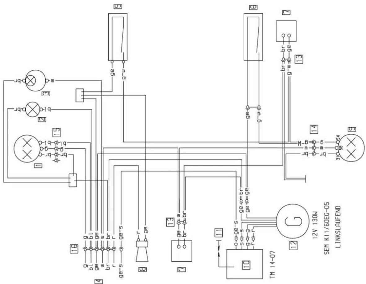
text_image
1 2 3 4 5 6 7 8 9 10 TM 14-07 11 12 13 14 15 16 g-g bl-bl ge-ge w-w br-br r-r ge-s-ge-s r- ge ge-w ge-w ge-w ge-w ge-w ge-w ge-w ge-w ge-w ge-w ge-w ge-w ge-w ge-w ge-w ge-w ge-w ge-w ge-w ge-w ge-w ge-w ge-w ge-w ge-w ge-w ge-w ge-w ge-w ge-w ge-w ge-w ge-w ge-w| Deutsch | Englisch | Italienisch | Französisch |
| 1 Scheinwerfer2 Fernlichtkontrolle3 Tochobeleuchtung4 zum Kombischalter5 Bremslichtsch vo6 Bremslichtsch hi7 Spannungsbegrenzer8 Schnarre9 Bræs-Schlußlicht10 Zündspule11 Zündkerze12 Generator13 2-pol Stecker14 3-pol Stecker15 4-pol Stecker16 9-pol Stecker17 Parallelverbinderbl blaubr braunge gelbgr graug grüno oranger rotss schwarzv violettweiβ | 1 headlight2 high beam indicator3 speedometer light4 to combinat switch5 stoplight switch f6 stoplight switch r7 voltage limiter8 horn9 rear-stoplight10 ignition coil11 spark plug12 generator13 multip cont plug (2)14 multip cont plug (3)15 multip cont plug (4)16 multip cont plug (9)16 parallel connectorbl bluebr brownge yellowgr greyg greeno oranger reds blackv violetw white | 1 faro2 spia abbagliante3 luce tachimetro4 multicomando5 int luce arresto ant6 int luce arresto post7 regol di tens8 clacson9 fanal post di freno10 bobina d'accens11 candela12 dinamo13 connettore a 2 poli14 connettore a 3 poli15 connettore a 4 poli16 connettore a 9 poli16 parallelo compostobl blubr marronege giallogr grigiog verdeo arancionerrossosnerov violettow bianco | 1 phare2 temoin feu route3 eciair comp vitesse4 conmodo5 contact de stop av6 contact de stop arr7 regulateur8 klaxon9 feu arr et de stop10 bobine d'allumage11 bougie12 generateur13 connect multiple (2)14 connect multiple (3)15 connect multiple (4)16 connect multiple (9)16 parallele connecteurbl bleubr brunge jaunegr grisg verto oranger rouges noirv violetw blanc |
| Spanisch |
| 1 faro |
| 2 control luces largas |
| 3 luz tocometro |
| 4 llave combinada |
| 5 interr luces de freno del |
| 6 interr luces de freno tras |
| 7 regulador de tension |
| 8 claxon |
| 9 luz freno tras |
| 10 bobina de encendido |
| 11 bujia |
| 12 generador |
| 13 conector multiple (2) |
| 14 conector multiple (3) |
| 15 conector multiple (4) |
| 16 conector multiple (9) |
| 16 conector paralelo |
| bl azul |
| br marron |
| ge amorillo |
| gr gris |
| g verde |
| o noranja |
| r rojo |
| s negro |
| v violeta |
| w blanco |
| g | bl | ge | w | ge/s | r | br | |
| LICHT ○ | |||||||
| Abblendl | ● | — | ● | ● | |||
| Fernlicht | ● | ● | ● | ||||
| HUPE | ● | ● | |||||
| ZUNDUNG AUS | ● | — | ● | ||||
| 5 | 2 | 1 | 3 | 6 | 4 |
KTM 250/380 EGS 1998
| Deutsch | Englisch | Italienisch | Französisch |
| 1 Scheinwerfer2 Standlicht3 Blinker li vo4 Blinker re vo5 Tachobeleuchtung6 Fernlichtkontrolle7 Blinkerkontrolle8 4-pol Stecker9 Zündschloß10 zum Kombischalter11 Bremslichtsch vo12 Bremslichtsch hi13 Horn14 Blinkgeber15 Diode16 Zündkerze17 Zündspule18 Generator19 Kondensator20 Spannungsregler21 Batterie 1 2Ah22 Stecksicherung 10A23 6-pol Stecker24 Blinker li hi25 Blinker re hi26 Brems-Schlußlicht27 Blinkerschalter28 Parallelverbinder29 3-pol Stecker | 1 headlight2 parking light3 turn indic left fr4 turn indic right fr5 speedometer light6 high beam indicator7 turn indicator8 multip cont plug (4)9 ignition lock10 to combinat switch11 stoplight switch f12 stoplight switch r13 horn14 turn indicator15 diode16 spark plug17 ignition coil18 generator19 capacitor20 voltage regulator21 battery 1 2Ah22 fuse 10A23 multip cont plug (9)24 blinker left rear25 blinker right rear26 rear-stoplight27 blink switch28 parallel connector29 multip cont plug (3) | 1 faro2 luce di posizione3 lampegg ant sn4 lampegg ant dx5 luce di tachimetro6 spia abbagliante7 spia lampeggiatori8 connettore a 4 poli9 accensione10 multicomando11 int luce arresto ant12 int luce arresto post13 clacson14 trasmett di lampeg15 diodo16 candela17 bobina d'accens18 dinamo19 condensatore20 regol di tens21 batteria 1 2Ah22 fusibile 10A23 connettore a 9 poli24 lampegg post sn25 lampegg post dx26 fanal post di freno27 int lampeggiatori28 parallelo composto29 connettore a 3 poli | 1 phare2 feu de position3 clignoteur av gauche4 clignoteur av droit5 eclair comp vitesse6 temoin feu route7 temoin de clignoteur8 connect multiple (4)9 contact d'allum10 commodo11 contact de stop av12 contact Harr de stop13 klaxon14 centrale clignot15 diode16 bougie17 bobine d'allumage18 generateur19 condensateur20 regulateur21 batterie 1 2Ah22 fusibile 10A23 connect multiple (9)24 clign arr gauche25 clign arr droite26 feu arr et de stop27 contact d clignoteur28 parallele connecteur29 connect multiple (9) |
| Deutsch | Englisch | Italienisch | Französisch | Spanisch |
| bl blau | bl blue | bl blu | bl bleu | bl azul |
| br braun | br brown | br marrone | br brun | br marron |
| ge gelb | ge yellow | ge giallo | ge jaune | ge amarillo |
| gr grau | gr grey | gr grigio | gr gris | gr gris |
| g grün | g green | g verde | g vert | g verde |
| o orange | o orange | o arancione | o orange | o naranja |
| r rot | r red | r rosso | r rouge | r rojo |
| s schwarz | s black | s nero | s noir | s negro |
| v violett | v violet | v violetto | v violet | v violeta |
| w weiß | w white | w bianco | w blanc | w blanco |
| g | bl | ge | w | s/ge | r | br | |
| Lights ● | |||||||
| LO beam ≈ | ● | — | ● | ● | |||
| Hi beam ≈ | ● | ● | ● | ||||
| Horn ➕ | ● | ● | |||||
| Engine off ≈ | ● | — | ● | ||||
| 5 | 2 | 1 | 3 | 6 | 4 |
| S | O | V |