Kingpin 8-Ball (2011) - Motorcycle Victory - Free user manual and instructions
Find the device manual for free Kingpin 8-Ball (2011) Victory in PDF.


User questions about Kingpin 8-Ball (2011) Victory
0 question about this device. Answer the ones you know or ask your own.
Ask a new question about this device
Download the instructions for your Motorcycle in PDF format for free! Find your manual Kingpin 8-Ball (2011) - Victory and take your electronic device back in hand. On this page are published all the documents necessary for the use of your device. Kingpin 8-Ball (2011) by Victory.
USER MANUAL Kingpin 8-Ball (2011) Victory
Ness Signature Series Vegas Jackpot®
California Proposition 65 Warning
This product contains or emits chemicals known to the state of California to cause cancer and birth defects or other reproductive harm.

The text is printed on 100% recycled with 40% post-consumer waste (PCW).
PMS 419

POLARIS®
The Way Out.
For your nearest Polaris dealer,
call 1-800-POLARIS
or visit www.polarisindustries.com
Polaris Sales Inc.,
2100 Hwy. 55, Medina, MN 55340
Phone 1-888-704-5290
Part No. 9923011 Rev 01
Printed in USA

FUEL IT.

VICTORY.
2011 Owner's Manual
Hammer®
Hammer® S
Hammer 8-Ball®
Vegas®
Vegas 8-Ball®
Kingpin®
Kingpin 8-Ball®
Vegas Jackpot®
Ness Signature Series Vegas Jackpot®
Copyright© 2010 Polaris Sales Inc.
All material in this publication is based on the latest product information at the time of publication. Due to constant improvements in the design and quality of production components, some minor discrepancies may result between the actual vehicle and the information presented in this publication. Depictions and/or procedures in this publication are intended for reference use only. No liability can be accepted for omissions or inaccuracies. Polaris Industries reserves the right to make changes at any time, without notice and without incurring obligation to make the same or similar changes to previously manufactured vehicles. Any reprinting, reuse or redistribution of the material in this document is expressly prohibited.
Features of VICTORY Motorcycles are covered by U.S. Patents: 6,976,691; 6,407,663; D489670; D482311; D482304; D481980; D481973; D474142. Refer also to the patent label on the motorcycle.
The following are registered trademarks of Polaris Industries Inc.:
POLARIS, THE WAY OUT, FREEDOM, HAMMER, HAMMER 8-BALL, VEGAS, VEGAS JACKPOT, VEGAS 8-BALL, KINGPIN, KINGPIN 8-BALL, VICTORY and VICTORY MOTORCYCLES.
DUNLOP is a registered trademark of Dunlop Tire Corporation.
Printed in U.S.A.
P/N 9923011
Table of Contents
Introduction 4
Safety....5
Reporting Safety Defects 14
Component Identification 17
Instruments, Features and Controls....19
Pre-Ride Inspections 26
Operation 35
Maintenance....41
Cleaning....68
Storage....74
Warranties 76
Specifications 82
Identification Numbers 88
Maintenance Record 89
Index 91
Introduction
Thank you for purchasing a Polaris vehicle, and welcome to our world-wide family of Polaris owners. We proudly produce an exciting line of utility and recreational products.
- Snowmobiles
- All-terrain vehicles (ATVs)
- RANGER ^ utility vehicles
- Low emission vehicles (LEVs)
- Victory Motorcycles ^®
For the safe and enjoyable operation of your vehicle, be sure to follow the instructions and recommendations in this owner's manual. Keep this manual with the motorcycle, especially when ownership changes. If your owner's manual is misplaced or damaged, please purchase a replacement from your VICTORY dealer.
All references in this manual to RIGHT, LEFT, FRONT or REAR are from the operator's perspective when seated in a normal riding position. If you have questions about the operation or maintenance of your motorcycle after you've read this manual, please see your VICTORY dealer. To locate the nearest authorized VICTORY dealer, call 1-800-POLARIS or visit www.polarisindustries.com.
VICTORY motorcycles comply with all federal, state and local safety and emission regulations for the area of intended sale.
About the Owner's Manual
WARNING
Failure to follow recommended precautions and procedures could result in severe injury or death. Always heed all safety precautions and follow all operation, inspection and maintenance procedures outlined in this manual.
Please read your VICTORY owner's manual. This manual contains information essential to safe riding and proper maintenance of the motorcycle. Anyone who rides the motorcycle (operators and passengers) must read the owner's manual before riding.
Read and understand the information found in the safety section, and bring the manual with you when you ride. Following the safety precautions and procedures will add to your riding enjoyment and ensure a safe ride.
Understand and follow all inspection and maintenance procedures outlined in this manual. Following these procedures will ensure that your motorcycle remains in safe operating condition at all times.
Safety Terms and Signal Words
The following signal words and symbols appear throughout this manual and on your vehicle. Your safety and the safety of others is involved when these words and symbols are used. Become familiar with their meanings before reading the manual.

The safety alert symbol indicates a potential personal injury hazard.
WARNING
A WARNING indicates a hazardous situation which, if not avoided, may result in death or serious injury.
CAUTION
A CAUTION indicates a hazardous situation which, if not avoided, may result in minor or moderate injury.
NOTICE
A NOTICE indicates a situation that may result in property damage.
Safety Safe Riding Practices
WARNING
Improper use of this motorcycle can result in serious injury or death to you, your passenger and others. To minimize the risk of injury, read and understand the information contained in this section before operating the motorcycle. Anyone who rides the motorcycle (operators and passengers) must follow these safety precautions.
Motorcycling has inherent risks.
You can minimize those risks, but you can't eliminate them completely. Even if you're an experienced motorcycle operator or passenger, read all of the information in this safety section before operating the motorcycle.
- Take a rider education course from the Motorcycle Safety Foundation or another qualified instructor. The course will help you develop or refresh your expertise in safe riding habits through instruction and riding. For information on Motorcycle Safety Foundation rider education courses in your area, call 1-800-446-9227 or visit their web site at www.msf-usa.org.
- Read and understand all information in this owner's manual.
- Observe all maintenance requirements specified in this manual. For assistance, see the VICTORY Service Manual or your authorized VICTORY dealer.
Design characteristics affect how you should ride the VICTORY motorcycle.
- The motorcycle is designed for on-road use with one rider and one passenger. See page 9.
- Do not exceed the gross vehicle weight rating (GVWR). See the specifications section beginning on page 82 or the certification label on the steering head. Riding off-road, riding with more than one passenger, or carrying weight exceeding the maximum weight rating can make handling difficult, which could cause loss of control.
- Be prepared to reduce speed to maintain stability if your motorcycle is equipped with features such as saddlebags, a windshield or a passenger backrest.
Safe Riding Practices
Follow these general safe riding practices:
- Before each ride, perform the pre-ride inspections. See page 26.
- Follow all break-in procedures during the first 500 miles (800 km) of operation. See page 35.
- Until you're thoroughly familiar with the motorcycle and all of its controls, practice riding where there is little or no traffic. Practice riding at a moderate speed on various road surfaces and in different weather conditions.
- Know your skills and limits, and ride within them.
- Allow only licensed, experienced operators to ride your motorcycle, and then only after they have become familiar with its controls and operation. Make sure all riders read and understand this owner's manual before riding.
- Do not ride when you're fatigued or under the influence of alcohol, prescription drugs, over-the-counter drugs or any other drugs.
- If your motorcycle operates abnormally, correct the problem immediately. See the VICTORY Service Manual or your authorized VICTORY dealer. Continued operation could aggravate the initial problem, increase the cost of repairs and threaten your safety.
- Ride defensively, as if you are invisible to other motorists, even in broad daylight. A motorist's failure to see or recognize a motorcycle is the leading cause of automobile/motorcycle accidents. Ride where you're clearly visible to other motorists, and observe their behavior carefully.
- Be especially cautious at intersections, as these are the most likely places for an accident.
- To prevent loss of control, keep your hands on the handlebars and your feet on the foot-rests.
- Do not move or operate the motorcycle with the steering locked (if equipped), as the severely restricted steering could result in loss of control.
- Obey the speed limit and adjust your speed and riding technique based on road, weather and traffic conditions. As you travel faster, the influence of all other conditions increases, which can affect the motorcycle's stability and increase the possibility of losing control.
Safety Safe Riding Practices
- Reduce speed when:
- the road has potholes or is otherwise rough or uneven.
- the road contains sand, dirt, gravel or other loose substances.
- the road is wet, icy or oily.
- the road contains painted surfaces, manhole covers, metal grating, railway crossings or other slippery surfaces.
- weather is windy, rainy or otherwise causing slippery or rapidly changing conditions.
- traffic is heavy, congested, not allowing sufficient space between vehicles or otherwise not flowing smoothly.
- being passed in either direction by a large vehicle that produces a wind blast in its wake.
- To maximize braking effectiveness, use the front and rear brakes together. Be aware of the following important information:
- The rear brake provides 40% of the motorcycle's stopping power, at most.
- To avoid skidding, apply the brakes gradually when the road is wet or rough, or contains loose or other slippery substances.
- If possible, avoid applying the brakes while making a turn. Motorcycle tires have less traction during turns, so braking will increase the possibility of skidding. Bring the motorcycle to the upright position before applying the brakes.
• To avoid loss of control:
- Retract the sidestand fully before riding. Ground clearance is reduced when the motorcycle leans.
- When approaching a curve, choose a speed and lean angle that will allow you to pass through the curve in your own lane without applying the brakes.
- Do not allow components to contact the road surface when leaning in a curve.
- Do not tow a trailer, which can make the motorcycle hard to handle.
Safe Riding Practices
Carrying a Passenger
Do not carry a passenger unless the motorcycle is equipped with passenger seat and passenger footrests.
To carry a passenger safely:
- Do not exceed the gross vehicle weight rating (GVWR).
- If necessary, adjust the rear shock preload. See page 50. Improper preload adjustment can make your motorcycle hard to handle and can cause loss of control.
- Before riding, be sure your passenger is familiar with safe riding procedures. An inexperienced passenger may distract you or make movements that cause instability.
- Direct the passenger to hold onto you or the seat strap with both hands and to keep both feet on the passenger footrests. Do not carry a passenger who cannot place both feet firmly on the passenger footrests. A passenger who rides improperly can shift body weight erratically and cause instability.
- Adjust your riding style to compensate for the differences in handling, acceleration and braking caused by the additional weight of the passenger.
Protective Apparel
Wear protective apparel to decrease the risk of injury and increase riding comfort.
- Always wear a helmet that meets or exceeds established safety standards. Approved helmets in the USA and Canada bear a U.S. Department of Transportation (DOT) label. Laws in some areas require that you wear an approved helmet. Head injuries are the leading cause of fatalities in accidents involving motorcycles. Statistics prove that an approved helmet is the most effective protection in preventing or reducing head injuries.
- Wear eye protection to protect eyes from wind or airborne particles and objects. Laws in some areas require that you wear eye protection. VICTORY recommends that you wear approved Personal Protective Equipment (PPE) bearing markings such as VESC 8, V-8, Z87.1, or CE. Make sure protective eyewear is kept clean.
- All riders should wear bright or light-colored and/or reflective clothing to improve visibility to other motorists. A motorist's failure to see or recognize a motorcycle is the leading cause of automobile/motorcycle accidents.
- Wear gloves, a jacket, heavy boots and long pants to prevent or reduce injury from abrasions, lacerations or burns should the motorcycle fall. Wear boots with low heels, as high heels can catch on pedals or footrests. The combination of boots and pants should completely cover legs, ankles and feet, protecting skin from engine and exhaust system heat.
- Do not wear loose, flowing clothing or long boot laces, as they can catch on handlebars, levers or footrests, or they can become entangled in the wheels, causing loss of control and serious injury.
Safety
Gross Vehicle Weight Rating (GVWR)
WARNING! Exceeding the gross vehicle weight rating of your motorcycle can reduce stability and handling and could cause loss of control. NEVER exceed the GVWR of your motorcycle.
The maximum load capacity of your motorcycle is the maximum weight you may add to your motorcycle without exceeding the GVWR. This capacity is determined by calculating the difference between your motorcycle's GVWR and wet weight.
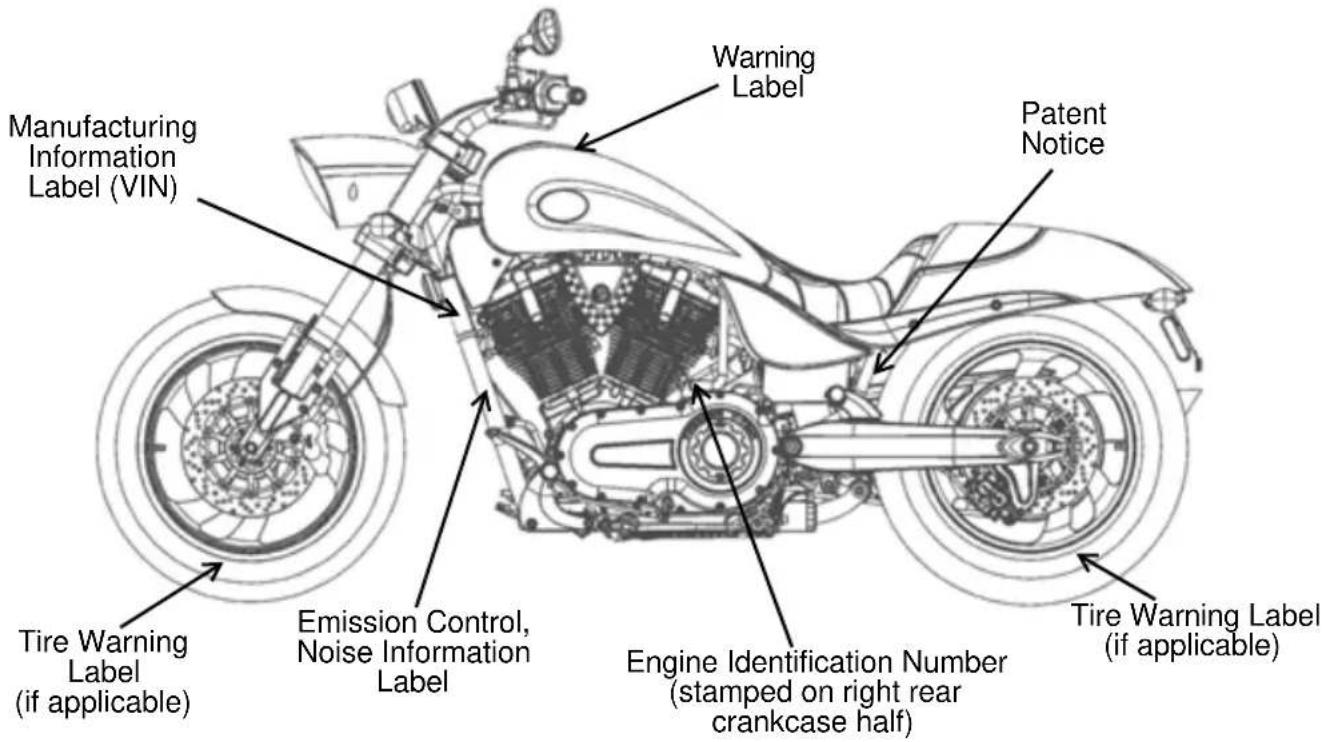
Refer to the specification section of this manual or the Manufacturing Information/VIN label on the motorcycle frame for model-specific information. Refer to the “Safety and Information Labels” section in this manual for location on the motorcycle.
When determining the weight you will be adding to your motorcycle, and to ensure you do not exceed the maximum load capacity, include the following:
- operator body weight
- passenger body weight
- weight of all riders' apparel and items in or on apparel
- weight of any accessories and their contents
- weight of any additional cargo on the motorcycle
Carrying Cargo
Use the following guidelines when attaching cargo or accessories to the motorcycle.
To prevent instability and loss of control:
- Keep cargo and accessory weight to a minimum. Keep items as close to the motorcycle as possible to minimize a change in the motorcycle's center of gravity.
- Distribute weight evenly on both sides of the motorcycle and secure cargo to prevent unexpected shifting. Check all accessories and cargo for security and even distribution before riding and at each riding break.
- Do not attach large or heavy cargo such as sleeping bags, duffel bags or tents to the handlebars, front fork area or front fender. These areas are not designed to carry cargo. Cargo in these areas can also block air flow to the engine and cause overheating.
- Do not exceed the maximum cargo weight limit of any accessory. Refer to the accessory instructions and labels. Do not attach cargo to an accessory not designed for that purpose.
- Do not attach anything to the highway bar except highway footrests.
Carrying Cargo Saddlebags
When operating a motorcycle equipped with saddlebags:
- Never ride at speeds exceeding 80 MPH (120 km/h). Depending on load and weather conditions, the maximum safe operating speed may be less. Saddlebags, combined with the lifting or buffeting effects of wind, can cause instability.
- Distribute weight evenly in each of the saddlebags.
- Do not exceed the maximum cargo capacity of the saddlebags.
- Do not exceed the gross vehicle weight rating (GVWR).
Parking the Motorcycle
When leaving the motorcycle unattended, turn the engine off and remove the ignition key.
Park the motorcycle where people are not likely to touch the hot engine or exhaust system or place combustible materials near these hot areas. Do not park near a flammable source such as a kerosene heater or an open flame, where hot components could ignite combustible materials.
Park the motorcycle on a firm, level surface. Sloped or soft surfaces may not support the motorcycle. See page 40.
Modifications
Modifying the motorcycle by removing any equipment or by adding equipment not approved by VICTORY may void your warranty. Such modifications may make the motorcycle unsafe to ride and could result in severe injury to operator or passengers, as well as damage to the motorcycle. Some modifications may not be legal in your area of operation. If in doubt, contact your authorized VICTORY dealer.
Safety Transporting the Motorcycle
When transporting the motorcycle:
- Use a truck or trailer. Never tow the motorcycle. Towing will impair steering and handling.
- Restrain the motorcycle in an upright position to prevent fuel leaks.
- Place the transmission in neutral.
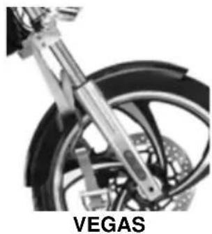
- Do not place restraints on the handlebars. Loosen the front turn signal mounts and slide them upward. Place tiedown straps around the fork tubes above the lower triple clamp. Secure the rear of the motorcycle with tiedowns around both sides of the swingarm, being careful to avoid the brake line, exhaust and drive belt. Reposition the turn signals before operating the motorcycle.
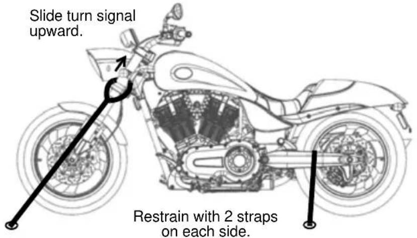
(Models differ in appearance, but locations are the same as shown)
natural_image
Close-up of a motorcycle's wheel and suspension system, labeled 'VEGAS' below (no other text or symbols visible)Accessory Selection and Installation
Use the following guidelines when choosing and installing accessories:
- Do not install accessories that impair the stability, handling or operation of the motorcycle. Before installing an accessory, be sure that it does not:
- Reduce ground clearance when the motorcycle is either leaning or upright.
- Limit suspension or steering travel or your ability to operate controls.
- Displace you from your normal riding position.
-
Obscure lights or reflectors.
-
Do not install bulky or large accessories that can cause instability (due to the lifting or buffeting effects of wind).
- Do not install electrical accessories that exceed the capacity of the electrical system. Never install higher wattage light bulbs than those supplied as original equipment. An electrical failure could result and cause hazardous loss of engine power or lights, or damage to the electrical system.
- Always install accessories designed and approved by VICTORY specifically for your model, especially a windshield, backrest or luggage rack. An improperly designed or installed accessories can reduce stability, causing loss of control. Follow the instructions for proper installation and use.
Fuel and Exhaust Safety
WARNING
Gasoline is highly flammable and explosive under certain conditions.
• Always exercise extreme caution whenever handling gasoline.
• Always turn off the engine before refueling.
• Always refuel outdoors or in a well-ventilated area.
- Open the fuel cap slowly. Do not overfill the tank. Do not fill the tank neck.
- Do not smoke or allow open flames or sparks in or near the area where refueling is performed or where gasoline is stored.
Gasoline and gasoline vapors are poisonous and can cause severe injury.
- Do not swallow gasoline, inhale gasoline vapors, or spill gasoline. If you swallow gasoline, inhale more than a few breaths of gasoline vapor, or get gasoline in your eyes, see a physician immediately.
- If gasoline spills on your skin or clothing, immediately wash it off with soap and water and change clothing.
- If gasoline spills on the any part of the motorcycle, immediately rinse it off with water.
Exhaust gases contain carbon monoxide, a colorless, odorless gas that can cause loss of consciousness or death in a short time.
- Never start the engine or let it run in an enclosed area.
- Never inhale exhaust gases.
Safety Safety Maintenance
WARNING
Failure to perform safety maintenance as recommended can result in difficult handling and loss of control, which could result in serious injury or death. Always perform the safety maintenance procedures as recommended. Perform maintenance and repairs promptly as outlined in the VICTORY Service Manual, or see your authorized VICTORY dealer for service.
- Before each ride, perform the pre-ride inspections. See page 26.
- Perform maintenance at the intervals specified in the periodic maintenance table. See page 42.
- Always maintain proper tire pressure, tread condition and wheel and tire balance. Inspect tires regularly and replace worn or damaged tires promptly. Use only approved replacement tires.
- Always ensure proper steering head bearing adjustment.
- Regularly inspect the rear shock absorber and the front forks for fluid leaks or damage. Make any necessary repairs promptly.
- Clean the motorcycle thoroughly to reveal items in need of repair. See page 69.
- Make sure all legally required equipment is properly installed and in good condition, including the license plate.
- Fasteners must meet original specifications for quality, finish and type to ensure safety. Use only genuine VICTORY replacement parts, and ensure that all fasteners are tightened to the proper torque.
Electromagnetic Interference
This vehicle complies with European directive 97/24/EC Chapter 8 requirements, which is equivalent to Canadian ICES-002.
Reporting Safety Defects
If you believe that your vehicle has a defect that could result in a crash or cause injury or death, you should immediately inform the National Highway Traffic Safety Administration (NHTSA) in addition to notifying Polaris Industries in writing.
If NHTSA receives similar complaints, it may open an investigation, and if it finds that a safety defect exists in a group of vehicles, it may order a recall and remedy campaign. However, NHTSA cannot become involved in individual problems between you, your dealer or Polaris Industries.
To contact NHTSA, or obtain other information about motor vehicle safety, you may call the Vehicle Safety Hotline toll free at 1-888-327-4236 (TTY: 1-800-424-9153), visit the NHTSA web site at www.safercar.gov, or write to:
ADMINISTRATOR, NHTSA
1200 New Jersey Avenue, SE
West Building
Washington, DC 20590
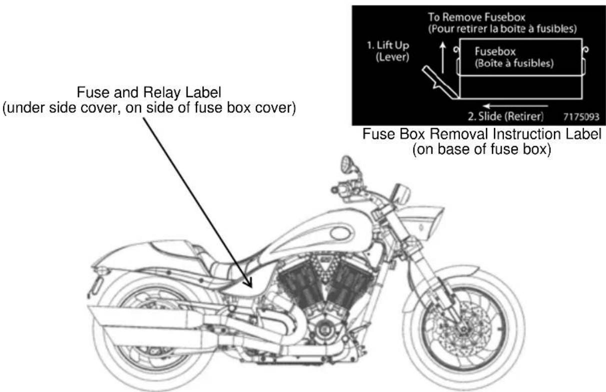
Safety and Information Labels
Due to different model and market requirements, your vehicle may not have all of the labels shown. Labels that apply to your model will be located as shown.
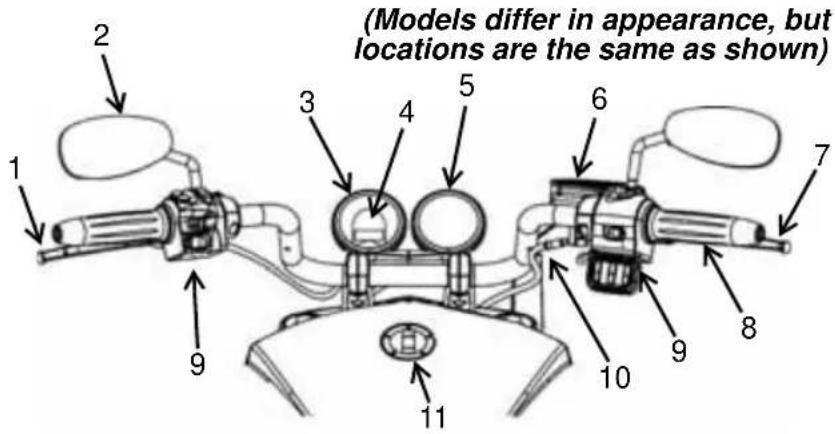
Component Identification Handlebar Area
- Clutch Lever
- Mirror
- Speedometer
- Indicator Light Panel
- Tachometer (if equipped)
- Front Brake Fluid Reservoir
- Front Brake Lever
- Throttle Control Grip
- Switches
- Throttle Cables
- Fuel Cap
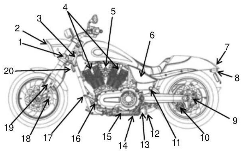
Left Side View
- Front Turn Signal
- Headlamp
- Air Filter
- Spark Plugs
- Ignition Switch
- Battery (under side cover)
- Taillight
- Rear Turn Signal
- Rear Axle Adjuster (each side)
- Rear Brake Caliper
- Passenger's Foot Rest
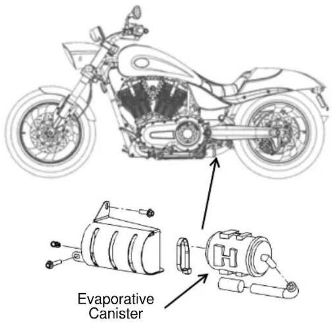
- Evaporative Emissions Canister (California Models)
- Oil Filter
- Oil Drain Plug (under engine)
- Sidestand
- Operator's Foot Rest
- Gear Shift Lever
- Front Brake Caliper
- Front Fork
- Horn
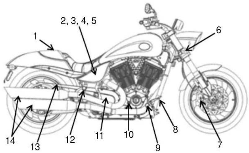
Right Side View
- Passenger Seat/Cowl
- Rear Brake Fluid Reservoir (under cover)
- Diagnostic Connector
- Fuses
- Rear Shock Access
- Front Turn Signal
- Front Brake Caliper
- Rear Brake Pedal
- Operator's Foot Rest
- Éngine Oil Fill Cap/Dipstick
- Drive Sprocket (under cover)
- Passenger's Foot Rest
- Drive Belt (under guard)
- Exhaust Mufflers
Component Identification
Vehicle Identification Number
The vehicle identification number (VIN) is stamped into the front of the steering head and also appears on the certification label. Record the number in the space provided on page 88. You will need this identification number to title, register, license or insure the motorcycle, or to order replacement parts.

flowchart
graph TD
    A["*5VPHB26N0B3000000*"] --> B["Chassis: B = CROSS ROADS CUSTOM C = KING PIN D = CROSS COUNTRY E = CROSS ROADS G = VEGAS H = HAMMER S = VISION X = JACKPOT"]
    A --> C["Engine Size 1 = 1507cc 2 = 1634cc 3 = 1731cc"]
    A --> D["Engine HP 6 = 78-94 7 = 95-115"]
    A --> E["Check Digit"]
    A --> F["Serial Number"]
    F --> G["Type: A = 8-BALL B = Standard C = Custom D = Touring S = Sport W = ABS Z = Limited Edition L = Low"]
    A --> H["Engine Size 1 = 1507cc 2 = 1634cc 3 = 1731cc"]
    A --> I["Model Year B = 2011"]
    A --> J["Plant Code"]
Component Identification Engine Identification Number
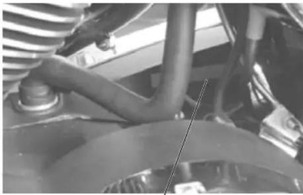
The engine identification number is stamped into the right crankcase half behind the rear cylinder. The first 8 digits are the engine model number. The last 5 digits are the serial number. Record the number in the space provided on page 88.
Ignition Key Number
The ignition key identification number is stamped into the shaft of each key. Record the number in the space provided on page 88.
natural_image
Close-up of a car's lower suspension system showing hoses, springs, and structural components (no visible text or symbols)Engine Identification Number
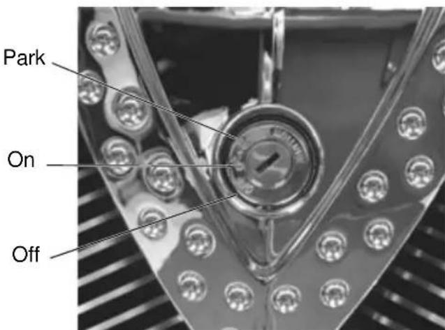
Ignition Switch
The ignition switch provides electrical power to the ignition, the lighting system and all electrical switches and buttons. The ignition key operates the ignition switch and parking lights.
OFF
All electrical circuits are inactive and the ignition key can be removed.
ON
All electrical circuits are energized and the ignition key cannot be removed. The head-lamp, taillight, and instrument lights illu-minate.
PARK (P)
The taillight, indicator lights, and license plate light illuminate. The emergency flashers can be activated, and the ignition key can be removed. Push the ignition key inward while selecting the PARK position.
Instruments, Features and Controls
Instrument Cluster Speedometer
The speedometer displays vehicle speed in either miles per hour (MPH) or kilometers per hour (km/h).
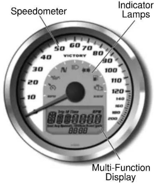
Indicator Lamps
| Lamp Indicates Condition | |
 | Neutral This lamp illuminates when the transmission is in neutral and the ignition key is in the ON position. |
 | High Beam This lamp illuminates when the headlamp switch is set to high beam. |
 [73H6] [73H6] | Turn Signal The turn signal indicator flashes when the left, right, or both turn signals (hazard) are active. If a bulb fails, or if there is a short circuit in the signal system, the lamp flashes at more than twice the normal rate. |
 | Low Oil Pressure This lamp illuminates when the ignition switch is in the ON position and the engine is off, indicating that the indicator circuit is functioning properly. This lamp also illuminates if engine oil pressure drops below safe operating pressure. If this lamp illuminates while the engine is running, turn the engine off as soon as safely possible and check the oil level. If the oil level is correct and the lamp remains on after the engine is restarted, turn the engine off immediately. |
 | Low Fuel This lamp illuminates when approximately one gallon (3.8 liters) of fuel remains in the fuel tank. |
 | Check Engine This lamp illuminates momentarily when the ignition switch is in the ON position and the engine is off. This indicates proper function. If this lamp illuminates while the engine is running, contact an authorized VICTORY dealer promptly for diagnosis. The light will remain on if the tilt sensor shuts down the engine. See page 37. If abnormal sensor or engine operation is detected the light will remain on as long as the fault condition exists. Retrieve the error codes for diagnosis. See page 22. This lamp is also known as a malfunction indicator lamp (MIL). |
 | Cruise Control Engaged (if equipped) |
Instruments, Features and Controls Instrument Cluster Multi-Function Display
Use the mode button to toggle through the modes of the multi-function display. Press and hold the mode button to reset the trip odometers, average fuel economy, average speed and trip hour meter.
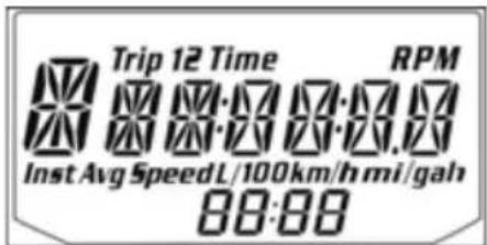
| Modes Available | |
| Standard Modes Accessory | Modes |
| Odometer Trip Odometer | 2 |
| Trip Odometer 1 Average Fuel Economy | |
| Tachometer Instantaneous | Fuel Economy |
| Gear Indicator Trip Hours | |
| Clock Average Speed | |
| DC Voltage | |
| Ambient Air Temperature | |
Display Units (Standard/Metric)
The display can be changed to display either standard or metric units of measurement.
Tip: To exit the set-up mode at any time, wait 10 seconds. The display automatically exits and returns to the odometer display.
| Standard Display Metric Display | ||
| Distance Miles Kilometers | ||
| Fuel U.S. Gallons Liters, Imperial Gallons | ||
| Temperature | Fahrenheit | Celsius |
| Time | 12-Hour Clock | 24-Hour Clock |
- Turn the key to the OFF position.
- Press and hold the mode button while turning the key to the ON position.
- When the display flashes the distance setting, tap the mode button to advance to the desired setting.
- Press and hold the mode button to save the setting and advance to the next display option.
- Repeat the procedure to change remaining display settings.
Instruments, Features and Controls
Instrument Cluster Multi-Function Display
Odometer
The odometer displays total distance traveled by the vehicle.
Trip Odometers
The ignition switch must be in the ON position to access the trip odometers. The trip odometers (Trip 1 and Trip 2) display total distance traveled since being reset. To reset a trip odometer, toggle to the trip odometer. Press and hold the mode button until the meter resets.
Engine Speed (Tachometer)
Engine speed displays in revolutions per minute (RPM).
Gear Position
A gear position displays only when the transmission is in gear and the motorcycle is moving. Two dashes (--) display if the stop/run switch is in the RUN position and the motorcycle is not moving while in gear. The dashes also display if the stop/run switch is in the STOP position.
“N” displays when the stop/run switch is in the RUN position and the transmission is in neutral.
Clock
Tip: The clock must be reset any time the battery has been disconnected or discharged.
- Turn the key to the ON position. Use the mode button to toggle to the odometer display.
- Press and hold the mode button until the hour segment flashes. Release the button.
- With the segment flashing, tap the mode button to advance to the desired setting.
- Press and hold the mode button until the next segment flashes. Release the button.
- Repeat steps 3-4 twice to set the 10-minute and 1-minute segments. After completing the 1-minute segment, step 4 will save the new settings and exit the clock mode.
- Turn the key to the OFF position.
Average Fuel Economy (Accessory)
This mode displays average fuel economy since being reset. To reset, toggle to this mode. Press and hold the mode button until the meter resets.
Instantaneous Fuel Economy (Accessory)
This mode displays the instantaneous fuel economy of the motorcycle.
Trip Hours Meter (Accessory)
The trip hours meter displays total hours of operation since being reset. To reset, toggle to this mode. Press and hold the mode button until the meter resets.
Instruments, Features and Controls Instrument Cluster Multi-Function Display
Average Speed (Accessory)
The average speed mode displays average vehicle speed since being reset. To reset, toggle to this mode. Press and hold the mode button until the meter resets.
DC Voltage (Accessory)
The volt meter displays battery voltage. If the engine is not running, approximate battery voltage displays. If the engine is running, approximate charging voltage displays.
Ambient Air Temperature (Accessory)
If the accessory sensor is installed, toggle to this mode to display the ambient air temperature. The key must be in the ON position.
Diagnostic Functionality
Certain conditions will cause an error message to display in the screen. If this occurs, please see your VICTORY dealer.
| Message Location Indicates | ||
| LO DC Voltage | Screen Voltage remains below 11.0 volts for more than 10 seconds | |
| OV DC Voltage | Screen Voltage remains above 15.0 volts for more than 10 seconds | |
| ERROR All Checksum error (gauge malfunction) | ||
Engine Error Codes
The error screen displays only when the CHECK ENGINE light is on or when it goes on and off during one ignition cycle. Error codes are not stored. When the key is turned OFF, the code and message is lost, but will reappear if the fault reoccurs after restarting the engine.
If the CHECK ENGINE indicator lamp illuminates, retrieve the error codes from the display.
- If the error codes are not displayed, use the mode button to toggle until "Ck ENG" displays on the main line of the display.
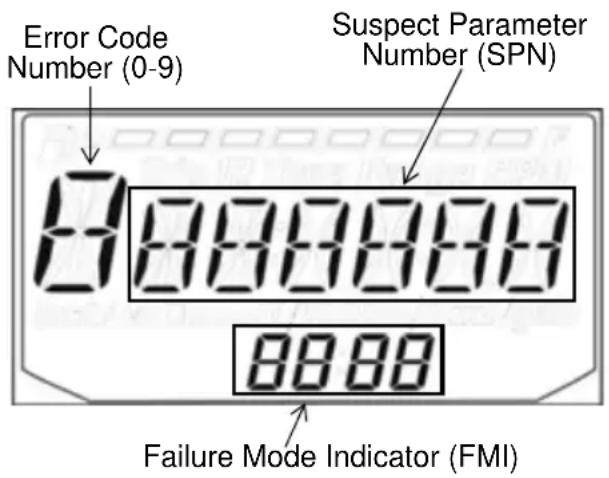
- Press and hold the mode button to enter the diagnostics code menu.
- Record the three numbers displayed in the gear position, clock and odometer displays.
- Press and release the mode button to advance to the next error code.
- Press and hold the mode button to exit the diagnostics code menu.
- See an authorized VICTORY dealer for code details and diagnosis.
Instruments, Features and Controls
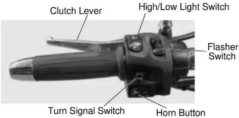
Left Handlebar Controls Clutch Lever
Pull the lever toward the handlebar to disengage the clutch. Gradually release the lever to engage the clutch. For smooth clutch operation, pull the lever quickly and release it gradually.
Tip: A clutch interlock switch prevents the engine from starting when the transmission is in gear and the clutch is engaged. See page 37.
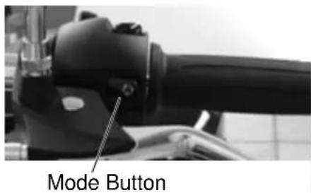
Mode Button
The mode button is located on the front side of the left handlebar switch. Use the mode button to toggle through the modes of the multi-function display. See page 20. Use the mode button to set the display units to either standard or metric units of measurement.

Emergency Flasher Switch (Hazard Switch)
Press the top of the switch to activate the emergency flashers. All turn signals will flash. Press the bottom of the switch to cancel the flashers.
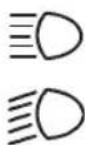
High Beam/Low Beam Light Switch
Press the upper portion of the switch to activate the high beam. Press the lower portion of the switch to activate the low beam. Press and hold the lower portion of the switch to activate the momentary passing beam.

Horn Button
To sound the horn, press the horn button.

Turn Signal Switch
Move the turn signal switch to the left to activate the left turn signals. Move the switch to the right to activate the right turn signals. A signal ends when speed or distance reach preset levels. To end a signal manually, move the switch to the center and push it inward.
Momentary Feature: Move the turn signal switch left or right and hold it in that position. The signal flashes until the switch is released.
Instruments, Features and Controls Right Handlebar Controls

Engine Stop/Run Switch
Press the top of the engine stop/run switch (STOP) to stop the engine. Press the bottom of the switch (RUN) to allow operation of the engine. The engine should not start or run when the switch is in the STOP position.

Starter Button
Press the right side of the button to start the engine. See page 37. The starter button works only when the stop/run switch is on RUN and the transmission is in neutral or the clutch is disengaged (lever pulled in toward handlebar.)

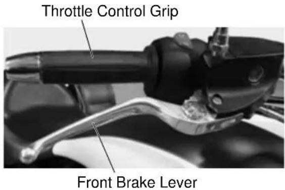
Throttle Control Grip
Twist the throttle control grip toward your body to increase engine speed. Twist the grip away from your body to decrease engine speed. When you release the grip, it returns to the idle speed position.
Front Brake Lever
Pull the lever toward the handlebar to apply the front brake. Always follow proper braking procedures. See page 39. To maximize braking effectiveness, use the front and rear brakes together.
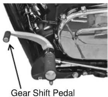
Gear Shift Pedal
To shift to a lower gear, press down on the gear shift pedal. To shift to a higher gear, lift up on the gear shift pedal. See page 37.
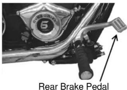
Rear Brake Pedal
To apply the rear brake, press down on the rear brake pedal. Always follow proper braking procedures. See page 39. To maximize braking effectiveness, use the front and rear brakes together.
Instruments, Features and Controls
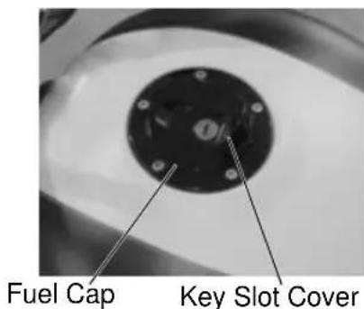
Fuel Cap
Use the ignition key to open and close the fuel cap. Follow proper fueling procedures. See page 36.
Tip: Prime the fuel pump if the tank is completely empty.
Open the fuel cap
- Lift the key slot cover on the fuel cap and insert the key.
- Turn the key clockwise while pushing downward lightly. The latch will release and allow you to open the cap.
Close the fuel cap
- Insert the key into the cap. Turn the key clockwise and press downward on the cap.
- Turn the key counter-clockwise while pushing downward lightly.
- Remove the key and close the key slot cover.
Sidestand
WARNING! An improperly retracted sidestand could contact the ground during operation and cause loss of control resulting in serious injury or death. Always make sure the sidestand is fully retracted before operating the motorcycle.
- While the motorcycle is in the upright position, push the sidestand downward until it is fully extended.
- Slowly lean the motorcycle to the left until the full weight of the motorcycle rests safely on the sidestand.
- To retract the sidestand, bring the motorcycle to the upright position. Swing the sidestand upward to its fully retracted position.
Side Covers
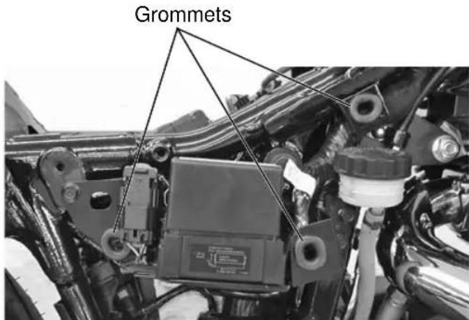
Remove the left side cover to access the battery. Remove the right side cover to access the fuses and the rear brake fluid reservoir.
- Pull outward at each corner of the side cover to disengage the darts.
- Remove the side cover.
- To reinstall the side cover, make sure each rubber grommet is properly located. Align each dart with the appropriate grommet and press inward firmly to secure.
Pre-Ride Inspections
Always perform the recommended pre-ride inspections before each ride. Always perform the inspections before making a long trip and when removing the motorcycle from storage.
WARNING
Failure to perform the recommended pre-ride inspections could result in component failure while riding, which could result in serious injury or death. Always perform the pre-ride inspections before each ride. When inspection reveals the need for adjustment, replacement or repair, perform the service promptly.
Tip: You must be familiar with all instruments and controls to perform the pre-ride inspections.
During the pre-ride inspections you may use products that are potentially hazardous, such as oil or brake fluid. When using any of these products, always follow the instructions and warnings on the product packaging.
When inspections reveal the need for adjustment, replacement or repair:
• refer to the maintenance section of this manual
• refer to the VICTORY Service Manual
• or see your authorized VICTORY dealer
Electrical Components
Move the ignition switch to the ON position before performing the electrical inspections outlined on this page. Return the ignition switch to the OFF position after completing these inspections. If inspection of any electrical item reveals component failure, repair or replace the component before operating the motorcycle.
| Electrical Item Inspection Procedure | |
| Headlamp Verify that | the headlamp illuminates. Switch to high beam. Verify that the high beam indicator comes on and that lamp brightness increases. |
| Taillight/Brake Light | Verify that the taillight and license plate light illuminate. Verify that taillight brightness increases when the front brake lever is applied and also when the rear brake pedal is applied. |
| Turn Signals Move the | turn signal switch to the left. Verify that front and rear left turn signals flash, as well as the corresponding light on the indicator panel. Push the switch inward to cancel the signal. Verify that the signals and the indicator light stop flashing. Repeat the procedure for the right turn signals. |
| Emergency Flashers | Slide the emergency flasher switch to the left. Verify that all four turn signals flash, as well as the light on the indicator panel. Slide the switch to the right. Verify that all signals and indicators stop flashing. |
| Horn Press the horn button. | Verify that the horn sounds loudly. |
| Low Oil Pressure Indicator | Start the engine. Verify that the low oil pressure indicator goes off. |
| Neutral Indicator | Place the transmission in neutral. Verify that the neutral indicator comes on. |
| Engine Stop/Run Switch | Start the engine. Move the stop/run switch to the STOP position. Verify that the engine stops. Attempt to restart the engine to verify that the engine WILL NOT start. |
Pre-Ride Inspections
Engine Oil Level
We recommend the use of only VICTORY brand Semi-Synthetic 20W-40 Motor Oil or an equivalent oil designed for use with wet clutches (such as those with a JASO MA rating). The oil fill cap/dipstick is located on the right side of the vehicle.
NOTICE: Operating the engine with too much or too little oil can cause serious engine damage or engine seizure, which could result in loss of control and serious injury or death. Do not operate the motorcycle with the oil level above the FULL mark or below the ADD mark.
Tip: The engine must be at normal operating temperature when checking the oil level.
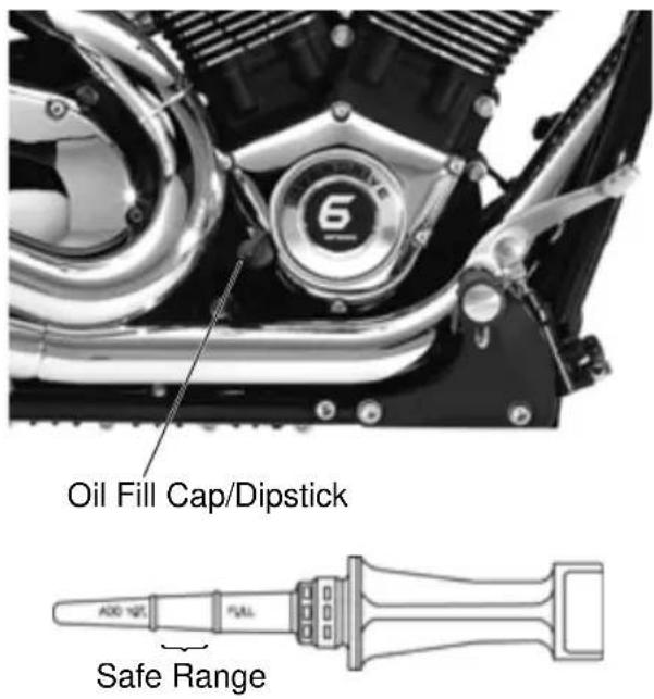
- Place the transmission in neutral. Start the engine and allow it to idle for several minutes.
- Stop the engine and wait 3-5 minutes before checking the oil level.
- On level ground, straddle the motorcycle and bring it to the fully upright position.
- Remove the oil fill cap/dipstick and wipe it clean. Reinstall the dipstick and turn the cap clockwise until it seats.
- Remove the dipstick and view the oil level. Add or remove oil as needed to bring the level into safe operating range (between the FULL and ADD marks) on the dipstick.
- Repeat steps 1 and 2 each time you adjust the oil level.
Fuel Level
- On level ground, straddle the motorcycle and bring it to the fully upright position.
- Start the engine. The low fuel indicator light will stay on if the fuel tank level is less than one gallon (3.8 l).
- Add fuel as needed.
Fuel Hose, Rail and Connections
- Inspect the fuel hoses for cracks or damage.
- Inspect the hose connection at the fuel tank and at the fuel rail for dampness or stains from leaking or dried fuel.
Pre-Ride Inspections Evaporative Emission Control System (California Models)
- Inspect all evaporative emission control system hoses and connections. Make sure all connections are tight.
- Inspect the evaporative canister to make sure it has not been damaged.
Tire Pressure
- Check tire pressure before riding, when the tires are cold. This will provide the most accurate reading, as riding warms the tires and increases tire air pressure.
- Adjust tire pressure as needed based on the total weight of your intended load. Refer to the tire pressure table. See page 59.
Tire Condition
Inspect the tire sidewalls, road contact surface and tread base. If inspection reveals cuts, punctures, cracks or other wear or damage, replace the tire before riding.
Tire Tread Depth
Wear bars (raised areas at the base of the tread) are easily visible tread depth indicators. When the road contact surface has worn to the top of the wear bars, replace the tire. See page 59.
Cargo Restraints
Inspect all cargo restraints when carrying cargo. Make sure all restraints are tightly secure to prevent cargo from shifting.
Pre-Ride Inspections
Front Brake Lever
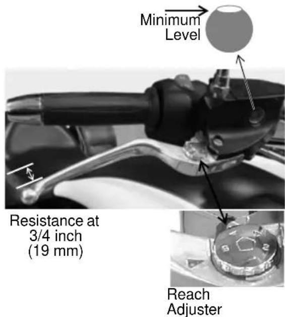
Pull the front brake lever toward the handlebar and release it. It should move freely and smoothly, and it should return to its rest position quickly when released. You should feel a firm resistance in the lever within the first 3/4 inch (19 mm) of lever travel.
If the lever fails to perform as stated, service the brake lever before riding. See the VICTORY Service Manual or your authorized VICTORY dealer.
Brake Lever Reach Adjustment
Lever reach (distance to the hand grip) is adjustable.
- Pull and hold the lever away from the grip.
- To increase reach distance, turn the adjuster to align a lower number to the indicator mark on the lever.
- To decrease reach distance, turn the adjuster to align a higher number to the indicator mark on the lever.
Front Brake Fluid Level
- Straddle the motorcycle and bring it to the fully upright position. Position the handlebars so that the fluid reservoir is level.
- View the fluid level through the sight glass. The fluid should be clear. Replace cloudy or contaminated fluid.
- The fluid level should be at or above the top of the sight glass. Add fluid as needed. See page 57.
Pre-Ride Inspections Rear Brake Pedal
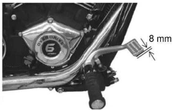
Press and release the rear brake pedal. It should move freely and smoothly, and it should return to its rest position quickly when released. You should feel a firm resistance in the pedal within the first 3/8 inch (8 mm) of pedal travel.
If the brake pedal fails to perform as stated or travels too far before beginning to engage the brake, see the VICTORY Service Manual, or contact an authorized VICTORY dealer for service.
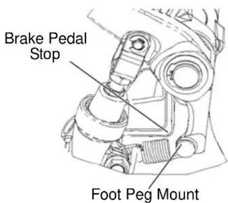
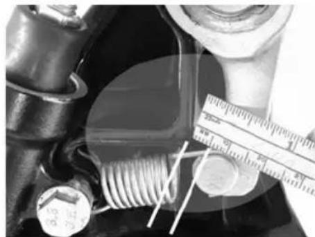
Brake Pedal Gap
With the brake pedal in the relaxed position, and with the master cylinder piston positioned against the internal stop, measure the distance between the brake pedal stop and the foot peg mount. The gap should be 2-5 mm. Make adjustments as needed.
- Hold the clevis to prevent it from bending. Loosen the brake linkage rod lock nut.
- Turn the linkage rod in or out as necessary.
- Hold the clevis and tighten the lock nut securely against the clevis.
- Verify that the gap is 2-5 mm.
- Verify that the rear wheel rotates freely through the full freeplay range of pedal without dragging or binding. If drag is present with the pedal released, refer to the VICTORY Service Manual or contact an authorized Victory dealer.
natural_image
Close-up of mechanical components including a solenoid, screwdriver, and ruler on a dark surface (no visible text or symbols)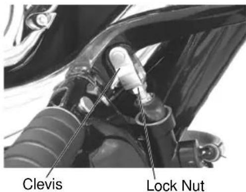
Pre-Ride Inspections
Rear Brake Fluid Level
- Remove the right side cover.
- Straddle the motorcycle and bring it to the fully upright position.
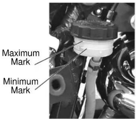
- View the brake fluid through the reservoir. The fluid should be clear. Replace cloudy or contaminated fluid.
- The fluid level should be between the minimum and maximum marks on the reservoir. Add fluid as needed. See page 57.
Brake Lines
Inspect all brake hoses and connections for dampness or stains from leaking or dried fluid. Tighten any leaking connections and replace components as necessary.
Brake Pads
Inspect front and rear brake pad thickness. Replace brake pads when wear lines are no longer visible, or when pad thickness reaches 1.5 mm. See page 58.
Throttle
- Rotate the throttle control grip. It should rotate smoothly from the rest position to the completely open position. It should return to the rest position quickly when released.
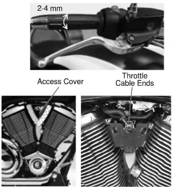
- Remove the right side access cover. Inspect throttle cables for frayed ends.
- Service the throttle system if throttle operation is not smooth, if throttle grip does not return properly, or if cable ends are frayed. See the VICTORY Service Manual or your authorized VICTORY dealer.
Throttle Freeplay
Throttle freeplay is the amount of throttle control grip movement from the rest position to the point of cable resistance. Measure this distance. Freeplay should be 2-4 mm. Adjust throttle freeplay as needed. See page 54.
Pre-Ride Inspections Mechanical Clutch
- Squeeze the clutch lever toward the handlebar and release it. It should move freely and smoothly, and it should return to the rest position quickly when released. If the lever fails to perform as stated, service the clutch lever before riding.
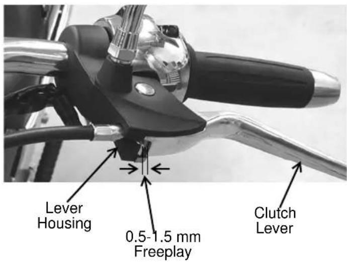
- Freeplay (gap) is the amount of lever movement from the rest position to the point of cable resistance. Clutch lever freeplay should be 0.5-1.5 mm. Measure the gap between the clutch lever and the lever housing. Adjust clutch lever freeplay if necessary. See page 55.
Hydraulic Clutch Fluid Level
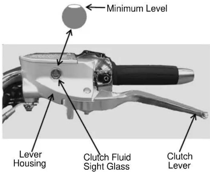
- Position the motorcycle on level ground with the front wheel straight forward. Do not use the sidestand. Position the handlebars so that the clutch fluid reservoir is level.
- View the fluid level through the sight glass. The fluid should be clear. Replace cloudy or contaminated fluid.
- The fluid level should be at or above the top of the sight glass. Add fluid as needed. See page 56.
Pre-Ride Inspections
Front Suspension
Inspect the front forks for oil leaks or damage, and verify smooth suspension operation. See page 51.
Steering
On level ground, straddle the motorcycle and bring it to the fully upright position. Turn the handlebars from stop to stop. The action should be smooth but not loose. Make sure wires, hoses and control cables do not interfere with smooth steering.
Rear Suspension
Proper rear suspension adjustment is essential for a safe and comfortable ride. Check rear shock absorber movement and preload to ensure the correct amount of suspension travel and ground clearance. See page 49.
WARNING! Inadequate ground clearance could result in components contacting the ground, causing loss of control resulting in serious injury or death. Always ensure ground clearance is at specification.
Drive Belt
- Check drive belt tension. See page 44. The drive belt should fit tightly.
Tip: The drive belt system must be cool, clean and dry to accurately measure belt tension (deflection). Do not measure belt tension when the belt or drive system is wet, or when it is hot (such as immediately after riding).
- Inspect drive belt condition. If you discover cracks, broken teeth or frayed edges, replace the drive belt before riding. See the VICTORY Service Manual or your authorized VICTORY dealer.
Pre-Ride Inspections Sidestand
-
Straddle the motorcycle and bring it to the fully upright position.
-
Move the sidestand upward to the stored position and downward to the fully extended position several times. It should move smoothly and quietly.
Make sure the return spring
holds the sidestand tightly in place when the sidestand is in the stored position.
- Replace a bent sidestand immediately. Do not try to straighten a bent sidestand. The sidestand will be weakened, and may not be able to support the motorcycle.
- Inspect the sidestand pivot bolt for looseness or wear. Tighten or replace a loose or worn bolt.
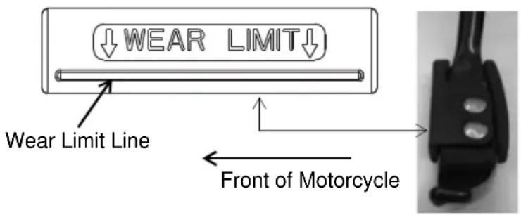
- Inspect the sidestand rubber pad. Make sure the pad is firmly attached to the sidestand. Check the wear indicator on the leading edge of the pad. Replace the pad when it's worn beyond the wear limit line.
Fasteners
- Inspect the entire motorcycle chassis and engine for loose, damaged or missing fasteners. Tighten loose fasteners to the proper torque.
Tip: Refer to the specifications section of this manual or to the VICTORY Service Manual for torque values. - Always replace stripped, damaged or broken fasteners before riding. Use genuine VICTORY fasteners of equal size and strength.
Operation
The operation section describes how to operate your VICTORY motorcycle to ensure the best performance and longevity of the engine and other components. Information includes:
• Engine Break-in Period
- Fueling and Fill Height
- Starting the Engine
- Shifting Gears
- Accelerating
- Braking
- Stopping the Engine
- Parking
Follow all safe riding practices outlined in the safety section. See page 5.
During the first 500 miles (800 km), critical engine parts require special wear-in procedures so they seat and mate properly. Read, understand and use the following rules for operating the motorcycle during the first 500 miles (800 km).
NOTICE: Do not put unnecessary load on the engine during the first 500 miles (800 km). Avoid prolonged full throttle operation or any condition that creates excessive engine heat.
Engine Break-in Period
NOTICE: If engine trouble should occur during the engine break-in period, consult the maintenance section of the Owner's Manual, the VICTORY Service Manual, or an authorized VICTORY dealer immediately.
Failure to perform the initial maintenance as recommended could result in less than desirable engine performance in the future. Perform the initial maintenance as recommended.
| Odometer Reading | Instructions | |
| Miles Kilometers | ||
| 0-90 0-1 | 45 Do not operate for extended periods of time at throttle positions above 1/3 throttle. Vary the engine speed frequently. Do not operate for extended periods of time at any one throttle position. | |
| 90-300 1 | 45-483 Do not operate for extended periods of time at throttle positions above 1/2 throttle. Vary the engine speed frequently. Do not operate for extended periods of time at any one throttle position. | |
| 300-500 | 483-800 | Do not operate for extended periods of time at throttle positions above 3/4 throttle. |
| At 500 800 | Perform the initial maintenance as described in the maintenance section of the owner's manual. This critical maintenance should be performed by an authorized VICTORY dealer. Initial maintenance includes servicing all adjustments, tightening all fasteners and changing engine oil. | |
Operation Engine Break-in Period Fueling and Fill Height
Always heed fuel warnings. See page 13. Always refuel on level ground with the sidestand down.
Use only the recommended fuel. See page 88. Fill the fuel tank to a level just below the bottom of the fuel filler insert.
WARNING! Overflows or spilled gasoline could contact a hot engine or exhaust system and cause a fire, which could result in serious injury or death. Do not allow gasoline to contact hot components. Fuel expands in the fuel tank. Do not overfill. To prevent leaks, make sure the fuel filler cap is properly seated and locked.
NOTICE: Fuel can damage painted surfaces and plastic parts. If gasoline spills on the any part of the motorcycle, immediately rinse it off with water.
Priming the Fuel System
If the motorcycle runs out of fuel, prime the fuel system before attempting to restart the engine.
- Fill the fuel tank.
- Turn the ignition switch to the ON position.
- Move the engine stop/run switch from the STOP position to the RUN position.
- Allow the fuel pump to run until it stops (about 3 seconds).
- Move the engine stop/run switch to the STOP position.
- Wait 10 seconds to allow the engine control module to reset.
- Repeat steps 3-6 four to five times.
Operation
Engine Break-in Period Starting the Engine
The starter interlock system allows the engine to be started only when the transmission is in neutral, or when the transmission is in gear with the clutch disengaged (clutch lever pulled in).
Tip: If the motorcycle runs out of fuel, prime the system before attempting to restart the engine. See page 36.
- Perform the pre-ride inspections. See page 26.
- Insert the key into the ignition switch and turn the switch to the ON position.
- Straddle the motorcycle and bring it to the fully upright position.
- Engage the front brake and place the sidestand in the stored (up) position.
- If the neutral indicator is not illuminated, shift the transmission to neutral.
- Move the engine stop/run switch to the RUN position. You should hear the fuel pump run momentarily as it pressurizes the fuel system.
CAUTION! Do not rev the engine or put the transmission in gear immediately after starting the engine. Allow the engine to idle for about one minute after a cold start, or 30 seconds after a warm start, to allow the oil to reach all areas requiring lubrication before the engine is put under load.
- Leaving the throttle closed, press and hold the starter button to start the engine. Release the button promptly when the engine starts. If the engine does not start within 10 seconds, release the starter button. Wait five seconds, then try again.
Tip: Hold the starter button for as short a time as possible to minimize battery drain. Do not hold the starter button for more than 10 seconds at one time.
- If either the check engine indicator or the low oil pressure indicator remains on after the engine starts, stop the engine. See page 19.
Tilt Sensor
The tilt sensor (if equipped) stops the engine if the motorcycle tips beyond 45 degrees to one side. If this occurs, the check engine light will also illuminate. To restart the engine, cycle the ignition switch to the OFF position, wait 10 seconds, then restart the engine.
Shifting Gears
Recommended Shift Points
| Upshifting (Accelerating) Downshifting (Decelerating) | |||
| Gear Change Recommended Speed | Gear Change Recommended Speed | ||
| 1 to 2 18 MPH | (29 km/h) O/D to 5 (if equipped) 50 MPH (80 km/h) | ||
| 2 to 3 30 MPH | (48 km/h) 5 to 4 35 MPH (56 km/h) | ||
| 3 to 4 40 MPH | (64 km/h) 4 to 3 25 MPH (40 km/h) | ||
| 4 to 5 50 MPH | (80 km/h) 3 to 2 15 MPH (24 km/h) | ||
| 5 to O/D(if equipped) | 60 MPH (97 km/h) 2 to 1 10 MPH (16 km/h) | ||
Operation Shifting Gears
WARNING! Forced shifting (with clutch engaged) could cause damage to the engine, transmission and drive train. Such damage could cause loss of control, which could result in serious injury or death. Always pull the clutch lever fully toward the handlebars to disengage the clutch before shifting gears.
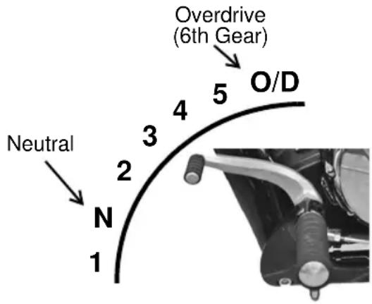
On motorcycles equipped with a six-speed transmission, the sixth gear is overdrive. Neutral is located between first and second gear.
Tip: The transmission is in neutral if you can move the motorcycle forward or rearward freely without disengaging the clutch. If the ignition switch is on, the neutral indicator illuminates when the transmission is in neutral.
- Start the engine.
- With the engine at idle speed, pull the front brake lever toward the handlebar.
- Pull the clutch lever toward the handlebar.
Tip: Shift to a higher gear by lifting the front of the gear shift pedal with your toe. Shift to a lower gear by pressing the pedal downward.
- Push the shift pedal downward until you feel it stop in first gear.
- Release the brake lever.
- Simultaneously release the clutch lever while opening the throttle (rolling the throttle control grip rearward) with a smooth motion. As the clutch begins to engage, the motorcycle will move forward.
- To shift to a higher gear, accelerate smoothly and easily to the recommended shift point. See page 37.
- With a quick motion, simultaneously close the throttle completely and disengage the clutch. Move the shift pedal until you feel it stop at the next gear.
- Simultaneously release the clutch lever while opening the throttle.
Tip: Within the recommended speed ranges, you can downshift to slow the motorcycle or to increase power. You may want to downshift when climbing a hill or passing. Downshifting also helps to decrease speed when combined with closing the throttle.
- To shift to a lower gear (downshift), simultaneously pull the clutch lever toward the handlebar and close the throttle. Move the shift pedal downward until you feel it stop at the next gear. Simultaneously release the clutch lever while opening the throttle.
WARNING! Downshifting improperly could cause loss of traction and loss of control, which could result in serious injury or death.
- Reduce speed before downshifting. Always downshift within the recommended shift points.
- Use extreme caution when downshifting on wet, slippery or other low traction surfaces. Release the clutch lever very gradually in these conditions.
- Avoid downshifting in a curve. Downshift before entering the curve.
Operation
Accelerating
Accelerate by opening the throttle (rolling the throttle control grip rearward). The more quickly you open the throttle, the more quickly the motorcycle accelerates. For even acceleration, open the throttle with a smooth, continuous motion. When you reach the recommended speed for upshifting, shift up one gear. See page 37.
WARNING! Accelerating abruptly could cause your body to shift rearward suddenly, which could result in loss of control. Accelerating abruptly could also cause loss of control on low traction surfaces. Loss of control could result in serious injury or death. Always accelerate gradually, especially on wet, slippery or other low traction surfaces.
Braking
Always allow sufficient stopping distance so that brakes can be applied gradually.
Tip: Applying slightly more front brake than rear brake generally provides the best braking performance.
- To slow the motorcycle with the brakes, close the throttle and apply the front and rear brakes evenly and gradually.
- As the motorcycle slows, disengage the clutch, or downshift each time vehicle speed reaches a downshift point.
WARNING! Braking improperly could result in loss of control, which could result in serious injury or death. Avoid braking abruptly. Always apply the brakes gradually, especially on wet, slippery or other low traction surfaces. Avoid braking in a curve or turn. Bring the motorcycle to the upright position before applying the brakes.
Stopping the Engine
Before stopping the engine, bring the motorcycle to a complete stop. Shift to neutral or disengage the clutch.
WARNING! Stopping the engine with the transmission in gear while the motorcycle is moving could cause loss of rear wheel traction or engine and transmission damage, which could cause loss of control and serious injury or death. Always stop the engine after the motorcycle is fully stopped and the transmission is in neutral. If the engine stops unexpectedly while the motorcycle is moving, guide the motorcycle to a safe location off the road and away from traffic.
- When fully stopped, shift into neutral.
- Move the engine stop/run switch to the STOP position.
- Move the ignition switch to the OFF position. Remove the ignition key.
Tip: Idle air control (IAC) noise is a normal engine management calibration process that occurs each time the engine stop/run switch is put into the STOP position or when the key is turned off.
Operation Parking the Motorcycle
Choose a firm level surface to park the motorcycle.
- When fully stopped, shift into neutral.
- Stop the engine.
- Fully extend the sidestand.
- Turn the handlebars to the left and lean the motorcycle to the left until the sidestand firmly supports the motorcycle.
- Remove the ignition key.
Parking on a Slope
If parking on a slope is unavoidable, position the front of the motorcycle toward the top of the slope. Place the transmission in gear and position the motorcycle so that it is stable when it rests on the sidestand.
Parking on a Soft Surface
If parking on a soft surface is unavoidable, place a sidestand footrest under the foot of the sidestand to provide a firm surface. The sidestand footrest must be strong enough and large enough to support the motorcycle's weight without sinking into the parking surface.
Asphalt becomes soft in hot weather. A sidestand can sink into soft asphalt and the motorcycle may fall. When parking on asphalt in hot weather, use a sidestand footrest.
CAUTION! Hot engine and exhaust components can cause burns to skin and can ignite a fire if exposed to flammable materials. Always park the motorcycle clear of flammable materials and where people are not likely to contact hot components.
Maintenance
Proper maintenance assures the highest level of safety, durability and dependability for your motorcycle.
- Have your VICTORY dealer perform the initial maintenance procedures when the motorcycle's odometer registers 500 miles (800 km).
- Review the safety-related maintenance information. See page 14.
- Perform the recommended periodic maintenance at the intervals specified in the periodic maintenance table. See page 42.
Initial Maintenance
Performing initial maintenance will help ensure optimum engine performance for the entire service life of the engine. Your dealer will change engine oil, inspect all fluids and serviceable components, ensure that all fasteners are tightened and make other adjustments as needed.
Major Maintenance
For major repair information, refer to the VICTORY Service Manual. Major repairs typically require technical skills and specially designed tools. Emission system service requires special tools and training and should be performed by your dealer.
Periodic Maintenance
Always position the motorcycle on a firm level surface before performing service. Inspect, clean, lubricate, adjust and replace parts as necessary. When inspection reveals the need for replacement parts, use genuine VICTORY parts available from your VICTORY dealer. Record service and maintenance information in the Maintenance Record. See page 89.
Perform maintenance at the intervals specified in the periodic maintenance table. See page 42. Perform the procedures more frequently if normal use of the motorcycle includes:
• high speed operation for extended periods
- low speed operation for extended periods
• operation in dusty or otherwise adverse conditions
Before beginning any maintenance procedure, read the instructions for the entire procedure. During some procedures you may use potentially hazardous products such as oil or brake fluid. Always follow the instructions and warnings on the product packaging.
WARNING! Improperly installed or adjusted components can make the motorcycle unstable or hard to handle. Improperly installed electrical components can cause engine or electrical system failure. In either event, damage or serious injury could result. If you do not have the time, tools and expertise necessary to complete a procedure properly, please see your dealer for service.
Road Tests
Before returning the motorcycle to regular use, perform a road test in a safe area. Pay special attention to the proper fit and operation of all serviced components. Make any corrections or additional adjustments promptly to ensure safe, reliable and enjoyable vehicle performance.
Maintenance
Periodic Maintenance Table
| See table key below Component Page | Odometer Reading in Miles (Kilometers) | |||||||||||||||||||||
| 500 (800) | 2500 (4000) | 5000 (8000) | 7500 (12000) | 10000 (16000) | 12500 (20000) | 15000 (24000) | 17500 (28000) | 20000 (32000) | 22500 (36000) | 25000 (40000) | 27500 (44000) | 30000 (48000) | 32500 (52000) | 35000 (56000) | 37500 (60000) | 40000 (64000) | 42500 (68000) | 45000 (72000) | 47500 (76000) | 50000 (80000) | ||
| ***Air Filter 44 II I I R | I I | I | R | I | I | I | R | I | I | I | R | I | I | I | R | |||||||
| Battery 63 I | II | III | III | II | ||||||||||||||||||
| **Brake Fluid 57 I | I | I | I | I | I | I | I | I | I | I | I | R | I | I | I | I | I | I | I | |||
| Brake Pads 58 I | I | I | I | I | I | I | I | I | I | I | I | I | I | I | I | I | I | I | I | |||
| **Clutch Fluid (Hydraulic) 56 I | I | I | I | I | I | I | I | I | I | I | I | R | I | I | I | I | I | I | I | |||
| Clutch Lever 55-56 I | I | I | I | I | I | |||||||||||||||||
| Clutch Cable (Mechanical) 55 I | I | I | I | I | I | |||||||||||||||||
| Crankcase Ventilation System | 52 I | II | III | III | II | |||||||||||||||||
| Drive Belt 44 I | I | I | I | I | I | I | I | I | I | I | I | R | I | I | I | I | I | I | I | |||
| *Engine Oil | 43 | R | R | R | R | R | R | R | R | R | R | |||||||||||
| *Engine Oil Filter | 43 | R | R | R | R | R | R | R | R | R | R | |||||||||||
| Engine Compression | 61 I | I | I | I | I | I | ||||||||||||||||
| Evaporative Emission Control System (California models) | 52 I | II | III | III | II | |||||||||||||||||
| Exhaust System | 61 I | I | I | I | I | I | I | I | I | I | I | I | I | I | I | I | I | I | I | I | ||
| Fasteners | 34 I | I | I | I | I | I | ||||||||||||||||
| Front Brake Lever | 29, 58 | I | II | III | III | II | ||||||||||||||||
| **Front Fork Oil | 51 I | I | I | R | I | I | R | I | I | R | ||||||||||||
| Front Forks/Front Axle | 51-52 I | II | III | III | II | |||||||||||||||||
| Fuel Filter | 52 | R | R | |||||||||||||||||||
| Fuel System | 52 I | I | I | I | I | I | I | I | I | I | I | I | I | I | I | I | I | I | I | I | ||
| Gear Shift Pedal | 56 I | I | I | I | I | I | ||||||||||||||||
| Headlamp | 66 I | I | I | I | I | I | ||||||||||||||||
| Rear Wheel Alignment | 48 I | II | III | III | II | |||||||||||||||||
| Rear Shock Absorber | 49 | I | I | I | R | |||||||||||||||||
| Rear Brake Pedal | 30 I | I | I | I | I | I | ||||||||||||||||
| Road Test | 41 | P | P | P | P | P | P | P | P | P | P | P | P | P | P | P | P | P | P | P | P | |
| Sidestand | 67 I | I | I | I | I | I | ||||||||||||||||
| Sidestand Rubber Pad | 34 I | I | I | I | I | I | I | I | I | I | I | I | I | I | I | I | I | I | I | I | ||
| Spark Plugs | 60 I | II | III | R | III | |||||||||||||||||
| Steering Head Bearings | 52 I | I | I | I | I | I | L | I | I | I | I | L | I | I | I | I | I | L | I | I | ||
| Swing Arm and Rear Axle | 51 I | II | III | III | II | |||||||||||||||||
| Throttle System | 54 I | I | I | I | L | I | I | I | L | I | I | L | I | I | I | L | I | I | I | L | ||
| Tires | 59 | I | I | I | I | I | I | I | I | I | I | I | I | I | I | I | I | I | I | I | I | |
| Wheel Condition | 60 I | II | III | III | II | |||||||||||||||||
Table Key
I Inspect (tighten, clean, adjust, replace as needed)
L Lubricate with proper lubricant
R Replace/Rebuild
P Perform
* Replace at specified interval, or annually
** Replace at specified interval, or every 2 years
*** Replace every 5000 mi. (8000 km) if operating in dusty conditions
Maintenance
Universal Tool
The universal tool and a 4 mm hexagonal wrench are located under the left side cover. The universal tool is a combination 6 mm hexagonal wrench with a Phillips screwdriver tip. It can be used to service the following items (if equipped):
- Oil drain plug • Accessory fasteners • Handlebar Adjustments
- Air filter • Passenger Seat • Indicator/turn signal lamps
- Headlight lamp
Engine Oil and Filter Change
- Start the engine and allow it to idle for several minutes. Stop the engine.
Tip: The engine must be at normal operating temperature before changing the oil.
CAUTION! Hot engine and exhaust components can cause burns to skin and can ignite a fire if exposed to flammable materials. Always park the motorcycle clear of flammable materials and where people are not likely to contact hot components.
- Position the motorcycle securely on the sidestand.
- Place a drain pan under the drain plug and oil filter.
- Remove the drain plug and seal. Use the universal tool (under the left side cover) or a good quality 6-mm hexagonal socket.
- Allow the oil to drain completely.
- Using an oil filter wrench, slowly loosen the filter. Allow the oil in the filter to drain before removing the filter.
- Reinstall the drain plug with a new seal.
Torque: 15 ft-lbs (20 Nm)
-
Clean the oil filter mounting plate and threads.
-
Make sure the new oil filter gasket is properly seated in the oil filter.
-
Apply a thin film of clean engine oil to the gasket. Screw the new filter on until the gasket contacts the filter mounting plate. Tighten the filter by hand an additional 3/4 turn.
-
Add about 8.75-9.0 pints (4.0-4.25 liters) of the recommended oil through the oil fill cap. See page 27.
-
Reinstall the oil fill cap.
NOTICE: After an oil change, the low oil pressure indicator remains illuminated longer than usual before going out. Revving the engine while the low oil pressure indicator is illuminated can damage the engine.
-
Start the engine and allow it to idle for several minutes. Stop the engine.
-
Check for leaks around the drain plug and oil filter. Check the oil level and adjust if needed. See page 27.
-
Recycle used oil and oil filter appropriately.
Maintenance Air Filter
Replace the air filter element at the intervals recommended in the periodic maintenance table. See page 42. Replace the element any time it becomes extremely dirty or contaminated.
Tip: Inspect the air filter often if riding in unusually wet or dusty conditions.
-
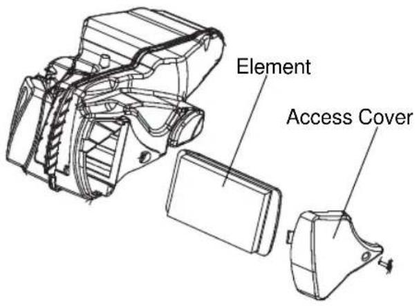
Remove the air filter access cover and air filter element using the universal tool (provided under the left side cover) or a #2 Phillips screwdriver.
-
To remove debris from the element, use low-pressure air and blow from the rear forward.
CAUTION! Wear face protection when using pressurized air.
-
Do not apply air filter oil to the paper element. Apply a small amount of lubricant to the edge of the air filter element frame.
-
Reinstall the element and access cover. Do not over-tighten the access cover screws.
Drive Belt Condition
Replace the drive belt if it is cracked or has broken teeth or frayed edges. No matter its condition, the drive belt should be replaced at periodic intervals. See the VICTORY Service Manual or your authorized VICTORY dealer.
DO NOT attempt to check belt tension if the belt has been exposed to rain or washing within a 24 hour period or if the belt is hot from riding. Allow the belt to cool down to ambient temperature before measuring belt tension. To obtain the maximum drive belt service life possible, VICTORY recommends the replacement of both sprockets as a set if the drive belt system has over 5,000 miles (8,000 km) of service at the time of damage or failure.
Drive Belt Tension Inspection
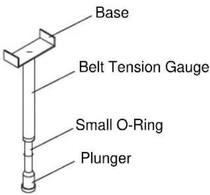
Checking drive belt tension involves using the belt tension gauge (P/N PV-43532). Before beginning this procedure:
- Make sure the drive belt is dry and at room temperature.
- Make sure the rear suspension is properly adjusted. See page 49.
Maintenance
Drive Belt Tension Inspection Maintenance
| Drive Belt Deflection - with 10 lbs. (4.5 kg) of force | ||
| HAMMER 8-BALLVEGASVEGAS JACKPOT | HAMMERHAMMER SKINGPIN | |
| New drive systems (new belt/sprockets) 5 mm +/- 0.5 mm 10 mm +/- 0.5 mm | ||
| After 500 miles on drive system 6 mm +/- 0.5 mm 12 mm +/- 0.5 mm | ||
| The following data is provided for use with a Sonic Tension Meter.Follow the instructions provided with the meter. | ||||
| Required Data Tension | ||||
| Span 658.3 mm HAM | MER / HAMMER $ 3 | 2.3 Hz +/- 1 | ||
| Belt width 28 mm HAM | MMER 8-BALL 48.3 | Hz +/- 1 | ||
| Belt mass constant 8. | 4 VEGAS / JACKPOT | T / KINGPIN 48.3 Hz +/- 1 | ||
| Drive Belt Wear Analysis | ||
 | ||
 | ||
Maintenance
Drive Belt Tension Inspection
- Elevate and support the rear of the motorcycle with the wheel slightly above the ground. Use an appropriate motorcycle support placed securely under the frame.
- Place the transmission in neutral.
CAUTION! Make sure the motorcycle is stable when elevated. Injury may occur if the motorcycle tips or falls.
- Position the small o-ring on the belt tension gauge directly over the 10 lbs. (4.5 kg) mark on the plunger as shown.
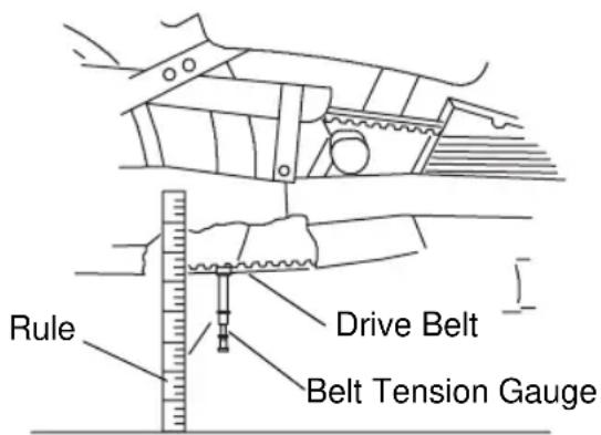
- Place a tape measure or rule next to the drive belt as shown.
- Place the base of the tension gauge bracket squarely against the lower strand of the drive belt halfway between the front and rear drive sprockets. Use the tape measure or ruler and record the position of the base of the tension gauge bracket. This position represents zero force.
- Push the plunger upward until the small O-ring touches the tension gauge body. Make sure the tension gauge is seated squarely against the drive belt, and record the position of the base of the tension gauge bracket. This position represents 10 lbs. (4.5 kg) of force.
- Calculate the difference between the zero force position and the 10 lbs. (4.5 kg) of force position you recorded. See page 45.
- Belt deflection must be measured and adjusted with the belt at the tightest spot. Measure deflection in 4 spots by rotating the wheel 90 degrees in the forward direction between measurements. Adjust tension as necessary. See page 47.
Important Belt Deflection Information
- Measure / adjust belt deflection at the tightest spot.
- Belt and sprockets must be clean, dry, and at room temperature for accurate deflection measurement.
- Lowering kits affect belt deflection specifications. Consult an authorized VICTORY dealer if a lowering kit is installed on your motorcycle.
- When a new drive belt is installed, tension must be adjusted after 500 miles (800 km) to ensure maximum belt service life.
Maintenance
Drive Belt Tension Adjustment
CAUTION! Make sure the motorcycle is stable when elevated. Injury may occur if the motorcycle tips or falls.
- Inspect wheel alignment before adjusting drive belt tension. See page 48.
- Loosen the rear axle nut on the left end of the rear axle. On screw-style adjusters, loosen the lock nut on both the left and right axle adjusters.
- Turn the axle adjusters clockwise (viewed from rear) an equal amount if wheel is in alignment, or turn each adjuster as needed to align the wheel and achieve proper tension. Use an 8-mm hex tool on screw-style adjusters.
- When alignment and belt tension is correct, tighten the rear axle nut. Tighten the adjuster lock nut (screw-style adjusters).
Torque: 65 ft-lbs (88 Nm)
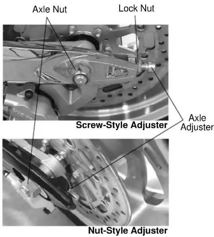
- Recheck drive belt tension and wheel alignment.
- Pump the rear brake pedal several times to reset brake pad distance.
- Slowly rotate the rear wheel. If the wheel does not rotate smoothly, inspect the wheel bearings, axle and brakes. See the VICTORY Service Manual or your authorized VICTORY dealer.
Drive Belt Cleaning
Cleaning the drive belt will maximize belt and sprocket life and minimize drive line noise. Clean the belt at every tire change. Clean the belt more often if riding in dirty, dusty or high debris environments.
- Mix a few drops of mild dish soap with a cup of warm water.
- Use a soft nylon brush to clean the belt and sprocket teeth with the soapy water. Clean well in corner areas where road debris and belt dust can collect.
- Rinse the belt with clear water, then dry thoroughly.
Tip: Do not inspect or adjust drive belt tension when the belt is wet. Improper adjustment will result.
Maintenance Rear Wheel Alignment
WARNING! A skewed rear axle can damage the drive belt, causing belt failure and loss of control of the motorcycle.
- Elevate and support the rear of the motorcycle with the wheel slightly above the ground. Use an appropriate motorcycle support placed securely under the frame.
- Place the transmission in neutral.
- The axle adjusters or plates are stamped with marks to verify proper wheel alignment. Inspect the position of the alignment marks in relation to the mark stamped on the swingarm. The marks should be in the same position on both sides of the wheel.
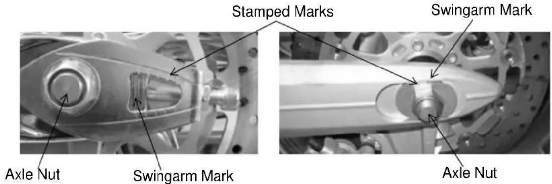
- To adjust rear wheel alignment, loosen the rear axle nut about 1 1/2 turns.
Tip: Turn the axle adjusters about 1/16 of a turn at a time and monitor wheel alignment as you proceed.
- Screw style adjusters: Use a 17-mm wrench to loosen the lock nut, then use an 8-mm hexagonal wrench to turn the axle adjuster screws. Nut style adjusters: Use a deep 14-mm socket to turn the adjuster nut.
- Both adjuster styles: Turn the screw or nut IN (clockwise) to draw the axle back, or OUT (counterclockwise) to allow the axle to move forward.
Tip: If adjuster screws or nuts are turned OUT, push the wheel and axle forward to be sure the ends of the adjuster screws or nuts are seated against the end of the swingarm before inspecting alignment or belt tension. - Recheck rear wheel alignment after each adjustment. Readjust as needed until alignment and drive belt tension are correct before proceeding. See page 44.
- Tighten the adjuster lock nut (screw-style), then tighten the axle nut.
Torque: 65 ft-lbs (88 Nm)
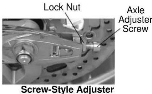
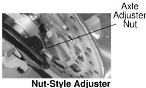
- Recheck drive belt tension and alignment after tightening the axle. If alignment is incorrect, repeat steps 4-8.
- Pump the rear brake pedal several times to reset brake pad distance.
Rear Suspension
Rear Shock Preload (Ride Height) Inspection
Set preload with accurate load conditions before riding to ensure optimum handling, safety and ride quality. A shock absorber preload wrench (PV-43507) is designed specifically for adjusting the preload on your motorcycle. The tool is available from your dealer. Have an assistant help with this procedure.
- Verify that tire pressure is at specification. See page 59.
- Load the motorcycle with all intended cargo. Wearing your riding gear, bring the motorcycle to the upright position and sit on the operator's seat. If you plan to carry a passenger, have the passenger (with riding gear) sit on the passenger seat.
- Compress the rear suspension a few times by pushing on the seat and slowly releasing. Make sure the suspension moves freely without binding.
- With as much of your weight on the seat as possible, have your assistant measure the distance from the floor to the rearmost flat section of the right side frame cradle. See illustration.
- With the motorcycle in the upright position, preload should be as specified in the table below. If the measurement differs, adjust the preload.
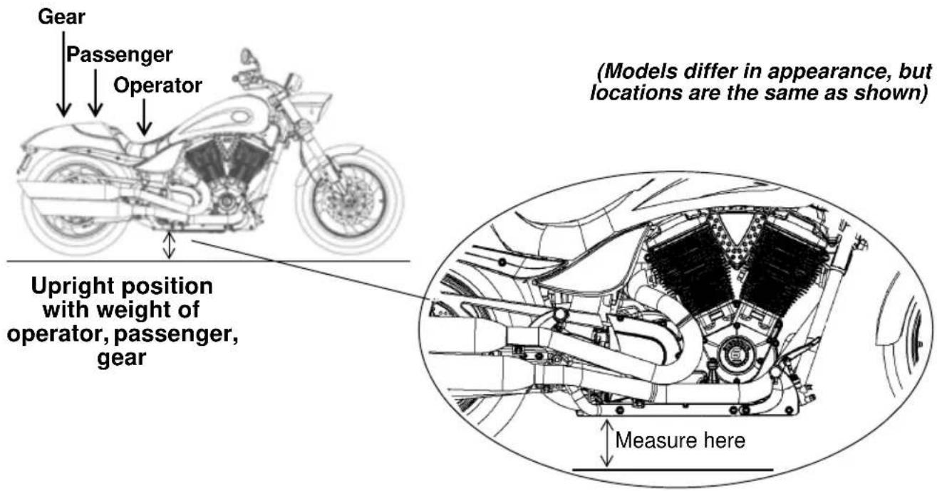
| Ride Height Specifications | |
| HAMMER / HAMMER S 132 mm (5 3/16 inches) | |
| HAMMER 8-BALL / VEGAS / VEGAS 8-BALL / KINGPIN 8-BALL / JACKPOT | 120 mm (4 3/4 inches) +/- 3 mm (1/8 inch) |
| KINGPIN 127 mm (5 inches) +/- 3 mm (1/8 inch) | |
Maintenance
Rear Suspension
Rear Shock Preload (Ride Height) Adjustment
- Rest the motorcycle on the sidestand. Remove the right side cover. See page 25.
- Remove the fuse box. See page 65. Make sure the rear brake fluid reservoir cap is secure to prevent fluid loss.
- Remove the three 10 mm bolts securing the fuse box bracket to the chassis.
- Remove the on-board diagnostics connector from the fuse box bracket by squeezing the connector lock and pulling the connector apart. Leave the terminated end attached to the fuse box bracket.
- Remove the wire harness dart from the fuse box bracket by sliding the connector off the dart clip.
- Carefully pull and rotate the fuse box bracket toward the front of the motorcycle.
- The upper spanner nut on the shock is the lock nut. The lower spanner nut is the adjuster nut. Loosen the lock nut by turning it counterclockwise (as viewed from the top of shock) with the spanner wrench.
- Spray a light lubricant on the adjuster nut where it contacts the spring. DO NOT allow spray to contact the drive belt.
- Adjust shock preload by rotating the adjuster nut clockwise (as viewed from the top of shock) to INCREASE preload (firm) or counterclockwise to DECREASE preload (softer).
- Recheck the preload measurement after adjusting.
- Tighten the lock nut securely against the adjuster nut.
- Reinstall the fuse box bracket and tighten the bolts securely.
- Reinstall the fuse box and side cover.
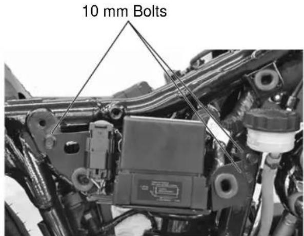
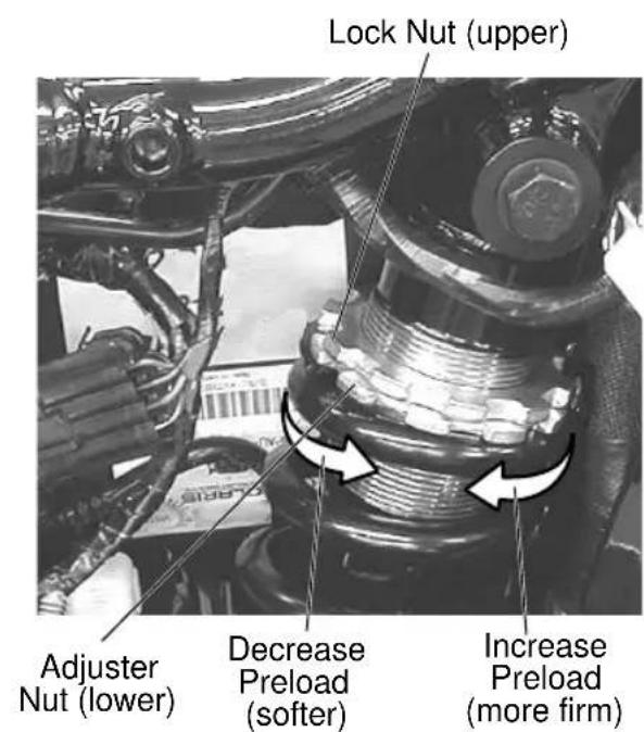
Rear Suspension
Swing Arm and Rear Axle Inspection
- Sit in the operator's seat and slowly bounce the rear suspension a few times. Make sure the suspension moves freely without binding.
- Elevate and support the rear of the motorcycle with the wheel slightly above the ground. Use an appropriate motorcycle support placed securely under the frame.
CAUTION! Make sure the motorcycle is stable when elevated. Injury may occur if the motorcycle tips or falls.
-
Grasp the rear tire and attempt to move the wheel side-to-side.
-
If there is movement at the rear axle, inspect the wheel bearings and rear axle. See the VICTORY Service Manual or your authorized VICTORY dealer.
-
If there is movement at the front of the swing arm, inspect the swing arm pivot bushings/bearings and pivot shaft nut torque. See the VICTORY Service Manual or your authorized VICTORY dealer.
-
With the transmission in neutral, slowly rotate the rear wheel. If the wheel does not rotate smoothly, inspect the wheel bearings, rear axle, belt adjustment and wheel alignment. See the VICTORY Service Manual or your authorized VICTORY dealer.
Front Suspension Front Fork Inspection
-
Place the motorcycle on the sidestand and inspect the front forks. Make sure there is no fork oil present on the outer fork tubes, around the fork seals or around the inner tubes.
-
Clean the fork tubes to remove bugs, tar or buildup which may cause seal wear or leakage.
-
Inspect the outer surfaces of the inner fork tubes for scratches or damage from foreign objects.
-
Straddle the motorcycle and bring it to the fully upright position. Apply the front brake and push downward (hard) on the handlebars several times. The front suspension should operate smoothly and quietly.
-
Fork oil condition and level affects front suspension performance and internal component wear. Replace fork oil at the recommended intervals. Special tools are required to perform this procedure. See the VICTORY Service Manual or your authorized VICTORY dealer.
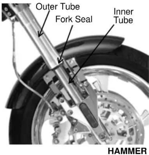
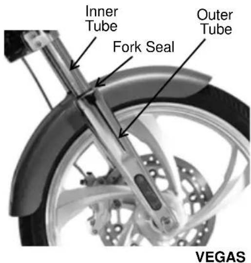
Maintenance
Front Suspension
Steering and Front Axle Inspection
- Elevate and support the front of the motorcycle with the wheel slightly above the ground. Use an appropriate motorcycle support placed securely under the frame.
CAUTION! Make sure the motorcycle is stable when elevated. Injury may occur if the motorcycle tips or falls. - Turn the handlebars from stop to stop. The action should be smooth but not loose. Make sure wires, hoses and control cables do not interfere with smooth steering.
- Position the front wheel straight ahead. Grasp the front forks near the front axle and attempt to move the wheel front-to-back. If there is front-to-back movement at the steering head, the steering head bearings should be inspected, lubricated and adjusted. Lubricate the steering head bearings at the recommended intervals even if there is no front-to-back movement at the steering head. See the VICTORY Service Manual or your authorized VICTORY dealer.
- Turn the handlebars fully to the right or left. Grasp the front tire and attempt to move the wheel side-to-side. If there is movement at the front axle, inspect the wheel bearings and front axle. See the VICTORY Service Manual or your authorized VICTORY dealer.
- Slowly rotate the front wheel. If the wheel does not rotate smoothly, inspect the wheel bearings, front axle and brakes. See the VICTORY Service Manual or your authorized VICTORY dealer.
Fuel System
CAUTION! Always observe all fuel safety procedures when inspecting or servicing the fuel system. See page 13.
Fuel Hose Inspection
Inspect the fuel hoses for cracks or damage. Inspect hose connections at the fuel pump and at the fuel rail for dampness or stains that would indicate a fuel leak.
Crankcase Ventilation Hose Inspection
Remove the operator's seat and fuel tank. Inspect the crankcase ventilation hose for cracks or damage. Inspect hose connections at the air cleaner and at the crankcase for dampness or stains that would indicate a leak.
Evaporative Emission Control System (California Models)
Inspect all evaporative emission control system hoses and connections. Make sure all connections are tight. Inspect the evaporative canister for damage.
Fuel Filters
Fuel filter condition affects engine performance and fuel economy. The fuel filters are attached to the electric fuel pump located inside the fuel tank. Replacement requires special tools. See the VICTORY Service Manual or your authorized VICTORY dealer.
Maintenance
Fuel System
CAUTION! Always observe all fuel safety procedures when inspecting or servicing the fuel system. See page 13.
Fuel Tank Removal/Installation
Before beginning, be prepared to place the fuel tank in a secure location with a drain pan positioned to catch any fuel that may leak or drip from disconnected hoses or fittings.
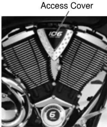
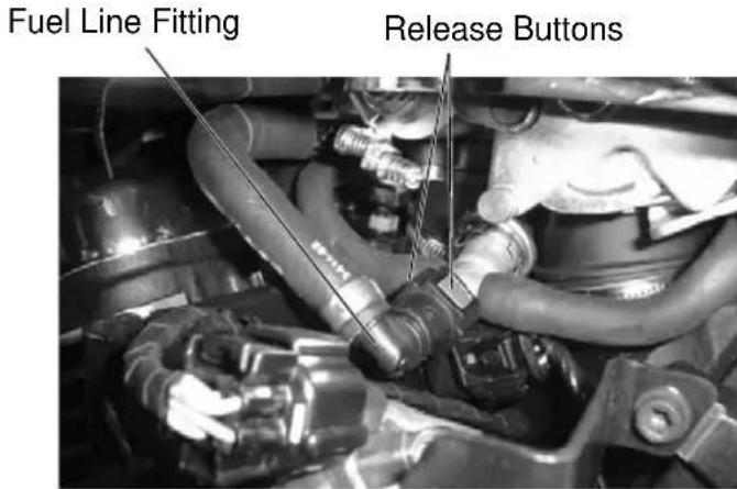
- Remove the operator's seat.
- Remove the fuel line access cover.
- Remove the two front and one rear fuel tank mounting screws.
- With the engine and exhaust cool, wrap a clean shop towel around the fuel line fitting at the fuel rail. Disconnect it from the fuel rail by squeezing both release buttons simultaneously. Gently slide the fitting from the fuel rail.
NOTICE: Fuel can damage painted surfaces and plastic parts. Wipe up spilled fuel immediately using a clean, dry, soft cloth.
- Lift the fuel tank and unplug the fuel pump wire harness at the rear of the tank.
- Disconnect the fuel line from the fuel pump using the same procedure used in step 4.
- At the rear left side of the tank, disconnect the tank vent hose and the water drain hose.
- Carefully remove the fuel tank. Be prepared to catch dripping fuel in an appropriate container.
- To reinstall the fuel tank, reverse the removal steps, routing the fuel supply hose to the right of the breather hose before installing the tank.
- Reinstall the fuel line fitting to the fuel rail by sliding the quick-connect onto the rail connector until you hear it click. Repeat this procedure to install the opposite end of the fuel line at the fuel pump. Make sure you hear the click.
- Reinstall the fuel tank mounting screws.
Torque: 35 ft-lb. (47.5 Nm)
- Reinstall the fuel line access cover. Reinstall the seat.
Maintenance Throttle System
Service the throttle system if throttle operation is not smooth, if throttle grip does not return properly, or if cable ends are frayed. See the VICTORY Service Manual or your authorized VICTORY dealer.
Throttle Freeplay Adjustment
Throttle freeplay is the amount of throttle control grip movement from the rest position to the point of cable resistance. Measure this distance. Freeplay should be 2-4 mm. Adjust throttle freeplay as needed.
- Hold the adjuster nuts securely and loosen the lock nuts on both cables. Turn the lock nuts away from the adjuster nuts as far as possible.
- Turn both adjuster nuts toward the lock nuts as far as possible for maximum freeplay in both cables.
-
Turn the adjuster on the throttle opening cable (front cable) away from the lock nut until throttle freeplay is 2-4 mm.
-
To adjust the closing cable (rear cable), move the throttle grip back and forth continuously while turning the adjuster slowly outward just until freeplay is removed. Then turn the adjuster inward one full turn.
-
Turn the lock nuts on both cables until they are seated against the adjuster nuts. Hold each adjuster nut and tighten each lock nut securely.
-
Measure throttle freeplay.
-
Start the engine with the transmission in neutral. Turn the handlebars fully to the left and to the right. Engine idle speed should not change. If idle speed changes, inspect for a damaged cable, incorrect routing or incorrect adjustments.
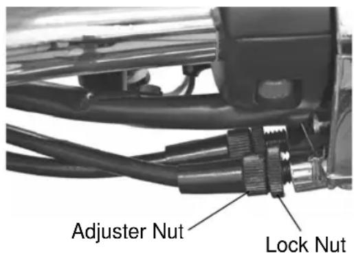
Throttle Cable Lubrication
Lubricate the cable ends at the intervals recommended in the periodic maintenance table. See page 42.
NOTICE: External casings are factory-lubricated. Additional lubrication could be detrimental to cable performance.
Verify proper routing and smooth movement. Inspect for damage to the external casing, and inspect exposed cable wire for fraying, kinks or corrosion. Replace any damaged, sticky or sluggish cable.
- Disconnect the cable at the throttle body.
- Apply a light film of VICTORY All Purpose Grease or equivalent to the barrel end.
- Reconnect the cable and adjust freeplay as needed.
Maintenance
Clutch (Mechanical)
Mechanical Clutch Lever Freeplay
- Remove the right side cover.
- While holding the cable, loosen the adjuster lock nut, turn the cable adjuster (until clutch lever freeplay is 0.5-1.5 mm), then tighten the lock nut securely.
- Reinstall the side cover.
- Verify that the safety switch activates properly. The engine should not start in gear with the clutch lever released.
Mechanical Clutch Lever Lubrication
- Remove the right side cover. Loosen the clutch cable adjuster lock nut.
- Turn the cable adjuster all the way inward to provide maximum lever freeplay.
- Remove the clutch lever pivot nut and screw. Disconnect the clutch cable from the clutch lever.
- Remove any old grease and dirt from the lever and housing. Lubricate the clutch lever and pivot screw with VICTORY Moly Assembly Grease or VICTORY All Purpose grease.
- Reconnect the clutch cable. Reinstall the lever, pivot screw and nut. Hold the screw down and torque the nut to 40 in-lbs (5 Nm).
- Adjust clutch lever freeplay.
Mechanical Clutch Cable Lubrication
Lubricate the cable ends at the intervals recommended in the periodic maintenance table. See page 42.
NOTICE: External casings are factory-lubricated. Additional lubrication could be detrimental to cable performance.
Verify proper routing and smooth movement. Inspect for damage to the external casing, and inspect exposed cable wire for fraying, kinks or corrosion. Replace any damaged, sticky or sluggish cable.
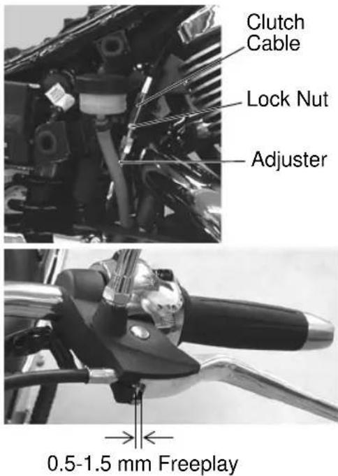
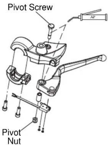
- Disconnect the cable at the clutch lever and at the primary cover.
- Lubricate both barrel ends with VICTORY All Purpose Grease or equivalent.
- Reconnect the cable and adjust freeplay as needed.
Maintenance Clutch (Hydraulic) Hydraulic Clutch Fluid
The fluid level should be at or above the top of the sight glass. Add fluid as needed. Replace cloudy or contaminated fluid.
Use DOT4 brake fluid in the hydraulic clutch reservoir. Use fluid only from a sealed, clean container.
Do not operate the clutch while the reservoir cover is removed. Fluid could overflow from the reservoir and cause air to enter the fluid system.
WARNING! Using the wrong fluid or allowing air or contaminants into the fluid system can damage the system seals or result in a malfunction that could lead to serious injury or death.
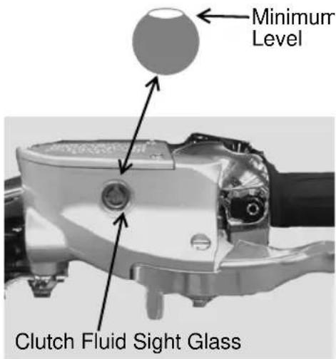
-
Straddle the motorcycle and bring it to the fully upright position. Position the handlebars so that the fluid reservoir is level.
-
Wipe the fluid container and the area around the reservoir cover with a clean cloth.
-
Remove the reservoir cover and gasket. Carefully add fluid to the recommended level. Reinstall the reservoir gasket and cover.
Hydraulic Clutch Lever Lubrication
-
Remove the clutch lever pivot nut and screw. Remove any old grease and dirt from the lever and housing.
-
Lubricate the clutch lever and pivot screw with VICTORY Moly Assembly Grease or VICTORY All Purpose grease.
-
Reinstall the lever, pivot screw and nut. Torque the pivot screw to 9 in-lbs (1 Nm). Torque the nut to 52 in-lbs (6 Nm).
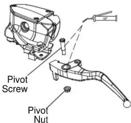
Gear Shift Pedal
Do not remove and reposition the shift arm on the shift shaft to adjust gear shift pedal height. A 90_+/-5_ angle between the shift arm and the linkage rod is necessary to ensure correct shift linkage operation.
-
Loosen the gear shift linkage rod lock nuts.
-
Turn the linkage rod inward or outward as necessary.
-
Tighten the linkage rod lock nuts.
-
Check the gear shift pedal height.
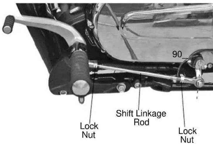
Maintenance
Brake Systems
Front Brake Fluid
Check the front brake fluid level. See page 29. The fluid level should be at or above the top of the sight glass. Add fluid as needed. Replace cloudy or contaminated fluid.
Use DOT4 brake fluid in the brake fluid reservoir. Use fluid only from a sealed, clean container.
Do not operate the brake while the reservoir cover is removed. Fluid could overflow from the reservoir and cause air to enter the fluid system.
WARNING! Using the wrong fluid or allowing air or contaminants into the fluid system can damage the system seals or result in a malfunction that could lead to serious injury or death.
- Straddle the motorcycle and bring it to the fully upright position. Position the handlebars so that the fluid reservoir is level.
- Wipe the fluid container and the area around the reservoir cover with a clean cloth.
NOTICE: Brake fluid will damage painted surfaces and plastic parts. Always clean spilled brake fluid immediately with water and a mild detergent.
- Remove the reservoir cover and gasket.
- Carefully add fluid to the recommended level.
- Reinstall the reservoir gasket and cover.
Rear Brake Fluid
Check the rear brake fluid level. See page 31. The fluid level should be between the minimum and maximum marks on the reservoir. Add fluid as needed. Replace cloudy or contaminated fluid.
Use DOT4 brake fluid in the brake fluid reservoir. Use fluid only from a sealed, clean container.
Do not operate the brake while the reservoir cover is removed. Fluid could overflow from the reservoir and cause air to enter the fluid system.
WARNING! Using the wrong fluid or allowing air or contaminants into the fluid system can damage the system seals or result in a malfunction that could lead to serious injury or death.
- Secure the motorcycle in a vertical position with an appropriate motorcycle lift.
- Remove the right side cover.
- Wipe the fluid container and the area around the reservoir cover with a clean cloth.
NOTICE: Brake fluid will damage painted surfaces and plastic parts. Always clean spilled brake fluid immediately with water and a mild detergent.
- Remove the reservoir cover and gasket.
- Carefully add fluid to the recommended level.
- Reinstall the reservoir gasket and cover.
- Reinstall the side cover.
Maintenance
Brake Systems
Brake Lever Lubrication
Lubricate at the intervals recommended in the periodic maintenance table. See page 42.
- Remove the right side mirror.
-
Remove the brake lever pivot nut (10 mm wrench or socket) and pin (4 mm hexagonal wrench). Note the direction the plunger is installed (if removing). Proper direction is critical for brake function.
-
Remove any old grease and dirt from the lever and housing.
-
Lubricate the lever and pivot pin with VICTORY All Purpose Grease or equivalent.
-
Reinstall the lever and pivot pin.
Torque: 52 in-lbs (6 Nm)
- Reinstall the pivot nut.
Torque: 52 in-lbs (6 Nm)
-
Check front brake lever movement. See page 29.
-
Reinstall the right side mirror and adjust.
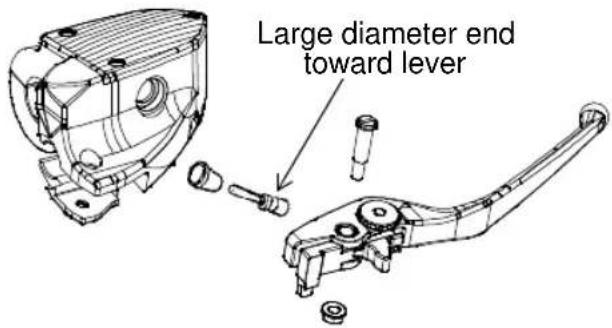
Brake Lines
Inspect all brake hoses and connections for dampness or stains from leaking or dried fluid. Tighten any leaking connections and replace components as necessary. Torque fasteners to specification. See the VICTORY Service Manual or your authorized VICTORY dealer.
Brake Pads
Inspect front and rear brake pad thickness. Replace brake pads when wear lines are no longer visible, or when pad thickness reaches 1.5 mm.
The shielded pad must be installed on the non-piston side of the caliper. See the VICTORY Service Manual or your authorized VICTORY dealer.
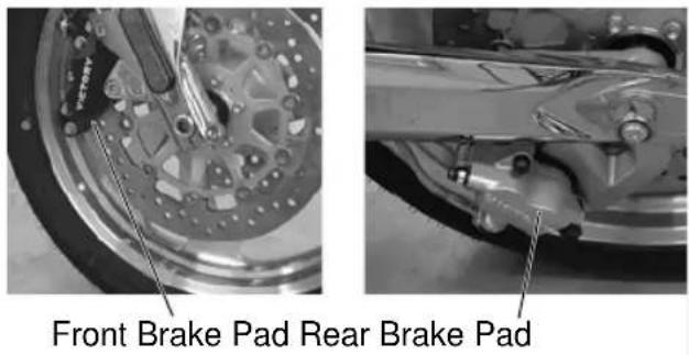
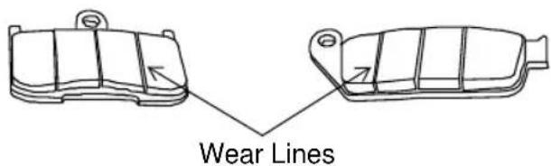
Brake Discs
Inspect brake discs for nicks, scratches, cracks or other damage. Inspect the thickness of each brake disc at four or more locations around the disc. Minimum thickness is stamped on the inner hub of the disc. If any disc is worn to the minimum thickness at the thinnest point, or if a disc is damaged, see your VICTORY dealer for replacement.
Tires

WARNING
Operating the motorcycle with improper tires or with improper or uneven tire pressure could cause loss of control or accident. Always use the correct size and type of tires specified for your vehicle. Always maintain proper tire pressure as recommended in the owner's manual and on safety labels.
Tire Pressure
Riding warms the tires and increases tire air pressure. For an accurate reading, check tire pressure before riding. Adjust tire pressure as recommended for the total weight of your intended load (see table).
WARNING! Do not exceed the maximum recommended inflation pressure to seat the bead. Tire or rim failure may result.
| Location | Size Brand Type | Recommended Pressure | |||
| Loads up to 200 lbs (91 kg) | Loads up to maximum load capacity | ||||
| HAMMER / HAMMER S / HAMMER 8-BALL | |||||
| Front 130/70R18 63H Dunlop Elite 3 36 psi (248 kPa) 38 psi (262 kPa) | |||||
| Rear 250/40R18 81V Dunlop Elite 3 38 psi (262 kPa) 41 psi (283 kPa) | |||||
| VEGAS JACKPOT | |||||
| Front 90/90 2154H Dunlop Elite 3 36 psi (248 kPa) 38 psi (262 kPa) | |||||
| Rear 250/40R18 81V Dunlop Elite 3 38 psi (262 kPa) 41 psi (283 kPa) | |||||
| NESS JACKPOT | |||||
| Front 90/90 21 54H Dunlop Elite 3 36 psi (248 kPa) 38 psi (262 kPa) | |||||
| Rear 250/40R18 81V Dunlop Elite 3 38 psi (262 kPa) 41 psi (283 kPa) | |||||
| VEGAS / VEGAS 8-BALL | |||||
| Front 90/90 2154H Dunlop Elite 3 36 psi (248 kPa) 38 psi (262 kPa) | |||||
| Rear 180/55 B18 74H Dunlop D417 36 psi (248 kPa) 41 psi (283 kPa) | |||||
| KINGPIN / KINGPIN 8-BALL | |||||
| Front | 130/70 B18 63H | Dunlop | 491 Elite II | 32 psi (221 kPa) | 36 psi (248 kPa) |
| Rear 180/55 B18 74H | Dunlop | D417 36 psi (248 kPa) 41 psi (283 kPa) | |||
Tire Condition
Inspect the tire sidewalls, road contact surface and tread base for cuts, punctures and cracking. Replace damaged tires immediately. See the VICTORY Service Manual or your authorized VICTORY dealer.
Tire Tread Depth
The raised areas at the base of the tread are wear bars. When the road contact surface has worn to the top of the wear bars, replace the tire. For more precise measurement, use a depth gauge or an accurate ruler to measure the depth of the center tire tread. Replace the tire if the tread depth is less than 1/16 inch (1.6 mm).
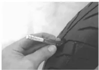
natural_image
Close-up of a hand holding a medical or surgical tool near a dark garment (no visible text or symbols)Maintenance Wheels
Inspect both wheels for cracks or damage and replace damaged wheels promptly. Do not operate the motorcycle if wheels are damaged or cracked. See the VICTORY Service Manual or your authorized VICTORY dealer.
Spark Plugs
Spark Plug Recommendations
Replace spark plugs at the intervals recommended in the periodic maintenance table. See page 42. Always replace spark plugs in pairs.
| Spark Plug Specifications | |
| Spark Plug Type NGK D | CPR6E |
| Spark Plug Gap .031-.03 | 5 inch (0.8-0.9 mm) |
| Spark Plug Torque 10.8- | 14.5 ft-lbs (14.6-19.7 Nm) |
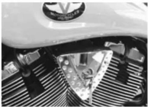
natural_image
Close-up of a motorcycle's front wheel and grille (no visible text or symbols)Spark Plug Inspection
CAUTION! Wear face protection when using pressurized air.
- Make sure the engine is at room temperature.
- Disconnect the spark plug wires by pulling upward on the spark plug boots.
- To prevent any debris from entering the engine through the spark plug hole, use pressurized air to clean the area around each spark plug before removing it.
- Remove the spark plug from the cylinder head with a 5/8-inch spark plug socket.
Tip: Both spark plugs should have the same light or medium tan color deposits on the insulator around the electrode tip. The spark plug electrode tip and bridge should have sharp, square edges.
- If spark plugs are in good condition and are not due for replacement, clean them with a non-metallic stiff bristle brush, set the gap with a spark plug gap tool, clean the mating surface on the cylinder head, and install the spark plug with a spark plug socket. Reinstall both spark plug wires.
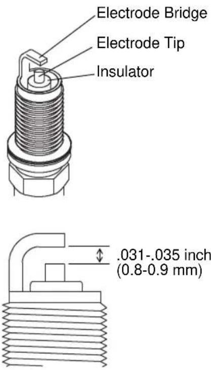
Tip: Spark plugs with bright white or sooty black deposits or with damaged insulators or electrodes can indicate engine problems. If these conditions exist, or if the condition of one plug is markedly different from the other, see the VICTORY Service Manual or your authorized VICTORY dealer.
Maintenance
Engine Compression
Check engine compression periodically to document engine wear and condition. For engine compression check procedures and special tools required, see the VICTORY Service Manual or contact an authorized VICTORY dealer.
Exhaust System
Check the exhaust system for stains from leaking exhaust gasses. Replace damaged or leaking exhaust gaskets. See the VICTORY Service Manual or your authorized VICTORY dealer.
Check all exhaust system fasteners.
- Tighten exhaust header flange nuts.
Torque: 12 ft-lbs (16 Nm)
- Tighten muffler mounting screws.
Torque: 18 ft-lbs (24.5 Nm)
- Tighten the support bracket nut.
Torque: 35 ft-lbs (47.5 Nm)
- Tighten muffler clamps.
Torque: 31 ft-lbs (42 Nm)
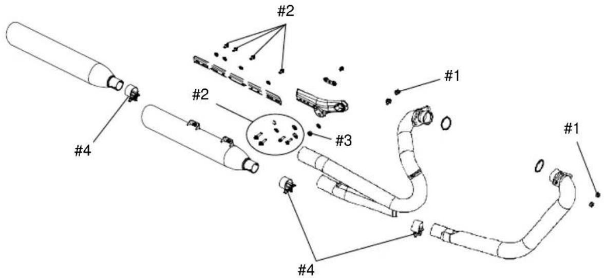
Maintenance
Seat Removal (HAMMER)
WARNING! A loose seat could cause a sudden shift in riding position, causing loss of control. Always ensure seats are secure before riding.
- Remove the passenger seat cowl by pulling evenly and directly upward on both sides of the cowl.
- Remove the (3) socket head seat screws using a 5 mm hexagonal wrench.
- Lift the rear of the seat and pull rearward to disengage the tab at the front of the seat. Remove the seat.
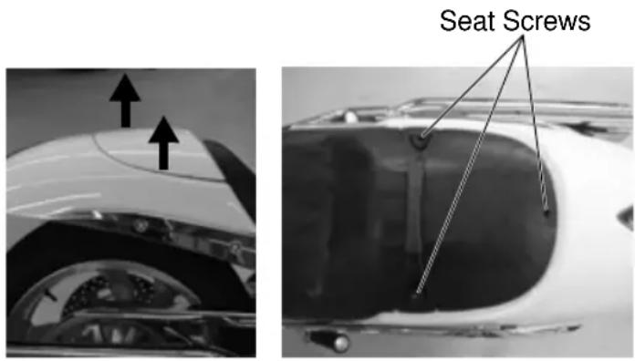
Seat Installation (HAMMER)
- Slide the seat tongue into the receiver at the rear of the fuel tank. Align the seat screw holes.
- Ensure the front seat mount is engaged in the front receiver, then install the screws. Torque: 57 in. lbs. (6.8 Nm)
- Reinstall the passenger seat cowl.
Seat Removal (JACKPOT)
WARNING! A loose seat could cause a sudden shift in riding position, causing loss of control. Always make sure the seats are securely fastened before riding the motorcycle.
- Remove the side covers.
- If necessary, remove the fuse box from the bracket.
- Remove the three screws securing the seat to the frame. Lift the rear of the seat and pull rearward and upward to remove it.
Seat Installation (JACKPOT)
- Slide the seat tongue into the rubber mount at the rear of the fuel tank. Push down on the rear of the seat until the screw holes align.
- Ensure the front seat mount is engaged in the front rubber mount, then install the screws and tighten securely.
- Reinstall the fuse box (if removed).
- Reinstall the side covers.
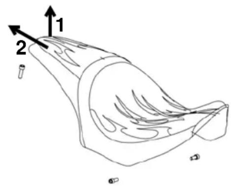
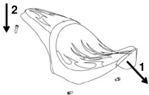
Maintenance
Seat Removal (VEGAS/KINGPIN)
WARNING! A loose seat could cause a sudden shift in riding position, causing loss of control. Always make sure the seats are securely fastened before riding the motorcycle.
- Remove the side covers.
- Remove the fuse box from the bracket.
- Remove the two screws (left and right) securing the seat to the frame.
- Lift the rear of the seat and pull rearward and upward to remove it.
Seat Installation (VEGAS/KINGPIN)
- Slide the seat tongue into the rubber mount at the rear of the fuel tank. Push down on the rear of the seat until the screw holes align.
- Ensure the front seat mount is engaged in the front rubber mount, then install the screws and tighten securely.
- Reinstall the fuse box.
- Reinstall the side covers.
Battery
The motorcycle battery is a sealed, maintenance-free battery. Do not remove the battery cap strip for any reason. Keep the battery connections clean and tight at all times.
WARNING
Battery electrolyte is poisonous. It contains sulfuric acid. Serious burns can result from contact with skin, eyes or clothing.
Antidote:
External: Flush with water.
Internal: Drink large quantities of water or milk. Follow with milk of magnesia, beaten egg, or vegetable oil. Call physician immediately.
Eyes: Flush with water for 15 minutes and get prompt medical attention.
Batteries may produce explosive gases.
- Keep sparks, flame, cigarettes, etc. away.
- Ventilate when charging or using in an enclosed space.
• Always shield eyes when working near batteries - KEEP OUT OF REACH OF CHILDREN.
Maintenance
Battery
Battery Removal
- Remove the seat and left side cover.
- Remove battery cover retaining nuts, and remove the cover.
WARNING! Improperly connecting or disconnecting battery cables can result in an explosion and cause serious injury or death. When removing the battery, always disconnect the negative (black) cable first. When reinstalling the battery, always connect the negative (black) cable last.
- Disconnect the negative (-) battery cables (black cables with ends exposed) first.
- Disconnect the positive (+) cables (cable ends are covered with a red boot).
- Slide the battery out.
Battery Charging
- Clean oxidation from battery posts and cable connectors with a wire brush. Wash the posts and cable connectors with a solution of one part baking soda to 16 parts water. Rinse with clean water and wipe dry. Apply a thin film of dielectric grease to the posts and cable connectors.
- Following the charger manufacturer's instructions, use an accessory battery charger or a charger designed for use with 12-volt batteries. The charger should have a maximum charging rate of 1.8 amps. Charge the battery for approximately 10 hours at a rate of 1.8 amps. If you use a taper or trickle charger, it will take longer to charge the battery.
- After charging the battery, allow the battery to sit 1-2 hours before checking the state of charge with a DC volt meter. The charge should be a minimum of 12.5 DC volts. Repeat the charging cycle if the charge is less than 12.5 DC volts. Replace the battery if it fails to reach 12.5 volts after the second charge.
Tip: An accessory maintenance charger is available through your authorized VICTORY dealer.
Battery Installation
- Before installing the battery, make sure it's fully charged and clean.
- Slide the battery into position in the battery tray with the positive (+) terminal to the rear of the motorcycle.
NOTICE: Connecting the battery cables to the wrong terminals can severely damage the electrical system.
- Connect the positive (+) battery cables, tighten securely and install the red boot.
- Connect the negative (-) cables and tighten securely. Be sure cables have adequate side cover clearance.
- Reinstall the battery cover.
- Reinstall the side cover.
Fuse Replacement
- Remove the right side cover.
-
Lift the release tab and slide the fuse box rearward to remove it from the bracket. Release the tabs on each side of the fuse box cover and remove the cover.
-
Remove the damaged fuse and seat the new fuse firmly in its place.
-
Reinstall the fuse box cover with the double cutout toward the front of the motorcycle.
- Reinstall the fuse box and side cover.
NOTICE: Use fuses with the recommended amperage to avoid damage to the electrical system.
Maintenance
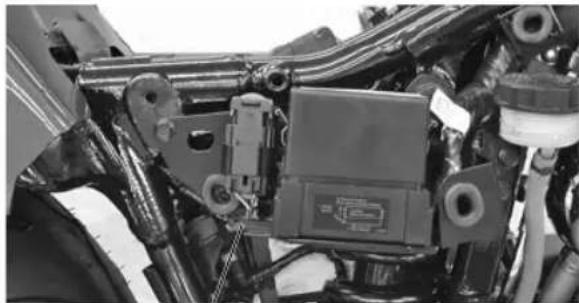
natural_image
Close-up of mechanical components with hoses and a central control unit (no visible text or symbols)Release Tab
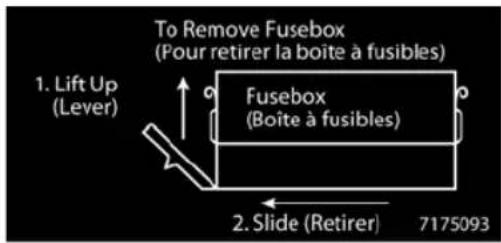
Maintenance Headlight Aim Inspection
The top edge of the high beam must be 3 inches (7.6 cm) below the height of the headlight housing parting line and centered straight ahead at 25 feet (7.6 m).
- Verify that tire pressure is at specification. See page 59.
- Verify that rear suspension ride height (preload) is at specification. Include rider, passenger (if applicable) and cargo when setting preload. See page 49.
- Position the motorcycle on a level surface with the headlight 25 feet (7.6 m) from a wall.
With the operator and passenger (if applicable) on board, bring the motorcycle to the fully upright position.
- Move the ignition switch to the ON position and switch the headlamp to high beam. Observe the headlight aim on the wall.
- Make any necessary adjustments to headlight aim.
Headlight Aim Adjustment
- To adjust the headlamp vertically, hold the headlamp firmly while loosening the adjustment bolt. Adjust the headlamp and hold it firmly in position while tightening the bolt.
Torque: 35 ft-lbs (47.5 Nm)
- To adjust the headlamp horizontally, loosen the horizontal adjustment nut. Adjust the headlamp and hold it firmly in position while tightening the nut.
Torque: 28 ft-lbs (38 Nm)
- Verify proper headlight aim. Readjust if necessary.
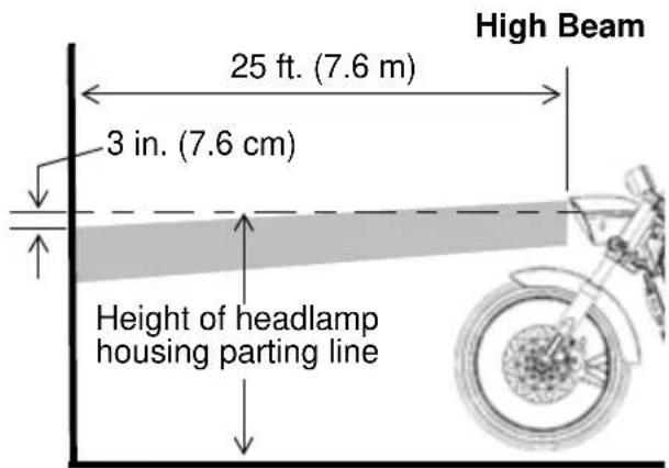
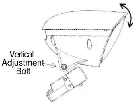
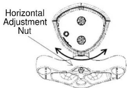
Maintenance
Headlight Lamp Replacement
High intensity discharge lamps should be handled only by a trained technician wearing the appropriate protective gear. See the VICTORY Service Manual or an authorized VICTORY dealer.
Halogen Lamps (8-BALL Models)
- Unplug the wiring harness from the back of the headlight (lift the tab). Be sure to pull on the connector, not on the wiring.
Tip: Avoid touching a halogen lamp with bare fingers. Oil from your skin leaves a residue, causing a hot spot that will shorten the life of the lamp. If a lamp is touched, clean it thoroughly with denatured alcohol. - Remove the spent lamp. Apply dielectric grease to the socket and install a new lamp.
- Reinstall the wiring harness.
Sidestand Lubrication
- Secure the motorcycle in a fully upright position using an appropriate motorcycle lift or a block of wood or steel placed securely under the frame.
- Move the sidestand upward to its stored position.
CAUTION! Wear face protection. The sidestand return spring is under tension and can injure your eyes and face when released.
- Hold the nut and remove the sidestand pivot bolt and sidestand return spring. Wipe any old grease and dirt from the sidestand, frame and pivot bolt.
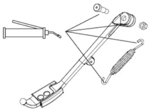
natural_image
Technical line drawing of a mechanical clamp or tool assembly (no text or symbols)- Lubricate the sidestand, the pivot bolt and the ends of the spring with VICTORY All Purpose Grease or equivalent.
- Reinstall the sidestand spring and place the sidestand on the mounting boss with the stand in the stored (up) position. Install the pivot bolt and tighten it while holding the nut.
Torque: 35 ft-lbs (47 Nm)
- Verify that the sidestand moves freely through its pivot range.
Cleaning
Suede Paint Finishes
If your motorcycle has a suede paint finish, do not use conventional cleaning methods to clean your motorcycle. Suede paint is different from VICTORY's usual high-gloss finish. Like suede fabric, suede paint changes as you interact with the finish. It will change with time, exposure to elements and use. The quality of the paint is not affected by these changes.
Suede paint cannot be buffed out if it becomes scratched or scuffed. If polished, the finish will become less flat or matte. This finish cannot be repaired if it receives heavy damage such as a scratch or chip.
Suede Finish Cleaning
Suede paint should be cleaned and cared for in the following manner:
-
Spray Pure Victory Polish Suede Finish Cleaner (#90949) directly on all the suede bodywork.
-
Using a Pure Victory Polish 100% Microfiber Polishing Towel (#90962), wipe the cleaner into the surface, then wipe the finish dry using a clean, dry surface of the towel.
-
After you have cleaned and dried your suede bodywork, apply Pure Victory Polish Suede Finish Protectant (#90950) to maintain and protect the beauty of your VICTORY motorcycle. Be sure to apply the protectant after every cleaning.
Suede Finish Protectant
-
Spray Pure Victory Polish Suede Finish Protectant (#90950) onto the suede bodywork. Use a Pure Victory Polish 100% Microfiber Polishing Towel (#90962) or Microfiber Applicator (#90965) to rub the protectant thoroughly into the surface.
-
Using a clean, dry microfiber towel, wipe the surface to achieve that showroom-new suede finish.
-
IMPORTANT: Be sure to apply Pure Victory Polish Suede Finish Protectant after every cleaning.
Cleaning
Pure VICTORY Products
This section provides tips on the very best way to clean, polish and preserve every surface of your beautiful new VICTORY Motorcycle. If your motorcycle has a suede paint finish, do not use conventional cleaning methods to clean your motorcycle. See page 68.
We recommend the use of our new Pure VICTORY cleaning and polishing products and accessories, which have been specially designed to offer the best care possible for your VICTORY motorcycle.
In addition to the products recommended in this section for cleaning and polishing, Pure VICTORY Polishes also has specialty products for:
- removing scratches, scuffs and swirls
• enhancing black and silver engines - cleaning engines, tires and wheels
- removing brake dust
After cleaning the motorcycle, inspect for damage to the painted surfaces. Repair chips or scratches promptly by applying VICTORY touch-up paint to prevent corrosion. For more information, or for answers to your cleaning and detailing questions, see your VICTORY dealer or write to the Pure VICTORY Polishes Staff at: victorymailbag@polarisind.com.
Washing the Motorcycle
Before Washing
- Make sure exhaust pipes are cool. Cover each pipe opening with a plastic bag secured with a strong rubber band.
- Check that the spark plugs, spark plug wire caps, oil fill cap and fuel caps are properly seated.
- Rinse off as much dirt and mud as possible with water running at low pressure. Use as little water as possible when washing near the air cleaner or the exhaust pipe openings. Dry these components thoroughly before using the motorcycle.
- Clean the front fork tubes thoroughly to reduce fork seal wear and leakage.
- After washing, remove the rubber bands and plastic bags from the exhaust pipes. Start the engine and let it idle for a few minutes. Make sure the brakes are functioning properly before riding.
NOTICE: Do not use pressurized water to wash the motorcycle. Water may seep in and deteriorate wheel bearings, brake caliper assemblies, brake master cylinders, electrical connectors, steering head bearings, and transmission seals. Do not direct any water stream at air intakes, exhaust outlets or electrical connectors.
Electrical components may be damaged by water. Do not allow water to contact electrical components or connectors.
Do not use glass cleaners, water or soil repellents, and petroleum or alcohol based cleaners on the windshield, as these products can damage the windshield.
Cleaning
Washing the Motorcycle
There are two totally different styles of motorcycle washing and there is a Pure VICTORY Polish product for each style. If your motorcycle has a suede paint finish, do not use conventional cleaning methods to clean your motorcycle. See page 68.
Standard "Bucket Wash"
This is the conventional way to wash your motorcycle. We recommend the use of Pure VICTORY Bike Wash Concentrate, a concentrated gentle product formulated to clean without diminishing the life of any durable polish. This product does not contain alkalis, acids or abrasives and is formulated to perform as a wetting agent to soften bugs, road grime and soil, and to prevent abrasion from your wash mitt or cloth. This product also decreases drying time without spotting or streaking.
- Add 1 ounce (about 2 capfuls) to 1 gallon of water.
- Apply to a cool motorcycle with a wool or microfiber wash mitt.
Tip: For best results, work one side of the motorcycle at a time, working from top to bottom. - Rinse thoroughly with an open hose, no pressure needed. Create a sheeting action to eliminate spotting.
- Use a Pure VICTORY Microfiber Chamois or Plush Microfiber Towel to dry virtually spot-free.
Spray-Rinse-and-Ride Wash
This is the new way to clean your VICTORY quickly and easily, then resume riding. Pure VICTORY Spray Rinse and Ride bike wash is safe and will not harm any surface that water won't harm. If your motorcycle has a suede paint finish, do not use conventional cleaning methods to clean your motorcycle. See page 68.
If you clean your bike frequently, you may mix this product 50/50 with water. Spray the product on surfaces cool to the touch. DO NOT spray on a hot motorcycle. When applied, this product softens dirt, soil, bugs and road grime.
- Spray windshields, body panels, saddle bags, trunks, engines, tires, wheels, pipes and chrome. Consistent and complete coverage of the motorcycle is important for best results.
Tip: Use a cloth or wash mitt on stubborn areas.
- DO NOT allow the product to dry on your motorcycle. Blast rinse with a garden hose equipped with a pressure nozzle. Be sure to rinse thoroughly, then use a gentle rinse to create sheeting action of the water to lessen the possibility of spotting.
Tip: Use a Pure VICTORY Microfiber Chamois or Plush Microfiber Towel to dry virtually spot-free.
Cleaning
Quick Clean-Ups
For quick clean-ups between washings, or when water is not available, use Pure VICTORY Spray & Wipe Instant Detailer, a complete spray-and-wipe product designed to clean and polish all surfaces. It works quickly and easily and is silicone-free so it leaves no oily nor white residue. It provides protection from UV rays, acid rain, and dirt. It will remove bugs, road tar, and road grime from your windshield, paint and chrome. This product is safe for all surfaces, including pin striping, custom paint or murals. It’s safe for Plexiglas, Lexan, Acrylic or factory-coated windscreens. It’s non-streaking, and it provides polish protection and a water-repellent shine.
If your motorcycle has a suede paint finish, do not use conventional cleaning methods to clean your motorcycle. See page 68.
- Spray on all surfaces, including the windshield, paint, chrome, wheels and leather to clean, polish and protect.
- Wipe dry with Pure VICTORY Plush Microfiber Towel. DO NOT use a T-shirt.
- Spray on and wipe off to easily remove bugs, dust and water spots. For heavily soiled surfaces, use product more liberally.
Tip: Use this product on the windshield to repel water and enhance rain visibility.
Polishing the Motorcycle Polished Aluminum Care
When a VICTORY is new, the polished aluminum wheels, hand levers and shifter shine like chrome. Ultraviolet (UV) rays and oxidation will cause polished aluminum to grow dull, however, if it's not properly polished and protected.
Pure VICTORY Awesome Metal Polish will clean, polish and protect these aluminum surfaces. This metal polish will restore that factory chrome-like shine and leave a protective coating that resists future oxidation for several months. Pure VICTORY Awesome Metal Polish provides instant results you must see to believe!
- Shake the polish container well before using.
- Apply the product with a terry cotton or microfiber cloth or pad.
- Rub gently until the black begins to come to the surface or until shine begins to show through the haze.
- Allow the product to haze.
- Remove the haze with a terry cotton or microfiber cloth and buff to a long-lasting chrome-like shine.
Cleaning
Polishing the Motorcycle
There are now two totally different styles of polishing or protecting your paint and chrome.
Standard Method of Polishing Paint and Chrome
Pure VICTORY Windshield, Paint and Chrome Polish is a unique formula designed to produce a glass-like shine on painted or clear-coated finishes and chrome surfaces.
- Use it on chrome-plated accessories to prevent surface rust and create a glass-like shine.
- This product creates a deep, shiny finish without silicone.
- Use it to polish and fill light scratches on Plexiglas, Lexan, Acrylic and factory-coated windshields.
- It repels water from windshields and keeps bugs from sticking.
-
Windshield, Paint and Chrome Polish provides long-lasting protection from oxidation, corrosion, UV rays and heat.
-
Shake the container well before using.
- Apply with Pure VICTORY 100% Microfiber Wax Applicator in a circular motion or straight line to a clean surface. It can be applied in direct sunlight.
- Rub the product until it is almost clear, then allow to dry to a haze before removal. The entire motorcycle can be treated before removing polish.
- Use a Pure VICTORY Polishes Plush Microfiber Towel to wipe it off easily and dust-free.
- For best results on a windshield, apply to a clean windshield. Once applied, rain water beads and blows off, enhancing rain visibility. The glass-like finish keeps bugs from sticking and permits their easy removal.
Polishing the Motorcycle
Premium Polishing for Long-Lasting Protection
This newer style of polishing paint and chrome utilizes the latest in high-quality polymer technology that provides the longest-lasting protection available in the polish industry today. Pure VICTORY Liquid Spray Wax for Windshields, Paint & Chrome is formulated for polishing after washing and can be sprayed on wet or dry surfaces. Liquid Spray Wax quickly produces a durable, high-gloss shine with minimal effort. It contains NO ABRASIVES and is clear coat-safe. It contains NO PETROLIUM DISTILLATES or SILICONES.
- Shake container well before use.
- Begin by washing and rinsing the motorcycle.
- Spray Liquid Spray Wax on a wet or dry bike, one section at a time. (For best results, the bike's surface should be cool.)
- Wipe dry one section at a time with Pure VICTORY Microfiber Chamois or microfiber towel.
- When finished drying, buff the entire motorcycle with a clean, dry Pure VICTORY Microfiber Polishing Towel for a clean and luxurious shine.
Tip: Liquid Spray Wax can also be applied to clean and dry clear coats, windshields and chrome. Apply to one section at a time and wipe dry. When finished, use a second towel to buff to a luxurious, long-lasting shine.
Leather, Rubber and Vinyl Care
WARNING
Never use a non-recommended protectant on seats, footrests, hand grips or tires. Slippery seats, footrests or hand grips can cause loss of control. Slippery tires can cause loss of traction and loss of control. Both situations could result in serious injury or death.
For the finest leather care, use Pure VICTORY Leather, Vinyl & Rubber Conditioner, a unique, pleasantly scented formula of premium-quality polymers designed to restore luster and softness to vinyl, leather and rubber without making them slippery.
This product is a true conditioner, not a coating. It does not close the pores of the surfaces but penetrates, nourishes and softens the material. It protects against ultra violet (UV) rays and cracking, repels water and prolongs the life and like-new appearance of the materials. Applied to rubber, this product creates a water-repellent, like-new appearance. Regular use increases soil resistance.
- Apply the product on a clean dry surface using a soft cloth.
- Rub the product into the material. Repeat the treatment if the surface is extremely dry.
- Wipe dry with a second cloth to remove excess product. Buff lightly with the second towel for additional luster.
Storage
If you will not operate the motorcycle for several months, such as during the winter, store the motorcycle to prevent damage to the fuel system and the battery and to protect components from corrosion or deterioration. During storage you might use products that are potentially hazardous; such as fuel stabilizer. When using any of these products, follow the instructions and warnings on the product packaging.
This section includes instructions for preparing the motorcycle for storage, maintaining it during storage and removing it from storage.
Storage Area Preparation
Choose a dry, well-ventilated storage location, inside a garage or other structure if possible. The location should have a firm, flat surface and allow enough space for the motorcycle.
To best preserve tire condition:
- The storage area should have a relatively constant and moderate temperature.
- The storage surface should be free of oil and gasoline.
- The motorcycle should not be near a heat source or any type of electric motor.
Clean and Protect the Motorcycle
Clean the motorcycle before placing it in storage. See page 69. Wax painted surfaces and polish chromed and other metal surfaces. Apply protectant to exposed rubber, vinyl, and plastic parts. Do not apply rubber protectant to the tire tread surfaces.
Fuel Stabilizer
Using a mixture of fuel and the recommended amount of VICTORY Premium Carbon Clean Plus or other gasoline stabilizer, fill the fuel tank to a level just below the bottom of the fuel filler insert.
Ride the motorcycle or start and run the engine for 15 minutes in a well ventilated area to pass the stabilized fuel through entire fuel-injection system.
Engine Protection
Change the engine oil. See page 43. Carbon deposits and combustion acids, normally suspended in the engine oil when in service, settle on internal engine components during storage. Settled deposits can cause engine damage or internal corrosion.
Tire Inflation
Verify that tire pressure is at specification. See page 59. Check and adjust tire pressure as needed during the storage period.
Battery Care
- Remove the battery. See page 64.
- Clean oxidation from battery posts and cable connectors with a wire brush. Wash the posts and cable connectors with a solution of one part baking soda to 16 parts water. Rinse with clean water and wipe dry. Apply a thin film of dielectric grease to the posts and cable connectors.
- Clean the outside of the battery with a solution of mild detergent and warm water.
- Store the battery in a dry area with a temperature of 32^ to 90^ F ( 0^ to 32^ C).
- While in storage, fully charge the battery monthly. If the motorcycle will not be used for a period of six weeks or longer, a maintenance charger should be connected to the battery. See page 64. A fused maintenance charger connection is provided under the left side cover. The connector is designed for use with the VICTORY maintenance charger.
Motorcycle Covers
Cover the motorcycle with a genuine VICTORY motorcycle cover or a cover made from a durable, breathable material designed for storage. The cover must be of a breathable material to prevent moisture build-up, which can cause oxidation of metal surfaces.
Protection from Rodents
If the motorcycle will be stored in an area where mice are a concern (rural areas, barns, sheds, etc.), take extra measures to deter infestation. This may include placing a screen mesh over any intake or exhaust openings.
Removal From Storage
- Remove the cover and any intake or exhaust coverings.
- Unlock the front forks (if locked).
- Verify that tire pressure is at specification.
- Install the battery and perform an electrical inspection.
- Check the oil level. If the motorcycle was stored in an area subject to wide swings in temperature and humidity (such as outdoors), change the engine oil before starting the engine. See page 43, beginning with step 3.
NOTICE: During storage, temperature and humidity changes can cause condensation to form in the crankcase and mix with engine oil. Running the engine with oil that contains condensation can cause engine damage.
-
Inspect the storage area for signs of fluid leaks. Identify and perform service to any leaking components.
-
Install new spark plugs if necessary.
-
Wash and polish the motorcycle. Wax, polish, or apply protectant to appropriate components.
-
Perform the pre-ride inspections. See page 26.
-
Perform a road test. See page 41.
Warranties Motorcycle Noise Regulation
Tampering with noise control systems is prohibited. Federal law prohibits the following acts or causing thereof:
- The removal or rendering inoperative by any person other than for purposes of maintenance, repair, or replacement, of any device or element of design incorporated into any new vehicle for the purpose of noise control prior to its sale or delivery to the ultimate purchaser or while it is in use, or
- The use of the vehicle after such device or element of design has been removed or rendered inoperative by any person.
Among those acts presumed to constitute tampering are:
- Removal or puncturing of the muffler, baffles, header pipes or any other component which conducts exhaust gases.
- Removal or puncturing of any part of the intake system.
- Lack of proper maintenance.
- Replacing any moving part of the vehicle, or parts of the exhaust or intake system, with parts other than those specified by the manufacturer.
This product should be checked for repair or replacement if the motorcycle noise has increased significantly through use. Otherwise, the owner may become subject to penalties under state and local ordinances.
Noise Emission Warranty
VICTORY Motorcycle Division warrants that this exhaust system, at the time of sale, meets all applicable U.S. EPA Federal noise standards. This warranty extends to the first person who buys this exhaust system for purposes other than resale, and to all subsequent buyers.
Warranty claims should be directed to an authorized VICTORY dealer or VICTORY Motorcycle Division, Polaris Sales Inc., P.O. Box 47700, Hamel, MN 55340-9960
Emissions Control System Warranty
VICTORY MOTORCYCLES, Polaris Sales Inc. - Emission Control System Warranty Statement
Your Warranty Rights and Obligations
The California Air Resources Board and VICTORY Motorcycle Division, Polaris Sales Inc. (hereinafter VICTORY) are pleased to explain the emission control system warranty on your 2010 or later VICTORY motorcycle. In California, new motor vehicles must be designed, built and equipped to meet the state's stringent anti-smog standards. VICTORY must warrant the emission control system on your motorcycle for the periods of time listed below provided there has been no abuse, neglect or improper maintenance of your motorcycle.
Your emission control system may include parts such as the fuel-injection system, the ignition system, catalytic converter and engine computer. Also included may be hoses, belts, connectors and other emission-related assemblies.
Where a warrantable condition exists, VICTORY will repair your motorcycle at no cost to you, including diagnosis, parts and labor.
Manufacturer's Warranty Coverage
Class III motorcycles (280 cc and larger): for a period of use of five (5) years or 30,000 kilometers (18,641 miles), whichever first occurs.
If an emission-related part on your motorcycle is defective, the part will be repaired or replaced by VICTORY. This is your emission control system DEFECTS WARRANTY.
Emissions Control System Warranty Owner's Warranty Responsibilities
As the motorcycle owner, you are responsible for the performance of the required maintenance listed in your owner's manual. VICTORY recommends that you retain all receipts covering maintenance on your motorcycle, but VICTORY cannot deny warranty solely for the lack of receipts or for your failure to ensure the performance of all scheduled maintenance.
You are responsible for presenting your motorcycle to a VICTORY dealer as soon as a problem exists. The warranty repairs should be completed in a reasonable amount of time, not to exceed 30 days.
As the motorcycle owner, you should be aware that VICTORY may deny your warranty coverage if your motorcycle or part has failed due to abuse, neglect, improper maintenance or unapproved modifications.
If you have any questions regarding your warranty rights and responsibilities, you should contact VICTORY Motorcycle Division, Polaris Sales Inc., P.O. Box 47700, Hamel, Minnesota 55340-9960, or the California Air Resources Board, P.O. Box 8001, 9528 Telstar Avenue, El Monte, CA 91734-8001.
VICTORY Motorcycle Division, Polaris Sales Inc. - Limited Warranty on Emission Control System
VICTORY Motorcycle Division, Polaris Sales Inc., (hereinafter VICTORY) warrants that each new 2010 and later VICTORY Motorcycle that includes as standard equipment a headlight, taillight and stoplight, and is street legal:
A. is designed, built and equipped so as to conform at the time of initial retail purchases with all applicable regulations of the United States environmental Protection Agency, and the California Air Resources Board; and
B. is free from defects in material and workmanship which cause such motorcycle to fail to conform with applicable regulations of the United States Environmental Protection Agency or the California Air Resources Board for a period of use, depending on the engine displacement, of 12,000 kilometers (7,456 miles), if the motorcycle's engine displacement is less than 170 cubic centimeters; of 18,000 kilometers (11,185 miles), if the motorcycle's engine displacement is equal or greater than 170 cubic centimeters but less than 280 cubic centimeters; or of 30,000 kilometers (18,641 miles), if the motorcycle's engine displacement is 280 cubic centimeters or greater; or 5 (five) years from the date of initial retail delivery, whichever occurs first.
Warranties
Emissions Control System Warranty
I. Coverage
Warranty defects shall be remedied during customary business hours at any authorized VICTORY motorcycle dealer located within the United States of America in compliance with the Clean Air Act and applicable regulations of the United States Environmental Protection Agency and the California Air Resources Board. Any part or parts replaced under this warranty shall become the property of VICTORY.
In the State of California only, emission related warranted parts are specifically defined by the state's Emission Warranty Parts List. These warranted parts are: carburetor and internal parts; intake manifold; fuel tank; fuel injection system; spark advance mechanism; crankcase breather; air cutoff valves; fuel tank cap for evaporative emission controlled vehicles; oil filler cap; pressure control valve; fuel/vapor separator; canister; igniters; breaker governors; ignition coils; ignition wires; ignition points; condensers, and spark plugs if failure occurs prior to the first scheduled replacement; and hoses, clamps, fittings and tubing used directly in these parts. Since emission related parts may vary from model to model, certain models may not contain all of these parts and certain models may contain functionally equivalent parts.
In the State of California only, Emission Control System emergency repairs, as provided for in the California Administrative Code, may be performed by other than an authorized VICTORY dealer. An emergency situation occurs when an authorized VICTORY dealers is not reasonably available, a part is not available within 30 days, or a repair is not complete within 30 days. Any replacement part can be used in an emergency repair. VICTORY will reimburse the owner for expenses, including diagnosis, not to exceed VICTORY's suggested retail price for all warranted parts replaced and labor charges based on VICTORY's recommended time allowance for the warranty repair and the geographically appropriate hourly labor rate. The owner may be required to keep receipts and failed parts in order to receive compensation.
II. Limitations
This Emission Control System warranty shall not cover any of the following:
A. Repair or replacement required as a result of:
(1) accident
(2) misuse
(3) repairs improperly performed or replacements improperly installed
(4) use of replacement parts or accessories not conforming to VICTORY specifications which adversely affect performance and/or
(5) use in competitive racing or related events.
B. Inspections, replacement of parts, and other services and adjustments necessary for required maintenance
C. Any motorcycle on which the odometer mileage has been changed so that actual mileage cannot be readily determined.
Emissions Control System Warranty III. Limited Liability
A. The liability of VICTORY under this Emission Control System Warranty is limited solely to the remedying of defects in material or workmanship by an authorized VICTORY motorcycle dealer at its place of business during customary business hours. This warranty does not cover inconvenience or loss of use of the motorcycle or transportation of the motorcycle to or from the VICTORY dealer. VICTORY SHALL NOT BE LIABLE FOR ANY OTHER EXPENSES, LOSS OR DAMAGE, WHETHER DIRECT, INCIDENTAL, CONSEQUENTIAL OR EXEMPLARY ARISING IN CONNECTION WITH THE SALE OR USE OF OR INABILITY TO USE THE VICTORY MOTORCYCLE FOR ANY PURPOSE. SOME STATES DO NOT ALLOW THE EXCLUSION OR LIMITATION OF ANY INCIDENTAL OR CONSEQUENTIAL DAMAGES, SO THE ABOVE LIMITATIONS MAY NOT APPLY TO YOU.
B. NO EXPRESS EMISSION CONTROL SYSTEM WARRANTY IS GIVEN BY VICTORY EXCEPT AS SPECIFICALLY SET FORTH HEREIN. ANY EMISSION CONTROL SYSTEM WARRANTY IMPLIED BY LAW, INCLUDING ANY WARRANTY OF MERCHANTABILITY OR FITNESS FOR A PARTICULAR PURPOSE, IS LIMITED TO THE EXPRESS EMISSION CONTROL SYSTEM WARRANTY TERMS STATED IN THIS WARRANTY. THE FOREGOING STATEMENTS OF WARRANTY ARE EXCLUSIVE AND IN LIEU OF ALL OTHER REMEDIES. SOME STATES DO NOT ALLOW LIMITATIONS ON HOW LONG AN IMPLIED WARRANTY LASTS SO THE ABOVE LIMITATIONS MAY NOT APPLY TO YOU.
C. No dealer is authorized to modify this VICTORY Limited Emission Control System Warranty.
Emissions Control System Warranty IV. Legal Rights
THIS WARRANTY GIVES YOU SPECIFIC LEGAL RIGHTS, AND YOU MAY ALSO HAVE OTHER RIGHTS WHICH VARY FROM STATE TO STATE.
V. This Warranty Is In Addition To The VICTORY Limited Motorcycle Warranty
VI. Additional Information
Any replacement part that is equivalent in performance and durability may be used in the performance of any maintenance or repairs. However, VICTORY is not liable for these parts. The owner is responsible for the performance of all required maintenance. Such maintenance may be performed at a service establishment or by any individual. The warranty period begins on the date the motorcycle is delivered to an ultimate purchaser.
VICTORY Motorcycle Division, Polaris Sales Inc.
P.O. Box 47700
Hamel, MN 55340-9960
ATTN: Warranty Department
Warranties
VICTORY Motorcycle Warranty Policy
Limited Warranty
VICTORY Motorcycle Division, Polaris Sales Inc., P.O. Box 47700, Hamel, Minnesota 55340-9960, gives a ONE YEAR LIMITED WARRANTY on all components of the VICTORY Motorcycle against defects in material or workmanship. This warranty covers the parts and labor charges for repair or replacement of defective parts which are covered by this warranty. This warranty begins on the date of purchase. This warranty is transferable to another consumer during the warranty period through a VICTORY Motorcycle dealer.
Registration
At the time of sale, the Warranty Registration Form must be completed by your dealer and submitted to VICTORY Motorcycle Division, Polaris Sales Inc. within ten days. Upon receipt of this registration, VICTORY Motorcycle Division, Polaris Sales Inc. will record the registration for warranty. No verification of registration will be sent to the purchaser as the copy of the Warranty Registration Form will be the warranty entitlement. If you have not signed the original registration and received the “customer copy”, please contact your dealer immediately. NO WARRANTY COVERAGE WILL BE ALLOWED UNLESS YOUR VICTORY MOTORCYCLE IS REGISTERED WITH VICTORY MOTORCYCLES DIVISION OF POLARIS SALES INC.
Initial dealer preparation and set-up of your VICTORY Motorcycle is very important in ensuring trouble-free operation. Purchasing a motorcycle in the crate or without proper dealer set-up will void your warranty coverage.
Warranty Coverage And Exclusions:
Limitations Of Warranties And Remedies
The warranty excludes any failures that are not caused by a defect in material or workmanship. This warranty does not cover accidental damage, normal wear and tear, abuse or improper handling. This warranty also does not cover any VICTORY Motorcycle that has been altered structurally, modified, neglected, improperly maintained, used for racing, or used for purposes other than for which it was manufactured, or for any damages which occur during trailer transit or as a result of unauthorized service or the use of unauthorized parts. In addition, this warranty does not cover physical damage to paint or finish, stress cracks, tearing or puncturing of upholstery material, corrosion, or defects in parts, components or VICTORY Motorcycle due to fire, explosions or any other cause beyond VICTORY Motorcycle Division, Polaris Sales Inc. control.
This warranty does not cover the use of unauthorized lubricants, chemicals, or fuels that are not compatible with the VICTORY Motorcycle.
The exclusive remedy for breach of this warranty shall be, at VICTORY Motorcycle Division, Polaris Sales Inc. exclusive option, repair or replacement of any defective materials, or components or products. THE REMEDIES SET FORTH IN THIS WARRANTY ARE THE ONLY REMEDIES AVAILABLE TO ANY PERSON FOR BREACH OF THIS WARRANTY. VICTORY MOTORCYCLES DIVISION OF POLARIS SALES INC. SHALL HAVE NO LIABILITY TO ANY PERSON FOR INCIDENTAL, CONSEQUENTIAL OR SPECIAL DAMAGES OF ANY DESCRIPTION, WHETHER ARISING OUT OF EXPRESS OR IMPLIED WARRANTY OR ANY OTHER CONTRACT, NEGLIGENCE, OR OTHER TORT OR OTHERWISE. THIS EXCLUSION OF CONSEQUENTIAL, INCIDENTAL, AND SPECIAL DAMAGES IS INDEPENDENT FROM AND SHALL SURVIVE ANY FINDING THAT THE EXCLUSIVE REMEDY FAILED OF ITS ESSENTIAL PURPOSE. Some states do not permit the exclusion or limitation of incidental or consequential damages or implied warranties, so the above limitations or exclusions may not apply to you if inconsistent with controlling state law.
VICTORY Motorcycle Warranty Policy Warranty Coverage And Exclusions:
Limitations Of Warranties And Remedies
ALL IMPLIED WARRANTIES (INCLUDING BUT NOT LIMITED TO THE IMPLIED WARRANTIES OF MERCHANTABILITY AND FITNESS FOR A PARTICULAR PURPOSE) ARE LIMITED IN DURATION TO THE ABOVE ONE YEAR WARRANTY PERIOD. VICTORY MOTORCYCLES DIVISION OF POLARIS SALES INC. FURTHER DISCLAIMS ALL EXPRESS WARRANTIES NOT STATED IN THIS WARRANTY OTHER THAN EMISSIONS AND EXCISE WARRANTIES. Some states do not allow limitations on how long an implied warranty lasts, so the above limitation may not apply to you if inconsistent with controlling state law.
How To Obtain Warranty Service
If your VICTORY Motorcycle requires warranty service, you must take it to a VICTORY Motorcycle Servicing Dealer. When requesting warranty service you must present your copy of the Warranty Registration form to the dealer. (THE COST OF TRANSPORTATION TO AND FROM THE DEALER IS YOUR RESPONSIBILITY). VICTORY Motorcycles division of Polaris Sales Inc. suggests that you use your original selling dealer; however, you may use any VICTORY Motorcycle Servicing Dealer to perform warranty service.
Please work with your dealer to resolve any warranty issues. Should your dealer require any additional assistance they will contact the appropriate person at VICTORY Motorcycles division of Polaris Sales Inc.
This warranty also gives you specific legal rights, and you may also have other rights which vary from state to state.
If any of the above terms are void because of state or federal law, all other warranty terms will remain in effect.
Specifications
| 2011 HAMMER | |
| Dimensions | |
| Overall Length 92.7 in. (235.5 cm) | |
| Overall Width 38.75 in. (98.4cm) | |
| Overall Height 47.25 in. (120.0 cm) (HAMMER) | 46.75 in. (118.7 cm) (HAMMER 8-BALL) |
| Seat Height 26.35 in. (67.0 cm) (HAMMER) | 25.85 in. (65.7 cm) (HAMMER 8-BALL) |
| Wheelbase 65.7 in. (166.9 cm) | |
| Ground Clearance 5.8 in. (14.8 cm) (HAMMER) | 5.3 in. (13.5 cm) (HAMMER 8-BALL) |
| Rake/Trail 32.9° / 5.57 in. (14.2 cm) | |
| Weight | |
| Dry Weight 672 lbs. (305 kg) | |
| Wet Weight 702 lbs. (319 kg) | |
| Gross Vehicle Weight Rating (GVWR) 1173 | Ibs. (532 kg) |
| Maximum Load Capacity (riders, cargo, accessories) | 471 lbs. (214 kg) |
| Gross Axle Weight Rating (GAWR) 415 lbs. | (188 kg) Front Axle758 lbs. (344 kg) Rear Axle |
| Capacities | |
| Engine Oil 5 qts. (4.75 l) / approximately 9 pts. (4.25 l) at oil change | |
| Fuel | 4.5 gal. (17 l) |
| Fuel Reserve 1 gal. (3.8 l) (approximate) | |
| Engine | |
| Engine Type | VICTORY FREEDOM 106 / 6 V-Twin |
| Configuration | 4 Stroke 50° V-Twin |
| Displacement | 106 cu. in. (1731 cc) |
| Cooling System / Oiling System | Air & Oil / Wet Sump |
| Compression Ratio | 9.4:1 |
| Valve Train SOHC - 4 Valves Per Cylinder / Hydraulic Lifters & Cam Chain Adjusters | |
| Bore and Stroke | 101 x 108 mm |
| Fuel System / Throttle Body Bore | Electronic Fuel Injection / 45 mm |
| Exhaust System | Dual-Large Bore Slash-Cut with Common Volume |
| Spark Plug / Gap | NGK DCPR6E / .031-.035 inch (0.8-0.9 mm) |
| Chassis | |
| Front Suspension Type / Travel | 43mm Inverted Telescopic Fork / 5.1 in. (13 cm) |
| Rear Suspension Type/Travel | Single Monotube Gas / Preload Adjustable3.9 in. (10 cm) (HAMMER)3.0 in. (7.5 cm) (HAMMER 8-BALL) |
| Swingarm | Forged & Cast Aluminum with Rising Rate Linkage |
| Front Brakes | Dual (HAMMER), Single (HAMMER 8-BALL)300 x 5 mm / Floating Rotor / 4 Piston Calipers |
| Rear Brakes | Single 300 x 5 mm / Floating Rotor / 2 Piston Caliper |
Tip: Dimensions and specifications may vary with features, options and accessories.
| 2011 HAMMER | |
| Drive System | |
| Final Drive Type Carbon Fiber Reinforced Belt | |
| Transmission Type 6 Speed Overdrive / Constant Mesh | |
| Primary Drive Gear Drive With Torque Compensator | |
| Primary Reduction Ratio 1.49:1 | |
| Gear Shift Pattern 1 Down / 5 Up | |
| Internal Gear Ratios | |
| 1st Gear 3.13:1 | |
| 2nd Gear 2.02:1 | |
| 3rd Gear 1.50:1 | |
| 4th Gear 1.20:1 | |
| 5th Gear 1:1 | |
| 6th Gear (Overdrive) .87:1 | |
| Final Drive Ratio | 2.12:1 |
| Clutch Type | Wet Multi-Plate / Diaphragm Spring |
| Wheels and Tires | |
| Front Wheel Type / Size | Cast 18 x 3.5 or Billet 18 x 3.0 |
| Rear Wheel Type / Size | Cast or Billet 18 x 8.5 |
| Front Tire Type / Size | Dunlop Elite 3 / 130/70R18 63H Tubeless |
| Rear Tire Type / Size | Dunlop Elite 3 / 250/40R18 81V Tubeless |
| Electrical | |
| Alternator | 48 amp |
| Battery | YTX20HL-BS / 12 Volts 18 Amp Hour / 310 CCA |
| Fuse, Engine / ECM | 15 amp |
| Fuse, Fuel Pump | 10 amp |
| Fuse, Headlight / Brake Light Lamps | 20 amp |
| Fuse, Tail Light Lamps / Flashers / Indicator Lamps / Horn | 15 amp |
| Fuse, Ignition / Gauges 15 amp | |
| Fuse, Accessory | 15 amp |
| Bulb, Headlight (International) | High H11 / Low H11 |
| Bulb, Taillight | Non-Serviceable LED |
| Bulb, Turn Signal | R10W / Auto-Cancel System |
| Bulb, Indicator | Non-serviceable LED |
Tip: Dimensions and specifications may vary with features, options and accessories.
Specifications
| 2011 VEGAS JACKPOT | |
| Dimensions | |
| Overall Length 96.3 in (244.6 cm) | |
| Overall Width 37.0 in. (94 cm) | |
| Overall Height 47.25 in (120.0 cm) | |
| Seat Height 25.70 in (65.3 cm) | |
| Wheelbase 66.3 in (168.4 cm) | |
| Ground Clearance 5.3 in (13.5 cm) | |
| Rake/Trail 33.5° / 5.12 in. (13 cm) | |
| Weight | |
| Dry Weight 652 lbs. (296 kg) | |
| Wet Weight 680 lbs. (309 kg) | |
| Gross Vehicle Weight Rating (GVWR) 1171 | Ibs. (531 kg) |
| Maximum Load Capacity (riders, cargo, accessories) | 491 lbs. (223 kg) |
| Gross Axle Weight Rating (GAWR) 407 lbs. | (185 kg) Front Axle764 lbs. (347 kg) Rear Axle |
| Capacities | |
| Engine Oil 5 qts. (4.75 l) / approximately 9 pts. (4.25 l) at oil change | |
| Fuel | 4.5 gal. (17 l) |
| Fuel Reserve 1 gal. (3.8 l) (approximate) | |
| Engine | |
| Engine Type | VICTORY FREEDOM 106 / 6 V-Twin |
| Configuration | 4 Stroke 50° V-Twin |
| Displacement | 106 cu. in. (1731 cc) |
| Cooling System | Air & Oil |
| Lubrication System | Wet Sump |
| Compression Ratio | 9.4:1 |
| Valve Train SOHC - 4 Valves Per Cylinder / Hydraulic Lifters & Cam Chain Adjusters | |
| Bore and Stroke | 101 x 108 mm |
| Fuel System / Throttle Body Bore | Electronic Fuel Injection / 45 mm |
| Exhaust System | Dual-Large Bore Slash-Cut with Common Volume |
| Spark Plug / Gap | NGK DCPR6E / .031-.035 inch (0.8-0.9 mm) |
| Chassis | |
| Front Suspension Type / Travel | 43mm Conventional Telescopic Fork / 5.1 in. (13 cm) |
| Rear Suspension Type/Travel | Single Monotube Gas / Preload Adjustable / 3.0 in. (7.5 cm) |
| Swingarm | Forged & Cast Aluminum with Rising Rate Linkage |
| Front Brakes | Dual 300 x 5 mm / Floating Rotor / 4 Piston Calipers |
| Rear Brakes | Single 300 x 5 mm / Floating Rotor / 2 Piston Caliper |
Tip: Dimensions and specifications may vary with features, options and accessories.
Specifications
| 2011 VEGAS JACKPOT | |
| Drive System | |
| Final Drive Type Carbon Fiber Reinforced Belt | |
| Transmission Type 6 Speed Overdrive / Constant Mesh | |
| Primary Drive Gear Drive With Torque Compensator | |
| Primary Reduction Ratio 1.49:1 | |
| Gear Shift Pattern 1 Down / 5 Up | |
| Internal Gear Ratios | |
| 1st Gear 3.13:1 | |
| 2nd Gear 2.02:1 | |
| 3rd Gear 1.50:1 | |
| 4th Gear 1.20:1 | |
| 5th Gear 1 | |
| 6th Gear (Overdrive) .87:1 | |
| Final Drive Ratio 2.12:1 | |
| Clutch Type | Wet Multi-Plate / Diaphragm Spring |
| Wheels and Tires | |
| Front Wheel Type / Size | Cast or Billet 21 x 2.15 |
| Rear Wheel Type / Size | Cast or Billet 18 x 8.5 |
| Front Tire Type / Size | Dunlop Elite 3 / 90/90 2154H Tubeless |
| Rear Tire Type / Size | Dunlop Elite 3 / 250/40R18 81V Tubeless |
| Electrical | |
| Alternator | 48 amp |
| Battery | YTX20HL-BS / 12 Volts 18 Amp Hour / 310 CCA |
| Fuse, Engine / ECM | 15 amp |
| Fuse, Fuel Pump | 10 amp |
| Fuse, Headlight / Brake Light Lamps | 20 amp |
| Fuse, Tail Light Lamps / Flashers / Indicator Lamps / Horn | 15 amp |
| Fuse, Ignition / Gauges 15 amp | |
| Fuse, Accessory 15 amp | |
| Bulb, Headlight (International) | High H11 / Low H11 |
| Bulb, Taillight | Non-Serviceable LED |
| Bulb, Turn Signal | R10W / Auto-Cancel System |
| Bulb, Indicator | Non-serviceable LED |
Tip: Dimensions and specifications may vary with features, options and accessories.
Specifications
| 2011 VEGAS 2011 KINGPIN | ||
| Dimensions | ||
| Overall Length 96.3 in (244.6 cm) 99.1 in. (251.9 cm) | ||
| Overall Width 38 in. (97 cm) 38 in. (97 cm) | ||
| Overall Height 50.75 in. (129 cm) 50.75 in. (129 cm) | ||
| Seat Height 25.2 in. (64 cm) 26.5 in. (67.3 cm) KINGPIN | 25.2 in. (64 cm) KINGPIN 8-BALL | |
| Wheelbase 66.5 in. (169 cm) 65.6 in. (167 cm) | ||
| Ground Clearance 5.8 in. (14.8 cm) 5.8 in. (14.8 cm) | ||
| Rake/Trail | 33.1° / 5.28 in. (13.4 cm) | 32.8° / 5.43 in. (13.8 cm) |
| Weight | ||
| Dry Weight | 645 lbs. (293 kg) VEGAS638 lbs. (290 kg) VEGAS 8-BALL | 666 lbs. (303 kg) KINGPIN660 lbs. (314 kg) KINGPIN 8-BALL |
| Wet Weight | 674 lbs. (306 kg) VEGAS667 lbs. (303 kg) VEGAS 8-BALL | 696 lbs. (316 kg) KINGPIN690 lbs. (314 kg) KINGPIN 8-BALL |
| Gross Vehicle Weight Rating (GVWR) | 1151 lbs. (522 kg) | 1234 lbs. (560 kg) |
| Maximum Load Capacity (riders, cargo, accessories) | 477 lbs. (217 kg) VEGAS484 lbs. (220 kg) VEGAS 8-BALL | 538 lbs. (245 kg) KINGPIN544 lbs. (247 kg) KINGPIN 8-BALL |
| Gross Axle Weight Rating (GAWR) | 402 lbs. (182 kg) Front Axle749 lbs. (340 kg) Rear Axle | 420 lbs. (190 kg) Front Axle814 lbs. (369 kg) Rear Axle |
| Capacities | ||
| Engine Oil | 5 qts. (4.75 l) Approximately 9 pts. (4.25 l) at oil change | |
| Fuel | 4.5 gal. (17 l) | |
| Fuel Reserve | 1 gal. (3.8 l) (approximate) | |
| Engine | ||
| Engine Type | FREEDOM 100/6 V-TwinFREEDOM 100/5 V-Twin (8-BALL) | |
| Configuration | 4 Stroke 50° V-Twin | |
| Displacement | 106 cu. in. (1731 cc) | |
| Cooling System | Air & Oil | |
| Compression Ratio | 9.4:1 | |
| Valve Train 4 Valves Per Cylinder, Hydraulic Lifters & Cam Chain Adjusters | ||
| Bore and Stroke | 101 x 108 mm | |
| Fuel System / Throttle Body Bore | Electronic Fuel Injection / 45 mm | |
| Exhaust System | Dual-Staggered | |
| Lubrication System | Wet Sump | |
| Spark Plug / Gap | NGK DCPR6E / .031-.035 inch (0.8-0.9 mm) | |
| Wheels and Tires | ||
| Front Wheel Type / Size | Cast 18 x 3.5 or Billet 21 x 2.15 | Cast 18 x 3.5 or Billet 18 x 3.0 |
| Rear Wheel Type / Size | Cast 18 x 5.5 or Billet 18 x 5.0 | Cast 18 x 5.5 or Billet 18 x 5.0 |
| Front Tire Type / Size | Dunlop Elite 3 / 90/90 2154H | Dunlop 491 Elite II / 130/70 B18 63H |
| Rear Tire Type / Size | Dunlop D417 / 180/55 B18 74H | Dunlop D417 / 180/55 B18 74H |
Tip: Dimensions and specifications may vary with features, options and accessories.
Specifications
| 2011 VEGAS 2011 KINGPIN | ||
| Chassis | ||
| Front Suspension Type / Travel | Telescopic Fork / 5.1 in. (13 cm) Inverted Telescopic Fork / 5.1 in. (13 cm) | |
| Rear Suspension Type/ Travel | Single Monotube Gas / Preload Adjustable 3.0 in. (7.5 cm) | Single Monotube Gas / Preload Adjustable 3.9 in. (10 cm) KINGPIN 3.0 in. (7.5 cm) KINGPIN 8-BALL |
| Swingarm Forged & Cast | Aluminum with Rising Rate Linkage | Forged & Cast Aluminum with Rising Rate Linkage |
| Front Brakes Single 300 x | 5 mm Floating Rotor 4 Piston Caliper | Single 300 x 5 mm Floating Rotor 4 Piston Caliper |
| Rear Brakes Single 300 x | 5 mm Floating Rotor 2 Piston Caliper | Single 300 x 5 mm Floating Rotor 2 Piston Caliper |
| Drive System | ||
| Final Drive Type Carbon Fiber Reinforced Belt | ||
| Transmission Type 6 Speed Overdrive / Constant Mesh 5 Speed Constant Mesh (8-BALL) | ||
| Primary Drive Gear Drive With Torque Compensator | ||
| Primary Reduction Ratio 1 .49:1 | ||
| Gear Shift Pattern 1 Down / 5 Up | ||
| Internal Gear Ratios | ||
| 1st Gear 3.13:1 | ||
| 2nd Gear | 2.02:1 | |
| 3rd Gear | 1.50:1 | |
| 4th Gear | 1.20:1 | |
| 5th Gear | 1 | |
| 6th Gear (Overdrive) | .87:1 | |
| Final Drive Ratio | 2.12:1 | |
| Clutch Type | Wet Multi-Plate / Diaphragm Spring | |
| Electrical | ||
| Alternator | 48 amp | |
| Battery | YTX20HL-BS / 12 Volts 18 Amp Hour / 310 CCA | |
| Fuse, Engine / ECM | 15 amp | |
| Fuse, Fuel Pump | 10 amp | |
| Fuse, Headlight / Brake Light Lamps | 20 amp | |
| Fuse, Tail Light Lamps / Flashers / Indicator Lamps / Horn | 15 amp | |
| Fuse, Ignition / Gauges | 15 amp | |
| Fuse, Accessory | 15 amp | |
| Bulb, Headlight (International) | High H11 / Low H11 | |
| Bulb, Taillight | Non-Serviceable LED | |
| Bulb, Turn Signal | R10W / Auto-Cancel System | |
| Bulb, Indicator | Non-serviceable LED | |
Tip: Dimensions and specifications may vary with features, options and accessories.
Specifications Fuel Specifications
For best performance, use only unleaded gasoline with a 91 pump octane minimum (R+M/2 Method).
DO NOT USE E85 GASOLINE OR GASOLINE CONTAINING METHANOL. Using E85 gasoline or gasoline/methanol blends can result in poor starting and driveability, and may damage critical fuel system components.
Gasoline containing up to 15% Methyl Tertiary Butyl Ether (MTBE) can be used.
Gasoline containing up to 10% Ethanol can be used.
Gasoline that has been reformulated or oxygenated can be used.
Engine Oil Specifications
Polaris recommends the use of VICTORY Brand Synthetic Blend 20W-40 Motor Oil or an equivalent oil designed for use with wet clutches (such as those with a JASO MA rating).
Service Manual Availability
See your dealer to purchase a VICTORY Service Manual for your motorcycle.
Identification Numbers
Record important identification numbers below.
Vehicle Identification Number: ____
(Located on right side of steering head)
Engine Identification Number: ____
(Located on crankcase behind rear cylinder)
Ignition Key Number: ____
(Stamped on shaft of key)
Model Number: ____
(Located on left side of steering head)
Maintenance Record
| SERVICE PERFORMED CO | COMMENTS MILES | (KM) | DATE PERFORMED BY |
Maintenance Record
| SERVICE PERFORMED COMMENTS MILES | (KM) | DATE PERFORMED BY | ||
A
About the Owner's Manual 5
Accelerating 39
Accessory Guidelines 10-11
Accessory Selection and Installation 13
Air Filter 44
Aluminum Care. 71
Apparel, Protective 9
Axle Inspection, Front 52
Axle Inspection, Rear 51
B
Battery 63-64
Charging....64
Connecting Cables Properly....64
Electrolyte 63
Emergency Treatment 63
Installation 64
Removal 64
Brake Disc Maintenance.... 58
Brake Fluid Level, Front. 29
Brake Fluid Level, Rear Brake 31
Brake Fluid Maintenance, Front 57
Brake Fluid Maintenance, Rear 57
Brake Lever Adjustment. 29
Brake Lever Lubrication.... 58
Brake Lever, Front Brake 24, 29
Brake Line Inspections 31
Brake Line Maintenance.... 58
Brake Pad Inspection 31
Brake Pad Maintenance 58
Brake Pedal Gap 30
Brake Pedal Inspection 30
Brake Pedal, Rear Brake. 24, 30
Brake Systems Maintenance.... 57-58
Braking 39
Break-in Period, Engine 35-37
C
Cargo Loading Safety 10-11
Cargo Restraints 28
Carrying a Passenger 9
Carrying Cargo 10-11
Caution Definition 5
Check Engine Indicator 22
Chrome Polishing 72
Cleaning Products 69
Cleaning, Suede Paint 68
Clock, Resetting 21
Clutch Cable Lubrication (Mechanical) ..... 55
Clutch Fluid (Hydraulic). 56
Clutch Fluid Level (Hydraulic). 32
Clutch Inspection (Mechanical) 32
Clutch Lever 23
C
Clutch Lever Freeplay (Mechanical) 55
Clutch Lever Lubrication (Hydraulic) 56
Clutch Lever Lubrication (Mechanical) ..... 55
Clutch Maintenance (Hydraulic) 56
Clutch Maintenance (Mechanical) 55
Crankcase Ventilation Hose Inspection ..... 52
D
Defects, Reporting 14
Diagnostic Functionality.... 22
Display Units, Standard/Metric 20
Drive Belt Condition. 44
Drive Belt Inspection 33
Drive Belt Tension Adjustment 47
Drive Belt Tension Inspection 44-46
E
Electrical Components 26
Electrical Inspection 26
Electromagnetic Interference 14
Emissions Control System Warranty ..... 76-79
Engine Break-in 35-37
Engine Compression Inspection 61
Engine Identification Number 18
Engine Identification Record 88
Engine Oil Change 43
Engine Oil Level. 27
Engine Starting 37
Engine Stopping 39
Equipment Modifications 11
Error Codes, Engine 22
Evaporative Emission Control System ..... 28, 52
Exhaust Safety 13
Exhaust System Inspection 61
F
Fastener Inspection 34
Fluid
Clutch (Hydraulic) 56
Front Brake 57
Rear Brake 57
Fluid Level, Front Brake. 29
Fluid Level, Hydraulic Clutch 32
Fluid Level, Rear Brake 31
Fork Inspection 51
Front Axle Inspection 52
Front Brake Lever. 24, 29
Front Fork Inspection 51
Fuel Cap Access 25
Fuel Fill Height. 36
Fuel Filters 52
Fuel Hose Inspection 52
Index
F
Fuel Hose, Rail and Connections.... 27
Fuel Level 27
Fuel Safety 13
Fuel Stabilizer 74
Fuel System Maintenance 52-53
Fuel System, Priming. 36
Fuel Tank Removal/Installation 53
Fuse Recommendations. 65
Fuse Replacement 65
G
Gasoline Safety 13
Gear Shift Pedal. 24
Gear Shift Pedal Adjustment 56
Gear Shifting 37-38
Gross Vehicle Weight Rating 10
GVWR 10
H
Halogen Lamps (8-BALL) 67
Handlebar Components 16
Handlebar Controls, Left 23
Handlebar Controls, Right. 24
Headlight Aim Adjustment 66
Headlight Aim Inspection 66
Headlight Lamp Replacement 67
Helmet Use 9
|
Identification Number, Engine 18
Identification Number, Vehicle 17
Identification Numbers Record 88
Ignition Key Number.... 18
Ignition Key Record 88
Ignition Switch. 18
Indicator Lamps 19
Information Labels. 15
Inspections, Pre-Ride. 26-34
Instrument Cluster 19-22
K
Key Number.... 18
L
Labels, Safety & Information 15
Leather Care. 73
M
Maintenance Record 89-90
Maintenance Requirements 41
Maintenance Schedule 42
Maintenance Table. 42
M
Maintenance, Initial 41
Maintenance, Periodic 41
Maintenance, Safety 14
Metric Display 20
MFD 20-22
Mode Button 23
Modifications....11
Motorcycle Covers 75
Motorcycle Safety Foundation 6
Multi-Function Display 20-22
N
Noise Control System Tampering ..... 76
Noise Emission Warranty 76
Notice Definition 5
0
Oil and Filter Change 43
Oil Level 27
P
Painted Finish, Polishing 72
Parking on a Slope....40
Parking on a Soft Surface 40
Parking the Motorcycle ..... 11, 40
Passenger 9
Polished Aluminum Care 71
Polishing
Leather, Rubber and Vinyl 73
Paint and Chrome 72
Polished Aluminum 71
Premium Long-Lasting Protection . . . 73
Polishing the Motorcycle. 71-73
Preload Adjustment, Rear Shock. 50
Preload Inspection, Rear Shock. 49
Priming the Fuel System 36
Protectant, Leather, Rubber and Vinyl ..... 73
Protective Equipment 9
Pure VICTORY Products 69
R
Rear Axle Inspection 51
Rear Brake Pedal 24,30
Refueling 36
Ride Height Adjustment 50
Ride Height Inspection 49
Ride Height Specifications 49
Riding Apparel 9
Riding Practices. 6-9
Riding with a Passenger 9
Road Testing 41
Rubber Care. 73
Running out of Fuel. 36
s
Saddlebags 11
Safe Riding Apparel 9
Safe Riding Practices 6-9
Safety Defects, Reporting 14
Safety Labels.... 15
Safety Maintenance.... 14
Safety Terms 5
Seat Removal/Installation
HAMMER 62
JACKPOT 62
VEGAS/KINGPIN....63
Service Manual Availability 88
Shift Pedal Adjustment 56
Shift Point Recommendations 37
Shifting Gears 37-38
Shock
Ride Height Adjustment. 50
Ride Height Inspection. 49
Spring Preload Adjustment ..... 50
Spring Preload Inspection ..... 49
Side Cover Removal & Installation 25
Side View Components, Left ..... 16
Side View Components, Right ..... 16
Sidestand 25
Sidestand Inspection 34
Sidestand Lubrication 67
Signal Words. 5
Spark Plug Inspection 60
Spark Plug Recommendations 60
Spark Plugs 60
Specifications
Engine Oil 88
Fuel....88
HAMMER 82-83
VEGAS/KINGPIN....86-87
VEGAS JACKPOT 84-85
Speedometer 19
Spring Preload Adjustment.... 50
Spring Preload Inspection. 49
Stabilizer, Fuel 74
Starting the Engine 37
Steering Inspection 33,52
Stopping the Engine 39
Storage
Area Preparation 74
Battery Care 75
Clean and Protect 74
Engine Protection 74
Fuel Stabilizer 74
Motorcycle Covers....75
Removal From 75
Rodent Protection....75
Tire Inflation 74
S
Suede Paint Cleaning 68
Suspension Inspection, Front 33
Suspension Inspection, Rear. 33
Suspension Maintenance, Front ..... 51, 52
Suspension Maintenance, Rear. 49-51
Swing Arm Inspection 51
Switches
Emergency Flasher Switch ..... 23
Engine Stop/Run Switch ..... 24
Hazard Switch 23
High Beam/Low Beam Switch ..... 23
Horn Button 23
Ignition Switch....18
Mode Button 23
Starter Button 24
Turn Signal Switch 23
T
Throttle Cable Lubrication 54
Throttle Control Grip 24
Throttle Freeplay 31
Throttle Freeplay Adjustment. 54
Throttle Inspection 31
Throttle Operation 39
Throttle System Maintenance. 54
Tilt Sensor.... 37
Tire Condition. 28
Tire Pressure 28
Tire Tread Depth. 28
Tire Condition.... 59
Tire Pressure 59
Tire Tread Depth. 59
Tool, Universal 43
Transporting the Motorcycle 12
Turn Signal Switch 23
V
Vehicle Identification Number 17,88
VIN 17
VIN Record. 88
Vinyl Care. 73
W
Warning Definition. 5
Warranty Policy 80-81
Washing
Before Washing 69
Quick Clean-Ups 71
Spray-Rinse-and-Ride Wash ..... 70
Standard "Bucket Wash"....70
Washing the Motorcycle. 69-70
Wheel Alignment, Rear 48
Wheel Inspection 60
- California Proposition 65 Warning
- FUEL IT.
- VICTORY.
- Owner's Manual
- Table of Contents
- Introduction
- About the Owner's Manual
- WARNING
- Safety Terms and Signal Words
- CAUTION
- NOTICE
- Safety Safe Riding Practices
- Motorcycling has inherent risks.
- Design characteristics affect how you should ride the VICTORY motorcycle.
- Safe Riding Practices
- Follow these general safe riding practices:
- Carrying a Passenger
- To carry a passenger safely:
- Protective Apparel
- Safety
- Gross Vehicle Weight Rating (GVWR)
- Carrying Cargo
- To prevent instability and loss of control:
- Carrying Cargo Saddlebags
- Parking the Motorcycle
- Modifications
- Safety Transporting the Motorcycle
- Accessory Selection and Installation
- Fuel and Exhaust Safety
- Safety Safety Maintenance
- Electromagnetic Interference
- Reporting Safety Defects
- Safety and Information Labels
- Component Identification Handlebar Area
- Left Side View
- Right Side View
- Component Identification
- Vehicle Identification Number
- Component Identification Engine Identification Number
- Ignition Key Number
- Ignition Switch
- OFF
- ON
- PARK (P)
- Instruments, Features and Controls
- Instrument Cluster Speedometer
- Instruments, Features and Controls Instrument Cluster Multi-Function Display
- Display Units (Standard/Metric)
- Instrument Cluster Multi-Function Display
- Odometer
- Trip Odometers
- Engine Speed (Tachometer)
- Gear Position
- Clock
- Average Fuel Economy (Accessory)
- Instantaneous Fuel Economy (Accessory)
- Trip Hours Meter (Accessory)
- Average Speed (Accessory)
- DC Voltage (Accessory)
- Ambient Air Temperature (Accessory)
- Diagnostic Functionality
- Engine Error Codes
- Left Handlebar Controls Clutch Lever
- Mode Button
- Emergency Flasher Switch (Hazard Switch)
- High Beam/Low Beam Light Switch
- Horn Button
- Turn Signal Switch
- Instruments, Features and Controls Right Handlebar Controls
- Engine Stop/Run Switch
- Starter Button
- Throttle Control Grip
- Front Brake Lever
- Gear Shift Pedal
- Rear Brake Pedal
- Fuel Cap
- Open the fuel cap
- Close the fuel cap
- Sidestand
- Side Covers
- Pre-Ride Inspections
- Electrical Components
- Engine Oil Level
- Fuel Level
- Fuel Hose, Rail and Connections
- Pre-Ride Inspections Evaporative Emission Control System (California Models)
- Tire Pressure
- Tire Condition
- Tire Tread Depth
- Cargo Restraints
- Brake Lever Reach Adjustment
- Front Brake Fluid Level
- Pre-Ride Inspections Rear Brake Pedal
- Brake Pedal Gap
- Rear Brake Fluid Level
- Brake Lines
- Brake Pads
- Throttle
- Throttle Freeplay
- Pre-Ride Inspections Mechanical Clutch
- Hydraulic Clutch Fluid Level
- Front Suspension
- Steering
- Rear Suspension
- Drive Belt
- Pre-Ride Inspections Sidestand
- Fasteners
- Operation
- Engine Break-in Period
- Operation Engine Break-in Period Fueling and Fill Height
- Priming the Fuel System
- Engine Break-in Period Starting the Engine
- Tilt Sensor
- Shifting Gears
- Recommended Shift Points
- Operation Shifting Gears
- Accelerating
- Braking
- Stopping the Engine
- Operation Parking the Motorcycle
- Parking on a Slope
- Parking on a Soft Surface
- Maintenance
- Initial Maintenance
- Major Maintenance
- Periodic Maintenance
- Road Tests
- Universal Tool
- Engine Oil and Filter Change
- Torque: 15 ft-lbs (20 Nm)
- Maintenance Air Filter
- Drive Belt Condition
- Drive Belt Tension Inspection
- Drive Belt Tension Inspection Maintenance
- Important Belt Deflection Information
- Drive Belt Tension Adjustment
- Drive Belt Cleaning
- Maintenance Rear Wheel Alignment
- Rear Shock Preload (Ride Height) Inspection
- Rear Shock Preload (Ride Height) Adjustment
- Swing Arm and Rear Axle Inspection
- Front Suspension Front Fork Inspection
- Steering and Front Axle Inspection
- Fuel System
- Fuel Hose Inspection
- Crankcase Ventilation Hose Inspection
- Evaporative Emission Control System (California Models)
- Fuel Filters
- Fuel Tank Removal/Installation
- Maintenance Throttle System
- Throttle Freeplay Adjustment
- Throttle Cable Lubrication
- Clutch (Mechanical)
- Mechanical Clutch Lever Freeplay
- Mechanical Clutch Lever Lubrication
- Mechanical Clutch Cable Lubrication
- Maintenance Clutch (Hydraulic) Hydraulic Clutch Fluid
- Hydraulic Clutch Lever Lubrication
- Brake Systems
- Front Brake Fluid
- Rear Brake Fluid
- Brake Lever Lubrication
- Brake Discs
- Tires
- Maintenance Wheels
- Spark Plugs
- Spark Plug Recommendations
- Spark Plug Inspection
- Engine Compression
- Exhaust System
- Seat Removal (HAMMER)
- Seat Installation (HAMMER)
- Seat Removal (JACKPOT)
- Seat Installation (JACKPOT)
- Seat Removal (VEGAS/KINGPIN)
- Seat Installation (VEGAS/KINGPIN)
- Battery
- Batteries may produce explosive gases.
- Battery Removal
- Battery Charging
- Battery Installation
- Fuse Replacement
- Maintenance Headlight Aim Inspection
- Headlight Aim Adjustment
- Headlight Lamp Replacement
- Halogen Lamps (8-BALL Models)
- Sidestand Lubrication
- Cleaning
- Suede Paint Finishes
- Suede Finish Cleaning
- Suede Finish Protectant
- Pure VICTORY Products
- Washing the Motorcycle
- Before Washing
- Standard "Bucket Wash"
- Spray-Rinse-and-Ride Wash
- Quick Clean-Ups
- Polishing the Motorcycle Polished Aluminum Care
- Polishing the Motorcycle
- Standard Method of Polishing Paint and Chrome
- Premium Polishing for Long-Lasting Protection
- Leather, Rubber and Vinyl Care
- Storage
- Storage Area Preparation
- Clean and Protect the Motorcycle
- Fuel Stabilizer
- Engine Protection
- Tire Inflation
- Battery Care
- Motorcycle Covers
- Protection from Rodents
- Removal From Storage
- Warranties Motorcycle Noise Regulation
- Noise Emission Warranty
- Emissions Control System Warranty
- Your Warranty Rights and Obligations
- Manufacturer's Warranty Coverage
- Emissions Control System Warranty Owner's Warranty Responsibilities
- Warranties
- Coverage
- Limitations
- Emissions Control System Warranty III. Limited Liability
- Emissions Control System Warranty IV. Legal Rights
- This Warranty Is In Addition To The VICTORY Limited Motorcycle Warranty
- Additional Information
- VICTORY Motorcycle Warranty Policy
- Limited Warranty
- Registration
- Warranty Coverage And Exclusions:
- Limitations Of Warranties And Remedies
- VICTORY Motorcycle Warranty Policy Warranty Coverage And Exclusions:
- How To Obtain Warranty Service
- Specifications
- Specifications Fuel Specifications
- Engine Oil Specifications
- Service Manual Availability
- Identification Numbers
- A
- B
- C
- D
- E
- F
- Fluid
- Index
- G
- H
- |
- K
- L
- M
- N
- 0
- P
- Polishing
- R
- s
- Seat Removal/Installation
- Shock
- Switches
- T
- V
- W
- Washing
Brand : Victory
Model : Kingpin 8-Ball (2011)
Category : Motorcycle