
GT-R (2016) - Automobile NISSAN - Free user manual and instructions
Find the device manual for free GT-R (2016) NISSAN in PDF.


| Product Type | Automobile |
| Brand | Nissan |
| Model | GT-R (2016) |
| Engine | VR38 V6, 3.8L twin-turbo |
| Transmission | 6-speed dual clutch transmission (DCT) |
| Drivetrain | All-wheel drive (AWD) |
| Horsepower | 545 hp |
| Torque | 463 lb-ft |
| Fuel Type | Unleaded premium gasoline |
| Fuel Octane Requirement | At least 93 AKI (98 RON) |
| Tire Type | Run-flat tires (specially designed GT-R tires) |
| Brake Type | Cross-drilled floating rotors, 6-piston monoblock calipers |
| Engine Oil Recommended | Mobil 1 (0W-40) 100% synthetic |
| Transmission Oil | Genuine NISSAN Transmission Oil R35 Special |
| Differential Oil | Differential Oil R35 COMPETITION type 2189E |
| Brake Fluid | Genuine NISSAN Brake Fluid R35 Special II |
| Vehicle Dynamic Control (VDC) | Standard; must be ON for normal driving |
| Break-in Period | 1,200 miles (2,000 km) with specific RPM and driving recommendations |
| Performance Optimization Services | Required at 1,000 miles, 12, 24, and 36 months (wheel alignment, transmission settings) |
| Seating Capacity | 4 (2 front, 2 rear) |
Frequently Asked Questions - GT-R (2016) NISSAN
User questions about GT-R (2016) NISSAN
0 question about this device. Answer the ones you know or ask your own.
Ask a new question about this device
Download the instructions for your Automobile in PDF format for free! Find your manual GT-R (2016) - NISSAN and take your electronic device back in hand. On this page are published all the documents necessary for the use of your device. GT-R (2016) by NISSAN.
USER MANUAL GT-R (2016) NISSAN
For your safety, read carefully and keep in this vehicle.
FOREWORD
Welcome to the growing family of new NISSAN owners. This vehicle is delivered to you with confidence. It was produced using the latest techniques and strict quality control.
This manual was prepared to help you understand the operation and maintenance of your vehicle so that you may enjoy many miles (kilometers) of driving pleasure. Please read through this manual before operating your vehicle.
A separate Warranty Information Booklet contains the warranties covering your vehicle (whose terms have control over this Owner's Manual or any other document or representation regarding warranty coverage). The "NISSAN GT-R Service and Maintenance Guide" explains details about maintaining and servicing your vehicle.
Additionally, a separate Customer Care/Lemon Law Booklet (U.S. only) will explain how to resolve any concerns you may have with your vehicle, as well as clarify your rights under your state's lemon law.
In addition to factory installed options, your vehicle may also be equipped with additional accessories installed by NISSAN or your GT-R certified NISSAN dealer prior to delivery. It is important that you familiarize yourself with all disclosures, warnings, cautions and instructions concerning proper use of such accessories prior to operating the vehicle and/or accessory. See a GT-R certified NISSAN dealer for details concerning the particular accessories with which your vehicle is equipped.
Your GT-R certified NISSAN dealer knows your vehicle best. When you require any service or have any questions, they will be glad to assist you with the extensive resources available to them.
READ FIRST — THEN DRIVE SAFELY
Before driving your vehicle, please read this Owner's Manual carefully. This will ensure familiarity with controls and maintenance requirements, assisting you in the safe operation of your vehicle.

WARNING
IMPORTANT SAFETY INFORMATION REMINDERS FOR SAFETY!
Follow these important driving rules to help ensure a safe and comfortable trip for you and your passengers!
• NEVER drive under the influence of
alcohol or drugs.
- ALWAYS observe posted speed limits and never drive too fast for conditions.
- ALWAYS give your full attention to driving and avoid using vehicle features or taking other actions that could distract you.
- ALWAYS use your seat belts and appropriate child restraint systems. Pre-teen children should be seated in the rear seat.
- ALWAYS provide information about the proper use of vehicle safety features to all occupants of the vehicle.
- ALWAYS review this Owner's Manual for important safety information.
MODIFICATION OF YOUR VEHICLE
This vehicle should not be modified. Modification could affect its performance, safety or durability, and may even violate governmental regulations. See the 2016 NISSAN GT-R Warranty Information Booklet for details including applicable exclusions.
WHEN READING THE MANUAL
This manual includes information for all features and equipment available on this model. Features and equipment in your vehicle may vary depending on model, trim level, options selected, order, date of production, region or availability. Therefore, you may find information about features or equipment that are not included or installed on your vehicle.
All information, specifications and illustrations in this manual are those in effect at the time of printing. NISSAN reserves the right to change specifications, performance, design or component suppliers without notice and without obligation. From time to time, NISSAN may update or revise this manual to provide owners with the most accurate information currently available. Please carefully read and retain with this manual all revision updates sent to you by NISSAN to ensure you have access to accurate and up-to-date information regarding your vehicle. Current versions of vehicle Owner's Manuals and any updates can also be found in the Owner section of the NISSAN website at https://owners.nissanusa.com/owners/navigation/manualsGuide. If you have questions concerning any information in your Owner's Manual, contact NISSAN Consumer Affairs. See the
NISSAN CUSTOMER CARE PROGRAM page in this Owner's Manual for contact information.
IMPORTANT INFORMATION ABOUT THIS MANUAL
You will see various symbols in this manual. They are used in the following ways:

WARNING
This is used to indicate a hazard that could cause death or serious personal injury. To avoid or reduce the risk, follow the information and instructions exactly.

CAUTION
This is used to indicate a hazard that could cause minor or moderate personal injury. To avoid or reduce the risk, follow the information and instructions carefully.
NOTICE
This is used to indicate a hazard that could cause damage to property or your vehicle. To avoid or reduce the risk, follow the information and instructions.

natural_image
Simple red X-shaped line drawing on white background (no text or symbols)If you see the symbol above, it means "Do not do this" or "Do not let this happen".


If you see a symbol similar to those above in an illustration, it means the arrow points to the front of the vehicle.


Arrows in an illustration that are similar to those above indicate movement or action.


Arrows in an illustration that are similar to those above call attention to an item in the illustration.

This indicates the title and reference page.
CALIFORNIA PROPOSITION 65 WARNING

WARNING
Engine Exhaust, some of its constituents, and certain vehicle components contain or emit chemicals known to the State of California to cause cancer and birth defects or other reproductive harm. In addition, certain fluids contained in vehicles and certain products of component wear contain or emit chemicals known to the State of California to cause cancer and birth defects or other reproductive harm.
CALIFORNIA PERCHLORATE ADVISORY
Some vehicle parts, such as lithium batteries, may contain perchlorate material. The following advisory is provided: "Perchlorate Material - special handling may
apply, See www.dtsc.ca.gov/hazardouswaste/perchlorate."
© 2014 NISSAN MOTOR CO., LTD.
All rights reserved. No part of this Owner's Manual may be reproduced or stored in a retrieval system, or transmitted in any form, or by any means, electronic, mechanical, photocopying, recording or otherwise, without the prior written permission of NISSAN Motor Co., Ltd.
NISSAN CUSTOMER CARE PROGRAM
NISSAN CARES ...
Both NISSAN and your GT-R certified NISSAN dealer are dedicated to serving all your automotive needs. Your satisfaction with your vehicle and your GT-R certified NISSAN dealer are our primary concerns. Your GT-R certified NISSAN dealer is always available to assist you with all your automobile sales and service needs.
However, if there is something that your GT-R certified NISSAN dealer cannot assist you with or you would like to provide NISSAN directly with comments or questions, please contact the NISSAN Consumer Affairs Department using our toll-free number:
For U.S. customers
1-866-668-1GTR
(1-866-668-1487)
For Canadian customers
1-800-387-0122
The Consumer Affairs Department will ask for the following information:
- Your name, address, and telephone number
- Vehicle identification number (attached to the top of the instrument panel on the driver's side)
- Date of purchase
- Current odometer reading
- Your NISSAN dealer's name
- Your comments or questions OR
You can write to NISSAN with the information on the left at:
For U.S. customers
NISSAN North America, Inc.
Consumer Affairs Department
P.O. Box 685003
Franklin, TN 37068-5003
or via e-mail at:
nnaconsumeraffairs@nissan-usa.
com
For Canadian customers
NISSAN Canada Inc.
5290 Orbitor Drive
Mississauga, Ontario L4W 4Z5
or via e-mail at:
information.centre@nissancanada.
com
If you prefer, visit us at:
www.nissanusa.com (for U.S. customers) or
www.nissan.ca (for Canadian customers)
We appreciate your interest in NISSAN and thank you for buying a quality NISSAN vehicle.
Table of Contents
| GT-R Overview | GTR |
| Illustrated table of contents | 0 |
| Safety — Seats, seat belts and supplemental restraint system | 1 |
| Instruments and controls | 2 |
| Pre-driving checks and adjustments | 3 |
| Display screen, heater, air conditioner and audio systems | 4 |
| Starting and driving | 5 |
| In case of emergency | 6 |
| Appearance and care | 7 |
| Maintenance and do-it-yourself | 8 |
| Technical and consumer information | 9 |
| Index | 10 |
GT-R Overview
GT-R specific information ...... GTR-3
Warranty information ...... GTR-3
Maintenance information ...... GTR-3
GT-R special specification parts ...... GTR-3
Engine oil GTR-3
Transmission oil GTR-4
Differential oil (front and rear) GTR-4
Brake fluid GTR-4
GT-R special precautions .... GTR-5
Tires and road wheels ...... GTR-5
Brake pad and disc rotor GTR-5
Exhaust muffler and trunk carpet ...... GTR-6
Titanium muffler and trunk carpet (if so equipped) GTR-6
Dry carbon fiber parts (if so equipped) ...... GTR-7
Matte paint (if so equipped) ...... GTR-8
GT-R performance optimization services ...... GTR-8
Wheel alignment inspection and adjustment
(if necessary) (including tire pressure adjustment) ...... GTR-8
Transmission settings ...... GTR-9
Break-in schedule GTR-9
Wheel alignment ...... GTR-10
Precautions before driving ...... GTR-10
Vehicle Dynamic Control (VDC) OFF mode .... GTR-10
Summer tires GTR-11
All-season tires ...... GTR-11
Avoiding body damage ...... GTR-11
Fuel GTR-12
Body repair GTR-12
Driving after replacing tires ...... GTR-12
Additional maintenance items ...... GTR-12
Precautions on performance driving ...... GTR-13
Inspection and adjustments before driving ..... GTR-14
Inspection and adjustments after driving ..... GTR-18
GT-R specific vehicle characteristics ...... GTR-23
Refueling precautions ...... GTR-23
Gasoline smell ...... GTR-23
Outside temperature display indicates
higher temperature ...... GTR-23
Idle speed is not steady GTR-23
Engine speed is restricted ...... GTR-23
Engine output GTR-23
Uneven wear of tires ...... GTR-24
Noises are heard while driving ...... GTR-24
Brake system information ...... GTR-26
Change of surface color of titanium muffler (if so equipped) GTR-26
Sound heard around titanium muffler (if so equipped) ...... GTR-27
Dry carbon fiber parts (if so equipped) ...... GTR-27 Dual clutch transmission ...... GTR-27
Transmission operation characteristics ...... GTR-28
GT-R SPECIFIC INFORMATION
The GT-R is NISSAN's first supercar category vehicle. The GT-R is equipped with special systems. These systems are different than those used on conventional vehicles to allow for the high performance driving characteristics of this vehicle. Your vehicle should be maintained by a GT-R certified NISSAN dealer. Special skills, knowledge and equipment are necessary to properly maintain your GT-R.
WARRANTY INFORMATION
Please read this Owner's Manual carefully, together with your Warranty Information Booklet which describes a number of express limitations, exclusions and ways to void your warranty for failing to follow the instructions contained in this Owner's Manual, including, but not limited to:
● Failure to use proper parts, fuel and fluids,
- Driving with the VDC off,
• Racing,
- Any competitive driving of any sort whatsoever,
- Use on a track or driving on any airstrip,
- Modifications, including adding/replacing, reprogramming, attempting to reprogram, altering, disconnecting any computer, control unit or electronic modules,
- Deleting any or all stored information in any computer, control unit or electronic module including VSDR,
- Failure to have required GT-R Performance Optimization Services performed.
In addition, see your tire warranty for specific limitations or exclusions for operating summer tires below -4^ ( -20^ ).
MAINTENANCE INFORMATION
- Special skills, knowledge and equipment are necessary to properly inspect and adjust the GT-R engine, transmission, suspension and brakes to maintain performance. A GT-R certified NISSAN dealer has the GT-R certified technical staff and the special equipment to properly maintain your GT-R.
- NISSAN recommends maintenance items that require the replacement of parts, engine oil, oil filters and air filters should be performed by a GT-R certified NISSAN dealer. Make sure the specified fluids and parts are used when the maintenance is performed. NISSAN also recommends the replacement of parts such as brakes should be performed by a GT-R certified NISSAN dealer.
Only use the following specified fluids and parts in the GT-R to avoid possible vehicle damage.
ENGINE OIL
Mobil 1 (0W-40) (100% synthetic oil)
Mobil 1 (0W-40) (100% synthetic) is the factory fill oil. The VR38 engine with its plasma-sprayed bores was developed using this oil. NISSAN cannot ensure proper engine operation and durability if other synthetic oil is used. If Mobil 1 (0W-40) is not available, Mobil 1 (10W-40) (100% synthetic) may be used; however, some performance loss may be noticed.
Furthermore, replacement of the engine oil with MOTUL NISMO COMPETITION OIL type 2193E(5W40) is recommended for the frequent high performance driving opportunities.
NISSAN cannot ensure proper engine operation and durability if other synthetic oil is used.
The use of additives, chemical materials or abrasive compounds is prohibited.
The use of additives, chemical materials, abrasive compounds or other high performance
GT-R Overview GTR-3
engine oils may cause internal engine damage.
Engine oil maintenance
- When the vehicle is delivered, the engine oil level is 0.39 in (10 mm) below the H mark on the engine oil dipstick for optimum high performance driving. The engine oil can be filled up to the H mark if not engaging in performance driving.
- Because of the high performance characteristics of the GT-R engine, more frequent oil level inspections are necessary. Check the oil level every 1,800 miles (3,000 km) and adjust as necessary. Also, change the engine oil based on the driving conditions. For the information regarding oil replacement intervals, refer to the 2016 NISSAN GT-R Service and Maintenance Guide.
- Some amount of oil is consumed by your engine under normal operating conditions, and oil consumption by itself does not necessarily indicate any malfunction. If your rate of oil consumption increases suddenly or without explanation, NISSAN recommends that you have your vehicle inspected by a GT-R certified NISSAN dealer.
- For information about the oil replacement intervals for performance driving, refer to the interval for replacing oil after high perfor-
GTR-4 GT-R Overview
mance driving. ( "Additional maintenance items" page GTR-12)
Make sure to replace the oil filter when the engine oil is changed.
TRANSMISSION OIL
Genuine NISSAN Transmission Oil R35 Special (100% synthetic oil)
The GT-R uses a multiple-disc dual wet clutch transmission. The specially developed transmission oil maximizes the friction characteristics of the clutch and the lubrication of the gear bearings.
The use of additives is prohibited.
The use of additives or other transmission oil may cause internal transmission or clutch damage.
DIFFERENTIAL OIL (front and rear) Differential Oil R35 COMPETITION type 2189E
Use only the Differential Oil R35 COMPETITION type 2189E that can keep the oil temperature low in order to protect all parts of the differential and maximize the performance of the Limited Slip Differential (LSD).
The use of additives is prohibited.
Using additives or any other than the specified
differential oil may cause the oil temperature to increase and the final drive to be damaged. Also it may cause vibration and adversely the vehicle handling characteristics.
BRAKE FLUID
Genuine NISSAN Brake Fluid R35 Special II
Genuine NISSAN Brake Fluid R35 Special II is the factory fill brake fluid. The Vehicle Dynamic Control (VDC) unit and other related parts were specially designed for this brake fluid. NISSAN cannot ensure proper operation of the vehicle if other brake fluid is used.
GT-R SPECIAL PRECAUTIONS
TIRES AND ROAD WHEELS
Tires
The GT-R uses specially designed run-flat tires and matching road wheels. Use of these specially developed tires and wheels provides the greatest potential for maximum performance.
- Using non-genuine GT-R tires may cause powertrain system damage if the vehicle is driven in a flat tire situation, even if run-flat tires are used. This may also prevent the vehicle from being stopped safely.
- Using non-genuine GT-R tires may also cause tire failure due to excessive heat buildup caused by tire distortion while driving.
- Using non-genuine GT-R tires may affect the operation of the VDC system.
Tire replacement:
- When tire replacement is required, replacing tires as a set of four with new tires is recommended. However, if a tire is punctured or damaged, it may be possible to replace only the damaged tire. Determining whether one tire or a complete set of tires should be replaced is based on a number of factors including tire wear and condition.
Contact your GT-R certified NISSAN dealer. They can recommend if an individual tire or a complete set should be replaced.
- The GT-R uses specially designed run-flat tires which have a rigid side wall. Special equipment and procedures are required when replacing these tires. NISSAN recommends that tire replacement be performed at a GT-R certified NISSAN dealer.
- Specific tire changing equipment must be used to remove the GT-R tires from the wheel and to install the GT-R tires onto the wheel. It is only possible to reuse the tires when they have no cracks and/or deformations on the bead portion of the tire. If the incorrect equipment is used to remove the GT-R tires from the wheel and to install the GT-R tires onto the wheel, cracks and deformation may occur on the bead portion of the tires meaning that the tires cannot be reused. Contact a GT-R certified NISSAN dealer if the tires need to be removed from the wheels.
- When reusing tires, contact a GT-R certified NISSAN dealer.
Road wheels
Using non-genuine GT-R wheels may cause the following:
- vehicle vibration
● the tire coming loose from the wheel during a flat tire - reduced wheel lug nut tightness
This vehicle is equipped with cross-drilled floating rotors and radial-mounted six-piston monoblock calipers. This helps to achieve excellent stopping performance and fade-resistance.
Using non-genuine GT-R brake pads or rotors can affect vehicle braking performance and the operation of the ABS and VDC system.
Replacement of brake pads and disc rotors
NISSAN generally recommends to replace all four sets of brake pads and disc rotors at the same time to maintain maximum brake performance.
However, replacing only the brake pads may be allowed in some cases (four wheels or only front wheels depending on the conditions). A GT-R
GT-R Overview GTR-5
certified technician must inspect the vehicle and determine that only the brake pads need to be replaced. In this case, replacing all brake pads and disc rotors as a set is not necessary.
Note that the replacement of brake pads and the disc rotors as a set on all four wheels should be performed when a GT-R certified technician determines that this is the correct repair.
If the inside of the disc rotors are cold during the winter and the surface becomes hot due to a heavy force being applied repeatedly to the brakes, cracks may occur near the coolant hole on the surface of the disc rotor. Cracks may also occur due to a heavy force being repeatedly applied to the brakes during high performance driving. In these cases it may be necessary to replace the disc rotors or brake pads depending on the condition of the crack. Contact a GT-R certified NISSAN dealer for replacement.
EXHAUST MUFFLER AND TRUNK CARPET
The GT-R exhaust system is designed to provide the maximum vehicle performance and to protect the vehicle from high exhaust gas temperatures.
If non-genuine GT-R exhaust system parts are used it is possible that the muffler or other exhaust system parts will deform and cause
damage to the underbody. Non-genuine GT-R exhaust system parts can also affect vehicle performance and possibly lead to turbocharger, engine or power train related parts including transmission, damage.
Also, do not remove the trunk carpet from the vehicle for any reason. The carpet insulates the vehicle interior from the heat of the muffler and from the noise of the transmission.
natural_image
Mechanical device interior view showing a clamping mechanism with labeled component (no text or symbols beyond label)TITANIUM MUFFLER AND TRUNK CARPET (if so equipped)
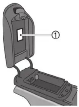
The vehicle is equipped with a label under the console lid ① that provides the body to the titanium muffler clearance specification (for example rear bumper to muffler tube clearance). Since the exhaust gas temperature of the high performance engine reaches a high temperature (1,832°F (1,000°C) or more), the muffler may be deformed or lowered due to the heat and then the underbody or peripheral parts may be damaged. Therefore, periodic inspections for the clearance between the muffler and the peripheral parts are required. Your GT-R has
GTR-6 GT-R Overview
been tested on a test circuit to ensure the suspension components "settle" prior to shipping. Following this circuit test the odometer reading at the time of vehicle shipment is as listed. Please note a small amount of additional mileage may have been added in the subsequent onward transportation. In addition your GT-R has been inspected and tested by the factory test personnel. The titanium muffler specifications are provided on a label under the console lid should the muffler need to be adjusted. Please do not remove the label from the console lid. See a GT-R certified NISSAN dealer for detailed information.
If a non-genuine titanium muffler is used, the muffler may become deformed and damage the underbody due to the high performance engine reaching high exhaust gas temperatures (1,832°F (1,000°C) or more). The highest-class titanium alloy is used for genuine parts to ensure the resistance strength and creeping characteristics against high exhaust gas temperature. In addition, further cooling effects are secured by adopting additional cooling fins and by applying partial plate thickness reduction. Since genuine titanium mufflers are made of titanium alloy, the surface color will change depending on the driving conditions, which is not unusual. Prior to shipping from factory, all vehicles receive balance aligning for engine, transmission, and clutch, as well as quench driving of brake pads and rotors. As a result, the muffler surface color may differ depending on the vehicle.
Never remove the trunk carpet from the vehicle for any reason. The carpet insulates the vehicle interior from the heat of the muffler and from the noise of the transmission.
Never Allow Oil or Grease to Adhere to the Titanium Muffler.
If the muffler is heated when oil or grease adhere to the muffler surface, the color of this area will be different from that of the surrounding area. To remove the oil or grease, check that the surface temperature of the muffler has cooled, wash the area with a neutral detergent, wipe it with a brake cleaner-sprayed clean shop cloth and gently tap it with a dry shop cloth to dry. Be careful not to allow the brake cleaner to splatter on rubber parts, bumper, etc.
DRY CARBON FIBER PARTS (if so equipped)
Because of the characteristics of the material, the dry carbon fiber parts may turn yellow due to exposure to ultraviolet rays. The surfaces of dry carbon fiber parts are coated with a special ultraviolet protection paint. To maintain the appearance of these parts, it is important to take proper care of them.
NOTICE
- Do not use compound agents on clear-coated dry carbon fiber parts (such as the NISMO model's bumper, side sill protector, rear spoiler, etc.).
- Do not use any chemical agents (wax, coating agent, compound agent, etc.) on matte-painted dry carbon fiber parts (such as the rear diffuser, a rear spoiler that is of specifications other than NISMO, etc.).
- When dry carbon fiber parts become dirty, prepare a dilute cleaning solution by mixing one capful of mild detergent in a bucket of water, and
GT-R Overview GTR-7
use that mixture to clean the parts.
NOTE:
The surfaces of the dry carbon fiber parts are lightly coated like a race car so that you can feel the proper texture of real carbon, which may feel rough. This is normal.
MATTE PAINT (if so equipped)
If your vehicle is equipped with matte paint, special care is necessary to clean your vehicle to maintain the appearance of the matte paint.
( "Matte paint care" page 7-2)
GT-R PERFORMANCE OPTIMIZATION SERVICES
In addition to the regular maintenance recommended by NISSAN, the GT-R requires the following special inspections:
- Wheel alignment inspection and adjustment (if necessary) (including tire pressure adjustment)
- Transmission settings
These inspections are required at the following intervals:
• 1,000 miles
• 12 months
• 24 months
• 36 months
NOTE:
- These inspections will be performed free of charge for labor at a GT-R certified NISSAN dealer only. Inspections thereafter are recommended every 12 months or 12,000 miles (whichever comes first) at the customer's expense. See the 2016 NISSAN GT-R Warranty Information Booklet for details.
• Repairs and adjustments involving parts replacement, etc. determined to be necessary as a result of these
inspections are performed at the customer's expense.
- See the 2016 NISSAN GT-R Warranty Information Booklet for significant limitations, exclusions and possible voiding of your warranty resulting from failure to have these necessary inspections, repairs and/or adjustments performed.
- See the 2016 NISSAN GT-R Service and Maintenance Guide for a detailed explanation of the GT-R Performance Optimization Services.
WHEEL ALIGNMENT INSPECTION AND ADJUSTMENT (if necessary) (including tire pressure adjustment)
This vehicle is equipped with a high performance suspension. The vehicle's wheel alignment needs to be measured and adjusted (if necessary) by a GT-R certified NISSAN dealer as necessary as the vehicle is driven and the suspension parts break-in.
The wheel alignment can be adjusted by a GT-R certified NISSAN dealer in accordance with specifications for city driving to high performance driving.
The tires on the GT-R may have different wear
rates and wear patterns in comparison to conventional passenger vehicles. Contact a GT-R certified NISSAN dealer to confirm that the alignment is within specifications.
Preventing toe-out:
Toe-out can cause uneven tire wear or damage to areas inside the tires due to high heat. Be sure to have the wheel alignment toe-in setting checked and adjusted by your GT-R certified NISSAN dealer before any performance driving on closed circuit tracks. Obey all traffic laws when on public roads.
| Toe-in specification | |
| Front ≤ 0.059 in (1.5 mm) | |
| Rear | ≤ 0.079 in (2.0 mm) |
TRANSMISSION SETTINGS
The design of the clutch and transmission requires inspection and adjustment of the clutch and shift forks by a GT-R certified NISSAN dealer at the recommended intervals. If the transmission setting is not complete, excessive loads may be applied to the transmission and power train system parts during starting and shifting, which may result in a malfunction or damage. Depending on the driving conditions, more frequent adjustments may be necessary to help maximize vehicle performance.
BREAK-IN SCHEDULE
NOTICE
Follow these recommendations to obtain maximum engine performance and ensure the future reliability and economy of your new vehicle. Failure to follow these recommendations may result in shortened engine life and reduced vehicle performance.
Please observe the following types of driving until the mileage shown below has been reached.
Until 300 miles (500 km):
- Do not depress the accelerator pedal more than halfway and avoid rapid acceleration.
- Drive with the engine speed kept at less than 3,500 RPM.
- Avoid unnecessary quick steering, abrupt braking and driving on poor roads.
300 to 600 miles (500 to 1,000 km): - Avoid rapid acceleration in a low gear (1st to 3rd gears) with the accelerator pedal fully depressed. Depress the pedal slowly.
- Avoid unnecessary quick steering and abrupt braking.
GT-R Overview GTR-9
- Drive with the suspension setup switch in the COMF mode to allow more suspension stroke.
600 to 1,200 miles (1,000 to 2,000 km): - Drive with the engine speed kept relatively high with the shift lever in the M position. Shifting is recommended between 1st and 4th gears.
- Avoid unnecessary quick steering and abrupt braking.
- Drive with the suspension setup switch in the COMF mode to allow more suspension stroke.
Even though the mileage reaches over 1,200 miles (2,000 km), the clutch may take longer to properly engage if the vehicle is mainly driven in town at a low speed. NISSAN recommends breaking in the clutch at a GT-R certified NISSAN dealer. Always perform the transmission setting after breaking in the clutch. If the transmission setting is not complete, excessive loads may be applied to the transmission and power train system parts during starting and shifting, which may result in a malfunction or damage.
WHEEL ALIGNMENT
Do not adjust the wheel alignment until the mileage reaches 1,000 miles (1,600 km). Until then, the suspension may not engage enough and the height may be higher.
However, make sure to adjust the alignment after 1,000 miles (1,600 km).
The wheel alignment can be adjusted by a GT-R certified NISSAN dealer in accordance with specifications for city driving to high performance driving.
The tires on the GT-R may have different wear rates and wear patterns in comparison to conventional passenger vehicles. Contact a GT-R certified NISSAN dealer to confirm that the alignment is within specifications.
PRECAUTIONS BEFORE DRIVING
VEHICLE DYNAMIC CONTROL (VDC) OFF MODE
Always make sure the VDC is ON before driving the vehicle by checking that the VDC OFF indicator lights on the meter and the VDC set-up switch are not illuminated. The GT-R is a high performance vehicle and the VDC must be on/activated to provide proper powertrain operation and intended drivability.

WARNING
- The VDC OFF mode should ONLY be used briefly to help free the vehicle if stuck in snow or mud by temporarily stopping operation of the VDC to maintain wheel torque.
- Driving the GT-R with the VDC off may lead to handling issues related to steering maneuvers, acceleration, or deceleration. Moreover, driving with the VDC off can result in an inoperative vehicle by causing serious damage to the powertrain, including damage to the Transaxle Assembly including Transfer, Clutch, Gears, Transaxle case and all of its components and other drivetrain
component(s) by overheating or excessive force.
- Damage to the powertrain or any drivetrain component(s) that occurs when there is a record in the Vehicle Status Data Recorder (VSDR) that the vehicle was driven with VDC off during the period when the damage was incurred is excluded from warranty coverage.
See your 2016 Warranty Information Booklet for important related information and warranty coverage exclusions. See also section 2 ("Transmission warning light" page 2-30) and section 5 ("Vehicle Dynamic Control (VDC) system" page 5-50) of this Owner's Manual, "Transmission Clutch Temperature High" and "Vehicle Dynamic Control (VDC) System" for important additional related information.
SUMMER TIRES
The GT-R summer tires are made from a specially formulated rubber to maximize the vehicle's performance capabilities. Performance of summer tires is substantially reduced when temperatures are less than 32^ F ( 0^ C) so you must drive carefully. NISSAN recommends the use of winter or all-season tires on all four wheels if you plan to operate your vehicle in snowy or icy conditions when temperatures are less than 32^ F ( 0^ C).

WARNING
Never use summer tires when the temperature is below -4^ ( -20^ ) to prevent permanent tread deformation which may cause tire damage or tire failure. This may cause a loss of vehicle control which can result in serious personal injury or death.
ALL-SEASON TIRES
Do not exceed the speed rating of the tire that is installed on the vehicle.
natural_image
Illustration of a car front with a yellow star and red lightning bolt, no text or symbols presentAVOIDING BODY DAMAGE
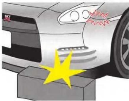
The GT-R bumper, fascia, side sills and undercarriage are close to the ground. Drive slowly on rough or uneven roads to avoid damaging these parts. Pay careful attention to wheel blocks and curbs. If the front bumper contacts a wheel block, curb, etc., the bumper and underlying parts may be damaged or cracked. Be careful not to damage the front spoiler that is installed below the engine room.
FUEL
NISSAN recommends using fuels that contain no alcohol. However, fuels containing up to 10% alcohol may be used, if necessary. Do not use E-15 or E-85 in your vehicle. ( "Fuel information" page 9-4)
NOTICE
To avoid serious engine damage due to increased cylinder temperatures, do not use fuels that contain more alcohol than indicated in “Gasoline containing oxygenates” page 9-4. Also, do not use fuel additives, fuel stabilizers or fuel deicers that contain alcohol.
BODY REPAIR
The body of the GT-R has been manufactured on special fixtures utilizing a hybrid structure with aluminum die cast parts for the frame work. Special skills, information and equipment are required to correctly repair the body. Contact a GT-R certified NISSAN dealer if the vehicle is damaged, such as in a collision, and they will recommend an appropriate body shop.
Only certified body shops using CELETTE advanced collision repair equipment are ap-
proved by NISSAN for repairing structural body damage. Contact a GT-R certified NISSAN dealer or NISSAN Consumer Affairs for a referral or list of certified body shops.
DRIVING AFTER REPLACING TIRES
Avoid the driving conditions listed under "Additional maintenance items" in this section for 48 hours after tires are installed on the wheels ( "Additional maintenance items" page GTR-12). The tire may slip on the wheel if the vehicle is driven in these conditions before 48 hours have passed. If the tire slips on the wheel, the wheel/tire assembly will be out of balance and will require rebalancing.
GTR-12 GT-R Overview
ADDITIONAL MAINTENANCE ITEMS
The information and specifications in this section apply only when engaging in performance driving.
The following information applies only if you engage in performance driving such as driving your GT-R for extended periods under the following conditions.
- Higher-RPM (approaching redline) operation
- Frequent high pedal force braking from moderate and higher speeds
• Frequent throttle activation - Fast revving throughout the RPM range In such cases, the following additional maintenance guidelines apply.
However, you should also carefully read your 2016 NISSAN GT-R Warranty Information Booklet for important information concerning warranty coverage, limitations and exclusions.
We recommend that all GT-R maintenance be performed at a GT-R certified NISSAN dealer. NISSAN will only pay for GT-R Performance Optimization Services performed at a GT-R certified NISSAN dealer.
PRECAUTIONS ON PERFORMANCE DRIVING
The information and specifications in this section apply only when engaging in performance driving.
Checking the temperature of the coolant and oils on the multi function display
When the temperatures of the engine coolant and oil, and the oil pressure exceed the normal range, the color of the meter on the multi function display changes to red to warn the driver. When engaging in high performance driving, switch the display to the function meter to display the temperature of the engine coolant and oil, and the oil pressure. When the color of the meter display changes to red, perform cool down driving. When the values of the temperature and pressure return to the normal range, the color of the meter display will turn back to white. Warning temperature:
- Engine coolant temperature is 230°F (110°C) or higher:
If the engine coolant temperature increases above 230^ F ( 110^ C), the color of the meter display on the multi function display changes to red to warn of a possible overheat
condition and engine output is reduced.
- Engine oil temperature is 275^ (135°C) or higher:
If the engine oil temperature is higher than 275^ F ( 135^ C), the meter display changes to red, maximum engine speed is automatically limited to 4,000 rpm, and the transmission automatically changes from the position to the A position.
- Transmission oil temperature is 284°F (140°C) or higher:
If the transmission oil temperature increases to over 284^ F ( 140^ C), the color of the meter display changes to red. However, the vehicle can continue to be driven until the temperature reaches 295^ F ( 146^ C). If the oil temperature exceeds 284^ F ( 140^ C) while driving (the color of the meter displayed in red), change both the transmission oil and the differential oil after driving because these fluids have deteriorated because of the heat.
Cool down
The information and specifications in this section apply only when engaging in performance driving.
Cool down the vehicle to help extend the life of the vehicle if coolant temperatures are extremely high. Drive the vehicle at 37 to 50 MPH (60 to 80 km/h), in 5th or 6th gear for 2 to 3 miles (3 to 5 km) and then stop the engine.
Refueling precautions

WARNING
Do not attempt to top off the fuel tank after the fuel pump nozzle shuts off automatically. Continued refueling may cause fuel overflow, resulting in fuel spray and possibly a fire. The fuel tank is full at the first automatic shutoff.
To maximize vehicle performance, the fuel tank is located as low as possible to lower the vehicle center of gravity. The tank is also divided into two parts. This fuel tank design causes higher pressures inside the tank than other vehicles so fuel spillage is possible by trying to top off the fuel tank after automatic shutoff.
The fuel tank pressure is higher when the vehicle is hot, especially if the tank is more than half full. If the cap is opened when the vehicle is hot, it may cause fuel spray and there may be a hissing noise. Open the cap slowly, releasing the pressure from the tank gradually. Also, if the
GT-R Overview GTR-13
vehicle is refueled when the vehicle is hot, the fuel pump may automatically shut off before the tank is full. This does not indicate that there is a malfunction. Refuel slowly or refuel after the vehicle has cooled.
INSPECTION AND ADJUSTMENTS BEFORE DRIVING
The information and specifications in this section apply only when engaging in performance driving.
Fluids
- Check the engine, transmission, differential and under vehicle surfaces for oil and coolant leaks.
- Check the fluid levels and adjust as necessary using the specified fluid as described under the conditions listed in this section. ( "Recommended fluids and maintenance interval" page GTR-19) If you do not drive under the conditions listed, refer to the 2016 NISSAN Service and Maintenance Guide.
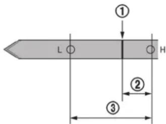
- NISSAN recommends to adjust the engine oil level ① to be 0.39 in (10 mm) (1/8 gal (0.5 liters)) ② below the H mark on the engine oil dipstick. (③ range is 1.18 in (30 mm).) Before checking the oil level, run the engine until it reaches operating temperature and wait at least 5 minutes after turning off the engine. Make sure the oil level always remains above the L mark. When the vehicle is delivered, the engine oil is set to "H- 0.39 in (10 mm)" for optimal high performance driving.
- Some amount of oil is consumed by your engine under normal operating conditions, and oil consumption by itself does not
necessarily indicate any malfunction. If your rate of oil consumption increases suddenly or without explanation, NISSAN recommends that you have your vehicle inspected by a GT-R certified NISSAN dealer.

- Adjust the power steering fluid level to the R mark ⑤ on the power steering dipstick when the fluid temperature is hot or ⑥ when the fluid temperature is cold.
Fluid temperature:
Hot: 122 to 176°F (50 to 80°C): between ① and ⑤
Cold: 32 to 86°F (0 to 30°C): between ③ and ⑥
Coolant level and mixture ratio
The information and specifications in this section apply only when engaging in performance driving.
Check the coolant level in the pressurized coolant reservoir. Adjust the level so that the fluid is between the MAX and MIN markings. For the coolant, use genuine NISSAN Long Life coolant. (On delivery of new vehicle, the reservoir is filled to the MIN level. Be sure to replenish approximately 3/8 US quart (0.3 to 0.4 liter) of coolant.)
NOTICE
Do not overfill the coolant. This may increase the pressure in the cooling system and cause coolant leaks.
To maximize vehicle performance, the coolant mixture ratio should be a combination of 30% coolant antifreeze and 70% demineralized or distilled water for maximum cooling system performance regardless of ambient temperatures.
If ambient temperatures are anticipated below 5^ F ( -15^ C), make sure a proper mixture ratio of 50% antifreeze and 50% demineralized or distilled water mix is used.
Engine and powertrain
The information and specifications in this section apply only when engaging in performance driving.
- Check the engine, transmission, differential and under the vehicle for oil and coolant leaks.
- Inspect the areas surrounding of the catalytic converter for heat deterioration.
● Always perform the transmission setting. After that, adjust the clutch clearance so that the clearance is less than the clearance used for daily driving. Your GT-R certified NISSAN dealer has the necessary information and equipment to set the clutch clearance to the correct specification. The clearance used for daily driving increases clutch heat generated during Performance Driving. This leads to an increase in temperature of the transmission oil. In addition, a more direct shifting feel can be obtained by reducing the clutch clearance for Performance Driving. The clutch clearance should be reset to the daily driving specification after Performance Driving. See your GT-R certified NISSAN dealer for information.
NOTICE
Failure to have the clutch properly adjusted before performance driving may cause the transmission oil temperature to increase which may cause transmission damage.
- Inspect and confirm the clearance between the exhaust finisher and rear bumper is more than 0.24 in (6 mm) (up/down) and more than 0.20 in (5 mm) (left/right).
- Inspect the dust boot of the drive shaft universal joint for cracks or damage.
Suspension and wheel alignment The information and specifications in this section apply only when engaging in performance driving.
- Check the steering and suspension system and other links for loose and/or damaged parts.
- Measure and adjust the wheel alignment. ( "Wheel alignment" page GTR-10) Contact a GT-R certified NISSAN dealer to adjust the wheel alignment to the recommended setting for high performance driving.
GTR-16 GT-R Overview
Preventing toe-out:
Toe-out can cause uneven tire wear or damage to areas inside the tires due to high heat. Be sure to have the wheel alignment toe-in setting checked and adjusted by your GT-R certified NISSAN dealer before any performance driving on closed circuit tracks. Obey all traffic laws when on public roads.
| Toe-in specification | |
| Front | ≤ 0.059 in (1.5 mm) |
| Rear | ≤ 0.079 in (2.0 mm) |
Wheels and tires
The information and specifications in this section apply only when engaging in performance driving.
- Check tire wear and cracking.
- Inspect the tire side wall for damage.
- Check the tire pressure and adjust the pressure as necessary when the tires are cold. ( "Wheels and tires" page 8-32)
The tire pressure changes depending on the outside temperature or altitude. Check the tire pressure regularly and when the climate conditions change.
* The following chart indicates how the tire pressure will decrease as outside air temperature decreases.

line
| Temperature (°C) | Change in litre pressure psi (kPa) | | :--- | :--- | | -4 | 0.0 | | 14 | -0.73 | | 32 | -1.45 | | 50 | -2.18 | | 68 | -2.90 | | 86 | -3.63 | | 30 | -4.35 | | 40 | -5.08 | | 50 | -5.80 | The chart displays a single linear trend line, indicating that as temperature increases from -4 to 86 degrees Celsius, the change in litre pressure increases proportionally from 0.0 to 0.0 kPa. The x-axis represents Temperature (°C) and the y-axis represents the change in litre pressure (kPa). The label '(-20)' appears at the top left, possibly indicating a reference point or parameter value.
WARNING
Keep your tires inflated to the correct tire pressure. Driving with low tire pressure can damage some powertrain systems and affect the operation of the ABS and VDC systems. Low Tire pressure may also cause tire failure and result in serious personal injury or death.
- Make sure the tire valve stem cap is installed and that the valve stem is tight. When installing the cap, make sure to tighten the
cap by hand. If a tool is used to tighten the cap, the cap may be damaged.
- Make sure the wheel nuts are tight. ( "Wheels and tires" page 8-32)
- Make sure the drive shaft nuts are tight.
- Make sure to replace the grommet seal, the valve core and the valve cap of the Tire Pressure Monitoring System (TPMS) sensor attached to the wheel every 3 years for performance driving use. Replace them every 5 years even when not engaging in performance driving. A dirty grommet seal will cause the air leak from the tire.
- Make sure that the nuts and valves that are attached to the TPMS sensor are tight and there is no nitrogen leak.
- Use only a NISSAN genuine valve cap or equivalent.
- Check wheel hub run out and that the wheel rotates smoothly without any friction. Check these with the tires removed whenever an inspection is performed with the vehicle jacked up.
- Secure road wheel balance weights with aluminum tape.
- Check that the wheel nuts are not stripped.

- Make sure the tire has not slipped on the wheel causing the assembly to be out of balance. The reference marks on the tire and wheel should be aligned. If the reference marks are not aligned, the tire has slipped on the wheel. Have the wheels/tires rebalanced. Make sure the old reference marks are erased and new reference marks are applied to the wheel and tire. When installing new tires on the wheels, make sure new reference marks are applied to the wheels and tires.
- Avoid the driving conditions listed under "Additional maintenance items" in this section for 48 hours after tires are installed on
GT-R Overview GTR-17
the wheels. The tire may slip on the wheel if the vehicle is driven in these conditions before 48 hours have passed. If the tire slips on the wheel, the wheel/tire assembly will be out of balance and will require rebalancing.
Brakes
The information and specifications in this section apply only when engaging in performance driving.
- Check for the heat deterioration of the brakes and parts around the brakes.
- It is recommended that you remove air from the brake system after any of the following:
— When engaging in high performance driving for the first time after purchasing a new vehicle.
— After replacing the brake fluid.
— When engaging in high performance driving for a sustained period of time. It is recommended that bleeding the brake be performed when the brake calipers are hot (about 212^ F ( 100^ C)).
Brake pad break-in procedure:
NISSAN recommends that a special brake pad break-in procedure be performed before engaging in performance driving. Contact a GT-R certified NISSAN dealer for details.
GTR-18 GT-R Overview
INSPECTION AND ADJUSTMENTS AFTER DRIVING
The information and specifications in this section apply only when engaging in performance driving.
NOTICE
At the completion of performance driving, all fluid and other adjustments should be returned to the normal fluid specifications as shown in the “Maintenance and do-it-yourself” section of this manual.
Fluids
The information and specifications in this section apply only when engaging in performance driving.
- Check the engine, transmission, differential and under the vehicle for oil and coolant leaks.
- Check the fluid levels and adjust as necessary using the specified fluid as described under the conditions listed in this section. ( "Recommended fluids and maintenance interval" page GTR-19) If you do not
drive under the conditions listed, refer to the 2016 NISSAN Service and Maintenance Guide.
- When changing fluids, be sure to use the specified fluids as described in this Owner's manual. ( "Capacities and recommended fluids/lubricants" page 9-2)
Recommended fluids and maintenance interval
The information and specifications in this section apply only when engaging in performance driving.
| ITEMS Engine Oil | ||
| GT-R SPECIFIED FLUIDS | Mobil 1 (0W-40)*1 | |
| MAINTENANCE INTERVAL | When the oil temperature stays below 230^ ( 110^ ) while driving | Change engine oil and engine oil filter at the same interval as Schedule 1 and 2 in the 2016 NISSAN GT-R Service and Maintenance Guide. |
| When the oil temperature reaches between 230^ ( 110^ ) and 266^ ( 130^ ) while driving | Change engine oil and engine oil filter every 3,000 miles (5,000 km). | |
| When the oil temperature exceeds 266^ ( 130^ ) while driving | Change engine oil and engine oil filter immediately after stopping. | |
*1: Mobil 1 (0W-40) (100% synthetic) is the factory fill oil. The VR38 engine with its plasma-sprayed bores was developed using this oil. NISSAN cannot ensure proper engine operation and durability if other 0W-40 synthetic oil is used. If Mobil 1 (0W-40) is not available, Mobil 1 (10W-40) (100% synthetic) may be used; however, some performance loss may be noticed.
GT-R Overview GTR-19
| ITEMS Transmission Oil | ||
| GT-R SPECIFIED FLUIDS Genuine NISSAN Transmission Oil R35 Special | ||
| MAINTENANCE INTERVAL | When the oil temperature stays below 248°F (120°C) while driving | Change transmission oil at the same interval as Schedule 1 and 2 in the 2016 NISSAN GT-R Service and Maintenance Guide. |
| When the oil temperature reaches between 248°F (120°C) and 284°F (140°C) while driving | Change transmission oil every 3,000 miles (5,000 km). | |
| When the oil temperature exceeds 284°F (140°C) while driving | Change both transmission oil and differential oil immediately after stopping. Differential oil temperature usually increases concurrently. | |
| ITEMS Differential | Oil (front and rear) | |
| GT-R SPECIFIED FLUIDS Differential Oil R35 COMPETITION type 2189E*2 | ||
| MAINTENANCE INTERVAL | When the oil temperature stays below 248°F (120°C) while driving | Change differential oil at the same interval as Schedule 1 and 2 in the 2016 NISSAN GT-R Service and Maintenance Guide. |
| When the oil temperature reaches between 248°F (120°C) and 284°F (140°C) while driving | Change differential oil every 3,000 miles (5,000 km). | |
| When the oil temperature exceeds 284°F (140°C) while driving | Change both transmission oil and differential oil immediately after stopping. Differential oil temperature usually increases concurrently as the transmission oil temperature. | |
*2: The differential oil temperature cannot be displayed on the multi function display. The differential oil temperature can be checked with the transmission oil temperature since both usually increases or decrease concurrently.
| ITEMS Brake Fluid | |
| GT-R SPECIFIED FLUIDS Genuine NISSAN Brake Fluid R35 Special II*3 | |
| MAINTENANCE INTERVAL Change brake fluid every 3,000 miles (5,000 km). | |
*3: Genuine NISSAN Brake Fluid R35 Special II is the factory fill brake fluid. The Vehicle Dynamic Control (VDC) unit and other related parts were specially designed for this brake fluid and NISSAN cannot ensure the best performance and proper operation of the vehicle if other brake fluid is used.
GT-R Overview GTR-21
Suspension and wheel alignment
- Check the steering and suspension system and other links for loose and/or damaged parts.
- Measure and adjust the wheel alignment. Contact a GT-R certified NISSAN dealer to adjust the wheel alignment to the recommended setting for normal driving.
Wheels and tires
- Check tire wear and cracking.
- Inspect the tire side wall for damage.
- Check the tire pressure and adjust the pressure as necessary when the tires are cold. ( "Wheels and tires" page GTR-16) If you do not drive under the conditions listed in this section, see "Wheels and tires" page 8-32.
- Check that the wheel nuts are not stripped. Check if there is no deformation on the contact surface of the wheel nuts.
- Make sure the wheel nuts are tight. ( "Wheels and tires" page 8-32)
- Make sure the drive shaft nuts are tight.
- Check wheel hub run out and that the wheel rotates smoothly without any friction. Check these with the tires removed whenever an
GTR-22 GT-R Overview
inspection is performed with the vehicle jacked up.
- Make sure the tire has not slipped on the wheel causing the assembly to be out of balance. The reference marks on the tire and wheel should be aligned. If the reference marks are not aligned, the tire has slipped on the wheel. Have the wheels/tires rebalanced. Make sure the old reference marks are erased and new reference marks are applied to the wheel and tire. When installing new tires on the wheels, make sure new reference marks are applied to the wheels and tires. ( "Wheels and tires" page GTR-16)
- Make sure that the TPMS sensor installation nuts and the sensor valve are tight and there is no nitrogen leak.
Brakes
- Check for the heat deterioration of the brakes and parts around the brakes.
- Check the condition of the brake pads and disc rotors and replace them as necessary.
Engine and powertrain
- Check the engine, transmission, differential and under the vehicle for oil and coolant
leaks.
- Inspect the area surrounding the catalytic converter for heat deterioration.
- Inspect and confirm the clearance between the exhaust finisher and rear bumper is more than 0.24 in (6 mm) (up/down) and more than 0.20 in (5 mm) (left/right).
- The clutch clearance and shift fork position may need to be adjusted.
- Inspect the dust boot of the drive shaft universal joint for cracks or damage.
- Check that there is no abnormal noise, vibrations or warning lights illuminated when making tight turns at slow speed (for tight corner braking phenomenon).
GT-R SPECIFIC VEHICLE CHARACTERISTICS
REFUELING PRECAUTIONS

WARNING
Do not attempt to top off the fuel tank after the fuel pump nozzle shuts off automatically. Continued refueling may cause fuel overflow, resulting in fuel spray and possibly a fire. The fuel tank is full at the first automatic shutoff.
To maximize vehicle performance, the fuel tank is located as low as possible to lower the vehicle center of gravity. The tank is also divided into two parts. This fuel tank design causes higher pressures inside the tank than other vehicles so fuel spillage is possible by trying to top off the fuel tank after automatic shutoff.
The fuel tank pressure is higher when the vehicle is hot, especially if the tank is more than half full. If the cap is opened when the vehicle is hot, it may cause fuel spray and there may be a hissing noise. Open the cap slowly, releasing the pressure from the tank gradually. Also, if the vehicle is refueled when the vehicle is hot, the fuel pump may automatically shut off before the tank is full. This does not indicate that there is a malfunction. Refuel slowly or refuel after the
vehicle has cooled.
GASOLINE SMELL
The fuel temperature is higher when the vehicle is hot. This may cause a gasoline smell from the vehicle. This does not indicate that there is a malfunction. The smell will go away when the fuel temperature has cooled.
OUTSIDE TEMPERATURE DISPLAY INDICATES HIGHER TEMPERATURE
Heat from the engine compartment, radiator and intercoolers can affect the outside temperature display. The outside temperature display may indicate a higher than actual temperature while driving or stopped. This is normal.
The idle speed may not be steady when the engine compartment is extremely hot. This is normal. The engine speed will be steady when the engine cools down.
In this case, the Malfunction Indicator Light (MIL) may come on. After a few driving trips, the MIL should turn off. If the light remains on after a few driving trips, have the vehicle inspected by a GT-R certified NISSAN dealer.
ENGINE SPEED IS RESTRICTED
To help protect the engine, the maximum engine speed is automatically controlled in the following conditions:
- Revving the engine with the shift lever in the P or N position: The maximum engine speed is 5,000 RPM
- Revving the engine when the engine oil is at a low (below 32^ F ( 0^ C)) or extremely high (over 275^ F ( 135^ C)) temperature: The maximum engine speed is 4,000 RPM (The
M position will automatically change to the
A position.)
ENGINE OUTPUT
High altitude
To protect the engine, engine output is controlled so that it does not increase at altitudes 3,281 ft (1,000 m) or higher.
Engine output according to the coolant temperature
The engine output is controlled at a low level when the engine coolant temperature is lower than approximately 158^ F ( 70^ C) or higher than 230^ F ( 110^ C). This is not a malfunction. If the temperature is lower than approximately
GT-R Overview GTR-23
158°F (70°C), drive the vehicle until it reaches normal operating temperature. If the temperature is higher than 230°F (110°C), perform cooldown driving procedure. ( "Cool down" page GTR-13) When the temperature of the engine coolant is between 158°F (70°C) and 230°F (110°C), the engine output returns to normal.
UNEVEN WEAR OF TIRES
The GT-R is equipped with high performance, low profile, run-flat tires that are optimized for performance and handling. The life of these tires will be less than those of tires installed on a typical vehicle, and you are likely to experience uneven tire wear and tire noise regardless of the type of tire used.
NOISES ARE HEARD WHILE DRIVING
- The GT-R brake pads use material that provides a high amount of braking power even in high temperatures. This material can cause an intermittent screeching noise just before the vehicle comes to a stop when the brakes are gently applied. The noise decreases as the brake pads wear. However, the additional brake pad break-in or replacing the cross spring may decrease the
noise. Contact a GT-R certified NISSAN dealer.
- A screeching noise may be heard when the brake pedal is depressed:
— When driving the vehicle for the first time in the morning,
— After leaving the vehicle parked for extended periods of time, or
— When the vehicle is damp following rain showers or washing the vehicle.
These sounds are normal. The noise is caused when the brake pads absorb moisture, and the noise stops after the brake is applied several times. - A screeching noise may also be heard when the brake pedal is depressed:
— When repeatedly applying gentle braking, especially on a curve at a low speed, or
— When the brake rotors have circular scores with the brake temperature high.

WARNING
Follow the instructions below when parking the vehicle to help prevent the brake rotor and brake pads from rusting together. Failure to follow the
instructions could cause the rotor and pads to rust together. If the rotor and pads rust together, there may be a popping noise and some vibration when the vehicle is driven, a wheel may not roll correctly, or the brake pads could be damaged. If the pads are damaged, this may reduce the effectiveness of the brake system which could cause a collision, serious personal injury or death.
- The GT-R uses brake pad materials that have high metallic content. The brake pad material helps maintain braking performance in a wide range of weather and driving conditions. For the first 3,000-6,000 miles (5,000-10,000 km) of the vehicle's service life, and for the first 3,000-6,000 miles (5,000-10,000 km) after a brake replacement, the brake pad to brake rotor clearance is very small. When parking, apply the parking brake and move the shift lever to the position. Idle the engine for more than 20 seconds without depressing the brake pedal. This allows the brake pads to move away from the rotor so the pad does not contact the rotor.
Additionally, the brakes must be dry before parking the vehicle after driving on wet roads or after washing the vehicle. If the roads are wet, lightly apply the brakes for a short distance before parking the vehicle to dry the brakes. After washing the vehicle, dry the brakes by driving on a dry road for a few miles and apply the brakes normally based on traffic and road conditions.
The metallic brake pads and brake disc rotor may rust together when the brakes are not applied:
— If the vehicle is not idled for 20 seconds without the brakes applied, or if the brakes are applied when the vehicle is shut off, the rotor and pads can rust together, even when the brake pads are dry.
— If the brakes are wet when the vehicle is parked and the parking brake is applied for a long time.
— The hill start assist system can apply the brakes even if the brake pedal is not depressed. The brake pads and rotors can rust together if the parking procedure previously described is not followed.
Contact a GT-R certified NISSAN dealer if the brake pads and brake rotor have rusted
together.
NOTICE
To help reduce the possibility of the rotors and brake pads rusting:
Have the brake pads and/or rotors quenched when the brake pads are replaced. For detailed information about quenching, contact a GT-R certified NISSAN dealer.
After quenching the brake pads and/or rotors, apply a brake of 0.5G to stop the vehicle 6-7 times at least once a week in a safe location. G-force can be checked on the multi function display. Refer to the separate Multi Function Display Owner's Manual.
- To maintain steady braking performance in both extremely high and low temperatures, the gap between the brake pad and caliper is larger than normal and large-size brake pads are used. When driving over a bump, a light rattling sound may be heard from the brake pad. This does not indicate that there is a malfunction.
- When the brake disc rotor undergoes thermal expansion, a ticking noise may be heard from the engaging portion of the wheel and the brake disc rotor. This does not indicate that there is a malfunction. The noise will reduce when the temperature decreases.
- In addition to noise resulting from uneven tire wear discussed in the previous section, the GT-R tires are more rigid than a typical passenger car tire and are made from a specially formulated rubber to maximize the vehicle's performance capabilities. These characteristics cause the GT-R tires to have more road noise than a typical passenger car tire. This road noise is normal.
- Due to the performance capabilities and requirements of the GT-R, the sequential 6-speed dual clutch transmission is unlike a typical automatic transmission. You will likely hear mechanical sounds from the transmission, particularly at slow speeds and at idle. This condition is normal.
The friction material of the GT-R disc brake pad is bonded to the pad backing plate more strongly than conventional brake pads to withstand the high brake temperatures. The friction material and backing plate expand due to heat at different rates. Some cracks may be on the surface of the friction material due to the differences in expansion rates and the strong bond between the friction material and backing plate. The cracks do not indicate the brake pads need to be replaced. However, depending on the condition of the cracks, the pads may need to be replaced. Contact a GT-R certified NISSAN dealer.

natural_image
Close-up of a mechanical component with perforated surface and two labeled parts (A and B), no readable text or symbols present.Cracks on the disc rotors
When the brake is repeatedly applied at high loads during the cold season, small cracks of approximately 0.12 in (3 mm) long may appear around the cross drilled holes Ⓐ. This is due to the temperature differential that occurs because the surfaces of the disc rotors become hot while the inside of the rotor is still cold. However, this poses no problem in terms of brake performance, and does not indicate a malfunction. The brakes do not need to be replaced.
However, if the cracks extend to 0.16 in (4 mm) or longer after repeated application of the brakes at high loads during high performance
driving, or through the continued use of the brakes, the disc rotors must be replaced.
Brake dust
This vehicle is equipped with high performance brakes, and the characteristics of the brake pad material may cause more brake dust than other vehicles. NISSAN recommends a wheel coating that helps prevent the brake dust from sticking to the wheels. Contact a GT-R certified NISSAN dealer for more details.
CHANGE OF SURFACE COLOR OF TITANIUM MUFFLER (if so equipped)
Genuine titanium mufflers are made of titanium alloy. The surface color will change depending on the driving conditions, which is not unusual. Prior to shipping from factory, all vehicles receive balance aligning for engine, transmission, and clutch, as well as quench driving of brake pads and rotors. As a result, the muffler surface color may differ depending on the vehicle.
SOUND HEARD AROUND TITANIUM MUFFLER (if so equipped)
When stopping the engine (rapid cooling), you may hear a metal-rubbing sound or unusual ticking sound because of the differential thermal expansion between the inner and outer pipes of the muffler. This is not a malfunction. The sound will decrease when the temperature lowers.
DRY CARBON FIBER PARTS (if so equipped)
Roughness or uneven surfaces of dry carbon fiber parts and fiber twists
The surfaces of the dry carbon fiber parts are lightly coated like a race car so that you can feel the proper texture of real carbon, which may feel rough. This is normal.
DUAL CLUTCH TRANSMISSION
The GT-R dual clutch transmission is a newly-developed system that uses an electronically controlled multiple-disc wet clutch attached to the highly efficient manual transmission. This transmission has two driving modes.
- A position (Automatic gearshift): allows automatic shifting of the manual transmission.
- M position (Manual gearshift): allows quick shifting of the manual transmission.
NOTE:
When starting or driving on a steep uphill grade, shift to the M position and operate the paddle shifter to shift down to 1st gear similar to a manual transmission vehicle.
The GT-R dual clutch transmission was developed specifically to maximize vehicle performance and driving enjoyment. The GT-R transmission components were designed using different engineering standards than typical passenger car transmissions. Because of this, the GT-R has different operating characteristics, and various rattle noises may be heard during some driving conditions because of the following items:
- Gear clearances
- Ultralight flywheel
- Dry sump lubrication
These noises do not indicate that there is a malfunction.
| Mechanism Operation characteristics | |
| Base Manual transmission | The GT-R transmission design is different from transmissions used in conventional passenger cars. The GT-R uses a transmission gear design, light flywheel and a dry sump lubrication system to provide maximum vehicle performance. Because the GT-R Transmission design is different, noises may be louder. When the transmission temperature is high, rattling, shaking and jarring noises may be heard.Clattering noises may be heard while shifting.Appropriate gaps are provided between gears to achieve smooth gear rotation and steady tooth surface lubrication under the high-load driving condition. However, this causes a rattling noise.If the shift lever is moved from R to A M position, or A M to R position before the vehicle stops, you may not be able to shift gear or it may take longer to shift gear. Make sure to depress the brake pedal and check that the vehicle has stopped before shifting. |
| Multiple disc wet clutch | When stopping the vehicle with the shift lever in the R or A M position, be sure to firmly depress the brake pedal. The vehicle may slowly move if the brake pedal is not depressed.Avoid depressing the brake and accelerator pedals at the same time. Depressing the brake and accelerator pedals at the same time could cause the clutch to overheat and accelerate deterioration.When the vehicle is stopped on a hill, do not hold the vehicle in place by depressing the accelerator pedal. Doing so may cause the clutch to overheat and result in transmission damage. Use the brakes to prevent the vehicle from moving. |
| Electronic oil pressure control | The following conditions are caused due to changes in fluid viscosity as a result of temperature changes.When the transmission oil is extremely cold or extremely hot, the transmission may feel like it is slipping during shifts or there may be hard shifts. This is normal. Transmission shifting should return to normal when the transmission oil returns to normal operating temperatures.When the transmission oil temperature is extremely cold, the time required to run a system check may increase. During the system check, the shift lever must stay in the P position. Move the shift lever after turning off the system check display. Also, it is normal to hear clicking noises during the transmission systems check. |
| Changing modes | The higher shift speeds in the M position may result in shift shock and jerkiness when starting or shifting.The quickest shifting in the R mode with the transmission in the M position is available when the engine speed is high. However, the transmission may shift more slowly when the engine speed is low. |
| Mechanical Limited Slip Differential (LSD) | If the vehicle accelerates from a stop with the steering wheel turned half a turn in cold temperatures, the inner wheel tire may slip and some noise or vibration may be heard. This phenomenon occurs because the viscosity of the differential oil becomes thicker and the Limited Slip Differential (LSD) operates with increasing load. When the steering wheel is returned to the straight ahead position or the differential oil warms up, the noise and vibration decrease. |
| Electronically-controlledAll-wheel drive (AWD) | If the vehicle accelerates from a stop with the steering wheel turned half a turn in cold temperatures, it may be hard to move the vehicle when the accelerator pedal is depressed. This phenomenon is unique to AWD vehicles and is caused by the speed difference between the front and rear wheel. This is not a malfunction. Resolve the phenomenon by returning the steering wheel to the straight ahead position. You can also alleviate the phenomenon by operating the transmission set up switch and using 2WD drive only when the steering wheel is turned significantly at a low speeds. Normally, the vehicle will not switch to 2WD drive when the set up switch is operated. ( "Tight corner braking phenomenon" page 5-43) |
| Ultralight flywheel | An ultralight flywheel is provided to achieve rapid engine response to the accelerator pedal operation. The engine rotation fluctuations become larger than conventional vehicles. Rattling, shaking or jarring noises may be heard when idling or driving at a low speed.Rattling noises may be heard when the engine is started or stopped. |
GT-R Overview GTR-29
MEMO
GTR-30 GT-R Overview
0 Illustrated table of contents
Seats, seat belts and Supplemental Restraint
System (SRS) 0-2
Front 0-2
Rear 0-3
Exterior front 0-4
Exterior rear 0-5
Passenger compartment 0-6
Cockpit 0-7
Instrument panel 0-8
Meters and gauges 0-9
Engine compartment 0-10
Warning and indicator lights 0-11
SEATS, SEAT BELTS AND SUPPLEMENTAL RESTRAINT SYSTEM (SRS)
FRONT
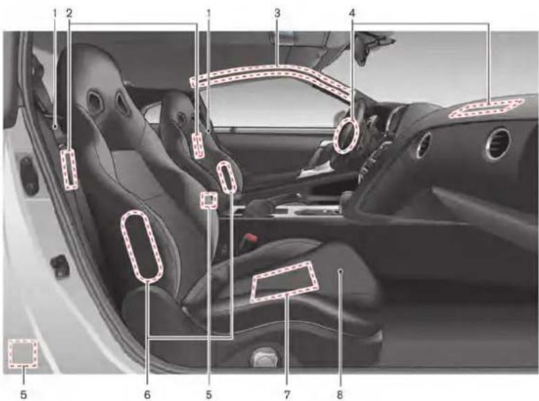
- Seat belt (Page 1-6)
- Rear seat walk-in lever (P.1-5)
- Roof-mounted curtain side-impact supplemental air bag system (P.1-34)
- Supplemental front-impact air bags (P.1-34)
- Seat belt pretensioner (P.1-46)
- Front seat-mounted side-impact supplemental air bag system (P.1-34)
- Occupant classification sensor (pattern sensor) (P.1-40)
- Front seats (P.1-3)
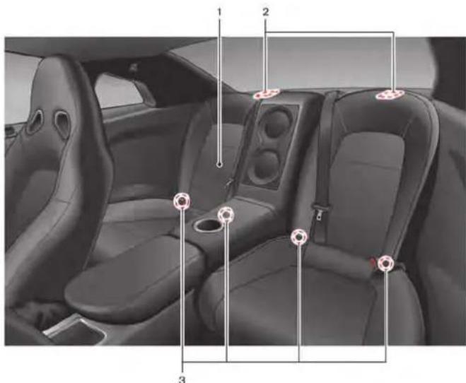
REAR
- Rear seats
— Child restraint installation (P.1-15)
-
Child restraint anchor points (for top tether strap child restraint) (P.1-19)
-
LATCH (Lower Anchors and Tethers for Children) system (P.1-17, P.1-26, P.1-30)
Illustrated table of contents 0-3
EXTERIOR FRONT

- Hood (P.3-17)
- Windshield wiper and washer (P.2-48, P.8-22)
- Doors (P.3-2, P.3-4, P.3-8)
- Outside mirrors (P.3-27)
- Power windows (P.2-60)
-
Daytime running light (P.2-50)
-
Headlight and turn signal (P.2-50, P.8-29)
-
Tires and wheels (P.5-4, P.6-3, P.8-32, P.9-9)
0-4 Illustrated table of contents
| ITEMS GENUINE PARTS | |
| Road wheel | Genuine road wheel specific to GT-R |
| Tire*1 Genuine tire | specific to GT-R |
| Brake pad*2 | Genuine brake pad specific to GT-R |
| Brake disc rotor*2 | Genuine brake disc rotor spec- cific to GT-R |
*1: When tire replacement is required, replacing tires as a set of four with new tires is recommended. However, if a tire is punctured or damaged, it may be possible to replace only the damaged tire. Determining whether one tire or a complete set of tires should be replaced is based on a number of factors including tire wear and condition. Contact your GT-R certified NISSAN dealer. They can recommend if an individual tire or a complete set should be replaced.
*2: "Replacement of brake pads and disc rotors" page GTR-5 Genuine NISSAN Brake Fluid R35 Special II is the factory fill brake fluid. The Vehicle Dynamic Control (VDC) unit and other related parts were specially designed for this brake fluid. NISSAN cannot ensure proper operation of the vehicle if other brake fluid is used.
EXTERIOR REAR
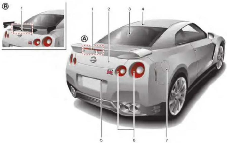
- High-mounted stop light (P.8-29)
- Trunk (P.3-8, P.3-19)
- Rear window defroster (P.2-50)
- Satellite antenna*
- Rear view camera*
-
Rear combination light (P.8-29)
-
Fuel-filler door (P.3-23, P.9-4)
*: Refer to the separate Multi Function Display Owner's Manual.
(A) : Except for NISMO models
B : NISMO models
| ITEMS GT-R SPECIFIED FUEL | |
| Fuel | Unleaded premium gasoline with an octane rating of at least 93 AKI (Anti-Knock Index) number (Research octane number 98)*1 |
*1: Use unleaded premium gasoline with an octane rating of at least 93 AKI (Anti- Knock Index) number (Research octane number 98) to maximize vehicle performance. If 93 AKI number (Research octane number 98) premium gasoline is not available, you may use unleaded premium gasoline with an octane rating of at least 91 AKI number (Research octane number 96), but you may notice a decrease in performance.
PASSENGER COMPARTMENT
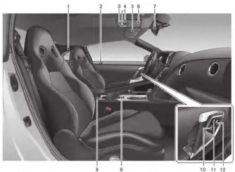
- Coat hooks (P.2-59)
- Inside lock knob (P.3-5)
- Interior light control switch (P.2-62)
- Map lights (P.2-62)
- Sun visors (P.3-26)
-
Sunglasses holder (P.2-57)
-
Inside rearview mirror (P.2-64, P.3-26)
- Center console box (P.2-59)
- USB memory operation*
— iPod ^® player operation ^* - Cup holders (P.2-56)
- Power window switches (P.2-60)
0-6 Illustrated table of contents
- Window lock button (P.2-61)
- Power door lock switch (P.3-5)
*: Refer to the separate Multi Function Display Owner's Manual.
COCKPIT
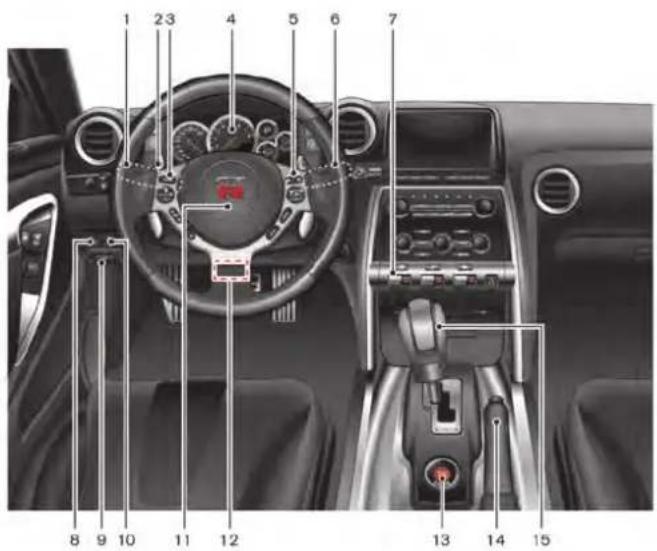
- Headlight and turn signal switch (P.2-50)
- Paddle shifters (P.5-15)
- Steering-wheel-mounted controls (left side)*
- Meters and gauges (P.2-5)
- Steering-wheel-mounted controls (right side)
— MRK (Mark) switch*
— Cruise control (P.5-34)
- Wiper and washer switch (P.2-48)
- VDC, transmission and suspension set up switches (P.5-25)
- Trunk lid release switch (P.3-19)
- Hood release handle (P.3-17)
-
Intelligent Key port (P.5-12)
-
Horn (P.2-54)
- Tilting/telescopic steering wheel lever (P.3-25)
- Push-button ignition switch (P.5-10)
- Parking brake (P.5-33, P.5-46)
- Shift lever (P.5-15)
*: Refer to the separate Multi Function Display Owner's Manual.
Illustrated table of contents 0-7
INSTRUMENT PANEL

- Outside mirror control switch (P.3-27)
- Center dial*
- Audio system*
- Heater and air conditioner*
- Multi function display*
-
Hazard warning flasher switch (P.6-2)
-
Glove box (P.2-58)
- Fuse box cover (P.8-25)
- Power outlet (P.2-55)
- Rear window defroster switch (P.2-50)
- Front passenger air bag status light (P.1-41)
-
CD/DVD slot*
-
Trunk release power cancel switch (P.3-20)
*: Refer to the separate Multi Function Display Owner's Manual.
0-8 Illustrated table of contents
METERS AND GAUGES

- Trip A/B reset switch (P.2-6)
- Speedometer (P.2-6)
- Tachometer (P.2-7)/Upshift indicator (P.2-9)
- Transmission position indicator (P.2-9)
- Engine coolant temperature gauge (P.2-7)
-
ENTER switch (P.2-15)
-
Instrument brightness control switch (P.2-11)
- Vehicle information display (P.2-12)
- Odometer/twin trip odometer (P.2-6)
- Fuel gauge (P.2-8)
- NEXT switch (P.2-15)
NOTE:
- Meters and gauges will illuminate when the ignition switch is pushed to the ON position.
- The needle indicators may move slightly after the ignition switch is pushed to the OFF position. This does not indicate that there is a malfunction.
ENGINE COMPARTMENT

- Fuse/fusible link holder (P.8-25)
- Battery (P.8-17)
- Engine oil filler cap (P.8-13)
- Engine oil dipstick (P.8-13)
- Brake fluid reservoir (P.8-15)
-
Air cleaner (P.8-21)
-
Power steering fluid reservoir (P.8-14)
- Radiator filler cap (P.8-10)
- Coolant reservoir cap (pressure type) (P.8-10)
- Coolant reservoir (P.8-10)
- Window washer fluid reservoir (P.8-16)
| ITEMS GT-R SPECIFIED FLUIDS | |
| Engine oil Mobil 1 (0W-40)*1 | |
| Transmission oil | Genuine NISSAN Transmission Oil R35 Special |
| Differential oil (front and rear) | Differential Oil R35 COMPE-TITION type 2189E |
| Brake fluid | Genuine NISSAN Brake Fluid R35 Special II*2 |
*1: Mobil 1 (0W-40) (100% synthetic) is the factory fill oil. The VR38 engine with its plasma-sprayed bores was developed using this oil. NISSAN cannot ensure proper engine operation and durability if other 0W-40 synthetic oil is used. If Mobil 1 (0W-40) is not available, Mobil 1 (10W-40) (100% synthetic) may be used; however, some performance loss may be noticed.
*2: Genuine NISSAN Brake Fluid R35 Special II is the factory fill brake fluid. The Vehicle Dynamic Control (VDC) unit and other related parts were specially designed for this brake fluid and NISSAN cannot ensure proper operation of the vehicle if other brake fluid is used.
0-10 Illustrated table of contents
WARNING AND INDICATOR LIGHTS
| Warning light | Name Page | |
 | All-Wheel Drive (AWD) warning light | 2-25 |
 | Anti-lock Braking System (ABS) warning light | 2-26 |
 | Brake warning light 2-26 | |
 | Charge warning light 2-27 | |
 | Engine oil pressure warning light | 2-27 |
 | Intelligent Key warning light 2-27 | |
 | Low tire pressure warning light 2-27 | 2-27 |
 | Master warning light 2-29 | |
 | Seat belt warning light 2-29 | |
 | Supplemental air bag warning light | 2-29 |
 | Transmission warning light 2-30 |
| Warning light | Name Page | |
| Vehicle Dynamic Control (VDC) warning light | 2-31 |
| Indicator light | Name Page | |
| Cruise main switch indicator light | 2-31 | |
| Cruise set switch indicator light 2 | 2-31 | |
| Exterior light indicator 2-31 | ||
| Front passenger air bag status light | 2-31 | |
| High beam indicator light 2-31 | ||
| Malfunction Indicator Light (MIL) | 2-31 | |
| Turn signal/hazard indicator lights | 2-32 | |
| Vehicle Dynamic Control (VDC) off indicator light | 2-32 |
MEMO
0-12 Illustrated table of contents
1 Safety — Seats, seat belts and supplemental restraint system
Seats 1-2
Front seats 1-3
Head restraints/headrests 1-5
Seat belts 1-6
Precautions on seat belt usage 1-6
Pregnant women 1-9
Injured persons 1-9
Three-point type seat belt with retractor 1-9
Seat belt extenders 1-12
Seat belt maintenance 1-13
Child safety 1-13
Infants 1-14
Small children 1-14
Larger children 1-14
Child restraints 1-15
Precautions on child restraints 1-15
Lower Anchors and Tethers for CHildren
System (LATCH) 1-17
Rear-facing child restraint installation using LATCH 1-19
Rear-facing child restraint installation using the seat belts 1-21
Forward-facing child restraint installation using LATCH 1-24
Forward-facing child restraint installation using the seat belts 1-26
Booster seats 1-30
Supplemental restraint system 1-34
Precautions on supplemental restraint system ..... 1-34
NISSAN Advanced Air Bag System (front seats) 1-40
Front seat-mounted side-impact supplemental air bag and roof-mounted curtain side-impact supplemental air bag systems 1-45
Seat belts with pretensioners (front seats) ..... 1-46
Supplemental air bag warning labels 1-47
Supplemental air bag warning light 1-47
Repair and replacement procedure 1-48

SEATS

natural_image
Illustration of a woman seated in a car seat, wearing a white jacket and yellow seatbelt, with no visible text or symbols.Sit upright and well back.

natural_image
Illustration of a person sitting in a car with a red 'X' symbol crossed out, indicating no text or symbols present.
WARNING
- Do not ride in a moving vehicle when the seatback is reclined. This can be dangerous. The shoulder belt will not be against your body. In an accident, you could be thrown into it and receive neck or other serious injuries. You could also slide under the lap belt and receive serious internal injuries.
- For the most effective protection when the vehicle is in motion, the seat should be upright. Always sit
well back in the seat with both feet on the floor and adjust the seat properly. ( "Precautions on seat belt usage" page 1-6)
- After adjustment, gently rock in the seat to make sure it is securely locked.
- Do not leave children unattended inside the vehicle. They could unknowingly activate switches or controls. Unattended children could become involved in serious accidents.
- The seatback should not be reclined any more than needed for comfort. Seat belts are most effective when the passenger sits with their back straight up and contacting the seat. If the seatback is reclined, the risk of sliding under the lap belt and being injured is increased.

CAUTION
When adjusting the seat positions, be sure not to contact any moving parts to avoid possible injuries or damage.
NOTICE
Make sure the front seatback does not contact the rear seat when reclining the seat. When the front seat is reclined to the rearmost position, it may contact the rear seat. This may cause an indentation in the seatback.
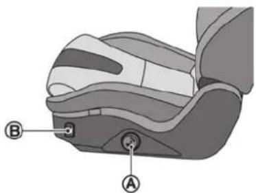
natural_image
Illustration of a car seat with labeled parts A and B (no text or symbols beyond labels)FRONT SEATS
Front power seat adjustment
Operating tips
- The power seat motor has an auto-reset overload protection circuit. If the motor stops during operation, wait 30 seconds, then reactivate the switch.
- Do not operate the power seat switch for a long period of time when the engine is off. This will discharge the battery.
| Seat Adjustment Switch Operation Location | |||
| Forward and backward | [A]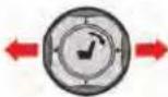 | Move the switch A forward or backward until the desired seat position is obtained. | Driver's and front passenger's seats |
| Reclining | [A] | Turn the switch A forward and backward until the desired seatback angle is obtained.The reclining feature allows adjustment of the seatback for occupants of different sizes for added comfort and to help obtain proper seat belt fit. ( "Precautions on seat belt usage" page 1-6)Also, the seatback can be reclined to allow occupants to rest when the vehicle is stopped and the transmission is in the P position with the parking brake fully applied. | |
| Seat lifter (front) | [B] | Push the switch up or down B to raise or lower the front portion of the seat. | Driver's seat |
| Seat lifter (rear) | [A] | Move the switch A up or down to raise or lower the rear portion of the seat. | |

Rear seat walk-in
This feature makes it easier to get in and out of the rear seat. Use the following procedure when getting in and out of the rear seat.
- Pull up the lever ①, hold the knob ②, and tilt the seatback forward.
- Use the seat adjustment switch Ⓐ to slide the seat forward to a position where it will be easier to enter or exit the rear seats. Fold the shoulder belt guide for easier access to the rear seat.
To return the seatback to its original position, hold the knob ②, raise the seatback, and use the seat adjustment switch Ⓐ to adjust the
seat position.
CAUTION
- When returning the seat to its original position, confirm that the seat and seatback are locked properly.
- Be careful not to pinch your hand or foot or bump your head when operating the walk-in seat.
NOTICE
Do not place any objects near the seatback of the front seats. They may be pinched and damaged.
HEAD RESTRAINTS/HEADRESTS
WARNING
Head restraints/headrests supplement the other vehicle safety systems. They may provide additional protection against injury in certain rear end collisions.
Head restraints/headrests must be adjusted properly, as specified in this section. Check the adjustment after someone else uses the seat. Failure to follow these instructions can reduce the effectiveness of the head restraints/headrests. This may increase the risk of serious injury or death in a collision.

natural_image
Top-down diagram of a car with four directional indicators (no text or symbols)The illustration shows the seating positions equipped with head restraint/headrest.
▲ Indicates the seating position is equipped with a head restraint.
+ Indicates the seating position is not equipped with a head restraint or headrest.
Your vehicle is equipped with integrated head restraints/headrests.
Proper adjustment:
Properly position the head restraint by adjusting the front seat so that the top of the seat is as upright as possible.
SEAT BELTS
PRECAUTIONS ON SEAT BELT USAGE
If you are wearing your seat belt properly adjusted, and you are sitting upright and well back in your seat with both feet on the floor, your chances of being injured or killed in an accident and/or the severity of injury may be greatly reduced. NISSAN strongly encourages you and all of your passengers to buckle up every time you drive, even if your seating position includes a supplemental air bag.
Most U.S. states and Canadian provinces or territories specify that seat belts be worn at all times when a vehicle is being driven.
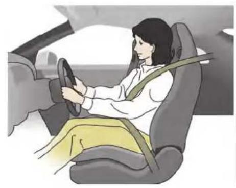
natural_image
Illustration of a woman seated in a car, wearing a steering wheel and yellow accents (no text or symbols visible)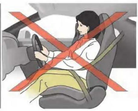
natural_image
Illustration of a person sitting in a car with a red cross symbol indicating no change or restriction, no text or symbols present.
natural_image
Illustration of a woman seated in a car seat, wearing a yellow seatbelt, with no visible text or symbols.
natural_image
Illustration of a person sitting in a car seat with a red 'X' symbol crossed out, indicating no vehicle restriction or absence.
WARNING
- Every person who drives or rides in this vehicle should use a seat belt at all times. Children should be properly restrained in the rear seat and, if appropriate, in a child restraint.
- The seat belt should be properly adjusted to a snug fit. Failure to do so may reduce the effectiveness of the entire restraint system and increase the chance or severity of injury in an accident. Serious injury or death can occur if the seat belt is not worn properly.
• Always route the shoulder belt over your shoulder and across your chest. Never put the belt behind your back, under your arm or across your neck. The belt should be away from your face and neck, but not falling off your shoulder. -
Position the lap belt as low and snug as possible AROUND THE HIPS, NOT THE WAIST. A lap belt worn too high could increase the risk of internal injuries in an accident.
-
Be sure the seat belt tongue is securely fastened to the proper buckle.
- Do not wear the seat belt inside out or twisted. Doing so may reduce its effectiveness.
- Do not allow more than one person to use the same seat belt.
- Never carry more people in the vehicle than there are seat belts.
- If the seat belt warning light glows continuously while the ignition is turned ON with all doors closed and all seat belts fastened, it may indicate a malfunction in the system. Have the system checked by a GT-R certified NISSAN dealer.
-
No changes should be made to the seat belt system. For example, do not modify the seat belt, add material, or install devices that may change the seat belt routing or tension. Doing so may affect the operation of the seat belt system. Modifying or tampering with the seat belt system may result in serious personal injury.
-
Once a seat belt pretensioner has activated, it cannot be reused and must be replaced together with the retractor. See a GT-R certified NISSAN dealer.
- Removal and installation of the pretensioner system components should be done by a GT-R certified NISSAN dealer.
- All seat belt assemblies, including retractors and attaching hardware, should be inspected after any collision by a GT-R certified NISSAN dealer. NISSAN recommends that all seat belt assemblies in use during a collision be replaced unless the collision was minor and the belts show no damage and continue to operate properly. Seat belt assemblies not in use during a collision should also be inspected and replaced if either damage or improper operation is noted.
- All child restraints and attaching hardware should be inspected after any collision. Always follow the restraint manufacturer's inspection instructions and replacement re-
commendations. The child restraints should be replaced if they are damaged.

natural_image
Illustration of a car seatbelt with a person inside, crossed by red prohibition symbols (no text or labels)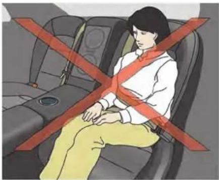
natural_image
Illustration of a person sitting in a car seat with red cross-bracing (no text or symbols)PREGNANT WOMEN
NISSAN recommends that pregnant women use seat belts. The seat belt should be worn snug, and always position the lap belt as low as possible around the hips, not the waist. Place the shoulder belt over your shoulder and across your chest. Never run the lap/shoulder belt over your abdominal area. Contact your doctor for specific recommendations.
INJURED PERSONS
NISSAN recommends that injured persons use seat belts. Check with your doctor for specific recommendations.
THREE-POINT TYPE SEAT BELT WITH RETRACTOR

WARNING
- Every person who drives or rides in this vehicle should use a seat belt at all times.
- Do not ride in a moving vehicle when the seatback is reclined. This can be dangerous. The shoulder belt will not be against your body. In an accident, you could be thrown into it and receive neck or other serious
injuries. You could also slide under the lap belt and receive serious internal injuries.
- For the most effective protection when the vehicle is in motion, the seat should be upright. Always sit well back in the seat with both feet on the floor and adjust the seat belt properly.
- Do not allow children to play with the seat belts. Most seating positions are equipped with Automatic Locking Retractor (ALR) mode seat belts. If the seat belt becomes wrapped around a child's neck with the ALR mode activated, the child can be seriously injured or killed if the seat belt retracts and becomes tight. This can occur even if the vehicle is parked. Unbuckle the seat belt to release the child. If the seat belt can not be unbuckled or is already unbuckled, release the child by cutting the seat belt with a suitable tool (such as a knife or scissors) to release the seat belt.
the retractor.

natural_image
Illustration of a person sitting on a car seat with a bandage and belt (no text or symbols)Fastening the seat belts
-
Adjust the seat. ("Seats" page 1-2)
-
Slowly pull the seat belt out of the retractor and insert the tongue into the buckle until you hear and feel the latch engage.
- The retractor is designed to lock during a sudden stop or on impact. A slow pulling motion permits the belt to move, and allows you some freedom of movement in the seat.
- If the seat belt cannot be pulled from its fully retracted position, firmly pull the belt and release it. Then smoothly pull the belt out of
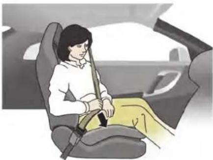
natural_image
Illustration of a woman seated in a car seat, wearing a seatbelt and holding a belt (no text or symbols visible)-
Position the lap belt portion low and snug on the hips as shown.
-
Pull the shoulder belt portion toward the retractor to take up extra slack. Be sure the shoulder belt is routed over your shoulder and across your chest.
The three-point type seat belts for the front passenger and rear seats have two modes of operation:
• Emergency Locking Retractor (ELR)
• Automatic Locking Retractor (ALR)
The Emergency Locking Retractor (ELR) mode allows the seat belt to extend and retract to allow the driver and passengers some freedom
1-10 Safety — Seats, seat belts and supplemental restraint system
of movement in the seat. The ELR locks the seat belt when the vehicle slows down rapidly or during impacts.
The Automatic Locking Retractor (ALR) mode or child restraint mode locks the seat belt for child restraint installation.
When the ALR mode is activated the seat belt cannot be extended again until the seat belt tongue is detached from the buckle and fully retracted. The seat belt returns to the ELR mode after the seat belt is fully retracted.
( "Child restraints" page 1-15)
The ALR mode should be used only for child restraint installation. During normal seat belt use by an occupant, the ALR mode should not be activated. If it is activated it may cause uncomfortable seat belt tension. It can also change the operation of the front passenger air bag.
( "Front passenger air bag and status light" page 1-41)

WARNING
When fastening the seat belts, be certain that seatbacks are completely secured in the latched position. If they are not completely secured, passengers
may be injured in an accident or sudden stop.
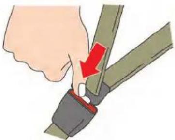
natural_image
Illustration of a hand adjusting a green belt buckle with a red arrow indicating the point of change (no text or symbols present)Unfastening the seat belts
To unfasten the seat belt, push the button on the buckle. The seat belt automatically retracts.
Checking seat belt operation
Seat belt retractors are designed to lock seat belt movement by two separate methods:
- When the belt is pulled quickly from the retractor.
- When the vehicle slows down rapidly. To increase your confidence in the seat belts, check the operation as follows:
- Grasp the shoulder belt and pull forward
quickly. The retractor should lock and restrict further belt movement. If the retractor does not lock during this check or if you have any question about seat belt operation, see a GT-R certified NISSAN dealer.
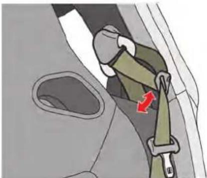
natural_image
Illustration of a car seatbelt buckle with a red arrow indicating the seatbelt buckle (no text or symbols present)Shoulder belt arm (for front seats)
Before fastening the seat belt, adjust the shoulder belt arm to the lock position where the belt fits snugly on the shoulder. The arm can also be folded down to allow rear seat passengers easier access.
Pulling the arm forward will allow an easy access to the belt.
SEAT BELT EXTENDERS
If, because of body size or driving position, it is not possible to properly fit the lap-shoulder belt and fasten it, an extender that is compatible with the installed seat belts is available that can be purchased. The extender adds approximately 8 in (200 mm) of length and may be used for either the driver or front passenger seating position. See a GT-R certified NISSAN dealer for assistance with purchasing an extender if an extender is required.

WARNING
- Only NISSAN seat belt extenders, made by the same company which made the original equipment seat belts, should be used with the NISSAN seat belts.
- Adults and children who can use the standard seat belt should not use an extender. Such unnecessary use could result in serious personal injury in the event of an accident.
- Never use seat belt extenders to install child restraints. If the child restraint is not secured properly, the child could be seriously injured in a
collision or a sudden stop.
SEAT BELT MAINTENANCE
- To clean the seat belt webbing, apply a mild soap solution or any solution recommended for cleaning upholstery or carpets. Then, wipe with a cloth and allow the seat belts to dry in the shade. Do not allow the seat belts to retract until they are completely dry.
- If dirt builds up in the shoulder belt guide of the seat belt anchors, the seat belts may retract slowly. Wipe the shoulder belt guide with a clean, dry cloth.
- Periodically check to see that the seat belt and the metal components such as buckles, tongues, retractors, flexible wires and anchors work properly. If loose parts, deterioration, cuts or other damage on the webbing is found, the entire seat belt assembly should be replaced.
CHILD SAFETY
WARNING
Do not allow children to play with the seat belts. Most seating positions are equipped with Automatic Locking Retractor (ALR) mode seat belts. If the seat belt becomes wrapped around a child's neck with the ALR mode activated, the child can be seriously injured or killed if the seat belt retracts and becomes tight. This can occur even if the vehicle is parked. Unbuckle the seat belt to release the child. If the seat belt can not be unbuckled or is already unbuckled, release the child by cutting the seat belt with a suitable tool (such as a knife or scissors) to release the seat belt.
Children need adults to help protect them. They need to be properly restrained.
In addition to the general information in this manual, child safety information is available from many other sources, including doctors, teachers, government traffic safety offices, and community organizations. Every child is different, so be sure to learn the best way to transport your child. There are three basic types of child restraint
systems:
- Rear-facing child restraint
- Forward-facing child restraint
- Booster seat
The proper restraint depends on the child's size. Generally, infants (up to about 1 year and less than 20 lb (9 kg)) should be placed in rear-facing child restraints. Forward-facing child restraints are available for children who outgrow rear-facing child restraints and are at least 1 year old. Booster seats are used to help position a vehicle lap/shoulder belt on a child who can no longer use a forward-facing child restraint.
WARNING
Infants and children need special protection. The vehicle's seat belts may not fit them properly. The shoulder belt may come too close to the face or neck. The lap belt may not fit over their small hip bones. In an accident, an improperly fitting seat belt could cause serious or fatal injury. Always use appropriate child restraints.
All U.S. states and Canadian provinces or territories require the use of approved child
restraints for infants and small children. ( "Child restraints" page 1-15)
A child restraint may be secured in the vehicle by using either the LATCH (Lower Anchor and Tethers for CHildren) system or with the vehicle seat belt. ( "Child restraints" page 1-15)
NISSAN recommends that all pre-teens and children be restrained in the rear seat. According to accident statistics, children are safer when properly restrained in the rear seat than in the front seat.
This is especially important because your vehicle has a supplemental restraint system (air bag system) for the front passenger. ( "Supplemental restraint system" page 1-34)
INFANTS
Infants up to at least one year old should be placed in a rear-facing child restraint. NISSAN recommends that infants be placed in child restraints that comply with Federal Motor Vehicle Safety Standards or Canadian Motor Vehicle Safety Standards. You should choose a child restraint which fits your vehicle and always follow the manufacturer's instructions for installation and use.
SMALL CHILDREN
Children that are over 1 year old and weigh at least 20 lb (9 kg) should remain in a rear-facing child restraint as long as possible up to the height or weight limit of the child restraint.
Children who outgrow the height or weight limit of the rear-facing child restraint and are at least 1 year old should be secured in a forward-facing child restraint with a harness. Refer to the manufacturer's instructions for minimum and maximum weight and height recommendations. NISSAN recommends that small children be placed in child restraints that comply with Federal Motor Vehicle Safety Standards or Canadian Motor Vehicle Safety Standards. You should choose a child restraint that fits your vehicle and always follow the manufacturer's instructions for installation and use.
LARGER CHILDREN
Children should remain in a forward-facing child restraint with a harness until they reach the maximum height or weight limit allowed by the child restraint manufacturer.
Once a child outgrows the height or weight limit of the harness-equipped forward-facing child restraint, NISSAN recommends that the child be placed in a commercially available booster seat to obtain proper seat belt fit. For a seat belt to fit properly, the booster seat should raise the child so that the shoulder belt is properly positioned across the chest and the top, middle portion of the shoulder. The shoulder belt should not cross the neck or face and should not fall off the shoulder. The lap belt should lie snugly across the lower hips or upper thighs, not the abdomen.
A booster seat can only be used in seating positions that have a three-point type seat belt. The booster seat should fit the vehicle seat and have a label certifying that it complies with Federal Motor Vehicle Safety Standards or Canadian Motor Vehicle Safety Standards. Once the child has grown so the shoulder belt is no longer on or near the face and neck, and the lap belt can be positioned properly across the lower hips or upper thighs, use the seat belt without the booster seat.

WARNING
Never let a child stand or kneel on any seat and do not allow a child in the cargo areas while the vehicle is moving. The child could be seriously injured or killed in an accident or sudden stop.
CHILD RESTRAINTS
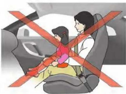
natural_image
Illustration of a car seatbelt with a child sitting on the back and an adult standing beside it, crossed out by red diagonal lines (no text or symbols)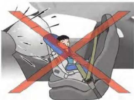
natural_image
Illustration of a person inside a car seat with red diagonal lines indicating no change or restriction (no text or symbols present)PRECAUTIONS ON CHILD RESTRAINTS

WARNING
- Failure to follow the warnings and instructions for proper use and installation of child restraints could result in serious injury or death of a child or other passengers in a sudden stop or collision:
— The child restraint must be used and installed properly. Always follow all of the child restraint manufacturer's instructions for installation and use.
— Infants and children should never be held on anyone's lap. Even the strongest adult cannot resist the forces of a collision.
— Do not put a seat belt around both a child and another passenger.
— NISSAN recommends that all child restraints be installed in the rear seat. Studies show that children are safer when properly restrained in the rear seat than
in the front seat. If you must install a forward-facing child restraint in the front seat. ( "Forward-facing child restraint installation using the seat belts" page 1-26)
— Even with the NISSAN Advanced Air Bag System, never install a rear-facing child restraint in the front seat. An inflating air bag could seriously injure or kill a child. A rear-facing child restraint must only be used in the rear seat.
— Be sure to purchase a child restraint that will fit the child and vehicle. Some child restraints may not fit properly in your vehicle.
— Child restraint anchor points are designed to withstand loads from child restraints that are properly fitted.
— Never use the anchor points for adult seat belts or harnesses.
— A child restraint with a top tether strap should not be used in the
front passenger seat.
— Keep seatbacks as upright as possible after fitting the child restraint.
— Infants and children should always be placed in an appropriate child restraint while in the vehicle.
- When the child restraint is not in use, keep it secured with the LATCH system or a seat belt. In a sudden stop or collision, loose objects can injure occupants or damage the vehicle.

CAUTION
A child restraint in a closed vehicle can become very hot. Check the seating surface and buckles before placing a child in the child restraint.
This vehicle is equipped with a universal child restraint anchor system, referred to as the LATCH (Lower Anchors and Tethers for CHil-dren) system. Some child restraints include rigid or webbing-mounted attachments that can be connected to these anchors. (See "Lower Anchors and Tethers for CHildren System (LATCH)" page 1-17.)
If you do not have a LATCH compatible child restraint, the vehicle seat belts can be used. Several manufacturers offer child restraints for infants and small children of various sizes. When selecting any child restraint, keep the following points in mind:
- Choose only a restraint with a label certifying that it complies with Federal Motor Vehicle Safety Standard 213 or Canadian Motor Vehicle Safety Standard 213.
- Check the child restraint in your vehicle to be sure it is compatible with the vehicle's seat and seat belt system.
- If the child restraint is compatible with your vehicle, place your child in the child restraint and check the various adjustments to be sure the child restraint is compatible with your child. Choose a child restraint that is designed for your child's height and weight. Always follow all recommended procedures.
-
If the combined weight of the child and child restraint is less than 65 lbs (29.5 kg), you may use either the LATCH anchors or the seat belt to install the child restraint (not both at the same time).
-
If the combined weight of the child and child restraint is greater than 65 lbs (29.5 kg), use the vehicle's seat belt (not the lower anchors) to install the child restraint.
- Be sure to follow the child restraint manufacturer's instructions for installation.
All U.S. states and Canadian provinces or territories require that infants and small children be restrained in an approved child restraint at all times while the vehicle is being operated. Canadian law requires the top tether strap on forward-facing child restraints be secured to the designated anchor point on the vehicle.

LATCH label location
Lower Anchors and Tethers for CHildren System (LATCH)
Your vehicle is equipped with special anchor points that are used with the LATCH (Lower Anchors and Tethers for CHildren) system compatible child restraints. This system may also be referred to as the ISOFIX or ISOFIX compatible system. With this system, you do not have to use a vehicle seat belt to secure the child restraint unless the combined weight of the child and child restraint exceeds 65 lbs (29.5 kg). If the combined weight of the child and child restraint is greater than 65 lbs (29.5 kg), use the vehicle's seat belt (not the lower anchors) to install the child restraint. Be sure to follow the child restraint manufacturer's instructions for installation.
LATCH lower anchor

WARNING
Failure to follow the warnings and instructions for proper use and installation of child restraints could result in serious injury or death of a child or other passengers in a sudden stop or collision:
- Attach LATCH system compatible child restraints only at the locations shown in the illustration.
- Inspect the lower anchors by inserting your fingers into the lower anchor area. Feel to make sure there are no obstructions over the anchors such as seat belt webbing or seat cushion material. The child restraint will not be secured properly if the lower anchors are obstructed.
Child restraint anchorages are designed to withstand only those loads imposed by correctly fitted child re-
straints. Under no circumstances are they to be used to attach adult seat belts, or other items or equipment to the vehicle. Doing so could damage the child restraint anchorages. The child restraint will not be properly installed using the damaged anchorage, and a child could be seriously injured or killed in a collision.

natural_image
Illustration of a hand pressing down on a car seat (no text or symbols visible)LATCH lower anchor location
LATCH lower anchor location
The LATCH anchors are located at the rear of the seat cushion near the seatback. A label is attached to the seatback to help you locate the LATCH anchors.

WARNING
The GT-R has seats and seat belts for four occupants, two in the front seats and two in the rear seats. Never use the rear console as a seating position or for a child restraint.
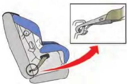
LATCH webbing-mounted attachment
Installing child restraint LATCH lower anchor attachments
LATCH compatible child restraints include two rigid or webbing-mounted attachments that can be connected to two anchors located at certain seating positions in your vehicle. With this system, you do not have to use a vehicle seat belt to secure the child restraint. Check your child restraint for a label stating that it is compatible with LATCH. This information may also be in the instructions provided by the child restraint manufacturer.
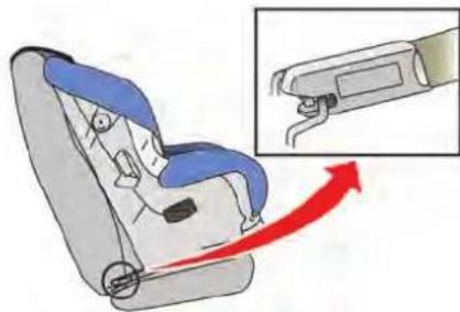
LATCH rigid-mounted attachment
When installing a child restraint, carefully read and follow the instructions in this manual and those supplied with the child restraint.
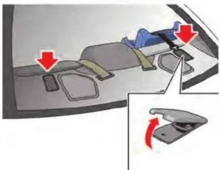
natural_image
Diagram showing a car interior with seatbelt and dashboard, highlighting red directional arrows (no text or symbols present)Top tether anchor point locations
Anchor points are located on the rear parcel shelf.

WARNING
Child restraint anchorages are designed to withstand only those loads imposed by correctly fitted child restraints. Under no circumstances are they to be used to attach adult seat belts, or other items or equipment to the vehicle. Doing so could damage the child restraint anchorages. The child
restraint will not be properly installed using the damaged anchorage, and a child could be seriously injured or killed in a collision.
REAR-FACING CHILD RESTRAINT INSTALLATION USING LATCH
Refer to all Warnings and Cautions in the "Child safety" and "Child restraints" sections before installing a child restraint.
Do not use the lower anchors if the combined weight of the child and the child restraint exceeds 65 lbs (29.5 kg). If the combined weight of the child and the child restraint is greater than 65 lbs (29.5 kg), use the vehicle's seat belt (not the lower anchors) to install the child restraint. Be sure to follow the child restraint manufacturer's instructions for installation.
Follow these steps to install a rear-facing child restraint using the LATCH system:
- Position the child restraint on the seat. Always follow the child restraint manufacturer's instructions.

natural_image
Interior view of a car seatbelt with a close-up inset showing the seatbelt detail (no text or symbols visible)Rear-facing web-mounted — step 2
- Secure the child restraint anchor attachments to the LATCH lower anchors. Check to make sure the LATCH attachment is properly attached to the lower anchors.
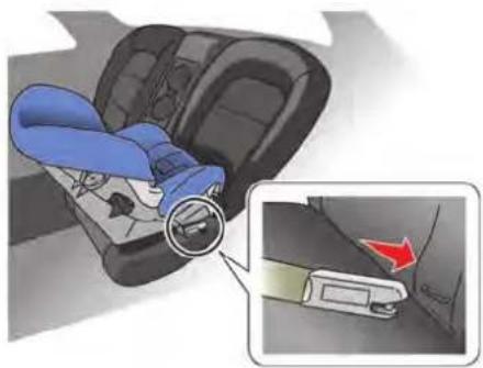
natural_image
Illustration of a car seatbelt buckle being inserted into the seat, with a magnified inset showing the same seat (no text or symbols present)Rear-facing rigid-mounted — step 2

natural_image
Illustration of a person adjusting a blue car seatbelt using a buckle, with red arrows indicating the seatbelt being adjusted (no text or symbols present)Rear-facing — step 3
- For child restraints that are equipped with webbing-mounted attachments, remove any additional slack from the anchor attachments. Press downward and rearward firmly in the center of the child restraint with your hand to compress the vehicle seat cushion and seatback while tightening the webbing of the anchor attachments.

natural_image
Illustration of a person adjusting a blue and gray car seatbelt (no text or symbols)Rear-facing — step 4
-
After attaching the child restraint, test it before you place the child in it. Push it from side to side while holding the child restraint near the LATCH attachment path. The child restraint should not move more than 1 inch (25 mm), from side to side. Try to tug it forward and check to see if the LATCH attachment holds the restraint in place. If the restraint is not secure, tighten the LATCH attachment as necessary, or put the restraint in another seat and test it again. You may need to try a different child restraint or try installing by using the vehicle seat belt (if applicable). Not all child restraints fit in all types of vehicles.
-
Check to make sure the child restraint is properly secured prior to each use. If the child restraint is loose, repeat steps 1 through 4.

natural_image
Illustration of a person sitting in a car seat with red diagonal lines indicating no change or restriction (no text or symbols present)change the operation of the front passenger air bag. See "Front passenger air bag and status light" later in this section.
REAR-FACING CHILD RESTRAINT INSTALLATION USING THE SEAT BELTS

WARNING
The three-point seat belt with Automatic Locking Retractor (ALR) must be used when installing a child restraint. Failure to use the ALR mode will result in the child restraint not being properly secured. The restraint could tip over or be loose and cause injury to a child in a sudden stop or collision. Also, it can

natural_image
Illustration of a person sitting on a car seat with red cross-bracing lines indicating no change or restriction (no text or symbols present)Rear-facing — step 1
Refer to all Warnings and Cautions in "Child safety" and "Child restraints" before installing a child restraint.
Do not use the lower anchors if the combined weight of the child and the child restraint exceeds 65 lbs (29.5 kg). If the combined weight of the child and the child restraint is greater than 65 lbs (29.5 kg), use the vehicle's seat belt (not the lower anchors) to install the child restraint. Be sure to follow the child restraint manufacturer's instructions for installation.
Follow these steps to install a rear-facing child restraint using the vehicle seat belts in the rear
seats:
- Child restraints for infants must be used in the rear-facing direction and therefore must not be used in the front seat. Position the child restraint on the seat. Always follow the restraint manufacturer's instructions.

natural_image
Illustration of a person adjusting a seatbelt using a belt buckle (no text or symbols present)Rear-facing — step 2
- Route the seat belt tongue through the child restraint and insert it into the buckle until you hear and feel the latch engage. Be sure to follow the child restraint manufacturer's instructions for belt routing.

natural_image
Illustration of a person adjusting a car seatbelt using a belt, with a red arrow indicating the safety direction (no text or symbols present)Rear-facing — step 3
3. Pull the shoulder belt until the belt is fully extended. At this time, the seat belt retractor is in the Automatic Locking Retractor (ALR) mode (child restraint mode). It reverts to the Emergency Locking Retractor (ELR) mode when the seat belt is fully retracted.

natural_image
Diagram of a car seatbelt with blue and gray seats, showing red directional arrows indicating movement or force (no text or symbols present)Rear-facing — step 4
4. Allow the seat belt to retract. Pull up on the shoulder belt to remove any slack in the belt.

natural_image
Illustration of a person adjusting a blue car seatbelt, with red arrows indicating force or pressure points (no text or symbols present)Rear-facing — step 5
5. Remove any additional slack from the seat belt; press downward and rearward firmly in the center of the child restraint to compress the vehicle seat cushion and seatback while pulling up on the seat belt.

natural_image
Illustration of a person adjusting a blue seatbelt inside a car seat, with a red arrow indicating left motion (no text or symbols)Rear-facing — step 6
-
After attaching the child restraint, test it before you place the child in it. Push it from side to side while holding the child restraint near the seat belt path. The child restraint should not move more than 1 inch (25 mm), from side to side. Try to tug it forward and check to see if the belt holds the restraint in place. If the restraint is not secure, tighten the seat belt as necessary, or put the restraint in another seat and test it again. You may need to try a different child restraint. Not all child restraints fit in all types of vehicles.
-
Check to make sure that the child restraint is properly secured prior to each use. If the
seat belt is not locked, repeat steps 1 through 6.
After the child restraint is removed and the seat belt fully retracted, the ALR mode (child restraint mode) is canceled.
FORWARD-FACING CHILD RE-STRAINT INSTALLATION USING LATCH
Refer to all Warnings and Cautions in the "Child safety" and "Child restraints" sections before installing a child restraint.
Do not use the lower anchors if the combined weight of the child and the child restraint exceeds 65 lbs (29.5 kg). If the combined weight of the child and the child restraint is greater than 65 lbs (29.5 kg), use the vehicle's seat belt (not the lower anchors) to install the child restraint. Be sure to follow the child restraint manufacturer's instructions for installation.
Follow these steps to install a forward-facing child restraint using the LATCH system:
- Position the child restraint on the seat. Always follow the child restraint manufacturer's instructions.
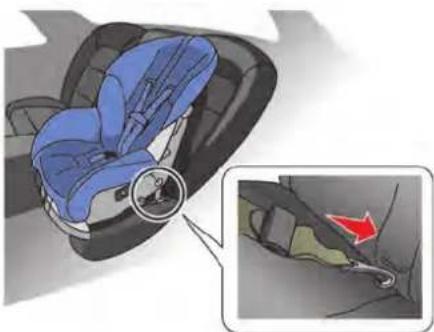
natural_image
Illustration of a blue car seat with a magnified inset showing the cable being inserted (no text or symbols present)Forward-facing web-mounted — step 2
- Secure the child restraint anchor attachments to the LATCH lower anchors. Check to make sure the LATCH attachment is properly attached to the lower anchors. If the child restraint is equipped with a top tether strap, route the top tether strap and secure the tether strap to the tether anchor point. See "Installing top tether strap" page 1-26. Do not install child restraints that require the use of a top tether strap in seating positions that do not have a top tether anchor.
1-24 Safety — Seats, seat belts and supplemental restraint system

natural_image
Illustration of a blue car seatbelt with a magnified inset showing the seatbelt switch (no text or symbols present)Forward-facing rigid-mounted — step 2
- The back of the child restraint should be secured against the vehicle seatback. If the seating position is interfering with the proper child restraint fit, try another seating position or a different child restraint.

natural_image
Illustration of a person adjusting a blue and gray car seatbelt, with red arrows indicating pressure points (no text or symbols present)Forward-facing — step 4
-
For child restraints that are equipped with webbing-mounted attachments, remove any additional slack from the anchor attachments. Press downward and rearward firmly in the center of the child restraint with your knee to compress the vehicle seat cushion and seatback while tightening the webbing of the anchor attachments.
-
Tighten the tether strap according to the manufacturer's instructions to remove any slack.

natural_image
Illustration of a person adjusting a blue car seatbelt (no text or symbols present)Forward-facing — step 6
-
After attaching the child restraint, test it before you place the child in it. Push it from side to side while holding the child restraint near the LATCH attachment path. The child restraint should not move more than 1 inch (25 mm), from side to side. Try to tug it forward and check to see if the LATCH attachment holds the restraint in place. If the restraint is not secure, tighten the LATCH attachment as necessary, or put the restraint in another seat and test it again. You may need to try a different child restraint. Not all child restraints fit in all types of vehicles.
-
Check to make sure the child restraint is properly secured prior to each use. If the
child restraint is loose, repeat steps 1 through 6.
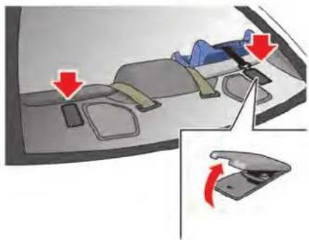
natural_image
Diagram showing a car interior with seatbelt and dashboard, highlighting red directional arrows (no text or symbols present)Installing top tether strap
The child restraint top tether strap must be used when installing the child restraint with the LATCH lower anchor attachments.
First, secure the child restraint with the LATCH lower anchors (rear outboard seat positions only).
- Flip up the anchor cover from the anchor point which is located directly behind the child restraint.
- Position the top tether strap over the top of the seatback.
-
Secure the tether strap to the tether anchor point on the rear parcel shelf.
-
Refer to the appropriate child restraint installation procedure steps earlier in this section before tightening the tether strap. If you have any questions when installing a top tether strap, consult a GT-R certified NISSAN dealer for details.
FORWARD-FACING CHILD RE-STRAINT INSTALLATION USING THE SEAT BELTS

WARNING
The three-point seat belt with Automatic Locking Retractor (ALR) must be used when installing a child restraint. Failure to use the ALR mode will result in the child restraint not being properly secured. The restraint could tip over or be loose and cause injury to a child in a sudden stop or collision. Also, it can change the operation of the front passenger air bag. See "Front passenger air bag and status light" later in this section.

natural_image
Interior view of a car showing seatbelt and dashboard, with a red arrow indicating direction (no text or symbols)Forward-facing (front passenger seat) — step 1 Refer to all Warnings and Cautions in the "Child safety" and "Child restraints" sections before installing a child restraint.
Do not use the lower anchors if the combined weight of the child and the child restraint exceeds 65 lbs (29.5 kg). If the combined weight of the child and the child restraint is greater than 65 lbs (29.5 kg), use the vehicle's seat belt (not the lower anchors) to install the child restraint. Be sure to follow the child restraint manufacturer's instructions for installation.
Follow these steps to install a forward-facing child restraint using the vehicle seat belt in the
rear seats or in the front passenger seat:
-
If you must install a child restraint in the front seat, it should be placed in a forward-facing direction only. Move the seat to the rearmost position. Child restraints for infants must be used in the rear-facing direction and, therefore, must not be used in the front seat.
-
Position the child restraint on the seat. Always follow the child restraint manufacturer's instructions.
The back of the child restraint should be secured against the vehicle seatback. If the seating position is interfering with the proper child restraint fit, try another seating position or a different child restraint.

natural_image
Illustration of a person's seatbelt being adjusted for a car, showing a blue jacket and green belt (no text or symbols)Forward-facing — step 3
- Route the seat belt tongue through the child restraint and insert it into the buckle until you hear and feel the latch engage. Be sure to follow the child restraint manufacturer's instructions for belt routing. If the child restraint is equipped with a top tether strap, route the top tether strap and secure the tether strap to the tether anchor point. ( "Installing top tether strap" page 1-30) Do not install child restraints that require the use of a top tether strap in seating positions that do not have a top tether anchor.

natural_image
Illustration of a person adjusting a blue car seatbelt with a red arrow indicating the seatbelt (no text or symbols present)Forward-facing — step 4
4. Pull the shoulder belt until the belt is fully extended. At this time, the seat belt retractor is in the Automatic Locking Retractor (ALR) mode (child restraint mode). It reverts to Emergency Locking Retractor (ELR) mode when the seat belt is fully retracted.

natural_image
Illustration of a blue car seat with red arrows indicating seatbelting (no text or symbols)Forward-facing — step 5
5. Allow the seat belt to retract. Pull up on the shoulder belt to remove any slack in the belt.
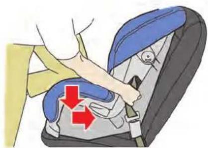
natural_image
Illustration of a person adjusting a car seatbelt with red arrows indicating force or pressure points (no text or symbols present)Forward-facing — step 6
6. Remove any additional slack from the seat belt; press downward and rearward firmly in the center of the child restraint with your knee to compress the vehicle seat cushion and seatback while pulling up on the seat belt.
7. Tighten the tether strap according to the manufacturer's instructions to remove any slack.
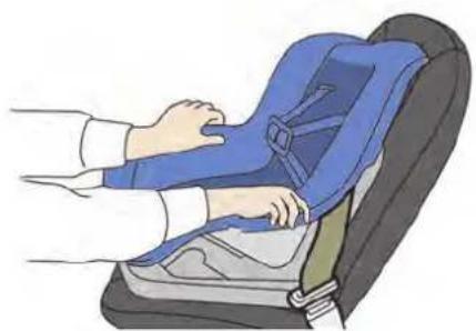
natural_image
Illustration of a person adjusting a blue seatbelt on a car seat (no text or symbols)Forward-facing — step 8
-
After attaching the child restraint, test it before you place the child in it. Push it from side to side while holding the child restraint near the seat belt path. The child restraint should not move more than 1 inch (25 mm), from side to side. Try to tug it forward and check to see if the belt holds the restraint in place. If the restraint is not secure, tighten the seat belt as necessary, or put the restraint in another seat and test it again. You may need to try a different child restraint. Not all child restraints fit in all types of vehicles.
-
Check to make sure the child restraint is properly secured prior to each use. If the
seat belt is not locked, repeat steps 2 through 8.

Forward-facing — step 10
- If the child restraint is installed in the front passenger seat, place the ignition switch in the ON position. The front passenger air bag status light should illuminate. If this light is not illuminated, see "Front passenger air bag and status light" in this section. Move the child restraint to another seating position. Have the system checked by a GT-R certified NISSAN dealer.
After the child restraint is removed and the seat belt is fully retracted, the ALR mode (child restraint mode) is canceled.
Safety — Seats, seat belts and supplemental restraint system 1-29

natural_image
Interior view of a car dashboard with red arrows indicating movement or change, showing no text or symbols.Installing top tether strap
The child restraint top tether strap must be used when installing the child restraint with the seat belts.
First, secure the child restraint with the seat belt.
- Flip up the anchor cover from the anchor point which is located directly behind the child restraint.
- Position the top tether strap over the top of the seatback.
- Secure the tether strap to the tether anchor point on the rear parcel shelf.
- Refer to the appropriate child restraint installation procedure steps earlier in this
section before tightening the tether strap. If you have any questions when installing a top tether strap, consult a GT-R certified NISSAN dealer for details.
BOOSTER SEATS
Precautions on booster seats

WARNING
If a booster seat and seat belt are not used properly, the risk of a child being injured in a sudden stop or collision greatly increases:
- Make sure the shoulder portion of the belt is away from the child's face and neck and the lap portion of the belt does not cross the stomach.
- Make sure the shoulder belt is not behind the child or under the child's arm.
- A booster seat must only be installed in a seating position that has a lap/shoulder belt.

natural_image
Illustration of a blue car seat with two labeled parts (① and ②), no text or symbols present.Booster seats of various sizes are offered by several manufacturers. When selecting any booster seat, keep the following points in mind:
- Choose only a booster seat with a label certifying that it complies with Federal Motor Vehicle Safety Standard 213 or Canadian Motor Vehicle Safety Standard 213.
- Check the booster seat in your vehicle to be sure it is compatible with the vehicle's seat and seat belt system.
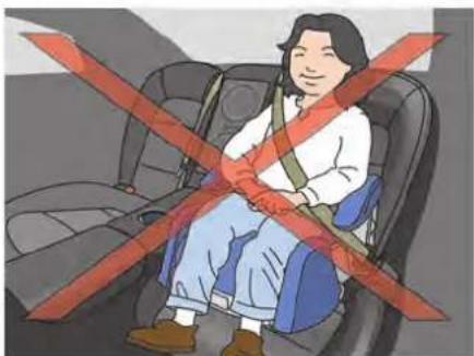
natural_image
Illustration of a person sitting in a car seat with red safety stripes (no text or symbols)- Make sure the child's head will be properly supported by the booster seat or vehicle seat. The seatback must be at or above the center of the child's ears. For example, if a low back booster seat ① is chosen, the vehicle seatback must be at or above the center of the child's ears. If the seatback is lower than the center of the child's ears, a high back booster seat ② should be used.
- If the booster seat is compatible with your vehicle, place your child in the booster seat and check the various adjustments to be sure the booster seat is compatible with your child. Always follow all recommended procedures.

natural_image
Illustration of a person sitting in a car seatbelt, wearing a white shirt and blue pants (no text or symbols visible)All U.S. states and Canadian provinces or territories require that infants and small children be restrained in an approved child restraint at all times while the vehicle is being operated.
The instructions in this section apply to booster seat installation in the rear seats or the front passenger seat.
Booster seat installation

CAUTION
Do not use the lap/shoulder belt Automatic Locking Retractor (ALR) mode when using a booster seat with the seat belts.
Refer to all Warnings and Cautions in the "Child safety", "Child restraints" and "Booster seats" sections earlier in this section before installing a child restraint.
Follow these steps to install a booster seat in the rear seat or in the front passenger seat:
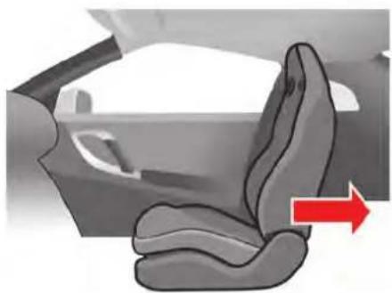
natural_image
Interior view of a car showing the seatbelt and dashboard area with a red arrow indicating direction (no text or symbols)-
If you must install a booster seat in the front seat, move the seat to the rear-most position.
-
Position the booster seat on the seat. Only place it in a forward-facing direction. Always follow the booster seat manufacturer's instructions.

natural_image
Illustration of a person sitting in a car seat, wearing a blue and white seatbelt (no text or symbols visible)Outboard position
-
The booster seat should be positioned on the vehicle seat so that it is stable. If the seating position is interfering with the proper booster seat fit, try another seating position or a different booster seat.
-
Position the lap portion of the seat belt low and snug on the child's hips. Be sure to follow the booster seat manufacturer's instructions for adjusting the belt routing.
-
Pull the shoulder belt portion of the seat belt toward the retractor to take up extra slack. Be sure the shoulder belt is positioned across the top, middle portion of the child's shoulder. Be sure to follow the booster seat
manufacturer's instructions for adjusting the belt routing.

natural_image
Illustration of a person sitting in a car seat, wearing a blue seatbelt and holding a belt (no text or symbols visible)Front seat
- Follow the warnings, cautions and instructions for properly fastening a seat belt. ( "Three-point type seat belt with retractor" page 1-9)
PASSENGER AIR BAG

- If the booster seat is installed in the front passenger seat, push the ignition switch to the ON position. The front passenger air bag status light may or may not illuminate depending on the size of the child and the type of booster seat used. ( "Front passenger air bag and status light" page 1-41)
SUPPLEMENTAL RESTRAINT SYSTEM
PRECAUTIONS ON SUPPLEMENTAL RESTRAINT SYSTEM
This Supplemental Restraint System (SRS) section contains important information concerning the following systems:
- Driver and passenger supplemental front-impact air bag (NISSAN Advanced Air Bag System)
- Front seat-mounted side-impact supplemental air bag
- Roof-mounted curtain side-impact supplemental air bag
- Seat belt pretensioner
Supplemental front-impact air bag system: The NISSAN Advanced Air Bag System can help cushion the impact force to the head and chest of the driver and front passenger in certain frontal collisions.
Front seat-mounted side-impact supplemental air bag system: This system can help cushion the impact force to the chest area of the driver and front passenger in certain side impact collisions. The side air bags are designed to inflate on the side where the vehicle is impacted.
Roof-mounted curtain side-impact supplemental air bag system: This system can help cushion the impact force to the head of
occupants in the front seating positions in certain side impact collisions. The curtain air bags are designed to inflate on the side where the vehicle is impacted.
These supplemental restraint systems are designed to supplement the crash protection provided by the driver and passenger seat belts and are not a substitute for them. Seat belts should always be correctly worn and the occupant seated a suitable distance away from the steering wheel, instrument panel and door finishers. ( "Seat belts" page 1-6)
The supplemental air bags operate only when the ignition switch is in the ON position.
After pushing the ignition switch to the ON position, the supplemental air bag warning light illuminates. The supplemental air bag warning light will turn off after about 7 seconds if the systems are operational.

natural_image
Illustration of a woman seated in a car, steering wheel and headboard (no text or symbols)
natural_image
Illustration of a person sitting in a car with red and yellow stripes crossed, indicating seatbelt or steering wheel (no text or symbols)Sit upright and well back.

natural_image
Illustration of a person seated in a car seat, wearing a yellow seatbelt (no text or symbols visible)
natural_image
Illustration of a person sitting in a car with a red cross symbol indicating no vehicle restriction (no text or symbols present)Sit upright and well back.

WARNING
- The front air bags ordinarily will not inflate in the event of a side impact, rear impact, rollover, or lower severity frontal collision. Always wear your seat belts to help reduce the risk or severity of injury in various kinds of accidents.
- The front passenger air bag will not inflate if the passenger air bag status light is lit or if the front passenger seat is unoccupied. ( "Front passenger air bag and status light" page 1-41)
- The seat belts and the front air bags are most effective when you are sitting well back and upright in the seat. The front air bags inflate with great force. Even with the NISSAN Advanced Air Bag System, if you are unrestrained, leaning forward, sitting sideways or out of position in any way, you are at greater risk of injury or death in a crash. You may also receive serious or fatal injuries from the front air bag if you are up against it when it inflates. Always sit
back against the seatback and as far-away as practical from the steering wheel or instrument panel. Always use the seat belts.
- The driver and front passenger seat belt buckles are equipped with sensors that detect if the seat belts are fastened. The Advanced Air Bag System monitors the severity of a collision and seat belt usage then inflates the air bags as needed. Failure to properly wear seat belts can increase the risk or severity of injury in an accident.
- The front passenger seat is equipped with an occupant classification sensor (pattern sensor) that turns the front passenger air bag OFF under some conditions. This sensor is only used in this seat. Failure to be properly seated and wearing the seat belt can increase the risk or severity of injury in an accident. ( "Front passenger air bag and status light" page 1-41)
- Keep hands on the outside of the steering wheel. Placing them inside the steering wheel rim could in-
crease the risk of hand injury if the supplemental front air bag inflates.

natural_image
Illustration of a child sitting on the seat with red X-shaped warning symbols (no text or symbols present)
natural_image
Illustration of a person sitting on a car seat with red X-shaped warning symbol (no text or symbols present)
natural_image
Illustration of a person sitting on a car seat facing a red X-shaped barrier (no text or symbols)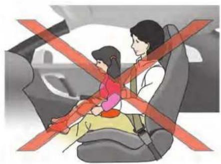
natural_image
Illustration of a car seatbelt with a child and adult, crossed by red tape (no text or symbols)
natural_image
Illustration of a person standing on a car seat with red cross symbols indicating restriction or no change (no text or symbols present)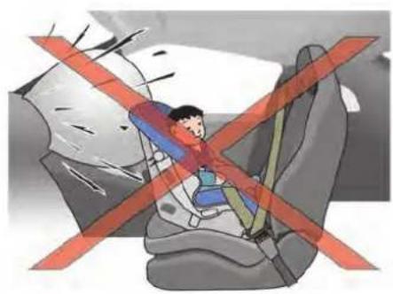
natural_image
Illustration of a child inside a car seat with red cross symbol indicating no change or restriction (no text or symbols present)
WARNING
- Never let children ride unrestrained or extend their hands or face out of the window. Do not attempt to hold them in your lap or arms. Some examples of dangerous riding positions are shown in the illustrations.
- Children may be severely injured or killed when the front air bags, side air bags or curtain air bags inflate if they are not properly restrained. Pre-teens and children should be properly restrained in the rear seat, if possible.
- Even with the NISSAN Advanced Air Bag System, never install a rear-facing child restraint in the front seat. An inflating supplemental front air bag could seriously injure or kill your child. ( "Child restraints" page 1-15)

natural_image
Illustration of a person sitting in a car with a red 'X' symbol crossed out, indicating no vehicle restriction or absence of any other vehicle.Do not lean against doors or windows.

natural_image
Illustration of a woman sitting in a car seat with red straps, no text or symbols presentDo not lean against doors or windows.
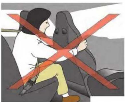
natural_image
Illustration of a person sitting on a vehicle with red safety stripes (no text or symbols)
natural_image
Illustration of a child sitting on a car seat with red cross-shaped warning bands (no text or symbols)
WARNING
Front seat-mounted side-impact supplemental air bag and roof-mounted curtain side-impact supplemental air bag :
- The side air bags and curtain air bags ordinarily will not inflate in the event of a frontal impact, rear impact, rollover or lower severity side collision. Always wear your seat belts to help reduce the risk or severity of injury in various kinds of accidents.
- The seat belts, side air bags and curtain air bags are most effective when you are sitting well back and upright in the seat. The side air bags and curtain air bags inflate with great force. Do not allow anyone to place their hand, leg or face near the side air bag on the side of the seatback of the front seat or near the side roof rails. Do not allow anyone sitting in the front seat to extend their hand out of the window or lean against the door. Some examples of dangerous riding posi-
tions are shown in the previous illustrations.
- When sitting in the rear seat, do not hold onto the seatback of the front seat. If the supplemental side air bag inflates, you may be seriously injured. Be especially careful with children, who should always be properly restrained. Some examples of dangerous riding positions are shown in the illustrations.
- Do not use seat covers on the front seatbacks. They may interfere with side air bag inflation.

- Crash zone sensor
- Supplemental front-impact air bag modules (NISSAN Advanced Air Bag System)
- Front seat-mounted side-impact supplemental air bags
-
Roof-mounted curtain side-impact supplemental air bags
-
Roof-mounted curtain side-impact supplemental air bag inflators
- Door satellite sensors
- Occupant classification sensor (pattern sensor)
- Occupant classification system control unit
-
Satellite sensors
-
Seat belt pretensioners
-
Air bag Control Unit (ACU)
NISSAN ADVANCED AIR BAG SYSTEM (front seats)
This vehicle is equipped with the NISSAN Advanced Air Bag System for the driver and front passenger seats. This system is designed to meet certification requirements under U.S. regulations. It is also permitted in Canada. All of the information, cautions and warnings in this manual apply and must be followed.
The driver supplemental front-impact air bag is located in the center of the steering wheel. The front passenger supplemental front-impact air bag is mounted in the instrument panel above the glove box. The front air bags are designed to inflate in higher severity frontal collisions, although they may inflate if the forces in another type of collision are similar to those of a higher severity frontal impact. They may not inflate in certain frontal collisions. Vehicle damage (or lack of it) is not always an indication of proper front air bag operation.
The NISSAN Advanced Air Bag System has dual stage air bag inflators. The system monitors information from the Air bag Control Unit (ACU), seat belt buckle sensors and the occupant classification sensor (pattern sensor). Inflator operation is based on the severity of a collision
and seat belt usage for the driver. For the front passenger, the occupant classification sensor is also monitored. Based on information from the sensors, only one front air bag may inflate in a crash, depending on the crash severity and whether the front occupants are belted or unbelted. Additionally, the front passenger air bag may be automatically turned OFF under some conditions, depending on the information provided by the occupant classification sensor. If the front passenger air bag is OFF, the passenger air bag status light will be illuminated (if the seat is unoccupied, the light will not be illuminated, but the air bag will be off). One front air bag inflating does not indicate improper performance of the system. ( "Front passenger air bag and status light" page 1-41) If you have any questions about your air bag system, contact NISSAN or a GT-R certified NISSAN dealer. If you are considering modification of your vehicle due to a disability, you may also contact NISSAN. Contact information is contained in the front of this Owner's Manual. When a front air bag inflates, a fairly loud noise may be heard, followed by release of smoke. This smoke is not harmful and does not indicate a fire. Care should be taken not to inhale it, as it may cause irritation and choking. Those with a history of a breathing condition should get fresh air promptly.
Front air bags, along with the use of seat belts, help to cushion the impact force on the head and chest of the front occupants. They can help save lives and reduce serious injuries. However, an inflating front air bag may cause facial abrasions or other injuries. Front air bags do not provide restraint to the lower body.
Even with NISSAN advanced air bags, seat belts should be correctly worn and the driver and passenger seated upright as far as practical away from the steering wheel or instrument panel. The front air bags inflate quickly in order to help protect the front occupants. Because of this, the force of the front air bag inflating can increase the risk of injury if the occupant is too close to, or is against, the air bag module during inflation.
The front air bags deflate quickly after a collision.
The front air bags operate only when the ignition switch is in the ON position.
After pushing the ignition switch to the ON position, the supplemental air bag warning light illuminates. The supplemental air bag warning light will turn off after about 7 seconds if the system is operational.
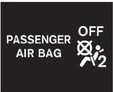
Front passenger air bag status light
Front passenger air bag and status light

WARNING
The front passenger air bag is designed to automatically turn OFF under some conditions. Read this section carefully to learn how it operates. Proper use of the seat, seat belt and child restraints is necessary for most effective protection. Failure to follow all instructions in this manual concerning the use of seats, seat belts and child restraints can
increase the risk or severity of injury in an accident.
Status light:
The front passenger air bag status light is located on the center instrument panel. After the ignition switch is placed in the ON position, the front passenger air bag status light on the instrument panel illuminates for about 7 seconds and then turns off or illuminates depending on the front passenger seat occupied status. The light operates as follows:
- Unoccupied passenger seat: The —— light is OFF and the front passenger air bag is OFF and will not inflate in a crash.
- Passenger seat occupied by a small adult, child or child restraint as outlined in this section: The light illuminates to indicate that the front passenger air bag is OFF and will not inflate in a crash.
- Occupied passenger seat and the passenger meets the conditions outlined in this section: The = light is OFF to indicate that the front passenger air bag is operational.
Front passenger air bag:
The front passenger air bag is designed to automatically turn OFF when the vehicle is operated under some conditions as described below as permitted by U.S. regulations. If the front passenger air bag is OFF, it will not inflate in a crash. The driver air bag and other air bags in your vehicle are not part of this system. The purpose of the regulation is to help reduce the risk of injury or death from an inflating air bag to certain front passenger seat occupants, such as children, by requiring the air bag to be automatically turned OFF.
The occupant classification sensor (pattern sensor) is in the front passenger seat cushion and is designed to detect an occupant and objects on the seat. For example, if a child is in the front passenger seat, the Advanced Air Bag System is designed to turn the passenger air bag OFF in accordance with the regulations. Also, if a child restraint of the type specified in the regulations is on the seat, the occupant classification sensor can detect it and cause the air bag to turn OFF.
Front passenger seat adult occupants who are properly seated and using the seat belt as outlined in this manual should not cause the passenger air bag to be automatically turned OFF. For small adults it may be turned OFF, however, if the occupant does not sit in the seat properly (for example, by not sitting upright, by sitting on an edge of the seat, or by otherwise being out of position), this could cause the sensor to turn the air bag OFF. Always be sure to be seated and wearing the seat belt properly for the most effective protection by the seat belt and supplemental air bag.
NISSAN recommends that pre-teens and children be properly restrained in a rear seat. NISSAN also recommends that appropriate child restraints and booster seats be properly installed in a rear seat. If this is not possible, the occupant classification sensor is designed to operate as described above to turn the front passenger air bag OFF for specified child restraints. Failing to properly secure child restraints and to use the Automatic Locking Retractor (ALR) mode (child restraint mode) may allow the restraint to tip or move in an accident or sudden stop. This can also result in the passenger air bag inflating in a crash instead of being OFF. ( "Child restraints" page 1-15)
If the front passenger seat is not occupied, the passenger air bag is designed not to inflate in a crash. However, heavy objects placed on the seat could result in air bag inflation, because of the object being detected by the occupant
classification sensor. Other conditions could also result in air bag inflation, such as if a child is standing on the seat, or if two children are on the seat, contrary to the instructions in this manual. Always be sure that you and all vehicle occupants are seated and restrained properly. Using the passenger air bag status light, you can monitor when the front passenger air bag is automatically turned OFF with the seat occupied. The light will not illuminate when the front passenger seat is unoccupied.
If an adult occupant is in the seat but the passenger air bag status light is illuminated (indicating that the air bag is OFF), it could be that the person is a small adult, or is not sitting on the seat properly.
If a child restraint must be used in the front seat, the passenger air bag status light may or may not be illuminated, depending on the size of the child and the type of child restraint being used. If the passenger air bag status light is not illuminated (indicating that the air bag might inflate in a crash), it could be that the child restraint or seat belt is not being used properly. Make sure that the child restraint is installed properly, the seat belt is used properly and the occupant is positioned properly. If the passenger air bag status light is still not illuminated, reposition the occupant or child restraint in a
rear seat.
If the passenger air bag status light will not illuminate even though you believe that the child restraint, the seat belts and the occupant are properly positioned, the system may be sensing an unoccupied seat (in which case the air bag is OFF). Your GT-R certified NISSAN dealer can check that the system is OFF by using a special tool. However, until you have confirmed with your dealer that your air bag is working properly, reposition the occupant or child restraint in a rear seat.
The NISSAN Advanced Air Bag System and passenger air bag status light will take a few seconds to register a change in the passenger seat status. However, if the seat becomes unoccupied, the air bag status light will remain off.
If a malfunction occurs in the front passenger air bag system, the supplemental air bag warning light , located in the meter and gauges area will blink. Have the system checked by a GT-R certified NISSAN dealer.
Other supplemental front air bag precautions

WARNING
- Do not place any objects on the steering wheel pad or on the instrument panel. Also, do not place any objects between any occupant and the steering wheel or instrument panel. Such objects may become dangerous projectiles and cause injury if the front air bag inflates.
- Do not place objects with sharp edges on the seat. Also, do not place heavy objects on the seat that will leave permanent impressions in the seat. Such objects can damage the seat or occupant classification sensor (pattern sensor). This can affect the operation of the air bag system and result in serious personal injury.
- Do not use water or acidic cleaners (hot steam cleaners) on the seat. This can damage the seat or occupant classification sensor. This can also affect the operation of the air
bag system and result in serious personal injury.
- Immediately after inflation, several front air bag system components will be hot. Do not touch them; you may severely burn yourself.
- No unauthorized changes should be made to any components or wiring of the supplemental air bag system. This is to prevent accidental inflation of the supplemental air bag or damage to the supplemental air bag system.
- Do not make unauthorized changes to your vehicle's electrical system, suspension system or front end structure. This could affect proper operation of the front air bag system.
-
Tampering with the supplemental air bag system may result in serious personal injury. Tampering includes changes to the steering wheel and the instrument panel assembly by placing material over the steering wheel pad and above the instrument panel or by installing additional trim material around the air bag system.
-
Modifying or tampering with the front passenger seat may result in serious personal injury. For example, do not change the front seats by placing material on the seat cushion or by installing additional trim material, such as seat covers, on the seat that is not specifically designed to assure proper air bag operation. Additionally, do not stow any objects under the front passenger seat or the seat cushion and seatback. Such objects may interfere with the proper operation of the occupant classification sensor.
- No unauthorized changes should be made to any components or wiring of the seat belt system. This may affect the front air bag system. Tampering with the seat belt system may result in serious personal injury.
- Work on and around the front air bag system should be done by a GT-R certified NISSAN dealer. Installation of electrical equipment should also be done by a GT-R certified NISSAN dealer. The Supplemental Restraint System (SRS)
wiring harnesses* should not be modified or disconnected. Unauthorized electrical test equipment and probing devices should not be used on the air bag system.
- A cracked windshield should be replaced immediately by a qualified repair facility. A cracked windshield could affect the function of the supplemental air bag system.
* The SRS wiring harness connectors are yellow and orange for easy identification.
When selling your vehicle, we request that you inform the buyer about the front air bag system and guide the buyer to the appropriate sections in this Owner's Manual.

natural_image
Interior view of a car showing two seats with black walls and beige panels, no text or symbols visibleFRONT SEAT-MOUNTED SIDE-IMPACT SUPPLEMENTAL AIR BAG AND ROOF-MOUNTED CURTAIN SIDE-IMPACT SUPPLEMENTAL AIR BAG SYSTEMS
The front side air bags are located in the outside of the seatback of the front seats. The curtain air bags are located in the side roof rails. All of the information, cautions and warnings in this manual apply and must be followed. The side air bags and curtain air bags are designed to inflate in higher severity side collisions, although they may inflate if the forces in another type of collision are similar to those of a higher severity side impact. They are designed to inflate on the side where the vehicle is impacted. They may not inflate in certain side collisions.
Vehicle damage (or lack of it) is not always an indication of proper side air bag and curtain air bag operation.
When the side air bags and curtain air bags inflate, a fairly loud noise may be heard, followed by release of smoke. This smoke is not harmful and does not indicate a fire. Care should be taken not to inhale it, as it may cause irritation and choking. Those with a history of a breathing condition should get fresh air promptly.
Front side air bags, along with the use of seat belts, help to cushion the impact force on the chest of the front occupants. Curtain air bags help to cushion the impact force to the head of occupants in the front seating positions. They can help save lives and reduce serious injuries. However, an inflating side air bag and curtain air bag may cause abrasions or other injuries. Side air bags and curtain air bags do not provide restraint to the lower body.
The seat belts should be correctly worn and the driver and passenger seated upright as far as practical away from the side air bags. The side air bags and curtain air bags inflate quickly in order to help protect occupants. Because of this, the force of the side air bags and curtain air bags inflating can increase the risk of injury if the occupant is too close to, or is against, these air bag modules during inflation. The side air bags and curtain air bags will deflate quickly after the collision is over.
The side air bags and curtain air bags operate only when the ignition switch is in the ON position.
After pushing the ignition switch to the ON position, the supplemental air bag warning light illuminates. The air bag warning light will turn off after about 7 seconds if the systems are operational.

WARNING
- Do not place any objects near the seatback of the front seats. Also, do not place any objects (an umbrella, bag, etc.) between the front door finisher and the front seat. Such objects may become dangerous projectiles and cause injury if a side air bag inflates.
- Right after inflation, several side air bag and curtain air bag system components will be hot. Do not touch them; you may severely burn yourself.
- No unauthorized changes should be made to any components or wiring of the side air bags and curtain air bags. This is to prevent damage to or accidental inflation of the side air bag and curtain air bag systems.
- Do not make unauthorized changes to your vehicle's electrical system, suspension system or side panel. This could affect proper operation of the side air bag and curtain air bag systems.
- Tampering with the side air bag system may result in serious personal injury. For example, do not change the front seat by placing material near the seatback or by installing additional trim material, such as seat covers, around the side air bags.
- Work around and on the side air bag and curtain air bag systems should be done by a GT-R certified NISSAN dealer. Installation of electrical equipment should also be done by a GT-R certified NISSAN dealer. The SRS wiring harnesses* should not be modified or disconnected. Un-
authorized electrical test equipment and probing devices should not be used on the side air bag and curtain air bag systems.
* The SRS wiring harness connectors are yellow and orange for easy identification. When selling your vehicle, we request that you inform the buyer about the side air bag and curtain air bag systems and guide the buyer to the appropriate sections in this Owner's Manual.
SEAT BELTS WITH PRETEN- SIONERS (front seats)

WARNING
- The pretensioners cannot be reused after activation. They must be replaced together with the retractor and buckle as a unit.
- If the vehicle becomes involved in a collision but the pretensioner is not activated, be sure to have the pretensioner system checked and, if necessary, replaced by a GT-R certified NISSAN dealer.
- No unauthorized changes should be
made to any components or wiring of the pretensioners. This is to prevent damage to or accidental activation of the pretensioners. Tampering with the pretensioner system may result in serious personal injury.
- Work around and on the pretensioners should be done by a GT-R certified NISSAN dealer. Installation of electrical equipment should also be done by a GT-R certified NISSAN dealer. Unauthorized electrical test equipment and probing devices should not be used on the pretensioners.
- If you need to dispose of a pretensioner or scrap the vehicle, contact a GT-R certified NISSAN dealer. Incorrect disposal procedures could cause personal injury.
The pretensioner system may activate with the supplemental air bag system in certain types of collisions. Working with the seat belt retractor, it helps tighten the seat belt when the vehicle becomes involved in certain types of collisions, helping to restrain front seat occupants.
The pretensioner is encased with the seat belt retractor. These seat belts are used the same way as conventional seat belts. When a pretensioner activates, smoke is released and a loud noise may be heard. The smoke is not harmful, and it does not indicate a fire. Care should be taken not to inhale it as it may cause irritation and choking. Those with a history of a breathing condition should get fresh air promptly.
After pretensioner activation, load limiters allow the seat belt to release webbing (if necessary) to reduce forces against the chest.
The supplemental air bag warning light is used to indicate malfunctions in the pretensioner system. (See "Supplemental air bag warning light" page 1-47 for more details.) If the operation of the supplemental air bag warning light indicates there is a malfunction, have the system checked by a GT-R certified NISSAN dealer.
When selling your vehicle, we request that you inform the buyer about the pretensioner system and guide the buyer to the appropriate sections in this Owner's Manual.

natural_image
Interior view of a car showing the door, seat, and dashboard (no text or symbols visible)SUPPLEMENTAL AIR BAG WARNING LABELS
Warning labels about the supplemental front-impact air bag are placed in the vehicle as shown in the illustration.
① SRS air bag
The warning labels are located on the surface of the sun visors.

natural_image
Red pictogram of a person climbing a rope, no text or symbols presentSUPPLEMENTAL AIR BAG WARNING LIGHT
The supplemental air bag warning light, displaying in the meter, monitors the circuits for the air bag systems, pretensioners and all related wirings.
When the ignition switch is in the ON position, the supplemental air bag warning light illuminates for about 7 seconds and then turns off. This means the SRS air bag systems are operational.
If any of the following conditions occur, the air bag and/or pretensioner systems need servicing:
● The supplemental air bag warning light remains on after approximately 7 seconds.
● The supplemental air bag warning light flashes intermittently.
- The supplemental air bag warning light does not come on at all.
Under these conditions, the air bag and/or pretensioner systems may not operate properly. They must be checked and repaired. Take your vehicle to the nearest GT-R certified NISSAN dealer.

WARNING
If the supplemental air bag warning light is on, it could mean that the front air bag, side air bag, curtain air bag and/or pretensioners will not operate in an accident. To help avoid injury to yourself or others, have your vehicle checked by a dealer as soon as possible.
REPAIR AND REPLACEMENT PROCEDURE
The front air bags, side air bags, curtain air bags and pretensioners are designed to activate on a one-time-only basis. As a reminder, unless it is damaged, the supplemental air bag warning light will remain illuminated after inflation has occurred. Repair and replacement of these systems should be done only by a GT-R certified NISSAN dealer.
When maintenance work is required on the vehicle, the front air bags, side air bags, curtain air bags, pretensioners and related parts should be pointed out to the person conducting the maintenance. The ignition switch should always be in the LOCK position when working under the hood or inside the vehicle.

WARNING
- Once a front air bag, side air bag, or curtain air bag has inflated, the air bag module will not function again and must be replaced. Additionally, the activated pretensioners must also be replaced. The air bag module and pretensioners should be replaced by a GT-R certified NISSAN dealer. The air bag module and
pretensioners cannot be repaired.
- The front air bag, side air bag, curtain air bag and the pretensioner should be inspected by a GT-R certified NISSAN dealer if there is any damage to the front end or side portion of the vehicle.
- If you need to dispose of a supplemental air bag or a pretensioner or scrap the vehicle, contact a GT-R certified NISSAN dealer. Incorrect disposal procedures could cause personal injury.
2 Instruments and controls
Cockpit 2-3
Instrument panel 2-4
Meters and gauges 2-5
Speedometer 2-6
Odometer/twin trip odometer 2-6
Tachometer 2-7
Engine coolant temperature gauge 2-7
Fuel gauge 2-8
Transmission position indicator 2-9
Upshift indicator 2-9
Instrument brightness control 2-11
Vehicle information display 2-12
Engine oil level display 2-12
Transmission system check display 2-14
Drive computer 2-15
Current fuel consumption 2-15
Vehicle speed 2-16
Cruise control 2-16
Average fuel consumption and speed 2-16
Elapsed time and trip odometer 2-17
Distance to empty 2-17
Outside air temperature 2-18
Setting (drive computer) 2-19
Warning (drive computer) 2-23
Warning lights, indicator lights and
audible reminders 2-25
Checking bulbs 2-25
Warning lights 2-25
Indicator lights 2-31
Audible reminders 2-32
Warning display 2-33
Engine oil low pressure warning 2-34
Engine system warning 2-34
Shift lever position warning 2-35
Reverse warning 2-35
Transmission system warning 2-35
Transmission oil high temperature warning ..... 2-36
Transmission clutch high temperature warning ..... 2-36
Parking brake release warning 2-36
Low brake fluid warning 2-37
Anti-lock Braking System (ABS) warning ...... 2-37
Vehicle Dynamic Control (VDC)
system warning 2-37
AWD clutch high temperature warning 2-38
Front/rear tire size discrepancy warning 2-38
AWD system warning 2-39
Low tire pressure warning 2-39
Run-flat tire warning 2-39
Tire Pressure Monitoring System
(TPMS) warning 2-40
Cruise control system warning 2-40
Low fuel warning 2-40
Door/trunk open warning 2-41
Headlight system warning 2-41
Low washer fluid warning 2-42
No key warning 2-42
Operation displays 2-43
Engine start operation indicator 2-43
Shift "P" warning 2-43
"PUSH" warning 2-44
Steering lock release malfunction indicator 2-44
Intelligent Key insertion indicator 2-44
Intelligent Key removal indicator 2-45
Intelligent Key battery discharge indicator 2-45
Security systems 2-45
Vehicle security system 2-45
NISSAN Vehicle Immobilizer System 2-47
Wiper and washer switch 2-48
Using the wipers 2-49
Using the washer 2-49
Rear window defroster switch 2-50
Headlight and turn signal switch 2-50
Headlight switch 2-50
Turn signal switch 2-53
Horn 2-54
Heated seats 2-54
Turning on the heaters 2-54
Turning off the heaters 2-54
Power outlets 2-55
Storage 2-56
Cup holders 2-56
Sunglasses holder 2-57
Door pocket 2-58
Glove box 2-58
Console box 2-59
Coat hooks 2-59
Windows 2-60
Power windows 2-60
Interior lights 2-62
Map lights 2-62
Interior light control switch 2-63
Vanity mirror lights 2-64
HomeLink ^ Universal Transceiver 2-64
Programming HomeLink ^ 2-65
Programming HomeLink ^® for Canadian customers
and gate openers 2-66
Operating the HomeLink ^® universal transceiver ... 2-66
Programming troubleshooting 2-67
Clearing the programmed information 2-67
Reprogramming a single HomeLink ^® button ..... 2-67
If your vehicle is stolen 2-67
COCKPIT

- Headlight and turn signal switch (P.2-50)
- Paddle shifters (P.5-15)
- Steering-wheel-mounted controls (left side)*
- Meters and gauges (P.2-5)
- Steering-wheel-mounted controls (right side)
— MRK (Mark) switch*
— Cruise control (P.5-34)
- Wiper and washer switch (P.2-48)
- VDC, transmission and suspension set up switches (P.5-25)
- Trunk lid release switch (P.3-19)
- Hood release handle (P.3-17)
-
Intelligent Key port (P.5-12)
-
Horn (P.2-54)
- Tilting/telescopic steering wheel lever (P.3-25)
- Push-button ignition switch (P.5-10)
- Parking brake (P.5-33, P.5-46)
- Shift lever (P.5-15)
*: Refer to the separate Multi Function Display Owner's Manual.
INSTRUMENT PANEL
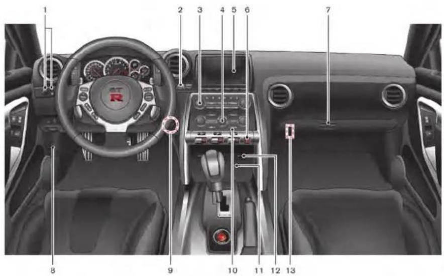
- Outside mirror control switch (P.3-27)
- Center dial*
- Audio system*
- Heater and air conditioner*
- Multi function display*
-
Hazard warning flasher switch (P.6-2)
-
Glove box (P.2-58)
- Fuse box cover (P.8-25)
- Power outlet (P.2-55)
- Rear window defroster switch (P.2-50)
- Front passenger air bag status light (P.1-41)
-
CD/DVD slot*
-
Trunk release power cancel switch (P.3-20)
*: Refer to the separate Multi Function Display Owner's Manual.
2-4 Instruments and controls
METERS AND GAUGES

- Trip A/B reset switch (P.2-6)
- Speedometer (P.2-6)
- Tachometer (P.2-7)/Upshift indicator (P.2-9)
- Transmission position indicator (P.2-9)
- Engine coolant temperature gauge (P.2-7)
-
ENTER switch (P.2-15)
-
Instrument brightness control switch (P.2-11)
- Vehicle information display (P.2-12)
- Odometer/twin trip odometer (P.2-6)
- Fuel gauge (P.2-8)
- NEXT switch (P.2-15)
NOTE:
- Meters and gauges will illuminate when the ignition switch is pushed to the ON position.
- The needle indicators may move slightly after the ignition switch is pushed to the OFF position. This does not indicate that there is a malfunction.

natural_image
Close-up of a car speedometer dial with red needle pointing to the center (no visible text or symbols)SPEEDOMETER
The speedometer indicates the vehicle speed.

CAUTION
- For cleaning, use a soft cloth, dampened with water. Never use a rough cloth, alcohol, benzine, thinner or any kind of solvent or paper towel with a chemical cleaning agent. They will scratch or cause discoloration to the lens.
- Do not spray any liquid such as water on the meter lens. Spraying
liquid may cause the system to malfunction.

ODOMETER/TWIN TRIP OD-OMETER
The odometer ① indicates the total distance that the vehicle has been driven.
The twin trip odometer ② indicates the distance of individual trips.
Changing the display
Push the TRIP A/B RESET switch to change between trips ▶ and ▶.
Resetting the trip odometer
To reset a trip, display the trip that you want to reset to zero, then push and hold the TRIP A/B
RESET switch for more than 1 second.
NOTE:
When the battery is disconnected, the memory for trips A and B is erased, and both return to zero.
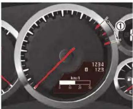
TACHOMETER
The tachometer indicates the engine speed in revolutions per minute (rpm). Do not rev the engine into the red zone ①.
NOTICE
When engine speed approaches the red zone, shift to a higher gear or reduce engine speed. Operating the engine in the red zone may cause serious engine damage.
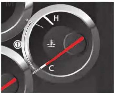
ENGINE COOLANT TEMPERATURE GAUGE
The gauge indicates the engine coolant temperature.
The engine coolant temperature is within the normal range when the gauge needle points within the zone ① shown in the illustration.
The engine coolant temperature varies with the outside air temperature and driving conditions.
NOTICE
If the gauge indicates engine coolant temperature near the hot (H) end of the normal range, reduce vehicle speed to decrease temperature. If gauge is over the normal range, stop the vehicle as soon as safely possible. If the engine is overheated, continued operation of the vehicle may seriously damage the engine. ( "If your vehicle overheats" page 6-8)
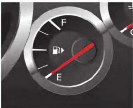
FUEL GAUGE
The gauge indicates the approximate fuel level in the tank.
The gauge may move slightly during braking, turning, acceleration, or going up or down hills. The gauge needle returns to E (Empty) after the ignition switch is pushed to the LOCK position. Refill the fuel tank before the gauge registers "E" (Empty).
The low fuel warning will be indicated on the vehicle information display when the fuel tank is getting low. Refuel as soon as it is convenient, preferably before the gauge reaches "E". There will be a small reserve of fuel in the tank when
the fuel gauge needle reaches "E". ( "Low fuel warning" page 2-40)
The ▶ indicates that the fuel-filler door is located on the passenger's side of the vehicle. ( "Fuel-filler door" page 3-23)
NOTE:
If the vehicle runs out of fuel, the Malfunction Indicator Light (MIL) may come on. Refuel as soon as possible. After a few driving trips, the SERVICE ENGINE light should turn off. If the light remains on after a few driving trips, have the vehicle inspected by a GT-R certified NISSAN dealer.
( "Malfunction Indicator Light (MIL)" page 2-31)
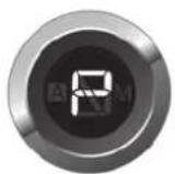

TRANSMISSION POSITION INDICATOR
The transmission position indicator indicates the gear positions.
The indicator blinks if it is not possible to shift the gear when in the M position.
- Upshift indicator (green)
- Upshift indicator (yellow)
- Upshift indicator (red)
UPSHIFT INDICATOR
When the upshift indicator is set to on, the indicators on the tachometer will illuminate to help upshift at a constant engine speed from any gear or to warn the driver of over-revving.
The upshift indicator operates only when the shift lever is in the M position. This function consists of two modes that can be selected on the vehicle information display: AUTO setting and MANUAL setting.
| MODE | INDICATOR | COLOR | CONDITIONS |
| AUTO setting | No color | Light is off at all times. | |
| Yellow | Light comes on about 700 RPM before the red zone. | ||
| Red | Light comes on immediately before the red zone. | ||
| MANUAL setting | Green | Light blinks about 500 RPM before the set RPM and comes on at the set RPM. | |
| Yellow | Light comes on about 700 RPM before the red zone. | ||
| Red | Light comes on immediately before the red zone. |

flowchart
graph TD
    A["SETTING\nSKIP > ALERT\n>MAINTENANCE\n>OPTIONS\nQENT ●NEXT"] --> B["ALERT\nBACK > UP SHIFT\n>TIMER\n>ICY\nQENT ●NEXT"]
    B --> C["UP SHIFT\nBACK > SETTING\nAUTO RPM\nQENT ●NEXT"]
    C --> D["UP SHIFT\n3000 RPM\nQENT ●NEXT"]
Setting
Push the ignition switch to the ON position. Use the ENTER switch ☐ and toggle the vehicle information display to show the SETTING screen.
Use the NEXT switch ● and ENTER switch
☐ to go to ALERT > UPSHIFT. The current status of the upshift indicator will be shown on the UPSHIFT screen. Note that the function is set to AUTO as the factory default setting.
To change the upshift indicator mode, choose SETTING on the UPSHIFT screen. Set one of the following modes by pushing the NEXT switch ●, and then push ENTER to □ complete.
• AUTO
• 3,000 to 6,300 RPM (MANUAL)
• OFF
The number will increase by 100 RPM. To increase the number by 500 RPM, push and hold the NEXT switch ●.
Example
When the maximum engine speed is desired:
Set the upshift indicator to AUTO. The yellow indicator illuminates approximately 700 RPM before the red zone, and the red indicator illuminates just before the red zone.
When the maximum engine torque is desired:
Set the figure at 6,000 RPM. The green indicator starts flashing from approximately
5,500 RPM and illuminates at 6,000 RPM.
When breaking-in the vehicle:
To help avoid high engine speeds during break-in, set the upshift indicator to less than 3,500 RPM. The green indicator starts flashing approximately 500 RPM before the set figure and illuminates from the set figure. ( "Break-in schedule" page 5-39)
NOTE:
- There may be a slight difference between the timing of the upshift indicator illumination and the tachometer indication.
- When the battery terminal is disconnected, the set memory will be erased and the mode returns to the default.

INSTRUMENT BRIGHTNESS CONTROL
The instrument brightness can be adjusted when the ignition switch is in the ON position. Push the switch to adjust the brightness up ① or down ②. The brightness level is shown on the vehicle information display. When the headlights are on, the brightness of the interior switches is also adjusted at the same time.
NOTE:
- The instrument brightness can be adjusted separately for daytime and nighttime conditions. The adjusted settings are automatically stored.
- When the battery terminal is disconnected, the set memory will be erased and the setting returns to the default.
VEHICLE INFORMATION DISPLAY
The vehicle information display can display the following information.
- Engine oil level display
● Transmission system check display - Instrument brightness control level display ( "Instrument brightness control" page 2-11)
- Drive computer ( "Drive computer" page 2-15)
- Warning display ( "Warning display" page 2-33)
- Operation display ("Operation displays" page 2-43)
- Cruise control display ( "Cruise control" page 5-34)

ENGINE OIL LEVEL DISPLAY
When the ignition switch is pushed to the ON position, the engine oil status before starting the engine is indicated as illustrated.
When the oil level is normal
"OIL LEVEL OK" is displayed. Push the displayed LEVEL switch ● to check the oil level.

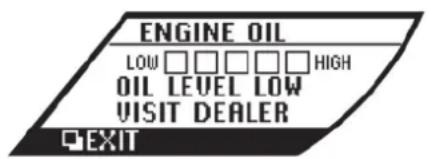
NOTE:
The engine oil level can be displayed after the "OIL LEVEL OK" display turns off or while the engine is started and running. ( "Maintenance" page 2-20)
When the oil level is low
If the message shown above is displayed, the engine oil level is low.
Warm up the engine in a level location. After at least 5 minutes have passed since engine stop, use the engine oil dipstick to check the oil level. ( "Engine oil" page 8-13)
If the oil level is low, have additional engine oil added, or the oil changed, at a GT-R certified NISSAN dealer.
NOTICE
If the vehicle is in a location that is not level, accurate measurement of the oil level may not be possible. If "OIL LEVEL LOW" is displayed, but the level shown by the oil dipstick is normal, move the vehicle to a level location and stop the engine. After at least 5 minutes have passed, open the driver's door and push the ignition switch back to ON. If the "OIL LEVEL LOW" message appears again, have engine oil added or the oil changed.
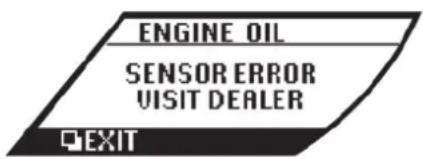

after the system check is finished. Release the button and push it again to operate the shift lever.
- During winter or at other times when the temperature is extremely low, changes in the hydraulic response characteristics may increase the amount of time that is required for the system check. During the system check, a thudding operating noise may occur or the engine speed may decrease, however this does not indicate that there is a malfunction.
When the oil level sensor malfunction occurs
If the message shown above is displayed, the engine oil level sensor may be malfunctioning. Contact a GT-R certified NISSAN dealer immediately.
TRANSMISSION SYSTEM CHECK DISPLAY
This is displayed after the engine is started while the transmission system is being checked. It turns off after a few seconds.
NOTE:
- During the system check, the shift lever cannot be moved out of the P position. Operate the shift lever after the system check indicator turns off.
- The shift lever cannot be moved if the shift lever button is pushed while the system check is being performed, even
DRIVE COMPUTER
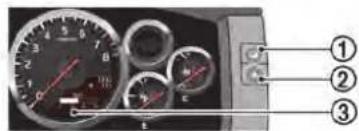
- ENTER switch
- NEXT switch
- Vehicle information display
The drive computer displays the following information:
- Current fuel consumption
- Vehicle speed
- Cruise control
• Average fuel consumption and speed - Elapsed time and trip computer
-
Distance to empty
• Outside air temperature -
Setting
- Warning
The vehicle information display ③ can be changed when the ignition switch is in the ON position. Push the ENTER switch □ ① to change the display.
NOTE:
- The cruise control display is shown if cruise control is set. ("Cruise control" page 5-34)
- The warning display is not shown if there are no conditions to warn the driver.
- Depending on the driving conditions and other factors, the displayed values may differ from the actual values.
- The position of the speedometer needle and the speed shown in the vehicle information display may slightly differ.
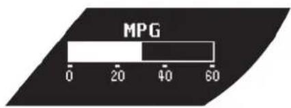
bar
MPG | Category | MPG | |---|---| | Bar 1 | 35 | | Bar 2 | 40 |CURRENT FUEL CONSUMPTION
The current fuel economy is displayed when driving.
55 MPH
CRUISE 60 MPH
MPG 19.0 MPH 55.0
VEHICLE SPEED
This displays the vehicle speed while driving.
CRUISE CONTROL
This displays the set cruise control status.
NOTE:
The cruise control display is shown if cruise control is set. ("Cruise control" page 5-34)
AVERAGE FUEL CONSUMPTION AND SPEED
This displays the average fuel economy and average vehicle speed beginning from the time when the display was last reset.
To reset the display, push and hold the NEXT switch ● for more than 1 second. (The average fuel economy and average vehicle speed are reset at the same time.)
NOTE:
- “ ----” is displayed during the first 1/3 mile (500 m) or the first 30 seconds after a reset.
- The values are updated approximately every 30 seconds.
TIME 1:00 MILES 34.5
RANGE 123 MILES
ELAPSED TIME AND TRIP OD-OMETER
This displays the elapsed time and trip odometer beginning from the time when the display was last reset.
To reset the display, push and hold the NEXT switch ● for more than 1 second. (The elapsed time and trip odometer are reset at the same time.)
DISTANCE TO EMPTY
This displays the approximate distance that the vehicle can be driven based on the amount of fuel remaining in the fuel tank and the actual fuel consumption.
NOTE:
- If the fuel level is low, the low fuel warning will be displayed. ( "Low fuel warning" page 2-40)
- If the vehicle is not refueled after the low fuel warning appears, the display will change to “----”. This change timing may become earlier depending
Instruments and controls 2-17
on the driving conditions. This does not indicate that there is a malfunction.
- The values are updated approximately every 30 seconds.

partment is high.
- When the outside air temperature is lower than 37°F (3°C), the low outside temperature warning will be displayed and "ICY" is indicated on the outside air temperature display. ( "Alert" page 2-19)
OUTSIDE AIR TEMPERATURE
This displays the outside air temperature.
NOTE:
- The outside air temperature may not be displayed correctly in the following cases.
— The outside air temperature is lower than -22^ ( -30^ ) or is higher than 131^ ( 55^ ).
— The vehicle is stopped or is driving at a low speed (less than approximately 12 MPH (20 km/h)).
— The temperature in the engine com-

NOTE:
- When the battery terminal is disconnected, the set memory will be erased and the settings return to the default.
- Setting is not possible in the following cases.
— The vehicle is being driven.
— A warning display is active.
— The instrument brightness control level display is active.
— The cruise control status is displayed.

SETTING (drive computer)
This is used to set the alert, maintenance and optional settings.
Use the NEXT switch ● to select an item, then confirm with the ENTER switch □ to change to the corresponding setting screen.
To return to the initial setting screen, push and hold the ENTER switch ☐ for more than 1 second.
Alert
This function can be used to make settings for the upshift indicator, "time to rest" indicator and low outside temperature warning.
Upshift indicator:
For details concerning the upshift indicator, refer to the following section. ( "Upshift indicator" page 2-9)
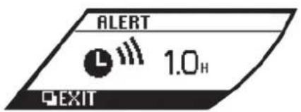


"TIMER" indicator:
This alert informs the driver that the set driving time has elapsed.
On the TIMER screen, push the NEXT switch to change the time. Push and hold the switch to increase the number every 1 hour. A maximum of 6 hours can be set.
NOTE:
The default setting is OFF.
Low outside temperature warning:
This alert informs the driver when the outside air temperature is lower than 37^ F ( 3^ C). On the ICY screen, push the NEXT switch to turn this warning ON/OFF.
NOTE:
The default setting is ON.
Maintenance
This function can be used to set the various maintenance intervals and to check the engine oil level. The reminders shown below are used to notify the driver of the maintenance intervals.
NOTE:
Because these are displayed based on the mileage driven, they do not indicate the actual conditions of the vehicle. Use these functions only as a reference.
Input the maintenance distance using the following items:
- On each setting screen, push the NEXT
switch to change the mileage. Push and hold the switch to increase the number every 600 miles (1,000 km).
- Set to “—” to set no reminders.
- To reset the accumulated mileage to zero, go to the RESET screen, then push the NEXT switch and confirm with the ENTER switch.
NOTE:
- To restore the mileage to the original figure after resetting, push the NEXT switch again.
- When the battery terminal is disconnected, the set mileage will be erased and the settings will return to their default settings.
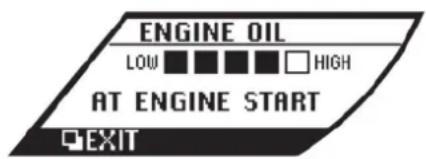

Engine oil level:
This can be used to check the pre-start oil level while the engine is running. Select SETTING > MAINTENANCE > OIL > ENGINE OIL > LEVEL.
If the low level reminder appears, check the level using the engine oil dipstick. ( "Checking engine oil level" page 8-13)
Engine oil:
When the customer set mileage approaches, the reminder will appear on the display and the remaining distance is displayed at regular intervals. Select SETTING > MAINTENANCE > OIL > ENGINE OIL to set or reset the mileage for the engine oil change.
NOTE:
The default setting is 9,500 miles (15,000 km). The maximum mileage that can be set is 9,500 miles (15,000 km).


Engine oil filter:
The reminder is displayed when the customer set mileage is exceeded. Select SETTING > MAINTENANCE > FILTER to set or reset the mileage for the engine oil filter change.
NOTE:
The default setting is 9,500 miles (15,000 km). The maximum mileage that can be set is 9,500 miles (15,000 km).
Transmission oil:
The reminder is displayed when the customer set mileage is exceeded. Select SETTING > MAINTENANCE > OIL > T/M OIL to set or reset the mileage for the transmission oil change.
NOTE:
The default setting is 37,000 miles (60,000 km). The maximum mileage that can be set is 55,500 miles (90,000 km).
Tires:
This reminder appears when the customer set distance comes for maintaining tires. You can set or reset the distance for maintaining tires. (See "Setting (drive computer)" page 2-19 earlier in this section.)

WARNING
The tire maintenance indicator is not a substitute for regular tire checks, including tire pressure checks. See "Changing wheels and tires" in the "8. Maintenance and do-it-yourself" section. Many factors including tire infla-
tion, alignment, driving habits and road conditions affect tire wear and when tires should be replaced. Setting the tire maintenance reminder for a certain driving distance does not mean your tires will last that long. Use the tire maintenance reminder as a guide only and always perform regular tire checks. Failure to perform regular tire checks, including tire pressure checks could result in tire failure. Serious vehicle damage could occur and may lead to a collision, which could result in serious personal injury or death.
NOTE:
The default setting is OFF.
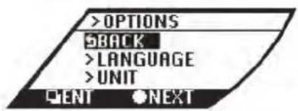
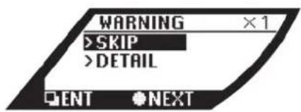
Options
This function can be used to make settings for language and unit.
Language:
Select ENGLISH or FRANCAIS for use in the vehicle information display.
Unit:
Select METRIC or US for use in the vehicle information display.
WARNING (drive computer)
Warning information is displayed on the vehicle information display.
Push the ENTER switch ☐ while a warning display is active to return to the original display. It is also possible to check any warnings that have not been corrected. ( "Warning display" page 2-33)
Checking the warnings
Use the NEXT switch to ●elect "DETAIL", then confirm with the ENTER switch □. When there are multiple warnings, push the ENTER switch □ to change the display
Instruments and controls 2-23
among them.
To return to the initial warning, push and hold the
ENTER switch □ for more than 1 second.
NOTE:
If there are no warnings to display, only "SKIP" can be selected.
WARNING LIGHTS, INDICATOR LIGHTS AND AUDIBLE REMINDERS

CHECKING BULBS
With all doors closed, apply the parking brake and push the ignition switch to the ON position without starting the engine. The following lights will come on:

,ABS or Ⓗ️,H,☐,☐,〈〉,KEY If any light does not come on, it may indicate a burned-out bulb or an open circuit in the electrical system. Have the system checked by
a GT-R certified NISSAN dealer.
WARNING LIGHTS
AWD All-Wheel Drive (AWD) warning light
The AWD warning light comes on when the ignition switch is pushed to ON. It turns off soon after the engine is started.
If the AWD system malfunctions, the warning light will either remain illuminated or blink. ( "All-Wheel Drive (AWD)" page 5-41)
CAUTION
- If the warning light comes on while driving there may be a malfunction in the AWD system. Reduce the vehicle speed and have your vehicle checked by a GT-R certified NISSAN dealer as soon as possible.
- If the AWD warning light blinks on when you are driving: — blinks rapidly (about twice a second):
Instruments and controls 2-25
Pull off the road in a safe area, and idle the engine. The driving mode will change to RWD to prevent the AWD system from malfunctioning. If the warning light turns off, you can drive again. This does not indicate that there is a malfunction.
— blinks slowly (about once every 2 seconds): Pull off the road in a safe area, and idle the engine. Check that all tire sizes are the same as that specified on the Tire and Loading Information label located in the driver's door opening, tire pressure is correct and tires are not worn. ( "Tire and loading information label" page 9-13) If the tire pressure is insufficient, fill with nitrogen gas. Contact a GT-R certified NISSAN dealer about filling with nitrogen gas. If nitrogen gas is not available, compressed air may be safely used under normal driving conditions. However, NISSAN recommends refilling
with nitrogen gas for maximum tire performance.
- If the warning light is still on after the above operations, have your vehicle checked by a GT-R certified NISSAN dealer as soon as possible.
ABS or Anti-lock Braking System (ABS) warning light
When the ignition switch is in the ON position, the Anti-lock Braking System (ABS) warning light illuminates and then turns off. This indicates the ABS is operational.
If the ABS warning light illuminates while the engine is running, or while driving, it may indicate the ABS is not functioning properly. Have the system checked by a GT-R certified NISSAN dealer.
If an ABS malfunction occurs, the anti-lock function is turned off. The brake system then operates normally, but without anti-lock assistance. ( "Brake system" page 5-48)
BRAKE or Ⓕ Brake warning light
This light functions for both the parking brake and the foot brake systems.
Parking brake indicator:
When the ignition switch is in the ON position, the light comes on when the parking brake is applied.
Low brake fluid warning light:
When the ignition switch is in the ON position, the light warns of a low brake fluid level. If the light comes on while the engine is running with the parking brake not applied, stop the vehicle and perform the following:
- Check the brake fluid level. Add brake fluid as necessary. ( "Brake fluid" page 8-15)
- If the brake fluid level is correct, have the warning system checked by a GT-R certified NISSAN dealer.
Anti-lock Braking System (ABS) warning indicator:
When the parking brake is released and the brake fluid level is sufficient, if both the brake warning light and the Anti-lock Braking System (ABS) warning light illuminate, it may indicate the ABS is not functioning properly. Have the brake system checked, and if necessary repaired, by a GT-R certified NISSAN dealer promptly. ( "Anti-lock Braking System (ABS) warning light" page 2-26)

WARNING
- Your brake system may not be working properly if the warning light is on. Driving could be dangerous. If you judge it to be safe, drive carefully to the nearest service station for repairs. Otherwise, have your vehicle towed because driving it could be dangerous.
- Pressing the brake pedal with the engine stopped and/or low brake fluid level may increase your stopping distance and braking will require greater pedal effort as well as pedal travel.
- If the brake fluid level is below the minimum or MIN mark on the brake fluid reservoir, do not drive until the brake system has been checked at a GT-R certified NISSAN dealer.

Charge warning light
If the light comes on while the engine is running, it may indicate the charging system is not functioning properly. Turn the engine off and check the alternator belt. If the belt is loose,
broken, missing or if the light remains on, see a GT-R certified NISSAN dealer immediately.
NOTICE
Do not continue driving if the alternator belt is loose, broken or missing.

Engine oil pressure warning
This light warns of low engine oil pressure. If the light flickers or comes on during normal driving, pull off the road in a safe area, stop the engine immediately and call a GT-R certified NISSAN dealer.
The engine oil pressure warning light is not designed to indicate a low oil level. Check the vehicle information display or use the dipstick to check the oil level.
( "Engine oil level display" page 2-12)
( "Checking engine oil level" page 8-13)
NOTICE
Running the engine with the engine oil pressure warning light on could cause serious damage to the engine almost immediately. Turn off the engine as
soon as it is safe to do so.

Intelligent Key warning light
After the ignition switch is pushed to the ON position, this light comes on for about 2 seconds and then turns off.
This light warns of a malfunction with the electrical steering lock system or the Intelligent Key system.
If the light comes on while the engine is stopped, it may be impossible to free the steering lock or to start the engine. If the light comes on while the engine is running, you can drive the vehicle. However in these cases, contact a GT-R certified NISSAN dealer for repair as soon as possible.

Low tire pressure warning light
Your vehicle is equipped with a Tire Pressure Monitoring System (TPMS) that monitors the tire pressure of all tires.
The low tire pressure warning light warns of low tire pressure and flat tire, or indicates that the TPMS is not functioning properly.
After the ignition switch is pushed to the ON position, the warning light illuminates for about 1 second and turns off.
Low tire pressure warning:
If the vehicle is being driven with low tire pressure, the warning light will illuminate.
When the low tire pressure warning light illuminates, you should stop and adjust the tire pressure of all 4 wheels to the recommended COLD tire pressure shown on the Tire and Loading Information label located in the driver's door opening.
The low tire pressure warning light does not automatically turn off when the tire pressure is adjusted. After the tire is inflated to the recommended pressure, the vehicle must be driven at speeds above 16 MPH (25 km/h) to activate the TPMS and turn off the low tire pressure warning light. Use a tire pressure gauge to check the tire pressure. ( "Tire Pressure Monitoring System (TPMS)" page 5-4) ( "Tire Pressure Monitoring System (TPMS)" page 6-3)
Run-flat tire warning:
The run-flat tire warning warns of a flat tire. If the vehicle is being driven with one or more flat tires, the warning light will illuminate continuously and a chime will sound for 10 seconds. The chime will only sound at the first indication of a flat tire and the warning light will illuminate
continuously. When the flat tire warning is activated, have the system reset and the tire checked and replaced if necessary by a GT-R certified NISSAN dealer. Even if the tire is inflated to the specified COLD tire pressure, the warning light will continue to illuminate until the system is reset by a GT-R certified NISSAN dealer.
If you select the tire pressure information in the multi function display, the warning message will be displayed. The tire pressure for each tire will also be displayed. Refer to the separate Multi Function Display Owner's Manual.
Your vehicle can be driven for a limited time on a flat tire. ( "Run-flat tires" page 6-4) ( "Run-flat tires" page 8-39)
TPMS malfunction:
If the TPMS is not functioning properly, the low tire pressure warning light will flash for approximately 1 minute when the ignition switch is pushed to the ON position. The light will remain on after the 1 minute. Have the system checked by a GT-R certified NISSAN dealer. ( "Tire Pressure Monitoring System (TPMS)" page 5-4) ( "Tire pressure" page 8-32)

WARNING
- If the light does not illuminate with the ignition switch pushed to the ON position, have the vehicle checked by a GT-R certified NISSAN dealer as soon as possible.
- If the light illuminates while driving, avoid sudden steering maneuvers or abrupt braking, reduce vehicle speed, pull off the road to a safe location and stop the vehicle as soon as possible. Driving with under-inflated tires may permanently damage the tires and increase the likelihood of tire failure. Serious vehicle damage could occur and may lead to an accident and could result in serious personal injury. Check the tire pressure for all four tires. Adjust the tire pressure to the recommended COLD tire pressure shown on the Tire and Loading Information label located in the driver's door opening to turn the low tire pressure warning light off. If the light still illuminates while driving after adjusting the tire pressure, a tire may be flat.
- Although you can continue driving with a punctured run-flat tire, remember that vehicle handling stability is reduced, which could lead to an accident and personal injury. Also, driving a long distance at high speeds may damage the tires.
- Do not drive at speeds above 50 MPH (80 km/h) and do not drive more than 50 miles (80 km) with a punctured run-flat tire. The actual distance the vehicle can be driven on a flat tire depends on outside temperature, vehicle load, road conditions and other factors.
- If you detect any unusual sounds or vibrations while driving with a punctured run-flat tire, pull off the road to a safe location and stop the vehicle as soon as possible. The tire may be seriously damaged and need to be replaced.
- When a wheel is replaced, the TPMS will not function and the low tire pressure warning light will flash for approximately 1 minute. The light will remain on after the 1 minute. Contact a GT-R certified NISSAN
dealer as soon as possible for tire replacement and/or system resetting.
- Replacing tires with those not originally specified by NISSAN could affect the proper operation of the TPMS.
CAUTION
- The TPMS is not a substitute for the regular tire pressure check. Be sure to check the tire pressure regularly.
- Be sure to install the specified size of tires on the four wheels.
NOTE:
- If the vehicle is being driven at speeds of less than 16 MPH (25 km/h), the TPMS may not operate correctly.
- The tires of this vehicle are filled with nitrogen gas. When the tire pressure is low, fill the tires with nitrogen gas. Contact a GT-R certified NISSAN dealer for information on filling the tires with nitrogen gas.
Master warning light
When the ignition switch is in the ON position, the master warning light illuminates if any of the warning displays appear on the vehicle information display. ( "Warning display" page 2-33)
Seat belt warning light and chime
The light and chime remind you to fasten seat belts. The light illuminates whenever the ignition switch is pushed to the ON position, and will remain illuminated until the driver's seat belt is fastened. At the same time, the chime will sound for about 6 seconds unless the driver's seat belt is securely fastened.
The seat belt warning light for the front passenger will illuminate if the seat belt is not fastened when the front passenger's seat is occupied. For approximately 5 seconds after the ignition switch is in the ON position, the system does not activate the warning light for the front passenger. ( "Seat belts" page 1-6)
Supplemental air bag warning light
After pushing the ignition switch to the ON position, the supplemental air bag warning light will illuminate for about 7 seconds and then turn
Instruments and controls 2-29
off. This means the system is operational. If any of the following conditions occur, the front air bag, side air bag, curtain air bag and pretensioner systems need servicing and your vehicle must be taken to a GT-R certified NISSAN dealer.
- The supplemental air bag warning light remains on after approximately 7 seconds.
- The supplemental air bag warning light flashes intermittently.
- The supplemental air bag warning light does not come on at all.
Unless checked and repaired, the supplemental restraint system (air bag system) and/or the pretensioners may not function properly. ( "Supplemental restraint system" page 1-34)

WARNING
If the supplemental air bag warning light is on, it could mean that the front air bag, side air bag, curtain air bag and/or pretensioner systems will not operate in an accident. To help avoid injury to yourself or others, have your vehicle checked by a GT-R certified NISSAN dealer as soon as possible.

Transmission warning light
This light warns of the following malfunctions.
Transmission system malfunction:
The light blinks if a malfunction in the transmission system occurs. If the light blinks, certain gear positions may become unusable, so that the vehicle may become undrivable. Have the system inspected promptly by a GT-R certified NISSAN dealer.
Transmission oil temperature high:
The light illuminates if the transmission oil temperature becomes unusually high. If the light illuminates, avoid driving at high speed or at high engine speed until the light turns off. The light will turn off after a short period of time and the vehicle can then be driven normally. If the light illuminates frequently, contact a GT-R certified NISSAN dealer.
NOTICE
If the light continues to illuminate, the engine output may be reduced to prevent transmission damage.
Transmission clutch temperature high:
The light illuminates if clutch temperature becomes unusually high. If the light illuminates, pull off the road in a safe area and idle the engine. When the light turns off, driving can be resumed. If the light illuminates frequently, contact a GT-R certified NISSAN dealer.
NOTICE
- Continuing to drive with the light on could cause serious damage to the transmission.
- If the light continues to illuminate, the vehicle cannot be driven because the engine output may be reduced and the clutch may be reduced to keep the clutch disengaged.
R mode start function:
If the R mode start function is used 4 times continuously, the function may be disabled and cannot be turned on for protection. While the function is disabled, the warning light illuminates. When the warning light goes off, the function can be used again. ( "R mode start function" page 5-32)
When the warning light illuminates, perform cool down driving (driving 1.3 mile (2 km) in 5th or 6th gear at a speed of approximately 37 - 50 MPH (60 - 80 km/h) while checking the temperature of the transmission oil until the warning light goes off.
NOTICE
While the warning light is illuminated, the engine output is controlled so that it does not increase.

Vehicle Dynamic Control (VDC) ning light
The light will blink when the VDC system or the traction control system is operating, thus alerting the driver that the vehicle is nearing its traction limits. The road surface may be slippery. If the VDC warning light illuminates when the VDC system is turned on, this light alerts the driver to the fact that the VDC system's fail-safe mode is operating, for example the VDC or hill start assist system may not be functioning properly. Have the system checked by a GT-R certified NISSAN dealer. If a malfunction occurs in the system, the VDC system function will be canceled but the vehicle is still driveable.
( "Vehicle Dynamic Control (VDC) system" page 5-50)
INDICATOR LIGHTS

Cruise main switch indicator
The light comes on when the cruise control is pushed. The light turns off when the main switch is pushed again. While the cruise control system main switch indicator light is on, the cruise control system is operational.

Cruise set switch indicator
The light comes on while the vehicle speed is controlled by the cruise control system. If the light blinks while the engine is running, it may indicate the cruise control system is not functioning properly. Have the system checked by a GT-R certified NISSAN dealer.

Exterior light indicator
This indicator illuminates when the headlight switch is turned to the AUTO, or position and the front parking lights, instrument panel lights, rear combination lights, license plate lights or headlights are on. The indicator turns off when these lights are turned off.

Front passenger air bag status
The front passenger air bag status light ( ) will be lit and the passenger front air bag will be OFF depending on how the front passenger seat is being used. ( "NISSAN Advanced Air Bag System (front seats)" page 1-40)

High beam indicator light
This light comes on when the headlight high beam is on and goes out when the low beam is selected.

Malfunction Indicator Light
If the malfunction indicator light comes on steady or blinks while the engine is running, it may indicate a potential emission control malfunction.
The malfunction indicator light may also come on steady if the fuel-filler cap is loose or missing, or if the vehicle runs out of fuel. Check to make sure the fuel-filler cap is installed and closed tightly, and that the vehicle has at least 3 US gallons (12 liters) of fuel in the fuel tank.
After a few driving trips, the SERVICE ENGINE light should turn off if no other potential emission control system malfunction exists.
If this indicator light remains on for 20 seconds
Instruments and controls 2-31
and then blinks for 10 seconds when the engine is not running, it indicates that the vehicle is not ready for an emission control system inspection/maintenance test. ( "Readiness for Inspection/Maintenance (I/M) test (US only)" page 9-20)
Operation:
The malfunction indicator light will come on in one of two ways:
- Malfunction indicator light on steady — An emission control system malfunction has been detected. Check the fuel-filler cap. If the fuel-filler cap is loose or missing, tighten or install the cap and continue to drive the vehicle. The SERVICE ENGINE BOOK light should turn off after a few driving trips. If the SERVICE ENGINE BOOK light does not turn off after a few driving trips, have the vehicle inspected by a GT-R certified NISSAN dealer. You do not need to have your vehicle towed to the dealer.
- Malfunction indicator light blinking — An engine misfire has been detected which may damage the emission control system.
To reduce or avoid emission control system damage:
1) Do not drive at speeds above 45 MPH (72 km/h).
2) Avoid hard acceleration or deceleration.
3) Avoid steep uphill grades.
4) If possible, reduce the amount of cargo being hauled or towed.
The malfunction indicator light may stop blinking and remain on.
Have the vehicle inspected by a GT-R certified NISSAN dealer. You do not need to have your vehicle towed to the dealer.
NOTICE
Continued vehicle operation without having the emission control system checked and repaired as necessary could lead to poor driveability, reduced fuel economy, and possible damage to the emission control system.

Turn signal/hazard indicator
lights
The light flashes when the turn signal switch lever or hazard switch is turned on.

Vehicle Dynamic Control (VDC)
off indicator light
When the ignition switch is in the ON position, the Vehicle Dynamic Control (VDC) off indicator
light illuminates and then turns off.
The light comes on when the VDC set up switch is pushed to OFF for more than 1 second. ( "VDC, transmission and suspension setup switches" page 5-25)
This indicates that the vehicle dynamic control system and traction control system are not operating. ( "Vehicle Dynamic Control (VDC) system" page 5-50)
AUDIBLE REMINDERS
Key reminder chime
A chime will sound if the driver side door is opened while the ignition switch is pushed to the ACC position or pushed to the OFF or LOCK position with the Intelligent Key left in the Intelligent Key port. Make sure the ignition switch is pushed to the OFF position, and take the Intelligent Key with you when leaving the vehicle.
Light reminder chime
A chime will sound when the driver side door is opened with the light switch in the ☐ or ☐ position and the ignition switch in the ACC, OFF or LOCK position.
Turn the light switch off when you leave the vehicle.
WARNING DISPLAY
Parking brake reminder chime
A chime will sound if the vehicle speed is above 4 MPH (7 km/h) with the parking brake applied. Stop the vehicle and release the parking brake.
Reverse warning chime
The chime will sound inside the vehicle if any of the following conditions occurs.
- The driver's door is opened while the shift lever is in the R position and the ignition switch is in the ON position.
- The shift lever is in the R position and 5 minutes have passed while the ignition switch is in the ON position.
Be sure to move the shift lever out of the position after driving in reverse.

Brake pad wear warning
The disc brake pads have audible wear warnings. When a brake pad requires replacement, it will make a high pitched scraping sound when the vehicle is in motion. This scraping sound will first occur only when the brake pedal is depressed. After the wear of the brake pad is increased, the sound will be heard all the time even if the brake pedal is not depressed. Have the brakes checked as soon as possible if the warning sound is heard.


WARNING
When the warning light illuminates or blinks and a warning is displayed, promptly take the appropriate action. Ignoring the warning may result in
malfunctions and accidents.
When the items mentioned below are detected the master warning light ① illuminates and the warning is displayed on the vehicle information display ②. A chime also sounds.
Instruments and controls 2-33
If there are multiple warnings, the warning lights remain lit or continue to blink and the warnings displayed in the vehicle information display are switched at regular intervals. The warnings displayed in the vehicle information display can be switched voluntarily by pushing the ENTER switch ☐.



ENGINE OIL LOW PRESSURE WARNING
This will appear if the engine oil pressure is low. ("Engine oil pressure warning light" page 2-27)
ENGINE SYSTEM WARNING
This will appear if a potential emission control malfunction is detected, the fuel-filler cap is loose or missing, or the vehicle runs out of fuel. ( "Malfunction Indicator Light (MIL)" page 2-31)


This will appear if the system cannot detect the shift lever position.
Stop the vehicle in a safe location. Depress the brake pedal and move this shift lever to another position then move the lever back to the desired position. If the warning is still displayed after the above operation is performed, have the system checked by a GT-R certified NISSAN dealer.
( "Driving the vehicle" page 5-15)
REVERSE WARNING
This will appear (and a chime will sound) if the shift lever is in the R position for more than 5 minutes, or when the driver's door is opened while the shift lever is in the R position.
TRANSMISSION SYSTEM WARNING
This will appear if a transmission system malfunction occurs. ("Transmission warning light" page 2-30)

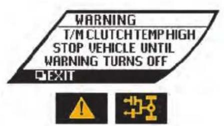
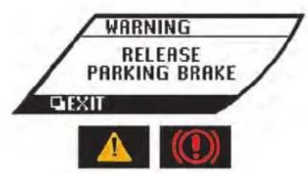
TRANSMISSION OIL HIGH TEM- PERATURE WARNING
This will appear if the transmission oil temperature becomes unusually high.
( "Transmission warning light" page 2-30)
TRANSMISSION CLUTCH HIGH TEMPERATURE WARNING
This will appear if the transmission clutch temperature becomes unusually high.
( "Transmission warning light" page 2-30)
This will appear if the vehicle speed is above 4 MPH (7 km/h) with the parking brake applied.
( "Brake warning light" page 2-26) ( "Parking brake reminder chime" page 2-33)
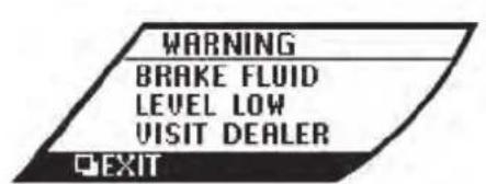

This will appear if the brake fluid level becomes low. ("Brake warning light" page 2-26)
ANTI-LOCK BRAKING SYSTEM (ABS) WARNING
This will appear if the Anti-lock Braking System (ABS) is not functioning properly. ("Anti-lock Braking System (ABS) warning light" page 2-26) ("Brake warning light" page 2-26)
VEHICLE DYNAMIC CONTROL (VDC) SYSTEM WARNING
This will appear if the Vehicle Dynamic Control (VDC) system or the hill start assist system is not functioning properly. ( "Vehicle Dynamic Control (VDC) warning light" page 2-31) ( "Vehicle Dynamic Control (VDC) off indicator light" page 2-32)
damage to the AWD system.
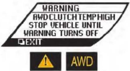
AWD CLUTCH HIGH TEMPERATURE WARNING
This will appear if the temperature of the AWD clutch becomes unusually high. ("All Wheel Drive (AWD) warning light" page 2-25)
NOTE:
If the vehicle is driven in a way which causes the rear wheels to slip, the AWD clutch temperature will increase and the warning indicator may flash. Continuing to drive in a way that causes the warning light to flash may cause the clutch to reach excessive temperatures that could result in

FRONT/REAR TIRE SIZE DISCREPANCY WARNING
This will appear if the diameter of the front and the rear wheels are different. ("All Wheel Drive (AWD) warning light" page 2-25)
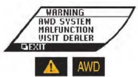

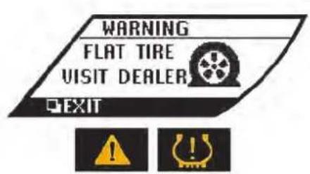
AWD SYSTEM WARNING
This will appear if the AWD system is not functioning properly while the engine is running. ( "All-Wheel Drive (AWD) warning light" page 2-25)
LOW TIRE PRESSURE WARNING
This will appear if the vehicle is being driven with low tire pressure. ("Low tire pressure warning light" page 2-27)
RUN-FLAT TIRE WARNING
This will appear and a chime will sound if the vehicle is being driven with one or more flat tires. ( "Low tire pressure warning light" page 2-27)


TIRE PRESSURE MONITORING SYSTEM (TPMS) WARNING
This will appear if the Tire Pressure Monitoring System (TPMS) is not functioning properly. (125 "Low tire pressure warning light" page 2-27)
CRUISE CONTROL SYSTEM WARNING
This will appear if the cruise control system is not functioning properly. ("Cruise set switch indicator light" page 2-31)
LOW FUEL WARNING
This will appear when the fuel level in the tank is getting low. Refuel as soon as it is convenient, preferably before the fuel gauge reaches the empty (E) position.
This displays the approximate distance that the vehicle can be driven based on the amount of fuel remaining in the fuel tank and the actual fuel consumption.
NOTE:
- The low fuel warning will appear when the amount of fuel remaining in the tank decreases to approximately 3 US gallons (12 liters).
- The timing of the low fuel warning display may change depending on braking, turning, acceleration, or going up or down hills.
- If the vehicle is not refueled after the low fuel warning appears, the display will change to “----”. This change timing may become earlier depending on the driving conditions. This does not indicate that there is a malfunction.
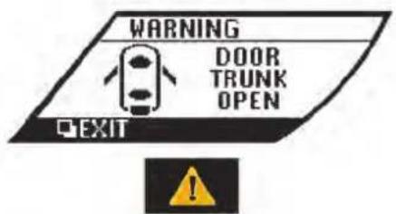

DOOR/TRUNK OPEN WARNING
This will appear if any of the doors and/or trunk lid are open or not closed securely. The vehicle icon indicates which door or the trunk lid is open.
HEADLIGHT SYSTEM WARNING
This will appear if the LED headlight system is not functioning properly. Have the system checked by a GT-R certified NISSAN dealer.


system. You cannot start the engine with an unregistered Intelligent Key.
( "Intelligent Key system" page 3-8)
LOW WASHER FLUID WARNING
This will appear when the washer tank fluid is at a low level. Add washer fluid as necessary. ( "Window washer fluid" page 8-16)
NO KEY WARNING
This will appear in either of the following conditions.
No key inside the vehicle
The warning appears when the door is closed with the Intelligent Key left outside the vehicle and the ignition switch in the ACC or ON position. Make sure that the Intelligent Key is inside the vehicle.
Unregistered Intelligent Key
The warning appears when the ignition switch is pushed from the LOCK position and the Intelligent Key cannot be recognized by the
2-42 Instruments and controls
OPERATION DISPLAYS
These displays appear when an appropriate operation is required in starting or stopping the engine.


ENGINE START OPERATION INDICATOR
This indicator appears when the shift lever is in the P position.
This indicator means that the engine will start by pushing the ignition switch with the brake pedal depressed.
SHIFT "P" WARNING
This warning appears and an inside warning chime sounds when the ignition switch is pushed to stop the engine with the shift lever in any position except the P position.
If this warning appears, move the shift lever to the P position. This warning will also turn off when pushing the ignition switch to the ON position.


natural_image
Two white icons on a black background: a steering wheel and a download button, with no text or symbols.
natural_image
Abstract black-and-white graphic with a stylized white icon of a helmet and an upward arrow, no text or symbols present."PUSH" WARNING
This warning appears when the shift lever is moved to the P position with the ignition switch in the ACC position after the SHIFT P warning appears.
If this warning appears, push the ignition switch to the OFF position.
STEERING LOCK RELEASE MAL-FUNCTION INDICATOR
This indicator appears when the steering wheel lock cannot be released from the LOCK position. If this indicator appears, push the ignition switch while lightly turning the steering wheel right and left.
INTELLIGENT KEY INSERTION INDICATOR
This indicator appears when the Intelligent Key needs to be inserted into the Intelligent Key port (for example, the Intelligent Key battery is discharged).
If this indicator appears, insert the Intelligent Key into the Intelligent Key port in the correct direction. ( "Intelligent Key battery discharge" page 5-12)
SECURITY SYSTEMS

natural_image
Black and white icon depicting a stylized helmet with a downward arrow, no text or symbols present.
natural_image
Black and white icon showing a key with two buttons labeled F and E, no text or symbols present.
natural_image
Illustration of a car with concentric circular patterns around its body, showing airflow or sensor targeting (no text or symbols)INTELLIGENT KEY REMOVAL INDICATOR
This indicator appears when the driver's door is opened with the ignition switch in the OFF or LOCK position and the Intelligent Key placed in the Intelligent Key port. A key reminder chime also sounds.
If this indicator appears, remove the Intelligent Key from the Intelligent Key port and take it with you when leaving the vehicle.
INTELLIGENT KEY BATTERY DIS- CHARGE INDICATOR
This indicator appears when the Intelligent Key battery is running out of power.
If this indicator appears, replace the battery with a new one. ( "Intelligent Key battery replacement" page 8-27)
Your vehicle has two types of security systems, as follows:
- Vehicle security system
• NISSAN Vehicle Immobilizer System
The security condition will be shown by the security indicator light.
VEHICLE SECURITY SYSTEM
The vehicle security system provides visual and audio alarm signals if someone opens the doors, hood, or trunk lid when the system is armed. It is not, however, a motion detection type system that activates when a vehicle is moved or when a vibration occurs.
Instruments and controls 2-45
The system helps deter vehicle theft but cannot prevent it, nor can it prevent the theft of interior or exterior vehicle components in all situations. Always secure your vehicle even if parking for a brief period. Never leave your Intelligent Key(s) in the vehicle, and always lock it when unattended. Be aware of your surroundings, and park in secure, well-lit areas whenever possible. Many devices offering additional protection, such as component locks, identification markers, and tracking systems, are available at auto supply stores and specialty shops. Your GT-R certified NISSAN dealer may also offer such equipment. Check with your insurance company to see if you may be eligible for discounts for various theft protection features.
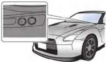
natural_image
Illustration of a sports car front view with a close-up inset showing the dashboard and seat (no text or symbols)How to arm the vehicle security system
- Close all windows.
The system can be armed even if the windows are open. - Push the ignition switch to the OFF or LOCK position.
- Remove the Intelligent Key from the vehicle.
-
Close all doors, hood and trunk. Lock all doors. The doors can be locked with the Intelligent Key, door handle request switch or power door lock switch. The power door lock switch should be operated while the door is open, and then closed.
-
Confirm that the security indicator light comes on. The security indicator light stays on for about 30 seconds. The vehicle security system is now pre-armed. After about 30 seconds the vehicle security system automatically shifts into the armed phase. The security light begins to flash once every approximately 3 seconds. If, during this 30-second pre-arm time period, the door is unlocked, or the ignition switch is pushed to ACC or ON, the system will not arm.
Even when the driver and/or passengers are in the vehicle, the system will activate with all doors, hood, and trunk lid locked with the ignition switch in the LOCK position. When pushing the ignition switch to the ACC or ON position, the system will be released.
Vehicle security system activation
The vehicle security system will give the following alarm:
- The headlights blink and the horn sounds intermittently.
- The alarm automatically turns off after approximately 1 minute. However, the alarm reactivates if the vehicle is tampered with again.
The alarm is activated by:
- Opening the door or the trunk lid without using the button on the Intelligent Key, the door handle request switch or the mechanical key. (Even if the door is opened by releasing the door inside lock knob, the alarm will activate.)
- Opening the hood.
How to stop an activated alarm
The alarm will stop by:
- Unlocking a door by pushing the UNLOCK button on the Intelligent Key.
- Unlocking a door by pushing the door handle request switch.
- Pushing the ignition switch to the ACC or ON position.
If the system does not operate as described above, have it checked by a GT-R certified NISSAN dealer.
NISSAN VEHICLE IMMOBILIZER SYSTEM
The NISSAN Vehicle Immobilizer System will not allow the engine to start without the use of the registered Intelligent Key. Never leave these keys in the vehicle.
FCC Notice:
For USA:
This device complies with Part 15 of the FCC Rules. Operation is subject to the following two conditions: (1) This device may not cause harmful interference, and (2) this device must accept any interference received, including interference that may cause undesired operation.
Note: Changes or modifications not expressly approved by the party responsible for compliance could void the user's authority to operate the equipment.
For Canada:
This device complies with Industry Canada licence-exempt RSS standard(s). Operation is subject to the following two conditions: (1) this device may not cause interference, and (2) this device must accept any interference, including interference that may cause undesired operation of the device.
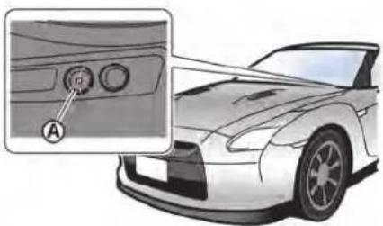
Security indicator light
The security indicator light is located on the instrument panel. It indicates the status of the NISSAN Vehicle Immobilizer System.
The light blinks whenever the ignition switch is in the ACC, OFF or LOCK position. This function indicates the security systems equipped on the vehicle are operational.
If the NISSAN Vehicle Immobilizer System is malfunctioning, this light will remain on while the ignition switch is in the ON position.
If the light still remains on and/or the engine will not start, see a GT-R certified NISSAN dealer for NISSAN Vehicle Immo-
Instruments and controls 2-47
bilizer System service as soon as possible. Please bring all Intelligent Keys that you have when visiting a GT-R certified NISSAN dealer for service.
WIPER AND WASHER SWITCH

WARNING
In freezing temperatures the washer solution may freeze on the windshield and obscure your vision which may lead to an accident. Warm windshield with the defroster before you wash the windshield.
window washer reservoir tank to mix the washer fluid concentrate and water.
The windshield wiper and washer operates when the ignition switch is in the ON position.
NOTICE
- Do not operate the washer continuously for more than 30 seconds.
- Do not operate the washer if the reservoir tank is empty.
- Do not fill the window washer reservoir tank with washer fluid concentrates at full strength. Some methyl alcohol based washer fluid concentrates may permanently stain the grille if spilled while filling the window washer reservoir tank.
- Pre-mix washer fluid concentrates with water to the manufacturer's recommended levels before pouring the fluid into the window washer reservoir tank. Do not use the
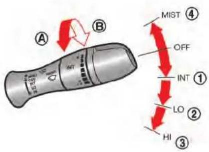
USING THE WIPERS
Push the lever down to operate the wiper at the following speed:
① INT (Intermittent) — intermittent operation can be adjusted by turning the knob toward (Slower) or (B) (Faster).
② Low — continuous low speed operation
③ High — continuous high speed operation
Push the lever up ④ to have one sweep operation of the wiper.
NOTE:
- In the MIST position, the wipers operate while the lever is lifted up. When the lever is released, it automatically returns to the OFF position and the wipers stop.
- When the speed sensing wiper interval function is turned on, the intermittent operation speed varies in accordance with the vehicle speed. (For example, when the vehicle speed is high, the intermittent operation speed will be faster.) To turn this function on and off, see the separate Multi Function Display Owner's Manual.
- If the wiper operation is interrupted by snow or ice, the wiper may stop moving to protect its motor. If this occurs, turn the wiper switch to the OFF position and remove the snow or ice on and around the wiper arms. In approximately 1 minute, turn the switch on again to operate the wiper.
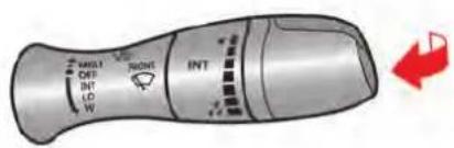
USING THE WASHER
Pull the lever toward you to operate the washer. Then the wiper will also operate several times.
NOTE:
When the level of washer fluid is low, a warning display appears on the vehicle information display. ( "Low washer fluid warning" page 2-42)
REAR WINDOW DEFROSTER SWITCH
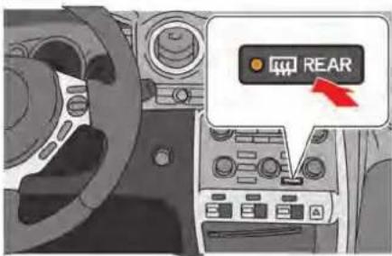
To defog/defrost the rear window, start the engine and push the switch on. The indicator light on the switch will come on. Push the switch again to turn the defroster off.
It will automatically turn off in approximately 15 minutes.
NOTE:
When the rear window defroster switch is pressed, the heated outside mirrors also operate at the same time. ( "Outside mirrors" page 3-27)
NOTICE
When cleaning the inner side of the rear window, be careful not to scratch or damage the rear window defroster.
HEADLIGHT AND TURN SIGNAL SWITCH

HEADLIGHT SWITCH
Lighting
The parking, tail and license plate lights will turn on after the engine is started regardless of the position of the headlight switch. The lights will turn off when the engine is turned off.
The daytime running lights will also turn on when the engine is started.
Turning the switch to the EDQ position:
The parking, side marker, tail, license plate and instrument lights will come on and the daytime running light will remain on.
Turning the switch to the position:
Headlights will come on and all the other lights remain on. The daytime running light will turn off.
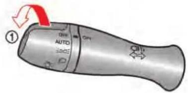
If the ignition switch is pushed to the OFF position and one of the doors is opened, the headlights remain on for 45 seconds.
Autolight system
The autolight system allows the headlights to be set so they turn on and off automatically.
To set the autolight system:
-
Make sure the headlight switch is in the AUTO position ①.
-
Push the ignition switch to the ON position.
-
The autolight system automatically turns the headlights on and off.
To turn the autolight system off, turn the switch to the OFF, or position.
The autolight system can turn on the headlights automatically when it is dark and turn off the headlights when it is light.
Instruments and controls 2-51

Headlight beam select
When the headlights are on, push the lever to the front of the vehicle ① to switch to the high beams. The high-beam indicator light illuminates. ( "High beam indicator light" page 2-31)
Pull the lever to the neutral position ② to switch to the low beams.
Pulling the lever toward you ③ will flash the headlight high beam even when the headlight switch is in the OFF position.
CAUTION
Use low beams when there are cars approaching from the opposite direction, during city driving and at similar times.
Battery saver system
A chime will sound when the driver side door is opened with the light switch in the EDGE or O position and the ignition switch in the ACC, OFF or LOCK position. ( "Light reminder chime" page 2-32)
When the headlight switch is in the ☐ or ☐ position while the ignition switch is in the ON position, the lights will automatically turn off after a period of time when the ignition switch has been pushed to the OFF position.
When the headlight switch remains in the EDGE or position after the lights automatically turn off, the lights will turn on when the ignition switch is pushed to the ON position.
NOTICE
- When you turn on the headlight switch again after the lights automatically turn off, the lights will not turn off automatically. Be sure to turn the light switch to the OFF position when you leave the vehicle for extended periods of time, otherwise the battery will be discharged.
- Never leave the light switch on when the engine is not running for extended periods of time even if the headlights turn off automatically.
Daytime running light system
The daytime running lights automatically illuminate when the engine is started with the parking brake released. The daytime running lights operate with the headlight switch in the OFF position. Turn the headlight switch to the position for full illumination when driving at night. If the parking brake is applied before the engine is started, the daytime running lights do not illuminate. The daytime running lights illuminate once the parking brake is released. The daytime running lights will remain on until the ignition switch is pushed to the OFF position.

WARNING
When the daytime running light system is active, tail lights on your vehicle are not on. It is necessary at dusk to turn on your headlights. Failure to do so could cause an accident injuring yourself and others.

latch, and release the lever. The turn signal will automatically flash three times. Choose the appropriate method to signal a lane change based on road and traffic conditions.
TURN SIGNAL SWITCH
① Turn signal
Move the lever up or down to signal the turning direction. When the turn is completed, the turn signals cancel automatically.
② Lane change signal
- Move the lever up or down until the turn signal begins to flash, but the lever does not latch, to signal a lane change. Hold the lever until the lane change is completed.
- Move the lever up or down until the turn signal begins to flash, but the lever does not
HORN

natural_image
Diagram of a car steering wheel with a red upward arrow indicating clockwise motion (no text or symbols)To sound the horn, push the center pad area of the steering wheel.

WARNING
Do not disassemble the horn. Doing so could affect proper operation of the supplemental front air bag system. Tampering with the supplemental front air bag system may result in serious personal injury.
HEATED SEATS

The seat heaters can be used when the ignition switch is in the ON position. The front seats are warmed by the built-in heaters.
TURNING ON THE HEATERS
Push the "HI" or "LO" side of the switch to activate the heaters. The switch indicator illuminates.
| Switch position Function | |
| HI To heat | the seat quickly |
| LO To keep | the seat warm |
Move the switch to the level position. The switch indicator turns off.

WARNING
Do not use or allow occupants to use the seat heater if you or the occupants cannot monitor elevated seat temperatures or have an inability to feel pain in those body parts in contact with the seat. Use of the seat heater by such people could result in serious injury.

CAUTION
- Do not put anything on the seat which insulates heat, such as a blanket, cushion, seat cover, etc. Otherwise, the seat may become overheated.
- Do not place anything hard or heavy on the seat or pierce it with a pin or similar object. This may result in damage to the heater.
- Any liquid spilled on the heated seat should be removed immediately
with a dry cloth.
- If any malfunctions are found or the heated seat does not operate, turn the switch off and have the system checked by a GT-R certified NISSAN dealer.
NOTICE
- The battery could run down if the seat heater is operated while the engine is not running.
- Do not use the seat heater for extended periods or when no one is using the seat.
- When cleaning the seat, never use gasoline, thinner, or any similar materials.
POWER OUTLETS
CAUTION
• The outlet and plug may be hot during or immediately after use.
- Do not use with accessories that exceed a 12 volt, 120W (10A) power draw. Do not use double adapters or more than one electrical accessory.
- This power outlet is not designed for use with a cigarette lighter unit.
- Before inserting or disconnecting a plug, be sure the electrical accessory being used is turned OFF.
- When not in use, be sure to close the cap. Do not allow water to contact the outlet.
NOTICE
- Use power outlet with the engine running to avoid discharging the vehicle battery.
- Avoid using power outlet when the air conditioner, headlights or rear window defroster is on.
- Push the plug in as far as it will go. If good contact is not made, the plug may overheat or the internal temperature fuse may open.
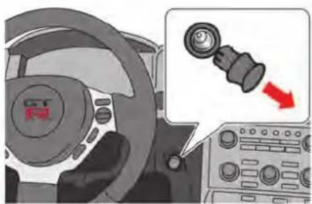
natural_image
Interior view of a car steering wheel with a close-up inset showing a gear shift (no text or symbols)Next to the steering wheel
Pull out the cap to use the outlet.
Replace the cap after use.

natural_image
Mechanical gear shift lever diagram showing a knob and adjustment knob (no text or symbols)Inside the console box (except for NISMO models)
Open the cap to use the outlet.
Close the cap after use.
STORAGE


CUP HOLDERS
CAUTION
- Avoid abrupt starting and braking when the cup holder is being used to prevent spilling the drink. If the liquid is hot, it can scald you or your passenger.
- Use only soft cups in the cup holder. Hard objects can injure you in an accident.
Front
Slide the cover toward the rear of the vehicle to open.
To close, slide the cover back toward the front of the vehicle.

natural_image
Mechanical component with a circular mark and concentric rings, no visible text or symbols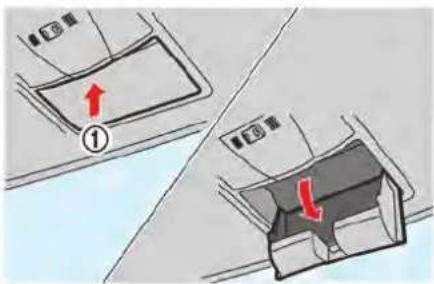
Rear
NOTE:
Cup holder Ⓐ is wider and shallower than cup holders Ⓑ and Ⓒ. Small-size cups are likely to tip over in cup holder Ⓐ. Use cup holders Ⓑ and Ⓒ.
SUNGLASSES HOLDER

WARNING
Keep the sunglasses holder closed while driving to prevent an accident.
To open the sunglasses holder, push ①.

CAUTION
Do not use for anything other than glasses.
NOTICE
Do not leave glasses in the sunglasses holder while parking in direct sunlight. The heat may damage the glasses.

natural_image
Close-up of a car's front wheel and grille (no text or symbols visible)
natural_image
Mechanical component diagram showing a sliding mechanism with red arrows indicating motion (no text or symbols)DOOR POCKET
Door pockets are located inside the driver's side and passenger's side doors.
NOTICE
Do not grasp the door pockets to open and close the doors. Doing so may damage the pockets.
GLOVE BOX

WARNING
Keep glove box lid closed while driving to help prevent injury in an accident or a sudden stop.
Pull the knob toward you to open the glove box. To close the glove box, press the lid forward until it locks in place.

Use the mechanical key to lock ① and unlock ② the glove box. ("Mechanical key" page 3-3)
The mechanical key stops when it is inserted approximately halfway in.

natural_image
Mechanical device interior view showing a car seat with a labeled component (no text or symbols present)CONSOLE BOX
Lift up the lock knob ① to open the lid. To close the center console box, press on the lid until it locks in place.
NOTE:
The console box contains a power outlet (except for NISMO models) or a USB (Universal Serial Bus) connection port (for NISMO models). This USB connection port is reserved for future use for features that have yet to be developed. Do not use for unapproved USB devices.

natural_image
Diagram showing two car door compartments with red arrows indicating movement or change, no text or symbols present.COAT HOOKS
To use the coat hook, push the upper side of the hook to release it.

CAUTION
Do not hang any objects with sharp edges on the coat hangers. These items may be knocked off if the SRS air bag deploys, possibly causing injury.
NOTICE
Do not place items that are more than 2 lb (1 kg) on the hook.
WINDOWS
POWER WINDOWS

WARNING
- Make sure that all passengers have their hands, etc. inside the vehicle while it is in motion and before closing the windows. Use the window lock switch to prevent unexpected use of the power windows.
- Do not leave children unattended inside the vehicle. They could unknowingly activate switches or controls and become trapped in the window. Unattended children could become involved in serious accidents.
The power windows operate when the ignition switch is in the ON position or for about 45 seconds after the ignition switch is pushed to the LOCK position. If the driver's or front passenger's door is opened during this period of about 45 seconds, power to the windows is canceled.

Driver's side
- Window lock button
- Driver's window switch
- Front passenger's window switch

natural_image
Diagram of a vehicle interior with two control panels and a numbered label (4), no readable text or symbols present.Front passenger's side
- Front passenger's window switch
Main power window switch (driver's side)
To open or close the window, push down or pull up the switch and hold it. The main switch (driver's side switches) will open or close all the windows.
Locking passengers' windows
When the window lock button is pushed in, only the driver's side window can be opened or closed. Push it in again to cancel.
Passenger's side power window switch
The passenger side switch will open or close only the corresponding window. To open close the window, push down or pull up the switch and hold it.
Automatic operation
To fully open or close the window, completely push down or pull up the switch and release it; it does not need to be held. The window will automatically open or close all the way. To stop the window, just push or lift the switch in the opposite direction.
A light push or pull on the switch will cause the window to open or close until the switch is released.
Auto reverse function
If the control unit detects something caught in the window as it is closing, the window will be immediately lowered.
The auto reverse function can be activated when the window is closed by automatic operation when the ignition switch is in the ON position or for 45 seconds after the ignition switch is pushed to the OFF position.
Depending on the environment or driving conditions, the auto reverse function may be
activated if an impact or load similar to something being caught in the window occurs.

WARNING
There are some small distances immediately before the closed position which cannot be detected. Make sure that all passengers have their hands, etc., inside the vehicle before closing the window.
Automatic adjusting function

CAUTION
When the battery cable is removed from the battery terminal, do not close either of the front doors. The automatic window adjusting function will not work and the side roof panel may be damaged.
The power window has an automatic adjusting function. When the door is being opened, the window is automatically lowered slightly to avoid contact between the window and the side roof panel. When the door is closed, the window is
Instruments and controls 2-61
automatically raised slightly.
While the automatic adjusting function does not work, the window will be controlled as follows:
- When the door is opened, the window lowers for approximately 2 seconds.
- While the door is open, the window cannot be raised.
If the windows do not close automatically
If the power window automatic function (closing only) does not operate properly, perform the following procedure to initialize the power window system.
- Push the ignition switch to the ON position.
- Close the door.
- Open the window completely by operating the power window switch.
- Pull the power window switch and hold it to close the driver side window, and then hold the switch more than 3 seconds after the window is closed completely.
- Release the power window switch. Operate the window by the automatic function to confirm the initialization is complete.
- Perform steps 2 through 5 above for the passenger side window by operating either driver's or passenger's side switch.
2-62 Instruments and controls
If the power window automatic function does not operate properly after performing the procedure above, have your vehicle checked by a GT-R certified NISSAN dealer.
INTERIOR LIGHTS
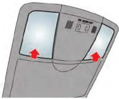
MAP LIGHTS
Push the button as illustrated to turn the light on or off.

INTERIOR LIGHT CONTROL SWITCH
The interior light control switch has three positions: ON ①, DOOR ② and OFF ③.
ON position
When the switch is in the ON position ①, the map lights will illuminate.
NOTICE
Do not use the light for extended periods of time with the engine stopped. This could result in a discharged battery.
NOTE:
The lights will also turn off after a period of time when the lights remain illuminated after the ignition switch has been pushed to the OFF or LOCK position to prevent the battery from becoming discharged.
DOOR position
When the switch is in the DOOR position ②, the map lights will turn on when the door is opened and turn off when the door is closed. The map lights will turn off approximately 15 seconds after the door is closed with the ignition switch in the OFF or LOCK position.
NOTE:
When the interior light control switch is in the DOOR position and the door is open, the light will remain on even when the map light switch is pressed to turn off.
Key-linked interior light control system:
The map lights will turn on and off linked with the locking and unlocking of the door. This function operates when the interior light control switch is in the DOOR position.
- When entering the vehicle
When the driver's seat door is unlocked, the map light illuminates for approximately 15
seconds, then it turns off.
While the map light is on, if the ignition switch is pushed to the ACC or ON position, or if the driver's side door is locked, the light turns off.
- When exiting the vehicle
When the ignition switch is pushed to the OFF or LOCK position, the map lights turn on for approximately 15 seconds, then it turns off. If the driver's side door is locked while the map lights are on, the light turns off.
NOTE:
It is possible to cancel the key-linked interior light control system setting. See the separate Multi Function Display Owner's Manual.
OFF position
When the switch is in the OFF position ③, the map lights will not illuminate, regardless of any condition.
VANITY MIRROR LIGHTS

natural_image
Diagram of a car front panel with a highlighted indicator light and red arrow (no text or symbols)There is an illuminated vanity mirror on the reverse side of the sun visor.
HomeLink® UNIVERSAL TRANSCEIVER
The HomeLink® Universal Transceiver provides a convenient way to consolidate the functions of up to three individual hand-held transmitters into one built-in device.
HomeLink® Universal Transceiver:
- Will operate most Radio Frequency (RF) devices such as garage doors, gates, home and office lighting, entry door locks and security systems.
- Is powered by your vehicle's battery. No separate batteries are required. If the vehicle's battery is discharged or is disconnected, HomeLink® will retain all programming.
When the HomeLink ^® Universal Transceiver is programmed, retain the original transmitter for future programming procedures (Example: new vehicle purchases).
Upon sale of the vehicle, the programmed HomeLink® Universal Transceiver buttons should be erased for security purposes.
For additional information, refer to "Programming HomeLink®" page 2-65.

WARNING
- Do not use the HomeLink ^® Universal Transceiver with any garage door opener that lacks safety stop and reverse features as required by federal safety standards. (These standards became effective for opener models manufactured after April 1, 1982.) A garage door opener which cannot detect an object in the path of a closing garage door and then automatically stop and reverse, does not meet current federal safety standards. Using a garage door opener without these features increases the risk of serious injury or death.
- During the programming procedure your garage door or security gate will open and close (if the transmitter is within range). Make sure that people or objects are clear of the garage door, gate, etc. that you are programming.
- Your vehicle's engine should be turned off while programming the HomeLink® Universal Transceiver.
Do not breathe exhaust gases; they contain colorless and odorless carbon monoxide. Carbon monoxide is dangerous. It can cause unconsciousness or death.
PROGRAMMING HomeLink®
If you have any questions or are having difficulty programming your HomeLink® buttons, refer to the HomeLink® web site at: www.homelink.com or call 1-800-355-3515.
NOTE:
It is also recommended that a new battery be placed in the hand-held transmitter of the device being programmed to HomeLink® for quicker programming and accurate transmission of the radio-frequency.
- Position the end of your hand-held transmitter 1-3 in (26-76 mm) away from the HomeLink® surface, keeping the HomeLink® indicator light ① in view.

- Using both hands, simultaneously press and hold the desired HomeLink ^ button and handheld transmitter button. DO NOT release until the HomeLink ^ indicator light ① flashes slowly and then rapidly. When the indicator light flashes rapidly, both buttons may be released. (The rapid flashing indicates successful programming.)
NOTE: Some devices to be programmed may require you to replace Step 2 with the cycling procedure noted in the "Programming HomeLink® for Canadian customers and gate openers" page 2-66.

- Press and hold the programmed HomeLink® button and observe the indicator light.
- If the indicator light ① is solid/continuous, programming is complete and your device should activate when the HomeLink® button is pressed and released.
- If the indicator light ① blinks rapidly for two seconds and then turns to a solid/continuous light, continue with Steps 4-6 for a rolling code device. A second person may make the following steps easier. Use a ladder or other device. Do not stand on your vehicle to perform the next steps.
Instruments and controls 2-65
-
At the receiver located on the garage door opener motor in the garage, locate the "learn" or "smart" button (the name and color of the button may vary by manufacturer but it is usually located near where the hanging antenna wire is attached to the unit). If there is difficulty locating the button, reference the garage door opener's manual.
-
Press and release the "learn" or "smart" button.
NOTE: Once the button is pressed, you have approximately 30 seconds to initiate the next step.
-
Return to the vehicle and firmly press and hold the programmed HomeLink® button for two seconds and release. Repeat the "press/hold/release" sequence up to 3 times to complete the programming process. HomeLink® should now activate your rolling code equipped device.
-
If you have any questions or are having difficulty programming your HomeLink® buttons, refer to the HomeLink® web site at: www.homelink.com or call 1-800-355-3515.
PROGRAMMING HomeLink® FOR CANADIAN CUSTOMERS AND GATE OPENERS
Canadian radio-frequency laws require transmitter signals to "time-out" (or quit) after several seconds of transmission – which may not be long enough for HomeLink® to pick up the signal during programming. Similar to this Canadian law, some U.S. gate operators are designed to "time-out" in the same manner.
If you live in Canada or you are having difficulties programming a gate operator or garage door opener by using the "Programming HomeLink®n procedures, replace "Programming HomeLink®n Step 2 with the following:
NOTE:
When programming a garage door opener, etc., unplug the device during the "cycling" process to prevent possible damage to the garage door opener components.
Step 2: Using both hands, simultaneously press and hold the desired HomeLink ^® button and the hand-held transmitter button. During programming, your hand-held transmitter may automatically stop transmitting. Continue to press and hold the desired HomeLink ^® button while you press and re-press ("cycle") your hand-held transmitter every two seconds until the fre-
quency signal has been learned. The HomeLink ^® indicator light will flash slowly and then rapidly after several seconds upon successful programming. DO NOT release until the HomeLink ^® indicator light flashes slowly and then rapidly. When the indicator light flashes rapidly, both buttons may be released. The rapid flashing indicates successful programming.
Proceed with "Programming HomeLink®" step 3 to complete.
Remember to plug the device back in when programming is completed.
The HomeLink ^® Universal Transceiver, after it is programmed, can be used to activate the programmed device. To operate, simply press and release the appropriate programmed HomeLink ^® Universal Transceiver button. The amber indicator light will illuminate while the signal is being transmitted.
For convenience, the hand-held transmitter of the device may also be used at any time.
PROGRAMMING TROUBLESHOOTING
If the HomeLink ^® does not quickly learn the hand-held transmitter information:
- replace the hand-held transmitter batteries with new batteries.
- position the hand-held transmitter with its battery area facing away from the HomeLink® surface.
- press and hold both the HomeLink ^ and hand-held transmitter buttons without interruption.
- position the hand-held transmitter 1-3 in (26-76 mm) away from the HomeLink surface. Hold the transmitter in that position for up to 15 seconds. If HomeLink is not programmed within that time, try holding the transmitter in another position - keeping the indicator light in view at all times.
If you have any questions or are having difficulty programming your HomeLink® buttons, refer to the HomeLink® web site at: www.homelink.com or 1-800-355-3515.
CLEARING THE PROGRAMMED INFORMATION
The following procedure clears the programmed information from both buttons. Individual buttons cannot be cleared. However, individual buttons can be reprogrammed, see "Reprogramming a single HomeLink® button" page 2-67.
To clear all programming
- Press and hold the two outer HomeLink buttons until the indicator light begins to flash in approximately 10 seconds. Do not hold for longer than 20 seconds.
- Release both buttons.
HomeLink ^® is now in the programming mode and can be programmed at any time beginning with “Programming HomeLink ^® ” - Step 1.
REPROGRAMMING A SINGLE HomeLink® BUTTON
To reprogram a HomeLink ^® Universal Transceiver button, complete the following.
- Press and hold the desired HomeLink button. Do not release the button.
- The indicator light will begin to flash after 20 seconds. Without releasing the HomeLink ^® button, proceed with "Programming
HomeLink ^®n - Step 1.
For questions or comments, contact HomeLink® at: www.homelink.com or 1-800-355-3515.
The HomeLink ^® Universal Transceiver button has now been reprogrammed. The new device can be activated by pushing the HomeLink ^® button that was just programmed. This procedure will not affect any other programmed HomeLink ^® buttons.
IF YOUR VEHICLE IS STOLEN
If your vehicle is stolen, you should change the codes of any non-rolling code device that has been programmed into HomeLink ^® . Consult the Owner's Manual of each device or call the manufacturer or retailer of those devices for additional information.
When your vehicle is recovered, you will need to reprogram the HomeLink® Universal Transceiver with your new transmitter information.
FCC Notice:
For USA:
This device complies with Part 15 of the FCC Rules. Operation is subject to the following two conditions: (1) This device may not cause harmful interference, and (2) this device must accept any interfer-
Instruments and controls 2-67
ence received, including interference that may cause undesired operation.
NOTE:
Changes or modifications not expressly approved by the party responsible for compliance could void the user's authority to operate the equipment.
For Canada:
This device complies with Industry Canada licence-exempt RSS standard(s). Operation is subject to the following two conditions: (1) this device may not cause interference, and (2) this device must accept any interference, including interference that may cause undesired operation of the device.
3 Pre-driving checks and adjustments
Keys 3-2
Intelligent Key 3-2
Doors 3-4
Locking with inside lock knob 3-5
Locking with power door lock switch 3-5
Automatic door lock system 3-5
Locking with mechanical key 3-6
Opening the doors 3-7
Intelligent Key system 3-8
Intelligent Key functions 3-9
Remote keyless entry system 3-12
Setting hazard indicator and horn mode 3-13
Warning signals 3-15
Troubleshooting guide 3-16
Hood 3-17
Opening the hood 3-17
Closing the hood 3-18
Trunk 3-19
Trunk open request switch 3-19
Trunk lid release switch 3-19
Trunk release power cancel switch 3-20
Opening and closing the trunk 3-21
Emergency trunk lid release 3-21
Outside mirrors 3-27
Vanity mirror 3-28

KEYS
A key number plate is supplied with your keys. Record the key number and keep it in a safe place (such as your wallet), not in the vehicle. If you lose your keys, see a GT-R certified NISSAN dealer for duplicates by using the key number. NISSAN does not record any key numbers so it is very important to keep track of your key number plate.
A key number is only necessary when you have lost all keys and do not have one to duplicate from. If you still have a key, this key can be duplicated by a GT-R certified NISSAN dealer.

- Intelligent Key (2 sets)
- Mechanical key (inside Intelligent Keys) (2 sets)
- Key number plate (1 set)
INTELLIGENT KEY
Your vehicle can only be driven with the Intelligent Keys which are registered to your vehicle's Intelligent Key system components and NISSAN Vehicle Immobilizer System components. As many as 4 Intelligent Keys can be registered and used with one vehicle. The new keys must be registered by a GT-R certified NISSAN dealer prior to use with the Intelligent Key system and NISSAN Vehicle Immobilizer System of your vehicle. Since the registration
process requires erasing all memory in the Intelligent Key components when registering new keys, be sure to take all Intelligent Keys that you have to a GT-R certified NISSAN dealer.
NOTICE
- Be sure to carry the Intelligent Key with you when driving. The Intelligent Key is a precision device with a built-in transmitter. To avoid damaging it, please note the following.
— The Intelligent Key is water resistant; however, wetting may damage the Intelligent Key. If the Intelligent Key gets wet, immediately wipe until it is completely dry.
— Do not bend, drop or strike it against another object.
— Do not place the Intelligent Key for an extended period in a place where temperatures exceed 140^ F ( 60^ C).
— If the outside temperature is below 14^ F ( -10^ C), the battery of the Intelligent Key may not
function properly.
— Do not change or modify the Intelligent Key.
— Do not use a magnet key holder.
— Do not place the Intelligent Key near an electric appliance such as a television set, personal computer or cellular phone.
— Do not allow the Intelligent Key to come into contact with water or salt water, and do not wash it in a washing machine. This could affect the system function.
- If an Intelligent Key is lost or stolen, NISSAN recommends erasing the ID code of that Intelligent Key. This will prevent the Intelligent Key from unauthorized use to unlock the vehicle. For information regarding the erasing procedure, please contact a GT-R certified NISSAN dealer.

Mechanical key
To remove the mechanical key, release the lock knob at the back of the Intelligent Key.
To install the mechanical key, firmly insert it into the Intelligent Key until the lock knob returns to the lock position.
Use the mechanical key to lock or unlock the doors and the glove box. ( "Locking with mechanical key" page 3-6) ( "Glove box" page 2-58)

CAUTION
Always carry the mechanical key installed in the Intelligent Key.
Valet hand-off
When you have to leave a key with a valet, give them the Intelligent Key itself and keep the mechanical key with you to protect your belongings.
To prevent the glove box and the trunk from being opened during valet hand-off, follow the procedures below.
- Push the trunk release power cancel switch to the OFF side. ( "Trunk release power cancel switch" page 3-20)
- Remove the mechanical key from the Intelligent Key.
- Lock the glove box with the mechanical key. ( "Glove box" page 2-58)
- Hand the Intelligent Key to the valet, keeping the mechanical key in your pocket or bag for insertion into the Intelligent Key when you retrieve your vehicle.
DOORS

WARNING
• Always have the doors locked while driving. Along with the use of seat belts, this provides greater safety in the event of an accident by helping to prevent persons from being thrown from the vehicle. This also helps keep children and others from unintentionally opening the doors, and will help keep out intruders.
- Before opening any door, always look for and avoid oncoming traffic.
- Do not leave children unattended inside the vehicle. They could unknowingly activate switches or controls. Unattended children could become involved in serious accidents.

CAUTION
To prevent theft or accidents, be sure to stop the engine and lock the doors before stepping away from the vehicle.
NOTICE
When the battery cable is removed from the battery terminal, do not close either of the front doors. The automatic window adjusting function will not work, and the side roof panel may be damaged. ( "Automatic adjusting function" page 2-61)
automatically raised slightly. (adjusting function" page 2-61)
"Automatic
NOTE:
- The doors of this vehicle are somewhat harder to close than those of an ordinary vehicle (especially when the vehicle is new). This is because the stiffness of the rubber has been increased to improve the airtightness of the vehicle interior during situations such as higher speed driving. This does not indicate that there is a malfunction.
- When the driver's door is locked or unlocked, the fuel-filler door is automatically locked or unlocked at the same time.
When the door is being opened, the window is automatically lowered slightly to avoid contact between the window and the side roof panel. When the door is closed, the window is
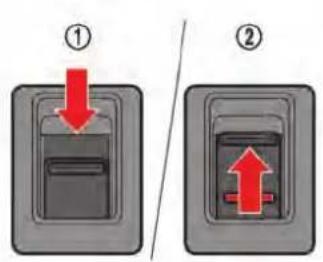
LOCKING WITH INSIDE LOCK KNOB
To lock a door individually, push down the inside lock knob to the lock position ① then close the door.
To unlock, lift up the inside lock knob to the unlock position ②.
NOTE:
When locking the door without an Intelligent Key, be sure not to leave the Intelligent Key inside the vehicle.
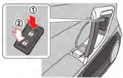
LOCKING WITH POWER DOOR LOCK SWITCH
Operating the power door lock switch will lock or unlock all the doors. The switches are located on the driver's and front passenger's door armrests.
To lock the doors, push the power door lock switch to the lock position ① with the driver's or front passenger's door open, then close the door.
NOTE:
When locking the door this way, be sure not to leave the Intelligent Key inside the vehicle.
To unlock the doors, push the power door lock switch to the unlock position ②.
Lockout protection
When the power door lock switch (driver or front passenger) is moved to the lock position with the Intelligent Key left in the key port and any door open, all doors will lock and unlock automatically.
When the power door lock switch (driver or front passenger) is moved to the lock position with the Intelligent Key left in the vehicle (not in the Intelligent Key port) and any door open, all doors will unlock automatically and a chime will sound after the door is closed.
These functions help to prevent the Intelligent Key from being accidentally locked inside the vehicle.
AUTOMATIC DOOR LOCK SYSTEM
- All doors lock automatically when the vehicle speed reaches 15 MPH (24 km/h).
- All doors unlock automatically when the ignition switch is placed in the OFF position.
The automatic unlock function can be
Pre-driving checks and adjustments 3-5
deactivated or activated. To deactivate or activate the automatic door unlock system, perform the following procedure:
- Close all doors.
- Place the ignition switch in the ON position.
- Within 20 seconds of performing Step 2, push and hold the power door lock switch to the 🔒 position (UNLOCK) for more than 5 seconds.
- When activated, the hazard indicator will flash twice. When deactivated, the hazard indicator will flash once.
- The ignition switch must be placed in the OFF and ON position again between each setting change.
When the automatic door unlock system is deactivated, the doors do not unlock when the ignition switch is placed in the OFF position. To unlock the door manually, use the inside lock knob or the power door lock switch (driver's or front passenger's side).
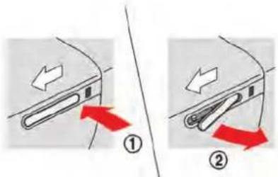

LOCKING WITH MECHANICAL KEY
The driver's door will be locked or unlocked using the mechanical key.
-
Press the rear end of the driver's outside door handle ① to lift up the front end ②.
-
With the outside door handle lifted up, use the mechanical key and turn the key cylinder cap Ⓐ counterclockwise to remove.

-
Turning the door key cylinder to the front of the vehicle ① will lock the driver's door, and turning to the rear of the vehicle ② will unlock the driver's door.
-
Replace the key cylinder cap in the reverse order.
NOTICE
Do not drive with the cap removed. Water that enters through the keyhole may cause a malfunction.
NOTE:
- Do not pull too hard on the door handle when locking or unlocking the doors. Pulling too hard will prevent the mechanical key from turning, making it impossible to lock or unlock the doors.
- Unlocking the driver's door using the mechanical key will not unlock the fuel-filler door.

OPENING THE DOORS
Opening from outside the vehicle
-
Press the rear end of the outside door handle ① to lift up the front end of the handle.
-
Pull the front end of the outside door handle ② toward you.
Pre-driving checks and adjustments 3-7
Opening from inside the vehicle
Lift up the inside door handle to open a door from inside the vehicle.
NOTICE
Do not grasp the door pockets to open and close the doors. Doing so may damage the pockets.
INTELLIGENT KEY SYSTEM

WARNING
- Radio waves could adversely affect electric medical equipment. Those who use a pacemaker should contact the electric medical equipment manufacturer for the possible influences before use.
- The Intelligent Key transmits radio waves when the buttons are pushed. The Federal Aviation Agency (FAA) advises the radio waves may affect aircraft navigation and communication systems. Do not operate the Intelligent Key while on an airplane. Make sure the buttons are not operated unintentionally when the unit is stored for a flight.
The Intelligent Key system can operate all the door locks using the remote controller function or pushing the request switch on the vehicle without taking the key out from a pocket or purse. The operating environment and/or conditions may affect the Intelligent Key system operation.
Be sure to read the following before using the Intelligent Key system.

CAUTION
- Be sure to carry the Intelligent Key with you when operating the vehicle.
- Never leave the Intelligent Key in the vehicle when you leave the vehicle.
- The Intelligent Key is always communicating with the vehicle as it receives radio waves. The Intelligent Key system transmits weak radio waves. Environmental conditions may interfere with the operation of the Intelligent Key system under the following operating conditions. In such cases, correct the operating conditions before using the Intelligent Key function or use the mechanical key.
— When operating near a location where strong radio waves are transmitted, such as a TV tower, power station and broadcasting station.
— When in possession of wireless equipment, such as a cellular telephone, transceiver, and CB radio.
— When the Intelligent Key is in contact with or covered by metallic materials.
— When any type of radio wave remote control is used nearby.
— When the Intelligent Key is placed near an electric appliance such as a personal computer.
— When the vehicle is parked near a parking meter.
- Although the life of the battery varies depending on the operating conditions, the battery's life is approximately 2 years. If the battery is discharged, replace it with a new one. ( "Intelligent Key battery replacement" page 8-27)
- Since the Intelligent Key is continuously receiving radio waves, if the key is left near equipment which transmits strong radio waves, such as signals from a TV and personal computer, the battery life may become shorter.
- Because the steering wheel is locked electrically, unlocking the steering wheel with the ignition switch in the LOCK position is impossible when the vehicle battery is completely discharged. Pay special attention that the vehicle battery is not completely discharged.
- Do not push the door handle request switch with the Intelligent Key held in your hand.
The close distance to the door handle will cause the Intelligent Key system to have difficulty recognizing that the Intelligent Key is outside the vehicle.
- After locking the doors, check that the doors are securely locked by testing them.
- To prevent the Intelligent Key from being left inside the vehicle, make sure you carry the key with you and then lock the doors.
- To prevent the Intelligent Key from being left inside the trunk, make sure you carry the key with you and then close the trunk.
- Do not pull the door handle before pushing the door handle request switch. The door will be unlocked but will not open. Release the door handle once and pull it again to open the door.
INTELLIGENT KEY FUNCTIONS
It is possible to lock/unlock all doors, fuel-filler door and trunk lid by pushing the request switch on the outside door handles and the trunk lid.

natural_image
Top-down line drawing of a car with visible headlights and seatbelt (no text or symbols)Intelligent Key operating range
The Intelligent Key functions can only be used when the Intelligent Key is within the specified operating range from the request switch. The operating range is within 31.50 in (80 cm) from each request switch.
NOTE:
- When the Intelligent Key battery is discharged or strong radio waves are present near the operating location, the Intelligent Key system's operating range becomes narrower, and the Intelligent Key may not function properly.
Pre-driving checks and adjustments 3-9
- If the Intelligent Key is too close to the door glass, handle or rear bumper, the request switches may not function.
- When the Intelligent Key is within the operating range, it is possible for anyone who does not carry the Intelligent Key to push the request switch to lock/unlock the doors.

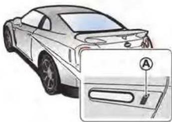
natural_image
Illustration of a car's front wheel and side panel, showing a close-up of the dashboard (no text or symbols present)Intelligent Key operation
You can lock or unlock the doors without taking the key out from your pocket or bag.
When you carry the Intelligent Key with you, you can lock or unlock all doors by pushing the door handle request switch Ⓐ within the range of operation.
NOTE:
- When the driver's door is locked or unlocked, the fuel-filler door is automatically locked or unlocked at the same time.
- When you lock or unlock the doors or the trunk lid, the hazard indicator will flash and the horn (or the outside chime) will sound as a confirmation. ( Setting hazard indicator and
horn mode" page 3-13)
Locking doors:
- Move the shift lever to the P position, push the ignition switch to the OFF position and make sure you carry the Intelligent Key with you.
- Close all the doors.
- Push the driver's or front passenger's door handle request switch while carrying the Intelligent Key with you.
- All the doors will lock.
- The hazard indicator flashes twice and the outside chime sounds twice.
NOTE:
- Doors will lock with the Intelligent Key while the ignition switch is in the ACC or ON position.
- Doors will not lock with the Intelligent Key while any door is open.
- Doors will not lock by pushing the door handle request switch with the Intelligent Key inside the vehicle. However, when an Intelligent Key is inside the vehicle, doors can be locked with another registered Intelligent Key.
Unlocking doors:
- Push the driver's or front passenger's door handle request switch once while carrying the Intelligent Key with you.
- The hazard indicator flashes once and outside chime sounds once. The corresponding door will unlock.
- Push the door handle request switch again within 1 minute.
- The hazard indicator flashes once and outside chime sounds once again. All the doors will unlock.
NOTE:
All doors will be locked automatically unless one of the following operations is performed within 1 minute after pushing the request switch while the doors are locked. If during this 1-minute time period, the request switch is pushed, all doors will be locked automatically after another 1 minute.
- Opening any door
- Pushing the ignition switch


Pre-driving checks and adjustments 3-11
Opening trunk lid:
- Push the trunk open request switch Ⓐ for more than 1 second.
- The trunk will unlatch. An outside chime will sound four times.
- Raise the trunk lid to open the trunk.
NOTE:
- To prevent the Intelligent Key from being accidentally locked in the trunk, lockout protection is equipped with the Intelligent Key system.
- When the trunk lid is closed with the Intelligent Key inside the trunk, the outside buzzer will sound and the trunk will open.
Battery saver system
When all the following conditions are met for a period of time, the battery saver system will cut off the power supply to prevent battery discharge.
- The ignition switch is in the ACC position, and
- All doors are closed, and
- The shift lever is in the P position.
REMOTE KEYLESS ENTRY SYSTEM
It is possible to lock/unlock all doors, fuel-filler door, and activate the panic alarm by pushing the buttons on the Intelligent Key.
NOTE:
Before locking the doors, make sure the Intelligent Key is not left in the vehicle.
Remote keyless entry operating range
The LOCK/UNLOCK button on the Intelligent Key can operate at a distance of approximately 33 ft (10 m) from the vehicle. (The effective distance depends upon the conditions around the vehicle.)
The lock and unlock buttons on the Intelligent Key will not operate when:
- the distance between the Intelligent Key and the vehicle is over 33 ft (10 m).
- the Intelligent Key battery runs down. The LOCK/UNLOCK operating range varies depending on the environment. To securely operate the lock and unlock buttons, approach the vehicle to about 3 ft (1 m) from the door.

Remote keyless entry operation
NOTE:
- When the driver's door is locked or unlocked, the fuel-filler door is automatically locked or unlocked at the same time.
- When you lock or unlock the doors or the trunk lid, the hazard indicator will flash and the horn (or the outside chime) will sound as a confirmation. ( Setting hazard indicator and horn mode" page 3-13)
3-12 Pre-driving checks and adjustments
Locking doors:
- Move the shift lever to the P position, push the ignition switch to the OFF position, and make sure you carry the Intelligent Key with you.
- Close all the doors.
- Push the LOCK Intelligent Key. 🔒 button ① on the
- All the doors will lock.
- The hazard indicator flashes twice and the horn chirps once.
NOTE:
- Doors will lock with the Intelligent Key while the ignition switch is in the ACC or ON position.
- Doors will not lock with the Intelligent Key while any door is open.
Unlocking doors:
- Push the UNLOCK button Intelligent Key once. ② on the
- The hazard indicator flashes once. The driver's door will unlock.
- Push the UNLOCK button ② on the Intelligent Key again within 60 seconds.
- The hazard indicator flashes once again. All the doors will unlock.
All doors will be locked automatically unless one
of the following operations is performed within 1 minute after pushing the UNLOCK button on the Intelligent Key while the doors are locked. If during this 1-minute time period, the UNLOCK button on the Intelligent Key is pushed, all doors will be locked automatically after another 1 minute.
- Opening any door
- Pushing the ignition switch
Opening trunk lid:
- Push the TRUNK button ③ on the Intelligent Key for more than 1 second.
- The trunk will unlatch.
- Raise the trunk lid to open the trunk.
Using panic alarm:
If you are near your vehicle and feel threatened, you may activate the alarm to call attention as follows:
- Push the PANIC ➕ button ④ on the Intelligent Key for more than 1 second.
- The theft warning alarm and headlights will stay on for 25 seconds.
- The panic alarm stops when:
• It has run for 25 seconds, or
- Any of the buttons on the Intelligent Key are pushed. (Note: the panic button should be pushed for more than 1
second to turn the panic alarm off.)
SETTING HAZARD INDICATOR AND HORN MODE
This vehicle is set in hazard indicator and horn mode when you first receive the vehicle.
When you lock/unlock the doors, the hazard indicator will flash and the horn (or the outside chime) will sound as a confirmation.
The following descriptions show how the hazard indicator and horn will activate when locking/unlocking the doors and how the horn feature can be deactivated.
Hazard indicator and horn mode
| DOOR LOCK DOOR | UNLOCK TRUNK UNLOCK | ||
| Intelligent Key system(Using door handle request switch or trunk open request switch) | HAZARD - twiceOUTSIDE CHIME - twice | HAZARD - onceOUTSIDE CHIME - once | HAZARD - noneOUTSIDE CHIME - 4 times |
| Remote keyless entry system(Using 🔒 , o!button 🔒) | HAZARD - twiceHORN - once | HAZARD - onceHORN - none | HAZARD - noneHORN - none |
Hazard indicator mode
| DOOR LOCK DOOR UNLOCK TRUNK UNLOCK | |||
| Intelligent Key system(Using door handle request switch or trunk open request switch) | HAZARD - twice HAZARD | - none HAZARD - none | |
| Remote keyless entry sys-tem(Using 🔒 , button) | HAZARD - twice HAZARD | - none | HAZARD - none |
Switching procedure
The horn beep feature can be deactivated with the following procedures.
- Push the LOCK
buttons simultaneously for more than 2 seconds. - The hazard indicator flashes 3 times.
- The horn beep feature will be deactivated (Hazard indicator mode).
- To reactivate the horn beep feature (Hazard indicator and horn mode), push the buttons once more. The hazard indicator flashes once and the horn beeps once.

flowchart
graph TD
    A["HAZARD INDICATOR AND HORN MODE"] --> B["Push (2 sec.) for more than 2 sec."]
    A --> C["HAZARD flashes 3 times"]
    A --> D["HAZARD INDICATOR MODE"]
    D --> E["Push (2 sec.) for more than 2 sec."]
    D --> F["HAZARD flashes once HORN chirps once"]
    F --> A
WARNING SIGNALS
To help prevent the vehicle from moving unexpectedly due to an erroneous operation of the Intelligent Key listed on the following chart or to help prevent the vehicle from being stolen, a chime or beep sounds inside and outside the vehicle and a warning displays in the vehicle information display. ( "Warning display" page 2-33) ( "Operation displays" page 2-43)
When a chime or beep sounds or a warning displays, be sure to check the vehicle and the Intelligent Key.
TROUBLESHOOTING GUIDE
| Symptom Possible cause Action to take | |||
| When pushing the ignition switch to stop the engine | The SHIFT P warning appears on the display and the inside warning chime sounds continuously. | The shift lever is not in the P position. | Shift the shift lever to the P position. |
| When opening the driver's door to get out of the vehicle | The inside warning chime sounds continuously. | The ignition switch is in the ACC position. | Push the ignition switch to the OFF position. |
| The Intelligent Key is in the Intelligent Key port. | Remove the Intelligent Key from the Intelligent Key port. | ||
| When closing the door after getting out of the vehicle | The NO KEY warning appears on the display, the outside chime sounds 3 times and the inside warning chime sounds for approximately 3 seconds. | The ignition switch is in the ACC or ON position. | Push the ignition switch to the OFF position. |
| The SHIFT P warning appears on the display and the outside chime sounds continuously. | The ignition switch is in the ACC or OFF position and the shift lever is not in the P position. | Move the shift lever to the P position and push the ignition switch to the OFF position. | |
| When closing the door with the inside lock knob turned to LOCK | The outside chime sounds for approximately 3 seconds and all the doors unlock. | The Intelligent Key is inside the vehicle or trunk. | Carry the Intelligent Key with you. |
| When pushing the door handle request switch to lock the door | The outside chime sounds for approximately 2 seconds. | The Intelligent Key is inside the vehicle or trunk. | Carry the Intelligent Key with you. |
| A door is not closed securely. Close the door securely. | door securely. | ||
| The door handle request switch is pushed before the door is closed. | Push the door handle request switch after the door is closed. | ||
| When closing the trunk lid | The outside chime sounds for approximately 10 seconds and the trunk lid opens. | The Intelligent Key is inside the trunk. | Carry the Intelligent Key with you. |
HOOD
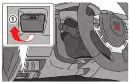
OPENING THE HOOD
- Pull the hood lock release handle located below the instrument panel. The hood will then spring up slightly.
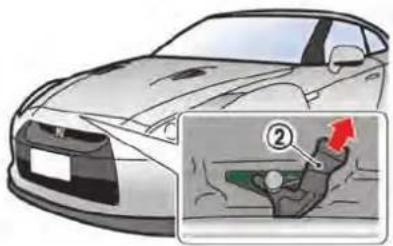
- Pull the lever ② at the front of the hood with your fingertips and raise the hood.

- Grasp the insulated part of the stay ③ and release it from the hook, then securely insert it into the hood hole ④.

WARNING
If you see steam or smoke coming from the engine compartment, do not open the hood. Doing so could cause injury.
Pre-driving checks and adjustments 3-17

CAUTION
- Do not insert hands, clothing, tools or other items into the engine compartment while the engine is running.
- Do not touch the exhaust system parts, radiator or other hot parts until the engine and the parts have cooled.
NOTICE
Do not open the hood while the wiper arms are lifted away from the windshield. The hood and wipers will be damaged.

natural_image
Illustration of a Nissan N19 car with red arrows indicating front and rear damage lines (no text or symbols)CLOSING THE HOOD
- While supporting the hood, store the stay to the original position.
- Slowly lower the hood. When it is at a height of 1 ft (30 cm) or higher, drop the hood and make sure that both sides of the hood securely lock in place.

WARNING
- Make sure the hood is completely closed and latched before driving. Failure to do so could cause the hood to open and result in an
accident.
- Be sure to check that the hood is securely closed before driving. If both sides of the hood are not locked in place, the hood may open during driving, possibly causing an accident.

CAUTION
When closing the hood, lower it slowly so that hands or other items do not get caught.
NOTE:
Because the hood of this vehicle requires more force to close than that for other vehicles, the hood will be difficult to close if you lower it all the way and then attempt to press it closed. Be sure to drop the hood from a height of approximately 1 ft (30 cm) and be sure that both sides securely lock in place.
TRUNK

WARNING
- Do not drive with the trunk lid open. This could allow dangerous exhaust gases to be drawn into the vehicle. ( "Exhaust gas (carbon monoxide)" page 5-3)
- Closely supervise children when they are around cars to prevent them from playing and becoming locked in the trunk where they could be seriously injured. Keep the car locked, with the trunk closed, when not in use, and prevent children's access to Intelligent Keys.
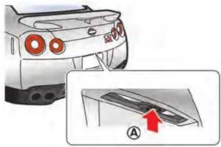

TRUNK OPEN REQUEST SWITCH
The trunk lid can be opened by pushing the trunk open request switch Ⓐ when the Intelligent Key is within the operating range of the trunk lock/unlock function regardless of the inside lock knob position. ( "Intelligent Key system" page 3-8)
TRUNK LID RELEASE SWITCH
Press the trunk lid release switch downwards to unlock the trunk.
Pre-driving checks and adjustments 3-19

When the switch located inside the glove box is in the OFF position ①, the power to the trunk lid will be canceled and the trunk lid cannot be opened by the trunk lid release switch, the trunk open request switch or the TRUNK button on the Intelligent Key.
When you have to leave the vehicle with a valet and want to keep your belongings safe in the glove box and the trunk, push this switch to OFF and lock the glove box with the mechanical key. Then leave the vehicle and the Intelligent Key with the valet and keep the mechanical key with
you. ( "Valet hand-off" page 3-3) To connect the power to the trunk lid, push the switch to the ON position ②.

Except for carbon trunk lid models
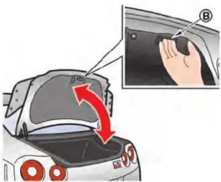
For carbon trunk lid models
3-20 Pre-driving checks and adjustments
OPENING AND CLOSING THE TRUNK
When opening the trunk, first unlock it then lift up the trunk lid so that it is fully open. When closing the trunk, lower the trunk lid and press it until it is securely locked in place. The strap Ⓐ (except for carbon trunk lid models) or the handle Ⓑ (for carbon trunk lid models) can be used when the trunk lid is dirty.
NOTICE
- Open and close the trunk without grasping the rear spoiler. Grasping the rear spoiler to open or close the trunk may damage the spoiler.
- Do not leave the key inside the trunk.
NOTE:
• To prevent the Intelligent Key from being accidentally locked in the trunk, lockout protection is equipped with the Intelligent Key system. When the trunk lid is closed with the Intelligent Key inside the trunk, the outside buzzer will sound and the trunk will open.
- The trunk of this vehicle is slightly more difficult to close than an ordinary vehicle (particularly when the vehicle is new). This is because the trunk rigidity has been increased to handle the high load on the rear spoiler during vehicle operation. This does not indicate that there is a malfunction. Check that the trunk is securely locked.

EMERGENCY TRUNK LID RELEASE

WARNING
Closely supervise children when they are around cars to prevent them from playing and becoming locked in the trunk where they could be seriously injured. Keep the car locked, with the trunk lid securely latched, when not in use, and prevent children's access to Intelligent Keys.
Pre-driving checks and adjustments 3-21
The emergency trunk lid release mechanism allows opening of the trunk lid in the event that people become locked inside the trunk or in the event of the loss of electrical power such as a discharged battery.
Inside the trunk
To open the trunk lid from the inside, pull the release handle ① until the lock releases and push up on the trunk lid. The release lever is made of a material that glows in the dark after a brief exposure to ambient light.
The handle is located on the back of the trunk lid as illustrated.

natural_image
Medical illustration showing a red arrow pointing to a specific anatomical structure, with no visible text or symbols.From the passenger compartment
The trunk can be opened with the emergency trunk lid opener located on the floor in front of the passenger's seat.
- Remove the board located on the floor in front of the passenger's seat.

natural_image
Cross-sectional diagram of an internal combustion engine cylinder with red directional arrow indicating rotation (no text or labels)- Insert the mechanical key into the emergency trunk lid opener and turn it clockwise until it stops.
NOTE:
Because the trunk rigidity has been increased to handle the high load on the rear spoiler during vehicle operation, more force is required to operate the mechanical key (particularly when the vehicle is new). Be sure to turn the key clockwise until it stops.
FUEL-FILLER DOOR
The fuel-filler door is located on the right and rear side of the vehicle.

WARNING
- Gasoline is extremely flammable and highly explosive under certain conditions. You could be burned or seriously injured if it is misused or mishandled. Always stop engine and do not smoke or allow open flames or sparks near the vehicle when refueling.
- Do not attempt to top off the fuel tank after the fuel pump nozzle shuts off automatically. Continued refueling may cause fuel overflow, resulting in fuel spray and possibly a fire.
-
Use only an original equipment type fuel-filler cap as a replacement. It has a built-in safety valve needed for proper operation of the fuel system and emission control system. An incorrect cap can result in a serious malfunction and possible injury. It could also cause the malfunction indicator light to come on.
-
Never pour fuel into the throttle body to attempt to start your vehicle.
- Do not fill a portable fuel container in the vehicle or trailer. Static electricity can cause an explosion of flammable liquid, vapor or gas in any vehicle or trailer. To reduce the risk of serious injury or death when filling portable fuel containers:
— Always place the container on the ground when filling.
— Do not use electronic devices when filling.
— Keep the pump nozzle in contact with the container while you are filling it.
— Use only approved portable fuel containers for flammable liquid.
NOTICE
- If fuel is spilled on the vehicle body, flush it away with water to avoid paint damage.
- Insert the cap straight into the fuel-
filler tube, then tighten until the fuel-filler cap clicks. Failure to tighten the fuel-filler cap properly may cause the SERVICE SERVICE Malfunction Indicator Light (MIL) to illuminate. If the light illuminates because the fuel-filler cap is loose or missing, tighten or install the cap and continue to drive the vehicle. The SERVICE SERVICE LIGHT should turn off after a few driving trips. If the SERVICE SERVICE LIGHT does not turn off after a few driving trips, have the vehicle inspected by a GT-R certified NISSAN dealer.
( "Malfunction Indicator Light (MIL)" page 2-31)
- This vehicle includes a system that can supply fuel even during high-G (gravity) turns. The fuel tank pressure is higher when the vehicle is hot. If the vehicle is refueled when the vehicle is hot, the fuel pump may automatically shut off before the tank is full. This does not indicate that there is a malfunction.
OPENING THE FUEL-FILLER DOOR
-
Unlock the fuel-filler door by using one of the following operations.
-
Push the door handle request switch with the Intelligent Key carried with you.
- Push the UNLOCK button on the Intelligent Key.
- Push the power door lock switch to the UNLOCK position.
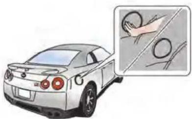
natural_image
Illustration of a silver car with circular headlights and a magnified inset showing hand cleaning the surface (no text or symbols)- Press the rear side of the fuel-filler door to release the door lock, and open the door.

- Turn the cap ① slowly counterclockwise to remove it. During refueling, place the cap on the inside of the door ②.
CLOSING THE FUEL-FILLER DOOR
- Turn the cap clockwise until a single click sound is heard.
- Close the door. Lock the fuel-filler door by using one of the following operations.
- Push the door handle request switch with the Intelligent Key carried with you.
- Push the LOCK button on the Intelligent Key.
3-24 Pre-driving checks and adjustments
- Push the power door lock switch to the LOCK position.
NOTE:
After a single click is heard and the cap is released it may move slightly. This is not a malfunction.
STEERING WHEEL

WARNING
- Do not adjust the steering wheel while driving. You could lose control of your vehicle and cause an accident.
- Do not adjust the steering wheel any closer to you than is necessary for proper steering operation and comfort. The driver's air bag inflates with great force. If you are unrestrained, leaning forward, sitting sideways or out of position in any way, you are at greater risk of injury or death in a crash. You may also receive serious or fatal injuries from the air bag if you are up against it when it inflates. Always sit back against the seatback and as far away as practical from the steering wheel. Always use the seat belts.

TILT/TELESCOPIC STEERING COL- UMN
Tilt adjustment
This adjusts up/down the position of the steering wheel.
- Press lever Ⓐ down ①.
- Move the steering wheel up/down stop it in an appropriate position. ② and
- Lift up lever ① to lock the steering wheel in position ③.
Pre-driving checks and adjustments 3-25

SUN VISORS MIRRORS
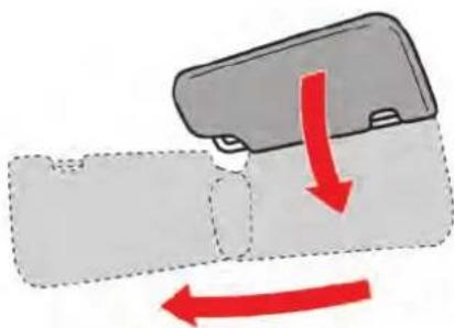
natural_image
Diagram showing a device with a handle and a red directional arrow indicating motion (no text or symbols)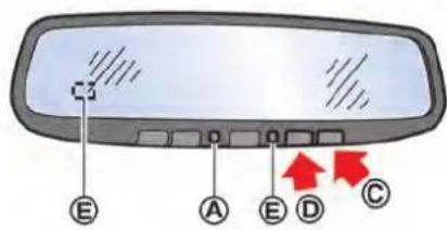
Telescopic adjustment
This adjusts the forward/backward position of the steering wheel.
- Press lever Ⓑ down ①.
- Move the steering wheel forward/backward ② and stop it in an appropriate position.
- Lift up lever Ⓑ to lock the steering wheel in position ③.
Lower the sun visor to block sunlight coming from the forward direction.
To block sunlight coming from the side, lower the sun visor, then unclip it from the hook and move it to the side.
INSIDE MIRROR
The inside mirror is designed so that it automatically changes reflection according to the intensity of the headlights of the following vehicle.
The anti-glare system will be automatically turned on when the ignition switch is pushed to the ON position.
When the anti-glare system is turned on, the indicator light Ⓐ will illuminate and excessive glare from the headlights of the vehicle behind you will be reduced.
Push the "○" switch ⓒ to make the inside
rearview mirror operate normally. The indicator light will turn off. Push the "I" switch Ⓓ to turn the system on.
NOTICE
Do not allow any object to cover the sensors Ⓔ or apply glass cleaner on them. Doing so will reduce the sensitivity of the sensor, resulting in improper operation.

Adjusting the outside mirrors
- Turn the switch right or left to select the right or left side mirror ①.
- Operate the control switch ② to adjust the mirror angle.

WARNING
Adjust the mirrors before starting to drive. Adjusting the mirrors during driving is dangerous as it reduces the driver's attention to the forward direction.
OUTSIDE MIRRORS

WARNING
Objects viewed in the outside mirror on the passenger side are closer than they appear. Be careful when moving to the right. Using only this mirror could cause an accident. Use the inside mirror or glance over your shoulder to properly judge distances to other objects.
The outside mirror will operate only when the ignition switch is in the ACC or ON position.
Pre-driving checks and adjustments 3-27
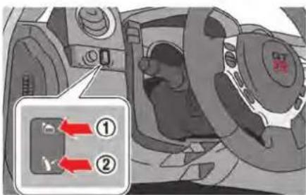
Folding the outside mirrors
Push the switch down ② to fold the outside mirrors.
Push the switch up ① to unfold the mirrors before driving.

CAUTION
- Do not touch the mirrors while they are moving. Your hand may be pinched, and the mirror may malfunction.
- Do not drive with the mirrors stored. You will be unable to see behind the
vehicle.
- If the mirrors were folded or unfolded by hand, there is a chance that the mirror will move forward or backward during driving. If the mirrors were folded or unfolded by hand, be sure to adjust them again electrically before driving.
NOTE:
- If the switch is operated continuously, the mirror may stop before movement is completed. This does not indicate that there is a malfunction. Wait a few moments, then operate the switch again.
- If the mirrors were folded or unfolded by hand, the mirrors may start moving when the ignition switch is set to the ACC or ON position.
- When the ignition switch is in the ON position, operating the rear window defroster will also remove frost and fog from the outside mirrors.
( "Rear window defroster switch" page 2-50)

natural_image
Diagram of a car interior with a highlighted component and red arrow indicating direction (no text or symbols)VANITY MIRROR
To use the front vanity mirror, pull down the sun visor and pull up the cover.
4 Display screen, heater, air conditioner and audio systems
Multi Function Display Owner's Manual 4-2
MULTI FUNCTION DISPLAY OWNER'S MANUAL
Refer to the separate Multi Function Display Owner's Manual that includes the following information.
- Multi function display system
- Navigation
- Audio system
- Bluetooth ^ hands-free phone system
- Heater and air conditioner
- Viewing information
- Other settings
- Voice recognition
- Monitor system
- Multi function meter
- General system information
5 Starting and driving
Precautions when starting and driving 5-3
Exhaust gas (carbon monoxide) 5-3
Three-way catalyst 5-3
Tire Pressure Monitoring System (TPMS) 5-4
Avoiding collision and rollover 5-7
Off-road recovery 5-7
Rapid air pressure loss 5-8
Drinking alcohol/drugs and driving 5-9
All-Wheel Drive (AWD) driving safety precautions .... 5-9
Push-button ignition switch 5-10
Operating range for engine start 5-10
Ignition switch operation 5-10
Ignition switch positions 5-11
Emergency engine shut off 5-11
Intelligent Key battery discharge 5-12
Before starting the engine 5-13
Starting the engine 5-13
Driving the vehicle 5-15
Dual clutch transmission 5-15
Driving tips 5-21
VDC, transmission and suspension setup switches .... 5-25
How to switch the modes 5-25
Features of each mode 5-27
Turbocharger system 5-31
R mode start function 5-32
How to use R mode start function 5-33
Parking brake 5-33
Cruise control 5-34
Precautions on cruise control 5-35
Steering-wheel-mounted controls 5-35
Indicators and display 5-36
Cruise control operations 5-36
Hill Start Assist System 5-38
Break-in schedule 5-39
Wheel alignment 5-39
Fuel Efficient Driving Tips 5-40
Increasing fuel economy 5-41
All-Wheel Drive (AWD) 5-41
AWD warning light 5-41
Tight corner braking phenomenon 5-43
Tires 5-44
AWD system characteristics 5-44
Limited Slip Differential (LSD) 5-45
Parking/parking on hills 5-46
Power steering 5-47
Brake system 5-48
Braking precautions 5-48
Parking brake break-in 5-48

Brake assist 5-49
Anti-lock Braking System (ABS) 5-49
Vehicle Dynamic Control (VDC) system 5-50
Cold weather driving 5-52
Freeing a frozen door lock 5-52
Anti-freeze 5-52
Battery 5-52
Draining of coolant water 5-52
Tire equipment 5-53
Special winter equipment 5-53
Driving on snow or ice 5-53
Engine block heater (if so equipped) 5-54
Active noise control (if so equipped) 5-54
PRECAUTIONS WHEN STARTING AND DRIVING

WARNING
- Do not leave children or adults who would normally require the support of others alone in your vehicle. Pets should not be left alone either. They could accidentally injure themselves or others through inadvertent operation of the vehicle. Also, on hot, sunny days, temperatures in a closed vehicle could quickly become high enough to cause severe or possibly fatal injuries to people or animals.
- Closely supervise children when they are around cars to prevent them from playing and becoming locked in the trunk where they could be seriously injured. Keep the car locked, with the rear seatback and trunk lid securely latched when not in use, and prevent children's access to car keys.
EXHAUST GAS (carbon monoxide)

WARNING
- Do not breathe exhaust gases; they contain colorless and odorless carbon monoxide. Carbon monoxide is dangerous. It can cause unconsciousness or death.
- If you suspect that exhaust fumes are entering the vehicle, drive with all windows fully open, and have the vehicle inspected immediately.
- Do not run the engine in closed spaces such as a garage.
- Do not park the vehicle with the engine running for any extended length of time.
- Keep the trunk lid closed while driving, otherwise exhaust gases could be drawn into the passenger compartment. If you must drive with the trunk lid open, follow these precautions:
a. Open all the windows.
b. Set the air recirculation to off and the fan control to high to
circulate the air.
• The exhaust system and body should be inspected by a qualified mechanic whenever:
— The vehicle is raised for service.
— You suspect that exhaust fumes are entering into the passenger compartment.
— You notice a change in the sound of the exhaust system.
— You have had an accident involving damage to the exhaust system, underbody, or rear of the vehicle.
THREE-WAY CATALYST
The three-way catalyst is an emission control device installed in the exhaust system. Exhaust gases in the three-way catalyst are burned at high temperatures to help reduce pollutants.

WARNING
- The exhaust gas and the exhaust system are very hot. Keep people, animals or flammable materials away from the exhaust system components.
- Do not stop or park the vehicle over flammable materials such as dry grass, waste paper or rags. They may ignite and cause a fire.
NOTICE
- Do not use leaded gasoline. Deposits from leaded gasoline seriously reduce the three-way catalyst's ability to help reduce exhaust pollutants.
- Keep your engine tuned up. Malfunctions in the ignition, fuel injection, or electrical systems can cause overrich fuel flow into the three-way catalyst, causing it to overheat. Do not keep driving if the engine misfires, or if noticeable loss of performance or other unusual operating
conditions are detected. Have the vehicle inspected promptly by a GT-R certified NISSAN dealer.
- Avoid driving with an extremely low fuel level. Running out of fuel could cause the engine to misfire, damaging the three-way catalyst.
- Do not race the engine while warming it up.
- Do not push or tow your vehicle to start the engine.
TIRE PRESSURE MONITORING SYSTEM (TPMS)
Each tire should be checked monthly when cold and inflated to the inflation pressure recommended by the vehicle manufacturer on the vehicle placard or tire inflation pressure label. (If your vehicle has tires of a different size than the size indicated on the vehicle placard or tire inflation pressure label, you should determine the proper tire inflation pressure for those tires.) As an added safety feature, your vehicle has been equipped with a Tire Pressure Monitoring System (TPMS) that illuminates a low tire pressure telltale when one or more of your tires is significantly under-inflated. Accordingly, when
the low tire pressure telltale illuminates, you should stop and check your tires as soon as possible, and inflate them to the proper pressure. Driving on a significantly under-inflated tire causes the tire to overheat and can lead to tire failure. Under-inflation also reduces fuel efficiency and tire tread life, and may affect the vehicle's handling and stopping ability.
If the vehicle is being driven with one or more flat tires, the low tire pressure warning light will illuminate continuously and a chime will sound for 10 seconds. The chime will only sound at the first indication of a flat tire, and the warning light will illuminate continuously. When the flat tire warning is activated, have the system reset and the tire checked and replaced if necessary by a GT-R certified NISSAN dealer. Even if the tire is inflated to the specified COLD tire pressure, the warning light will continue to illuminate until the system is reset by a GT-R certified NISSAN dealer. Your vehicle can be driven for a limited time on a flat tire. ( "Run-flat tires" page 8-39)
Please note that the TPMS is not a substitute for proper tire maintenance, and it is the driver's responsibility to maintain correct tire pressure, even if under-inflation has not reached the level to trigger illumination of the TPMS low tire pressure telltale.
Your vehicle has also been equipped with a TPMS malfunction indicator to indicate when the system is not operating properly. The TPMS malfunction indicator is combined with the low tire pressure telltale. When the system detects a malfunction, the telltale will flash for approximately one minute and then remain continuously illuminated. This sequence will continue upon subsequent vehicle start-ups as long as the malfunction exists. When the malfunction indicator is illuminated, the system may not be able to detect or signal low tire pressure as intended. TPMS malfunctions may occur for a variety of reasons, including the installation of replacement or alternate tires or wheels on the vehicle that prevent the TPMS from functioning properly. Always check the TPMS malfunction telltale after replacing one or more tires or wheels on your vehicle to ensure that the replacement or alternate tires and wheels allow the TPMS to continue to function properly.
Additional information
- The TPMS will activate only when the vehicle is driven at speeds above 16 MPH (25 km/h). Also, this system may not detect a sudden drop in tire pressure (for example a flat tire while driving).
- The low tire pressure warning light does not automatically turn off when the tire pressure is adjusted. After the tire is inflated to the recommended pressure, the vehicle must be driven at speeds above 16 MPH (25 km/h) to activate the TPMS and turn off the low tire pressure warning light. Use a tire pressure gauge to check the tire pressure.
- The "TIRE LOW PRESSURE - VISIT DEALER" warning appears in the vehicle information display when the low tire pressure warning light is illuminated and low tire pressure is detected. The "TIRE LOW PRESSURE - VISIT DEALER" warning turns off when the low tire pressure warning light turns off.
The "TIRE LOW PRESSURE - VISIT DEALER" warning appears each time the ignition switch is placed in the "ON" position as long as the low tire pressure warning light remains illuminated.
The "TIRE LOW PRESSURE - VISIT DEAL-
ER" warning does not appear if the low tire pressure warning light illuminates to indicate a TPMS malfunction.
- The "FLAT TIRE - VISIT DEALER" warning appears in the vehicle information display when the low tire pressure warning light is illuminated and one or more flat tires are detected.
- Tire pressure rises and falls depending on the heat caused by the vehicle's operation and the outside temperature. Low outside temperature can lower the temperature of the air inside the tire which can cause a lower tire inflation pressure. Altitude can also affect tire pressure. These may cause the low tire pressure warning light to illuminate. If the warning light illuminates, check the tire pressure for all four tires.
- GT-R vehicles are delivered from the factory with nitrogen-filled tires. For best performance, NISSAN recommends that GT-R owners maintain their vehicles by using nitrogen for tire inflation. Because nitrogen is more stable than compressed air, it is less prone to pressure fluctuation resulting from temperature variations. If nitrogen is not available, compressed air may be safely used under normal driving conditions. However, NISSAN recommends refilling with
Starting and driving 5-5
Nitrogen for maximum tire performance.
- The Tire and Loading Information label (also referred to as the vehicle placard or tire inflation pressure label) is located in the driver's door opening.
- You can also check the pressure of all tires on the multi function display. Refer to the separate Multi Function Display Owner's Manual.
- The tire pressure sensor should be reset anytime the wheels or tires are removed or replaced.
- If the tire is removed in order to replace the tire pressure sensor battery, it may not be possible to reuse the removed tire from the wheel. To replace the tire pressure sensor battery, contact a GT-R certified NISSAN dealer.

WARNING
- If the low tire pressure warning light illuminates while driving, avoid sudden steering maneuvers or abrupt braking, reduce vehicle speed, pull off the road to a safe location and stop the vehicle as soon as possible. Driving with under-inflated tires
may permanently damage the tires and increase the likelihood of tire failure. Serious vehicle damage could occur and may lead to an accident and could result in serious personal injury. Check the tire pressure for all four tires. Adjust the tire pressure to the recommended COLD tire pressure shown on the Tire and Loading Information label to turn the low tire pressure warning light off. If the light still illuminates while driving after adjusting the tire pressure, a tire may be flat.
- Although you can continue driving with a punctured run-flat tire, remember that vehicle handling stability is reduced, which could lead to an accident and personal injury. Also, driving a long distance at high speeds may damage the tires.
-
Do not drive at speeds above 50 MPH (80 km/h) and do not drive more than 50 miles (80 km) with a punctured run-flat tire. The actual distance the vehicle can be driven on a flat tire depends on outside temperature, vehicle load, road conditions and other factors.
-
When a wheel is replaced, the TPMS will not function and the low tire pressure warning light will flash for approximately 1 minute. The light will remain on after 1 minute. Contact your GT-R certified NISSAN dealer as soon as possible for tire replacement and/or system resetting.
- Replacing tires with those not originally specified by NISSAN could affect the proper operation of the TPMS.
- Do not inject any tire liquid or aerosol tire sealant into the tires, as this may cause a malfunction of the tire pressure sensors.
NOTICE
- The TPMS may not function properly when the wheels are equipped with tire chains or the wheels are buried in snow.
- The TPMS may not function properly if the TPMS sensor is not reset and when wheels/tires from another
GT-R are installed on your vehicle.
- The TPMS will not function properly if non-GT-R wheels are installed on the vehicle.
- Do not place metalized film or any metal parts (antenna, etc.) on the windows. This may cause poor reception of the signals from the tire pressure sensors, and the TPMS will not function properly.
Some devices and transmitters may temporarily interfere with the operation of the TPMS and cause the low tire pressure warning light to illuminate. Some examples are:
● Facilities or electric devices using similar radio frequencies are near the vehicle.
- If a transmitter set to similar frequencies is being used in or near the vehicle.
- If a computer (or similar equipment) or a DC/AC converter is being used in or near the vehicle.
FCC Notice:
For USA:
This device complies with Part 15 of the FCC Rules. Operation is subject to the following two conditions: (1) This device
may not cause harmful interference, and (2) this device must accept any interference received, including interference that may cause undesired operation.
Note: Changes or modifications not expressly approved by the party responsible for compliance could void the user's authority to operate the equipment.
For Canada:
This device complies with Industry Canada licence-exempt RSS standard(s). Operation is subject to the following two conditions: (1) this device may not cause interference, and (2) this device must accept any interference, including interference that may cause undesired operation of the device.
AVOIDING COLLISION AND ROLL-OVER
WARNING
Failure to operate this vehicle in a safe and prudent manner may result in loss of control or an accident.
Be alert and drive defensively at all times. Obey all traffic regulations. Avoid excessive speed,
high speed cornering, or sudden steering maneuvers, because these driving practices could cause you to lose control of your vehicle.
As with any vehicle, a loss of control could result in a collision with other vehicles or objects, or cause the vehicle to rollover, particularly if the loss of control causes the vehicle to slide sideways. Be attentive at all times, and avoid driving when tired. Never drive when under the influence of alcohol or drugs (including prescription or over-the-counter drugs which may cause drowsiness). Always wear your seat belt as outlined in this manual, and also instruct your passengers to do so. ( "Seat belts" page 1-6)
Seat belts help reduce the risk of injury in collisions and rollovers. In a rollover crash, an unbelted or improperly belted person is significantly more likely to be injured or killed than a person properly wearing a seat belt.
OFF-ROAD RECOVERY
While driving, the right side or left side wheels may unintentionally leave the road surface. If this occurs, maintain control of the vehicle by following the procedure below. Please note that this procedure is only a general guide. The vehicle must be driven as appropriate based on the conditions of the vehicle, road and traffic.
Starting and driving 5-7
- Remain calm and do not overreact.
- Do not apply the brakes.
- Maintain a firm grip on the steering wheel with both hands and try to hold a straight course.
- When appropriate, slowly release the accelerator pedal to gradually slow the vehicle.
- If there is nothing in the way, steer the vehicle to follow the road while the vehicle speed is reduced. Do not attempt to drive the vehicle back onto the road surface until vehicle speed is reduced.
- When it is safe to do so, gradually turn the steering wheel until both tires return to the road surface. When all tires are on the road surface, steer the vehicle to stay in the appropriate driving lane.
- If you decide that it is not safe to return the vehicle to the road surface based on vehicle, road or traffic conditions, gradually slow the vehicle to a stop in a safe place off the road.
RAPID AIR PRESSURE LOSS
Rapid air pressure loss or a "blow-out" can occur if the tire is punctured or is damaged due to hitting a curb or pothole. Rapid air pressure loss can also be caused by driving on under-inflated tires.
Rapid air pressure loss can affect the handling and stability of the vehicle, especially at highway speeds.
Help prevent rapid air pressure loss by maintaining the correct air pressure and visually inspect the tires for wear and damage. ( "Wheels and tires" page 8-32)
If a tire rapidly loses air pressure or "blows-out" while driving maintain control of the vehicle by following the procedure below. Please note that this procedure is only a general guide. The vehicle must be driven as appropriate based on the conditions of the vehicle, road and traffic.

WARNING
The following actions can increase the chance of losing control of the vehicle if there is a sudden loss of tire air pressure. Losing control of the vehicle may cause a collision and result in personal injury.
- The vehicle generally moves or pulls in the direction of the flat tire.
- Do not rapidly apply the brakes.
- Do not rapidly release the accelerator pedal.
-
Do not rapidly turn the steering wheel.
-
Remain calm and do not overreact.
- Maintain a firm grip on the steering wheel with both hands and try to hold a straight course.
- When appropriate, slowly release the accelerator pedal to gradually slow the vehicle.
- Gradually steer the vehicle to a safe location off the road and away from traffic if possible.
- Lightly apply the brake pedal to gradually stop the vehicle.
- Turn on the hazard warning flashers and contact a roadside emergency service to change the tire.
DRINKING ALCOHOL/DRUGS AND DRIVING

WARNING
Never drive under the influence of alcohol or drugs. Alcohol in the bloodstream reduces coordination, delays reaction time and impairs judgement. Driving after drinking alcohol increases the likelihood of being involved in an accident injuring yourself and others. Additionally, if you are injured in an accident, alcohol can increase the severity of the injury.
NISSAN is committed to safe driving. However, you must choose not to drive under the influence of alcohol. Every year thousands of people are injured or killed in alcohol-related accidents. Although the local laws vary on what is considered to be legally intoxicated, the fact is that alcohol affects all people differently and most people underestimate the effects of alcohol.
Remember, drinking and driving don't mix! And that is true for drugs, too (over-the-counter, prescription, and illegal drugs). Don't drive if your ability to operate your vehicle is impaired by alcohol, drugs, or some other physical condition.
ALL-WHEEL DRIVE (AWD) DRIVING SAFETY PRECAUTIONS

WARNING
- Do not drive beyond the performance capability of the tires, even with AWD engaged. Accelerating quickly, sharp steering maneuvers or sudden braking may cause loss of control.
- Always use the specified tires on all four wheels. Install tire chains on the rear wheels when driving on slippery roads and drive carefully.
- This vehicle is not designed for offroad (rough road) use. Do not drive on sandy or muddy roads that tires may get stuck in.
-
Do not attempt to raise two wheels off the ground and shift the transmission to any A M or R position with the engine running. Doing so may result in drivetrain damage or unexpected vehicle movement which could result in serious vehicle damage or personal injury.
-
Do not attempt to test an AWD equipped vehicle on a 2-wheel dynamometer, (such as the dynamometers used by some states for emissions testing), or similar equipment even if the other two wheels are raised off the ground. Make sure you inform test facility personnel that your vehicle is equipped with AWD before it is placed on a dynamometer. Using the wrong test equipment may result in drivetrain damage or unexpected vehicle movement which could result in serious vehicle damage or personal injury.
- When a wheel is off the ground due to an unlevel surface, do not spin the wheel excessively.
PUSH-BUTTON IGNITION SWITCH

WARNING
Do not operate the push-button ignition switch while driving the vehicle except in an emergency. (The engine will stop when the ignition switch is pushed three consecutive times or the ignition switch is pushed and held for more than 2 seconds.) If the engine stops while the vehicle is being driven, this could lead to a crash and serious injury.
Before operating the push-button ignition switch, be sure to move the shift lever to the
P position.

natural_image
Top-down line drawing of a car with red roof and silver body (no text or symbols)
flowchart
graph TD
    A["LOCK"] --> B["ACC"]
    B --> C["ON"]
    D["Start Stop Engine"] --> E["OFF"]
The operating range for starting the engine inside the vehicle is shown in the illustration.
- If the Intelligent Key is on the instrument panel, rear parcel shelf, inside the glove box, door pocket, cup holders or console box, or the corner of the passenger compartment, it may not be possible to start the engine. Carry the Intelligent-Key and try to start the engine again.
- If the Intelligent Key is near the door or door glass outside the vehicle, it may be possible to start the engine.
When the Intelligent Key is carried with you and the ignition switch is pushed without depressing the brake pedal, the ignition switch position will change as follows:
- Push center once to change to ACC.
- Push center two times to change to ON.
- Push center three times to change to OFF. (No position illuminates.)
- Push center four times to return to ACC.
- Open or close any door to return to LOCK during the OFF position.
IGNITION SWITCH POSITIONS
LOCK (Normal parking position)
The ignition switch can only be locked in this position.
The ignition switch will be unlocked when it is pushed to the ACC position while carrying the Intelligent Key or with the Intelligent Key inserted in the port.
ACC (Accessories)
This position activates electrical accessories such as the radio, when the engine is not running.
ON (Normal operating position)
This position turns on the ignition system and electrical accessories.
OFF
The engine can be turned off without locking the steering wheel.
The ignition lock is designed so that the ignition switch cannot be switched to the LOCK position until the shift lever is moved to the P position.
NOTE:
- If the steering lock release malfunction indicator appears on the vehicle information display when the ignition switch is pressed, press the ignition switch again while gently turning the steering wheel left and right. ( "Steering lock release malfunction indicator" page 2-44)
- If the shift P warning appears on the vehicle information display when the ignition switch is pushed, the shift lever is in any position except the P position. Move the shift lever to the P position. ( "Shift "P" warning" page 2-43)
- If the Intelligent Key battery discharge indicator appears on the vehicle information display, the Intelligent Key battery is discharged and the ignition switch will not operate. Insert the Intelligent Key into the key port to operate the ignition switch. ( "Intelligent Key battery discharge indicator" page 2-45)
- When all of the following conditions are met for 60 minutes, the battery saver system will cut off the power supply to prevent battery discharge.
— The ignition switch is in the ACC position, and
— All doors are closed, and
— The shift lever is in the P position.
- Do not leave the vehicle with the ignition switch in the ACC or ON position when the engine is not running for an extended period of time. This can discharge the battery.
EMERGENCY ENGINE SHUT OFF
To shut off the engine in an emergency situation while driving, perform the following procedure:
- Rapidly push the push-button ignition switch 3 consecutive times in less than 1.5 seconds, or
- Push and hold the push button ignition switch for more than 2 seconds.

the Intelligent Key out of the port.
NOTICE
Never place anything except the Intelligent Key in the Intelligent Key port. Doing so may cause damage to the equipment.

natural_image
Diagram showing two oval objects with a red arrow pointing to a cross-shaped object, intersected by two red diagonal lines (no text or symbols)INTELLIGENT KEY BATTERY DIS- CHARGE
If the battery of the Intelligent Key is almost discharged, the guide light ① of the Intelligent Key port blinks and the indicator appears on the vehicle information display. ( "Intelligent Key insertion indicator" page 2-44)
In this case, inserting the Intelligent Key into the port allows you to start the engine. Make sure that the mechanical key side faces backward as illustrated. Insert the Intelligent Key in the port until it is latched and secured.
To remove the Intelligent Key from the port, push the ignition switch to the OFF position and pull
NOTE:
- Make sure the Intelligent Key is in the correct direction when inserting it into the Intelligent Key port. The engine may not start if it is in the incorrect direction.
- Remove the Intelligent Key from the Intelligent Key port after the ignition switch is pushed to the OFF position.
- The Intelligent Key port does not charge the Intelligent Key battery. If you see the low battery indicator in the vehicle information display, replace the battery as soon as possible.
("Intelligent Key battery replacement" page 8-27)
BEFORE STARTING THE ENGINE
- Make sure the area around the vehicle is clear.
- Check fluid levels such as engine oil, coolant, brake fluid and window washer fluid as frequently as possible, or at least whenever you refuel.
- Check that all windows and lights are clean.
- Visually inspect tires for their appearance and condition. Also check tires for proper inflation.
- Lock all doors.
- Position seat.
- Adjust inside and outside mirrors.
- Fasten seat belts and ask all passengers to do likewise.
- Check the operation of warning lights when the ignition switch is pushed to the ON position. ( "Warning lights, indicator lights and audible reminders" page 2-25)
STARTING THE ENGINE
NOTE:
- This vehicle includes spark plugs that are designed for maximum performance. If the start time becomes longer, the plugs may be fouled, making the engine difficult to start. If this occurs, start the engine using the procedure described in this section.
- A click sound may be heard when the brake pedal is depressed and released. This is normal.
- A low rattling operating sound may occur when the engine is started or stopped. This is because of the transmission gear design, light flywheel and dry sump lubrication system used in this transmission. This does not indicate that there is a malfunction. This sound is likely to occur in particular if the engine is stopped when the temperature of the transmission oil is high.

- Check the positions of the accelerator pedal ① and brake pedal ②. Adjust the steering wheel and seat positions so that the correct driving posture is achieved. ( "Front seats" page 1-3)
- Check that the parking brake is engaged.
- Check that the shift lever is in the position. (P or N)
- Firmly depress the brake pedal. Without depressing the accelerator pedal, push the ignition switch once to start the engine.
- To stop the engine, move the shift lever to the P position, and push the ignition switch to the OFF position.
NOTE:
- Care should be taken to avoid situations that can lead to potential battery discharge and potential no-start conditions such as:
a. Installation or extended use of electronic accessories that consume battery power when the engine is not running (Phone chargers, GPS, DVD players, etc.)
b. Vehicle is not driven regularly and/or only driven short distances. In these cases, the battery may need to be charged to maintain battery health. - If the engine is difficult to start, depress the accelerator pedal all the way to the floor and hold it. Push the ignition switch with the brake pedal depressed to start cranking the engine. After 5 or 6 seconds, stop cranking by pushing the ignition switch to the OFF position, and then release the accelerator pedal. Then perform steps 1 to 5 to start the engine. If the engine starts, but fails to run, repeat this procedure.
- Starting and stopping the engine over a short period of time may make the vehicle more difficult to start. If this occurs, wait for more than 3 minutes,
and then push the ignition switch again to start the engine.
- To maintain high performance over a long period of time, the engine speed is limited to 5,000 rpm when the engine is revved with the shift lever in the N or P position, and to 4,000 rpm when the engine oil or coolant temperature is low or higher than normal.
- If the ignition switch is pushed before the shift lever is moved to the position, the ignition switch will not change to the OFF position. If this occurs, the SHIFT P warning display appears on the vehicle information display. When stopping the engine, be sure to move the shift lever to the position and then push the ignition switch. Failure to do so may result in discharge of the battery. ( "Shift "P" warning" page 2-43)
- If the shift lever was in the A M or R position when the engine was stopped, then be sure to move the shift lever to the P position before starting the engine the next time. If the engine is started with the shift lever in the N position, then it may not be possible to
5-14 Starting and driving
drive the vehicle even when the shift lever is moved to the A↔M or R position. If this occurs, the SHIFT P warning appears on the vehicle information display. ( "Shift "P" warning" page 2-43)

CAUTION
If the engine was stopped soon when the engine is hot, the cooling fan may operate for approximately 2 minutes after the engine was stopped to cool the components in the engine compartment. When the cooling fan is operating, be sure that hands or other items do not get caught in it.
DRIVING THE VEHICLE
DUAL CLUTCH TRANSMISSION
The GT-R dual clutch transmission is a newly-developed system that uses an electronically controlled multiple-disc wet clutch attached to the highly efficient manual transmission. This transmission has two driving modes.
• A position (Automatic gearshift): allows automatic shifting of the manual transmission.
- M position (Manual gearshift): allows quick shifting of the manual transmission.
NOTE:
When starting or driving on a steep uphill grade, shift to the M position and operate the paddle shifter to shift down to 1st gear similar to a manual transmission vehicle.
The GT-R dual clutch transmission was developed specifically to maximize vehicle performance and driving enjoyment. The GT-R transmission components were designed using different engineering standards than typical passenger car transmissions. Because of this, the GT-R has different operating characteristics, and various rattle noises may be heard during some driving conditions because of the following items:
- Gear clearances
- Ultralight flywheel
- Dry sump lubrication
These noises do not indicate that there is a malfunction.

WARNING
- Do not depress the accelerator pedal while shifting from the P or N position to the R or A↔M position. Always depress the brake pedal until shifting is completed. Failure to do so could cause loss of control and an accident.
- Cold engine idle speed is high, so use caution when shifting into a forward or reverse gear before the engine has warmed up.
- Never shift to the P or R position while the vehicle is moving forward. Never shift to the P or A M position while the vehicle is moving rearward. Doing so could cause loss of control and an accident.
- The shift lever contains a powerful magnet. Do not place electronic
Starting and driving 5-15
medical devices or other electronic products that are susceptible to magnetic force close to the shift lever.
- Do not downshift abruptly on slippery roads. This may cause a loss of control.
- If the shift lever is moved from R to A↔M position, or A↔M to R position before the vehicle stops, you may not be able to shift gear or it may take longer to shift gear. Make sure to depress the brake pedal and check that the vehicle has stopped before shifting.

CAUTION
- Because the vehicle includes a dual clutch transmission that automatically controls the clutch and shifting operation of the manual transmission, whenever the shift lever is in a position other then P or N, the vehicle will begin to move slowly, in the same way as when the clutch in a manual transmission vehicle is
partially engaged. Keep the brake pedal firmly depressed when the vehicle is stopped. In some circumstances the vehicle may not start moving on its own, however this does not indicate that there is a malfunction.
NOTICE
- When the vehicle is stopped on a hill, do not hold the vehicle in place by depressing the accelerator pedal. Doing so may cause the clutch to overheat and result in transmission damage. Use the brakes to prevent the vehicle from moving.
- The GT-R dual clutch transmission is provided with a dry sump lubrication system that improves efficiency and ensures reliability under high g-force conditions. When oil viscosity is high at low temperatures, it takes longer for all components to be sufficiently lubricated. Thus, when the transmission temperature is low (approximately 104^ ( 40^ ), do not accelerate rapidly or run the engine
faster than 4,000 rpm.

Operating the shift lever
After starting the engine, fully depress the brake pedal and move the shift lever from the P position to the R, N, or A↔M position. Push the button to shift into the P or R position. All other positions can be selected without pushing the button.
| Shift lever operation | |
| Push the button while depressing the brake pedal. | |
| Push the button. | |
| Just move the shift lever. | |
| Automatically returns. | |
P position:
Use this position for parking and starting the engine. The ignition switch will be changed to the OFF or LOCK position.
CAUTION
Use the P position only when the vehicle is completely stopped.
R position:
Use this position for driving in reverse. A chime will sound inside the vehicle and a warning will appear in the vehicle information display if the shift lever is in the R position for more than 5 minutes, or when the driver's door is opened while the shift lever is in the R position.
N position:
Neither forward nor reverse gear is engaged.
A↔M position:
Use this position for all normal forward driving. The shift lever can be moved between A and
M to alternately change each other. The position indicator indicates the gear position with the indication of "A" or "M".
- A position: Use this position for ordinary driving, with the gears shifted automatically from first gear to sixth gear according to the speed and driving conditions.
- M position: Operate the paddle shifter to drive in first gear to sixth gear as desired.
- The position indicator blinks if it is not possible to shift the gear. ( "Transmission position indicator" page 2-9)
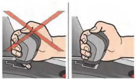
natural_image
Two-panel illustration showing a hand holding a car seatbelt with a red X mark indicating the switch (no text or symbols present)
CAUTION
- Grip the shift lever correctly when operating it. Failure to do so may cause a finger or other items to be trapped between the lever and gate, possibly causing an accident.
- Because rolling resistance is reduced in the GT-R, the vehicle can move when on a road with a slight gradient, even when in the N position. Be sure to depress the brake pedal.
NOTICE
- Be sure to observe the following precautions. Failure to do so may result in shift lever malfunction.
— Do not spill water, beverages or other liquids on the shift lever.
— Do not allow sand or similar substances to contact the shift lever. - Develop the habit of performing the operations marked with “→” without pressing the button. If the button is pressed at these times, there is the possibility that the lever could accidentally enter the P or R positions.
- When the vehicle is hot, the area around the shift lever may be hot or may produce an unusual sound, however this does not indicate that there is a malfunction.
- Avoid depressing the brake and accelerator pedals at the same time. Depressing both pedals at the same time could cause the clutch to overheat and accelerate deterioration.
NOTE:
- When moving the shift lever out of the P position, it may not be possible to move the shift lever if the button is pressed before the brake pedal is depressed. Press the button only after depressing the brake pedal.
- Do not place coins or other small objects in the area around the shift lever. These objects may get stuck in the shift gate and prevent the shift lever from moving into a position. Sometimes, you may not be able to retrieve these objects.
- Immediately after a cold start, while the transmission system check display ("T/M SYSTEM CHECK IN PROCESS") appears on the vehicle information display, the shift lever cannot be moved out of the P position. This is because a check of the transmission system is in progress. This does not indicate that there is a malfunction. Move the shift lever after the message on the vehicle information display turns off.
- The shift lever knob and console-mounted shift indicator have a genuine leather finish that requires proper care
and maintenance. ("Cleaning interior" page 7-7)

Shift lock release
If the battery charge is low or discharged, the shift lever may not be moved from the position even with the brake pedal depressed and the shift lever button pushed.
To move the shift lever, perform the following procedure.
- Push the ignition switch to the OFF or LOCK position.
- Apply the parking brake.
- Remove the shift lock cover using a suitable tool wrapped with a cloth.
-
Push down the shift lock as illustrated.
-
Push the shift lever button and move the shift lever to the N position while holding down the shift lock.
Push the ignition switch to the ON position to unlock the steering wheel. Now the vehicle may be moved to the desired location.
If the battery is discharged completely, the steering wheel cannot be unlocked. Do not move the vehicle with the steering wheel locked.
NOTICE
If the shift lever cannot be moved out of the P position after performing the shift lock release procedure, immediately have the vehicle inspected by a GT-R certified NISSAN dealer.
Adaptive shift control
The adaptive shift control system automatically operates when the transmission is in the position and selects an appropriate gear depending on the road conditions such as uphill, downhill or curving roads.
Control on uphill and curving roads:
A low gear is maintained that suits the degree of the slope or curve to allow smooth driving with a small number of shifts.
Starting and driving 5-19
Control on downhill roads:
The adaptive shift control system shifts to a low gear that suits the degree of the slope, and uses the engine brake to reduce the number of times that the foot brake must be used.
Control on winding roads:
A low gear is maintained on continuous curves that involve repeated acceleration and deceleration, so that smooth acceleration is available instantly when the accelerator pedal is depressed.
NOTE:
Adaptive shift control may not operate when the transmission oil temperature is low immediately after the start of driving or when it is very hot. If this occurs, switch to the M position and downshift if necessary.
M position
Changing to the M position:
To change to the M position from the A position, either move the shift lever to the M side or operate the paddle shifter. The position indicator indicates the gear position with the indication of "M".
If the paddle shifter is used, the first operation changes from the A position to the M position,
and the second and later operations change the gears.
To return to the A position, move the shift lever to the M side again. The position indicator indicates the gear position with the indication of "A".
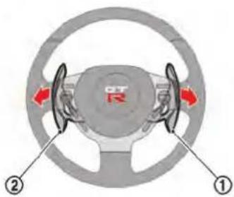
Changing gears using paddle shifters:
NOTE:
The vehicle cannot be accelerated from a stop condition while the gear is in the 2nd to 6th position. When accelerating the vehicle from a stop condition, use the 1st gear position.
To shift up, pull the paddle shifter on the right side ① toward you.
To shift down, pull the paddle shifter on the left side ② toward you.



- First gear: Use this position when accelerating from a stop, climbing a steep hill slowly or engine braking at low speeds.
- Second gear: Use this position when accelerating or engine braking at mid-low speeds.
- Third gear: Use this position when accelerating or gently engine braking at middle speeds.
-
Fourth gear: Use this position when accelerating or gently engine braking at mid-high speeds.
-
Fifth gear: Use this position for all normal forward driving at highway speeds. Engine braking is weaker in this position.
- Sixth gear: Use this position for all normal forward driving at highway speeds. Engine braking is weakest in this position.
Suggested maximum speed in each gear:
Downshift to a lower gear if the engine is not running smoothly, or if you need to accelerate. Do not exceed the maximum suggested speed (shown below) in any gear. For level road driving, use the highest gear suggested for that speed. Always observe posted speed limits, and drive according to the road conditions that will ensure safe operation. Do not over-rev the engine when shifting to a lower gear as it may cause engine damage or loss of vehicle control.
| Gear MPH (km/h) | |
| 1st 36 (58) | |
| 2nd 63 (102) | |
| 3rd 91 (148) | |
| 4th — | |
| 5th — | |
| 6th | — |
DRIVING TIPS
After starting the engine, fully depress the foot brake pedal and push the shift lever button before shifting the shift lever from the P position to the R, N, or A←M position. Be sure the vehicle is fully stopped before attempting to shift the shift lever.
The transmission is designed so that the foot brake pedal must be depressed before shifting from P to any other position.
The shift lever cannot be moved out of the position and into any other position with the ignition switch other in the LOCK, OFF or ACC position.
When accelerating from a stop
Keep the foot brake pedal depressed and push the shift lever button to shift into a driving gear as following:
- To drive forward, move the shift lever to the A M position.
- To back up, move the shift lever to the position.
Starting on level ground or an uphill:
- Check the shift lever position indicator on the meter to confirm that the driving gear is selected.
Starting and driving 5-21
- Release the parking brake.
- Release the foot brake pedal gradually, then slowly depress the accelerator pedal to start the vehicle in motion.
( "R mode start function" page 5-32)
NOTE:
- To prevent the clutch from overheating when the parking brake is applied, engine output is limited when the accelerator pedal is depressed. In particular, the vehicle may not start smoothly when the accelerator pedal is depressed with the parking brake applied on an uphill grade. To enable smooth starting, release the parking brake before moving the vehicle.
- The hill start assist system operates when the vehicle is accelerating from a stop on an uphill. ( "Hill Start Assist System" page 5-38)
When driving the vehicle
WARNING
Do not move the shift lever to the position while driving. Doing so may result in an accident due to loss of engine braking. It may also damage the transmission.
Normal driving:
Drive with the shift lever in the A position. The appropriate gear will be automatically shifted according to the position of the accelerator pedal, the driving speed and driving conditions.
Passing:
• A position:
Fully depress the accelerator pedal to the floor. This shifts the transmission down into a lower gear depending on the vehicle speed. Then depress the accelerator pedal as needed to adjust vehicle speed.
• M position:
Use the paddle shifter to down shift, then fully depress the accelerator pedal to the floor. Then depress the accelerator pedal as needed to
adjust vehicle speed.
Hill climbing:
- When the vehicle speed decreases, depress the accelerator pedal to the floor with the shift lever in the A position. This automatically shifts the transmission into a lower gear and maintains this position depending on the gradient of the hill.
- The system may down shift according to the accelerator pedal position and the vehicle speed.
- If the transmission is frequently changing gears while driving, switch to the M position and select the appropriate gear for the driving conditions.
Driving on a downhill:
• A position:
The system shifts down according to the degree of downhills to increase the effectiveness of the engine brake.
• M position:
When driving on a long slope, selecting the position and 4th or 3rd gear will provide gentle engine braking.
When driving on a steep downhill, selecting the
M position and 2nd or 1st gear will provide powerful engine braking.

WARNING
- When the shift lever is in the position, the adaptive shift control system will stay in a low gear in order to maintain the effectiveness of the engine brake. However if the vehicle is traveling too fast depending on the degree of the slope, you should shift to the M position and use the paddle shifter to shift down. If you continue to use only the foot brake, a high load will be applied to the brake, which may overheat, reducing its effectiveness. Be sure to use the engine brake together with the foot brake. ( "Adaptive shift control" page 5-19)
- Do not downshift abruptly on slippery roads. This may cause a loss of control.
NOTICE
When driving in the A position, gear-shifting will be performed automatically with the adaptive shift control system ( "Adaptive shift control" page 5-
19) even on road conditions with continuous and sudden hills or curves. However, when the transmission oil temperature is low immediately after starting the vehicle or high when engaging in high performance driving, there may be some cases where the system cannot control shifting. When this occurs, switch to the M position and select a lower gear, depending on the gradient of the hill.
When stopping the vehicle
Leave the shift lever in the A→M or R position and firmly depress the foot brake pedal. If the vehicle will be stopped for a long period of time, apply the parking brake and move the shift lever to the P or N position as necessary.

WARNING
- Do not race the engine while the vehicle is stopped. Doing so may accelerate the vehicle suddenly and cause an accident when shifting to a driving gear.
- While the engine is running, the propeller shaft that transmits torque
from the engine to the transmission is turning at all times. Crawling or reaching under the vehicle while the engine is running may result in serious injury.
NOTICE
When the vehicle is stopped on a hill, do not hold the vehicle in place by depressing the accelerator pedal. Doing so may cause the clutch to overheat and result in transmission damage. Use the brakes to prevent the vehicle from moving.
When parking the vehicle

WARNING
Follow the instructions below when parking the vehicle to help prevent the brake rotor and brake pads from rusting together. Failure to follow the instructions could cause the rotor and pads to rust together. If the rotor and pads rust together, there may be a popping noise and some vibration
Starting and driving 5-23
when the vehicle is driven, a wheel may not roll correctly, or the brake pads could be damaged. If the pads are damaged, this may reduce the effectiveness of the brake system which could cause a collision, serious personal injury or death.
The GT-R uses brake pad materials that have high metallic content. The brake pad material helps maintain braking performance in a wide range of weather and driving conditions.
For the first 3,000 miles (5,000 km) of the vehicle's service life, and for the first 3,000 miles (5,000 km) after a brake replacement, the brake pad to brake rotor clearance is very small. When parking, apply the parking brake and move the shift lever to the P position. Idle the engine for more than 20 seconds without depressing the brake pedal. This allows the brake pads to move away from the rotor so the pad does not contact the rotor.
Additionally, the brakes must be dry before parking the vehicle after driving on wet roads or after washing the vehicle. If the roads are wet, lightly apply the brakes for a short distance before parking the vehicle to dry the brakes. After washing the vehicle, dry the brakes by driving on a dry road for a few miles and apply
the brakes normally based on traffic and road conditions.
The metallic brake pads and brake disc rotor may rust together when the brakes are not applied:
- If the vehicle is not idled for 20 seconds without the brakes applied, or if the brakes are applied when the vehicle is shut off, the rotor and pads can rust together, even when the brake pads are dry.
- If the brakes are wet when the vehicle is parked and the parking brake is applied for a long time.
Contact a GT-R certified NISSAN dealer if the brake pads and brake rotor have rusted together.
- Bring the vehicle to a complete stop.
- With the foot brake pedal depressed, apply the parking brake.
- Move the shift lever to the P position.
- Check the shift lever position indicator on the meter to confirm that the P position is selected.
- Push the ignition switch to stop the engine.

WARNING
Before exiting the vehicle, be sure to move the shift lever to the P position and stop the engine. If the engine is running and the shift lever is not in the P position, the vehicle may start moving due to partial engagement of the clutch or to the effects of gravity on a slope, or the vehicle may suddenly accelerate due to accidental operation of the accelerator pedal, possibly causing an accident.
VDC, TRANSMISSION AND SUSPENSION SETUP SWITCHES
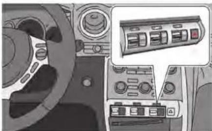
natural_image
Interior view of a car dashboard with control panels and a highlighted control panel (no visible text or symbols)The control of the dual clutch transmission, Bilstein DampTronic® electronically controlled shock absorbers and Vehicle Dynamic Control (VDC) can be changed to the desired modes by operating the setup switches. Select the desired mode best suited to the driving conditions.
NOTE:
Bilstein DampTronic® is a registered trademark of ThyssenKrupp Bilstein Suspension GmbH.

- Transmission setup switch
- Suspension setup switch
- Vehicle Dynamic Control (VDC) setup switch
HOW TO SWITCH THE MODES
Each time the engine is started, all switches are set to the normal mode. The normal mode is recommended for normal driving. Move the VDC, transmission and suspension setup switches up or down to change the mode when the engine is running.
| Switch | Transmission* | Suspension | VDC |
| Indicator |


NOTICE
- "ESC (Electronic Stability Control) OFF" indicated on the VDC setup switch stands for "VDC OFF".
- When the ignition switch is pushed to the "ON" position, the indicators on the setup switches may illuminate briefly, however this is not a malfunction.
→: Push and hold the switch for longer than approximately 1 second
→: Push the switch
* The selected mode is maintained even if the shift lever is moved between A and M position.
FEATURES OF EACH MODE
Transmission
The transmission mode differs depending on the shift lever position,

A position:
| Set up mode Features | |
 | In addition to the normal mode functions, this mode allows you to achieve higher engine speed, greater powertrain torque and engine braking.With the VDC switch in R mode, the R mode start function can be used. ( “R mode start function” page 5-32)When the R mode is selected, the maximum speed is lower than the one in the normal mode. |
| Normal (light is off) | For everyday and performance driving, an appropriate gear position is automatically selected. |
 | For long distance driving, this mode helps improve fuel economy by reducing engine output compared to the normal mode.The engine response to accelerator operation changes to be less sensitive to pedal movement than the normal mode. The engine speed does not change as quickly for small accelerator pedal position changes.This mode controls powertrain torque on snowy roads and slippery surfaces making starting and driving easier.When the SAVE mode is selected, the maximum speed is lower than the one in the normal mode. |
M position:
| Set up mode Features | |
 | This mode allows you to shift gears quickly and directly.This mode will not allow the transmission to automatically upshift even when the engine speed reaches the red zone. Do not rev the engine into the red zone.With the VDC switch in R mode, the R mode start function can be used. (“R mode start function” page 5-32) |
| Normal (light is off) | For everyday and performance driving, any gear position can be selected.This mode will allow the transmission to automatically upshift even when the engine speed is about to reach the red zone. |
 | For long distance highway driving, this mode improves fuel economy by reducing engine output compared to the normal mode.The engine response to accelerator operation changes to be less sensitive to pedal movement than the normal mode. The engine speed does not change as quickly for small accelerator pedal position changes.This mode controls powertrain torque on snowy roads and slippery surfaces making starting and driving easier.This mode allows the transmission to automatically upshift even when the engine speed is about to reach the red zone.When the SAVE mode is selected, the maximum speed is lower than the one in the normal mode. |
NOTICE
- When the engine speed approaches the red zone, shift to a higher gear or reduce the engine speed. Operating the engine in the red zone may cause serious engine damage.
- Quickest shifting in the R mode with the transmission in the M position is available when the engine speed is high. However, the transmission may shift more slowly when the engine speed is low.
Suspension
| Set up mode Features | |
 | The damping force of the shock absorbers is set for maximum vehicle performance.Riding comfort becomes harder. |
| Normal (light is off) | The damping force of the shock absorbers is variably adjusted for everyday driving or maximum vehicle performance. |
 | The damping force of the shock absorbers is variably adjusted for more comfortable driving. Movement of the vehicle body is larger than the normal and R modes. |
NOTICE
While maximizing vehicle performance, shock absorber control may automatically be returned to the normal mode. If the R mode or the COMF mode is selected in the case above, the suspension setup switch indicator may turn off. Operate the suspension setup switch to the R mode or the COMF mode and check to make sure the indicator illuminates. If the indicator does not illuminate, have the system checked by a GT-R certified NISSAN dealer.
Vehicle Dynamic Control (VDC)
| Set up mode Features | |
 | In addition to the normal mode function, this mode adjusts front and rear wheel power distribution to improve handling.With the transmission switch in R mode, the R mode start function can be used.( "R mode start function" page 5-32) |
| Normal (light is off) | This mode is for use in a broad range of driving conditions, for routine driving during fair to rainy weather, as well as for driving on road surfaces that are slippery due to snow or ice.Make sure to use this mode for everyday driving. |
 | Temporary mode that can be used to free if it is stuck in snow or mudAlso place transmission setup switch in SAVE mode when freeing a stuck vehicle. |
NOTE:
Always make sure the VDC is ON before driving the vehicle by checking that the VDC OFF indicator lights on the meter and the VDC set-up switch are not illuminated. The GT-R is a high performance vehicle and the VDC must be on/activated to provide proper powertrain operation and intended drivability.

WARNING
- The VDC OFF mode should ONLY be used briefly to help free the vehicle if stuck in snow or mud by temporarily stopping operation of the VDC to maintain wheel torque.
- Driving the GT-R with the VDC off may lead to handling issues related to steering maneuvers, acceleration, or deceleration. Moreover, driving with the VDC off can result in an inoperative vehicle by causing serious damage to the powertrain, including damage to the Transaxle Assembly including Transfer, Clutch, Gears, Transaxle case and all of its components and other drivetrain component(s) by overheating or excessive force.
- Damage to the powertrain or any drivetrain component(s) that occurs when there is a record in the Vehicle Status Data Recorder (VSDR) that the vehicle was driven with VDC off during the period when the damage was incurred is excluded from warranty coverage.
See your 2016 Warranty Information Booklet for important related information and warranty coverage exclusions. See also section 2 (“Transmission warning light” page 2-30) and section 5 (“Vehicle Dynamic Control (VDC) system” page 5-50) of this Owner’s Manual, “Transmission Clutch Temperature High” and “Vehicle Dynamic Control (VDC) System” for important additional related information.
TURBOCHARGER SYSTEM
The turbocharger system uses engine oil for lubrication and cooling of its rotating components. The turbocharger turbine turns at extremely high speeds and it can get very hot. It is essential to maintain a supply of oil flowing through the turbocharger system. Therefore, a sudden interruption of oil supply may cause a malfunction in the turbocharger.
To ensure prolonged life and performance of the turbocharger, it is essential to perform the following maintenance procedure:
- Change your engine oil according to the recommended intervals shown in the separate Service and Maintenance Guide. Use only the recommended engine oil.
- If the engine had been operating at high engine speed for an extended period of time, let it idle for a few minutes prior to shutdown.
- Do not accelerate your engine to high engine speed immediately after start.
NOTICE
- This vehicle includes spark plugs that are designed for high performance. For this reason, if the engine is repeatedly started and stopped
over a short time, the spark plugs may become fouled, making the engine difficult to start. To prevent diminished starting performance, avoid starting and stopping the engine repeatedly during a short period of time.
NOTE:
- When the vehicle is delivered, the engine oil level is 0.39 in (10 mm) below the H mark on the engine oil dipstick for optimum high performance driving. The engine oil can be filled up to the H mark if not engaging in performance driving.
- Because of the high performance characteristics of the GT-R engine, more frequent oil level inspections are necessary. Check the oil level every 1,800 miles (3,000km) and adjust as necessary. Also, change the engine oil based on the driving conditions. For the information regarding oil replacement intervals, refer to the 2016 NISSAN GT-R Service and Maintenance Guide.
- Some amount of oil is consumed by your engine under normal operating
Starting and driving 5-31
conditions, and oil consumption by itself does not necessarily indicate any malfunction. If your rate of oil consumption increases suddenly or without explanation, NISSAN recommends that you have your vehicle inspected by a GT-R certified NISSAN dealer.
R MODE START FUNCTION
This function enables the driver to start acceleration from a stop by selecting R mode with the VDC and transmission setup switch. The engine output will be maintained at approximately 4,000 rpm. When using the R mode or the R mode start function, always use proper seating position and follow the safety instructions in Section 1 of this manual.

WARNING
- Failure to follow the warnings and instruction for the use of this feature may cause a loss of vehicle control or a collision which may lead to serious personal injury or death:
- Make sure to drive carefully within legal limits.
- Only use this function when you can guarantee that it is safe to do so, based on the surrounding traffic conditions.
- Do not use this function on slippery or wet roads. This may cause loss of vehicle control and could result in an accident.
- The R mode start function has been developed not only for controlling
the engine, transmission and VDC system, but also the settings of the suspension and tires. Therefore, any modification of the vehicle may disrupt the vehicle's balance. This will not only reduce the optimum performance of the vehicle but may also cause damage to powertrain components, including the transmission.
NOTICE
- When the temperature of the engine coolant and transmission oil is high or low, the function cannot be used. The temperature range in which the R mode start function can be used:
— Engine coolant: 140°F - 212°F (60°C - 100°C)
— Transmission oil: 140°F - 266°F (60°C - 130°C) - If the R mode start function is used 4 times consecutively, the function may be disabled and cannot be turned on to protect the vehicle system. While the function is dis-
abled, the warning light illuminates. When the warning light illuminates, perform cool down driving. ( "Cool down" page GTR-13) When the warning light turns off, the function can be used again.
- The performance of start may vary depending on the amount of wheel spin, or increase and decrease of the engine output in response to the outside temperature. (This vehicle was set up according to the road surface conditions of the straight sections of the Sendai Highland Raceway course in Japan at 59°F (15°C).)
- For safety reasons, VDC control may activate automatically when driving on a slippery road surface, such as a wet road, in order to apply the brakes or limit the engine output.
- Frequent use of the R mode start function increases the load on the powertrain related parts such as the clutch and transmission compared to normal driving. In particular, the clutch will wear out more quickly.
HOW TO USE R MODE START FUNCTION
- Move the shift lever to the A or M position.
- Select the R mode with the transmission setup switch. ( "VDC, transmission and suspension setup switches" page 5-25)
- Select the R mode with the VDC setup switch.
- Depress the brake pedal firmly with your left foot and keep depressing the brake pedal.
- Depress the accelerator pedal quickly to the floor with your right foot while the brake pedal is depressed. The engine speed will increase to approximately 4,000 rpm and will be maintained.
- Within 3 seconds after depressing the accelerator pedal, release the brake pedal.
PARKING BRAKE


WARNING
- Be sure the parking brake is fully released before driving. Failure to do so can cause brake failure and lead to an accident.
- Do not release the parking brake from outside the vehicle.
- Do not use the shift lever in place of the parking brake. When parking, be sure the parking brake is fully engaged.
- Do not leave children unattended in
Starting and driving 5-33
a vehicle. They could release the parking brake and cause an accident.
To apply: Pull the parking brake lever up.
To release:
- Firmly apply the foot brake.
- While pulling up on the parking brake lever slightly, push the button Ⓐ and lower the lever completely.
- Before driving, be sure the brake warning light goes out.
CRUISE CONTROL
The cruise control allows driving at speeds above 25 MPH (40 km/h) without keeping your foot on the accelerator pedal.

WARNING
Do not use the cruise control when driving under the following conditions. Doing so could cause a loss of vehicle control and result in an accident.
- When it is not possible to keep the vehicle at a set speed.
- In heavy traffic or in traffic that varies in speed.
- On winding or hilly roads.
- On slippery roads (rain, snow, ice, etc.).
• In very windy areas.
proaches a gentle uphill, there may be a slight delay as the vehicle returns to the preset speed. However, the vehicle will gradually accelerate and return to the preset speed.
NOTE:
- When the SAVE mode is selected with the transmission setup switch, the acceleration and deceleration can be controlled smoothly. When the SAVE mode is selected, the maximum setting speed is lower than the one in the normal mode. When the vehicle ap-

certified NISSAN dealer.
- The SET indicator may sometimes blink when the cruise control main switch is turned on while pushing the RESUME/ACCELERATE, SET/COAST or CANCEL switch. To properly set the cruise control system, perform the steps below in the order indicated.

PRECAUTIONS ON CRUISE CONTROL
- If the cruise control system malfunctions, it will cancel automatically. The SET indicator will blink and the cruise control system warning will appear to warn the driver. ( "Cruise control system warning" page 2-40)
- If the engine coolant temperature becomes excessively high, the cruise control system will be canceled automatically.
- If the SET indicator blinks, turn the cruise control main switch off and contact a GT-R
STEERING-WHEEL-MOUNTED CONTROLS
- MAIN switch Turns cruise control ON/OFF.
- SET/COAST switch (pressed down) Lowers the set vehicle speed.
- RESUME/ACCELERATE switch (pressed up) Raises the set vehicle speed.
- CANCEL switch Cancels cruise control.

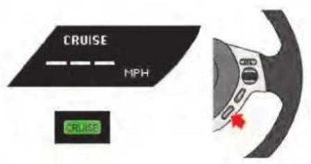

INDICATORS AND DISPLAY
- CRUISE display
Displays the set vehicle speed.
- CRUISE indicator
Informs the driver that the MAIN switch is ON.
- SET indicator
Informs the driver that the vehicle is driving at the set speed.
Constant-speed driving
To set the cruising speed, perform the following procedure.
-
Push the MAIN switch on. The CRUISE indicator will come on.
-
Accelerate your vehicle to the desired speed, push the SET/COAST switch and release it. (The SET indicator will illuminate in the meter.) Take your foot off the accelerator pedal. Your vehicle will maintain the set speed.
NOTE:
If the vehicle speed reaches approximately 3 MPH (5 km/h) over the set speed, the set speed on the vehicle information display blinks.
Passing another vehicle
To pass another vehicle, depress the accelerator pedal. When you release the pedal, the vehicle will return to the previously set speed.
Increasing the set vehicle speed
To reset at a faster cruising speed, use one of the following methods:
- Depress the accelerator pedal. When the vehicle attains the desired speed, push and release the SET/COAST switch.
- Push and hold the RESUME/ACCELERATE switch. When the vehicle attains the speed you desire, release the switch.
- Push and then quickly release the RESUME/ACCELERATE switch. Each time you do this, the set speed will increase by about 1 MPH or 1 km/h.
Decreasing the set vehicle speed
To reset at a slower cruising speed, use one of the following methods:
- Lightly tap the brake pedal. When the vehicle attains the desired speed, push and release the SET/COAST switch.
- Push and hold the SET/COAST switch. Release the switch when the vehicle slows
down to the desired speed.
- Push and then quickly release the SET/COAST switch. Each time you do this, the set speed will decrease by about 1 MPH or 1 km/h.
Resuming the preset speed
To resume the preset speed, push and release the RESUME/ACCELERATE switch. The vehicle will resume the last set cruising speed when the vehicle speed is over 25 MPH (40 km/h).
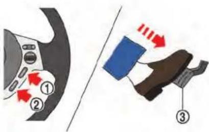
Canceling the preset speed
To cancel the preset speed, use one of the following methods:
- Push the CANCEL switch indicator will turn off. ①. The SET
- Tap the brake pedal ③. The SET indicator will turn off.
- Turn the MAIN switch ② off. Both the CRUISE indicator and SET indicator will turn off.
Starting and driving 5-37
HILL START ASSIST SYSTEM
NOTE:
- If cruise control was canceled by pressing the cancel switch or by depressing the brake pedal, the system changes to standby status.
- If you depress the brake pedal while pushing the RESUME/ACCELERATE or SET/COAST switch and reset at the cruising speed, the cruise control will be deactivated. Turn the MAIN switch off once and then turn it on again.
Under the following conditions, cruise control will be automatically canceled.
- Vehicle speed drops to below approximately 19 MPH (30 km/h).
- Vehicle speed drops to more than approximately 8 MPH (13 km/h) below the set vehicle speed.
- The shift lever is moved to a position other than A M .
• VDC operates. - A tire is spinning.
- There is a malfunction in the cruise control system.
WARNING
- Never rely solely on the hill start assist system to prevent the vehicle from moving backward on a hill. Always drive carefully and attentively. Depress the brake pedal when the vehicle is stopped on a steep hill. Be especially careful when stopped on a hill on frozen or muddy roads. Failure to prevent the vehicle from rolling backwards may result in a loss of control of the vehicle and possible serious injury or death.
- The hill start assist system is not designed to hold the vehicle at a standstill on a hill. Depress the brake pedal when the vehicle is stopped on a steep hill. Failure to do so may cause the vehicle to roll backwards and may result in a collision or serious personal injury.
- The hill start assist may not prevent the vehicle from rolling backwards on a hill under all load or road conditions. Always be prepared to depress the brake pedal to prevent
the vehicle from rolling backwards. Failure to do so may result in a collision or serious personal injury.
NOTICE
When the vehicle is stopped on a hill, do not hold the vehicle in place by depressing the accelerator pedal. Doing so may cause the clutch to overheat and result in transmission damage. Use the brakes to prevent the vehicle from moving.
The hill start assist system automatically keeps the brakes applied to help prevent the vehicle from rolling backwards in the time it takes the driver to release the brake pedal and apply the accelerator when the vehicle is stopped on a hill. Hill start assist will operate automatically under the following conditions:
- The shift lever is moved to a forward or reverse position.
- The vehicle is stopped completely on a hill by applying the brake.
The maximum holding time is 2 seconds. After 2 seconds the vehicle will begin to roll back and
hill start assist will stop operating completely. Hill start assist will not operate when the shift lever is moved to the N or P position or on a flat and level road.
NOTE:
This system does not function when the Vehicle Dynamic Control VDC) system warning appears on the vehicle information display located in the tachometer. ( "Vehicle Dynamic Control (VDC) system warning" page 2-37)
BREAK-IN SCHEDULE
NOTICE
Follow these recommendations to obtain maximum engine performance and ensure the future reliability and economy of your new vehicle. Failure to follow these recommendations may result in shortened engine life and reduced vehicle performance.
Please observe the following types of driving until the mileage shown below has been reached.
Until 300 miles (500 km):
- Do not depress the accelerator pedal more than halfway and avoid rapid acceleration.
- Drive with the engine speed kept at less than 3,500 RPM.
- Avoid unnecessary quick steering, abrupt braking and driving on poor roads. 300 to 600 miles (500 to 1,000 km):
- Avoid rapid acceleration in a low gear (1st to 3rd gears) with the accelerator pedal fully depressed. Depress the pedal slowly.
-
Avoid unnecessary quick steering and abrupt braking.
-
Drive with the suspension setup switch in the COMF mode to allow more suspension stroke.
600 to 1,200 miles (1,000 to 2,000 km): - Drive with the engine speed kept relatively high with the shift lever in the M position. Shifting is recommended between 1st and 4th gears.
- Avoid unnecessary quick steering and abrupt braking.
- Drive with the suspension setup switch in the COMF mode to allow more suspension stroke.
Even though the mileage reaches over 1,200 miles (2,000 km), the clutch may take longer to properly engage if the vehicle is mainly driven in town at a low speed. NISSAN recommends breaking in the clutch at a GT-R certified NISSAN dealer.
WHEEL ALIGNMENT
Do not adjust the wheel alignment until the mileage reaches 1,000 miles (1,600 km). Until then, the suspension may not engage enough and the height may be higher.
However, make sure to adjust the alignment after 1,000 miles (1,600 km).
The wheel alignment can be adjusted by a GT-R
Starting and driving 5-39
certified NISSAN dealer in accordance with specifications for city driving to high performance driving.
The tires on the GT-R may have different wear rates and wear patterns in comparison to conventional passenger vehicles. Contact a GT-R certified NISSAN dealer to confirm that the alignment is within specifications.
FUEL EFFICIENT DRIVING TIPS
Follow these easy-to-use Fuel Efficient Driving Tips to help you achieve the most fuel economy from your vehicle.
-
Use smooth accelerator and brake pedal application.
-
Avoid rapid starts and stops.
- Use smooth, gentle accelerator and brake application whenever possible.
-
Maintain constant speed while commuting and coast whenever possible.
-
Maintain constant speed.
-
Look ahead to try and anticipate and minimize stops.
- Synchronizing your speed with traffic lights allows you to reduce your number of stops.
-
Maintaining a steady speed can minimize red light stops and improve fuel efficiency.
-
Use air conditioning (A/C) at higher vehicle speeds.
-
Below 40 MPH (64 km/h), it is more efficient to open windows to cool the vehicle due to reduced engine load.
- Above 40 MPH (64 km/h), it is more efficient to use A/C to cool the vehicle due to increased aerodynamic drag.
• Recirculating the cool air in the cabin
when the A/C is on reduces cooling load.
-
Drive at economical speeds and distances.
-
Observing the speed limit and not exceeding 60 MPH (97 km/h) (where legally allowed) can improve fuel efficiency due to reduced aerodynamic drag.
- Maintaining a safe following distance behind other vehicles reduces unnecessary braking.
- Safely monitoring traffic to anticipate changes in speed permits reduced braking and smooth acceleration changes.
-
Select a gear range suitable to road conditions.
-
Use cruise control.
• Using cruise control during highway driving helps maintain a steady speed.
- Cruise control is particularly effective in providing fuel savings when driving on flat terrains.
-
Plan for the shortest route.
-
Utilize a map or navigation system to determine the best route to save time.
-
Avoid idling.
- Shutting off your engine when safe for stops exceeding 30-60 seconds saves fuel and reduces emissions.
- Buy an automated pass for toll roads.
- Automated passes permit drivers to use special lanes to maintain cruising speed through the toll and avoid stopping and starting.
- Winter warm up.
- Limit idling time to minimize impact to fuel economy.
• Vehicles typically need no more than 30 seconds of idling at start-up to effectively circulate the engine oil before driving.
- Your vehicle will reach its ideal operating temperature more quickly while driving versus idling.
- Keeping your vehicle cool.
- Park your vehicle in a covered parking area or in the shade whenever possible.
- When entering a hot vehicle, opening the windows will help to reduce the inside temperature faster, resulting in reduced demand on your A/C system.
INCREASING FUEL ECONOMY
- Keep your engine tuned up.
- Follow the recommended scheduled maintenance.
- Keep the tires inflated to the correct pressure. Low tire pressure increases tire wear and lowers fuel economy.
- Keep the wheels in correct alignment. Improper alignment increases tire wear and lowers fuel economy.
- Use the recommended viscosity engine oil. ( "Oil viscosity" page 9-6)
ALL-WHEEL DRIVE (AWD)
| Warning light | Comes on or blinks when |
 | There is a malfunction in the all wheel drive system. |
| Comes on | |
 | The AWD clutch temperature rises abnormally. |
| Blinks rapidly | |
 | The difference in wheel rotation is large. |
| Blinks slowly |
AWD WARNING LIGHT
The AWD warning light is located in the meter. The AWD warning light comes on when the ignition switch is pushed to the ON position. It turns off soon after the engine is started.
If any malfunction occurs in the AWD system while the engine is running, the warning light will come on.
The warning light may blink rapidly (about twice per second) while trying to free a stuck vehicle due to high AWD clutch temperature. The driving mode may change to two-wheel drive. If the warning light blinks rapidly during operation, stop the vehicle with the engine idling in a safe place immediately. Then if the light goes off after a while, you can continue driving.
A large difference between the diameters of front and rear wheels will make the warning light blink slowly (about once per two seconds). Pull off the road in a safe area, and idle the engine. Check that all tire sizes are the same, tire pressure is correct and tires are not worn and winter tires are not installed on the front or rear wheels only.
If the warning light is blinking after the above operation, have your vehicle checked by a GT-R certified NISSAN dealer as soon as possible.
If non-genuine GT-R tires are used, the warning light may illuminate. ( "GT-R special precautions" page GTR-5)

WARNING
- Do not attempt to raise two wheels off the ground and shift the transmission to any drive or reverse position with the engine running. Doing so may result in drivetrain damage or unexpected vehicle movement which could result in serious vehicle damage or personal injury.
- Do not attempt to test an AWD equipped vehicle on a 2-wheel dynamometer (such as the dynamometers used by some states for emissions testing) or similar equipment even if the other two wheels are raised off the ground. Make sure that you inform the test facility personnel that your vehicle is equipped with AWD before it is placed on a dynamometer. Using the wrong test equipment may result in drivetrain damage or unexpected vehicle movement which could result in serious vehicle damage or personal injury.
NOTICE
- If the warning light comes on while driving there may be a malfunction in the AWD system. Reduce the vehicle speed and have your vehicle checked by a GT-R certified NISSAN dealer as soon as possible.
- If the warning light remains on after the above operation, have your vehicle checked by a GT-R certified NISSAN dealer as soon as possible.
- The powertrain may be damaged if you continue driving with the warning light blinking.
- Do not spin the rear wheels while driving. Spinning the rear wheels may increase the temperatures of the AWD clutch system and damage the system. Adjust the accelerator pedal position to stop wheel spin.
If the steering wheel is turned more than half a turn when the vehicle is started when it is cold, it may be harder to move the vehicle forward and backward. This phenomenon is known as the "tight corner braking phenomenon".
This phenomenon is unique to AWD vehicles, and occurs due to a difference in speeds between the front and rear wheels while the vehicle is turning. This does not indicate that there is a malfunction.
NOTE:
If the tight corner braking phenomenon occurs, a slipping sound may be heard from the tires, or a squeaking sound may be heard from the drive system.
Reducing tight corner braking phenomenon
The tight corner braking phenomenon can be temporarily reduced.
Push the transmission setup switch down for approximately 4 seconds while the engine is running.
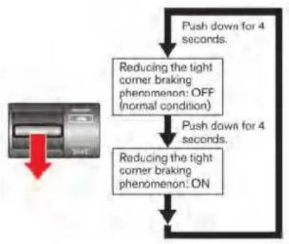
flowchart
graph TD
    A["Push down for 4 seconds."] --> B["Reducing the tight corner braking phenomenon: OFF (normal condition)"]
    B --> C["Push down for 4 seconds."]
    C --> D["Reducing the tight corner braking phenomenon: ON"]
    D --> E["End"]
- The SAVE mode indicator will blink once and will then turn off.
- If the SAVE mode is already selected, the SAVE mode indicator will blink once and then illuminate again. ( "VDC, transmission and suspension setup switches" page 5-25)
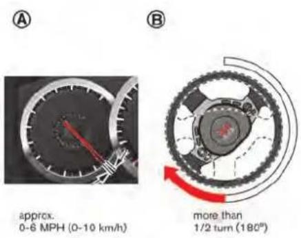
After performing the above, the vehicle switches from the AWD mode to 2WD mode only if both of the following conditions are met:
- Vehicle speed is less than approximately 6 MPH (10 km/h) Ⓐ AND
- The steering wheel is turned more than 1/2 turn Ⓑ.
If the above driving conditions are not met, the vehicle will not switch to the 2WD mode to temporarily reduce the braking phenomenon even if the transmission setup switch is operated.
To stop reducing the phenomenon, push the transmission setup switch down for approxi-
Starting and driving 5-43
mately 4 seconds again. The driving mode will switch to the normal AWD mode.
Reduction of the tight corner braking phenomenon will be cancelled when:
- the R mode is selected with the transmission setup switch
- the SAVE mode is selected with the transmission setup switch and the OFF mode is selected with the VDC setup switch
- the ignition switch is pushed to the "OFF" position
- the R mode start function is used

WARNING
Do not reduce the tight corner braking phenomenon when driving on a road surface that is slippery or covered in snow, because the driving mode will switch to 2WD. This may cause tire slipping and may cause a loss of control and result in a collision, personal injury or death.
TIRES
This vehicle is equipped with special tires. When changing the tires, install the designated special tires. Replacing tires as a set of four with new ones is recommended. However, if a tire is punctured or damaged, it may be possible to replace only the damaged tire. Determining whether one tire or a complete set of tires should be replaced is based on a number of factors including tire wear and condition. Contact your GT-R certified NISSAN dealer. They can recommend if an individual tire or a complete set should be replaced.
NOTICE
If tires other than the designated tires, tires with large differences in wear or tires of different sizes are installed, the AWD performance will be degraded and the drive mechanism may be damaged.
AWD SYSTEM CHARACTERISTICS
The AWD system automatically distributes the optimal torque to the front and rear wheels. This provides both the superior turning performance of a rear wheel drive vehicle and the traction of a AWD vehicle.
Electronic control continuously distributes torque to the front and rear wheels in the range from 0:100 (rear-wheel drive mode) to 50:50 (all-wheel drive mode) to match the driving conditions and road conditions. This allows the engine output (torque) to be effectively transmitted to the road surface.
LIMITED SLIP DIFFERENTIAL (LSD)
The rear final drive of this vehicle is equipped with a 1.5-way mechanical Limited Slip Differential (LSD).

WARNING
Sudden operation of the accelerator pedal can result in fishtailing or side-slip, possibly causing an accident. Use particular caution when driving in rainy weather or on slippery roads.
NOTICE
Use the designated differential gear oil. If any oil other than the designated oil is used, the LSD may not operate correctly, and noise and vibration may occur, possibly resulting in a malfunction.
NOTE:
- If the vehicle accelerates from a stop with the steering wheel turned in cold temperatures, the inner wheel tire may slip and some noise or vibration may be heard. This phenomenon is unique to vehicles equipped with the LSD. This
does not indicate that there is a malfunction.
- The LSD controls the speed difference between the left and right wheels, and optimally allocates torque to the wheels.
- The 1.5-way mechanical LSD in the rear final drive of this vehicle is characterized by its asymmetrical LSD effects when the accelerator pedal is ON and when it is OFF. This allows the appropriate amount of torque for the driving environment to be transmitted to the road surface.
PARKING/PARKING ON HILLS
①


WARNING
- Do not stop or park the vehicle over flammable materials such as dry grass, waste paper or rags. They may ignite and cause a fire.
- Never leave the engine running while the vehicle is unattended.
- Do not leave children unattended inside the vehicle. They could unknowingly activate switches or controls. Unattended children could become involved in serious acci-
dents.
- Safe parking procedures require that both the parking brake be applied and the transmission placed into the P position. Failure to do so could cause the vehicle to move unexpectedly or roll away and result in an accident.
- Make sure the shift lever has been pushed as far forward as it can go and cannot be moved without depressing the foot brake pedal.
- Follow the instructions below when
parking the vehicle to help prevent the brake rotor and brake pads from rusting together. Failure to follow the instructions could cause the rotor and pads to rust together. If the rotor and pads rust together, there may be a popping noise and some vibration when the vehicle is driven, a wheel may not roll correctly, or the brake pads could be damaged. If the pads are damaged, this may reduce the effectiveness of the brake system which could cause a collision, serious personal injury or death.
- Firmly apply the parking brake.
- Move the shift lever to the P position.
- To help prevent the vehicle from rolling into the street when parked on a sloping drive way, it is a good practice to turn the wheels as illustrated.
- HEADED DOWNHILL WITH CURB: ① Turn the wheels into the curb and move the vehicle forward until the curb side wheel gently touches the curb.
- HEADED UPHILL WITH CURB: ② Turn the wheels away from the curb and move the vehicle back until the curb side
wheel gently touches the curb.
• HEADED UPHILL OR DOWNHILL, NO CURB: ③
Turn the wheels toward the side of the road so the vehicle will move away from the center of the road if it moves.
- Push the ignition switch to the LOCK position.
The GT-R uses brake pad materials that have high metallic content. The brake pad material helps maintain braking performance in a wide range of weather and driving conditions.
For the first 3,000 - 6,000 miles (5,000 - 10,000 km) of the vehicle's service life, and for the first 3,000 - 6,000 miles (5,000 - 10,000 km) after a brake replacement, the brake pad to brake rotor clearance is very small. When parking, apply the parking brake and move the shift lever to the P position. Idle the engine for more than 20 seconds without depressing the brake pedal. This allows the brake pads to move away from the rotor so the pad does not contact the rotor.
Additionally, the brakes must be dry before parking the vehicle after driving on wet roads or after washing the vehicle. If the roads are wet, lightly apply the brakes for a short distance before parking the vehicle to dry the brakes. After washing the vehicle, dry the brakes by
driving on a dry road for a few miles and apply the brakes normally based on traffic and road conditions.
The metallic brake pads and brake disc rotor may rust together when the brakes are not applied:
- If the vehicle is not idled for 20 seconds without the brakes applied, or if the brakes are applied when the vehicle is shut off, the rotor and pads can rust together, even when the brake pads are dry.
- If the brakes are wet when the vehicle is parked and the parking brake is applied for a long time.
Contact a GT-R certified NISSAN dealer if the brake pads and brake rotor have rusted together.
POWER STEERING

WARNING
If the engine is not running or is turned off while driving, the power assist for the steering will not work. Steering will be harder to operate.
The power assisted steering uses a hydraulic pump, driven by the engine, to assist steering. If the engine stops or the drive belt breaks, you will still have control of the vehicle. However, much greater steering effort is needed, especially in sharp turns and at low speeds.
BRAKE SYSTEM
BRAKING PRECAUTIONS
The brake system has two separate hydraulic circuits. If one circuit malfunctions, you will still have braking at two wheels.
You may feel a small click and hear a sound when the brake pedal is fully depressed slowly. This is not a malfunction and indicates that the brake assist mechanism is operating properly.
Vacuum assisted brakes
The brake booster aids braking by using engine vacuum. If the engine stops, you can stop the vehicle by depressing the brake pedal. However, greater foot pressure on the brake pedal will be required to stop the vehicle and the stopping distance will be longer.
Wet brakes
When the vehicle is washed or driven through water, the brakes may get wet. As a result, your braking distance will be longer and the vehicle may pull to one side during braking.
To dry brakes, drive the vehicle at a safe speed while lightly tapping the brake pedal to heat-up the brakes. Do this until the brakes return to normal. Avoid driving the vehicle at high speeds until the brakes function correctly.
Using the brakes
Avoid resting your foot on the brake pedal while driving. This will cause overheating of the brakes, wearing out the brake and pads faster and reduce gas mileage.
To help reduce brake wear and to prevent the brakes from overheating, reduce speed and downshift to a lower gear before going down a slope or long grade. Overheated brakes may reduce braking performance and could result in loss of vehicle control.

WARNING
- While driving on a slippery surface, be careful when braking, accelerating or downshifting. Abrupt braking or accelerating could cause the wheels to skid and result in an accident.
- If the engine is not running or is turned off while driving, the power assist for the brakes will not work. Braking will be harder.
Break in the parking brake shoes whenever the stopping effect of the parking brake is weakened or whenever the parking brake shoes and/or drums/rotors are replaced, in order to assure the best braking performance.
This procedure is described in the vehicle service manual and can be performed by a GT-R certified NISSAN dealer.
BRAKE ASSIST
ANTI-LOCK BRAKING SYSTEM (ABS)

WARNING
- The Anti-lock Braking System (ABS) is a sophisticated device, but it cannot prevent accidents resulting from careless or dangerous driving techniques. It can help maintain vehicle control during braking on slippery surfaces. Remember that stopping distances on slippery surfaces will be longer than on normal surfaces even with ABS. Stopping distances may also be longer on rough, gravel or snow covered roads, or if you are using tire chains. Always maintain a safe distance from the vehicle in front of you. Ultimately, the driver is responsible for safety.
- Tire type and condition may also affect braking effectiveness. When replacing tires, install the specified size of tires on all four wheels.
The Anti-lock Braking System (ABS) controls
the brakes so the wheels do not lock during hard braking or when braking on slippery surfaces. The system detects the rotation speed at each wheel and varies the brake fluid pressure to prevent each wheel from locking and sliding. By preventing each wheel from locking, the system helps the driver maintain steering control and helps to minimize swerving and spinning on slippery surfaces.
Using the system
Depress the brake pedal and hold it down. Depress the brake pedal with firm steady pressure, but do not pump the brakes. The ABS will operate to prevent the wheels from locking up. Steer the vehicle to avoid obstacles.

WARNING
Do not pump the brake pedal. Doing so may result in increased stopping distances.
Self-test feature
The ABS includes electronic sensors, electric pumps, hydraulic solenoids and a computer. The computer has a built-in diagnostic feature that tests the system each time you start the engine and move the vehicle at a low speed in forward
or reverse. When the self-test occurs, you may hear a "clunk" noise and/or feel a pulsation in the brake pedal. This does not indicate that there is a malfunction. If the computer senses a malfunction, it switches the ABS off and illuminates the ABS warning light on the meter. The brake system then operates normally, but without anti-lock assistance.
If the ABS warning light illuminates during the self-test or while driving, have the vehicle checked by a GT-R certified NISSAN dealer.
Normal operation
The ABS operates at speeds above 3 to 6 MPH (5 to 10 km/h). The speed varies according to road conditions.
When the ABS senses that one or more wheels are close to locking up, the actuator rapidly applies and releases hydraulic pressure. This action is similar to pumping the brakes very quickly. You may feel a pulsation in the brake pedal and hear a noise from under the hood or feel a vibration from the actuator when it is operating. This is normal and indicates that the ABS is operating properly. However, the pulsation may indicate that road conditions are hazardous and extra care is required while driving.
VEHICLE DYNAMIC CONTROL (VDC) SYSTEM
The Vehicle Dynamic Control (VDC) system uses various sensors to monitor driver inputs and vehicle motion. Under certain driving conditions, the VDC system helps to perform the following functions.
- Controls brake pressure to reduce wheel slip on one slipping drive wheel so power is transferred to a non slipping drive wheel on the same axle.
- Controls brake pressure and engine output to reduce drive wheel slip based on vehicle speed (traction control function).
- Controls brake pressure at individual wheels and engine output to help the driver maintain control of the vehicle in the following conditions:
— understeer (vehicle tends to not follow the steered path despite increased steering input)
— oversteer (vehicle tends to spin due to certain road or driving conditions).
The VDC system can help the driver to maintain control of the vehicle, but it cannot prevent loss of vehicle control in all driving situations.
When the VDC system operates, the VDC warning light 🎨 in the meter flashes so note the following:
- The road may be slippery or the system may determine some action is required to help keep the vehicle on the steered path.
- You may feel a pulsation in the brake pedal and hear a noise or vibration from under the hood. This is normal and indicates that the VDC system is working properly.
- Adjust your speed and driving to the road conditions.
- The VDC mode can be changed using the VDC setup switch. ( "VDC, transmission and suspension setup switches" page 5-25)
( "Vehicle Dynamic Control (VDC) warning light" page 2-31, "Vehicle Dynamic Control (VDC) off indicator light" page 2-32)
If a malfunction occurs in the system, the VDC warning light 📁 illuminates in the meter. The VDC system automatically turns off.
The VDC setup switch is used to turn off the VDC system. The VDC off indicator illuminates to indicate the VDC system is off.
When the VDC setup switch is used to turn off the system, the VDC system still operates to prevent one drive wheel from slipping by transferring power to a non slipping drive wheel.
The VDC warning light flashes if this occurs. All other VDC functions are off and the
VDC warning light 📋 will not flash. The VDC system is automatically reset to on when the ignition switch is placed in the off position then back to the on position.
( "Vehicle Dynamic Control (VDC) warning light" page 2-31, "Vehicle Dynamic Control (VDC) off indicator light" page 2-32)
The computer has a built-in diagnostic feature that tests the system each time you start the engine and move the vehicle forward or in reverse at a slow speed. When the self-test occurs, you may hear a "clunk" noise and/or feel a pulsation in the brake pedal. This is normal and is not an indication of a malfunction.

WARNING
- The VDC system is designed to help the driver maintain stability but does not prevent accidents due to abrupt steering operation at high speeds or by careless or dangerous driving techniques. Reduce vehicle speed and be especially careful when driving and cornering on slippery surfaces and always drive carefully.
- Do not modify the vehicle's suspension. If suspension parts such as
shock absorbers, struts, springs, stabilizer bars, bushings and wheels are not NISSAN approved or are extremely deteriorated, the VDC system may not operate properly. This could adversely affect vehicle handling performance, and the VDC warning light may illuminate.
- If brake related parts such as brake pads, rotors and calipers are not standard equipment or are extremely deteriorated, the VDC system may not operate properly and the VDC warning light may illuminate.
- If engine control related parts are not standard equipment or are extremely deteriorated, the VDC warning light may illuminate.
- When driving on extremely inclined surfaces such as higher banked corners, the VDC system may not operate properly and the VDC warning light 📁 may illuminate. Do not drive on these types of roads.
- When driving on an unstable surface such as a turntable, ferry,
elevator or ramp, the VDC warning light may illuminate. This is not a malfunction. Restart the engine after driving onto a stable surface.
- If wheels or tires other than the those recommended are used, the VDC system may not operate properly and the VDC warning light may illuminate.
- The VDC system is not a substitute for winter tires or tire chains on a snow covered road.
NOTE:
- Always make sure the VDC is ON before driving the vehicle by checking that the VDC OFF indicator lights on the meter and the VDC set-up switch are not illuminated.
The GT-R is a high performance vehicle and the VDC must be on/activated to provide proper powertrain operation and intended drivability.

WARNING
- The VDC OFF mode should ONLY be used briefly to help free the vehicle if stuck in snow or mud by temporarily stopping operation of the VDC to maintain wheel torque.
- Driving the GT-R with the VDC off may lead to handling issues related to steering maneuvers, acceleration, or deceleration. Moreover, driving with the VDC off can result in an inoperative vehicle by causing serious damage to the powertrain, including damage to the Transaxle Assembly including Transfer, Clutch, Gears, Transaxle case and all of its components and other drivetrain component(s) by overheating or excessive force.
- Damage to the powertrain or any drivetrain component(s) that occurs when there is a record in the Vehicle Status Data Recorder (VSDR) that the vehicle was driven with VDC off during the period when the damage was incurred is excluded from warranty coverage.
Starting and driving 5-51
See your 2016 Warranty Information Booklet for important related information and warranty coverage exclusions. See also section 2 (“Transmission warning light” page 2-30) and section 5 (“Vehicle Dynamic Control (VDC) system” page 5-50) of this Owner’s Manual, “Transmission Clutch Temperature High” and “Vehicle Dynamic Control (VDC) System” for important additional related information.
- Except for the emergency cases above, any issues related to driving stability (e.g., steering maneuvers and maneuvers during acceleration and deceleration) and any damages to drivetrain components (e.g., transfer, clutch, a sort of gear, transaxle case) will not be covered by warranty if there is a record in the Vehicle Status Data Recorder (VSDR) that the vehicle was driven with VDC off.
- When attempting to free the vehicle from mud or fresh snow, the VDC will detect the tire slipping, and the engine speed may not increase even when the accelerator pedal is depressed. To raise the engine speed, use the VDC set up switch to turn the VDC system OFF and select SAVE mode with the transmis-
sion switch. ( "VDC, transmission and suspension setup switches" page 5-25)
- When the VDC system is turned OFF, all VDC functions (including traction control), except for the ABS functions, are deactivated.
COLD WEATHER DRIVING
FREEING A FROZEN DOOR LOCK
To prevent a door lock from freezing, apply deicer through the key hole. If the lock becomes frozen, heat the key before inserting it into the key hole or use the Intelligent Key system.
ANTI-FREEZE
In the winter when it is anticipated that the outside temperature will drop below 32^ F ( 0^ C), check antifreeze to assure proper winter protection. (“Engine cooling system” page 8-10)
BATTERY
If the battery is not fully charged during extremely cold weather conditions, the battery fluid may freeze and damage the battery. To maintain maximum efficiency, the battery should be checked regularly. ( "Battery" page 8-17)
DRAINING OF COOLANT WATER
If the vehicle is to be left outside without antifreeze, drain the cooling system, including the engine block. Refill before operating the vehicle. For details, contact a GT-R certified NISSAN dealer.
TIRE EQUIPMENT
The GT-R summer tires are made from a specially formulated rubber to maximize the vehicle's performance capabilities. Performance of summer tires is substantially reduced when temperatures are less than 32^ F ( 0^ C) so you must drive carefully. NISSAN recommends the use of winter or all-season tires on all four wheels if you plan to operate your vehicle in snowy or icy conditions when temperatures are less than 32^ F ( 0^ C).

WARNING
Never use summer tires when the temperature is below -4^ ( -20^ ) to prevent permanent tread deformation which may cause tire damage or tire failure. This may cause a loss of vehicle control which can result in serious personal injury or death.
Tire chains may be used. ( "Tire chains" page 8-40)
If you install tires, they must also be the specified size, brand, construction and tread pattern on all four wheels.
SPECIAL WINTER EQUIPMENT
It is recommended that the following items be carried in the vehicle during winter:
- A scraper and stiff-bristled brush to remove ice and snow from the windows and wiper blades.
- A sturdy, flat board to be placed under the jack to give it firm support.
• A shovel to dig the vehicle out of snowdrifts. - Extra window washer fluid to refill the reservoir tank.
DRIVING ON SNOW OR ICE

WARNING
- Wet ice (32°F, 0°C and freezing rain), very cold snow or ice can be slick and very hard to drive on. The vehicle will have much less traction or "grip" under these conditions. Try to avoid driving on wet ice until the road is salted or sanded.
-
Whatever the condition, drive with caution. Accelerate and slow down with care. If accelerating or down-shifting too fast, the drive wheels will lose even more traction.
-
Allow more stopping distance under these conditions. Braking should be started sooner than on dry pavement.
- Allow greater following distances on slippery roads.
- Watch for slippery spots (glare ice). These may appear on an otherwise clear road in shaded areas. If a patch of ice is seen ahead, brake before reaching it. Try not to brake while on the ice, and avoid any sudden steering maneuvers.
- Do not use the cruise control on slippery roads.
- Snow can trap dangerous exhaust gases under your vehicle. Keep snow clear of the exhaust pipe and from around your vehicle.
NOTE:
When driving on snow, select the SAVE mode with the setup switch. By selecting the SAVE mode, the engine output is controlled appropriately for snow or slippery road surfaces. This enables the vehicle to start or accelerate smoothly.
Starting and driving 5-53
ENGINE BLOCK HEATER (if so equipped)
Engine block heaters are used to assist with cold temperature starting.
The engine block heater should be used when the outside temperature is 20^ F ( -7^ C) or lower.
To use the engine block heater
- Turn the engine off.
- Plug the engine block heater cord into a grounded 3-wire, 3-pronged extension cord.
-
Plug the extension cord into a Ground Fault Interrupt (GFI) protected, grounded 110-volt AC (VAC) outlet.
-
The engine block heater must be plugged in for at least 2 - 4 hours, depending on outside temperatures, to properly warm the engine coolant. Use an appropriate timer to turn the engine block heater on.
-
Before starting the engine, unplug and properly store the cord to keep it away from moving parts.
WARNING
- Do not use your engine block heater with an ungrounded electrical system or a 2-pronged adapter. You can be seriously injured by an electrical shock if you use an ungrounded connection.
- Disconnect and properly store the engine block heater cord before starting the engine. Damage to the cord could result in an electrical shock and can cause serious injury.
- Use a heavy-duty 3-wire, 3-pronged extension cord rated for at least 10A. Plug the extension cord into a Ground Fault Interrupt (GFI) protected, grounded 110-VAC outlet.
Failure to use the proper extension cord or a grounded outlet can result in a fire or electrical shock and cause serious personal injury.
ACTIVE NOISE CONTROL (if so equipped)

natural_image
Interior view of a car showing the dashboard and seatbelt with numbered annotations (① and ②), no visible text or symbols beyond labels.
natural_image
Interior view of a car showing the rear seats and seatbelt, with a highlighted circular component (labeled ③) pointing to the side of the seat.This system uses the front and rear microphones ① to detect engine booming noise. The system then automatically generates a noise cancelling sound through the speakers ② and woofer ③ to reduce engine booming noise.
The front and rear microphones ① are located inside of the roof.
The front speakers are located on the doors and the woofer is located in between the rear seats.
NOTE:
To operate the active noise control properly:
- Do not cover the speakers or woofer.
- Do not cover the microphones.
- Do not change or modify speakers including the woofer and any audio related parts such as the amplifier.
- Do not make any modification including sound deadening or modifications around the microphones, speakers or woofer.
MEMO
6 In case of emergency
Hazard warning flasher switch 6-2
Roadside assistance program 6-2
Emergency engine shut off 6-3
Flat tire 6-3
Tire Pressure Monitoring System (TPMS) 6-3
Run-flat tires 6-4
Jump starting 6-5
Push starting 6-7
If your vehicle overheats 6-8
Towing your vehicle 6-9
Towing recommended by NISSAN 6-9
Vehicle recovery (freeing a stuck vehicle) 6-10

HAZARD WARNING FLASHER SWITCH

natural_image
Interior view of a car dashboard with a control panel and a warning sign (no readable text or symbols)Push the switch on to warn other drivers when you must stop or park under emergency conditions. All turn signal lights will flash.
The flasher can be actuated with the ignition switch in any position.
Some state laws may prohibit the use of the hazard warning flasher switch while driving.
ROADSIDE ASSISTANCE PROGRAM
In the event of a roadside emergency, Roadside Assistance Service is available to you. Please refer to your Warranty Information Booklet (U.S.) or Warranty & Roadside Assistance Information Booklet (Canada) for details.

WARNING
- If stopping for an emergency, be sure to move the vehicle well off the road.
- Do not use the hazard warning flashers while moving on the highway unless unusual circumstances force you to drive so slowly that your vehicle might become a hazard to other traffic.
- Turn signals do not work when the hazard warning flasher lights are on.
EMERGENCY ENGINE SHUT OFF
To shut off the engine in an emergency situation while driving, perform the following procedure:
- Rapidly push the push-button ignition switch 3 consecutive times in less than 1.5 seconds, or
- Push and hold the push-button ignition switch for more than 2 seconds.
FLAT TIRE
TIRE PRESSURE MONITORING SYSTEM (TPMS)
This vehicle is equipped with the Tire Pressure Monitoring System (TPMS). It monitors tire pressure of all tires. When the low tire pressure warning light is lit, one or more of your tires is significantly under-inflated. If the vehicle is being driven with low tire pressure, the TPMS will activate and warn you of it by the low tire pressure warning light (in the meter) or the warning message (on the display). This system will activate only when the vehicle is driven at speeds above 16 MPH (25 km/h). ( "Low tire pressure warning light" page 2-27) ( "Tire Pressure Monitoring System (TPMS)" page 5-4)

WARNING
- If the low tire pressure warning light illuminates while driving, avoid sudden steering maneuvers or abrupt braking, reduce vehicle speed, pull off the road to a safe location and stop the vehicle as soon as possible. Driving with under-inflated tires may permanently damage the tires and increase the likelihood of tire failure. Serious vehicle damage
could occur and may lead to an accident and could result in serious personal injury. Check the tire pressure for all four tires. Adjust the tire pressure to the recommended COLD tire pressure shown on the Tire and Loading Information label to turn the low tire pressure warning light off. If the light still illuminates while driving after adjusting the tire pressure, a tire may be flat.
- When a wheel is replaced, the TPMS will not function and the low tire pressure warning light will flash for approximately 1 minute. The light will remain on after 1 minute. Contact a GT-R certified NISSAN dealer as soon as possible for tire replacement and/or system resetting.
- Replacing tires with those not originally specified by NISSAN could affect the proper operation of the TPMS.
- Do not inject any tire liquid or aerosol tire sealant into the tires, as this may cause a malfunction of the tire pressure sensors.
In case of emergency 6-3
NOTE:
- You can check the pressure of all four tires on the multi function display. See the separate Multi Function Display Owner's Manual.
- The tires of this vehicle are filled with nitrogen gas. When the tire pressure is low, fill the tires with nitrogen. Contact a GT-R certified NISSAN dealer for information on filling the tires with nitrogen.
- If nitrogen is not available, compressed air may be safely used under normal driving conditions. However, NISSAN recommends refilling with nitrogen for maximum tire performance.
RUN-FLAT TIRES
Run-flat tires are those tires that can be used temporarily if they are punctured. ( "Run-flat tires" page 8-39)
Also, see the tire safety information in the Warranty Information Booklet.

WARNING
- Although you can continue driving with a punctured run-flat tire, remember that vehicle handling stability is reduced, which could lead to an accident and personal injury. Also, driving a long distance at high speeds may damage the tires.
- Do not drive at speeds above 50 MPH (80 km/h) and do not drive more than 50 miles (80 km) with a punctured run-flat tire. The actual distance the vehicle can be driven on a flat tire depends on outside temperature, vehicle load, road conditions and other factors.
- Drive safely at reduced speeds. Avoid hard cornering or braking, which may cause you to lose control of the vehicle.
NOTICE
- Never install tire chains on a punctured run-flat tire, as this could damage your vehicle.
- Avoid driving over any projection or pothole, as the clearance between the vehicle and the ground is smaller than normal.
- Do not enter an automated car wash with a punctured run-flat tire.
- Have the punctured tire replaced by your GT-R certified NISSAN dealer as soon as possible, as the tire's performance capability is reduced.
If you have a flat tire and have to stop the vehicle, follow the instructions below.
- Safely move the vehicle off the road and away from traffic.
- Turn on the hazard warning flashers.
- Park on a level surface and apply the parking brake. Move the shift lever to the P position.
- Turn off the engine.
-
Raise the hood to warn other traffic, and to signal professional road assistance personnel that you need assistance.
-
Have all passengers get out of the vehicle and stand in a safe place, away from traffic and clear of the vehicle.
For the tire removing procedure, see the following section. ( "Jacking vehicle and removing wheels" page 8-43)
JUMP STARTING
The following circumstances indicate that the battery is discharged.
- The starter motor does not turn or it turns weakly and the engine does not start.
- The vehicle lights are much dimmer than usual.
- The sound of the horn is weak. The horn makes no sound.
NOTICE
When the battery is discharged, do not close either of the front doors. The automatic window adjusting function will not work, and the side roof panel may be damaged.
To start your engine with a booster battery, the instructions and precautions below must be followed.
For the battery maintenance information, see the following section. ( "Battery" page 8-17)

WARNING
- If done incorrectly, jump starting can lead to a battery explosion, resulting in severe injury or death. It could also damage your vehicle.
- Explosive hydrogen gas is always present in the vicinity of the battery. Keep all sparks and flames away from the battery.
- Do not allow battery fluid to come into contact with eyes, skin, clothing or painted surfaces. Battery fluid is a corrosive sulphuric acid solution which can cause severe burns. If the fluid should come into contact with anything, immediately flush the contacted area with water.
- Keep the battery out of the reach of children.
- The booster battery must be rated at 12 volts. Use of an improperly rated battery can damage your vehicle.
- Whenever working on or near a battery, always wear suitable eye protectors (for example, goggles or industrial safety spectacles) and
In case of emergency 6-5
remove rings, metal bands, or any other jewelry. Do not lean over the battery when jump starting.
- Do not attempt to jump start a frozen battery. It could explode and cause serious injury.
- Your vehicle has an automatic engine cooling fan. It could come on at any time. Keep hands and other objects away from it.


WARNING
Always follow the instructions below. Failure to do so could result in damage to the charging system and cause personal injury.
- If the booster battery is in another vehicle Ⓐ, position the two vehicles (A and B) to bring their batteries into close proximity to each other. Do not allow the two vehicles to touch.
- Apply parking brake. Move the shift lever to the P position. Switch off all unnecessary
electrical systems (light, heater, air conditioner, etc.).
- Remove the battery cover. Cover the battery with a firmly wrung out moist cloth to reduce explosion hazard.
- Connect jumper cables in the sequence as illustrated (① → ② → ③ → ④). If the battery is disconnected or discharged, the steering wheel will lock and cannot be turned. Supply power using jumper cables before pushing the ignition switch and disengaging the steering lock.

CAUTION
- Always connect positive (+) to positive (+) and negative (−) to body ground (as illustrated), not to the battery.
-
Make sure that the jumper cables do not touch moving parts in the engine compartment and that clamps do not contact any other metal.
-
Start the engine of the booster vehicle and let it run for a few minutes.
-
Keep the engine speed of the booster vehicle Ⓐ at about 2,000 rpm, and start the engine of the vehicle being jump started Ⓑ.
NOTE: Do not keep the starter motor engaged for more than 10 seconds. If the engine does not start right away, push the ignition switch to the OFF position and wait 10 seconds before trying again.
- After starting your engine, carefully disconnect the negative cable and then the positive cable (④ → ③ → ② → ①).
- Be sure to dispose of the cloth used to cover the vent holes as it may be contaminated with corrosive acid.
- Put the battery cover on.
NOTE:
If the clamp clip is difficult to connect to the battery terminal, remove the cowl top cover to make it easier. ( "Removing the cowl top cover" page 8-9)
PUSH STARTING
Do not attempt to start the engine by pushing.
NOTICE
Your NISSAN cannot be push-started or tow-started. Attempting to do so may cause transmission damage.
IF YOUR VEHICLE OVERHEATS

WARNING
- Do not continue to drive if your vehicle overheats. Doing so could cause engine damage or a vehicle fire.
• To avoid the danger of being scalded, never remove the radiator filler cap and the coolant reservoir cap while the engine is still hot. When the cap is removed, pressurized hot water will spurt out, possibly causing serious injury. - Do not open the hood if steam is coming out.
If your vehicle is overheating (indicated by an extremely high temperature gauge reading), or if you feel a lack of engine power, detect unusual noise, etc., take the following steps:
- Move the vehicle safely off the road, apply the parking brake and move the shift lever to the P position.
Do not stop the engine. - Turn off the air conditioner. Open all the windows, move the temperature control to maximum hot and fan control to high speed.
6-8 In case of emergency
- If engine overheating is caused by climbing a long hill on a hot day, run the engine at a fast idle (approximately 1,500 rpm) until the temperature gauge indication returns to normal.
- Get out of the vehicle. Look and listen for steam or coolant escaping from the radiator before opening the hood. (If steam or coolant is escaping, turn off the engine.) Do not open the hood further until no steam or coolant can be seen.
- Open the engine hood.

WARNING
If steam or water is coming from the engine, stand clear to prevent getting burned.
- Visually check drive belts for damage or looseness. Also check if the cooling fan is running. The radiator hoses and radiator should not leak water. If coolant is leaking, the drive belts are missing or loose, or the cooling fan does not run, stop the engine.

WARNING
Be careful not to allow your hands, hair, jewelry or clothing to come into contact with, or get caught in, engine belts or the engine cooling fan. The engine cooling fan can start at any time.
- When the coolant temperature gauge goes down to the midpoint, stop the engine and wait until the gauge goes down further to "C" (cold).
- After the engine cools down, check the coolant level in the reservoir tank. Add coolant to the reservoir, if necessary, after opening the coolant reservoir cap with a heavy cloth covering it. ( "Engine cooling system" page 8-10)
- Have your vehicle repaired at the nearest GT-R certified NISSAN dealer.
TOWING YOUR VEHICLE
When towing your vehicle, all State (Provincial in Canada) and local regulations for towing must be followed. Incorrect towing equipment could damage your vehicle. Towing instructions are available from a GT-R certified NISSAN dealer. Local service operators are familiar with the applicable laws and procedures for towing. To assure proper towing and to prevent accidental damage to your vehicle, NISSAN recommends that you have a service operator tow your vehicle. It is advisable to have the service operator carefully read the following precautions.

WARNING
- Never ride in a vehicle that is being towed.
- Never get under your vehicle after it has been lifted by a tow truck.

CAUTION
Always attach safety chains before towing.

TOWING RECOMMENDED BY NISSAN
NISSAN recommends that towing dollies be used when towing your vehicle or the vehicle be placed on a flat bed truck as illustrated.
NOTICE
Never tow the vehicle with any of the wheels on the ground as this may cause serious and expensive damage to the powertrain.

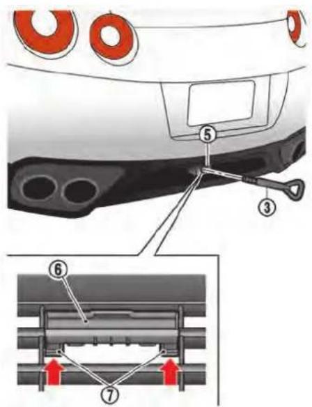
VEHICLE RECOVERY (freeing a stuck vehicle)

WARNING
- Stand clear of a stuck vehicle.
- Do not spin your tires at high speed. This could cause them to explode and result in serious injury. Parts of your vehicle could also overheat and be damaged.
Pulling a stuck vehicle
If your vehicle is stuck in sand, snow, mud, etc., use a tow strap or other device designed specifically for vehicle recovery. Always follow the manufacturer's instructions for the recovery device.
Front:
Using a suitable tool wrapped with a cloth ①, remove the cover ② from the front bumper.
Securely install the vehicle recovery hook ③ stored in the toolbox located under the front passenger's floor. Use the wheel nut wrench ④ as illustrated to secure the recovery hook.
Attach the tow strap to the recovery hook. Make sure that the hook is properly secured in the
original place after use.
Rear:
The rear hook ⑤ is designed as the recovery hook.
To remove the cover ⑥ from the rear bumper, first push in the tabs ⑦ until they unlatch and then pull the cover.
Securely install the recovery hook ③ to the attaching mount located on the rear bumper.
Make sure that the recovery hook is properly secured in its storage location after use.
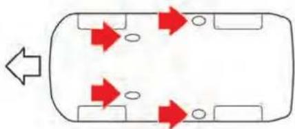
flowchart
graph TD
    A[" "] --> B[" "]
    C[" "] --> D[" "]
    E[" "] --> F[" "]
    G[" "] --> H[" "]
Do not use the tie down hooks for towing or vehicle recovery.

CAUTION
- Do not use the vehicle tie downs to free a vehicle stuck in sand, snow, mud, etc.
• Always pull the cable straight out from the vehicle. Never pull on the vehicle at an angle. - Pulling devices such as ropes or canvas straps are not recommended for use in vehicle towing or recov-
ery.
NOTICE
- Tow chains or cables must be attached only to the vehicle recovery hooks or main structural members of the vehicle. Otherwise, the vehicle body will be damaged.
- Never tow a vehicle using the vehicle tie downs or recovery hooks.
- Pulling devices should be routed so they do not touch any part of the suspension, steering, brake or cooling systems.
Rocking a stuck vehicle
If your vehicle is stuck in sand, snow, mud, etc., use the following procedure:
-
Turn off the Vehicle Dynamic Control (VDC) system and select SAVE mode with the transmission setup switch. ( "VDC, transmission and suspension setup switches" page 5-25)
-
Make sure the area in front and behind the vehicle is clear of obstructions.
In case of emergency 6-11
- Turn the steering wheel right and left to clear an area around the front tires.
- Slowly rock the vehicle forward and backward.
- Shift back and forth between the R and A↔M positions.
- Apply the accelerator as little as possible to maintain the rocking motion.
- Release the accelerator pedal before shifting between the R and A↔M positions.
- Do not spin the tires above 35 MPH (55 km/h).
- Turn on the Vehicle Dynamic Control (VDC) system.
- If the vehicle cannot be freed after a few tries, contact a professional towing service to remove the vehicle.
6-12 In case of emergency
7 Appearance and care
Cleaning exterior 7-2
Matte paint care (if so equipped) 7-2
Washing 7-3
Waxing 7-4
Removing spots 7-4
Underbody 7-5
Glass 7-5
Wheels 7-5
Chrome parts 7-5
Cleaning interior 7-7
Air fresheners 7-7
Floor mats 7-8
Seat belts 7-8
Corrosion protection 7-9
Most common factors contributing to
vehicle corrosion 7-9
Environmental factors influence the rate of corrosion 7-9
To protect your vehicle from corrosion 7-10

CLEANING EXTERIOR
In order to maintain the appearance of your vehicle, it is important to take proper care of it. To protect the paint surfaces, wash your vehicle as soon as you can:
● after a rainfall to prevent possible damage from acid rain
● after driving on coastal roads
- when contaminants such as soot, bird droppings, tree sap, metal particles or bugs get on the paint surface
- when dust or mud builds up on the surface Whenever possible, store or park your vehicle inside a garage or in a covered area.
When it is necessary to park outside, park in a shady area or protect the vehicle with a body cover.
Be careful not to scratch the paint surface when putting on or removing the body cover.
MATTE PAINT CARE (if so equipped)
If your vehicle is equipped with matte paint, special care is necessary to clean your vehicle to maintain the appearance of the matte paint.

CAUTION
Failure to follow the proper matte paint care instructions can permanently affect the appearance of the paint. Improper care can result in shiny spots, rub marks or other damage. This damage can only be repaired at a body shop trained in matte paint repair. Damage resulting from improper matte paint care is not covered under NISSAN's new vehicle limited warranty.
- Do not use an automatic car wash.
- Do not rub the paint.
- Only use cleaners and soaps that are specifically formulated for matte paint.
- Do not use terry cloth towels to wash or dry the vehicle.
-
Do not rub repeatedly with any cleaning material to minimize the risk of burnishing a shiny spot.
-
Hand wash with a wet microfiber cloth, dry with clean damp chamois, and use light pressure with a microfiber towel. Minimize the pressure you use.
- Test all cleaning products on a hidden part of the vehicle (such as under the rocker sills) to make certain they do not affect the appearance of the matte paint.
- Pre-rinse the vehicle before washing to remove coarse dirt that can scratch the paint.
- Do not wash using a pressure washer.
- Spot treat heavy dirt accumulation with a cleaner made for matte paint.
- Do not use solvent based tar and bug remover products to clean the vehicle.
- Do not use waxes and sealers, even those specifically formulated for matte paint. These products may affect the appearance (add shine) of the matte paint.
Washing
Hand wash the vehicle for best results. Park the vehicle in a cool, shaded area, out of direct sunlight. Read these procedures and gather the necessary equipment and supplies before washing the vehicle.
Equipment/Supplies:
- Vehicle soap specifically made for matte paint
- Microfiber cloth
- Chamois cloth, for drying
-
Two buckets with grit guards or dirt separators (available at many automotive supply or detaining supply sources).
-
Clean the wheels.
-
Use a product specifically formulated to clean wheels.
- Do not get any wheel cleaner on the paint. Immediately wash and rinse the paint if any wheel clear contacts the paint.
-
Do not use the same cleaning materials to clean the wheels and paint.
-
Fill the buckets.
- Fill one bucket (with dirt separator grid at the bottom) with vehicle soap specifically made for matte paint and water. Follow
the soap manufacturer's instructions.
- Fill the second bucket with clean water for rinsing the wash cloth.
-
Always rinse the wash cloth in the clean water before putting the wash cloth into the cleaning solution.
-
Inspect the car for areas with heavy soiling or spots and, if necessary, treat these areas first, before washing the entire vehicle.
- Remove large pieces of dirt by spraying the vehicle with a hose.
-
Soak the wash cloth in the soap solution and wash the vehicle lightly. Work in small sections from the bottom of the vehicle to the top.
-
Wash a section then rinse the soapy section of the vehicle completely before starting another section.
-
Keep the clean sections of the vehicle wet as the remaining sections are completed.
-
Use a clean damp chamois to dry the vehicle before it air dries. If the undried surfaces start to air dry, redampen those areas.
Use a clean damp chamois to dry the vehicle before it air dries. If the undried surfaces start to air dry, redampen those areas.
- Do not allow surface to air dry. Air drying allows water spots to form.
WASHING
Wash dirt off the vehicle with a wet sponge and plenty of water. Clean the vehicle thoroughly using a mild soap, a special vehicle soap or general purpose dishwashing liquid mixed with clean, lukewarm (never hot) water.
NOTICE
- Do not use an automatic car wash. The rear spoiler may be damaged.
- Do not use car washes that use acid in the detergent. Some car washes, especially brushless ones, use some acid for cleaning. The acid may react with some plastic vehicle components, causing them to crack. This could affect their appearance, and also could cause them not to function properly. Always check with your car wash to confirm that acid is not used.
- Do not wash the vehicle with strong household soap, strong chemical detergents, gasoline or solvents.
- Do not wash the vehicle in direct sunlight or while the vehicle body is hot, as the surface may become
Appearance and care 7-3
water-spotted.
- Avoid using tight-napped or rough cloths, such as washing mitts. Care must be taken when removing caked-on dirt or other foreign substances so the paint surface is not scratched or damaged.
Rinse the vehicle thoroughly with plenty of clean water.
Inside flanges, seams and folds on the doors, hatches and hood are particularly vulnerable to the effects of road salt. Therefore, these areas must be regularly cleaned. Take care that the drain holes in the lower edge of the door are open. Spray water under the body and in the wheel wells to loosen the dirt and wash away road salt.
Avoid leaving water spots on the paint surface by using a damp chamois to dry the vehicle.
WAXING
Regular waxing protects the paint surface and helps retain new vehicle appearance. Polishing is recommended to remove built-up wax residue and to avoid a weathered appearance before reapplying wax.
A GT-R certified NISSAN dealer can assist you in choosing the proper product.
- Wax your vehicle only after a thorough washing. Follow the instructions supplied with the wax.
- Do not use a wax containing any abrasives, cutting compounds or cleaners that may damage the vehicle finish.
Machine compound or aggressive polishing on a base coat/clear coat paint finish may dull the finish or leave swirl marks.

WARNING
Do not use wax on the glass, rubber or plastic parts around the glass or door. This may prevent the window operation or cause poor visibility and the wax cannot be coated uniformly.
NOTICE
- Do not use compound agents on clear-coated dry carbon fiber parts (such as the NISMO model's bumper, side sill protector, rear spoiler, etc.).
- Do not use any chemical agents (wax, coating agent, compound agent, etc.) on matte-painted dry carbon fiber parts (such as the rear diffuser, a rear spoiler that is of specifications other than NISMO, etc.).
REMOVING SPOTS
Remove tar and oil spots, industrial dust, insects, and tree sap as quickly as possible from the paint surface to avoid lasting damage or staining. Special cleaning products are available at a GT-R certified NISSAN dealer or any automotive accessory stores.
UNDERBODY
In areas where road salt is used in winter, the underbody must be cleaned regularly. This will prevent dirt and salt from building up and causing the acceleration of corrosion on the underbody and suspension. Before the winter period and again in the spring, the underseal must be checked and, if necessary, re-treated.
GLASS
Use glass cleaner to remove smoke and dust film from the glass surfaces. It is normal for glass to become coated with a film after the vehicle is parked in the hot sun. Glass cleaner and a soft cloth will easily remove this film.
NOTICE
When cleaning the inside of the windows, do not use sharp-edged tools, abrasive cleaners or chlorine-based disinfectant cleaners. They could damage the electrical conductors, radio antenna elements or rear window defroster elements.
WHEELS
Wash the wheels when washing the vehicle to maintain their appearance.
- Clean the inner side of the wheels when the wheel is changed or the underside of the vehicle is washed.
- Inspect wheel rims regularly for dents or corrosion. Such damage may cause loss of pressure or poor seal at the tire bead.
- NISSAN recommends that the road wheels be waxed to protect against road salt in areas where it is used during winter.
CAUTION
Do not use abrasive cleaners when washing the wheels.
Aluminum alloy wheels
Wash regularly with a sponge dampened in a mild soap solution, especially during winter months in areas where road salt is used. Salt could discolor the wheels if not removed.
The dark chrome coat wheel is specially coated to a distinctive color. It may discolor to black depending on storage conditions. If only one wheel is changed, it may be different color with
other wheels. If the wheel is changed, consult with a GT-R certified NISSAN dealer.
NOTICE
Follow the directions below to avoid staining or discoloring the wheels:
- Do not use a cleaner that uses strong acid or alkali contents to clean the wheels.
- Do not apply wheel cleaners to the wheels when they are hot. The wheel temperature should be the same as ambient temperature.
- Rinse the wheel to completely remove the cleaner within 15 minutes after the cleaner is applied.
CHROME PARTS
Clean chrome parts regularly with a non-abrasive chrome polish to maintain the finish.
OUTSIDE DOOR HANDLES
After driving on a road where salt is used in winter, immediately wash and clean the outside door handles that are provided with a special coating. This will keep the beautiful finish longer.
TIRE DRESSING
NISSAN does not recommend the use of tire dressings. Tire manufacturers apply a coating to the tires to help reduce discoloration of the rubber. If a tire dressing is applied to the tires, it may react with the coating and form a compound. This compound may come off the tire while driving and stain the vehicle paint.
If you choose to use a tire dressing, take the following precautions:
- Use a water-based tire dressing. The coating on the tire dissolves more easily with an oil-based tire dressing.
- Apply a light coat of tire dressing to help prevent it from entering the tire tread/grooves (where it would be difficult to remove).
- Wipe off excess tire dressing using a dry towel. Make sure the tire dressing is completely removed from the tire tread/grooves.
- Allow the tire dressing to dry as recommended by tire dressing manufacturer.
DRY CARBON FIBER PARTS (if so equipped)
Because of the characteristics of the material, the dry carbon fiber parts may turn yellow due to exposure to ultraviolet rays. The surfaces of dry carbon fiber parts are coated with a special ultraviolet protection paint. To maintain the appearance of these parts, it is important to take proper care of them.
NOTICE
- Do not use compound agents on clear-coated dry carbon fiber parts (such as the NISMO model's bumper, side sill protector, rear spoiler, etc.).
- Do not use any chemical agents (wax, coating agent, compound agent, etc.) on matte-painted dry carbon fiber parts (such as the rear diffuser, a rear spoiler that is of specifications other than NISMO, etc.).
- When dry carbon fiber parts become dirty, prepare a dilute cleaning solu-
tion by mixing one capful of mild detergent in a bucket of water, and use that mixture to clean the parts.
NOTE:
The surfaces of the dry carbon fiber parts are lightly coated like a race car so that you can feel the proper texture of real carbon, which may feel rough. This is normal.
CLEANING INTERIOR
Occasionally remove loose dust from the interior trim, plastic parts and seats using a vacuum cleaner or soft bristled brush. Wipe the vinyl and leather surfaces with a clean, soft cloth dampened in mild soap solution, then wipe clean with a dry soft cloth.
Regular care and cleaning is required in order to maintain the appearance of the leather.
Before using any fabric protector, read the manufacturer's recommendations. Some fabric protectors contain chemicals that may stain or bleach the seat material.
Use a cloth dampened only with water, to clean the meter and gauge lens.

WARNING
Do not use water or acidic cleaners (hot steam cleaners) on the seat. This can damage the seat or occupant classification sensor. This can also affect the operation of the air bag system and result in serious personal injury.

CAUTION
- Never use benzine, thinner, or any similar material.
- For cleaning, use a soft cloth, dampened with water. Never use a rough cloth, alcohol, benzine, thinner or any kind of solvent or paper towel with a chemical cleaning agent. They will scratch or cause discoloration to the lens.
- Do not spray any liquid such as water on the meter lens. Spraying liquid may cause the system to malfunction.
NOTICE
- Small dirt particles can be abrasive and damaging to the leather surfaces and should be removed promptly. Do not use saddle soap, car waxes, polishes, oils, cleaning fluids, solvents, detergents or ammonia-based cleaners as they may damage the leather's natural finish.
- Never use fabric protectors unless
recommended by the manufacturer.
- Do not use glass or plastic cleaner on meter or gauge lens covers. It may damage the lens cover.
AIR FRESHENERS
Most air fresheners use a solvent that could affect the vehicle interior. If an air freshener is used, take the following precautions:
- Hanging-type air fresheners can cause permanent discoloration when they contact vehicle interior surfaces. Place the air freshener in a location that allows it to hang free and not contact an interior surface.
- Liquid-type air fresheners typically clip on the vents. These products can cause immediate damage and discoloration when spilled on interior surfaces.
Carefully read and follow the manufacturer's instructions before using air fresheners.
FLOOR MATS

WARNING
To avoid potential pedal interference that may result in a collision or injury:
- NEVER place a floor mat on top of another floor mat in the driver front position.
- Use only genuine NISSAN floor mats specifically designed for use in your vehicle model. See your GT-R certified NISSAN dealer for more information.
- Properly position the mats in the floorwell using the floor mat positioning aid. See “Floor mat positioning aid” later in this section.
The use of genuine NISSAN floor mats can extend the life of your vehicle carpet and make it easier to clean the interior. Mats should be maintained with regular cleaning and replaced if they become excessively worn.

natural_image
Technical illustration of a mechanical component with layered surfaces and a small protrusion (no text or symbols)Floor mat positioning aid
This model includes front floor mat brackets to act as floor mat positioning aid. NISSAN floor mats have been specially designed for your vehicle model. The floor mats have grommet holes in them. To install, simply position the mat by placing the floor mat bracket through the floor mat grommet hole while centering the mat in the floorwell.
Periodically check to make certain that the mats are properly positioned.

natural_image
Top-down line drawing of a car with no text, numbers, or symbolsBracket positions
The illustration shows the location of the floor mat brackets.
SEAT BELTS
The seat belts can be cleaned by wiping them with a sponge dampened in a mild soap solution. Allow the belts to dry completely in the shade before using them. ( "Seat belt maintenance" page 1-13)

WARNING
Do not allow wet seat belts to roll up in the retractor. NEVER use bleach, dye, or chemical solvents to clean the seat belts, since these materials may severely weaken the seat belt webbing.
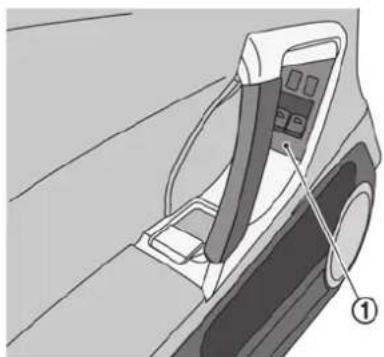
natural_image
Diagram of a car's side panel with a belt and control panel, showing no text or symbolsCleaning the power window finisher
Moisten a soft cloth with neutral detergent and wipe off the dirt on the power window finisher ①.
After wiping off the dirt, soak a cloth with water and wring it out thoroughly, then wipe off the neutral detergent.
NOTICE
Some cleaners may cause the paint to peel or cause spots to occur. If using a cleaner, consult with a GT-R certified NISSAN dealer.
CORROSION PROTECTION
MOST COMMON FACTORS CONTRIBUTING TO VEHICLE CORROSION
- The accumulation of moisture-retaining dirt and debris in body panel sections, cavities, and other areas.
- Damage to paint and other protective coatings caused by gravel and stone chips or minor traffic accidents.
ENVIRONMENTAL FACTORS IN- FLUENCE THE RATE OF CORRO- SION
Moisture
Accumulation of sand, dirt and water on the vehicle body underside can accelerate corrosion. Wet floor coverings will not dry completely inside the vehicle, and should be removed for drying to avoid floor panel corrosion.
Relative humidity
Corrosion will be accelerated in areas of high relative humidity, especially those areas where the temperatures stay above freezing where atmospheric pollution exists, or where road salt is used.
Appearance and care 7-9
Temperature
A temperature increase will accelerate the rate of corrosion to those parts which are not well ventilated.
Air pollution
Industrial pollution, the presence of salt in the air in coastal areas, or heavy road salt use will accelerate the corrosion process. Road salt will also accelerate the disintegration of paint surfaces.
TO PROTECT YOUR VEHICLE FROM CORROSION
- Wash and wax your vehicle often to keep the vehicle clean.
- Always check for minor damage to the paint and repair it as soon as possible.
- Keep drain holes at the bottom of the doors open to avoid water accumulation.
- Check the underbody for accumulation of sand, dirt or salt. If present, wash with water as soon as possible.
CAUTION
- NEVER remove dirt, sand or other debris from the passenger compartment by washing it out with a hose. Remove dirt with a vacuum cleaner.
- Never allow water or other liquids to come in contact with electronic components inside the vehicle as this may damage them.
Chemicals used for road surface deicing are extremely corrosive. They accelerate corrosion and deterioration of underbody components such as the exhaust system, fuel and brake lines, brake cables, floor pan and fenders.
In winter, the underbody must be cleaned periodically.
For additional protection against rust and corrosion, which may be required in some areas, consult a GT-R certified NISSAN dealer.
8 Maintenance and do-it-yourself
Maintenance requirements 8-3
Scheduled maintenance 8-3
General maintenance 8-3
Where to go for service 8-3
General maintenance 8-4
Explanation of maintenance items 8-4
Maintenance precautions 8-6
Engine compartment check locations 8-8
Removing the cowl top cover 8-9
Engine cooling system 8-10
Checking engine coolant level 8-11
Changing engine coolant 8-12
Engine oil 8-13
Checking engine oil level 8-13
Changing engine oil and filter 8-14
Transmission oil 8-14
Power steering fluid 8-14
Brake fluid 8-15
Window washer fluid 8-16
Battery 8-17
Precautions 8-17
Fluid level check 8-18
Jump starting 8-19
Drive belts 8-19
Spark plugs 8-20
Replacing spark plugs 8-20
Air cleaner 8-21
Windshield wiper blades 8-22
Cleaning 8-22
Replacing the wiper blades 8-23
Brakes 8-23
Self-adjusting brakes 8-23
Brake pad wear warning 8-23
High performance brake system 8-24
Replacing the brake pads 8-24
Fuses 8-25
Engine compartment 8-25
Passenger compartment 8-26
Intelligent Key battery replacement 8-27
Lights 8-29
Headlights 8-30
Exterior and interior lights 8-30
Wheels and tires 8-32
Tire pressure 8-32
Tire and loading information label 8-35
Checking the tire pressure 8-36

Tire labeling 8-37
Types of tires 8-38
Tire chains 8-40
Changing wheels and tires 8-41
Jacking vehicle and removing wheels 8-43
Wheel lock nuts (if so equipped) 8-49
MAINTENANCE REQUIREMENTS
Some day-to-day and regular maintenance is essential to maintain your vehicle good mechanical condition, as well as its emission and engine performance.
It is the owner's responsibility to make sure that the scheduled maintenance, as well as general maintenance, is performed.
As the vehicle owner, you are the only one who can ensure that your vehicle receives the proper maintenance care. You are a vital link in the maintenance chain.
SCHEDULED MAINTENANCE
For your convenience, both required and optional scheduled maintenance items are described and listed in your NISSAN Service and Maintenance Guide. You must refer to that guide to ensure that necessary maintenance is performed on your vehicle at regular intervals.
GENERAL MAINTENANCE
General maintenance includes those items which should be checked during normal day-to-day operation. They are essential for proper vehicle operation. It is your responsibility to perform these procedures regularly as prescribed.
Performing general maintenance checks requires minimal mechanical skill and only a few general automotive tools.
These checks or inspections can be done by yourself, a qualified technician or, if you prefer, a GT-R certified NISSAN dealer.
WHERE TO GO FOR SERVICE
GT-R certified NISSAN dealers are required to have additional training and equipment and are the only NISSAN dealers authorized to perform warranty work on key vehicle performance systems such as engine, transmission, suspension and brakes.
If maintenance service is required or your vehicle appears to malfunction, have the systems checked and serviced by a GT-R certified NISSAN dealer.
NISSAN technicians are well-trained specialists and are kept up to date with the latest service information through technical bulletins, service tips, and in-dealer information systems. They are completely qualified to work on NISSAN vehicles before work begins.
You can be confident that a GT-R certified NISSAN dealer's service department performs the best job to meet the maintenance requirements on your vehicle.
To find a GT-R certified NISSAN dealer near you, call 1-866-668-1GTR in the US or 1-800- 387-0122 in Canada, or go to www.gtrnissan.com/.
GENERAL MAINTENANCE
During the normal day-to-day operation of the vehicle, general maintenance should be performed regularly as prescribed in this section. If you detect any unusual sounds, vibrations or smell, be sure to check for the cause or have a GT-R certified NISSAN dealer do it promptly. In addition, you should notify a GT-R certified NISSAN dealer if you think that repairs are required. ( "Maintenance precautions" page 8-6)
Additional information on the following items with “*” is found later in this section.
Outside the vehicle
The maintenance items listed here should be performed from time to time, unless otherwise specified.
Doors and engine hood: Check that all doors and the engine hood, operate properly. Also ensure that all latches lock securely. Lubricate hinges, latches, latch pins, rollers and links if necessary. Make sure that the secondary latch keeps the hood from opening when the primary latch is released.
When driving in areas using road salt or other corrosive materials, check lubrication frequently.
Lights*: Clean the headlights on a regular basis. Make sure that the headlights, stop lights, tail lights, turn signal lights, and other lights are all operating properly and installed securely. Also check headlight aim.
Road wheel nuts (lug nuts)*: When checking the tires, make sure no wheel nuts are missing, and check for any loose wheel nuts. Tighten if necessary.
Tire rotation*: Tires cannot be rotated because your vehicle is equipped with different sized tires in the front and rear.
Tires*: Check the pressure with a gauge often and always prior to long distance trips. If necessary, adjust the pressure in all tires to the pressure specified. Check carefully for damage, cuts or excessive wear.
NOTE:
- You can check the pressure of all four tires on the multi function display. See the separate Multi Function Display Owner's Manual.
- The tires of this vehicle are filled with nitrogen gas. When the tire pressure is low, fill the tires with nitrogen. Contact a GT-R certified NISSAN dealer for information on filling the tires with nitrogen.
- If nitrogen is not available, compressed air may be safely used under normal driving conditions. However, NISSAN recommends refilling with nitrogen for maximum tire performance.
Tire Pressure Monitoring System (TPMS) transmitter components: Replace grommet seal of transmitter in TPMS, when replacing each tire by reaching the wear limit.
Tire, wheel alignment and balance: If the vehicle should pull to either side while driving on a straight and level road, or if you detect uneven or abnormal tire wear, there may be a need for wheel alignment.
If the steering wheel or seat vibrates at normal highway speeds, wheel balancing may be needed.
For additional information regarding tires, refer to "Important Tire Safety Information" (US) or "Tire Safety Information" (Canada) in the Warranty Information Booklet.
Windshield: Clean the windshield on a regular basis. Check the windshield at least every six months for cracks or other damage. Have a damaged windshield repaired by a qualified repair facility.
Windshield wiper blades*: Check for cracks or wear if they do not wipe properly.
Inside the vehicle
The maintenance items listed here should be checked on a regular basis, such as when performing scheduled maintenance, cleaning the vehicle, etc.
Accelerator pedal: Check the pedal for smooth operation and make sure the pedal does not catch or require uneven effort. Keep the floor mat away from the pedal.
Transmission P mechanism: On a fairly steep hill, check that your vehicle is held securely with the shift lever in the P position without applying any brakes.
Brake pedal: Check the pedal for smooth operation. If the brake pedal suddenly goes down further than normal, the pedal feels spongy or the vehicle seems to take longer to stop, see a GT-R certified NISSAN dealer immediately. Keep the floor mat away from the pedal.
Brakes: Check that the brakes do not pull the vehicle to one side when applied.
Parking brake: Check the parking brake operation regularly. The vehicle should be securely held on a fairly steep hill with only the parking brake applied. If the parking brake needs to be adjusted, see a GT-R certified NISSAN dealer.
Seat belts: Check that all parts of the seat belt system (for example, buckles, anchors, adjuster and retractors) operate properly and smoothly, and are installed securely. Check the belt webbing for cuts, fraying, wear or damage.
Seats: Check seat position controls such as seat adjusters, seatback recliner, etc. to ensure they operate smoothly and that all latches lock securely in every position.
Steering wheel: Check for changes in the steering conditions, such as excessive free play, hard steering or strange noises.
Warning lights and chimes: Make sure that all warning lights and chimes are operating properly.
Windshield defroster: Check that the air comes out of the defroster outlets properly and in sufficient quantity when operating the heater or air conditioner.
Windshield wiper and washer*: Check that the wipers and washer operate properly and that the wipers do not streak.
Under the hood and vehicle
The maintenance items listed here should be checked periodically (for example, each time you check the engine oil or refuel).
Battery*: Check the fluid level in each cell. It should be between the MAX and MIN lines. Vehicles operated in high temperatures or under severe condition require frequent checks of the battery fluid level.
NOTE:
Care should be taken to avoid situations that can lead to potential battery discharge and potential no-start conditions such as:
-
Installation or extended use of electronic accessories that consume battery power when the engine is not running (Phone chargers, GPS, DVD players, etc.)
-
Vehicle is not driven regularly and/or only driven short distances.
In these cases, the battery may need to be charged to maintain battery health.
Brake fluid level*: Make sure that the brake fluid level is between the MAX and MIN lines on the reservoir.
Engine coolant level*: Check the coolant level when the engine is cold.
Maintenance and do-it-yourself 8-5
Engine drive belts*: Make sure that no belt is frayed, worn, cracked or oily.
Engine oil level*: Check the level after parking the vehicle on a level spot and turning off the engine. Wait at least 5 minutes for the oil to drain back into the oil pan before checking the oil.
Exhaust system: Make sure there are no loose supports, cracks or holes. If the sound of the exhaust seems unusual or there is a smell of exhaust fumes in the engine compartment, immediately have the exhaust system inspected by a GT-R certified NISSAN dealer. ( "Exhaust gas (carbon monoxide)" page 5-3)
Fluid leaks: Check under the vehicle for fuel, oil, water or other fluid leaks after the vehicle has been parked for a while. Water dripping from the air conditioner after use is normal. If you should notice any leaks or if gasoline fumes are evident, check for the cause and have it corrected immediately.
Power steering fluid level* and lines: Check the level when the fluid is cold, with the engine off. Check the lines for proper attachment, leaks, cracks, etc.
Radiator and hoses: Check the front of the radiator and clean off any dirt, insects, leaves, etc., that may have accumulated. Make sure the hoses have no cracks, deformation, rot or loose connections.
Underbody: The underbody is frequently exposed to corrosive substances such as those used on icy roads or to control dust. It is very important to remove these substances, otherwise rust will form on the floor pan, frame, fuel lines and around the exhaust system. At the end of winter, the underbody should be thoroughly flushed with plain water, being careful to clean those areas where mud and dirt may accumulate. ( "Underbody" page 7-5)
Windshield washer fluid*: Check that there is adequate fluid in the reservoir.
MAINTENANCE PRECAUTIONS
When performing any inspection or maintenance work on your vehicle, always take care to prevent serious accidental injury to yourself or damage to the vehicle. The following are general precautions which should be closely observed.

WARNING
- Park the vehicle on a level surface, apply the parking brake securely and block the wheels to prevent the vehicle from moving. Move the shift lever to the P position.
- Be sure the ignition switch is in the OFF or LOCK position when performing any parts replacement or repairs.
- If you must work with the engine running, keep your hands, clothing, hair and tools away from moving fans, belts and any other moving parts.
-
It is advisable to secure or remove any loose clothing and remove any jewelry, such as rings, watches, etc. before working on your vehicle.
• Always wear eye protection whenever you work on your vehicle. -
If you must run the engine in an enclosed space such as a garage, be sure there is proper ventilation for exhaust gases to escape.
- Never get under the vehicle while it is supported only by a jack. If it is necessary to work under the vehicle, support it with safety stands.
- Keep smoking materials, flame and sparks away from fuel tank and the battery.
- Your vehicle is equipped with an automatic engine cooling fan. It may come on at any time without warning, even if the ignition key is in the OFF position and the engine is not running. To avoid injury, always disconnect the negative battery cable before working near the fan.
- The fuel filter or fuel lines should be serviced by a GT-R certified NISSAN dealer because the fuel lines are under high pressure even when the engine is off.
CAUTION
- Do not work under the hood while the engine is hot. Turn the engine off and wait until it cools down.
- Avoid direct contact with used engine oil and coolant. Improperly disposed engine oil, coolant, and/or other vehicle fluids can damage the environment. Always conform to local regulations for disposal of vehicle fluid.
NOTICE
- Never connect or disconnect the battery or any transistorized component while the ignition switch is in the ON position.
- Never leave the engine or transmission related component harnesses disconnected while the ignition switch is in the ON position.
This "8. Maintenance and do-it-yourself" section gives instructions regarding only those items which are relatively easy for an owner to perform.
A genuine NISSAN Service Manual is also available. ( "Owner's Manual/Service Manual order information" page 9-22)
You should be aware that incomplete or improper servicing may result in operating difficulties or excessive emissions. If in doubt about any servicing, we recommend that it be done by a GT-R certified NISSAN dealer.
ENGINE COMPARTMENT CHECK LOCATIONS

- Fuse/fusible link holder
- Battery
- Engine oil filler cap
- Engine oil dipstick
- Brake fluid reservoir
-
Air cleaner
-
Power steering fluid reservoir
- Radiator filler cap
- Coolant reservoir cap (pressure type)
- Coolant reservoir
- Window washer fluid reservoir
8-8 Maintenance and do-it-yourself
NOTICE
The coolant reservoir is equipped with a pressure type cap, and the radiator is equipped with a non-pressure type cap. Do not switch the radiator filler cap and the coolant reservoir cap. Doing so will cause substandard cooling performance and overheating.
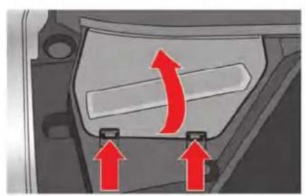
natural_image
Mechanical component with red arrows indicating motion or force direction (no text or symbols)REMOVING THE COWL TOP COVER
Remove the cowl top cover if necessary.
- Remove the battery cover.

- Unfasten the 5 clips and remove the cowl top cover Ⓐ by pulling it up.
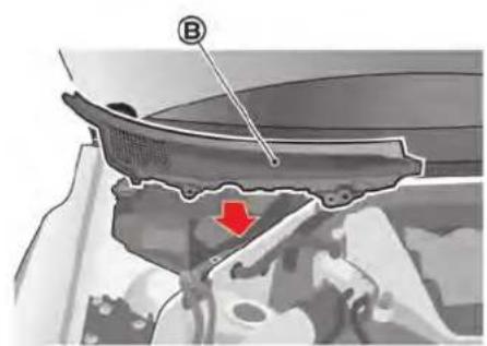
natural_image
Mechanical component diagram showing a curved structure with a red arrow pointing to a specific area (no text or symbols present)- Unfasten the 3 clips and remove the cowl top cover Ⓑ by pulling it towards the front of the vehicle.
ENGINE COOLING SYSTEM
The engine cooling system is filled at the factory with a pre-diluted mixture of 50% Genuine NISSAN Long Life Antifreeze/Coolant (blue) and 50% water to provide year-round anti-freeze and coolant protection. The anti-freeze solution contains rust and corrosion inhibitors. Additional engine cooling system additives are not necessary.

WARNING
- Never remove the radiator or coolant reservoir cap when the engine is hot. Wait until the engine and radiator cool down. Serious burns could be caused by high pressure fluid escaping from the radiator. ( "If your vehicle overheats" page 6-8)
- The radiator is equipped with a pressure type radiator cap. To prevent engine damage, use only a genuine NISSAN radiator cap.

CAUTION
- Never use any cooling system additives such as radiator sealer. Additives may clog the cooling system and cause damage to the engine, transmission and/or cooling system.
- When adding or replacing coolant, be sure to use only Genuine NISSAN Long Life Antifreeze/Coolant (blue) or equivalent. Genuine NISSAN Long Life Antifreeze/Coolant (blue) is pre-diluted to provide antifreeze protection to -34^ (-37^) . If additional freeze protection is needed due to weather where you operate your vehicle, add Genuine NISSAN Long Life Antifreeze/ Coolant (blue) concentrate following the directions on the container. If an equivalent coolant other than Genuine NISSAN Long Life Anti-freeze/ Coolant (blue) is used, follow the coolant manufacture's instructions to maintain minimum antifreeze protection to -34^ (-37^) . The use of other types of coolant solutions other than Genu
ine NISSAN Long Life Antifreeze/ Coolant (blue) or equivalent may damage the engine cooling system.
- The life expectancy of the factory-fill coolant is 24,000 miles (38,400 km) or 2 years. Mixing any other type of coolant other than Genuine NISSAN Long Life Antifreeze/Coolant (blue), including Genuine NISSAN Long Life Antifreeze/Coolant (green), or the use of nondistilled water will reduce the life expectancy of the factory-fill coolant. Refer to the GT-R Service and Maintenance Guide for more details.
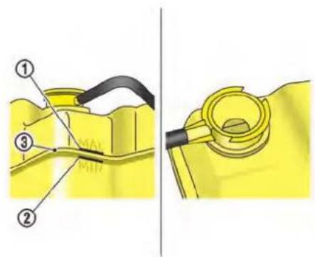
Except for NISMO models

NISMO models
CHECKING ENGINE COOLANT LEVEL
①: MAX line
②: MIN line
③ : Between MAX and MIN lines (except for NISMO models)

Check the coolant level in the reservoir when the engine is cold. If the coolant level is below the MIN level ②, open the reservoir cap (pressure type) B and add coolant up to between the MAX ① and MIN ② level. If the reservoir is empty, open the radiator filler cap A and check the coolant level in the radiator when the engine is cold. If there is insufficient coolant in the radiator, fill the radiator with coolant up to the filler opening and also add it to the reservoir up to between the MAX ① and MIN ② level.
This vehicle contains Genuine NISSAN Long Life Antifreeze/Coolant (blue). The life expectancy of the factory-fill coolant is 24,000 miles
Maintenance and do-it-yourself 8-11
(38,400 km) or 2 years. Mixing any other type of coolant or the use of non-distilled water will reduce the life expectancy of the factory-fill coolant. Refer to the GT-R Service and Maintenance Guide for more details.
If the cooling system frequently requires coolant, have it checked by a GT-R certified NISSAN dealer.
Check that the level of coolant is between MAX and MIN on the pressurized radiator reservoir. If the level is below the midpoint, the amount of coolant circulating may be insufficient for maximum vehicle performance, possibly causing engine overheating or other trouble.
For the coolant level and mixture ratio when engaging in performance driving, see "Coolant level and mixture ratio" page GTR-15.
Except for NISMO models:
If it is difficult to determine the midpoint between MAX and MIN, remove the coolant reservoir cap and look inside through the opening to check that the coolant level is above the divider ③ between the top half and bottom half of the pressurized coolant reservoir.
NOTICE
- The coolant reservoir is equipped with a pressure type cap, and the radiator is equipped with a non-pressure type cap. Do not switch the radiator filler cap and the coolant reservoir cap. Doing so will cause substandard cooling performance and overheating.
- If you have added only water as the coolant in an emergency, change it to a coolant mixture ratio specified as soon as possible.
CHANGING ENGINE COOLANT
If major cooling system repairs are required, contact a GT-R certified NISSAN dealer. The service procedures can be found in the appropriate NISSAN Service Manual.
Improper servicing can result in reduced heater performance and engine overheating.

WARNING
- To avoid the danger of being scalded, never change the coolant when the engine is hot.
- Never remove the radiator filler cap and the coolant reservoir cap when the engine is hot. Serious burns could be caused by high pressure fluid escaping from the radiator and reservoir.
- Avoid direct skin contact with used coolant. If skin contact is made, wash thoroughly with soap or hand cleaner as soon as possible.
- Keep coolant out of reach of children and pets.
Engine coolant must be disposed of properly. Check your local regulations.
ENGINE OIL
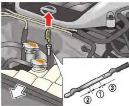
CHECKING ENGINE OIL LEVEL
- Park the vehicle on a level surface and apply the parking brake.
- Run the engine until it reaches operating temperature.
- Turn off the engine. Wait at least 5 minutes for the oil to drain back into the oil pan before checking the oil.
- Remove the dipstick and wipe it clean. Reinsert it all the way.
- Remove the dipstick again and check the oil level. It should be within the range ①. If the oil level is below ②, remove the oil filler cap
and pour recommended oil through the opening. Do not overfill ③.
- Recheck oil level with the dipstick.
NOTE:
- It is normal to add some oil between oil maintenance intervals or during the break-in period, depending on the severity of operating conditions. More engine oil is consumed by frequent acceleration/deceleration especially when the engine rpm is high. If your rate of oil consumption increases suddenly or without explanation, NISSAN recommends that you have your vehicle inspected by a GT-R certified NISSAN dealer.
- When the vehicle is delivered, the engine oil is set to 0.39 in (10 mm) below the H mark for optimal high performance driving. The engine oil can be filled up to the H mark if performance driving is not engaged.
NOTICE
- Mobil 1 (0W-40) (100% synthetic) is the factory fill oil. The VR38 engine with its plasma-sprayed bores was developed using this oil. NISSAN cannot ensure proper engine operation and durability if other 0W-40 synthetic oil is used. If Mobil 1 (0W-40) is not available, Mobil 1 (10W-40) (100% synthetic) may be used; however, some performance loss may be noticed.
- Oil level should be checked regularly. Operating the engine with an insufficient amount of oil can damage the engine. See the 2016 NISSAN GT-R Warranty Information Booklet for details including applicable exclusions.
CHANGING ENGINE OIL AND FILTER
NOTE:
When replacement is required, contact a GT-R certified NISSAN dealer for servicing.

WARNING
- Prolonged and repeated contact with used engine oil may cause skin cancer.
- Try to avoid direct skin contact with used oil. If skin contact is made, wash thoroughly with soap or hand cleaner as soon as possible.
- Keep used engine oil out of reach of children.
TRANSMISSION OIL
NOTE:
When checking or replacement is required, contact a GT-R certified NISSAN dealer for servicing.
NOTICE
- Use only Genuine NISSAN Transmission Oil R35 Special. Do not mix with other fluids.
- Using transmission oil other than Genuine NISSAN Transmission Oil R35 Special will cause deterioration in driveability and transmission durability, and may damage the transmission. See the 2016 NISSAN GT-R Warranty Information Booklet for details including applicable exclusions.
POWER STEERING FLUID
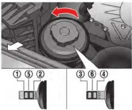
Check the fluid level in the reservoir. Remove the cap that is attached with a gauge inside.
The fluid level should be checked using the front side of the gauge marked "HOT" ( ①: HOT MIN., ②: HOT MAX.) at fluid temperatures of 122 to 176°F (50 to 80°C) or using the reverse side of the gauge marked "COLD" ( ③: COLD MIN., ④: COLD MAX.) at fluid temperatures of 32 to 86°F (0 to 30°C).
If the fluid is below the MIN line, add Genuine NISSAN PSF or equivalent. Remove the cap and fill through the opening.
NOTE:
For maximum steering system performance, adjust the fluid level at the line ⑤ at the hot fluid temperature or ⑥ at the cold fluid temperature. Contact a GT-R certified NISSAN dealer when precise fluid level adjustment is required.
NOTICE
- Do not overfill.
- Use Genuine NISSAN PSF or equivalent.
BRAKE FLUID
For further brake fluid information, see the following section. ( "Capacities and recommended fluids/lubricants" page 9-2)

WARNING
- Use only new fluid from a sealed container. Old, inferior or contaminated fluid may damage the brake system. The use of improper fluids can damage the brake system and affect the vehicle's stopping ability.
- Clean the filler cap before removing.
- Brake fluid is poisonous and should be stored carefully in marked containers out of the reach of children.

CAUTION
Genuine NISSAN Brake Fluid R35 Special II is the factory fill brake fluid. The Vehicle Dynamic Control (VDC) unit and other related parts were specially designed for this brake fluid and NISSAN cannot ensure proper operation of the vehicle if other brake fluid is used.
NOTICE
Do not spill the fluid on any painted surfaces. This will damage the paint. If fluid is spilled, wash the surface with water.
WINDOW WASHER FLUID
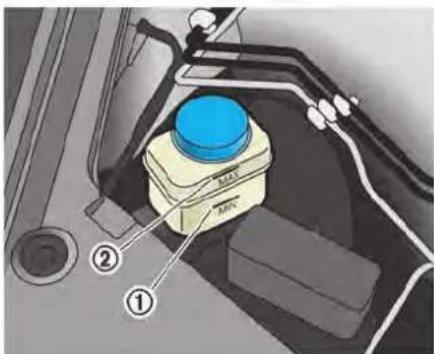
Check the fluid level in the reservoir. If the fluid is below the MIN line ① or the brake warning light comes on, add Genuine NISSAN Brake Fluid R35 Special II fluid up to the MAX line ②. If fluid must be added frequently, the system should be checked by a GT-R certified NISSAN dealer.
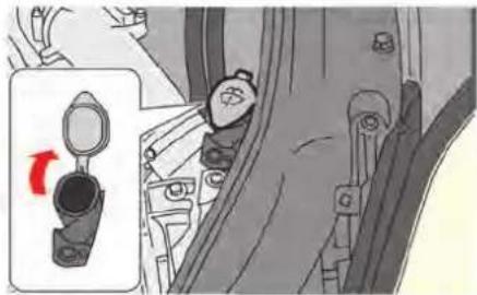
natural_image
Illustration of a car interior with a hand valve and a red arrow indicating rotation (no text or symbols)
WARNING
Antifreeze is poisonous and should be stored carefully in marked containers out of the reach of children.
Fill the window washer fluid reservoir periodically. Add window washer fluid when the low washer fluid warning appears on the vehicle information display. ( "Low washer fluid warning" page 2-42)
To fill the window washer fluid reservoir, lift the cap off the reservoir tank and pour the window
washer fluid into the tank opening.
Add a washer solvent to the washer for better cleaning. In the winter season, add a windshield washer antifreeze. Follow the manufacturer's instructions for the mixture ratio.
Refill the reservoir more frequently when driving conditions require an increased amount of window washer fluid.
NOTICE
- Do not substitute engine anti-freeze coolant for window washer solution. This may result in damage to the paint.
- Do not fill the window washer reservoir tank with washer fluid concentrates at full strength. Some methyl alcohol based washer fluid concentrates may permanently stain the grille if spilled while filling the window washer reservoir tank.
NOTE:
Pre-mix washer fluid concentrates with water to the manufacturer's recommended levels before pouring the fluid into the window washer reservoir. Do not use the
window washer reservoir to mix the washer fluid concentrate and water.
BATTERY
- Keep the battery surface clean and dry. Clean the battery with a solution of baking soda and water.
- Make certain the terminal connections are clean and securely tightened.
- If the vehicle is not to be used for 30 days or longer, disconnect the negative (−) battery terminal cable to prevent discharging it.
NOTE:
Care should be taken to avoid situations that can lead to potential battery discharge and potential no-start conditions such as:
-
Installation or extended use of electronic accessories that consume battery power when the engine is not running (Phone chargers, GPS, DVD players, etc.)
-
Vehicle is not driven regularly and/or only driven short distances.
In these cases, the battery may need to be charged to maintain battery health.
PRECAUTIONS
NOTICE
When the battery cable is removed from the battery terminal, do not close either of the front doors. The automatic window adjusting function will not work, and the side roof panel may be damaged.
To disconnect the negative (−) battery terminal, perform the procedure in the following order. Otherwise, the window and the side roof panel may contact and be damaged.
- Close the windows.
- Open the hood.
- Close and lock all the doors.
- Disconnect the negative (−) battery terminal.
- Securely close the hood.
To connect the negative (−) battery terminal, perform the procedure in the following order. Otherwise, the window and the side roof panel may contact and be damaged.
- Unlock and open the driver side door. Do not close the door.
- Open the hood.
Maintenance and do-it-yourself 8-17
- Connect the negative (−) battery terminal. Then close the hood.
- Fully open the driver side door window.
- Close the driver side door and the window.
FLUID LEVEL CHECK

WARNING
- Do not expose the battery to flames or electrical sparks. Hydrogen gas generated by the battery is explosive. Do not allow battery fluid to contact your skin, eyes, fabrics, or painted surfaces. After touching a battery or battery cap, do not touch or rub your eyes. Thoroughly wash your hands. If the acid contacts your eyes, skin or clothing, immediately flush with water for at least 15 minutes and seek medical attention.
- Do not operate the vehicle if the fluid in the battery is low. Low battery fluid can cause a higher load on the battery which can generate heat, reduce battery life, and in some cases lead to an explosion.
- When working on or near a battery, always wear suitable eye protection
8-18 Maintenance and do-it-yourself
and remove all jewelry.
- Battery posts, terminals and related accessories contain lead and lead compounds. Wash hands after handling.
- Keep the battery out of the reach of children.
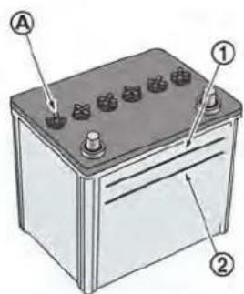
Check the fluid level in each cell (Remove the battery cover if it is necessary). It should be between the UPPER LEVEL ① and LOWER LEVEL ② lines.
If it is necessary to add fluid, add only distilled water to bring the level to the indicator in each filler opening. Do not overfill.

- Remove the cell plugs Ⓐ.
-
Add distilled water up to the UPPER LEVEL ① line.
If the side of the battery is not clear, check the distilled water level by looking directly above the cell; the condition ① indicates OK and the conditions ② needs more to be added. -
Tighten cell plugs Ⓐ.
Vehicles operated in high temperatures or under severe conditions require frequent checks of the battery fluid level.
JUMP STARTING
If jump starting is necessary, see the following section. ( "Jump starting" page 6-5) If the engine does not start by jump starting, the battery may have to be replaced. Contact a GT-R certified NISSAN dealer.
DRIVE BELTS

- Power steering fluid pump
- Alternator
- Crankshaft pulley
- Air conditioner compressor
- Drive belt auto-tensioner

WARNING
Be sure the ignition switch is in the OFF or LOCK position before servicing drive belts. The engine could rotate unexpectedly.
- Visually inspect each belt for signs of unusual wear, cuts, fraying or looseness. If Maintenance and do-it-yourself 8-19
the belt is in poor condition or loose, have it replaced or adjusted by a GT-R certified NISSAN dealer.
- Have the belts checked regularly for condition and tension in accordance with the maintenance schedule in your NISSAN Service and Maintenance Guide.
SPARK PLUGS

WARNING
Be sure the engine and the ignition switch are off and that the parking brake is engaged securely.
NOTICE
Be sure to use the correct socket to remove the spark plugs. An incorrect socket can damage the spark plugs.

natural_image
Illustration of a spark plug and its side profile showing internal structure (no text or symbols)REPLACING SPARK PLUGS
If replacement is required, see a GT-R certified NISSAN dealer for servicing.
Iridium-tipped spark plugs
It is not necessary to replace the iridium-tipped spark plugs as frequently as the conventional type spark plugs since they will last much longer. Follow the maintenance schedule in NISSAN Service and Maintenance Guide, but do not reuse them by cleaning or regapping.
Always replace spark plugs with recommended or equivalent ones.
AIR CLEANER

natural_image
Interior view of a car engine bay with red arrows pointing to components (no visible text or symbols)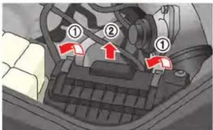
Remove the retainers ① as illustrated and pull out the filter element ②.
The filter element should not be cleaned and reused. Replace it according to the maintenance intervals. See NISSAN Service and Maintenance Guide for maintenance intervals. When
replacing the filter, wipe the inside of the air cleaner housing and the cover with a damp cloth.

WARNING
- Operating the engine with the air cleaner removed can cause you or others to be burned. The air cleaner not only cleans the air, it stops flame if the engine backfires. If it isn't there, and the engine backfires, you could be burned. Do not drive with the air cleaner removed, and be careful when working on the engine with the air cleaner removed.
- Never pour fuel into the throttle body or attempt to start the engine with the air cleaner removed. Doing so could result in serious injury.
WINDSHIELD WIPER BLADES
CLEANING
If your windshield is not clear after using the windshield washer or if a wiper blade chatters when running, wax or other material may be on the blade or windshield.
Clean the outside of the windshield with a washer solution or a mild detergent. Your windshield is clean if beads do not form when rinsing with clear water.
Clean each blade by wiping it with a cloth soaked in a washer solution or a mild detergent. Then rinse the blade with clear water. If your windshield is still not clear after cleaning the blades and using the wiper, replace the blades.

CAUTION
Worn windshield wiper blades can damage the windshield and impair driver vision.

REPLACING THE WIPER BLADES
Replace the wiper blades if they are worn.
- Pull the wiper arm.
- Push the release tab Ⓐ, and then move the wiper blade down the wiper arm ⓛ while pushing the release tab to remove.
- Insert the new wiper blade onto the wiper arm until a click sounds.
- Rotate the wiper blade so the dimple is in the groove.
NOTICE
- After wiper blade replacement, return the wiper arm to its original position; otherwise it may be damaged when the hood is opened.
- Make sure the wiper blades contact the glass; otherwise the arm may be damaged from wind pressure.

natural_image
Close-up of a mechanical linkage or clamping mechanism with labeled component A (no text or symbols beyond label)
B
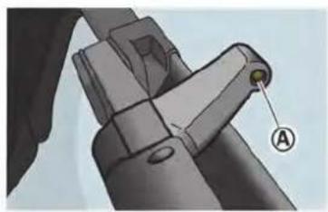
natural_image
Mechanical component diagram showing a belt buckle assembly with a labeled section (A), no text or symbols present.Be careful not to clog the washer nozzle Ⓐ. This may cause improper windshield washer operation. If the nozzle is clogged, remove any objects with a needle or small pin Ⓑ. Be careful not to damage the nozzle.
BRAKES
If the brakes do not operate properly, have the brakes checked by a GT-R certified NISSAN dealer.
SELF-ADJUSTING BRAKES
Your vehicle is equipped with self-adjusting brakes.
The disc-type brakes self-adjust every time the brake pedal is applied.

WARNING
See a GT-R certified NISSAN dealer for a brake system check if the brake pedal height does not return to normal.
The disc brake pads have audible wear warnings. When a brake pad requires replacement, it will make a high pitched scraping sound when the vehicle is in motion. This scraping sound will first occur only when the brake pedal is depressed. After more wear of the brake pad, the sound will always be heard even if the brake pedal is not depressed. Have the brakes checked as soon as possible if the wear warning sound is heard.
Under some driving or climate conditions,
Maintenance and do-it-yourself 8-23
occasional brake squeak, squeal or other noise may be heard. Occasional brake noise during light to moderate stops is normal and does not affect the function or performance of the brake system.
Proper brake inspection intervals should be followed. For additional information, see the maintenance log section of your NISSAN Service and Maintenance Guide for maintenance intervals.
This vehicle is equipped with high performance brake pads that provide appropriate braking force in a broad range of driving environments. Due to the material used for the brake pads, the road wheels may become more easily covered by brake dust, however this does not indicate that there is a malfunction.
The GT-R brake pads use material that contains a lot of iron to maintain steady braking performance even in high and low temperatures. However, if the brake system is wet and the parking brake is applied for a long time, the iron in this material may get rusty and the brake pad and disc rotor may be fixed together. This may cause noise and vibration while driving. Before parking the vehicle, dry the brake by driving on a dry road, especially after washing the vehicle or driving in rain. Contact a GT-R certified NISSAN dealer if the noise and vibration continue.
Frequent hard braking may cause scorching of the brake pads. This will require the brake pads to be replaced, even if the wear limit has not been reached. Have the brake pads and disc rotors inspected at the regular vehicle inspections.
For more details, contact a GT-R certified NISSAN dealer.
REPLACING THE BRAKE PADS
NISSAN generally recommends to replace all four sets of brake pads and disc rotors at the same time to maintain maximum brake performance.
However, replacing only the brake pads may be allowed in some cases (four wheels or only front wheels depending on the conditions). A GT-R certified technician must inspect the vehicle and determine that only the brake pads need to be replaced. In this case, replacing all brake pads and disc rotors as a set is not necessary.
Note that the replacement of brake pads and the disc rotors as a set on all four wheels should be performed when a GT-R certified technician determines that this is the correct repair.
If the inside of the disc rotors are cold during the winter and the surface becomes hot due to a heavy force being applied repeatedly to the brakes, cracks may occur near the coolant hole on the surface of the disc rotor. Cracks may also occur due to a heavy force being repeatedly applied to the brakes during high performance driving. In these cases it may be necessary to replace the disc rotors or brake pads depending on the condition of the crack. Contact a GT-R certified NISSAN dealer for replacement.
FUSES
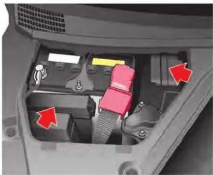
natural_image
Interior view of a car showing internal components with red arrows pointing to specific parts (no text or symbols visible)ENGINE COMPARTMENT

CAUTION
Never use a fuse of a higher or lower amperage rating than that specified on the fuse box cover. This could damage the electrical system or cause a fire.
If any electrical equipment does not operate, check for an open fuse.
-
Be sure the ignition switch is pushed to the OFF or LOCK position and the headlight switch is turned to OFF.
-
Open the engine hood and remove the cover on the battery and the fuse/fusible link holder.
- Remove the fuse/fusible link holder cover.
- Remove the fuse with the fuse puller that is located in the engine compartment fuse box.
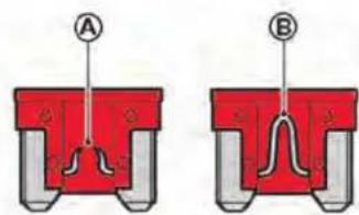
- If the fuse is open Ⓐ, replace it with a new fuses Ⓑ. Spare fuses are stored in the passenger compartment fuse box.
- If a new fuse also opens, have the electrical system checked and repaired by a GT-R certified NISSAN dealer.
Fusible links
If any electrical equipment does not operate and fuses are in good condition, check the fusible links. If any of these fusible links are melted, replace only with genuine NISSAN parts.
Maintenance and do-it-yourself 8-25

- Open the fuse box lid.
PASSENGER COMPARTMENT

CAUTION
Never use a fuse of a higher or lower amperage rating than that specified on the fuse box cover. This could damage the electrical system or cause a fire.
If any electrical equipment does not operate, check for an open fuse.
- Be sure the ignition switch is pushed to the OFF or LOCK position and the headlight switch is turned to OFF.
8-26 Maintenance and do-it-yourself

natural_image
Technical illustration of a mechanical component with two views: one showing a cross-sectional view and the other showing a red rectangular housing (no text or symbols present)- Remove the fuse with the fuse puller Ⓐ.
- If the fuse is open, replace it with a new fuse.
- If a new fuse also opens, have the electrical system checked and repaired by a GT-R certified NISSAN dealer.
Extended storage fuse switch
To reduce battery drain, the extended storage fuse switch comes from the factory switched off. Prior to delivery of your vehicle, the switch is pushed in (switched on) and should always remain on.
If any electrical equipment does not operate, remove the extended storage fuse switch and
check for an open fuse.
NOTE:
If the extended storage fuse switch malfunctions, or if the fuse is open, it is not necessary to replace the switch. In this case, remove the extended storage fuse switch and replace it with a new fuse of the same rating.

INTELLIGENT KEY BATTERY REPLACEMENT
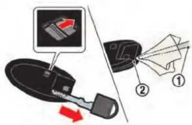
How to remove the extended storage fuse switch:
- To remove the extended storage fuse switch, be sure the ignition switch is in the OFF or LOCK position.
- Be sure the headlight switch is in the OFF position.
- Remove the fuse box cover.
- Pinch the locking tabs ① found on each side of the extended storage fuse switch.
- Pull the extended storage fuse switch straight out from the fuse box ②.

WARNING
Be careful that batteries and other removed components are not swallowed by children.
NOTICE
There is the possibility that the key may be damaged when the battery is replaced. It is recommended that you have the battery replaced by a GT-R certified NISSAN dealer.
Maintenance and do-it-yourself 8-27
Recommended battery: Lithium battery CR2032 or an equivalent.
- Disengage the lock on the reverse side of the Intelligent Key while pulling out the mechanical key.
- Insert a flat-bladed screwdriver ① wrapped with a cloth into the slit ② and twist it to separate the case into the upper and lower parts.
NOTICE
Because there is the risk of scratching the key, wrap a cloth or similar item around the screwdriver when separating the parts. If the screwdriver is inserted too far into the key, it may damage the internal circuit board.

natural_image
Simple illustration of a red downward arrow pointing to a circular object on a black textured surface (no text or symbols)- Remove the old battery and insert a new battery with the + side facing down.
NOTICE
- Be sure that the + and - sides of the battery are facing in the correct directions when the battery is inserted.
- Do not touch the internal circuits or electronic terminals. Doing so may damage them.

natural_image
Illustration of a closed black electronic device with green internal components and a red arrow indicating rotation (no text or symbols)- Reconnect the upper and lower parts of the Intelligent Key.
See a GT-R certified NISSAN dealer if you need any assistance for replacement.
NOTE:
After replacing the battery, be sure to check and check that all Intelligent Key system functions operate correctly.
FCC Notice:
For USA:
This device complies with Part 15 of the FCC Rules. Operation is subject to the following two conditions: (1) This device
LIGHTS
may not cause harmful interference, and (2) this device must accept any interference received, including interference that may cause undesired operation.
Note: Changes or modifications not expressly approved by the party responsible for compliance could void the user's authority to operate the equipment.
For Canada:
This device complies with Industry Canada licence-exempt RSS standard(s). Operation is subject to the following two conditions: (1) this device may not cause interference, and (2) this device must accept any interference, including interference that may cause undesired operation of the device.

- Headlight (High beam)
- Front parking light
- Front turn signal light
- Daytime running light
- Headlight (Low beam)
- Front side marker light
-
High-mounted stop light
-
License plate light
-
Rear combination light (rear turn signal/tail/stop/back-up)
-
Rear side marker light
(A) : Except for NISMO models
B : NISMO models
Maintenance and do-it-yourself 8-29
HEADLIGHTS
Fog may temporarily form inside the lens of the exterior lights in the rain or in a car wash. A temperature difference between the inside and the outside of the lens causes the fog. This does not indicate that there is a malfunction. If large drops of water collect inside the lens, contact a GT-R certified NISSAN dealer.
Replacing
LED headlight:
If replacement is necessary, see a GT-R certified NISSAN dealer.
EXTERIOR AND INTERIOR LIGHTS
| Item Wattage (W) Bulb No. | ||
| Headlight assembly | ||
| low-beam* LED — | ||
| high-beam* LED — | ||
| Front turn signal light* 28 | 7444NA | |
| Front parking light* | LED — | |
| Daytime running light* | LED — | |
| Front side marker light* | 3.8 | |
| Rear combination light* | ||
| back-up | 16 | |
| turn signal | 21 | |
| stop/tail | LED — | |
| Rear side marker light* | LED — | |
| License plate light* | 5 | |
| Map light | 8 | |
| Vanity mirror light | 2 | |
| Step light* | 2.7 | |
| Trunk light* | 3.4 | |
| High-mounted stop light* | LED |
*: See a GT-R certified NISSAN dealer for replacement.
Always check with the Parts Department at a GT-R certified NISSAN dealer for the latest parts information.
Replacement procedures
All other lights are either type A, B, C, D, E or F. When replacing a bulb, first remove the lens and/or cover.

flowchart
graph TD
    A["Light Bulb"] --> B["Add Battery"]
    B --> C["Remove Battery"]
    C --> D["Install"]
    D --> E["Battery"]
    E --> F["Add Battery"]
    F --> G["Remove Battery"]
    G --> H["Install"]
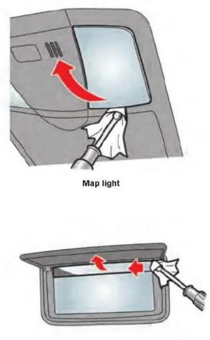
Vanity mirror light
Maintenance and do-it-yourself 8-31
WHEELS AND TIRES
If you have a flat tire, see the following section. ( "Flat tire" page 6-3)

CAUTION
A GT-R certified NISSAN dealer should perform a tire change. It will be necessary to reset the tire pressure sensors. To change the tires, contact a GT-R certified NISSAN dealer.
Be sure to use the tires and wheels together as a set that are designated for use with this vehicle.
When tire replacement is required, replacing the tires as a set of four with new tires is recommended. However, if a tire is punctured or damaged, it may be possible to replace only the damaged tire. Determining whether one tire or a complete set of tires should be replaced is based on a number of factors including tire wear and condition. Contact your GT-R certified NISSAN dealer. They can recommend if an individual tire or a complete set should be replaced.
NOTICE
Make sure the tire valve stem cap is installed and that the valve stem is tight. When installing the cap, make sure to tighten the cap by hand. If a tool is used to tighten the cap, the cap may be damaged.
TIRE PRESSURE
Tire Pressure Monitoring System (TPMS)
This vehicle is equipped with the Tire Pressure Monitoring System (TPMS). It monitors tire pressure of all tires. When the low tire pressure warning light is lit, one or more of your tires is significantly under-inflated. The system also displays pressure of all tires on the multi function display by sending a signal from a sensor that is installed in each wheel.
The TPMS will activate only when the vehicle is driven at speeds above 16 MPH (25 km/h).
Also, this system may not detect a sudden drop in tire pressure. ( "Low tire pressure warning light" page 2-27) ( "Tire Pressure Monitoring System (TPMS)" page 5-4) ( "Flat tire" page 6-3)
Tire inflation pressure
Check the tire pressure often and always prior to long distance trips. The recommended tire pressure specifications are shown on the F.M.V.S.S./C.M.V.S.S. label or the Tire and Loading Information label (if so equipped) under the "Cold Tire Pressure" heading. The Tire and Loading Information label is affixed to the driver side door end. Tire pressures should be checked regularly because:
- Most tires naturally lose air over time.
- Tires can lose air suddenly when driven over potholes or other objects or if the vehicle strikes a curb while parking.
NOTE:
- You can check the pressure of all four tires on the multi function display. See the separate Multi Function Display Owner's Manual.
- The tires of this vehicle are filled with nitrogen gas. When the tire pressure is low, fill the tires with nitrogen. Contact a GT-R certified NISSAN dealer for information on filling the tires with nitrogen.
- If nitrogen is not available, compressed air may be safely used under normal driving conditions. However, NISSAN recommends refilling with nitrogen for maximum tire performance.
The tire pressures should be checked when the tires are cold. The tires are considered COLD after the vehicle has been parked for 3 or more hours, or driven less than 1 mile (1.6 km) at moderate speeds.
Incorrect tire pressure, including under inflation, may adversely affect tire life and vehicle handling.

WARNING
- Improperly inflated tires can fail suddenly and cause an accident.
- The Gross Vehicle Weight rating (GVWR) is located on the F.M.V. S.S./C.M.V.S.S. certification label. The vehicle weight capacity is indicated on the Tire and Loading Information label (if so equipped). Do not load your
vehicle beyond this capacity. Overloading your vehicle may result in reduced tire life, unsafe operating conditions due to premature tire failure, or unfavorable handling characteristics and could also lead to a serious accident. Loading beyond the specified capacity may also result in failure of other vehicle components.
- Before taking a long trip, or whenever you heavily load your vehicle, use a tire pressure gauge to ensure that the tire pressures are at the specified level.
- For additional information regarding tires, refer to "Important Tire Safety Information" (US) or "Tire Safety Information" (Canada) in the Warranty Information Booklet.
NOTE:
- Use only genuine GT-R tires and road wheels.
The GT-R uses specially designed run-flat tires and matching road wheels. Use of these specially developed tires and wheels provides the greatest potential for maximum performance.
— Genuine GT-R tires and road wheels help achieve maximum cornering and braking performance.
— Genuine GT-R tires and road wheels help achieve maximum tire durability during acceleration.
— Genuine GT-R tires and road wheels help achieve maximum handling capability during performance driving.
— Genuine GT-R tires and road wheels help provide road holding in the event of decreasing tire pressure and punctures.
— Genuine GT-R tires and road wheels help prevent the decrease of straight-running stability caused by uneven tire wear due to high rigidity wheels and wide tires.
- The GT-R uses specially designed run-flat tires which feature an extremely Maintenance and do-it-yourself 8-33
rigid side wall. Special techniques and equipment are therefore required when replacing these tires. NISSAN recommends that tire replacement be performed at a GT-R certified NISSAN dealer.
- Specific tire changing equipment must be used to remove the GT-R tires from the wheel and to install the GT-R tires onto the wheel. It is only possible to reuse the tires when they have no cracks and/or deformations on the bead portion of the tire. If the incorrect equipment is used to remove the GT-R tires from the wheel and to install the GT-R tires onto the wheel, cracks and deformation may occur on the bead portion of the tires meaning that the tires cannot be reused. Contact a GT-R certified NISSAN dealer if the tires need to be removed from the wheels.
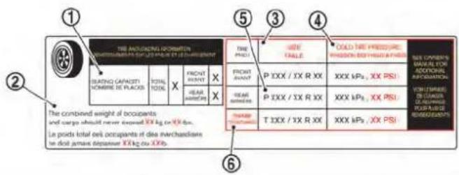

TIRE AND LOADING INFORMATION LABEL
① Seating capacity: The maximum number of occupants that can be seated in the vehicle.
② Vehicle load limit: See the following section. ("Vehicle loading information" page 9-14)
③ Original size: The size of the tires originally installed on the vehicle at the factory.
④ Cold tire pressure: Inflate the tires to this pressure when the tires are cold. Tires are considered COLD after the vehicle has been parked for 3 or more hours, or driven less than 1 mile (1.6 km) at moderate speeds. The recommended cold tire inflation is set by the manufacturer to provide the best balance of tire wear, vehicle handling, driveability, tire noise, etc., up to the vehicle's GVWR.
⑤ Tire size — see the following section. ( "Tire labeling" page 8-37)
⑥ Spare tire size or compact spare tire size (if so equipped)
Maintenance and do-it-yourself 8-35
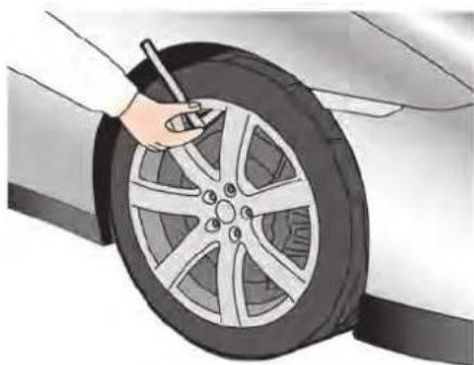
natural_image
Illustration of a car tire being cleaned with a hand using a tool (no text or symbols visible)CHECKING THE TIRE PRESSURE
- Remove the valve stem cap from the tire.
- Press the pressure gauge squarely onto the valve stem. Do not press too hard or force the valve stem sideways, or air will escape. If the hissing sound of air escaping from the tire is heard while checking the pressure, reposition the gauge to eliminate this leakage.
- Remove the gauge.
- Read the tire pressure on the gauge stem and compare it to the specifica-
tion shown on the Tire and Loading Information label.
- Add air to the tire as needed. If too much air is added, press the core of the valve stem briefly with the tip of the gauge stem to release pressure. Re-check the pressure and add or release air as needed.
- Install the valve stem cap.
- Check the pressure of all other tires.
NOTE:
- You can check the pressure of all four tires on the multi function display. See the separate Multi Function Display Owner's Manual.
- The tires of this vehicle are filled with nitrogen gas. When the tire pressure is low, fill the tires with nitrogen. Contact a GT-R certified NISSAN dealer for information on filling the tires with nitrogen.
- If nitrogen is not available, compressed air may be safely used under normal driving conditions. However, NISSAN recommends re-
filling with nitrogen for maximum tire performance.
Summer tires:
| SIZE | COLD TIRE INFLATION PRESSURE | |
| FRONT ORI-GINAL TIRE | 255/40ZR-F20 (97Y) | 30 PSI (210 kPa) |
| REAR ORI-GINAL TIRE | 285/35ZR-F20 (100Y) | 29 PSI (200 kPa) |
All-season tires:
| SIZE | COLD TIRE INFLATION PRESSURE | |
| FRONT ORI-GINAL TIRE | 255/40RF20 97W | 32 PSI (220 kPa) |
| REAR ORI-GINAL TIRE | 285/35RF20 100W | 30 PSI (210 kPa) |
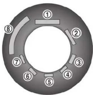
Example
TIRE LABELING
Federal law requires tire manufacturers to place standardized information on the sidewall of all tires. This information identifies and describes the fundamental characteristics of the tire and also provides the tire identification number (TIN) for safety standard certification. The TIN can be used to identify the tire in case of a recall.

Example
① Tire size (example: P215/60R16 94H)
- P: The "P" indicates the tire is designed for passenger vehicles. (Not all tires have this information.)
- Three-digit number (215): This number gives the width in millimeters of the tire from sidewall edge to sidewall edge.
- Two-digit number (65): This number, known as the aspect ratio, gives the tire's ratio of height to width.
-
R: The "R" stands for radial. F: The "F" after "R" indicates Self-Supporting type run-flat tire.
-
Two-digit number (15): This number is the wheel or rim diameter in inches.
- Two- or three-digit number (95): This number is the tire's load index. It is a measurement of how much weight each tire can support. You may not find this information on all tires because it is not required by law.
- H: Tire speed rating. You should not drive the vehicle faster than the tire speed rating.
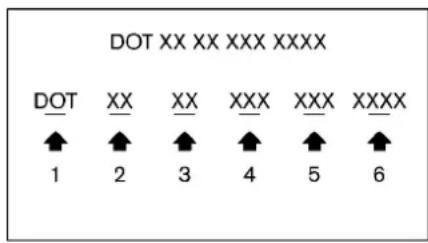
- DOT: Abbreviation for the "Department of Transportation". The symbol can be placed above, below or to the left or right of the Tire Identification Number.
- Two-digit code: Manufacturer's identification mark
- Two-digit code: Tire size
- Three-digit code: Tire type code (Optional)
- Three-digit code: Date of Manufacture
- Four numbers represent the week and
year the tire was built. For example, the numbers 3103 means the 31st week of 2003. If these numbers are missing, then look on the other sidewall of the tire.
③ Tire ply composition and material The number of layers or plies of rubber-coated fabric in the tire.
Tire manufacturers also must indicate the materials in the tire, which include steel, nylon, polyester, and others.
④ Maximum permissible inflation pressure
This number is the greatest amount of air pressure that should be put in the tire. Do not exceed the maximum permissible inflation pressure.
⑤ Maximum load rating
This number indicates the maximum load in kilograms and pounds that can be carried by the tire. When replacing the tires on the vehicle, always use a tire that has the same load rating as the factory installed tire.
⑥ Term of "tubeless" or "tube type"
Indicates whether the tire requires an inner tube ("tube type") or not ("tubeless").
⑦ The word "radial"
The word "radial" is shown, if the tire has radial structure.
⑧ Manufacturer or brand name
Manufacturer or brand name is shown.
Other tire-related terminology:
In addition to the many terms that are defined throughout this section, Intended Outboard Sidewall is (1) the sidewall that contains a whitewall, bears white lettering or bears manufacturer, brand and/or model name molding that is higher or deeper than the same molding on the other sidewall of the tire, or (2) the outward facing sidewall of an asymmetrical tire that has a particular side that must always face outward when mounted on a vehicle.
TYPES OF TIRES

WARNING
- When changing or replacing tires, be sure all four tires are of the same type (Examples: Summer or All Season) and construction. A GT-R certified NISSAN dealer may be able
to help you with information about tire type, size, speed rating and availability.
- Replacing tires with those not originally specified by NISSAN could affect the proper operation of the TPMS.
- For additional information regarding tires, refer to "Important Tire Safety Information" (US) or "Tire Safety Information" (Canada) in the Warranty Information Booklet.
All-season tires
NISSAN specifies all-season tires on some models to provide good performance for use all year around, including snowy and icy road conditions. All-season tires are identified by ALL SEASON on the tire sidewall.
Summer tires
The GT-R summer tires are made from a specially formulated rubber to maximize the vehicle's performance capabilities. Performance of summer tires is substantially reduced when temperatures are less than 32^ F ( 0^ C) so you must drive carefully. NISSAN recommends the use of winter or all-season tires on all four
wheels if you plan to operate your vehicle in snowy or icy conditions when temperatures are less than 32^ F ( 0^ C).

WARNING
Never use summer tires when the temperature is below -4^ ( -20^ ) to prevent permanent tread deformation which may cause tire damage or tire failure. This may cause a loss of vehicle control which can result in serious personal injury or death.
Run-flat tires
Your vehicle is equipped with run-flat tires. You can continue driving to a safe location even if they are punctured. Always use run-flat tires of the specified size on all four wheels. Mixing tire sizes or construction may reduce vehicle handling stability. If necessary, contact a GT-R certified NISSAN dealer for assistance.
Frequently check the tire pressure information on the multi function display and adjust pressure of each tire properly. See the separate Multi Function Display Owner's Manual. It can be difficult to tell if a run-flat tire is under-inflated or flat. Check the tire pressures as
described earlier in this section. If the tire becomes under-inflated while driving, the low tire pressure warning light will come on. If the tire becomes flat while driving, the low tire pressure warning light and the run-flat tire warning display will come on.
Low tire pressure:
If the vehicle is being driven with low tire pressure, the low tire pressure warning light will illuminate and the low tire pressure warning will appear in the vehicle information display.
Flat tire:
If the vehicle is being driven with one or more flat tires, the low tire pressure warning light will illuminate continuously and a chime will sound for 10 seconds. The run-flat tire warning also appears in the vehicle information display.
The chime will only sound at the first indication of a flat tire and the run-flat tire warning display will illuminate continuously. When the flat tire warning is activated, have the system reset and the tire checked and replaced if necessary by a GT-R certified NISSAN dealer. Even if the tire is inflated to the specified COLD tire pressure, the warning light will continue to illuminate until the system is reset by a GT-R certified NISSAN dealer.
If the low tire pressure and the run-flat tire
Maintenance and do-it-yourself 8-39
warning appears on the vehicle information display:
- Do not exceed 50 MPH (80 km/h).
- Increase your following distance to allow for increased stopping distances.
- Avoid sudden maneuvers, hard cornering and hard braking.

WARNING
- Although you can continue driving with a punctured run-flat tire, remember that vehicle handling stability is reduced, which could lead to an accident and personal injury. Also, driving a long distance at high speeds may damage the tire.
- Do not drive at speeds above 50 MPH (80 km/h) and do not drive more than 50 miles (80 km) with a punctured run-flat tire. The actual distance the vehicle can be driven on a flat tire depends on outside temperature, vehicle load, road conditions and other factors.
- Drive safely at reduced speeds. Avoid hard cornering or braking, which may cause you to lose control
of the vehicle.
NOTICE
- Never install tire chains on a punctured run-flat tire, as this could damage your vehicle.
- Avoid driving over any projection or pothole, as the clearance between the vehicle and the ground is smaller than normal.
- Do not enter an automated car wash with a punctured run-flat tire.
- Have the punctured tire replaced by a GT-R certified NISSAN dealer as soon as possible, as the tire's performance capability is reduced.
Tires for All-Wheel Drive (AWD)
If excessive tire wear is found, it is recommended that all four tires be replaced with tires of the specified size, brand, construction and tread pattern. The tire pressure and wheel alignment should also be checked and corrected as necessary. Contact a GT-R certified NISSAN dealer.
TIRE CHAINS
Use of tire chains may be prohibited according to location. Check the local laws before installing tire chains. When installing tire chains, make sure they are of proper size for the tires on your vehicle and are installed according to the chain manufacturer instructions. Use only SAE class S chains. Class "S" chains are used on vehicles with restricted tire to vehicle clearance. Vehicles that can use Class "S" chains are designed to meet the SAE standard minimum clearances between the tire and the closest vehicle suspension or body component required to accommodate the use of a winter traction device (tire chains or cables). The minimum clearances are determined using the factory equipped tire size. Other types may damage your vehicle. Use chain tensioners when recommended by the tire chain manufacturer to ensure a tight fit. Loose end links of the tire chain must be secured or removed to prevent the possibility of whipping action damage to the fenders or undercarriage. If possible, avoid fully loading your vehicle when using tire chains. In addition, drive at a reduced speed. Otherwise, your vehicle may be damaged and/or vehicle handling and performance may be adversely affected.
NOTE:
Tire chains must be installed only on the rear wheels and not on the front wheels.

CAUTION
Do not use tire chains on dry roads.
NOTICE
Never install tire chains on a punctured run-flat tire, as this could damage your vehicle.
Do not drive with tire chains on paved roads that are clear of snow. Driving with chains in such conditions can cause damage to the various mechanisms of the vehicle due to some overstress.
CHANGING WHEELS AND TIRES
Tire rotation
Tires cannot be rotated because your vehicle is equipped with different sized tires in the front and rear.

- Wear indicator
- Location mark
Tire wear and damage

WARNING
- Tires should be periodically inspected for wear, cracking, bulging or objects caught in the tread. If excessive wear, cracks, bulging or deep cuts are found, the tire(s) should be replaced.
- The original tires have built-in tread wear indicators. When the
Maintenance and do-it-yourself 8-41
wear indicators are visible, the tire(s) should be replaced.
- Tires degrade with age and use. Have tires, over 6 years old checked by a qualified technician because some tire damage may not be obvious. Replace the tires as necessary to prevent tire failure and possible personal injury.
- For additional information regarding tires, refer to "Important Tire Safety Information" (US) or "Tire Safety Information" (Canada) in the Warranty Information Booklet.
Replacing wheels and tires
When tire replacement is required, replacing tires as a set of four with new tires is recommended. However, if a tire is punctured or damaged, it may be possible to replace only the damaged tire. Determining whether one tire or a complete set of tires should be replaced is based on a number of factors including tire wear and condition. Contact your GT-R certified
NISSAN dealer. They can recommend if an individual tire or a complete set should be replaced. When replacing a tire, use the specified size, speed rating and load carrying capacity as originally equipped. ( "Wheels and tires" page 9-9)
NOTICE
- When you replace the GT-R tires, it is recommended that you replace all the tires at the same time.
- The GT-R uses specially designed run-flat tires which feature an extremely rigid side wall. Special techniques and equipment are therefore required when replacing these tires. NISSAN recommends that tire replacement be performed at a GT-R certified NISSAN dealer.
- When tires are reinstalled after being uninstalled from the wheels, use equipment such as a leverless automatic tire changer. It is only possible to reuse the tires when they have no cracks and/or deformations on the bead portion. However, if you use a lever-type tire
changer, cracks and deformation may occur on the bead portion of the tires meaning that the tires cannot be reused.
- Make sure the tire valve stem cap is installed and that the valve stem is tight. When installing the cap, make sure to tighten the cap by hand. If a tool is used to tighten the cap, the cap may be damaged.

WARNING
- The use of tires other than those specified or the mixed use of tires of different brands, construction (bias, bias-belted, radial or run-flat), or tread patterns can adversely affect the ride, braking, VDC system, handling, ground clearance, body-to-tire clearance, tire chain clearance, speedometer calibration, headlight aim and bumper height. Some of these effects may lead to accidents and could result in serious personal injury. - If the wheels are changed for any reason, always replace with wheels
which have the same off-set dimension. Wheels of a different off-set could cause premature tire wear, degrade vehicle handling characteristics, affect the VDC system and/or cause interference with the brake discs. Such interference can lead to decreased braking efficiency and/or early brake pad wear. ( "Wheels and tires" page 9-9)
- When a wheel is replaced, tire pressure will not be indicated, the TPMS will not function and the low tire pressure warning light will flash for approximately 1 minute and remain on after the 1 minute. Contact a GT-R certified NISSAN dealer as soon as possible for tire replacement and/or system resetting.
- Replacing tires with those not originally specified by NISSAN could affect the proper operation of the TPMS.
-
Do not install a damaged or deformed wheel or tire even if it has been repaired. Such wheels or tires could have structural damage and could fail without warning.
-
Never use retread tires.
- For additional information regarding tires, refer to "Important Tire Safety Information" (US) or "Tire Safety Information" (Canada) in the Warranty Information Booklet.
• Always use tires of the specified type, size, brand, construction (bias, bias-belted, radial or run-flat), and tread pattern on all four wheels. Failure to do so may result in a circumference difference between tires on the front and rear axles which will cause excessive tire wear and may damage the transmission, transfer case and differential gears.
Wheel balance
Unbalanced wheels may affect vehicle handling and tire life. Even with regular use, wheels can get out of balance. Therefore, they should be balanced as required.
Wheel balance service should be performed with the wheels off the vehicle. Spin balancing the rear wheels on the vehicle could lead to mechanical damage.
For additional information regarding tires, refer
to "Important Tire Safety Information" (US) or "Tire Safety Information" (Canada) in the Warranty Information Booklet.
Care of wheels
( "Cleaning exterior" page 7-2)
JACKING VEHICLE AND REMOVING WHEELS

WARNING
- Make sure the parking brake is securely applied and the transmission is shifted into the P position.
- Never change tires when the vehicle is on a slope, ice or slippery areas. This is hazardous.
- Never change tires if oncoming traffic is close to your vehicle. Wait for professional road assistance.
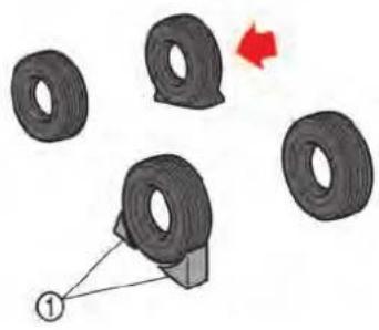
natural_image
Diagram showing a car tire with a triangular object and a red arrow indicating direction (no text or symbols)Blocking wheels
Place suitable blocks ① at both the front and back of the wheel diagonally opposite the flat tire to prevent the vehicle from moving when it is jacked up.

WARNING
Be sure to block the wheel as the vehicle may move and result in personal injury.

natural_image
Diagram showing a vehicle interior with a red arrow indicating direction, no text or symbols presentGetting the tools
NOTE:
A jack, jack lever and rod are not equipped as standard with this vehicle. These parts are dealer options. Contact a GT-R certified NISSAN dealer about acquiring a jack, jack lever and rod. You can store a jack, jack lever and rod in the floor in front of the passenger's seat.

CAUTION
After using the tools, put them back in their original places. An accident may occur if you leave them in the car unsecured.
Jacking up the vehicle and removing the tire

WARNING
- Never get under the vehicle while it is supported only by the jack. If it is necessary to work under the vehicle, support it with safety stands.
- Use the correct jack-up points. Never use any other part of the vehicle for jack support.
- Never jack up the vehicle more than necessary.
- Never use blocks on or under the jack.
- Do not start or run the engine while vehicle is on the jack, as it may cause the vehicle to move. This is especially true for vehicles with
limited slip differentials.
- Do not allow passengers to stay in the vehicle while it is on the jack.
Carefully read the caution label attached to the jack body and the following instructions.

natural_image
Illustration of a silver Nissan F9 car with red arrows pointing to the side of its dashboard (no text or symbols present)Jack-up point
- Place the jack directly under the jack-up point as illustrated so the top of the jack contacts the vehicle at the jack-up point. The jack should be used on level firm ground.
Maintenance and do-it-yourself 8-45
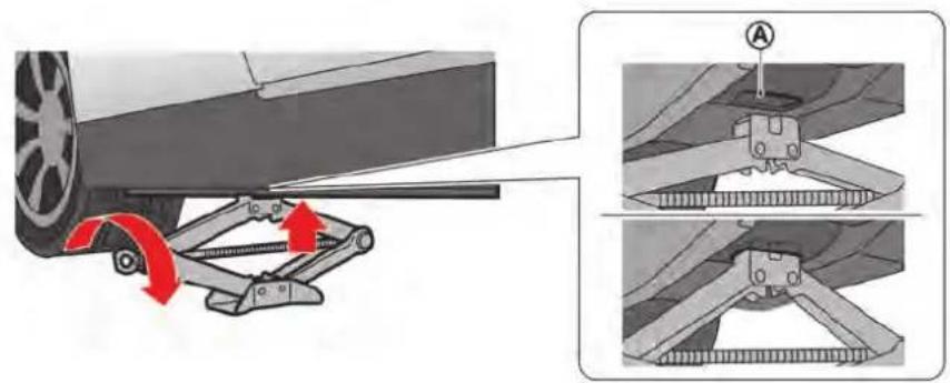
- Fit the jack head into the recess Ⓐ of the jack-up point by turning the jackscrew clockwise with your fingers.
- Loosen each wheel nut one or two turns by turning counterclockwise with the wheel nut wrench. Do not remove the wheel nuts until the tire is off the ground.
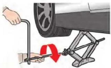
natural_image
Illustration of a car tire being adjusted with a wrench, showing the wheel and suspension mechanism (no text or symbols)- Carefully raise the vehicle until the tire clears the ground. To lift the vehicle, securely hold the jack lever and rod with both hands as shown above.

natural_image
Mechanical assembly showing a car wheel with a brake caliper and red arrow indicating motion (no text or symbols)- Remove the wheel nuts and then remove the wheel.
NOTE:
When putting a wheel on the ground, put it down with the outer side of the wheel facing up to prevent scratching of the wheel surface.


natural_image
Illustration of a hand adjusting a tire with a pin (no text or symbols)- Clean any mud or dirt from the surface between the brake disc rotor ① and wheel ②.

- Tighten the wheel nuts by hand by turning them clockwise until the tapered part of each nut lightly contacts the seat part of the wheel hole.
When replacing a front wheel, make sure the hole in the wheel is aligned with the pin on the brake disc rotor.

- With the wheel nut wrench, tighten wheel nuts alternately and evenly in the sequence as illustrated (①, ②, ③, ④, ⑤) until they are tight.
- Lower the vehicle slowly until the tire touches the ground. Then, with the wheel nut wrench, tighten the wheel nuts securely in the sequence as illustrated. Lower the vehicle completely.
WARNING
- Incorrect wheel nuts or improperly tightened wheel nuts can cause the wheel to become loose or come off. This could cause an accident.
- Do not use oil or grease on the wheel studs or nuts. This could cause the nuts to become loose.
- Retighten the wheel nuts when the vehicle has been driven for 600 miles (1,000 km).
WARNING
If the road wheels are hot, allow them to cool sufficiently before tightening the wheel nuts. Otherwise, the wheel nuts cannot be tightened to specification.
NOTE:
- As soon as possible, tighten the wheel nuts to the specified torque with a torque wrench.
Wheel nut tightening torque:
Except for NISMO models 97 ft-lb (132 N·m)
NISMO models 114 ft-lb (155 N·m)
The wheel nuts must be kept tightened to specification at all times. It is recommended that wheel nuts be tightened to specifications at each lubrication interval.
- Adjust tire pressure to the COLD pressure.
COLD pressure: After the vehicle has been parked for three hours or more or driven less than 1 mile (1.6 km).
COLD tire pressures are shown on the Tire and Loading Information label affixed to the driver's door opening.
- Securely store the jacking equipment in the vehicle.

natural_image
Technical illustration of two mechanical connectors (no text or symbols present)

WHEEL LOCK NUTS (if so equipped)
In order to prevent theft, the specially designed wheel lock nut ① is installed on each wheel. The wheel lock nut cannot be removed with commonly used tools.
When removing tires, use the lock key provided with your vehicle. ②
Removing the wheel lock nut
To remove the wheel lock nut, use the lock key stored under the passenger's side floor.
- Insert the lock key to the wheel lock nut.
- To remove the wheel lock nut, turn the lock key counterclockwise using the wheel nut wrench.
CAUTION
- Do not use a power tool to remove the wheel lock nuts.
- Tighten the wheel lock nuts to the same tightening torque as the normal wheel nuts. ( "Jacking up the vehicle and removing the tire" page 8-44)
NOTE:
- The wheel lock nut has an individual code. A lock key which does not match the individual code cannot remove the wheel lock nut. If you lose the wheel lock key, contact a GT-R certified NISSAN dealer immediately.
- Keep the key code card ③ in a safe place. To purchase a lock key, contact a GT-R certified NISSAN dealer with your original code ④ on the key code card.
- When you ask for a service at a GT-R certified NISSAN dealer, make sure to keep the lock key in the vehicle. Otherwise, tires cannot be removed and any service requiring the removal of the wheels cannot be performed.
MEMO
9 Technical and consumer information
Capacities and recommended fluids/lubricants 9-2
Fuel information 9-4
Engine oil and oil filter recommendation 9-6
Air conditioning system refrigerant and lubricant recommendations 9-7
Specifications 9-8
Engine 9-8
Wheels and tires 9-9
Dimensions 9-10
When traveling or registering in another country ..... 9-11
Vehicle identification 9-11
Vehicle Identification Number (VIN) plate 9-11
Vehicle identification number (chassis number) ..... 9-11
Engine serial number 9-12
F.M.V.S.S./C.M.V.S.S. certification label 9-12
Emission control information label 9-12
Tire and loading information label 9-13
Air conditioner specification label 9-13
Installing front license plate 9-13
Vehicle loading information 9-14
Terms 9-14
Vehicle load capacity 9-15
Loading tips 9-16
Measurement of weights 9-16
Towing a trailer 9-17
Flat towing 9-17
Uniform tire quality grading 9-17
Treadwear 9-17
Traction AA, A, B and C 9-18
Temperature A, B and C 9-18
Emission control system warranty 9-18
Reporting safety defects 9-19
Readiness for Inspection/Maintenance (I/M) test (US only) 9-20
Event Data Recorders (EDR) 9-20
Vehicle status data recorder (VSDR) 9-21
Handling of data 9-21
Owner's Manual/Service Manual order information .... 9-22

CAPACITIES AND RECOMMENDED FLUIDS/LUBRICANTS
The following are approximate capacities. The actual refill capacities may be a little different. When refilling, follow the procedure instructed in the "8. Maintenance and do-it-yourself" section to determine the proper refill capacity.
| Capacity (Approximate) | Recommended specifications | ||||
| US measure Imp | measure Liter | ||||
| Fuel 19-1/2 gal 16-1/4 gal 73.8 | ●( "Fuel information" page 9-4) | ||||
| Engine oil*Drain and refill*For additional information, see *Changing engine oil and filter* page 8-14. | With oil filter change 5-1/4 qt 4-3/8 qt | 5.0 | ●Mobil 1 (0W-40)●Mobil 1 (0W-40) (100% synthetic) is the factory fill oil. The VR38 engine with its plasma-sprayed bores was developed using this oil.NISSAN cannot ensure proper engine operation and durability if other 0W-40 synthetic oil is used. If Mobil 1 (0W-40) is not available, Mobil 1 (10W-40) (100% synthetic) may be used; however, some performance loss may be noticed. For additional information, see the following section. ( "Engine oil and oil filter recommendation" page 9-6)●The recommended oil capacity level is 0.39 in (10mm) (0.5 L) below the H mark on the engine oil dipstick. For additional information, see the following section. ( "Engine oil" page 8-13) | ||
| Without oil filter change | 4-3/4 qt | 4 qt | 4.5 | ||
| Cooling system | With reservoir (except for NISMO models) | 12 qt | 10 qt | 11.3 | ●Genuine NISSAN Long Life Antifreeze/Coolant (blue) or equivalent●For additional information, see the following section. ( "Engine cooling system" page 8-10) |
| With reservoir (NISMO models) | 12-3/8 qt | 10-1/4 qt | 11.7 | ||
| Reservoir (except for NISMO models) | 1-1/2 qt | 1-1/4 qt | 1.4 | ||
| Reservoir (NISMO models) | 1-7/8 qt | 1-5/8 qt | 1.8 | ||
| Transmission oil (Drain and refill) | 10 qt | 8-1/4 qt | 9.4 | ●Genuine NISSAN Transmission Oil R35 Special●The use of fluids and lubricants other than the specified may cause vehicle malfunctions and result in non-warranty vehicle repairs.●All of the fluid cannot be removed when servicing the transmission.The actual refill amount may be less than shown. | |
| Differential oil(Drain and refill) | Front | 1-3/8 pt 1-1/8 pt | 0.65 | ●Genuine NISSAN Differential Oil R35 COMPETITION type 2189E●The use of fluids and lubricants other than the specified may cause vehicle malfunctions and result in non-warranty vehicle repairs. | |
| Rear | 2-7/8 pt 2-3/8 pt | 1.35 | |||
| Power steering fluid (PSF) | Refill to the proper oil level according to the instructions in the "8. Maintenance and do-it-yourself" section. | ●Genuine NISSAN PSF or equivalent●DEXRON TM VI type ATF may also be used. | |||
9-2 Technical and consumer information
| Brake fluid | Refill to the proper oil level according to the instructions in the “8. Maintenance and do-it-yourself” section. | ● Genuine NISSAN Brake Fluid R35 Special II● Genuine NISSAN Brake Fluid R35 Special II is the factory fill brake fluid. The Vehicle Dynamic Control (VDC) unit and other related parts were specially designed for this brake fluid and NISSAN cannot ensure the best performance and proper operation of the vehicle if other brake fluid is used. | ||
| Multi-purpose grease — — — | ● NLGI No. 2 (Lithium soap base) | |||
| Air conditioning system refrigerant — — — | ● HFC-134a (R-134a)● For additional information, see the following section. (“Air conditioner specification label” page 9-13) | |||
| Air conditioning system lubricants — — — | ● NISSAN UV Luminous Oil Type S or exact equivalent | |||
| Window washer fluid — — — | ● Genuine NISSAN Windshield Washer Concentrate Cleaner & Antifreeze or equivalent | |||
FUEL INFORMATION
VR38 engine
Use unleaded premium gasoline with an octane rating of at least 93 AKI (Anti-Knock Index) number (Research octane number 98) to maximize vehicle performance.
If the premium gasoline specified above is not available, you may use unleaded premium gasoline with an octane rating of at least 91 AKI number (Research octane number 96), but you may notice a decrease in performance.
Do not use gasoline with an octane rating lower than 91 AKI (Research octane number 96).
NOTICE
- Using a fuel other than that specified could adversely affect the emission control system, and may also affect warranty coverage.
- Under no circumstances should a leaded gasoline be used, because this will damage the three-way catalyst.
- Do not use E-15 or E-85 fuel in your vehicle. Your vehicle is not designed to run on E-15 or E-85 fuel. Using E-
15 or E-85 fuel in a vehicle not specifically designed for E-15 or E-85 fuel can adversely affect the emission control devices and systems of the vehicle. Damage caused by such fuel is not covered by the NISSAN new vehicle limited warranty.
• U.S. government regulations require ethanol dispensing pumps to be identified by a small, square, orange and black label with the common abbreviation or the appropriate percentage for that region.
- NISSAN recommends using fuels that contain no alcohol. However, fuels containing up to 10% alcohol may be used, if necessary. To avoid serious engine damage due to increased cylinder temperatures, do not use fuels that contain more alcohol than indicated in this section. Also, do not use fuel additives, fuel stabilizers or fuel deicers that contain alcohol.
Gasoline specifications
NISSAN recommends using gasoline that meets the World-Wide Fuel Charter (WWFC) specifications where it is available. Many of the automobile manufacturers developed this specification to improve emission system and vehicle performance. Ask your service station manager if the gasoline meets the World-Wide Fuel Charter (WWFC) specifications.
Reformulated gasoline
Some fuel suppliers are now producing reformulated gasolines. These gasolines are specially designed to reduce vehicle emissions. NISSAN supports efforts towards cleaner air and suggests that you use reformulated gasoline when available.
Gasoline containing oxygenates
Some fuel suppliers sell gasoline containing oxygenates such as ethanol, MTBE and methanol with or without advertising their presence. NISSAN does not recommend the use of fuels of which the oxygenate content and the fuel compatibility for your NISSAN cannot be readily determined. If in doubt, ask your service station manager.
If you use oxygenate-blend gasoline, please take the following precautions as the usage of such
fuels may cause vehicle performance problems and/or fuel system damage.
- The fuel should be unleaded and have an octane rating no lower than that recommended for unleaded gasoline.
- If an oxygenate-blend, excepting a methanol blend, is used, it should contain no more than 10% oxygenate. (MTBE may, however, be added up to 15% .)
- E-15 fuel contains more than 10% oxygenate. E-15 fuel will adversely affect the emission control devices and systems of the vehicle and should not be used. Damage caused by such fuel is not covered under the NISSAN new vehicle limited warranty.
- If a methanol blend is used, it should contain no more than 5% methanol (methyl alcohol and wood alcohol). It should also contain a suitable amount of appropriate cosolvents and corrosion inhibitors. If not properly formulated with the appropriate cosolvents and corrosion inhibitors, such methanol blends may cause fuel system damage and/or vehicle performance malfunctions. At this time, sufficient
data is not available to ensure that all methanol blends are suitable for use in NISSAN vehicles.
If any undesirable driveability problems such as engine stalling or hard hot starting are experienced after using oxygenate-blend fuels, immediately change to a non-oxygenate fuel or a fuel with a low blend of MTBE.
NOTICE
Take care not to spill gasoline during refueling. Gasoline containing oxygenates can cause paint damage.
E-15 fuel
E-15 fuel is a mixture of approximately 15% fuel ethanol and 85% unleaded gasoline. E-15 can only be used in vehicles designed to run on E-15 fuel. Do not use E-15 in your vehicle. U.S. government regulations require fuel ethanol dispensing pumps to be identified with small, square, orange and black label with the common abbreviation or the appropriate percentage for that region.
E-85 fuel
E-85 fuel is a mixture of approximately 85% fuel ethanol and 15% unleaded gasoline. E-85 can only be used in a Flexible Fuel Vehicle (FFV). Do not use E-85 fuel in your vehicle. U.S. government regulations require fuel ethanol dispensing pumps to be identified by a small, square, orange and black label with the common abbreviation or the appropriate percentage for that region.
Aftermarket fuel additives
NOTICE
NISSAN does not recommend the use of any aftermarket fuel additives (Example: fuel injector cleaner, intake valve deposit removers, etc.) which are sold commercially. Many of these additives intended for gum, varnish or deposit removal may contain active solvent or similar ingredients that can be harmful to the fuel system and engine.
Octane rating tips
Using unleaded gasoline with an octane rating lower than recommended above can cause persistent, heavy spark knock. (Spark knock is a metallic rapping noise.) If severe, this can lead to engine damage. If you detect a persistent heavy spark knock even when using gasoline of the stated octane rating, or if you hear steady spark knock while holding a steady speed on level roads, have a GT-R certified NISSAN dealer correct the condition. Failure to correct the condition is misuse of the vehicle, for which NISSAN is not responsible.
Incorrect ignition timing will result in knocking, after-run or overheating. This in turn may cause excessive fuel consumption or damage to the engine. If any of the above symptoms are encountered, have your vehicle checked at a GT-R certified NISSAN dealer or other competent service facility.
However, now and then you may notice light spark knock for a short time while accelerating or driving up hills. This is no cause for concern, because you get the greatest fuel benefit when there is light spark knock for a short time under heavy engine load.
ENGINE OIL AND OIL FILTER RECOMMENDATION
Selecting the correct oil
It is essential to choose the correct grade, quality, and viscosity engine oil to ensure satisfactory engine life and performance. ( "Capacities and recommended fluids/lubricants" page 9-2)
Mobil 1 (0W-40) (100% synthetic) is the factory fill oil. The VR38 engine with its plasma-sprayed bores was developed using this oil. NISSAN cannot ensure proper engine operation and durability if other 0W-40 synthetic oil is used. If Mobil 1 (0W-40) is not available, Mobil 1 (10W-40) (100% synthetic) may be used; however, some performance loss may be noticed.
NOTICE
Using an engine oil other than that specified could adversely affect the engine. See the 2016 NISSAN GT-R Warranty Information Booklet for details and exclusions.
Oil additives
NISSAN does not recommend the use of oil additives. The use of an oil additive is not necessary when the proper oil type is used and maintenance intervals are followed.
Oil which may contain foreign matter or has been previously used should not be used.
Oil viscosity
The engine oil viscosity or thickness changes with temperature. Because of this, it is important that the engine oil viscosity be selected based on the temperatures at which the vehicle will be operated before the next oil change. Choosing an oil viscosity other than that recommended could cause serious engine damage.
Selecting the correct oil filter
Your new vehicle is equipped with a high-quality genuine NISSAN oil filter. NISSAN recommends to use the genuine NISSAN oil filter for the reason described in change intervals.
Change intervals
The oil and oil filter change intervals for your engine are based on the use of the specified quality oils and filters. Oil and filter other than the specified quality, or oil and filter change intervals longer than recommended could reduce engine
life. Damage to engines caused by improper maintenance or use of incorrect oil and filter quality and/or viscosity is not covered by the NISSAN new vehicle limited warranties.
Your engine was filled with a high quality engine oil when it was built. You do not have to change the oil before the first recommended change interval. Oil and filter change intervals depend upon how you use your vehicle. Operation under the following conditions may require more frequent oil and filter changes.
- repeated short distance driving at cold outside temperatures
● driving in dusty conditions - extensive idling
- stop and go "rush hour" traffic Refer to the "NISSAN Service and Maintenance Guide" for the maintenance schedule.
AIR CONDITIONING SYSTEM RE- FRIGERANT AND LUBRICANT RE- COMMENDATIONS
The air conditioning system in your NISSAN vehicle must be charged with the refrigerant HFC-134a (R-134a) and the lubricant, NISSAN UV Luminous Oil Type S or the exact equivalents.
NOTICE
The use of any other refrigerant or lubricant will cause severe damage to the air conditioning system and will require the replacement of all air conditioner system components.
The refrigerant HFC-134a (R-134a) in your NISSAN vehicle will not harm the earth's ozone layer. Although this refrigerant does not affect the earth's atmosphere, certain governmental regulations require the recovery and recycling of any refrigerant during automotive air conditioning system service. Your GT-R certified NISSAN dealer has the trained technicians and equipment needed to recover and recycle your air conditioning system refrigerant.
Contact a GT-R certified NISSAN dealer when servicing your air conditioning system.
SPECIFICATIONS
ENGINE
| Model VR38 | |
| Type Gasoline, 4-cycle | |
| Cylinder arrangement 6-cylinder, V-slanted at 60° | |
| Bore × Stroke in (mm) | 3.760 × 3.480 (95.5 × 88.4) |
| Displacement cu in (cm) | 3) 231.83 (3,799) |
| Firing order 1-2-3-4-5-6 | |
| Idle speed rpm | No adjustment is necessary. |
| Ignition timing (B.T.D.C.) degree/rpm | |
| Spark plug Standard DILKAR8A8 | |
| Spark plug gap (Normal) in (mm) 0.031 (0.8) | |
| Camshaft operation | Timing chain |
This spark ignition system complies with the Canadian standard ICES-002.

WHEELS AND TIRES
Tire
| Type Size Pressure PSI (kPa) [Cold] | ||
| Summer | Front: 255/40ZRF20 (97Y) 30 (210) | |
| Rear: 285/35ZRF20 (100Y) 29 (200) | ||
| All-season | Front: 255/40RF20 97W 32 (220) | |
| Rear: 285/35RF20 100W | 30 (210) | |
Make sure to use the tires for GT-R. See the 2016 Warranty Information Booklet for the applicable exclusions.
Road wheel
| Type Size Offset in (mm) | ||
| Aluminum | Front: 20 × 9-1/2J^*1 | 1.77 (45)^*1 |
| 20 × 10J^*2 | 1.61 (41)^*2 | |
| Rear: 20 × 10-1/2J | 0.98 (25) | |
*1: Except for NISMO models
*2: NISMO models
Make sure to use the road wheels for GT-R. See the 2016 Warranty Information Booklet for the applicable exclusions.
DIMENSIONS
in (mm)
| Overall length | 183.9 (4,670)*1184.3 (4,680)*2 |
| Overall width 74.6 (1,895) | |
| Overall height 53.9 (1,370) | |
| Front tread | 62.6 (1,590)*163.0 (1,600)*2 |
| Rear tread 63.0 (1,600) | |
| Wheelbase | 109.4 (2,780) |
*1: Except for NISMO models
*2: NISMO models
WHEN TRAVELING OR REGISTERING IN ANOTHER COUNTRY VEHICLE IDENTIFICATION
If you plan to travel in another country, you should first find out if the fuel available is suitable for your vehicle's engine.
Using fuel with too low an octane rating may cause engine damage. All gasoline vehicles must be operated with unleaded gasoline. Therefore, avoid taking your vehicle to areas where appropriate fuel is not available.
When transferring the registration of your vehicle to another country, state, province or district, it may be necessary to modify the vehicle to meet local laws and regulations.
The laws and regulations for motor vehicle emission control and safety standards vary according to the country, state, province or district; therefore, vehicle specifications may differ.
When any vehicle is to be taken into another country, state, province or district and registered, its modifications, transportation, and registration are the responsibility of the user. NISSAN is not responsible for any inconvenience that may result.
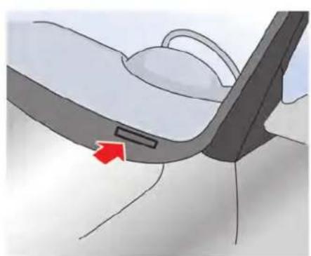
natural_image
Illustration of a car seatbelt with a red arrow pointing to the seat area (no text or symbols present)VEHICLE IDENTIFICATION NUMBER (VIN) PLATE
The vehicle identification number plate is attached as shown. This number is the identification for your vehicle and is used in the vehicle registration.

natural_image
Interior view of a car showing engine bay and dashboard with a red arrow indicating a component (no text or symbols present)VEHICLE IDENTIFICATION NUMBER (chassis number)
The number is stamped as shown in the engine compartment.
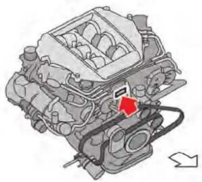
natural_image
Technical illustration of an internal combustion engine assembly (no text or labels)ENGINE SERIAL NUMBER
The number is stamped on the engine as shown.

natural_image
Side view of a car showing the door and side panel, with a red arrow pointing to the door (no text or symbols present)F.M.V.S.S./C.M.V.S.S. CERTIFICATION LABEL
The Federal/Canadian Motor Vehicle Safety Standards (F.M.V.S.S./C.M.V.S.S.) certification label is affixed as shown. This label contains valuable vehicle information, such as: Gross Vehicle Weight Ratings (GVWR), Gross Axle Weight Rating (GAWR), month and year of manufacture, Vehicle Identification Number (VIN), etc. Review it carefully.

natural_image
Top-down view of a car head panel showing internal compartments and mounting points (no text or symbols)EMISSION CONTROL INFORMATION LABEL
The emission control information label is attached as shown.

natural_image
Diagram of a car interior showing the front and side views with a red arrow pointing to the door (no text or symbols present)TIRE AND LOADING INFORMATION LABEL
The cold tire pressure is shown on the Tire and Loading Information label affixed to the door end as illustrated.
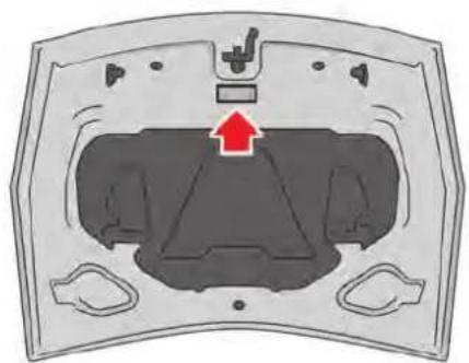
natural_image
Diagram of a car hood with a red arrow pointing to the vent, showing internal components without any text or symbols.AIR CONDITIONER SPECIFICATION LABEL
The air conditioner specification label is attached as shown.
INSTALLING FRONT LICENSE PLATE

Make sure that the two POP ^® nuts as illustrated are enclosed in the plastic bag. They are used for front license plate installation.
To install the front license plate to your vehicle, contact a GT-R certified NISSAN dealer.
VEHICLE LOADING INFORMATION

WARNING
- It is extremely dangerous to ride in a cargo area inside the vehicle. In a collision, people riding in these areas are more likely to be seriously injured or killed.
- Do not allow people to ride in any area of vehicle that is not equipped with seats and seat belts.
- Be sure everyone in your vehicle is in a seat and using a seat belt properly.
TERMS
It is important to familiarize yourself with the following terms before loading your vehicle:
- Curb Weight (actual weight of your vehicle) - vehicle weight including: standard and optional equipment, fluids or emergency tools. This weight does not include passengers and cargo.
• GVW (Gross Vehicle Weight) - curb
weight plus the combined weight of passengers and cargo.
- GVWR (Gross Vehicle Weight Rating) - maximum total combined weight of the unloaded vehicle, passengers, luggage, hitch, trailer tongue load and any other optional equipment. This information is located on the F.M.V.S.S./C.M.V.S.S. label.
- GAWR (Gross Axle Weight Rating) - maximum weight (load) limit specified for the front or rear axle. This information is located on the F.M.V.S.S./C.M.V.S.S. label.
- GCWR (Gross Combined Weight Rating) - The maximum total weight rating of the vehicle, passengers, cargo, and trailer.
- Vehicle Capacity Weight, Load limit, Total load capacity - maximum total weight limit specified of the load (passengers and cargo) for the vehicle. This is the maximum combined weight of occupants and cargo that can be loaded into the vehicle. If the vehicle is
used to tow a trailer, the trailer tongue weight must be included as part of the cargo load. This information is located on the Tire and Loading Information label.
- Cargo capacity - permissible weight of cargo, the weight of total occupants weight subtracted from the load limit.
$$ \begin{array}{l} \text { Example 1 } \boxed {\text { Load limit }} - \left( \begin{array}{c c} \text { Occupants } & \text { Luggage } \ \bigcirc & + \ 1 5 0 \text { lb } + 1 5 0 \text { lb } = 3 0 0 \text { lb } & 3 0 \text { lb } \ (7 0 \text { kg }) (7 0 \text { kg }) (1 4 0 \text { kg }) (1 5 \text { kg }) \end{array} \right) = \begin{array}{l} \text { Available cargo } \ \text { and luggage load } \ \text { capacity } \ 1, 0 7 0 \text { lb } \ (4 8 5 \text { kg }) \end{array} \ \text { Example 2 } \boxed {\text { Load limit }} - \left( \begin{array}{c c c} \text { Occupants } & & \text { Luggage } \ \text { } & & + \ 1 5 0 \text { lb } \times 4 = 6 0 0 \text { lb } & 3 0 \text { lb } \times 4 = 1 2 0 \text { lb } \ (7 0 \text { kg }) & (2 8 0 \text { kg }) & (1 5 \text { kg }) & (6 0 \text { kg }) \end{array} \right) = \text { Available cargo and luggage load capacity } \ 6 8 0 \text { lb } \ (3 0 0 \text { kg }) \ \end{array} $$
VEHICLE LOAD CAPACITY
Do not exceed the load limit of your vehicle shown as "The combined weight of occupants and cargo" on the Tire and Loading Information label. Do not exceed the number of occupants shown as "Seating Capacity" on the Tire and Loading Information label.
To get "the combined weight of occupants and cargo", add the weight of all occupants, then add the total luggage weight. Examples are shown in the illustration.
Steps for determining correct load limit
- Locate the statement "The combined weight of occupants and cargo should never exceed XXX kg or XXX lbs" on your vehicle's placard.
- Determine the combined weight of the driver and passengers that will be riding in your vehicle.
-
Subtract the combined weight of the driver and passengers from XXX kg or XXX lbs.
-
The resulting figure equals the available amount of cargo and luggage load capacity. For example, if the XXX amount equals 1400 lbs. and there will be five 150 lb. passengers in your vehicle, the amount of available cargo and luggage load capacity is 650 lbs. (1400 - 750 (5 x 150) = 650 lbs) or 640 - 340 (5 x 70) = 300 kg.)
- Determine the combined weight of luggage and cargo being loaded on the vehicle. That weight may not safely exceed the available cargo and luggage load capacity calculated in Step 4.
- If your vehicle will be towing a trailer, load from your trailer will be transferred to your vehicle. Consult this manual to determine how this reduces the available cargo and luggage load capacity of your vehicle.
Before driving a loaded vehicle, confirm that you do not exceed the Gross Vehicle Weight Rating (GVWR) or the Gross Axle Weight Rating (GAWR) for your vehicle. ( "Measurement of weights" page 9-16)
Technical and consumer information 9-15
Also check tires for proper inflation pressures. See the Tire and Loading Information label.
LOADING TIPS
- The GVW must not exceed GVWR or GAWR as specified on the F.M.V.S.S./C.M.V.S.S. certification label.
- Do not load the front and rear axle to the GAWR. Doing so will exceed the GVWR.

WARNING
- Properly secure all cargo to help prevent it from sliding or shifting. Do not place cargo higher than the seatbacks. In a sudden stop or collision, unsecured cargo could cause personal injury.
- Do not load your vehicle any heavier than the GVWR or the maximum front and rear GAWRs. If you do, parts of your vehicle can break, tire damage could occur, or it can change the way your vehicle handles. This
could result in loss of control and cause personal injury.
- Overloading could not only shorten the life of your vehicle and the tires, but also could lead to hazardous vehicle handling and long braking distance. This may cause a premature tire malfunction, which could result in a serious accident and personal injury. Repairs due to overloading the vehicle are not covered by the vehicle's warranty. (See the 2016 NISSAN GT-R Warranty Information Booklet.)
(GAWR). The total of the axle loads should not exceed the gross vehicle weight rating (GVWR). These ratings are given on the vehicle certification label. If weight ratings are exceeded, move or remove items to bring all weights below the ratings.
MEASUREMENT OF WEIGHTS
Secure loose items to prevent weight shifts that could affect the balance of your vehicle. When the vehicle is loaded, drive to a scale and weigh the front and the rear wheels separately to determine axle loads. Individual axle loads should not exceed either of the gross axle weight ratings
TOWING A TRAILER
FLAT TOWING
Do not tow a trailer with your vehicle. Towing your vehicle with all four wheels on the
ground is sometimes called flat towing. This method is sometimes used when towing a vehicle behind a recreational vehicle, such as a motor home.
DO NOT tow the GT-R with all four wheels on the ground (flat towing). Doing so WILL DAMAGE internal transmission parts. Tow the GT-R with all four wheels off the ground.
( "Towing your vehicle" page 6-9)
UNIFORM TIRE QUALITY GRADING
DOT (Department Of Transportation) Quality Grades: All passenger car tires must conform to federal safety requirements in addition to these grades.
Quality grades can be found where applicable on the tire sidewall between tread shoulder and maximum section width. For example:
Treadwear 200 Traction AA Temperature A
TREADWEAR
The treadwear grade is a comparative rating based on the wear rate of the tire when tested under controlled conditions on a specified government test course. For example, a tire graded 150 would wear one and one-half (1 1/2) times as well on the government course as a tire graded 100. The relative performance of tires depends upon actual conditions of their use, however, and may depart significantly from the norm due to variations in driving habits, service practices and differences in road characteristics and climate.
Technical and consumer information 9-17
TRACTION AA, A, B AND C
The traction grades, from highest to lowest, are AA, A, B and C. Those grades represent the tire's ability to stop on wet pavement as measured under controlled conditions on specified government test surfaces of asphalt and concrete. A tire marked C may have poor traction performance.

WARNING
The traction grade assigned to this tire is based on straight-ahead braking traction tests, and does not include acceleration, cornering, hydroplaning, or peak traction characteristics.
TEMPERATURE A, B AND C
The temperature grades A (the highest), B, and C, representing the tire's resistance to the generation of heat and its ability to dissipate heat when tested under controlled conditions on a specified indoor laboratory test wheel. Sustained high temperature can cause the material of the tire to degenerate and reduce tire life, and excessive temperature can lead to sudden tire failure. The grade C corresponds to a level of performance which all passenger car tires must
meet under the Federal Motor Vehicle Safety Standard No. 109. Grades B and A represent higher levels of performance on the laboratory test wheel than the minimum required by law.

WARNING
The temperature grade for this tire is established for a tire that is properly inflated and not overloaded. Excessive speed, under-inflation, or excessive loading, either separately or in combination, can cause heat build-up and possible tire failure.
EMISSION CONTROL SYSTEM WARRANTY
Your NISSAN is covered by specific emission warranties:
For the United States, see the 2016 NISSAN GT-R Warranty Information Booklet.
For Canada, see the Warranty and Roadside Assistance Information Booklet.
If you did not receive a Warranty Information Booklet (Warranty and Roadside Assistance Information (Canada only)), or it has become lost, you may obtain a replacement by writing to:
• NISSAN Division
NISSAN North America, Inc.
Consumer Affairs Department
P.O. Box 685003
Franklin, TN 37068-5003
• NISSAN Canada Inc.
5290 Orbitor Drive
Mississauga, Ontario,
L4W 4Z5
REPORTING SAFETY DEFECTS
For USA
If you believe that your vehicle has a defect which could cause a crash or could cause injury or death, you should immediately inform the National Highway Traffic Safety Administration (NHTSA) in addition to notifying NISSAN.
If NHTSA receives similar complaints, it may open an investigation, and if it finds that a safety defect exists in a group of vehicles, it may order a recall and remedy campaign. However, NHTSA cannot become involved in individual problems between you, your dealer, or NISSAN.
To contact NHTSA, you may call the Vehicle Safety Hotline toll-free at 1-888-327-4236 (TTY: 1-800-424-9153); go to http://www.safercar.gov; or write to: Administrator, NHTSA, 400 Seventh Street, SW., Washington, D.C. 20590. You can also obtain other information about motor vehicle safety from http://www.safercar.gov.
You may notify NISSAN by contacting our Consumer Affairs Department, toll-free, at
1-866-668-1GTR (1-866-668-1487).
For Canada
If you believe that your vehicle has a defect which could cause a crash or could cause injury or death, you should immediately inform Transport Canada in addition to notifying NISSAN.
If Transport Canada receives complaints, it may open an investigation, and if it finds that a safety defect exists in a group of vehicles, it may request that NISSAN conduct a recall campaign. However, Transport Canada cannot become involved in individual problems between you, your dealer, or NISSAN.
You may contact Transport Canada's Defect Investigations and Recalls Division toll free at 1-800-333-0510. You may also report safety defects online at: https://wwwapps.tc.gc.ca/Saf-Sec-Sur/7/PCDB-BDPP/Index.aspx.
Additional information concerning motor vehicle safety may be obtained from Transport Canada's Road Safety Information Centre at 1-800-333-0371 or online at
www.tc.gc.ca/roadsafety (English speakers) or www.tc.gc.ca/securiteroutiere (French speakers).
To notify NISSAN of any safety concerns please contact our Consumer Information Centre toll free at 1-800-387-0122.
READINESS FOR INSPECTION/MAINTENANCE (I/M) TEST (US only)
A vehicle equipped with All-Wheel Drive (AWD) should never be tested using a two wheel dynamometer (such as the dynamometers used by some states for emissions testing), or similar equipment. Make sure you inform test facility personnel that your vehicle is equipped with AWD before it is placed on a dynamometer.
Using the wrong test equipment may result in transmission damage or unexpected vehicle movement which could result in serious vehicle damage or personal injury.
Due to legal requirements in some states/ areas, your vehicle may be required to be in what is called the “ready condition” for an Inspection/Maintenance (I/M) test of the emission control system.
The vehicle is set to the "ready condition" when it is driven through certain driving patterns.
Usually, the "ready condition" can be obtained by ordinary usage of the vehicle.
If a powertrain system component is repaired or the battery is disconnected, the vehicle may be reset to a "not ready condition". Before taking the I/M test, check the vehicle's inspection/maintenance test readiness condition. Push the ignition switch to the ON position without starting the engine. If the Malfunction Indicator Light (MIL) comes on steady for 20 seconds and then blinks for 10 seconds, the I/M test
condition is "not ready". If the MIL does not blink after 20 seconds, the I/M test condition is "ready".
Contact a GT-R certified NISSAN dealer to set "ready condition" or to prepare the vehicle for testing.
This vehicle is equipped with an Event Data Recorder (EDR). The main purpose of an EDR is to record, in certain crash or near crash-like situations, such as an air bag deployment or hitting a road obstacle, data that will assist in understanding how a vehicle's systems performed. The EDR is designed to record data related to vehicle dynamics and safety systems for a short period of time, typically 30 seconds or less. The EDR in this vehicle is designed to record such data as:
- How various systems in your vehicle were operating;
- Whether or not the driver and passenger safety belts were buckled/fastened;
- How far (if at all) the driver was depressing the accelerator and/or brake pedal; and,
- How fast the vehicle was traveling.
- Sounds are not recorded.
These data can help provide a better understanding of the circumstances in which crashes and injuries occur. NOTE: EDR data are recorded by your vehicle only if a nontrivial crash situation occurs; no data are recorded by the EDR under normal driving conditions and no personal data (e.g. name, gender, age and crash location) are recorded. However, other parties, such as law enforcement, could combine the
EDR data with the type of personally identifying data routinely acquired during a crash investigation.
To read data recorded by an EDR, special equipment is required and access to the vehicle or the EDR is needed. In addition to the vehicle manufacturer and NISSAN dealer, other parties, such as law enforcement, that have the special equipment, can read the information if they have access to the vehicle or the EDR. EDR data will only be accessed with the consent of the vehicle owner or lessee or as otherwise required or permitted by law.
VEHICLE STATUS DATA RECORDER (VSDR)
The Vehicle Status Data Recorder (VSDR) is different from the Event Data Recorder described in "Event Data Recorder" in this section. The VSDR is not a crash-activated device, but it records and accumulates vehicle data while driving.
Examples are:
● Vehicle operating information such as the wheel speeds of the front and rear wheels
- Engine control information such as the engine speed and boost pressure
The VSDR always records and stores vehicle operating data between periodic inspections, which can assist and be used for servicing, diagnosing and performing warranty repairs.
The VSDR does not record sounds, conversations or images.
To read data recorded by the VSDR, special equipment is required and access to the vehicle or the VSDR is needed.
HANDLING OF DATA
NISSAN and third parties affiliated with NISSAN can acquire and use the data recorded by the VSDR in order to confirm the part replacement history to improve the quality of NISSAN vehicles.
With the exception of the following cases,
neither NISSAN nor third parties affiliated with NISSAN, shall disclose or offer the acquired data to other non-affiliated third parties.
- With the agreement of the vehicle owner
- When legally required to, such as when ordered by a court of law, etc.
- When offering processed data so that neither the vehicle owner nor the vehicle is identified, to research centers for statistical analysis, etc.
OWNER'S MANUAL/SERVICE MANUAL ORDER INFORMATION
Genuine NISSAN Service Manuals for this model year and prior can be purchased. A genuine NISSAN Service Manual is the best source of service and repair information for your vehicle. This manual is the same one used by the factory-trained technicians working at NISSAN dealerships. Genuine NISSAN Owner's Manuals can also be purchased.
For USA:
For current pricing and availability of genuine NISSAN Service Manuals,
www.nissan-techinfo.com
For current pricing and availability of genuine NISSAN Owner's Manuals, contact: 1-800-247-5321
For Canada:
To purchase a copy of a genuine NISSAN Service Manual or Owner's Manual for this model year and prior, please contact a GT-R certified NISSAN dealer. For the phone number and location of a GT-R certified NISSAN dealer in your area call the NISSAN Information Center at 1-800-387-0122 and a bilingual NISSAN representative will assist you.
MEMO
Technical and consumer information 9-23
MEMO
9-24 Technical and consumer information
10 Index
A
Active noise control 5-54
Additional maintenance items ...... GTR-12
Air cleaner 8-21
Air conditioner
Air conditioner specification label 9-13
Air conditioning system refrigerant and
lubricant recommendations 9-7
Air fresheners 7-7
All-season tires GTR-11
All-Wheel Drive 5-41
All-Wheel Drive driving safety precautions.... 5-9
Anti-freeze 5-52
Anti-lock Braking System 5-49
Anti-lock Braking System warning 2-37
Audible reminders 2-32
Automatic
Automatic door lock system 3-5
Average fuel consumption and speed 2-16
Avoiding body damage ...... GTR-11
Avoiding collision and rollover 5-7
AWD clutch high temperature warning 2-38
AWD system characteristics 5-44
AWD system warning.... 2-39
AWD warning light.... 5-41
B
Battery 5-52, 8-17
Intelligent Key battery discharge 5-12
Intelligent Key battery discharge indicator .... 2-45
Intelligent Key battery replacement.... 8-27
Before starting the engine 5-13
Body repair.... GTR-12
Booster seats 1-30
Brake
Brake assist 5-49
Brake fluid GTR-4, 8-15
Brake pad wear warning 8-23
Brake system 5-48
Brakes 8-23
High performance brake system 8-24
Low brake fluid warning 2-37
Parking brake.... 5-33
Parking brake break-in 5-48
Parking brake release warning.... 2-36
Replacing the brake pads 8-24
Self-adjusting brakes.... 8-23
Brake dust GTR-26
Brake pad GTR-15
Brake pad and disc rotor GTR-5
Brake pad break-in procedure ...... GTR-15
Brake system information ...... GTR-26
Brakes GTR-18, GTR-22
Braking precautions 5-48
Break-in schedule.... GTR-9, 5-39
C
Capacities and recommended fluids/lubricants ... 9-2
Changing
Changing engine coolant 8-12
Changing engine oil and filter 8-14
Changing wheels and tires 8-41
Checking
Checking bulbs 2-25
Checking engine coolant level 8-11
Checking engine oil level 8-13
Checking the tire pressure 8-36
Child restraints 1-15
Child safety 1-13
Chrome parts.... 7-5
Cleaning....8-22
Cleaning exterior 7-2
Cleaning interior....7-7
Closing the hood 3-18
Coat hooks.... 2-59
Cockpit.... 2-3
Cold weather driving 5-52
Console box.... 2-59
Cool down.... GTR-13
Coolant
Changing engine coolant 8-12
Checking engine coolant level 8-11
Draining of coolant water 5-52
Engine coolant temperature gauge 2-7
Coolant level and mixture ratio ...... GTR-15
Corrosion protection.... 7-9
Cracks on brake pad.... GTR-26
Cracks on the disc rotors ...... GTR-26
Cruise control 2-16, 5-34
Cruise control operations 5-36
Cruise control system warning 2-40
Cup holders 2-56
Current fuel consumption.... 2-15
D
Differential oil.... GTR-4
Dimensions....9-10
Distance to empty 2-17
Door pocket 2-58
Door/trunk open warning.... 2-41
Doors 3-4
Draining of coolant water 5-52
Drinking alcohol/drugs and driving 5-9
Drive belts 8-19
Drive computer.... 2-15
Driving
All-Wheel Drive driving safety precautions..... 5-9
Cold weather driving 5-52
Drinking alcohol/drugs and driving 5-9
Driving on snow or ice 5-53
Driving the vehicle 5-15
Driving tips 5-21
Precautions when starting and driving 5-3
Driving after replacing tires.... GTR-12
Dry carbon fiber parts ...... GTR-7, GTR-27, 7-6
Dual clutch transmission ...... GTR-27, 5-15
E
Elapsed time and trip odometer 2-17
Emergency engine shut off 5-11, 6-3
Emergency trunk lid release 3-21
Emission control information label 9-12
Emission control system warranty.... 9-18
Engine 9-8
Before starting the engine 5-13
Changing engine coolant 8-12
Changing engine oil and filter 8-14
Checking engine coolant level.... 8-11
Checking engine oil level 8-13
Emergency engine shut off 5-11, 6-3
Engine block heater 5-54
Engine compartment.... 8-25
Engine compartment check locations 8-8
Engine coolant temperature gauge 2-7
Engine cooling system 8-10
Engine oil GTR-3, 8-13
Engine oil and oil filter recommendation ..... 9-6
Engine oil level display.... 2-12
Engine oil low pressure warning 2-34
Engine serial number 9-12
Engine start operation indicator 2-43
Engine system warning 2-34
Operating range for engine start.... 5-10
Starting the engine 5-13
Engine and powertrain ...... GTR-15, GTR-22
Engine oil maintenance GTR-4
Engine output GTR-23
Engine output according to the
coolant temperature GTR-23
Engine speed is restricted ...... GTR-23
Environmental factors influence the rate
of corrosion 7-9
Event Data Recorders (EDR) 9-20
Exhaust gas.... 5-3
Exhaust muffler and trunk carpet.... GTR-6
Explanation of maintenance items.... 8-4
Extended storage fuse switch.... 8-26
Exterior and interior lights 8-30
F
F.M.V.S.S./C.M.V.S.S. certification label.... 9-12
Features of each mode.... 5-27
Flat tire 6-3
Flat towing....9-17
Floor mats....7-8
Fluid
Brake fluid GTR-4, 8-15
Fluid level check 8-18
Low brake fluid warning 2-37
Low washer fluid warning 2-42
Power steering fluid 8-14
Window washer fluid.... 8-16
Fluids GTR-14, GTR-18
Forward-facing child restraint installation
using LATCH 1-24
Forward-facing child restraint installation using
the seat belts.... 1-26
Freeing a frozen door lock 5-52
Front seat-mounted side-impact supplemental
air bag and roof-mounted curtain side-impact
supplemental air bag systems.... 1-45
Front seats 1-3
Front/rear tire size discrepancy warning 2-38
Fuel GTR-12
Average fuel consumption and speed 2-16
Capacities and
recommended fluids/lubricants 9-2
Current fuel consumption.... 2-15
Fuel gauge 2-8
Fuel information.... 9-4
Increasing fuel economy 5-41
Low fuel warning 2-40
Opening the fuel-filler door.... 3-24
Fuel Efficient Driving Tips 5-40
Fuses 8-25
G
Garage door opener
HomeLink ^® Universal Transceiver 2-64
Gasoline smell GTR-23
Gauge
Engine coolant temperature gauge 2-7
Fuel gauge 2-8
Meters and gauges 2-5
General maintenance 8-3, 8-4
Glass 7-5
Glove box 2-58
GT-R performance optimization services ...... GTR-8
GT-R special precautions.... GTR-5
GT-R special specification parts ...... GTR-3
GT-R specific information.... GTR-3
GT-R specific vehicle characteristics..... GTR-23
H
Handling of data 9-21
Hazard warning flasher switch 6-2
Head restraints/headrests 1-5
Headlight
Headlight and turn signal switch.... 2-50
Headlight switch 2-50
Headlights 8-30
Heated seats 2-54
High altitude GTR-23
High performance brake system 8-24
Hill Start Assist System 5-38
HomeLink ^® Universal Transceiver 2-64
Hood 3-17
Horn 2-54
How to switch the modes 5-25
How to use R mode start function 5-33
I
Idle speed is not steady ...... GTR-23
If your vehicle overheats 6-8
Ignition switch operation 5-10
Ignition switch positions 5-11
Increasing fuel economy 5-41
Indicator lights 2-31
Indicators and display.... 5-36
Infants 1-14
Injured persons 1-9
Inside mirror 3-26
Inspection and adjustments after driving ..... GTR-18
Inspection and adjustments before driving .... GTR-14
Installing front license plate 9-13
Installing top tether strap 1-26, 1-30
Instrument brightness control.... 2-11
Instrument panel 2-4
Intelligent Key 3-2
Intelligent Key battery discharge 5-12
Intelligent Key battery discharge indicator ..... 2-45
Intelligent Key battery replacement.... 8-27
Intelligent Key functions 3-9
Intelligent Key insertion indicator.... 2-44
Intelligent Key removal indicator 2-45
Intelligent Key system 3-8
Interior light control switch 2-63
Interior lights 2-62
J
Jacking vehicle and removing wheels 8-43
Jump starting 6-5, 8-19
K
Key
Intelligent Key 3-2
Intelligent Key battery discharge 5-12
Intelligent Key battery discharge indicator .... 2-45
Intelligent Key battery replacement.... 8-27
Intelligent Key functions 3-9
Intelligent Key insertion indicator.... 2-44
Intelligent Key removal indicator 2-45
Intelligent Key system 3-8
Keys 3-2
Locking with mechanical key.... 3-6
No key warning 2-42
Remote keyless entry system 3-12
L
Larger children 1-14
Light
AWD warning light.... 5-41
Exterior and interior lights 8-30
Headlight and turn signal switch.... 2-50
Headlight switch 2-50
Headlights 8-30
Indicator lights 2-31
Interior light control switch 2-63
Interior lights 2-62
Lights 8-29
Map lights.... 2-62
Supplemental air bag warning light 1-47
Vanity mirror lights.... 2-64
Warning lights 2-25
Warning lights, indicator lights and
audible reminders 2-25
Limited Slip Differential 5-45
Loading tips 9-16
Lock
Anti-lock Braking System 5-49
Anti-lock Braking System warning 2-37
Automatic door lock system 3-5
Freeing a frozen door lock 5-52
Locking with inside lock knob.... 3-5
Locking with mechanical key.... 3-6
Locking with power door lock switch 3-5
Steering lock release
malfunction indicator.... 2-44
Wheel lock nuts.... 8-49
Low brake fluid warning 2-37
Low fuel warning 2-40
Low tire pressure warning 2-39
Low washer fluid warning 2-42
Lower anchors and tethers for
children system 1-17
M
Maintenance
Explanation of maintenance items 8-4
General maintenance 8-3, 8-4
Maintenance information...... GTR-3
Maintenance precautions 8-6
Maintenance requirements 8-3
Readiness for
Inspection/Maintenance test.... 9-20
Scheduled maintenance 8-3
Seat belt maintenance 1-13
Map lights.... 2-62
Matte paint care.... 7-2
Measurement of weights 9-16
Meters and gauges 2-5
Mirror
Inside mirror 3-26
Mirrors 3-26
Outside mirrors 3-27
Vanity mirror 3-28
Vanity mirror lights.... 2-64
Most common factors contributing to
vehicle corrosion.... 7-9
Multi Function Display Owner's Manual 4-2
N
NISSAN Advanced Air Bag System 1-40
NISSAN Vehicle Immobilizer System 2-47
No key warning 2-42
Noises are heard while driving ...... GTR-24
O
Odometer/twin trip odometer.... 2-6
Off-road recovery 5-7
Oil
Changing engine oil and filter 8-14
Checking engine oil level 8-13
Differential oil GTR-4
Engine oil GTR-3, 8-13
Engine oil and oil filter recommendation ..... 9-6
Engine oil level display.... 2-12
Engine oil low pressure warning 2-34
Transmission oil.... GTR-4, 8-14
Transmission oil high temperature warning.... 2-36
Opening and closing the trunk 3-21
Opening the doors.... 3-7
Opening the fuel-filler door.... 3-24
Opening the hood 3-17
Operating range for engine start.... 5-10
Operation displays 2-43
Outside air temperature.... 2-18
Outside door handles.... 7-6
Outside mirrors 3-27
Outside temperature display indicates
higher temperature GTR-23
Overheat
If your vehicle overheats 6-8
Owner's Manual/Service Manual
order information....9-22
P
Parking
Parking brake.... 5-33
Parking brake break-in 5-48
Parking brake release warning.... 2-36
Parking/parking on hills.... 5-46
Passenger compartment 8-26
Power
Locking with power door lock switch 3-5
Power outlets.... 2-55
Power steering 5-47
Power steering fluid 8-14
Power windows.... 2-60
Trunk release power cancel switch 3-20
Precautions 8-17
All-Wheel Drive driving safety precautions..... 5-9
Braking precautions 5-48
Maintenance precautions 8-6
Precautions on child restraints 1-15
Precautions on cruise control 5-35
Precautions on seat belt usage 1-6
Precautions on supplemental
restraint system 1-34
Precautions when starting and driving 5-3
Precautions before driving ...... GTR-10
Precautions on performance driving.... GTR-13
Pregnant women.... 1-9
Push starting....6-7
"PUSH" warning 2-44
Push-button ignition switch 5-10
R
R mode start function.... 5-32
Rapid air pressure loss 5-8
Readiness for Inspection/Maintenance test ..... 9-20
Rear window defroster switch 2-50
Rear-facing child restraint installation
using LATCH 1-19
Rear-facing child restraint installation using the
seat belts 1-21
Recommended fluids and
maintenance interval ...... GTR-19
Reducing tight corner braking phenomenon..... 5-43
Refueling precautions.... GTR-13
Remote keyless entry system 3-12
Removing spots 7-4
Removing the cowl top cover 8-9
Repair and replacement procedure 1-48
Replacement of brake pads and disc rotors.... GTR-5
Replacing spark plugs 8-20
Replacing the brake pads 8-24
Replacing the wiper blades 8-23
Reporting safety defects 9-19
Reverse warning 2-35
Roadside assistance program.... 6-2
Run-flat tire warning 2-39
Run-flat tires 6-4
\$
Safety
All-Wheel Drive driving safety precautions..... 5-9
Child safety 1-13
Reporting safety defects 9-19
Safety — Seats, seat belts and supplemental
restraint system 1-1
Scheduled maintenance 8-3
Seat
Booster seats 1-30
Forward-facing child restraint installation
using the seat belts 1-26
Front seat-mounted side-impact supplemental air bag and roof-mounted curtain side-impact supplemental air bag systems.... 1-45
Front seats 1-3
Heated seats 2-54
NISSAN Advanced Air Bag System 1-40
Precautions on seat belt usage 1-6
Rear-facing child restraint installation using the seat belts 1-21
Seat belt extenders 1-12
Seat belt maintenance 1-13
Seat belts 1-6, 7-8
Seat belts with pretensioners 1-46
Seats 1-2
Three-point type seat belt with retractor..... 1-9
Seat belt
Forward-facing child restraint installation using the seat belts 1-26
Precautions on seat belt usage 1-6
Rear-facing child restraint installation using the seat belts 1-21 Seat belt extenders 1-12
Seat belt maintenance 1-13
Seat belts 1-6, 7-8
Seat belts with pretensioners.... 1-46 Three-point type seat belt with retractor.... 1-9
Security systems.... 2-45
Self-adjusting brakes 8-23
Setting (drive computer) 2-19
Setting hazard indicator and horn mode 3-13
Shift lever position warning 2-35
Shift "P" warning 2-43
Small children 1-14
Spark plugs.... 8-20
Special winter equipment.... 5-53
Specifications 9-8
Speedometer 2-6
Starting
Before starting the engine 5-13
Jump starting 6-5, 8-19
Precautions when starting and driving 5-3
Push starting.... 6-7
Starting the engine 5-13
Steering
Power steering 5-47
Power steering fluid 8-14
Steering lock release
malfunction indicator.... 2-44
Steering wheel 3-25
Steering-wheel-mounted controls.... 5-35
Tilt/telescopic steering column 3-25
Storage 2-56
Summer tires ...... GTR-11
Sun visors.... 3-26
Sunglasses holder.... 2-57
Supplemental air bag warning labels 1-47
Supplemental air bag warning light 1-47
Supplemental restraint system 1-34
Suspension and wheel alignment.... GTR-16, GTR-22
Switch
Hazard warning flasher switch 6-2
Headlight and turn signal switch.... 2-50
Headlight switch 2-50
How to switch the modes 5-25
Ignition switch operation 5-10
Ignition switch positions 5-11
Interior light control switch 2-63
Locking with power door lock switch 3-5
Push-button ignition switch 5-10
Rear window defroster switch 2-50
Trunk lid release switch 3-19
Trunk open request switch.... 3-19
Trunk release power cancel switch 3-20
VDC, transmission and suspension
setup switches 5-25
Wiper and washer switch 2-48
T
Tachometer.... 2-7
Temperature A, B and C 9-18
Terms 9-14
Three-point type seat belt with retractor.... 1-9
Three-way catalyst 5-3
Tight corner braking phenomenon 5-43
Tilt/telescopic steering column 3-25
Tire
Changing wheels and tires 8-41
Checking the tire pressure 8-36
Flat tire 6-3
Front/rear tire size discrepancy warning ..... 2-38
Low tire pressure warning 2-39
Run-flat tire warning 2-39
Run-flat tires 6-4
Tire and loading information label ..... 8-35, 9-13
Tire chains 8-40
Tire dressing 7-6
Tire equipment 5-53
Tire labeling.... 8-37
Tire pressure....8-32
Tire Pressure Monitoring System 5-4, 6-3
Tire Pressure Monitoring System warning .... 2-40
Tires 5-44
Types of tires 8-38
Uniform tire quality grading.... 9-17
Wheels and tires 8-32, 9-9
Tires and road wheels.... GTR-5
Titanium muffler GTR-6
Change of surface color of
titanium muffler GTR-26
Sound heard around titanium muffler..... GTR-27
To protect your vehicle from corrosion .... 7-10
Towing
Flat towing....9-17
Towing a trailer....9-17
Towing recommended by NISSAN 6-9
Towing your vehicle 6-9
Traction AA, A, B and C 9-18
Transceiver
HomeLink ^® Universal Transceiver 2-64
Transmission
Dual clutch transmission 5-15
Transmission clutch high
temperature warning 2-36
Transmission oil.... GTR-4, 8-14
Transmission oil high temperature warning.... 2-36
Transmission position indicator 2-9
Transmission system check display 2-14
Transmission system warning.... 2-35
VDC, transmission and suspension
setup switches 5-25
Transmission operation characteristics ...... GTR-28
Transmission settings GTR-9
Treadwear 9-17
Troubleshooting guide.... 3-16
Trunk 3-19
Trunk lid release switch 3-19
Trunk open request switch.... 3-19
Trunk release power cancel switch 3-20
Turbocharger system 5-31
Turning off the heaters 2-54
Turning on the heaters 2-54
Types of tires 8-38
U
Underbody....7-5
Uneven wear of tires ...... GTR-24
Uniform tire quality grading.... 9-17
Upshift indicator.... 2-9
Using the washer 2-49
Using the wipers.... 2-49
V
Vanity mirror 3-28
Vanity mirror lights 2-64
VDC, transmission and suspension
setup switches 5-25
Vehicle Dynamic Control (VDC)
OFF mode ...... GTR-10
Vehicle Dynamic Control (VDC) warning light .... 2-31
Vehicle Dynamic Control system.... 5-50
Vehicle Dynamic Control system warning...... 2-37
Vehicle identification 9-11
Vehicle identification number.... 9-11
Vehicle Identification Number plate 9-11
Vehicle information display.... 2-12
Vehicle load capacity.... 9-15
Vehicle loading information 9-14
Vehicle recovery.... 6-10
Vehicle security system.... 2-45
Vehicle speed 2-16
Vehicle status data recorder.... 9-21
W
Warning
Anti-lock Braking System warning 2-37
AWD clutch high temperature warning ..... 2-38
AWD system warning.... 2-39
AWD warning light 5-41
Brake pad wear warning 8-23
Cruise control system warning 2-40
Door/trunk open warning.... 2-41
Engine oil low pressure warning 2-34
Engine system warning 2-34
Front/rear tire size discrepancy warning ..... 2-38
Hazard warning flasher switch 6-2
Low brake fluid warning 2-37
Low fuel warning 2-40
Low tire pressure warning 2-39
Low washer fluid warning 2-42
No key warning 2-42
Parking brake release warning.... 2-36
"PUSH" warning 2-44
Reverse warning 2-35
Run-flat tire warning 2-39
Shift lever position warning 2-35
Shift "P" warning 2-43
Supplemental air bag warning labels ..... 1-47
Supplemental air bag warning light 1-47
Tire Pressure Monitoring System warning .... 2-40
Transmission clutch high
temperature warning 2-36
Transmission oil high temperature warning.... 2-36
Transmission system warning.... 2-35
Vehicle Dynamic Control system warning..... 2-37
Warning (drive computer) 2-23
Warning display 2-33
Warning lights 2-25
Warning lights, indicator lights and
audible reminders 2-25
Warning signals 3-15
Warranty information...... GTR-3
Washing....7-3
Waxing 7-4
Wheel alignment GTR-10, 5-39
Wheel alignment inspection and adjustment
(if necessary) (including tire
pressure adjustment) GTR-8
Wheel lock nuts....8-49
Wheels 7-5
Wheels and tires ...... GTR-16, GTR-22, 8-32, 9-9
When traveling or registering in
another country 9-11
Where to go for service 8-3
Window washer fluid.... 8-16
Windows.... 2-60
Windshield wiper blades 8-22
Wiper
Replacing the wiper blades 8-23
Using the wipers.... 2-49
Windshield wiper blades 8-22
Wiper and washer switch 2-48
Wiper and washer switch 2-48
MEMO
GAS STATION INFORMATION
FUEL INFORMATION
VR38 engine
Use unleaded premium gasoline with an octane rating of at least 93 AKI (Anti-Knock Index) number (Research octane number 98) to maximize vehicle performance.
If the premium gasoline specified above is not available, you may use unleaded premium gasoline with an octane rating of at least 91 AKI number (Research octane number 96), but you may notice a decrease in performance.
Do not use gasoline with a lower octane rating than 91 AKI (Research octane number 96).
NOTICE
- Using a fuel other than that specified could adversely affect the emission control systems, and may also affect warranty coverage.
- Under no circumstances should a leaded gasoline be used, since this will damage the three way catalyst.
- Do not use E-15 or E-85 fuel in your vehicle. Your vehicle is not designed to run on E-15 or E-85 fuel. Using E-15 or E-85 fuel in a vehicle not
specifically designed for E-15 or E-85 fuel can adversely affect the emission control devices and systems of the vehicle. Damage caused by such fuel is not covered by the NISSAN new vehicle limited warranty.
• U.S. government regulations require ethanol dispensing pumps to be identified by a small, square, orange and black label with the common abbreviation or the appropriate percentage for that region.
- NISSAN recommends using fuels that contain no alcohol. However, fuels containing up to 10% alcohol may be used, if necessary. To avoid serious engine damage due to increased cylinder temperature, do not use fuels that contain more alcohol than indicated in “Gasoline containing oxygenates” page 9-4. Also, do not use fuel additives, fuel stabilizers or fuel deicers that contain alcohol.
For additional information, see the following section. ( "Capacities and recommended
fluids/lubricants" page 9-2)
ENGINE OIL RECOMMENDATION
Mobil 1 (0W-40) (100% synthetic) is the factory fill oil. The VR38 engine with its plasma-sprayed bores was developed using this oil. NISSAN cannot ensure proper engine operation and durability if other 0W-40 synthetic oil is used. If Mobil 1 (0W-40) is not available, Mobil 1 (10W-40) (100% synthetic) may be used; however, some performance loss may be noticed.
See the following section for engine oil and oil filter recommendation. ( "Capacities and recommended fluids/lubricants" page 9-2)
COLD TIRE PRESSURES
The label is typically located on the driver side center pillar or on the driver's door. ( "Wheels and tires" page 8-32)
NEW VEHICLE BREAK-IN PROCEDURES RECOMMENDATION
Follow these recommendations for the future reliability and economy of your new vehicle.
During the first 1,200 miles (2,000 km) of vehicle use, follow the recommendations outlined in this Owner's Manual. ( "Break-in schedule" page 5-39)

Printing: December 2014 (20) Publication No.: OM16E0 0R35U0 Printed in U.S.A.
R35-D

- FOREWORD
- READ FIRST — THEN DRIVE SAFELY
- WARNING
- IMPORTANT SAFETY INFORMATION REMINDERS FOR SAFETY!
- alcohol or drugs.
- MODIFICATION OF YOUR VEHICLE
- WHEN READING THE MANUAL
- IMPORTANT INFORMATION ABOUT THIS MANUAL
- CAUTION
- NOTICE
- CALIFORNIA PROPOSITION 65 WARNING
- CALIFORNIA PERCHLORATE ADVISORY
- NISSAN CUSTOMER CARE PROGRAM
- NISSAN CARES ...
- For U.S. customers
- For Canadian customers
- GT-R Overview
- GT-R SPECIFIC INFORMATION
- WARRANTY INFORMATION
- MAINTENANCE INFORMATION
- ENGINE OIL
- Mobil 1 (0W-40) (100% synthetic oil)
- The use of additives, chemical materials or abrasive compounds is prohibited.
- Engine oil maintenance
- TRANSMISSION OIL
- Genuine NISSAN Transmission Oil R35 Special (100% synthetic oil)
- The use of additives is prohibited.
- DIFFERENTIAL OIL (front and rear) Differential Oil R35 COMPETITION type 2189E
- BRAKE FLUID
- Genuine NISSAN Brake Fluid R35 Special II
- GT-R SPECIAL PRECAUTIONS
- TIRES AND ROAD WHEELS
- Tires
- Tire replacement:
- Road wheels
- Replacement of brake pads and disc rotors
- EXHAUST MUFFLER AND TRUNK CARPET
- TITANIUM MUFFLER AND TRUNK CARPET (if so equipped)
- Never Allow Oil or Grease to Adhere to the Titanium Muffler.
- DRY CARBON FIBER PARTS (if so equipped)
- NOTE:
- MATTE PAINT (if so equipped)
- GT-R PERFORMANCE OPTIMIZATION SERVICES
- WHEEL ALIGNMENT INSPECTION AND ADJUSTMENT (if necessary) (including tire pressure adjustment)
- Preventing toe-out:
- TRANSMISSION SETTINGS
- BREAK-IN SCHEDULE
- WHEEL ALIGNMENT
- PRECAUTIONS BEFORE DRIVING
- VEHICLE DYNAMIC CONTROL (VDC) OFF MODE
- SUMMER TIRES
- ALL-SEASON TIRES
- AVOIDING BODY DAMAGE
- FUEL
- BODY REPAIR
- DRIVING AFTER REPLACING TIRES
- ADDITIONAL MAINTENANCE ITEMS
- The information and specifications in this section apply only when engaging in performance driving.
- PRECAUTIONS ON PERFORMANCE DRIVING
- Checking the temperature of the coolant and oils on the multi function display
- Cool down
- Refueling precautions
- INSPECTION AND ADJUSTMENTS BEFORE DRIVING
- Fluids
- Coolant level and mixture ratio
- Do not overfill the coolant. This may increase the pressure in the cooling system and cause coolant leaks.
- Engine and powertrain
- Suspension and wheel alignment The information and specifications in this section apply only when engaging in performance driving.
- Wheels and tires
- Brakes
- Brake pad break-in procedure:
- INSPECTION AND ADJUSTMENTS AFTER DRIVING
- Recommended fluids and maintenance interval
- Suspension and wheel alignment
- leaks.
- GT-R SPECIFIC VEHICLE CHARACTERISTICS
- GASOLINE SMELL
- OUTSIDE TEMPERATURE DISPLAY INDICATES HIGHER TEMPERATURE
- ENGINE SPEED IS RESTRICTED
- ENGINE OUTPUT
- High altitude
- Engine output according to the coolant temperature
- UNEVEN WEAR OF TIRES
- NOISES ARE HEARD WHILE DRIVING
- Cracks on the disc rotors
- Brake dust
- CHANGE OF SURFACE COLOR OF TITANIUM MUFFLER (if so equipped)
- SOUND HEARD AROUND TITANIUM MUFFLER (if so equipped)
- Roughness or uneven surfaces of dry carbon fiber parts and fiber twists
- DUAL CLUTCH TRANSMISSION
- When starting or driving on a steep uphill grade, shift to the M position and operate the paddle shifter to shift down to 1st gear similar to a manual transmission vehicle.
- Illustrated table of contents
- SEATS, SEAT BELTS AND SUPPLEMENTAL RESTRAINT SYSTEM (SRS)
- FRONT
- REAR
- EXTERIOR FRONT
- 0-4 Illustrated table of contents
- EXTERIOR REAR
- PASSENGER COMPARTMENT
- 0-6 Illustrated table of contents
- COCKPIT
- INSTRUMENT PANEL
- 0-8 Illustrated table of contents
- METERS AND GAUGES
- ENGINE COMPARTMENT
- 0-10 Illustrated table of contents
- Safety — Seats, seat belts and supplemental restraint system
- SEATS
- FRONT SEATS
- Front power seat adjustment
- Rear seat walk-in
- HEAD RESTRAINTS/HEADRESTS
- SEAT BELTS
- PRECAUTIONS ON SEAT BELT USAGE
- PREGNANT WOMEN
- INJURED PERSONS
- THREE-POINT TYPE SEAT BELT WITH RETRACTOR
- Fastening the seat belts
- Unfastening the seat belts
- Checking seat belt operation
- Shoulder belt arm (for front seats)
- SEAT BELT EXTENDERS
- SEAT BELT MAINTENANCE
- CHILD SAFETY
- Children need adults to help protect them. They need to be properly restrained.
- INFANTS
- SMALL CHILDREN
- LARGER CHILDREN
- CHILD RESTRAINTS
- PRECAUTIONS ON CHILD RESTRAINTS
- Lower Anchors and Tethers for CHildren System (LATCH)
- LATCH lower anchor
- LATCH lower anchor location
- Installing child restraint LATCH lower anchor attachments
- Top tether anchor point locations
- REAR-FACING CHILD RESTRAINT INSTALLATION USING LATCH
- REAR-FACING CHILD RESTRAINT INSTALLATION USING THE SEAT BELTS
- FORWARD-FACING CHILD RE-STRAINT INSTALLATION USING LATCH
- Installing top tether strap
- FORWARD-FACING CHILD RE-STRAINT INSTALLATION USING THE SEAT BELTS
- BOOSTER SEATS
- Precautions on booster seats
- All U.S. states and Canadian provinces or territories require that infants and small children be restrained in an approved child restraint at all times while the vehicle is being operated.
- Booster seat installation
- Outboard position
- PASSENGER AIR BAG
- SUPPLEMENTAL RESTRAINT SYSTEM
- PRECAUTIONS ON SUPPLEMENTAL RESTRAINT SYSTEM
- NISSAN ADVANCED AIR BAG SYSTEM (front seats)
- increase the risk or severity of injury in an accident.
- Status light:
- Front passenger air bag:
- Other supplemental front air bag precautions
- FRONT SEAT-MOUNTED SIDE-IMPACT SUPPLEMENTAL AIR BAG AND ROOF-MOUNTED CURTAIN SIDE-IMPACT SUPPLEMENTAL AIR BAG SYSTEMS
- SEAT BELTS WITH PRETEN- SIONERS (front seats)
- SUPPLEMENTAL AIR BAG WARNING LABELS
- ① SRS air bag
- SUPPLEMENTAL AIR BAG WARNING LIGHT
- REPAIR AND REPLACEMENT PROCEDURE
- Instruments and controls
- 2-4 Instruments and controls
- SPEEDOMETER
- ODOMETER/TWIN TRIP OD-OMETER
- Changing the display
- Resetting the trip odometer
- TACHOMETER
- ENGINE COOLANT TEMPERATURE GAUGE
- FUEL GAUGE
- TRANSMISSION POSITION INDICATOR
- UPSHIFT INDICATOR
- Setting
- Example
- When the maximum engine speed is desired:
- When the maximum engine torque is desired:
- When breaking-in the vehicle:
- INSTRUMENT BRIGHTNESS CONTROL
- VEHICLE INFORMATION DISPLAY
- ENGINE OIL LEVEL DISPLAY
- When the oil level is normal
- When the oil level is low
- When the oil level sensor malfunction occurs
- TRANSMISSION SYSTEM CHECK DISPLAY
- DRIVE COMPUTER
- CURRENT FUEL CONSUMPTION
- VEHICLE SPEED
- CRUISE CONTROL
- AVERAGE FUEL CONSUMPTION AND SPEED
- ELAPSED TIME AND TRIP OD-OMETER
- DISTANCE TO EMPTY
- OUTSIDE AIR TEMPERATURE
- SETTING (drive computer)
- Alert
- Upshift indicator:
- "TIMER" indicator:
- Low outside temperature warning:
- Maintenance
- Engine oil level:
- Engine oil:
- Engine oil filter:
- Transmission oil:
- Tires:
- Options
- Language:
- Unit:
- WARNING (drive computer)
- Checking the warnings
- WARNING LIGHTS, INDICATOR LIGHTS AND AUDIBLE REMINDERS
- CHECKING BULBS
- WARNING LIGHTS
- AWD All-Wheel Drive (AWD) warning light
- ABS or Anti-lock Braking System (ABS) warning light
- BRAKE or Ⓕ Brake warning light
- Parking brake indicator:
- Low brake fluid warning light:
- Anti-lock Braking System (ABS) warning indicator:
- Charge warning light
- Engine oil pressure warning
- Intelligent Key warning light
- Low tire pressure warning light
- Low tire pressure warning:
- Run-flat tire warning:
- TPMS malfunction:
- Master warning light
- Seat belt warning light and chime
- Transmission warning light
- Transmission system malfunction:
- Transmission oil temperature high:
- Transmission clutch temperature high:
- R mode start function:
- Vehicle Dynamic Control (VDC) ning light
- INDICATOR LIGHTS
- Cruise main switch indicator
- Cruise set switch indicator
- Exterior light indicator
- Front passenger air bag status
- High beam indicator light
- Malfunction Indicator Light
- Operation:
- Turn signal/hazard indicator
- lights
- Vehicle Dynamic Control (VDC)
- off indicator light
- AUDIBLE REMINDERS
- Key reminder chime
- Light reminder chime
- WARNING DISPLAY
- Parking brake reminder chime
- Reverse warning chime
- Brake pad wear warning
- malfunctions and accidents.
- ENGINE OIL LOW PRESSURE WARNING
- ENGINE SYSTEM WARNING
- REVERSE WARNING
- TRANSMISSION SYSTEM WARNING
- TRANSMISSION OIL HIGH TEM- PERATURE WARNING
- TRANSMISSION CLUTCH HIGH TEMPERATURE WARNING
- ANTI-LOCK BRAKING SYSTEM (ABS) WARNING
- VEHICLE DYNAMIC CONTROL (VDC) SYSTEM WARNING
- AWD CLUTCH HIGH TEMPERATURE WARNING
- FRONT/REAR TIRE SIZE DISCREPANCY WARNING
- AWD SYSTEM WARNING
- LOW TIRE PRESSURE WARNING
- RUN-FLAT TIRE WARNING
- TIRE PRESSURE MONITORING SYSTEM (TPMS) WARNING
- CRUISE CONTROL SYSTEM WARNING
- LOW FUEL WARNING
- DOOR/TRUNK OPEN WARNING
- HEADLIGHT SYSTEM WARNING
- LOW WASHER FLUID WARNING
- NO KEY WARNING
- No key inside the vehicle
- Unregistered Intelligent Key
- OPERATION DISPLAYS
- ENGINE START OPERATION INDICATOR
- SHIFT "P" WARNING
- "PUSH" WARNING
- STEERING LOCK RELEASE MAL-FUNCTION INDICATOR
- INTELLIGENT KEY INSERTION INDICATOR
- SECURITY SYSTEMS
- INTELLIGENT KEY REMOVAL INDICATOR
- INTELLIGENT KEY BATTERY DIS- CHARGE INDICATOR
- VEHICLE SECURITY SYSTEM
- How to arm the vehicle security system
- Vehicle security system activation
- How to stop an activated alarm
- NISSAN VEHICLE IMMOBILIZER SYSTEM
- Security indicator light
- WIPER AND WASHER SWITCH
- USING THE WIPERS
- USING THE WASHER
- REAR WINDOW DEFROSTER SWITCH
- HEADLIGHT AND TURN SIGNAL SWITCH
- HEADLIGHT SWITCH
- Lighting
- Turning the switch to the EDQ position:
- Turning the switch to the position:
- Autolight system
- Headlight beam select
- Battery saver system
- Daytime running light system
- TURN SIGNAL SWITCH
- ① Turn signal
- ② Lane change signal
- HORN
- HEATED SEATS
- TURNING ON THE HEATERS
- POWER OUTLETS
- STORAGE
- CUP HOLDERS
- SUNGLASSES HOLDER
- DOOR POCKET
- GLOVE BOX
- CONSOLE BOX
- COAT HOOKS
- WINDOWS
- POWER WINDOWS
- Main power window switch (driver's side)
- Locking passengers' windows
- Passenger's side power window switch
- Automatic operation
- Auto reverse function
- Automatic adjusting function
- If the windows do not close automatically
- INTERIOR LIGHTS
- MAP LIGHTS
- INTERIOR LIGHT CONTROL SWITCH
- ON position
- DOOR position
- Key-linked interior light control system:
- - When entering the vehicle
- - When exiting the vehicle
- OFF position
- VANITY MIRROR LIGHTS
- HomeLink® UNIVERSAL TRANSCEIVER
- PROGRAMMING HomeLink®
- NOTE: Once the button is pressed, you have approximately 30 seconds to initiate the next step.
- PROGRAMMING HomeLink® FOR CANADIAN CUSTOMERS AND GATE OPENERS
- When programming a garage door opener, etc., unplug the device during the "cycling" process to prevent possible damage to the garage door opener components.
- PROGRAMMING TROUBLESHOOTING
- CLEARING THE PROGRAMMED INFORMATION
- To clear all programming
- REPROGRAMMING A SINGLE HomeLink® BUTTON
- IF YOUR VEHICLE IS STOLEN
- Pre-driving checks and adjustments
- KEYS
- INTELLIGENT KEY
- Mechanical key
- Valet hand-off
- DOORS
- LOCKING WITH INSIDE LOCK KNOB
- LOCKING WITH POWER DOOR LOCK SWITCH
- Lockout protection
- AUTOMATIC DOOR LOCK SYSTEM
- LOCKING WITH MECHANICAL KEY
- OPENING THE DOORS
- Opening from outside the vehicle
- Opening from inside the vehicle
- INTELLIGENT KEY SYSTEM
- INTELLIGENT KEY FUNCTIONS
- Intelligent Key operating range
- Intelligent Key operation
- horn mode" page 3-13)
- Locking doors:
- Unlocking doors:
- Opening trunk lid:
- REMOTE KEYLESS ENTRY SYSTEM
- Remote keyless entry operating range
- Remote keyless entry operation
- 3-12 Pre-driving checks and adjustments
- Using panic alarm:
- SETTING HAZARD INDICATOR AND HORN MODE
- Switching procedure
- WARNING SIGNALS
- HOOD
- OPENING THE HOOD
- CLOSING THE HOOD
- accident.
- TRUNK
- TRUNK OPEN REQUEST SWITCH
- TRUNK LID RELEASE SWITCH
- OPENING AND CLOSING THE TRUNK
- EMERGENCY TRUNK LID RELEASE
- Inside the trunk
- From the passenger compartment
- FUEL-FILLER DOOR
- OPENING THE FUEL-FILLER DOOR
- CLOSING THE FUEL-FILLER DOOR
- STEERING WHEEL
- TILT/TELESCOPIC STEERING COL- UMN
- Tilt adjustment
- SUN VISORS MIRRORS
- Telescopic adjustment
- INSIDE MIRROR
- Adjusting the outside mirrors
- OUTSIDE MIRRORS
- Folding the outside mirrors
- vehicle.
- VANITY MIRROR
- Display screen, heater, air conditioner and audio systems
- MULTI FUNCTION DISPLAY OWNER'S MANUAL
- Starting and driving
- PRECAUTIONS WHEN STARTING AND DRIVING
- EXHAUST GAS (carbon monoxide)
- THREE-WAY CATALYST
- conditions are detected. Have the vehicle inspected promptly by a GT-R certified NISSAN dealer.
- TIRE PRESSURE MONITORING SYSTEM (TPMS)
- Additional information
- AVOIDING COLLISION AND ROLL-OVER
- OFF-ROAD RECOVERY
- RAPID AIR PRESSURE LOSS
- DRINKING ALCOHOL/DRUGS AND DRIVING
- ALL-WHEEL DRIVE (AWD) DRIVING SAFETY PRECAUTIONS
- PUSH-BUTTON IGNITION SWITCH
- IGNITION SWITCH POSITIONS
- LOCK (Normal parking position)
- ACC (Accessories)
- ON (Normal operating position)
- OFF
- EMERGENCY ENGINE SHUT OFF
- INTELLIGENT KEY BATTERY DIS- CHARGE
- BEFORE STARTING THE ENGINE
- STARTING THE ENGINE
- 5-14 Starting and driving
- DRIVING THE VEHICLE
- Operating the shift lever
- P position:
- R position:
- N position:
- A↔M position:
- Shift lock release
- Adaptive shift control
- Control on uphill and curving roads:
- Control on downhill roads:
- Control on winding roads:
- M position
- Changing to the M position:
- Changing gears using paddle shifters:
- Suggested maximum speed in each gear:
- DRIVING TIPS
- When accelerating from a stop
- Starting on level ground or an uphill:
- When driving the vehicle
- Normal driving:
- Passing:
- Hill climbing:
- Driving on a downhill:
- When stopping the vehicle
- When parking the vehicle
- VDC, TRANSMISSION AND SUSPENSION SETUP SWITCHES
- HOW TO SWITCH THE MODES
- FEATURES OF EACH MODE
- Transmission
- TURBOCHARGER SYSTEM
- R MODE START FUNCTION
- HOW TO USE R MODE START FUNCTION
- PARKING BRAKE
- To release:
- PRECAUTIONS ON CRUISE CONTROL
- STEERING-WHEEL-MOUNTED CONTROLS
- INDICATORS AND DISPLAY
- Constant-speed driving
- Passing another vehicle
- Increasing the set vehicle speed
- Decreasing the set vehicle speed
- Resuming the preset speed
- Canceling the preset speed
- HILL START ASSIST SYSTEM
- FUEL EFFICIENT DRIVING TIPS
- INCREASING FUEL ECONOMY
- ALL-WHEEL DRIVE (AWD)
- AWD WARNING LIGHT
- Reducing tight corner braking phenomenon
- AWD SYSTEM CHARACTERISTICS
- LIMITED SLIP DIFFERENTIAL (LSD)
- PARKING/PARKING ON HILLS
- dents.
- POWER STEERING
- BRAKE SYSTEM
- BRAKING PRECAUTIONS
- Vacuum assisted brakes
- Wet brakes
- Using the brakes
- BRAKE ASSIST
- ANTI-LOCK BRAKING SYSTEM (ABS)
- Using the system
- Self-test feature
- Normal operation
- VEHICLE DYNAMIC CONTROL (VDC) SYSTEM
- COLD WEATHER DRIVING
- FREEING A FROZEN DOOR LOCK
- ANTI-FREEZE
- BATTERY
- DRAINING OF COOLANT WATER
- TIRE EQUIPMENT
- SPECIAL WINTER EQUIPMENT
- DRIVING ON SNOW OR ICE
- ENGINE BLOCK HEATER (if so equipped)
- To use the engine block heater
- To operate the active noise control properly:
- In case of emergency
- HAZARD WARNING FLASHER SWITCH
- ROADSIDE ASSISTANCE PROGRAM
- FLAT TIRE
- RUN-FLAT TIRES
- JUMP STARTING
- PUSH STARTING
- IF YOUR VEHICLE OVERHEATS
- TOWING YOUR VEHICLE
- TOWING RECOMMENDED BY NISSAN
- VEHICLE RECOVERY (freeing a stuck vehicle)
- Pulling a stuck vehicle
- Front:
- Rear:
- Rocking a stuck vehicle
- Appearance and care
- CLEANING EXTERIOR
- MATTE PAINT CARE (if so equipped)
- Washing
- Equipment/Supplies:
- water-spotted.
- WAXING
- REMOVING SPOTS
- UNDERBODY
- GLASS
- WHEELS
- Aluminum alloy wheels
- CHROME PARTS
- OUTSIDE DOOR HANDLES
- TIRE DRESSING
- CLEANING INTERIOR
- AIR FRESHENERS
- FLOOR MATS
- Floor mat positioning aid
- Cleaning the power window finisher
- CORROSION PROTECTION
- MOST COMMON FACTORS CONTRIBUTING TO VEHICLE CORROSION
- ENVIRONMENTAL FACTORS IN- FLUENCE THE RATE OF CORRO- SION
- Moisture
- Relative humidity
- Temperature
- Air pollution
- TO PROTECT YOUR VEHICLE FROM CORROSION
- In winter, the underbody must be cleaned periodically.
- Maintenance and do-it-yourself
- MAINTENANCE REQUIREMENTS
- SCHEDULED MAINTENANCE
- GENERAL MAINTENANCE
- WHERE TO GO FOR SERVICE
- Outside the vehicle
- Inside the vehicle
- Under the hood and vehicle
- MAINTENANCE PRECAUTIONS
- ENGINE COMPARTMENT CHECK LOCATIONS
- 8-8 Maintenance and do-it-yourself
- REMOVING THE COWL TOP COVER
- ENGINE COOLING SYSTEM
- CHECKING ENGINE COOLANT LEVEL
- If the cooling system frequently requires coolant, have it checked by a GT-R certified NISSAN dealer.
- Except for NISMO models:
- CHANGING ENGINE COOLANT
- CHECKING ENGINE OIL LEVEL
- CHANGING ENGINE OIL AND FILTER
- POWER STEERING FLUID
- WINDOW WASHER FLUID
- PRECAUTIONS
- FLUID LEVEL CHECK
- 8-18 Maintenance and do-it-yourself
- DRIVE BELTS
- SPARK PLUGS
- REPLACING SPARK PLUGS
- Iridium-tipped spark plugs
- AIR CLEANER
- WINDSHIELD WIPER BLADES
- CLEANING
- REPLACING THE WIPER BLADES
- SELF-ADJUSTING BRAKES
- REPLACING THE BRAKE PADS
- FUSES
- Fusible links
- Extended storage fuse switch
- How to remove the extended storage fuse switch:
- For Canada:
- HEADLIGHTS
- Replacing
- LED headlight:
- Replacement procedures
- TIRE PRESSURE
- Tire inflation pressure
- TIRE AND LOADING INFORMATION LABEL
- CHECKING THE TIRE PRESSURE
- TIRE LABELING
- Other tire-related terminology:
- TYPES OF TIRES
- Low tire pressure:
- Flat tire:
- Tires for All-Wheel Drive (AWD)
- TIRE CHAINS
- CHANGING WHEELS AND TIRES
- Tire rotation
- Tire wear and damage
- Replacing wheels and tires
- Wheel balance
- Care of wheels
- JACKING VEHICLE AND REMOVING WHEELS
- Blocking wheels
- Getting the tools
- WHEEL LOCK NUTS (if so equipped)
- Removing the wheel lock nut
- Technical and consumer information
- CAPACITIES AND RECOMMENDED FLUIDS/LUBRICANTS
- 9-2 Technical and consumer information
- FUEL INFORMATION
- VR38 engine
- Gasoline specifications
- Reformulated gasoline
- Gasoline containing oxygenates
- E-15 fuel
- E-85 fuel
- Aftermarket fuel additives
- Octane rating tips
- ENGINE OIL AND OIL FILTER RECOMMENDATION
- Selecting the correct oil
- Oil additives
- Oil viscosity
- Selecting the correct oil filter
- Change intervals
- AIR CONDITIONING SYSTEM RE- FRIGERANT AND LUBRICANT RE- COMMENDATIONS
- SPECIFICATIONS
- WHEN TRAVELING OR REGISTERING IN ANOTHER COUNTRY VEHICLE IDENTIFICATION
- VEHICLE IDENTIFICATION NUMBER (VIN) PLATE
- VEHICLE IDENTIFICATION NUMBER (chassis number)
- AIR CONDITIONER SPECIFICATION LABEL
- INSTALLING FRONT LICENSE PLATE
- VEHICLE LOADING INFORMATION
- TERMS
- VEHICLE LOAD CAPACITY
- Steps for determining correct load limit
- LOADING TIPS
- MEASUREMENT OF WEIGHTS
- TOWING A TRAILER
- FLAT TOWING
- UNIFORM TIRE QUALITY GRADING
- Treadwear 200 Traction AA Temperature A
- TREADWEAR
- TRACTION AA, A, B AND C
- TEMPERATURE A, B AND C
- EMISSION CONTROL SYSTEM WARRANTY
- REPORTING SAFETY DEFECTS
- For USA
- READINESS FOR INSPECTION/MAINTENANCE (I/M) TEST (US only)
- VEHICLE STATUS DATA RECORDER (VSDR)
- HANDLING OF DATA
- OWNER'S MANUAL/SERVICE MANUAL ORDER INFORMATION
- For USA:
- Index
- A
- B
- C
- D
- E
- F
- G
- H
- I
- J
- K
- L
- M
- N
- O
- P
- R
- \$
- T
- U
- V
- W
- GAS STATION INFORMATION
- ENGINE OIL RECOMMENDATION
- COLD TIRE PRESSURES
- NEW VEHICLE BREAK-IN PROCEDURES RECOMMENDATION
Brand : NISSAN
Model : GT-R (2016)
Category : Automobile