
XBR Firebolt (2003) - Motorcycle BUELL - Free user manual and instructions
Find the device manual for free XBR Firebolt (2003) BUELL in PDF.


User questions about XBR Firebolt (2003) BUELL
0 question about this device. Answer the ones you know or ask your own.
Ask a new question about this device
Download the instructions for your Motorcycle in PDF format for free! Find your manual XBR Firebolt (2003) - BUELL and take your electronic device back in hand. On this page are published all the documents necessary for the use of your device. XBR Firebolt (2003) by BUELL.
USER MANUAL XBR Firebolt (2003) BUELL
Section 1: Maintenance
Section 2: Chassis
Section 3: Engine
Section 4: Fuel System
Section 5: Starter
Section 6: Drive/Transmission
Section 7: Electrical
Appendices
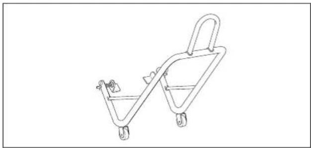
natural_image
Line drawing of a two-tiered mechanical device with wheels and handle (no text or symbols)Part No. B-41174 Rear Wheel Support Stand and Part No. B-41174-2 Replacement Pad
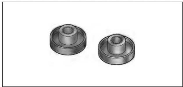
natural_image
Two metallic mechanical components with circular bases, shown from 3D perspective (no text or symbols)Part No. B-45521 Steering Head Bearing Remover/Installer
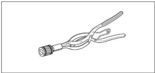
natural_image
Line drawing of a pair of pliers with metal fittings (no text or symbols)Part No. B-42887 Brake Caliper Piston Remover
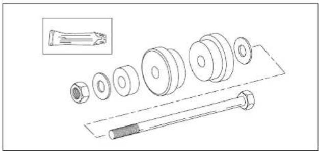
natural_image
Technical line drawing of a mechanical assembly with exploded view and detail inset (no text or symbols)Part No. 39302
natural_image
Technical line drawing of a mechanical component with no visible text or symbolsPart No. B-43721 Front Fork Seal Driver
natural_image
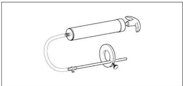
Technical line drawing of a syringe and pump assembly (no text or symbols)Part No. B-59000A Pro Level Oil Gauge
natural_image
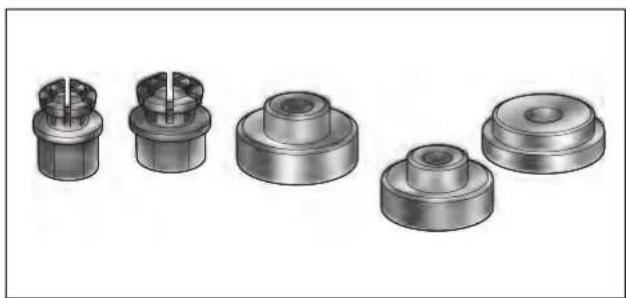
Six metallic mechanical components with cylindrical bases, shown from different angles (no text or symbols visible)Part No. B-43993-7/-8 Wheel Bearing Collets
natural_image
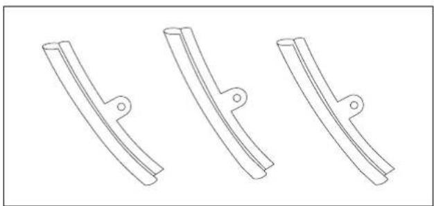
Three identical line drawings of a mechanical clip or bracket, shown in side profile with no text or symbols.Part No. HD-01289 Rim Protectors
natural_image
Technical line drawing of a mechanical support structure (no text or symbols)Part No. HD-21000 Tire Spreader
natural_image
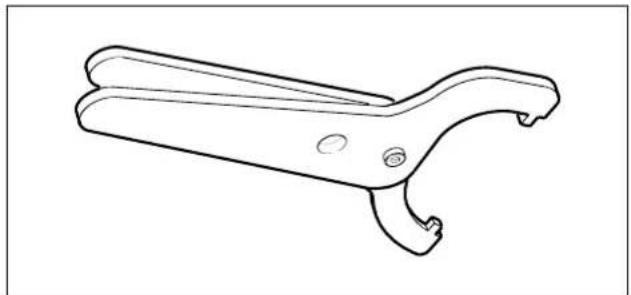
Line drawing of a mechanical clamp or bracket component (no text or symbols)Part No. HD-94700-52C Shock Spanner Preload Adjustment Tool
natural_image
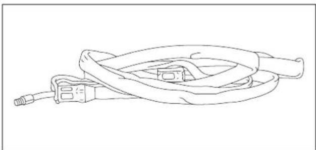
Line drawing of a cable and connector assembly (no text or symbols)Part No. HD-28700 Tire Bead Expander
natural_image
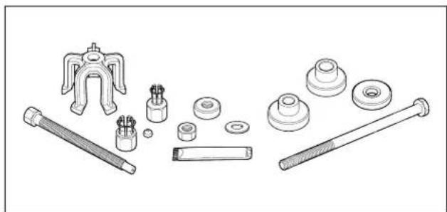
Exploded view of mechanical components including bolts, washers, and washers (no text or labels)Part No. HD-44060
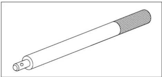
natural_image
Technical line drawing of a cylindrical mechanical component with a textured end (no text or symbols)Part No. HD-33416 Universal Driver Handle
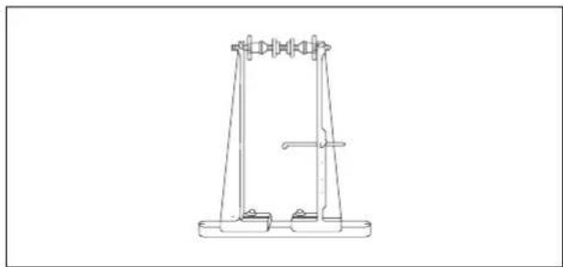
natural_image
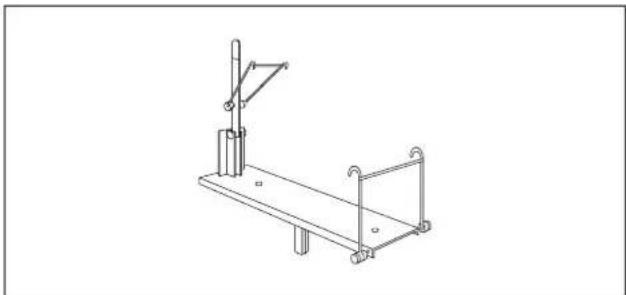
Line drawing of a mechanical device with two vertical supports and a central vertical bar (no text or symbols)Part No. HD-99500-80 Wheel Truing and Balancing Stand
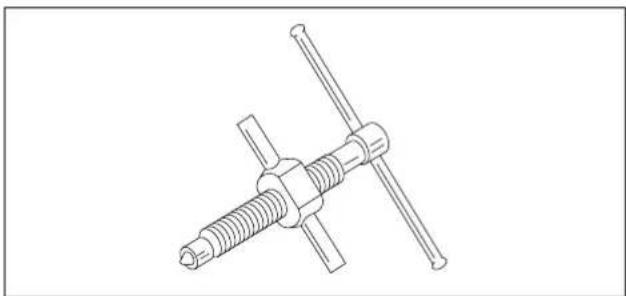
natural_image
Technical line drawing of a mechanical fastener assembly (no text or symbols)Part No. HD-33418 Universal Puller Forcing Screw
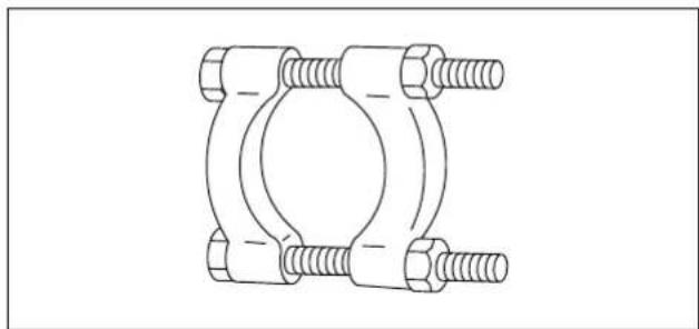
natural_image
Technical line drawing of a mechanical clamp or bracket assembly (no text or symbols)Part No. HD-95637-46A Wedge Attachment for Claw Puller. Use with HD-95635-46.
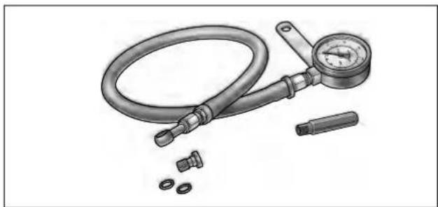
natural_image
Illustration of a pressure regulator with attached gauge, bolt, and bolts (no text or symbols)Part No. HD-96921-52A Oil Pressure Gauge
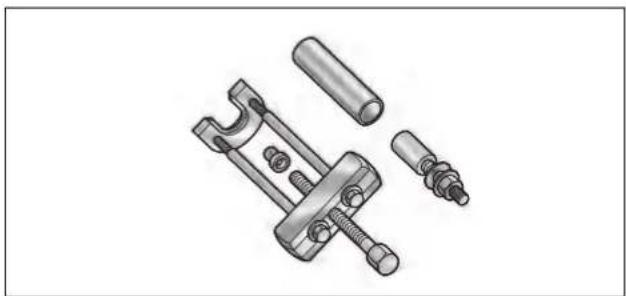
natural_image
Mechanical clamp assembly with multiple cylindrical components and threaded fasteners (no text or symbols visible)Part No. HD-34902-B
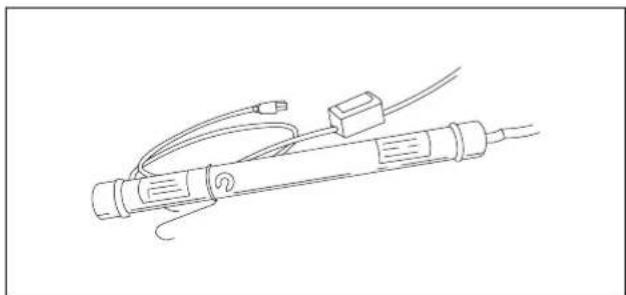
natural_image
Line drawing of a handheld electronic device with wires and connectors (no text or symbols)Part No. HD-35457 Black Light Leak Detector
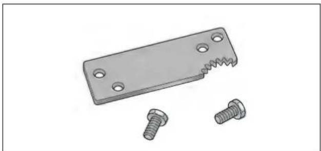
natural_image
3D rendering of a metal bracket with two bolts and a zigzag hole (no text or symbols)Part No. HD-43984 Crankshaft Locking Tool
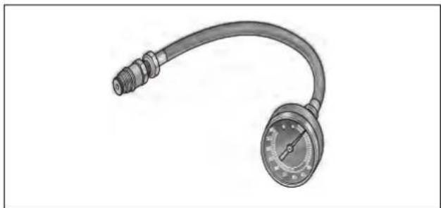
natural_image
Illustration of a pressure gauge with threaded end and central dial (no text or symbols)Part No. HD-33223-1 Cylinder Compression Gauge

natural_image
Line drawing of a rectangular metal bracket with a circular hole on top (no text or symbols)Part No. HD-38362 Sprocket Locking Link
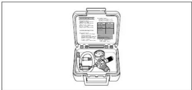
text_image
Diagram of a lifebuoy with labeled components including pressure gauge, valve, and devicePart No. HD-35667A Cylinder Leakdown Tester
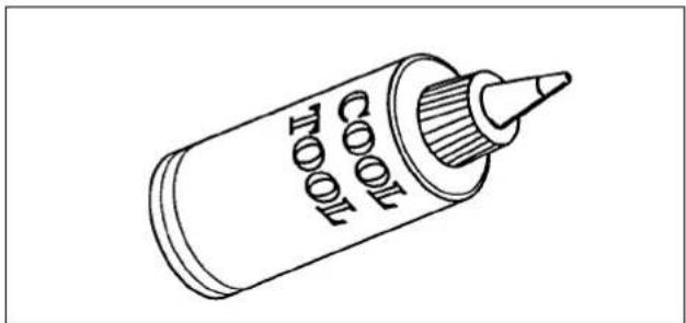
text_image
TOOLPart No. HD-39964 Reamer Lubricant (Cool Tool)
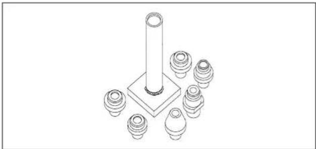
natural_image
Isometric line drawing of a mechanical component with a central cylindrical shaft and multiple flanged circular components (no text or symbols)Part No. HD-39782 Cylinder Head Support
natural_image
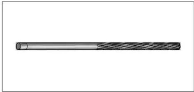
Illustration of a cylindrical mechanical shaft with a textured end and central hole (no text or symbols)Part No. B-45523 Valve Guide Reamer (7mm)
natural_image
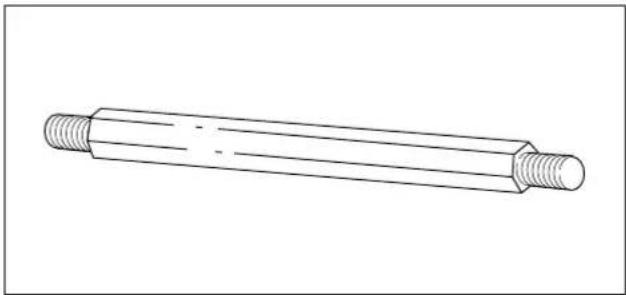
Technical line drawing of a cylindrical mechanical part with threaded ends (no text or symbols)Part No. HD-39786 Cylinder Head Holding Fixture
natural_image
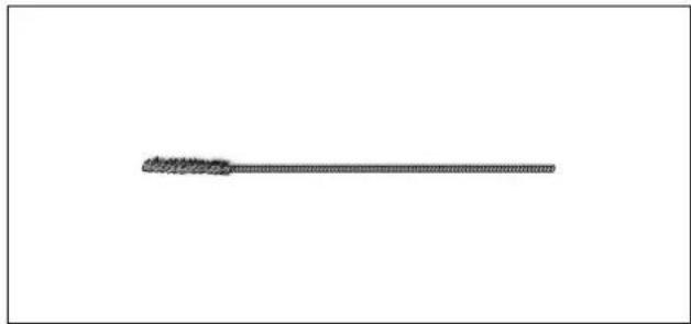
Simple line drawing of a long, elongated object with a small cluster on the left (no text or symbols)Part No. B-45525 Valve Guide Hone
natural_image
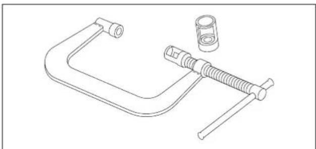
Line drawing of a mechanical clamp tool with a spring, bolt, and cylindrical component (no text or symbols)Part No. HD-34736B Valve Spring Compressor
natural_image
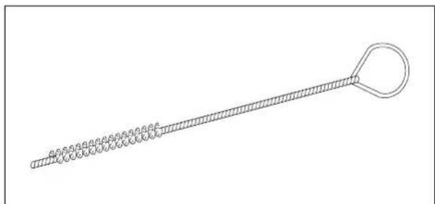
Line drawing of a stringed mechanical tool with a loop handle (no text or symbols)Part No. HD-34751 Nylon Valve Guide Brush
natural_image
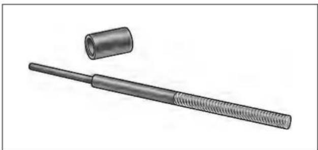
Illustration of a mechanical tool with a cylindrical component and threaded shaft (no text or symbols)Part No. B-45524 Valve Guide Installer
natural_image
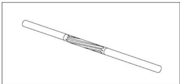
Line drawing of a twisted cable or wire with internal grooves (no text or symbols)Part No. HD-94804-57 Rocker Arm Bushing Reamer
natural_image
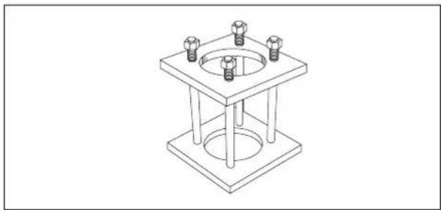
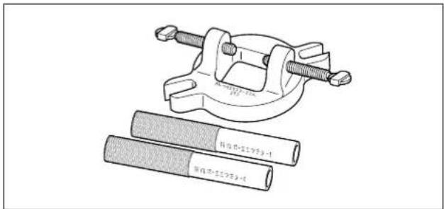
Isometric line drawing of a mechanical support structure with four bolts and concentric circles (no text or symbols)Part No. HD-33446A Cylinder Torque Plates and Torque Plate Bolts Part No. HD-33446-86
text_image
12.5 12.5 12.5 12.5 12.5 12.5 12.5 12.5 12.5 12.5 12.5 12.5 12.5 12.5 12.5 12.5 12.5 12.5 12.5 12.5 12.5Part No. HD-95952-33B Connecting Rod Clamping Tool
natural_image
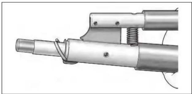
Mechanical assembly diagram showing a tool with threaded end and spring, no visible text or symbolsPart No. HD-34623C Piston Pin Retaining Ring Installer/Remover
natural_image
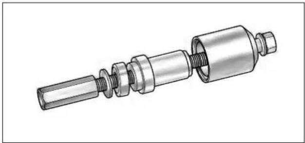
Technical illustration of a mechanical assembly with threaded shaft and cylindrical component (no text or symbols)Part No. HD-95970-32D Piston Pin Bushing Tool
natural_image
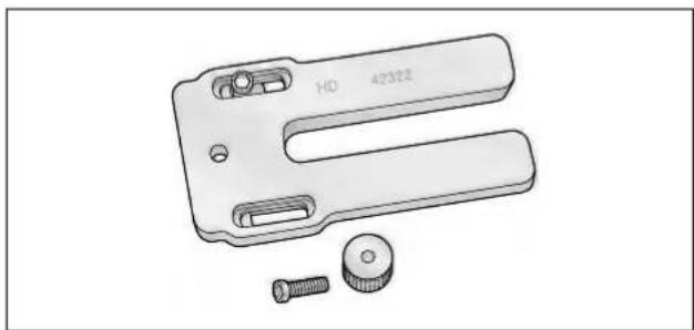
Technical illustration of a mechanical clamp or bracket with screws and a bolt, no text or symbols presentPart No. HD-42322 Piston Support Plate
natural_image
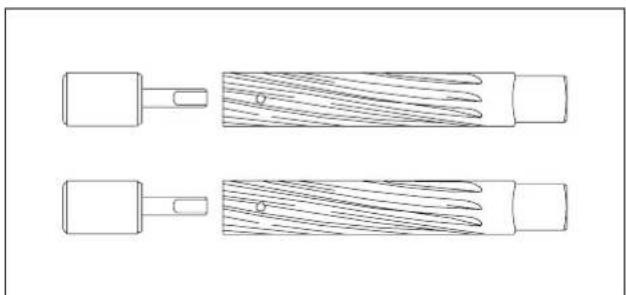
Technical line drawing of two mechanical components with internal hatching patterns (no text or symbols)Part No. HD-94800-26A Connecting Rod Bushing Reamers and Pilots
natural_image
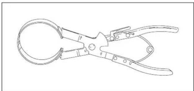
Line drawing of a pair of pliers (no text or symbols present)Part No. HD-96333-51C Piston Ring Compressor
natural_image
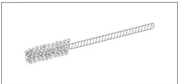
Diagram of a long rod with multiple circular holes, no text or symbols presentPart No. HD-35102 Wrist Pin Bushing Hone (20 mm)
natural_image
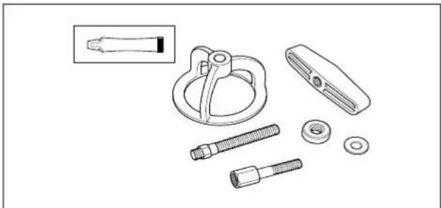
Technical line drawing of mechanical components including a bracket, washer, bolt, and nut (no text or labels)Part No. HD-38515-A Clutch Spring Compressing Tool and Part No. HD-38515-91 Forcing Screw
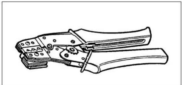
natural_image
Line drawing of a pair of crimping tools (no text or symbols)Part No. HD-39965 Deutsch Terminal Crimp Tool
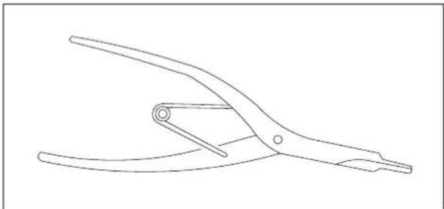
natural_image
Line drawing of a pair of pliers or tools (no text or symbols present)Part No. J-5586 Transmission Shaft Retaining Ring Pliers
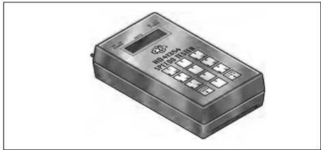
natural_image
Illustration of a handheld electronic device with control panel and display (no visible text or symbols)Part No. HD-41354
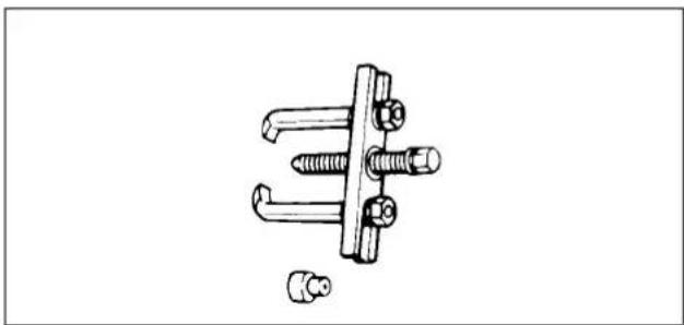
natural_image
Technical line drawing of a mechanical clamp or bracket assembly (no text or symbols)Part No. HD-97292-61 Two Claw Puller
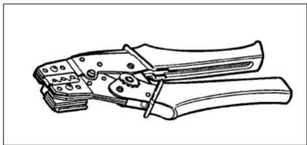
natural_image
Line drawing of a pair of crimping tools (no text or symbols)Part No. HD-41609 Amp Terminal Crimp Tool
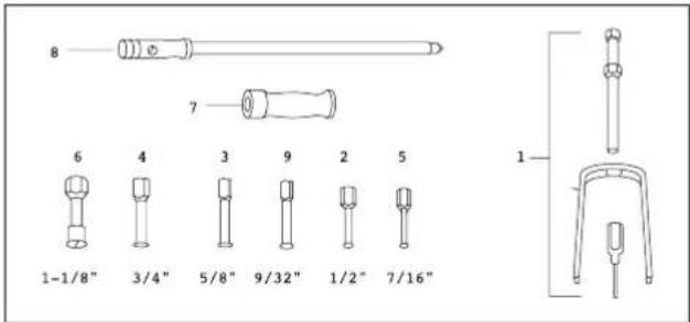
text_image
8 7 6 4 3 9 2 5 1-1/8" 3/4" 5/8" 9/32" 1/2" 7/16" 1Part No. HD-95760-69A Bushing/Bearing Puller Tool Set. Set includes items 1-7. Items 8 (HD-95769-69), 9 (HD-95770-69) and 10 (HD-95771-69) are optional.
REMOVING SOCKET/PIN TERMINALS
- Remove connector from the retaining device, either attachment or rosebud clip.
- Depress the button on the socket terminal side of the connector (plug) and pull apart the pin and socket halves.
- Bend back the latch slightly and free one side of secondary lock, then repeat the step to release the other side. Rotate the secondary lock outward on hinge to access terminals in chambers of connector housing.
- Looking in the terminal side of the connector (opposite the secondary lock), take note of the cavity next to each terminal.
- See Figure B-1. With the flat edge against the terminal, insert the pick tool (Snap-On TT600-3) into the cavity until it stops. Pivot the end of the pick away from the terminal (locktab is inside housing) and gently tug on wire to pull terminal from chamber. Do not tug on the wire until the tang is released or the terminal will be difficult to remove. A "click" is heard if the tang is engaged but then
inadvertently released. Repeat the step without releasing the tang.
NOTE
- If pick tool is not available, a push pin/safety pin may be used instead.
- An ELECTRICAL TERMINAL CRIMP TOOL (Part No. HD-41609) is used to install Amp Multi lock pin and socket terminals on wires. If new terminals must be installed, see Crimping Instructions on the next page.
INSTALLING SOCKET/PIN TERMINALS
NOTE
For wire location purposes, numbers are stamped into the secondary locks of both the socket and pin housings. See Figure B-2.
- From the secondary lock side of the connector, insert the terminal into its respective numbered chamber until it snaps in place. For proper fit, the slot in the terminal must face the tang in the chamber.
d0242x3x
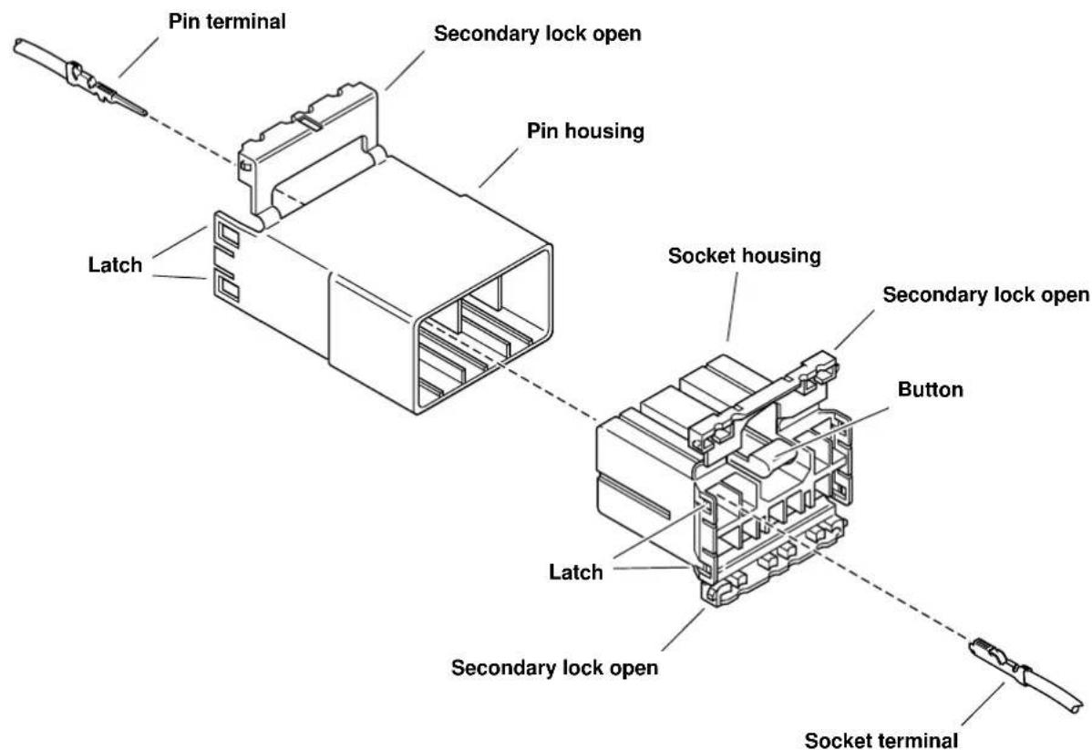
text_image
Pin terminal Secondary lock open Pin housing Latch Socket housing Secondary lock open Button Latch Secondary lock open Socket terminalFigure B-1. 10-Place Amp Multilock Connector
d0243x8x
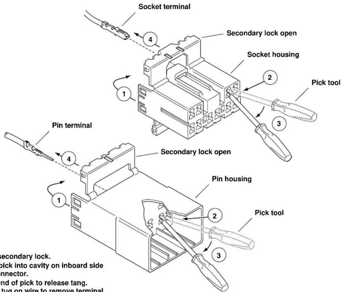
text_image
Socket terminal 4 Secondary lock open Socket housing 2 Pick tool 1 3 Pin terminal 4 Secondary lock open Pin housing 2 Pick tool 1 3 secondary lock. pick into cavity on inboard side nrector. end of pick to release tang. tug on wire to remove terminal- Open secondary lock.
- Insert pick into cavity on inboard side of connector.
- Pivot end of pick to release tang.
- Gently tug on wire to remove terminal from housing.
Figure B-2. Release Tang and Back Out Terminals
NOTES
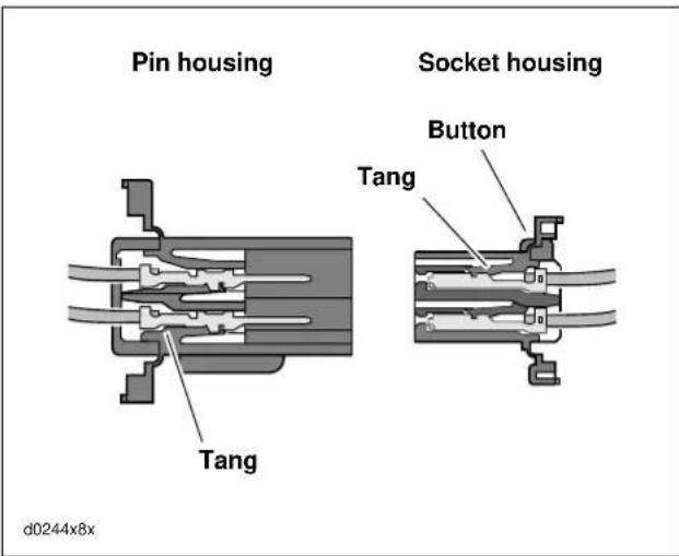
● See Figure B-3. The tang in the chamber engages the slot to lock the terminal in position.
- On the pin side of the connector, tangs are positioned at the bottom of each chamber, so the slot in the pin terminal (on the side opposite the crimp tails) must face downward.
- On the socket side, tangs are at the top of each chamber, so the socket terminal slot (on the same side as the crimp tails) must face upward.
- Up and down can be determined by the position of the release button (used to separate the pin and socket halves). Consider the button to always be on top of the connector.
2. Gently tug on wire end to verify that the terminal is locked in place and will not back out of chamber.
3. Rotate the hinged secondary lock inward until tabs fully engage latches on both sides of connector.
4. Insert the socket housing (plug) into the pin housing (receptacle) until it snaps in place.
5. Install connector on retaining device, either attachment or rosebud clip.
text_image
Pin housing Socket housing Tang Button Tang d0244x8xFigure B-3. Multilock Connector Cutaway View
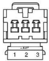
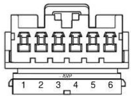
Secondary locks open (socket housings shown)
Stamped numbers on secondary locks indicate wire color locations
text_image
1 2 3 4 5 6 APP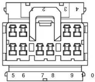
text_image
0 5 6 7 8 9 4 3 2text_image
Secondary lock Pin terminal Pin housing Socket housing Button Secondary lock Secondary lock Pin terminal Latch Pin housing Socket terminal Button Latch Socket housing Secondary lock Socket terminald0245x2x
Figure B-4. 3-Place and 6-Place Amp Multilock Connectors
CRIMPING INSTRUCTIONS
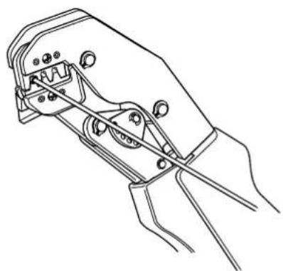
- Squeeze the handles to cycle the crimp tool (Part No. HD-41609) to the fully open position.
- Raise locking bar by pushing up on bottom flange. With the crimp tails facing upward, insert contact (socket/pin) through locking bar, so that the closed side of the contact rests on the front nest (concave split level area of the crimp tool). See Figure B-3.
-
Release locking bar to lock position of contact. When correctly positioned, the locking bar fits snugly in the space at the front of the core crimp tails.
-
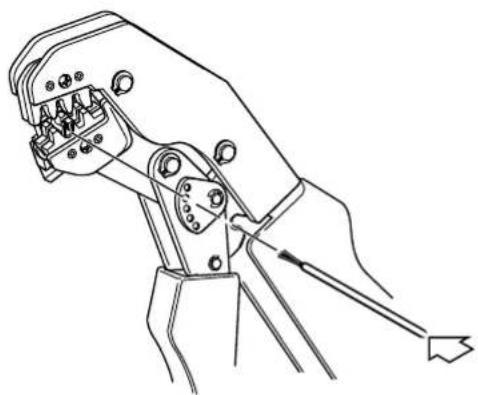
Strip lead removing 5/32 in. (4 mm) of insulation. Insert wires between crimp tails until ends make contact with locking bar. Verify that wire is positioned so that short pair of crimp tails squeeze bare wire strands, while long pair folds over insulation material.
- Squeeze handle of crimp tool until tightly closed. Tool automatically opens when the crimping sequence is complete. Raise up locking bar and remove contact.
-
Inspect the quality of the core and insulation crimps. Distortion should be minimal.
-
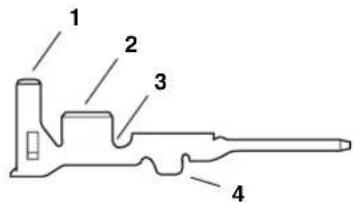
Insulating crimp tail
- Core crimp tail
- Locking bar groove
- Tang slot
text_image
1 2 3 4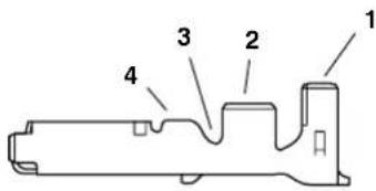
text_image
1 2 3 4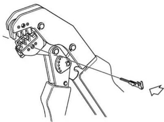
natural_image
Line drawing of a hand using a crimping tool to handle a wire (no text or symbols present)- Raise locking bar and seat contact on front nest of crimp tool. Release locking bar
natural_image
Line drawing of a hand using a crimping tool to handle components (no text or symbols)- Insert stripped lead until it contacts locking bar.
natural_image
Line drawing of a hand using a crimping tool to handle (no text or symbols present)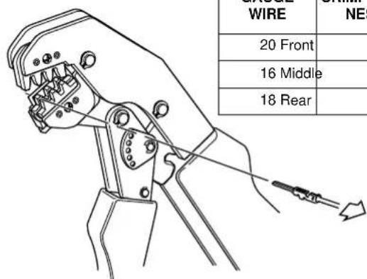
text_image
WIRE NES 20 Front 16 Middle 18 Rear| GAUGE WIRE | CRIMPTOOL NEST |
| 20 Front | |
| 16 Middle | |
| 18 Rear |
- Close and squeeze crimp tool. 4. Raise locking bar and remove contact.
d0246x8x
Figure B-5. Amp Multilock Crimping Procedure
GENERAL
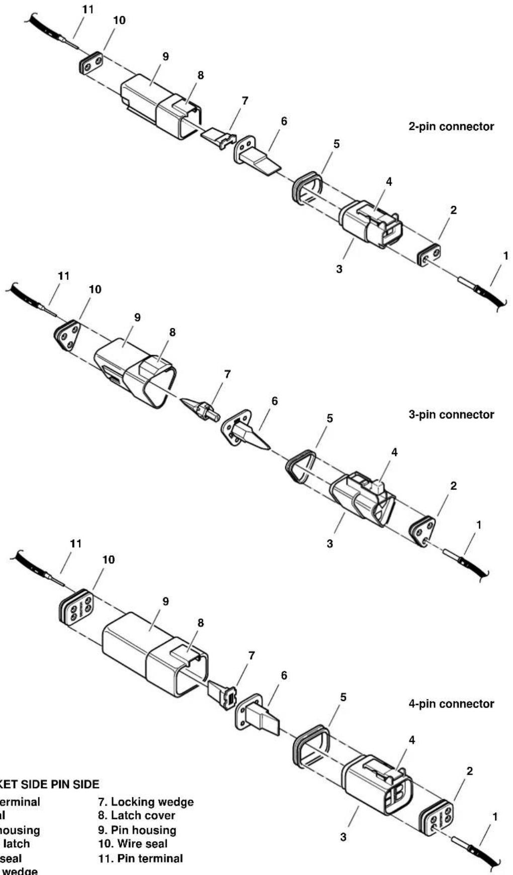
Deutsch Connectors feature a superior seal to protect electrical contacts from dirt and moisture in harsh environments. The connector also provides superior pin retention.
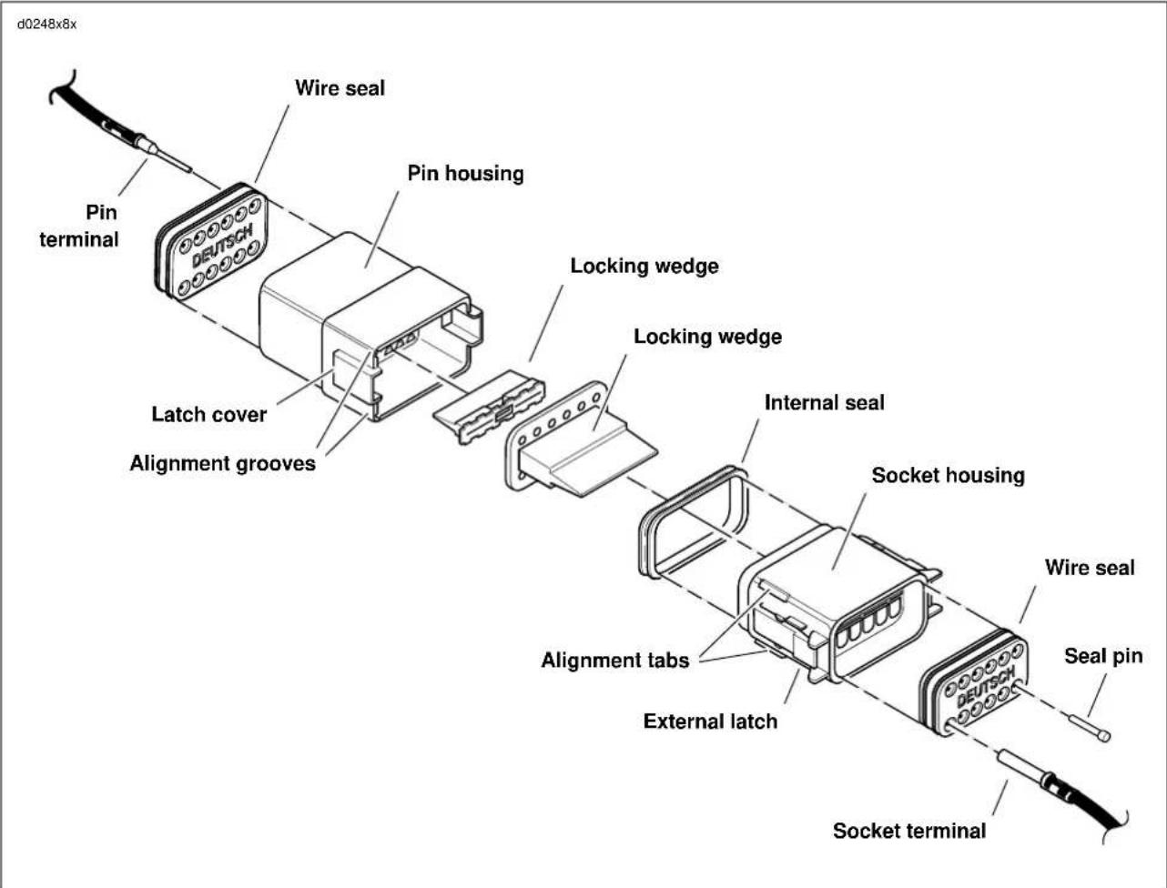
See Figure B-8. This 12-pin connector illustrates the various parts of the Deutsch connector. The following instructions may be followed for all 2-pin through 12-pin Deutsch connectors.
Socket housing: alignment tabs and/or external latch, secondary locking wedge, internal seal, wire seal, seal pin.
NOTE
Seal pins or plugs are installed in the wire seals of unused pin and socket locations. If removed, seal pins must be replaced to maintain the integrity of the environmental seal.
Pin housing: alignment grooves and/or external latch cover, attachment clip, secondary locking wedge, wire seal, seal pin.
REMOVING/DISASSEMBLING
Attachment clips are attached to the pin housings of most connectors. The clips are then attached to T-studs on the motorcycle frame. T-studs give positive location to electrical connectors and wire harness. Consistent location reduces electrical problems and improves serviceability.
- Push the connector to disengage small end of slot on attachment clip from T-stud. Lift connector off T-stud.
- Depress the external latch(es) on the socket housing side and use a rocking motion to separate the pin and socket halves. Two-, three-, four- and six-pin Deutsch connectors have one external latch, while eight- and twelve-pin connectors have two, both of which must be pressed simultaneously to separate the connector halves.
NOTE
With few exceptions, the socket housing can always be found on the accessory side, while the pin side of the connector is connected to the wiring harness.
REMOVING/INSTALLING SOCKETS
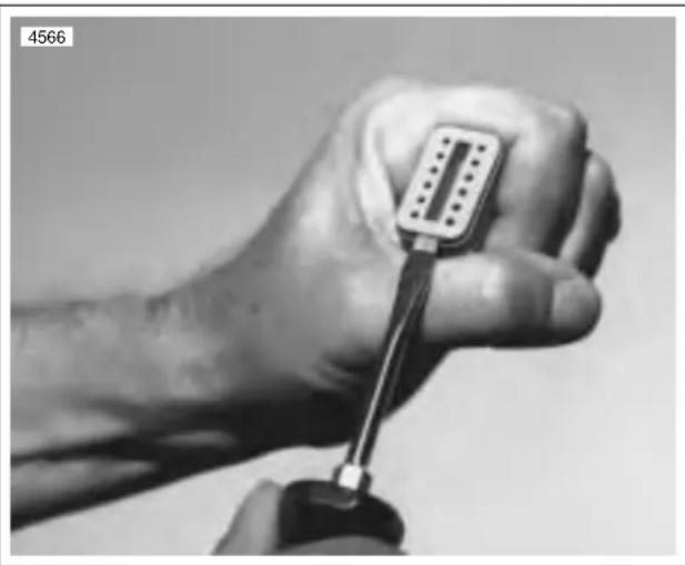
- See Figure B-7. Remove the secondary locking wedge. Insert the blade of a small screwdriver between the socket housing and locking wedge inline with the groove (inline with the pin holes if the groove is absent). Turn the screwdriver 90 degrees to pop the wedge up.
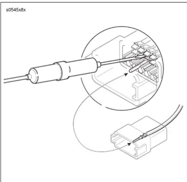
- See Figure B-8. Gently depress terminal latches inside socket housing and back out sockets through holes in rear wire seal.
natural_image
Close-up of a hand holding a connector with a plug, no visible text or symbolsFigure B-6. Remove Secondary Locking Wedge
text_image
s0545x8xFigure B-7. Depress Terminal Latches/Back Out Pins
NOTE
An ELECTRICAL TERMINAL CRIMP TOOL (Part No. HD-39965) is used to install Deutsch pin and socket terminals on wires. If new terminals must be installed, follow the instructions included with the crimping tool or see Crimping Instructions in this section.
Fit rear wire seal into back of socket housing, if removed. Grasp socket approximately 1.0 in. (25.4 mm) behind the contact barrel. Gently push sockets through holes in wire seal into their respective chambers. Feed socket into chamber until it "clicks" in place. Verify that socket will not back out of chamber; a slight tug on the wire will confirm that it is properly locked in place.
text_image
d0248x8x Wire seal Pin terminal Pin housing Locking wedge Locking wedge Latch cover Alignment grooves Internal seal Socket housing Wire seal Seal pin External latch Alignment tabs Socket terminalFigure B-8. 12-pin Deutsch Connector (Exploded View)
- Install internal seal on lip of socket housing, if removed. Insert tapered end of secondary locking wedge into socket housing and press down until it snaps in place. The wedge fits into the center groove within the socket housing and holds the terminal latches tightly closed.
NOTES
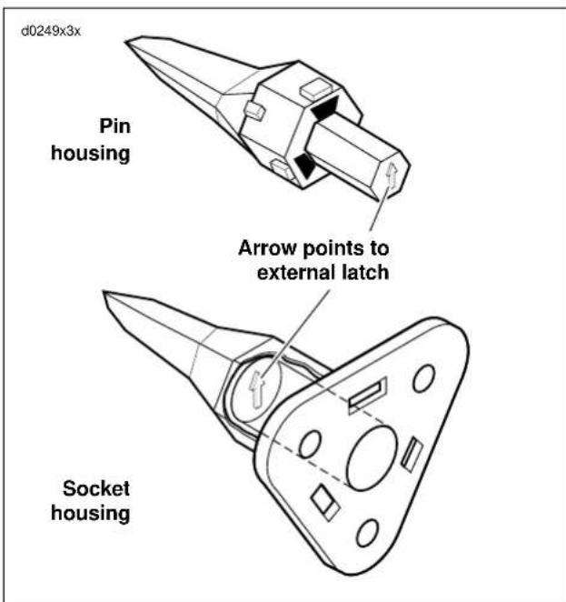
- While rectangular wedges do not require a special orientation, the conical secondary locking wedge of the 3-pin connector must be installed with the arrow pointing toward the external latch. See Figure B-9.
- If the secondary locking wedge does not slide into the installed position easily, verify that all terminals are fully installed in the socket housing. The lock indicates when terminals are not properly installed by not entering its fully installed position.
REMOVING/INSTALLING PINS
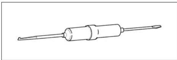
- Remove the secondary locking wedge. Use the hooked end of a stiff piece of mechanics wire a needle nose pliers, or a suitable pick tool (Part No. HD-41475-100). See Figure B-10.
- Gently depress terminal latches inside pin housing and back out pins through holes in wire seal.
text_image
d0249x3x Pin housing Arrow points to external latch Socket housingFigure B-9. Depress Terminal Latches/Back Out Pins
HOME
NOTE
An ELECTRICAL TERMINAL CRIMP TOOL (Part No. HD-39965) is used to install Deutsch pin and socket terminals on wires. If new terminals must be installed, see Crimping Instructions in this section.
-
Fit wire seal into back of pin housing. Grasp crimped pin approximately 1.0 in. (25.4 mm) behind the contact barrel. Gently push pins through holes in wire seal into their respective numbered locations. Feed pin into chamber until it "clicks" in place. Verify that pin will not back out of chamber; a slight tug on the wire will confirm that it is properly locked in place.
-
Insert tapered end of secondary locking wedge into pin housing and press down until it snaps in place. The wedge fits in the center groove within the pin housing and holds the terminal latches tightly closed.
NOTES
● While rectangular wedges do not require a special orientation, the conical secondary locking wedge of the 3-pin connector must be installed with the arrow pointing toward the external latch. See Figure B-9.
- If the secondary locking wedge does not slide into the installed position easily, verify that all terminals are fully installed in the pin housing. The lock indicates when terminals are not properly installed by not entering its fully installed position.
ASSEMBLING/INSTALLING
- Insert socket housing into pin housing until it snaps in place. Two-, three-, four- and six-pin Deutsch connectors have one external latch on the socket half of the connector. To fit the halves of the connector together, the latch on the socket side must be aligned with the latch cover on the pin side.
For those connectors with two external latches (8-pin and 12-pin), a different system is used to prevent improper assembly. Align the tabs on the socket housing with the grooves on the pin housing. Push the connector halves together until the latches "click." If latches do not click (latch), press on one side of the connector until that latch engages, then press on the opposite side to engage the other latch.
NOTE
Deutsch connectors are color coded for location purposes. Those connectors associated with left side accessories, such as the front and rear left turn signals, are gray All other connectors, including those associated with right side accessories, are black.
If it should become necessary to replace a plug or receptacle, please note that the 8-pin and 12-pin gray and black connectors are not interchangeable. Since location of the alignment tabs differ between the black and gray connectors, plugs or receptacles must be replaced by those of the same color. If replacing both the socket and pin halves, then the black may be substituted for the gray, and vice versa. The socket and pin halves of all other connectors are interchangeable, that is, the black may be mated with the gray, since the alignment tabs are absent and the orientation of the external latch is the same.
natural_image
Line drawing of a screwdriver with a cylindrical head and pointed tip (no text or symbols)Figure B-10. Deutsch Connector Pick Tool (Part No. HD-41475-100)
text_image
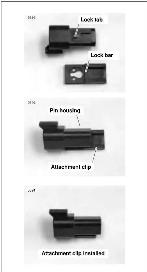
5893 Lock tab Lock bar 5892 Pin housing Attachment clip 5891 Attachment clip installedFigure B-11. Attachment Clip Installation
- See Figure B-11. Fit the attachment clip to the pin housing, if removed. Place large end of slot on attachment clip over T-stud on frame. Push assembly forward to engage small end of slot.
d0250x8x
text_image
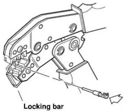
Locking bar- Insert contact through middle hole in locking bar.
natural_image
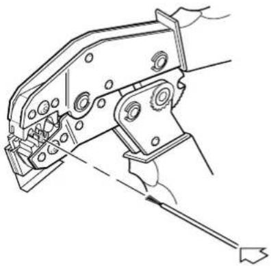
Technical line drawing of a mechanical clamp or crimping tool (no text or symbols present)- Insert stripped lead until it contacts locking bar.
natural_image
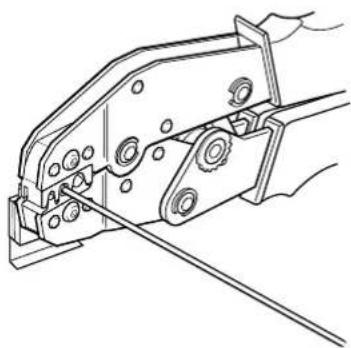
Technical line drawing of a mechanical clamp or bracket assembly (no text or symbols)- Close and squeeze crimp tool 4. Raise locking bar and remove contact.
natural_image
Technical line drawing of a mechanical clamp or bracket assembly (no text or symbols)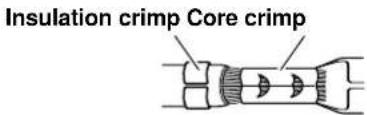
text_image
Insulation crimp Core crimpFigure B-12. Deutsch Crimping Procedure
CRIMPING INSTRUCTIONS
- See Figure B-12. Squeeze the handles to cycle the crimp tool to the fully open position.
- Raise locking bar by pushing up on bottom flange. With the crimp tails facing upward and the rounded side of the contact barrel resting on the concave split level area of the crimp tool, insert contact (socket/pin) through middle hole of locking bar.
-
Release locking bar to lock position of contact. If the crimp tails are slightly out of vertical alignment, the crimp tool automatically rotates the contact so that the tails face straight upward. When correctly positioned, the locking bar fits snugly in the space between the contact band and the core crimp tails.
-
Strip lead removing 5/32 in. (4 mm) of insulation. Insert wires between crimp tails until ends make contact with locking bar. Verify that wire is positioned so that short pair of crimp tails squeeze bare wire strands, while long pair folds over insulation material.
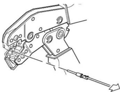
- Squeeze handle of crimp tool until tightly closed. Tool automatically opens when the crimping sequence is complete. Raise up locking bar and remove contact.
- Inspect the quality of the core and insulation crimps. Distortion should be minimal.
d0251x3x
text_image
2-pin connector 3-pin connector 4-pin connector 11 10 9 8 7 6 5 4 3 1 2-pin connector 3-pin connector 4-pin connector 11 10 9 8 7 6 5 4 3 1 2-pin connector 3-pin connector 11 10 9 8 7 6 5 4 3 1 2-pin connector 3-pin connector 11 10 9 8 7 6 5 4 3 1 2-pin connector 3-pin connector 11 10 9 8 7 6 5 4 3 1 2-pin connector 3-pin connector 11 10 7. Locking wedge 8. Latch cover 9. Pin housing 10. Wire seal 11. Pin terminalFigure B-13. 2-Pin, 3-pin and 4-pin Deutsch Connectors
GENERAL
From a servicing standpoint, there are two basic types of Packard electrical connectors, those with pull-to-seat terminals and those with push-to-seat terminals.
Look into the mating end of the connector. If it appears that the terminal can be extracted from this side, then it is probably the pull-to-seat type.
At least one Packard pull-to-seat terminal can be easily recognized by the presence of a locking ear. The ear engages a slot in the connector housing and prevents the terminal from being removed from the wire end side of the connector. The ear also acts as a strain relief in the event that the wires are pulled and further inhibits movement of the terminal inside the chamber. For an example of this type of connector, note the MAP sensor connector [80].
Unlike most connectors, where the terminals are pulled out the wire end of the connector, to remove the terminals from the pull-to-seat connectors, the terminal is pushed out the mating end of the connector. Once a new terminal is crimped onto the end of the wire, the wire is pulled to draw the terminal back inside the chamber of the connector housing.
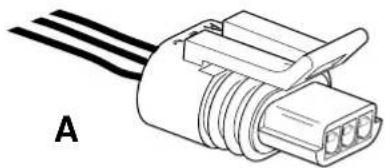
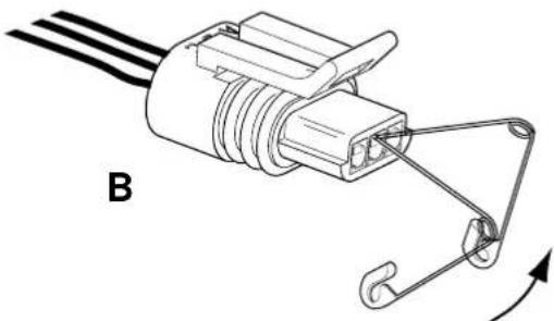
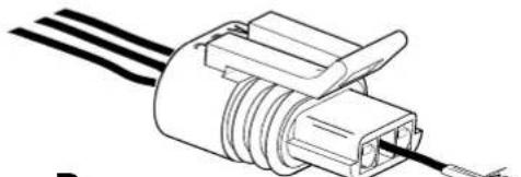
Two types of Packard pull-to-seat electrical connectors are used. One type has an external latch to lock the pin and socket halves together, while the other makes use of a wire-form. See Figure B-14. The manner in which the terminals are picked differs between these two types of connectors, as further described below.
d0258x8x
natural_image
Diagram of a multi-pin electrical connector with three leads (no text or symbols)Locate tang on latch side of chamber.
text_image
C Push on wire end of lead toPush on wire end of lead to remove terminal.
natural_image
Technical line drawing of a mechanical connector with wires and a curved hook, labeled B (no text or symbols present)Pivot end of pin to depress tang.
natural_image
Diagram of a connector with three leads and a cable, no text or symbols presentD
text_image
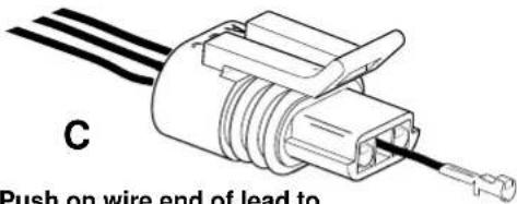
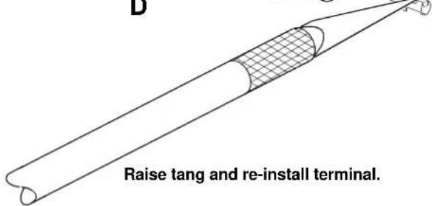
D Raise tang and re-install terminal.Figure B-14. Packard Connectors
PULL-TO-SEAT TERMINALS
Removing External Latch Type
To remove a pull-to-seat terminal from connectors with external latches, proceed as follows:
- Remove the connector from the retaining device, if present.
-
Bend back the external latch(es) slightly and separate the pin and socket halves of the connector.
-
To free a pull-to-seat terminal from the connector housing, first look into the mating end of the connector to find the locking tang. See A in Figure B-14. The tangs are always positioned in the middle of the chamber and are on the same side as the external latch. On those connectors with locking ears, the tang is on the side opposite the ear.
-
At a slight angle, gently insert the point of a one inch safety pin down the middle of the chamber (about 1/8 inch) and pivot the end of the pin toward the terminal body. When a click is heard, remove the pin and repeat the procedure. See B in Figure B-14. The click is the sound of the tang returning to the locked position as it slips from the point of the pin. Pick at the tang in this manner until the clicking stops and the pin seems to slide in at a slightly greater depth than it had previously. This is an indication that the tang has been depressed.
NOTES
- On those terminals that have been extracted on a previous occasion, no clicking sound may be heard when the pin is pivoted to depress the tang, but proceed as if the clicking is audible and then push on the wire end of the lead to check if the terminal is free.
-
When picking multiple terminals, the end of the pin may become malleable. For best results, continue the procedure with a new safety pin.
-
Remove the pin and push on the wire end of the lead to extract the terminal from the mating end of the connector. See C in Figure B-14. If necessary, pull back the conduit and remove the wire seal at the back of the connector to introduce some slack in the wires.
NOTE
A series of Packard Electrical Terminal Crimp Tools are available to install Packard pin and socket terminals on wires. If new terminals must be installed, see Crimping Instructions.
Installing External Latch Type
NOTE
For wire location purposes, alpha characters are stamped into the socket housings.
- To install a terminal back into the chamber of the connector housing, use a thin flat blade, like that on an X-Acto knife, and carefully bend the tang outward away from the terminal body. See D in Figure B-14.
- Gently pull on the lead at the wire end of the connector to draw the terminal back into the chamber. A click is heard when the terminal is properly seated.
- Push on the lead to verify that the terminal is locked in place.
- Push the pin and socket halves of the connector together until the latches "click."
PUSH-TO-SEAT TERMINALS
The Packard push-to-seat terminal connectors found on Softail model vehicles are listed below.
- Ignition Switch [33]
- Fuse Terminals
● MAP Sensor [80]
Removing Push-to-Seat Terminals
Like most connectors, Packard push-to-seat terminals are pulled out the wire end of the connector. To remove a push-to-seat terminal, proceed as follows:
- Remove the connector from the retaining device, if present.
- Bend back the external latch(es) slightly and separate the pin and socket halves of the connector.
NOTE
Both the Ignition Light/Key Switch and the Main Power connectors are provided with secondary locks. The secondary lock, which may be molded onto the connector or exist as a separate piece, aids in terminal retention. Secondary locks must be opened (or removed) before the terminals can be extracted from the connector housing.
- Open or remove the secondary lock. Bend back the latch slightly and free one side of the secondary lock, then repeat the step to release the other side. Rotate the secondary lock outward on hinge to access the terminals in the chambers of the connector housing.
- Looking in the mating end or terminal side of the connector (opposite the secondary lock), take note of the larger cavity next to each terminal.
- Insert the pick (Snap-On TT600-3) into the cavity until it stops. Pivot the end of the pick toward the terminal to depress the locking tang. Remove the pick and gently tug on the wire to pull the terminal from the wire end of the connector. Repeat the step if the terminal is still locked in place.
NOTE
A series of Packard Electrical Terminal Crimp Tools are available to install Packard pin and socket terminals on wires. If new terminals must be installed, see Crimping Instructions.
Installing Push-to-Seat Terminals
NOTE
For wire location purposes, alpha characters are stamped onto the secondary locks or onto the wire end of the connector housing.
- To install a terminal back into the chamber of the connector housing, use a thin flat blade, like that on an X-Acto knife, and carefully bend the tang outward away from the terminal body.
- Push the lead into the chamber at the wire end of the connector. A click is heard when the terminal is properly seated.
- Gently tug on the wire end to verify that the terminal is locked in place and will not back out of the chamber.
- Close or install the secondary lock. Rotate the hinged secondary lock inward until tabs fully engage latches on both sides of connector.
- Push the pin and socket halves of the connector together until the latches "click."
- Install connector on retaining device, if present.
CRIMPING INSTRUCTIONS
- Strip wire lead removing 5/32 in. (4 mm) of insulation.
- Compress handles until ratchet automatically opens.
NOTE
Always perform core crimp before insulation/seal crimp.
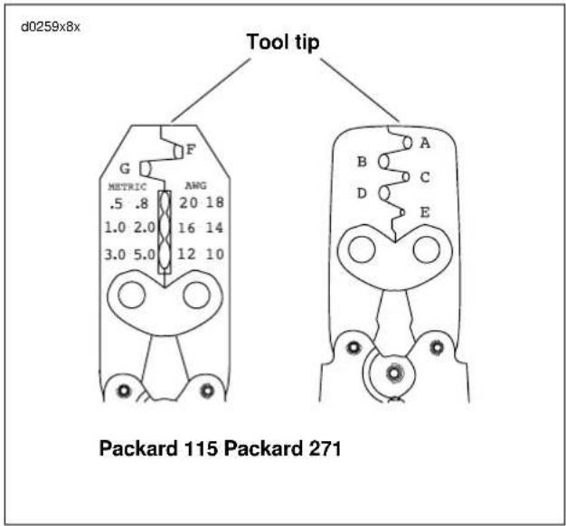
- See Table B-1. Determine the correct dye or nest for the core crimp.
NOTE
When the word "TIP" appears in the Crimp Table, use the tip of the tool specified to perform the core crimp procedure. See Figure B-15.
- Lay the back of the core crimp tails on the appropriate nest. Be sure the core crimp tails are pointing towards the forming jaws.
- Gently apply pressure to handles of tool until crimpers slightly secure the core crimp tails.
- Insert stripped wire between crimp tails. Verify that wire is positioned so that short pair of crimp tails squeeze bare wire strands, while long pair folds over insulation or seal material.
- Squeeze handle of crimp tool until tightly closed. Tool automatically opens when the crimping sequence is complete.
- Table B-1. Determine the correct dye or nest for the insulation/seal crimp.
- Lay the back of the insulation/seal crimp tails on the appropriate nest. Be sure the insulation/seal crimp tails are pointing towards the forming jaws.
- Squeeze handle of crimp tool until tightly closed. Tool automatically opens when the crimping sequence is complete.
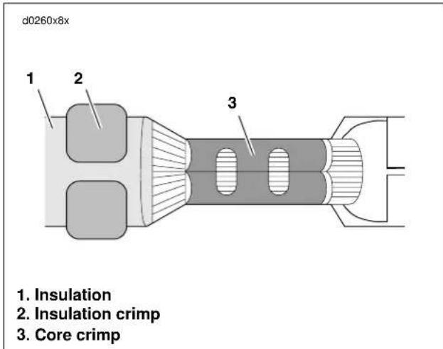
- See Figure B-16. Inspect the quality of the core (3) and insulation/seal (2) crimps. Distortion should be minimal.
text_image
d0259x8x Tool tip G F METRIC ANG .5 .8 20 18 1.0 2.0 16 14 3.0 5.0 12 10 Packard 115 Packard 271Figure B-15. Packard Terminal Crimp Tools
Table B-1. Packard Terminal Crimp Tools
| SPECIFICATION | PACKARD 115 PACKARD 271 | |
| Part No. HD-38125-8 | HD-38125-7 | |
| Typeof Crimp | Non-sealed terminals, butt splices | Non-sealed terminals |
| Dye/nests F-G A-E | ||
text_image
d0260x8x 1. Insulation 2. Insulation crimp 3. Core crimpFigure B-16. Inspect Core and Insulation/Seal Crimps
GENERAL
Connector numbers are listed in [brackets] in this manual.
The following table provides a brief description of the connectors found on the Firebolt XB9R.
Table B-2. Electrical Connector and Location Table
| CONNECTOR | COMPONENT(S) | DESCRIPTION | LOCATION | |
| [5] main fuse spade terminals under seat | ||||
| [7] tail lamp harness 8-place Multilock left side under tail section | ||||
| [10] ECM (black) 12-place Deutsch in fairing | ||||
| [11] ECM (gray) | 12-place Deutsch in fairing | |||
| [14] cam position sensor | 3-place Deutsch under sprocket cover | |||
| [18] right rear turn signal | 2 1-place bullet under tail section | |||
| [19] left rear turn signal | 2 1-place bullet under tail section | |||
| [22] right hand controls | 4-place Multilock | beneath right side of fairing | ||
| [24] left hand controls | 4-place Multilock beneath left side of fairing | |||
| [30] flasher | 5-place Amp in fairing | |||
| [31] right front turn signal | 2 1-place bullet | beneath right side of fairing | ||
| [31] left front turn signal | 2 1-place bullet | beneath left side of fairing | ||
| [33] ignition switch | 4-place Augat beneath right side of fairing | |||
| [38] headlamp connector | 4-place Amp beneath fairing | |||
| [39] instrument module | 20-place Multilock in fairing | |||
| [46] stator | 4-place Deutsch under sprocket cover | |||
| [61] fuse and diode assembly | spade terminals right side of fairing | |||
| [62] relay assembly | spade terminals left side of fairing | |||
| [65] vehicle speed sensor | 3-place Deutsch under sprocket cover | |||
| [77] voltage regulator | 2-place Packard under sprocket cover | |||
| [83] ignition coil | 3-place Packard beneath airbox base | |||
| [84] front fuel injector | 2-place Packard underneath airbox base | |||
| [85] rear fuel injector | 2-place Packard underneath airbox base | |||
| [86] fuel pump | 4-place Multilock left side of rear shock absorber | |||
| [88] throttle position sensor | 3-place Packard | right side of engine between cylinders | ||
| [89] intake air temperature sensor | 2-place Amp in airbox base | |||
| [90] engine temperature sensor | 1-place bullet beneath airbox base | |||
| [91A] data link | 4-place Deutsch | beneath left side fairing | ||
| [93] tail light | 2-place spade 1-place spade (ground) | back of tail light | ||
Table B-2. Electrical Connector and Location Table
| CONNECTOR | COMPONENT(S) | DESCRIPTION | LOCATION |
| [95] clutch | switch 2-place Multilock beneath fairing | ||
| [97] cooling | fan 2-place Multilock behind rear cylinder | ||
| [120] oil pressure | shock post terminal crankcase above oil filter | ||
| [121] front brake switch | 2-place Multilock beneath fairing | ||
| [121] rear brake switch | 2-place Multilock under seat | ||
| [122] horn spade terminals in fairing | |||
| [128] starter solenoid spade terminals top of starter | |||
| [131] neutral switch | 1-place bullet under sprocket cover | ||
| [133] sidest and switch | 2-place Multilock top of sidestand | ||
| [134] bank angle sensor | 6-place Sumitomo in fairing | ||
| [137] oxygen sensor | 1-place Packard | behind rear cylinder head |
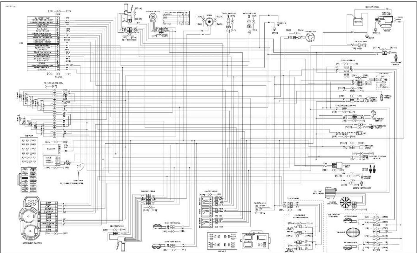
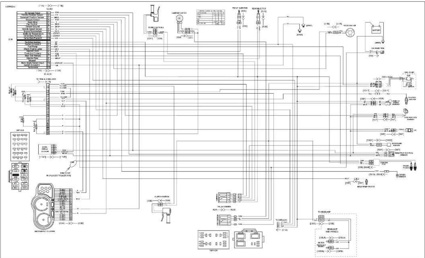
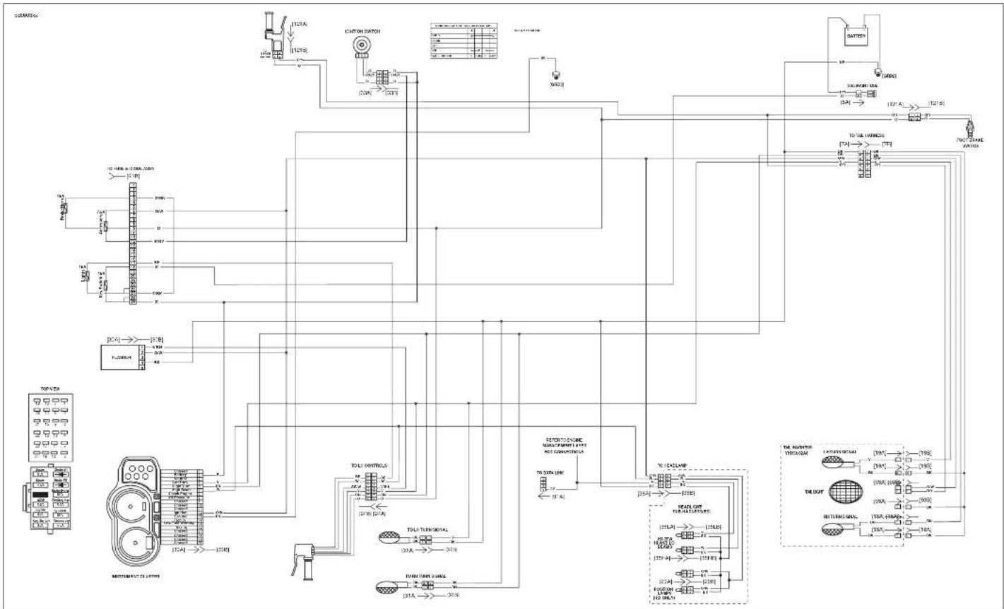
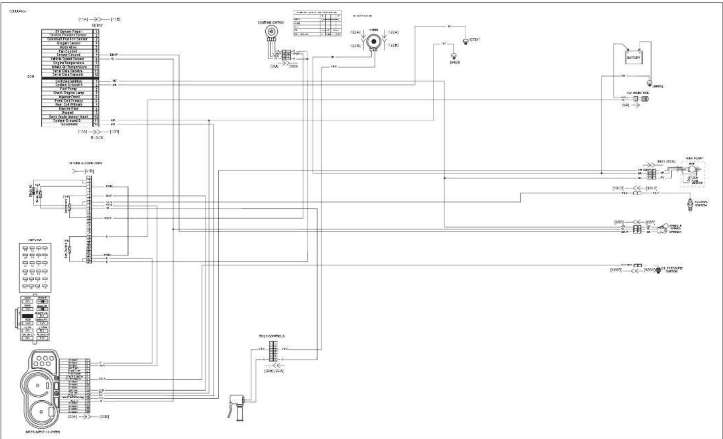
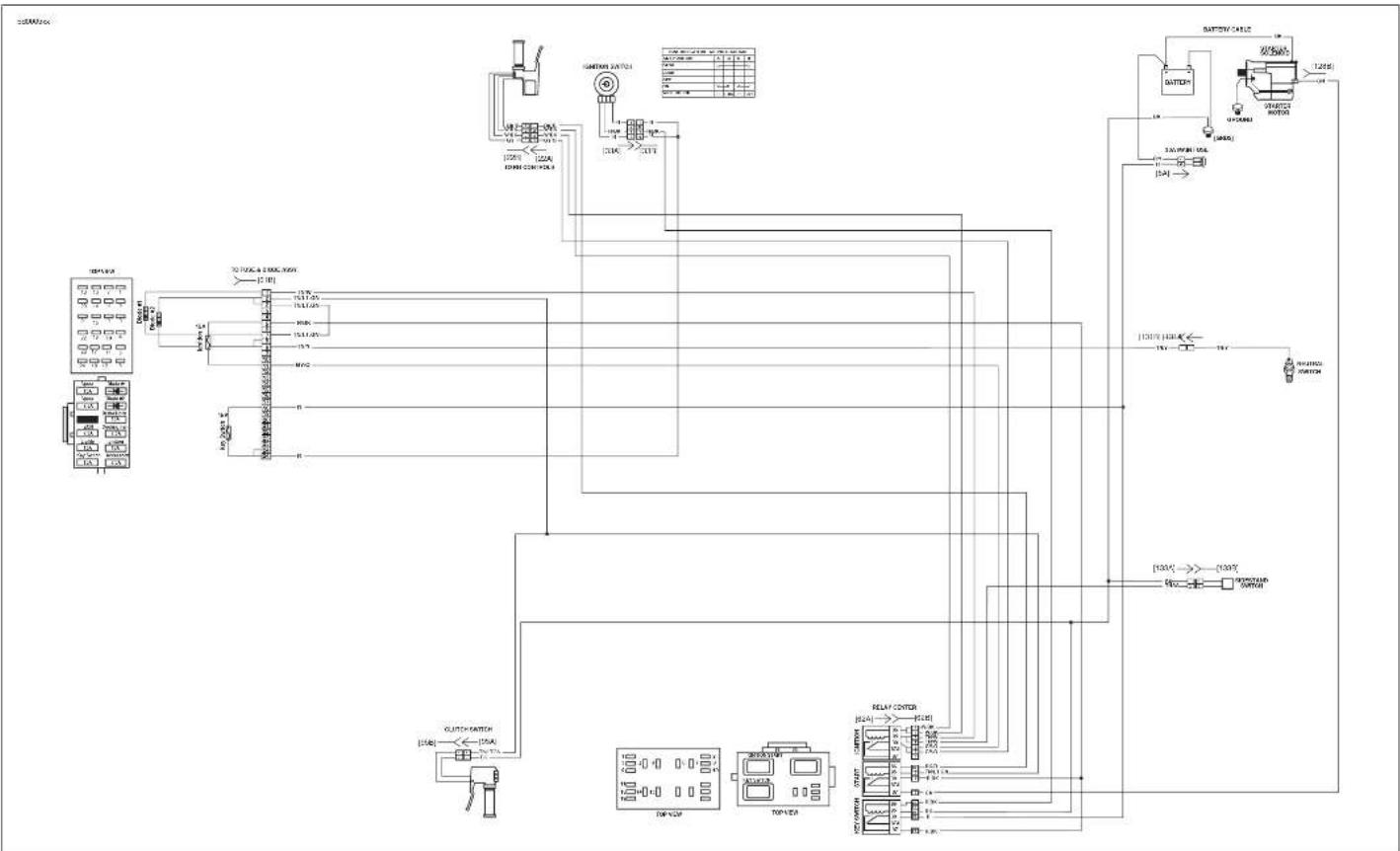
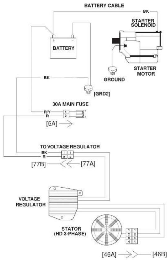
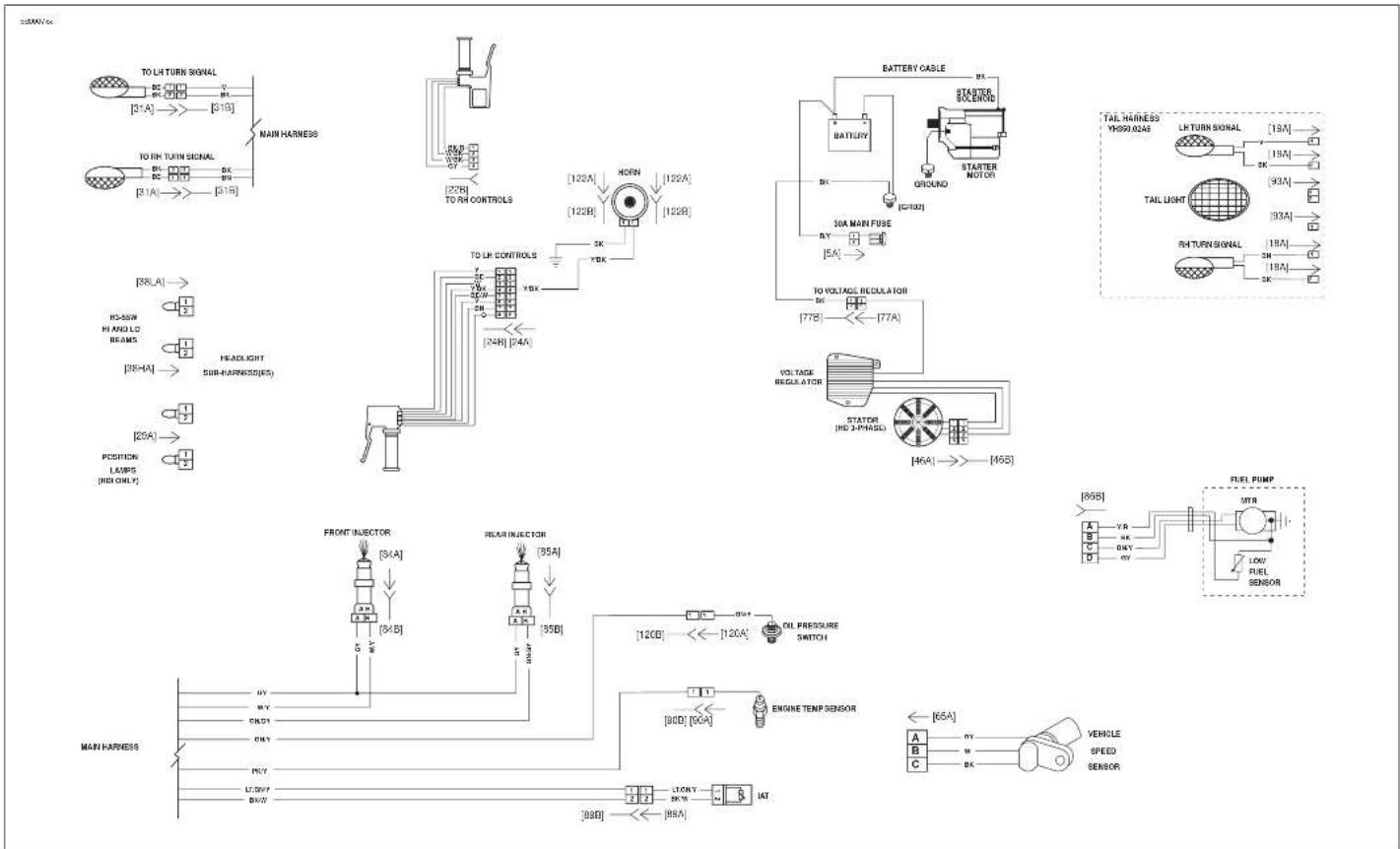
Table B-3. XB9R Wiring Diagrams
| DIAGRAM PAGE | |
| Main harness B-17 | |
| Engine management circuit B-18 | |
| Lighting circuit B-19 | |
| Horn and instruments circuit B-20 | |
| Starting circuit B-21 | |
| Starting and charging circuits B-22 | |
| Component Circuits B-23 |
HOME
flowchart
graph TD
    A["Power Supply"] --> B["Control Logic"]
    B --> C["Motor Control"]
    C --> D["Motor Output"]
    D --> E["Output Signal"]
    E --> F["Ground"]
    F --> G["Ground"]
    G --> H["Ground"]
    H --> I["Ground"]
    I --> J["Ground"]
    J --> K["Ground"]
    K --> L["Ground"]
    L --> M["Ground"]
    M --> N["Ground"]
    N --> O["Ground"]
    O --> P["Ground"]
    P --> Q["Ground"]
    Q --> R["Ground"]
    R --> S["Ground"]
    S --> T["Ground"]
    T --> U["Ground"]
    U --> V["Ground"]
    V --> W["Ground"]
    W --> X["Ground"]
    X --> Y["Ground"]
    Y --> Z["Ground"]
    Z --> AA["Ground"]
    AA --> AB["Ground"]
    AB --> AC["Ground"]
    AC --> AD["Ground"]
    AD --> AE["Ground"]
    AE --> AF["Ground"]
    AF --> AG["Ground"]
    AG --> AH["Ground"]
    AH --> AI["Ground"]
    AI --> AJ["Ground"]
    AJ --> AK["Ground"]
    AK --> AL["Ground"]
    AL --> AM["Ground"]
    AM --> AN["Ground"]
    AN --> AO["Ground"]
    AO --> AP["Ground"]
    AP --> AQ["Ground"]
    AQ --> AR["Ground"]
    AR --> AS["Ground"]
    AS --> AT["Ground"]
    AT --> AU["Ground"]
    AU --> AV["Ground"]
    AV --> AW["Ground"]
    AW --> AX["Ground"]
    AX --> AY["Ground"]
    AY --> AZ["Ground"]
    AZ --> BA["Ground"]
    BA --> BB["Ground"]
    BB --> BC["Ground"]
    BC --> BD["Ground"]
    BD --> BE["Ground"]
    BE --> BF["Ground"]
    BF --> BG["Ground"]
    BG --> BH["Ground"]
    BH --> BI["Ground"]
    BI --> BJ["Ground"]
    BJ --> BK["Ground"]
    BK --> BL["Ground"]
    BL --> BM["Ground"]
    BM --> BN["Ground"]
    BN --> BO["Ground"]
    BO --> BP["Ground"]
    BP --> BQ["Ground"]
    BQ --> BR["Ground"]
    BR --> BS["Ground"]
    BS --> BT["Ground"]
    BT --> BU["Ground"]
    BU --> BV["Ground"]
    BV --> BW["Ground"]
    BW --> BX["Ground"]
    BX --> BY["Ground"]
    BY --> BZ["Ground"]
    BZ --> CA["Ground"]
    CA --> CB["Ground"]
    CB --> CC["Ground"]
    CC --> CD["Ground"]
    CD --> CE["Ground"]
    CE --> CF["Ground"]
    CF --> CG["Ground"]
    CG --> CH["Ground"]
    CH --> CI["Ground"]
    CI --> CJ["Ground"]
    CJ --> CK["Ground"]
    CK --> CL["Ground"]
    CL --> CM["Ground"]
    CM --> CN["Ground"]
    CN --> CO["Ground"]
    CO --> CP["Ground"]
    CP --> CQ["Ground"]
    CQ --> CR["Ground"]
    CR --> CS["Ground"]
    CS --> CT["Ground"]
    CT --> CU["Ground"]
    CU --> CV["Ground"]
    CV --> CW["Ground"]
2003 XB9R Main Harness
2003 Buell XB9R: Electrical B-17
HOME
flowchart
graph TD
    A["Motor"] --> B["Switch"]
    B --> C["Power Supply"]
    C --> D["Control Panel"]
    D --> E["Motor Control Panel"]
    E --> F["Power Supply"]
    F --> G["Control Panel"]
    G --> H["Power Supply"]
    H --> I["Control Panel"]
    I --> J["Power Supply"]
    J --> K["Control Panel"]
    K --> L["Power Supply"]
    L --> M["Control Panel"]
    M --> N["Power Supply"]
    N --> O["Control Panel"]
    O --> P["Power Supply"]
    P --> Q["Control Panel"]
    Q --> R["Power Supply"]
    R --> S["Control Panel"]
    S --> T["Power Supply"]
    T --> U["Control Panel"]
    U --> V["Power Supply"]
    V --> W["Control Panel"]
    W --> X["Power Supply"]
    X --> Y["Control Panel"]
    Y --> Z["Power Supply"]
    Z --> AA["Control Panel"]
    AA --> AB["Power Supply"]
    AB --> AC["Control Panel"]
    AC --> AD["Power Supply"]
    AD --> AE["Control Panel"]
    AE --> AF["Power Supply"]
    AF --> AG["Control Panel"]
    AG --> AH["Power Supply"]
    AH --> AI["Control Panel"]
    AI --> AJ["Power Supply"]
    AJ --> AK["Control Panel"]
    AK --> AL["Power Supply"]
    AL --> AM["Control Panel"]
    AM --> AN["Power Supply"]
    AN --> AO["Control Panel"]
    AO --> AP["Power Supply"]
    AP --> AQ["Control Panel"]
    AQ --> AR["Power Supply"]
    AR --> AS["Control Panel"]
    AS --> AT["Power Supply"]
    AT --> AU["Control Panel"]
    AU --> AV["Power Supply"]
    AV --> AW["Control Panel"]
    AW --> AX["Power Supply"]
    AX --> AY["Control Panel"]
    AY --> AZ["Power Supply"]
    AZ --> BA["Control Panel"]
    BA --> BB["Power Supply"]
    BB --> BC["Control Panel"]
    BC --> BD["Power Supply"]
    BD --> BE["Control Panel"]
    BE --> BF["Power Supply"]
    BF --> BG["Control Panel"]
    BG --> BH["Power Supply"]
    BH --> BI["Control Panel"]
    BI --> BJ["Power Supply"]
    BJ --> BK["Control Panel"]
    BK --> BL["Power Supply"]
    BL --> BM["Control Panel"]
    BM --> BN["Power Supply"]
    BN --> BO["Control Panel"]
    BO --> BP["Power Supply"]
    BP --> BQ["Control Panel"]
    BQ --> BR["Power Supply"]
    BR --> BS["Control Panel"]
    BS --> BT["Power Supply"]
    BT --> BU["Control Panel"]
    BU --> BV["Power Supply"]
    BV --> BW["Control Panel"]
    BW --> BX["Power Supply"]
    BX --> BY["Control Panel"]
    BY --> BZ["Power Supply"]
    BZ --> CA["Control Panel"]
    CA --> CB["Power Supply"]
    CB --> CC["Control Panel"]
    CC --> CD["Power Supply"]
    CD --> CE["Control Panel"]
    CE --> CF["Power Supply"]
    CF --> CG["Control Panel"]
    CG --> CH["Power Supply"]
    CH --> CI["Control Panel"]
    CI --> CJ["Power Supply"]
    CJ --> CK["Control Panel"]
2003 XB9R Engine Management Circuit
2003 Buell XB9R: Electrical B-18
HOME
flowchart
graph TD
    A["Power Supply Panel"] --> B["Control Panel"]
    B --> C["Motor"]
    C --> D["Light Control System"]
    D --> E["Temperature Control"]
    E --> F["Power Source"]
    F --> G["Current Control"]
    G --> H["Motor"]
    H --> I["Light Output"]
    I --> J["Temperature Control"]
    J --> K["Temperature Input"]
    K --> L["Power Source"]
    L --> M["Current Control"]
    M --> N["Temperature Control"]
    N --> O["Temperature Input"]
    O --> P["Power Source"]
    P --> Q["Current Control"]
    Q --> R["Temperature Control"]
    R --> S["Temperature Input"]
    S --> T["Power Source"]
    T --> U["Current Control"]
    U --> V["Temperature Control"]
    V --> W["Temperature Input"]
    W --> X["Power Source"]
    X --> Y["Current Control"]
    Y --> Z["Temperature Control"]
    Z --> AA["Temperature Input"]
2003 XB9R Lighting Circuit
2003 Buell XB9R: Electrical B-19
HOME
flowchart
graph TD
    A["Motor Control Panel"] --> B["Power Supply"]
    B --> C["Control Panel"]
    C --> D["Motor Control Panel"]
    D --> E["Power Supply"]
    E --> F["Control Panel"]
    F --> G["Motor Control Panel"]
    G --> H["Power Supply"]
    H --> I["Control Panel"]
    I --> J["Motor Control Panel"]
    J --> K["Power Supply"]
    K --> L["Control Panel"]
    L --> M["Motor Control Panel"]
    M --> N["Power Supply"]
    N --> O["Control Panel"]
    O --> P["Motor Control Panel"]
    P --> Q["Power Supply"]
    Q --> R["Control Panel"]
    R --> S["Motor Control Panel"]
    S --> T["Power Supply"]
    T --> U["Control Panel"]
    U --> V["Motor Control Panel"]
    V --> W["Power Supply"]
    W --> X["Control Panel"]
    X --> Y["Motor Control Panel"]
    Y --> Z["Power Supply"]
    Z --> AA["Control Panel"]
    AA --> AB["Motor Control Panel"]
    AB --> AC["Power Supply"]
    AC --> AD["Control Panel"]
    AD --> AE["Motor Control Panel"]
    AE --> AF["Power Supply"]
    AF --> AG["Control Panel"]
    AG --> AH["Motor Control Panel"]
    AH --> AI["Power Supply"]
    AI --> AJ["Control Panel"]
    AJ --> AK["Motor Control Panel"]
2003 XB9R Horn & Instruments Circuit
2003 Buell XB9R: Electrical B-20
HOME
flowchart
graph TD
    A["Control Panel"] --> B["Switch 1"]
    A --> C["Switch 2"]
    A --> D["Switch 3"]
    B --> E["Motor 1"]
    C --> F["Motor 2"]
    D --> G["Motor 3"]
    E --> H["PLC"]
    F --> I["PLC"]
    G --> J["PLC"]
    H --> K["Ground"]
    I --> L["Ground"]
    J --> M["Ground"]
    K --> N["Ground"]
    L --> O["Ground"]
    M --> P["Ground"]
    N --> Q["Ground"]
    O --> R["Ground"]
    P --> S["Ground"]
    Q --> T["Ground"]
    R --> U["Ground"]
    S --> V["Ground"]
    T --> W["Ground"]
    U --> X["Ground"]
    V --> Y["Ground"]
    W --> Z["Ground"]
    X --> AA["Ground"]
    Y --> AB["Ground"]
    Z --> AC["Ground"]
    AA --> AD["Ground"]
    AB --> AE["Ground"]
2003 XB9R Starting Circuit
2003 Buell XB9R: Electrical B-21
HOME
=0.006x
flowchart
graph TD
    A["BATTERY"] --> B["30A MAIN FUSE"]
    B --> C["TO VOLTAGE REGULATOR"]
    C --> D["VOLTAGE REGULATOR"]
    D --> E["STATOR (HD 3-PHASE)"]
    E --> F["STARTER SOLENOID"]
    E --> G["STARTER MOTOR"]
    E --> H["Ground"]
    I["BK"] --> J["GRD2"]
    K["R/Y"] --> L["1/2"]
    M["R"] --> N["5A"]
    O["77B"] --> P["77A"]
    Q["46A"] --> R["46B"]
2003 XB9R Starting & Charging Circuit
2003 Buell XB9R: Electrical B-22
HOME
flowchart
graph TD
    A["TO LH TURN SIGNAL"] --> B["31A"] --> C["31B"]
    B --> D["TO LH TURN SIGNAL"]
    D --> E["31A"] --> F["31B"]
    F --> G["MAIN HARNESS"]
    G --> H["22B TO RH CONTROLS"]
    H --> I["120A HORN 120A 120B"]
    I --> J["SOA MAIN FUBE"]
    J --> K["5A"] --> L["TO VOLTAGE REGULATOR"]
    L --> M["77B"] --> N["VOLTAGE REGULATOR"]
    N --> O["46A"] --> P["STATOR (HD 2-PHASE)"]
    P --> Q["46B"]
    Q --> R["FUEL PUMP"]
    R --> S["MTR"]
    S --> T["LOW FUEL SENSOR"]
    T --> U["ENGINE TEMP SENSOR"]
    U --> V["80D 80A"]
    V --> W["LUXRY 80W 80A"]
    W --> X["AT"]
    X --> Y["65A"]
    Y --> Z["A VY"]
    Y --> AA["B W"]
    Y --> AB["C SK"]
    subgraph MAIN HARNESS
        AC["FRONT INJECTOR 34A"] --> AD["REAR INJECTOR 35A"]
        AE["MAIN HAPNESS 8V"] --> AF["MAIN HAPNESS 8V"]
        AG["MAIN HAPNESS 8V"] --> AH["MAIN HAPNESS 8V"]
        AI["MAIN HAPNESS 8V"] --> AJ["MAIN HAPNESS 8V"]
        AK["MAIN HAPNESS 8V"] --> AL["MAIN HAPNESS 8V"]
        AM["MAIN HAPNESS 8V"] --> AN["MAIN HAPNESS 8V"]
        AO["MAIN HAPNESS 8V"] --> AP["MAIN HAPNESS 8V"]
        AQ["MAIN HAPNESS 8V"] --> AR["MAIN HAPNESS 8V"]
        AS["MAIN HAPNESS 8V"] --> AT["MAIN HAPNESS 8V"]
        AU["MAIN HAPNESS 8V"] --> AV["MAIN HAPNESS 8V"]
        AW["MAIN HAPNESS 8V"] --> AX["MAIN HAPNESS 8V"]
        AY["TO LH TURN SIGNAL"] --> AZ["31A"] --> BA["31B"]
    end
    subgraph MAIN HARNESS
        BB["TO LH TURN SIGNAL"] --> BC["31A"] --> BD["31B"]
        BE["TO LH TURN SIGNAL"] --> BF["31A"] --> BG["31B"]
        BH["TO LH TURN SIGNAL"] --> BI["31A"] --> BJ["31B"]
        BK["TO LH TURN SIGNAL"] --> BL["31A"] --> BM["31B"]
        BN["TO LH TURN SIGNAL"] --> BO["31A"] --> BP["31B"]
        BQ["TO LH TURN SIGNAL"] --> BR["31A"] --> BS["31B"]
        BT["TO LH TURN SIGNAL"] --> BU["31A"] --> BV["31B"]
        BW["TO LH TURN SIGNAL"] --> BX["31A"] --> BY["31B"]
        BZ["TO LH TURN SIGNAL"] --> CA["31A"] --> CB["31B"]
        CC["TO LH TURN SIGNAL"] --> CD["31A"] --> CE["31B"]
        CF["TO LH TURN SIGNAL"] --> CG["31A"] --> DH["31B"]
        DI["TO LH TURN SIGNAL"] --> DJ["31A"] --> DE["31B"]
        FD["TO LH TURN SIGNAL"] --> ED["31A"] --> EF["31B"]
        GF["TO LH TURN SIGNAL"] --> GH["31A"] --> ID["31B"]
        IJ["TO LH TURN SIGNAL"] --> JQ["31A"] --> KQ["31B"]
        LK["HORN 120A"] --> MQ["HORN 120A 120B"]
        NQ["HORN 120A"] --> OQ["HORN 120A 120B"]
        PQ["HORN 120A"] --> QQ["HORN 120A 120B"]
        RQ["HORN 120A"] --> SQ["HORN 120A 120B"]
        TQ["HORN 120A"] --> UQ["HORN 120A 120B"]
        VQ["HORN 120A"] --> WQ["HORN 120A 120B"]
        XQ["HORN 120A"] --> YQ["HORN 120A 120B"]
        ZQ["HORN 120A"] --> AA["HORN 120A 120B"]
        AB["HORN 120A"] --> AC["HORN 120A 120B"]
        AD["HORN 120A"] --> AE["HORN 120A 120B"]
        AF["HORN 120A"] --> AG["HORN 120A 120B"]
        AH["HORN 120A"] --> AI["HORN 120A 120B"]
        AJ["HORN 120A"] --> AK["HORN 120A 120B"]
        AL["HORN 120A"] --> AM["HORN 120A 120B"]
        AN["HORN 120A"] --> AO["HORN 120A 120B"]
        AP["HORN 120A"] --> AQ["HORN 120A 120B"]
        AR["HORN 120A"] --> AS["HORN 120A 120B"]
        AT["HORN 120A"] --> AU["HORN 120A 120B"]
        AV["HORN 120A"] --> AW["HORN 120A 120B"]
        AX["HORN 120A"] --> AY["HORN 120A 120B"]
        AZ["HORN 120A"] --> BA["HORN 120A 120B"]
        BB["HORN 120A"] --> BC["HORN 120A 120B"]
        BD["HORN 120A"] --> BE["HORN 120A 120B"]
        BF["HORN 120A"] --> BG["HORN 120A 120B"]
        BH["HORN 120A"] --> BI["HORN 120A 120B"]
        BJ["HORN 120A"] --> BK["HORN 120A 120B"]
        BL["HORN 120A"] --> BM["HORN 120A 120B"]
        BN["HORN 120A"] --> BO["HORN 120A 120B"]
        BP["HORN 120A"] --> BQ["HORN 120A 120B"]
        BR["HORN 120A"] --> BS["HORN 120A 120B"]
        BT["HORN 120A"] --> BU["HORN 120A 120B"]
        BV["HORN 120A"] --> BW["HORN 120A 120B"]
        BX["HORN 120A"] --> BY["HORN 120A 120B"]
        BYH["HORN 120A"] --> BQH["HORN 120A 120B"]
        BQH["HORN 120A"] --> BQHH["HORN 120A 120B"]
2003 XB9R Component Circuits
2003 Buell XB9R: Electrical B-23
Table C-1. Metric Conversions
| MILLIMETERS TO INCHES(MM X 0.03937 = INCHES) | INCHES TO MILLIMETERS(INCHES X 25.40 = MM) | ||||||||||||||
| mm in. mm in. | mm in. mm in. | in. mm in. mm | in. mm in. mm | ||||||||||||
| .1 | .0039 | 25 | .9842 | 58 | 2.283 | 91 | 3.582 | .001 | .025 | .6 | 15.240 | 1^15/_16 | 49.21 | 3^5/_16 | 84.14 |
| .2 | .0078 | 26 | 1.024 | 59 | 2.323 | 92 | 3.622 | .002 | .051 | 5/8 | 15.875 | 2 | 50.80 | 3^3/_8 | 85.72 |
| .3 | .0118 | 27 | 1.063 | 60 | 2.362 | 93 | 3.661 | .003 | .076 | 11/16 | 17.462 | 2^1/_16 | 52.39 | 3.4 | 86.36 |
| .4 | .0157 | 28 | 1.102 | 61 | 2.401 | 94 | 3.701 | .004 | .102 | .7 | 17.780 | 2.1 | 53.34 | 3^7/_16 | 87.31 |
| .5 | .0197 | 29 | 1.142 | 62 | 2.441 | 95 | 3.740 | .005 | .127 | 3/4 | 19.050 | 2^1/_8 | 53.97 | 3^1/_2 | 88.90 |
| .6 | .0236 | 30 | 1.181 | 63 | 2.480 | 96 | 3.779 | .006 | .152 | .8 | 20.320 | 2^3/_16 | 55.56 | 3^9/_16 | 90.49 |
| .7 | .0275 | 31 | 1.220 | 64 | 2.519 | 97 | 3.819 | .007 | .178 | 13/16 | 20.638 | 2.2 | 55.88 | 3.6 | 91.44 |
| .8 | .0315 | 32 | 1.260 | 65 | 2.559 | 98 | 3.858 | .008 | .203 | 7/8 | 22.225 | 2^1/_4 | 57.15 | 3^5/_8 | 92.07 |
| .9 | .0354 | 33 | 1.299 | 66 | 2.598 | 99 | 3.897 | .009 | .229 | .9 | 22.860 | 2.3 | 58.42 | 3^11/_16 | 93.66 |
| 1 | .0394 | 34 | 1.338 | 67 | 2.638 | 100 | 3.937 | .010 | .254 | 15/16 | 23.812 | 2^5/_16 | 58.74 | 3.7 | 93.98 |
| 2 | .0787 | 35 | 1.378 | 68 | 2.677 | 101 | 3.976 | 1/_64 | .397 | 1 | 25.40 | 2^3/_8 | 60.32 | 3^3/_4 | 95.25 |
| 3 | .1181 | 36 | 1.417 | 69 | 2.716 | 102 | 4.016 | .020 | .508 | 1^1/_16 | 26.99 | 2.4 | 60.96 | 3.8 | 96.52 |
| 4 | .1575 | 37 | 1.456 | 70 | 2.756 | 103 | 4.055 | .030 | .762 | 1.1 | 27.94 | 2^7/_16 | 61.91 | 3^13/_16 | 96.84 |
| 5 | .1968 | 38 | 1.496 | 71 | 2.795 | 104 | 4.094 | 1/_32 | .794 | 1^1/_8 | 28.57 | 2^1/_2 | 63.50 | 3^7/_8 | 98.42 |
| 6 | .2362 | 39 | 1.535 | 72 | 2.834 | 105 | 4.134 | .040 | 1.016 | 1^3/_16 | 30.16 | 2^9/_16 | 65.09 | 3.9 | 99.06 |
| 7 | .2756 | 40 | 1.575 | 73 | 2.874 | 106 | 4.173 | .050 | 1.270 | 1.2 | 30.48 | 2.6 | 66.04 | 3^15/_16 | 100.01 |
| 8 | .3149 | 41 | 1.614 | 74 | 2.913 | 107 | 4.212 | .060 | 1.524 | 1^1/_4 | 31.75 | 2^5/_8 | 66.67 | 4 | 101.6 |
| 9 | .3543 | 42 | 1.653 | 75 | 2.953 | 108 | 4.252 | 1/_16 | 1.588 | 1.3 | 33.02 | 2^11/_16 | 68.26 | 4^1/_16 | 102.19 |
| 10 | .3937 | 43 | 1.693 | 76 | 2.992 | 109 | 4.291 | .070 | 1.778 | 1^5/_16 | 33.34 | 2.7 | 68.58 | 4.1 | 104.14 |
| 11 | .4331 | 44 | 1.732 | 77 | 3.031 | 110 | 4.331 | .080 | 2.032 | 1^3/_8 | 34.92 | 2^3/_4 | 69.85 | 4^1/_8 | 104.77 |
| 12 | .4724 | 45 | 1.772 | 78 | 3.071 | 111 | 4.370 | .090 | 2.286 | 1.4 | 35.56 | 2.8 | 71.12 | 4^3/_16 | 106.36 |
| 13 | .5118 | 46 | 1.811 | 79 | 3.110 | 112 | 4.409 | .1 | 2.540 | 1^7/_16 | 36.51 | 2^13/_16 | 71.44 | 4.2 | 106.68 |
| 14 | .5512 | 47 | 1.850 | 80 | 3.149 | 113 | 4.449 | 1/_8 | 3.175 | 1^1/_2 | 38.10 | 2^7/_8 | 73.02 | 4^1/_4 | 107.95 |
| 15 | .5905 | 48 | 1.890 | 81 | 3.189 | 114 | 4.488 | 3/_16 | 4.762 | 1^9/_16 | 39.69 | 2.9 | 73.66 | 4.3 | 109.22 |
| 16 | .6299 | 49 | 1.929 | 82 | 3.228 | 115 | 4.527 | .2 | 5.080 | 1.6 | 40.64 | 2^15/_16 | 74.61 | 4^5/_16 | 109.54 |
| 17 | .6693 | 50 | 1.968 | 83 | 3.268 | 116 | 4.567 | 1/_4 | 6.350 | 1^5/_8 | 41.27 | 3 | 76.20 | 4^3/_8 | 111.12 |
| 18 | .7086 | 51 | 2.008 | 84 | 3.307 | 117 | 4.606 | .3 | 7.620 | 1^11/_16 | 42.86 | 3^1/_16 | 77.79 | 4.4 | 111.76 |
| 19 | .7480 | 52 | 2.047 | 85 | 3.346 | 118 | 4.645 | 5/_16 | 7.938 | 1.7 | 43.18 | 3.1 | 78.74 | 4^7/_16 | 112.71 |
| 20 | .7874 | 53 | 2.086 | 86 | 3.386 | 119 | 4.685 | 3/_8 | 9.525 | 1^3/_4 | 44.45 | 3^1/_8 | 79.37 | 4^1/_2 | 114.30 |
| 21 | .8268 | 54 | 2.126 | 87 | 3.425 | 120 | 4.724 | .4 | 10.160 | 1.8 | 45.72 | 3^3/_16 | 80.96 | 4^9/_16 | 115.89 |
| 22 | .8661 | 55 | 2.165 | 88 | 3.464 | 121 | 4.764 | 7/_16 | 11.112 | 1^13/_16 | 46.04 | 3.2 | 81.28 | 4.6 | 116.84 |
| 23 | .9055 | 56 | 2.205 | 89 | 3.504 | 122 | 4.803 | 1/_2 | 12.700 | 1^7/_8 | 47.62 | 3^1/_4 | 82.55 | 4^5/_8 | 117.47 |
| 24 | .9449 | 57 | 2.244 | 90 | 3.543 | 123 | 4.842 | 9/_16 | 14.288 | 1.9 | 48.26 | 3.3 | 83.82 | 4^11/_16 | 119.06 |
Torque specifications for specific components are listed in each section at the point of use. When converting to Newton-meters, use the formulas given under the metric chart. For all other steel fasteners, use the values listed in one of the tables below. In the English table, torque figures are listed in ft-lbs, except those marked with an asterisk (*), which are listed in in-lbs. In the metric table, figures are listed in Newton-meters.
WARNING
The quality fasteners used on Buell motorcycles have specific strength, finish and type requirements to perform properly in the assembly and the operating environment. Use only genuine Buell replacement fasteners tightened to the proper torque. Substitution could cause fastener failure, which could result in death or serious injury.
Table C-2. English Torque Values
| FASTENER | TYPE | MINIMUM TENSILE STRENGTH | MATERIAL | BODY SIZE OR OUTSIDE DIAMETER | ||||||||||||||||
| # (number) in. (inches) | ||||||||||||||||||||
| 2 | 3 | 4 | 5 | 6 | 8 | 10 | 1/4 | 5/16 | 3/8 | 7/16 | 1/2 | 9/16 | 5/8 | 3/4 | 7/8 | 1 | ||||
 | SAE 2 STEEL | 74,000 PSI | LOW CARBON | 6 | 12 | 20 | 32 | 47 | 69 | 96 | 155 | 206 | 310 | |||||||
 | SAE 5 STEEL | 120,000 PSI | MEDIUM CARBON HEAT TREAT | 14* | 22* | 10 | 19 | 33 | 54 | 78 | 114 | 154 | 257 | 382 | 587 | |||||
 | SAE 7 STEEL | 133,000 PSI | MEDIUM CARBON ALLOY | 13 | 25 | 44 | 71 | 110 | 154 | 215 | 360 | 570 | 840 | |||||||
 | SAE 8 STEEL | 150,000 PSI | MEDIUM CARBON ALLOY | 14 | 29 | 47 | 78 | 119 | 169 | 230 | 380 | 600 | 900 | |||||||
 | SAE 8 STEEL | 150,000 PSI | MEDIUM CARBON ALLOY | 14 | 29 | 47 | 78 | 119 | 169 | 230 | 380 | 600 | 900 | |||||||
 | SOCKET SET SCREW | 212,000 PSI | HIGH CARBON QUENCHED TEMPERED | 9* | 16* | 30* | 70* | 140* | 18 | 29 | 43 | 63 | 100 | 146 | ||||||
 | STUDS | Use SAE 2, 5 and 8 values when grade is known, with nut of sufficient strength. | ||||||||||||||||||
*Torque values in in-lbs.
Table C-3. Metric Torque Values
| FASTENER | TYPE | MINIMUM TENSILE STRENGTH | MATERIAL | BODY SIZE OR OUTSIDE DIAMETER | ||||||||||||||||
| # (number) | mm (millimeters) | |||||||||||||||||||
| 2 | 3 | 4 | 5 | 6 | 8 | 10 | 6.4 | 7.9 | 9.5 | 11.1 | 12.7 | 14.3 | 15.9 | 19.1 | 22.2 | 25.4 | ||||
 | SAE 2 STEEL | 5,202 kg/cm^2 | LOW CARBON | 8.3 | 16.6 | 27.7 | 44.3 | 65.0 | 95.4 | 132.8 | 214.4 | 283.5 | 428.7 | |||||||
 | SAE 5 STEEL | 8,436 kg/cm^2 | MEDIUM CARBON HEAT TREAT | 1.6 | 2.5 | 13.8 | 26.3 | 45.6 | 74.7 | 107.9 | 157.7 | 213.0 | 355.4 | 528.3 | 811.8 | |||||
 | SAE 7 STEEL | 9,350 kg/cm^2 | MEDIUM CARBON ALLOY | 18.0 | 34.6 | 60.8 | 98.2 | 152.1 | 213.0 | 297.3 | 497.9 | 768.3 | 1161.7 | |||||||
 | SAE 8 STEEL | 10,545 kg/cm^2 | MEDIUM CARBON ALLOY | 19.4 | 40.1 | 65.0 | 107.9 | 164.6 | 233.7 | 318.1 | 525.5 | 829.8 | 1220.0 | |||||||
 | SAE 8 STEEL | 10,545 kg/cm^2 | MEDIUM CARBON ALLOY | 19.4 | 40.1 | 65.0 | 107.9 | 164.6 | 233.7 | 318.1 | 525.5 | 829.8 | 1220 .0 | |||||||
 | SOCKET SET SCREW | 14,904 kg/cm^2 | HIGH CARBON QUENCHED TEMPERED | 1.0 | 1.8 | 3.4 | 8.1 | 16.1 | 24.9 | 40.1 | 59.5 | 87.1 | 138.3 | 201.9 | ||||||
 | STUDS | Use SAE 2, 5 and 8 values when grade is known, with nut of sufficient strength. | ||||||||||||||||||
foot-pounds (ft-lbs) x 1.356 = Newton-meters (Nm) inch-pounds (in-lbs) x 0.113 = Newton-meters (Nm)
natural_image
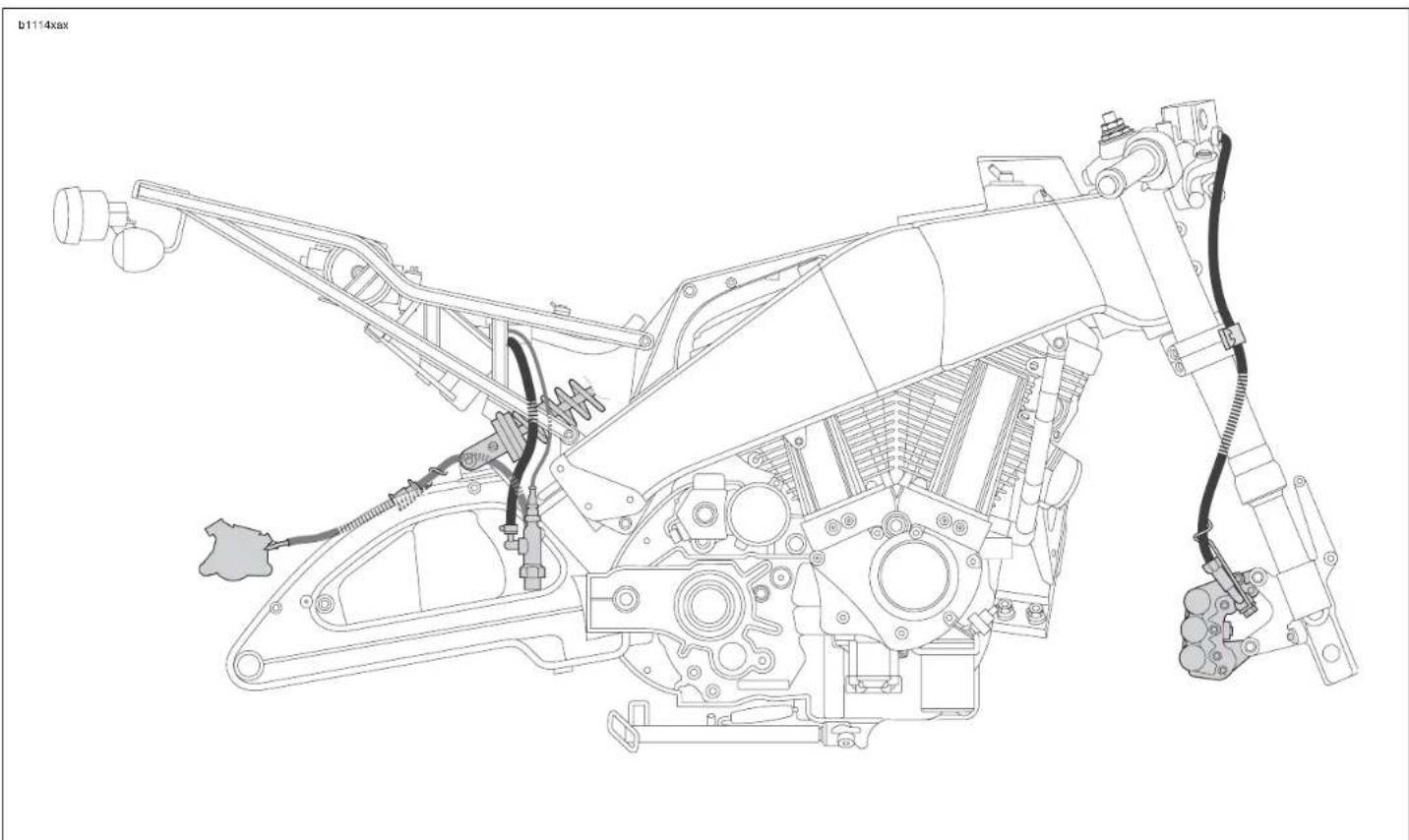
Technical line drawing of a mechanical assembly with no visible text or symbolsFigure D-1. Front and Rear Brake Systems, Right Side View
HOME
natural_image
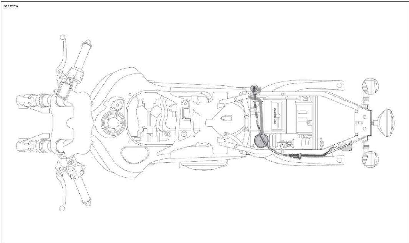
Technical line drawing of a mechanical assembly with internal components (no text or symbols)Figure D-2. Rear Brake Systems, Top View
HOME
natural_image
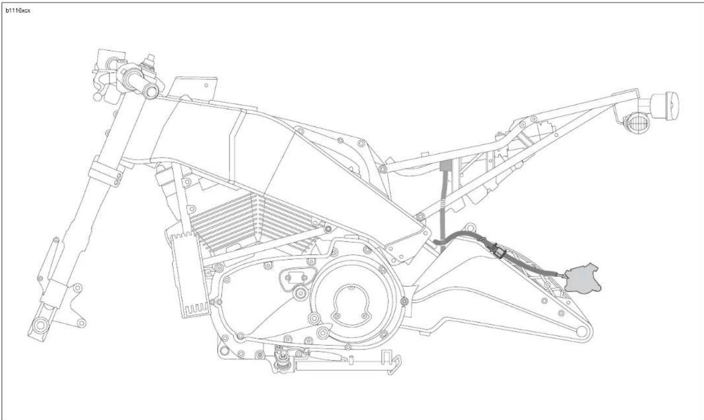
Technical line drawing of a mechanical assembly with no visible text or symbolsFigure D-3. Rear Brake Systems, Left Side View
HOME
text_image
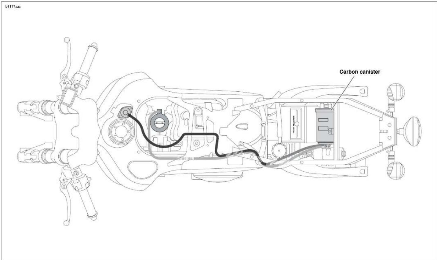
b1117ax Carbon canisterFigure D-4. Evaporative Emissions Control, California Models, Top View
HOME
text_image
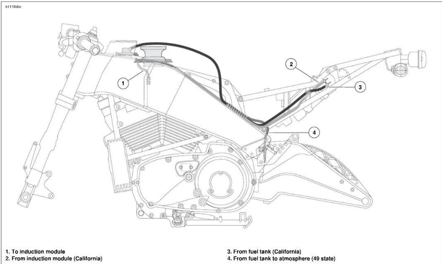
b1118sbx 1. To induction module 2. From induction module (California) 3. From fuel tank (California) 4. From fuel tank to atmosphere (49 state)Figure D-5. Evaporative Emissions Control, California and 49 State Models, Left Side View
HOME
b1119xax
text_image
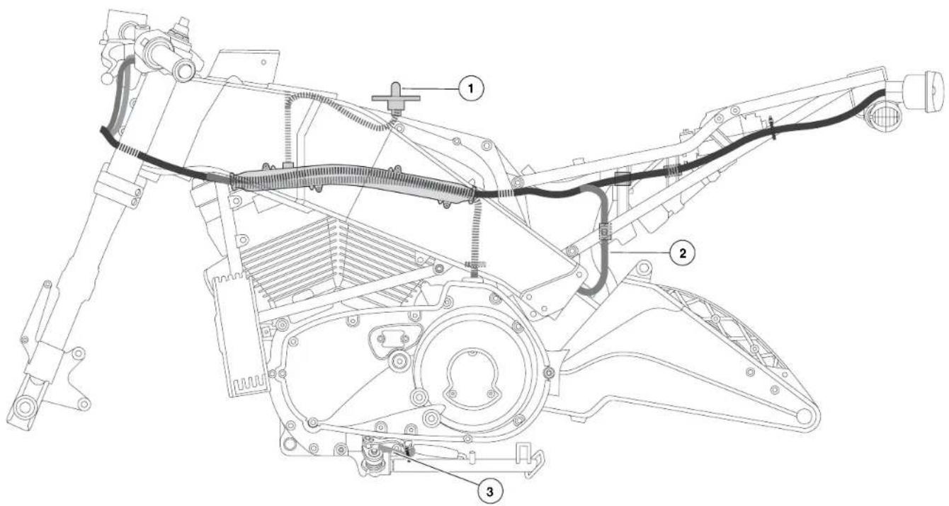
Technical diagram of a mechanical assembly with numbered components and labeled parts- Intake air temperature sensor (IAT) 2. Fuel pump 3. Sidestand switch
Figure D-6. Wiring Harness, Left Side View
HOME
text_image
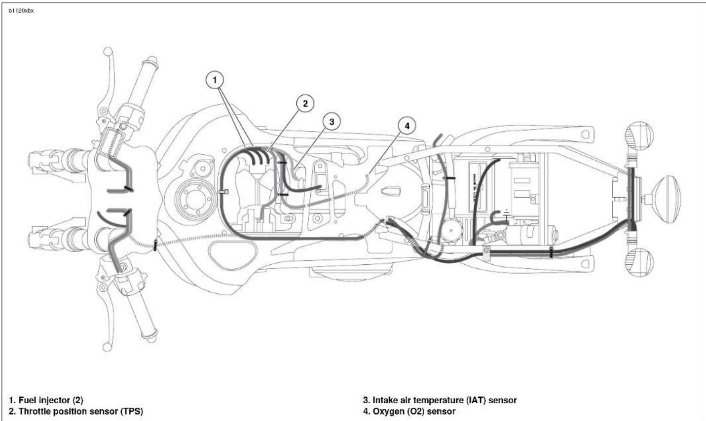
b1 120sbx 1. Fuel injector (2) 2. Throttle position sensor (TPS) 3. Intake air temperature (IAT) sensor 4. Oxygen (O2) sensorFigure D-7. Wiring Harness, Top View
HOME
b1121xcx
text_image
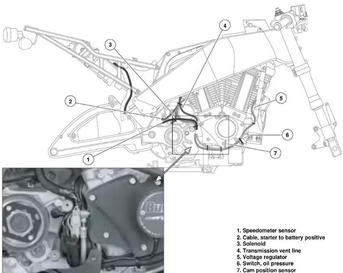
1. Speedometer sensor 2. Cable, starter to battery positive 3. Solenoid 4. Transmission vent line 5. Voltage regulator 6. Switch, oil pressure 7. Cam position sensor- Speedometer sensor
- Cable, starter to battery positive
- Solenoid
- Transmission vent line
- Voltage regulator
- Switch, oil pressure
- Cam position sensor
Figure D-8. Wiring Harness, Right Side View
HOME

text_image
b1122xx 1. Vent line 2. Feed oil line 3. Return oil line 4. Feed oil line from the oil pump to the oil cooler 5. Return oil line from the oil cooler to the oil filter housingFigure D-9. Oil Lines, Right Side View
HOME
b1123xbx
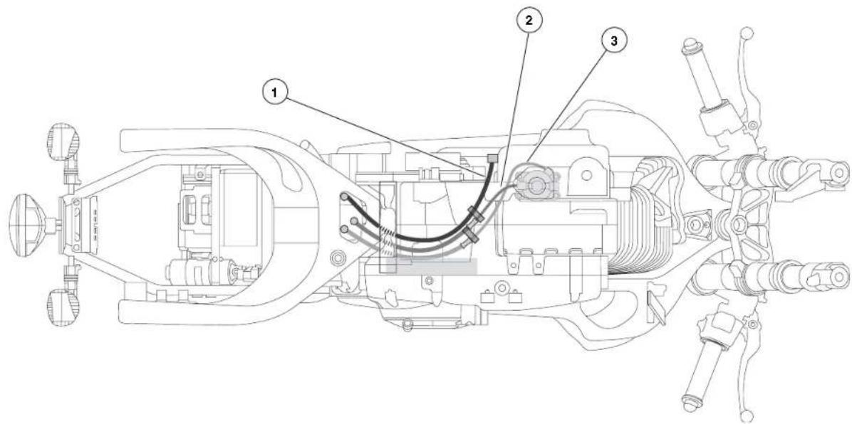
text_image
Technical diagram of a mechanical assembly with numbered components labeled 1, 2, and 3.- Vent line 2. Feed oil line 3. Return oil line
Figure D-10. Oil Lines, Bottom View
HOME
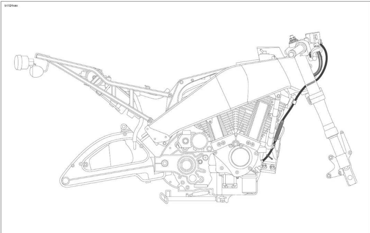
natural_image
Technical line drawing of a mechanical assembly with no visible text or symbolsFigure D-11. Clutch and Throttle Cables, Right Side View
HOME
b1125xbx
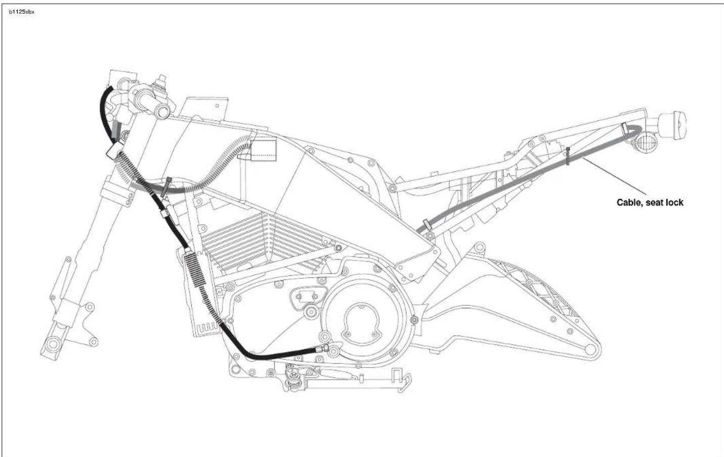
text_image
b1125sbx Cable, seat lockFigure D-12. Clutch, Throttle and Seat Release Cables, Left Side View
HOME
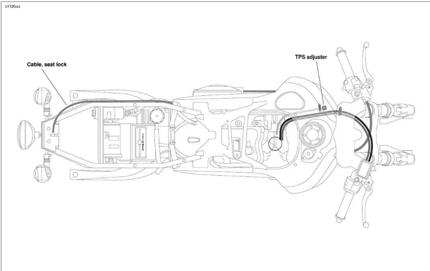
text_image
b1126xxc Cable, seat lock TPS adjusterFigure D-13. Clutch, Throttle and Seat Release Cables, Top View
MAINTENANCE 1
Table Of Contents
SUBJECT PAGE NO.
1.1 General 1-1
1.2 Fluid Requirements 1-2
1.3 Care of Molded-in-Color Body Panels 1-4
1.4 Battery Maintenance 1-5
1.5 Engine Lubrication System 1-8
1.6 Brake System Maintenance 1-11
1.7 Tires and Wheels 1-19
1.8 Clutch 1-20
1.9 Drive Belt System 1-23
1.10 Primary Chain 1-29
1.11 Suspension Damping Adjustments 1-31
1.12 Front Fork Oil Change 1-35
1.13 Steering Head Bearings 1-38
1.14 Spark Plugs 1-39
1.15 Air Cleaner Filter 1-41
1.16 Throttle Cable and Idle Speed Adjustment 1-43
1.17 Ignition Timing 1-44
1.18 Headlights 1-46
1.19 Throttle Position Sensor (TPS) 1-48
1.20 Storage 1-49
1.21 Troubleshooting 1-50
SERVICING A NEW MOTORCYCLE
WARNING
Always follow the listed service and maintenance recommendations, because they affect the safe operation of the motorcycle and the personal welfare of the rider. Failure to follow recommendations could result in death or serious injury.
Service operations to be performed before customer delivery are specified in the applicable model year PREDELIVERY AND SETUP MANUAL.
The performance of new motorcycle initial service is required to keep warranty in force and to ensure proper emissions systems operation.
After a new motorcycle has been driven its first 1000 miles (1600 km), and at every 2500 mile (4000 km) interval thereafter, have a Buell dealer perform the service operations listed in Table 1-2.
- Do not attempt to re-tighten engine head bolts. Retightening can cause engine damage.
- During the initial 1000 mile (1600 km) break-in period, use only Harley-Davidson 20W50 engine oil. Failure to use the recommended oil will result in improper break-in of the engine cylinders and piston rings.
A careful check of certain equipment is necessary after periods of storage, and frequently between regular service intervals, to determine if additional maintenance is required.
Check:
- Tires for abrasions, cuts and correct pressure.
- Drive belt for proper tension and condition.
- Brakes, steering and throttle for responsiveness.
- Brake fluid level and condition. Hydraulic lines and fittings for leaks. Also, check brake pads and rotors for wear.
- Cables for fraying, crimping and free operation.
- Engine oil and transmission fluid levels.
- Headlamp, passing lamp, tail lamp, brake lamp and turn signal operation.
XB9R TOOL SET
The Buell XB9R comes with a standard tool set (stored in the trunk) that consists of the following:
● Shock Spanner Wrench
T27 TORX Wrench
- 7/8" Axle Wrench (Hex)
- Tool Kit Pouch
- Screw Driver
INSPECTING
Leak Dye
When using leak dye with the black light leak detector, add 1/4 oz. (7.4 ml) of dye for each 1 quart (0.9 liter) of fluid in the system being checked.
GENERAL
United States System
Unless otherwise specified, all fluid volume measurements in this Service Manual are expressed in United States (U.S.) units-of-measure. See below:
● 1 pint (U.S.) = 16 fluid ounces (U.S.)
● 1 quart (U.S.) = 2 pints (U.S.) = 32 fl. oz. (U.S.)
● 1 gallon (U.S.) = 4 quarts (U.S.) = 128 fl. oz. (U.S.)
Metric System
Fluid volume measurements in this Service Manual include the metric system equivalents. In the metric system, 1 liter (L) = 1,000 milliliters (mL). Should you need to convert from U.S. units-of-measure to metric units-of-measure (or vice versa), refer to the following:
● fluid ounces (U.S.) x 29.574 = milliliters
● pints (U.S.) x 0.473 = liters
● quarts (U.S.) x 0.946 = liters
● gallons (U.S.) x 3.785 = liters
- milliliters x 0.0338 = fluid ounces (U.S.)
● liters x 2.114 = pints (U.S.)
● liters x 1.057 = quarts (U.S.)
● liters x 0.264 = gallons (U.S.)
PRIMARY DRIVE/ TRANSMISSION FLUID
Use only SPORT-TRANS FLUID (Part No. 98854-96 quart size or Part No. 98855-96 gallon size).
FRONT FORK OIL
Use only TYPE E FORK OIL (Part No. HD-99884-80).
BRAKE FLUID
WARNING
D.O.T. 4 brake fluid can cause irritation of eyes and skin, and may be harmful if swallowed. If large amount of fluid is swallowed, induce vomiting by administering two tablespoons of salt in a glass of warm water. Call a doctor. In case of contact with skin or eyes, flush with plenty of water. Get medical attention for eyes. KEEP BRAKE FLUID OUT OF THE REACH OF CHILDREN. Failure to comply could result in death or serious injury.
Use only D.O.T. 4 BRAKE FLUID (Part No. 99953-99Y).
1-2 2003 Buell XB9R: Maintenance
FUEL
Use a good quality unleaded gasoline (91 pump octane or higher). Pump octane is the octane number usually shown on the gas pump. See 3.2 ENGINE for a detailed explanation of alternative fuels.
ENGINE OIL
Use the proper grade of oil for the lowest temperature expected before the next oil change.
If it is necessary to add oil and Harley-Davidson oil is not available, use an oil certified for diesel engines. Acceptable diesel engine oil designations include CE, CF, CF-4 and CG-4. The preferred viscosities for the diesel engine oils, in descending order, are 20W-50, 15W-40 and 10W-40. At the first opportunity, see a Buell dealer to change back to 100 percent Harley-Davidson oil.
Table 1-1. Recommended Oil Grades
| HARLEY-DAVIDSON TYPE | VISCOSITY | HARLEY-DAVIDSON RATING | LOWEST AMBIENT TEMP °F | COLD WEATHER STARTS BELOW 50° F |
| H.D. Multi-Grade SAE | 10W40 | HD 360 | Below 40° (4°C) | Excellent |
| H.D. Multi-Grade SAE | 20W50 | HD 360 | Above 40° (4°C) | Good |
| H.D. Regular Heavy SAE | 50 | HD 360 | Above 60° (16°C) | Poor |
| H.D. Extra Heavy SAE | 60 | HD 360 | Above 80° (27°C) | Poor |
Table 1-2. Regular Service Intervals
| ODOMETER READING SERVICE OPERATIONS(see chart code below) | 1000ml | 2500ml | 5000ml | 7500ml | 1000ml | 12500ml | 15000ml | 17500ml | 2000ml | 22500ml | 25000ml | 27500ml | 30000ml | 32500ml | 35000ml | 37500ml | 4000ml | 42500ml | 45000ml | 47500ml | 5000ml | |
| 1600km | 400km | 800km | 1200km | 1600km | 200km | 2400km | 2800km | 3200km | 3600km | 4000km | 4400km | 4800km | 5200km | 5600km | 6000km | 6400km | 6800km | 7200km | 7600km | 8000km | ||
| Change engine oil and filter. R I R I R I R I R | I | R | I | R | I | R | I | R | I | R | I | R | ||||||||||
| Inspect air cleaner, service as required. I I I | I | R | I | R | I | I | ||||||||||||||||
| Inspect brake pads and discs for wear. I I I I I | I | I | I | I | I | I | I | I | I | I | I | I | I | I | I | |||||||
| Adjust primary chain. A A A A | A | A | A | A | A | A | ||||||||||||||||
| Inspect primary shoe. I I | I | |||||||||||||||||||||
| Change transmission/primary chaincase lube and clean drain plug. | RI | RI | RI | RI | RI | RI | RI | RI | ||||||||||||||
| Check ignition timing. I I | I | |||||||||||||||||||||
| Spark plugs. | R | R | R | R | ||||||||||||||||||
| Zero throttle position sensor (TPS) | A | A | A | A | A | |||||||||||||||||
| Check engine idle speed. | I | I | I | I | I | I | I | I | I | I | ||||||||||||
| Steering head bearing resistance test | X | X | X | X | X | X | X | X | X | |||||||||||||
| Adjust throttle cables | A | A | A | A | A | A | A | A | A | A | ||||||||||||
| Adjust clutch and clutch cable | A | A | A | A | A | A | A | A | A | A | ||||||||||||
| Check rear belt and idler pulley. Replace belt and idler pulley every 15,000 mi. (24,000 km) | I | I | I | R | I | I | R | I | ||||||||||||||
| Check front and rear tire pressure and inspect tread. | I | I | I | I | I | I | I | I | I | I | I | I | I | I | I | I | I | I | I | I | I | |
| Clean oil cooler fins | X | X | X | X | X | X | X | X | X | X | ||||||||||||
| Change front fork oil. X X X | X | X | ||||||||||||||||||||
| Check brake fluid reservoir levels and condition. | I | I | I | I | I | I | I | I | I | I | ||||||||||||
| Inspect front and rear brake caliper and master cylinder for leaks every 2500 miles (4000 km) or two years. | I | I | I | I | I | I | I | I | I | I | I | I | I | I | I | I | ||||||
| Check operation of all electrical equipment & switches. | I | I | I | I | I | I | I | I | I | I | I | I | I | I | I | I | I | I | I | I | I | |
| Inspect oil lines and brake system for leaks. | I | I | I | I | I | I | I | I | I | I | I | I | I | I | I | I | I | I | I | I | ||
| Lubricate front brake hand lever, throttle control cables, clutch control cables (and hand lever), sidestand pivot, and rear brake pedal bushing (if applicable). | IL | IL | IL | IL | IL | IL | IL | IL | IL | IL | IL | |||||||||||
| Check tightness of all critical fasteners: hand controls, brake system, front and rear axles, upper and lower triple clamps, front fork components, engine mounts, stabilizers, rear shock.. | T | T | T | T | ||||||||||||||||||
| Inspect motorcycle: Check front and rear brake lines, oil lines, front forks, rear shock, exhaust system, exhaust system mounting | X | X | X | X | X | X | X | X | X | X | X | X | X | X | X | X | X | X | X | X | X | |
| Road test. | X | X | X | X | X | X | X | X | X | X | X | X | X | X | X | X | X | X | X | X | X | |
| Chart Codes:I - Inspect, & if necessary correct, clean or replace.R- Replace or change.A- Adjust.D- Disassemble (lube & inspect).L- Lubricate with specified lubricant.T- Tighten to proper torque.X- Perform. | ||||||||||||||||||||||
GENERAL
Special care and maintenance are required for the molded-in-color body panels that are standard on your Buell XB9R motorcycle.
Molded-in-color surfaces look like painted surfaces, but are not. The color pigment is mixed in with the material when the part is made, not applied over the surface. Molded-in-color panels require different maintenance than painted surfaces to maintain their original shine. Using methods that work on painted surfaces may ruin the finish of molded-in-color parts.
CAUTION
Use of abrasive products or powered buffing equipment will cause permanent cosmetic damage to molded-in-color body panels. Use only the recommended products and techniques outlined in this section to avoid damaging molded-in-color body panels.
CAUTION
Do not use touch-up paint on molded-in-color panels.
RECOMMENDED PRODUCTS
Products recommended for the proper care and maintenance of molded-in-color body panels are available at your Buell dealer and are listed below:
● Harley Wash (Part No. 99715-90) or Harley Sun Wash (Part No. 94659-98)
● Harley Gloss (Part No. 94627-98)
● Harley Glaze Polish and Sealant (Part No. 99701-84)
● Harley Swirl and Scratch Treatment (Part No. 94655-98)
● Harley Softcloth (Part No. 94656-98)
CARE AND MAINTENANCE
Washing
To wash molded-in-color panels:
- Rinse surface with water.
- Wash with Harley Wash or Harley Sun Wash.
- Rinse surface thoroughly with water.
- Dry with a clean chamois or soft dry natural fiber cloth.
1-4 2003 Buell XB9R: Maintenance
Cleaning Between Washings
Untreated molded-in-color body panels sometimes have a static charge that attracts dust. Applying Harley Gloss or Harley Glaze Polish and Sealant to molded-in-color surfaces will eliminate this condition.
To keep a high gloss finish on molded-in-color panels between washings:
- Spray Harley Gloss onto surface and wipe with a clean soft natural fiber cloth or Harley Softcloth.
NOTE
Rain or water will remove Harley Gloss from body panels.
- Reapply Harley Gloss as described above to keep surfaces looking their best.
Polishing
Polishing molded-in-color body panels results in greater surface gloss and a protective coating.
- Apply Harley Glaze Polish and Sealant every six months or as required to keep molded-in-color panels protected and looking their best.
- Clean and dry surfaces to be polished (see Washing).
- Apply Harley Glaze Polish and Sealant to clean, slightly dampened cloth or sponge and apply to surface with a light overlapping motion. Make sure to cover all areas.
- Let Harley Glaze Polish and Sealant dry to a haze and buff off residue with a clean soft cloth or Harley Softcloth.
Minor Scratch Removal
To remove minor scratches from body panels:
- To remove light surface scratches and rubs, use Harley Swirl and Scratch Treatment as recommended.
- Make sure Swirl and Scratch Treatment is applied with a moist cloth and by hand (not by machine).
- After scratch or rub has been repaired, polish surface lightly with Harley Glaze.
Major Scratches
There is no repair procedure for severely scratched surfaces. Severely scratched body panels must be replaced.
GENERAL
Buell motorcycle batteries are permanently sealed, maintenance-free, valve-regulated, lead/calcium and sulfuric acid batteries. The batteries are shipped pre-charged and ready to be put into service. Do not attempt to open these batteries for any reason.
Inspect the battery for damage or leaks and for clean, non-corroded connections:
● At the 1000 mile (1600 km) service interval.
- At every scheduled service interval thereafter.
WARNING
All batteries contain electrolyte. Electrolyte is a sulfuric acid solution that is highly corrosive and can cause severe chemical burns. Avoid contact with skin, eyes, and clothing. Avoid spillage. Always wear protective face shield, rubberized gloves and protective clothing when working with batteries. A warning label is attached to the top of the battery. See Figure 1-1. Never remove warning label from battery. Failure to read and understand all precautions contained in warning label before performing any service on batteries could result in death or serious injury.
WARNING
Battery posts, terminals and related accessories contain lead and lead components, chemicals known to the State of California to cause cancer and birth defects or other reproductive harm. Wash hands after handling.
Table 1-3. Battery Electrolyte Antidotes
| CONTACT SOLUTION | |
| External Flush with water. | |
| Internal | Drink large quantities of milk or water, followed by milk of magnesia, vegetable oil or beaten eggs. Call doctor immediately. |
| Eyes | Flush with water, get immediate medical attention. |
BATTERY TESTING
Voltmeter Test
See Table 1-4. The voltmeter test provides a general indicator of battery condition. Check the voltage of the battery to verify that it is in a 100% fully charged condition. If the open circuit (disconnected) voltage reading is below 12.6V, charge the battery and then recheck the voltage after the battery has set for one to two hours. If the voltage reading is 12.8V or above, perform the load test described under 7.10 BATTERY.
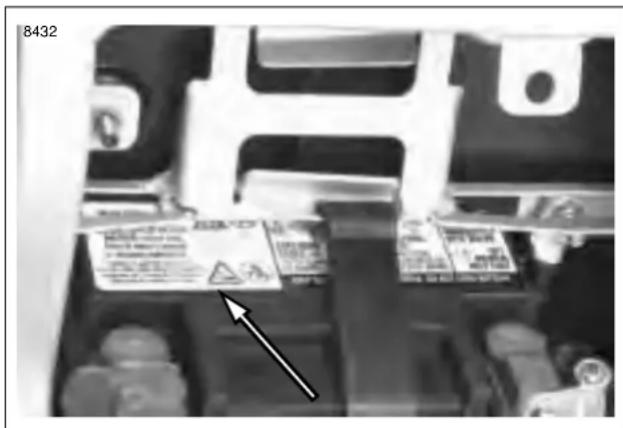
text_image
8432Figure 1-1. Battery Warning Label
Table 1-4. Voltmeter Test
| BATTERY CHARGE CONDITIONS | |
| 12.8 100% | |
| 12.6 75% | |
| 12.3 50% | |
| 12.0 25% | |
| 11.8 0% | |
BATTERY DISCONNECTION AND REMOVAL
- Remove seat. See 2.38 SEAT.
WARNING
Always disconnect the negative battery cable first. If the positive cable should contact ground with the negative cable installed, the resulting sparks may cause a battery explosion which could result in death or serious injury.
- Unthread fastener and remove battery negative cable (black) from battery negative (-) terminal.
- Pull back terminal cover boot.
- Unthread fastener and remove battery positive cable (red) from battery positive (+) terminal.
- Unhook strap and remove battery.
CLEANING AND INSPECTION
- Battery top must be clean and dry. Dirt and electrolyte on top of the battery can cause battery to self-discharge. Clean battery top with a solution of baking soda (sodium bicarbonate) and water (5 teaspoons baking soda per quart or liter of water). When the solution stops bubbling, rinse off the battery with clean water.
- Clean cable connectors and battery terminals using a wire brush or sandpaper. Remove any oxidation.
- Inspect the battery screws, clamps and cables for breakage, loose connections and corrosion. Clean clamps.
- Check the battery posts for melting or damage caused by overtightening.
- Inspect the battery for discoloration, raised top or a warped or distorted case, which might indicate that the battery has been frozen, overheated or overcharged.
- Inspect the battery case for cracks or leaks.
STORAGE
WARNING
Always store batteries where they cannot be reached by children. Contact with the battery's sulfuric acid could result in death or serious injury.
CAUTION
The electrolyte in a discharged battery will freeze if exposed to freezing temperatures. Freezing may crack the battery case and buckle battery plates.
If the motorcycle will not be operated for several months, such as during the winter season, remove the battery from the motorcycle and fully charge. See 7.10 BATTERY.
See Figure 1-2. Self-discharge is a normal condition and occurs continuously at a rate that depends on the ambient temperature and the battery's state of charge. Batteries discharge at a faster rate at higher ambient temperatures. To reduce the self-discharge rate, store battery in a cool (not freezing), dry place.
Charge the battery every month if stored at temperatures below 60^ F. ( 16^ C). Charge the battery more frequently if stored in a warm area above 60^ F. ( 16^ C).
NOTE
The H-D Battery Tender Automatic Battery Charger (P/N 99863-93TA) may be used to maintain battery charge for extended periods of time without risk of overcharging or boiling.
When returning a battery to service after storage, fully charge the battery. See 7.10 BATTERY.
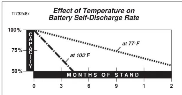
line
| MONTHS OF STAND | Effect of Temperature on Battery Self-Discharge Rate | | -------------- | --------------------------------------------------- | | 0 | 100% | | 3 | 75% | | 6 | 50% | | 9 | 50% | | 2 | 50% |Figure 1-2. Battery Self-Discharge Rate
HOME
BATTERY INSTALLATION AND CONNECTION
- Place the fully charged battery in the mounting position, terminal side to the rear of motorcycle.
- Hook rubber strap around body of battery.
CAUTION
Connect the cables to the correct battery terminals or damage to the motorcycle electrical system will occur.
WARNING
Always connect the positive battery cable first. If the positive cable should contact ground with the negative cable installed, the resulting sparks may cause a battery explosion which could result in death or serious injury.
CAUTION
Overtightening fasteners can damage battery terminals.
- Insert fastener through battery positive cable (red) into threaded hole of battery positive (+) terminal and tighten fastener to 72-96 in-lbs (8-11 Nm).
- Install terminal cover boot.
- Insert fastener through battery negative cable (black) into threaded hole of battery negative (-) terminal and tighten fastener to 72-96 in-lbs (8-11 Nm).
- Apply a light coat of petroleum jelly or corrosion retardant material to both battery terminals.
WARNING
After installing seat, pull upward on front of seat to be sure it is locked in position. If seat is loose, it could shift during vehicle operation and startle the rider, causing loss of control which could result in death or serious injury.
- Install seat. See 2.38 SEAT.
GENERAL
Check engine oil level (hot check) at every refueling stop.
Inspect oil lines and filter for leaks:
- At 1500 mi (2400 km) initial service and every 2500 mi (4000 km) service interval.
Change engine oil and filter under normal service conditions in warm or moderate temperatures: - At 1000 mi (1600 km) initial service and every 5000 mi (8000 km) service interval thereafter.
- When storing or removing the motorcycle for the season.
Change engine oil and filter under severe service conditions in warm or moderate temperatures (severe dust, temperatures above 80^ F/ 27^ C, extensive idling or speeds in excess of 65 mph/105 km/h):
- At 1000 mi (1600 km) initial service and every 2500 mi (4000 km) service interval thereafter.
- When storing or removing the motorcycle for the season.
NOTE
The colder the weather, the shorter the recommended oil change interval. A vehicle used only for short runs in cold weather must have the engine oil drained more frequently.
CHECKING ENGINE OIL LEVEL
An accurate engine oil level reading can only be obtained with the engine at normal operating temperature (hot check). The engine will require a longer warm up period in colder temperatures.
For pre-ride inspection, simply verify that there are no oil leaks from the oil filter and oil lines prior to operating the motorcycle.
- Perform a hot check of the engine oil level at each fuel stop.
CAUTION
Do not allow hot oil level to fall below lower mark on dipstick. To do so may result in equipment damage and/or malfunction.
CAUTION
Do not overfill oil tank. Overfilling oil tank may result in oil carryover to the air cleaner, equipment damage and/or equipment malfunction.
1-8 2003 Buell XB9R: Maintenance
CAUTION
Do not switch oil brands indiscriminately because some oils interact chemically when mixed. Use of inferior oils or non-detergent oils can damage the engine.
Ride motorcycle for approximately 10 minutes to ensure the oil is hot and the engine is at normal operating temperature.
- The motorcycle must be on level ground, on the side-stand, with the engine off.
- See Figure 1-4. Unscrew and remove dipstick from oil tank/swingarm filler hole. Wipe dipstick clean.
- Insert dipstick into oil tank filler hole, screwing dipstick in completely. DO NOT OVER TIGHTEN.
NOTE
The area between the upper and lower registration marks is the operating range.
- See Figure 1-4. Unscrew and remove dipstick and note oil level.
a. Oil level should be within the operating range (between upper and lower registration marks) on dipstick.
b. If oil level is below lower registration mark, add only enough oil to bring oil level between lower and upper registration marks.
HOME
CHANGING ENGINE OIL AND FILTER
Ride motorcycle for approximately 10 minutes to ensure the oil is hot and the engine is at normal operating temperature. Turn engine off.
NOTE
Secure rear wheel on lift or place scissor jack under jacking point.
Draining Oil
- See Figure 1-3. Place a suitable container under the drain plug.
- Using a 5/8 in. wrench, remove drain plug from under oil tank/swingarm. Wipe any accumulated debris from magnetic tip on drain plug.
- See Figure 1-4. Unscrew and remove dipstick from oil fill hole on top of oil tank/swingarm.
Changing Filter
- Remove chin fairing See 2.33 CHIN FAIRING.
- See Figure 1-5. Remove oil filter using pliers or belt type OIL FILTER WRENCH.
- Clean filter gasket contact surface on crankcase. Surface should be smooth and free of any debris or old gasket material.
- Apply a thin film of clean engine oil to filter gasket.
- Pour 4.0 ounces (0.12 liter) of clean engine oil into new filter when changing oil (until filter is approximately 1/2 full).
- Screw filter onto adapter until filter gasket touches crank-case surface. Rotate filter another 1/2-3/4 turn by hand.
WARNING
Be sure no oil gets on tires when changing oil and filter. Traction will be adversely affected which may lead to loss of control which could result in death or serious injury.
Replacing Oil
- Install drain plug.
- Fill oil tank through filler (dipstick) hole with recommended oil from Table 1-5. Oil tank capacity with filter change is approximately 2.5 quarts (2.4 liters) and includes the 4.0 ounces (0.12 liter) poured into the filter. Always verify proper hot oil level on dipstick. Do not overfill.
- Inspect o-ring on dipstick for rips or tears. Replace as required.
NOTE
For ease of installation, apply a light film of clean engine oil to the dipstick o-ring.
- Install dipstick into oil tank/swingarm fill hole. Make sure dipstick is installed completely. DO NOT OVER TIGHTEN
- Remove left side oil cooler scoop. See 2.35 AIR SCOOPS.
-
Inspect oil cooler fins for debris or damage. Blow out any debris from fins with compressed air from the inside of the cooler outward.
-
Wipe up any spilled oil on muffler.
-
Start engine. Verify that oil pressure signal light on instrument support turns off after a few seconds when engine speed is 1000 RPM or above.
-
Check for oil leaks at oil filter, drain plug, hoses and oil cooler.
-
Install chin spoiler. See 2.33 CHIN FAIRING.
-
Install air scoop 2.35 AIR SCOOPS.
-
Check (hot) oil level. See CHECKING ENGINE OIL LEVEL.
Table 1-5. Recommended Oil Grades
| HARLEY-DAVIDSON TYPE | VISCOSITY | HARLEY-DAVIDSON RATING | LOWEST AMBIENT TEMP °F | COLD WEATHER STARTS BELOW 50°F |
| H.D. Multi-Grade | SAE 10W40 | HD 360 | Below 40° (4°C) | Excellent |
| H.D. Multi-Grade | SAE 20W50 | HD 360 | Above 40° (4°C) | Good |
| H.D. Regular Heavy | SAE 50 | HD 360 | Above 60° (16°C) | Poor |
| H.D. Extra Heavy | SAE 60 | HD 360 | Above 80° (27°C) | Poor |
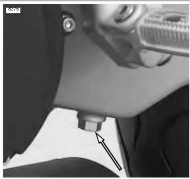
natural_image
Close-up of a mechanical component with a pointed tip and arrow indicator (no visible text or symbols)Figure 1-3. Oil Tank Drain Plug
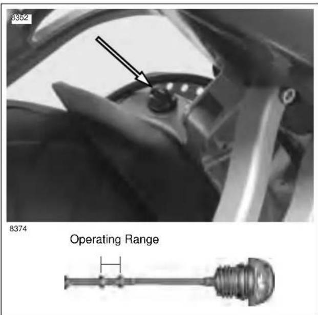
text_image
8352 8374 Operating RangeFigure 1-4. Dipstick Location/Engine Oil Level
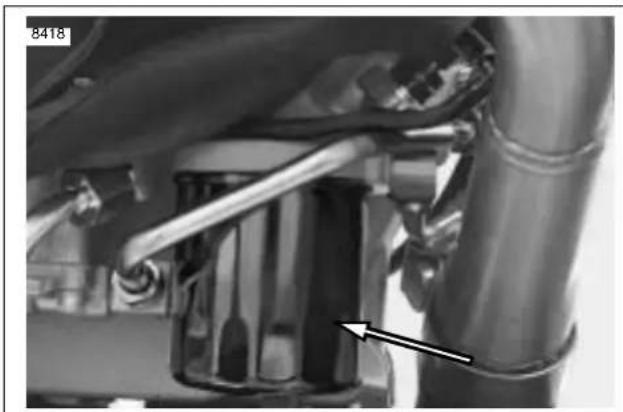
natural_image
Close-up of mechanical components with a directional arrow pointing to a component (no visible text or symbols)Figure 1-5. Oil Filter
GENERAL
Check brake fluid level and condition:
● At the 1000 mile (1600 km) service interval.
- At every 5000 mile (8000 km) service interval thereafter.
- When storing or removing the motorcycle for the season.
Replace D.O.T. 4 BRAKE FLUID:
● Every 2 years.
Front brake hand lever and rear brake foot pedal must have a firm feel when brakes are applied. If not, bleed system as described.
Inspect front and rear brake lines and replace as required:
● At the 1000 mile (1600 km) service interval.
- At every 2500 miles (4000 km) service interval thereafter.
● Every 4 years.
Inspect caliper and master cylinder seals and replace as required:
● At the 1000 mile (1600 km) service interval.
- At every 2500 miles (4000 km) service interval thereafter.
● Every 2 years.
If determining probable causes of poor brake operation, see Table 1-6.
BLEEDING BRAKES
WARNING
D.O.T. 4 brake fluid can cause irritation of eyes and skin, and may be harmful if swallowed. If large amount of fluid is swallowed, induce vomiting by administering two tablespoons of salt in a glass of warm water. Call a doctor. In case of contact with skin or eyes, flush with plenty of water. Get medical attention for eyes. KEEP BRAKE FLUID OUT OF THE REACH OF CHILDREN. Failure to comply could result in death or serious injury.
WARNING
Never mix D.O.T. 4 with other brake fluids (such as D.O.T. 5). Use only D.O.T. 4 brake fluid in motorcycles that specify D.O.T. 4 fluid on the reservoir cap. Mixing different types of fluid may adversely affect braking ability and lead to brake failure which could result in death or serious injury.
WARNING
Use only fresh, uncontaminated D.O.T. 4 fluid. Cans of fluid that have been opened may have been contaminated by moisture in the air or dirt. Use of contaminated brake fluid may adversely affect braking ability and lead to brake failure which could result in death or serious injury
WARNING
Use only copper crush banjo washers (See Parts Catalog for Part No.) with D.O.T. 4 brake fluid. Earlier silver banjo washers are not compatible with D.O.T. 4 fluid and will not seal properly over time. Failure to comply may adversely affect braking ability and lead to brake failure which could result in death or serious injury.
WARNING
Clean brake system components using denatured alcohol. Do not use mineral-base cleaning solvents, such as gasoline or paint thinner. Use of mineral-base solvents causes deterioration of rubber parts that continues after assembly. This may result in improper brake operation which could result in death or serious injury.
WARNING
Always test motorcycle brakes at low speed after servicing or bleeding system. To prevent death or serious injury, Buell recommends that all brake repairs be performed by a Buell dealer or other qualified technician.
CAUTION
Cover molded-in-color surfaces and right handlebar switches and use care when removing brake reservoir cover and adding D.O.T. 4 brake fluid. Spilling D.O.T. 4 brake fluid on molded-in-color surfaces will result in cosmetic damage. Spilling brake fluid on switches may render them inoperative.
Table 1-6. Brake Troubleshooting
| CONDITION CHECK FOR REMEDY | ||
| Excessive lever/pedal travel or spongy feel. | Air in system.Master cylinder low on fluid. | Bleed brake(s).Fill master cylinder with approved brake fluid. |
| Brake fade Moisture in system. Bleed brake(s). | Fill master cylinder with approved brake fluid. | |
| Chattering sound when brake is applied. | Worn pads.Worn D shape bushingsLoose mounting bolts.Warped rotor. | Replace brake pads.Replace rotor and bushings as set.Tighten bolts.Replace rotor. |
| Ineffective brake – lever/pedal travels to limit. | Low fluid level.Piston cup not functioning. | Fill master cylinder with approved brake fluid, and bleed system.Rebuild cylinder. |
| Ineffective brake – lever/pedal travel normal. | Distorted or glazed rotor.Distorted, glazed or contaminated brake pads. | Replace rotor.Replace pads. |
| Brake pads drag on rotor – will not retract. | Cup in master cylinder not uncovering relief port.Rear brake pedal linkage out of adjustment. | Inspect master cylinder.Adjust linkage. |
HOME
Bleeding Front Brake
NOTE
Hydraulic brake fluid bladder-type pressure equipment can be used to fill the brake master cylinder through the bleeder valve if master cylinder reservoir cover is removed to prevent pressurization.
- See Figure 1-6. Install end of plastic tubing over front caliper bleeder valve; place other end in a clean container. Stand motorcycle upright.
CAUTION
Cover molded-in-color surfaces and right handlebar switches and use care when removing brake reservoir cover and adding D.O.T. 4 brake fluid. Spilling D.O.T. 4 brake fluid on molded-in-color surfaces will result in cosmetic damage. Spilling brake fluid on switches may render them inoperative.
- Cover body surfaces, right handlebar switches and instrument panel to protect from spillage.
- See Figure 1-7. Remove two fasteners from front master cylinder cover.
- Add D.O.T. 4 BRAKE FLUID to master cylinder reservoir. Bring fluid level to within 1/8 in. (3.2 mm) of molded boss inside front master cylinder.
NOTE
Do not reuse brake fluid.
- Depress, release and then hold brake hand lever to build up hydraulic pressure.
- Open bleeder valve about 1/2-turn counterclockwise; brake fluid will flow from bleeder valve and through tubing. When brake lever has moved 1/2 to 3/4 of its full range of travel, close bleeder valve (clockwise). Allow brake lever to return slowly to its released position.
- Repeat steps 5-6 until all air bubbles are purged.
- Tighten front caliper bleeder valves (metric) to 36-60 in-lbs (4-7 Nm).
- Verify master cylinder fluid level as described in step 4.
- Attach cover to front master cylinder reservoir and tighten fastener to 9-13 in-lbs (1.0-1.5 Nm).
- Remove cover from molded-in-color surfaces, right handlebar switches and instrument panel.
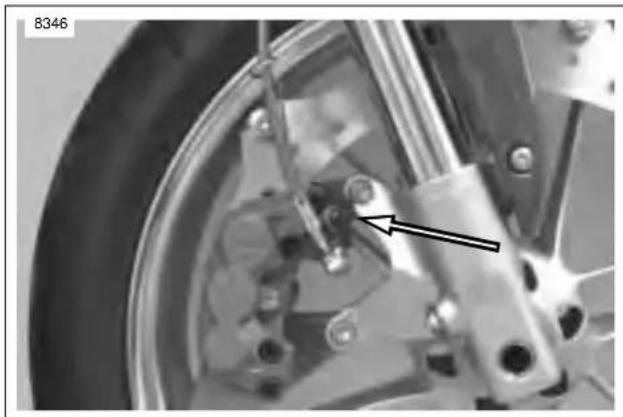
natural_image
Close-up mechanical assembly showing a brake caliper and wheel (no visible text or symbols)Figure 1-6. Front Caliper Bleeder Valve
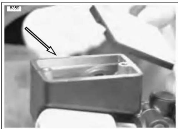
natural_image
Close-up of a small mechanical component with an arrow pointing to it, no visible text or symbolsFigure 1-7. Front Master Cylinder Reservoir
HOME
Bleeding Rear Brake
NOTE
Hydraulic brake fluid bladder-type pressure equipment can be used to fill the brake master cylinder through the bleeder valve if master cylinder reservoir cover is removed to prevent pressurization.
- See Figure 1-8. Install end of plastic tubing over rear caliper bleeder valve; place other end in a clean container. Stand motorcycle upright.
CAUTION
Cover molded-in-color surfaces and right handlebar switches and use care when removing brake reservoir cover and adding D.O.T. 4 brake fluid. Spilling D.O.T. 4 brake fluid on molded-in-color surfaces will result in cosmetic damage. Spilling brake fluid on switches may render them inoperative.
- Remove seat. See 2.38 SEAT.
- See Figure 1-9. Remove cap and gasket from rear master cylinder reservoir.
- Add D.O.T. 4 BRAKE FLUID to master cylinder reservoir with motorcycle upright (not on sidestand). Bring fluid level between upper and lower marks on reservoir.
NOTE
Do not reuse brake fluid.
- Depress, release and then hold brake pedal to build up hydraulic pressure.
- Open bleeder valve about 1/2-turn counterclockwise; brake fluid will flow from bleeder valve and through tubing. When brake pedal has moved 1/2 to 3/4 of its full range of travel, close bleeder valve (clockwise). Allow brake pedal to return slowly to its released position.
- Repeat steps 5-6 until all air bubbles are purged.
- Tighten rear caliper bleeder valves (metric) to 36-60 in-lbs (4-7 Nm).
- Verify master cylinder fluid level as described in step 4.
- Attach covers to master cylinder reservoirs and tighten cap on rear master cylinder reservoir securely.
WARNING
After installing seat, pull upward on front of seat to be sure it is locked in position. If seat is loose, it could shift during vehicle operation and startle the rider, causing loss of control which could result in death or serious injury.
- Install seat. See 2.38 SEAT.
1-14 2003 Buell XB9R: Maintenance
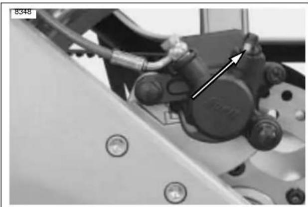
natural_image
Close-up of a mechanical component with a black arrow pointing to a circular feature, no visible text or symbols.Figure 1-8. Rear Caliper Bleeder Valve
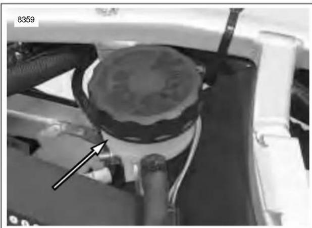
natural_image
Close-up of a mechanical component with a circular dial and pipe fittings, no visible text or symbolsFigure 1-9. Rear Master Cylinder Reservoir
BRAKE PEDAL ADJUSTMENT
WARNING
After completing repairs or bleeding the system, always test motorcycle brakes at low speed. If brakes are not operating properly or braking efficiency is poor, testing at high speeds could result in death or serious injury.
Check rear brake pedal operation:
- Before every ride.
● At the 1000 mile (1600 km) service interval. -
At every 5000 mile (8000 km) service interval thereafter.
-
See Figure 1-10. Measure distance from bottom of master cylinder (1) to center of lower adjuster rod clevis hole (5).
a. If measurement is approximately 3 in.
(77 mm +/- 1 mm), brake pedal adjustment is not needed.
b. If measurement is not within specification, adjust brake pedal.
NOTE
See Figure 1-10. Minimum allowable pushrod thread engagement inside clevis(4) is 0.24 in. (6.0 mm).
- Adjust brake pedal.
a. See Figure 1-10. Loosen locknut (3) while holding rod adjuster (2). Move locknut away from top surface of turn buckle (4).
b. Turn rod adjuster to set pedal height.
c. Return locknut (3) to fit flush against top surface of clevis.
NOTE
Brake pedal has no free play adjustment.
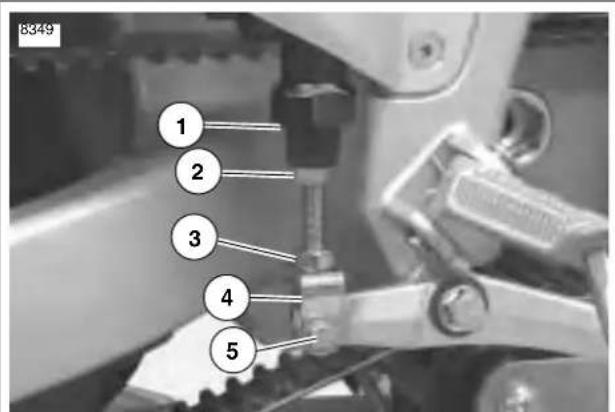
text_image
8349 1 2 3 4 5- Bottom of master cylinder
- Rod adjuster
- Locknut
- Clevis
- Clevis pin
Figure 1-10. Pushrod Adjustment
BRAKE PAD THICKNESS
WARNING
Always replace brake pads in complete sets for correct brake operation. Never replace just one brake pad. Failure to install brake pads as a set could result in death or serious injury.
Check brake pads for minimum thickness:
● At the 1000 mile (1600 km) service interval.
- At every 2500 miles (4000 km) service interval thereafter.
- At every scheduled service interval thereafter.
Check front brake pad:
- At the 10000 mi (16,000 km) interval or as required.
Check rear brake pad: - At the 25,000 mi (40,000 km) interval or as required.
See Figure 1-11. Inspect brake pads for damage or excessive wear. Replace both pads as a set if friction material of either pad is worn to 0.040 in. (1.0 mm) or less. If this amount of wear occurs, wear grooves will disappear from friction material surface.
BRAKE ROTOR THICKNESS
WARNING
Do not allow brake fluid, bearing grease, lubricants, etc. to contact brake rotor when servicing motorcycle or reduced braking ability will occur, which could result in death or serious injury.
Check brake rotors for minimum thickness:
● At the 1000 mile (1600 km) service interval.
- At every 2500 miles (4000 km) service interval thereafter.
- At every scheduled service interval thereafter.
- Measure rotor thickness. Replace rotor if minimum thickness is less than 0.18 in. (4.5 mm). Replace drive bushings, fasteners, washers and springs whenever rotor is replaced.
- Check rotor surface. Replace if warped or badly scored. See 2.5 FRONT WHEEL or 2.6 REAR WHEEL for procedure.
1-16 2003 Buell XB9R: Maintenance
7082
text_image
1 2 3-
Friction material
-
Wear groove
-
Backing material
Figure 1-11. Brake Pad Thickness
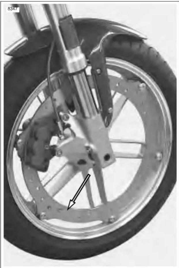
natural_image
Close-up of a motorcycle wheel assembly with visible brake and suspension components (no text or symbols)Figure 1-12. Front Brake Rotor
BRAKE PAD REPLACEMENT
Front Pad Removal
- See Figure 1-13. Loosen pin (1) but do not remove.
- Rotate wheels so that caliper is centered between rotor mounting fasteners (2).
- Remove lower caliper mounting fastener (3) that secures caliper to fork lower.
- Loosen but do not remove upper caliper mounting fastener (2) that secures caliper to fork lower.
- Remove pin (1).
- Rotate caliper counterclockwise to allow access to outer pad.
- Remove outer pad from right side.
- Remove inner pad from left side by pulling rearward, rotating pad 90 degrees and pulling through wheel opening.
Front Pad Installation
- Push pistons in with suitable tool such as a clean paint scraper until fully seated in bores. Be careful not to damage rotor.
- Install new inner side pad from left side of motorcycle.
- Install new outer pad from right side of motorcycle.
- See Figure 1-13. Install pin (1) making sure it engages hole on both pads and spring clip.
- Rotate caliper clockwise to align mounting fastener hole.
- See Figure 1-13. Install lower caliper mounting fastener (2).
- Tighten both caliper mounting fasteners (2) to 35-37 ft-lbs (48-50 Nm).
- Tighten pin (1) to 11-15 ft-lbs (15-20 Nm).
NOTE
Avoid making hard stops for the first 100 miles (160 km) to allow new brake pads to "wear in" properly with the rotor.
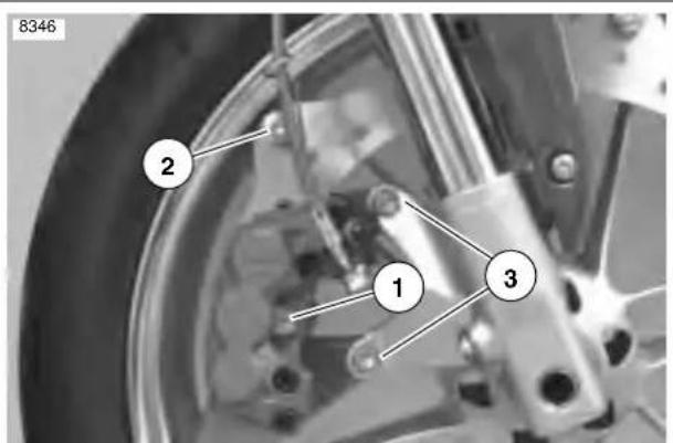
text_image
8346 2 1 3- Front caliper pin plug
- Rotor mounting fastener
- Caliper mounting fastener
Figure 1-13. Front Brake Caliper
HOME
Rear Pad Removal
- See Figure 1-14. Remove rear caliper pin plug (2) and loosen pin.
- Remove two mounting fasteners (1) and brake caliper carrier assembly from rotor.
- Remove pin.
- Remove p-clamp, wire form and fastener on swingarm.
- Lift caliper up and off of rotor.
- Remove inner and outer pads, being careful not to dis-lodge pad spring.
Rear Pad Installation
- Check that forward guide clip is present.
- See Figure 1-15. Check that pad spring is present. Should pad spring become dislodged, install with long side on piston side of caliper.
- Push piston in with suitable tool such as a clean paint scraper until fully seated in bore.
- Install new inner and outer brake pads
- See Figure 1-14. Install pin (2) making sure pin engages hole on both pads.
- Install brake carrier with two mounting fasteners (2). Tighten fasteners to 24-26 ft-lbs (33-35 Nm).
- Tighten pin to 11-15 ft-lbs (15-20 Nm).
- Install pin plug (2). Tighten plug to 18-25 in-lbs (2-3 Nm).
NOTE
Avoid making hard stops for the first 100 miles (160 km) to allow new brake pads to "wear in" properly with the rotor.
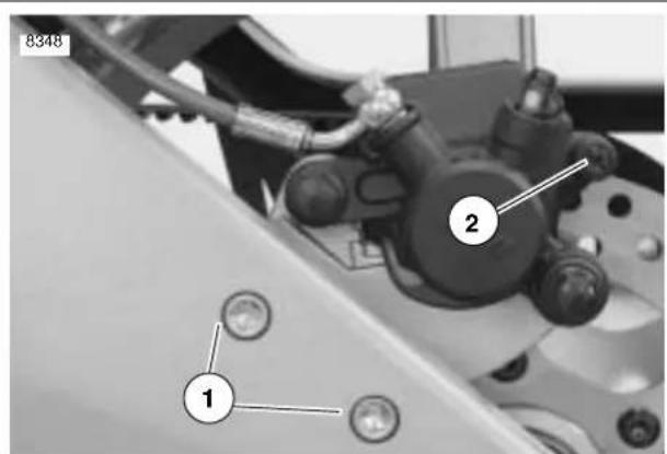
text_image
8348 1 2- Rear caliper mounting fasteners
- Rear caliper pin plug
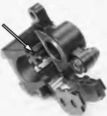
natural_image
Close-up of a mechanical component with a black arrow pointing to a specific part (no visible text or symbols)Figure 1-15. Rear Brake Pad Spring
TIRE INFLATION
WARNING
Do not inflate any tire beyond its maximum inflation pressure as specified on tire sidewall. Overinflation may cause tire to suddenly deflate which could result in death or serious injury.
Check tire pressure and tread:
● Before every ride.
● At the 1000 mile (1600 km) service interval.
- At every scheduled service interval.
Check for proper front and rear tire pressures when tires are cold. Compare pressure against Table 1-7.
Table 1-7. Tire Pressures
| TIRE | PRESSURE FOR SOLO RIDING | PRESSURE AT GVWR | |
| Front 36 | PSI 248 kPa | Same as Solo Riding | |
| Rear 38 | PSI 262 kPa | ||
TIRE REPLACEMENT
Tire wear indicator bars will appear on tire tread surfaces when 1/32 inch or less of tire tread remains. Arrows on tire sidewalls pinpoint location of wear bar indicators. Always remove tires from service before they reach the tread wear indicator bars (1/32 of an inch tread pattern depth remaining).
New tires are needed if any of the following conditions exist.
- Tire wear indicator bars become visible on the tread surfaces.
- Tire cords or fabric become visible through cracked sidewalls, snags or deep cuts.
- A bump, bulge or split in the tire.
- Puncture, cut or other damage to the tire that cannot be repaired.
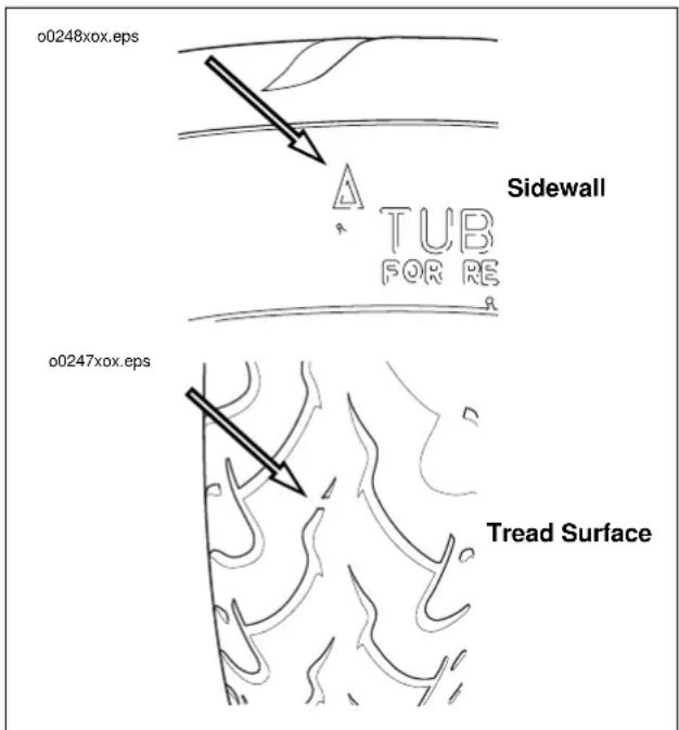
text_image
o0248xox.eps Sidewall TUB FOR RE o0247xox.eps Tread SurfaceFigure 16. Treadwear Indicators
WHEEL BEARINGS
WARNING
Never use compressed air to "spin-dry" bearings. Very high bearing speeds can damage unlubricated bearings. Spinning bearings with compressed air can also cause a bearing to fly apart, which could result in death or serious injury.
Check front and rear wheel bearings for wear:
● Every time a wheel is removed.
- When storing or removing the motorcycle for the season.
Check front wheel bearing:
● At every 5000 mile (8000 km) service interval.
Check rear wheel bearing:
- At every 10000 mile (16000 km) service interval.
Check wheel bearings for wear and corrosion. Excessive play or roughness indicates worn bearings. Replace bearings in sets only.
TRANSMISSION FLUID
Check transmission fluid level:
● At every 1000 mile (1600 km) service interval.
- At every 5000 miles (8000 km) service interval thereafter.
Replace transmission fluid:
● At the 1000 mile (1600 km) service interval.
● At every 5000 mile (8000 km) service interval.
Transmission fluid capacity is approximately 1.0 quart (0.95 liter). For best results, drain fluid while hot.
- Raise rear wheel off floor using REAR WHEEL SUPPORT STAND (Part No. B-41174). This prevents transmission fluid from spilling out of the clutch inspection cover opening.
- See Figure 1-18. Position a suitable container under drain plug. Remove plug and drain fluid.
- Wipe any foreign material from the magnetic drain plug. Reinstall plug and tighten to 29-31 ft-lbs (39-42 Nm).
- Remove three fasteners and washers from clutch inspection cover. Remove clutch inspection cover with gasket from primary cover.
CAUTION
Do not overfill the transmission with fluid. Overfilling may cause rough clutch engagement and incomplete disengagement, clutch drag and/or difficulty finding neutral at engine idle.
- See Figure 1-19. Add SPORT-TRANS FLUID (Part No. 98854-96 quart size; Part No. 98855-96 gallon size) as required until fluid level (3) is even with bottom of clutch diaphragm spring (2).
- See Figure 1-17. Install clutch inspection cover tightening three fasteners and washers to 7-9 ft-lbs (10-12 Nm).
- Clean up any fluid that may have spilled on muffler.
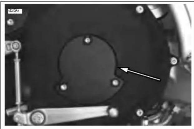
natural_image
Close-up of a mechanical component with a circular opening and directional arrow indicator (no readable text or symbols)Figure 1-17. Clutch Inspection Cover
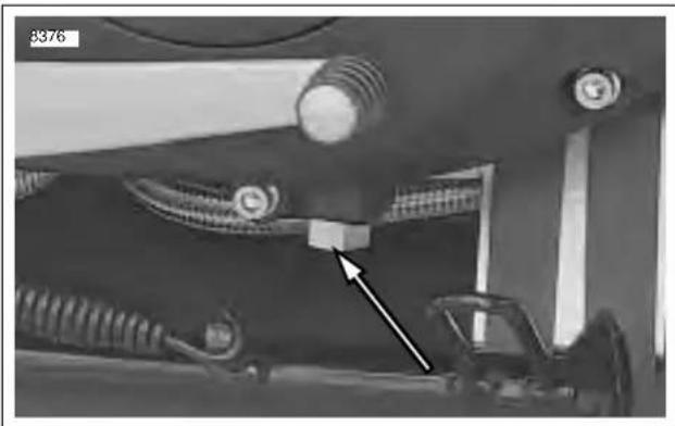
natural_image
Mechanical assembly diagram showing components like springs, bolts, and a vehicle (no text or symbols visible)Figure 1-18. Primary Drain Plug
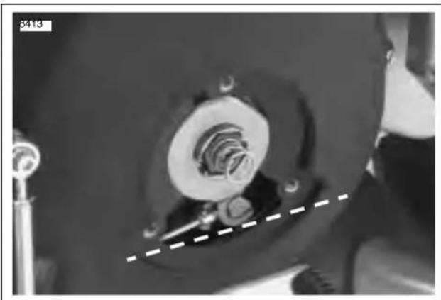
natural_image
Close-up of a mechanical component with a central spring and dashed line indicating a measurement or alignment (no visible text or symbols)Figure 1-19. Fluid Level
ADJUSTMENT
Check clutch adjustment:
● At the 1000 mile (1,600 km) service interval.
- At every 5000 mile (8,000 km) service interval.
If clutch slips under load or drags when released, first check control cable adjustment. If cable adjustment is within specifications, adjust clutch mechanism as described below.
When necessary, lubricate cable with LUBIT-8 TUFOIL® CHAIN AND CABLE LUBE (Part No. HD-94968-85TV).
- Raise rear wheel off floor using REAR WHEEL SUPPORT STAND (Part No. B-41174).
- See Figure 1-20. Slide rubber boot (1) upward to expose adjuster mechanism. Loosen jam nut (3) from adjuster (4). Turn adjuster to shorten cable housing until there is a large amount of free play at clutch hand lever.
- See Figure 1-17. Remove three fasteners and washers from clutch inspection cover. Remove clutch inspection cover and gasket from primary cover.
- See Figure 1-21. Remove spring (1) and lockplate (2). Using a flat tip screwdriver, turn adjusting screw (3) counterclockwise until it lightly bottoms.
- Turn adjusting screw clockwise 1/4 turn. Install lockplate and spring on adjusting screw flats. If hex on lockplate does not align with recess in outer ramp, rotate adjusting screw clockwise until it aligns.
NOTE
Spring installs on outboard side of hex lockplate.
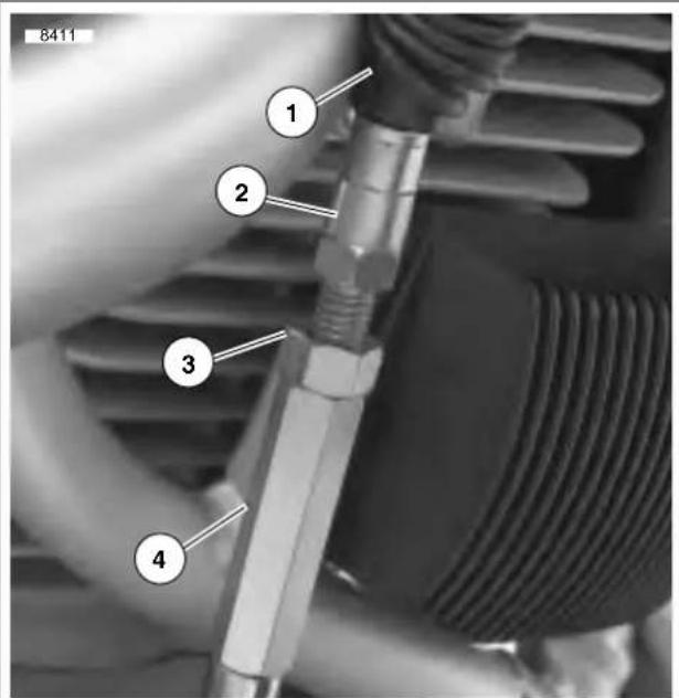
text_image
8411 1 2 3 4- Rubber boot
- Cable end
- Jam nut
- Adjuster
Figure 1-20. Clutch Cable Adjuster Mechanism
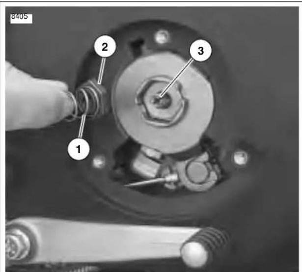
text_image
8405 1 2 3- Diaphragm spring
- Lockplate
- Adjusting screw
Figure 1-21. Clutch Adjustment
HOME
- Squeeze clutch hand lever to maximum limit three times. This sets the ball and ramp mechanism. Pull outer cable conduit and at the same time adjust cable adjuster to provide 1/16-1/8 in. (1.6-3.2 mm) free play at clutch hand lever. Adjust as follows:
a. See Figure 1-22. Pull ferrule (end of cable housing) away from bracket. Gap between ferrule and bracket should be 1/16-1/8 in. (1.6-3.2 mm).
b. See Figure 1-20. Set free play by turning adjuster (4).
c. Tighten jam nut (3) against adjuster (4).
d. Slide boot (1) over cable adjuster mechanism.
-
Change or add transmission fluid if necessary.
-
See Figure 1-17. Install clutch inspection cover and gasket using three fasteners and washers and tighten to 7-9 ft-lbs (10-12 Nm).
-
Check clutch cable free play. See Step 6 above.
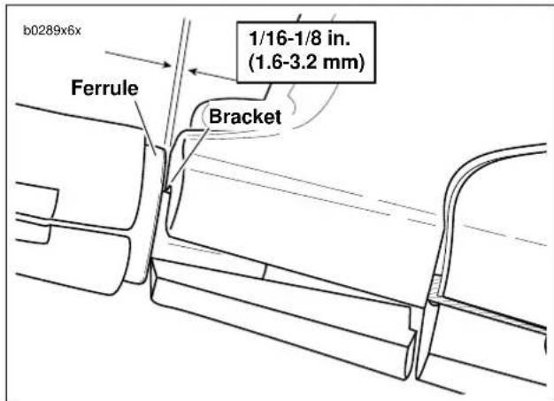
text_image
b0289x6x Ferrule 1/16-1/8 in. (1.6-3.2 mm) BracketFigure 1-22. Adjusting Clutch Free Play
GENERAL
The drive belt tension on a new belt will be considerable tight and will loosen after approximately 1000 miles. The drive belt tension is automatically adjusted by the idler pulley. Axle alignment is not adjustable.
Check drive belt and idler pulley condition:
● At the 1000 mile (1600 km) service interval.
● At every 5000 mile (8000 km) service interval.
Replace drive belt and idler pulley assembly:
- At every 15000 mile (24000 km) service interval.
INSPECTION
Rear Sprocket
NOTE
If chrome chips or gouges to rear sprocket are large enough to be harmful, they will leave a pattern on the belt face.
- Inspect each tooth of rear sprocket for:
a. Major tooth damage.
b. Large chrome chips with sharp edges.
c. Gouges caused by hard objects.
d. Excessive loss of chrome plating (see Step 2).
- To check if chrome plating has worn off, drag a scribe or sharp knife point across the bottom of a groove (2) (between two teeth) with medium pressure.
a. If scribe or knife point slides across groove without digging in or leaving a visible mark, chrome plating is still good.
b. If scribe or knife point digs in and leaves a visible mark, it is cutting the bare aluminum. A knife point will not penetrate the chrome plating.
- Replace rear sprocket if major tooth damage or loss of chrome exists.
Drive Belt
See Figure 1-27. Inspect drive belt for:
● Cuts or unusual wear patterns on both sides of belt.
● Outside edge bevelling (8). Some bevelling is common, but it indicates that sprockets are misaligned.
- Outside surface for signs of stone puncture (7). If cracks/ damage exists near edge of belt, replace belt immediately. Damage to center of belt will require belt replacement eventually, but when cracks extend to edge of belt, belt failure is imminent.
- Inside (toothed portion) of belt for exposed tensile cords (normally covered by nylon layer and polyethylene layer). This condition will result in belt failure and indicates worn transmission sprocket teeth. Replace belt and transmission sprocket.
- Signs of puncture or cracking at the base of the belt teeth. Replace belt if either condition exists.
Idler Pulley
Inspect idler pulley for signs of uneven wear. Excessive play or roughness indicates worn bearings. Replace idler pulley as an assembly. See following section.
CLEANING
Keep dirt, grease, oil, and debris off the belt, idler pulley and sprockets. Clean the drive belt with a mild soap and water spray solution as required. Dry thoroughly. Do not immerse belt in solution.
DRIVE BELT REMOVAL
- Place a scissor jack under jacking point and raise rear wheel off ground. For location of jacking point see Figure 2-98.
- Remove right side rider footpeg support bracket. See 2.29 FOOTPEG, HEEL GUARD AND MOUNT.
- Remove right passenger footpeg support bracket.
- See Figure 1-24. Remove front sprocket cover (5) by removing fasteners. See 2.30 SPROCKET COVER.
NOTE
The rear chin fairing fasteners must be removed to access the front sprocket cover. Front belt guard (4) will dangle but can not be removed at this time.
- See Figure 1-23. Loosen rear axle pinch fastener (2).
- Loosen rear axle (1) approximately 15 rotations to allow partial tension to be removed from rear drive system.
- Remove idler pulley assembly by removing nuts and washers. See IDLER PULLEY REMOVAL in 1.9 DRIVE BELT SYSTEM.
- See Figure 1-24. Remove lower belt guard (3) by removing fasteners (6).
- Remove upper belt guard (10) by removing fasteners (7).
NOTE
The upper belt guard is attached to the swingarm brace and can not be removed from vehicle at this time.
- Remove swingarm brace. See 2.19 SWINGARM AND BRACE.
a. Remove fastener (8) and spacer collar (2) between upper belt guard (10), inner belt guard (1) and swingarm brace.
b. Allow inner belt guard (1) to drape.
NOTE
Inner belt guard does not have to be removed to remove belt or rear wheel.
- Remove upper belt guard (10) by removing fasteners (9) from swingarm brace.
CAUTION
When removing or installing belt, do not bend or twist belt, partially slide belt onto sprocket and "roll" wheel or belt damage will occur.
- Slide belt from sprocket and remove.
DRIVE BELT INSTALLATION
CAUTION
When removing or installing belt, do not bend or twist belt, partially slide belt onto sprocket and "roll" wheel or belt damage will occur.
- Slide belt onto sprocket.
- See Figure 1-24. Install upper belt guard (10) to swing-arm brace tightening fasteners (9) to 12-36 in-lbs (1-4 Nm).
1-24 2003 Buell XB9R: Maintenance
- Loosely install swingarm brace. See 2.19 SWINGARM AND BRACE.
a. Position the inner belt guard (1) and upper belt guard (10) onto swingarm.
b. Install fastener (8) and spacer collar (2) between upper belt guard (10), inner belt guard (1) and swingarm brace.
- Install upper belt guard (10) and tighten fasteners (7) to 12-36 in-lbs (1-4 Nm).
- Tighten swingarm brace fasteners to 25-27 ft-lbs (34-37 Nm).
- Install lower belt guard (3) and tighten fasteners (6) to 12-36 in-lbs (1-4 Nm).
- Install idler pulley assembly tightening washers and nuts to 33-35 ft-lbs (45-47 Nm). See IDLER PULLEY INSTALLATION in 1.9 DRIVE BELT SYSTEM.
- See Figure 1-23. Tighten rear axle (1) to 48-52 ft-lbs (65-70 Nm).
- Tighten rear axle pinch fastener (2) to 40-45 ft-lbs (54-61 Nm).
- Rotate rear wheel to ensure the belt does not make visible or audible contact. It may be necessary to loosen belt guard(s) to adjust for proper clearance.
- See Figure 1-24. Install front sprocket cover (5) by tightening fasteners to 12-36 in-lbs (1-4 Nm). See 2.30 SPROCKET COVER.
- Install chin fairing fasteners and tighten to 36-48 in-lbs (4-5 Nm). See 2.33 CHIN FAIRING.
- Install right side rider footpeg mount and tighten fasteners to 108-132 in-lbs (12-15 Nm). See 2.29 FOOTPEG, HEEL GUARD AND MOUNT.
- Install right passenger footpeg mount. use LOCTITE 272 and tighten fasteners to 25-28 ft-lbs (34-38 Nm).
- Remove scissor jack from motorcycle.
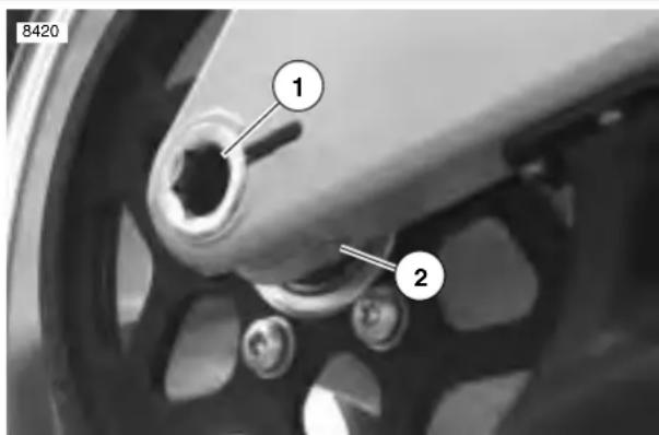
text_image
8420 1 2- Axle
- Pinch bolt fastener
Figure 1-23. Rear Wheel Mounting, Right Side
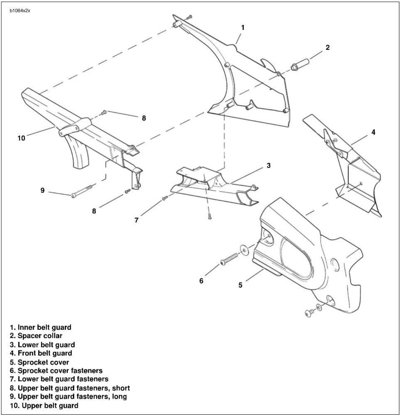
text_image
b1064x2x 1. Inner belt guard 2. Spacer collar 3. Lower belt guard 4. Front belt guard 5. Sprocket cover 6. Sprocket cover fasteners 7. Lower belt guard fasteners 8. Upper belt guard fasteners, short 9. Upper belt guard fasteners, long 10. Upper belt guardFigure 1-24. Belt Guard Assembly
IDLER PULLEY REMOVAL
- See Figure 1-25. Loosen rear axle pinch fastener (2).
- Unthread axle approximately 15 rotations to release tension from drive belt.
- Remove front sprocket cover. See 2.30 SPROCKET COVER.
- See Figure 1-26. Remove idler pulley bracket nuts and washers (5) from studs (3).
- Slide idler pulley bracket (4) off studs (3).
- Inspect pulley by spinning wheel (1) and checking for wheel bearing wear.
- If pulley wheel needs replacement, remove fastener (6), washer and nut (2) from idler pulley bracket (4) and discard wheel. Replace with new pulley wheel (1).
NOTE
The pulley wheel bearings can not be replaced separately.
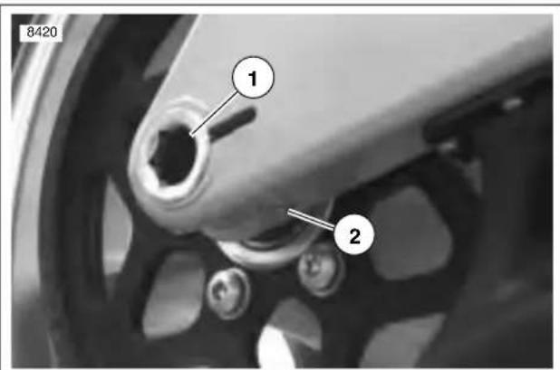
text_image
8420 1 2- Axle
- Pinch bolt fastener
Figure 1-25. Rear Wheel Mounting, Right Side
IDLER PULLEY INSTALLATION
- See Figure 1-26. Install new or existing pulley wheel (1), if removed, and tighten washer and nut (2) wheel fastener (6) to 96-120 in-lbs (11-14 Nm).
- Slide idler pulley bracket (4), washer and nuts (5) on to studs (3) and tighten to 33-35 ft-lbs (45-47 Nm).
- Install front sprocket cover. See 2.30 SPROCKET COVER.
CAUTION
Never tighten rear axle with swingarm brace removed.
- See Figure 1-25. Tighten rear axle to 48-52 ft-lbs (65-70 Nm).
- Tighten rear axle pinch fastener (2) to 40-45 ft-lbs (54-61 Nm).
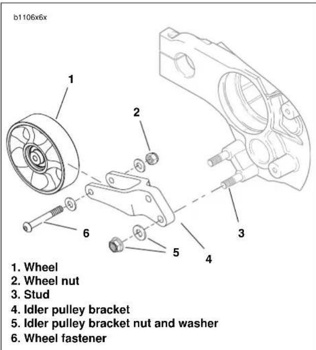
text_image
b1106x6x 1. Wheel 2. Wheel nut 3. Stud 4. Idler pulley bracket 5. Idler pulley bracket nut and washer 6. Wheel fastenerFigure 1-26. Idler Pulley Assembly
b0594x1x
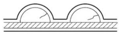
natural_image
Pure diagram of two arches resting on a textured surface (no text or symbols)1

natural_image
Pure technical diagram showing two curved components embedded in a rectangular base (no text or symbols)2
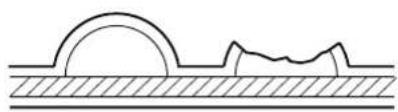
natural_image
Cross-sectional diagram of a geological or structural cross-section showing layered layers and a curved top layer (no text or symbols)3
natural_image
Cross-sectional diagram of a semiconductor device showing two semicircular structures with internal lattice patterns (no text or symbols)4
natural_image
Cross-sectional diagram of a mechanical or structural component with curved and straight elements, no text or symbols present.5
natural_image
Pure technical line drawing of a mechanical component with two curved notches and a hatched base (no text or symbols)6
text_image
Stone7
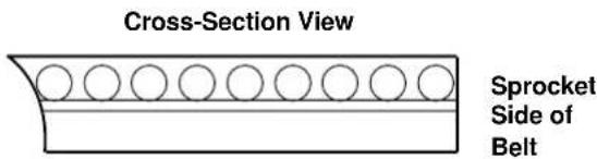
text_image
Cross-Section View Sprocket Side of Belt8
Figure 1-27. Drive Belt Wear Patterns
Table 1-8. Drive Belt Wear Analysis in Figure 1-27.
| PATTERN CONDITION REQUIRED ACTION | ||
| 1 | I nternal tooth cracks (hairline) OK to run, but monitor condition | |
| 2 | E xternal tooth cracks Replace belt | |
| 3 | M issuing teeth Replace belt | |
| 4 | C hipping (not serious) OK to run, but monitor condition | |
| 5 Fuzzy edge cord OK to run, but monitor condition | ||
| 6 | H ook wear Replace belt | |
| 7 | S tone damage Replace belt if damage is on the edge | |
| 8 | Bevel wear (outboard edge only) | OK to run, but monitor condition |
INSPECTION
Check primary chain tension:
● At the 1000 mile (1600 km) service interval.
- At every 5000 mile (8000 km) service interval thereafter.
See Figure 1-28. Measure primary chain tension through the inspection cover opening. Adjust primary chains not meeting vertical free play specifications.
- See Figure 1-28. Remove two fasteners with captive washers and primary chain inspection cover with gasket from primary cover.
- See Figure 1-29. Check primary chain tension by measuring vertical free play.
a. Measure vertical free play through chain inspection cover opening.
b. Rotate engine to move primary chain to a different position on sprockets.
c. Measure vertical free play several times, each time with primary chain moved so that the measurement is taken with sprockets rotated to the tightest chain position.
- The tightest measurement taken in Step 2 must be within the specifications listed in Table 1-9. If necessary, adjust as described under 1.10 PRIMARY CHAIN in ADJUSTMENT,
NOTE
The initial primary chain vertical free play specification used at the assembly plant is 1/4-1/2 in. (6.4-12.7 mm) with a cold engine. The 1/4 in. (6.4 mm) minimum is only allowed at the absolute tightest point in the drive, as measured with specialized factory equipment. If a chain has less than 1/4 in. (6.4 mm) vertical free play (with a cold engine), adjust free play to the "field" specification of 3/8-1/2 in. (9.5-12.7 mm). The looser specification will avoid overtightening, which might otherwise occur during adjustment using "non-factory" equipment and methods.
4. See Figure 1-28. Install primary chain inspection cover and gasket to primary cover using two fasteners with captive washers. Tighten fasteners to 40-60in-lbs (5-7 Nm).
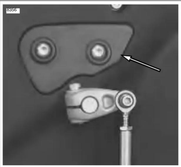
natural_image
Mechanical assembly diagram showing a robotic arm with two circular components and a pointer indicating a specific part (no text or symbols present)Figure 1-28. Primary Chain Inspection Cover
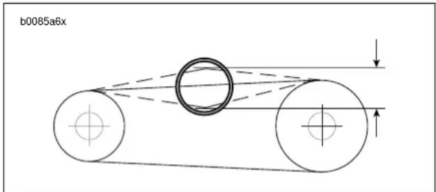
text_image
b0085a6xFigure 1-29. Measuring Primary Chain Tension
Table 1-9. Primary Chain Tension
| ENGINE TEMPERATURE | FREE PLAY | |
| Cold 3/8-1/2 in. 9.5-12.7 mm | ||
| Hot (normal running temperature) | 1/4-3/8 in. 6.4-9.5 mm | |
ADJUSTMENT
NOTE
If vertical free play cannot be set within the limits specified, then primary chain and/or chain adjuster are worn beyond adjustment limits. Replace parts as necessary. See 6.2 PRIMARY CHAIN.
- See Figure 1-30. Loosen locknut (1).
- Turn adjusting fastener (2):
a. Clockwise (inward) to reduce free play.
b. Counterclockwise (outward) to increase free play.
- Tighten locknut (1) to 20-25 ft-lbs (27-34 Nm).
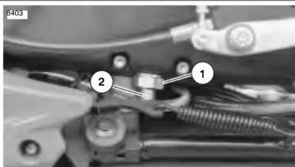
text_image
8403 2 1- Locknut
- Adjusting screw
Figure 1-30. Chain Tension Adjusting Fastener
GENERAL
WARNING
Before evaluating and adjusting suspension settings, check the motorcycle's tires. Tires must be in good condition and properly inflated. Failure to check the tires could result in death or serious injury.
Make all suspension adjustments in one or two click increments. Adjusting more than one or two clicks at a time may cause you to skip the best adjustment. Test ride after each adjustment. When an adjustment makes no difference, return to the previous adjustment and try a different approach.
If both preload adjustments are correct, and you have the rebound and compression damping set at the factory recommended points, the motorcycle should handle and ride properly. If you wish to fine tune these settings they can be changed according to the following procedures.
NOTE
Evaluating and changing the rebound and compression damping is a very subjective process. Many variables affect motorcycle handling under different circumstances. Approach all changes carefully and consult Table 1-11.
SUSPENSION ADJUSTMENTS
Setting Rear Shock Preload
The factory setting is #2 ramp position (#7 position being the tallest ramp and maximum preload). See Table 1-10. for recommended spring preload.
-
Remove seat. See 2.38 SEAT.
-
See Figure 1-31. Change the spring preload by turning the preload adjuster at the upper part of the shock with the SHOCK SPANNER WRENCH (HD-94700-52C) or the wrench included in the tool kit.
a. Turn adjuster to setting specified in Table 1-10. Rotate adjuster clockwise to increase preload.
b. Rotate adjuster counterclockwise to decrease preload.
- Install two fasteners and seat.
Setting Front Fork Preload
- See Table 1-10. Check number of lines (3) to be showing for your load condition.
- See Figure 1-32. Adjust preload by turning the adjuster nut (2) with a wrench.
WARNING
Always adjust each fork leg to the same settings. Uneven adjustment between left and right forks may lead to a loss of control which could result in death or serious injury.
Table 1-10. Recommended Suspension Settings
| RIDING CONDITION | PRELOAD SETTINGS | |
| Rear Setting (Ramp position) | Front Setting (Number of lines showing) | |
| Rider, 150 lbs (68 kg) or less | 1 | 5 |
| Rider, 150 - 180 lbs (68-82 kg)(Note: this is the factory setting) | 2 | 4 |
| Rider, 180 - 210 lbs (82-95 kg) | 3 to 4 4 | |
| Rider, 210 - 250 lbs (95-113 kg) | 5 | 4 |
| Rider+passenger+cargo, 250-325 lbs (113-147 kg) total | 6 | 3 |
| Rider+passenger+cargo, 325-390 lbs (147-177 kg) total | 6 | 3 |
| GVWRUp to 410 lbs (186 kg) of rider+passenger+cargo | 7 | 2 |
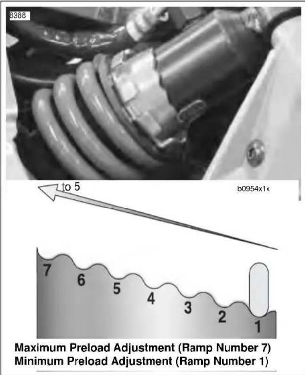
text_image
8388 b0954x1x to 5 7 6 5 4 3 2 1 Maximum Preload Adjustment (Ramp Number 7) Minimum Preload Adjustment (Ramp Number 1)Figure 1-31. Rear Shock Preload Adjuster
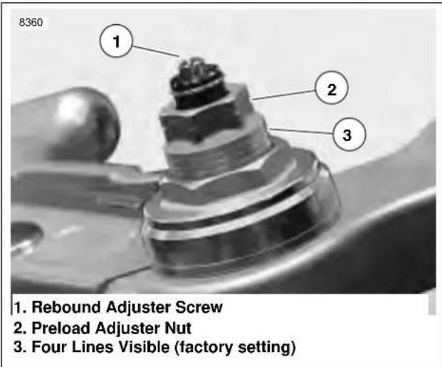
text_image
8360 1. 2. 3 1. Rebound Adjuster Screw 2. Preload Adjuster Nut 3. Four Lines Visible (factory setting)Figure 1-32. Front Fork Preload And Rebound Adjuster
HOME
Adjusting Suspension Damping
See Table 1-11. The recommended rebound and compression damping settings for various road and riding conditions are given in the table.
NOTE
All "turn settings" in Table 1-10 are "turns out from maximum". That is, first gently turn adjustment screws fully clockwise (until they stop), then turn adjustment screws counterclockwise the amount specified in Table 1-10.
Setting Front Fork Rebound Damping
- See Figure 1-32. Using a screwdriver, turn the slotted dial (1) clockwise until it stops. This is the maximum rebound damping setting.
- Then turn the dial counterclockwise the recommended amount specified in Table 1-11.
Setting Front Fork Compression Damping
- See Figure 1-33. Using a screwdriver, turn the slotted dial clockwise until it stops. This is the maximum compression damping setting.
- Then turn the dial counterclockwise the recommended amount specified in Table 1-11.
Setting Rear Shock Rebound Damping
- See Figure 1-34. Using a screwdriver, turn the slotted dial clockwise until it stops. This is the maximum rebound damping setting.
- Then turn the dial counterclockwise the recommended amount specified in Table 1-11.
Setting Rear Shock Compression Damping
- See Figure 1-35. Using a screwdriver, turn the slotted dial clockwise until it stops. This is the maximum compression damping setting.
- Then turn the dial counterclockwise the recommended amount specified in Table 1-11.
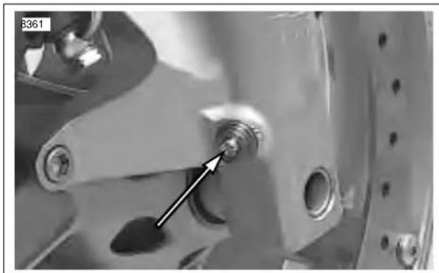
natural_image
Close-up of mechanical components with a black arrow pointing to a small component (no visible text or symbols)Figure 1-33. Front Fork Compression Damping Adjuster
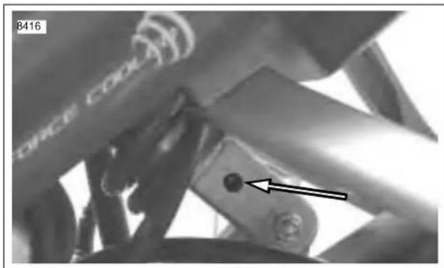
natural_image
Close-up of a mechanical component with a black arrow pointing to a small circular feature (no visible text or symbols)Figure 1-34. Rear Shock Rebound Adjustment
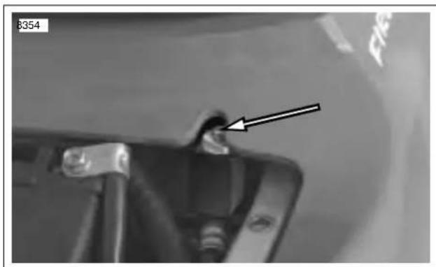
natural_image
Close-up of a mechanical component with a black arrow pointing to a small feature, no visible text or symbols.Figure 1-35. Rear Shock Compression Adjustment
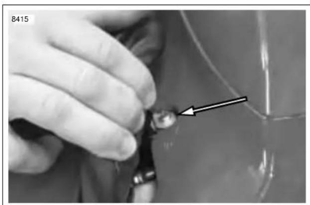
natural_image
Close-up of a hand holding a small mechanical component with an arrow pointing to it, no visible text or symbols.Figure 1-36. Accessing Rear Shock Compression Adjuster
Table 1-11. Recommended Suspension Damping Settings
| Riding/Road Conditions | Counterclockwise Turns | |||
| Rear Shock Front Forks | ||||
| Rebound | Compression | Rebound. | Compression | |
| Smooth surface, aggressive riding, max feedback (race track) 1/4 1/4 3/4 1/4 | ||||
| Average roads, but high preload (2-up or heavy rider) 3/4 1 1-1/4 1 | ||||
| Average Roads, sport riding (Note: this is the factory setting) 1-1/4 1-1/4 1-5/8 | 1-1/2 | |||
| Moderately rough roads, more comfort, less sport | 2 3-1/2 | 1-3/4 2 | ||
| Rough roads, long rides, “max comfort setting” | 2-5/8 | 4-3/4 | 2-3/8 | 2-1/4 |
FORK OIL CHANGE
Replace fork oil.
● At every 10000 mile (32,000 km) service interval.
- If fork is submerged in water.
NOTE
If fork oil is emulsified, aerated or light brown in color, then it has been contaminated by water. If this happens, replace the fork oil seals.
Disassembly
NOTE
Record rider suspension settings before disassembly.
- Remove front fork. See REMOVAL in 2.16 FRONT FORK.
- See Figure 1-37. Clamp the FORK TUBE HOLDER TOOL (Part No. HD-41177) in a vise and install the upper front fork in the holding tool.
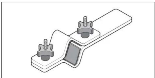
natural_image
Technical illustration of a mechanical clamp or bracket with two cylindrical components (no text or symbols)Figure 1-37. Fork Tube Holder (HD-41177)
- See Figure 1-38. Remove snap ring (2).
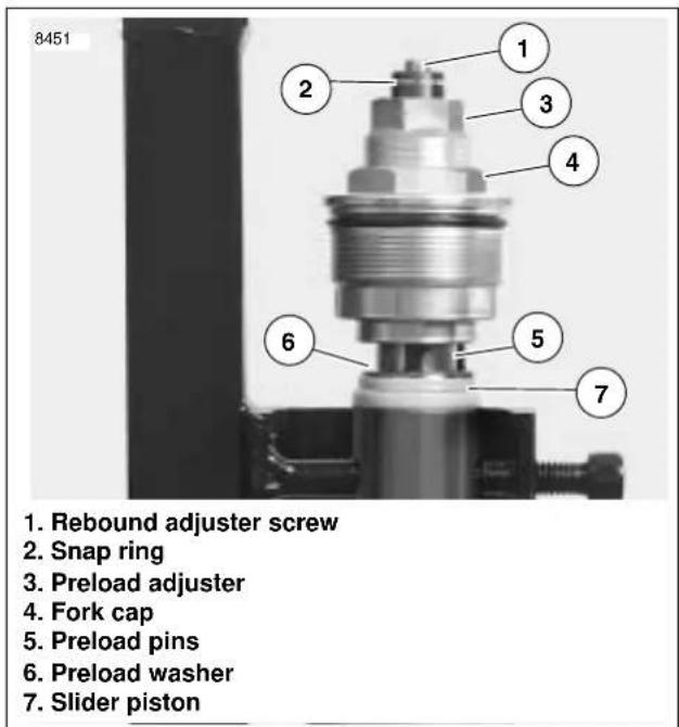
text_image
8451 1. Rebound adjuster screw 2. Snap ring 3. Preload adjuster 4. Fork cap 5. Preload pins 6. Preload washer 7. Slider pistonFigure 1-38. Fork Cap Assembly
- Remove preload adjuster (3) by turning counterclockwise.
After fully unthreading preload adjuster (3), gently pull on adjuster. - Remove fork cap (4) from outer tube.
- See Figure 1-39. Move the fork assembly from the holding tool and compress fork in the FORK SPRING COMPRESSION TOOL.
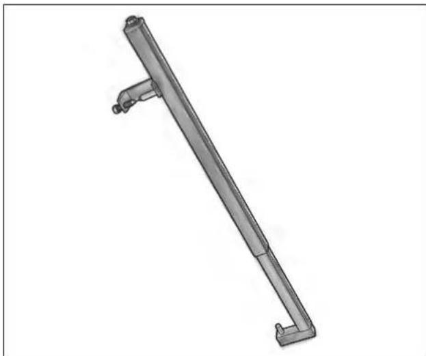
natural_image
3D rendered mechanical lever or support structure with no visible text or symbolsFigure 1-39. Fork Spring Compressing Tool
- See Figure 1-40. Hold damper rod assembly (3) and remove fork cap (1).
NOTE
See Figure 1-40. Be careful not to damage preload pins (2) while holding damper rod assembly (3),
8. Remove preload washer (4) and slider piston (5).
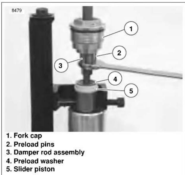
text_image
8479 1. Fork cap 2. Preload pins 3. Damper rod assembly 4. Preload washer 5. Slider pistonFigure 1-40. Holding Damper Rod Assembly
HOME
- See Figure 1-39. Uncompress fork and remove from FORK SPRING COMPRESSION TOOL.
Drain and Replace Oil
- See Figure 2-42. Over drain pan, remove spring (15), spring collar (16), and drain fork oil.
- Drain remaining fork oil by pumping the damping rod approximately 8 to 10 times or until damping rod moves freely.
- Install the front fork right side up in the FORK TUBE HOLDER TOOL (Part No. HD-41177).
- Pour 7 oz. (204 cc) into the fork pipe.
NOTE
Use only TYPE E FORK OIL (Part No. HD-99884-80).
- Completely compress front fork and slowly pump the damper rod approximately 12-15 times or until resistance is felt.
- Pour 7 oz. (204 cc) more fork oil into the slide pipe.
- See Figure 1-41. Adjust fork oil level with FRONT FORK OIL LEVEL GAUGE (Part No. B-59000A) so that it is 4.6 in. (118 mm) from the top of the fork tube.
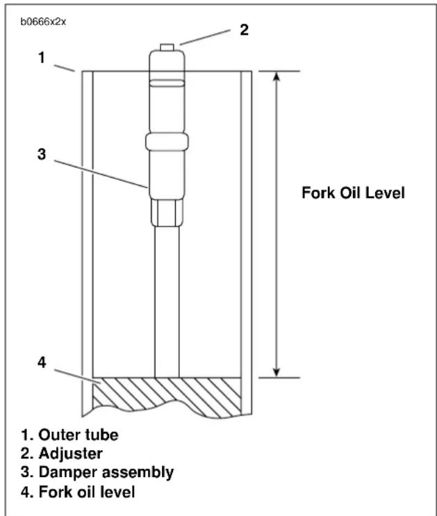
text_image
b0666x2x 1 2 3 4 Fork Oil Level 1. Outer tube 2. Adjuster 3. Damper assembly 4. Fork oil levelFigure 1-41. Measuring Fork Oil Level
- See Figure 2-42. Install spring (16), and spring collar (15).
- Move fork assembly from holding tool to the FORK SPRING COMPRESSION TOOL.
1-36 2003 Buell XB9R: Maintenance
Reassembly
- See Figure 2-42. Install preload washer (5) and slider piston (6).
- See Figure 1-40. Hold damper rod and install fork cap onto damper rod assembly tightening to 22-30 ft-lbs (30-40 Nm).
NOTE
Be careful not to damage preload pins while holding damper rod assembly (3),
-
See Figure 1-38. Install preload adjuster (3) back to rider suspension settings.
-
Apply fork oil or light grease to o-rings on preload adjuster and install preload adjuster (3).
-
Install snap ring (2).
-
Install front fork. See INSTALLATION in 2.16 FRONT FORK
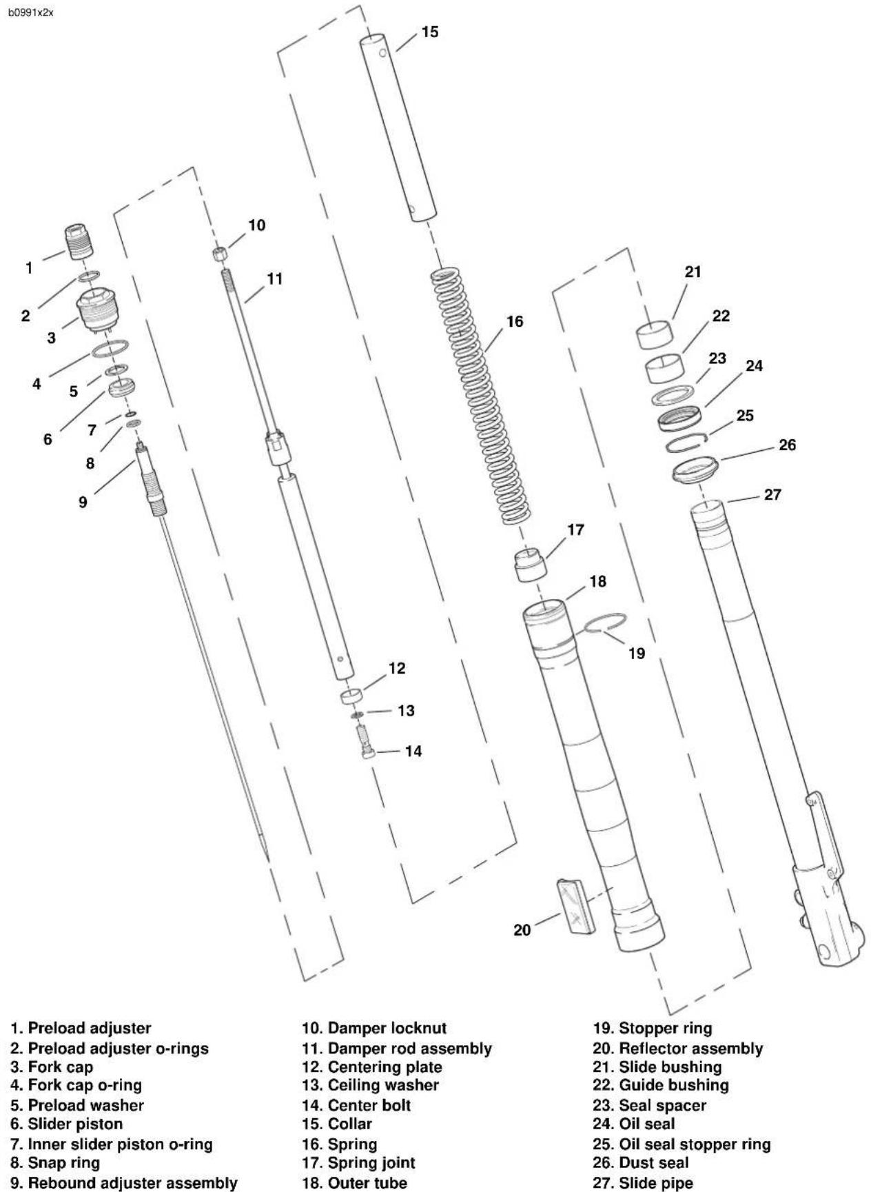
text_image
b0991x2x 1. Preload adjuster 2. Preload adjuster o-rings 3. Fork cap 4. Fork cap o-ring 5. Preload washer 6. Slider piston 7. Inner slider piston o-ring 8. Snap ring 9. Rebound adjuster assembly 10. Damper locknut 11. Damper rod assembly 12. Centering plate 13. Ceiling washer 14. Center bolt 15. Collar 16. Spring 17. Spring joint 18. Outer tube 19. Stopper ring 20. Reflector assembly 21. Slide bushing 22. Guide bushing 23. Seal spacer 24. Oil seal 25. Oil seal stopper ring 26. Dust seal 27. Slide pipeFigure 2-42. Front Fork Assembly
GENERAL
The steering head bearings on the XB9R are sealed, angular contact bearings and do not require additional lubrication.
Check steering head bearing resistance:
● At every 5000 mile (8000 km) service interval.
● When storing or removing the motorcycle for the season.
INSPECTION
NOTES
- Check that throttle cables do not bind when measuring bearing resistance.
● Steering head bearings are sealed and do not require additional lubrication.
● Steering head bearing resistance is not adjustable. Replace bearings that do not meet resistance specifications.
-
Detach clutch cable at handlebar.
-
Place a scissor jack under jacking point and raise front wheel off ground. For location of jacking point see Figure 2-98.
WARNING
Steering must be smooth and free with no binding or interference. Anything interfering with steering system operation may cause loss of vehicle control, which could result in death or serious injury.
-
Check steering stem bearings for notches by turning front wheel full right and then left. Repeat if necessary.
-
Next place wheel facing straight ahead and grabbing both fork sides at the bottom move front-end forward and back to check for steering head play.
-
To inspect for correct steering head resistance turn front wheel all the way to the right.
-
See Figure 1-43. Hook a spring scale into the hole in the front axle. With scale 90 degrees from fork leg, pull front wheel to center position.
a. It should take a maximum of 7 lbs. (3.2 kg) to pull front wheel to center.
b. If steering head resistance measurement is not within specification, see ADJUSTMENT.
- When adjustment is complete, attach clutch cable and adjust. See 1.8 CLUTCH.
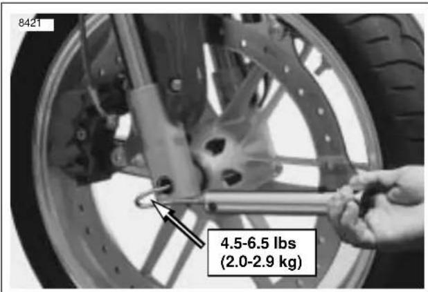
text_image
8421 4.5-6.5 lbs (2.0-2.9 kg)Figure 1-43. Measuring Steering Head Bearing Resistance
ADJUSTMENT
-
Detach clutch cable at handlebar and ensure that throttle cables do not bind before measuring steering head bearing resistance.
-
Remove steering stem pinch fastener at upper fork clamp.
-
Loosen steering stem capnut and back off several turns.
-
Remove lower fork clamp pinch fasteners, two per side.
-
Tighten steering stem capnut to 38-42 ft-lbs (52-57 Nm).
-
Turn front wheel all the way to the right.
-
See Figure 1-43. Hook a spring scale into the hole in the front axle. With scale 90 degrees from fork leg, pull front wheel to center position.
-
The correct resistance is between 4.5-6.5lbs (2.0-2.9 kg) with a maximum resistance of 7 lbs. (3.2 kg).
NOTE
If the correct specification cannot be achieved, the steering head bearings must be replaced. See 2.18 STEERING HEAD BEARINGS.
-
Once correct steering head resistance has been verified, apply LOCTITE 272 to steering stem pinch bolt, install and tighten to 17-19 ft-lbs (23-26 Nm).
-
Apply LOCTITE 272 to lower fork clamp fasteners, install and tighten to 13-15 ft-lbs (18-20 Nm).
-
When adjustment is complete, attach clutch cable and adjust. See 1.8 CLUTCH.
-
Remove scissor jack.
INSPECTION
Check spark plugs:
- Inspect at every 5000 mile (8000 km) service interval.
- Replace every 10,000 mile (16,000 km) service interval.
-
Use only Harley-Davidson 10R12A spark plugs (Part No. 27671-01K).
-
Remove left side air scoop to access front cylinder spark plug. See 2.35 AIR SCOOPS.
-
Disconnect cable from front spark plug.
-
Using a 5/8 in. box end wrench and 5/8 in. spark plug socket, remove front spark plug.
-
Remove seat. See 2.38 SEAT.
-
Remove air box assembly. See 4.43 AIRBOX.
-
Disconnect cable from rear spark plug (use automotive spark plug boot remover/installer if required).
-
Using a 5/8 in. wobble socket and 12 in. extension, remove rear spark plug.
-
See Figure 1-44. Compare your observations of the plug deposits with the descriptions provided below.
a. A wet, black and shiny deposit on plug base, electrodes and ceramic insulator tip indicates an oil fouled plug. The condition may be caused by one or more of the following: worn pistons, worn piston rings, worn valves, worn valve guides, worn valve seals, a weak battery or a faulty ignition system.
b. A dry, fluffy or sooty black deposit indicates an air-fuel mixture that is too rich and/or engine idling for excessive periods.
c. A light brown, glassy deposit indicates an overheated plug. This condition may be accompanied by cracks in the insulator or by erosion of the electrodes and is caused by an air-fuel mixture that is too lean, a hot-running engine, valves not seating or improper ignition timing. The glassy deposit on the spark plug is a conductor when hot and may cause high-speed misfiring. A plug with eroded electrodes, heavy deposits or a cracked insulator must be replaced.
d. A plug with a white, yellow, tan or rusty brown powdery deposit indicates balanced combustion. Clean off spark plug deposits at regular intervals.
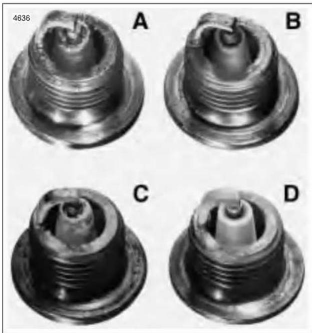
natural_image
Four grayscale images of a mechanical component, labeled A, B, C, D, showing different top views (no text or symbols beyond labels)Figure 1-44. Typical Spark Plug Deposits
HOME
- If the plugs require cleaning between tune-ups and replacement plugs are not available, proceed as follows:
a. Degrease firing end of spark plug using ELECTRICAL CONTACT CLEANER. Dry plug with compressed air.
b. Use a thin file to flatten spark plug electrodes. A spark plug with sharp edges on its electrodes requires 25-40% less firing voltage than one with rounded edges.
- If the plugs cannot be cleaned, replace with 10R12A spark plugs (Part No. 27671-01K).
- Check electrode gap with a wire-type feeler gauge. Gap should be 0.035 in. (0.9 mm).
- Apply LOCTITE ANTI-SEIZE to threads of spark plugs. Install and tighten spark plugs to 11-18 ft-lbs (15-24 Nm).
NOTES
- Start threading rear spark plug with 3/8" fuel hose being careful not to cross thread spark plug.
● Start front spark plug with fingers. - An extension may be needed to push on rear spark plug boot to ensure it is seated properly.
- Connect spark plug cables. Verify that cables are securely connected to coil and spark plugs.
- Install left side air scoop. See 2.35 AIR SCOOPS.
- Install air box assembly. See 4.43 AIRBOX.
WARNING
After installing seat, pull upward on front of seat to be sure it is locked in position. If seat is loose, it could shift during vehicle operation and startle the rider, causing loss of control which could result in death or serious injury.
- Install seat. See 2.38 SEAT.
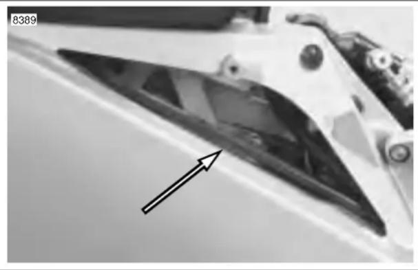
natural_image
Close-up of a mechanical component with an arrow pointing to a specific area (no visible text or symbols)Figure 1-45. Rear Spark Plug Access
REMOVAL
CAUTION
Do not run engine without filter element in place. Debris could be drawn into the engine causing damage.
Check air cleaner filter element:
● Inspect at the 1000 mile (1600 km) service interval and at every 5000 mile (8000 km) service interval thereafter
- Replace at every 20,000 mile (32,000 km) service interval
NOTE
Inspect and replace air cleaner filter element more often if the motorcycle is run in a dusty environment.
- Remove seat. See 2.38 SEAT.
- Remove four fasteners, nylon washers and intake cover assembly. See 2.34 INTAKE COVER ASSEMBLY.
- See Figure 1-46. Remove fuel vent tube (2) from vapor valve (3) and groove on top of air box cover (1).
- See Figure 1-46. Unlatch six latching tabs (4) and remove air box cover from baseplate.
- See Figure 1-47. Remove the filter element (1) from baseplate (2). Inspect and replace if necessary.
CAUTION
Cover the air horn so nothing can drop into the motor.
CLEANING AND INSPECTION
WARNING
Do not use gasoline or solvents to clean the filter element. Volatile/flammable cleaning agents may cause an intake system fire which could result in death or serious injury.
- Check filter element. Hold filter element up to strong light source. The element can be considered sufficiently clean if light is uniformly visible through the element.
- Thoroughly clean baseplate and inside of air box.
- See Figure 1-48. Make sure two crankcase breather hoses (1) and intake air sensor (3) are captured in baseplate behind velocity stack (2).
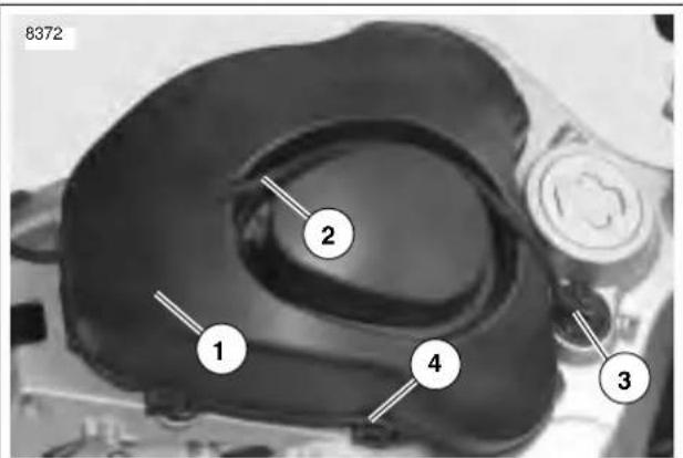
text_image
8372 1 2 4 3- Airbox cover
- Fuel vent tube
- Vapor valve
- Airbox cover latch tabs
Figure 1-46. Air Box, Fuel Vent Tube and Fuel Vapor Valve
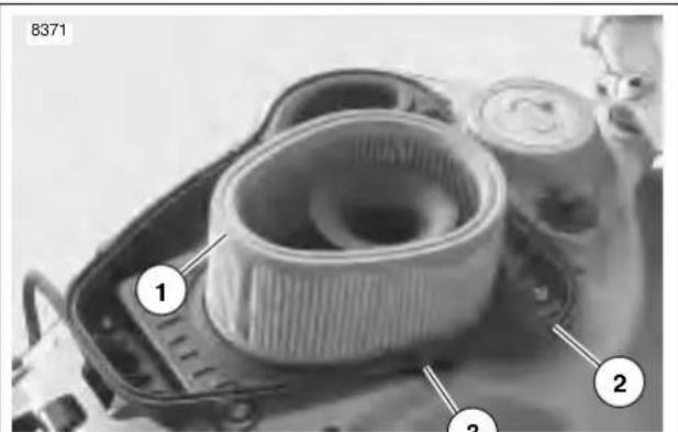
text_image
8371 ① ② ③- Filter element
- Baseplate assembly
- Airbox latch tabs (6)
Figure 1-47. Installed Air Cleaner Filter Element
INSTALLATION
- See Figure 1-47. Place filter element (1) on baseplate (2).
- See Figure 1-46. Position air box cover (1) over baseplate. Make sure air filter remains correctly positioned.
- Install air box cover by latching six latch tabs (4) to base-plate.
- Position fuel vent tube (2) in groove on top of air box and connect to fuel vent valve (3). Secure vent tube to vent valve with new cable tie.
- Install intake cover assembly with four fasteners and nylon washers. Tighten fasteners to 12-36 in-lbs (1-4 Nm).
WARNING
After installing seat, pull upward on front of seat to be sure it is locked in position. If seat is loose, it could shift during vehicle operation and startle the rider, causing loss of control which could result in death or serious injury.
- Install seat. See 2.38 SEAT.
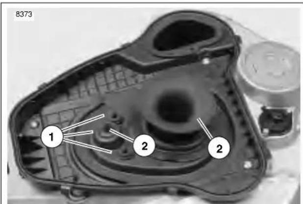
text_image
8373 1 2 2-
Breather hoses (2)
-
Velocity stack
-
Intake air sensor
Figure 1-48. Airbox Baseplate
THROTTLE CABLE
WARNING
Throttle cables must not pull tight when handlebars are turned fully to left or right fork stops. Be sure wires and throttle cables are clear of fork stops at steering head so they will not be pinched when fork is turned against stops. Steering must be smooth and free with no binding or interference. Anything interfering with steering system operation may cause loss of vehicle control, which could result in death or serious injury.
Check throttle cable adjustment:
● Before every ride.
- At every scheduled service interval.
With engine running, turn handlebars through full range of travel. If engine speed changes during this maneuver, turn engine OFF and adjust throttle cables as follows:
- Remove air box and baseplate. See 4.43 AIRBOX.
- See Figure 1-49. Loosen cable adjuster lock (thick disc) on each cable.
- Turn adjusters (thin disc) in direction which will shorten cable housings to minimum length.
- Point front wheel straight ahead. Twist throttle control grip to fully open position; hold in position.
- Turn adjuster on throttle control cable until throttle cam stop touches stop plate. Tighten jam nut on throttle control cable adjuster; release throttle control grip.
- Turn handlebars fully to right. Turn adjuster on idle control cable until end of cable housing just touches the cable guide.
- Twist and release throttle control grip a few times. Throttle plate must return to idle position each time throttle grip is released. If this is not the case, turn adjuster on idle control cable (shortening cable housing) until throttle control functions properly.
- Tighten cable adjuster lock on idle control cable. Recheck operation of throttle control.
- Recheck engine slow idle speed; adjust if required.
- Install airbox, baseplate and intake cover assembly. See 4.43 AIRBOX.
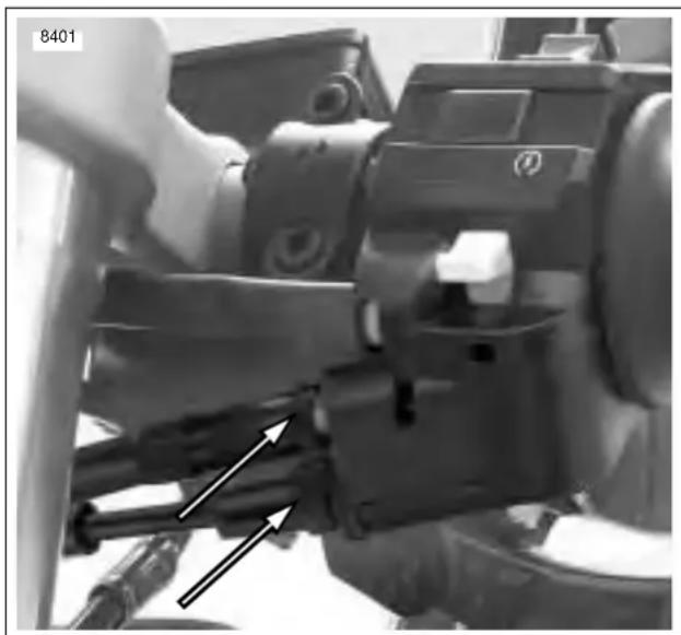
natural_image
Mechanical assembly with mechanical components and directional arrows indicating motion (no readable text or symbols)Figure 1-49. Throttle Cable Adjusters
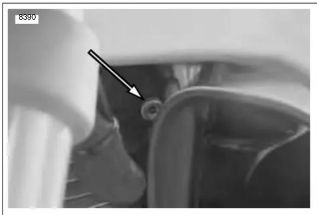
natural_image
Close-up of a mechanical component with a black arrow pointing to a small circular feature, no visible text or symbols.Figure 1-50. Idle Adjuster (behind left fork)
IDLE SPEED
Check engine idle speed and adjust as required:
- At every 1000 mile (1600 km) service interval.
- At every 5000 miles (8000 km) service interval thereafter.
Regular idle speed is 1050 +/- 50 RPM. Set idle speed using idle adjuster shown in Figure 1-50. Turn adjuster clockwise to increase idle speed or counterclockwise to decrease idle speed.
INSPECTION
Check ignition timing:
- At every 10000 mile (16000 km) service interval.
● After each removal of the cam position sensor.
CHECKING STATIC TIMING
CAUTION
Always wear proper eye protection when drilling. Flying debris may result in minor or moderate injury.
CAUTION
Carefully drill hole, applying minimum pressure, to just penetrate timer plate cover. Applying too much pressure will damage cam position sensor and/or timer plate.
NOTES
- It is not necessary to remove the spark plug to determine TDC compression stroke of the front cylinder in the following procedure.
-
Do not remove the timing inspection cover to check the static timing. If timing must be corrected, the inspection plate will then be removed.
-
Raise rear wheel using a lift or jacking point. Tie down motorcycle for additional support.
- Remove timing inspection plug.
- Place transmission in 5th gear.
- Raise sidestand.
NOTE
Sidestand must be raised to enable the starter interlock system.
-
Connect Digital Technician to data port on motorcycle.
-
Select the Static Timing procedure screen.
-
Turn on ignition and move handlebar stop switch to the run position. Listen for fuel pump cycling to confirm ignition is active.
-
Turn or gently bump the flywheel in a forward direction using the rear wheel. Position the flywheel TDC mark at the very left edge of the inspection hole.
-
If the engine is coming up on the compression stroke for the FRONT (correct) cylinder, the screen will be displaying LOW - 0 volts with timing mark at left edge of window.
-
Gently bump flywheel forward in tiny increments.
-
See Figure 1-52. If the static timing is correct, the screen will switch to HIGH - 5 volts at the precise moment the timing mark exactly centers in the inspection window.
- If engine is coming up on the compression stroke for the REAR (incorrect) cylinder, the screen will be displaying HIGH - 5 volts as timing mark is just coming into view at left edge of window and will switch to LOW - 0 volts at same point as the timing mark continues through the window. (If this is observed, turn flywheel forward one
revolution to bring engine to compression stroke for front cylinder.)
NOTES
- If timing mark check point is overshot, bump flywheel backwards till TDC mark is at left edge of inspection window and repeat test bumping flywheel in forward (normal) direction.
-
Never confirm timing while bumping flywheel backwards. This will give you an incorrect reading.
-
If timing is correct, install timing inspection plug and tighten to 120-180 in-lbs (14-20 Nm). If timing is not correct, see ADJUST TIMING in this section.
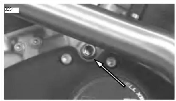
natural_image
Close-up of mechanical components with a black arrow pointing to a circular component (no visible text or symbols)Figure 1-51. Timing Plug
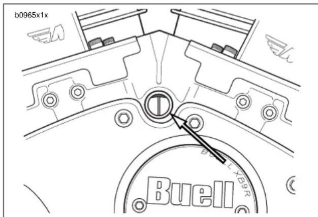
text_image
b0965x1x Buell Buell X89RFigure 1-52. Correct Timing
HOME
ADJUST TIMING
- Remove timing plate cover.
a. Drill rivets holding the timing plate cover.
b. Using a hook, remove timing plate cover.
- See Figure 1-56. If timing is advanced (mark appears on left side of window) rotate timing plate counterclockwise.
- Check timing. See CHECKING STATIC TIMING.
- See Figure 1-55. If timing is retarded (mark appears on right side of window) rotate timing plate clockwise.
- Recheck timing.
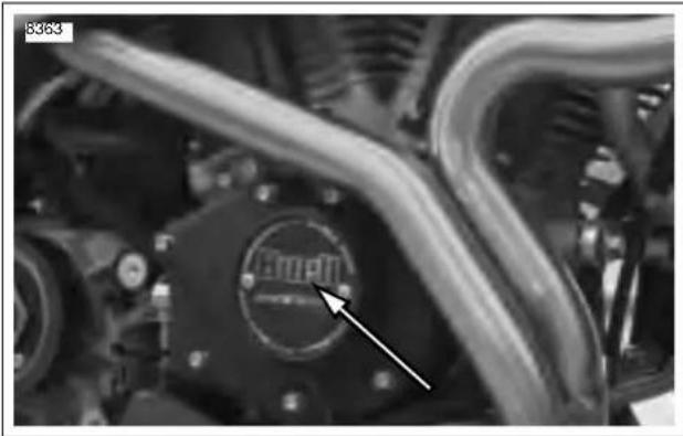
natural_image
Close-up of a mechanical component with a circular feature and an arrow pointing to it (no visible text or symbols)Figure 1-53. Timer Cover
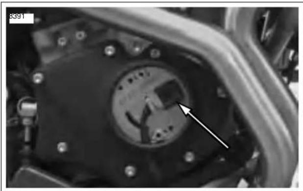
natural_image
Close-up of a mechanical component with a circular dial and an arrow pointing to a feature (no visible text or symbols)Figure 1-54. Cam Position Sensor
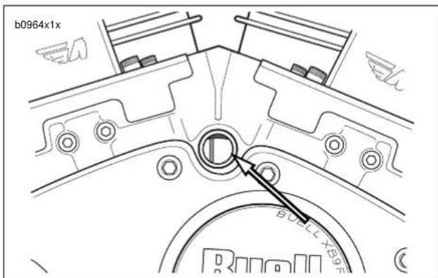
text_image
b0964x1x BULLXE9FFigure 1-55. Advanced Timing
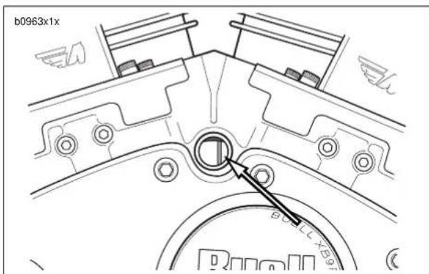
text_image
b0963x1x BULLX891Figure 1-56. Retard Timing
INSPECTION
WARNING
Do not modify ignition/light switch wiring to circumvent the automatic-on headlight feature. High visibility is an important consideration for motorcycle riders. Failure to have headlight on at all times could cause an accident, resulting in death or serious injury.
Check headlights for proper alignment:
- When the new owner takes delivery of the motorcycle.
-
When there is a change in load (adding luggage, etc.).
-
In a location with low light, draw a horizontal line on a screen or wall that measures 34-36 in. (86-91 cm) above floor.
- See Figure 1-57. Position motorcycle 25 ft (7.6 m) away from a screen or wall by measure the distance from the front axle to the screen/wall.
-
Verify correct front and rear tire pressure. See 1.7 TIRES AND WHEELS.
-
Load vehicle with rider/passenger/cargo/accessories. Weight will compress vehicle suspension slightly.
-
Stand motorcycle upright with front fairing aimed straight forward.
-
Check LOW beam (right lens) for alignment.
a. See Figure 1-58. Turn ignition switch to IGN. Set handlebar headlamp switch to LOW beam position.
b. Turn engine stop switch to the run position.
c. Check that the correct pattern of light is a double rectangular pattern and is aligned with the horizontal line as shown in Figure 1-57.
d. Adjust headlight alignment. See ADJUSTMENT which follows.
- Check HIGH beam (left lens) for alignment.
a. See Figure 1-58. Set handlebar headlamp switch to HIGH beam position.
NOTE
Low beam lamp will stay illuminated.
b. Check that the correct pattern of light is a circular pattern and is centered on the horizontal line as shown in Figure 1-57.
c. Adjust headlamp alignment. See ADJUSTMENT section.
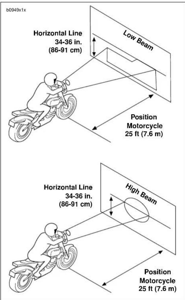
text_image
b0949x1x Horizontal Line 34-36 in. (86-91 cm) Low Beam Position Motorcycle 25 ft (7.6 m) Horizontal Line 34-36 in. (86-91 cm) High Beam Position Motorcycle 25 ft (7.6 m)Figure 1-57. Checking Headlight Alignment
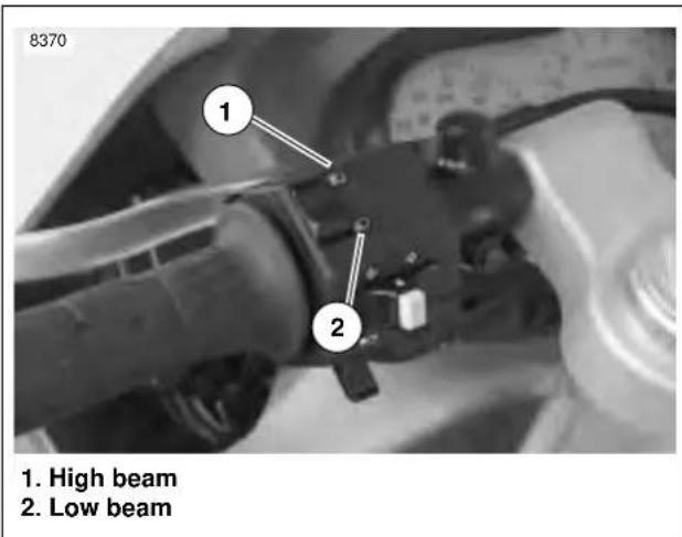
text_image
8370 1. 2. 1. High beam 2. Low beamFigure 1-58. Headlamp Switch
HOME
ADJUSTMENT
HIGH beam and LOW beam have independent adjuster screws.
See Figure 1-59. The HIGH Beam adjuster (1) is on the left and the LOW Beam adjuster (2) is on the right underneath the front fairing.
If headlamp requires adjustment, perform the following:
NOTE
● To lower beam, turn adjuster clockwise.
● To raise beam, turn adjuster counterclockwise.
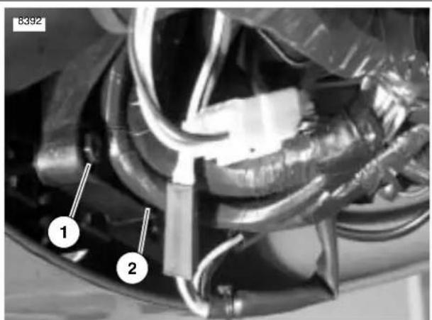
text_image
8392 1 2-
High beam adjuster (left)
-
Low beam adjuster (right)
Figure 1-59. Headlamp Height Adjustment
INSPECTION
- Connect vehicle to Digital Technician.
- Select data monitor screen.
- Select TP degrees on screen.
- Ignition and run switch should be in the on position with engine off and throttle in the closed position.
- If closed throttle TP degree reading is not between 5.2 - 5.6 degrees, TPS should be recalibrated. See ADJUSTMENT below.
ADJUSTMENT
- Connect vehicle to Digital Technician.
- Select data monitor screen.
- Select TP degrees on screen.
- See Figure 1-60. Back off idle adjustment until TPS is at 0^ and then continue to back out one to two additional turns.
- Open and snap shut throttle control grip 2-3 times.
NOTE
This is to ensure that the throttle plate is completely closed before beginning recalibration.
-
Select calibrations screen.
-
Select the Buell calibrations tab.
-
Select Zero TPS function.
NOTE
When calibration is complete, dialogue box will appear on Digital Tech screen with message display "Command Sent Successfully". Select OK to continue.
- Select data monitor screen.
- Select TP degrees on screen.
- Turn idle speed screw in until the TPS degree reading is between 5.2° and 5.6°.
- Select RPM/Speed and Temperature on screen and start vehicle.
- Run vehicle until engine temperature is at 270 °F.
- Set idle to 1050-1100 RPM.
- Adjustment is complete.
1-48 2003 Buell XB9R: Maintenance
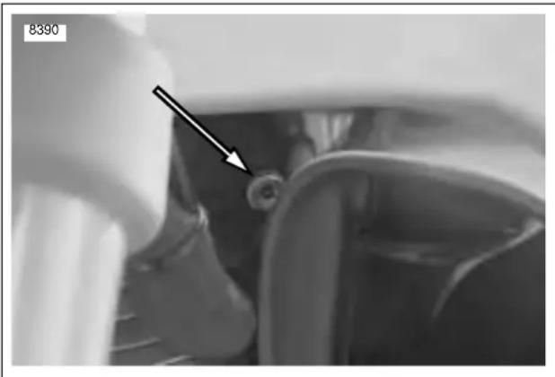
natural_image
Close-up of a mechanical component with a black arrow pointing to a small circular feature, no visible text or symbols.Figure 1-60. Idle Adjuster (behind left fork)
GENERAL
WARNING
Gasoline is flammable. Do not store motorcycle having gasoline in tank within the home or garage where open flames, pilot lights, sparks or electric motors are present. Inadequate safety precautions may cause an accident which could result in death or serious injury.
If the motorcycle will not be operated for several months, such as during the winter season, there are several things which should be done to protect parts against corrosion, to preserve the battery and to prevent the buildup of gum and varnish in the fuel system.
- Fill fuel tank and add a gasoline stabilizer. Use one of the commercially available gasoline stabilizers following the manufacturer's instructions. Run engine until treated gasoline has had a chance to reach fuel injectors.
- Fill the oil tank. See 1.5 ENGINE LUBRICATION SYSTEM. Remove and plug the line leading from the oil tank bottom to the oil pump feed fitting. This prevents oil from seeping past the check ball into the oil pump and filling the engine flywheel compartment.
- Remove battery and charge as needed to maintain the correct voltage. See 1.4 BATTERY MAINTENANCE.
- Remove the spark plugs, inject a few squirts of engine oil into each cylinder and crank the engine 5-6 revolutions. Reinstall spark plugs. See 1.14 SPARK PLUGS.
- Adjust primary chain. See 1.10 PRIMARY CHAIN.
- Check tire inflation. See 1.7 TIRES AND WHEELS. If the motorcycle will be stored for an extended period of time, securely support the motorcycle so that all weight is off the tires.
WARNING
Do not apply any oil to brake rotors or brake pads. Oil on brake pads degrades braking efficiency and can result in an accident which could result in death or serious injury.
- Wash molded-in-color and chrome-plated surfaces. Apply a light film of oil to exposed uncoated metal surfaces.
- If motorcycle is to be covered, use a material that will breathe, such as light canvas. Plastic materials that do not breathe promote the formation of condensation.
REMOVAL FROM STORAGE
WARNING
After extended periods of storage and prior to starting vehicle, place transmission in gear, disengage clutch and push vehicle back and forth a few times to ensure proper clutch disengagement. Improper clutch disengagement could result in death or serious injury.
- Charge and install battery. See 1.4 BATTERY MAINTENANCE.
- Remove and inspect spark plugs. Replace if necessary. See 1.14 SPARK PLUGS.
- Inspect air filter element. Replace if necessary. See 1.15 AIR CLEANER FILTER Element.
- If fuel tank was drained, fill fuel tank with fresh gasoline.
- If oil feed line was pinched off or plugged, unplug it and reconnect.
- Start the engine and run until it reaches normal operating temperature. Check fluids and refill to proper levels if required.
a. Check engine oil level. See 1.5 ENGINE LUBRICATION SYSTEM.
b. Check transmission fluid level. See 1.8 CLUTCH. - Perform all of the checks in the PRE-RIDING CHECK LIST in the Owner's Manual.
GENERAL
The following check list can be helpful in locating most operating troubles. Refer to the appropriate sections in this Service Manual for detailed procedures.
ENGINE
Starter Motor Does Not Operate or Does Not Turn Engine Over
- Engine stop switch in OFF position.
- Ignition key switch not ON.
- Discharged battery or loose or corroded connections. (Solenoid chatters.)
- Starter control relay or solenoid not functioning.
- Electric starter shaft pinion gear not engaging or over-running clutch slipping.
- Clutch lever pulled in. Vehicle in neutral.
- Starter interlock circuit malfunction.
Engine Turns Over But Does Not Start
NOTE
See 4.11 ENGINE CRANKS BUT WILL NOT START for specific tests.
- Fuel tank empty.
- Discharged battery, loose or broken battery terminal connections.
- Fouled spark plugs.
- Loose or shorting spark plug cables or connections.
- Ignition timing badly out of adjustment.
-
Loose wire connection at coil or battery connection or plug between ignition sensor and module. See Section 4.
-
Ignition coil not functioning.
-
Ignition module not functioning.
-
Ignition sensor not functioning.
-
Sticking or damaged valve or valves.
-
Engine oil too heavy (winter operation).
-
Ignition circuit interlock malfunction.
-
No output from the ECM. See dealer.
-
Inadequate fuel pressure in fuel lines (possible leak). See dealer.
-
Clogged fuel filter. See dealer.
-
Clogged fuel injectors. See dealer.
-
Tripped bank angle sensor. Turn key to OFF, wait 15 seconds, and then back to IGN again to start bike.
-
TP Sensor/fast idle screw not set properly. See dealer.
-
No output from CMP sensor. See dealer.
-
Inoperative fuel pump. See dealer.
1-50 2003 Buell XB9R: Maintenance
Starts Hard
- Spark plugs in bad condition, have improper gap or are partially fouled.
- Spark plug cables in bad condition and shorting.
- Battery nearly discharged.
- Loose wire connection at one of the battery terminals, at coil or at plug between ignition sensor and module.
- Throttle controls not adjusted correctly.
- Ignition coil not functioning.
- Engine oil too heavy (winter operation).
- Ignition not timed properly. See dealer.
- Vapor vent valve plugged or fuel line closed off restricting fuel flow.
- Water or dirt in fuel system.
- Air leak at intake manifold.
- Valves sticking.
- TP Sensor and/or fast idle screw not set properly. See dealer.
- O2, IAT or ET sensors damaged or malfunctioning. See dealer.
Starts But Runs Irregularly or Misses
NOTE
See 4.15 MISFIRE for specific tests.
- Spark plugs in bad condition or partially fouled.
- Spark plug cables in bad condition and shorting.
- Spark plug gap too close or too wide.
- Ignition coil not functioning.
- Ignition module not functioning.
- Ignition sensor not functioning.
- Battery nearly discharged.
- Damaged wire or loose connection at battery terminals or coil.
-
Intermittent short circuit due to damaged wire insulation.
-
Water or dirt in fuel system and throttle body or filter.
-
Vapor vent valve plugged.
- Throttle controls improperly adjusted.
- Air leak at intake manifold or air filter.
-
Damaged intake or exhaust valve.
-
Weak or broken valve springs.
-
Incorrect valve timing.
-
O2, IAT or ET sensors damaged or malfunctioning. See dealer.
-
TP Sensor not set properly. See dealer.
-
Fuel level too low. Add gasoline.
-
Inoperative fuel injector. See dealer.
-
Obstructed fuel tank vent valve or pinched vent tube. See dealer.
HOME
Spark Plug Fouls Repeatedly
- Incorrect spark plug.
- Piston rings badly worn or broken.
- Valve stem seals worn or damaged.
- Valve guides badly worn.
- Sensors damaged.
Pre-Ignition or Detonation (Knocks or Pings)
- Excessive carbon deposit on piston head or combustion chamber.
- Incorrect heat range spark plug.
- Spark plugs not firing.
- Ignition timing advanced.
- Fuel octane rating too low.
- Intake manifold vacuum leak.
Overheating
- Insufficient oil supply or oil not circulating.
- Clogged or damaged fins on oil cooler.
- Cooling fan not operating properly.
- Leaking valves.
- Heavy carbon deposit.
- Ignition timing retarded.
Valve Train Noise
- Hydraulic lifter not functioning properly.
- Bent push rod.
- Cam, cam gears or cam bushings worn.
- Rocker arm binding on shaft.
- Valve sticking in guide.
Excessive Vibration
- Engine tie-bars loose, broken or improperly spaced.
- Isolator mounting fasteners loose.
- Broken frame.
- Primary chain badly worn or links tight as a result of insufficient lubrication.
- Wheels not aligned and/or tires worn.
- Internal engine problem.
- Wheels not balanced correctly.
ENGINE LUBRICATION SYSTEM
Oil Does Not Return To Oil Tank
- Oil tank empty.
- Return pump gears damaged.
- Oil feed pump not functioning.
- Restricted oil lines or fittings.
Engine Uses Too Much Oil or Smokes Excessively
- Piston rings badly worn or broken.
- Valve stem seals worn or damaged.
- Valve guides worn.
Engine Leaks Oil From Cases, Push Rods, Hoses
- Loose parts.
- Imperfect seal at gaskets, push rod cover, washers, etc. To aid locating leaks, use BLACK LIGHT LEAK DETECTOR (Part No. HD-35457).
- Restricted oil return line to tank.
- Restricted breather passage(s) to air cleaner.
ELECTRICAL SYSTEM
Alternator Does Not Charge
- Regulator-rectifier module not functioning.
- Rectifier not grounded.
- Engine ground wire loose or broken.
- Loose or broken wires in charging circuit.
- Stator not functioning.
- Rotor not functioning.
Alternator Charge Rate Is Below Normal
- Regulator-rectifier module not functioning.
- Stator not functioning.
- Rotor not functioning.
- Weak battery.
- Loose connections.
FUEL SYSTEM
Fuel System Floods
- Inlet valve sticking.
- Inlet valve and/or valve seat worn or damaged.
- Dirt or other foreign matter between valve and its seat.
Poor Fuel Economy
- O2 sensor damaged or malfunctioning (bike running rich). See dealer.
TRANSMISSION
Shifts Hard
- Clutch dragging slightly.
- Shifter forks (inside transmission) damaged.
- Corners worn off shifter clutch dogs (inside transmission).
Jumps Out of Gear
- Shifter pawl improperly adjusted.
- Shifter engaging parts (inside transmission) badly worn and rounded.
- Shifter forks bent.
- Damaged gears.
CLUTCH
Slips
- Clutch controls improperly adjusted.
- Worn friction plates.
Drags or Does Not Release
- Clutch controls improperly adjusted.
- Clutch plates excessively warped.
Chatters
- Friction or steel plates worn, warped or dragging.
CHASSIS
Irregular/Inadequate Brake Action
- Master cylinder low on fluid.
- Brake line contains air bubbles or moisture.
- Master or wheel cylinder piston worn.
- Brake pads covered with grease or oil.
- Brake pads badly worn to minimum lining thickness.
- Brake rotor badly worn or warped.
- Brake pads dragging or excessive braking (brake fades due to heat buildup).
- Insufficient brake pedal or hand lever free play (brake drags).
Handling Irregularities
- Tires improperly inflated. See 1.7 TIRES AND WHEELS. Do not overinflate.
- Loose wheel axle. Tighten front axle to 39-41 ft-lbs (53-56 Nm). Tighten rear axle to 48-52 ft-lbs (65-70 Nm).
- Excessive wheel hub bearing play.
- Rims and tires out-of-true sideways (tire runout should not be more than 0.080 in. (2.03 mm)).
- Rims and tires out-of-round or eccentric with hub (tire runout should not be more than 0.060 in. (1.5 mm)).
- Irregular or peaked front tire tread wear.
- Tire and wheel unbalanced or weights on wrong side of wheel.
- Steering head bearings improperly tightened or worn. See 1.13 STEERING HEAD BEARINGS. Check for proper torque and replace worn bearings. See 2.17 FORK CLAMPS, UPPER AND LOWER.
- Shock absorber or front forks not functioning normally.
- Heavy front end loading. Non-standard equipment on the front end (such as heavy radio receivers, extra lighting equipment or luggage) tends to cause unstable handling.
SUSPENSION
When making adjustments, remember there are two mediums in setting up a bike, geometry and suspension. Both components work together because suspension is a part of geometry. In order to solve handling problems, it is important to diagnose the problem's true nature. Chattering, sliding or an uncomfortable feeling are suspension-related. Handling and a swinging fork are geometry-related, but often these unwanted characteristics can be solved by suspension adjustments.
The following tables list possible suspension and operating troubles and their probable causes.
Table 1-12. General Suspension Problems
| TROUBLESHOOTING CONDITION ADJUSTMENT SOLUTION | |
| Bike wallows through turns.Feels loose or vague after bumps.Wheel tends to “pogo” after passing over a bump. This is noticeable by watching the bike continue to bounce as it travels over multiple bumps. | Increase rebound damping. |
| Wheel responds to bump, but doesn’t return to ground quickly after bumps. This is more pronounced over a series of bumps and is often referred to as “packing down.” | Reduce rebound damping. |
| The bike bottoms out or dips while cornering.Bike has excessive brake dive. | Increase compression damping. |
| Harsh ride particularly over washboard surfaces.Bumps kick through handlebars or seat.Suspension seems not to respond to bumps. This is evidenced by tire chattering (a movement with short stroke and high frequency) through corners or by jolting the rider over rough roads. | Reduce compression damping. |
Table 1-13. Rear Suspension Problems
| TROUBLESHOOTING CONDITION ADJUSTMENT SOLUTION | |
| “Pumping on the Rear” occurs when you are accelerating out of a corner. This problems occurs in two varieties.1. The first type has a movement with a long stroke and a high frequency.2. The second version has a movement with a short stroke and high frequency. | 1. The shock is too soft. Increase compression damping. If the adjuster is already set to the maximum, add more preload to the spring (one turn maximum).2. In this case the shock is too hard. Decrease compression damping. |
| Chattering during braking. Decrease the compression damping. | If the problem persists, decrease rebound damping for a faster rebound rate. Less spring preload may also help. |
| Lack of tire feedback. The suspension is too soft. Increase compression damping. | |
| Sliding during cornering. Sliding may occur going into the corner or accelerating out of the corner. | The suspension is too hard. Decrease compression damping. |
Table 1-14. Front Suspension Problems
| TROUBLESHOOTING CONDITION ADJUSTMENT | SOLUTION |
| Not absorbing bumps. A good suspension is a balance between damping and track condition. Finding this balance requires exploring all possible compression settings. | |
| Lack of tire feedback. Increase compression damping. | |
| Tire slides. Decrease compression damping. |
CHASSIS 2
SUBJECT PAGE NO.
2.1 Specifications 2-1
2.2 Tire Specifications 2-5
2.3 Vehicle Identification Number 2-6
2.4 Wheels 2-7
2.5 Front Wheel 2-9
2.6 Rear Wheel 2-15
2.7 Checking Cast Rim Runout 2-18
2.8 Tires 2-19
2.9 Brake Pedal 2-22
2.10 Front Brake Master Cylinder 2-23
2.11 Front Brake Line 2-26
2.12 Front Brake Caliper 2-28
2.13 Rear Brake Master Cylinder 2-31
2.14 Rear Brake Line 2-34
2.15 Rear Brake Caliper 2-36
2.16 Front Fork 2-39
2.17 Fork Clamps, Upper and Lower 2-45
2.18 Steering Head Bearings 2-47
2.19 Swingarm and Brace 2-49
2.20 Front and Rear Isolator 2-53
2.21 Frame 2-54
2.22 Rear Shock Absorber 2-55
2.23 Throttle Control 2-57
2.24 Clutch Hand Lever 2-58
2.25 Headlight Support Bracket 2-59
2.26 Fairing Support Bracket 2-62
2.27 Handlebars 2-64
2.28 Exhaust System 2-66
2.29 Footpeg, Heel Guard, and Mount 2-68
2.30 Sprocket Cover 2-70
2.31 Fenders 2-71
2.32 Belt Guards 2-72
2.33 Chin Fairing 2-74
2.34 Airbox Cover 2-75
2.35 Air Scoops 2-76
2.36 Tail Frame and Body Work 2-77
2.37 Front Fairing, Windshield, and Mirrors 2-80
2.38 Seat 2-81
2.39 Passenger Seat Lock 2-82
2.40 Sidestand 2-83
Table 2-1. Dimensions
| DIMENSIONS IN. MM | ||
| Wheel Base 52.0 1320 | ||
| Seat Height 31.2 792 | ||
| Ground Clearance 4.0 102 | ||
| Trail | 3.3 | |
| Rake 21 Degrees | ||
Table 2-3. Capacities
| CAPACITIES | U.S. | LITERS |
| Fuel Tank (inc. reserve) | 3.7 gallons | 14.0 |
| Reserve/Low fuel light at | 0.7 gallons | 1.5 |
| Oil Tank(wet - for normal oil change) | 2.5 quarts 2.4 | |
| Fork Oil | 14 ounces | 0.41 |
| Transmission | 1.0 quart |
Table 2-2. Weight Specifications
| WEIGHT-U.S. MODELS LBS. | KG | |
| Wet Weight | 445 | 202 |
| GVWR | 850 | 385 |
| GAWR - Front | 325 | 147 |
| GAWR - Rear | 525 | 238 |
| Load Capacity | 405 | 184 |
NOTE
Gross Vehicle Weight Rating (GVWR) (maximum allowable loaded vehicle weight) and corresponding Gross Axle Weight Ratings (GAWR) are given on an information decal located on the steering head.
Table 2-4. Tire and Positions
| TIRE AND POSITION | SOLO RIDING | GVWR |
| FrontDunlop Sportmax Radial II120/70 ZR 17 D207FY | 36 PSI(248 kPa) | Same as Solo |
| RearDunlop Sportmax Radial II180/55 ZR 17 D207U | 38 PSI(262 kPa) |
Table 2-5. Rotor Runout
| RUNOUT | IN. | MM |
| FRONT | ||
| Radial | 0.0177 | 0.45 |
| Lateral | 0.0248 | 0.63 |
| REAR | ||
| Radial | 0.0177 | 0.45 |
| Lateral | 0.0154 | 0.39 |
WARNING
Do not inflate any tire beyond its maximum inflation pressure as specified on tire sidewall. Overinflation may cause tire to suddenly deflate which could result in death or serious injury.
| ITEMS TORQUE NOTES | |||
| Airbox cover fasteners 12-36 | in-lbs | 1-4 Nm page | 2-75 |
| Airhorn fastener 72-96 | in-lbs | 8-10 Nm page | 2-62 |
| Axle pinch fastener, rear 40-45 ft-lbs 54-61 Nm page 2-16 | |||
| Axle pinch fasteners, front 20-22 ft-lbs 27-30 Nm page 2-14 | |||
| Axle, front 39-41 ft-lbs 53-56 Nm ANTI-SIEZE, Left handed thread, page 2-8 | |||
| Bank angle sensor 12-36 | in-lbs | 1-4 Nm page | 2-60 |
| Belt guard, upper 12-36 | in-lbs | 1-4 Nm page | 2-51 |
| Brake hand lever housing fasteners | 80-90 in-lbs | 9-10 Nm page | 2-25 |
| Brake lamp switch fastener, front | 7-10 in-lbs | 0.8-1.0 Nm | page 2-25 |
| Brake line p-clamp fastener, front | 36-60 in-lbs | 4-7 Nm page | 2-26 |
| Brake line p-clamp fastener, rear | 36-60 in-lbs | 4-7 Nm page | 2-35 |
| Brake pedal fastener | 22-24 ft-lbs 30-33 Nm LOCTITE 272, page 2-22 | ||
| Brake pin hanger set, front | 11-14 ft-lbs | 15-19 Nm | page 2-29 |
| Brake pin hanger set, rear 11-14 ft-lbs | 15-20 Nm | page 2-37 | |
| Brake pin plug, rear | 22-26 in-lbs | 2-3 Nm | page 2-37 |
| Brake reservoir fastener, rear | 96-120 in-lbs | 11-14 Nm page | 2-78 |
| Caliper banjo bolt, front | 16-20 ft-lbs 22-27 Nm metric, page 2-27 | ||
| Caliper banjo bolt, rear 16-20 ft-lbs 22-27 Nm page 2-35 | |||
| Caliper banjo bolt, rear 16-20 ft-lbs 22-27 Nm page 2-38 | |||
| Caliper bleeder valves | 36-60 in-lbs | 4-7 Nm metric, page 2-23 | |
| Caliper carrier, rear | 24-26 ft-lbs 32-35 Nm page 2-16 | ||
| Caliper fasteners, front | 15-19 ft-lbs 20-26 Nm page 2-29 | ||
| Caliper mounting fasteners, front | 35-37 ft-lbs 47-50 Nm page 2-29 | ||
| Caliper mounting large fastener, rear 18-21 ft-lbs 24-28 Nm page 2-38 | |||
| Caliper mounting small fastener, rear | 14-18 ft-lbs 19-24 Nm page 2-38 | ||
| Chin fairing fasteners | 36-48 in-lbs | 4-5 Nm page | 2-74 |
| Clutch cable p-clamp | 12-36 in-lbs | 1-4 Nm page | 2-53 |
| Clutch lever clamp pinch fastener | 36-60 in-lbs | 4-7 Nm page | 2-58 |
| Clutch lever pivot fastener | 39-48 in-lbs | 4-5 Nm page | 2-58 |
| Electronic control module fasteners | 72-96 in-lbs | 8-11 Nm page | 2-61 |
| Engine shroud air scoop | 12-36 in-lbs | 1-4 Nm page | 2-76 |
| Exhaust header mounting nut | 72-96 in-lbs | 8-11 Nm page | 2-67 |
| Fairing support bracket fastener | 16-18 ft-lbs | 22-26 Nm | page 2-62 |
| Flasher fastener | 30-40 in-lbs | 3-5 Nm page | 2-60 |
| Footpeg mount fasteners, rider | 108-132 in-lbs | 12-15 Nm page | 2-68 |
| Footpeg mount, passenger | 25-28 ft-lbs | 34-38 Nm | LOCTITE 272, page 2-69 |
| Fork cap | 22-30 ft-lbs | 30-40 Nm | page 2-42 |
| Fork center bolt | 22-30 ft-lbs | 30-40 Nm | page 2-42 |
| ITEMS | TORQUE | NOTES | |
| Fork clamp, lower 13-15 ft-lbs 18-20 Nm | LOCTITE 272, page 2-43 | ||
| Fork clamp, upper 17-19 ft-lbs 23-26 Nm | LOCTITE 272, page 2-45 | ||
| Fork damper locknut 22-30 ft-lbs 30-40 Nm page 2-41 | |||
| Front fender fasteners 12-36 | in-lbs | 1-4 Nm page | 2-71 |
| Front isolator bolt 49-51 ft-lbs 66-69 Nm page 2-53 | |||
| Front isolator bracket mounting fastener | 49-51 ft-lbs 66-69 Nm page 2-53 | ||
| Front isolator snubber, upper 12-36 | in-lbs | 1-4 Nm page | 2-53 |
| Front isolator threaded frame insert 49-51 ft-lbs 66.4-69.1 Nm LOCTITE 222, page 2-53 | |||
| Fuse block and relay fasteners | 72-96 in-lbs | 8-11 Nm | page 2-62 |
| Hand lever pivot fastener | 60-120 in-lbs | 9-14 Nm | page 2-24 |
| Handlebar clipon fastener, left | 24-26 ft-lbs 33-35 Nm LOCTITE 272, page 2-64 | ||
| Handlebar clipon fastener, right | 24-26 ft-lbs 33-35 Nm LOCTITE 272, page 2-64 | ||
| Headlight fasteners | 20-25 in-lbs | 2.3-2.8 Nm | page 2-60 |
| Headlight support bracket pivot fasteners | 72-96 in-lbs | 8-11 Nm | page 2-61 |
| Heel guard fasteners, passenger | 48-72 in-lbs | 5-8 Nm page | 2-69 |
| Heel guard fasteners, rider | 72-96 in-lbs | 8-11 Nm | page 2-68 |
| Instrument cluster fastener | 36-48 in-lbs | 4-5 Nm page | 2-62 |
| License plate fasteners | 36-48 in-lbs | 4-5 Nm page | 2-78 |
| Main battery ground fastener | 72-96 in-lbs | 8-11 Nm | page 2-78 |
| Master cylinder banjo bolt, front | 16-20 ft-lbs 22-27 Nm page 2-27 | ||
| Master cylinder banjo bolt, rear | 16-20 ft-lbs 22-27 Nm page 2-35 | ||
| Master cylinder cover fasteners, front | 9-13 in-lbs | 1.0-1.5 Nm | page 2-25 |
| Master cylinder mounting fasteners, rear | 48-72 in-lbs | 8-11 Nm | page 2-33 |
| Mirror fasteners | 60-70 ft-lbs | 7-8 Nm page | 2-80 |
| Muffler mounting block fastener, front | 22-25 ft-lbs 30-34 Nm page 2-67 | ||
| Muffler mounting block fastener, rear | 32-36 ft-lbs 43-49 Nm page 2-67 | ||
| Muffler strap fastener, front | 108-120 in-lbs | 12-14 Nm page | 2-67 |
| Muffler strap fastener, rear | 48-60 in-lbs | 5-7 Nm page | 2-67 |
| Oil cooler air scoop | 120-144 in-lbs | 14-16 Nm page | 2-76 |
| Oil drain plug | 29-31 ft-lbs 39-42 Nm page 2-51 | ||
| Oil line fittings | 29-31 ft-lbs 39-42 Nm page 2-51 | ||
| Passenger seat latch | 60-96 in-lbs | 7-11 Nm | page 2-78 |
| Pivot shaft pinch bolt | 17-19 ft-lbs 23-26 Nm page 2-51 | ||
| Ram air scoop | 12-36 in-lbs | 1-4 Nm page | 2-76 |
| Rear fender fastener | 12-36 ft-lbs | 1-4 Nm page | 2-71 |
| Rotor mounting fasteners, front | 25-27 ft-lbs 34-37 Nm metric, Replace with new, page 2-13 | ||
| Rotor mounting fasteners, rear | 25-27 ft-lbs 34-37 Nm metric, Replace with new, page 2-16 | ||
| Safety interlock fastener | 7-10 in-lbs | 0.8-1.1 Nm | page 2-58 |
HOME
| ITEMS | TORQUE | NOTES | |
| Seat fasteners 12-36 | in-lbs | 1-4 Nm page | 2-81 |
| Shock absorber, lower 17-19 ft-lbs 23-26 | Nm page 2-51 | ||
| Shock mounting fastener, upper 49-51 ft-lbs 66-69 Nm page 2-55 | |||
| Shock remote reservoir fastener 96-120 | in-lbs | 11-14 Nm page | 2-33 |
| Shock reservoir clamp, rear 120-144 | in-lbs | 14-16 Nm page | 2-78 |
| Sidestand bracket fasteners 25-27 ft-lbs | 34-37 Nm page 2-84 | ||
| Sidestand pivot bolt 18-20 ft-lbs 24-27 Nm page 2-84 | |||
| Sidestand switch fastener 36-60 | in-lbs | 4-7 Nm page | 2-84 |
| Sprocket cover fastener 12-36 | in-lbs | 1-4 Nm LOCTITE 222, page 2-70 | |
| Sprocket fasteners 35-37 ft-lbs 48-50 Nm Replace with new, page 2-16 | |||
| Steering stem cap | 38-42 ft-lbs 52 | 57 Nm page 2-45 | |
| Steering stem pinch fastener | 17-19 ft-lbs 23 | 26 Nm LOCTITE 272, page 2-45 | |
| Swingarm brace mounting fasteners | 25-27 ft-lbs 34 | 37 Nm page 2-51 | |
| Swingarm pivot shaft | 24-26 ft-lbs 32 | 35 Nm page 2-51 | |
| Switch housing fasteners, right | 25-33 in-lbs | 3-4 Nm page | 2-57 |
| Tail body work, lower | 36-48 in-lbs | 4-5 Nm page | 2-78 |
| Tail body work, upper | 12-36 in-lbs | 1-4 Nm page | 2-79 |
| Tail frame to frame 21-23 ft-lbs 28-31 Nm LOCTITE 272, page 2-78 | |||
| Torca clamp | 40-45 ft-lbs | 54-61 Nm | page 2-67 |
| Turn signals and reflectors | 25-28 in-lbs | 2-3 Nm page | 2-78 |
| Valve stem nut | 40-44 in-lbs | 4-5 Nm page | 2-20 |
GENERAL
WARNING
Tires must be correctly matched to wheel rims. Only the tires listed in the fitment tables below can be used for replacement. Mismatching tires and rims can cause damage to the tire bead during mounting. Using tires other than those specified can adversely affect motorcycle handling and could result in death or serious injury.
See Figure 2-1. Tire sizes are molded on the sidewall. Rim size and contour are marked on the rim's exterior surface.
Example: MT 3.5 x 17.0 DOT
● MT designates the rim contour.
● 3.5 is the width of the bead seat measured in inches.
● 17.0 is the normal diameter of the rim in inches, measured at the bead seat diameter.
- DOT means that the rim meets Department of Transportation Federal Motor Vehicle Safety Standards. See Table 2-6.
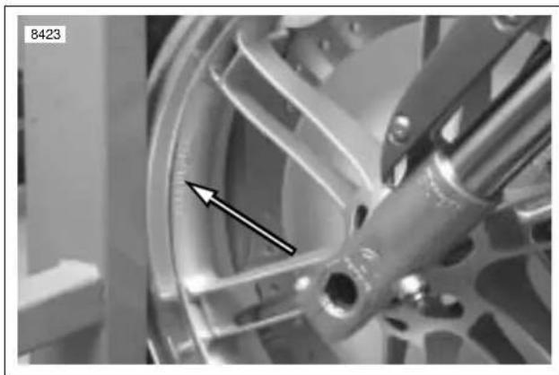
natural_image
Close-up of a car wheel rim with an arrow pointing to the center (no text or symbols visible)Figure 2-1. Rim Markings
Table 2-6. Tire Fitment-Tubeless Cast Wheels
| WHEEL SIZE& POSITION | CONTOUR &RIM SIZE | RIM VALVEHOLE DIAMETER | DUNLOP SPORTMAX RADIAL IITIRE SIZE |
| 17 in. – Front MT 3.5 | x 17.0 DOT 0.33 in. 120/70 | ZR17 D207FY | |
| 17 in. – Rear MT 5.5 | x 17.0 DOT 0.33 in. 180/55 | ZR17 D207U |
GENERAL
The full 17 digit serial or Vehicle Identification Number (V.I.N.) is stamped on the steering head and on an information decal at the same location.
See Figure 2-2. An abbreviated V.I.N. is stamped on the front left side of the crankcase.
NOTE
See Figure 2-3. Always give the V.I.N. or abbreviated V.I.N. when ordering parts or making inquiries about your Buell motorcycle.
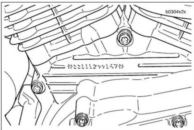
Figure 2-2. Abbreviated V.I.N. Location
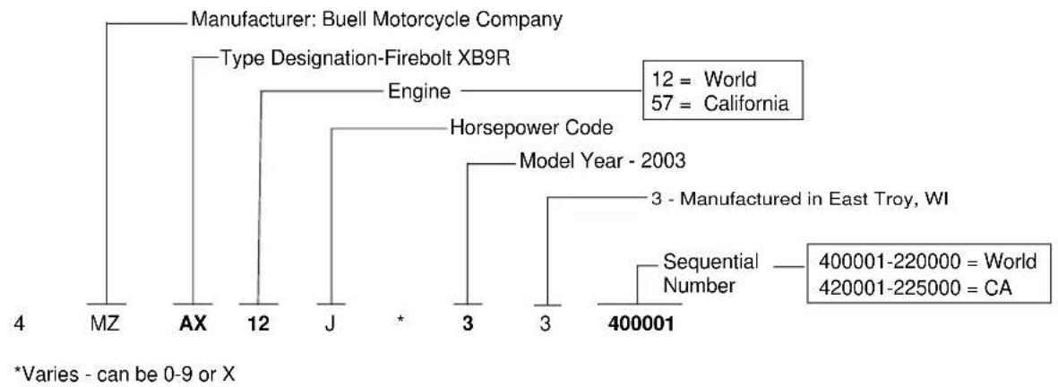
flowchart
graph TD
    A["Manufacturer: Buell Motorcycle Company"] --> B["Type Designation-Firebolt XB9R"]
    B --> C["Engine"]
    C --> D["12 = World\n57 = California"]
    B --> E["Horsepower Code"]
    E --> F["Model Year - 2003"]
    F --> G["3 - Manufactured in East Troy, WI"]
    G --> H["Sequential Number"]
    H --> I["400001-220000 = World\n420001-225000 = CA"]
    style A fill:#f9f,stroke:#333
    style B fill:#ccf,stroke:#333
    style C fill:#cfc,stroke:#333
    style D fill:#fcc,stroke:#333
    style E fill:#cff,stroke:#333
    style F fill:#ffc,stroke:#333
    style G fill:#cfc,stroke:#333
    style H fill:#fcc,stroke:#333
    style I fill:#fff,stroke:#333
Sample V.I.N. as it appears on the steering head - 4MZAX12J133400001 Sample abbreviated V.I.N. as it appears on the left side crankcase - AX123400001
Figure 2-3. Vehicle Identification Number (V.I.N.)
GENERAL
Good handling and maximum tire mileage are directly related to the care of wheels and tires. Regularly inspect wheels and tires for damage and wear. If handling problems occur, see 1.21 TROUBLESHOOTING or Table2-7.
See 1.7 TIRES AND WHEELS for tire pressures. Keep tires inflated to the recommended air pressure. Always balance the wheel after replacing a tire.
WARNING
Do not inflate any tire beyond its maximum inflation pressure as specified on tire sidewall. Overinflation may cause tire to suddenly deflate which could result in death or serious injury.
TROUBLESHOOTING
See Figure 2-4. Check tire inflation pressure at least once each week. At the same time, inspect tire tread for punctures, cuts, breaks and other damage. Repeat the inspection before long trips.
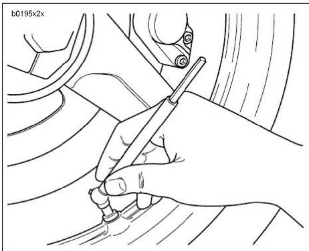
natural_image
Line drawing of a hand using a tool to lift or rotate a car wheel (no text or symbols)Figure 2-4. Checking Tire Inflation Pressure
Table 2-7. Wheel Service
| CHECK FOR REMEDY | |
| Loose axles. Tighten front axle with LOCTITE | ANTI-SEIZE to 39-41 ft-lbs (53-56 Nm).Tighten rear axle with LOCTITE ANTI-SEIZE to 48-52 ft-lbs (65-70 Nm). |
| Excessive side-play or radial (up-and-down) play in wheel hubs. | Replace wheel bearings. |
| Rims and tires out-of-true sideways; should not be more than 0.080 in. (2.03 mm). | Replace rims. See 2.8 TIRES. |
| Rims and tires out-of-round or eccentric with hub; should not be more than 0.090 in. (2.29 mm). | Replace rims. See 2.8 TIRES. |
| Irregular or peaked front tire wear. | Replace as described under 2.5 FRONT WHEEL, 2.6 REAR WHEEL and 2.8 TIRES. |
| Correct tire inflation. Inflate tires to correct pressure. | See 1.7 TIRES AND WHEELS. |
| Correct tire and wheel balance. Static balance | may be satisfactory if dynamic balancing facilities are not available. However, dynamic balancing is strongly recommended. |
| Steering head bearings. | Check for proper torque and replace worn or damaged bearings. See 1.13 STEERING HEAD BEARINGS. |
| Damper tubes. | Check for leaks. See 2.16 FRONT FORK. |
| Shock absorbers. | Check damping action and mounts. See 1.11 SUSPENSION DAMPING ADJUSTMENTS. |
| Swingarm bearings. | Check for proper torque and replace worn or damaged bearings.See 2.19 SWINGARM AND BRACE. |
WARNING
To prevent death or serious injury, use the following guidelines when installing a new tire or repairing a flat:
- Always locate and eliminate the cause of the original tire failure.
- Do not patch or vulcanize a tire casing. These procedures weaken the casing and increase the risk of a blowout.
- The use of tires other than those specified can adversely affect handling which could result in death or serious injury.
- Tires and wheels are critical items. Since the servicing of these components requires special tools and skills, Buell recommends that you see your dealer for these services.
WARNING
Buell recommends replacement of any tire punctured or damaged. In some cases small punctures in the tread area may be repaired from within the demounted tire by your Buell dealer. Speed should not exceed 50 mph (80 km/h) for the first 24 hours after repair and the repaired tire should NEVER be used over 80 mph (129 km/h). In emergency situations, if a temporary repair is made, ride slowly with as light of a load as possible until the tire is permanently repaired or replaced. Failure to follow this warning could result in death or serious injury.
WARNING
Replace excessively worn tires. Excessively worn tires adversely affect motorcycle traction, steering and handling and could result in death or serious injury.
At regular intervals of 2500 miles (4000 km) or whenever handling irregularities are noted, perform the recommended service checks. See Table2-7.
If tires must be replaced, same as original equipment tires must be used. Other tires may not fit correctly and may be hazardous to use.
REMOVAL
- Place a scissor jack under jacking point and raise front wheel off ground. For location of jacking point see Figure 2-98.
NOTE
Do not operate front brake lever with front wheel removed or caliper pistons may be forced out. Reseating pistons requires caliper disassembly.
-
Remove the right side fender fasteners.See 2.31 FENDERS.
-
See Figure 2-5. Loosen front axle pinch fasteners (2) (metric) on front fork.
-
Remove axle (1).
NOTE
The front axle is left handed thread.
-
See Figure 2-6. Raise the wheel up until the rotor clears the caliper and rotate the fork leg counterclockwise allowing wheel clearance for removal.
-
Remove wheel.
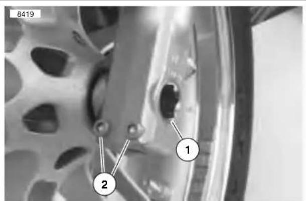
text_image
8419 1 2-
Axle (left handed thread)
-
Front axle pinch fasteners (2) (metric)
Figure 2-5. Front Wheel Mounting
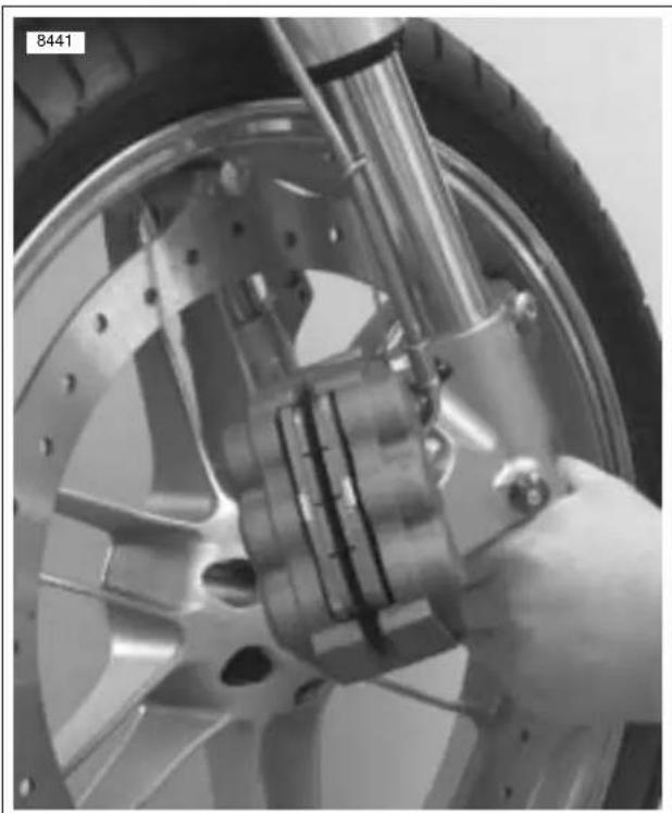
natural_image
Close-up of a hand adjusting a car tire and brake caliper assembly (no visible text or symbols)Figure 2-6. Front Wheel Removal and Installation
Bearing Removal
NOTE
On single disc wheels, always remove the brake disc side first. If the wheel has two brake discs, remove the left bearing first.
- See Figure 2-7. Remove wheel bearings using BUSHING AND BEARING PULLER (Part No. B43993-7) and WHEEL BEARING REMOVER AND INSTALLER (Part No. HD-44060).
- Sparingly apply Extreme Pressure Lubricant (J-23444-A) to the threads of the short forcing screw (1) to prolong service life and ensure smooth operation.
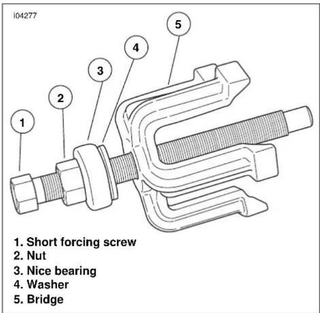
text_image
i04277 1. Short forcing screw 2. Nut 3. Nice bearing 4. Washer 5. BridgeFigure 2-7. Assemble Puller
- Assemble the short forcing screw (1), nut (2), Nice bearing (3), washer (4) and bridge (5) from the Wheel Bearing Installer/Remover (HD-44060).
- See Figure 2-8. Insert the Front Wheel Bearing Remover Collet (B-43993-7) into the wheel bearing until it fully seats against the bearing.
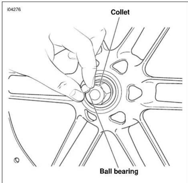
text_image
i04276 Collet Ball bearingFigure 2-8. Install Collet and Ball Bearing
- Insert the ball bearing into the collet.
- See Figure 2-9. Thread the puller assembly (1) into the collet (2).
- Hold the collet (2), and turn the forcing screw (3) to expand the collet.
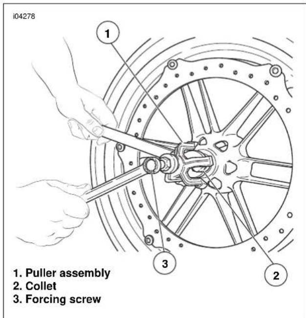
text_image
i04278 1. Puller assembly 2. Collet 3. Forcing screwFigure 2-9. Expand the Collet
- See Figure 2-10. Place the bridge (1) against the wheel hub.
- Hold the forcing screw (2), and turn the nut (3) clockwise until the bearing is free of the hub.
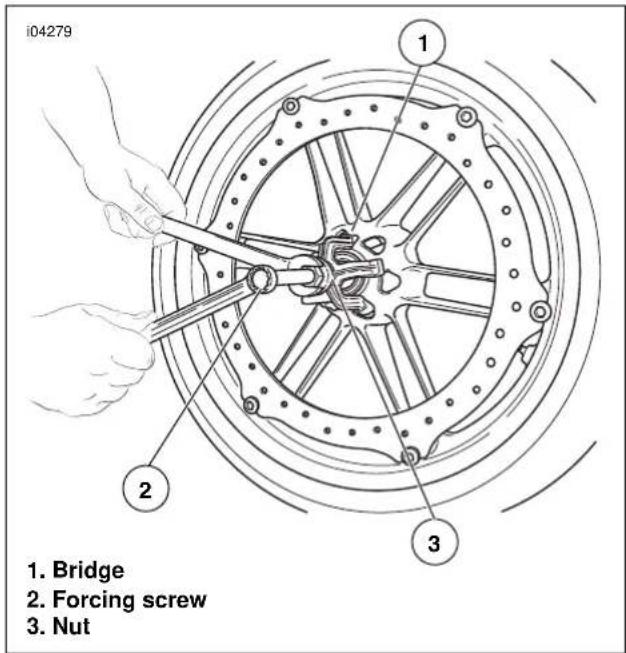
text_image
i04279 1. Bridge 2. Forcing screw 3. NutFigure 2-10. Remove the Bearing
- See Figure 2-11. Loosen the nut (1), and back off the bridge (2). Hold the forcing screw (3) while holding the collet (4) to remove the forcing screw from the collet.
- Remove the ball bearing (5) and wheel bearing (6) from the collet (4).
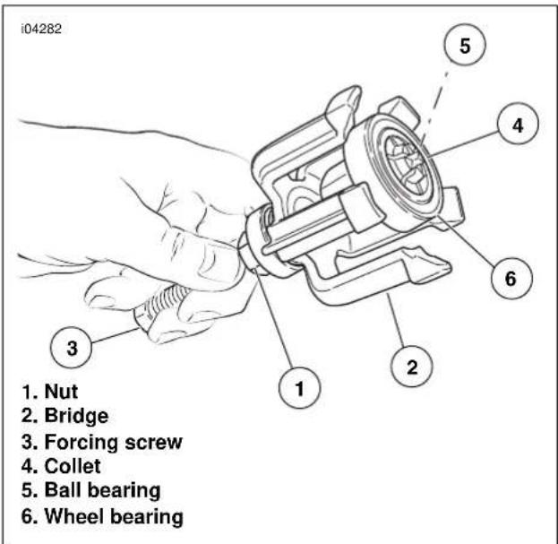
text_image
i04282 1. Nut 2. Bridge 3. Forcing screw 4. Collet 5. Ball bearing 6. Wheel bearingFigure 2-11. Removing Bearing from Puller
- See Figure 2-12. Remove the spacer.
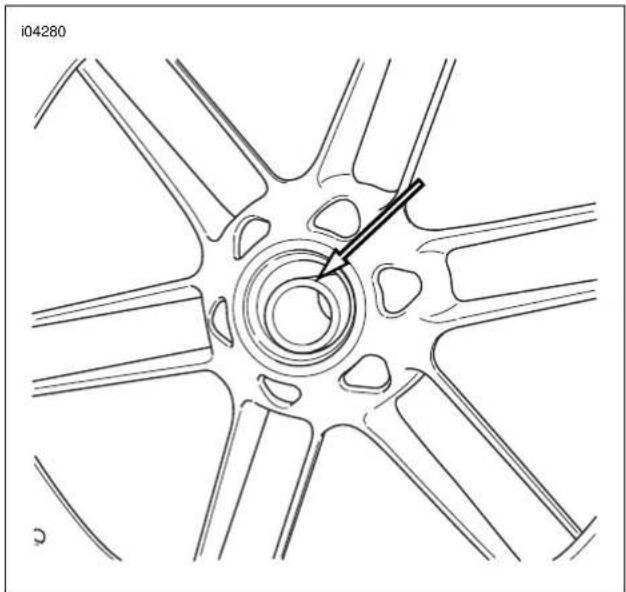
natural_image
Technical line drawing of a wheel rim with six spokes and a central hub, no text or symbols presentFigure 2-12. Remove the Spacer
- Repeat Steps 4-12 for the bearing on the other side of the wheel.
Front Rotor Removal
- See Figure 2-18. Remove and discard rotor mounting fasteners (7).
- Remove and inspect brake rotor (6) for wear and warping. See 1.7 TIRES AND WHEELS.
- Remove drive bushings (8) and discard.
- Remove washers (9) and discard.
- Remove rotor spring (4) and discard.
CLEANING AND INSPECTION
WARNING
Never use compressed air to "spin-dry" bearings. Very high bearing speeds can damage unlubricated bearings. Spinning bearings with compressed air can also cause a bearing to fly apart, which could result in death or serious injury.
- Inspect all parts for damage or excessive wear.
NOTE
XB wheel bearings are designed as sealed bearings which are not intended to be disassembled, serviced or cleaned with solvents.
WARNING
Always replace brake pads in complete sets for correct brake operation. Never replace just one brake pad. Failure to install brake pads as a set could result in death or serious injury.
- Inspect brake rotor and pads. See 1.6 BRAKE SYSTEM MAINTENANCE.
ASSEMBLY
- See Figure 2-18. Install spacer (5).
- Install new wheel bearings (2) into hub using suitable driver. Press on outer race only.
NOTE
Press the rotor side bearings in first ensuring it is seated on the shoulder of the wheel. Followed by pressing the alternate side until it contacts the spacer.
WARNING
Do not allow brake fluid, bearing grease, lubricants, etc. to contact brake rotor or reduced braking ability will occur, which could result in death or serious injury.
Bearing Installation
NOTE
On single disc wheels, always install the brake disc side first. If the wheel has two brake discs, install the left bearing first.
The following procedure describes the bearing installation for the front wheel; the procedure for the rear wheel is the same.
- See Figure 2-13. Install the Backing Plate (B-43993-11) onto the long forcing screw from the Wheel Bearing Installer/Remover (HD-44060), with the smaller diameter toward the wheel hub. Insert the forcing screw and backing plate into the wheel hub.
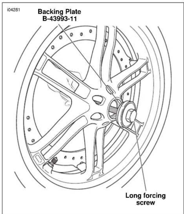
text_image
i04281 Backing Plate B-43993-11 Long forcing screwFigure 2-13. Install the Backing Plate (B-43993-11) and Forcing Screw
- See Figure 2-14. Sparingly apply Extreme Pressure Lubricant (J-23444-A) to the threads of the long forcing screw (1) to prolong service life and ensure smooth operation.
2-12 2003 Buell XB9R: Chassis
- Insert a new wheel bearing (2) squarely into the hub, with the lettered side pointing out (away from the wheel).
- Slide the Front Wheel Bearing Installer Tool (B-43993-10) (3) onto the forcing screw (1), with the smaller diameter toward the bearing bore.
- Install a washer (4), Nice bearing (5) and nut (6) onto the forcing screw (1).
- While holding the forcing screw (1), tighten the nut (6) until the bearing is flush with the hub.
- Remove the nut, bearing, washer, Front Wheel Bearing Installer (B-43993-10) and forcing screw.
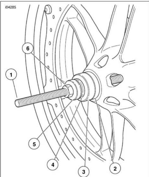
text_image
i04285 1 6 5 4 3 2- Long forcing screw
- Wheel bearing
- Front Wheel Bearing Installer (B-43993-9)
- Washer
- Nice bearing
- Nut
Figure 2-14. Install Bearing
- See Figure 2-15. Remove the Backing Plate (B-43993-11) from the long forcing screw. Reinstall the Backing Plate onto the forcing screw, with the smaller diameter toward the hex-head.
- Insert the forcing screw through the wheel hub on the opposite side of the wheel.
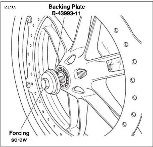
text_image
i04283 Backing Plate B-43993-11 Forcing screwFigure 2-15. Insert Forcing Screw and Backing Plate
- See Figure 2-16. Install the spacer.
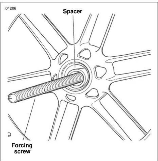
text_image
I04286 Spacer Forcing screwFigure 2-16. Install the Spacer
- See Figure 2-17. Insert a new wheel bearing (1) squarely into the hub, with the lettered side pointing out (away from the wheel).
- Slide the Front Wheel Bearing Installer Tool (B-43993-10) (2) onto the forcing screw (3), with the smaller diameter toward the bearing bore.
- Install a washer (4), Nice bearing (5) and nut (6) onto the forcing screw (3).
NOTE
See Figure 2-16. Center the spacer while installing the wheel bearing. Failure to center the spacer could cause the bearing not to pull in straight.
-
While holding the forcing screw (3), tighten the nut (6) until the bearing is flush with the hub.
-
Remove the nut, bearing, washer, Front Wheel Bearing Installer (B-43993-10) and forcing screw.
- Install the wheel. See INSTALLATION in this section according to the procedure in the Service Manual.
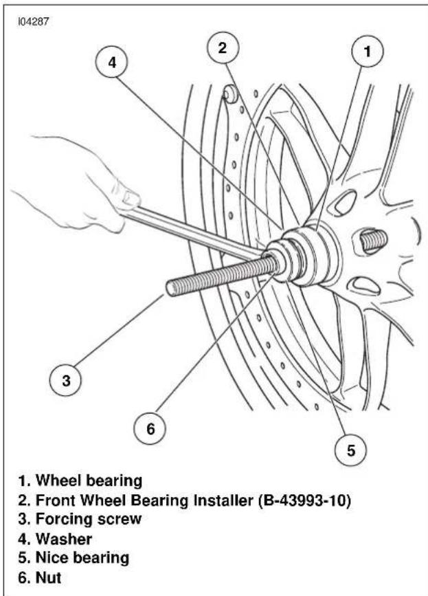
text_image
1. Wheel bearing 2. Front Wheel Bearing Installer (B-43993-10) 3. Forcing screw 4. Washer 5. Nice bearing 6. NutFigure 2-17. Install the Bearing
Front Rotor Installation
- See Figure 2-18. Install new spring (4).
- Install new washers (9).
- Install drive bushings (8) into rotor.
NOTE
Note the identifying mark of rotor is up and radius end of drive bushing (8) toward center of wheel. See Figure 2-18.
- See Figure 2-18. Align reference dot on front rotor with the valve stem.
- Install new rotor mounting fasteners in a criss-cross pattern around the wheel to insure proper fitting between rotor, fastener and bushing. Tighten to 25-27 ft-lbs (34-37 Nm).
CAUTION
Rotor mounting fasteners must be seated into drive bushings and drive bushings must be fitted into rotor properly. Failure to comply may affect braking ability and lead to brake failure which could result in death or serious injury.
INSTALLATION
- Raise front wheel to allow clearance for the caliper to swing under the front rotor.
- Install caliper.
a. Align wheel so that rotor mounting fasteners straddle caliper.
b. Rotate right front fork counterclockwise to align caliper with rotor.
c. Lower front wheel into caliper assembly.
- Install front axle.
a. Apply LOCTITE ANTI-SEIZE LUBRICANT to axle.
b. See Figure 2-5. With pinch fasteners (metric) loose, insert threaded end of axle (1) through left side fork, wheel hub and thread into right fork.
c. Compress the front suspension to make sure it is free and not binding.
d. Tighten axle (1) (metric) to 39-41 ft-lbs (53-56 Nm).
NOTE
The front axle is left handed thread.
- See Figure 2-5. Tighten the front axle pinch fasteners (2) to 20-22 ft-lbs (27-30 Nm).
- Install right side fender fasteners. See 2.31 FENDERS.
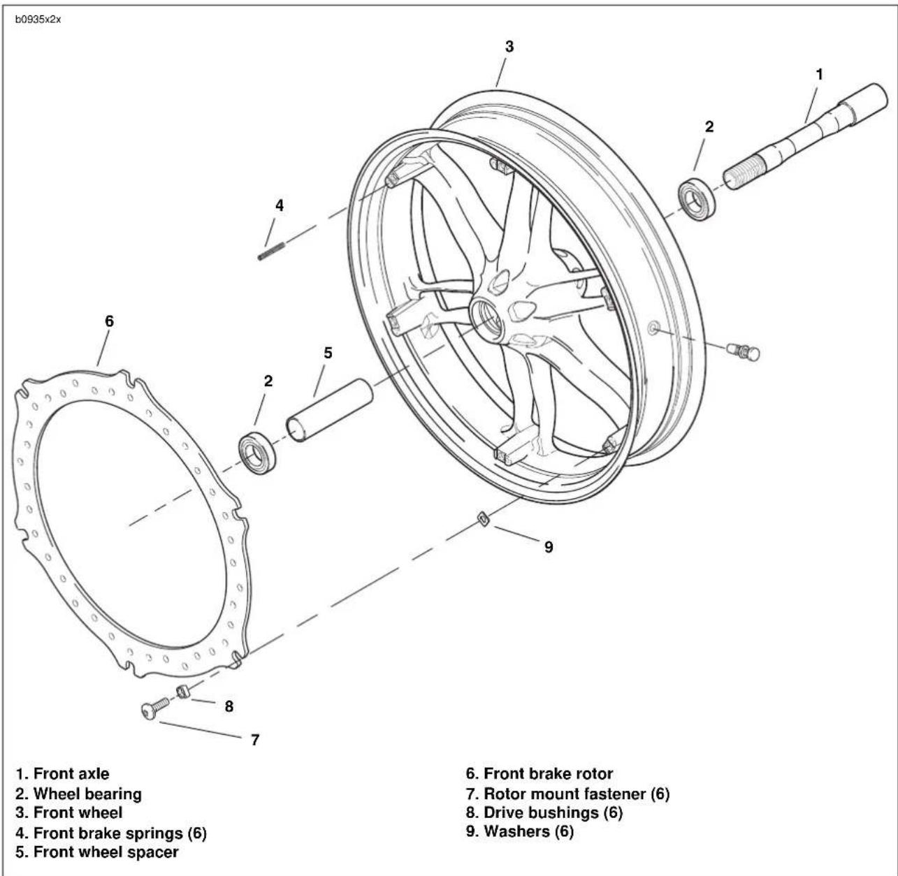
text_image
b0935x2x 1. Front axle 2. Wheel bearing 3. Front wheel 4. Front brake springs (6) 5. Front wheel spacer 6. Front brake rotor 7. Rotor mount fastener (6) 8. Drive bushings (6) 9. Washers (6)Figure 2-18. Front Wheel Assembly
REMOVAL
- See Figure 2-19. Remove caliper carrier from swingarm by removing caliper carrier fasteners. See 2.15 REAR BRAKE CALIPER.
NOTE
Do not operate rear brake pedal with rear wheel removed or caliper piston may be forced out. Reseating piston requires caliper disassembly.
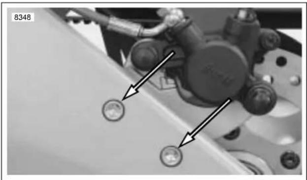
natural_image
Close-up of a mechanical component with two circular buttons and directional arrows indicating alignment (no text or symbols)Figure 2-19. Rear Brake Caliper Carrier Fasteners
- Remove drive belt. See 1.9 DRIVE BELT SYSTEM.

text_image
8420 1. Axle 2. Pinch bolt fastenerFigure 2-20. Rear Wheel Mounting, Right Side
- See Figure 2-20. Remove rear axle (1).
- Remove rear wheel.
CLEANING AND INSPECTION
WARNING
Never use compressed air to "spin-dry" bearings. Very high bearing speeds can damage unlubricated bearings. Spinning bearings with compressed air can also cause a bearing to fly apart, which could result in death or serious injury.
- Inspect all parts for damage or excessive wear.
- Inspect brake rotor. See 1.6 BRAKE SYSTEM MAINTENANCE.
DISASSEMBLY
- Remove sprocket.
a. Remove sprocket fasteners and washers. Discard fasteners.
b. Remove sprocket from wheel.
- Remove rear rotor.
a. See Figure 2-23. Remove and discard rotor mounting fasteners (1).
b. Remove and inspect brake rotor for wear and warping. See BRAKE ROTOR THICKNESS in 1.6 BRAKE SYSTEM MAINTENANCE.
- Remove rear wheel bearings using BUSHING AND BEARING PULLER (Part No. B43993-8) and WHEEL BEARING REMOVER AND INSTALLER (Part No. HD-44060).
NOTE
The procedure for the rear wheel bearing removal is the same as front wheel bearing removal. See Bearing Removal in 2.5 FRONT WHEEL.
4. Remove rear wheel spacer (4).
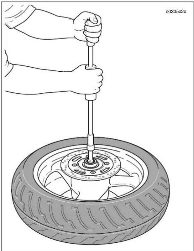
natural_image
Illustration of a hand using a tool to lift a tire, no text or symbols presentFigure 2-21. Removing Wheel Bearing
ASSEMBLY
WARNING
Do not allow brake fluid, bearing grease, lubricants, etc. to contact brake rotor or reduced braking ability will occur, which could result in death or serious injury.
- See Figure 2-23. Install wheel bearing (3) on rotor side of motorcycle.
- Install rear wheel spacer (4).
- Install wheel bearing (3) on sprocket side of motorcycle. Remove rear wheel bearing. The procedure for the rear wheel bearing installation is the same as front wheel bearing installation. See Bearing Installation in 2.5 FRONT WHEEL.
- Install sprocket.
a. Position sprocket (6) on wheel (5) keeping lip of sprocket facing the inside.
b. Install new sprocket fasteners (7) and washers tightening to 35-37 ft-lbs (48-50 Nm).
- See Figure 2-23. Install rear rotor (2).
a. Position rear brake rotor (2) on wheel (5).
b. Install brake rotor (2) with new rotor mounting fasteners (1) and tighten to 25-27 ft-lbs (34-37 Nm).
2-16 2003 Buell XB9R: Chassis
INSTALLATION
- See Figure 2-23. Install the rear axle by threading partially into swingarm.
a. Center wheel in swingarm and lower bike to align swingarm and hub.
b. See Figure 2-22. Coat the axle with ANTI-SIEZE LUBRICANT.
c. Slide axle through right side of swing arm and wheel hub.
- Install drive belt. See DRIVE BELT INSTALLATION in 1.9 DRIVE BELT SYSTEM.
- Install idler pulley. See IDLER PULLEY INSTALLATION in 1.9 DRIVE BELT SYSTEM.
- Install sprocket cover. See 2.30 SPROCKET COVER.
CAUTION
Never tighten rear axle with swingarm brace removed.
- See Figure 2-20. Tighten rear axle (1) to 48-52 ft-lbs (65-70 Nm).
- Tighten pinch fastener (2) on right side of swingarm to 40-45 ft-lbs (54-61 Nm).
- See Figure 2-19. Install caliper carrier and tighten fastener to 24-26 ft-lbs (32-35 Nm). See 2.15 REAR BRAKE CALIPER.
NOTE
The brake pads may become cocked and will not allow the rotor to slide into the caliper. Press on the brake pad from the outside of the caliper to straighten out the pad.
WARNING
Always test motorcycle brakes at low speed after servicing or bleeding system. To prevent death or serious injury, Buell recommends that all brakes repairs be performed by a Buell dealer or other qualified mechanic.

natural_image
Technical line drawing of a mechanical component with two directional arrows indicating movement (no text or symbols)Figure 2-22. Anti-Seize Lubricant Location
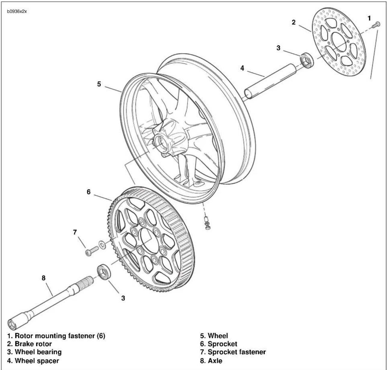
text_image
b0936x2x 1. Rotor mounting fastener (6) 2. Brake rotor 3. Wheel bearing 4. Wheel spacer 5. Wheel 6. Sprocket 7. Sprocket fastener 8. AxleFigure 2-23. Rear Wheel Assembly
GENERAL
Check wheels for lateral and radial runout before installing a new tire.
Rim Lateral Runout
- See Figure 2-24. Install truing arbor in wheel hub and place wheel in WHEEL TRUING AND BALANCING STAND (Part No. HD-99500-80).
- Tighten arbor nuts so hub will turn on its bearings.
- Check rim lateral runout by placing a gauge rod or dial indicator near the rim bead. Replace wheel if lateral runout exceeds specification shown in Table 2-8.
Rim Radial Runout
- See Figure 2-25. Install truing arbor in wheel hub and place wheel in WHEEL TRUING AND BALANCING STAND (Part No. HD-99500-80).
- Tighten arbor nuts so hub will turn on its bearings.
- Check radial runout as shown. Replace wheel if runout exceeds specification shown in Table2-8.
Table 2-8. Wheel Runout
| CAST WHEEL IN MM | ||
| Maximum Lateral Runout | 0.040 | 1.02 |
| Maximum Radial Runout | 0.030 | 0.76 |
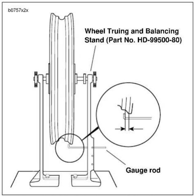
text_image
b0757x2x Wheel Truing and Balancing Stand (Part No. HD-99500-80) Gauge rodFigure 2-24. Checking Cast Rim Lateral Runout
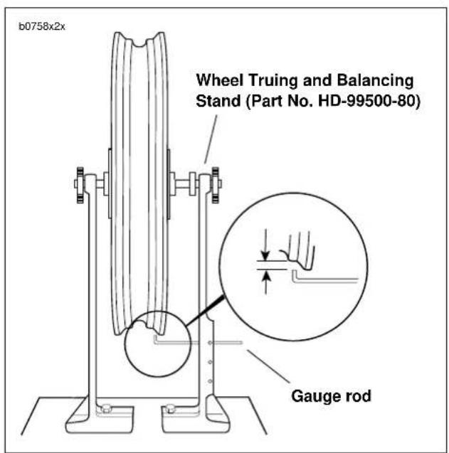
text_image
b0758x2x Wheel Truing and Balancing Stand (Part No. HD-99500-80) Gauge rodFigure 2-25. Checking Cast Rim Radial Runout
GENERAL
Inspect tires for punctures, cuts, breaks and wear at least weekly.
WARNING
● Always check both tire sidewalls for arrows indicating forward rotation. Some tires require different tire rotation depending on whether tire is used on front or rear wheel. Installing a tire with the wrong rotation could result in death or serious injury.
● Dunlop front and rear tires for Buell motorcycles are not the same. They are not interchangeable. Use front tire ONLY for a front tire. DO NOT put a rear tire on the front of a vehicle. Failure to follow this warning could result in death or serious injury.
CAUTION
Some tires have arrows molded into the tire sidewall. These tires should be mounted on the rim with the arrow pointing in the direction of forward rotation. The yellow circle on the sidewall is a balance mark and should be aligned 180 degrees from the balance mark (blue dot) on inside of rim.
REMOVAL
- Remove wheel from motorcycle. See 2.5 FRONT WHEEL or 2.6 REAR WHEEL.
- Deflate tire.
- See Figure 2-26. Loosen both tire beads from rim flange.
WARNING
Do not use excessive force when starting bead over rim. Excessive force may damage tire or rim and adversely affect handling which could result in death or serious injury.
- If a bead breaker machine is not available, attach RIM PROTECTORS (Part No. HD-01289) to the rim. Using tire tools (not sharp instruments), start upper bead over edge of rim at valve. Repeat all around rim until first bead is over rim.
- See Figure 2-27. Push lower bead into rim well on one side and insert tire tool underneath bead from opposite side. Pry bead over rim edge. Remove tire from rim.
- Remove valve stem if it is damaged or leaks.
- Mount tire on TIRE SPREADER (Part No. HD-21000) for inspection and repair procedures.
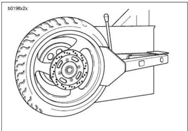
natural_image
Technical line drawing of a car tire mounted on a vehicle chassis (no text or symbols)Figure 2-26. Loosening Beads from Rim Flange
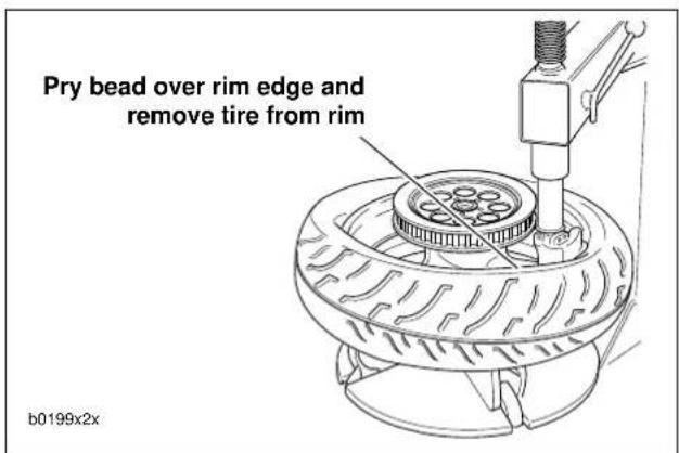
text_image
Pry bead over rim edge and remove tire from rim b0199x2xFigure 2-27. Starting Tire Off Rim
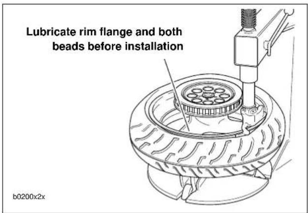
text_image
Lubricate rim flange and both beads before installation b0200x2xFigure 2-28. Starting Bead on Rim
CLEANING AND INSPECTION
- Clean inside of tire with dry rag.
- If rim is dirty or corroded, clean with a stiff wire brush.
- Inspect tire for wear and damage. Replace worn or damaged tires. See 1.7 TIRES AND WHEELS.
INSTALLATION
WARNING
Only install original equipment (stock) tire valves and valve caps. A valve or valve and cap combination that is too long may interfere with (strike) adjacent components, damage the valve and cause rapid tire deflation. Rapid tire deflation could cause loss of control. These events could result in death or serious injury.
WARNING
Aftermarket valve caps that are heavier than the stock cap may have clearance at slow speeds; but, at high speed the valve/cap will be moved outward by centrifugal force. This outward movement could cause the valve/cap to strike the adjacent components, damage the valve and cause rapid tire deflation. Rapid tire deflation could cause loss of control. These events could result in death or serious injury.
- Damaged or leaking valve stems must be replaced.
- Install and tighten fastener to 40-44 in-lbs (4-5 Nm).
- Thoroughly lubricate rim flanges and both beads of tire with tire lubricant.
- See Figure 2-28. Starting at the valve stem, start first bead into the rim well using a bead breaker machine. If no machine is available, work bead on as far as possible by hand. Use a tire tool to pry the remaining bead over rim flange.
- Start 180° from valve stem hole and place second bead on rim. Work bead onto rim with tire tools, working toward valve in both directions.
WARNING
Do not inflate over 40 psi (275 kPa) to seat the beads. Inflating the tire beyond 40 psi (275 kPa) to seat the beads can cause the tire rim assembly to burst with force sufficient to cause death or serious injury. If the beads fail to seat to 40 psi (275 kPa), deflate and relubricate the bead and rim and reinflate to seat the beads, but do not exceed 40 psi (275 kPa).
- Apply air to stem to seat beads on rim. It may be necessary to use a TIRE BEAD EXPANDER (Part No. HD-28700) on the tire until beads seal on rim.
2-20 2003 Buell XB9R: Chassis
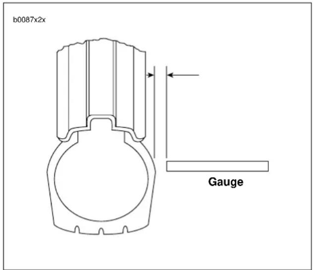
text_image
b0087x2x GaugeFigure 2-29. Checking Tire Lateral Runout
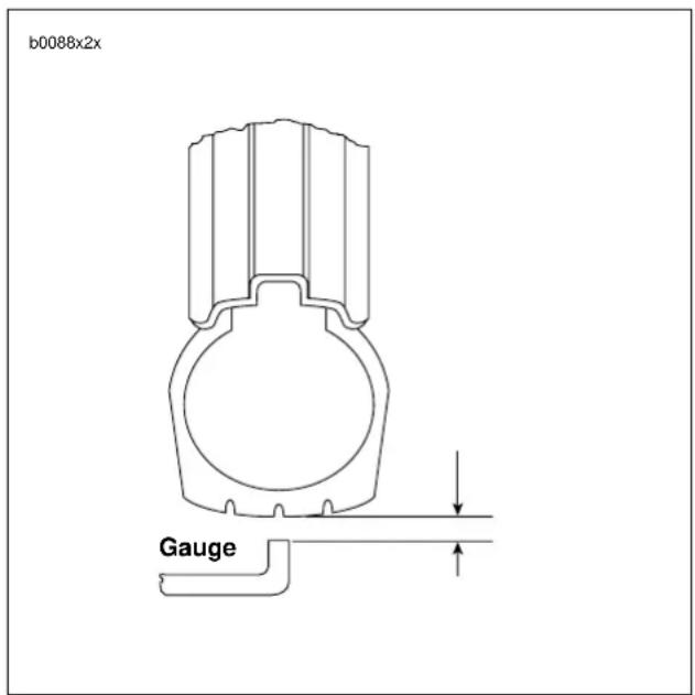
text_image
b0088x2x GaugeFigure 2-30. Checking Tire Radial Runout
Table 2-9. Tire Runout
| RUNOUT IN. MM | ||
| Radial 0.060 1.52 | ||
| Lateral 0.080 2.03 |
HOME
Checking Tire Lateral Runout
- See Figure 2-29. Turn wheel on axle and measure amount of displacement from a fixed point to tire sidewall.
- Check tire tread for appropriate runout specification. See Table 2-9. If runout is more then specification, remove tire from rim.
- Check rim bead side runout. See 2.7 CHECKING CAST RIM RUNOUT. Replace rims not meeting specifications.
- Install tire and check again for tire tread lateral runout.
Checking Tire Radial Runout
- See Figure 2-30. Turn wheel on axle and measure tread radial runout.
- Check tire tread for appropriate runout specification. See Table 2-9. If runout is more then specification, remove tire from rim.
- Check rim bead runout. See 2.7 CHECKING CAST RIM RUNOUT. Replace rims not meeting specifications.
- Install tire and check tire tread radial runout again.
ADJUSTMENT
Wheel Balancing
Wheel balancing is recommended to improve handling and reduce vibration, especially at high road speeds.
In most cases, static balancing using WHEEL TRUING AND BALANCING STAND (Part No. HD-99500-80) will produce satisfactory results. However, dynamic balancing, utilizing a wheel spinner, can be used to produce finer tolerances for better high-speed handling characteristics. Follow the instructions supplied with the balance machine you are using.
NOTE
If the rear wheel on the XB9R will not fit on a stock dynamic spin balance shaft, use the Carlson wheel balance shaft (Part No. AF15).
WEIGHTS FOR CAST WHEELS
The maximum weight permissible to accomplish balance is:
● 1.0 oz. (28 g) total weight applied to the front wheel.
● 2.0 oz. (56 g) total weight applied to the rear wheel.
Wheels should be balanced to within 1/4 oz. (7 g) at 60 MPH (97 KM/H).
See Figure 2-31. Use only WHEEL WEIGHTS (Part No. 43692-94Y) which have special self-adhesive backings. Apply WHEEL WEIGHTS to the flat surface of the wheel rim.
- Make sure that area of application is completely clean, dry and free of oil and grease.
- Remove paper backing from weight. For additional adhesive strength, apply three drops of LOCTITE SUPERBONDER 420 to adhesive side of weight.
- Locate a flat surface on the right side of the wheel rim and press weight firmly in place, holding for ten seconds.
- Allow eight hours for adhesive to cure completely before using wheel.
NOTE
If wheel assembly is out of specification (1 oz front, 2 oz rear) rotate tire and rebalance until wheel is within specification.
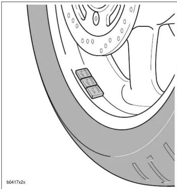
natural_image
Diagram of a car wheel and dashboard with a small block of red blocks on the wheel (no text or symbols)Figure 2-31. Wheel Weights
REMOVAL
- See Figure 2-32. Remove cotter pin (7) and discard.
- Remove clevis pin (2).
- Remove pedal fastener (5).
- Remove shift brake pedal sleeve (4).
- Remove pedal bushings (3).
- Remove brake pedal (6).
INSTALLATION
- See Figure 2-32. Install pedal bushings (3).
- Install shift brake pedal sleeve (4).
- Install brake pedal (6) using LOCTITE 272 and tighten fastener (5) to 22-24 ft-lbs (30-33 Nm).
- Install clevis pin (2).
- Install new cotter pin (7).
b0938x2x

text_image
Labeled diagram of a mechanical assembly with numbered parts for identification- Rear master cylinder body
- Clevis pin
- Pedal bushings (2)
- Shift brake pedal sleeve
- Brake pedal fastener
- Brake pedal
- Cotter pin
Figure 2-32. Brake Pedal Assembly
REMOVAL
NOTE
Steps 1 is not required for removing the master cylinder assembly from the handlebars. Do not disassemble master cylinder unless problems are experienced.
- Drain brake fluid into a suitable container. Discard used fluid according to local laws.
a. Install a length of plastic tubing over caliper bleeder valve. Place free end in a suitable container.
b. Open bleeder valve (metric) about 1/2-turn.
c. Pump brake hand lever to drain brake fluid.
d. Tighten bleeder valve to 36-60 in-lbs (4-7 Nm).
CAUTION
Damaged banjo bolt seating surfaces will leak when reassembled. Prevent damage to seating surfaces by carefully removing brake line components.
- See Figure 2-35. Remove the banjo bolt (12) (metric) and two copper washers (14) to disconnect brake line (13) from master cylinder (4). Discard copper washers.
- Unplug terminal (11) to detach brake lamp switch (10).
NOTE
The individual parts of the brake lamp switch are not serviceable. Replace switch upon failure.
4. Remove mounting clamp fasteners (5) (metric) to detach master cylinder reservoir (4) from handlebar.
DISASSEMBLY
Brake Hand Lever
- See Figure 2-35. Remove pivot bolt nut (8) (metric) and pivot bolt (15) from hand lever pivot.
- Detach front brake hand lever assembly (7) from hand lever pivot.
- Detach front brake lamp switch (10) by removing the switch fastener (9).
Front Master Cylinder
- See Figure 2-35. Remove master cylinder cover (2) by removing cylinder cover fasteners (1).
- Discard excess brake fluid.
- See Figure 2-34. Remove rubber boot (1) and discard.
- See Figure 2-33. Depress piston assembly (1) and remove internal snap ring (2) and discard.
- See Figure 2-35. Remove piston assembly (6) from front master cylinder reservoir (4) and discard.
CLEANING AND INSPECTION
WARNING
Clean brake system components using denatured alcohol. Do not use mineral-base cleaning solvents, such as gasoline or paint thinner. Use of mineral-base solvents causes deterioration of rubber parts that continues after assembly. This may result in improper brake operation which could result in death or serious injury.
- Clean all parts with denatured alcohol or D.O.T. 4 BRAKE FLUID. Do not contaminate with mineral oil or other solvents. Wipe dry with a clean, lint free cloth. Blow out drilled passages and bore with a clean air supply. Do not use a wire or similar instrument to clean drilled passages in bottom of reservoir.
- Inspect piston bore in master cylinder housing for scoring, pitting or corrosion. Replace housing if any of these conditions are found.
- Inspect outlet port that mates with brake line fitting. As a critical sealing surface, replace housing if any scratches, dents or other damage is noted.
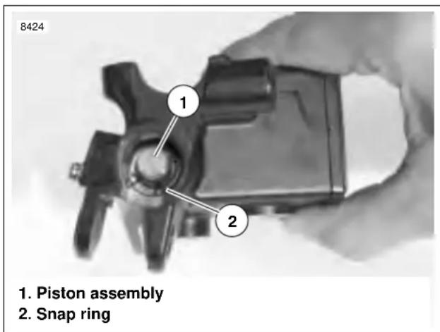
text_image
8424 1. Piston assembly 2. Snap ringFigure 2-33. Piston Assembly in Master Cylinder
Front Master Cylinder
- Obtain PISTON ASSEMBLY KIT.
- See Figure 2-34. Assemble new piston components placing small end of spring (5) behind primary seal of piston (4).
- Lubricate master cylinder body and piston seals with special lubricant found in the service parts kit.
WARNING
When installing snap ring to secure master cylinder, be sure the snap ring snaps into place. Failure to do so can result in improper brake operation which could result in death or serious injury.
- See Figure 2-35. Insert piston assembly (6), spring first, into master cylinder reservoir (4).
- See Figure 2-33. Secure piston assembly (1) with a new snap ring (2).
- See Figure 2-34. Install ridge on boot (1) into groove on piston (3).
Brake Hand Lever
- See Figure 2-35. Lubricate pivot bolt (15) with LOCTITE ANTI-SEIZE.
- Align hole in hand lever (7) with hole in hand lever pivot and install pivot bolt (15) through top of hand lever pivot and tighten to 80-120 in-lbs (9-14 Nm).
b0977x2x
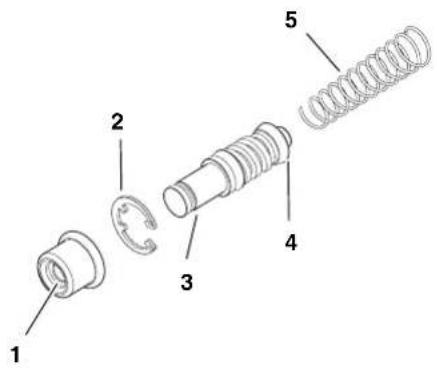
text_image
Exploded view diagram of a mechanical assembly with numbered parts for identification- Ridge on rubber boot
- Snap ring
- Groove on piston
- Primary seal of piston
- Spring
Figure 2-34. Front Master Cylinder Piston Assembly
b0979x2x
- Reservoir cover fasteners
- Reservoir cover
- Reservoir cover gasket
- Master cylinder reservoir
- Master cylinder housing fasteners (metric)
- Piston assembly
- Brake hand lever
- Pivot bolt nut (metric)
- Brake switch fastener
- Brake switch
- Brake switch terminal
- Banjo bolt (metric)
- Brake line
- Copper washers
- Pivot bolt
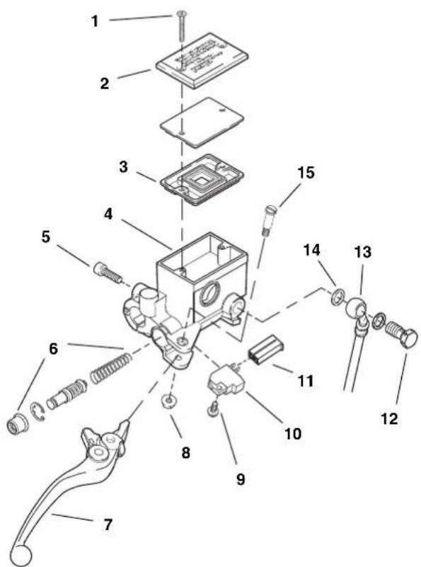
text_image
Exploded view diagram of a mechanical assembly with numbered parts for identificationFigure 2-35. Front Brake Hand Lever Assembly
INSTALLATION
- See Figure 2-35. Install front brake lamp switch (10).
a. Install brake lamp switch (10) with switch fastener (9) and tighten to 7-10 in-lbs (0.8-1.0 Nm).
b. Connect brake switch terminal (11) to brake lamp switch (10).
c. Test switch action. Tang on switch must release when hand lever is moved.
- Install master cylinder to handlebar by fastening clamp with fasteners and tighten to 80-90 in-lbs (9-10 Nm).
WARNING
Use only copper crush banjo washers (See Parts Catalog for Part No.) with D.O.T. 4 brake fluid. Earlier silver banjo washers are not compatible with D.O.T. 4 fluid and will not seal properly over time. Failure to comply may adversely affect braking ability and lead to brake failure which could result in death or serious injury.
WARNING
To avoid leakage, verify that banjo washers, banjo bolt, hydraulic brake line and master cylinder bore are completely clean.
- See Figure 2-35. Connect brake line to master cylinder using two new copper washers (14) and banjo bolt (4) (metric) and tighten to 16-20 ft-lbs (22-27 Nm).
- See Figure 2-36. Verify brake lamp switch wires are tight.
- See Figure 2-35. Remove two master cylinder cover screws (1), cover (2) and cover gasket (3).
- See Figure 2-37. With the master cylinder in a level position, add D.O.T. 4 BRAKE FLUID. Bring fluid level to within 1/8 in. (3.2 mm) of molded boss inside front master cylinder reservoir.
WARNING
Verify proper operation of the master cylinder relief port. A plugged or covered relief port can cause brake drag or lockup, which could result in loss of vehicle control which could result in death or serious injury.
- Verify proper operation of the master cylinder relief port. Actuate the brake lever with the reservoir cover removed. A slight spurt of fluid will break the surface if all internal components are working properly.
- Bleed brake system. See 1.6 BRAKE SYSTEM MAINTENANCE.
- See Figure 2-35. Attach master cylinder cover (2) and cover gasket (3). Tighten two cover fasteners (1) to 9-13 in-lbs (1.0-1.5 Nm).
WARNING
Always test motorcycle brakes at low speed after servicing or bleeding system. To prevent death or serious injury, Buell recommends that all brake repairs be performed by a Buell dealer or other qualified technician.
WARNING
Check for proper brake lamp operation before riding motorcycle. Visibility is a major concern for motorcyclists. Failure to have proper brake lamp operation could result in death or serious injury.
- Turn ignition key switch to ON. Apply brake hand lever to test brake lamp operation. Turn ignition key switch to OFF.
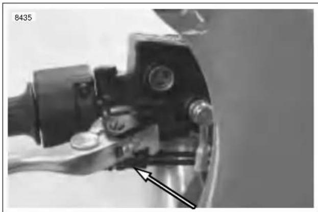
natural_image
Close-up of mechanical components with a black arrow pointing to a component (no visible text or symbols)Figure 2-36. Brake Lamp Switch Connectors
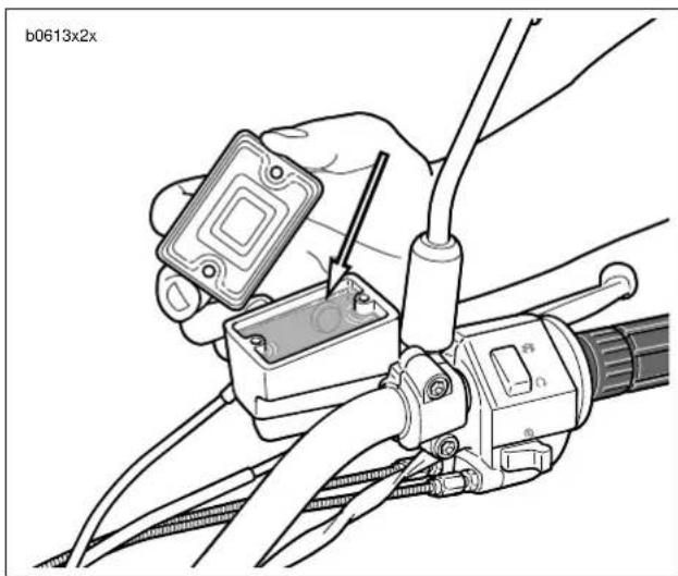
natural_image
Close-up of hands connecting electrical connectors with wires, no visible text or symbolsFigure 2-37. Brake Fluid Level (Standard Brake Reservoir Shown)
REMOVAL
- Drain brake fluid into a suitable container. Discard of used fluid according to local laws.
a. Install a length of plastic tubing over caliper bleeder valve. Place free end in a suitable container.
b. Open bleeder valve (metric) about 1/2-turn.
c. Pump brake hand lever to drain brake fluid.
d. Tighten bleeder valve to 36-60 in-lbs (4-7 Nm).
- See Figure 2-38. Remove p-clamp (1) detaching brake line from right side of lower fork clamp.
CAUTION
Damaged banjo bolt seating surfaces will leak when reassembled. Prevent damage to seating surfaces by carefully removing brake line components.
- See Figure 2-35. Remove master cylinder banjo bolt (12) (metric) and two copper washers (14) to disconnect brake line from master cylinder (4). Discard copper washers.
- See Figure 2-38. Remove caliper banjo bolt (5) (metric), two copper washers and wire form (3) to disconnect brake line (2) from caliper. Discard copper washers.
- Carefully inspect the brake line for dents, cuts, chaffing or other defects. Replace the brake line if any damage is noted.
INSTALLATION
CAUTION
To avoid leakage, verify that gaskets, banjo bolt, hydraulic brake line and master cylinder bore are completely clean.
- See Figure 2-35. Connect brake line (13) to master cylinder (4) using two new copper washers (14) and a banjo bolt (12) (metric). Loosely install bolt into master cylinder.
- Route the brake line from the master cylinder to the caliper. See D.1 HOSE AND WIRE ROUTING for front brake line routing.
WARNING
Use only copper crush banjo washers (See Parts Catalog for Part No.) with D.O.T. 4 brake fluid. Earlier silver banjo washers are not compatible with D.O.T. 4 fluid and will not seal properly over time. Failure to comply may adversely affect braking ability and lead to brake failure which could result in death or serious injury.
CAUTION
To avoid leakage, verify that gaskets, banjo bolt, hydraulic brake line and caliper bore are completely clean.
- Install brake line to caliper.
a. See Figure 2-38. Install new copper washer, brake line (2), new copper washer and wire form (3) onto banjo bolt (5).
b. Finger tighten banjo bolt (5) onto front caliper being careful not to pinch wire form (3) while tightening, wire form should rotate around banjo bolt freely.
c. Twist brake line (2) into wire form (3) spiral and clock wire form against bleeder valve (4).
- Tighten p-clamp with fastener (1) on lower triple clamp to 36-60 in-lbs (4-7 Nm).
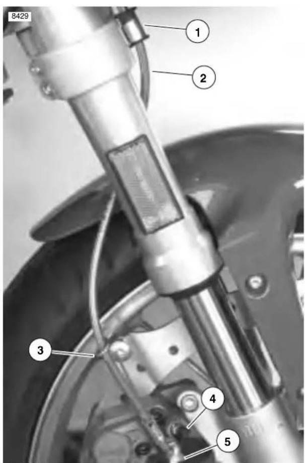
text_image
8429 1 2 3 4 5- P-clamp
- Brake line
- Wire form
- Bleeder valve
- Banjo bolt
Figure 2-38. Front Brake Line
HOME
- See Figure 2-35. Tighten master cylinder banjo bolt (12) (metric) to 16-20 ft-lbs (22-27 Nm).
- See Figure 2-38. Tighten brake caliper banjo bolt (5) (metric) to 16-20 ft-lbs (22-27 Nm).
WARNING
Always test motorcycle brakes at low speed after servicing or bleeding system. To prevent death or serious injury, Buell recommends that all brake repairs be performed by a Buell dealer or other qualified mechanic.
- Install bleeder valve if removed. Refill master cylinder and bleed brakes. See 1.6 BRAKE SYSTEM MAINTENANCE.
WARNING
Check for proper brake lamp operation before riding motorcycle. Visibility is a major concern for motorcyclists. Failure to have proper brake lamp operation could result in death or serious injury.
- Turn ignition key switch to ON. Apply brake hand lever to test brake lamp operation. Turn ignition key switch to LOCK.
REMOVAL
- Drain brake fluid into a suitable container. Discard used fluid according to local laws.
a. Install a length of plastic tubing over caliper bleeder valve. Place free end in a suitable container.
b. Open bleeder valve (metric) about 1/2-turn.
c. Pump brake hand lever to drain brake fluid.
d. Tighten bleeder valve to 36-60 in-lbs (4-7 Nm).
CAUTION
Damaged banjo bolt seating surfaces will leak when reassembled. Prevent damage to seating surfaces by carefully removing brake line components.
- See Figure 2-40. Disconnect brake line at caliper. See 2.11 FRONT BRAKE LINE.
- Remove caliper mounting fasteners (5).
- Slide caliper down the rotor to clear fork lower and then remove off rotor.
DISASSEMBLY
- See Figure 2-41. Remove pin hanger set (1), caliper pad spring (2) and brake pads.
- Split caliper by removing caliper fasteners (3).
- See Figure 2-42. Remove and discard o-rings (6).
- See Figure 2-39. Remove pistons using a BRAKE PISTON REMOVER (Part No. B-42887).
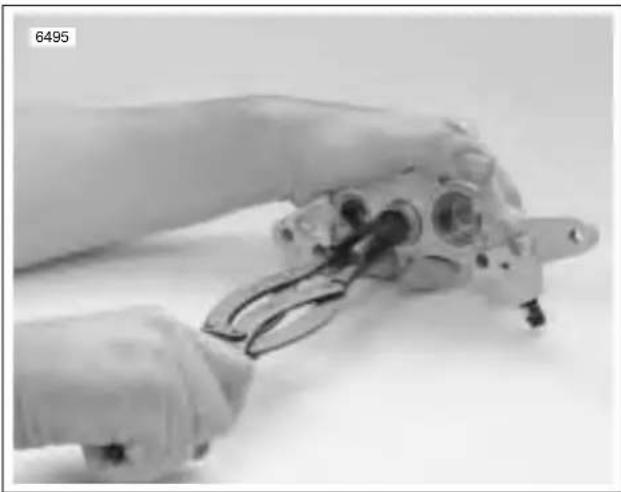
natural_image
Close-up of hands using a mechanical tool to adjust or install a component (no visible text or symbols)Figure 2-39. Removing Pistons (B-42887)
- Remove and discard top and bottom seal.
2-28 2003 Buell XB9R: Chassis
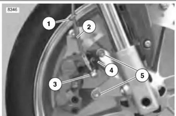
text_image
8346 1 2 3 4 5- Wire form
- Brake line
- Banjo bolt (metric)
- Pin plug
- Mounting fasteners (2)
Figure 2-40. Front Brake Caliper Mounts
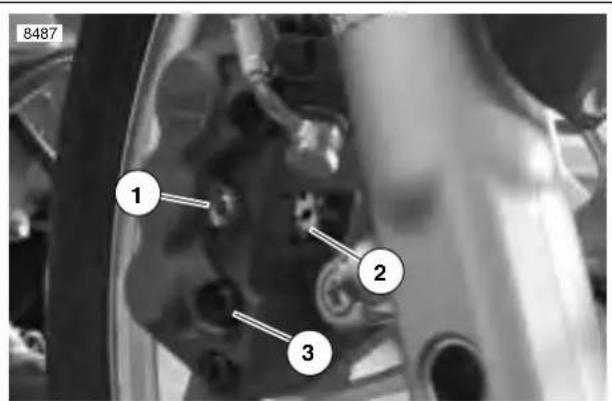
text_image
8487 1 2 3- Pin hanger set
- Caliper pad spring
- Caliper fasteners
Figure 2-41. Pad Spring (Typical)
WARNING
Clean brake system components using denatured alcohol. Do not use mineral-base cleaning solvents, such as gasoline or paint thinner. Use of mineral-base solvents causes deterioration of rubber parts that continues after assembly. This may result in improper brake operation which could result in death or serious injury.
- Clean all parts with denatured alcohol or D.O.T. 4 BRAKE FLUID. Do not contaminate with mineral oil or other solvents. Wipe dry with a clean, lint free cloth. Blow out drilled passages and bore with a clean air supply. Do not use a wire or similar instrument to clean drilled passages.
- Carefully inspect all components. Replace any parts that appear damaged or worn. Do not hone caliper piston bore.
WARNING
Always replace brake pads in complete sets for correct brake operation. Never replace just one brake pad. Failure to install brake pads as a set could result in death or serious injury.
- Inspect brake rotor and pads. See 1.6 BRAKE SYSTEM MAINTENANCE.
- Check rotor surface. Replace if warped or badly scored. See Table2-10.
Table 2-10. Front Rotor Runout
| RUNOUT IN. | MM | |
| Radial | 0.0177 | 0.45 |
| Lateral | 0.0248 | 0.63 |
ASSEMBLY
- See Figure 2-42. Install pistons and o-rings.
a. Lubricate new o-rings (6), pistons (5), and caliper piston bores with D.O.T. 4 BRAKE FLUID.
b. Install two new o-rings (6) in grooves of each piston bore.
c. Install pistons (5) in each piston bore.
-
Install new o-rings (8) between caliper halves.
-
Clamp caliper together with caliper fasteners (11) and tighten to 15-19 ft-lbs (20-26 Nm).
INSTALLATION
- See Figure 2-42. Install brake pads (10).
- Install pin hanger set (1) and tighten to 11-14 ft-lbs (15-19 Nm).
- Rotate front fork counterclockwise and install caliper on caliper mount. Using LOCTITE 272, tighten fasteners (9) to 35-37 ft-lbs (47-50 Nm).
- Rotate front fork/caliper clockwise and slide caliper onto rotor.
WARNING
Use only copper crush banjo washers (See Parts Catalog for Part No.) with D.O.T. 4 brake fluid. Earlier silver banjo washers are not compatible with D.O.T. 4 fluid and will not seal properly over time. Failure to comply may adversely affect braking ability and lead to brake failure which could result in death or serious injury.
- Install brake line to caliper. See 2.11 FRONT BRAKE LINE.
- Bleed front brakes. See BLEEDING BRAKES in 1.6 BRAKE SYSTEM MAINTENANCE.
WARNING
Check for proper brake lamp operation before riding motorcycle. Visibility is a major concern for motorcyclists. Failure to have proper brake lamp operation could result in death or serious injury.
- Turn ignition key switch to ON. Apply brake hand lever to test brake lamp operation.
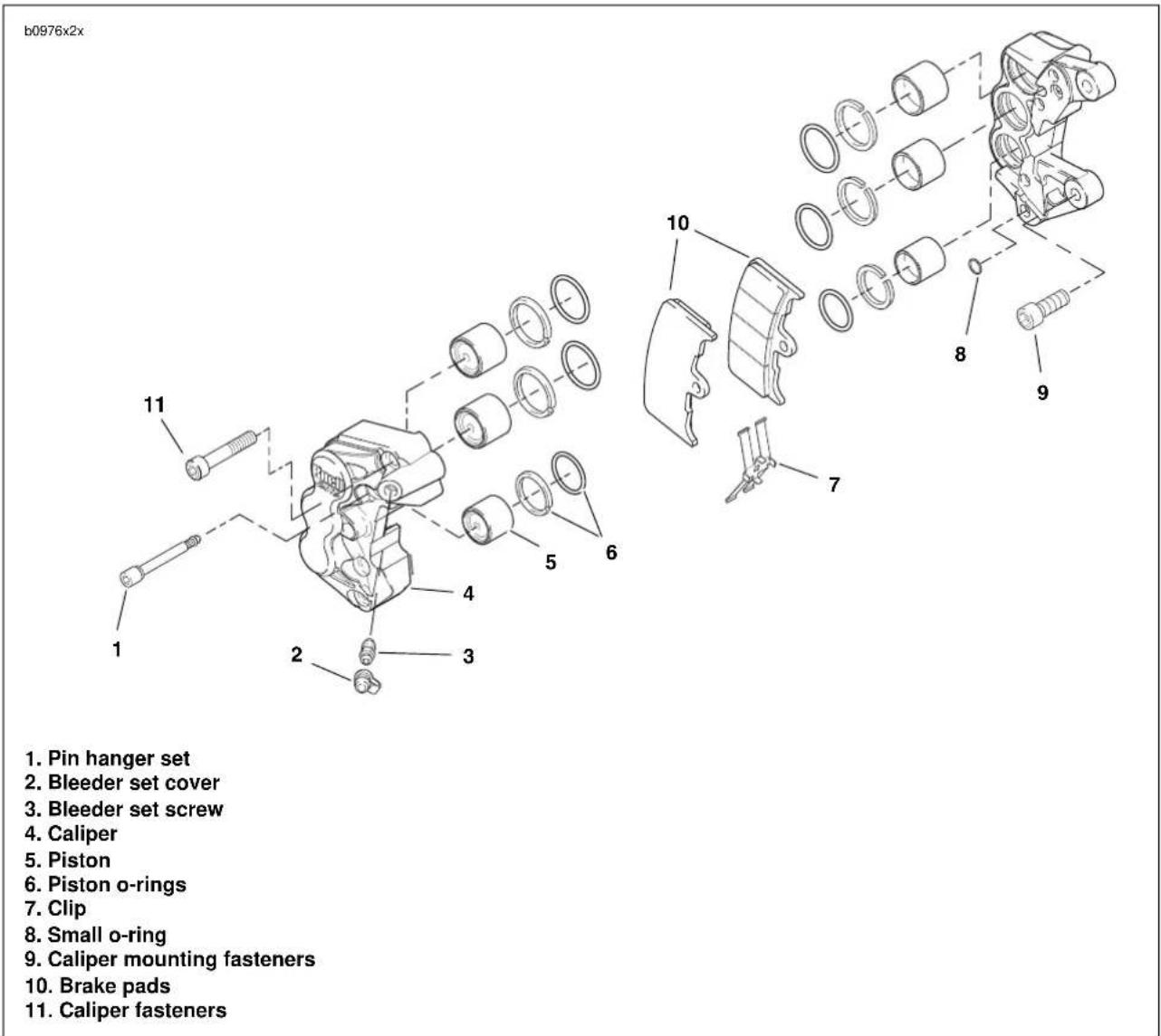
text_image
b0976x2x 1. Pin hanger set 2. Bleeder set cover 3. Bleeder set screw 4. Caliper 5. Piston 6. Piston o-rings 7. Clip 8. Small o-ring 9. Caliper mounting fasteners 10. Brake pads 11. Caliper fastenersFigure 2-42. Front Caliper Assembly
REMOVAL
- Drain brake fluid into a suitable container. Discard used fluid according to local laws.
a. Install a length of plastic tubing over caliper bleeder valve. Place free end in a suitable container.
b. Open bleeder valve (metric) about 1/2-turn.
c. Pump brake foot pedal to drain brake fluid.
d. Tighten bleeder valve to 36-60 in-lbs (4-7 Nm).
- Remove brake pedal. See 2.9 BRAKE PEDAL.
- Remove heel guard. See 2.29 FOOTPEG, HEEL GUARD AND MOUNT.
- See Figure 2-47. Remove brake reservoir hose at master cylinder.
CAUTION
Damaged banjo bolt surfaces will leak when reassembled. Prevent damage to seating surfaces by carefully removing brake line components.
- Remove seat. See 2.38 SEAT.
- See Figure 2-43. Disconnect brake light connector located under the seat.
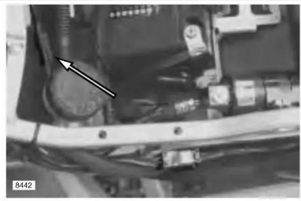
natural_image
Close-up of a car engine compartment with visible wiring and a black arrow pointing to a component (no text or symbols)Figure 2-43. Brake Line Switch Connector
- Remove right side rider footpeg mount. See 2.29 FOOT-PEG, HEEL GUARD AND MOUNT.
- See Figure 2-47. Remove banjo bolt (2) (metric) and two copper crush washers (3) to detach brake switch (1) from master cylinder (4). Discard copper crush washers.
- See Figure 2-44. Remove fasteners (3) (metric) to detach master cylinder (4) from rider footpeg mount.
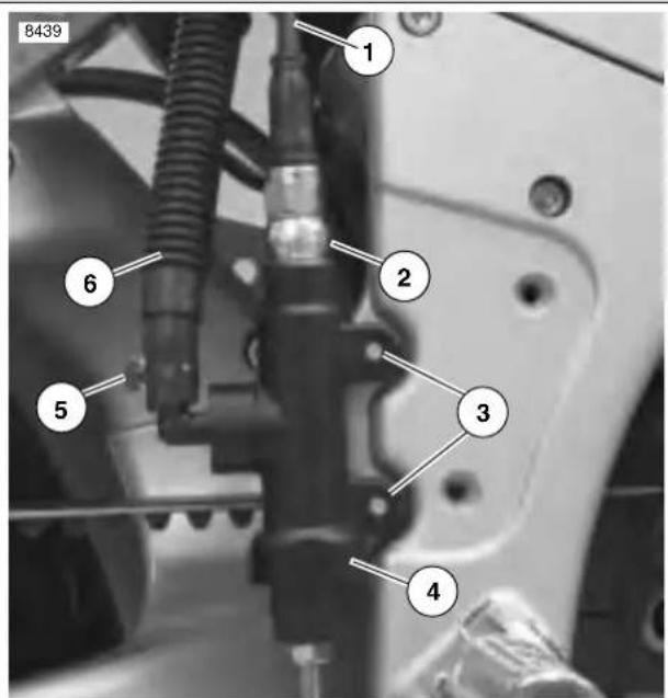
text_image
8439 1 2 3 4 5 6- Brake line
- Banjo bolt (metric)
- Fasteners (2) (metric)
- Master cylinder body
- Clamp
- Remote reservoir hose
Figure 2-44. Rear Master Cylinder Mounting
- See Figure 2-45. Detach remote reservoir.
a. Remove top clamp (4) on hose connected to master cylinder.
b. Remove fastener (2) to detach reservoir (1) from frame if necessary.
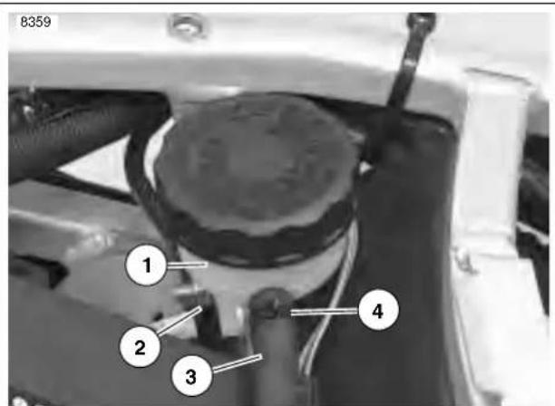
text_image
8359 1 2 3 4- Reservoir
- Fastener and washer
- Remote reservoir hose
- Clamp
Figure 2-45. Remote Reservoir
DISASSEMBLY
- See Figure 2-46. Slide rubber boot on rod assembly (3) away from master cylinder body (1).
- Depress rod assembly (3) and remove internal snap ring (2). Discard snap ring.
- Remove piston assembly (4) from master cylinder body (1).
- Loosen adjuster locknut on the rod assembly (3).
- Remove the clevis from the rod assembly (3).
NOTE
Do not disassemble master cylinder unless problems are experienced. Discard all seals during the disassembly procedure. Install a complete rebuild kit upon assembly.
CLEANING AND INSPECTION
WARNING
Clean brake system components using denatured alcohol. Do not use mineral-base cleaning solvents, such as gasoline or paint thinner. Use of mineral-base solvents causes deterioration of rubber parts that continues after assembly. This may result in improper brake operation which could result in death or serious injury.
- Thoroughly clean master cylinder and all brake system components. Stand master cylinder on wooden block or towel to protect seating surfaces.
a. Examine walls of master cylinder reservoir for scratches and grooves. Replace if damaged.
b. Verify that vent holes on master cylinder are completely open and free of dirt or debris.
- Inspect boot on front of master cylinder for cuts, tears or general deterioration. Replace if necessary.
ASSEMBLY
- Obtain PISTON ASSEMBLY KIT.
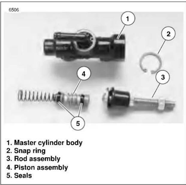
text_image
6506 1. Master cylinder body 2. Snap ring 3. Rod assembly 4. Piston assembly 5. SealsFigure 2-46. Master Cylinder Internal
- See Figure 2-46. Assemble new piston components placing small end of spring behind primary seal of piston (4).
- Lubricate master cylinder body (1) and piston seals (5) with D.O.T. 4 BRAKE FLUID.
- Place round side of rod assembly (3) over piston. Depress piston (4) into master cylinder body (1) and secure with a new snap ring (2).
WARNING
Snap ring must be snapped into the groove of the master cylinder body. If the snap ring is not properly installed, improper brake operation could result in death or serious injury.
- Tuck rubber boot on rod assembly (3) into master cylinder body (1).
INSTALLATION
- See Figure 2-47. Install master cylinder (4) onto footpeg mount with fasteners (11). Tighten to 72-96 in-lbs (8-11 Nm).
- Install rear brake switch (1) and banjo bolt (2) and new copper crush washers (3). Tighten to 16-20 ft-lbs (22-27 Nm).
- Install footpeg mount to frame. See 2.29 FOOTPEG, HEEL GUARD AND MOUNT.
WARNING
Use only copper crush banjo washers (See Parts Catalog for Part No.) with D.O.T. 4 brake fluid. Earlier silver banjo washers are not compatible with D.O.T. 4 fluid and will not seal properly over time. Failure to comply may adversely affect braking ability and lead to brake failure which could result in death or serious injury.
CAUTION
To avoid leakage after assembly, verify that banjo washers, banjo bolt, hydraulic brake line and bore of master cylinder are completely clean.
- See Figure 2-45. Connect remote reservoir.
a. If removed, attach remote reservoir (1) to frame using clamp fastener (2). Tighten to 48-72 in-lbs (5.4-8.1 Nm).
b. Attach hose (3) to rear brake reservoir using clamp.
- See Figure 2-43. Connect brake line switch connector under seat.
- Install heel guard. See 2.29 FOOTPEG, HEEL GUARD AND MOUNT.
- Install rear brake pedal. See 2.9 BRAKE PEDAL.
- Adjust rear brake pedal. See BRAKE PEDAL ADJUSTMENT in 1.6 BRAKE SYSTEM MAINTENANCE.
- Install master cylinder to brake pedal. See 2.9 BRAKE PEDAL.
WARNING
Always test motorcycle brakes at low speed after servicing or bleeding system. To prevent death or serious injury, Buell recommends that all brake repairs be performed by a Buell dealer or other qualified mechanic.
- Add brake fluid and bleed brake system. See 1.6 BRAKE SYSTEM MAINTENANCE.
WARNING
Check for proper brake lamp operation before riding motorcycle. Visibility is a major concern for motorcyclists. Failure to have proper brake lamp operation could result in death or serious injury.
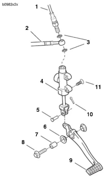
text_image
b0983x2x 1 2 3 4 5 6 7 8 9 10 11- Switch/Banjo bolt
- Brake line
- Copper washer
- Rear master cylinder body
- Clevis pin
- Pedal bearing
- Sleeve
- Brake pedal fastener
- Brake pedal
- Cotter pin
- Rear master cylinder mount screw
Figure 2-47. Rear Master Cylinder Assembly
REMOVAL
- Remove seat. See 2.38 SEAT.
WARNING
To protect against accidental start-up of vehicle and possible personal injury, disconnect the negative battery cable before proceeding. Inadequate safety precautions could cause a battery explosion, which could result in death or serious injury.
- Disconnect battery by unthreading fastener removing negative cable (black) from battery first. See 1.4 BATTERY MAINTENANCE.
- See Figure 2-48. Disconnect brake line connector from under seat in the front of the battery.
- Remove right side heel guard. See 2.29 FOOTPEG, HEEL GUARD AND MOUNT.
- Drain brake fluid into a suitable container. Discard used fluid according to local laws.
a. Install a length of plastic tubing over caliper bleeder valve. Place free end in a suitable container.
b. Open bleeder valve (metric) about 1/2-turn.
c. Pump brake foot pedal to drain brake fluid.
d. Tighten bleeder valve to 36-60 in-lbs (4-7 Nm).
- See Figure 2-49. Remove p-clamp (3) and wire form (2) securing brake line (1) to the left side of swingarm.
CAUTION
Damaged banjo bolt seating surfaces will leak when reassembled. Prevent damage to seating surfaces by carefully removing brake line components.
- Remove banjo bolt (4) from rear caliper. Discard copper washers.
- See Figure 2-50. Remove brake line switch/banjo bolt from rear master cylinder. Discard copper washer.
- Remove brake line from motorcycle.
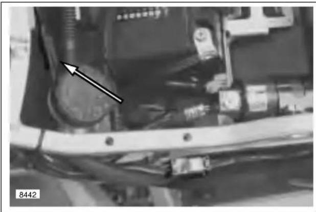
natural_image
Close-up of a car engine compartment with visible wiring and a black arrow pointing to a component (no text or symbols)Figure 2-48. Brake Line Switch Connector
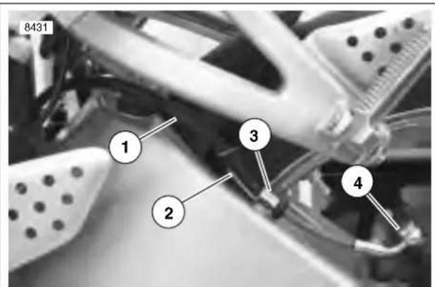
text_image
8431 1 2 3 4- Brake line
- Wire form
- P-clamp
- Banjo bolt
Figure 2-49. Rear Brake Line
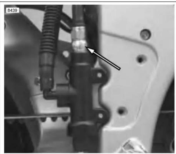
natural_image
Close-up of mechanical components with a black arrow pointing to a component, no visible text or symbolsFigure 2-50. Rear Brake Line Switch/Banjo Bolt
INSTALLATION
- See Figure 2-50. Install brake line switch/banjo bolt with new copper washers to the master cylinder. Tighten to 16-20 ft-lbs (22-27 Nm).
NOTE
Tighten the right side banjo bolt with FLARE NUT SOCKET tool (SNAP-ON Part No. FRXM14) or a crowsfoot.
WARNING
Use only copper crush banjo washers (See Parts Catalog for Part No.) with D.O.T. 4 brake fluid. Earlier silver banjo washers are not compatible with D.O.T. 4 fluid and will not seal properly over time. Failure to comply may adversely affect braking ability and lead to brake failure which could result in death or serious injury.
- Install brake line switch/banjo bolt and new copper washers to rear caliper. Tighten to 16-20 ft-lbs (22-27 Nm).
- See Figure 2-49. Secure brake line (1) to left side of swingarm with p-clamp (3), wire form (2), and tighten to 36-60 in-lbs (4-7 Nm). See D.1 HOSE AND WIRE ROUTING for brake line routing.
- See Figure 2-51. Connect brake line switch connector underneath seat. See D.1 HOSE AND WIRE ROUTING for brake line routing.
- Install right heel guard. See 2.29 FOOTPEG, HEEL GUARD AND MOUNT.
- Bleed brakes. See BLEEDING BRAKES in 1.6 BRAKE SYSTEM MAINTENANCE.
WARNING
Always connect the positive battery cable first. If the positive cable should contact ground with the negative cable installed, the resulting sparks may cause a battery explosion which could result in death or serious injury.
-
Install battery by threading positive cable (red) into threaded hole first tightening to 72-96 in-lbs (8-11 Nm). See 1.4 BATTERY MAINTENANCE.
-
Install seat. See 2.38 SEAT.
WARNING
Check for proper brake lamp operation before riding motorcycle. Visibility is a major concern for motorcyclists. Failure to have proper brake lamp operation could result in death or serious injury.
- Turn ignition key ON, depress rear brake pedal and check for proper brake light operation.
WARNING
After completing repairs or bleeding the system, always test motorcycle brakes at low speed. If brakes are not operating properly or braking efficiency is poor, testing at high speeds could result in death or serious injury.
- Test ride motorcycle and check for proper brake operation.
REMOVAL
NOTE
Steps 1 and 2 are not required for detaching caliper from rotor. Drain fluid only when disassembling caliper.
CAUTION
Damaged banjo bolt seating surfaces will leak when reassembled. Prevent damage to seating surfaces by carefully removing brake line components.
- Drain brake fluid into a suitable container. Discard used fluid according to local laws.
a. Install a length of plastic tubing over caliper bleeder valve. Place free end in a suitable container.
b. Open bleeder valve (metric) about 1/2-turn.
c. Pump brake foot pedal to drain brake fluid.
d. Tighten bleeder valve to 36-60 in-lbs (4-7 Nm).
- Remove banjo bolt connecting brake line to rear caliper. See 2.14 REAR BRAKE LINE.
- See Figure 2-51. Remove caliper mounting fasteners (6 and 7).
DISASSEMBLY
- See Figure 2-51. Remove pin plug (5) and pad hanger (metric) to free brake pads.
- See Figure 2-53. Remove spring clip (1).
- See Figure 2-54. Remove piston (3) using BRAKE CALI-PER PISTON REMOVER (1) (Part No. B-42887) with adaptor (2).
- Remove two o-rings from groove in caliper bore and discard.
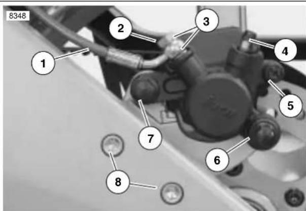
text_image
8348 1 2 3 4 5 6 7 8- Brake line
- Banjo bolt (metric)
- Copper washers (2)
- Bleeder valve (metric)
- Pin plug
- Small caliper fastener
- Larger caliper fastener
- Caliper mounting fasteners
Figure 2-51. Rear Brake Caliper
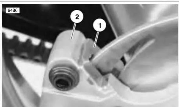
text_image
6486 2 1- Clip
- Rear caliper mount
Figure 2-52. Caliper Mount Clip
CLEANING AND INSPECTION
WARNING
Clean brake system components using denatured alcohol. Do not use mineral-base cleaning solvents, such as gasoline or paint thinner. Use of mineral-base solvents causes deterioration of rubber parts that continues after assembly. This may result in improper brake operation which could result in death or serious injury.
- Clean all parts with denatured alcohol or D.O.T. 4 BRAKE FLUID. Do not contaminate with mineral oil or other solvents. Wipe dry with a clean, lint free cloth. Blow out drilled passages and bore with a clean air supply. Do not use a wire or similar instrument to clean drilled passages.
- Carefully inspect all components. Replace any parts that appear damaged or worn. Do not hone caliper piston bore.
- Inspect brake rotor.
a. Measure rotor thickness. Replace if minimum thickness is less than 0.18 in. (4.5 mm).
b. Check rotor surface. Replace if warped or badly scored. See Table2-11.
WARNING
Always replace brake pads in complete sets for correct brake operation. Never replace just one brake pad. Failure to install brake pads as a set could result in death or serious injury.
- Inspect brake pads for damage or excessive wear. Replace both pads as a set if the friction material of either pad is worn to 0.04 in. (1.0 mm) or less.
ASSEMBLY
- See Figure 2-53. Place clip (1) inside caliper body as shown.
NOTE
To ensure proper brake pad-to-brake rotor clearance when the caliper is installed, piston must be pressed all the way into the bore whenever new brake pads are used.
- Install pistons and o-rings.
a. Apply a light coat of D.O.T. 4 BRAKE FLUID to o-rings, piston and caliper piston bore.
b. Place two new o-rings inside grooves of piston bore.
c. Install piston inside caliper body.
- See Figure 2-53. Install brake pads (3) using pad hanger and pin plug (2).
a. Install pad hanger pin (metric). Tighten to 11-14 ft-lbs (15-19 Nm).
b. Install pin plug. Tighten to 22-26 in-lbs (2-3 Nm).
- Install a new bleeder valve (metric) if necessary and tighten to 36-60 in-lbs (4-7 Nm).
6487

text_image
Technical diagram of a mechanical component with numbered parts labeled 1, 2, and 3- Clip
- Pin plug and pad hanger (metric)
- Brake pads (2)
Figure 2-53. Brake Pads
6496
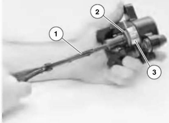
text_image
Labeled diagram of a mechanical device with numbered parts 1, 2, and 3 indicating parts of the tool.- Brake caliper piston remover
- Adaptor
- Piston
Figure 2-54. Removing Rear Brake Caliper Piston
Table 2-11. Rear Rotor Runout
| RUNOUT | IN. | MM |
| Radial | 0.0177 | 0.45 |
| Lateral | 0.0154 | 0.39 |
INSTALLATION
- See Figure 2-52. Install caliper mount clip (1) if removed.
- See Figure 2-51. Install caliper assembly on caliper mount. Brake pad surfaces must face rear brake rotor.
a. Install large caliper screw (7) (metric) tightening to 18-21 ft-lbs (24-28 Nm).
b. Install small caliper screw (6) (metric) tightening to 14-18 ft-lbs (19-24 Nm).
c. Install caliper carrier onto swingarm tightening caliper carrier fasteners (8) to 24-26 ft-lbs (33-35 Nm).
WARNING
Use only copper crush banjo washers (See Parts Catalog for Part No.) with D.O.T. 4 brake fluid. Earlier silver banjo washers are not compatible with D.O.T. 4 fluid and will not seal properly over time. Failure to comply may adversely affect braking ability and lead to brake failure which could result in death or serious injury.
CAUTION
To avoid leakage, verify that gaskets, banjo bolt, hydraulic brake line and caliper bore are completely clean.
- See Figure 2-51. Connect brake line (1) to caliper using two new copper washers (3) and banjo bolt (2) (metric). Tighten to 16-20 ft-lbs (22-27).
- Depress rear brake pedal several times to set brake pads to proper position within caliper. Bleed brake system.
- Verify proper fluid level in reservoir.
WARNING
Always test motorcycle brakes at low speed after servicing or bleeding system. To prevent death or serious injury, Buell recommends that all brake repairs be performed by a Buell dealer or other qualified mechanic.
- Turn ignition key switch to ON. Apply brake pedal to test brake lamp operation. Turn ignition key switch to LOCK.
WARNING
Check for proper brake lamp operation before riding motorcycle. Visibility is a major concern for motorcyclists. Failure to have proper brake lamp operation could result in death or serious injury.
NOTE
Avoid making hard stops for the first 100 miles (160 km) to allow new brake pads to "wear in" properly with the brake rotor.
2-38 2003 Buell XB9R: Chassis
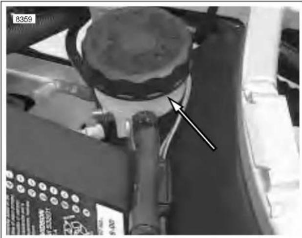
natural_image
Close-up of a mechanical component with a circular feature and an arrow pointing to a detail (no visible text or symbols)Figure 2-55. Rear Reservoir
GENERAL
The front fork consists of two telescoping outer tube/inner slider assemblies. Each assembly has an internal compression spring which supports the forward weight of the vehicle and rider. The compression spring extends and retracts to cushion the ride over rough or irregular road surfaces. An oil filled damping mechanism controls the telescoping action of each tube/slider assembly.
See 1.11 SUSPENSION DAMPING ADJUSTMENTS for more information.
REMOVAL
- Remove front fender. See 2.31 FENDERS.
- Remove front wheel. See 2.5 FRONT WHEEL.
- Remove caliper mounting fasteners. See 2.12 FRONT BRAKE CALIPER.
- See Figure 2-56. Loosen upper and lower fork clamp pinch fasteners.
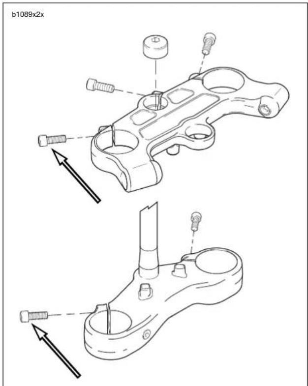
text_image
b1089x2xFigure 2-56. Upper and Lower Fork Clamp Pinch Fasteners
- See Figure 2-57. Remove fork from upper fork clamp and slide the stopper ring up and over the top of the fork.
- See Figure 2-69. Remove fork from lower fork clamp (8).
- Repeat 4 through 6 on opposite side.
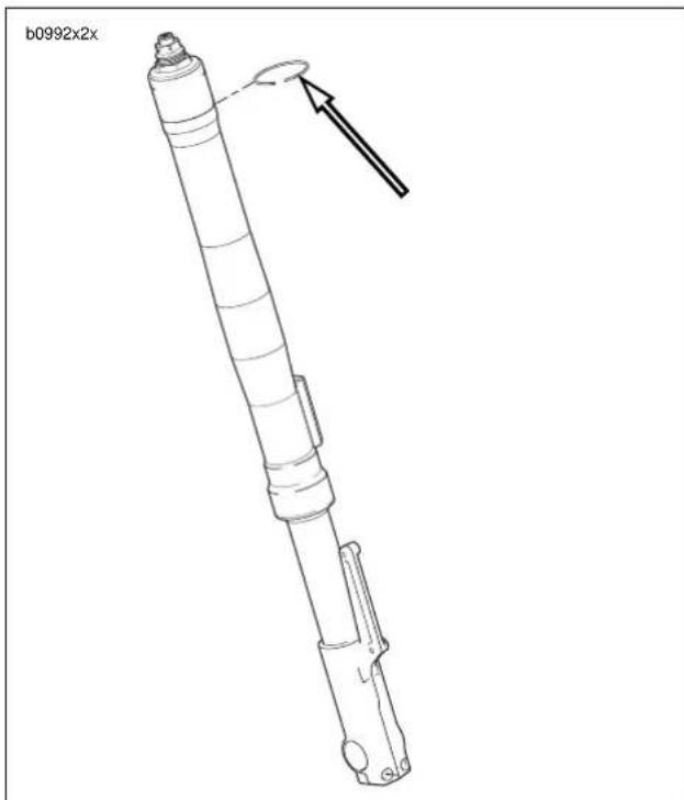
text_image
b0992x2xFigure 2-57. Stopper Ring
DISASSEMBLY
NOTE
Record rider suspension settings before disassembly.
- Remove front fork. See REMOVAL in 2.16 FRONT FORK.
- See Figure 2-58. Clamp the FORK TUBE HOLDER TOOL (Part No. HD-41177) in a vise and install the upper front fork in the holding tool.
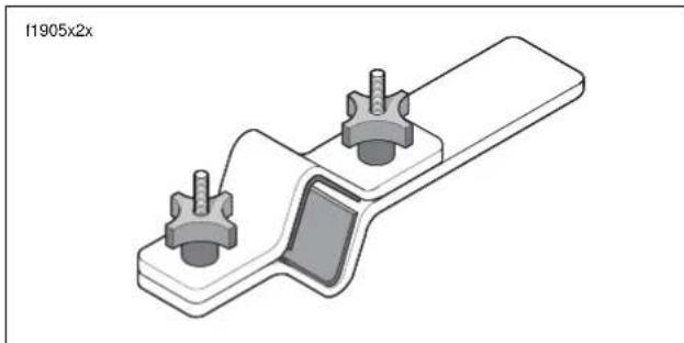
natural_image
Isometric technical drawing of a mechanical clamp or bracket component (no text or symbols)Figure 2-58. Fork Tube Holder (HD-41177)
- See Figure 2-59. Remove snap ring (2).
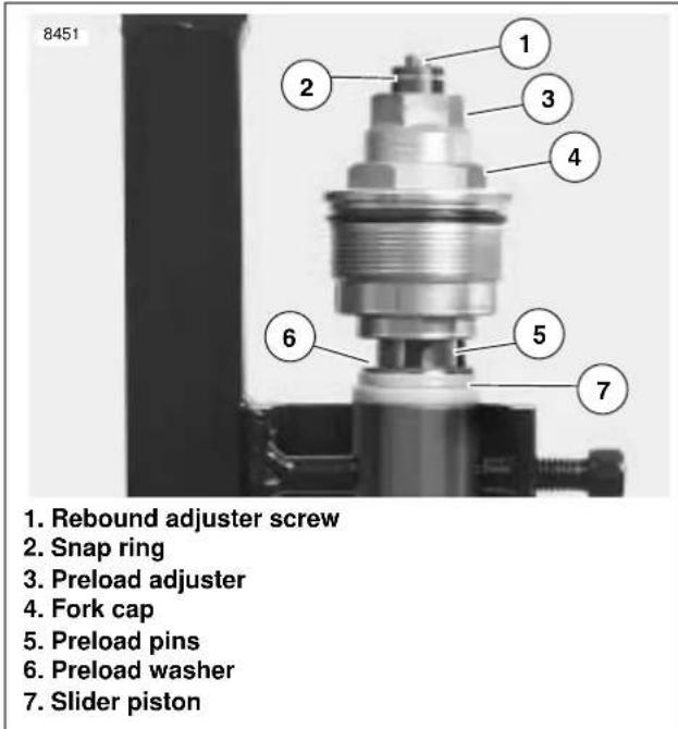
text_image
8451 1. Rebound adjuster screw 2. Snap ring 3. Preload adjuster 4. Fork cap 5. Preload pins 6. Preload washer 7. Slider pistonFigure 2-59. Fork Cap Assembly
- Remove preload adjuster (3) by turning counterclockwise.
NOTE
After fully unthreading preload adjuster (3), gently pull on adjuster.
- Remove fork cap (4) from outer tube.
- See Figure 2-60. Move the fork assembly from the holding tool and compress fork in the FORK SPRING COMPRESSION TOOL.
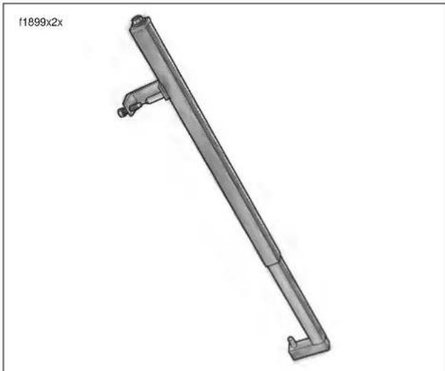
natural_image
3D rendered mechanical component with a long rod and flange (no text or symbols visible)Figure 2-60. Fork Spring Compressing Tool
- See Figure 2-61. Hold damper rod assembly (3) and remove fork cap (1).
NOTE
See Figure 2-61. Careful not to damage preload pins (2) while holding damper rod assembly (3).
- Remove preload washer (4) and slider piston (5).
2-40 2003 Buell XB9R: Chassis
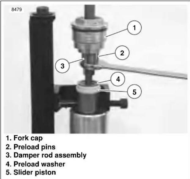
text_image
8479 1. 2. 3. 4. 5. 1. Fork cap 2. Preload pins 3. Damper rod assembly 4. Preload washer 5. Slider pistonFigure 2-61. Holding Damper Rod Assembly
- See Figure 2-60. Uncompress fork and remove from FORK SPRING COMPRESSION TOOL.
- See Figure 2-67. Over drain pan, remove spring (16), spring collar (15), and drain fork oil.
- Drain remaining fork oil by pumping the damping rod (11) approximately 8 to 10 times or until damping rod moves freely.
- Clamp fork upside down in the FORK TUBE HOLDER TOOL over drain pan allowing fork oil to drain.
- Remove center bolt (14) to release damping rod assembly (11).
NOTE
Be careful not to drop damping rod assembly into oil pan when removing center bolt.
14. Remove centering plate (12) from dampening rod (11).
WARNING
Be careful not to scratch the slide pipe or the outer tube. Improperly operating forks may lead to a loss of control which could result in death or serious injury.
- Remove dust seal (26) to access oil seal stopper ring (25).
- Release the oil seal stopper ring (25) out from the outer tube with a small pry tool.
- Using a slide hammer action, remove the slide pipe (27) from the outer tube (18).
- Remove the slide bushing (21) from slide pipe by prying the slide bushing at the split.
NOTE
Careful not to over expand slide bushing.
19. Remove guide bushing (22), seal spacer (23), oil seal (24), stopper ring (19) and dust seal (26).
HOME
Damper Rod Disassembly
IMPORTANT NOTES
See Figure 2-67. Disassembly of damper rod is not required unless damper locknut (10) has been moved. If damper rod needs servicing refer to the Firebolt Parts Catalog (Part No. 99574-03Y) for kit information.
If damper locknut has been moved, proceed with the following disassembly and assembly procedures for setting the correct range of motion.
- See Figure 2-59. Lightly turn the rebound adjuster screw (1) counter clockwise till it stops.
- See Figure 2-67. Holding the damper locknut (10), unscrew the rebound adjuster assembly (9) and remove from damper rod assembly (11).
- Remove damper locknut (10) from damper rod assembly (11).
CLEANING AND INSPECTION
- Thoroughly clean and inspect all parts. Replace any parts that are bent, broken or damaged.
- See Figure 2-67. Check the slide pipe (27) and outer tube (18) for score marks, scratches and excessive or abnormal wear. Replace if worn or damaged.
- Check the slide bushing (21) and the guide bushing (22) for excessive wear or scratches. Replace if damaged or worn.
- Replace the stopper ring (19) if distorted.
- Measure spring (16) free length. Replace springs shorter than service wear limit of 9.13 in. (232 mm).
- See Figure 2-62. Measure slide pipe runout. Replace pipe if runout exceeds the service wear limit of 0.008 in. (0.2 mm).
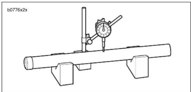
text_image
b0776x2xFigure 2-62. Pipe Runout
ASSEMBLY
Damper Rod Assembly
Note
Skip to fork assembly if damper rod assembly was not disassembled.
- See Figure 2-67. Fully thread the damper rod locknut (10) on to damper rod (11) clockwise till it lightly bottoms.
NOTE
Set both forks to the exact same suspension settings.
- Adjust rebound assembly for proper range of motion.
a. Lightly turn the rebound adjuster screw (9) counter clockwise till it stops.
b. Turn the rebound adjuster screw three full turns clockwise.
- Fully thread rebound adjuster assembly (9) onto the damper rod assembly (11) until it lightly bottoms. Do not tighten.
- Thread the damper locknut (10) until bottoms lightly on the rebound adjuster assembly. Do not tighten
- Turning the rebound adjuster screw (9) counter clockwise three full turns or until stops.
- Tighten the damper locknut (10) to 22-30 ft-lbs (30-40 Nm).
- Repeat for other fork assembly.
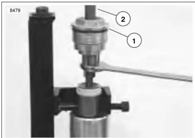
text_image
8479 2 1- Fork cap assembly
- Rebound assembly
Figure 2-63. Rebound Assembly and Fork Cap Assembly
Fork Assembly
- See Figure 2-67. Wrap the end of the slide pipe (27) and the slide bushing channel with tape to avoid damaging the oil seal lip when installing.
- Install a new dust seal (26) and stopper ring (19) onto the slide pipe (27).
- Coat the sealing lips of the new oil seal (24) with fork oil or sealing grease and install onto the slide pipe with its marked side facing the dust seal (26).
- Remove the tape from the slide pipe end.
- Install the seal spacer (23), the guide bushing (22) and the slide bushing (21) onto the slide pipe (27).
- Coat the slide bushing (21) and the guide bushing (22) with fork oil.
CAUTION
The outer tube can move freely up and down on the slide pipe. Always hold both the slide pipe and outer tube to prevent damage to bushings and seals.
-
See Figure 2-67. Drive the guide bushing (22) with the seal spacer (23) and oil seal (24) into position in the outer tube using a FORK SEAL DRIVER (Part No. B-43721). See Figure 2-64.
-
Install the oil seal stopper ring (25) and a new dust seal (26).
HOME
- Place the fork in the FORK TUBE HOLDER TOOL (Part No. HD-41177) and clamp into vise horizontally.
- See Figure 2-67. Install the centering plate (12) onto the damper assembly (11) and insert the damper assembly into the slide pipe (27).
- Replace the sealing washer (13) and center bolt (14) (metric). Tighten the center bolt to 22-30 ft-lbs (30-40 Nm).
- Remove the front fork from the FORK TUBE HOLDER TOOL and install back in the FORK TUBE HOLDER TOOL vertically.
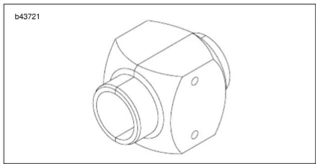
natural_image
Technical line drawing of a mechanical component with no visible text or symbolsFigure 2-64. Fork Seal Driver
NOTES
The recommended fork oil is hydraulic fork oil Type "E".
Use only TYPE E FORK OIL (Part No. HD-99884-80).
- Pour 7 oz. (204 cc) into the fork pipe.
- Pump the damper rod approximately 12 to 15 times or until resistance is felt.
- Place the damper rod in the fully bottomed position and compress fork completely.
- Pour 7 oz. (204 cc) more fork oil into the slide pipe.
- See Figure 2-65. Adjust fork oil level with FRONT FORK OIL LEVEL GAUGE (Part No. B-59000A) so that it is 4.6 in. (118 mm) from the top of the fork tube.
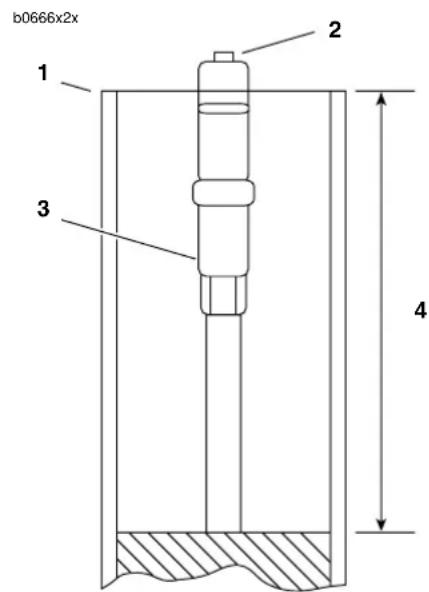
text_image
b0666x2x 1 2 3 4- Outer tube
- Adjuster
- Damper assembly
- Fork oil level
Figure 2-65. Measuring Fork Oil Level
- See Figure 2-67. Install spring (16) and collar (15).
- Move fork assembly from holding tool to the FORK SPRING COMPRESSION TOOL.
- See Figure 2-61. Install preload washer (4) and slider piston (5).
- Hold damper rod assembly (3) and install fork cap (1) from damper rod assembly (3) tightening to 22-30 ft-lbs (30-40 Nm).
NOTE
See Figure 2-61. Careful not to damage preload pins (2) while holding damper rod assembly (3),
- Apply fork oil or light grease to o-rings on preload adjuster and install preload adjuster (3).
- Install snap ring (2).
HOME
INSTALLATION
- See Figure 2-57. Install one front fork assembly into lower fork clamp.
- Slide the stopper ring over top of fork assembly and into groove.
WARNING
Carefully install the fork into the upper fork clamp. Forcing the fork into the upper fork clamp could move the stopper ring out of the groove which will not allow the correct upper fork clamp load resulting in possible loss of control of the motorcycle and could result in death or serious injury.
- Install fork assembly into upper fork clamp.
WARNING
Both forks should display the same number of alignment lines. Forks that are not properly aligned may lead to a loss of control which could result in death or serious injury.
- See Figure 2-66. Position fork with alignment lines (4) visible and reflector facing to the side and tighten the lower fork clamp. Do not tighten.
- Repeat step 1 through 4 on second front fork.
- Temporarily install front axle to the fork assemblies to verify correct alignment.
- Use LOCTITE 272 on upper fork clamp fasteners and tighten to 17-19 ft-lbs (23-26 Nm).
- Use LOCTITE 272 on lower fork clamp fasteners and tighten to 13-15 ft-lbs (18-20 Nm).
- Repeat torque sequence in steps 7 and 8.
- Install front brake caliper onto caliper mount. See 2.12 FRONT BRAKE CALIPER.
- Install front wheel. See 2.5 FRONT WHEEL.
- Install front fender. See 2.31 FENDERS.
- Check headlamp alignment. See 1.18 HEADLIGHTS.
- Adjust front forks suspension to rider preferences. See 1.11 SUSPENSION DAMPING ADJUSTMENTS.
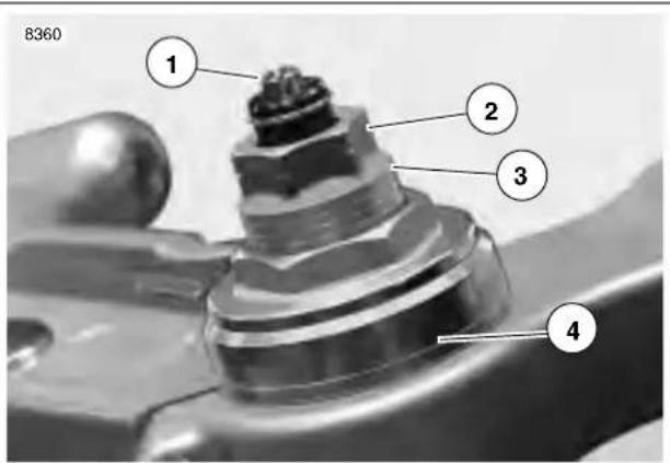
text_image
8360 1 2 3 4- Rebound adjuster screw
- Preload adjuster nut
- Four preload alignment lines visible (factory setting)
- Alignment lines
Figure 2-66. Front Fork Preload And Rebound Adjuster
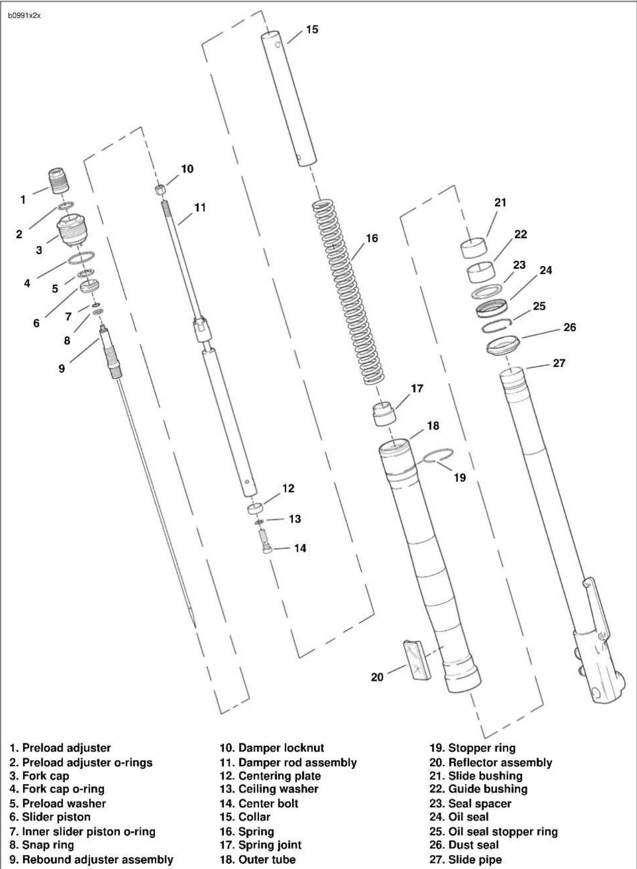
text_image
b0991x2x 1. Preload adjuster 2. Preload adjuster o-rings 3. Fork cap 4. Fork cap o-ring 5. Preload washer 6. Slider piston 7. Inner slider piston o-ring 8. Snap ring 9. Rebound adjuster assembly 10. Damper locknut 11. Damper rod assembly 12. Centering plate 13. Ceiling washer 14. Center bolt 15. Collar 16. Spring 17. Spring joint 18. Outer tube 19. Stopper ring 20. Reflector assembly 21. Slide bushing 22. Guide bushing 23. Seal spacer 24. Oil seal 25. Oil seal stopper ring 26. Dust seal 27. Slide pipeFigure 2-67. Front Fork Assembly
REMOVAL
- Remove front fork assemblies. See 2.16 FRONT FORK.
- Remove handlebars. See 2.27 HANDLEBARS.
- See Figure 2-68. Remove cable straps attached to the upper fork clamp.
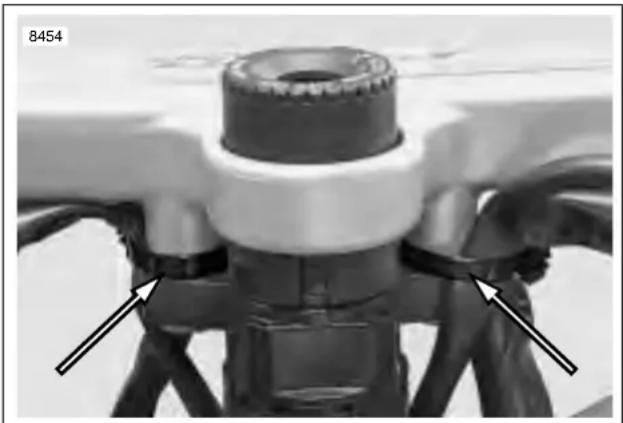
natural_image
Close-up of a mechanical component with no visible text or symbols, marked with arrows pointing to features (no readable text or symbols)Figure 2-68. Cable Straps On Upper Fork Clamp
- Remove intake cover. assembly. See 2.34 INTAKE COVER ASSEMBLY.
- See Figure 2-69. Remove steering stem pinch fastener (2).
- Under right side of front fairing, cut cable strap holding ignition switch, fuse block and right handlebar switch wires. See 7.3 IGNITION/HEADLIGHT KEY SWITCH.
- Unplug the ignition switch. See 7.3 IGNITION/HEAD-LIGHT KEY SWITCH.
- See Figure 2-69. Hold or brace the lower fork clamp and remove steering stem cap (1).
- Remove the upper fork clamp (4).
- Remove the lower fork clamp (8).
- Remove ignition switch. See 7.3 IGNITION/HEADLIGHT KEY SWITCH.
- If steering head bearings need replacing, see 2.18 STEERING HEAD BEARINGS.
INSTALLATION
- See Figure 2-69. Install the lower fork clamp (8) into the steering stem bore and install the upper fork clamp (4).
- Install steering stem cap (1). Tighten but do not torque.
WARNING
Carefully install the fork into the upper fork clamp. Forcing the fork into the upper fork clamp could move the stopper ring out of the groove which will not allow the correct clamp load causing a possible loss of control of the motorcycle which could result in death or serious injury.
- Install one front fork assembly into lower fork clamp (8).
- See Figure 2-67. Slide the stopper ring (19) over top of fork assembly and into groove.
- Install upper clamp on fork assembly. Tighten but do not torque lower fork clamp pinch fasteners.
- Repeat previous two steps on second fork assembly.
- Tighten steering stem cap to 38-42 ft-lbs (52-57 Nm).
- Install steering stem pinch bolt applying LOCTITE 272 and tightening to 17-19 ft-lbs (23-26 Nm).
WARNING
Both forks should display the same number of alignment lines. Forks that are not properly aligned may lead to a loss of control which could result in death or serious injury.
- See Figure 2-66. Position both forks with same number alignment lines (4) visible and reflectors facing to the sides. Do not tighten.
- Use LOCTITE 272 on upper fork clamp fasteners and tighten to 17-19 ft-lbs (23-26 Nm).
- Use LOCTITE 272 on lower fork clamp fasteners and tighten to 13-15 ft-lbs (18-20 Nm).
- Repeat torque sequence in steps 10 and 11.
- Install intake cover assembly. See 2.34 INTAKE COVER ASSEMBLY.
-
Install handlebars. See 2.27 HANDLEBARS.
-
See Figure 2-68. Install cable straps.
a. Install cable strap to the right of ignition switch securing right hand switch and brake line wires to upper fork clamp.
b. Install cable strap to the left of ignition switch securing left hand switch and clutch cable wires to upper fork clamp.
b0937x2x
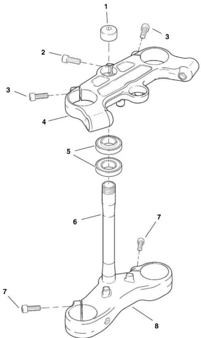
text_image
Technical diagram of a mechanical assembly with numbered parts for identification-
Stem capnut
-
Stem pinch fastener
-
Upper fork clamp pinch fastener
-
Upper fork clamp
-
Head bearing
-
Stem
-
Lower fork clamp pinch fastener
-
Lower fork clamp
Figure 2-69. Steering Stem Assembly
REMOVAL
- Place a scissor jack under jacking point and raise front wheel off ground. For location of jacking point see Figure 2-98.
- Remove brake lever housing. See 2.10 FRONT BRAKE MASTER CYLINDER AND HAND LEVER.
- Remove front forks, lower fork clamp, brake and wheel as front-end assembly.
a. See Figure 2-69. Loosen steering stem pinch fastener (2) and upper and lower fork clamp pinch fasteners (3, 7).
b. Brace wheel while removing steering stem cap fastener (1).
c. Remove upper fork clamp (4) and front-end assembly which includes front wheel, steering stem/lower fork clamp.
- Remove upper and lower steering head bearings (5).
a. See Figure 2-70. Locate notches inside steering head stem bore (upper bearing removed for clarity).
b. Place a suitable tool in the notches of the steering stem bore and remove upper and lower steering head bearings.
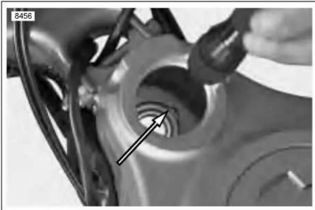
natural_image
Close-up of a mechanical component with a tool and arrow indicating a specific part (no visible text or symbols)Figure 2-70. Lower Steering Head Bearing Notches (upper bearing removed for clarity)
NOTE
Discard steering head bearings and replace with new. Steering head bearings are not reusable.
INSTALLATION
NOTE
For easier installation of bearing, lubricate the outer bearing with engine oil prior to installing into steering stem bore.
- See Figure 2-71. Install new upper and lower steering head bearings into the steering stem using STEERING HEAD BEARING RACE INSTALLER (Part No. HD-39302). and the STEERING HEAD BEARING INSTALLER (Part No. B-45521).
a. See Figure 2-72. Place the upper bearing squarely in the steering stem bore with the inner race lip pointing away from the steering head.
b. See Figure 2-71. Insert the steering head bearing installation tool into the upper bearing, with the shoulder into the bearing bore.
c. Insert the forcing screw from the steering head bearing race installer through the steering head bearing installation tool.
h39302
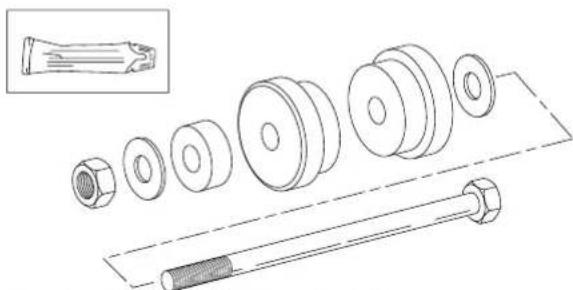
natural_image
Technical line drawing of mechanical components including bolts, gears, and a pin (no text or symbols)Steering Head Bearing Race Installer (Part No. HD-39302)
i04256
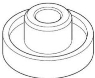
natural_image
Technical line drawing of a mechanical component with concentric rings and a central shaft (no text or symbols)Steering Head Bearing Installer (Part No. B-45521)
Figure 2-71. Steering Head Bearings Installation Tools
i04252
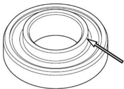
natural_image
Diagram of concentric circular layers with a pointer arrow indicating direction (no text or symbols)Figure 2-72. Steering Head Bearing Lip
HOME
- See Figure 2-73. Sparingly apply Extreme Pressure Lubricant (J-23444-A) to the threads of the forcing screw (1) from the Steering Head Bearing Race Installer (HD-39302), to prolong service life and ensure smooth operation. Insert the forcing screw (1) through the Steering Head Bearing Installation Tool (B-45521) (2).
NOTE
For ease of steering head bearing installation, lubricate the outside of the steering head bearings.
- See Figure 73. Place the lower bearing (3) onto the forcing screw (1), with the inner race lip pointing away from the steering head.
- Place the Steering Head Bearing Installation Tool (B-45521) (2) onto the forcing screw, with the shoulder into the bearing bore.
- Install the bearing (4), washer (5) and nut (6) from the Steering Head Bearing Race Installer (HD-39302) onto the forcing screw (1).
- Tighten the nut (6) by hand, until both bearings are started into the bores in the steering head.
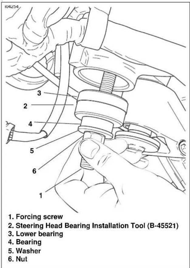
text_image
1. Forcing screw 2. Steering Head Bearing Installation Tool (B-45521) 3. Lower bearing 4. Bearing 5. Washer 6. NutFigure 2-73. Lower Bearing
- See Figure 2-74. Hold the forcing screw while tightening the nut to draw the bearings into the steering head. Continue tightening until both bearings are fully seated.
- Visually check to make sure the bearings are completely seated against the shoulders in the steering head.
2-48 2003 Buell XB9R: Chassis
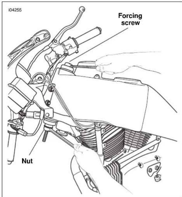
text_image
i04255 Forcing screw NutFigure 2-74. Install Bearings
- Install forks, front wheel, and lower fork clamp/steering stem as an assembly.
- Install upper fork clamp.
- Tighten steering stem cap to 38-42 ft-lbs (52-57 Nm).
- Use LOCTITE 272 on steering stem pinch fastener and tighten to 17-19 ft-lbs (23-26 Nm).
GENERAL
The swingarm also serves as the oil tank on the Buell XB9R. For information on the swingarm function as the oil tank, see 3.8 LUBRICATION SYSTEM.
The swingarm features a removable brace on the right side to allow drive belt replacement. Sealed bearings eliminate the need for preload adjustment.
REMOVAL
Brace
CAUTION
Before removing swingarm brace, always relieve belt tension first. Removing swingarm brace without releasing tension will cause swingarm brace damage.
- Remove right side rider footpeg mount. See 2.29 FOOT-PEG, HEEL GUARD AND MOUNT.
- Remove right side passenger footpeg mount. See 2.29 FOOTPEG, HEEL GUARD AND MOUNT.
- See Figure 2-76. Loosen rear axle pinch fastener (2).
- Loosen rear axle (1) approximately 15 rotations to allow partial tension to be removed from rear drive system.
- See Figure 2-75. Remove upper belt guard (1) by removing fasteners (2).
NOTE
The upper belt guard is attached to the swingarm brace and can not be removed from vehicle at this time.
- See Figure 2-78. Remove swingarm brace mounting fasteners (12) and swingarm brace (13).
- See Figure 2-75. Remove belt guard spacer (3).
- Remove swingarm brace.
b1087x2x
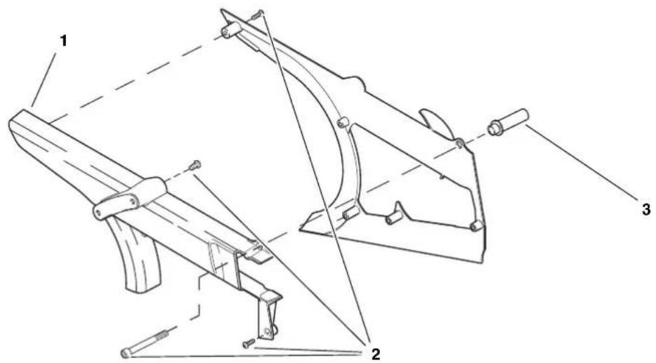
text_image
Technical diagram of a mechanical assembly with labeled parts 1, 2, and 3- Upper belt guard
- Upper belt guard fasteners
- Belt guard spacer
Figure 2-75. Belt Guard Assembly
Swingarm
WARNING
To protect against accidental start-up of vehicle and possible personal injury, disconnect the negative battery cable before proceeding. Inadequate safety precautions could cause a battery explosion, which could result in death or serious injury.
- Disconnect battery by unthreading fasteners removing negative cable (black) from battery first. See 1.4 BATTERY MAINTENANCE.
- See Figure 2-78. Remove oil drain plug (9) and drain oil from swingarm. See Draining Oil in 1.5 ENGINE LUBRIFICATION SYSTEM.
- Remove rear wheel. See 2.6 REAR WHEEL.
- Remove three oil lines from swingarm fittings. See 3.9 OIL HOSE ROUTING AND OIL RESERVOIR.
- Remove p-clamp and washer that secures rear brake line to swingarm.
- See Figure 2-85. Remove lower shock absorber mounting fastener (9) and spacer from shock absorber and swingarm.
- See Figure 2-78. Loosen pivot shaft pinch fastener (7).
- Remove pivot shaft (10) with a special 7/8 in. hex tool located in tool kit.
DISASSEMBLY
CAUTION
Carefully mark all bearing components as they are removed so that they may be returned to their original locations. Do not intermix bearing components.
Brace
Remove upper belt guard assembly. See 2.32 BELT GUARDS.
Swingarm
- See Figure 2-77. Remove oil line fittings from swingarm. See Table 2-12.
- See Figure 2-78. Remove swingarm bearings (5, 9) using slide hammer (SNAP-ON Part No. CJ1275 or equivalent) and 3/4 in. bearing remover and spacer.
- Remove shock mount bushings (3) and sleeve.
- Remove rear fender. See 2.31 FENDERS.
NOTE
See Figure 2-78. Remove swingarm bearings (5, 9) only if replacement is required. The complete bearing assembly must be replaced as a unit when replacement is necessary. Do not intermix bearing components.
2-50 2003 Buell XB9R: Chassis
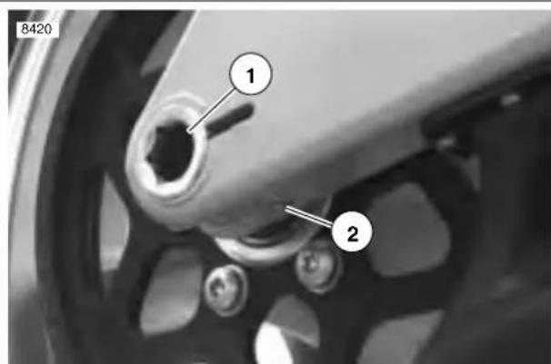
text_image
8420 1 2- Axle
- Pinch bolt fastener
Figure 2-76. Rear Wheel Mounting, Right Side
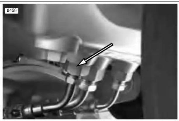
natural_image
Close-up of mechanical components with a black arrow pointing to a component (no visible text or symbols)Figure 2-77. Oil Line Fittings
WARNING
Compressed air can pierce the skin and cause injury. Never use your hand to check for leaks or to determine air flow rates. Wear safety glasses to shield your eyes from flying dirt and debris. Failure to comply could result in death or serious injury.
- Thoroughly clean all components in solvent. Blow dry with compressed air.
- Carefully inspect all bearing components for wear and/or corrosion. Replace complete bearing assembly if any component is damaged.
- Check that swingarm is not bent or twisted. Replace if damaged.
ASSEMBLY
Brace
See Figure 2-75. Install upper belt guard (1) onto swingarm brace. See 2.32 BELT GUARDS.
Swingarm
- See Figure 2-78. Install new shock mount bushings (3) and sleeve (4).
- Install new bearings (5, 9) and spacer (4) with BEARING INSTALLER (Part No. HD44060) by lightly seating spacer.
NOTE
Swingarm bearings should be replaced as a unit. Do not intermix components. Mark all components so they may be correctly installed.
-
See Figure 2-77. Install oil line fittings on swingarm. Tighten to 29-31 ft-lbs (39-42 Nm). See 3.9 OIL HOSE ROUTING AND OIL RESERVOIR.
-
See Figure 2-78. Install drain plug (9). Tighten to 29-31 ft-lbs (39-42 Nm).
INSTALLATION
Swingarm
- See Figure 2-78. Align swingarm (1) in pivot of engine crankcase (6).
- Install pivot shaft (10) with a special 7/8 in. hex tool located in tool kit, ANTI-SIEZE and tighten to 24-26 ft-lbs (32-35 Nm).
- Tighten pivot shaft pinch fastener (7) to 17-19 ft-lbs (23-26 Nm).
- See Figure 2-85. Install lower shock absorber mounting fastener (9) and spacer from shock absorber and swing-arm and tighten to 17-19 ft-lbs (23-26 Nm).
- Install p-clamp and washer that secures rear brake line to swingarm and tighten to 36-60 in-lbs (4-7 Nm).
-
Install three oil lines from swingarm fittings. See 3.9 OIL HOSE ROUTING AND OIL RESERVOIR.
-
Install rear wheel. See 2.6 REAR WHEEL.
NOTE
Installing the rear wheel will include installation of the belt drive system. See 1.9 DRIVE BELT SYSTEM.
- Fill motorcycle with recommended oil. See 1.5 ENGINE LUBRICATION SYSTEM.
WARNING
Always connect the positive battery cable first. If the positive cable should contact ground with the negative cable installed, the resulting sparks may cause a battery explosion which could result in death or serious injury.
- Install battery by threading positive cable (red) into threaded hole first tightening to 72-96 in-lbs (8-11 Nm). See 1.4 BATTERY MAINTENANCE.
WARNING
After completing repairs or bleeding the system, always test motorcycle brakes at low speed. If brakes are not operating properly or braking efficiency is poor, testing at high speeds could result in death or serious injury.
Brace
- See Figure 2-75. Position upper belt guard (1) and spacer (3).
- See Figure 2-78. Install swingarm brace (13) with swing-arm brace mounting fasteners (12) loosely. Do not tighten.
- See Figure 2-75. Tighten upper belt guard (2) fasteners to 12-36 in-lbs (1-4 Nm).
- See Figure 2-78. Tighten swingarm brace fasteners (12) to 25-27 ft-lbs (34-37 Nm).
- See Figure 2-76. Tighten rear axle (1) to 48-52 ft-lbs (65-70 Nm).
- Tighten rear axle pinch fastener (2) to 40-45 ft-lbs (54-61 Nm).
- Install right side passenger footpeg mount tightening fasteners to 15-18 ft-lbs (20-24 Nm). See 2.29 FOOTPEG, HEEL GUARD AND MOUNT.
- Install right side rider footpeg mount tightening fasteners to 108-132 in-lbs (12-15 Nm). See 2.29 FOOTPEG, HEEL GUARD AND MOUNT.
- Install heel guard. See 2.29 FOOTPEG, HEEL GUARD AND MOUNT.
- Remove rear wheel support stand.
Final Swingarm Inspection
- Check oil level after starting motorcycle and allowing it to reach operating temperature.
- Check rear brake operation.
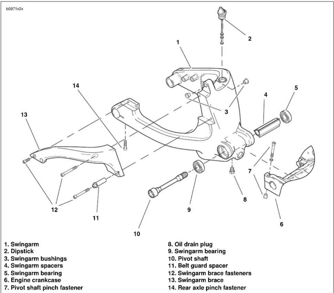
text_image
b0971x2x 1. Swingarm 2. Dipstick 3. Swingarm bushings 4. Swingarm spacers 5. Swingarm bearing 6. Engine crankcase 7. Pivot shaft pinch fastener 8. Oil drain plug 9. Swingarm bearing 10. Pivot shaft 11. Belt guard spacer 12. Swingarm brace fasteners 13. Swingarm brace 14. Rear axle pinch fastenerFigure 2-78. Swingarm Assembly
Table 2-12. Oil line Fittings
| FITTINGS(FUNCTION) | HEX SIZE(SWINGARM) | HEX SIZE(HOSE) |
| Right/Small (Vent) 5/8" 7/16" | ||
| Center/Large (Supply) 13/16" 5/8" | ||
| Left/Medium (Return) 3/4" 1/2" |
FRONT ISOLATOR
Removal
CAUTION
Avoid cross-threading front isolator bolt or insert. Keep weight of motorcycle off front isolator by alternately loosening front isolator bolt and raising scissor jack to support engine.
- Place a scissor jack under jacking point for supporting engine only. For location of jacking point see Figure 2-98.
- See Figure 2-79. Remove clutch cable p-clamp.
natural_image
Close-up mechanical assembly showing a gear and pipe connection (no visible text or symbols)Figure 2-79. Clutch Cable P-clamp
- See Figure 2-80. Remove front isolator bolt (6).
- Remove front isolator mount fasteners (5).
- Remove front isolator bracket (4).
- Remove upper snubber fastener (2) and remove upper snubber (1).
Installation
- See Figure 2-80. Install upper snubber (1) tightening snubber fastener (2) to 12-36 in-lbs (1-4 Nm).
- See Figure 2-81. Lubricate front isolator bolt with ANTI-SEIZE and loosely install.
- See Figure 2-80. Use LOCTITE 272 on front isolator bracket (4) and install. Tightening fastener (5) to 49-51 ft-lbs (66-69 Nm).
CAUTION
Avoid cross-threading front isolator bolt or insert. Keep weight of motorcycle off front isolator by alternately tightening front isolator bolt and raising scissor jack to support engine.
-
Tighten front isolator bolt (6) to 49-51 ft-lbs (66-69 Nm).
-
See Figure 2-79. Install clutch cable p-clamp. Tighten fastener to 12-36 in-lbs (1-4 Nm).
NOTE
See Figure 2-80. If the threaded insert (3) is damaged and needs to be replaced, install new insert with LOCTITE 272 and tighten to 49-51 Ft-Lbs (66.4-69.1 Nm).

text_image
b1040x2x 1. 2. 3. 4. 5. 6. 1. Upper snubber 2. Upper snubber fastener 3. Insert 4. Front isolator bracket 5. Front isolator bracket fastener to engine 6. Front isolator boltFigure 2-80. Front Isolator
text_image
b1041x2xFigure 2-81. Lubrication Points on Front Isolator Bolt
REAR ISOLATOR
NOTE
It is necessary to remove engine to access rear isolator.
See 3.4 STRIPPING MOTORCYCLE FOR ENGINE SERVICE to access the rear isolator.
REMOVAL
- Remove fuel from frame. See DRAINING FUEL TANK in 4.38 FUEL PUMP.
- Rotate engine. See 3.3 ENGINE ROTATION FOR SERVICE.
- Remove exhaust header. See 2.28 EXHAUST SYSTEM.
- Remove tail frame. See 2.36 TAIL FRAME AND BODY WORK.
- Remove rear shock. See 2.22 REAR SHOCK ABSORBER.
- Remove upper and lower fork clamps. See 2.17 FORK CLAMPS, UPPER AND LOWER.
- Remove main wire harness. See 7.23 MAIN WIRE HARNESS.
- Remove rear isolator fastener. See 2.20 FRONT AND REAR ISOLATORS.
- Lift and remove frame from the motorcycle.
INSTALLATION
- Place frame over the motorcycle.
- Install rear isolator fastener. See 2.20 FRONT AND REAR ISOLATORS.
- Install main wire harness. See 7.23 MAIN WIRE HARNESS.
- Install upper and lower fork clamps. See 2.17 FORK CLAMPS, UPPER AND LOWER.
- Install rear shock. See 2.22 REAR SHOCK ABSORBER.
- Install tail frame. See 2.36 TAIL FRAME AND BODY WORK.
- Install exhaust header. See 2.28 EXHAUST SYSTEM.
- Rotate engine. See 3.3 ENGINE ROTATION FOR SERVICE.
natural_image
Close-up of a mechanical assembly with visible gears and springs (no text or symbols)Figure 2-82. Lift Frame Off Motorcycle
GENERAL
The rear suspension is controlled by the shock absorber. The XB9R shock allows adjustment of rear compression and rebound damping and spring preload.
The most important rear shock adjustment is the preload setting. Before making any damping adjustments, set the proper preload. See 1.11 SUSPENSION DAMPING ADJUSTMENTS.
NOTE
The rear shock absorber contains no user serviceable parts.
REMOVAL
- Remove seat. See 2.38 SEAT.
WARNING
Always disconnect the negative battery cable first. If the positive cable should contact ground with the negative cable installed, the resulting sparks may cause a battery explosion which could result in death or serious injury.
- Disconnect and remove battery. See 1.4 BATTERY MAINTENANCE.
- Remove tail body work. See 2.36 TAIL FRAME AND BODY WORK.
- Place a scissor jack under jacking point and raise rear wheel off ground. For location of jacking point see Figure 2-98.
-
See Figure 2-85. Remove upper shock (5) and lower shock mount fasteners (6 and 9) and lower shock mount sleeve (8).
-
Remove rear shock reservoir clamp (2).
-
See Figure 2-84. Cut cable strap.
-
Feed rear shock reservoir through tail section.
-
Remove rear shock.
a. Raise motorcycle up approximately 2 more inches (51 mm).
b. Remove shock through the top of the tail section (opening underneath rider seat).
INSTALLATION
- See Figure 2-85. Install upper shock mount and tighten fastener (5) to 49-51 ft-lbs (66-69 Nm).
- Install lower shock mount with fasteners (6, 9) and lower shock mount sleeve (8) and tighten to 15-17 ft-lbs (20.3-23 Nm).
- Feed rear shock reservoir through tail section. D.1 HOSE AND WIRE ROUTING for correct routing.
a. Loosely install reservoir in clamp.
b. See Figure 2-83. Temporarily place upper body work onto tail section and adjust reservoir placement so dial aligns with bodywork.
c. Tighten clamp on reservoir to 96-120 in-lbs (11-14 Nm).
- See Figure 2-84. Add cable strap.
NOTE
Verify compression dial is facing up. See Figure 2-85.
- Install upper body work. See 2.36 TAIL FRAME AND BODY WORK.
WARNING
Always connect the positive battery cable first. If the positive cable should contact ground with the negative cable installed, the resulting sparks may cause a battery explosion which could result in death or serious injury.
-
Install battery by threading positive cable (red) into threaded hole first tightening to 72-96 in-lbs (8-11 Nm). See 1.4 BATTERY MAINTENANCE.
-
Install seat. See 2.38 SEAT.
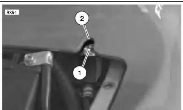
text_image
B354 2 1- Adjuster screw
- Adjuster screw alignment hole
Figure 2-83. Adjuster Screw Alignment
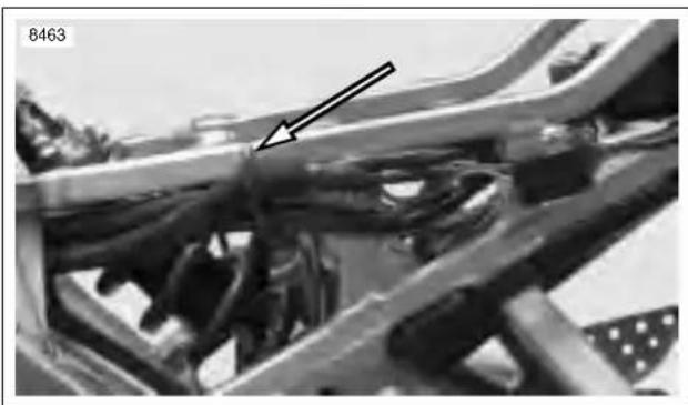
natural_image
Close-up of mechanical components with a black arrow pointing to a central component (no visible text or symbols)Figure 2-84. Cable Strap
b0940x2x
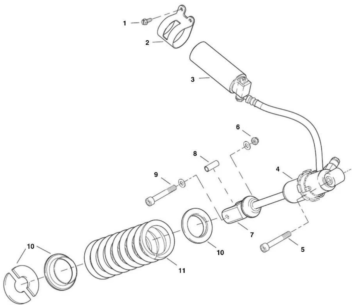
text_image
Technical diagram of a mechanical assembly with numbered components for identification-
Shock remote reservoir clamp fastener
-
Shock remote reservoir clamp
-
Shock remote reservoir
-
Shock reservoir body
-
Upper shock mount fastener
-
Lower shock mount nut and washer
-
Lower shock mount
-
Lower shock mount sleeve
-
Lower shock mount fastener and washer
-
Shock spring retainer kit
-
Rear shock spring
Figure 2-85. Rear Shock Absorber Assembly
REMOVAL/DISASSEMBLY
- See Figure 2-86. Loosen cable adjuster lock (thick disc) (3) on each cable.
- Turn adjusters (thin disc) (3) in direction which will shorten cable housings to minimum length.
- Remove fasteners (1) on right switch housing and separate housing from handlebar.
- See Figure 2-87. Remove cables (2, 3) from notches in front housing (4).
- Remove ferrules (6) from throttle (7).
- Remove airbox cover and baseplate. See 4.43 AIRBOX.
- Disconnect cables from throttle body manifold to remove.
- Cut cable straps and remove cables.
CLEANING AND INSPECTION
WARNING
Compressed air can pierce the skin and cause injury. Never use your hand to check for leaks or to determine air flow rates. Wear safety glasses to shield your eyes from flying dirt and debris. Failure to comply could result in death or serious injury.
Clean all parts except cables in a non-flammable cleaning solvent. Blow dry with compressed air. Replace cables if frayed, kinked or bent.
ASSEMBLY/INSTALLATION
- Route cable as shown in D.1 HOSE AND WIRE ROUTING.
- Add cable straps as shown in the throttle cable routing in D.1 HOSE AND WIRE ROUTING.
- Install throttle grip and position ferrules (6) into cable wheel (7).
- Insert idle control into front switch housing.
- Slide switch housing over throttle.
- Insert throttle cable into front switch housing.
- See Figure 2-86. Attach rear switch housing and position housings on right handlebar by engaging locating pin on front housing with hole in handlebar. Attach housings with two fasteners, installing longer fastener on bottom. Tighten to 25-33 in-lbs (3-4 Nm).
- Adjust cables. See 1.16 THROTTLE CABLE AND IDLE SPEED ADJUSTMENT.
- Install airbox assembly. See 4.43 AIRBOX.
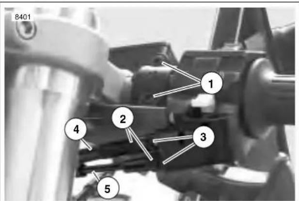
text_image
8401 1 2 3 4 5- Right switch housing fasteners
- Adjusters
- Cable adjuster lock
- Throttle control cable
- Idle control cable
Figure 2-86. Throttle Control Cables
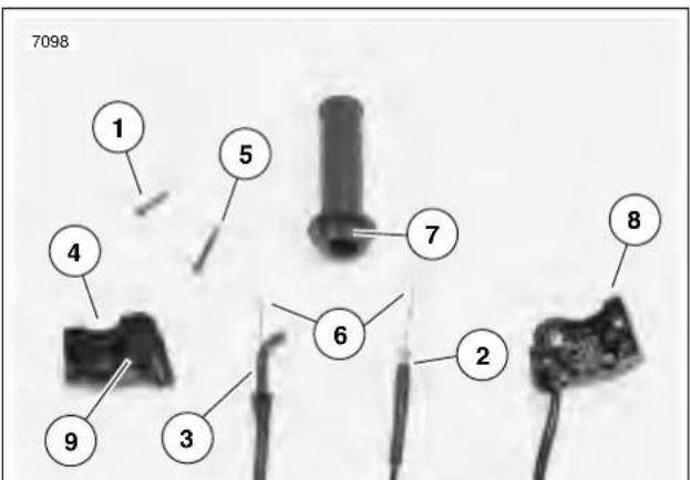
text_image
7098 1 5 4 6 2 8 3 9- Screw (short, top)
- Idle control cable
- Throttle control cable with molded end
- Front housing
- Screw (long, bottom)
- Ferrules
- Cable wheel
- Rear housing
- Locating pin
Figure 2-87. Cable Connections
REMOVAL/DISASSEMBLY
NOTE
For clutch adjustment, see 1.8 CLUTCH.
- See Figure 2-89. Remove p-clamp from front isolator.
- See Figure 2-88. Slide clutch cable adjuster boot (8) up to access clutch adjuster (7).
- Loosen clutch adjuster (7) to release tension from hand lever (4).
- Remove clutch cable ferrule (9) from hand lever (4).
- Remove hand lever pinch bolt (3).
- Remove hand lever (4) from hand lever clamp (2).
- Remove safety interlock switch (5).
a. Remove hand lever clamp fastener (1) and spin clamp (2) to access safety interlock switch (5).
b. Disconnect safety interlock switch connector (5) and remove switch fastener (6) and switch (5).
NOTE
The individual parts of the clutch switch are not serviceable. Replace switch upon failure.
-
See Figure 2-90. Cut cable strap from left upper fork clamp.
-
Remove left clip-on. See 2.27 HANDLEBARS.
-
Remove clutch assembly from clip-on.
ASSEMBLY/INSTALLATION
- See Figure 2-88. Slide hand lever clutch clamp (2) over left clip-on. Loosely tighten hand lever pinch fastener and nut (3).
- Install left clip-on. See 2.27 HANDLEBARS.
- Connect safety interlock connector and switch (5).
- Install safety interlock switch (5) with fastener (6) tightening to 7-10 in-lbs (0.8-1.0 Nm).
NOTE
Apply small amount of LOCTITE ANTI-SEIZE LUBRICANT to bolt (3).
-
Install clutch hand lever (4) in hand lever clamp (2) and tighten hand lever pinch fastener (3) to 39-48 in-lbs (4-5 Nm).
-
Position hand lever (4) to rider preference and tighten hand lever clamp pivot fastener (1) to 36-60 in-lbs (4-7 Nm).
-
Connect clutch cable ferrule (9) to hand lever clamp (2).
-
See Figure 2-90. Install cable strap holding safety interlock switch and left switch housing on left upper fork. Do not over tighten cable strap.
-
If not yet performed, route clutch cable to primary cover. D.1 HOSE AND WIRE ROUTING for clutch cable routing.
-
With clutch cable lower section connected to primary cover, adjust clutch. See 1.8 CLUTCH.
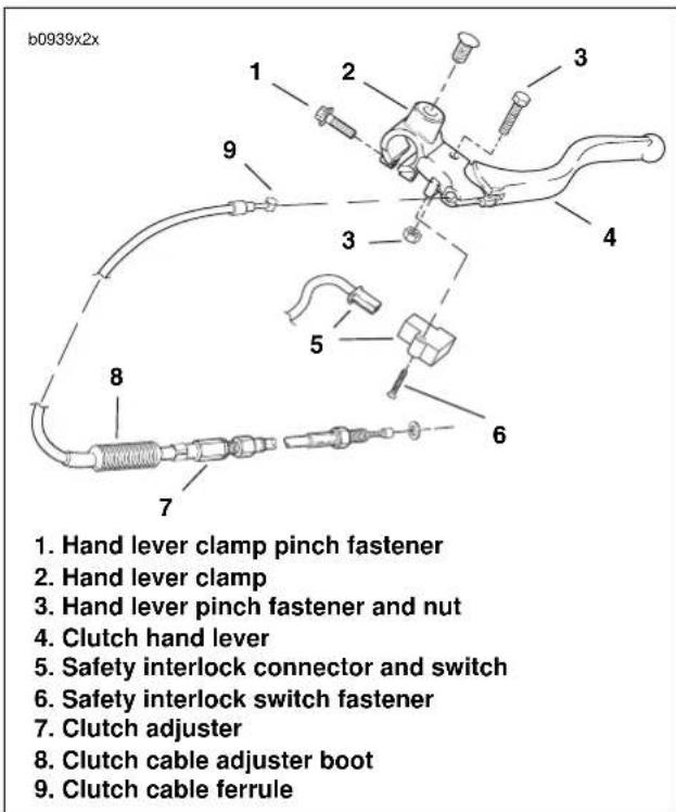
text_image
b0939x2x 1. Hand lever clamp pinch fastener 2. Hand lever clamp 3. Hand lever pinch fastener and nut 4. Clutch hand lever 5. Safety interlock connector and switch 6. Safety interlock switch fastener 7. Clutch adjuster 8. Clutch cable adjuster boot 9. Clutch cable ferruleFigure 2-88. Clutch Hand Control Assembly
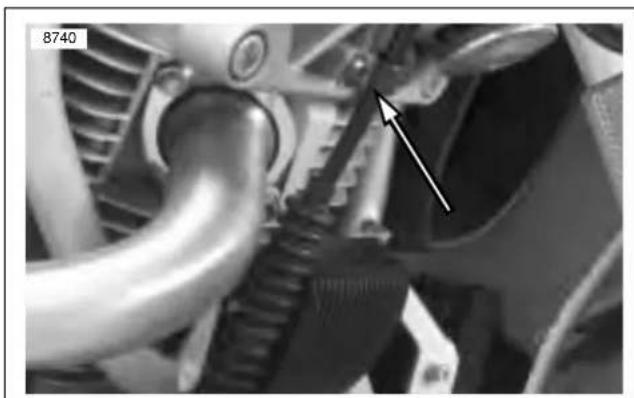
natural_image
Close-up mechanical assembly showing a gear and shaft component with an arrow pointing to a specific part (no visible text or symbols)Figure 2-89. Clutch Cable P-clamp
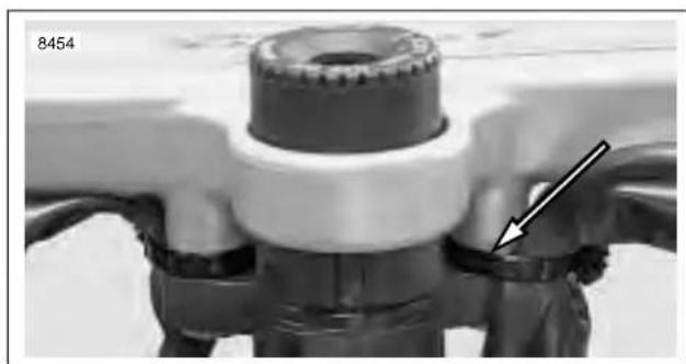
natural_image
Close-up of a mechanical component with a central cylindrical feature and a black arrow pointing to a small component (no text or symbols visible)Figure 2-90. Cable Straps On Upper Fork Clamp
REMOVAL
- Remove seat. See 2.38 SEAT.
WARNING
To protect against accidental start-up of vehicle and possible personal injury, disconnect the negative battery cable before proceeding. Inadequate safety precautions could cause a battery explosion, which could result in death or serious injury.
- Disconnect battery by unthreading fastener removing negative cable (black) from battery first. See 1.4 BATTERY MAINTENANCE.
- Remove front fairing. See 2.37 FRONT FAIRING, WINDSHIELD, AND MIRRORS.
- See Figure 2-91. Disconnect flasher (1) and bank angle sensor (2). Remove electronic control module fasteners (3).
- See Figure 2-93. Rotate headlamp support bracket.
a. Loosen headlamp pivot fasteners (1).
b. Rotate headlight bracket (2) down.
- See Figure 2-92. Disconnect headlight connection.
- Disconnect and remove electronic control module. See 4.29 ELECTRONIC CONTROL MODULE.
- See Figure 2-93. Remove headlight support bracket (2).
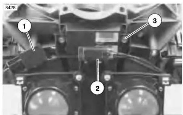
text_image
8428 1 2 3- Flasher
- Bank angle sensor
- Electronic control module
Figure 2-91. Headlight Support Bracket
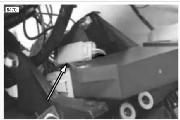
natural_image
Close-up of mechanical components with an arrow pointing to a component (no visible text or symbols)Figure 2-92. Headlight Connector
DISASSEMBLY
- See Figure 2-91. Remove bank angle sensor (2).
- Remove flasher (1).
- See Figure 2-93. Remove black rubber cover (4) from rear of headlights.
- Disconnect black connector from headlights.
- Disconnect headlight bulb (8) connector (white) from wire harness.
- Remove headlights (5, 7) from headlight support bracket (2) by removing headlight fasteners (6).
- Remove headlights (5, 7).
ASSEMBLY
- See Figure 2-93. Align headlights (5, 7) into headlight support bracket (2). Tighten headlight fasteners (6) to 20-25 in lbs (2.3-2.8 Nm).
- Connect headlight bulb (8) connector (white) into wire-harness.
- Connect black headlight connector.
- Install black rubber cover (4).
- See Figure 2-91. Install bank angle sensor connector case (2). Tighten to 12-36 in-lbs (1-4 Nm).
- Install flasher (1) and tighten to 30-40 in-lbs (3-5 Nm).
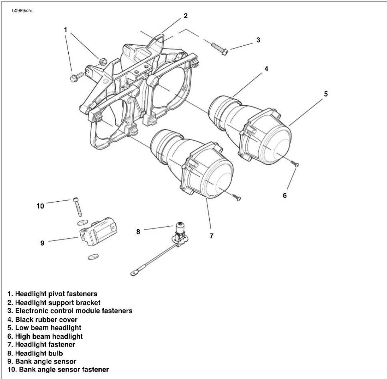
text_image
b0989x2x 1. Headlight pivot fasteners 2. Headlight support bracket 3. Electronic control module fasteners 4. Black rubber cover 5. Low beam headlight 6. High beam headlight 7. Headlight fastener 8. Headlight bulb 9. Bank angle sensor 10. Bank angle sensor fastenerFigure 2-93. Headlight Support Bracket Assembly
INSTALLATION
- See Figure 2-94. Position headlight pivot fasteners into groove of the headlight support bracket, flat side of nut lined up with groove.
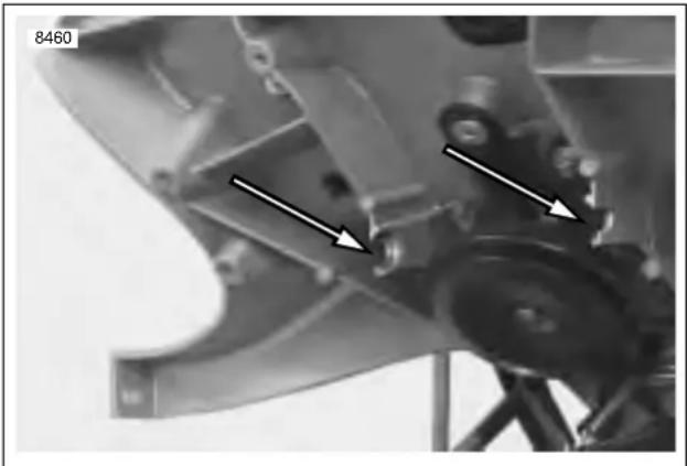
natural_image
Mechanical assembly diagram showing a gear and mounting bracket with directional arrows indicating motion (no text or symbols)Figure 2-94. Headlamp Pivot Groove
- See Figure 2-93. Install headlight pivot fasteners (1) but do not tighten.
- Connect electronic control module. See 4.29 ELECTRONIC CONTROL MODULE.
- See Figure 2-92. Attach headlight connector to headlight support bracket.
- Connect headlight connections. See 7.11 HEADLIGHT.
- See Figure 2-93. Rotate headlight support bracket up (2) and tighten pivot fasteners (1) to 72-96 in-lbs (8-11 Nm).
- See Figure 2-91. Install electric control module.
a. Figure 2-93. Align electronic control module and headlight support bracket with fairing support bracket.
b. Tighten electronic control module fasteners (3) to 72-96 in-lbs (8-11 Nm). - See Figure 2-91. Connect flasher (1) and bank angle sensor (2).
- Install front fairing. See 2.37 FRONT FAIRING, WINDSHIELD, AND MIRRORS.
WARNING
Always connect the positive battery cable first. If the positive cable should contact ground with the negative cable installed, the resulting sparks may cause a battery explosion which could result in death or serious injury.
-
Install battery by threading positive cable (red) into threaded hole first tightening to 72-96 in-lbs (8-11 Nm). See 1.4 BATTERY MAINTENANCE.
-
Install seat. See 2.38 SEAT.
REMOVAL
- Remove seat. See 2.38 SEAT.
WARNING
To protect against accidental start-up of vehicle and possible personal injury, disconnect the negative battery cable before proceeding. Inadequate safety precautions could cause a battery explosion, which could result in death or serious injury.
- Disconnect battery by unthreading fastener removing negative cable (black) from battery first. See 1.4 BATTERY MAINTENANCE.
- Remove front fairing. See 2.37 FRONT FAIRING, WINDSHIELD, AND MIRRORS.
- Remove headlight support bracket. See 2.25 HEADLIGHT SUPPORT BRACKET.
- Remove fuse block (1) and relay block (4) and p-clamp. See 7.22 MAIN FUSE AND FUSES.
- Disconnect and remove horn (5). See 7.20 HORN.
- Disconnect and remove instrument cluster (2, 3). See 7.17 INSTRUMENT MODULE.
- See Figure 2-95. Remove fairing support bracket fasteners and washers (4), p-clamp (7) to remove fairing support bracket (5).
INSTALLATION
- Route the wire harness. See D.1 HOSE AND WIRE ROUTING for wire harness routing.
- See Figure 2-95. Install fairing support bracket with fasteners and washers (4). Tightening to 16-18 ft-lbs (22-26 Nm).
- Install p-clamp (7) with p-clamp fasteners and washers (8).
- Connect instrument cluster connector and install instrument cluster. Tightening to 36-48 in-lbs (4-5 Nm). See 7.17 INSTRUMENT MODULE.
- Install horn and tighten fasteners to 72-96 in-lbs (8-10 Nm). See 7.20 HORN.
- Install fuse block, relay and p-clamp tightening fasteners to 72-96 in-lbs (8-11 Nm). See 7.22 MAIN FUSE AND FUSES.
- Install lower headlight support bracket. See 2.25 HEAD-LIGHT SUPPORT BRACKET.
- Install front fairing. See 2.37 FRONT FAIRING, WINDSHIELD, AND MIRRORS.
WARNING
Always connect the positive battery cable first. If the positive cable should contact ground with the negative cable installed, the resulting sparks may cause a battery explosion which could result in death or serious injury.
-
Install battery by threading positive cable (red) into threaded hole first tightening to 72-96 in-lbs (8-11 Nm). See 1.4 BATTERY MAINTENANCE.
-
Install seat. See 2.38 SEAT.
b0958x2x
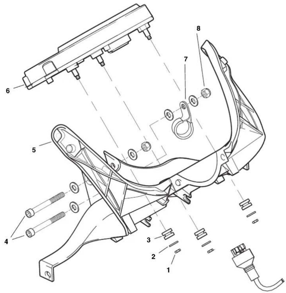
text_image
Technical diagram of a mechanical assembly with numbered components for identification- Jam nut
- Washer
- Rubber grommet
- Fairing support bracket fasteners and washers
- Fairing support bracket
- Instrument cluster
- P-clamp
- P-clamp fastener and washers
Figure 2-95. Fairing Support Bracket Assembly
GENERAL
XB9R handlebars use a clip-on assembly and are not adjustable.
REMOVAL
Right Clip-on
- Remove right switchgear housing. See 7.15 HANDLE-BAR SWITCHES.
- Remove front brake master cylinder and grip. See 2.10 FRONT BRAKE MASTER CYLINDER AND HAND LEVER.
- See Figure 2-97. Remove right clip-on assembly.
a. Partially loosen clip-on mounting fastener (5).
b. Using a rubber mallet, tap the partially loosened fastener (5) to push the clip-on (3) from the upper right fork clamp (4). Repeat this procedure until fastener and clip-on has been removed from fork clamp (4). - Remove clip-on endcap (1).
Left Clip-on
- Remove left switchgear housing. See 7.15 HANDLEBAR SWITCHES.
- See Figure 2-96. Remove clip-on assembly.
a. See Figure 2-97. Partially loosen clip-on mounting fastener (5).
b. Using a rubber mallet, tap the partially loosened fastener (5) to push the clip-on (3) from the upper left fork clamp (4). Repeat this procedure until fastener (5) and clip-on (3) has been removed from fork clamp (4).
-
Remove clutch lever assembly. See 2.24 CLUTCH HAND LEVER.
-
Remove clip-on endcap (1).
INSTALLATION
Right Clip-on
- Install right switch gear housing.
- Install front brake master cylinder. Tighten but do not torque.
- Install right clip-on into right fork clamp using LOCTITE 272 and tighten fastener (5) to 24-26 ft-lbs (33-35 Nm).
- Install throttle and grip onto right clip-on. See 2.23 THROTTLE CONTROL.
-
Install endcap onto right clip-on.
-
See Figure 2-35. Position brake hand lever to rider preferences and tighten fastener (5) to 80-90 in-lbs (9-10 Nm). See 2.10 FRONT BRAKE MASTER CYLINDER AND HAND LEVER.
Left Clip-on
- Install clutch hand lever assembly onto clip-on. Tighten but do not torque.
- Install left switchgear housing. See 7.15 HANDLEBAR SWITCHES.
- See Figure 2-97. Install grip (2) and endcap (1).
- Install left clip-on into upper fork clamp (4) and using LOCTITE 272, tighten fastener (5) to 24-26 ft-lbs (33-35 Nm).
- See Figure 2-88. Position clutch hand lever to rider preferences and tighten fastener (1) to 36-60 in-lbs (4-7 Nm). See 2.24 CLUTCH HAND LEVER.
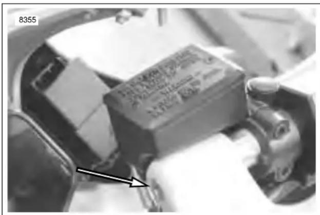
text_image
8355Figure 2-96. Handlebar Clip-on Mounting Fasteners (right clip-on shown)
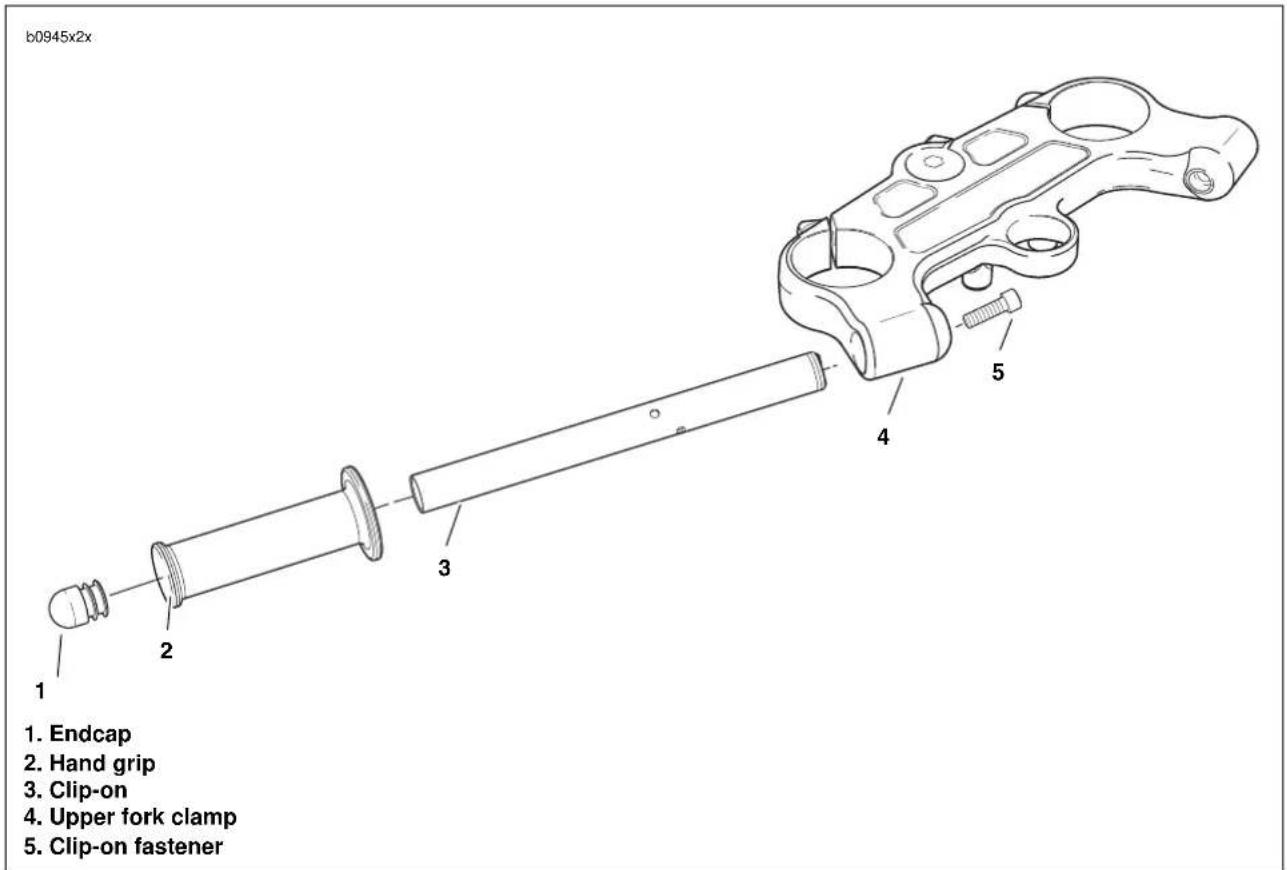
text_image
b0945x2x 1. Endcap 2. Hand grip 3. Clip-on 4. Upper fork clamp 5. Clip-on fastenerFigure 2-97. Handlebar Clip-on Assembly (left clip-on shown)
REMOVAL/DISASSEMBLY
Muffler
- Remove chin fairing. See 2.33 CHIN FAIRING.
- Remove front sprocket cover. See 2.30 SPROCKET COVER.
- Remove idler pulley. See DRIVE BELT REMOVAL in 1.9 DRIVE BELT SYSTEM.
- See Figure 2-98. Loosen front muffler strap mount fastener (7) but do not remove.
- Remove front and rear muffler straps.
Front: Remove front muffler strap fastener (5). Front strap will not be removed.
Rear: Alternately loosen rear strap fasteners (1) and remove straps (2).
- See Figure 2-99. Loosen Torca clamp (1) and remove muffler.
NOTE
The muffler may be removed for replacement without removing the exhaust header.
Front Muffler Mounting Block/Strap
-
Remove muffler. See Muffler in this section.
-
See Figure 2-98. Remove front muffler mounting block fastener (7).
- Remove strap (4) from front muffler mounting block (6).
- Remove front mounting block bushings (8) by punching out with suitable tool.
Rear Muffler Mounting Block
- Remove muffler. See Muffler in this section.
- Drain oil. See Draining Oil in 1.5 ENGINE LUBRICATION SYSTEM.
- Remove oil lines from swingarm. See 3.9 OIL HOSE ROUTING AND OIL RESERVOIR.
- See Figure 2-98. Remove rear muffler mounting block fasteners (10).
- Slide oil lines from rear muffler block. and remove rear muffler strap mount block (9).
Exhaust Header
- Rotate engine down. See 3.3 ENGINE ROTATION FOR SERVICE.
- Remove oxygen sensor. See 4.32 OXYGEN SENSOR.
- See Figure 2-99. Remove exhaust header (2) by removing mounting fasteners (3).
- Remove exhaust ring (4), retaining ring (5) and port gasket (6).
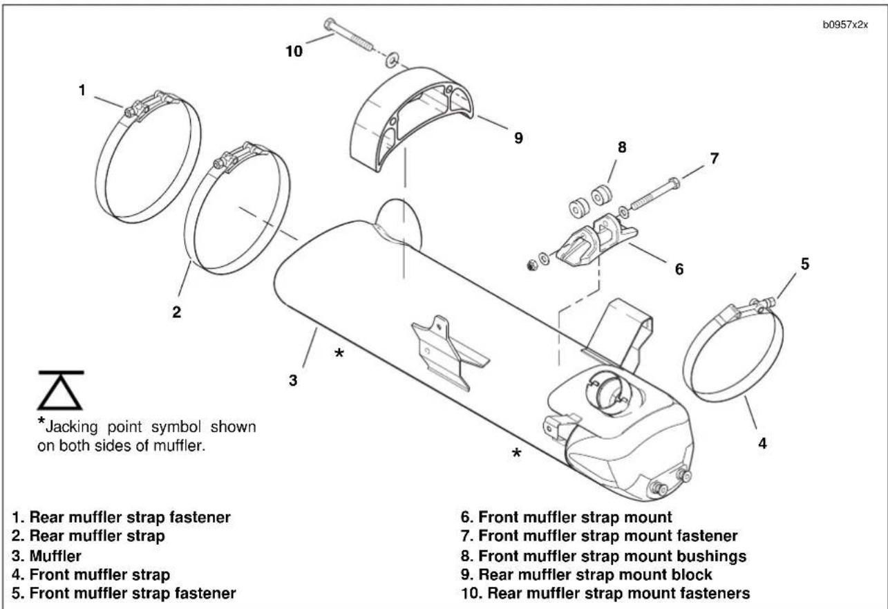
text_image
b0957x2x 1. Rear muffler strap fastener 2. Rear muffler strap 3. Muffler 4. Front muffler strap 5. Front muffler strap fastener 6. Front muffler strap mount 7. Front muffler strap mount fastener 8. Front muffler strap mount bushings 9. Rear muffler strap mount block 10. Rear muffler strap mount fasteners *Jacking point symbol shown on both sides of muffler. 1 2 3 4 5 6 7 8 9 10Figure 2-98. Muffler Assembly
ASSEMBLY/INSTALLATION
Exhaust Header
- See Figure 2-99. Install exhaust ring (4), retaining ring (5) and new port gasket (6).
- Install exhaust header (2). Tighten mounting fasteners (3) to 72-96 in-lbs (8-11 Nm).
NOTE
Tighten header nuts gradually, alternating between studs to insure that exhaust rings are flush with engine.
- Install oxygen sensor. See 4.32 OXYGEN SENSOR.
- Rotate engine up. See 3.3 ENGINE ROTATION FOR SERVICE.
Rear Muffler Mounting Block
- See Figure 2-98. Slide rear muffler mounting block (9) over oil lines.
- Install rear muffler mounting block fasteners (10) and tighten to 32-36 ft-lbs (43-49 Nm).
- Install oil lines to swingarm. See 3.9 OIL HOSE ROUTING AND OIL RESERVOIR.
- Fill swingarm/oil tank with 2.5 quarts (3.3 liters) oil. See Draining Oil in 1.5 ENGINE LUBRICATION SYSTEM.
- Install muffler. See Muffler in this section.
Front Muffler Mounting Block
- See Figure 2-98. Install front mounting block bushings (8).
- Install strap on front muffler mounting block (4).
- Install front muffler mounting block fastener (7) loosely. Do not tighten.
- Install muffler. See Muffler in this section.
Muffler and Straps
NOTE
Torca muffler clamps have eliminated the need for silicone or graphite tape during assembly. To ensure sealing integrity of muffler clamps and prevent the possibility of leakage, Buell recommends that muffler clamp assemblies be discarded and replaced each time they are removed.
- Install muffler and new Torca clamp onto header.
NOTE
If necessary, use a fiber hammer to fit muffler on header.
- See Figure 2-98. Loosely install front and rear muffler straps (2, 4).
WARNING
Muffler straps must be tightened in steps to keep from over tightening or muffler will be crushed.
- Tighten front strap fastener and alternately tighten rear muffler strap fasteners evenly till fasteners are tightened to:
Front: 108-120 in-lbs (12-14 Nm).
Rear: 48-60 in-lbs (5-7 Nm).
- See Figure 2-98. Tighten front muffler mounting block fastener (7) to 22-25 ft-lbs (30-34 Nm).
- See Figure 2-99. Tighten the Torca clamp (1) to 40-45 ft-lbs (54-61 Nm).
- Install idler pulley. See DRIVE BELT REMOVAL in 1.9 DRIVE BELT SYSTEM.
- Install front sprocket cover. See 2.30 SPROCKET COVER.
- Install chin fairing. See 2.33 CHIN FAIRING.
b0973x2x
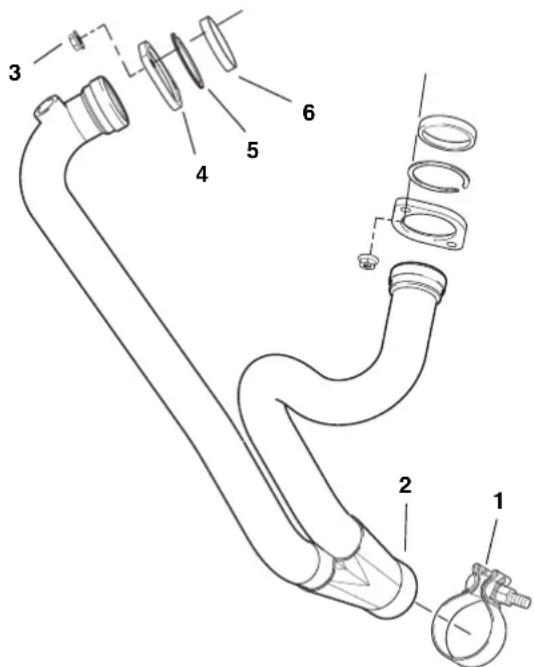
text_image
Technical diagram of a mechanical component with numbered parts for identification- Torca clamp
- Header
- Header mount fastener
- Exhaust ring
- Exhaust retaining ring
- Exhaust port gasket
Figure 2-99. Exhaust Header
RIDER
Remove Footpeg
- See Figure 2-100. Remove e-ring (5).
- Remove footpeg pin (8).
- Remove footpeg (7).
Remove Heel Guard
- See Figure 2-100. Remove heel guard fasteners (4).
- Remove heel guard (3).
Remove Mount
- See Figure 2-100. Remove footpeg mount fasteners (2).
- Remove footpeg mount (1).
Install Footpeg
- See Figure 2-100. Install e-ring (5).
- Position footpeg (7) on to footpeg mount (1).
- Install footpeg pin (8).
Install Heel Guard
- See Figure 2-100. Position heel guard (3) onto footpeg mount (1).
- Install heel guard (3) with fasteners (4). Tighten to 72-96 in-lbs (8-11 Nm).
Install Mount
- See Figure 2-100. Position footpeg mount (1).
- Install footpeg mount with fasteners (2). Tighten to 108-132 in-lbs (12-15 Nm).

text_image
b0934x2x 1 2 3 4 5 6 7 8- Footpeg mount
- Footpeg mount fastener
- Heel guard
- Heel guard fasteners
- E-ring
- Spring
- Footpeg
- Pin
Figure 2-100. Rider Footpeg, Mount and Heel Guard Assembly
PASSENGER
Remove Footpeg
- See Figure 2-101. Remove e-ring (7).
- Remove footpeg pin (9).
- Remove footpeg (8), detent plate (6), ball (5) and spring (4).
Remove Heel Guard
- See Figure 2-101. Remove heel guard fasteners (1).
- Remove heel guard (2).
Remove Mount
- See Figure 2-101. Remove footpeg mount fasteners (10).
- Remove footpeg mount (3).
Install Footpeg
- See Figure 2-101. Position footpeg (8), detent plate (6), ball (5), and spring (4) on to footpeg mount (3).
- Install footpeg pin (9).
- Install e-ring (7).
- Check that footpeg clicks in the up and down position.
Install Heel Guard
- See Figure 2-101. Position heel guard (2) onto footpeg mounts (3).
- Install heel guard (2). Tightening heel guard fasteners to 48-72 in-lbs (5-8 Nm).
Install Mount
- See Figure 2-101. Position footpeg mount (3) onto tail frame.
- Install footpeg mount (3). Using LOCTITE 272 tighten, fasteners (10) to 25-28 ft-lbs (34-38 Nm).
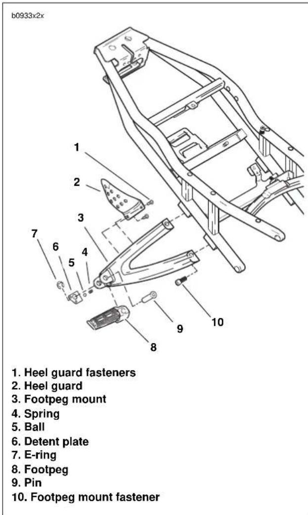
text_image
b0933x2x 1. Heel guard fasteners 2. Heel guard 3. Footpeg mount 4. Spring 5. Ball 6. Detent plate 7. E-ring 8. Footpeg 9. Pin 10. Footpeg mount fastenerFigure 2-101. Passenger Footpeg, Mount and Heel Guard Assembly
REMOVAL
- See Figure 2-102. Remove back right chin fairing fasteners.
NOTE
Must remove two chin fairing fasteners for sprocket cover access.
- See Figure 2-103. Remove sprocket cover fasteners and washers (1).
INSTALLATION
- See Figure 2-103. Position sprocket cover (2) over front belt guard (3) and front sprocket.
- Install sprocket cover (2) using LOCTITE 222 on rear sprocket cover fastener (1) and tighten all fasteners and washers (1) to 12-36 in-lbs (1-4 Nm).
- Install chin fairing. See 2.33 CHIN FAIRING.
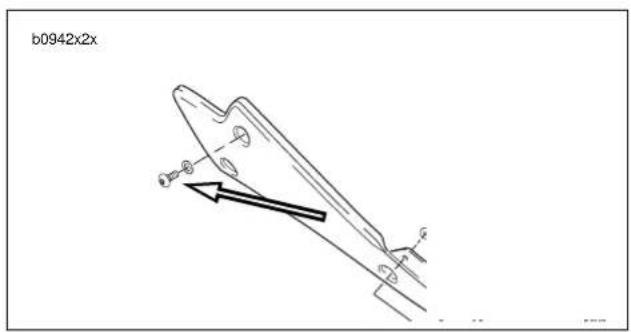
text_image
b0942x2xFigure 2-102. Chin Fairing Assembly
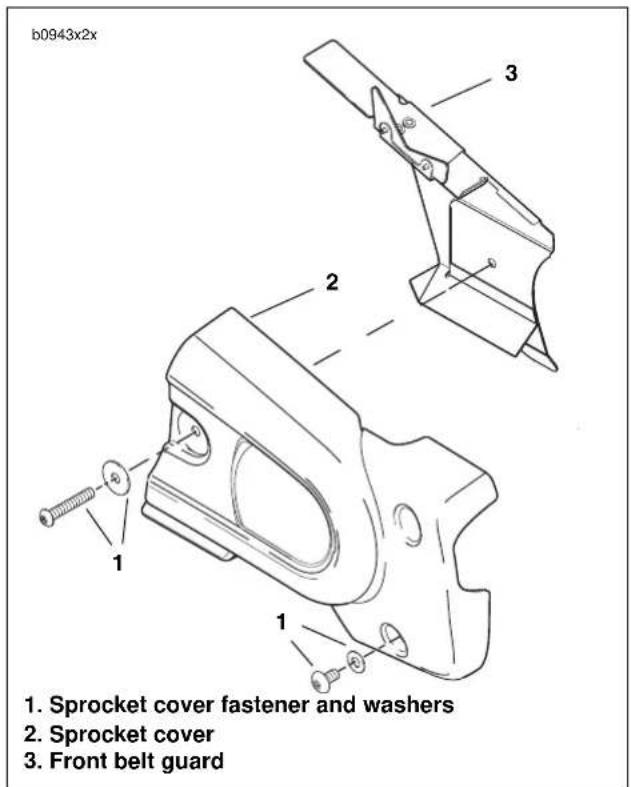
text_image
b0943x2x 1. Sprocket cover fastener and washers 2. Sprocket cover 3. Front belt guardFigure 2-103. Sprocket Cover
FRONT FENDER
Removal
- See Figure 2-104. Remove fasteners and washers (2) securing the front fender (1) to front forks.
- Carefully remove front fender (1).
Installation
- See Figure 2-104. Align front fender (1) to fender mounts on front forks.
- Install front fender (1) with fasteners and washers (2) and tighten to 12-36 in-lbs (1-4 Nm).
REAR FENDER
Removal
- Remove rear wheel. See 2.6 REAR WHEEL.
- See Figure 2-104. Remove fasteners and washers (4) securing the rear fender (3) to frame.
- Remove rear fender (3).
Installation
- See Figure 2-104. Align rear fender (3) to frame.
- Install rear fender (3) with fasteners and washers (4), Tighten to 12-15 in-lbs (1-1.7 Nm).
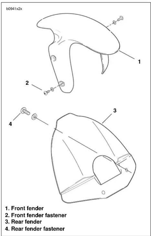
text_image
b0941x2x 1. 2. 3. 4. 1. Front fender 2. Front fender fastener 3. Rear fender 4. Rear fender fastenerFigure 2-104. Front and Rear Fender
REMOVAL
- Place a scissor jack under jacking point and raise rear wheel off ground. For location of jacking point see Figure 2-98.
- Remove right side rider footrest support bracket.
- Remove right passenger footrest support bracket.
- See Figure 2-105. Remove front sprocket cover (5) by remove fasteners (6).
NOTE
Must remove two chin fairing fasteners for access. Front belt guard will dangle but can not be removed at this time.
-
Loosen rear axle pinch fastener.
-
Loosen rear axle approximately 15 rotations to allow partial tension to be removed from rear drive system.
-
Remove idler pulley assembly by removing nuts and washers. See IDLER PULLEY REMOVAL in 1.9 DRIVE BELT SYSTEM.
-
Remove lower belt guard (3) by removing fasteners (7).
-
Remove upper belt guard (10) by removing fasteners (8, 9).
NOTE
The upper belt guard is attached to the swingarm brace and can not be removed from vehicle at this time.
- Remove swingarm brace by removing fasteners. See 2.19 SWINGARM AND BRACE.
a. Remove spacer collar (2) between upper belt guard (10), inner belt guard (1) and swingarm brace.
b. Allow inner belt guard (1) to drape.
NOTE
Inner belt guard does not have to be removed to remove belt or rear wheel.
-
Remove upper belt guard (10) by removing fasteners from swingarm brace.
-
Remove belt from sprocket.
NOTE
Inner belt guard does not have to be removed to remove belt or rear wheel.
- Removing inner belt guard (1):
a. Remove rear axle.
b. Remove inner belt guard (1) from swingarm.
NOTE
The rear wheel does not have to be removed to remove inner belt guard.
2-72 2003 Buell XB9R: Chassis
INSTALLATION
a. Slide inner guard between rear wheel and swing-arm.
b. Partially install rear axle.
a. Position the inner belt guard (1) and upper belt guard (10) onto swingarm.
b. Install spacer collar (2) between upper belt guard (10), inner belt guard (1) and swingarm brace.
- See Figure 2-105. Installing inner belt guard (1):
- Install front belt guard (4). Do not tighten.
- Install belt.
- Install upper belt guard (10) to swingarm brace tightening fasteners to 12-36 in-lbs (1-4 Nm).
- Loosely install swingarm brace. See 2.19 SWINGARM AND BRACE.
- Install upper belt guard (10) and tighten fasteners (8, 9) to 12-36 in-lbs (1-4 Nm).
- Tighten swingarm brace fasteners to 25-27 ft-lbs (34-37 Nm).
- Install lower belt guard (3) and tighten fasteners (7) to 12-36 in-lbs (1-4 Nm).
- Install idler pulley assembly tightening washers, nuts and fasteners to 33-35 ft-lbs (45-47 Nm). See IDLER PULLEY INSTALLATION in 1.9 DRIVE BELT SYSTEM.
- Tighten rear axle to 48-52 ft-lbs (65-70 Nm).
- Tighten rear axle pinch fastener to 40-45 ft-lbs (54-61 Nm).
- Rotate rear wheel to ensure the belt does not make visible or audible contact. It may be necessary to loosen belt guard(s) to adjust for proper clearance.
- Install front sprocket cover (5) by tightening fasteners (6) to 12-36 in-lbs (1-4 Nm).
- Install chin fairing fasteners and tighten to 36-60 in-lbs (4-7 Nm).
- Install right side rider footrest mount and tighten fasteners to 108-132 in-lbs (12-15 Nm).
- Install right passenger footrest mount. use LOCTITE 272 and tighten fasteners to 25-28 ft-lbs (34-38 Nm).
- Remove scissor jack from motorcycle.
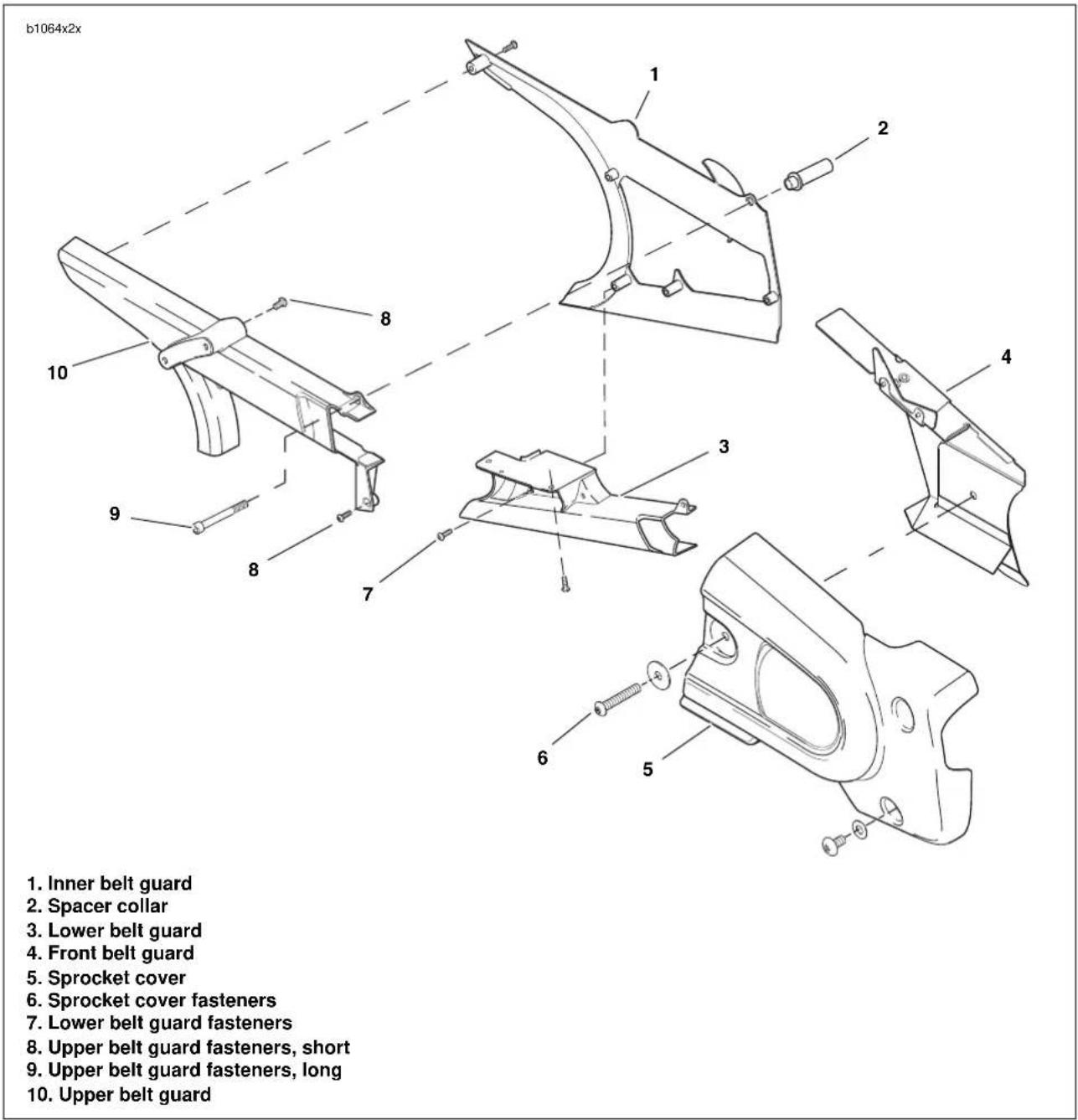
text_image
b1064x2x 1. Inner belt guard 2. Spacer collar 3. Lower belt guard 4. Front belt guard 5. Sprocket cover 6. Sprocket cover fasteners 7. Lower belt guard fasteners 8. Upper belt guard fasteners, short 9. Upper belt guard fasteners, long 10. Upper belt guardFigure 2-105. Belt Guard Assembly
REMOVAL
- Secure back tire down.
- Turn wheel full right or left for easier access to center fasteners.
- See Figure 2-106. Remove center section fasteners and washers (2).
- Remove left section fasteners and washers (4) and remove left section (3).
- Remove sprocket cover. See 2.30 SPROCKET COVER.
- Remove right section fasteners and washers (6) and remove right section (5).
INSTALLATION
- See Figure 2-106. Position right section (5) and install with right section fasteners and washers (6).
- Position left section (3) and install with left section fasteners and washers (4).
- Turn wheel full right or left for easier access to center fasteners.
- Position center section (1) and install with center section fasteners and washers (2). Use LOCTITE 272 on all fasteners tightening to 36-48 in-lbs (4-5 Nm).
- Install sprocket cover. See 2.30 SPROCKET COVER.
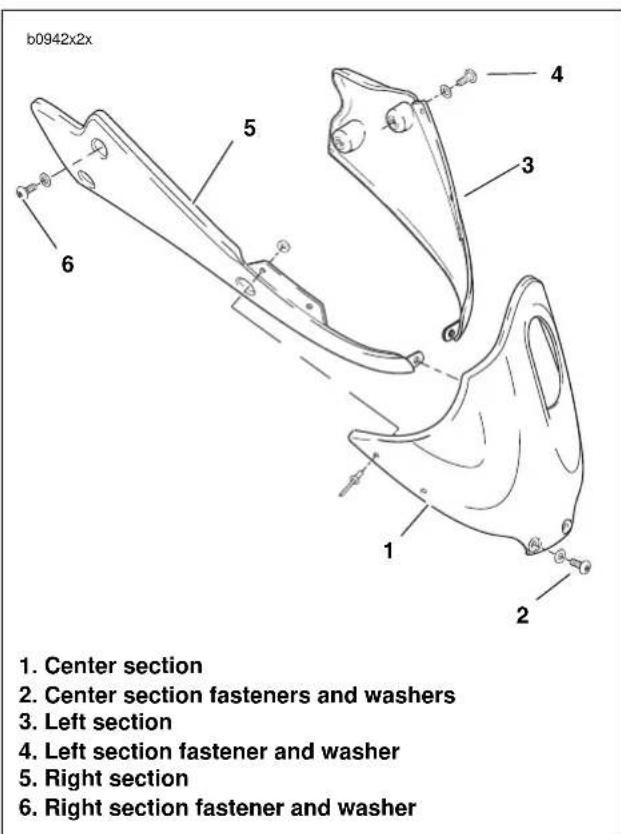
text_image
b0942x2x 1. Center section 2. Center section fasteners and washers 3. Left section 4. Left section fastener and washer 5. Right section 6. Right section fastener and washerFigure 2-106. Chin Fairing Assembly
REMOVAL
- Remove seat. See 2.38 SEAT.
- See Figure 2-107. Remove fasteners and nylon washers (2).
- Remove intake cover assembly (1).
INSTALLATION
- Position intake cover assembly over top of airbox cover.
- See Figure 2-107. Secure intake cover assembly (1) with fasteners and nylon washers (2). Tighten to 12-36 in-lbs (1-4 Nm).
NOTE
Front screws go in at a slight angle.
- Install seat. See 2.38 SEAT.
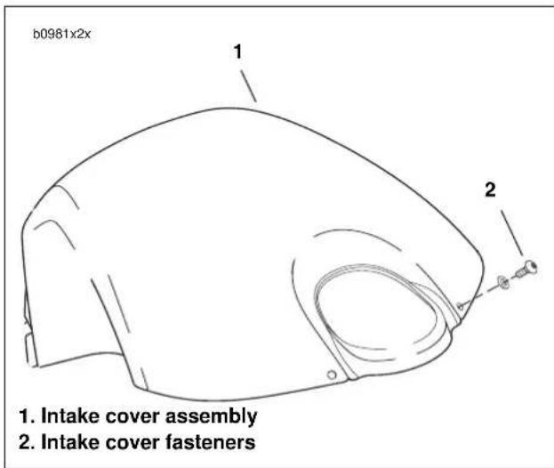
text_image
b0981x2x 1. 2. 1. Intake cover assembly 2. Intake cover fastenersFigure 2-107. Intake Cover Assembly
RAM AIR SCOOP
Removal
- See Figure 2-108. On left side of bike, locate ram air scoop (4).
- Remove three ram air scoop fasteners (3).
- Remove ram air scoop (4).
Installation
- See Figure 2-108. Position ram air scoop (4).
- Install ram air scoop (4) with three fasteners (3). Tighten to 12-36 in-lbs (1-4 Nm).
ENGINE SHROUD AIR SCOOP
Removal
- See Figure 2-108. On right side of bike, locate engine shroud air scoop (6).
- Remove three engine shroud air scoop fasteners (5).
- Remove engine shroud air scoop (6).
Installation
- See Figure 2-108. Position engine shroud air scoop (6).
- Install engine shroud air scoop (6) with three fasteners (5). Tighten to 12-36 in-lbs (1-4 Nm).
OIL COOLER AIR SCOOP
Removal
- See Figure 2-108. On left side of bike, locate oil cooler air scoop (2).
- Remove two oil cooler air scoop fasteners (1).
- Remove oil cooler air scoop (2).
Installation
- See Figure 2-108. Position oil cooler air scoop (2).
- Install oil cooler air scoop (2) using LOCTITE 272 tightening fasteners (1) to 120-144 in-lbs (14-16 Nm).
b01012x2x
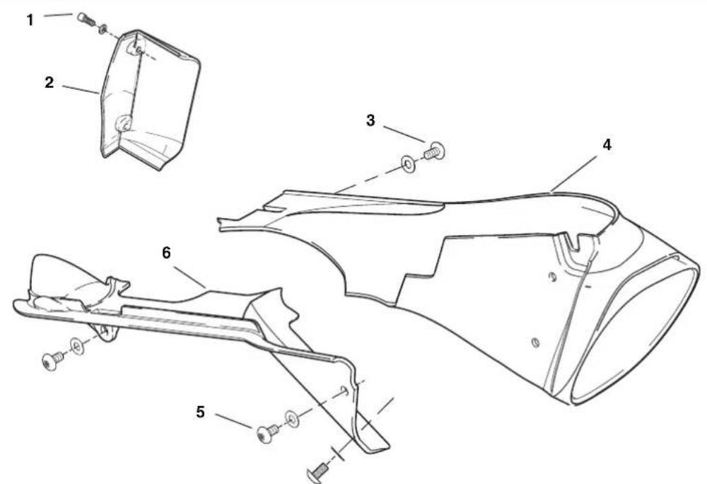
text_image
Technical diagram of a mechanical component with numbered parts for identification- Oil cooler air scoop fastener and washer
- Oil cooler air scoop
-
Ram air scoop fastener and washer
-
Ram air scoop
- Engine shroud scoop fastener and washer
- Engine shroud scoop
Figure 2-108. RAM Air Scoop, Engine Shroud, Oil Cooler
DISASSEMBLY
- Remove seat and pillion. See 2.38 SEAT.
WARNING
Always disconnect the negative battery cable first. If the positive battery cable should contact ground with the negative cable installed, the resulting sparks may cause a battery explosion which could result in death or serious injury.
- Disconnect battery by unthreading fastener removing negative cable (black) from battery first. See 1.4 BATTERY MAINTENANCE.
- See Figure 2-112. Remove upper body work (1) from tail frame (8).
a. Remove body work fasteners (2).
b. Disconnect passenger lock cable (6) by removing cable from seat lock plate (4) and ferrule from key-lock (3).
c. Lift upper tail body work (1) off tail frame (8).
-
Remove passenger seat latch (14) from rear of tail frame.
-
See Figure 2-109. Disconnect rear power harness connection (5).
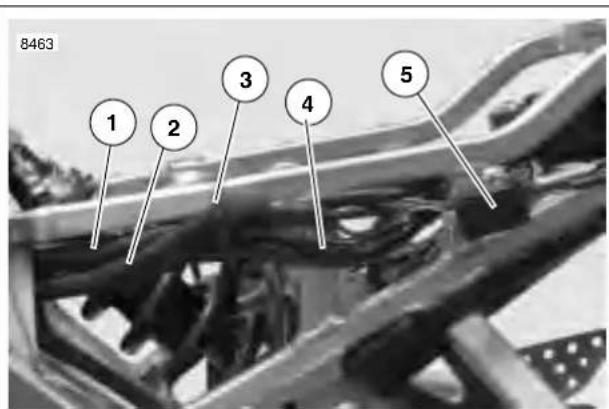
text_image
8463 1 2 3 4 5- Fuel vent hose
- Main wire harness
- Cable strap
- Rear shock reservoir hose
- Main wire harness connection
Figure 2-109. Left Side Tail Frame Hose and Wire Routing
- Disconnect turn signal bullet connections and tail light connections. See 7.13 TURN SIGNALS and 7.12 TAIL LAMP.
- Remove christmas tree tie that holds the turn signals and tail light wire harness to tail frame.
- Remove turn signals and reflectors from lower body work. See 7.13 TURN SIGNALS.
-
See Figure 2-112. Remove license plate fasteners (12) from lower tail body work (9) and remove license plate (13).
-
Remove passenger footpeg mounts. See 2.29 FOOT-PEG, HEEL GUARD AND MOUNT.
- Remove lower body work (9) and trunk (11) from tail frame (8).
a. Remove lower body work (9) underneath tail frame by removing fasteners (10).
b. Remove trunk (11).
- See Figure 2-110. Disconnect main battery ground (1) and ground to wire harness (2).
- Remove main fuse case (3) from tail frame.
NOTE
When removing the main fuse case from tail frame, be very careful not to bend the tail frame.
- See Figure 2-110. Cut cable strap (4) holding rear brake light wire (5) and rear brake reservoir hose (6).
- Disconnect rear brake light connection (5).
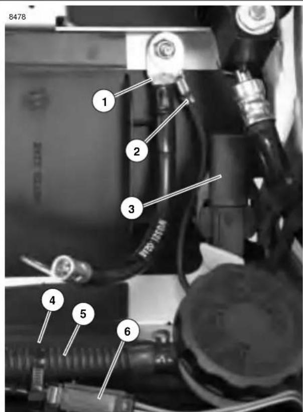
text_image
8478 1 2 3 4 5 6- Main battery ground
- Wire harness ground
- Main fuse case
- Cable strap
- Brake light wire and connector
- Rear brake reservoir hose
Figure 2-110. Inside Tail Frame Hose and Wire Routing
- See Figure 2-109. Cut cable strap (3) from tail frame holding vent hose (1), main wire harness (2) and shock reservoir hose (4).
HOME
- See Figure 2-111. Remove rear brake reservoir clamp nut.
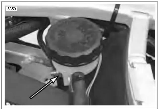
natural_image
Close-up of a mechanical component with a circular knob and pipe fittings, no visible text or symbolsFigure 2-111. Remote Reservoir Clamp Nut
- Disconnect fuel pump connection and remove case from tail frame. See 4.38 FUEL PUMP.
- Remove shock reservoir fasteners and feed the reservoir out of tail frame. See 2.22 REAR SHOCK ABSORBER.
- See Figure 2-112. Remove tail frame fasteners (7) and remove tail frame (8) from frame.
CLEANING
CAUTION
Do not use wheel care products or other compounds developed specifically for cleaning and polishing powdercoat. These cleaners could potentially damage the tail section finish.
The cast aluminum tail section has a black powdercoat. Because the surface is not bare polished aluminum, it must be cleaned using only mild soap and warm water. After washing, always dry the surface using a clean, soft cloth.
ASSEMBLY
- Install tail frame (8) to frame and tighten tail frame fasteners (7) to 21-23 ft-lbs (28-31 Nm) using LOCTITE 272.
- Connect fuel pump connection and install connection case onto tail frame. See 4.38 FUEL PUMP.
- See Figure 2-110. Feed rear brake light connector (5) into tail frame and connect.
- Install main fuse case (3) onto tail frame.
- Install main battery ground (1) and ground to wire harness (2) to tail frame. Tightening fastener to 72-96 in-lbs (8-11 Nm).
- See Figure 2-109. Feed the rear shock reservoir (4) through second tail frame support.
-
Install rear shock reservoir into shock reservoir clamp and install clamp on to tail frame. Do not tighten. See 2.22 REAR SHOCK ABSORBER.
-
Check rear shock reservoir suspension screw alignment with upper body work.
a. Install upper body work without tightening any fasteners.
b. Move the rear shock canister in position to see the suspension screw through the upper body work.
c. Remove upper body work and tighten rear shock reservoir clamp to 120-144 in-lbs (14-16 Nm). -
See Figure 2-109. Feed fuel vent hose (1) through tail section, keeping the hose on top of rear shock reservoir hose. See D.1 HOSE AND WIRE ROUTING for hose and wire routing.
-
Install cable strap (3) holding shock reservoir hose, wire harness and fuel vent hose to tail frame.
-
See Figure 2-111. Feed rear brake reservoir hose underneath tail frame and install rear brake reservoir tightening fastener to 48-72 in-lbs (5.4-8.1 Nm).
-
See Figure 2-110. Install cable strap holding brake light switch and rear reservoir hose.
-
See Figure 2-112. Install lower body work (9) and trunk (11) onto tail frame (8).
a. Install trunk (11).
b. Install lower body work (9) underneath tail frame by tightening fasteners (10) to 36-48 in-lbs (4-5 Nm).
-
Install passenger footpeg mounts. tightening footpeg mount fasteners to 15-18 ft-lbs (20-24 Nm). See 2.29 FOOTPEG, HEEL GUARD AND MOUNT.
-
See Figure 2-109. Connect rear power harness to tail light harness (5).
-
Install christmas tree tie down that holds the turn signals and tail light wire harness to tail frame. See 7.13 TURN SIGNALS.
WARNING
Check for proper turn signal operation before riding motorcycle. Visibility is a major concern for motorcyclists. Failure to have proper turn signal operation could result in death or serious injury.
- See Figure 2-112. Install license plate (13) to lower tail body work (9) and tighten fasteners (12) to 36-48 in-lbs (4-5 Nm).
- Install turn signals and reflectors onto lower body work and tighten to 25-28 in-lbs (2-3 Nm). See 7.13 TURN SIGNALS.
- Connect turn signal bullet connections and tail light connections. See 7.13 TURN SIGNALS and 7.12 TAIL LAMP.
- Install passenger seat latch (14) from rear of tail frame and tighten to 60-96 in-lbs (7-11 Nm).
HOME
- See Figure 2-112. Install upper body work onto tail frame.
a. Connect passenger lock cable (6) by installing ferrule into lock lever.
b. Starting on the left side of the tail frame cover the lock cable and wire harness and align upper body work (1) on tail frame (8).
c. Install tail body work starting with the fastener in the center of upper body work and between the passenger and rider seat. Tighten all fasteners to 12-36 in-lbs (1-4 Nm).
WARNING
Always connect positive battery cable first. If the positive cable should contact ground with the negative cable installed, the resulting sparks may cause a battery explosion which could result in death or serious injury.
-
Install battery by threading positive cable (red) into threaded hole first tightening to 72-96 in-lbs (8-11 Nm). See 1.4 BATTERY MAINTENANCE.
-
Install seat and pillion. See 2.38 SEAT.
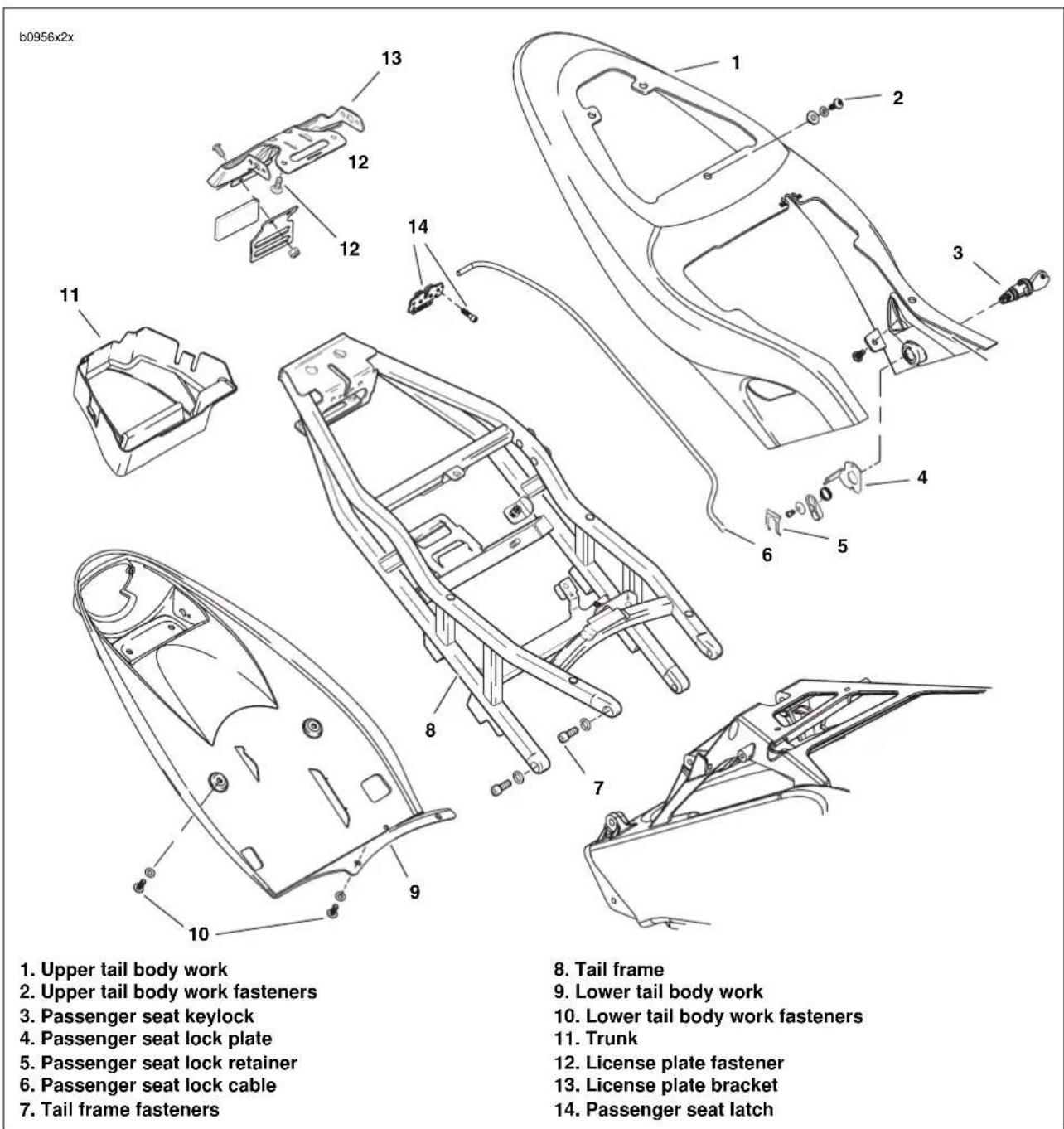
text_image
b0956x2x 1. Upper tail body work 2. Upper tail body work fasteners 3. Passenger seat keylock 4. Passenger seat lock plate 5. Passenger seat lock retainer 6. Passenger seat lock cable 7. Tail frame fasteners 8. Tail frame 9. Lower tail body work 10. Lower tail body work fasteners 11. Trunk 12. License plate fastener 13. License plate bracket 14. Passenger seat latchFigure 2-112. Tail Frame and Body Work Assembly
REMOVAL
- See Figure 2-113. Remove two center (4) and four side windscreen fasteners (3) to remove windshield (1).
- Remove mirrors (2).
- Remove turn signals (6, 7). See 7.13 TURN SIGNALS and remove front fairing (5).
INSTALLATION
- See Figure 2-113. Position fairing (5) onto fairing support bracket and install turn signals (6, 7). See 7.13 TURN SIGNALS.
- Install mirrors (2) with fasteners and tighten to 72-96 in-lbs (8-11 Nm).
- Install two center (4) and four side windscreen fasteners (3).
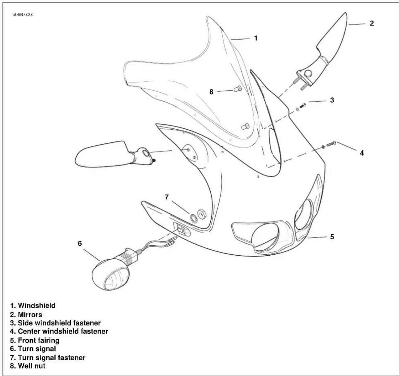
text_image
b0967x2x 1. Windshield 2. Mirrors 3. Side windshield fastener 4. Center windshield fastener 5. Front fairing 6. Turn signal 7. Turn signal fastener 8. Well nutFigure 2-113. Front Fairing and Windscreen
REMOVAL
Rider Seat
- See Figure 2-114. Peel up rear corners of seat and remove two fasteners.
- Pull seat back over tail section and remove.
Pillion Seat
NOTE
The trunk is located under the pillion seat.
- See Figure 2-115. Insert ignition key into pillion seat lock located on left side of motorcycle. Turn key clockwise to disengage rear seat latch.
CAUTION
Do not place keys in underseat storage area. If seat is installed, keys will not be accessible.
2. Lift and remove pillion seat.
INSTALLATION
Rider Seat
- Position seat in mounting position with center tab aligned with slot on frame crossmember.
- Slide seat forward to engage center tab in slot. Pull up on front of seat to verify tab/slot engagement.
WARNING
After installing seat, pull upward on front of seat to be sure it is locked in position. If seat is loose, it could shift during vehicle operation and startle the rider, causing loss of control which could result in death or serious injury.
- Pull up rear corners of seat and tighten two fasteners to 12-36 in-lbs (1-4 Nm).
Pillion Seat
- Install seat by sliding metal locating tab on front underside of seat into opening on motorcycle.
- Align rear tab with latch slot at rear of motorcycle.
- Press down firmly on rear of pillion seat to engage seat latch. Pull up on rear of pillion seat to make sure latch is engaged.
- Turn ignition key counterclockwise and remove from seat lock.
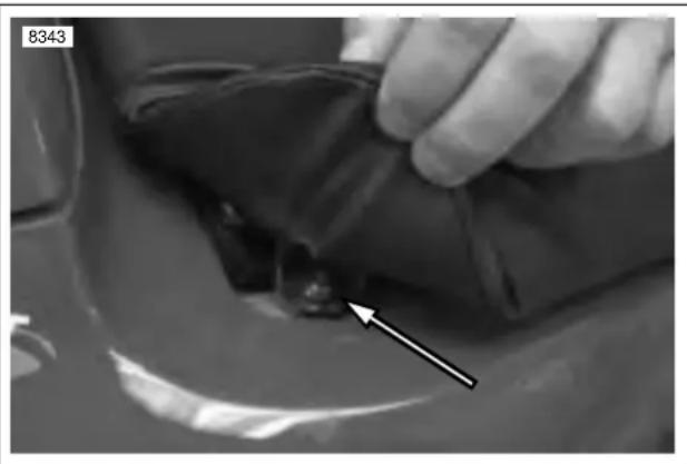
natural_image
Close-up of a hand holding a dark fabric item with an arrow pointing to a small object, no visible text or symbols.Figure 2-114. Accessing Rider Seat Screws
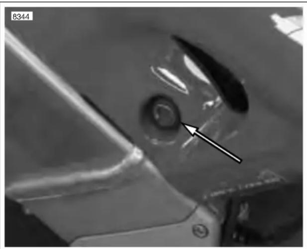
natural_image
Close-up of a car's wheel and side panel with an arrow pointing to the center (no text or symbols visible)Figure 2-115. Pillion Seat Lock
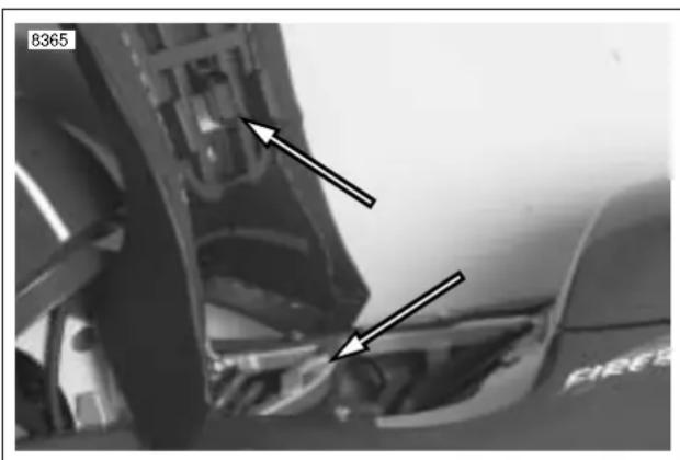
natural_image
Close-up of a car's front wheel and dashboard components with two arrows pointing to specific parts (no text or symbols visible)Figure 2-116. Center Tab and Frame Slot
REMOVAL
- Remove rider and pillion seat. See 2.38 SEAT.
- Remove upper body work on tail section. See 2.36 TAIL FRAME AND BODY WORK.
- See Figure 2-117. Disconnect passenger lock cable (9) by removing cable from seat lock plate (6) and ferrule from seat lock lever (4).
- Remove seat lock lever (4) by removing fastener (2) and washer (3) from seat lock (7).
- Remove spring (5).
- Remove seat lock clip (1) by sliding from seat lock plate (6).
- Remove seat lock plate (6) and seat lock (7).
INSTALLATION
- See Figure 2-117. Install the seat lock (7) on to upper tail body work.
- Install seat lock plate (6) by aligning plate tab onto seat lock (7).
- Install seat lock clip (1) by sliding clip aligning clip groove onto seat lock plate (6) tab.
- Position short tab of spring (5) into seat lock notch.
- Position long end of spring into the seat lock lever (4).
- Load the spring (5) by turning the seat lock lever (4) counterclockwise 1/4 turn.
- Once the spring is loaded, install the seat lock lever (4) onto the lock aligning the lever to the square groove that is cast into the seat lock (7).
- Fasten the lock lever (4) to the seat lock (7) with the washer (3) and fastener (2).
- Install the ferrule (8) of the seat lock cable (9) into the seat lock lever (4).
- Open and close the seat lock with ignition key to verify that cable is working properly.
- Install the seat lock cable (9) into the seat lock plate (6).
- Install upper body work on tail section. See 2.36 TAIL FRAME AND BODY WORK.
- Install rider and pillion seat. See 2.38 SEAT.
2-82 2003 Buell XB9R: Chassis
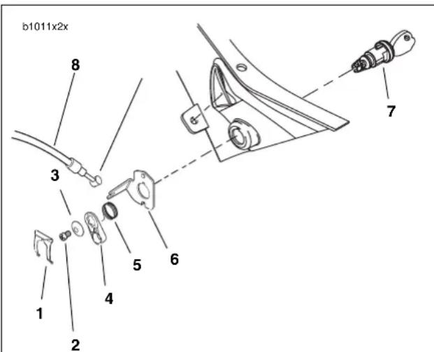
text_image
b1011x2x 8 3 7 5 6 4 1 2- Seat lock clip
- Fastener
- Washer
- Seat lock lever
- Spring
- Seat lock plate
- Seat lock
- Ferrule
- Seat lock cable
Figure 2-117. Seat Lock and Cable Assembly
GENERAL
WARNING
- If the side stand is not in the full forward position when vehicle weight is rested on it, the vehicle could fall over, which could result in death or serious injury.
● Always park motorcycle on a level, firm surface. Vehicle weight could cause motorcycle to fall over, which could result in death or serious injury.
The sidestand is located on the left side of the motorcycle. The sidestand swings outward to support the motorcycle for parking.
The sidestand activates the integral sidestand switch which is part of the starter interlock system. See 7.5 STARTER INTERLOCK for more information.
INSPECTION
- Test the sidestand in the following manner. Without motorcycle weight resting on it, side stand should move freely into extended (down) and retracted (up) positions.
- Check sidestand switch (starter interlock) for proper operation after the first 1500 miles (2400 km) and every 2500 miles (4000 Km) thereafter. See 7.5 STARTER INTERLOCK.
SIDESTAND REMOVAL
- Remove muffler. See Muffler and Straps in 2.28 EXHAUST SYSTEM.
- See Figure 2-120. Remove sidestand switch (6). See SIDESTAND SWITCH REMOVAL in this section.
- Remove fasteners (2) securing sidestand bracket (3) to frame.
SIDESTAND SWITCH REMOVAL
- See Figure 2-118. Cut cable strap securing harness.
- See Figure 2-119. Remove sidestand switch, leaving wire attached, and pull switch assembly and wire harness through to right side of vehicle.
- Remove sidestand assembly.
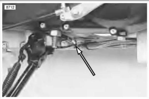
natural_image
Close-up of a mechanical assembly with wires and connectors (no visible text or symbols)Figure 2-118. Sidestand Switch with Cable Strap
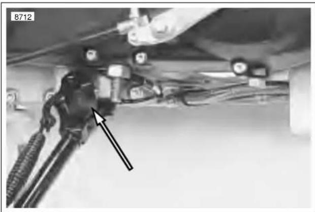
natural_image
Close-up of a mechanical assembly with wires and connectors, no visible text or symbolsFigure 2-119. Sidestand Switch
SIDESTAND DISASSEMBLY
NOTE
Sidestand does not have to be removed from bike to be disassembled.
- See Figure 2-120. Remove fastener (7) securing side-stand switch (6).
- Remove spring (8).
- Remove sidestand pivot bolt (5).
SIDESTAND ASSEMBLY
- See Figure 2-120. Lubricate sidestand pivot bolt (5) and mating portions on sidestand bracket.
- Install sidestand pivot bolt (5) tightening to 18-20 ft-lbs (24-27 Nm).
- Install spring extension plate (4) and spring (8).
NOTE
Extension plate should curve towards primary chain adjustment screw.
-
Install sidestand switch tightening the switch fastener (7) to 36-60 in-lbs (4-7 Nm).
-
Connect sidestand switch to switch connector.
SIDESTAND SWITCH INSTALLATION
- Install sidestand assembly. See SIDESTAND INSTALLATION in this section.
- See Figure 2-119. Install sidestand switch, pulling switch assembly and wire harness through right side of vehicle and connect wire.
- See Figure 2-118. Install cable strap securing harness.
SIDESTAND INSTALLATION
- Install sidestand switch to sidestand assembly.
- Install sidestand to frame tightening the sidestand bracket fasteners to 25-27 ft-lbs (34-37 Nm).
- Install muffler. See Muffler and Straps in 2.28 EXHAUST SYSTEM.
- Inspect sidestand. See INSPECTION in this section.
2-84 2003 Buell XB9R: Chassis
b0946x2x
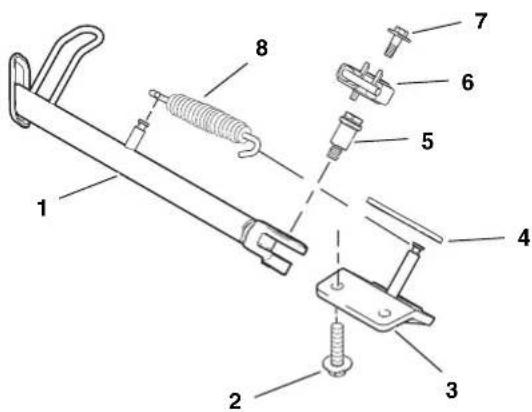
text_image
Technical diagram of a mechanical clamp or bracket assembly with numbered parts for identification- Sidestand leg
- Sidestand bracket fastener
- Sidestand bracket
- Spring extension plate
- Sidestand pivot fastener
- Sidestand switch
- Sidestand switch fastener
- Sidestand spring
Figure 2-120. Sidestand Assembly
ENGINE 3
Table Of Contents
SUBJECT PAGE NO.
3.1 Specifications 3-1
3.2 Engine 3-6
3.3 Engine Rotation for Service 3-8
3.4 Stripping Motorcycle For Engine Service 3-19
3.5 Engine Installation 3-29
3.6 Cylinder Head 3-45
3.7 Cylinder and Piston 3-63
3.8 Lubrication System 3-73
3.9 Oil Hose Routing And Oil Reservoir 3-74
3.10 Oil Pressure Indicator Switch 3-75
3.11 Crankcase Breathing System 3-76
3.12 Oiling System 3-78
3.13 Oil Pump 3-79
3.14 Oil Filter Mount 3-82
3.15 Hydraulic Lifters 3-83
3.16 Gearcase Cover And Cam Gears 3-85
3.17 Crankcase 3-90
NOTE
Service wear limits are given as a guideline for measuring components that are not new. For measurement specifications not given under SERVICE WEAR LIMITS, see NEW COMPONENTS.
Table 3-1. General Information
| Type 2 cylinder, air cooled, four-stroke 45 Degree | V-twin | |
| Compression Ratio 10:1 | ||
| Bore 3.50 in. 88.8 mm | ||
| Stroke 3.125 in. 79.375 mm | ||
| Engine Displacement 60 cu. in. 984 cc | ||
| Oil Capacity (with filter change) 2.5 quarts 2.37 liters | ||
Table 3-2. Engine Ignition Specifications
| Type | Sequential, non waste spark | |
| Regular Idle | 1050-1150 RPM | |
| Spark Plug Size | 12 mm | |
| Spark Plug Type | Harley-Davidson No. 10R12A | |
| Spark Plug Gap | 0.035 in. 0.8890 mm | |
| Spark Plug Torque | 11-18 ft-lbs | 15-24 Nm |
Table 3-3. Valve and Valve Seat Specifications
| VALVE | NEW COMPONENTS | SERVICE WEAR LIMITS | |||
| Fit in guide | Exhaust | 0.001-0.003 in. | 0.0254-0.0762 mm | 0.0038 in. | 0.1016 mm |
| Intake | 0.001-0.003 in. | 0.0254-0.0762 mm | 0.0038 in. | 0.0889 mm | |
| Seat width | 0.040-0.062 in. | 1.016-1.575 mm | 0.090 in. | 2.286 mm | |
| Stem protrusion from cylinder valve pocket | 2.028-2.064 in. | 51.511-52.426 mm | 2.082 in. | 52.8828 mm | |
Table 3-4. Valve Spring Specifications
| VALVE SPRING | NEW COMPONENTS | SERVICE WEAR LIMITS | |||
| Free length | 2.325 in. | 59.1 mm | 2.2.325. (min) | 59.1 mm (min) | |
| Intake | 1.850 in. (closed) | 135 lbs | 61.2 kg | ||
| 1.300 in. (open) | 312 lbs | 141.5 kg | |||
| Exhaust | 1.850 in. (closed) | 135 lbs | 61.2 kg | ||
| 1.300 in. (open) | 312 lbs | 141.5 kg | |||
Table 3-5. Rocker Arm Specifications
| ROCKER ARM NEW COMPONENTS SERVICE WEAR LIMITS | ||||
| Shaft fit in bushing (loose) 0.0005-0.0020 in. 0.0127-0.0508 mm 0.0035 in. 0.0889 mm | ||||
| End clearance 0.003-0.013 in. 0.076-0.330 mm 0.025 in 0.635 mm | ||||
| Bushing fit in rocker arm (tight) | 0.004-0.002 in. 0.102-0.0559 mm | |||
| Rocker arm shaft fit in rocker cover (loose) | 0.0007-0.0022 in. 0.018-0.056 mm | 0.0035 in. 0.0889 mm | ||
Table 3-6. Piston Ring and Piston Pin Specifications
| PISTON | NEW COMPONENTS SERVICE WEAR LIMITS | ||||
| Compression ring gap (top and 2nd) | 0.007-0.020 in. | 0.178-0.508 mm | 0.032 in. | 0.813 mm | |
| Oil control ring rail gap | 0.009-0.052 in. | 0.229-1.321 mm | 0.065 in | 1.651 mm | |
| Compression ring side clearance | Top | 0.0020-0.0045 in. | 0.0508-0.1143 mm | 0.0065 in. | 0.1651 mm |
| 2nd clearance | 0.0016-0.0041 in. 0.0 | 406-0.1041 mm 0.0065 in. | 0.1651 mm | ||
| Oil control ring side clearance | 0.0016-0.0076 in. | 0.0406-0.1930 mm | 0.0094 in. | 0.2388 mm | |
| Pin fit (loose, at room temperature) | 0.00005-0.00045 in. 0. | 00127-0.01143 mm 0.001 | 00 in. 0.025 | 40 mm | |
Table 3-7. Cylinder Head Specifications
| CYLINDER HEAD | NEW COMPONENTS SERVICE WEAR LIMITS | |||
| Valve guide in head (tight) | 0.0033-0.0020 in. | 0.0838-0.0508 mm | ||
| Valve seat in head (tight) 0.0035-0.0010 in. 0.0889-0.0254 mm | ||||
| Head gasket surface (flatness) | 0.006 in. total | 0.152 mm total | 0.006 in. total | 0.152 mm total |
Table 3-8. Cylinder Specifications
| CYLINDER | NEW COMPONENTS | SERVICE WEAR LIMITS | |||
| Taper | 0.002 in. | 0.051 mm | |||
| Out of round | 0.003 in. 0.076 mm | ||||
| Warpage (gasket surfaces) | Top | 0.006 in. | 0.152 mm | ||
| Base | 0.008 in. 0.203 mm | ||||
| Bore diameter± 0.0002 in. | Standard | 3.4978 in. | 88.8441 mm | 3.5008 in. | 88.9203 mm |
Table 3-9. Connecting Rod Specifications
| CONNECTING ROD | NEW COMPONENTS | SERVICE WEAR LIMITS | ||
| Piston pin fit (loose) | 0.00145-0.00155 in. | 0.03683-0.03937 mm | 0.00180 in. | 0.04572 mm |
| Side play between flywheels | 0.005-0.031 in. | 0.1-0.8 mm | 0.036 in. | 0.9 mm |
| Fit on crankpin (loose) | 0.0004-0.0017 in. | 0.0102-0.0432 mm | 0.0027 in. | 0.0686 mm |
| Connecting rod race ID | 1.6245-1.6250 in. | 41.2623-41.2750 mm | 1.6270 in. | 41.3258 mm |
Table 3-10. Hydraulic Lifter Specifications
| HYDRAULIC LIFTER NEW COMPONENTS SERVICE WEAR LIMITS | ||||
| Fit in guide 0.0008-0.0020 in. | 0.0203-0.0508 mm 0.0030 in. | 0.0762 mm | ||
| Roller fit 0.0006-0.0010 in. 0.0 | 152-0.0254 mm 0.0015 in. | 0.0381 mm | ||
| Roller end clearance 0.008-0. | 022 in. 0.203-0.559 mm 0.0 | 26 in. 0.660 mm | ||
Table 3-11. Oil Pump Specifications
| OIL PUMP NEW COMPONENTS SERVICE WEAR LIMITS | |||||
| Oil pressure | 1000 RPM | 7-12 PSI | 48-83 KPa | ||
| 2500 RPM | 10-17 PSI | 69-117 KPa | |||
| Shaft to pump clearance | 0.0025 in. | 0.0635 mm | |||
| Feed/scavenge inner/outer gerotor clearance | 0.003 in. | 0.076 mm | 0.004 in. 0.102 mm | ||
Table 3-12. Gearcase Specifications
| GEARCASE | NEW COMPONENTS SERVICE WEAR LIMITS | |||
| Cam gear shaft in bushing (loose) | 0.0007-0.0022 in. | 0.0178-0.0559 mm | 0.003 in. | 0.076 mm |
| Cam gear shaft end play (min) | 0.005-0.024 in. | 0.127-0.610 mm | 0.025 in. | 0.635 mm |
| Intake cam gear shaft end play (min) | 0.006-0.024 in. | 0.152-0.610 mm | 0.040 in. | 1.016 mm |
Table 3-13. Flywheel Specifications
| FLYWHEEL | NEW COMPONENTS SERVICE WEAR LIMITS | ||||
| Runout | Flywheels at rim | 0.000-0.010 in. | 0.000-0.254 mm | 0.010 in. | 0.254 mm |
| Shaft at flywheel end | 0.000-0.002 in. | 0.000-0.051 mm | 0.002 in. | 0.051 mm | |
Table 3-14. Sprocket Shaft Bearing Specifications
| SPROCKET SHAFT BEARING | NEW COMPONENTS SERVICE WEAR LIMITS | |||
| Bearing outer race fit in crankcase (tight) | 0.006 in.Interference fit | 0.2 mm | ||
| Bearing inner race fit on shaft (tight) | 0.006 in.Interference fit | 0.2 mm | ||
Table 3-15. Pinion Shaft Bearing Specifications
| PINION SHAFT BEARINGS NEW COMPONENTS SERVICE WEAR LIMITS | ||||
| Pinion shaft journal diameter | 1.2496-1.2500 in. | 31.7398-31.7500 mm | 1.2496 in. (min) 31.7398 mm (min) | |
| Outer race diameter in right crankcase | 1.5646-1.5652 in. | 39.7408-39.7561 mm | 1.5672 in. (max) 39.8069 mm (max) | |
| Bearing running clearance 0.000 | 12-0.00088 in. | 0.00305-0.02235 mm | ||
| Fit in cover bushing (loose) 0.00 | 23-0.0043 in. 0.0584-0.1 | 092 mm 0.0050 in. 0.12 | 70 mm | |
TORQUE VALUES
| ITEM TORQUE NOTES | |||
| "V" bracket to main frame | 120-144 in-lbs | 13.6-16.3 Nm | page 3-14, page 3-32 |
| All tie bars | 25-27 ft-lbs | 33.9-36.6 Nm | page 3-14 |
| Anti-rotation screws (lifter) | 55-65 in-lbs | 6-7 Nm | page 3-84 |
| Crankcase 5/16 in. screws | 15-19 ft-lbs 20-26 Nm page 3-102 | ||
| Cylinder head screws | See NOTES | See NOTES | Special pattern to tighten, page 3-60 |
| Cylinder studs | 10-20 ft-lbs | 14-27 Nm | Special method to tighten, page 3-104 |
| Exhaust header nuts | 72-96 in-lbs | 8.1-10.8 Nm | page 3-14 |
| Feed oil line at oil reservoir | 20-22 ft-lbs | 27.1-29.8 Nm | page 3-35 |
| Feed oil line at pump to oil cooler | 18-20 ft-lbs | 24.4-27.1 Nm | page 3-39 |
| Feed oil line at rear of oil pump | 18-20 ft-lbs | 24.4-27.1 Nm | page 3-36 |
| Feed oil line at the oil cooler | 15-17 ft-lbs | 20.3-23 Nm | page 3-39 |
| Front isolator bolt | 49-51 ft-lbs | 66-69 Nm | page 3-14 |
| Front isolator bracket mounting fastener | 49-51 ft-lbs | 66-69 Nm | page 3-14, page 3-32 |
| Front muffler strap fastener | 108-120 in-lbs | 12.2-13.6 Nm | page 3-16 |
| Gearcase cover screws | 80-110 in-lbs | 9-12 Nm | Special pattern to tighten, page 3-89 |
| Oil cooler feed line at the oil pump | 18-20 ft-lbs | 24.4-27.1 Nm | page 3-39 |
| Oil cooler return line fitting at crankcase | 15-17 ft-lbs | 20.3-23 Nm | page 3-39 |
| Oil cooler return line fitting at the oil cooler | 15-17 ft-lbs | 20.3-23 Nm | page 3-39 |
| Oil cooler return oil line | 15-17 ft-lbs | 20.3-23 Nm | page 3-15 |
| Oil filter adapter | 8-12 ft-lbs | 11-16 Nm | LOCTITE 243, page 3-82 |
| Oil pressure signal light switch | 50-70 in-lbs | 6-8 Nm | page 3-82 |
| Oil pump cover screws | 70-80 in-lbs | 8-9 Nm | TORX, page 3-81 |
| Oil pump mounting screws | 125-150 in-lbs | 14-17 Nm | Page 3-81 |
| Pinion shaft nut | 19-21 ft-lbs 26-29 Nm page 3-88 | ||
| Piston jet TORX screws | 25-35 in-lbs | 2.8-4 Nm Loctite 222, page 3-91 | |
| Pushrod cover screw | 30-40 in-lbs | 3-5 Nm | page 3-84 |
| Rear isolator assembly fasteners | 25-27 ft-lbs | 33.9-36.6 Nm | page 3-29 |
| ITEM | TORQUE | NOTES | |
| Rear isolator bolt 49-51 ft-lbs 66.4-69.1 Nm page 3-14 | |||
| Rear muffler bracket 32-36 ft-lbs 43.4-48.8 Nm page 3-33 | |||
| Rear muffler straps 48-60 | in-lbs | 5.4-6.8 Nm page 3-16 | |
| Reed valve fasteners 25-30 | in-lbs | 3.4-4.5 Nm page 3-77 | |
| Return oil line at oil reservoir 19-21 ft-lbs 25.8-28.5 Nm page 3-35 | |||
| Return oil line at top front oil pump 18-20 ft-lbs 24.4-27.1 Nm page 3-36 | |||
| Rocker box cover screws 120-156 | in-lbs | 13.6-17.6 Nm page 3-62 | |
| Rocker box to head bolts 135-155 | in-lbs | 15-18 Nm Small fasteners (2), page 3-62 | |
| Rocker box to head bolts 135-155 | in-lbs | 15-18 Nm Small fasteners (3), page 3-62 | |
| Rocker box to head bolts 18-22 ft-lbs 24-30 Nm Large fasteners, page 3-62 | |||
| Sprocket cover fastener | 12-36 in-lbs | 1-4 Nm | page 3-18, page 3-44 |
| Swingarm pivot shaft pinch bolt | 17-19 ft-lbs | 23-25.8 Nm | page 3-30 |
| Swingarm pivot shaft | 24-26 ft-lbs 32.5-35.2 Nm page 3-30 | ||
| Torca clamp | 40-45 ft-lbs | 54.2-61 Nm | page 3-16 |
| Vent oil line at gearcase cover | 120-132 in-lbs | 13.6-14.9 Nm page 3-36 | |
| Vent oil line at oil reservoir | 14-16 ft-lbs | 19-21.7 Nm | page 3-35 |
Table 3-16. Electrical Items for Engine Removal and Replacement
| Description | Location |
| Ignition Coil | Beneath air box on the left side between cylinders |
| Throttle position sensor (TP) [88] | Located on the right side of engine between cylinders. |
| Head temperature sensor [90] | Beneath air box |
| Oxygen sensor | Behind rear cylinder head (Note: connection under air box) |
| Front and rear fuel injectors | Beneath air box on the right side of engine |
| Speedo sensor [65] | Located under sprocket cover. |
| Cam position sensor | Located under sprocket cover. |
| Neutral switch [131] | Located under sprocket cover. |
| Oil pressure switch [120] | Disconnect at oil pressure switch, right front side of engine. |
| Alternator stator [46] | Located under sprocket cover. |
| Starter solenoid wire [128B] | Disconnect at bottom of starter. |
| Positive battery at starter [128A] | Disconnect at rear of starter |
| Side stand switch [60] Tie wrapped to rear | brake line under vehicle. |
FUEL
Gasoline/alcohol Blends
The Buell XB9R motorcycle has been designed to obtain the best performance and efficiency using a good quality unleaded gasoline. Buell recommends using at least 91 pump octane (RON). Octane rating is usually found on the pump. Some fuel suppliers sell gasoline/alcohol blends as a fuel. The type and amount of alcohol added to the fuel is important.
- DO NOT USE GASOLINES CONTAINING METHANOL. Using gasoline/methanol blends will result in starting and driveability deterioration and damage to critical fuel system components.
- Gasolines containing ETHANOL: Gasoline/ethanol blends are mixture of 10% ethanol (Grain alcohol) and 90% unleaded gasoline. Gasoline/ethanol blends can be used in your motorcycle if the ethanol content does not exceed 10%.
● Gasolines containing ETHER: Gasoline/ether blends are a mixture of gasoline and as much as 15% ether. Gasoline/ether blends can be used in your motorcycle if the ether content does not exceed 17%. - REFORMULATED OR OXYGENATED GASOLINES (RFG): "Reformulated gasoline" is a term used to describe gasoline blends that are specifically designed to burn cleaner than other types of gasoline, leaving fewer "tailpipe" emissions. They are also formulated to evaporate less when you are filling your tank. Reformulated gasolines use additives to "oxygenate" the gas. Your motorcycle will run normally using this type of gas. Buell recommends you use it when possible, as an aid to cleaner air in our environment.
Because of their generally higher volatility, these blends may adversely affect the starting, driveability and fuel efficiency of your motorcycle. If you experience these problems, Buell recommends that you operate your motorcycle on straight, unleaded gasoline.
LUBRICATION
The engine has a force-feed (pressure) type oiling system, incorporating oil feed and return pumps in one pump body, with one check valve on the oil feed side. The feed pump forces oil through the oil cooler to the engine, lubricating lower connecting rod bearings, rocker arm bushings, valve stems, valve springs, push rods and tappets. Cylinder wall, piston, piston pin, timing gears, bushings and main bearings are lubricated by oil spray thrown off connecting rods and crankshaft, and by oil draining from each rocker box through an internal drain passage in each cylinder and each tappet guide. Oil is transferred to the teeth of all the cam gears by way of the gear meshing action. The oil-scavenging section of the pump returns oil to the tank from the engine. See 3.8 LUBRICATION SYSTEM for more information.
ADJUSTMENT/TESTING
General
When an engine needs repair, it is not always possible to determine definitely beforehand whether repair is possible with only cylinder head, cylinder and piston disassembled or whether complete engine disassembly is required for crank-case repair.
Most commonly, only cylinder head and cylinder repair is needed (valves, rings, piston, etc.) and it is recommended procedure to service these units first, allowing engine crank-case to remain in frame.
See 3.4 STRIPPING MOTORCYCLE FOR ENGINE SERVICE to strip motorcycle for removal of cylinder head, cylinder, and piston.
After disassembling “upper end” only, it may be found that crankcase repair is necessary. In this situation, remove the engine crankcase from the chassis.
CAUTION
If engine is removed from chassis, do not lay engine on primary side. Placing engine on primary side will damage clutch cable end fitting. If fitting is damaged, clutch cable must be replaced.
See 1.21 TROUBLESHOOTING section. Symptoms indicating a need for engine repair are often misleading, but generally, if more than one symptom is present, possible causes can be narrowed down to make at least a partial diagnosis. An above-normal consumption of oil, for example, could be caused by several mechanical faults. However, when accompanied by blue-gray exhaust smoke and low engine compression, it indicates the piston rings need replacing. Low compression by itself, however, may indicate improperly seated valves, in addition to or in lieu of worn piston rings.
Most frequently, valves, rings, pins, bushings, and bearings need attention at about the same time. If the possible causes can be narrowed down through the process of elimination to indicate any one of the above components is worn, it is best to give attention to all of the cylinder head and cylinder parts.
COMPRESSION TEST PROCEDURE
Combustion chamber leakage can result in unsatisfactory engine performance. A compression test can help determine the source of cylinder leakage. Use CYLINDER COMPRESSION GAUGE (Part No. HD-33223-1).
A proper compression test should be performed with the engine at normal operating temperature when possible. Proceed as follows:
CAUTION
After completing the compression test(s), make sure that the throttle plate is in the closed position before starting engine. Engine will start at an extremely high RPM if throttle plate is left open.
- Disconnect spark plug wire. Clean around plug base and remove plug.
- Connect compression tester to cylinder.
- With induction module throttle plate in wide open position, crank engine continuously through 5-7 full compression strokes.
- Note gauge readings at the end of the first and last compression strokes. Record test results.
- Compression is normal if final readings are 120 psi (827 kPa) or more.
- Inject approximately 1/2 oz. (15 ml) of SAE 30 oil into cylinder and repeat the compression test. Readings that are considerably higher during the second test indicate worn piston rings.
Table 3-17. Compression Test Results
| DIAGNOSIS TEST RESULTS | |
| Ring trouble Compression | ion low on first stroke;tends to build up on the following strokes but does not reach normal;improves considerably when oil is added to cylinder. |
| Valve trouble Compression | ion low on first stroke;does not build up much on following strokes; does not improve considerably with the addition of oil. |
| Head gasket leak Same reaction as valve trouble. | |
Cylinder Leakage Test
The cylinder leakage test pinpoints engine problems including leaking valves, worn, broken or stuck piston rings and blown head gaskets. The cylinder leakage tester applies compressed air to the cylinder at a controlled pressure and volume, and measures the percent of leakage from the cylinder.
Use a CYLINDER LEAKDOWN TESTER (Part No. HD-35667A) and follow the specific instructions supplied with the tester.
The following are some general instructions that apply to Buell motorcycle engines:
- Run engine until it reaches normal operating temperature.
- Stop engine. Clean dirt from around spark plug and remove spark plug.
-
Remove air cleaner and set induction module throttle plate in wide open position.
-
Remove timing inspection plug from crankcase.
-
The piston, in cylinder being tested, must be at top dead center of compression stroke during test.
-
To keep engine from turning over when air pressure is applied to cylinder, engage transmission in fifth gear and lock the rear brake.
-
Following the manufacturer's instructions, perform a cylinder leakage test on the front cylinder. Make a note of the percent leakdown. Any cylinder with 12% leakdown, or more, requires further attention.
-
See Table 3-18. Listen for air leaks at induction intake, exhaust, head gasket and timing inspection hole.
NOTE
If air is escaping through valves, check push rod length.
- Repeat procedure on rear cylinder.
CAUTION
After completing the compression test(s), make sure that the throttle plate is in the closed position before starting engine. Engine will start at an extremely high RPM if throttle plate is left open.
Table 3-18. Air Leakage Test
| AIR LEAK LOCATION POSSIBLE CAUSES | |
| Induction Module intake | Intake valve leaking. |
| Exhaust pipe | Exhaust valve leaking. |
| Timing inspection hole | Piston rings leaking.Worn or broken piston.Worn cylinder. |
| Head gasket | Leaking gasket. |
Diagnosing Smoking Engine or High Oil Consumption
Perform COMPRESSION TEST PROCEDURE or Cylinder Leakage Test as described previously. If further testing is needed, remove suspect head(s) and inspect the following:
- Valve guide seals.
● Valve guide-to-valve stem clearance.
● Gasket surface of both head and cylinder.
The following process allows you to rotate engine down, pivoting on rear isolator mount, in order to service components in the top end. The engine does not need to be removed from chassis in order to perform top end repairs.
DISASSEMBLY
NOTE
Vehicle should be placed onto the lift with rear tire placed in the wheel vise in order to successfully perform this procedure.
- Disconnect fuel pump and run vehicle until it is out of fuel.
NOTES
● This step is always performed in order to purge fuel lines.
- The connection for fuel pump is just above the pump located at the rear of the fuel tank on the left side of the vehicle.
WARNING
To protect against shock and accidental start-up of vehicle, disconnect the negative battery cable before proceeding. Inadequate safety precautions could result in death or serious injury.
- Remove seat and disconnect battery.
- Remove intake cover and airbox assembly .
- Remove throttle body velocity stack .
NOTE
Cover velocity stack to prevent objects from falling into the induction module.
- See Figure 3-1. Disconnect fuel line.
- Disconnect the throttle position sensor [88].
- Disconnect the fuel injector leads [84 & 85].
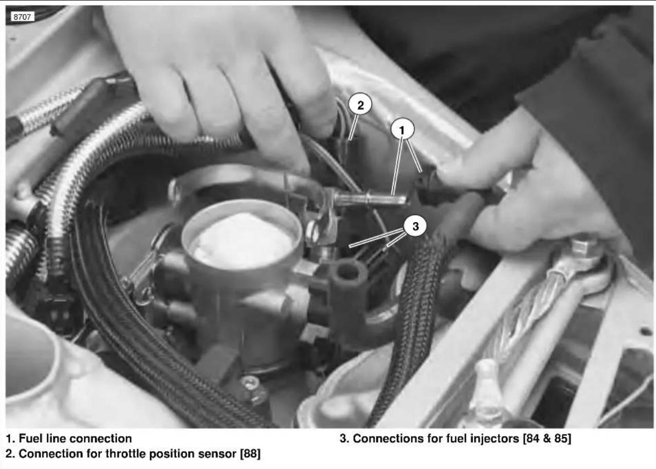
text_image
8707 1. Fuel line connection 2. Connection for throttle position sensor [88] 3. Connections for fuel injectors [84 & 85]Figure 3-1. Fuel Line and DDFI Electrical Connections
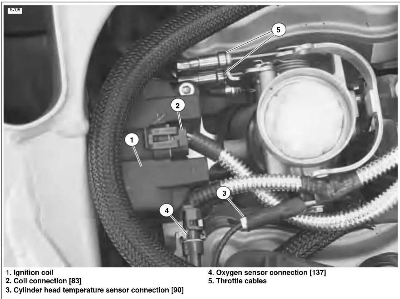
text_image
1. Ignition coil 2. Coil connection [83] 3. Cylinder head temperature sensor connection [90] 4. Oxygen sensor connection [137] 5. Throttle cablesFigure 3-2. Electrical Connections and Throttle Cables
-
See Figure 3-2. Disconnect the ignition coil [83] and remove.
-
See Figure 3-2. Disconnect the following sensors:
a. Temperature sensor [90].
b. Oxygen sensor [137].
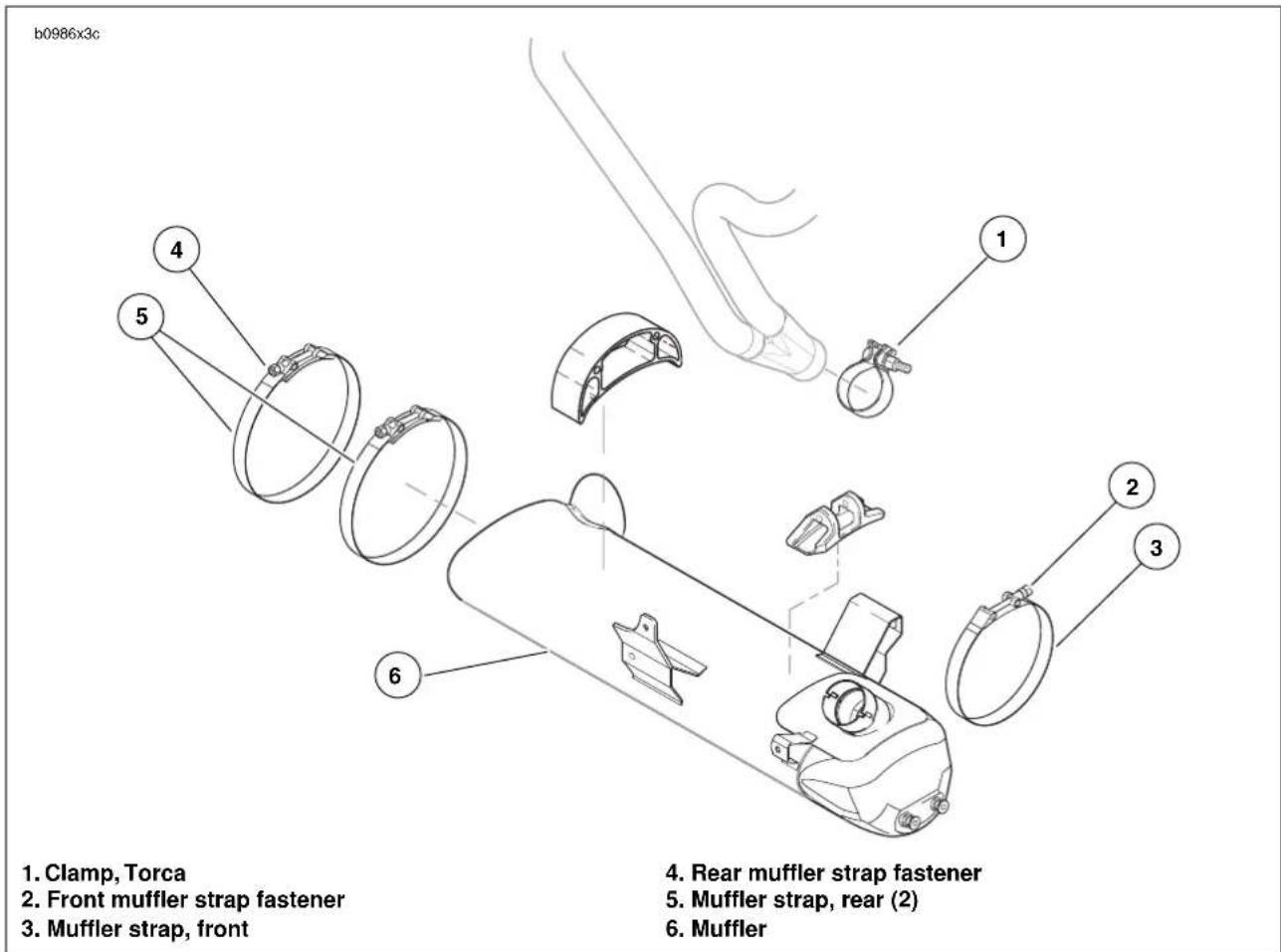
text_image
b0986x3c 1. Clamp, Torca 2. Front muffler strap fastener 3. Muffler strap, front 4. Rear muffler strap fastener 5. Muffler strap, rear (2) 6. MufflerFigure 3-3. Muffler and Mounting System
- Disconnect and remove air scoops, right and left sides.
- Remove complete chin fairing.
- Remove transmission sprocket side cover.
-
Remove rear belt and idler pulley. See 1.9 DRIVE BELT SYSTEM and 2.13 REAR BRAKE MASTER CYLINDER.
-
See Figure 3-3. Remove muffler:
a. Remove front muffler strap.
b. Remove rear muffler straps.
c. Loosen Torca clamp and remove muffler.
HOME
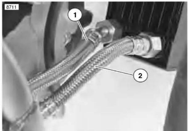
text_image
8711 1 2-
Feed oil line from oil pump to oil cooler
-
Return oil line for oil cooler to crankcase
Figure 3-4. Oil Line Connections at Oil Cooler
-
See Figure 3-4. Disconnect oil lines at oil cooler only.
-
Remove left side rider footrest and support plate.
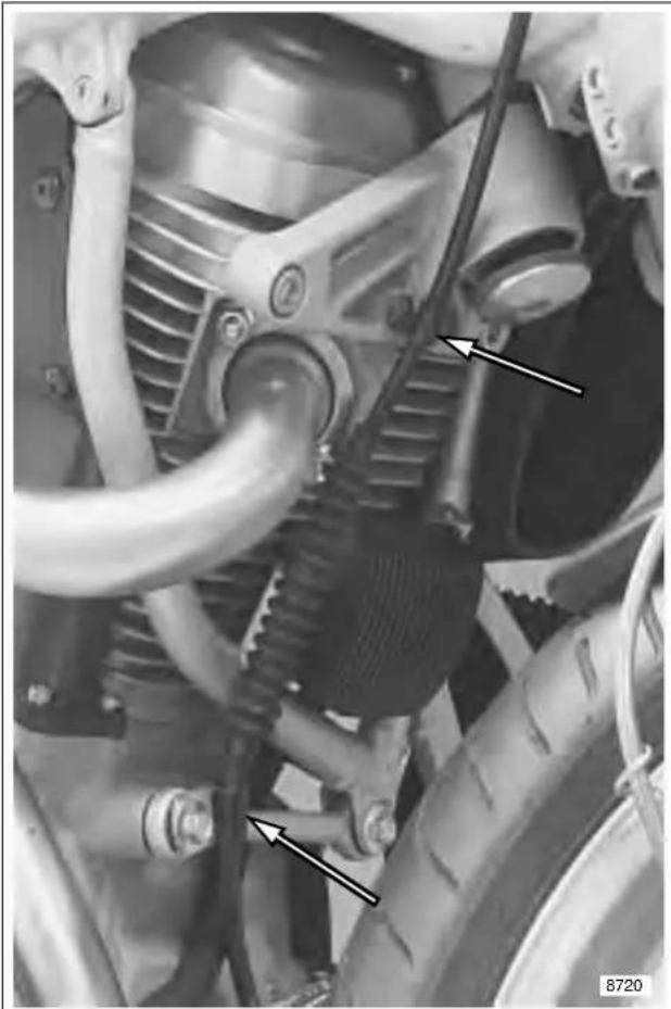
natural_image
Close-up mechanical assembly showing gears and hoses with no visible text or symbolsFigure 3-5. Clutch Cable Retaining Clamps
- See Figure 3-5. Disconnect clutch cable.
a. Remove retaining clamps.
b. Pull clutch cable down.
b0985x3x
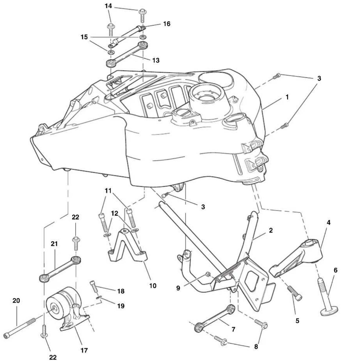
text_image
Technical diagram of a mechanical assembly with numbered components for identification- Frame assembly
- "V" bracket
- Fasteners for "V" bracket (3)
- Isolator assembly, front
- Fasteners for front isolator (2)
- Bolt, front isolator
- Tie bar assembly, front
- Fasteners for front tie bar assembly (2)
- Nut for one fastener for front tie bar assembly
- Mount, center tie bar
-
Fasteners for center tie bar mount (2)
-
Washers for center tie bar mount (2)
- Tie bar assembly, center
- Fasteners for center tie bar assembly (2)
- Washers for center tie bar assembly (2)
- Cable, negative battery
- Isolator assembly, rear
- Fasteners for rear isolator assembly (4)
- Washers for rear isolator assembly (4)
- Bolt, rear isolator
- Tie bar assembly, rear
- Fasteners for rear tie bar assembly (2)
Figure 3-6. Engine Mounting System
HOME
-
Support engine with wide scissors jack.
-
See Figure 3-6. Remove front "V" bracket with oil cooler from main frame:
a. Remove cable strap securing the remote idle adjustment cable.
b. Remove the three cable straps holding regulator wiring harness in order to extend the harness to remove "V" bracket.
c. Unplug regulator harness, (2) plugs.
d. Remove front tie bar from engine.
e. Unbolt "V" bracket from main frame and remove from left side.
- Remove center tie-bar from engine.
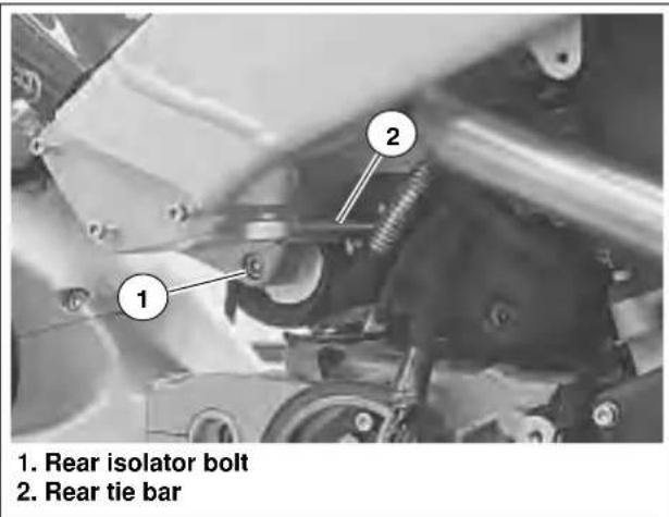
text_image
1. Rear isolator bolt 2. Rear tie barFigure 3-7. Rear Isolator Bolt and Rear Tie Bar
- See Figure 3-7. Remove rear tie bar from frame.
- Loosen rear isolator bolt. DO NOT REMOVE.
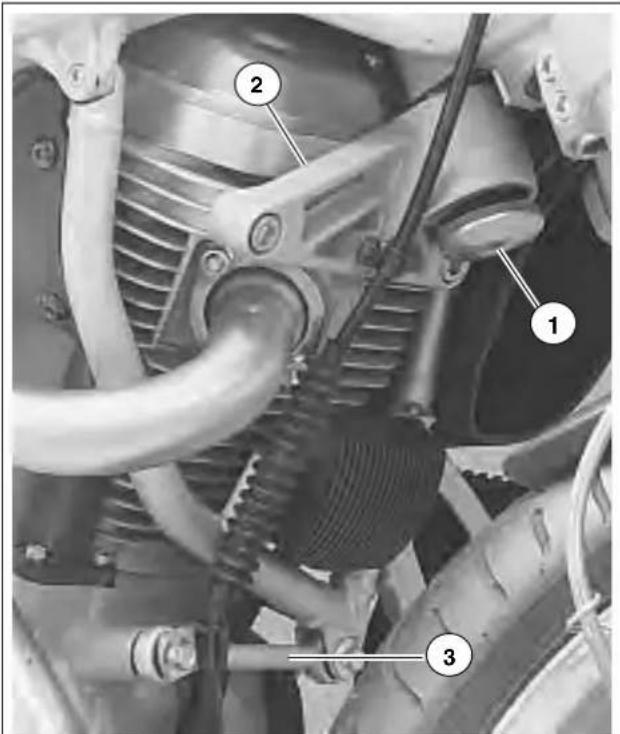
text_image
Technical diagram of a vehicle's internal components with numbered labels pointing to specific parts.- Front isolator bolt
- Front isolator mount
- Front tie bar
Figure 3-8. Front Isolator and Tie Bar Assemblies
- See Figure 3-8. Remove front isolator bolt.
- Remove front isolator mount from engine.
- Rotate engine down.
REASSEMBLY
NOTE
-
If exhaust header was removed during service it must be torqued with the engine rotated in the down position. It is not possible to reach fasteners on the rear exhaust at the head with engine rotated in the up position.
● Tighten header nuts gradually, alternating between studs to insure that exhaust rings are flush with engine. Tighten fasteners to 72-96 in-lbs (8.1-10.8 Nm). -
When repairs have been completed, rotate engine back up into frame.
NOTE
When installing and tightening isolator bolt it is important to keep load off of isolator bolt for installation purposes. Alternate between tightening isolator bolt and raising engine with scissors jack.
b1041x2x
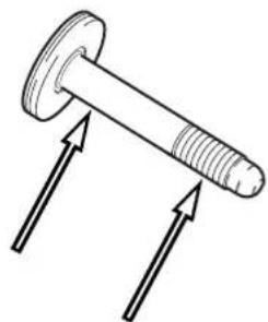
natural_image
Diagram of a bolt with threaded shaft and two upward arrows indicating direction (no text or symbols)Figure 3-9. Lubrication Points on Front Isolator Bolt
NOTE
See Figure 3-9. Always coat shaft and threads of front isolator bolt with anti-seize before installing.
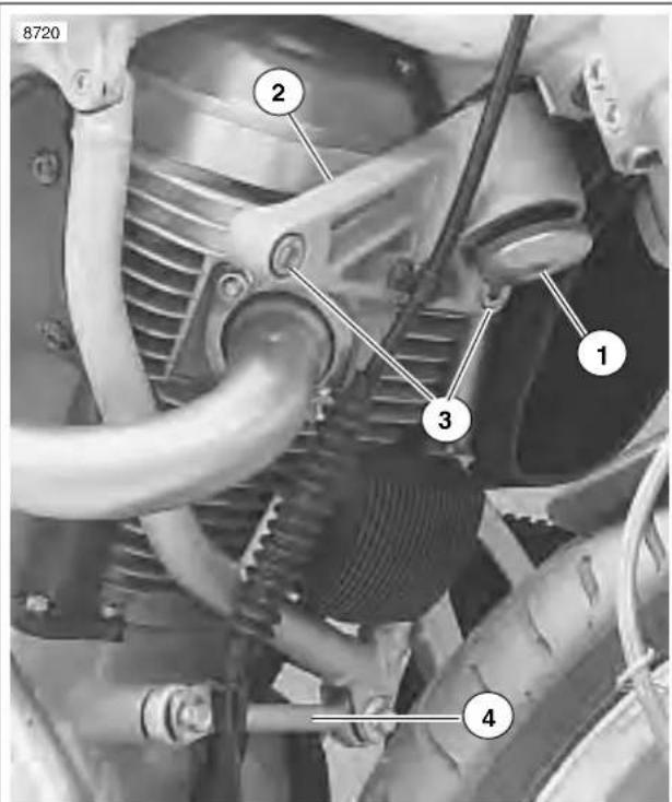
text_image
8720 1 2 3 4- Front isolator bolt
- Front isolator mount
- Front isolator mount fasteners (2)
- Front tie bar
Figure 3-10. Front Isolator and Tie Bar Assemblies
- See Figure 3-10. Insert front isolator bolt (1) through front isolator (2) and loosely thread into frame. Do not tighten at this point.
- See Figure 3-10. Install isolator mounting fasteners (3) and tighten to 49-51 ft-lbs (66-69 Nm).
- Tighten front isolator bolt to 49-51 ft-lbs (66-69 Nm).
- See Figure 3-6. Torque rear isolator bolt to 49-51 ft-lbs (66.4-69.1 Nm).
- See Figure 3-6. Install rear tie bar to frame and tighten to 25-27 ft-lbs (33.9-36.6 Nm).
- See Figure 3-6. Install center tie bar to engine and tighten to 25-27 ft-lbs (33.9-36.6 Nm).
- See Figure 3-6. Install front "V" bracket with oil cooler to main frame.
a. Install "V" bracket to main frame from the left side of the vehicle and tighten to 120-144 in-lbs (13.6-16.3 Nm).
b. Figure 3-10. Install front tie-bar to engine and tighten to 25-27 ft-lbs (33.9-36.6 Nm).
c. Attach regulator wiring harness to bracket nylon cable straps.
- Remove scissors jack.
HOME
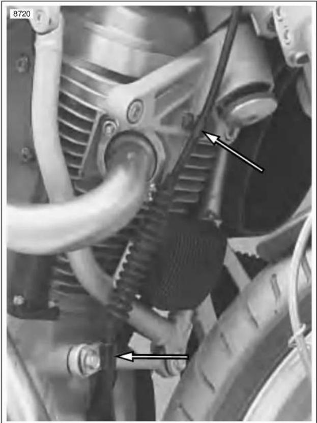
natural_image
Close-up mechanical assembly showing gears and hoses with no visible text or symbolsFigure 3-11. Clutch Cable Retaining Clamps
- See Figure 3-11. Pull clutch cable back up into the proper position.
a. Connect clutch cable to handlebars and adjust to specifications.
b. Install retaining clamps.
NOTE
When torquing the feed oil line from the pump to the oil cooler it is necessary to torque the fitting at the oil pump first.
- See Figure 3-12. Install oil cooler oil feed line first and tighten to 15-17 ft-lbs (20.3-23 Nm).
NOTE
When installing the oil cooler return oil line it is necessary to install the end at the crankcase first.
- See Figure 3-12. Install the oil cooler return oil line and tighten to 15-17 ft-lbs (20.3-23 Nm).
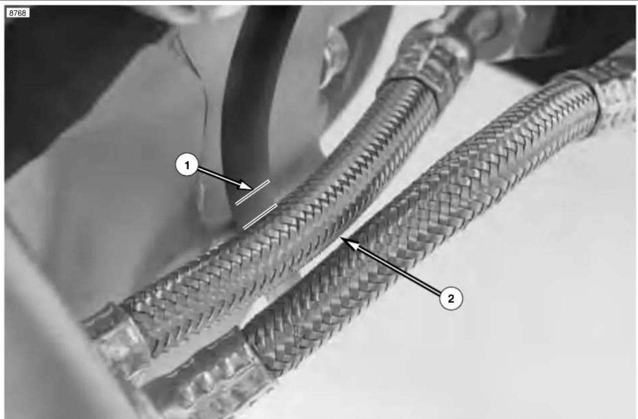
text_image
8768 1 2-
Verify that the clutch cable and feed line have a clearance of 1/8 to 1/4 in. (3.175-6.35 mm) between them.
-
Verify that oil lines have a minimum clearance of 1/8 in. (3.175 mm) between them.
Figure 3-12. Oil Cooler Feed and Return Oil Line Orientation and Clearances
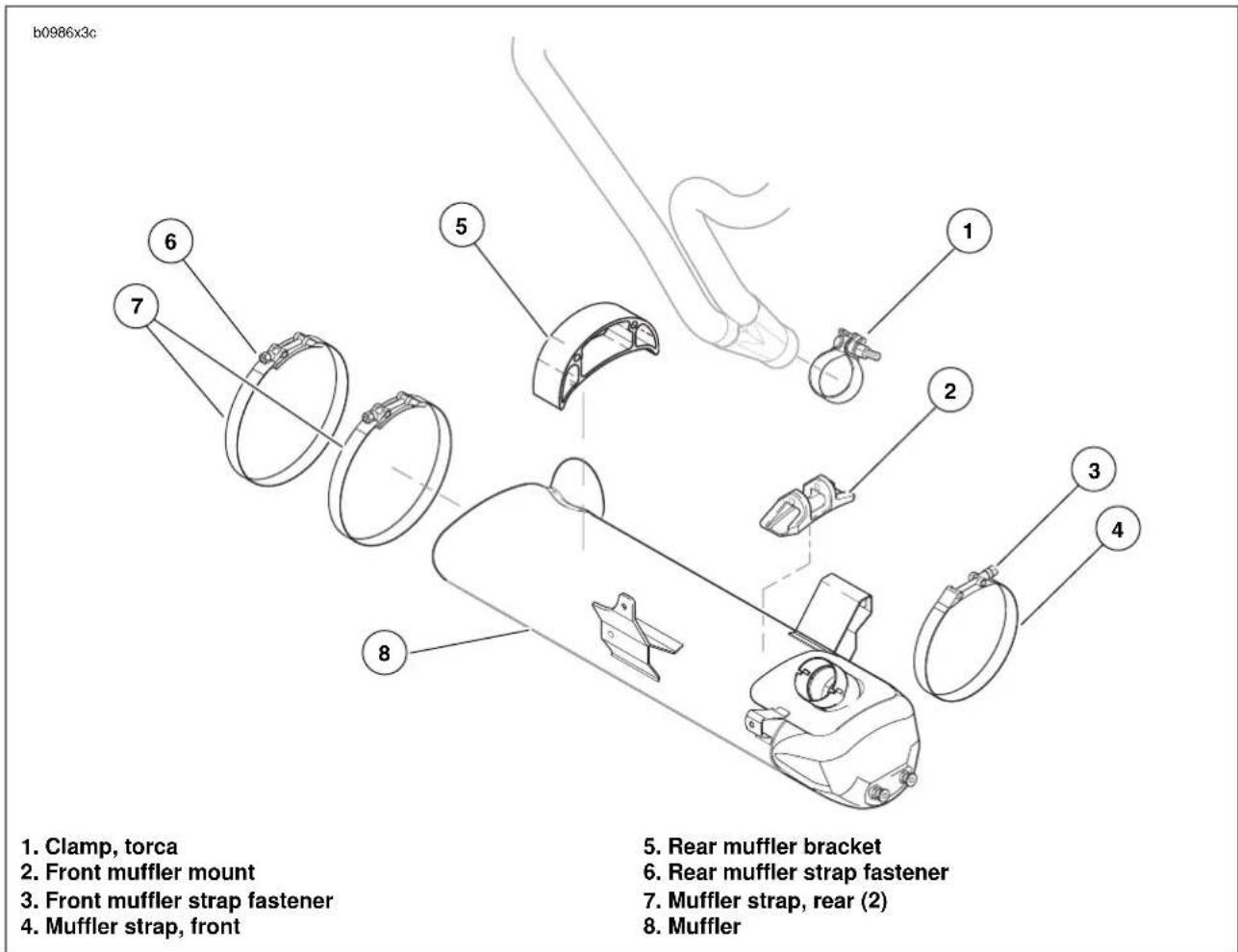
text_image
b0986x3c 1. Clamp, torca 2. Front muffler mount 3. Front muffler strap fastener 4. Muffler strap, front 5. Rear muffler bracket 6. Rear muffler strap fastener 7. Muffler strap, rear (2) 8. MufflerFigure 3-13. Muffler and Mounting System
- See Figure 3-13. Install muffler with new torca clamp but do not tighten:
a. Install rear muffler straps and alternately tighten rear strap fasteners (6) to 48-60 in-lbs (5.4-6.8 Nm).
b. Install front muffler strap fastener (7) and tighten to 108-120 in-lbs (12.2-13.6 Nm).
c. Tighten torca clamp to 40-45 ft-lbs (54.2-61 Nm).
- Tighten front muffler mount to 22-25 ft-lbs (29.8-33.9 Nm).
CAUTION
It is important that the front muffler mount is tightened last in order to ensure proper alignment of the exhaust system.
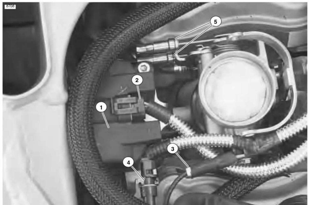
text_image
8708 1 2 3 4 5- Ignition coil
- Coil connection [83]
- Cylinder head temperature sensor connection [90]
- Oxygen sensor connection [137]
- Throttle cables
Figure 3-14. Electrical Connections and Throttle Cables
- See Figure 3-14. Connect throttle cables from induction module/throttle body.
- Disconnect the following sensors:
a. Temperature sensor [90].
b. Oxygen sensor [137].
- See Figure 3-14. Install the ignition coil and connect [83] and tighten fasteners to 120-144 in-lbs (13.6-16.3 Nm).
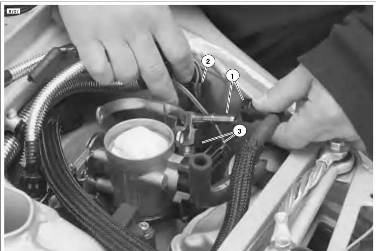
text_image
8707 2 1 3- Fuel line connection
- Connection for throttle position sensor [88]
- Connections for fuel injectors [84 & 85]
Figure 3-15. Fuel Line and DDFI Electrical Connections
CAUTION
Remove shop towel from entrance of throttle body to ensure proper operation of induction module.
-
See Figure 3-15. Connect throttle position sensor [88].
-
Connect fuel injector leads [84 & 85].
-
Connect fuel line.
-
Install throttle body velocity stack (tighten).
-
Install airbox assembly and intake cover and tighten fasteners to 84-120 in-lbs (9.5-13.6 Nm).
-
Install rear belt and idler pulley. See 1.9 DRIVE BELT SYSTEM and 2.13 REAR BRAKE MASTER CYLINDER.
-
Install left side rider footrest and support plate and tighten fasteners to 120-144 in lbs (13.56-16.27 Nm).
-
Install sprocket cover and tighten fasteners and washers to 12-36 in-lbs (1-4 Nm).
-
Install chin fairing. See 2.33 CHIN FAIRING.
-
Install air scoops, right and left sides. See 2.35 AIR SCOOPS.
-
Connect fuel pump.
NOTE
The connection for fuel pump is just above the pump located at the rear of the fuel tank on the left side of the vehicle.
WARNING
Always connect positive battery cable first. If the positive cable should contact ground with the negative cable installed, the resulting sparks may cause a battery explosion which could result in death or serious injury.
- Connect negative ground cable to battery and install seat (tighten).
WARNING
Pull up on seat to verify that it is properly secured, front and rear. A loose seat may shift during vehicle operation and startle the rider, possibly causing loss of vehicle control resulting in death or serious injury.
DISASSEMBLY
NOTE
Vehicle should be placed onto the lift with rear tire in the wheel vise in order to successfully perform this procedure.
- Disconnect fuel pump and run vehicle until it is out of fuel. See 4.40 FUEL PUMP.
NOTES
● This step is always performed in order to purge fuel lines.
● The connection for fuel pump is just above the pump located at the rear of the fuel tank on the left side of the vehicle.
- Drain oil tank.
WARNING
To protect against shock and accidental start-up of vehicle, disconnect the negative battery cable before proceeding. Inadequate safety precautions could result in death or serious injury.
- Remove seat and disconnect battery.
- Remove intake cover and airbox assembly.
- Remove throttle body velocity stack.
NOTE
Install shop towel in entrance to throttle body to prevent objects from falling into the induction module.
- See Figure 3-16. Disconnect fuel line.
- Disconnect throttle position sensor [88].
- Disconnect fuel injector leads [84 & 85].
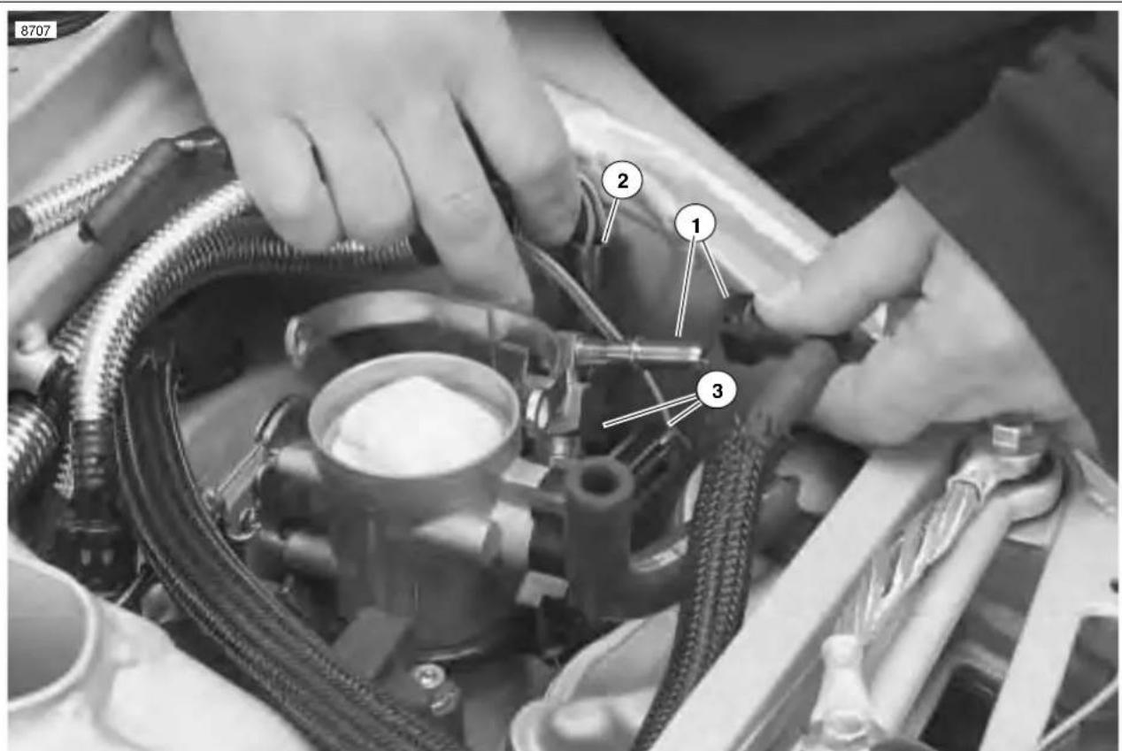
text_image
8707 2 1 3- Fuel line connection
- Connection for throttle position sensor [88]
- Connections for fuel injectors [84 & 85]
Figure 3-16. Fuel Line and DDFI Electrical Connections
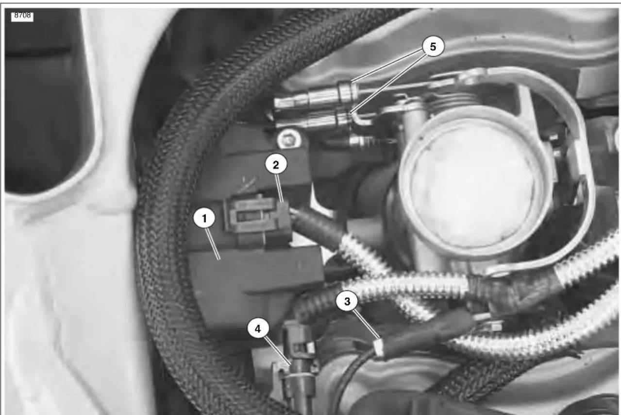
text_image
8708 1 2 3 4 5- Ignition coil
- Coil connection [83]
- Cylinder head temperature sensor connection [90]
- Oxygen sensor connection [137]
- Throttle cables
Figure 3-17. Electrical Connections and Throttle Cables
- See Figure 3-17. Disconnect the ignition coil (2) and remove.
- Disconnect the following sensors:
c. Temperature sensor [90].
d. Oxygen sensor [137].
- Disconnect throttle cables from induction module/throttle body.
00986X3X
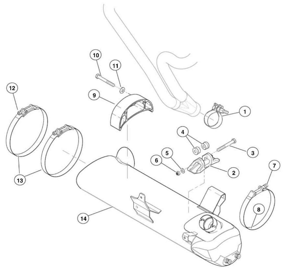
text_image
Exploded view diagram of a device with numbered parts for identification and assembly reference.- Clamp, Torca
- Muffler mount, front
- Screw, front muffler mount (1)
- Bushings, front muffler mount (2)
- Flat washer, front muffler mount (1)
- Nut, front muffler mount (1)
-
Front muffler strap fastener
-
Muffler strap, front
- Muffler bracket, rear
- Screw, rear muffler bracket (2)
- Flat washer, rear muffler bracket (2)
- Rear muffler strap fastener
- Muffler strap, rear (2)
- Muffler
Figure 3-18. Muffler and Mounting System
- Disconnect and remove air scoops, right and left sides.
- Remove complete chin fairing, (7) bolts.
- Remove transmission sprocket side cover.
-
Remove rear belt and idler pulley. See 1.9 DRIVE BELT SYSTEM and 2.13 REAR BRAKE MASTER CYLINDER.
-
See Figure 3-18. Remove muffler:
a. Remove front muffler strap fastener (7). Front strap will not be removed.
b. Alternately loosen rear strap fasteners (12) and remove rear muffler straps.
c. Loosen Torca clamp and remove muffler.
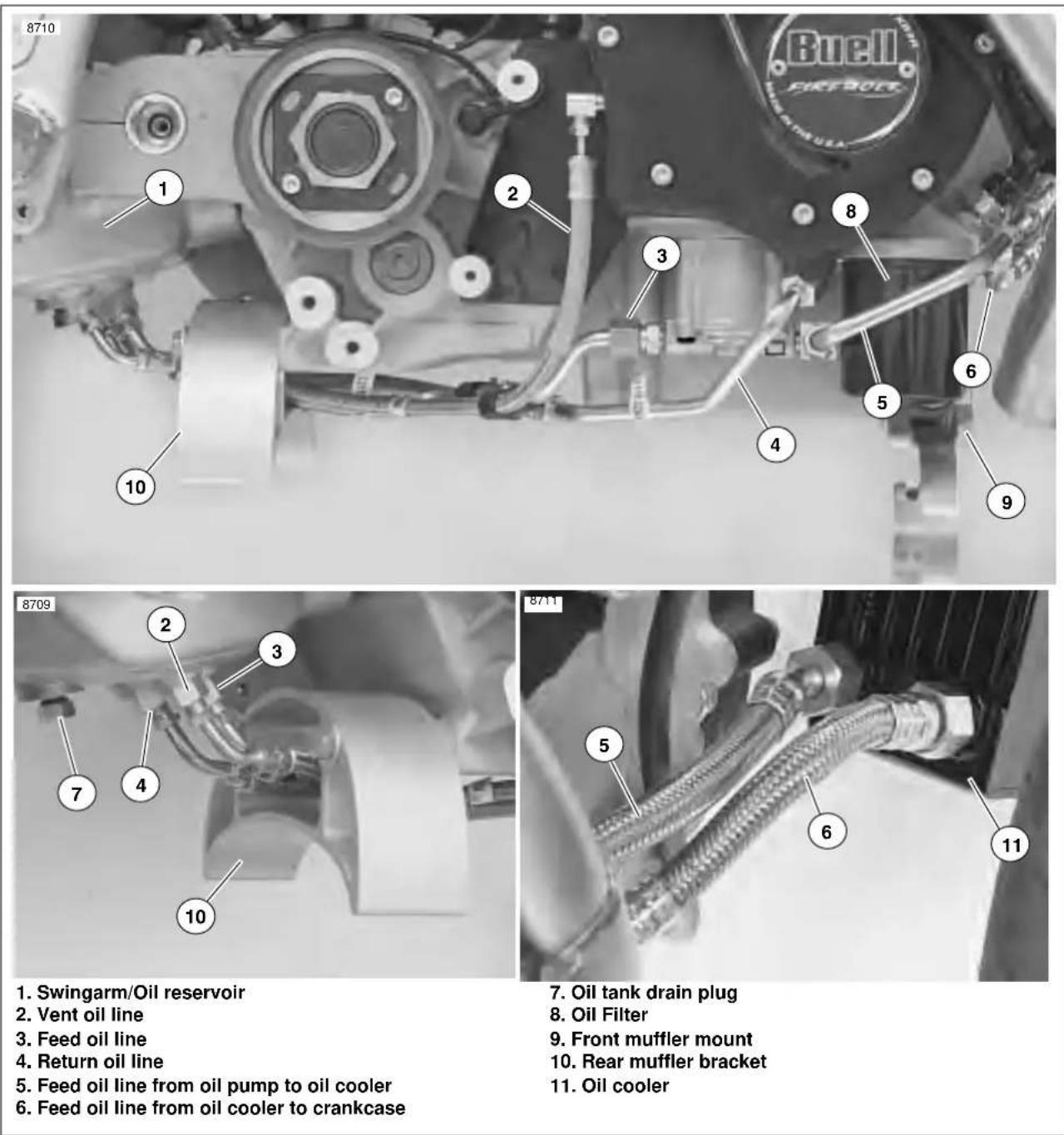
text_image
8710 1 2 3 4 5 6 7 8 9 10 8709 2 3 7 4 10 8/11 5 6 7. Oil tank drain plug 8. Oil Filter 9. Front muffler mount 10. Rear muffler bracket 11. Oil cooler 1. Swingarm/Oil reservoir 2. Vent oil line 3. Feed oil line 4. Return oil line 5. Feed oil line from oil pump to oil cooler 6. Feed oil line from oil cooler to crankcaseFigure 3-19. Oil Lines and Connections
- See Figure 3-19. Remove oil filter.
-
Remove all oil lines (including lines to oil cooler).
-
Remove front and rear muffler brackets.
HOME
- Remove left and right side rider footrests and support plates. See 2.29 FOOTPEG, HEEL GUARD AND MOUNT.
NOTE
When removing the right side rider footrest and support plate, also remove rear brake pedal assembly and remote reservoir and secure towards rear of vehicle.
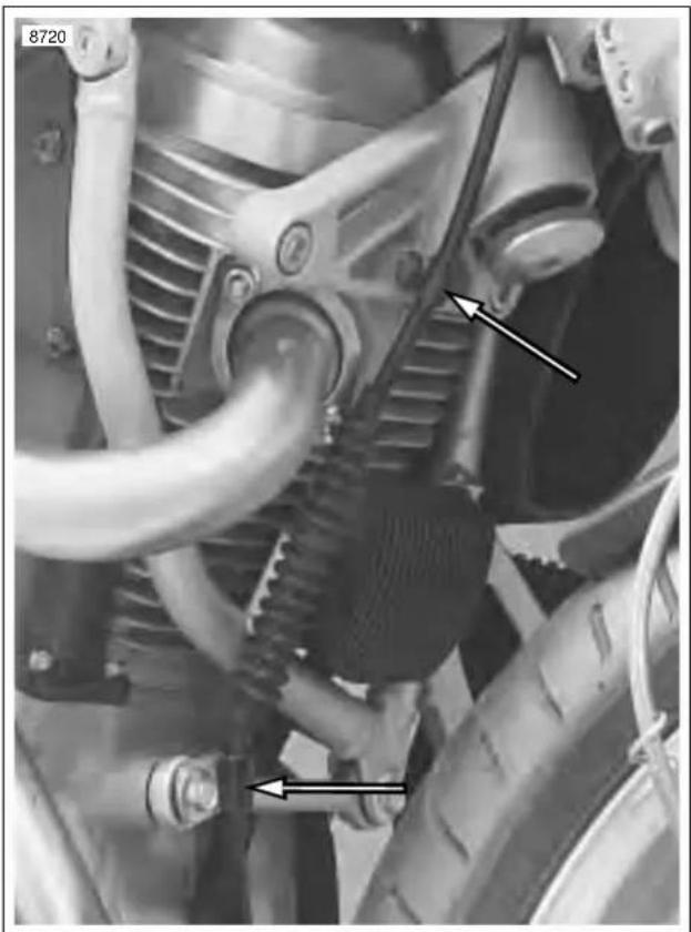
natural_image
Close-up mechanical assembly showing gears and hoses with no visible text or symbolsFigure 3-20. Clutch Cable Retaining Clamps
- See Figure 3-20. Disconnect clutch cable from handlebars.
a. Remove retaining clamps.
b. Pull clutch cable down.
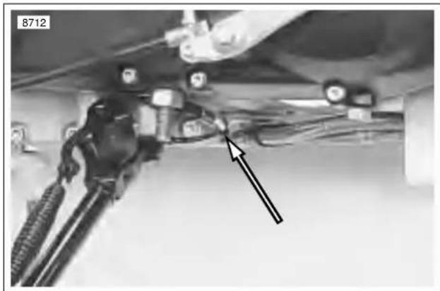
natural_image
Close-up of a mechanical assembly with wires and components, no visible text or symbolsFigure 3-21. Sidestand Switch with Cable Strap
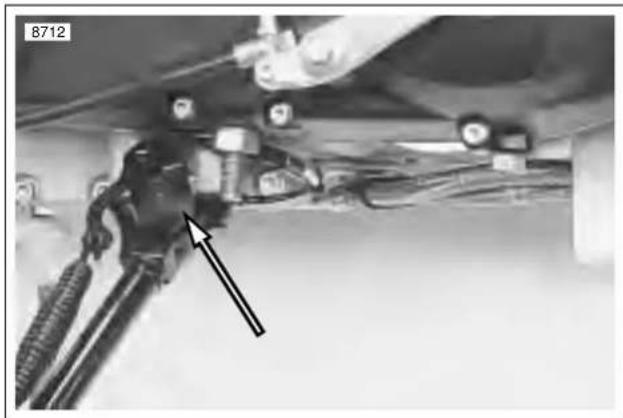
natural_image
Close-up of a mechanical assembly with wires and components, no visible text or symbolsFigure 3-22. Sidestand Switch
- See Figure 3-21. Cut cable strap securing harness.
- See Figure 3-22. Remove sidestand switch, leaving wire attached, and pull switch assembly and wire harness through to right side of vehicle.
- Remove sidestand assembly.
b0985x3x
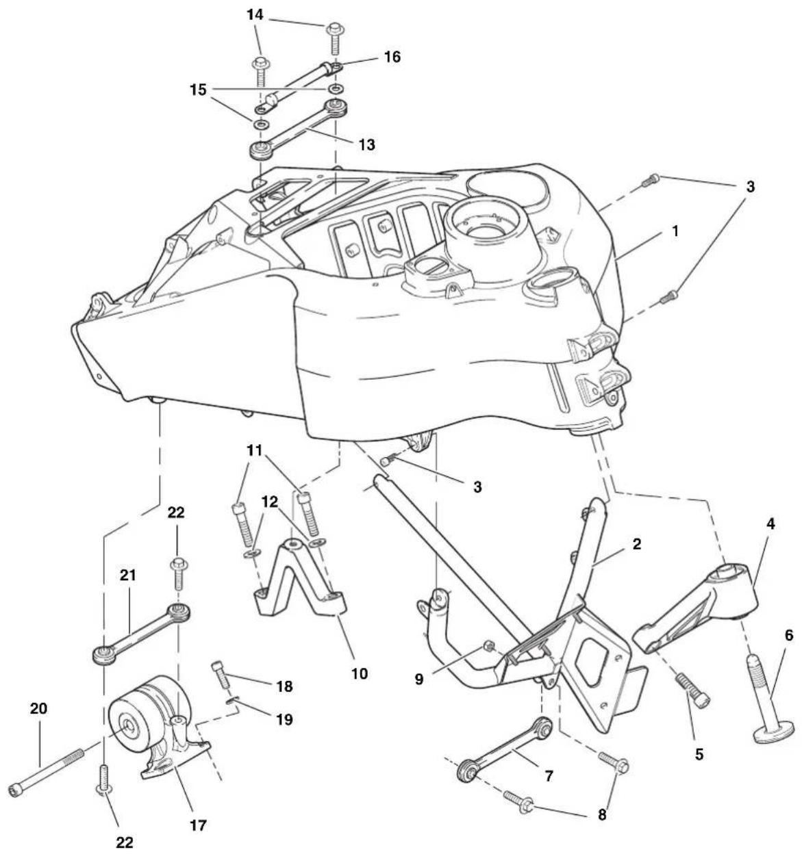
text_image
Technical diagram of a mechanical assembly with numbered components for identification- Frame assembly
- "V" bracket
- Fasteners for "V" bracket (3)
- Isolator assembly, front
- Fasteners for front isolator (2)
- Bolt, front isolator
- Tie bar assembly, front
- Fasteners for front tie bar assembly (2)
- Nut for one fastener for front tie bar assembly
- Mount, center tie bar
-
Fasteners for center tie bar mount (2)
-
Washers for center tie bar mount (2)
- Tie bar assembly, center
- Fasteners for center tie bar assembly (2)
- Washers for center tie bar assembly (2)
- Cable, negative battery
- Isolator assembly, rear
- Fasteners for rear isolator assembly (4)
- Washers for rear isolator assembly (4)
- Bolt, rear isolator
- Tie bar assembly, rear
- Fasteners for rear tie bar assembly (2)
Figure 3-23. Engine Mounting System
HOME
-
Support engine with wide scissors jack.
-
See Figure 3-23. Remove front "V" bracket with oil cooler from main frame.
a. Remove cable strap securing the remote idle adjustment cable
b. Remove the three cable straps holding regulator wiring harness in order to extend the harness to remove "V" bracket
c. See Figure 3-24. Unplug regulator harness, (2) plugs
- Alternator [46].
● Voltage regulator [77].
d. Remove front tie-bar from engine.
e. Unbolt "V" bracket from main frame and remove from left side.
- See Figure 3-23. Remove center tie-bar from engine.
- Remove rear tie bar from frame.
- Loosen rear isolator bolt.
- Remove front isolator bolt.
- Remove front isolator mount from engine.
- See Figure 3-24. Disconnect electrical components:
a. Neutral switch [131].
b. Speedometer sensor [65] (remove tie wrap).
c. Cam position sensor [14].
d. Positive battery cable at starter.
e. Starter solenoid [128].
f. Oil pressure switch [120].
- Rotate engine down to remove exhaust header.
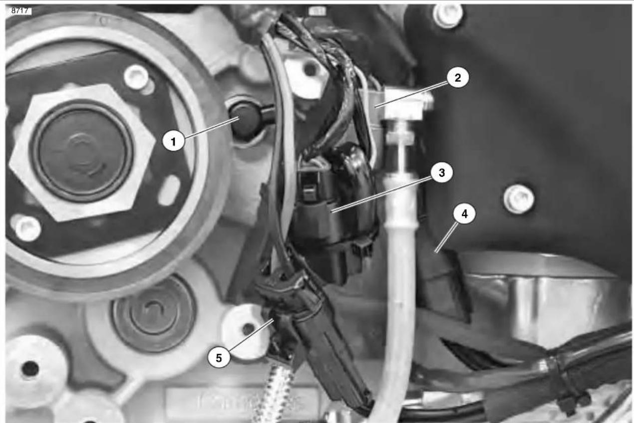
text_image
8717 1 2 3 4 5-
Neutral switch [131]
-
Speedometer sensor connection [65]
-
Cam position sensor connection [14]
-
Alternator connection [46]
-
Voltage regulator connection [77]
Figure 3-24. Electrical Connections
CAUTION
See Figure 3-25. At this point it is necessary to support main frame with overhead hoist in order to remove rear isolator bolt. Failure to do this will result in main frame dropping slightly.
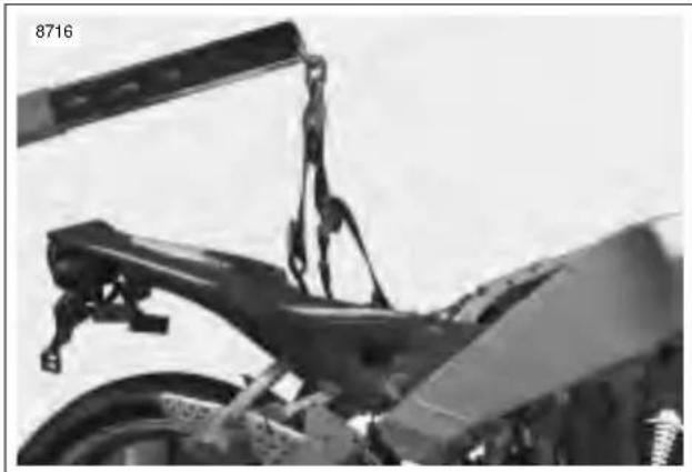
natural_image
Mechanical assembly with attached bracket and mounting bracket (no visible text or symbols)Figure 3-25. Supporting Vehicle for Disassembly
- See Figure 3-26. After rotating engine back up into frame, continue to remove:
a. Rear isolator bolt.
b. Swingarm pivot shaft.
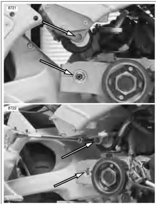
natural_image
Mechanical assembly diagrams showing two views of a vehicle's wheel and suspension components (no text or symbols)Figure 3-26. Rear Isolator Bolt and Swingarm Pivot Shaft
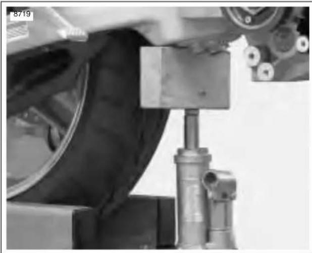
natural_image
Close-up of a car tire under maintenance with mechanical components (no visible text or symbols)Figure 3-27. Supporting the Swingarm
- See Figure 3-27. Support swingarm/oil tank with wooden blocks, jack, etc.
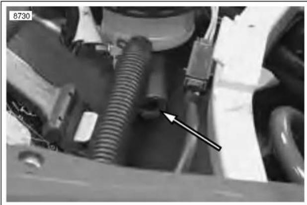
natural_image
Close-up of mechanical components with a black arrow pointing to a component (no visible text or symbols)Figure 3-28. Transmission Vent Line
- See Figure 3-28. Cut the two tie wraps holding transmission vent line and pull vent line out of frame leaving it attached to engine.
NOTE
The transmission vent line runs up the left side of the frame and exits underneath the rear brake reservoir and hose.
-
Lower engine with scissors lift all the way down.
-
Move the engine assembly from under the main frame to the right side of the lift.
-
Remove engine.
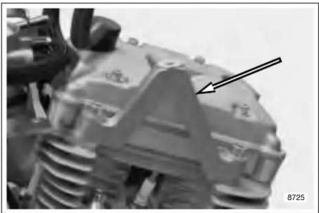
natural_image
Close-up of a mechanical component with a black arrow pointing to a specific part (no visible text or symbols)Figure 3-29. Center Tie Bar Mount
- Once engine has been removed from vehicle finish removing the following items as required:
a. Shifter assembly.
b. See Figure 3-29. Center tie bar mount.
c. See Figure 3-30. Swingarm pivot shaft pinch bolt threaded insert.
d. See Figure 3-31. Aluminum bushings from front exhaust mount.
e. Timer cover.
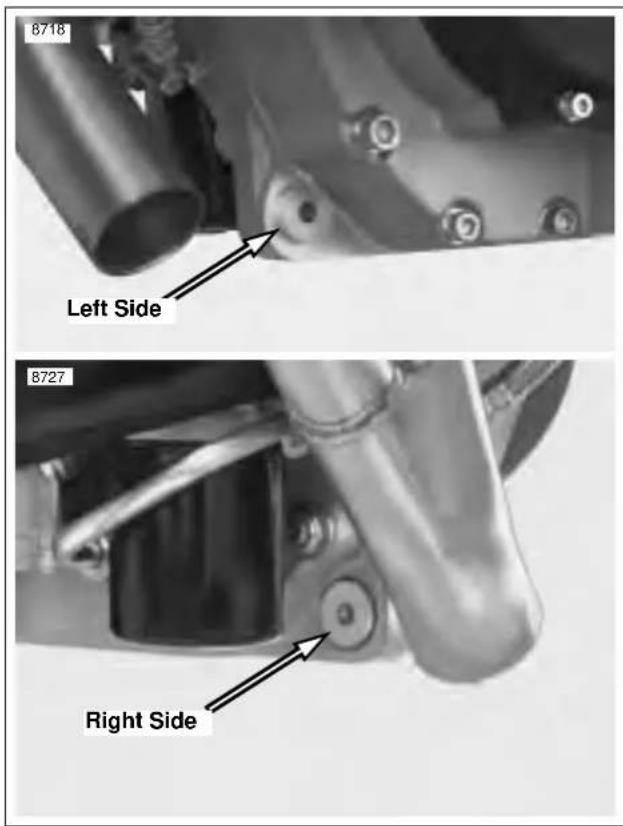
text_image
8718 Left Side 8727 Right SideFigure 3-31. Front Exhaust Mount Bushings (2 piece)
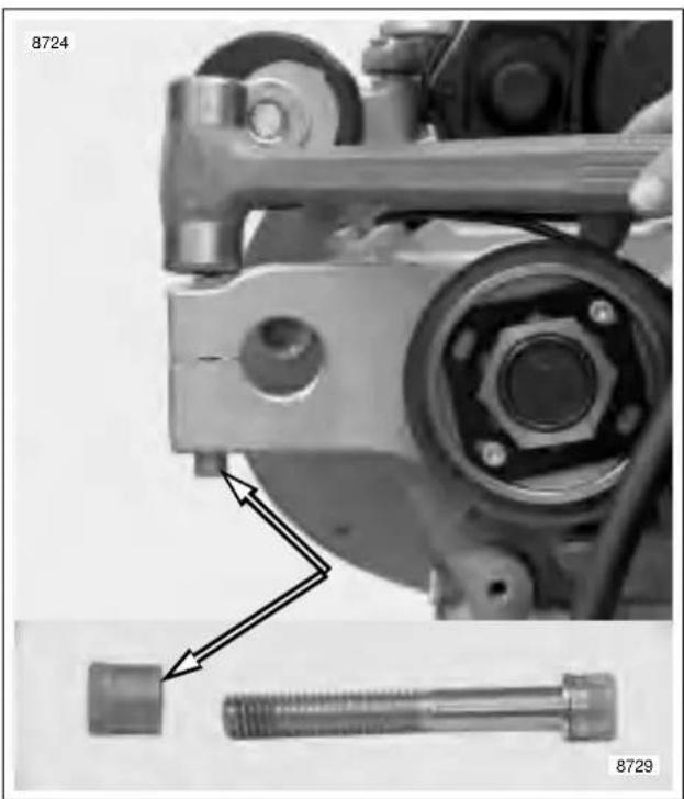
natural_image
Mechanical assembly diagram showing a bolt and nut assembly with no visible text or symbolsFigure 3-30. Removing Threaded Insert
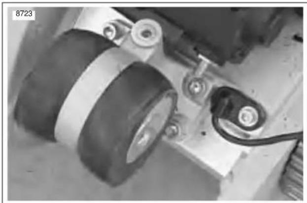
natural_image
Close-up of a mechanical assembly with visible wheels and components (no text or symbols)Figure 3-32. Rear Isolator and Mounting Hardware
- See Figure 3-32. If the crankcases are being separated it will be necessary to remove rear isolator assembly by removing the forward two fasteners first and then the two rear fasteners (re-install with new fasteners).
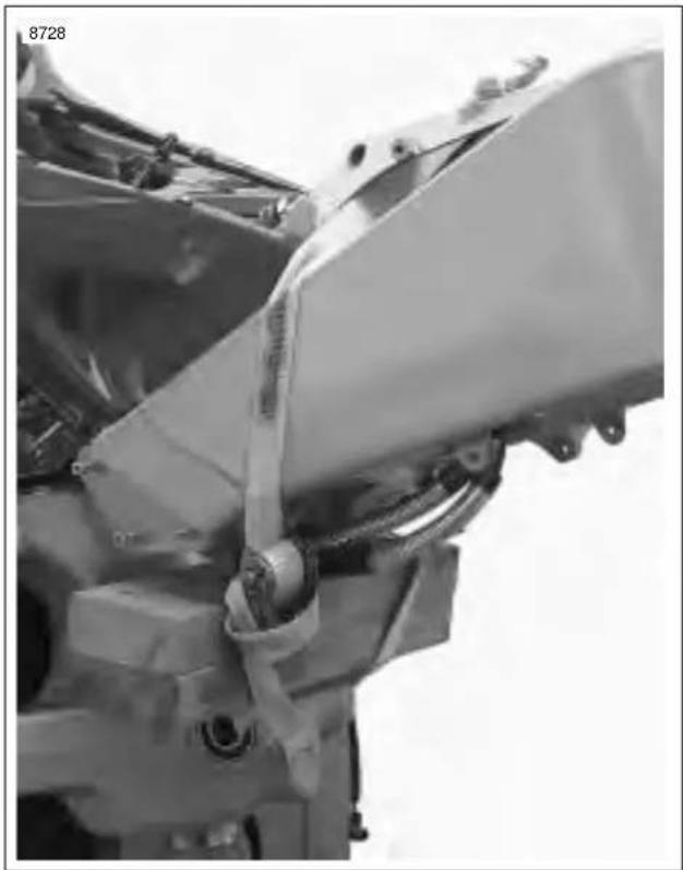
natural_image
Close-up of mechanical components with visible springs and connectors (no text or symbols)Figure 3-33. Securing Vehicle for Relocation
- See Figure 3-33. Place a block of wood between rear isolator mount on main frame and swingarm/oil tank.
- Route a ratcheting tie down through the swingarm bearings, up over the main frame, through the top stabilizer area, back down to the ratchet mechanism and secure swingarm to main frame.
NOTE
See Figure 3-34. This allows the vehicle to remain together as a rolling chassis and to be removed from the lift and stored if necessary.
- Remove support from under swingarm/oil tank.
- Remove overhead support.
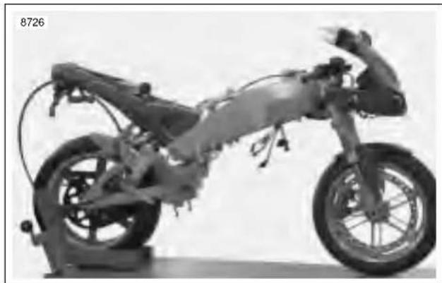
natural_image
Black-and-white photo of a motorcycle with visible suspension and wheel structure (no text or symbols)Figure 3-34. Rolling Chassis
ASSEMBLY
Engine Prep for Re-installation
NOTE
Install components that were removed from engine as were necessary for service prior to installing engine in frame.
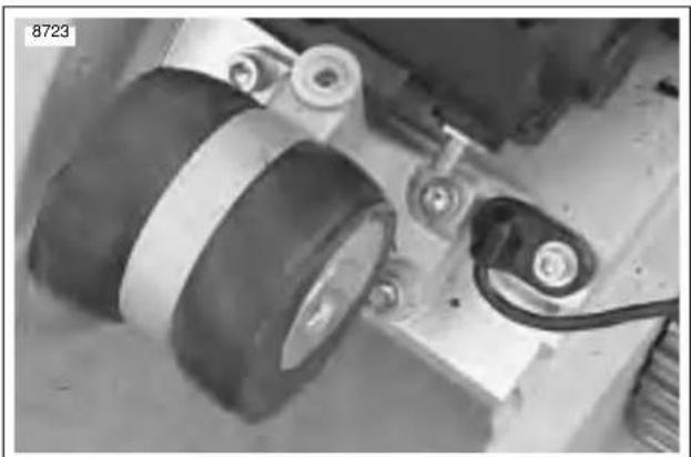
natural_image
Close-up of mechanical components including a tire and pulley system (no visible text or symbols)Figure 3-35. Rear Isolator and Mounting Hardware
- See Figure 3-35. Install rear isolator assembly by installing the two rear fasteners first and then the two forward fasteners (re-install with new fasteners). Tighten to 25-27 ft-lbs (33.9-36.6 Nm).
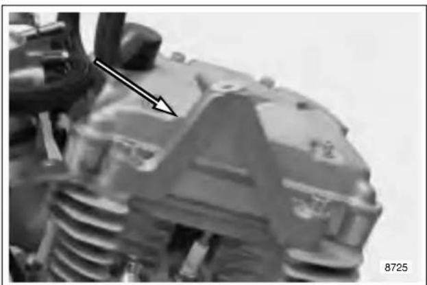
natural_image
Close-up of a mechanical component with a black arrow pointing to a specific part (no visible text or symbols)Figure 3-36. Center Tie Bar Mount
- Install the following items on the engine assembly as required:
a. Shifter assembly.
b. See Figure 3-36. Center tie bar mount 25-27 ft-lbs (33.9-36.6 Nm).
c. See Figure 3-37. Swingarm pivot shaft pinch bolt threaded insert.
d. See Figure 3-38. Aluminum bushings from front exhaust mount.
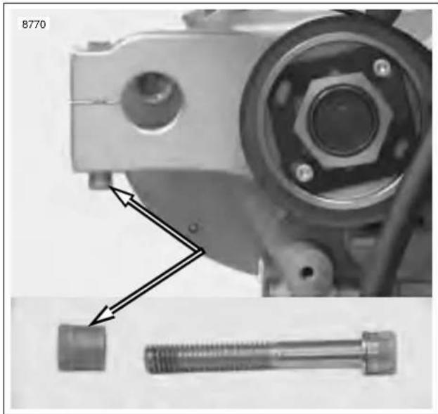
natural_image
Mechanical assembly diagram showing a bolt and nut assembly with no visible text or symbolsFigure 3-37. Installing Threaded Insert
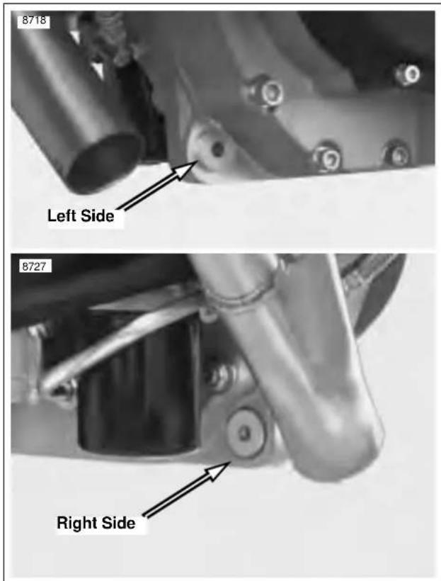
text_image
8718 Left Side 8727 Right SideFigure 3-38. Front Exhaust Mount Bushings (2 piece)
HOME
Installing Engine in Frame
NOTE
Vehicle should be placed onto the lift with rear tire in the wheel vise in order to successfully perform this procedure.
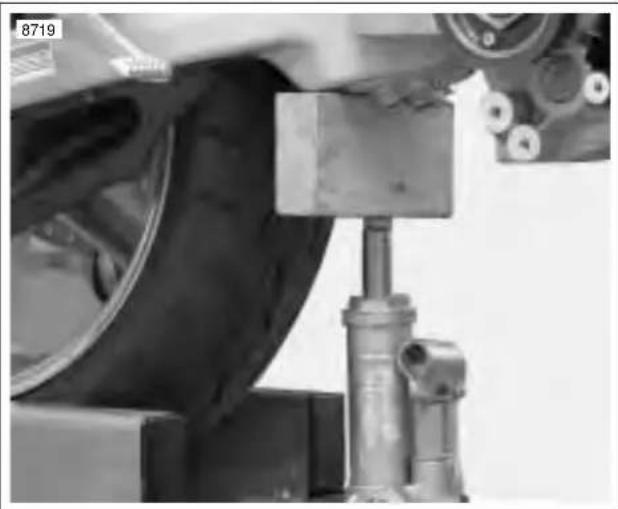
natural_image
Close-up of a car tire under a vehicle suspension system with mechanical components (no visible text or symbols)Figure 3-39. Supporting the Swingarm
- See Figure 3-39. Install bottle jack and wooden block under swingarm/oil tank to the rear of the oil line fittings.
- Remove ratcheting tie down and block of wood between rear isolator mount on main frame and swingarm/oil reservoir.
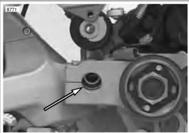
natural_image
Close-up mechanical component with a highlighted bolt and arrow indicator (no readable text or symbols)Figure 3-40. Aligning Swingarm to Crankcase for Pivot Shaft Installation
- See Figure 3-40. With engine on a flat scissors jack, raise engine and chassis until swingarm and rear isolator mount align and pivot shaft can be installed.
- Torque swingarm pivot shaft to 24-26 ft-lbs (32.5-35.2 Nm).
- Torque swingarm pivot shaft pinch bolt to 17-19 ft-lbs (23-25.8 Nm) using LOCTITE 272.
- See Figure 3-41. Route transmission vent line up through left side of frame exiting under the rear master cylinder under the rider's seat. Install two tie wraps to secure transmission vent line in place. Inspect vent line to verify space between vent line and rear exhaust.
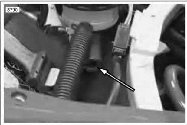
natural_image
Close-up of mechanical components with a black arrow pointing to a component (no visible text or symbols)Figure 3-41. Transmission Vent Line
NOTE
See Figure 3-42. At this point it is necessary to support main frame with overhead hoist in order to install rear isolator bolt.
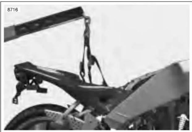
natural_image
Mechanical assembly with attached suspension bracket and mounting bracket (no visible text or symbols)Figure 3-42. Supporting Vehicle for Assembly
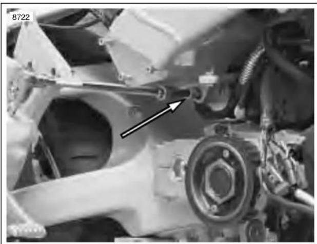
natural_image
Close-up of a mechanical assembly with visible components and a black arrow pointing to a component (no text or symbols)Figure 3-43. Installing Rear Isolator Bolt
- See Figure 3-43. Using the overhead hoist to align the frame to the rear isolator, install rear isolator bolt and leave loose at this time.
b0985x3x
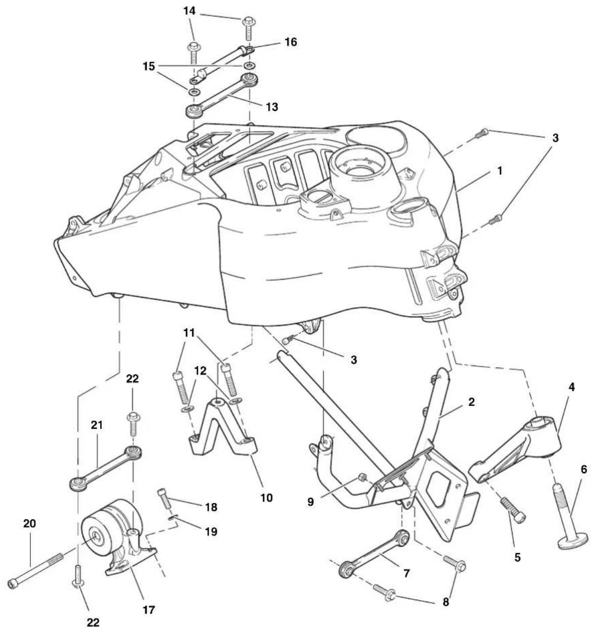
text_image
Technical diagram of an engine assembly with numbered components for identification- Frame assembly
- "V" bracket
- Fasteners for "V" bracket (3)
- Isolator assembly, front
- Fasteners for front isolator (2)
- Bolt, front isolator
- Tie bar assembly, front
- Fasteners for front tie bar assembly (2)
- Nut for one fastener for front tie bar assembly
- Mount, center tie bar
-
Fasteners for center tie bar mount (2)
-
Washers for center tie bar mount (2)
- Tie bar assembly, center
- Fasteners for center tie bar assembly (2)
- Washers for center tie bar assembly (2)
- Cable, negative battery
- Isolator assembly, rear
- Fasteners for rear isolator assembly (4)
- Washers for rear isolator assembly (4)
- Bolt, rear isolator
- Tie bar assembly, rear
- Fasteners for rear tie bar assembly (2)
Figure 3-44. Engine Mounting System
HOME
- Rotate engine down and install exhaust header only and tighten fasteners to 72-96 in-lbs (8.1-10.8 Nm).
NOTES
● Tighten header nuts gradually, alternating between studs to insure that exhaust rings are flush with engine.
- Exhaust header must be torqued with the engine rotated in the down position. It is not possible to reach fasteners on the rear exhaust at the head with engine rotated in the up position.
9. When the exhaust header has been torqued, rotate engine back up into frame.
NOTE
When tightening isolator bolt it is important to keep load off of isolator bolt for installation purposes. Alternate between tightening isolator bolt and raising engine with scissors jack.
b1041x2x
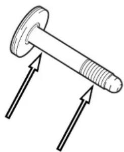
natural_image
Diagram of a bolt with two arrows indicating upward movement (no text or symbols)Figure 3-45. Lubrication Points on Front Isolator Bolt
NOTE
See Figure 3-45. Always coat shaft and threads of front isolator bolt with anti-seize before installing.
b1049x3x
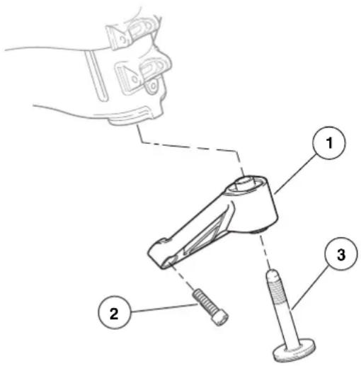
text_image
Technical diagram showing a hand holding a tool with three labeled parts: one with a dashed line, one with a solid line, and one with a threaded rod.- Front isolator
- Front isolator fasteners (2)
- Front isolator bolt
Figure 3-46. Front Isolator
- See Figure 3-46. Insert front isolator bolt (3) through front isolator (1) and loosely thread into frame. Do not tighten at this point.
- See Figure 3-46. Install isolator mounting fasteners (2) and tighten to 49-51 ft-lbs (66-69 Nm).
- Tighten front isolator bolt to 49-51 ft-lbs (66-69 Nm).
- See Figure 3-44. Torque rear isolator bolt to 49-51 ft-lbs (66.4-69.1 Nm).
- See Figure 3-44. Install rear tie bar to frame and tighten to 25-27 ft-lbs (33.9-36.6 Nm).
- See Figure 3-44. Install center tie bar to engine and tighten to 25-27 ft-lbs (33.9-36.6 Nm).
- See Figure 3-44. Install front "V" bracket with oil cooler to main frame.
a. Install "V" bracket to main frame from the left side of the vehicle and tighten to 120-144 in-lbs (13.6-16.3 Nm).
b. Install front tie-bar to engine and tighten to 25-27 ft-lbs (33.9-36.6 Nm).
c. Attach regulator wiring harness to bracket nylon cable straps.
- Remove scissors jack.
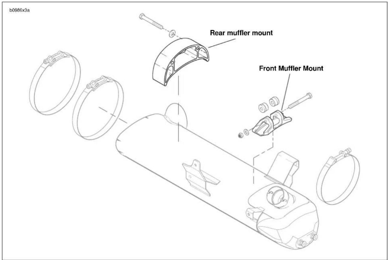
text_image
b0986x3a Rear muffler mount Front Muffler MountFigure 3-47. Muffler Mounting System
- See Figure 3-47. Install rear muffler bracket and torque to 32-36 ft-lbs (43.4-48.8 Nm).
- Install front muffler mount and leave loose at this time.
NOTE
DO NOT install muffler at this time. It is necessary to install muffler mounts first in order to properly install oil lines.
CAUTION
At this point it will be necessary to install the oil lines. It is important to follow this procedure to ensure correct orientation of oil lines in order to establish the proper clearances needed between the oil lines and varied components on the vehicle.
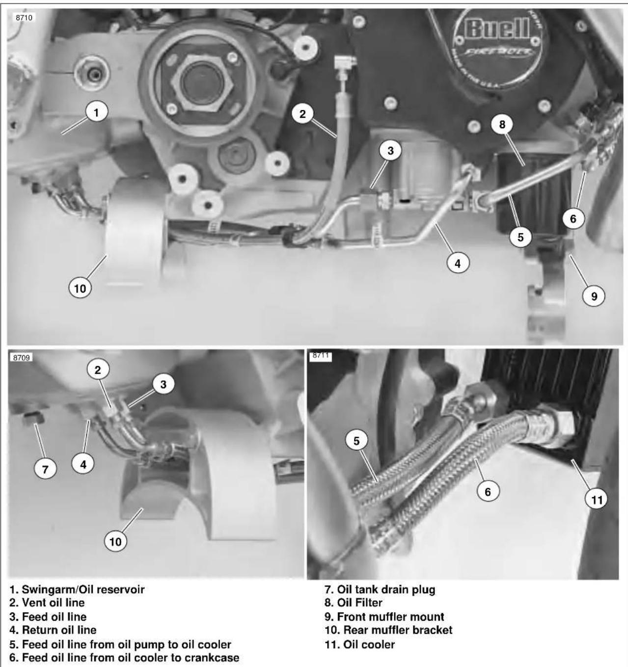
- Swingarm/Oil reservoir
- Vent oil line
- Feed oil line
- Return oil line
- Feed oil line from oil pump to oil cooler
-
Feed oil line from oil cooler to crankcase
-
Oil tank drain plug
- Oil Filter
- Front muffler mount
- Rear muffler bracket
- Oil cooler
Figure 3-48. Oil Lines and Connections
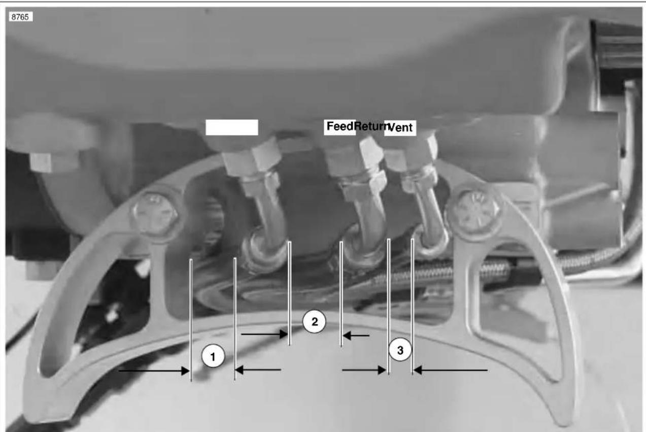
text_image
8765 FeedReturnVent 1 2 3-
5/16 - 3/8 in. (8-9.53mm) 2. 37/64 - 45/64 in. (14.68-17.86mm) 3. 1/4 - 23/64 in. (6mm - 9.13mm)
Figure 3-49. Oil Line Clearances and Torques -
See Figure 3-48. Install the return, feed and vent oil lines starting at the swingarm/oil reservoir and working towards the front of the vehicle. Leave all oil line fittings loose at this time.
NOTE
Once the three main oil lines are attached, it will be necessary to follow the proper torquing sequence. The three main oil lines must be torqued at the swingarm/oil reservoir first.
-
See Figure 3-49. Torque the return oil line first making sure to maintain the proper clearance between the oil line and the rear muffler bracket. 19-21 ft-lbs (25.8-28.5 Nm.)
-
Torque the feed oil line next making sure the distance between the feed line and the return line is within specifications. 20-22 ft-lbs (27.1-29.8 Nm).
-
Torque the vent oil line next making sure the distance between the vent line and the feed line is within specifications. 14-16 ft-lbs (19-21.7 Nm).
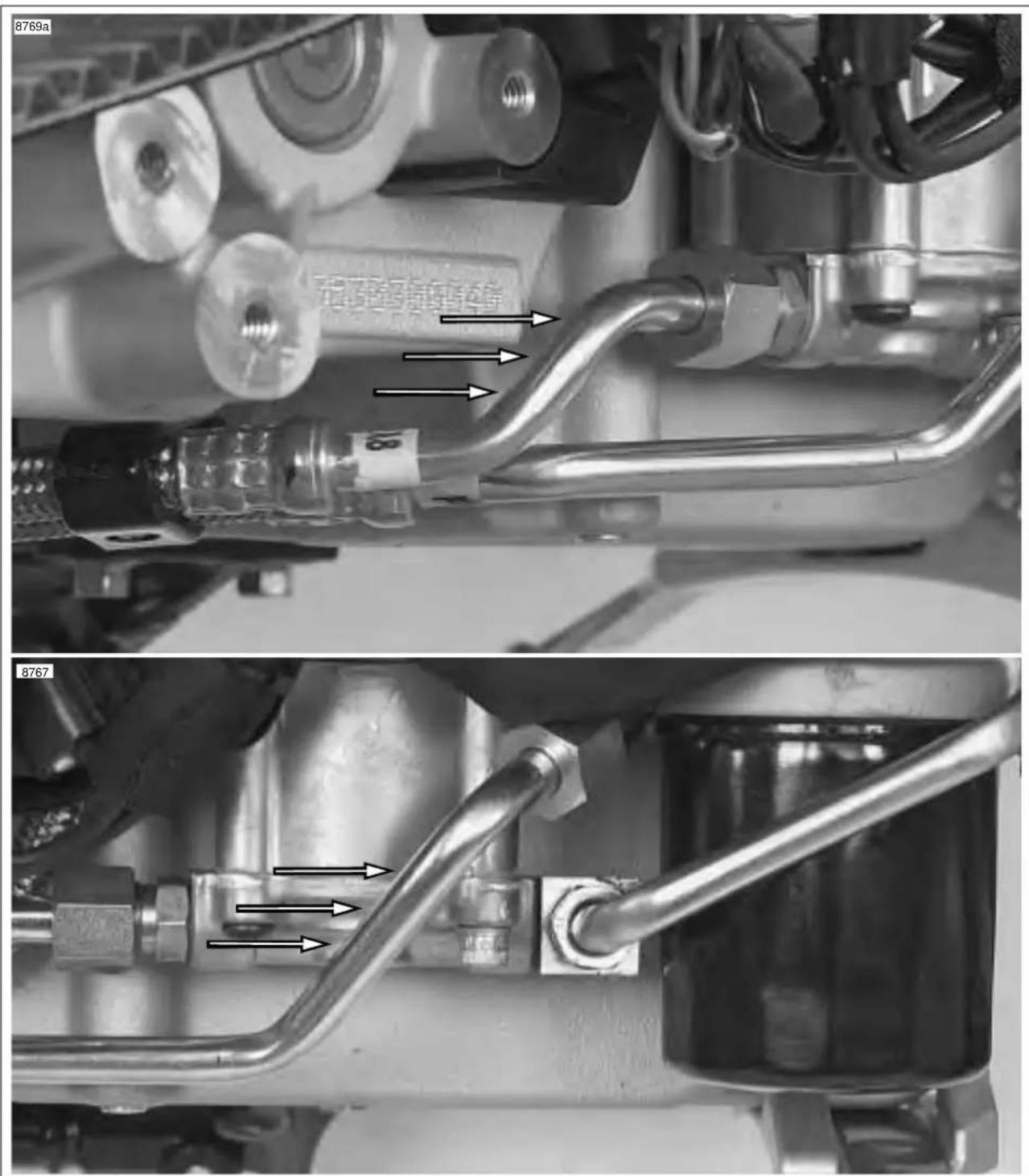
text_image
8769a 8767Figure 3-50. Approximate Seven O'Clock Orientation of Oil Feed Line and Oil Return Line at the Oil Pump
- See Figure 3-50. The feed oil line at the rear of the oil pump should be torqued to 18-20 ft-lbs (24.4-27.1 Nm). When the oil line has been properly torqued, the orientation of the line should be approximately 7 o'clock.
-
Also torque the return oil line at the top front oil pump fitting to 18-20 ft-lbs (24.4-27.1 Nm). When the oil line has been properly torqued, the orientation of the line should also be approximately 7 o'clock.
-
Torque the vent oil line at the gearcase cover to 120-132 in-lbs (13.6-14.9 Nm).
NOTE
When torquing the vent line, verify that the line does not twist down towards the muffler, but remains horizontal and aligned with the feed and return lines after torquing.
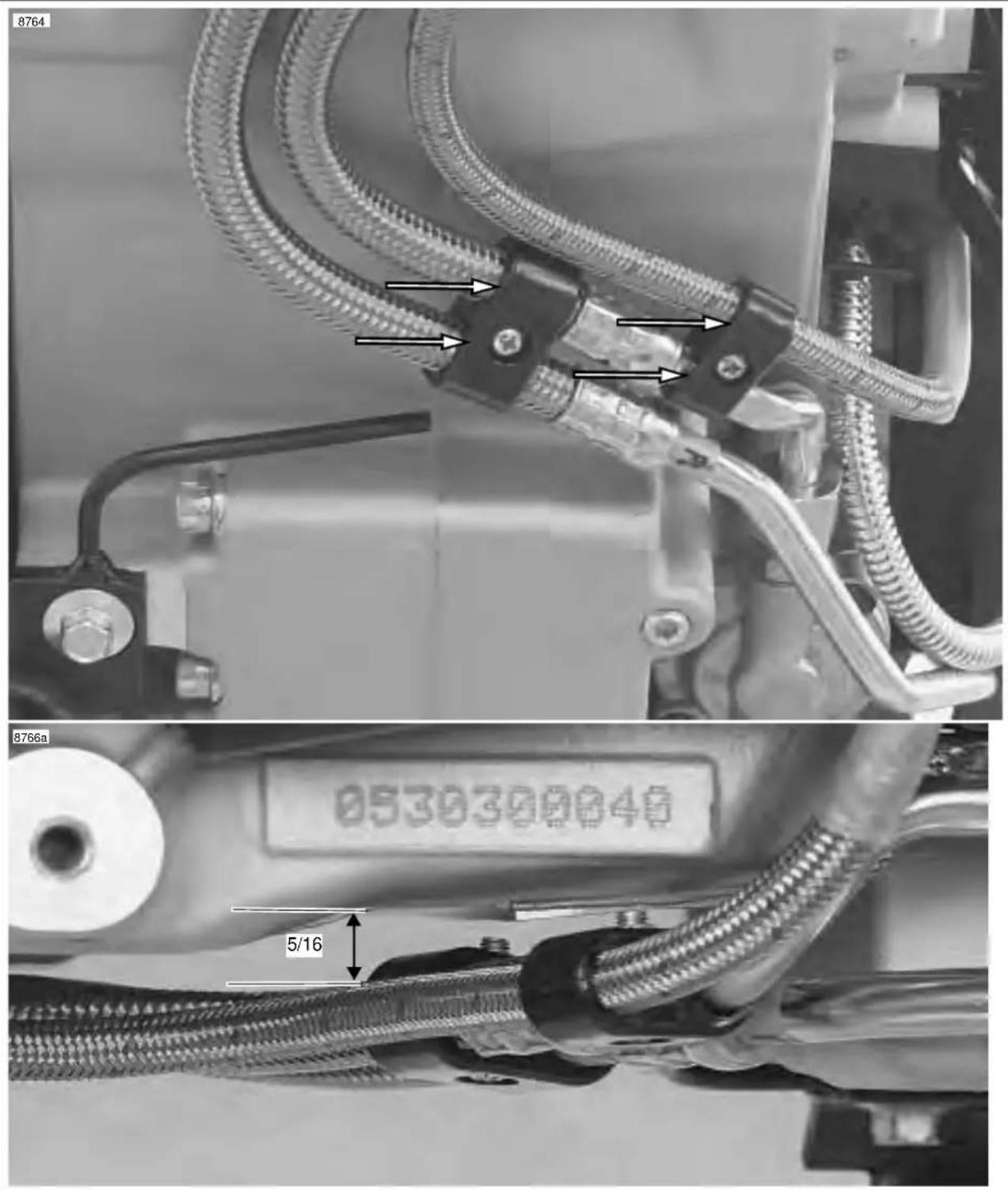
text_image
8764 8766a 0539388848 5/16Figure 3-51. Clamp Orientation and Oil Line Spacing
CAUTION
The orientation of the oil lines is extremely important to the relation of the oil lines and certain components on the vehicle.
- See Figure 3-51. Verify that both black plastic oil line clamps are parallel to the crankcases and there is a clearance of 5/16 in. (7.9375 mm) between the bottom of the crankcases and the oil lines.
NOTE
The 5/16 in. clearance is between the crankcase and the steel oil line as shown. Not between the crankcase and the clamp.
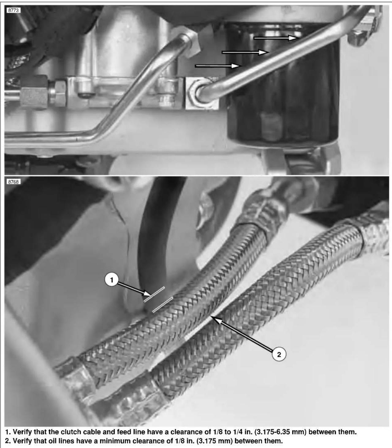
text_image
8773 8768 1. Verify that the clutch cable and feed line have a clearance of 1/8 to 1/4 in. (3.175-6.35 mm) between them. 2. Verify that oil lines have a minimum clearance of 1/8 in. (3.175 mm) between them.Figure 3-52. Oil Cooler Feed Oil Line Orientation (Approximately 2 O'Clock) and Oil Line Clearances
- Loosely install the feed oil line that runs from the lower front oil pump fitting to the rear fitting on the oil cooler.
NOTE
Depending on the type of crowsfoot being used to torque the oil lines it may be necessary to remove the oil filter in order to properly torque certain oil line fittings.
CAUTION
See Figure 3-52. It is important to maintain an orientation of approximately 2 o'clock with the rigid part of the feed oil line running to the oil cooler. Also be aware of the 1/8-1/4 (3.175-6.35 mm) clearance specified between the feed oil line and the clutch cable at the front of the crankcase.
HOME
NOTE
When torquing the oil cooler feed and return lines to the oil cooler, verify that the lines do not twist while torquing.
-
See Figure 3-54. When torquing the feed oil line from the pump to the oil cooler it is necessary to torque the fitting at the oil pump first, 18-20 ft-lbs (24.4-27.1 Nm), making sure to center the oil line between the oil sending switch and the return oil line fitting on the crankcase.
-
See Figure 3-53. Torque the feed oil line at the oil cooler to 15-17 ft-lbs (20.3-23 Nm).
NOTE
When installing the oil cooler return oil line it is necessary to install the end at the crankcase first.
-
Install the oil cooler return oil line that runs from the crankcase fitting, which is located above and forward of the oil filter, to the front fitting on the oil cooler.
-
Torque the oil cooler return line fitting at the crankcase first to 15-17 ft-lbs (20.3-23 Nm).
NOTE
See Figure 3-54. The orientation of the oil cooler return oil line where it enters the crankcase should be at approximately 4 o'clock to allow for proper alignment and clearance of other components on the vehicle.
- See Figure 3-53. Finally torque the oil cooler return line fitting on the front of the oil cooler to 15-17 ft-lbs (20.3-23 Nm).
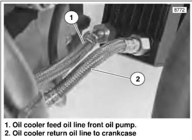
text_image
1. Oil cooler feed oil line front oil pump. 2. Oil cooler return oil line to crankcaseFigure 3-53. Oil Cooler Oil Lines
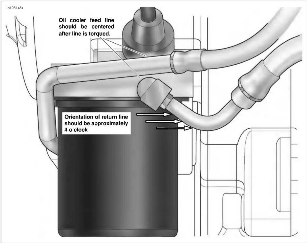
text_image
b1031x3x Oil cooler feed line should be centered after line is torqued. Orientation of return line should be approximately 4 o'clockFigure 3-54. Oil Cooler Feed and Return Oil Lines Location and Orientation
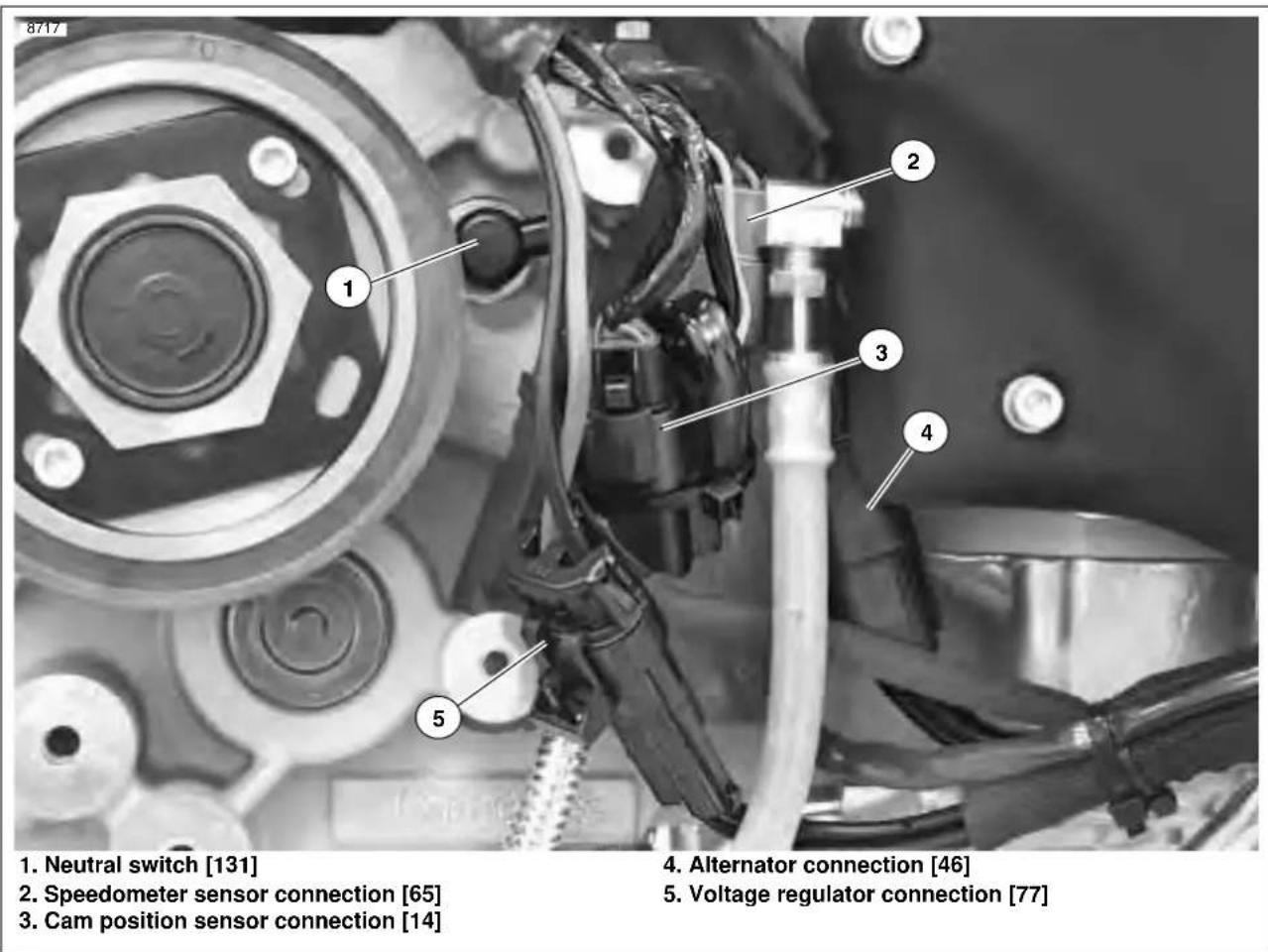
text_image
8/17 1. Neutral switch [131] 2. Speedometer sensor connection [65] 3. Cam position sensor connection [14] 4. Alternator connection [46] 5. Voltage regulator connection [77]Figure 3-55. Electrical Connections
- See Figure 3-55. Connect the following electrical components:
a. Neutral switch [131].
b. Speedometer sensor [65] (install tie wrap).
c. Cam position sensor [14].
d. Alternator [46].
e. Voltage regulator [77].
f. Positive battery cable at starter.
g. Starter solenoid [128].
h. Oil pressure switch [120].
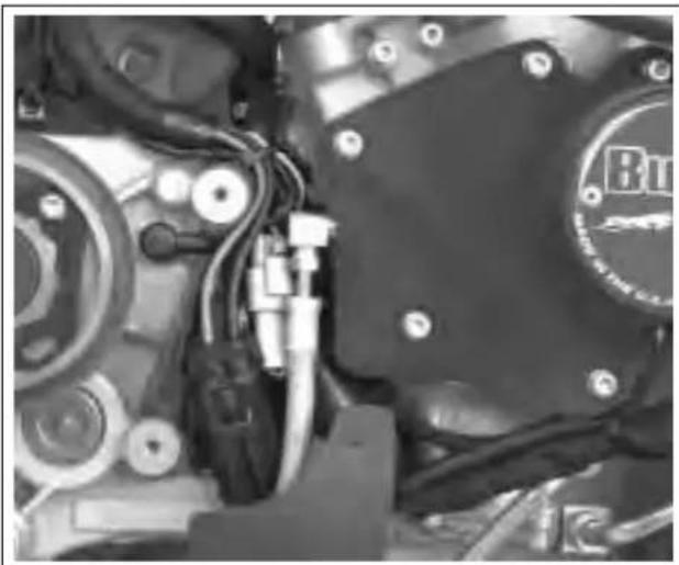
natural_image
Close-up of mechanical components with visible wiring and connectors (no readable text or symbols)Figure 3-56. Correct Routing of Wiring Harnesses
HOME
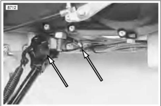
natural_image
Close-up of a mechanical assembly with wires and components, no visible text or symbolsFigure 3-57. Sidestand Assembly and Switch with Cable Strap
NOTE
-
See Figure 3-57. Install sidestand assembly.
-
Pull wire harness and sidestand switch through from right side of vehicle.
-
Install sidestand switch to sidestand assembly and install cable strap.
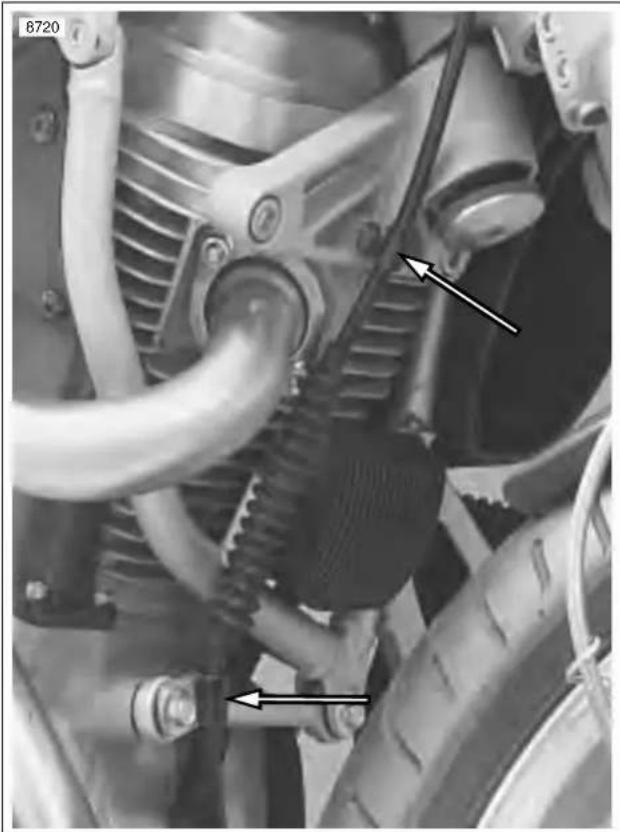
natural_image
Close-up mechanical assembly showing hoses, gears, and a tire (no visible text or symbols)Figure 3-58. Clutch Cable Retaining Clamps
- See Figure 3-58. Pull clutch cable back up into the proper position.
a. Connect clutch cable to handlebars and adjust to specifications.
b. Install retaining clamps.
b0986x3x
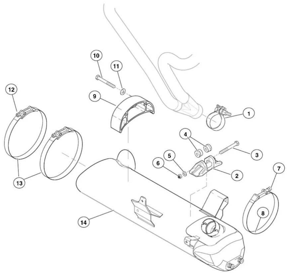
text_image
Exploded view diagram of a mechanical device with numbered parts for identification- Clamp, Torca
- Muffler mount, front
- Screw, front muffler mount (1)
- Bushings, front muffler mount (2)
- F lat washer, front muffler mount (1)
- Nut, front muffler mount (1)
-
F r ont muffler strap fastener
-
Muffler strap, front
- Muffler bracket, rear
- Screw, rear muffler bracket (2)
- Flat washer, rear muffler bracket (2)
- Rear muffler strap fastener
- Muffler strap, rear (2)
- Muffler
Figure 3-59. Muffler and Mounting System
- See Figure 3-59. Install muffler with Torca clamp but do not tighten:
a. Install rear muffler straps and alternately tighten rear strap fasteners (12) until properly torqued to 48-60 in-lbs (5.4-6.8 Nm).
b. Install front muffler strap fastener (7) and torque to 108-120 in-lbs (12.2-13.6 Nm).
c. Tighten Torca clamp to 40-45 ft-lbs (54.2-61 Nm).
d. Tighten front muffler mount to 22-25 ft-lbs (29.8-33.9 Nm).
CAUTION
It is important that the front muffler mount is tightened last in order to ensure proper alignment of the exhaust system.
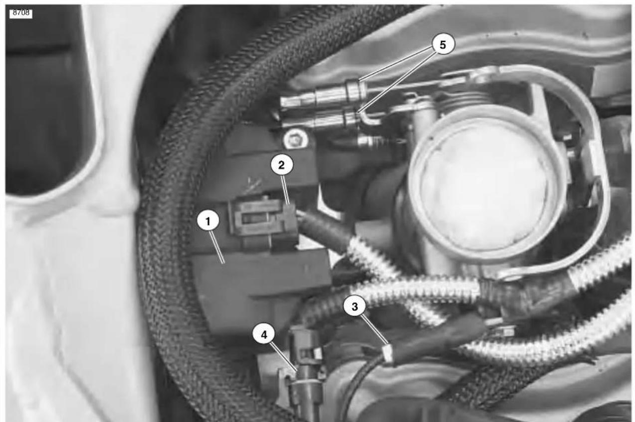
text_image
8708 1 2 3 4 5- Ignition coil
- Coil connection [83]
- Cylinder head temperature sensor connection [90]
- Oxygen sensor connection [137]
- Throttle cables
Figure 3-60. Electrical Connections and Throttle Cables
- See Figure 3-60. Connect throttle cables to induction module/throttle body.
- Connect the following sensors:
a. Temperature sensor [90].
b. Oxygen sensor [137] (Install wire tire on harness).
- See Figure 3-60. Install the ignition coil and spark plug wires and connect [83]. Tighten ignition coil fasteners to 120-144 in-lbs (13.6-16.3 Nm).
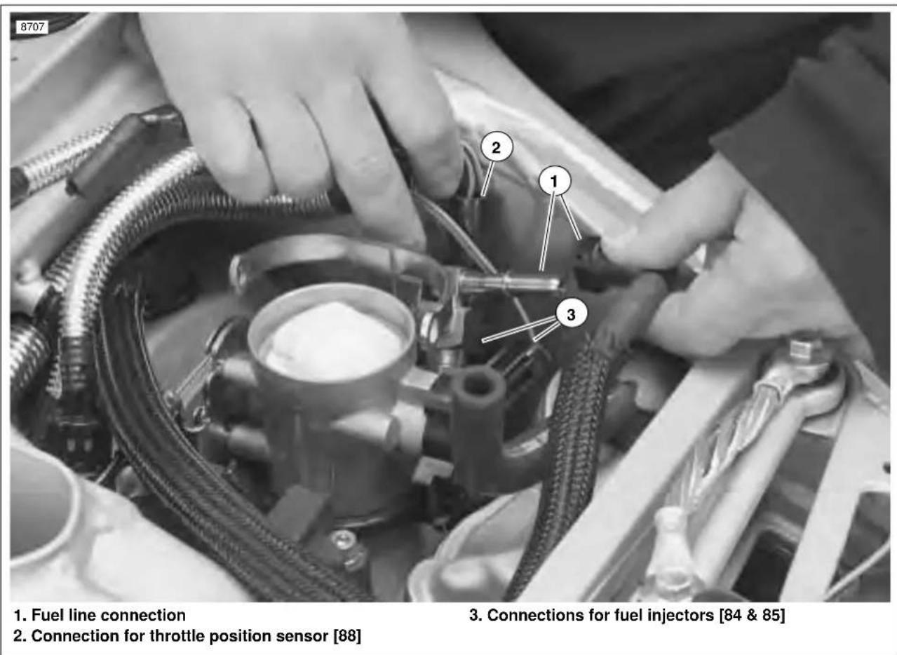
text_image
8707 1. Fuel line connection 2. Connection for throttle position sensor [88] 3. Connections for fuel injectors [84 & 85]Figure 3-61. Fuel Line and DDFI Electrical Connections
CAUTION
Remove shop towel from entrance of throttle body to ensure proper operation of induction module.
- See Figure 3-61. Connect throttle position sensor [88].
- Connect fuel injector leads [84 & 85].
- Connect fuel line.
- Install throttle body velocity stack and tighten to 12-36 in-lbs (1.356-4.064 Nm).
- Install air box cover and assembly. Tighten fasteners to 84-120 in-lbs (9.49-13.56 Nm).
- Fill oil tank.
- Connect fuel pump.
- Install rear belt and idler pulley. See 1.9 DRIVE BELT SYSTEM and 2.13 REAR BRAKE MASTER CYLINDER.
- Install left and right side rider footrests and support plates and torque to 108-132 in-lbs (12.20-14.91 mm).
NOTE
When re-installing the right side rider footrest and support plate, also install rear brake pedal assembly and remote reservoir.
- Install sprocket cover and tighten fasteners and washers to 12-36 in-lbs (1-4 Nm).
3-44 2003 Buell XB9R: Engine
- Install chin fairing. See 2.33 CHIN FAIRING.
- Install air scoops, right and left sides. See 2.35 AIR SCOOPS.
NOTE
The connection for fuel pump is just above the pump located at the rear of the fuel tank on the left side of the vehicle.
WARNING
Always connect positive battery cable first. If the positive cable should contact ground with the negative cable installed, the resulting sparks may cause a battery explosion which could result in death or serious injury.
- Connect negative ground cable to battery and install seat (tighten).
WARNING
Pull up on seat to verify that it is properly secured, front and rear. A loose seat may shift during vehicle operation and startle the rider, possibly causing loss of vehicle control resulting in death or serious injury.
CAUTION
All washers and fasteners used in the engine are hardened. Do not mix or replace hardened washers and fasteners with unhardened parts. Do not reuse fiber cover seals. Engine damage may result.
REMOVAL
Before removing the cylinder head assembly, it is necessary to rotate engine down as described in 3.3 ENGINE ROTATION FOR SERVICE. The rocker arm covers and internal components must be removed before removing cylinder heads.
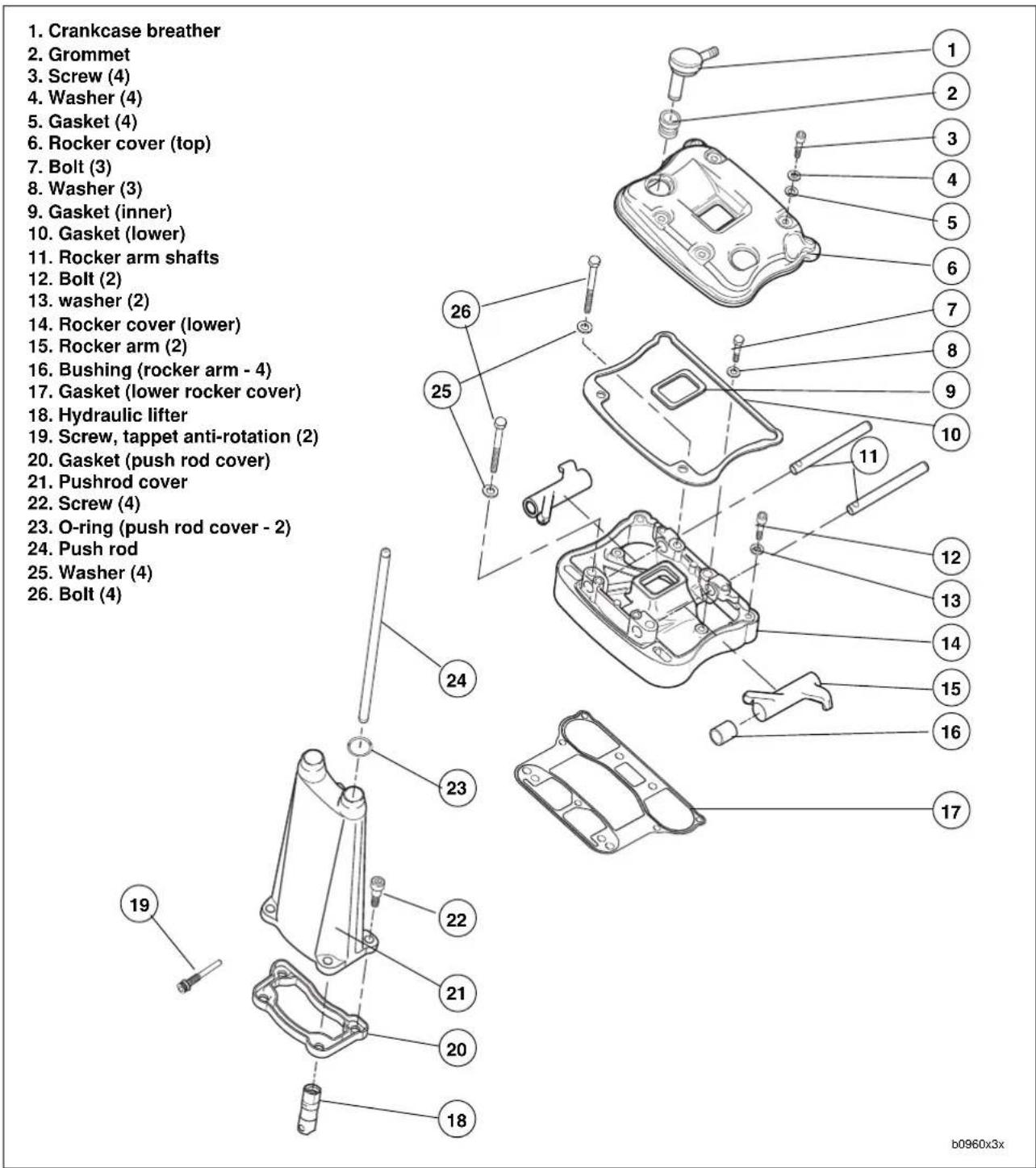
text_image
1. Crankcase breather 2. Grommet 3. Screw (4) 4. Washer (4) 5. Gasket (4) 6. Rocker cover (top) 7. Bolt (3) 8. Washer (3) 9. Gasket (inner) 10. Gasket (lower) 11. Rocker arm shafts 12. Bolt (2) 13. washer (2) 14. Rocker cover (lower) 15. Rocker arm (2) 16. Bushing (rocker arm - 4) 17. Gasket (lower rocker cover) 18. Hydraulic lifter 19. Screw, tappet anti-rotation (2) 20. Gasket (push rod cover) 21. Pushrod cover 22. Screw (4) 23. O-ring (push rod cover - 2) 24. Push rod 25. Washer (4) 26. Bolt (4)Figure 3-62. Rocker Arm and Pushrod Cover Assemblies
HOME
Rocker Box Assemblies
- Remove spark plugs.
- See Figure 3-62. Remove screws with washers and fiber cover seals. Discard fiber seals.
- Remove top rocker covers.
- Remove and discard gaskets.
- Rotate crankshaft until both valves are closed on head being removed.
-
See Figure 3-63. Remove hardware holding lower rocker cover to cylinder head in the following order.
a. Remove two screws and washers (1).
b. Remove three bolts and washers (2).
c. Loosen the four rocker arm fasteners (3) in 1/4-1/2 turn increments using a cross pattern in order to relieve valve spring pressure on the lower rocker box. -
See Figure 3-62. Remove lower rocker cover.
NOTE
Remove lower rocker box as an assembly; then disassemble as required.
CAUTION
Mark rocker arm shafts for reassembly in their original positions. Valve train components must be reinstalled in their original positions to prevent accelerated wear and increased valve train noise.
- See Figure 3-64. Remove rocker arm shafts by tapping them out using a hammer and a soft metal punch.
- Remove rocker arms; mark them for reassembly in their original locations.
- Mark the location and orientation (top/bottom) of each push rod. Remove push rods.
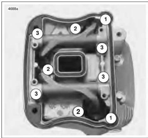
text_image
4688a 1 2 3 2 3 3 3 2 2 1Figure 3-63. Lower Rocker Box Fasteners
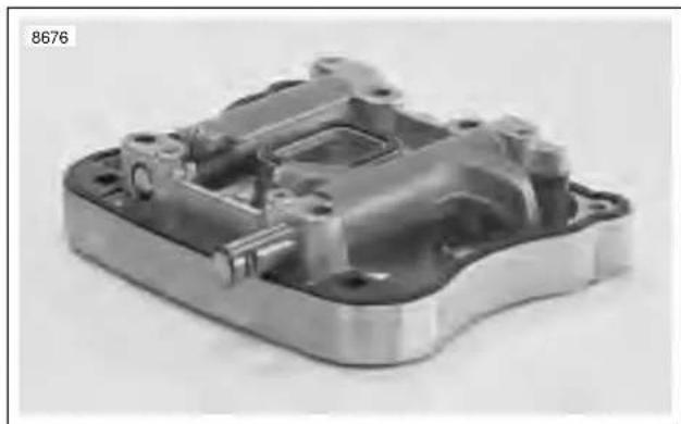
natural_image
Metallic mechanical component with internal cavities and mounting holes (no visible text or symbols)Figure 3-64. Removing Rocker Arm Shafts
Cylinder Head Assemblies
CAUTION
See Figure 3-65. Distortion to the head, cylinder and crankcase studs may result if head screws are not loosened (or tightened) gradually in the sequence shown.
- See Figure 3-65. Loosen each head screw 1/8-turn following the sequence shown.
a. Continue loosening in 1/8-turn increments until screws are loose. Remove head screws.
b. Remove cylinder head, head gasket, and O-rings. - Discard head gasket.
- See Figure 3-62. Remove push rod cover, gasket and valve tappets.
DISASSEMBLY
- See Figure 3-66. Clamp VALVE SPRING COMPRESSOR TOOL (Part No. HD-34736B) in vise.
- See Figure 3-66. Compress valve spring with VALVE SPRING COMPRESSOR.
- See Figure 3-67. Remove valve keepers, upper collar and valve spring. Mark valve keepers for reassembly in their original locations.
- Use a fine tooth file to remove any burrs on the valve stem at the keeper groove.
- Mark valve to ensure that it will be reassembled in the same head. Remove valve, valve stem seal and lower collar assembly by hand. No special tools are required to remove valve stem seal and lower collar assembly.
- Repeat the above procedure for the other valves.
x0128x3a
Front Cylinder
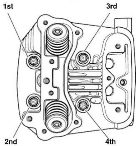
text_image
1st 3rd 2nd 4thRear Cylinder
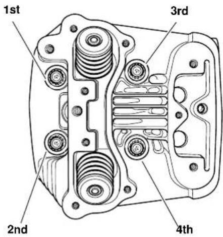
text_image
1st 3rd 2nd 4thHead Screw Loosening/Tightening Sequence
Figure 3-65. Head Screw Loosening/Tightening Sequence
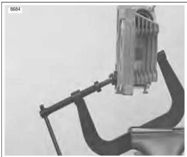
natural_image
Close-up of a mechanical device with a curved bracket and internal components (no visible text or symbols)Figure 3-66. Valve Spring Compressor (Part No. HD-34736B)
b1024x3x
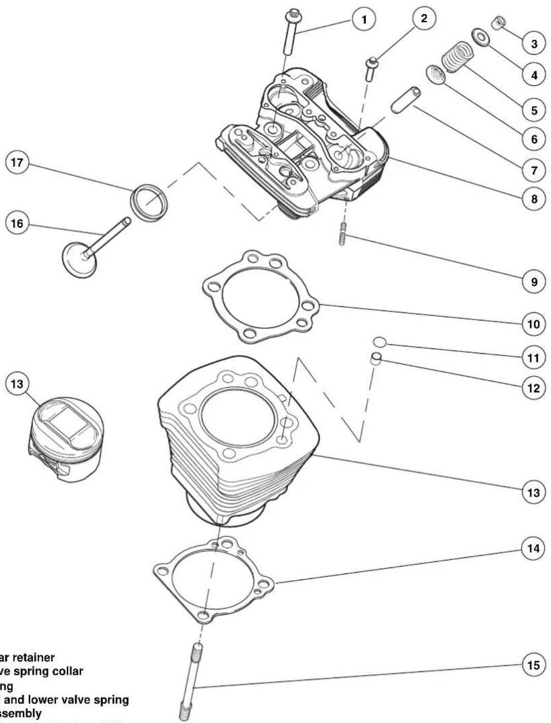
text_image
17 16 1 2 3 4 5 6 7 8 9 10 11 12 13 13 14 15 car retainer ve spring collar ing and lower valve spring assembly- Screw
- Screw
- Valve collar retainer
- Upper valve spring collar
- Valve spring
- Valve seal and lower valve spring collar assembly
- Valve guide intake & exhaust (2)
- Cylinder head
- Exhaust port stud
- Cylinder head gasket
- Cylinder O-ring (4)
- Cylinder insert
- Cylinder w/piston & rings
- Cylinder base gasket
- Cylinder base stud
- Exhaust valve
- Exhaust valve seat
Figure 3-67. Cylinder Head, Cylinder and Piston Assembly
CLEANING AND INSPECTION
Cylinder Heads
WARNING
Low pressure compressed air can blow debris into your face and eyes. Always wear eye protection or a face shield when using pressurized air. Failure to take adequate safety precautions could result in death or serious injury.
- Bead blast or scrape carbon from head, top of cylinder and valve ports. Be careful to avoid scratching or nicking cylinder head and cylinder joint faces. Blow off loosened carbon or dirt with compressed air.
- Soak cylinder head in an aluminum-compatible cleaner/solvent to loosen carbon deposits.
- Wash all parts in non-flammable solvent, followed by a thorough washing with hot, soapy water. Blow out oil passages in head. Be sure they are free of sludge and carbon particles. Remove loosened carbon from valve head and stem using a wire wheel. Never use a file or other hardened tool which could scratch or nick valve. Polish valve stem with very fine emery cloth or steel wool.
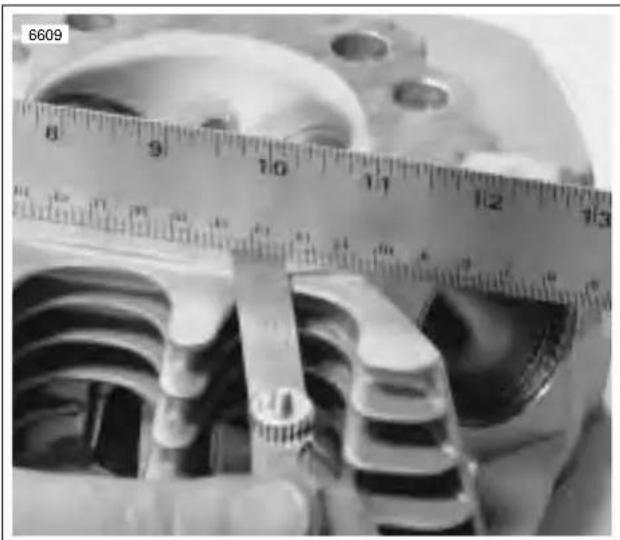
natural_image
Close-up of mechanical components with a ruler measuring their length (no visible text or symbols)Figure 3-68. Checking Gasket Surface
- See Figure 3-68. Check head gasket surface on head for flatness. Machine or replace any head which exceeds SERVICE WEAR LIMIT of 0.006 in. (0.152 mm).
HOME
Rocker Arm Assemblies
- Check each rocker arm, at pad end and push rod end, for uneven wear or pitting. Replace rocker arm if either condition exists.
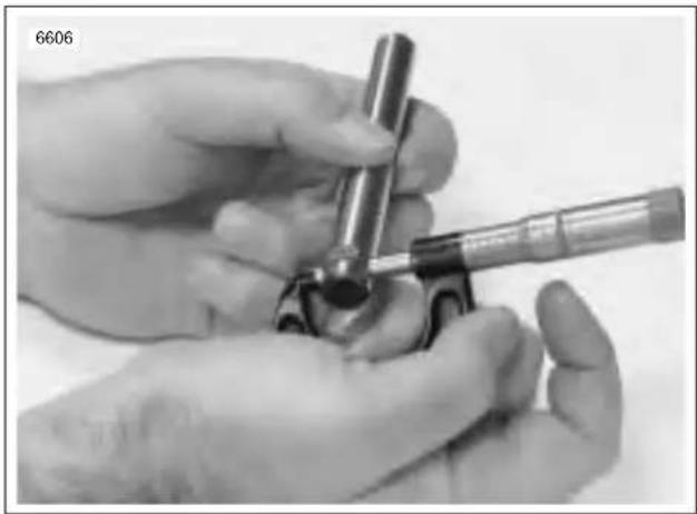
natural_image
Close-up of hands using a tool to adjust or install a mechanical component (no visible text or symbols)Figure 3-69. Measuring Rocker Arm Shaft Diameter (Rocker Cover Position)
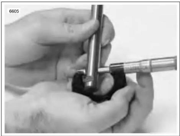
natural_image
Close-up of hands holding a mechanical tool or device with a metallic handle (no visible text or symbols)Figure 3-70. Measuring Rocker Arm Shaft Diameter (Rocker Arm Bushing Position)
- Measure and record rocker arm shaft diameter.
a. See Figure 3-69. Measure where shaft fits in lower rocker arm cover.
b. See Figure 3-70. Measure where rocker arm bushings ride.
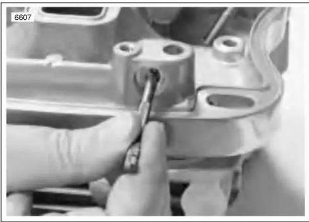
natural_image
Close-up of a gloved hand using a tool to adjust or install a mechanical component (no visible text or symbols)Figure 3-71. Measuring Rocker Arm Shaft Bore Diameter in Lower Rocker Cover
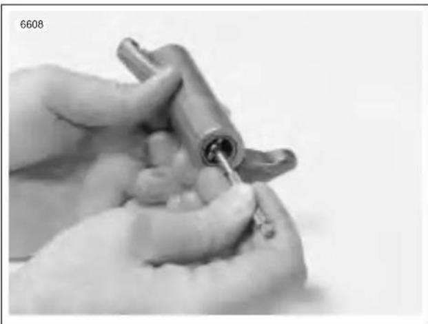
natural_image
Close-up of hands using a tool to adjust or install a mechanical component (no visible text or symbols)Figure 3-72. Measuring Rocker Arm Bushing Inner Diameter
- Measure and record rocker arm shaft bore diameter.
a. See Figure 3-71. Measure bore of lower rocker cover.
b. See Figure 3-72. Measure rocker arm bushing inner diameter.
- Check the measurements obtained in Steps 5-6 against the SERVICE WEAR LIMITS. Repair or replace parts exceeding limits.
- Assemble rocker arms and rocker arm shafts into lower rocker cover.
- Check end play of rocker arm with feeler gauge.
- Replace rocker arm or lower cover or both if end play exceeds 0.025 in. (0.635 mm).
HOME
Valves
- Replace the valve if there is evidence of burning or cracking.
- Inspect the end of the valve stem for pitting or uneven wear. Replace the valve if either of these conditions are found.
- Inspect for burrs around the valve stem keeper groove. Remove burrs with a fine tooth file if found.
Valve Seats
NOTE
Valve seats are also subject to wear. Resurface valve seats whenever valves are refinished.
- Inspect seats for cracking, chipping or burning. Replace seats if any evidence of these conditions are found.
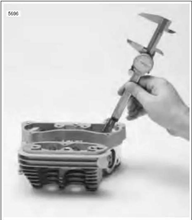
natural_image
Hand using a caliper to work on an engine cylinder (no text or symbols visible)Figure 3-73. Measuring Valve Stem Protrusion
- See Figure 3-73. Check seats for recession by measuring valve stem protrusion.
a. Wipe valve seats and valve faces clean.
b. Measure valve stem protrusion.
c. If valve stem protrudes more than 2.031 in. (51.587 mm), replace valve seat or cylinder head.
NOTE
Replacing a valve seat is a complex operation requiring special equipment. If the seat is loose or is not fully seated in the head, then seat movement will prevent the proper transfer of heat from the valve. The seat surface must be flush with (or below) the head surface. See 3.1 SPECIFICATIONS for valve seat-to-cylinder head fit.
Valve Guides
- Clean valve guides by lightly honing with VALVE GUIDE HONE (Part No. HD-34723).
- Scrub guides with VALVE GUIDE BRUSH (Part No. HD-34751) and hot soapy water. Measure valve stem outer diameter and valve guide inner diameter. Check measurements against 3.1 SPECIFICATIONS.
Valve Springs
- Inspect valve springs for broken or discolored coils.
NOTE
The XB9R utilizes a single valve spring for each valve. The inner and outer springs are combined into one tapered spring that is progressively wound.
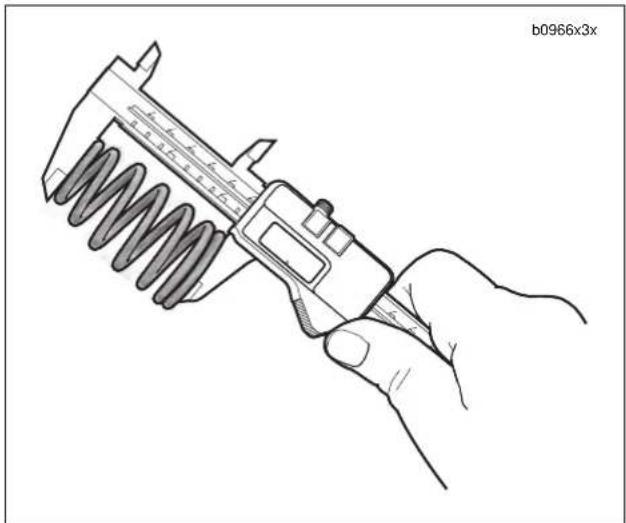
natural_image
Line drawing of a hand using a caliper to measure a spring (no text or symbols)Figure 3-74. Checking Spring Free Length
- See Figure 3-74. Check free length and compression force of each spring. Compare with 3.1 SPECIFICATIONS. If spring length is shorter than specification or if spring compression force is below specification, replace spring.
Spark Plug Threads
Inspect spark plug threads for damage. If threads in head are damaged, a special plug type insert can be installed using a 12 mm spark plug repair kit.
Push Rods
Examine push rods, particularly the ball ends. Replace any rods that are bent, worn, discolored or broken.
HOME
Replacing Rocker Arm Bushings
- See Figure 3-75. To replace worn bushings, press or drive them from the rocker arm. If bushing is difficult to remove, turn a 9/16-18 tap into bushing. From opposite side of rocker arm, press out bushing and tap using a discarded rocker arm shaft.
- Press replacement bushing into rocker arm, flush with arm end, and split portion of bushing towards top of arm.
- Using remaining old bushing as a pilot, line ream new bushing with ROCKER ARM BUSHING REAMER (Part No. HD-94804-57).
- Repeat for other end of rocker arm.
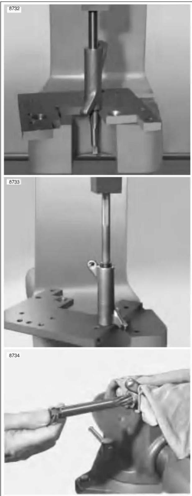
natural_image
Three-panel black-and-white photo sequence showing a mechanical assembly: 8732, 8733, and 8734, with no visible text or symbols.Figure 3-75. Replacing Rocker Arm Bushings
HOME
Replacing Valve Guides
Valve guide replacement, if necessary, must be done before valve seat is ground. It is the valve stem hole in valve guide that determines seat grinding location. Valve stem-to-valve guide clearances are listed in Table 3-19. If valve stems and/or guides are worn beyond limits, install new parts.
Table 3-19. Valve Stem Clearances and Service Wear Limits
| VALVE CLEARANCE | SERVICE WEAR LIMIT | |
| Exhaust 0.001-0.003 in.(0.025-0.076 mm) | 0.0035 in.(0.0889 mm) | |
| Intake 0.001-0.003 in.(0.025-0.076 mm) | 0.0035 in.(0.0889 mm) | |
- To remove shoulderless guides, press or tap guides toward combustion chamber using VALVE GUIDE REMOVER/INSTALLER (Part No. B-45524).
- Clean and measure valve guide bore in head.
- Measure outer diameter of a new standard valve guide. The guide diameter should be 0.0020-0.0033 in. (0.0508-0.0838 mm). larger than bore in head. If it is not, select one of the following oversizes: +0.001 in. (+0.025 mm), +0.002 in. (+0.051 mm) or +0.003 in. (+0.076 mm) (intake and exhaust).
- See Figure 3-76. Install shoulderless guides using VALVE GUIDE REMOVER/INSTALLER TOOL (Part No. B-45524). Press or drive guide until the tool touches the machined surface surrounding the guide. At this point, the correct guide height has been reached.
- Ream guides to final size or within 0.0010 in. (0.0254 mm) of final size using VALVE GUIDE REAMER (Part No. B-45523). Use REAMER LUBRICANT (Part No. HD-39964) or liberal amounts of suitable cutting oil to prevent reamer chatter.
NOTE
The hone is not intended to remove material.
- Apply the proper surface finish to the valve guide bores using the VALVE GUIDE HONE (Part No. B-45525). Lubricate hone with honing oil. Driving hone with an electric drill, work for a crosshatch pattern with an angle of approximately 60°.
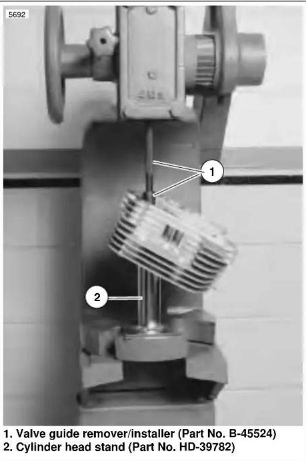
text_image
5692 1. Valve guide remover/installer (Part No. B-45524) 2. Cylinder head stand (Part No. HD-39782)Figure 3-76. Installing Shoulderless Valve Guide
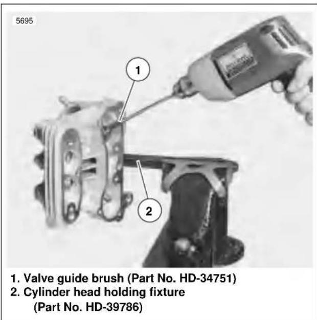
text_image
5695 1. Valve guide brush (Part No. HD-34751) 2. Cylinder head holding fixture (Part No. HD-39786)Figure 3-77. Cleaning Valve Guides
- See Figure 3-77. Thoroughly clean valve guide bores using VALVE GUIDE BRUSH (Part No. HD-34751) and hot soapy water.
PROCEDURE FOR USING THE NEWAY VALVE SEAT CUTTER
Table 3-20. Neway Valve Seat Cutter
| PART NO. SPE | CIALTY TOOL |
| HD-35758A Neway | valve seat cutter |
| HD-39786 Cylinder | head holding fixture |
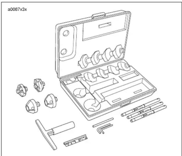
natural_image
Line drawing of a mechanical tool kit with multiple components and tools (no text or symbols)Figure 3-78. Neway Valve Seat Cutter
NOTE
- Verify correct valve stem to valve guide clearance before refacing. See Table 3-19. If new guides must be installed, complete that task before refacing valves and seats.
- This procedure is not based on the lapping of valves. The end result is an interference fit between the valve of 45^ and the valve seat which will be 46^ .
1. Secure cylinder head for service.
a. Thread 12 mm end of CYLINDER HEAD HOLDING FIXTURE (Part No. HD-39786) into cylinder head spark plug hole.
b. Clamp tool in vise and further tighten cylinder head onto the fixture to prevent any movement during operation.
c. Place cylinder head at a 45^ angle or one that offers a comfortable working position.
- Obtain the NEWAY VALVE SEAT CUTTER SET (HD-35758A) and cut valve seat angle to 46°. Do not remove any more metal than is necessary to clean up the seat (that is, to provide a uniform finish and remove pitting).
- In order to determine the correct location of the 46^ valve seat in the head, measure the width of the valve to be used and subtract 0.080" (2.032 mm) from that number.
- Set your dial caliper to the lesser measurement and lock down for quick reference. This is the location of your valve seat.
- Use a permanent magic marker to highlight the valve seat area that is going to be cut and be sure to highlight all 3 angles. Allow marker to dry before proceeding.
NOTE
● Always ensure cutter blades and cutter pilot are clean before beginning the cutting process. The correct cleaning brush is supplied with the Neway tool set.
- Also ensure the inside of the valve guide is clean by using Kent-Moore cleaning brush (Part No. HD-34751).
-
Choose the cutter pilot that fits properly into the valve guide hole and securely seat the pilot by pushing down and turning using the installation tool supplied in the tool set.
-
Choose the proper 46^ cutter (intake or exhaust) and gently slide the cutter onto the pilot being careful not to drop the cutter onto the seat.
-
While applying a constant and consistent pressure, remove just enough material to show a complete clean-up on the 46^ angle.
NOTES
- If the width of the clean-up angle is greater on one side of the seat than the other, the guide may need to be replaced due to improper installation.
- After making the 46^ cut, if you discover a groove cut completely around the seat this means the blades of the cutter are in alignment and need to be staggered. This is accomplished by loosening all of the blades from the cutter body and moving each blade slightly in it's cradle in opposite directions on the cutter. The tool needed to loosen the blades is supplied in the tool set. A permanent magic marker mark every 90^ will help in determining where new angles are.
HOME
- Next, with your dial caliper locked to the predetermined setting, measure the 46^ cut at the outer most edge at the widest point of the circle to determine what cut needs to be made next.
a. If the 46^ cut is to high (towards the combustion chamber), use the 31^ cutter to lower the valve seat closer to the port.
b. If the 46^ cut is too low, use the 60^ cutter to raise the valve seat or move it away from the port.
NOTE
- Due to using the top measurement of our valve seat as a reference point it will usually be necessary to use the 31^ cutter following the initial 46^ cut.
● Always highlight the valve seat with the permanent magic marker in order to ensure the location of the 46^ valve seat. - If the location of the valve seat is not correct, repeat steps 8 and 9.
-
When you accomplish a complete clean-up of the 46^ angle and the width is at least.062 in. (1.575 mm), proceed to the next step.
-
Select the proper 60° cutter and gently slide the cutter down the cutter pilot to the valve seat.
- Remove just enough material to provide an even valve seat width of .040-.062 in. (1.016-1.575 mm).
- Remove cutter pilot and wash head thoroughly and dry completely.
- Repeat the process on any valve seat that needs service.
- Insert valve to be used in the valve guide and bottom on the valve seat. Positioning the cylinder head port upwards and with slight thumb pressure against the valve, completely fill the port with solvent to verify proper seal between the valve and the valve seat.
NOTE
Hold pressure against the valve for a minimum of 10 seconds. If any leakage occurs, examine the valve seat for irregularities or defects and if necessary repeat the above cutting process.
b0972x3x
Intake & Exhaust Valve and Seat
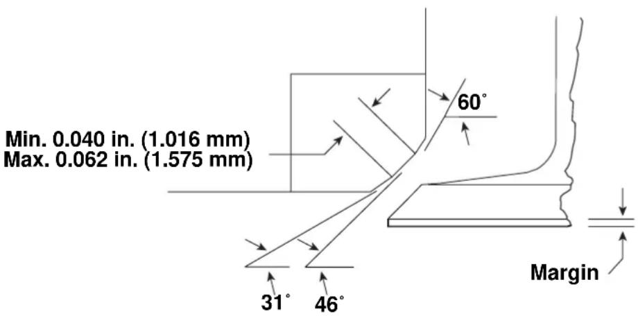
text_image
Min. 0.040 in. (1.016 mm) Max. 0.062 in. (1.575 mm) 60° 31° 46° MarginFigure 3-79. Valve and Seat Dimensions
b1024x3x
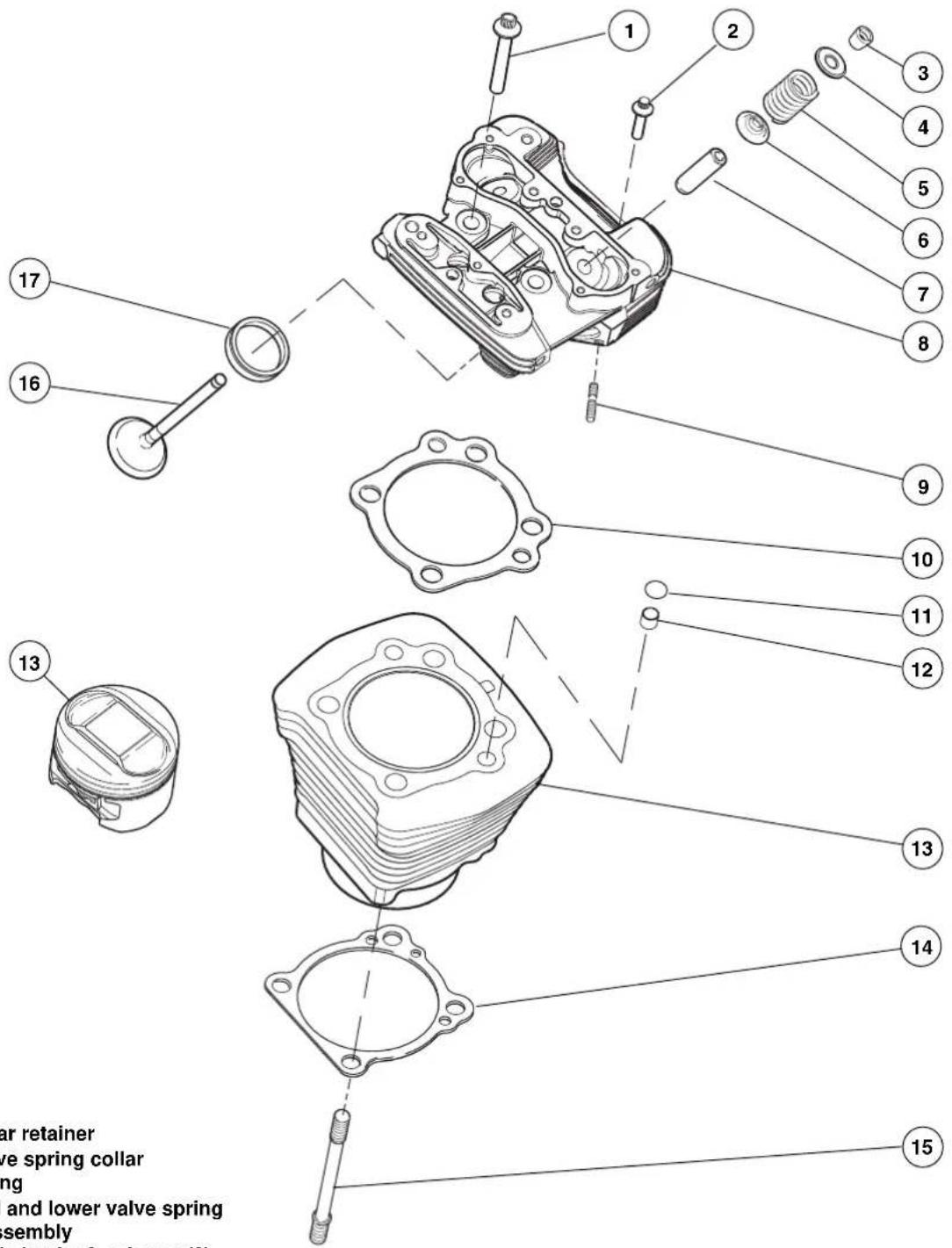
text_image
17 16 1 2 3 4 5 6 7 8 9 10 11 12 13 13 14 15 car retainer ve spring collar ing and lower valve spring assembly- Screw
- Screw
- Valve collar retainer
- Upper valve spring collar
- Valve spring
- Valve seal and lower valve spring collar assembly
- Valve guide intake & exhaust (2)
- Cylinder head
- Exhaust port stud
- Cylinder head gasket
- Cylinder O-ring (4)
- Cylinder insert
- Cylinder w/piston & rings
- Cylinder base gasket
- Cylinder base stud
- Exhaust valve
- Exhaust valve seat
Figure 3-80. Cylinder Head, Cylinder and Piston Assembly
ASSEMBLY
- Wash cylinder head and valves in warm, soapy water to remove all debris from cutting valve seats.
- Scrub valve guide bores with VALVE GUIDE BRUSH (Part No. HD-34751) and hot, soapy water.
WARNING
Low pressure compressed air can blow debris into your face and eyes. Always wear eye protection or a face shield when using pressurized air. Failure to take adequate safety precautions could result in death or serious injury.
- Blow dry with compressed air.
- Apply a liberal amount of engine oil to the valve stem.
- See Figure 3-80. Insert valve into valve guide and bottom valve on valve seat.
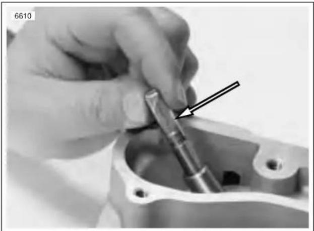
natural_image
Close-up of a hand using a tool to adjust or install a mechanical component (no visible text or symbols)Figure 3-81. Valve Guide Seal Protector Sleeve
- See Figure 3-81. Place a protective sleeve over the valve stem keeper groove.
CAUTION
Failure to use a protective sleeve on the valve stem keeper groove when installing the valve stem seal and collar assembly will result in damage to the seal causing leakage around the valve stem, excessive oil consumption and valve sticking.
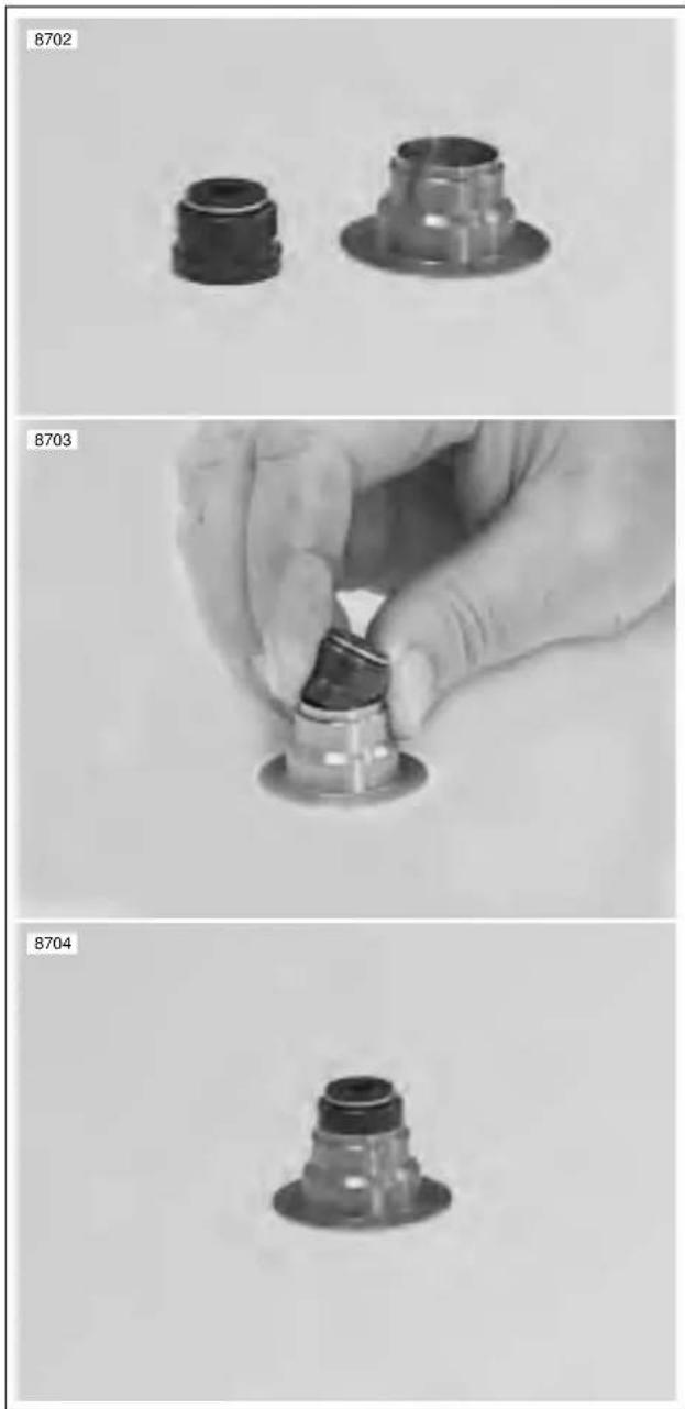
natural_image
Three sequential images showing a hand holding a small mechanical component, labeled 8702, 8703, and 8704 (no text or symbols on the objects themselves)Figure 3-82. Valve Seal and Lower Collar Assembly (seal and lower collar replaced as assembly only)
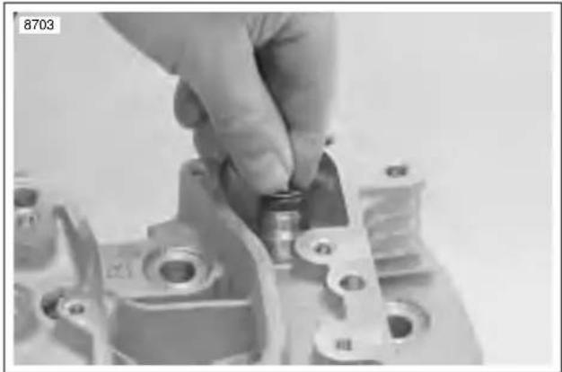
natural_image
Close-up of a hand adjusting a mechanical component with a small cylindrical part (no visible text or symbols)Figure 3-83. Valve Seal and Lower Collar Assembly Installation
- See Figure 3-83. Coat the sleeve with oil and place a new seal and lower collar assembly over the valve stem and onto valve guide.
NOTE
- See Figure 3-82. The valve seal is now incorporated into the lower collar and is installed by hand. NO SPECIAL TOOLS ARE REQUIRED.
● The seal is completely installed when the lower collar contacts the machined surface of the head.
CAUTION
Do not remove valve after seal is installed. Otherwise, sharp edges on keeper groove will damage seal.
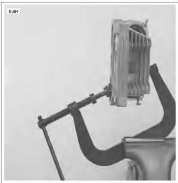
natural_image
Close-up of a mechanical device with a cooling fan and lever mechanism (no visible text or symbols)Figure 3-84. Valve Spring Compressor (Part No. HD-34736B)
-
Install valve spring and upper collar.
-
See Figure 3-84. Compress spring with VALVE SPRING COMPRESSOR (Part No. HD-34736B).
NOTE
The XB9R utilizes a single valve spring for each valve. The inner and outer springs are combined into one tapered spring that is progressively wound.
-
Insert valve keepers into upper collar, making sure they engage grooves in valve stem. The keeper gaps should be equal.
-
Release and remove from VALVE SPRING COMPRESSOR.
-
Repeat Steps 4-11 for the remaining valve.
PUSH ROD COVER INSTALLATION
NOTE
Push rod covers must be installed prior to installing cylinder heads.
natural_image
Close-up of a mechanical assembly with springs and gears (no visible text or symbols)Figure 3-85. Push Rod Locations
- See Figure 3-86. Install push rod covers.
a. Install new o-rings (2) on top of each pushrod cover (3).
b. Install new push rod cover gasket (5) onto bottom of each push rod cover.
c. Install each push rod cover assembly and start the fasteners (4) securing the bottom of each cover to the crankcase.
d. Tighten fasteners to 30-40 in lbs (3.4-4.5 Nm).
- See Table 3-21. Identify push rod color coding, length and respective push rod positions in engine. Place intake and exhaust push rods onto seat at top of tappet.
Table 3-21. Push Rod Selection
| POSITION | COLOR CODES | LENGTH PART NO. |
| Exhaust 1 Band-Pink/Purple | 10.780 in.(274.320 mm) | 17908-02 |
| Intake 1 Band-Orange/Brown | 10.726 in.(272.948 mm) | 17909-02 |
CAUTION
After head(s) have been installed do not turn engine over until both push rods can be turned with fingers. Otherwise, damage to push rods or rocker arms may result.
b1092x3x
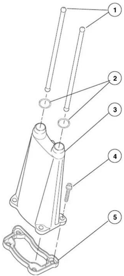
text_image
Technical diagram of a mechanical assembly with numbered components and labeled parts- Push Rod (2)
- O-ring (2)
- Push Rod Cover
- Screws (4)
- Push Rod Cover gasket
Figure 3-86. Push Rods and Push Rod Cover Assembly
CYLINDER HEAD INSTALLATION
CAUTION
Thoroughly clean and lubricate the threads of the cylinder head screws before installation. Friction caused by dirt and grime will result in a false torque indication.
- Thoroughly clean and dry the gasket surfaces of cylinders and cylinder heads.
- Install new O-rings over two ring dowels at the top of the cylinder. Apply a very thin film of clean H-D 20W50 engine oil to O-rings before installation.
CAUTION
To ensure proper head gasket alignment, install new O-rings over cylinder ring dowels before installing the head gasket. Improper head gasket alignment will cause leaks.
- Install a new head gasket to cylinder.
- Carefully lower cylinder head over studs and position on dowels. Use great care so as not to disturb head gasket.
- Lightly coat the threads and bottom face of the cylinder head bolts in clean H-D 20W50 engine oil. Wipe off any excess oil.
CAUTION
The procedure for tightening the head screws is critical to proper distribution of pressure over gasket area. It prevents gasket leaks, stud failure, and head and cylinder distortion.
-
Start the cylinder head screws onto the cylinder studs, two short bolts on the left side of the engine, two long bolts on the right.
-
See Figure 3-87. For each cylinder head, start with screw numbered one, as shown. In increasing numerical sequence (i.e. -1, 2, 3 and 4):
a. Tighten bolts to 96-120 in-lbs (11-14 Nm).
b. Tighten bolts to 13-15 ft-lbs (18-20 Nm).
c. Loosen all screws.
- After screws are loosened from initial torque, tighten head screws in three stages. Tighten fasteners in increasing numerical sequence (i.e. -1, 2, 3 and 4).
a. Tighten each screw to 96-120 in-lbs (11-14 Nm).
b. Tighten each screw to 13-15 ft-lbs (18-20 Nm).
c. See Figure 3-88. Mark cylinder head and head screw shoulder with a line as shown (View A).
d. Turn all bolts an additional 85 -95.°
x0128x3a
Front Cylinder
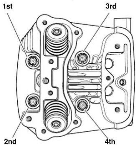
text_image
1st 3rd 2nd 4thRear Cylinder
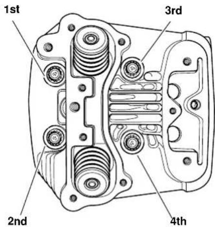
text_image
1st 3rd 2nd 4thHead Screw Loosening/Tightening Sequence
Figure 3-87. Head Screw Loosening/Tightening Sequence
a0089x3x
View A
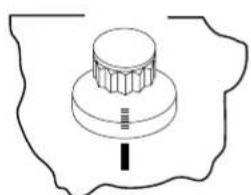
natural_image
Simple line drawing of a mechanical knob or dial component on a curved surface (no text or symbols)View B
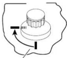
natural_image
Pure mechanical component diagram without any text, numbers, or symbolsTighten head screws 1/4-turn in the third stage of installation
Figure 3-88. Tightening Head Screws
- Crankcase Breather
- Grommet
- Screw (4)
- Washer (4)
- Gasket (4)
- Rocker Cover (top)
- Bolt (3)
- Washer (3)
- Gasket (inner)
- Gasket (lower)
- Rocker Arm Shafts
- Bolt (2)
- washer (2)
- Rocker Cover (lower)
- Rocker Arm (2)
- Bushing (rocker arm - 4)
- Gasket (lower rocker cover)
- Hydraulic lifter
- Screw, tappet anti-rotation (2)
- Gasket (push rod cover)
- Push Rod cover
- Screw (4)
- O-ring (push rod cover - 2)
- Push Rod
- Washer (4)
- Bolt (4)
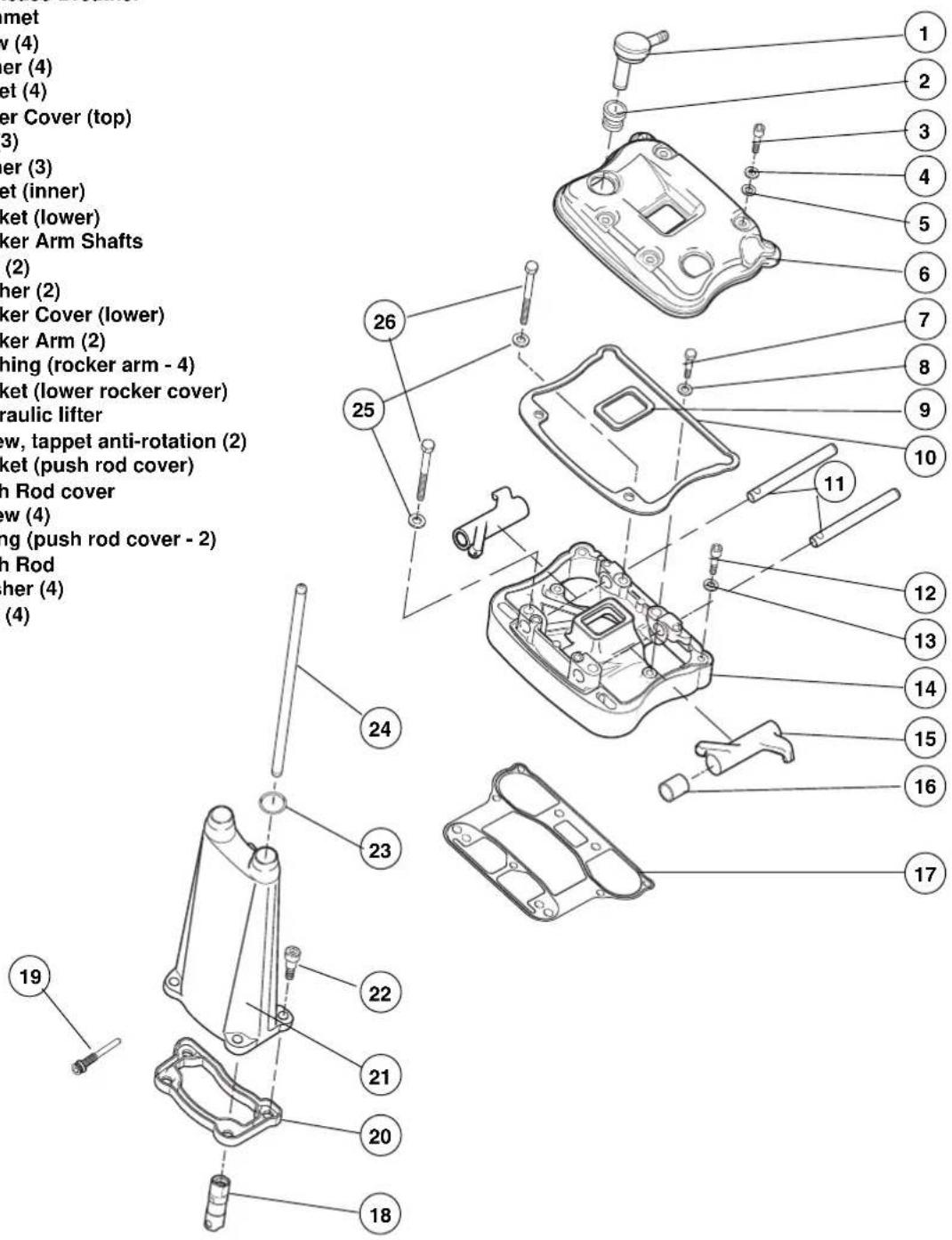
text_image
met w (4) er (4) et (4) er Cover (top) (3) er (3) et (inner) ket (lower) ker Arm Shafts (2) ner (2) ker Cover (lower) ker Arm (2) ning (rocker arm - 4) ket (lower rocker cover) raulic lifter w, tappel anti-rotation (2) ket (push rod cover) n Rod cover w (4) ing (push rod cover - 2) n Rod her (4) (4) 19 20 21 22 23 24 25 26 1 2 3 4 5 6 7 8 9 10 11 12 13 14 15 16 17b0960x3x
Figure 3-89. Rocker Arm and Pushrod Cover Assemblies
HOME
- See Figure 3-90. Install new gaskets with the bead facing up. Place lower rocker box assembly (with rocker arms and shafts) into position. Place push rods in rocker arm sockets.
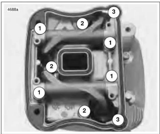
text_image
4688a 1 2 3 1 2 1 1 1 2 3Figure 3-90. Lower Rocker Box Fasteners
- See Figure 3-90. Install hardware attaching lower rocker cover to cylinder head in the following order. After loosely installing all fasteners, use a cross pattern on the four large bolts that fasten the lower rocker box to head to tighten and then torque to specifications. This will bleed the tappets. Finish tightening remaining fasteners. Fastener sequences, sizes and torque specifications are listed in Table3-22.
a. Tighten bolts (1) to 18-22 ft-lbs (24-30 Nm).
b. Tighten bolts (2) to 135-155 in-lbs (15-18 Nm).
c. Tighten bolts (3) to 135-155 in-lbs (15-18 Nm).
- See Figure 3-89. Install upper rocker covers.
a. Place a new inner gaskets on lower rocker box assemblies.
b. Place a new lower gaskets on lower rocker cover.
c. Install upper rocker cover using screws with washers and new fiber seals. Tighten screws to 10-14 ft-lbs (13.6-19 Nm).
Table 3-22. Lower Rocker Box Hardware
| ITEM SIZE TORQUE | ||
| (1)Bolt w/washer | 5/16-18 X 2-1/2 | 18-22 ft-lbs(24-30 Nm) |
| (2)Bolt w/washer | 1/4-20 X 1-1/4 | 11-13 ft-lbs(15-18 Nm) |
| (3)Screw w/washer | 1/4-20 X 1-1/2 | 135-155 in-lbs(15-18 Nm |
REMOVAL/DISASSEMBLY
- Strip motorcycle as described under 3.4 STRIPPING MOTORCYCLE FOR ENGINE SERVICE.
- Remove cylinder head. See 3.6 CYLINDER HEAD.
- Clean crankcase around cylinder base to prevent dirt and debris from entering crankcase while removing cylinder.
- See Figure 3-91. Turn engine over until piston of cylinder being removed is at bottom of its stroke.
- Carefully raise cylinder just enough to permit placing clean towel under piston to prevent any foreign matter from falling into crankcase.
NOTE
If cylinder does not come loose, lightly tap a plastic hammer perpendicular to the cylinder fins. Never try to pry a cylinder up.
- Carefully lift cylinder over piston and cylinder studs. Do not allow piston to fall against cylinder studs. Discard cylinder base gasket.
CAUTION
With cylinder removed, be careful not to bend the cylinder studs. The slightest bend could cause a stress riser and lead to stud failure.
- Install a 6 in. (152 mm) length of 1/2 in. (12.7 mm) ID plastic or rubber hose over each cylinder stud. This will protect the studs and the piston.
WARNING
Retaining rings are highly compressed in the ring groove and may "fly out" with considerable force when pried out. Always wear safety glasses or goggles when removing or installing retaining rings. Failure to wear safety glasses or goggles could result in death or serious injury.
CAUTION
DO NOT re-use piston pin retaining rings. Removal may weaken retaining rings and they may break or dislodge if reinstalled resulting in engine damage.
b0962x3x
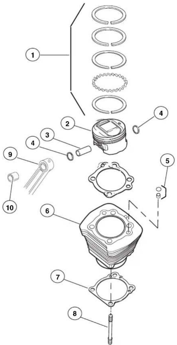
text_image
Exploded view diagram of a mechanical assembly with numbered parts for identification- Ring set
- Piston
- Piston pin
- Retaining ring (2)
- Dowel and o-ring
- Cylinder
- Base gasket
- Cylinder stud (4)
- Connecting rod
- Piston pin bushing
Figure 3-91. Cylinder and Piston
CAUTION
Handle the piston with extreme care. The alloy used in these pistons is very hard. Any scratches, gouges or other marks in the piston could score the cylinder during engine operation and cause engine damage.
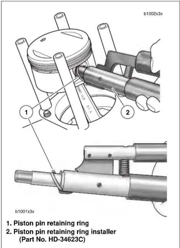
text_image
b1002x3x 1. Piston pin retaining ring 2. Piston pin retaining ring installer (Part No. HD-34623C)Figure 3-92. Removing Piston Pin Circlip
- See Figure 3-92. Remove the piston pin circlip as follows:
a. Insert the PISTON PIN CIRCLIP REMOVER/INSTALLER (Part No. HD-34623C) into the piston pin bore until claw on tool is positioned in slot of piston (directly under circlip).
b. Squeeze the handles of the tool together and pull from bore. In the event that the circlip should fly out, hold a shop towel over the bore during removal. Remove circlip from claw and discard.
NOTES
- It is not necessary to remove both piston pin circlips during piston removal. Leave the second circlip in the pin bore.
- Since the piston pin is a loose fit in the piston, the pin will easily slide out. The pin has tapered ends to help seat the round retaining rings.
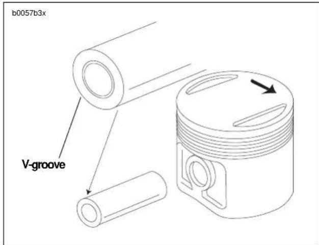
text_image
b0057b3x V-grooveFigure 3-93. Piston Pin and Piston Identification
NOTE
See Figure 3-93. The arrow at the top of pistons must always point toward the front of the engine.
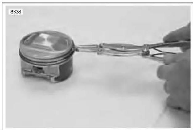
natural_image
Close-up of a hand holding wires connecting a mechanical component (no visible text or symbols)Figure 3-94. Removing Piston Rings
- See Figure 3-94. To remove piston rings spread outward until they clear grooves in piston and lift off.
WARNING
Low pressure compressed air can blow debris into your face and eyes. Always wear eye protection or a face shield when using pressurized air. Failure to take adequate safety precautions could result in death or serious injury.
- Soak cylinder and piston in an aluminum-compatible cleaner/solvent until deposits are soft, then clean with a brush. Blow off loosened carbon and dirt particles and wash in solvent.
- Clean oil passage in cylinder with compressed air.
- Clean piston ring grooves with a piece of compression ring ground to a chisel shape.
- Examine piston pin to see that it is not pitted or scored.
- Check piston pin bushing to see that it is not loose in connecting rod, grooved, pitted or scored.
a. A piston pin properly fitted to upper connecting rod bushing has a 0.00125-0.00175 in. (0.03175-0.04445 mm) clearance in bushing.
b. See Connecting Rod Bushing section. If piston pin-to-bushing clearance exceeds 0.00200 in. (0.05080 mm), replace worn parts. - Clean piston pin retaining ring grooves.
- Examine piston and cylinder for cracks, burnt spots, grooves and gouges.
- Check connecting rod for up and down play in lower bearings. When up and down play is detected, lower bearing should be refitted. This requires removing and disassembling engine crankcase.
Checking Gasket Surface
CAUTION
If cylinder gasket surface does not meet flatness specifications, replace cylinder and piston. Proper tolerances will extend component life and prevent leaks.
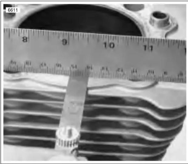
natural_image
Close-up of a metal measuring tape placed over layered wavy material, no visible text or symbolsFigure 3-95. Checking Gasket Surfaces
-
See Figure 3-95. Check cylinder head gasket surface for flatness.
a. Lay a straightedge across the surface.
b. Try to insert a feeler gauge between the straight-edge and the gasket surface.
c. If cylinder head gasket surface is not flat within 0.006 in. (0.152 mm), replace cylinder and piston. -
Check cylinder base gasket surface for flatness.
a. Lay a straightedge across the surface.
b. Try to insert a feeler gauge between the straight-edge and the gasket surface.
c. If cylinder base gasket surface is not flat within 0.008 in. (0.203 mm), replace cylinder and piston.
Measuring Cylinder Bore
- Remove any burrs from the cylinder gasket surfaces.
- See Figure 3-96. Install a head gasket, base gasket and O-rings, and CYLINDER TORQUEPLATES (Part No. HD-33446B) and XL EVOLUTION TORQUE PLATE BOLTS (Part No. HD-33446-86). Tighten the bolts using the same method used when installing the cylinder head screws. See 3.6 CYLINDER HEAD.
NOTE
Torque plates, properly tightened and installed with gaskets, simulate engine operating conditions. Measurements will vary as much as 0.001 in. (0.025 mm) without torque plates.

text_image
b0306x3xFigure 3-96. Measuring Cylinder Bore Using Torque Plates (Part No. HD-33446B)
- See Figure 3-96. Take cylinder bore measurement in ring path, starting about 0.50 in. (12.7 mm) from top of cylinder, measuring from front to rear and then side to side. Record readings.
- Repeat measurement at center and then at bottom of ring path. Record readings. This process will determine if cylinder is out-of-round and will also show any cylinder taper or bulge.
- See Table 3-23. If cylinder is not scuffed or scored and is within service limit, see next section, DEGLAZING CYLINDER.
NOTE
If piston clearance exceeds service wear limit, cylinders and pistons should be replaced with new components. See 3.1 SPECIFICATIONS.
Table 3-23. Cylinder Bore Service Wear Limit
| BORE SIZES IN. | MM | |
| Standard Bore 3.50 | 08 88.9203 |
Deglazing Cylinder
NOTE
Deglazing removes wear patterns, minor scuff marks and scratches without enlarging the bore diameter.
- Lightly swab the cylinder bore with a cloth dipped in clean engine oil.
- Obtain a 240 grit flexible ball-type deglazing tool with a bristle tip or finishing stone arrangement able to produce a 60° cross hatch pattern.
- Install the deglazing tool in a slow-speed drill. The speed at which the tool rotates determines the speed at which it must be stroked up and down the bore to produce the desired cross hatch pattern.
- Starting at the bottom of the cylinder, move the deglazing tool up and down the entire length of the cylinder bore for 10 to 12 complete strokes.
Stop to examine the cylinder bore and/or take measurements. A precise 60° cross hatch pattern in the piston travel area is the most important.
CAUTION
The angular cross hatch pattern ensures an even flow of oil onto the cylinder walls and promotes longer cylinder, piston and ring life. An Improper crosshatch pattern will result in insufficient oil retention and possible piston seizure and/or high oil consumption.
CAUTION
Failure to remove all abrasive particles may result in premature cylinder, piston and ring wear and possible engine failure.
- Thoroughly wash the cylinder bore with liquid dishwashing soap and warm water to remove all abrasive particles and residual grit. Continue cleaning until a clean cloth shows no evidence or dirt or debris.
- Hot rinse the cylinder and dry with moisture free compressed air.
- Immediately apply a thin film of clean engine oil to a clean white paper towel and thoroughly wipe the inside of the cylinder.
NOTE
After wiping the cylinder with a clean, oiled paper towel, the towel will be dark with contamination. repeat this process using a new lightly oiled paper towel each time until the towel remains white. The cylinder is now clean.
- With the cylinder at room temperature, check the piston clearance in the cylinder in which the piston will run. See 3.1 SPECIFICATIONS.
HOME
Fitting Piston Rings
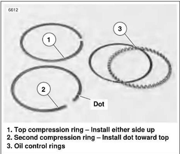
text_image
6612 1 2 Dot 3 Top compression ring – Install either side up Second compression ring – Install dot toward top Oil control ringsFigure 3-97. Piston Rings
See Figure 3-97. Piston rings are of two types: compression and oil control. The two compression rings are positioned in the two upper piston ring grooves. The dot on the second compression ring must face upward. Ring sets are available to fit standard and oversize pistons.
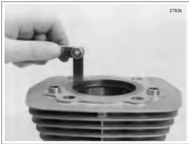
natural_image
Close-up of a hand adjusting a cylindrical mechanical component on a stepped base (no visible text or symbols)Figure 3-98. Measuring Ring End Gap
Piston ring sets must be properly fitted to piston and cylinder:
- See Figure 3-98. Insert the new ring into the cylinder, square it in the bore using the top of the piston and measure the ring end gap with a feeler gauge. Do not use the ring if the end gap does not fall within the following specifications, See Table 3-24.
Table 3-24. Piston Ring End Gap
| Ring Type Ring End Gap | ||
| inches mm | ||
| Top compression ring 0.010 - 0.020 0.25- 0.51 | ||
| 2nd compression ring 0.014 - 0.024 0.36- 0.61 | ||
| Oil control ring rails 0.010 - 0.050 0.25 - 1.27 | ||
HOME
NOTE
The same piston may be used if cylinder bore was not changed, unless it is scuffed or grooved. If re-using piston, replace piston rings and hone the cylinder walls with a No. 240 grit flexible hone to facilitate ring seating.
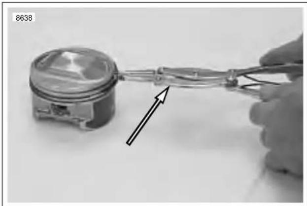
natural_image
Close-up of a hand holding wires connecting a mechanical component (no visible text or symbols)Figure 3-99. Installing Piston Rings Transmission Shaft Retaining Ring Pliers (Part No. J-5586)
- See Figure 3-99. Apply engine oil to piston grooves. Use TRANSMISSION SHAFT RETAINING RING PLIERS (Part No. J-5586) to slip compression rings over piston into their respective grooves. Be extremely careful not to over expand, twist rings or damage piston surface when installing rings.
NOTE
Install second compression ring with dot towards top.
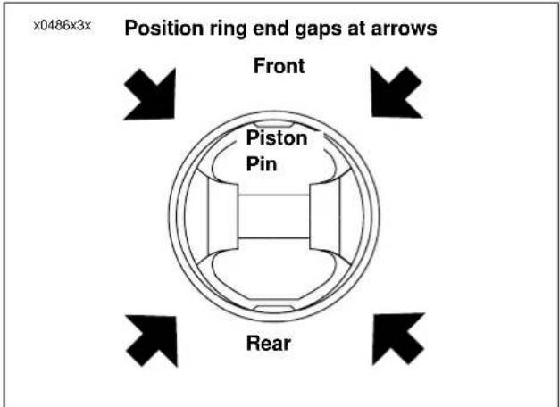
text_image
x0486x3x Position ring end gaps at arrows Front Piston Pin RearFigure 3-100. Ring End Gap Position
- See Figure 3-100. Install rings so end gaps of adjacent rings are a minimum of 90° apart. Ring gaps are not to be within 10° of the thrust face centerline.
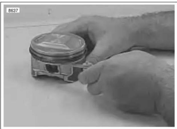
natural_image
Close-up of hands assembling a mechanical piston component (no visible text or symbols)Figure 3-101. Measuring Ring Clearance in Groove
- See Figure 3-101. Check for proper side clearance with thickness gauge, as shown. See 3.1 SPECIFICATIONS.
NOTE
If the ring grooves are clean and the side play is still not correct, replace the rings, the piston or both.
HOME
Connecting Rod Bushing
REMOVAL/INSTALLATION
When connecting rod bushing is worn to excessive pin clearance (0.002 in. or more) (0.051 mm) it must be replaced.
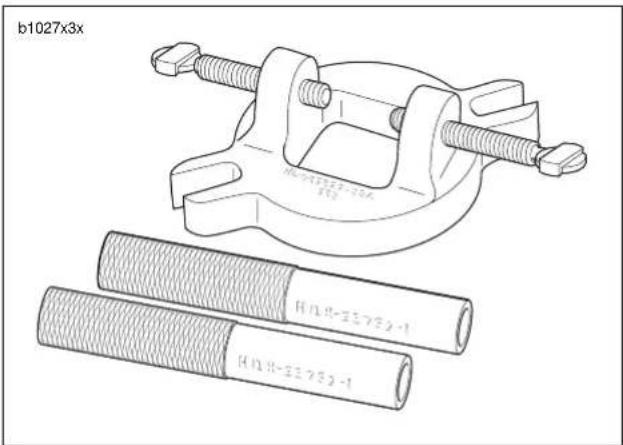
text_image
b1027x3x H11R-23752-1 H11R-23752-1Figure 3-102. Connecting Rod Clamping Tool (Part No. HD-95952-33B)
- See Figure 3-102. Secure connecting rod with CONNECTING ROD CLAMPING TOOL (Part No. HD-95952-33B).
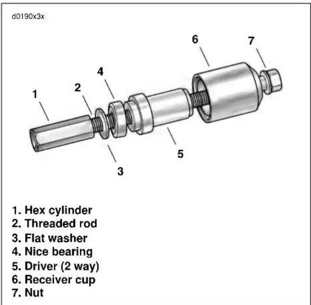
text_image
d0190x3x 1. Hex cylinder 2. Threaded rod 3. Flat washer 4. Nice bearing 5. Driver (2 way) 6. Receiver cup 7. NutFigure 3-103. Connecting Rod Bushing Remover/Installer (Part No. HD-95970-32D)
- See Figure 3-103. Attach PISTON PIN BUSHING TOOL (Part No. HD-95970-32D) to the connecting rod.
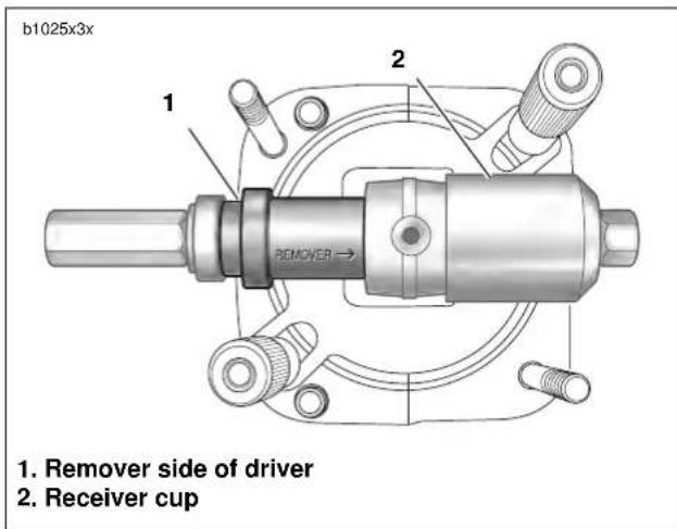
text_image
b1025x3x 1. Remover side of driver 2. Receiver cupFigure 3-104. Removing Wrist Pin Bushing
NOTE
See Figure 3-104. The receiver cup fits on one side of the rod while the driver fits on the opposite side as shown.
- Use two box wrenches and push worn bushing from connecting rod.
- Remove piston pin bushing tool from connecting rod.
- Remove bushing from receiver cup.
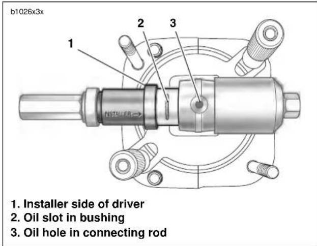
text_image
b1026x3x 1. 2 3 INSTALLER 1. Installer side of driver 2. Oil slot in bushing 3. Oil hole in connecting rodFigure 3-105. Installing New Wrist Pin Bushing
- See Figure 3-105. Place new bushing between connecting rod and driver.
NOTE
The driver must be attached facing the opposite direction as it was for removal of the bushing.
- Clean up and size bushing to 0.0010-0.0005 in. (0.0254-0.0127 mm) undersize using REAMER (Part No. HD-94800-26A). Sizing bushing with less than 0.00125 in. (0.03175 mm) clearance can result in a bushing loosening and/or seized pin in rod.
- Hone bushing to final size using WRIST PIN BUSHING HONE (Part No. HD-35102). Use a liberal amount of honing oil to prevent damage to hone or bushing. Use care to prevent foreign material from falling into the crankcase.
ASSEMBLY/INSTALLATION
- See Figure 3-106. Place PISTON SUPPORT PLATE (Part No. HD-42322) in position as shown.
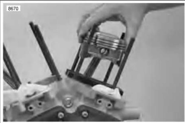
natural_image
Close-up of a hand operating a mechanical device with visible components and no text or symbolsFigure 3-106. Piston Support Plate (Part No. HD-42322)
- Install piston assembly over connecting rod.
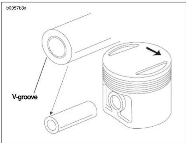
text_image
b0057b3x V-grooveFigure 3-107. Piston Pin and Piston Identification
NOTE
See Figure 3-107. Piston must be installed with the arrow, at the top of the piston, pointing towards the front of the engine.
- Install piston pin.
CAUTION
Always use new retaining ring. Make sure retaining ring groove is clean and that ring seats firmly in groove. If it does not, discard the ring. Never install a used retaining ring or a new one if it has been installed and then removed for any reason. A loosely installed ring will come out of the piston groove and damage cylinder and piston beyond repair.
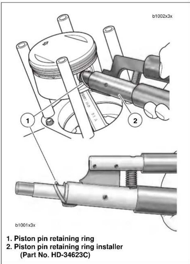
text_image
b1002x3x 1. Piston pin retaining ring 2. Piston pin retaining ring installer (Part No. HD-34623C)Figure 3-108. Installing Piston Pin Circlip
- See Figure 3-108. Install new piston pin retaining rings (1) using PISTON PIN RETAINING RING INSTALLER (2) (Part No. HD-34623C). Place new retaining ring on tool with gap pointing up.
NOTE
Make sure the ring groove is clean. Ring must be fully seated in the groove with the gap away from the slot at the bottom.
a0101x3x
Position ring end gaps at arrows—minimum of 90° apart
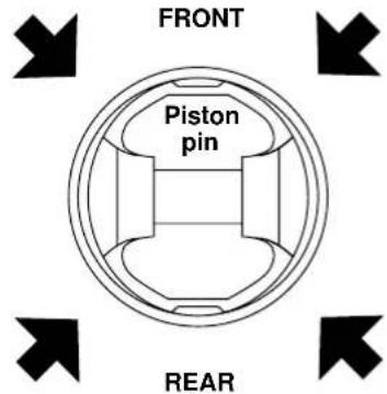
text_image
FRONT Piston pin REARFigure 3-109. Ring End Gap Position
- See Figure 3-109. Make sure the piston ring end gaps are properly positioned as shown.
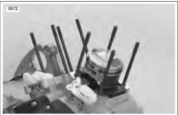
natural_image
Close-up of a mechanical assembly with multiple cylindrical rods and a central piston (no visible text or symbols)Figure 3-110. Piston Support Plate
- See Figure 3-110. Turn engine until piston is resting on top of PISTON SUPPORT PLATE (Part No. HD-42322).
- Lubricate cylinder wall, piston, pin and rod bushing with engine oil.
- Remove protective sleeves from cylinder studs. Install a new cylinder base gasket. Make sure the piston does not bump the studs or crankcase.
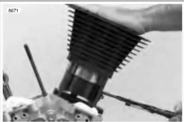
natural_image
Close-up of a mechanical engine component with visible gears and shafts (no text or symbols)-
Piston ring compressor (Part No. HD-96333-51C)
Figure 3-111. Compressing Piston Rings -
See Figure 3-111. Compress the piston rings using PISTON RING COMPRESSOR (Part No. HD-96333-51C).
- Install cylinder over piston.
- Remove PISTON RING COMPRESSOR.
- Assemble and install cylinder head. See 3.6 CYLINDER HEAD.
- Install assembled engine. See 3.4 STRIPPING MOTORCYCLE FOR ENGINE SERVICE.
CHECKING AND ADDING OIL
Check engine oil level in oil reservoir at least once every 500 miles (800 km). Check level more frequently if engine uses more oil than normal or if vehicle is operated under harsh conditions. Check oil when engine is warmed up to operating temperature (see Hot Check).
CHANGING OIL AND FILTER
After a new engine has run its first 1000 miles (1600 km) and at 5000 miles (8000 km) intervals or annually thereafter, completely drain oil reservoir of used oil. If riding habits include severe dust conditions, operation at temperature above 80^ F, extensive idling, speeds in excess of 65 mph and/or extensive two up riding or similar loads the oil should be changed at 2500 mile (4000 km) intervals. Refill with fresh oil. Always change oil filter when changing engine oil.
NOTE
See 1.5 ENGINE LUBRICATION SYSTEM for more information on checking oil level and changing oil and filter.
WINTER LUBRICATION
Normal fuel combustion in a gasoline engine produces water vapor and carbon dioxide along with other gases and particulates. When first starting and warming an engine, some of the water vapor that gets into the engine crankcase condenses to form liquid water. If the engine is driven long enough to thoroughly warm the crankcase, most of this liquid water is again vaporized and exhausted through the crankcase breather system.
A moderately driven vehicle making short runs may not be able to vacate water vapors allowing liquid water to accumulate in the oil reservoir. This is especially true if the vehicle is operated in cold weather. In freezing weather, an accumulation of water in the engine oil may become slush or ice, which can block oil lines and lead to severe engine damage. Water remaining in the engine oil for long periods of time can form an acidic sludge that is corrosive to metal engine parts and causes accelerated wear of moving components.
In winter the oil change interval should be shorter than normal. The colder the weather, the shorter the recommended oil change interval. A vehicle used only for short runs in cold weather must have the engine oil drained frequently.
OIL HOSE ROUTING AND OIL RESERVOIR 3.9
GENERAL
See Figure 3-112. Engine oil runs through the swingarm which serves as the oil reservoir. From the front of the reservoir, the vent hose, the return hose and the feed hose run downward below the crankcases. Two rubberized clamps secure the hoses in place.
The feed line exits the front of the oil pump and routes across
the front of the engine to the oil cooler on the left front side of the crankcases. The feed line then exits the oil cooler and connects to the oil filter housing on the right front side of the crankcases.
The vent hose continues upward from under the vehicle to connect to an elbow fitting at the rear of the gearcase cover.
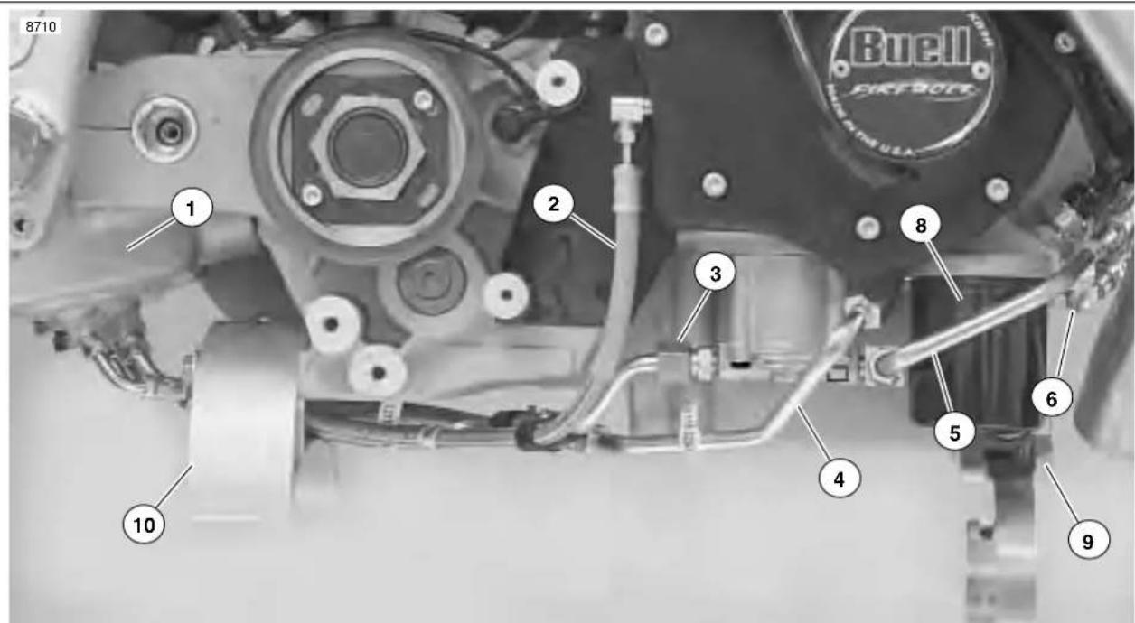
text_image
8710 Bucell FIREBOLT 1 2 3 8 4 5 6 9 10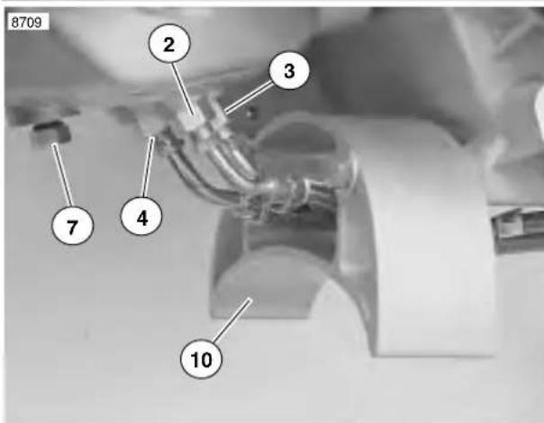
text_image
8709 2 3 4 7 10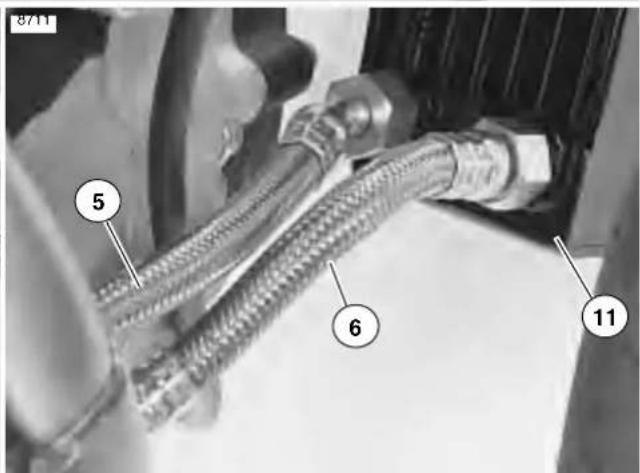
text_image
8711 5 6 11- Swingarm/Oil reservoir
- Vent oil line
- Feed oil line
- Return oil line
- Feed oil line from oil pump to oil cooler
-
Return oil line from oil cooler to crankcase
-
Oil tank drain plug
- Oil filter
- Front muffler mount
- Rear muffler bracket
- Oil cooler
Figure 3-112. Oil Lines and Connections
GENERAL
The oil pressure indicator switch is a pressure-actuated diaphragm-type switch. When oil is not circulating through the system or when oil pressure is low, spring tension holds the switch contacts closed, thereby completing the signal light circuit and causing the indicator lamp to illuminate.
OIL PRESSURE SIGNAL LIGHT
The oil pressure signal light turns ON when:
● Ignition switch is turned on prior to starting engine.
● Oil is not circulating through the running engine.
● Oil pressure is abnormally low in the running engine.
● Engine is idling below 1000 RPM.
The oil pressure signal light turns OFF when:
- Oil is circulating with adequate pressure through the engine running at 1000 RPM or greater.
Troubleshooting information is listed in Table 3-25.
NOTE
If the ignition is turned back on immediately after the engine is stopped, the oil light may not turn on right away because of oil pressure retained in the filter housing.
OIL PRESSURE
See Figure 3-113. The oil pump is non regulatory and delivers its entire volume of oil under pressure to the oil filter mount. When an engine is cold, the engine oil will be more viscous (i.e., thicker).
When an engine is operated at high speeds, the volume of oil circulated through the oiling system increases, resulting in higher oil pressure. As engine speed is reduced, the volume of oil pumped is also reduced, resulting in lower oil pressure.
To check oil pressure, use OIL PRESSURE GAUGE (Part No. HD-96921-52B) and OIL PRESSURE GAUGE ADAPTER (Part No. HD-96940-58). Remove oil pressure indicator switch and insert pressure gauge fitting.
Ride motorcycle at least 20 miles (32 km) at or above 50 MPH (80 KM/H) until engine oil reaches normal operating temperature. At 2500 RPM, oil pressure will vary from 10-12 psi (69-83 KPa). At idle speed (950-1050 RPM), oil pressure will vary from 6-8 psi (42-55 KPa).
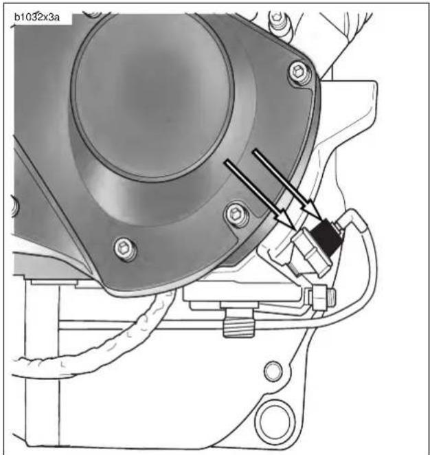
natural_image
Technical line drawing of a mechanical assembly with no visible text or symbolsFigure 3-113. Oil Pressure Indicator Switch
Table 3-25. Troubleshooting Oil Pressure Signal Light
| OIL PRESSURE SIGNAL LIGHT | PROBABLE CAUSES |
| Stays on at speeds above idle. | ● Empty oil reservoir. ● Clogged feed line (ice and sludge, freezing temperatures). ● Air-bound oil line. ● Grounded oil switch wire. ● Malfunctioning signal switch. ● Diluted oil. ● Malfunctioning check valve (see 3.14 OIL FILTER MOUNT). |
| Flickers at idle. | ● Incorrect idle speed. Malfunctioning or improperly installed check valve (see 3.14 OIL FILTER MOUNT). |
| Does not glow when ignition is turned on (prior to operating engine). | ● Malfunctioning signal switch. ● Malfunction in wiring. ● Burned-out signal bulb. ● Dead battery (see NOTE). |
GENERAL
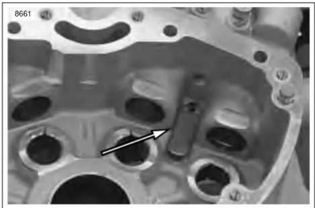
natural_image
Close-up of an engine cylinder head with visible internal cavities and a black arrow pointing to a specific component (no text or symbols present)Figure 3-114. Reed Valve Assembly in Gearcase
See Figure 3-114. Pressure created in the flywheel area on piston downstroke is released through the reed valve into the gearcase. From there a mixture of crankcase air and oil mist is vented up the push rod covers to the upper rocker box.
See Figure 3-115. Air is allowed to escape the rocker boxes by exiting the positive crankcase vent (PCV) valves (4) located on top of the rocker boxes. From the PCV valves the air enters the crankcase breather hoses (2 & 3). The crankcase breather hoses route through the air cleaner base plate (1) to the air box where it is directed inside the air filter element and back into the engine.
The oil mist collects and eventually returns to the crankcase through oil passageways in the cylinder head.
b0974x3x
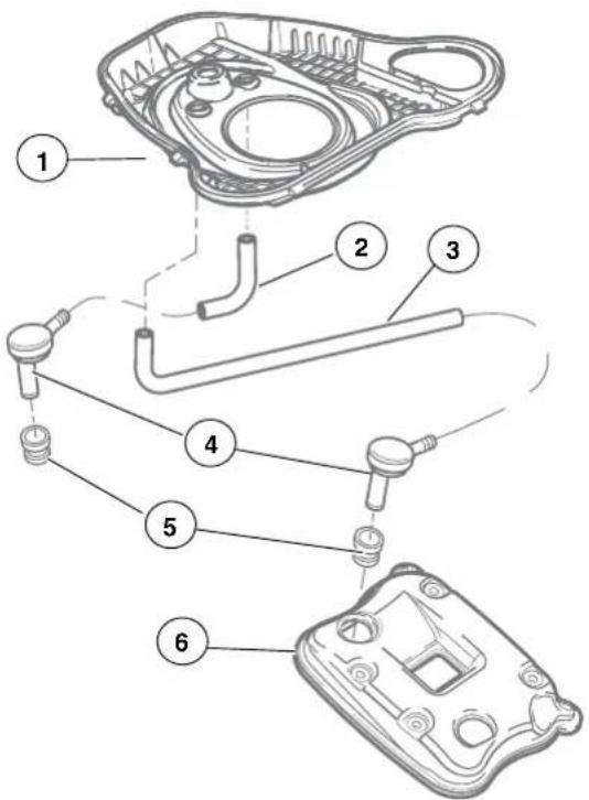
text_image
Exploded view diagram of a mechanical device with numbered parts for identification- Base plate, air box
- Breather hose, rear
- Breather hose, front
- PCV Valves (2)
- Grommet
- Rocker cover, top (2)
Figure 3-115. Crankcase Breathing System,
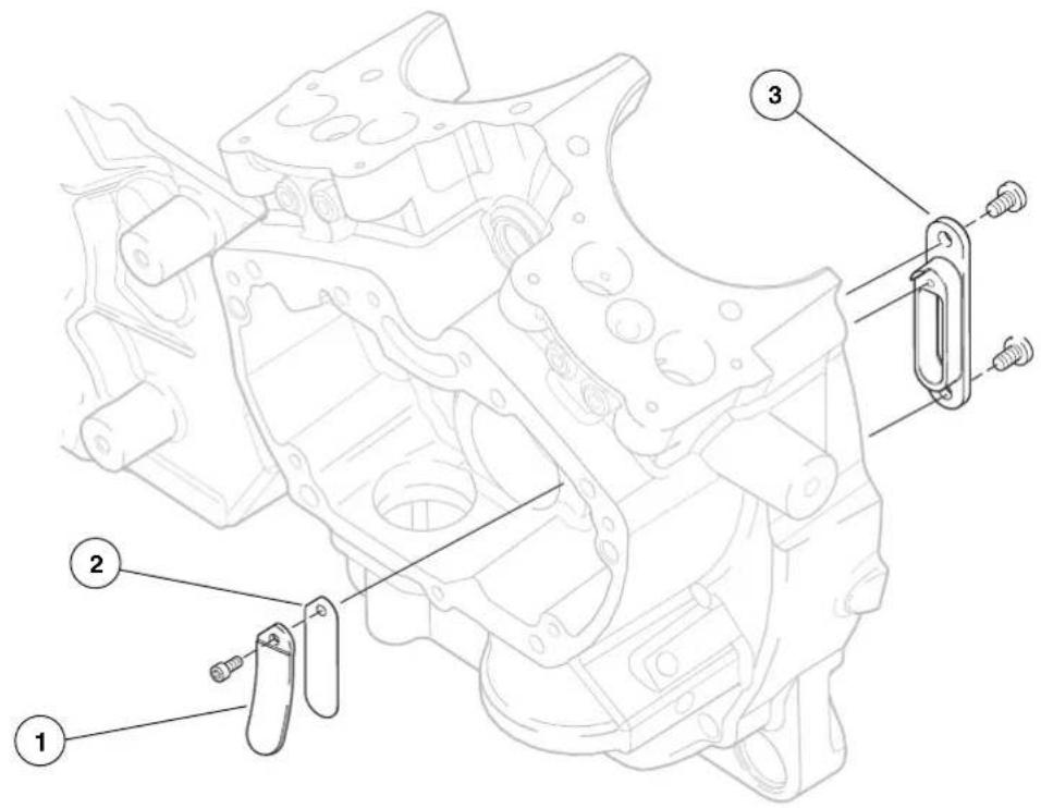
text_image
Technical diagram of an engine cylinder assembly with numbered parts labeled 1, 2, and 3- Reed valve stop 2. Reed valve 3. Reed block
Figure 3-116. Reed Valve Assembly
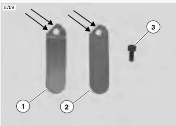
text_image
8759 1 2 3- Reed valve stop 2. Reed valve 3. Stop screw

text_image
Diagram of a mechanical component with numbered parts labeled 1, 2, and 3Figure 3-117. Reed Valve Stop and Reed Valve
NOTE
See Figure 3-117. Whenever the gearcase cover is removed, the reed valve should always be inspected for cracks, chips and breakage. The reed valve (2) is what moves out with the downstroke and in with the upstroke of the pistons. The reed valve stop (1) limits the movement the reed valve (2). See 3.11 CRANKCASE BREATHING SYSTEM.
Fasteners should be tightened to 30-40 in-lbs (3.4-4.5 Nm).
CAUTION
See Figure 3-117. When replacing the reed valve it is extremely important to ensure that both edges of the reed valve stop (1) and the reed valve (2) are properly aligned to prevent premature failure of the reed valve. When replacing the reed valve it is not necessary to replace the reed block. See Figure 3-116.
GENERAL
- Oil is gravity-fed from the oil reservoir to the gerotor-style oil pump through a feed hose. Oil enters the feed section and fills a cavity located under the feed pump.
NOTE
See 3.13 OIL PUMP for a complete explanation of the gerotor pump sets.
- The feed pump transfers oil from the inlet cavity through the external steel line to the oil cooler.
- From the oil cooler oil flows to the oil filter mount.
- Through the filter mount cavity oil flows to the oil filter.
- Oil enters the peripheral cavity of the oil filter, passes through the filtering medium into the central cavity of the oil filter, and flows into the filter adapter (fitting which connects filter to filter mount).
- Adequate oil pressure in the filter mount cavity activates the oil pressure signal light switch and shuts off the oil pressure signal light.
- Oil flowing from the filter adapter opens the check ball. The check ball opens at 4-6 psi (28-41 kPa) oil pressure.
- With the check ball open, oil flows into the crankcase feed galley.
- Oil enters an intersecting passage in the gearcase cover and flow is then routed to the pinion bushing.
-
Oil enters a hole in the end of the pinion gear shaft and travels to the right flywheel where it is routed through the flywheel to the crankpin. Oil is forced through the crankpin to properly lubricate the rod bearing assembly.
-
Oil flow then continues through the gearcase cover to the main feed galley at the top of the gearcase cover. Drilled passages in the crankcase intersect the main feed galley and carry oil to all hydraulic lifters and piston jets.
- Oil flows up passages in the push rods to the rocker arm shafts and bushings.
- The valve stems are lubricated by oil supplied through drilled oil holes in the rocker arms.
- Oil collected in the push rod areas of the cylinder heads flows down the push rod cover, through drain holes in the tappet blocks and into the gearcase. After providing lubrication to the gearcase components oil returns to the scavenge section of the oil pump through a passage located in the top of the pump. Oil is then returned to the oil tank.
- Feed oil to the rocker area is returned to the crankcase through a passage in the head and cylinder.
- Oil collected in the sump is splash-fed to the pistons, cylinder walls and flywheel components.
- A pair of piston oil jets cools the bottom of the piston with a spray of oil.
- Oil collected in the sump area returns to the scavenge section of the oil pump through a passage located in the rear section of the sump. Oil flow to the pump is accomplished by the scavenging effect of the pump and by the pressure created by the downward stroke of the pistons.
- Return oil fills a cavity above the pump's return gears. The return gears pump oil back to the oil reservoir.
GENERAL
See Figure 3-118. The oil pump consists of two gerotor gear sets, feed and return, housed in one pump body. The feed set distributes oil to the engine, the scavenge set returns oil to the tank/frame reservoir.
A gerotor-type gear set has two parts — an inner and an outer gerotor. The inner gerotor has one less tooth than the outer gerotor. Both geroters have fixed centers which are offset to each other.
In a gerotor gear set, oil is transferred from inlet to outlet as it is trapped between the rotating inner and outer geroters.
Gravity-fed oil from the oil reservoir enters the pump through the feed line connector. It is forced by the gerotor feed set through a line to the oil filter. Return oil from the flywheel compartment is drawn back into the pump and is forced by the gerotor scavenge set back to the oil reservoir.
The oil pump seldom needs servicing. Before you disassemble an oil pump suspected of not producing adequate oil pressure, be sure that all possible related malfunctions have been eliminated:
- Make sure all oil line connections are tight and that lines are not pinched or damaged.
- Check level and condition of oil in reservoir/swingarm. Pressure will be affected if oil is diluted. In freezing weather, proper circulation of oil can be affected if the oil feed line becomes clogged with ice or sludge.
- Check for a grounded oil pressure switch wire or faulty switch if oil indicator light fails to go out with engine running.
a0018x3x
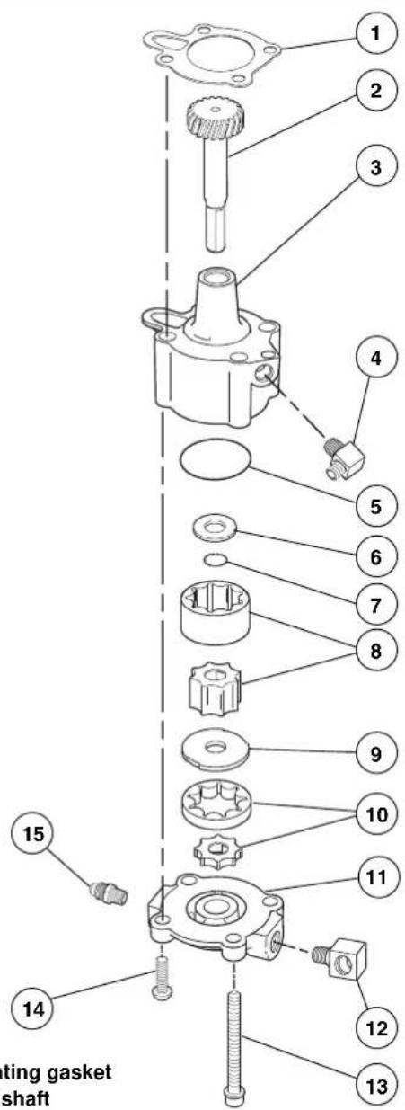
text_image
1 2 3 4 5 6 7 8 9 10 11 12 13 14 15 gating gasket shaft- Mounting gasket
- Gear shaft
- Oil pump body
- 90 ° fitting
- O-ring
- Thrust washer
- Retaining ring
- Gerotor return set
- Separator plate
- Gerotor feed set
- Cover
- 45 ° Fitting
- Sems screw (2)
- TORX screw (2)
- Rear connector fitting
Figure 3-118. Oil Pump
NOTE
Oil pump can be removed with engine in frame and without removing gearcase cover.
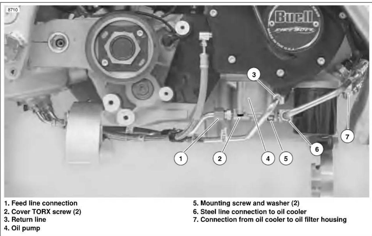
- Feed line connection
- Cover TORX screw (2)
- Return line
-
Oil pump
-
Mounting screw and washer (2)
- Steel line connection to oil cooler
- Connection from oil cooler to oil filter housing
Figure 3-119. Oil Pump Hardware
- Drain oil reservoir. See 1.5 ENGINE LUBRICATION SYSTEM.
- Remove and discard oil filter.
- See Figure 3-119. Disconnect feed line connections (1 & 6) on both sides of the oil pump.
- Detach return line connection (3).
-
Carefully remove mounting screws (5) and washers only. Pump will drop with screws removed. Discard mounting gasket.
-
Remove cover TORX screws (2). Lift cover off body.
- Remove and discard O-ring.
- Slide both pieces of gerotor feed set, separator plate and both pieces of gerotor scavenge set off gear shaft.
- Remove and discard retaining ring. Remove thrust washer and gear shaft.
CLEANING AND INSPECTION
- Clean all parts in cleaning solvent. Blow out holes and oil passages with compressed air.
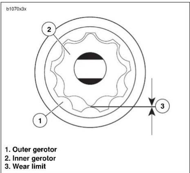
text_image
b1070x3x 1. Outer gerotor 2. Inner gerotor 3. Wear limitFigure 3-120. Gerotor Wear Limits
- See Figure 3-120. Inspect both gerotor sets for wear.
a. Mesh pieces of each set together as shown.
b. Use a feeler gauge to determine clearance.
c. The SERVICE WEAR LIMIT between gerotors is 0.004 in. (0.102 mm). Replace gerotors as a set if clearance exceeds this dimension.
d. Measure thickness of feed geroters with a micrometer. Replace geroters as a set if they are not the same thickness.
- See Figure 3-118. Check gear shaft teeth for damage or wear. Replace if necessary.
ASSEMBLY/INSTALLATION
NOTE
Liberally coat all moving parts with clean engine oil to ensure easy assembly and smooth operation at start-up.
- See Figure 3-118. Install gear shaft through body. Position thrust washer over end of shaft. Install new retaining ring into groove in shaft.
- Insert inner gerotor of the gerotor scavenge set over gear shaft.
- Place outer gerotor over inner gerotor to complete scavenge set.
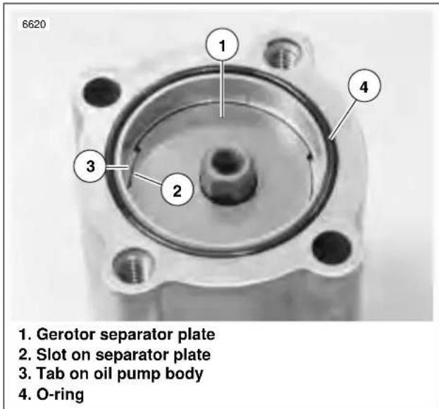
text_image
6620 1. Gerotor separator plate 2. Slot on separator plate 3. Tab on oil pump body 4. O-ringFigure 3-121. Separator Plate Slots
- See Figure 3-121. Install gerotor separator plate by lining up slots on perimeter with tabs inside oil pump body.
- Install a new O-ring into groove in pump body.
- See Figure 3-118. Place gerotor feed set over gear shaft.
- Place cover onto pump body. Install cover TORX screws. Tighten to 70-80 in-lbs (8-9 Nm).
- Place new mounting gasket in position.
NOTE
If fittings were removed, use TEFLON® PIPE SEALANT or HYLOMAR® on fitting threads.
- Secure pump to crankcase with mounting screws. Tighten to 125-150 in-lbs (14-17 Nm).
- See Figure 3-119. Attach return line connection.
- Attach feed line connections to both sides of the oil pump.
- Install new oil filter and fill oil reservoir with proper oil. See 1.5 ENGINE LUBRICATION SYSTEM.
GENERAL
See Figure 3-122. Oil is pressure-fed from the oil pump to the oil cooler via an external steel line. From the oil cooler, oil flows to the oil filter mount. Oil travels through the filter mount into the filter through the outer filter holes.
Adequate oil pressure activates the oil pressure indicator switch in the filter mount, which turns off the oil pressure indicator lamp.
The check ball in the filter adapter opens at 4-6 psi (28-41 kPa) oil pressure. Filtered oil leaves the filter, flowing past the check ball.
DISASSEMBLY
- Remove chin fairing. See 2.33 CHIN FAIRING.
- Drain oil reservoir and remove filter. See 1.5 ENGINE LUBRICATION SYSTEM.
- See Figure 3-122. Remove filter adapter (6) from filter mount (3). Remove check ball (5) and spring (4).
- Detach indicator lamp wire (2) from oil pressure indicator switch (1). Remove switch using OIL PRESSURE SENDING UNIT WRENCH (Part No. HD-41675).
CLEANING AND INSPECTION
Thoroughly clean all parts in cleaning solvent. Blow out holes and passages using compressed air.
ASSEMBLY
NOTE
Use TEFLON PIPE SEALANT or HYLOMAR on all fittings installed to oil filter mount.
-
See Figure 3-122. Install oil pressure indicator switch (1) using OIL PRESSURE SENDING UNIT WRENCH (Part No. HD-41675). Tighten to 50-70 in-lbs (6-8 Nm).
-
Attach indicator lamp wire (2).
NOTE
The filter adapter has identical ends; either end may be installed into the filter mount.
-
Apply several drops of LOCTITE ^® thread locker 243 (blue) to last few threads on that end of the filter adapter which is installed into filter mount. Do not apply LOCTITE to adapter threads on filter element side.
-
Install filter mount components.
a. Place spring (4) and check ball (5) into threaded hole at center of mount.
b. Push threaded end of filter adapter (6) (with LOC-TITE) against check ball to compress spring.
c. Screw adapter into threaded hole. Tighten to 8-12 ft-lbs (11-16 Nm).
- Install a new filter and fill oil reservoir with proper oil. See 1.5 ENGINE LUBRICATION SYSTEM.
3-82 2003 Buell XB9R: Engine
- Install chin fairing. See 2.33 CHIN FAIRING.
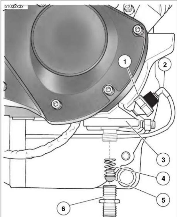
text_image
b1032x3x 1 2 3 4 5 6- Oil pressure indicator switch
- Indicator lamp wire
- Oil filter mount (part of right crankcase half)
- Spring
- Check ball
- Filter adapter
Figure 3-122. Oil Filter Mount Assembly
GENERAL
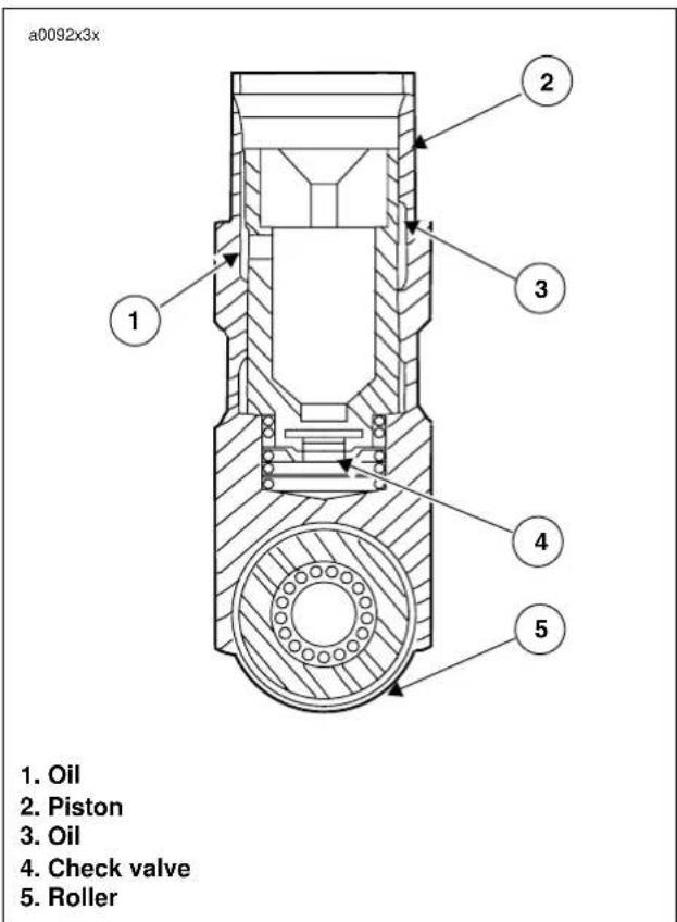
text_image
a0092x3x 1. Oil 2. Piston 3. Oil 4. Check valve 5. RollerFigure 3-123. Lifter Assembly (Typical)
See Figure 3-123. The lifter assembly consists of a hydraulic lifter and roller. The lifter and roller, under compression force from valve spring, follow the surface of the revolving cam. The up-and-down motion produced is transmitted to the valve by the push rod and rocker arm. The lifter contains a piston (or plunger) and cylinder; it also contains a check valve, which allows the unit to fill with engine oil, thereby reducing clearance in the valve train.
When a lifter is functioning properly, the assembly operates with minimal lifter clearance. The unit automatically compensates for heat expansion to maintain a no-clearance condition.
It is normal for lifters to click when engine is started after standing for some time. Hydraulic lifters have a definite leakdown rate which permits the oil in the lifters to escape. This is necessary to allow units to compensate for various expansion conditions of parts and still maintain correct clearance operation. Lifters are functioning properly if they become quiet after a few minutes of engine operation.
REMOVAL
- Clean all dirt from around crankcase. Blow loose particles from area with compressed air.
- Pull each push rod upward through top of cylinder head. See 3.6 CYLINDER HEAD.
- Remove cylinder head assemblies. See 3.6 CYLINDER HEAD.
-
See Figure 3-125. Remove push rod covers.
a. Remove screws.
b. Remove push rod covers.
c. Remove gaskets and o-rings. Discard parts. -
Remove valve hydraulic lifters.
a. Remove anti-rotation screws.
b. Remove lifters from crankcase bore using a thin-bladed screwdriver. Mark the location and orientation (front/back) of each lifter.
CLEANING AND INSPECTION
WARNING
Low pressure compressed air can blow debris into your face and eyes. Always wear eye protection or a face shield when using pressurized air. Failure to take adequate safety precautions could result in death or serious injury.
- Clean all parts, except roller/lifter assembly, thoroughly in solvent. Blow dry with compressed air.
NOTE
Inside and outside micrometers used for measuring tappets and tappet guides must be calibrated to ensure accurate readings.
- Inspect valve lifters for excessive clearance in guide. Accurately measure lifter bore inner diameter with a gauge.
a. Clearance should be within 0.0008-0.0020 in. (0.0203-0.0508 mm).
b. Fit a new lifter and/or replace crankcases if clearance exceeds SERVICE WEAR LIMIT of 0.0030 in. (0.076 mm).
- Check lifter roller freeplay.
a. Roller clearance on pin should be within 0.0006-0.0010 in. (0.0152-0.0254 mm).
b. Replace lifters if clearance exceeds SERVICE WEAR LIMIT of 0.0015 in. (0.0381 mm).
- Check lifter roller end clearance.
a. End clearance should be within 0.008-0.022 in. (0.203-0.559 mm).
b. Replace lifters if clearance exceeds SERVICE WEAR LIMIT of 0.026 in. (0.660 mm).
- Soak lifters in clean engine oil. Keep covered until assembly.
INSTALLATION
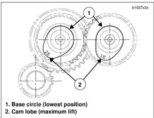
text_image
1. Base circle (lowest position) 2. Cam lobe (maximum lift)Figure 3-124. Base Circle
- See Figure 3-124. Rotate engine so that both lifters from the cylinder will be installed on the base circle of the cam.
- Apply a liberal amount of engine oil to each lifter assembly (especially the roller needles) for smooth initial operation.
- See Figure 3-125. Insert lifter into bore in crankcase. Rotate lifter so that flats at upper end of lifter face the front and rear of the engine. If the lifter is installed incorrectly, anti-rotation screws cannot be inserted.
-
Secure lifters in place.
a. Install anti-rotation screws with washers in the holes in lifter block.
b. Tighten anti-rotation screws to 55-65 in-lbs (6-7 Nm). -
See Figure 3-125. Install push rod cover.
a. Place new pushrod cover gasket over bottom of push rod cover.
b. Position push rod cover onto crankcase.
c. Install screws through holes in push rod cover into tapped holes in crankcase. Tighten screws evenly to 30-40 in-lbs (3-5 Nm).
d. Place new o-rings on top of push rod cover.
-
Install push rods, cylinder head, lower and upper rocker covers. See 3.6 CYLINDER HEAD.
-
Repeat process for remaining cylinder head.
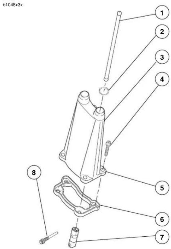
text_image
b1048x3x 1 2 3 4 5 6 7 8- Push Rod (exhaust)
- O-ring
- Push Rod Cover
- Screws (4)
- Push Rod Cover
- Push Rod Cover gasket
- Hydraulic Lifter (tappet)
- Anti- Rotation Screw
Figure 3-125. Valve Lifter Service
GENERAL
Read the complete gearcase section carefully before you begin any service work.
For the gearcase components to operate at their optimum, all components must be properly fitted and matched. Changing one component can affect many others. It is important to know and understand all inspection procedures and how components interact.
b0980x3x
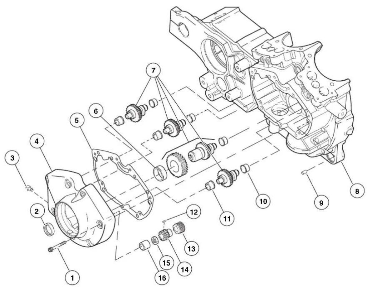
text_image
Technical diagram of an engine assembly with numbered components for identification- Screw (7)
- Seal
- Fitting, oil vent line
- Gear Cover
- Gear cover gasket
- Bushing, outer, intake camshaft gear
- "E" Cam gear set
-
Right crankcase half
-
Dowel pin
- Bushing, inner, camshaft gear (4)
- Bushing, outer, camshaft gear (3)
- Key
- Oil pump drive gear
- Pinion gear
- Nut
- bushing, gear shaft- pinion
Figure 3-126. Gearcase Cover & Cam Assembly
REMOVAL/DISASSEMBLY
WARNING
Low pressure compressed air can blow debris into your face and eyes. Always wear eye protection or a face shield when using pressurized air. Failure to take adequate safety precautions could result in death or serious injury.
- See Figure 3-126. Thoroughly clean area around gear-case cover and tappets. Blow loose dirt from crankcase with compressed air.
- Remove any parts that will interfere with gearcase disassembly.
- Remove push rods. See 3.6 CYLINDER HEAD.
- Remove hydraulic lifters. See 3.15 HYDRAULIC LIFTERS.
-
Check for minimum cam gear end play. Record readings.
-
Remove cam position sensor and rotor from gearcase cover. See 4.30 CAM POSITION SENSOR AND ROTOR.
- Place a pan under gearcase to collect oil. Remove cover screws. Carefully remove gearcase cover. Discard old gasket.
NOTE
If cover does not come loose on removal of screws, tap lightly with a plastic hammer. Never pry cover off.
- See Figure 3-127. Remove cam gears (1, 2, 3 & 4).
NOTE
Nut is secured by LOCTITE 262 (red) on the nut threads.
- Remove pinion nut (6). Slide pinion gear (5) and oil pump drive gear (6) off pinion shaft.
NOTE
See Figure 3-127. The XB9R uses new style timing marks on the front intake cam assembly (2). Please note the "V" markings.
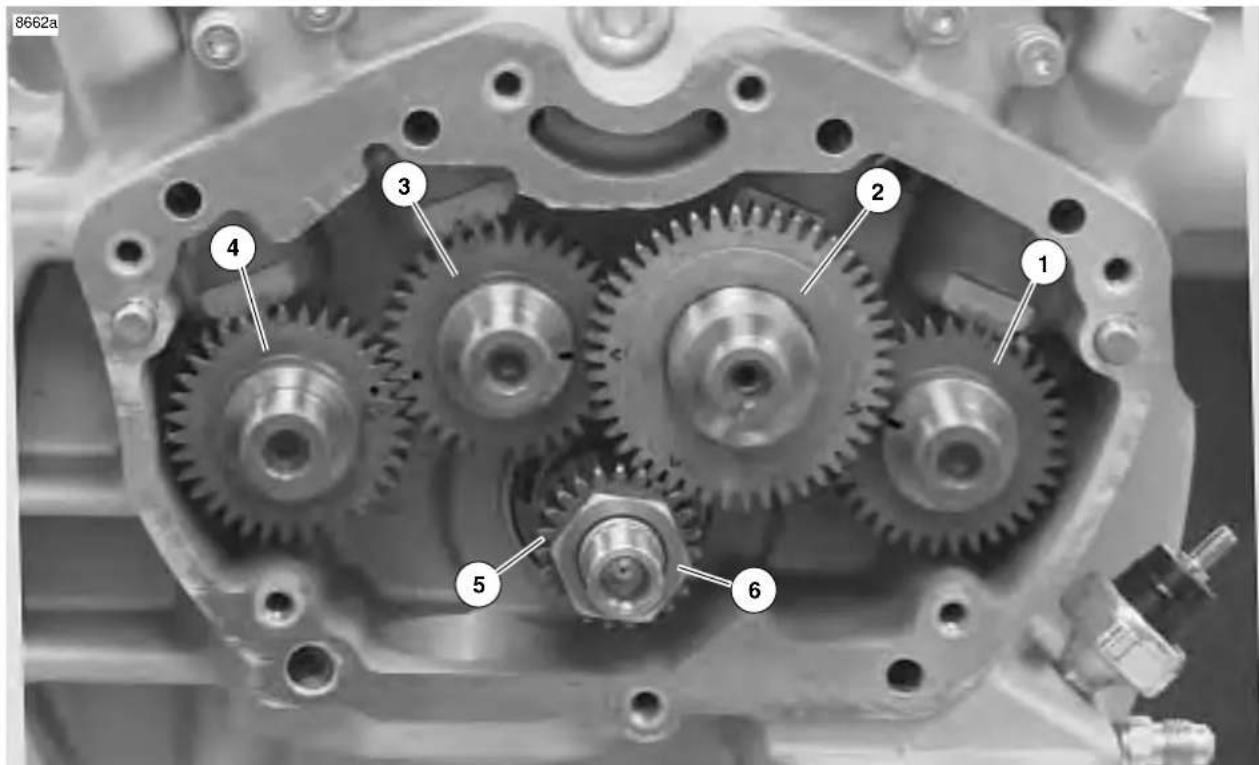
text_image
8662a 1 2 3 4 5 6- Front exhaust cam gear
- Front intake cam gear
-
Rear intake cam gear
-
Rear exhaust cam gear
- Pinion gear
- Pinion nut
Figure 3-127. Cam and Pinion Gear Location and Timing Mark Indexing
CLEANING AND INSPECTION
- Thoroughly clean gearcase compartment, gearcase cover and gears in solvent to remove oil and carbon deposits.
WARNING
Low pressure compressed air can blow debris into your face and eyes. Always wear eye protection or a face shield when using pressurized air. Failure to take adequate safety precautions could result in death or serious injury.
- Blow out all cover oil passages and bushings with compressed air.
- Clean old gasket material from gearcase and crankcase.
Cam and Pinion Gear Identification, Inspection and Selection
b0952x1x
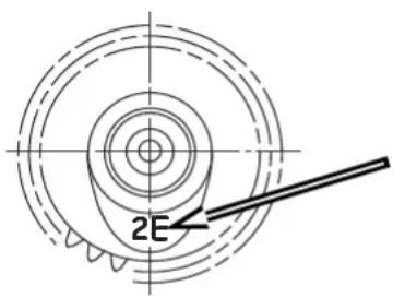
text_image
2EFigure 3-128. Cam Identification Stamp
See Figure 3-128. Cam lobes are stamped with a number (1, 2, 3 or 4) followed by a letter ("E"). The numbers identify the cam location/function and the letter ("E") indicates model year application:
Table 3-26.
| Stamp Location/Function | |
| 1E Front Exhaust | |
| 2E Front Intake | |
| 3E Rear Intake | |
| 4E Rear Exhaust | |
NOTE
Prior to changing any cam gears, check gear shaft fit within corresponding bushings. Worn bushings can cause excessive backlash.
Bushing Inspection
- Bushings are press fit in gearcase cover and crankcase. Inspect each bushing against its corresponding cam gear shaft or pinion gear shaft. See Table 3-27.
NOTE
If Service Wear Limits are exceeded, replace crankcase set and/or gearcase cover as required.
Table 3-27. Gear Shaft Specifications
| GEAR SHAFT | CORRECT CLEARANCE | SERVICE WEAR LIMIT |
| Cam 0.0007 | -0.0022 in.(0.0178-0.0559 mm) | 0.003 in.(0.076 mm) |
| Pinion 0.002 | 3-0.0043 in.(0.0584-0.1092 mm) | 0.0050 in.(0.1270 mm) |
ASSEMBLY/INSTALLATION
- See Figure 3-129. Install oil pump drive gear and pinion gear on pinion shaft.
a. Install shaft key into pinion shaft slot.
b. Slide oil pump drive gear over pinion shaft. Drive gear must align with shaft key.
c. Align keyway in ID of pinion gear with shaft key.
d. Slide pinion gear over shaft key and against oil pump drive gear.
- See Figure 3-126. Install pinion nut.
a. Clean threads on pinion shaft and nut.
b. See Figure 3-130. Install CRANKSHAFT LOCKING TOOL (Part No. HD-43984) to gearcase with "Side B" facing out, over pinion shaft, with two screws.
c. Apply several drops of LOCTITE 262 (red) to last few threads of nut.
d. Install nut to pinion shaft. Tighten nut to 19-21 ft-lbs (26-29 Nm) plus an additional 15° to 19° rotation.
- See Figure 3-126. Liberally apply engine oil to bushings, shafts, and gears. Install all cam gears into bushings of right crankcase half, properly aligning timing marks of cam gears and pinion gear.
NOTE
- The XB9R uses new style timing marks on the front intake cam assembly. Please note the "V" design.
● Because of the larger diameter additional gear (which meshes with the pinion gear) on the outboard end of the cam, the front exhaust cam gear and the rear intake cam gear must be installed before the front intake cam gear is installed. - See Figure 3-126. Install a new seal and new dry gear-cover gasket on crankcase.

text_image
a0078x3x 1 2 3 4 5- Pinion shaft
- Timing Mark on pinion gear
- Keyway
- Shaft key
- Oil pump drive gear
Figure 3-129. Aligning Pinion Gear
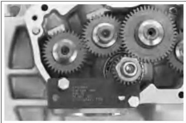
natural_image
Close-up of mechanical gears and a circuit board component (no visible text or symbols)Figure 3-130. Crankshaft Locking Tool (Part No. HD-43984)
HOME
-
See Figure 3-131. Install gearcase cover over all gears and onto right crankcase half. Secure cover to crankcase half with 7 socket head screws. Tighten screws evenly to 80-110 in-lbs (9-12 Nm). Use torque sequence as shown in Figure 3-131.
-
See Figure 3-132. Check cam gear end play for each cam gear as follows:
a. Turn engine over until lobe of cam gear being checked is pointing toward its respective tappet guide hole.
b. Gently pry the cam gear toward the gearcase cover using a flat blade screwdriver.
c. Measure gap between bushing (in crankcase half) and cam gear shaft thrust face (shoulder) using a feeler gauge. This is cam gear end play.
d. Compare cam gear end play measurements with the SERVICE WEAR LIMITS. Make repairs as required if end play does not meet specifications.
-
Install hydraulic lifters and push rods. See 3.15 HYDRAULIC LIFTERS.
-
Install cam position sensor and rotor in gearcase cover. See CAM POSITION SENSOR AND ROTOR section.
-
Install any components removed to gain access to gear-case (i.e. exhaust system components, air cleaner, etc.).
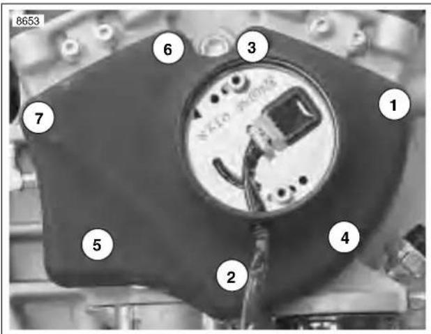
text_image
8653 1 2 3 4 5 6 7Figure 3-131. Gearcase Cover Mounting Screw Torque Sequence
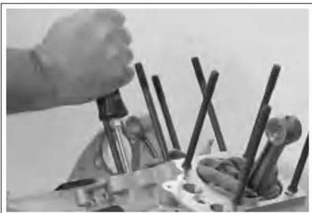
natural_image
Close-up of a hand using a tool to adjust or install a mechanical component, with no visible text or symbols.Figure 3-132. Checking Cam Gear End Play
GENERAL
When rod bearings, pinion shaft bearing, or sprocket shaft bearing are in need of repair, the engine must be removed from the chassis; see 3.4 STRIPPING MOTORCYCLE FOR ENGINE SERVICE in this section. It is recommended procedure to check and make repairs to cylinder heads, cylinders, gear case and transmission at the same time (perform entire engine overhaul).
CAUTION
Laying engine on primary side will damage clutch cable end fitting. If fitting is damaged, clutch cable must be replaced.
DISASSEMBLY
Crankcase Halves
- Remove cylinder heads. See 3.6 CYLINDER HEAD.
CAUTION
After removing cylinders, install plastic or rubber hose over cylinder studs. Lifting or moving crankcase by grasping studs will cause cylinder stud damage.
- Remove cylinders and pistons. See 3.7 CYLINDER AND PISTON.
- Remove oil pump. See 3.13 OIL PUMP.
- Remove gearcase components. See 3.16 GEARCASE COVER AND CAM GEARS.
- Remove primary cover and primary drive/clutch components. See 6.2 PRIMARY CHAIN.
- Remove starter motor. See 5.7 STARTER.
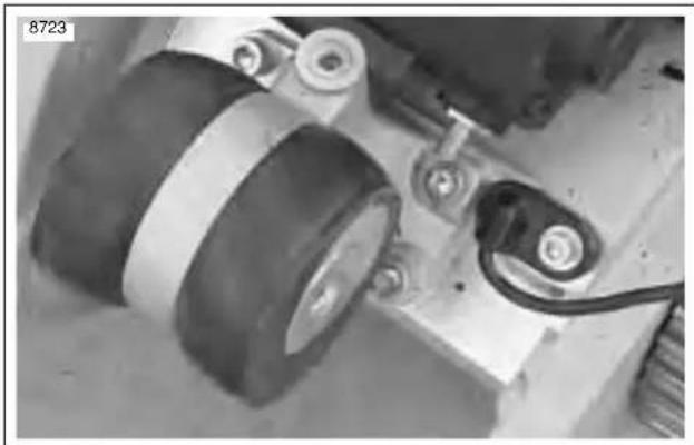
natural_image
Close-up of mechanical components including a large wheel and attached gear assembly (no visible text or symbols)Figure 3-133. Rear Isolator Assembly
- See Figure 3-133. Remove rear isolator assembly by removing the forward two fasteners first and then the two rear fasteners (re-install with new fasteners).
- See Figure 3-134. Remove screws securing crankcase halves together.
- Tap crankcase with plastic mallet to loosen and separate the halves.
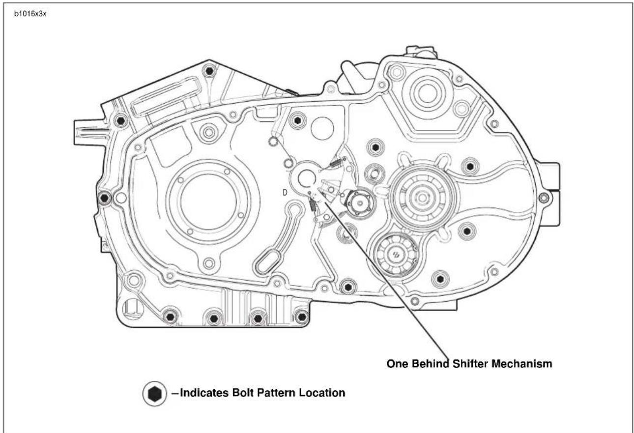
text_image
b1016x3x One Behind Shifter Mechanism —Indicates Bolt Pattern LocationFigure 3-134. Crankcase Fasteners
PISTON JETS
Removal
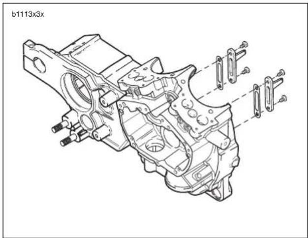
natural_image
Technical line drawing of an internal combustion engine component (no text or symbols)Figure 3-135. Piston Oil Jet Assemblies
- See Figure 3-135. Remove two TORX screws from each piston jet assembly to free piston jets from right crank-case.
- Remove piston jet gaskets from right crankcase.
Installation
CAUTION
Gaskets that are missing, distorted, pinched or otherwise damaged will result in either oil leakage or low oil pressure.
NOTE
Gasket is part of the piston jet assembly. Gasket not sold separately.
- Install new piston oil jet assemblies in right crankcase.
- Apply Loctite Low Strength Threadlocker 222 (purple) to threads of TORX screws.
- With the jet pointed upward, install TORX screws to secure piston jet to crankcase. Tighten screws to 25-35 in-lbs (2.8-4.0 Nm).

natural_image
Close-up of hands holding various mechanical tools, no visible text or symbolsFigure 3-136. Removing Flywheels from Left Crankcase
- See Figure 3-136. Remove the flywheel assembly from left crankcase half.
NOTE
Flywheel assembly slides out of the left main bearing by hand. No tools are required for this operation.
NOTE
See Figure 3-137. If it is necessary to remove either the pinion shaft bearing or sprocket shaft bearing, proceed as follows:
- See Figure 3-137. Gear shaft bearing (11) will remain on flywheel pinion shaft. Remove retaining ring (12) and bearing can be slipped off pinion shaft.
b0975x3x
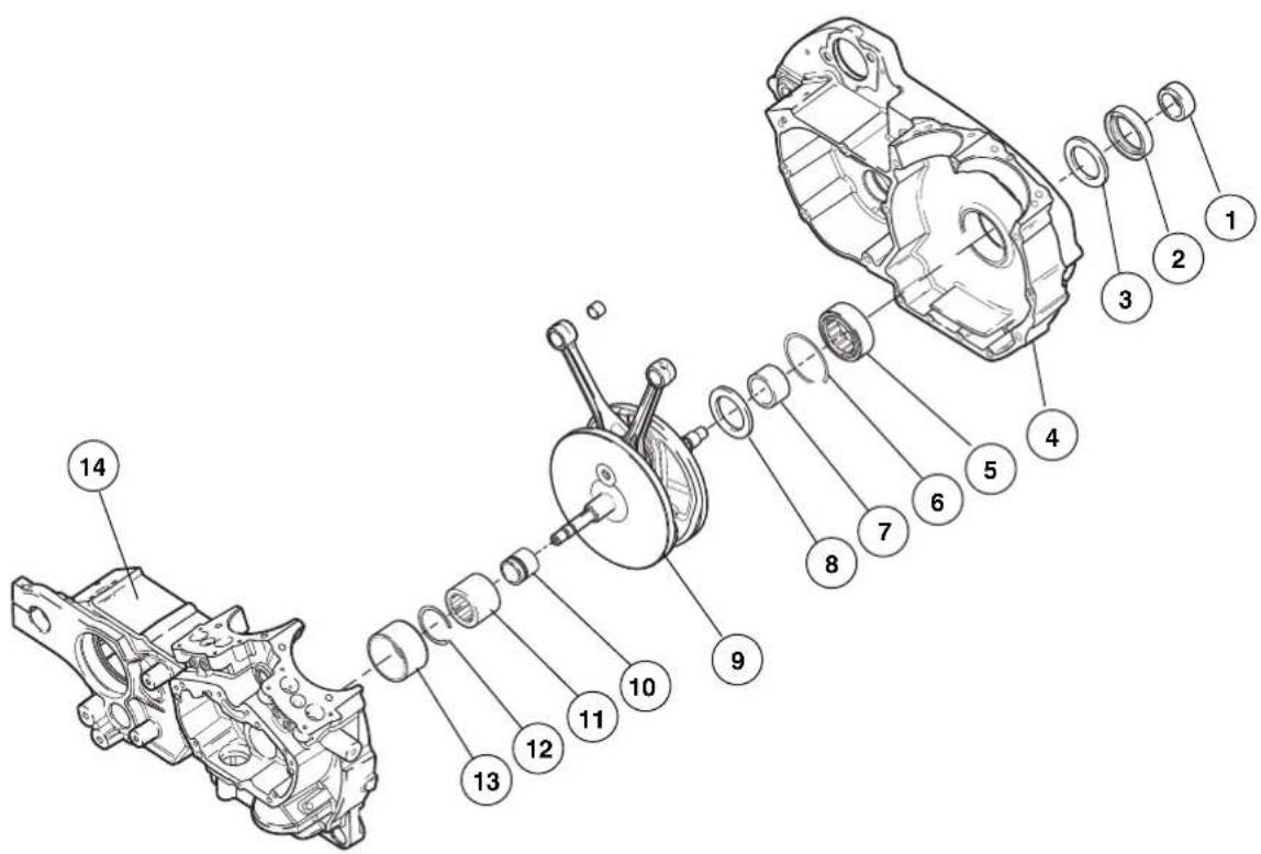
text_image
Exploded view diagram of a mechanical assembly with numbered parts for identification- Spacer, sprocket shaft
- Oil seal
- Thrust washer
- Crankcase half
- Bearing
- Retaining ring
-
Inner race, left main bearing
-
Thrust washer
-
Connecting rod and flywheel assembly
-
Inner race
-
Gear shaft bearing
- Retaining ring
- Outer bearing race
- Crankshaft case
Figure 3-137. Crankcase and Flywheel Assembly
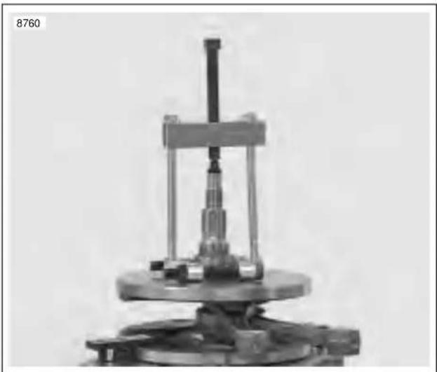
natural_image
Mechanical testing apparatus with a central vertical rod and flanged base (no visible text or symbols)Figure 3-138. Removing Sprocket Shaft Inner Bearing Race
- See Figure 3-138. Place flywheel assembly in FLY-WHEEL SUPPORT FIXTURE (Part No. HD-44385). Pull sprocket shaft bearing inner race with WEDGE ATTACHMENT for CLAW PULLER (Part No. HD-95637-46A) with BEARING RACE REMOVER/INSTALLER (Part No. HD-34902B) and END CAP (Part No. HD-34902-7).
- See Figure 3-137. Remove left main oil seal (2) from crankcase using Snap-On Tool (Part No. CJ 114, Body Dent Puller)
- Remove outer thrust washer (3) next to left main bearing (5).
NOTE
Left main bearing inner race does not need to be ground once it is installed on the sprocket shaft.
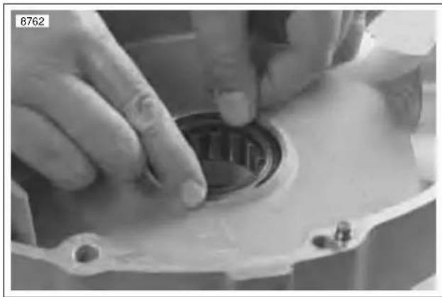
natural_image
Close-up of hands assembling a mechanical component with a circular bearing (no visible text or symbols)Figure 3-139. Removing Left Main Bearing Retaining Ring
- See Figure 3-139. Remove left main bearing retaining ring from the inside of the left crankcase half.
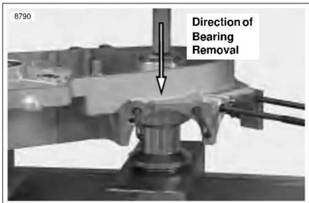
text_image
8790 Direction of Bearing RemovalFigure 3-140. Removing Left Main Bearing from Crankcase
- See Figure 3-140. Using CRANKCASE BEARING REMOVER/INSTALLER (Part No. B-45655 and HD-42720-2) press left main bearing out of the left crank-case half.
NOTE
The bearing presses to the inside. There is a shoulder incorporated into the left crankcase half which allows the bearing to be removed in one direction only.
HOME
FITTING PINION BEARINGS
See Figure 3-137. A pressed-in bushing in the right crank-case half is the outer race (14). The inner race (10) is pressed onto the pinion shaft.
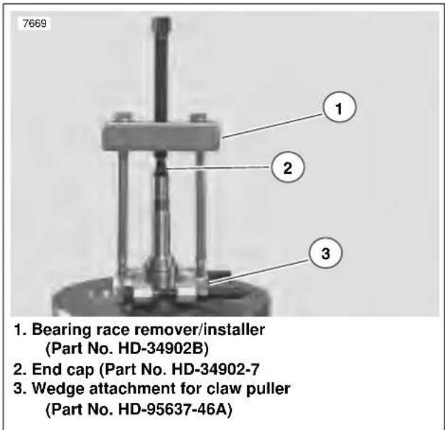
text_image
7669 1. Bearing race remover/installer (Part No. HD-34902B) 2. End cap (Part No. HD-34902-7) 3. Wedge attachment for claw puller (Part No. HD-95637-46A)Figure 3-141. Removing Pinion Bearing Inner Race
- See Figure 3-141. To remove pinion shaft inner race, use WEDGE ATTACHMENT for CLAW PULLER (Part No. HD-95637-46A) with BEARING RACE REMOVER/INSTALLER (Part No. HD-34902B) and END CAP (Part No. HD-34902-7). Apply heat to race to aid removal.
NOTE
Pinion bearing selection at the factory, during engine build, or replacement of crankcase set or flywheel assembly is based on the largest measured outside diameter (OD) of the inner race and the smallest measured inside diameter (ID) of the outer race (crankcase bushing). A running clearance of 0.0002-0.0008 in. (0.0051-0.0203 mm) is established during crankcase set or flywheel assembly replacement and engine rebuild.
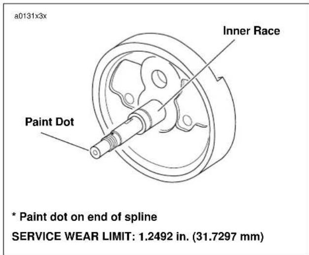
text_image
a0131x3x Inner Race Paint Dot * Paint dot on end of spline SERVICE WEAR LIMIT: 1.2492 in. (31.7297 mm)Figure 3-142. Factory Inner Race Sizes
- See Figure 3-142. Installed inner races are identified at the factory as shown. See Table 3-28.
Table 3-28. Paint Dot Specifications
| RACE OD CLASS | IDENTIFICATION* | |
| 1.2498-1.2500 in.(31.7449-31.7500 mm) | A | W |
| 1.2496-1.2498 in.(31.7398-31.7449 mm) | B | G |
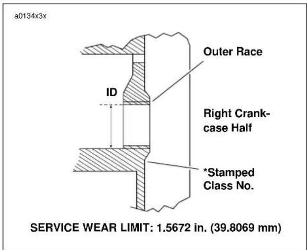
text_image
a0134x3x Outer Race ID Right Crank- case Half *Stamped Class No. SERVICE WEAR LIMIT: 1.5672 in. (39.8069 mm)Figure 3-143. Factory Outer Race Sizes
Table 3-29. Stamp Specifications
| RACE ID | CLASS NO. | STAMPED IDENTIFICATION* |
| 1.5646-1.5648 in.(39.7408-39.7459 mm) | 1 | 1 |
| 1.5648-1.5650 in.(39.7459-39.7510 mm) | 2 | 2 |
| 1.5650-1.5652 in.(39.7510-39.7561 mm) | 3 | 3 |
- See Table 3-29. Outer races are identified at the factory as shown.
NOTE
The different sizes of crankcase sets and flywheel assemblies will not have separate part numbers. That is, a replacement crankcase set may have a class 1, 2 or 3 pinion outer race. Replacement flywheel assemblies will have either a class A or B inner race.
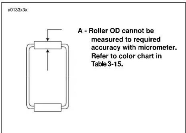
text_image
a0133x3x A - Roller OD cannot be measured to required accuracy with micrometer. Refer to color chart in Table 3-15.Figure 3-144. Bearing Identification
Table 3-30. Roller Specifications
| ROLLER OD (*A) IDENTIFICATION* | |
| Largest | RedBlueWhite (Grey) |
| Smallest | Green |
- See Figure 3-144. Pinion bearings are identified as shown.
BEARING SELECTION
See Table 3-31. Select bearings using the identification information given for inner and outer races and bearings.
Table 3-31. Pinion Shaft Bearing Selection
| FAC-TORY STAMPED NUM-BER | OUTER RACE ID | BEARING SIZE AS IDENTIFIED BY COLOR CODING | |||||||||
| over 1.5672 in.39.807 mm | Service Wear Limit Exceeded - Replace Outer Race and Resize | ||||||||||
| 1.5670-1.5672 in.39.802-39.807 mm | Red | ||||||||||
| 1.5668-1.5670 in.39.797-39.802 mm | Red Blue | e White- | |||||||||
| 1.5666-1.5668 in.39.792-39.797 mm | Red Blue | e White- | Gray | ||||||||
| 1.5664-1.5666 in.39.787-39.792 mm | Red Blue | e White- | Gray | Green | |||||||
| 1.5662-1.5664 in.39.781-39-787 mm | Red Blue | e White- | Gray | Green | |||||||
| 1.5660-1.5662 in.39.776-39.781 mm | Red Blue | e White- | Gray | Green | |||||||
| 1.5658-1.5660 in.39.771-39.776 mm | Red Blue | e White- | Gray | Green | |||||||
| 1.5656-1.5658 in.39.766-39.771 mm | Red Blue | e White- | Gray | Green | |||||||
| 1.5654-1.5656 in.39.761-39.766 mm | Red Blue | White- | Gray | Green | |||||||
| 1.5652-1.5654 in.39.756-39.761 mm | Red Blue | White- | Gray | Green | |||||||
| 3 | 1 .5650-1.56539.751-39.756 mm | Red Blue | White- | Gray | Green | ||||||
| 2 | 1 .5648-1.56539.746-39.751 mm | Blue | White-Gray | Green | |||||||
| 1 | 1 .5646-1.56439.741-39.746 mm | White-Gray | Green | ||||||||
| INNER RACE OD (In) | 1.2496-1.2498in. | 1.2498-1.2500in. | 1.2500-1.2502in. | 1.2502-1.2504in. | 1.2504-1.2506in. | 1.2506-1.2508in. | 1.2508-1.2510in. | 1.2510-1.2512in. | 1.2512-1.2514in. | 1.2514-1.2516in. | |
| 31.74031.745mm | 31.74531.750mm | 31.750-31.755mm | 31.755-31.760mm | 31.760-31.765mm | 31.765-31.770mm | 31.770-31.755mm | 31.775-31.780mm | 31.780-31.786mm | 31.786-31.791mm | ||
| FACTORY COLOR CODE | Green | White | |||||||||
NOTE
If either inner or outer race show wear, measure both races to confirm correct bearing fit.
- Use a dial bore gauge to measure and record ID of outer race. Take four measurements on ID where bearing rollers ride.
a. If the largest measurement is larger than 1.5672 in. (39.8069 mm) or the required lapping to remove wear marks would enlarge bore beyond 1.5672 in., continue at Step 5.
b. If largest measurement is 1.5672 in. (39.8069 mm) or less, cover the cam bearings with masking tape to prevent debris from entering bearings. Assemble crankcase halves.
NOTE
The next step requires lapping the outer race. To keep sprocket shaft and pinion shaft bearings aligned the lap must be supported by an adaptor or pilot in the left crankcase half.
-
See LAPPING ENGINE RIGHT MAIN BEARING RACE. Lap race until all wear marks are removed.
-
Measure and record ID of race at four places.
-
Check measurements against the specifications listed in Table 3-32.
Table 3-32. Outer Pinion Race Service Wear Limits
| Largest ID measured | 1.5672 in. (39.8069 mm) or less |
| Roundness of ID | within 0.0002 in. (0.0051 mm) |
| Taper within 0.0002 in. (0.0051) | |
a. If lapping increased bore ID to larger than 1.5672 in. (39.8069 mm), go to Step 5.
b. If roundness or taper do not meet specifications, continue lapping until specifications are met.
c. If all specifications are met, continue at Step 7 to remove and size inner race.
- Press the outer race from the right crankcase. Press new outer race into crankcase flush with inside edge of cast-in insert.
NOTE
See Figure 3-145. Dimensions are shown for fabrication of tools used in pressing the outer race into or out of crankcase.
a0109x3x
Pinion outer race installation

text_image
2.00" (50.8 mm) .167" (4.75 mm) 5/16" (7.94 mm) DRILL 1.00 (25.4 mm) 1.560" (39.82 mm) Pinion outer race removal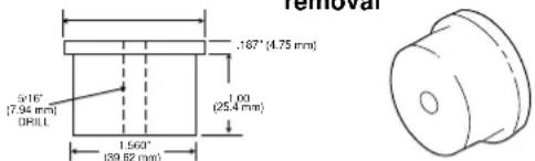
text_image
removal .167" (4.75 mm) 5.16" (7.94 mm) DRILL 1.03" (25.4 mm) 1.560" (39.82 mm)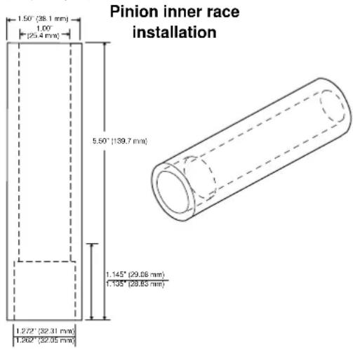
text_image
Pinion inner race installation 1.50" (38.1 mm) 1.00" (25.4 mm) 5.50" (139.7 mm) 1.145" (29.08 mm) 1.735" (28.85 mm) 1.772" (32.31 mm) 1.962" (32.05 mm)Figure 3-145. Pinion Shaft Bearing Tools
- The new outer race must be lapped slightly to true and align with left case bearing and to meet the following specifications in Table 3-33. See LAPPING ENGINE RIGHT MAIN BEARING RACE.
Table 3-33. New Component Specifications
| Outer Race ID | 1.5646 - 1.5652 in. (39.7408 - 39.7561 mm) |
| Roundness | within 0.0002 in. (0.0051 mm) |
| Taper | within 0.0002 in. (0.0051 mm) |
| Surface finish | 16 RMS |
HOME
- See Figure 3-141. Pull inner race from pinion shaft using WEDGE ATTACHMENT for CLAW PULLER (Part No. HD-95637-46A) with BEARING RACE REMOVER/INSTALLER (Part No. HD-34902B) and END CAP (Part No. HD-34902-7). Apply heat to race to aid removal.
NOTE
For necessary dimensions for constructing a press-on tool for the pinion bearing inner race see Figure 3-145.
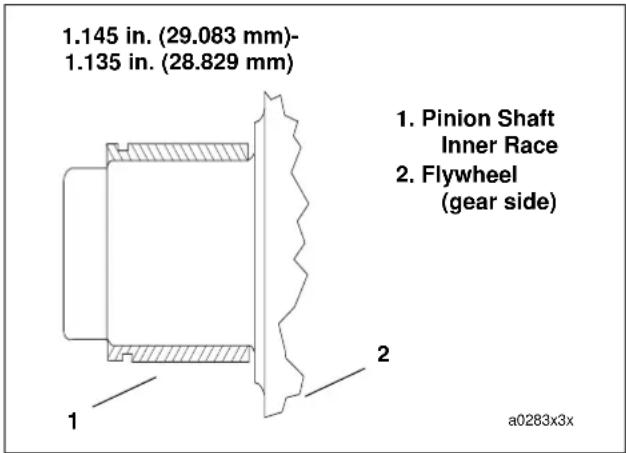
text_image
1.145 in. (29.083 mm)- 1.135 in. (28.829 mm) 1. Pinion Shaft Inner Race 2. Flywheel (gear side) a0283x3xFigure 3-146. Inner Race Location
- See Figure 3-146. Press new inner race on pinion shaft as shown. When the tool bottoms against the flywheel, correct inner race location is automatically established. The new inner race must be ground by a competent machinist to OD dimension range for the finished lapped ID of the outer race. See Table 3-31. The finished inner race must meet the specifications in Table 3-34.
Table 3-34. Pinion Inner Race Fitment Specifications
| Roundness within 0.0002 in. (0.0051 mm) | |
| Taper | within 0.0002 in. (0.0051 mm) |
| Surface finish | 16 RMS |
NOTES
- Have machinist grind inner race to center or middle of required OD range in Table 3-31. This will prevent grinding outer race undersize and gives a more easily achieved tolerance range.
-
If you are unable to perform this operation, Harley-Davidson Motor Company provides a flywheel refurbishing program as outlined in Tech Tip #38.
● Always use the smallest outer race ID measurement and the largest OD inner race measurement when selecting bearings. -
The following example illustrates how to determine the required inner race OD.
a. See Table 3-31. For example purposes, suppose the smallest outer race ID measurement is 1.5651 in. (39.754 mm). This requires an inner race OD range of 1.2496-1.2504 in. (31.740 - 31.760 mm).
b. Grind inner race. Measure OD at four places. Check that specifications in Step 8 are met.
c. For example purposes, suppose the largest inner race OD measurement after grinding is 1.2499 in. (31.747 mm) OD.
d. With a 1.5651 in. (39.754 mm) ID outer race and a 1.2499 in. (31.747 mm) OD inner race, a blue bearing is required.
HOME
Lapping Engine Right Main Bearing Race
- Secure right and left crankcase halves with three crank-case stud bolts (top center and bottom left and right). The sprocket shaft bearing outer races and large spacer must be installed in left crankcase.
- See Figure 3-147. Obtain CRANKCASE MAIN BEARING LAPPING TOOL (Part No. HD-96710-40B). Assemble CRANKCASE MAIN BEARING LAP (Part No. HD-96718-87) to lapping handle. Assemble guide sleeve to sprocket shaft bearing bushing. Sleeves, for use with tapered bearing, are assembled to case with bearings and small spacer collar. Finger-tighten the sleeve parts.
- Insert lap shaft with arbor assembled through pinion bearing bushing and into guide sleeve. Tighten arbor expansion collars using a length of 0.156 in. (3.962 mm) rod as spanner until arbor begins to drag. Do not adjust arbor snug in bushing or bushing will develop a condition where hole is larger at ends than it is in the center.
- Withdraw arbor far enough to coat lightly with 220 grit lapping compound. Do not apply a heavy coat. Reposition lap in bushing and turn handle at moderate hand speed. Work lap back and forth in bushing, as it is revolved, to avoid grooving and tapering.
At frequent intervals, remove lap from crankcase, wash and inspect bushing. Lapping is completed when entire bushing surface has a dull, satin finish rather than a glossy, smooth appearance. If necessary, flush off lap in cleaning solvent, air dry and apply fresh, light coat of fine lapping compound.
Checking Connecting Rod Side Play
- See Figure 3-148. Check connecting rod side play with a thickness gauge as shown.
- If side play measurement is greater than service wear limit listed below, replace flywheel/connecting rod assembly. Service wear limit, 0.036 in. (0.8 mm)
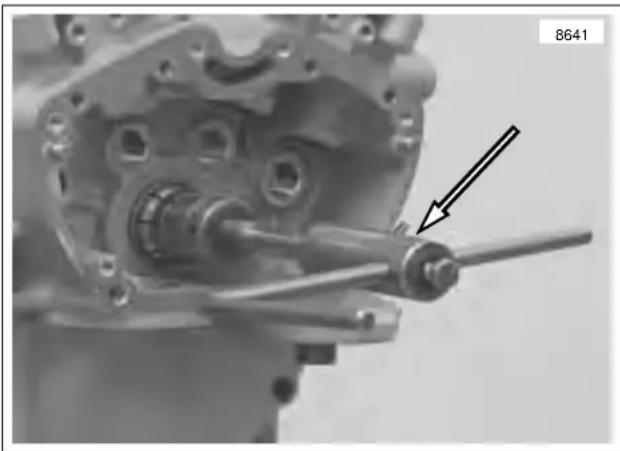
natural_image
Mechanical assembly showing a shaft and housing component with an arrow pointing to a specific part (no text or symbols visible)Figure 3-147. Lapping Pinion Shaft Main Bearing with Crankcase Main Bearing Lapping Tool (Part No. HD-96710-40B)
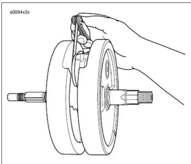
natural_image
Technical line drawing of a hand operating a mechanical gear assembly (no text or symbols)Figure 3-148. Checking Connecting Rod Side Play
Crankcase Halves
NOTE
Lubricate all parts with Harley-Davidson 20W50 engine oil, and proceed as follows:
b1046x3x
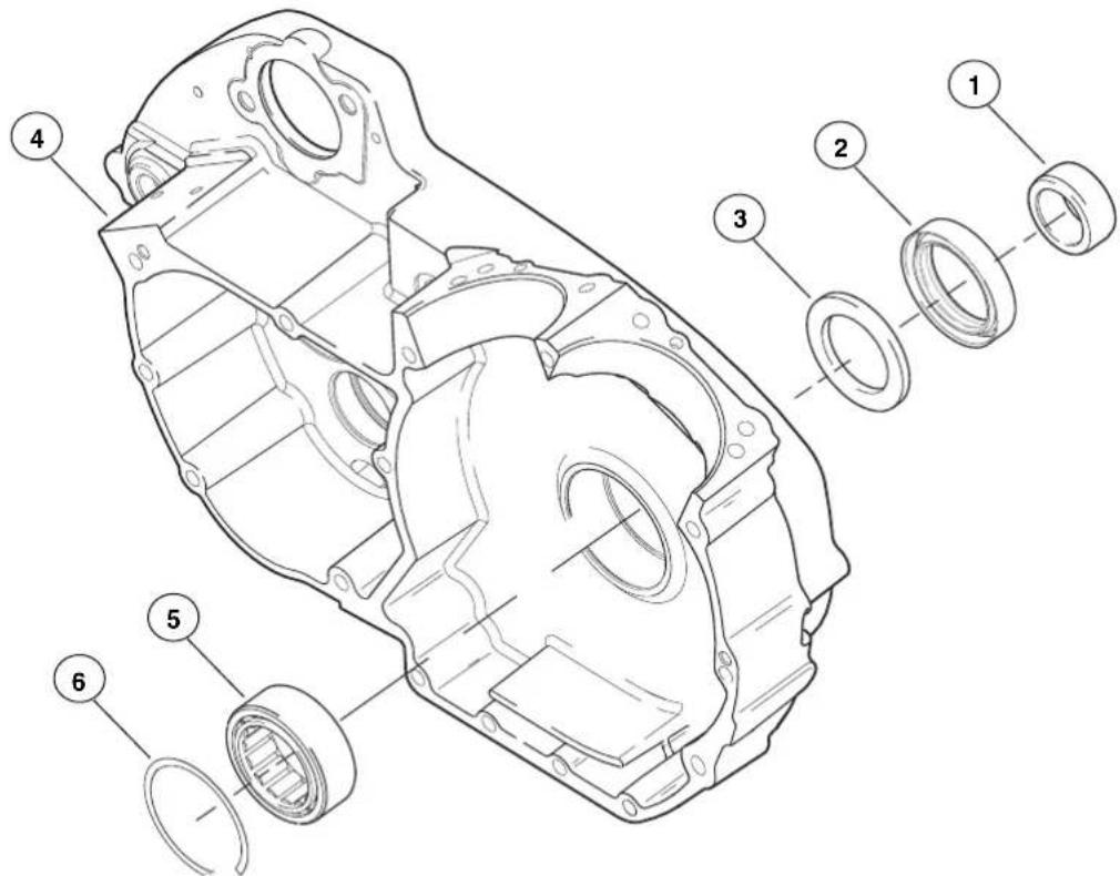
text_image
Technical diagram of a mechanical assembly with numbered parts for identification- Spacer, sprocket shaft
- Oil seal
-
Thrust washer
-
Crankcase half
- Bearing
- Retaining ring
Figure 3-149. Left Main Bearing Assembly
HOME

1. Shoulder for left main to press against
2. Crankcase bearing remover/installer tool (Part No. B-45655 and HD-42720-2)
3. Left main bearing retaining ring
1. See Figure 3-150. Using CRANKCASE BEARING REMOVER/INSTALLER (Part No. B-45655 and HD-42720-2), install left main bearing into left crankcase half from the inside.
Figure 3-150. Left Main Bearing Installation
NOTE
Make sure that the bearing assembly bottoms against the machined shoulder in the left crankcase half.
- Install bearing retaining ring in left crankcase half.
- Install transmission. See 6.12 TRANSMISSION INSTALLATION.
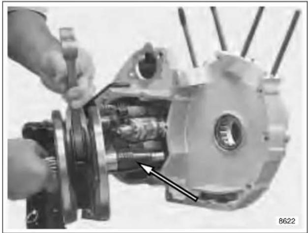
natural_image
Close-up of a mechanical assembly with hands operating a motor or gear component, showing internal gears and shafts (no visible text or symbols)Figure 3-151. Installing Flywheel Assembly with CRANKSHAFT GUIDE (Part No. HD-42326)
- See Figure 3-151. Attach left crankcase half to engine stand.
- Install flywheel assembly using CRANKSHAFT GUIDE (Part No. HD-42326).
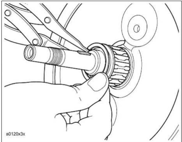
natural_image
Technical line drawing of a hand operating a mechanical gear assembly (no text or symbols)Figure 3-152. Pinion Shaft Bearing
- See Figure 3-152. Install pinion shaft bearing.
a. Lubricate pinion shaft bearing with engine oil.
b. Slip bearing on pinion shaft.
c. Install new retaining ring in groove of pinion shaft bearing inner race.
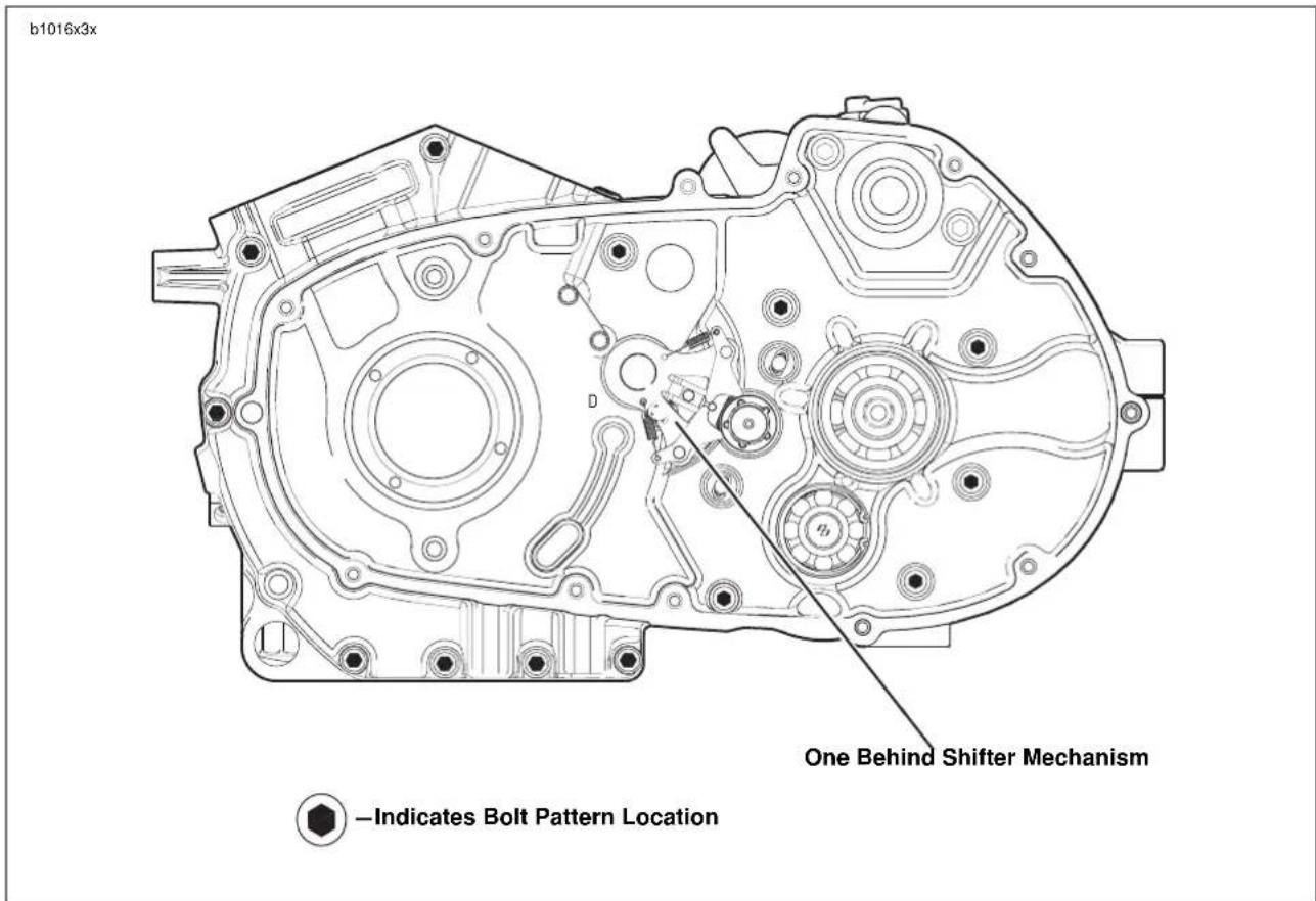
text_image
b1016x3x One Behind Shifter Mechanism —Indicates Bolt Pattern LocationFigure 3-153. Crankcase Fasteners
- See Figure 3-153. Assemble crankcase halves together.
a. Apply a thin coat of DOW CORNING SILASTIC #732 CLEAR sealant to crankcase joint faces.
b. Slide outer race in right crankcase over pinion shaft and bearing assembly.
c. Tighten fasteners to 15-19 ft-lbs (20-26 Nm).
NOTE
According to manufacturing, there is no torque sequence to follow when tightening crankcase fasteners.
HOME
- See Figure 3-149. Install thrust washer (3) from the outside against the left main bearing.
- Install new spacer (1) in seal ID. With the thin (lipped) side facing outward, center seal/spacer assembly over bearing bore.
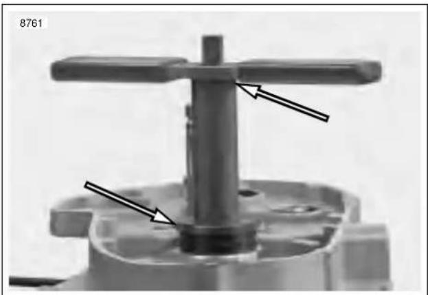
natural_image
Mechanical component with a central shaft and mounting base, showing directional arrows (no text or symbols)Figure 3-154. Sprocket Shaft Seal/Spacer Installer (Part No. HD-42579 and B-45676)
CAUTION
Do not remove the spacer after installation or the new seal will have to be discarded and the procedure repeated.
- See Figure 3-154. Use SPROCKET SHAFT SEAL INSTALLER (Part No. B-45676) to install sprocket shaft seal.
a. Install bearing seal and spacer.
b. Center seal/spacer driver over seal, so that the sleeve (smaller OD) seats between seal wall and garter spring.
c. Sparingly apply graphite lubricant to threads of pilot shaft to ensure smooth operation.
d. Slide sleeve over pilot until sleeve contacts the oil seal. Install handle on top of sleeve.
e. Rotate handle clockwise until tool bottoms on crank-case lip. Remove tool from sprocket shaft.
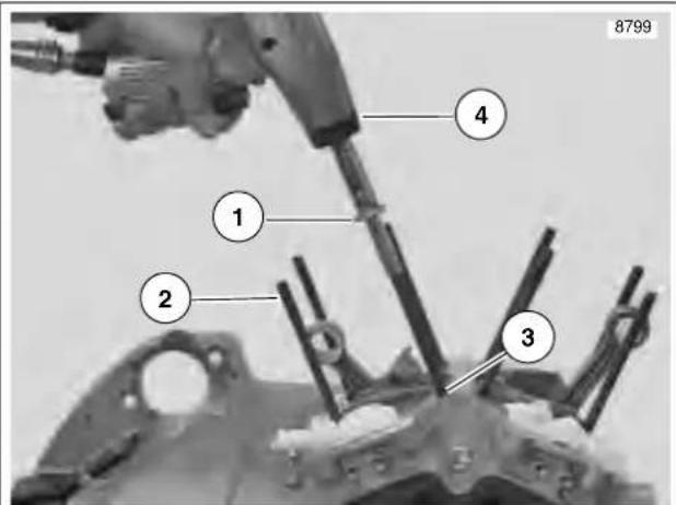
text_image
8799 ① ② ③ ④- Head Screw with ball inside
- Cylinder stud
- Shoulder on cylinder stud
- Air gun
Figure 3-155. Cylinder Studs
- See Figure 3-155. Install cylinder studs.
a. Pack clean towels into crankcase opening.
b. Place a steel ball into a head screw.
c. The cylinder studs have a shoulder at the lower end. Place the end of the stud without the shoulder into the head screw.
d. Install the stud in the crankcase with the shoulder end down. Use an air gun to drive the stud until the shoulder reaches the crankcase.
e. Remove air gun. Use a torque wrench to tighten stud to 10-20 ft-lbs (14-27 Nm).
- Install piston and cylinder. See 3.7 CYLINDER AND PISTON.
- Install oil pump. See 3.13 OIL PUMP.
- Install cam gears, gearcase cover, lifter guides and lifters. See 3.16 GEARCASE COVER AND CAM GEARS.
- Install cylinder head. See 3.6 CYLINDER HEAD.
- Install starter. See 5.7 STARTER.
- Install shift linkage.
- Install all primary drive components. This includes engine sprocket, primary chain, complete clutch assembly, engine sprocket nut and mainshaft nut. See 6.4 PRIMARY DRIVE/CLUTCH.
- Install primary cover. See 6.2 PRIMARY CHAIN.
NOTE
Be sure to refill transmission to proper level with fresh lubricant. See 1.10 PRIMARY CHAIN.
-
See 3.6 CYLINDER HEAD and perform the applicable steps.
-
To reinstall engine in frame see 3.5 ENGINE INSTALLATION.
Table Of Contents
FUEL SYSTEM 4
SUBJECT PAGE NO.
4.1 Specifications 4-1
4.2 Dynamic Digital Fuel Injection 4-3
4.3 Diagnostic Introduction 4-5
4.4 Checking For Trouble Codes 4-6
4.5 Check Engine Lamp Diagnostics 4-8
4.6 Breakout Box 4-10
4.7 Wiggle Test 4-11
4.8 Initial Diagnostic Check 4-12
4.9 Check Engine Lamp Not Illuminated at Key ON 4-17
4.10 Check Engine Lamp On Continuously 4-20
4.11 Engine Cranks But Will Not Start 4-23
4.12 No ECM Power 4-28
4.13 Fuel Pressure Test 4-31
4.14 Idle Speed Control 4-36
4.15 Misfire 4-37
4.16 Trouble Code 11 4-41
4.17 Trouble Code 13 4-45
4.18 Trouble Code 14 4-50
4.19 Trouble Code 15 4-54
4.20 Trouble Code 16 4-58
4.21 Trouble Codes 23 and 32 4-62
4.22 Trouble Codes 24 and 25 4-66
4.23 Trouble Code 33 4-69
4.24 Trouble Code 35 4-72
4.25 Trouble Code 36 4-75
4.26 Trouble Code 44 4-79
4.27 Trouble Codes 52, 53, 54 and 55 4-83
4.28 Trouble Code 56 4-84
4.29 Electronic Control Module 4-89
4.30 Cam Position Sensor and Rotor 4-91
4.31 Ignition Coil 4-95
4.32 Oxygen Sensor 4-97
4.33 Engine Temperature Sensor 4-98
4.34 Bank Angle Sensor 4-100
4.35 Intake Air Temperature Sensor 4-101
4.36 Throttle Position Sensor 4-102
4.37 Cooling Fan 4-103
4.38 Fuel Pump 4-104
4.39 Fuel Tank Vent Valve 4-110
4.40 Fuel Cap Retaining Ring 4-111
4.41 Throttle Body and Intake Manifold 4-112
4.42 Intake Leak Test 4-117
4.43 Airbox 4-119
4.44 Evaporative Emissions Control-California Models 4-121
Table 4-25. Fuel System Specifications
| FUEL SYSTEM TYPE | |
| Intake | 45 mm downdraft manifold, ram air |
| Fuel Delivery DDFI fuel injection | |
| Fuel Pressure 46-53 Psi (317-365 kPa) | |
| Recommended Fuel 91 | Octane |
Table 4-26. Fuel Tank Specifications
| FUEL TANK CAPACITY GALLONS LITERS | ||
| Total (including reserve) 3.7 | 14.0 | |
| Reserve/Low Fuel Indicator at | 0.7 | 2.7 |
Table 4-27. Idle Speed Specifications
| IDLE SPEED ADJUSTMENT | |
| Normal Idle Speed | 1050 -1150 RPM |
Torque Values
| ITEM | TORQUE | NOTES | |
| Airbox baseplate fasteners | 84-120 in-lbs | 9.5-13.6 Nm | page 4-120 |
| Bank angle sensor mounting fastener | 12-36 in-lbs | 1.4-4.1 Nm | page 4-100 |
| Battery terminal hardware | 60-96 in-lbs | 7-11 Nm | page 4-110 |
| Cooling fan fasteners | 12-36 in-lbs | 1.4-4.1 Nm page 4-103 | |
| Engine temperature sensor | 10-14 ft-lbs | 14-19 Nm | page 4-99 |
| Fuel cap retaining ring fasteners | 17-70 in-lbs | 1.9-7.9 Nm page 4-111 | |
| Fuel pump drain plug | 84-108 in-lbs | 9.5-12.2 Nm | page 4-104 |
| Fuel pump harness fastener | 18-22 in-lbs | 2.0-2.5 Nm page 4-108 | |
| Fuel pump screws | 48-51 in-lbs | 5.4-5.8 Nm page 4-109 | |
| Fuel pump wire harness fastener | 18-22 in-lbs | 2.0-2.5 Nm page 4-108 | |
| Fuel rail fasteners | 24-28 in-lbs | 2.7-3.2 Nm | LOCTITE THREADLOCKER 222 (purple), page 4-114, page 4-115 |
| Fuel supply line banjo fitting | 10-12 ft-lbs | 13.6-16.3 Nm | page 4-109 |
| Fuel tank vent valve fasteners | 39-41 in-lbs | 4.4-4.6 Nm page 4-110 | |
| Ignition coil mounting screws | 144-168 in-lbs | 16.3-19.0 Nm | page 4-96 |
| Ignition rotor mounting bolt | 43-53 in-lbs | 5-6 Nm | LOCTITE THREADLOCKER 243 (blue), page 4-94 |
| Inner timer cover screws 12-20 | in-lbs | 1-2 Nm | page 4-94 |
| Intake flange screws | 6-10 ft-lbs | 8-14 Nm | page 4-116 |
| Oxygen sensor | 40-45 ft-lbs | 54-61 Nm | LOCTITE ANTI-SEIZE, page 4-97 |
| Rear shock absorber reservoir clamp rear | 10-12 ft-lbs | 13.6-16.3 Nm | page 4-122 |
| Throttle position sensor | 16-20 in-lbs | 1.8-2.3 Nm | LOCTITE THREADLOCKER 222 (purple), page 4-102 |
| Timer plate studs | 15-30 in-lbs | 2-3 Nm | page 4-94 |
| Upper tie bar | 25-27 ft-lbs | 33.9-36.6 Nm | page 4-99 |
INTRODUCTION
The Buell Dynamic Digital Fuel Injection (DDFI) System provides microprocessor-based electronic engine management for the 984cc high performance engine. The DDFI system has the following features:
● Independently mapped spark and fuel control.
● Engine and air temperature compensated fuel delivery.
● Engine load measurement through throttle position.
● Single point spark delivery (no waste spark).
- Sequential port indirect (manifold) fuel injection.
- Open/Closed-loop air/fuel control.
● Automatic enrichment at start-up.
● Electric cooling fan for improved thermal management.
● Engine speed and position determined using a single sensor (Cam Position Sensor).
● Full diagnostic capability compatible with the DIGITAL TECHNICIAN (Part No. HD-44750).
- Returnless fuel system (excess pressure relieved in tank by Fuel Pressure Regulator Valve).
The DDFI system uses six sensors to monitor the operating conditions of the engine and make decisions as to spark and fuel delivery. These sensors are:
● Throttle position (TP) sensor.
● Cam position (CMP) sensor.
● Engine temperature (ET) sensor.
● Intake air temperature (IAT) sensor.
- Oxygen (O2) sensor.
● Bank Angle Sensor (BAS).
The DDFI system also analyzes how the engine performs during a ride. It then stores this information internally so it will be available for the next ride.
GENERAL
The Buell DDFI operates both as an open and closed loop system which allows it to adjust for all possible operating conditions. During open loop operation, the system utilizes programmed fuel and spark maps in the ECM which provide ease of cold starting and maximum power at wide open throttle (WOT). The adaptive fuel value which is “learned” during closed loop operation is applied during open loop operation to adjust fuel and spark maps for optimum performance.
During closed loop operation, the system relies on input from the O2 sensor to provide for the most efficient, stoichiometric air fuel mixture (14.7:1) which results in reduced emissions, good fuel economy and power. In order for the system to enter closed loop operation, the following conditions must be met:
- O2 Sensor at operating temperature (Engine at normal operating temperature).
- Operation above 5000 RPM with engine under normal, steady load conditions.
By using both open and closed loop systems, engine performance is continuously tuned to compensate for changing conditions and provide maximum performance.
FOR MORE INFORMATION
To learn more about the Buell DDFI system, read the following topics in this section. A system diagram can be found on the next page in Figure 4-112.
Troubleshooting
4.3 DIAGNOSTIC INTRODUCTION.
4.4 CHECKING FOR TROUBLE CODES.
● 4.5 CHECK ENGINE LAMP DIAGNOSTICS.
4.8 INITIAL DIAGNOSTIC CHECK.
● TABLE 4-31. TROUBLE CODES AND FAULT CONDITIONS.
Fuel Injection Components
4.29 ELECTRONIC CONTROL MODULE.
● 4.30 CAM POSITION SENSOR AND ROTOR
4.32 OXYGEN SENSOR.
● 4.33 ENGINE TEMPERATURE SENSOR.
4.34 BANK ANGLE SENSOR.
● 4.35 INTAKE AIR TEMPERATURE SENSOR.
4.36 THROTTLE POSITION SENSOR
4.38 FUEL PUMP.
4.41 THROTTLE BODY.
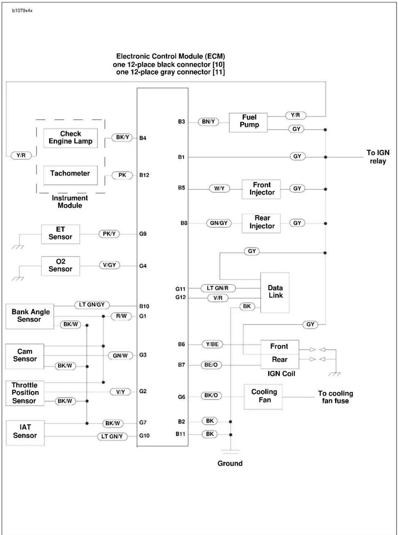
flowchart
graph TD
    subgraph "Electronic Control Module (ECM)"        direction TB
        A["Check Engine Lamp"] --> B["BK/Y"]
        C["Tachometer"] --> D["PK"]
        E["Instrument Module"] --> F["G9"]
        G["ET Sensor"] --> H["PK/Y"]
        I["O2 Sensor"] --> J["V/GY"]
        K["Bank Angle Sensor"] --> L["LT GN/GY"]
        M["Cam Sensor"] --> N["GN/W"]
        O["Throttle Position Sensor"] --> P["V/Y"]
        Q["IAT Sensor"] --> R["G7"]
        S["Ground"] --> T["B10"]
        U["To IGN relay"] --> V["B3"]
        W["To IGN relay"] --> X["B1"]
        Y["To IGN relay"] --> Z["B5"]
        AA["To IGN relay"] --> AB["B8"]
        AC["To IGN relay"] --> AD["G11"]
        AE["To IGN relay"] --> AF["G12"]
        AG["To IGN relay"] --> AH["G6"]
        AI["To cooling fan fuse"] --> AJ["B2"]
        AK["To cooling fan fuse"] --> AL["B11"]
    end

    B -->|BN/Y| AK
    B -->|Fuel Pump| AL
    B -->|GY| AM["To IGN relay"]
    B -->|W/Y| AN["Front Injector"]
    B -->|GN/GY| AO["Rear Injector"]
    B -->|GY| AP["Data Link"]
    B -->|LT GN/R| AQ["Data Link"]
    B -->|V/R| AR["Data Link"]
    B -->|BK| AS["IGN Coil"]
    B -->|BY| AT["Front Rear"]
    B -->|Y/BE| AU["IGN Coil"]
    B -->|BE/O| AV["TO cooling fan fuse"]

    L -->|R/W| AG
    N -->|GN/W| AG
    P -->|V/Y| AG
    R -->|G7| AG
    S -->|G10| AG
    T -->|B3| AK
    U -->|B1| AK
    V -->|BY| AK
    W -->|GY| AK
    X -->|GY| AK
    Y -->|GY| AK
    Z -->|GY| AK
    AD -->|BY| AK
    AF -->|BY| AK
    AR -->|BY| AK
    AS -->|BY| AK
    AT -->|BY| AK
    AU -->|BY| AK
    AV -->|BY| AK
    AW["To cooling fan fuse"] --> AX["Cooling Fan"]
    AX --> AY["Ground"]
Figure 4-112. Buell Dynamic Digital Fuel Injection
SYSTEM PROBLEMS
All system problems fall into at least one of three general categories.
No Start
The engine cranks over freely, but will not start. This does not include situations where the engine will not crank, such as a bad starter, dead battery, etc. This condition assumes that all obvious checks (fuel in tank, etc.) have been made.
Poor Performance
The engine starts but there are performance problems. These problems may include poor fuel economy, rough idle, engine misfire, engine hesitation, severe spark knock, etc.
Check Engine Lamp
See Figure 4-113. The check engine lamp indicates a fault condition exists. There may also be starting or performance problems.
RESOLVING PROBLEMS
NOTE
The most sophisticated method of resolving problems involves using a computer based diagnostic package called DIGITAL TECHNICIAN (Part No. HD-44750).
To resolve system problems, five basic steps are involved. In order of occurrence, they are:
- Check for trouble codes by observing check engine lamp. See 4.4 CHECKING FOR TROUBLE CODES.
- Retrieve trouble codes using check engine lamp diagnostics. See 4.5 CHECK ENGINE LAMP DIAGNOSTICS.
- Diagnose system problems. This involves using special tools and the diagnostic flow charts in this section.
- Correct problems through the replacement and/or repair of the affected components.
- After repairs are performed, the work must be validated. This involves clearing the trouble codes and confirming proper vehicle operation as indicated by the behavior of the check engine lamp.
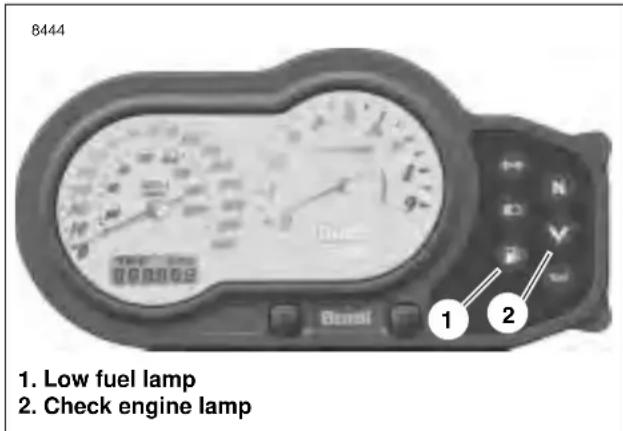
text_image
8444 1. Low fuel lamp 2. Check engine lampFigure 4-113. Check Engine Lamp
CHECK ENGINE LAMP
To diagnose system problems, start by observing the behavior of the check engine lamp.
NOTE
- All references to "Key ON" or "Ignition Switch ON" require that the ignition key be in the ON position and the engine stop switch be set to RUN.
-
If the check engine lamp is not illuminated at Key ON or if it fails to turn OFF after the initial four second period, then a problem exists in the lamp circuit. See 4.9 CHECK ENGINE LAMP NOT ILLUMINATED AT KEY ON or 4.10 CHECK ENGINE LAMP ON CONTINUOUSLY for more information.
-
When the ignition switch is turned ON after being OFF for 2 seconds or more, the check engine lamp will illuminate for approximately four seconds and then turn off.
-
See Figure 4-116. After lamp turns off after being illuminated for the first four second period, one of three situations may occur.
a. The lamp remains off. This indicates there are no current fault conditions or stored functional trouble codes currently detected by the ECM.
b. The lamp stays off for only four seconds and then comes back on for an eight second period. This indicates a functional error code is stored, but no current trouble code exists.
c. If the lamp remains on beyond the eight second period, then a current trouble code exists.
- See CODE TYPES for a complete description of trouble code formats.
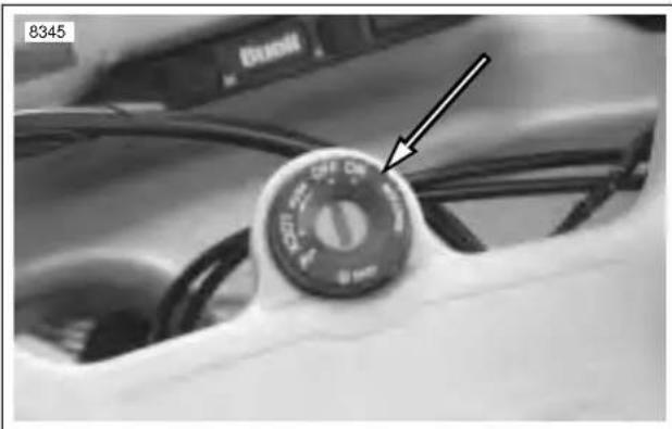
text_image
8345 ON OFF ON ON OFF ON 8345Figure 4-114. Ignition Key Switch
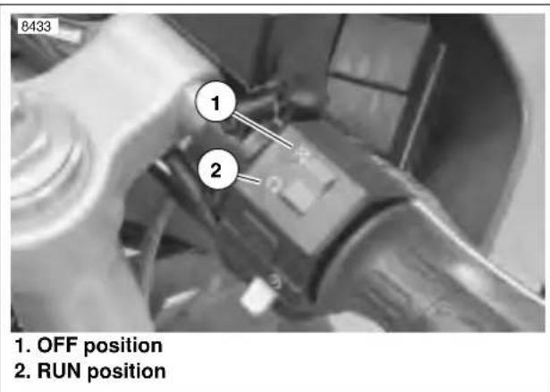
text_image
8433 1. OFF position 2. RUN positionFigure 4-115. Engine Stop Switch
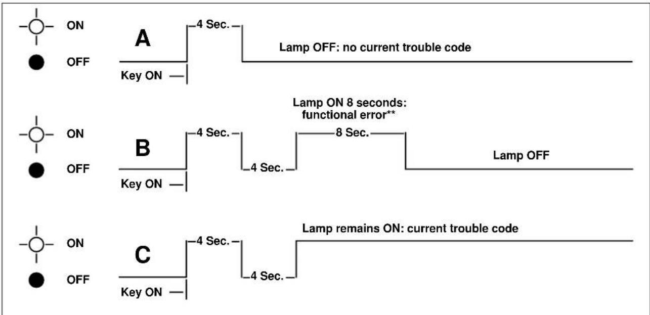
flowchart
graph TD
    A["ON"] --> B["A"]
    B --> C["4 Sec."]
    C --> D["Lamp OFF: no current trouble code"]
    E["OFF"] --> F["Key ON"]
    F --> G["4 Sec."]
    G --> H["Lamp OFF"]

    I["ON"] --> J["B"]
    J --> K["4 Sec."]
    K --> L["8 Sec."]
    L --> M["Lamp ON 8 seconds: functional error**"]
    N["OFF"] --> O["Key ON"]
    O --> P["4 Sec."]
    P --> Q["Lamp OFF"]

    R["ON"] --> S["C"]
    S --> T["4 Sec."]
    T --> U["4 Sec."]
    U --> V["Lamp remains ON: current trouble code"]
    W["OFF"] --> X["Key ON"]
    X --> Y["4 Sec."]
    Y --> Z["Lamp OFF"]
Figure 4-116. Check Engine Lamp Operation
CODE TYPES
There are two types of trouble codes: current and historic. Certain codes are also called functional codes. Historic codes can be read using the check engine lamp diagnostics.
All trouble codes reside in the memory of the ECM until the code is cleared by DIGITAL TECHNICIAN (Part No. HD-44750) or a total of 50 trips has elapsed. A trip consists of a start and run cycle, the run cycle lasting at least 30 seconds. After the 50 trip retention period, the trouble code is automatically erased from memory providing that no subsequent faults of the same type are detected in that period.
NOTE
Trouble codes relating to the fuel injectors or the ignition coil can only be fully diagnosed during actuation. For example, a problem with the ignition coil will be considered a current fault even after the problem is corrected, since the ECM will not know of its resolution until after the coil is activated by vehicle start sequence. In this manner, there may sometimes be a false indication of the current trouble code.
Current
Current trouble codes are those which presently disrupt motorcycle operation. See the appropriate flow charts for solutions.
Historic
If a particular problem happens to resolve itself, the active status problem is dropped and it becomes a historic fault rather current fault.
Historic trouble codes are stored for a length of time to assist in the diagnosis of intermittent faults. The check engine lamp will not turn on during normal operation if only historic codes are present.
It is important to note that historic trouble codes may also be present whenever the system indicates the existence of a current fault. See 4.4 CHECKING FOR TROUBLE CODES if multiple trouble codes are found.
Functional
Trouble codes 52 through 56 are considered to be functional codes. They indicate an internal problem with the ECM (trouble codes 52 through 55) or with the camshaft sensor/timing (trouble code 56).
RETRIEVING TROUBLE CODES
The fuel injection system provides two levels of diagnostics.
- The most sophisticated mode employs using a computer based diagnostic package called DIGITAL TECHNICIAN (Part No. HD-44750).
- The other mode requires using the check engine lamp. See 4.5 CHECK ENGINE LAMP DIAGNOSTICS for more information.
MULTIPLE TROUBLE CODES
The throttle position, cam position and bank angle sensors are all connected to the same reference line (5v REF). If this line goes to ground or open, multiple trouble codes (codes 11 and 56) may be set.
Also, the ECM, fuel pump, fuel injectors and ignition coil all receive +12 volts from the ignition relay. If this line should go to ground the ignition fuse will open.
Always start with the trouble code having the lowest numerical value. See Table4-31.
CHECK ENGINE LAMP BLINKS
In addition to alerting the rider to trouble codes, the check engine lamp will blink during operation to warn of potentially damaging engine operating temperatures. If the key is in the on position and the check engine lamp is blinking, the engine is at a potentially damaging temperature. While this condition is in effect, the ECM will reduce engine power to assist in cooling the engine down to a safe operating temperature. The check engine lamp will blink until the engine has cooled to a safe operating temperature. This will not set a trouble code.
RETRIEVING TROUBLE CODES
Trouble codes may be retrieved without the use of the DIGITAL TECHNICIAN (Part No. HD-44750).
- Remove protective cover from data link connector [91A]. Data link connector is located on left side of vehicle under fairing.
- To activate the diagnostic feature of the check engine lamp, proceed as follows:
a. See Figure 4-117. Create diagnostic test wire from parts shown.
b. See Figure 4-118. Install diagnostic test wire across Terminal 1 and Terminal 2 on the data link connector [91A].
c. Turn the ignition/light key switch ON and wait approximately eight seconds for the check engine lamp to start flashing.
- See Figure 4-119. All trouble codes are sent out as a series of flashes. To retrieve the first digit of the trouble code simply observe the number of times the lamp flashes.
a. The transmission of a trouble code is always preceded by six rapid flashes (about 3 per second).
b. This "intermission" is followed by a 2 second pause in which the lamp is off.
c. The lamp will then flash one or more times to indicate the first digit of the trouble code. The length of time the lamp is illuminated and the length of time in which it is off are each about 1 second in duration.
- The second digit follows:
a. Following transmission of the first digit, there is another 2 second pause in which the lamp is off.
b. The lamp will then flash one or more times to indicate the second digit of the trouble code. Count the number of times the lamp flashes to retrieve the second digit.
- If more than one trouble code is sent:
a. Following transmission of the second digit of the first code, there is a third 2 second pause in which the lamp is off.
b. After the pause comes the intermission, which is followed by transmission of the next recorded trouble code.
c. All subsequent codes are sent in the same manner, each separated from the next by the intermission.
- Once all codes have been sent, the data string is repeated. When you have recorded the same trouble code twice, it is an indication that the transmission has been restarted and that all trouble codes have been retrieved.
b0523x4x
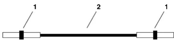
text_image
1 2 1- Part Number 72191-94 (2)
- 2.0 in. (51 mm) 18 Gauge Wire
Figure 4-117. Diagnostic Test Wire

text_image
6924 1 2 3 4 5- Terminal 1: Receive Data Line (Lt GN/R)
- Terminal 2: Ground (BK)
- Terminal 3: Transmit Data Line (V/R)
- Terminal 4: Power (GY)
- Protective Cap
Figure 4-118. Installing Diagnostic Test Wire
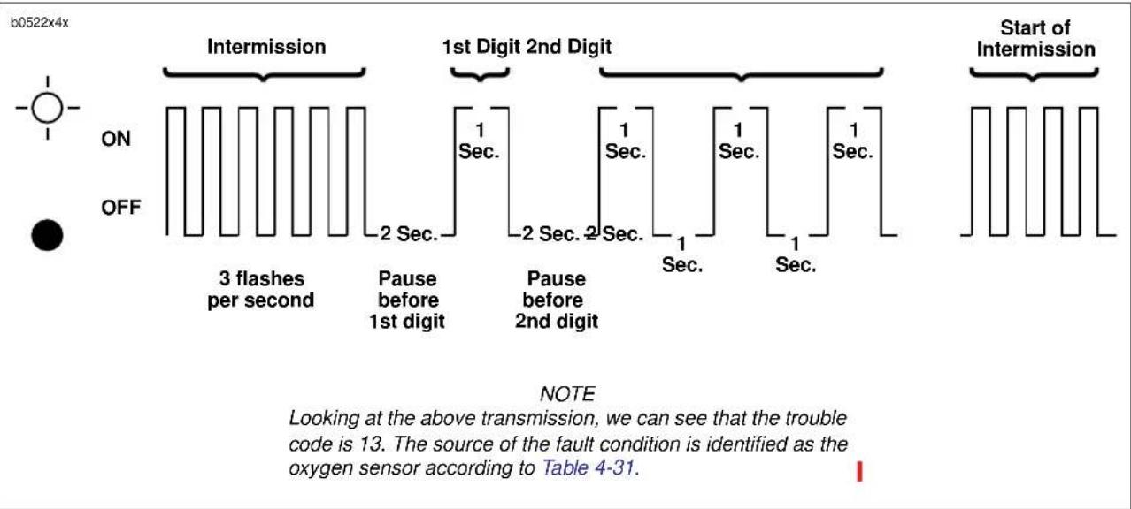
flowchart
graph LR
    A["Start of Intermission"] --> B["Intermission"]
    B --> C["1st Digit 2nd Digit"]
    C --> D["3 flashes per second"]
    D --> E["Pause before 1st digit"]
    E --> F["2 Sec."]
    F --> G["Pause before 2nd digit"]
    G --> H["1 Sec."]
    H --> I["1 Sec."]
    I --> J["1 Sec."]
    J --> K["1 Sec."]
    K --> L["2 Sec."]
    L --> M["2 Sec."]
    M --> N["3 Flashes per second"]
    style A fill:#f9f,stroke:#333
    style B fill:#ccf,stroke:#333
    style C fill:#cfc,stroke:#333
    style D fill:#ffc,stroke:#333
    style E fill:#fcc,stroke:#333
    style F fill:#cff,stroke:#333
    style G fill:#ffc,stroke:#333
    style H fill:#cfc,stroke:#333
    style I fill:#fcc,stroke:#333
    style J fill:#ffc,stroke:#333
    style K fill:#cfc,stroke:#333
    style L fill:#fcc,stroke:#333
    style M fill:#ffc,stroke:#333
    style N fill:#cfc,stroke:#333
Figure 4-119. Check Engine Lamp Diagnostics
NOTE
If the lamp flashes at a rate faster than normal, then you are observing the "Intermission" only, which means that no trouble codes are present.
- When examining trouble codes, write down all codes on a piece of paper.
a. If trouble codes are present, see Table 4-31. Follow the applicable flow charts for each code.
b. If trouble codes are NOT present, but starting or driveability problems are evident, see charts under 4.8 INITIAL DIAGNOSTIC CHECK.
-
Turn the ignition/light key switch OFF.
-
Remove diagnostic test wire and install protective cover over data link connector. Return data link to original position.
IMPORTANT NOTE
The engine may be started and run when the trouble codes are received using a jumper wire on Pins 1 and 2 of the data link connector. However, if the jumper wire is removed with the engine running, the check engine lamp will continue to flash trouble codes. To stop check engine lamp from flashing codes, turn engine stop switch OFF.
CLEARING CODES
After correcting system problems, clear trouble codes. If the Digital Technician (Part No. HD-44750) is not available, perform 50 start and run cycles. To execute one run cycle:
- Start the vehicle.
- Let it run for at least 30 seconds.
- Turn the engine off.
GENERAL
The BREAKOUT BOX (Part No. HD-42682) splices into the main harness. Used in conjunction with a DVOM, it allows circuit diagnosis of wiring harness and connections without having to probe with sharp objects.
INSTALLATION
- Remove ECM. See 4.29 ELECTRONIC CONTROL MODULE.
- Depress latches on each side of connectors [10] (black) and [11] (gray) and detach connectors from the ECM.
-
See Figure 4-121. Attach Breakout Box (2) to black connector [10].
a. Attach black connector from Breakout Box to corresponding black ECM connector.
b. Attach black connector from the wiring harness to black connector on Breakout Box. -
Attach Breakout Box to gray connector [11].
a. Attach gray connector from Breakout Box to corresponding gray ECM connector.
b. Attach gray connector from the wiring harness to gray connector on Breakout Box.
REMOVAL
- See Figure 4-121. Depress latches on each side of connectors [10] (black) and [11] (gray).
- Detach Breakout Box connectors from ECM connectors.
- Detach Breakout Box connectors from wiring harness.
- Install ECM. See 4.29 ELECTRONIC CONTROL MODULE.
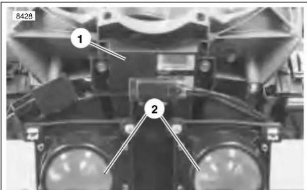
text_image
8428 1 2- ECM
- Headlights
Figure 4-120. ECM
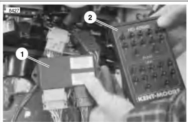
text_image
8427 1 2 KENT-MOOR- ECM
- Breakout Box
Figure 4-121. Installed Breakout Box
GENERAL
NOTE
DIGITAL TECHNICIAN (Part No. HD-44750) can be used to perform wiggle test.
The wiggle test checks for the presence of intermittents in a wiring harness.
PROCEDURE
- See Figure 4-122. Connect DVOM (Part No. H-D-39978) to wiring harness between the suspect connections. When diagnosing ECM connections, a BREAKOUT BOX (Part No. HD-42682) may be used to simplify the procedure. See 4.6 BREAKOUT BOX.
- Set DVOM to read voltage changes.
- Start motorcycle engine and run at idle.
- Shake or wiggle harness to detect intermittents. If intermittents are present, radical voltage changes will register on the DVOM.
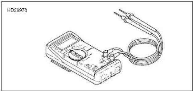
natural_image
Line drawing of a digital multimeter connected to a coiled probe (no text or symbols visible)Figure 4-122. Fluke 78 Multimeter (DVOM) (Part No. HD-39978)
GENERAL
To locate faulty circuits or other system problems, follow the diagnostic flow charts in this section. For a systematic approach, always begin with INITIAL DIAGNOSTICS. Read the general information and then work your way through the flow chart box by box.
Diagnostic Notes
If a numbered circle appears adjacent to a flow chart box, then more information is offered in the diagnostic notes. Many diagnostic notes contain supplemental information, descriptions of various diagnostic tools or references to other parts of the manual where information on the location and removal of components may be obtained.
Circuit Diagram/Wire Harness Connector Table
When working through a flow chart, refer to the illustrations, the associated circuit diagram and the wire harness connector table as necessary. The wire harness connector table for each circuit diagram identifies the connector number, description, type and general location.
In order to perform most diagnostic routines, a Breakout Box and a DVOM are required. See 4.6 BREAKOUT BOX.
To perform the circuit checks with any degree of efficiency, a familiarity with the various wire connectors is also necessary.
Job/Time Code Values
Dealership technicians filing warranty claims should use the job/time code values printed in bold text underneath the appropriate repair.
INITIAL DIAGNOSTICS
General Information
The diagnostic check is an organized approach to identifying a problem caused by an electronic control system malfunction.
IMPORTANT NOTE
The engine may be started and run when the trouble codes are received using a jumper wire on Pins 1 and 2 of the data link connector. However, if the jumper wire is removed with the engine running, the check engine lamp will continue to flash trouble codes. To stop check engine lamp from flashing codes, turn engine stop switch OFF.
Diagnostic Notes
The reference numbers below correlate with the circled numbers on the diagnostic check flow charts. See Diagnostic Check (Part 1 of 2).
- Compare engine behavior to tables.
a. Starts hard. See Table 4-28.
b. Hesitates, stumbles, surges, misfires and/or sluggish performance. See Table 4-29.
c. Engine exhaust emits black smoke or fouls plugs. See Table4-30.
- Use HARNESS CONNECTOR TEST KIT (Part No. HD-41404), black socket probes and patch cord.
- Connect BREAKOUT BOX (Part No. HD-42682) to ECM. See 4.6 BREAKOUT BOX.
All diagnostic codes are listed in Table 4-31.
Table 4-28. Engine Starts Hard
| CAUSE SOLUTION | |
| Engine temperature circuit 4 | 18 TROUBLE CODE 14. |
| Improper fuel pressure 4.13 | FUEL PRESSURE TEST. |
| Spark plugs and/or wires | 4.15 MISFIRE. |
| Battery discharged | See charging system trouble-shooting in Section 7. |
| Cam position sensor | 4.28 TROUBLE CODE 56. |
| Manifold leak | Spray water around induction module seals with engine idling. If RPM changes, change seals. |
| Ignition coil | 4.15 MISFIRE. |
| Leaky injectors | Test fuel injectors. See 4.41 THROTTLE BODY. |
| Valve sticking | See Section 3. |
Table 4-29. Engine Performance Problems
| CAUSE SOLUTION | |
| Engine temperature circuit | 4.18 TROUBLE CODE 14. |
| Improper ignition timing | 1.17 IGNITION TIMING. |
| Cam position sensor circuit | 4.28 TROUBLE CODE 56. |
| Spark plugs and/or wires | 4.15 MISFIRE. |
| Improper fuel pressure | 4.13 FUEL PRESSURE TEST. |
| Improper throttle position sensor adjustment | Calibrate sensor using DIGITAL TECHNICIAN (Part No. HD-44750). |
| Manifold leak | See 4.42 INTAKE LEAK TEST. |
| Throttle plates not opening fully | 1.16 THROTTLE CABLE AND IDLE SPEED ADJUSTMENT. |
| EVAP hose disconnected from induction module (CA) | Connect. |
HOME
Table 4-29. Engine Performance Problems
| CAUSE SOLUTION | |
| Water or dirt in fuel system Drain and refill with fresh fuel. | |
| Cooling Fan Inoperative 4.25 | TROUBLE CODE 36. |
Table 4-30. Engine Exhaust Emits Black Smoke or Fouls Plugs
| CAUSE SOLUTION | |
| Engine temperature circuit 4.1 | 8 TROUBLE CODE 14. |
| Clogged air filter 1.15 AIR CLEANER FILTER Element. | |
| Improper throttle position sensor adjustment | Calibrate sensor. See 4.36 THROTTLE POSITION SENSOR. |
| Leaky injectors Test fuel injectors. See 4.41 THROTTLE BODY. | |
| Improper fuel pressure 4.13 FUEL PRESSURE TEST. | |
Table 4-31. Trouble Codes and Fault Conditions
| CODE NO. FAULT CONDITION RELEVANT TOPIC | ||
| 11 Throttle position sensor | 4.16 TROUBLE CODE 11 | |
| 13 Oxygen sensor | 4.17 TROUBLE CODE 13 | |
| 14 Engine temperature sensor | 4.18 TROUBLE CODE 14 | |
| 15 Intake air temperature sensor | 4.19 TROUBLE CODE 15 | |
| 16 Battery voltage | 4.20 TROUBLE CODE 16 | |
| 23 Front fuel injector | 4.21 TROUBLE CODES 23 AND 32 | |
| 24 Front ignition coil | 4.22 TROUBLE CODES 24 AND 25 | |
| 25 Rear ignition coil | 4.22 TROUBLE CODES 24 AND 25 | |
| 32 Rear fuel injector | 4.21 TROUBLE CODES 23 AND 32 | |
| 33 Fuel pump | 4.23 TROUBLE CODE 33 | |
| 35 Tachometer | 4.24 TROUBLE CODE 35 | |
| 36 Cooling fan | 4.25 TROUBLE CODE 36 | |
| 44 Bank angle sensor | 4.26 TROUBLE CODE 44 | |
| 52, 53, 54, 55 | ECM failure 4.27 TROUBLE CODES 52, 53, 54 AND 55 | |
| 56 Cam sync failure | 4.28 TROUBLE CODE 56 | |
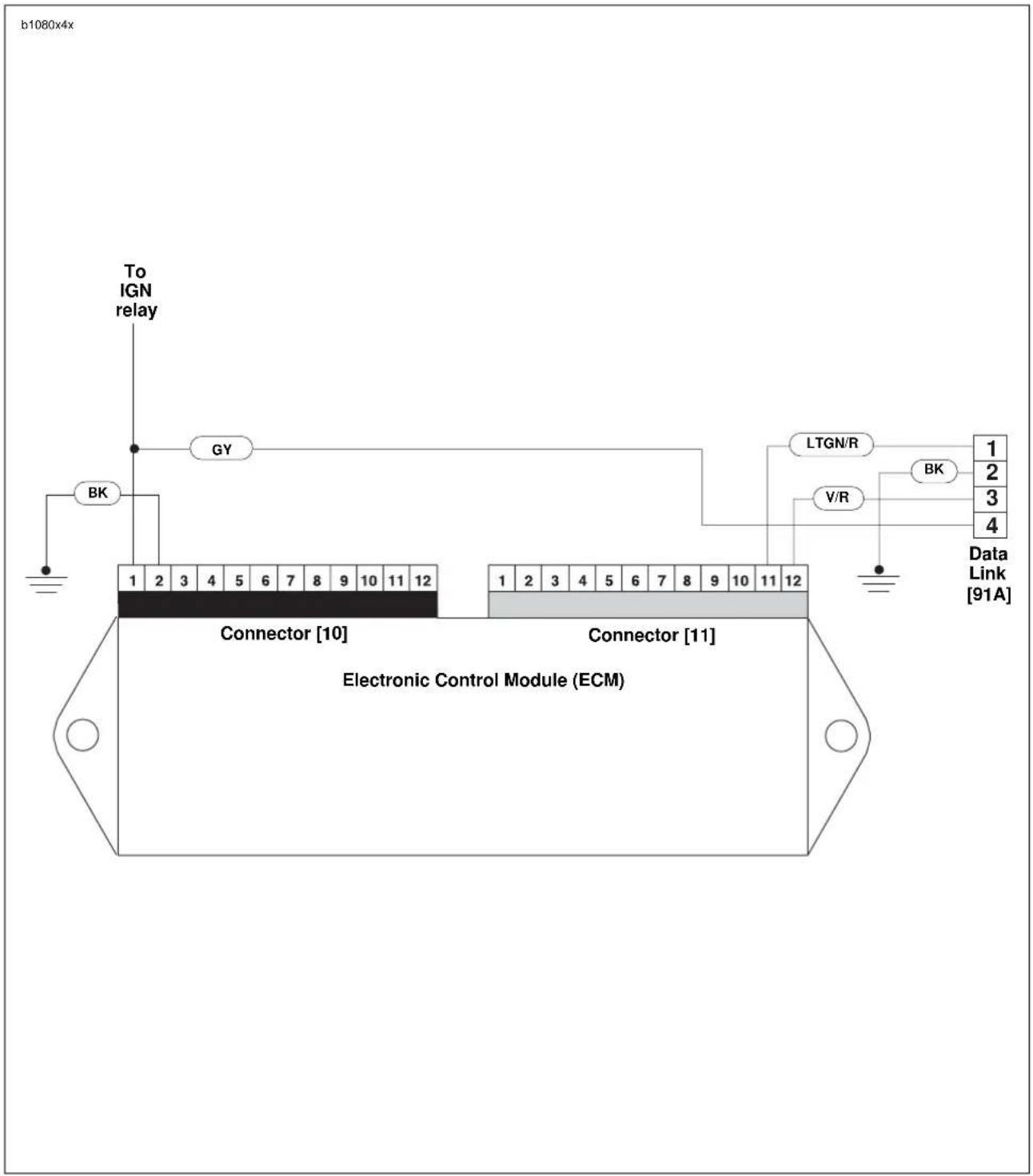
text_image
b1080x4x To IGN relay GY BK 1 2 3 4 5 6 7 8 9 10 11 12 Connector [10] LTGN/R 1 2 3 4 V/R Data Link [91A] Connector [11] Electronic Control Module (ECM)Figure 4-123. Diagnostic Check
Table 4-32. Wire Harness Connectors in Figure 4-123.
| NO. DESCRIPTION TYPE LOCATION | |||
| [10] ECM (black) 12-place Deutsch in fairing | |||
| [11] ECM (gray) 12-place Deutsch in fairing | |||
| [91A] data link 4-place Deutsch beneath left side fairing | |||
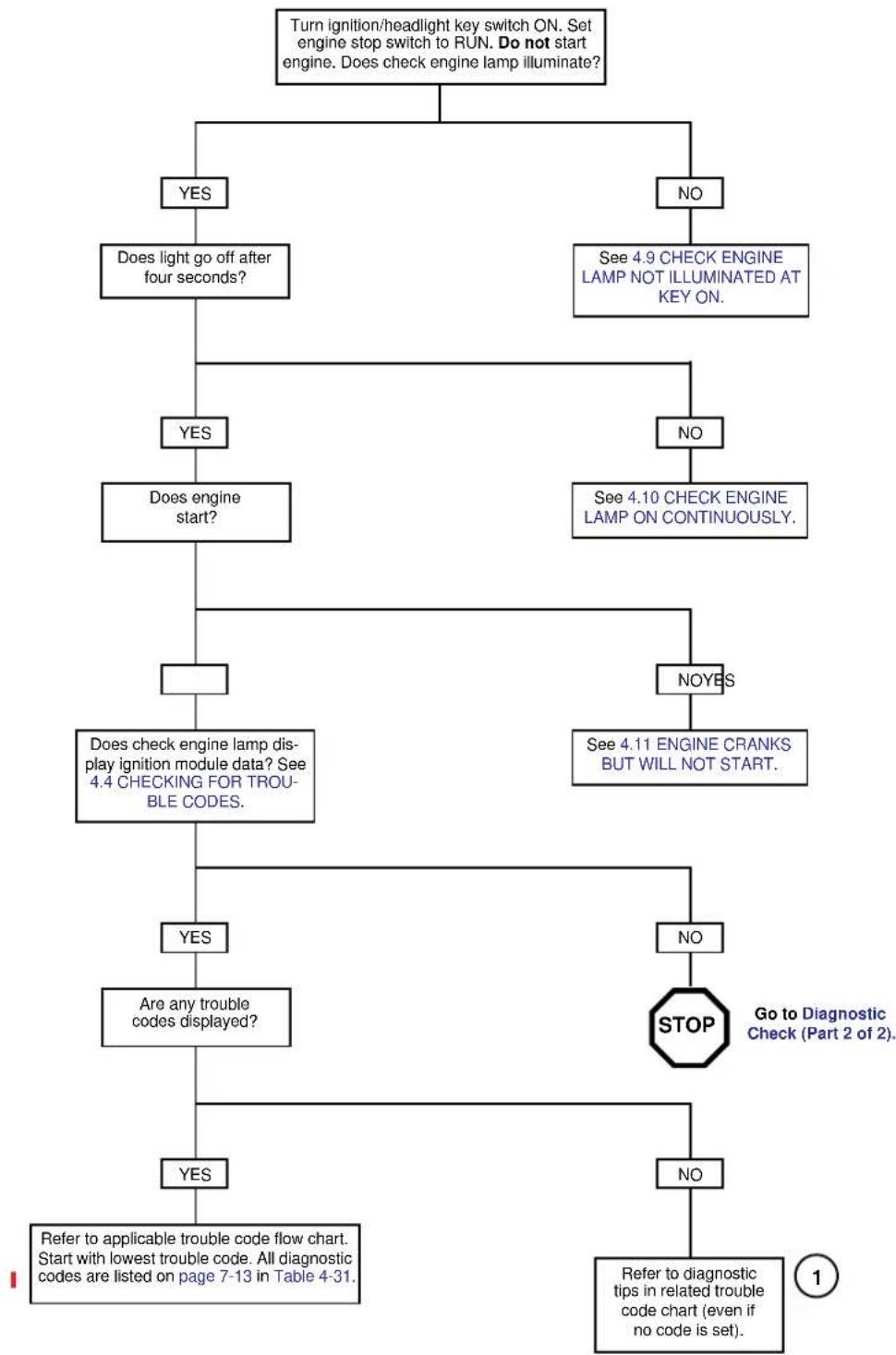
flowchart
graph TD
    A["Turn ignition/headlight key switch ON. Set engine stop switch to RUN. Do not start engine. Does check engine lamp illuminate?"] --> B{YES}
    A --> C{NO}
    B --> D{Does light go off after four seconds?}
    D --> E{YES}
    D --> F{NO}
    E --> G{Does engine start?}
    G --> H{NO?}
    G --> I{Does check engine lamp display ignition module data? See 4.4 CHECKING FOR TROUBLE CODES.}
    H --> J{NO?}
    H --> K{See 4.10 CHECK ENGINE LAMP ON CONTINUOUSLY.}
    I --> L{NO?}
    I --> M{See 4.11 ENGINE CRANKS BUT WILL NOT START.}
    J --> N{YES}
    J --> O{NO}
    N --> P{Are any trouble codes displayed?}
    O --> Q{STOP}
    P --> R{Yes}
    P --> S{No}
    Q --> T["Refer to applicable trouble code flow chart. Start with lowest trouble code. All diagnostic codes are listed on page 7-13 in Table 4-31."]
    Q --> U["Refer to diagnostic tips in related trouble code chart (even if no code is set)."]
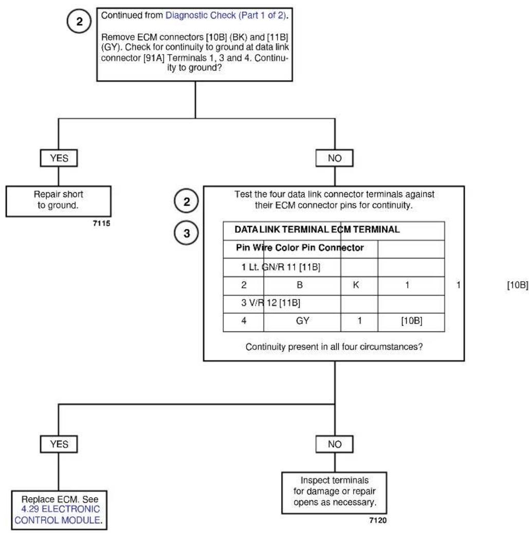
flowchart
graph TD
    A["Continued from Diagnostic Check (Part 1 of 2). Remove ECM connectors [10B"] (BK) and["11B"] (GY). Check_for_continuity_to_ground_at_data_link_connector["91A"] Terminals 1, 3 and 4. Continuity to ground?] --> B{YES}
    B --> C["Repair short to ground."]
    B --> D{NO}
    C --> E["7115"]
    D --> F["2"]
    D --> G["3"]
    F --> H["Test the four data link connector terminals against their ECM connector pins for continuity."]
    G --> I["DATA LINK TERMINAL ECM TERMINAL"]
    I --> J["Pin Wire Color Pin Connector"]
    J --> K["1 Lt. GN/R 11 [11B"]]
    J --> L["2 B K 1"]
    J --> M["3 V/R 12 [11B"]]
    J --> N["4 GY 1 [10B"]]
    I --> O["Continuity present in all four circumstances?"]
    O --> P["7120"]
    P --> Q{YES}
    P --> R{NO}
    Q --> S["Replace ECM. See 4.29 ELECTRONIC CONTROL MODULE."]
    R --> T["Inspect terminals for damage or repair opens as necessary."]
CHECK ENGINE LAMP NOT ILLUMINATED AT KEY ON 4.9
GENERAL
If the engine stop switch is set to RUN with the engine off, and the ignition key switch is turned ON, the check engine lamp should illuminate for four seconds. See Figure 4-124.
Battery voltage is supplied to the lamp bulb. The lamp bulb is grounded by the ECM through the BK/Y wire. A lack of power to the ECM will cause the check engine lamp to be inoperative and also create a no start situation.
DIAGNOSTICS
Diagnostic Tips
Check for the following conditions:
- Check for open in BK/Y wire.
- Check for blown accessory fuse.
Diagnostic Notes
The reference numbers below correlate with the circled numbers on the Test 4.9 flow chart.
- Use HARNESS CONNECTOR TEST KIT (Part No. HD-41404), black pin probe and patch cord.
- See Figure 4-125. Inspect connector [10] (black) for contamination or corrosion. If connection is good, replace ECM. See 4.29 ELECTRONIC CONTROL MODULE.
- Check continuity between instrument connector [39] Pin 7 and ECM connector [10] (black), Pin 4.
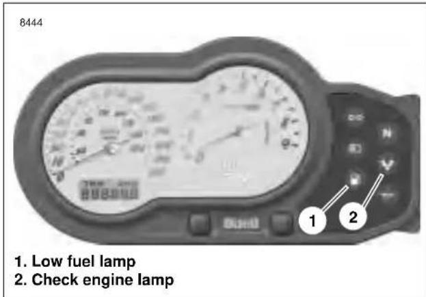
text_image
8444 1. Low fuel lamp 2. Check engine lampFigure 4-124. Check Engine Lamp
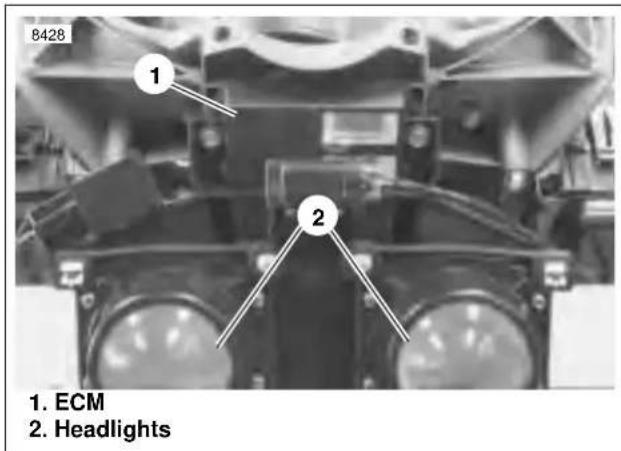
text_image
8428 1. ECM 2. HeadlightsFigure 4-125. Electronic Control Module
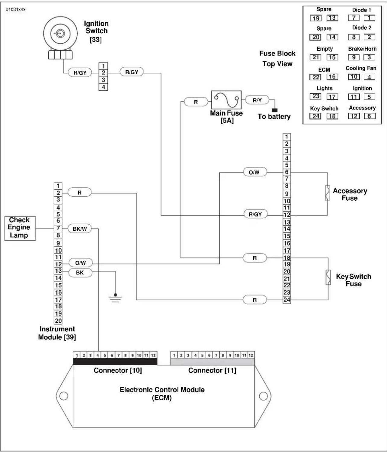
flowchart
graph TD
    A["Ignition Switch [33"]] --> B["R/GY"]
    B --> C["1 2 3 4"]
    C --> D["R/GY"]
    D --> E["Fuse Block Top View"]
    E --> F["R Main Fuse [5A"]]
    F --> G["R/Y"]
    G --> H["To battery"]
    H --> I["1 2 3 4 5"]
    I --> J["O/W"]
    J --> K["Accessory Fuse"]
    K --> L["R/GY"]
    L --> M["10 11 12"]
    M --> N["18 19 20 21 22 23"]
    N --> O["KeySwitch Fuse"]
    O --> P["12 6"]
    P --> Q["Spare 19 13 7 1"]
    Q --> R["Diode 2 20 14 8 2"]
    R --> S["Diode 1 7 1"]
    S --> T["Spare 20 14 8 2"]
    T --> U["Diode 2 8 2"]
    U --> V["Empty 21 15 Brake/Horn 9 3"]
    V --> W["ECM 22 16 10 4"]
    W --> X["Lights 23 17 Ignition 11 5"]
    X --> Y["Key Switch 24 18 Accessory 12 6"]
    Y --> Z["Electronic Control Module (ECM)"]
    AA["Check Engine Lamp"] --> AB["1 2 3 4 5 6 7 8 9 10 11 12"]
    AB --> AC["OK"]
    AC --> AD["Instrument Module [39"]]
    AE["Connector [10"] Connector["11"]] --> AF["Electronic Control Module (ECM)"]
Figure 4-126. Check Engine Lamp Circuit
Table 4-33. Wire Harness Connectors in Figure 4-126.
| NO. DESCRIPTION TYPE LOCATION | |||
| [10] ECM (black) 12-place Deutsch in fairing | |||
| [39] instrument module 20-place Multilock in fairing | |||
HOME
Test 4.9
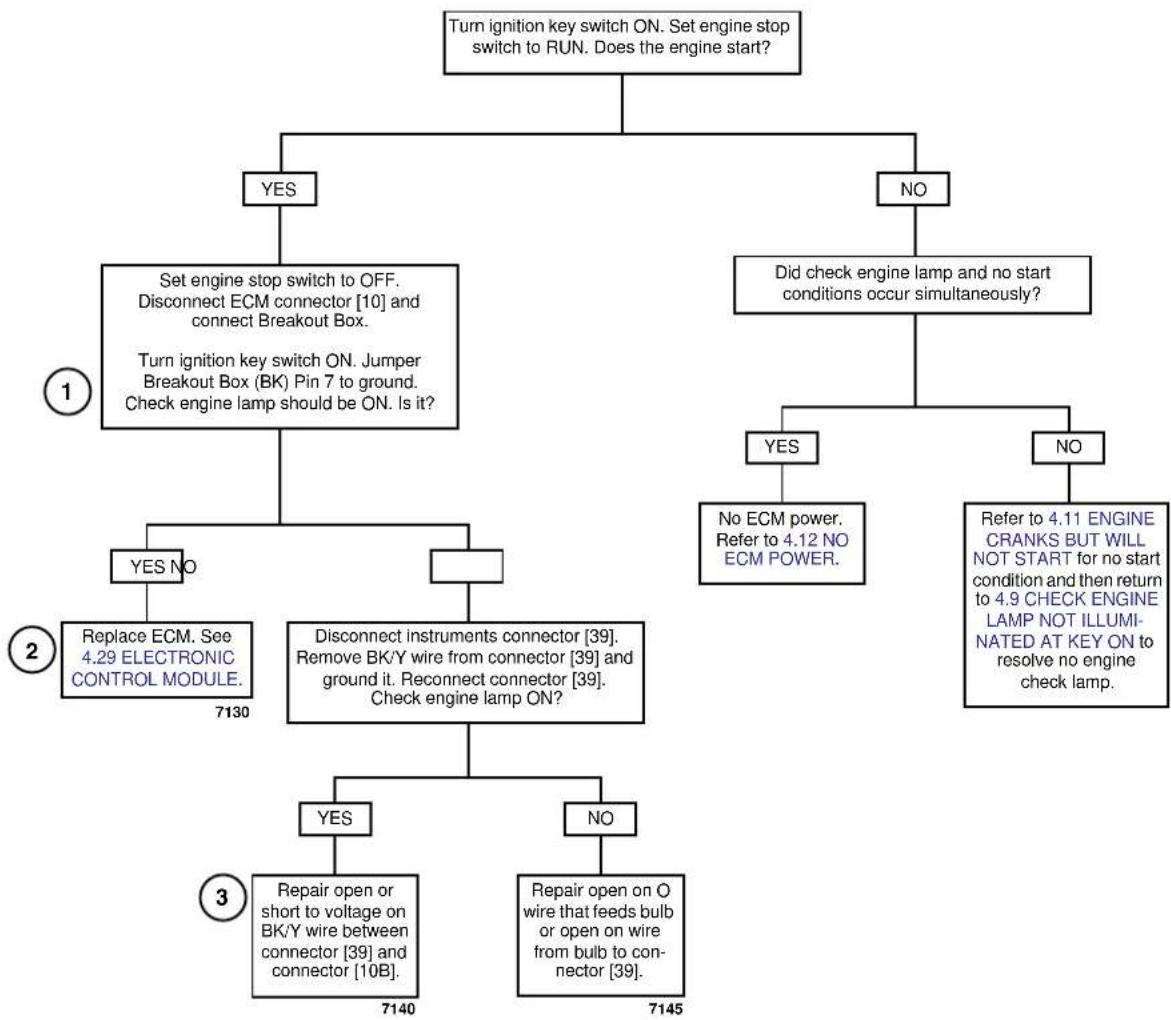
flowchart
graph TD
    A["Turn ignition key switch ON. Set engine stop switch to RUN. Does the engine start?"] --> B{YES}
    A --> C{NO}
    B --> D["Set engine stop switch to OFF.<br>Disconnect ECM connector [10"] and connect Breakout Box.
Turn ignition key switch ON. Jumper Breakout Box (BK) Pin 7 to ground.
Check engine lamp should be ON. Is it?]
    C --> E{Did check engine lamp and no start conditions occur simultaneously?}
    E --> F{YES}
    E --> G{NO}
    F --> H{No ECM power.
Refer to 4.12 NO ECM POWER.}
    G --> I{Refer to 4.11 ENGINE CRANKS BUT WILL NOT START for no start condition and then return to 4.9 CHECK ENGINE LAMP NOT ILLUMINATED AT KEY ON to resolve no engine check lamp.}
    D --> J{YES NO}
    D --> K{NO}
    J --> L["Replace ECM. See 4.29 ELECTRONIC CONTROL MODULE. 7130"]
    K --> M["Disconnect instruments connector [39"].
Remove BK/Y_wire_from_connector["39"] and ground it. Reconnect_connector["39"].
Check engine lamp ON?]
    M --> N{YES}
    M --> O{NO}
    N --> P["Repair open or short to voltage on BK/Y wire between connector [39"] and_connector["10B"]. 7140]
    O --> Q["Repair open on O wire that feeds bulb or open on wire from bulb to connector [39"]. 7145]
GENERAL
If the engine stop switch is set to RUN with the engine off, and the ignition key switch is turned ON, the check engine lamp should illuminate for four seconds. See Figure 4-127.
Following the initial period of illumination, the lamp should go off for four seconds. It may then come back on for an eight second period (for a stored error) or remain on continuously (current error).
DIAGNOSTICS
Diagnostic Notes
The reference numbers below correlate with the circled numbers on the Test 4.10 flow chart.
- See Figure 4-128. If the lamp goes off when the black ECM connector [10] is unplugged, the BK/Y wire is not shorted to ground.
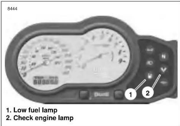
text_image
8444 1. Low fuel lamp 2. Check engine lampFigure 4-127. Check Engine Lamp
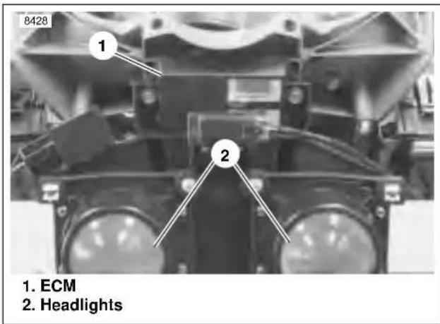
text_image
8428 1 2 1. ECM 2. HeadlightsFigure 4-128. Electronic Control Module
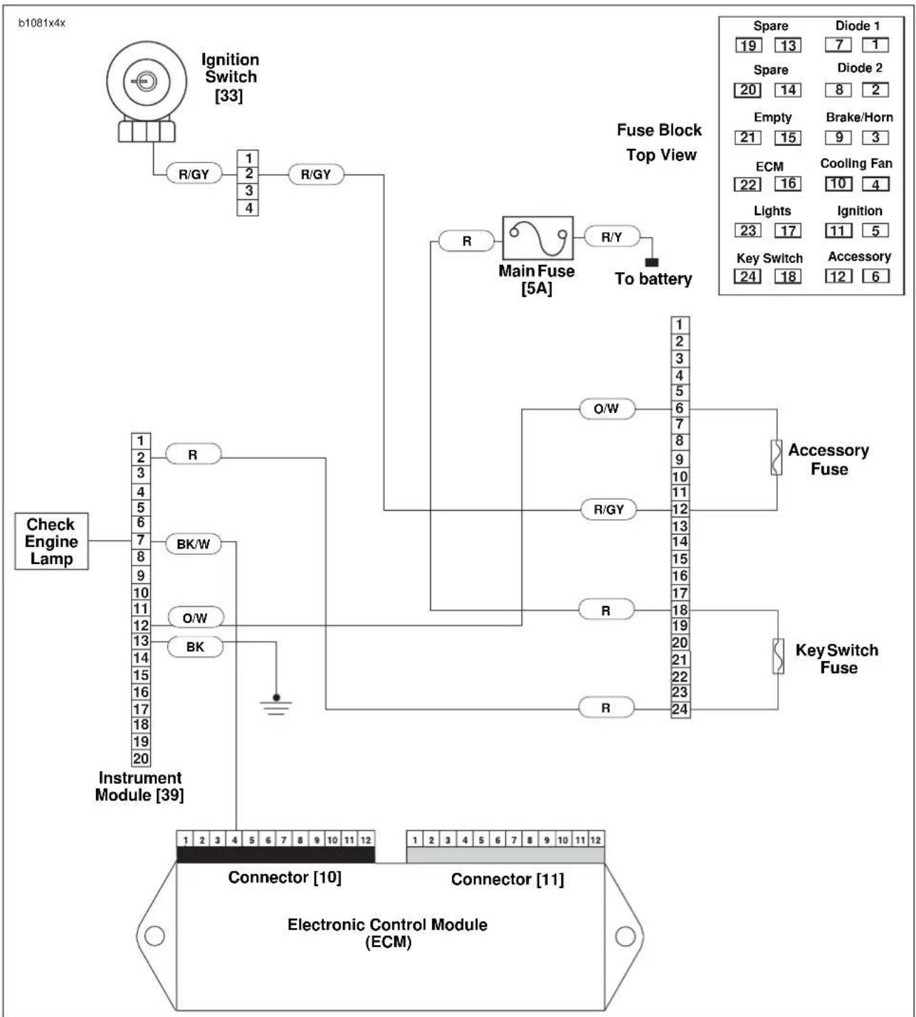
flowchart
graph TD
    A["Ignition Switch [33"]] --> B["R/GY"]
    B --> C["1 2 3 4"]
    C --> D["R/GY"]
    D --> E["Fuse Block Top View"]
    E --> F["R Main Fuse [5A"]]
    F --> G["R/Y To battery"]
    G --> H["O/W"]
    H --> I["Accessory Fuse"]
    I --> J["Key Switch Fuse"]
    K["Check Engine Lamp"] --> L["Instrument Module [39"]]
    L --> M["BK/W"]
    M --> N["O/W"]
    N --> O["BK"]
    O --> P["1 2 3 4 5 6 7 8 9 10 11 12"]
    P --> Q["1 2 3 4 5 6 7 8 9 10 11 12"]
    R["Connector [10"] Connector["11"] Electronic Control Module (ECM)] --> S["1 2 3 4 5 6 7 8 9 10 11 12"]
Figure 4-129. Check Engine Lamp Circuit
Table 4-34. Wire Harness Connectors in Figure 4-129.
| NO. DESCRIPTION TYPE LOCATION | ||
| [10] ECM (black) 12-place Deutsch in fairing | ||
| [39] instrument module 20-place Multilock in fairing |
HOME
Test 4.10
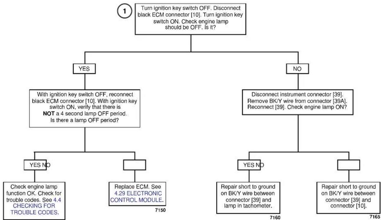
flowchart
graph TD
    A["1"] --> B{Turn ignition key switch OFF. Disconnect_black_ECM_connector["10"]. Turn ignition key switch ON. Check engine lamp should be OFF. Is it?}
    B -->|YES| C["With ignition key switch OFF, reconnect black ECM connector [10"]. With ignition key switch ON, verify that there is NOT a 4 second lamp OFF period. Is there a lamp OFF period?]
    B -->|NO| D["Disconnect instrument connector [39"]. Remove BK/Y_wire_from_connector["39A"]. Reconnect["39"]. Check engine lamp ON?]
    C --> E{YES NO}
    C --> F{7150}
    D --> G{YES NO}
    D --> H{7160}
    E --> I["Check engine lamp function OK. Check for trouble codes. See 4.4 CHECKING FOR TROUBLE CODES."]
    F --> J["Replace ECM. See 4.29 ELECTRONIC CONTROL MODULE."]
    G --> K["Repair short to ground on BK/Y wire between connector [39"] and lamp in tachometer.]
    H --> L["Repair short to ground on BK/Y wire between connector [39"] and_connector["10"].]
GENERAL
If the starter will not crank engine, the problem is not ignition related. See Section 5-Electric Starter.
IMPORTANT NOTE
The engine may be started and run when the trouble codes are received using a jumper wire on Pins 1 and 2 of the data link connector. However, if the jumper wire is removed with the engine running, the check engine lamp will continue to flash trouble codes. To stop check engine lamp from flashing codes, turn engine stop switch OFF.
DIAGNOSTICS
Diagnostic Notes
The reference numbers below correlate with the circled numbers on the Test 4.11 flow charts.
- Connect BREAKOUT BOX (Part No. HD-42682) between harness and ECM. See 4.6 BREAKOUT BOX.
- Check battery condition. Perform a voltage test and recharge if below 12.80 volts. Check battery connections and perform load test. Replace the battery if necessary.
- Remove spark plug cable from spark plug.
a. Visually check condition of plug.
b. See Figure 4-130. Attach cable to SPARK PLUG TESTER (Part No. HD-26792). Clip tester to cylinder head bolt.
c. While cranking starter, look for spark. Repeat procedure on other spark plug cable.
WARNING
The gasoline in the fuel supply line downstream of the fuel pump is under high pressure (49 psi [338 kPa]). To avoid an uncontrolled discharge or spray of gasoline, always purge the system of high pressure gas before servicing the fuel system. Gasoline is extremely flammable and highly explosive. Inadequate safety precautions could result in death or serious injury.
- Purge fuel line of high pressure gasoline. See 4.38 FUEL PUMP.
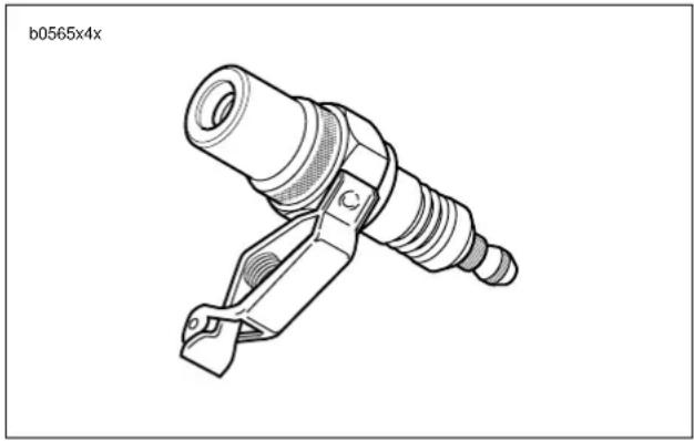
natural_image
Technical line drawing of a mechanical component (no text or symbols)Figure 4-130. Spark Plug Tester (Part No. HD-26792)
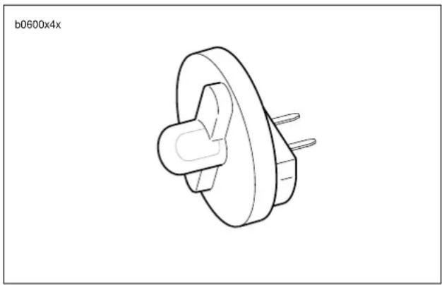
natural_image
Technical line drawing of a mechanical component with a flanged circular base and two protruding pins (no text or symbols)Figure 4-131. Test Lamp
- Access fuel injectors.
a. Remove right side air scoop. See 2.35 AIR SCOOPS.
b. Remove airbox to access fuel injectors. See 4.43 AIRBOX.
-
Use test lamp as shown in Figure 4-131.
-
Use HARNESS CONNECTOR TEST KIT (Part No. HD-41404) gray pin probe and patch cord.
Table 4-35. Wire Harness Connectors in Figure 4-132.
| NO. DESCRIPTION | TYPE | LOCATION | |
| [10] | ECM (black) | 12-place Deutsch | in fairing |
| [11] | ECM (gray) | 12-place Deutsch | in fairing |
| [14] | cam position sensor | 3-place Deutsch | under sprocket cover |
| [83] | ignition coil | 3-place Amp | beneath airbox base |
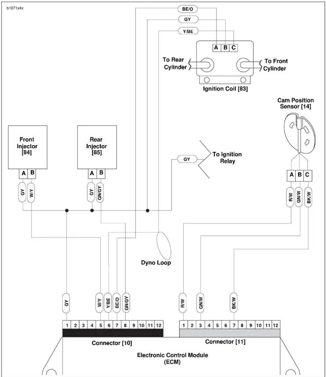
flowchart
graph TD
    A["Front Injector [84"]] -->|A B| B["GY W/Y"]
    A -->|A B| C["Rear Injector [85"]]
    C -->|A B| D["GY GN/GY"]
    C --> E["Dyno Loop"]
    E --> F["Connector [10"]]
    E --> G["Connector [11"]]
    H["Ignition Coil [83"]] --> I["To Rear Cylinder"]
    H --> J["To Front Cylinder"]
    K["Cam Position Sensor [14"]] --> L["A B C"]
    K --> M["R/W GN/W BK/W"]
    N["Electronic Control Module (ECM)"] --> O["Connector [10"]]
    N --> P["Connector [11"]]
    Q["BE/O"] --> H
    R["GY"] --> H
    S["Y/BE"] --> H
    T["BYO"] --> H
    U["BYO"] --> V["BYO"]
    W["BYO"] --> X["BYO"]
    Y["BYO"] --> Z["BYO"]
    AA["BYO"] --> AB["BYO"]
    AC["BYO"] --> AD["BYO"]
    AE["BYO"] --> AF["BYO"]
    AG["BYO"] --> AH["BYO"]
    AI["BYO"] --> AJ["BYO"]
    AK["BYO"] --> AL["BYO"]
Figure 4-132. Ignition Circuit
HOME
Test 4.11 (Part 1 of 3)
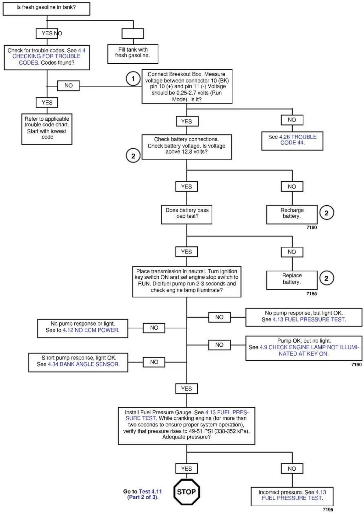
flowchart
graph TD
    A["Is fresh gasoline in tank?"] --> B{YES NO}
    B -->|Yes| C["Check for trouble codes. See 4.4 CHECKING FOR TROUBLE CODES. Codes found?"]
    B -->|No| D["Fill tank with fresh gasoline."]
    C --> E{NO}
    E -->|Yes| F["Refer to applicable trouble code chart. Start with lowest code"]
    E -->|No| G{Connect Breakout Box. Measure voltage between connector 10 (BK) pin 10 (+) and pin 11 (-) Voltage should be 0.25-2.7 volts (Run Mode). Is it?}
    G --> H{YES}
    G --> I{NO}
    H --> J["Check battery connections. Check battery voltage. Is voltage above 12.8 volts?"]
    I --> K["See 4.26 TROUBLE CODE 44."]
    J --> L{YES}
    J --> M{NO}
    L --> N["Does battery pass load test?"]
    M --> O["Recharge battery."]
    N --> P{YES}
    N --> Q{NO}
    O --> R["Replace battery."]
    P --> S["Place transmission in neutral. Turn ignition key switch ON and set engine stop switch to RUN. Did fuel pump run 2-3 seconds and check engine lamp illuminate?"]
    Q --> T["No pump response or light. See to 4.12 NO ECM POWER."]
    Q --> U{NO}
    U --> V["Short pump response, light OK. See 4.34 BANK ANGLE SENSOR."]
    V --> W{YES}
    W --> X["Install Fuel Pressure Gauge. See 4.13 FUEL PRESSURE TEST. While cranking engine (for more than two seconds to ensure proper system operation), verify that pressure rises to 49-51 PSI (338-352 kPa). Adequate pressure?"]
    X --> Y{YES}
    X --> Z{NO}
    Y --> AA["Go to Test 4.11 (Part 2 of 3). STOP"]
    Z --> AB["Incorrect pressure. See 4.13 FUEL PRESSURE TEST. 7195"]
Test 4.11 (Part 2 of 3)
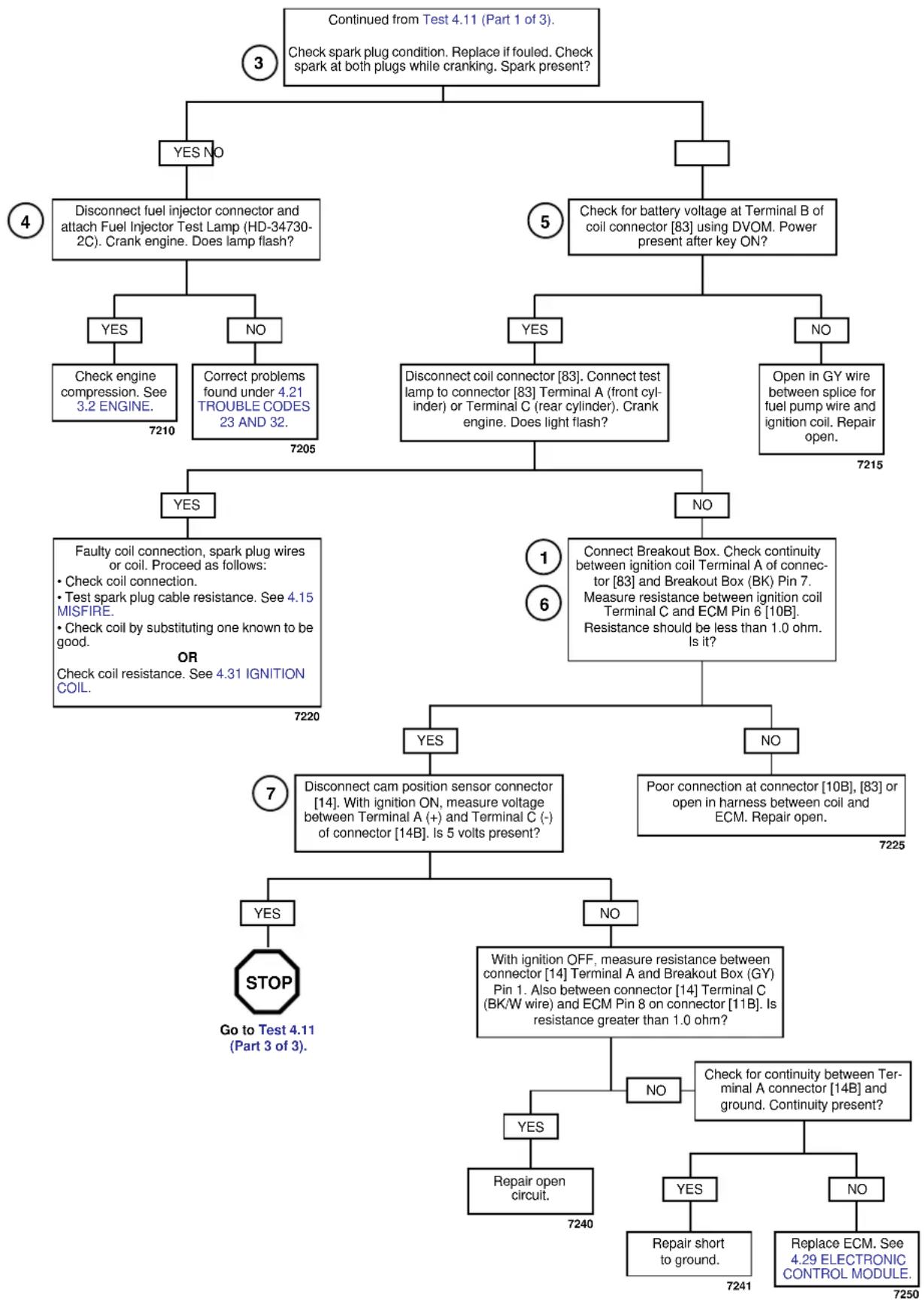
flowchart
graph TD
    A["Continued from Test 4.11 (Part 1 of 3). Check spark plug condition. Replace if fouled. Check spark at both plugs while cranking. Spark present?"] --> B{YES NO}
    A --> C{5_Check_for_battery_voltage_at_Terminal_B_of_coil_connector["83"] using DVOM. Power present after key ON?}
    C --> D{YES}
    C --> E{NO}
    D --> F["Check engine compression. See 3.2 ENGINE."]
    D --> G["Correct problems found under 4.21 TROUBLE CODES 23 AND 32."]
    H{7 Faulty coil connection, spark plug wires or coil. Proceed as follows: Check coil connection. Test spark plug cable resistance. See 4.15 MISFIRE. Check coil by substituting one known to be good. OR Check coil resistance. See 4.31 IGNITION COIL.} --> I{YES}
    H --> J{6 Connect Breakout Box. Check_continuity_between_ignition_coil_Terminal_A_of_connector["83"] and Breakout Box (BK) Pin 7. Measure_resistance_between_ignition_coil_Terminal_C_and_ECM_Pin_6["10B"]. Resistance should be less than 1.0 ohm. Is it?}
    K{7_Disconnect_cam_position_sensor_connector["14"]. With ignition ON, measure voltage between Terminal A (+) and Terminal C (-) of_connector["14B"]. Is 5 volts present?} --> L{YES}
    K --> M{NO}
    L --> N{STOP Go to Test 4.11 (Part 3 of 3).} --> O{Yes}
    L --> P{No}
    O --> Q["Repair open circuit."]
    O --> R{Yes}
    P --> S{No}
    Q --> S
    R --> S
    S --> T{Check_for_continuity_between_Terminal_A_connector["14B"] and ground. Continuity present?}
    T --> U{Yes}
    T --> V{No}
    U --> W["Repair short to ground."]
    V --> X["Replace ECM. See 4.29 ELECTRONIC CONTROL MODULE."]
HOME
Test 4.11 (Part 3 of 3)
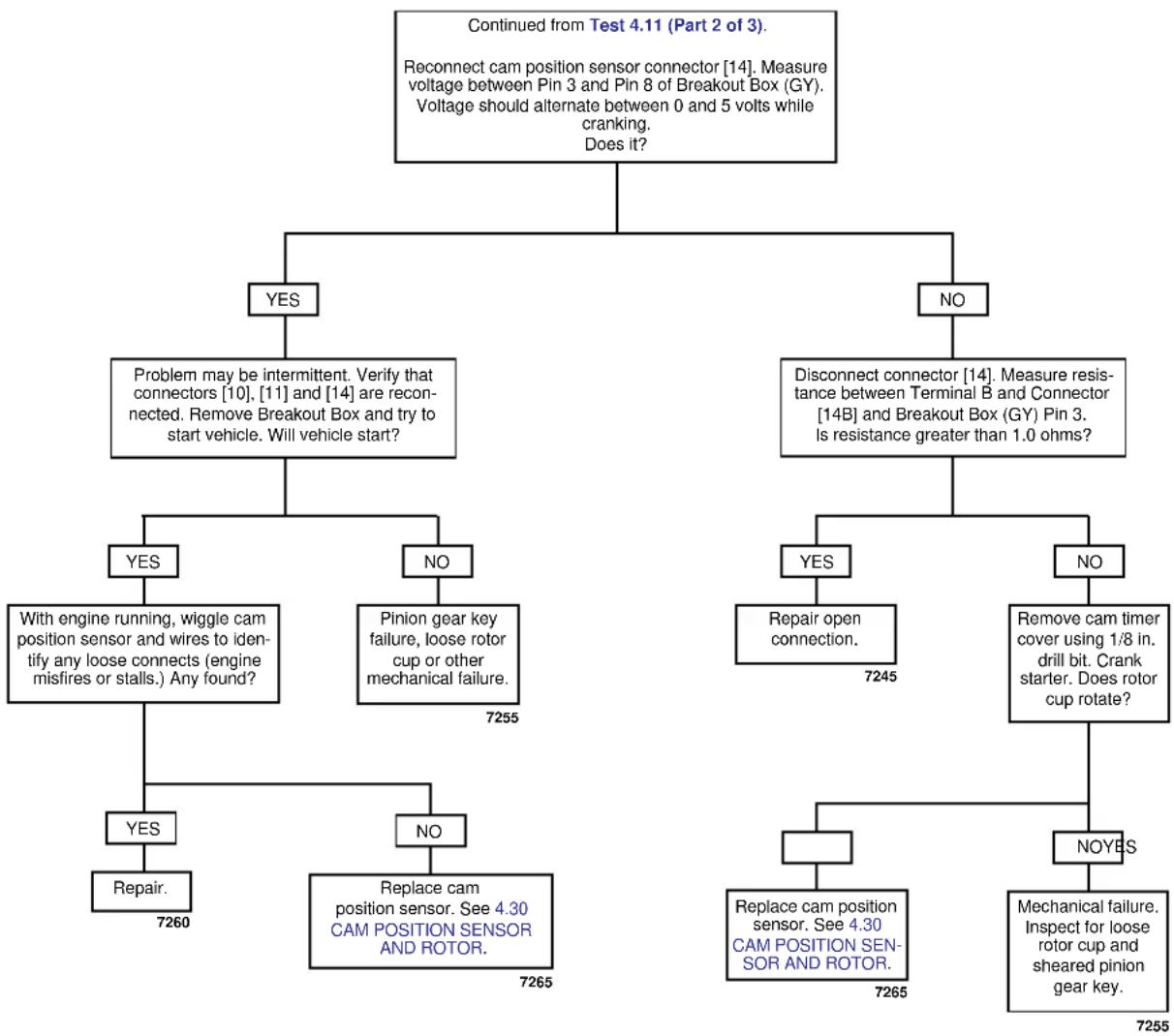
flowchart
graph TD
    A["Continued from Test 4.11 (Part 2 of 3). Reconnect cam position sensor connector [14"]. Measure voltage between Pin 3 and Pin 8 of Breakout Box (GY). Voltage should alternate between 0 and 5 volts while cranking. Does it?]
    B{YES}
    B -->|YES| C["Problem may be intermittent. Verify that connectors [10"], [11] and["14"] are reconnected. Remove Breakout Box and try to start vehicle. Will vehicle start?]
    B -->|NO| D["Disconnect connector [14"]. Measure_resistance_between_Terminal_B_and_Connector["14B"] and Breakout Box (GY) Pin 3. Is resistance greater than 1.0 ohms?]
    C --> E{YES}
    C -->|NO| F["With engine running, wiggle cam position sensor and wires to identify any loose connects (engine misfires or stalls.) Any found?"]
    F --> G{YES}
    F -->|NO| H["Pinion gear key failure, loose rotor cup or other mechanical failure. 7255"]
    G --> I["Repair. 7260"]
    H --> J{NO}
    J --> K["Replace cam position sensor. See 4.30 CAM POSITION SENSOR AND ROTOR. 7265"]
    L{YES}
    L -->|NO| M["Repair open connection. 7245"]
    N{NO}
    N -->|NO| O["Remove cam timer cover using 1/8 in. drill bit. Crank starter. Does rotor cup rotate?"]
    O --> P{NO?}
    P --> Q["Replace cam position sensor. See 4.30 CAM POSITION SENSOR AND ROTOR. 7265"]
    P --> R["Repair open connection. 7245"]
    S["NO?S"]
    S --> T["Replace cam position sensor. See 4.30 CAM POSITION SENSOR AND ROTOR. 7265"]
    T --> U["Mechanical failure. Inspect for loose rotor cup and sheared pinion gear key. 7255"]
GENERAL
A relay controlled by the engine stop switch supplies power to the ECM. The relay requires a ground to operate. If the ground is not established, the ECM will not receive power. Grounds may be established three ways.
- By placing the motorcycle in neutral and grounding the relay through the neutral switch. See Figure 4-133.
- By retracting the sidestand and grounding the relay through the sidestand switch. See Figure 4-134.
- By disengaging the clutch and grounding the relay through the clutch switch. See Figure 4-135.
If the ECM does not appear to be receiving power, check the ground sources. A blown ignition fuse can also disable the ECM.
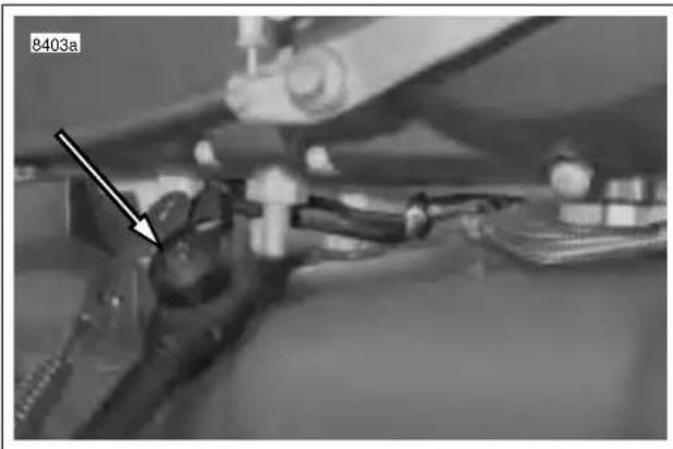
natural_image
Close-up of mechanical components with a white arrow pointing to a component, no visible text or symbolsFigure 4-134. Sidestand Switch
DIAGNOSTICS
Diagnostic Notes
The reference numbers below correlate with the circled numbers on the Test 4.12 flow chart.
- Connect BREAKOUT BOX (Part No. HD-42682) to ECM. See 4.6 BREAKOUT BOX.
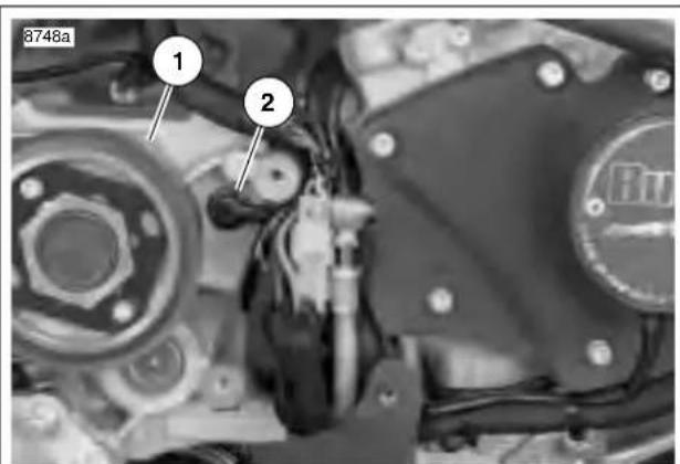
text_image
8748a 1 2- Transmission sprocket
- Neutral switch
Figure 4-133. Neutral Switch
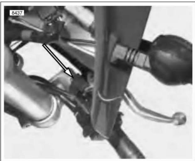
natural_image
Mechanical assembly diagram showing components like gears and levers with no visible text or symbolsFigure 4-135. Clutch Switch (viewed from underneath fairing)
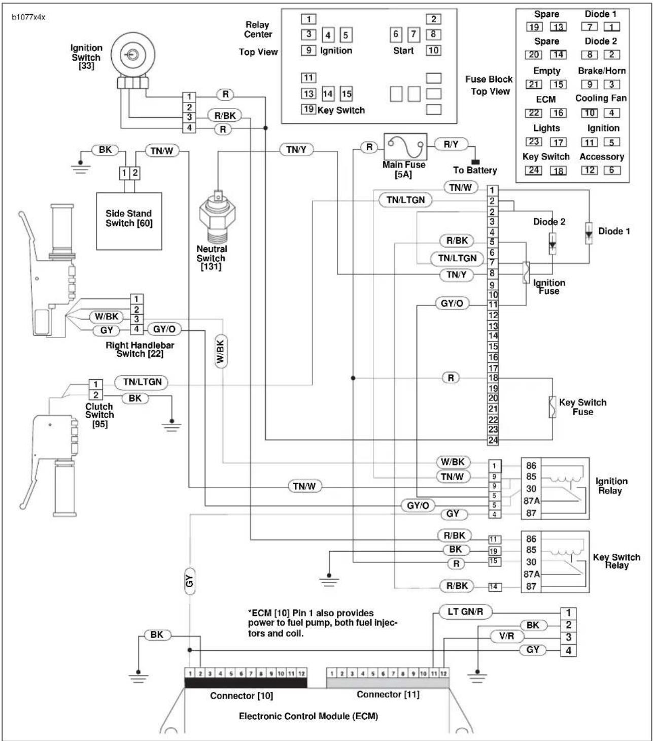
flowchart
graph TD
    A["Ignition Switch [33"]] --> B["R/BK"]
    B --> C["Main Fuse [5A"]]
    C --> D["Fuse Block Top View"]
    D --> E["Spare 19 13 7 1"]
    D --> F["Spare 20 14 8 2"]
    D --> G["Empty 21 15 9 3"]
    D --> H["ECM 22 16 10 4"]
    D --> I["Lights 23 17 11 5"]
    D --> J["Key Switch Accessory 24 18 12 6"]
    K["Side Stand Switch [60"]] --> L["TN/W"]
    L --> M["Neutral Switch [131"]]
    M --> N["W/BK"]
    N --> O["Right Handlebar Switch [22"]]
    O --> P["Clutch Switch [95"]]
    P --> Q["TN/LTGN"]
    Q --> R["BK"]
    R --> S["Output"]

    T["Electronic Control Module (ECM)"] --> U["Connector [10"]]
    U --> V["Connector [11"]]

    W["Main Fuse"] --> X["TN/Y"]
    X --> Y["R/Y"]
    Y --> Z["To Battery"]

    AA["Main Fuse"] --> AB["TN/LTGN"]
    AB --> AC["R/BK"]
    AC --> AD["TN/LTGN"]
    AD --> AE["TN/Y"]
    AE --> AF["Diode 1"]
    AF --> AG["Ignition Fuse"]

    AH["Main Fuse"] --> AI["R/Y"]
    AI --> AJ["To Battery"]

    AK["Main Fuse"] --> AL["TN/W"]
    AL --> AM["R/BK"]
    AM --> AN["TN/LTGN"]
    AN --> AO["TN/Y"]
    AO --> AP["Diode 2"]

    AQ["Main Fuse"] --> AR["R/Y"]
    AR --> AS["TN/LTGN"]
    AS --> AT["TN/Y"]
    AT --> AU["Diode 1"]

    AV["Main Fuse"] --> AW["R/Y"]
    AW --> AX["TN/LTGN"]
    AX --> AY["TN/Y"]
    AY --> AZ["Diode 1"]

    BA["Main Fuse"] --> BB["R/Y"]
    BB --> BC["TN/LTGN"]
    BC --> BD["TN/Y"]
    BD --> BE["Diode 1"]

    BF["Main Fuse"] --> BG["R/Y"]
    BG --> BH["TN/LTGN"]
    BH --> BI["TN/Y"]
    BI --> BJ["Diode 1"]

    BK["Main Fuse"] --> BL["R/Y"]
    BL --> BM["TN/LTGN"]
    BM --> BN["TN/Y"]
    BN --> BO["Diode 1"]

    BP["Main Fuse"] --> BQ["R/Y"]
    BQ --> BR["TN/LTGN"]
    BR --> BS["TN/Y"]
    BS --> BT["Diode 1"]

    BU["Main Fuse"] --> BV["R/Y"]
    BV --> BW["TN/LTGN"]
    BW --> BX["TN/Y"]
    BX --> BY["Diode 1"]

    CA["Main Fuse"] --> CB["R/Y"]
    CB --> CC["TN/LTGN"]
    CC --> CD["TN/Y"]
    CD --> CE["Diode 1"]

    CF["Main Fuse"] --> CG["R/Y"]
    CG --> CH["TN/LTGN"]
    CH --> CI["TN/Y"]
    CI --> CJ["Diode 1"]

    CK["Main Fuse"] --> CL["R/Y"]
    CL --> CD["TN/LTGN"]
    CD --> CDQ["TN/Y"]
    CDQ --> CEQ["Diode 1"]

    CF --> CFQ["Main Fuse"] & CC
    CFQ --> CFQ

    DG["Main Fuse"] & DC["Main Fuse"] & E["Main Fuse"] & AF["Main Fuse"] & AG["Main Fuse"] & AH["Main Fuse"] & AI["Main Fuse"] & AJ["Main Fuse"] & AK["Main Fuse"] & AL["Main Fuse"] & AM["Main Fuse"] & AN["Main Fuse"] & AO["Main Fuse"] & AP["Main Fuse"] & AQ["Main Fuse"] & AR["Main Fuse"] & AS["Main Fuse"] & AT["Main Fuse"] & AU["Main Fuse"] & AV["Main Fuse"] & AW["Main Fuse"] & AX["Main Fuse"] & AY["Main Fuse"] & AZ["Main Fuse"] & BA["Main Fuse"] & BB["Main Fuse"] & BC["Main Fuse"] & BD["Main Fuse"] & BE["Main Fuse"] & BF["Main Fuse"] & BG["Main Fuse"] & BH["Main Fuse"] & BI["Main Fuse"] & BJ["Main Fuse"] & BK["Main Fuse"] & BL["Main Fuse"] & BN["Main Fuse"] & BO["Main Fuse"] & BP["Main Fuse"] & BPQ["Main Fuse"] & BPQQ

    BO["Main Fuse"] & BP["Main Fuse"] & BPQ["Main Fuse"] & BPQQ["Main Fuse"] & BPQQ["Main Fuse"] & BPQQQ["Main Fuse"] & BPQQQ["Main Fuse"] & BPQQQ

    BQ["W/BK"] --> BQW["GY/O"]

    AC["W/BK"] --> ACW["GY/O"]

    AD["W/BK"] --> ADW["GY/O"]

    AE["W/BK"] --> AEW["GY/O"]

    AF["W/BK"] --> AFW["GY/O"]

    AG["W/BK"] --> AGW["GY/O"]

    AH["W/BK"] --> AHW["GY/O"]

    AI["W/BK"] --> AIW["GY/O"]

    AJ["W/BK"] --> AJW["GY/O"]

    AK["W/BK"] --> AKW["GY/O"]

    AL["W/BK"] --> ALW["GY/O"]

    AM["W/BK"] --> AMW["GY/O"]

    AN["W/BK"] --> ANW["GY/O"]

    AO["W/BK"] --> AOW["GY/O"]

    AP["W/BK"] --> APW["GY/O"]

    AQ["W/BK"] --> AQW["GY/O"]

    AR["W/BK"] --> ARW["GY/O"]

    AS["W/BK"] --> ASW["GY/O"]

    AT["W/BK"] --> ATW["GY/O"]

    AU["W/BK"] --> AUW["GY/O"]

    AV["W/BK"] --> AVW["GY/O"]

    AW["W/BK"] --> AWW["GY/O"]

    AX["W/BK"] --> AXW["GY/O"]

    AY["W/BK"] --> AYW["GY/O"]

    AZ["W/BK"] --> AZW["GY/O"]

    BA["W/BK"] --> BBW["GY/O"]

    BB["X/N/W"] --> BBX["TN/W"]

    BC["Y/N/W"] --> BCX["TN/W"]

    BD["Y/N/W"] --> BDX["TN/W"]

    BE["Y/N/W"] --> BEX["TN/W"]

    BF["Y/N/W"] --> BFX["TN/W"]

    BG["Y/N/W"] --> BGX["TN/W"]

    BH["Y/N/W"] --> BHX["TN/W"]

    BI["Y/N/W"] --> BIX["TN/W"]

    BJ["Y/N/W"] --> BJX["TN/W"]

    BK["Y/N/W"] --> BKX["TN/W"]

    BL["Y/N/W"] --> BLX["TN/W"]

    BM["Y/N/W"] --> BMX["TN/W"]

    BN["Y/N/W"] --> BNX["TN/W"]

    BO["X/N/W"] --> BOX["TN/W"]

    BP["X/N/W"] --> BPX["TN/W"]

    BZ["X/N/W"] --> BZX["TN/W"]

    CA["X/N/W"] --> CAX["TN/W"]

    BD["X/N/W"] --> BDX["X/N/W"]

    BE["X/N/W"] --> BEX["X/N/W"]

    BF["X/N/W"] --> BFX["X/N/W"]

    BG["X/N/W"] --> BGX["X/N/W"]

    BH["X/N/W"] --> BHX["X/N/W"]

    BI["X/N/W"] --> BIX["X/N/W"]

    BJ["X/N/W"] --> BJX["X/N/W"]

    BK["X/N/W"] --> BKX["X/N/W"]

    BL["X/N/W"] --> BLX["X/N/W"]

    BM["X/N/W"] --> BMX["X/N/W"]

    BN["X/N/W"] --> BNX["X/N/W"]
Figure 4-136. ECM Power Circuit
Table 4-36. Wire Harness Connectors in Figure 4-136.
| NO. DESCRIPTION TYPE LOCATION | |||
| [10] ECM (black) 12-place Deutsch in fairing | |||
| [22] right hand controls 4-place Multilock beneath right side of fairing | |||
| [95] clutch switch 2-place Multilock beneath fairing | |||
HOME
No ECM Power
CONDITION: Sidestand up, key ON and transmission in neutral
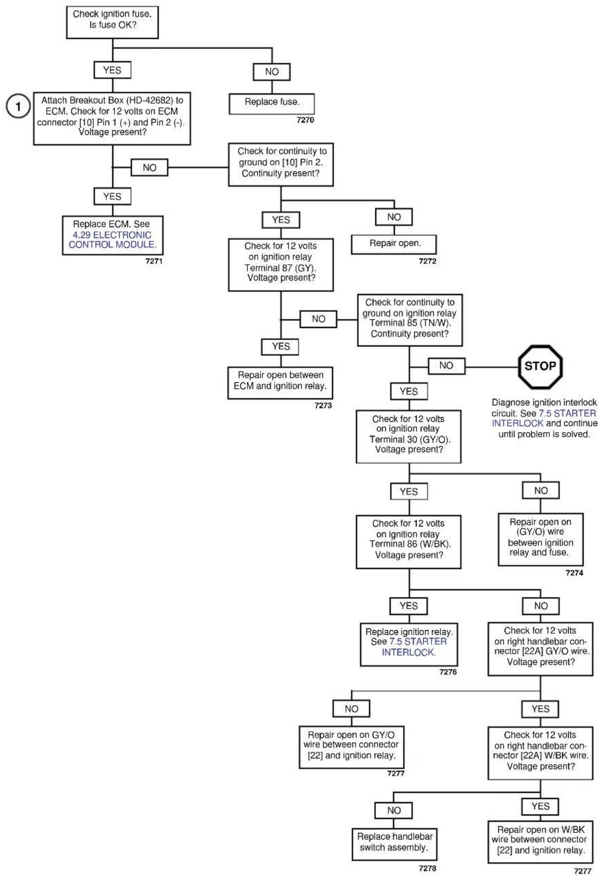
flowchart
graph TD
    A["Check ignition fuse. Is fuse OK?"] --> B{ATTACH Breakout Box (HD-42682) to ECM. Check_for_12_volts_on_ECM_connector["10"] Pin 1 (+) and Pin 2 (-). Voltage present?}
    B -->|YES| C["Replace ECM. See 4.29 ELECTRONIC CONTROL MODULE."]
    B -->|NO| D["Replace fuse."]
    D --> E{Check_for_continuity_to_ground_on["10"] Pin 2. Continuity present?}
    E -->|YES| F["Check for 12 volts on ignition relay Terminal 87 (GY). Voltage present?"]
    E -->|NO| G["Repair open."]
    F --> H{Check for continuity to ground on ignition relay Terminal 85 (TN/W). Continuity present?}
    H -->|YES| I["Repair open between ECM and ignition relay."]
    H -->|NO| J{STOP: Diagnose ignition interlock circuit. See 7.5 STARTER INTERLOCK and continue until problem is solved.}
    I --> K{Check for 12 volts on ignition relay Terminal 30 (GY/O). Voltage present?}
    K -->|YES| L["Check for 12 volts on ignition relay Terminal 86 (W/BK). Voltage present?"]
    K -->|NO| M["Repair open on (GY/O) wire between ignition relay and fuse."]
    L --> N{Check for 12 volts on ignition relay Terminal 86 (W/BK). Voltage present?}
    N -->|YES| O["Replace ignition relay. See 7.5 STARTER INTERLOCK."]
    N -->|NO| P["Check for 12 volts on right handlebar connector [22A"] W/BK wire. Voltage present?]
    O --> Q{Repair open on GY/O_wire_between_connector["22"] and ignition relay.}
    P --> R{Check_for_12_volts_on_right_handlebar_connector["22A"] W/BK wire. Voltage present?}
    Q -->|YES| S["Repair open on W/BK wire between connector [22"] and ignition relay.]
    R --> T{No}
    S --> U["Replace handlebar switch assembly."]
    T --> V["7278"]
    U --> W["7277"]
INSPECTION
| PART NO. SPECIALTY TOOL |
| B-45522 Fuel pressure gauge adapter |
| HD-41182 Fuel pressure gauge |
WARNING
The gasoline in the fuel supply line downstream of the fuel pump is under high pressure (49 psi [338 kPa]). To avoid an uncontrolled discharge or spray of gasoline, always purge the system of high pressure gas before attaching fuel pressure gauge. Gasoline is extremely flammable and highly explosive. Inadequate safety precautions could result in death or serious injury.
- Remove airbox. See 4.43 AIRBOX.
- Purge the fuel supply line of high pressure gasoline.
a. See Figure 4-137. Disconnect the 4-place fuel pump connector [86]. The connector is located inside the left rear portion of the fuel tank/frame.
b. With the motorcycle in neutral, start the engine and allow vehicle to run.
c. When the engine stalls, press the starter button for 3 seconds to remove any remaining fuel from fuel line.
WARNING
A small amount of gasoline will drain from the valve when the gauge is installed. Thoroughly wipe up any spilt fuel immediately. Dispose of rags in a suitable manner. Gasoline is extremely flammable and highly explosive. Inadequate safety precautions could result in death or serious injury.
- See Figure 4-138. Depress button (2) of fuel line connector and disconnect the fuel line (3) from throttle body inlet (1).
- See Figure 4-139. Attach FUEL PRESSURE GAUGE ADAPTER (Part No. B-45522) (2) to throttle body inlet (1).
- Connect the fuel line (3) to fuel pressure gauge adapter.
NOTE
See Figure 4-140. Verify that fuel valve (2) and air bleed petcock (5) on the gauge are closed.
- Attach FUEL PRESSURE GAUGE (Part No. HD-41182) (4) to fuel pressure gauge adapter (1).
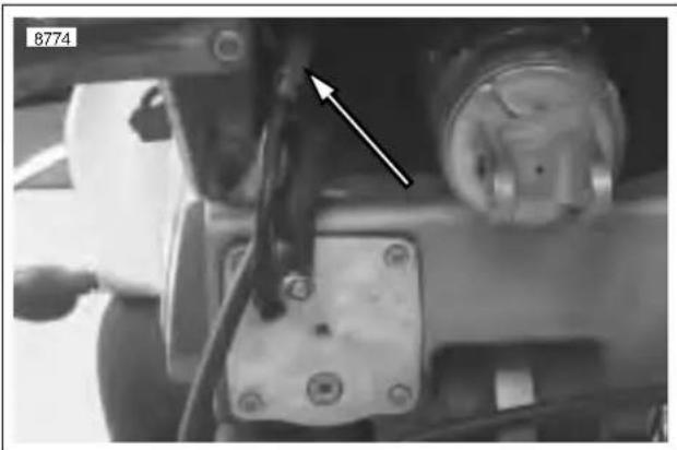
natural_image
Close-up of mechanical components with a white arrow pointing to a component, no visible text or symbolsFigure 4-137. Fuel Pump connector [86] (swingarm removed for illustration)
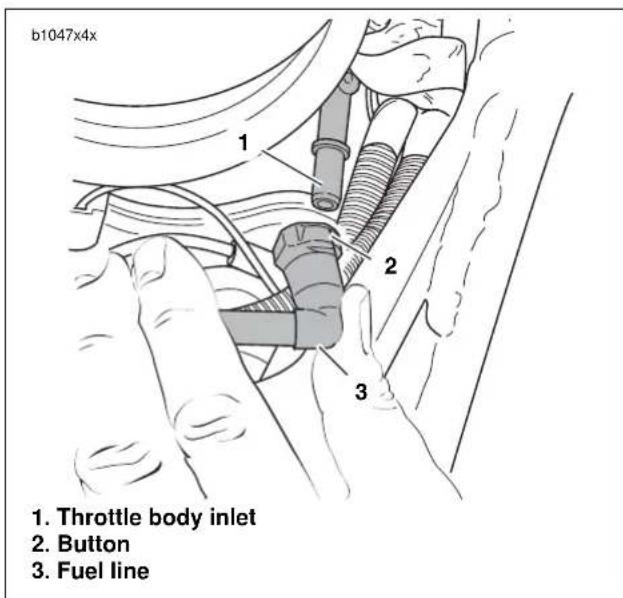
text_image
b1047x4x 1. Throttle body inlet 2. Button 3. Fuel lineFigure 4-138. Fuel Line
HOME
- See Figure 4-137. Attach fuel pump connector [86] to main wiring harness.
- See Figure 4-140. Pressurize the fuel system.
a. Start and idle engine to pressurize the fuel system.
b. Open fuel valve (2) on fuel pressure gauge to allow fuel to flow down the gauge hose.
c. Position the air bleed tube (3) into proper container.
d. Open and close the air bleed petcock (5) to purge the fuel pressure gauge and hose of air. Repeat this step several times until only solid fuel (without bubbles) flows from the air bleed tube.
e. Close the air bleed petcock.
- Open throttle and increase engine speed to 2500-3000 RPM. Note the reading on the pressure gauge.
a. If pressure is 49-51 PSI (338-352 kPa) then system is operating within limits.
b. If pressure is not within limits, see Test 4.13 (Part 1 of 2) flow chart after disconnecting pressure gauge.
WARNING
A small amount of gasoline will drain from the valve when the valve is removed. Thoroughly wipe up any spilt fuel immediately. Dispose of rags in a suitable manner. Gasoline is extremely flammable and highly explosive. Inadequate safety precautions could result in death or serious injury.
- See Figure 4-140. Turn engine off. Detach pressure gauge (4) from adapter (1).
a. Open the air bleed petcock (5) to relieve fuel system pressure and purge the pressure gauge of gasoline. b. Remove pressure gauge from adapter.
- Detach adapter from vehicle.
- Connect fuel line to throttle body inlet.
DIAGNOSTICS
Diagnostic Notes
The reference numbers below correlate with the circled numbers on the Test 4.13 flow charts.
- Use HARNESS CONNECTOR TEST KIT (Part No. HD-41404), gray socket probe and patch cord.
- Connect BREAKOUT BOX (Part No. HD-42682) to ECM. See 4.6 BREAKOUT BOX.
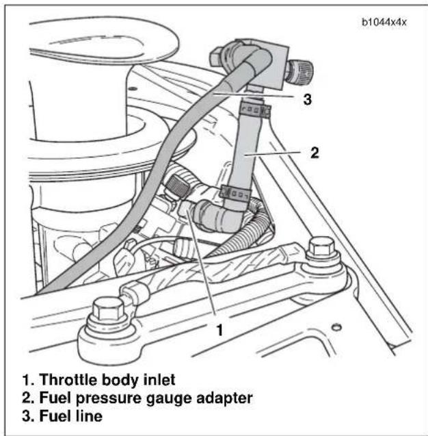
text_image
b1044x4x 1. Throttle body inlet 2. Fuel pressure gauge adapter 3. Fuel lineFigure 4-139. Fuel Pressure Gauge Adapter

text_image
b1045x4x 1. Fuel pressure gauge adapter (B-45522) 2. Fuel valve (closed position) 3. Air bleed tube 4. Fuel pressure gauge (HD-41182) 5. Air bleed petcockFigure 4-140. Fuel Pressure Gauge (Part No. HD-41182)
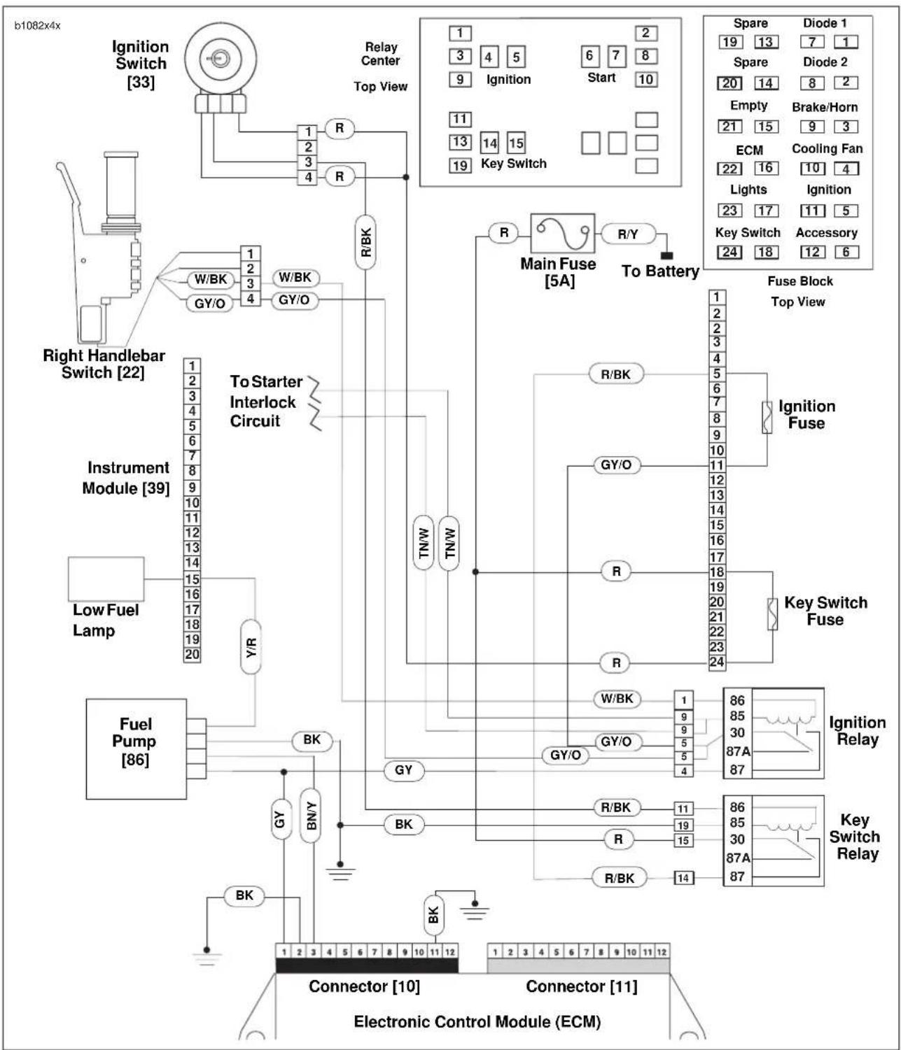
flowchart
graph TD
    A["Ignition Switch [33"]] --> B["Top View"]
    B --> C["R"]
    C --> D["Main Fuse [5A"]]
    D --> E["To Battery"]
    E --> F["Fuse Block Top View"]
    F --> G["Ignition Fuse"]
    G --> H["Key Switch Fuse"]
    H --> I["Ignition Relay"]
    I --> J["Key Switch Relay"]
    J --> K["Electronic Control Module (ECM)"]

    subgraph Top View
        L["1"] --> M["3"]
        N["4"] --> O["5"]
        P["9"] --> Q["Ignition"]
        R["6"] --> S["7"]
        T["8"] --> U["Start"]
        V["10"] --> W["11"]
        X["13"] --> Y["14"]
        Z["15"] --> AA["15"]
        AB["19"] --> AC["Key Switch"]
    end

    subgraph Key Switch
        AD["Spare 19"] --> AE["Diode 17"]
        AF["Spare 20"] --> AG["Diode 28"]
        AH["Empty 21"] --> AI["Brake/Horn 9"]
        AJ["ECM 22"] --> AK["Cooling Fan 10"]
        AL["Lights 23"] --> AM["Ignition 11"]
        AN["Key Switch 24"] --> AO["Accessory 12"]
    end

    subgraph To Battery
        AP["R/BK"] --> AQ["R/Y"]
    end

    subgraph Power Supply
        AR["W/BK"] --> AS["GY/O"]
        AT["W/BK"] --> AU["GY/O"]
        AV["TN/W"] --> AW["TN/W"]
        AX["TN/W"] --> AY["R/BK"]
    end

    subgraph Power Control
        AZ["R/BK"] --> BA["R/Y"]
    end

    subgraph Power Supply
        BB["R/BK"] --> BC["R/Y"]
    end

    style Top View fill:#f9f,stroke:#333
    style Key Switch module fill:#ccf,stroke:#333
    style Power Supply fill:#cfc,stroke:#333
Figure 4-141. Fuel Pump Circuit
Table 4-37. Wire Harness Connectors in Figure 4-141.
| NO. DESCRIPTION TYPE LOCATION | ||
| [10] ECM (black) 12-place Deutsch in fairing | ||
| [39] instrument module 20-place Multilock in fairing | ||
| [86] fuel pump 4-place Multilock left side of rear shock absorber |
HOME
Test 4.13 (Part 1 of 2)
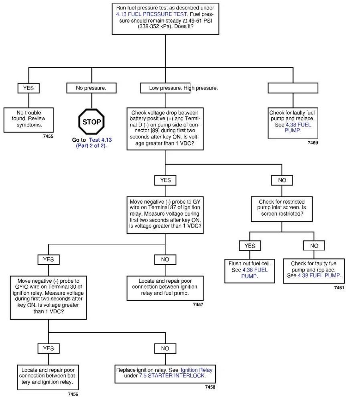
flowchart
graph TD
    A["Run fuel pressure test as described under 4.13 FUEL PRESSURE TEST. Fuel pressure should remain steady at 49-51 PSI (338-352 kPa). Does it?"] --> B{YES}
    B -->|No trouble found. Review symptoms.| C["7455"]
    B -->|No pressure.| D{STOP}
    D -->|Go to Test 4.13 (Part 2 of 2).| E["Check voltage drop between battery positive (+) and Terminal D (-) on pump side of connector [89"] during first two seconds after key ON. Is voltage greater than 1 VDC?]
    D -->|Low pressure. High pressure.| F{YES}
    F -->|Yes| G["Check for faulty fuel pump and replace. See 4.38 FUEL PUMP."]
    F -->|NO| H{NO}
    H -->|Yes| I["Check for restricted pump inlet screen. Is screen restricted?"]
    H -->|NO| J{YES}
    J -->|Yes| K["Flush out fuel cell. See 4.38 FUEL PUMP."]
    J -->|NO| L["Check for faulty fuel pump and replace. See 4.38 FUEL PUMP."]
    I --> M{YES}
    I --> N{NO}
    M --> O["Move negative (-) probe to GY/O wire on Terminal 30 of ignition relay. Measure voltage during first two seconds after key ON. Is voltage greater than 1 VDC?"]
    N --> P["Locate and repair poor connection between ignition relay and fuel pump."]
    O --> Q{YES}
    O --> R{NO}
    P --> S["Locate and repair poor connection between battery and ignition relay."]
    R --> T["Replace ignition relay. See Ignition Relay under 7.5 STARTER INTERLOCK."]
    T --> U["7456"]
    T --> V["7458"]
HOME
Test 4.13 (Part 2 of 2)
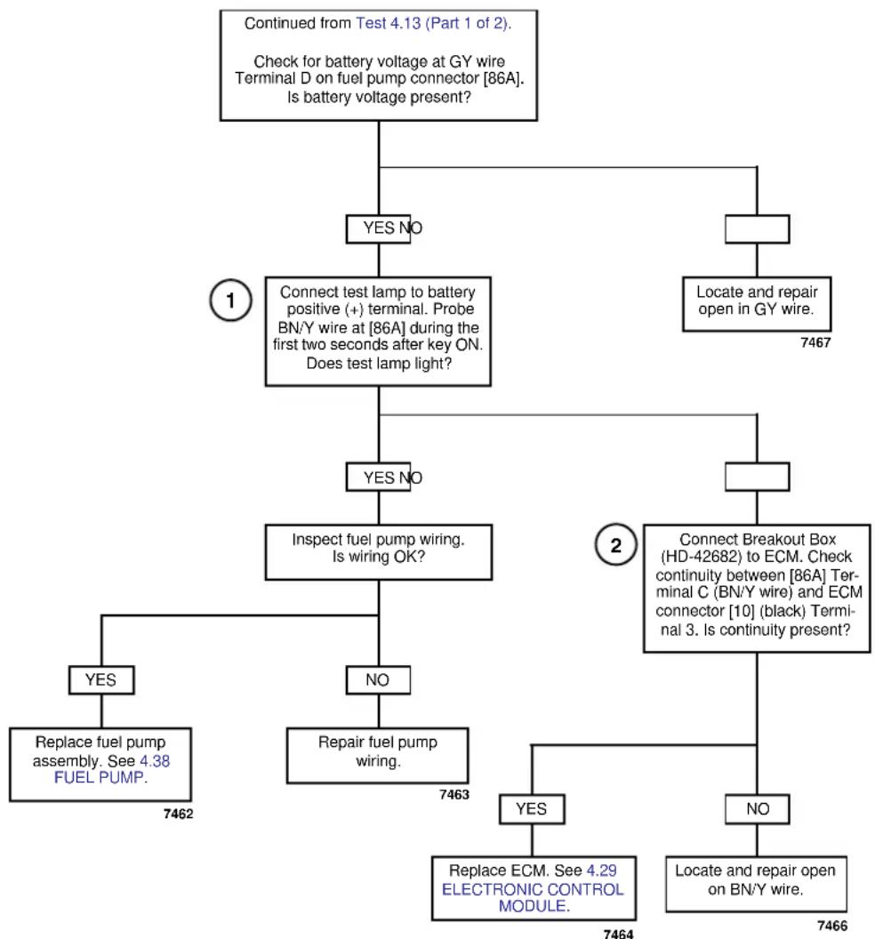
flowchart
graph TD
    A["Continued from Test 4.13 (Part 1 of 2). Check for battery voltage at GY wire Terminal D on fuel pump connector [86A"]. Is battery voltage present?] --> B{YES NO}
    A --> C{Locate and repair open in GY wire.}
    B --> D{Connect test lamp to battery positive (+) terminal. Probe BN/Y_wire_at["86A"] during the first two seconds after key ON. Does test lamp light?}
    C --> E{7467}
    D --> F{YES NO}
    D --> G{Inspect fuel pump wiring. Is wiring OK?}
    E --> H{Connect Breakout Box (HD-42682) to ECM. Check_continuity_between["86A"] Terminal C (BN/Y wire) and_ECM_connector["10"] (black) Terminal 3. Is continuity present?}
    F --> I{YES}
    F --> J{NO}
    I --> K["Replace fuel pump assembly. See 4.38 FUEL PUMP."]
    J --> L["Repair fuel pump wiring."]
    K --> M["7462"]
    L --> N["7463"]
    M --> O["7464"]
    N --> P["7465"]
    O --> Q["7466"]
    P --> R["7466"]
ADJUSTMENTS
CAUTION
Setting the idle below the recommended speed can result in hard starting, especially in cold ambient temperatures.
See Figure 4-142. The idle speed control cable (1) is located on the left side of the vehicle between the front cylinder head and the ram air scoop assembly (2). Idle speeds are listed in 4.1 SPECIFICATIONS. A 3/16 in. allen wrench may be used to turn adjuster knob.
Table 4-38. Engine Idle Speeds
| MODEL REGULAR IDLE | |
| XB9R 1050-1150 | |
CAUTION
Idle adjuster is located near the engine and could be extremely hot. Use suggested tool for adjusting the idle speed. Failure to comply could result in minor or moderate injury.
The idle speed should be adjusted when the engine is at normal operating temperature.
NOTE
An idle speed too low can cause poor throttle response. An idle speed too high can cause a slow return to idle.
See 1.16 THROTTLE CABLE AND IDLE SPEED ADJUSTMENT for more information on idle speed adjustment.
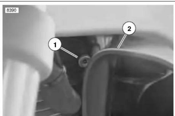
text_image
8390 1 2-
Idle speed control cable
-
Ram air scoop
Figure 4-142. Idle Adjustment Cable
GENERAL
Misfire At Idle or Under Load
Misfire conditions may be caused by:
● Battery condition and connections.
- Fuel system problems. See tables under 4.8 INITIAL DIAGNOSTIC CHECK.
DIAGNOSTICS
Diagnostic Notes
The reference numbers below correlate with the circled numbers on the Test 4.15 flow charts.
WARNING
Thoroughly wipe up any spilled fuel and dispose of rags in a suitable manner. Any open spark around gasoline or other combustibles could result in fire or explosion causing death or serious injury.
- See Figure 4-143. A SPARK TESTER (Part No. HD-26792) must be used to verify adequate secondary voltage (25,000 volts) at the spark plug.
a. Turn ignition switch OFF.
b. Remove spark plug cable from spark plug. Visually check plug condition.
c. Attach cable to SPARK TESTER. Clip tester to cylinder head bolt.
d. While cranking engine, watch for spark to jump tester gap on leads.
e. Reinstall and repeat procedure on other spark plug cable.
- Perform spark plug cable resistance test.
a. Remove spark plug cable from spark plug and ignition coil. See 7.4 SPARK PLUG CABLES.
b. Using an ohmmeter, touch probes to terminals on each end plug wire.
c. Compare resistance values to Table 4-39. Replace cables not meeting specifications. Reinstall and repeat procedure on other spark plug cable.
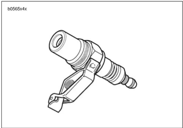
natural_image
Technical line drawing of a mechanical connector component (no text or symbols)Figure 4-143. Spark Tester (Part No, HD-26792)
Table 4-39. Spark Plug Cables
| SPECIFICATION FRONT & REAR | |
| Length-in. (mm) | 5.75(146) |
| Resistance -ohms | 1,430-3,360 |
- If carbon tracking is evident, replace ignition coil and inspect spark plug wires. Wires must be clean and tight. Excessive wire resistance or faulty connections can cause coil damage. See 4.31 IGNITION COIL.
- This test can also be performed by substituting a known good coil for one causing the no spark condition. The coil does not require full installation to be functional. Verify faulty coil by performing resistance test. See 4.31 IGNITION COIL.
- Use HARNESS CONNECTOR TEST KIT (Part No. HD-41404) gray pin probe and patch cord.
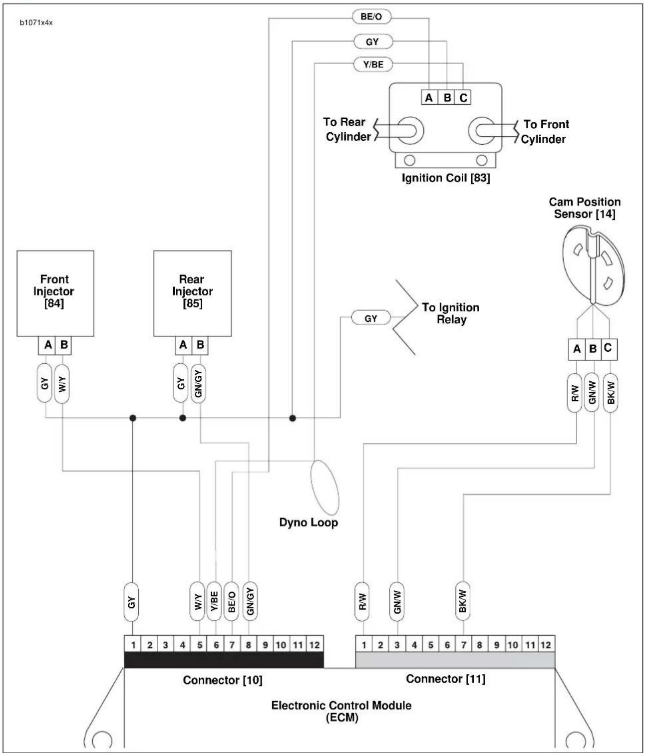
flowchart
graph TD
    A["Front Injector [84"]] -->|A B| B["CY W/Y"]
    C["Rear Injector [85"]] -->|A B| D["GY GN/GY"]
    E["Ignition Coil [83"]] --> F["BY O"]
    G["Cam Position Sensor [14"]] --> H["BY R/W GN/W BK/W"]
    I["Dyno Loop"] --> J["Connector [10"]]
    K["Connector [11"]]
    L["Electronic Control Module (ECM)"] --> M["1 2 3 4 5 6 7 8 9 10 11 12"]
    N["To Rear Cylinder"] --> O["To Front Cylinder"]
    P["To Ignition Relay"] --> Q["To Ignition Relay"]
Figure 4-144. Ignition Coil Circuit
Table 4-40. Wire Harness Connectors in Figure 4-144.
| NO. DESCRIPTION TYPE LOCATION | ||
| [10] ECM (black) 12-place Deutsch in fairing | ||
| [22] right hand controls 4-place Multilock beneath right side of fairing | ||
| [83] ignition coil 3-place Packard beneath airbox base |
HOME
Test 4.15 (Part 1 of 2)
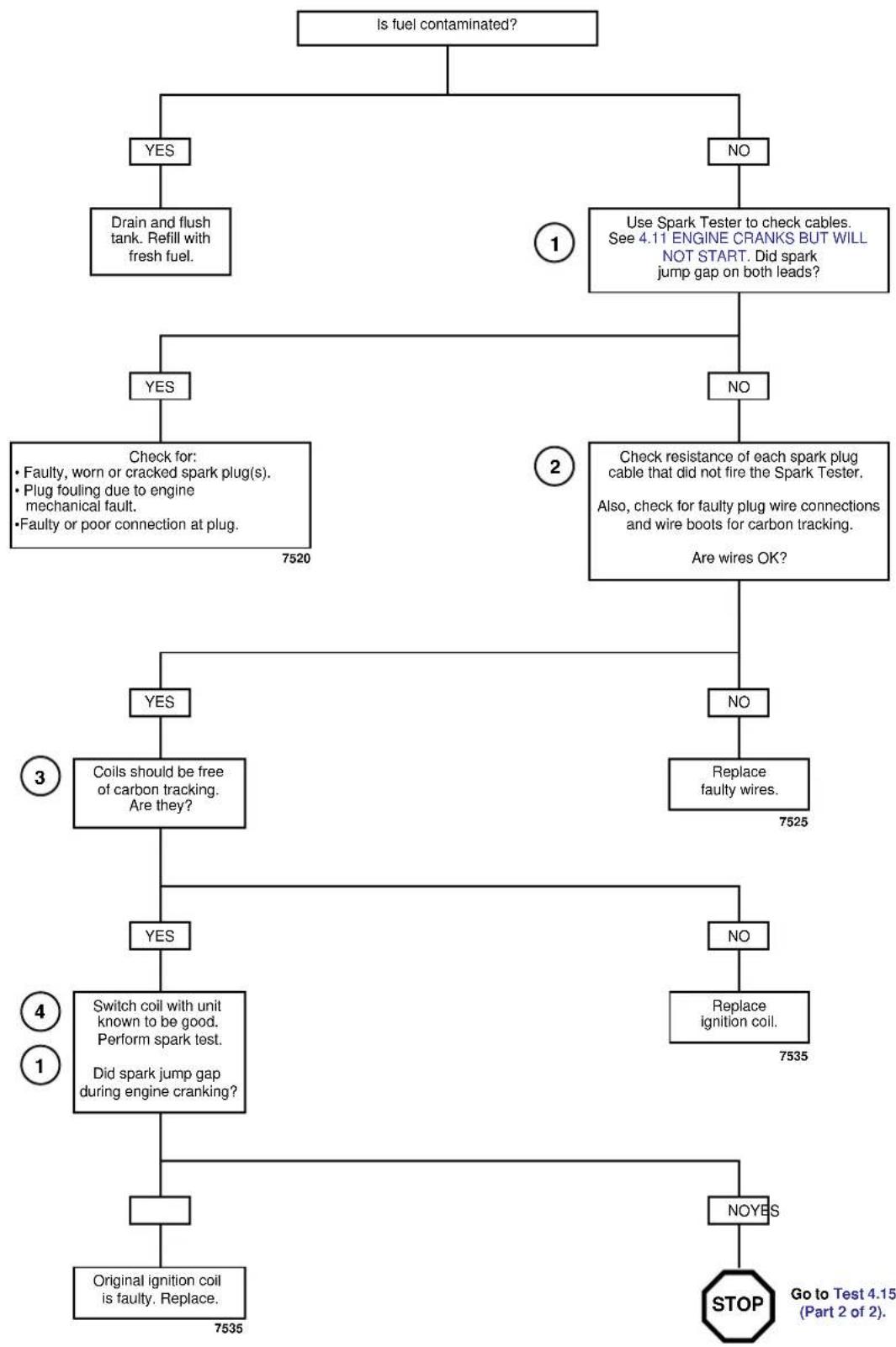
flowchart
graph TD
    A["Is fuel contaminated?"] --> B{Yes}
    A --> C{NO}
    B --> D["Drain and flush tank. Refill with fresh fuel."]
    C --> E{Use Spark Tester to check cables. See 4.11 ENGINE CRANKS BUT WILL NOT START. Did spark jump gap on both leads?}
    D --> F{Check for: Faulty, worn or cracked spark plug(s). Plug fouling due to engine mechanical fault. Faulty or poor connection at plug.}
    E --> G{Check resistance of each spark plug cable that did not fire the Spark Tester. Also, check for faulty plug wire connections and wire boots for carbon tracking. Are wires OK?}
    F --> H{Coils should be free of carbon tracking. Are they?}
    G --> I{Replace faulty wires.}
    H --> J{Switch coil with unit known to be good. Perform spark test. Did spark jump gap during engine cranking?}
    I --> K{Replace ignition coil.}
    J --> L{Original ignition coil is faulty. Replace.}
    K --> M{NoYES}
    L --> N{STOP Go to Test 4.15 (Part 2 of 2).}
Test 4.15 (Part 2 of 2)
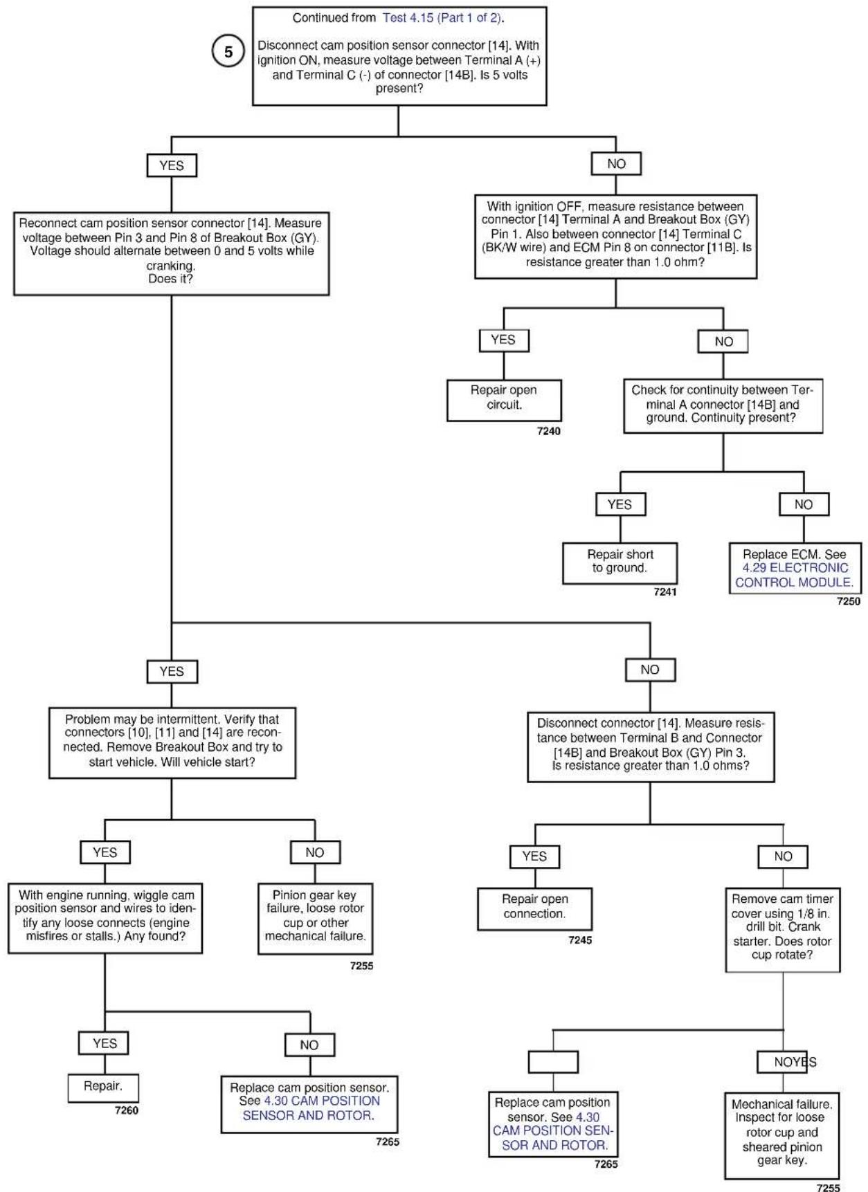
flowchart
graph TD
    A["Continued from Test 4.15 (Part 1 of 2). Disconnect cam position sensor connector [14"]. With ignition ON, measure voltage between Terminal A (+) and Terminal C (-) of_connector["14B"]. Is 5 volts present?] --> B{5}
    B -->|YES| C["Reconnect cam position sensor connector [14"]. Measure voltage between Pin 3 and Pin 8 of Breakout Box (GY). Voltage should alternate between 0 and 5 volts while cranking. Does it?]
    B -->|NO| D["With ignition OFF, measure resistance between connector [14"] Terminal A and Breakout Box (GY) Pin 1. Also_between_connector["14"] Terminal C (BK/W wire) and_ECM_Pin_8_on_connector["11B"]. Is resistance greater than 1.0 ohm?]
    C --> E{7240}
    D --> F{7240}
    E --> G["Repair open circuit."]
    F --> H["Check for continuity between Terminal A connector [14B"] and ground. Continuity present?]
    G --> I{7241}
    H --> J{7241}
    I --> K["Repair short to ground."]
    J --> L["Replace ECM. See 4.29 ELECTRONIC CONTROL MODULE."]
    K --> M{7250}
    L --> N["7250"]
    C --> O{YES}
    O --> P{Problem may be intermittent. Verify_that_connectors["10"], [11] and["14"] are reconnected. Remove Breakout Box and try to start vehicle. Will vehicle start?}
    P --> Q{YES}
    P --> R{NO}
    Q --> S{With engine running, wiggle cam position sensor and wires to identify any loose connects (engine misfires or stalls.) Any found?}
    Q --> T{No}
    S --> U{Pinion gear key failure, loose rotor cup or other mechanical failure.}
    T --> V{7255}
    U --> W{Yes}
    U --> X{NO}
    V --> Y{Repair.}
    V --> Z{Repair.}
    W --> AA{7260}
    X --> AB{7260}
    X --> AC{7265}
    Y --> AD{7265}
    X --> AE{7265}
    X --> AF{7265}
    AD --> AG{7265}
    AE --> AH{7265}
    AF --> AI{7265}
    AG --> AJ["Repair."]
    AG --> AK["Replace cam position sensor. See 4.30 CAM POSITION SENSOR AND ROTOR."]
    AH --> AL["Repair open connection."]
    AH --> AM["Remove cam timer cover using 1/8 in. drill bit. Crank starter. Does rotor cup rotate?"]
    AI --> AN["Repair."]
    AI --> AO["No YES"]
    AJ --> AP["Repair."]
    AK --> AQ["Repair."]
    AL --> AR["Repair."]
    AM --> AS["Repair."]
    AN --> AT["Repair."]
    AO --> AU["Repair."]
    AP --> AV["Repair."]
    AQ --> AW["Repair."]
    AR --> AX["Repair."]
    AS --> AY["Repair."]
    AT --> AZ["Repair."]
    AU --> BA["Repair."]
    AV --> BB["Repair."]
    AW --> BC["Repair."]
GENERAL
Throttle Position Sensor
See Figure 4-145. The throttle position sensor (TP sensor) is supplied 5.0 volts from the ECM (5v REF) and sends a signal back to the ECM (TP sensor signal) which varies according to throttle position. The output signal from the TP sensor varies from:
● 0.5-1.5 volts at idle (closed throttle).
● 3.9-4.9 volts at wide open throttle.
A Code 11 will set if the TP sensor signal voltage does not fall within the acceptable range.
NOTE
If the TP sensor is removed and/or replaced, the sensor must be calibrated using Digital Technician (Part No. HD-44750). For replacement of TP sensor see 4.36 THROTTLE POSITION SENSOR.
DIAGNOSTICS
Diagnostic Tips
TP sensor voltage should increase at a steady rate as throttle is moved from idle to wide open throttle. An open or short to ground in R/W or BK/W wires will also result in a Code 11.
Check for the following conditions:
- Poor connection. Inspect ECM harness connector for backed out terminals, improper mating, broken locks improperly formed or damaged terminals, poor terminal-to-wire connection and damaged harness.
- Perform 4.7 WIGGLE TEST to locate intermittents. If connections and harness check out OK, monitor TP sensor voltage using DVOM while moving related connectors and wiring harness. If the failure is induced, the DVOM display will change.
- TP sensor scaling. Observe the TP sensor voltage display while opening the throttle with engine stopped and ignition switch ON. Display should vary from closed throttle TP sensor voltage (when throttle is closed) to greater than 4.0 volts (when throttle is held wide open). As the throttle is slowly moved, the voltage should change gradually without spikes or low voltages being observed.
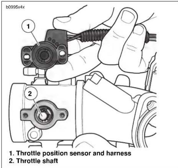
text_image
b0995x4x 1. 2. 1. Throttle position sensor and harness 2. Throttle shaftFigure 4-145. TP Sensor Assembly
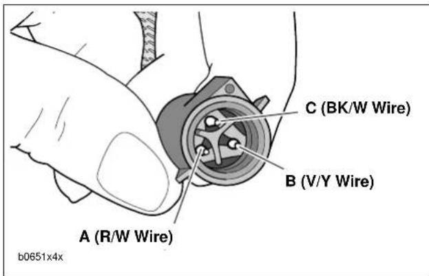
text_image
C (BK/W Wire) B (V/Y Wire) A (R/W Wire) b0651x4xFigure 4-146. TP Sensor Terminals [88A]
Diagnostic Notes
The reference numbers below correlate with the circled numbers on the Code 11 flow charts.
- Connect BREAKOUT BOX (Part No. HD-42682) to ECM. See 4.6 BREAKOUT BOX.
- Use HARNESS CONNECTOR TEST KIT (Part No. HD-41404), black socket probe and patch cord.
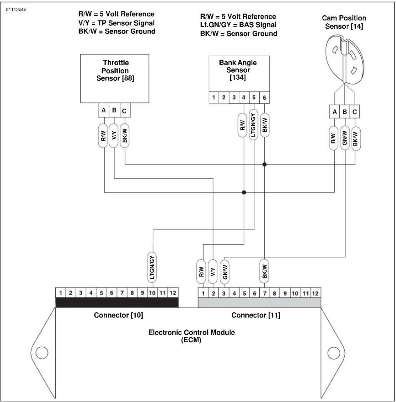
flowchart
graph TD
    A["Throttle Position Sensor [88"]] -->|R/W = 5 Volt Reference\nV/Y = TP Sensor Signal\nBK/W = Sensor Ground| B["Cap Position Sensor [14"]]
    C["Bank Angle Sensor [134"]] -->|R/W = 5 Volt Reference\nLt.GN/GY = BAS Signal\nBK/W = Sensor Ground| D["Cam Position Sensor [14"]]
    E["LTGN/GY"] --> F["Connector [10"]]
    G["R/W"] --> H["Connector [11"]]
    I["V/Y"] --> H
    J["GN/W"] --> H
    K["BK/W"] --> H
    L["1"] --> M["12"]
    N["2"] --> O["11"]
    P["3"] --> Q["12"]
    R["4"] --> S["11"]
    T["5"] --> U["12"]
    V["6"] --> W["11"]
    X["7"] --> Y["12"]
    Z["8"] --> AA["11"]
    AB["9"] --> AC["12"]
    AD["10"] --> AE["Connector [10"]]
    AF["Electronic Control Module (ECM)"] --> AG["Connector [11"]]
    AH["AC"] --> AI["AC"]
    AJ["AC"] --> AK["AC"]
Figure 4-147. Throttle Position Sensor Circuit
Table 4-41. Wire Harness Connectors in Figure 4-147.
| NO. DESCRIPTION TYPE LOCATION | |||
| [10] ECM (black) 12-place Deutsch in fairing | |||
| [11] ECM (gray) 12-place Deutsch in fairing | |||
| [14] cam position sensor 3-place Deutsch under sprocket cover | |||
| [88] throttle position sensor 3-place Packard | right side of engine between cylinders | ||
| [134] | bank angle sensor | 6-place Sumitomo | in fairing |
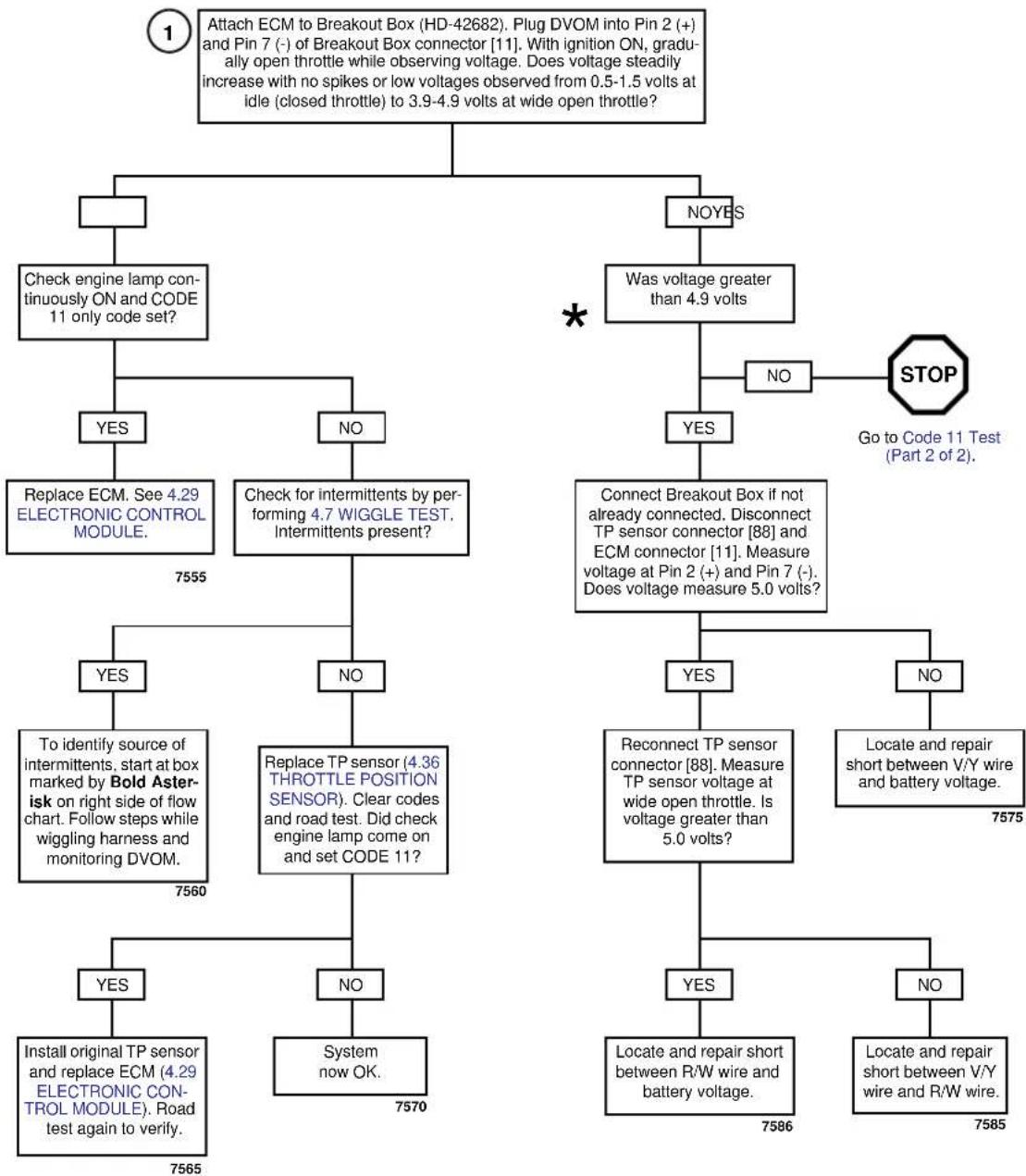
flowchart
graph TD
    A["1 Attach ECM to Breakout Box (HD-42682). Plug DVOM into Pin 2 (+) and Pin 7 (-) of Breakout Box connector [11"]. With ignition ON, gradually open throttle while observing voltage. Does voltage steadily increase with no spikes or low voltages observed from 0.5-1.5 volts at idle (closed throttle) to 3.9-4.9 volts at wide open throttle?] --> B{Check engine lamp continuously ON and CODE 11 only code set?}
    B -->|YES| C["Replace ECM. See 4.29 ELECTRONIC CONTROL MODULE."]
    B -->|NO| D["Check for intermittents by performing 4.7 WIGGLE TEST. Intermittents present?"]
    D --> E{To identify source of intermittents, start at box marked by Bold Asterisk on right side of flow chart. Follow steps while wiggling harness and monitoring DVOM.}
    E -->|YES| F["Install original TP sensor and replace ECM (4.29 ELECTRONIC CONTROL MODULE). Road test again to verify."]
    E -->|NO| G["Replace TP sensor (4.36 THROTTLE POSITION SENSOR). Clear codes and road test. Did check engine lamp come on and set CODE 11?"]
    G --> H["System now OK."]
    H --> I["7570"]
    I --> J{Will not qualify?}
    J -->|YES| K["Reconnect TP sensor connector [88"]. Measure TP sensor voltage at wide open throttle. Is voltage greater than 5.0 volts?]
    J -->|NO| L["Locate and repair short between R/W wire and battery voltage."]
    K --> M{Will not qualify?}
    M -->|YES| N["Locate and repair short between R/W wire and R/W wire."]
    M -->|NO| O["Locate and repair short between V/Y wire and R/W wire."]
    N --> P["7586"]
    O --> Q["7585"]
    P --> R["7565"]
    Q --> S["7585"]
    T["No YES"] --> U["Was voltage greater than 4.9 volts"]
    U --> V{NO}
    V -->|STOP Go to Code 11 Test (Part 2 of 2).} U
    V --> W{Connect Breakout Box if not already connected. Disconnect_TP_sensor_connector["88"] and_ECM_connector["11"]. Measure voltage at Pin 2 (+) and Pin 7 (-). Does voltage measure 5.0 volts?}
    W --> X{YES}
    X --> Y["Reconnect TP sensor connector [88"]. Measure TP sensor voltage at wide open throttle. Is voltage greater than 5.0 volts?]
    X --> Z{NO}
    Z --> AA["Locate and repair short between V/Y wire and battery voltage."]

At some point in the flow chart you may be instructed to jump directly to a box with the bold asterisk. Disregard the asterisk (but not the instruction box) if your normal progression through the chart brings you to this location.
Clear codes and confirm proper operation with no check engine lamp. Codes can be cleared using DIGITAL TECHNICIAN (Part No. HD-44750).
Code 11 Test (Part 2 of 2)
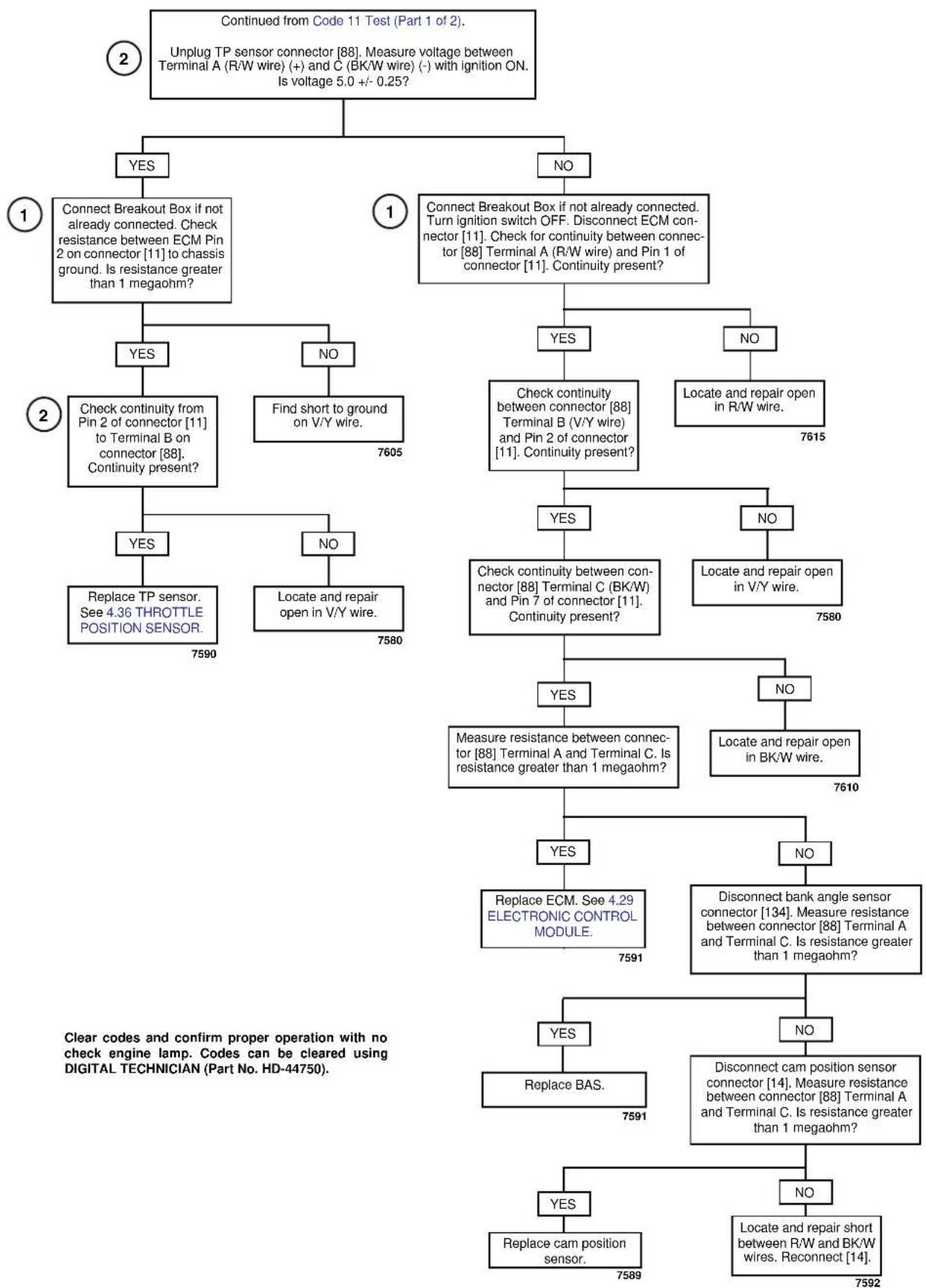
flowchart
graph TD
    A["Continued from Code 11 Test (Part 1 of 2). Unplug TP sensor connector [88"]. Measure voltage between Terminal A (R/W wire) (+) and C (BK/W wire) (-) with ignition ON. Is voltage 5.0 +/- 0.25?] --> B{2}
    B -->|YES| C["Connect Breakout Box if not already connected. Check resistance between ECM Pin 2 on connector [11"] to chassis ground. Is resistance greater than 1 megaohm?]
    B -->|NO| D["Connect Breakout Box if not already connected. Turn ignition switch OFF. Disconnect ECM connector [11"]. Check_for_continuity_between_connector["88"] Terminal A (R/W wire) and_Pin_1_of_connector["11"]. Continuity present?]
    C --> E{1}
    E -->|YES| F["Check continuity from Pin 2 of connector [11"] to_Terminal_B_on_connector["88"]. Continuity present?]
    E -->|NO| G["Find short to ground on V/Y wire. 7605"]
    F --> H{2}
    H -->|YES| I["Replace TP sensor. See 4.36 THROTTLE POSITION SENSOR. 7590"]
    H -->|NO| J["Locate and repair open in V/Y wire. 7580"]
    D --> K{1}
    K -->|YES| L["Check continuity between connector [88"] Terminal B (V/Y wire) and_Pin_2_of_connector["11"]. Continuity present?]
    K -->|NO| M["Locate and repair open in R/W wire. 7615"]
    L --> N{2}
    N -->|YES| O["Measure resistance between connector [88"] Terminal A and Terminal C. Is resistance greater than 1 megaohm?]
    N -->|NO| P["Locate and repair open in V/Y wire. 7580"]
    O --> Q{3}
    Q -->|YES| R["Replace ECM. See 4.29 ELECTRONIC CONTROL MODULE. 7591"]
    Q -->|NO| S["Disconnect bank angle sensor connector [134"]. Measure_resistance_between_connector["88"] Terminal A and Terminal C. Is resistance greater than 1 megaohm?]
    R --> T{4}
    T -->|YES| U["Replace BAS. 7591"]
    T -->|NO| V["Disconnect cam position sensor connector [14"]. Measure_resistance_between_connector["88"] Terminal A and Terminal C. Is resistance greater than 1 megaohm?]
    U --> W{5}
    W -->|YES| X["Replace cam position sensor. 7589"]
    W -->|NO| Y["Locate and repair short between R/W and BK/W wires. Reconnect [14"]. 7592]
GENERAL
Oxygen (O2) Sensor
See Figure 4-148. The oxygen (O2) sensor provides a signal to the ECM which indicates whether the engine is running rich or lean.
- A low voltage signal (<0.41 V) indicates the engine is running lean.
● A high voltage signal (>0.56 V) indicates the engine is running rich.
When the air/fuel mixture is ideal, approximately 14.7 parts air to 1 part fuel, the voltage will be approximately 0.48 V.
DIAGNOSTICS
Diagnostic Tips
The DVOM displays the signal from the O2 sensor in volts. This voltage will have an average value tending towards lean, rich or ideal value depending on operating temperature of the engine, engine speed and throttle position. An open/short to voltage or short to ground in the V/GY wire will cause the engine to run rich (short to ground) or lean (short to voltage) until fault is detected. Once fault is detected, vehicle will run in open loop. The engine must be running below 5000 RPM for the ECM to detect an O2 sensor failure.
Check for the following conditions:
- Poor connection. Inspect the ECM harness connector [11], fuel injector connectors [84, 85] and O2 sensor connector wiring for backed out terminals, improper mating, broken locks, improperly formed or damaged terminals, poor terminal-to-wire connection and damaged harness.
- Dirty/stuck open injectors. The motorcycle may run lean (dirty/clogged injectors) or rich (stuck open injectors) if there is an injector problem. This could also cause poor fuel economy and performance.
- Loose O2 sensor. See Figure 4-149. If the O2 sensor is loose engine performance may be affected. This could also show up as a slow changing O2 sensor voltage.
- Loose/leaking exhaust. This can cause a poor ground connection for sensor or allow fresh air into the exhaust system. If fresh air enters exhaust system, the O2 sensor will read a lean condition, causing the system to go rich.
Diagnostic Notes
- Connect BREAKOUT BOX (Part No. HD-42682) to ECM. See 4.6 BREAKOUT BOX.
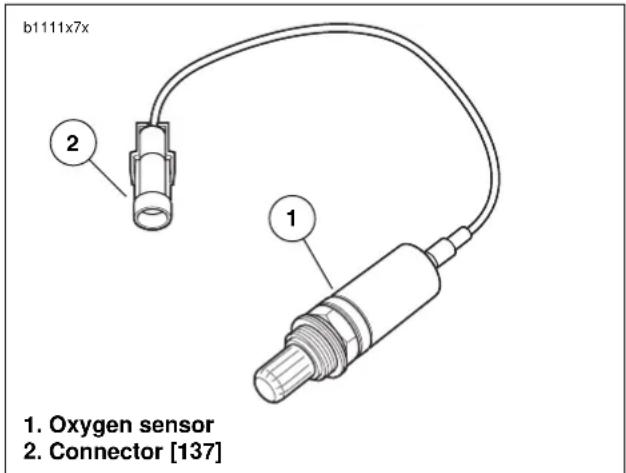
text_image
b1111x7x 2 1 1. Oxygen sensor 2. Connector [137]Figure 4-148. Oxygen Sensor
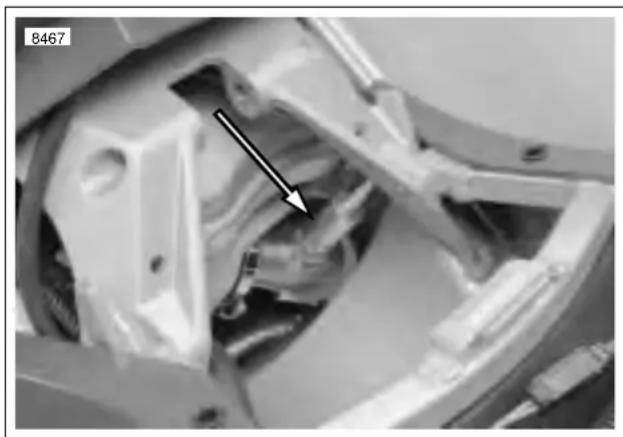
natural_image
Close-up of a mechanical component with an arrow pointing to a specific area (no visible text or symbols)Figure 4-149. Oxygen Sensor (shock absorber removed)
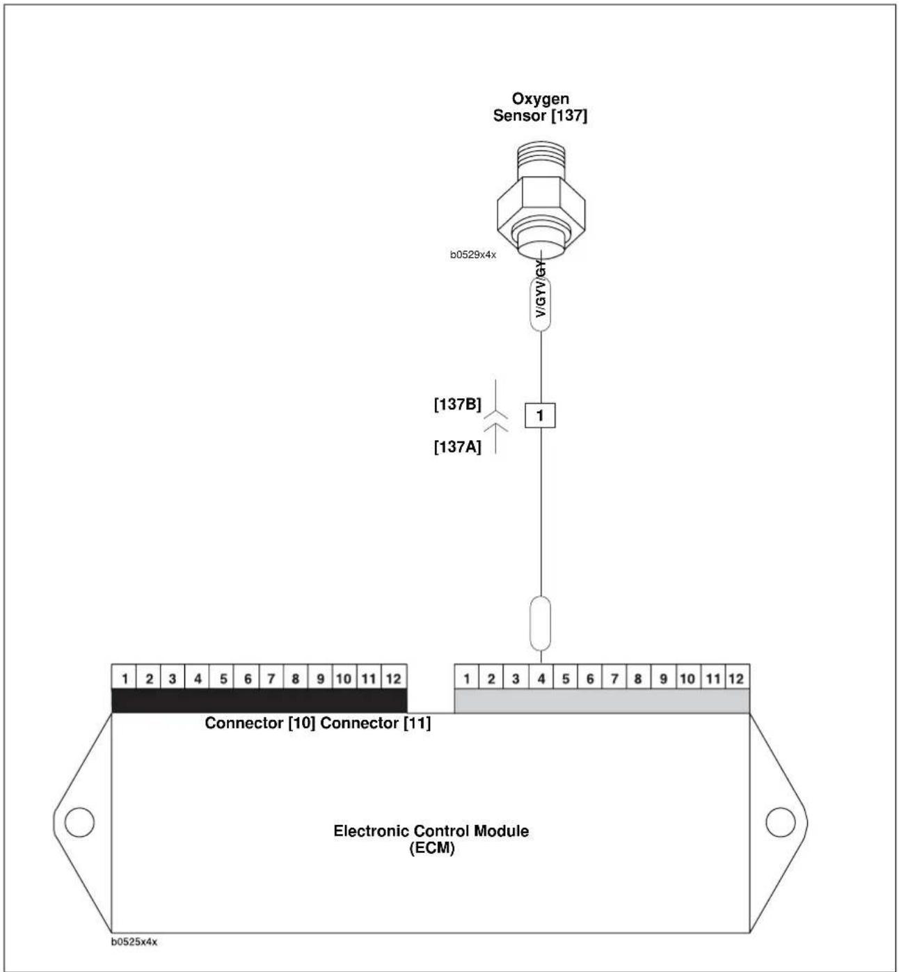
text_image
Oxygen Sensor [137] b0529x4x V/GY/GY [137B] [137A] 1 Connector [10] Connector [11] Electronic Control Module (ECM) b0525x4xFigure 4-150. Oxygen Sensor Circuit
Table 4-42. Wire Harness Connectors in Figure 4-150.
| NO. DESCRIPTION TYPE LOCATION | ||
| [11] ECM (gray) 12-place Deutsch in fairing | ||
| [137] oxygen sensor 1-place Packard behind rear cylinder head |
HOME
Code 13 Test (Part 1 of 3)
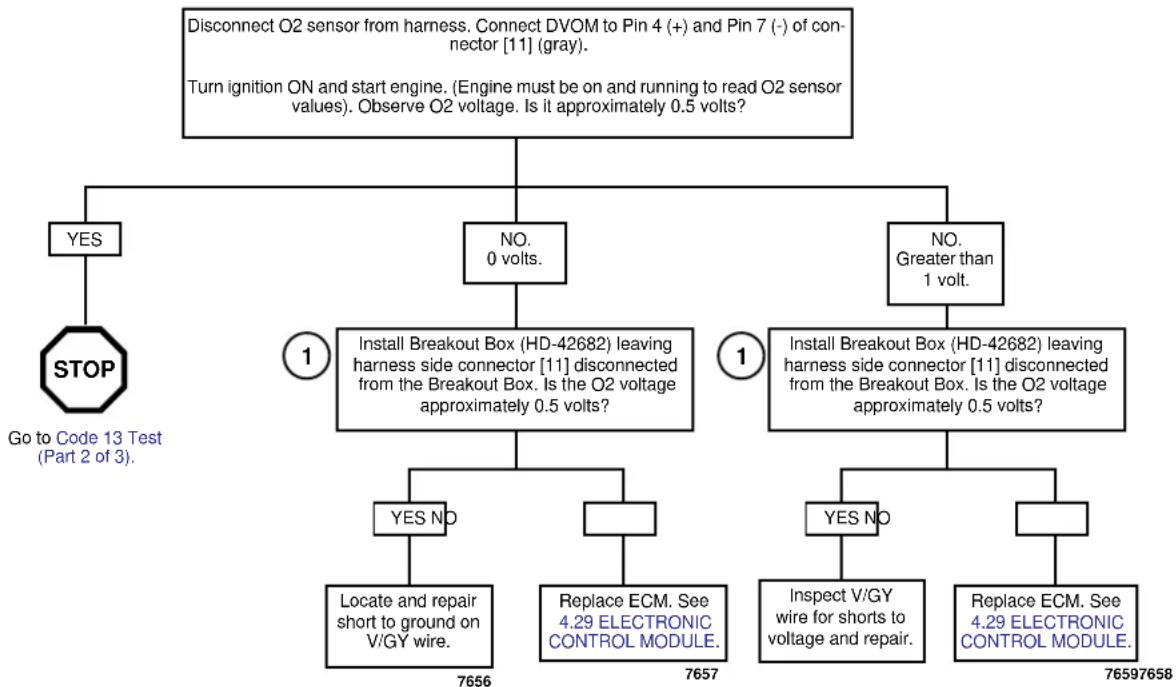
flowchart
graph TD
    A["Disconnect O2 sensor from harness. Connect DVOM to Pin 4 (+) and Pin 7 (-) of connector [11"] (gray). Turn ignition ON and start engine. (Engine must be on and running to read O2 sensor values). Observe O2 voltage. Is it approximately 0.5 volts?] --> B{YES}
    B --> C["STOP"]
    C --> D["Go to Code 13 Test (Part 2 of 3)."]
    A --> E{NO. 0 volts.}
    E --> F{Install Breakout Box (HD-42682) leaving_harness_side_connector["11"] disconnected from the Breakout Box. Is the O2 voltage approximately 0.5 volts?}
    E --> G{NO. Greater than 1 volt.}
    G --> H{Install Breakout Box (HD-42682) leaving_harness_side_connector["11"] disconnected from the Breakout Box. Is the O2 voltage approximately 0.5 volts?}
    G --> I{YES NO}
    I --> J["Locate and repair short to ground on V/GY wire. 7656"]
    I --> K["Replace ECM. See 4.29 ELECTRONIC CONTROL MODULE. 7657"]
    G --> L{YES NO}
    L --> M["Inspect V/GY wire for shorts to voltage and repair. 7657"]
    L --> N["Replace ECM. See 4.29 ELECTRONIC CONTROL MODULE. 7657"]
Clear codes and confirm proper operation with no check engine lamp. Codes can be cleared using DIGITAL TECHNICIAN (Part No. HD-44750).
Code 13 Test (Part 2 of 3)
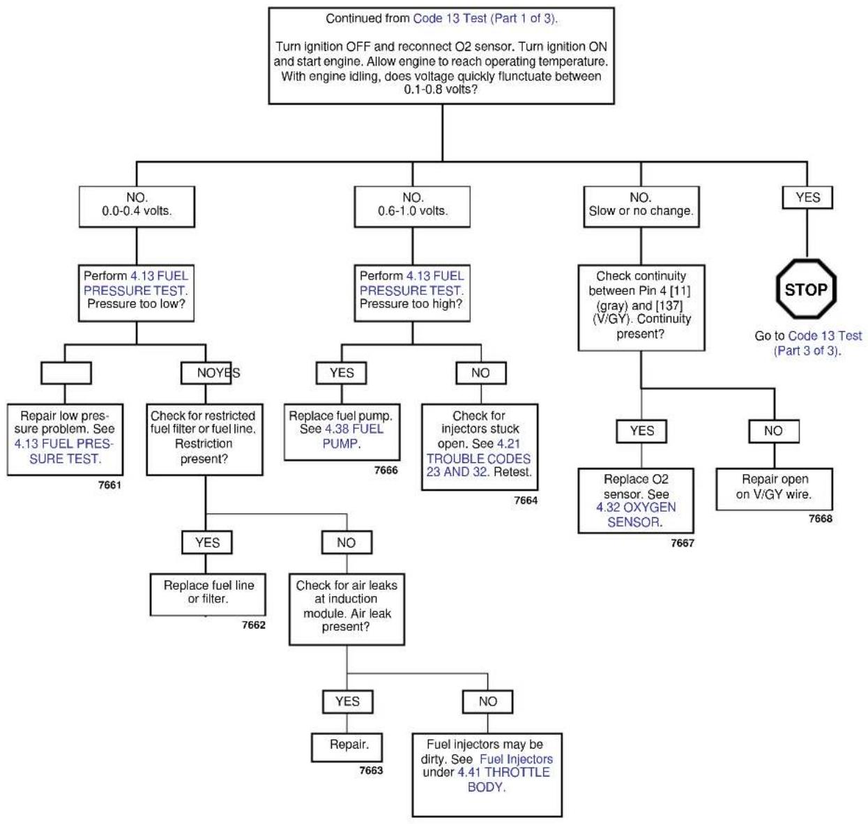
flowchart
graph TD
    A["Continued from Code 13 Test (Part 1 of 3). Turn ignition OFF and reconnect O2 sensor. Turn ignition ON and start engine. Allow engine to reach operating temperature. With engine idling, does voltage quickly fluctuate between 0.1-0.8 volts?"] --> B{NO. 0.0-0.4 volts.}
    B --> C["Perform 4.13 FUEL PRESSURE TEST. Pressure too low?"]
    C --> D{NOYES}
    D --> E["Repair low pressure problem. See 4.13 FUEL PRESSURE TEST. 7661"]
    D --> F["Check for restricted fuel filter or fuel line. Restriction present?"]
    F --> G{YES}
    G --> H["Replace fuel line or filter. 7662"]
    G --> I{NO}
    I --> J["Check for air leaks at induction module. Air leak present?"]
    J --> K{YES}
    J --> L{NO}
    K --> M["Repair. 7663"]
    L --> N["Fuel injectors may be dirty. See Fuel Injectors under 4.41 THROTTLE BODY."]
    A --> O{NO. 0.6-1.0 volts.}
    O --> P["Perform 4.13 FUEL PRESSURE TEST. Pressure too high?"]
    O --> Q{NO. Slow or no change.}
    Q --> R["Check continuity between Pin 4 [11"] (gray) and["137"] (V/GY). Continuity present?]
    R --> S{YES}
    R --> T{NO}
    S --> U["Replace O2 sensor. See 4.32 OXYGEN SENSOR. 7667"]
    T --> V["Repair open on V/GY wire. 7668"]
    U --> W["Go to Code 13 Test (Part 3 of 3). STOP"]
Clear codes and confirm proper operation with no check engine lamp. Codes can be cleared using DIGITAL TECHNICIAN (Part No. HD-44750).
HOME
Code 13 Test (Part 3 of 3)

flowchart
graph TD
    A["Continued from Code 13 Test (Part 2 of 3). Turn ignition OFF and reconnect O2 sensor. Turn ignition ON and start engine. Allow engine to reach operating temperature. Does voltage quickly fluctuate between 0.1-0.8 volts?"] --> B{YES}
    A --> C{NO}
    B --> D{Check for intermittents by performing 4.7 WIGGLE TEST. Intermittents present?}
    C --> E{See Code 13 Test (Part 2 of 3) for diagnostic material.}
    D --> F{YES}
    D --> G{NO}
    F --> H["Repair as necessary."]
    G --> I["Replace O2 sensor (4.32 OXYGEN SENSOR). Clear codes and road test. Did check engine lamp come on and set CODE 13?"]
    I --> J{YES}
    I --> K{NO}
    J --> L["Install original O2 sensor and replace ECM (4.29 ELECTRONIC CONTROL MODULE). Road test again to verify."]
    K --> M["System now OK."]
Clear codes and confirm proper operation with no check engine lamp. Codes can be cleared using DIGITAL TECHNICIAN (Part No. HD-44750).
GENERAL
Engine Temperature Sensor
CAUTION
Do not pull on engine temperature sensor wiring. Excess strain to sensor wiring will cause sensor damage.
The ECM supplies and monitors a 0-5 volt signal to one side of the engine temperature sensor (ET sensor). The other side of the ET sensor is connected to ground through the engine.
See Table 4-43. The ET sensor is a thermistor device which means that at a specific temperature it will have a specific resistance across its terminals. As this resistance varies, so does the supplied voltage.
- At high temperatures, the resistance of the sensor is very low. This effectively lowers the signal voltage.
- At low temperatures, the resistance is very high, allowing the voltage to rise close to the supplied voltage of 5 volts.
The ECM monitors this voltage to compensate for various operating conditions.
DIAGNOSTICS
Diagnostic Tips
An intermittent may be caused by poor connection, rubbed through wire insulation or a wire broken inside the insulation.
Check the following conditions:
- Poor connection. Inspect ECM harness connector [11] for backed out terminals, improper mating, broken locks, improperly formed or damaged terminals, poor terminal-to-wire connection and damaged harness.
- Shifted sensor. The temperature-to-resistance values table may be used to test the ET sensor at various temperature levels in order to evaluate the possibility of a shifted (out-of-calibration) sensor which may result in driveability problems.
Diagnostic Notes
The reference numbers below correlate with the circled numbers on the Code 14 flow charts.
- Connect BREAKOUT BOX (Part No. HD-42682) to ECM. See 4.6 BREAKOUT BOX.
- Use HARNESS CONNECTOR TEST KIT (Part No. HD-41404), gray pin probes and patch cord.
Table 4-43. Engine Temperature Sensor Specifications
| VOLTS RESISTANCE TEMP | °C TEMP °F | ||
| 0.00 0 300 | 572 | ||
| 0.21 | 145 | 255 | 491 |
| 0.42 | 303 | 210 | 410 |
| 0.62 | 463 | 190 | 374 |
| 0.81 | 638 | 170 | 338 |
| 1.20 | 1042 | 150 | 302 |
| 1.59 | 1539 | 130 | 266 |
| 3.01 | 4991 | 85 | 185 |
| 4.43 | 25,647 | 40 | 104 |
| 4.63 | 41,295 | 25 | 77 |
| 4.83 | 93,759 | 10 | 50 |
| 4.88 | 134,200 | 0 | 32 |
| 4.93 | 232,414 | -10 | 14 |
NOTE
All voltage and resistance values are approximate (+/- 20%). Engine temperature sensor is measured between Terminal 9 of connector [11] and system ground (Terminals 2 and 11 of connector [10]).
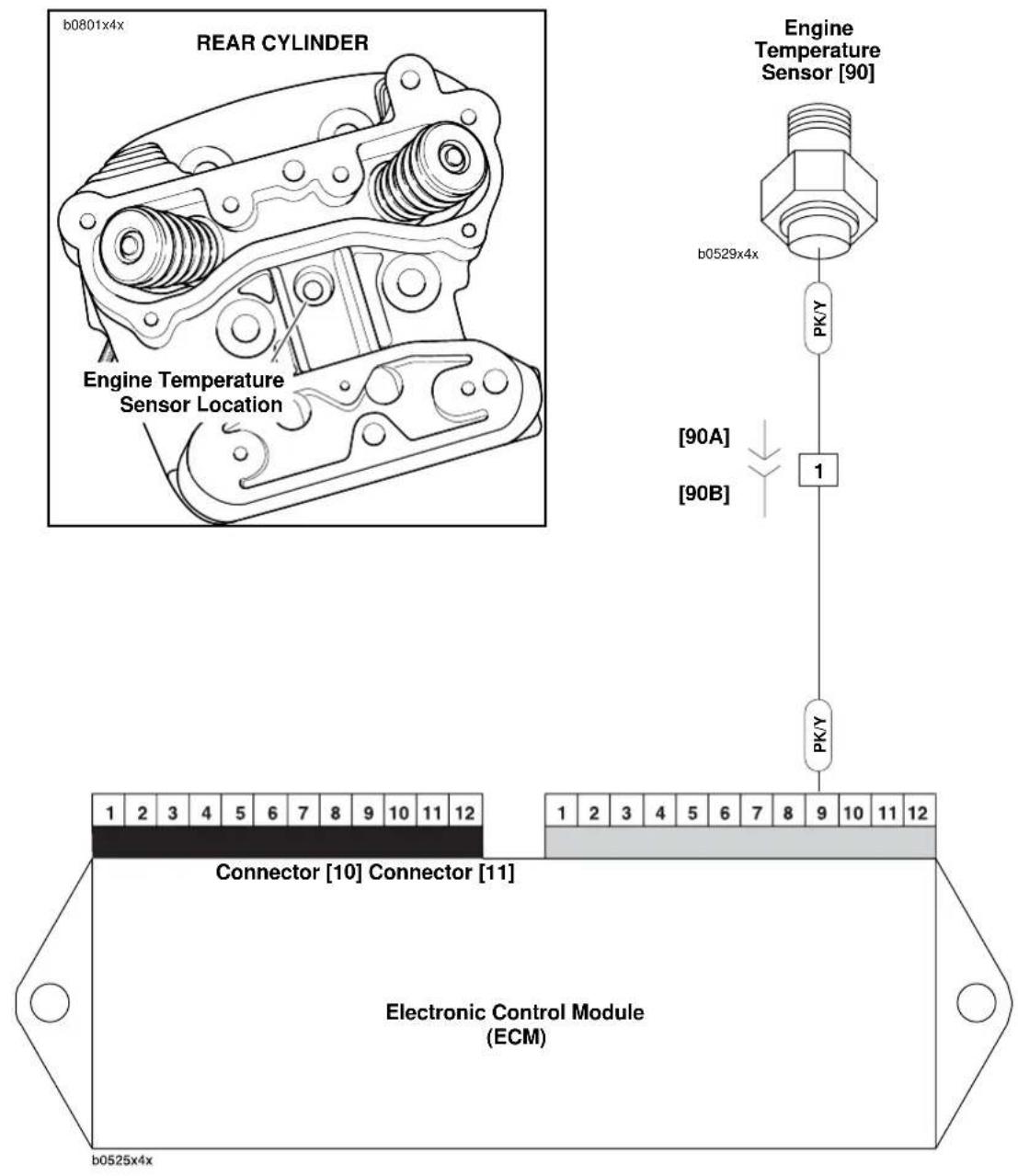
text_image
b0801x4x REAR CYLINDER Engine Temperature Sensor Location Engine Temperature Sensor [90] b0529x4x PK/Y [90A] [90B] 1 PK/Y Connector [10] Connector [11] Electronic Control Module (ECM) b0525x4xFigure 4-151. Engine Temperature Sensor Circuit
Table 4-44. Wire Harness Connectors in Figure 4-151.
| NO. DESCRIPTION TYPE LOCATION | ||
| [11] ECM (gray) 12-place Deutsch in fairing | ||
| [90] engine temperature sensor 1-place bullet beneath airbox base |
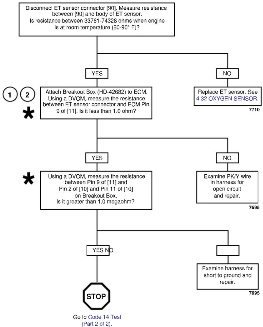
flowchart
graph TD
    A["Disconnect ET sensor connector [90"]. Measure_resistance_between["90"] and body of ET sensor.
Is resistance between 33761-74328 ohms when engine is at room temperature (60-90° F)?] --> B{YES}
    B -->|Yes| C["Attach Breakout Box (HD-42682) to ECM.<br>Using a DVOM, measure the resistance between ET sensor connector and ECM Pin 9 of [11"]. Is it less than 1.0 ohm?]
    B -->|No| D["Replace ET sensor. See 4.32 OXYGEN SENSOR. 7710"]
    C --> E{YES}
    C --> F{NO}
    E --> G["Using a DVOM, measure the resistance between Pin 9 of [11"] and_Pin_2_of["10"] and_Pin_11_of["10"] on Breakout Box.
Is it greater than 1.0 megaohm?]
    F --> H["Examine PK/Y wire in harness for open circuit and repair. 7695"]
    G --> I{YES NO}
    G --> J{STOP}
    H --> K["Examine harness for short to ground and repair. 7695"]
    K --> L["Go to Code 14 Test<br>(Part 2 of 2)."]

At some point in the flow chart you may be instructed to jump directly to the box marked by an asterisk. Disregard the asterisk (but not the instruction box) if your normal progression through the chart brings you to this location.
Clear codes and confirm proper operation with no check engine lamp. Codes can be cleared using DIGITAL TECHNICIAN (Part No. HD-44750).
HOME
Code 14 Test (Part 2 of 2)
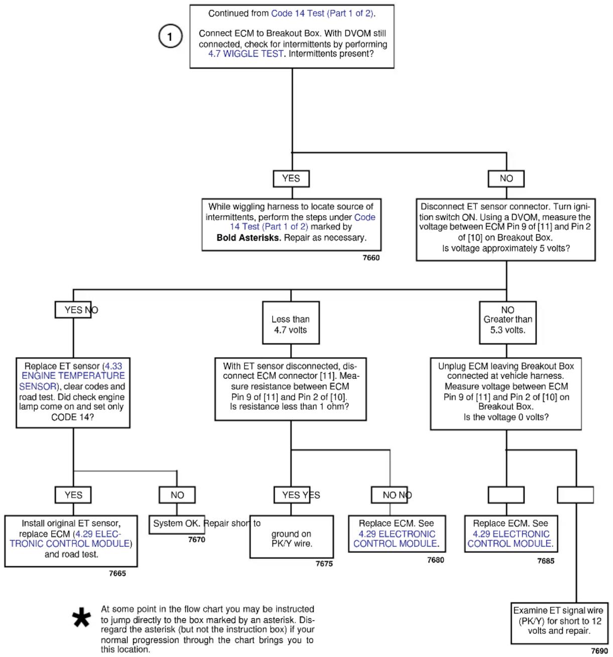
flowchart
graph TD
    A["Continued from Code 14 Test (Part 1 of 2). Connect ECM to Breakout Box. With DVOM still connected, check for intermittents by performing 4.7 WIGGLE TEST. Intermittents present?"] --> B{YES}
    A --> C{NO}
    B --> D{While wiggling harness to locate source of intermittents, perform the steps under Code 14 Test (Part 1 of 2) marked by Bold Asterisks. Repair as necessary. 7660}
    C --> E{Disconnect ET sensor connector. Turn ignition switch ON. Using a DVOM, measure_the_voltage_between_ECM_Pin_9_of["11"] and_Pin_2_of["10"] on Breakout Box. Is voltage approximately 5 volts?}
    D --> F{YES NO}
    D --> G{Less than 4.7 volts}
    D --> H{NO Greater than 5.3 volts.}
    F --> I["Replace ET sensor (4.33 ENGINE TEMPERATURE SENSOR), clear codes and road test. Did check engine lamp come on and set only CODE 14?"]
    G --> J["With ET sensor disconnected, disconnect ECM connector [11"]. Measure_resistance_between_ECM_Pin_9_of["11"] and_Pin_2_of["10"]. Is resistance less than 1 ohm?]
    H --> K["Unplug ECM leaving Breakout Box connected at vehicle harness. Measure voltage between ECM Pin 9 of [11"] and_Pin_2_of["10"] on Breakout Box. Is the voltage 0 volts?]
    I --> L{YES}
    I --> M{NO}
    J --> N["Replace ECM. See 4.29 ELECTRONIC CONTROL MODULE. 7680"]
    K --> O["Replace ECM. See 4.29 ELECTRONIC CONTROL MODULE. 7685"]
    L --> P["Install original ET sensor, replace ECM (4.29 ELECTRONIC CONTROL MODULE) and road test. 7665"]
    M --> Q["System OK. Repair short to ground on PK/Y wire. 7675"]
    N --> R["Examine ET signal wire (PK/Y) for short to 12 volts and repair. 7690"]
    O --> R

Clear codes and confirm proper operation with no check engine lamp. Codes can be cleared using DIGITAL TECHNICIAN (Part No. HD-44750).
GENERAL
Intake Air Temperature Sensor
The ECM supplies and monitors a signal at Pin 10 of [11] to one side of the intake air temperature sensor (IAT sensor). The other side of the IAT sensor is connected to a common sensor ground, which is also connected to the ECM (Pin 7 of [11]).
See Table 4-45. The IAT sensor is a thermistor device, meaning that at a specific temperature, it will have a specific resistance across its terminals. As this resistance varies, so does the supplied voltage (Pin 10).
- At high temperatures, the resistance of the sensor is very low. This effectively lowers the signal voltage on Pin 10.
- At low temperatures, the resistance is very high, allowing the voltage to rise close to the supplied voltage of 5 volts.
The ECM monitors this voltage to compensate for various operating conditions.
DIAGNOSTICS
Diagnostic Tips
An intermittent may be caused by a poor connection, rubbed through wire insulation or a wire broken inside the insulation.
Check for the following conditions:
- Poor connection. Inspect ECM harness connector for backed out terminals, improper mating, broken locks improperly formed or damaged terminals, poor terminal-to-wire connection and damaged harness.
- Perform 4.7 WIGGLE TEST to locate intermittents. If connections and harness check out OK, check intake air temperature reading while moving related connectors and wiring harness. If the failure is induced, the IAT sensor display will change.
- Shifted sensor. The temperature-to-resistance values table may be used to test the IAT sensor at various temperature levels in order to evaluate the possibility of a shifted (out-of-calibration) sensor which may result in driveability problems.
Diagnostic Notes
The reference numbers below correlate with the circled numbers on the Code 15 flow charts.
- Connect BREAKOUT BOX (Part No. HD-42682) to EFI harness only (leave ECM disconnected). See 4.6 BREAKOUT BOX.
- Use HARNESS CONNECTOR TEST KIT (Part No. HD-41404), gray socket probes and patch cord.
- Use HARNESS CONNECTOR TEST KIT (Part No. HD-41404), gray pin probe and patch cord.
Table 4-45. Intake Air Temperature Sensor Specifications
| VOLTS RESISTANCE TEMP | °C TEMP °F | ||
| 0.49 1086 | 125 257 | ||
| 0.68 1561 | 113 235 | ||
| 0.86 2077 | 100 212 | ||
| 1.13 2920 | 90 | 194 | |
| 1.40 3889 | 80 | 176 | |
| 2.25 8149 | 60 | 140 | |
| 3.09 | 16,178 | 40 | 104 |
| 3.52 | 23,670 | 30 | 86 |
| 3.94 | 37,170 | 20 | 68 |
| 4.24 | 55,359 | 10 | 50 |
| 4.53 | 96,383 | 0 | 32 |
| 4.68 | 146,250 | -10 | 14 |
| 4.83 | 284,118 | -20 | -4 |
NOTE
All voltage and resistance values are approximate (+/- 20%). Intake air temperature sensor is measured between Terminal 10 of [11] and system ground (Terminals 2 and 11 of [10]).
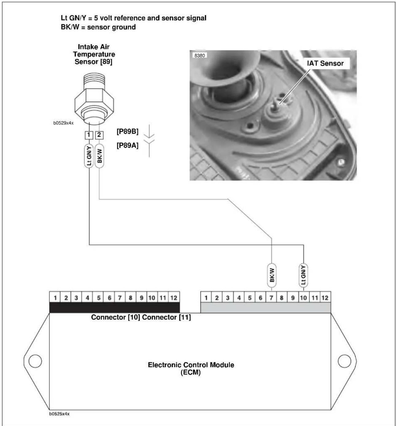
text_image
Lt GN/Y = 5 volt reference and sensor signal BK/W = sensor ground Intake Air Temperature Sensor [89] b0529x4x 1 2 Lt GN/Y BK/W [P89B] [P89A] IAT Sensor 8380 bk/w Lt GN/Y Connector [10] Connector [11] Electronic Control Module (ECM) b0525x4xFigure 4-152. Intake Air Temperature Sensor Circuit
Table 4-46. Wire Harness Connectors in Figure 4-152.
| NO. DESCRIPTION TYPE LOCATION | |||
| [11] ECM (gray) 12-place Deutsch in fairing | |||
| [89] intake | air temperature sensor 2-place Amp in airbox base | ||
Code 15 Test (Part 1 of 2)
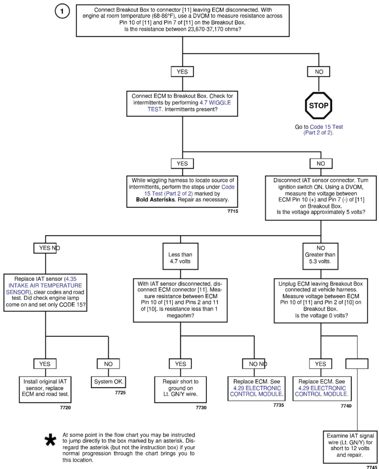
flowchart
graph TD
    A["Connect Breakout Box to connector [11"] leaving ECM disconnected. With engine at room temperature (68-86°F), use_a_DVOM_to_measure_resistance_across_Pin_10_of["11"] and_Pin_7_of["11"] on the Breakout Box. Is the resistance between 23,670-37,170 ohms?] --> B{YES}
    A --> C{NO}
    B --> D["Connect ECM to Breakout Box. Check for intermittents by performing 4.7 WIGGLE TEST. Intermittents present?"]
    D --> E{YES}
    D --> F{NO}
    E --> G["While wiggling harness to locate source of intermittents, perform the steps under Code 15 Test (Part 2 of 2) marked by Bold Asterisks. Repair as necessary. 7715"]
    F --> H["Disconnect IAT sensor connector. Turn ignition switch ON. Using a DVOM, measure the voltage between ECM Pin 10 (+) and Pin 7 (-) of [11"] on Breakout Box. Is the voltage approximately 5 volts?]
    G --> I{YES NO}
    G --> J{Less than 4.7 volts}
    G --> K{NO Greater than 5.3 volts.}
    I --> L["Replace IAT sensor (4.35 INTAKE AIR TEMPERATURE SENSOR), clear codes and road test. Did check engine lamp come on and set only CODE 15?"]
    J --> M["With IAT sensor disconnected, disconnect ECM connector [11"]. Measure_resistance_between_ECM_Pin_10_of["11"] and_Pins_2_and_11_of["10"]. Is resistance less than 1 megaohm?]
    K --> N["Unplug ECM leaving Breakout Box connected at vehicle harness. Measure voltage between ECM Pin 10 of [11"] and_Pin_2_of["10"] on Breakout Box. Is the voltage 0 volts?]
    L --> O{YES}
    L --> P{NO}
    M --> Q{YES}
    M --> R{NO NO}
    N --> S{YES}
    N --> T{No NO}
    O --> U["Install original IAT sensor, replace ECM and road test. 7720"]
    P --> V["System OK. 7725"]
    Q --> W["Repair short to ground on Lt. GN/Y wire. 7730"]
    R --> X["Replace ECM. See 4.29 ELECTRONIC CONTROL MODULE. 7735"]
    S --> Y["Replace ECM. See 4.29 ELECTRONIC CONTROL MODULE. 7740"]
    T --> Z["Examine IAT signal wire (Lt. GN/Y) for short to 12 volts and repair. 7745"]
    style A fill:#f9f,stroke:#333
    style B fill:#ccf,stroke:#333
    style C fill:#cfc,stroke:#333
    style D fill:#fcc,stroke:#333
    style E fill:#cff,stroke:#333
    style F fill:#ffc,stroke:#333
    style G fill:#fcc,stroke:#333
    style H fill:#fcc,stroke:#333
    style I fill:#cff,stroke:#333
    style J fill:#fcc,stroke:#333
    style K fill:#fcc,stroke:#333
    style L fill:#cff,stroke:#333
    style M fill:#fcc,stroke:#333
    style N fill:#fcc,stroke:#333
    style O fill:#fcc,stroke:#333
    style P fill:#fcc,stroke:#333
    style Q fill:#fcc,stroke:#333
    style R fill:#fcc,stroke:#333
    style S fill:#fcc,stroke:#333
    style T fill:#fcc,stroke:#333
Clear codes and confirm proper operation with no check engine lamp. Codes can be cleared using DIGITAL TECHNICIAN (Part No. HD-44750).
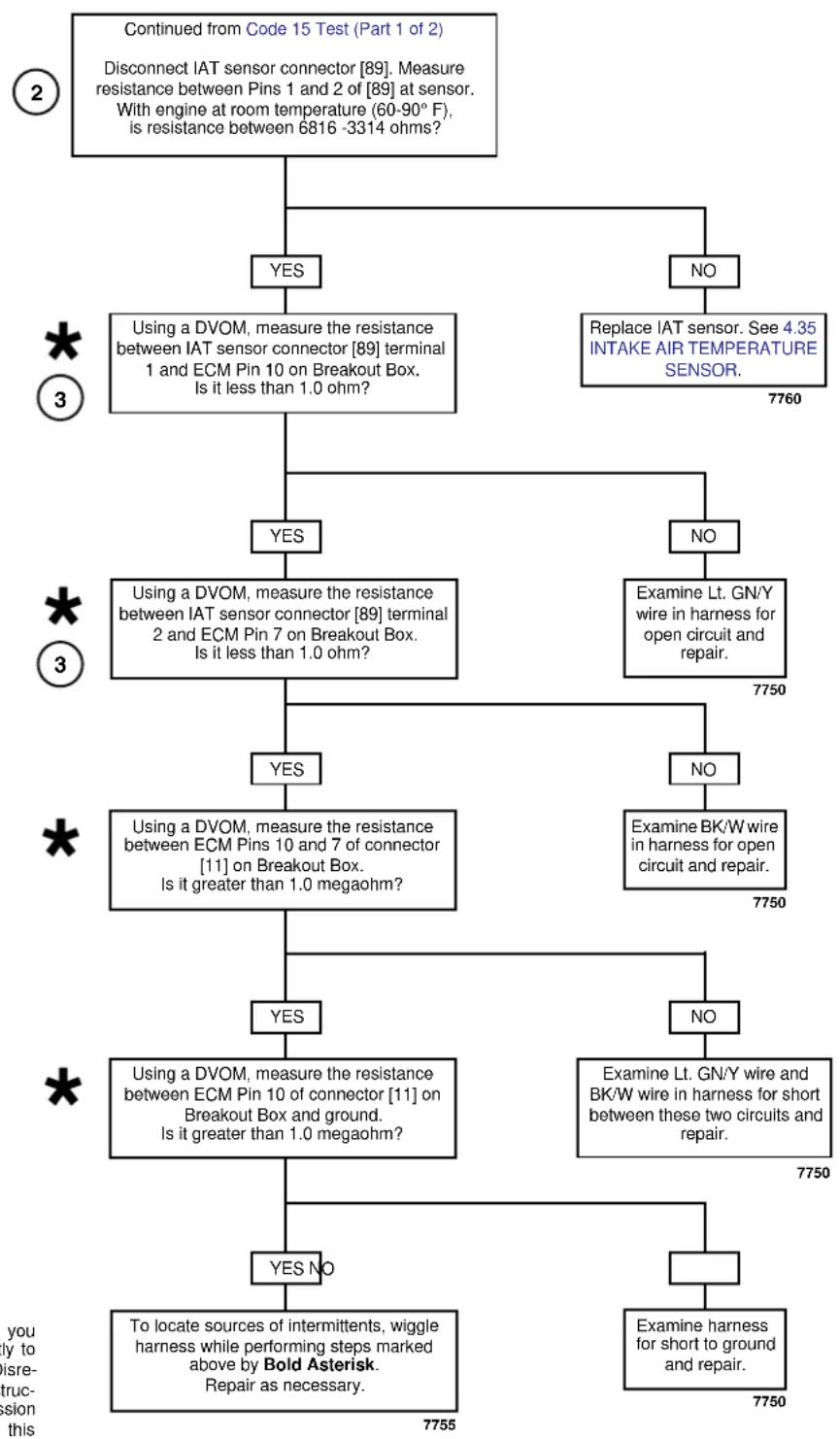
flowchart
graph TD
    A["Continued from Code 15 Test (Part 1 of 2)<br>Disconnect IAT sensor connector [89"]. Measure_resistance_between_Pins_1_and_2_of["89"] at sensor.
With engine at room temperature (60-90° F),
is resistance between 6816 -3314 ohms?] --> B{YES}
    A --> C{NO}
    B --> D["Using a DVOM, measure the resistance between IAT sensor connector [89"] terminal 1 and ECM Pin 10 on Breakout Box.
Is it less than 1.0 ohm?]
    D --> E{YES}
    D --> F{NO}
    E --> G["Using a DVOM, measure the resistance between IAT sensor connector [89"] terminal 2 and ECM Pin 7 on Breakout Box.
Is it less than 1.0 ohm?]
    G --> H{YES}
    G --> I{NO}
    H --> J["Using a DVOM, measure the resistance between ECM Pins 10 and 7 of connector [11"] on Breakout Box.
Is it greater than 1.0 megaohm?]
    J --> K{YES}
    J --> L{NO}
    K --> M["Using a DVOM, measure the resistance between ECM Pin 10 of connector [11"] on Breakout Box and ground.
Is it greater than 1.0 megaohm?]
    L --> N{YES}
    L --> O{NO}
    M --> P["To locate sources of intermittents, wiggle harness while performing steps marked above by Bold Asterisk.<br>Repair as necessary."]
    N --> Q["To locate sources of intermittents, wiggle harness while performing steps marked above by Bold Asterisk.<br>Repair as necessary."]
    O --> R["To locate sources of intermittents, wiggle harness while performing steps marked above by Bold Asterisk.<br>Repair as necessary."]

At some point in the flow chart you may be instructed to jump directly to the box marked by an asterisk. Disregard the asterisk (but not the instruction box) if your normal progression through the chart brings you to this location.
Clear codes and confirm proper operation with no check engine lamp. Codes can be cleared using DIGITAL TECHNICIAN (Part No. HD-44750).
GENERAL
Battery Voltage
A Code 16 will set if the ECM detects battery positive voltage less than 6 volts or greater than 20 volts.
● A low voltage condition typically occurs during activation of the starter or generally indicates loose wire connections.
● A high voltage condition is usually caused by a faulty voltage regulator.
DIAGNOSTICS
Diagnostic Notes
The reference numbers below correlate with the circled numbers on the Code 16 flow charts.
- The ECM is monitoring voltage at ECM connector [10] (black) Terminal 1. Connect BREAKOUT BOX (Part No. HD-42682) to ECM. See 4.6 BREAKOUT BOX.
- This checks for voltage drops in the ECM power circuit. If a significant voltage drop is not present, condition may be caused by excessive starter current draw.
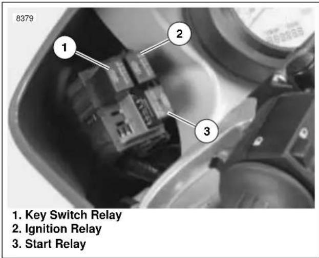
text_image
8379 1. Key Switch Relay 2. Ignition Relay 3. Start RelayFigure 4-153. Electrical Relays
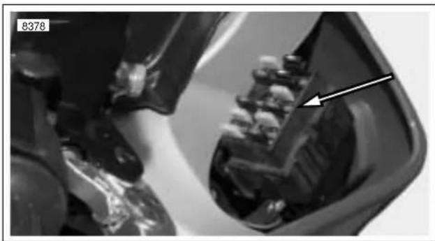
natural_image
Close-up mechanical component with a white arrow pointing to a specific part (no visible text or symbols)Figure 4-154. Fuse Block
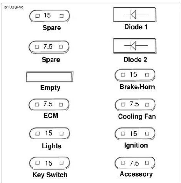
text_image
D1U03X4X □ 15 □ Spare Diode 1 □ 7.5 □ Spare Diode 2 Empty □ 15 □ Brake/Horn □ 7.5 □ ECM □ 7.5 □ Cooling Fan □ 15 □ Lights □ 15 □ Ignition □ 15 □ Key Switch □ 7.5 □ AccessoryFigure 4-155. Fuses and Diodes
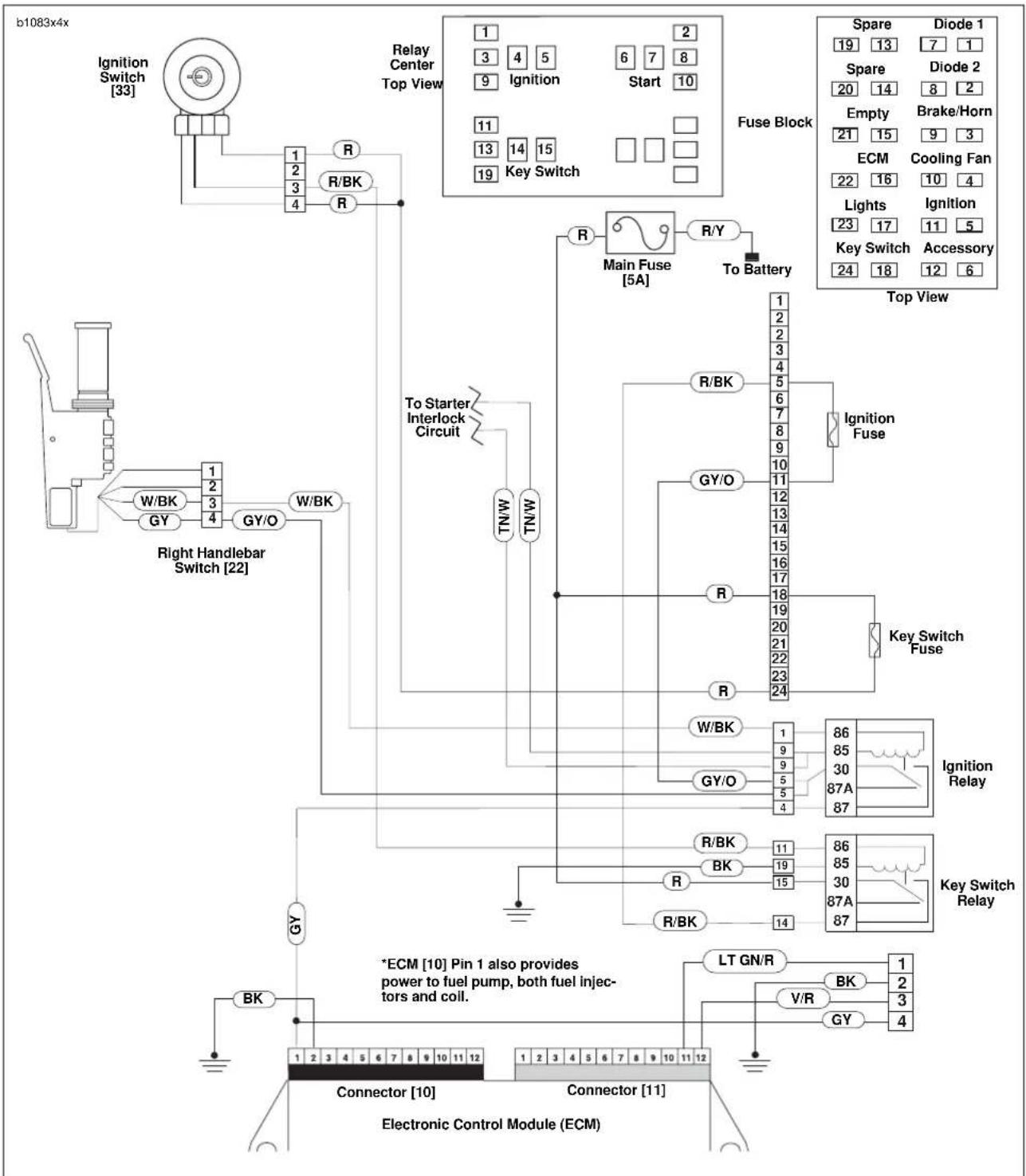
flowchart
graph TD
    A["Ignition Switch [33"]] --> B["1"]
    B --> C["R/BK"]
    C --> D["2"]
    D --> E["3"]
    E --> F["4"]
    F --> G["R"]
    G --> H["Main Fuse [5A"]]
    H --> I["R/Y"]
    I --> J["To Battery"]
    J --> K["Ignition Fuse"]
    K --> L["10"]
    L --> M["Spare 19"]
    L --> N["Diode 13"]
    L --> O["Diode 7"]
    L --> P["Diode 1"]
    L --> Q["Diode 2"]
    L --> R["Diode 2"]
    L --> S["Diode 2"]
    L --> T["Empty Brake/Horn 20"]
    L --> U["Brake/Horn 14"]
    L --> V["ECM 21"]
    L --> W["Cooling Fan 15"]
    L --> X["Lights Ignition 22"]
    L --> Y["Ignition 23"]
    L --> Z["Key Switch Accessory 16"]
    L --> AA["Key Switch Fuse 18"]
    L --> AB["Key Switch Relay 17"]
    L --> AC["Key Switch Relay 20"]
    L --> AD["Key Switch Relay 21"]
    L --> AE["Key Switch Relay 22"]
    L --> AF["Key Switch Relay 23"]
    L --> AG["Key Switch Relay 24"]
    L --> AH["Key Switch Relay 25"]
    L --> AI["Key Switch Relay 26"]
    L --> AJ["Key Switch Relay 27"]
    L --> AK["Key Switch Relay 28"]
    L --> AL["Key Switch Relay 29"]
    L --> AM["Key Switch Relay 30"]
    L --> AN["Key Switch Relay 31"]
    L --> AO["Key Switch Relay 32"]
    L --> AP["Key Switch Relay 33"]
    L --> AQ["Key Switch Relay 34"]
    L --> AR["Key Switch Relay 35"]
    L --> AS["Key Switch Relay 36"]
    L --> AT["Key Switch Relay 37"]
    L --> AU["Key Switch Relay 38"]
    L --> AV["Key Switch Relay 39"]
    L --> AW["Key Switch Relay 40"]
    L --> AX["Key Switch Relay 41"]
    L --> AY["Key Switch Relay 42"]
    L --> AZ["Key Switch Relay 43"]
    L --> BA["Key Switch Relay 44"]
    L --> BB["Key Switch Relay 45"]
    L --> BC["Key Switch Relay 46"]
    L --> BD["Key Switch Relay 47"]
    L --> BE["Key Switch Relay 48"]
    L --> BF["Key Switch Relay 49"]
    L --> BG["Key Switch Relay 50"]
    L --> BH["Key Switch Relay 51"]
    L --> BI["Key Switch Relay 52"]
    L --> BJ["Key Switch Relay 53"]
    L --> BK["Key Switch Relay 54"]
    L --> BL["Key Switch Relay 55"]
    L --> BM["Key Switch Relay 56"]
    L --> BN["Key Switch Relay 57"]
    L --> BO["Key Switch Relay 58"]
    L --> BP["Key Switch Relay 59"]
    L --> BQ["Key Switch Relay 60"]
    L --> BR["Key Switch Relay 61"]
    L --> BS["Key Switch Relay 62"]
    L --> BT["Key Switch Relay 63"]
    L --> BU["Key Switch Relay 64"]
    L --> BV["Key Switch Relay 65"]
    L --> BW["Key Switch Relay 66"]
    L --> BX["Key Switch Relay 67"]
    L --> BY["Key Switch Relay 68"]
    L --> BZ["Key Switch Relay 69"]
    L --> CA["Key Switch Relay 70"]
    L --> CB["Key Switch Relay 71"]
    L --> CC["Key Switch Relay 72"]
    L --> CD["Key Switch Relay 73"]
    L --> CE["Key Switch Relay 74"]
    L --> CF["Key Switch Relay 75"]
    L --> CG["Key Switch Relay 76"]
    L --> CH["Key Switch Relay 77"]
    L --> CI["Key Switch Relay 78"]
    L --> CJ["Key Switch Relay 79"]
    L --> CK["Key Switch Relay 80"]
    L --> CL["Key Switch Relay 81"]
    L --> CM["Key Switch Relay 82"]
    L --> CN["Key Switch Relay 83"]
    L --> CO["Key Switch Relay 84"]
    L --> CP["Key Switch Relay 85"]
    L --> CQ["Key Switch Relay 86"]
    L --> CR["Key Switch Relay 87A"]
    L --> CS["Key Switch Relay 88A"]
    L --> CT["Key Switch Relay 89A"]
    L --> CU["Key Switch Relay 90A"]
    L --> CV["Key Switch Relay 91A"]
    L --> CW["Key Switch Relay 92A"]
    L --> CX["Key Switch Relay 93A"]
    L --> CY["Key Switch Relay 94A"]
    L --> CZ["Key Switch Relay 95A"]
    L --> DA["Key Switch Relay 96A"]
    L --> DB["Key Switch Relay 97A"]
    L --> DC["Key Switch Relay 98A"]
    L --> DD["Key Switch Relay 99A"]
    L --> DE["Key Switch Relay 100A"]
Figure 4-156. Battery Voltage Circuit
Table 4-47. Wire Harness Connectors in Figure 4-156.
| NO. DESCRIPTION TYPE LOCATION | ||
| [10] ECM (black) 12-place Deutsch in fairing |
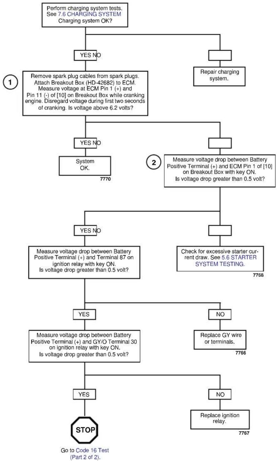
flowchart
graph TD
    A["Perform charging system tests. See 7.6 CHARGING SYSTEM Charging system OK?"] --> B{Remove spark plug cables from spark plugs. Attach Breakout Box (HD-42682) to ECM. Measure voltage at ECM Pin 1 (+) and Pin 11 (-) of["10"] on Breakout Box while cranking engine. Disregard voltage during first two seconds of cranking. Is voltage above 6.2 volts?}
    B -->|YES NO| C["System OK. 7770"]
    B -->|Repair charging system.| D{Measure voltage drop between Battery Positive Terminal (+) and_ECM_Pin_1_of["10"] on Breakout Box with key ON. Is voltage drop greater than 0.5 volt?}
    D -->|YES NO| E["Measure voltage drop between Battery Positive Terminal (+) and Terminal 87 on ignition relay with key ON. Is voltage drop greater than 0.5 volt?"]
    D -->|Check for excessive starter current draw. See 5.6 STARTER SYSTEM TESTING.| F["7768"]
    E --> G{Measure voltage drop between Battery Positive Terminal (+) and Terminal 87 on ignition relay with key ON. Is voltage drop greater than 0.5 volt?}
    G -->|YES| H["Measure voltage drop between Battery Positive Terminal (+) and GY/O Terminal 30 on ignition relay with key ON. Is voltage drop greater than 0.5 volt?"]
    G -->|NO| I["Replace GY wire or terminals. 7766"]
    H --> J{STOP}
    I --> K["Replace ignition relay. 7767"]
    J --> L["Go to Code 16 Test (Part 2 of 2)."]
Clear codes and confirm proper operation with no check engine lamp. Codes can be cleared using DIGITAL TECHNICIAN (Part No. HD-44750).
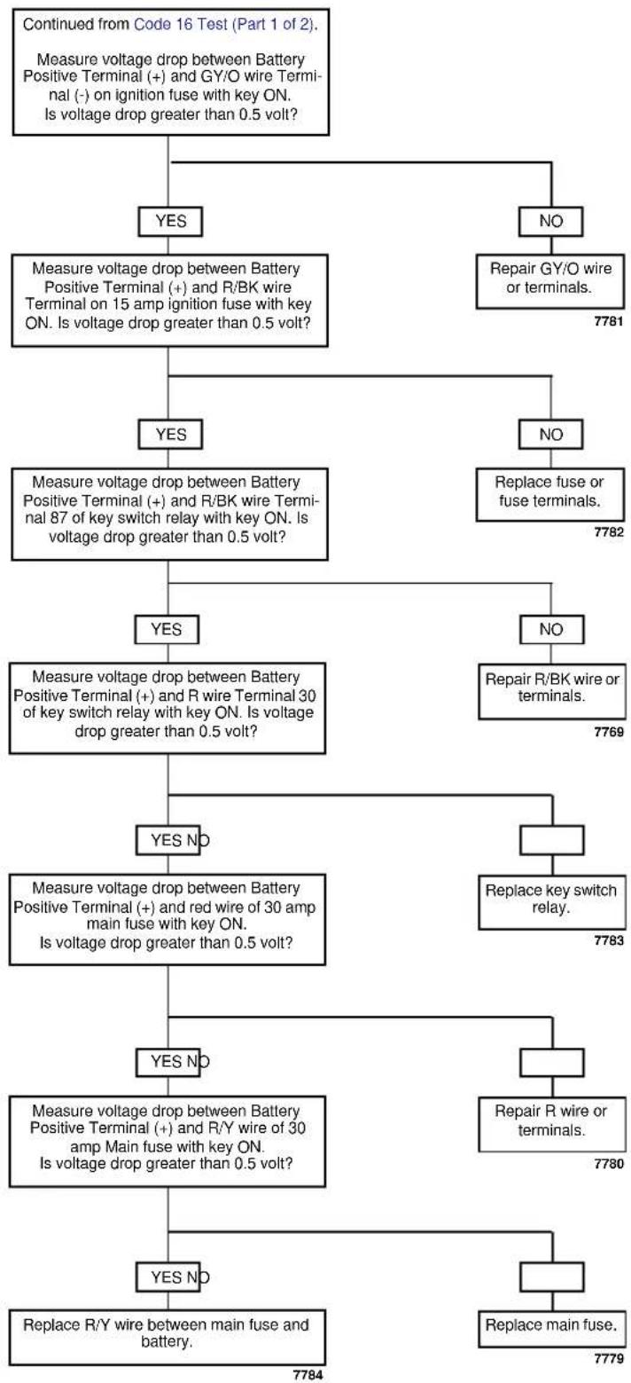
flowchart
graph TD
    A["Continued from Code 16 Test (Part 1 of 2)."] --> B{Measure voltage drop between Battery Positive Terminal (+) and GY/O wire Terminal (-) on ignition fuse with key ON. Is voltage drop greater than 0.5 volt?}
    B -->|YES| C["Measure voltage drop between Battery Positive Terminal (+) and R/BK wire Terminal on 15 amp ignition fuse with key ON. Is voltage drop greater than 0.5 volt?"]
    B -->|NO| D["Repair GY/O wire or terminals. 7781"]
    C -->|YES| E["Measure voltage drop between Battery Positive Terminal (+) and R/BK wire Terminal 87 of key switch relay with key ON. Is voltage drop greater than 0.5 volt?"]
    C -->|NO| F["Replace fuse or fuse terminals. 7782"]
    E -->|YES| G["Measure voltage drop between Battery Positive Terminal (+) and R/BK wire Terminal 30 of key switch relay with key ON. Is voltage drop greater than 0.5 volt?"]
    E -->|NO| H["Repair R/BK wire or terminals. 7769"]
    G -->|YES| I["Measure voltage drop between Battery Positive Terminal (+) and red wire of 30 amp main fuse with key ON. Is voltage drop greater than 0.5 volt?"]
    G -->|NO| J["Replace key switch relay. 7783"]
    I -->|YES| K["Measure voltage drop between Battery Positive Terminal (+) and R/Y wire of 30 amp main fuse with key ON. Is voltage drop greater than 0.5 volt?"]
    I -->|NO| L["Repair R wire or terminals. 7780"]
    K -->|YES| M["Measure voltage drop between Battery Positive Terminal (+) and R/Y wire of 30 amp main fuse with key ON. Is voltage drop greater than 0.5 volt?"]
    K -->|NO| N["Replace R/Y wire between main fuse and battery. 7784"]
    L --> O["Replace main fuse. 7779"]
Clear codes and confirm proper operation with no check engine lamp. Codes can be cleared using DIGITAL TECHNICIAN (Part No. HD-44750).
GENERAL
Front Fuel Injector (Code 23) And Rear Fuel Injector (Code 32)
See Figure 4-157. The fuel injectors (1, 4) are solenoids that allow pressurized fuel into the engine intake tract. The injectors are timed to the engine cycle and are triggered sequentially.
The power for the injectors comes from the ignition relay. The ignition relay also provides power for fuel pump, ECM, vehicle speed sensor and the ignition coils. The ECM provides the path to ground to trigger the injectors.
NOTE
Ignition relay failures or wiring harness problems will cause 12 volt power to be lost to both injectors, ignition coils, ECM, vehicle speed sensor and fuel pump.
DIAGNOSTICS
Diagnostic Notes
The reference numbers below correlate with the circled numbers on the Code 23/32 flow charts.
WARNING
The gasoline in the fuel supply line downstream of the fuel pump is under high pressure (49 psi [338 kPa]). To avoid an uncontrolled discharge or spray of gasoline, always purge the system of high pressure gas before servicing the fuel system. Gasoline is extremely flammable and highly explosive. Inadequate safety precautions could result in death or serious injury.
- Purge fuel line. See 4.38 FUEL PUMP.
- Use HARNESS CONNECTOR TEST KIT (Part No. HD-41404), purple pin probes and patch cord.
- Connect BREAKOUT BOX (Part No. HD-42682) to ECM. See 4.6 BREAKOUT BOX.
- Use HARNESS CONNECTOR TEST KIT (Part No. HD-41404), purple pin probes and patch cord to BREAKOUT BOX (Part No. HD-42682) and gray socket probes and patch cord to FUEL INJECTOR TEST LAMP (Part No. HD-34730-2C).
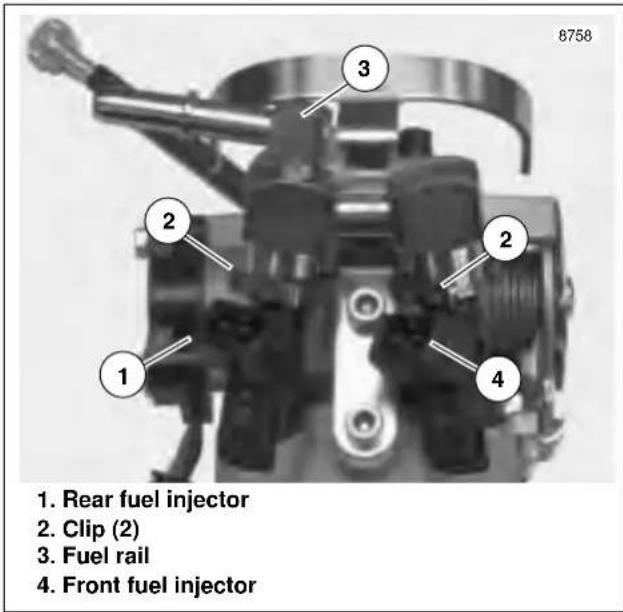
text_image
8758 1. Rear fuel injector 2. Clip (2) 3. Fuel rail 4. Front fuel injectorFigure 4-157. Fuel Injectors
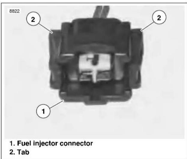
text_image
8822 2 2 1 1. Fuel injector connector 2. TabFigure 4-158. Fuel Injector Connector
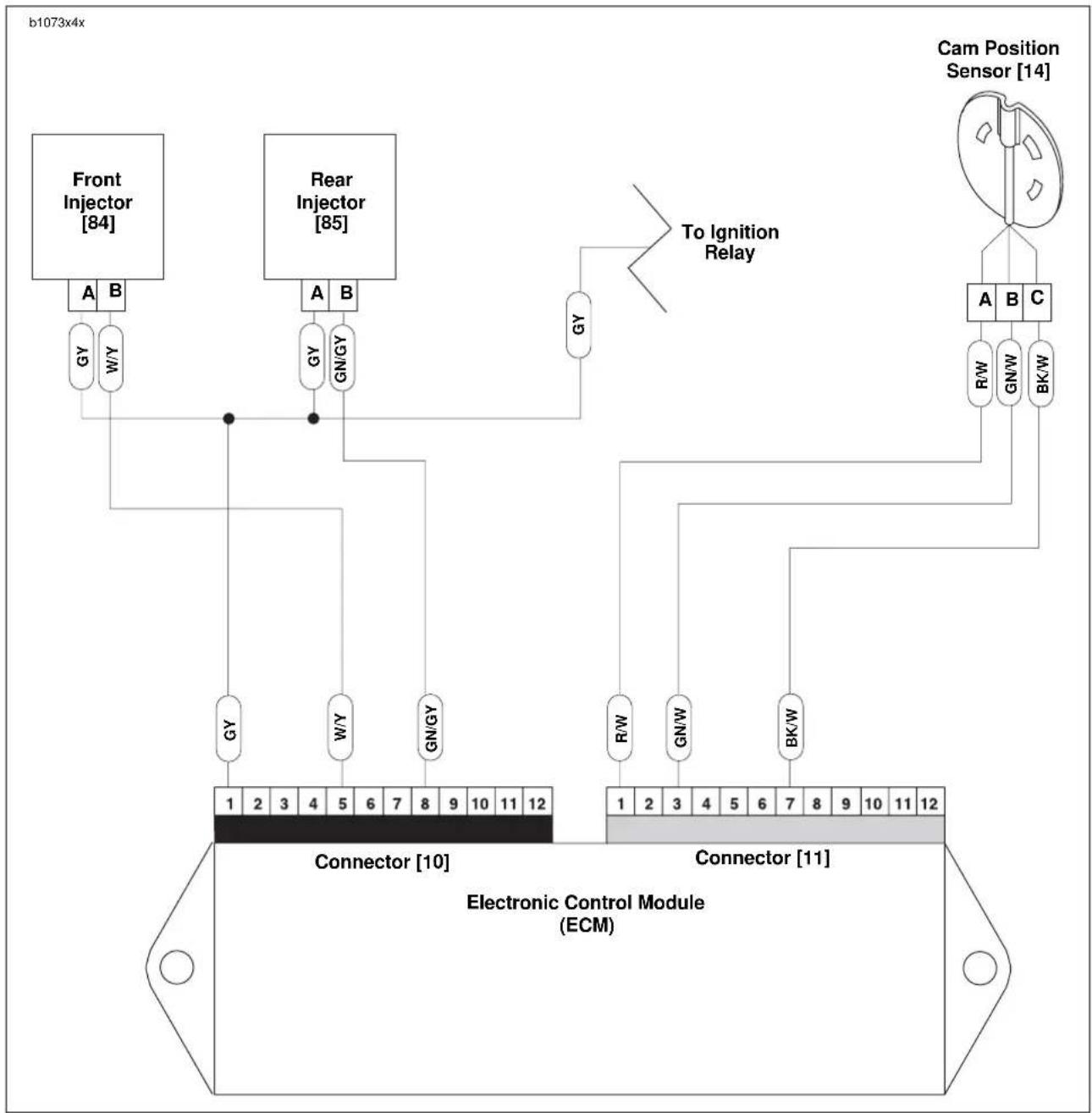
flowchart
graph TD
    A["Front Injector [84"]] -->|A B| B["Connector 10"]
    C["Rear Injector [85"]] -->|A B| D["Connector 11"]
    E["Cam Position Sensor [14"]] -->|A B C| F["Connector 12"]
    G["To Ignition Relay"] --> H["Line"]
    I["Electronic Control Module (ECM)"] --> J["Connector 10"]
    K["GY"] --> L["Connector 10"]
    M["W/Y"] --> L
    N["GN/GY"] --> L
    O["GY"] --> P["Connector 10"]
    Q["R/W"] --> R["Connector 11"]
    S["GN/W"] --> T["Connector 11"]
    U["BK/W"] --> V["Connector 11"]
    W["Ground"] --> X["1 2 3 4 5 6 7 8 9 10 11 12"]
Figure 4-159. Fuel Injector Circuit
Table 4-48. Wire Harness Connectors in Figure 4-159.
| NO. DESCRIPTION TYPE LOCATION | |||
| [10] ECM (black) 12-place Deutsch in fairing | |||
| [14] cam position sensor 3-place Deutsch under sprocket cover | |||
| [84] front fuel injector 2-place Packard underneath airbox base | |||
| [85] rear fuel injector 2-place Packard underneath airbox base | |||
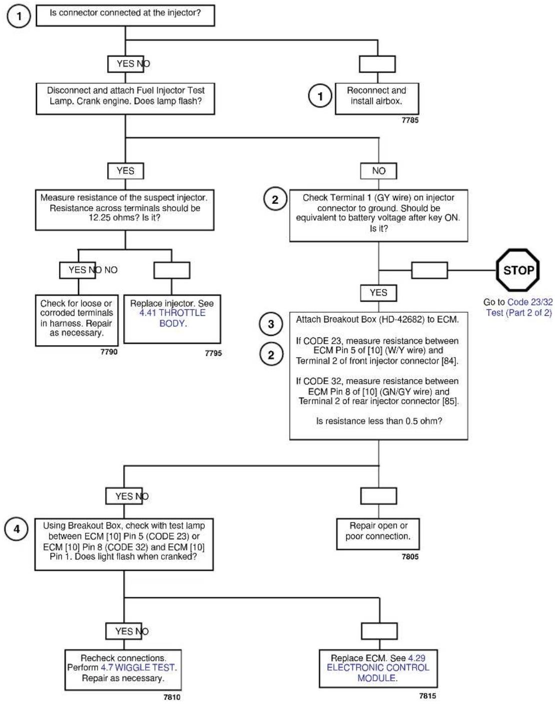
flowchart
graph TD
    A["Is connector connected at the injector?"] --> B{YES NO}
    B -->|Yes| C["Disconnect and attach Fuel Injector Test Lamp. Crank engine. Does lamp flash?"]
    B -->|No| D["Reconnect and install airbox. 7785"]
    C --> E{YES}
    D --> F{NO}
    E --> G["Measure resistance of the suspect injector. Resistance across terminals should be 12.25 ohms? Is it?"]
    F --> H{YES NO NO}
    H --> I["Check for loose or corroded terminals in harness. Repair as necessary. 7790"]
    H --> J["Replace injector. See 4.41 THROTTLE BODY. 7795"]
    G --> K{3}
    J --> L{2}
    K --> M{ATTACH Breakout Box (HD-42682) to ECM. If CODE 23, measure_resistance_between_ECM_Pin_5_of["10"] (W/Y wire) and_Terminal_2_of_front_injector_connector["84"]. If CODE 32, measure_resistance_between_ECM_Pin_8_of["10"] (GN/GY wire) and_Terminal_2_of_rear_injector_connector["85"]. Is resistance less than 0.5 ohm?}
    L --> M
    M --> N{4}
    N --> O{YES NO}
    O --> P["Using Breakout Box, check with test lamp between ECM [10"] Pin 5 (CODE 23) or_ECM["10"] Pin 8 (CODE 32) and_ECM["10"] Pin 1. Does light flash when cranked?]
    P --> Q{Yes NO}
    Q --> R["Recheck connections. Perform 4.7 WIGGLE TEST. Repair as necessary. 7810"]
    Q --> S["Replace ECM. See 4.29 ELECTRONIC CONTROL MODULE. 7815"]
    S --> T["Repair open or poor connection. 7805"]
    T --> M
    style A fill:#f9f,stroke:#333
    style B fill:#ccf,stroke:#333
    style C fill:#cfc,stroke:#333
    style D fill:#fcc,stroke:#333
    style E fill:#ffc,stroke:#333
    style F fill:#cfc,stroke:#333
    style G fill:#fcc,stroke:#333
    style H fill:#cfc,stroke:#333
    style I fill:#fcc,stroke:#333
    style J fill:#fcc,stroke:#333
    style K fill:#fcc,stroke:#333
    style L fill:#fcc,stroke:#333
    style M fill:#cfc,stroke:#333
    style N fill:#fcc,stroke:#333
    style O fill:#fcc,stroke:#333
    style P fill:#fcc,stroke:#333
    style Q fill:#fcc,stroke:#333
    style R fill:#fcc,stroke:#333
    style S fill:#fcc,stroke:#333
Clear codes and confirm proper operation with no check engine lamp. Codes can be cleared using DIGITAL TECHNICIAN (Part No. HD-44750).
HOME
Code 23/32 Test (Part 2 of 2)
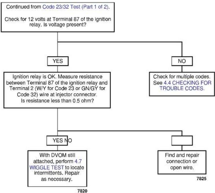
flowchart
graph TD
    A["Continued from Code 23/32 Test (Part 1 of 2). Check for 12 volts at Terminal 87 of the ignition relay. Is voltage present?"] --> B{YES}
    A --> C{NO}
    B --> D["Ignition relay is OK. Measure resistance between Terminal 87 of the ignition relay and Terminal 2 (W/Y for Code 23 or GN/GY for Code 32) wire at injector connector. Is resistance less than 0.5 ohm?"]
    C --> E["Check for multiple codes. See 4.4 CHECKING FOR TROUBLE CODES."]
    D --> F{YES NO}
    D --> G{No}
    F --> H["With DVOM still attached, perform 4.7 WIGGLE TEST to locate intermittents. Repair as necessary."]
    G --> I["Find and repair connection or open wire."]
Clear codes and confirm proper operation with no check engine lamp. Codes can be cleared using DIGITAL TECHNICIAN (Part No. HD-44750).
GENERAL
Front Ignition Coil (Code 24) And Rear Ignition Coil (Code 25)
A Code 24 or 25 will set if the ignition coil rise time is out of range. This could occur if there is an open coil or loss of power to the coil. If both codes are set, it is likely a coil power failure or a coil failure.
See Figure 4-160. The coil receives power from the ignition relay at coil pin B (3) at the same time that the fuel pump and injectors are activated.
DIAGNOSTICS
Diagnostic Notes
The reference numbers below correlate with the circled numbers on the Code 24/25 flow charts.
-
Use HARNESS CONNECTOR TEST KIT (Part No. HD-41404), purple pin probes and patch cord.
-
Connect BREAKOUT BOX (Part No. HD-42682) to ECM. See 4.6 BREAKOUT BOX.
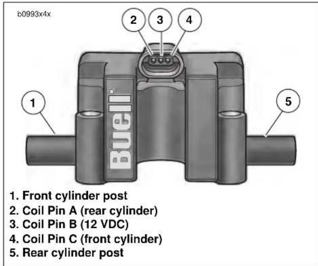
text_image
b0993x4x 1. Front cylinder post 2. Coil Pin A (rear cylinder) 3. Coil Pin B (12 VDC) 4. Coil Pin C (front cylinder) 5. Rear cylinder postFigure 4-160. Ignition Coil
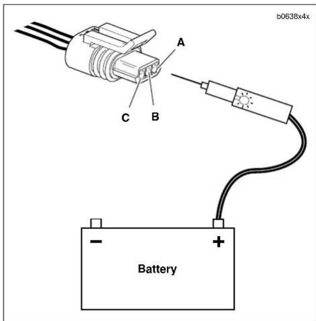
text_image
b0638x4x A C B BatteryFigure 4-161. Testing Ignition Coil Connectors
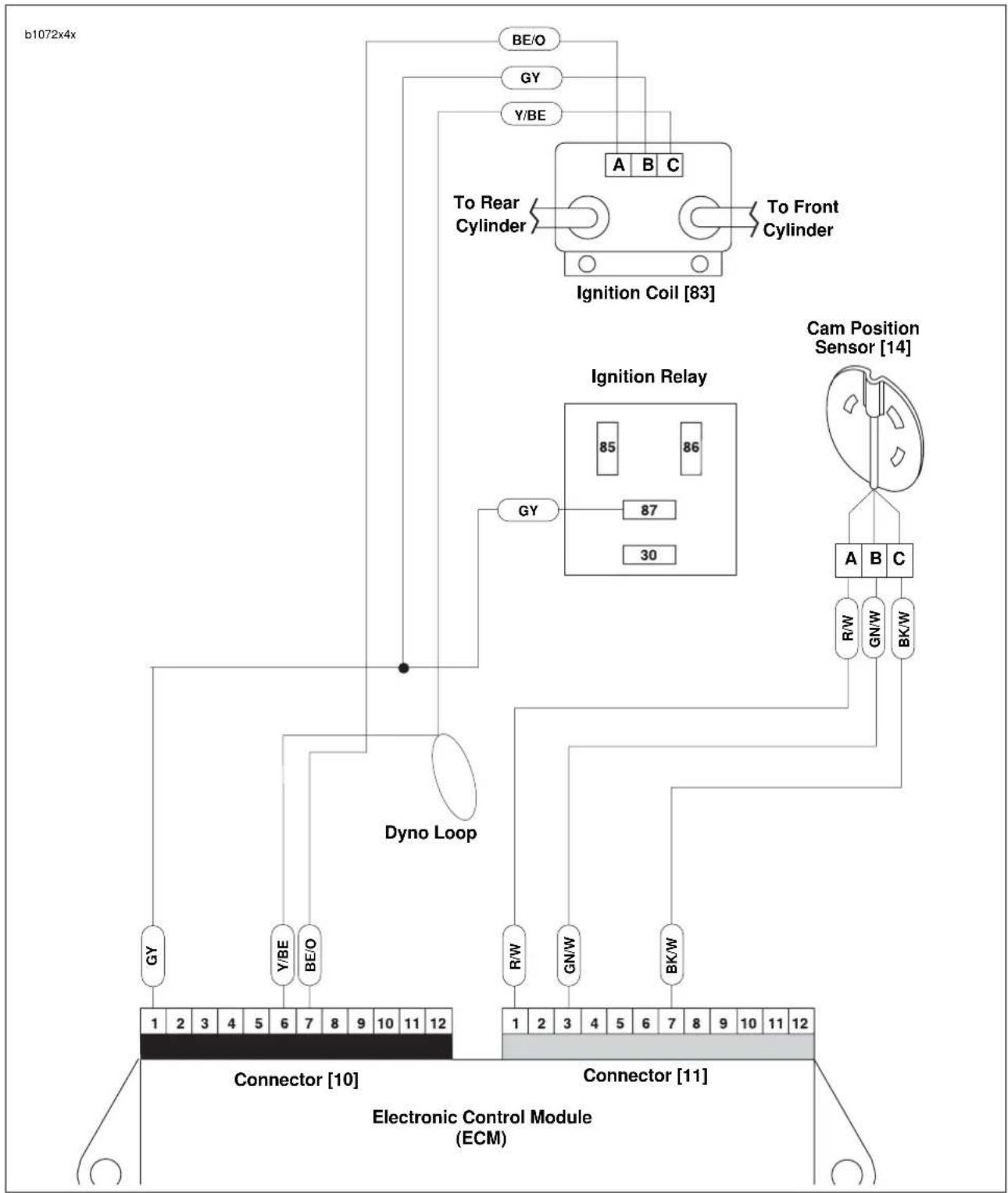
flowchart
graph TD
    A["Electronic Control Module (ECM)"] --> B["Connector [10"]]
    A --> C["Connector [11"]]
    B --> D["Dyno Loop"]
    C --> E["Dyno Loop"]
    D --> F["BY"]
    D --> G["Y/BE"]
    D --> H["BE/O"]
    E --> I["R/W"]
    E --> J["GN/W"]
    E --> K["BK/W"]
    F --> L["BY"]
    G --> M["Y/BE"]
    H --> N["BY"]
    I --> O["BY"]
    J --> P["BY"]
    K --> Q["BY"]
    L --> R["A"]
    M --> S["B"]
    N --> T["C"]
    O --> U["A"]
    P --> V["B"]
    Q --> W["C"]
    R --> X["BY"]
    S --> Y["BY"]
    T --> Z["BY"]
    U --> AA["BY"]
    V --> AB["C"]
    W --> AC["BY"]
    X --> AD["A"]
    Y --> AE["B"]
    Z --> AF["C"]
    AA --> AG["BY"]
    AB --> AH["BY"]
    AC --> AI["BY"]
    AD --> AJ["BY"]
    AE --> AK["BY"]
    AF --> AL["BY"]
    AG --> AM["A"]
    AH --> AN["B"]
    AI --> AO["C"]
    AJ --> AP["BY"]
    AK --> AQ["BY"]
Figure 4-162. Ignition Coil Circuit
Table 4-49. Wire Harness Connectors in Figure 4-162.
| NO. DESCRIPTION TYPE LOCATION | |||
| [10] ECM (black) 12-place Deutsch under fairing | |||
| [83] ignition coil 3-place Packard beneath airbox base | |||
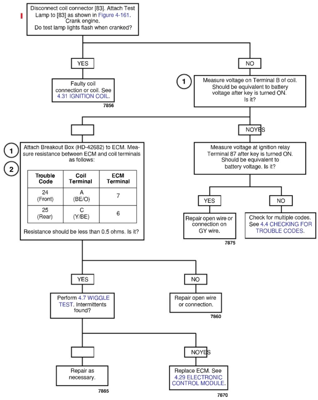
flowchart
graph TD
    A["Disconnect coil connector [83"]. Attach_Test_Lamp_to["83"] as shown in Figure 4-161. Crank engine. Do test lamp lights flash when cranked?] --> B{Yes}
    A --> C{NO}
    B --> D["Faulty coil connection or coil. See 4.31 IGNITION COIL."]
    C --> E{Measure voltage on Terminal B of coil. Should be equivalent to battery voltage after key is turned ON. Is it?}
    D --> F{NOYES}
    E --> G{Measure voltage at ignition relay Terminal 87 after key is turned ON. Should be equivalent to battery voltage. Is it?}
    G --> H{YES}
    G --> I{NO}
    H --> J["Repair open wire or connection on GY wire."]
    I --> K["Check for multiple codes. See 4.4 CHECKING FOR TROUBLE CODES."]
    J --> L{YES}
    J --> M{NO}
    L --> N["Perform 4.7 WIGGLE TEST. Intermittents found?"]
    M --> O["Repair open wire or connection."]
    N --> P{No}
    O --> Q["Repair as necessary."]
    P --> R["Repair as necessary."]
    Q --> S["Replace ECM. See 4.29 ELECTRONIC CONTROL MODULE."]
Clear codes and confirm proper operation with no check engine lamp. Codes can be cleared using DIGITAL TECHNICIAN (Part No. HD-44750).
GENERAL
Fuel Pump
The fuel pump assembly is shown in Figure 4-163. ECM Pin 3 provides ground to the fuel pump. Code 33 will set if:
● BN/Y wire is shorted to 12 volts. This will also cause the ignition fuse to blow. See Figure 4-164.
- BN/Y wire is shorted to ground. This will cause the fuel pump to run continuously even when the motor is not running.
● Fuel pump motor stalls or spins without providing fuel pressure.
DIAGNOSTICS
Diagnostic Notes
The reference numbers below correlate with the circled numbers on the Code 33 flow chart.
- Connect BREAKOUT BOX (Part No. HD-42682) to ECM. See 4.6 BREAKOUT BOX.
- Use HARNESS CONNECTOR TEST KIT (Part No. HD-41404), red pin probe and patch cord.
- Use HARNESS CONNECTOR TEST KIT (Part No. HD-41404), gray socket probe and patch cord.
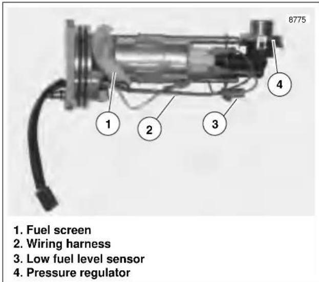
text_image
8775 1. Fuel screen 2. Wiring harness 3. Low fuel level sensor 4. Pressure regulatorFigure 4-163. Fuel Pump Assembly
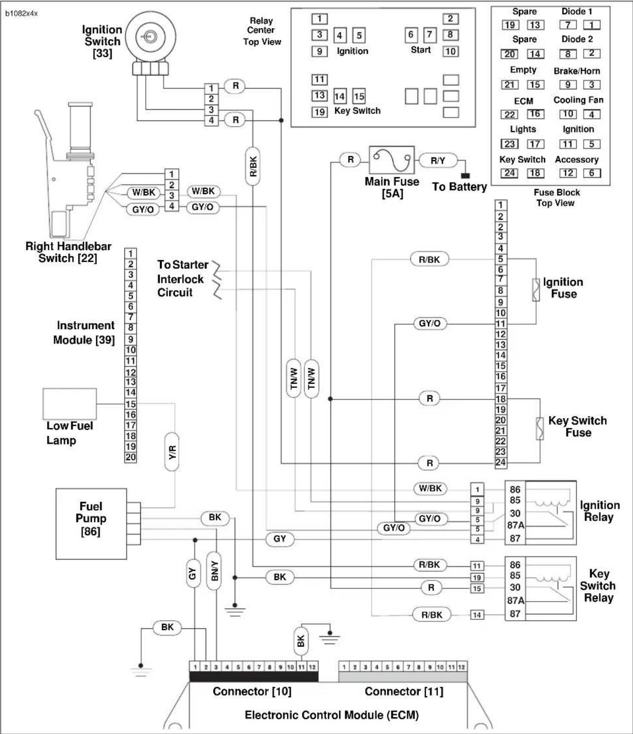
flowchart
graph TD
    A["Ignition Switch [33"]] --> B["R"]
    B --> C["Relay Center Top View"]
    C --> D["Main Fuse [5A"]]
    D --> E["To Battery"]
    E --> F["Fuse Block Top View"]
    G["Right Handlebar Switch [22"]] --> H["W/BK 1/2 3/4"]
    H --> I["W/BK 1/2 3/4"]
    I --> J["To Starter Interlock Circuit"]
    K["Instrument Module [39"]] --> L["TN/W 10/15 17/18 19/20"]
    L --> M["Y/R"]
    N["Fuel Pump [86"]] --> O["BK"]
    O --> P["BN/Y"]
    P --> Q["Low Fuel Lamp"]
    R["Spare 19 13 7 1"] --> S["Diode 1"]
    T["Spare 20 14 8 2"] --> U["Diode 2"]
    V["Empty 21 15 9 3"] --> W["Brake/Horn"]
    X["ECM 22 16 10 4"] --> Y["Cooling Fan"]
    Z["Lights 23 17 11 5"] --> AA["Ignition"]
    AB["Key Switch 24 18 12 6"] --> AC["Accessory"]
Figure 4-164. Fuel Pump Circuit
Table 4-50. Wire Harness Connectors in Figure 4-164.
| NO. DESCRIPTION TYPE LOCATION | ||
| [10] ECM (black) 12-place Deutsch in fairing | ||
| [39] instrument module 20-place Multilock in fairing | ||
| [86] fuel pump 4-place Multilock left side of rear shock absorber |
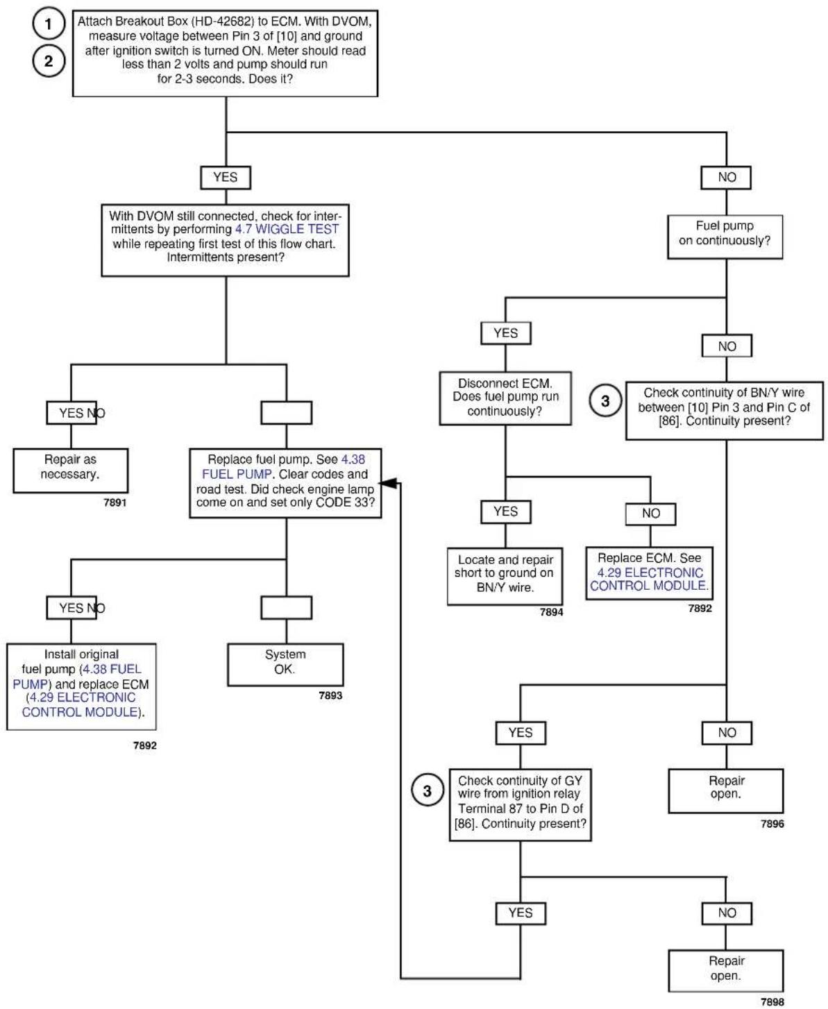
flowchart
graph TD
    A["1 Attach Breakout Box (HD-42682) to ECM. With DVOM, measure voltage between Pin 3 of [10"] and ground after ignition switch is turned ON. Meter should read less than 2 volts and pump should run for 2-3 seconds. Does it?] --> B{YES}
    B -->|Yes| C["With DVOM still connected, check for intermittents by performing 4.7 WIGGLE TEST while repeating first test of this flow chart. Intermittents present?"]
    B -->|No| D["NO Fuel pump on continuously?"]
    C --> E{YES NO}
    C --> F{No}
    E --> G["Repair as necessary. 7891"]
    F --> H["Replace fuel pump. See 4.38 FUEL PUMP. Clear codes and road test. Did check engine lamp come on and set only CODE 33?"]
    H --> I{YES NO}
    H --> J{No}
    I --> K["Install original fuel pump (4.38 FUEL PUMP) and replace ECM (4.29 ELECTRONIC CONTROL MODULE). 7892"]
    J --> L["System OK. 7893"]
    D --> M{YES}
    D --> N{NO}
    M --> O["Disconnect ECM. Does fuel pump run continuously?"]
    N --> P["Check continuity of BN/Y wire between [10"] Pin_3_and_Pin_C_of["86"]. Continuity present?]
    P --> Q{YES}
    P --> R{NO}
    Q --> S["Locate and repair short to ground on BN/Y wire. 7894"]
    R --> T["Replace ECM. See 4.29 ELECTRONIC CONTROL MODULE. 7892"]
    T --> U{YES}
    T --> V{NO}
    U --> W["Check continuity of GY wire from ignition relay Terminal 87 to Pin D of [86"]. Continuity present?]
    V --> X["Repair open. 7896"]
    W --> Y{YES}
    W --> Z{NO}
    X --> AA["Repair open. 7898"]
Clear codes and confirm proper operation with no check engine lamp. Codes can be cleared using DIGITAL TECHNICIAN (Part No. HD-44750).
GENERAL
Tachometer
A Code 35 will set if the PK tachometer wire is shorted to power or ground.
DIAGNOSTICS
Diagnostic Notes
The reference numbers below correlate with the circled numbers on the Code 35 flow chart.
- Connect BREAKOUT BOX (Part No. HD-42682) to ECM. See 4.6 BREAKOUT BOX.
- Replace instrument module. See 7.17 INSTRUMENT MODULE.
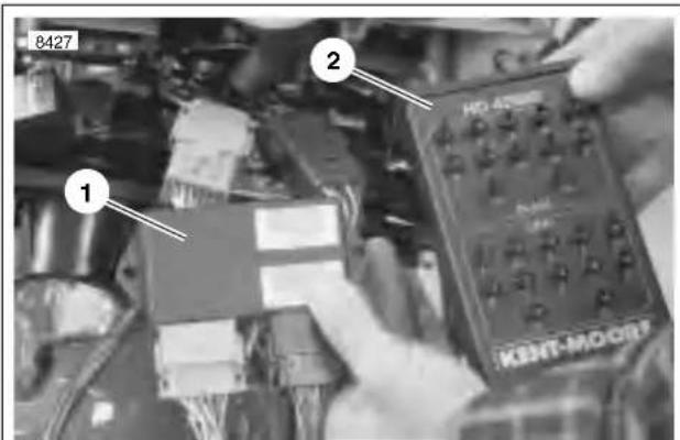
text_image
8427 1 2 HD-400 KENT-MOOR- ECM
- Breakout box
Figure 4-165. Installed Breakout Box
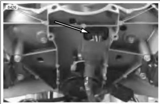
natural_image
Close-up mechanical assembly showing internal components and a highlighted arrow (no text or symbols)Figure 4-166. Instrument Module Connector [39]
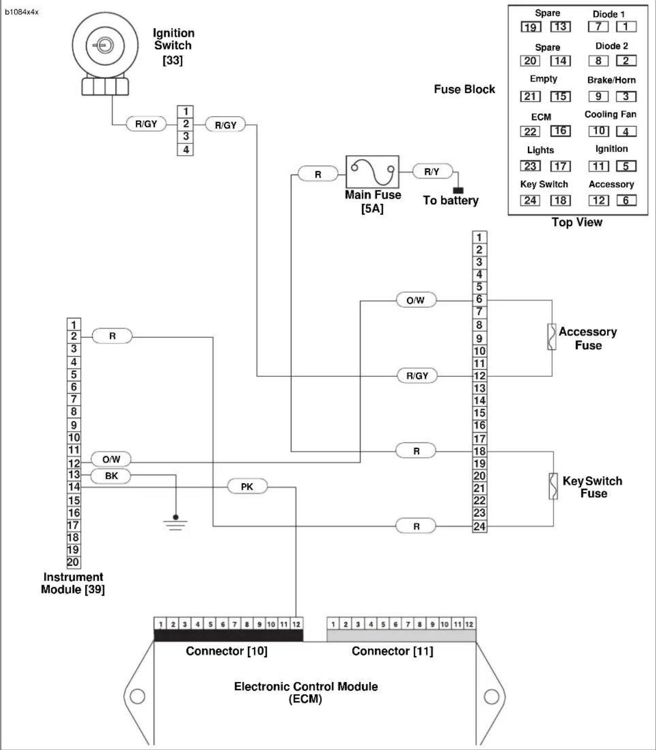
flowchart
graph TD
    A["Ignition Switch [33"]] --> B["R/GY"]
    B --> C["1/2/3/4"]
    C --> D["R/GY"]
    D --> E["Fuse Block"]
    E --> F["R"]
    F --> G["Main Fuse [5A"]]
    G --> H["R/Y"]
    H --> I["To battery"]
    I --> J["Top View"]
    K["Instrument Module [39"]] --> L["1/2/3/4/5/6/7/8/9/10/11/12"]
    L --> M["R/W BK"]
    M --> N["O/W"]
    N --> O["R"]
    O --> P["PK"]
    P --> Q["R"]
    Q --> R["KeySwitch Fuse"]
    R --> S["Accessory Fuse"]
    S --> T["Spare 19 Diode 1 7 1"]
    S --> U["Spare 20 Diode 2 8 2"]
    S --> V["Empty Brake/Horn 21 15 9 3"]
    S --> W["ECM Cooling Fan 22 16 10 4"]
    S --> X["Lights Ignition 23 17 11 5"]
    S --> Y["Key Switch Accessory 24 18 12 6"]
    R --> Z["Connector [10"] Connector["11"]]
    AA["Electronic Control Module (ECM)"] --> AB["1 2 3 4 5 6 7 8 9 10 11 12"]
Figure 4-167. Tachometer Circuit
Table 4-51. Wire Harness Connectors in Figure 4-167.
| NO. DESCRIPTION TYPE LOCATION | ||
| [10] ECM (black) 12-place Deutsch in fairing | ||
| [39] instrument module 20-place Multilock in fairing |
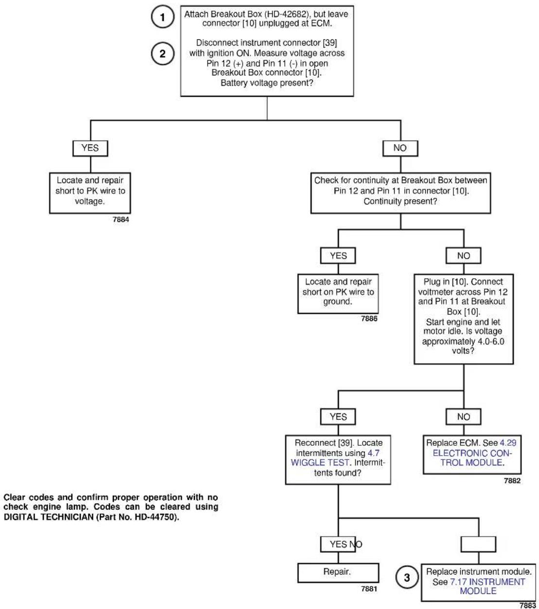
flowchart
graph TD
    A["1 Attach Breakout Box (HD-42682), but leave connector [10"] unplugged at ECM.] --> B["2 Disconnect instrument connector [39"] with ignition ON. Measure voltage across Pin 12 (+) and Pin 11 (-) in_open_Breakout_Box_connector["10"]. Battery voltage present?]
    A --> C{YES}
    A --> D{NO}
    C --> E["Locate and repair short to PK wire to voltage. 7884"]
    D --> F{Check_for_continuity_at_Breakout_Box_between_Pin_12_and_Pin_11_in_connector["10"]. Continuity present?}
    F --> G{YES}
    F --> H{NO}
    G --> I["Locate and repair short on PK wire to ground. 7886"]
    H --> J["Plug in [10"]. Connect_voltmeter_across_Pin_12_and_Pin_11_at_Breakout_Box["10"]. Start engine and let motor idle. Is voltage approximately 4.0-6.0 volts?]
    J --> K{YES}
    J --> L{NO}
    K --> M["Reconnect [39"]. Locate intermittents using 4.7 WIGGLE TEST. Intermittents found?]
    L --> N["Replace ECM. See 4.29 ELECTRONIC CONTROL MODULE. 7882"]
    M --> O{YES NO}
    M --> P{Repair. 7881}
    N --> Q{3}
    Q --> R["Replace instrument module. See 7.17 INSTRUMENT MODULE 7883"]
GENERAL
Cooling Fan High Voltage
This code occurs when the engine is running and the ECM has commanded the fan on, and the voltage remains high at pin 6 of ECM connector [11] (gray connector).
NOTE
An engine temperature (ET) sensor signal, indicating a cylinder head temperature above 428^ F ( 220^ C), causes the ECM to command the fan on. When ignition is OFF, fan runs at approximately half speed. See Table 4-52. Cooling Fan Specifications.
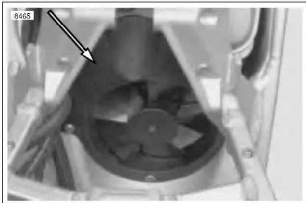
natural_image
Close-up of a mechanical device interior with a highlighted component and arrow indicator (no readable text or symbols)Figure 4-168. Cooling Fan
Table 4-52. Cooling Fan Specifications
| FAN ON FAN OFF | |
| Key ON | 220°C (428°F) 180°C (356°F) |
| Key OFF 1 | 70°C (338°F) 150°C (302°F) |
This code can also set if fan blade does not spin (blocked fan blade) when fan is commanded on and battery voltage is applied to fan.
Cooling Fan Low Voltage
This code will set when the ignition key is ON and the ECM does not sense voltage at pin 6 of ECM terminal 11 (gray connector).
DIAGNOSTICS
Diagnostic Notes
The reference numbers below correlate with the circled numbers on the Code 36 flow charts.
-
Use HARNESS CONNECTOR TEST KIT (Part No. HD-41404), gray pin probes and patch cord.
-
Connect BREAKOUT BOX (Part No. HD-42682) to ECM. See 4.6 BREAKOUT BOX.
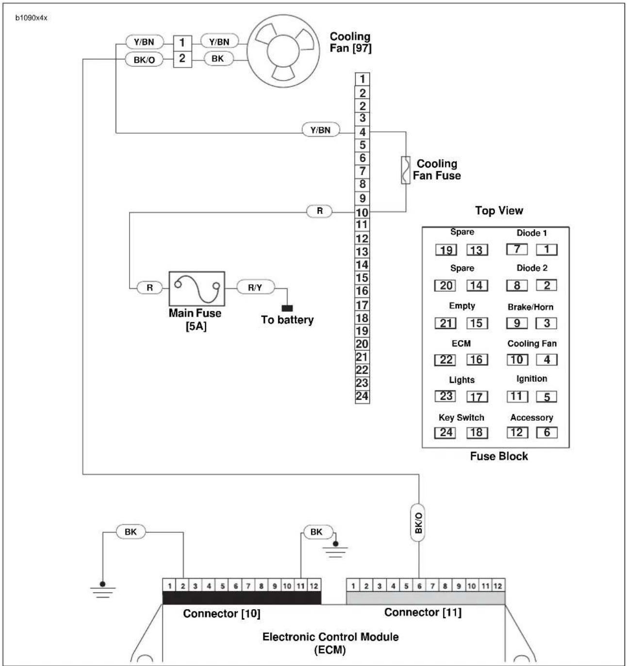
flowchart
graph TD
    A["Main Fuse [5A"]] -->|R/Y| B["To battery"]
    B --> C["Cooling Fan Fuse"]
    C --> D["Top View"]
    D --> E["Spare 19 13 7 1"]
    D --> F["Spare 20 14 8 2"]
    D --> G["Empty 21 15 9 3"]
    D --> H["ECM 22 16 10 4"]
    D --> I["Lights 23 17 11 5"]
    D --> J["Key Switch 24 18 12 6"]
    K["BY/NB"] --> L["1"]
    M["BK/O"] --> N["2"]
    O["Y/BN"] --> P["1"]
    Q["Y/BN"] --> R["2"]
    S["Cooling Fan [97"]] --> T["1"]
    U["Y/BN"] --> V["4"]
    W["R"] --> X["10"]
    Y["R"] --> Z["11"]
    AA["Electronic Control Module (ECM)"] --> AB["1 2 3 4 5 6 7 8 9 10 11 12"]
    AC["Fuse Block"] --> AD["1 2 3 4 5 6 7 8 9 10 11 12"]
Figure 4-169. Cooling Fan Circuit
Table 4-53. Wire Harness Connectors in Figure 4-169.
| NO. DESCRIPTION TYPE LOCATION | ||
| [11] ECM (gray) 12-place Deutsch in fairing | ||
| [97] cooling fan 2-place Multilock behind rear cylinder |
HOME
Code 36 Test (Part 1 of 2-fan runs continuously)
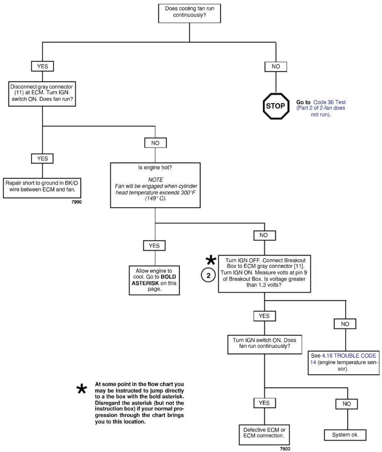
flowchart
graph TD
    A["Does cooling fan run continuously?"] --> B{YES}
    A --> C{NO}
    B --> D["Disconnect gray connector (11) at ECM. Turn IGN. switch ON. Does fan run?"]
    D --> E{YES}
    D --> F{NO}
    E --> G["Repair short to ground in BK/O wire between ECM and fan. 7900"]
    F --> H{Is engine hot?}
    H --> I{NOTE Fan will be engaged when cylinder head temperature exceeds 300°F (149°C).}
    I --> J{YES}
    I --> K{NO}
    J --> L["Allow engine to cool. Go to BOLD ASTERISK on this page."]
    K --> M{Turn IGN OFF. Connect_Breakout_Box_to_ECM_gray_connector["11"]. Turn IGN ON. Measure volts at pin 9 of Breakout Box. Is voltage greater than 1.3 volts?}
    M --> N{YES}
    M --> O{NO}
    N --> P["Turn IGN switch ON. Does fan run continuously?"]
    O --> Q["See 4.18 TROUBLE CODE 14 (engine temperature sensor)."]
    P --> R{YES}
    P --> S{NO}
    R --> T["Defective ECM or ECM connection. 7902"]
    S --> U["System ok."]
    T --> V["7902"]
    U --> W["Go to Code 36 Test (Part 2 of 2-fan does not run)."]
    V --> X["STOP"]
Code 36 Test (Part 2 of 2-fan does not run)
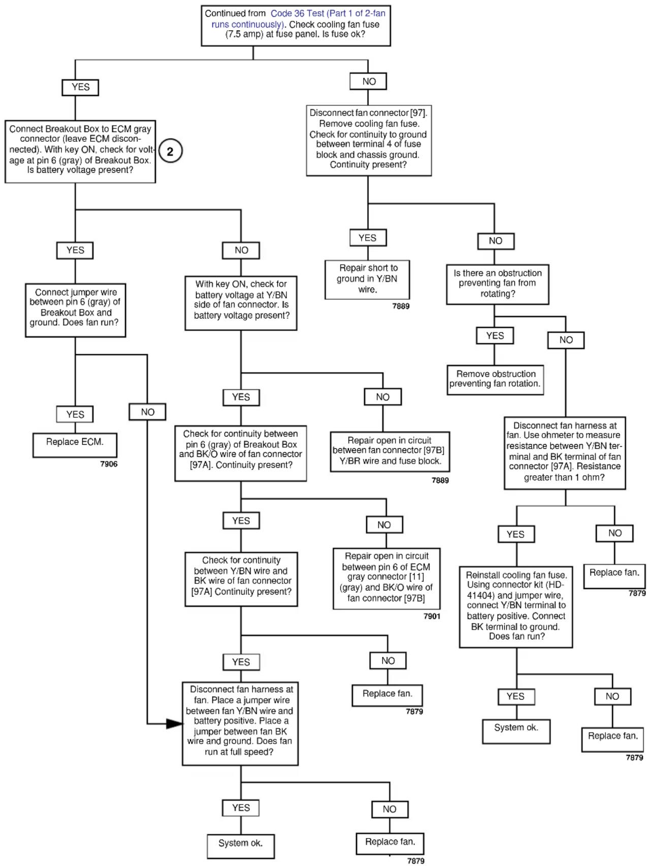
flowchart
graph TD
    A["Continued from Code 36 Test (Part 1 of 2-fan runs continuously). Check cooling fan fuse (7.5 amp) at fuse panel. Is fuse ok?"] --> B{YES}
    A --> C{NO}
    B --> D["Connect Breakout Box to ECM gray connector (leave ECM disconnected). With key ON, check for voltage at pin 6 (gray) of Breakout Box. Is battery voltage present?"]
    D --> E{YES}
    D --> F{NO}
    E --> G["Connect jumper wire between pin 6 (gray) of Breakout Box and ground. Does fan run?"]
    G --> H{YES}
    G --> I{NO}
    H --> J["Replace ECM. 7906"]
    I --> K{NO}
    K --> L["Check for continuity between pin 6 (gray) of Breakout Box and BK/O wire of fan connector [97A"]. Continuity present?]
    L --> M{YES}
    L --> N{NO}
    M --> O["Check for continuity between pin 6 (gray) of Breakout Box and BK/O wire of fan connector [97A"]. Continuity present?]
    N --> P["Repair open in circuit between pin 6 of ECM gray connector [11"] (gray) and BK/O_wire_of_fan_connector["97B"]. Continuity present?]
    P --> Q{YES}
    P --> R{NO}
    Q --> S["Disconnect fan harness at fan. Place a jumper wire between fan Y/BN wire and battery positive. Place a jumper between fan BK wire and ground. Does fan run at full speed?"]
    R --> T{YES}
    R --> U{NO}
    T --> V["System ok."]
    U --> W["System ok."]
    V --> X["Replace fan. 7879"]
    W --> Y["Replace fan. 7879"]
    X --> Z["Reinstall cooling fan fuse. Using connector kit (HD-41404) and jumper wire, connect Y/BN terminal to battery positive. Connect BK terminal to ground. Does fan run?"]
    Y --> AA["Yes"]
    Y --> AB["No"]
    Z --> AC["System ok."]
    AA --> AD["No"]
    AB --> AE["No"]
    F --> AF{YES}
    F --> AG{NO}
    AF --> AH["Repair short to ground in Y/BN wire. 7889"]
    AG --> AI["Is there an obstruction preventing fan from rotating?"]
    AI --> AJ{YES}
    AI --> AK{NO}
    AJ --> AL["Remove obstruction preventing fan rotation."]
    AK --> AM["Disconnect fan harness at fan. Use ohmeter to measure resistance between Y/BN terminal and BK terminal of fan connector [97A"]. Resistance greater than 1 ohm?]
GENERAL
NOTE
See Figure 4-171. When vehicle lean angle causes weighted pendulum to enter shaded area for a period of greater than one second, ECM shuts off ignition and fuel systems.
Bank Angle Sensor
See Figure 4-170. A Code 44 occurs when the bank angle sensor (1) voltage is outside the normal operating range of 0.25-4.8 volts. This may be caused by:
● Short to ground in harness between sensor and electronic control module.
● Short to voltage in harness between sensor and electronic control module.
- Failed sensor.
If this code occurs, the engine may stop running. The engine may still be restarted and ridden to the dealership for repair.
DIAGNOSTICS
Diagnostic Notes
The reference numbers below correlate with the circled numbers on the Code 44 flow charts.
- Use HARNESS CONNECTOR TEST KIT (Part No. HD-41404), gray pin probes and patch cord.
- Connect BREAKOUT BOX (Part No. HD-42682) to ECM. See 4.6 BREAKOUT BOX.
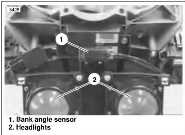
text_image
8428 1. Bank angle sensor 2. HeadlightsFigure 4-170. Bank Angle Sensor
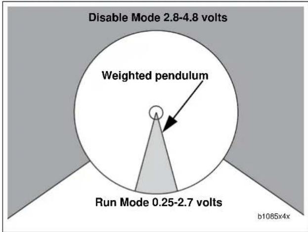
text_image
Disable Mode 2.8-4.8 volts Weighted pendulum Run Mode 0.25-2.7 volts b1085x4xFigure 4-171. Bank Angle Sensor Operation
Table 4-54. Bank Angle Sensor Voltage
| MODE VOLTS | |
| Run mode 0.25-2.7 volts | |
| Disable mode 2.8-4.8 volts |
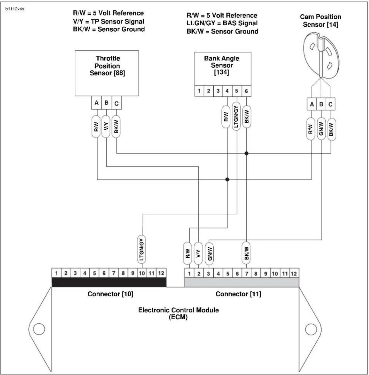
flowchart
graph TD
    A["Throttle Position Sensor [88"]] -->|R/W = 5 Volt Reference\nV/Y = TP Sensor Signal\nBK/W = Sensor Ground| B["Cap Position Sensor [14"]]
    C["Bank Angle Sensor [134"]] -->|R/W = 5 Volt Reference\nLt.GN/GY = BAS Signal\nBK/W = Sensor Ground| D["Cam Position Sensor [14"]]
    E["LTGN/GY"] --> F["Connector [10"]]
    G["R/W"] --> H["Connector [11"]]
    I["V/Y"] --> H
    J["GN/W"] --> H
    K["BK/W"] --> H
    L["1"] --> M["Connector [10"]]
    N["2"] --> O["Connector [11"]]
    P["3"] --> Q["Connector [10"]]
    R["4"] --> S["Connector [11"]]
    T["5"] --> U["Connector [10"]]
    V["6"] --> W["Connector [11"]]
    X["7"] --> Y["Connector [10"]]
    Z["8"] --> AA["Connector [11"]]
    AB["9"] --> AC["Connector [10"]]
    AD["10"] --> AE["Connector [11"]]
    AF["11"] --> AG["Connector [10"]]
    AH["12"] --> AI["Connector [11"]]
    AJ["ECM"] --> AK["Electronic Control Module (ECM)"]
    style A fill:#f9f,stroke:#333
    style C fill:#f9f,stroke:#333
    style E fill:#ccf,stroke:#333
    style F fill:#ccf,stroke:#333
    style G fill:#ccf,stroke:#333
    style H fill:#ccf,stroke:#333
    style I fill:#ccf,stroke:#333
    style J fill:#ccf,stroke:#333
    style K fill:#ccf,stroke:#333
    style L fill:#ccf,stroke:#333
    style M fill:#ccf,stroke:#333
    style N fill:#ccf,stroke:#333
    style O fill:#ccf,stroke:#333
    style P fill:#ccf,stroke:#333
    style Q fill:#ccf,stroke:#333
    style R fill:#ccf,stroke:#333
    style S fill:#ccf,stroke:#333
    style T fill:#ccf,stroke:#333
    style U fill:#ccf,stroke:#333
    style V fill:#ccf,stroke:#333
    style W fill:#ccf,stroke:#333
    style X fill:#ccf,stroke:#333
    style Y fill:#ccf,stroke:#333
    style Z fill:#ccf,stroke:#333
Figure 4-172. Bank Angle Sensor Circuit
Table 4-55. Wire Harness Connectors in Figure 4-172.
| NO. DESCRIPTION TYPE LOCATION | |||
| [10] ECM (black) 12-place Deutsch in fairing | |||
| [11] ECM (gray) 12-place Deutsch in fairing | |||
| [14] cam position sensor 3-place Deutsch under sprocket cover | |||
| [88] throttle position sensor 3-place Packard | right side of engine between cylinders | ||
| [134] | bank angle sensor | 6-place Sumitomo | in fairing |
HOME
Code 44 Test (Part 1 of 2)
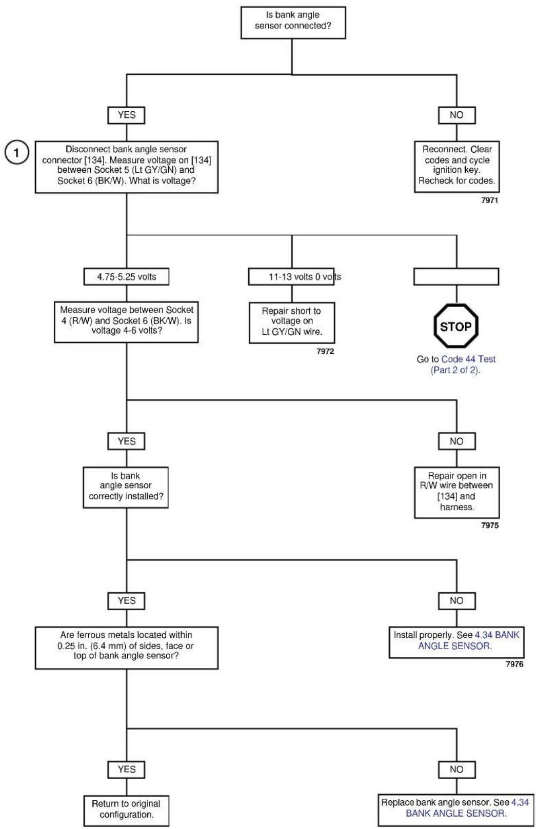
flowchart
graph TD
    A["Is bank angle sensor connected?"] --> B{YES}
    A --> C{NO}
    B --> D["Disconnect bank angle sensor connector [134"]. Measure_voltage_on["134"] between Socket 5 (Lt GY/GN) and Socket 6 (BK/W). What is voltage?]
    D --> E["4.75-5.25 volts"]
    D --> F["11-13 volts 0 volts"]
    E --> G["Measure voltage between Socket 4 (R/W) and Socket 6 (BK/W). Is voltage 4-6 volts?"]
    F --> H["Repair short to voltage on Lt GY/GN wire. 7972"]
    G --> I{YES}
    G --> J{NO}
    I --> K["Is bank angle sensor correctly installed?"]
    K --> L{YES}
    K --> M{NO}
    L --> N["Are ferrous metals located within 0.25 in. (6.4 mm) of sides, face or top of bank angle sensor?"]
    M --> O["Install properly. See 4.34 BANK ANGLE SENSOR. 7976"]
    N --> P{YES}
    N --> Q{NO}
    P --> R["Return to original configuration."]
    P --> S["Replace bank angle sensor. See 4.34 BANK ANGLE SENSOR."]
    C --> T["Reconnect. Clear codes and cycle ignition key. Recheck for codes. 7971"]
    T --> U["STOP Go to Code 44 Test (Part 2 of 2)."]
Code 44 Test (Part 2 of 2)
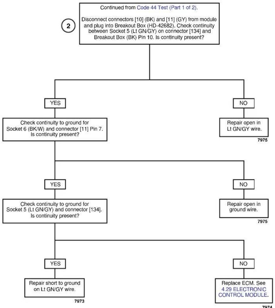
flowchart
graph TD
    A["Continued from Code 44 Test (Part 1 of 2). Disconnect connectors [10"] (BK) and["11"] (GY) from module and plug into Breakout Box (HD-42682). Check continuity between Socket 5 (Lt GN/GY) on_connector["134"] and Breakout Box (BK) Pin 10. Is continuity present?] --> B{?}
    B -->|YES| C["Check continuity to ground for Socket 6 (BK/W) and connector [11"] Pin 7. Is continuity present?]
    B -->|NO| D["Repair open in Lt GN/GY wire. 7975"]
    C --> E{?}
    E -->|YES| F["Check continuity to ground for Socket 5 (Lt GN/GY) and connector [134"]. Is continuity present?]
    E -->|NO| G["Repair open in ground wire. 7975"]
    F --> H{?}
    H -->|YES| I["Repair short to ground on Lt GN/GY wire. 7973"]
    H -->|NO| J["Replace ECM. See 4.29 ELECTRONIC CONTROL MODULE. 7974"]
Clear codes and confirm proper operation with no check engine lamp. Codes can be cleared using DIGITAL TECHNICIAN (Part No. HD-44750).
GENERAL
ECM Failure
All of the following codes indicate a failure which requires replacement of the ECM. See 4.29 ELECTRONIC CONTROL MODULE.
● Code 52 - RAM failure.
● Code 53 - ROM failure.
● Code 54 - EE PROM failure.
● Code 55 - Microprocessor failure.
NOTE
Dealership technicians filing warranty claims should use job/time code 7913 for all Code 52, 53, 54 and 55 ECM replacements.
GENERAL
Cam Sync Failure
This code occurs only when the engine is running if the electronic control module either receives an intermittent (extra or missing) signal from the cam position sensor or receives an unexpected signal. The motorcycle may continue to run, not run normally or stop running altogether.
DIAGNOSTICS
Diagnostic Notes
The reference numbers below correlate with the circled numbers on the Code 56 flow charts.
- Connect BREAKOUT BOX (Part No. HD-42682) to ECM. See 4.6 BREAKOUT BOX.
- Use HARNESS CONNECTOR TEST KIT (Part No. HD-41404), black pin probes and patch cord.
- See 4.30 CAM POSITION SENSOR AND ROTOR.
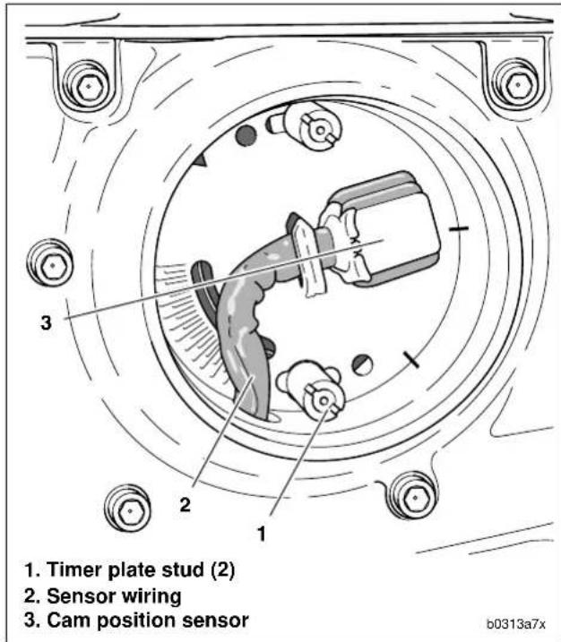
text_image
1. Timer plate stud (2) 2. Sensor wiring 3. Cam position sensor b0313a7xFigure 4-173. Cam Position Sensor
b1112x4x
R/W = 5 Volt Reference V/Y = TP Sensor Signal BK/W = Sensor Ground
R/W = 5 Volt Reference Lt.GN/GY = BAS Signal BK/W = Sensor Ground
Cam Position Sensor [14]
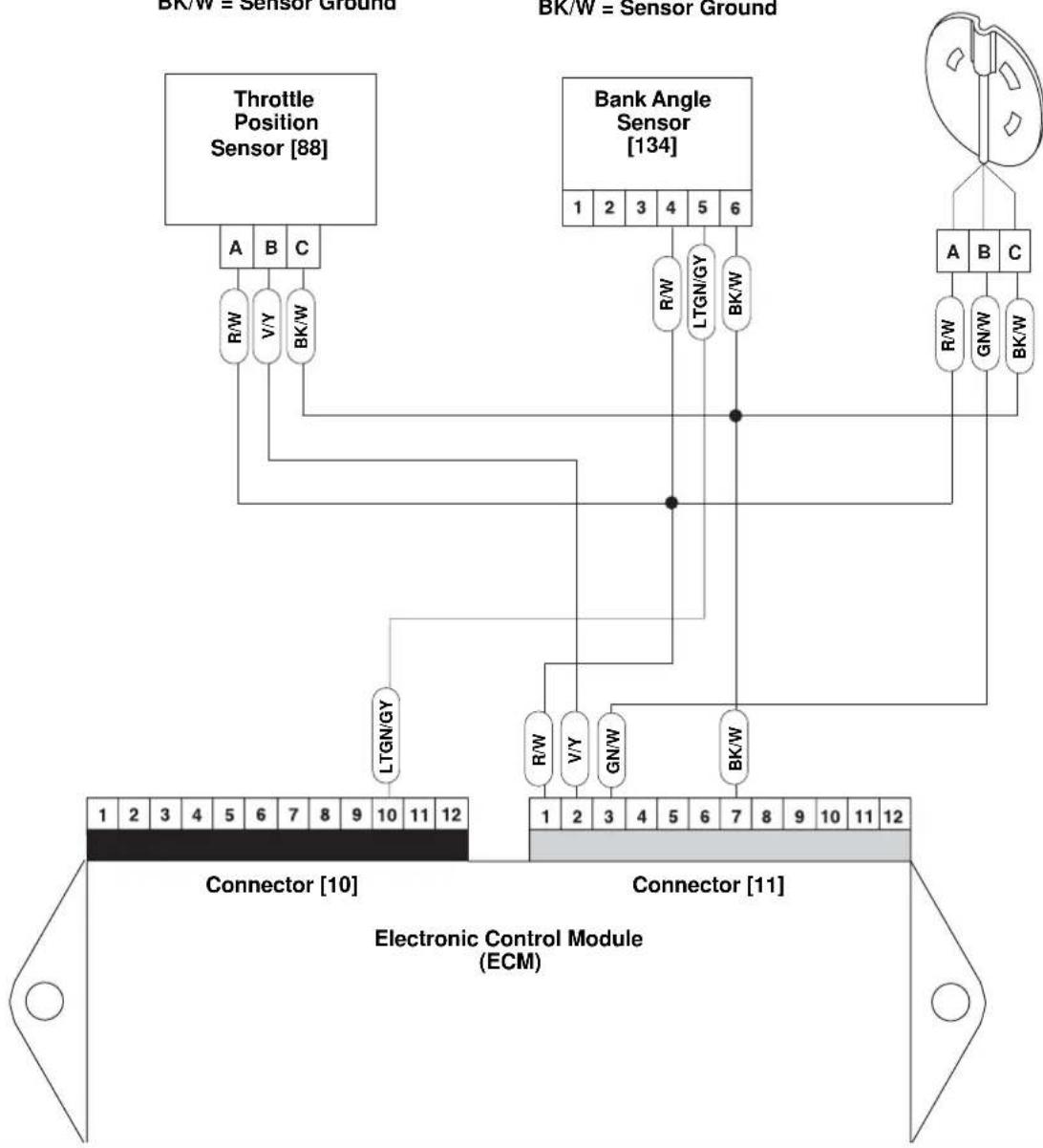
flowchart
graph TD
    A["Throttle Position Sensor [88"]] -->|A B C| B["R/W"]
    A -->|V/Y BK/W| C["V/Y"]
    D["Bank Angle Sensor [134"]] -->|1 2 3 4 5 6| E["R/W"]
    D -->|LTGN/GY| F["LTGN/GY"]
    D -->|Bk/W| G["Bk/W"]
    H["Electronic Control Module (ECM)"] --> I["Connector [10"]]
    H --> J["Connector [11"]]
    H --> K["AC"]
    style A fill:#f9f,stroke:#333
    style D fill:#f9f,stroke:#333
    style H fill:#ccf,stroke:#333
Figure 4-174. Cam Position Sensor Circuit
Table 4-56. Wire Harness Connectors in Figure 4-174.
| NO. DESCRIPTION TYPE LOCATION | |||
| [10] ECM (black) 12-place Deutsch in fairing | |||
| [11] ECM (gray) 12-place Deutsch in fairing | |||
| [14] cam position sensor 3-place Deutsch under sprocket cover | |||
| [88] throttle position sensor 3-place Packard right side of engine between cylinders | |||
| [134] bank angle sensor | 6-place Sumitomo | in fairing | |
Code 56 (Part 1 of 2)
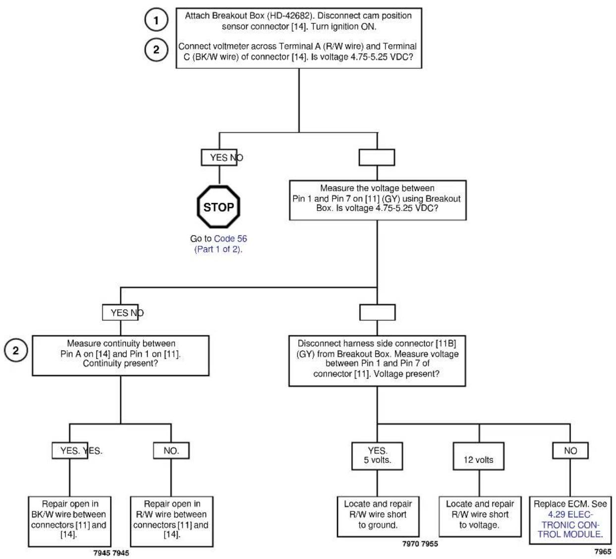
flowchart
graph TD
    A["1 Attach Breakout Box (HD-42682). Disconnect cam position sensor connector [14"]. Turn ignition ON.] --> B["2 Connect voltmeter across Terminal A (R/W wire) and Terminal C (BK/W wire) of connector [14"]. Is voltage 4.75-5.25 VDC?]
    B --> C{STOP}
    B --> D{Measure_the_voltage_between_Pin_1_and_Pin_7_on["11"] (GY) using Breakout Box. Is voltage 4.75-5.25 VDC?}
    C --> E{YES NO}
    C --> F{YES NO}
    D --> G{Measure_continuity_between_Pin_A_on["14"] and_Pin_1_on["11"]. Continuity present?}
    D --> H{Disconnect_harness_side_connector["11B"] (GY) from Breakout Box. Measure_voltage_between_Pin_1_and_Pin_7_of_connector["11"]. Voltage present?}
    E --> I{YES. YES.}
    E --> J{NO.}
    I --> K["Repair open in BK/W wire between connectors [11"] and["14"].]
    J --> L["Repair open in R/W wire between connectors [11"] and["14"].]
    H --> M{YES. 5 volts.}
    H --> N{12 volts.}
    H --> O{NO.}
    M --> P["Locate and repair R/W wire short to ground."]
    N --> Q["Locate and repair R/W wire short to voltage."]
    O --> R["Replace ECM. See 4.29 ELECTRONIC CONTROL MODULE."]
Clear codes and confirm proper operation with no check engine lamp. Codes can be cleared using DIGITAL TECHNICIAN (Part No. HD-44750).
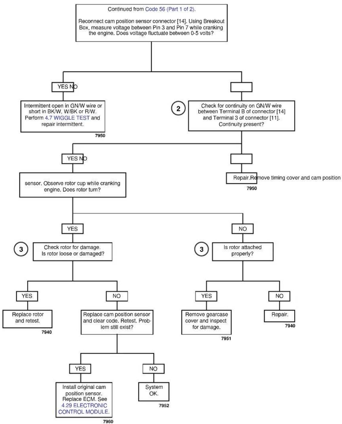
flowchart
graph TD
    A["Continued from Code 56 (Part 1 of 2). Reconnect cam position sensor connector [14"]. Using Breakout Box, measure voltage between Pin 3 and Pin 7 while cranking the engine. Does voltage fluctuate between 0-5 volts?] --> B{Yes NO}
    A --> C{Check for continuity on GN/W_wire_between_Terminal_B_of_connector["14"] and_Terminal_3_of_connector["11"]. Continuity present?}
    B --> D{Intermittent open in GN/W wire or short in BK/W, W/BK or R/W. Perform 4.7 WIGGLE TEST and repair intermittent.}
    C --> E{Repair. Remove timing cover and cam position}
    D --> F{sensor. Observe rotor cup while cranking engine. Does rotor turn?}
    F --> G{YES}
    F --> H{NO}
    G --> I{Check rotor for damage. Is rotor loose or damaged?}
    H --> J{Is rotor attached properly?}
    I --> K{YES}
    I --> L{NO}
    J --> M{YES}
    J --> N{NO}
    K --> O["Replace rotor and retest."]
    L --> P["Replace cam position sensor and clear code. Retest. Problem still exist?"]
    M --> Q["Remove gearcase cover and inspect for damage."]
    N --> R["Repair."]
    O --> S{YES}
    O --> T{NO}
    P --> U["Install original cam position sensor. Replace ECM. See 4.29 ELECTRONIC CONTROL MODULE."]
    Q --> V["System OK."]
    R --> W["7951"]
    R --> X["7940"]
Clear codes and confirm proper operation with no check engine lamp. Codes can be cleared using DIGITAL TECHNICIAN (Part No. HD-44750).
GENERAL
The Electronic Control Module (ECM) is located inside the fairing.
REMOVAL
- Remove front fairing. See 2.37 FRONT FAIRING, WINDSHIELD, AND MIRRORS.
- Remove Electronic Control Module (ECM). See 2.25 HEADLIGHT SUPPORT BRACKET but do not disconnect sensors.
- Disconnect ECM black connector [10] and gray connector [11].
INSTALLATION
- Attach ECM connectors [10] and [11].
- Locate ECM between fairing and headlight bracket.
- Install headlight bracket. See 2.25 HEADLIGHT SUPPORT BRACKET.
- Install front fairing. See 2.37 FRONT FAIRING, WINDSHIELD, AND MIRRORS.
- Recalibrate Throttle position sensor. Throttle position sensor can only be calibrated using DIGITAL TECHNICIAN (Part No. HD-44750).
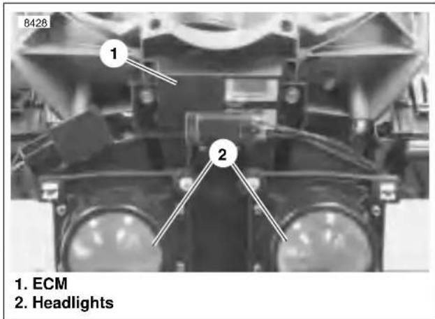
text_image
8428 1. ECM 2. HeadlightsFigure 4-175. ECM
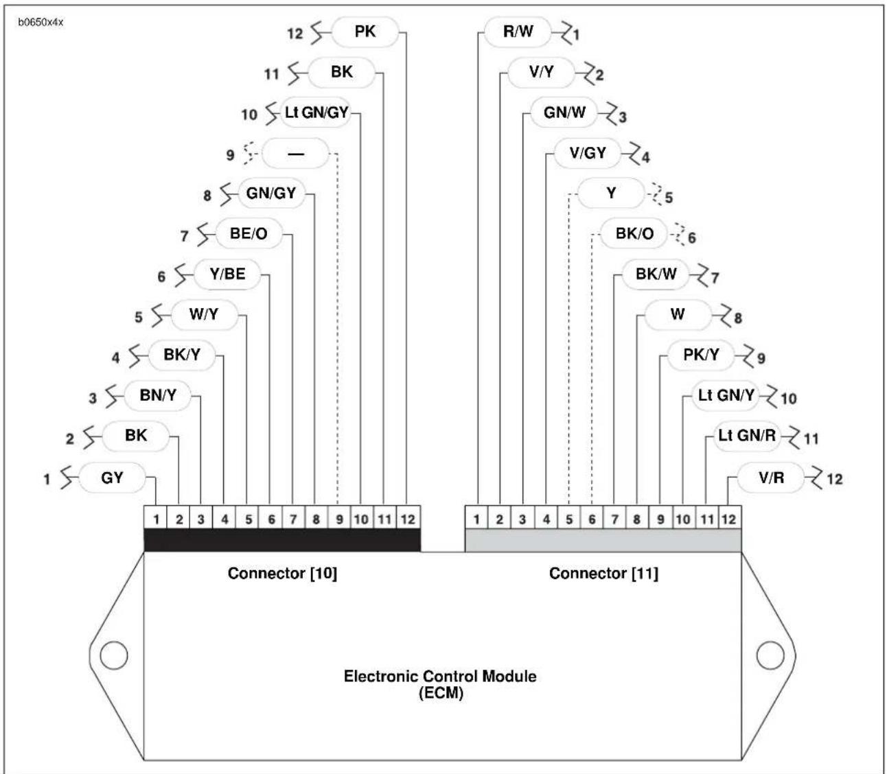
flowchart
graph TD
    subgraph_Connector["10"]
        A["GY"] --> B["BK"]
        B --> C["BN/Y"]
        C --> D["3"]
        D --> E["2"]
        E --> F["1"]
        F --> G["2"]
        G --> H["4"]
        H --> I["5"]
        I --> J["6"]
        J --> K["7"]
        K --> L["8"]
        L --> M["9"]
        M --> N["10"]
        N --> O["11"]
        O --> P["12"]
    end

    subgraph_Connector["11"]
        Q["W"] --> R["BK/W"]
        S["R/W"] --> T["V/Y"]
        U["GN/W"] --> V["V/GY"]
        W["GN/GY"] --> X["Lt GN/GY"]
        Y["Y"] --> Z["Y"]
        AA["BK/O"] --> AB["K/P/Y"]
        AC["BK/W"] --> AD["Lt GN/Y"]
        AE["V/R"] --> AF["V/R"]
    end

    style_Connector["10"] fill:#f9f,stroke:#333
    style_Connector["11"] fill:#bbf,stroke:#333
Figure 4-176. ECM Wiring
Table 4-57. Pin Table for ECM Connector [10] (Black)
| PIN FUNCTION | |
| 1 Switched ignition | |
| 2 | System ground A (module) |
| 3 Fuel pump | |
| 4 Check engine lamp | |
| 5 | In jector front |
| 6 | Front coil primary |
| 7 Rear coil primary | |
| 8 | In jector rear |
| 9 | Un u s e |
| 10 Bank angle sensor input | |
| 11 System ground B (coil) | |
| 12 Tachometer | |
Table 4-58. Pin Table for ECM Connector [11] (Gray)
| PIN FUNCTION | |
| 1 | 5 volt sensor power |
| 2 Throttle position sensor | |
| 3 | C amshaft position sensor |
| 4 | Oxygen sensor |
| 5 | M e m o r |
| 6 | F an control |
| 7 Sensor ground 1 | |
| 8 | V vehicle speed sensor |
| 9 Engine temperature | |
| 10 Intake air temperature | |
| 11 Serial data receive | |
| 12 Serial data transmit | |
REMOVAL
WARNING
To protect against accidental start-up of vehicle, disconnect the negative battery cable before proceeding. Inadequate safety precautions could result in death or serious injury.
- Disconnect negative battery cable.
- Remove sprocket cover. See 2.30 SPROCKET COVER.
NOTES
● Make note of cable strap positions and wire routing during disassembly.
- For more information about the wiring located underneath the sprocket cover see 7.24 SPROCKET COVER WIRING.
-
Cut cable straps holding cam position sensor wiring.
-
See Figure 4-177. Disconnect cam position sensor wiring at connector [14].
-
Note position of each cam position sensor wiring terminal in plug end of connector.
-
See Figure 4-179. Remove connector terminal pins (7). See B.2 DEUTSCH ELECTRICAL CONNECTORS under B.1 AMP MULTILOCK ELECTRICAL CONNECTORS.
-
Remove timer cover.
a. Drill off heads of outer timer cover pop rivets (1) using a 3/8 in. drill bit.
b. Tap remaining rivet shafts inboard through holes in timer cover (2) and inner cover (20).
c. Remove timer cover. Remove inner cover screws (3) and inner cover (20).
d. Carefully remove any remaining pieces of rivets from gearcase cover timer bore.
-
See Figure 4-178. To obtain approximate ignition timing during installation, scribe alignment marks (4) across cam position sensor (3) in two places.
-
See Figure 4-179. Remove timer plate studs (4). Carefully remove cam position sensor. Remove bolt (18) and trigger rotor (17).
-
Carefully remove camshaft oil seal (16) if damaged or if there is any evidence of oil leakage past the seal.
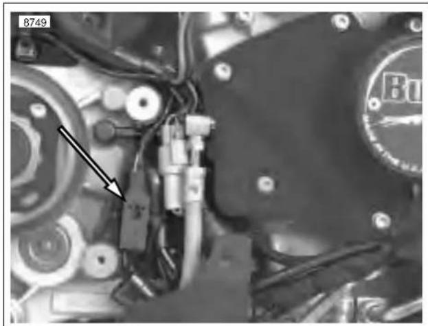
natural_image
Close-up of mechanical components with wiring and a labeled component (no readable text or symbols)Figure 4-177. Cam Position Sensor Connector [14] (stator connector disconnected)
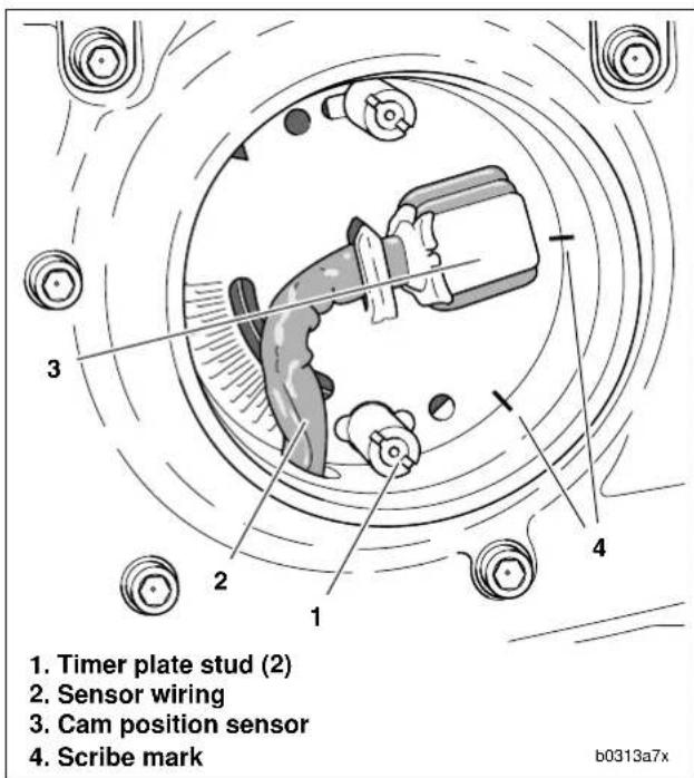
text_image
1. Timer plate stud (2) 2. Sensor wiring 3. Cam position sensor 4. Scribe mark b0313a7xFigure 4-178. Marking Ignition Timing
- Pop rivet (2)
- Timer cover
- Screw (2)
- Timer plate stud (2)
- Secondary lock
- Cam position sensor connector [14]
- Terminal pin
- Electronic control module (ECM)
- Spark plug (2)
- Rear spark plug cable
- Mounting fastener
- Ignition coil
- Front spark plug cable
- Engine mount
- Gearcase cover
- Seal
- Trigger rotor
- Trigger rotor bolt
- Cam position sensor
- Inner cover
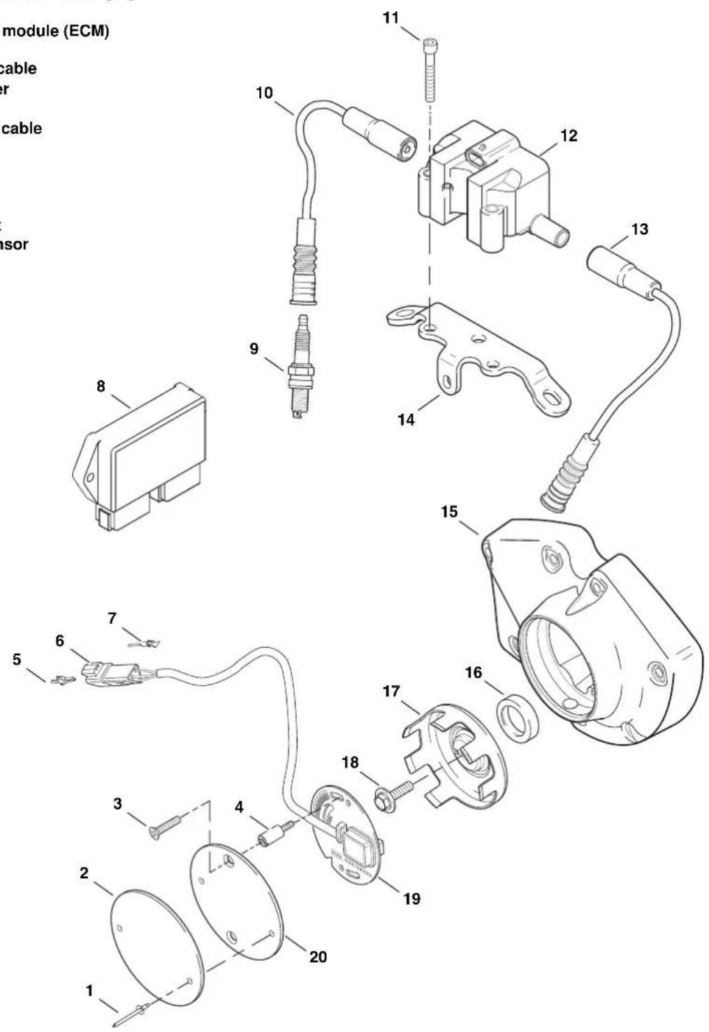
text_image
module (ECM) cable cable nsorb0990x4x
Figure 4-179. Ignition Components
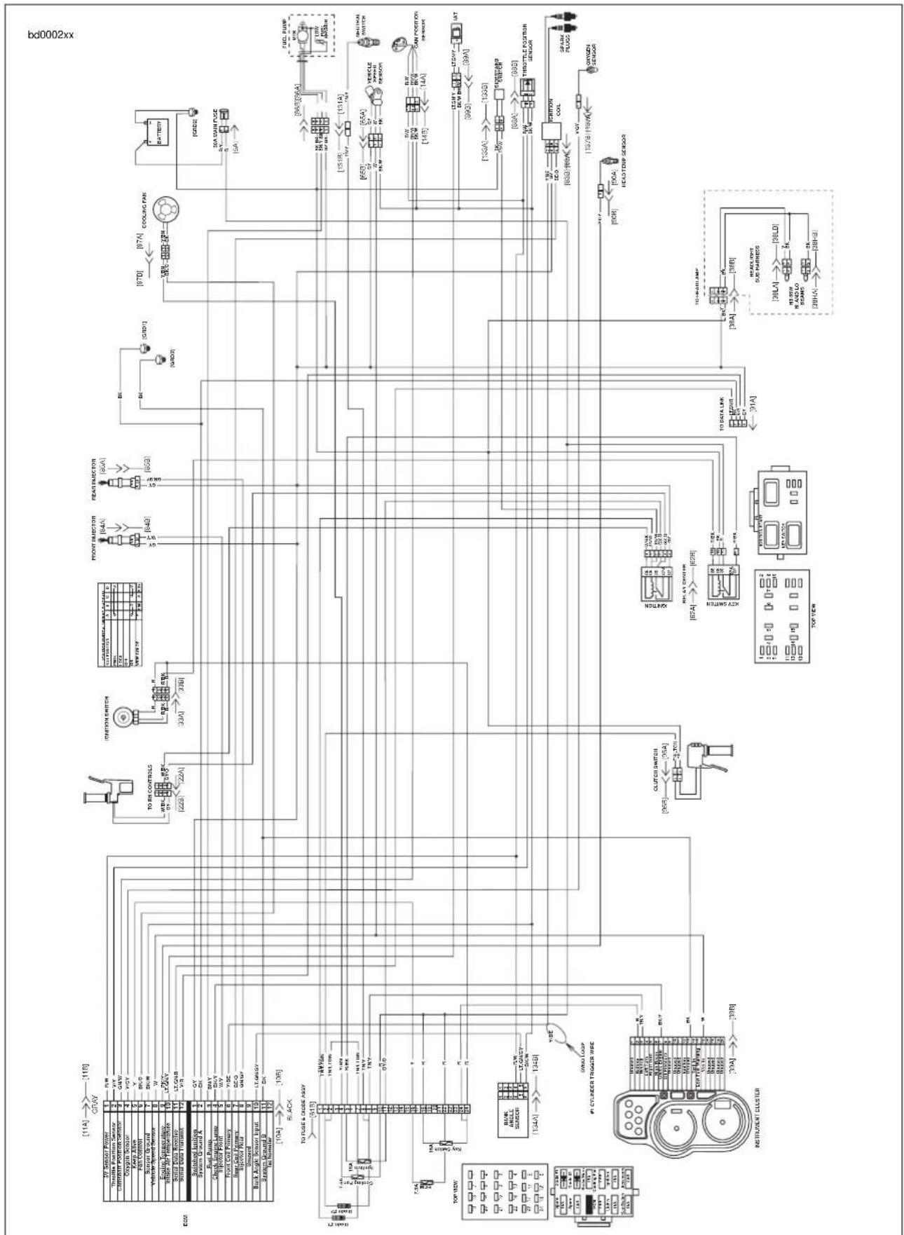
flowchart
graph TD
    A["Engine/Instrument Cluster"] --> B["TO C Valley"]
    A --> C["TO C Valley Switch"]
    A --> D["TO C Valley"]
    A --> E["TO C Valley"]
    A --> F["TO C Valley"]
    A --> G["TO C Valley"]
    A --> H["TO C Valley"]
    A --> I["TO C Valley"]
    A --> J["TO C Valley"]
    A --> K["TO C Valley"]
    A --> L["TO C Valley"]
    A --> M["TO C Valley"]
    A --> N["TO C Valley"]
    A --> O["TO C Valley"]
    A --> P["TO C Valley"]
    A --> Q["TO C Valley"]
    A --> R["TO C Valley"]
    A --> S["TO C Valley"]
    A --> T["TO C Valley"]
    A --> U["TO C Valley"]
    A --> V["TO C Valley"]
    A --> W["TO C Valley"]
    A --> X["TO C Valley"]
    A --> Y["TO C Valley"]
    A --> Z["TO C Valley"]
    A --> AA["TO C Valley"]
    A --> AB["TO C Valley"]
    A --> AC["TO C Valley"]
    A --> AD["TO C Valley"]
    A --> AE["TO C Valley"]
    A --> AF["TO C Valley"]
    A --> AG["TO C Valley"]
    A --> AH["TO C Valley"]
    A --> AI["TO C Valley"]
    A --> AJ["TO C Valley"]
    A --> AK["TO C Valley"]
    A --> AL["TO C Valley"]
    A --> AM["TO C Valley"]
    A --> AN["TO C Valley"]
    A --> AO["TO C Valley"]
    A --> AP["TO C Valley"]
    A --> AQ["TO C Valley"]
    A --> AR["TO C Valley"]
    A --> AS["TO C Valley"]
    A --> AT["TO C Valley"]
    A --> AU["TO C Valley"]
    A --> AV["TO C Valley"]
    A --> AW["TO C Valley"]
    A --> AX["TO C Valley"]
    A --> AY["TO C Valley"]
    A --> AZ["TO C Valley"]
    A --> BA["TO C Valley"]
    A --> BB["TO C Valley"]
    A --> BC["TO C Valley"]
    A --> BD["TO C Valley"]
    A --> BE["TO C Valley"]
    A --> BF["TO C Valley"]
    A --> BG["TO C Valley"]
    A --> BH["TO C Valley"]
    A --> BI["TO C Valley"]
    A --> BJ["TO C Valley"]
    A --> BK["TO C Valley"]
    A --> BL["TO C Valley"]
    A --> BM["TO C Valley"]
    A --> BN["TO C Valley"]
    A --> BO["TO C Valley"]
    A --> BP["TO C Valley"]
    A --> BQ["TO C Valley"]
    A --> BR["TO C Valley"]
    A --> BS["TO C Valley"]
    A --> BT["TO C Valley"]
    A --> BU["TO C Valley"]
    A --> BV["TO C Valley"]
    A --> BW["TO C Valley"]
    A --> BX["TO C Valley"]
    A --> BY["TO C Valley"]
    A --> BZ["TO C Valley"]
Figure 4-180. Ignition System Circuit
INSTALLATION
- See Figure 4-179. Coat lip of seal with a thin film of clean engine oil. With the lipped side facing inboard, install new camshaft oil seal (16) into gearcase cover (15), if removed. Press seal into position until flush with surface of timer bore.
- Install trigger rotor (17).
a. Apply LOCTITE THREADLOCKER 243 (blue) to threads of bolt (18).
b. Position trigger rotor (17) onto end of camshaft aligning notch with camshaft slot.
c. Install bolt to secure rotor. Tighten to 43-53 in-lbs (5-6 Nm).
- Install cam position sensor (19) and timer plate studs (4). Rotate cam position sensor to its previously marked position to obtain approximate ignition timing.
- Route sensor wiring leads and install cable straps. See 7.24 SPROCKET COVER WIRING.
- See Figure 4-181. Install sensor wiring terminals into correct positions in plug end of connector [14]. R/W, GN/W and BK/W wires of plug end (from cam position sensor) must match same color wires in receptacle end of connector (from ignition module wiring harness). Install pin terminals. See B.2 DEUTSCH ELECTRICAL CONNECTORS under B.1 AMP MULTILOCK ELECTRICAL CONNECTORS.
- See Figure 4-179. Attach connector [14] (6).
- Check ignition timing. See 1.17 IGNITION TIMING.
- Tighten timer plate studs (4) to 15-30 in-lbs (2-3 Nm).
- Install inner cover (20) using screws (3). Tighten to 12-20 in-lbs (1-2 Nm).
CAUTION
Use only H-D Part No. 8699 rivets to secure outer timing cover. These rivets are specially designed so that no rivet end falls off into the timing compartment. Use of regular rivets can damage ignition system components and may allow water to enter the timing compartment.
- Secure timer cover (2) to inner cover using new rivets (1).
- Connect negative battery cable.
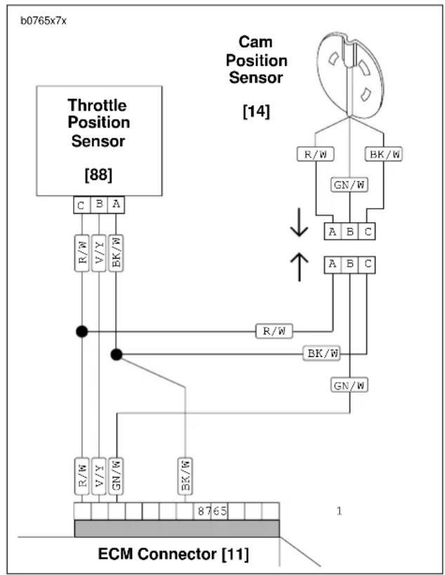
flowchart
graph TD
    A["Throttle Position Sensor [88"]] --> B["C"]
    A --> C["B"]
    A --> D["A"]
    B --> E["R/W"]
    C --> F["V/Y"]
    D --> G["BK/W"]
    E --> H["ECM Connector [11"]]
    F --> H
    G --> H
    H --> I["8765"]
    H --> J["65"]
    H --> K["1"]
    L["Cam Position Sensor [14"]] --> M["R/W"]
    L --> N["BK/W"]
    M --> O["GN/W"]
    N --> P["A B C"]
    O --> Q["A B C"]
    P --> R["GN/W"]
    Q --> S["R/W"]
    R --> T["BK/W"]
    S --> U["GN/W"]
    T --> V["ECM Connector [11"]]
    U --> V
    style L fill:#f9f,stroke:#333
    style M fill:#ccf,stroke:#333
    style N fill:#ccf,stroke:#333
    style O fill:#cfc,stroke:#333
    style P fill:#cfc,stroke:#333
    style Q fill:#cfc,stroke:#333
    style R fill:#fcc,stroke:#333
    style S fill:#fcc,stroke:#333
    style T fill:#fcc,stroke:#333
    style U fill:#fcc,stroke:#333
    style V fill:#fcc,stroke:#333
Figure 4-181. Connecting Sensor Wires
TROUBLESHOOTING
Follow the troubleshooting procedures listed under 4.8 INITIAL DIAGNOSTIC CHECK if the engine will not start, is difficult to start or runs roughly. Also check condition of spark plug cables. Insulation on cables may be cracked or damaged allowing high tension current to short to metal parts. This problem is most noticeable when cables are wet.
If poor starting/running condition persists, check resistance of ignition coil primary and secondary windings using an ohmmeter.
Ignition Coil Primary Circuit Test
- Remove ignition coil. See REMOVAL in this section.
- Set ohmmeter scale to RX1.
- See Figure 4-182. Place multimeter wires on primary coil windings (1).
- Check for primary coil winding resistance.
a. Normal resistance range is 0.5-0.7 ohms.
b. See TEST RESULTS if resistance is not within normal operating range.
Ignition Coil Secondary Circuit Test
- Remove ignition coil. See 4.31 IGNITION COIL.
- Set ohmmeter scale to RX1K.
- See Figure 4-182. Place multimeter wires on secondary coil windings (2).
- Check for secondary coil winding resistance.
a. Normal resistance range is 5.5-7.5K ohms.
b. See TEST RESULTS if resistance is not within normal operating range.
Test Results
- A low resistance value indicates a short in the coil winding. Replace coil.
- A high resistance value might indicate that there is some corrosion/oxidation of the coil terminals. Clean the terminals and repeat resistance test. If resistance is still high after cleaning terminals, replace coil.
- An infinite ohms ( or no continuity) resistance value indicates an open circuit (a break in the coil winding). Replace coil.
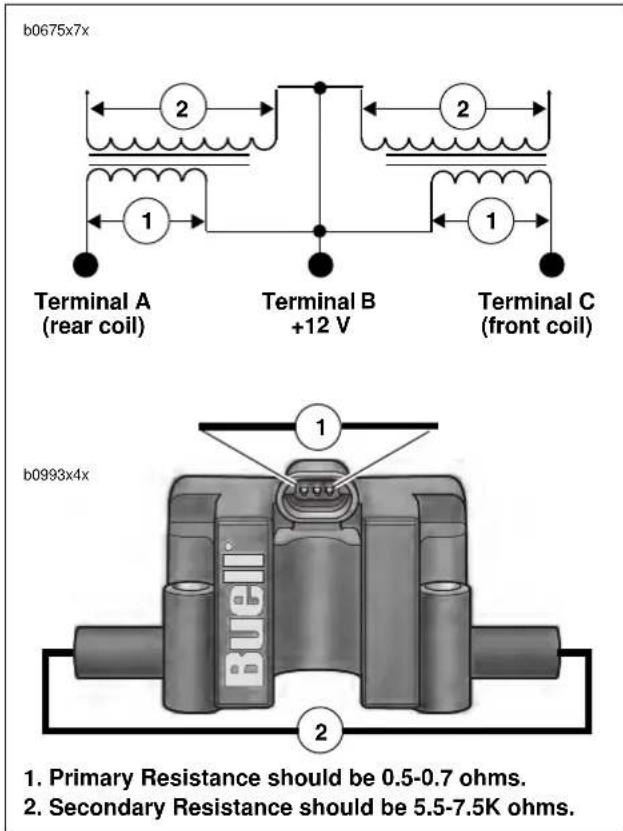
-
Primary Resistance should be 0.5-0.7 ohms.
-
Secondary Resistance should be 5.5-7.5K ohms.
Figure 4-182. Ignition Coil Testing
Ignition Coil Substitution
If a coil tester is not available, use the following test.
NOTE
Coil will function without being attached to frame.
- Substitute a new ignition coil by attaching it to any convenient point near the old coil. Transfer terminal wires to new coil.
- Attach new spark plug cables to coil and plugs.
- Test system. If ignition trouble is eliminated by the temporary installation of a new coil, carefully inspect old coil and cables for damage. The insulation on the cables may be cracked or otherwise damaged allowing high tension current to short to metal parts. This is most noticeable in wet weather or after the motorcycle has been washed.
REMOVAL
WARNING
To protect against accidental start-up of vehicle, disconnect the negative battery cable before proceeding. Inadequate safety precautions could result in death or serious injury.
- Disconnect negative battery cable.
- Remove intake cover assembly. See 2.34 INTAKE COVER ASSEMBLY.
- Remove airbox. See 4.43 AIRBOX.
- See Figure 4-183. Disconnect the spark plug cables from the coil plug posts (1, 5).
- Detach connector (3) [83].
- Remove coil fasteners (2).
INSTALLATION
NOTE
To ease installation, install spark plug cables to ignition coil first.
- Connect spark plug cables to ignition coil.
- See Figure 4-183. Attach coil to frame with fasteners (2). Tighten to 144-168 In-lbs (16.3-19.0 Nm).
- Attach front and rear spark plug cables to ignition coil posts.
- Attach connector (3) [83].
- Install ram air scoop assembly. See 2.35 AIR SCOOPS.
- Install airbox. See 4.43 AIRBOX.
- Install intake cover assembly. See 2.34 INTAKE COVER ASSEMBLY.
- Connect negative battery cable.
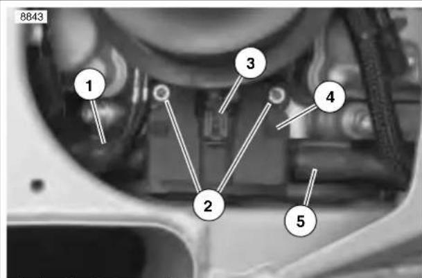
text_image
8843 1 2 3 4 5- Front cylinder post
- Fasteners
- Coil connector [83]
- Coil
- Rear cylinder post
Figure 4-183. Ignition Coil Location
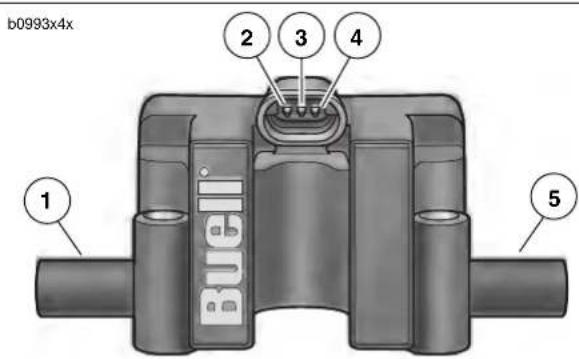
text_image
b0993x4x 1 2 3 4 5- Rear Cylinder Post
- Coil Pin A (rear cylinder)
- Coil Pin B (12 VDC)
- Coil Pin C (front cylinder)
- Front Cylinder Post
Figure 4-184. Ignition Coil
GENERAL
The oxygen sensor (O2 Sensor), located in the rear header pipe, monitors oxygen content in the exhaust gas and converts it to a voltage reading. This voltage reading is used by the ECM to maintain the proper air/fuel ratio during closed loop operation.
REMOVAL
WARNING
Toprotect against accidental start-up of vehicle, disconnect the negative battery cable before proceeding. Inadequate safety precautions could result in death or serious injury.
- Disconnect negative battery cable.
- Remove intake cover assembly. See 2.34 INTAKE COVER ASSEMBLY.
- Remove airbox assembly. See 4.43 AIRBOX.
- Remove shock absorber. See 2.22 REAR SHOCK ABSORBER.
- Remove cooling fan. See 4.37 COOLING FAN
- See Figure 4-186. Remove cable straps (2). Unplug 1-place connector [137] (1).
- Remove oxygen sensor from exhaust header using Snap-on Part No. YA8875.
INSTALLATION
- Apply LOCTITE ANTI-SEIZE LUBRICANT to threads of sensor. Make sure anti-seize is marked as safe for use with O2 sensors.
- See Figure 4-185. Thread sensor into exhaust header. Tighten sensor to 40-45 ft-lbs (54-61 Nm).
- Install cooling fan. See 4.37 COOLING FAN.
- Install shock absorber. See 2.22 REAR SHOCK ABSORBER.
- See Figure 4-186. Connect 1-place connector [137] (1) to wiring harness.
- Install cable straps (2).
- Install airbox assembly. See 4.43 AIRBOX.
- Install intake cover assembly. See 2.34 INTAKE COVER ASSEMBLY.
- Connect negative battery cable.
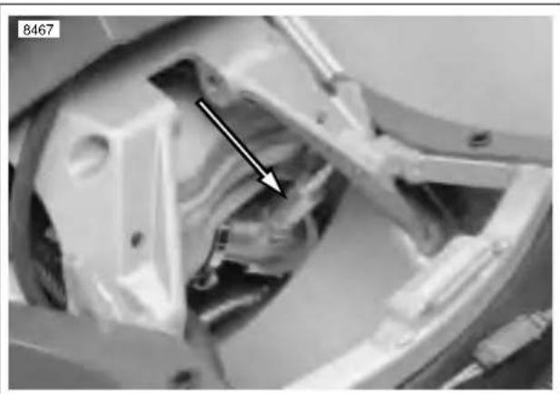
natural_image
Close-up mechanical component with a black arrow pointing to a specific part (no visible text or symbols)Figure 4-185. Installed Oxygen Sensor (shock absorber removed)
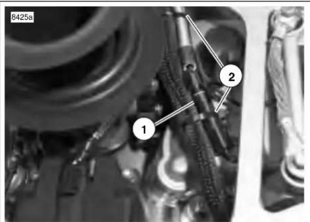
text_image
8425a 1 2- Oxygen sensor connector [137]
- Cable strap
Figure 4-186. Oxygen Sensor Connector [137]
GENERAL
The Engine Temperature Sensor (ET Sensor), located in the rear cylinder head, monitors the engine temperature close to the combustion chamber. In addition to aiding the ECM in monitoring the operation of the engine, it is also used to warn the operator of potentially damaging temperatures by causing the CHECK ENGINE lamp to blink during operation.
REMOVAL
WARNING
To protect against accidental start-up of vehicle, disconnect the negative battery cable before proceeding. Inadequate safety precautions could result in death or serious injury.
- Disconnect negative battery cable.
- Remove intake cover assembly. See 2.34 INTAKE COVER ASSEMBLY.
- Remove airbox. See 4.43 AIRBOX.
- See Figure 4-188. Remove right upper tie bar fastener (2). Rotate tie bar to provide access to sensor.
CAUTION
Do not pull on engine temperature sensor wiring. Excess strain to sensor wiring will cause sensor damage.
- Unplug 1-place ET Sensor connector (1) [90] above rear cylinder head.
- Slide rubber boot up ET sensor wire.
- Remove sensor from rear cylinder head using Snap-on socket M3503B.
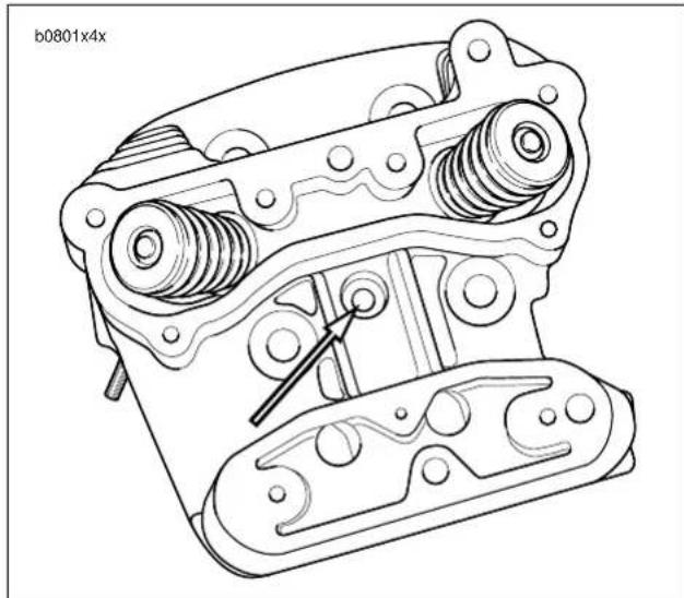
natural_image
Technical line drawing of a mechanical component with internal gears and shafts (no text or symbols)Figure 4-187. Engine Temperature Sensor Location (rear cylinder)
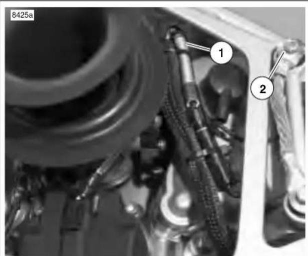
text_image
8425a 1 2- Engine temperature sensor connector [90] (approximate location)
- Upper tie bar fastener (right side)
Figure 4-188. Engine Temperature Sensor Connector Approximate Location [90]
CAUTION
Do not pull on engine temperature sensor wiring. Excess strain to sensor wiring will cause sensor damage.
- See Figure 4-187. Screw sensor into rear cylinder head.
NOTE
In next step, make sure wire is in cutout portion (slot) of socket to prevent damage.
- Secure sensor with Snap-on socket M3503B. Tighten ET sensor to 10-14 ft-lbs (14-19 Nm).
NOTE
Orient the rubber boot so the flat on the boot is towards the left side of the motorcycle.
- Push rubber boot down sensor wire towards cylinder head until it seats in hole on top of ET sensor.
- See Figure 4-188. Connect ET sensor 1-place connector [90] to wiring harness.
-
Install right upper tie bar fastener (2). Tighten fastener to 25-27 ft-lbs (33.9-36.6 Nm).
-
Install airbox. See 4.43 AIRBOX.
-
Install intake cover assembly. See 2.34 INTAKE COVER ASSEMBLY.
-
Connect negative battery cable.
GENERAL
The Bank Angle Sensor (BAS), located inside the fairing on the headlight bracket, provides input to the ECM on vehicle lean angle. If vehicle lean angle exceeds predetermined bank angle limit, the Bank Angle Sensor will shut off power to the ignition and fuel pump.
REMOVAL
WARNING
To protect against shock and accidental start-up of vehicle, disconnect the negative battery cable before proceeding. Inadequate safety precautions could result in death or serious injury.
- Disconnect negative battery cable.
- Remove front fairing. See 2.37 FRONT FAIRING, WINDSHIELD, AND MIRRORS.
- See Figure 4-189. Unplug bank angle sensor connector [134].
- Remove screws and washers to detach sensor from headlight bracket.
INSTALLATION
- Position bank angle sensor on headlight bracket. Make sure locating post on sensor engages hole in mounting tab.
- Install bank angle sensor to mounting tab with fasteners and new locknuts. Tighten fastener to 12-36 in-lbs (1.4-4.1 Nm).
- See Figure 4-189. Install bank angle sensor connector [134].
- Install front fairing. See 2.37 FRONT FAIRING, WINDSHIELD, AND MIRRORS.
- Connect negative battery cable.
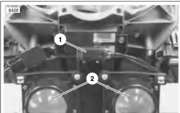
text_image
8428 1 2- Bank angle sensor
- Headlights
Figure 4-189. Bank Angle Sensor
GENERAL
The intake air temperature sensor (IAT Sensor), located on the airbox baseplate, measures the air temperature allowing the ECM to calculate the density of the air entering the manifold. The IAT is a thermistor type sensor.
REMOVAL
WARNING
Toprotect against shock and accidental start-up of vehicle, disconnect the negative battery cable before proceeding. Inadequate safety precautions could result in death or serious injury.
- Disconnect negative battery cable.
- See Figure 4-190. Remove airbox cover, filter. Remove fasteners securing base. See 4.43 AIRBOX.
- Raise base and pull IAT sensor from sensor grommet.
- Disconnect connector [89] from intake air temperature sensor.
- Inspect sensor grommet for damage and replace as required.
INSTALLATION
- Connect IAT sensor connector [89] to wiring harness.
- Install IAT sensor into grommet on air cleaner base from underneath.
- Install airbox. See 4.43 AIRBOX.
- Install negative battery cable.
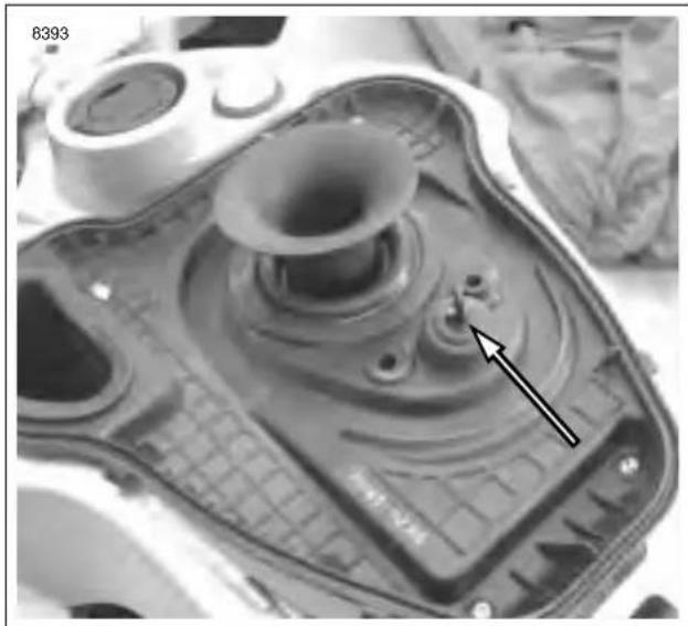
natural_image
Close-up of a mechanical component with a highlighted part and arrow indicator (no readable text or symbols)Figure 4-190. Intake Air Temperature Sensor Installed
REMOVAL
- Remove airbox. See 4.43 AIRBOX.
- See Figure 4-191. Disconnect throttle position sensor connector [88].
- See Figure 4-192. Remove two screws and washers to detach TP sensor.
INSTALLATION
- See Figure 4-192. Apply LOCTITE THREADLOCKER 222 (purple) to threads of fasteners.
- Install fastener into lower mounting hole of sensor prior to installation.
- Attach TP sensor with both fasteners and washers. Tighten to 16-20 in-lbs (1.8-2.3 Nm).
- See Figure 4-193. Attach throttle position sensor connector [88]. Slots on female connector [88B] must fully engage tabs on male connector housing [88A].
NOTE
Throttle position sensor can only be calibrated using DIGITAL TECHNICIAN (Part No. HD-44750).
- Calibrate throttle position sensor.

natural_image
Close-up mechanical assembly showing gears and springs with a white arrow pointing to a component (no text or symbols visible)Figure 4-191. Throttle Position Sensor Location
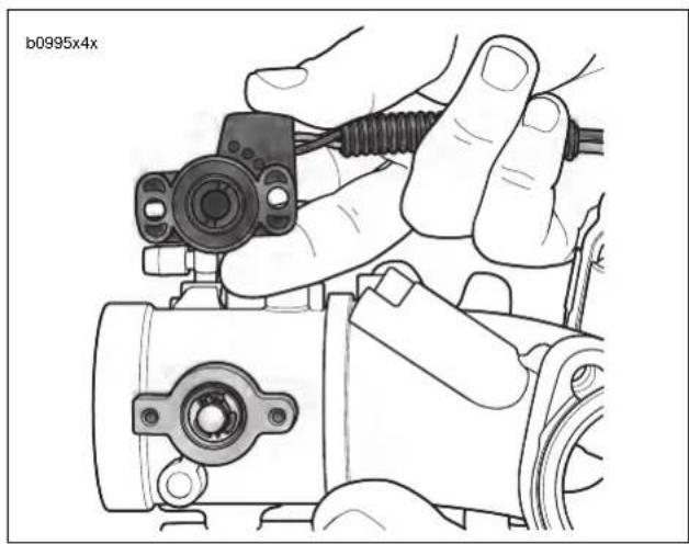
natural_image
Close-up of hands assembling a mechanical component with a coiled cable (no text or symbols visible)Figure 4-192. Throttle Position Sensor
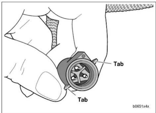
text_image
Tab Tab b0651x4xFigure 4-193. Tabs on TP Sensor Connector [88A]
GENERAL
The XB9R has a computer-controlled cooling fan to assist in engine cooling during operation in high temperatures. Fan actuation is controlled by the ECM. See Table 4-59. Cooling Fan Specifications.
Table 4-59. Cooling Fan Specifications
| FAN ON FAN OFF | |
| Key ON | 220°C (428°F) 180°C (356°F) |
| Key OFF | 170°C (338°F) 150°C (302°F) |
REMOVAL
- Remove seat. See 2.38 SEAT.
WARNING
Toprotect against shock and accidental start-up of vehicle, disconnect the negative battery cable before proceeding. Inadequate safety precautions could result in death or serious injury.
- Disconnect negative battery cable.
- Remove shock absorber. See 2.22 REAR SHOCK ABSORBER.
- See Figure 4-194. Remove cooling fan fasteners (1).
- Rotated fan clockwise (looking towards front of vehicle) to remove.
- See Figure 4-195. Disconnect cooling fan connector [97].
INSTALLATION
- See Figure 4-195. Connect cooling fan connector [97].
NOTES
- When installing cooling fan (3), be sure wiring, transmission vent hose and fuel line are routed through notch (2) in fan body.
- On California models, both fuel tank and canister vent hoses are routed through notch in fan body.
- Install fan and rotate counter-clockwise into position.
- Install cooling fan fasteners. Tighten to 12-36 in-lbs (1.4-4.1 Nm).
- Install shock absorber. See 2.22 REAR SHOCK ABSORBER.
- Connect negative battery cable.
WARNING
After installing seat, pull upward on front of seat to be sure it is locked in position. If seat is loose, it could shift during vehicle operation and startle the rider, causing loss of control which could result in death or serious injury.
- Install seat. See 2.38 SEAT.
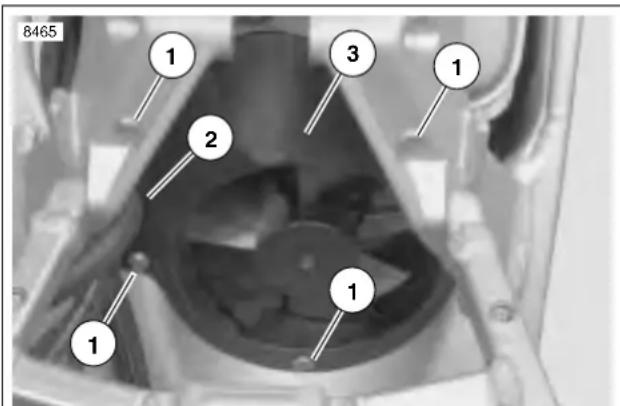
text_image
8465 1 2 3 1 1 1Figure 4-194. Cooling Fan
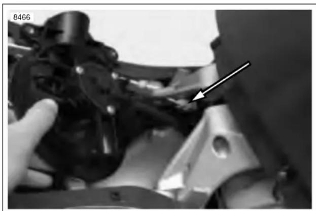
natural_image
Close-up of mechanical components with a hand adjusting parts, no visible text or symbolsFigure 4-195. Cooling Fan Connector [97]
GENERAL
The fuel pump is located inside the left rear portion of the fuel tank/frame.
DRAINING FUEL TANK
WARNING
The gasoline in the fuel supply line downstream of the fuel pump is under high pressure (49 psi [338 kPa]). To avoid an uncontrolled discharge or spray of gasoline, always purge the system of high pressure gas before servicing fuel pump. Gasoline is extremely flammable and highly explosive. Inadequate safety precautions could result in death or serious injury.
- Purge the fuel supply line of high pressure gasoline.
a. See Figure 4-196. Disconnect the 4-place fuel pump connector (2) [86]. Connector is located inside the left rear portion of the fuel tank/frame.
b. With the motorcycle in neutral, start the engine and allow vehicle to run.
c. When the engine stalls, press the starter button for 3 seconds to remove any remaining fuel from fuel line.
WARNING
An open flame or spark may cause a fuel tank explosion if all traces of fuel are not purged from the tank. Use extreme caution when servicing fuel tanks. Gasoline is extremely flammable and highly explosive. Inadequate safety precautions could result in death or serious injury.
- Remove drain plug (5) and drain fuel into appropriate container. Discard plug.
- When fuel tank is empty, replace with new drain plug. Tighten to 84-108 in-lbs (9.5-12.2 Nm).
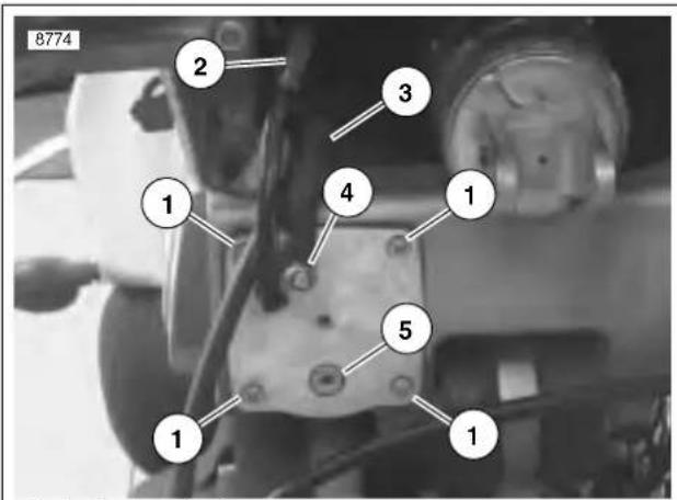
text_image
8774 1 2 3 4 1 5 1 1- Fuel pump fastener
- Fuel pump connector [86]
- Fuel supply stud
- Fuel supply fitting
- Drain plug 84-108 in-lbs (9.5-12.2 Nm)
Figure 4-196. Fuel Pump Location
REMOVAL
| PART NO. SPECIALTY TOOL |
| B-45657 Fuel pump puller |
- Remove rider footpeg mounts. See 2.29 FOOTPEG, HEEL GUARD AND MOUNT.
- Remove swingarm. See 2.19 SWINGARM AND BRACE.
- Drain fuel tank. See DRAINING FUEL TANK under 4.38 FUEL PUMP.
WARNING
A small amount of gasoline will drain from the fuel supply fitting, fuel line and fuel pump when removed. Thoroughly wipe up any spilt fuel immediately. Dispose of rags in a suitable manner. Gasoline is extremely flammable and highly explosive. Inadequate safety precautions could result in death or serious injury.
- See Figure 4-196. Remove fuel line from fuel supply fitting (4).
- Remove four fuel pump fasteners (1).
- See Figure 4-197. Assemble fuel pump puller.
a. Thread nut (3) onto bolt (4).
b. Slide washer (2) onto bolt.
c. Insert bolt assembly into hole in main body (1).
-
See Figure 4-198. Place the main body of the fuel pump puller over the fuel pump assembly.
-
Thread bolt into the threaded hole in the center of the fuel pump assembly until snug.
-
Thread the nut down the shaft of the bolt until it makes contact with the main body of the fuel pump puller.
-
Place wrench onto nut and another wrench onto the bolt. Hold the bolt stationary and turn nut clockwise until fuel pump is pulled free from frame.
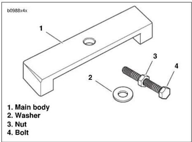
text_image
b0988x4x 1. Main body 2. Washer 3. Nut 4. BoltFigure 4-197. Fuel Pump Puller
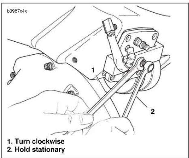
text_image
b0987x4x 1. Turn clockwise 2. Hold stationaryFigure 4-198. Fuel Pump Removal
REPAIR
Fuel Pressure Regulator Replacement
- Remove fuel pump assembly from tank. See REMOVAL in this section.
- See Figure 4-199. Pry four tabs of clip holding fuel pressure regulator (8) in place. Detach regulator from regulator housing.
- Remove and discard O-rings from regulator.
- Install new O-rings on regulator. Press new regulator into place.
- Install new regulator clip.
- Install fuel pump assembly. See INSTALLATION in this section.
Low Fuel Level Sensor Replacement
- Remove fuel pump assembly from tank. See REMOVAL in this section.
- See Figure 4-200. Disconnect low fuel level sensor connector (4).
- Remove clamp (5) securing low fuel level sensor (6) in place.
- Install new sensor.
- Install new clamp over sensor.
- Attach wire connector.
- Install fuel pump assembly. See INSTALLATION in this section.
Fuel Filter Replacement
- Remove fuel pump assembly from tank. See REMOVAL in this section.
- See Figure 4-200. Remove fuel pump clamps (3, 7).
- See Figure 4-201. Remove fuel pump clips (1).
- Pull regulator housing (2) from fuel pump assembly.
- See Figure 4-202. Discard regulator housing o-rings (2).
- See Figure 4-200. Remove fuel filter hose from fitting (2) and remove fuel filter (1).
- Install new clamps on fuel filter hose.
- Install new fuel filter hose with 90° bend towards fitting (2).
- See Figure 4-202. Install new regulator housing o-rings.
- Install regulator housing onto fuel pump assembly.
- See Figure 4-200. Tighten fuel filter clamps (3, 7).
- See Figure 4-201. Install clips (1) into center grooves.
- Install fuel pump assembly. See INSTALLATION in this section.
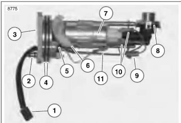
text_image
8775 3 2 4 5 6 7 11 10 9 8- Fuel pump connector [86]
- Fuel supply stud
- Fuel pump assembly
- O-rings
- Fastener
- Fuel screen
- Fuel Pump
- Fuel pressure regulator
- Low fuel pressure regulator
- Fuel pump connectors
- Low fuel level sensor connector
Figure 4-199. Fuel Pump Assembly (left side)
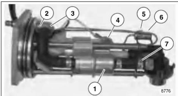
text_image
2 3 4 5 6 7 1 8776- Filter
- Fitting
- Fuel filter clamp
- Low fuel level sensor connector
- Low fuel level sensor clamp
- Low fuel level sensor
- Fuel filter clamp
Figure 4-200. Fuel Pump Assembly (right side)
HOME
Fuel Screen Replacement
- Remove fuel pump assembly from tank. See REMOVAL in this section.
- See Figure 4-200. Remove fuel filter clamp (3). Disconnect hose from fitting (2).
- See Figure 4-201. Remove clips (1).
- See Figure 4-199. Disconnect fuel pump connectors (10) and low fuel level sensor connector (11).
- Slide fuel pump and fuel filter off of fuel pump assembly.
- Pry fuel screen (6) from fuel pump (7).
NOTE
In next step, make sure that section of screen with most material faces towards inside of fuel pump assembly.
- Install new fuel screen on fuel pump.
- Without damaging fuel screen, slide fuel pump onto fuel pump assembly.
-
See Figure 4-200. Attach fuel filter hose to fitting (2) with clamp (3).
-
See Figure 4-201. Install clips (1) into middle grooves.
-
See Figure 4-199. Connect low fuel level sensor wiring (11).
-
Connect fuel pump connectors (10). Connectors are two different sizes.
-
Install fuel pump assembly. See INSTALLATION in this section.
Table 4-60. Fuel Pump Specifications
| SPECIFICATION DATA | |
| Pressure Setting 49 PSI | |
| Operating Voltage 13.2 volts | |
| Fuel Delivery 60 LPH @ 45 PSI [310 kPa] | |
| Current Draw 6.0 amps | |
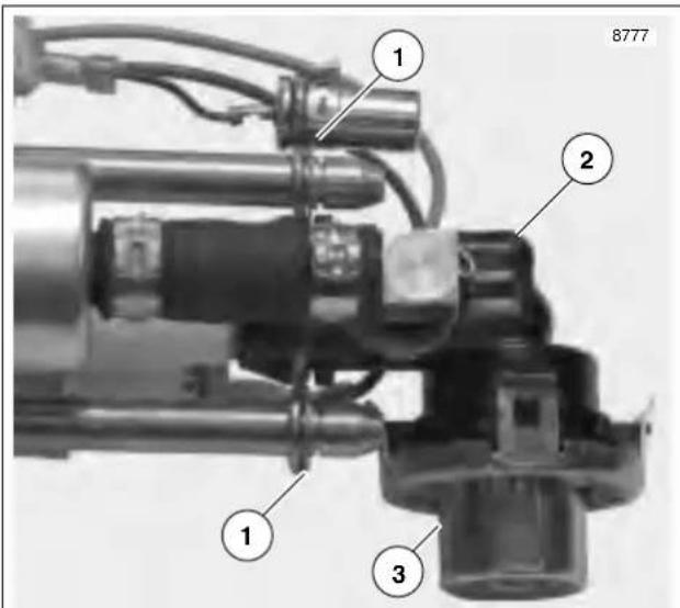
text_image
8777 1 2 1 3- Clips
- Regulator housing
- Regulator
Figure 4-201. Fuel Pump Clips
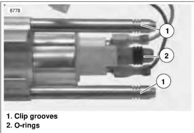
text_image
877B 1. Clip grooves 2. O-ringsFigure 4-202. Regulator Housing O-rings
HOME
Fuel Pump Wire Harness Replacement
- Remove fuel pump assembly from tank. See REMOVAL in this section.
- See Figure 4-200. Remove fuel filter clamp (3). Disconnect hose from fitting (2).
- See Figure 4-201. Remove fuel pump clips (1).
- See Figure 4-199. Disconnect fuel pump connector (10) and low fuel level sensor connector (11).
- Slide fuel pump and fuel filter off of fuel pump assembly.
- Remove terminals from fuel pump connector [86].
NOTE
Note positions of wires in connector for correct assembly.
- Disassemble fuel pump connector [86].
a. See Figure 4-203. Remove connector clips (3).
b. Insert push pin/safety pin (1), into connector as shown.
c. Bend terminal tab towards connector pin and pull wire from opposite side of connector.
d. Repeat for all wires.
- See Figure 4-199. Remove screw (5).
- See Figure 4-204. From outer side of fuel pump assembly, push wire harness through assembly.
- Lubricate new o-rings with clean engine oil. From inner side of fuel pump assembly, push new wire harness into assembly.
- See Figure 4-199. Insert new fastener (5), through ground wire terminal and secure to fuel pump assembly. Tighten to 18-22 in-lbs (2.0-2.5 Nm).
NOTE
After installing terminals, pull slightly on wire to make sure it is seated. If necessary, bend tab on terminal to aid in seating wire.
- Install terminals into proper locations of fuel pump connector [86]. Install connector clips.
- Without pinching fuel screen, slide fuel pump onto fuel pump assembly.
- See Figure 4-200. Attach fuel filter hose to fitting (2) with clamp (3).
- See Figure 4-201. Install clips (1) into middle grooves.
- See Figure 4-199. Connect low fuel level sensor connector (11)..
- Connect fuel pump connectors (10). Connectors are two different sizes.
- Install fuel pump assembly. See INSTALLATION in this section.
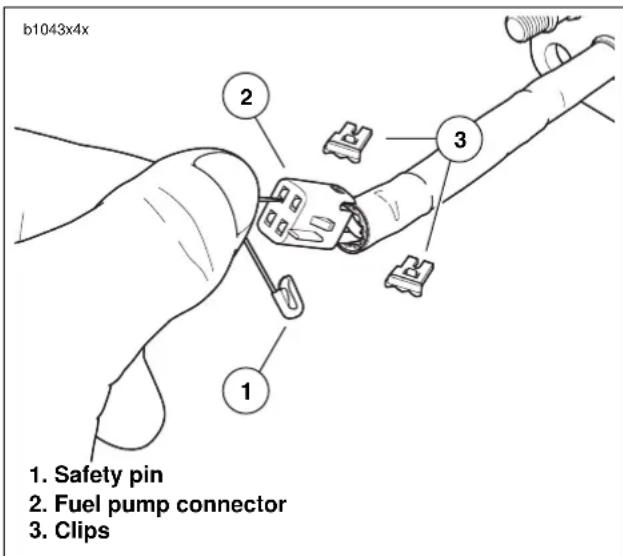
text_image
b1043x4x 1. Safety pin 2. Fuel pump connector 3. ClipsFigure 4-203. Fuel Pump Connector Disassembly
HOME
INSTALLATION
- See Figure 4-199. Replace o-rings (4). Lubricate new o-rings with clean engine oil.
- Install new o-rings on fuel supply stud (2). Larger o-ring is located in groove closer to fuel pump.
- See Figure 4-205. Insert fuel pump into frame until resistance is felt.
- Insert four screws (1) through fuel pump and into frame.
CAUTION
Use all four screws to draw fuel pump into frame. Using less than four screws will damage fuel pump o-rings.
- Using crosswise pattern, draw fuel pump into frame by tightening screws. Final tighten screws to 48-51 in-lbs (5.4-5.8 Nm).
WARNING
Do NOT overtighten fuel fitting nuts. Overtightening fasteners may result in excessive compression of sealing components and fuel leakage which could result in death or serious injury.
- Install fuel supply line (3) banjo fitting over fuel supply stud (4). Install new fastener. Tighten to 120-144 in-lbs (13.6-16.3 Nm).
- Fill tank with a small amount of fuel. Check for leaks.
- Connect fuel pump connector [86] (2) and push cable strap tab into hole in frame.
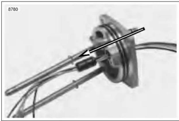
natural_image
Close-up of a mechanical component with wires and a labeled arrow pointing to a feature (no readable text or symbols)Figure 4-204. Wire Harness Removal Direction
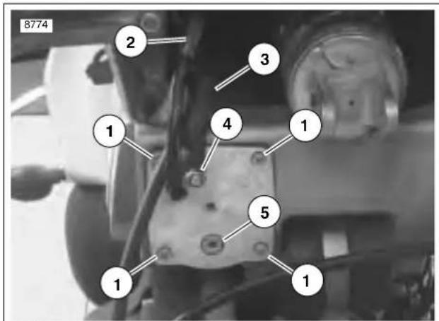
text_image
8774 1 2 3 4 1 5 1 1- Fuel pump fastener
- Fuel pump connector [86]
- Fuel supply line
- Fuel supply stud
- Drain plug 90-110 in lbs (10.2-12.4 Nm)
Figure 4-205. Fuel Pump Installation
GENERAL
The vent valve opens to allow gas vapor to escape the fuel tank and either vent to the atmosphere or to the charcoal canister on California Models (EVAP-equipped) and closes to prevent gasoline from leaking out of the fuel tank if the vehicle is tipped at an extreme angle.
NOTE
The fuel tank must be drained to perform this service.
REMOVAL
- Drain fuel tank. See DRAINING FUEL TANK under 4.38 FUEL PUMP.
- Remove fuel tank vent line from vent valve.
- See Figure 4-207. Remove vent valve fasteners (5).
- Remove bracket (4), vent valve (3) and o-ring (2) from fuel tank/frame (1).
INSTALLATION
- See Figure 4-207. Install new vent valve o-ring (2).
- Install vent valve (3) into fuel tank/frame. Vent valve nozzle should be at approximately the 7:00 position.
- Install bracket over vent valve. Slot in bracket should line up with notch in valve.
- Loosely install vent valve fasteners (5).
- Tighten fasteners to 39-41 in-lbs (4.4-4.6 Nm).
- Connect fuel tank vent line to vent valve.
- Install airbox. See 4.43 AIRBOX.
- Install intake cover assembly. See 2.34 INTAKE COVER ASSEMBLY.
- Connect negative battery cable. Tighten battery terminal hardware to 60-96 in-lbs (7-11 Nm).
WARNING
After installing seat, pull upward on front of seat to be sure it is locked in position. If seat is loose, it could shift during vehicle operation and startle the rider, causing loss of control which could result in death or serious injury.
- Install seat. See 2.38 SEAT.
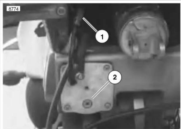
text_image
8774 1 2-
Fuel pump connector [86]
-
Fuel pump drain plug
Figure 4-206. Fuel Pump Drain Screw (swingarm removed for illustration)
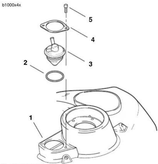
text_image
b1000x4x 1 2 3 4 5- Fuel tank/frame
- O-ring
- Vent valve
- Bracket
- Fastener (2)
Figure 4-207. Fuel Tank Vent Valve
REMOVAL
NOTE
The fuel tank must be drained to perform this service.
- Drain fuel tank. See DRAINING FUEL TANK under 4.38 FUEL PUMP.
- Remove fuel filler cap.
- See Figure 4-209. Remove fasteners (4) securing fuel cap retaining ring (3) to fuel filler neck (1).
- Remove fuel cap retaining ring and o-ring (2). Discard o-ring.
INSTALLATION
- Coat new o-ring (2) with thin film of clean engine oil.
- Place o-ring into groove in underside of fuel cap retaining ring (3).
Be sure o-ring remains in groove of fuel cap retaining ring during installation. - Insert fuel cap retaining ring into fuel filler neck.
- Install fasteners (4). Tighten to 17-70 in-lbs (1.9-7.9 Nm).
- Install fuel filler cap.
NOTE
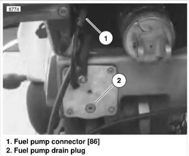
text_image
8774 1. Fuel pump connector [86] 2. Fuel pump drain plugFigure 4-208. Fuel Pump Drain Screw (swingarm removed for illustration)
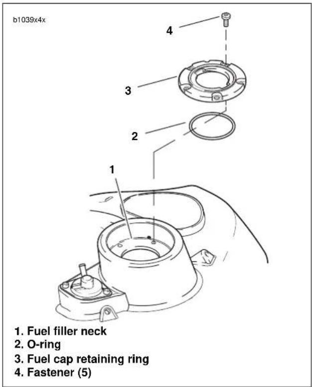
text_image
b1039x4x 1. Fuel filler neck 2. O-ring 3. Fuel cap retaining ring 4. Fastener (5)Figure 4-209.
GENERAL
See Figure 4-211. The throttle body consists of the following components:
● Fuel supply fitting.
● Idle speed adjustment screw.
● Cable bracket.
● Throttle position sensor.
- Throttle lever.
REMOVAL
WARNING
The gasoline in the fuel supply line downstream of the fuel pump is under high pressure (49 psi [338 kPa]). To avoid an uncontrolled discharge or spray of gasoline, always purge the system of high pressure gas before servicing throttle body. Gasoline is extremely flammable and highly explosive. Inadequate safety precautions could result in death or serious injury.
- Purge the fuel supply line of high pressure gasoline.
a. See Figure 4-210. Disconnect the 4-place fuel pump connector [86]. Connector is located on the left side, above the fuel pump.
b. With the motorcycle in neutral, start the engine and allow vehicle to run.
c. When the engine stalls, press the starter button for 3 seconds to remove any remaining fuel from fuel line.
d. Reconnect fuel pump connector.
- Label and detach throttle cables. See 2.23 THROTTLE CONTROL.
- See Figure 4-212. On California models, pull EVAP hose from fitting (1).
- Rotate engine for service. See 3.3 ENGINE ROTATION FOR SERVICE.
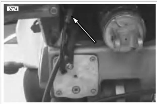
natural_image
Close-up of mechanical components with a white arrow pointing to a component (no visible text or symbols)Figure 4-210. Fuel Pump connector [86] (swingarm removed for illustration)
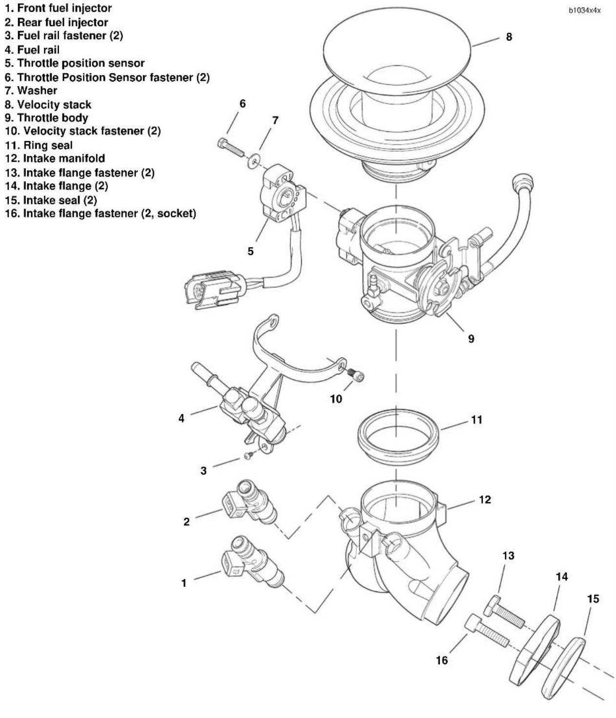
text_image
1. Front fuel injector 2. Rear fuel injector 3. Fuel rail fastener (2) 4. Fuel rail 5. Throttle position sensor 6. Throttle Position Sensor fastener (2) 7. Washer 8. Velocity stack 9. Throttle body 10. Velocity stack fastener (2) 11. Ring seal 12. Intake manifold 13. Intake flange fastener (2) 14. Intake flange (2) 15. Intake seal (2) 16. Intake flange fastener (2, socket)Figure 4-211. Throttle Body/Intake Manifold Assembly
HOME
- Remove assembly from motorcycle.
a. See Figure 4-213. On primary cover side, loosen but do not remove the two front and rear intake flange fasteners (2).
b. Remove fastener (1) holding manifold to engine mount.
c. See Figure 4-214. On gearcase cover side, remove both intake flange fasteners from cylinder heads.
d. Slide the throttle body and manifold assembly through top of bike frame.
- See Figure 4-211. Remove intake flanges (14) from manifold. Remove and discard seals (15).
REPAIR
Throttle Position Sensor
See 4.36 THROTTLE POSITION SENSOR for removal, installation and calibration information.
Intake Manifold
- See Figure 4-215. Remove upper fuel rail fastener (1).
- See Figure 4-211. Separate intake manifold (12) from throttle body (9). Discard ring seal (11).
- Install new ring seal on intake manifold.
- Install intake manifold on throttle body.
- See Figure 4-215. Apply a drop of LOCTITE THREAD-LOCKER 222 (purple) to threads of fuel rail fastener (1).
- Install fastener. Tighten to 24-28 in-lbs (2.7-3.2 Nm).
Fuel Injectors
- Remove throttle body. See REMOVAL in this section.
- Separate fuel rail assembly from intake manifold.
a. See Figure 4-215. Remove both injector clips (4).
b. Remove fuel rail fasteners (1, 6) that hold the fuel rail to the throttle body and manifold.
c. Separate fuel rail from injectors (2, 5) by gently rocking the fuel rail and pulling it away from the injectors.
- Remove fuel injectors (2, 5) from manifold by gently rocking and pulling it away from the manifold.
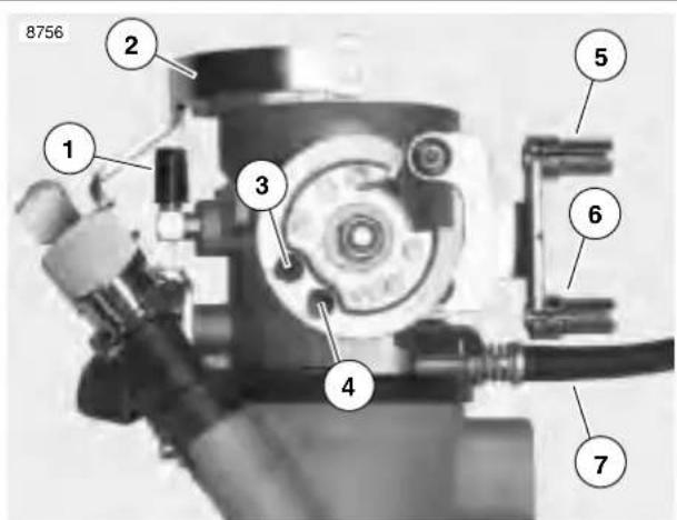
text_image
8756 1 2 3 4 5 6 7- EVAP hose fitting
- Velocity stack bracket
- Throttle control cable attachment
- Idle control cable attachment
- Throttle control cable slot
- Idle control cable slot
- Idle adjuster cable
Figure 4-212. Throttle Cable Bracket (Typical)

text_image
8750 1 2-
Manifold to engine mount fastener
-
Intake flange fastener (2)
Figure 4-213. Intake Manifold (primary side)
WARNING
Do not use any injector that has damaged or deformed O-rings. Damaged O-rings may leak gasoline. Gasoline is extremely flammable and highly explosive. Use of damaged O-rings could result in death or serious injury.
- Inspect all injector O-rings for cuts, tears or general deterioration. Replace injector if O-rings have been damaged or have taken a definite set.
- Apply a thin coat of clean engine oil to top and bottom injector O-rings.
- See Figure 4-215. Install fuel injectors.
a. Install both injectors (2, 5) into intake manifold.
b. Press the fuel rail assembly (3) onto the top of the injectors.
c. Apply a drop of LOCTITE THREADLOCKER 222 (purple) to threads of fuel rail fasteners (1, 6).
d. Secure the fuel rail to the throttle body and manifold with fasteners. Tighten to 24-28 in-lbs (2.7-3.2 Nm).
- Snap the injector clips (4) over the flange on the fuel rail outlet and into the top grove in the injector.
Testing
- Remove intake cover assembly. See 2.34 INTAKE COVER ASSEMBLY.
- Remove airbox cover. See 4.43 AIRBOX.
- Conduct test.
a. Turn key ON for two seconds.
b. Turn key OFF for two seconds.
c. Repeat Steps A and B five consecutive times.
d. Open throttle, replace fuel injectors if there is any evidence of raw fuel in throttle body manifold.
-
Install airbox cover. See 4.43 AIRBOX.
-
Install intake cover assembly. See 2.34 INTAKE COVER ASSEMBLY.
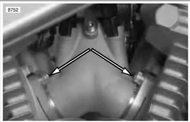
natural_image
Close-up of a mechanical component with directional arrows indicating movement or force (no visible text or symbols)Figure 4-214. Intake Manifold fasteners (gearcase cover side)
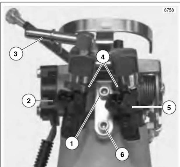
text_image
8758 3 4 2 1 6 5- Upper fuel rail fastener
- Rear fuel injector
- Fuel rail assembly
- Clip (2)
- Front fuel injector
- Lower fuel rail fastener
Figure 4-215. Fuel Injectors
INSTALLATION
- See Figure 4-216. Install front and rear intake flanges onto manifold with the counterbore facing out. Each intake flange is labeled and the pieces are not interchangeable.
- Place a new seal in each intake flange with the beveled side against the counterbore.
- Install throttle body/intake manifold assembly.
a. See Figure 4-213. Slide the assembly toward installed position. Manifold should slide over fasteners (2) on primary cover side of engine.
b. Align holes in intake flanges with those in cylinder heads and start screws.
c. Make sure throttle body is centered between cylinders and tighten all intake flange screws to 6-10 ft-lbs (8-14 Nm).
- Rotate engine into installed position. See 3.3 ENGINE ROTATION FOR SERVICE.
- Attach throttle cables. See 2.23 THROTTLE CONTROL.
- Attach wiring.
a. Injector cables are tagged F(ront) and R(ear) for ease of assembly. Push connector halves together until latches "click." Grooves in female connector must align with the tabs in male housing.
b. Connect throttle position sensor by pushing the connector halves together. Slots on female connector must fully engage tabs on male connector housing.
- Connect EVAP hose to port at bottom of throttle body (California models only).
- Calibrate throttle position sensor if removed or replaced. See 4.36 THROTTLE POSITION SENSOR.
- Install airbox. See 4.43 AIRBOX.
- Check throttle cable adjustment. See 2.23 THROTTLE CONTROL.
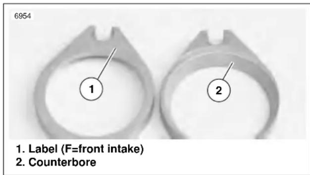
text_image
6954 1. Label (F=front intake) 2. CounterboreFigure 4-216. Intake Flanges
GENERAL
!DANGER
Propane is an extremely flammable liquid and vapor. Vapor may cause flash fire. Keep away from heat, sparks and flame. Keep container closed. Use only with adequate ventilation.
WARNING
Read all directions and warnings on propane bottle. Failure to follow all directions and warnings on bottle could result in death or serious injury.
● To prevent false readings, keep airbox cover installed when performing test.
- Do not direct propane into air scoop, false readings will result.
LEAK TESTER
Parts List
● Standard 14oz. propane cylinder.
● SNAP-ON YA7148 Propane Enrichment Kit.
● 12 in. (304 mm) long-1/4 in. (6mm) diameter copper tubing.
Tester Assembly
- Cut rubber hose from kit to 18 in. (457 mm) in length.
- See Figure 4-217. Flatten one end of copper tube to form a nozzle.
- Insert round side of copper tube into end of tubing.
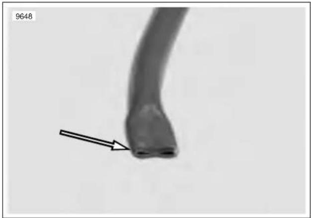
natural_image
Close-up of a curved, segmented object with an arrow pointing to a small feature (no text or symbols visible)Figure 4-217. Nozzle
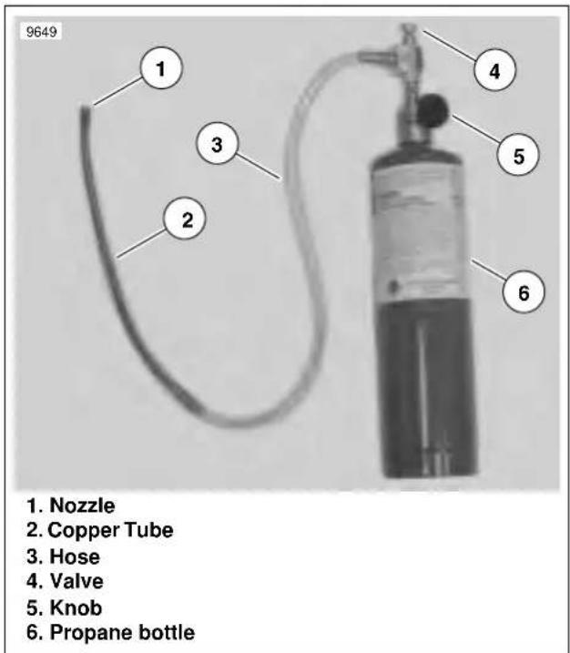
text_image
9649 1. Nozzle 2. Copper Tube 3. Hose 4. Valve 5. Knob 6. Propane bottleFigure 4-218. Leak Tester
- Start engine.
- Warm engine to operating temperature.
- See Figure 4-218. Turn knob (5) counterclockwise to open propane bottle (6).
! DANGER
Propane is an extremely flammable liquid and vapor. Vapor may cause flash fire. Keep away from heat, sparks and flame. Keep container closed. Use only with adequate ventilation.
NOTE
Do not direct propane stream toward front of engine. If propane enters air scoop a false reading will be obtained.
- Aim nozzle toward possible sources of leak such as fuel injectors and intake tract.
- Push valve (4) to release propane. Tone of engine will change when propane enters source of leak.
REMOVAL
- Remove intake cover assembly. 2.34 INTAKE COVER ASSEMBLY.
- See Figure 4-219. Remove fuel vent tube (3) from fuel vapor valve (4) and groove on top of airbox cover (2).
- Unlatch six lock tabs (1) and remove airbox cover from baseplate.
- Remove the filter element from baseplate. Inspect and replace if necessary.
- See Figure 4-220. Remove air cleaner baseplate.
a. Remove four fasteners (1) and raise baseplate (4).
b. Disconnect longer breather hose from baseplate (pull out from bottom).
c. Disconnect shorter breather hose from PVC valve located on top of rear cylinder.
d. Remove IAT sensor (2) from grommet on bottom of baseplate.
e. Lift baseplate off of frame, carefully disengaging baseplate from rubber sealing ring (8) on velocity stack (7).
f. Remove baseplate from motorcycle.
INSPECTION
- Inspect air cleaner. Check for dirt, torn filter material and general condition. Replace if necessary.
- Inspect inside of backing plate and cover. Remove any dirt or debris.
- Inspect condition of velocity stack and velocity stack sealing ring, If torn or damaged, replace.
- Inspect IAT sensor and replace if faulty. See 4.35 INTAKE AIR TEMPERATURE SENSOR
- Inspect breather hoses, intake air temperature sensor grommet and baseplate gasket (3). Replace as necessary.
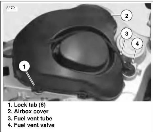
text_image
8372 1. Lock tab (6) 2. Airbox cover 3. Fuel vent tube 4. Fuel vent valveFigure 4-219. Airbox Cover
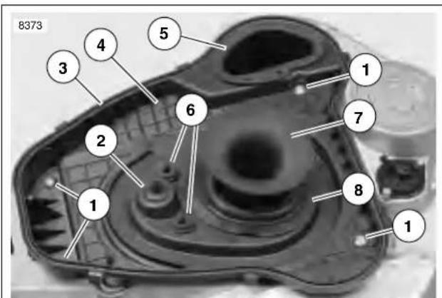
text_image
8373 1 2 3 4 5 6 7 8 11. Fasteners
- Intake air temperature sensor (IAT)
- Gasket
- Baseplate
- Intake snorkel
- Breather hoses
- Velocity stack
- Velocity stack sealing ring
Figure 4-220. baseplate
INSTALLATION
- See Figure 4-221. Hold baseplate above mounting position.
- Insert IAT sensor into grommet on baseplate from underside.
NOTE
A small amount of soapy water applied to the inside diameter of grommet will make breather hose installation easier.
CAUTION
In next step, be sure breather hoses do not extend past Intake air temperature sensor tower. If hoses extend past tower, damage to sensor may occur.
- Insert longer breather hose into right baseplate grommet from underside.
- Attach shorter breather hose onto crankcase breather located on top of rear cylinder.
- Carefully lower baseplate into mounting position. Ensure rubber sealing ring on velocity stack completely engages
baseplate. Baseplate should be sandwiched between upper and lower rubber sealing rings.
- Install baseplate to frame with four fasteners and washers (5). Tighten fasteners to 84-120 in-lbs (9.5-13.6 Nm).
- Position air cleaner filter on baseplate.
- Install airbox to baseplate and latch six latches to secure.
- Route vent hose through groove on airbox to vent valve.
- Install intake cover assembly. See 2.34 INTAKE COVER ASSEMBLY.
WARNING
After installing seat, pull upward on front of seat to be sure it is locked in position. If seat is loose, it could shift during vehicle operation and startle the rider, causing loss of control which could result in death or serious injury.
- Install seat. See 2.38 SEAT.
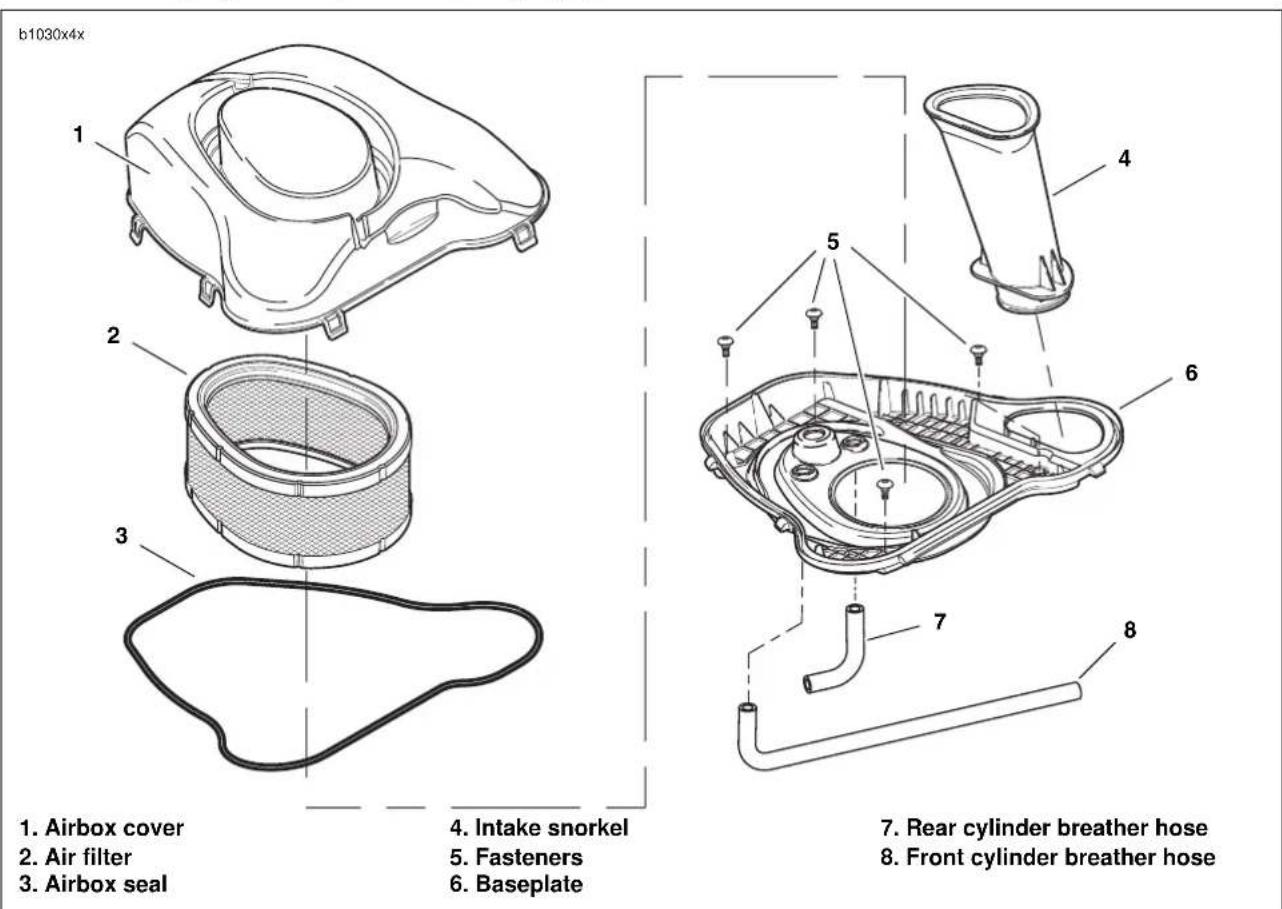
text_image
b1030x4x 1. Airbox cover 2. Air filter 3. Airbox seal 4. Intake snorkel 5. Fasteners 6. Baseplate 7. Rear cylinder breather hose 8. Front cylinder breather hoseFigure 4-221. Airbox
GENERAL
Buell motorcycles sold in the state of California are equipped with an evaporative (EVAP) emissions control system. The EVAP system prevents fuel hydrocarbon vapors from escaping into the atmosphere and is designed to meet the California Air Resource Board (CARB) regulations in effect at the time of manufacture.
The EVAP functions in the following manner:
● Hydrocarbon vapors in the fuel tank are directed through the vent valve and stored in the carbon canister. If the vehicle is tipped at an abnormal angle, the vent valve closes to prevent liquid gasoline from leaking out of the fuel tank through the fuel tank vent hose.
- When the engine is running, manifold venturi negative pressure (vacuum) slowly draws off the hydrocarbon vapors from the carbon canister through the canister vent hose. These vapors pass through the throttle body manifold and are burned as part of normal combustion in the engine.
TROUBLESHOOTING
WARNING
Verify that the evaporative emissions system hoses do not contact hot exhaust or engine parts. The hoses contain flammable vapors that can be ignited if damaged, which could result in death or serious injury.
The system has been designed to operate with a minimum of maintenance. Check that all hoses are properly routed and connected and are not pinched or kinked.
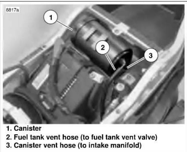
text_image
8817a 1. Canister 2. Fuel tank vent hose (to fuel tank vent valve) 3. Canister vent hose (to intake manifold)Figure 4-222. Carbon Canister Installation.
REMOVAL
Vent Valve
- Remove vent valve. See 4.39 FUEL TANK VENT VALVE.
- If necessary, label fuel tank vent hose at canister fitting and remove.
Canister
- Remove upper tail body work. See 2.36 TAIL FRAME AND BODY WORK.
- See Figure 4-222. The canister assembly mounts behind the battery in the tail section.
- Label and disconnect the fuel tank vent hose (2) and canister vent hose (3) from the canister.
- See Figure 4-224. Remove rear shock absorber reservoir fasteners (2). Move reservoir assembly away from canister.
- Slide canister towards left side of vehicle to disengage from mounting plate (1).
Vent Valve
WARNING
Verify that the fuel tank vent hose does not contact hot exhaust or engine parts. The hose contains flammable vapors that can be ignited if damaged, which could result in death or serious injury.
- Install vent valve. See 4.39 FUEL TANK VENT VALVE.
- See Figure 4-222. Attach fuel tank vent hose (2) to canister if disconnected.
Canister
NOTE
In next step, be sure canister hose barbs are facing left side of vehicle and barb holes are facing toward front of vehicle.
- See Figure 4-224. Slide canister into position on canister mounting plate (1).
- Place rear shock reservoir assembly (3) into position.
NOTE
See Figure 4-225. To ensure proper reservoir mounting, temporarily place upper body work onto tail section and adjust reservoir placement so adjuster screw (1) aligns with alignment hole (2).
- See Figure 4-224. Install reservoir mounting fasteners (2). Tighten fasteners to 120-144 in-lbs (13.6-16.3 Nm).
WARNING
Always make sure fuel hoses are seated against the component they connect to and that hose clamps are properly tightened and positioned on straight section of fitting and not on the fitting barb. Failure to comply may result in fuel leakage which could result in death or serious injury.
NOTE
The barb is the larger outside diameter portion (bump) on the fuel fitting.
- See Figure 4-222. Connect two hoses to the canister. Make sure to push hoses all the way on to carbon canister fittings.
- Install upper tail body work. See 2.36 TAIL FRAME AND BODY WORK.
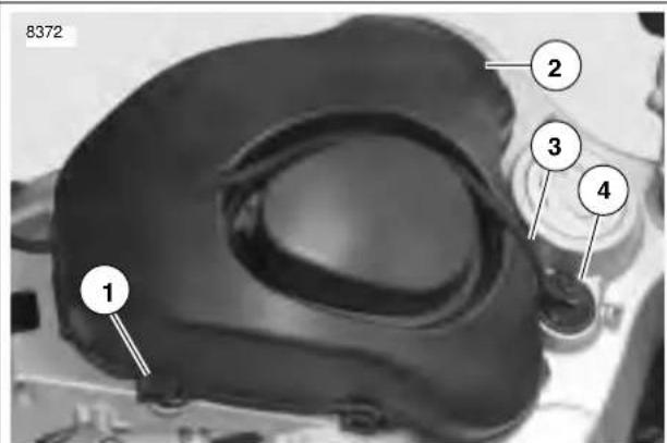
text_image
8372 1 2 3 4- Lock tab (6)
- Airbox cover
- Fuel tank vent hose
- Fuel vent valve
Figure 4-223. Airbox Cover
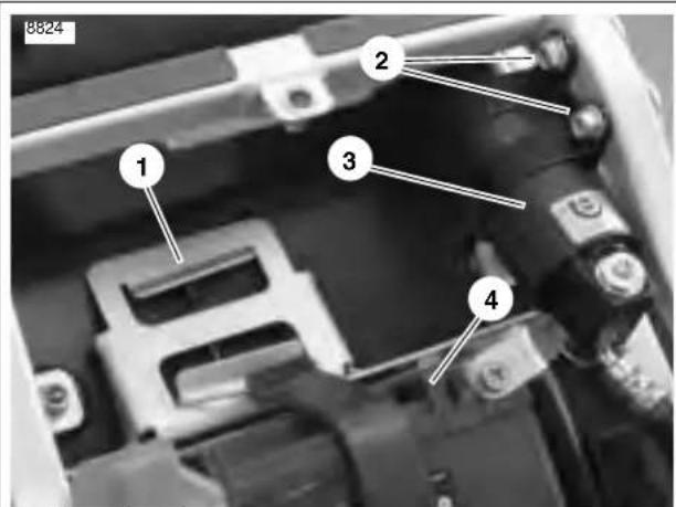
text_image
8824 1 2 3 4- Mounting plate
- Rear shock reservoir fasteners (2)
- Rear shock reservoir
- Battery
Figure 4-224. Carbon Canister Mounting
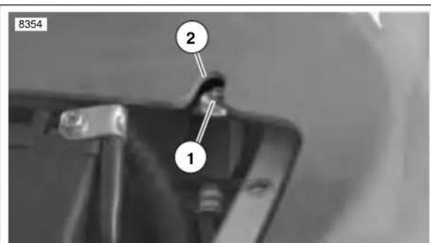
text_image
8354 2 1- Adjuster screw
- Adjuster screw alignment hole
Figure 4-225. Adjuster Screw Alignment
HOME
HOSE ROUTING
Both fuel tank and canister vent hoses are routed through notch in fan body.
NOTE
For information on vent hose routing, see D.1 HOSE AND WIRE ROUTING.
WARNING
Always make sure fuel hoses are seated against the component they connect to and that hose clamps are properly tightened and positioned on straight section of fitting and not on the fitting barb. Failure to comply may result in fuel leakage which could result in death or serious injury.
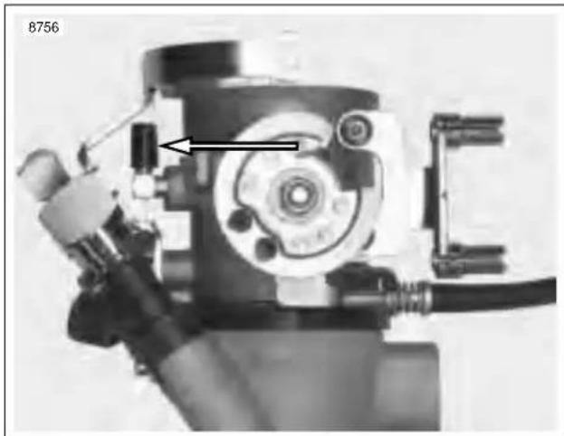
natural_image
Mechanical component with mechanical parts and a labeled arrow (no readable text or symbols)Figure 4-226. Emissions Hose Attachment, California Modesl Only
Table Of Contents
ELECTRIC STARTER 5
SUBJECT PAGE NO.
5.1 Specifications 5-1
5.2 Electric Starter System 5-2
5.3 Starting System Diagnosis 5-4
5.4 Starter Activation Circuits 5-8
5.5 Diagnostics/Troubleshooting 5-9
5.6 Starter System Testing 5-11
5.7 Starter 5-12
5.8 Starter Solenoid 5-21
Table 5-1. Starter Specifications
| STARTER | |
| Free Speed 3000 RPM (min.) @ 11.5 V | |
| Free Current 90 amp (max.) @ 11.5 V | |
| Stall Current 400 amp (max.) @ 2.4 V | |
| Stall Torque 8 ft-lbs (11 Nm) (min.) @ 2.4 V |
Table 5-2. Service Wear Specifications
| SERVICE WEAR LIMITS | IN. MM | |
| Brush Length (minimum) 0.433 11.0 | ||
| Commutator Diameter (minimum) | 1.141 28.981 |
TORQUE VALUES
| ITEM TORQUE | NOTES | ||
| Starter battery positive cable Nut | 60-85 in-lbs | 7-10 Nm | page 5-19 |
| Starter mounting bolts | 13-20 ft-lbs | 18-27 Nm | page 5-19 |
GENERAL
The starter is made up of an armature, field winding assembly, solenoid, drive assembly, idler gear and drive housing.
The starter motor torque is increased through gear reduction. The gear reduction consists of the drive pinion on the armature, an idler gear and a clutch gear in the drive housing. The idler gear is supported by rollers. The clutch gear is part of the overrunning clutch/drive assembly.
The overrunning clutch is the part which engages and drives the clutch ring gear. It also prevents the starter from overrunning. The field windings are connected in series with the armature through brushes and commutator segments.
Wiring Diagrams
For additional information concerning the starting system circuit, see the wiring diagram at the end of Section 7, ELECTRICAL.
Starter Relay
The starter relay is not repairable. Replace the unit if it fails.
Starter Interlock
See 7.5 STARTER INTERLOCK for operation and troubleshooting information.
OPERATION
See Figure 5-1. When the starter switch is pushed, the starter relay is activated and battery current flows into the pull-in winding (10) and the hold-in winding (11), to ground.
The magnetic forces of the pull-in and hold-in windings in the solenoid push the plunger (7) causing it to shift to the left. This action engages the pinion gear (1) with the clutch ring gear (13). At the same time, the main solenoid contacts (8) are closed, so battery current flows directly through the field windings (3) to the armature (4) and to ground. Simultaneously, the pull-in winding (10) is shorted.
The current continues flowing through the hold-in winding (11) keeping the main solenoid contacts (8) closed. At this point, the starter begins to crank the engine.
After the engine has started, the pinion gear (1) turns freely on the pinion shaft through the action of the overrunning clutch (12). The overrunning clutch prevents the clutch ring gear (13) (which is now rotating under power from the engine) from turning the armature (4) too fast.
When the starter switch is released, the current of the hold-in winding (11) is fed through the main solenoid contacts (8) and the direction of the current in the pull-in winding (10) is reversed. The solenoid plunger (7) is returned to its original position by the return spring, which causes the pinion gear (1) to disengage from the clutch ring gear (13).
b0164a5x
Starter at moment starter switch is closed
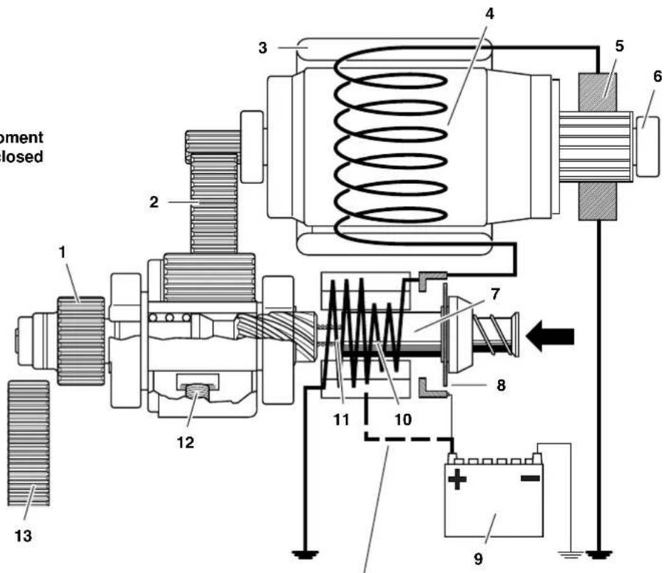
text_image
Component Closed 1 2 3 4 5 6 7 8 9 10 11 12 13Starting circuit-see wiring diagram
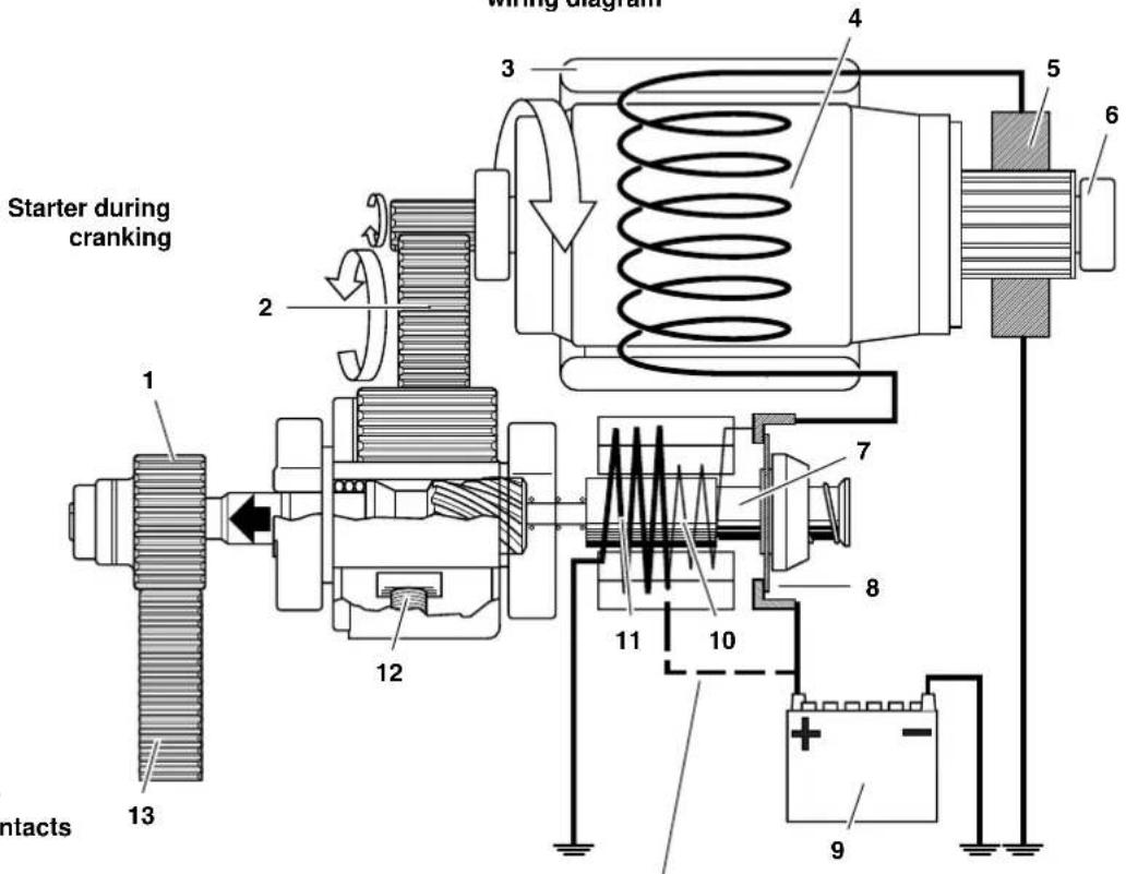
text_image
Wiring Diagram Starter during cranking 1 2 3 4 5 6 7 8 9 10 11 12 13 ContactsStarting circuit-see wiring diagram
-
Pinion gear
-
Idler gear
-
Field winding
-
Armature
-
Brush
-
Ball bearing
-
Solenoid plunger
-
Main solenoid contacts
-
Battery
-
Pull-in winding
-
Hold-in winding
-
Overrunning clutch
-
Clutch ring gear
Figure 5-1. Starter Operation
DIAGNOSTICS
Diagnostic Notes
The reference numbers below correlate with the circled numbers on the starter system flow charts.
- See VOLTAGE DROPS under 5.5 DIAGNOSTICS/TROUBLESHOOTING.
- Remove starter motor and connect jumper wires as described in FREE RUNNING CURRENT DRAW TEST under 5.7 STARTER.
- Take measurement with connector mated.
- See DIAGNOSTICS in 7.5 STARTER INTERLOCK.
- See STARTER CURRENT DRAW TEST under 5.6 STARTER SYSTEM TESTING.
- See FREE RUNNING CURRENT DRAW TEST.
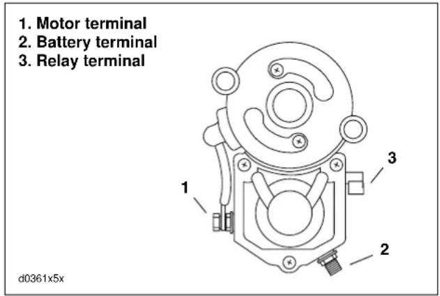
text_image
1. Motor terminal 2. Battery terminal 3. Relay terminal 1 2 3 d0361x5xFigure 5-2. Starter Terminals
Starter Test 1
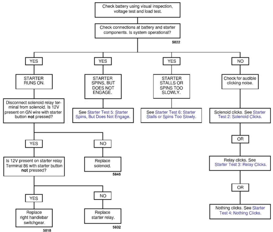
flowchart
graph TD
    A["Check battery using visual inspection, voltage test and load test."] --> B["Check connections at battery and starter components. Is system operational?"]
    B --> C{5822}
    B --> D{YES}
    B --> E{YES}
    B --> F{YES}
    B --> G{NO}
    C --> H["STARTER RUNS ON."]
    D --> I["STARTER SPINS, BUT DOES NOT ENGAGE."]
    E --> J["STARTER STALLS OR SPINS TOO SLOWLY."]
    F --> K["Check for audible clicking noise."]
    H --> L["Disconnect solenoid relay terminal from solenoid. Is 12V present on GN wire with starter button not pressed?"]
    I --> M["See Starter Test 5: Starter Spins, But Does Not Engage."]
    J --> N["See Starter Test 6: Starter Stalls or Spins Too Slowly."]
    K --> O["Solenoid clicks. See Starter Test 2: Solenoid Clicks."]
    L --> P{YES}
    M --> Q{NO}
    P --> R["Is 12V present on starter relay Terminal 86 with starter button not pressed?"]
    Q --> S["Replace solenoid."]
    R --> T{YES}
    S --> U{NO}
    T --> V["Replace right handlebar switchgear."]
    U --> W["Replace starter relay."]
    V --> X["5818"]
    W --> Y["5832"]
    K --> Z["OR"]
    Z --> AA["Relay clicks. See Starter Test 3: Relay Clicks."]
    AA --> AB["OR"]
    AB --> AC["Nothing clicks. See Starter Test 4: Nothing Clicks."]
HOME
Starter Test 2: Solenoid Clicks
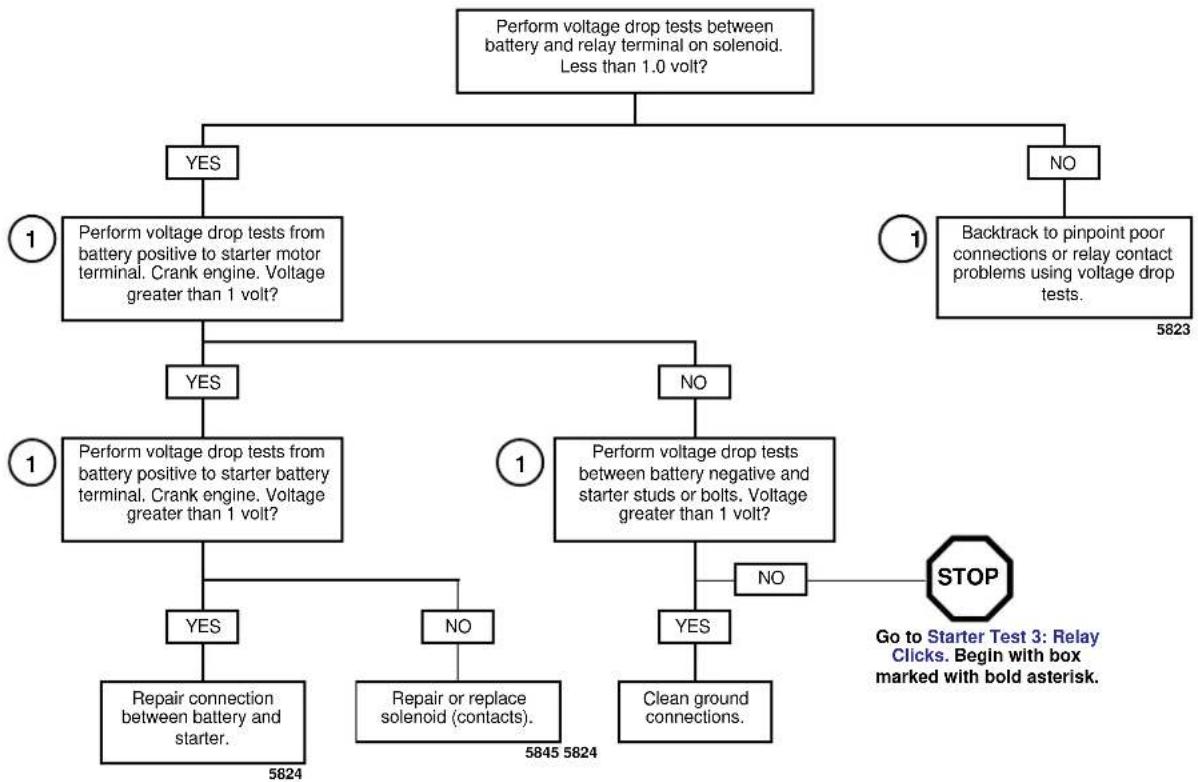
flowchart
graph TD
    A["Perform voltage drop tests between battery and relay terminal on solenoid. Less than 1.0 volt?"] --> B{YES}
    A --> C{NO}
    B --> D{Perform voltage drop tests from battery positive to starter motor terminal. Crank engine. Voltage greater than 1 volt?}
    C --> E{Backtrack to pinpoint poor connections or relay contact problems using voltage drop tests. 5823}
    D --> F{Perform voltage drop tests from battery positive to starter battery terminal. Crank engine. Voltage greater than 1 volt?}
    E --> G{Perform voltage drop tests between battery negative and starter studs or bolts. Voltage greater than 1 volt?}
    F --> H{Repair connection between battery and starter. 5824}
    F --> I{Repair or replace solenoid (contacts). 5845 5824}
    G --> J{Clean ground connections.}
    G --> K{NO}
    K --> L{STOP}
    L --> M["Go to Starter Test 3: Relay Clicks. Begin with box marked with bold asterisk."]
Starter Test 3: Relay Clicks
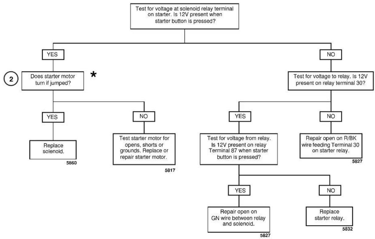
flowchart
graph TD
    A["Test for voltage at solenoid relay terminal on starter. Is 12V present when starter button is pressed?"] --> B{YES}
    A --> C{NO}
    B --> D["Does starter motor turn if jumped?"]
    D --> E{YES}
    D --> F{NO}
    E --> G["Replace solenoid. 5860"]
    F --> H["Test starter motor for opens, shorts or grounds. Replace or repair starter motor. 5817"]
    C --> I["Test for voltage to relay. Is 12V present on relay terminal 30?"]
    I --> J{YES}
    I --> K{NO}
    J --> L["Test for voltage from relay. Is 12V present on relay Terminal 87 when starter button is pressed?"]
    K --> M["Repair open on R/BK wire feeding Terminal 30 on starter relay. 5827"]
    L --> N{YES}
    L --> O{NO}
    N --> P["Repair open on GN wire between relay and solenoid. 5827"]
    O --> Q["Replace starter relay. 5832"]
Starter Test 4: Nothing Clicks
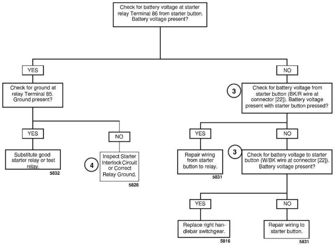
flowchart
graph TD
    A["Check for battery voltage at starter relay Terminal 86 from starter button. Battery voltage present?"] --> B{YES}
    A --> C{NO}
    B --> D{Check for ground at relay Terminal 85. Ground present?}
    D --> E{YES}
    D --> F{NO}
    E --> G["Substitute good starter relay or test relay. 5832"]
    E --> H{Inspect Starter Interlock Circuit or Correct Relay Ground. 5828}
    H --> I["4"]
    F --> J{YES}
    F --> K{NO}
    J --> L["Repair wiring from starter button to relay. 5831"]
    K --> M{Check for battery voltage to starter button (BK/R_wire_at_connector["22"]). Battery voltage present with starter button pressed?}
    M --> N{YES}
    M --> O{NO}
    N --> P["Replace right handlebar switchgear. 5816"]
    O --> Q["Repair wiring to starter button. 5831"]
HOME
Starter Test 5: Starter Spins, But Does Not Engage
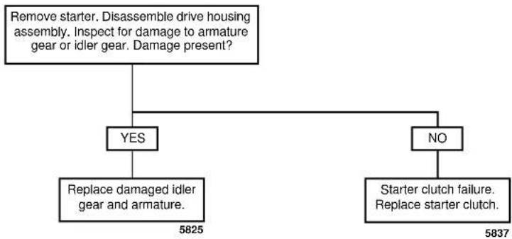
flowchart
graph TD
    A["Remove starter. Disassemble drive housing assembly. Inspect for damage to armature gear or idler gear. Damage present?"] --> B{YES}
    A --> C{NO}
    B --> D["Replace damaged idler gear and armature. 5825"]
    C --> E["Starter clutch failure. Replace starter clutch. 5837"]
Starter Test 6: Starter Stalls or Spins Too Slowly
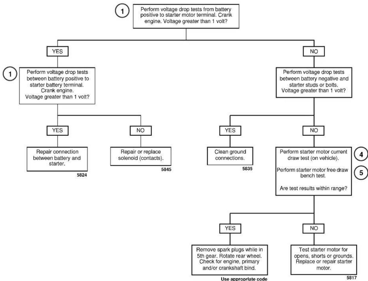
flowchart
graph TD
    A["Perform voltage drop tests from battery positive to starter motor terminal. Crank engine. Voltage greater than 1 volt?"] --> B{YES}
    A --> C{NO}
    B --> D["Perform voltage drop tests between battery positive to starter battery terminal. Crank engine. Voltage greater than 1 volt?"]
    D --> E{YES}
    D --> F{NO}
    E --> F
    F --> G["Repair connection between battery and starter. 5824"]
    F --> H["Repair or replace solenoid (contacts). 5845"]
    G --> I["Use appropriate code"]
    H --> J["Clean ground connections. 5835"]
    H --> K["Perform starter motor free draw bench test. Are test results within range?"]
    K --> L{YES}
    K --> M{NO}
    L --> N["Remove spark plugs while in 5th gear. Rotate rear wheel. Check for engine, primary and/or crankshaft bind."]
    M --> O["Test starter motor for opens, shorts or grounds. Replace or repair starter motor. 5817"]
b0157a5x
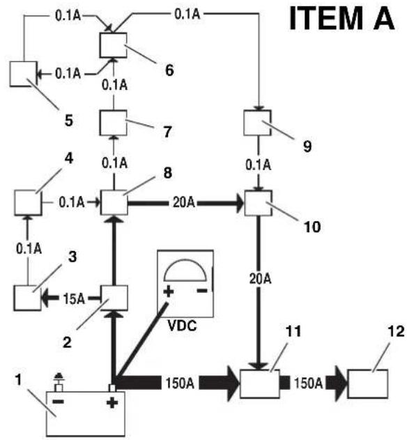
flowchart
graph TD
    A["1"] --> B["+"]
    B --> C["150A"]
    C --> D["150A"]
    D --> E["12"]
    E --> F["1"]
    F --> G["2"]
    G --> H["3"]
    H --> I["15A"]
    I --> J["4"]
    J --> K["0.1A"]
    K --> L["5"]
    L --> M["6"]
    M --> N["7"]
    N --> O["8"]
    O --> P["9"]
    P --> Q["10"]
    Q --> R["11"]
    R --> S["150A"]
    S --> T["150A"]
    T --> U["VDC"]
    U --> V["20A"]
    V --> W["20A"]
    W --> X["10"]
    X --> Y["150A"]
    Y --> Z["150A"]
    Z --> AA["12"]
    AA --> AB["150A"]
    AB --> AC["150A"]
    AC --> AD["150A"]
    AD --> AE["150A"]
    AE --> AF["150A"]
    AF --> AG["150A"]
    AG --> AH["150A"]
    AH --> AI["150A"]
    AI --> AJ["150A"]
    AJ --> AK["150A"]
    AK --> AL["150A"]
    AL --> AM["150A"]
    AM --> AN["150A"]
    AN --> AO["150A"]
    AO --> AP["150A"]
    AP --> AQ["150A"]
    AQ --> AR["150A"]
    AR --> AS["150A"]
    AS --> AT["150A"]
    AT --> AU["150A"]
    AU --> AV["150A"]
    AV --> AW["150A"]
    AW --> AX["150A"]
    AX --> AY["150A"]
ITEM C ITEM D

flowchart
graph TD
    A["1"] --> B["+"]
    B --> C["150A"]
    C --> D["150A"]
    D --> E["12"]
    E --> F["1"]
    F --> G["3"]
    G --> H["15A"]
    H --> I["2"]
    I --> J["4"]
    J --> K["0.1A"]
    K --> L["6"]
    L --> M["0.1A"]
    M --> N["7"]
    N --> O["8"]
    O --> P["20A"]
    P --> Q["9"]
    Q --> R["10"]
    R --> S["20A"]
    S --> T["11"]
    T --> U["150A"]
    U --> V["150A"]
    V --> W["12"]
    W --> X["1"]
    X --> Y["0.1A"]
    Y --> Z["0.1A"]
    Z --> AA["0.1A"]
    AA --> AB["0.1A"]
    AB --> AC["0.1A"]
    AC --> AD["0.1A"]
    AD --> AE["0.1A"]
    AE --> AF["0.1A"]
    AF --> AG["0.1A"]
    AG --> AH["0.1A"]
    AH --> AI["0.1A"]
    AI --> AJ["0.1A"]
    AJ --> AK["0.1A"]
    AK --> AL["0.1A"]
    AL --> AM["0.1A"]
    AM --> AN["0.1A"]
    AN --> AO["0.1A"]
    AO --> AP["0.1A"]
    AP --> AQ["0.1A"]
    AQ --> AR["0.1A"]
    AR --> AS["0.1A"]
    AS --> AT["0.1A"]
    AT --> AU["0.1A"]
    AU --> AV["0.1A"]
    AV --> AW["0.1A"]
    AW --> AX["0.1A"]
    AX --> AY["0.1A"]
GROUND CIRCUITOPEN CIRCUIT
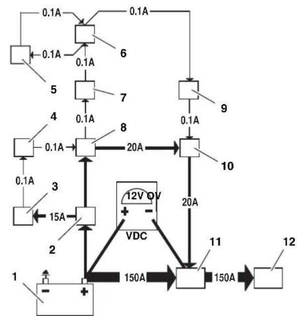
flowchart
graph TD
    A["1"] --> B["+"]
    B --> C["150A"]
    C --> D["150A"]
    D --> E["12"]
    E --> F["12V QV"]
    F --> G["VDC"]
    G --> H["20A"]
    H --> I["10"]
    I --> J["9"]
    J --> K["7"]
    K --> L["6"]
    L --> M["5"]
    M --> N["4"]
    N --> O["3"]
    O --> P["15A"]
    P --> Q["2"]
    Q --> R["1"]
    R --> S["0.1A"]
    S --> T["0.1A"]
    T --> U["0.1A"]
    U --> V["0.1A"]
    V --> W["0.1A"]
    W --> X["0.1A"]
    X --> Y["0.1A"]
    Y --> Z["0.1A"]
- Battery
- Main fuse (30 A)
- Key switch fuse
- Key switch
-
Run/Stop switch
-
Ignition relay (used for junction purposes only)
-
Ignition fuse
-
Key switch relay
-
Start switch
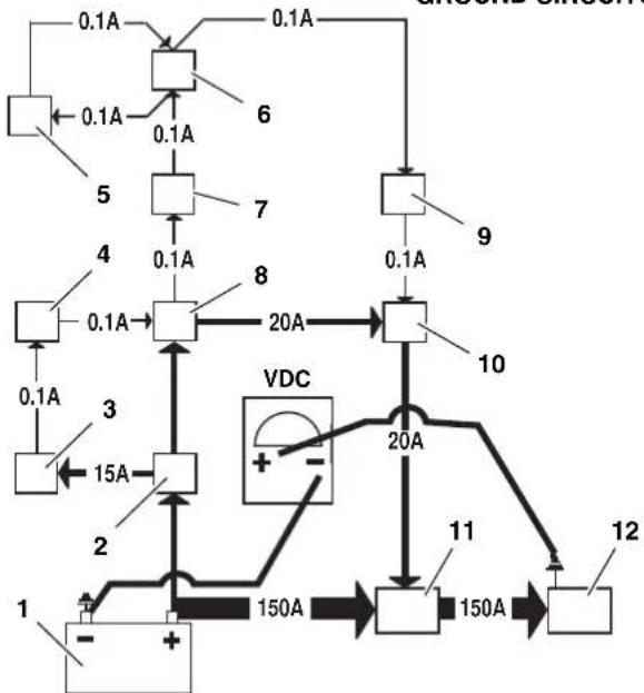
flowchart
graph TD
    A["1"] --> B["2"]
    B --> C["3"]
    C --> D["4"]
    D --> E["5"]
    E --> F["6"]
    F --> G["7"]
    G --> H["8"]
    H --> I["9"]
    I --> J["10"]
    J --> K["11"]
    K --> L["12"]
    L --> M["150A"]
    M --> N["150A"]
    N --> O["VDC"]
    O --> P["20A"]
    P --> Q["20A"]
    Q --> R["15A"]
    R --> S["0.1A"]
    S --> T["0.1A"]
    T --> U["0.1A"]
    U --> V["0.1A"]
    V --> W["0.1A"]
    W --> X["0.1A"]
    X --> Y["0.1A"]
    Y --> Z["0.1A"]
    Z --> AA["0.1A"]
    AA --> AB["0.1A"]
- Start relay
- Solenoid
- Starter
Figure 5-3. Typical Circuity. Refer to wiring diagrams for more information.
GENERAL
Follow the 5.3 STARTING SYSTEM DIAGNOSIS diagram to diagnose starting system problems. The VOLTAGE DROPS procedure below will help you to locate poor connections or components with excessive voltage drops.
VOLTAGE DROPS
Check the integrity of all wiring, switches, fuses and connectors between the source and destination.
The voltage drop test measures the difference in potential or the actual voltage dropped between the source and destination.
- See ITEM A in Figure 5-3. Attach your red meter lead to the most positive part of the circuit, which in this case would be the positive post of the battery (1).
- See ITEM B in Figure 5-3. Attach the black meter lead to the final destination or component in the circuit (solenoid terminal from relay).
- Activate the starter and observe the meter reading. The meter will read the voltage dropped or the difference in potential between the source and destination.
- An ideal circuit's voltage drop would be 0 volts or no voltage dropped, meaning no difference in potential.
-
See ITEM C in Figure 5-3. An open circuit should read 12 volts, displaying all the voltage dropped, and the entire difference in potential displayed on the meter.
-
Typically, a good circuit will drop less than 1 volt.
- If the voltage drop is greater, back track through the connections until the source of the potential difference is found. The benefit of doing it this way is speed.
a. Readings aren't as sensitive to real battery voltage.
b. Readings show the actual voltage dropped, not just the presence of voltage.
c. This tests the system as it is actually being used. It is more accurate and will display hard to find poor connections.
d. This approach can be used on lighting circuits, ignition circuits, etc. Start from most positive and go to most negative (the destination or component).
- See ITEM D in Figure 5-3. The negative or ground circuit can be checked as well.
a. Place the negative lead on the most negative part of the circuit (or the negative battery post). Remember, there is nothing more negative than the negative post of the battery.
b. Place the positive lead to the ground you wish to check.
c. Activate the circuit. This will allow you to read the potential difference or voltage dropped on the negative or ground circuit. This technique is very effective for identifying poor grounds due to powdered paint. Even the slightest connection may cause an ohmmeter to give a good reading. However, when sufficient current is passed through, the resistance caused by the powdered paint will cause a voltage drop or potential difference in the ground circuit.
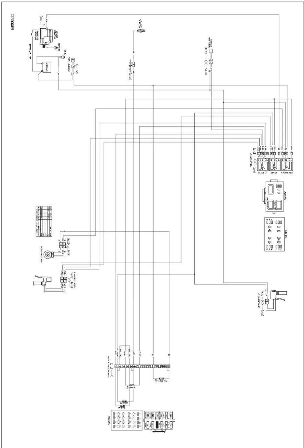
flowchart
graph TD
    A["Top view"] --> B["TO FUSE & BRIKE ADDY"]
    B --> C["TO FUSE"]
    C --> D["CLUTCH SWITCH"]
    D --> E["SO Box"]
    E --> F["SO Box"]
    F --> G["SO Box"]
    G --> H["SO Box"]
    H --> I["SO Box"]
    I --> J["SO Box"]
    J --> K["SO Box"]
    K --> L["SO Box"]
    L --> M["SO Box"]
    M --> N["SO Box"]
    N --> O["SO Box"]
    O --> P["SO Box"]
    P --> Q["SO Box"]
    Q --> R["SO Box"]
    R --> S["SO Box"]
    S --> T["SO Box"]
    T --> U["SO Box"]
    U --> V["SO Box"]
    V --> W["SO Box"]
    W --> X["SO Box"]
    X --> Y["SO Box"]
    Y --> Z["SO Box"]
    Z --> AA["SO Box"]
    AA --> AB["SO Box"]
    AB --> AC["SO Box"]
    AC --> AD["SO Box"]
    AD --> AE["SO Box"]
    AE --> AF["SO Box"]
    AF --> AG["SO Box"]
    AG --> AH["SO Box"]
    AH --> AI["SO Box"]
    AI --> AJ["SO Box"]
    AJ --> AK["SO Box"]
    AK --> AL["SO Box"]
    AL --> AM["SO Box"]
    AM --> AN["SO Box"]
    AN --> AO["SO Box"]
    AO --> AP["SO Box"]
    AP --> AQ["SO Box"]
    AQ --> AR["SO Box"]
    AR --> AS["SO Box"]
    AS --> AT["SO Box"]
    AT --> AU["SO Box"]
    AU --> AV["SO Box"]
    AV --> AW["SO Box"]
    AW --> AX["SO Box"]
    AX --> AY["SO Box"]
Figure 5-4. Electric Starting System Circuit
"ON-MOTORCYCLE" TESTS
Starter Relay Test
NOTE
Starter relay test also applies to ignition and key switch relays.
- See Figure 5-5. Locate starter relay. The relay is attached to the relay block left of instrument console.
- To test relay, proceed to Step 3. If installing a new starter relay, remove old relay. Installnew relay into relay block.
- See Figure 5-6. Obtain a 12 volt battery and a continuity tester or ohmmeter.
a. Pull relay from relay block.
b. Connect positive battery lead to the 86 terminal.
c. Connect negative battery lead to the 85 terminal to energize relay.
d. Check for continuity between the 30 and 87 terminals. A good relay shows continuity (continuity tester lamp "on" or a zero ohm reading on the ohmmeter). A malfunctioning relay will not show continuity and must be replaced.
- If starter relay is functioning properly, proceed to STARTER CURRENT DRAW TEST.
Starter Current Draw Test
NOTES
● Engine temperature should be stable and at room temperature.
● Battery should be fully charged.
See Figure 5-7. Check starter current draw with an induction ammeter before disconnecting battery. Proceed as follows:
- Verify that transmission is in neutral. Disconnect spark plug wires from spark plug terminals.
- Clamp induction ammeter over positive battery cable next to starter.
- With ignition key switch ON, turn engine over by pressing starter switch while taking a reading on the ammeter. Disregard initial high current reading which is normal when engine is first turned over.
a. Typical starter current draw will range between 140-180 amperes.
b. If starter current draw exceeds 180 amperes, then the problem may be in the starter or starter drive. Remove starter for further tests. See 5.7 STARTER.
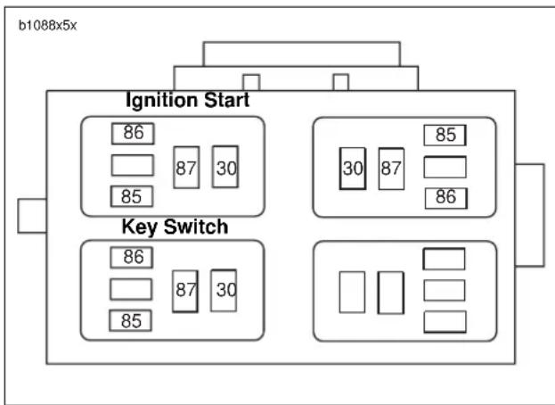
text_image
b1088x5x Ignition Start 86 87 30 85 Key Switch 86 87 30 85Figure 5-5. Relay Block (top view)

text_image
b0755x5x Battery A B 86 87A 85 87 30 Ohmmeter ΩFigure 5-6. Starter Relay Test
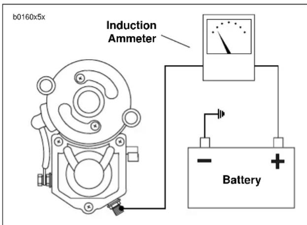
text_image
b0160x5x Induction Ammeter BatteryFigure 5-7. Starter Draw Test
REMOVAL
- Remove seat. See 2.38 SEAT.
- Remove primary cover. See PRIMARY COVER under 6.2 PRIMARY CHAIN.
- Remove sprocket cover. See 2.30 SPROCKET COVER.
NOTE
A ball hex driver may be required to gain access to the starter mounting bolts.
4. See Figure 5-8. Remove two starter mounting bolts and washers (1).
5. See Figure 5-9. Remove fastener with washer (1) (metric).
a. Remove protective boot.
b. Remove positive battery cable ring terminal (2).
c. Detach solenoid wire (3).
- Remove starter and gasket from the gearcase cover side.
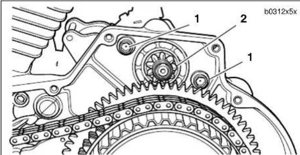
text_image
b0312x5x 1 2 1- Mounting bolts and washers
- Starter
Figure 5-8. Starter Mounting
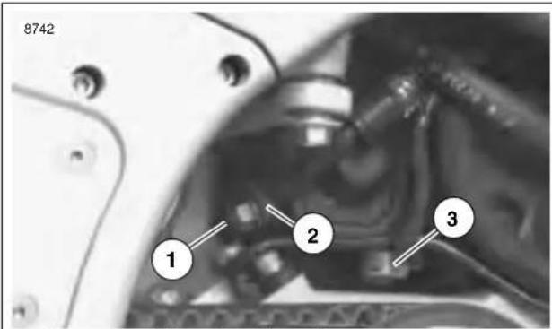
text_image
8742 1 2 3- Fastener with washer (metric)
- Positive battery cable ring terminal
- Solenoid wire
Figure 5-9. Starter Wires (Protective Boot Not Shown)
TESTING ASSEMBLED STARTER
Free Running Current Draw Test
- Place starter in vise, using a clean shop towel to prevent scratches or other damage.
- See Figure 5-10. Attach one heavy jumper cable (6 gauge minimum).
a. To the starter mounting flange (1).
b. To the negative (-) terminal of a fully charged battery.
- Connect a second heavy jumper cable (6 gauge minimum).
a. To the positive (+) terminal of the battery (2).
b. To an inductive ammeter (3). Continue on to the battery terminal (4) on the starter solenoid.
- Connect a smaller jumper cable (14 gauge minimum).
a. To the positive (+) terminal of the battery (2).
b. To the solenoid relay terminal (5).
- Check ammeter reading.
a. Ammeter should show 90 amps maximum.
b. If reading is higher, disassemble starter for inspection. See 5.7 STARTER.
c. If starter current draw on vehicle was over 200 amps and this test was within specification, there may be a problem with engine or primary drive.
Starter Solenoid
NOTE
Do not disassemble solenoid. Before testing, disconnect field wire from motor terminal as shown in Figure 5-11.
CAUTION
Each test should be performed for only 3-5 seconds to prevent damage to solenoid.
NOTE
The solenoid Pull-in, Hold-in, and Return tests must be performed together in one continuous operation. Conduct all three tests one after the other in the sequence given without interruption.
Solenoid Pull-in Test
- See Figure 5-11. Using a 12 volt battery, connect three separate test leads as follows:
a. Solenoid housing to negative battery post.
b. Solenoid motor terminal to negative battery post.
c. Solenoid relay terminal to positive battery post.
- Observe starter pinion.
a. If starter pinion pulls in strongly, solenoid is working properly.
b. If starter pinion does not pull in, replace the sole-noid.
b0439x5x
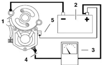
text_image
Electrical circuit diagram with labeled components including motor, battery, and voltmeter- Mounting flange
- Battery
- Induction ammeter
- Battery terminal
- Relay terminal
Figure 5-10. Free Running Current Draw Test
b0161a5x
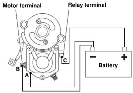
text_image
Motor terminal Relay terminal B A C BatteryFigure 5-11. Pull-In Test
HOME
Solenoid Hold-in Test
-
See Figure 5-12. With test leads still connected in the manner specified in the previous SOLENOID PULL-IN TEST, disconnect solenoid motor terminal/battery negative test lead (B) at negative battery post only; reconnect loose end of this test lead to positive battery post instead.
-
Observe starter pinion.
a. If starter pinion remains in pull-in position, solenoid is working properly.
b. If starter pinion does not remain in pull-in position, replace the solenoid.
Solenoid Return Test
-
See Figure 5-13. With test leads still connected in the manner specified at the end of the previous SOLENOID HOLD-IN TEST, disconnect solenoid relay terminal/positive battery post test lead (C) at either end.
-
Observe starter pinion.
a. If starter pinion returns to its original position, sole-noid is working properly.
b. If starter pinion does not return to its original position, replace the solenoid.
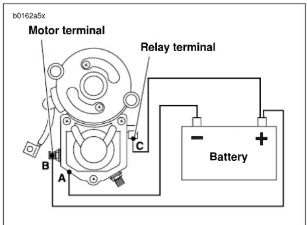
text_image
b0162a5x Motor terminal Relay terminal B A C BatteryFigure 5-12. Hold-In Test
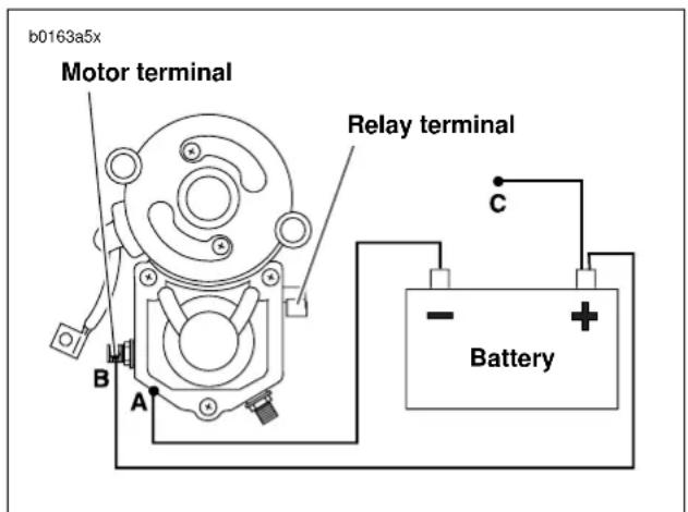
text_image
b0163a5x Motor terminal Relay terminal B A C BatteryFigure 5-13. Return Test
HOME
DISASSEMBLY, INSPECTION AND REPAIR
- See Figure 5-14. Lift rubber boot (1). Remove field wire nut with washer (2) (metric) to detach field wire (3).
- See Figure 5-15. Remove both thru-bolts (1, 3).
- Remove both end cover screws with O-rings (2) and end cover (4).
- See Figure 5-16. Use a wire hook to pull upward on brush springs (3), and lift brushes out of holder (2). Remove brush holder.
- Check brush length. Replace all four brushes if length of any one brush is less than 0.433 in. (11.0 mm).
NOTE
Brushes not available separately. Purchase a new field frame (1) and brush holder (2) to replace brushes.
- Remove armature (4) and field frame (1).
- Place armature in lathe or truing stand and check commutator runout and diameter.
a. Commutators with more than 0.016 in. (0.406 mm) of runout should be replaced or machined on a lathe.
b. Replace commutators when diameter is less than 1.141 in. (28.981 mm)
c. Check armature bearings. Replace if necessary.
CAUTION
Do not use sandpaper or emery cloth to remove burrs on commutator. Otherwise, abrasive grit may remain on commutator segments; this could lead to excessive brush wear. Use only the recommended crocus cloth.
NOTE
See Figure 5-17. If an undercutting machine is not available, undercutting can be done satisfactorily using a thin hacksaw blade. After undercutting, lightly sand the commutator with crocus cloth to remove any burrs.
- Check depth of mica on commutator. If undercut is less than 0.008 in. (0.203 mm), use an undercutting machine to undercut the mica to 1/32 in. (0.794 mm) deep. The slots should then be cleaned to remove any dirt or copper dust.
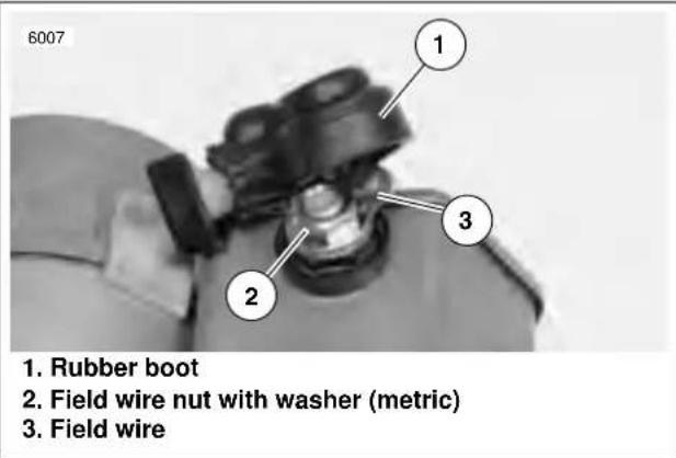
text_image
6007 1. Rubber boot 2. Field wire nut with washer (metric) 3. Field wireFigure 5-14. Field Wire
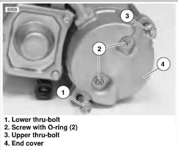
text_image
6009 1. Lower thru-bolt 2. Screw with O-ring (2) 3. Upper thru-bolt 4. End coverFigure 5-15. Removing the Thru-Bolts
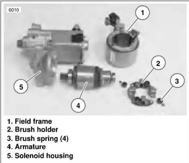
text_image
6010 1. Field frame 2. Brush holder 3. Brush spring (4) 4. Armature 5. Solenoid housingFigure 5-16. Starter Components
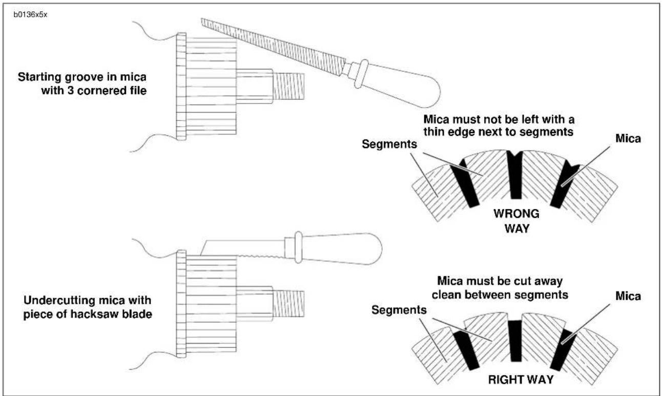
text_image
b0136x5x Starting groove in mica with 3 cornered file Mica must not be left with a thin edge next to segments Segments Mica WRONG WAY Undercutting mica with piece of hacksaw blade Mica must be cut away clean between segments Segments Mica RIGHT WAYFigure 5-17. Undercutting Mica Separators
HOME
- See Figure 5-18. Check for SHORTED ARMATURE with a growler.
a. Place armature on growler (1).
b. Hold a thin steel strip (2) (hacksaw blade) against armature core and slowly turn armature.
c. A shorted armature will cause the steel strip to vibrate and be attracted to the core. Replace shorted armatures.
- See Figure 5-19. Check for a GROUNDED ARMATURE with an ohmmeter or continuity tester.
a. Touch one probe to any commutator segment (1).
b. Touch the other probe to the armature core (2).
c. There should be no continuity (infinite ohms). If there is continuity, then the armature is grounded. Replace grounded armatures.
- See Figure 5-20. Check for OPEN ARMATURE with an ohmmeter or continuity tester.
a. Check for continuity between all commutator segments (1).
b. There should be continuity (0 ohms) at all test points. No continuity at any test point indicates armature is open and must be replaced.
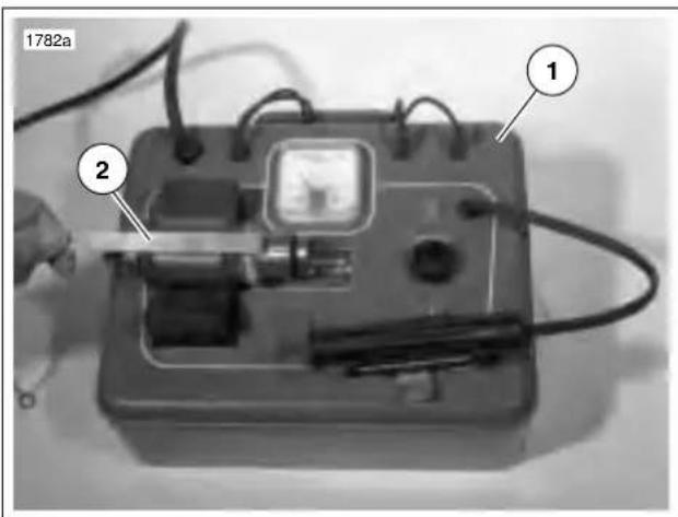
text_image
1782a ① ②Figure 5-18. Shorted Armature Test Using Growler
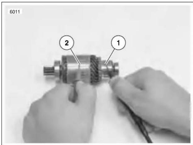
text_image
6011 ② ①Figure 5-19. Grounded Armature Test
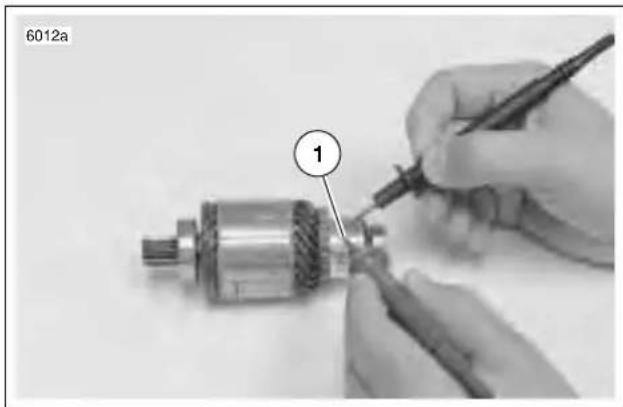
natural_image
Close-up of hands using a screwdriver to adjust a mechanical component (no visible text or symbols)Figure 5-20. Open Armature Test
HOME
- See Figure 5-21. Check for GROUNDED FIELD COIL with an ohmmeter or continuity tester.
a. Touch one probe to the frame (1).
b. Touch the other probe to each of the brushes (2) attached to the field coil.
c. There should be no continuity (infinite ohms). If there is any continuity at either brush, then the field coil(s) are grounded and the field frame must be replaced.
- See Figure 5-22. Check for OPEN FIELD COILS with an ohmmeter or continuity tester.
a. Touch one probe to the field wire (1).
b. Touch the other probe to each of the brushes attached to the field coil(s) (2).
c. There should be continuity (0 ohms). If there is no continuity at either brush, then the field coil(s) are open and the field frame must be replaced.
- See Figure 5-23. Test BRUSH HOLDER INSULATION with an ohmmeter or continuity tester.
a. Touch one probe to holder plate (1).
b. Touch the other probe to each of the positive (insulated) brush holders (2).
c. There should be no continuity (infinite ohms). If there is continuity at either brush holder, replace the brush holder assembly.
-
See Figure 5-24. Remove two drive housing mounting screws (6). Remove drive housing (5) from solenoid housing.
-
Remove drive (1), idler gear (2), idler gear bearing (3), and O-ring (4) from drive housing (O-ring is located in drive housing groove).
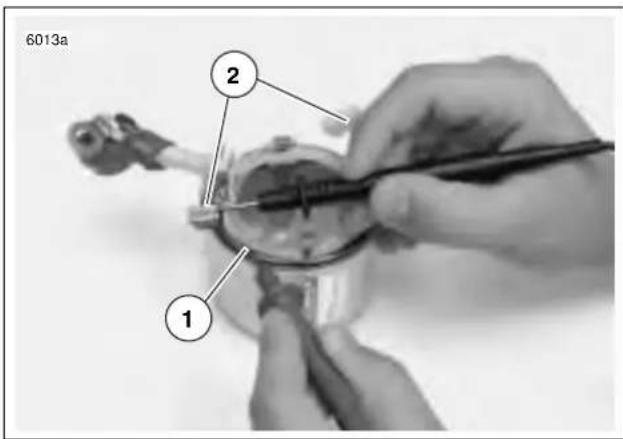
text_image
6013a 1 2Figure 5-21. Grounded Field Test
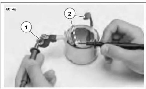
text_image
6014a 1 2Figure 5-22. Open Field Test
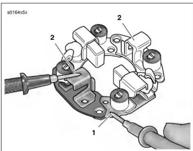
text_image
s0164x5x 2 2 1Figure 5-23. Brush Holder Insulation Test
ASSEMBLY
- See Figure 5-24. Clean, inspect and lubricate drive assembly components. Lubricate parts with high temperature grease, such as LUBRIPLATE 110.
- See Figure 5-27. When installing drive assembly components, open end of idler bearing cage (15) faces toward solenoid.
- When installing drive housing (10) to solenoid housing (11), use new O-ring (16). Be sure to install return spring (17) and ball (18).
- Lubricate armature bearings (8) with high temperature grease, such as LUBRIPLATE 110. Install armature (6) and field frame (7) to solenoid housing (11).
- Install brushes and brush holder (4).
- Install O-rings (23). Attach end cover (3) with end cover screws and O-rings (2).
- Install thru-bolts (1).
- Attach field wire (22) to solenoid housing (11) with field wire nut and washer (24) (metric). Replace rubber boot.
INSTALLATION
- Install starter and starter gasket from the gearcase cover side.
- See Figure 5-25. Connect wiring to starter.
a. Connect solenoid wire (3).
b. Attach positive battery cable ring terminal (2) to stud with fastener and washer.
c. Install nut and washer (1) (metric). Tighten nut to 60-85 in-lbs (7-10 Nm).
d. Replace protective boot. - See Figure 5-26. Install both starter mounting bolts and washers. Tighten to 13-20 ft-lbs (18-27 Nm).
- Install sprocket cover. See 2.30 SPROCKET COVER.
- Install primary cover. See PRIMARY COVER under 6.2 PRIMARY CHAIN.
WARNING
After installing seat, pull upward on front of seat to be sure it is locked in position. If seat is loose, it could shift during vehicle operation and startle the rider, causing loss of control which could result in death or serious injury.
- Install seat. See 2.38 SEAT.
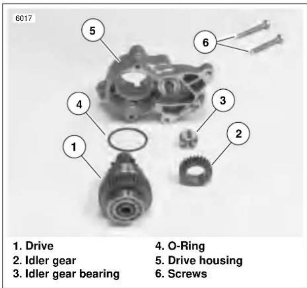
text_image
6017 1. Drive 2. Idler gear 3. Idler gear bearing 4. 5. 6. 3. 2. 1. 4. O-Ring 5. Drive housing 6. ScrewsFigure 5-24. Starter Drive Assembly
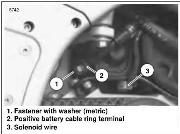
text_image
8742 1. Fastener with washer (metric) 2. Positive battery cable ring terminal 3. Solenoid wireFigure 5-25. Starter Wires (Protective Boot Not Shown)
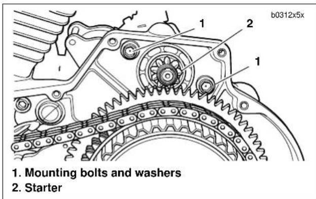
text_image
b0312x5x 1. Mounting bolts and washers 2. StarterFigure 5-26. Starter Mounting
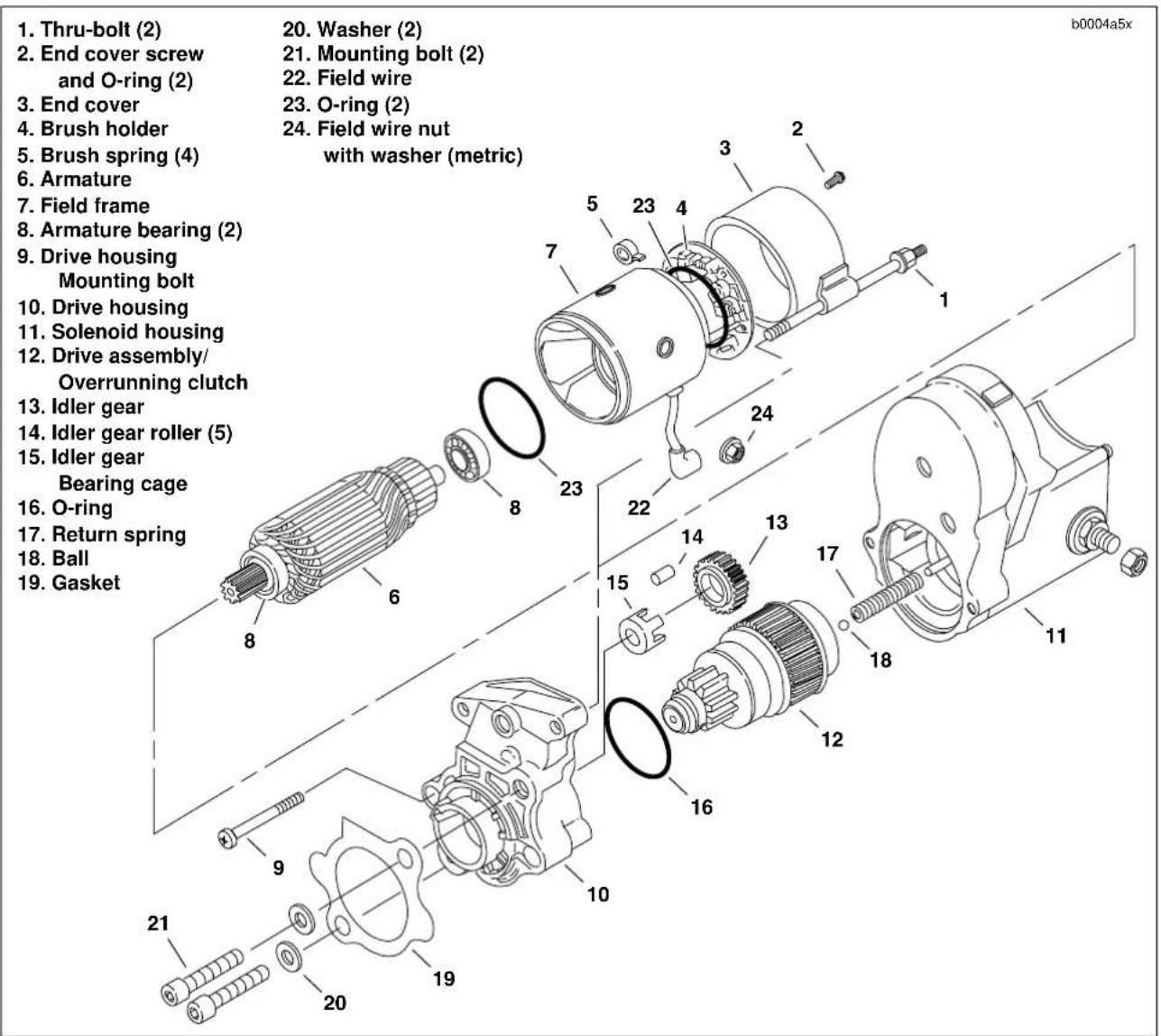
text_image
1. Thru-bolt (2) 2. End cover screw and O-ring (2) 3. End cover 4. Brush holder 5. Brush spring (4) 6. Armature 7. Field frame 8. Armature bearing (2) 9. Drive housing Mounting bolt 10. Drive housing 11. Solenoid housing 12. Drive assembly/ Overrunning clutch 13. Idler gear 14. Idler gear roller (5) 15. Idler gear Bearing cage 16. O-ring 17. Return spring 18. Ball 19. Gasket 20. Washer (2) 21. Mounting bolt (2) 22. Field wire 23. O-ring (2) 24. Field wire nut with washer (metric)Figure 5-27. Starter Assembly
GENERAL
CAUTION
See Figure 5-28. Do not tighten nut (7) without removing items (1) through (5). Movement will cause damage to the contact.
The starter solenoid is a switch that is designed to open and close the starting circuit electromagnetically. The switch consists of contacts and a winding around a hollow cylinder containing a movable plunger.
DISASSEMBLY
- See Figure 5-28. Remove screws (1) and clip (2).
- Remove cover (3) and gasket (4). Discard gasket.
- Remove plunger (5) from solenoid housing (6).
ASSEMBLY
- See Figure 5-28. Replace wire connection hardware as necessary.
- Install plunger (5) in solenoid housing (6).
- Install new gasket (4) onto cover (3).
- Position cover with gasket onto solenoid housing. Install clip (2) and screws (1).
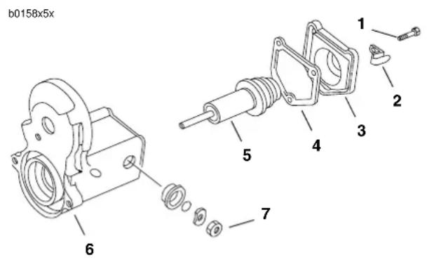
text_image
b0158x5x 1 2 3 4 5 6 7- Screw (3)
- Clip
- Cover
- Gasket
- Plunger
- Solenoid housing
- Nut
Figure 5-28. Starter Solenoid
Table Of Contents
6.1 Specifications 6-1
6.2 Primary Chain 6-3
6.3 Clutch Release Mechanism 6-7
6.4 Primary Drive/Clutch 6-9
6.5 Transmission 6-23
6.6 Case Disassembly For Transmission Removal 6-24
6.7 Transmission Disassembly 6-27
6.8 Transmission Assembly 6-34
6.9 Main Drive Gear 6-36
6.10 Transmission Right Case Bearings 6-39
6.11 Transmission Left Case Bearings 6-41
6.12 Transmission Installation 6-42
6.13 Shifter Shaft Installation 6-46
6.14 Transmission Sprocket 6-47
NOTE
Service wear limits are given as a guideline for measuring components that are not new. For measurement specifications not given under SERVICE WEAR LIMITS, see NEW COMPONENTS.
Table 6-1. Primary Drive (Engine-to-transmission)
| ITEM NEW COMPONENTS SERVICE WEAR LIMITS | |
| Engine sprocket – number of teeth 34 N/A | |
| Clutch sprocket – number of teeth 57 N/A | |
| Ratio* 1.60:1 N/A |
Table 6-2. Final Drive (Transmission-to-rear Wheel)
| ITEM NEW COMPONENTS SERVICE WEAR LIMITS | ||
| Transmission sprocket – number of teeth 30 Inspect at 15,000 mi | ||
| Rear wheel sprocket – number of teeth | 72 Inspect at 15,000 mi | |
| Secondary drive belt – number of teeth | 155 | Replace at 15,000 mi |
| Ratio | 2.40:1 | |
Table 6-3. Transmission
| ITEM NEW COMPONENTS SERVICE WEAR LIMITS | ||
| Primary drive / transmission lubricant capacity (approximately) | 32 fl. oz. (946 ml) | N/A |
| Overall gear ratios** | ||
| First gear (low) | 12.74 | N/A |
| Second gear | 8.77 | N/A |
| Third gear | 6.79 | N/A |
| Fourth gear | 5.60 | N/A |
| Fifth gear (high) | 4.74 | N/A |
* Internal gear ratios indicate number of mainshaft revolutions required to drive output sprocket one revolution.
** Overall gear ratios indicate number of engine revolutions required to drive rear wheel one revolution.
Table 6-4. Wet Clutch Multiple Disc-clutch Plate Thickness
| ITEM NEW COMPONENTS SERVICE WEAR LIMITS | ||
| Friction plate (fiber) 0.0866 + 0.0031 in. (2.200 + 0.079 mm) N/A | ||
| Steel plate 0.0629 + 0.0020 in. | (1.598 + 0.051 mm) N/A | |
| Clutch pack (in.) N/A 0.661 in. | (16.789 mm) (minimum) | |
| Friction plate (fiber) (in.) 0.0866 + 0.0031 N/A | ||
Table 6-5. Wet Clutch Multiple Disc-maximum Allowable Warpage
| ITEM NEW COMPONENTS SERVICE WEAR LIMITS | ||
| Friction plate (fiber) N/A | 0.0059 in. (0.150 mm) | |
| Steel plate | N/A | 0.0059 in. (0.150 mm) |
TORQUE VALUES
| ITEM | TORQUE | NOTES | |
| Clutch inspection cover fasteners | 84-108 in-lbs | 9.5-12.2 Nm | Tighten in a crosswise pattern, page 6-6 |
| Clutch inspection cover screws | 84-108 in-lbs | 9.5-12.2 Nm | Tighten crosswise pattern, page 6-8 |
| Clutch mainshaft nut | 70-80 ft-lbs | 94.9-108.5 Nm | LOCTITE 262 , left hand threads, page 6-21 |
| Crankcase 5/16 in. fasteners | 15-19 ft-lbs | 20.3-25 Nm | LOCTITE 262 , page 6-45 |
| Engine sprocket nut | 190-210 ft-lbs | 257.6-284.7 Nm | page 6-20 |
| Idler pulley fasteners | 33-35 ft-lbs | 44.74-47.45 Nm | page 6-49 |
| Negative battery cable at battery terminal | 60-96 in-lbs | 6.8-10.9 Nm | page 6-6 |
| Primary cover bolts | 80-110 in-lbs | 9.0-12.4 Nm | Follow torque sequence, page 6- 6-6 |
| Primary cover fasteners | 80-110 in-lbs | 9-12.4 Nm | page 6-6 |
| Primary cover magnetic drain plug | 14-30 ft-lbs | 19-54 Nm | page 6-6 |
| Rear axle pinch fastener | 40-45 ft-lbs | 54-61 Nm | page 6-49 |
| Rear axle | 48-52 ft-lbs | 65-70 Nm | page 6-49 |
| Retention collar screw | 13-17 ft-lbs | 18-23 Nm | LOCTITE 243 , page 6-46 |
| Shift lever pinch screw | 12-14 ft-lbs | 16.3-19.0 Nm | Page 6-6 |
| Transmission sprocket nut | See NOTES | See NOTES | LOCTITE 262, left hand threads, special torque turn method, page 6-48 |
| Transmission sprocket screws | 90-110 in-lbs | 10.2-12.4 Nm | Replace after 3 removals, page 6-49 |
GENERAL
An opening between the primary drive and transmission compartments allows the same lubricant supply to lubricate moving parts in both areas.
Since the primary chain runs in lubricant, little service will be required other than checking lubricant level and chain tension. If, through hard usage, the primary chain does become worn, it must be replaced. Remove and install the chain following the procedure under 6.4 PRIMARY DRIVE/CLUTCH.
b1050x6x
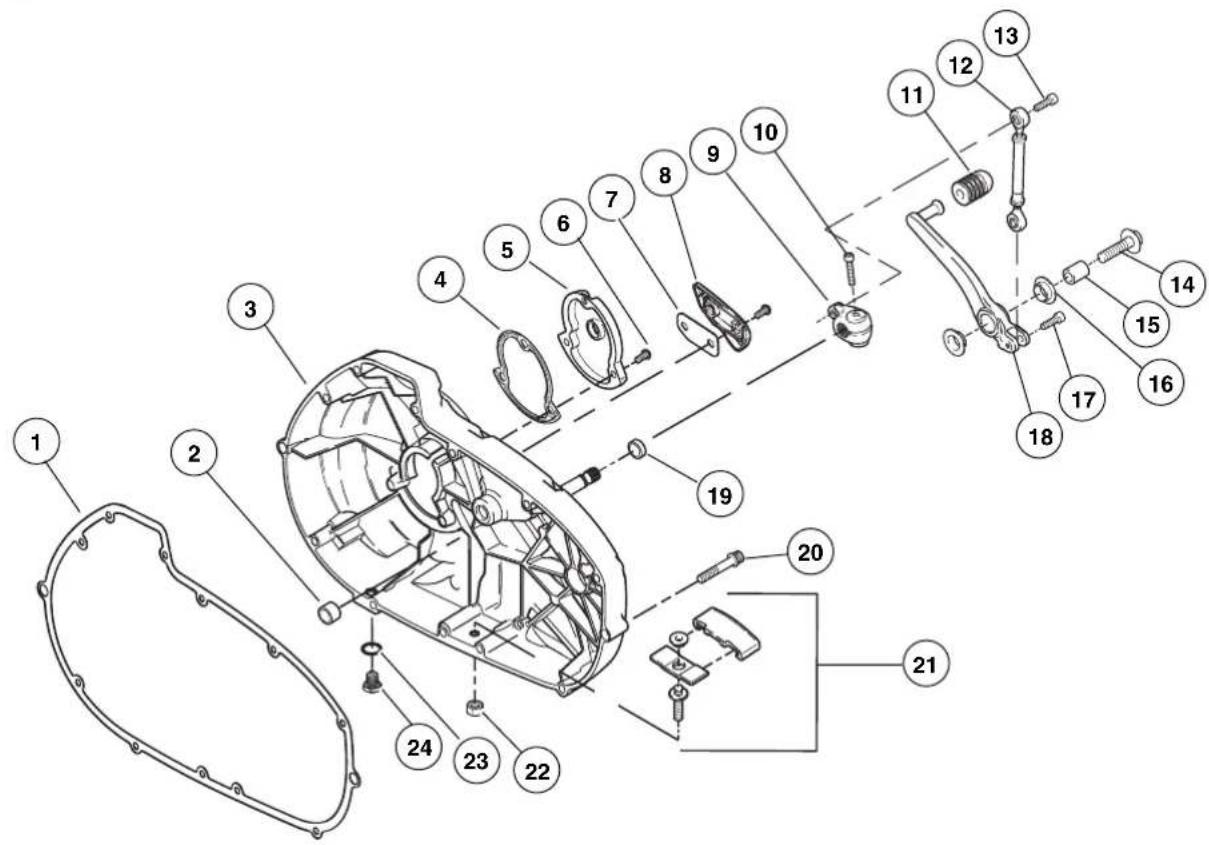
text_image
Exploded view diagram of a mechanical assembly with numbered parts for identification- Gasket, primary cover
- Shifter bushing
- Primary cover
- Gasket, clutch cover
- Cover, clutch
- Screw, sems (5)
- Gasket, inspection cover
-
Cover, inspection
-
Lever, engine
- Screw, engine lever
- Pad, rubber shift lever
- Linkage assembly, shifter
- Bolt, shifter linkage assembly
- Bolt, flange head
- Sleeve, shift/brake lever
-
Bearing, pedal (2)
-
Bolt
- Shifter lever
- Oil seal, shifter shaft
- Screw, sems (14)
- Adjuster assembly
- Nut, chain adjustment
- O-ring
- Drain plug
Figure 6-1. Primary Cover, Primary Chain Adjuster and Shifter Assembly
REMOVAL
Primary Cover
- Remove seat. See 2.38 SEAT.
WARNING
To protect against shock and accidental start-up of vehicle, disconnect the negative battery cable before proceeding. Inadequate safety precautions could result in death or serious injury.
- Disconnect negative battery cable from battery.
- Remove chin fairing. See 2.33 CHIN FAIRING.
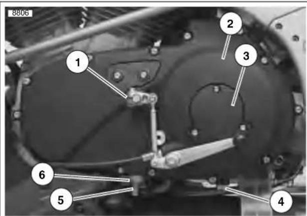
text_image
8806 1 2 3 4 5 6- Shifter linkage
- Primary cover
- Clutch inspection cover
- Drain plug
- Chain adjuster screw
- Locknut
Figure 6-2. Removing Primary Cover
- See Figure 6-2. Place a drain pan under the engine/primary area. Remove drain plug (4) and drain lubricant from primary drive.
- Remove shifter lever assembly and rubber washer. Do not scratch primary cover.
NOTE
It is recommended that the shifter shaft seal be replaced whenever the primary cover is removed.
- Add freeplay to clutch cable. See ADJUSTMENT under 1.8 CLUTCH.
- See Figure 6-2. Loosen locknut (6). Turn chain adjuster screw (5) counterclockwise to remove tension on primary chain.
- Remove three TORX screws with washers and clutch inspection cover.
- See Figure 6-2. Remove clutch inspection cover (3).
6-4 2003 Buell XB9R: Drive/Transmission
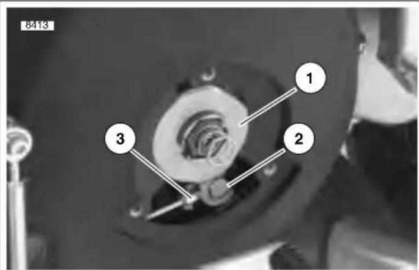
text_image
8413 1 2 3- Outer ramp and hook
- Coupling
- Cable end
Figure 6-3. Clutch Release Mechanism
- See Figure 6-3. Remove the outer ramp and hook (1) from the cable end (3) and coupling (2). Remove cable end from slot in coupling. See 6.3 CLUTCH RELEASE MECHANISM
- Remove screws which secure primary cover. Remove cover and gasket.
- Discard gasket.
- Remove and discard shifter lever oil seal.
- Clean all parts in a non-volatile cleaning solution or solvent.
WARNING
Low pressure compressed air can blow debris into your face and eyes. Always wear eye protection or a face shield when using pressurized air. Failure to take adequate safety precautions could result in death or serious injury.
- Blow parts dry with low pressure compressed air.
HOME
Primary Chain Adjuster Inspection & Replacement
NOTE
The primary chain adjuster shoe should be inspected and measured for wear every 10,000 miles (16,000 km).
NOTE
See Figure 6-5. When measuring the shoe for wear it is necessary to measure from the top surface of the shoe to the bottom of the chain groove. If the measurement in any one of the four locations exceeds the listed specifications, the shoe should be replaced.
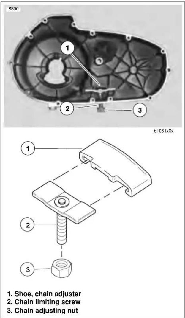
text_image
8800 1 2 3 b1051x6x 1 2 3 1. Shoe, chain adjuster 2. Chain limiting screw 3. Chain adjusting nutFigure 6-4. Primary Chain Adjuster
- See Figure 6-4. Remove chain adjusting nut from the chain limiting screw.
- Turn the chain limiting screw clockwise until it can be removed from the inside of the primary cover along with the chain adjuster shoe.
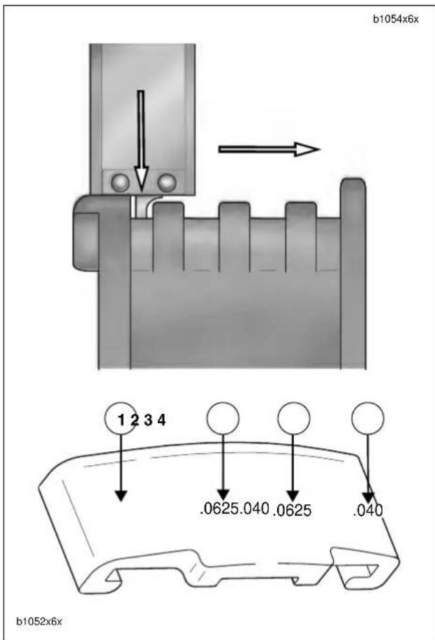
text_image
b1054x6x 1 2 3 4 .0625.040 .0625 .040 b1052x6xFigure 6-5. Measuring Chain Adjuster Shoe
- See Figure 6-4. Thread chain limiting screw (2), counterclockwise, down through the bottom of the outer primary cover, on the inside, until it bottoms out.
- Install the chain adjusting nut (3) but do not lock down.
- Install primary cover. See Primary Cover in 6.2 PRIMARY CHAIN.
INSTALLATION
Primary Cover
- Remove foreign material from magnetic drain plug. Install plug and tighten to 14-30 ft-lbs (19-54 Nm).
- Wipe gasket surface clean. Install new gasket on primary cover.
- Install primary cover and gasket onto left crankcase half using mounting bolts.
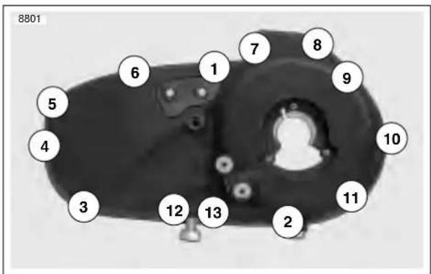
text_image
8801 1 7 8 6 9 5 10 4 3 12 13 2 11Figure 6-6. Primary Cover Tightening Sequence
- See Figure 6-6. Tighten bolts to 80-110 in-lbs (9-12.4 Nm) in sequence shown.
- See Figure 6-1. Install new shifter lever oil seal.
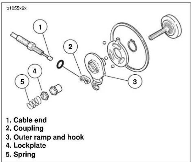
text_image
b1055x6x 1. Cable end 2. Coupling 3. Outer ramp and hook 4. Lockplate 5. SpringFigure 6-7. Clutch Release Mechanism
- See Figure 6-7. Fit coupling (2) over cable end (1) with rounded side inboard and the ramp connector button outboard. With retaining ring side of ramp assembly facing inward, place hook of ramp (3) around coupling button and rotate assembly counterclockwise until tang on inner ramp fits in slot of primary cover.
- Thread nut on adjustment screw until slot of screw is accessible with a screwdriver. Fit nut hex into recess of outer ramp and turn adjustment screw counterclockwise.
- Adjust clutch. See ADJUSTMENT under 1.8 CLUTCH.
6-6 2003 Buell XB9R: Drive/Transmission
- Adjust primary chain tension. See 6.2 PRIMARY CHAIN.
- Fill transmission to proper level with fresh lubricant. See PRIMARY DRIVE/TRANSMISSION FLUID under section 1.5 ENGINE LUBRICATION SYSTEM.
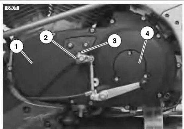
text_image
8806 1 2 3 4- Primary cover
- Lever, engine
- Engine lever pinch screw
- Clutch inspection cover
Figure 6-8. Installing Primary Cover
- See Figure 6-8. Install clutch inspection cover (4) with new gasket and three TORX screws with washers. Tighten screws in a crosswise pattern to 84-108 in-lbs (9.5-12.2 Nm).
- Install rubber washer and shifter lever assembly (2).
- Tighten engine lever pinch screw (3) to 12-14 ft-lbs 16.3-19.0 Nm)
- Install left footpeg support bracket. See 2.29 FOOTPEG, HEEL GUARD AND MOUNT.
- Install chin fairing. See 2.33 CHIN FAIRING.
WARNING
Always connect positive battery cable first. If the positive cable should contact ground with the negative cable installed, the resulting sparks may cause a battery explosion which could result in death or serious injury.
- Connect negative battery cable to battery terminal. Tighten fastener to 60-96 in-lbs (6.8-10.9 Nm).
WARNING
Pull up on seat to verify that it is properly secured, front and rear. A loose seat may shift during vehicle operation and startle the rider, possibly causing loss of vehicle control resulting in death or serious injury.
- Install seat. See 2.38 SEAT.
DISASSEMBLY
NOTE
For clutch adjustment procedure, See 1.8 CLUTCH.
- Remove seat. See 2.38 SEAT.
WARNING
To protect against shock and accidental start-up of vehicle, disconnect the negative battery cable before proceeding. Inadequate safety precautions could result in death or serious injury.
- Disconnect negative battery cable.
- Slide rubber boot on clutch cable adjuster upward to expose adjuster mechanism. Loosen jam nut from adjuster. Turn adjuster to shorten cable housing until there is a large amount of freeplay at clutch hand lever. See 1.8 CLUTCH.
- See Figure 6-9. Remove three TORX screws with washers and clutch inspection cover.
-
Slide spring (4) with attached screw lockplate (5) from flats of adjusting screw.
-
Turn adjusting screw clockwise to release ramp and coupling mechanism (7). As the adjusting screw is turned, ramp assembly moves forward. Unscrew nut (6) from end of adjusting screw.
- Remove hook of ramp from cable end coupling (10). Remove cable end from slot in coupling.
- Remove and discard retaining ring from ramp assembly to separate inner and outer halves. Remove three balls from ramp sockets.
CLEANING AND INSPECTION
- Thoroughly clean all parts in cleaning solvent.
- See Figure 6-9. Inspect three balls of release mechanism and ball socket surfaces of inner and outer ramps for wear, pitting, surface breakdown and other damage. Replace parts as necessary.
- Check hub fit of inner and outer ramps. Replace ramps if excessively worn.
- Check clutch cable for frayed or worn ends. Replace cable if damaged or worn.
- Change or add transmission fluid if necessary. See 1.8 CLUTCH.
b1057x6x
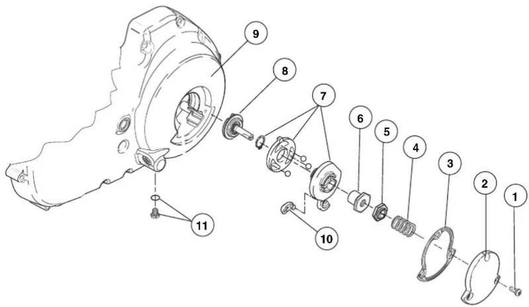
text_image
Exploded view diagram of a mechanical assembly with numbered parts for identification- TORX screw with washers (3)
- Clutch inspection cover
- Clutch cover gasket
- Spring
- Lockplate
-
Nut
-
Ramp assembly
- Adjusting screw assembly
- Primary cover
- Coupling
- Drain plug and o-ring
Figure 6-9. Clutch Release Mechanism
ASSEMBLY
- See Figure 6-10. Assemble inner and outer ramps.
a. Apply multi-purpose grease to balls and ramps.
b. Insert balls in sockets of outer ramp.
c. Install inner ramp on hub of outer ramp with tang 180° from hook of outer ramp.
d. Install new retaining ring in groove of outer ramp hub.
- See Figure 6-11. Install ramp assembly.
a. Fit coupling over cable end with rounded side inboard, the ramp connector button outboard.
b. With retaining ring side of ramp assembly facing inward, place hook of ramp around coupling button.
c. Rotate assembly counterclockwise until tang on inner ramp fits in slot of primary cover.
- Secure assembly in place.
a. Thread nut on adjusting screw until slot of screw is accessible with a screwdriver.
b. Turn adjusting screw counterclockwise until resistance is felt.
c. Adjust clutch release mechanism. See 6.3 CLUTCH RELEASE MECHANISM.
d. Fit nut hex into recess of outer ramp.
e. Install clutch adjusting lockplate and spring.
-
Install clutch inspection cover and new gasket with three TORX screws with washers. Tighten in a crosswise pattern to 84-108 in-lbs (9.5-12.2 Nm).
-
Adjust clutch cable. See 1.8 CLUTCH.
WARNING
Always connect positive battery cable first. If the positive cable should contact ground with the negative cable installed, the resulting sparks may cause a battery explosion which could result in death or serious injury.
- Connect negative battery cable to battery terminal. Tighten fastener to 60-96 in-lbs (6.8-10.9 Nm).
- Install seat. See 2.38 SEAT.
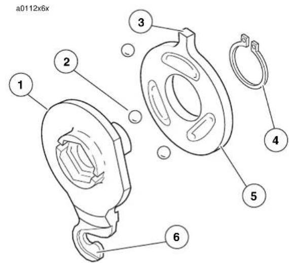
text_image
a0112x6x 1 2 3 4 5 6- Outer ramp
- Balls (3)
- Tang
- Inner ramp
- Retaining ring
- Hook
Figure 6-10. Inner and Outer Ramp
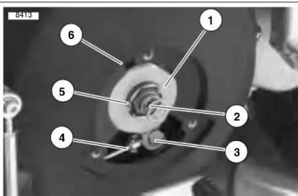
text_image
8413 1 2 3 4 5 6- Outer ramp
- Adjusting screw
- Coupling
- Cable end
- Lockplate
- Slot in primary cover
Figure 6-11. Nut and Outer Ramp
GENERAL
The purpose of the clutch is to smoothly disengage and engage the engine from the rear wheel for starting, stopping and shifting gears.
See Figure 6-12. The clutch is a wet, multiple-disc clutch with steel plates and fiber (friction) plates stacked alternately in the clutch shell. The pack consists of seven fiber plates, seven steel plates, one narrow fiber plate, one damper spring and one damper spring seat. The fiber plates (clutch driving plates) are keyed to the clutch shell, which is driven by the engine through the primary chain. The steel plates (clutch driven plates) are keyed to the clutch hub, which drives the rear wheel through the transmission and secondary drive belt.
When the clutch is engaged (clutch lever released), the diaphragm spring applies strong inward force against the pressure plate. The pressure plate then presses the clutch plates together, allowing no slippage between the plates and caus-
ing the plates to turn as a single unit. The result is that the rotational force of the clutch shell is fully transmitted through the "locked" clutch plates to the clutch hub. As long as the transmission is set in a forward gear, power from the engine will be transmitted to the rear wheel.
When the clutch is disengaged (clutch lever pulled to left handlebar grip), the pressure plate is pulled outward (by clutch cable action) against the diaphragm spring, thereby compressing the diaphragm spring. With the pressure plate retracted, strong inward force no longer squeezes the clutch plates together. The fiber plates are now free to rotate at a different relative speed than that of the steel and spring plates (i.e. – Slippage between the clutch plates occurs). The result is that the rotational force of the clutch shell is no longer fully transmitted through the “unlocked” clutch plates to the clutch hub. The engine is free to rotate at a different speed than the rear wheel.
Table 6-6. Troubleshooting
| SYMPTOM CAUSE (CHECK IN FOLLOWING ORDER) REMEDY | ||
| Clutch slips. Incorrect | clutch release adjustment.Worn clutch plates. | Check and adjust clutch release mechanism.Check service wear limits. Replace plates. |
| Clutch drags. Incorrect | clutch release adjustment.Worn clutch release ramps or balls.Warped clutch steel plates.Blade worn or damaged clutch gear splines.Overfilled primary. | Check and adjust clutch release mechanism.Replace release ramps and/or balls.Replace clutch steel plates.Replace clutch gear or hub as required.Drain lubricant to correct level. |
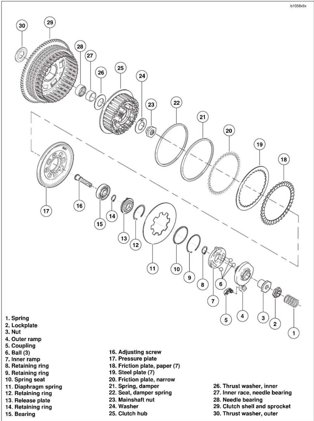
text_image
b1058x6x 1. Spring 2. Lockplate 3. Nut 4. Outer ramp 5. Coupling 6. Ball (3) 7. Inner ramp 8. Retaining ring 9. Retaining ring 10. Spring seat 11. Diaphragm spring 12. Retaining ring 13. Release plate 14. Retaining ring 15. Bearing 29 30 28 27 26 25 24 23 22 21 20 19 18 17 16 15 14 13 12 11 10 9 8 7 6 5 4 3 2 16. Adjusting screw 17. Pressure plate 18. Friction plate, paper (7) 19. Steel plate (7) 20. Friction plate, narrow 21. Spring, damper 22. Seat, damper spring 23. Mainshaft nut 24. Washer 25. Clutch hub 26. Thrust washer, inner 27. Inner race, needle bearing 28. Needle bearing 29. Clutch shell and sprocket 30. Thrust washer, outerFigure 6-12. Clutch Assembly
REMOVAL/DISASSEMBLY
Clutch Pack
WARNING
To protect against shock and accidental start-up of vehicle, disconnect the negative battery cable before proceeding. Inadequate safety precautions could result in death or serious injury.
- Remove primary cover. See 6.2 PRIMARY CHAIN.
WARNING
Do not attempt to disassemble the clutch without SPRING COMPRESSING TOOL (Part No. HD-38515-A), CLUTCH SPRING FORCING SCREW (Part No. HD-38515-91) and proper eye protection. Otherwise, the highly compressed diaphragm spring could fly out with great force which could result in death or serious injury.
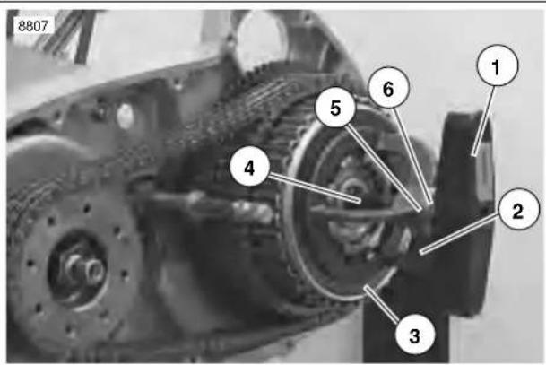
text_image
8807 1 2 3 4 5 6- Tool handle
- Bridge
- Diaphragm spring
- Clutch spring forcing screw
- Bearing
- Washer
Figure 6-13. Compressing Clutch Diagram Spring
- See Figure 6-13. Attach tools to compress clutch diaphragm spring.
a. Thread the CLUTCH SPRING FORCING SCREW (Part No. HD-38515-91) onto the clutch adjusting screw.
b. Place the bridge of SPRING COMPRESSING TOOL (Part No. HD-38515-A) against diaphragm spring.
c. Install bearing and washer.
d. Thread the tool handle onto end of forcing screw.
CAUTION
See Figure 6-14. Turn compressing tool handle only the amount required to release spring seat and remove snap ring. Excessive compression of diaphragm spring could damage clutch pressure plate.
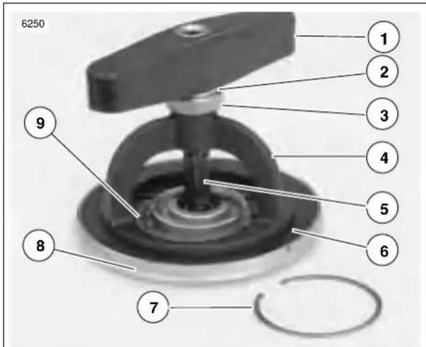
text_image
6250 1 2 3 4 5 6 7 8 9- Tool handle
- Washer
- Bearing
- Bridge
- Forcing screw
- Diaphragm spring
- Snap ring
- Pressure plate
- Spring seat
Figure 6-14. Pressure Plate Assembly
- See Figure 6-14. Remove pressure plate assembly.
a. Place a wrench on the clutch spring forcing screw flats to prevent the forcing screw from turning.
b. Turn compressing tool handle clockwise until tool relieves pressure on retaining ring and spring seat. Remove and discard retaining ring.
c. Unseat spring seat from the groove in clutch hub prongs.
d. Remove pressure plate assembly.
- See Figure 6-12. Remove the clutch pack from the hub/shell assembly. The pack consists of seven fiber plates, seven steel plates, one narrow fiber plate, one damper spring and one damper spring seat.
Primary Chain/Drive
WARNING
To protect against shock and accidental start-up of vehicle, disconnect the negative battery cable before proceeding. Inadequate safety precautions could result in death or serious injury.
- Remove negative battery cable from battery.
- Remove primary cover. See 6.2 PRIMARY CHAIN.
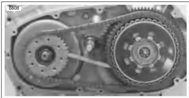
natural_image
Mechanical gear assembly diagram showing two interlocking gears and a shaft (no text or symbols)Figure 6-15. Sprocket Locking Link Tool (Part No. HD-38362)
- Loosen engine sprocket.
a. See Figure 6-15. Install SPROCKET LOCKING LINK (Part No. HD-38362).
b. Remove the engine sprocket nut.
c. Loosen but do not remove engine sprocket. If necessary, use the slotted portion of TWO CLAW PULLER (Part No. HD-97292-61) and two bolts to loosen the engine sprocket.
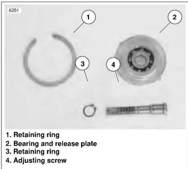
text_image
6251 1. Retaining ring 2. Bearing and release plate 3. Retaining ring 4. Adjusting screwFigure 6-16. Adjusting Screw Assembly
- See Figure 6-16. Remove adjusting screw assembly.
a. Remove large retaining ring.
b. Remove adjusting screw assembly from pressure plate.
6-12 2003 Buell XB9R: Drive/Transmission
CAUTION
See Figure 6-12. Mainshaft nut has left-hand threads. To prevent damage, turn nut clockwise to loosen and remove from mainshaft.
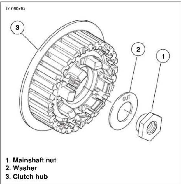
text_image
b1060x6x 3 2 1 OUT 1. Mainshaft nut 2. Washer 3. Clutch hubFigure 6-17. Mainshaft Nut and Washer
- See Figure 6-17. Remove mainshaft nut and washer.
- Remove the clutch assembly, primary chain and engine sprocket as a unit.
- Inspect primary chain and sprockets for damage or excessive wear.
- Inspect stator and rotor. See 7.7 ALTERNATOR.
- Replace damaged parts as necessary.
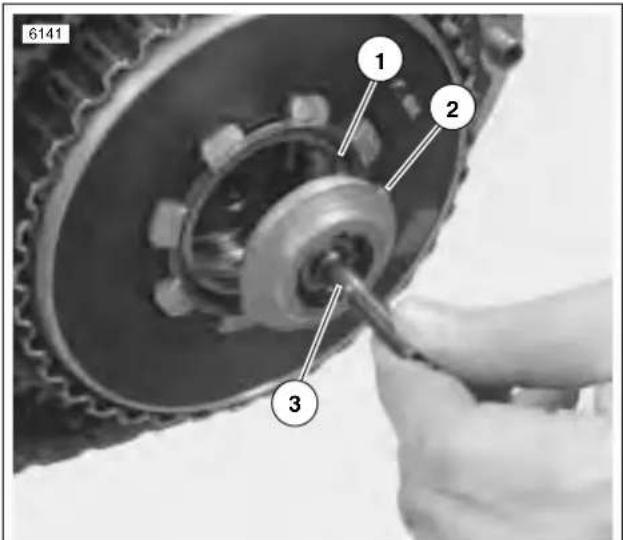
text_image
6141 1 2 3- Recess in pressure plate
- Tab on release plate
- Adjusting screw assembly
Figure 6-18. Aligning Tabs
- Install adjusting screw assembly into pressure plate.
a. See Figure 6-18. Align two tabs on perimeter of release plate with corresponding recesses in pressure plate.
b. See Figure 6-16. Secure the adjusting screw assembly with large retaining ring.
- Attach tools to compress clutch diaphragm spring. See Step 2 of CLUTCH PACK under 6.4 PRIMARY DRIVE/CLUTCH.
- Remove pressure plate assembly.
CAUTION
The clutch hub and clutch shell are no longer pressed together. There are no retaining rings securing the clutch hub to the clutch shell. Once the pressure plate assembly has been removed the clutch hub will slide out of the clutch shell.
- Remove clutch pack components. See Steps 3-4 of CLUTCH PACK under 6.4 PRIMARY DRIVE/CLUTCH.
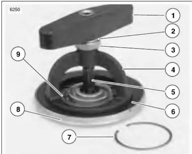
text_image
6250 1 2 3 4 5 6 7 8 9- Tool handle
- Washer
- Bearing
- Bridge
- Forcing screw
- Diaphragm spring
- Snap ring
- Pressure plate
- Spring seat
Figure 6-19. Pressure Plate Assembly
- See Figure 6-19. Disassemble pressure plate.
a. Place a wrench on the clutch spring forcing screw flats to prevent the forcing screw from turning.
b. Turn the compressing tool handle counterclockwise until the handle spins off.
c. Remove washer, bearing and bridge.
d. Remove clutch spring forcing screw from clutch adjusting screw.
e. Remove spring seat and diaphragm spring from pressure plate.
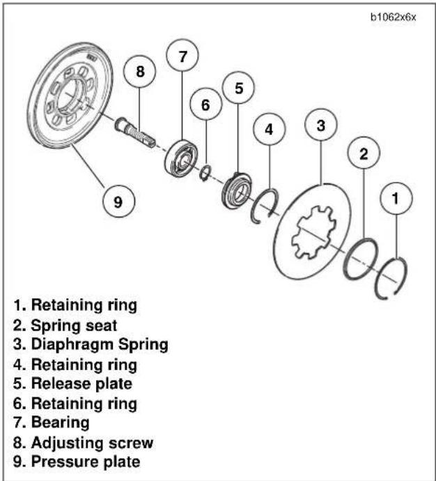
text_image
b1062x6x 1. Retaining ring 2. Spring seat 3. Diaphragm Spring 4. Retaining ring 5. Release plate 6. Retaining ring 7. Bearing 8. Adjusting screw 9. Pressure plateFigure 6-20. Adjusting Screw Assembly
- See Figure 6-20. Remove and disassemble adjusting screw assembly.
a. Remove large retaining ring.
b. Remove adjusting screw assembly from pressure plate.
c. If necessary, disassemble adjusting screw assembly. Remove and discard small retaining ring (6) and then separate the adjusting screw (8) from the bearing (7) and release plate (5). Remove bearing (7) from release plate (5).
- Remove clutch hub from clutch shell for inspection.
NOTE
See Figure 6-21. The clutch shell incorporates a compensating spring set and new style needle bearing.
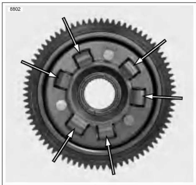
natural_image
Mechanical gear assembly diagram with arrows indicating specific teeth and central bore (no text or symbols)Figure 6-21. Compensating Spring Set
CLEANING AND INSPECTION
WARNING
Low pressure compressed air can blow debris into your face and eyes. Always wear eye protection or a face shield when using pressurized air. Failure to take adequate safety precautions could result in death or serious injury.
- Wash all parts, except fiber (friction) plates and bearing, in cleaning solvent. Blow dry with compressed air. Examine the clutch components as follows:
a. Check all clutch plates for wear and discoloration.
b. Inspect each steel (drive) plate for grooves.
c. Place each steel plate on a flat surface. Using a feeler gauge, check for flatness in several places. Replace any plates that are damaged or are warped more than 0.006 in. (0.152 mm).
- Inspect the damper spring for cracks or distortion. Install a new spring if either condition exists.
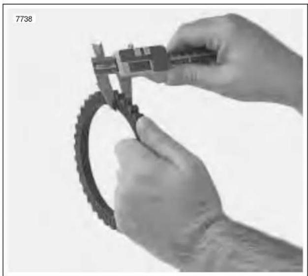
natural_image
Close-up of hands using a caliper to measure a tire ring (no text or symbols visible)Figure 6-22. Measuring Friction Plates
- See Figure 6-22. Check fiber plates for thickness.
a. Wipe the lubricant from the eight fiber plates (7 regular and 1 narrow) and stack them on top of each other.
b. Measure the thickness of the eight stacked fiber plates with a dial caliper or micrometer. The minimum thickness must be 0.661 in. (16.789 mm).
c. If the thickness is less than specified, discard the fiber plates and steel plates. Install a new set of both friction and steel plates.
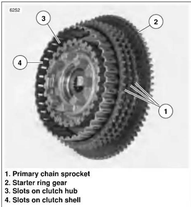
text_image
6252 1. Primary chain sprocket 2. Starter ring gear 3. Slots on clutch hub 4. Slots on clutch shellFigure 6-23. Checking Clutch Shell
- See Figure 6-23. Inspect primary chain sprocket and the starter ring gear on the clutch shell. If either sprocket or ring gear are badly worn or damaged, replace the clutch shell.
- Inspect slots that mate with the clutch plates on both clutch shell and hub. If slots are worn or damaged, replace shell and/or hub.
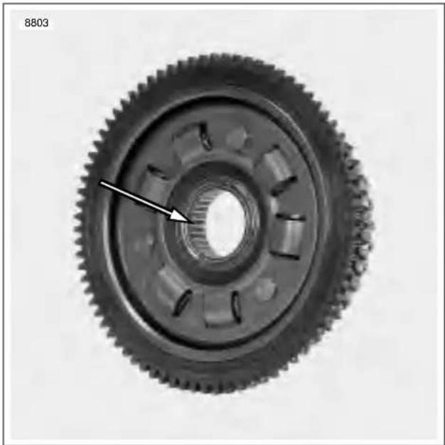
natural_image
Close-up of a mechanical gear with visible teeth and central bore (no text or symbols)Figure 6-24. New Needle Bearing in Clutch Shell
- See Figure 6-24. Inspect clutch shell needle bearing for smoothness. Rotate the clutch shell while holding the clutch hub. If bearing is rough or binds, it must be replaced. See Replacing Clutch Shell Bearing.
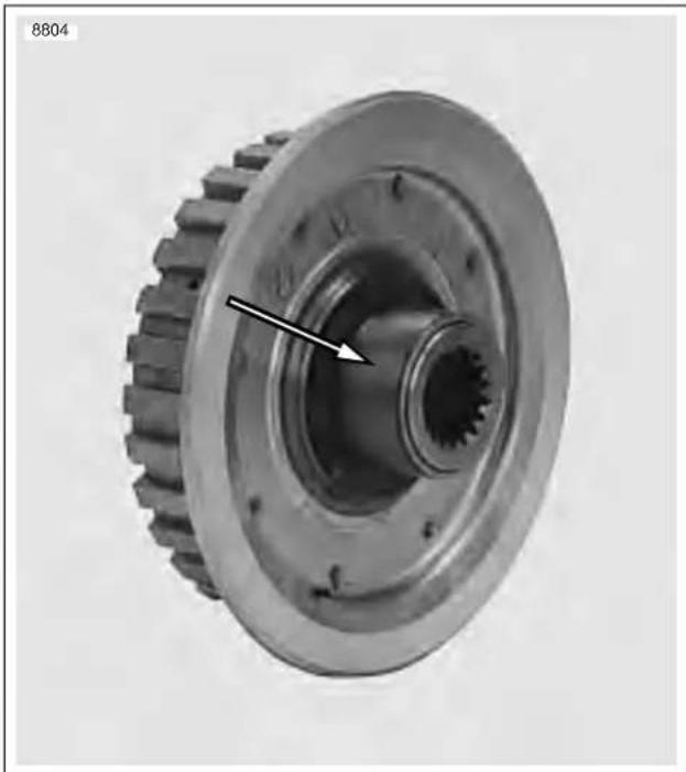
natural_image
Close-up of a mechanical gear assembly with visible teeth and central bore (no text or symbols)Figure 6-25. Clutch Hub Bearing Race
- See Figure 6-25. Inspect clutch shell bearing inner race on the back side of the clutch hub for pitting and wear. If the inner race shows any of these signs the complete hub assembly must be replaced.
HOME
Replacing Clutch Shell Bearing
Removal
The XB9R clutch shell uses a caged needle bearing that corresponds to an inner race installed on the clutch hub.
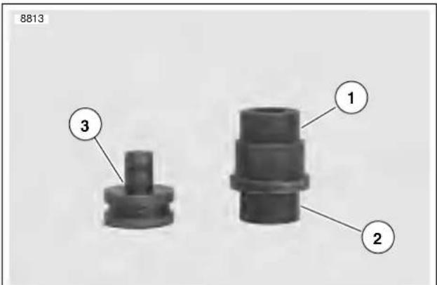
text_image
8B13 1 2 3- Removal end of bearing tool
- Installation end of bearing tool
- Bearing guide, installer
Figure 6-26. Clutch Shell Bearing Remover/Installer B-45926
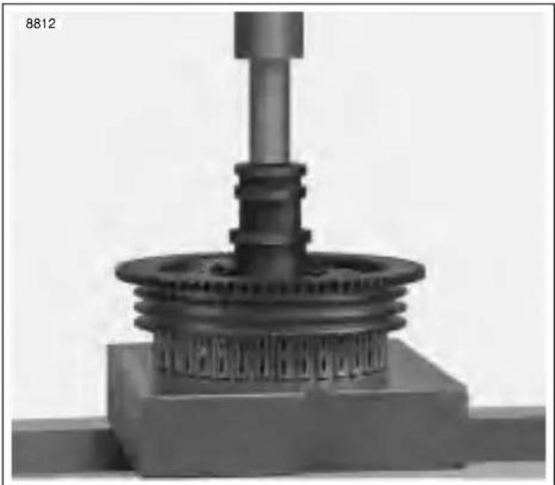
natural_image
Mechanical gear assembly with a shaft and housing (no visible text or symbols)Figure 6-27. Removing Clutch Shell Needle Bearing
- See Figure 6-27. Place clutch shell on support blocks with sprocket side facing up.
NOTE
The CLUTCH SHELL BEARING REMOVER/INSTALLER (Part No. B-45926) is clearly marked for removal and installation purposes.
- See Figure 6-27. Insert removal end of tool into bearing assembly and remove bearing from clutch shell.
- Continue with CLEANING AND INSPECTION.
Installation
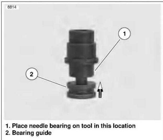
text_image
8814 1. Place needle bearing on tool in this location 2. Bearing guideFigure 6-28. Bearing Installer
- See Figure 6-28. Remove bearing guide from end of CLUTCH SHELL BEARING REMOVER/INSTALLER (Part No. B-45926).
- Place new needle bearing onto installer end of tool and insert the bearing guide to prevent the bearing from falling off during installation and to align bearing with clutch shell.
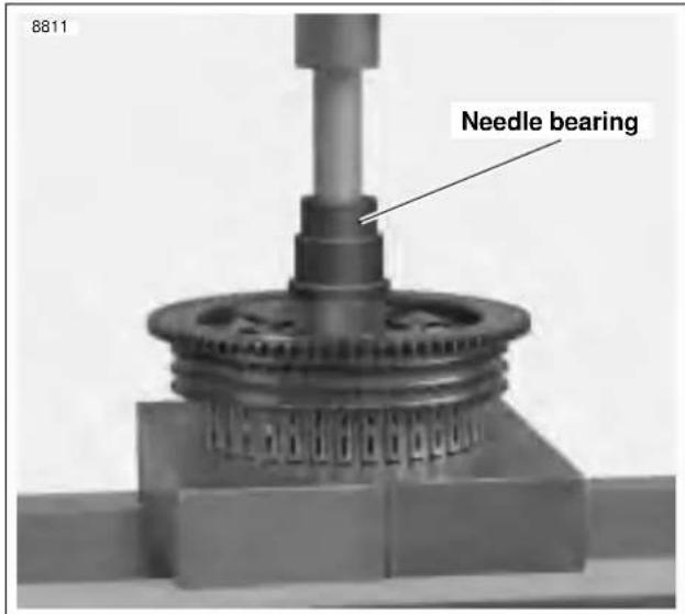
text_image
8811 Needle bearingFigure 6-29. Installing Clutch Shell Needle Bearing Clutch Shell Bearing Remover/Installer B-45926
- See Figure 6-29. Place clutch shell on support blocks with sprocket side facing up.
- Press bearing into clutch shell until tool bottoms on the shell. This will be the correct installed height.
ASSEMBLY
Clutch Pack
- Submerge and soak all friction and steel plates in SPORT-TRANS FLUID for at least five minutes.
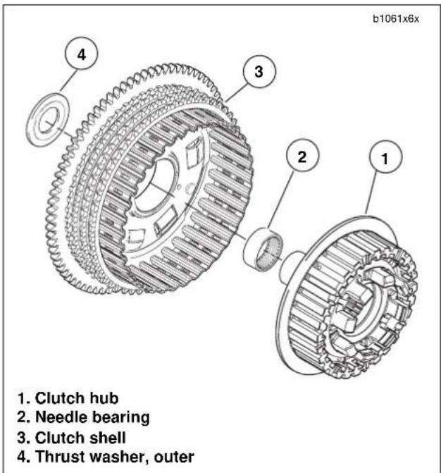
text_image
b1061x6x 1. Clutch hub 2. Needle bearing 3. Clutch shell 4. Thrust washer, outerFigure 6-30. Clutch Hub and Shell Assembly
- See Figure 6-30. Assemble clutch hub and shell by sliding inboard end of clutch hub into shell bearing by hand. No tools are required for this operation.
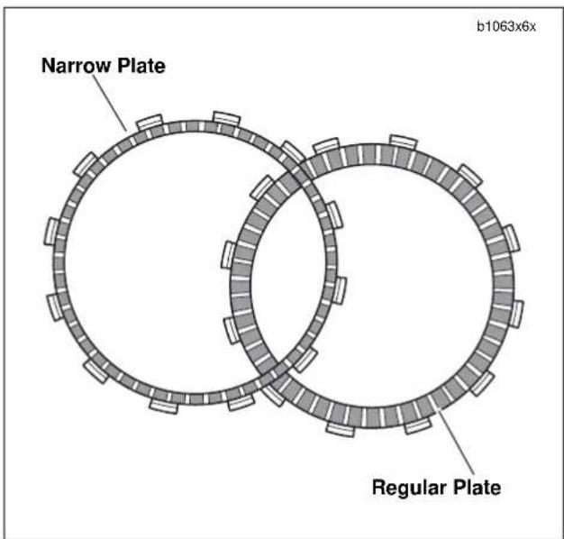
text_image
b1063x6x Narrow Plate Regular PlateFigure 6-31. Friction Plates
- See Figure 6-31. Install the narrow friction plate on the clutch hub engaging tabs on plate with slots in clutch shell.
6-18 2003 Buell XB9R: Drive/Transmission
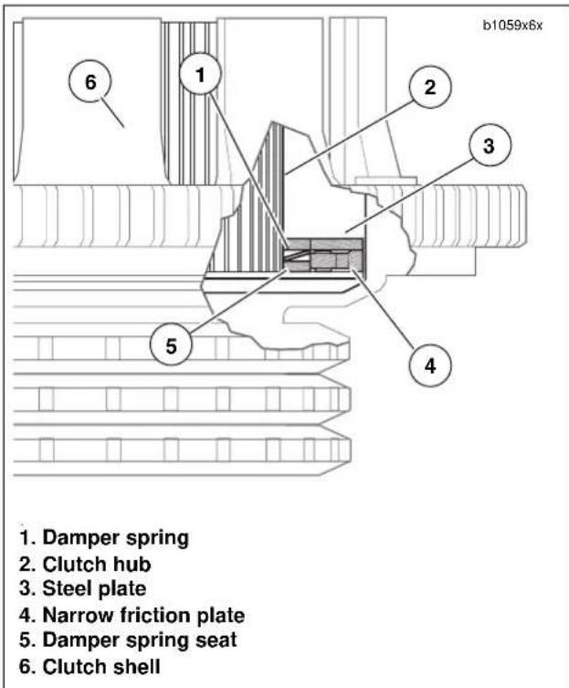
text_image
b1059x6x 1. Damper spring 2. Clutch hub 3. Steel plate 4. Narrow friction plate 5. Damper spring seat 6. Clutch shellFigure 6-32. Clutch Pack Stack-Up (Cut-Away View)
- See Figure 6-32. Install damper spring seat (5) on clutch hub so that it seats inboard of narrow friction plate (4).
- Install damper spring (1) on clutch hub with the concave side up (facing opposite damper spring seat).
- Install a steel plate and then a friction plate on the clutch hub. Install six remaining sets in the same manner, alternating between steel plates and friction plates.
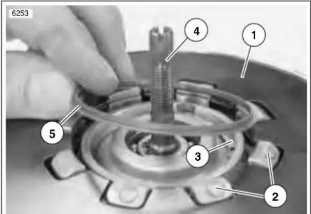
text_image
6253 1 4 3 2 5- Diaphragm spring (pressure plate below)
- Prongs on clutch hub
- Retaining ring
- Adjusting screw assembly
- Spring seat
Figure 6-33. Spring Seat Installation
- Place pressure plate, diaphragm spring, adjusting screw assembly with new retaining ring and spring seat onto clutch pack.
a. See Figure 6-33. Align square openings of pressure plate and diaphragm spring so that the assembly can be installed over prongs on clutch hub.
b. Position spring seat with its larger outer diameter side toward diaphragm spring.
CAUTION
See Figure 6-14. Turn compressing tool handle only the amount required to install spring seat and snap ring. Excessive compression of diaphragm spring could damage clutch pressure plate.
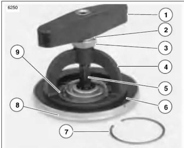
text_image
6250 1 2 3 4 5 6 7 8 9- Tool handle
- Washer
- Bearing
- Bridge
- Forcing screw
- Diaphragm spring
- Snap ring
- Pressure plate
- Spring seat
Figure 6-34. Pressure Plate Assembly
c. See Figure 6-34. Install compressing tool onto clutch hub against diaphragm spring.
d. Place a wrench on the clutch spring forcing screw flats to prevent the forcing screw from turning.
e. Turn compressing tool handle clockwise until diaphragm spring compresses just enough to install new retaining ring into the groove in clutch hub prongs.
f. With retaining ring fully seated in groove of clutch hub, carefully loosen and remove compression tool.
NOTE
When the compressing tool is removed, the diaphragm spring will move outward forcing the spring seat up into the inside of the retaining ring. The spring seat provides an operating surface for the diaphragm spring at the same time preventing the retaining ring from coming out during operation.
INSTALLATION
NOTE
If clutch pack replacement was the only service work performed, start with Step 5.
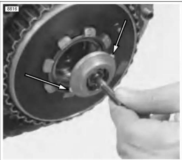
natural_image
Close-up of a hand turning a mechanical gear component with arrows indicating direction (no text or symbols visible)Figure 6-35. Adjusting Screw Assembly Aligning Tabs
- See Figure 6-35. Remove adjusting screw assembly in order to install mainshaft nut and washer.
- Install the engine sprocket, clutch assembly and primary chain as a unit into primary chaincase.
NOTE
Prior to installing engine sprocket nut and the clutch hub nut, the threads on the sprocket shaft, sprocket nut, mainshaft and clutch hub nut must be thoroughly cleaned to remove any oil that might contaminate and interfere with the locking agent.
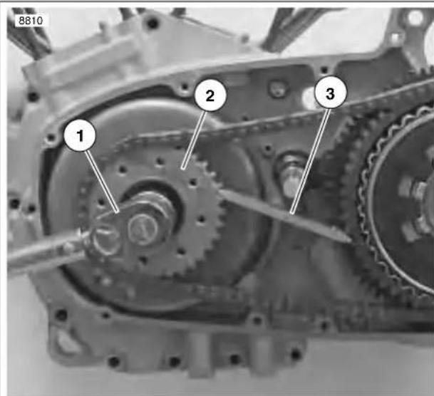
text_image
8810 1 2 3- Torque wrench
- Engine sprocket
- Sprocket locking link (Part No. HD-38362)
Figure 6-36. Sprocket Locking Link
- See Figure 6-36. Install the engine sprocket nut.
a. Install SPROCKET LOCKING LINK (Part No. HD-38362).
b. Apply two or three drops of LOCTITE 262 (red) onto threads of sprocket shaft.
c. Install engine sprocket nut. Tighten to 190-210 ft-lbs (257.6-284.7 Nm).
CAUTION
See Figure 6-37. Washer must be installed with the word "out" facing the mainshaft nut or transmission may be damaged.
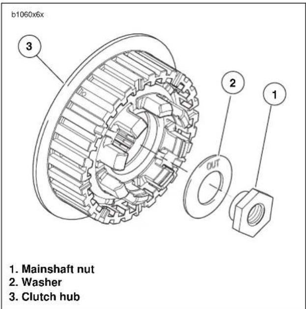
text_image
b1060x6x 3 2 1 OUT 1. Mainshaft nut 2. Washer 3. Clutch hubFigure 6-37. Mainshaft Nut and Washer
- See Figure 6-37. Install mainshaft nut and washer.
a. Apply two or three drops of LOCTITE 262 (red) onto threads on end of mainshaft.
b. Place washer on mainshaft with the word "out" facing away from clutch hub.
c. Install nut (left-hand threads). Tighten to 70-80 ft-lbs (94.9-108.5 Nm).
- Remove SPROCKET LOCKING LINK.

natural_image
Close-up of a mechanical gear assembly with labeled components (1 and 2), no readable text or symbols beyond labels- Adjusting screw assembly
- Retaining ring
Figure 6-38. Clutch Adjusting Screw Assembly and Retaining Ring
- Install adjusting screw assembly into pressure plate.
a. See Figure 6-38. Align two tabs on perimeter of release plate with corresponding recesses in pressure plate.
b. Secure the adjusting screw assembly with new retaining ring.
- Install primary cover. See 6.2 PRIMARY CHAIN.
- Add SPORT-TRANS FLUID. See 1.8 CLUTCH.
WARNING
Always connect positive battery cable first. If the positive cable should contact ground with the negative cable installed, the resulting sparks may cause a battery explosion which could result in death or serious injury.
9. Connect negative battery cable to battery terminal. Tighten fastener to 60-96 in-lbs (6.8-10.9 Nm).
WARNING
Pull up on seat to verify that it is properly secured, front and rear. A loose seat may shift during vehicle operation and startle the rider, possibly causing loss of vehicle control resulting in death or serious injury.
- Install seat. See 2.38 SEAT.
GENERAL
See Figure 6-39. The XB9R transmission is a five-speed constant-mesh type housed in an extension of the crankcase.
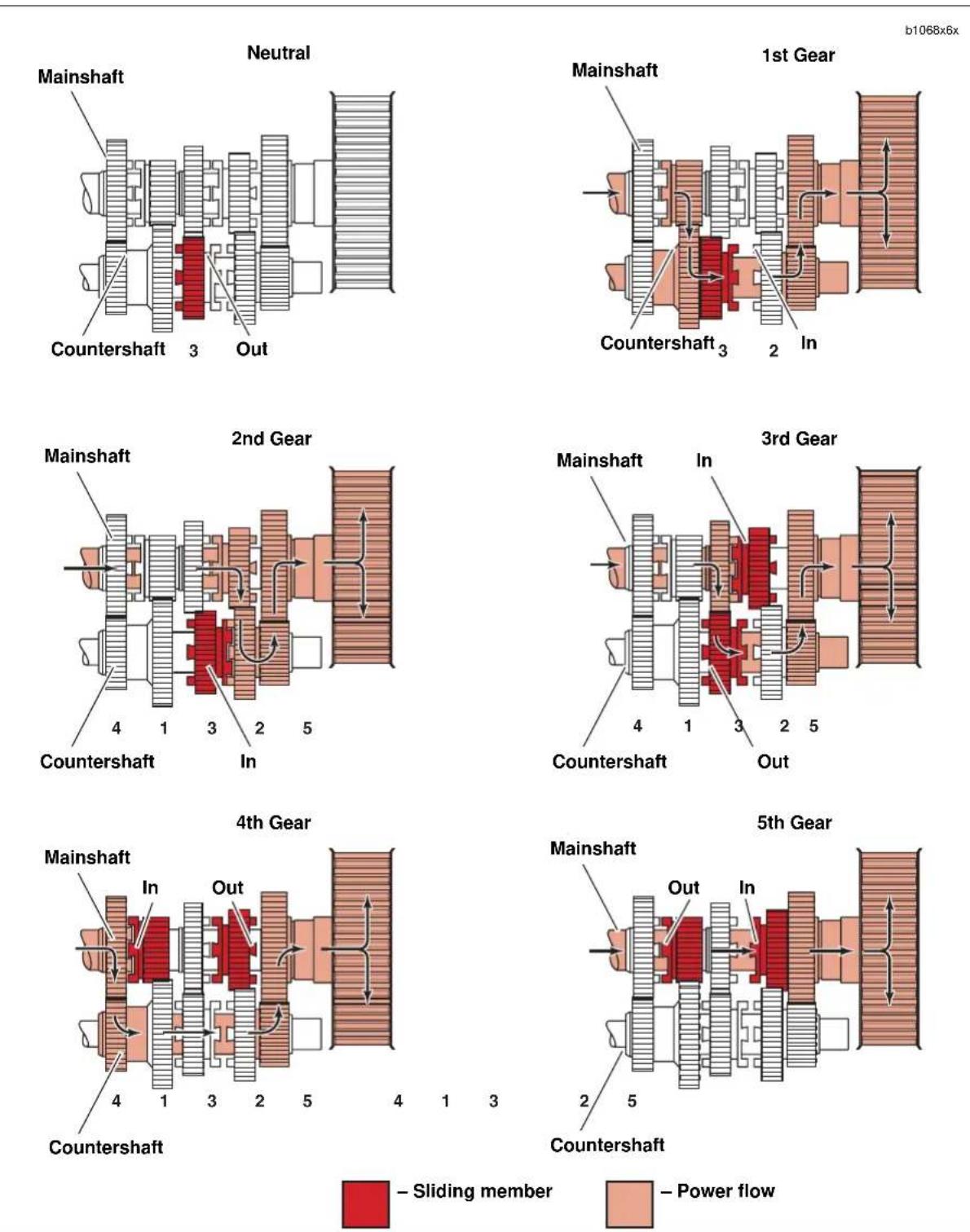
Figure 6-39. Transmission Power Flow
CASE DISASSEMBLY FOR TRANSMISSION REMOVAL 6.6
GENERAL
The rear compartment of the left and right crankcase halves form the transmission case. Servicing of transmission components requires removing the engine and disassembling (splitting) the crankcase.
RIGHT CRANKCASE REMOVAL
- Remove transmission sprocket. See 6.14 TRANSMISSION SPROCKET.
- Remove engine from chassis. See 3.4 STRIPPING MOTORCYCLE FOR ENGINE SERVICE.
- Support engine using ENGINE SUPPORT STAND (Part No. HD-42310/HD-43646 or HD-43682).
- Disassemble top end. See 3.6 CYLINDER HEAD.
- Disassemble gearcase. See 3.16 GEARCASE COVER AND CAM GEARS.
- Remove primary cover. See 6.2 PRIMARY CHAIN.
- Remove clutch assembly, primary chain and engine sprocket. See 6.4 PRIMARY DRIVE/CLUTCH.
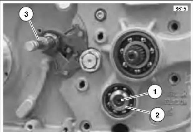
text_image
8615 1 2 3- TORX screw
- Retention collar
- Shifter lever assembly
Figure 6-40. Countershaft Retainer
- See Figure 6-40. Place transmission in 1st gear. Remove countershaft TORX screw (1) and retention collar (2).
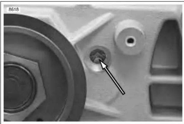
natural_image
Close-up of a mechanical component with a highlighted bolt and arrow pointing to a small hole (no text or symbols visible)Figure 6-41. Shifter Drum Neutral Detent
- See Figure 6-41. Place transmission in neutral. Remove neutral switch to ensure shifter drum detent is visible indicating transmission is in correct location.
HOME
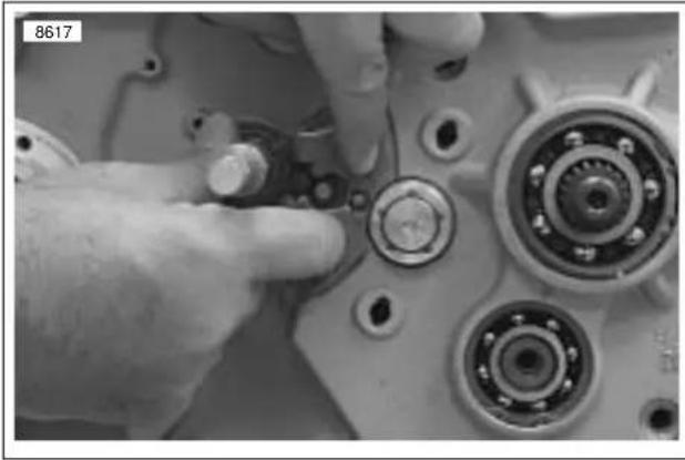
natural_image
Close-up of hands assembling mechanical components with visible gears and bolts (no text or symbols)Figure 6-42. Removing Shifter Shaft Assembly
- See Figure 6-43. Remove shifter shaft assembly.

text_image
8626 1 3 2- Shifter shaft
- Ratchet arms
- Return spring
Figure 6-43. Shifter Shaft Assembly
- See Figure 6-42. Depress ratchet arms in order to clear the shifter drum and remove shifter shaft assembly from left crankcase half.
- Remove starter. See 5.7 STARTER.
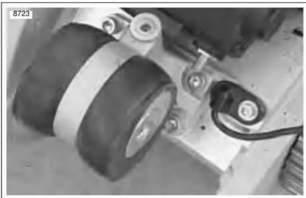
natural_image
Close-up of a mechanical assembly with visible gears and springs (no text or symbols)Figure 6-44. Rear Isolator Assembly
- See Figure 6-44. Remove rear isolator assembly by removing the forward two fasteners first and then the two rear fasteners (re-install with new fasteners).
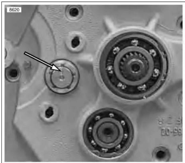
natural_image
Close-up of mechanical components with visible gears and bolts, no text or symbols presentFigure 6-45. Scribed Line on Shifter Drum at 12 o'clock (Transmission in Neutral)
- See Figure 6-45. Scribe a line on the end of the shifter drum at the 12 o'clock position for later reference.
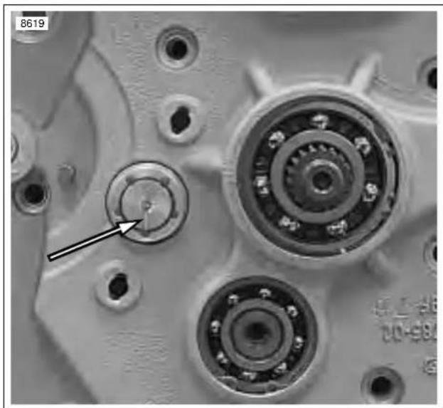
natural_image
Close-up of mechanical components with visible gears and bolts, no text or symbols presentFigure 6-46. Scribed Line on Shifter Drum at 6 O'clock (Transmission in 4th Gear)
- See Figure 6-46. Place transmission in 4th gear. The scribed line should now be at the 6 o'clock position.
NOTE
Transmission can be easily shifted by rotating the mainshaft and shifter drum at the same time by hand.
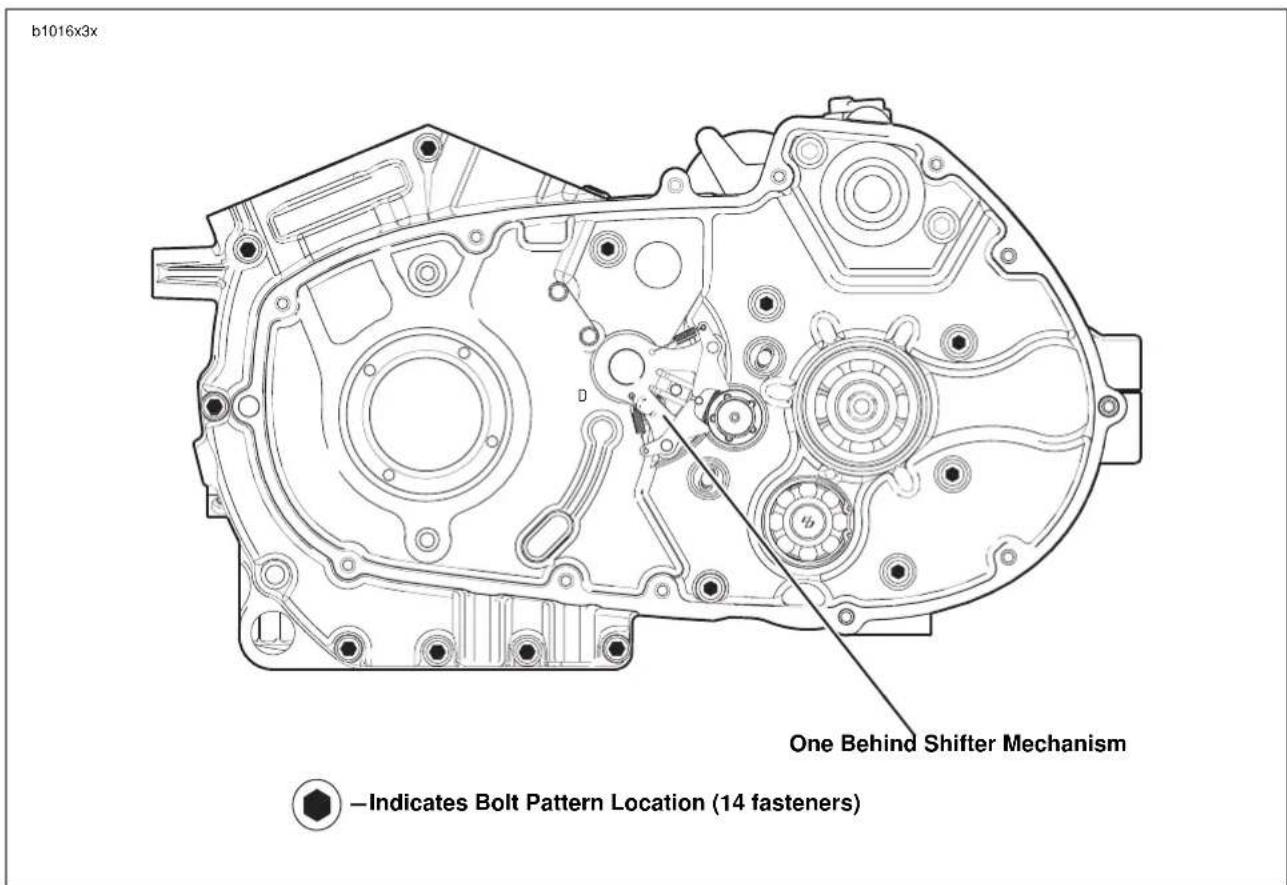
text_image
b1016x3x One Behind Shifter Mechanism —Indicates Bolt Pattern Location (14 fasteners)Figure 6-47. Crankcase Fasteners
- See Figure 6-47. Remove crankcase bolt set (14 fasteners).

natural_image
Close-up of a mechanical assembly with hands operating a motor or engine component (no visible text or symbols)Figure 6-48. Separating Crankcase Halves
- See Figure 6-48. Separate crankcase halves.
NOTE Flywheel assembly slides out of the left main bearing by hand. No tools are required for this operation.
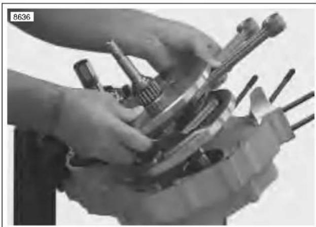
natural_image
Close-up of hands holding mechanical components, no visible text or symbolsFigure 6-49. Removing Flywheels from Left Case Half
- See Figure 6-49. Remove the flywheel assembly from left crankcase half.
TRANSMISSION REMOVAL FROM LEFT CRANKCASE
NOTE
See Figure 6-52. Shifter design allows for one common part number for all three shifter forks. As the transmission runs, each shifter fork develops a certain wear pattern with its mating parts. For this reason, it is important that each shifter fork be reinstalled in its original location.
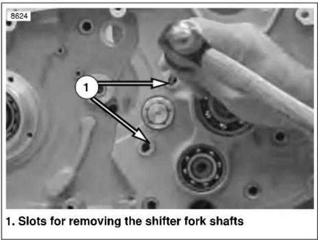
text_image
8624 1. Slots for removing the shifter fork shaftsFigure 6-50. Removing Shifter Fork Shafts
- See Figure 6-50. Remove shifter fork shafts.
NOTE
Carefully tap on alternate sides of the shaft using the provided slots.
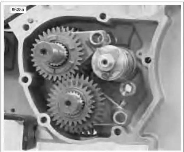
natural_image
Close-up of a mechanical gear assembly inside a housing (no visible text or symbols)Figure 6-51. Transmission Assembly
- See Figure 6-51. Remove shifter drum and shifter forks.
- Remove mainshaft 2nd gear from mainshaft.

text_image
8616 3-5 4 Mainshaft Left Right 1-2 CountershaftFigure 6-52. Shifter Forks, Drum and Shafts
b1015x6x
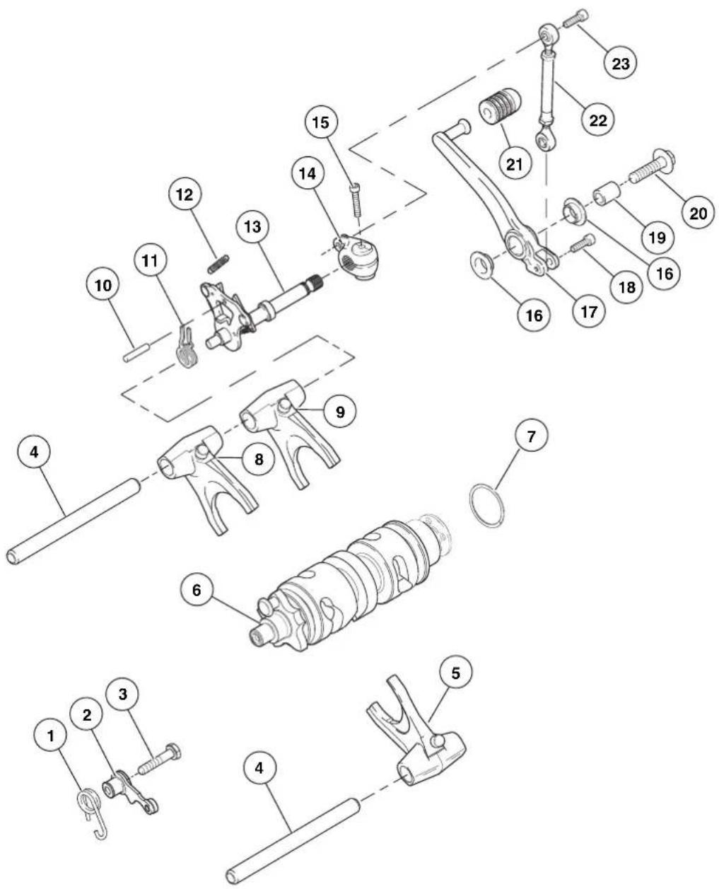
text_image
Exploded view diagram of a mechanical assembly with numbered parts for identification- Spring, detent
- Detent spring sleeve assembly
- Screw, detent assembly
- Shaft, shifter forks (2)
- Fork assembly, shifter (1st-2nd)
- Shifter cam assembly
- Retaining ring
- Fork assembly, shifter (3rd-5th)
- Fork assembly, shifter (4th)
- Pin, shifter stop
- Spring, shifter return
-
Spring, extension
-
Shifter lever assembly
- Lever, engine
- Bolt, engine lever
- Bearing, shift lever assembly (2)
- Shift lever
- Bolt, linkage assembly
- Sleeve, shift/brake lever
- Bolt, shift lever
- Pad, rubber, shift lever
- Linkage assembly, shifter
- Bolt, linkage assembly
Figure 6-53. Shifter Mechanism
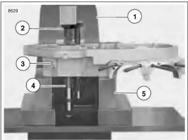
text_image
8629 1 2 3 4 5- Arbor press
- Transmission remover (Part No. B-43985-1)
- Crankcase
- Transmission assembly
- Parallel Supports
Figure 6-54. Removing Transmission Assembly from Left Case Half
WARNING
Always wear proper eye protection when installing retaining rings. Use the correct retaining ring pliers. Verify that the tips of the pliers are not damaged or excessively worn. Slippage may propel the ring with enough force to cause eye injury.
- See Figure 6-54. Remove left crankcase half and transmission assembly (4) from engine stand.
a. Place crankcase half (3) and transmission assembly (4) on arbor press (1) and support transmission assembly on parallel supports (5).
b. Press transmission assembly using TRANSMISSION REMOVER (2) (Part No. B-43895-1) to remove transmission assembly from crankcase half.
c. Remove crankcase from press.
MAINSHAFT/COUNTERSHAFT
NOTE
- As the transmission runs, each part develops a certain wear pattern and a kind of "set" with its mating parts. For this reason, it is important that each component be reinstalled in its original location and facing its original direction.
● See Figure 6-55. As each component is removed, place it on a clean surface in the exact order of removal.
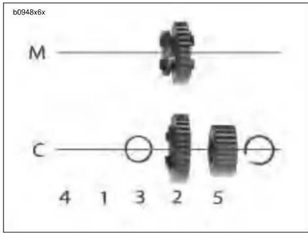
text_image
b0948x6x M C 4 1 3 2 5Figure 6-55. Transmission Parts Identification
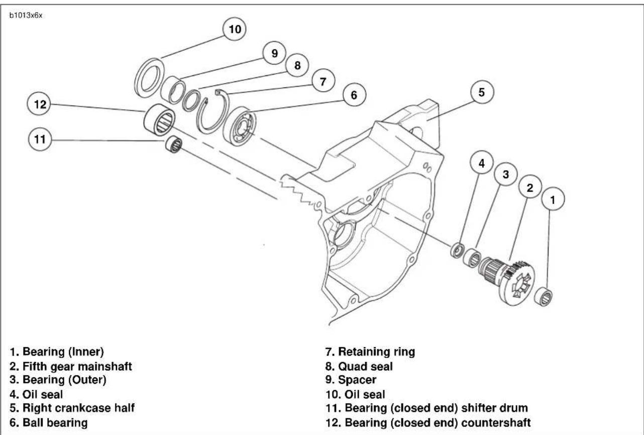
text_image
b1013x6x 1. Bearing (Inner) 2. Fifth gear mainshaft 3. Bearing (Outer) 4. Oil seal 5. Right crankcase half 6. Ball bearing 7. Retaining ring 8. Quad seal 9. Spacer 10. Oil seal 11. Bearing (closed end) shifter drum 12. Bearing (closed end) countershaftFigure 6-56. Transmission Assembly-Right Crankcase Half
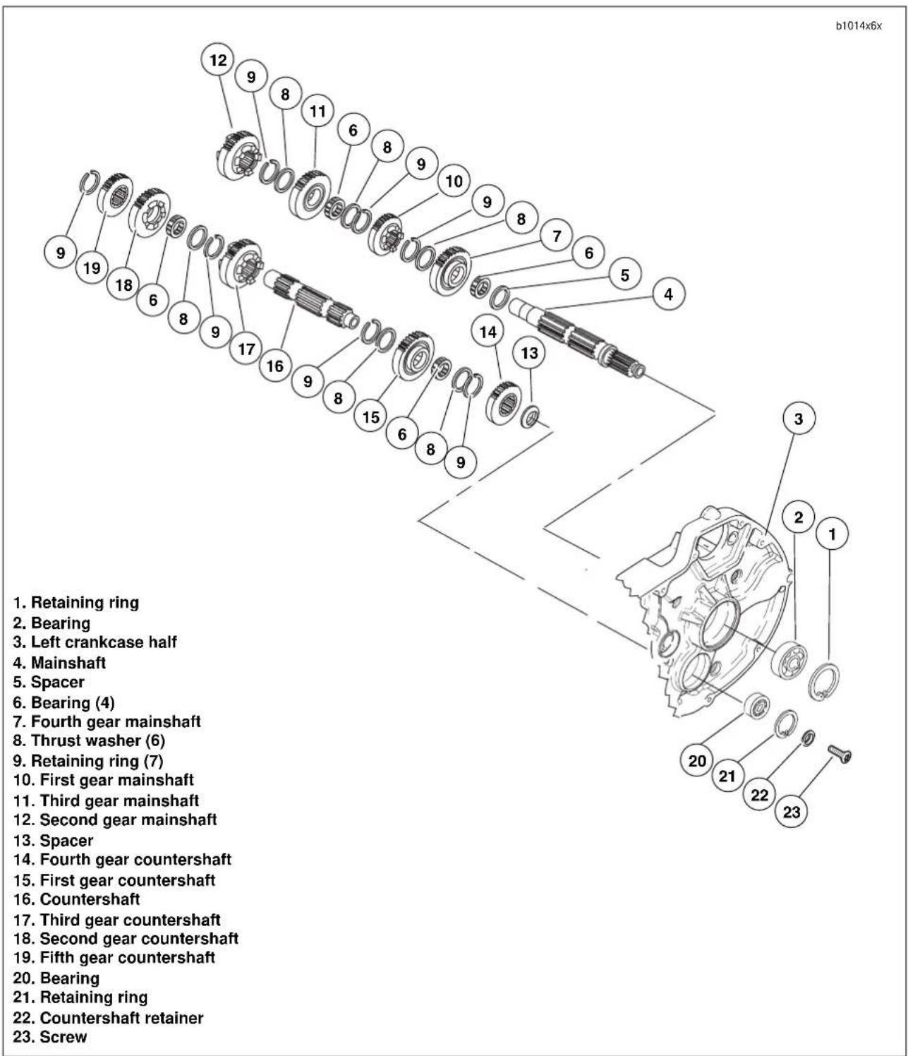
text_image
b1014x6x 1. Retaining ring 2. Bearing 3. Left crankcase half 4. Mainshaft 5. Spacer 6. Bearing (4) 7. Fourth gear mainshaft 8. Thrust washer (6) 9. Retaining ring (7) 10. First gear mainshaft 11. Third gear mainshaft 12. Second gear mainshaft 13. Spacer 14. Fourth gear countershaft 15. First gear countershaft 16. Countershaft 17. Third gear countershaft 18. Second gear countershaft 19. Fifth gear countershaft 20. Bearing 21. Retaining ring 22. Countershaft retainer 23. ScrewFigure 6-57. Transmission Assembly-Left Crankcase Half
MAINSHAFT DISASSEMBLY
NOTE
- Once the transmission assembly has been pressed out of the left crankcase half, the mainshaft and countershaft assemblies can be serviced separately.
● All thrust washers are one common part number. There is no shimming required with this transmission.
WARNING
Always wear proper eye protection when removing retaining rings. Use the correct retaining ring pliers. Verify that the tips of the pliers are not damaged or excessively worn. Slippage could propel the ring with enough force to cause death or serious injury.

text_image
b1019x6x Left Crankcase 13 12 11 10 9 8 7 1. Spacer 2. Split bearing 3. Mainshaft 4th 4. Thrust washer 5. Retaining ring 6. Mainshaft 1st 7. Retaining ring 8. Thrust washer 9. Split bearing 10. Mainshaft 3rd 11. Thrust washer 12. Retaining ring 13. MainshaftFigure 6-58. Transmission Mainshaft Assembly Once Removed from Left Crankcase/Disassembly
- See Figure 6-58. Remove spacer (1), mainshaft 4th gear (3), split bearing (2) and thrust washer (4) from the threaded end of the mainshaft.
- On the mainshaft, between mainshaft 1st gear (6) and mainshaft 3rd gear (10), use RETAINING RING PLIERS (Part No. J-5586) to expand retaining ring (7) and move next to mainshaft 1st gear along with thrust washer (8).
a. Move mainshaft 3rd gear (10) as far as possible toward mainshaft 1st gear (6).
b. Expand retaining ring (12) at opposite side of main shaft 3rd gear (10) and slide off end of mainshaft with thrust washer (11).
c. Remove mainshaft 3rd gear (10) and its split bearing (9). - Slide thrust washer (8) off end of mainshaft.
- Expand retaining ring (7), which is next to mainshaft 1st gear (6), and slide off end of shaft.
- Remove mainshaft 1st gear (6).
- Expand retaining ring (5) and remove.
Cleaning And Inspection
WARNING
Never use compressed air to "spin-dry" bearings. Spinning bearings with compressed air can also cause a bearing to fly apart, which could result in death or serious injury.
- Clean all parts (except bearings) in cleaning solvent and blow dry with compressed air.
- Check gear teeth for damage. If gears are pitted, scored, rounded, cracked or chipped, they should be replaced.
- Inspect the engaging dogs on the gears. Replace the gears if dogs are rounded, cracked, battered, chipped or dimpled.
- Discard all retaining rings that were removed.
COUNTERSHAFT DISASSEMBLY
NOTE
- Once the transmission assembly has been pressed out of the left crankcase half, the mainshaft and countershaft assemblies can be serviced separately.
● All thrust washers are one common part number. There is no shimming required with this transmission.
WARNING
Always wear proper eye protection when removing retaining rings. Use the correct retaining ring pliers. Verify that the tips of the pliers are not damaged or excessively worn. Slippage could propel the ring with enough force to cause death or serious injury.
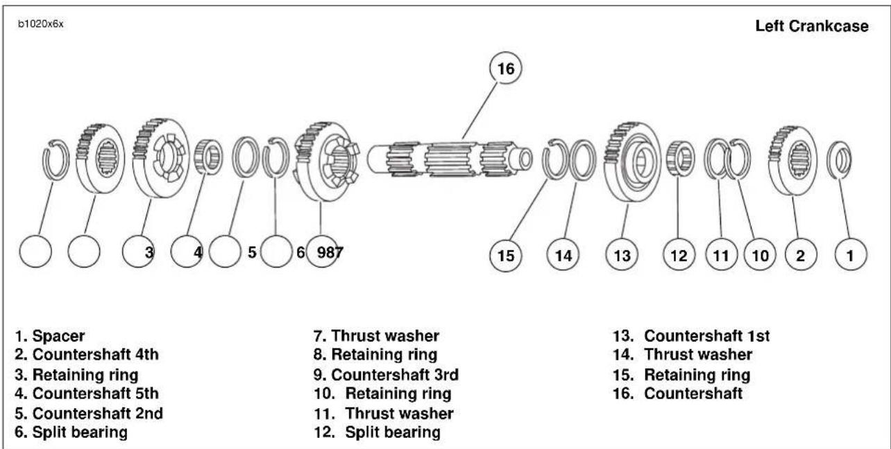
text_image
b1020x6x Left Crankcase 1. Spacer 2. Countershaft 4th 3. Retaining ring 4. Countershaft 5th 5. Countershaft 2nd 6. Split bearing 7. Thrust washer 8. Retaining ring 9. Countershaft 3rd 10. Retaining ring 11. Thrust washer 12. Split bearing 13. Countershaft 1st 14. Thrust washer 15. Retaining ring 16. CountershaftFigure 6-59. Transmission Countershaft Assembly Once Removed from Left Crankcase/Disassembly
- See Figure 6-59. Remove spacer (1) and countershaft 4th gear (2) from the end of the of the countershaft with internal threads.
- Using RETAINING RING PLIERS (Part No. J-5586), remove and discard retaining ring (3) next to counter-shaft 5th gear (4).
a. Slide countershaft 5th (4), and countershaft 2nd (5) off end of countershaft.
b. Remove split bearing (6) that was under countershaft 2nd gear (5) and thrust washer (7).
c. Remove retaining ring (8) on the countershaft and slide countershaft 3rd gear (9) off free end of countershaft. - Expand retaining ring (10) located next to countershaft 1st gear (11). Remove retaining ring (10) and thrust washer (11).
a. Slide countershaft 1st gear (13) off end of shaft.
b. Remove split bearing (12). - Remove thrust washer (14). Expand remaining retaining ring (15) and slide off countershaft.
Cleaning And Inspection
WARNING
Never use compressed air to "spin-dry" bearings. Spinning bearings with compressed air can also cause a bearing to fly apart, which could result in death or serious injury.
- Clean all parts (except bearings) in cleaning solvent and blow dry with compressed air.
- Check gear teeth for damage. If gears are pitted, scored, rounded, cracked or chipped, they should be replaced.
- Inspect the engaging dogs on the gears. Replace the gears if dogs are rounded, cracked, battered, chipped or dimpled.
- Discard all retaining rings that were removed.
MAINSHAFT ASSEMBLY
WARNING
Always wear proper eye protection when removing retaining rings. Use the correct retaining ring pliers. Verify that the tips of the pliers are not damaged or excessively worn. Slippage could propel the ring with enough force to cause death or serious injury.
CAUTION
During assembly, the split bearings and the internal bores of the gears must be lubricated with SPORT-TRANS FLUID prior to assembly. Leaving these parts dry could accelerate wear at start-up.
- See Figure 6-61. Install new retaining ring (1) onto mainshaft in the first ring groove from the threaded end of the mainshaft.
- Slide mainshaft 1st gear (2), identified by two grooves in gear teeth, onto mainshaft with the fork groove facing mainshaft 4th gear (10).
NOTE
See Figure 6-60. The shifting fork groove on mainshaft 1st gear has been made 0.020 wider than existing mainshaft first gear (Part No. 35762-89A) to accommodate the new style shifting fork and has a new part number.
- See Figure 6-61. Install new retaining ring (3).
a. Install thrust washer (4) onto mainshaft.
b. Install split bearing (5) onto mainshaft.
c. Install mainshaft 3rd gear (6) onto shaft over bearing (5). 3rd gear is installed with shifting lugs away from 1st gear mainshaft.
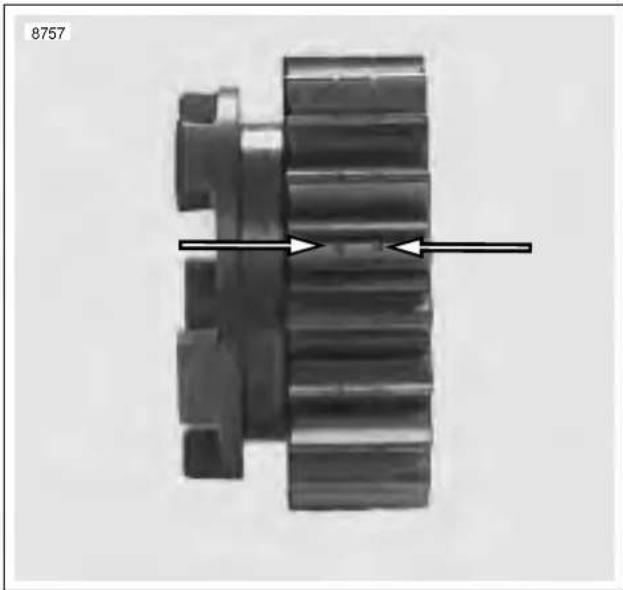
natural_image
Mechanical gear assembly diagram showing shaft and gear teeth with directional arrows (no text or symbols)Figure 6-60. New Mainshaft 1st Gear with Identification Grooves
- Install thrust washer (7) and new retaining ring (8) next to mainshaft 3rd gear (6).
- Install thrust washer (9) on threaded end of mainshaft next to retaining ring (1).
- Install split bearing (10) onto mainshaft next to thrust washer (9).
- Install mainshaft 4th gear (11), which can be identified by the two radial grooves on one side, onto mainshaft over split bearing (10) and against thrust washer (9).
- Install spacer (12) onto end of mainshaft.
b1019x6x
Left Crankcase
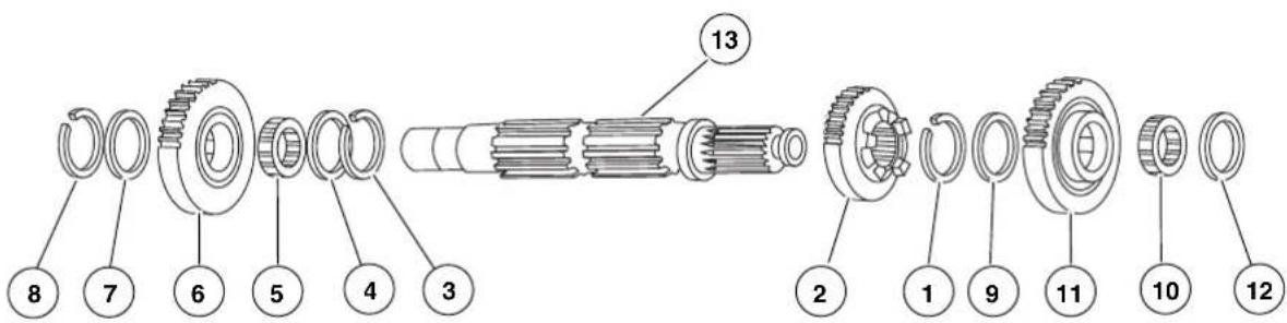
text_image
8 7 6 5 4 3 13 2 1 9 11 10 12- Retaining ring
- Mainshaft 1st
- Retaining ring
- Thrust washer
-
Split bearing
-
Mainshaft 3rd
- Thrust washer
- Retaining ring
- Thrust washer
-
Split bearing
-
Mainshaft 4th
- Spacer
- Mainshaft
Figure 6-61. Transmission Mainshaft Assembly/Reassembly
COUNTERSHAFT ASSEMBLY
WARNING
Always wear proper eye protection when removing retaining rings. Use the correct retaining ring pliers. Verify that the tips of the pliers are not damaged or excessively worn. Slippage could propel the ring with enough force to cause death or serious injury.
CAUTION
During assembly, the split bearings and the internal bores of the gears must be lubricated with SPORT-TRANS FLUID prior to assembly. Leaving these parts dry could accelerate wear at start-up.
- See Figure 6-62. Install new retaining ring (1) and thrust washer (2) onto countershaft in the second ring groove from the end with internal threads.
- Install split bearing (4) onto countershaft.
-
Locate countershaft 1st gear (3), identified by one radial groove at one side, and slide gear onto shaft. Position gear over bearing (4).
-
Install thrust washer (5) and new retaining ring (6) next to countershaft 1st gear (3).
- Install countershaft 3rd gear (7) on countershaft with fork groove facing away from countershaft 1st gear (3).
- Install new retaining ring (8) on countershaft. Position new retaining ring in the second ring groove from the end. Install thrust washer (9) next to retaining ring (8). Install split bearing (10) in seat next to washer (9).
- Install countershaft 2nd gear (11) with the locking dogs facing countershaft 3rd gear (7).
- Install countershaft 5th gear (12) on countershaft.
- Install new retaining ring (13) on countershaft.
- Locate countershaft 4th gear (14). This flat, shoulder less gear is splined and has a single radial groove at one side. Position gear next to retaining ring (6) on countershaft. Place beveled spacer (15) over end of shaft with beveled side away from countershaft 4th gear (14).
NOTE
At this point both mainshaft and countershaft sub-assemblies are ready to be pressed into the left crankcase half.
b1020x6x
Left Crankcase
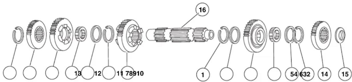
text_image
Technical diagram of a mechanical assembly with numbered components and cross-sectional views- Retaining ring
- Thrust washer
- Countershaft 1st
- Split bearing
- Thrust washer
-
Retaining ring
-
Countershaft 3rd
- Retaining ring
- Thrust washer
- Split bearing
- Countershaft 2nd
-
Countershaft 5th
-
Retaining ring
- Countershaft 4th
- Beveled spacer
- Countershaft
Figure 6-62. Transmission Countershaft Assembly/Reassembly
REMOVAL
- Split crankcases in half. See 6.6 CASE DISASSEMBLY FOR TRANSMISSION REMOVAL.
- Remove transmission as an assembly. See 6.7 TRANSMISSION DISASSEMBLY.
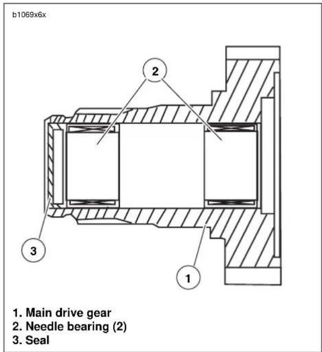
text_image
b1069x6x 1. Main drive gear 2. Needle bearing (2) 3. SealFigure 6-63. Main Drive Gear Assembly
- See Figure 6-63. From inside case tap out seal at end of mainshaft 5th gear. Discard seal.
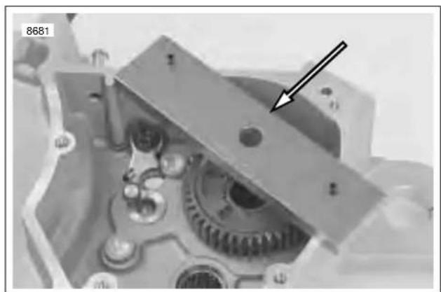
natural_image
Close-up of a mechanical gear assembly with a black arrow pointing to a specific component (no text or symbols visible)Figure 6-64. Bearing Remover Cross Plate Mounting (Part No. B-45847)
- See Figure 6-64. Place cross plate on crankcase as shown.
6-36 2003 Buell XB9R: Drive/Transmission
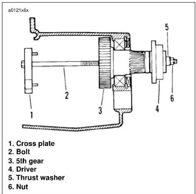
text_image
a0121x6x 1. Cross plate 2. Bolt 3. 5th gear 4. Driver 5. Thrust washer 6. NutFigure 6-65. Removing Main Drive Gear
- See Figure 6-65. Assemble MAIN DRIVE GEAR REMOVER AND INSTALLER (Part No. HD-35316A) with CROSS PLATE (Part No. B-45847).
- Insert bolt (2) through cross plate (1) and 5th gear (3).
CAUTION
When removing the main drive gear, the gear is pressed out against the resistance of the bearing inner race. Without any support at the inner race, the bearing is destroyed. Whenever the main drive gear is removed the main drive gear bearing will also have to be replaced.
- At outside of case, place driver (4) and thrust washer (5) over end of bolt (2). Install and tighten nut (6) until 5th gear (3) is free.
DISASSEMBLY
Drive out needle bearings from inside bore of main drive gear. Do not reuse bearings after removal.
ASSEMBLY
- See Figure 6-66. Use INNER/OUTER MAIN DRIVE GEAR NEEDLE BEARING INSTALLATION TOOL (Part No. HD-37842-A) for assembly. Select which end of tool to use.
a. The end stamped 0.080 in. (2.032 mm) is for driving the bearing into the inner end.
b. The end stamped 0.315 in. (8.001 mm) is for the outer end bearing.
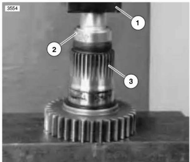
text_image
3554 1 2 3-
Ram on end of press
-
Needle bearing installation tool
-
Main drive gear
Figure 6-66. Needle Bearing Installation Tool
- Assemble parts. The installation tool will automatically bottom on the gear when the correct depth is reached.
a. Place main drive gear on a press.
b. Press in the outer bearing to a depth of 0.315-0.285 in. (8.001-7.239 mm).
c. Press in the inner bearing to a depth of 0.080 in. (2.032 mm).
INSTALLATION
- Replace main drive gear bearing.
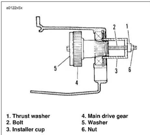
text_image
a0122xSx 1. Thrust washer 2. Bolt 3. Installer cup 4. Main drive gear 5. Washer 6. NutFigure 6-67. Main Drive Gear Installation
- See Figure 6-67. Use MAIN DRIVE GEAR REMOVER AND INSTALLER (Part No. HD-35316-A) for assembly.
a. Take bolt (2) and place washer (5) followed by main drive gear (4) over end of bolt.
b. From inside of case insert bolt and main drive gear through inner race of ball bearing.
c. Insert threaded end of bolt (2) through installer cup (3) and thrust washer (1).
d. Thread nut (6) onto end of bolt (2). Tighten nut (6) until shoulder on gear (4) bottoms against inner race of bearing.
HOME
- See Figure 6-68. Tap in new seal (3) at threaded end of 5th gear to a depth of 0.060-0.030 in. (1.524-0.762 mm).
- See Figure 6-69. Place new quad ring over threaded end of fifth gear, and position next to the gear taper. Install spacer over threaded end of fifth gear with chamfered end toward quad ring. Slide spacer up against bearing.
- Install large seal.
a. Coat lips of seal with SPORT-TRANS FLUID.
b. Position seal over spacer with lips of seal toward case.
c. Use MAIN DRIVE GEAR SEAL INSTALLER (Part No. HD-41496) to gently tap seal into bore of case until the outside of seal is flush with outer edge of bore.
NOTE
It is acceptable to recess seal to about 0.030 in. (0.762 mm) below outer edge of bore. Seal will be controlled by tool.
b1069x6x
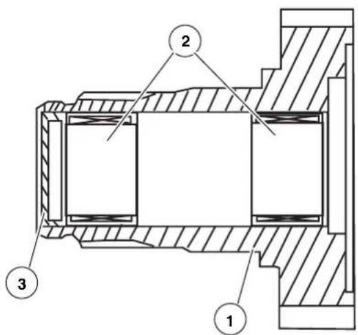
text_image
Technical cross-sectional diagram of a mechanical assembly with numbered components- Main drive gear
- Needle bearing (2)
- Seal
Figure 6-68. Main Drive Gear Assembly
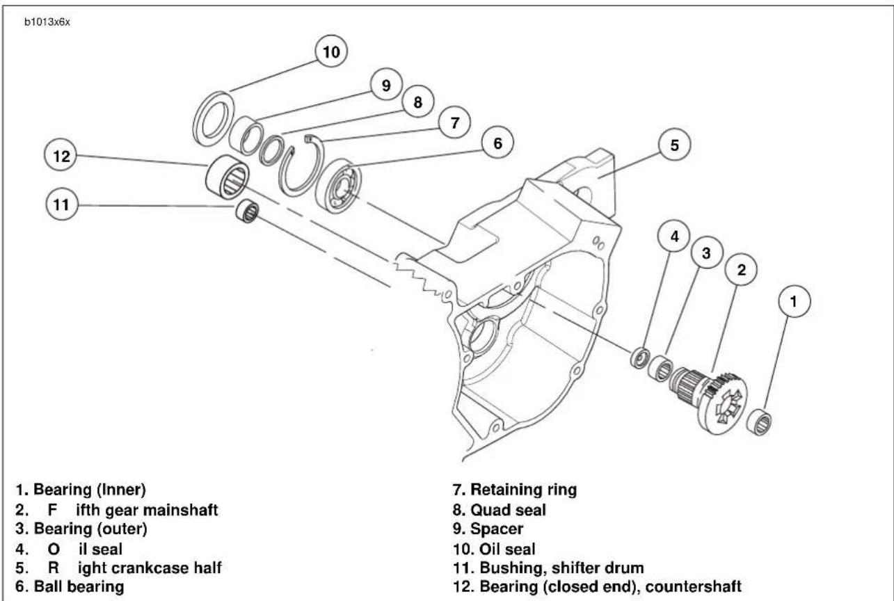
text_image
b1013x6x 1. Bearing (Inner) 2. F ifth gear mainshaft 3. Bearing (outer) 4. O il seal 5. R ight crankcase half 6. Ball bearing 7. Retaining ring 8. Quad seal 9. Spacer 10. Oil seal 11. Bushing, shifter drum 12. Bearing (closed end), countershaftFigure 6-69. Transmission Assembly Right Crankcase Half
REMOVAL
NOTE
See Figure 6-69. Refer to Transmission assembly right crank-case half, for location of items discussed on this page.
- Remove transmission assembly. See 6.7 TRANSMISSION DISASSEMBLY.
- See Figure 6-69. Remove main drive 5th gear. Use MAIN DRIVE GEAR REMOVER AND INSTALLER (Part No. HD-35316A). See 6.9 MAIN DRIVE GEAR.
- At outside of case remove seal next to 5th gear bearing retainer. Remove retaining ring.
- From inside transmission case drive bearings (5th gear, countershaft or shifter shaft) out of bores. Carefully tap bearings free by working around bearing diameter to keep bearing from skewing.
INSTALLATION
Mainshaft 5th Gear Ball Bearing
- See Figure 6-70. Locate MAIN DRIVE GEAR REMOVER AND INSTALLER (Part No. HD-35316-A). Place cross-plate pins in appropriate holes in transmission case.
- See Figure 6-71. Insert bolt (2) through cross plate (1), new bearing (3), driver (4) and thrust bearing (5). Thread nut (6) on end of bolt. Tighten nut carefully until bearing is started in bore squarely. Tighten nut (6) until bearing is seated against shoulder in bore.
- At outside of case install beveled retaining ring in groove inside bearing bore with beveled side facing outside of case.
- Lubricate bearing with SPORT-TRANS FLUID.
Countershaft Needle Bearing
- Find a suitable bearing driver 1-1/4 in. (31.75 mm) in diameter.
- See Figure 6-69. From the outside of the case place the needle bearing open end first next to the bearing bore. Hold the driver squarely against the closed end of the bearing and tap the bearing into place. The bearing is properly positioned when it is driven inward flush or 0.030 in. (0.762 mm) below the outside surface of the case.
- Lubricate bearing with SPORT-TRANS FLUID.
Shifter Drum Bushing
- See Figure 6-69. The shifter drum bushing (11) is a press fit in the right crankcase half. Inspect the bushing against the corresponding end of the shifter drum for proper fit and wear.
-
If bushing is to be replaced, use a BUSHING AND BEARING PULLER (Part No. HD-95760-69A) with a 1/2 in. collet (Part No. HD-95765-69A) to remove bushing from right crankcase half.
-
To install new bushing, use SNAP-ON BUSHING DRIVER SET (Part No. A-157C) with a 1/2 inch adapter (Part No. A157-8).
- Lubricate bushing with SPORT-TRANS FLUID.
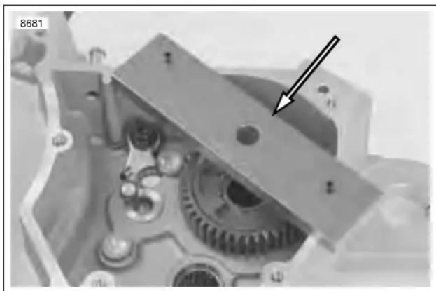
natural_image
Close-up mechanical assembly showing gears and a component with an arrow pointing to a hole (no text or symbols visible)Figure 6-70. Bearing Remover Cross Plate Mounting (Part No. B-45847)
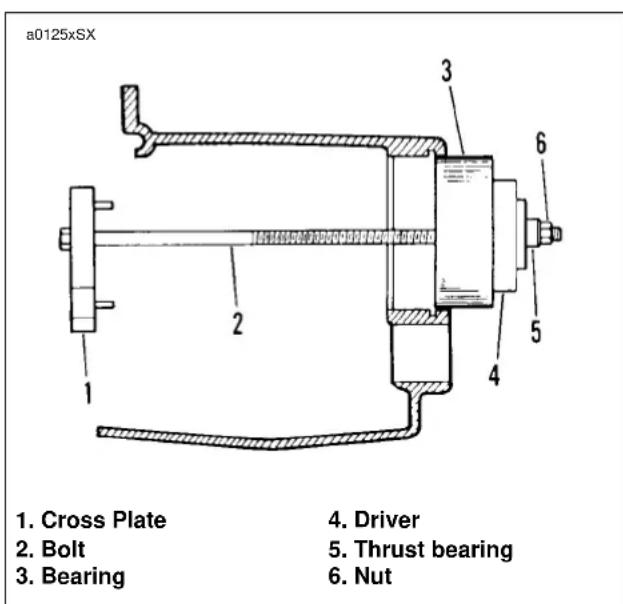
text_image
a0125xSX 1. Cross Plate 2. Bolt 3. Bearing 4. Driver 5. Thrust bearing 6. NutFigure 6-71. Installing Mainshaft Ball Bearing
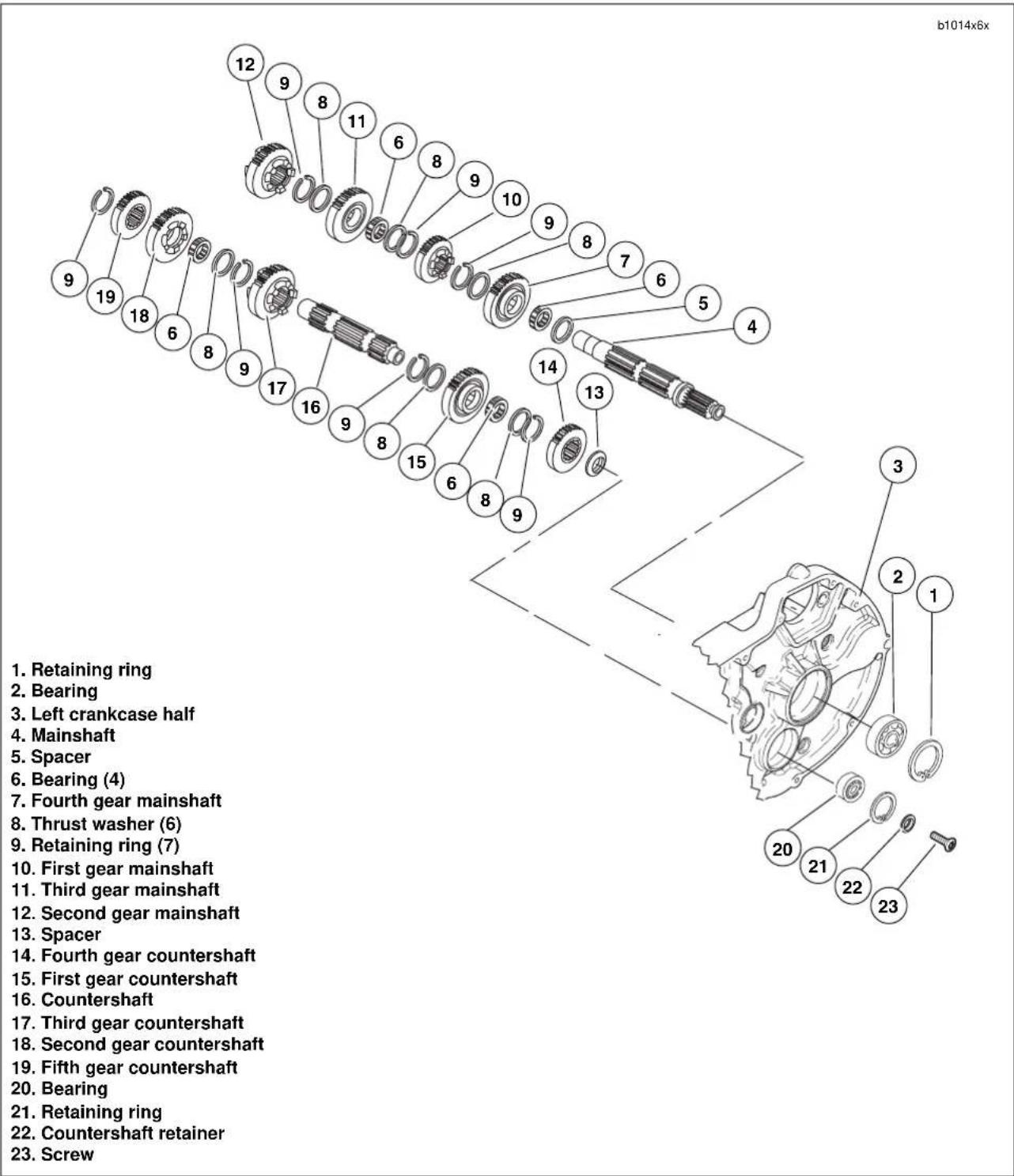
text_image
b1014x6x 1. Retaining ring 2. Bearing 3. Left crankcase half 4. Mainshaft 5. Spacer 6. Bearing (4) 7. Fourth gear mainshaft 8. Thrust washer (6) 9. Retaining ring (7) 10. First gear mainshaft 11. Third gear mainshaft 12. Second gear mainshaft 13. Spacer 14. Fourth gear countershaft 15. First gear countershaft 16. Countershaft 17. Third gear countershaft 18. Second gear countershaft 19. Fifth gear countershaft 20. Bearing 21. Retaining ring 22. Countershaft retainer 23. ScrewFigure 6-72. Transmission Assembly Left Crankcase Half
REMOVAL
NOTE
See Figure 6-72. Refer to Transmission assembly left crank-case half, for location of items discussed on this page.
Mainshaft and Countershaft Bearings
- Split crankcases in half. See 6.6 CASE DISASSEMBLY FOR TRANSMISSION REMOVAL.
- Remove shifter forks and drum. See 6.8 TRANSMISSION ASSEMBLY under 6.7 TRANSMISSION DISASSEMBLY.
- Remove countershaft and mainshaft. See 6.7 TRANSMISSION DISASSEMBLY.
- Inspect the mainshaft and countershaft ball bearings for pitting, scoring, discoloration or other damage.
- See Figure 6-73. If bearing replacement is required, remove retaining rings (1, 2) using snap ring pliers (Snap-On Part No. PR-36). Press out bearings (3, 4) from the inside of the crankcase.
Shift Drum Bushing
Inspect the shifter drum bushing for pitting, scoring, discoloration or excessive wear. If bushing requires replacement press bushing out of crankcase from either side.
INSTALLATION
Mainshaft and Countershaft Bearings
- Place crankcase on press with inside surface of crank-case downward.
- Lay bearing squarely over bore with printed side of bearing upward. Place a pressing tool (slightly smaller than outside diameter of bearing) against outer race. Press bearing into bore until bearing bottoms against shoulder.
- Install new retaining ring with beveled side facing away from bearing.
Shift Drum Bushing
- Place crankcase on press with outside surface of crankcase downward.
- See Figure 6-74. Lay bushing squarely over bore. Using a pressing tool larger than diameter of bushing, press bushing into bore until bushing contacts shoulder in left crankcase half. If using a pressing tool larger than diameter of bushing, the pressing tool will bottom against crankcase when bushing is flush with top surface.
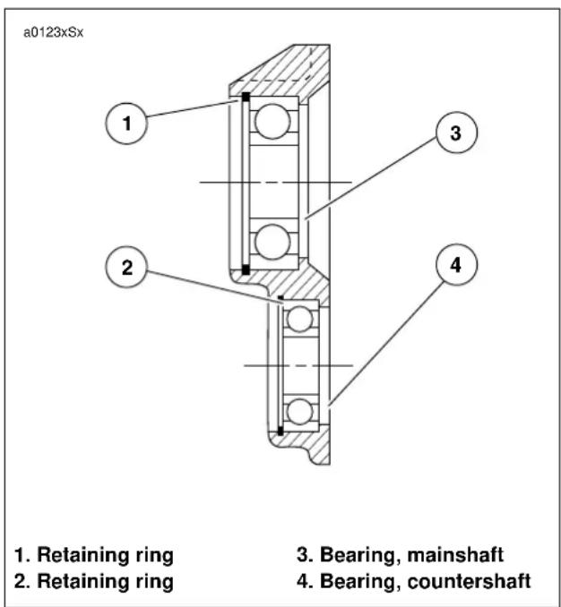
text_image
a0123xSx 1. Retaining ring 2. Retaining ring 3. Bearing, mainshaft 4. Bearing, countershaftFigure 6-73. Ball Bearing Assembly
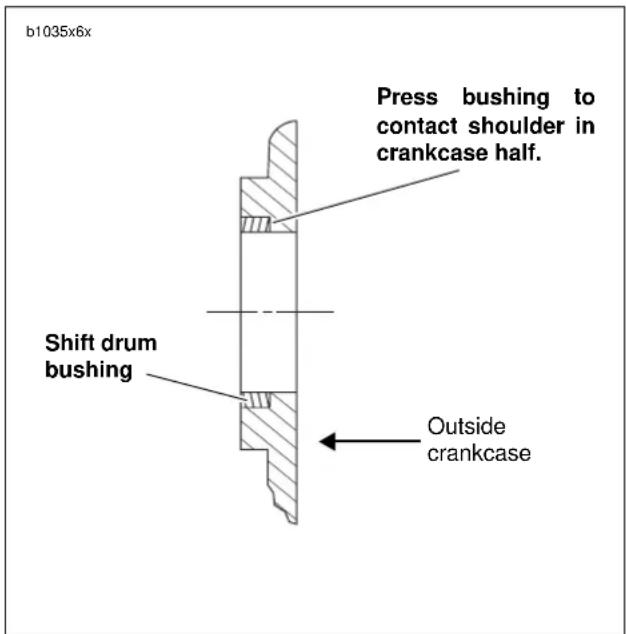
text_image
b1035x6x Press bushing to contact shoulder in crankcase half. Shift drum bushing Outside crankcaseFigure 6-74. Shift Drum Bushing Assembly
INSTALLATION
NOTE
After re-installing the transmission assembly, verify that all parts have been properly installed. See Figure 6-72.
● 6.9 MAIN DRIVE GEAR
● 6.8 TRANSMISSION ASSEMBLY
● 6.11 TRANSMISSION LEFT CASE BEARINGS
● 6.10 TRANSMISSION RIGHT CASE BEARINGS
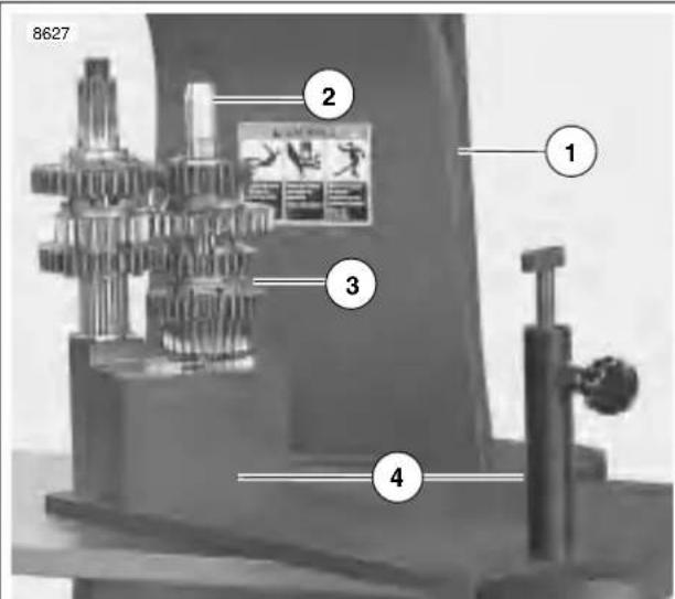
text_image
8627 1 2 3 4- Arbor press
- Guide tool (Part No. B-43985-4)
- Transmission assembly
- Transmission Remover/Installer fixture (Part No. B-43985-2)
Figure 6-75. Transmission Assembly in Fixture
- See Figure 6-75. Place transmission assembly onto TRANSMISSION REMOVER/INSTALLER FIXTURE (Part No. B-43985-2) on arbor press.
- Install COUNTERSHAFT GUIDE ADAPTER (Part No. B-43985-4).
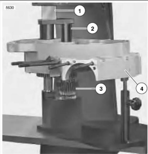
text_image
8630 1 2 3 4- Arbor press
- Transmission Installer (Part No. B-43985-3)
- Transmission assembly
- Left case half
Figure 6-76. Installing Transmission in Left Case Half
- See Figure 6-76. Place left case half over transmission assembly and install TRANSMISSION INSTALLER (Part No. B-43985-3) into crankcase.
- See Figure 6-76. Press crankcase onto transmission assembly into until it bottoms out.
- Remove COUNTERSHAFT GUIDE ADAPTER (Part No. B-43985-4).
- Remove transmission assembly and left crankcase half from fixture.
- Re-install transmission assembly and left crankcase half in engine stand.
- Install mainshaft 2nd gear with shifter fork groove towards mainshaft 3rd gear.
- Install shifter forks, shafts and shifter drum. See 6.8 TRANSMISSION ASSEMBLY.
HOME
SHIFTER FORKS AND DRUM ASSEMBLY
NOTES
- See Figure 6-77. Shifter fork design allows for one common part number for all three shifter forks. As the transmission runs, each shifter fork develops a certain wear pattern with its mating parts. For this reason, it is important that each shifter fork be reinstalled in its original location.
● Always lubricate the shaft bore in each shifting fork with Sport Transmission Lube before assembly.

text_image
8616 3-5 4 Mainshaft Left Right 1-2 CountershaftFigure 6-77. Shifter Forks, Drum and Shafts
- Place the 4th gear shifter fork on the appropriate main-shaft sliding gear.
- Install the shifter drum into the left case half with the previously scribed line at the 6 o'clock position. This will place the shifter drum in the 4th gear position.
- See Figure 6-78. Place the 3rd and 5th gear shifter fork on the appropriate mainshaft sliding gear and install the shifter fork shaft through the two installed shifter forks and into the left case half.
- Install the 1st and 2nd gear shifter fork on the appropriate countershaft sliding gear and install the remaining shifter fork shaft through the last installed shifter fork and into the left case half.
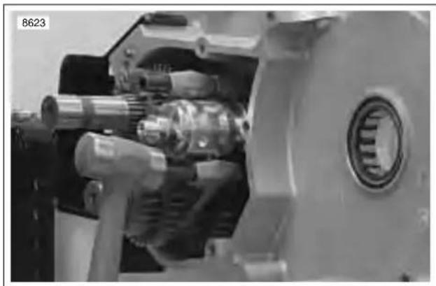
natural_image
Close-up of mechanical components including gears and a bearing assembly (no visible text or symbols)Figure 6-78. Installing Shift Fork Shafts
NOTE
See Figure 6-78. Install shifter fork shafts in the left case half by lightly tapping on the end with a brass hammer until seated in bore.
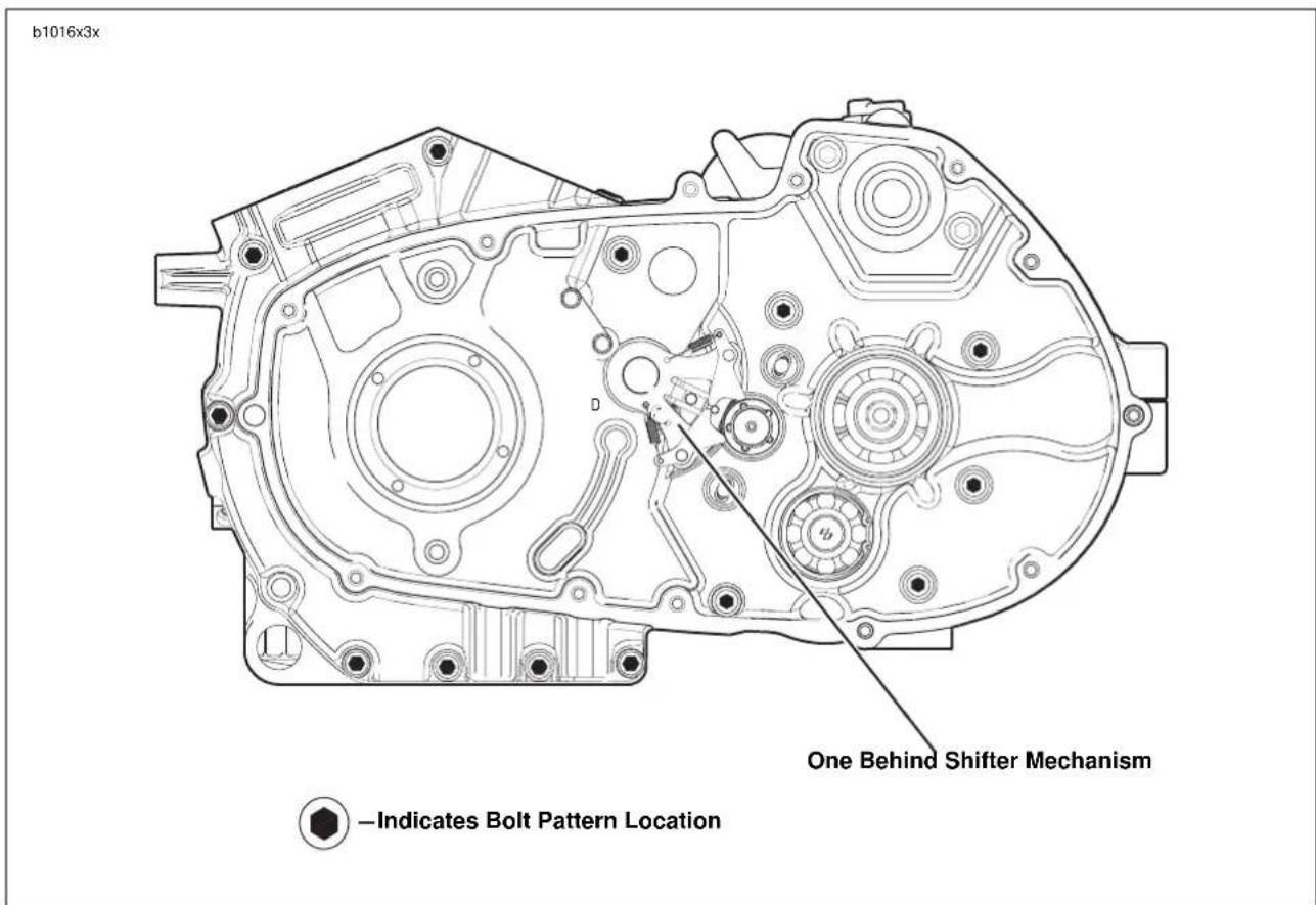
text_image
b1016x3x One Behind Shifter Mechanism —Indicates Bolt Pattern LocationFigure 6-79. Crankcase Fasteners
INSTALLING RIGHT CRANKCASE
- See Figure 6-80. Install the flywheel assembly into the left crankcase half using CRANKSHAFT GUIDE TOOL Part No. HD-42326.
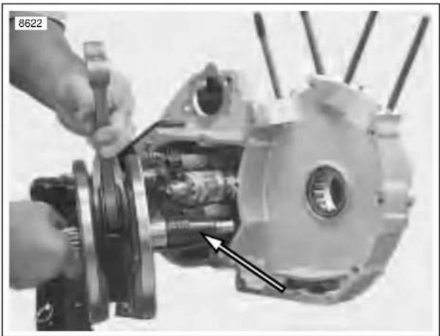
natural_image
Close-up of a mechanical assembly with hands operating a motor component (no visible text or symbols)Figure 6-80. Installing Flywheel Assembly Using Crankshaft Guide Tool (Part No. HD-42326)
NOTE
The Gear Detent Assembly Aid is used to move the gear detent lever clear of the shifter drum for assembly purposes.
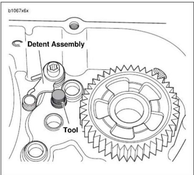
text_image
b1067x6x Detent Assembly ToolFigure 6-81. Gear Detent Assembly Aid (Part No. B-45520)
- See Figure 6-81. Retract detent assembly in right case half and install GEAR DETENT ASSEMBLY AID (Part No. B-45520) until it has bottomed in right case half.
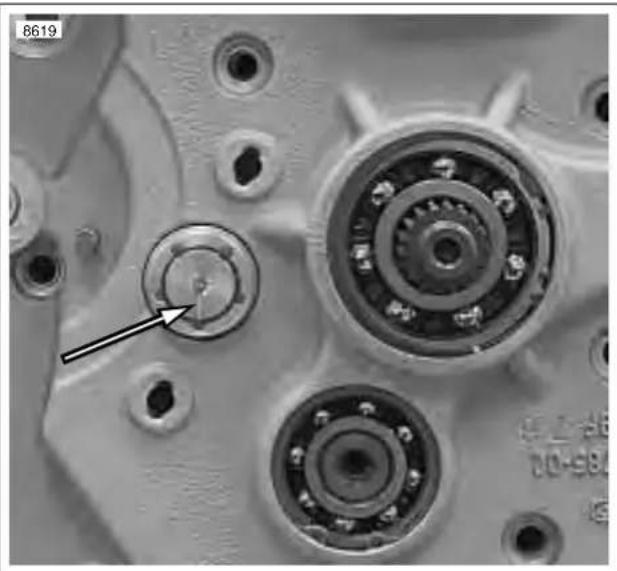
natural_image
Close-up of mechanical components with visible gears and bolts, no text or symbols presentFigure 6-82. Scribed Line on Shifter Drum at 6 O'clock (Transmission in 4th Gear)
- See Figure 6-82. Place Transmission in the 4th gear position. The scribed line on the shifting drum should be at 6 o'clock.
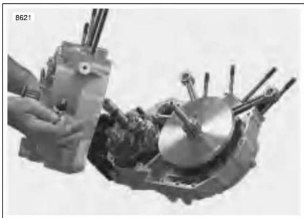
natural_image
Close-up of a mechanical assembly with hands operating a motor or engine component (no visible text or symbols)Figure 6-83. Crankcase Halves
- See Figure 6-83. Assemble crankcase halves together.
a. Apply a thin coat of DOW CORNING SILASTIC #732 clear sealant to crankcase joint faces
b. Apply several drops of LOCTITE 262 (red) to last few threads.
c. See Figure 6-79. Tighten 5/16-in. fasteners to 15-19 ft-lbs (20.3-25 Nm).
INSTALLATION
- See Figure 6-84. Correctly install shifter return spring onto the reverse side of the shifter shaft assembly before placing shaft in left crankcase half.

natural_image
Technical line drawing of a mechanical clamp or bracket component (no text or symbols)Figure 6-84. Shifter Shaft Return Spring (Correctly Installed)
CAUTION
See Figure 6-85. The shifter shaft return spring can be installed incorrectly and then assembled in the left crankcase half. Failure to install the spring properly will result in improper shifting.
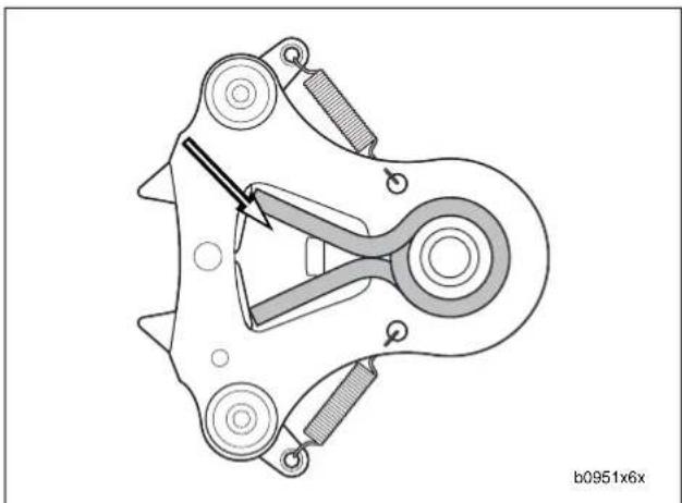
natural_image
Technical line drawing of a mechanical clamp or bracket component (no text or symbols)Figure 6-85. Shifter Shaft Return Spring (Incorrectly Installed)
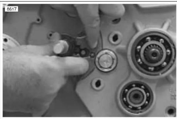
natural_image
Close-up of a hand adjusting mechanical components with ball bearings (no visible text or symbols)Figure 6-86. Installing Shifter Shaft Assembly
- See Figure 6-86. Depress ratchet arms and insert shaft assembly into the bushing in the left case half and release. Ratchet arms should now be inside the end plate of the shifter drum contacting the shifter drum pins.
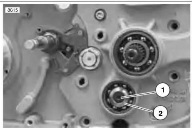
natural_image
Close-up of mechanical components with numbered annotations (1 and 2) pointing to a central component (no readable text or symbols beyond labels)- TORX screw
- Retention collar
Figure 6-87. Countershaft Retainer
- See Figure 6-87. Position retention collar (2) next to end of countershaft with beveled side facing outward.
a. Apply several drops of LOCTITE 243 (blue) to last few threads.
b. Insert screw (1) through retention collar (2) and thread into end of shaft.
c. Place transmission in gear and tighten TORX screw (1) to 13-17 ft-lbs (18-23 Nm).
REMOVAL
| PART NO. SPECIALTY TOOL |
| B-45659 Transmission sprocket locking tool |
| HD-94660-37B Mainshaft locknut wrench |
- Loosen rear axle pinch fastener. See IDLER PULLEY REMOVAL in 1.9 DRIVE BELT SYSTEM.
- Unthread axle approximately 15 threads to release tension from drive belt.
- Remove front sprocket cover. See 2.30 SPROCKET COVER.
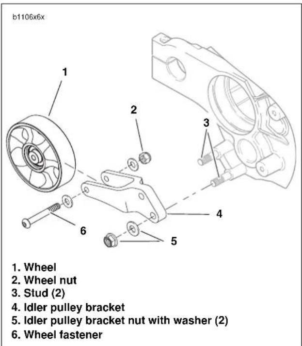
text_image
b1106x6x 1. Wheel 2. Wheel nut 3. Stud (2) 4. Idler pulley bracket 5. Idler pulley bracket nut with washer (2) 6. Wheel fastenerFigure 6-88. Idler Pulley Assembly
- See Figure 6-88. Remove both bracket nuts with washers (5) attaching idler pulley (4) to studs (3).
- Slide idler pulley assembly off studs.
- Inspect pulley by spinning wheel (1) and checking for excessive wheel bearing wear.
- If pulley wheel needs replacement, remove fastener (6) and nut (3) from idler pulley bracket (2) and discard. Replace with new pulley wheel (1).
NOTE
The pulley wheel bearings can not be replaced separately. A new pulley wheel must be installed.
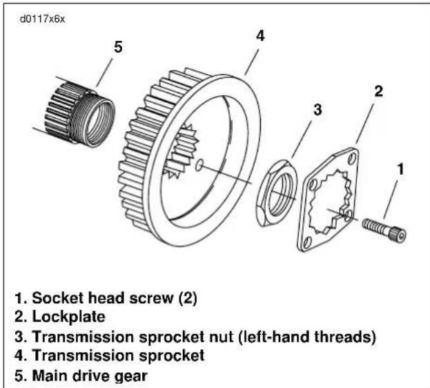
text_image
d0117x6x 1. Socket head screw (2) 2. Lockplate 3. Transmission sprocket nut (left-hand threads) 4. Transmission sprocket 5. Main drive gearFigure 6-89. Transmission Sprocket
- See Figure 6-89. Place transmission in first gear. Remove two socket head screws (1) and lockplate (2).
CAUTION
Transmission sprocket nut has left-hand threads. Turn nut clockwise to loosen and remove from main drive gear shaft.
- Remove transmission sprocket nut (3) from main drive gear (5) using MAINSHAFT LOCKNUT WRENCH (Part No. HD-94660-37B). Use an air impact wrench for best results.
- Remove secondary drive belt from transmission sprocket. Remove transmission sprocket (4) from main drive gear (5).
INSTALLATION
- See Figure 6-89. Install transmission sprocket (4) with secondary drive belt onto main drive gear (5).
- Place transmission in neutral.
- Apply a few drops of LOCTITE 262 (red) to the left-hand threads of transmission sprocket nut (3) and lightly coat the washer-faced side with clean H-D 20W50 engine oil. Wipe off any excess oil.
- Position nut with washer-faced side facing transmission sprocket. Turn the nut counterclockwise to install it onto main drive gear.
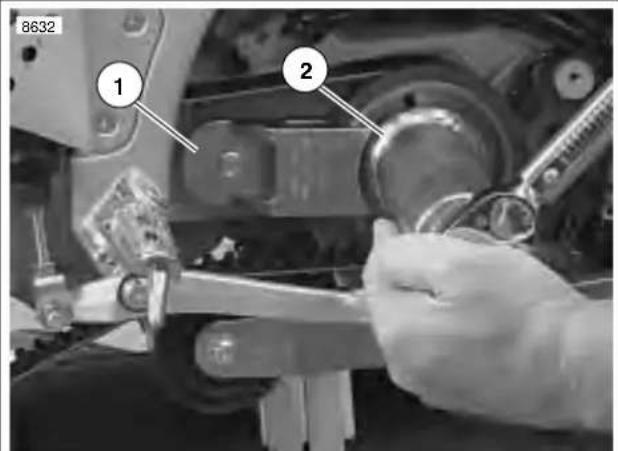
text_image
8632 1 2- Sprocket holding tool (Part No. B-45659)
-
Mainshaft locknut wrench (Part No. HD-94660-37B)
Figure 6-90. Transmission Sprocket Tightening -
See Figure 6-90. Install SPROCKET HOLDING TOOL (Part No. B-45659) as shown.
- Using MAINSHAFT LOCKNUT WRENCH (Part No. HD-94660-37B) and a torque wrench, tighten sprocket nut to 50 ft-lbs (67.8 Nm) INITIAL TORQUE ONLY.
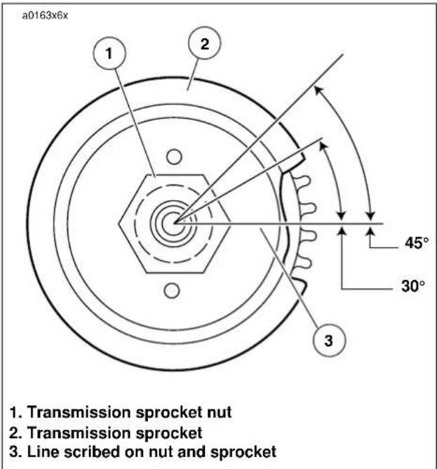
text_image
a0163x6x 1. Transmission sprocket nut 2. Transmission sprocket 3. Line scribed on nut and sprocket 45° 30°Figure 6-91. Aligning Transmission Sprocket
- See Figure 6-91. Scribe a line on the transmission sprocket nut and continue the line on the transmission sprocket as shown.
- Tighten the transmission sprocket nut an additional 30°-40°.
- See Figure 6-89. Install lockplate over nut so that two of lockplate's four drilled holes (diagonally opposite) align with sprocket's two tapped holes.
NOTE
The lockplate has four screw holes and can be turned to either side, so you should be able to find a position without having to additionally tighten the nut. If you cannot align the screw holes properly, the nut may be additionally TIGHTENED until the screw holes line up, but do not exceed 45°. NEVER LOOSEN nut to align the screw holes.
CAUTION
Maximum allowable tightening of sprocket nut is 45° of counterclockwise rotation, after initially tightening to 50 ft-lbs. Do not loosen sprocket nut while attempting to align the screw holes. If you cannot align lockplate and sprocket screw holes, nut may be additionally tightened 45° as specified above. Tightening too much or too little may cause the nut to come loose during vehicle operation. If you cannot align lockplate and sprocket screw holes, nut may be additionally tightened until screw holes align.
- See Figure 6-89. Install two socket head screws through aligned holes of lockplate and into tapped holes of sprocket. Tighten to 90-110 in-lbs (10.2-12.4 Nm).
NOTE
The original equipment socket head screws (1) have thread-locking compound applied to them. Since this compound remains effective for about three removal/installation cycles, the original screws may be reused up to three times. After the third removal/installation cycle, replace both screws with new screws identical to the original.
- See Figure 6-88. Slide idler pulley assembly on to studs (4), install nuts and washers (5) and tighten to 33-35 ft-lbs (44.74-47.45 Nm).
- Install front sprocket cover. See 2.30 SPROCKET COVER.
CAUTION
Never remove rear axle with swingarm brace removed.

text_image
8420 1 2- Axle
- Pinch bolt fastener
Figure 6-92. Rear Wheel Mounting, Right Side
- See Figure 6-92. Tighten rear axle (1) to 48-52 ft-lbs (65-70 Nm).
- Tighten rear axle pinch fastener (2) to 40-45 ft-lbs (54-61 Nm).
- Install clutch assembly, primary chain and engine sprocket. See 6.4 PRIMARY DRIVE/CLUTCH.
- Install primary cover. See 6.2 PRIMARY CHAIN.
- Assemble gearcase. See 3.16 GEARCASE COVER AND CAM GEARS.
- Assemble top end. See 3.6 CYLINDER HEAD.
- Remove engine from ENGINE SUPPORT STAND (Part No. HD-42310/HD-43646 or HD-43682).
- Install engine in chassis. See 3.4 STRIPPING MOTORCYCLE FOR ENGINE SERVICE.
- Fill transmission and engine to proper level with fresh lubricant. See 1.2 FLUID REQUIREMENTS.
2003 Buell XB9R: Drive/Transmission 6-49
SUBJECT PAGE NO.
7.1 Specifications 7-1
7.2 Ignition System 7-3
7.3 Ignition/Headlight Key Switch 7-5
7.4 Spark Plug Cables 7-9
7.5 Starter Interlock 7-11
7.6 Charging System 7-19
7.7 Alternator 7-26
7.8 Voltage Regulator 7-28
7.9 Battery Cables 7-29
7.10 Battery 7-31
7.11 Headlight 7-37
7.12 Tail Lamp 7-39
7.13 Turn Signals 7-40
7.14 Turn Signal Flasher 7-43
7.15 Handlebar Switches 7-44
7.16 Speedometer Sensor 7-46
7.17 Instrument Module 7-47
7.18 Speedometer Performance Check 7-48
7.19 Tachometer Performance Check 7-53
7.20 Horn 7-55
7.21 Neutral Indicator Switch 7-57
7.22 Main Fuse and Fuses 7-58
7.23 Main Wire Harness 7-59
7.24 Sprocket Cover Wiring 7-64
ELECTRICAL 7
Table 7-1. Battery Specifications
| BATTERY | |
| Size 12 VDC/12 AH/2000 | CCA |
| Type Sealed, AGM | |
Table 7-2. Spark Plug Specifications
| SPARK PLUGS | ||
| Size | 12 | |
| Type 10R12A | ||
| Gap | 0.035 | in. |
| Torque 11-18 ft-lbs | 15-24 Nm | |
| Cable Resistance(front and rear) | 1,430-3,360 ohms | |
Table 7-3. Alternator Specifications
| ALTERNATOR | |
| AC Voltage Output 16-20 | VAC per 1000 engine RPM |
| Stator Coil Resistance | 0.1-0.3 Ohms |
Table 7-4. Regulator Specifications
| REGULATOR | |
| Voltage Output @ 3600 RPM | 14.3-14.7 VDC@ 75° F (24°C) |
| Amperes @ 3600 RPM | 34-38 Amps |
Table 7-5. Ignition Coil Specifications
| IGNITION COIL RESISTANCE | |
| Primary Winding | 0.5-0.7 ohms |
| Secondary Winding 0.9mm | 5500-7500 ohms |
Table 7-6. Electrical System Specifications
| ELECTRICAL SYSTEM AMPERES | |
| Main Main fuse | 30 |
| Ignition fuse | 15 |
| Light fuse | 15 |
| Accessory fuse | 7.5 |
| Brake/Horn fuse | 15 |
| ECM fuse | 7.5 |
| Key switch fuse | 15 |
| Cooling fan fuse | 7.5 |
Table 7-7. Specifications
| BULB CHART | BULBS REQUIRED | WATTS AMPS | PART NUMBER | ||||
| Headlights | Bulb (H3) | 2 | 55 | 4.58 | 68918-98 | ||
| Position Lamp (European models only) | 1 | 4 | 0.33 | Y0026.02A8 | |||
| Marker Lamps | Tail/Stop Lamp | 1 | 5/21 | 0.42/1.75 | Y0401B.2U | ||
| Turn Signal Lamp (front and rear (1 bulb each) | 4 | 10.0 | 0.84 | Y0042.K | |||
| Indicator Lamps, Speedometer and Tachometer Illumination | Indicator, Speedometer and Tachometer LED's are part of the instrument module and are not replaceable. Entire assembly must be replaced if LED fails. | ||||||
| ITEM TORQUE NOTES | |||||||
| Battery (+) to starter fastener 60 | 85 in-lbs | 7-10 Nm page | 7-30 | ||||
| Battery terminal fastener 72-96 | in-lbs | 8-11 Nm page | 7-29, page 7-35, page 7-62 | ||||
| Fork clamp, upper 17-19 ft-lbs 23 | -26 Nm LOCTITE | 272, page 7-8 | |||||
| Fuse block mounting fasteners 72 | -96 in-lbs | 8.1-10.8 Nm page | 7-61 | ||||
| Handlebar control housing screws (left side) | 25-33 in-lbs | 3-4 Nm page | 7-45 | ||||
| Handlebar control housing screws (right side) | 25-33 in-lbs | 3-4 Nm longer | ser screw on bottom, page 7-45 | ||||
| Horn fastener 72-96 | in-lbs | 8.1-10.8 Nm page | 7-55 | ||||
| Ignition switch body fastener 12 | -36 in-lbs | 1.4-4.0 Nm | page 7-7 | ||||
| Ignition switch fastener | 18-20 ft-lbs | 24.4-27.1 Nm | LOCTITE THREADLOCKER 272, page 7-8 | ||||
| Instrument module fastener | 12-36 in-lbs | 1.4-4.0 Nm | page 7-47 | ||||
| Main battery ground | 48-72 in-lbs | 5.4-8.1 Nm | page 7-30, page 7-62 | ||||
| Neutral indicator switch | 36-60 in-lbs | 4-6.8 Nm | LOCTITE THREADLOCKER 243 (blue), page 7-57 | ||||
| Relay block mounting fasteners | 72-96 in-lbs | 8.1-10.8 Nm page | 7-61 | ||||
| Rotor mounting fasteners | 90-110 in-lbs | 10-12 Nm LOCTITE | THREADLOCKER 243 (blue), page 7-27 | ||||
| Spark plugs | 11-18 ft-lbs 15 | -24 Nm page 7-1 | |||||
| Stator TORX mounting screws | 30-40 in-lbs | 3-4 Nm | T-27 TORX with retaining compound, replace with new after each removal, page 7-27 | ||||
| Steering head wiring clamp | 16-18 ft-lbs | 21.7-24.4 Nm | page 7-61 | ||||
| Steering stem cap | 38-42 ft-lbs 52 | -57 Nm page 7-8 | |||||
| Steering stem pinch fastener | 17-19 ft-lbs 23 | -26 Nm LOCTITE | 272, page 7-8 | ||||
| Turn signal fastener (rear) | 25-28 in-lbs | 2.8-3.2 Nm | page 7-42 | ||||
| Turn signal fasteners (front) | 25-28 in-lbs | 2.8-3.2 Nm | page 7-42 | ||||
| Turn signal flasher fastener | 30-40 in-lbs | 3.4-4.5 Nm | page 7-43 | ||||
| Voltage regulator mounting fasteners | 36-60 in-lbs | 4.0-6.8 Nm | use new fasteners, page 7-28 | ||||
GENERAL
The vehicle uses a breakerless inductive-discharge ignition system. The system has both a primary and secondary circuit. The primary circuit consists of the battery, main fuse, ignition switch, primary coil windings, computerized ignition timer and associated wiring. The secondary circuit consists of the secondary coil, spark plugs and associated wiring. See Figure 7-1.
DIGITAL TECHNICIAN (Part No. HD-44750) can access the information received by and stored in the electronic control module.
The electronic control module (ECM) is located in the fairing. The module has three primary functions. First, it computes the spark advance for proper ignition timing based on sensor input. Second, it controls the independent, primary windings of the spark coil and is thus able to provide sequential and independent firing of the spark plugs (non waste spark). Third, it calculates the correct air/fuel ratio based on input from the sensors.
The electronic control module contains all the solid-state components used in the ignition system. The dwell time for the ignition coil is also calculated by the ECM microprocessor and is dependent upon battery voltage. The programmed dwell is an added feature to keep battery drain to a minimum and to adequately charge the coil at all speeds. The ECM has added protection against transient voltages, continuous reverse voltage protection and damage due to jump starts. The ECM is fully enclosed to protect it from vibration, dust, water and oil. The module is not repairable. Replace the unit if it fails.
The ECM uses six different sensors to monitor rider demands and changing engine conditions. These sensors are:
● Throttle Position (TP) Sensor
● Cam Position (CMP) Sensor
● Intake Air Temperature (IAT) Sensor
● Engine Temperature (ET) Sensor
- Oxygen (O2) Sensor
● Bank Angle Sensor (BAS)
The ECM uses the information provided by the throttle position and cam position sensors to calculate how much air is entering the engine. The throttle position sensor monitors the amount of air entering the engine by how far the throttle is open, whether it is opening or closing and how fast it is opening or closing. The IAT sensor measures the temperature of the air entering the engine, providing the rest of the information necessary to determine the density of the air entering the engine. The ECM also monitors the cam position sensor to determine the exact position of both cylinders in the combustion cycle and the engine speed.
The ET sensor provides the ECM the current engine temperature. Proper fuel and spark delivery are dependent on the temperature of the engine. The ECM will provide a richer fuel mixture on start up and a higher degree of spark advance. As the vehicle warms up to operating temperature the fuel mixture will lean and the spark advance will decrease.
Cooling fan actuation is controlled by the ECM. With key ON, fan turns on when engine cylinder head temperature reaches 220^ C ( 428^ F) and shuts off when temperature reaches 180^ C ( 356^ F). With key OFF, fan turns on when engine temperature reaches 170^ C ( 338^ F) and shuts off when temperature reaches 150^ C ( 302^ F).
The information provided by the O2 sensor allows the ECM to ensure a proper air/fuel mixture by monitoring the final combustion efficiency in the exhaust system. This ensures optimum engine performance at any altitude or barometric pressure. The O2 sensor input to the ECM is required to ensure a stoichiometric (14.7:1) air/fuel ratio during closed loop operation.
The Bank Angle Sensor (BAS) provides input to the ECM on whether the vehicle lean is greater than predetermined bank angle limit. As long as lean angle does not exceed limit, fuel supply and ignition operation are unaffected. If the vehicle exceeds the predetermined bank angle limit, the BAS will interrupt the operation of the ignition system and fuel supply. To reset system, return vehicle to the upright position and switch key OFF.
The ECM-controlled ignition coil fires each spark plug independently on the compression stroke of each cylinder (no waste spark). The spark plug in the front cylinder fires at the end of that cylinder's compression stroke, thereby igniting the air/fuel mixture. The same sequence occurs at the end of the rear cylinder's compression stroke (thereby igniting the air/fuel mixture in the rear cylinder).
The rotor and cam position sensor are located in the gear-case cover on the right side of the motorcycle. The Cam position sensor consists of a Hall-effect device, magnet and plate. The plate is mounted over a rotating cup ("rotor cup"). The rotor cup is mounted on the camshaft and operates at one-half crankshaft speed. As the rotor cup turns inside the gear-case, six asymmetrical teeth on the rotor cup sequentially break the magnetic field between the magnet and the Hall-effect device. The edges of these teeth are cut to correspond to specific positions of the camshaft during the engine cycle such as TDC for the front cylinder. The output of the cam position sensor is used by the ECM to not only determine engine position, but also to calculate engine speed. This method of measuring camshaft position provides accurate information on engine position down to zero engine speed.
For more information on the sensors used in conjunction with the ECM see Section 4 Fuel System.
See the wiring diagrams in the Appendix for additional information on ignition system circuits.
TROUBLESHOOTING
See Section 4 Fuel System for troubleshooting information.
- Pop rivet (2)
- Timer cover
- Screw (2)
- Timer plate stud (2)
- Secondary lock
- Cam position sensor connector [14]
- Terminal pin
- Electronic control module (ECM)
- Spark plug (2)
- Rear spark plug cable
- Fastener (2)
- Ignition coil
- Front spark plug cable
- Engine mount
- Gearcase cover
- Seal
- Trigger rotor
- Trigger rotor bolt
- Cam position sensor
- Inner cover
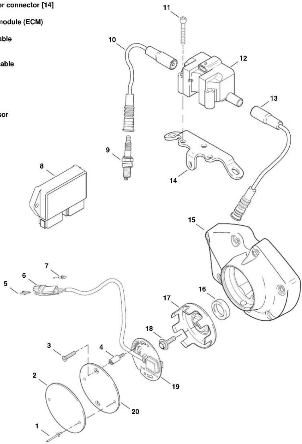
text_image
or connector [14] module (ECM) able able or 8 9 10 11 12 13 14 15 16 17 18 19 20 2 3 4 5 6 7b0990x4x
Figure 7-1. Ignition System Components
GENERAL
WARNING
DO NOT modify the ignition/headlight switch wiring to circumvent the automatic-on headlight feature. Visibility is a major concern for motorcyclists. Failure to have proper headlight operation could result in death or serious injury.
Switch positions are explained in Table 7-8.
CAUTION
When turning off the ignition, verify that the key is removed in the OFF position and that the lights are not left on. If the rider stops the engine and inadvertently removes the key in the P position, the battery will be drained of its charge if the vehicle is left standing too long.
NOTE
The key locks the ignition system and is removable in both the LOCK and P positions. The P position is located counterclockwise from the LOCK position and allows the rider to remove the key while leaving the lights on. When the key is placed in the P position, several indicator markers are or can be activated. See Table 7-9.
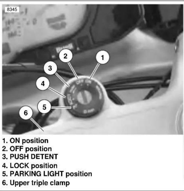
text_image
8345 1. ON position 2. OFF position 3. PUSH DETENT 4. LOCK position 5. PARKING LIGHT position 6. Upper triple clampFigure 7-2. Ignition/Headlight Key Switch
Table 7-8. Ignition Key Switch Positions
| LABEL IGN. LAMPS | REMOVE KEY | ||
| OFF off off yes | |||
| P | o | f Table7-9. | yes |
| ON on no | |||
| LOCK | off off yes | ||
Table 7-9. Indicator Markers
| ITEM | P | ON |
| Headlight position marker (European models only) | on | on |
| Headlight high beam | off | can be activated |
| Headlight low beam | off | on* |
| Instrument module illumination lamps | on | on |
| Stop lamp | can be activated | |
| Front and rear turn signals | can be activated | |
| Horn | cannot be activated | can be activated |
* Run switch must be on.
REMOVAL
- Remove seat. See 2.38 SEAT.
WARNING
To protect against accidental start-up of vehicle, disconnect the negative battery cable before proceeding. Inadequate safety precautions could result in death or serious injury.
- Disconnect negative battery cable.
- See Figure 7-6. Cut cable strap (2) holding ignition switch, fuse block and right handlebar switch wires.
-
Disconnect ignition switch connector [33] (3).
-
See Figure 7-3. Remove cable straps attached to the upper fork clamp.
-
Remove airbox cover. See 2.34 INTAKE COVER ASSEMBLY.
-
See Figure 7-4. Remove steering stem pinch fastener (2).
-
Remove upper fork clamp pinch fasteners (1).
-
See Figure 7-4. Hold or brace the lower fork clamp and remove steering stem cap (3).
-
Remove the upper fork clamp (4) from forks.
-
See Figure 7-5. Use Snap-on Tamper-Resistant T45 Torx driver, Part No FTXR45E to remove ignition switch fasteners (3) securing ignition switch (4) to upper fork clamp. Slide ignition switch out of upper fork clamp.
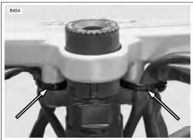
natural_image
Close-up of a mechanical component with no visible text or symbols, marked with arrows pointing to features (no readable text or symbols)Figure 7-3. Cable Straps On Upper Fork Clamp
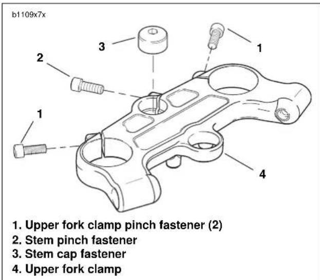
text_image
b1109x7x 1. Upper fork clamp pinch fastener (2) 2. Stem pinch fastener 3. Stem cap fastener 4. Upper fork clampFigure 7-4. Upper Fork Clamp
HOME
DISASSEMBLY
- See Figure 7-5. Remove ignition switch housing (5) from ignition switch (4) by prying tabs on side of housing
- Remove ignition switch body fasteners (1). Separate ignition switch body (2) from ignition switch (4).
ASSEMBLY
NOTE
See Figure 7-5. In next step, be sure wide slot in ignition switch housing (5) is installed over wide boss on ignition switch (4).
- Push ignition switch housing (5) on to ignition switch (4).
NOTE
In next step, do not force ignition switch (4) into ignition switch body (2). If ignition switch does not easily slide into ignition switch body, rotate slot in ignition switch body with screw-driver until proper installation can be achieved.
- Mate ignition switch to ignition switch body.
- Install ignition switch body fasteners (1). Tighten to 12-36 in-lbs (1.4-4.0 Nm).
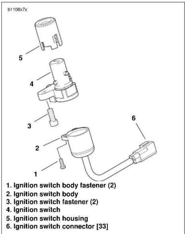
text_image
b1108x7x 5 4 3 2 1 6 1. Ignition switch body fastener (2) 2. Ignition switch body 3. Ignition switch fastener (2) 4. Ignition switch 5. Ignition switch housing 6. Ignition switch connector [33]Figure 7-5. Ignition Switch Assembly
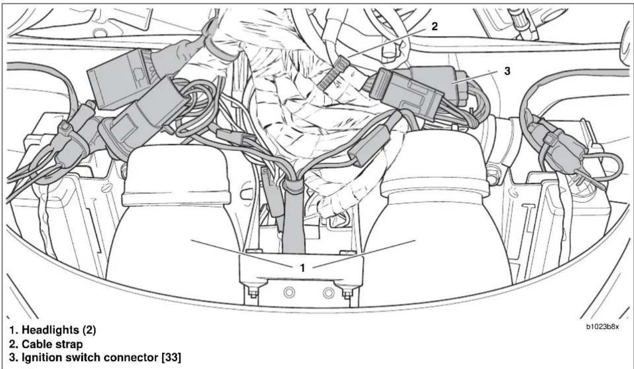
text_image
1. Headlights (2) 2. Cable strap 3. Ignition switch connector [33] b1023b8xFigure 7-6. Ignition Switch Connector (viewed from underneath fairing)
INSTALLATION
- See Figure 7-4. From underneath upper triple clamp (4), insert ignition switch assembly into hole. The word "OFF" stamped on the switch housing should face front of vehicle.
- See Figure 7-5. Attach ignition switch assembly to upper triple clamp using ignition switch fasteners (3). USE LOCTITE THREADLOCKER 272 on fasteners. Tighten to 18-20 ft-lbs (24.4-27.1 Nm).
- See Figure 7-4. Install steering stem cap (3). Tighten but do not torque.
- Install upper clamp on fork assembly.
a. Apply LOCTITE 272 to upper fork clamp pinch fasteners (1).
b. Tighten but do not torque upper fork clamp pinch fasteners.
c. Tighten steering stem cap to 38-42 ft-lbs (52-57 Nm).
d. Install steering stem pinch fastener (2) applying LOCTITE 272 and tightening to 17-19 ft-lbs (23-26 Nm).
e. Tighten upper fork clamp fasteners to 17-19 ft-lbs (23-26 Nm).
f. Repeat torque sequence in steps d and e.
-
See Figure 7-6. Connect ignition key switch connector (3) to wiring harness. Install cable strap (2) around ignition switch, fuse block and right handlebar switch wires.
-
Install airbox assembly. See 4.43 AIRBOX.
- See Figure 7-3. Attach cable straps to upper fork clamp.
a. Install cable strap to the right of ignition switch securing right hand switch and brake line wires to upper fork clamp.
b. Install cable strap to the left of ignition switch securing left hand switch and clutch cable wires to upper fork clamp.
- Install negative battery cable.
WARNING
Check for proper headlight operation before riding motorcycle. Visibility is a major concern for motorcyclists. Failure to have proper headlight operation could result in death or serious injury.
- Check ignition key switch for proper operation. If operation fails, reread procedure and verify that all steps were performed.
WARNING
After installing seat, pull upward on front of seat to be sure it is locked in position. If seat is loose, it could shift during vehicle operation and startle the rider, causing loss of control which could result in death or serious injury.
- Install seat. See 2.38 SEAT.
b1110x7x
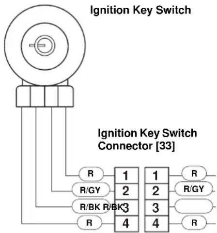
text_image
Ignition Key Switch Ignition Key Switch Connector [33] R R/GY R/BK R/BK 1 2 3 4 1 2 3 4 R R/GY R RFigure 7-7. Ignition Key Switch Wiring
GENERAL
Resistor-type high-tension spark plug cables have a carbon-impregnated fabric core, instead of solid wire, for radio noise suppression and improved reliability of electronic components. Use the exact replacement cable for best results.
REMOVAL
WARNING
Never disconnect a spark plug cable with the engine running. If you disconnect a spark plug cable with the engine running, you may receive a potentially fatal electric shock from the ignition system which could result in death or serious injury.
CAUTION
When disconnecting each spark plug cable from its spark plug terminal, always grasp and pull on the rubber boot at the end of the cable assembly (as close as possible to the spark plug terminal). Do not pull on the cable portion itself. Pulling on the cable will damage the cable's carbon core.
- Remove airbox assembly. See 4.43 AIRBOX.
- See Figure 7-8. Disconnect spark plug cables from ignition coil and spark plug terminals. Inspect cables for damage.
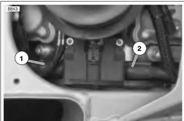
text_image
8843 1 2- Front spark plug cable
- Rear spark plug cable
Figure 7-8. Spark Plug Cable Location
INSPECTION
- Inspect spark plug cables. Replace cables that are worn or damaged.
a. Check for cracks or loose terminals.
b. Check for loose fit on ignition coil and spark plugs.
- Check cable boots/caps for cracks or tears. Replace boots/caps that are worn or damaged.
NOTE
Both cables are the same length.
- See Figure 7-9. Check spark plug cable resistance with an ohmmeter. Replace cables not meeting resistance specifications.
Table 7-10. Spark Plug Cables
| SPECIFICATION FRONT & REAR | |
| Length-in. (mm) | 5.75(146) |
| Resistance - ohms 1,430-3,360 | |
INSTALLATION
NOTES
● To ease installation, install spark plug cables to ignition coil first.
● See 1.14 SPARK PLUGS for spark plug information.
-
Connect spark plug cables to ignition coil and spark plugs. Fasten boots/caps securely. Tight connections provide the necessary moisture-proof environment for the ignition coil and spark plug terminals.
-
Install airbox assembly. See 4.43 AIRBOX.
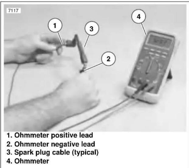
text_image
7117 1. Ohmmeter positive lead 2. Ohmmeter negative lead 3. Spark plug cable (typical) 4. OhmmeterFigure 7-9. Testing Resistance
GENERAL
The starter interlock system is designed to prevent unintended start-up and/or forward motion of the motorcycle with the vehicle's sidestand not retracted.
Two circuits make up the starter interlock system.
Starter Circuit
The starter circuit prevents the motorcycle from being started unless a ground has been established at the starter relay. This ground may come from one of two sources.
- By placing the motorcycle in neutral and grounding through the neutral switch.
- By disengaging the clutch and grounding through the clutch lever switch.
Once the starter circuit is grounded and the starter button pushed, the starter relay can be energized. The energized relay then permits the starter motor to crank the engine.
Ignition Circuit
The ignition circuit prevents the motorcycle from operating unless a ground is established at the ignition relay. If this ground is not established, the ignition system will be not turned on and the motorcycle will not run. Grounds may be established three ways.
- By retracting the sidestand and grounding through the sidestand switch.
- By placing the motorcycle in neutral and grounding through the neutral switch.
- By disengaging the clutch and grounding through the clutch lever switch.
Note that the ignition circuit allows operation in gear with the sidestand extended if the clutch is disengaged. However, if the motorcycle is in gear with the sidestand extended, and the clutch is released, the ignition ground is lost and the ignition system is turned off. This system will prevent vehicle operation if forward motion is attempted with the sidestand down.
Table 7-11. Starter Interlock Troubleshooting
| PROBLEM CHECK FOR | CORRECTION | |
| Electric starter will not crank. | Battery problems. | See 7.10 BATTERY. |
| Inappropriate gear selected. | Place vehicle in neutral. | |
| Clutch lever not disengaged. | Pull in clutch lever. | |
| Starter relay problems. Listen for starter relay “click”. If click is not heard, perform starter relay tests. | ||
| Follow starter troubleshooting in Section 5. | ||
| Electric starter cranks, but vehicle will not start. | Sidestand not retracted. | Retract sidestand. |
| Motorcycle will not start with side-stand retracted. | Clutch lever not disengaged. | Pull in clutch lever. |
| Motorcycle will not start with side-stand retracted or clutch disengaged. | Ignition relay problems. | Listen for relay “click”. If click is not heard, perform ignition system tests. |
| Motorcycle will not start after starter relay tests. | No spark at spark plug. | Check for 12 VDC at coil W/BK wire. |
| Follow ignition system troubleshooting. | ||
DIAGNOSTICS
The reference numbers below correlate with the circled numbers in the 7.5 STARTER INTERLOCK flow charts.
- Check diode with an ohmmeter as shown in Figure 7-11.
- Check diode polarity as shown in Figure 7-10.
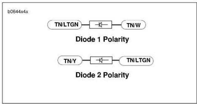
flowchart
graph LR
    A["TN/LTGN"] --> B["Diode 1"]
    B --> C["TN/W"]
    D["TN/Y"] --> E["Diode 2"]
    E --> F["TN/LTGN"]
Figure 7-10. Diode Polarity
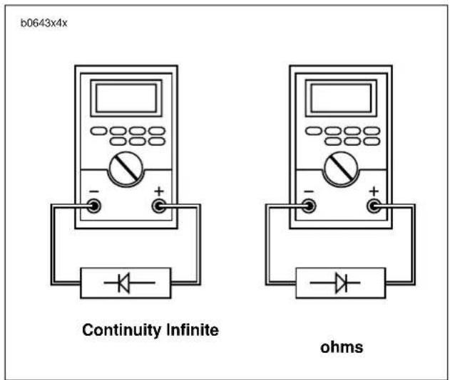
text_image
b0643x4x Continuity Infinite ohmsFigure 7-11. Ohmmeter Diode Test
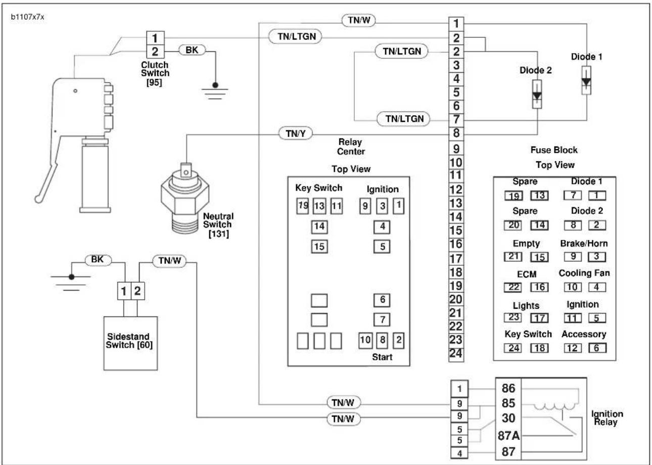
flowchart
graph TD
    A["Clutch Switch [95"]] -->|1| B["TN/LTGN"]
    A -->|2| C["TN/W"]
    A -->|BK| D["Neutral Switch [131"]]
    A --> E["BK"]
    E --> F["Sidestand Switch [60"]]
    F --> G["TN/W"]
    G --> H["Start"]
    H --> I["Ignition Relay"]
    I --> J["87A"]
    I --> K["87B"]
    I --> L["86C"]
    M["Fuse Block Top View"] --> N["Diode 1"]
    N --> O["Diode 2"]
    O --> P["Diode 1"]
    Q["Relay Center"] --> R["Top View"]
    S["Fuse Block Top View"] --> T["Spare 19 13 7 1"]
    S --> U["Spare 20 14 8 2"]
    S --> V["Empty 21 15 Brake/Horn 9 3"]
    S --> W["ECM 22 16 Cooling Fan 10 4"]
    S --> X["Lights 23 17 Ignition 11 5"]
    S --> Y["Key Switch 24 18 Accessory 12 6"]
    Z["TN/W"] --> AA["TN/W"]
    AB["TN/W"] --> AC["TN/W"]
    AD["TN/W"] --> AE["TN/W"]
    AF["TN/W"] --> AG["TN/W"]
Figure 7-12. Diode Wiring
HOME
Ignition Test
CONDITION: Sidestand up and key ON, transmission in neutral and clutch engaged
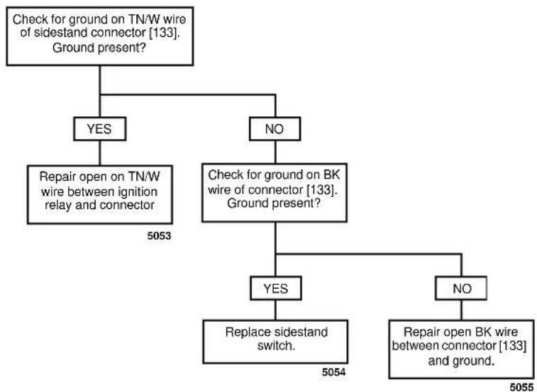
flowchart
graph TD
    A["Check for ground on TN/W wire of sidestand connector [133"]. Ground present?] --> B{YES}
    A --> C{NO}
    B --> D["Repair open on TN/W wire between ignition relay and connector 5053"]
    C --> E["Check for ground on BK wire of connector [133"]. Ground present?]
    E --> F{YES}
    E --> G{NO}
    F --> H["Replace sidestand switch. 5054"]
    G --> I["Repair open BK wire between connector [133"] and ground. 5055]
Starter Test (Part 1 of 2)
CONDITION: Sidestand down, key ON, transmission in neutral and clutch engaged
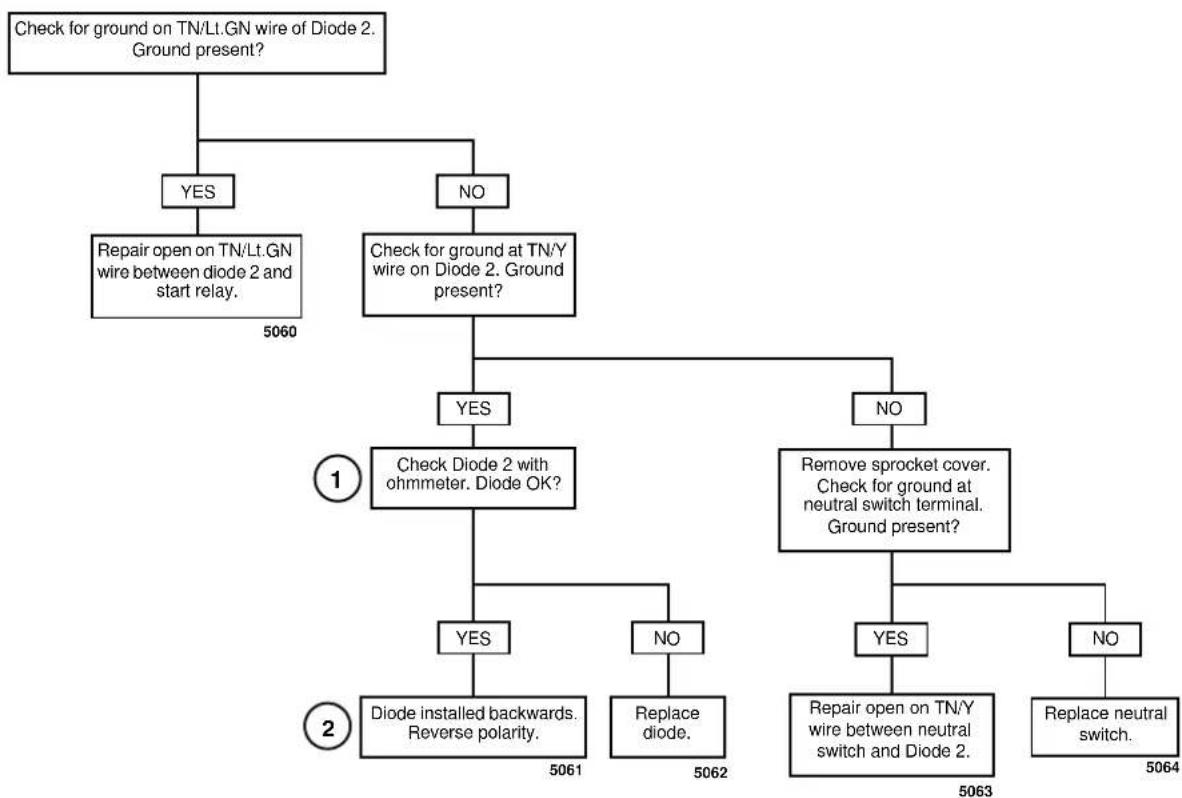
flowchart
graph TD
    A["Check for ground on TN/Lt.GN wire of Diode 2. Ground present?"] --> B{YES}
    A --> C{NO}
    B --> D["Repair open on TN/Lt.GN wire between diode 2 and start relay. 5060"]
    C --> E{Check for ground at TN/Y wire on Diode 2. Ground present?}
    E --> F{YES}
    E --> G{NO}
    F --> H{Check Diode 2 with ohmmeter. Diode OK?}
    G --> I{Remove sprocket cover. Check for ground at neutral switch terminal. Ground present?}
    H --> J{Diode installed backwards. Reverse polarity. 5061}
    H --> K{No Replace diode. 5062}
    I --> L{Repair open on TN/Y wire between neutral switch and Diode 2. 5063}
    I --> M{No Replace neutral switch. 5064}
HOME
Starter Test (Part 2 of 2)
CONDITION: Sidestand down, key ON, transmission in gear and clutch disengaged
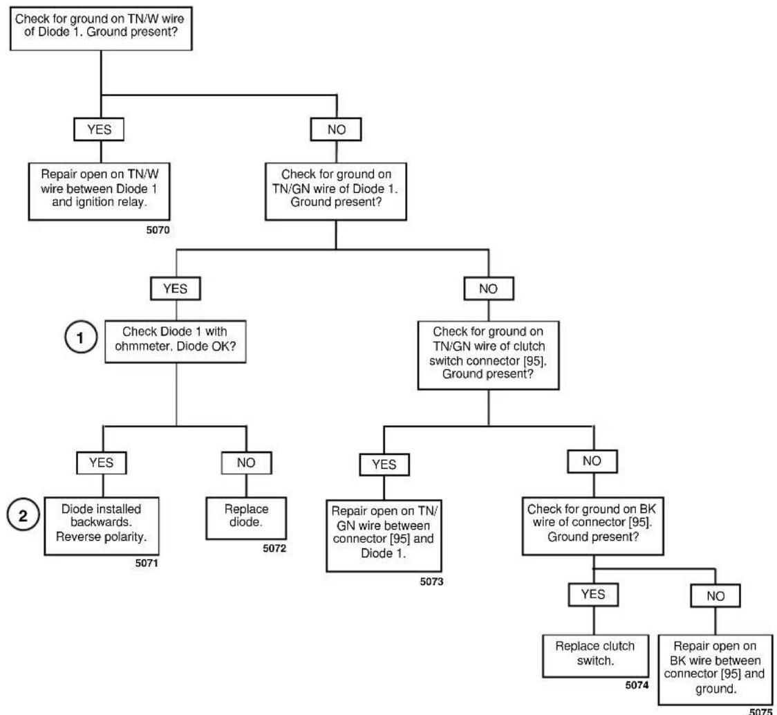
flowchart
graph TD
    A["Check for ground on TN/W wire of Diode 1. Ground present?"] --> B{YES}
    A --> C{NO}
    B --> D["Repair open on TN/W wire between Diode 1 and ignition relay."]
    C --> E["Check for ground on TN/GN wire of Diode 1. Ground present?"]
    D --> F{YES}
    D --> G{NO}
    E --> H{YES}
    E --> I{NO}
    F --> J{Check Diode 1 with ohmmeter. Diode OK?}
    G --> K{Check for ground on TN/GN_wire_of_clutch_switch_connector["95"]. Ground present?}
    J --> L{YES}
    J --> M{NO}
    L --> N["Diode installed backwards. Reverse polarity."]
    M --> O["Replace diode."]
    N --> P["5071"]
    O --> Q["5072"]
    P --> R["5073"]
    Q --> S["5072"]
    R --> T["5073"]
    S --> U["5074"]
    T --> V{YES}
    T --> W{NO}
    U --> X["Replace clutch switch."]
    V --> Y["Repair open on BK wire between connector [95"] and ground.]
    W --> Z["5074"]
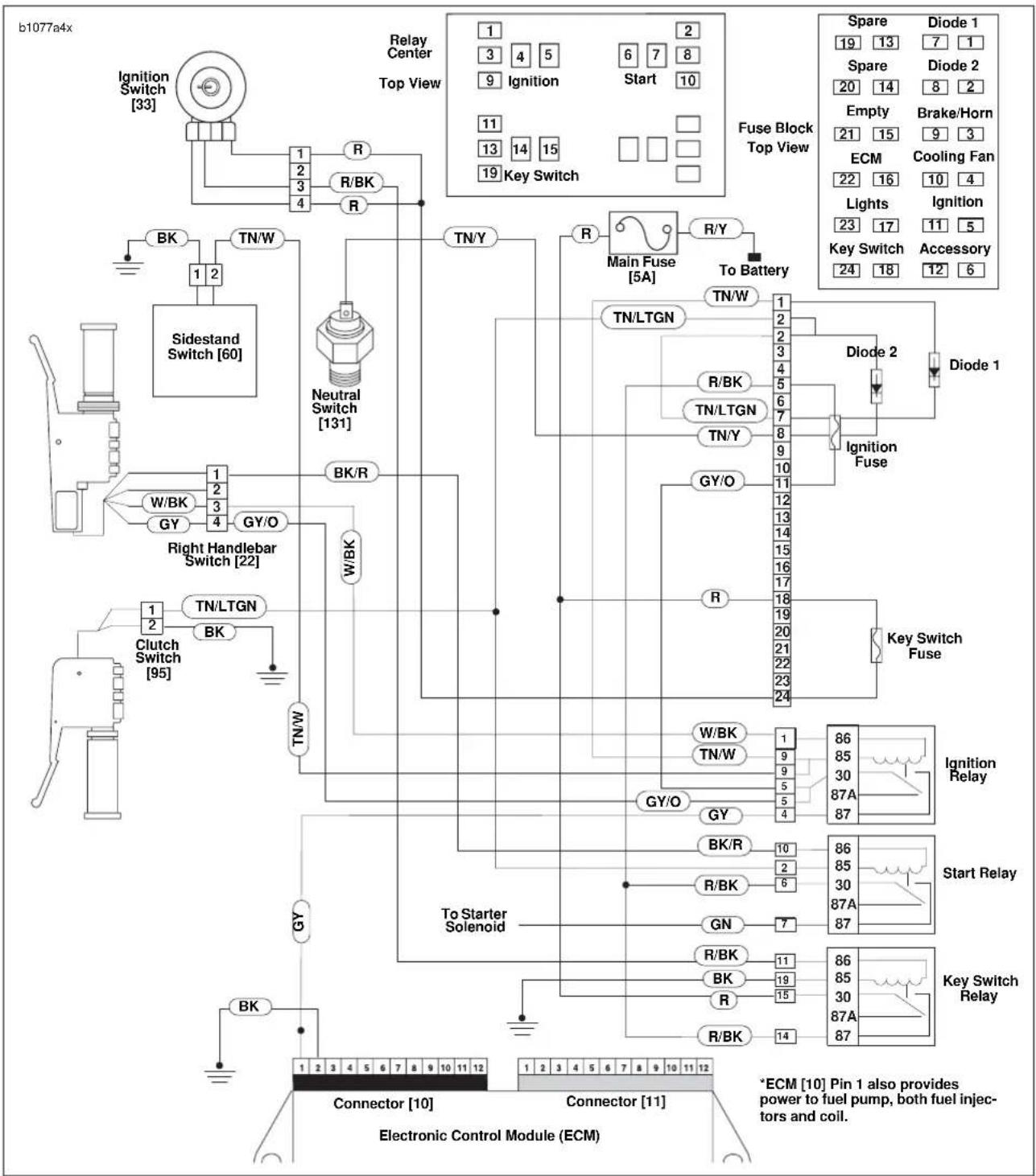
flowchart
graph TD
    A["Ignition Switch [33"]] --> B["R/BK"]
    B --> C["Neutral Switch [131"]]
    C --> D["TN/Y"]
    D --> E["Main Fuse [5A"]]
    E --> F["R/Y"]
    F --> G["To Battery"]
    G --> H["Diode 1"]
    H --> I["Spare 19 13 7 1"]
    H --> J["Spare 20 14 8 2"]
    H --> K["Empty 21 15 9 3"]
    H --> L["ECM 22 16 10 4"]
    H --> M["Lights 23 17 11 5"]
    H --> N["Key Switch Accessory 24 18 12 6"]
    O["Sidestand Switch [60"]] --> P["BK"]
    P --> Q["TN/W"]
    Q --> R["Neutral Switch [131"]]
    R --> S["W/BK"]
    S --> T["Right Handlebar Switch [22"]]
    T --> U["TN/LTGN"]
    U --> V["BK"]
    V --> W["Clutch Switch [95"]]
    W --> X["TN/LTGN"]
    X --> Y["W/BK/R"]
    Y --> Z["TN/Y"]
    Z --> AA["Main Fuse"]
    AA --> AB["To Battery"]
    AB --> AC["Diode 2"]
    AC --> AD["Spare 19 13 7 1"]
    AC --> AE["Spare 20 14 8 2"]
    AC --> AF["Brake/Horn 21 15 9 3"]
    AC --> AG["Cooling Fan 22 16 10 4"]
    AC --> AH["Ignition Fuse"]
    AH --> AI["Key Switch Fuse"]
    AI --> AJ["Start Relay"]
    AJ --> AK["Key Switch Relay"]
    AJ --> AL["Start Relay"]
    AJ --> AM["Key Switch Relay"]
    AN["Electronic Control Module (ECM)"] --> AO["Connector [10"]]
    AN --> AP["Connector [11"]]
    AN --> AQ["*ECM [10"] Pin 1 also provides power to fuel pump, both fuel injectors and coil.]
    style AN fill:#f9f,stroke:#333
    style AO fill:#ccf,stroke:#333
    style AP fill:#ccf,stroke:#333
    style AQ fill:#ccf,stroke:#333
Figure 7-13. Interlock Circuit
TESTING/REPLACEMENT
Sidestand Switch
See Figure 7-14. The sidestand switch is a rotary type switch. The switch completes a path to ground for the ignition relay when the sidestand is in the retracted position. Test the switch as follows:
- Remove heat shrink tubing from sidestand.
- Unplug the 2-place sidestand switch connector [60].
- Test the switch using an ohmmeter.
a. With sidestand down (switch open), the switch should show ohms (infinite ohms).
b. With sidestand up (switch closed), the switch should show 0 ohms or little resistance.
-
Replace the assembly with a new switch if necessary. See 2.40 SIDESTAND.
-
Replace heat shrink tubing.
Clutch Switch
See Figure 7-15. The clutch switch attaches to the clutch control lever bracket. The switch completes a path to ground for the ignition relay and the starter relay when the clutch is disengaged. Test the switch as follows:
-
Unplug the 2-place clutch switch connector [95].
-
Test the switch using an ohmmeter.
a. With clutch engaged (1) (switch open), the switch should show ohms (infinite ohms).
b. With clutch disengaged (2) (switch closed), the switch should show 0 ohms or little resistance.
- Replace the assembly with a new switch if necessary. See 2.24 CLUTCH HAND LEVER.
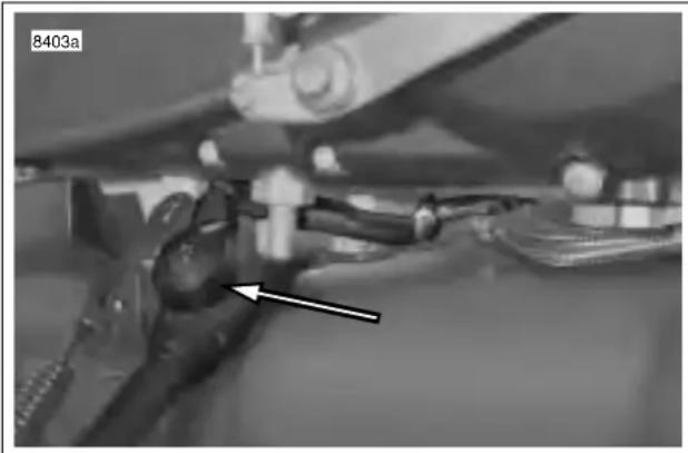
natural_image
Mechanical assembly with pipes and tools, no visible text or symbolsFigure 7-14. Sidestand Switch
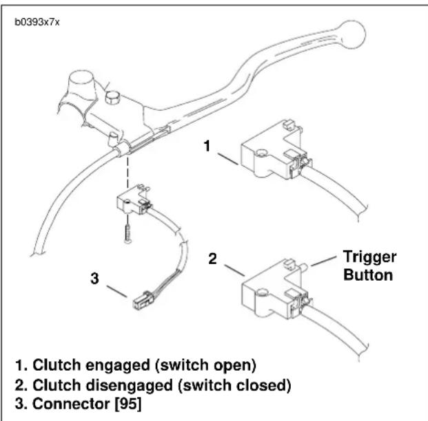
text_image
b0393x7x 1. Clutch engaged (switch open) 2. Clutch disengaged (switch closed) 3. Connector [95] 1 2 Trigger Button 3Figure 7-15. Clutch Switch
HOME
Ignition Relay
The ignition relay is located on the left side of the vehicle behind the fairing. Test the relay as follows:
- See Figure 7-16. Locate ignition relay (2) within relay block.
- To test relay, proceed to Step 3. If installing a new starter relay, remove old relay. Install new relay into relay block.
-
See Figure 7-17. Obtain a 12 volt battery and a continuity tester or ohmmeter.
a. Pull relay from relay block.
b. Connect positive battery lead to the 86 terminal.
c. Connect negative battery lead to the 85 terminal to energize relay.
d. Check for continuity between the 30 and 87 terminals. A good relay shows continuity (continuity tester lamp "on" or a zero ohm reading on the ohmmeter). A malfunctioning relay will not show continuity and must be replaced. -
Replace the relay with a new relay if necessary.
Key Switch Relay
See Figure 7-16. The key switch relay (1) is located on the left side of the vehicle behind the fairing. See Ignition Relay under 7.5 STARTER INTERLOCK for testing procedure.
Main Fuse
A 30 Amp main fuse links the ignition key switch and the battery. The 30A main fuse is located under the rider's seat. See 7.22 MAIN FUSE AND FUSES for more information.
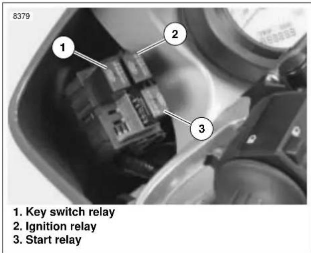
text_image
8379 1. Key switch relay 2. Ignition relay 3. Start relayFigure 7-16. Relay Block
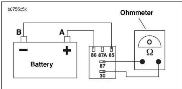
text_image
b0755x5x Battery A B 86 87A 85 87 30 Ohmmeter O ΩFigure 7-17. Starter Relay Test
HOME
Diodes
See Figure 7-18. The diodes are located on the right side of the vehicle behind the fairing.
- See Figure 7-19. Locate diodes within fuse block.
- Test diodes using Starter Test flow charts under DIAGNOSTICS.
- Identify the diode which must be replaced. Replace both diodes if necessary.
- Replace the diodes by pulling them straight out. The spare diode may be used in either circuit as long as it is installed in the correct direction.
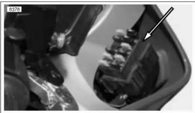
natural_image
Close-up of mechanical components with a white arrow pointing to a component (no visible text or symbols)Figure 7-18. Fuse Block (contains diodes)
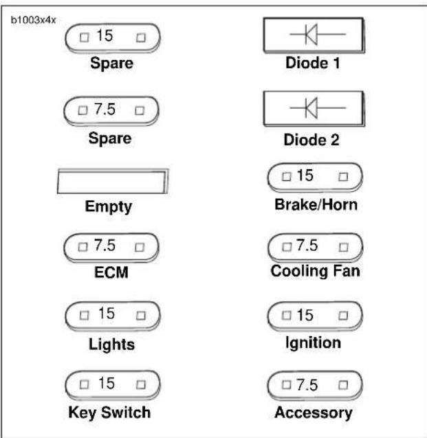
text_image
b1003x4x □ 15 □ Spare Diode 1 □ 7.5 □ Spare Diode 2 Empty □ 15 □ Brake/Horn □ 7.5 □ ECM □ 7.5 □ Cooling Fan □ 15 □ Lights □ 15 □ Ignition □ 15 □ Key Switch □ 7.5 □ AccessoryFigure 7-19. Fuses and Diodes
GENERAL
The charging system consists of the alternator and regulator. Charging system circuits are shown in Figure 7-22.
CAUTION
Never install accessory wiring between battery post and battery cable. Installing wire between battery post and battery cable could cause damage to electrical system.
When installing electrical accessories, install longer battery post fasteners. Install wiring between battery cable and fastener.
Alternator
The alternator consists of two main components:
● The rotor which mounts to the engine sprocket shaft.
● The stator which bolts to the engine crankcase.
Voltage Regulator
See Figure 7-20. The voltage regulator is a series regulator with shunt control. The voltage regulator combines the functions of rectifying (converting AC voltage to DC) and regulating (controlling voltage output).
TROUBLESHOOTING
When the charging system fails to charge or does not charge at a satisfactory rate, check the following:
Battery
Check for a weak or dead battery. See 7.10 BATTERY. Battery must be fully charged in order to perform any electrical tests.
Wiring
Check for corroded or loose connections in the charging circuit. See Figure 7-22.
Voltage Regulator Inspection
See Figure 7-21. The plug connector to stator must be clean and tight.
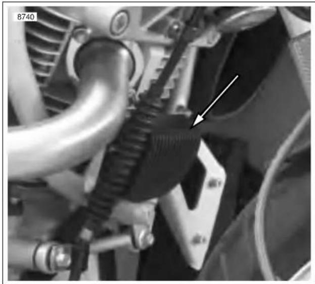
natural_image
Close-up mechanical assembly showing a gear and pipe connection (no visible text or symbols)Figure 7-20. Voltage Regulator
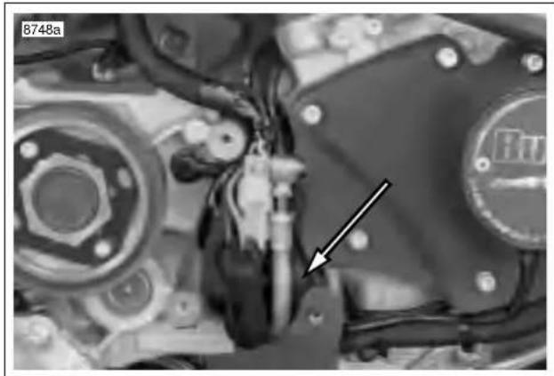
natural_image
Close-up mechanical assembly showing internal components and a white arrow pointing to a component (no readable text or symbols)Figure 7-21. Stator Connector [46]
HOME
Test 7.6 (Part 1 of 2)
SYMPTOM: BATTERY BECOMES DISCHARGED
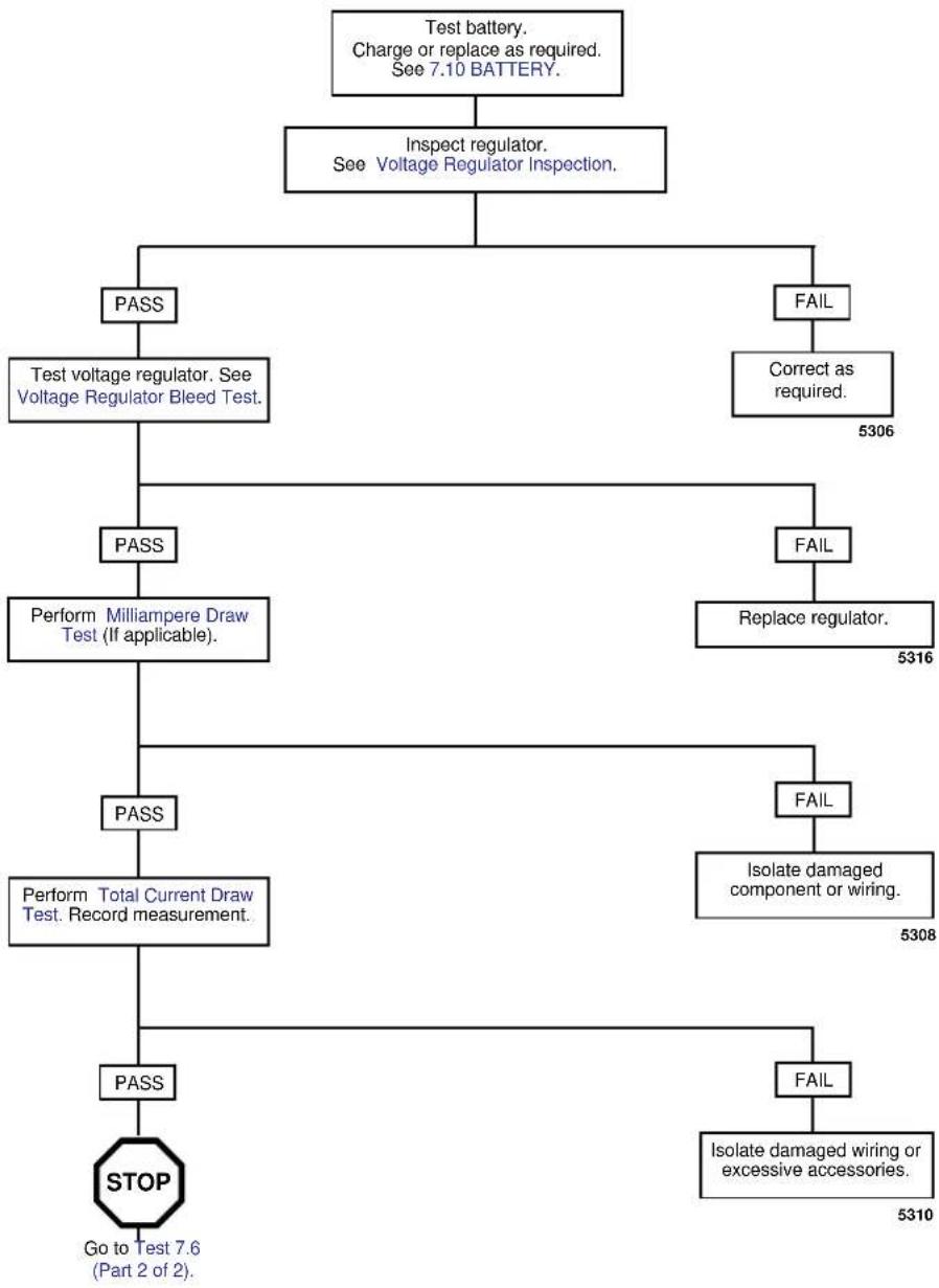
flowchart
graph TD
    A["Test battery.<br>Charge or replace as required.<br>See 7.10 BATTERY."] --> B["Inspect regulator.<br>See Voltage Regulator Inspection."]
    B --> C{PASS}
    B --> D{FAIL}
    C --> E["Test voltage regulator. See Voltage Regulator Bleed Test."]
    E --> F{PASS}
    E --> G{Correct as required. 5306}
    F --> H["Perform Milliampere Draw Test (If applicable)."]
    H --> I{PASS}
    H --> J{FAIL}
    I --> K["Perform Total Current Draw Test. Record measurement."]
    K --> L{PASS}
    K --> M{Isolate damaged component or wiring. 5308}
    L --> N{FAIL}
    N --> O["Isolate damaged wiring or excessive accessories. 5310"]
    L --> P["STOP<br>Go to Test 7.6<br>(Part 2 of 2)."]
NOTE
Whenever a charging system component fails a test and is replaced, re-test the system to be sure the problem has been corrected.
HOME
Test 7.6 (Part 2 of 2)
SYMPTOM: BATTERY BECOMES DISCHARGED
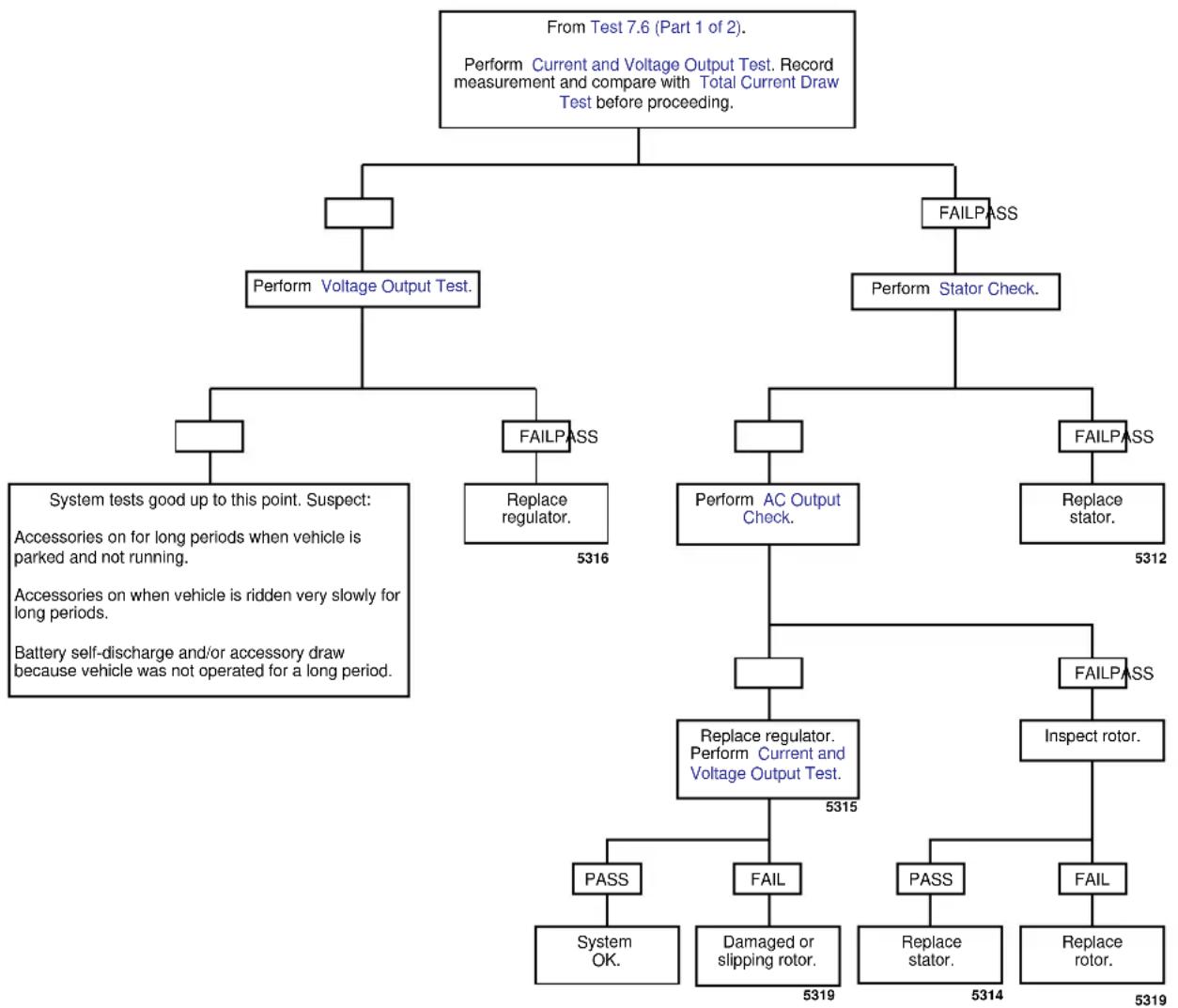
flowchart
graph TD
    A["From Test 7.6 (Part 1 of 2). Perform Current and Voltage Output Test. Record measurement and compare with Total Current Draw Test before proceeding."] --> B["Perform Voltage Output Test."]
    A --> C["FAILPASS"]
    B --> D["Perform Stator Check."]
    D --> E["FAILPASS"]
    D --> F["System tests good up to this point. Suspect: Accessories on for long periods when vehicle is parked and not running."]
    D --> G["Replace regulator. 5316"]
    D --> H["Perform AC Output Check."]
    H --> I["FAILPASS"]
    H --> J["Replace stator. 5312"]
    H --> K["Repair regulator. Perform Current and Voltage Output Test. 5315"]
    K --> L["FAILPASS"]
    K --> M["Inspect rotor."]
    L --> N["PASS"]
    L --> O["FAIL"]
    M --> P["System OK."]
    M --> Q["Damaged or slipping rotor. 5319"]
    M --> R["Replace stator. 5314"]
    M --> S["Replace rotor. 5319"]
NOTE
Whenever a charging system component fails a test and is replaced, re-test the system to be sure the problem has been corrected.
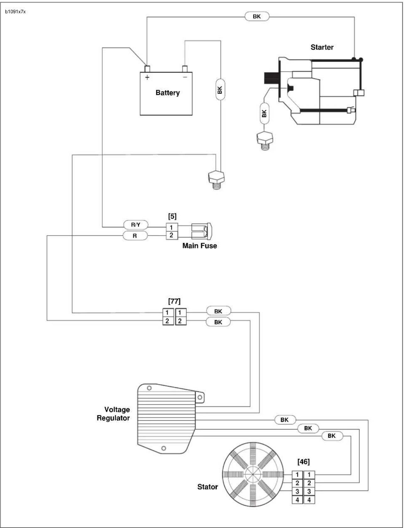
flowchart
graph TD
    A["+ Battery"] --> B["BK"]
    B --> C["Starter"]
    C --> D["Main Fuse"]
    D --> E["R/Y R"]
    E --> F["1 2"]
    F --> G["Main Fuse"]
    G --> H["[5"]]
    H --> I["Main Fuse"]
    I --> J["Main Fuse"]
    J --> K["[77"]]
    K --> L["1 2"]
    L --> M["Main Fuse"]
    M --> N["Main Fuse"]
    N --> O["Voltage Regulator"]
    O --> P["Stator"]
    P --> Q["[46"]]
    Q --> R["Stator"]
    R --> S["Stator"]
    S --> T["Stator"]
    T --> U["Stator"]
    U --> V["Stator"]
    V --> W["Stator"]
    W --> X["Stator"]
    X --> Y["Stator"]
    Y --> Z["Stator"]
Figure 7-22. Charging System Circuit
Voltage Regulator Bleed Test
NOTE
Stator connector [46] and regulator connector [77] are located under sprocket cover. for more information see 7.24 SPROCKET COVER WIRING.
- Be sure regulator is connected to battery.
a. Check that voltage regulator connector [77] halves are engaged.
b. Check that main fuse is not blown.
-
Locate and disconnect stator connector [46].
-
Check regulator connector using a trouble light.
a. Touch one probe to a suitable ground.
b. Touch the other to the regulator pins, one at a time.
c. If light glows, replace regulator.
Milliampere Draw Test
NOTE
Be sure accessories are not wired so they stay on at all times. This condition could drain battery completely if vehicle is parked for a long time. Check for this by connecting ammeter between negative battery terminal and battery.
- See Figure 7-23. Connect ammeter between negative battery terminal and battery. With this arrangement, you will also pick up any regulator drain.
- With ignition key switch turned to OFF and all lights and accessories off, observe amperage reading.
a. Maximum reading should be 1.0 milliamperes.
b. A higher reading indicates excessive current draw. Any accessories must be considered and checked for excessive drain.
NOTE
A battery with a surface discharge condition could suffer a static drain. Correct by cleaning battery case.
Total Current Draw Test
If battery runs down during use, the current draw of the motorcycle components and accessories may exceed output of the charging system.
WARNING
Always turn the battery load tester OFF before connecting tester cables to the battery terminals. Connecting tester cables with the load tester ON could cause a spark resulting in a battery explosion which could result in death or serious injury.
- See Figure 7-24. To check for this condition, place load tester induction pickup or current probe pickup over battery negative cable.
- Disconnect stator wiring from voltage regulator wiring at the connector [46] under front sprocket cover See 7.24 SPROCKET COVER WIRING. Start the motorcycle and run the engine at 2000 RPM.
- With ignition and all continuously running lights and accessories turned on (headlight on high beam), read the total current draw.
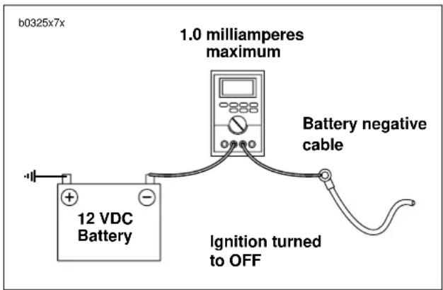
text_image
b0325x7x 1.0 milliamperes maximum Battery negative cable Ignition turned to OFF 12 VDC BatteryFigure 7-23. Milliampere Draw Test
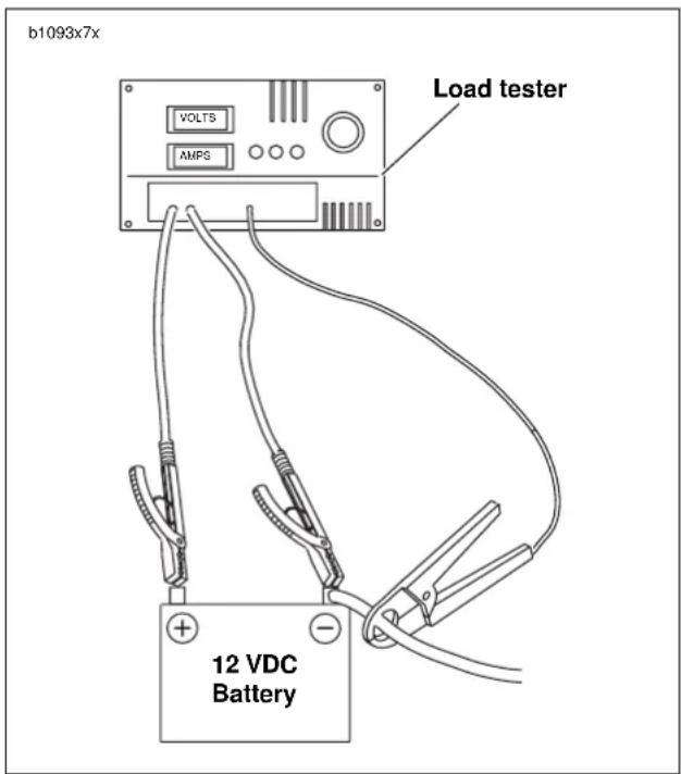
text_image
b1093x7x VOLTS AMPS Load tester 12 VDC BatteryFigure 7-24. Check Current Draw (Ignition Switch On)
- Compare this reading to the reading obtained after performing the CURRENT AND VOLTAGE OUTPUT TEST.
a. The current output should exceed current draw by 3.5 amps minimum.
b. If output does not meet specifications, there may be too many accessories for the charging system to handle.
- Reconnect regulator after testing.
HOME
Current and Voltage Output Test
- Connect load tester.
a. Connect negative and positive leads to battery terminals.
b. See Figure 7-25. Place load tester induction pickup over positive regulator cable.
CAUTION
Do not leave any load switch turned on for more than 20 seconds or overheating and tester damage are possible.
- Run the engine at 3000 RPM. Increase the load as required to obtain a constant 13.0 VDC.
- The current output should be 34-38 amps. Make note of measurement for use in TOTAL CURRENT DRAW TEST.
NOTE
Rider's habits may require output test at lower RPM.
Voltage Output Test
- See Figure 7-25. After removing the load, read the load tester voltage meter.
a. If voltage to the battery is not more than 15 VDC, voltage output is within specifications. Investigate other possible problems. See TROUBLESHOOTING in this section.
b. If voltage is higher, regulator is not functioning properly or connections are loose or dirty.
Stator Check
- Turn ignition key switch to OFF.
- See Figure 7-26. Connect an ohmmeter.
a. Locate voltage regulator connector [46] under sprocket cover. See 7.24 SPROCKET COVER WIRING. Disconnect from alternator stator wiring.
b. Insert one ohmmeter lead into a stator socket.
c. Attach the other lead to a suitable ground.
- Test for continuity with ohmmeter set on the RX1 scale.
a. A good stator will show no continuity ( ohms) across all stator sockets and ground.
b. Any other reading indicates a grounded stator which must be replaced.
-
See Figure 7-27. Remove ground lead. Check resistance across stator sockets 1-2, 2-3 and 3-1.
-
Test for resistance with ohmmeter set on the RX1 scale.
a. Resistance across the stator sockets should be 0.1-0.3 ohms.
b. If the resistance is lower, the stator is damaged and must be replaced.
NOTE
Verify that meter reads 0 ohms when probes are shorted together. If not, subtract lowest value to resistance value of stator.
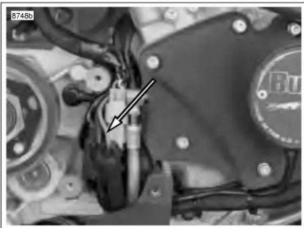
natural_image
Close-up of a mechanical assembly with visible wiring and components, no readable text or symbols present.Figure 7-25. Positive Regulator Cable (red wire)
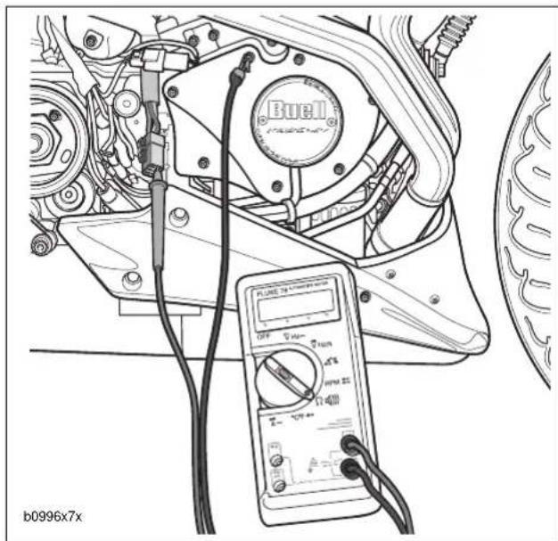
text_image
Buel FLUKE 12 OFF 50mm 70mm 40% Hue 22 11 b0996x7xFigure 7-26. Test for Grounded Stator
HOME
AC Output Check
- See Figure 7-28. Test AC output.
a. Locate voltage regulator connector [46] under sprocket cover. See 7.24 SPROCKET COVER WIRING. Disconnect from alternator stator wiring.
b. Connect an AC voltmeter across stator sockets 1-2.
c. Run the engine at 2000 RPM. The AC output should be 32-40 volts AC. (approximately 16-20 volts per 1000 RPM).
d. Repeat test across stator sockets 2-3 and 1-3.
- Compare test results to specifications.
a. If the output is below specifications, charging problem could be a faulty rotor or stator.
b. If output is good, charging problem might be faulty regulator/rectifier. Replace as required.
- Check the output again as described under CURRENT AND VOLTAGE OUTPUT TEST on page 7-24.
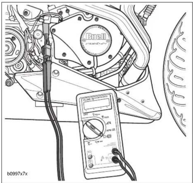
text_image
Borell PLANE 10 b0997x7xFigure 7-27. Check for Stator Resistance

text_image
Bucil b0998x7xFigure 7-28. Check Stator AC Voltage Output
REMOVAL/DISASSEMBLY
WARNING
To protect against accidental start-up of vehicle, disconnect the negative battery cable before proceeding. Inadequate safety precautions could result in death or serious injury.
- Disconnect negative battery cable.
- Remove primary cover. See 6.2 PRIMARY CHAIN.
- Remove clutch assembly, primary chain and engine sprocket/rotor assembly as a unit. See 6.4 PRIMARY DRIVE/CLUTCH.
- Remove/disassemble rotor and/or stator, as required. Refer to the following procedures.
Rotor
- See Figure 7-29. Remove the eight fasteners which secure alternator rotor to engine sprocket.
- See Figure 7-30. Position blocking under rotor. Press sprocket free of rotor.
NOTE
Resistance to sprocket/rotor disassembly is due in part to the magnetic force of the permanent rotor magnets.
Stator
- See Figure 7-31. Disconnect stator wiring (4) from voltage regulator wiring at connector (5) [46] under sprocket cover. See 7.24 SPROCKET COVER WIRING.
- Remove cable straps holding stator wire to wire harness.
CAUTION
Stator TORX screws contain a thread locking compound. Do not reuse existing screws. Always use new screws with the proper thread locking compound. Loss of torque on TORX fasteners could result in alternator damage.
- Remove and discard the four TORX screws (1) which secure stator (2) to left crankcase half.
- Remove stator wiring grommet (3) from left crankcase half.
- Withdraw stator wiring (4) from grommet hole in left crankcase half. Remove stator.
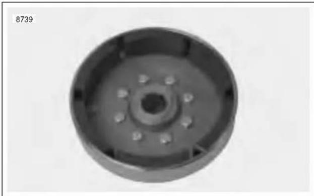
natural_image
Top-down view of a circular mechanical component with bolt holes and central hub (no text or symbols visible)Figure 7-29. Rotor Assembly
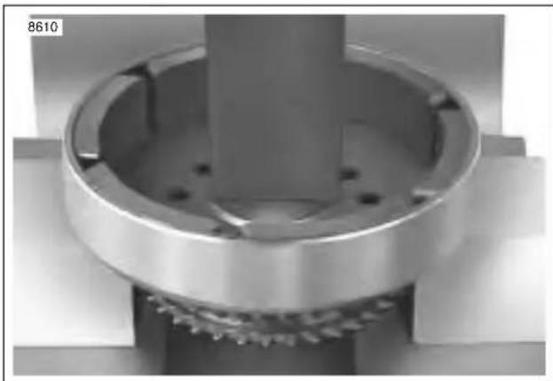
natural_image
Close-up of a mechanical gear assembly with central shaft and meshing (no visible text or symbols)Figure 7-30. Removing Rotor From Sprocket
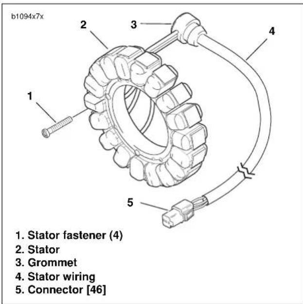
text_image
b1094x7x 1. Stator fastener (4) 2. Stator 3. Grommet 4. Stator wiring 5. Connector [46]Figure 7-31. Stator Assembly
CLEANING AND INSPECTION
CAUTION
Do not strike or drop alternator rotor or damage to magnet adhesive may occur. Magnet adhesive damage can result in rotor failure.
- Clean rotor with a petroleum-base solvent. Remove all foreign material from rotor magnets. Replace rotor if rotor magnets are cracked or loose.
- Clean stator by wiping with a clean cloth.
- Examine stator leads for cracked or damaged insulation.
NOTE
The rotor and stator can be replaced individually if either is damaged.
ASSEMBLY/INSTALLATION
Depending on whether the rotor, the stator, or both the rotor and stator were removed/disassembled, perform the applicable procedures which follow:
- See Figure 7-31. Feed stator wiring (4) with attached grommet (3) into open grommet hole in left crankcase half.
- Apply a light coating of clean engine oil or chaincase lubricant to grommet. Install grommet into hole in left crankcase half.
CAUTION
Stator TORX screws contain a thread locking compound. Do not reuse existing screws. Always use new screws with the proper thread locking compound. Loss of torque on TORX fasteners could result in alternator damage.
- Position stator (2) on left crankcase half. Secure stator using four new TORX screws (1). Tighten TORX screws to 30-40 in-lbs (3-4 Nm).
- Route stator wiring (4) behind rear cylinder and in front of transmission breather hose. See 7.24 SPROCKET COVER WIRING for remaining wire routing information.
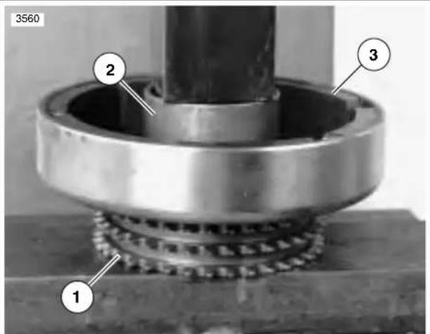
text_image
3560 2 3 1- Sprocket
- Pipe section
- Rotor
Figure 7-32. Pressing Rotor onto Sprocket
- See Figure 7-32. Attach rotor to sprocket.
a. Position rotor (3) on sprocket (1). Align holes in sprocket with holes in rotor.
b. Insert the new eight mounting fasteners through rotor and start fasteners into tapped holes in sprocket.
c. Position a section of pipe (2) with an inside diameter larger than the sprocket mounting hub over center of rotor. Press rotor onto sprocket. Tighten fasteners to 90-110 in-lbs (10-12 Nm).
- Install clutch assembly, primary chain and engine sprocket/rotor assembly as a unit. See 6.4 PRIMARY DRIVE/CLUTCH.
- Install primary cover. See 6.2 PRIMARY CHAIN.
- Connect negative battery cable.
- Test charging system. See 7.6 CHARGING SYSTEM.
GENERAL
The voltage regulator is mounted to the front of the crank-case. The voltage regulator is not repairable. Replace the unit if it fails.
REMOVAL
- Remove seat. See 2.38 SEAT.
WARNING
To protect against shock and accidental start-up of vehicle, disconnect the negative battery cable before proceeding. Inadequate safety precautions could result in death or serious injury.
- Disconnect negative battery cable from battery.
CAUTION
When disconnecting the alternator stator wiring, pull apart the connector by firmly grasping both connector halves. Do not pull on leads or damage to the wires and/or terminals may result.
- See Figure 7-34. Disconnect stator connector [46] (1) and voltage regulator connector [77] (2) located under sprocket cover. See 7.24 SPROCKET COVER WIRING.
- Remove fasteners (5) and voltage regulator (4) from bracket (3).
INSTALLATION
- See Figure 7-34. Attach new voltage regulator (4) to bracket (3). Tighten new fasteners (5) to 48-60 in-lbs (5.4-6.8 Nm).
- Connect stator connector [46] (1) and voltage regulator connector [77] (2) located under sprocket cover. See 7.24 SPROCKET COVER WIRING.
- Connect negative battery cable to battery terminal.
WARNING
After installing seat, pull upward on front of seat to be sure it is locked in position. If seat is loose, it could shift during vehicle operation and startle the rider, causing loss of control which could result in death or serious injury.
- Install seat. See 2.38 SEAT.
- Test charging system. See 7.6 CHARGING SYSTEM.
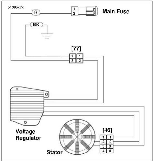
text_image
b1095x7x R 1 2 Main Fuse BK [77] 1 1 2 2 Voltage Regulator Stator [46] 1 1 2 2 3 3 4 4Figure 7-33. Voltage Regulator Connector [77]
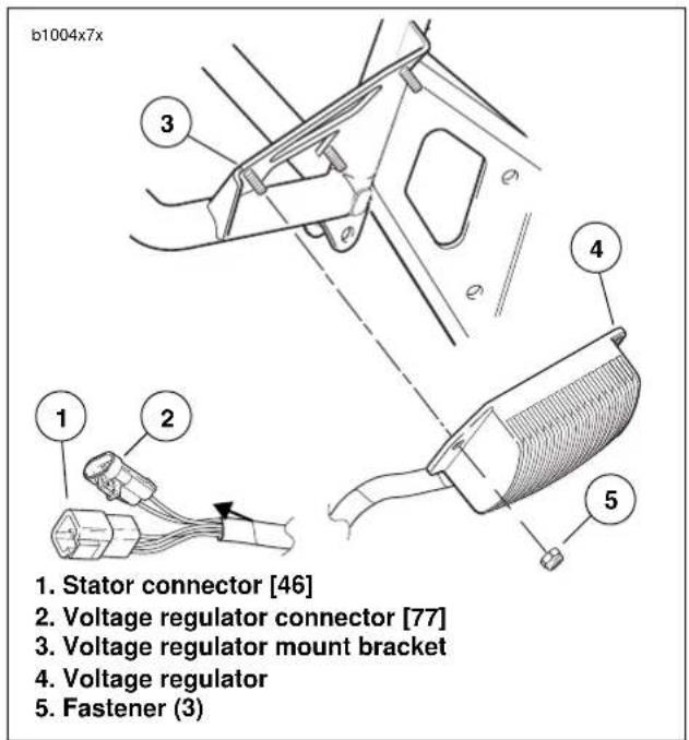
text_image
b1004x7x 1. Stator connector [46] 2. Voltage regulator connector [77] 3. Voltage regulator mount bracket 4. Voltage regulator 5. Fastener (3)Figure 7-34. Voltage Regulator
REMOVAL
WARNING
To protect against shock and accidental start-up of vehicle, disconnect the negative battery cable before proceeding. Inadequate safety precautions could result in death or serious injury.
WARNING
Always disconnect the negative battery cable first. If the positive cable should contact ground with the negative cable installed, the resulting sparks may cause a battery explosion which could result in death or serious injury.
- See Figure 7-35. Disconnect negative and positive cables from battery, negative cable first.
a. Remove fastener holding negative cable to negative terminal.
b. Remove fastener holding positive cable to positive battery terminal. - See Figure 7-36. Remove fastener to detach negative battery cable from frame.
- See Figure 7-37. Remove protective rubber boot from starter fastener. Remove fastener with washer to detach positive battery cable from starter.
INSTALLATION
- Clean cable connectors and battery terminals using a wire brush or sandpaper to remove any oxidation.
WARNING
Always connect positive battery cable first. If the positive cable should contact ground with the negative cable installed, the resulting sparks may cause a battery explosion which could result in death or serious injury.
CAUTION
Connect cables to correct terminals of battery or serious damage to motorcycle electrical system will occur.
- Connect cables to battery.
a. See Figure 7-35. Positive battery cable runs from starter to positive battery terminal.
b. Connect positive cable to positive (+) battery terminal using fastener.
c. Connect negative cable to negative (-) battery terminal using fastener.
d. Tighten terminal fasteners to 72-96 in-lbs (8-11 Nm).
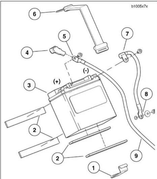
text_image
b1005x7x 6 4 3 2 2 1 2 (-) (+) + 7 8 9- Battery strap bracket
- Battery pad (4)
- Battery
- Battery boot
- Positive cable
- Battery strap
- Negative cable
- To frame
- To starter
Figure 7-35. Battery
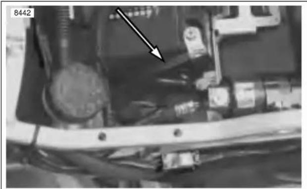
natural_image
Close-up of a vehicle's engine compartment with a white arrow pointing to a component (no visible text or symbols)Figure 7-36. Negative Battery Cable
HOME
- Connect cables to frame and starter.
a. See Figure 7-37. First, connect positive cable to starter using fastener with washer. Tighten fastener to 60-85 in-lbs (7-10 Nm).
b. See Figure 7-36. Attach negative cable to frame. Tighten to 48-72 in-lbs (5.4-8.1 Nm).
- Apply light coat of petroleum jelly or corrosion-retardant material to both battery terminals.
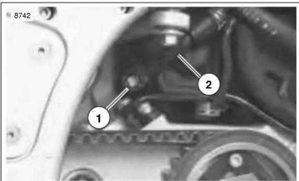
text_image
8742 1 2-
Fastener with washer
-
Positive battery cable
Figure 7-37. Positive Battery Cable (Protective Boot Not Shown)
GENERAL
All Buell batteries are permanently sealed, maintenance-free, valve-regulated, lead/calcium and sulfuric acid batteries. The batteries are shipped pre-charged and ready to be put into service. Do not attempt to open these batteries for any reason.
WARNING
All batteries contain electrolyte. Electrolyte is a sulfuric acid solution that is highly corrosive and can cause severe chemical burns. Avoid contact with skin, eyes, and clothing. Avoid spillage. Always wear protective face shield, rubberized gloves and protective clothing when working with batteries. A warning label is attached to the top of the battery. See Figure 7-38. Never remove warning label from battery. Failure to read and understand all precautions contained in warning label before performing any service on batteries could result in death or serious injury.
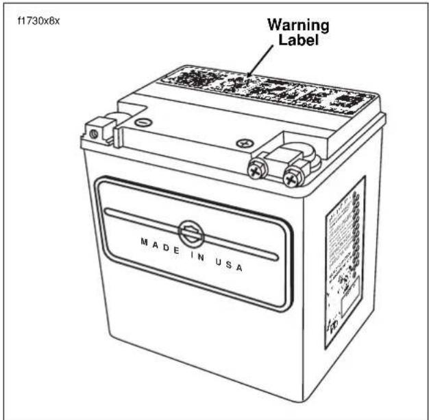
text_image
f1730x8x Warning Label MADE IN USAFigure 7-38. Maintenance-Free Battery (Typical)
Table 7-12. Battery Electrolyte Antidotes
| CONTACT SOLUTION | |
| External Flush | with water. |
| Internal Drink | large quantities of milk or water,followed by milk of magnesia, vegetable oilor beaten eggs. Call doctor immediately. |
| Eyes Flush with water, get immediate medicalattention. | |
b1096x7x

Contents are Corrosive.
Wear Safety Glasses.
Contents are Explosive.

Keep
Flames Away.
Read Instructions.

Keep Away
From Children.
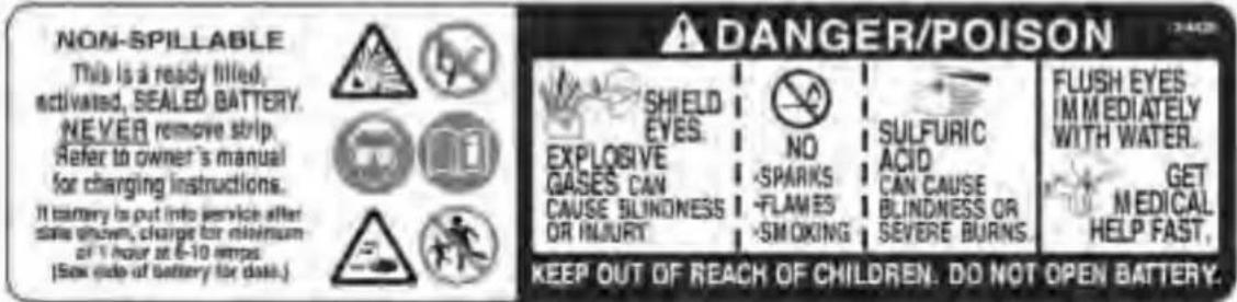
text_image
NON-SPILLABLE This is a ready filled, activated, SEALED BATTERY. NEVER remove strip. Refer to owner's manual for charging instructions. It battery is put into service after side shown, charge for minimum of 1 hour at 6-10 amps. (Sex side of battery for dose.) SHIELD EYES. EXPLOSIVE GASES CAN CAUSE BLINDNESS OR INJURY NO -SPARKS -FLAWES -SMOKING SULFURIC ACID CAN CAUSE BLINDNESS OR SEVERE BURNS. FLUSH EYES IMMEDIATELY WITH WATER. GET MEDICAL HELP FAST. KEEP OUT OF REACH OF CHILDREN. DO NOT OPEN BATTERY.Figure 7-39. Battery Warning Label
Voltmeter Test
See Table 7-13. The voltmeter test provides a general indicator of battery condition. Check the voltage of the battery to verify that it is in a 100% fully charged condition. If the open circuit (disconnected) voltage reading is below 12.6V, charge the battery and then recheck the voltage after the battery has set for one to two hours. If the voltage reading is 12.8V or above, perform the load test.
Table 7-13. Voltmeter Test
| BATTERY CHARGE CONDITIONS | |
| 12.8 100% | |
| 12.6 | 75% |
| 12.3 | 50% |
| 12.0 | 25% |
| 11.8 | 0% |
Load Test
The load test measures battery performance under full current load and is the best indicator of battery condition. To load test the battery, proceed as follows:
CAUTION
Load testing a discharged battery can result in permanent battery damage.
- Always fully charge the battery before testing or test readings will be incorrect. See BATTERY INSTALLATION AND CONNECTION. Load testing a discharged battery can also result in permanent battery damage.
- After charging, allow battery to stand for at least one hour before testing.
WARNING
Always turn the battery load tester OFF before connecting the tester cables to the battery terminals. Connecting tester cables with the load tester ON could cause a spark resulting in a battery explosion which could result in death or serious injury.
3. Connect tester leads to battery posts and place induction pickup over negative (black) cable. See Figure 7-41.
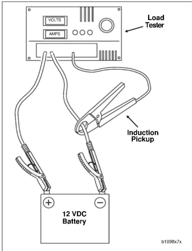
text_image
VOLTS AMPS Load Tester Induction Pickup 12 VDC Battery b1098x7xFigure 7-40. Load Test
CAUTION
To avoid load tester and/or battery damage, do not leave the load tester switch turned ON for more than 20 seconds.
- See Table 7-14. Load battery at 50% of CCA rating using the load tester. Voltage reading after 15 seconds should be 9.6V or more at 70°F. (21°C).
Table 7-14. Battery Load Test
| COLD CRANKINGAMPERAGE (CCA) | 100% | 50% |
| XB9R | 200 | 100 |
WARNING
Always turn the battery load tester OFF before disconnecting the tester cables from the battery terminals. Disconnecting tester cables with the load tester ON could cause a spark resulting in a battery explosion which could result in death or serious injury.
- Install the battery on the motorcycle. See BATTERY INSTALLATION AND CONNECTION.
DISCONNECTION AND REMOVAL
- Remove seat. See 2.38 SEAT.
WARNING
To protect against accidental start-up of vehicle, disconnect the negative battery cable before proceeding. Inadequate safety precautions could result in death or serious injury.
WARNING
Always disconnect the negative battery cable first. If the positive battery cable should contact ground with the negative cable installed, the resulting sparks may cause a battery explosion which could result in death or serious injury.
- Unthread fastener and remove battery negative cable (black) from battery negative (-) terminal.
- Unthread fastener and remove battery positive cable (red) from battery positive (+) terminal.
- Unhook battery strap from frame.
- Remove battery.
CLEANING AND INSPECTION
- Battery top must be clean and dry. Dirt and electrolyte on top of the battery can cause battery to self-discharge. Clean battery top with a solution of baking soda (sodium bicarbonate) and water (5 teaspoons baking soda per quart or liter of water). When the solution stops bubbling, rinse off the battery with clean water.
- Clean cable connectors and battery terminals using a wire brush or sandpaper. Remove any oxidation.
- Inspect the battery screws and cables for breakage, loose connections and corrosion. Clean clamps.
- Check the battery posts for melting or damage caused by overtightening.
- Inspect the battery for discoloration, raised top or a warped or distorted case, which might indicate that the battery has been frozen, overheated or overcharged.
- Inspect the battery case for cracks or leaks.
Safety Precautions
Never charge a battery without first reviewing the instructions for the charger being used. In addition to the manufacturer's instructions, follow these general safety precautions:
● Always wear proper eye, face and hand protection.
● Always charge batteries in a well-ventilated area.
- Turn the charger "OFF" before connecting the leads to the battery to avoid dangerous sparks.
● Never try to charge a visibly damaged or frozen battery.
- Connect the charger leads to the battery; red positive (+) lead to the positive (+) terminal and black negative (−) lead to the negative (−) terminal. If the battery is still in the vehicle, connect the negative lead to the chassis ground. Be sure that the ignition and all electrical accessories are turned off.
● Make sure that the charger leads to the battery are not broken, frayed or loose.
- If the battery becomes hot, or if violent gassing or spewing of electrolyte occurs, reduce the charging rate or turn off the charger temporarily.
● Always turn the charger "OFF" before removing charger leads from the battery to avoid dangerous sparks.
Charging Battery
Charge the battery if any of the following conditions exist:
● Vehicle lights appear dim.
● Electric starter sounds weak.
● Battery has not been used for an extended period of time.
WARNING
Charge the battery in a well ventilated area. Explosive hydrogen gas escapes from the battery during charging. Keep open flames, electrical sparks and smoking materials away from the battery at all times. Inadequate safety precautions could result in death or serious injury.
CAUTION
If the battery releases an excessive amount of gas during charging, decrease the charging rate. If the battery gets hotter than 110^ F. ( 43^ C) during charging, discontinue charging and allow the battery to cool. Overheating may result in plate distortion, internal shorting, dryout or other damage.
- Perform a voltmeter test to determine the state of charge. See BATTERY TESTING. If battery needs to be charged, proceed to step 2.
7-34 2003 Buell XB9R: Electrical
CAUTION
Always remove the battery from the motorcycle before charging. Accidental electrolyte leakage will damage motorcycle parts.
- Remove the battery from the motorcycle. See DISCONNECTION AND REMOVAL. Place the battery on a level surface.
WARNING
Always unplug or turn OFF the battery charger before connecting the charger clamps to the battery. Connecting clamps with the charger ON could cause a spark resulting in a battery explosion which could result in death or serious injury.
CAUTION
Do not reverse the charger connections described in the following steps or the charging system of the motorcycle could be damaged.
- Connect the red battery charger lead to the positive (+) terminal of the battery.
- Connect the black battery charger lead to negative (-) terminal of the battery.
NOTE
If the battery is still in the vehicle, connect the negative lead to the chassis ground. Be sure that the ignition and all electrical accessories are turned off.
- Step away from the battery and turn on the charger. See the charging instructions in Table 7-15.
WARNING
Always unplug or turn OFF the battery charger before disconnecting the charger clamps from the battery. Disconnecting clamps with the charger ON could cause a spark resulting in a battery explosion which could result in death or serious injury.
- After the battery is fully charged, disconnect the black battery charger lead to the negative (−) terminal of the battery.
- Disconnect the red battery charger lead to the positive (+) terminal of the battery.
- Mark the charging date on the battery.
- Perform a load test to determine the condition of the battery. See BATTERY TESTING.
Table 7-15. Battery Charging Rates/Times
| Battery Amp-Hour | State of Charge | 3 Amp Charger | 6 Amp Charger | 10 Amp Charger | 20 Amp Charger | |
| Voltage Reading | % of Charge | |||||
| 12 | 12.8 V 100% | - | - | - | ||
| 12.6 V 75% 1 | hour | 20 minutes | 40 minutes 25 | minutes 12 minutes | ||
| 12.3 V 50% 2 | hours | 40 minutes | 1 hour 20 minutes | 40 minutes 25 | minutes | |
| 12.0 V 25% | 4 hours 2 hours | 1 hour | 10 minutes | 40 minutes | ||
| 11.8 V | 0% | 5 hours, 20 minutes | 2 hours, 40 minutes | 1 hour 40 minutes | 50 minutes | |
| The figures listed above assume that the battery is charging at room temperature. If warmer than room temperature, use a slightly shorter charging time. If colder, use a slightly longer charging time.The use of constant current chargers to charge sealed maintenance-free batteries is not recommended. Any overcharge will cause dry-out and premature battery failure. If a constant current charger is the only type available, do not exceed the charge times listed above and do not continue charging the battery if it gets hot. When charging, never exceed 15 volts for more than 30 minutes. | ||||||
BATTERY CABLE ROUTING
Positive battery cable runs from starter post to positive battery terminal. Negative battery cable runs from frame to negative battery terminal. See Figure 7-41.
BATTERY INSTALLATION AND CONNECTION
- Place the fully charged battery into the battery box, terminal side up.
CAUTION
Connect the cables to the correct battery terminals or damage to the motorcycle electrical system will occur.
WARNING
Always connect the positive battery cable first. If the positive cable should contact ground with the negative cable installed, the resulting sparks may cause a battery explosion which could result in death or serious injury.
CAUTION
Overtightening fasteners can damage battery terminals.
- Insert fastener through battery positive cable (red) into threaded hole of battery positive (+) terminal. Tighten fastener to 72-96 in-lbs (8-11 Nm).
- Insert fastener through battery negative cable (black) into threaded hole of battery negative (-) terminal. Tighten fastener to 72-96 in-lbs (8-11 Nm).
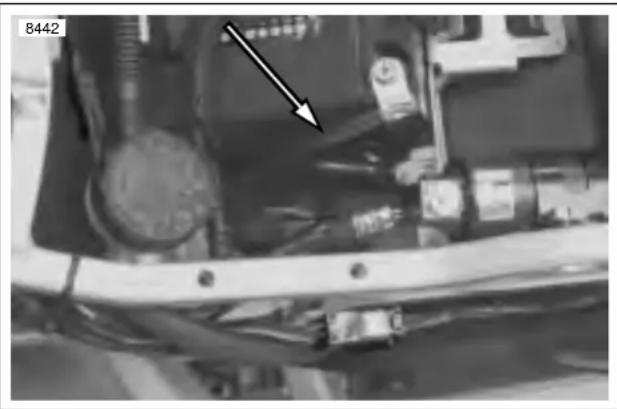
natural_image
Close-up of a car's front engine compartment with visible wiring and a black arrow pointing to a component (no text or symbols)Figure 7-41. Negative Battery Cable
- Apply a light coat of petroleum jelly or corrosion retardant material to both battery terminals.
- Install battery strap.
WARNING
After installing seat, pull upward on front of seat to be sure it is locked in position. If seat is loose, it could shift during vehicle operation and startle the rider, causing loss of control which could result in death or serious injury.
- Install seat. See 2.38 SEAT.
WARNING
Always store batteries where they cannot be reached by children. Contact with the battery's sulfuric acid could result in death or serious injury.
CAUTION
The electrolyte in a discharged battery will freeze if exposed to freezing temperatures. Freezing may crack the battery case and buckle battery plates.
If the motorcycle will not be operated for several months, such as during the winter season, remove the battery from the motorcycle and fully charge. See BATTERY CHARGING.
Self-discharge is a normal condition and occurs continuously at a rate that depends on the ambient temperature and the battery's state of charge. Batteries discharge at a faster rate at higher ambient temperatures. To reduce the self-discharge rate, store battery in a cool (not freezing), dry place. See Figure 7-42.
Charge the battery every month if stored at temperatures below 60^ F. ( 16^ C). Charge the battery more frequently if stored in a warm area above 60^ F. ( 16^ C).
NOTE
The H-D Battery Tender Automatic Battery Charger (P/N 99863-93TA) may be used to maintain battery charge for extended periods of time without risk of overcharging or boiling.
When returning a battery to service after storage, refer to the instructions under BATTERY CHARGING.

line
| Months of Stand | Capacity | | --------------- | -------- | | 0 | 100% | | 3 | 75% | | 6 | 50% | | 9 | 50% | | 2 | 50% |Figure 7-42. Battery Self-Discharge Rate
GENERAL
The XB9R uses dual headlights with replaceable bulbs. High beam headlight is located on the right side of vehicle.
● High beam headlight turns on and off with headlight switch.
● Low beam headlight is located on the left side of vehicle. RUN switch must be on for low beam to be on.
- Adjustment of individual headlight projection is accomplished by adjusting two screws located in the headlight support.
For information on headlight housing and bracket disassembly/assembly see 2.25 HEADLIGHT SUPPORT BRACKET.
HEADLIGHT BULBS
Removal
WARNING
To protect against accidental start-up of vehicle, disconnect the negative battery cable before proceeding. Inadequate safety precautions could result in death or serious injury.
- Disconnect negative battery cable.
CAUTION
The bulb contains Halogen gas under pressure. Handle bulb carefully and wear eye protection. Failure to follow adequate safety precautions could result in minor or moderate injury.
CAUTION
Never touch the bulb with your fingers. Fingerprints will etch the glass and cause the bulb to fail. Always wrap the bulb in paper or a clean, dry cloth during handling.
- See Figure 7-43. Disconnect headlight connection (1).
- Release wire retaining latch (5) from headlight housing clips.
- Pull bulb housing from headlight housing.
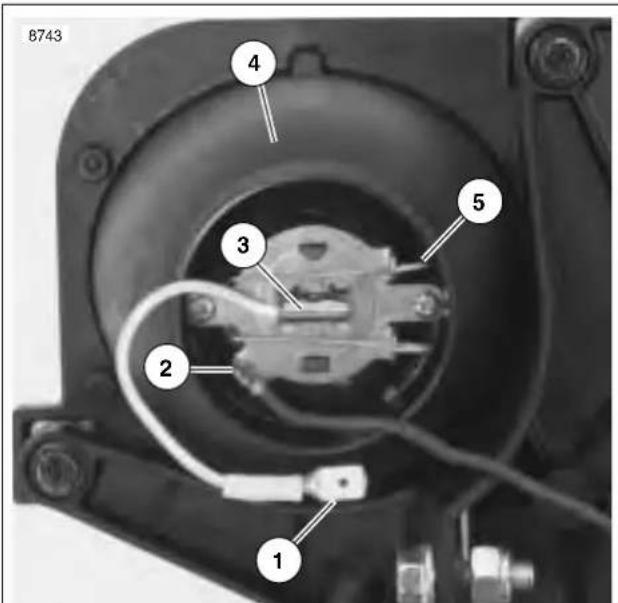
text_image
B743 1 2 3 4 5- Headlight connection
- Ground connection
- Headlight bulb
- Headlight
- Wire retaining latch
Figure 7-43. Headlight Bulb
HOME
Installation
NOTE
Not using the specified bulb may cause charging system problems.
CAUTION
The bulb contains Halogen gas under pressure. Handle bulb carefully and wear eye protection. Failure to follow adequate safety precautions could result in minor or moderate injury.
CAUTION
Never touch the bulb with your fingers. Fingerprints will etch the glass and cause the bulb to fail. Always wrap the bulb in paper or a clean, dry cloth during handling.
- See Figure 7-43. Align tabs on bulb (3) with tabs on headlight (4). Insert bulb.
- Close the wire retaining latch (5).
- Connect the headlight bulb connector.
- Connect negative battery cable.
WARNING
Check for proper headlight operation before riding motorcycle. Visibility is a major concern for motorcyclists. Failure to have proper headlight operation could result in death or serious injury.
- Check headlight for proper operation. If operation fails, reread procedure and verify that all steps were performed.
a. Turn ignition key switch to ON. Set engine stop switch to RUN.
b. See Figure 7-44. Check headlight LOW (3) and HIGH beam (2) settings.
c. Set headlight to LOW beam. Press passing lamp switch (1). Headlight should flash HIGH beam for as long as the switch is pressed.
d. Turn ignition key switch to OFF.
- Align headlight. See 1.18 HEADLIGHTS.
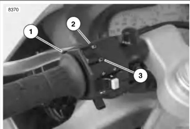
text_image
8370 1 2 3- Passing lamp switch
- HIGH beam
- LOW beam (always on when bike is running)
Figure 7-44. Headlight Controls
REMOVAL/DISASSEMBLY
- See Figure 7-45. Remove two screws (3) to detach tail light lens (4) and tail light (5). If replacing bulb (2), turn counterclockwise and remove.
- Remove pillion seat. See 2.38 SEAT.
- Disconnect two connectors [93] from tail lamp harness (6).
ASSEMBLY/INSTALLATION
- See Figure 7-45. Attach the two tail light harness connectors [93] (6).
a. Single wire connector connects to single spade of tail lamp.
b. Dual wire connector connects to dual spades of tail lamp with red wire facing left side of vehicle.
- If removed, install tail lamp bulb (2).
a. Turn bulb clockwise to install.
b. Install tail light lens (4) and tail light (5) with two fasteners (3).
WARNING
Check for proper tail lamp operation before riding motorcycle. Visibility is a major concern for motorcyclists. Failure to have proper tail lamp operation could result in death or serious injury.
- Check tail lamp for proper operation. If operation fails, reread procedure and verify that all steps were performed.
a. Turn ignition key switch to ON.
b. Check for tail lamp illumination.
c. Squeeze front brake hand lever. Check for brake lamp illumination. Release front brake hand lever.
d. Press rear brake pedal. Check for brake lamp illumination. Release rear brake pedal.
e. Turn ignition key switch to OFF.
WARNING
After installing seat, pull upward on front of seat to be sure it is locked in position. If seat is loose, it could shift during vehicle operation and startle the rider, causing loss of control which could result in death or serious injury.
- Install pillion seat. See 2.38 SEAT.
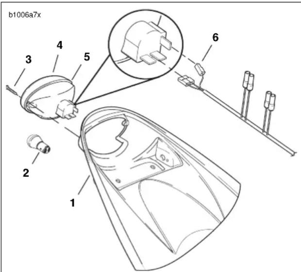
text_image
b1006a7x 1 2 3 4 5 6- Tail section
- Tail lamp bulb
- Fastener (2)
- Tail light lens
- Tail light
- Tail light harness
Figure 7-45. Tail Lamp Assembly
REMOVAL
NOTE
To ensure correct installation, make note of wire routing and cable strap locations before removing turn signals.
Bulbs
Remove screw on back of housing to access turn signal bulbs.
Front
- See Figure 7-46. Disconnect bullet connectors on turn signal wires.
- See Figure 7-47. Remove fastener (3) and lockwasher (2) from fairing support bracket (4).
- Pull bullet connectors and wiring through hole in fairing support bracket (4) and fairing (5).
Rear
- Remove seat See 2.38 SEAT.
- Remove tail frame upper body work. See 2.36 TAIL FRAME AND BODY WORK.
- See Figure 7-49. Disconnect bullet connectors on turn signal wires.
- See Figure 7-48. Remove fastener (6) and lockwasher (5).
NOTE
In next step, reflector bracket (3) will be removed with turn signal (1).
- Remove turn signal from tail section (7) and license plate bracket (4).
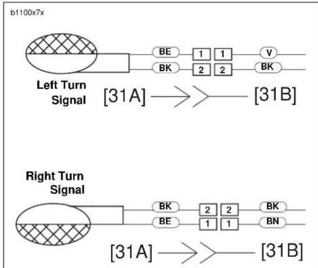
flowchart
graph LR
    subgraph_Left_Turn_Signal["Left Turn Signal"]
        A["Be"] --> B["1"]
        C["BK"] --> D["2"]
        E["V"] --> F["2"]
        G["BK"] --> H["2"]
        I["31A"] --> J["31B"]
    end
    subgraph_Right_Turn_Signal["Right Turn Signal"]
        K["BE"] --> L["2"]
        M["BK"] --> N["1"]
        O["BN"] --> P["1"]
        Q["31A"] --> R["31B"]
    end
Figure 7-46. Front Turn Signal Connections
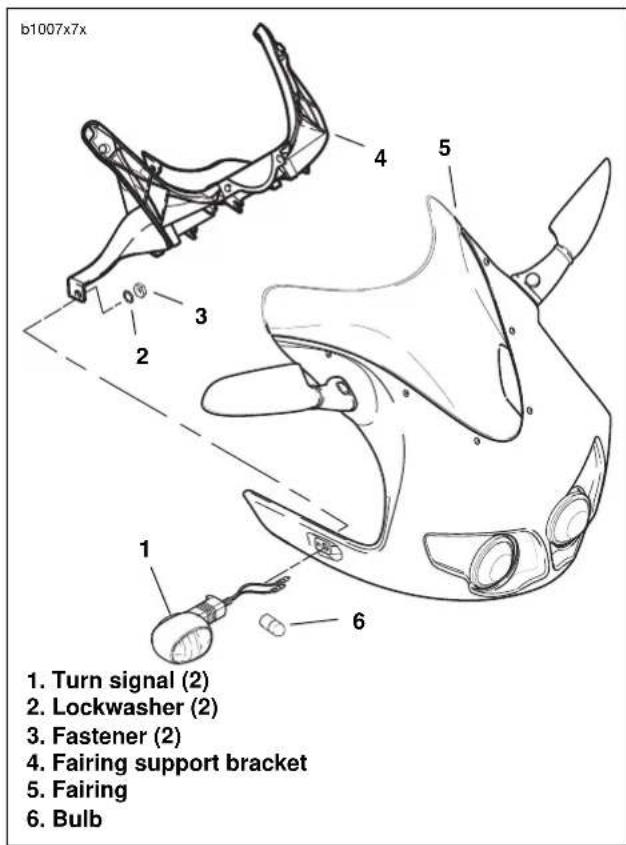
text_image
b1007x7x 1. Turn signal (2) 2. Lockwasher (2) 3. Fastener (2) 4. Fairing support bracket 5. Fairing 6. BulbFigure 7-47. Front Turn Signals
b1008a7x
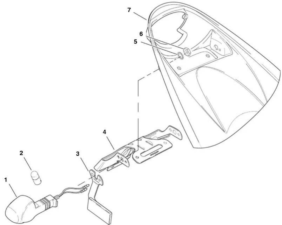
text_image
Technical diagram of a device with numbered parts, likely illustrating a mechanical or electrical assembly.- Turn signal
- Turn signal bulb
- Reflector bracket
- License plate bracket
- Washer (2)
- Fastener (2)
- Tail section
Figure 7-48. Rear Turn Signals
Front
- See Figure 7-47. Insert bullet connectors and wiring through hole in fairing (5) and fairing support bracket (4).
- Install turn signal (1) using lockwasher (2) and fastener (3). Tighten fastener to 25-28 in-lbs (2.8-3.2 Nm).
- Attach bullet connectors on turn signal wires as shown in Figure 7-46.
WARNING
Check for proper turn signal operation before riding motorcycle. Visibility is a major concern for motorcyclists. Failure to have proper turn signal operation could result in death or serious injury.
- Check turn signals for proper operation. If operation fails, reread procedure and verify that all steps were performed.
a. Turn ignition key switch to ON.
b. Activate left turn signals using switch on left handlebar. Front and rear left turn signals must flash.
c. Activate right turn signals using switch on left handlebar. Front and rear right turn signals must flash.
d. Turn ignition key switch to OFF.
Rear
- See Figure 7-49. Insert bullet connectors through license plate bracket (4) and tail section (7).
- Install reflector bracket (3).
a. Place license plate bracket into position over threads on turn signal (1).
b. Be sure tab on turn signal fits into hole in reflector bracket and tab on reflector bracket fits into hole in license plate bracket.
- Attach turn signal using lockwasher (5) and fastener (6). Tighten fastener to 25-28 in-lbs (2.8-3.2 Nm).
- Attach bullet connectors on turn signal wires as shown in Figure 7-49.
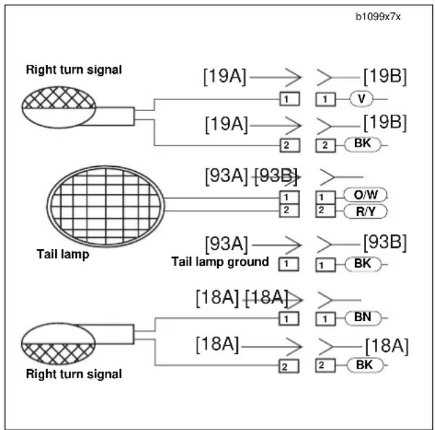
flowchart
graph TD
    A["Right turn signal"] --> B["[19A"]] --> C["[19B"]] --> D["[19A"]]
    A --> E["[19A"]] --> F["[19B"]] --> G["[2"]
    G --> H["[2"]
    H --> I["BK"]]
    J["Tail lamp"] --> K["[93A"]] --> L["[93B"]] --> M["[1"]
    M --> N["[2"]
    N --> O["O/W"]
    N --> P["R/Y"]]
    Q["Tail lamp ground"] --> R["[93A"]] --> S["[93B"]] --> T["[1"]
    T --> U["[1"]
    U --> V["BK"]]
    W["Right turn signal"] --> X["[18A"]] --> Y["[18A"]] --> Z["[18A"]]
    W --> AA["[18A"]] --> AB["[18A"]]
    W --> AC["[18A"]] --> AD["[2"]
    AD --> AE["[2"]
    AE --> AF["BK"]]
Figure 7-49. Rear Turn Signal Connections
WARNING
Check for proper turn signal operation before riding motorcycle. Visibility is a major concern for motorcyclists. Failure to have proper turn signal operation could result in death or serious injury.
- Check turn signals for proper operation. If operation fails, reread procedure and verify that all steps were performed.
a. Turn ignition key switch to ON.
b. Activate left turn signals using switch on left handlebar. Front and rear left turn signals must flash.
c. Activate right turn signals using switch on left handlebar. Front and rear right turn signals must flash.
d. Turn ignition key switch to OFF.
WARNING
After installing seat, pull upward on front of seat to be sure it is locked in position. If seat is loose, it could shift during vehicle operation and startle the rider, causing loss of control which could result in death or serious injury.
- Install seat. See 2.38 SEAT.
REMOVAL
NOTE
The turn signal flasher is not repairable. Replace flasher upon failure.
- Remove front fairing. See 2.37 FRONT FAIRING, WINDSHIELD, AND MIRRORS.
- Remove fastener securing turn signal flasher to head-light support bracket.
- Detach 3-place connector [30] from flasher body.
INSTALLATION
- See Figure 7-50. Attach 3-place connector [30] to flasher.
- Install turn signal to headlight support bracket. Tighten fastener to 30-40 in-lbs (3.4-4.5 Nm).
- Install front fairing. See 2.37 FRONT FAIRING, WINDSHIELD, AND MIRRORS.
WARNING
Check for proper turn signal operation before riding motorcycle. Visibility is a major concern for motorcyclists. Failure to have proper turn signal operation could result in death or serious injury.
- Check turn signals for proper operation. If operation fails, reread procedure and verify that all steps were performed.
a. Turn ignition key switch to IGN.
b. See Figure 7-51. Activate left turn signals using switch on left handlebar. Front and rear left turn signals must flash.
c. Activate right turn signals using switch on left handlebar. Front and rear right turn signals must flash.
d. Turn ignition key switch to OFF.
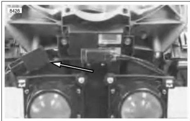
natural_image
Close-up mechanical component with circular features and a white arrow pointing to a specific part (no visible text or symbols)Figure 7-50. Turn Signal Flasher
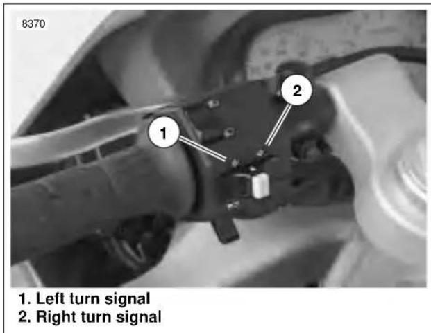
text_image
8370 1. Left turn signal 2. Right turn signalFigure 7-51. Turn Signal Controls
REMOVAL
NOTE
The individual handlebar switches are not repairable. Replace switch assembly upon switch failure.
Right Side
- Remove throttle cables. See 2.23 THROTTLE CONTROL.
- Access right handlebar switch connector [22] under fairing. Remove cable straps. Detach connector [22] from wiring harness.
- Detach brake switch connector [121].
Left Side
- Remove left switch housing mounting fasteners.
- Unplug the clutch switch [95].
- Access left handlebar switch connector [24] under fairing. Remove cable straps. Detach connector [24] from wiring harness.
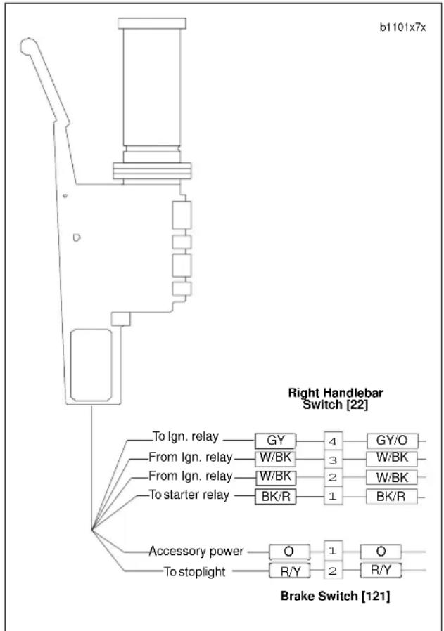
flowchart
graph TD
    A["Left Brake System"] --> B["To Ign. relay"]
    A --> C["From Ign. relay"]
    A --> D["From Ign. relay"]
    A --> E["To starter relay"]
    A --> F["Accessory power"]
    A --> G["To stoplight"]
    H["Right Handlebar Switch [22"]] --> I["To Ign. relay"]
    H --> J["From Ign. relay"]
    H --> K["From Ign. relay"]
    H --> L["To starter relay"]
    H --> M["Accessory power"]
    H --> N["To stoplight"]
    I --> O["GY"]
    I --> P["W/BK"]
    J --> Q["W/BK"]
    K --> R["BK/R"]
    L --> S["1"]
    M --> T["1"]
    N --> U["R/Y"]
    O --> V["4"]
    P --> W["3"]
    Q --> X["2"]
    R --> Y["1"]
    T --> Z["O"]
    U --> AA["2"]
    V --> AB["GY/O"]
    W --> AC["W/BK"]
    X --> AD["W/BK"]
    Y --> AE["BK/R"]
    Z --> AF["O"]
    AA --> AG["R/Y"]
Figure 7-52. Right Handlebar Switch Connection
Right Side
- Attach throttle cables to hand control. See 2.23 THROT-TLE CONTROL.
- Install right switch housing.
a. Position housing on right handlebar by engaging alignment pin on front housing with hole in handlebar.
b. Attach switch housing with two mounting fasteners and tighten to 25-33 in-lbs (3-4 Nm).
- Attach brake switch connector [121].
- Attach right handlebar switch connector [22] to wire harness. See D.1 HOSE AND WIRE ROUTING for wire routing information.
WARNING
Check all handlebar switch operations before riding motorcycle. Visibility is a major concern for motorcyclists. Handlebar switches not operating properly could result in death or serious injury.
- Check handlebar switch for proper operation. If operation fails, reread procedure and verify that all steps were performed.
a. Turn ignition key switch to IGN.
b. Start motorcycle.
c. Turn ignition key switch to OFF.
Left Side
- Install left switch housing.
a. Position housing on left handlebar by engaging alignment pin on front housing with hole in handlebar.
b. Attach switch housing with three mounting fasteners and tighten to 25-33 in-lbs (3-4 Nm).
- Connect clutch switch [95].
- Attach right handlebar switch connector [24] to wire harness. See D.1 HOSE AND WIRE ROUTING for wire routing information.
WARNING
Check all handlebar switch operations before riding motorcycle. Visibility is a major concern for motorcyclists. Handlebar switches not operating properly could result in death or serious injury.
- Check handlebar switch for proper operation. If operation fails, reread procedure and verify that all steps were performed.
a. Turn ignition key switch to ON.
b. Check headlight LOW and HIGH beam settings.
c. Set headlight to LOW beam. Press passing lamp switch. Headlight should flash HIGH beam for as long as the switch is pressed.
d. Check left and right turn signals.
e. Activate horn by pressing horn switch.
- Turn ignition key switch to OFF.
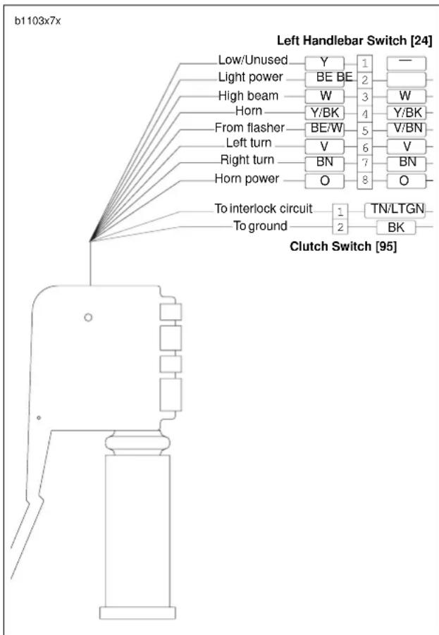
flowchart
graph TD
    A["Left Handlebar Switch [24"]] --> B["Low/Unused"]
    A --> C["Light power"]
    A --> D["High beam"]
    A --> E["Horn"]
    A --> F["From flasher"]
    A --> G["Left turn"]
    A --> H["Right turn"]
    A --> I["Horn power"]
    A --> J["To interlock circuit"]
    A --> K["To ground"]
    B --> L["Y"]
    C --> M["BE BE"]
    D --> N["W"]
    E --> O["Y/BK"]
    F --> P["BE/W"]
    G --> Q["V"]
    H --> R["BN"]
    I --> S["O"]
    J --> T["1"]
    K --> U["2"]
    L --> V["1"]
    M --> W["2"]
    N --> X["3"]
    O --> Y["4"]
    P --> Z["5"]
    Q --> AA["6"]
    R --> AB["7"]
    S --> AC["8"]
    T --> AD["TN/LTGN"]
    U --> AE["BK"]
    V --> AF["—"]
    W --> AG["—"]
    X --> AH["—"]
    Y --> AI["—"]
    Z --> AJ["—"]
    AA --> AK["—"]
    AB --> AL["—"]
    AC --> AM["—"]
    AD --> AN["—"]
    AE --> AO["—"]
Figure 7-53. Left Handlebar Switch Connection
REMOVAL
- See Figure 7-54. Remove fastener (1) to detach vehicle speed sensor (2) from crankcase.
- Remove cable strap (4).
- Disconnect 3-place Deutsch connector [65] under sprocket cover. See 7.24 SPROCKET COVER WIRING.
INSTALLATION
- See Figure 7-54. Install fastener (1) to attach vehicle speed sensor (2) to crankcase.
- Connect vehicle speed sensor connector [65] to wiring harness. See 7.24 SPROCKET COVER WIRING.
- Install cable strap (4).
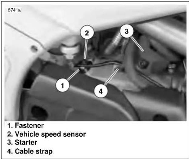
text_image
8741a 1. Fastener 2. Vehicle speed sensor 3. Starter 4. Cable strapFigure 7-54. Speedometer Sensor
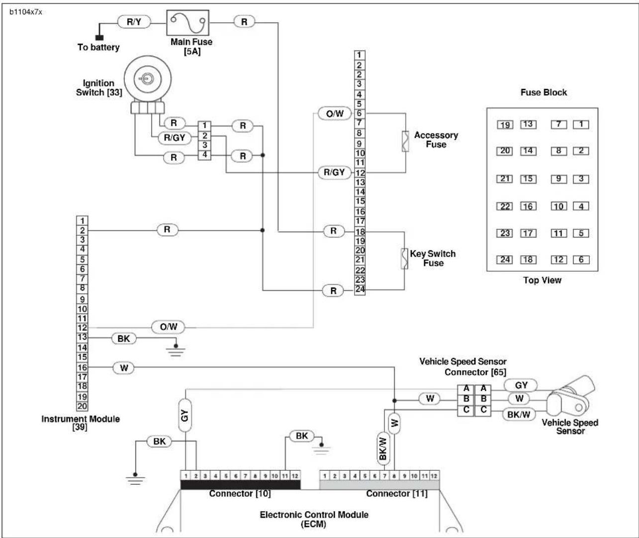
flowchart
graph TD
    A["Main Fuse [5A"]] --> B["R/Y"]
    B --> C["To battery"]
    C --> D["Ignition Switch [33"]]
    D --> E["R/GY"]
    E --> F["1 2 3 4"]
    F --> G["R"]
    G --> H["O/W"]
    H --> I["Accessory Fuse"]
    I --> J["Key Switch Fuse"]
    J --> K["Vehicle Speed Sensor Connector [65"]]
    K --> L["A B C"]
    L --> M["GY W BK/W"]
    M --> N["Vehicle Speed Sensor"]
    N --> O["Electronic Control Module (ECM)"]
    P["Instrument Module [39"]] --> Q["BK"]
    Q --> R["O/W"]
    R --> S["W"]
    S --> T["Vehicle Speed Sensor"]
    T --> U["Vehicle Speed Sensor"]
    V["Top View"] --> W["19 13 7 1"]
    V --> X["20 14 8 2"]
    V --> Y["21 15 9 3"]
    V --> Z["22 16 10 4"]
    V --> AA["23 17 11 5"]
    V --> AB["24 18 12 6"]
Figure 7-55. Vehicle Speed Sensor Wiring
GENERAL
Replace the instrument module if the unit is not working properly or if a lamp is inoperative. The module is not repairable. However, before replacing a component, check that the problem is not caused by a loose wire connection.
REMOVAL
WARNING
To protect against shock and accidental start-up of vehicle, disconnect the negative battery cable before proceeding. Inadequate safety precautions could result in death or serious injury.
- Disconnect negative battery cable.
- Remove headlight support bracket. See 2.25 HEAD-LIGHT SUPPORT BRACKET.
- See Figure 7-57. Disconnect instrument module connector [39].
- See Figure 7-58. Remove fasteners (5) and washers (4).
- Pull instrument module (2) from headlight support bracket (1).
INSTALLATION
- See Figure 7-58. Place instrument module (2) into position in headlight support bracket (1).
- Install washers (4) and fasteners (5). Tighten fasteners to 12-36 in-lbs (1.4-4.0 Nm).
- See Figure 7-57. Connect instrument module connector [39].
- Install headlight support bracket. See 2.25 HEADLIGHT SUPPORT BRACKET.
- Install negative battery cable.

text_image
8444 10 9- 1-2 N E V LFigure 7-56. Instrument Module
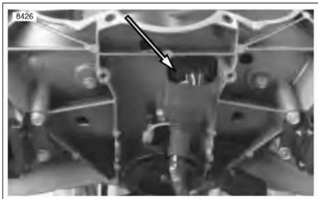
natural_image
Close-up mechanical assembly showing internal components and a black arrow pointing to a specific part (no text or symbols visible)Figure 7-57. Instrument Module Connector [39]

text_image
b1009x7x 1. Headlight support bracket 2. Instrument module 3. Grommet (3) 4. Washer (3) 5. Fastener (3) 6. Instrument module connector [39]Figure 7-58. Instrument Module
GENERAL
See Figure 7-59. Use the SPEEDOMETER TESTER (Part No. HD-41354) for speedometer diagnostics. These diagnostics may include:
- Checking speedometer operation.
● Testing speedometer needle sweeping action.
The tester generates a simulated speedometer sensor signal. This signal aids in determining whether speedometer replacement is necessary. It can also be used to simulate running engine conditions for ignition system troubleshooting.
NOTES
- Use the following procedures in conjunction with the manual supplied with the speedometer tester.
● Test results may be inaccurate if tester battery is low.
TESTING
NOTE
The SPEEDOMETER TESTER (Part No. HD-41354) cannot be used to verify the calibration of a speedometer and it will not verify the speedometer's function to support legal proceedings. It's purpose is to verify speedometer function when performing service diagnosis or repair. It can also assist in determining if speedometer replacement is necessary.
Speedometer Operation Test
NOTE
For information on the correct routing of vehicle speed sensor wiring see 7.24 SPROCKET COVER WIRING.
- See Figure 7-60. Locate the 3-place vehicle speed sensor connector [65] under the sprocket cover. See 2.30 SPROCKET COVER.
- Place speedometer tester power switch in the ON position. Place signal switch in the OUT position.
- Turn vehicle ignition switch ON.
- Begin test.
a. Press ENTER on the tester keypad.
b. Enter a frequency from Table 7-16. Note that different markets use different frequencies.
c. Verify that speedometer display reads the corresponding speed. To change the test frequency, press CLEAR to cancel and enter the new frequency. Press ENTER to begin and reverify.
NOTE
The speedometer should be accurate within 0-5 MPH (0-8 KPH).
Speedometer Needle Sweep Test
The tester's sweep function moves the speedometer needle through the full range of movement. This allows for testing the smoothness of operation and checking for hesitancy or a stuck needle.
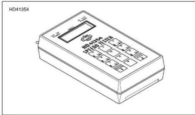
text_image
HD41354 SPLC800 TESTERFigure 7-59. Speedometer Tester (Part No. HD-41354)
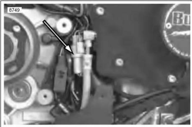
natural_image
Close-up mechanical assembly showing components and wiring (no readable text or symbols)Figure 7-60. Vehicle Speed Sensor Connector [65]
Table 7-16. Speedometer Test Frequency in Hertz (Hz)
| MARKET SPEED FREQUENCY | ||
| USA | 20 MPH | 461 |
| 40 MPH | 923 | |
| 60 MPH | 1365 | |
| 80 MPH | 1847 | |
| ENG, AUS, EUR, CAN, JPN | 40 KPH | 577 |
| 60 KPH | 865 | |
| 80 KPH | 1154 | |
| 100 KPH | 1443 | |
- See Figure 7-60. Disconnect vehicle speed sensor connector [65]. Attach speedometer tester connector to vehicle speed sensor connector.
- Place speedometer tester power switch in the ON position. Place signal switch in the OUT position.
HOME
- Turn vehicle ignition switch ON.
- Begin test by pressing 0 on the tester keypad, then pressing ENTER. The tester will scan for two seconds, then the tester will put out a 1 Hz signal.
- Select a test range.
a. Press 2 to select LO range (1-20 Hz).
b. Press 5 to select CEN range (21-999 Hz).
c. Press 8 to select HI range (1000-20,000 Hz).
- After selecting a range, use the corresponding arrow keys to accelerate through the range. As you move through the speed range, check for smooth needle movement.
a. If testing LO range, press 1 or 3.
b. If testing CEN range, press 4 or 6.
c. If testing HI range, press 7 or 9.
Speedometer Sensor Test
If the speedometer is inoperative, but backlighting and odometer work, the speedometer sensor may not be working.
See Figure 7-61. Fabricate a test harness using the following parts. This harness can also be used to test the tachometer.
● Two Deutsch 3-place socket housings (Part No. 72113-94BK) and six socket terminals (Part No. 72191-94).
● Deutsch 3-place pin housing (Part No. 72103-94BK) and three pin terminals (Part No. 72080-99Y).
● Six lengths of 18 gauge wire, each 6.0 in. (15 cm) long.
● Test for voltage to sensor by checking for 8-12 VDC on red wire in connector [65].
- Then check for continuity to ground on black wire in connector [65].
- Install the test harness between the vehicle speed sensor connector halves [65].
- Raise rear wheel off floor using REAR WHEEL SUPPORT STAND (Part No. B-41174).
- Place speedometer tester power switch in the ON position. Place signal switch in the IN position.
- Plug the speedometer tester into the test harness. Turn vehicle ignition switch ON.
- Press ENTER on the tester keypad.
- Rotate the motorcycle's rear wheel.
a. If reading on speedometer tester changes as wheel is rotated, speedometer sensor is OK.
b. If reading does not change, vehicle speed sensor is suspect. Install a known, good vehicle speed sensor and test again.
- Deutsch socket housing (2)
- Deutsch pin housing
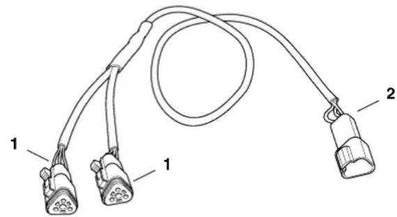
natural_image
Line drawing of a cable with two connectors labeled 1 and 2, no text or symbols presentb0779x7x
Figure 7-61. Test Harness
HOME
Speedometer Test: Chart 1
ODOMETER, TRIP ODOMETER AND RESET SWITCH TESTING
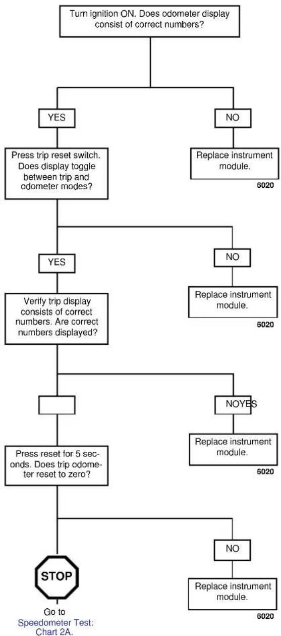
flowchart
graph TD
    A["Turn ignition ON. Does odometer display consist of correct numbers?"] --> B{YES}
    A --> C{NO}
    B --> D["Press trip reset switch. Does display toggle between trip and odometer modes?"]
    D --> E{YES}
    D --> F{NO}
    E --> G["Verify trip display consists of correct numbers. Are correct numbers displayed?"]
    G --> H{NO?}
    G --> I{Yes?}
    H --> J["Press reset for 5 seconds. Does trip odometer reset to zero?"]
    I --> K{NO?}
    J --> L["STOP"]
    K --> M["No"]
    M --> N["Replace instrument module."]
    N --> O["6020"]
    C --> P["Replace instrument module."]
    P --> Q["6020"]
    P --> R["6020"]
    R --> S["6020"]
    S --> T["6020"]
    T --> U["6020"]
    U --> V["6020"]
    V --> W["6020"]
    W --> X["6020"]
    X --> Y["6020"]
    Y --> Z["6020"]
    Z --> AA["6020"]
    AA --> AB["6020"]
    AB --> AC["6020"]
    AC --> AD["6020"]
    AD --> AE["6020"]
    AE --> AF["6020"]
    AF --> AG["6020"]
    AG --> AH["6020"]
    AH --> AI["6020"]
    AI --> AJ["6020"]
    AJ --> AK["6020"]
    AK --> AL["6020"]
    AL --> AM["6020"]
    AM --> AN["6020"]
    AN --> AO["6020"]
    AO --> AP["6020"]
    AP --> AQ["6020"]
    AQ --> AR["6020"]
    AR --> AS["6020"]
    AS --> AT["6020"]
    AT --> AU["6020"]
    AU --> AV["6020"]
    AV --> AW["6020"]
    AW --> AX["6020"]
    AX --> AY["6020"]
HOME
Speedometer Test: Chart 2A
INOPERATIVE, INACCURATE OR ERRATIC SPEEDOMETER
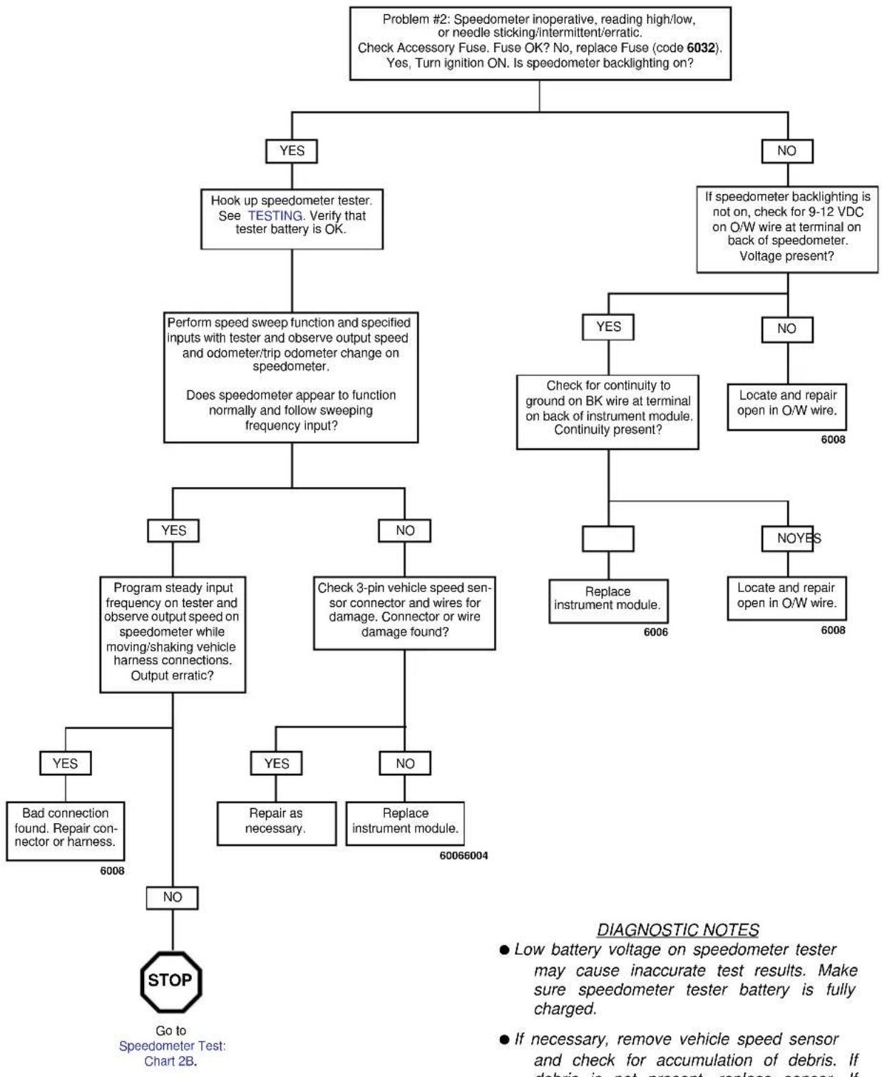
flowchart
graph TD
    A["Problem #2: Speedometer inoperative, reading high/low, or needle sticking/intermittent/erratic.<br>Check Accessory Fuse. Fuse OK? No, replace Fuse (code 6032).<br>Yes, Turn ignition ON. Is speedometer backlighting on?"] --> B{YES}
    A --> C{NO}
    B --> D["Hook up speedometer tester.<br>See TESTING. Verify that tester battery is OK."]
    D --> E["Perform speed sweep function and specified inputs with tester and observe output speed and odometer/trip odometer change on speedometer.<br>Does speedometer appear to function normally and follow sweeping frequency input?"]
    E --> F{YES}
    E --> G{NO}
    F --> H["Program steady input frequency on tester and observe output speed on speedometer while moving/shaking vehicle harness connections.<br>Output erratic?"]
    G --> I{YES}
    G --> J{NO}
    H --> K["Bad connection found. Repair connector or harness. 6008"]
    I --> L{YES}
    I --> M{NO}
    J --> N["Repair as necessary. 600666004"]
    K --> O{STOP}
    L --> P["Replace instrument module. 600666004"]
    M --> Q["Check 3-pin vehicle speed sensor connector and wires for damage. Connector or wire damage found?"]
    Q --> R{YES}
    Q --> S{NO}
    R --> T["Diagnostic NOTES"]
    S --> U["Low battery voltage on speedometer tester may cause inaccurate test results. Make sure speedometer tester battery is fully charged."]
    S --> V["If necessary, remove vehicle speed sensor and check for accumulation of debris. If debris is not present, replace sensor. If"]
DIAGNOSTIC NOTES
● Low battery voltage on speedometer tester may cause inaccurate test results. Make sure speedometer tester battery is fully charged.
- If necessary, remove vehicle speed sensor and check for accumulation of debris. If debris is not present, replace sensor. If debris is present, clean sensor and repeat test. Replace if necessary.
Speedometer Test: Chart 2B
INOPERATIVE, INACCURATE OR ERRATIC SPEEDOMETER
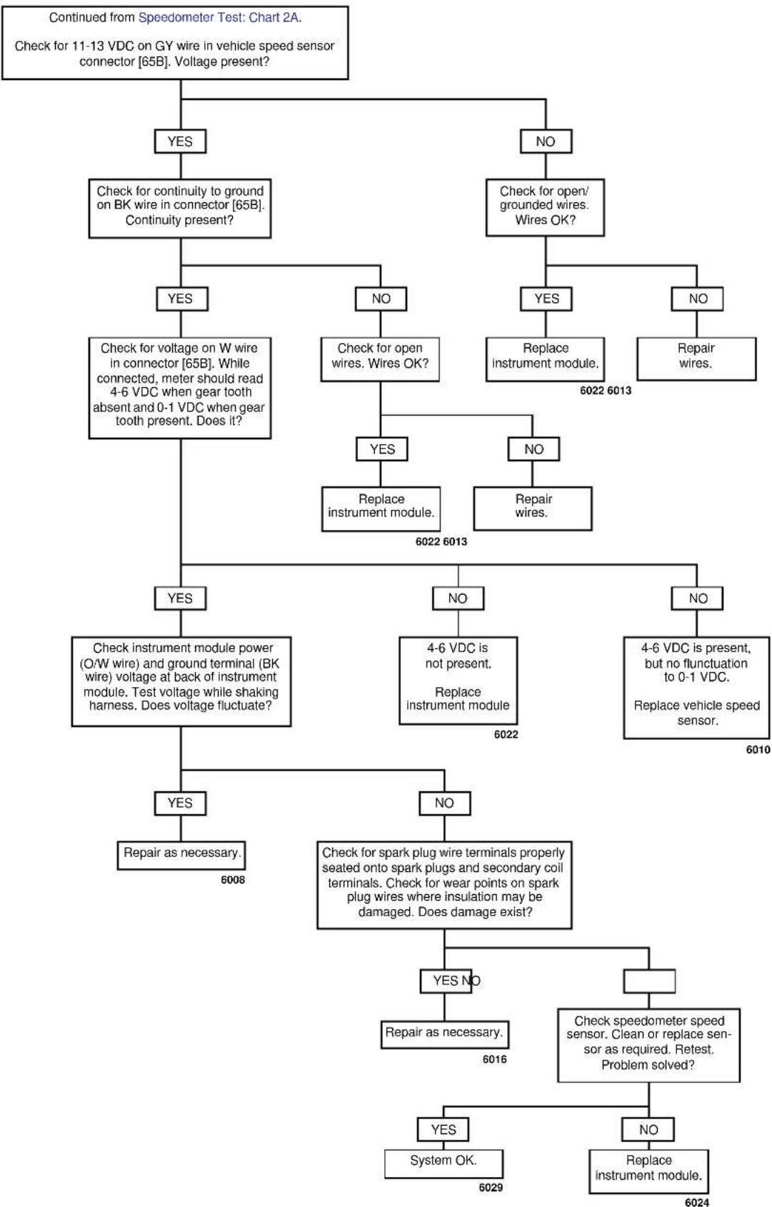
flowchart
graph TD
    A["Continued from Speedometer Test: Chart 2A.<br>Check for 11-13 VDC on GY wire in vehicle speed sensor connector [65B"]. Voltage present?] --> B{YES}
    A --> C{NO}
    B --> D{Check_for_continuity_to_ground_on_BK_wire_in_connector["65B"].
Continuity present?}
    D --> E{YES}
    D --> F{NO}
    E --> G{Check_for_voltage_on_W_wire_in_connector["65B"].
While connected, meter should read 4-6 VDC when gear tooth absent and 0-1 VDC when gear tooth present. Does it?}
    G --> H{YES}
    G --> I{NO}
    H --> J{Check for open wires. Wires OK?}
    J --> K{YES}
    J --> L{NO}
    K --> M["Replace instrument module."]
    L --> N["Repair wires."]
    M --> O{6022 6013}
    N --> P["6022 6013"]
    O --> Q{YES}
    P --> R{NO}
    Q --> S{Check instrument module power (O/W wire) and ground terminal (BK wire) voltage at back of instrument module.
Test voltage while shaking harness. Does voltage fluctuate?}
    R --> T{4-6 VDC is not present.
Replace instrument module}
    S --> U{4-6 VDC is present, but no fluctuation to 0-1 VDC.
Replace vehicle speed sensor.}
    S --> V{6022}
    T --> W{6008}
    T --> X{NO}
    W --> Y{YES}
    X --> Z{NO}
    Y --> AA["Repair as necessary."]
    Z --> AB{Check for spark plug wire terminals properly seated onto spark plugs and secondary coil terminals.
Check for wear points on spark plug wires where insulation may be damaged. Does damage exist?}
    AB --> AC{YES NO}
    AB --> AD{Repair as necessary.}
    AC --> AE["6016"]
    AD --> AF{Check speedometer speed sensor. Clean or replace sensor as required. Retest. Problem solved?}
    AF --> AG{YES}
    AF --> AH{NO}
    AG --> AI["System OK."]
    AH --> AJ["Replace instrument module."]
GENERAL
NOTE
Tachometer performance check can also be performed using DIGITAL TECHNICIAN (Part No. HD-44750).
See Figure 7-59. Use the SPEEDOMETER TESTER (Part No. HD-41354) for tachometer diagnostics. These diagnostics may include:
- Checking tachometer operation.
● Testing tachometer needle sweeping action.
The tester can be connected to the vehicle's cam position sensor connector. This connection introduces a signal to the ignition module that simulates the signal from the cam position sensor. The ignition module will use this simulated signal to open and close circuits to fire the spark plugs. This allows you to simulate the engine running and therefore generate tachometer readings.
TESTING
Operation Test
NOTE
For information on the correct routing of speedometer sensor wiring see 7.24 SPROCKET COVER WIRING.
- See Figure 7-62. Locate the 3-place cam position connector [14] under the sprocket cover. See 2.30 SPROCKET COVER.
- See Figure 7-63. Connect the speedometer tester to the cam position sensor Deutsch socket housing using test harness. See Speedometer Sensor Test under 7.18 SPEEDOMETER PERFORMANCE CHECK for more information on test harness.
- Convert the desired test RPM to a tester frequency in Hertz. Several conversions are listed in Table 7-16.
a. Select a desired tachometer reading for testing. This example will use 2000 RPM.
b. Divide the desired tachometer reading by 60. For example, 2000/60=33.3.
NOTE
All tachometer accuracy tolerances were taken at 68°-77°F (20-25°C).
- Enter the result (33.3 for 2000 RPM) into the speedometer tester.
a. The tachometer should respond by moving its needle to the desired RPM.
b. Test the tachometer at several different RPM readings to verify proper operation.
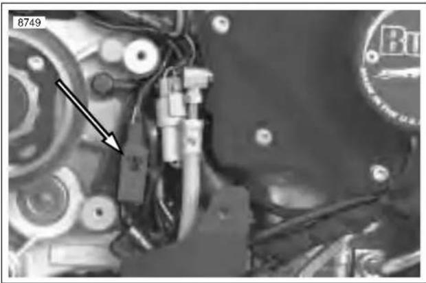
natural_image
Close-up of mechanical components with wiring and a black arrow pointing to a component (no readable text or symbols)Figure 7-62. Cam Position Sensor Connector
Table 7-17. Tachometer Accuracy Tolerances and Conversions
| READING | 2000 RPM | 4000 RPM | 6000 RPM | 7500 RPM |
| Tolerance (+/- RPM) | 100 120 | 210 320 | ||
| Conversion factor | 33.3 | 66.7 | 100 125 |
HOME
Sweep Test
- See Figure 7-63. Connect the speedometer tester to the cam position sensor Deutsch socket housing using test harness. See Speedometer Sensor Test under 7.18 SPEEDOMETER PERFORMANCE CHECK for more information on test harness.
- Place speedometer tester power switch in the ON position. Place signal switch in the OUT position.
- Turn vehicle ignition switch ON.
- Begin test by pressing 0 on the tester keypad, then pressing ENTER. The tester will scan for two seconds, then the tester will put out a 1 Hz signal.
- Select a test range.
a. Press 2 to select LO range.
b. Press 5 to select CEN range.
c. Press 8 to select HI range.
- After selecting a range, use the corresponding arrow keys to accelerate through the range. As you move through the speed range, check for smooth needle movement.
a. If testing LO range, press 1 or 3.
b. If testing CEN range, press 4 or 6.
c. If testing HI range, press 7 or 9.
- Deutsch socket housing test connector
- Deutsch socket housing
- Deutsch pin housing
- Cam position sensor
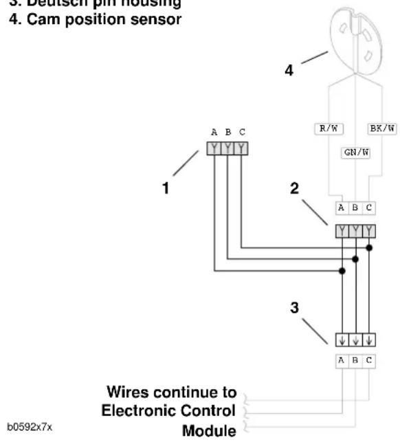
text_image
6. Deutsch pin housing 4. Cam position sensor 1 A B C 2 3 Wires continue to Electronic Control Module 4 R/W BK/W GN/W A B C A B C A B C b0592x7xFigure 7-63. Testing Tachometer
GENERAL
The horn is located inside fairing.
REMOVAL
- Remove seat. See 2.38 SEAT.
WARNING
To protect against shock and accidental start-up of vehicle, disconnect the negative battery cable before proceeding. Inadequate safety precautions could result in death or serious injury.
- Disconnect negative battery cable.
- Remove headlight support bracket. See 2.25 HEAD-LIGHT SUPPORT BRACKET.
- See Figure 7-64. Remove fastener (3).
- Remove horn (1) from fairing support bracket (4).
- See Figure 7-65. Detach Y/BK power wire and BK ground wire from terminal clips on horn.
INSTALLATION
- See Figure 7-65. Connect Y/BK power wire and BK ground wire to terminal clips on horn.
- See Figure 7-64. Attach horn (1) to fairing support bracket (4) using fastener (3). Tighten to 72-96 in-lbs (8.1-10.8 Nm).
- Check horn operation. If horn does not sound or fails to function satisfactorily, see TROUBLESHOOTING.
a. Turn ignition key switch ON.
b. Press horn switch to activate horn.
c. Turn ignition key switch OFF.
- Install negative battery cable.
WARNING
After installing seat, pull upward on front of seat to be sure it is locked in position. If seat is loose, it could shift during vehicle operation and startle the rider, causing loss of control which could result in death or serious injury.
- Install seat. See 2.38 SEAT.
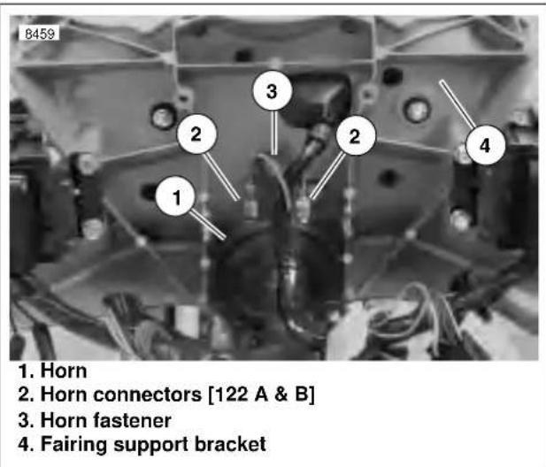
text_image
8459 1. Horn 2. Horn connectors [122 A & B] 3. Horn fastener 4. Fairing support bracketFigure 7-64. Horn Assembly
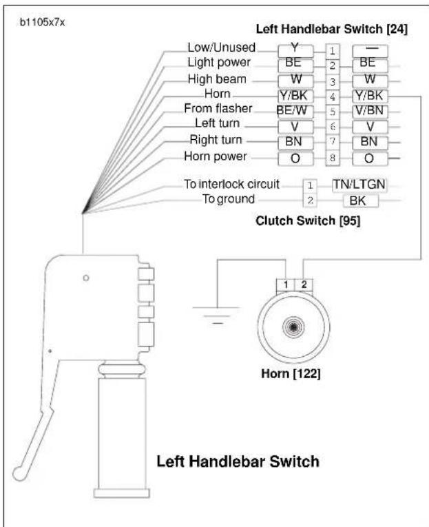
text_image
b1105x7x Left Handlebar Switch [24] Low/Unused Y 1 — Light power BE 2 BE High beam W 3 W Horn Y/BK 4 Y/BK From flasher BE/W 5 V/BN Left turn V 6 V Right turn BN 7 BN Horn power O 8 O To interlock circuit 1 TN/LTGN To ground 2 BK Clutch Switch [95] Horn [122] Left Handlebar SwitchFigure 7-65. Horn Wiring
TROUBLESHOOTING
- If the horn does not sound or fails to function satisfactorily, check for the following conditions:
a. Discharged battery.
b. Loose, frayed or damaged wiring leading to horn terminal.
- If battery has a satisfactory charge and wiring appears to be in good condition, test horn grounds and switch using voltmeter.
a. See Figure 7-65. Remove Y/BK power and BK ground wires from terminal clips.
b. Connect voltmeter positive (+) lead to Y/BK wire.
c. Connect voltmeter negative (−) lead to ground.
d. Turn ignition key switch ON.
- See Figure 7-66. Depress horn switch and observe voltmeter reading.
a. If battery voltage is present, horn or horn grounding is faulty. If horn is faulty, replace unit as an assembly. The horn is not repairable.
b. If battery voltage is not present, either horn switch or wiring to horn is faulty. If horn switch is faulty, replace left handlebar switch. See 7.15 HANDLE-BAR SWITCHES.
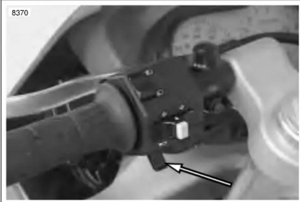
natural_image
Close-up of a mechanical component with a black tool and arrow pointing to a small component (no visible text or symbols)Figure 7-66. Horn Switch
GENERAL
See Figure 7-67. The neutral indicator switch (2) is threaded into the transmission portion of the right crankcase half. It is immediately forward of the transmission sprocket (1). The sprocket cover must be removed to test the switch.
A pin on the shifter drum contacts the neutral indicator switch plunger, completing the neutral indicator circuit. The switch is not repairable. Replace the switch if it malfunctions.
TESTING
- Remove sprocket cover. See 2.30 SPROCKET COVER.
- See Figure 7-67. Disconnect wire lead from neutral indicator switch (2).
- Turn ignition key switch to ON. Touch the neutral indicator wire lead to a suitable ground.
a. If indicator lamp lights, then problem is at indicator switch. Replace switch.
b. If indicator lamp does not light, then problem is elsewhere in circuit. Check for loose connections, burned out indicator lamps or faulty wiring.
c. After testing and repair, connect wire lead to indicator switch.
- Install sprocket cover. See 2.30 SPROCKET COVER.
REMOVAL/INSTALLATION
- Verify that the ignition key switch is turned to OFF.
- Remove sprocket cover. See 2.30 SPROCKET COVER.
NOTE
If replacing neutral indicator switch wiring, see 7.24 SPROCKET COVER WIRING for correct wire routing.
3. See Figure 7-68. Remove wire lead (1) from neutral indicator switch (2).
4. Remove neutral indicator switch and washer (3).
5. Install new neutral indicator switch.
a. Apply a light coating of LOCTITE THREADLOCKER 243 (blue) to new neutral indicator switch (1) threads.
b. Install washer (3) over neutral indicator switch (2) threads.
c. Install switch in crankcase. Tighten switch to 36-60 in-lbs (4-6.8 Nm).
d. Connect wire lead (1) to switch.
- Install sprocket cover. See 2.30 SPROCKET COVER.
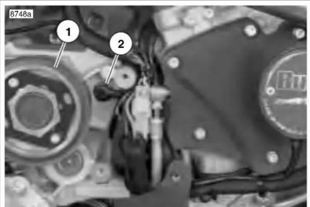
text_image
8748a 1 2- Transmission sprocket
- Neutral indicator switch
Figure 7-67. Neutral Indicator Switch Location
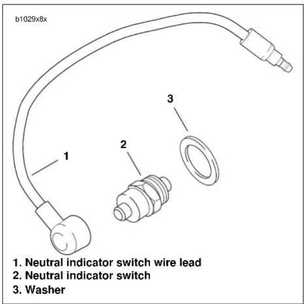
text_image
b1029x8x 1. Neutral indicator switch wire lead 2. Neutral indicator switch 3. WasherFigure 7-68. Neutral Indicator Switch
GENERAL
Buell motorcycles feature two components which protect the electrical system.
Fuses
See Figure 7-69. The covered fuse block is behind the fairing on the right hand side of the motorcycle.
See Figure 7-70. The lights, key switch, brake/horn and ignition fuses are rated at 15 amps. The ECM, cooling fan and accessory fuses are rated at 7.5 amps.
Always investigate the cause of blown fuses before replacing them.
Main Fuse
See Figure 7-71. The 30 amp main fuse is located under the seat.
Todisable the motorcycle's ignition system, pull the main fuse up and out of the main fuse holder.
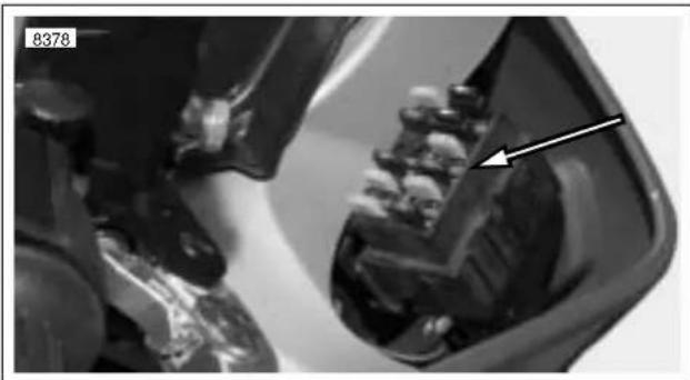
natural_image
Close-up of mechanical components with a white arrow pointing to a component (no visible text or symbols)Figure 7-69. Fuse Block
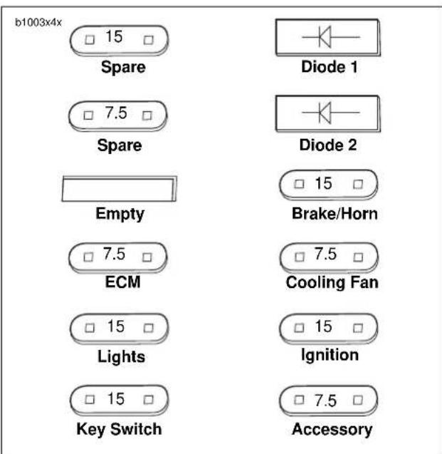
text_image
b1003x4x □ 15 □ Spare Diode 1 □ 7.5 □ Spare Diode 2 Empty □ 15 □ Brake/Horn □ 7.5 □ ECM □ 7.5 □ Cooling Fan □ 15 □ Lights □ 15 □ Ignition □ 15 □ Key Switch □ 7.5 □ AccessoryFigure 7-70. Fuses and Diodes
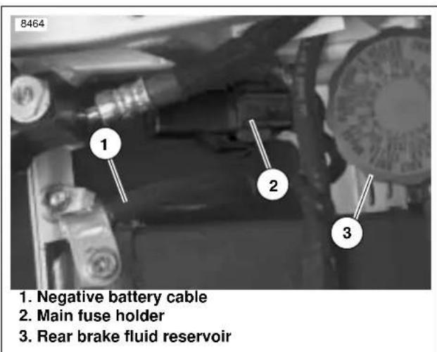
text_image
8464 1. Negative battery cable 2. Main fuse holder 3. Rear brake fluid reservoirFigure 7-71. 30 A Main Fuse Location
GENERAL
The main wire harness runs from the front of the motorcycle to the tail section where it connects to the tail section mini-harness.
Always replace plastic tree fasteners when replacing main wire harness. Remove tree fasteners carefully. do not leave any of fastener in frame.
REMOVAL
NOTES
-
To ensure correct installation, make note of wire routing and cable strap locations before removing main wire harness.
● Main wire harness is removed from front of vehicle in between fork tube and frame. -
Remove seat. See 2.38 SEAT.
WARNING
Always disconnect the negative battery cable first. If the positive cable should contact ground with the negative cable installed, the resulting sparks may cause a battery explosion which could result in death or serious injury.
- Unthread fastener and remove battery negative cable (black) from battery negative (-) terminal.
- Pull back terminal cover boot.
- Unthread fastener and remove battery positive cable (red) from battery positive (+) terminal.
- Disconnect positive battery cable from starter.
- Remove tail frame upper body work. 2.36 TAIL FRAME AND BODY WORK.
- See Figure 7-72. Disconnect tail harness connector [7] (3).
- See Figure 7-73. Remove wire harness ground (2).
- Remove main fuse case (3).
- Disconnect foot brake light switch connector [121] (5).
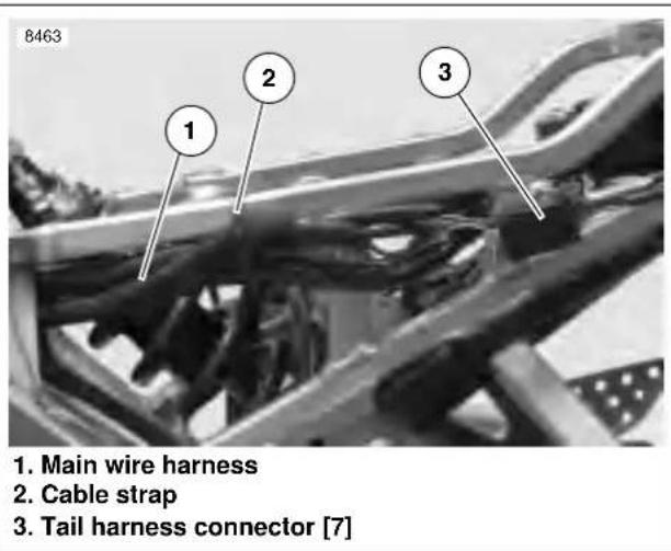
text_image
8463 1. Main wire harness 2. Cable strap 3. Tail harness connector [7]Figure 7-72. Tail Harness Connector
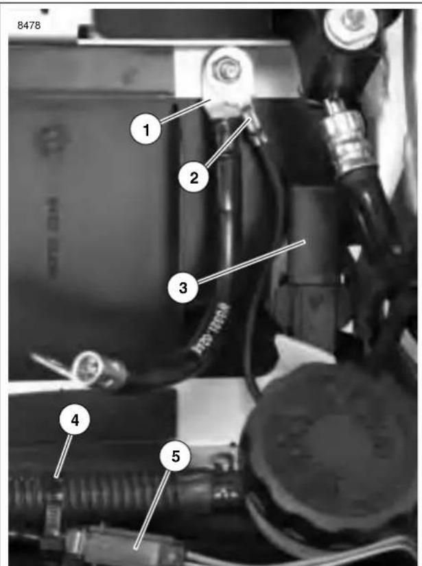
text_image
8478 1 2 3 4 5- Main battery ground
- Wire harness ground
- Main fuse case
- Cable strap
- Foot brake light switch connector [121]
Figure 7-73. Battery Tray Wiring
HOME
- Disconnect wiring located under sprocket cover. See 7.24 SPROCKET COVER WIRING.
- See Figure 7-74. Remove heat shrink tubing and disconnect sidestand switch [133] (1).
- Remove connector from oil pressure switch [120]. Oil pressure switch is located on front of engine.
- Rotate engine. See 3.3 ENGINE ROTATION FOR SERVICE.
- Disconnect intake air temperature sensor [89].
- Disconnect throttle position sensor [88].
- Remove fan connector [97]. Fan connector is located behind rear cylinder.
- Remove upper fork clamp. 2.17 FORK CLAMPS, UPPER AND LOWER.
- Remove fairing. See 2.37 FRONT FAIRING, WINDSHIELD, AND MIRRORS.
- Disconnect:
a. Flasher connector [30].
b. Bank angle sensor connector [134].
c. Electronic control module (ECM). 4.29 ELECTRONIC CONTROL MODULE.
d. Instrument module connector [39].
e. Horn connectors [122].
f. Ground terminals on front of steering head.
g. Left switch housing connector [24] and right switch housing connector [22].
h. Clutch switch [95] from left switch housing.
i. Front brake switch [121] from right switch housing.
j. headlight connector. [38].
- Remove fuse block and relay block by removing fasteners securing them to fairing support bracket.
- Remove fuse and relay bundle clamps.
- Remove fuse block and relay block from their brackets.
- Remove any remaining cable straps and clamps securing wire harness and remove harness from front of vehicle.
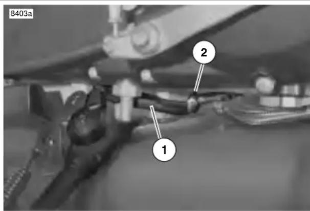
text_image
8403a 1 2- Sidestand switch connector [133] (inside heat shrink tubing)
- Cable strap
Figure 7-74. Sidestand Switch Connector [133]
INSTALLATION
NOTE
For more information on wire harness and hose routing, see D.1 HOSE AND WIRE ROUTING.
- Feed rear portion of new harness between left front fork and frame.
- Continue to feed rear and center portion of harness between left side of engine and frame.
- Place connectors in general location of installation.
- Secure plastic harness holder to left inside portion of frame using plastic tree fasteners.
NOTE
Fuel line is installed under engine connector portion of wire harness.
- See Figure 7-75. Install clamp over portion of harness that leads to engine connectors. Install clamp as shown using new plastic tree fastener.
-
See Figure 7-76. Route portion of main wire harness that contains the positive battery cable (3), sprocket cover wiring (4) and transmission vent hose (2) through corner mounting tab (1) at rear of frame. Install new plastic tree fasteners.
-
Connect fan connector [97].
-
Connect throttle position sensor [88].
-
Rotate motor into position. See REASSEMBLY under 3.3 ENGINE ROTATION FOR SERVICE.
-
Install sprocket cover wiring. See 7.24 SPROCKET COVER WIRING.
-
See Figure 7-74. Connect sidestand switch connector [133] (1). Install heat shrink tubing. Install cable strap (2) securing sidestand switch wiring to sidestand switch bracket.
-
Install oil pressure switch connector to oil pressure switch.
-
See Figure 7-77. Install cable straps:
a. Front cable strap (3) secures voltage regulator and oil pressure switch wiring.
b. Middle cable strap (2) secures voltage regulator, oil pressure switch and cam position sensor wiring.
c. Rear cable strap (1) secures conduit to voltage regulator wiring.
NOTE
Snap fuse and relay blocks into mounting brackets before installing blocks to fairing mounting bracket.
-
Place clamp (2) around fuse block wiring. Mount fuse block (1) and clamp to fairing support bracket using top fastener (4) and bottom fastener (3). Tighten fasteners to 72-96 in-lbs (8.1-10.8 Nm).
-
Repeat previous steps for relay block.
-
Install steering head clamp around wire harness and secure clamp to fairing support bracket with loop facing vehicle. Tighten fastener to 16-18 ft-lbs (21.7-24.4 Nm).
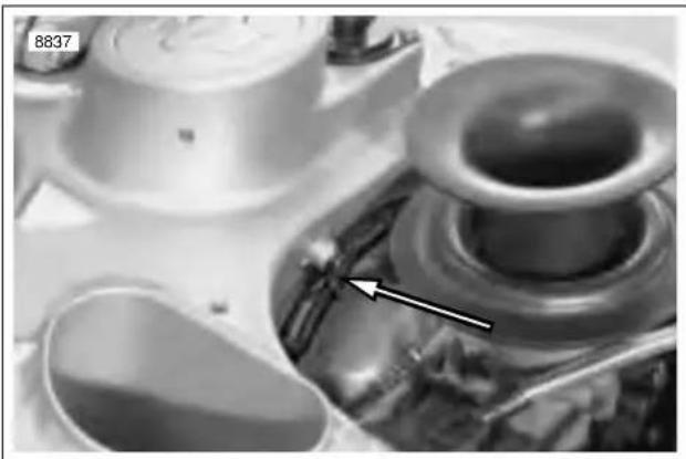
natural_image
Close-up of mechanical components with a white arrow pointing to a component (no visible text or symbols)Figure 7-75. Wire Harness Clip
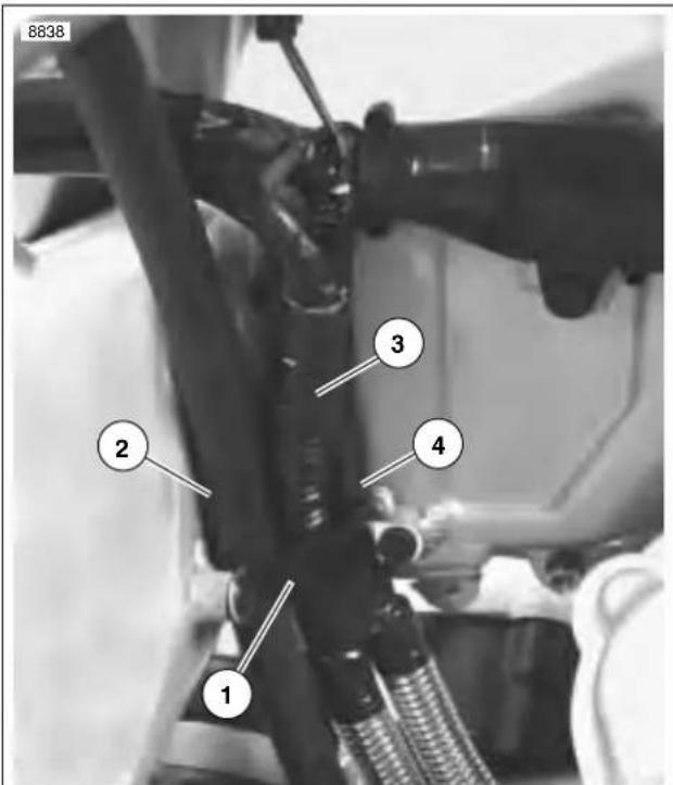
text_image
8838 1 2 3 4- Mounting tab
- Transmission vent hose
- Positive battery cable
- Sprocket cover wiring
Figure 7-76. Corner Mounting Tab
HOME
-
Install upper fork clamp. See INSTALLATION under 2.17 FORK CLAMPS, UPPER AND LOWER.
-
Connect:
a. headlight connector [38].
b. Front brake switch [121] to right switch housing.
c. Clutch switch [95] to left switch housing.
d. Left switch housing connector [24] and right switch housing connector [22].
e. Ignition switch [33]
f. Ground terminals on front of steering head.
g. Horn connectors [122].
h. Instrument module connector [39].
i. Install electronic control module. See INSTALLATION under 4.29 ELECTRONIC CONTROL MODULE.
j. Bank angle sensor connector [134].
k. Flasher connector [30].
- See Figure 7-79. Verify proper fairing wire routing and cable strap locations.
- Verify that front forks can be turned from full left to full right lock without wire harness binding or pinching.
- Install fairing. See INSTALLATION under 2.37 FRONT FAIRING, WINDSHIELD, AND MIRRORS.
- See Figure 7-73. Connect foot brake light switch connector [121] (5). Install cable strap (4).
- Install main fuse case (3).
- Install main battery ground (1) and wire harness ground (2). Tighten fastener to 48-72 in-lbs (5.4-8.1 Nm).
- See Figure 7-72. Connect tail harness connector (3). Attach cable strap (2).
- Install starter side of positive battery cable to starter.
WARNING
Always connect the positive battery cable first. If the positive cable should contact ground with the negative cable installed, the resulting sparks may cause a battery explosion which could result in death or serious injury.
- Install positive battery cable (red) to positive terminal of battery. Tighten to 72-96 in-lbs (8-11 Nm).
- Connect negative battery cable. Tighten to 72-96 in-lbs (8-11 Nm).
- Install tail frame upper body work. See 2.36 TAIL FRAME AND BODY WORK.
WARNING
After installing seat, pull upward on front of seat to be sure it is locked in position. If seat is loose, it could shift during vehicle operation and startle the rider, causing loss of control which could result in death or serious injury.
- Install seat. See 2.38 SEAT.
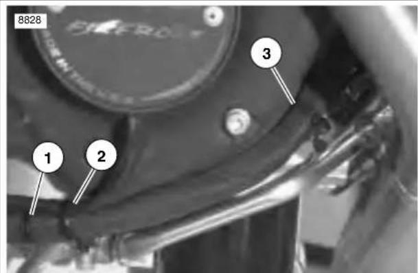
text_image
8828 1 2 3- Rear cable strap
- Middle cable strap
- Front cable strap
Figure 7-77. Cable Straps
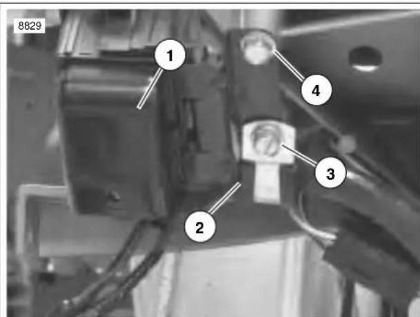
text_image
8829 1 2 3 4- Fuse block
- Clamp
- Bottom fuse block fastener
- Top fuse block fastener
Figure 7-78. Fuse Block
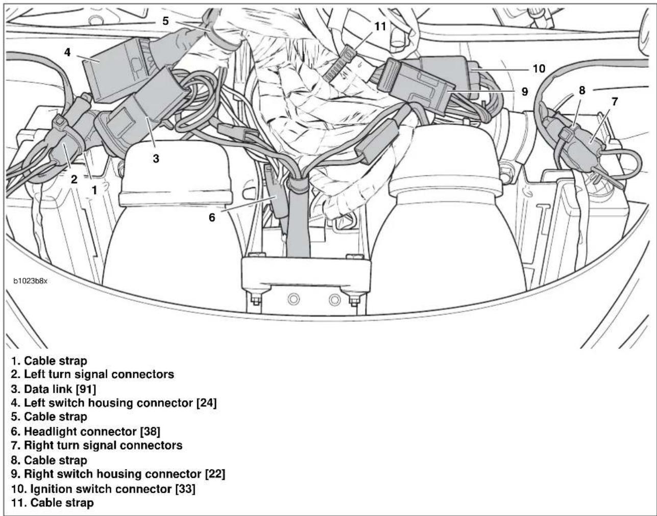
text_image
1. Cable strap 2. Left turn signal connectors 3. Data link [91] 4. Left switch housing connector [24] 5. Cable strap 6. Headlight connector [38] 7. Right turn signal connectors 8. Cable strap 9. Right switch housing connector [22] 10. Ignition switch connector [33] 11. Cable strap b1023b8xFigure 7-79. Fairing Wiring (viewed from underneath fairing)
GENERAL
Connectors for the stator [46], voltage regulator [77], vehicle speed sensor [65], cam position sensor [14] and neutral switch [131] are located under the sprocket cover.
REMOVAL
-
Remove sprocket cover. See 2.30 SPROCKET COVER.
-
See Figure 7-80. Disconnect appropriate connector(s).
INSTALLATION
NOTE
See Figure 7-80. All wiring under sprocket cover that gets routed from sprocket area towards front of vehicle is routed behind cam cover breather hose (8).
-
Route oil pressure switch wiring (10) from main harness (6), behind cam cover breather hose (8) to oil pressure switch located on front of engine.
-
Route sidestand switch wiring (not shown) from main harness, underneath engine and to sidestand switch [133].
NOTE
Stator connector wiring is installed over oil pressure and side-stand switch wiring.
-
Connect stator connector (9).
-
See Figure 7-81. Connect cam position sensor [14] (1). Form a loop (2) as shown using wiring leading to cam position sensor.
-
See Figure 7-82. Connect neutral switch connector.
-
See Figure 7-83. Form a loop (6) as shown using neutral switch wiring.
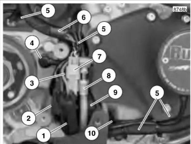
text_image
5 6 5 4 7 3 8 9 2 10 5 BU 8748b- Voltage regulator connector [77]
- Cam position sensor connector [14]
- Neutral switch connector [131] (approximate location)
- Neutral switch location
- Cable strap
- Main harness
- Vehicle speed sensor connector [65]
- Cam cover breather hose
- Stator connector [46]
- Oil pressure switch wiring
Figure 7-80. Sprocket Cover Wiring
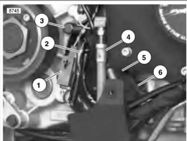
text_image
8745 1 2 3 4 5 6- Cam position sensor [14]
- Loop in voltage regulator wiring
- Neutral switch location
- Cam cover breather hose
- Stator connector [46]
- Oil pressure switch wiring
Figure 7-81. Cam Position Sensor Wiring
HOME
NOTE
In next step, be sure loops in cam position sensor and neutral switch wiring are intact.
-
Use cable strap (5) to secure cam position sensor (1), cam position sensor wiring (3), neutral switch connector (4) and neutral switch connector wiring (6).
-
See Figure 7-84. Connect vehicle speed sensor connector.
NOTE
See Figure 7-85. In next step, be sure main harness (4) is routed around sprocket cover boss (2).
- See Figure 7-85. Connect voltage regulator connector [77] (1). Be sure connector latch faces inward and voltage regulator wires are positioned behind other wires in harness at sprocket cover boss (2).
- Install cable strap (3) securing vehicle speed sensor wiring to starter connector [128] wiring.
- Install cable strap (5) securing main harness wiring.
- Install cable strap (6) securing stator, cam position sensor and oil pressure switch wiring.
- Add cable strap (7) to secure cam position sensor and voltage regulator wiring.

natural_image
Close-up mechanical assembly with visible springs and bolts, no text or symbols presentFigure 7-82. Neutral Switch Connector [131]
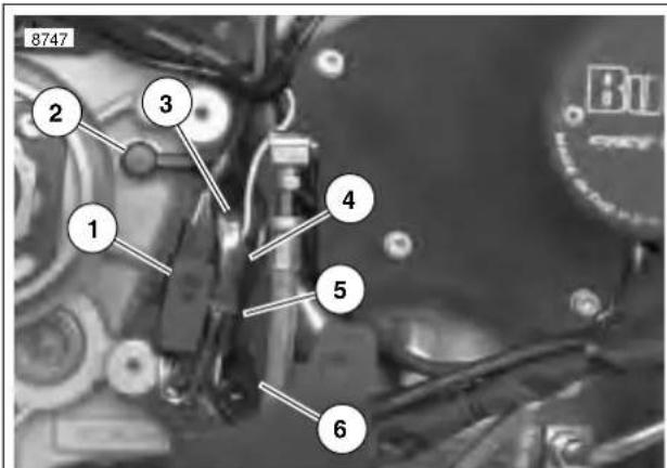
text_image
8747 2 3 1 4 5 6-
Cam position sensor connector [14]
-
Neutral switch location
-
Cam position sensor wiring
-
Neutral switch connector [131]
-
Cable strap
-
Loop in neutral switch wiring
Figure 7-83. Neutral Switch Wiring
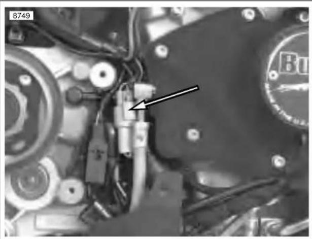
natural_image
Close-up of mechanical components with visible wiring and a numbered label (8749), no readable text or symbols beyond the number.Figure 7-84. Vehicle Speed Sensor Connector [65]
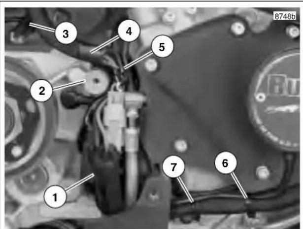
text_image
8748b 1 2 3 4 5 6 7-
Voltage regulator connector [77]
-
Sprocket cover boss
-
Cable strap
-
Main harness
-
Cable strap
-
Cable strap
-
Cable strap
Figure 7-85. Assembled Wiring
Table Of Contents
SUBJECT PAGE NO.
Appendix A-Tools....A-1
Appendix B-Wiring B-1
Appendix C-Metric Conversions. C-1
Appendix D-Wiring and Hose Routing .... D-1
APPENDICES